Abstract—In this paper the authors report the study done on welded Ti-6Al-4V alloy sheets by friction stir and laser beam welding. Fusion and solid-state techniques were compared to determine the most performance favourable welding process. Welds were accomplished by varying the process traverse speed. High traverse speeds indicated increased hardness in the weld nugget and wider nugget area for laser beam as compared to FSW. Tensile strength for both processes showed similar performance to that of the parent plate. Welds from laser beam welding exhibited superior fatigue strength under tension-tension loading than friction stir welds at intermediate speeds. Microstructure was discussed to explain the effect of the process parameters on joint integrity in relation to the parent plate. Additionally, residual stresses measured in the weld nugget are explained. Keywords— Friction stir; laser beam; Ti6Al4V; traverse speed; tensile strength; fatigue I. INTRODUCTION n recent years, the usage of Ti-6Al-4V alloy has increased in the aerospace, shipbuilding and automotive industries as well as the manufacture of medical devices and human body implants, of which these typical applications require a better understanding of the behaviour of the welded joints. Ti-6Al-4V is the “workhorse” of Titanium alloys which offers high strength to weight ratio, excellent resistance to corrosion and high fatigue resistance as a result of slow crack propagation and fatigue crack initiation [1, 2, 3]. Friction Stir Welding (FSW) is a solid-state joining process using a specially designed rotating tool to generate frictional heat at the weld joint line as the tool is plunged into the material as a result plasticize the welded material. As the rotating tool traverses, there is mixing of the plasticized material, the plasticized material is moved from the Manuscript received March 24, 2016; revised April 5, 2016. Dr P. M. Mashinini is a Lecturer in the Department of Mechanical and Industrial Engineering Technology, University of Johannesburg, Doornfontein Campus, Johannesburg, 2028, South Africa. (Phone: +27 11 559 6652; e-mail: [email protected] ). Prof D. G. Hattingh is a Professor in the Department of Mechanical Engineering, Nelson Mandela Metropolitan University, North Campus, Port Elizabeth, 6001, South Africa. (Phone: +27 41 504 3608; e-mail: [email protected] ) Prof H. Lombard is an Associate Professor in the Department of Mechanical Engineering, Nelson Mandela Metropolitan University, North Campus, Port Elizabeth, 6031, South Africa. (Phone: +27 41 504 3285; e- mail: [email protected] ). advancing side (AS) to the retreating side (RS) of the weld. At the same time, the plasticized material is also consolidated underneath the tool shoulder by the downwards force of the tool [4, 5]. On the other hand, Laser Beam Welding (LBW) is a fusion technique, for joining materials by heat produced from a high powered laser beam directed onto the weld-line. Welding is done by first surface irradiation as the beam is projected on the welded surface, surface melting, then vaporization and keyhole formation which trap the metallic vapour there by forming a welded joint [6, 7]. As stated earlier that the two processes are fundamentally different, a few notable differences are the variances in heat affected zone (HAZ) and weld nugget. In LBW, the heat is only concentrated within the joint-line as a result produces narrow HAZ and weld nugget however, FSW produces a wider HAZ and nugget area which are mostly as a result of the size of the rotating tool pin and shoulder. Research has been reported by various authors relating to these specific welding processes highlighting the static performance and some typical microstructure of the welded joints. Mironov et al. [8] reported a study that showed α- grain structure is governed by the grain elongation and transverse grain subdivision which is mostly influenced by the transformation of β to α phase during the cooling rate cycle after FSW [8]. A report by Kitamura et al. [9] showed that microstructure of FSW of Ti6Al4V alloy is highly influenced by the cooling rate of increases with traverse speed as a result caused an increase in tensile strength with increase in traverse speed [9]. Xu et al. [10] showed similar results which indicated martensitic (α’) structure with α and retained β as result of phase transformation during laser welding. High traverse speed showed more martensitic (α’) structure in the weld nugget [10, 11]. On the other hand Liu et al [12] reported the fatigue damage evolution on laser welded joints. The results showed high weld fatigue crack resistance compared to the parent plate due to the martensitic (α’) structure in the weld nugget [12]. Additionally, the crack initiation was more sensitive to localized notch stress, which was the result of the underfill in the weld joint [11, 12]. Increased hardness in the weld nugget and heat affected zone were recorded in a study done by Mashinini [13]. The study also showed weld joint tensile strength similar to the parent plate [13, 14]. On the contrary, Ramulu et al [15] reported a study indicating superior yield and ultimate tensile strength but reduced weld elongation than the parent plate as a result of grain refinement [15]. An influence of Mechanical Properties and Microstructure of Friction Stir and Laser Beam Welded 3mm Ti6Al4V Alloy Peter M. Mashinini, Danie G. Hattingh, Hannalie Lombard I Proceedings of the World Congress on Engineering 2016 Vol II WCE 2016, June 29 - July 1, 2016, London, U.K. ISBN: 978-988-14048-0-0 ISSN: 2078-0958 (Print); ISSN: 2078-0966 (Online) WCE 2016

Welcome message from author
This document is posted to help you gain knowledge. Please leave a comment to let me know what you think about it! Share it to your friends and learn new things together.
Transcript
Abstract—In this paper the authors report the study done on
welded Ti-6Al-4V alloy sheets by friction stir and laser beam welding. Fusion and solid-state techniques were compared to determine the most performance favourable welding process. Welds were accomplished by varying the process traverse speed. High traverse speeds indicated increased hardness in the weld nugget and wider nugget area for laser beam as compared to FSW. Tensile strength for both processes showed similar performance to that of the parent plate. Welds from laser beam welding exhibited superior fatigue strength under tension-tension loading than friction stir welds at intermediate speeds. Microstructure was discussed to explain the effect of the process parameters on joint integrity in relation to the parent plate. Additionally, residual stresses measured in the weld nugget are explained. Keywords— Friction stir; laser beam; Ti6Al4V; traverse speed; tensile strength; fatigue
I. INTRODUCTION
n recent years, the usage of Ti-6Al-4V alloy has increased in the aerospace, shipbuilding and automotive industries as well as the manufacture of medical devices and human body implants, of which these typical
applications require a better understanding of the behaviour of the welded joints. Ti-6Al-4V is the “workhorse” of Titanium alloys which offers high strength to weight ratio, excellent resistance to corrosion and high fatigue resistance as a result of slow crack propagation and fatigue crack initiation [1, 2, 3]. Friction Stir Welding (FSW) is a solid-state joining process using a specially designed rotating tool to generate frictional heat at the weld joint line as the tool is plunged into the material as a result plasticize the welded material. As the rotating tool traverses, there is mixing of the plasticized material, the plasticized material is moved from the
Manuscript received March 24, 2016; revised April 5, 2016. Dr P. M. Mashinini is a Lecturer in the Department of Mechanical and
Industrial Engineering Technology, University of Johannesburg, Doornfontein Campus, Johannesburg, 2028, South Africa. (Phone: +27 11 559 6652; e-mail: [email protected]).
Prof D. G. Hattingh is a Professor in the Department of Mechanical Engineering, Nelson Mandela Metropolitan University, North Campus, Port Elizabeth, 6001, South Africa. (Phone: +27 41 504 3608; e-mail: [email protected])
Prof H. Lombard is an Associate Professor in the Department of Mechanical Engineering, Nelson Mandela Metropolitan University, North Campus, Port Elizabeth, 6031, South Africa. (Phone: +27 41 504 3285; e-mail: [email protected]).
advancing side (AS) to the retreating side (RS) of the weld. At the same time, the plasticized material is also consolidated underneath the tool shoulder by the downwards force of the tool [4, 5]. On the other hand, Laser Beam Welding (LBW) is a fusion technique, for joining materials by heat produced from a high powered laser beam directed onto the weld-line. Welding is done by first surface irradiation as the beam is projected on the welded surface, surface melting, then vaporization and keyhole formation which trap the metallic vapour there by forming a welded joint [6, 7]. As stated earlier that the two processes are fundamentally different, a few notable differences are the variances in heat affected zone (HAZ) and weld nugget. In LBW, the heat is only concentrated within the joint-line as a result produces narrow HAZ and weld nugget however, FSW produces a wider HAZ and nugget area which are mostly as a result of the size of the rotating tool pin and shoulder. Research has been reported by various authors relating to these specific welding processes highlighting the static performance and some typical microstructure of the welded joints. Mironov et al. [8] reported a study that showed α-grain structure is governed by the grain elongation and transverse grain subdivision which is mostly influenced by the transformation of β to α phase during the cooling rate cycle after FSW [8]. A report by Kitamura et al. [9] showed that microstructure of FSW of Ti6Al4V alloy is highly influenced by the cooling rate of increases with traverse speed as a result caused an increase in tensile strength with increase in traverse speed [9]. Xu et al. [10] showed similar results which indicated martensitic (α’) structure with α and retained β as result of phase transformation during laser welding. High traverse speed showed more martensitic (α’) structure in the weld nugget [10, 11]. On the other hand Liu et al [12] reported the fatigue damage evolution on laser welded joints. The results showed high weld fatigue crack resistance compared to the parent plate due to the martensitic (α’) structure in the weld nugget [12]. Additionally, the crack initiation was more sensitive to localized notch stress, which was the result of the underfill in the weld joint [11, 12]. Increased hardness in the weld nugget and heat affected zone were recorded in a study done by Mashinini [13]. The study also showed weld joint tensile strength similar to the parent plate [13, 14]. On the contrary, Ramulu et al [15] reported a study indicating superior yield and ultimate tensile strength but reduced weld elongation than the parent plate as a result of grain refinement [15]. An influence of
Mechanical Properties and Microstructure of Friction Stir and Laser Beam Welded 3mm
Ti6Al4V Alloy
Peter M. Mashinini, Danie G. Hattingh, Hannalie Lombard
I
Proceedings of the World Congress on Engineering 2016 Vol II WCE 2016, June 29 - July 1, 2016, London, U.K.
ISBN: 978-988-14048-0-0 ISSN: 2078-0958 (Print); ISSN: 2078-0966 (Online)
WCE 2016
residual stress as a result of increased traverse speed was made by Steuwer et al [16], which indicated that high residual stress are recorded at high traverse speed but with low tensile strength [16] and also the weld nugget showing tensile peak stresses and compressive stresses outside of the weld [16, 17]. The purpose of this research paper is to compare the microstructure and mechanical properties of the welded joints between conventional fusion welding being LBW and solid-state welding being FSW. This comparison was used to identify which welding process will provide better fatigue strength and also assist in determining the crack initiation sites of the welded joints. Also surface residual stresses are looked at as an attempt to assist in understanding the fatigue performance of the welded joints which adds knowledge in processing of Ti-6Al-4V alloy.
II. EXPERIMENTAL PROCEDURES
For both friction stir and laser beam welding, mill annealed Ti-6Al-4V 3.17 mm sheet samples with dimensions 110 mm by 475 mm in a full penetration butt weld configuration were used for this research. The sheets chemical composition were: (wt.%) of Al 6.25, V 4.04, Fe 0.19, C 0.018, N 0.008, 0 0.18 and balance Ti. The platform used for FSW was an I-STIR Process Development System (PDS) which has a tool holder incorporating a cooling head. This platform is based at Nelson Mandela Metropolitan University (NMMU) in Port Elizabeth. Friction stir welding was done using Lanthanated Tungsten tool which had the following features; 14 mm flat shoulder diameter, a truncated pin with 5 mm and 7 mm diameters. Both the shoulder and the pin had no features, and pin length was 3.05 mm. Tool tilt and dwell time were kept constant at 1.5o and 2 seconds, respectively. Weld coupons were made at constant rotational of 500 rev/min and varying traverse speed between 40 mm/min and 200 mm/min. As for LBW, the welding platform used for this research was a TRUMPF LASERCELL 1005 (TLF laser) based at the National Lacer Centre (NLC) in Pretoria. Weld coupons for LBW were processed by constant laser power of 3300 W and by varying traverse speed between 1000 mm/min and 5000 mm/min. For both welding processes, Argon gas shielding was done as an attempt to maintain the oxygen level below 200 ppm. The welded plates were sectioned transverse to the welding direction and samples for tensile testing, hardness and macrostructure evaluation were removed. The macrostructure samples were mounted, and etched using a solution of: 2 ml HF (40%); 5 ml H2O2 (30%); and 10 ml H2O for approximately 30 seconds. The same mounted specimens were used for Vickers microhardness testing with 0.5 kg load and 15 seconds dwell time using FM-ARS9000 Full Automatic Microhardness Testing System. A hardness profile was measured across the transverse direction of the weld and the spacing of the indentations was 0.5 mm. For both FSW and LBW Vickers hardness was measured across the weld at mid-section to determine the influence of varying traverse speed on the welded joints.
The fatigue and tensile specimens were prepared according to ASTM E466-96 and ASTM E8M standards respectively. For tensile testing, three specimens were cut from each weld while for fatigue testing, eighteen specimens were cut from each weld. The fatigue specimens were tested in the polished condition as to reduce any geometrical features that can influence the fatigue performance. For this research, the fatigue test stress ratio was R=0.1 and the test frequency was set at 55 Hz. Stress test limits were set to be 900 MPa (about 90 percent of parent material UTS) and 200 MPa (about 20 percent of parent material UTS) for upper and lower stress limits respectively for the fatigue tests. The method used for fatigue testing is called Step-Loading Technique used quite successfully by James, Hattingh and Bradley [18]. The specimens are tested from the upper limit stress, as the specimens fail, the testing load is lowered until the fatigue limit is reached. For all fatigue testing, the run-out (fatigue limit) was set at 5x10⁶ cycle.
III. RESULTS
a) Macrographs Weld macrographs of both FSW and LBW are shown in Table I. The macrographs showed a wider weld nugget area for FSW which is attributed to the tapered welding tool and the nugget size does not change despite variation in traverse speed. As for LBW, there is a small weld nugget and narrow heat affected zone, of which both decreases with increase in traverse speed. This is due to very high cooling rates compared to FSW.
Table I: Macrographs of welds.
Traverse Speed
(mm/min)
Weld cross-section
Retreating Side
Advancing Side
40
120
200
1000
3000
5000
In FSW the typical defect that occurs is a root-type defect which occurred at the forge force below 5 kN (for example 40 mm/min weld) as the welds were done under position control. This defect was analysed critically as it does influence fatigue performance. In LBW due to very high cooling rates and sudden contraction of the weld pool, the weld toe/undercut defect always occurs. This occurrence was eliminated when polishing the fatigue specimens in order to reduce the effect.
Proceedings of the World Congress on Engineering 2016 Vol II WCE 2016, June 29 - July 1, 2016, London, U.K.
ISBN: 978-988-14048-0-0 ISSN: 2078-0958 (Print); ISSN: 2078-0966 (Online)
WCE 2016

b) Harness data. As stated earlier in macro-graphs discussion, there is a narrow nugget in LBW compared to FSW. Similarly, the hardness profile across the weld shows similar behaviour. Fig. 1 illustrates the comparison of hardness profiles of FSW and LBW at varying traverse speed.
Fig. 1: Vickers hardness profiles for FSW and LBW welds.
There is a wide and fairly distributed hardness in the nugget for FSW compared to the narrow sharp hardness peaks in the nugget center for LBW. Increase in traverse speed showed little increase in hardness for FSW due to moderate amount of energy induced in the weld. As for LBW, there is an increase in hardnes with increased traverse speed due to high cooling rate and high energy induced in the nugget..
c) Ultimate tensile strength data. Firstly the parent plate was tested which gave the following ultimate tensile strength (UTS) and percentage elongation; 1017MPa and 20 percent respectively. There was no influence of traverse speed for both FSW and LBW on UTS as the weld UTS is statistically within the range of the parent plate as specimen failure occurred in the parent plate for both welding processes although there was a drop in percentage elongation as compared to parent plate. Approximately nine percent elongation was recorded for FSW and approximately 15 percent for LBW. The difference in percentage elongation is attributed to the width of the weld. There is more strained area (weld nugget) in FSW which occupied more area of the tensile specimen reduced length which therefore result in less elongation compared to LBW which has less area occupied by the weld nugget. Table II shows the results from tensile testing. Therefore, it is envisage that an ideal comparison will be to use a sub-standard or mini tensile specimen which will only be comprised of the welded area.
Table II: Ultimate tensile strength and percentage elongation
of welds. Weld Parameters Ultimate
Tensile Strength (MPa)
Elong. (%) Rotational
Speed/Laser Power
Travel Speed
(mm/min)
500 rev/min 40 1040 9
120 1002 8 200 1009 10
3300 W 1000 1031 16 3000 1027 14 5000 1023 16
d) Residual stress On this paper only the longitudinal residual stress will be reported. The most significance in surface residual stress were recorded in the longitudinal direction, that is, along the weld direction. First, the parent plate was measured which showed compressive surface stresses of approximately 110MPa in the longitudinal direction although the Ti6Al4V plates were supposedly be mill annealed. Despite this measurement, the plates were used as they were received. In FSW, the weld nugget showed tensile residual stress and peak stress recorded in the HAZ/TMAZ which is adjacent to tool shoulder. This induced stresses are due to the plastic flow of the material around the tool pin as it traverses hence increase in stress peaks with increase in traverse speed. As for LBW, the weld nugget showed tensile peak stresses which is attributed to the thermal contraction of the molten weld pool during cooling. A large molten pool will experience a greater thermal contraction, and hence high residual stresses. Therefore increase in traverse speed causes reduction in residual stresses for LBW. It is clear that the residual stress recorded in FSW are lower than those achieved in LBW and it is noted that the peak residual stresses are found in the HAZ for FSW and in the approximate centre of the weld nugget in LBW. A key advantage of FSW highlighted in this comparison is that the highest stress of FSW being approximately 310MPa, is not comparative to the lowest residual stress in LBW of approximately 450MPa. Additionally, the highest surface residual stress recorded in LBW in the weld nugget is approximately 630MPa at low traverse speed and the lowest residual stress for FSW in the weld nugget is approximately 45MPa. The surface residual stress in the longitudinal direction for both FSW and LBW are illustrated in Fig. 2.
Proceedings of the World Congress on Engineering 2016 Vol II WCE 2016, June 29 - July 1, 2016, London, U.K.
ISBN: 978-988-14048-0-0 ISSN: 2078-0958 (Print); ISSN: 2078-0966 (Online)
WCE 2016

Fig. 2: Surface residual stress plots for FSW and LBW
welds in the longitudinal direction.
e) Fatigue data. Similar to the static testing, the parent plate was dynamically tested, fatigue strength of 550 MPa at 5x10⁶ cycles was recorded. As mentioned earlier, the fatigue specimen were polished to eliminate the surface geometries that can reduce the performance of the welded joints. Considering first FSW, there was no difference between traverse speed of 40 mm/min and 200 mm/min as indicated by the fatigue strength-life slope of approximately six which is illustrated in Fig. 3. There is a clear distinction in fatigue performance for the 120 mm/min weld with a fatigue strength-life slope of 10.6. When considering LBW, similarly there is no difference in fatigue-life slope for traverse speed of 1000 mm/min and 5000 mm/min. Both traverse speed gave an approximate fatigue strength-life slope of 9.8. Traverse speed of 3000mm/min showed the better performance with fatigue strength-life slope of 15. From the fatigue strength-life plots shown in Fig. 3, there is better fatigue performance by LBW compared to FSW. LBW gave the highest fatigue strength of 500 MPa while for FSW the fatigue strength was 450 MPa. It is important to note that better fatigue performance of weld specimens for these two welding processes is at the 120 mm/min weld for FSW and 3000 mm/min for LBW as there seemed to be a transition in fatigue performance and showed better performance for the respective weld processes. Therefore it is worth considering the microstructure transformation for the welded joints.
Fig. 3: Fatigue strength - life plot of welds for both FSW
and LBW
f) Crack initiation sites. The crack initiation sites for the fatigue specimens were evaluated for both FSW and LBW respectively. In FSW, crack initiation is either from internal voids in the nugget or surface marks inherent from polishing as illustrated in Fig. 4. Weld specimen failure occurred in the weld nugget for welds with internal void defects, in the HAZ/transition zone. Weld specimen in FSW that failed due to void defect were attributed to lack of forge force. This was specifically the weld at 200 mm/min. In LBW, crack initiation started from surface marks induced from polishing and also internal voids defects in the weld nugget. Weld specimens that failed due to internal void in LBW was analysed further, the void was associated to the high cooling rates which caused gas entrapment in the weld nugget during weld pool solidification. These were typically welds at 3000mm/min and 5000mm/min. For both FSW and LBW, failures due to polishing marks occurred either in the nugget or HAZ/transition zone. Fig. 4 illustrates the crack initiation sites for FSW and LBW due to polishing marks. Typical examples of crack initiation sites due to internal void defect for both FSW and LBW in the weld nugget are shown in Fig. 5.
Fig. 4: Typical crack initiation due to surface marks induce during polishing: a) FSW and b) LBW
Fig. 5: Typical crack initiation due to voids defects in: a) FSW and b) LBW
a) b)
a) b)
Proceedings of the World Congress on Engineering 2016 Vol II WCE 2016, June 29 - July 1, 2016, London, U.K.
ISBN: 978-988-14048-0-0 ISSN: 2078-0958 (Print); ISSN: 2078-0966 (Online)
WCE 2016
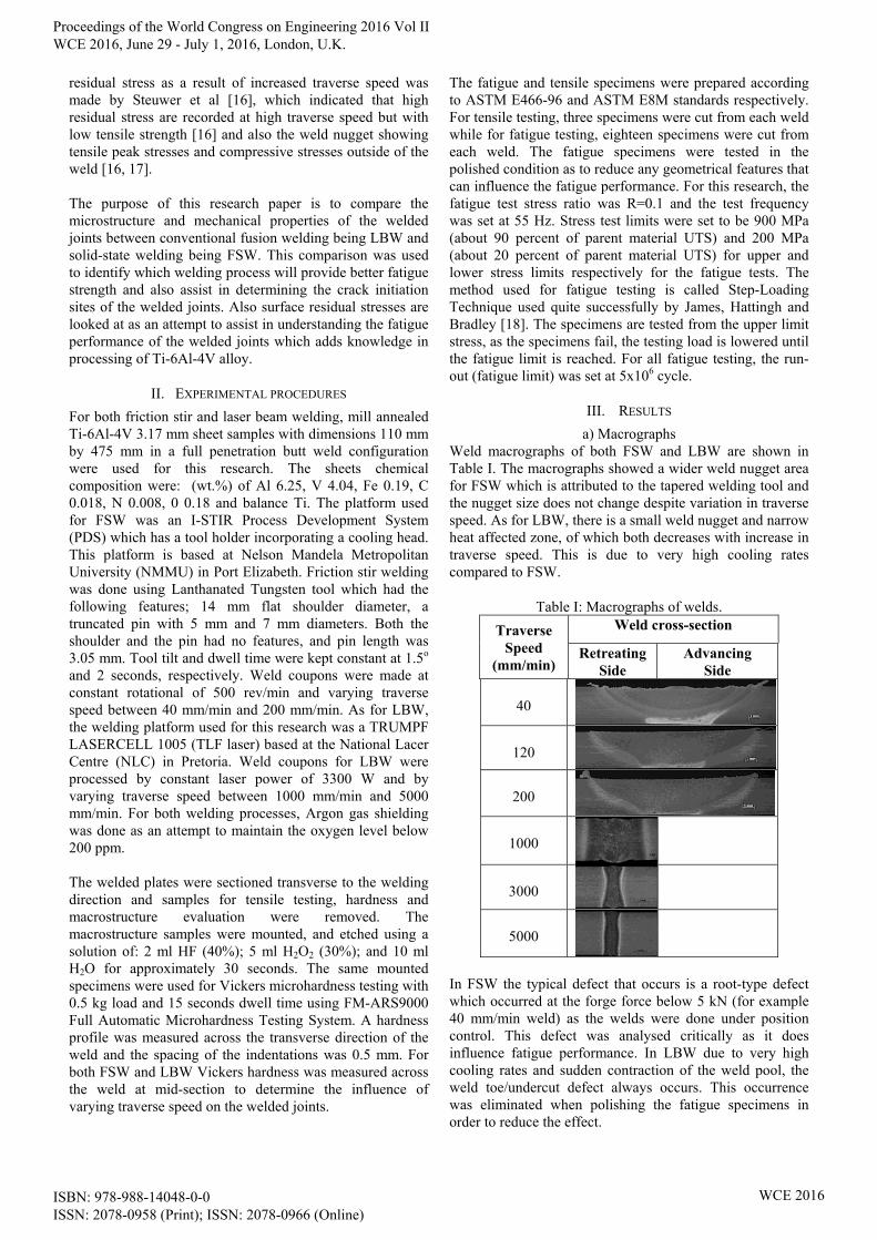
g) Microstructure evaluation. Secondary electron images of the etched surface showing the different zones in the micro-structure. Parent plate refers to material that experienced temperatures below 700ºC and are unaffected by the welding process. The heat affected zone consist of the area that experienced temperatures between 700-1000ºC, and are unaffected by the mechanical deformation of the rotating tool. In this region, the beta-phase transformed to a lamellar structure. The thermos-mechanical zone consist of material affected by the rotating tool. In this case equi-axed refined microstructure is probably formed by a process of dynamic recrystallization. The stir-zone consist of the area where the rotating tool imparted mechanical deformation. This microstructure is typical of a martensitically transformed microstructure
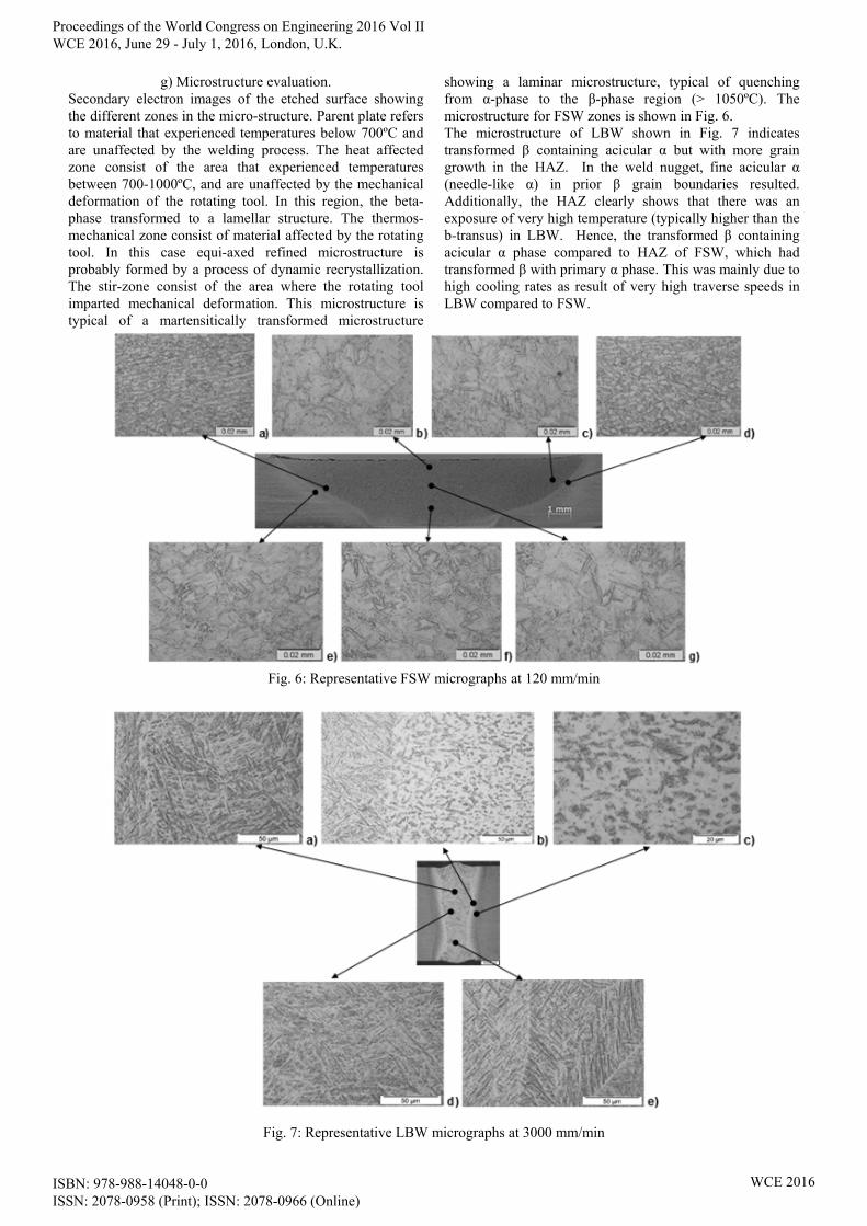
showing a laminar microstructure, typical of quenching from α-phase to the β-phase region (> 1050ºC). The microstructure for FSW zones is shown in Fig. 6. The microstructure of LBW shown in Fig. 7 indicates transformed β containing acicular α but with more grain growth in the HAZ. In the weld nugget, fine acicular α (needle-like α) in prior β grain boundaries resulted. Additionally, the HAZ clearly shows that there was an exposure of very high temperature (typically higher than the b-transus) in LBW. Hence, the transformed β containing acicular α phase compared to HAZ of FSW, which had transformed β with primary α phase. This was mainly due to high cooling rates as result of very high traverse speeds in LBW compared to FSW.
Fig. 6: Representative FSW micrographs at 120 mm/min
Fig. 7: Representative LBW micrographs at 3000 mm/min
Proceedings of the World Congress on Engineering 2016 Vol II WCE 2016, June 29 - July 1, 2016, London, U.K.
ISBN: 978-988-14048-0-0 ISSN: 2078-0958 (Print); ISSN: 2078-0966 (Online)
WCE 2016
IV. CONCLUSION
This investigation was accomplished by varying the process traverse speed for both FSW and LBW to successfully achieve defect free welds. Welds tensile strength for both FSW and LBW showed comparable tensile strength to the parent plate and indicates that static tensile properties is not dependant on weld traverse speed. Both joining techniques showed reduction in elongation, LBW and LBW achieved 15 and 10 percent respectively. Very high cooling rates resulted in high Vickers hardness and fine acicular α (needle-like α) in prior β grain boundaries in the weld nugget compared to low Vickers hardness and Basket weave α/β lamellar colonies for FSW in the weld nugget. High tensile residual stresses were measured in the weld nugget for LBW in comparison to FSW which had high tensile residual stresses in the HAZ. In the absence of weld defects and geometrical features LBW exhibited fatigue strength of 500 MPa which is superior to that of FSW at fatigue strength of 450 MPa, both at 5x10⁶ cycles respectively. This fatigue results were favourable to the parent plate fatigue strength of 550 MPa.
ACKNOWLEDGEMENTS
The authors wish to express their thanks to Mr Glynne Erasmus from Nelson Mandela Metropolitan University Materials laboratory, Mr Corney van Rooyen and Mr Herman Burger from National Laser Center (NLC) situated at the Council for Scientific and Industrial Research (CSIR) and the National Department of Science and Technology for funding provided via the National Research Foundation (NRF) in support of this research.
REFERENCES
[1] I. P. Polmear, Light alloys: Metallurgy of light metals London: Metallurgy and Materials Science Series; 1981.
[2] R. Boyer, G. Welsch, Collings EW. Materials properties handbook: titanium alloys OH: ASM International Materials Park; 2007.
[3] G. Lutjering, J. C. Williams, A. Gysler, “Microstructure and mechanical properties of Titanium alloys”. Germany: University of Hamburg-Harburg.
[4] W. M. Thomas, E. D. Nicholas, J. C. Needham, M. G. Murch, P. Temple-Smith, C. J. Dawes, “Improvements relating to friction welding”. European patent 0 615 480 B1.
[5] R. S. Mishra, M. W. Mahoney, Friction stir welding and processing: ASM International; 2007 March 30.
[6] A. O'Brien, C. Guzman, Welding handbook: Welding processes, Part 2. 9th ed. Society AW, editor; 2007.
[7] E. Akman, A. Demir, T. Canel, T. Sinmzçlik, “Laser welding of Ti6Al4V titanium alloys”. Material Processing Technology. 2009 November; 209(8): p. 3705-3713.
[8] S. Mironov, Y. Zhang, Y. S. Sato, H. Kokawa, “Development of grain structure in b-phase field
during friction stir welding of Ti6Al-4V alloy”. Scripta Materialia. 2008 July; 59(9): p. 27-30.
[9] K. Kitamura, H. Fujii, Y. Iwata, Y. S. Sun, Y. Morisada, “Flexible control of microstructure and mechanical properties of friction stir welded Ti-6Al-4V joints”. Materials and Design. 2013;(46): p. 348-354.
[10] P. Xu, L. Li, S. Zhang, “Microstructure characterization of laser welded Ti-6Al-4V fusion zones”. Material characterization. 2014; 87: p. 179-185.
[11] A. Squillace, U. Prisco, S. Ciliberto, A. Astarita, “Effect of welding parameters on morphology and mechanical properties of Ti-6Al-4V laser beam welded butt joints”. Journal of Materials Processing Technology. 2012; (212): p. 427-436.
[12] H. Liu, K. Nakata, N. Yamamoto, “Microstructural characteristics and mechanical properties in laser beam welds of Ti6Al4V alloy”. Material Science. 2012; 47: p. 1460-1470.
[13] P. M. Mashinini, Developing a process window for friction stir welding of 3 mm Titanium (Ti-6Al-4V) sheet. Masters Dissertation. Port Elizabeth, South Africa: Nelson Mandela Metropolitan University, Mechanical Engineering; 2010.
[14] L. Zhou, H. J. Liu, Q. W. Liu, “Effect of rotational speed on microstructure and mechanical properties of Ti-6Al-4V friction stir welded joints”. Materials and Design. 2010; (31): p. 2631-2636.
[15] M. Ramulu, P. D. Edwards, D. G. Sanders, A. P. Reynolds, T. Trapp, “Tensile properties of friction stir welded and friction stir welded superplastically formed Ti-6Al-4V butt joints”. Materials and Design. 2010;(31): p. 3056-3061.
[16] A. Streuwer, D. G. Hattingh, M. N. James, U. Singh, T. Buslaps, “Residual Stresses, microstructure and tensile properties in Ti-6Al-4V friction stir welds”. Science and Technology of Welding and Joining. 2012; 17(7): p. 525-533.
[17] S. Pasta, A. P. Reynolds, “Residual stress effects on fatigue crack growth in Ti6Al4V friction stir weld”. Fatigue and Fracture of Engineering Materials and Structure. 2008;(31): p. 569-580.
[18] M. N. James, D. G. Hattingh, G. R. Bradley, “Welding tool travel speed effects on fatigue life of friction stir welding in 5083 aluminium”. International Journal of Fatigue. 2003; ISSN (25):1389-9.
Proceedings of the World Congress on Engineering 2016 Vol II WCE 2016, June 29 - July 1, 2016, London, U.K.
ISBN: 978-988-14048-0-0 ISSN: 2078-0958 (Print); ISSN: 2078-0966 (Online)
WCE 2016
Related Documents