ME 5210/6210 & CH EN 5203/6203 Spring 2012 Lab 1: System ID and Full-State-Feedback Controller In this lab, you will create a position regulator for the Quanser SRV-02 system. The SRV-02 will be modeled as a mass-damper system, and its step response will be used to identify the parameters of the model. A state feedback controller will then be developed to satisfy certain design requirements. The prelab part should be completed before going into the lab. This lab is intended for teams of 2–3 people. Only one report needs to be submitted per team. 1 Equipment A total of three workstations are setup in the small robotics lab (MEB 2172) to perform this lab. Each workstation has an SRV-02 connected to a computer via an NI DAQ board (NI-6024). Before running any simulation make sure the amplifier is turned on, the kill switch is disengaged, and the signal conditioning box is plugged in. After finishing each lab turn off the amplifier, engage the kill switch, and disconnect the power plug for the signal conditioning box. Make sure to trace the cables to find out which amplifier, kill switch, and signal-conditioning box are actually connected to your system. Kill Switch SRV-02 Signal Conditioning Box 2 Prelab We’ll use a simplified model of the system relating the input voltage V to the position θ as: J eff ¨ θ + B eff ˙ θ = V (1) where J eff is the effective rotational inertia of the system, and B eff is the effective friction in the system. Find the transfer function of the system, with voltage V as the input and angular velocity ˙ θ as the output. Using this plant transfer function, calculate the dc gain and time constant τ of the plant in terms of J eff and B eff . 1

Welcome message from author
This document is posted to help you gain knowledge. Please leave a comment to let me know what you think about it! Share it to your friends and learn new things together.
Transcript
ME 5210/6210 & CH EN 5203/6203 Spring 2012
Lab 1: System ID and Full-State-Feedback Controller
In this lab, you will create a position regulator for the Quanser SRV-02 system. The SRV-02will be modeled as a mass-damper system, and its step response will be used to identify theparameters of the model. A state feedback controller will then be developed to satisfy certaindesign requirements. The prelab part should be completed before going into the lab. This labis intended for teams of 2–3 people. Only one report needs to be submitted per team.
1 Equipment
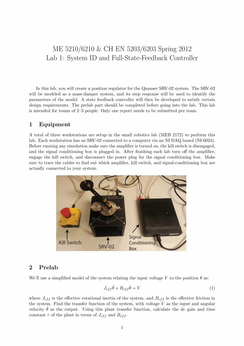
A total of three workstations are setup in the small robotics lab (MEB 2172) to perform thislab. Each workstation has an SRV-02 connected to a computer via an NI DAQ board (NI-6024).Before running any simulation make sure the amplifier is turned on, the kill switch is disengaged,and the signal conditioning box is plugged in. After finishing each lab turn off the amplifier,engage the kill switch, and disconnect the power plug for the signal conditioning box. Makesure to trace the cables to find out which amplifier, kill switch, and signal-conditioning box areactually connected to your system.
Kill SwitchSRV-02
Signal ConditioningBox
2 Prelab
We’ll use a simplified model of the system relating the input voltage V to the position θ as:
Jeff θ̈ +Beff θ̇ = V (1)
where Jeff is the effective rotational inertia of the system, and Beff is the effective friction inthe system. Find the transfer function of the system, with voltage V as the input and angularvelocity θ̇ as the output. Using this plant transfer function, calculate the dc gain and timeconstant τ of the plant in terms of Jeff and Beff .
1

We will choose our system state vector as ~x = [x1 x2]T , where x1 = θ and x2 = θ̇, the input
as u = V , and the output as angular position θ. Find the state-space representation of Eq. 1.We will design a feedback controller for the system to track step inputs. We can measure both
the angular position and the angular velocity of the system from the encoder and tachometer,respectively. Using the state control law u = r −K~x the state equation becomes:
~̇x = (A−BK)~x+Br (2)
~y = C~x (3)
where K = [K1 K2] is the state-feedback gain matrix. We want our system to have settlingtime of Ts = 0.5 s to a step input, and we would like it to be critically damped (i.e., make bothclosed-loop poles real and at the same location). Find pole locations p1 = p2 = p to achievethe desired system characteristics. The closed-loop characteristic equation can be expressed as(s− p)(s− p) = 0; the roots of this equation are also the closed-loop system eigenvalues. Solvefor the gains K1 and K2 in terms of Jeff , Beff , and p.
We will set the reference r as
r =θdgdc
(4)
where θd is the desired angular position, and gdc is the dc gain of the closed-loop system (whichis different than the dc gain of the plant). Since the steady-state value of θ will be gdcr, usingEq. 4 will force the steady-state value of θ to approach θd. Solve for gdc in terms of Jeff , Beff ,and p, using the values for K already chosen.
3 In lab
For each lab, a simulink model will be provided in the folder ‘Desktop/ME6210’. Begin bymaking a copy (with a different team-specific name) of this folder. Don’t modify the original,only modify your copy! You will use this same lab station for Lab 2, so make note of the stationthat you are using, and your team’s folder (you’ll also include Lab 2 in this folder in the future).
First, we will estimate Jeff and Beff by studying the step response of the plant. Openthe ‘systemIdentificaton.mdl’ file located in the folder ‘Lab1’. Give a suitable step input in thevoltage V (try multiple values) to the system and record the output (angular velocity θ̇ rad/s)from the tachometer. Looking at the response of the system find:
1. the dc gain of the plant
2. the time constant τ
From the dc gain and time constant, calculate Jeff and Beff .Once you have Jeff and Beff , calculate the values for the gain matrix K and dc gain gdc
derived in Section 2. To implement the state-feedback controller, use the file ‘feedbackCon-troller.mdl’. The gains in K are set to zero by default, and gdc is set to one by default. Insertyour calculated values, and then record the response of the system to step inputs in θd. Checkif the design criteria are satisfied.
4 Report
Simulate the step responses of your plant and closed-loop system in MATLAB using the systemparameters estimated in Section 3 and compare it with the actual experimental responses. Showall work from the prelab. Include all necessary plots, including one (or more) step-response plotsof the plant and one (or more) step-response plots of the closed-loop system. Make sure plotsare clearly labeled. Include any MATLAB scripts used (print-outs). Only turn in one reportper team.
2
Related Documents