MATRIX TRAINING GUIDE 01/2014

Welcome message from author
This document is posted to help you gain knowledge. Please leave a comment to let me know what you think about it! Share it to your friends and learn new things together.
Transcript

MATRIX TRAINING GUIDE
01/2014
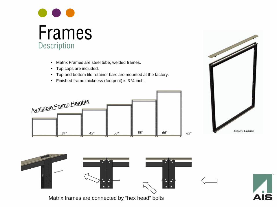
Frames Description
• Matrix Frames are steel tube, welded frames. • Top caps are included. • Top and bottom tile retainer bars are mounted at the factory. • Finished frame thickness (footprint) is 3 ¼ inch.
Matrix Frame
Matrix frames are connected by “hex head” bolts
34” 50” 42” 58” 66” 82”

Frames Example
• Below is an example station that will be used for the training. • In CAP and Giza, as long as the frames are snapped together in the corners,
the automatic connector features will work • 42”w x 82”h doors are also available
Matrix Frame
Stack-On Frames Description
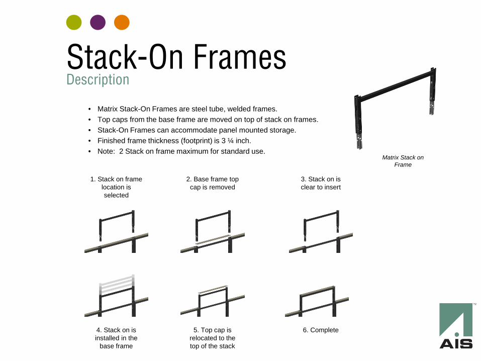
• Matrix Stack-On Frames are steel tube, welded frames. • Top caps from the base frame are moved on top of stack on frames. • Stack-On Frames can accommodate panel mounted storage. • Finished frame thickness (footprint) is 3 ¼ inch. • Note: 2 Stack on frame maximum for standard use.
Matrix Stack on Frame
1. Stack on frame location is selected
2. Base frame top cap is removed
3. Stack on is clear to insert
4. Stack on is installed in the
base frame
5. Top cap is relocated to the top of the stack
6. Complete
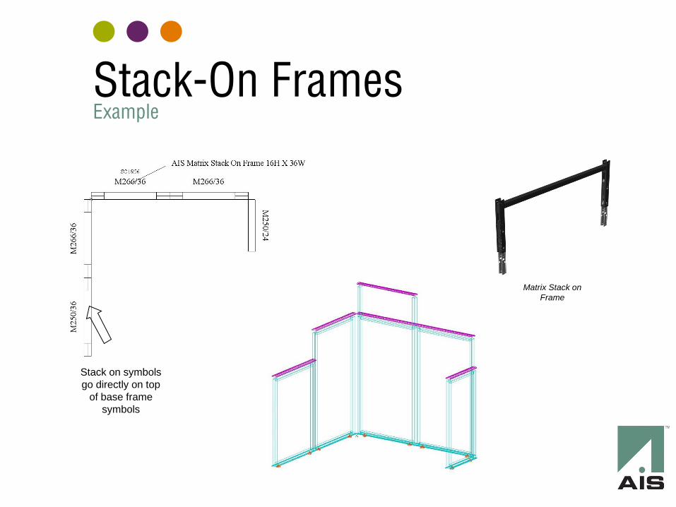
Stack-On Frames Example
Matrix Stack on Frame
Stack on symbols go directly on top
of base frame symbols
Connectors Description
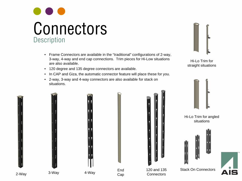
2-Way 3-Way 4-Way End Cap
Stack On Connectors 120 and 135 Connectors
Hi-Lo Trim for straight situations
Hi-Lo Trim for angled situations
• Frame Connectors are available in the “traditional” configurations of 2-way, 3-way, 4-way and end cap connections. Trim pieces for Hi-Low situations are also available.
• 120 degree and 135 degree connectors are available. • In CAP and Giza, the automatic connector feature will place these for you. • 2-way, 3-way and 4-way connectors are also available for stack on
situations.
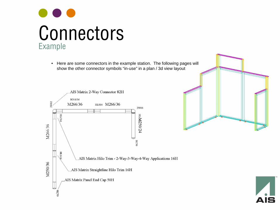
Connectors Example
• Here are some connectors in the example station. The following pages will show the other connector symbols “in-use” in a plan / 3d view layout
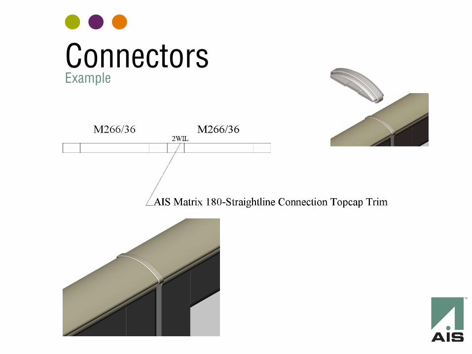
Connectors Example
Connectors Example
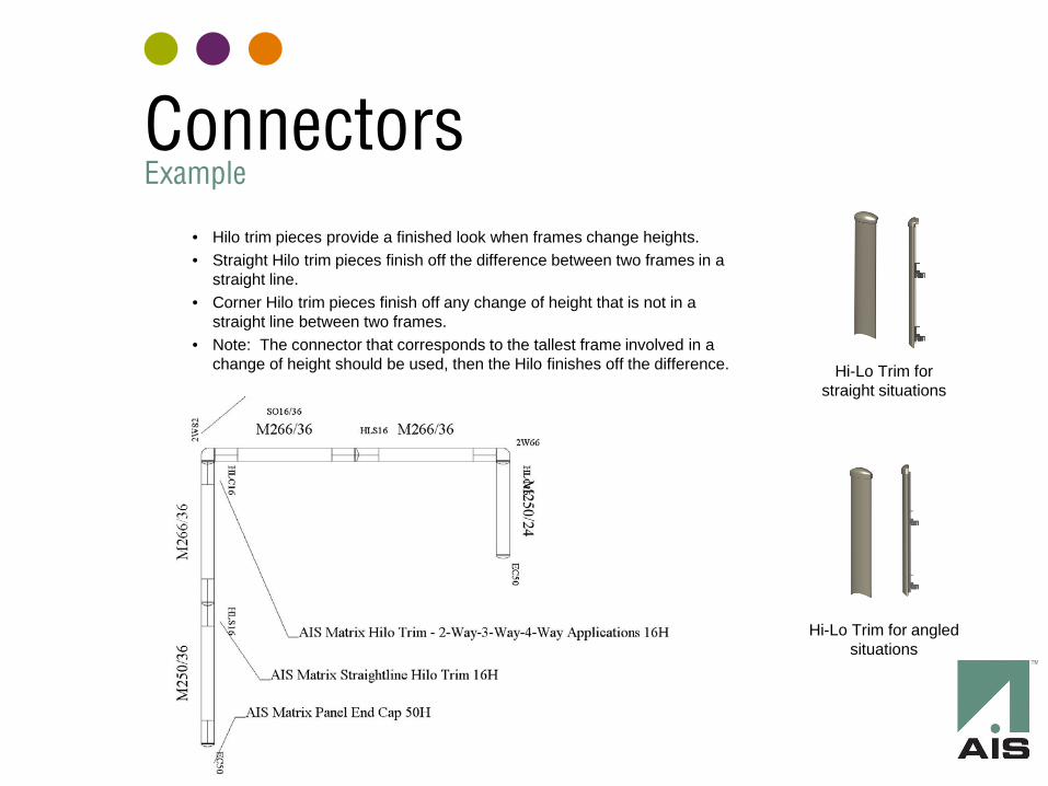
• Hilo trim pieces provide a finished look when frames change heights. • Straight Hilo trim pieces finish off the difference between two frames in a
straight line. • Corner Hilo trim pieces finish off any change of height that is not in a
straight line between two frames. • Note: The connector that corresponds to the tallest frame involved in a
change of height should be used, then the Hilo finishes off the difference. Hi-Lo Trim for straight situations
Hi-Lo Trim for angled situations
Electrical Description
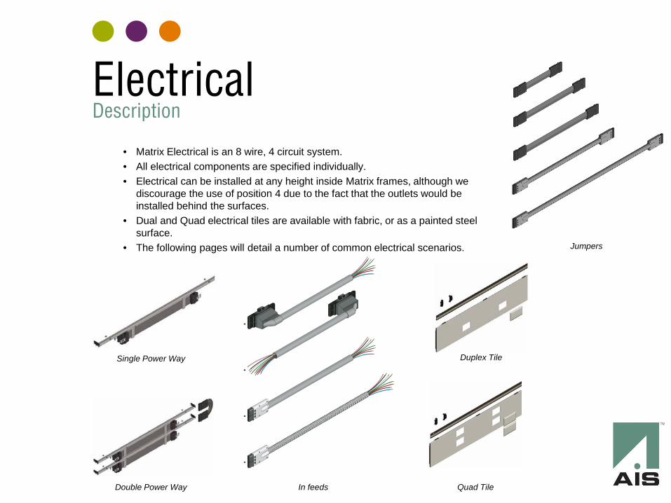
• Matrix Electrical is an 8 wire, 4 circuit system. • All electrical components are specified individually. • Electrical can be installed at any height inside Matrix frames, although we
discourage the use of position 4 due to the fact that the outlets would be installed behind the surfaces.
• Dual and Quad electrical tiles are available with fabric, or as a painted steel surface.
• The following pages will detail a number of common electrical scenarios.
Single Power Way
Jumpers
In feeds Double Power Way
Duplex Tile
Quad Tile
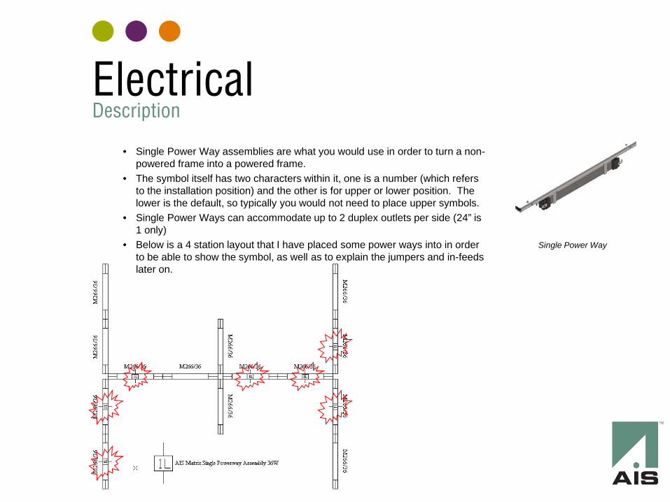
• Single Power Way assemblies are what you would use in order to turn a non-powered frame into a powered frame.
• The symbol itself has two characters within it, one is a number (which refers to the installation position) and the other is for upper or lower position. The lower is the default, so typically you would not need to place upper symbols.
• Single Power Ways can accommodate up to 2 duplex outlets per side (24” is 1 only)
• Below is a 4 station layout that I have placed some power ways into in order to be able to show the symbol, as well as to explain the jumpers and in-feeds later on.
Single Power Way
Electrical Description
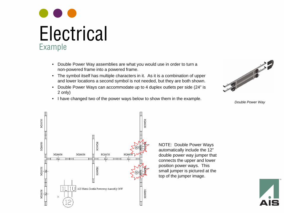
• Double Power Way assemblies are what you would use in order to turn a non-powered frame into a powered frame.
• The symbol itself has multiple characters in it. As it is a combination of upper and lower locations a second symbol is not needed, but they are both shown.
• Double Power Ways can accommodate up to 4 duplex outlets per side (24” is 2 only)
• I have changed two of the power ways below to show them in the example.
Double Power Way
NOTE: Double Power Ways automatically include the 12” double power way jumper that connects the upper and lower position power ways. This small jumper is pictured at the top of the jumper image.
Electrical Example
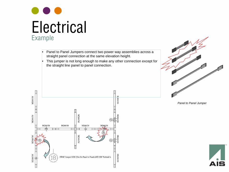
• Panel to Panel Jumpers connect two power way assemblies across a straight panel connection at the same elevation height.
• This jumper is not long enough to make any other connection except for the straight line panel to panel connection.
Panel to Panel Jumper
Electrical Example
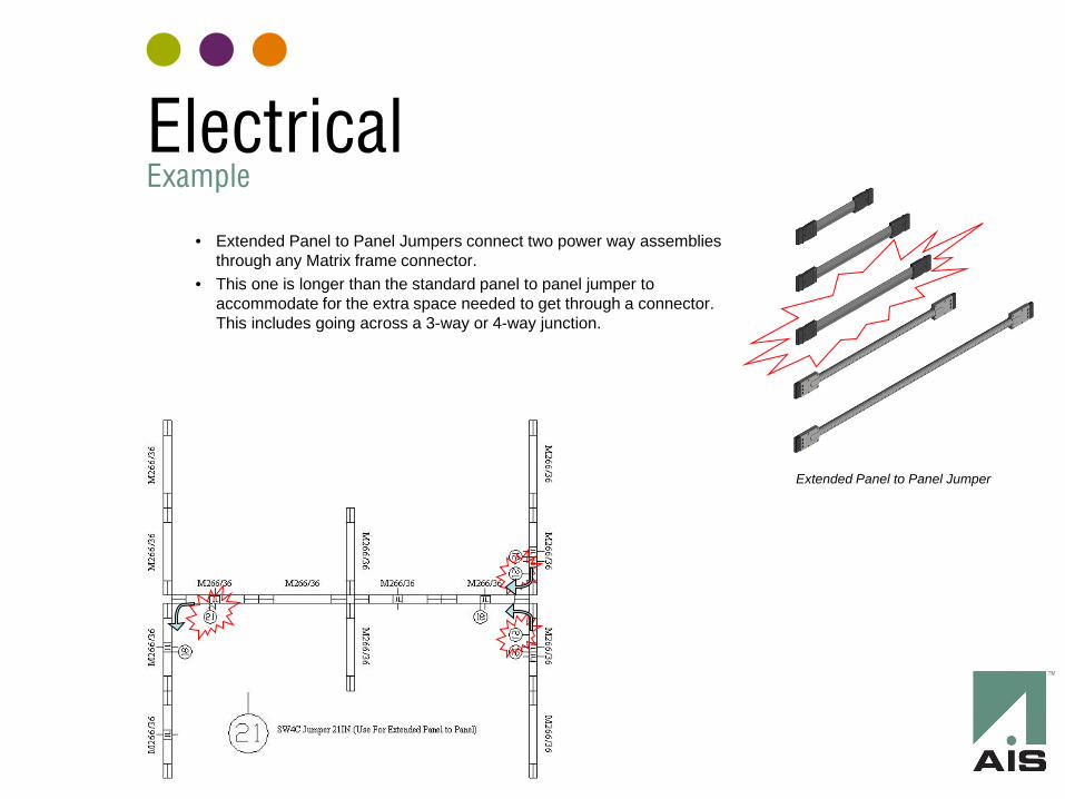
• Extended Panel to Panel Jumpers connect two power way assemblies through any Matrix frame connector.
• This one is longer than the standard panel to panel jumper to accommodate for the extra space needed to get through a connector. This includes going across a 3-way or 4-way junction.
Extended Panel to Panel Jumper
Electrical Example
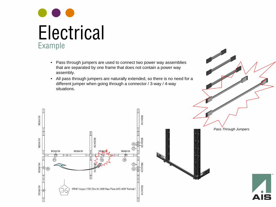
• Pass through jumpers are used to connect two power way assemblies that are separated by one frame that does not contain a power way assembly.
• All pass through jumpers are naturally extended, so there is no need for a different jumper when going through a connector / 3-way / 4-way situations.
Pass Through Jumpers
Electrical Example
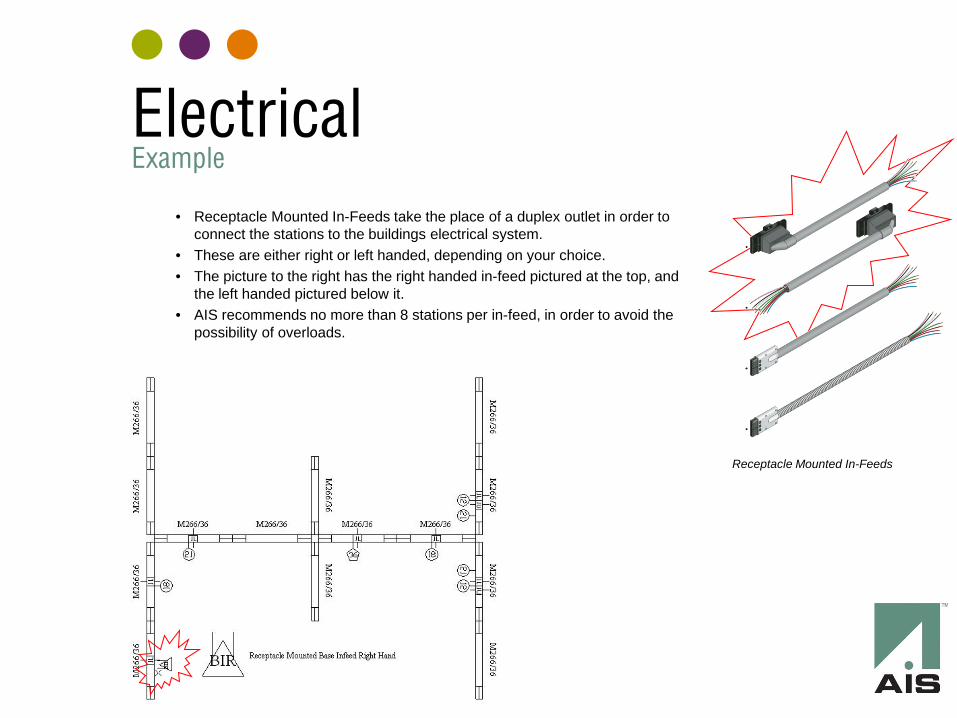
• Receptacle Mounted In-Feeds take the place of a duplex outlet in order to connect the stations to the buildings electrical system.
• These are either right or left handed, depending on your choice. • The picture to the right has the right handed in-feed pictured at the top, and
the left handed pictured below it. • AIS recommends no more than 8 stations per in-feed, in order to avoid the
possibility of overloads.
Receptacle Mounted In-Feeds
Electrical Example
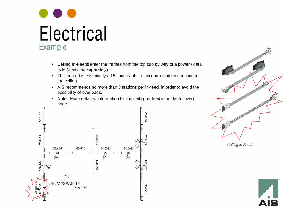
• Ceiling In-Feeds enter the frames from the top cap by way of a power / data pole (specified separately)
• This in-feed is essentially a 15’ long cable, to accommodate connecting to the ceiling.
• AIS recommends no more than 8 stations per in-feed, in order to avoid the possibility of overloads.
• Note: More detailed information for the ceiling in-feed is on the following page.
Ceiling In-Feeds
Electrical Example
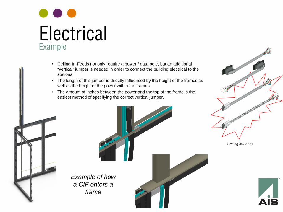
• Ceiling In-Feeds not only require a power / data pole, but an additional “vertical” jumper is needed in order to connect the building electrical to the stations.
• The length of this jumper is directly influenced by the height of the frames as well as the height of the power within the frames.
• The amount of inches between the power and the top of the frame is the easiest method of specifying the correct vertical jumper.
Ceiling In-Feeds
Example of how a CIF enters a
frame
Electrical Example
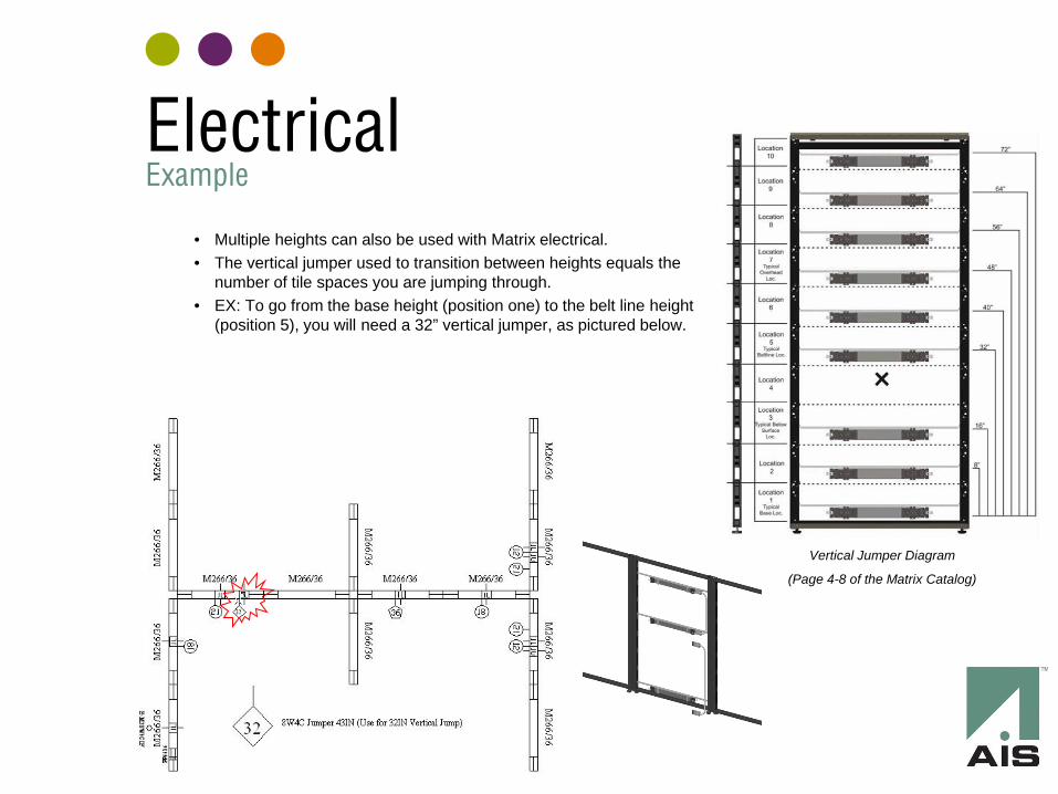
• Multiple heights can also be used with Matrix electrical. • The vertical jumper used to transition between heights equals the
number of tile spaces you are jumping through. • EX: To go from the base height (position one) to the belt line height
(position 5), you will need a 32” vertical jumper, as pictured below.
Vertical Jumper Diagram
(Page 4-8 of the Matrix Catalog)
Electrical Example
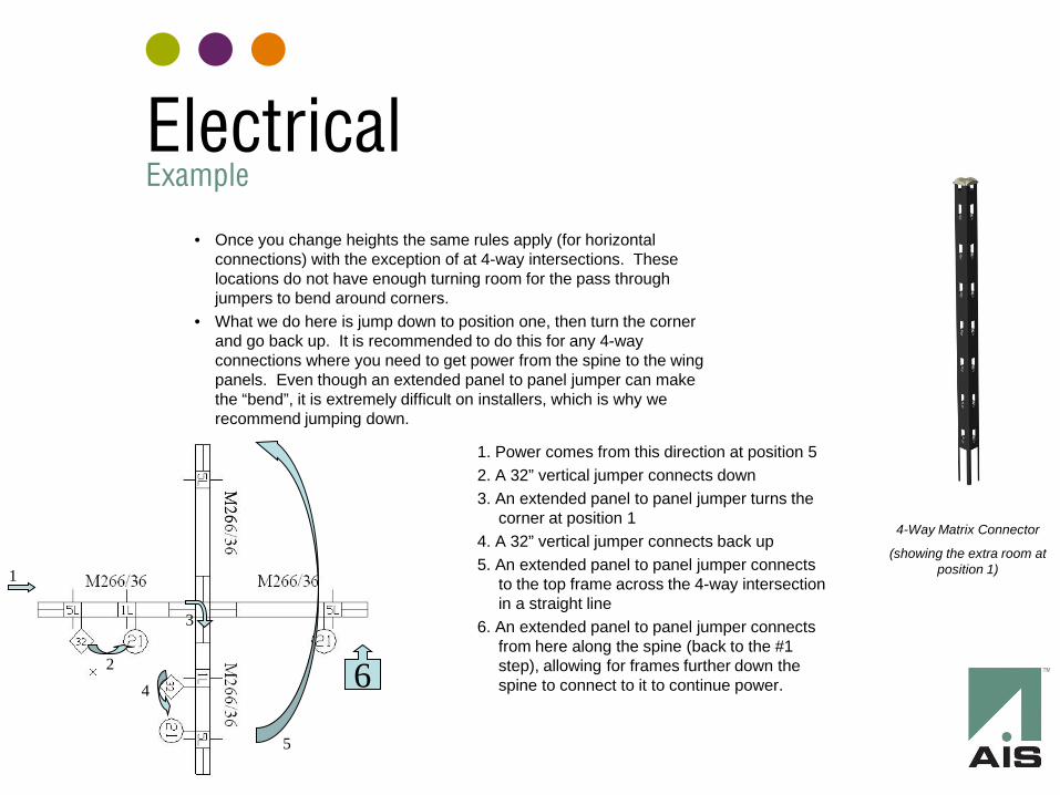
• Once you change heights the same rules apply (for horizontal connections) with the exception of at 4-way intersections. These locations do not have enough turning room for the pass through jumpers to bend around corners.
• What we do here is jump down to position one, then turn the corner and go back up. It is recommended to do this for any 4-way connections where you need to get power from the spine to the wing panels. Even though an extended panel to panel jumper can make the “bend”, it is extremely difficult on installers, which is why we recommend jumping down.
4-Way Matrix Connector
(showing the extra room at position 1)
1. Power comes from this direction at position 5 2. A 32” vertical jumper connects down 3. An extended panel to panel jumper turns the
corner at position 1 4. A 32” vertical jumper connects back up 5. An extended panel to panel jumper connects
to the top frame across the 4-way intersection in a straight line
6. An extended panel to panel jumper connects from here along the spine (back to the #1 step), allowing for frames further down the spine to connect to it to continue power.
1
5
4
3
2 6
Electrical Example
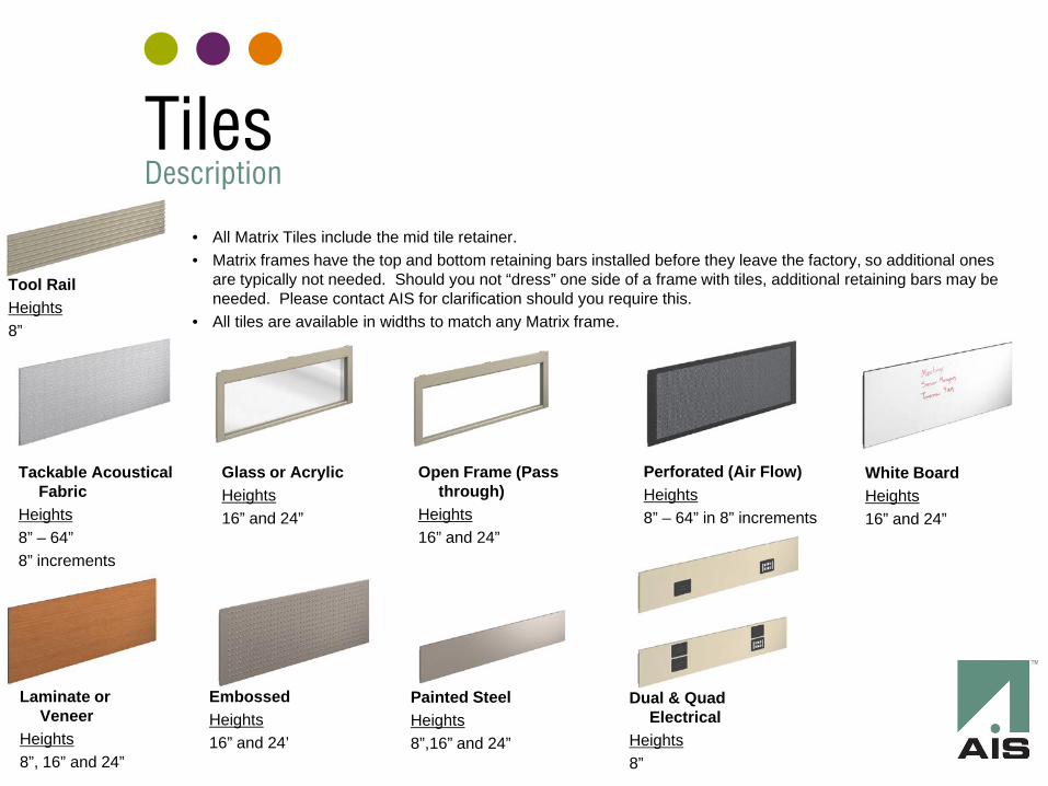
• All Matrix Tiles include the mid tile retainer. • Matrix frames have the top and bottom retaining bars installed before they leave the factory, so additional ones
are typically not needed. Should you not “dress” one side of a frame with tiles, additional retaining bars may be needed. Please contact AIS for clarification should you require this.
• All tiles are available in widths to match any Matrix frame.
Tackable Acoustical Fabric
Heights 8” – 64” 8” increments
Glass or Acrylic Heights 16” and 24”
Open Frame (Pass through)
Heights 16” and 24”
Perforated (Air Flow) Heights 8” – 64” in 8” increments
White Board Heights 16” and 24”
Laminate or Veneer
Heights 8”, 16” and 24”
Embossed Heights 16” and 24’
Painted Steel Heights 8”,16” and 24”
Tool Rail Heights 8”
Dual & Quad Electrical
Heights 8”
Tiles Description
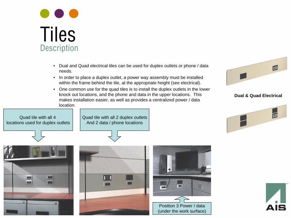
Dual & Quad Electrical
• Dual and Quad electrical tiles can be used for duplex outlets or phone / data needs.
• In order to place a duplex outlet, a power way assembly must be installed within the frame behind the tile, at the appropriate height (see electrical).
• One common use for the quad tiles is to install the duplex outlets in the lower knock out locations, and the phone and data in the upper locations. This makes installation easier, as well as provides a centralized power / data location.
Quad tile with all 4 locations used for duplex outlets
Quad tile with all 2 duplex outlets And 2 data / phone locations
Position 3 Power / data (under the work surface)
Tiles Description
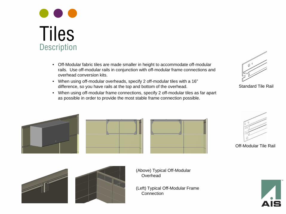
• Off-Modular fabric tiles are made smaller in height to accommodate off-modular rails. Use off-modular rails in conjunction with off-modular frame connections and overhead conversion kits.
• When using off-modular overheads, specify 2 off-modular tiles with a 16” difference, so you have rails at the top and bottom of the overhead.
• When using off-modular frame connections, specify 2 off-modular tiles as far apart as possible in order to provide the most stable frame connection possible.
Standard Tile Rail
Off-Modular Tile Rail
(Above) Typical Off-Modular Overhead
(Left) Typical Off-Modular Frame
Connection
Tiles Description
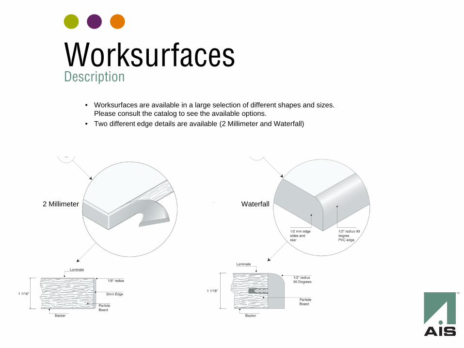
• Worksurfaces are available in a large selection of different shapes and sizes. Please consult the catalog to see the available options.
• Two different edge details are available (2 Millimeter and Waterfall)
2 Millimeter Waterfall
Worksurfaces Description
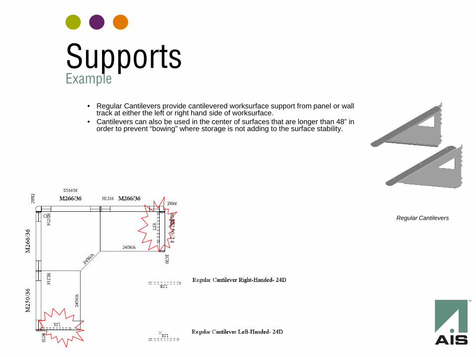
• Regular Cantilevers provide cantilevered worksurface support from panel or wall track at either the left or right hand side of worksurface.
• Cantilevers can also be used in the center of surfaces that are longer than 48” in order to prevent “bowing” where storage is not adding to the surface stability.
Regular Cantilevers
Supports Example
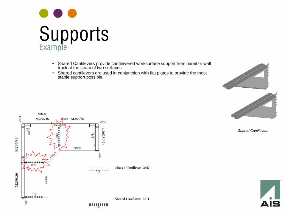
• Shared Cantilevers provide cantilevered worksurface support from panel or wall track at the seam of two surfaces.
• Shared cantilevers are used in conjunction with flat plates to provide the most stable support possible.
Shared Cantilevers
Supports Example
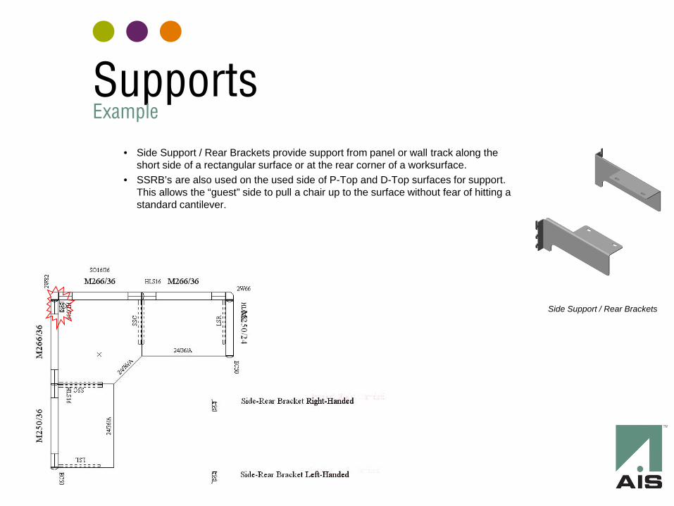
• Side Support / Rear Brackets provide support from panel or wall track along the short side of a rectangular surface or at the rear corner of a worksurface.
• SSRB’s are also used on the used side of P-Top and D-Top surfaces for support. This allows the “guest” side to pull a chair up to the surface without fear of hitting a standard cantilever.
Side Support / Rear Brackets
Supports Example
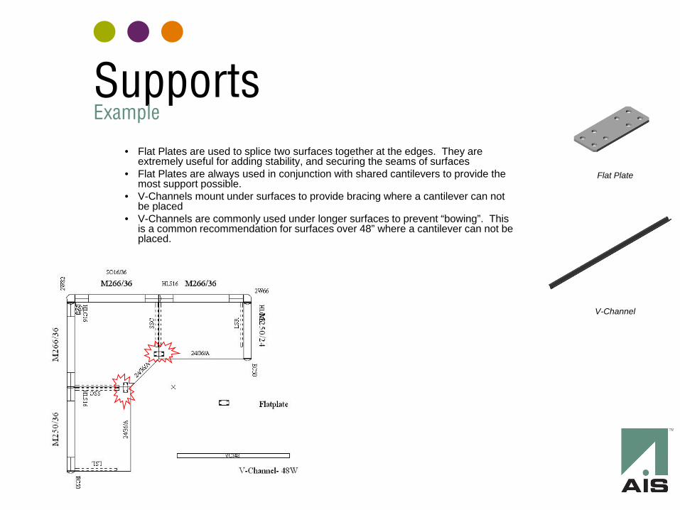
• Flat Plates are used to splice two surfaces together at the edges. They are extremely useful for adding stability, and securing the seams of surfaces
• Flat Plates are always used in conjunction with shared cantilevers to provide the most support possible.
• V-Channels mount under surfaces to provide bracing where a cantilever can not be placed
• V-Channels are commonly used under longer surfaces to prevent “bowing”. This is a common recommendation for surfaces over 48” where a cantilever can not be placed.
V-Channel
Flat Plate
Supports Example
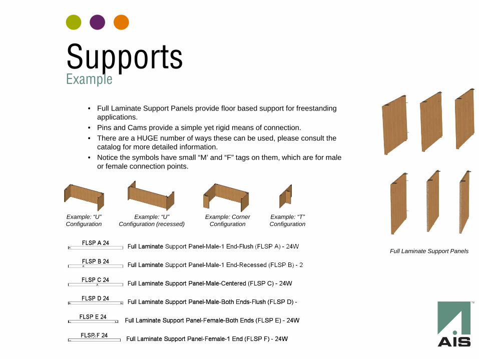
• Full Laminate Support Panels provide floor based support for freestanding applications.
• Pins and Cams provide a simple yet rigid means of connection. • There are a HUGE number of ways these can be used, please consult the
catalog for more detailed information. • Notice the symbols have small “M’ and “F” tags on them, which are for male
or female connection points.
Full Laminate Support Panels
Example: “U” Configuration
Example: “U” Configuration (recessed)
Example: Corner Configuration
Example: “T” Configuration
Supports Example
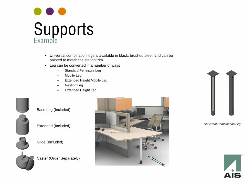
• Universal combination legs is available in black, brushed steel, and can be painted to match the station trim.
• Leg can be converted in a number of ways – Standard Peninsula Leg – Mobile Leg – Extended Height Mobile Leg – Nesting Leg – Extended Height Leg
Universal Combination Leg
Base Leg (Included) Extended (Included) Glide (Included) Caster (Order Separately)
Supports Example
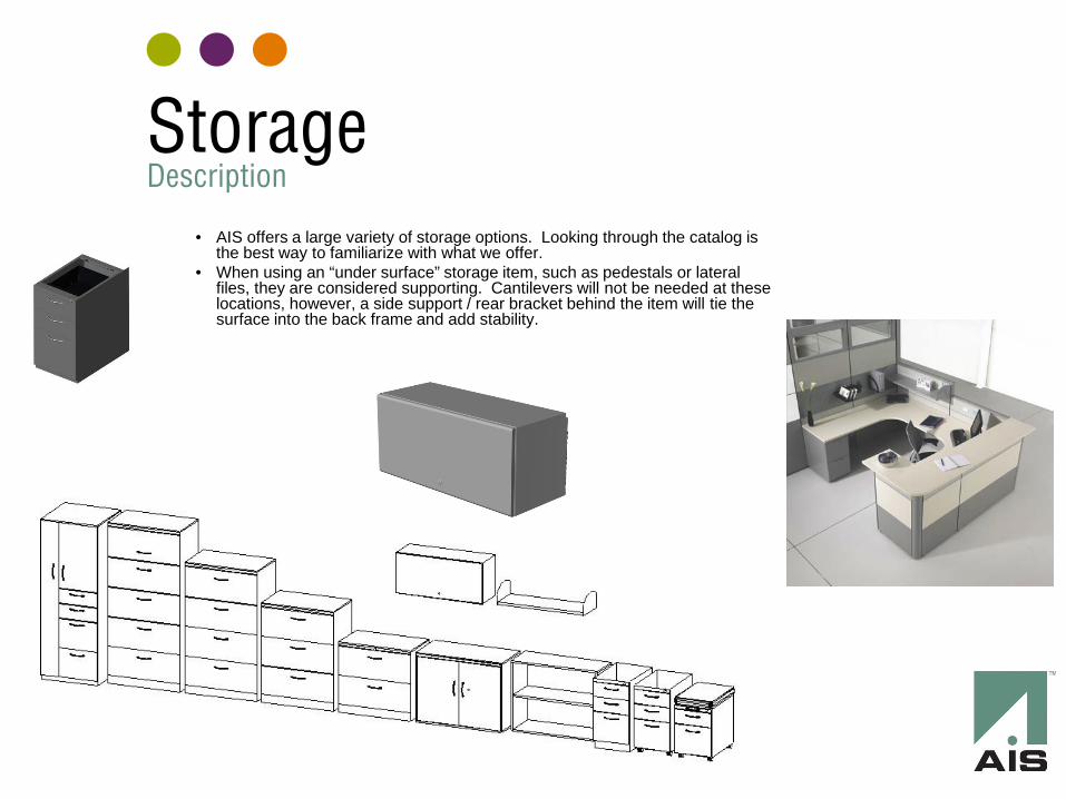
• AIS offers a large variety of storage options. Looking through the catalog is the best way to familiarize with what we offer.
• When using an “under surface” storage item, such as pedestals or lateral files, they are considered supporting. Cantilevers will not be needed at these locations, however, a side support / rear bracket behind the item will tie the surface into the back frame and add stability.
Storage Description
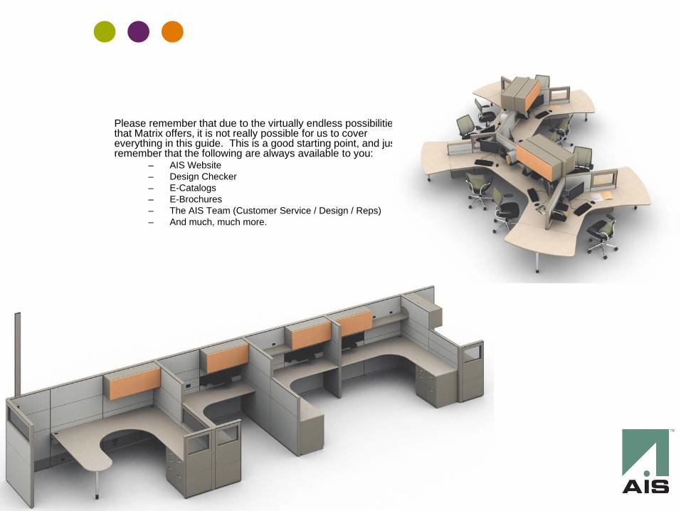
Please remember that due to the virtually endless possibilities that Matrix offers, it is not really possible for us to cover everything in this guide. This is a good starting point, and just remember that the following are always available to you:
– AIS Website – Design Checker – E-Catalogs – E-Brochures – The AIS Team (Customer Service / Design / Reps) – And much, much more.
Related Documents