Rev 1.0 For more information about Matrix Fitness: matrixfitness.com | Toll-Free 866.693.4863 Matrix Fitness 7xi – Setup and Network Connection guide Introduction: Please note that this guide is meant to provide an overview on the configuration and setup steps that are unique to the 7xi product. The equipment itself is assembled and installed almost identically to the Matrix Fitness 7xe product line. What sets the Matrix Fitness 7xi equipment apart is our new ‘app’ interface, personalized logins for each user, social media access, on demand content, and network connectivity. This guide will cover the initial setup of the 7xi console by Matrix Fitness.

Welcome message from author
This document is posted to help you gain knowledge. Please leave a comment to let me know what you think about it! Share it to your friends and learn new things together.
Transcript
Rev 1.0For more information about Matrix Fitness: matrixfitness.com | Toll-Free 866.693.4863
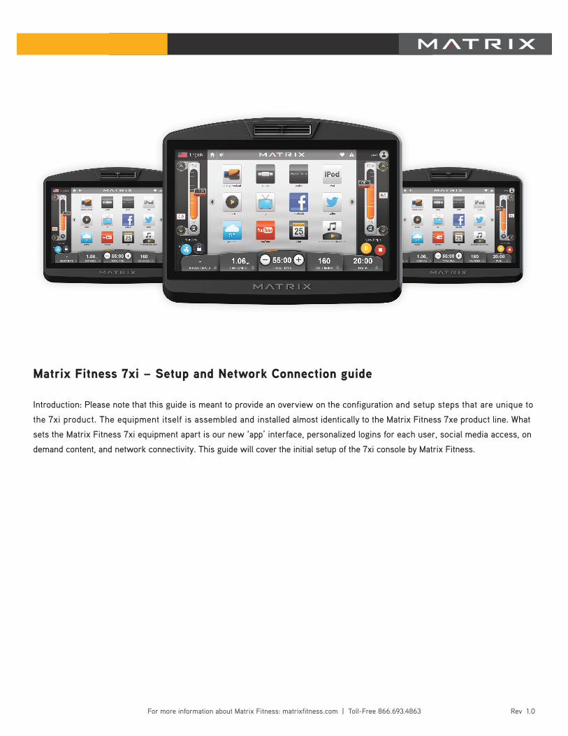
Matrix Fitness 7xi – Setup and Network Connection guide
Introduction: Please note that this guide is meant to provide an overview on the configuration and setup steps that are unique to
the 7xi product. The equipment itself is assembled and installed almost identically to the Matrix Fitness 7xe product line. What
sets the Matrix Fitness 7xi equipment apart is our new ‘app’ interface, personalized logins for each user, social media access, on
demand content, and network connectivity. This guide will cover the initial setup of the 7xi console by Matrix Fitness.
Rev 1.0For more information about Matrix Fitness: matrixfitness.com | Toll-Free 866.693.4863
Table Of Contents:
Page 3 - 7xi Product Workflow
Page 4 - Asset Management – How to create a facility ID and user ID
Page 5-6 – Wired Network Setup
Page 7-11- Wireless Network setup
Page 12 – Post-Installation Console setup
Page 13 – FAQ and Overview – 2013 7xi
Rev 1.0For more information about Matrix Fitness: matrixfitness.com | Toll-Free 866.693.4863
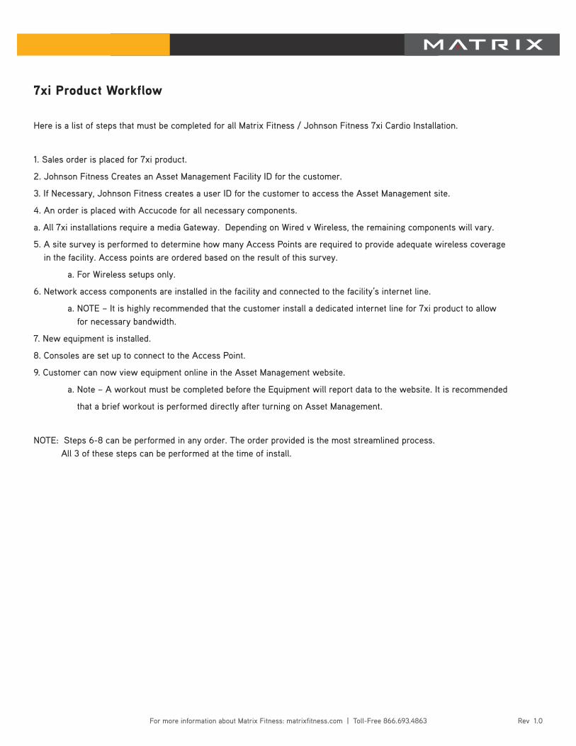
7xi Product Workflow
Here is a list of steps that must be completed for all Matrix Fitness / Johnson Fitness 7xi Cardio Installation.
1. Sales order is placed for 7xi product.
2. Johnson Fitness Creates an Asset Management Facility ID for the customer.
3. If Necessary, Johnson Fitness creates a user ID for the customer to access the Asset Management site.
4. An order is placed with Accucode for all necessary components.
a. All 7xi installations require a media Gateway. Depending on Wired v Wireless, the remaining components will vary.
5. A site survey is performed to determine how many Access Points are required to provide adequate wireless coverage in the facility. Access points are ordered based on the result of this survey.
a. For Wireless setups only.
6. Network access components are installed in the facility and connected to the facility’s internet line.
a. NOTE – It is highly recommended that the customer install a dedicated internet line for 7xi product to allow for necessary bandwidth.
7. New equipment is installed.
8. Consoles are set up to connect to the Access Point.
9. Customer can now view equipment online in the Asset Management website.
a. Note – A workout must be completed before the Equipment will report data to the website. It is recommended
that a brief workout is performed directly after turning on Asset Management.
NOTE: Steps 6-8 can be performed in any order. The order provided is the most streamlined process. All 3 of these steps can be performed at the time of install.
Rev 1.0For more information about Matrix Fitness: matrixfitness.com | Toll-Free 866.693.4863
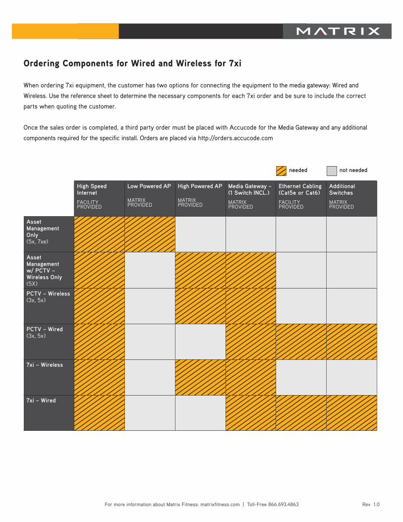
Ordering Components for Wired and Wireless for 7xi
When ordering 7xi equipment, the customer has two options for connecting the equipment to the media gateway: Wired and
Wireless. Use the reference sheet to determine the necessary components for each 7xi order and be sure to include the correct
parts when quoting the customer.
Once the sales order is completed, a third party order must be placed with Accucode for the Media Gateway and any additional
components required for the specific install. Orders are placed via http://orders.accucode.com
High Speed Internet
Facility PROViDED
Low Powered AP
MatRixPROViDED
High Powered AP
MatRixPROViDED
Media Gateway – (1 Switch INCL.)
MatRixPROViDED
Ethernet Cabling(Cat5e or Cat6)
Facility PROViDED
Additional Switches
MatRixPROViDED
Asset Management Only(5x, 7xe)
Asset Management w/ PCTV – Wireless Only(5x)
PCTV – Wireless(3x, 5x)
PCTV – Wired(3x, 5x)
7xi – Wireless
7xi – Wired
needed not needed
Rev 1.0For more information about Matrix Fitness: matrixfitness.com | Toll-Free 866.693.4863
Matrix Fitness 7xi and Asset Management
Introduction: Every order for Matrix Fitness 7xi product includes access to the Matrix Fitness Asset Management Website.
At the time the sales order is placed, a new facility ID is created and assigned to the facility. Each facility requires only one
Facility ID, any future orders for the same location will use the same Facility ID. This step is to be performed by Matrix Fitness.
To Create a facility ID:
1. Log in to the Matrix Fitness Asset Management site: http://am.matrixfitness.com
2. Select the Organization that pertains to the facility. If a new organization is required, select ‘Add Organization’ from the CTS dropdown menu at the top of the Screen.
a. The Organization name is typically the name of the Franchise for a facility. If a facility is a standalone business, University, or commercial property, it should have its own Organization, which is named the same as the Facility.
3. Once and organization has been selected, select ‘Add Facility’ from the Organization Management dropdown.
4. Fill out all necessary information and select ‘Add.’ A new facility ID will be provided for the facility.
To create a new user in Asset Management:
1. Log in to the Matrix Fitness Asset Management site: http://am.matrixfitness.com
2. Select ‘Add Users’ from the CTS dropdown menu at the top of the screen.
3. Fill out the necessary information. Username is typically presented as firstname.lastname.
4. Select the ‘Standard’ Role, and the select the organization that the new user is to be affiliated with.
5. Save.
6. Select ‘Users List’ from the CTS dropdown menu and select the user that was just created.
7. Select the ‘Set Permissions’ option from the Edit User page.
8. Use the dropdown menus to select the correct Organization and Facility for the user and click ‘Assign Tag.’
For more in-depth instruction on the Matrix Fitness Asset Management website, consult the Matrix Fitness
Asset Management Service Manual.
Rev 1.0For more information about Matrix Fitness: matrixfitness.com | Toll-Free 866.693.4863
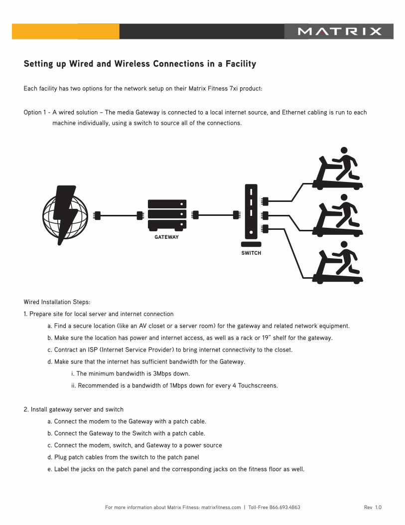
Setting up Wired and Wireless Connections in a Facility
Each facility has two options for the network setup on their Matrix Fitness 7xi product:
Option 1 - A wired solution – The media Gateway is connected to a local internet source, and Ethernet cabling is run to each
machine individually, using a switch to source all of the connections.
Wired Installation Steps:
1. Prepare site for local server and internet connection
a. Find a secure location (like an AV closet or a server room) for the gateway and related network equipment.
b. Make sure the location has power and internet access, as well as a rack or 19” shelf for the gateway.
c. Contract an ISP (Internet Service Provider) to bring internet connectivity to the closet.
d. Make sure that the internet has sufficient bandwidth for the Gateway.
i. The minimum bandwidth is 3Mbps down.
ii. Recommended is a bandwidth of 1Mbps down for every 4 Touchscreens.
2. Install gateway server and switch
a. Connect the modem to the Gateway with a patch cable.
b. Connect the Gateway to the Switch with a patch cable.
c. Connect the modem, switch, and Gateway to a power source
d. Plug patch cables from the switch to the patch panel
e. Label the jacks on the patch panel and the corresponding jacks on the fitness floor as well.
GATEWAY
SWITCH
Rev 1.0For more information about Matrix Fitness: matrixfitness.com | Toll-Free 866.693.4863
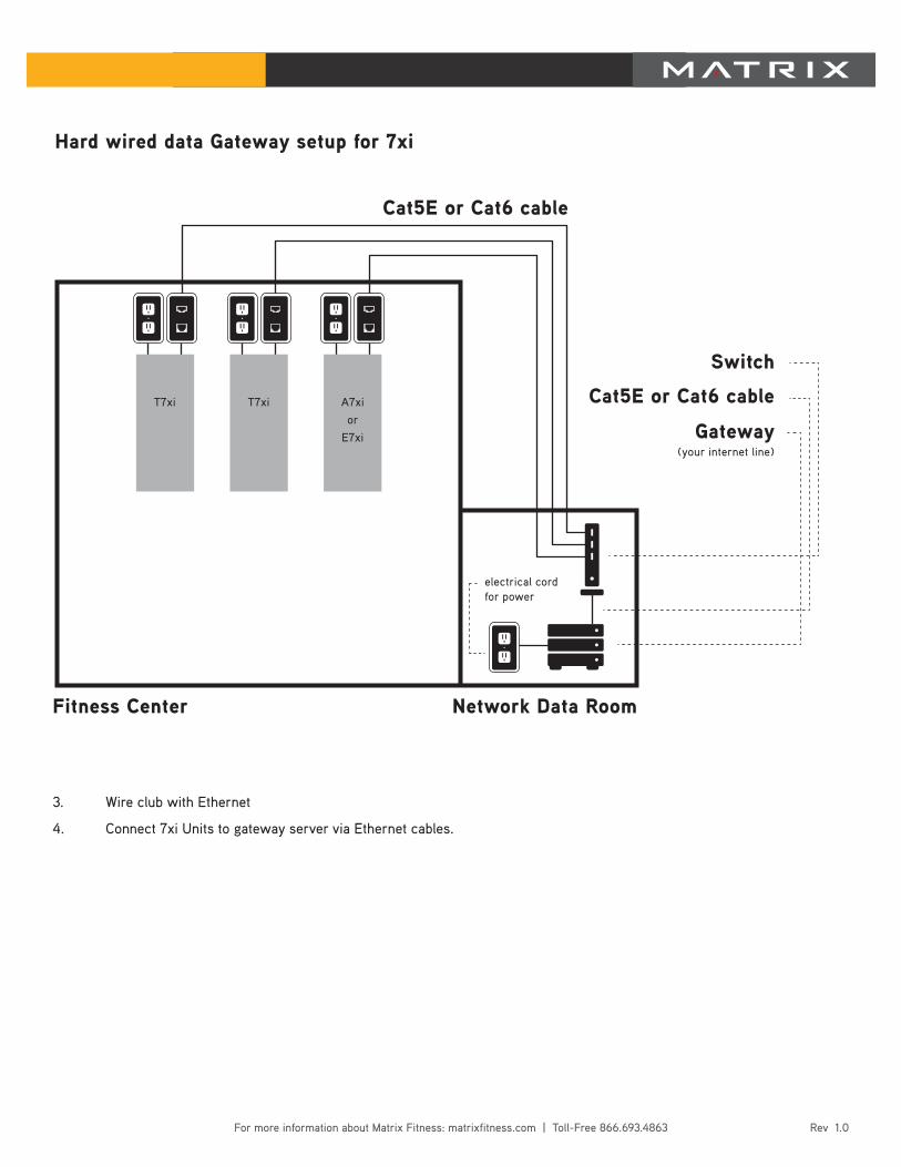
3. Wire club with Ethernet
4. Connect 7xi Units to gateway server via Ethernet cables.
Cat5E or Cat6 cable
Fitness Center Network Data Room
Gateway(your internet line)
Cat5E or Cat6 cable
Switch
electrical cord for power
Hard wired data Gateway setup for 7xi
A7xior
E7xi
T7xiT7xi
Rev 1.0For more information about Matrix Fitness: matrixfitness.com | Toll-Free 866.693.4863
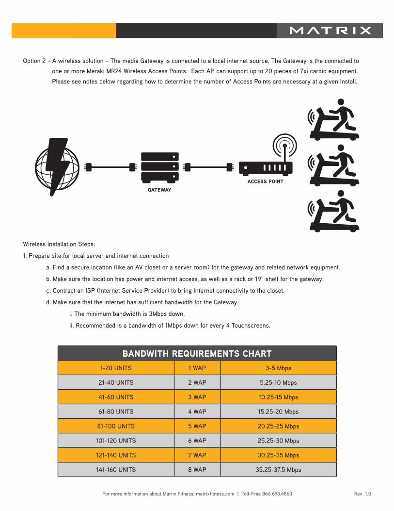
Option 2 - A wireless solution – The media Gateway is connected to a local internet source. The Gateway is the connected to
one or more Meraki MR24 Wireless Access Points. Each AP can support up to 20 pieces of 7xi cardio equipment.
Please see notes below regarding how to determine the number of Access Points are necessary at a given install.
Wireless Installation Steps:
1. Prepare site for local server and internet connection
a. Find a secure location (like an AV closet or a server room) for the gateway and related network equipment.
b. Make sure the location has power and internet access, as well as a rack or 19” shelf for the gateway.
c. Contract an ISP (Internet Service Provider) to bring internet connectivity to the closet.
d. Make sure that the internet has sufficient bandwidth for the Gateway.
i. The minimum bandwidth is 3Mbps down.
ii. Recommended is a bandwidth of 1Mbps down for every 4 Touchscreens.
1-20 UNITS 1 WAP 3-5 Mbps
21-40 UNITS 2 WAP 5.25-10 Mbps
41-60 UNITS 3 WAP 10.25-15 Mbps
61-80 UNITS 4 WAP 15.25-20 Mbps
81-100 UNITS 5 WAP 20.25-25 Mbps
101-120 UNITS 6 WAP 25.25-30 Mbps
121-140 UNITS 7 WAP 30.25-35 Mbps
141-160 UNITS 8 WAP 35.25-37.5 Mbps
BANDWITH REQUIREMENTS CHART
GATEWAY
ACCESS POINT
Rev 1.0For more information about Matrix Fitness: matrixfitness.com | Toll-Free 866.693.4863
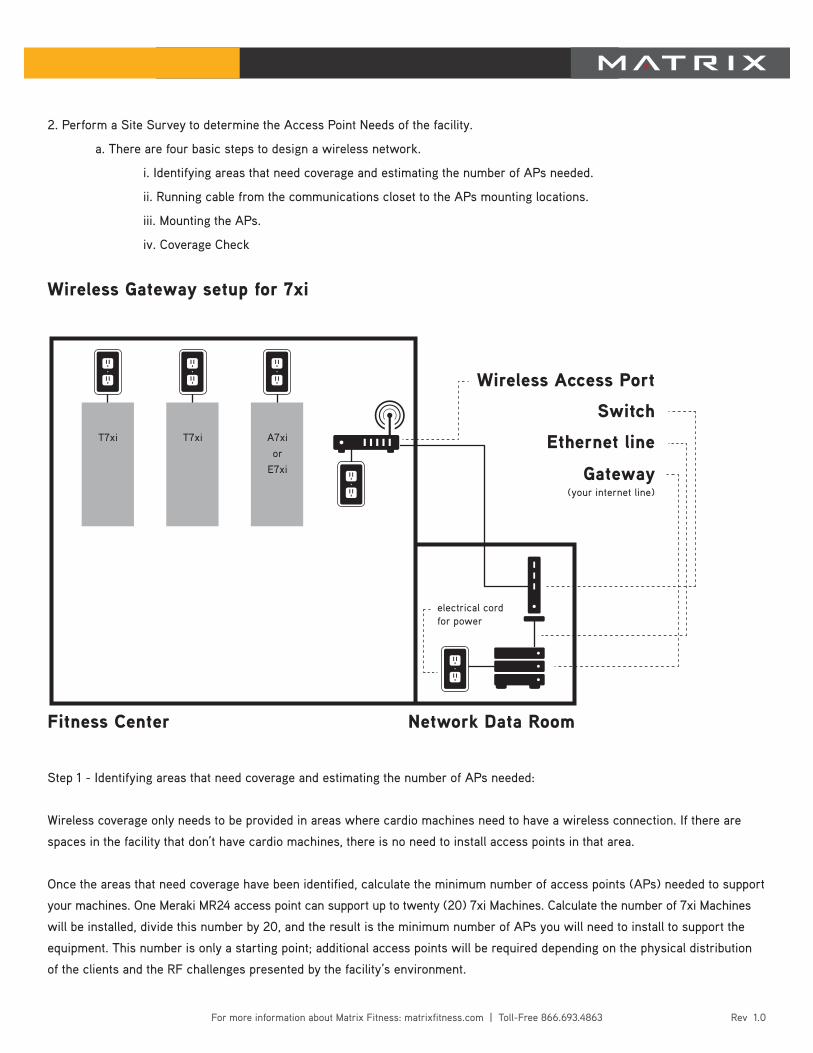
Step 1 - Identifying areas that need coverage and estimating the number of APs needed:
Wireless coverage only needs to be provided in areas where cardio machines need to have a wireless connection. If there are
spaces in the facility that don’t have cardio machines, there is no need to install access points in that area.
Once the areas that need coverage have been identified, calculate the minimum number of access points (APs) needed to support
your machines. One Meraki MR24 access point can support up to twenty (20) 7xi Machines. Calculate the number of 7xi Machines
will be installed, divide this number by 20, and the result is the minimum number of APs you will need to install to support the
equipment. This number is only a starting point; additional access points will be required depending on the physical distribution
of the clients and the RF challenges presented by the facility’s environment.
2. Perform a Site Survey to determine the Access Point Needs of the facility.
a. There are four basic steps to design a wireless network.
i. Identifying areas that need coverage and estimating the number of APs needed.
ii. Running cable from the communications closet to the APs mounting locations.
iii. Mounting the APs.
iv. Coverage Check
Wireless Gateway setup for 7xi
Gateway(your internet line)
Ethernet line
Switch
Wireless Access Port
electrical cord for power
Fitness Center Network Data Room
A7xior
E7xi
T7xiT7xi
Rev 1.0For more information about Matrix Fitness: matrixfitness.com | Toll-Free 866.693.4863
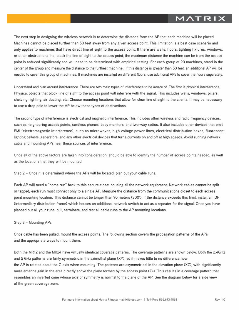
The next step in designing the wireless network is to determine the distance from the AP that each machine will be placed.
Machines cannot be placed further than 50 feet away from any given access point. This limitation is a best case scenario and
only applies to machines that have direct line of sight to the access point. If there are walls, floors, lighting fixtures, windows,
or other obstructions that block the line of sight to the access point, the maximum distance the machine can be from the access
point is reduced significantly and will need to be determined with empirical testing. For each group of 20 machines, stand in the
center of the group and measure the distance to the furthest machine. If this distance is greater than 50 feet, an additional AP will be
needed to cover this group of machines. If machines are installed on different floors, use additional APs to cover the floors separately.
Understand and plan around interference. There are two main types of interference to be aware of. The first is physical interference.
Physical objects that block line of sight to the access point will interfere with the signal. This includes walls, windows, pillars,
shelving, lighting, air ducting, etc. Choose mounting locations that allow for clear line of sight to the clients. It may be necessary
to use a drop pole to lower the AP below these types of obstructions.
The second type of interference is electrical and magnetic interference. This includes other wireless and radio frequency devices,
such as neighboring access points, cordless phones, baby monitors, and two-way radios. It also includes other devices that emit
EMI (electromagnetic interference), such as microwaves, high voltage power lines, electrical distribution boxes, fluorescent
lighting ballasts, generators, and any other electrical devices that turns currents on and off at high speeds. Avoid running network
cable and mounting APs near these sources of interference.
Once all of the above factors are taken into consideration, should be able to identify the number of access points needed, as well
as the locations that they will be mounted.
Step 2 – Once it is determined where the APs will be located, plan out your cable runs.
Each AP will need a “home run” back to this secure closet housing all the network equipment. Network cables cannot be split
or tapped; each run must connect only to a single AP. Measure the distance from the communications closet to each access
point mounting location. This distance cannot be longer than 90 meters (300’). If the distance exceeds this limit, install an IDF
(intermediary distribution frame) which houses an additional network switch to act as a repeater for the signal. Once you have
planned out all your runs, pull, terminate, and test all cable runs to the AP mounting locations.
Step 3 – Mounting APs
Once cable has been pulled, mount the access points. The following section covers the propagation patterns of the APs
and the appropriate ways to mount them.
Both the MR12 and the MR24 have virtually identical coverage patterns. The coverage patterns are shown below. Both the 2.4GHz
and 5 GHz patterns are fairly symmetric in the azimuthal plane (XY), so it makes little to no difference how
the AP is rotated about the Z-axis when mounting. The patterns are asymmetrical in the elevation plane (XZ), with significantly
more antenna gain in the area directly above the plane formed by the access point (Z+). This results in a coverage pattern that
resembles an inverted cone whose axis of symmetry is normal to the plane of the AP. See the diagram below for a side view
of the green coverage zone.
Rev 1.0For more information about Matrix Fitness: matrixfitness.com | Toll-Free 866.693.4863
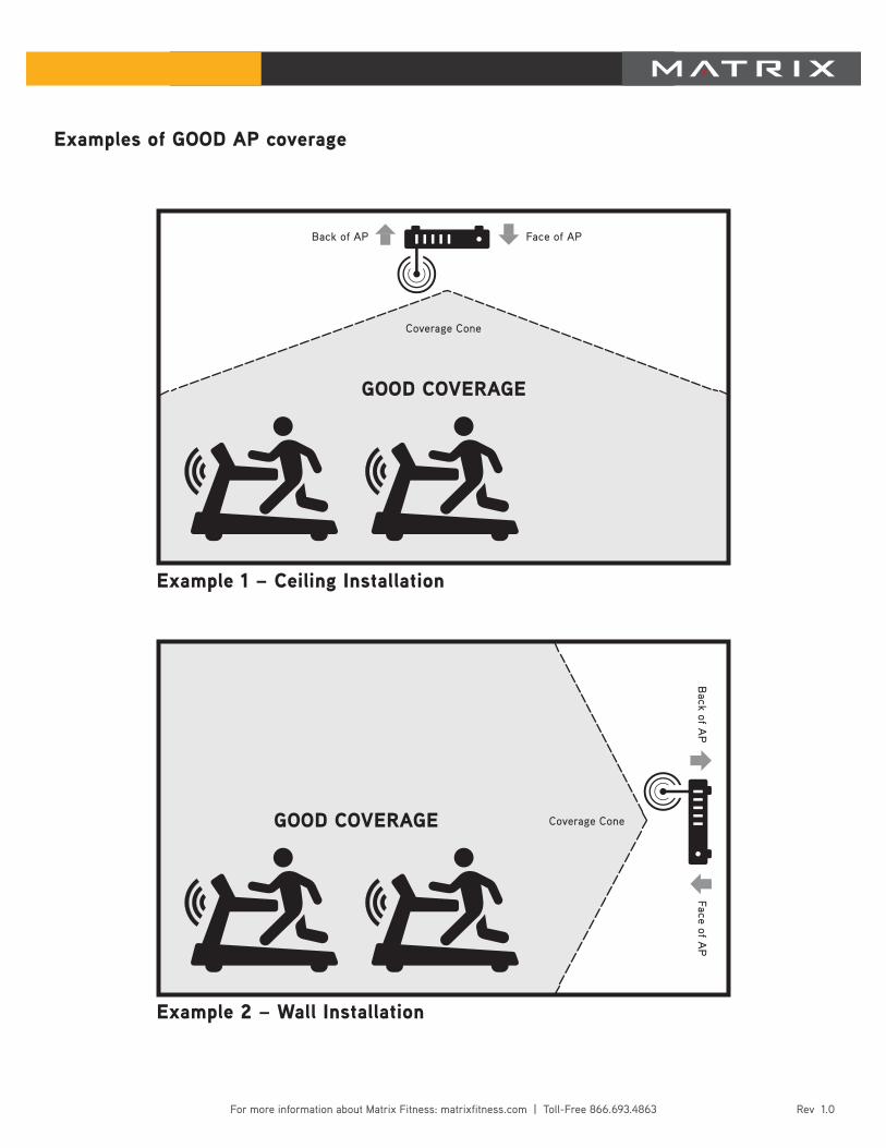
Examples of GOOD AP coverage
Example 1 – Ceiling Installation
Example 2 – Wall Installation
GOOD COVERAGE
GOOD COVERAGE
Coverage Cone
Back of AP
Back of A
P
Face of AP
Face of AP
Coverage Cone
Rev 1.0For more information about Matrix Fitness: matrixfitness.com | Toll-Free 866.693.4863
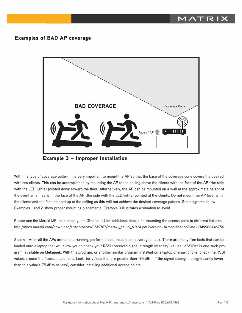
With this type of coverage pattern it is very important to mount the AP so that the base of the coverage cone covers the desired
wireless clients. This can be accomplished by mounting the AP to the ceiling above the clients with the face of the AP (the side
with the LED lights) pointed down toward the floor. Alternatively, the AP can be mounted on a wall at the approximate height of
the client antennas with the face of the AP (the side with the LED lights) pointed at the clients. Do not mount the AP level with
the clients and the face pointed up at the ceiling as this will not achieve the desired coverage pattern. See diagrams below.
Examples 1 and 2 show proper mounting placements. Example 3 illustrates a situation to avoid.
Please see the Meraki MR installation guide (Section 4) for additional details on mounting the access point to different fixtures.
http://docs.meraki.com/download/attachments/8519767/meraki_setup_MR24.pdf?version=1&modificationDate=1349988446756
Step 4 - After all the APs are up and running, perform a post installation coverage check. There are many free tools that can be
loaded onto a laptop that will allow you to check your RSSI (received signal strength intensity) values. InSSIDer is one such pro-
gram, available on Metageek. With this program, or another similar program installed on a laptop or smartphone, check the RSSI
values around the fitness equipment. Look for values that are greater than -70 dBm. If the signal strength is significantly lower
than this value (-75 dBm or less), consider installing additional access points.
Example 3 – Improper Installation
BAD COVERAGE
Face of AP
Coverage Cone
Examples of BAD AP coverage
Rev 1.0For more information about Matrix Fitness: matrixfitness.com | Toll-Free 866.693.4863
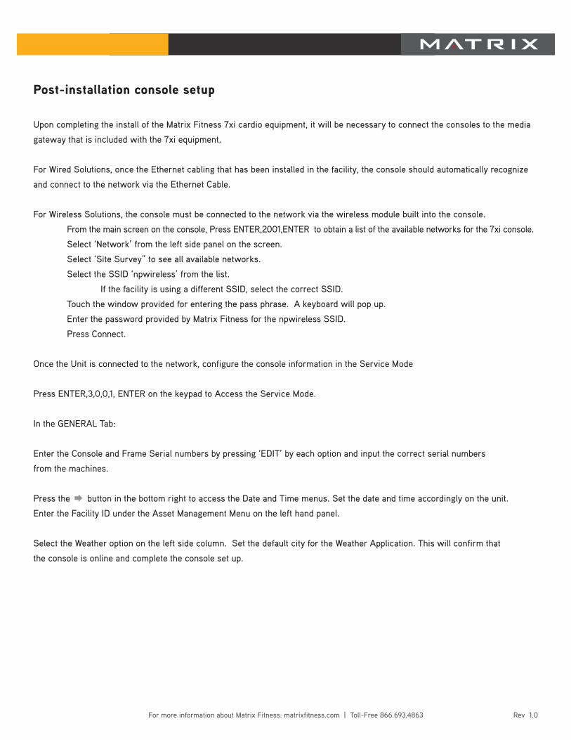
Post-installation console setup
Upon completing the install of the Matrix Fitness 7xi cardio equipment, it will be necessary to connect the consoles to the media
gateway that is included with the 7xi equipment.
For Wired Solutions, once the Ethernet cabling that has been installed in the facility, the console should automatically recognize
and connect to the network via the Ethernet Cable.
For Wireless Solutions, the console must be connected to the network via the wireless module built into the console.
From the main screen on the console, Press ENTER,2001,ENTER to obtain a list of the available networks for the 7xi console.
Select ‘Network’ from the left side panel on the screen.
Select ‘Site Survey” to see all available networks.
Select the SSID ‘npwireless’ from the list.
If the facility is using a different SSID, select the correct SSID.
Touch the window provided for entering the pass phrase. A keyboard will pop up.
Enter the password provided by Matrix Fitness for the npwireless SSID.
Press Connect.
Once the Unit is connected to the network, configure the console information in the Service Mode
Press ENTER,3,0,0,1, ENTER on the keypad to Access the Service Mode.
In the GENERAL Tab:
Enter the Console and Frame Serial numbers by pressing ‘EDIT’ by each option and input the correct serial numbers
from the machines.
Press the → button in the bottom right to access the Date and Time menus. Set the date and time accordingly on the unit.
Enter the Facility ID under the Asset Management Menu on the left hand panel.
Select the Weather option on the left side column. Set the default city for the Weather Application. This will confirm that
the console is online and complete the console set up.
Rev 1.0For more information about Matrix Fitness: matrixfitness.com | Toll-Free 866.693.4863
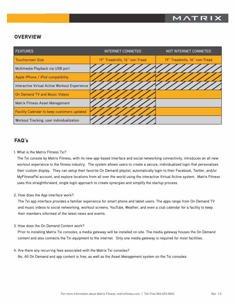
OVERVIEW
FEATURES INTERNET CONNETED NOT INTERNET CONNETED
Touchscreen Size 19” Treadmills, 16” non-Tread 19” Treadmills, 16” non-Tread
Multimedia Playback via USB port
Apple iPhone / iPod compatibility
Interactive Virtual Active Workout Experience
On Demand TV and Music Videos
Matrix Fitness Asset Management
Facility Calendar to keep customers updated
Workout Tracking, user individualization
1. What is the Matrix Fitness 7xi?
The 7xi console by Matrix Fitness, with its new app-based interface and social networking connectivity, introduces an all new
workout experience to the fitness industry. The system allows users to create a secure, individualized login that personalizes
their custom display. They can setup their favorite On Demand playlist, automatically login to their Facebook, Twitter, and/or
MyFitnessPal account, and explore locations from all over the world using the interactive Virtual Active system. Matrix Fitness
uses this straightforward, single login approach to create synergies and simplify the startup process.
2. How does the App interface work?
The 7xi app interface provides a familiar experience for smart phone and tablet users. The apps range from On Demand TV
and music videos to social networking, workout screens, YouTube, Weather, and even a club calendar for a facility to keep
their members informed of the latest news and events.
3. How does the On Demand Content work?
Prior to installing Matrix 7xi consoles, a media gateway will be installed on site. The media gateway houses the On Demand
content and also connects the 7xi equipment to the internet. Only one media gateway is required for most facilities.
4. Are there any recurring fees associated with the Matrix 7xi consoles?
No. All On Demand and app content is free, as well as the Asset Management system on the 7xi consoles.
FAQ’s
Rev 1.0For more information about Matrix Fitness: matrixfitness.com | Toll-Free 866.693.4863
5. How do I connect the 7xi to the Internet?
The 7xi equipment connects to the Internet via the media gateway. The gateway will be housed in a network room with
a connection to the Internet, and the console will connect to the gateway either via Ethernet cabling or WiFi connection.
6. If I’m using Ethernet Cabling, what type of cable can I use?
We recommend using Cat6 cabling as it will better accommodate any new technology released, however either Cat5e or Cat6
cable will work. In either situation it is necessary to use shielded cabling to ensure the highest performance.
7. If I have WiFi already, can I use that existing WiFi to connect to the media gateway?
No. The 7xi will need to be connected through the commercial grade WiFi access points that will be supplied by Matrix Fitness.
8. How do the media gateway and access points get installed into the facility?
In North America and UK, the gateway and access points will be installed by Accucode, a partner of Matrix Fitness. In all other
areas, Matrix Fitness will install and set up the gateway and access point.
9. In addition to all of the On Demand Content, can I still watch live TV?
Absolutely. Matrix 7xi equipment is capable of viewing live TV in addition to On Demand content. All you need is a coax cable
running to the equipment from your local TV source.
10. Can I update the software on the 7xi via the Internet?
Yes. You can adjust the setting in the console to automatically check for available updates on a set schedule. Otherwise you
can manually check for updates at any time.
11. How does the Asset Management system work with the 7xi?
Asset Management serves as a helpful tool for tracking maintenance, errors, and service issues. Additionally, you can
customize the logo and front page on your 7xi units to help promote your facility. Additionally you can use Asset Management
to add events to the calendar app on the 7xi console to keep your members informed of upcoming events.
Technical Requirement FAQ – 7xi
1. Power requirements for 7xi equipment:
All 7xi units must be plugged in. The power requirements on all 7xi units are the same as other Matrix models regarding
dedicated circuits for treadmills and how many units you can connect on a single circuit for other models.
2. Ethernet Cabling:
In all situations where Ethernet Cable is needed, either Cat5e or Cat6 cable can be used. We recommend using Cat6 cable,
as the flexibility for new technology. We recommend using shielded cabling, as it will prevent any interference that may occur
on the lines.
FAQ’s
Rev 1.0For more information about Matrix Fitness: matrixfitness.com | Toll-Free 866.693.4863
3. Coaxial Cable:
To watch live TV, coaxial cable needs to be connected to the equipment. We recommend using quad-shielded RG-6 cable with
an F-Type connecter and compression fitting. TV signal must be delivered to the equipment unencrypted. The TV signal can be
split as long as the signal at the TV is +7 dBmV, ±5dBmV.
4. Internet questions:
a. Do I need to have a dedicated Internet line installed? It is not required, but we do recommend a separate Internet
line to help prevent the equipment from slowing down computers and mobile devices on the existing network and
vice versa.
b. Do I need to set a Static IP for the media gateway or access points? No. The Gateway works with a DHCP and will
assign Dynamic IP Addresses to all machines that connect through the gateway.
c. Is On Demand Content available for all 7xi units? Within the United States, both the On Demand TV and music videos
are available. Outside of the United States, only the On Demand music videos are available.
FAQ’s
Related Documents