Mechanical behaviour of similar and dissimilar AA5182-H111 and AA6016-T4 thin friction stir welds C. Leitao a , R.M. Leal a,b , D.M. Rodrigues a, * , A. Loureiro a , P. Vilac ßa c a CEMUC, Department of Mechanical Engineering, University of Coimbra, Portugal b ESAD.CR, Polytechnic Institute of Leiria, Caldas da Rainha, Portugal c IST, Technical University of Lisbon, Lisbon, Portugal article info Article history: Received 18 December 2007 Accepted 16 April 2008 Available online 28 April 2008 Keywords: Taylor welded blanks Friction stir welding Aluminium alloys Thin sheets abstract The tensile behaviour of similar and dissimilar friction stir welds in 1 mm thick sheets of two aluminium alloys (AA5182-H111 and AA6016-T4) is analysed in this paper. The heterogeneity in properties across the welds was studied by performing microhardness tests and microstructural analysis. The tensile tests were performed in samples extracted longitudinal and transverse to the weld direction. It was found that the tensile behaviour of the welds depends mainly on the grain size in the TMAZ, for the AA5182-H111 alloy, and on precipitate distribution, for the AA6016-T4 alloy. In all types of welds, the HAZ preserves the same properties of the base materials. The global mechanical behaviour of the AA5182-H111 similar welds is very similar to that of the base material. However, for the AA6016-T4 similar welds and for the AA6016-T4-AA5182-H111 dissimilar welds a 10–20% strength reduction relative to the base materi- als and important losses in ductility were reported. Ó 2008 Elsevier Ltd. All rights reserved. 1. Introduction Increasing industrial concern with ambience and energy is becoming notorious. In this context, friction stir welding (FSW) ap- peared as an easy, ecologic and promisingly productive weld meth- od that enables to diminish material waste and to avoid radiation and harmful gas emissions, usually associated with the fusion welding processes. The FSW tools are mainly constituted by a small diameter entry probe and a concentric larger diameter shoulder, both usually made of high strength steel. During the weld process, the FSW tool is rotated and the probe is plunged into the boundary of the adjoining plates. Penetration depth of the probe is controlled by its length and by the tool shoul- der, which should be in intimate contact with the plates during welding. The heat generated by friction between the rotating tool and the plates promotes a local increase in temperature and soft- ens the materials under the tool shoulder. At the same time, the plunged rotating probe moves and mixes the softened materials, by intense plastic deformation, joining both in a solid state weld. According to the temperature attained and the volume of mate- rial which is plastically deformed during the welding process, it is usually possible to distinguish two main zones, with different characteristics, in the FS welds: the thermomechanically affected zone (TMAZ), that is constituted by the material plastically de- formed during the welding process, and the heat affected zone (HAZ), comprising the material affected by the weld thermal cycle but not plastically deformed [1–4]. Frequently, part of the TMAZ presents a recrystallized fine-grained microstructure, resulting from the combination of extremely high plastic deformation and temperature, which is usually called as Nugget. The HAZ of the fric- tion stir welds is of the same nature of the heat affected zone of welds resulting from the fusion welding processes [5]. Despite the large amount of published literature about the FSW process, systematic information does not exist on the influence of the tool and the process parameters on the weld quality for a large range of materials, thicknesses and joint configurations. Until now, FSW industrial application had mostly been restricted to the con- struction of large components in shipbuilding and aerospace and aeronautics industry [6,7]. The application of this process in the automotive industry is relatively recent and has one of its main fields of interest for the production of aluminium tailored welded blanks (TWB) from very thin sheets [8–13]. In fact, some difficul- ties continue to restrict the application of TWBs in industry [14– 17] such as, the difficulty in welding some materials (Al alloys and HSS), the strength reduction in the weld line and the poor formability of the TWBs. The FSW process diminishes some of the weldability problems usually associated with fusion welding processes, due to its low heat input [6]. However, FSW process has limitations in butt-joining thin sheets. The thickness reduction resulting from the forging effect of the shoulder can significantly reduce the mechanical resistance in thin plates (1 mm or less). The presence of micro defects, usually acceptable in thick welds, also pose serious problems in thin plate sheet welds [11]. 0261-3069/$ - see front matter Ó 2008 Elsevier Ltd. All rights reserved. doi:10.1016/j.matdes.2008.04.045 * Corresponding author. Tel.: +351 239 790 700; fax: +351 239 790 701. E-mail address: [email protected] (D.M. Rodrigues). Materials and Design 30 (2009) 101–108 Contents lists available at ScienceDirect Materials and Design journal homepage: www.elsevier.com/locate/matdes

Welcome message from author
This document is posted to help you gain knowledge. Please leave a comment to let me know what you think about it! Share it to your friends and learn new things together.
Transcript
Materials and Design 30 (2009) 101–108
Contents lists available at ScienceDirect
Materials and Design
journal homepage: www.elsevier .com/locate /matdes
Mechanical behaviour of similar and dissimilar AA5182-H111 and AA6016-T4thin friction stir welds
C. Leitao a, R.M. Leal a,b, D.M. Rodrigues a,*, A. Loureiro a, P. Vilac�a c
a CEMUC, Department of Mechanical Engineering, University of Coimbra, Portugalb ESAD.CR, Polytechnic Institute of Leiria, Caldas da Rainha, Portugalc IST, Technical University of Lisbon, Lisbon, Portugal
a r t i c l e i n f o a b s t r a c t
Article history:Received 18 December 2007Accepted 16 April 2008Available online 28 April 2008
Keywords:Taylor welded blanksFriction stir weldingAluminium alloysThin sheets
0261-3069/$ - see front matter � 2008 Elsevier Ltd. Adoi:10.1016/j.matdes.2008.04.045
* Corresponding author. Tel.: +351 239 790 700; faE-mail address: [email protected] (D.M. R
The tensile behaviour of similar and dissimilar friction stir welds in 1 mm thick sheets of two aluminiumalloys (AA5182-H111 and AA6016-T4) is analysed in this paper. The heterogeneity in properties acrossthe welds was studied by performing microhardness tests and microstructural analysis. The tensile testswere performed in samples extracted longitudinal and transverse to the weld direction. It was found thatthe tensile behaviour of the welds depends mainly on the grain size in the TMAZ, for the AA5182-H111alloy, and on precipitate distribution, for the AA6016-T4 alloy. In all types of welds, the HAZ preserves thesame properties of the base materials. The global mechanical behaviour of the AA5182-H111 similarwelds is very similar to that of the base material. However, for the AA6016-T4 similar welds and forthe AA6016-T4-AA5182-H111 dissimilar welds a 10–20% strength reduction relative to the base materi-als and important losses in ductility were reported.
� 2008 Elsevier Ltd. All rights reserved.
1. Introduction
Increasing industrial concern with ambience and energy isbecoming notorious. In this context, friction stir welding (FSW) ap-peared as an easy, ecologic and promisingly productive weld meth-od that enables to diminish material waste and to avoid radiationand harmful gas emissions, usually associated with the fusionwelding processes. The FSW tools are mainly constituted by a smalldiameter entry probe and a concentric larger diameter shoulder,both usually made of high strength steel.
During the weld process, the FSW tool is rotated and the probeis plunged into the boundary of the adjoining plates. Penetrationdepth of the probe is controlled by its length and by the tool shoul-der, which should be in intimate contact with the plates duringwelding. The heat generated by friction between the rotating tooland the plates promotes a local increase in temperature and soft-ens the materials under the tool shoulder. At the same time, theplunged rotating probe moves and mixes the softened materials,by intense plastic deformation, joining both in a solid state weld.
According to the temperature attained and the volume of mate-rial which is plastically deformed during the welding process, it isusually possible to distinguish two main zones, with differentcharacteristics, in the FS welds: the thermomechanically affectedzone (TMAZ), that is constituted by the material plastically de-formed during the welding process, and the heat affected zone
ll rights reserved.
x: +351 239 790 701.odrigues).
(HAZ), comprising the material affected by the weld thermal cyclebut not plastically deformed [1–4]. Frequently, part of the TMAZpresents a recrystallized fine-grained microstructure, resultingfrom the combination of extremely high plastic deformation andtemperature, which is usually called as Nugget. The HAZ of the fric-tion stir welds is of the same nature of the heat affected zone ofwelds resulting from the fusion welding processes [5].
Despite the large amount of published literature about the FSWprocess, systematic information does not exist on the influence ofthe tool and the process parameters on the weld quality for a largerange of materials, thicknesses and joint configurations. Until now,FSW industrial application had mostly been restricted to the con-struction of large components in shipbuilding and aerospace andaeronautics industry [6,7]. The application of this process in theautomotive industry is relatively recent and has one of its mainfields of interest for the production of aluminium tailored weldedblanks (TWB) from very thin sheets [8–13]. In fact, some difficul-ties continue to restrict the application of TWBs in industry [14–17] such as, the difficulty in welding some materials (Al alloysand HSS), the strength reduction in the weld line and the poorformability of the TWBs. The FSW process diminishes some ofthe weldability problems usually associated with fusion weldingprocesses, due to its low heat input [6]. However, FSW processhas limitations in butt-joining thin sheets. The thickness reductionresulting from the forging effect of the shoulder can significantlyreduce the mechanical resistance in thin plates (1 mm or less).The presence of micro defects, usually acceptable in thick welds,also pose serious problems in thin plate sheet welds [11].
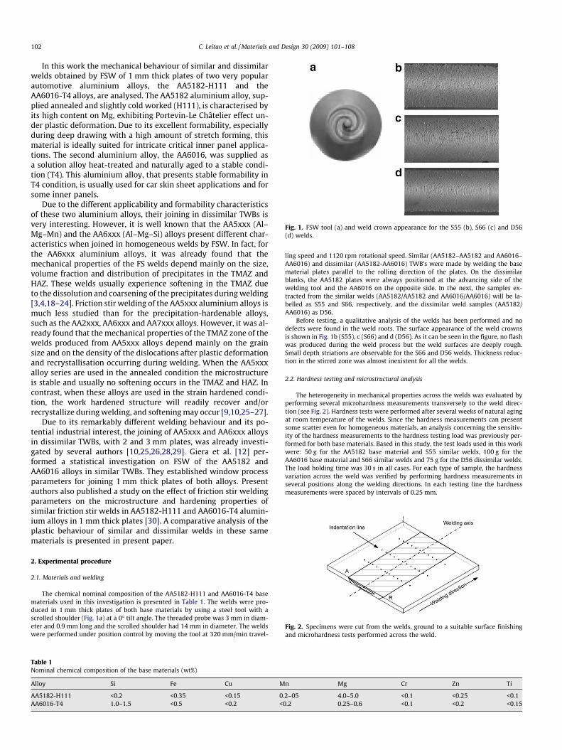
Fig. 1. FSW tool (a) and weld crown appearance for the S55 (b), S66 (c) and D56(d) welds.
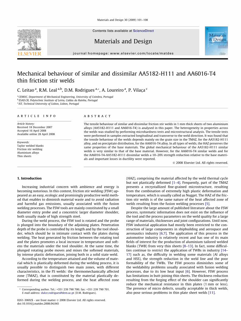
Fig. 2. Specimens were cut from the welds, ground to a suitable surface finishingand microhardness tests performed across the weld.
102 C. Leitao et al. / Materials and Design 30 (2009) 101–108
In this work the mechanical behaviour of similar and dissimilarwelds obtained by FSW of 1 mm thick plates of two very popularautomotive aluminium alloys, the AA5182-H111 and theAA6016-T4 alloys, are analysed. The AA5182 aluminium alloy, sup-plied annealed and slightly cold worked (H111), is characterised byits high content on Mg, exhibiting Portevin-Le Châtelier effect un-der plastic deformation. Due to its excellent formability, especiallyduring deep drawing with a high amount of stretch forming, thismaterial is ideally suited for intricate critical inner panel applica-tions. The second aluminium alloy, the AA6016, was supplied asa solution alloy heat-treated and naturally aged to a stable condi-tion (T4). This aluminium alloy, that presents stable formability inT4 condition, is usually used for car skin sheet applications and forsome inner panels.
Due to the different applicability and formability characteristicsof these two aluminium alloys, their joining in dissimilar TWBs isvery interesting. However, it is well known that the AA5xxx (Al–Mg–Mn) and the AA6xxx (Al–Mg–Si) alloys present different char-acteristics when joined in homogeneous welds by FSW. In fact, forthe AA6xxx aluminium alloys, it was already found that themechanical properties of the FS welds depend mainly on the size,volume fraction and distribution of precipitates in the TMAZ andHAZ. These welds usually experience softening in the TMAZ dueto the dissolution and coarsening of the precipitates during welding[3,4,18–24]. Friction stir welding of the AA5xxx aluminium alloys ismuch less studied than for the precipitation-hardenable alloys,such as the AA2xxx, AA6xxx and AA7xxx alloys. However, it was al-ready found that the mechanical properties of the TMAZ zone of thewelds produced from AA5xxx alloys depend mainly on the grainsize and on the density of the dislocations after plastic deformationand recrystallisation occurring during welding. When the AA5xxxalloy series are used in the annealed condition the microstructureis stable and usually no softening occurs in the TMAZ and HAZ. Incontrast, when these alloys are used in the strain hardened condi-tion, the work hardened structure will readily recover and/orrecrystallize during welding, and softening may occur [9,10,25–27].
Due to its remarkably different welding behaviour and its po-tential industrial interest, the joining of AA5xxx and AA6xxx alloysin dissimilar TWBs, with 2 and 3 mm plates, was already investi-gated by several authors [10,25,26,28,29]. Giera et al. [12] per-formed a statistical investigation on FSW of the AA5182 andAA6016 alloys in similar TWBs. They established window processparameters for joining 1 mm thick plates of both alloys. Presentauthors also published a study on the effect of friction stir weldingparameters on the microstructure and hardening properties ofsimilar friction stir welds in AA5182-H111 and AA6016-T4 alumin-ium alloys in 1 mm thick plates [30]. A comparative analysis of theplastic behaviour of similar and dissimilar welds in these samematerials is presented in present paper.
2. Experimental procedure
2.1. Materials and welding
The chemical nominal composition of the AA5182-H111 and AA6016-T4 basematerials used in this investigation is presented in Table 1. The welds were pro-duced in 1 mm thick plates of both base materials by using a steel tool with ascrolled shoulder (Fig. 1a) at a 0� tilt angle. The threaded probe was 3 mm in diam-eter and 0.9 mm long and the scrolled shoulder had 14 mm in diameter. The weldswere performed under position control by moving the tool at 320 mm/min travel-
Table 1Nominal chemical composition of the base materials (wt%)
Alloy Si Fe Cu M
AA5182-H111 <0.2 <0.35 <0.15 0AA6016-T4 1.0–1.5 <0.5 <0.2 <
ling speed and 1120 rpm rotational speed. Similar (AA5182–AA5182 and AA6016–AA6016) and dissimilar (AA5182-AA6016) TWB’s were made by welding the basematerial plates parallel to the rolling direction of the plates. On the dissimilarblanks, the AA5182 plates were always positioned at the advancing side of thewelding tool and the AA6016 on the opposite side. In the next, the samples ex-tracted from the similar welds (AA5182/AA5182 and AA6016/AA6016) will be la-belled as S55 and S66, respectively, and the dissimilar weld samples (AA5182/AA6016) as D56.
Before testing, a qualitative analysis of the welds has been performed and nodefects were found in the weld roots. The surface appearance of the weld crownsis shown in Fig. 1b (S55), c (S66) and d (D56). As it can be seen in the figure, no flashwas produced during the weld process but the weld surfaces are deeply rough.Small depth striations are observable for the S66 and D56 welds. Thickness reduc-tion in the stirred zone was almost inexistent for all the welds.
2.2. Hardness testing and microstructural analysis
The heterogeneity in mechanical properties across the welds was evaluated byperforming several microhardness measurements transversely to the weld direc-tion (see Fig. 2). Hardness tests were performed after several weeks of natural agingat room temperature of the welds. Since the hardness measurements can presentsome scatter even for homogeneous materials, an analysis concerning the sensitiv-ity of the hardness measurements to the hardness testing load was previously per-formed for both base materials. Based in this study, the test loads used in this workwere: 50 g for the AA5182 base material and S55 similar welds, 100 g for theAA6016 base material and S66 similar welds and 75 g for the D56 dissimilar welds.The load holding time was 30 s in all cases. For each type of sample, the hardnessvariation across the weld was verified by performing hardness measurements inseveral positions along the welding directions. In each testing line the hardnessmeasurements were spaced by intervals of 0.25 mm.
n Mg Cr Zn Ti
.2–05 4.0–5.0 <0.1 <0.25 <0.10.2 0.25–0.6 <0.1 <0.2 <0.15
C. Leitao et al. / Materials and Design 30 (2009) 101–108 103
Cross-sectioning of the welds perpendicular to the welding direction for metal-lographic analysis was also performed. The samples were prepared according tostandard metallographic practice and etched with Hatch (macrographs) and Modi-fied Poultons (micrographs) reagent’s in order to enable the identification of the dif-ferent weld zones and its association with the respective hardness values.Metallographic analysis was performed using an optical microscope ZEISS HD100. In each hardness graph presented in this paper, a macrograph of the weld instudy will be shown, together with an indication of the position relative to weldthickness (approximately 0.75 mm from root face) at which the hardness measure-ments were performed.
2.3. Tensile testing
Tensile specimens of 50 mm gauge length were machined from the friction stirwelded plates parallel (longitudinal) and normal (transverse) to the welding direc-tion, as it is schematized in Fig. 3. The longitudinal tensile samples (labelled S55_L,S66_L, D56_L) were extracted from all the welds in order to test exclusively the stir-red material. The transverse tensile specimens (S55_T, S66_T, D56_T) were ma-chined from the TWBs so that the weld was centred in the gauge section and thetensile axis was normal to the welding direction. Longitudinal samples were alsoextracted from the S55 TWBs, at the advancing and retreating sides of the welds(S55_HAZ_LA and S55_HAZ_LR, respectively), in order to test the HAZ mechanicalbehaviour.
All the tensile tests were carried out at room temperature at a crosshead speedof 5 mm/min using an Instron computer-controlled testing machine. The tensileproperties were evaluated by testing three tensile specimens of each type. Noneof the tensile samples (transverse or longitudinal) were machined in order to elim-inate weld surface roughness and its possible influence on the plastic behaviour ofthe samples.
3. Results and discussion
3.1. Hardness test results
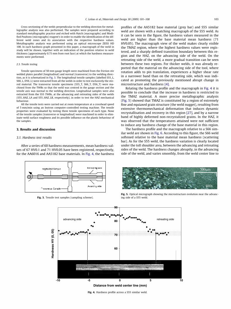
After a series of 60 hardness measurements, mean hardness val-ues of 67 HV0.1 and 71 HV0.05 have been registered, respectively,for the AA6016 and AA5182 base materials. In Fig. 4, the hardness
Fig. 3. Tensile test samples (sampling scheme).
60
70
80
90
-10 -5 0
Distance from wel
Har
dn
ess
HV
(0,
05)
advancing side
Fig. 4. Hardness profile acr
profiles of the AA5182 base material (grey bar) and S55 similarweld are shown with a matching macrograph of the S55 weld. Asit can be seen in the figure, the hardness values measured in theweld are higher than the base material mean hardness (71HV0.05). The macrograph view of the weld makes clearly visiblethe TMAZ region, where the highest hardness values were regis-tered, and a sharply defined transition boundary between this re-gion and the HAZ, on the advancing side of the weld. On theretreating side of the weld, a more gradual transition can be seenbetween these two regions. For thicker welds, it was already re-ported that the material on the advancing side of the tool, whererotation adds to pin translation, experiences a higher shear ratein a narrower band than on the retreating side, which was indi-cated as promoting the previously mentioned abrupt change inmicrostructure and hardness [4].
Relating the hardness profile and the macrograph in Fig. 4 it ispossible to conclude that the increase in hardness is restricted tothe TMAZ material. A more precise metallographic analysis(Fig. 5) showed that TMAZ is constituted by a region of extremelyfine and equiaxed grain structure (the weld nugget), resulting fromextensive thermomechanical deformation that induces dynamicrecrystallisation and recovery in this region [27], and by a narrowband of highly deformed non-recrystalized grains. In the HAZ, itwas observed that the temperatures attained were not sufficientto induce any hardness change of the base material in this region.
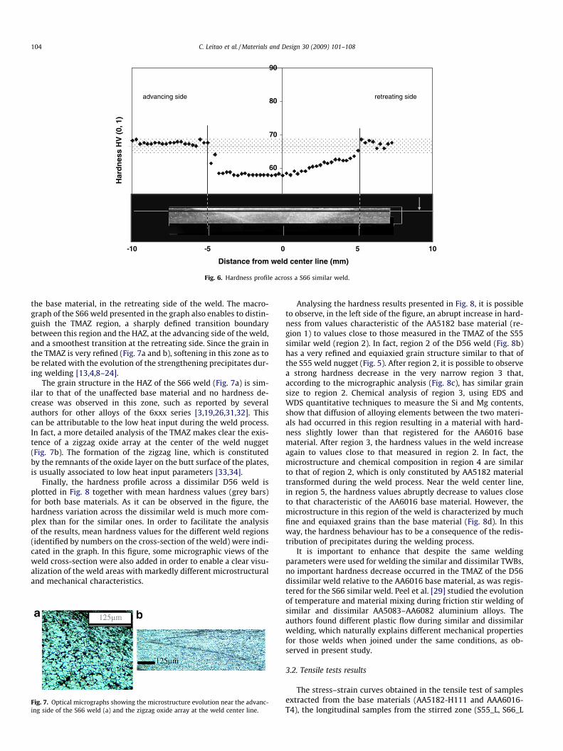
The hardness profile and the macrograph relative to a S66 sim-ilar weld are shown in Fig. 6. According to this figure, the S66 weldsoftened relative to the base material mean hardness (scatteringbar). As for the S55 weld, the hardness variation is clearly locatedunder the toll shoulder area, between the advancing and retreatingsides of the weld. The hardness changes abruptly, in the advancingside of the weld, and varies smoothly, from the weld center line to
5 10
d center line (mm)
retreating side
oss a S55 similar weld.
Fig. 5. Optical micrograph showing the microstructure evolution near the advanc-ing side of a S55 weld.
-10 -5 0 5 10
Distance from weld center line (mm)
Har
dn
ess
HV
(0,
1)
60
70
80
90
advancing side retreating side
Fig. 6. Hardness profile across a S66 similar weld.
104 C. Leitao et al. / Materials and Design 30 (2009) 101–108
the base material, in the retreating side of the weld. The macro-graph of the S66 weld presented in the graph also enables to distin-guish the TMAZ region, a sharply defined transition boundarybetween this region and the HAZ, at the advancing side of the weld,and a smoothest transition at the retreating side. Since the grain inthe TMAZ is very refined (Fig. 7a and b), softening in this zone as tobe related with the evolution of the strengthening precipitates dur-ing welding [13,4,8–24].
The grain structure in the HAZ of the S66 weld (Fig. 7a) is sim-ilar to that of the unaffected base material and no hardness de-crease was observed in this zone, such as reported by severalauthors for other alloys of the 6xxx series [3,19,26,31,32]. Thiscan be attributable to the low heat input during the weld process.In fact, a more detailed analysis of the TMAZ makes clear the exis-tence of a zigzag oxide array at the center of the weld nugget(Fig. 7b). The formation of the zigzag line, which is constitutedby the remnants of the oxide layer on the butt surface of the plates,is usually associated to low heat input parameters [33,34].
Finally, the hardness profile across a dissimilar D56 weld isplotted in Fig. 8 together with mean hardness values (grey bars)for both base materials. As it can be observed in the figure, thehardness variation across the dissimilar weld is much more com-plex than for the similar ones. In order to facilitate the analysisof the results, mean hardness values for the different weld regions(identified by numbers on the cross-section of the weld) were indi-cated in the graph. In this figure, some micrographic views of theweld cross-section were also added in order to enable a clear visu-alization of the weld areas with markedly different microstructuraland mechanical characteristics.
Fig. 7. Optical micrographs showing the microstructure evolution near the advanc-ing side of the S66 weld (a) and the zigzag oxide array at the weld center line.
Analysing the hardness results presented in Fig. 8, it is possibleto observe, in the left side of the figure, an abrupt increase in hard-ness from values characteristic of the AA5182 base material (re-gion 1) to values close to those measured in the TMAZ of the S55similar weld (region 2). In fact, region 2 of the D56 weld (Fig. 8b)has a very refined and equiaxied grain structure similar to that ofthe S55 weld nugget (Fig. 5). After region 2, it is possible to observea strong hardness decrease in the very narrow region 3 that,according to the micrographic analysis (Fig. 8c), has similar grainsize to region 2. Chemical analysis of region 3, using EDS andWDS quantitative techniques to measure the Si and Mg contents,show that diffusion of alloying elements between the two materi-als had occurred in this region resulting in a material with hard-ness slightly lower than that registered for the AA6016 basematerial. After region 3, the hardness values in the weld increaseagain to values close to that measured in region 2. In fact, themicrostructure and chemical composition in region 4 are similarto that of region 2, which is only constituted by AA5182 materialtransformed during the weld process. Near the weld center line,in region 5, the hardness values abruptly decrease to values closeto that characteristic of the AA6016 base material. However, themicrostructure in this region of the weld is characterized by muchfine and equiaxed grains than the base material (Fig. 8d). In thisway, the hardness behaviour has to be a consequence of the redis-tribution of precipitates during the welding process.
It is important to enhance that despite the same weldingparameters were used for welding the similar and dissimilar TWBs,no important hardness decrease occurred in the TMAZ of the D56dissimilar weld relative to the AA6016 base material, as was regis-tered for the S66 similar weld. Peel et al. [29] studied the evolutionof temperature and material mixing during friction stir welding ofsimilar and dissimilar AA5083–AA6082 aluminium alloys. Theauthors found different plastic flow during similar and dissimilarwelding, which naturally explains different mechanical propertiesfor those welds when joined under the same conditions, as ob-served in present study.
3.2. Tensile tests results
The stress–strain curves obtained in the tensile test of samplesextracted from the base materials (AA5182-H111 and AAA6016-T4), the longitudinal samples from the stirred zone (S55_L, S66_L
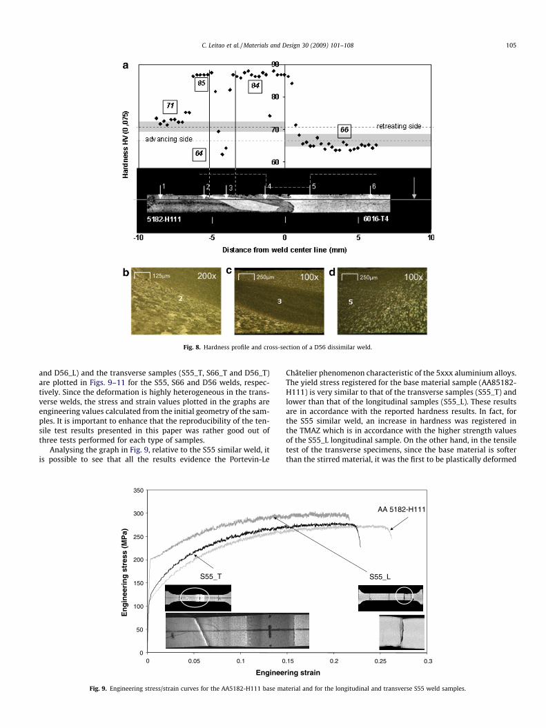
Fig. 8. Hardness profile and cross-section of a D56 dissimilar weld.
C. Leitao et al. / Materials and Design 30 (2009) 101–108 105
and D56_L) and the transverse samples (S55_T, S66_T and D56_T)are plotted in Figs. 9–11 for the S55, S66 and D56 welds, respec-tively. Since the deformation is highly heterogeneous in the trans-verse welds, the stress and strain values plotted in the graphs areengineering values calculated from the initial geometry of the sam-ples. It is important to enhance that the reproducibility of the ten-sile test results presented in this paper was rather good out ofthree tests performed for each type of samples.
Analysing the graph in Fig. 9, relative to the S55 similar weld, itis possible to see that all the results evidence the Portevin-Le
0
50
100
150
200
250
300
350
En
gin
eeri
ng
str
ess
(MP
a)
0 0.05 0.1 0
Enginee
S55_T
Fig. 9. Engineering stress/strain curves for the AA5182-H111 base ma
Châtelier phenomenon characteristic of the 5xxx aluminium alloys.The yield stress registered for the base material sample (AA85182-H111) is very similar to that of the transverse samples (S55_T) andlower than that of the longitudinal samples (S55_L). These resultsare in accordance with the reported hardness results. In fact, forthe S55 similar weld, an increase in hardness was registered inthe TMAZ which is in accordance with the higher strength valuesof the S55_L longitudinal sample. On the other hand, in the tensiletest of the transverse specimens, since the base material is softerthan the stirred material, it was the first to be plastically deformed
.15 0.2 0.25 0.3
ring strain
S55_L
AA 5182-H111
terial and for the longitudinal and transverse S55 weld samples.
0
50
100
150
200
250
0 0.05 0.1 0.15 0.2 0.25 0.3
Engineering strain
En
gin
eeri
ng
str
ess
(MP
a)
AA 6016-T4
S66_T S66_L
Fig. 10. Engineering stress/strain curves for the AA6016-T4 base material and longitudinal and transverse S66 weld samples.
0
50
100
150
200
250
300
350
0 0.05 0.1 0.15 0.2 0.25 0.3
AA 5182-H111 AA6016-T4
D56_L
D56_T
En
gin
eeri
ng
str
ess
(MP
a)
Engineering strain
Fig. 11. Engineering stress/strain curves for the AA5182-H111 and 6016–T4 base materials and for the longitudinal and transverse D56 weld samples.
106 C. Leitao et al. / Materials and Design 30 (2009) 101–108
making the yield stress of the transverse sample similar to that ofthe base material.
It is also important to emphasize that none of the weld sampleswere subjected to surface flat finishing before testing. In this way,strain localisation at the maximum load (necking), for both weldsamples, could be induced by the small surface irregularities andthickness variation characteristics of FS welds. However, it is inter-esting to denote that both the welded samples (longitudinal andtransverse) had almost the same elongation at fracture of thesmooth base material samples. This is especially important forthe transverse sample that also experiences inhomogeneousbehaviour in plastic deformation due to the presence of micro-structures with different mechanical properties across the sample.Pictures from the S55_L and S55_T samples after necking in tensionare also shown in the figure. These pictures clearly show a 45�shear fracture, in the base material, far from the weld, for theS55_T weld sample and a straight fracture normal to the load axisfor the homogeneous S55_L sample. The shear fracture at 45� to theprincipal stress axis is characteristic of homogeneous materials
loaded in tension and resulted from the stress concentration inthe soft base material. The straight crack at right angles to thestress axis, observed for the longitudinal weld sample, certainly re-flects a contribution of the weld grooves in fracture. In fact, surfaceroughness is a function of the FSW tooling design and the weldingparameters and can seriously compromise the plastic and fatiguebehaviour of the welds [3,35]. In present study, surface groovesdid not influence the global ductility of the longitudinal or trans-verse samples.
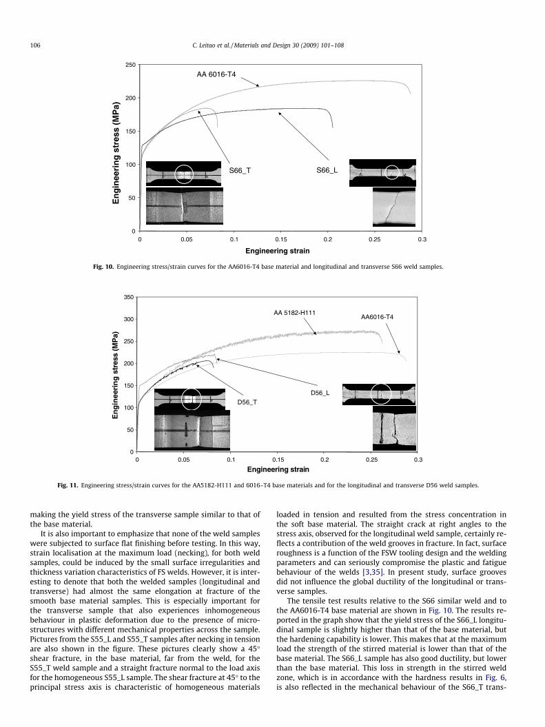
The tensile test results relative to the S66 similar weld and tothe AA6016-T4 base material are shown in Fig. 10. The results re-ported in the graph show that the yield stress of the S66_L longitu-dinal sample is slightly higher than that of the base material, butthe hardening capability is lower. This makes that at the maximumload the strength of the stirred material is lower than that of thebase material. The S66_L sample has also good ductility, but lowerthan the base material. This loss in strength in the stirred weldzone, which is in accordance with the hardness results in Fig. 6,is also reflected in the mechanical behaviour of the S66_T trans-
C. Leitao et al. / Materials and Design 30 (2009) 101–108 107
verse samples that apparently have much lower ductility than thelongitudinal weld and base material samples. In fact, plastic defor-mation concentrates in the weakest zone, the TMAZ, almost pre-venting the deformation of the parent material in each specimen.
Again, pictures of the tensile samples after fracture in tensionare presented in the graph of Fig. 10. Analysing the pictures it ispossible to conclude that despite the surface roughness character-istic of the weld, the S66_L samples experienced a 45� shear frac-ture characteristic of homogeneous and soft materials. For theS66_T sample a straight failure, coincident with the axis of the softweld region, can be observed.
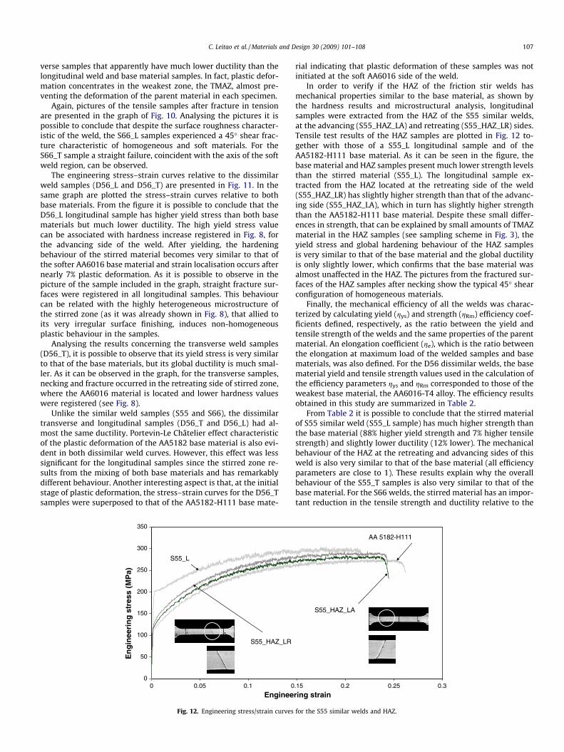
The engineering stress–strain curves relative to the dissimilarweld samples (D56_L and D56_T) are presented in Fig. 11. In thesame graph are plotted the stress–strain curves relative to bothbase materials. From the figure it is possible to conclude that theD56_L longitudinal sample has higher yield stress than both basematerials but much lower ductility. The high yield stress valuecan be associated with hardness increase registered in Fig. 8, forthe advancing side of the weld. After yielding, the hardeningbehaviour of the stirred material becomes very similar to that ofthe softer AA6016 base material and strain localisation occurs afternearly 7% plastic deformation. As it is possible to observe in thepicture of the sample included in the graph, straight fracture sur-faces were registered in all longitudinal samples. This behaviourcan be related with the highly heterogeneous microstructure ofthe stirred zone (as it was already shown in Fig. 8), that allied toits very irregular surface finishing, induces non-homogeneousplastic behaviour in the samples.
Analysing the results concerning the transverse weld samples(D56_T), it is possible to observe that its yield stress is very similarto that of the base materials, but its global ductility is much smal-ler. As it can be observed in the graph, for the transverse samples,necking and fracture occurred in the retreating side of stirred zone,where the AA6016 material is located and lower hardness valueswere registered (see Fig. 8).
Unlike the similar weld samples (S55 and S66), the dissimilartransverse and longitudinal samples (D56_T and D56_L) had al-most the same ductility. Portevin-Le Châtelier effect characteristicof the plastic deformation of the AA5182 base material is also evi-dent in both dissimilar weld curves. However, this effect was lesssignificant for the longitudinal samples since the stirred zone re-sults from the mixing of both base materials and has remarkablydifferent behaviour. Another interesting aspect is that, at the initialstage of plastic deformation, the stress–strain curves for the D56_Tsamples were superposed to that of the AA5182-H111 base mate-
0
50
100
150
200
250
300
350
0 0.05 0.1 0
S55_L
S55_HAZ_LR
En
gin
eeri
ng
str
ess
(MP
a)
Enginee
Fig. 12. Engineering stress/strain curves
rial indicating that plastic deformation of these samples was notinitiated at the soft AA6016 side of the weld.
In order to verify if the HAZ of the friction stir welds hasmechanical properties similar to the base material, as shown bythe hardness results and microstructural analysis, longitudinalsamples were extracted from the HAZ of the S55 similar welds,at the advancing (S55_HAZ_LA) and retreating (S55_HAZ_LR) sides.Tensile test results of the HAZ samples are plotted in Fig. 12 to-gether with those of a S55_L longitudinal sample and of theAA5182-H111 base material. As it can be seen in the figure, thebase material and HAZ samples present much lower strength levelsthan the stirred material (S55_L). The longitudinal sample ex-tracted from the HAZ located at the retreating side of the weld(S55_HAZ_LR) has slightly higher strength than that of the advanc-ing side (S55_HAZ_LA), which in turn has slightly higher strengththan the AA5182-H111 base material. Despite these small differ-ences in strength, that can be explained by small amounts of TMAZmaterial in the HAZ samples (see sampling scheme in Fig. 3), theyield stress and global hardening behaviour of the HAZ samplesis very similar to that of the base material and the global ductilityis only slightly lower, which confirms that the base material wasalmost unaffected in the HAZ. The pictures from the fractured sur-faces of the HAZ samples after necking show the typical 45� shearconfiguration of homogeneous materials.
Finally, the mechanical efficiency of all the welds was charac-terized by calculating yield (gys) and strength (gRm) efficiency coef-ficients defined, respectively, as the ratio between the yield andtensile strength of the welds and the same properties of the parentmaterial. An elongation coefficient (ge), which is the ratio betweenthe elongation at maximum load of the welded samples and basematerials, was also defined. For the D56 dissimilar welds, the basematerial yield and tensile strength values used in the calculation ofthe efficiency parameters gys and gRm corresponded to those of theweakest base material, the AA6016-T4 alloy. The efficiency resultsobtained in this study are summarized in Table 2.
From Table 2 it is possible to conclude that the stirred materialof S55 similar weld (S55_L sample) has much higher strength thanthe base material (88% higher yield strength and 7% higher tensilestrength) and slightly lower ductility (12% lower). The mechanicalbehaviour of the HAZ at the retreating and advancing sides of thisweld is also very similar to that of the base material (all efficiencyparameters are close to 1). These results explain why the overallbehaviour of the S55_T samples is also very similar to that of thebase material. For the S66 welds, the stirred material has an impor-tant reduction in the tensile strength and ductility relative to the
.15 0.2 0.25 0.3
AA 5182-H111
S55_HAZ_LA
ring strain
for the S55 similar welds and HAZ.
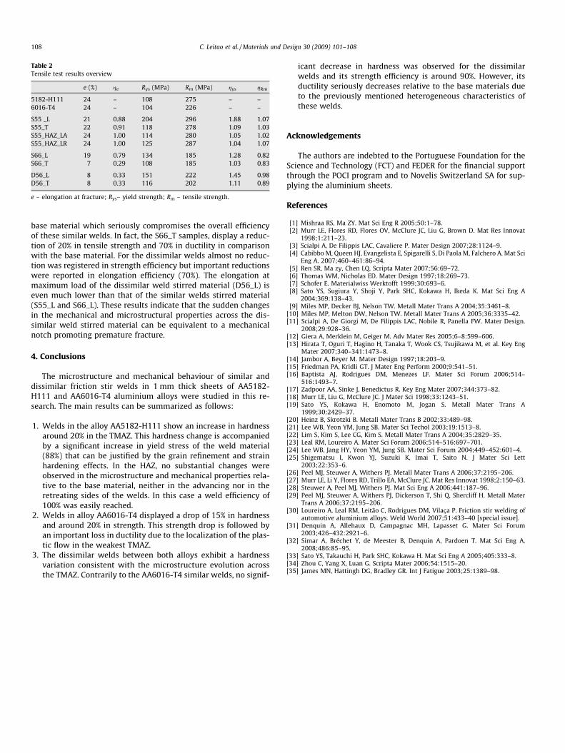
Table 2Tensile test results overview
e (%) ge Rys (MPa) Rm (MPa) gys gRm
5182-H111 24 – 108 275 – –6016-T4 24 – 104 226 – –
S55 _L 21 0.88 204 296 1.88 1.07S55_T 22 0.91 118 278 1.09 1.03S55_HAZ_LA 24 1.00 114 280 1.05 1.02S55_HAZ_LR 24 1.00 125 287 1.04 1.07
S66_L 19 0.79 134 185 1.28 0.82S66_T 7 0.29 108 185 1.03 0.83
D56_L 8 0.33 151 222 1.45 0.98D56_T 8 0.33 116 202 1.11 0.89
e – elongation at fracture; Rys– yield strength; Rm – tensile strength.
108 C. Leitao et al. / Materials and Design 30 (2009) 101–108
base material which seriously compromises the overall efficiencyof these similar welds. In fact, the S66_T samples, display a reduc-tion of 20% in tensile strength and 70% in ductility in comparisonwith the base material. For the dissimilar welds almost no reduc-tion was registered in strength efficiency but important reductionswere reported in elongation efficiency (70%). The elongation atmaximum load of the dissimilar weld stirred material (D56_L) iseven much lower than that of the similar welds stirred material(S55_L and S66_L). These results indicate that the sudden changesin the mechanical and microstructural properties across the dis-similar weld stirred material can be equivalent to a mechanicalnotch promoting premature fracture.
4. Conclusions
The microstructure and mechanical behaviour of similar anddissimilar friction stir welds in 1 mm thick sheets of AA5182-H111 and AA6016-T4 aluminium alloys were studied in this re-search. The main results can be summarized as follows:
1. Welds in the alloy AA5182-H111 show an increase in hardnessaround 20% in the TMAZ. This hardness change is accompaniedby a significant increase in yield stress of the weld material(88%) that can be justified by the grain refinement and strainhardening effects. In the HAZ, no substantial changes wereobserved in the microstructure and mechanical properties rela-tive to the base material, neither in the advancing nor in theretreating sides of the welds. In this case a weld efficiency of100% was easily reached.
2. Welds in alloy AA6016-T4 displayed a drop of 15% in hardnessand around 20% in strength. This strength drop is followed byan important loss in ductility due to the localization of the plas-tic flow in the weakest TMAZ.
3. The dissimilar welds between both alloys exhibit a hardnessvariation consistent with the microstructure evolution acrossthe TMAZ. Contrarily to the AA6016-T4 similar welds, no signif-
icant decrease in hardness was observed for the dissimilarwelds and its strength efficiency is around 90%. However, itsductility seriously decreases relative to the base materials dueto the previously mentioned heterogeneous characteristics ofthese welds.
Acknowledgements
The authors are indebted to the Portuguese Foundation for theScience and Technology (FCT) and FEDER for the financial supportthrough the POCI program and to Novelis Switzerland SA for sup-plying the aluminium sheets.
References
[1] Mishraa RS, Ma ZY. Mat Sci Eng R 2005;50:1–78.[2] Murr LE, Flores RD, Flores OV, McClure JC, Liu G, Brown D. Mat Res Innovat
1998;1:211–23.[3] Scialpi A, De Filippis LAC, Cavaliere P. Mater Design 2007;28:1124–9.[4] Cabibbo M, Queen HJ, Evangelista E, Spigarelli S, Di Paola M, Falchero A. Mat Sci
Eng A. 2007;460–461:86–94.[5] Ren SR, Ma zy, Chen LQ. Scripta Mater 2007;56:69–72.[6] Thomas WM, Nicholas ED. Mater Design 1997;18:269–73.[7] Schofer E. Materialwiss Werktofft 1999;30:693–6.[8] Sato YS, Sugiura Y, Shoji Y, Park SHC, Kokawa H, Ikeda K. Mat Sci Eng A
2004;369:138–43.[9] Miles MP, Decker BJ, Nelson TW. Metall Mater Trans A 2004;35:3461–8.
[10] Miles MP, Melton DW, Nelson TW. Metall Mater Trans A 2005;36:3335–42.[11] Scialpi A, De Giorgi M, De Filippis LAC, Nobile R, Panella FW. Mater Design.
2008;29:928–36.[12] Giera A, Merklein M, Geiger M. Adv Mater Res 2005;6–8:599–606.[13] Hirata T, Oguri T, Hagino H, Tanaka T, Wook CS, Tsujikawa M, et al. Key Eng
Mater 2007;340–341:1473–8.[14] Jambor A, Beyer M. Mater Design 1997;18:203–9.[15] Friedman PA, Kridli GT. J Mater Eng Perform 2000;9:541–51.[16] Baptista AJ, Rodrigues DM, Menezes LF. Mater Sci Forum 2006;514–
516:1493–7.[17] Zadpoor AA, Sinke J, Benedictus R. Key Eng Mater 2007;344:373–82.[18] Murr LE, Liu G, McClure JC. J Mater Sci 1998;33:1243–51.[19] Sato YS, Kokawa H, Enomoto M, Jogan S. Metall Mater Trans A
1999;30:2429–37.[20] Heinz B, Skrotzki B. Metall Mater Trans B 2002;33:489–98.[21] Lee WB, Yeon YM, Jung SB. Mater Sci Techol 2003;19:1513–8.[22] Lim S, Kim S, Lee CG, Kim S. Metall Mater Trans A 2004;35:2829–35.[23] Leal RM, Loureiro A. Mater Sci Forum 2006;514–516:697–701.[24] Lee WB, Jang HY, Yeon YM, Jung SB. Mater Sci Forum 2004;449–452:601–4.[25] Shigematsu I, Kwon YJ, Suzuki K, Imai T, Saito N. J Mater Sci Lett
2003;22:353–6.[26] Peel MJ, Steuwer A, Withers PJ. Metall Mater Trans A 2006;37:2195–206.[27] Murr LE, Li Y, Flores RD, Trillo EA, McClure JC. Mat Res Innovat 1998;2:150–63.[28] Steuwer A, Peel MJ, Withers PJ. Mat Sci Eng A 2006;441:187–96.[29] Peel MJ, Steuwer A, Withers PJ, Dickerson T, Shi Q, Shercliff H. Metall Mater
Trans A 2006;37:2195–206.[30] Loureiro A, Leal RM, Leitão C, Rodrigues DM, Vilac�a P. Friction stir welding of
automotive aluminium alloys. Weld World 2007;51:433–40 [special issue].[31] Denquin A, Allehaux D, Campagnac MH, Lapasset G. Mater Sci Forum
2003;426–432:2921–6.[32] Simar A, Bréchet Y, de Meester B, Denquin A, Pardoen T. Mat Sci Eng A.
2008;486:85–95.[33] Sato YS, Takauchi H, Park SHC, Kokawa H. Mat Sci Eng A 2005;405:333–8.[34] Zhou C, Yang X, Luan G. Scripta Mater 2006;54:1515–20.[35] James MN, Hattingh DG, Bradley GR. Int J Fatigue 2003;25:1389–98.
Related Documents