Materializing design: the implications of rapid prototyping in digital design Larry Sass, Department of Architecture, Massachusetts Institute of Technology, 77 Massachusetts Avenue, Cambridge, MA 02139, USA Rivka Oxman, Faculty of Architecture and Town Planning, Technion, Israel Institute of Technology, 32000 Haifa, Israel Rapid prototyping (RP) today is absorbed into practice and is being recognized as a significant technology for design. This paper attempts to formulate key aspects of the design methodological framework that are coalescing with RP’s capability to build artifacts as part of the creative design process. In doing so, it attempts to formulate questions and issues of RP as a design medium that supports the full spectrum of digital design as a paperless process. These issues have been the resultant of early experimental and hands-on involvement with RP technologies in research and educational environments. In this paper, a DDF method (Digital Design Fabrication) is introduced. The DDF method is a two-stage process of working that integrates generative computing and RP into one process. Together they support a process to generate diverse candidate artifacts as solutions to design problems. Through a presentation of issues, procedural observations, and research findings, a range of potential applications of the DDF model are defined and presented. It demonstrates a process of design situated between conceptual design and real-world construction. Ó 2005 Elsevier Ltd. All rights reserved. Keywords: digital process, rapid prototyping P hysical modeling is one way through which designers realize mental concepts (Cuff, 1992). As a design representational medi- um, the model making process can lead to new forms beyond the original concept. Physical model making is not new to the profession of architecture. For hundreds of years model making has served as an in- termediary between complex design ideas and the construction workers. When designing the Vatican, Michelangelo used physical models as an intermediary to describe construction techniques and the form of inter- nal spaces to both clients and stonemasons (Millon, 1994). Palladio in the 16 th century also used intermediate models of wood as full-scale mockups to explain buildings to masons (Burns, 1991). Today, Corresponding author: L. Sass [email protected] www.elsevier.com/locate/destud 0142-694X $ - see front matter Design Studies 27 (2006) 325e355 doi:10.1016/j.destud.2005.11.009 325 Ó 2005 Elsevier Ltd All rights reserved Printed in Great Britain

Welcome message from author
This document is posted to help you gain knowledge. Please leave a comment to let me know what you think about it! Share it to your friends and learn new things together.
Transcript
Materializing design: the implicationsof rapid prototyping in digital design
Larry Sass, Department of Architecture, Massachusetts Institute of
Technology, 77 Massachusetts Avenue, Cambridge, MA 02139, USA
Rivka Oxman, Faculty of Architecture and Town Planning, Technion,
Israel Institute of Technology, 32000 Haifa, Israel
Rapid prototyping (RP) today is absorbed into practice and is being
recognized as a significant technology for design. This paper attempts to
formulate key aspects of the design methodological framework that are
coalescing with RP’s capability to build artifacts as part of the creative
design process. In doing so, it attempts to formulate questions and issues
of RP as a design medium that supports the full spectrum of digital design
as a paperless process. These issues have been the resultant of early
experimental and hands-on involvement with RP technologies in research
and educational environments. In this paper, a DDF method (Digital
Design Fabrication) is introduced. The DDF method is a two-stage
process of working that integrates generative computing and RP into one
process. Together they support a process to generate diverse candidate
artifacts as solutions to design problems. Through a presentation of
issues, procedural observations, and research findings, a range of potential
applications of the DDF model are defined and presented. It demonstrates
a process of design situated between conceptual design and real-world
construction.
� 2005 Elsevier Ltd. All rights reserved.
Keywords: digital process, rapid prototyping
Physical modeling is one way through which designers realize
mental concepts (Cuff, 1992). As a design representational medi-
um, the model making process can lead to new forms beyond the
original concept. Physical model making is not new to the profession of
architecture. For hundreds of years model making has served as an in-
termediary between complex design ideas and the construction workers.
When designing the Vatican, Michelangelo used physical models as an
intermediary to describe construction techniques and the form of inter-
nal spaces to both clients and stonemasons (Millon, 1994). Palladio in
the 16th century also used intermediate models of wood as full-scale
mockups to explain buildings to masons (Burns, 1991). Today,
Corresponding author:
www.elsevier.com/locate/destud
0142-694X $ - see front matter Design Studies 27 (2006) 325e355
doi:10.1016/j.destud.2005.11.009 325� 2005 Elsevier Ltd All rights reserved Printed in Great Britain
326
computer model making affords opportunities not only to create com-
plex shapes, but also to serve as intermediary between design and
construction.
Material representation from digital files is a seminal development
among the current applications of digital media in design processes.
As the set of technologies known as rapid prototyping (RP) emerges
and is absorbed into practice, it is being recognized as a technology of
great potential significance for design. As schools of design and design
professionals begin to incorporate rapid prototyping devices within
the design process, issues of this mediated relationship begin to be cen-
tered less on the characteristics of the machinery and more on the nature
of the design process. After the first wave of experience we are beginning
to formulate approaches to methods to produce designs with these devi-
ces as part of the design environment. A characteristic of these ap-
proaches is that RP can potentially support a comprehensive and
integrated environment to study form, space making and the physics
of materials relative to machine processes in construction. The simulta-
neous conceptual manipulation of spatialeconfigurational, physicale
behavioral and materialeconstructional aspects of design within RP
technologies appears to present a truly unique potential for integrated
design. Beyond the design-related and material-representational benefits
of RP within overall design and fabrication processes, there also appear
to be significant pedagogical benefits to be derived from these
technologies.
1 RP as design environmentCreative fields are characterized by the generation and manufacture of
objects for reflection and evaluation (Schon, 1983). Painters manufac-
ture sketches as products of their creative process exploring the possibil-
ities of composition in the form of pencil drawings or monochrome
wash prior to a finalized painting. Architects explore many design pos-
sibilities through design sketching, hard-line drawings and physical
models, manufacturing artifacts for the exploration of diverse ideas
(Kroes, 2002). Currently, many architects use digital design to manufac-
ture shape and space including advanced technologies such as generative
modeling methods with parametric modeling and CAD scripting.
This paper attempts to formulate certain key aspects of the design meth-
odological framework that are coalescing with RP’s capability to build
artifacts as part of the creative design process. In doing so, it attempts to
Design Studies Vol 27 No. 3 May 2006
The implications of r
formulate questions of RP as a design methodology in support of a pa-
perless design and construction process. These general design methodo-
logical issues have been the resultant of early experimental and hands-on
involvement with these technologies in research and educational envi-
ronments. Through a presentation of issues, procedural observations,
and research findings we define and review a range of potential applica-
tions of RP as a medium of design process. The work described here is
situated between two areas of research and design practice. The first is
the exploitation of RP in the early stage design and the creation of de-
signs as 3D shapes with attention to material detail. The second field
is an emerging interest in the final building as a model of production.
Here, among other approaches, building product modeling is a down-
stream method to generate models and information of building con-
struction (Eastman, 1999). The work described in this paper attempts
to synthesize these two emphases of conceptual stage materialization
through RP and construction information modeling. It demonstrates
a process of design situated between conceptual design and real-world
construction. Research examples conceptually demonstrate a method
to integrate these two fields. In the case of our research we have ex-
ploited shape grammars for form generation in conceptual stage design
and building product modeling as a construction information model.
However, we view the coupling and continuity of early design models
with construction information models as a general problem of integrat-
ed design process beyond any particular formal models that we may
have applied.
Over the past decade, there has been a rapid increase in the volume of
high-profile international projects that have been designed digitally.
Among this increasing proportion of digitally supported designs,
many have also been characterized by shapes and spaces that are com-
plex to build. In many cases, these visionary projects were conceived
with little initial consideration for construction. Today, many designers
strive to realize their concepts in construction through the use of CADe
CAM technologies applied to digital designs in the concluding stages of
the design process. The most outstanding example of this phenomenon
is the work of Gehry Partners whose design practice builds complex
shapes as physical models made conventionally of paper, cardboard
and wood. Designs are later realized for construction through the use
of parametrically based software and CADeCAMmanufacturing tech-
niques (Lindsey, 2001). In summary, in many significant examples such
as that of Gehry, computing was introduced after early phase design
work has been completed by conventional means.
apid prototyping in digital design 327
328
Alternatively, for certain designers, RP may be used for finalized design
representation or to study complex forms as physical artifacts. A major
advantage of RP is its ability to manufacture high quality material rep-
resentations for complex designs. The design process with RP also sup-
ports the creative process of designers to produce variations of a single
artifact or diverse artifacts at various stages of design.
Research questions explored in this paper are the definition of processes
that are needed in order to support various aspects of RP integrated de-
sign. Furthermore, we attempt to define the potential innovations that
may be attributes of these new processes. Finally, we consider the ques-
tion of the integration of RP into the design process to act as a bridge
between formal methods in early stage design computing and later stage
building information models including the core-model support of
CADeCAM machinery in construction.
1.1 OutlineThis paper presents work and research findings on a methodology of
digital design with the use of rapid prototyping in design. Theoretical
points are introduced by examples from design explorations conducted
as part of ongoing research projects. The paper begins with an outline of
the technology and background of the use of RP for architectural de-
sign. We briefly provide a discussion of design creativity that introduces
a method of working from an engineered process of artifact manufac-
ture. A presentation of RP-based digital design and digital fabrication
defines the characteristics of both fields and the advantages that come
from the integration of the two areas. Issues developed from this new
integrated process are demonstrated with examples. The paper con-
cludes with a presentation of two examples illuminating possible solu-
tions to process issues.
2 Rapid prototyping for the productionof digital designs
2.1 Desktop manufacturingRapid prototyping (RP) is one half of a larger field identified as digital
fabrication (DF), a field that spans the application of RP for design and
CADeCAM for construction (Kolarevic, 2003). Much has been written
on the taxonomy of RP devices and their application to design and en-
gineering fields (Jacobs, 1992; Cooper, 2001; Chua et al., 2003; Geb-
hardt, 2003). Invented in the mid-1980s, RP has been used mainly by
Design Studies Vol 27 No. 3 May 2006
product and industrial designers to demonstrate design concepts to
clients through physical models. Conventional methods to produce
such models start with a computer model which outputs to a file for
a specific device that is manufactured typically in one or two business
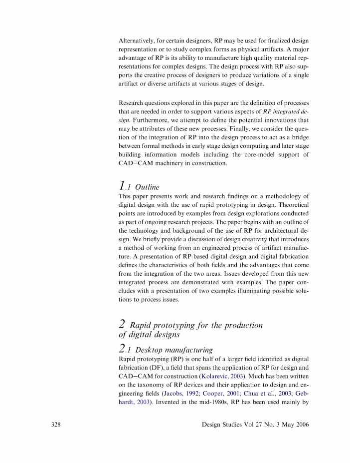
days. There are three common RP devices each of which is a smaller
scale version of machines found in real-world manufacturing environ-
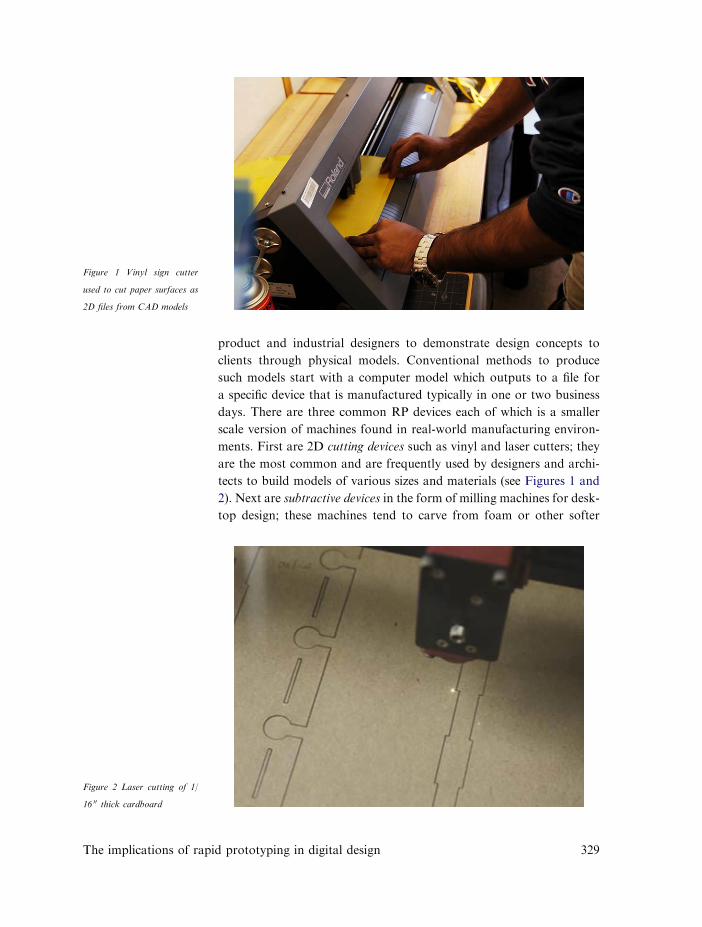
ments. First are 2D cutting devices such as vinyl and laser cutters; they
are the most common and are frequently used by designers and archi-
tects to build models of various sizes and materials (see Figures 1 and
2). Next are subtractive devices in the form of milling machines for desk-
top design; these machines tend to carve from foam or other softer
Figure 1 Vinyl sign cutter
used to cut paper surfaces as
2D files from CAD models
Figure 2 Laser cutting of 1/
16 00 thick cardboard
The implications of rapid prototyping in digital design 329
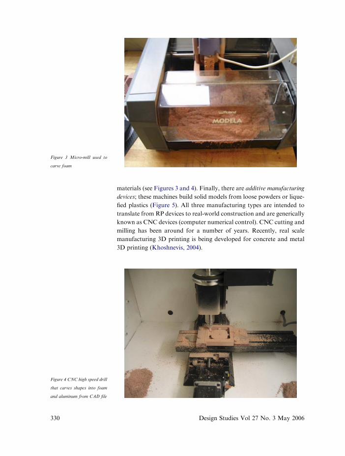
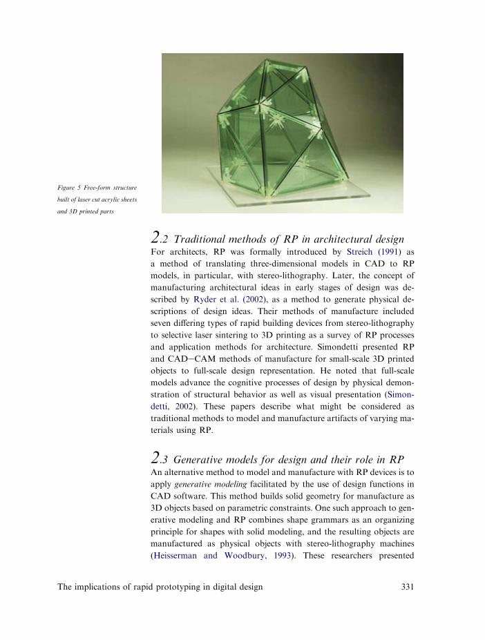
materials (see Figures 3 and 4). Finally, there are additive manufacturing
devices; these machines build solid models from loose powders or lique-
fied plastics (Figure 5). All three manufacturing types are intended to
translate from RP devices to real-world construction and are generically
known as CNC devices (computer numerical control). CNC cutting and
milling has been around for a number of years. Recently, real scale
manufacturing 3D printing is being developed for concrete and metal
3D printing (Khoshnevis, 2004).
Figure 3 Micro-mill used to
carve foam
Figure 4 CNC high speed drill
that carves shapes into foam
and aluminum from CAD file
330 Design Studies Vol 27 No. 3 May 2006
2.2 Traditional methods of RP in architectural designFor architects, RP was formally introduced by Streich (1991) as
a method of translating three-dimensional models in CAD to RP
models, in particular, with stereo-lithography. Later, the concept of
manufacturing architectural ideas in early stages of design was de-
scribed by Ryder et al. (2002), as a method to generate physical de-
scriptions of design ideas. Their methods of manufacture included
seven differing types of rapid building devices from stereo-lithography
to selective laser sintering to 3D printing as a survey of RP processes
and application methods for architecture. Simondetti presented RP
and CADeCAM methods of manufacture for small-scale 3D printed
objects to full-scale design representation. He noted that full-scale
models advance the cognitive processes of design by physical demon-
stration of structural behavior as well as visual presentation (Simon-
detti, 2002). These papers describe what might be considered as
traditional methods to model and manufacture artifacts of varying ma-
terials using RP.
2.3 Generative models for design and their role in RPAn alternative method to model and manufacture with RP devices is to
apply generative modeling facilitated by the use of design functions in
CAD software. This method builds solid geometry for manufacture as
3D objects based on parametric constraints. One such approach to gen-
erative modeling and RP combines shape grammars as an organizing
principle for shapes with solid modeling, and the resulting objects are
manufactured as physical objects with stereo-lithography machines
(Heisserman and Woodbury, 1993). These researchers presented
Figure 5 Free-form structure
built of laser cut acrylic sheets
and 3D printed parts
The implications of rapid prototyping in digital design 331
332
a grammar interpreter that generated robust designs for manufacturing.
A second generative technique also investigated a method to apply
shape grammars as an organizing principle and solid modeling to gener-
ate early design phase models (Wang and Duartes, 2002). They present
a computer program that generates shapes based on design constraints.
In their approach, shapes generated as solid models were manufactured
with FDM 3D print techniques.
In general, generative methods to model and manufacture designs with
RP are an effective basis to address issues of production speed and rede-
sign time. Two practical shortcomings of generative methods are the
technical limitations of access to solid modeling functions when pro-
gramming within existing CAD programs. Also, the two generative
methods presented above generated shape models without architectural
features (windows, doors, etc.). This work indicates that with respect to
advancing the integration of generative approaches and RP modeling in
design, high-level programming skills are required for the production of
sophisticated and highly detailed designs.
2.4 Generative models for constructionThere are other methods to use RPmodels in design to generate 1:1 scale
objects with CAD scripting and programming for real-world construc-
tion. Currently, there exist downstream methods to generate geometry
for manufacturing of the final components or formwork for real scale
manufacturing. First, professional CADeCAM software companies
such as Tekala and CATIA offer predetermined forms for steel connec-
tions and analysis. Second, there exist simpler methods to generate fric-
tion fit key joints in CAD that join sheet metal edges in any
configuration (Kilian, 2003). This program creates key joinery for two
or more planar sheets of heavy gauge sheet metal, the parts of which
are processed by water jet cutting. A third example of a downstream
process was introduced as a rule-based computer program used to fab-
ricate lightweight sheet metal for casings for electronic devices (Soman
et al., 2003). Rules within the program are based on metal material and
assembly properties. The program contains rules for notching, bending
and punching sheets of metal. While real-world computational methods
are fast to generate, actual machine manufacturing of real-world mate-
rials for complex objects and geometries is still time consuming and
complex. RP methods aid conventional modeling and manufacture
methods by reduction of time wasted in the manufacturing of
simulations.
Design Studies Vol 27 No. 3 May 2006
The implications of rap
2.5 Complexity, quality and timeOne additional asset of digital fabrication is the quality of its output.
Models printed in 3D or production with laser cutting technologies sup-
port high levels of accuracy, and there is no mistaking the high quality of
the artifacts produced by current rapid prototyping devices. For exam-
ple, 3D prints of Palladian villa models demonstrate many levels of de-
tail down to leaves and scrolls on column capitols (Sass, 2003). For
assemblies, the precision of digital fabrication allows for glue less/fric-
tion fit connections between parts, thus speeding up assembly time
(see Figure 5).
Associated with any means of manufacturing are issues of time required
to generate usable schemes in CAD and manufacture parts. For RP
technologies, the construction of computer models and manufacturing
time are currently far more extensive than those required in hand draw-
ing or hand model making. The trade-off for designers is quality against
time, and these technologies should therefore be selectively applied in
appropriate design situations.
3 Digital design and digital fabrication
3.1 Digital designThe term, digital design, has taken on various meanings and definitions.
Frequently the term has, in architecture, been associated with the repre-
sentation and manipulation of complex form and space. However, the
idea of unique processes of digital design, as differentiated from tradi-
tional paper-based design, most significantly implies a self-contained
way of designing exclusively within a computational environment.
How then does RP fit into, and integrate with, other classes of activities,
operations, facilities, knowledge and reasoning that together form com-
putational design environments?
Digital design as a method can be generically described as a constructed
relationship between information and forms of representation that sup-
port design in computational environments. As we have seen this may,
or may not, also include data regarding materialization and, even, con-
struction data. Alternative methods of digital design are distinguished
by their task specificity or by their comprehensiveness in a ‘core-model’
approach. For example, in construction-level design and representation
it is common to find wire-frame renderings used to describe the compo-
nents and workings of complex constructions. Parametric modeling pro-
grams such as CATIA can provide data and representations of design
id prototyping in digital design 333
projects as descriptions of the inner workings of the building’s construc-
tion system.
It is clear that current definitions of digital design still differentiate be-
tween design environments and building information/construction
data environments. Concepts of RP andDF tend to reduce these distinc-
tions in digital design, to emphasize the continuities and continuousness
of design, materialization and construction.
3.2 Advantages of digital fabricationDigital fabrication for designers offers realistic opportunities for shape
representation, evaluation and redesign of complex design initiatives.
One asset worth noting is that digital fabrication extends learning in
a digital design environment by engaging the designer with materials
and machine processes similar to those used in construction. It may
also be said that the use of these appliances and software extends crea-
tive design beyond the early stages of design and supports the continuity
of design through its various stages. Not only is this an advantage in de-
sign, design materialization also has certain didactic advantages that
support the acquisition of knowledge and the learning of design proce-
dural structures (Oxman, 1999, 2003).
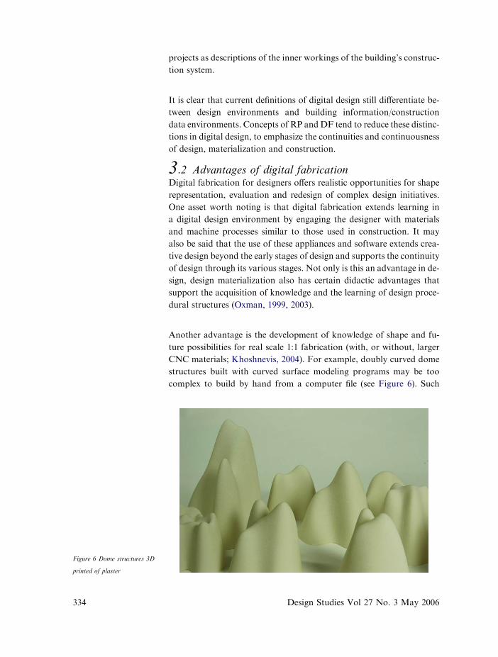
Another advantage is the development of knowledge of shape and fu-
ture possibilities for real scale 1:1 fabrication (with, or without, larger
CNC materials; Khoshnevis, 2004). For example, doubly curved dome
structures built with curved surface modeling programs may be too
complex to build by hand from a computer file (see Figure 6). Such
Figure 6 Dome structures 3D
printed of plaster
334 Design Studies Vol 27 No. 3 May 2006

shapes, though too complex to visualize by rendering and animation
alone, are manufactured with ease using 3D build technologies. Digital
fabrication also offers the possibility for study and invention of new con-
struction systems for the support of complex design forms such as devel-
opable curves typically used by Gehry Partners (see Figure 7). Other
aspects of innovative designs such as the building’s assembly method
can be tested and evaluated beyond dependence upon imagery. The as-
sembly design process engages aspects of manufacturing early in the de-
sign process and supports constructive aspects of learning, as well. The
illustrated examples support a design method of learning by trial and re-
design. The advantage for design computing is that in such approaches
knowledge can be represented in the form of parametric constraints and
associative modeling that support processes of design change and
remodeling.
3.3 Design learning in digital fabricationA major characteristic of DF is the enhancement through materializa-
tion of the concept of learning by doing. An important attribute of
learning in design is acquisition of processes of redescription or redesign
based on acquired knowledge from a previously described artifact
(Oxman, 1999, 2003). Here, DF contributes new dimensions to design
learning.
Digital fabrication for RP and CADeCAM fabrication is a relationship
between modeled geometries and material properties. Critical links
between CADeCAM and RP are machine processes and materials
Figure 7 Model built of devel-
opable surfaces where each
side is curved in one direction.
Built in CAD manufactured
using the vinyl sign cutter,
flat shapes are glued together
to build the object
The implications of rapid prototyping in digital design 335
336
selection and design. Materialization as a way of designing fulfills
Lesgold’s presentation of learning by doing, which he defines as an
opportunity to manage the full domain or real life experiences through
activity-based learning. He argues that it is necessary to combine rules
with conceptually based activity as a means to prepare people for
real-world experiences (Lesgold and Nahemow, 2001).
The connection to materials for either design or construction quickly
builds skill sets for rule-based design from the relationship between ma-
terials, modeled geometry and machinery. The characteristics of work-
ing with a particular material with RP machinery link cognitive design
skills to modeling geometries. For example, plywood is embedded
with geometric rules based on the limits of a flat sheet of stock material.
Geometries are constructed in CAD as planar geometries and then
translated into a model for laser cutting or CNC cutting with a flat
bed wood router. If generative methods are used, rules for plywood
are based on rules for the manipulation of flat sheet stock. Laser cutting
cardboard flat stock material acts the same as the cutting of plywood; in
essence the rules of the material are the same. For design evaluation, the
only difference is that sheet material can be cut and assembled more rap-
idly using laser cut technology.
3.4 Digital design fabricationThe integration of digital design and digital fabrication extends many
opportunities to design constructible solutions at many levels of com-
plexity. Current methods to design and construct buildings using com-
puters tend to fall into two categories depending upon the emphasis
on either design visualization simulation or construction information.
On one side is the production of imagery and animations to describe de-
signed objects and their performance. On the other side is product infor-
mation modeling where CADmodels are generated to explain and guide
physical construction. An inherent characteristic of this approach con-
siders construction as a function in the design process and not the result.
Digital Design Fabrication (DDF) is computer modeling applied to the
design process from early stage design, including materialization and up
to, but not generally including, detailed project information modeling.
DDF represents building information as material and product models.
However, these models are designed to support constant and significant
degrees of change based on visual and performative evaluation. DDF
in its ultimate sense is a materialized, parametric, and an interactive
design.
Design Studies Vol 27 No. 3 May 2006
The implications of r
4 Digital design fabrication (DDF): towarda method for integrating RP in designThe emphasis of this paper is on defining and developing methods of
working with RP in continuous processes of design conceptualization,
materialization, and fabrication design. This approach to a continuous
integration of RP in digital design processes is seen as differentiated
from discrete procedural stages of design computing, fabrication and
product information modeling.
4.1 Procedural methods of product designas a model for DDFThe process of product modeling may be closer in nature to the contin-
uous materialization methods of digital design proposed in this paper
than are conventional design methods. The procedural methods of
product design include the process of model making where designers
manufacture many artifacts (computer and hand) for evaluation. The
models are also managed for other issues beyond appearance, including
production.
The product design process includes a review of many aspects of a prod-
uct from design analysis to design synthesis and evaluation (Pahl and
Beitz, 1988). Designs are studied to find and solve general problems as
well as localized problems by isolating the product’s function followed
by a process of reasoning to solve product problems (Cross, 2000).
For a cogent review of the product design relative to managerial meth-
ods, Smith and Morrow offer insight into the background and methods.
Most important for our work, they define a clear distinction between ar-
chitectural and product design. They note that engineering models are
frequently designed as linear processes, while architectural process mod-
els are ill-structured leading to a process that is built mostly on cognition
and perception (Smith and Morrow, 1999). Rapid prototyping is be-
coming a major facilitator of design production for product designers.
Typically used to view products at all phases of the process, rapid pro-
totyping can be used to demonstrate a product’s functional and ergo-
nomic makeup. In the analogy to product design, architectural
exploitation of DF must include systematic ways of working that with
flexibility in order to accommodate the ill-structured nature of architec-
tural problems.
4.2 CADeCAM and implications for DDFCurrent architectural construction has seen a rise in CADeCAM ma-
chinery for fabrication as an intermediary between design concepts
apid prototyping in digital design 337
338
and real-world construction. Over the past decade, the design profession
has witnessed many methods to construct designs using digital fabrica-
tion at the level of real manufacturing (Matsushima, 2004). Particularly
common is large CADeCAM machinery used to bend and cut metals
from CAD files in the form of G-Code. The CADeCAM building fab-
rication process may be considered as a way of building; it is also a way
of thinking about construction through the interaction with machinery.
Shortcomings of CADeCAM as a method for teaching and learning are
that the first time CAD files are materialized physically is typically the
final time they are fabricated. Most materials created in this way are
full scale, 1:1 models typically manufactured of nonrecyclable materials
such as dense foam or fiberboards. Also CADeCAMmachinery is large
and very complex requiring physical space and very skilled labor to run
machines.
4.3 The potential of DDF as a design methodfor integrated and continuous materializationA goal of the process is the production of effective technical artifacts
with a variety of functions. A technical artifact is described as an object
with a technical function of a physical structure designed and made
through conscious production (Kroes, 2002). Kroes states that the na-
ture of design must consider the method used to generate these artifacts.
Within the method are also issues of design process and design product.
A sketch on paper works as a technical artifact with functions such as
the construct of space or 2D diagramming for orientation. Alternative-
ly, rapid prototyping produces very technical artifacts whose functions
can determine a building’s form, internal spaces, construction methods
and materials. Digital design as a process generates a variety of technical
artifacts for visual evaluation, typically in the form of a 2D presentation
(computer renderings and 3D computer models). Fabrication external-
izes technical artifacts for physical as well as visual evaluation. An effec-
tive design process can use RP technology for structural models, shape
and formal models, interior models, etc.
The field of DDF is attempting to achieve a synthesis of the design flex-
ibility of conventional paper-based design, the precision and modeling
capability of digital design, and the knowledge construction information
models. The intention is to develop an environment to support design
through the interaction with physical artifacts production that is charac-
terized by both the flexibility of sketching and the precision and data
handling capacity of product description environments. Materialization
environments for design have these two poles of behavior that are
Design Studies Vol 27 No. 3 May 2006
The implications o
potentially contradictory: flexibility in support of the design process ver-
sus exactitude and detailing capacity characteristic of CADeCAM
modeling packages.
5 The DDF (Digital Design Fabrication) modelof designIn this paper we introduce the DDF (Digital Design Fabrication) method.
The DDF method is a two-stage process of working that integrates gen-
erative computing and RP into one process. Together they support
a process to generate diverse candidate artifacts as solutions to design
problems. DDF models also support physical evaluation of object
form, structure, lighting, etc. versus reasoning from drawings or virtual
imagery. For architectural design, model size is significant. Small-scale
models support formal evaluation, while larger-scale models are needed
to complete spatial evaluation, and even larger-scale models enable
study of detailing. This design scalar sequence is also significant to com-
puting, since different classes of data are required for each scalar level.
Our proposed DDF method combines RP production with automated
generation of design variants. However, many of the findings reported
here regarding the use of RP in design are valid even for conventionally
generated CAD models. The DDF method integrates two automated
functions (generative CAD modeling and model manufacturing) into
one process. The first stage of the process exploits CAD scripting, or
programming, to generate various parametric details in 3D from desig-
nated variables. The second stage manufactures the generated objects
using RP. Together, these two processes produce a candidate family
of models capable of being built at a high level of detail. This approach
is different from the conventional design process in which a single arti-
fact is usually produced, evaluated, modified and reconstructed. In ad-
dition to these design methodological attributes, the integration of the
two processes also offers many possibilities for working with digital de-
sign forms of varying levels of complexity. DDF generates design solu-
tions with an emphasis, even in early stages of design, upon structure
and construction. The combination of the two processes supports new
opportunities for design conceived of as a continuous integrated process
of conceptualization, materialization, fabrication, and construction.
5.1 Artifact characteristicsThe DDF process produces two model types, design models as a single
object and design information models built of components constrained
f rapid prototyping in digital design 339

by real-world construction methods. For example, early stage design
models are generated as surfaces, or objects, in CAD manufactured
with very fast RP devices. These small models (less than 10 00 square)
are evaluated for shape, less for internal space, or assemblies (see
Figure 8a). They typically do not reflect materials behavior, or construc-
tion methods. In the second type, design information models are robust
assemblies containing varying levels of detailed design, or construction,
information (see Figure 8b and c). In our work, we have experimented
with these models as rule-based models constrained by material proper-
ties and requiring high levels of model detailing and information input.
Models of this type can be built of solid-modeled parametrically based
components combined with solid objects of fixed geometries. Design in-
formation models are an abstract way to model building products as
design products (Eastman, 1999). This may introduce certain complica-
tions in model generation and manufacturing in that models at the level
of design information modelsmay be physically built of two or more ma-
terials (see Figure 8b) and generally physically large in size (greater than
10 00 square). These models offer opportunities for design evaluation of
construction processes, details, and building assemblies as well as inter-
nal spaces and form. Finally, design information models may require
many hours of computer modeling and component manufacture time
thus emphasizing the current need for computationally efficient model-
ing and manufacturing procedures.
Figure 8 Examples of digi-
tally fabricated models at
different scales, (a) model
scale is 1/4 00 ¼ 10-0 00, (b)
model scale 1/2 00 ¼ 10-0 00 and
(c) model scale 1 00 ¼e 10-0 00
340 Design Studies Vol 27 No. 3 May 2006
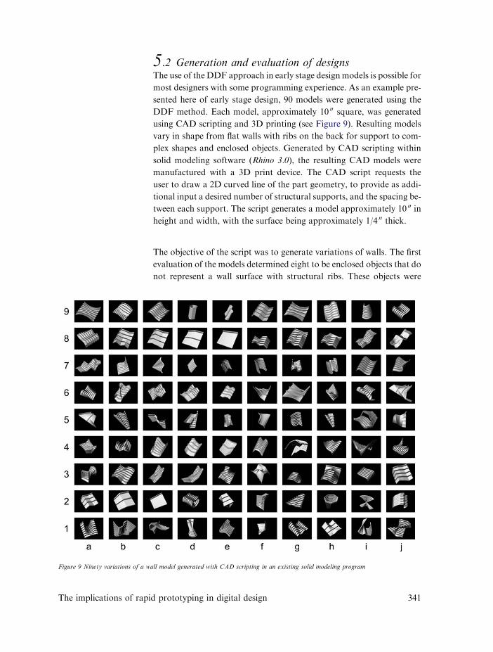
5.2 Generation and evaluation of designsThe use of the DDF approach in early stage design models is possible for
most designers with some programming experience. As an example pre-
sented here of early stage design, 90 models were generated using the
DDF method. Each model, approximately 10 00 square, was generated
using CAD scripting and 3D printing (see Figure 9). Resulting models
vary in shape from flat walls with ribs on the back for support to com-
plex shapes and enclosed objects. Generated by CAD scripting within
solid modeling software (Rhino 3.0), the resulting CAD models were
manufactured with a 3D print device. The CAD script requests the
user to draw a 2D curved line of the part geometry, to provide as addi-
tional input a desired number of structural supports, and the spacing be-
tween each support. The script generates a model approximately 10 00 in
height and width, with the surface being approximately 1/4 00 thick.
The objective of the script was to generate variations of walls. The first
evaluation of the models determined eight to be enclosed objects that do
not represent a wall surface with structural ribs. These objects were
Figure 9 Ninety variations of a wall model generated with CAD scripting in an existing solid modeling program
The implications of rapid prototyping in digital design 341

eliminated from the corpus of candidates. Of the remaining 82 models,
only 10 were printable in 3D of which only six remained in one piece
when removed from the 3D print device (see Figure 10). Physical man-
ufacture of CAD models eliminated even more designs. Thin walled
structures that collapsed or design models where structural ribs inter-
sected wall surfaces physically were also eliminated. As a result, design
constraints were narrowed and altered in the scripting process itself. The
next generation of models resulted in stronger models of diverse and in-
teresting flat shapes.
6 Generating information models for designAn advantage of DDF is its ability to produce designs as intermediary
artifacts between conceptual design modeling and building information
modeling (BIM). Building information models focus on full-scale repre-
sentation without supporting extensive change in model geometry. BIM
models allow for some limited degree of design change. The goal of the
method is to record information for construction from data to 3D mod-
eled information. Design information models (DIM) are defined here as
RP artifacts built of components and assemblies of many scale represen-
tations within the design process (see Figure 8aec). These types of models
are most relevant within the design process after schematics and before
BIM. Design information models are the physical representation of de-
sign development including some preliminary levels of construction
documentation.
These two phases begin to focus design energy on building construction
as the guiding principles of representation. This phase of the design
Figure 10 3D prints of six
wall surfaces selected from
the 90 variations
342 Design Studies Vol 27 No. 3 May 2006
process generates artifacts that describe the complex relationships be-
tween materials and parts assemblies at varying levels of resolution.
Within this phase, designers set and solve problem at both local and
global levels, including designing details and assemblies. For drawing
and model making within the design development phase, problems are
traditionally studied at scales from 1/4 00 ¼ 10-0 00 to 6 00 ¼ 10-0 00. Since
architectural design produces unique solutions, management of an ill-
structure process with many components at many scales over the life-
time of one design project is a challenging problem of design efficiency.
With respect to such problems of design process, DDF offers great po-
tential for intermediary design. It is inspired by product modeling of
building components where most components and assemblies are repre-
sented in 3D (Eastman, 1999) and these procedural characteristics are
becoming most significant to the architectural design process.
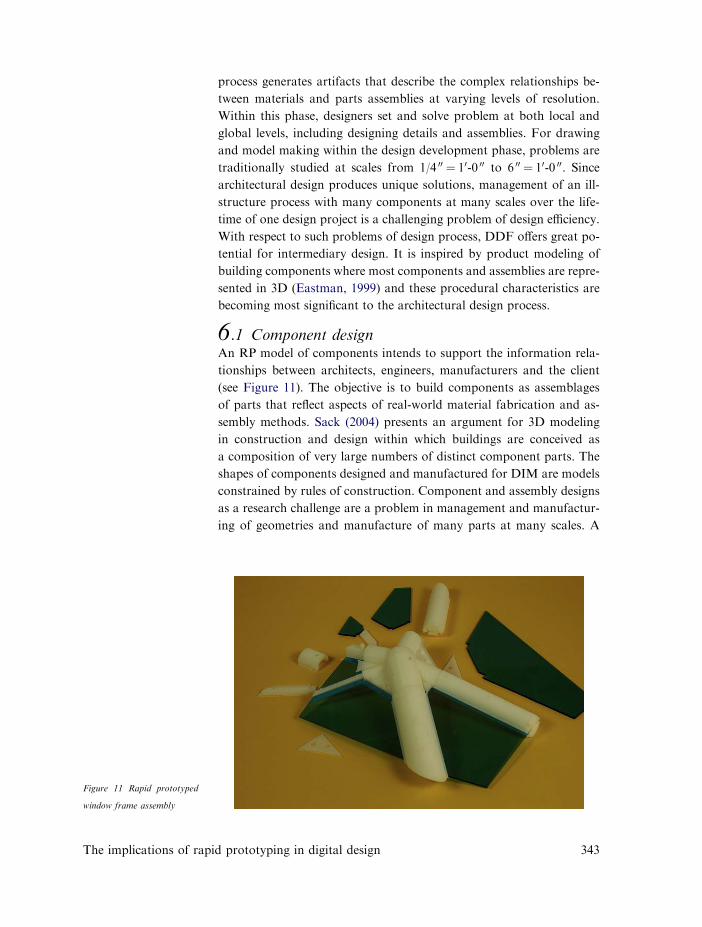
6.1 Component designAn RP model of components intends to support the information rela-
tionships between architects, engineers, manufacturers and the client
(see Figure 11). The objective is to build components as assemblages
of parts that reflect aspects of real-world material fabrication and as-
sembly methods. Sack (2004) presents an argument for 3D modeling
in construction and design within which buildings are conceived as
a composition of very large numbers of distinct component parts. The
shapes of components designed and manufactured for DIM are models
constrained by rules of construction. Component and assembly designs
as a research challenge are a problem in management and manufactur-
ing of geometries and manufacture of many parts at many scales. A
Figure 11 Rapid prototyped
window frame assembly
The implications of rapid prototyping in digital design 343
management format for DIM looks similar to building product design
in which the method manages real scale building construction as mod-
eled objects and associated data.
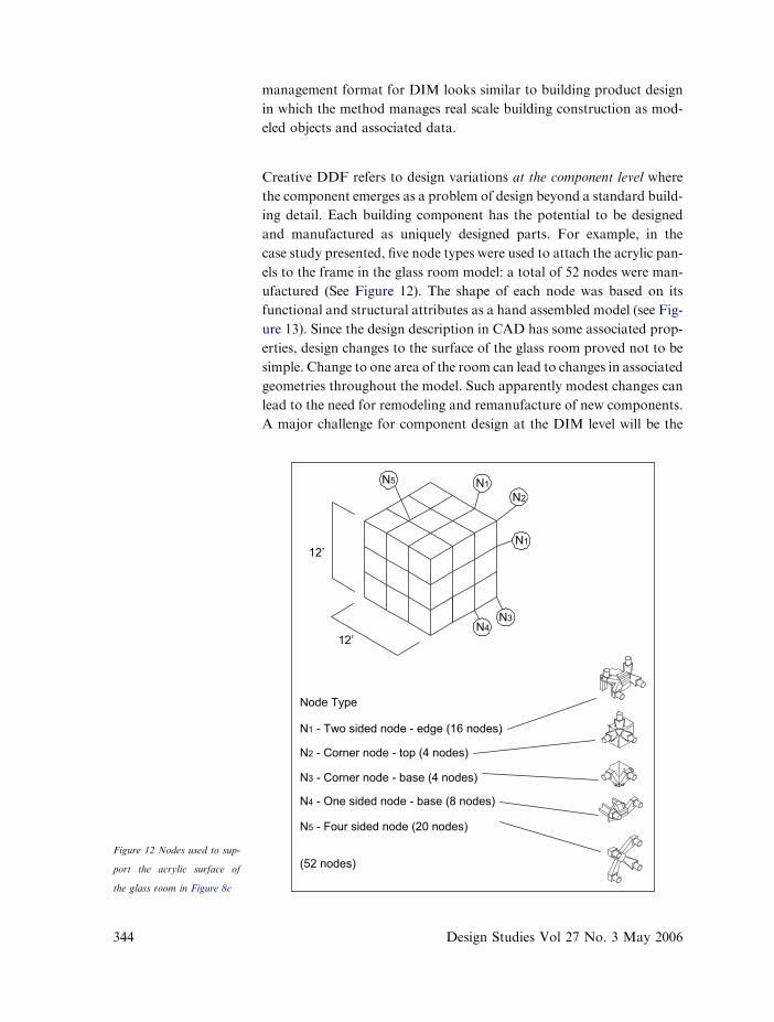
Creative DDF refers to design variations at the component level where
the component emerges as a problem of design beyond a standard build-
ing detail. Each building component has the potential to be designed
and manufactured as uniquely designed parts. For example, in the
case study presented, five node types were used to attach the acrylic pan-
els to the frame in the glass room model: a total of 52 nodes were man-
ufactured (See Figure 12). The shape of each node was based on its
functional and structural attributes as a hand assembled model (see Fig-
ure 13). Since the design description in CAD has some associated prop-
erties, design changes to the surface of the glass room proved not to be
simple. Change to one area of the room can lead to changes in associated
geometries throughout the model. Such apparently modest changes can
lead to the need for remodeling and remanufacture of new components.
A major challenge for component design at the DIM level will be the
N1
N3N4
N2N1N5
12’
12’
Node Type
N1 - Two sided node - edge (16 nodes)
N2 - Corner node - top (4 nodes)
N3 - Corner node - base (4 nodes)
N4 - One sided node - base (8 nodes)
N5 - Four sided node (20 nodes)
(52 nodes)Figure 12 Nodes used to sup-
port the acrylic surface of
the glass room in Figure 8c
344 Design Studies Vol 27 No. 3 May 2006

management of assembly parts and associated parts that can lead to
constructible solutions.
6.2 Assembly descriptionsA benefit of working with RP for assemblies is the emergence of new de-
sign languages at the assembly level. New assembly methods emerge
from failures in testing. Assembly descriptions are parametric objects
with physical and visual constraints. Although components produced
here with RP are physically small, a goal for DDF has been to build as-
sembly descriptions based on real-world construction. As with real-
world descriptions an assembly description is judged for connection
strength, manufacturing methods, and appearance. For DDF, compo-
nents are evaluated physically by hand testing (see Figure 14).
Figure 13 Rapid prototyped
node used to connect glass
room model
Figure 14 Assembly testing of
3D printed bricks
The implications of rapid prototyping in digital design 345

346
Assemblies are a systematic substructure of design whose emergence can
lead to new design possibilities at the shape level as well as at perfor-
mance and assembly levels. At the technical level assembly design for
DIM gives new meaning to systematic ways of thinking for generative
computer modeling. Generated components need to contain assembly
features between parts. Geometries are designed and produced as con-
jectures, tested in relationship to building scale constraints as indivi-
dually produced objects, then as a complete assembly of objects
(Boothroyd and Dewhurst, 1989). For DIM models, assembly design
is a bottom up approach to design engineering based on the relationship
between real-world construction and abstract representation.
6.3 Scales of DDFScaling refers to measured ratios of representation between real-world
construction (1:1) and DIM models of varying scales (1:2, 1:4, 1:8,
etc.) (see Figure 8). Before rapid prototyping and CADeCAM were in-
troduced to architecture, there was little need for concern with issues of
scale in computer modeling. The DDF process calls for modeling as it
relates to a physical material representation and meaning that materials
are modeled with specific material constraints. For the field of digital
fabrication, there are twomajor scales of representation: CNC and rapid
prototyping. Of the two types, DIM modeling relates to RP and BIM
modeling relates to CNC processing. The complexity is that DIM mod-
els come in many scales of representation relative to real model making
materials properties. A DIM model manufactured of 0.2 inches sheet
material is not modeled in the same way as models built of 0.5 inches
material. In order to reduce the need to remodel for each scale, ideally
sheet material at the RP level can scale to sheet material at the CNC lev-
el. For example, 3/4 00 plywood sheet construction can be simulated at
the rapid prototyping level with 1/16 00 cardboard. A geometric model
built of a 4 00 � 8 00 � 1/16 00 rectangular sheet scales to a 40 � 80 � 3/4 00
sheet when scaled by a multiple of 12.
6.4 Manufacturing descriptionsCreating design for one project and the generation of many design arti-
facts at many scales including remodeling based on demands in design
evolution are very complex problems. Effective creative design is also
based on the production of artifacts and workflow.Manufacturing tech-
niques for generating machine descriptions and machining methods
can define effective workflows. New functions are needed in computer
programs to generate design and fabrication descriptions in two
and three dimensions. For example, laser cut models require descrip-
tions in the form of 2D shapes from 3D models. Generation of
Design Studies Vol 27 No. 3 May 2006

a machine description from a design description is a three-stage process:
(a) a design description is typically prepared as a 3D model; (b) second,
amaterials description is applied in order to build geometry and assemblies;
and (c) finally, machine descriptions are developed (see Figures 15 and 16).
a b
c
Figure 15 Three geometric de-
scriptions in CAD: (a) the
design shape, (b) materials
descriptions (1/16 00 acrylic
sheets) and (c) machine de-
scription (laser cutter)
Figure 16 Final assembled
model of 1/16 00 laser cut
acrylic sheets
The implications of rapid prototyping in digital design 347
Success in this method of working in which files are translated from 3D
solid models to 2D machine language is in the translation from a design
description to a machine description.
7 Digital design fabrication schemasThe following two models are simplistic examples that demonstrate the
technical process used to translate surface models built in CAD to man-
ufacture descriptions and physical assembly. Both cases present schemas
for design automation incorporating generative methods in CAD with
RP devices. These schemas demonstrate how to manufacture one arti-
fact at one scale as part of a design process. The generation method
for shape of the original surface model is less important here, and it
can be generated parametrically, or with generative software. The focus
of the two schemas is on the definition of a process that collapses the
space between digital information and physical objects.
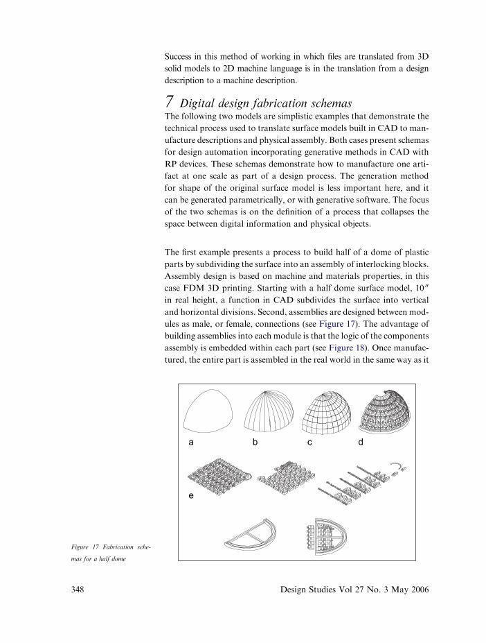
The first example presents a process to build half of a dome of plastic
parts by subdividing the surface into an assembly of interlocking blocks.
Assembly design is based on machine and materials properties, in this
case FDM 3D printing. Starting with a half dome surface model, 10 00
in real height, a function in CAD subdivides the surface into vertical
and horizontal divisions. Second, assemblies are designed between mod-
ules as male, or female, connections (see Figure 17). The advantage of
building assemblies into each module is that the logic of the components
assembly is embedded within each part (see Figure 18). Once manufac-
tured, the entire part is assembled in the real world in the same way as it
a
e
b c d
Figure 17 Fabrication sche-
mas for a half dome
348 Design Studies Vol 27 No. 3 May 2006
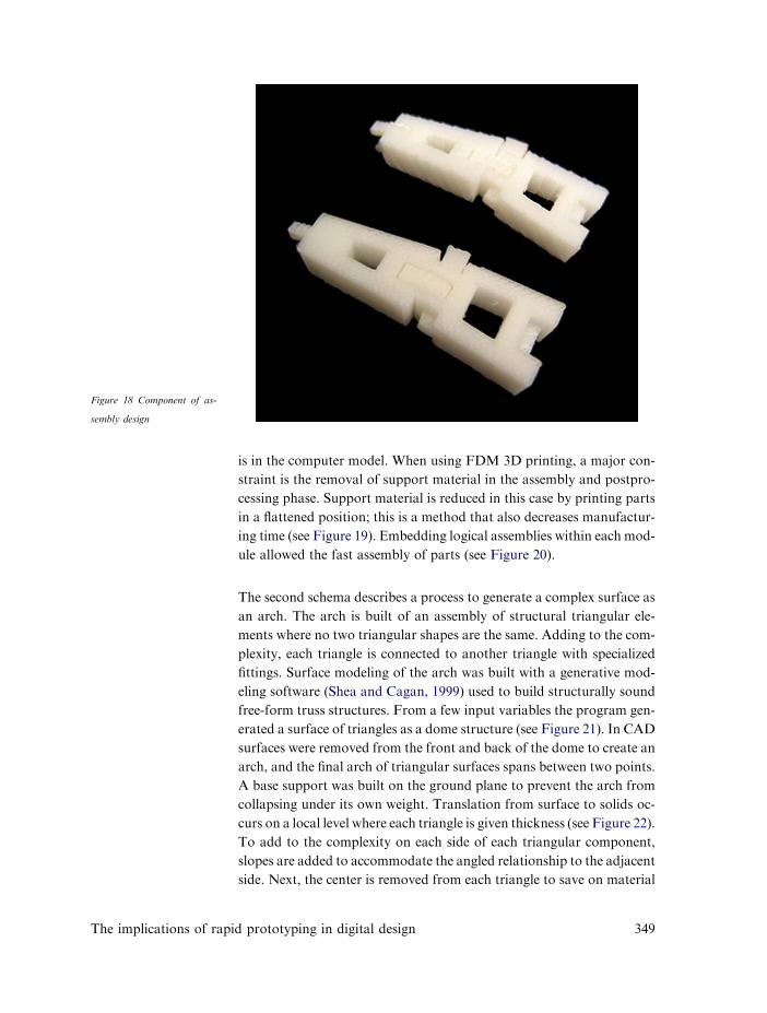
is in the computer model. When using FDM 3D printing, a major con-
straint is the removal of support material in the assembly and postpro-
cessing phase. Support material is reduced in this case by printing parts
in a flattened position; this is a method that also decreases manufactur-
ing time (see Figure 19). Embedding logical assemblies within each mod-
ule allowed the fast assembly of parts (see Figure 20).
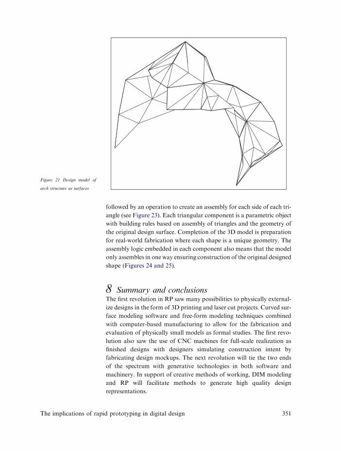
The second schema describes a process to generate a complex surface as
an arch. The arch is built of an assembly of structural triangular ele-
ments where no two triangular shapes are the same. Adding to the com-
plexity, each triangle is connected to another triangle with specialized
fittings. Surface modeling of the arch was built with a generative mod-
eling software (Shea and Cagan, 1999) used to build structurally sound
free-form truss structures. From a few input variables the program gen-
erated a surface of triangles as a dome structure (see Figure 21). In CAD
surfaces were removed from the front and back of the dome to create an
arch, and the final arch of triangular surfaces spans between two points.
A base support was built on the ground plane to prevent the arch from
collapsing under its own weight. Translation from surface to solids oc-
curs on a local level where each triangle is given thickness (see Figure 22).
To add to the complexity on each side of each triangular component,
slopes are added to accommodate the angled relationship to the adjacent
side. Next, the center is removed from each triangle to save on material
Figure 18 Component of as-
sembly design
The implications of rapid prototyping in digital design 349
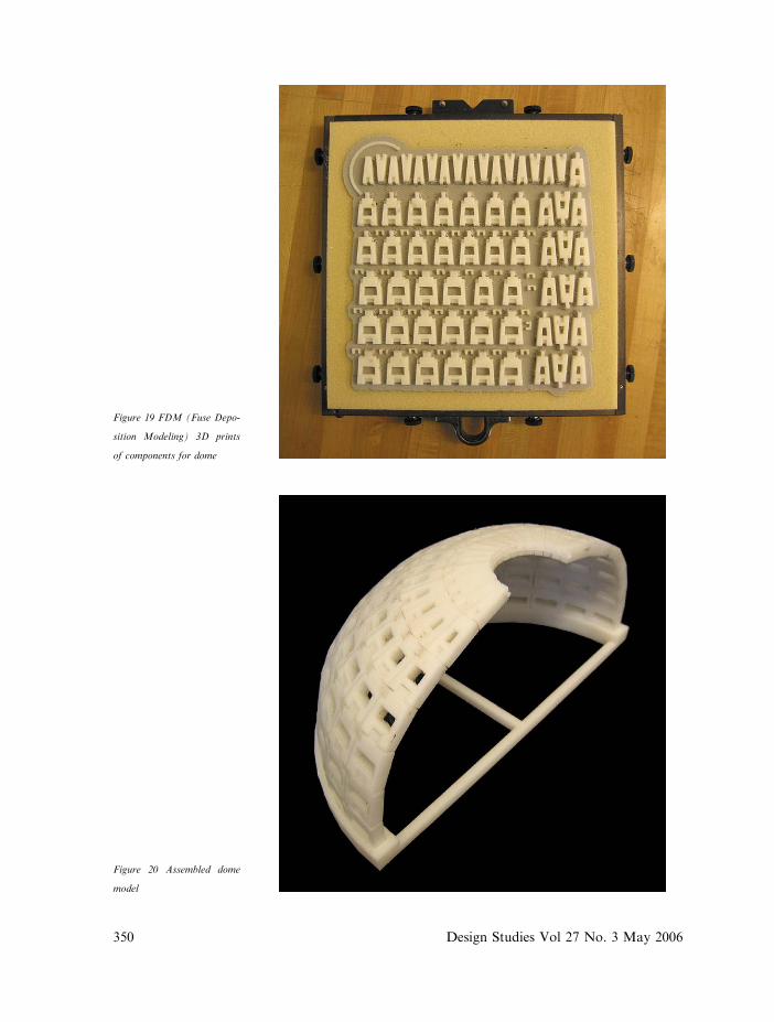
Figure 20 Assembled dome
model
Figure 19 FDM (Fuse Depo-
sition Modeling) 3D prints
of components for dome
350 Design Studies Vol 27 No. 3 May 2006
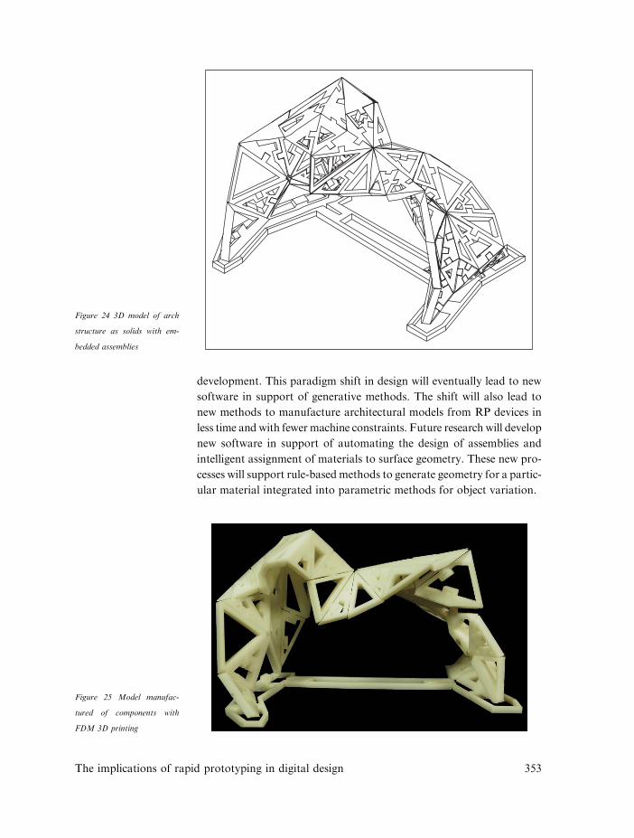
followed by an operation to create an assembly for each side of each tri-
angle (see Figure 23). Each triangular component is a parametric object
with building rules based on assembly of triangles and the geometry of
the original design surface. Completion of the 3D model is preparation
for real-world fabrication where each shape is a unique geometry. The
assembly logic embedded in each component also means that the model
only assembles in one way ensuring construction of the original designed
shape (Figures 24 and 25).
8 Summary and conclusionsThe first revolution in RP saw many possibilities to physically external-
ize designs in the form of 3D printing and laser cut projects. Curved sur-
face modeling software and free-form modeling techniques combined
with computer-based manufacturing to allow for the fabrication and
evaluation of physically small models as formal studies. The first revo-
lution also saw the use of CNC machines for full-scale realization as
finished designs with designers simulating construction intent by
fabricating design mockups. The next revolution will tie the two ends
of the spectrum with generative technologies in both software and
machinery. In support of creative methods of working, DIM modeling
and RP will facilitate methods to generate high quality design
representations.
Figure 21 Design model of
arch structure as surfaces
The implications of rapid prototyping in digital design 351

This paper presents conceptual aspects of digital design fabrication
(DDF) as an integrated, continuous design process supporting concep-
tualization, materialization, fabrication and construction information.
For architects, the issue of scaling and ill-structured problems makes
the idea of a structured method of design harder to solve. Digital design
fabrication is presented as a structured means to physically externalize
these complexities of architectural design within a digital design
environment.
The future of digital design fabrication will integrate design models with
finalized solution models (BIM) allowing a process that supports the full
spectrum of digital design as a paperless process. In support of an effi-
cient design process, both software and RP devices will need further
Figure 22 Solid model of arch
structure from surfaces
Figure 23 Schemas for sur-
face translations for each tri-
angle to constructible solid
model with embedded
assemblies
352 Design Studies Vol 27 No. 3 May 2006
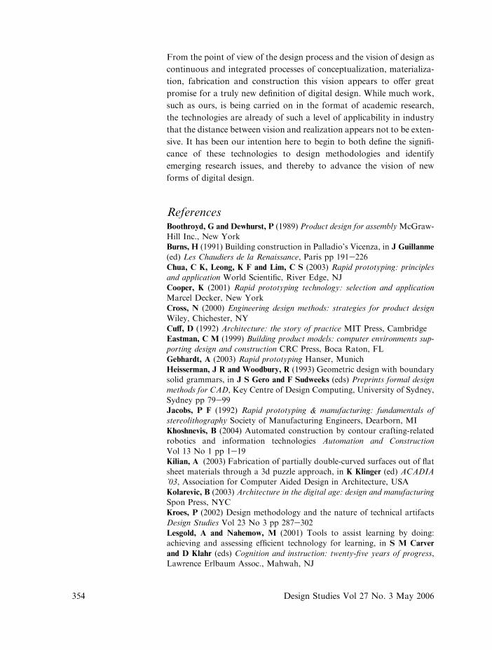
development. This paradigm shift in design will eventually lead to new
software in support of generative methods. The shift will also lead to
new methods to manufacture architectural models from RP devices in
less time and with fewer machine constraints. Future research will develop
new software in support of automating the design of assemblies and
intelligent assignment of materials to surface geometry. These new pro-
cesses will support rule-basedmethods to generate geometry for a partic-
ular material integrated into parametric methods for object variation.
Figure 24 3D model of arch
structure as solids with em-
bedded assemblies
Figure 25 Model manufac-
tured of components with
FDM 3D printing
The implications of rapid prototyping in digital design 353
354
From the point of view of the design process and the vision of design as
continuous and integrated processes of conceptualization, materializa-
tion, fabrication and construction this vision appears to offer great
promise for a truly new definition of digital design. While much work,
such as ours, is being carried on in the format of academic research,
the technologies are already of such a level of applicability in industry
that the distance between vision and realization appears not to be exten-
sive. It has been our intention here to begin to both define the signifi-
cance of these technologies to design methodologies and identify
emerging research issues, and thereby to advance the vision of new
forms of digital design.
ReferencesBoothroyd, G and Dewhurst, P (1989) Product design for assemblyMcGraw-Hill Inc., New YorkBurns, H (1991) Building construction in Palladio’s Vicenza, in J Guillanme
(ed) Les Chaudiers de la Renaissance, Paris pp 191e226Chua, C K, Leong, K F and Lim, C S (2003) Rapid prototyping: principlesand application World Scientific, River Edge, NJ
Cooper, K (2001) Rapid prototyping technology: selection and applicationMarcel Decker, New YorkCross, N (2000) Engineering design methods: strategies for product design
Wiley, Chichester, NYCuff, D (1992) Architecture: the story of practice MIT Press, CambridgeEastman, C M (1999) Building product models: computer environments sup-
porting design and construction CRC Press, Boca Raton, FLGebhardt, A (2003) Rapid prototyping Hanser, MunichHeisserman, J R and Woodbury, R (1993) Geometric design with boundarysolid grammars, in J S Gero and F Sudweeks (eds) Preprints formal design
methods for CAD, Key Centre of Design Computing, University of Sydney,Sydney pp 79e99Jacobs, P F (1992) Rapid prototyping & manufacturing: fundamentals of
stereolithography Society of Manufacturing Engineers, Dearborn, MIKhoshnevis, B (2004) Automated construction by contour crafting-relatedrobotics and information technologies Automation and Construction
Vol 13 No 1 pp 1e19Kilian, A (2003) Fabrication of partially double-curved surfaces out of flatsheet materials through a 3d puzzle approach, in K Klinger (ed) ACADIA’03, Association for Computer Aided Design in Architecture, USA
Kolarevic, B (2003) Architecture in the digital age: design and manufacturingSpon Press, NYCKroes, P (2002) Design methodology and the nature of technical artifacts
Design Studies Vol 23 No 3 pp 287e302Lesgold, A and Nahemow, M (2001) Tools to assist learning by doing:achieving and assessing efficient technology for learning, in S M Carver
and D Klahr (eds) Cognition and instruction: twenty-five years of progress,Lawrence Erlbaum Assoc., Mahwah, NJ
Design Studies Vol 27 No. 3 May 2006
The implications of r
Lindsey, B (2001) Digital Gehry: material resistance digital constructionBirkhauser, SwitzerlandMatsushima, S (2004) Technology-mediated process: MIT stata center casestudy, in P Beesley, N Cheng and S Williamson (eds) ACADIA ’04,
Association for Computer Aided Design in Architecture, CanadaMillon, H (1994) The renaissance from Brunelleschi to Michelangelo: the rep-resentation of architecture Thames and Hudson, London
Oxman, R E (1999) Educating the designerly thinker Design Studies Vol 20No 2Oxman, R E (2003) Think-maps: teaching design thinking in design educa-
tion Design Studies Vol 25 No 1 pp 63e91Pahl, G and Beitz, W (1988) Engineering design a systematic approach, inK Wallace (ed), Springer-Verlag, London
Ryder, G, Bill, I, Graham, G, David, H and Bruce, W (2002) Rapid designand manufacture tools in architecture Automation in Construction Vol 11pp 279e290Sack, R (2004) Parametric 3D modeling in building construction with ex-
amples from precast concrete Automation in Construction Vol 13Sass, L (2003) Rule based rapid prototyping of Palladio’s Villas’, in DigitalDesign 21th eCAADe Conference Proceedings, Graz (Austria), 17e20 Sep-
tember pp 649e652Schon, D A (1983) The reflective practitioner: how professional think in ac-tion Basic Books, New York
Shea, K and Cagan, J (1999) The design of novel roof trusses with shapeannealing: assessing the ability of a computational method in aiding struc-tural designers with varying design intent Design Studies Vol 20 pp 3e23
Simondetti, A (2002) Computer generated physical modeling in the earlystages of the design process Automation in Construction Vol 11 pp 303e311Smith, R and Morrow, J (1999) Product development process modelingDesign Studies Vol 20 No 3 pp 237e261Soman, A, Padhye, S and Campbell, M (2003) Toward an automated ap-proach to the design of sheet metal components Artificial Intelligence forEngineering Design, Analysis and Manufacturing Vol 17 No 3 pp 187e204
Streich, B (1991) Creating architecture models by computer-aided proto-typing, in Proceedings of the International Conference for Computer AidedArchitectural Design: Education, Research, Application. July, Swiss Federal
Institute of Technology, Zurich, Friedr. Vieweg and Sohn,VerlagsgesellschaftWang, Y and Duartes, J (2002) Automatic generation of fabrication of de-signs Automation in Construction Vol 11 No 3 pp 291e302
apid prototyping in digital design 355
Related Documents