Material flow and mechanical behaviour of dissimilar AA2024-T3 and AA7075-T6 aluminium alloys friction stir welds A.A.M. da Silva ⇑ , E. Arruti, G. Janeiro, E. Aldanondo, P. Alvarez, A. Echeverria Asociación Centro de Investigación en Tecnologías de Unión LORTEK, Barrio La Granja, s/n, 20240 Ordizia (Guipúzcoa), Spain article info Article history: Received 13 September 2010 Accepted 25 November 2010 Available online 1 December 2010 Keywords: A. Non-ferrous metals and alloys D. Welding F. Microstructure abstract The scope of this investigation is to evaluate the effect of joining parameters on the mechanical proper- ties, microstructural features and material flow of dissimilar aluminium alloys (3 mm-thick AA2024-T3 and AA7075-T6 sheets) joints produced by friction stir welding. Mechanical performance has been inves- tigated in terms of hardness and tensile testing. Material flow using the stop action technique has also been investigated in order to understand the main features of the mixing process. No onion ring forma- tion has been observed; the boundary between both base materials at the stir zone is clearly delineated, i.e., no material mixing is observed. A non-stable rotational flow inside the threads has been identified due to the formation of a cavity on the rear of the pin. Microstructural observation has revealed the devel- opment of a recrystallised fine-grained stir zone, with two different grain sizes resulting from the two different base materials. Ó 2010 Elsevier Ltd. All rights reserved. 1. Introduction Friction stir welding (FSW) is a solid-state joining process whereby no bulk melting of the base material occurs during joining [1]. In comparison to fusion welds there is no evidence of an as cast structure in the join zone, less distortion and residual stresses, no need of cleaning operations of the surface oxide prior to the weld- ing process as well as no presence of defects arising from melting and solidification. The workpieces are joined by means of frictional heating and plastic deformation typically at temperatures below that of the absolute melting temperature of the alloys being joined. This is brought about by the interaction of a non-consumable and rotating tool comprised of a pin and shoulder with the interfacing surfaces that is plunged into until the shoulder makes contact with the top surface of the workpieces and then traversed along the interface between the workpieces. High strength aluminium alloys (2xxx- and 7xxx-series) that are usually employed in the aeronautic industry are normally dif- ficult to fusion weld since dendritic structure is formed in the fu- sion zone when TIG and laser welding are used leading to a drastic reduction of the mechanical behaviour [2]. As a solid-state process, FSW is capable of producing high-quality defect free welds when optimised parameters are used in dissimilar high-strength 2xxx- and 7xxx-series alloys avoiding the severe heating and cool- ing cycles induced during fusion joining [3–9]. An important feature in FSW is the degree of material mixing as well as the microstructure distribution which can have a great ef- fect on the final mechanical behaviour of the joint. A key factor in material mixing is the onion ring formation at the stir zone which has been investigated by Chen and Cui [10,11]. Although this banded structure is the commonly known feature of the stir zone, a clear ring structure can also be absent. According to Sato et al. [12] investigating the microstructural features of dissimilar FSW between 2024 and 7075 aluminium alloys, the heat input plays an important role in material mixing, i.e., high heat inputs have lead to a stir zone with onion ring patterns consisting of 2024 and 7075 bands; while low heat inputs have produced a stir zone clearly divided into 2024 and 7075 regions. Several authors have investigated material flow in different materials using distinct techniques such as the introduction of marker materials [13–16]; stop action [17–19]; microstructural observations [20–23]; computational modelling [24,25] or a com- bination of two or more of these techniques [26–30]. There is a general agreement on the characteristics and basics of material flow in FSW that the majority of this flow occurs through the retreating side and the transport of the plasticized material behind the tool forms the welded joint [31]. The objective of the present study is to investigate the micro- structural features and the mechanical properties of dissimilar FSW joints of AA2024-T3 and AA7075-T6 high-strength Al alloys. Material flow is going to be analysed by the stop action technique focusing on the visualization of the flow pattern. 0261-3069/$ - see front matter Ó 2010 Elsevier Ltd. All rights reserved. doi:10.1016/j.matdes.2010.11.059 ⇑ Corresponding author. Tel.: +34 943882303; fax: +34 943884345. E-mail address: [email protected] (A.A.M. da Silva). Materials and Design 32 (2011) 2021–2027 Contents lists available at ScienceDirect Materials and Design journal homepage: www.elsevier.com/locate/matdes

Welcome message from author
This document is posted to help you gain knowledge. Please leave a comment to let me know what you think about it! Share it to your friends and learn new things together.
Transcript
Materials and Design 32 (2011) 2021–2027
Contents lists available at ScienceDirect
Materials and Design
journal homepage: www.elsevier .com/locate /matdes
Material flow and mechanical behaviour of dissimilar AA2024-T3 andAA7075-T6 aluminium alloys friction stir welds
A.A.M. da Silva ⇑, E. Arruti, G. Janeiro, E. Aldanondo, P. Alvarez, A. EcheverriaAsociación Centro de Investigación en Tecnologías de Unión LORTEK, Barrio La Granja, s/n, 20240 Ordizia (Guipúzcoa), Spain
a r t i c l e i n f o
Article history:Received 13 September 2010Accepted 25 November 2010Available online 1 December 2010
Keywords:A. Non-ferrous metals and alloysD. WeldingF. Microstructure
0261-3069/$ - see front matter � 2010 Elsevier Ltd. Adoi:10.1016/j.matdes.2010.11.059
⇑ Corresponding author. Tel.: +34 943882303; fax:E-mail address: [email protected] (A.A.M. da Silv
a b s t r a c t
The scope of this investigation is to evaluate the effect of joining parameters on the mechanical proper-ties, microstructural features and material flow of dissimilar aluminium alloys (3 mm-thick AA2024-T3and AA7075-T6 sheets) joints produced by friction stir welding. Mechanical performance has been inves-tigated in terms of hardness and tensile testing. Material flow using the stop action technique has alsobeen investigated in order to understand the main features of the mixing process. No onion ring forma-tion has been observed; the boundary between both base materials at the stir zone is clearly delineated,i.e., no material mixing is observed. A non-stable rotational flow inside the threads has been identifieddue to the formation of a cavity on the rear of the pin. Microstructural observation has revealed the devel-opment of a recrystallised fine-grained stir zone, with two different grain sizes resulting from the twodifferent base materials.
� 2010 Elsevier Ltd. All rights reserved.
1. Introduction
Friction stir welding (FSW) is a solid-state joining processwhereby no bulk melting of the base material occurs during joining[1]. In comparison to fusion welds there is no evidence of an as caststructure in the join zone, less distortion and residual stresses, noneed of cleaning operations of the surface oxide prior to the weld-ing process as well as no presence of defects arising from meltingand solidification. The workpieces are joined by means of frictionalheating and plastic deformation typically at temperatures belowthat of the absolute melting temperature of the alloys being joined.This is brought about by the interaction of a non-consumable androtating tool comprised of a pin and shoulder with the interfacingsurfaces that is plunged into until the shoulder makes contact withthe top surface of the workpieces and then traversed along theinterface between the workpieces.
High strength aluminium alloys (2xxx- and 7xxx-series) thatare usually employed in the aeronautic industry are normally dif-ficult to fusion weld since dendritic structure is formed in the fu-sion zone when TIG and laser welding are used leading to adrastic reduction of the mechanical behaviour [2]. As a solid-stateprocess, FSW is capable of producing high-quality defect free weldswhen optimised parameters are used in dissimilar high-strength
ll rights reserved.
+34 943884345.a).
2xxx- and 7xxx-series alloys avoiding the severe heating and cool-ing cycles induced during fusion joining [3–9].
An important feature in FSW is the degree of material mixing aswell as the microstructure distribution which can have a great ef-fect on the final mechanical behaviour of the joint. A key factor inmaterial mixing is the onion ring formation at the stir zone whichhas been investigated by Chen and Cui [10,11]. Although thisbanded structure is the commonly known feature of the stir zone,a clear ring structure can also be absent. According to Sato et al.[12] investigating the microstructural features of dissimilar FSWbetween 2024 and 7075 aluminium alloys, the heat input playsan important role in material mixing, i.e., high heat inputs havelead to a stir zone with onion ring patterns consisting of 2024and 7075 bands; while low heat inputs have produced a stir zoneclearly divided into 2024 and 7075 regions.
Several authors have investigated material flow in differentmaterials using distinct techniques such as the introduction ofmarker materials [13–16]; stop action [17–19]; microstructuralobservations [20–23]; computational modelling [24,25] or a com-bination of two or more of these techniques [26–30]. There is ageneral agreement on the characteristics and basics of materialflow in FSW that the majority of this flow occurs through theretreating side and the transport of the plasticized material behindthe tool forms the welded joint [31].
The objective of the present study is to investigate the micro-structural features and the mechanical properties of dissimilarFSW joints of AA2024-T3 and AA7075-T6 high-strength Al alloys.Material flow is going to be analysed by the stop action techniquefocusing on the visualization of the flow pattern.
2022 A.A.M. da Silva et al. / Materials and Design 32 (2011) 2021–2027
2. Materials and experimental procedure
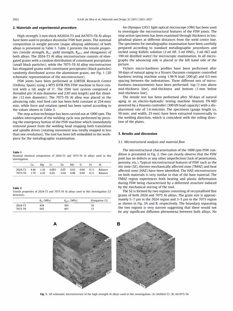
High-strength 3 mm-thick AA2024-T3 and AA7075-T6 Al alloyshave been used to produce dissimilar FSW butt joints. The nominalcomposition in weight percent (major alloying additions) of bothalloys is presented in Table 1. Table 2 presents the tensile proper-ties (tensile strength, Rm; yield strength, Rp0.2 and elongation) ofboth alloys. The 2024-T3 Al alloy microstructure consists of elon-gated grains with a random distribution of constituent precipitates(small black particles); while the 7075-T6 Al alloy microstructurehas elongated grains with constituent precipitates (black particles)randomly distributed across the aluminium grains, see Fig. 1 (3Dschematic representation of the microstructure).
FSW joints have been performed at LORTEK Research Centre(Ordizia, Spain) using a MTS ISTIR PDS FSW machine in force con-trol with a tilt angle of 3�. The FSW tool system comprised athreaded pin (4 mm diameter and 2.85 mm length) and flat shoul-der (12 mm diameter). The 7075-T6 Al alloy was placed in theadvancing side; tool feed rate has been held constant at 254 mm/min; while force and rotation speed has been varied according tothe values shown in Table 3.
The stop action technique has been carried out at 1000 rpm. Thesudden interruption of the welding cycle was performed by press-ing the emergency button of the FSW machine which immediatelyremoved power from the welding head stopping both translationand spindle drives (rotating movement was totally stopped in lessthan one revolution). The tool has been left embedded in the work-piece for the metallographic examination.
Table 1Nominal chemical composition of 2024-T3 and 7075-T6 Al alloys used in thisinvestigation.
Cu Mg Cr Zn Mn Si Fe Al
2024-T3 4.46 1.42 0.001 0.05 0.63 0.04 0.11 Balance7075-T6 1.70 2.43 0.20 5.64 0.08 0.04 0.11 Balance
Table 2Tensile properties of 2024-T3 and 7075-T6 Al alloys used in this investigation (LTdirection).
Rm (MPa) Rp0.2 (MPa) Elongation (%)
2024-T3 458 305 187075-T6 565 491 13
Fig. 1. 3D schematic microstructure of the high-strength Al alloy
An Olympus GX51 light optical microscope (OM) has been usedto investigate the microstructural features of the FSW joints. Thestop action specimen has been examined through thickness in lon-gitudinal planes at different distances from the weld centre line.The specimens for metallographic examination have been carefullyprepared according to standard metallographic procedures andetched using Kellers solution (2 ml HF, 5 ml HNO3, 3 ml HCl and190 ml distilled water) for microscopic examination. In all micro-graphs the advancing side is placed in the left hand side of thepicture.
Vickers micro-hardness profiles have been performed after50 days of natural aging in a Struers Duramin computer controlledhardness testing machine using 1.96 N load (200 gf) and 0.5 mmspacing between the indentations. Three different sets of micro-hardness measurements have been performed: top (1 mm abovemid-thickness line), mid-thickness and bottom (1 mm belowmid-thickness line).
The tensile test has been performed after 50 days of naturalaging in an electro-hydraulic testing machine Hoytom TN-MDpowered by a Hoywin controller (300 kN load capacity) with a dis-placement rate of 1.6 mm/min. The specimens (gauge length Lo,50 mm; and width, 25 mm) have been extracted transversally tothe welding direction, which is coincident with the rolling direc-tion of the plates.
3. Results and discussion
3.1. Microstructural analysis and material flow
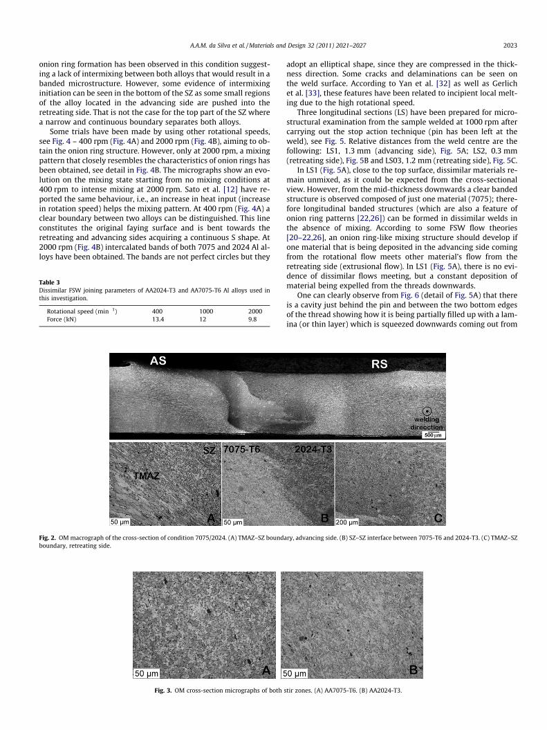
The microstructural characterisation of the 1000 rpm FSW con-dition is presented in Fig. 2. One can clearly observe that the FSWjoint has no defects or any other imperfection (lack of penetration,porosity, etc.). Typical microstructural features of FSW such as thestir zone (SZ), thermo-mechanically affected zone (TMAZ) and heataffected zone (HAZ) have been identified. The HAZ microstructureon both materials is very similar to that of the base material. TheTMAZ region experiences both heating and plastic deformationduring FSW being characterised by a deformed structure inducedby the mechanical stirring of the tool.
The SZ is formed by two regions consisting of recrystallised finegrains of both 2024 and 7075 Al alloys. The grain size is approxi-mately 5–7 lm in the 2024 region and 3–5 lm in the 7075 regionas shown in Fig. 3A and B, respectively. The boundary separatingthe two regions is very narrow suggesting that there would notbe any significant diffusion phenomena between both alloys. No
s used in this investigation. (A) AA2024-T3. (B) AA7075-T6.
A.A.M. da Silva et al. / Materials and Design 32 (2011) 2021–2027 2023
onion ring formation has been observed in this condition suggest-ing a lack of intermixing between both alloys that would result in abanded microstructure. However, some evidence of intermixinginitiation can be seen in the bottom of the SZ as some small regionsof the alloy located in the advancing side are pushed into theretreating side. That is not the case for the top part of the SZ wherea narrow and continuous boundary separates both alloys.
Some trials have been made by using other rotational speeds,see Fig. 4 – 400 rpm (Fig. 4A) and 2000 rpm (Fig. 4B), aiming to ob-tain the onion ring structure. However, only at 2000 rpm, a mixingpattern that closely resembles the characteristics of onion rings hasbeen obtained, see detail in Fig. 4B. The micrographs show an evo-lution on the mixing state starting from no mixing conditions at400 rpm to intense mixing at 2000 rpm. Sato et al. [12] have re-ported the same behaviour, i.e., an increase in heat input (increasein rotation speed) helps the mixing pattern. At 400 rpm (Fig. 4A) aclear boundary between two alloys can be distinguished. This lineconstitutes the original faying surface and is bent towards theretreating and advancing sides acquiring a continuous S shape. At2000 rpm (Fig. 4B) intercalated bands of both 7075 and 2024 Al al-loys have been obtained. The bands are not perfect circles but they
Table 3Dissimilar FSW joining parameters of AA2024-T3 and AA7075-T6 Al alloys used inthis investigation.
Rotational speed (min�1) 400 1000 2000Force (kN) 13.4 12 9.8
Fig. 2. OM macrograph of the cross-section of condition 7075/2024. (A) TMAZ–SZ boundaboundary, retreating side.
Fig. 3. OM cross-section micrographs of both s
adopt an elliptical shape, since they are compressed in the thick-ness direction. Some cracks and delaminations can be seen onthe weld surface. According to Yan et al. [32] as well as Gerlichet al. [33], these features have been related to incipient local melt-ing due to the high rotational speed.
Three longitudinal sections (LS) have been prepared for micro-structural examination from the sample welded at 1000 rpm aftercarrying out the stop action technique (pin has been left at theweld), see Fig. 5. Relative distances from the weld centre are thefollowing: LS1, 1.3 mm (advancing side), Fig. 5A; LS2, 0.3 mm(retreating side), Fig. 5B and LS03, 1.2 mm (retreating side), Fig. 5C.
In LS1 (Fig. 5A), close to the top surface, dissimilar materials re-main unmixed, as it could be expected from the cross-sectionalview. However, from the mid-thickness downwards a clear bandedstructure is observed composed of just one material (7075); there-fore longitudinal banded structures (which are also a feature ofonion ring patterns [22,26]) can be formed in dissimilar welds inthe absence of mixing. According to some FSW flow theories[20–22,26], an onion ring-like mixing structure should develop ifone material that is being deposited in the advancing side comingfrom the rotational flow meets other material’s flow from theretreating side (extrusional flow). In LS1 (Fig. 5A), there is no evi-dence of dissimilar flows meeting, but a constant deposition ofmaterial being expelled from the threads downwards.
One can clearly observe from Fig. 6 (detail of Fig. 5A) that thereis a cavity just behind the pin and between the two bottom edgesof the thread showing how it is being partially filled up with a lam-ina (or thin layer) which is squeezed downwards coming out from
ry, advancing side. (B) SZ–SZ interface between 7075-T6 and 2024-T3. (C) TMAZ–SZ
tir zones. (A) AA7075-T6. (B) AA2024-T3.
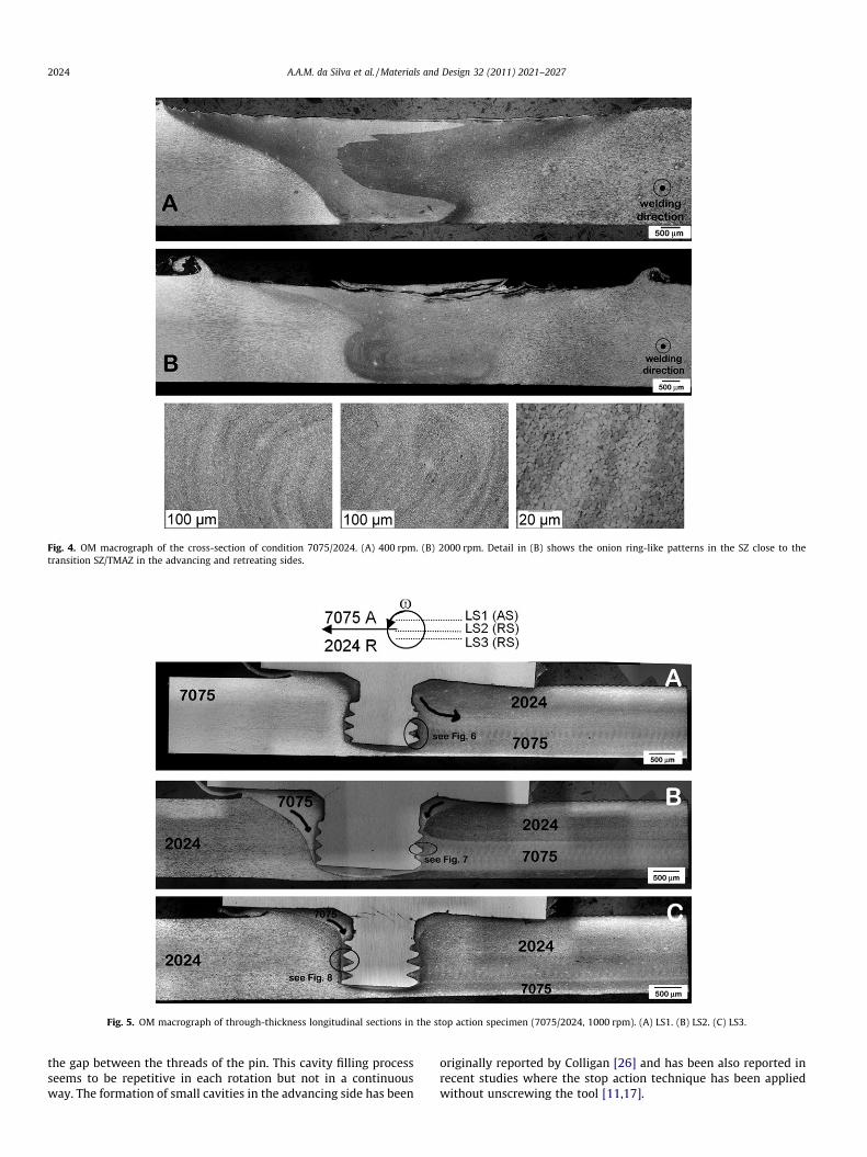
Fig. 4. OM macrograph of the cross-section of condition 7075/2024. (A) 400 rpm. (B) 2000 rpm. Detail in (B) shows the onion ring-like patterns in the SZ close to thetransition SZ/TMAZ in the advancing and retreating sides.
Fig. 5. OM macrograph of through-thickness longitudinal sections in the stop action specimen (7075/2024, 1000 rpm). (A) LS1. (B) LS2. (C) LS3.
2024 A.A.M. da Silva et al. / Materials and Design 32 (2011) 2021–2027
the gap between the threads of the pin. This cavity filling processseems to be repetitive in each rotation but not in a continuousway. The formation of small cavities in the advancing side has been
originally reported by Colligan [26] and has been also reported inrecent studies where the stop action technique has been appliedwithout unscrewing the tool [11,17].
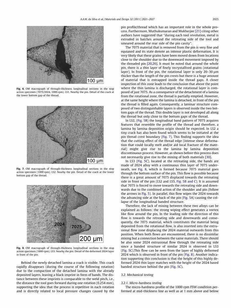
Fig. 6. OM macrograph of through-thickness longitudinal sections in the stopaction specimen (7075/2024, 1000 rpm). LS1. Nearby the pin. Detail of the crack atthe lower bottom gap of the thread.
Fig. 7. OM macrograph of through-thickness longitudinal sections in the stopaction specimen (1000 rpm). LS2. Nearby the pin. Detail of the crack at the lowerbottom gap of the thread.
Fig. 8. OM macrograph of through-thickness longitudinal sections in the stopaction specimen (1000 rpm). LS3. Nearby the pin. Detail of the deformed 2024 layerin front of the pin.
A.A.M. da Silva et al. / Materials and Design 32 (2011) 2021–2027 2025
Behind the newly detached lamina a crack is visible. This crackrapidly disappears (during the course of the following rotation)due to the compaction of the detached lamina with the alreadydeposited layers, leaving a black imprint in form of bands. The dis-tance between these imprints is comparable to the weld pitch, i.e.,the distance the tool goes forward during one rotation (0.254 mm),supporting the idea that the process is repetitive in each rotationand is directly related to local pressure changes caused by the
pin profile/thread which has an important role in the whole pro-cess. Furthermore, Muthukumaran and Mukherjee [21] citing otherauthors have suggested that ‘‘during each tool revolution, metal isextruded in batches around the retreating side of the tool andsmeared around the rear side of the pin cavity’’.
The 7075 material that is removed from the pin is very fine andequiaxed and its state denote an intense plastic deformation. It isvery likely that these grains have been moved down from locationsclose to the shoulder due to the downward movement imposed bythe threaded pin [20,26]. It must be noted that around the wholepin, there is a thin layer of finely recrystallised grains (rotationallayer). In front of the pin, the rotational layer is only 20–30 lmthicker than the length of the pin crests but there is a huge amountof material that is entrapped inside the thread gaps. A closerinspection of this zone leads to the conclusion that above the pointwhere the thin lamina is discharged, the rotational layer is com-posed of just 7075. As a consequence of the detachment of a laminafrom the rotational zone, the thread is partially emptied. However,at the same height where the lamina is detached, in front of the pinthe thread is filled again. Consequently, a laminar structure com-posed of two distinguishable layers is observed inside the two bot-tom gaps of the thread. This double layer is not developed all alongthe thread but only close to the bottom gaps of the thread.
In LS2, (Fig. 5B) the longitudinal band pattern of 7075 acquiresfeatures that resemble the profile of the thread and therefore, alamina by lamina deposition origin should be expected. In LS2 atiny crack has also been found which seems to be initiated at thepin thread crest boundary (Fig. 7). This finding supports the ideathat the cutting effect of the thread edge (intense shear deforma-tion that could locally melt and/or aid local fracture of the mate-rial) might give rise to the lamina by lamina depositiondiscontinuous process. However, as shown before this process doesnot necessarily give rise to the mixing of both materials [30].
In LS3 (Fig. 5C), located at the retreating side, the bands aremade of 2024 alloy with a continuous thin layer of 7075 under-neath, see Fig. 8, which is formed because 7075 material goesthrough the bottom surface of the pin. This flow is possible becausethere is a great amount of 7075 displaced towards the retreatingside in front of the pin (LS2 and LS3, Fig. 5B and C). It is assumedthat 7075 is forced to move towards the retreating side and down-wards due to the combined action of the shoulder and pin (followthe arrows in Fig. 5). In parallel, this flow wipes the 2024 towardsthe advancing side at the back of the pin (Fig. 5A) causing the col-lapse of the longitudinal banded structure.
Therefore, the lack of mixing between these two alloys can beexplained as follows: the strong wiping effect generates a vortexlike flow around the pin. In the leading side the direction of thisflow is towards the retreating side and downwards and conse-quently, the 7075 material, which constitutes the material beingdeposited from the rotational flow, is also inserted into the extru-sional flow zone displacing the 2024 material outwards from thisposition. When both flows are encountered, there is no dissimilarmixing but a connection between the same materials. There shouldbe also some 2024 extrusional flow through the retreating sidesince a banded structure of similar 2024 is observed in LS3(Fig. 5C).This flow can be seen from the layer of highly deformed2024 which is observed in front of the pin (Fig. 8). Another indica-tion supporting this conclusion is that the height of this highly de-formed 2024 thin layer matches with the height of the 2024 basedbanded structure behind the pin (Fig. 5C).
3.2. Mechanical testing
3.2.1. Micro-hardness testingThe micro-hardness profile of the 1000 rpm FSW condition per-
formed at mid-thickness line as well as at 1 mm above and below
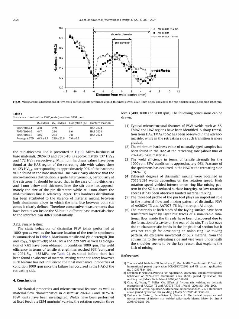
Fig. 9. Microhardness distributions of FSW cross-sections joints performed at mid-thickness as well as at 1 mm below and above the mid-thickness line. Condition 1000 rpm.
Table 4Tensile test results of the FSW joints (condition 1000 rpm).
Rm (MPa) Rp0.2 (MPa) Elongation (%) Fracture location
7075/2024-1 438 269 7.1 HAZ 20247075/2024-2 447 224 8.0 HAZ 20247075/2024-3 445 253 7.8 HAZ 2024Average ± STD 443 ± 4.7 229 ± 22.8 7.6 ± 0.5 –
2026 A.A.M. da Silva et al. / Materials and Design 32 (2011) 2021–2027
the mid-thickness line is presented in Fig. 9. Micro-hardness ofbase materials, 2024-T3 and 7075-T6, is approximately 137 HV0.2
and 172 HV0.2 respectively. Minimum hardness values have beenfound at the HAZ region of the retreating side with values closeto 123 HV0.2, corresponding to approximately 90% of the hardnessvalue found in the base material. One can clearly observe that themicro-hardness distribution is quite heterogeneous, particularly atthe stir zone. It should be noted that in the case of mid-thicknessand 1 mm below mid-thickness lines the stir zone has approxi-mately the size of the pin diameter; while at 1 mm above themid-thickness line is relatively larger. This hardness distributionhas been attributed to the absence of material mixing betweenboth aluminium alloys in which the interface between both stirzones is clearly defined. Therefore consecutive measurements thathave been taken inside the SZ but in different base materials closeto the interface can differ substantially.
3.2.2. Tensile testingThe static behaviour of dissimilar FSW joints performed at
1000 rpm as well as the fracture location of the tensile specimensis summarised in Table 4. Maximum tensile and yield strength (Rmand Rp0.2, respectively) of 443 MPa and 229 MPa as well as elonga-tion of 7.6% have been obtained in condition 1000 rpm. The weldefficiency in terms of tensile strength has reached 96% (comparedto 2024 Rm – 458 MPa, see Table 2). As stated before, there hasbeen found an absence of material mixing at the stir zone; howeversuch feature has not influenced the final mechanical properties ofcondition 1000 rpm since the failure has occurred in the HAZ of theretreating side.
4. Conclusions
Mechanical properties and microstructural features as well asmaterial flow characteristics in dissimilar 2024-T3 and 7075-T6FSW joints have been investigated. Welds have been performedat fixed feed rate (254 mm/min) varying the rotation speed in three
levels (400, 1000 and 2000 rpm). The following conclusions can bedrawn:
(1) Typical microstructural features of FSW welds such as SZ,TMAZ and HAZ regions have been identified. A sharp transi-tion from HAZ/TMAZ to SZ has been observed in the advanc-ing side; while in the retreating side such transition is moregradual.
(2) The minimum hardness value of naturally aged samples hasbeen found in the HAZ at the retreating side (about 88% of2024-T3 base material).
(3) The weld efficiency in terms of tensile strength for the1000 rpm FSW condition is approximately 96%. Fracture ofthe specimens has occurred in the HAZ at the retreating side(2024-T3).
(4) Different degrees of dissimilar mixing were obtained in7075/2024 welds depending on the rotation speed. Highrotation speed yielded intense onion ring-like mixing pat-tern in the SZ but reduced surface integrity. At low rotationspeeds it has been observed limited material mixing.
(5) The threaded profile of the pin tool plays an important rolein the material flow and mixing pattern of dissimilar FSWof AA2024-T3 and AA7075-T6 high-strength Al alloys.
(6) The materials at both sides of the faying surface have beentransferred layer by layer but traces of a non-stable rota-tional flow inside the threads have been discovered due tothe formation of a cavity on the rear of the pin. This fact gaverise to characteristic bands in the longitudinal section but itwas not enough for developing an onion ring-like mixingpattern. An excessive movement of bulk material from theadvancing to the retreating side and vice versa underneaththe shoulder seems to be the key reason that explains thelack of mixing.
References
[1] Thomas WM, Nicholas ED, Needham JC, Murch MG, Templesmith P, Smith CJ.International patent application PCT/GB92/02203 and GB patent applicationno. 9125978.9; 1991.
[2] Cavaliere P, Nobile R, Pannela FW, Squillace A. Mechanical and microstructuralbehaviour of 2024–7075 aluminium alloy sheets joined by friction stirwelding. Int J Mach Tools Manuf 2006;46:588–94.
[3] Chao YJ, Wang Y, Miller KW. Effect of friction stir welding on dynamicproperties of AA2024-T3 and AA7075-T7351. Weld J 2001;80:196s–200s.
[4] Cavaliere P, Cerri E, Squillace A. Mechanical response of 2024–7075 aluminiumalloys joined by friction stir welding. J Mater Sci 2005;40:3669–76.
[5] Zadpoor A, Sinke J, Benedictus R, Pieters R. Mechanical properties andmicrostructure of friction stir welded tailor-made blanks. Mater Sci Eng A2008;494:281–90.
A.A.M. da Silva et al. / Materials and Design 32 (2011) 2021–2027 2027
[6] Khodir SA, Shibayanagi T. Friction stir welding of dissimilar AA2004 andAA7075 aluminum alloys. Mater Sci Eng B 2008;148:82–7.
[7] Dubourg L, Merati A, Jahazi M. Process optimisation and mechanical propertiesof friction stir lap welds of 7075-T6 stringers on 2024-T3 skin. Mater Des2010;31:3324–30.
[8] Aldanondo E, da Silva AAM, Alvarez P, Lizarralde A, Echeverria A. Dissimilarfriction stir welding of AA2024-T3 and AA7075-T6 aluminium alloys. In: 138thAnnual meeting and exhibition TMS2009 – friction stir welding and processingV, San Francisco, USA, 15–19 February 2009.
[9] da Silva AAM, Aldanondo E, Alvarez P, Lizarralde A, Echeverria A. Mechanicaland microstructural characterisation of dissimilar friction stir welded AA2024-T3 and AA7075-T6 aluminium alloys. Mater Sci Forum 2010;638–642:1221–6.
[10] Chen ZW, Cui S. Material flow phenomenon in thread space and the resultingmode of nugget zone formation during friction stir welding. In: 7thInternational symposium on FSW, Awaji Island, Japan, 20–22 May 2008.
[11] Chen ZW, Cui S. On the forming mechanism of banded structures in aluminiumalloy friction stir welds. Scripta Mater 2008;58:417–20.
[12] Sato YS, Kurihara Y, Kokawa H. Microstructural characteristics of dissimilarbutt friction stir welds of AA7075 and AA2024. In: 6th Internationalsymposium on FSW, Toronto, Canada, 10–13 October 2006.
[13] Reynolds A, Seidel RU, Simonsen M. Visualization of material flow in anautogenous friction stir weld. In: 1st International symposium on FSW,Thousand Oaks, USA, 14–16 June 1999.
[14] Dickerson TL, Shercliff HR, Schmidt HNB. A weld marker technique for flowvisualisation in friction stir welding. In: 4th International symposium on FSW,Park City, USA, 14–16 May 2003.
[15] Seidel TU, Reynolds AP. Visualisation of the material flow in AA2195 friction-stir welds using a marker insert technique. Metall Mater Trans A2001;32:2879–84.
[16] Zhao Y-H, Lin S-B, Qu F-X, Wu L. Influence of pin geometry on material flow infriction stir welding process. Mater Sci Technol 2006;22:45–50.
[17] Guerra M, Schmidt C, McClure JC, Murr LE, Nunes AC. Flow patterns duringfriction stir welding. Mater Charact 2003;49:95–101.
[18] Fonda RW, Bingert JF, Colligan KJ. Development of grain structure duringfriction stir welding. Scripta Mater 2004;51:243–8.
[19] Prangnell PB, Heason CP. Grain structure formation during friction stir weldingobserved by the stop action technique. Acta Mater 2005;53:3179–92.
[20] Schneider JA, Nunes AC. Characterization of plastic flow and resultingmicrotextures in a friction stir weld. Metall Mater Trans B 2004;35:777–83.
[21] Muthukumaran S, Mukherjee SK. Multi-layered metal flow and formation ofonion rings in friction stir welds. Int J Adv Manuf Technol 2008;38:68–73.
[22] Krishnan KN. On the formation of onion rings in friction stir welds. Mater SciEng A 2002;327:246–51.
[23] Ke L, Xing L, Indacochea JE. Material flow patterns and cavity model in frictionstir welding of aluminum alloys. Metall Mater Trans B 2004;35B:153–60.
[24] Zhang HW, Zhang Z, Chen JT. 3D modelling of material flow in friction stirwelding under different process parameters. J Mater Process Technol2007;183:62–70.
[25] Hamilton C, Dymek S, Blicharski M. A model of material flow during frictionstir welding. Mater Charact 2008;59:1206–14.
[26] Colligan K. Material flow behavior during friction stir welding of aluminum.Weld J 1999;78:229s–37s.
[27] Schmidt HNB, Dickerson TL, Hattel JH. Material flow in butt friction stir weldsin AA2024-T3. Acta Mater 2006;54:1199–209.
[28] Fratini L, Buffa G, Palmeri D, Hua J, Shivpuri R. Material flow in FSW 7075-T6Butt-Joints: numerical simulations and experimental verification. Sci TechnolWeld Join 2006;11:412–21.
[29] Reynolds AP. Flow visualization and simulation in FSW. Scripta Mater2008;58:338–42.
[30] Alvarez P, Janeiro G, da Silva AAM, Aldanondo E, Echeverría. Material flow andmixing patterns during dissimilar FSW. Sci Technol Weld Join 2010.doi:10.1179/136217110X12785889549543.
[31] Nandan R, DebRoy T, Bhadeshia HKDH. Recent advances in friction stirwelding-process, weldment structure and properties. Prog Mater Sci2008;53:980–1023.
[32] Yan J, Sutton MA, Reynolds AP. Process–structure–property relationship fornugget and heat affected zone regions of AA2524–T351 friction stir welds. SciTechnol Weld Join 2005;10:725–36.
[33] Gerlich A, Yamamoto M, North TH. Local melting and cracking in Al 7075-T6and Al 2024-T3 friction stir spot welds. Sci Technol Weld Join 2007;12:472–80.
Related Documents