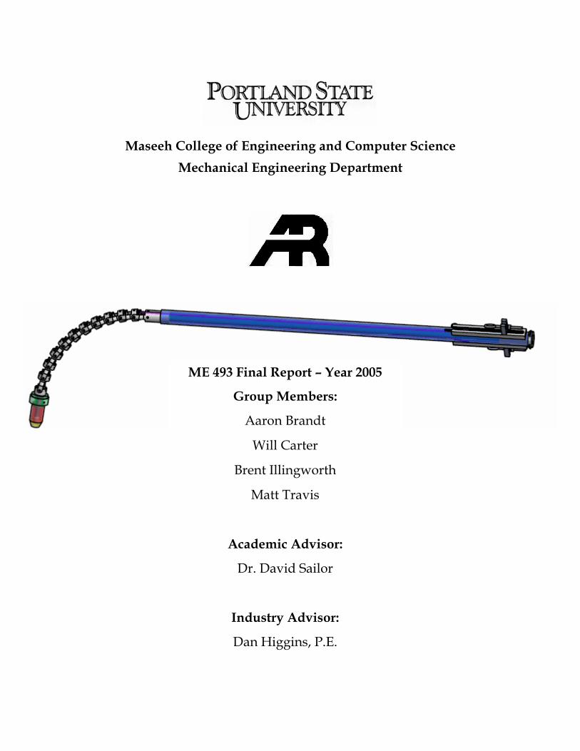
Maseeh College of Engineering and Computer Science Mechanical Engineering Department ME 493 Final Report – Year 2005 Group Members: Aaron Brandt Will Carter Brent Illingworth Matt Travis Academic Advisor: Dr. David Sailor Industry Advisor: Dan Higgins, P.E.

Welcome message from author
This document is posted to help you gain knowledge. Please leave a comment to let me know what you think about it! Share it to your friends and learn new things together.
Transcript
Maseeh College of Engineering and Computer Science Mechanical Engineering Department
Sponsor: Anthony Ross Company
ME 493 Final Report – Year 2005
Group Members:
Aaron Brandt
Will Carter
Brent Illingworth
Matt Travis
Academic Advisor:
Dr. David Sailor
Industry Advisor:
Dan Higgins, P.E.
Infrared Imaging of Black Liquor Spray
2
1 · EXECUTIVE SUMMARY
Black liquor is a byproduct of the kraft paper pulping process; it is made up of chemicals, solids
and water. A recovery boiler's main purpose is to provide heat in order to convert the chemicals in the
black liquor back to reusable form. This is accomplished by spraying the black liquor through nozzles
into the boiler. While the droplets are suspended, the water is evaporated, the solids are combusted, and
the reusable chemicals fall to the bottom of the boiler where they are recovered. The excess heat from the
process is used to create steam which is used for other processes or to produce power.
Mathematical models of the recovery boiler environment are utilized by the pulp and paper
industry to increase the life of equipment, increase chemical recovery, and reduce atmospheric emissions.
The most important factors in the model are the airflow and black liquor spray characteristics. Currently
the spray characteristics in the model are developed analytically. The model's accuracy would be
improved if the spray characteristics were developed from empirical data.
The project sponsor, Anthony Ross Company, would like an instrument that can provide data
that accurately represents the spray characteristics. Anthony Ross Company currently provides infrared
video cameras to kraft paper plants to image the inside of the boiler for maintenance purposes. This same
camera combined with a proper optical system could be employed to provide high quality images of the
black liquor spray for data collection purposes. By designing an optical assembly that can attach to
Anthony Ross' infrared camera and provide clear images of the black liquor spray, accurate
characterization would be possible.
The design team has developed an optical assembly that allows for adjustable viewing of the black
liquor spray. The assembly can be used at first as an R&D tool to gather data. From the data, the current
model could be improved and accurately reveal the effect of droplet size and spray pattern on chemical
recovery efficiency. If significant improvements in efficiency can be made by using the system, the
camera and optics assembly could become marketable.
Infrared Imaging of Black Liquor Spray
3
2 · TABLE OF CONTENTS
1 · EXECUTIVE SUMMARY ......................................................................................................................2
2 · TABLE OF CONTENTS .........................................................................................................................3
3 · INTRODUCTION & BACKGROUND INFORMATION......................................................................5
Figure 1: Schematic representation of pulping and chemical recovery process ..................................6
4 · MISSION STATEMENT .........................................................................................................................6
5 · PRODUCT DESIGN SPECIFICATIONS ...............................................................................................6
Figure 2: Fiber optic imaging bundle ....................................................................................................7
6 · TOP LEVEL DESIGN CONSIDERATIONS..........................................................................................7
Figure 3: Three conceptual methods of tip actuation ...........................................................................8
Figure 4: Final design of actuation brackets .........................................................................................9
7 · FINAL DESIGN PRESENTATION ........................................................................................................9
Overview....................................................................................................................................................9
Figure 5: Complete design ..................................................................................................................10
1 • Optical Fiber Imaging Bundle ............................................................................................................10
Table 1: Fiber Bundle Assembly Requirements ...................................................................................11
Figure 6: Pictures of the distal optics barrel used in the prototype....................................................12
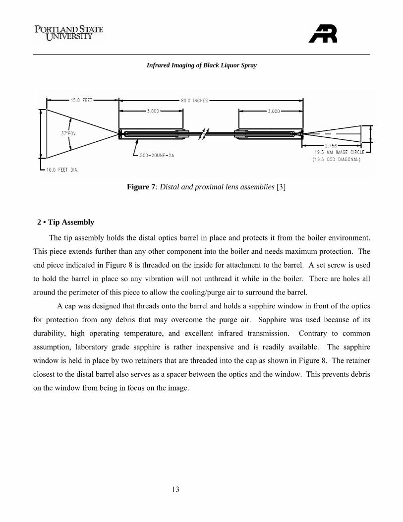
Figure 7: Distal and proximal lens assemblies ....................................................................................13
2 • Tip Assembly......................................................................................................................................13
Figure 8: Tip assembly .........................................................................................................................14
Figure 9: Tip assembly showing the assumed 45° angle of view .........................................................15
3 • Actuating Bracket Assembly ..............................................................................................................15
Figure 10: Actuation Brackets..............................................................................................................15
Figure 11: Bracket assembly in the bent and straight positions .........................................................16
Figure 12: Stainless Steel Sheath Used for Prototype..........................................................................16
4 • Main Tube with Actuation Control.....................................................................................................17
Figure 13: Control assembly ................................................................................................................17
Infrared Imaging of Black Liquor Spray
4
5 • Camera Interface.................................................................................................................................17
Figure 14: Proximal end design ...........................................................................................................18
8 · EVALUATIONS ....................................................................................................................................19
Figure 15: Fiber bundle adaptor at proximal end & distal end...........................................................19
1 • Fiber Bundle .......................................................................................................................................19
2 • Actuation system ................................................................................................................................20
Figure 16: Tip actuated 90°. ................................................................................................................20
3 • Air flow system...................................................................................................................................20
4 • Environmental Testing........................................................................................................................20
9 · FUTURE CONSIDERATIONS .............................................................................................................20
10 · CONCLUSION.....................................................................................................................................21
11 · REFERENCES .....................................................................................................................................22
12 · ACKNOWLEGMENTS .......................................................................................................................22
13 · APPENDICES ......................................................................................................................................22
APPENDIX A: Manufacturing Instructions............................................................................................22
APPENDIX B: Bill of Materials...............................................................................................................30
APPENDIX C: Operations Manual .........................................................................................................31
APPENDIX D: Calculations ....................................................................................................................32
Bracket Analysis ..................................................................................................................................32
Air Flow Analysis ................................................................................................................................34
Heat Transfer Analysis.........................................................................................................................41
APPENDIX E: Product Design Specifications ........................................................................................44
APPENDIX F: Top Level Search.............................................................................................................52
APPENDIX G: Manufacturing Drawings................................................................................................56
Infrared Imaging of Black Liquor Spray
5
3 · INTRODUCTION & BACKGROUND INFORMATION
The kraft paper pulping process uses an aqueous solution of sodium hydroxide (NaOH) and
sodium sulfide (Na2S) to break down the binding agents in wood pulp. During the pulping process, most
of the NaOH is consumed in the neutralization of wood acids, and some of the Na2S is oxidized to sodium
thiosulfate (Na2S2O3). The spent pulping chemicals in combination with dissolved wood components and
water make up what is referred to as the weak liquor byproduct of the pulping process. The weak liquor
is fed into evaporators where most of the water is removed. The liquid is then referred to as black liquor.
Black liquor may contain as much as 85% solids. Most of the solids are carbon based and can be
burned off. The recovery boiler is used for this purpose. Black liquor is sprayed through nozzles into the
boiler. The water in the droplets evaporates quickly and combustion takes place. The generated heat
from combustion is used to oxidize the inorganic sodium salts to reusable form and to create steam, which
can be used to produce power. The reusable substance is referred to as smelt and falls out of the bottom
of the boiler. If the droplets are too large as they enter the boiler, complete combustion will not occur and
chemical recovery will be limited. If the droplets are too small, complete combustion takes place too
early and the particles get entrained in the central airflow rather than falling out of the boiler; this can clog
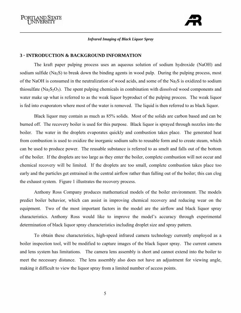
the exhaust system. Figure 1 illustrates the recovery process.
Anthony Ross Company produces mathematical models of the boiler environment. The models
predict boiler behavior, which can assist in improving chemical recovery and reducing wear on the
equipment. Two of the most important factors in the model are the airflow and black liquor spray
characteristics. Anthony Ross would like to improve the model’s accuracy through experimental
determination of black liquor spray characteristics including droplet size and spray pattern.
To obtain these characteristics, high-speed infrared camera technology currently employed as a
boiler inspection tool, will be modified to capture images of the black liquor spray. The current camera
and lens system has limitations. The camera lens assembly is short and cannot extend into the boiler to
meet the necessary distance. The lens assembly also does not have an adjustment for viewing angle,
making it difficult to view the liquor spray from a limited number of access points.
Infrared Imaging of Black Liquor Spray
6
4 · MISSION STATEMENT
Design an optical assembly that will attach to the infrared camera currently being distributed by
Anthony Ross Company. The assembly will provide clear images of black liquor spray to the camera.
Data gathered from the images will allow Anthony Ross’ engineers to improve their mathematical model
of the recovery boiler.
5 · PRODUCT DESIGN SPECIFICATIONS
Anthony Ross Company is the main customer for the optical assembly. The camera to be used is
distributed by Anthony Ross Co. through a license agreement with Enertechnix. The design team has
worked with Anthony Ross Co. to establish the following major design specifications:
A · The equipment will be safe to operate. It is possible that flame may escape the boiler through the
air injection ports where the assembly will most likely be inserted. The operator must be protected from
White Liquor
Steam
Smelt
Weak Liquor
concentrated Black Liquor
P-2 P-3
Pulp Digester
Evaporator Evaporator Evaporator
Recovery Boiler
Causticizer
Air
Combustion consumes solids
Sodium returned to NaOH and NaS
Schematic of Pulping Process
Turbine
Figure 1: Schematic representation of pulping and chemical recovery process
Infrared Imaging of Black Liquor Spray
7
the escaping flame. The installation of the assembly onto the boiler must be simple and not require any
actions that may pose a hazard to the operator.
B · The assembly must survive the boiler environment. The boiler can reach temperatures of 2,000°F
and contains debris moving at high velocities. The assembly must withstand the environment for a
minimum of 30 minutes without suffering damage or degradation to the image quality.
C · The viewing angle must be adjustable. The apparatus will have an adjustable viewing angle of 90º.
This means that the assembly must be able to look straight ahead as well as down.
D · The camera must extend far enough into the boiler. Because of a recovery boiler’s internal
structure, the assembly must extend a minimum of 1 meter into the boiler to allow for multiple views of
the spray.
E · The focal length and field of view must be adjustable. The versatility of the camera and assembly
will be increased if the focal length and field of view are adjustable.
6 · TOP LEVEL DESIGN CONSIDERATIONS
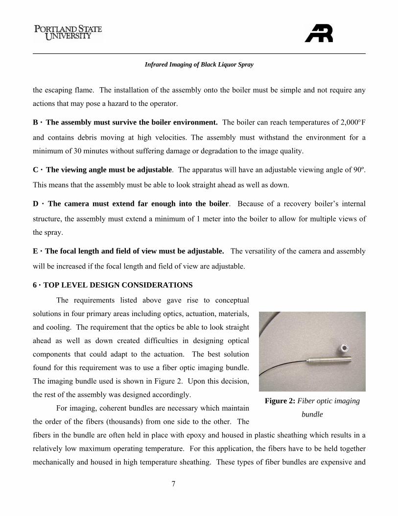
The requirements listed above gave rise to conceptual
solutions in four primary areas including optics, actuation, materials,
and cooling. The requirement that the optics be able to look straight
ahead as well as down created difficulties in designing optical
components that could adapt to the actuation. The best solution
found for this requirement was to use a fiber optic imaging bundle.
The imaging bundle used is shown in Figure 2. Upon this decision,
the rest of the assembly was designed accordingly.
For imaging, coherent bundles are necessary which maintain
the order of the fibers (thousands) from one side to the other. The
fibers in the bundle are often held in place with epoxy and housed in plastic sheathing which results in a
relatively low maximum operating temperature. For this application, the fibers have to be held together
mechanically and housed in high temperature sheathing. These types of fiber bundles are expensive and
Figure 2: Fiber optic imaging
bundle
Infrared Imaging of Black Liquor Spray
8
require that any sort of lens system be designed and attached to the bundle by qualified personnel for
optimal performance. The components of a complete system include the optics at the tip of the bundle
(distal end), the optics at the camera (proximal end), and the coherent bundle itself.
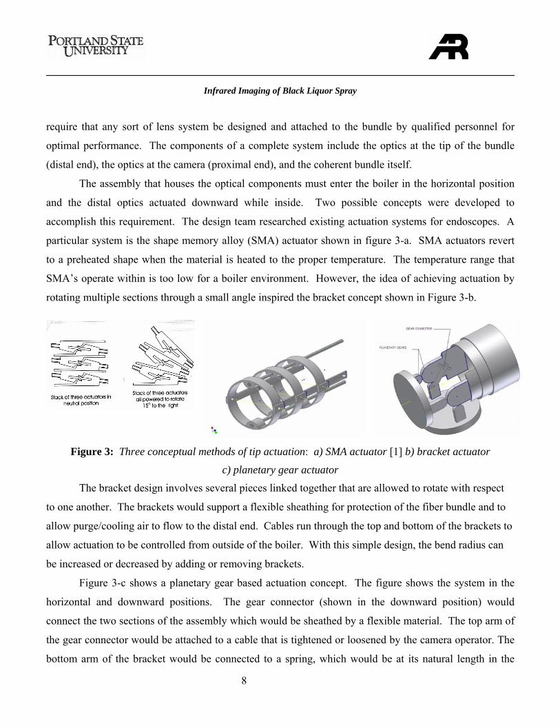
The assembly that houses the optical components must enter the boiler in the horizontal position
and the distal optics actuated downward while inside. Two possible concepts were developed to
accomplish this requirement. The design team researched existing actuation systems for endoscopes. A
particular system is the shape memory alloy (SMA) actuator shown in figure 3-a. SMA actuators revert
to a preheated shape when the material is heated to the proper temperature. The temperature range that
SMA’s operate within is too low for a boiler environment. However, the idea of achieving actuation by
rotating multiple sections through a small angle inspired the bracket concept shown in Figure 3-b.
Figure 3: Three conceptual methods of tip actuation: a) SMA actuator [1] b) bracket actuator
c) planetary gear actuator
The bracket design involves several pieces linked together that are allowed to rotate with respect
to one another. The brackets would support a flexible sheathing for protection of the fiber bundle and to
allow purge/cooling air to flow to the distal end. Cables run through the top and bottom of the brackets to
allow actuation to be controlled from outside of the boiler. With this simple design, the bend radius can
be increased or decreased by adding or removing brackets.
Figure 3-c shows a planetary gear based actuation concept. The figure shows the system in the
horizontal and downward positions. The gear connector (shown in the downward position) would
connect the two sections of the assembly which would be sheathed by a flexible material. The top arm of
the gear connector would be attached to a cable that is tightened or loosened by the camera operator. The
bottom arm of the bracket would be connected to a spring, which would be at its natural length in the
Infrared Imaging of Black Liquor Spray
9
downward position. As the camera operator tightens a cable attached to the upper arm of the gear
connecter, the end would move toward the horizontal position. The disk at the end (facing left) would
have a hole big enough to allow the fiber bundle to pass through. This design is complex and would
require high precision manufacturing. The bend radius would also be very small which would not adapt
well to the fiber bundle or the sheathing.
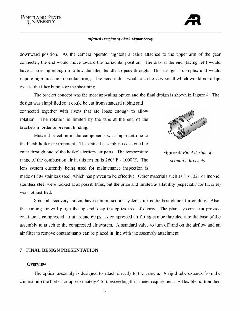
The bracket concept was the most appealing option and the final design is shown in Figure 4. The
design was simplified so it could be cut from standard tubing and
connected together with rivets that are loose enough to allow
rotation. The rotation is limited by the tabs at the end of the
brackets in order to prevent binding.
Material selection of the components was important due to
the harsh boiler environment. The optical assembly is designed to
enter through one of the boiler’s tertiary air ports. The temperature
range of the combustion air in this region is 260° F - 1000°F. The
lens system currently being used for maintenance inspection is
made of 304 stainless steel, which has proven to be effective. Other materials such as 316, 321 or Inconel
stainless steel were looked at as possibilities, but the price and limited availability (especially for Inconel)
was not justified.
Since all recovery boilers have compressed air systems, air is the best choice for cooling. Also,
the cooling air will purge the tip and keep the optics free of debris. The plant systems can provide
continuous compressed air at around 60 psi. A compressed air fitting can be threaded into the base of the
assembly to attach to the compressed air system. A standard valve to turn off and on the airflow and an
air filter to remove contaminants can be placed in line with the assembly attachment.
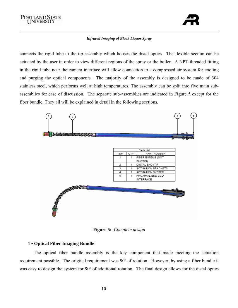
7 · FINAL DESIGN PRESENTATION
Overview
The optical assembly is designed to attach directly to the camera. A rigid tube extends from the
camera into the boiler for approximately 4.5 ft, exceeding the1 meter requirement. A flexible portion then
Figure 4: Final design of
actuation brackets
Infrared Imaging of Black Liquor Spray
10
connects the rigid tube to the tip assembly which houses the distal optics. The flexible section can be
actuated by the user in order to view different regions of the spray or the boiler. A NPT-threaded fitting
in the rigid tube near the camera interface will allow connection to a compressed air system for cooling
and purging the optical components. The majority of the assembly is designed to be made of 304
stainless steel, which performs well at high temperatures. The assembly can be split into five main sub-
assemblies for ease of discussion. The separate sub-assemblies are indicated in Figure 5 except for the
fiber bundle. They all will be explained in detail in the following sections.
1 • Optical Fiber Imaging Bundle
The optical fiber bundle assembly is the key component that made meeting the actuation
requirement possible. The original requirement was 90º of rotation. However, by using a fiber bundle it
was easy to design the system for 90º of additional rotation. The final design allows for the distal optics
Figure 5: Complete design
Infrared Imaging of Black Liquor Spray
11
to view up, down and any angle in-between (180º). This will enable users of the assembly to image
different sections of the spray as well as other regions of the boiler.
The bundle assembly includes three main components: the distal optics, the fiber bundle, and the
proximal optics. The distal optics gathers infrared light emitted from objects within the field of view and
delivers it to the fiber bundle. The proximal optics then projects the light from the bundle onto the CCD
of the camera. As explained earlier, a coherent fiber bundle is necessary for imaging so the light that
enters the bundle at the distal end is at the same cross-sectional location at the proximal end.
The distal optics must withstand high temperatures since they will be approximately one meter
within the boiler. This means that no epoxies can be used to hold the fibers or lenses in place. Epoxy is
commonly used in less-expensive imaging bundles. By holding the fibers and lenses together
mechanically rather than by epoxy, the operating temperature increases dramatically and can withstand
800ºF.
A 10 ft. image circle at a focal length of 15 ft. was desired as an initial configuration for the
prototype. The maximum depth of focus (DOF) was also desired so clear images could be provided at
distances other than the focal length. It was necessary that the distal optics be adjustable in the future in
case more magnification or a smaller DOF is necessary to image the individual droplets. The
magnification is increased by decreasing the image circle, thus projecting and enlarging a smaller image
onto the CCD. The DOF is decreased by increasing the aperture size.
The non-standard configuration of the infrared camera used by Anthony Ross required the use of
a custom proximal optics configuration. Most cameras use a standard system such a C-mount or CS-
Table 1: Fiber Bundle Assembly Requirements
Distal Optics 15 ft. focal length 10 ft. image circle at 10 ft. (37º angle of view) Depth of focus to be 0 ft. to 10 ft. Fibers and lenses mechanically fixed (for high temperature requirement) Ability to change in the future
Proximal Optics
19.5mm image circle (fills CCD) Focal length greater than 0.7 in.
Assembly Long enough so entire assembly is 80 in. from end to end High temperature Transmit short IR
Infrared Imaging of Black Liquor Spray
12
mount which specifies the CCD size and distance from the camera face to the CCD. All of the
requirements of the fiber bundle assembly are summarized in Table 1. Myriad Fiber Imaging Inc. was the
only vendor found that could meet all of the requirements shown in the table. Because of the infrared
requirement, special coated lenses must be used in the optical assemblies that allow for optimum infrared
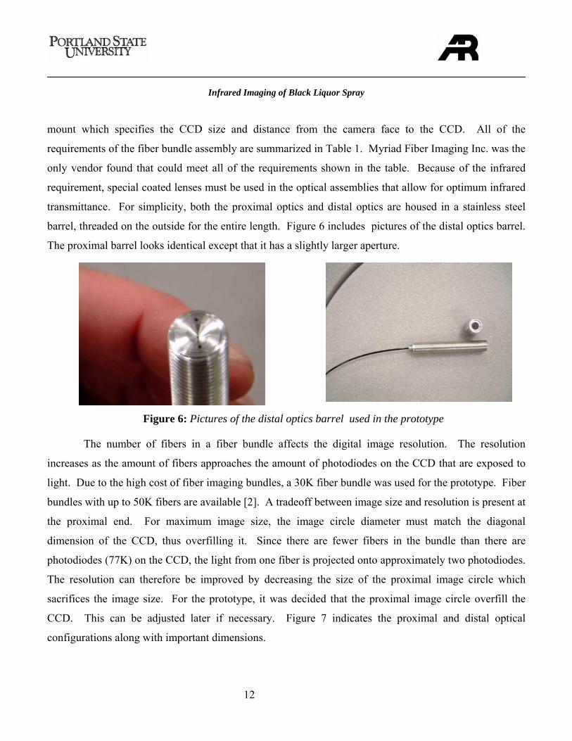
transmittance. For simplicity, both the proximal optics and distal optics are housed in a stainless steel
barrel, threaded on the outside for the entire length. Figure 6 includes pictures of the distal optics barrel.
The proximal barrel looks identical except that it has a slightly larger aperture.
The number of fibers in a fiber bundle affects the digital image resolution. The resolution
increases as the amount of fibers approaches the amount of photodiodes on the CCD that are exposed to
light. Due to the high cost of fiber imaging bundles, a 30K fiber bundle was used for the prototype. Fiber
bundles with up to 50K fibers are available [2]. A tradeoff between image size and resolution is present at
the proximal end. For maximum image size, the image circle diameter must match the diagonal
dimension of the CCD, thus overfilling it. Since there are fewer fibers in the bundle than there are
photodiodes (77K) on the CCD, the light from one fiber is projected onto approximately two photodiodes.
The resolution can therefore be improved by decreasing the size of the proximal image circle which
sacrifices the image size. For the prototype, it was decided that the proximal image circle overfill the
CCD. This can be adjusted later if necessary. Figure 7 indicates the proximal and distal optical
configurations along with important dimensions.
Figure 6: Pictures of the distal optics barrel used in the prototype
Infrared Imaging of Black Liquor Spray
13
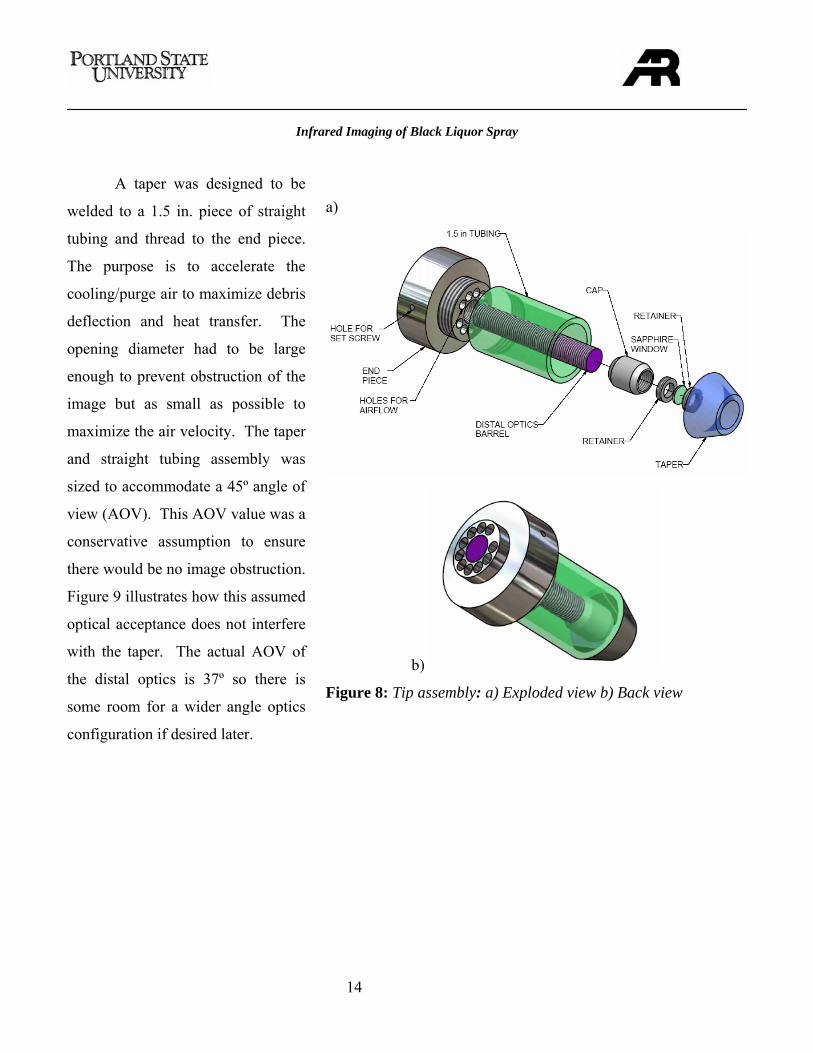
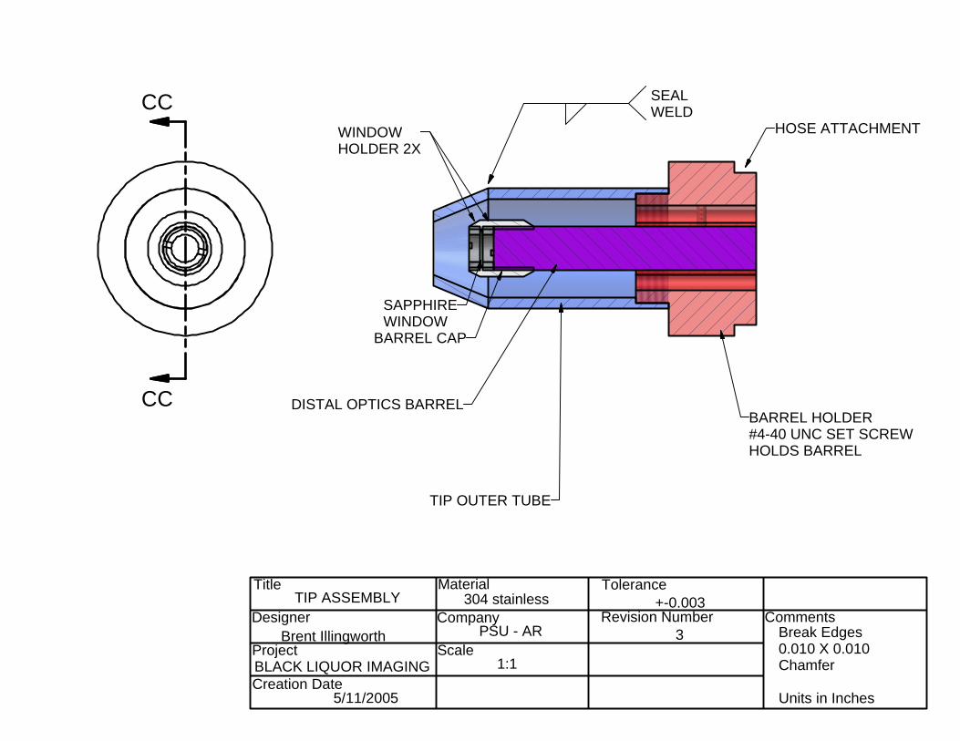
2 • Tip Assembly
The tip assembly holds the distal optics barrel in place and protects it from the boiler environment.
This piece extends further than any other component into the boiler and needs maximum protection. The
end piece indicated in Figure 8 is threaded on the inside for attachment to the barrel. A set screw is used
to hold the barrel in place so any vibration will not unthread it while in the boiler. There are holes all
around the perimeter of this piece to allow the cooling/purge air to surround the barrel.
A cap was designed that threads onto the barrel and holds a sapphire window in front of the optics
for protection from any debris that may overcome the purge air. Sapphire was used because of its
durability, high operating temperature, and excellent infrared transmission. Contrary to common
assumption, laboratory grade sapphire is rather inexpensive and is readily available. The sapphire
window is held in place by two retainers that are threaded into the cap as shown in Figure 8. The retainer
closest to the distal barrel also serves as a spacer between the optics and the window. This prevents debris
on the window from being in focus on the image.
Figure 7: Distal and proximal lens assemblies [3]
Infrared Imaging of Black Liquor Spray
14
A taper was designed to be
welded to a 1.5 in. piece of straight
tubing and thread to the end piece.
The purpose is to accelerate the
cooling/purge air to maximize debris
deflection and heat transfer. The
opening diameter had to be large
enough to prevent obstruction of the
image but as small as possible to
maximize the air velocity. The taper
and straight tubing assembly was
sized to accommodate a 45º angle of
view (AOV). This AOV value was a
conservative assumption to ensure
there would be no image obstruction.
Figure 9 illustrates how this assumed
optical acceptance does not interfere
with the taper. The actual AOV of
the distal optics is 37º so there is
some room for a wider angle optics
configuration if desired later.
a)
b)
Figure 8: Tip assembly: a) Exploded view b) Back view
Infrared Imaging of Black Liquor Spray
15
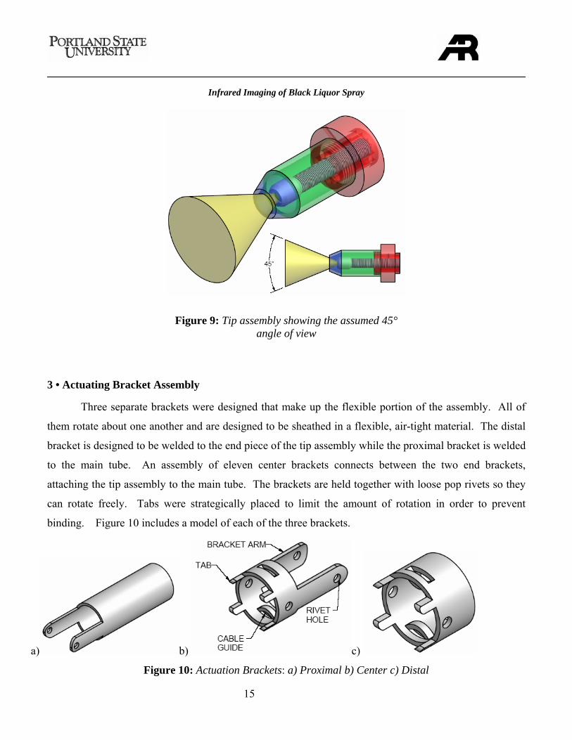
3 • Actuating Bracket Assembly
Three separate brackets were designed that make up the flexible portion of the assembly. All of
them rotate about one another and are designed to be sheathed in a flexible, air-tight material. The distal
bracket is designed to be welded to the end piece of the tip assembly while the proximal bracket is welded
to the main tube. An assembly of eleven center brackets connects between the two end brackets,
attaching the tip assembly to the main tube. The brackets are held together with loose pop rivets so they
can rotate freely. Tabs were strategically placed to limit the amount of rotation in order to prevent
binding. Figure 10 includes a model of each of the three brackets.
Figure 9: Tip assembly showing the assumed 45° angle of view
a) b) c)
Figure 10: Actuation Brackets: a) Proximal b) Center c) Distal
Infrared Imaging of Black Liquor Spray
16
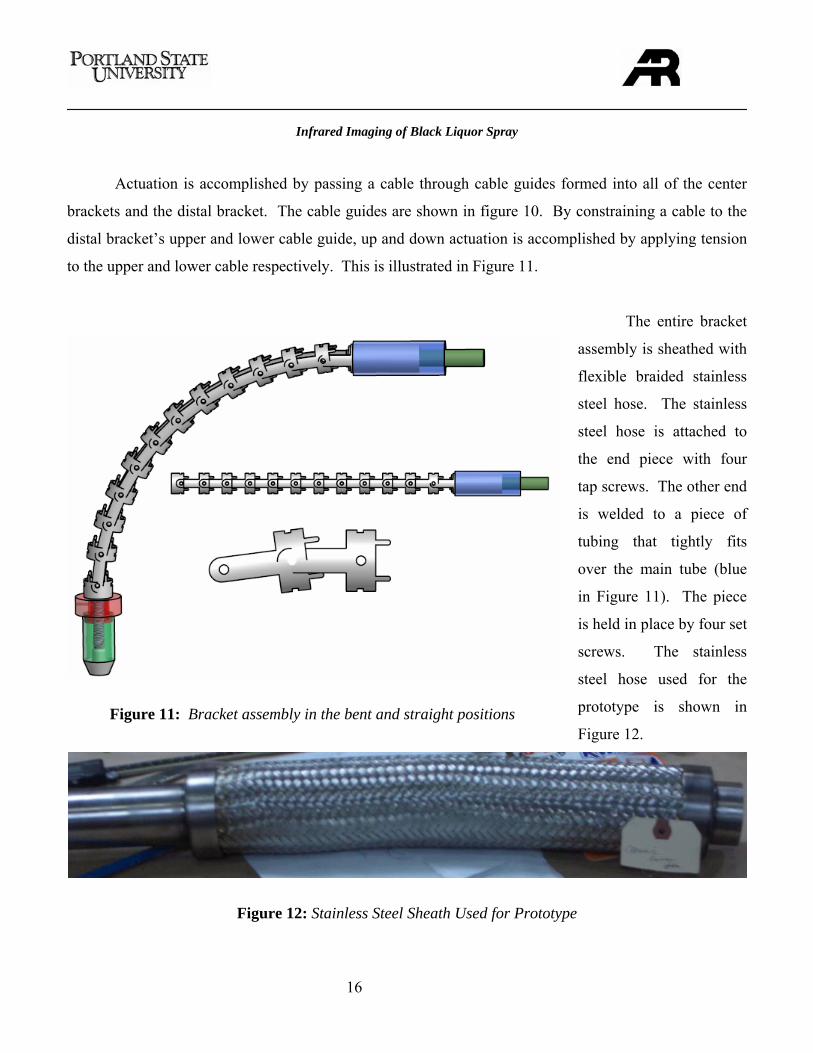
Actuation is accomplished by passing a cable through cable guides formed into all of the center
brackets and the distal bracket. The cable guides are shown in figure 10. By constraining a cable to the
distal bracket’s upper and lower cable guide, up and down actuation is accomplished by applying tension
to the upper and lower cable respectively. This is illustrated in Figure 11.
The entire bracket
assembly is sheathed with
flexible braided stainless
steel hose. The stainless
steel hose is attached to
the end piece with four
tap screws. The other end
is welded to a piece of
tubing that tightly fits
over the main tube (blue
in Figure 11). The piece
is held in place by four set
screws. The stainless
steel hose used for the
prototype is shown in
Figure 12.
Figure 12: Stainless Steel Sheath Used for Prototype
Figure 11: Bracket assembly in the bent and straight positions
Infrared Imaging of Black Liquor Spray
17
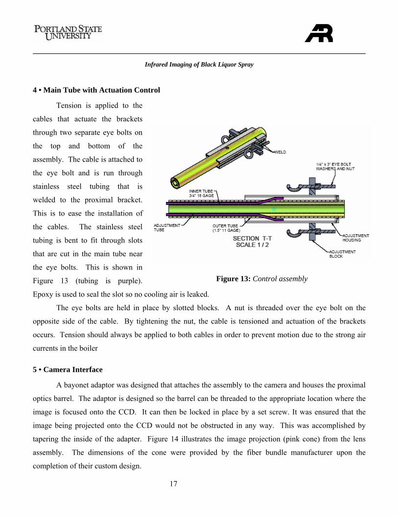
4 • Main Tube with Actuation Control
Tension is applied to the
cables that actuate the brackets
through two separate eye bolts on
the top and bottom of the
assembly. The cable is attached to
the eye bolt and is run through
stainless steel tubing that is
welded to the proximal bracket.
This is to ease the installation of
the cables. The stainless steel
tubing is bent to fit through slots
that are cut in the main tube near
the eye bolts. This is shown in
Figure 13 (tubing is purple).
Epoxy is used to seal the slot so no cooling air is leaked.
The eye bolts are held in place by slotted blocks. A nut is threaded over the eye bolt on the
opposite side of the cable. By tightening the nut, the cable is tensioned and actuation of the brackets
occurs. Tension should always be applied to both cables in order to prevent motion due to the strong air
currents in the boiler
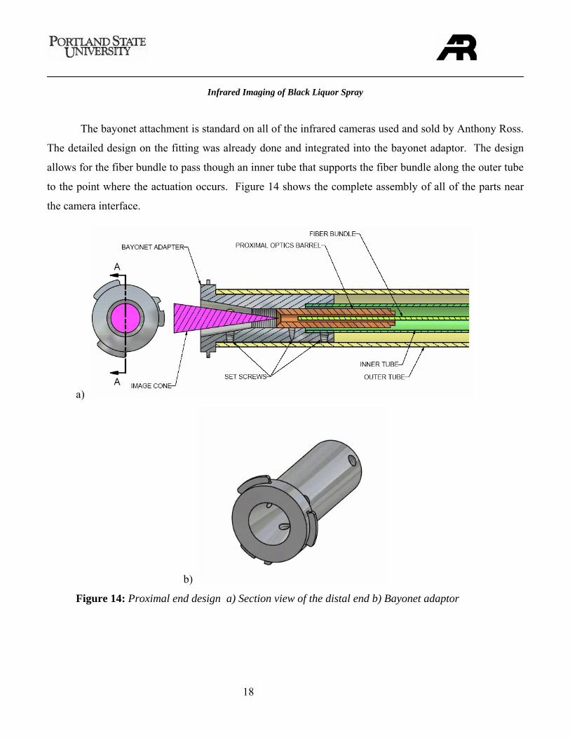
5 • Camera Interface
A bayonet adaptor was designed that attaches the assembly to the camera and houses the proximal
optics barrel. The adaptor is designed so the barrel can be threaded to the appropriate location where the
image is focused onto the CCD. It can then be locked in place by a set screw. It was ensured that the
image being projected onto the CCD would not be obstructed in any way. This was accomplished by
tapering the inside of the adapter. Figure 14 illustrates the image projection (pink cone) from the lens
assembly. The dimensions of the cone were provided by the fiber bundle manufacturer upon the
completion of their custom design.
Figure 13: Control assembly
Infrared Imaging of Black Liquor Spray
18
The bayonet attachment is standard on all of the infrared cameras used and sold by Anthony Ross.
The detailed design on the fitting was already done and integrated into the bayonet adaptor. The design
allows for the fiber bundle to pass though an inner tube that supports the fiber bundle along the outer tube
to the point where the actuation occurs. Figure 14 shows the complete assembly of all of the parts near
the camera interface.
a)
b)
Figure 14: Proximal end design a) Section view of the distal end b) Bayonet adaptor
Infrared Imaging of Black Liquor Spray
19
8 · EVALUATIONS
A prototype was built and the performance and ease of assembly was
tested. The following sections go into detail on the testing and the
results.
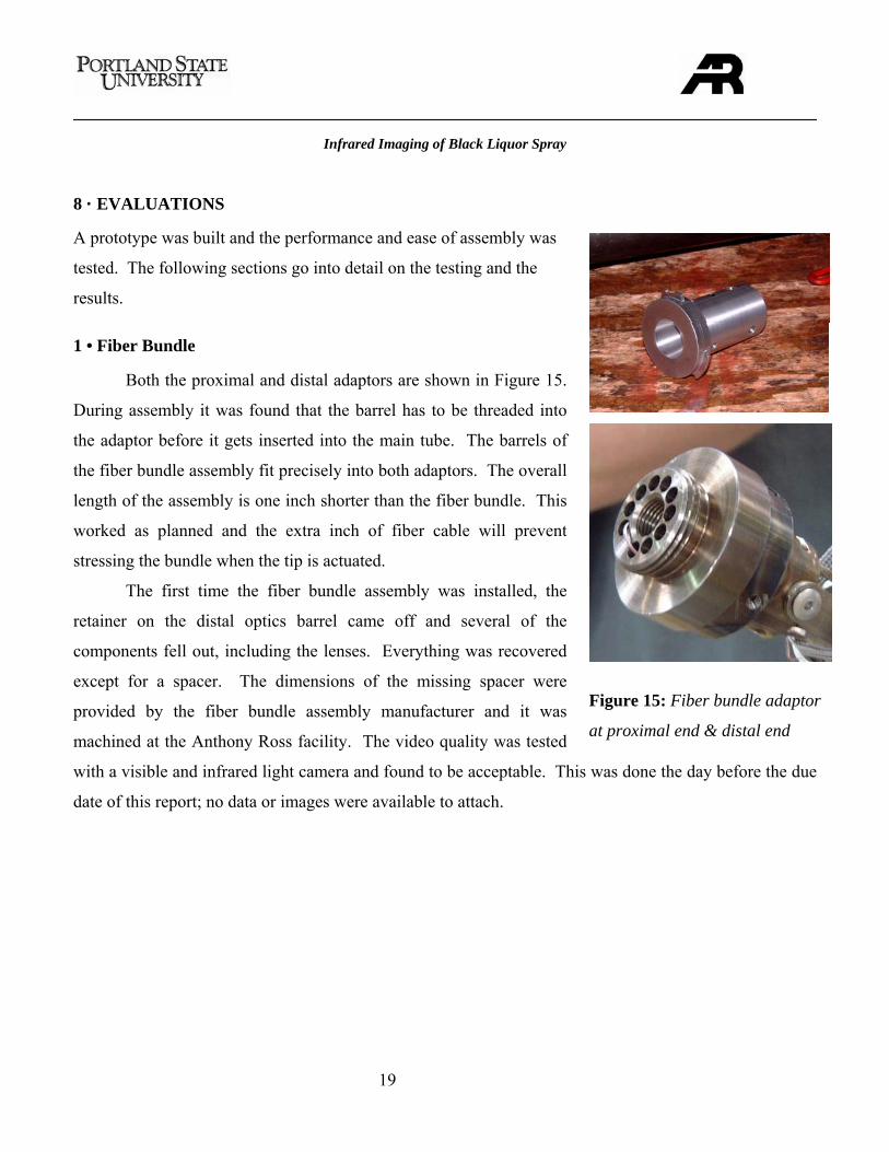
1 • Fiber Bundle
Both the proximal and distal adaptors are shown in Figure 15.
During assembly it was found that the barrel has to be threaded into
the adaptor before it gets inserted into the main tube. The barrels of
the fiber bundle assembly fit precisely into both adaptors. The overall
length of the assembly is one inch shorter than the fiber bundle. This
worked as planned and the extra inch of fiber cable will prevent
stressing the bundle when the tip is actuated.
The first time the fiber bundle assembly was installed, the
retainer on the distal optics barrel came off and several of the
components fell out, including the lenses. Everything was recovered
except for a spacer. The dimensions of the missing spacer were
provided by the fiber bundle assembly manufacturer and it was
machined at the Anthony Ross facility. The video quality was tested
with a visible and infrared light camera and found to be acceptable. This was done the day before the due
date of this report; no data or images were available to attach.
Figure 15: Fiber bundle adaptor
at proximal end & distal end
Infrared Imaging of Black Liquor Spray
20
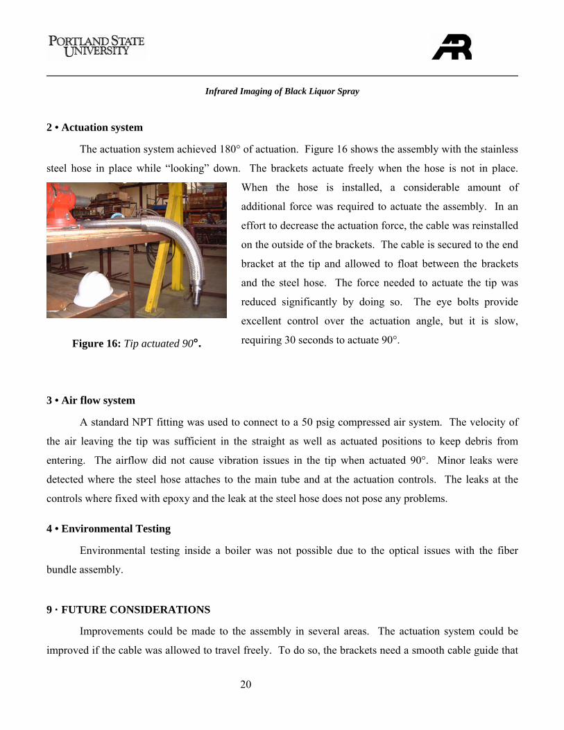
2 • Actuation system
The actuation system achieved 180° of actuation. Figure 16 shows the assembly with the stainless
steel hose in place while “looking” down. The brackets actuate freely when the hose is not in place.
When the hose is installed, a considerable amount of
additional force was required to actuate the assembly. In an
effort to decrease the actuation force, the cable was reinstalled
on the outside of the brackets. The cable is secured to the end
bracket at the tip and allowed to float between the brackets
and the steel hose. The force needed to actuate the tip was
reduced significantly by doing so. The eye bolts provide
excellent control over the actuation angle, but it is slow,
requiring 30 seconds to actuate 90°.
3 • Air flow system
A standard NPT fitting was used to connect to a 50 psig compressed air system. The velocity of
the air leaving the tip was sufficient in the straight as well as actuated positions to keep debris from
entering. The airflow did not cause vibration issues in the tip when actuated 90°. Minor leaks were
detected where the steel hose attaches to the main tube and at the actuation controls. The leaks at the
controls where fixed with epoxy and the leak at the steel hose does not pose any problems.
4 • Environmental Testing
Environmental testing inside a boiler was not possible due to the optical issues with the fiber
bundle assembly.
9 · FUTURE CONSIDERATIONS
Improvements could be made to the assembly in several areas. The actuation system could be
improved if the cable was allowed to travel freely. To do so, the brackets need a smooth cable guide that
Figure 16: Tip actuated 90°.
Infrared Imaging of Black Liquor Spray
21
will reduce friction. The flexible hose diameter could also be decreased; this would increase the
flexibility of the hose and decrease the actuation force required. The bracket assembly would be easier to
disassemble if the brackets were connected together with small bolts instead of rivets. If this was done,
the tip could be threaded onto the barrel of the fiber bundle reducing both installation time and the risk of
damage.
The fiber bundle diameter is very small, but the barrels are ½ in. The diameter of the barrels at the
distal and proximal ends could be decreased. If the barrel diameters were decreased, the overall scale of
the assembly could be decreased. The overall weight would be reduced, allowing for easier handling.
Since the surface area would be reduced, less heat would be absorbed, reducing the cooling requirement.
10 · CONCLUSION
Prototyping the assembly has been very informative. The assembly has been partially tested and
the overall design is sound. The assembly can be actuated 90° to look up or down, exceeding the
actuation requirement. The force required to actuate the tip was greater than expected due to friction in
the cable guides on the brackets, the problem was resolved by allowing the cable to float between the
outside of the bracket and the steel hose. The actuation controls, although slow, allow precise angle
adjustment of the tip. Airflow through the assembly was tested and found to be sufficient in blocking
debris from entering the tip and providing supplemental cooling.
The optics at the distal and proximal ends of the fiber bundle can be changed in the future. At the
proximal end, the optics can be changed to work with a different camera or to partially fill the CCD and
provide better resolution. At the distal end, the magnification, depth of focus, and the field of view can be
changed by replacing the lenses. This will have to be performed by the bundle manufacturer. The design
is both versatile and durable. The imaging performance was acceptable. It could be improved with the
use of a higher density bundle or by under-filling the CCD.
Infrared Imaging of Black Liquor Spray
22
11 · REFERENCES
[1] J. Peirs, D. Reyaenrts, et. al., Design of Miniature Parallel manipulators for integration in a self propelling endoscope, Sensors & actuators A, Vol 85, Elsevier Science, 2000, pp. 409-417. [2] Myriad Fiber Imaging Inc. [Online] http://www.myriadfiber.com, 5/25/05 [3] J. McDonald, Anthony Ross Fiber Bundle Assembly Drawing [4] Veterinary Endoscope and Otoscope. [Online] Medit Endocopy http://endoscopy4vet.com, 3/4/05 [5] Products associated with fiber optic systems incorporating CCD cameras, [Online] Schott North America. http://www.us.schott.com/fiberoptics/english/products, 3/3/05 [6] G. Ellison, Electronics Cooling [electronic version], 2005, pp. 62-65 [7] F. Incropera, D. Dewitt. Fundamentals of Heat and Mass Transfer, 2004 [8] T. Adams, W. Fredrick, T. Grace, M. Hupa, K. Lisa, A. Jones, H. Tran, Kraft Recovery Boilers, Tappi Press, 1997
12 · ACKNOWLEGMENTS
This project would not have been possible without the expertise and resources of Anthony Ross
Company. A special thanks is given to Dan Higgins of Anthony Ross Company, for his dedication to
moving the project forward. Thanks to Rich Hogle of Enertechnix, for the infrared camera support.
Thanks to Jim McDonald of Myriad Fiber Inc. for the fiber bundle support. Thanks to Brent Benoit
Machining for the part manufacturing on short notice.
13 · APPENDICES
APPENDIX A: Manufacturing Instructions
Overview
Drawings are shown below of the tip subassembly, the bracket subassembly, the end subassembly,
and the full assembly. The full assembly describes the assembly of all of the three subassemblies. A list
of manufactured parts is provided after each of the assembly drawings. The parts are referenced to an
assembly and the material and method of manufacture is listed. For more detailed part information, refer
to the drawings in Appendix G.
Infrared Imaging of Black Liquor Spray
23
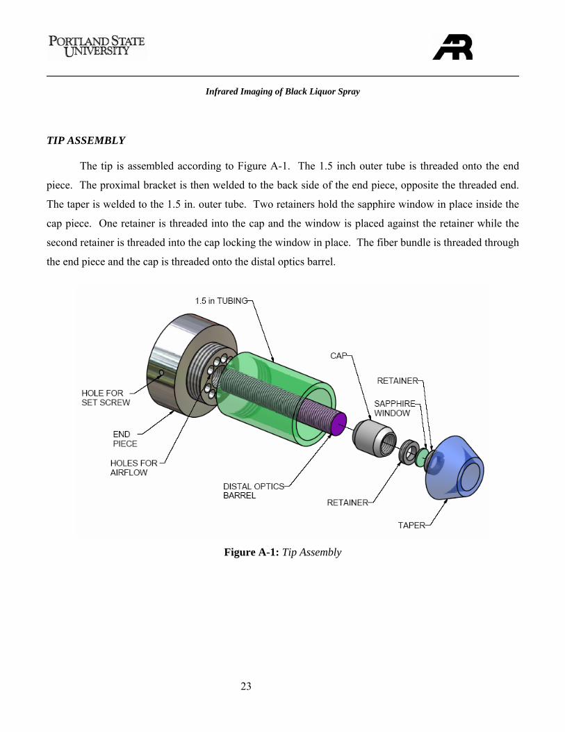
TIP ASSEMBLY The tip is assembled according to Figure A-1. The 1.5 inch outer tube is threaded onto the end
piece. The proximal bracket is then welded to the back side of the end piece, opposite the threaded end.
The taper is welded to the 1.5 in. outer tube. Two retainers hold the sapphire window in place inside the
cap piece. One retainer is threaded into the cap and the window is placed against the retainer while the
second retainer is threaded into the cap locking the window in place. The fiber bundle is threaded through
the end piece and the cap is threaded onto the distal optics barrel.
Figure A-1: Tip Assembly
Infrared Imaging of Black Liquor Spray
24
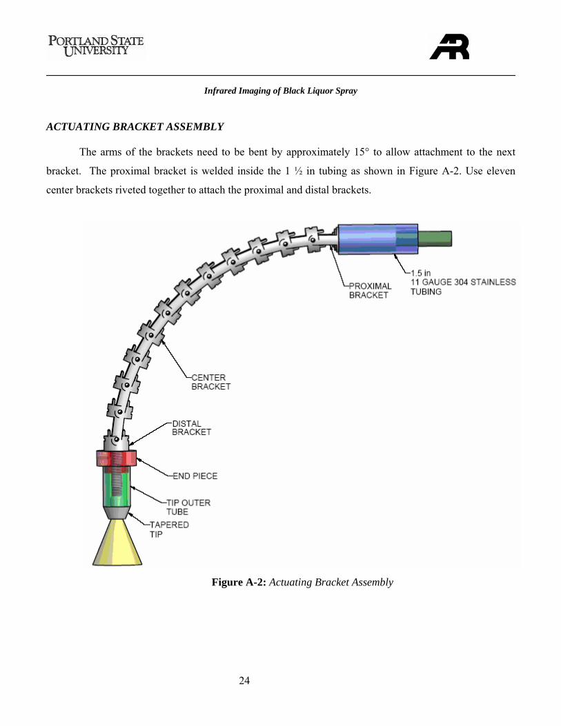
ACTUATING BRACKET ASSEMBLY The arms of the brackets need to be bent by approximately 15° to allow attachment to the next
bracket. The proximal bracket is welded inside the 1 ½ in tubing as shown in Figure A-2. Use eleven
center brackets riveted together to attach the proximal and distal brackets.
Figure A-2: Actuating Bracket Assembly
Infrared Imaging of Black Liquor Spray
25
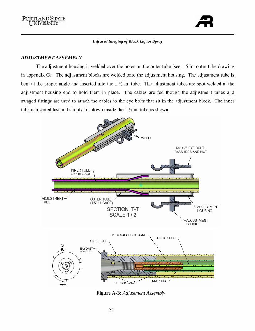
ADJUSTMENT ASSEMBLY
The adjustment housing is welded over the holes on the outer tube (see 1.5 in. outer tube drawing
in appendix G). The adjustment blocks are welded onto the adjustment housing. The adjustment tube is
bent at the proper angle and inserted into the 1 ½ in. tube. The adjustment tubes are spot welded at the
adjustment housing end to hold them in place. The cables are fed though the adjustment tubes and
swaged fittings are used to attach the cables to the eye bolts that sit in the adjustment block. The inner
tube is inserted last and simply fits down inside the 1 ½ in. tube as shown.
Figure A-3: Adjustment Assembly
Infrared Imaging of Black Liquor Spray
26
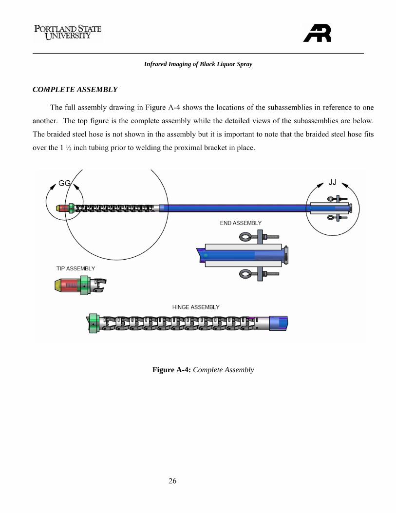
COMPLETE ASSEMBLY
The full assembly drawing in Figure A-4 shows the locations of the subassemblies in reference to one
another. The top figure is the complete assembly while the detailed views of the subassemblies are below.
The braided steel hose is not shown in the assembly but it is important to note that the braided steel hose fits
over the 1 ½ inch tubing prior to welding the proximal bracket in place.
Figure A-4: Complete Assembly
Infrared Imaging of Black Liquor Spray
27
Table A-1 shows the designed parts, how they are manufactured and the material they are made from.
Standard off the shelf items such as tubing and bolts are not shown.
Table A-1: Parts Description
Tapered Tip – Machined from 304 stainless steel.
Location: Tip assembly
Description: This part is welded onto the tip outer tube shown next.
Tip Outer Tube – Manufactured from 1 ½ in, 11 gauge, 304 stainless tubing.
Location: Tip assembly
Description: This part is threaded onto the end piece.
Barrel Cap – Machined from 304 stainless steel.
Location: Tip assembly
Description: This part is threaded onto the distal barrel of the fiber bundle.
Retainer – Machined from 304 stainless steel
Location: Tip assembly
Description: This part holds the window in place inside the barrel cap.
Infrared Imaging of Black Liquor Spray
28
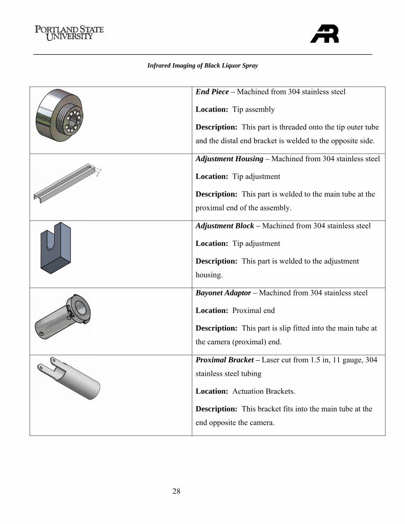
End Piece – Machined from 304 stainless steel
Location: Tip assembly
Description: This part is threaded onto the tip outer tube
and the distal end bracket is welded to the opposite side.
Adjustment Housing – Machined from 304 stainless steel
Location: Tip adjustment
Description: This part is welded to the main tube at the
proximal end of the assembly.
Adjustment Block – Machined from 304 stainless steel
Location: Tip adjustment
Description: This part is welded to the adjustment
housing.
Bayonet Adaptor – Machined from 304 stainless steel
Location: Proximal end
Description: This part is slip fitted into the main tube at
the camera (proximal) end.
Proximal Bracket – Laser cut from 1.5 in, 11 gauge, 304
stainless steel tubing
Location: Actuation Brackets.
Description: This bracket fits into the main tube at the
end opposite the camera.
Infrared Imaging of Black Liquor Spray
29
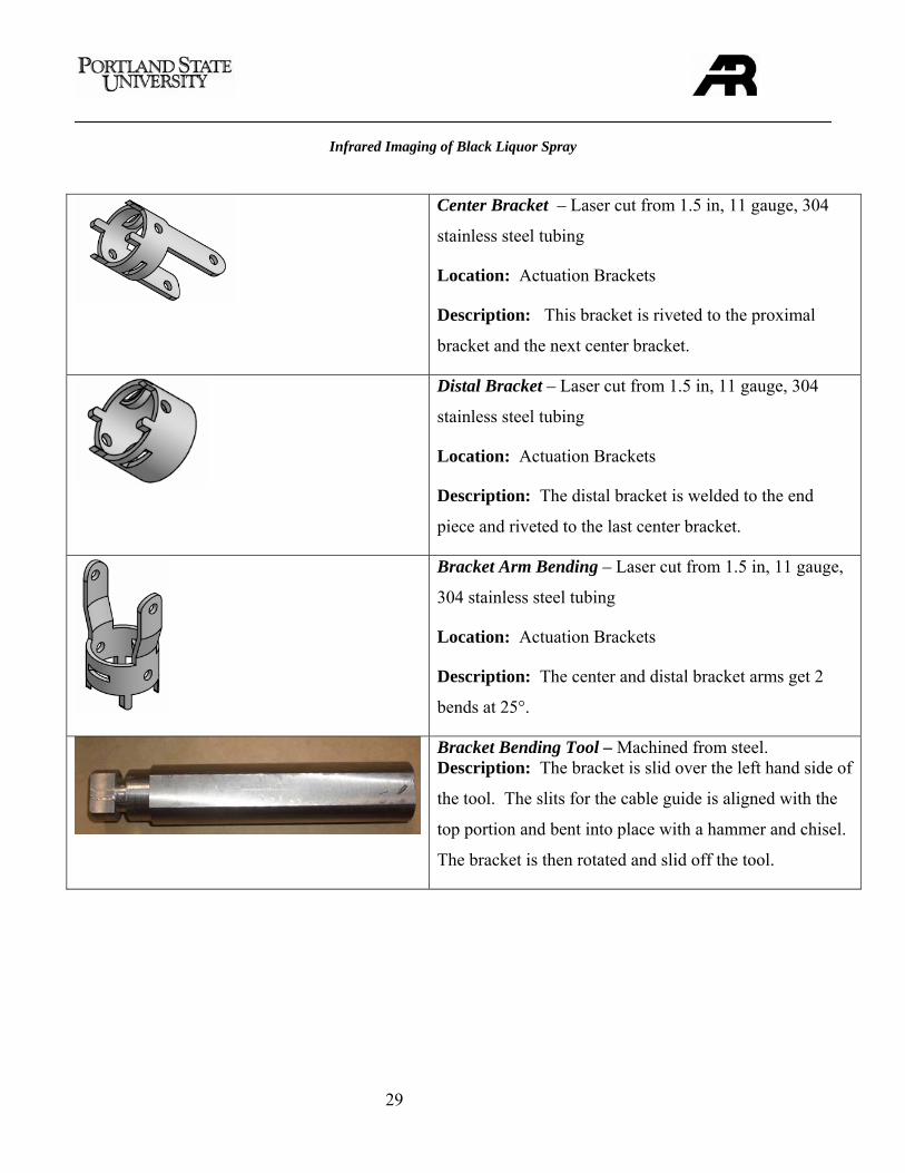
Center Bracket – Laser cut from 1.5 in, 11 gauge, 304
stainless steel tubing
Location: Actuation Brackets
Description: This bracket is riveted to the proximal
bracket and the next center bracket.
Distal Bracket – Laser cut from 1.5 in, 11 gauge, 304
stainless steel tubing
Location: Actuation Brackets
Description: The distal bracket is welded to the end
piece and riveted to the last center bracket.
Bracket Arm Bending – Laser cut from 1.5 in, 11 gauge,
304 stainless steel tubing
Location: Actuation Brackets
Description: The center and distal bracket arms get 2
bends at 25°.
Bracket Bending Tool – Machined from steel. Description: The bracket is slid over the left hand side of
the tool. The slits for the cable guide is aligned with the
top portion and bent into place with a hammer and chisel.
The bracket is then rotated and slid off the tool.
Infrared Imaging of Black Liquor Spray
30
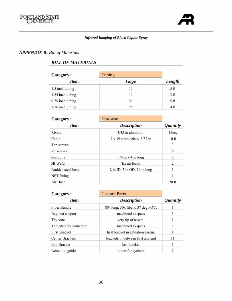
APPENDIX B: Bill of Materials
BILL OF MATERIALS Category: Tubing
Item Gage Length 1.5 inch tubing 11 5 ft 1.25 inch tubing 11 3 ft 0.75 inch tubing 21 5 ft 3/16 inch tubing 22 4 ft Category: Hardware
Item Description Quantity Rivets 3/32 in aluminum 1 box Cable 7 x 19 strand class, 3/32 in 10 ft Tap screws 3 set screws 5 eye bolts 1/4 in x 4 in long 2 JB Weld fix air leaks 2 Braided steel hose 2 in ID, 5 in OD, 24 in long 1 NPT fitting 1 Air Hose 20 ft Category: Custom Parts
Item Description Quantity Fiber Bundle 80" long, 30k fibers, 37 deg FOV, 1 Bayonet adaptor machined to specs 1 Tip cone very tip of assem. 1 Threaded tip connector machined to specs 1 First Bracket first bracket in actuation assem. 1 Center Brackets brackets in between first and end 11 End Bracket last bracket 1 Actuation guide mount for eyebolts 2
Infrared Imaging of Black Liquor Spray
31
APPENDIX C: Operations Manual
Safety:
• Proper clothing should be worn that covers the legs and arms. • Do not touch the assembly as it comes out of the boiler; it will be hot. • Two people are required to operate the camera and assembly. • Always follow safety rules set forth by the boiler facilities management.
Operation:
• Connect air hose to the assembly. • Ensure that air is flowing through the assembly. • Straighten the assembly to enter the boiler.
o Using the ratcheting wrench, loosen or tighten the eye bolts until the tip is parallel with the rest of the assembly
• Insert the assembly into the boiler though the tertiary air port. • To look down, tighten the bottom eyebolt and then loosen the top eye bolt until assembly is at
desired angle. • To look up, do the opposite. • A thermocouple is installed near the fiber bundle at the tip. Remove assembly when
temperature reaches 500°F to prevent damage to the fiber bundle. • After capturing desired footage, straighten lens assembly back to parallel and remove from the
boiler. Be sure not to touch the lens assembly as it will be extremely hot. • Allow lens system to cool (could take an hour or more). • Remove the fiber bundle and store in safe place. • Clean the assembly using solvents where necessary.
Infrared Imaging of Black Liquor Spray
32
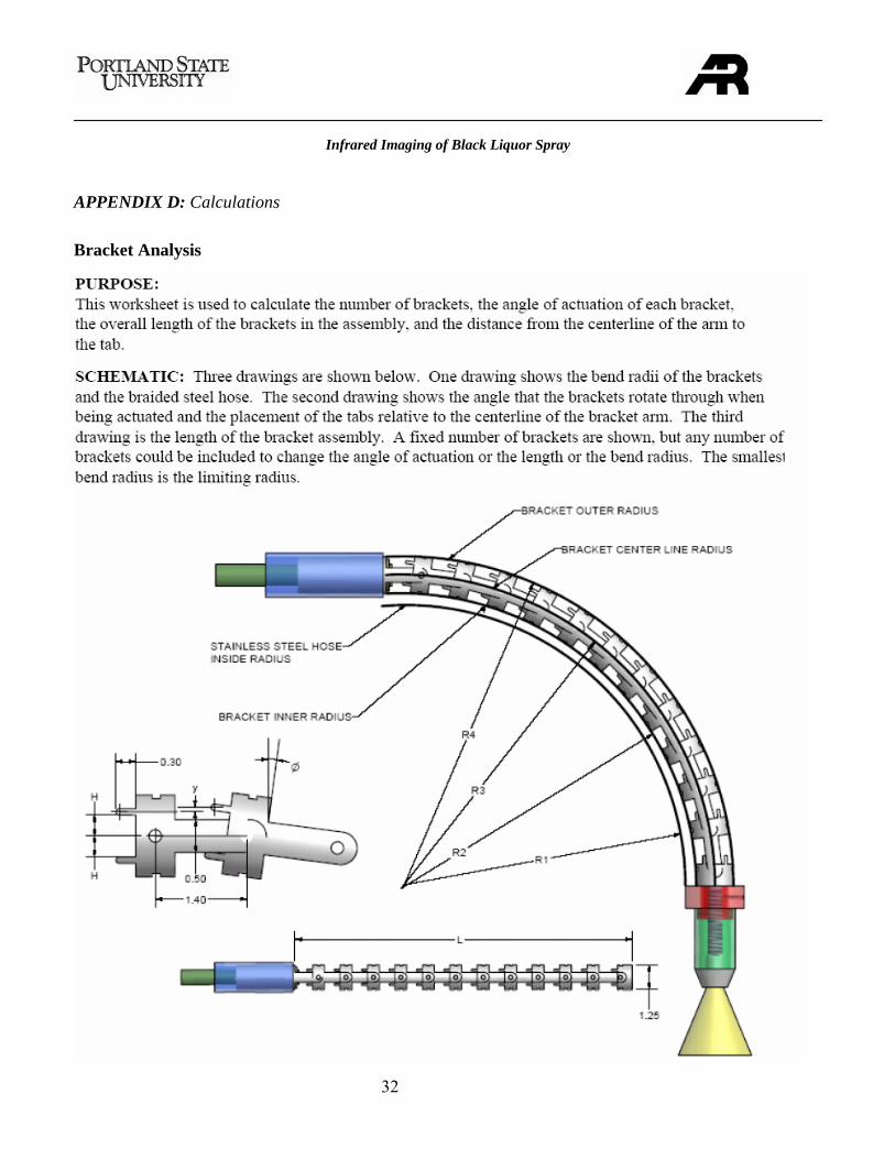
APPENDIX D: Calculations
Bracket Analysis
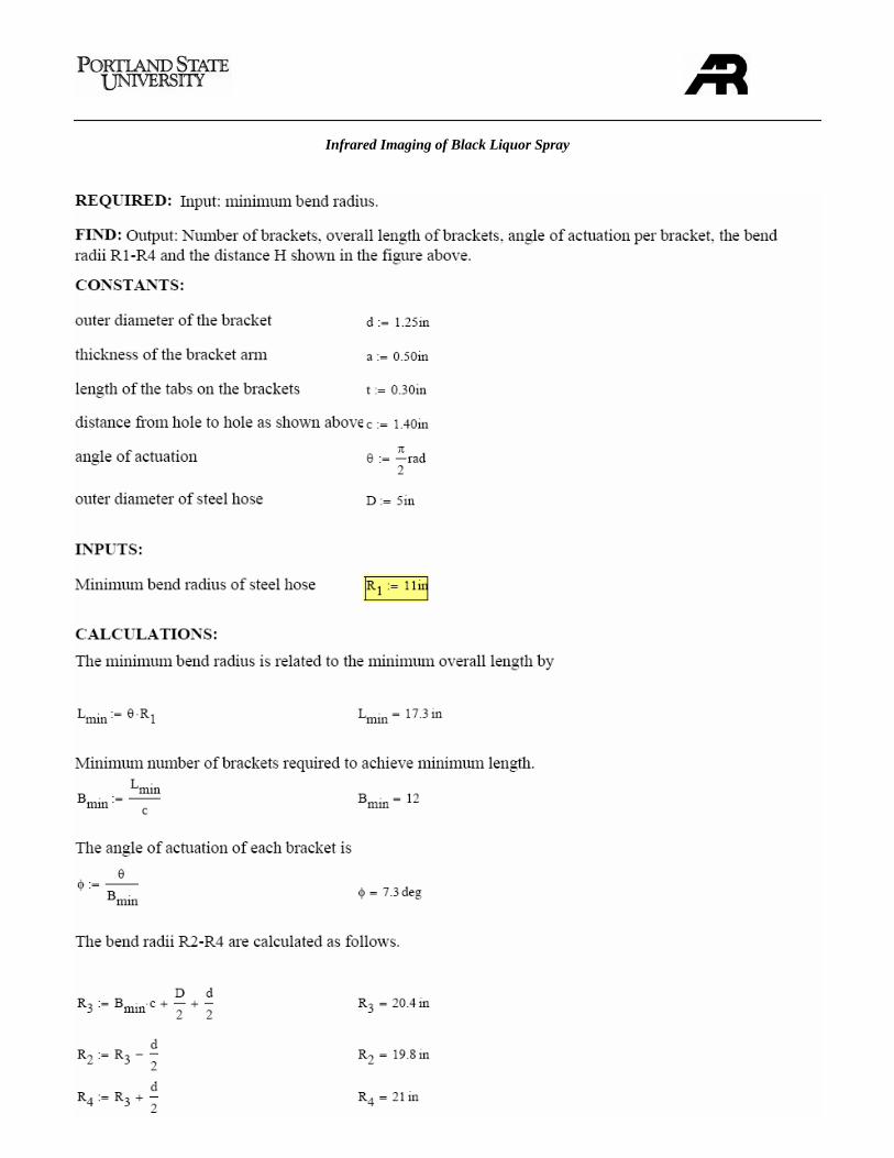
Infrared Imaging of Black Liquor Spray
33
Infrared Imaging of Black Liquor Spray
34
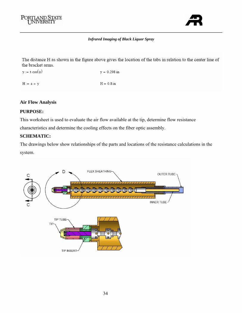
Air Flow Analysis
PURPOSE:
This worksheet is used to evaluate the air flow available at the tip, determine flow resistance
characteristics and determine the cooling effects on the fiber optic assembly.
SCHEMATIC:
The drawings below show relationships of the parts and locations of the resistance calculations in the
system.
Infrared Imaging of Black Liquor Spray
35
REQUIRED:
Total system resistance to air flow and corresponding mass flow rates in the system with provided
pressure range
FIND:
Individual air flow resistance of each component, maximum cooling rate possible, Reynolds number for
flow, maximum flow rate possible through system.
CONSTANTS:
Airflow Available: 35CFM to 50 CFM
Inlet Air Temperature: 100ºF
Maximum outlet air temperature: 500 ºF
Cp Air (@ 370 ºF Ave. Temp.): 0.243 BTU/Lbm*ºR
ρair (@ 370 ºF Ave. Temp.): 0.051 Lbm/Ft3
ASSUMPTIONS:
1. No air is lost through the adjustment tubes or fiber-optic interface.
2. Air introduced into the system is at 100 ºF with low relative humidity
3. Low velocity airflow modeling techniques are valid (relatively accurate) at
extreme velocities.
CALCULATIONS:
The following calculations are based on airflow methodology and the work of Professor Gordon Ellison
in relation to heat transfer and electronics cooling. To determine the heat transfer and dissipation
characteristics of the system mass flowrate for the air must be calculated for the initial estimation
purposes.
Mass flowrate = available airflow * density of the air mass* unit correction factor
Infrared Imaging of Black Liquor Spray
36
Mass flowrate = (35CFM to 50 CFM) * (0.051 Lbm/Ft3) * (1 min./60 sec.)
Mass flowrate =0.0298 to 0.0425 Lbm/s
Maximum heat transfer capability of the air in the system with all other properties constant is:
Q = mass flowrate * Cp air * Temperature change of the air
Q = (0.0298 to 0.0425 Lbm/s) * (0.243 BTU/Lbm*ºR) * (500 ºF- 100ºF)
Q = 2.897 to 4.131 BTU/s = 3056 to 4358 Watts
This is a generalized over estimation of the thermal dissipation properties of the system. The following
calculations will refine the values above to closer model air resistance, flow and heat transfer
characteristics within the system. First approximation of the velocity in the pipe can be calculated using
the Bernoulli equation. Relating pressure drop and velocity in the system:
∆P = (V22- V1
2)ρ/(2Gc)
V=[(∆P*2*Gc)/ ρ]1/2
V = [(50 psi*2*32.2ft/s2*144si/sf)/0.053Lbm/ft3]1/2
V = 2958 ft/s
This allows us to calculate the Reynolds number for the airflow in the system:
Re = ρVD/µ
Re = (0.053lbm/ft3)(2958ft/s)(0.081 ft)/(5.24e-7lb*s/ft2)
Re = 2.4 x 10⁷
Flow is high in the turbulent range and will cause a significant amount of noise in the system. This noise
will be eclipsed by the surrounding noise of the boiler.
Infrared Imaging of Black Liquor Spray
37
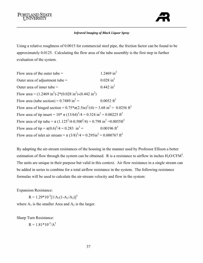
Using a relative roughness of 0.0015 for commercial steel pipe, the friction factor can be found to be
approximately 0.0125. Calculating the flow area of the tube assembly is the first step in further
evaluation of the system.
Flow area of the outer tube = 1.2469 in2
Outer area of adjustment tube = 0.028 in2
Outer area of inner tube = 0.442 in2
Flow area = (1.2469 in2)-2*(0.028 in2)-(0.442 in2)
Flow area (tube section) = 0.7489 in2 = 0.0052 ft2
Flow area of hinged section = 0.75*π(2.5in)2/(4) = 3.68 in2 = 0.0256 ft2
Flow area of tip insert = 10* π (13/64)2/4 = 0.324 in2 = 0.00225 ft2
Flow area of tip tube = π (1.1252/4-0.5002/4) = 0.798 in2 =0.0055ft2
Flow area of tip = π(0.6)2/4 = 0.283 in2 = 0.00196 ft2
Flow area of inlet air stream = π (3/8)2/4 = 0.295in2 = 0.000767 ft2
By adapting the air-stream resistances of the housing in the manner used by Professor Ellison a better
estimation of flow through the system can be obtained. R is a resistance to airflow in inches H2O/CFM2.
The units are unique in their purpose but valid in this context. Air flow resistance in a single stream can
be added in series to combine for a total airflow resistance in the system. The following resistance
formulas will be used to calculate the air-stream velocity and flow in the system:
Expansion Resistance:
R = 1.29*10-3[1/A1(1-A1/A2)]2
where A1 is the smaller Area and A2 is the larger.
Sharp Turn Resistance:
R = 1.81*10-3/A2
Infrared Imaging of Black Liquor Spray
38
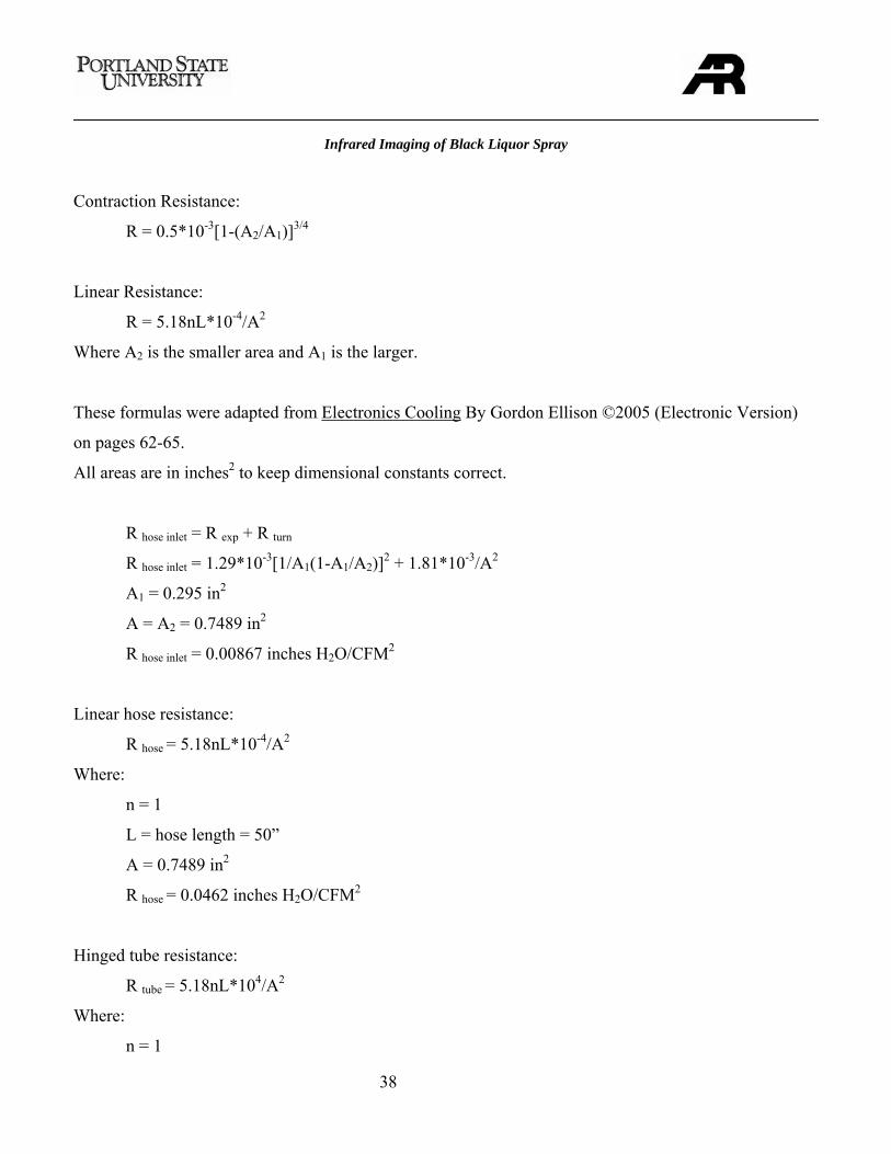
Contraction Resistance:
R = 0.5*10-3[1-(A2/A1)]3/4
Linear Resistance:
R = 5.18nL*10-4/A2
Where A2 is the smaller area and A1 is the larger.
These formulas were adapted from Electronics Cooling By Gordon Ellison ©2005 (Electronic Version)
on pages 62-65.
All areas are in inches2 to keep dimensional constants correct.
R hose inlet = R exp + R turn
R hose inlet = 1.29*10-3[1/A1(1-A1/A2)]2 + 1.81*10-3/A2
A1 = 0.295 in2
A = A2 = 0.7489 in2
R hose inlet = 0.00867 inches H2O/CFM2
Linear hose resistance:
R hose = 5.18nL*10-4/A2
Where:
n = 1
L = hose length = 50”
A = 0.7489 in2
R hose = 0.0462 inches H2O/CFM2
Hinged tube resistance:
R tube = 5.18nL*104/A2
Where:
n = 1
Infrared Imaging of Black Liquor Spray
39
L = 17”
A = 3.68 in2
R tube = 0.00564 inches H2O/CFM2
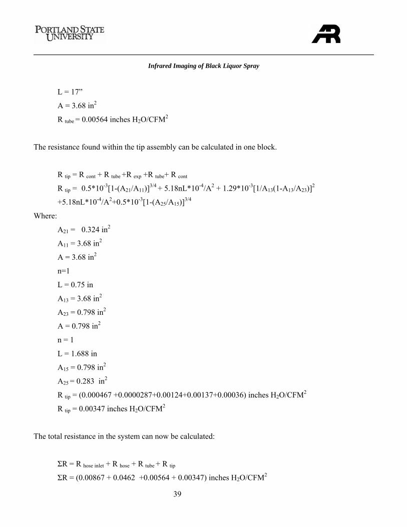
The resistance found within the tip assembly can be calculated in one block.
R tip = R cont + R tube +R exp +R tube+ R cont
R tip = 0.5*10-3[1-(A21/A11)]3/4 + 5.18nL*10-4/A2 + 1.29*10-3[1/A13(1-A13/A23)]2
+5.18nL*10-4/A2+0.5*10-3[1-(A25/A15)]3/4
Where:
A21 = 0.324 in2 A11 = 3.68 in2
A = 3.68 in2
n=1
L = 0.75 in
A13 = 3.68 in2
A23 = 0.798 in2
A = 0.798 in2
n = 1
L = 1.688 in
A15 = 0.798 in2
A25 = 0.283 in2
R tip = (0.000467 +0.0000287+0.00124+0.00137+0.00036) inches H2O/CFM2
R tip = 0.00347 inches H2O/CFM2
The total resistance in the system can now be calculated:
ΣR = R hose inlet + R hose + R tube + R tip
ΣR = (0.00867 + 0.0462 +0.00564 + 0.00347) inches H2O/CFM2
Infrared Imaging of Black Liquor Spray
40
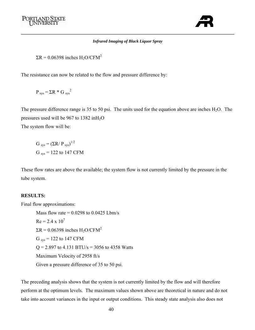
ΣR = 0.06398 inches H2O/CFM2
The resistance can now be related to the flow and pressure difference by:
P sys = ΣR * G sys2
The pressure difference range is 35 to 50 psi. The units used for the equation above are inches H2O. The
pressures used will be 967 to 1382 inH2O
The system flow will be:
G sys = (ΣR/ P sys)1/2
G sys = 122 to 147 CFM
These flow rates are above the available; the system flow is not currently limited by the pressure in the
tube system.
RESULTS:
Final flow approximations:
Mass flow rate = 0.0298 to 0.0425 Lbm/s
Re = 2.4 x 10⁷
ΣR = 0.06398 inches H2O/CFM2
G sys = 122 to 147 CFM
Q = 2.897 to 4.131 BTU/s = 3056 to 4358 Watts
Maximum Velocity of 2958 ft/s
Given a pressure difference of 35 to 50 psi.
The preceding analysis shows that the system is not currently limited by the flow and will therefore
perform at the optimum levels. The maximum values shown above are theoretical in nature and do not
take into account variances in the input or output conditions. This steady state analysis also does not
Infrared Imaging of Black Liquor Spray
41
consider the effects of changing densities due to temperature in the system. These factors are considered
negligible for this exercise.
Heat Transfer Analysis
PURPOSE:
This worksheet is used to calculate the heat transfer from the boiler to the surface of the fiber optics and
verify that the assembly can remain in the boiler for approximately thirty minutes
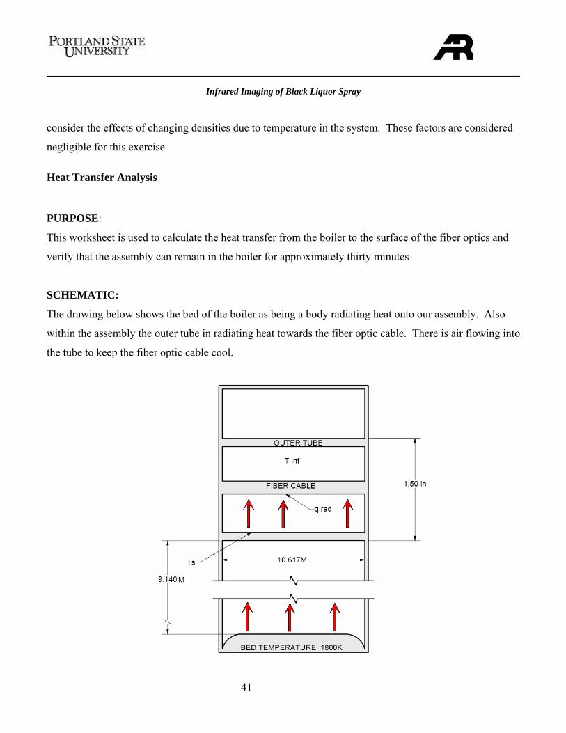
SCHEMATIC:
The drawing below shows the bed of the boiler as being a body radiating heat onto our assembly. Also
within the assembly the outer tube in radiating heat towards the fiber optic cable. There is air flowing into
the tube to keep the fiber optic cable cool.
Infrared Imaging of Black Liquor Spray
42
CONSTANTS:
Tbed = 1800K
Tinf, air = 900K
h = 25 Km
W∗2
81067.5 −∗=σ
23.23.
==
o
T
εε
Emissivity of solid stainless steel
H = 9.144m
L = .6096m
w = 10.617m
KKgKJC bundlep
*750, =
mrmr
inner
outer
036.0381.
==
ASSUMPTIONS:
1. No losses in system.
2. The fiber bundle is located in the center of the housing.
3. After rising to 898K the surface temperature of the housing is constant.
4. The environment inside boiler is static. (No temperature fluctuation.)
5. Cooling airflow is at a constant temperature and pressure.
REQUIRED:
Determine the time that the fiber optic cable can be in the boiler before its temperature reaches 644 K.
CALCULATIONS:
First step of this solution is to determine the surface temperature of the outer tubing of the assembly by
looking at the radiation from the bed.
Infrared Imaging of Black Liquor Spray
43
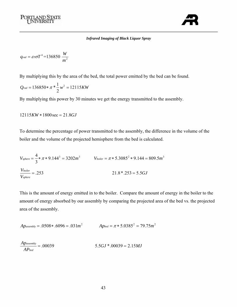
4Tq Trad σε= =136850 2mW
By multiplying this by the area of the bed, the total power emitted by the bed can be found.
KWwQrad 1211521*136850 2 =∗= π
By multiplying this power by 30 minutes we get the energy transmitted to the assembly.
GJKW 8.21sec180012115 =∗
To determine the percentage of power transmitted to the assembly, the difference in the volume of the
boiler and the volume of the projected hemisphere from the bed is calculated.
33 3202144.934 mVsphere =∗∗= π 32 5.809144.93085.5 mVboiler =∗∗= π
253.=sphere
boiler
VV GJ5.5253.*8.21 =
This is the amount of energy emitted in to the boiler. Compare the amount of energy in the boiler to the
amount of energy absorbed by our assembly by comparing the projected area of the bed vs. the projected
area of the assembly.
2031.6096.0508. mApassembly =∗= 22 75.790385.5 mApbed =∗= π
00039.=bed
assembly
APAp MJGJ 15.200039.*5.5 =
Infrared Imaging of Black Liquor Spray
44
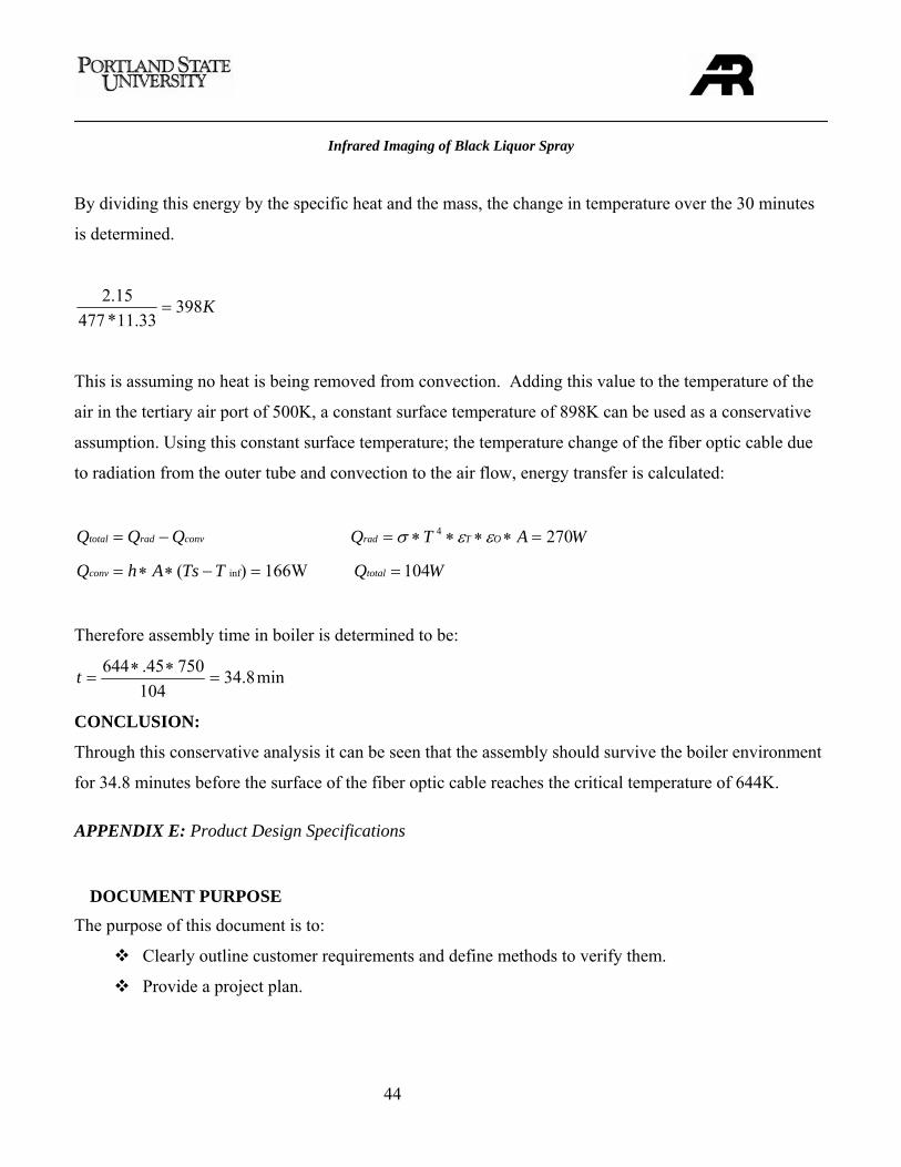
By dividing this energy by the specific heat and the mass, the change in temperature over the 30 minutes
is determined.
K39833.11*477
15.2=
This is assuming no heat is being removed from convection. Adding this value to the temperature of the
air in the tertiary air port of 500K, a constant surface temperature of 898K can be used as a conservative
assumption. Using this constant surface temperature; the temperature change of the fiber optic cable due
to radiation from the outer tube and convection to the air flow, energy transfer is calculated:
convradtotal QQQ −= WATQ OTrad 2704 =∗∗∗∗= εεσ
=−∗∗= )( infTTsAhQconv 166W WQtotal 104=
Therefore assembly time in boiler is determined to be:
min8.34104
75045.644=
∗∗=t
CONCLUSION:
Through this conservative analysis it can be seen that the assembly should survive the boiler environment
for 34.8 minutes before the surface of the fiber optic cable reaches the critical temperature of 644K.
APPENDIX E: Product Design Specifications
DOCUMENT PURPOSE
The purpose of this document is to:
Clearly outline customer requirements and define methods to verify them.
Provide a project plan.
Infrared Imaging of Black Liquor Spray
45
MISSION STATEMENT
Design an optical assembly that will attach to the infrared camera currently being distributed by Anthony
Ross Company. The assembly will provide clear images of black liquor droplets to the camera and allow
Anthony Ross’ engineers to improve their mathematical model of the recovery boiler.
CUSTOMER IDENTIFICATION
The following outline indicates our main customers along with their most important design criteria.
Anthony Ross:
Performance
Quality and reliability
Testing
Legal
Product life
Boiler Personnel/Technicians:
Safety
Maintainability
Performance
Size
Weight
Installation
Ergonomics
Quality and reliability
Applicable codes
PROJECT PLAN
The project fell behind by April, but recovered in May. The prototype was built by June, but testing time
was reduced. The setback was due to the fiber bundle, which had to be custom designed for a difficult
Infrared Imaging of Black Liquor Spray
46
application. The time allotted for testing went from two weeks to three days. The assembly performance
was tested and verified within those three days and the requirements were met.
Figure E-1: Project Timeline
PRODUCT DESIGN SPECIFICATIONS
Environment
Primary Customers: Recovery boiler personnel, Anthony Ross
Customer requirement:
Assembly will be able to withstand environment up to 2000°F for 30 minutes.
Assembly will be able to handle an environment that contains harsh chemicals, fast moving
debris.
Assembly must fit through tertiary air port above the liquor guns (63 mm diameter).
Assembly must extend at least 1 meter into the boiler.
Engineering Targets:
Assembly will be capable of withstanding the recovery boiler environment for a period of 30
minutes minimum.
Infrared Imaging of Black Liquor Spray
47
The Assembly must handle the boiler environment without loss of resolution or equipment
integrity.
Safety
Primary Customers: Recovery boiler personnel, Anthony Ross
Customer requirement:
The camera operator will be protected from flames that may escape from the boiler.
The camera system will be safe to install.
Documentation on use and maintenance will be provided.
Engineering Targets:
All components will conform to codes and standards governing recovery boiler operation.
Materials will be selected with properties that ensure compatibility with boiler environment.
Documentation explaining safe operation will be provided.
Maintenance
Primary Customers: Recovery boiler personnel, Anthony Ross
Customer requirement:
Tools and parts needed for maintenance will be defined.
Documentation describing the maintenance procedure and schedule.
Engineering Targets:
Maintenance schedule will be determined to provide long life.
Documentation on maintenance will be provided.
Performance
Primary Customers: Recovery boiler personnel, Anthony Ross
Customer requirement:
Assembly will have the ability to image black liquor droplets high resolution.
Assembly must be able to provide clear images while in the boiler for 30-minute periods and
prevent damage to itself or the camera.
Assembly must survive multiple trips into the boiler without image degradation or damage.
Infrared Imaging of Black Liquor Spray
48
A viewing angle adjustment from 0º to 90º is required. This is necessary to enable the user to
locate and analyze different regions of the spray.
Focal length must be adjustable and known.
Depth of focus must be narrow.
Engineering Targets:
Camera and assembly will provide clear images. A clear image is defined as an image with
enough resolution that data may be obtained.
The camera system will withstand the recovery boiler environment for 30 minute periods.
Proper optics cleaning while extension is in the boiler such that view remains unobstructed.
Focal length will be adjustable and indicated.
All customer performance criteria will be met.
Materials
Primary Customers: Recovery boiler personnel, Anthony Ross
Customer requirement:
Assembly will withstand boiler properties.
Engineering Targets:
Materials will tolerate boiler properties for periods of 30 minutes with no damage or degradation
of image resolution.
Materials will be selected to be economical and resistant to chemical wear.
Life in Service
Primary Customers: Recovery boiler personnel, Anthony Ross
Customer requirement:
Assembly will have a long life with proper maintenance.
Engineering Targets:
Assembly will resist the boiler environments for periods of 30 minutes.
Assembly will perform up to current two-year warranty standard.
Quantity
Primary Customers: Recovery boiler personnel, Anthony Ross
Infrared Imaging of Black Liquor Spray
49
Customer requirement:
Prototype is desired for verification of performance.
Future sales potential includes the pulp and paper industry.
Engineering Targets:
One prototype will be produced to verify performance.
Manufacturing Facilities
Primary Customers: Anthony Ross
Customer requirement:
Customer would like to use onsite manufacturing facilities where ever possible.
External manufacturers may be utilized where necessary.
Engineering Targets:
Timely requests for needed parts will be given.
Testing
Primary Customers: Anthony Ross
Customer requirement:
Assembly prototype will be tested in a recovery boiler environment to verify heat and chemical
resistance, image resolution and
Image resolution and clarity will be such that droplet size determination has a better accuracy
then current analysis.
Engineering Targets:
Images will be taken from different access points.
Images will be taken at multiple angles and distances from the black liquor spray.
Images will be taken over 30 minute periods to check image resolution as function time.
Quality and Reliability
Customer requirement:
Good imaging.
Infrared Imaging of Black Liquor Spray
50
Meets reliability standards in warranty.
Engineering Targets:
Assembly maintains quality image.
System will consistently produce clear droplet images.
Documentation
Primary Customers: Recovery boiler personnel, Anthony Ross
Customer requirement:
Drawings
o 2-D and 3-D drawings of all parts and assemblies
Instructions on camera lens extension use.
Maintenance instructions and timelines.
Engineering Targets:
Provide all necessary documentation in a timely manner.
Infrared Imaging of Black Liquor Spray
51
Table E-1: Product design specifications and metrics
Importance is scaled as a portion of 100 Rated on a scale of 1 - 5
REQUIREMENT IMPORTANCE
ENGINEERING
CRITERIA
Assembly
Temperature (F)
Clean Lens
(min)
Weight
(lbf)
Setup time
(min)
Transport
Volume
(in^2)
Image
Quality Length (in)
30 Minutes in boiler 14 5 5 5 2
Useable images 14 4 5 5 2
Transportable 6 5 5 3
Safe to use 15 5 4 3
Life in Service 6 4 5
Ease of installation 7 4 5 4 2
Short enough depth of focus 9 3 5 1
Large enough field of view 8 4
Adequate cooling 10 5 2 2
High Stability 4 5 3
Maintainability 7 4 3
Total 100
Importance of criteria 27 18 16 5 12 26 15
Method of Verification Test Test Measure Measure Measure Test Measure
Infrared Imaging of Black Liquor Spray
52
APPENDIX F: Top Level Search
The purpose of this document is to:
Clearly outline the design decisions that were made.
Justify design decisions based on criteria.
TOP LEVEL DESIGN CONSIDERATIONS
Fiber Optics
Since the viewing angle is to be adjustable, a fiber optic cable is
an appealing option to transfer the image. Fibers are able to transfer
light around corners due the phenomenon of total internal reflection
(TIF). Fiber optic imaging is accomplished using coherent fiber
bundles which are cables consisting of multiple fibers who’s relative
position to one another is controlled. Each fiber can carry a certain
signal flux that is unaffected by the flux of neighboring strands. A
bundle used for imaging divides the image into as many separate light
signals as there are fibers (thousands) and delivers it to a CCD. An
example of a device that uses a fiber bundle for imaging is an endoscope (shown in figure F-1) which is
used for viewing the inside of a body.
Figure F-1: An endoscope [4]
Infrared Imaging of Black Liquor Spray
53
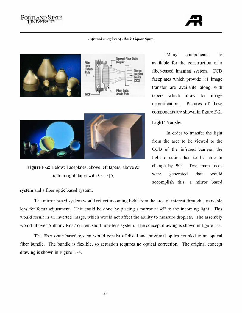
Many components are
available for the construction of a
fiber-based imaging system. CCD
faceplates which provide 1:1 image
transfer are available along with
tapers which allow for image
magnification. Pictures of these
components are shown in figure F-2.
Light Transfer
In order to transfer the light
from the area to be viewed to the
CCD of the infrared camera, the
light direction has to be able to
change by 90º. Two main ideas
were generated that would
accomplish this, a mirror based
system and a fiber optic based system.
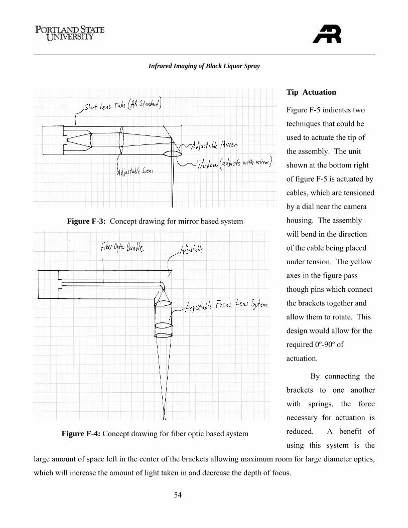
The mirror based system would reflect incoming light from the area of interest through a movable
lens for focus adjustment. This could be done by placing a mirror at 45º to the incoming light. This
would result in an inverted image, which would not affect the ability to measure droplets. The assembly
would fit over Anthony Ross' current short tube lens system. The concept drawing is shown in figure F-3.
The fiber optic based system would consist of distal and proximal optics coupled to an optical
fiber bundle. The bundle is flexible, so actuation requires no optical correction. The original concept
drawing is shown in Figure F-4.
Figure F-2: Below: Faceplates, above left tapers, above &
bottom right: taper with CCD [5]
Infrared Imaging of Black Liquor Spray
54
Tip Actuation
Figure F-5 indicates two
techniques that could be
used to actuate the tip of
the assembly. The unit
shown at the bottom right
of figure F-5 is actuated by
cables, which are tensioned
by a dial near the camera
housing. The assembly
will bend in the direction
of the cable being placed
under tension. The yellow
axes in the figure pass
though pins which connect
the brackets together and
allow them to rotate. This
design would allow for the
required 0º-90º of
actuation.
By connecting the
brackets to one another
with springs, the force
necessary for actuation is
reduced. A benefit of
using this system is the
large amount of space left in the center of the brackets allowing maximum room for large diameter optics,
which will increase the amount of light taken in and decrease the depth of focus.
Figure F-3: Concept drawing for mirror based system
Figure F-4: Concept drawing for fiber optic based system
Infrared Imaging of Black Liquor Spray
55
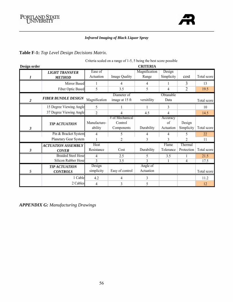
All concepts and ideas were
placed into a decision matrix. The light
transfer method was evaluated first. It is
clear from Table F-1, that the fiber bundle
design is the best choice. Knowing that
the fiber bundle will be used, its design
was then determined. The field of view of
the bundle presents a trade-off between
detail and coverage. Initially, the best
option is the larger field of view to make
the assembly able to view more at a given
time. The method of actuation is also
apparent; the bracket system has shown to
be much simpler and more likely to fulfill
the design requirements than the planetary
gear system (bottom left of Figure F-5).
The final bracket design was quite similar to the initial bracket design. The brackets require a
sheath to protect the bundle and maintain airflow to the tip. There were two options: a braided steel hose
or a silicon hose. The steel hose is more durable and can resist flame much better than silicone hose. Due
to the symmetry of the bracket design, two cables and two tensioning mechanisms could be used and the
assembly could be actuated up or down 90°. Installing two tensioning mechanisms versus one does not
significantly complicate the design. This concept was chosen to increase the versatility of the assembly.
Table F-1 shows a summary of the design decisions and the order they had to be made in.
Figure F-5: Actuation methods, SMA actuator, top row,
planetary gear actuator bottom left, bracket actuator bottom
right.
Infrared Imaging of Black Liquor Spray
56
Table F-1: Top Level Design Decisions Matrix.
Design order CRITERIA
1LIGHT TRANSFER
METHODEase of
Actuation Image QualityMagnification
RangeDesign
Simplicity cost Total score
Mirror Based 1 4 4 1 3 13Fiber Optic Based 5 3.5 5 4 2 19.5
2 FIBER BUNDLE DESIGN MagnificationDiameter of
image at 15 ft versitilityObtanable
Data Total score15 Degree Viewing Angle 5 1 1 3 1037 Degree Viewing Angle 2 4 4.5 4 14.5
3TIP ACTUATION Manufacture-
ability
# of Mechanical Control
Components Durability
Accuracy of
ActuationDesign
Simplicity Total scorePin & Bracket System 4 5 4 4 5 22Planetary Gear System 1 2 3 3 2 11
3ACTUATION ASSEMBLY
COVERHeat
Resistance Cost DurabilityFlame
ToleranceThermal
Protection Total scoreBraided Steel Hose 4 2.5 5 3.5 1 21.5
Silicon Rubber Hose 3 3.5 3 1 4 17.5
5TIP ACTUATION
CONTROLSDesign
simplicity Easy of controlAngle of Actuation Total score
1 Cable 4.2 4 3 11.2 2 Cables 4 3 5 12
Criteria scaled on a range of 1-5, 5 being the best score possible
APPENDIX G: Manufacturing Drawings
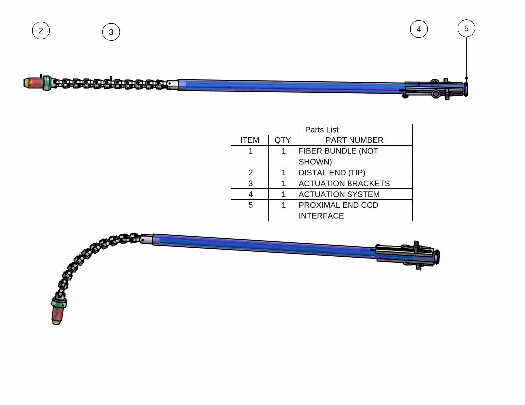
1 1 FIBER BUNDLE (NOT SHOWN)
2 1 DISTAL END (TIP)3 1 ACTUATION BRACKETS4 1 ACTUATION SYSTEM5 1 PROXIMAL END CCD
INTERFACE
Parts ListITEM QTY PART NUMBER
2 3 4 5
Owner
Text Box
OVERALL LENGTH OF ASSEMBLY IS 85"
Title
Designer
Project
Creation Date
Material
Company
Scale
Tolerance
Revision Number Comments
BLACK LIQUOR IMAGING
5/11/2005
304 stainless
PSU - AR
+-0.003
Break Edges 0.010 X 0.010Chamfer Units in Inches
GG JJ
MASTER STRAIGHT
William Carter 1
0.15:1
TIP ASSEMBLY
END ASSEMBLY
HINGE ASSEMBLY
Title
Designer
Project
Creation Date
Material
Company
Scale
Tolerance
Revision Number Comments
BLACK LIQUOR IMAGING
5/11/2005
304 stainless
PSU - AR
+-0.003
Break Edges 0.010 X 0.010Chamfer Units in Inches
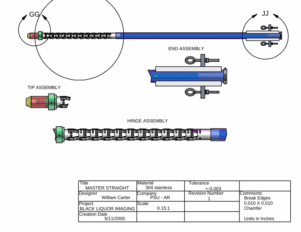
ACTUATION ASSM 1
Aaron Brandt 5
1:2
PIECES RIVETED TOGETHER WITH ALUMINUM RIVETS
Title
Designer
Project
Creation Date
Material
Company
Scale
Tolerance
Revision Number Comments
BLACK LIQUOR IMAGING
5/11/2005
304 stainless
PSU - AR
+-0.003
Break Edges 0.010 X 0.010Chamfer Units in Inches
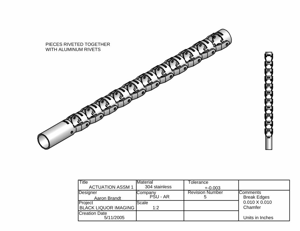
CURVED ACTUATION
Aaron Brandt 5
1:2
Title
Designer
Project
Creation Date
Material
Company
Scale
Tolerance
Revision Number Comments
BLACK LIQUOR IMAGING
5/11/2005
304 stainless
PSU - AR
+-0.003
Break Edges 0.010 X 0.010Chamfer Units in Inches
1:1
Aaron Brandt 2
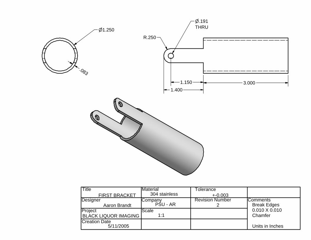
FIRST BRACKET
n1.250
.083
3.0001.1501.400
R.250
n.191THRU
Title
Designer
Project
Creation Date
Material
Company
Scale
Tolerance
Revision Number Comments
BLACK LIQUOR IMAGING
5/11/2005
304 stainless
PSU - AR
+-0.003
Break Edges 0.010 X 0.010Chamfer Units in Inches
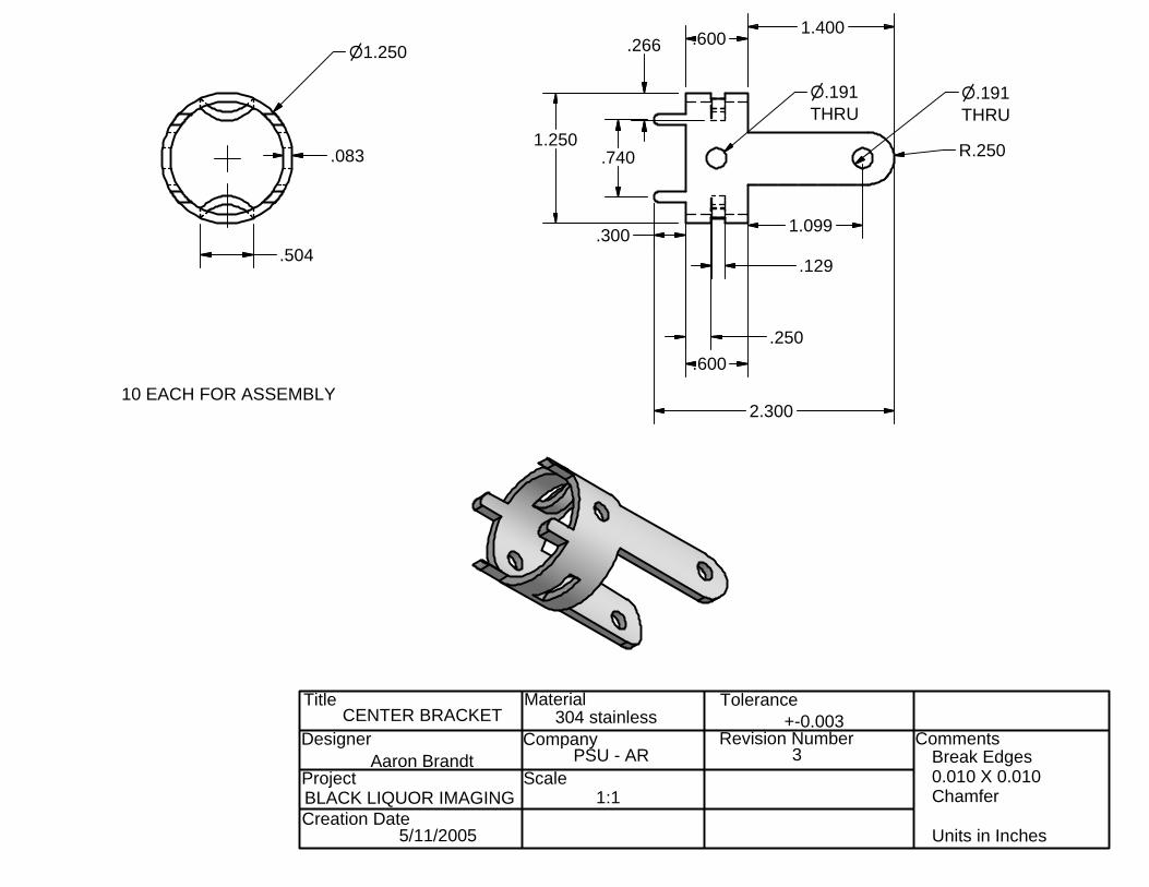
CENTER BRACKET
Aaron Brandt
1:1
3
2.300
.300
.600.250
.129
1.099
.7401.250
n.191THRU
n.191THRU
R.250
n1.250
.083
.504
.266
10 EACH FOR ASSEMBLY
.600 1.400
Title
Designer
Project
Creation Date
Material
Company
Scale
Tolerance
Revision Number Comments
BLACK LIQUOR IMAGING
5/11/2005
304 stainless
PSU - AR
+-0.003
Break Edges 0.010 X 0.010Chamfer Units in Inches
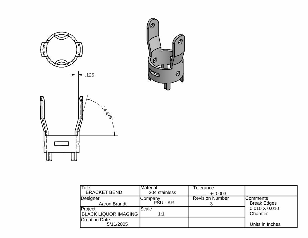
BRACKET BEND
Aaron Brandt 3
1:1
.125
74.476°
Title
Designer
Project
Creation Date
Material
Company
Scale
Tolerance
Revision Number Comments
BLACK LIQUOR IMAGING
5/11/2005
304 stainless
PSU - AR
+-0.003
Break Edges 0.010 X 0.010Chamfer Units in Inches
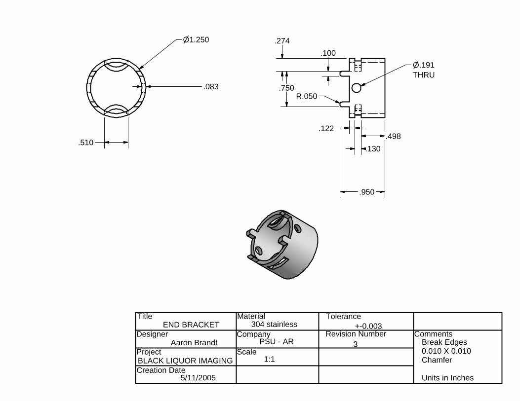
n1.250
.083
.510
.950
.498.130
.122
R.050
n.191THRU
.274
.750
.100
END BRACKET
Aaron Brandt
1:1
3
Title
Designer
Project
Creation Date
Material
Company
Scale
Tolerance
Revision Number Comments
BLACK LIQUOR IMAGING
5/11/2005
304 stainless
PSU - AR
+-0.003
Break Edges 0.010 X 0.010Chamfer Units in Inches
CC
CC
SEAL WELD
BARREL HOLDER#4-40 UNC SET SCREWHOLDS BARREL
1:1
Brent Illingworth
TIP OUTER TUBE
BARREL CAP
TIP ASSEMBLY
3
DISTAL OPTICS BARREL
WINDOW HOLDER 2X
SAPPHIREWINDOW
HOSE ATTACHMENT
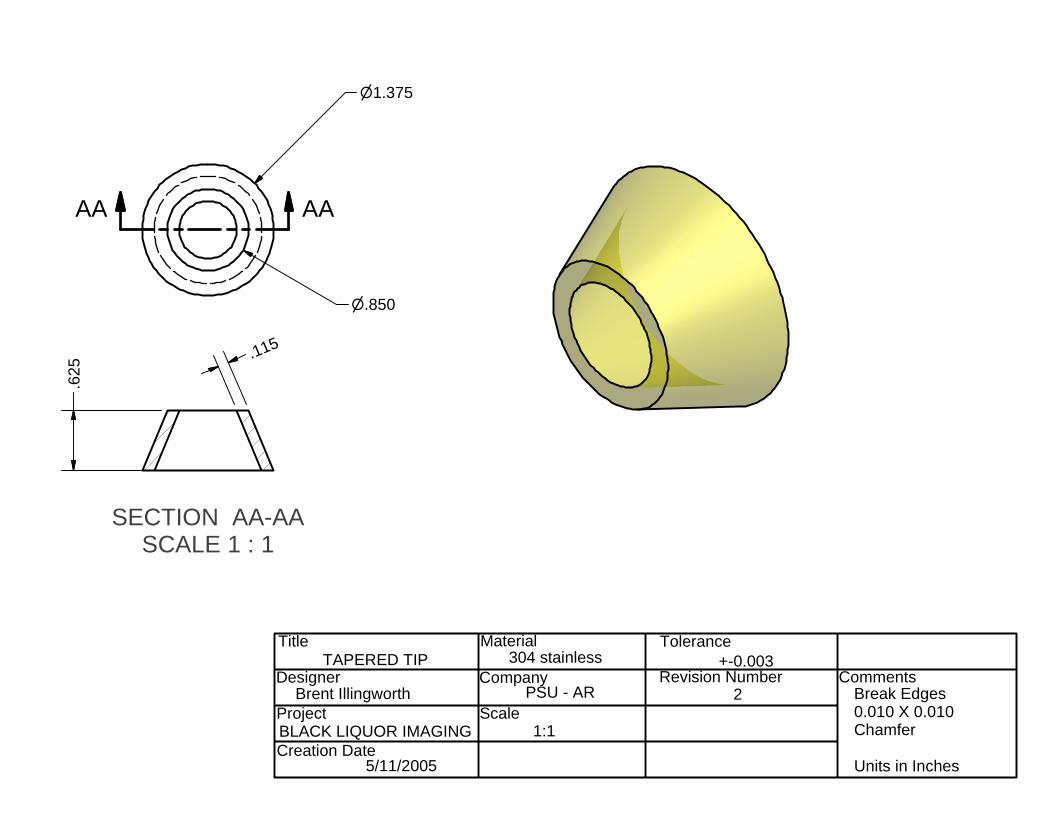
SECTION AA-AASCALE 1 : 1
Title
Designer
Project
Creation Date
Material
Company
Scale
Tolerance
Revision Number Comments
BLACK LIQUOR IMAGING
5/11/2005
304 stainless
PSU - AR
+-0.003
Break Edges 0.010 X 0.010Chamfer Units in Inches
AAAA
n1.375
n.850
.115
.625
TAPERED TIP
Brent Illingworth
1:1
2
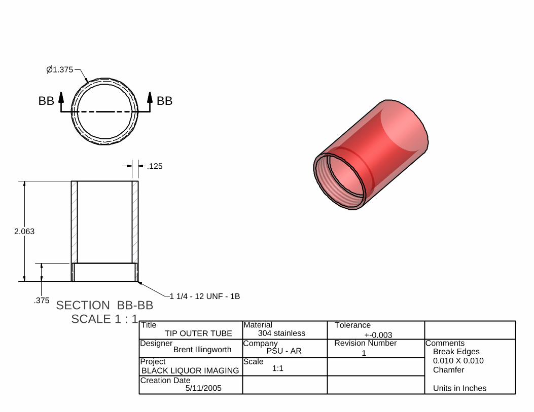
SECTION BB-BBSCALE 1 : 1 Title
Designer
Project
Creation Date
Material
Company
Scale
Tolerance
Revision Number Comments
BLACK LIQUOR IMAGING
5/11/2005
304 stainless
PSU - AR
+-0.003
Break Edges 0.010 X 0.010Chamfer Units in Inches
BBBB
n1.375
.125
TIP OUTER TUBE
Brent Illingworth
1:1
1
1 1/4 - 12 UNF - 1B.375
2.063
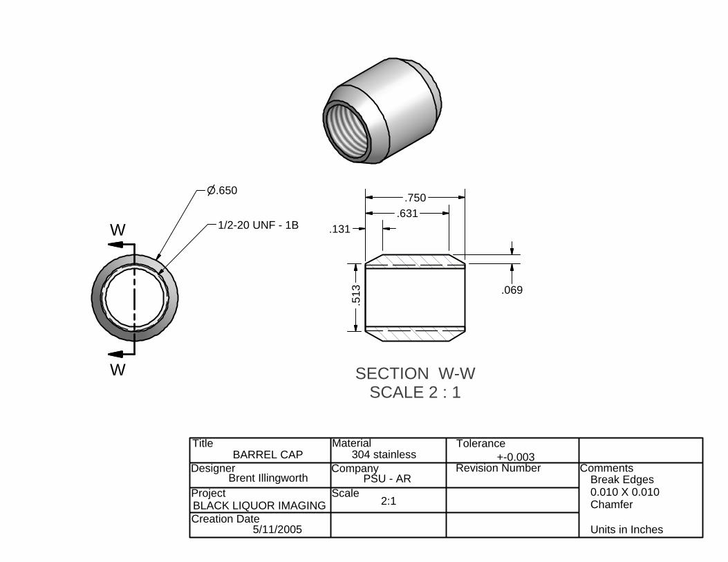
SECTION W-WSCALE 2 : 1
Title
Designer
Project
Creation Date
Material
Company
Scale
Tolerance
Revision Number Comments
BLACK LIQUOR IMAGING
5/11/2005
304 stainless
PSU - AR
+-0.003
Break Edges 0.010 X 0.010Chamfer Units in Inches
W
W
1/2-20 UNF - 1B
n.650
.513
BARREL CAP
2:1
.131.631
.750
.069
Brent Illingworth
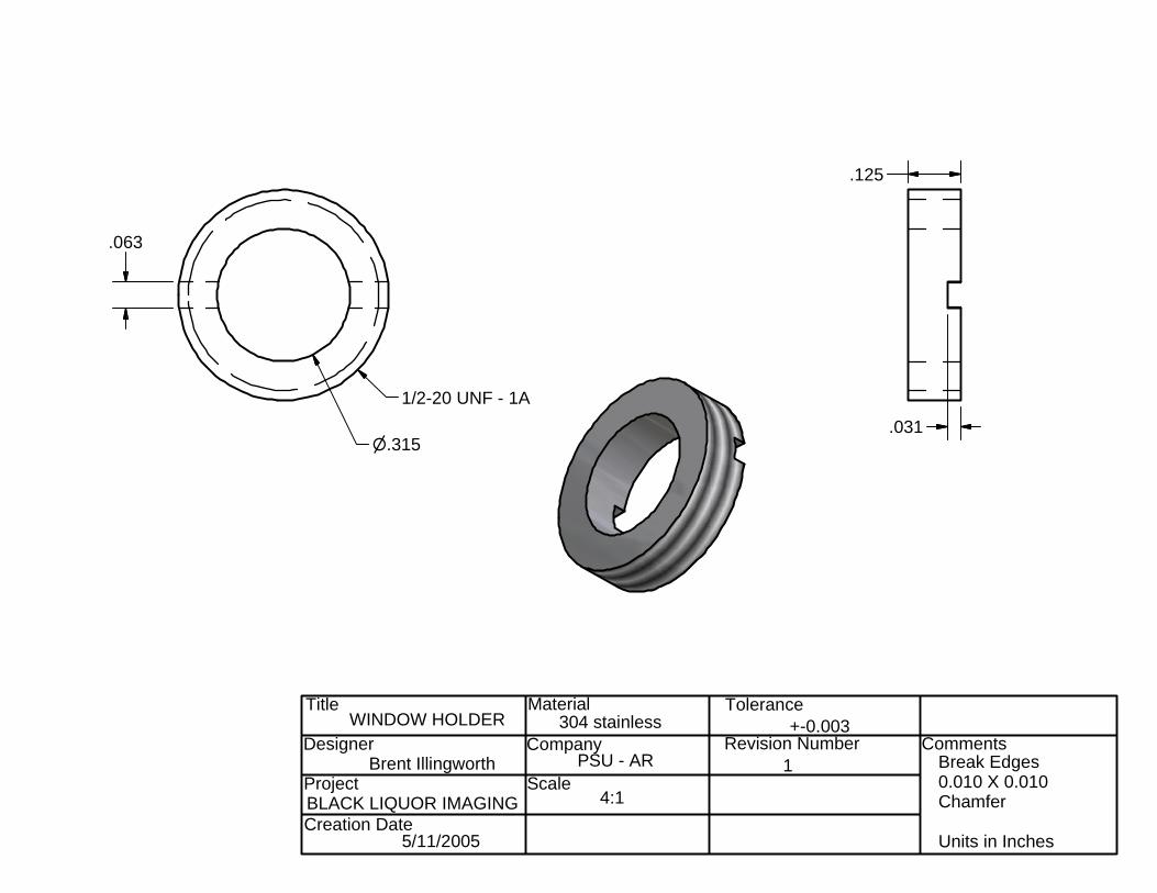
Title
Designer
Project
Creation Date
Material
Company
Scale
Tolerance
Revision Number Comments
BLACK LIQUOR IMAGING
5/11/2005
304 stainless
PSU - AR
+-0.003
Break Edges 0.010 X 0.010Chamfer Units in Inches
.063
.031
.125
n.315
1/2-20 UNF - 1A
WINDOW HOLDER
Brent Illingworth
4:1
1
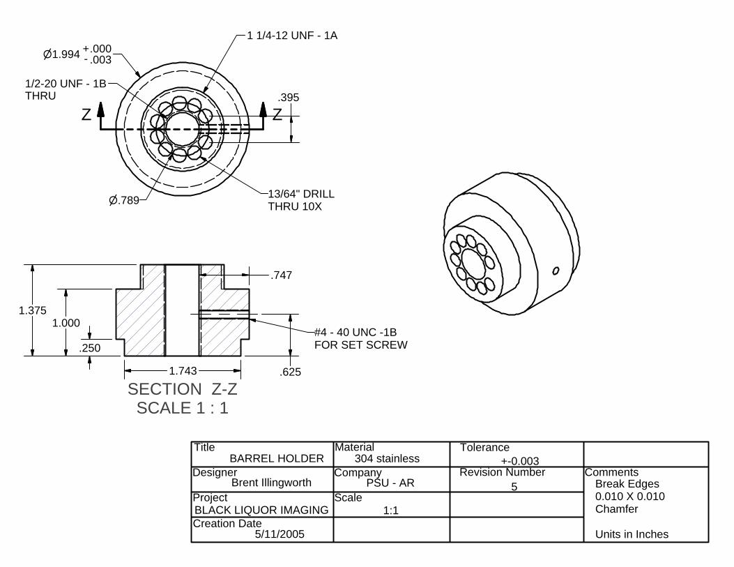
SECTION Z-ZSCALE 1 : 1
Title
Designer
Project
Creation Date
Material
Company
Scale
Tolerance
Revision Number Comments
BLACK LIQUOR IMAGING
5/11/2005
304 stainless
PSU - AR
+-0.003
Break Edges 0.010 X 0.010Chamfer Units in Inches
ZZ
BARREL HOLDER
Brent Illingworth
1:1
.747
#4 - 40 UNC -1BFOR SET SCREW
1.994n - .003.000+
1 1/4-12 UNF - 1A
1/2-20 UNF - 1BTHRU
13/64" DRILL THRU 10Xn.789
.395
5
1.743
.250
1.0001.375
.625
SECTION U-USCALE 1 / 5
SECTION U-USCALE 1 / 5
SECTION U-USCALE 1 / 5
SECTION U-USCALE 1 / 5
Title
Designer
Project
Creation Date
Material
Company
Scale
Tolerance
Revision Number Comments
BLACK LIQUOR IMAGING
5/11/2005
304 stainless
PSU - AR
+-0.003
Break Edges 0.010 X 0.010Chamfer Units in Inches
U U
V
MASTER TUBE ASSEMBLY
MASTER ASSEMBLYSECONDARY VIEW
Will Carter 4
0.2:1
SCALE 1 : 1
SCALE 1 / 2
Title
Designer
Project
Creation Date
Material
Company
Scale
Tolerance
Revision Number Comments
BLACK LIQUOR IMAGING
5/11/2005
304 stainless
PSU - AR
+-0.003
Break Edges 0.010 X 0.010Chamfer Units in Inches
n1.500
.120
1.000
.250
6.000
1.5" Outer Tube
Scale 0.25:1
3/8" NPT Pipe threadWith nut welded on if necessary
6.000
William Carter 2
N/A
60.000
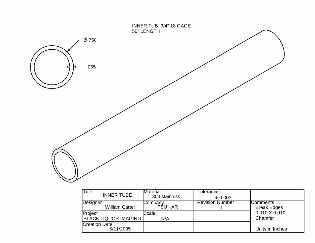
Title
Designer
Project
Creation Date
Material
Company
Scale
Tolerance
Revision Number Comments
BLACK LIQUOR IMAGING
5/11/2005
304 stainless
PSU - AR
+-0.003
Break Edges 0.010 X 0.010Chamfer Units in Inches
n.750
.065
INNER TUB 3/4" 18 GAGE 50" LENGTH
INNER TUBE
N/A
William Carter 1
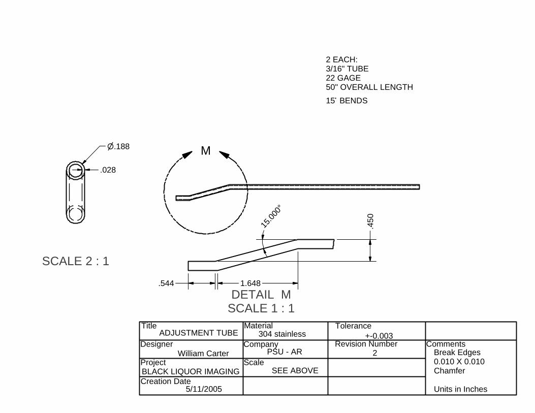
SCALE 2 : 1
DETAIL MSCALE 1 : 1
Title
Designer
Project
Creation Date
Material
Company
Scale
Tolerance
Revision Number Comments
BLACK LIQUOR IMAGING
5/11/2005
304 stainless
PSU - AR
+-0.003
Break Edges 0.010 X 0.010Chamfer Units in Inches
M
2 EACH:3/16" TUBE 22 GAGE50" OVERALL LENGTH15~ BENDS
ADJUSTMENT TUBE
n.188
.028
.544 1.648
.450
15.00
0°
SEE ABOVE
William Carter 2
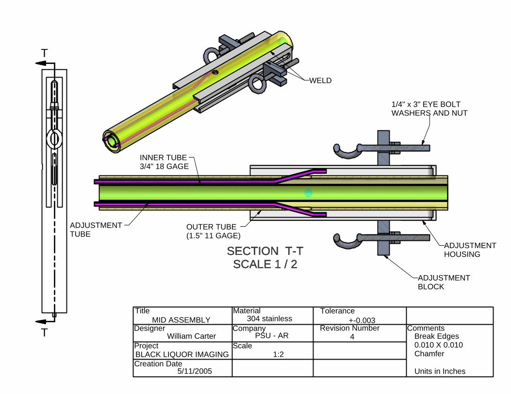
SECTION T-TSCALE 1 / 2
SECTION T-TSCALE 1 / 2
SECTION T-TSCALE 1 / 2
SECTION T-TSCALE 1 / 2
Title
Designer
Project
Creation Date
Material
Company
Scale
Tolerance
Revision Number Comments
BLACK LIQUOR IMAGING
5/11/2005
304 stainless
PSU - AR
+-0.003
Break Edges 0.010 X 0.010Chamfer Units in Inches
T
T
ADJUSTMENT TUBE
OUTER TUBE(1.5" 11 GAGE)
MID ASSEMBLY
William Carter 4
1:2
INNER TUBE 3/4" 18 GAGE
WELD
1/4" x 3" EYE BOLTWASHERS AND NUT
ADJUSTMENTHOUSING
ADJUSTMENT BLOCK
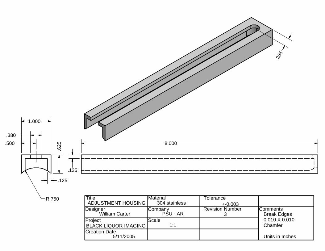
Title
Designer
Project
Creation Date
Material
Company
Scale
Tolerance
Revision Number Comments
BLACK LIQUOR IMAGING
5/11/2005
304 stainless
PSU - AR
+-0.003
Break Edges 0.010 X 0.010Chamfer Units in Inches
.125
R.750
.625
1.000
.3808.000
.265
ADJUSTMENT HOUSING
William Carter
1:1
3
.125
.500
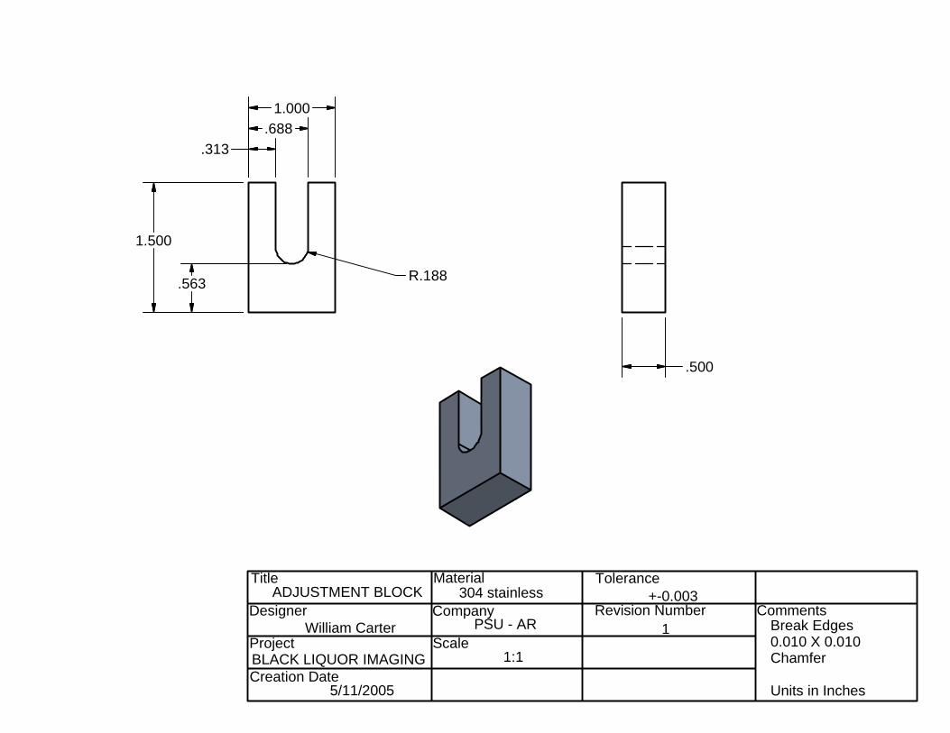
Title
Designer
Project
Creation Date
Material
Company
Scale
Tolerance
Revision Number Comments
BLACK LIQUOR IMAGING
5/11/2005
304 stainless
PSU - AR
+-0.003
Break Edges 0.010 X 0.010Chamfer Units in Inches
ADJUSTMENT BLOCK
William Carter
1:1
1
.313.688
1.000
1.500
.563 R.188
.500
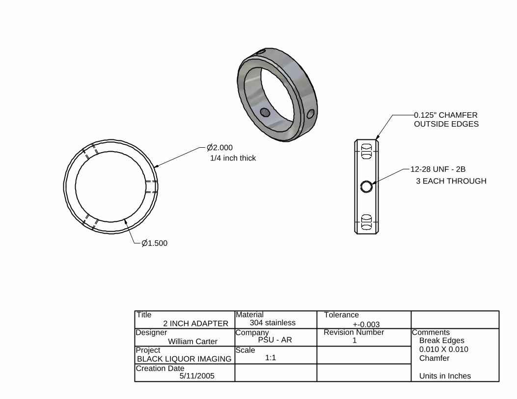
Title
Designer
Project
Creation Date
Material
Company
Scale
Tolerance
Revision Number Comments
BLACK LIQUOR IMAGING
5/11/2005
304 stainless
PSU - AR
+-0.003
Break Edges 0.010 X 0.010Chamfer Units in Inches
0.125" CHAMFEROUTSIDE EDGES
12-28 UNF - 2B3 EACH THROUGH
n2.0001/4 inch thick
n1.500
2 INCH ADAPTER
William Carter
1:1
1
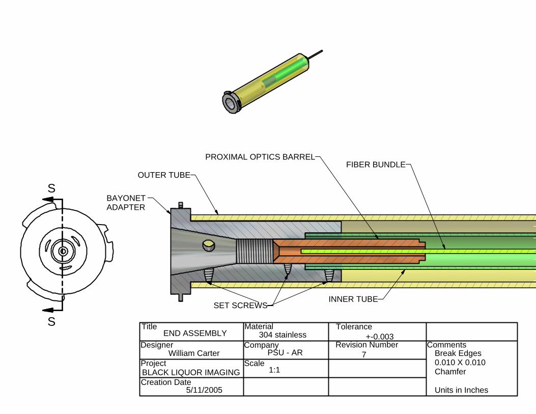
Title
Designer
Project
Creation Date
Material
Company
Scale
Tolerance
Revision Number Comments
BLACK LIQUOR IMAGING
5/11/2005
304 stainless
PSU - AR
+-0.003
Break Edges 0.010 X 0.010Chamfer Units in Inches
S
S
OUTER TUBE
INNER TUBE
END ASSEMBLY
FIBER BUNDLE
William Carter 7
1:1
BAYONET ADAPTER
PROXIMAL OPTICS BARREL
SET SCREWS
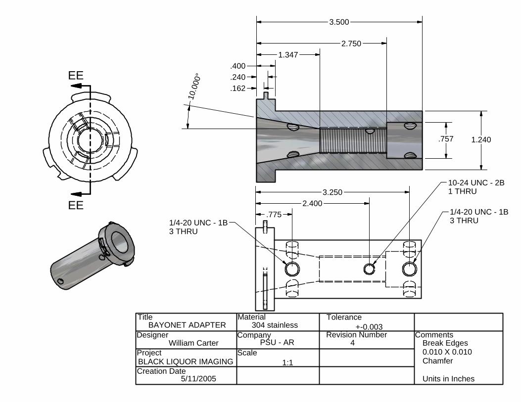
Title
Designer
Project
Creation Date
Material
Company
Scale
Tolerance
Revision Number Comments
BLACK LIQUOR IMAGING
5/11/2005
304 stainless
PSU - AR
+-0.003
Break Edges 0.010 X 0.010Chamfer Units in Inches
EE
EE
.162
.240
.4001.347
2.750
3.500
BAYONET ADAPTER
William Carter 4
1:1
1.240.757
10.0
00°
1/4-20 UNC - 1B3 THRU1/4-20 UNC - 1B
3 THRU
10-24 UNC - 2B1 THRU
.7752.400
3.250
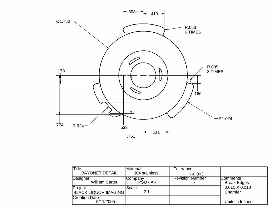
Title
Designer
Project
Creation Date
Material
Company
Scale
Tolerance
Revision Number Comments
BLACK LIQUOR IMAGING
5/11/2005
304 stainless
PSU - AR
+-0.003
Break Edges 0.010 X 0.010Chamfer Units in Inches
BAYONET DETAIL
2:1
William Carter
n1.750
R1.024
R.924
R.0636 TIMES
R.0358 TIMES
.398 .419
.166
.511
.170
.774 .533
.761
4
Related Documents