PRECISION MEASURING EQUIPMENT GENERAL CATALOG

Welcome message from author
This document is posted to help you gain knowledge. Please leave a comment to let me know what you think about it! Share it to your friends and learn new things together.
Transcript

���������������
����� ��� �������
������� �����
P R E C I S I O N M E A S U R I N G E Q U I P M E N T
G E N E R A L C ATA L O G
��� ������� �� ������� ���� ��� �� �� ������������� �! ��� ��"����#���$
�� �������� �! ���� �������%�� ��� �� �! &�'$ ����
�� �����������������
���� ������������ ������ ������������� ������������ ������ �����������!�� ��" ���#���� �����( )%*% ���+ �����������+ ,�������� ��+ �(��--��+ .������/01-���2����3�3- &�4/01-���2����3�31����/55���$�����#�$��$6�
���� ������ �����"������������ ������ ���#���� ������$%��"&������3& -�( �������%� 7���+ �����+ -�� �����8��/ 011�����(���1(�( &�4/ 011�����(����2��$������� �������! ����9�$�1�+ )��$�+ :���� 7���+ 9���%� ��������+ ����%�� ����+ ��1 �������/ 011�����21���(31 ;��011�����21��(31< &�4/ 011�����21���-�-����/55���$����$��#$��5��#����5=)>����4$���4
���� ������������ ������ �������' ������21- :��#��� ������+ �� � &�����+ ��+ ���2���/ 0-�����33��1��� &�4/0-�����33��1��1����/55���$������$��#
���� ������������ ������ ����������� (�����:����!����� )������ �-+ ��3�2�3 )�%������+ ��#�����/ 0���3--�(1(1�333 &�4/ 0���3--�(1��3-(����/55���$����#��%!���%����$��#
2 3
Sony Manufacturing Systems Corporation
DIGITAL GAUGE
ContentsTraceability
Contents
Applications
Lineup
System
Gauge
DK802 A/Bseries
DK805 A/Bseries
DK812 A/Bseries
DK10/25 series
DK50/100 series
DK155/205
DK110
DE-BR series
DG805/DG810 series
DG10/25 series
DG50 /100 /155 / 205 series
DG110 series
DT512 series
2
3
4
6
8
9
10
11
12
13
14
15
16
20
22
23
24
26
30
DT12 / 32 series
MT12 /13 /14
DL-B series
U series
Interface unit
MG series
Counter unit
LT30 series
LT20A series
LT11A series
LT10A series
LY71
LY72
Technical information
Accessories
Connection Cables
Compatible
Safety
Support
31
33
34
36
39
40
43
44
45
46
47
48
49
50
51
52
53
55
55
Traceability Flow Chart (Length)
Traceability Flow Chart (Electromagnetic Charge)
Certificate of Accreditation(JAB)Accreditation No.RCL00240Electromagnetics(DC/Low Frequency)
Certificate of Accreditation (JCSS)Accreditation Number: 0046Laser WavelengthWavelength of 633 nmLine StandardsStandard scale: up to 500mmEnd standard: up to 100mm
�������� ����
���� � �
National Institute of Advanced Industrial Science and Technology (AIST)Iodine saturation absorption stabilized He-Ne laser at 633nmSpeed of light (laser) C=299792458m/s
������������ � � International Committee for Weights
and Measures (CIPM)
International Bureau of Weights and Measures (BIPM)
��������
����� ��
���� � �
��������
���� � �
Iodine saturation absorption stabilized He-Ne laser at 633nm
���� ������������ ������ ���������
�����������
�������� ����
���� � �
International Bureau of Weights and Measures (BIPM)
National Institute of Advanced Industrial Science and Technology (AIST)
��������
���� � �
Sony Manufacturing Systems CorporationDirect Current Voltage Generator (FLUKE 5700A) Direct Current Voltage Generator (HP3458A)
�������� ����� ��
���� � �Japan Electric Meters Inspection Corporation (JEMIC)
���������� �� ��� ��������� ��������� � �������� �� ���
���������� �� ��� ��������� ��������� � �������� �� ���
Stabilized He-Ne Laser (633nm)
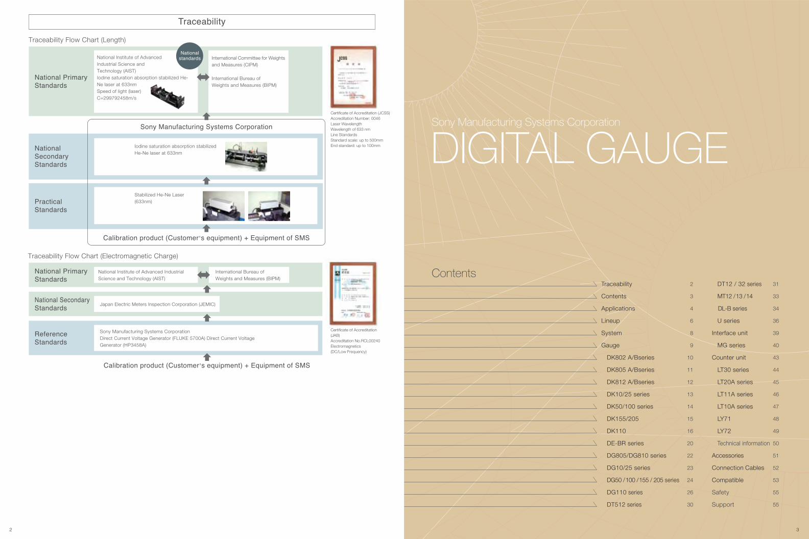
Multipoint measurement of turbine blades
Measures the blade shape of aircraft turbine blades.
Multipoint measurement of liquid crystal panels
Measurement can be conducted easily in a small space by using a slim-shape
measuring unit with fixture.
Camshaft displacement measurement
Measuring the height of camshaft lobes and journals.
Measurement of hard disc flatness
Measuring the flatness of mass-produced discs.
Measurement of the height of chassis height
Measurement can be conducted easily in a small space by using a slim-shape
measuring unit Measuring muitiple points or a chassis.
Measurement of motor shaft deviation
Measurement of a high speed spinning object is possible by utilizing a vibration-
resistant gauge.
Automatic measurement and screening
Measurement/QA decisions can be performed on the production line.
Measurement of inner diameter
Measuring the inner diameter of work.
Measurement of material strength
Applicable for strength tests of various materials such as metal, resin materials
and wood. Measuring unit is resistant to vibration.
Measurement of crimp height
Measures the calking height of crimp terminal.
Measurement of fastener height
Measures the height of screws in order to
control the amount of torque.
Positioning control
Measuring the thickness and flatness of objects moving at high-speed, such as metal
plates, resin boards and film, as well as to control the position of feeding rollers.Measurement of the height of high-density mounting wiring boards
High-density measurement is possible with a slim-shaped measuring unit.
Combination with machine tools
Measuring the position of the grinding stone of surface grinding machines.
Sequencer Motor
Motor
4 5
Applications
NO GOGO
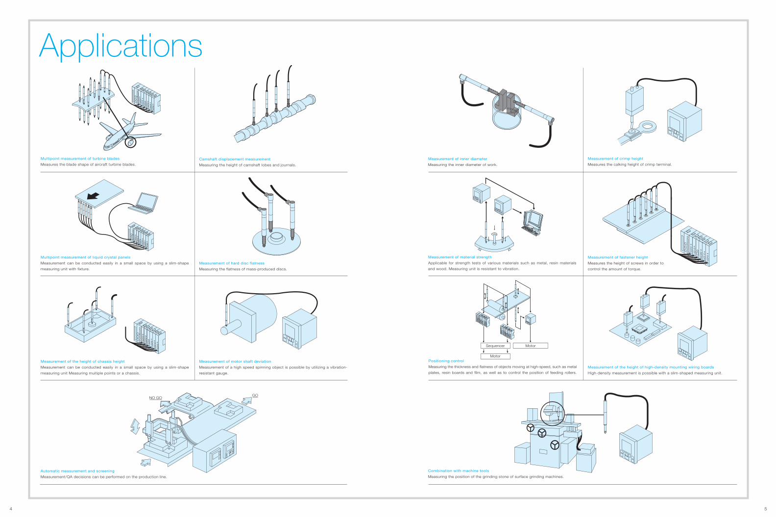
Lineup
6 7
1 5 100.1 0.5
DK50PR5(Straight • Protect sealing)
DK50NR5 (Straight)
DK802AR, DK802BR (Straight)
DK802ALR, DK802BLR (Right angle)
DK805AR, DK805BR (Straight)DK805ALR, DK805BLR (Right angle)
DK805AFR, DK805BFR (Straight • Flange)DK805AFLR, DK805BFLR (Right angle • Flange)
DK805AR5, DK805BR5 (Straight)DK805ALR5, DK805BLR5 (Right angle)
DK805AFR5, DK805BFR5 (Straight • Flange)DK805AFLR5, DK805BFLR5 (Right angle • Flange)
DK812AR5, DK812BR5 (Straight)
DK812ALR5, DK812BLR5 (Right angle)
DK25PR5(Straight • Protect sealing)
DK25NR5 (Straight)DK25PLR5
(Right angle • Protect sealing)DK25NLR5(Right angle)
DT32N (Box type)DT32NV
(Box type • Preumatic push)DT32P
(Box type • Protect sealing)DT32PV
(Box type • Protect sealing • Preumatic push)
DG25BN (Straight)DG25BP (Straight • Protect sealing)
DG25BL (Right angle)DG25BS (Right angle)
DG25B (Straight • Protect sealing)
DK812AR, DK812BR (Straight)
DK812ALR, DK812BLR (Right angle)
DE12BR (Straight)DT512N (BOX type)
DT512P (BOX type • Protect sealing)
DL330B (Straight)
DT12N (Straight)DT12P
(Straight • Protect sealing)
DK802AR5, DK802BR5 (Straight)
DK802ALR5, DK802BLR5 (Right angle)
DK10PR5(Straight • Protect sealing)
DK10NR5 (Straight)DK10PLR5
(Right angle • Protect sealing)
DL310B(Straight • Protect sealing)
DG810B (Straight)DG810BL (Right angle)
DG810F (Straigh • Flange)DG810FL (Right angle • Flange)
DG10B (Straight)
DK155PR5(Straight • Protect sealing) DG155B (Straight)
DK100PR5(Straight • Protect sealing)
DK100NR5 (Straight)DK110NLR5
(Right angle • Protect sealing)
DG50BN (Straight)DG25BP (Straight • Protect sealing)
LT30
・LY71・LY72
(Connection cable CE29)
・LY71, LY72(+SZ70-1 (Adapter) )
・LY71・LY72
(+DZ51 +SZ70-1)
・LY71・LY72
(Connection cable CE29)
・LY71, LY72(+DZ51 +SZ70-1)
・LY71, LY72(+MT13 +CE29)
・LY71, LY72(+MT13 +CE29)
MG30MG20-DG
MG10
MG30MG20-DK
MG10
MG30MG20-DK
MG10(+ SZ70-2 (Adapter) )
MG30MG20-DK
MG10
MG30MG20-DT
MG10
MG30MG20-DT
MG10
MG30MG20-DG
MG10
LT30 LT20A LT11A LT10A LT20ALT30+ SZ70-2 (Adapter)
DG100B (Straight)DG110B (Right angle)
DK DE DK DG DT DT DL
DK205PR5(Straight • Protect sealing) DG205B (Straight)
DINsize
Fulltype
2
DG805BL (Right angle •
Low measuring force)DG805FL (Right angle • Flange •
Low measuring force)
5.2
10
12
25
155
30|
32
50|
60
100|
110
205
Measuringrange (mm)
Resolution (µm)
Inte
rface
Cou
nter
Dig
ital G
auge
DE30BR (Straight)
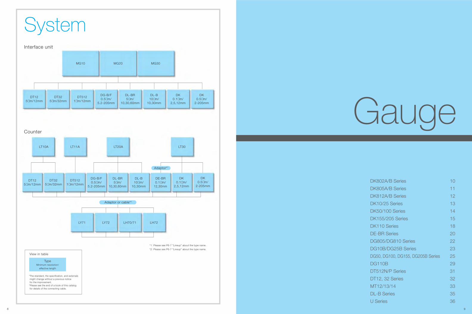
SystemInterface unit
Counter
DK802A/B Series
DK805A/B Series
DK812A/B Series
DK10/25 Series
DK50/100 Series
DK155/205 Series
DK110 Series
DE-BR Series
DG805/DG810 Series
DG10B/DG25B Series
DG50, DG100, DG155, DG205B Series
DG110B
DT512N/P Series
DT12, 32 Series
MT12/13/14
DL-B Series
U Series
10
11
12
13
14
15
18
20
22
23
25
29
31
32
33
35
368
Gauge
MG10 MG20 MG30
DT325µm/32mm
DT125µm/12mm
DT5121µm/12mm
DK0.1µm/
2,5,12mm
DK0.5µm/
2-205mm
DK0.5µm/
2-205mm
DT325µm/32mm
DT125µm/12mm
LT10A
LY71 LY72 LH70/71 LH72
LT20A LT30
DL-B10µm/
10,30mm
DL-BR5µm/
10,30,60mm
DG-B/F0.5µm/
5.2-205mm
DL-B10µm/
10,30mm
DL-BR5µm/
10,30,60mm
DE-BR0.1µm/
12,30mm
DG-B/F0.5µm/
5.2-205mm
LT11A
DT5121µm/12mm
DK0.1µm/
2,5,12mm
9
TypeMinimum resolution/
effective length
View in table
*The standard, the specification, and externals might change without a previous notice for the improvement. *Please see the end of a book of this catalog for details of the connecting cable.
Adaptor*1
Adaptor or cable*2
*1: Please see P6-7 "Lineup" about the type name.
*2: Please see P6-7 "Lineup" about the type name.
10
���� �������� �� ���� ��� �� ���� �� ����� � ����DK DK802A/B Series
11
�����������������
����������������
64.2/2.53
8.6/0.3412.2/0.48
�������������������
������������������
56.2/2.21
ø9/ø0.35
21/0
.83
ø10/
ø0.3
9
46.2/1.82
8.6/0.3412.2/0.48
64.2/2.53
������� ���� ������� ����
Option : Extension cable
13/0
.51
Cable length 1,3,5,10m (39.37"/118.11"/196.85"/393.70")
ø11.
8/ø0
.46
ø10/
ø0.3
9
41.5/1.63
13/0.51 13.6/0.54
14/0.555.5/0.225.5/0.22 30.5/1.2
49.5/1.9535.5/1.4
6.2/0.24 24.3/0.964.8/0.16 13
.6/0
.54
(CK-T12:1m/3.3’, CK-T13:3m/9.8’, CK-T14:5m/16’, CK-T15:10m/32.8’)
13.6
/0.5
4 Cable length 1,3,5,10m
50/1.9741.5/1.63
55.5/2.19
Option : Extension cable(CE22-01:1m/3.3’, CE22-03:3m/9.8’, CE22-05:5m/16’, CE22-10:10m/32.8’)
+VccSignal Cable color
RedWhiteBlue
YellowOrange
GrayGreenViolet
�
�
�
0VAABBZZ
(39.37"/118.11"/196.85"/393.70")
����� ��
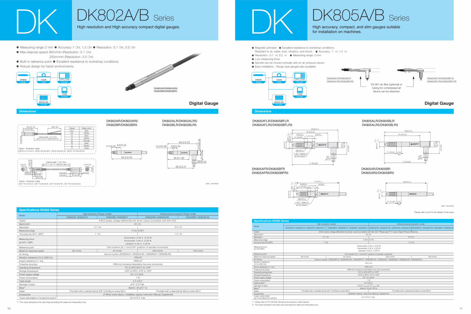
• Measuring range:2 mm • Accuracy :1 µm, 1.5 µm • Resolution : 0.1 µm, 0.5 µm
• Max.respose speed:80m/min (Resolution : 0.1 µm)
250m/min (Resolution : 0.5 µm)
• Built-in reference point • Excellent resistance to workshop conditions.
• Robust design for harsh environments.
����� !�"
#$��%��
�&'()�&'�
�*+�
����� !�"
#$��%��
�&'()�&'�
�*+�
• Magnetic principle • Excellent resistance to workshop conditions. Resistant to oil, water, dust, vibration, and shock. • Accuracy : 1 m, 1.5 m
• Resolution : 0.1 m, 0.5 m • Measuring range: 5 mm
• Low measuring force
• Spindle can be moved vertically with an air pressure device
• Easy installation. Flange type gauges also available.
DK DK805A/B Series���� ��� ��) ���� ��) �� ��� � ��� ��� ,�
-�� ���� ���� �� � �������
DZ-801 air lifter (optional) ortubing for compressed airdevice can be attached.
DK805ALR/DK805BLRDK805ALR5/DK805BLR5
DK805AFLR/DK805BFLRDK805AFLR5/DK805BFLR5
Unit : mm/inch
���������������������������������
ModelDK805AFR5, DK805AFLR5, DK805AR5, DK805ALR5 DK805BFR5, DK805BFLR5, DK805BR5, DK805BLR5DK805BFR, DK805BFLR, DK805BR, DK805BLRDK805AFR, DK805AFLR, DK805AR, DK805ALR
Downward: 0.45 ± 0.25 NHorizontal: 0.40 ± 0.25 NUpward: 0.35 ± 0.25 N
OutputSignal pitchResolutionMeasuring rangeAccuracy (at 20˚C/68˚F)
Reference pointMaximum response speedAir driving
Shock resistance (11 ms)Protective structureOperating temperatureStorage temperaturePower supply voltagePower consumptionCable length*1
Diameter of stemMass*2
FeelerAccessoriesOutput cable length(up to the electronic section)
Vibration resistance(10 to 2000 Hz)
Measuring force(at 20˚C/68˚F)
A/B/Z phase voltage-differential line driver output (compliant with EIA-422) *Please see P17 Output Signal Phase Difference.40 µm
Vacuum suction ( DK805AFLR / DK805AFLR5 / DK805BFLR / DK805BFLR5 / DK805ALR / DK805BLR / DK805ALR5 / DK805BLR5 )
100 m/s2
1000 m/s2
IP66 (not including interpolation box and connectors)0˚C to 50˚C/32˚F to 122˚F
-20˚C to 60˚C/-4˚F to 140˚FDC +5 V ±5%
1 W2.5 m/8.2'
ø 9.50 /0.37" dia.Approx. 30 g/1.06 oz
Installation spacer, Instruction Manual, Supplement
22 m/72.2' max.
5 mm (0.19")
One location (at 1 mm/0.04" position of spindle movement)
0.1 µm
1 µm
0.5 µm
1.5 µm
Provided with a carbide ball tip (DZ-123) Mount screw M2.5 Provided with a steel ball tip Mount screw M2.5
80 m/min 42 m/min 250 m/min 100 m/min
High-resolution models General-purpose resolution model
*1 : Please refer to P10 DK 802 A/B about the extension cable (Option).
*2 : The mass indicated is the total mass excluding the cable and interpolation box.
���������� �� ����� ����
0-0.009
0-0.0004
Vacuum suction (DK802ALR / DK802ALR5 / DK802BLR / DK802BLR5)
100m/s2
1000m/s2
IP66 (not including interpolation box and connectors)
0˚C to 50˚C/32˚C F to 122˚F
–20˚C to 60˚C/_4˚CF to 140˚F
DC +5 V ±5%
1 W
2.5 m/8.2'
Approx. 20 g/0.7 oz
+P M4x5 screw (2pcs.). Installation spacer, Instruction Manual, Supplement
22 m/72.2' max.
A/B/Z phase voltage-differential line driver output (compliant with EIA-422)
40 µ m
2 mm (0.08")
One location (at 1 mm/0.04" position of spindle movement)
ModelDK802BR, DK802BLR DK802AR5, DK802ALR5 DK802BR5, DK802BLR5
High-resolution Flange models General-purpose resolution Flange models
DK802AR, DK802ALR
*1: The mass indicated is the total mass excluding the cable and interpolation box.
Output
Signal pitch
Resolution
Measuring range
"Accuracy (at 20˚C / 68˚F)"
Reference point
Maximum response speed
Air driving
Vibration resistance (10 to 2000 Hz)
Impact resistance (11 ms)
Protective structure
Operating temperature
Storage temperature
Power supply voltage
Power consumption
Cable length
Diameter of stem
Mass*1
Feeler
Accessories
"Output cable length(up to the electronic section)"
Measuring force
(at 20˚C / 68˚F)
0.1 µ m
1 µ m
0.5 µ m
1.5 µ m
Provided with a carbide ball tip (DZ-123) Mount screw M2.5 Provided with a steel ball tip Mount screw M2.5
80 m/min 250 m/min 100 m/min42 m/min
φ”8 / 0.31”dia.
���������� �� ����� ����
Downward: 0.45 ± 0.25 NHorizontal: 0.40 ± 0.25 N
Upward: 0.35 ± 0.25 N
������.��������.�
������.���������.��
����� ��
�����������������
�������������������
���������������
�����������������
������.���������.��
������.����������.���
Unit : mm/inch
*Please refer to p54 for the details of the screw.
79.6/31.3
21.2/0.83
0
-0.
009/
0
-0.
004
φ8/
0.31
0.34/
8.6
21.2/0.83
71.6/31.3
0
-0.
009/
0
-0.
004
φ95
φ0.
37
4/0.265.3/0.218.7/0.34
M9xP0.5
4-φ2.1 deep2.5/
φ0.08 deep0.1
φ12
/0.4
7
79.6/31.3
71.6/2.82
21.2/0.83
61.6/2.43
8.7/0.345.3/0.21 4/0.16
0
-0.
009/
0
-0.
004
φ9.
5φ
0.37
M9xP0.5
4-φ2.1 deep2.5/
φ0.08 deep0.1
φ12
/0.4
7
21/0
.83
φ9/
φ0.35
φ10
/
φ0.
39
21.2/0.83 0.34/8.6
0
-0.
009/
0
-0.
004
φ8/
0.31
21/0
.83φ10
/
φ0.
39
79.6/3.13
61.6/2.43
71.6/2.82
φ9/
φ035
12 13
����������
����� � ��
���� ������� ������ ����� �
�������� ��� �� ��������� �� ��������DK DK10/25 Series
DK25NLR5/DK25PLR5DK10PLR5
DK25NR5/DK25PR5DK10NR5/DK10PR5
Output
Resolution*1
Measuring range
Accuracy (at 20˚C)Upward
Horizontal
Downward
0.3 ± 0.25 N
0.6 ± 0.3 N
0.8 ± 0.35 N
4.9 N or less
150 m/s2
1500 m/s2
10 mm 25 mm
Approx. 230 g Approx. 300 g
4.9 N or less 4.9 N or less
IP50
Measuringforce
(at 20˚C)
Impact resistance (11 ms)
Protective structure
Operating temperature
Storage temperature
Power supply voltage
Power consumption
Cable length*2
Diameter of stem
Mass*3
Feeler
Guaranteed number of Strokes
Accessories
Reference point
Maximum response speed
Vibration resistance(10 to 2000 Hz)
Output cable length
�������������
Model DK10NR5
0.4 ± 0.3 N
0.7 ± 0.35 N
1 ± 0.4 N
IP50
DK25NR5
0.4 ± 0.3 N
0.7 ± 0.35 N
1 ± 0.4 N
IP50IP64 IP64 IP64
DK25NLR5 DK25PLR5DK25PR5DK10PLR5DK10PR5
A/B/Z phase voltage-differential line driver output (compliant with EIA-422) *Please see P17 Output Signal Phase Difference.
0.5 µm
2 µm
One location (at 1 mm position of spindle movement)
250 m/min
0˚C to 50˚C
-20˚C to 60˚C
DC +5 V ±5%
1 W or less
Approx. 2.5 m
ø 20 mm0 -0.013
Minimum 5 million cycles without shock
+P M4x5 screw (2 pcs.), Instruction Manual
22 m max.
Provided with a carbide ball tip DZ-122 (Mount screw M2.5)
*1 : The resolution setting needs to be made when connecting to the LT30 series, MG series, and LY70 series. For details, please refer to the respective instruction manual.*2 : Please refer to P10 DK 802 A/B about the extension cable (Option).*3 : The mass indicated is the total mass excluding the cable and interpolation box.
��������
ø5.8
/ø0.
23
102.5/4.04
12.3/0.48
ø22/ø0.87
79/3.1126.3/1.0352.7/2.07
-0.0
7-0
.02
ø20-0
.013
0ø2
0-0
.000
50
/ø0.
79
-0.0
030.
0008
/ø0.
79
21.3/0.84
(ste
m)
12/0.47
(11.5/0.45)
ø6/ø
0.24
37/1
.46
69.5
/2.7
4
(20/
0.79
)
���� ���!����
12/0.47
160/6.3
(26.5/1.04)121.5/4.78
95.2/3.75 26.3/1.04
33.8/1.33
ø6/ø
0.24
-0.0
130
ø20
-0.0
005
0/ø
0.79
(ste
m)
-0.0
7-0
.02
ø20 -0
.003
0.00
08/ø
0.79
12.3/0.48
ø22/ø0.87
Cable length 5000/196.85
37/1
.46
69.5
/2.7
4
(20/
0.79
)
-0.0
130 -0
.000
50 -0.0
7-0
.02
-0.0
030.
0008
ø20
/ø0.
79(s
tem
)
ø20
/ø0.
79
Cable length 5000/196.85
ø6/ø
0.34
12/0.47
(11.5/0.45)21.3/0.84
98.5/3.88122/4.81
(20/0.79)
ø5.8
/ø0.
23
���� ��!��� ���� ��!���
(20/0.79)
Cable length 5000/196.85
ø5.8
/ø0.
23
-0.0
130
ø20
-0.0
005
0/ø
0.79
(ste
m) -0
.07
-0.0
2ø2
0 -0.0
030.
0008
/ø0.
79
ø6/ø
0.24
12/0.47 (26.5/1.04)
33.8/1.33
141/5.55179.5/7.07
Unit : mm/inch
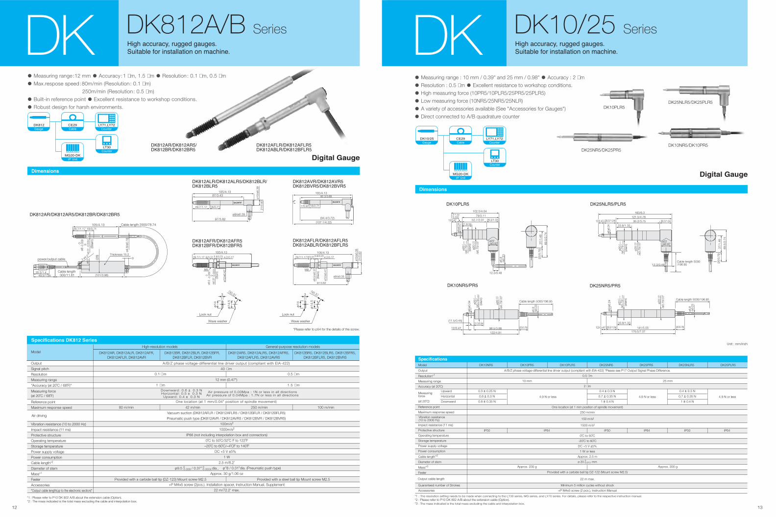
• Measuring range : 10 mm / 0.39" and 25 mm / 0.98" • Accuracy : 2 µm
• Resolution : 0.5 µm • Excellent resistance to workshop conditions.
• High measuring force (10PR5/10PLR5/25PR5/25PLR5)
• Low measuring force (10NR5/25NR5/25NLR)
• A variety of accessories available (See "Accessories for Gauges")
• Direct connected to A/B quadrature counter
����!�� "#�$
%&��'��
�()��()�
�*+�
����������
���� ������� ������ ����� �
�������� ��� �� ��������� �� ��������DK DK812A/B Series
��,��-��!��,��-���!��,��.��!��,��.���
ø9/ø0.35
21/0
.83
ø10/
ø0.3
9
97/3.82
87/3.43105/4.13
18/0.7129.7/1.17
��,��-�!��,��-��!��,��.�!��,��.��
��,��-/�!��,��-/����,��./�!��,��./��
M9
ø12/
ø0.4
7
4.2/0.175.8/0.238/0.3129.7/1.17
105/4.13
-0.0
004
0-0
.009
0
/ø0.
37
ø9.5
(Ste
m)
��,��-/��!��,��-/�����,��-.��!��,��./���
ø9/ø0.35
21/0
.83
ø10/
ø0.3
9
97/3.82
ø9.5
/ø0.
37
ø12/
ø0.4
7
4.2/0.175.8/0.238/0.3129.7/1.17
105/4.13
M9
(Ste
m)
��,��-0�!��,��-0����,��.0��!��,��.0��
(107.1/4.22)(94.4/3.72)
92.3/3.68105/4.13
18/0.71170.67
(t0.3)
Wave washer
Lock nut
φ14
φ14
.5
3(t0.3)
Wave washer
Lock nut
φ14
φ14
.5
3
49.5/1.9535.5/1.4
ø4.8
/ø0.
19
29.7/1.17105/4.13
(28)
(101/3.98)
power/output cable
-0.0
004
0-0.0
09 0
/ø0.
31ø8
18/0.71
(Ste
m)
Cable length 300/11.81
Cable length 2000/78.74
92-ø4.2
ø8.5
Thickness 15.2
• Measuring range:12 mm • Accuracy :1 µm, 1.5 µm • Resolution : 0.1 µm, 0.5 µm
• Max.respose speed:80m/min (Resolution : 0.1 µm)
250m/min (Resolution : 0.5 µm)
• Built-in reference point • Excellent resistance to workshop conditions.
• Robust design for harsh environments.
��,�� "#�$
%&��'��
�()��()�
�*+�
����� � ��
��,��-�!��,��-��!��,��.�!��,��.��
��,��-/��!��,��-/�����,��-.��!��,��./���
*Please refer to p54 for the details of the screw.
Vacuum suction (DK812AFLR / DK812AFLR5 / DK812BFLR / DK812BFLR5)
Pneumatic push type (DK812AVR / DK812AVR5 / DK812BVR / DK812BVR5)
100m/s2
1000m/s2
IP66 (not including interpolation box and connectors)
0˚C to 50˚C/32˚C F to 122˚F
–20˚C to 60˚C/–4˚CF to 140˚F
DC +5 V ±5%
1 W
2.5 m/8.2'
φ”8 / 0.31”dia. (Pneumatic push type)
Approx. 30 g/1.06 oz
+P M4x5 screw (2pcs.). Installation spacer, Instruction Manual, Supplement
22 m/72.2' max.
A/B/Z phase voltage-differential line driver output (compliant with EIA-422)
40 µ m
12 mm (0.47")
One location (at 1 mm/0.04" position of spindle movement)
Model DK812BR, DK812BLR, DK812BFR,DK812BFLR, DK812BVR
DK812AR5, DK812ALR5, DK812AFR5,DK812AFLR5, DK812AVR5
DK812BR5, DK812BLR5, DK812BFR5,DK812BFLR5, DK812BVR5
High-resolution models General-purpose resolution models
DK812AR, DK812ALR, DK812AFR,DK812AFLR, DK812AVR
*1 : Please refer to P10 DK 802 A/B about the extension cable (Option).*2 : The mass indicated is the total mass excluding the cable and interpolation box.
Output
Signal pitch
Resolution
Measuring range
"Accuracy (at 20˚C / 68˚F)"
Reference point
Maximum response speed
Vibration resistance (10 to 2000 Hz)
Impact resistance (11 ms)
Protective structure
Operating temperature
Storage temperature
Power supply voltage
Power consumption
Cable length*2
Diameter of stem
Mass*1
Feeler
Accessories
"Output cable length(up to the electronic section)"
Measuring force(at 20˚C / 68˚F)
0.1 µ m
1 µ m
0.5 µ m
1.5 µ m
Provided with a carbide ball tip (DZ-123) Mount screw M2.5 Provided with a steel ball tip Mount screw M2.5
80 m/min 250 m/min 100 m/min42 m/min
������������� ����� ������
Downward : 0.6 ± 0.3 NHorizontal : 0.5 ± 0.3 N
Upward : 0.4 ± 0.3 N
Air pressure of 0.03Mpa : 1N or less in all directionsAir pressure of 0.04Mpa : 1.7N or less in all directions
Air driving
φ9.5 / 0.37” dia., 0-0.009
0-0.0004
14 15
Output
Resolution*1
Measuring range
Accuracy (at 20˚C)
Reference point
Maximum response speed
Guaranteed number of Strokes
Accessories
Impact resistance (11 ms)
Protective structure
Operating temperature
Storage temperature
Power supply voltage
Power consumption
Cable length*2
Diameter of stem
Mass*3
Feeler mounting base
Magnetically attachable feeler
Spindle*4
Vibration resistance(10 to 2000 Hz)
Output cable length
������������
Model DK155PR5
155 mm
5 µm
A/B/Z phase voltage-differential line driver output (compliant with EIA-422) *Please see P17 Output Signal Phase Difference.
0.5 µm
One location (at 5 mm position of spindle movement)
250 m/min
150 m/s2
1500 m/s2
IP64
0˚C to 50˚C
-20˚C to 60˚C
DC +5 V ±5%
1 W or less
Approx. 2.5 m
ø32 mm
Approx. 1100 g
DK205PR5
205 mm
6 µm
Approx. 1300 g
Minimum 5 million cycles without shock
+P M4x5 screw (2 pcs.), Instruction Manual
22 m max.
Magnetic substance
Magnetic attraction: 10 N, resistance against horizontal slip: 2.7 N Provided with ø4 mm carbide ball tip
ø 8 mm, radial swing: 0.04 mm max.
*1 : The resolution setting needs to be made when connecting to the LT30 series, MG series, and LY70 series. For details, please refer to the respective instruction manual.*2 : Please refer to P10 DK 802 A/B about the extension cable (Option).
*3 : The mass indicated is the total mass excluding the cable and interpolation box.*4 : The spindle weighs about 400g.
0] -0.05
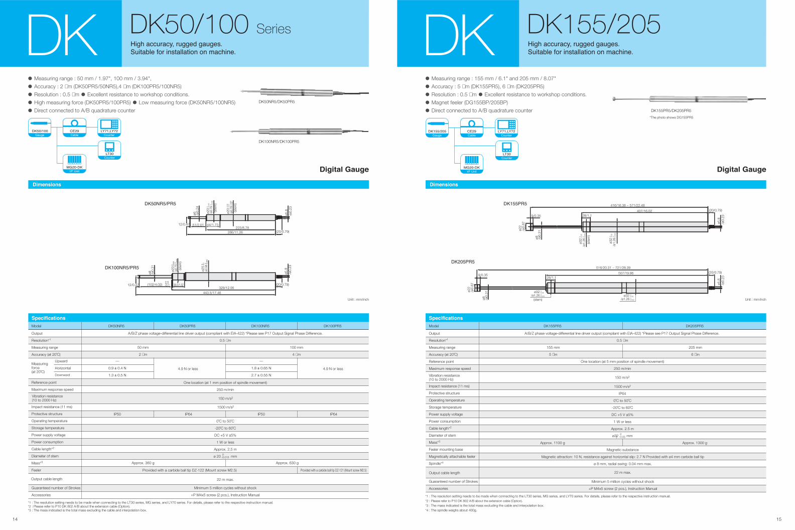
• Measuring range : 155 mm / 6.1" and 205 mm / 8.07"
• Accuracy : 5 µm (DK155PR5), 6 µm (DK205PR5)
• Resolution : 0.5 µm • Excellent resistance to workshop conditions.
• Magnet feeler (DG155BP/205BP)
• Direct connected to A/B quadrature counter
������
���� ������� ������ ����� �
�������� ��� �� ��������� �� ��������DK DK155/205
�� ���� ��� �
0 0 0-0.0
02/ø
1.26
-0.0
5 0
ø32
-0.0
02/ø
1.26
-0.0
5ø3
2
(20/0.79)
ø5.8
/ø0.
23
ø22
/ø0.
87
9/0.35
ø8 /ø0.
31
28/1.1
(ste
m)
416/16.38 ~ 571/22.48
407/16.02
��������
Unit : mm/inch
��������
-0.002 0/ø1.26-0.05 0ø32
(20/0.79)
ø5.8
/ø0.
2328/1.1
-0.002 0/ø1.26-0.05 0ø32
(stem)
ø22
/ø0.
87
9/0.35
ø8 /ø0.
31
516/20.31 ~ 721/28.39
507/19.96
DK155PR5/DK205PR5
*The photo shows DG155PR5
��������� !�"
#$��%��
&'(�&'(�
&)*�
• Measuring range : 50 mm / 1.97", 100 mm / 3.94",
• Accuracy : 2 µm (DK50PR5/50NR5),4 µm (DK100PR5/100NR5)
• Resolution : 0.5 µm • Excellent resistance to workshop conditions.
• High measuring force (DK50PR5/100PR5) • Low measuring force (DK50NR5/100NR5)
• Direct connected to A/B quadrature counter
�� ���� ��� �
������
DK DK50/100 Series���� ������� ������ ����� �
�������� ��� �� ��������� �� ��������
Output
Resolution*1
Measuring range
Accuracy (at 20˚C)
Upward
Horizontal
Downward
—
0.9 ± 0.4 N
1.3 ± 0.5 N
4.9 N or less
150 m/s2
1500 m/s2
50 mm
2 µm
100 mm
4 µm
Approx. 360 g Approx. 630 g
IP50
Measuringforce(at 20˚C)
Impact resistance (11 ms)
Protective structure
Operating temperature
Storage temperature
Power supply voltage
Power consumption
Cable length*2
Diameter of stem
Mass*3
Feeler
Guaranteed number of Strokes
Accessories
Reference point
Maximum response speed
Vibration resistance(10 to 2000 Hz)
Output cable length
������������
Model DK50NR5
—
1.8 ± 0.65 N
2.7 ± 0.55 N
IP50
DK100NR5
IP64
DK50PR5
4.9 N or less
IP64
DK100PR5
A/B/Z phase voltage-differential line driver output (compliant with EIA-422) *Please see P17 Output Signal Phase Difference.
0.5 µm
One location (at 1 mm position of spindle movement)
250 m/min
0˚C to 50˚C
-20˚C to 60˚C
DC +5 V ±5%
1 W or less
Approx. 2.5 m
ø 20 mm0 -0.013
Minimum 5 million cycles without shock
+P M4x5 screw (2 pcs.), Instruction Manual
22 m max.
Provided with a carbide ball tip DZ-122 (Mount screw M2.5) Provided with a carbide ball tip DZ-121 (Mount screw M2.5)
*1 : The resolution setting needs to be made when connecting to the LT30 series, MG series, and LY70 series. For details, please refer to the respective instruction manual.*2 : Please refer to P10 DK 802 A/B about the extension cable (Option).*3 : The mass indicated is the total mass excluding the cable and interpolation box.
DK50NR5/DK50PR5
DK100NR5/DK100PR5
����+������
ø6 /ø0.
24 -0.0
13 0
ø20
-0.0
005
0/ø
0.79
(ste
m)
-0.0
03 0
.000
8/ø
0.78
(ste
m)
-0.0
7-0
.02
ø20
12/0.47 51/2.01 44/1.73223/8.78
286/11.26 (20/0.79)
ø5.8
/ø0.
23
Unit : mm/inch
%����,
�
%����*
�
%������
�
%����
12/0.47 (20/0.79)ø5
.8/ø
0.23
ø20
/ø0.
79(s
tem
)
ø0.9
8ø2
5
ø8 /ø0.
31
(102/4.02)2.5/0.1 38.5/1.52
329/12.95443.5/17.46
�����+������
�������� !�"
#$��%��
&'(�&'(�
&)*�
1716
If the response speed is exceeded, the A/B output from this measuring unit changes to Hi impeadance for about 400 ms to serve as an alarm.
Output Signal Alarm
Alarm section A/B is Hi impeadance
�� ������ ������ �������
In operating the feeler with a vacuum pump, use such an air-pass system as shown in Fig. 1 to enable air driving. The optimum vacuum rate is 0.04 to 0.067MPa. Further, put such an orifice as shown in Fig. 2 on a tube from the air lifter connector to control the air suction and discharge speed. The feeler is lifted at the air discharge to the vacuum pump.
����� ������ � ���� ����� ���������� �� �������
VG
Fitting
Filter
Orifice
Cable
Valve
EXHVAC
Vacuum pumpsystem
3/0.12"3/0.12" 3/0.12"Φ0.3/0.01" dia.
φ3/
0.12
" di
a.
φ2.
5/0.
1" d
ia.
To fitting tube
C0.5/0.02" 1/0.04"
To vacuumsystem
Unit: mm/inch
�� ������ ������� ���� ����� �� ���
A
B
Z
The signals output from this measuring unit are A/B quadrature signal, Z signal in the form of voltage-differential line driver output compliant with EIA-422.
Before using, check that the minimum input phase difference of the control device connected to this measuring unit or the counter is smaller than 50 ns for the DK800A (A signal cycle: 200 ns, 5 MHz) or smaller than 100 ns for the DK800B (A cycle: 400 ns, 2.5 MHz). *The minimum phase difference can be modified under special specifications.
Before using, check that the minimum input phase difference of the control device connected to this measuring unit or the counter is smaller than 50 ns for-DK 10~110 series (A signal cycle: 200 ns, 5 MHz).*The minimum phase difference can be modified under special specifications.
The reference point is the synchronized reference point that is at Hi impeadance when the phase A and phase B are at the Hi level.
A
B
50 ns
200 ns (5 MHz)
������ ����� ������ � ������
������� ���� �� ���� �� � ���!
A
B
100 ns
400 ns (2.5 MHz)
�����" ����� ������ � ������
������� ���� �� ���� #� � ���!
A
B
50 ns
200 ns (5 MHz)
���� �$ ��� �$$ ��$ ���
����� ������ � ������ ������� ����
�� ���� #� � ���!
������ "����� "
The travel amount of the measuring unit is detected every 50 ns for the DK800A and every 100 ns for the DK800B, and the phase difference proportional to the amount traveled is output. The phase difference changes in integer multiples of 50 ns or 100 ns. Also, the minimum phase difference for the A and B is 50 ns for the DK800A and 100 ns for the DK800B.
A
B
Integer multiple of 50 ns or 100 ns
In maximum standard specifications, the minimum phase difference is fixed at 50 ns for the DK800A and 100 ns for the DK800B, but the minimum phase differences in the table below are available as special specifications.
100 ns DK800B standard product
50 ns DK800A standard product
300 ns Special specifications
500 ns
400 ns
200 ns
1.2 µs
2 µs
2.5 MHz
5 MHz
833 kHz
500 kHz
42 m/min
80 m/min
14 m/min
8.4 m/min
100 m/min
250 m/min
33 m/min
20 m/min Special specifications
A/B minimumphasedifference
Maximum response speed
Resolution 0.1 µ m Resolution 0.5 µ mRemarks
Counterallowablefrequency
A signalcycle
The travel amount of the measuring unit is detected every 50 ns, and the phase difference proportional to the amount traveled is output. The phase difference changes in integer multiples of 50 ns. Also, the minimum phase difference for the A and B is 50 ns.
Output Signal Phase Difference
A
B
Integer multiple of 50 ns
���� �$ ��� �$$ ��$ ���
In the standard specifications, the minimum phase difference is fixed at 50 ns, but the minimum phase differences in the table below are available as special specifications.
100 ns
50 ns
300 ns
500 ns
A/B minimumphasedifference
100 m/min
250 m/min
33 m/min
20 m/min
Maximum response speedResolution 0.5 µ m
Special specifications
Standard product
Special specifications
Special specifications
Remarks
2.5 MHz
5 MHz
833 kHz
500 kHz
Counterallowablefrequency
400 ns
200 ns
1.2 µs
2 µs
A signalcycle
Receiver
���� �$ ��� �$$ ��$ ���
(*If extending the cable, the supply voltage is +5 V±5%.) *Use the CE22 series extension cables for bare wires (optional accessories).
20 m or less
Line driver
Output: phase A/B/Z
*+V
0V
+V
AM26C32
DS34C87
0V
Line driver Line receiver AM26C32 or equivalent
SIG
120
SIG*SIG
�� ��� �� �
����������
DK110 DK %��& ����� ���� '��& ��������(�� �������� �����
Output
Resolution*1
Measuring range
Accuracy (at 20˚C)
Reference point
Maximum response speed
Guaranteed number of Strokes
Accessories
Impact resistance (11 ms)
Protective structure
Operating temperature
Storage temperature
Power supply voltage
Power consumption
Cable length*2
Diameter of stem
Mass*3
Feeler
Vibration resistance(10 to 2000 Hz)
Output cable length
������������
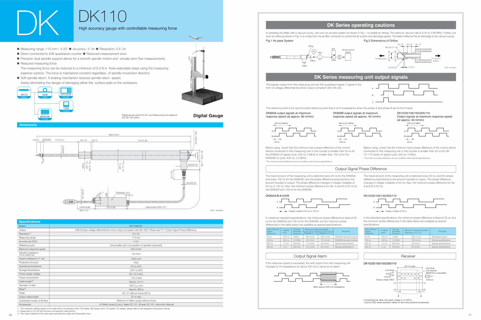
Model DK110NLR5
A/B/Z phase voltage-differential line driver output (compliant with EIA-422) *Please see P17 Output Signal Phase Difference.
0.5 µm
110 mm
4 µm
One location (at 5 mm position of spindle movement)
250 m/min
150 m/s2
1500 m/s2
IP50
0˚C to 50˚C
-20˚C to 60˚C
DC +5 V ±5%
1 W or less
Approx. 2.5 m
ø20 mm
Approx. 800 g
DZ-121 (Mount screw M2.5)
Minimum 5 million cycles without shock
+P M4x5 screw (2 pcs.), feeler DZ-121, lift lever DZ-161, Instruction Manual
22 m max.
*1 : The resolution setting needs to be made when connecting to the LT30 series, MG series, and LY70 series. For details, please refer to the respective instruction manual.*2 : Please refer to P10 DK 802 A/B about the extension cable (Option).*3 : The mass indicated is the total mass excluding the cable and interpolation box.
0 -0.013
Unit : mm/inch
ø29
ø5.8/ø0.23
ø2.5
/ø0.
1 ho
leø4
/ø0.
16
34.5
/1.3
628
/1.1
ø20/ø0.79
(31/
1.22
)
Cable length 2000/78.7,
Cable length
300/11.81
(101/3.98)
(112/4.41) 314/12.36
489.5/19.27
-0.1
0
/ø1.
14(ste
m)
-0.0
040
ø20
-0.0
30
/ø0.
79-0
.001
0
ø5.7
/ø0.
22
3/0.1240/1.57
ø8/ø
0.31
8.5/0.3312/0.47
• Measuring range :110 mm / 4.33" • Accuracy: 4 µm • Resolution: 0.5 µm
• Direct connected to A/B quadrature counter • Reduced measurement error
• Precision dual spindle support allows for a smooth spindle motion and virtually error free measurements.
• Reduced measuring force
The measuring force can be reduced to a minimum of 0.3 N in three selectable steps using the measuring
balancer (option). The force is maintained constant regardless of spindle movement direction.
• Soft spindle return. A braking mechanism reduces spindle return speed,
therby eliminating the danger of damaging either the surface plate or the workpiece.
*Digital gauge stand DZ-531 and Measuring force balancer DZ-581 are option.
92-ø4.2
ø8.5 (2
8) Thickness 15.2
����� )*�+
,-�����
./0�1./0�
.23�
1918
������ ����� ���� � � � ���� ������ �������
160ø20
290Column washer
Spring washer350350
ø50
500
25~
355
75
420
64
Grooved bearingCord
Balance arm
153
ø10
Mounting screws2-M6
520
330M
ax.
633~
698
Balancer mountinghook hole
Digital gauge stand DZ-531
HookWeight
A/C
135
Unit : mm
Unit : mm
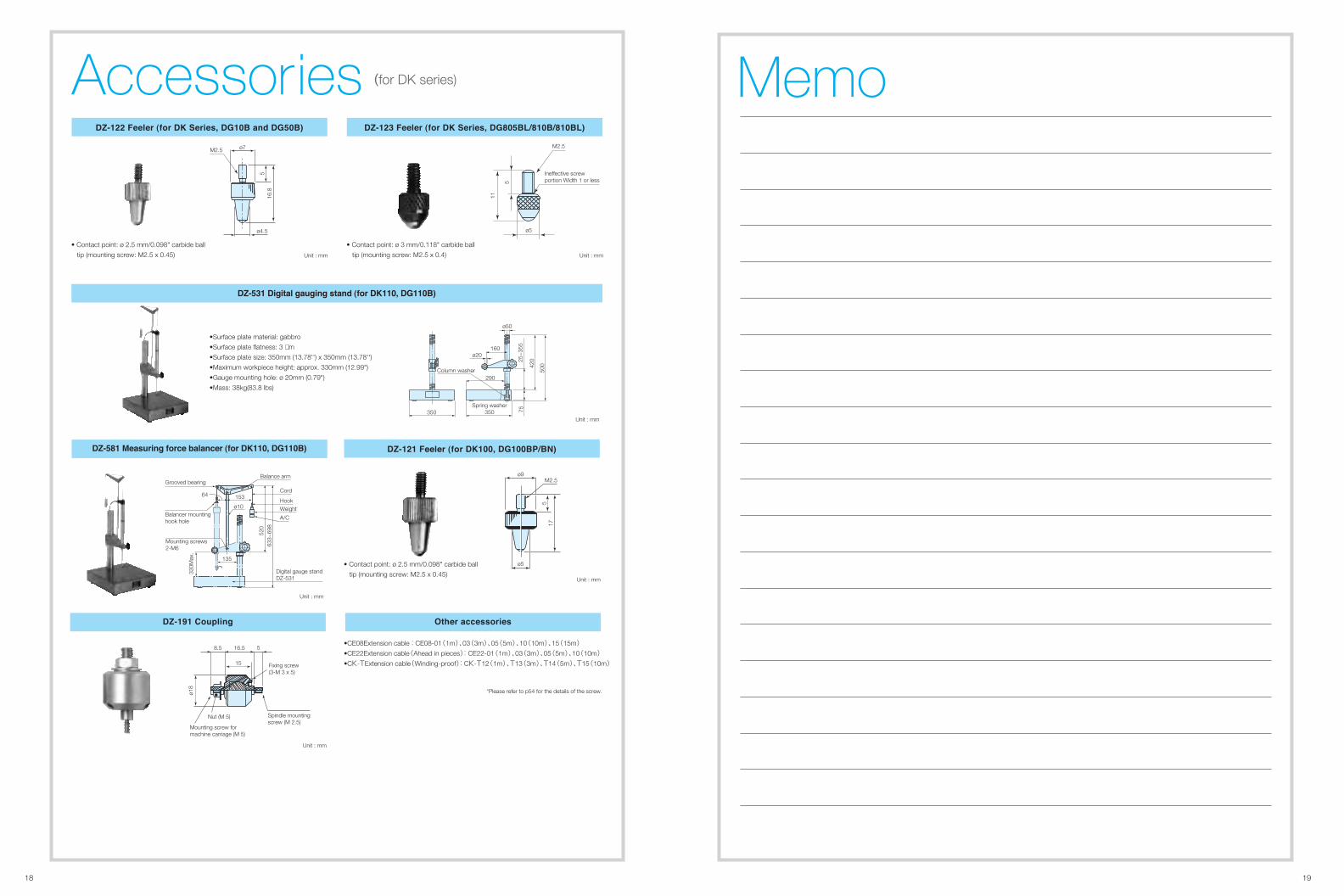
•Surface plate material: gabbro
•Surface plate flatness: 3 µm
•Surface plate size: 350mm (13.78'') x 350mm (13.78'')
•Maximum workpiece height: approx. 330mm (12.99")
•Gauge mounting hole: ø 20mm (0.79")
•Mass: 38kg(83.8 lbs)
Accessories������ ������ ���� �� ������� ����� � ������ ������ ������ ���� �� ������� ������� ���� ������
ø5
5
11
M2.5
Ineffective screwportion Width 1 or less
ø7
ø4.5
516
.8
M2.5
• Contact point: ø 2.5 mm/0.098" carbide ball
tip (mounting screw: M2.5 x 0.45)
• Contact point: ø 3 mm/0.118" carbide ball
tip (mounting screw: M2.5 x 0.4)Unit : mm Unit : mm
������ !����� � ���"� #� "�� ���� ������ ������� ������ ������ ���� ������ ������$ �%�
M2.5ø9
17
ø5
5
• Contact point: ø 2.5 mm/0.098" carbide ball
tip (mounting screw: M2.5 x 0.45)Unit : mm
•CE08Extension cable : CE08-01(1m)、03(3m)、05(5m)、10(10m)、15(15m)•CE22Extension cable(Ahead in pieces): CE22-01(1m)、03(3m)、05(5m)、10(10m)•CK-TExtension cable(Winding-proof): CK-T12(1m)、T13(3m)、T14(5m)、T15(10m)
Memo(for DK series)
*Please refer to p54 for the details of the screw.
&'�� ""������������(� )��*�� �
8.5 16.5 5
15
ø18
Fixing screw(3-M 3 x 5)
Nut (M 5) Spindle mountingscrew (M 2.5)
Mounting screw formachine carriage (M 5)
Unit : mm
2120
ø7
ø5
M2.5
5
17
•Plastic ball contact
point: ø 3mm nylon ball
ø6.5
5
13
M2.5
•Flat carbide contact point
ø7
10
19.3
517
.5
M2.5
•Off-center contact point:
ø 1mm steel ball
•Pin contact point
ø1.5
255
5
ø6
M2.5
Note : The four contactors shown at right are included.
������� ���� ���
Unit : mm
�� �� ����� ��� ��� �� ��� �� ���� �� �� ����� ��� ��� �������
24.2
ø7.5
ø4 ø3
15.5
8 (5)
13
M2.5 M2.5Bellows Extension spindle
71
ø7.5
(5)25
30
6
ø4
M2.5 M2.5
Bellows Extension spindle
Unit : mm Unit : mm
•With the extension spindle attached,
the spindle is extended by 25 mm and
the measuring force increases by about 0.3 N.
•With the extension spindle attached,
the spindle is extended by 8 mm.
Unit : mm
������ ������ ������� ����� ��� � ��� �!��� �� �!����� ��� ����
Accessories
Unit : mm
SZ70-1 is required for connecting the following scale units and counters:
Gauge unit : DE-BR Series, DG-B Series
Counter : LH71A, LH72-3, LY71 and LY72
* Adapter DZ51 is also required
"�#��� $��%��
(Φ6.5)
(33)
(15) (45) 300
1.222
15.5
19
-0+0.
228
.1
22.8
±0.
145
8.5
±0.1
546
10.72.2 17
99
±0.
136
40
54
28.6
84.4
4
29.8
63
2-M3 baring2-φ3.7
����� !������ ����� ��� �!&����'&���'&����� � "����� �������
88.5 150
75 ø25
59.5
~13
5.5
233
80
Internal springprevents the armfrom dropping
mounting hole o/ 8
Lever-type clamp
Unit : mm
•Surface plate material : alumina ceramic (dark brown)
•Surface plate flatness : 2 µm
•Surface plate size : 80 mm (3.15'') x 80 mm (3.15'')
•Maximum workpiece height : approx. 105 mm (4.13'')
•Gauge mounting hole : ø 8 mm (0.31")
•Mass: 3.8 kg (8.38 lbs)
•Surface plate material : alumina ceramic
•Surface plate flatness: 2 µm
•Surface plate size : 110 mm (4.33") x 110 mm (4.33")
•Maximum workpiece height: approx. 190 mm(7.48")
•Gauge mounting hole : ø 20mm (0.79")
•Mass : 13kg (28.67 lbs)
200100
110
ø40
ø20Probe mounting hole
370
272
98
132
����(� )��%���
8.5 16.5 5
15
ø18
Fixing screw(3-M 3 x 5)
Nut (M 5) Spindle mountingscrew (M 2.5)
Mounting screw formachine carriage (M 5) Unit : mm
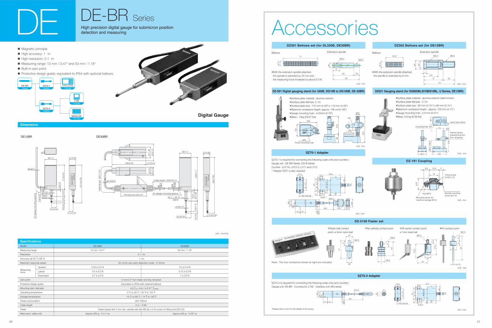
• Magnetic principle
• High accuracy: 1 m
• High resolution: 0.1 m
• Measuring range: 12 mm / 0.47" and 30 mm / 1.18"
• Built-in zero point
• Protective design grade: equivalent to IP64 with optional bellows.
��*�������
������ !����
���� ������� ���� �� ����� �� ������� �� ��
�� �� �� ��� ��������DE DE-BR Series
������
Cab
le le
ngth
300
/11.
81
108/4.25 0.7/0.03
35/1
.38
22/0
.87
26.5
/1.0
454
/2.1
3
24/0
.94
ø5.2/ø0.2
Pre-amp box 84/3.31
Cable length 2000/78.74
��
�����
��������
Air release monuting apeture
ø8 /ø0.31-0.015 0
-0.0006 0
(stem)
ø4/ø0.16
16.3/0.64
6/0.
24(3
3/1.
3)35
/1.3
810
6/4.
17
5/0.
2
38/1.5
�+!+,$�!$�!��� ���
"���-�.
/$��+-
0$1$-
21/0.83
180/
7.09
13.2/0.52
�� ���
�+!+,$�!$�!�������
ø5/ø0.2
Air
rele
ase
mon
utin
g ap
etur
e
5.6/
0.22
ø8/ø0.31
-0.015 0
-0.0006 0
(stem)ø4/ø0.16
16.3/0.64
13.2/0.52
6/0.
24(1
4.5/
0.57
)23/
0.91
3/0.
12
77.9
/3.0
7
/$��+-
0$1$-
"���-�.
38/1.5
121.
4/4.
78
21/0.83
Unit : mm/inch
Model DE30BRDE12BR
0.1 µm
1 µm
20 m/min zero point detection mode : 0.15/min
5 mm/0.2" from feeler end fully retracted
Equivalent to IP64 (with optional bellows)
ø 8 mm / ø 0.31"
0 ˚C to 50 ˚C / 32 ˚F to 122 ˚F
-10 ˚C to 60 ˚C / 14 ˚F to 140 ˚F
±5V 100mA
2 m / 6.56'
Feeler tipped with 3 mm dia. carbide ball with M2.5p x 0.45 screw on fitting end (DZ123)
12 mm / 0.47"
0.35 ± 0.2 N
0.5 ± 0.2 N
0.7 ± 0.2 N
Approx.400 g / 14.11 oz
30 mm / 1.18"
0.5 ± 0.3 N
0.75 ± 0.3 N
1 ± 0.3 N
Approx.450 g / 15.87 oz
Measuring range
Resolution
Accuracy (at 20 ˚C /68 ˚F)
Maximam response speed
Zero point
Protective design grade
Mounting stem diameter
Operating temperature
Storage temperature
Power consumption
Cable length
Feeler
Mass (excl. cable unit)
Upward
Lateral
Downward
Measuringforce
0-0.015
0-0.0006"
"%�2���2������
Unit : mm
"�#��� $��%��
SZ70-2 is required for connecting the following scale units and counters:
Gauge unit: DE-BR Counterunit: LT30 Interface unit: MG series22.8
±0.
145
8.5
±0.
1546
10.72.2 17
99
±0.
136
40
54
84.4
4
63
2-M3 baring2-φ3.7
(Φ4.8)
300
1.222
15.5
19
-0+0.
228
.1
28.6
29.8
13
13
*Please refer to p54 for the details of the screw.
��!��
"#��!�$
%&' (%&'�
%)��
*+'�!
*+'�!�
2322
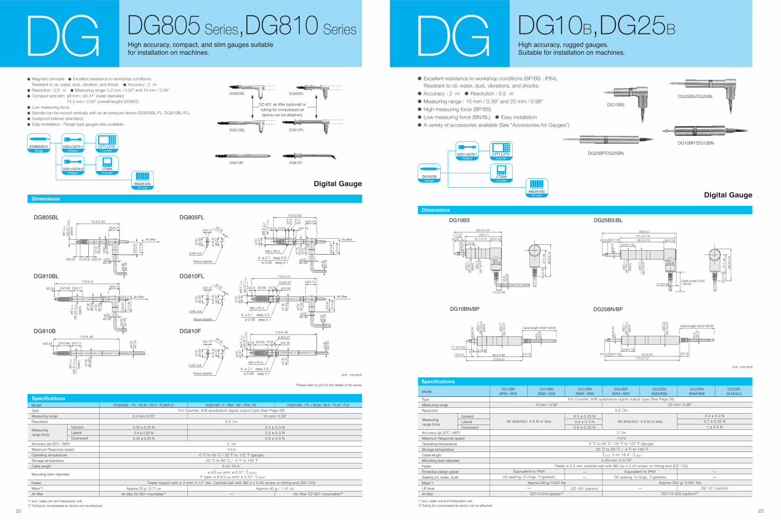
• Excellent resistance to workshop conditions (BP/BS : IP64).
Resistant to oil, water, dust, vibrations, and shocks.
• Accuracy : 2 m • Resolution : 0.5 m
• Measuring range : 10 mm / 0.39" and 25 mm / 0.98"
• High measuring force (BP/BS)
• Low measuring force (BN/BL) • Easy installation
• A variety of accessories available (See "Accessories for Gauges")
���� ������� ������ ����� �
�������� ��� �� ��������� �� ������� �DG DG10B,DG25B
*1 excl. cable unit and Interpolator unit. *2 Tubing for compressed air device can be attached.
Type
Measuring range
Resolution
Accuracy (at 20˚C / 68˚F)
Maximum Response speed
Operating temperature
Storage temperature
Cable length
Mounting stem diameter
Feeler
Protective design grade
Sealing (oil, water, dust)
Mass*1
Lift lever
Air lifter
ModelDG10BP
BPM / BPE
Measuringrange force
DG10BSBSM / BSE
DG10BNBNM / BNE
DG25BPBPM / BPE
DG25BSBSM/BSE
DG25BNBNM/BNE
DG25BLBLM/BLE
Upward
Lateral
Downward
10 mm / 0.39"
Approx.230 g/ 0.507 lbs
DZ174-010 (option)*2
25 mm/ 0.98"
Approx.300 g/ 0.661 lbs
DZ174-025 (option)*2
0.3 ± 0.25 N
0.6 ± 0.3 N
0.8 ± 0.35 N
—
—
DZ-161 (option)
All direction: 4.9 N or less
Equivalent to IP64
Oil sealing, O-rings, Y-gaskets
—
0.4 ± 0.3 N
0.7 ± 0.35 N
1 ± 0.4 N
—
—
DZ-161 (option)
All direction: 4.9 N or less
Equivalent to IP64
Oil sealing, O-rings, Y-gaskets
—
For Counter, A/B quadrature signal output type (See Page 26)
0.5 µm
2 µm
1m/s
0 ˚C to 50 ˚C / 32 ˚F to 122 ˚F (gauge)
-20 ˚C to 60 ˚C / -4 ˚F to 140 ˚F
5 m/ 16.4'
ø 20 mm/ ø 0.79"
Feeler ø 2.5 mm carbide ball with M2.5p x 0.45 screw on fitting end (DZ-122)
0-0.013
0-0.005"
������������
������
ø5.8
/ø0.
23
102.5/4.04
12.3/0.48
ø22/ø0.87
79/3.1126.3/1.0352.7/2.07
-0.0
7-0
.02
ø20-0
.013
0ø2
0-0
.000
50
/ø0.
79
-0.0
030.
0008
/ø0.
79
21.3/0.84
(ste
m)
12/0.47
(11.5/0.45)
ø6/ø
0.24
37/1
.46
69.5
/2.7
4
(20/
0.79
)
���������
12/0.47
160/6.3
(26.5/1.04)121.5/4.78
95.2/3.75 26.3/1.04
33.8/1.33
ø6/ø
0.24
-0.0
130
ø20
-0.0
005
0/ø
0.79
(ste
m)
-0.0
7-0
.02
ø20 -0
.003
0.00
08/ø
0.79
12.3/0.48
ø22/ø0.87
Cable length 5000/196.85
37/1
.46
69.5
/2.7
4
(20/
0.79
)
-0.0
130 -0
.000
50 -0.0
7-0
.02
-0.0
030.
0008
ø20
/ø0.
79(s
tem
)
ø20
/ø0.
79
Cable length 5000/196.85
ø6/ø
0.34
12/0.47
(11.5/0.45)21.3/0.84
98.5/3.88122/4.81
(20/0.79)
ø5.8
/ø0.
23
����� ��! ����� ��!
(20/0.79)
Cable length 5000/196.85
ø5.8
/ø0.
23
-0.0
130
ø20
-0.0
005
0/ø
0.79
(ste
m) -0
.07
-0.0
2ø2
0 -0.0
030.
0008
/ø0.
79
ø6/ø
0.24
12/0.47 (26.5/1.04)
33.8/1.33
141/5.55179.5/7.07
Unit : mm/inch
������
�� ���� ��� �
DG25BS/DG25BL
DG10BS
DG25BP/DG25BN
DG10BP/DG10BN
�������
"���#��
�$%��$%�
�&��'
�(��)�(%�#�
• Magnetic principle • Excellent resistance to workshop conditions. Resistant to oil, water, dust, vibration, and shock. • Accuracy : 2 m
• Resolution : 0.5 m • Measuring range: 5.2 mm / 0.20" and 10 mm / 0.39 "
• Compact and slim: ø8 mm / ø0.31" (outer diameter) 74.5 mm / 2.93" (overall length) (DG805)
• Low measuring force
• Spindle can be moved vertically with an air pressure device (DG805BL/FL, DG810BL/FL).
• Dustproof bellows (standard).
• Easy installation. Flange type gauges also available.
�� ���� ��� �
DG810BL
DG810B
DG810FL
DG810F
DG805BL DG805FL
DZ-801 air lifter (optional) ortubing for compressed airdevice can be attached.
������
Unit : mm/inch
��*��+
��*��+�
��*���
��*����
��*���� ��*��+�
ø4.8
/ø0
.19
(15.2/0.6)
(24/0.94)
(24/0.94)
7/0.28
7/0.28
5.3/0.21
(t0.3)
74.5/2.93
ø14/
ø0.5
5
ø14.
5/ø0
.57
3/0.12
M9 x P0.5
4- ø 2.1 deep 2.5/ø 0.08 deep 0.1
M9 x P0.5
4- ø 2.1 deep 2.5/ø 0.08 deep 0.1
M9 x P0.5
4- ø 2.1 deep 2.5/ø 0.08 deep 0.1
8.7/0.34
ø12/
ø0.4
7
19/0.75
-0.0
004
0/ø
0.37-0
.009
0ø9
.5
ø12/
ø0.4
7ø1
2/ø0
.47
-0.0
004
0/ø
0.37-0
.009
0ø9
.5-0
.000
40
/ø0.
37-0.0
090
ø9.5
6.8/0.27
4/0.16
6.8/0.27
4/0.16
112/4.41
6/0.24
6/0.24
(15.2/0.6)
22/0
.87
ø7.8
/ø0.3
1
ø10/
ø0.3
9
ø4.8
/ø0
.19
ø4.8
/ø0
.19
ø4.8
/ø0
.19
27/1
.06
22/0
.87
27/1
.06
74.5/2.93
8.6/0.34
-0.0
090
ø8-0
.000
40
/ø0.
31-0
.009
0ø8
-0.0
004
0/ø
0.31
(ste
m)
Air lifter Air lifter
Air lifter
(24/0.94)
112/4.41
18/0.71
6/0.24 (24/0.94) 18/0.71
(ste
m)
-0.0
090
ø8-0
.000
30
/ø0.
31 (ste
m)
114/4.49114/4.49
ø10/ø0.39
ø7.8
/ø0
.31
ø10/
ø0.3
9
ø10/ø0.39
19/0.75
Air lifter
19/0.7519/0.75
22/0
.87
27/1
.06
Lock nut
Wave washer
(t0.3)
ø14/
ø0.5
5
ø14.
5/ø0
.57
3/0.12
Lock nut
Wave washer
(t0.3)
ø14/
ø0.5
5
ø14.
5/ø0
.57
3/0.12
Lock nut
Wave washer
6/0.24 4/0.15
ø7.8
/ø0.3
1ø10/
ø0.3
9
ø10/ø0.39
ø7.8
/ø0
.31
ø7.8
/ø0
.31
ø10/
ø0.3
9
ø10/ø0.39
6/0.24
ø4.8
/ø0
.19
ø4.8
/ø0
.19
22/0
.87
27/1
.06
6/0.24
ø7.
8/ø0
.307
Model DG810B / F / BM / BE / FM / FE DG810BL / FL / BLM / BLE / FLM / FLEDG805BL / FL / BLM / BLE / FLM/FLE
*1 excl. cable unit and Interpolator unit. *2 Tubing for compressed air device can be attached.
Type
Measuring range
Resolution
Accuracy (at 20˚C / 68˚F)
Maximum Response speed
Operating temperature
Storage temperature
Cable length
Feeler
Mass*1
Air lifter
Measuringrange force
ø 8 mm/ ø 0.31" F type: ø 9.5 mm/ ø 0.37"
Mounting stem diameter
Upward
Lateral
Downward
5.2 mm/ 0.20"
0.35 ± 0.25 N
0.4 ± 0.25 N
0.45 ± 0.25 N
Approx.20 g / 0.71 oz
Air lifter DZ-801 mountable*2
10 mm/ 0.39"
0.4 ± 0.3 N
0.5 ± 0.3 N
0.6 ± 0.3 N
Approx.40 g / 1.41 oz
Air lifter DZ-801 mountable*2
For Counter, A/B quadrature signal output type (See Page 26)
0.5 µ m
2 µ m
1m/s
0 ˚C to 50 ˚C / 32 ˚F to 122 ˚F (gauge)
-20 ˚C to 60 ˚C / -4 ˚F to 140 ˚F
5 m/ 16.4'
Feeler tipped with ø 3 mm/ 0.12" dia. Carbide ball with M2.5 x 0.45 screw on fitting end (DZ-123)
—
0-0.009
0-0.009
0-0.0004"
0-0.0004"
������������
DG DG805 Series,DG810 Series���� ������� ���,��� ��� ��� ����� �������
��� �� ��������� �� ������� �
��*���*��
"���#��
�$%��$%�
�&��'
�(��)�(%�#�
�(��)�(%�#�
*Please refer to p54 for the details of the screw.
24 25
����������
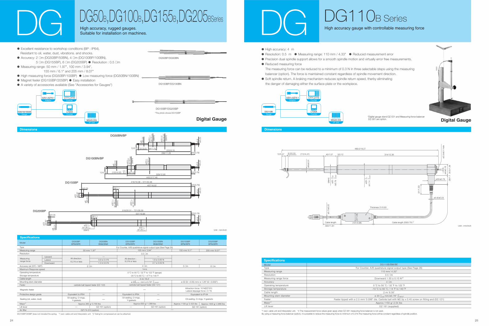
MG• High accuracy: 4 m
• Resolution: 0.5 m • Measuring range: 110 mm / 4.33" • Reduced measurement error
• Precision dual spindle support allows for a smooth spindle motion and virtually error free measurements.
• Reduced measuring force
The measuring force can be reduced to a minimum of 0.3 N in three selectable steps using the measuring
balancer (option). The force is maintained constant regardless of spindle movement direction.
• Soft spindle return. A braking mechanism reduces spindle return speed, therby eliminating
the danger of damaging either the surface plate or the workpiece.
����� ���
DG DG110B Series
*1 excl. cable unit and Interpolator unit. *2 The measurement force values given apply when DZ-581 measuring force balancer is not used.By using a measuring force balancer (option), it is possible to reduce the measuring force to minimum of 0.3 N.The measuring force will be constant regardless of spindle position.
Type
Measuring range
Resolution
Measuring range force
Accuracy
Operating temperature
Storage temperature
Cable length
Mounting stem diameter
Feeler
Mass*1
Lift lever
Model DG110B/BM/BE
For Counter, A/B quadrature signal output type (See Page 26)
110 mm/ 4.33"
0.5 µm
Downward 1.55 ± 0.15 N*2
4 µm
0 ˚C to 50 ˚C / 32 ˚F to 122 ˚F
-10 ˚C to 60 ˚C / 14 ˚F to 140 ˚F
2 m/ 6.56'
ø 20 mm/ø0.78"
Feeler tipped with ø 2.5 mm/ 0.098" dia. Carbide ball with M2.5p x 0.45 screw on fitting end (DZ-121)
Approx.1150 g/ 2.54 lbs
DZ-161 (supplied)
0-0.03
0"-0.0012"
Unit : mm/inch
ø29
ø5.8/ø0.23
ø2.5
/ø0.
1 ho
leø4
/ø0.
16
34.5
/1.3
628
/1.1
ø20/ø0.79
(31/
1.22
)
Cable length 2000/78.7,
Cable length
300/11.81
(101/3.98)
(112/4.41) 314/12.36
489.5/19.27
-0.1
0
/ø1.
14(ste
m)
-0.0
040
ø20
-0.0
30
/ø0.
79-0
.001
0
(27/
1.06
)ø5.7
/ø0.
22
3/0.1240/1.57
ø8/ø
0.31
8.5/0.3312/0.47
Thickness 21/0.83
������������
���� ������� ���� ���� � ��� ����� �������� � ��
*Digital gauge stand DZ-531 and Measuring force balancer DZ-581 are option.
������
�������
���������
� ��!
�"#�$%"����
DG50BP/DG50BN
DG100BP/DG100BN
����� ���
��#��&'�(
ø6 /ø0.
24 -0.0
13 0
ø20
-0.0
005
0/ø
0.79
(ste
m)
-0.0
03 0
.000
8/ø
0.78
(ste
m)
-0.0
7-0
.02
ø20
12/0.47 51/2.01 44/1.73223/8.78
286/11.26 (20/0.79)
ø5.8
/ø0.
23
0 0 0-0.0
02/ø
1.26
-0.0
5 0
ø32
-0.0
02/ø
1.26
-0.0
5ø3
2
(20/0.79)
ø5.8
/ø0.
23
ø22
/ø0.
87
9/0.35
ø8 /ø0.
31
28/1.1
(ste
m)
416/16.38 ~ 571/22.48
407/16.02���##�(
��)��*
�
��)��+
�
��)���#
�
��)��
12/0.47 (20/0.79)
ø5.8
/ø0.
23
ø20
/ø0.
79(s
tem
)
ø0.9
8ø2
5
ø8 /ø0.
31
(102/4.02)2.5/0.1 38.5/1.52
329/12.95443.5/17.46
������&'�(
Unit : mm/inch
����#�(
-0.002 0/ø1.26-0.05 0ø32
(20/0.79)
ø5.8
/ø0.
2328/1.1
-0.002 0/ø1.26-0.05 0ø32
(stem)
ø22
/ø0.
87
9/0.35
ø8 /ø0.
31
516/20.31 ~ 721/28.39
507/19.96
����������
• Excellent resistance to workshop conditions (BP : IP64). Resistant to oil, water, dust, vibrations. and shocks.
• Accuracy: 2 µm (DG50BP/50BN), 4 µm (DG100BP/100BN), 5 µm (DG155BP), 6 µm (DG205BP) • Resolution : 0.5 µm
• Measuring range: 50 mm / 1.97", 100 mm / 3.94", 155 mm / 6.1" and 205 mm / 8.07"
• High measuring force (DG50BP/100BP) • Low measuring force (DG50BN/100BN)
• Magnet feeler (DG155BP/205BP) • Easy installation
• A variety of accessories available (See "Accessories for Gauges")
DG155BP/205BP does not included the spring. *1 excl. cable unit and Interpolator unit *2 Tubing for compressed air can be attached.
Type
Measuring range
Resolution
Accuracy (at 20˚C / 68˚F)
Maximum Response speed
Operating temperature
Storage temperature
Cable length
Mounting stem diameter
Feeler
Protective design grade
Mass*1
Lift lever
Air lifter
ModelDG50BPBPM/BPE
Measuringrange force
Oil sealing, O-rings, Y-gaskets
Oil sealing, O-rings, Y-gaskets
Attraction force: 10 N(DZ181)Lateral slippage force: 2.7 N
Oil sealing, O-rings, Y-gasketsSealing (oil, water, dust)
Magnetic feeler
All direction:
6.2 N or lessAll direction :9.3 N or less
DG50BNBNM/BNE
DG100BPBPM/BPE
DG100BNBNM/BNE
DG155BPBPM/BPE
DG205BPBPM/BPE
Upward
Lateral
Downward
50 mm/ 1.97"
2 µm
carbide ball tipped feeler (DZ-122)
Approx.360 g/ 0.793 lbs
100 mm/ 3.94"
4 µm
1m/s
carbide ball tipped feeler (DZ-121)
Approx.630 g/ 1.388 lbs
Equivalent to IP64
—
—
1.8 ± 0.65 N
2.7 ± 0.55 N
—
DZ-161 (option)
155 mm/ 6.1"
5 µm
Approx.1100 g/ 2.425 lbs
205 mm/ 8.07"
6 µm
Approx.1300 g/ 2.866 lbs
—
0.9 ± 0.4 N
1.3 ± 0.5 N
—
DZ-161 (option)
Equivalent to IP64
—
ø 32 (0/ -0.05) mm/ ø 1.26" (0/ -0.002")
Equivalent to IP 64
DZ-161 (option)
For Counter, A/B quadrature signal output type (See Page 26)
0.5 µm
0 ˚C to 50 ˚C / 32 ˚F to 122 ˚F (gauge)
-20 ˚C to 60 ˚C / -4 ˚F to 140 ˚F
5 m/ 16.4'
ø 20 mm/ ø 0.79"
—
— —
—
—
—
0-0.013
0-0.0005"
—DZ174-010 (option)
������������
DG50B,DG100B,DG155B,DG205BSeriesDG ���� �������� ����, �����)
%������ � � ���������� � � �������)
DG155BP/DG205BP
*The photo shows DG155BP��#�'���'�##'��#
�������
���������
� ��!
�"#�$%"����
26 27
26
3646 2-ø5.5
9
34.553
15
11
B22A
Unit : mm
Measuring unit
DG10BP/BN
DG10BS
DG25BP/BN
Measuring unit
DG25BS
DG25BL
DG50BP/BN
A
32.5
32.5
47.5
B
75.5
56
118
A
47.5
47.5
72
B
98.5
98.5
200
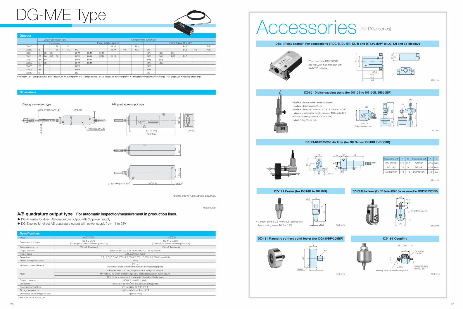
DG-M/E Type
������������
������
� � ������� � � ����������� ��� �� � ����������� ��������� ����� �� � � �������� ��� �� � � �������� ��������� ����� � � ����������� ��������� ������� ���� � � � �������� ��������� ������� ����
DG805
DG810
DG10
DG25
DG50
DG100
DG155
DG205
DG110
B
BP
BP
BP
BP
BP
BP
B
BM
BPM
BPM
BPM
BPM
BPM
BPM
BM
BN
BN
BN
BN
BNM
BNM
BNM
BNM
BS
BS
BSM
BSM
BL
BL
BL
BLM
BLM
BLM
F FM
Power supply output 5V
Display connection type
For counter Power supply 11 to 28V
FL
FL
FLM
FLM BE
BPE
BPE
BPE
BPE
BPE
BPE
BE
BNE
BNE
BNE
BNE
BSE
BSE
BLE
BLE
BLE
FE
FLE
FLE
A/B quadrature output type
�� ���������� ������ ���� ��� ��������� ����������������� � ��������� ����
• DG-M series for direct AB quadrature output with 5V power supply
• DG-E series for direct AB quadrature output with power supply from 11 to 28V
*Cable MDR-10114-3000VE (3M)
Model
Power supply voltage
Minimum phase difference
DG□□□EDG□□□M
DC 5 V ± 5 %(Corresspond to remote sensing function)
Based on EIA-422 (Line driver:AM 26C31 or equivalent)
A/B quadrature signal
0.5,1,2,5,10 µm (0.000025",0.0005",0.0001",0.00025",0.0005") selectable
1 m/s
A/B quadrature output of this probe turns to high impedance
for 10 to 20 ms when excessive speed or cable disconnection alarm occurs.
If the cause is removed, the alarm signal is automatically reset.
MDR10214-52A2JL (3M) *
125 x 28 x 28 (mm) (not including projecting parts)
0˚C to 40˚C / 32 ˚F to 104 ˚F
-20˚C to 60˚C / -4 ˚F to 140 ˚F
Approx.150 g
200 nsThe output phase difference varies with the measuring speed.
300 mA (Maximum)
DC 11 V to 28 V(Corresspond to remote sensing function)
150 mA (Maximum)Power consumption
Output interface
Output signal
Resolution
Maximum response speed
Alarm
Output connector
Dimensions
Operating temperature
Storage temperature
Mass (excl. cable and gauge part)
Unit : mm/inch
���� �� ���������� ���� ��� ���������� ������ ����
deep 4/0.162 - M4 100/3.94 9/0.35
26/1
.02
28/1
.1
ø5.7
/ø0.
22
Thickness 21/0.83
Cable length 300/11.81
(27/
1.06
)
(101/3.98)
Serial No.
MADE IN JAPAN
117.5/4.63125/4.92
38/1
.5
16/0.63
Sony Manufacturing Systems Corporation
������
*Build to order for A/B quadrature output type.
���� ������ �������� ��� ������� �� � !�" �#!��" �#!� �� �$�%�&%'�() �� # " #* �� #+ ������
��!�,� ��-���� -��-�- ��� ���� � �,� �� � �,,�" �.!&,���
���/0!,�,�,%��,�, �� ������ ���� �1 �����" � �,� �� � �,��
*To connect the DT12/32N/P,
use the DZ51 in combination with
the MT10 detector.
��!�%% ������ ���� � �,� �� � �,�� ��!�,, ������ ������ ���� �$ �����"� !� �����2 �3���� ��� � ����(�%,��(�
(10.4)
(61.3)
(64)
60.6
35
(24.
5)
22
54
Unit : mm
Unit : mm
•Surface plate material: alumina ceramic
•Surface plate flatness: 2 µm
•Surface plate size: 110 mm (4.33") x 110 mm (4.33")
•Maximum workpiece height: approx. 190 mm(7.48")
•Gauge mounting hole: ø 20mm (0.79")
•Mass: 13kg (28.67 lbs)
200100
110
ø40
ø20Probe mounting hole
370
272
98
132
ø7
ø4.5
516
.8
M2.5
• Contact point: ø 2.5 mm/0.098" carbide ball
tip (mounting screw: M2.5 x 0.45) Unit : mm
Roller thickness:4mm
ø12
ø10
722
M2.5
Unit : mm
��!�4� 5�-���� ������ ���� ������ ���� � ����(�%,��(� ��!�6� 7�����-
9
16
ø22
M5
Gasket
8.5 16.5 5
15
ø18
Fixing screw(3-M 3 x 5)
Nut (M 5) Spindle mountingscrew (M 2.5)
Mounting screw for machine carriage (M 5)
Unit : mm Unit : mm
Accessories (for DGB series)
28 29
ø7
ø5
M2.5
5
17
•Plastic ball contact
point: ø 3mm nylon ball
ø6.5
5
13
M2.5
•Flat carbide contact point
ø7
10
19.3
517
.5
M2.5
•Off-center contact point:
ø 1mm steel ball
•Pin contact point
ø1.5
255
5
ø6
M2.5
Note: The four contactors shown at right are included.
������� ���� ���
Unit : mm
Unit : mm
SZ70-1 is required for connecting the following scale units and counters:
Gauge unit : DE-BR Series, DG-B Series
Counter : LH71A/72, LY71 and LY72
* Adapter DZ51 is also required
����� ������
(Φ6.5)
(33)
(15) (45) 300
1.222
15.5
19
-0+0.
228
.1
22.8
±0.
145
8.5
±0.1
546
10.72.2 17
99
±0.
136
40
54
28.6
84.4
4
29.8
63
2-M3 baring2-φ3.7
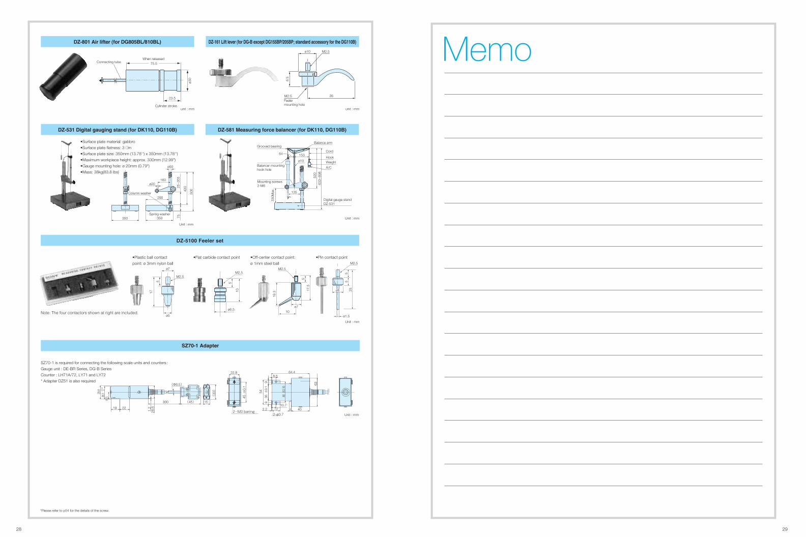
������ ������ ������� ����� ��� ������ ������� ���� � !������� ��"� #���"� ��� ������ �������
64
Grooved bearingCord
Balance arm
153
ø10
Mounting screws2-M6
520
330M
ax.
633~
698
Balancer mountinghook hole
Digital gauge stand DZ-531
HookWeight
A/C
135
Unit : mm
160ø20
290Column washer
Spring washer350350
ø50
500
25~
355
75
420
Unit : mm
•Surface plate material: gabbro
•Surface plate flatness: 3 µm
•Surface plate size: 350mm (13.78'') x 350mm (13.78'')
•Maximum workpiece height: approx. 330mm (12.99")
•Gauge mounting hole: ø 20mm (0.79")
•Mass: 38kg(83.8 lbs)
��� �� �� ���� ��� �� ���$% ���$�
23.5
75.5
ø30
Connecting tubeWhen released
Cylinder strokeunit : mm
����&� $��� �'� ��� ���� �("��� ������)%*���)+ ������� �""����, �� �-� �������
M2.5
Feelermounting hole
M2.5
8.5
ø10
26
unit : mm
Memo
*Please refer to p54 for the details of the screw.
30 31
DT12P
DT12N
DT32NV DT32PV
����������
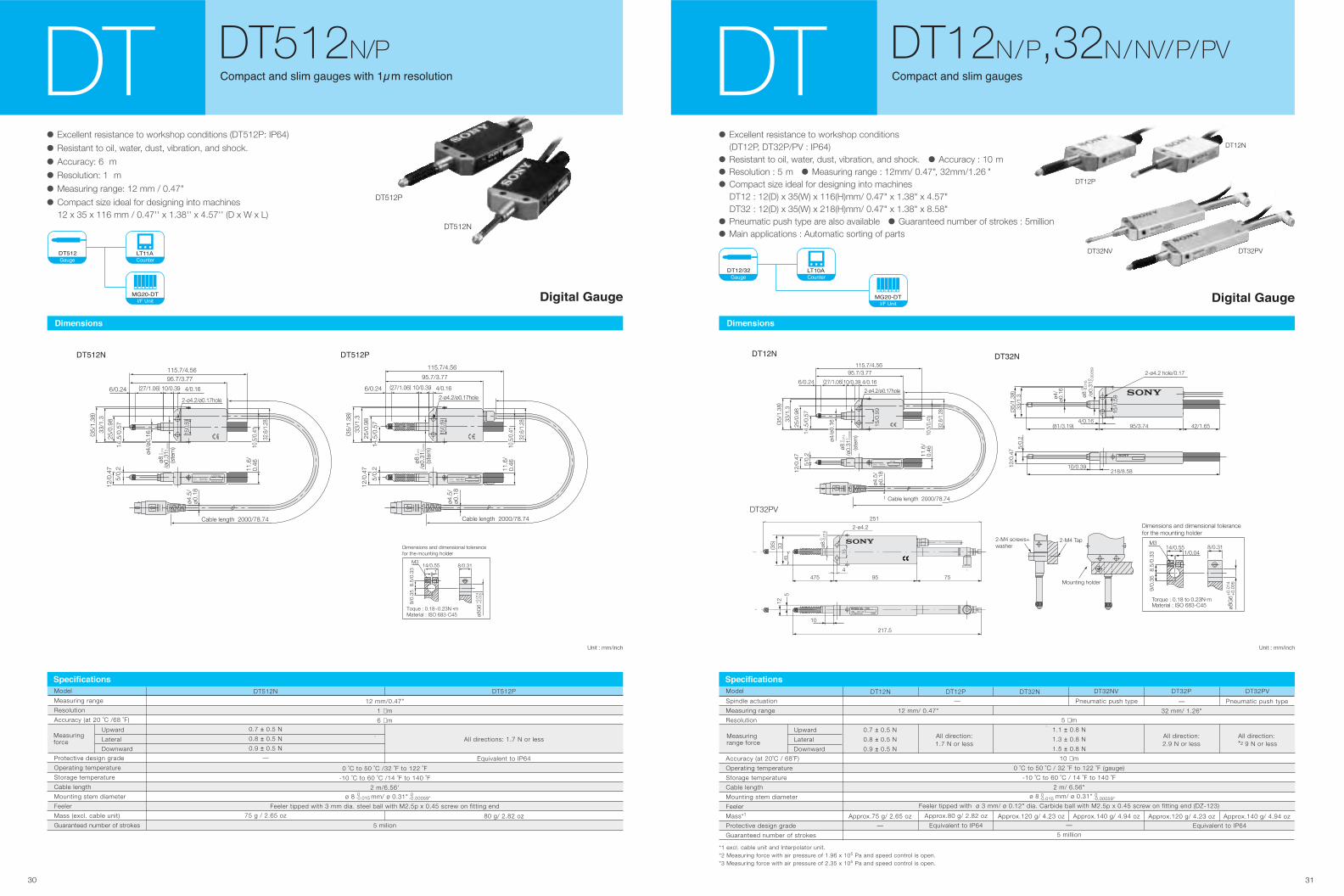
• Excellent resistance to workshop conditions
(DT12P, DT32P/PV : IP64)
• Resistant to oil, water, dust, vibration, and shock. • Accuracy : 10 m
• Resolution : 5 m • Measuring range : 12mm/ 0.47", 32mm/1.26 "
• Compact size ideal for designing into machines
DT12 : 12(D) x 35(W) x 116(H)mm/ 0.47" x 1.38" x 4.57"
DT32 : 12(D) x 35(W) x 218(H)mm/ 0.47" x 1.38" x 8.58"
• Pneumatic push type are also available • Guaranteed number of strokes : 5million
• Main applications : Automatic sorting of parts
����� ���
������� �� ��� �� �DT DT12N/P,32N/NV/P/PV
10/0.39218/8.58
5/0.
2
12/0
.47
4/0.16
2-ø4.2 hole/0.17
(81/3.19) 95/3.74 42/1.65
(35/
1.38
)33
/1.3 ø4
/ø0
.16
15/0
.59/ø
0.31
0 -0.0
0059
ø80 -0
.015
�����
2-M4 screws+washer
2-M4 Tap
Mounting holder
Dimensions and dimensional tolerancefor the mounting holder
Torque : 0.18 to 0.23N.m
8/0.31
ø8G
6+
0.01
4+
0.00
5
Material : ISO 683-C45
M314/0.55
1/0.04
8.5/
0.33
9/0.
35
Unit : mm/inch
�����
ø4.5
/ø0
.18
(27/1.06)6/0.24 4/0.16
2-ø4.2/ø0.17hole
33/1
.3
25/0
.98
15/0
.59
32.6
/1.2
8
( 35/
1.38
)
11.6
/0.
46
12/0
.47
95.7/3.77115.7/4.56
10/0.39
(ste
m)
-0.0
006
0/ø
0.31
-0.0
150
ø8
SonyMADE IN JAPANPrecision Technology Inc.
Ser.No.
DT12N
Cable length 2000/78.74
5/0.
214
.5/0
.57
ø4/ø
0.16
10.5
/0.4
1
*1 excl. cable unit and Interpolator unit. *2 Measuring force with air pressure of 1.96 x 10⁵ Pa and speed control is open. *3 Measuring force with air pressure of 2.35 x 10⁵ Pa and speed control is open.
Spindle actuation
Measuring range
Resolution
Accuracy (at 20˚C / 68˚F)
Operating temperature
Storage temperature
Cable length
Mounting stem diameter
Feeler
Mass*1
Protective design grade
Guaranteed number of strokes
Model DT12N
Measuringrange force
All direction:1.7 N or less
All direction:2.9 N or less
All direction: *2 9 N or less
DT12P DT32N DT32NV DT32P DT32PV
Upward
Lateral
Downward
Approx.80 g/ 2.82 oz
Equivalent to IP64
Approx.120 g/ 4.23 oz
Pneumatic push type
Approx.140 g/ 4.94 oz
—
32 mm/ 1.26"
Approx.120 g/ 4.23 oz
Pneumatic push type
Approx.140 g/ 4.94 oz
0.7 ± 0.5 N
0.8 ± 0.5 N
0.9 ± 0.5 N
Approx.75 g/ 2.65 oz
— Equivalent to IP64
5 µm
1.1 ± 0.8 N
1.3 ± 0.8 N
1.5 ± 0.8 N
10 µm
0 ˚C to 50 ˚C / 32 ˚F to 122 ˚F (gauge)
-10 ˚C to 60 ˚C / 14 ˚F to 140 ˚F
2 m/ 6.56"ø 8 mm/ ø 0.31"
Feeler tipped with ø 3 mm/ ø 0.12" dia. Carbide ball with M2.5p x 0.45 screw on fitting end (DZ-123)
—
5 million
12 mm/ 0.47"
—
0-0.015
0-0.00059"
������������
DT32PV
10
217.5
512
4
2-ø4.2
251
95475 75
(35)
33 ø80 -0
.015
45
15
�������
�������
�����
• Excellent resistance to workshop conditions (DT512P: IP64)
• Resistant to oil, water, dust, vibration, and shock.
• Accuracy: 6 m
• Resolution: 1 m
• Measuring range: 12 mm / 0.47"
• Compact size ideal for designing into machines
12 x 35 x 116 mm / 0.47'' x 1.38'' x 4.57'' (D x W x L)
������� �� ��� �� � ���� ��� ��������DT DT512N/P
Unit : mm/inch
��!��� ��!��"
ø8G
6+
0.00
5+
0.01
4
Dimensions and dimensional tolerance for the mounting holder
Toque : 0.18~0.23N m
M314/0.55
18/0.31
8.5/
0.33
9/0.
35
Material : ISO 683-C45
DT512N
115.7/4.5695.7/3.77
6/0.24 (27/1.06) 10/0.39 4/0.16
2-ø4.2/ø0.17hole
(ste
m)
-0.0
006
0/ø
0.31-0
.015
0ø8
33/1
.325
/0.9
8
( 35/
1.38
)
14.5
/0.5
7
ø4/ø
0.16 15
/0.59
32.6
/1.2
8
10.5
/0.4
1
12/0
.47
5/0.
2 11.6
/0.
46
ø4.5
/ø0
.18
Cable length 2000/78.74
Sony Ser.No.Precision Technology Inc. MADE IN JAPAN
15/0
.59
32.6
/1.2
8
10.5
/0.4
1
12/0
.47
5/0.
2 11.6
/0.
46
ø4.5
/ø0
.18
Cable length 2000/78.74
DT512PSony Ser.No.
Precision Technology Inc. MADE IN JAPAN
115.7/4.56
95.7/3.77
6/0.24 (27/1.06) 10/0.39 4/0.16
2-ø4.2/ø0.17hole
33/1
.325
/0.9
8
( 35/
1.38
)
14.5
/0.5
7
(ste
m)
-0.0
006
0/ø
0.31-0
.015
0ø8
������������
Model DT512N DT512P
All directions: 1.7 N or less
12 mm/0.47"
1 µm
6 µm
0 ˚C to 50 ˚C /32 ˚F to 122 ˚F
-10 ˚C to 60 ˚C /14 ˚F to 140 ˚F
2 m/6.56'ø 8 mm/ ø 0.31"
Feeler tipped with 3 mm dia. steel ball with M2.5p x 0.45 screw on fitting end
5 milion
0.7 ± 0.5 N
0.8 ± 0.5 N
0.9 ± 0.5 N
—
75 g / 2.65 oz
Equivalent to IP64
80 g/ 2.82 oz
Measuring range
Resolution
Accuracy (at 20 ˚C /68 ˚F)
Protective design grade
Operating temperature
Storage temperature
Cable length
Mounting stem diameter
Feeler
Mass (excl. cable unit)
Guaranteed number of strokes
Upward
Lateral
Downward
Measuringforce
0-0.015
0-0.00059"
DT512P
DT512N
����������
����� ���
��!��
�������
�����
A, B, ALARM A, B, ALARM_ _ _
MT14
A, B A, B_ _
MT13A, B, ALARM
MT12
32 33
������������
��������� ��� �� � � ������MT MT12/13/14
���� ���
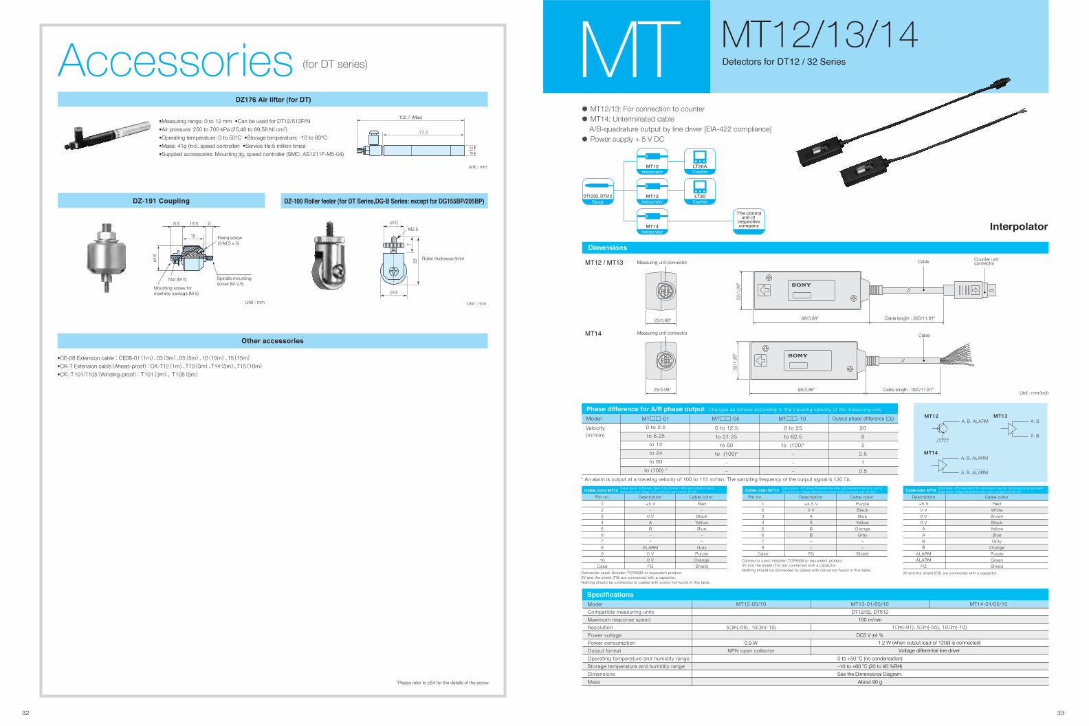
• MT12/13: For connection to counter
• MT14: Unterminated cable A/B-quadrature output by line driver [EIA-422 compliance]
• Power supply + 5 V DC
Unit : mm/inch
�� � �
��
Measuring unit connector
25/0.98"
32/1
.26"
98/3.86" Cable length : 300/11.81"
Cable Counter unit connector
Measuring unit connector
25/0.98"
32/1
.26"
98/3.86" Cable length : 300/11.81"
Cable
Model MT12-05/10
5µm(-05), 10µm(-10)
0.9 W
NPN open collector
MT14-01/05/10MT13-01/05/10
Compatible measuring units
Maximum response speed
Resolution
Power voltage
Power consumption
Output format
Operating temperature and humidity range
Storage temperature and humidity range
Dimensions
Mass
DT12/32, DT512
100 m/min
DC5 V ±4 %
0 to +50 ˚C (no condensation)
-10 to +60 ˚C (20 to 90 %RH)
See the Dimensional Diagram.
About 90 g
�������������
1µm(-01), 5µm(-05), 10µm(-10)
1.2 W (when output load of 120Ω is connected)
Voltage differential line driver
�� ����������� ��
�����������������
��� �� ��� � �
������
�
��
��� � ���������� ��� ��� ��� � ������ Changes as follows according to the traveling velocity of the measuring unit.
Model MT□□-01
0 to 2.5
to 6.25
to 12
to 24
to 60
to (100) *
MT□□-05 MT□□-10 Output phase difference (µs)
Velocity(m/min)
0 to 12.5
to 31.25
to 60
to (100)*
–
–
0 to 25
to 62.5
to (100)*
–
–
–
20
8
5
2.5
1
0.5
* An alarm is output at a traveling velocity of 100 to 115 m/min. The sampling frequency of the output signal is 120 µs.
Cable color MT12
Pin no. Description Cable color
1
2
3
4
5
6
7
8
9
10
Case
+5 V
–
0 V
A
B
–
–
ALARM
0 V
0 V
FG
Red
–
Black
Yellow
Blue
–
–
Gray
Purple
Orange
Shield
Connector used: Hosiden TCP8938 or equivalent product0V and the shield (FG) are connected with a capacitor.Nothing should be connected to cables with colors not found in this table.
Output signal : A/B phase, Alarm Output format : NPN open collector output(maximum rated voltage: 31 V, maximum rated current: 50 mA) Cable color MT14
Description Cable color
+5 V
0 V
0 V
0 V
A
A
B
B
ALARM
ALARM
FG
Red
White
Brown
Black
Yellow
Blue
Gray
Orange
Purple
Green
Shield
0V and the shield (FG) are connected with a capacitor.
Output signal : A/B phase, Alarm (The output does not become high impedance during an alarm.)Output format : Voltage differential line driver output (compliant with EIA-422)
_
_
_
Cable color MT13
Pin no. Description Cable color
1
2
3
4
5
6
7
8
Case
+4.5 V
0 V
A
A
B
B
–
–
FG
Purple
Black
Blue
Yellow
Orange
Gray
–
–
Shield
Connector used: Hosiden TCP8938 or equivalent product0V and the shield (FG) are connected with a capacitor.Nothing should be connected to cables with colors not found in this table.
Output signal : A/B phase (The output becomes high impedance during an alarm.)Output format : Voltage differential line driver output (compliant with EIA-422)
_
_
8.5 16.5 5
15
ø18
Fixing screw(3-M 3 x 5)
Nut (M 5) Spindle mountingscrew (M 2.5)
Mounting screw formachine carriage (M 5)
Unit : mm
����� ������ ������ ���� � ����� !�� ����� " �#���� ��� !�$$���%�$��&
Roller thickness:4mm
ø12
ø10
722
M2.5
Unit : mm
���'� (������)
��*+ ��� ������ ���� �&
102.7 (Max)
77.7
ø10
unit : mm
•Measuring range: 0 to 12 mm •Can be used for DT12/512P/N
•Air pressure: 250 to 700 kPa (25,48 to 69,58 N/ cm2)
•Operating temperature: 0 to 50°C •Storage temperature: -10 to 60°C
•Mass: 41g (incl. speed controller) •Service life:5 million times
•Supplied accessories: Mounting jig, speed controller (SMC: AS1211F-M5-04)
,���� ���� ����
•CE-08 Extension cable : CE08-01(1m)、03(3m)、05(5m)、10(10m)、15(15m) •CK-T Extension cable(Ahead-proof): CK-T12(1m)、T13(3m)、T14(5m)、T15(10m) •CK-T101/T105(Winding-proof): T101(3m)、 T105(5m)
Accessories (for DT series)
*Please refer to p54 for the details of the screw.
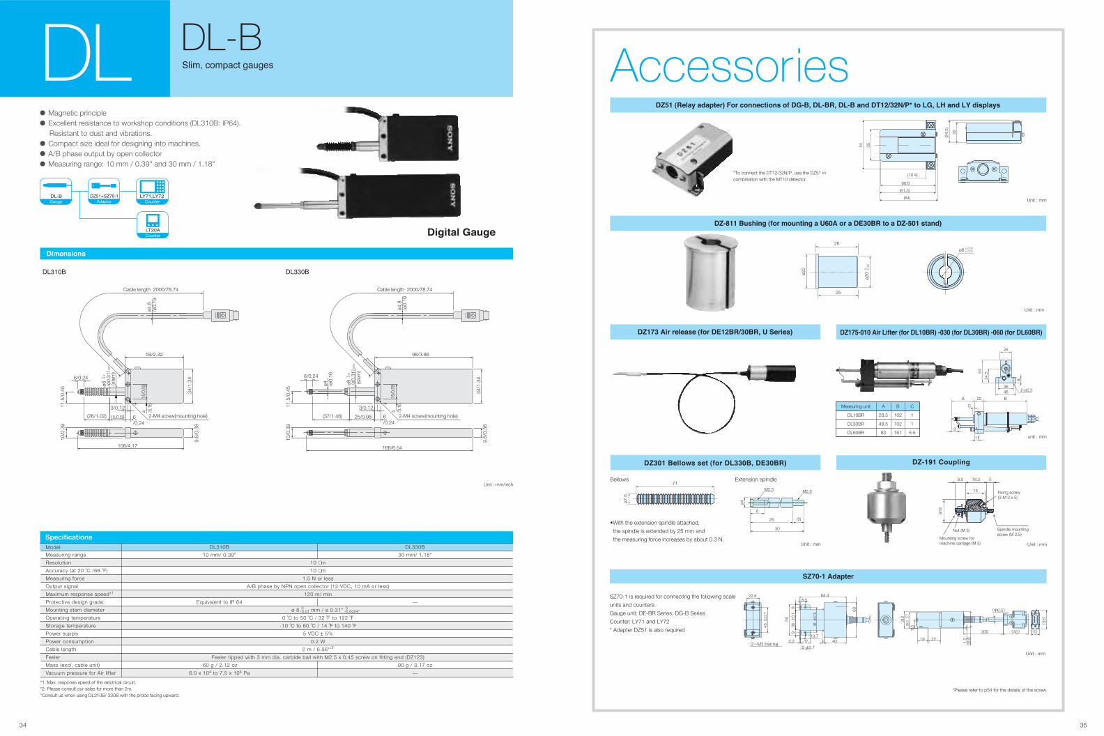
����� ��� ��� ��� ������������ � �����
34 35
Accessories���� ��� ������� ��� �!! ���!� �� �"#�� �$#��� �$#� �!� �%�����&�'( �� $"� $) �!� $* �������
*To connect the DT12/32N/P, use the DZ51 in combination with the MT10 detector.
(10.4)
(61.3)
(64)
60.6
35
(24.
5)
22
54
Unit : mm
Measuring unit
DL10BR
DL30BR
DL60BR
A
28.5
48.5
83
B
102
102
161
C
1
1
5.5
26
22
11
9
3646 2-ø5.5
934.553
A B
C
unit : mm
�����#��� ��� $���� ��� �$����� #��� ��� �$����� #�+� ��� �$+����
����� ��,� �� ��� �$����� �������
Extension spindle
(5)25
30
6
ø4
M2.5 M2.5
Unit : mm
Bellows71
ø7.5
•With the extension spindle attached,
the spindle is extended by 25 mm and
the measuring force increases by about 0.3 N.
SZ70-1 is required for connecting the following scale
units and counters:
Gauge unit: DE-BR Series, DG-B Series
Counter: LY71 and LY72
* Adapter DZ51 is also required
����#� ������
Unit : mm
22.8
±0.
145
2-M3 baring
8.5
±0.1
546
10.72.2 17
99
±0.
136
40
54
84.4
4
63
2-φ3.7
(Φ6.5)
(33)
(15) (45) 300
1.222
15.5
19
-0+0.
228
.1
28.6
29.8
��.!���!�
• Magnetic principle
• Excellent resistance to workshop conditions (DL310B: IP64). Resistant to dust and vibrations.
• Compact size ideal for designing into machines.
• A/B phase output by open collector
• Measuring range: 10 mm / 0.39" and 30 mm / 1.18"
����� ����� ��� �DL DL-B
��/��� "�0/
Unit : mm/inch
������ ������
ø8-0
.01
0
/ø0.
310
(ste
m)-0
.000
4
6/0.24
11.5
/0.4
5
(26/1.02)
3/0.12
6/0.24
15/0.59 2-M4 screw(mounting hole)
4 /0.1
615
/0.5
9
10/0
.39
106/4.17
9.6/
0.38
34/1
.34
59/2.32
ø4.8
/ø0.
19
Cable length 2000/78.74
6/0.24
11.5
/0.4
5
3/0.12
6/0.24
2-M4 screw(mounting hole)
4 /0.1
615
/0.5
9
10/0
.39
9.6/
0.38
34/1
.34
98/3.86
ø4.8
/ø0.
19
Cable length 2000/78.74
166/6.54
25/0.98(37/1.46)
ø8-0
.01
0
/ø0.
310
(ste
m)-0
.000
4
ø4 /ø0.
16
Model DL330BDL310B
10 µm
10 µm
1.5 N or less
A/B phase by NPN open collector (12 VDC, 10 mA or less)
120 m/ min
ø 8 mm / ø 0.31"
0 ˚C to 50 ˚C / 32 ˚F to 122 ˚F
-10 ˚C to 60 ˚C / 14 ˚F to 140 ˚F
5 VDC ± 5%
0.2 W
2 m / 6.56'*2
Feeler tipped with 3 mm dia. carbide ball with M2.5 x 0.45 screw on fitting end (DZ123)
10 mm/ 0.39"
Equivalent to IP 64
60 g / 2.12 oz
6.0 x 10⁴ to 7.5 x 10⁴ Pa
30 mm/ 1.18"
—
90 g / 3.17 oz
—
Measuring range
Resolution
Accuracy (at 20 ˚C /68 ˚F)
Measuring force
Output signal
Maximum response speed*1
Protective design grade
Mounting stem diameter
Operating temperature
Storage temperature
Power supply
Power consumption
Cable length
Feeler
Mass (excl. cable unit)
Vacuum pressure for Air lifter
�� ��� ����!�
0-0.01
0-0.0004"
*1: Max. response speed of the electrical circuit.*2: Please consult our sales for more than 2m.*Consult us when using DL310B/ 330B with the probe facing upward.
���� ���������
�����
�����������
��#�1� 2�0��!/
8.5 16.5 5
15
ø18
Fixing screw(3-M 3 x 5)
Nut (M 5) Spindle mountingscrew (M 2.5)
Mounting screw formachine carriage (M 5) Unit : mm
*Please refer to p54 for the details of the screw.
��#3�� �0�4�!/ ��� .�0!��!/ � �+�� �� � ������ �� � ��#��� ���!��
25
ø22
26
ø20
0 - 0.
05
ø8 + 0.05+ 0.01
Unit : mm
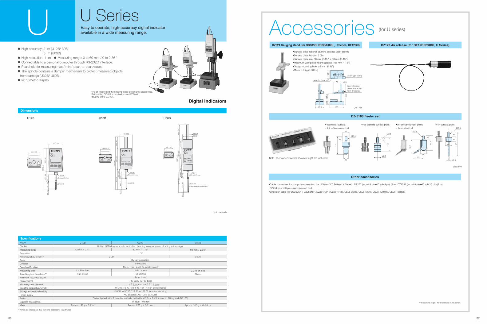
3736
����� ��� ��� ��� ������������ � �����
ø7
ø5
M2.5
5
17
•Plastic ball contact
point: ø 3mm nylon ball
ø6.5
5
13
M2.5
•Flat carbide contact point
ø7
10
19.3
517
.5
M2.5
•Off-center contact point:
ø 1mm steel ball
•Pin contact point
ø1.5
255
5
ø6
M2.5
Note: The four contactors shown at right are included.
������� �� ��
Unit : mm
���� � ������
•Cable connectors for computer connection (for U Series/ LT Series/ LY Series) DZ252 (round 8 pin D sub 9 pin) (2 m) DZ253A (round 8 pin D sub 25 pin) (2 m)
DZ254 (round 8 pin unterminated end)
•Extension cable (for DZ252N/P, DZ253N/P, DZ254N/P) : CE08-1(1m), CE08-3(3m), CE08-5(5m), CE08-10(10m), CE08-15(15m)
��"#���#�
���� �� ������ �� ��������� �� ���� ��������
��������� �� � ���� ������� �� ��U U Series
*The air release and the gauging stand are optional accessories.*Set bushing DZ-811 is required to use U60B with gauging stand DZ-501.
��$��� %#&� �����
���� ����
Unit : mm/inch
����
(46/1.81)
DC IN 6 V DATA OUT
ø5/ø0.19
M12 x 1
60/2.36
43/1
.69
31/1
.22
45/1
.7794
/3.7
98/3
.85
53/2
.08
245/
9.64
6/0.
23
POWER
MODE RECALL RESET
ONOFF
DIGITAL INDICATOR
MEM . CL
ø8 0– 0.015/ø0.31 0
– 0.0006
(46/1.81)
ø5/ø0.19
M12 x 1
ø8 0– 0.015/ø0.31 0
– 0.0006
60/2.36
31/1
.22
43/1
.69
98/3
.85
174/
6.85
27/1
.06
6/0.
23
DC IN 6 V DATA OUT
POWER
MODE RECALL RESET
ONOFF
DIGITAL INDICATOR
MEM . CL
(46/1.81)
DC IN 6 V DATA OUT
M12 x 1
ø5/ø0.19
POWER
MODE RECALL RESET
ONOFF
DIGITAL INDICATOR
MEM . CL
58/2.28
365/
14.3
66/2
.59
175/
6.88
124/
4.88
47/1
.85
98/3
.85
30/1
.18
31/1
.22
75/2
.95
6/0.
2343
/1.6
9
52/2.04
ø8 0– 0.015/ø0.31 0
– 0.0006
(When a battery is attached)
Accessories (for U series)
*Please refer to p54 for the details of the screw.
• High accuracy: 2 m (U12B/ 30B) 3 m (U60B)
• High resolution: 1 m • Measuring range: 0 to 60 mm / 0 to 2.36 "
• Connectable to a personal computer through RS-232C interface.
• Peak hold for measuring max./ min./ peak-to-peak values
• The spindle contains a damper mechanism to protect measured objects from damage (U30B/ U60B).
• Inch/ metric display
����� '�($�#$ ���#& ��� �')���*�)����)���*� � ����� �������
88.5 150
75 ø25
59.5
~13
5.5
233
80
Internal springprevents the armfrom dropping
mounting hole o/ 8
Lever-type clamp
Unit : mm
•Surface plate material: alumina ceramic (dark brown)
•Surface plate flatness: 2 µm
•Surface plate size: 80 mm (3.15'') x 80 mm (3.15'')
•Maximum workpiece height: approx. 105 mm (4.13'')
•Gauge mounting hole: ø 8 mm (0.31")
•Mass: 3.8 kg (8.38 lbs)
�+ ��� ����#�
Model U30BU12B
2 µm
U60B6-digit LCD display, mode indication (leading zero suppress, floating minus sign)
30 mm / 1.18"
1 µm
By key operation
Selectable
Max./ min./ peak-to-peak values
1.5 N or less
Full stroke
24 m / min
RS-232C (2400 bps)
ø 8 mm / ø 0.31"
0 ˚C to 40 ˚C / 32 ˚F to 104 ˚F (non condensing)
-10 ˚C to 50 ˚C / 14 ˚F to 122 ˚F (non condensing)
AC adaptor: AC 100V 50/60Hz
Feeler tipped with 3 mm dia. carbide ball with M2.5p x 0.45 screw on fitting end (DZ123)
lift lever wrench
Approx.230 g / 8.11 oz
12 mm / 0.47"
1.3 N or less
Full stroke
Approx.190 g / 6.7 oz
60 mm / 2.36"
3 µm
2.2 N or less
32mm
Approx.300 g / 10.58 oz
Display
Measuring range
Resolution
Accuracy (at 20 ˚C /68 ˚F)
Reset
Direction
Peak hold function
Measuring force
Travel length of the release*1
Maximum response speed
Output signal
Mounting stem diameter
Operating temperature/humidity
Storage temperature/humidity
Power supply
Feeler
Supplied accessories
Mass
0-0.015
0-0.0006"
*1 When air release DZ-173 (optional accessory) is activated
Interface unit
MG Series 40
38 39
Memo
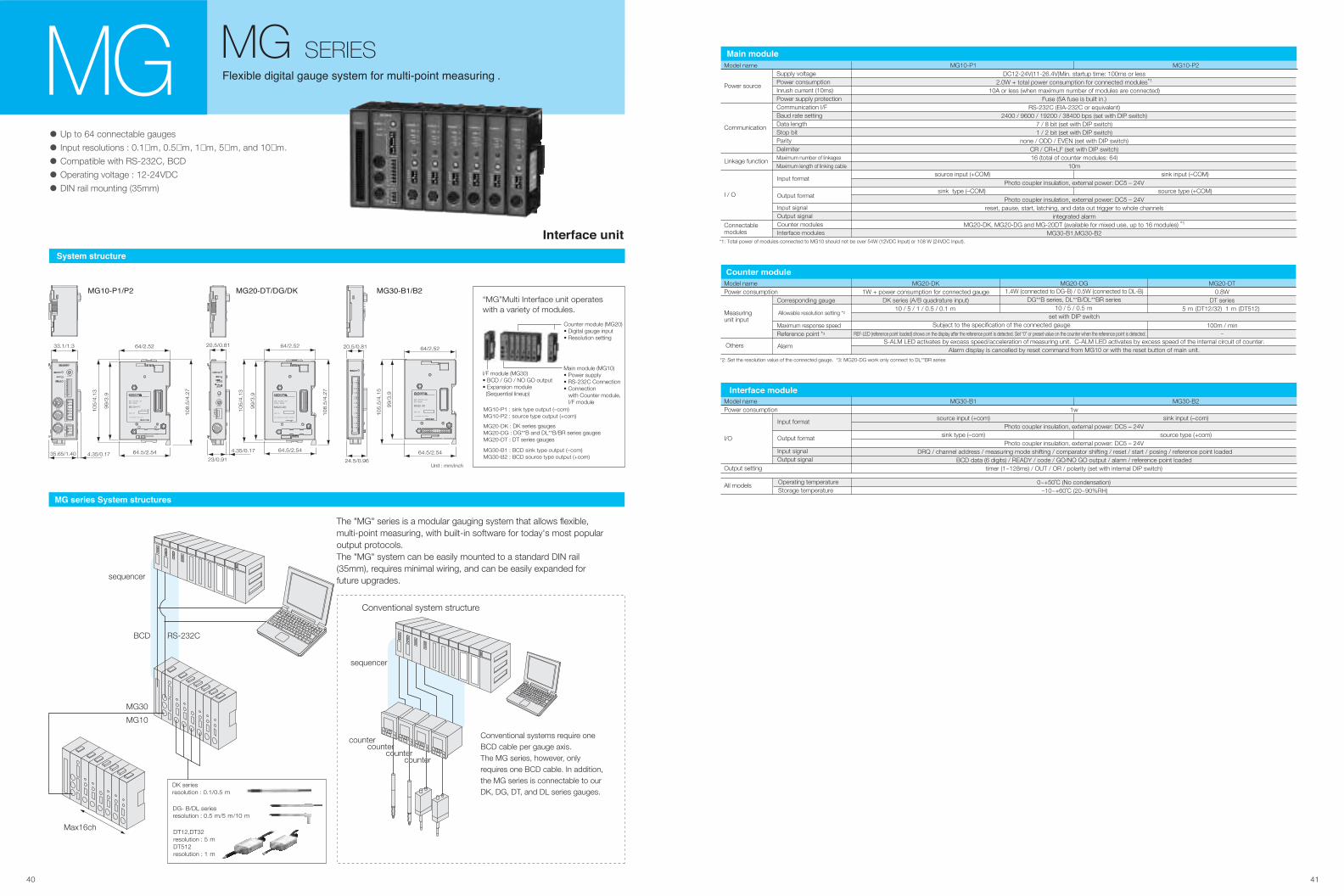
40 41
��������� �� �
Model namePower consumption
I/O
Output setting
MG30-B1
source input (+com)
sink type (–com)
MG30-B2
sink input (–com)
source type (+com)
1w
Photo coupler insulation, external power: DC5 – 24V
Photo coupler insulation, external power: DC5 – 24V DRQ / channel address / measuring mode shifting / comparator shifting / reset / start / posing / reference point loaded
BCD data (6 digits) / READY / code / GO/NO GO output / alarm / reference point loadedtimer (1~128ms) / OUT / OR / polarity (set with internal DIP switch)
Input format
Output format
Input signalOutput signal
All models Operating temperature Storage temperature
0~+50˚C (No condensation) –10~+60˚C (20~90%RH)
����� ���������
• Up to 64 connectable gauges
• Input resolutions : 0.1µm, 0.5µm, 1µm, 5µm, and 10µm.
• Compatible with RS-232C, BCD
• Operating voltage : 12-24VDC
• DIN rail mounting (35mm)
MG MG SERIES
*1: Total power of modules connected to MG10 should not be over 54W (12VDC Input) or 108 W (24VDC Input).
Model name
Power source
Communication
Linkage function
I / O
Connectable modules
Supply voltagePower consumptionInrush current (10ms)Power supply protectionCommunication I/FBaud rate settingData lengthStop bitParityDelimiterMaximum number of linkages
Maximum length of linking cable
DC12-24V(11-26.4V)Min. startup time: 100ms or less2.0W + total power consumption for connected modules*1
10A or less (when maximum number of modules are connected)Fuse (5A fuse is built in.)
RS-232C (EIA-232C or equivalent)2400 / 9600 / 19200 / 38400 bps (set with DIP switch)
7 / 8 bit (set with DIP switch)1 / 2 bit (set with DIP switch)
none / ODD / EVEN (set with DIP switch)CR / CR+LF (set with DIP switch)16 (total of counter modules: 64)
10m
Photo coupler insulation, external power: DC5 – 24V
Photo coupler insulation, external power: DC5 – 24Vreset, pause, start, latching, and data out trigger to whole channels
integrated alarmMG20-DK, MG20-DG and MG-20DT (available for mixed use, up to 16 modules) *1
MG30-B1,MG30-B2
Input formatsource input (+COM)
sink type (–COM)
sink input (–COM)
source type (+COM)
MG10-P1 MG10-P2
Output format
���� �� �
DK seriesresolution : 0.1/0.5 m
DG- B/DL seriesresolution : 0.5 m/5 m/10 m
DT12,DT32resolution : 5 mDT512resolution : 1 m
*2: Set the resolution value of the connected gauge. *3: MG20-DG work only connect to DL**BR series
Model namePower consumption
Corresponding gauge
Maximum response speedReference point *3
MG20-DK MG20-DG MG20-DT1W + power consumption for connected gauge
DK series (A/B quadrature input)10 / 5 / 1 / 0.5 / 0.1 m
1.4W (connected to DG-B) / 0.5W (connected to DL-B)DG**B series, DL**B/DL**BR series
10 / 5 / 0.5 mset with DIP switch
S-ALM LED activates by excess speed/acceleration of measuring unit. C-ALM LED activates by excess speed of the internal circuit of counter.Alarm display is cancelled by reset command from MG10 or with the reset button of main unit.
0.8WDT series
5 m (DT12/32) 1 m (DT512)
100m / min–
Measuringunit input
Others Alarm
Subject to the specification of the connected gauge
Allowable resolution setting *2
REF-LED (reference point loaded) shows on the display after the reference point is detected. Set “0” or preset value on the counter when the reference point is detected.
������ �� �
��������� ����
�� ������ ����� ����������
“MG”Multi Interface unit operates with a variety of modules.
Counter module (MG20)• Digital gauge input• Resolution setting
Main module (MG10)• Power supply• RS-232C Connection• Connection with Counter module, I/F module
I/F module (MG30)• BCD / GO / NO GO output• Expansion module (Sequential lineup)
MG10-P1 : sink type output (–com)MG10-P2 : source type output (+com)
MG30-B1 : BCD sink type output (–com)MG30-B2 : BCD source type output (+com)
MG20-DK : DK series gaugesMG20-DG : DG**B and DL**B/BR series gaugesMG20-DT : DT series gauges
sequencer
RS-232CBCD
MG30
MG10
Max16ch
The "MG" series is a modular gauging system that allows flexible, multi-point measuring, with built-in software for today's most popular output protocols.The "MG" system can be easily mounted to a standard DIN rail (35mm), requires minimal wiring, and can be easily expanded for future upgrades.
Conventional systems require one BCD cable per gauge axis.The MG series, however, only requires one BCD cable. In addition, the MG series is connectable to our DK, DG, DT, and DL series gauges.
Unit : mm/inch
sequencer
countercounter
countercounter
countercounter
countercounter
Conventional system structure
����������
4.35/0.1735.65/1.40
33.1/1.3
64.5/2.54
64/2.52
108.5
/4.2
7
105/4
.13
99/3
.9
RS-232C
LINK-IN
LINK-OUT
FG
DC-IN
I/O
232C-SET
Unit No.
��������
24.5/0.96
20.5/0.81
64.5/2.54
64/2.52
105.5
/4.1
5
99/3
.9
BCD I/O
����������
4.35/0.17
23/0.91
20.5/0.81
64.5/2.54
64/2.52
108.5
/4.2
7
105/4
.13
99/3
.9
SIG
DIR
RES
ADDRESS
RESET
MG20-DK
Input signalOutput signalCounter modulesInterface modules
������� ������� ����� ������ ��� ��������� � ������� � !
Counter unit
LT30 SERIES
LT20A SERIES
LT11A SERIES
LT10A SERIES
LY71
LY72
44
45
46
47
48
49
Memo
42 43
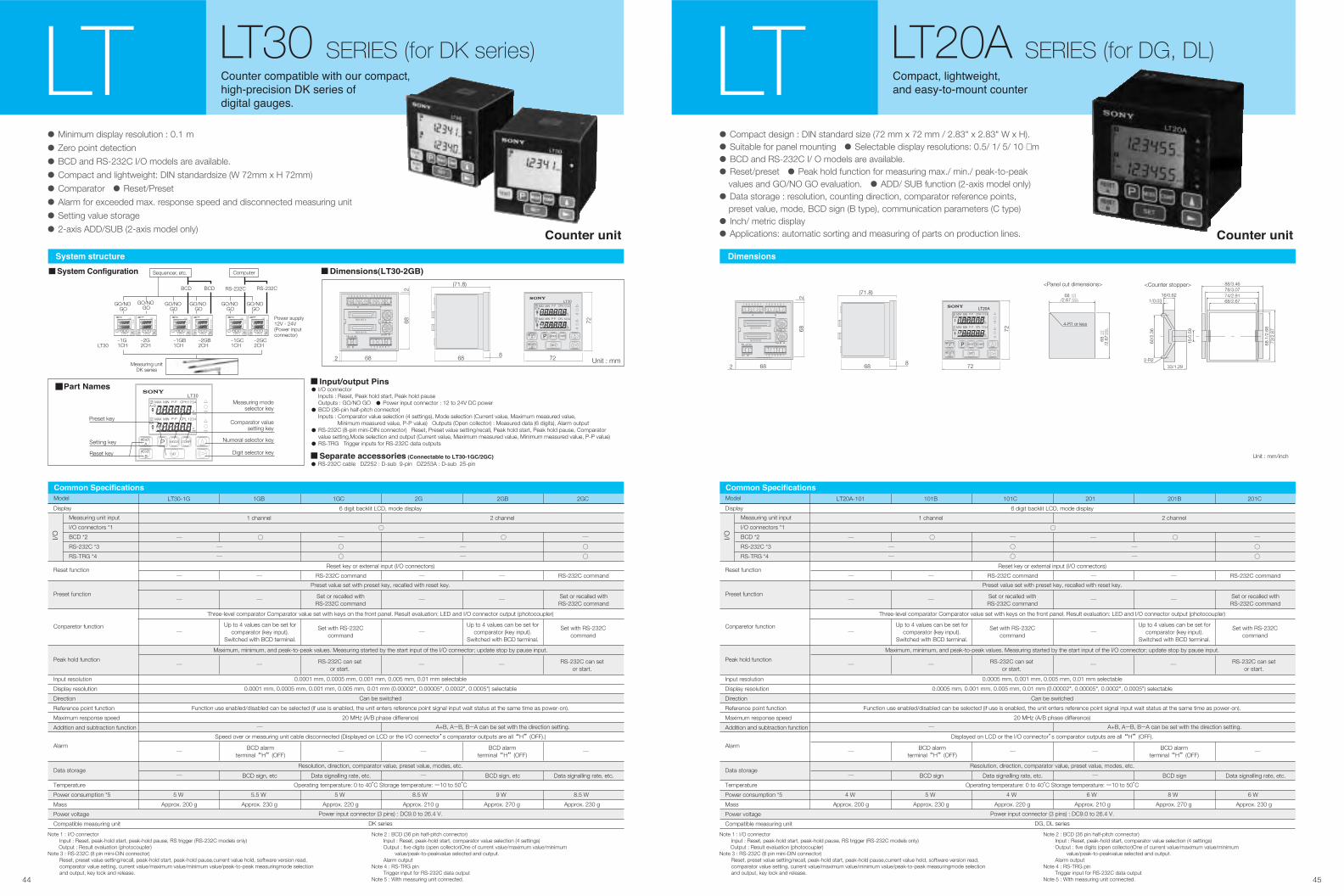
44 45
������ ������
• Minimum display resolution : 0.1 m
• Zero point detection
• BCD and RS-232C I/O models are available.
• Compact and lightweight: DIN standardsize (W 72mm x H 72mm)
• Comparator • Reset/Preset
• Alarm for exceeded max. response speed and disconnected measuring unit
• Setting value storage
• 2-axis ADD/SUB (2-axis model only)
• Compact design : DIN standard size (72 mm x 72 mm / 2.83" x 2.83" W x H).
• Suitable for panel mounting • Selectable display resolutions: 0.5/ 1/ 5/ 10 µm
• BCD and RS-232C I/ O models are available.
• Reset/preset • Peak hold function for measuring max./ min./ peak-to-peak values and GO/NO GO evaluation. • ADD/ SUB function (2-axis model only)
• Data storage : resolution, counting direction, comparator reference points, preset value, mode, BCD sign (B type), communication parameters (C type)
• Inch/ metric display
• Applications: automatic sorting and measuring of parts on production lines.�� ��� �� �� ��� ��
������� ����� �� ���� ��� ������
������������� �� ������ ��
������� �������
������ ������������
��� ������������ �������LT LTLT30 SERIES (for DK series) LT20A SERIES (for DG, DL)
���� ��� �
� ������� �� �
• RS-232C cable DZ252 : D-sub 9-pin DZ253A : D-sub 25-pin�������� ��������� ��� ������ �� ������������
���� ��� ���������!
(71.8)
68 8682
682
BCD OUT.B
BCD OUT.A 4321
4321
B A
A+B
CPL
CPH
P-P
P-P
MIN
MINMAX
MAX
COMP
SETB
A
RESET
RESET MODE
72
72
(71.8)
68 8682
682
BCD OUT.B
BCD OUT.A 4321
4321
B A
A+B
CPL
CPH
P-P
P-P
MIN
MINMAX
MAX
COMP
SETB
A
RESET
RESET MODE
72
72
Preset key
Setting key
Reset key
Comparator valuesetting key
Measuring modeselector key
Numeral selector key
Digit selector key
4321
4321
BA
A+B
CPL
CPH
P-P
P-P
MIN
MINMAX
MAX
P COMP
SETB
A
RESET
RESETMODE
• I/O connector Inputs : Reset, Peak hold start, Peak hold pause Outputs : GO/NO GO • Power input connector : 12 to 24V DC power
• BCD (36-pin half-pitch connector) Inputs : Comparator value selection (4 settings), Mode selection (Current value, Maximum measured value, Minimum measured value, P-P value) Outputs (Open collector) : Measured data (6 digits), Alarm output
• RS-232C (8-pin mini-DIN connector) Reset, Preset value setting/recall, Peak hold start, Peak hold pause, Comparator value setting,Mode selection and output (Current value, Maximum measured value, Minimum measured value, P-P value)
• RS-TRG Trigger inputs for RS-232C data outputs
Sequencer, etc.
Power supply 12V - 24V(Power inputconnector)
Measuring unitDK series
LT30–1G1CH
–2G2CH
–1GB1CH
–2GB2CH
–1GC1CH
–2GC2CH
Computer
4321
B A
A+BCPH
P-P
P-P
MIN
MINMAX
MAX 4321
4321
B A
A+B
CPL
CPH
P-P
P-P
MIN
MINMAX
MAX
P COMP
SET
MODERESET P COMP
SETB
AMODE
GO/NO GO
GO/NO GO
GO/NO GO
GO/NO GO
GO/NO GO
GO/NO GO
BCD BCD RS-232C RS-232C
RESET
RESET
4321
4321
B A
A+B
CPL
CPH
P-P
P-P
MIN
MINMAX
MAX 4321
4321
B A
A+B
CPL
CPH
P-P
P-P
MIN
MINMAX
MAX
P COMP
SET
MODERESET P COMP
SETB
AMODERESET
RESET
4321
4321
B A
A+B
CPL
CPH
P-P
P-P
MIN
MINMAX
MAX 4321
4321
B A
A+B
CPL
CPH
P-P
P-P
MIN
MINMAX
MAX
P COMP
SET
MODERESET P COMP
SETB
AMODERESET
RESET
<Counter stopper>
68/2.67
73/2
.87
68.1
/2.6
8
74/2.9178/3.0788/3.46
16/0.621/0.03
33/1.29
60/2
.36
2-R2
15/0
.59
/2.67 +0.03+0.015
68 +1.0+0.4
4-R1 or less
<Panel cut dimensions>
/2.6
7+0.
03+
0.01
5
68+
1.0
+0.
4
Unit : mm/inch
Unit : mm
Model
LT10A-105
LT30-1G
105B
1GB
105C
1GC
205
2G
205B
2GB
205C
2GC
����� ����"����� �
Note 1 : I/O connector Input : Reset, peak-hold start, peak-hold pause, RS trigger (RS-232C models only) Output : Result evaluation (photocoupler)Note 3 : RS-232C (8 pin mini-DIN connector) Reset, preset value setting/recall, peak-hold start, peak-hold pause,current value hold, software version read, comparator value setting, current value/maximum value/minimum value/peak-to-peak measuringmode selection and output, key lock and release.
Note 2 : BCD (36 pin half-pitch connector) Input : Reset, peak-hold start, comparator value selection (4 settings) Output : five digits (open collector)One of current value/maximum value/minimum value/peak-to-peakvalue selected and output. Alarm outputNote 4 : RS-TRG pin Trigger input for RS-232C data outputNote 5 : With measuring unit connected.
Display
Reset function
Preset function
Conparetor function
Peak hold function
Input resolution
Display resolution
Direction
Reference point function
Maximum response speed
Addition and subtraction function
Alarm
Data storage
Temperature
Power consumption *5
Mass
Power voltage
Compatible measuring unit
I/O
6 digit backlit LCD, mode display
Reset key or external input (I/O connectors)
Preset value set with preset key, recalled with reset key.
Maximum, minimum, and peak-to-peak values. Measuring started by the start input of the I/O connector; update stop by pause input.
0.0001 mm, 0.0005 mm, 0.001 mm, 0.005 mm, 0.01 mm selectable
0.0001 mm, 0.0005 mm, 0.001 mm, 0.005 mm, 0.01 mm (0.00002", 0.00005", 0.0002", 0.0005") selectable
Can be switched
Function use enabled/disabled can be selected (if use is enabled, the unit enters reference point signal input wait status at the same time as power-on).
20 MHz (A/B phase difference)
Speed over or measuring unit cable disconnected (Displayed on LCD or the I/O connector’s comparator outputs are all “H” (OFF).)
Operating temperature: 0 to 40°C Storage temperature: -10 to 50°C
Resolution, direction, comparator value, preset value, modes, etc.
Power input connector (3 pins) : DC9.0 to 26.4 V.
DK series
Three-level comparator Comparator value set with keys on the front panel. Result evaluation: LED and I/O connector output (photocoupler)
1 channel 2 channel
─
─
─
─
─
BCD sign, etc Data signalling rate, etc. BCD sign, etc Data signalling rate, etc.
A+B, A-B, B-A can be set with the direction setting.
─
─
○
RS-232C command
Up to 4 values can be set forcomparator (key input).
Switched with BCD terminal.
Set or recalled withRS-232C command
Set with RS-232Ccommand
Set or recalled withRS-232C command
── ─
─
BCD alarmterminal “H” (OFF)
BCD alarmterminal “H” (OFF)
RS-232C can setor start.
─
─ ─ ─
─
5 W
Approx. 200 g
5.5 W
Approx. 230 g
5 W
Approx. 220 g
8.5 W
Approx. 210 g
9 W
Approx. 270 g
8.5 W
Approx. 230 g
─
─
RS-232C can setor start.
── ─
─Up to 4 values can be set for
comparator (key input).Switched with BCD terminal.
Set with RS-232Ccommand─
── ─
RS-232C command
○
─
○
○
─
○
○
─ ○
Measuring unit input
I/O connectors *1
BCD *2
RS-232C *3
RS-TRG *4
Model
LT10A-105
LT20A-101
105B
101B
105C
101C
205
201
205B
201B
205C
201C
����� ����"����� �
Note 1 : I/O connector Input : Reset, peak-hold start, peak-hold pause, RS trigger (RS-232C models only) Output : Result evaluation (photocoupler)Note 3 : RS-232C (8 pin mini-DIN connector) Reset, preset value setting/recall, peak-hold start, peak-hold pause,current value hold, software version read, comparator value setting, current value/maximum value/minimum value/peak-to-peak measuringmode selection and output, key lock and release.
Note 2 : BCD (36 pin half-pitch connector) Input : Reset, peak-hold start, comparator value selection (4 settings) Output : five digits (open collector)One of current value/maximum value/minimum value/peak-to-peakvalue selected and output. Alarm outputNote 4 : RS-TRG pin Trigger input for RS-232C data outputNote 5 : With measuring unit connected.
Display
Reset function
Preset function
Conparetor function
Peak hold function
Input resolution
Display resolution
Direction
Reference point function
Maximum response speed
Addition and subtraction function
Alarm
Data storage
Temperature
Power consumption *5
Mass
Power voltage
Compatible measuring unit
I/O
6 digit backlit LCD, mode display
Reset key or external input (I/O connectors)
Preset value set with preset key, recalled with reset key.
Maximum, minimum, and peak-to-peak values. Measuring started by the start input of the I/O connector; update stop by pause input.
0.0005 mm, 0.001 mm, 0.005 mm, 0.01 mm selectable
0.0005 mm, 0.001 mm, 0.005 mm, 0.01 mm (0.00002", 0.00005", 0.0002", 0.0005") selectable
Can be switched
Function use enabled/disabled can be selected (if use is enabled, the unit enters reference point signal input wait status at the same time as power-on).
20 MHz (A/B phase difference)
Displayed on LCD or the I/O connector’s comparator outputs are all “H” (OFF).
Operating temperature: 0 to 40°C Storage temperature: -10 to 50°C
Resolution, direction, comparator value, preset value, modes, etc.
Power input connector (3 pins) : DC9.0 to 26.4 V.
DG, DL series
Three-level comparator Comparator value set with keys on the front panel. Result evaluation: LED and I/O connector output (photocoupler)
1 channel 2 channel
─
─
─
─
─
BCD sign Data signalling rate, etc. BCD sign Data signalling rate, etc.
A+B, A-B, B-A can be set with the direction setting.
─
─
○
RS-232C command
Up to 4 values can be set forcomparator (key input).
Switched with BCD terminal.
Set or recalled withRS-232C command
Set with RS-232Ccommand
Set or recalled withRS-232C command
─ ─ ─
─
BCD alarmterminal “H” (OFF)
BCD alarmterminal “H” (OFF)
RS-232C can setor start.
─
─ ─ ─
─
4 W
Approx. 200 g
5 W
Approx. 230 g
4 W
Approx. 220 g
6 W
Approx. 210 g
8 W
Approx. 270 g
6 W
Approx. 230 g
─
─
RS-232C can setor start.
─ ─ ─
─ Up to 4 values can be set for
comparator (key input).Switched with BCD terminal.
Set with RS-232Ccommand─
─ ─ ─
RS-232C command
○
─
○
○
─
○
○
─ ○
Measuring unit input
I/O connectors *1
BCD *2
RS-232C *3
RS-TRG *4
�����
���� #����
������ �� "�$�����
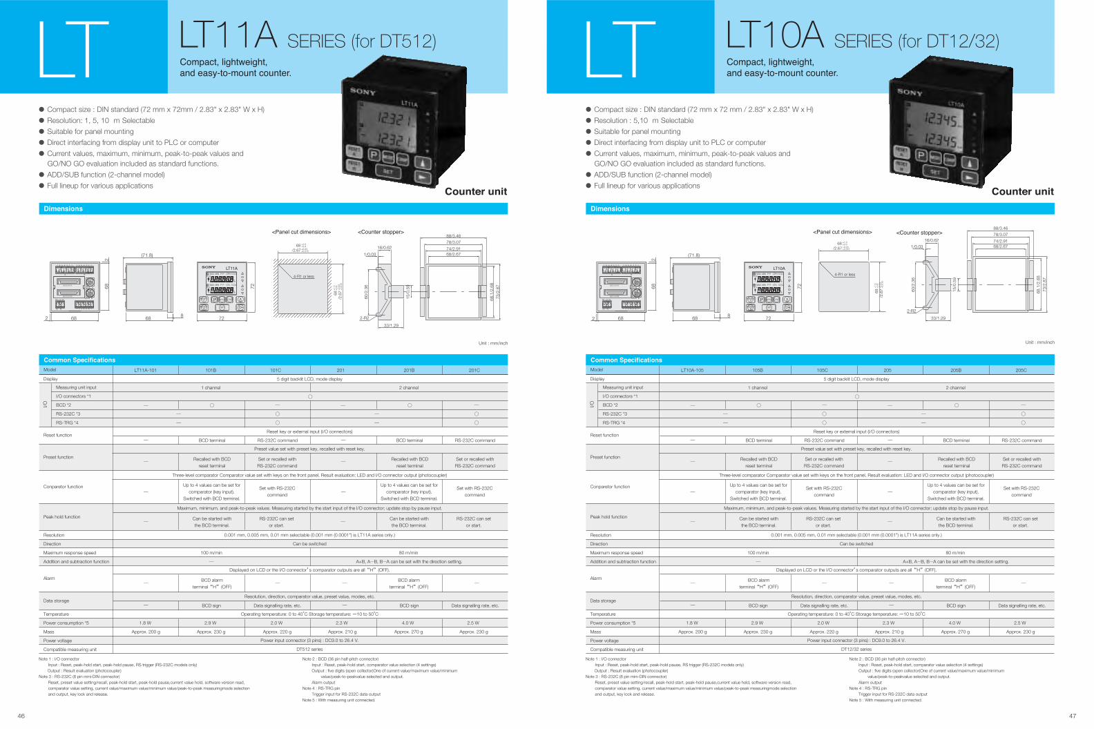
���������� ����������
• Compact size : DIN standard (72 mm x 72mm / 2.83" x 2.83" W x H)
• Resolution: 1, 5, 10 m Selectable
• Suitable for panel mounting
• Direct interfacing from display unit to PLC or computer
• Current values, maximum, minimum, peak-to-peak values and
GO/NO GO evaluation included as standard functions.
• ADD/SUB function (2-channel model)
• Full lineup for various applications
• Compact size : DIN standard (72 mm x 72 mm / 2.83" x 2.83" W x H)
• Resolution : 5,10 m Selectable
• Suitable for panel mounting
• Direct interfacing from display unit to PLC or computer
• Current values, maximum, minimum, peak-to-peak values and
GO/NO GO evaluation included as standard functions.
• ADD/SUB function (2-channel model)
• Full lineup for various applications����� �� ����� ��
�������� ��� �����
��� ������������� ��������
�������� ��� �����
��� ������������� ��������LT LTLT11A SERIES (for DT512) LT10A SERIES (for DT12/32)
����� ��� ���������
/2.67 +0.03+0.015
68 +1.0+0.4
4-R1 or less
/2.6
7+
0.03
+0.
015
68+
1.0
+0.
4
�������� ��������
68/2.67
73/2
.87
68.1
/2.6
8
74/2.91
78/3.07
88/3.46
16/0.62
1/0.03
33/1.29
60/2
.36
2-R2
15/0
.59
Unit : mm/inch
/2.67 +0.03+0.015
68 +1.0+0.4
4-R1 or less
����� ��� ���������
/2.6
7+
0.03
+0.
015
68+
1.0
+0.
4
�������� ��������
68/2.67
73/2
.87
68.1
/2.6
8
74/2.91
78/3.07
88/3.46
16/0.62
1/0.03
33/1.29
60/2
.36
2-R2
15/0
.59
Unit : mm/inch
Model LT11A-101 101B 101C 201 201B 201C
������ ������������
Note 1 : I/O connector Input : Reset, peak-hold start, peak-hold pause, RS trigger (RS-232C models only) Output : Result evaluation (photocoupler)Note 3 : RS-232C (8 pin mini-DIN connector) Reset, preset value setting/recall, peak-hold start, peak-hold pause,current value hold, software version read, comparator value setting, current value/maximum value/minimum value/peak-to-peak measuringmode selection and output, key lock and release.
Note 2 : BCD (36 pin half-pitch connector) Input : Reset, peak-hold start, comparator value selection (4 settings) Output : five digits (open collector)One of current value/maximum value/minimum value/peak-to-peakvalue selected and output. Alarm outputNote 4 : RS-TRG pin Trigger input for RS-232C data outputNote 5 : With measuring unit connected.
Display
Reset function
Preset function
Conparetor function
Peak hold function
Resolution
Direction
Maximum response speed
Addition and subtraction function
Alarm
Data storage
Temperature
Power consumption *5
Mass
Power voltage
Compatible measuring unit
I/O
5 digit backlit LCD, mode display
Reset key or external input (I/O connectors)
Preset value set with preset key, recalled with reset key.
Maximum, minimum, and peak-to-peak values. Measuring started by the start input of the I/O connector; update stop by pause input.
0.001 mm, 0.005 mm, 0.01 mm selectable (0.001 mm (0.0001") is LT11A series only.)
Can be switched
Displayed on LCD or the I/O connector’s comparator outputs are all “H” (OFF).
Operating temperature: 0 to 40°C Storage temperature: -10 to 50°C
Resolution, direction, comparator value, preset value, modes, etc.
Power input connector (3 pins) : DC9.0 to 26.4 V.
DT512 series
Three-level comparator Comparator value set with keys on the front panel. Result evaluation: LED and I/O connector output (photocoupler)
1 channel 2 channel
─
─
─
─
100 m/min
─
BCD sign Data signalling rate, etc. BCD sign Data signalling rate, etc.
80 m/min
A+B, A-B, B-A can be set with the direction setting.
─
─
○
BCD terminal RS-232C command
Recalled with BCDreset terminal
Up to 4 values can be set forcomparator (key input).
Switched with BCD terminal.
Set or recalled withRS-232C command
Set with RS-232Ccommand
Recalled with BCDreset terminal
Set or recalled withRS-232C command
─
─
Can be started withthe BCD terminal.
BCD alarmterminal “H” (OFF)
BCD alarmterminal “H” (OFF)
RS-232C can setor start.
─
─ ─ ─
─
1.8 W
Approx. 200 g
2.9 W
Approx. 230 g
2.0 W
Approx. 220 g
2.3 W
Approx. 210 g
4.0 W
Approx. 270 g
2.5 W
Approx. 230 g
─
─
Can be started withthe BCD terminal.
RS-232C can setor start.
─
─Up to 4 values can be set for
comparator (key input).Switched with BCD terminal.
Set with RS-232Ccommand
─
─
BCD terminal RS-232C command
○
─
○
○
─
○
○
─ ○
Measuring unit input
I/O connectors *1
BCD *2
RS-232C *3
RS-TRG *4
Model LT10A-105 105B 105C 205 205B 205C
������ ������������
Note 1 : I/O connector Input : Reset, peak-hold start, peak-hold pause, RS trigger (RS-232C models only) Output : Result evaluation (photocoupler)Note 3 : RS-232C (8 pin mini-DIN connector) Reset, preset value setting/recall, peak-hold start, peak-hold pause,current value hold, software version read, comparator value setting, current value/maximum value/minimum value/peak-to-peak measuringmode selection and output, key lock and release.
Note 2 : BCD (36 pin half-pitch connector) Input : Reset, peak-hold start, comparator value selection (4 settings) Output : five digits (open collector)One of current value/maximum value/minimum value/peak-to-peakvalue selected and output. Alarm outputNote 4 : RS-TRG pin Trigger input for RS-232C data outputNote 5 : With measuring unit connected.
Display
Reset function
Preset function
Conparetor function
Peak hold function
Resolution
Direction
Maximum response speed
Addition and subtraction function
Alarm
Data storage
Temperature
Power consumption *5
Mass
Power voltage
Compatible measuring unit
I/O
5 digit backlit LCD, mode display
Reset key or external input (I/O connectors)
Preset value set with preset key, recalled with reset key.
Maximum, minimum, and peak-to-peak values. Measuring started by the start input of the I/O connector; update stop by pause input.
0.001 mm, 0.005 mm, 0.01 mm selectable (0.001 mm (0.0001") is LT11A series only.)
Can be switched
Displayed on LCD or the I/O connector’s comparator outputs are all “H” (OFF).
Operating temperature: 0 to 40°C Storage temperature: -10 to 50°C
Resolution, direction, comparator value, preset value, modes, etc.
Power input connector (3 pins) : DC9.0 to 26.4 V.
DT12/32 series
Three-level comparator Comparator value set with keys on the front panel. Result evaluation: LED and I/O connector output (photocoupler)
1 channel 2 channel
─
─
─
─
100 m/min
─
BCD sign Data signalling rate, etc. BCD sign Data signalling rate, etc.
80 m/min
A+B, A-B, B-A can be set with the direction setting.
─
─
○
BCD terminal RS-232C command
Recalled with BCDreset terminal
Up to 4 values can be set forcomparator (key input).
Switched with BCD terminal.
Set or recalled withRS-232C command
Set with RS-232Ccommand
Recalled with BCDreset terminal
Set or recalled withRS-232C command
─
─
Can be started withthe BCD terminal.
BCD alarmterminal “H” (OFF)
BCD alarmterminal “H” (OFF)
RS-232C can setor start.
─
─ ─ ─
─
1.8 W
Approx. 200 g
2.9 W
Approx. 230 g
2.0 W
Approx. 220 g
2.3 W
Approx. 210 g
4.0 W
Approx. 270 g
2.5 W
Approx. 230 g
─
─
Can be started withthe BCD terminal.
RS-232C can setor start.
─
─Up to 4 values can be set for
comparator (key input).Switched with BCD terminal.
Set with RS-232Ccommand
─
─
BCD terminal RS-232C command
○
─
○
○
─
○
○
─ ○
Measuring unit input
I/O connectors *1
BCD *2
RS-232C *3
RS-TRG *4
(71.8)
68 8682
682
BCD OUT.B
BCD OUT.A 4321
4321
B A
A+B
CPL
CPH
P-P
P-P
MIN
MINMAX
MAX
COMP
SETB
A
RESET
RESET MODE
72
72(71.8)
68 8682
682
BCD OUT.B
BCD OUT.A 4321
4321
B A
A+B
CPL
CPH
P-P
P-P
MIN
MINMAX
MAX
COMP
SETB
A
RESET
RESET MODE
72
72
����� �����
4746
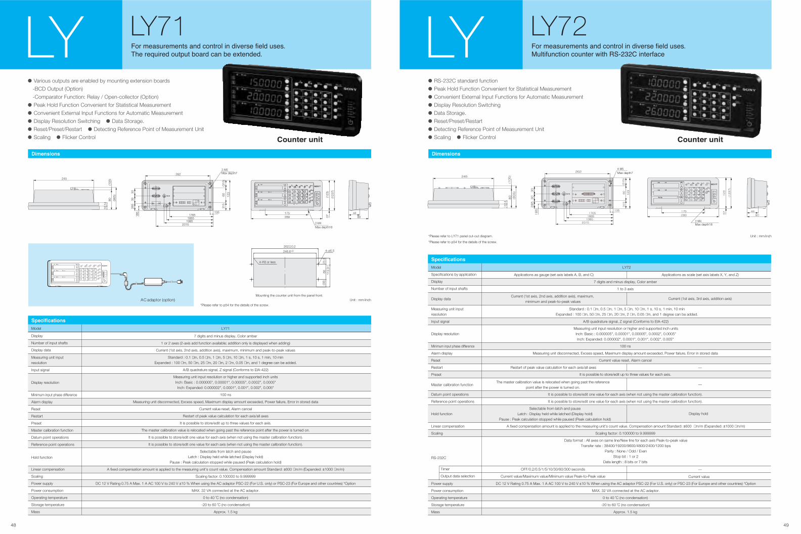
48 49
��� ���������� �� ���� � ������� ��� � �����
��� �������� ���� ����� �� �� �������
LY71 LY
����������
• Various outputs are enabled by mounting extension boards
-BCD Output (Option)
-Comparator Function: Relay / Open-collector (Option)
• Peak Hold Function Convenient for Statistical Measurement
• Convenient External Input Functions for Automatic Measurement
• Display Resolution Switching • Data Storage.
• Reset/Preset/Restart • Detecting Reference Point of Measurement Unit
• Scaling • Flicker Control
Display
Number of input shafts
Display data
Input signal
Display resolution
Minimum input phase difference
Alarm display
Reset
Restart
Preset
Master calibration function
Datum point operations
Reference point operations
Linear compensation
Scaling
Power supply
Power consumption
Operating temperature
Storage temperature
Mass
Hold function
Measuring unit input resolution
�����������
Model LY71
7 digits and minus display, Color amber
1 or 2 axes (2-axis add function available; addition only is displayed when adding)
Current (1st axis, 2nd axis, addition axis), maximum, minimum and peak-to-peak values
Standard : 0.1 µm, 0.5 µm, 1 µm, 5 µm, 10 µm, 1 s, 10 s, 1 min, 10 minExpanded : 100 µm, 50 µm, 25 µm, 20 µm, 2 µm, 0.05 µm, and 1 degree can be added.
A/B quadrature signal, Z signal (Conforms to EIA-422)
Measuring unit input resolution or higher and supported inch unitsInch: Basic : 0.000005", 0.00001", 0.00005", 0.0002", 0.0005"Inch: Expanded: 0.000002", 0.0001", 0.001", 0.002", 0.005"
100 ns
Measuring unit disconnected, Excess speed, Maximum display amount exceeded, Power failure, Error in stored data
Current value reset, Alarm cancel
Restart of peak value calculation for each axis/all axes
It is possible to store/edit up to three values for each axis.
The master calibration value is relocated when going past the reference point after the power is turned on.
It is possible to store/edit one value for each axis (when not using the master calibration function).
It is possible to store/edit one value for each axis (when not using the master calibration function).
Selectable from latch and pauseLatch : Display held while latched (Display hold)
Pause : Peak calculation stopped while paused (Peak calculation hold)
A fixed compensation amount is applied to the measuring unit's count value. Compensation amount Standard: ±600 µm/m (Expanded: ±1000 µm/m)
Scaling factor: 0.100000 to 9.999999
DC 12 V Rating 0.75 A Max. 1 A AC 100 V to 240 V ±10 % When using the AC adaptor PSC-22 (For U.S. only) or PSC-23 (For Europe and other countries) *Option
MAX. 32 VA connected at the AC adaptor.
0 to 40 ˚C (no condensation)
-20 to 60 ˚C (no condensation)
Approx. 1.5 kg
245
(905
)
80
14
(105
)
16
4480289
175
(123
7)
(123
)07
2-M4Max depth18
17651885
19852315
135
262
3028
5
185
30
123
60(3
15)
315
2-M5Max depth7
Unit : mm/inch
• RS-232C standard function
• Peak Hold Function Convenient for Statistical Measurement
• Convenient External Input Functions for Automatic Measurement
• Display Resolution Switching
• Data Storage.
• Reset/Preset/Restart
• Detecting Reference Point of Measurement Unit
• Scaling • Flicker Control
��� ���������� �� ���� � ������� ��� � �����
�� ������ ����� ��� ������� �������
LY72 LY
����������
Minimum input phase difference
Alarm display
Reset
Restart
Preset
Master calibration function
Linear compensation
Scaling
Hold function
RS-232C
Power supply
Power consumption
Operating temperature
Storage temperature
Mass
Timer
Output data selection
Datum point operations
Reference point operations
Display resolution
Input signal
Measuring unit input resolution
Display data
Specifications by application
Display
Number of input shafts
7 digits and minus display, Color amber
1 to 3 axis
It is possible to store/edit one value for each axis (when not using the master calibration function).
It is possible to store/edit one value for each axis (when not using the master calibration function).
DC 12 V Rating 0.75 A Max. 1 A AC 100 V to 240 V ±10 % When using the AC adaptor PSC-22 (For U.S. only) or PSC-23 (For Europe and other countries) *Option
MAX. 32 VA connected at the AC adaptor.
0 to 40 ˚C (no condensation)
-20 to 60 ˚C (no condensation)
Approx. 1.5 kg
100 ns
Measuring unit disconnected, Excess speed, Maximum display amount exceeded, Power failure, Error in stored data
Current value reset, Alarm cancel
A/B quadrature signal, Z signal (Conforms to EIA-422)
Display hold
Current value
It is possible to store/edit up to three values for each axis.
A fixed compensation amount is applied to the measuring unit's count value. Compensation amount Standard: ±600 µm/m (Expanded: ±1000 µm/m)
Scaling factor: 0.100000 to 9.999999
Data format : All axes on same line/New line for each axis Peak-to-peak valueTransfer rate : 38400/19200/9600/4800/2400/1200 bps
Parity : None / Odd / EvenStop bit : 1 or 2
Data length : 8 bits or 7 bits
Measuring unit input resolution or higher and supported inch unitsInch: Basic : 0.000005", 0.00001", 0.00005", 0.0002", 0.0005"Inch: Expanded: 0.000002", 0.0001", 0.001", 0.002", 0.005"
Selectable from latch and pauseLatch : Display held while latched (Display hold)
Pause : Peak calculation stopped while paused (Peak calculation hold)
Current (1st axis, 2nd axis, addition axis), maximum, minimum and peak-to-peak values
The master calibration value is relocated when going past the referencepoint after the power is turned on.
OFF/0.2/0.5/1/5/10/30/60/300 seconds
Current value/Maximum value/Minimum value Peak-to-Peak value
Standard : 0.1 µm, 0.5 µm, 1 µm, 5 µm, 10 µm, 1 s, 10 s, 1 min, 10 minExpanded : 100 µm, 50 µm, 25 µm, 20 µm, 2 µm, 0.05 µm, and 1 degree can be added.
Current (1st axis, 3rd axis, addition axis)
—
—
—
Restart of peak value calculation for each axis/all axes
�����������
Model LY72
Applications as gauge (set axis labels A, B, and C) Applications as scale (set axis labels X, Y, and Z)
Unit : mm/inch*Please refer to LY71 panel cut-out diagram.
44
80
245
(905)
80
14
16
(105)
262±0.24–ø5.5246.6+0
Mounting the counter unit from the panel front.
4–R3 or less 23.3
60 113.
3+1
0
(30)
AC adaptor (option)
������ ���� ������ ����
4-M5Max depth7
176518851985
2315
135
262
30
285
185
30
123
60
315
(315)
2-M4Max depth18
175
289
(1237)
123
07
*Please refer to p54 for the details of the screw.
*Please refer to p54 for the details of the screw.
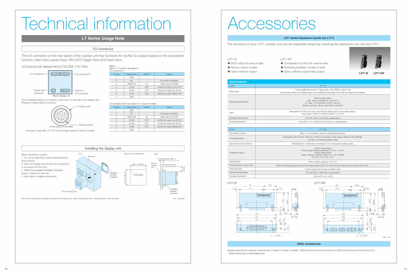
50 51
Unit : mm/inch
Technical information�� ������ ��� �� �
I/O connector
Installing the display unit
The I/O connector on the rear panel of the counter unit has functions for Go/No Go output based on the comparator function, start input, pause input, RS-232C trigger input and reset input.
When mounting in a panel
1. Cut out an opening to match the dimensions
shown (Fig.2)
2. Insert the display unit into the cut-out opening
in the panel from the front.
3. Attach the supplied installation brackets
(upper / lower) from the rear.
4. Use fingers to tighten and secure.
Note: When attaching the installation brackets to the display unit, leave enough space (min. 30mm) between it and the panel.
Panel box
Front of display unit
Fig.1
Installation brackets(supplied)
Fig.2 Cut-out dimensions Fig.3
4-R1 or less
Front ofdisplayunit
Panel thickness: Max. 4
30m
m
68 / 2.68+1.0+0.4
+0.033+0.016
Installation brackets(supplied)
68
/ 2
.68
+1.
0+
0.4
+0.
033
+0.
016
<Connector pin assignment (LT30,20A,11A,10A)>
1
2
3
4
5
6
7
GND
NC
RESET (A)
LO (A)
GO (A)
HI (A)
GND
Pin No.
-
-
IN
OUT
OUT
OUT
-
Signal name IN/OUT
Connection prohibited
Reset input (A CH)AB
Go/No Go output Low (A CH)
Go/No Go output Go (A CH)
Go/No Go output High (A CH)
Signal
Use a shielded cable for connection to the FG pin on the rear of the display unit.(Prepare a shield cable by yourself.)
Signal (See “4-3. Function description”.) I/O connector A
1
2
3
4
5
6
7
GND
NC
RESET (B)
LO (B)
GO (B)
HI (B)
GND
Pin No.
-
-
IN
OUT
OUT
OUT
-
Signal name IN/OUT
Connection prohibited
Reset input (A CH)AB
Go/No Go output Low (B CH)
Go/No Go output Go (B CH)
Go/No Go output High (B CH)
Signal
I/O connector B (not provided for 1-channel models)
Rear of display unit
� � � � � � � � � � � � � �
� � � � � � �
�
� � �
�� ��
I/O connector BI/O connector A
Power input connector
Common I/O connector
Cross section of the cable
Outer cover
Knitted shield
Connector used: MC1.5/7-ST-3.5 (provided) made by Phoenix Contact
LZ71-B
• BCD output of various data
• Various output modes
• Open collector output
LZ71-KR
• Comparator function for various data
• Switching between 16 sets of data
• Open collector output/relay output������ �������
���� ������ �������� ����� ���� �����
AccessoriesThe functions of your LY71 counter unit can be expanded simply by inserting the expansion unit into the LY71.
BCD output
Electrical specifications
Latch
Operating temperature
Storage temperature
�������� ����
Model LZ71-B
7 digit parallel data (4 bits x 7 digits), sign (1 bit), READY signal (1 bit)Output logic positive and negative logic can be selected individually for the data and sign by the settings.
0 to 40˚C (32 to 104˚F) (No condensation)
-20 to 60˚C (-4 to 140˚F) (20 to 90 % RH, no condensation)
Comparator function
Comparable data
Upper limit and lower limit combinations
Judgment outputs
External input
Positioning function (1 point) modes
Applicable data
Operating temperature
Storage temperature
Model LZ71-KR
Sets 1 to 4 comparator values for judging the data size.
Sets the positioning data and turns the output signal on for 0.5 s when the set value and the current value match.
Current value only (1st axis or addition axis)
0 to 40˚C (32 to 104˚F) (No condensation)
-20 to 60˚C (-4 to 140˚F)
Selectable from 16 data sets consisting of 1 to 4 comparator setting values.
Photo coupler: supports 12 to 24 V
Comparable data Current, maximum, minimum and peak-to-peak values. (Based on the settings) (1st axis, 2nd axis and addition axis)
(42) 87
(7.5) 1147.5 14.8
129
122
102
14.85
19
(59
.3)
48.7
10
6.3
26.5
13.2
5
10.9
2-R1.8
LZ71-B LZ71-KR
15
(42) 87
(7.5) 1147.5 14.8
14.8519
(59
.3)
48.7
106.
3129
122
102
26.5
13.2
5
2-R1.8Unit : mm
Photocoupler outputVCE : Recommended DC +12 to 24 V
IC : Max. 15 mA/terminal, TOTAL: 300 mAOutput connector: 36-pin micro ribbon connector
5-point output signalPhotocoupler (voltage resistance: 24 V), Ic = 15 mA
5-point output signalRelay : Panasonic Electric Works, Co., Ltd. ATQ209
24 V DC, 120 V AC, 0.3 A
Selectable from "BCD only latch" and "BCD & display latch" by the initial settings. Input signal : DRQ1 to 3 (Photocoupler: 12 to 24 V)
!�� ����������
•Cable connectors for computer connection (for U Series/ LT Series/ LY Series) DZ252 (round 8 pin D sub 9 pin) (2 m) DZ253A (round 8 pin D sub 25 pin) (2 m)
DZ254 (round 8 pin unterminated end)
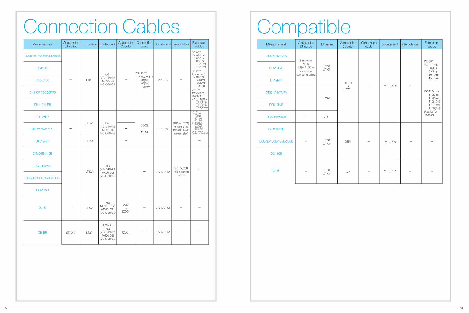
CE-08****=-01(1m), -03(3m), -05(5m), -10(10m), -15(15m)
CK-T12(1m), T13(3m), T14(5m), T15(10m) T101(3m) T105(5m)(Realize for flection)
CompatibleDT32N/NV/P/PV
DT512N/P
DT12N/P
DT32N/NV/P/PV
DT512N/P
DG805B/810B
DG10B/25B
DG50B/100B/155B/205B
DG110B
LT20LT100
LT20LT100
LT20LT100
-
-
-
-
-
-
-
- -
-
-
-
InterpolatorMT12
LZ60-P1/P2 is required to
connect to LT100.
DL-B
MT12+
DZ51
DZ51
DZ51
LY51, LY52
LY51, LY52
LY51, LY52
Extension cables
Connectioncable
InterpolatorsCounter unitAdapter forCounter
LT seriesAdapter forLT series
Measuring unit
LT11
LT10
Connection Cables Extension
cablesConnection
cableInterpolatorsCounter unitAdapter for
Counter LT seriesAdapter for
LT seriesMeasuring unit
DK805A/B, DK805A/B, DK810A/B
DK10/25
DK50/100
DK155PR5/205PR5
DK110NLR5
DT12N/P
DT32N/NV/P/PV
DT512N/P
DG805B/810B
DG10B/25B
DG50B/100B/155B/205B
DG-110B
DE-BR SZ70-2
-
Interface unit
MG(MG10-P1/P2)
(MG20-DT)(MG30-B1/B2)
MG(MG10-P1/P2)
(MG20-DG)(MG30-B1/B2)
MG(MG10-P1/P2)
(MG20-DG)(MG30-B1/B2)
SZ70-2+MG
(MG10-P1/P2)(MG20-DG)
(MG30-B1/B2)
MG(MG10-P1/P2)
(MG20-DK)(MG30-B1/B2)
LT10A
LT11A
LT20A
LT20A
LT30
LT30
LY71, LY72
LY71, LY72
LY71, LY72
LY71, 72
-
-
-
-
CE-22**(Open-end)**=-01(1m), -03(3m), -05(5m), -10(10m)
CE-08****=-01(1m), -03(3m), -05(5m), -10(10m), -15(15m)
CE-08****=-01(1m), -03(3m), -05(5m), -10(10m), -15(15m)
CK-T**(Realize for flection)CK-T12(1m), T13(3m), T14(5m), T15(10m)
CK-T12(1m), T13(3m), T14(5m), T15(10m),CK-T101(1m)CK-T105(5m)(Realize for flection)
-
MD10A/20B※D-sub15pin
Female
MT12(for LT20A),MT13(for LT30)
MT14(Cable withunterminated)
-
-
-
DZ51+
SZ70-1
SZ70-1
-
-
-
-
- -
-
LY71, 72CE-29
+MT13
CE-29-******=-003(0.3m) -01(1m) -05(5m) -10(10m)
-
-
-
DL-B
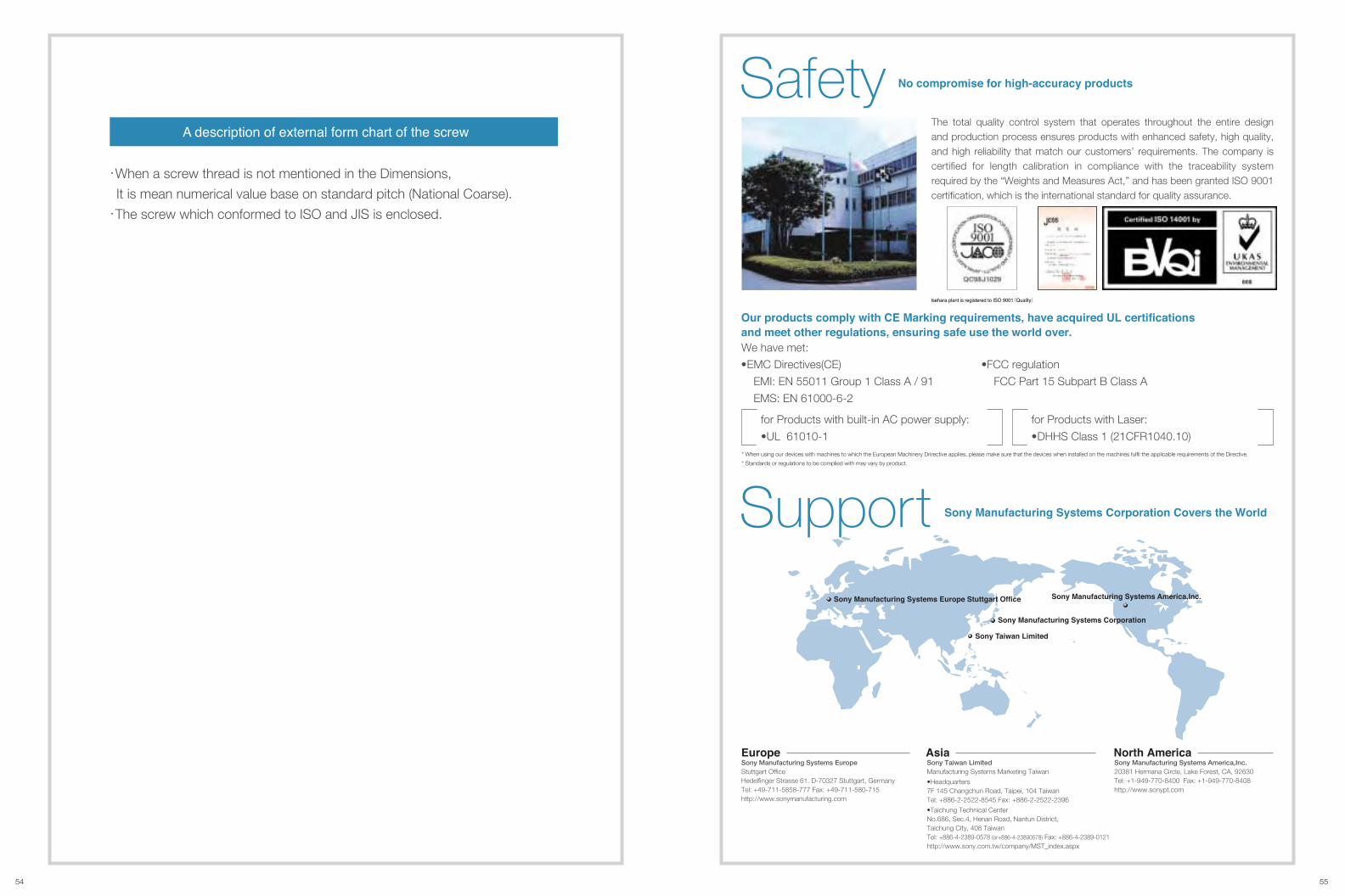
54 55
� ��������� � � ����� ��� ���� � �� �����
・When a screw thread is not mentioned in the Dimensions,
It is mean numerical value base on standard pitch (National Coarse).
・The screw which conformed to ISO and JIS is enclosed.
Safety
We have met:
��� ������� ����� ��� �� ������� ����������� ���� �������� �� �������������
��� ��� ����� ����������� ������� ��� �� ��� ���� �����
* When using our devices with machines to which the European Machinery Drirective applies, please make sure that the devices when installed on the machines fulfil the applicable requirements of the Directive.
* Standards or regulations to be complied with may vary by product.
•EMC Directives(CE)
EMI: EN 55011 Group 1 Class A / 91
EMS: EN 61000-6-2
•FCC regulation
FCC Part 15 Subpart B Class A
for Products with built-in AC power supply:
•UL 61010-1
for Products with Laser:
•DHHS Class 1 (21CFR1040.10)
���� ������������� ���� �����������
���� �� �� ������
���� ������������� ���� !������"������� ������������� ���� ������ ��������� ������
The total quality control system that operates throughout the entire design and production process ensures products with enhanced safety, high quality, and high reliability that match our customers’ requirements. The company is certified for length calibration in compliance with the traceability system required by the “Weights and Measures Act,” and has been granted ISO 9001 certification, which is the international standard for quality assurance.
#� ������� ��� ����$�������� �������
Support ���� ������������� ���� ����������� ����� ��� %����
Sony Manufacturing Systems America,Inc.20381 Hermana Circle, Lake Forest, CA, 92630Tel: +1-949-770-8400 Fax: +1-949-770-8408http://www.sonypt.com
Sony Taiwan LimitedManufacturing Systems Marketing Taiwan
•Headquarters7F 145 Changchun Road, Taipei, 104 TaiwanTel: +886-2-2522-8545 Fax: +886-2-2522-2396
•Taichung Technical Center No.686, Sec.4, Henan Road, Nantun District, Taichung City, 408 TaiwanTel: +886-4-2389-0578 (or+886-4-23890578) Fax: +886-4-2389-0121http://www.sony.com.tw/company/MST_index.aspx
#���� !�����!��Sony Manufacturing Systems EuropeStuttgart OfficeHedelfinger Strasse 61. D-70327 Stuttgart, GermanyTel: +49-711-5858-777 Fax: +49-711-580-715http://www.sonymanufacturing.com
������
Related Documents