Austempering, A Technology for Substitution ADI DAYS 2016 6 th –7 th October Minerbe 1 Machining of Austempered Ductile Iron Challanges and Solutions - Austempering a technology for substitution - Prof. Dr.-Ing. Dr.-Ing. E. h. Dr. h. c. Dr. h. c. Fritz Klocke Dr.-Ing. Dipl.-Wirt.-Ing. Benjamin Döbbeler Dipl.-Ing. Sven Lung Bevilacqua, 6. and 7. October 2016

Welcome message from author
This document is posted to help you gain knowledge. Please leave a comment to let me know what you think about it! Share it to your friends and learn new things together.
Transcript
Austempering, A Technology for Substitution
ADI DAYS 2016 6th – 7th October Minerbe
1
Machining of Austempered Ductile Iron Challanges and Solutions- Austempering a technology for substitution -
Prof. Dr.-Ing. Dr.-Ing. E. h. Dr. h. c. Dr. h. c. Fritz Klocke Dr.-Ing. Dipl.-Wirt.-Ing. Benjamin Döbbeler Dipl.-Ing. Sven Lung
Bevilacqua, 6. and 7. October 2016
Agenda
Austempering, A Technology for Substitution
ADI DAYS 2016 6th – 7th October Minerbe
2
Summary5
Investigation of Contact Fatigue for ADI1200, ADI900 and AST4
Improvement of the ADI machining process 3
Machining properties of ADI2
Fundamentals in Metal Cutting1
Shear zones during chip formation
Austempering, A Technology for Substitution
ADI DAYS 2016 6th – 7th October Minerbe
3
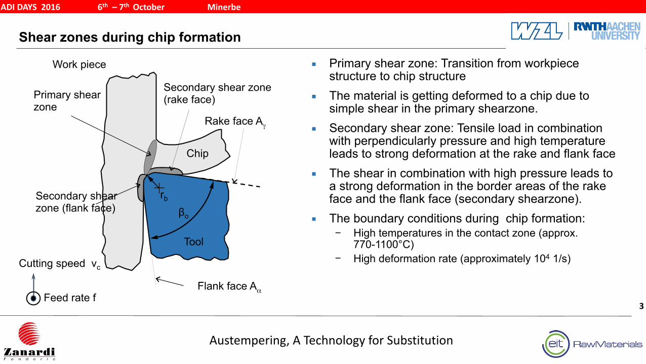
▪ Primary shear zone: Transition from workpiece structure to chip structure
▪ The material is getting deformed to a chip due to simple shear in the primary shearzone.
▪ Secondary shear zone: Tensile load in combination with perpendicularly pressure and high temperature leads to strong deformation at the rake and flank face
▪ The shear in combination with high pressure leads to a strong deformation in the border areas of the rake face and the flank face (secondary shearzone).
▪ The boundary conditions during chip formation: − High temperatures in the contact zone (approx.
770-1100°C) − High deformation rate (approximately 104 1/s)
Tool
Rake face Aγ
Chip
Work piece
Secondary shear zone (flank face)
Secondary shear zone (rake face)Primary shear
zone
βo
rb
Flank face Aα
Cutting speed vc
Feed rate f
Resolution of the Effective cutting speed and the resultant force
Austempering, A Technology for Substitution
ADI DAYS 2016 6th – 7th October Minerbe
4
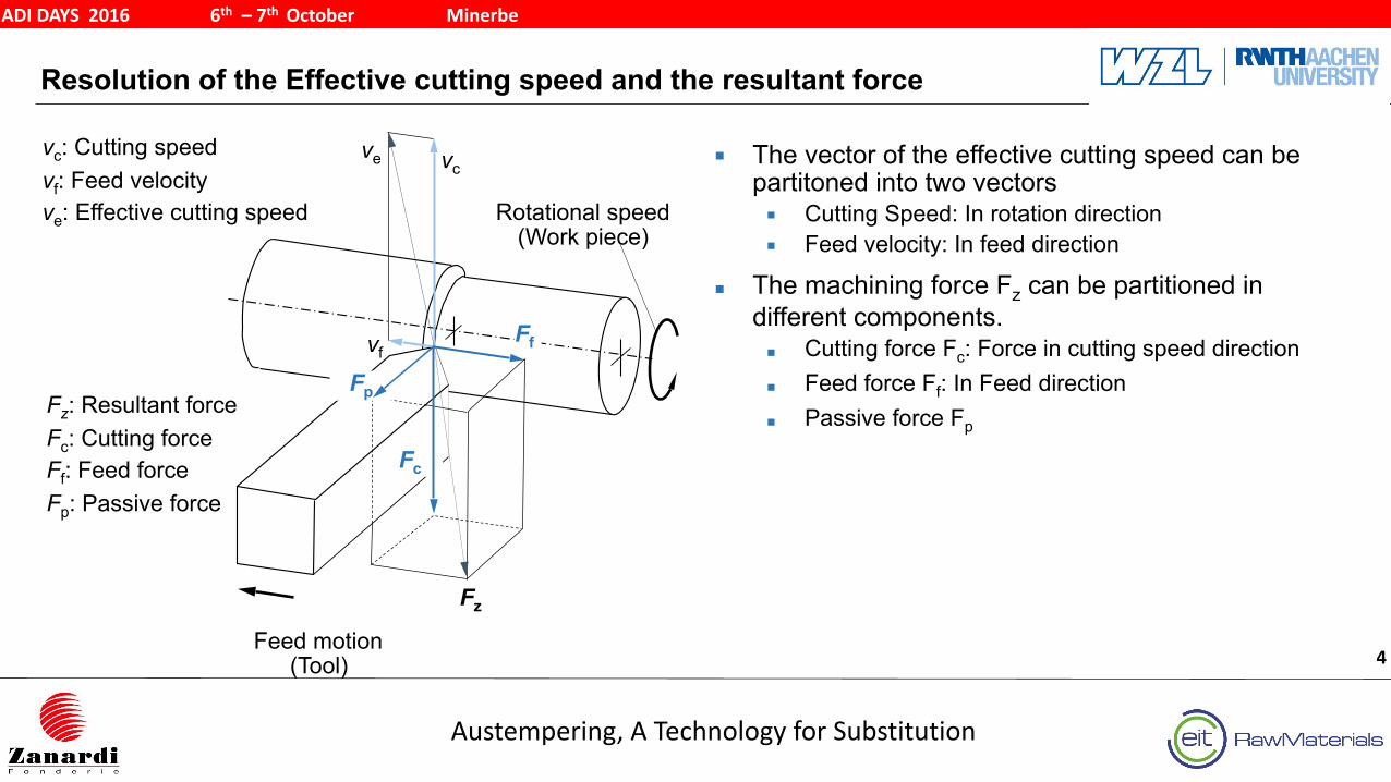
Fz: Resultant force Fc: Cutting force Ff: Feed force Fp: Passive force
vc: Cutting speed vf: Feed velocity ve: Effective cutting speed
Feed motion (Tool)
vc
vf
ve
Fc
Fp
Ff
Rotational speed (Work piece)
Fz
▪ The vector of the effective cutting speed can be partitoned into two vectors ▪ Cutting Speed: In rotation direction ▪ Feed velocity: In feed direction
▪ The machining force Fz can be partitioned in different components. ▪ Cutting force Fc: Force in cutting speed direction ▪ Feed force Ff: In Feed direction ▪ Passive force Fp
Agenda
Austempering, A Technology for Substitution
ADI DAYS 2016 6th – 7th October Minerbe
5
Summary5
Investigation of Contact Fatigue for ADI1200, ADI900 and AST4
Improvement of the ADI machining process 3
Machining properties of ADI2
Fundamentals in Metal Cutting1
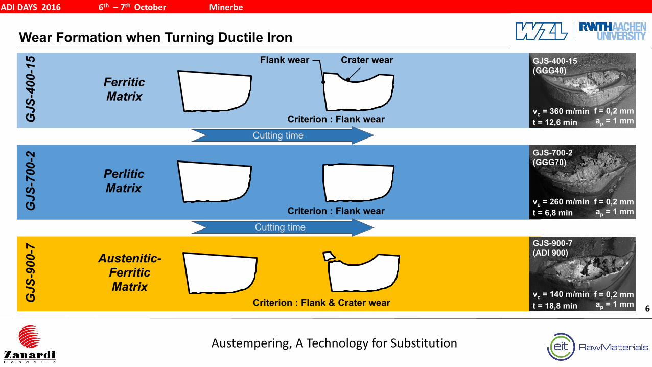
Wear Formation when Turning Ductile Iron
Austempering, A Technology for Substitution
ADI DAYS 2016 6th – 7th October Minerbe
6
GJS-900-7 (ADI 900)
f = 0,2 mm ap = 1 mm
vc = 140 m/min t = 18,8 minG
JS-9
00-7
Criterion : Flank & Crater wear
Austenitic- Ferritic Matrix
GJS
-700
-2
Criterion : Flank wear
Perlitic Matrix
GJS
-400
-15 Crater wearFlank wear
Criterion : Flank wear
Ferritic Matrix
Cutting time
Cutting time
GJS-700-2 (GGG70)
f = 0,2 mm ap = 1 mm
vc = 260 m/min t = 6,8 min
GJS-400-15 (GGG40)
f = 0,2 mm ap = 1 mm
vc = 360 m/min t = 12,6 min
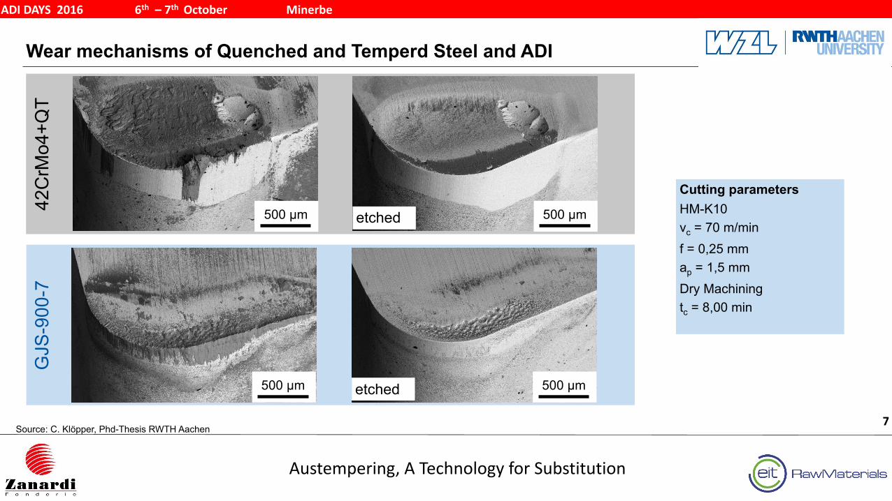
Wear mechanisms of Quenched and Temperd Steel and ADI
Austempering, A Technology for Substitution
ADI DAYS 2016 6th – 7th October Minerbe
7
Cutting parameters HM-K10 vc = 70 m/min f = 0,25 mm ap = 1,5 mm Dry Machining tc = 8,00 min
Source: C. Klöpper, Phd-Thesis RWTH Aachen
500 µm42C
rMo4
+QT
GJS
-900
-7
500 µm
500 µmetched
500 µmetched
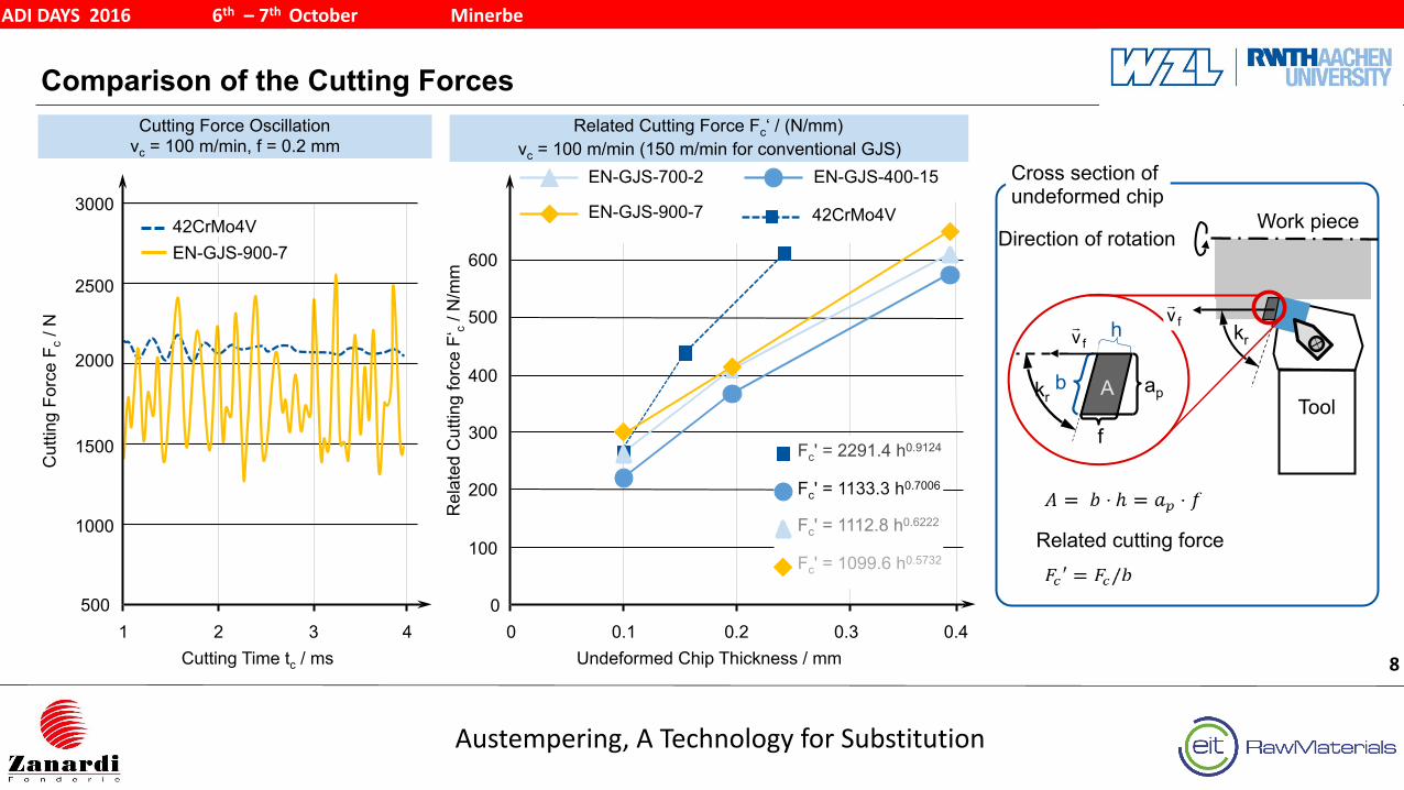
Comparison of the Cutting Forces
Austempering, A Technology for Substitution
ADI DAYS 2016 6th – 7th October Minerbe
8
1000
1500
2500
3000
1 2 3 4
Cutting Force Oscillation vc = 100 m/min, f = 0.2 mm
Cutting Time tc / ms
500
2000
Cut
ting
Forc
e F c
/ N
42CrMo4VEN-GJS-900-7
0
100
200
300
400
500
0 0.1 0.2 0.3 0.4Undeformed Chip Thickness / mm
Related Cutting Force Fc‘ / (N/mm) vc = 100 m/min (150 m/min for conventional GJS)
600
42CrMo4V
EN-GJS-400-15EN-GJS-700-2
EN-GJS-900-7
Rel
ated
Cut
ting
forc
e F‘
c / N
/mm
Fc' = 1133.3 h0.7006
Fc' = 1112.8 h0.6222
Fc' = 1099.6 h0.5732
Fc' = 2291.4 h0.9124
Cross section ofundeformed chip
Work piece
Toolb A ap
f
kr
Direction of rotation
h kr
Related cutting force
fv! fv
!
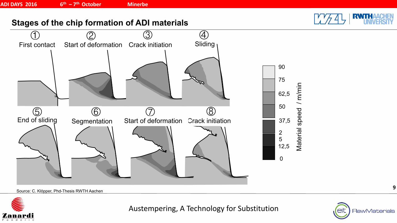
Stages of the chip formation of ADI materials
Austempering, A Technology for Substitution
ADI DAYS 2016 6th – 7th October Minerbe
9
⑧⑦⑤
①First contact Start of deformation Crack initiation Sliding
End of sliding Segmentation⑥
Crack initiationStart of deformation
Mat
eria
l spe
ed /
m/m
in
0
12,5
25
37,5
50
62,5
75
90
Source: C. Klöpper, Phd-Thesis RWTH Aachen
③ ④②
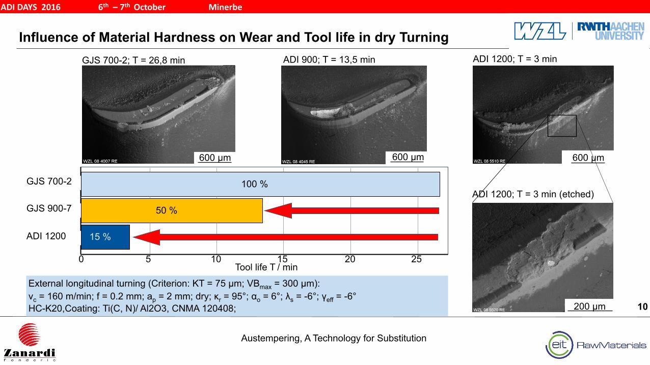
Influence of Material Hardness on Wear and Tool life in dry Turning
Austempering, A Technology for Substitution
ADI DAYS 2016 6th – 7th October Minerbe
10
External longitudinal turning (Criterion: KT = 75 µm; VBmax = 300 µm): vc = 160 m/min; f = 0.2 mm; ap = 2 mm; dry; κr = 95°; αo = 6°; λs = -6°; γeff = -6°HC-K20,Coating: Ti(C, N)/ Al2O3, CNMA 120408;
ADI 900; T = 13,5 min
600 µm
GJS 700-2; T = 26,8 min
600 µm
Tool life T / min0 5 10 15 20 25
GJS 700-2 100 %
ADI 1200 15 %
GJS 900-7 50 %
ADI 1200; T = 3 min
600 µm600 µm
200 µm600 µm200 µm
ADI 1200; T = 3 min (etched)
Agenda
Austempering, A Technology for Substitution
ADI DAYS 2016 6th – 7th October Minerbe
11
Summary5
Investigation of Contact Fatigue for ADI1200, ADI900 and AST4
Improvement of the ADI machining process 3
Machining properties of ADI2
Fundamentals in Metal Cutting1
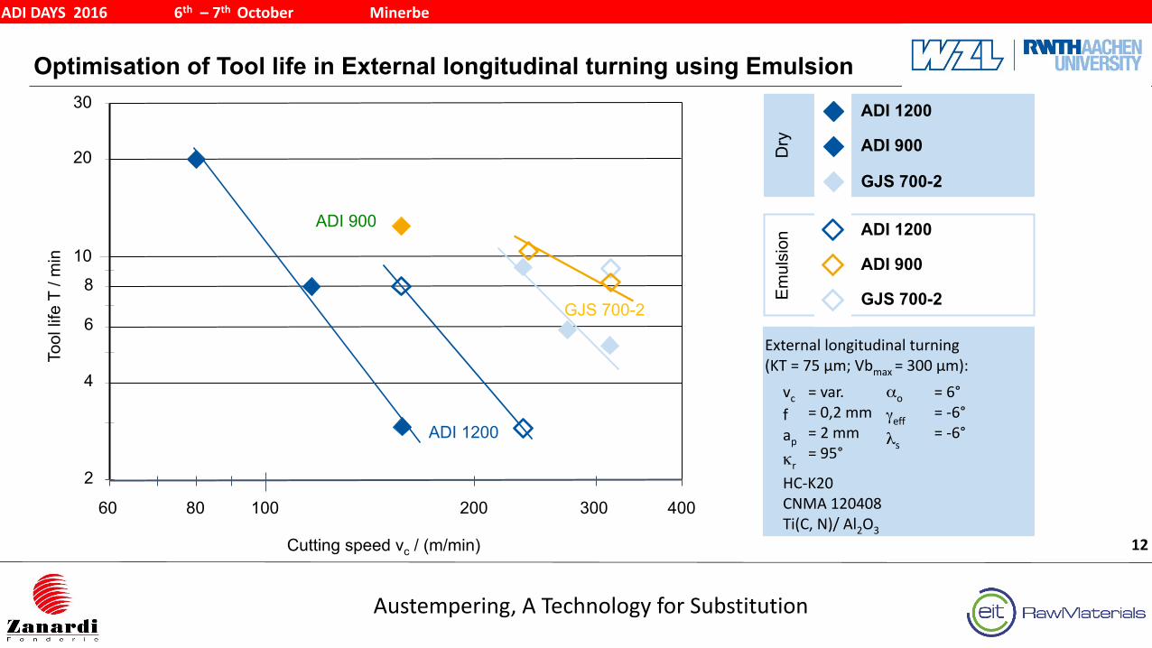
Optimisation of Tool life in External longitudinal turning using Emulsion
Austempering, A Technology for Substitution
ADI DAYS 2016 6th – 7th October Minerbe
12
Em
ulsi
on
ADI 900
GJS 700-2
ADI 1200
Tool
life
T /
min
Cutting speed vc / (m/min)
Dry ADI 900
GJS 700-2
ADI 1200
10
100
2
30
60 40080 200 300
8
6
4
20
ADI 1200
ADI 900
GJS 700-2
= 6° = -‐6° = -‐6°
αo
γeffλs
vc f ap κr HC-‐K20 CNMA 120408 Ti(C, N)/ Al2O3
= var. = 0,2 mm = 2 mm = 95°
External longitudinal turning (KT = 75 µm; Vbmax = 300 µm):
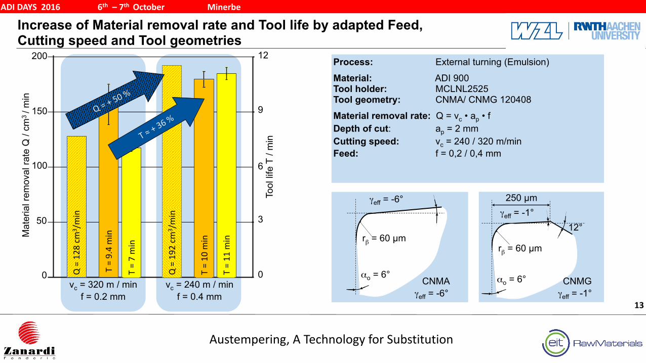
Increase of Material removal rate and Tool life by adapted Feed, Cutting speed and Tool geometries
Austempering, A Technology for Substitution
ADI DAYS 2016 6th – 7th October Minerbe
13
Process: External turning (Emulsion) Material: ADI 900 Tool holder: MCLNL2525Tool geometry: CNMA/ CNMG 120408 Material removal rate: Q = vc • ap • f Depth of cut: ap = 2 mm Cutting speed: vc = 240 / 320 m/min Feed: f = 0,2 / 0,4 mm
Mat
eria
l rem
oval
rate
Q /
cm3 / m
in
0
50
100
150
200
0
3
6
12
Tool
life
T /
min
9
rβ = 60 µm
γeff = -6°
αo = 6°CNMA
γeff = -6°
rβ = 60 µm
αo = 6°
γeff = -1°12°
250 µm
CNMGγeff = -1°
T = 9.4 min
vc = 320 m / min f = 0.2 mm
Q = 128 cm
3 /min
T = 7 min
vc = 240 m / min f = 0.4 mm
Q = 192 cm
3 /min
T = 10 m
in
T = 11 m
in
Q = + 5
0 %
T ≈ + 3
6 %
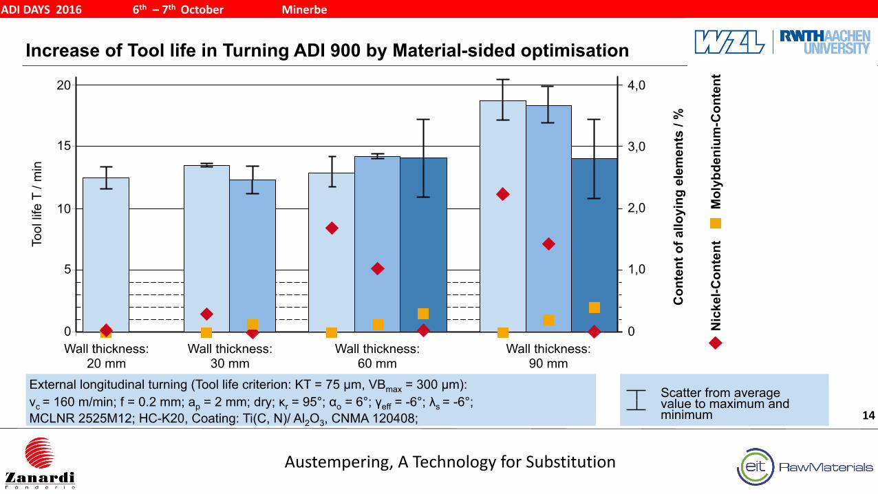
Increase of Tool life in Turning ADI 900 by Material-sided optimisation
Austempering, A Technology for Substitution
ADI DAYS 2016 6th – 7th October Minerbe
14
5
10
15
20
Tool
life
T /
min
Wall thickness: 20 mm
Wall thickness: 30 mm
Wall thickness: 60 mm
Wall thickness: 90 mm
Nic
kel-C
onte
ntM
olyb
deni
um-C
onte
nt
Con
tent
of a
lloyi
ng e
lem
ents
/ %
0
1,0
2,0
3,0
4,0
0
External longitudinal turning (Tool life criterion: KT = 75 µm, VBmax = 300 µm):vc = 160 m/min; f = 0.2 mm; ap = 2 mm; dry; κr = 95°; αo = 6°; γeff = -6°; λs = -6°; MCLNR 2525M12; HC-K20, Coating: Ti(C, N)/ Al2O3, CNMA 120408;
Scatter from average value to maximum and minimum
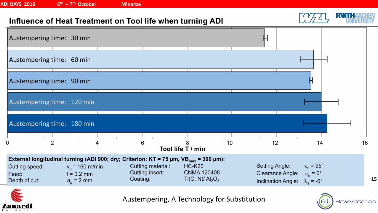
Influence of Heat Treatment on Tool life when turning ADI
Austempering, A Technology for Substitution
ADI DAYS 2016 6th – 7th October Minerbe
15
0 2 4 6 8 10 12 14 16
Haltezeit Salzbad: 180 min
Tool life T / minExternal longitudinal turning (ADI 900; dry; Criterion: KT = 75 µm, VBmax = 300 µm): Cutting speed: vc = 160 m/min Feed: f = 0.2 mm Depth of cut: ap = 2 mm
Cutting material: HC-K20 Cutting insert: CNMA 120408 Coating: Ti(C, N)/ Al2O3
Setting Angle: κr = 95° Clearance Angle: αο = 6° Inclination Angle: λs = -6°
Austempering time: 30 min
Austempering time: 60 min
Austempering time: 90 min
Austempering time: 120 min
Austempering time: 180 min
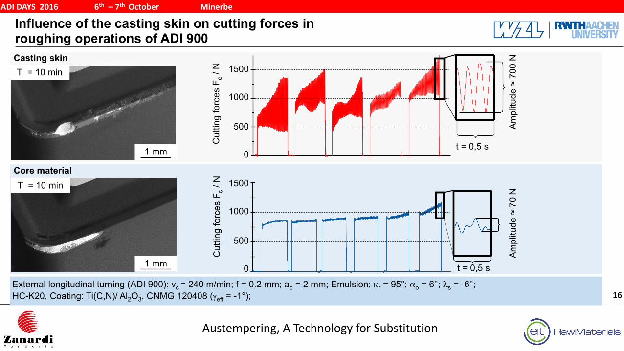
Influence of the casting skin on cutting forces in roughing operations of ADI 900
Austempering, A Technology for Substitution
ADI DAYS 2016 6th – 7th October Minerbe
16External longitudinal turning (ADI 900): vc = 240 m/min; f = 0.2 mm; ap = 2 mm; Emulsion; κr = 95°; αo = 6°; λs = -6°; HC-K20, Coating: Ti(C,N)/ Al2O3, CNMG 120408 (γeff = -1°);
Casting skin
Core material
T = 10 min
T = 10 min
1 mm
1 mm
Cut
ting
forc
es F
c / N
Cut
ting
forc
es F
c / N
Am
plitu
de ≈
700
N
500
1000
1500
0
Am
plitu
de ≈
70
N
500
1000
1500
0 t = 0,5 s
t = 0,5 s
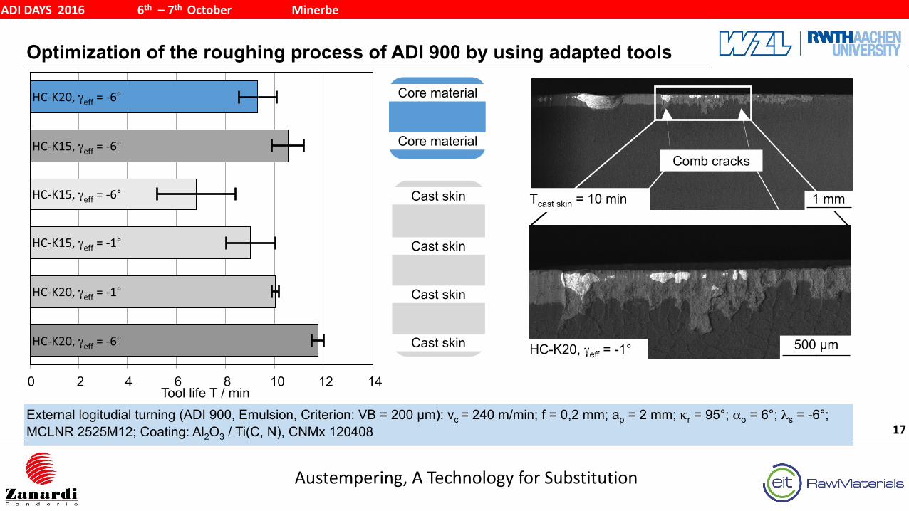
Optimization of the roughing process of ADI 900 by using adapted tools
Austempering, A Technology for Substitution
ADI DAYS 2016 6th – 7th October Minerbe
17External logitudial turning (ADI 900, Emulsion, Criterion: VB = 200 µm): vc = 240 m/min; f = 0,2 mm; ap = 2 mm; κr = 95°; αo = 6°; λs = -6°; MCLNR 2525M12; Coating: Al2O3 / Ti(C, N), CNMx 120408
Tool life T / min0 2 4 6 8 10 12 14
Comb cracks
Tcast skin = 10 min 1 mm
HC-K20, γeff = -1°
HC-‐K20, γeff = -‐6°
HC-‐K15, γeff = -‐6°
HC-‐K15, γeff = -‐6°
HC-‐K15, γeff = -‐1°
HC-‐K20, γeff = -‐1°
HC-‐K20, γeff = -‐6°
Core material
Core material
Cast skin
Cast skin
Cast skin
Cast skin
500 µm
Agenda
Austempering, A Technology for Substitution
ADI DAYS 2016 6th – 7th October Minerbe
18
Summary5
Investigation of Contact Fatigue for ADI1200, ADI900 and AST4
Improvement of the ADI machining process 3
Machining properties of ADI2
Fundamentals in Metal Cutting1
Project Overview
Austempering, A Technology for Substitution
ADI DAYS 2016 6th – 7th October Minerbe
19
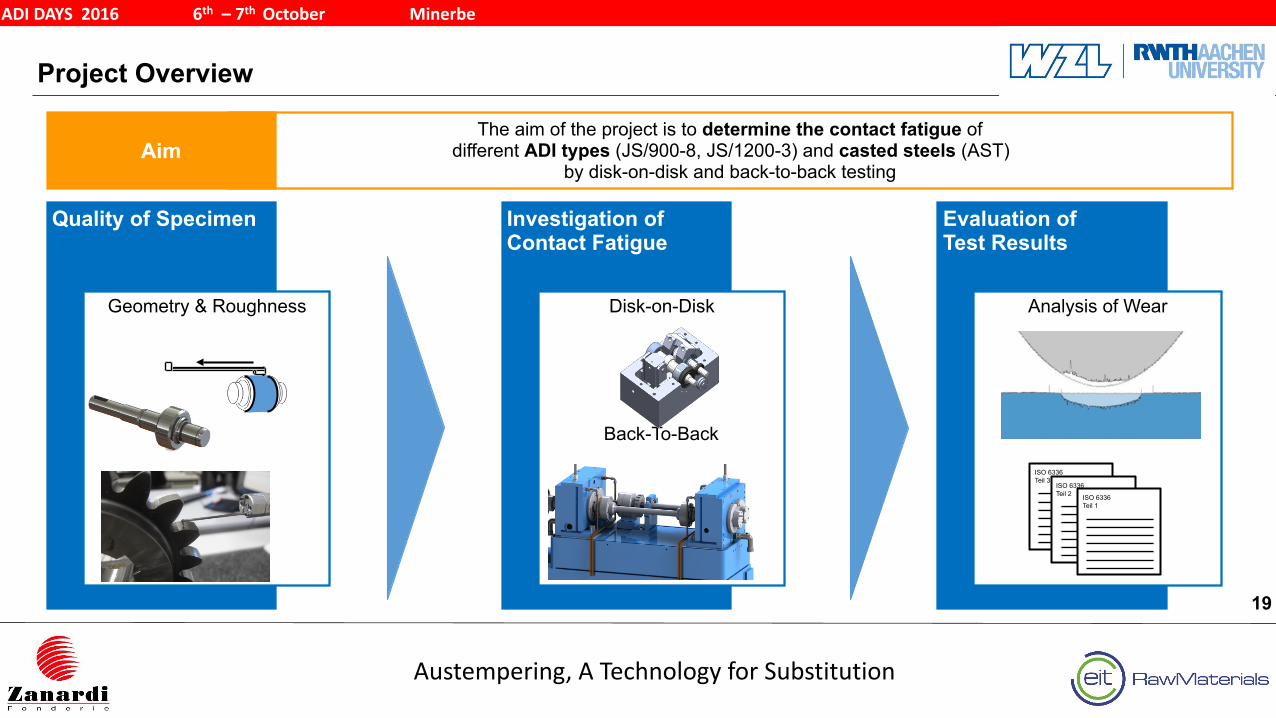
Evaluation of Test Results
Analysis of Wear
Calculation ISO6336
The aim of the project is to determine the contact fatigue of different ADI types (JS/900-8, JS/1200-3) and casted steels (AST)
by disk-on-disk and back-to-back testing
Investigation of Contact Fatigue
Disk-on-Disk
Back-To-Back
Aim
Quality of Specimen
Geometry & Roughness
ISO 6336 Teil 3
ISO 6336 Teil 2 ISO 6336
Teil 1
SN-Curves: Comparison of Variants ADI900 and ADI1200
Austempering, A Technology for Substitution
ADI DAYS 2016 6th – 7th October Minerbe
20
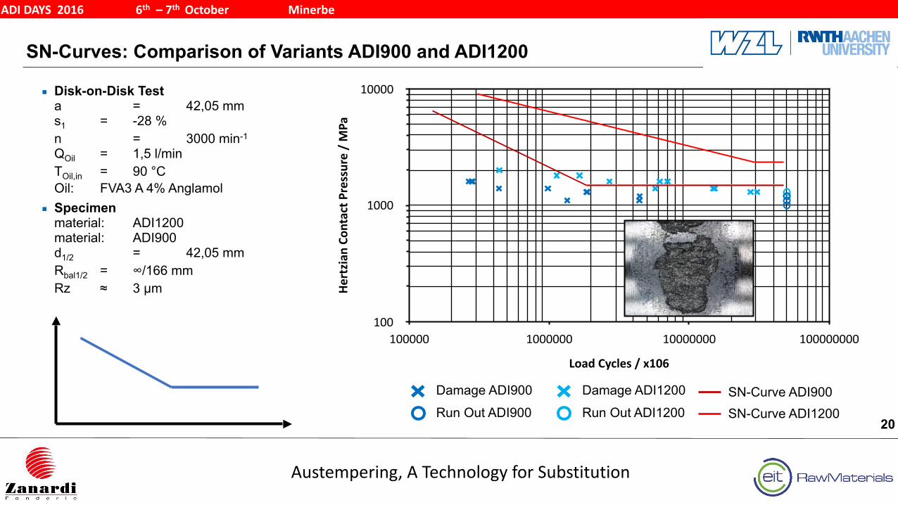
Damage ADI900
Run Out ADI900
■ Disk-on-Disk Testa = 42,05 mms1 = -28 % n = 3000 min-1
QOil = 1,5 l/min TOil,in = 90 °C Oil: FVA3 A 4% Anglamol
■ Specimenmaterial: ADI1200material: ADI900d1/2 = 42,05 mmRbal1/2 = ∞/166 mmRz ≈ 3 µm
Hertzian Co
ntact P
ressure / MPa
100
1000
10000
Load Cycles / x106
100000 1000000 10000000 100000000
Damage ADI1200
Run Out ADI1200SN-Curve ADI900SN-Curve ADI1200
Agenda
Austempering, A Technology for Substitution
ADI DAYS 2016 6th – 7th October Minerbe
21
Summary5
Investigation of Contact Fatigue for ADI1200, ADI900 and AST4
Improvement of the ADI machining process 3
Machining properties of ADI2
Fundamentals in Metal Cutting1
Summary
Austempering, A Technology for Substitution
ADI DAYS 2016 6th – 7th October Minerbe
22
■ Tool life criterion by machining of ADI is the flank and crater wear. ■ In comparison to a quenched and tempered ADI has a more abrasive tool wear. ■ The dynamic tool load due to the chip formation leads to material fatigue of the tool. ■ The thermal tool load can be reduced by using emulsion. ■ The cutting speed should be decreased and the feed rate increased to achieve a high
tool life ■ A high molybdenum content leads to a higher tool life scatter ■ Machining the casting skin leads to a higher dynamic tool load due to the different
material allowance
Related Documents