M A N U A L Digital battery - motor controller BAMOCAR-PG-D3-400/400 BAMOCAR-PG-D3-700/250 BAMOCAR-PG-D3-700/400 for EC servo motor for AC asynchronous servo motor Hans-Paul-Kaysser-Straße 1 Edition / Version 71397 Leutenbach-Nellmersbach 2021/ V2 Tel: 07195 / 92 83 - 0 [email protected] www.unitek.eu

Welcome message from author
This document is posted to help you gain knowledge. Please leave a comment to let me know what you think about it! Share it to your friends and learn new things together.
Transcript

M A N U A L
Digital battery - motor controller BAMOCAR-PG-D3-400/400 BAMOCAR-PG-D3-700/250 BAMOCAR-PG-D3-700/400 for EC servo motor for AC asynchronous servo motor
Hans-Paul-Kaysser-Straße 1 Edition / Version 71397 Leutenbach-Nellmersbach 2021/ V2 Tel: 07195 / 92 83 - 0 [email protected] www.unitek.eu

Basic - Information
Version: 2021 / V2 Page: 1 BAMOCAR-PG-D3-700/250, 400
Table of contents 1 Basic - Information ..................................................................................................................... 3
1.1 History .......................................................................................................................................... 3
1.2 Other products ............................................................................................................................. 3
1.3 Project planning instructions (MANUAL) ..................................................................................... 3
1.4 Validity .......................................................................................................................................... 4
1.5 Designations and symbols used ................................................................................................... 4
1.6 General product information ....................................................................................................... 5
1.7 Application/use/design/property ................................................................................................. 6
1.8 Safety regulations ......................................................................................................................... 8
1.9 Commissioning ........................................................................................................................... 10
1.10 Details of the safety instructions ................................................................................................ 11
1.11 Intended use ............................................................................................................................... 12
1.12 Regulations and guidelines ......................................................................................................... 13
1.13 Risks ............................................................................................................................................ 14
1.14 Technical data ............................................................................................................................ 15
2 Mechanical installation ............................................................................................................ 18
2.1 Important notes ......................................................................................................................... 18
2.2 Dimension drawings BAMOCAR-PG-D3-400/400, 700/250, 700/400 ....................................... 19
2.3 Mounting on mounting rails ....................................................................................................... 21
2.4 Mounting on mounting surface.................................................................................................. 21
3 Electrical installations .............................................................................................................. 22
3.1 Important notes ......................................................................................................................... 22
3.2 Block diagrams ........................................................................................................................... 23
3.3 Connection overview .................................................................................................................. 25
3.4 EMC ............................................................................................................................................ 26
3.5 Connector overview ................................................................................................................... 28
3.6 Auxiliary voltage connection ...................................................................................................... 30
3.7 Power connections ..................................................................................................................... 31
3.8 Battery connection ..................................................................................................................... 32
3.9 Motor power connection ........................................................................................................... 33
4 Control connections ................................................................................................................. 34
4.1 Digital inputs ............................................................................................................................... 34
4.2 Safety input RFE (rotating field - enable) / stop category 0 ....................................................... 35
4.3 Digital outputs (0pen emitter).................................................................................................... 36
4.4 Signalling contact Ready for operation (solid state relay) / Ready BTB / RDY ........................... 37
4.5 Analogue inputs ±10 V................................................................................................................ 38
4.6 Analogue output - not available ................................................................................................. 38
Basic - Information
Version: 2021 / V2 Page: 2 BAMOCAR-PG-D3-700/250, 400
4.7 Serial interface RS232 ................................................................................................................. 39
4.8 CAN-BUS ..................................................................................................................................... 40
4.9 Resolver connection ................................................................................................................... 41
4.10 Encoder TTL connection ............................................................................................................. 42
4.11 SIN COS 1VSS Connection ........................................................................................................... 44
4.12 Rotor position sensor connection with BL tacho ....................................................................... 45
5 Status information ................................................................................................................... 46
5.1 Status display on the BAMOCAR ................................................................................................ 46
5.2 Status information - Error .......................................................................................................... 47
5.3 Status information - Warnings ................................................................................................... 48
6 Measured values ...................................................................................................................... 49
6.1 DC link DC BUS voltage, battery voltage (400 V and 700 V) ....................................................... 49
6.2 Output stages - temperature ..................................................................................................... 50
7 Warranty ................................................................................................................................. 51

Basic - Information
Version: 2021 / V2 Page: 3 BAMOCAR-PG-D3-700/250, 400
1 Basic - Information
1.1 History
Version Change Date
2021 / V1 Version "250" completed, pictures, graphics etc. renewed 07.04.2021
2021 / V2 Page 50 / Temperature table supplemented / renewed 27.04.2021
1.2 More products
For synchronous motors and asynchronous motors
Digital AC servo amplifier (mains up to 480V~) UNITEK DS series / DPC series
Digital AC servo amplifier for battery operation UNITEK BAMOBIL-D3 series
Analogue three-phase servo amplifier (mains 400V~) UNITEK TVD series
For DC motors
Analogue DC servo amplifier for battery operation UNITEK BAMOBIL-A2/BAMO series
Analogue DC servo amplifier (mains operation) UNITEK Series TV
Thyristor converter 1Q, 4Q, servo UNITEK Classic series 200 W to 800 kW
1.3 Project planning instructions (MANUAL)
1. MANUAL BAMOCAR-PG-D3-xxx Hardware 2. MANUAL NDrive x Software
Use all MANUALs for project planning, installation and commissioning!
Online as download: www.unitek.eu Hardware MANUAL contains warnings and safety instructions, explanations of standards, mechanical and electrical installation instructions. The MANUAL must be made accessible to all persons working with the unit.

Basic - Information
Version: 2021 / V2 Page: 4 BAMOCAR-PG-D3-700/250, 400
1.4 Validity
Hardware status: TMS 2-3d, Driver 1-8
Firmware version: FW 476
1.5 Designations and symbols used
Device BAMOCAR-PG-D3-700/400, 700/250, 400/400
User: Vehicles, boats, machinery or plant manufacturers or operators in the industrial sector (B2B, second environment)
Manufacturer: UNITEK Industry Electronics GmbH
Danger to life! High voltage
Warning. Important
Dangerous electric fields
Scope of delivery / in the shipping box: -Unit BAMOCAR- PG-D3-x -Hint for download "Operating Instructions / Manual“ Not included (order as accessory):
- PG screw fittings
- Control plug: X1 (In/Out) Order number G435 / Binder 99-5662-15-19 X7 (feedback) Order number G436 / Binder 99-5661-15-19 X9 (CAN-BUS) Order number G437 / Binder 99-0436-14-05
- Control cable:
X10 RS232 cable Order number G432 / Binder 79-3464-52-06

Basic - Information
Version: 2021 / V2 Page: 5 BAMOCAR-PG-D3-700/250, 400
1.6 General product information
The digital three-phase servo amplifier BAMOCAR-PG-D3-400/400, 700/250, 700/400 forms a 4-quadrant drive unit together with the motor, driving and braking with energy feedback in both directions of rotation. Depending on the installed parameter set, the amplifier is suitable for EC synchronous motors, AC asynchronous motors or DC motors. The drive concepts are characterised by different advantages and disadvantages. The EC drive (synchronous motor) has the highest efficiency and the highest power per weight and volume. It is maintenance-free and has high control dynamics. The disadvantage is the field weakening range, which is difficult to control, and the high braking torque in the event of a motor short circuit. The EC synchronous motor (brushless DC motor) in its electrical version is a synchronous motor with permanent magnet rotor and three-phase stator. The physical properties correspond to those of the DC motor, i.e. the current is proportional to the torque and the voltage is proportional to the speed. The speed is controlled stably up to the current limit (max. torque). In case of overload, the speed decreases at constant current. Rectangular speed-torque characteristic. Current, speed and position are measured exactly. The rotating field frequency is not a controlled variable, it adjusts itself independently. The motor voltages and motor currents are sinusoidal. The AC drive (asynchronous motor) has the highest speed range due to the simple field weakening and it does not generate a braking torque in the event of a motor short circuit. The disadvantage is the size and the poorer efficiency. The controlled variable is the rotating field frequency, taking into account the motor-specific parameters (field-oriented control). The motor voltages and motor currents are sinusoidal. With both three-phase systems, no motor movement takes place if the rotating field is switched off or there is power stage damage. The heat loss occurs mainly in the motor stator. The DC drive (direct current motor) has the best synchronisation and a high control range. Emergency operation can be achieved by directly connecting the battery voltage. Disadvantages are the carbon brushes and the heat generation in the armature. The drive can rotate at high speed in the event of a power stage failure. The current is proportional to the torque and the voltage is proportional to the speed. Current, speed and position (bearing) are measured exactly. The speed is controlled stably up to the current limit (max. torque). In case of overload, the speed decreases at constant current. Rectangular speed-torque characteristic. Field weakening is possible with externally excited motors. BAMOCAR-PG-D3-xxx can be used as a position controller, torque or speed amplifier. The actual speed value is generated from the encoder unit (resolver or other) or internally (sensorless). A large control range and high control dynamics require an encoder system.
Warning / Caution: For DC, AC and BL servo amplifiers fed from the DC mains, the energy feedback into the DC link during braking operation must be taken into account. (External ballast circuit)

Basic - Information
Version: 2021 / V2 Page: 6 BAMOCAR-PG-D3-700/250, 400
1.7 Application/use/design/property
Application: In vehicles, boats, machines and plants of all kinds up to a drive power of 100 kW in rough use, especially as 4Q servo drives for: - highly dynamic acceleration and braking processes, - large control ranges, - high efficiency, - small motor dimensions, - smooth, quiet running and - for speed control, torque control or combined speed-torque without superimposed position control, - conveyor drives, spindle operation, pumps, transverse and longitudinal dividing drives, multi-motor
synchronous drives.
Deployment: In battery-powered vehicles such as electric vehicles, electric boats, forklifts, transport systems as well as in battery-powered machines and systems such as automatic assembly machines, metalworking machines, X-Y tables, food processing machines, robots and handling systems, rack conveyors, stone processing machines and in many other battery-powered applications. Structure: - Compact unit according to VDE- DIN and EC directives / protection class IP65 (option IP69K) - For harsh environment and high dynamic overload - Maintenance free - Contact protection of the power connections - Power electronics for (S1 operation) 125 A~eff, 200 A~effA - Power input range nom. 12... 700 V= - Liquid cooling (special version air cooling) - Uniform digital control electronics - Independent 12.. 24 V chopper power supply for the auxiliary voltages Galvanic separation between: - Power connection, motor connection and all other control connections - Auxiliary voltage connection and all other voltages - Housing and cooling block. - Clearance and creepage distances comply with EU standards - No internal insulation monitoring, Y2 capacitors to housing Features: - Fully insulated IGBT power semiconductors, generously dimensioned - Only commercially available components in industrial standard - SMD assembly

Basic - Information
Version: 2021 / V2 Page: 7 BAMOCAR-PG-D3-700/250, 400
Features: Battery connection 12 V= / 700 V= (DC mains, observe restrictions). ✓ Independent auxiliary voltage connection 24 V= or 12 V= ✓ Digital interfaces RS232, CAN-BUS (further option) ✓ Analogue inputs, programmable differential inputs ✓ Digital inputs and outputs, programmable, opto-decoupled ✓ Setpoint ramps linear ✓ Enable and limit switch logic, emergency stop function, safety ✓ BTB-ready, solid state relay ✓ Position, speed and torque control ✓ Feedback encoder systems: resolver, encoder incremental encoder, SINCOS 1Vpp,
Rotor position + BL tacho ✓ Static and dynamic current limit ✓ Uniform fully digital control unit ✓ Processor-independent protective shutdown in case of overvoltage, undervoltage
Short circuit, earth fault and overtemperature of amplifier or motor ✓ Intrinsically safe short-circuit-proof power section (EN50178) Attention: Braking energy The braking energy is fed back into the battery. The battery must be able to absorb the braking energy. If the battery is disconnected from the unit during braking operation high DC link voltages can occur. Pay special attention when operating on laboratory power supplies! In DC networks, the network must absorb the braking energy without the voltage rising above the permissible value. If this is not ensured, a ballast circuit must be used.
In the case of non-grounded systems (vehicles, boats, machines) the insulation between the touchable parts and the HV voltages must be monitored with an independent insulation monitor.
Basic - Information
Version: 2021 / V2 Page: 8 BAMOCAR-PG-D3-700/250, 400
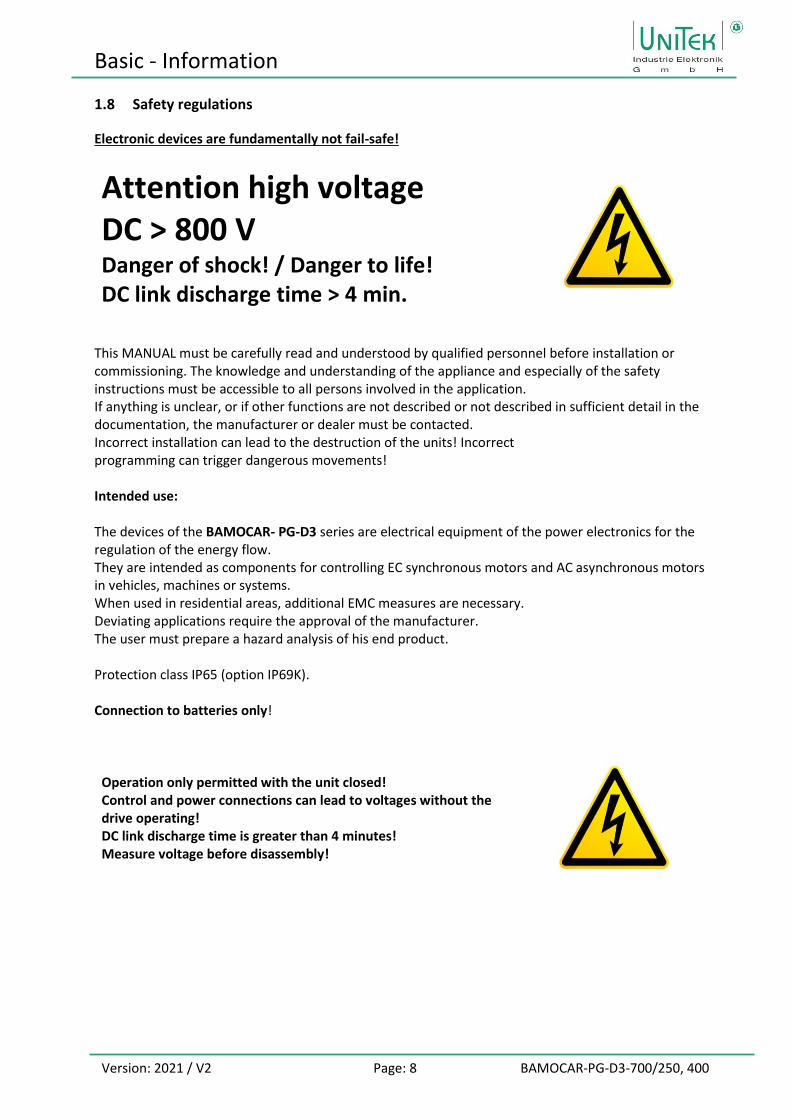
1.8 Safety regulations
Electronic devices are fundamentally not fail-safe!
Attention high voltage DC > 800 V Danger of shock! / Danger to life! DC link discharge time > 4 min.
This MANUAL must be carefully read and understood by qualified personnel before installation or commissioning. The knowledge and understanding of the appliance and especially of the safety instructions must be accessible to all persons involved in the application. If anything is unclear, or if other functions are not described or not described in sufficient detail in the documentation, the manufacturer or dealer must be contacted. Incorrect installation can lead to the destruction of the units! Incorrect programming can trigger dangerous movements! Intended use: The devices of the BAMOCAR- PG-D3 series are electrical equipment of the power electronics for the regulation of the energy flow. They are intended as components for controlling EC synchronous motors and AC asynchronous motors in vehicles, machines or systems. When used in residential areas, additional EMC measures are necessary. Deviating applications require the approval of the manufacturer. The user must prepare a hazard analysis of his end product. Protection class IP65 (option IP69K). Connection to batteries only!
Operation only permitted with the unit closed! Control and power connections can lead to voltages without the drive operating! DC link discharge time is greater than 4 minutes! Measure voltage before disassembly!

Basic - Information
Version: 2021 / V2 Page: 9 BAMOCAR-PG-D3-700/250, 400
The user must prepare a hazard analysis for his machine, vehicle or plant.
The user must ensure: - that after a failure of the unit, - in case of operating errors, - in case of failure of the regulation and control unit, etc. the drive is guided into a safe operating state.
Vehicles, boats, machines and installations must also be equipped with monitoring and safety devices that are independent of the equipment. The user must take appropriate measures to ensure that inadmissible movements do not cause danger to people and property!
The unit must be closed during operation. All connectors must be securely engaged or screwed down. The protective systems must be active. With the unit open and/or protection systems deactivated, the user must ensure that only qualified personnel have access to the units.
Assembly work - Only in a secured, de-energised state - Only by trained specialist personnel Installation work - Only in a secured, de-energised state - Only by trained electricians - Observe the safety regulations. Setting and programming work - Only by qualified personnel with knowledge of electronic drives and software - Observe programming instructions - Observe safety instructions

Basic - Information
Version: 2021 / V2 Page: 10 BAMOCAR-PG-D3-700/250, 400
1.9 Commissioning
The servo amplifiers BAMOCAR-PG-D3-400/400, 700/250, 700/400 are components of electronic drive technology. They are only functional in connection with an electrical consumer (e.g. motor). The use is limited to commercial applications. In the case of installation in vehicles, boats, machines and systems, the start of the intended operation of the device is prohibited until it has been determined that the machine, system or vehicle complies with the provisions of the EC Machinery Directive 2006/42/EC and the EMC Directive 2004/108/EC. The EC Directive 2004/108/EC with the EMC standards EN61000-2 and EN61000-4 is complied with under the installation and test conditions specified in the chapter EMC notes. When used in residential areas, additional EMC measures are necessary. A manufacturer's declaration can be requested. Compliance with the limit values required by EMC legislation is the responsibility of the manufacturer of the vehicle, system or machine.

Basic - Information
Version: 2021 / V2 Page: 11 BAMOCAR-PG-D3-700/250, 400
1.10 Details of the safety instructions
Machinery Directive The vehicle, machine or plant manufacturer must prepare a hazard analysis for his product. He must ensure that no unforeseeable movements can lead to personal injury or damage to property. Qualified staff Hardware Qualified personnel are characterised by education and training for the use of electronic drive technology. They know the standards and accident prevention regulations for drive technology and can assess the application. Possible dangers are recognised. The local regulations (IEC, VDE, VGB) are known to the qualified personnel and are taken into account. Software Qualified personnel for the software must be trained for the safe programming of the devices in the machines and systems. Incorrect parameterisation can lead to unauthorised movements. The parameter settings must be checked against incorrect operation. Careful acceptance tests are to be carried out with a 4-eyes principle Working environment Incorrect handling of the units can lead to damage to property or personal injury. Only operate the units when the unit is closed or the control cabinet is secured! Unit covers must not be removed. Work on electrical connections only in a de-energised state. The battery voltage must be safely switched off. The voltages and residual voltages (intermediate circuit) must be measured before working on the unit. The maximum permissible voltage must be < 42 V. High temperatures > 70 °C may occur. Working environments may be hazardous for wearers of electronic medical devices. (e.g. pacemakers) can be dangerous. A sufficient distance to these electrical parts must be maintained. Stress During transport and storage, the prescribed climatic conditions must be observed. The units must not show any mechanical damage. Bent housing parts can damage the insulating sections. Never install damaged units! The units contain components that can be damaged by electrostatic discharge. The general recommendations for handling ESD-components must be observed. Special attention must be paid to highly insulating plastic foils and synthetic fibres. For operation, it must be ensured that the environmental conditions in the control cabinet are complied with. This applies in particular to the non-permitted condensation of the units.

Basic - Information
Version: 2021 / V2 Page: 12 BAMOCAR-PG-D3-700/250, 400
1.11 Intended use
The devices are intended as components for controlling EC synchronous motors and AC asynchronous motors in vehicles, boats, machines or systems. Deviating applications require the approval of the manufacturer. The unit protection class is IP65 (option IP69K). Installation is only permitted in vehicles, boats, machines or systems. Additional EMC measures are necessary for use in residential areas. The user must prepare a hazard analysis of his end product Only approved for connection to a battery with battery-side charging current limitation. Use external insulation monitors for voltage > 60 V. The user must ensure that the standards are observed throughout the control wiring. In the case of components connected to the unit without potential-separated inputs/outputs, attention must be paid to the potential equalisation (equalisation connection GND). The equalising currents can destroy components. For insulation measurements, the units must be disconnected or the power connections among each other and the control connections among each other must be bridged. Non-observance can destroy semiconductors in the unit. Repetitive earth and short circuits below the short-circuit threshold can damage the output stages. (Conditionally short-circuit proof according to EN 50178, EN61800-5-1) Impermissible applications: - In life-supporting medical equipment or machines. - On power supply units or DC mains without protective circuits. - In potentially explosive atmospheres. - In environments with corrosive vapours.

Basic - Information
Version: 2021 / V2 Page: 13 BAMOCAR-PG-D3-700/250, 400
1.12 Regulations and guidelines
The units and the associated components must be installed and connected in accordance with the local legal and technical regulations:
EC Directive 2004/108/EC, 2006/95/EC, 2006/42/EC, 2002/96/EC
EC standards EN60204-1, EN292, EN 50178, EN60439-1, EN61800-3, ECE-R100
International Standards ISO 6469, ISO 26262, ISO 16750, ISO 20653, ISO 12100
IEC/UL IEC 61508, IEC364, IEC 664, UL508C, UL840
VDE regulations and TÜV regulations
VDE 100, VDE 110, VDE 160
Regulations of the employers' liability insurance association
VGB4
EU standards and regulations taken into account in the appliance
Standard Explanation Output
EN 60146-1,-2 Semiconductor power converter 2010
EN 61800-1,-2,-3 Variable speed electric drives 2010
EN 61800-5-1 Electric power drive systems Safety 2010
EN 60664-1 Insulation coordination low voltage 2012
EN 61010 Safety regulations for control units 2011
EN 61508-5 Functional safety of electrical, electronic systems 2011
EN 60068-1,-2 Environmental influences 2011
ISO 20653 Protection class of electrical equipment of vehicles
ECE-R100 Conditions battery-powered electric vehicles
UL 508 C UL regulation power converter 2002
UL 840 UL Regulation Air and Creepage Distances 2005
EU standards and regulations to be observed by the user
Standard Explanation Output
EN 60204 Safety and electrical equipment of machines 2011
EN 50178 Equipment of heavy current installations 1998
EN 61800-3 Variable speed electric drives -EMC 2010
EN 60439 Low-voltage switchgear and controlgear assemblies 2011
EN 1175-1 Safety of electric industrial trucks 2011
ISO 6469 Electric road vehicles 2009
ISO 26262 Functional safety of electric road vehicles 2011
ISO 16750 Electrical components Vehicles 2010
ISO 12100 Safety of machinery 2011
ISO 13849 Safety of machines and controls 2011
IEC 364 Protection against electric shock 2010
IEC 664 Insulation coordinates low voltage 2011

Basic - Information
Version: 2021 / V2 Page: 14 BAMOCAR-PG-D3-700/250, 400
1.13 Risks
The manufacturer endeavours to reduce the residual risks emanating from the device as far as possible through design, electrical and software measures. Following known residual risks from drive technology must be taken into account in the risk assessment of machines, vehicles and systems. Impermissible movements caused by:
• the failure or deactivation of safety monitoring systems during commissioning or repairs
• Software errors in upstream controls or errors in BUS systems
• Unmonitored hardware and software errors in the actuator or the connecting cables
• Inverted sense of the rules
• Error in parameterisation or wiring
• Limited reaction time of the control properties. Ramps, limits
• Operation outside the specifications
• Electromagnetic disturbances
• Electrostatic disturbances, lightning strike
• Component failure
• Fault in the brakes Dangerous temperatures caused by:
• Error during installation
• Defects at connections, bad contacts, ageing
• Error in electrical fuse protection, wrong fuse types
• Operation outside the specifications
• Weather influences, lightning strike
• Component failure Dangerous voltages caused by:
• Faulty earth connection of unit or motor
• Faulty insulation monitoring
• Defects at connections, bad contacts, ageing
• Error in potential separation, component failure
• Conductive pollution, condensation
Dangerous fields The units, the inductive and capacitive accessories, and the power cabling can generate strong electric and electromagnetic fields. These can be dangerous for wearers of electronic medical aids (e.g. pacemakers). A sufficient distance to these electrical parts must be maintained. The installation area must be marked accordingly.

Basic - Information
Version: 2021 / V2 Page: 15 BAMOCAR-PG-D3-700/250, 400
1.14 Technical data
Version for three-phase motors
Data BAMOCAR Dim. 400-400 700-250 700-400
Auxiliary voltage connection V= 12 V= .. 24 V = ±10 % /peak 4A (2 A)
Residual ripple <10 % (self-healing fuse)
Supply voltage V= 12 to. max. 400 12 to max. 700
Output voltage max. V~eff up to 3x260 up to 3x450
Continuous current Aeff 200 125 200
Continuous power max kVA 75 85 135
Peak current max. Alo peak 400 250 400
Peak current max. A~eff 285 178 285
Peak power max. kW
Power loss max. kW 3 2 4
Clock frequency kHz 8-16
Rotation frequency max. Hz 1000
Overvoltage switching threshold V= 440 800
Input fuse A 250
DC link capacity µF 320
Weight kg 8,5
Dimensions HxWxD mm 355 x 230 x 135
Control signals V A Function Connection
Analogue inputs ± 10 0.005 Differential input X1
Digital inputs ON OFF
10-30 <6
0.010 0
Logic IO X1
Digital outputs +24 1 Transistor output open emitter
X1
Analogue output Not available
Resolver / TTL / SINCOS Differential input X7
CAN interface Logic IO X9
RS232 interface Logic IO X10

Basic - Information
Version: 2021 / V2 Page: 16 BAMOCAR-PG-D3-700/250, 400
Environmental conditions
Protection class IP 65 (option IP69K)
Standards EN60204, ISO 16750, EN61800, IEC60146
Overvoltage 400 V and 700 V DC +10 %
Operating temperature range -30 to +85 °C
Storage, transport -30 °C to +80 °C EN60721
Installation height ≤ 1000m above sea level 100 %, >1000 m power reduction 2 %/100 m
Cooling Liquid cooler -30 to max. 65°C, 12 l/min, Pressure max. 6 bar >65 °C Power reduction 2 %/°C
Extended cooling range Cooling medium 65 to 80 °C Torque reduction (see table)
Mounting position independent
Pollution Pollution degree 2 according to EN 61800-5-1
Vibration 10..58 Hz Amplitude 0.075 mm according to IEC 60068-2-358 ..200 Hz 1 g
Shock 15 g for 11 ms
Environmental conditions Not permissible: Condensation, ice formation, oil mist, salt mist, water
Humidity Class F Humidity < 85 no internal condensation!
Environmental conditions The closed housings are resistant to most environmental influences. Special attention should be paid to the connection plugs. To prevent internal condensation, pressure equalisation valves with moisture protection are installed. In case of oil mist or salt spray, the function of the valves may be impaired. Internal condensation can also occur when the heat sink temperature is colder than the ambient temperature. Short-term occurrence of impermissible environmental conditions is not critical. Ice formation can damage the seals. Operation under water is not permitted. Humidity The function of the pressure equalisation valves is overloaded. Increased humidity in conjunction with salty air can lead to corrosion of the aluminium heat sink.

Basic - Information
Version: 2021 / V2 Page: 17 BAMOCAR-PG-D3-700/250, 400
Current reduction (torque reduction)
Only with air cooler Permissible current limit depending on the installation height (not automatic, but must be observed by the user).
For air cooler Permissible current limit depending on the ambient temperature.
For liquid coolers Permissible current limit depending on to the coolant temperature.
Dependence on IGBT module temperature
Operating temperature of the reduction. I-red-TD 0x58
Final temperature of the reduction I-red-TE 0x4C
Protection limits Warning from 0x4A =24600 Num Disable at 0x4A = 25200 Num
Automatic current reduction in Dependence on the clock frequency.

Mechanical installation
Version: 2021 / V2 Page: 18 BAMOCAR-PG-D3-700/250, 400
2 Mechanical installation
2.1 Important notes
Check the unit for mechanical damage. Only install faultless units. Mounting only in de-energised state. Disconnect the positive and negative battery terminals, disconnect the DC mains. Assembly only by trained specialist personnel. The installation position is arbitrary for units with liquid cooler. If the heat dissipation is too low, the unit switches off via its thermal monitoring. Take the unit mounting holes from the dimensional drawing or the drilling plan, do not mark off the unit. Mount the filter and choke spatially close to the unit. Contact the cable shields with the mounting surface. Lay the power cables (battery and motor cables) separately from the signal cables. Observe the minimum cable cross-section. Safe earth connection from the enclosure to the ground level (vehicle ground, control cabinet ground) Shieldless cable ends as short as possible. Use only specified plugs. Use vibration-proof screw connections. Attention: Power connection cable from BAMOCAR to battery as short as possible. Longer cables lead to dynamic voltage drops due to the cable impedance. These stress the built-in capacitors and shorten the service life.
Mechanical installation
Version: 2021 / V2 Page: 19 BAMOCAR-PG-D3-700/250, 400
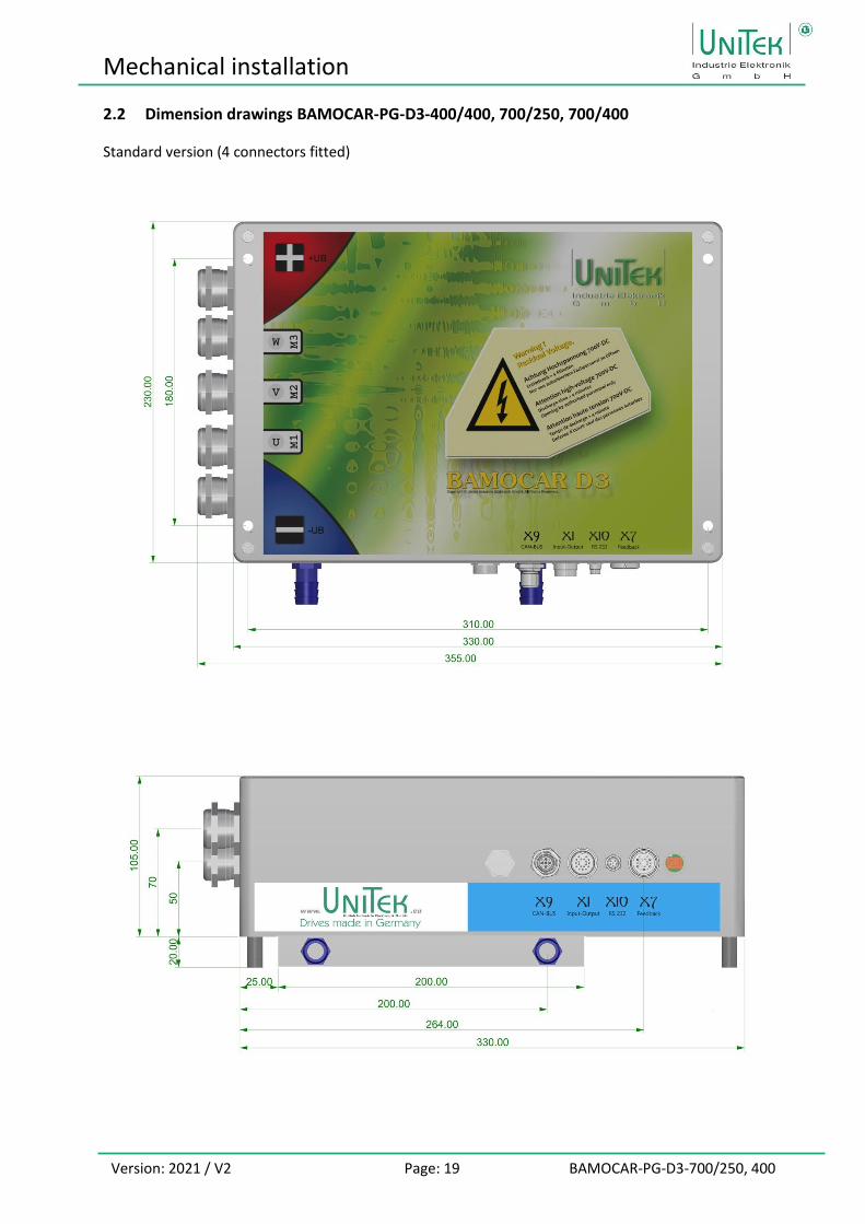
2.2 Dimension drawings BAMOCAR-PG-D3-400/400, 700/250, 700/400
Standard version (4 connectors fitted)

Mechanical installation
Version: 2021 / V2 Page: 20 BAMOCAR-PG-D3-700/250, 400
Power connection: Screws for power connections: Allen key M10 x 20 / Max. tightening torque 20 Nm PG cable entry metal M25 x 1.5 With umbrella insert Cable diameter max. 21 mm Recommended cable glands: Lapp-SKINTOP-MS-x Pflitsch-blueglobe TRI
Liquid cooler: Cooling medium down to -40 degrees (water + glycol) Hose connection: Metal G¼-13 Input temperature: < 65 °C Flow rate: 6 to 12 l / min Print: max. 6 bar Pressure loss (6 l/min): max. 0.56 bar Thermal resistance: K/W 0.01 Weight: 2,4 kg

Mechanical installation
Version: 2021 / V2 Page: 21 BAMOCAR-PG-D3-700/250, 400
2.3 Mounting on mounting rails
4 x M5x20 bolt
2.4 Mounting on mounting surface
Mounting screws: M5 x 40 Spacer rollers: 10 x 20 inside 6.5
Support rail and mounting surface must be provided by the customer

Electrical installations
Version: 2021 / V2 Page: 22 BAMOCAR-PG-D3-700/250, 400
3 Electrical installations
3.1 Important notes
The connection instructions are binding in their assignment of the connections to the plug numbers or terminal numbers! All further information on this is non-binding. The input and output lines can be changed and supplemented taking into account the electrical regulations and guidelines.
The regulations to be observed are - Connection and operating instructions - Local regulations - EC regulations such as EC Machinery Directive 2006/42/EC - Vehicle regulations ECE-R100, ISO 6469, ISO 26262 - VDE, TÜV and Employer's Liability Insurance Association regulations
Electrical installation only in de-energised state. Ensure secure activation. - Insert shorting bar - Put up warning signs Installation only by electrotechnically trained personnel
Compare the connection values with the nameplate data. Ensure correct fusing of the auxiliary voltage supply. Lay power cables and control cables spatially separated. Carry out shield connections and earthing measures in accordance with EMC directives. Use the correct cable cross-sections. Note polarity!
Attention: Use external insulation monitors!
• Poor or undersized cable connections between the battery and the unit can damage the unit! (Braking energy)
• The power connection cable from the BAMOCAR to the battery should be as short as possible. Longer cables lead to dynamic voltage drops due to the cable impedance. These stress the built-in capacitors and shorten the service life.

Electrical installations
Version: 2021 / V2 Page: 23 BAMOCAR-PG-D3-700/250, 400
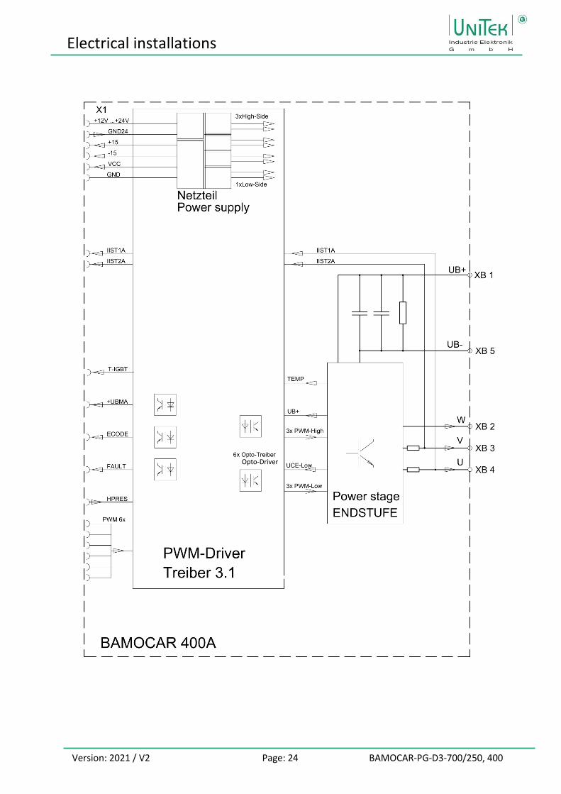
3.2 Block diagrams
Round plug 19pol M16
Output 4
Electrical installations
Version: 2021 / V2 Page: 24 BAMOCAR-PG-D3-700/250, 400
Opto-Driver

Electrical installations
Version: 2021 / V2 Page: 25 BAMOCAR-PG-D3-700/250, 400
3.3 Connection overview

Electrical installations
Version: 2021 / V2 Page: 26 BAMOCAR-PG-D3-700/250, 400
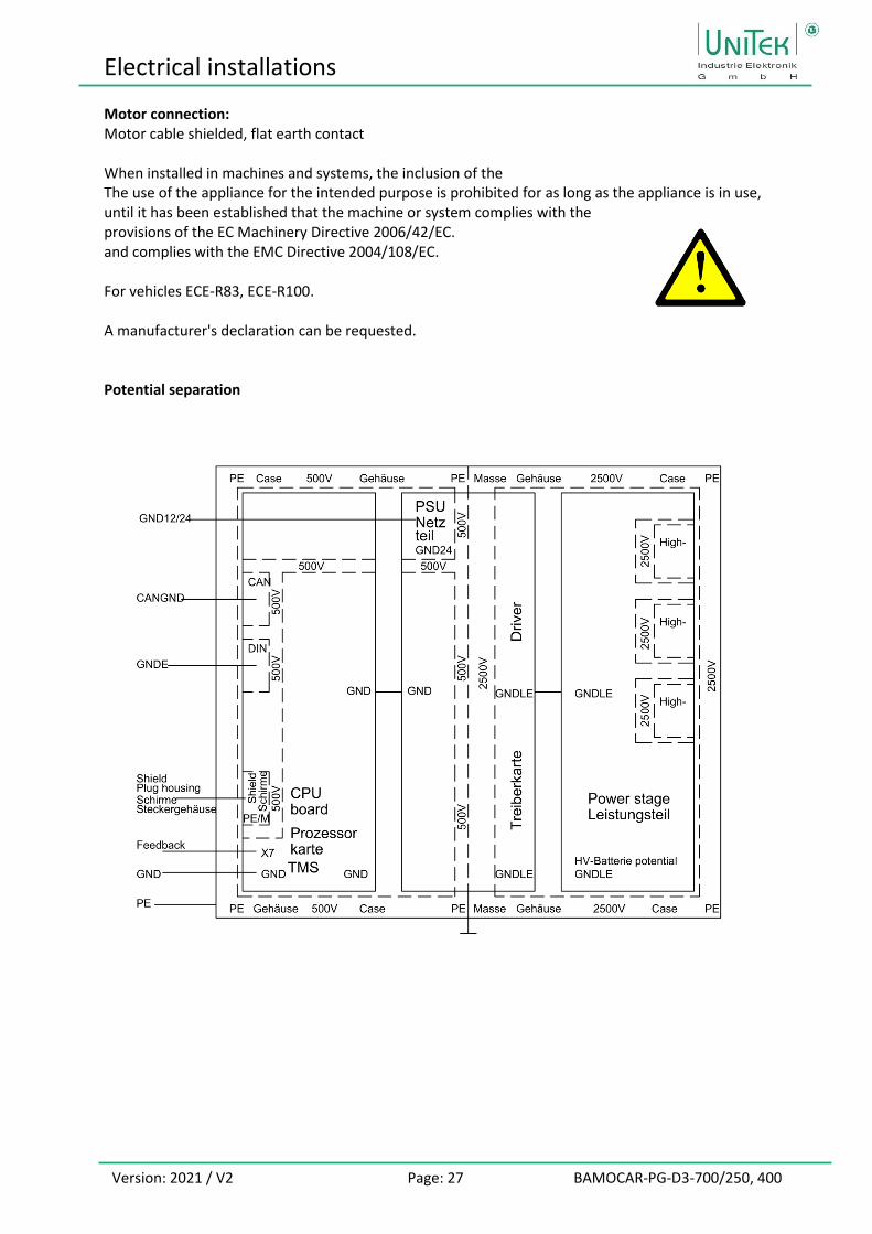
3.4 EMC
The units comply with the EC Directive 2004/108/EC in the standards EN61800-3 under the following installation and test conditions Mounting: Unit is conductively mounted on a blank mounting plate 500 x 500 x 5 mm. Mounting plate connected to earth via 10 mm². Motor housing connected to earth via 10 mm². Device ground X-AGND connected to mounting plate via 1.5 mm². Unit PE screw X3:6 connected to mounting plate via cable 4 mm². Control connections: Signal lines shielded, analogue signal lines twisted and shielded Shield: Flat contact on mounting plate (earth) Battery connection: 12.. 360 V DC voltage
Electrical installations
Version: 2021 / V2 Page: 27 BAMOCAR-PG-D3-700/250, 400
Motor connection: Motor cable shielded, flat earth contact When installed in machines and systems, the inclusion of the The use of the appliance for the intended purpose is prohibited for as long as the appliance is in use, until it has been established that the machine or system complies with the provisions of the EC Machinery Directive 2006/42/EC. and complies with the EMC Directive 2004/108/EC. For vehicles ECE-R83, ECE-R100. A manufacturer's declaration can be requested. Potential separation

Electrical installations
Version: 2021 / V2 Page: 28 BAMOCAR-PG-D3-700/250, 400
3.5 Connector overview
Plugs are not included in the scope of delivery.
Pressure equalisation X9 CAN X1 Tax X10 RS232 X7 Feedback Display
Valve BUS Inputs/Outputs Parameter Encoder Status error
Connector X9 CAN
1 FE
2 CAN-V+
3 CAN-GND
4 CAN-H
5 CAN-L
Connector X1 Control inputs/outputs
A brown BTB Ready for operation
B red BTB
C pink GND24 Auxiliary voltage 0
D yellow +24 V Auxiliary voltage +
E green END1/LMT1 Limit switch 1
F blue END2/LMT2 Limit switch 2
G violet FRG/RUN Release
H grey AIN1+ Analogue input1
J white AIN1-
K black GNDE Logic Zero
L brown-green DIN1 Digital input1
M brown-yellow DIN2 Digital input2
N white-green DOUT1 Digi output1
O red-blue DOUT2 Digi-output2
P white-yellow AIN2+ Analogue input2
R white-red AIN2-
S white-grey DOUT3 Digi output3
T white-black RFE Rotary field release
U white-blue +24 V Auxiliary voltage+
Unit View of connector pins Connection plug: Binder 99-5662-15-19 Cable view on solder side
Unit View of connector pins Connection plug: Binder 99-0436-14-05 Cable view on solder side
Electrical installations
Version: 2021 / V2 Page: 29 BAMOCAR-PG-D3-700/250, 400
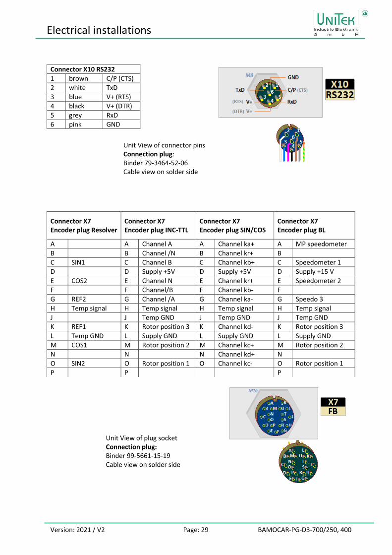
Connector X10 RS232
1 brown C/P (CTS)
2 white TxD
3 blue V+ (RTS)
4 black V+ (DTR)
5 grey RxD
6 pink GND
Connector X7 Encoder plug Resolver
Connector X7 Encoder plug INC-TTL
Connector X7 Encoder plug SIN/COS
Connector X7 Encoder plug BL
A A Channel A A Channel ka+ A MP speedometer
B B Channel /N B Channel kr+ B
C SIN1 C Channel B C Channel kb+ C Speedometer 1
D D Supply +5V D Supply +5V D Supply +15 V
E COS2 E Channel N E Channel kr+ E Speedometer 2
F F Channel/B F Channel kb- F
G REF2 G Channel /A G Channel ka- G Speedo 3
H Temp signal H Temp signal H Temp signal H Temp signal
J J Temp GND J Temp GND J Temp GND
K REF1 K Rotor position 3 K Channel kd- K Rotor position 3
L Temp GND L Supply GND L Supply GND L Supply GND
M COS1 M Rotor position 2 M Channel kc+ M Rotor position 2
N N N Channel kd+ N
O SIN2 O Rotor position 1 O Channel kc- O Rotor position 1
P P P
Unit View of plug socket Connection plug: Binder 99-5661-15-19 Cable view on solder side
Unit View of connector pins Connection plug: Binder 79-3464-52-06 Cable view on solder side

Electrical installations
Version: 2021 / V2 Page: 30 BAMOCAR-PG-D3-700/250, 400
3.6 Auxiliary voltage connection
Mains potential-free auxiliary DC V= (4 A) to +24 V= (2 A) ±10 %. Observe the type plate! The auxiliary voltage has
• Galvanic connection to the logic voltage
• Galvanic protective separation from all internal supply voltages and from the housing.
• Internal self-healing fuse
• EMC filter External fuse for line protection only
Input voltage 12.. 24 V DC X1:D
GND24 X1:C
Residual ripple 10 %
Inrush current max. 4 A
Nominal current 1.4 A at 12 V
0.9 A at 24 V
Connect the negative terminal of the power supply unit to earth.
Attention:
• In addition to the internal supply current (1.4 A at 12 V / 0.9 A at 24 V), the total current of the outputs (DOUT) must be supplied by the power supply unit.
• If the auxiliary voltage is less than 10.5 V, the error message hardware error 1 (Power Fault) appears.
• If the auxiliary voltage is less than 10 V, including brief voltage interruptions, the internal power supply unit switches off. - Temporary data in the RAM memory is deleted. - Digital speed and torque setpoints are set to 0. - Message OK in the status is dark.
• Firmware download only with power switched off! • Only switch auxiliary voltage and/or power voltage when BAMOCAR is locked.
- No clearance. - Enable input X1:G = zero

Electrical installations
Version: 2021 / V2 Page: 31 BAMOCAR-PG-D3-700/250, 400
3.7 Power connections
PG cable gland Metal M25 x 1.5 with shield contact Connection - battery positive pole Connection - Motor W Connection - Motor V Connection-- Motor U Connection - battery negative pole Connection cable maximum 50 mm2 Structure: Only use cables with shield layer! Connection example: Adapt dimensions to the cable and cable gland used! Remove outer insulation to 34... 38 mm, shorten shield layer to 10 mm. Shorten inner insulation. Copper strands 7..12 mm. Cable lug insulation 25 mm (fabric hose or shrink hose). Cable lug for M10 screw. Push on the PG screw connection with shield springs. Slide on the cable shoe insulation. Press the cable strands into the cable lug (15 mm). Screw in the PG gland in the unit. Screw cable lug onto the internal busbar. Tighten the cap of the PG screw connection. Tighten the cable gland on the cable lug. Connection screw: M10 x 12 (self-locking or corrugated washer, no toothed lock washer) Maximum tightening torque 20 Nm Remark: The cable gland is not included in the scope of delivery.

Electrical installations
Version: 2021 / V2 Page: 32 BAMOCAR-PG-D3-700/250, 400
3.8 Battery connection
DC link capacitor C-ZW at 400 V 320 µF at 700 V 320 µF Discharge resistance R-ZW: 50 kΩ Series resistor RV approx. 40 Ω, 50 W Charging current via K2: < 20 A
Attention: Enable (RUN) only after the main contactor K1 has been switched.
The maximum connection voltage (battery voltage) 450 V= (780 V=), do not exceed even for a short time - risk of destruction! Error message: OVERVOLTAGEF1 = slow-blow fuse Programming an output for the pre-charge: The output Dout1 switches the relay K3 if the DC link voltage (DC BUS) is greater than variable 1.
Attention: The power connection has no reverse polarity protection. If the polarity of the power connection is reversed, the unit may be destroyed.
Type Battery connection Connection cross-section Fuse AT Drive-
mm² AWG Contactor size
250/400 35 1 250
Battery connection <2 m, from 2 to 10 m make connection stronger. Use additional capacity from 10 m! Lay positive and negative cables in parallel. Maximum connection cross-section 50 mm2, cable lug for M10.
Electrical installations
Version: 2021 / V2 Page: 33 BAMOCAR-PG-D3-700/250, 400
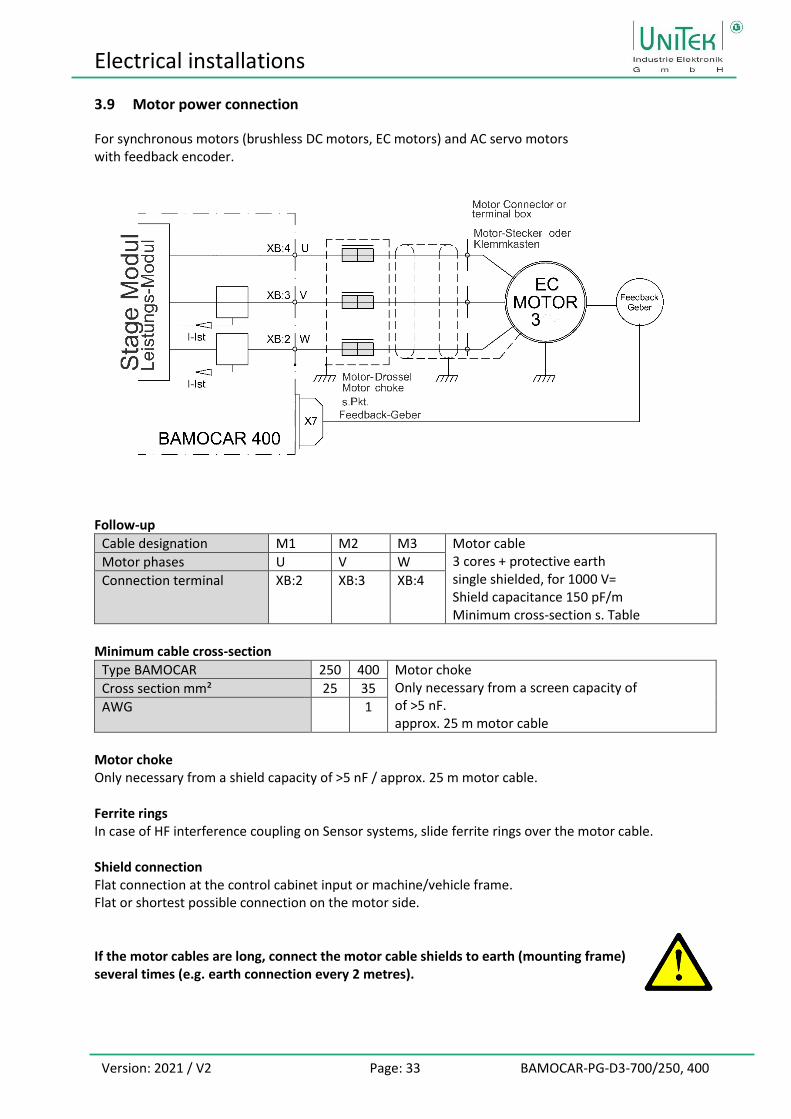
3.9 Motor power connection
For synchronous motors (brushless DC motors, EC motors) and AC servo motors with feedback encoder.
Follow-up
Cable designation M1 M2 M3 Motor cable 3 cores + protective earth single shielded, for 1000 V= Shield capacitance 150 pF/m Minimum cross-section s. Table
Motor phases U V W
Connection terminal XB:2 XB:3 XB:4
Minimum cable cross-section
Type BAMOCAR 250 400 Motor choke Only necessary from a screen capacity of of >5 nF. approx. 25 m motor cable
Cross section mm² 25 35
AWG 1
Motor choke Only necessary from a shield capacity of >5 nF / approx. 25 m motor cable. Ferrite rings In case of HF interference coupling on Sensor systems, slide ferrite rings over the motor cable. Shield connection Flat connection at the control cabinet input or machine/vehicle frame. Flat or shortest possible connection on the motor side. If the motor cables are long, connect the motor cable shields to earth (mounting frame) several times (e.g. earth connection every 2 metres).

Control ports
Version: 2021 / V2 Page: 34 BAMOCAR-PG-D3-700/250, 400
4 Control ports
4.1 Digital inputs
Input voltage
ON level +10.. +30 V
OFF level < +6 V
Input current Max. 7.5 mA
Nominal voltage/current
+24 V/6 mA
Reference mass GNDE (X1:K)
The enable input (FRG/RUN) and the input for rotating field enable (RFE) are permanently assigned and cannot be programmed. Without FRG/RUN enable, the servo is electronically locked (no PWM pulses). Without rotating field release RFE, the rotating field of the output stage is additionally blocked (second blocking channel). The drive is torque-free (no holding torque). The other 4 digital inputs are freely programmable. The inputs LMT1 (X1:E) and LMT2 (X1:F) are preferably to be used as limit switch inputs.
Entrance Connection Function Status
RFE X1:T Rotary field/enable fixed
FRG/RUN X1:G Enable fixed
END1/LMT1 X1:E Limit switch1/Dig. input programmable
END2/LMT2 X1:F Limit switch2/Dig. input programmable
DIN1 X1:L Digital input1 programmable
DIN2 X1:M Digital input2 programmable
The enable (FRG X1:G) may only be activated after the auxiliary voltage (12-24 V) and the power voltage (both) have been switched on. External power supply for inputs and outputs
+12 ..+24 V for logic and auxiliary voltage
GNDE Logic Mass
+12 ..+24 V for logic and auxiliary voltage
GNDE Logic Mass

Control ports
Version: 2021 / V2 Page: 35 BAMOCAR-PG-D3-700/250, 400
4.2 Safety input RFE (rotating field - enable) / stop category 0
When the input of the release or the rotating field release is switched off the drive is torque-free. Without mechanical brake or lock the drive may fall through or move The motor cables are not voltage-free. Only the rotating field is blocked. When working on the motor or BAMOCAR, the battery motor controller must be separated from the battery high voltage. Operation with RFE input Two-channel enabling lock via a Safety switchgear. Enable input FRG/RUN. Rotary field enable input RFE. Switch on Safety device contacts closed. Release FRG/RUN 0.5 s after RFE. Safety shutdown Safety device contacts opened. No FRG/RUN signal blocks in the first blocking channel the PWM pulses in the processor. No RFE signal blocks the PWM pulses in a second barrier channel after the Processor. Switch on again Unlock the safety device. Safety device Contacts closed. Only after renewed release FRG/RUN in time after the rotating field release RFE the motor can move. Operation without RFE input The RFE input must be connected to the logic voltage. If the logic voltage is equal to the supply voltage, the RFE input is bridged with +24 V. The release FRG/RUN at least 0.5 s after the RFE signal.

Control ports
Version: 2021 / V2 Page: 36 BAMOCAR-PG-D3-700/250, 400
4.3 Digital outputs (Open emitter)
Output Connection Function Status Parameter
BTB/RDY X1:A X1:B
Ready for operation fixed Solid State Relay
DOUT1 X1:N Digital output 1 programmable
DOUT2 X1:O Digital output 2 programmable
DOUT3 X1:S Digital output 3 programmable
DOUT4 (option) X11 Brake (option) 4 programmable
The auxiliary voltage is also the supply voltage for the logic outputs.
+12.. +24 V for logic and auxiliary voltage Observe the total current of all outputs GNDE Logic Mass
Output voltage
ON level +12.. +24 V=
OFF level < 1 V=
Output current nom 1 A
Output current max. 2 A, 1s
Reference voltage +24 V (X1:D)
Reference mass GNDE (X1:K)

Control ports
Version: 2021 / V2 Page: 37 BAMOCAR-PG-D3-700/250, 400
4.4 Signalling contact Ready for operation (solid state relay) / Ready BTB / RDY
Hardware safety circuit with solid state relay contact. Software: Message Signal Parameter Status RDY (0x40 Bit 14) Ready for operation BTB = logical 1 In the event of a fault, this safety circuit is disconnected by the relay and the RDY status is set to 0. Other control units (e.g. BMS, VCU, etc.) can react.
Contact for max. 48 V / 0.5 A (not short-circuit-proof) Capacitive load: max. 1 µF Contact resistance: max. 2 Ω
Ready for operation BTB The BTB relay contact is closed.
Not ready for operation BTB relay contact is open. Red LED and error messages with 7-segment status LED.
Always insert BTB/RDY contact in the safety circuit! Secure BTB/RDY signal path with 0.5 AF! BTB function for undervoltage monitoring. BTB message also in the absence of power voltage Programming in NDrive: Parameter BTB Power = without (0x5ABit5 = 1). No BTB message in case of missing power voltage Programming in NDrive: Parameter BTB Power = with (0x5ABit5 = 0). (see NDrive-x manual)

Control ports
Version: 2021 / V2 Page: 38 BAMOCAR-PG-D3-700/250, 400
4.5 Analogue inputs ±10 V
Entrance Connection Basic function Voltage Status Parameter
AIN1+, AIN1- X1:H, X1:J Speed setpoint ± 10 V prog.
AIN2+, AIN2- X1:P, X1:R Current limit 2. speed setpoint
± 10 V prog.
Properties
Differential input AIN1+ / AIN1- AIN2+ / AIN2-
Input resistance 70 kΩ
Voltage limit ±12 V
Resolution 11 bit + sign
The direction of motor rotation can be changed by swapping the +/- connections on the differential input, by a logic input or by programming (see NDrive-x). The analogue inputs can be assigned to different functions (see NDrive-x). The analogue input AIN1 can be programmed as an external analogue speed limit and the analogue input AIN2 can be programmed as an external analogue current limit.
4.6 Analogue output - not available
There is no analogue output in this BAMOCAR variant.

Control ports
Version: 2021 / V2 Page: 39 BAMOCAR-PG-D3-700/250, 400
4.7 Serial interface RS232
The unit is programmed via the serial PC interface RS232 and operated during commissioning. The software is described in the NDrive software manual.
Attention: The serial interface is galvanically connected to the device zero (GND/AGND). Connection between BAMOCAR-PG-D3-400/400, 700/250, 700/400 (round plug X10) and the serial interface (COMx) on the PC only with a shielded null modem cable. Only plug in the cable when the power is off. The interface is factory set to 115200 baud. This can also be changed to 9600 baud with NDrive. Connecting cable: LiYCY 5x0.25 + shield; cable length max. 10 m Screen on the housing RS232 cable: order no. G432 / Binder 79-3464-52-06 In case of strong interference on the interface, a line filter should be used. Laptops with USB RS232 converters are usually sensitive to interference. For firmware update: Plug in short-circuit jumper X10:1 to X10:3 (D-connector 7 to 8), then switch on auxiliary voltage. Start Flash programme.

Control ports
Version: 2021 / V2 Page: 40 BAMOCAR-PG-D3-700/250, 400
4.8 CAN-BUS
The CAN-BUS is the digital connection to the CNC control. Optimum conditions with CNC controls and CAN components from LABOD electronic or CAN Open. Programming and operation via control panel with CAN-BUS. Interface according to ISO 11898. For setting and programming, see NDrive and CAN Manual.
CAN BUS cable Use shielded bus cable with low shield capacity. Signal plus GND (+supply internal DC/DC converter, galvanically isolated) Round plug M12-5p / LiYCY 4 x 0.25 + screen
(Attention: Colours can be different) Termination resistor at both ends of the bus line / 120 Ohm between CAN-H and CAN-L
Designation Plug Cable colour
FE X9:1 Umbrella
CAN-V+ X9:2 brown
CAN-GND X9:3 white
CAN-H X9:4 green
CAN-L X9:5 yellow
The BUS interface is galvanically separated from the internal device voltage. Power is supplied via an internal isolated DC-DC converter. CAN-BUS is isolated / CAN GND must be connected
2CAN-V+
4CANH
5CANL
3CANGND
CAN-BUS
CAN-V+
CANH
CANL
CANGND
CAN-VCC
CANGND
VCC
GND
DC
DC
1
PE on the connector housing
Rundsteckerround connector
PE am Steckergehäuse
Unit View of connector pins Connection plug: Binder 99-0436-14-05 Cable view on solder side

Control ports
Version: 2021 / V2 Page: 41 BAMOCAR-PG-D3-700/250, 400
4.9 Resolver connection
Only for BAMOCAR-PG-D3-RS The resolver is an absolute measuring system for one motor revolution. It is robust and insensitive to high engine temperatures. The design corresponds to a rotating transformer. The rotor is fed by the reference (10 kHz). The stator supplies the sine and cosine signals modulated by the rotational frequency. In the servo amplifier, the amplitudes of these signals are evaluated and digitised. The resolution is automatically set to 10, 12 or 14 bits. The maximum possible speed is 50 000 rpm (10 bit). The digitised signals are used for the pole wheel angle, the position control, the speed control and for the incremental output.
Socket on the unit
Only use motor with 2, 4, 6 or 8 pole resolver approved by the manufacturer.
Connector plug X7 19-pin round plug
Connection cable 4 x 2 cores twisted in pairs and shielded, plus overall shield. Use only suitable cable for drag chain
Minimum cross section 0.25 mm
Cable length for >25 m, only use high-quality resolver cables with improved shielding properties.
Shield connection at connector X7 combine all umbrellas and Contact with the housing
on the motor plug Contact the overall shield with the connector housing
Setting parameters see software manual NDrive
Connector X2 A B C SIN 1 D E COS 2 F G REF 2 H Temperature signal J K REF 1 L Temperature GND M COS 1 N O SIN 2 P
AD2S
REF1
REF2
K
G
C
O
M
E
COS2
COS1
SIN1
SIN2
REF1
REF2
10nF
10nF
2x2u2
2x2u2
100nF
47
47
Stecker X7
PE am Steckergehäuse
TEMP
Motor-Stecker
Resolver
H
L
MotorTemperatur
REF1
REF2
SIN1
SIN2
COS1
COS2
R1
R2
S2
S4
S1
S3
PE am Steckergehäuse
Rundstecker
4k7
VCC +5V
PE on the connector housingPE on the connector housing
MotorTemperature
Motor-Connector
Connector x7 round connector

Control ports
Version: 2021 / V2 Page: 42 BAMOCAR-PG-D3-700/250, 400
4.10 Encoder TTL connection
Only for BAMOCAR-PG-D3-IN TTL incremental encoder (encoder) with 2 counting tracks and one zero track plus 3 rotor position marks. Counting tracks with or without push-pull output. (With single connection A, B, N the negated inputs). Count input corresponds to RS485. Maximum counting frequency 500 kHz. The incremental encoder is galvanically with the device zero (GND) connected. Supply voltage 5 V supplies the servo.
Connector X7
Encoder plug INC
A Channel A B Channel /N C Channel B D Supply +5V E Channel N F Channel /B G Channel /A H Temperature signal J Temperature GND K Rotor position L Supply GND M Rotor position 2 N O Rotor position 1 P
Only use motors approved by the manufacturer with TTL incremental encoder and rotor position tracks.
Connector plug X7 19 pole round plug
Connection cable 11 x signal wires shielded Minimum cross section 0.14 mm
2 x supply wires Minimum cross section 0.5 mm
Use only suitable cable for drag chain
Cable length for >25 m cross-section one step larger
Shield connection at connector X7 Contact the shield with the connector housing.
on the motor plug Contact the shield with the connector housing.
Setting parameters see software manual NDrive
PE am Steckergehäuse
TemperaturMotor
PE am Steckergehäuse
J
H
TEMP
Moto
r-S
tecker
Stecker X7
TMS
Encoder
D
VCC +5V
AA
GA
CB
FB
EN
BN
OROTOR1
MROTOR2
KROTOR3
TEMP
L
VCC +5V
GND
GND
4k7
VCC +5V
PE on the connector housing
PE on the connector housing
Moto
r-C
onnecto
r
MotorTemperature
Connector x7
Rundsteckerround connector
Control ports
Version: 2021 / V2 Page: 43 BAMOCAR-PG-D3-700/250, 400
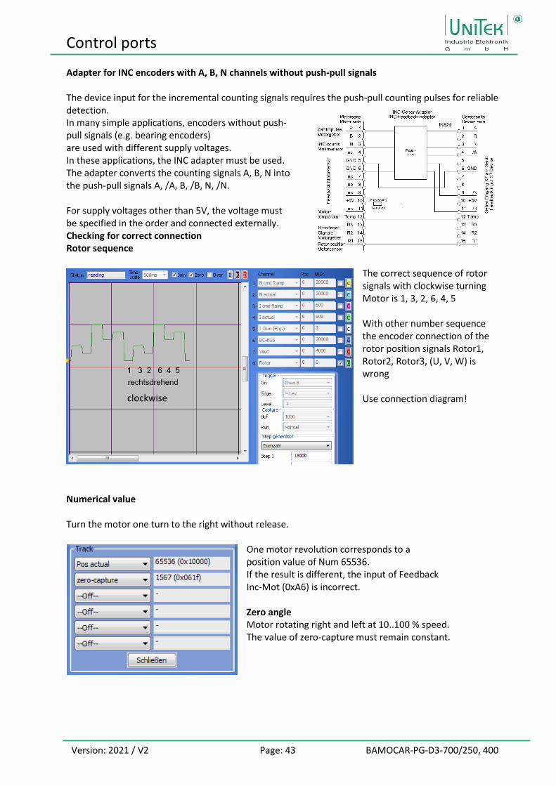
Adapter for INC encoders with A, B, N channels without push-pull signals The device input for the incremental counting signals requires the push-pull counting pulses for reliable detection. In many simple applications, encoders without push-pull signals (e.g. bearing encoders) are used with different supply voltages. In these applications, the INC adapter must be used. The adapter converts the counting signals A, B, N into the push-pull signals A, /A, B, /B, N, /N. For supply voltages other than 5V, the voltage must be specified in the order and connected externally. Checking for correct connection Rotor sequence
The correct sequence of rotor signals with clockwise turning Motor is 1, 3, 2, 6, 4, 5 With other number sequence the encoder connection of the rotor position signals Rotor1, Rotor2, Rotor3, (U, V, W) is wrong Use connection diagram!
Numerical value Turn the motor one turn to the right without release.
One motor revolution corresponds to a position value of Num 65536. If the result is different, the input of Feedback Inc-Mot (0xA6) is incorrect. Zero angle Motor rotating right and left at 10..100 % speed. The value of zero-capture must remain constant.
clockwise

Control ports
Version: 2021 / V2 Page: 44 BAMOCAR-PG-D3-700/250, 400
4.11 SIN COS 1VSS Connection
Only for BAMOCAR-PG-D3-SC Incremental encoder with 2 analogue sinusoidal Counting lanes and one zero lane plus 2 commutation tracks. Differential signals 1 VSS.
Maximum counting frequency 500 kHz. The incremental encoder is galvanically connected to the device zero (GND) connected. Supply voltage 5 V is supplied by the Servo.
Connector X7 Encoder plug SIN/COS
A Channel ka+ B Channel kr+ c Channel kb+ D Supply +5V E Channel kr+ F Channel kb- G Channel ka-K
H Temperature signal
J Temperature GND K Channel kd- L Supply GND M Channel kc+ N Channel kd+ O Channel kc- P
Only use motors approved by the manufacturer with SIN / COS encoder (SC).
Connector plug X7 19-pin round plug
Connection cable
6 x 2 signal wires drill-shielded Minimum cross section 0.14 mm
2 x supply wires Minimum cross section 0.5 mm
Cable type (4 x (2 x 0.14) + (4 x 0.14) C + 4 x 0.5) C Use only suitable cable for drag chain
Cable length for > 25 m cross-section one step larger
Shield connection at connector X7 Contact the shield with the connector housing.
on the motor plug Contact the shield with the connector housing.
Setting parameters see Software Manual NDrive
Control ports
Version: 2021 / V2 Page: 45 BAMOCAR-PG-D3-700/250, 400
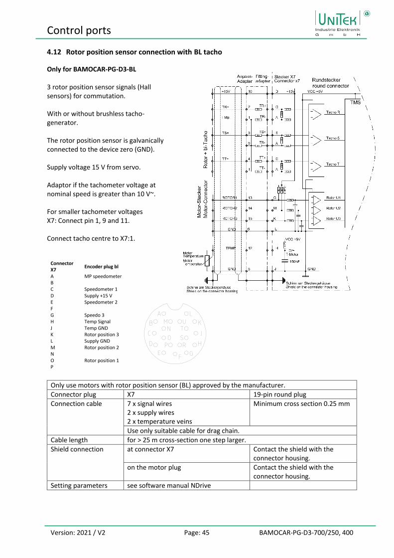
4.12 Rotor position sensor connection with BL tacho
Only for BAMOCAR-PG-D3-BL 3 rotor position sensor signals (Hall sensors) for commutation. With or without brushless tacho-generator. The rotor position sensor is galvanically connected to the device zero (GND). Supply voltage 15 V from servo. Adaptor if the tachometer voltage at nominal speed is greater than 10 V~. For smaller tachometer voltages X7: Connect pin 1, 9 and 11. Connect tacho centre to X7:1.
Connector X7
Encoder plug bl
A MP speedometer B C Speedometer 1 D Supply +15 V E Speedometer 2 F G Speedo 3 H Temp Signal J Temp GND K Rotor position 3 L Supply GND M Rotor position 2 N O Rotor position 1 P
Only use motors with rotor position sensor (BL) approved by the manufacturer.
Connector plug X7 19-pin round plug
Connection cable
7 x signal wires 2 x supply wires 2 x temperature veins
Minimum cross section 0.25 mm
Use only suitable cable for drag chain.
Cable length for > 25 m cross-section one step larger.
Shield connection at connector X7 Contact the shield with the connector housing.
on the motor plug Contact the shield with the connector housing.
Setting parameters see software manual NDrive
Status information
Version: 2021 / V2 Page: 46 BAMOCAR-PG-D3-700/250, 400
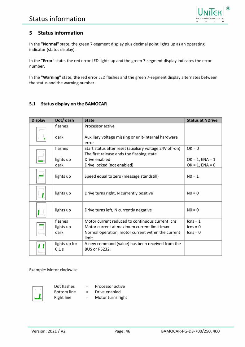
5 Status information
In the "Normal" state, the green 7-segment display plus decimal point lights up as an operating indicator (status display). In the "Error" state, the red error LED lights up and the green 7-segment display indicates the error number. In the "Warning" state, the red error LED flashes and the green 7-segment display alternates between the status and the warning number.
5.1 Status display on the BAMOCAR
Display Dot/ dash State Status at NDrive
flashes dark
Processor active Auxiliary voltage missing or unit-internal hardware error
flashes lights up dark
Start status after reset (auxiliary voltage 24V off-on) The first release ends the flashing state Drive enabled Drive locked (not enabled)
OK = 0 OK = 1, ENA = 1 OK = 1, ENA = 0
lights up
Speed equal to zero (message standstill)
N0 = 1
lights up
Drive turns right, N currently positive
N0 = 0
lights up
Drive turns left, N currently negative
N0 = 0
flashes lights up dark
Motor current reduced to continuous current Icns Motor current at maximum current limit Imax Normal operation, motor current within the current limit
Icns = 1 Icns = 0 Icns = 0
lights up for 0,1 s
A new command (value) has been received from the BUS or RS232.
Example: Motor clockwise
Dot flashes = Processor active Bottom line = Drive enabled Right line = Motor turns right
Status information
Version: 2021 / V2 Page: 47 BAMOCAR-PG-D3-700/250, 400
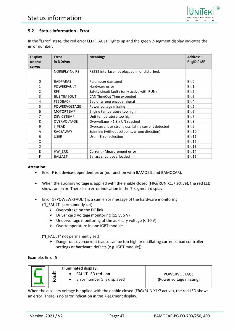
5.2 Status information - Error
In the "Error" state, the red error LED "FAULT" lights up and the green 7-segment display indicates the error number.
Display on the servo:
Error in NDrive:
Meaning: Address: RegID 0x8F
NOREPLY-No RS RS232 interface not plugged in or disturbed.
0 BADPARAS Parameter damaged Bit 0
1 POWERFAULT Hardware error Bit 1
2 RFE Safety circuit faulty (only active with RUN) Bit 2
3 BUS TIMEOUT CAN TimeOut Time exceeded Bit 3
4 FEEDBACK Bad or wrong encoder signal Bit 4
5 POWERVOLTAGE Power voltage missing Bit 5
6 MOTORTEMP Engine temperature too high Bit 6
7 DEVICETEMP Unit temperature too high Bit 7
8 OVERVOLTAGE Overvoltage > 1.8 x UN reached Bit 8
9 I_PEAK Overcurrent or strong oscillating current detected Bit 9
A RACEAWAY Spinning (without setpoint, wrong direction) Bit 10
B USER User - Error selection Bit 11
C Bit 12
D Bit 13
E HW_ERR Current - Measurement error Bit 14
F BALLAST Ballast circuit overloaded Bit 15
Attention:
• Error F is a device-dependent error (no function with BAMOBIL and BAMOCAR).
• When the auxiliary voltage is applied with the enable closed (FRG/RUN X1:7 active), the red LED shows an error. There is no error indication in the 7-segment display.
• Error 1 (POWEWRFAULT) is a sum error message of the hardware monitoring: ("I_FAULT" permanently set)
➢ Overvoltage on the DC link ➢ Driver card Voltage monitoring (15 V, 5 V) ➢ Undervoltage monitoring of the auxiliary voltage (< 10 V) ➢ Overtemperature in one IGBT module
("I_FAULT" not permanently set)
➢ Dangerous overcurrent (cause can be too high or oscillating currents, bad controller settings or hardware defects (e.g. IGBT module)).
Example: Error 5
Fau
lt Illuminated display:
• FAULT LED red - on • Error number 5 is displayed
POWERVOLTAGE (Power voltage missing)
When the auxiliary voltage is applied with the enable closed (FRG/RUN X1:7 active), the red LED shows an error. There is no error indication in the 7-segment display.

Status information
Version: 2021 / V2 Page: 48 BAMOCAR-PG-D3-700/250, 400
5.3 Status information - Warnings
In the "Warning" state, the red error LED flashes and the green 7-segment display alternately shows the status and the warning number.
Display on the servo:
Warnings in NDrive:
Meaning: Address: RegID 0x8FH
0 WARNING_0 Device detection inconsistent Bit 16
1 ILLEGAL STATUS RUN Signal disturbed, EMI Bit 17
2 SAFE_IN RFE input inactive (without RUN input active) Bit 18
3 Bit 19
4 Bit 20
5 Bit 21
6 MOTORTEMP Engine temperature > (I-red-TM or 93 % of M-Temp) Bit 22
7 DEVICETEMP Unit temperature > 87 % of limit Bit 23
8 Vout_Sat Limit of existing voltage output reached Bit 24
9 I_PEAK Overcurrent 200 % Bit 25
A RACEWAY Resolution range of the speed measurement exceeded Bit 26
B Bit 27
C Bit 28
D Bit 29
E Bit 30
F BALLAST Ballast circuit > 87 % overloaded Bit 31
Attention:
• Warning F is a device-dependent warning (without function for BAMOCAR). Example: Warning 7
Fau
lt Illuminated display:
• FAULT LED red - flashing
• The display alternates between status and warning number 7
DEVICETEMP Engine temperature
> (I-red-TM or 93 % of M-Temp)

Measured values
Version: 2021 / V2 Page: 49 BAMOCAR-PG-D3-700/250, 400
0100020003000400050006000700080009000
100001100012000130001400015000160001700018000190002000021000220002300024000250002600027000280002900030000310003200033000
0 50 100 150 200 250 300 350 400 450 500 550 600 650 700 750 800 850 900 950 1000 1050 1100
6 Measured values
6.1 DC link DC BUS voltage, battery voltage (400 V and 700 V)
BAMOCAR 400V 700V
DC-BUS voltage
Parameter 0xEB
DC BUS %
DC-BUS voltage
Parameter 0xEB
DC BUS %
Maximum voltage 460 V 25300 154 800 V 25200 154
Overvoltage cut-off 440 V 24200 148 780 V 24570 150
without power voltage 0 V 0 0 0 0 0
Standardisation 1 V 55,0 0,3363 1 V 31,5 0,1925
Tolerance : +/-2 %
DC-BUS Measuring tolerance +/-2 %.
Example of settings on the BAMOCAR-PG-D3-400
DC BUS max. (0xA5H) for limit voltage Num 0x0b Comment
144 % 440 V= 24200 1 % corresponds to 3 V
DC BUS min. (0xA5L) for undervoltage
101 % 300 V= 16500
Example of settings on the BAMOCAR-PG-D3-700
DC BUS max. (0xA5H) for limit voltage Num 0x0b Comment
144 % 750 V= 23625 1 % corresponds to 5.2 V
DC BUS min. (0xA5L) for undervoltage
116 % 600 V= 18900

Measured values
Version: 2021 / V2 Page: 50 BAMOCAR-PG-D3-700/250, 400
6.2 Power stages - temperature
Sensor: 3x NTC (in IGBT)
Warning overtemperature at 72.9 °C (Num 24000) Error message overtemperature at 82,2 °C (Num 25000) The current reduction, as a function of the temperature, is programmed with the parameters I-red-TD (0x58) and I-red-TE (0x4C) (see NDrive manual). Current - actual value
BAMOCAR I 100 % Calibration nominal current I-device
Peak current DC blocked
Maximum value +/- 11Bit mV Num A~eff A~eff Num A=pk
250 440 335 125 500 176 265
400 700 535 200 803 282 424
The basic settings are protected in the parameter set.
T_deg .
[0x4A]
125 °C 28480 120 °C 28179 115 °C 27851 110 °C 27497 105 °C 27114 100 °C 26702
95 °C 26261 90 °C 25792 85 °C 25296 80 °C 24775 75 °C 24232 70 °C 23671 65 °C 23097 60 °C 22515 55 °C 21933 50 °C 21357 45 °C 20793 40 °C 20250 35 °C 19733 30 °C 19247 25 °C 18797 20 °C 18387 15 °C 18017 10 °C 17688
5 °C 17400 0 °C 17151
-5 °C 16938 -10 °C 16757 -15 °C 16609 -20 °C 16487 -25 °C 16387 -30 °C 16308
12000
13000
14000
15000
16000
17000
18000
19000
20000
21000
22000
23000
24000
25000
26000
27000
28000
29000
30000
31000
32000
-30
-20
-10 0
10
20
30
40
50
60
70
80
90
10
0
11
0
12
0
TIG
BT
[0x4
A]
T IGBT [°C]

Warranty
Version: 2021 / V2 Page: 51 BAMOCAR-PG-D3-700/250, 400
7 Warranty
UniTek guarantees that the device is free from material and manufacturing defects. The values of the pre- and final quality assurance checks are archived with the unit serial number. The warranty period begins with the delivery of the unit and lasts for two years.
UniTek makes no warranty as to the suitability of the unit for any particular application.
UniTek shall be liable for defects in the delivery, including the absence of warranted characteristics, only in such a way that, if the goods are returned to the manufacturer's works, they will be repaired free of charge or, if necessary, replaced. This liability for defects is excluded if improper repair work or improper modifications are carried out on the part of the purchaser or third parties, if defects are caused by non-observance of the operating instructions (MANUAL) enclosed with the delivery, by non-observance of the electrical standards and regulations, by improper handling or by unforeseeable effects of nature.
Consequential damage All further right to conversion, reduction in price and compensation for damages of any kind, in
particular also damages which have not occurred to the UniTek device, are excluded. Consequential damage resulting from malfunctions or defects of the unit in the machine or system cannot be claimed. This does not apply insofar as liability is mandatory by law.
MANUAL notes The information contained in this MANUAL is subject to change without notice. All connection instructions are for general information and are non-binding. The local legal regulations and the provisions of the standards apply.
UniTek assumes no liability, express or implied, for the product information presented in this MANUAL, either for its functionality or its suitability for any particular application.
All rights reserved. Reproduction, distribution and translation are permitted, subject to the exclusion of any liability on the
part of UniTek.
Related Documents