Low-complexity Video Coding for Receiver-driven Layered Multicast Steven McCanne University of California, Berkeley Martin Vetterli EPFL, Switzerland Van Jacobson Lawrence Berkeley National Laboratory January 11, 1997 Abstract In recent years the “Internet Multicast Backbone”, or MBone, has risen from a small, research curiosity to a large scale and widely used communications infrastructure. A driving force behind this growth was the development of multipoint au- dio, video, and shared whiteboard conferencing applications. Because these real-time media are transmitted at a uniform rate to all the receivers in the network, a source must either run at the bottleneck rate or overload portions of its multi- cast distribution tree. We overcome this limitation by mov- ing the burden of rate-adaptation from the source to the re- ceivers with a scheme we call Receiver-driven Layered Mul- ticast, or RLM. In RLM, a source distributes a hierarchical signal by striping the different layers across multiple multi- cast groups and receivers adjust their reception rate by sim- ply joining and leaving multicast groups. In this paper we de- scribe a layered video compression algorithm which, when combined with RLM, provides a comprehensive solution for scalable multicast video transmission in heterogeneous net- works. In addition to a layered representation, our coder has low-complexity (admitting an efficient software implemen- tation) and high loss resilience (admitting robust operation in loosely controlled environments like the Internet). Even with these constraints, our hybrid DCT/wavelet-based coder exhibits good compression performance. It outperforms all publicly available Internet video codecs while maintaining comparable run-time performance. We have implemented our coder in a “real” application — the UCB/LBL video con- ferencing tool vic.Unlike previous work on layered video compression and transmission, we have built a fully opera- tional system that is currently being deployed on a very large scale over the MBone. 1 Introduction I want to say a special welcome to everyone that’s climbed into the Internet tonight, and has got into the MBone — and I hope it doesn’t all collapse! — Mick Jagger (Nov 18, 1994) With these words, the Rolling Stones launched into the first audio/video broadcast of a major rock band over the Internet. Hundreds of Internet-based fans tuned in by run- ning software-based audio/video codecs on general-purpose workstations and PCs. At the concert site, a machine digi- tized and compressed the analog audio and video feeds into a serial bit stream, and in turn, broke the bit stream into a sequence of discrete messages, or packets, for transmission over the Internet. Rather than send a copy of each packet to each user individually — as is required by the conventional unicast packet delivery model in the Internet — each packet was efficiently multicast to all receivers simultaneously using a multicast-capable portion of the Internet known as the Mul- ticast Backbone or MBone [1]. Though bandwidth-efficient, this style of multipoint transmission — where a packet stream is transmitted to all receivers at a uniform rate — is undesir- able because receivers are usually connected to the Internet at heterogeneous rates. For example, some users have high- speed access to the backbone, while others connect through ISDN or dial-up links. If a source’s transmission rate exceeds any receiver’s access link capacity, network congestion en- sues, packets are discarded, and “reception quality” rapidly deteriorates. A single, fixed-rate stream cannot satisfy the conflicting requirements of a heterogeneous set of receivers, and as Jagger forewarned, large portions of the network can “collapse” under sustained congestion. Unfortunately, the same problem that plagued the Rolling Stones broadcast constrains other “MBone sessions”. To il- lustrate more clearly the obstacles posed by network het- erogeneity, consider the physical network topology that car- ries live seminars broadcast regularly over the MBone from U.C. Berkeley . Figure 1 depicts this scenario: Some users participate from their office over the high-speed campus net- work, while other users interact over the Internet, and still others join in from home using low-rate dial-up or ISDN tele- phone lines. To maximize the quality delivered to the largest audience, Berkeley runs the transmission at a rate suitable for the MBone, which as a current rule of thumb, is 128 kb/s. But See http://bmrc.berkeley.edu/298/ 1

Welcome message from author
This document is posted to help you gain knowledge. Please leave a comment to let me know what you think about it! Share it to your friends and learn new things together.
Transcript
Low-complexity Video Coding forReceiver-driven Layered Multicast
Steven McCanneUniversity of California, Berkeley
Martin VetterliEPFL, Switzerland
Van JacobsonLawrence Berkeley National Laboratory
January 11, 1997
Abstract
In recent years the “Internet Multicast Backbone”, or MBone,has risen from a small, research curiosity to a large scale andwidely used communications infrastructure. A driving forcebehind this growth was the development of multipoint au-dio, video, and shared whiteboard conferencing applications.Because these real-time media are transmitted at a uniformrate to all the receivers in the network, a source must eitherrun at the bottleneck rate or overload portions of its multi-cast distribution tree. We overcome this limitation by mov-ing the burden of rate-adaptation from the source to the re-ceivers with a scheme we call Receiver-driven Layered Mul-ticast, or RLM. In RLM, a source distributes a hierarchicalsignal by striping the different layers across multiple multi-cast groups and receivers adjust their reception rate by sim-ply joining and leaving multicast groups. In this paper we de-scribe a layered video compression algorithm which, whencombined with RLM, provides a comprehensive solution forscalable multicast video transmission in heterogeneous net-works. In addition to a layered representation, our coder haslow-complexity (admitting an efficient software implemen-tation) and high loss resilience (admitting robust operationin loosely controlled environments like the Internet). Evenwith these constraints, our hybrid DCT/wavelet-based coderexhibits good compression performance. It outperforms allpublicly available Internet video codecs while maintainingcomparable run-time performance. We have implementedour coder in a “real” application — the UCB/LBL video con-ferencing tool vic.Unlike previous work on layered videocompression and transmission, we have built a fully opera-tional system that is currently being deployed on a very largescale over the MBone.
1 IntroductionI want to say a special welcome to everyone that’sclimbed into the Internet tonight, and has got intothe MBone — and I hope it doesn’t all collapse!
— Mick Jagger (Nov 18, 1994)
With these words, the Rolling Stones launched into thefirst audio/video broadcast of a major rock band over theInternet. Hundreds of Internet-based fans tuned in by run-ning software-based audio/video codecs on general-purposeworkstations and PCs. At the concert site, a machine digi-tized and compressed the analog audio and video feeds intoa serial bit stream, and in turn, broke the bit stream into asequence of discrete messages, or packets, for transmissionover the Internet. Rather than send a copy of each packet toeach user individually — as is required by the conventionalunicast packet delivery model in the Internet — each packetwas efficiently multicast to all receivers simultaneously usinga multicast-capable portion of the Internet known as the Mul-ticast Backbone or MBone [1]. Though bandwidth-efficient,this style of multipoint transmission — where a packet streamis transmitted to all receivers at a uniform rate — is undesir-able because receivers are usually connected to the Internetat heterogeneous rates. For example, some users have high-speed access to the backbone, while others connect throughISDN or dial-up links. If a source’s transmission rate exceedsany receiver’s access link capacity, network congestion en-sues, packets are discarded, and “reception quality” rapidlydeteriorates. A single, fixed-rate stream cannot satisfy theconflicting requirements of a heterogeneous set of receivers,and as Jagger forewarned, large portions of the network can“collapse” under sustained congestion.
Unfortunately, the same problem that plagued the RollingStones broadcast constrains other “MBone sessions”. To il-lustrate more clearly the obstacles posed by network het-erogeneity, consider the physical network topology that car-ries live seminars broadcast regularly over the MBone fromU.C. Berkeley1. Figure 1 depicts this scenario: Some usersparticipate from their office over the high-speed campus net-work, while other users interact over the Internet, and stillothers join in from home using low-rate dial-up or ISDN tele-phone lines. To maximize the quality delivered to the largestaudience, Berkeley runs the transmission at a rate suitable forthe MBone, which as a current rule of thumb, is 128 kb/s. But
1See http://bmrc.berkeley.edu/298/
1
64 kb/s
EthernetsGateway
H H
RouterISDN MBone
Campus Backbone
EthernetsSeminarUCB MBoneISDN
Gateway Router
? kb/s
HInternet
H (MBone)
Seminar
10 Mb/s
UCB
Campus Backbone
Internet(MBone)
500 kb/s
Figure 1: U.C. Berkeley MBone Seminar. U.C. Berkeley trans-mits a multimedia seminar over their campus network, to users athome via ISDN, and over the Internet. A single rate at the sourcecannot meet the conflicting bandwidth requirements of this hetero-geneous set of users.
at this rate, home users cannot participate because the trans-mission exceeds their access bandwidth, and campus usersmust settle for unnecessarily low quality because the low-rate video stream underutilizes the abundant local bandwidth.If we run the broadcast at a lower rate, then users behindISDN lines would benefit but the Internet users would ex-perience lower quality. Likewise, if we run the transmissionat a very high rate, then local users would receive improvedquality, but the MBone and ISDN users would receive greatlyreduced quality due to the resulting congestion. A uniformtransmission rate fails to accommodate the bandwidth hetero-geneity of this diverse set of receivers.
An often cited approach for coping with receiver hetero-geneity in real-time multimedia transmissions is the use oflayered media streams [2, 3, 4, 5, 6, 7, 8, 9]. In this model,rather than distribute a single level of quality using a sin-gle network channel, the source distributes multiple levels ofquality simultaneously across multiple network channels. Inturn, each receiver individually adapts its reception rate byadjusting the number of layers that it receives. The net ef-fect is that the signal is delivered to a heterogeneous set ofreceivers at different levels of quality using a heterogeneousset of rates.
To fully realize this architecture, we must solve two sub-problems: the layered compression problem and the layeredtransmission problem. That is, we must develop a compres-sion scheme that allows us to generate multiple levels of qual-ity using multiple layers simultaneously with a network de-livery model that allows us to selectively deliver subsets oflayers to individual receivers.
1.1 Layered Compression
One approach for delivering multiple levels of quality acrossmultiple network connections is to encode the video signal
D
D
D
DD
D
D
D
1
2L
videoL
0L
L3
Lay
ered
Co
der
Lay
ered
Co
der
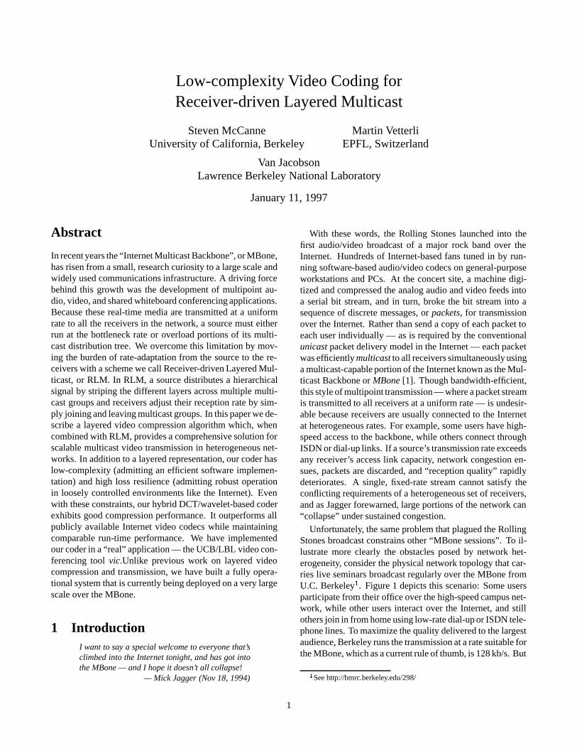
Figure 2: Layered Video. A layered codec produces a cumulativeset of layers where information is combined across layers to produceprogressive refinement. Each decoder module D is capable of de-coding any cumulative set of bit strings. Here we show an imageat multiple resolutions but the refinement can occur across other di-mensions like frame rate or signal-to-noise ratio.
with a set of independent encoders each producing a differ-ent output rate (e.g., through controlled quantization, pixelsubsampling, or frame subsampling). This approach, oftencalled simulcast, has the advantage that we can use exist-ing codecs and/or compression algorithms as system com-ponents. However, because simulcast does not exploit sta-tistical correlations across sub-flows, its compression perfor-mance is suboptimal.
In contrast, a layered coder exploits correlations acrosssub-flows to achieve better overall compression. The inputsignal is compressed into a number of discrete layers, ar-ranged in a hierarchy that provides progressive refinement.For example, if only the first layer is received, the decoderproduces the lowest quality version of the signal. If, on theother hand, the decoder receives two layers, it combines thesecond layer information with the first layer to produce im-proved quality. Overall, the quality progressively improveswith the number of layers that are received and decoded.
The structure of such a layered video coder is depicted inFigure 2. The input video is compressed to produce a set oflogically distinct output strings on channels L0, L1, : : :, andeach decoder module D is capable of decoding any cumula-tive set of bit strings. Each additional string produces an im-provement in reconstruction quality.
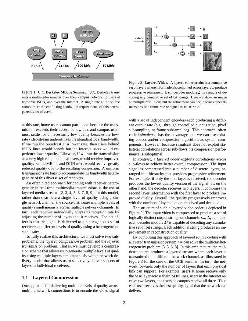
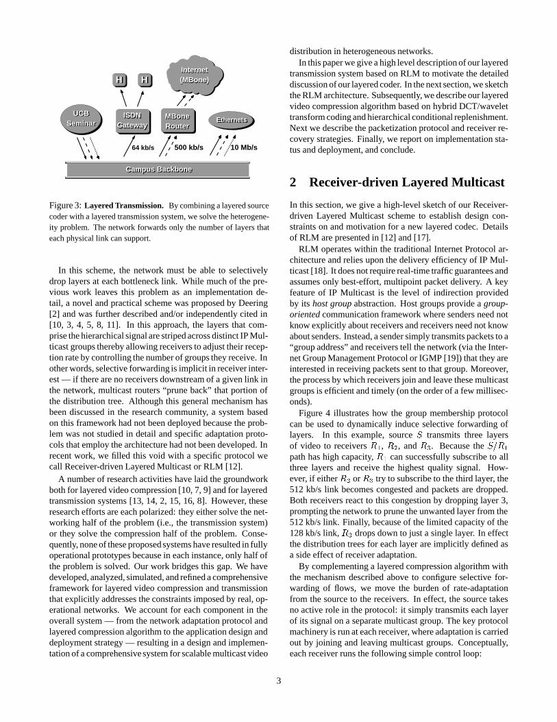
By combining this approach of layered source coding witha layered transmission system, we can solve the multicast het-erogeneity problem [3, 5, 6, 8]. In this architecture, the mul-ticast source produces a layered stream where each layer istransmitted on a different network channel, as illustrated inFigure 3 for the case of the UCB seminar. In turn, the net-work forwards only the number of layers that each physicallink can support. For example, users at home receive onlythe base layer across their ISDN lines, users in the Internet re-ceive two layers, and users on campus receive all three. Thuseach user receives the best quality signal that the network candeliver.
2
64 kb/s
ISDNGateway Router
MBone
HH
Ethernets
Campus Backbone
UCBSeminar EthernetsMBone
Router
ISDNGateway
(MBone)HInternet
H
10 Mb/s500 kb/s
UCBSeminar
Internet(MBone)
Campus Backbone
Figure 3: Layered Transmission. By combining a layered sourcecoder with a layered transmission system, we solve the heterogene-ity problem. The network forwards only the number of layers thateach physical link can support.
In this scheme, the network must be able to selectivelydrop layers at each bottleneck link. While much of the pre-vious work leaves this problem as an implementation de-tail, a novel and practical scheme was proposed by Deering[2] and was further described and/or independently cited in[10, 3, 4, 5, 8, 11]. In this approach, the layers that com-prise the hierarchical signal are striped across distinct IP Mul-ticast groups thereby allowing receivers to adjust their recep-tion rate by controlling the number of groups they receive. Inother words, selective forwarding is implicit in receiver inter-est — if there are no receivers downstream of a given link inthe network, multicast routers “prune back” that portion ofthe distribution tree. Although this general mechanism hasbeen discussed in the research community, a system basedon this framework had not been deployed because the prob-lem was not studied in detail and specific adaptation proto-cols that employ the architecture had not been developed. Inrecent work, we filled this void with a specific protocol wecall Receiver-driven Layered Multicast or RLM [12].
A number of research activities have laid the groundworkboth for layered video compression [10, 7, 9] and for layeredtransmission systems [13, 14, 2, 15, 16, 8]. However, theseresearch efforts are each polarized: they either solve the net-working half of the problem (i.e., the transmission system)or they solve the compression half of the problem. Conse-quently, none of these proposed systems have resulted in fullyoperational prototypes because in each instance, only half ofthe problem is solved. Our work bridges this gap. We havedeveloped, analyzed, simulated, and refined a comprehensiveframework for layered video compression and transmissionthat explicitly addresses the constraints imposed by real, op-erational networks. We account for each component in theoverall system — from the network adaptation protocol andlayered compression algorithm to the application design anddeployment strategy — resulting in a design and implemen-tation of a comprehensive system for scalable multicast video
distribution in heterogeneous networks.In this paper we give a high level description of our layered
transmission system based on RLM to motivate the detaileddiscussion of our layered coder. In the next section, we sketchthe RLM architecture. Subsequently, we describe our layeredvideo compression algorithm based on hybrid DCT/wavelettransform coding and hierarchical conditional replenishment.Next we describe the packetization protocol and receiver re-covery strategies. Finally, we report on implementation sta-tus and deployment, and conclude.
2 Receiver-driven Layered Multicast
In this section, we give a high-level sketch of our Receiver-driven Layered Multicast scheme to establish design con-straints on and motivation for a new layered codec. Detailsof RLM are presented in [12] and [17].
RLM operates within the traditional Internet Protocol ar-chitecture and relies upon the delivery efficiency of IP Mul-ticast [18]. It does not require real-time traffic guarantees andassumes only best-effort, multipoint packet delivery. A keyfeature of IP Multicast is the level of indirection providedby its host group abstraction. Host groups provide a group-oriented communication framework where senders need notknow explicitly about receivers and receivers need not knowabout senders. Instead, a sender simply transmits packets to a“group address” and receivers tell the network (via the Inter-net Group Management Protocol or IGMP [19]) that they areinterested in receiving packets sent to that group. Moreover,the process by which receivers join and leave these multicastgroups is efficient and timely (on the order of a few millisec-onds).
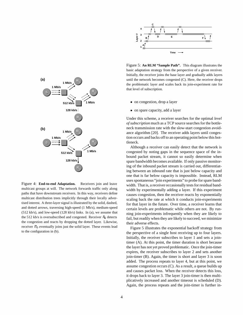
Figure 4 illustrates how the group membership protocolcan be used to dynamically induce selective forwarding oflayers. In this example, source S transmits three layersof video to receivers R1, R2, and R3. Because the S=R1
path has high capacity, R1 can successfully subscribe to allthree layers and receive the highest quality signal. How-ever, if either R2 or R3 try to subscribe to the third layer, the512 kb/s link becomes congested and packets are dropped.Both receivers react to this congestion by dropping layer 3,prompting the network to prune the unwanted layer from the512 kb/s link. Finally, because of the limited capacity of the128 kb/s link, R3 drops down to just a single layer. In effectthe distribution trees for each layer are implicitly defined asa side effect of receiver adaptation.
By complementing a layered compression algorithm withthe mechanism described above to configure selective for-warding of flows, we move the burden of rate-adaptationfrom the source to the receivers. In effect, the source takesno active role in the protocol: it simply transmits each layerof its signal on a separate multicast group. The key protocolmachinery is run at each receiver, where adaptation is carriedout by joining and leaving multicast groups. Conceptually,each receiver runs the following simple control loop:
3
S
2
R3
S
R1
2R
R
1
3
R
R
128 kb/s
1 Mb/s
128 kb/s
512 kb/s
(a)
(b)
1 Mb/s
S
S
1 Mb/s
1 Mb/s512 kb/s
3
1 Mb/s
1 Mb/s
2
R
3R
R1
R2
R
1R
Figure 4: End-to-end Adaptation. Receivers join and leavemulticast groups at will. The network forwards traffic only alongpaths that have downstream receivers. In this way, receivers definemulticast distribution trees implicitly through their locally adver-tised interest. A three-layer signal is illustrated by the solid, dashed,and dotted arrows, traversing high-speed (1 Mb/s), medium-speed(512 kb/s), and low-speed (128 kb/s) links. In (a), we assume thatthe 512 kb/s is oversubscribed and congested. Receiver R2 detectsthe congestion and reacts by dropping the dotted layer. Likewise,receiver R3 eventually joins just the solid layer. These events leadto the configuration in (b).
A
4
3
2
1
DFB
Lay
er #
Time
C
E
Figure 5: An RLM “Sample Path”. This diagram illustrates thebasic adaptation strategy from the perspective of a given receiver.Initially, the receiver joins the base layer and gradually adds layersuntil the network becomes congested (C). Here, the receiver dropsthe problematic layer and scales back its join-experiment rate forthat level of subscription.
� on congestion, drop a layer
� on spare capacity, add a layer
Under this scheme, a receiver searches for the optimal levelof subscription much as a TCP source searches for the bottle-neck transmission rate with the slow-start congestion avoid-ance algorithm [20]. The receiver adds layers until conges-tion occurs and backs off to an operating point below this bot-tleneck.
Although a receiver can easily detect that the network iscongested by noting gaps in the sequence space of the in-bound packet stream, it cannot so easily determine whenspare bandwidth becomes available. If only passive monitor-ing of the inbound packet stream is carried out, differentiat-ing between an inbound rate that is just below capacity andone that is far below capacity is impossible. Instead, RLMuses spontaneous “join experiments” to probe for spare band-width. That is, a receiver occasionally tests for residual band-width by experimentally adding a layer. If this experimentcauses congestion, then the receiver reacts by exponentiallyscaling back the rate at which it conducts join-experimentsfor that layer in the future. Over time, a receiver learns thatcertain levels are problematic while others are not. By run-ning join-experiments infrequently when they are likely tofail, but readily when they are likely to succeed, we minimizetheir adverse effects.
Figure 5 illustrates the exponential backoff strategy fromthe perspective of a single host receiving up to four layers.Initially, the receiver subscribes to layer 1 and sets a join-timer (A). At this point, the timer duration is short becausethe layer has not yet proved problematic. Once the join-timerexpires, the receiver subscribes to layer 2 and sets anotherjoin-timer (B). Again, the timer is short and layer 3 is soonadded. The process repeats to layer 4, but at this point, weassume congestion occurs (C). As a result, a queue builds upand causes packet loss. When the receiver detects this loss,it drops back to layer 3. The layer 3 join-timer is then multi-plicatively increased and another timeout is scheduled (D).Again, the process repeats and the join-timer is further in-
4
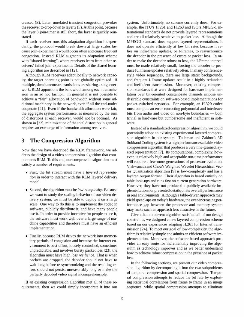
creased (E). Later, unrelated transient congestion provokesthe receiver to drop down to layer 2 (F). At this point, becausethe layer 3 join-timer is still short, the layer is quickly rein-stated.
If each receiver runs this adaptation algorithm indepen-dently, the protocol would break down at large scales be-cause join-experiments would occur often and cause frequentcongestion. Instead, RLM augments its adaptation schemewith “shared learning”, where receivers learn from other re-ceivers’ failed join-experiments. Details of the shared learn-ing algorithm are described in [12].
Although RLM receivers adapt locally to network capac-ity, the target operating point is not globally optimized. Ifmultiple, simultaneous transmissions are sharing a single net-work, RLM apportions the bandwidth among each transmis-sion in an ad hoc fashion. In general it is not possible toachieve a “fair” allocation of bandwidth without some ad-ditional machinery in the network, even if all the end-nodescooperate [21]. Even if the bandwidth allocation were fair,the aggregate system performance, as measured by the sumof distortions at each receiver, would not be optimal. Asshown in [22], minimization of the total distortion in generalrequires an exchange of information among receivers.
3 The Compression Algorithm
Now that we have described the RLM framework, we ad-dress the design of a video compression algorithm that com-plements RLM. To this end, our compression algorithm mustsatisfy a number of requirements:
� First, the bit stream must have a layered representa-tion in order to interact with the RLM layered deliverymodel.
� Second, the algorithm must be low-complexity. Becausewe want to study the scaling behavior of our video de-livery system, we must be able to deploy it on a largescale. One way to do this is to implement the codec insoftware, publicly distribute it, and have many peopleuse it. In order to provide incentive for people to use it,the software must work well over a large range of ma-chine capabilities and therefore must have an efficientimplementation.
� Finally, because RLM drives the network into momen-tary periods of congestion and because the Internet en-vironment is best-effort, loosely controlled, sometimesunpredictable, and involves bursty packet loss [23], thealgorithm must have high loss resilience. That is whenpackets are dropped, the decoder should not have towait long before re-synchronizing and the resulting er-rors should not persist unreasonably long or make thepartially decoded video signal incomprehensible.
If an existing compression algorithm met all of these re-quirements, then we could simply incorporate it into our
system. Unfortunately, no scheme currently does. For ex-ample, the ITU’s H.261 and H.263 and ISO’s MPEG-1 in-ternational standards do not provide layered representationsand are all relatively sensitive to packet loss. Although theMPEG-2 standard does support layered representations, itdoes not operate efficiently at low bit rates because it re-lies on intra-frame updates, or I-Frames, to resynchronizethe decoder in the presence of errors or packet loss. In or-der to make the decoder robust to loss, the I-Frame intervalmust be made relatively small, forcing the encoder to pro-duce full frame updates relatively often. In many conference-style video sequences, there are large static backgrounds,and frequent I-Frame updates result in a highly redundantand inefficient transmission. Moreover, existing compres-sion standards that were designed for hardware implemen-tation over bit-oriented constant-rate channels impose un-desirable constraints on software-based implementations forpacket-switched networks. For example, an H.320 codecmust compute an error-correcting polynomial and interleavebits from audio and video on non-byte boundaries — bothtrivial in hardware but cumbersome and inefficient in soft-ware.
Instead of a standardized compression algorithm, we couldpotentially adopt an existing experimental layered compres-sion algorithm in our system. Taubman and Zakhor’s 3DSubband Coding system is a high performance scalable videocompression algorithm that produces a very fine-grained lay-ered representation [7]. Its computational complexity, how-ever, is relatively high and acceptable run-time performancewill require a few more generations of processor evolution.Vishwanath and Chou’s Weighted Wavelet Hierarchical Vec-tor Quantization algorithm [9] is low-complexity and has alayered output format. Their algorithm is based entirely ontable look-ups and runs fast on current generation hardware.However, they have not produced a publicly available im-plementation nor presented details on its overall performancein real environments. Although a table-driven approach mayyield speed-ups on today’s hardware, the ever-increasing per-formance gap between the processor and memory systemmay make such an approach less attractive in the future.
Given that no current algorithm satisfied all of our designconstraints, we designed a new layered compression schemebased on our experiences adapting H.261 for Internet trans-mission [24]. To meet our goal of low-complexity, the algo-rithm is relatively simple and admits an efficient software im-plementation. Moreover, the software-based approach pro-vides an easy route for incrementally improving the algo-rithm as technology improves and as we better understandhow to achieve robust compression in the presence of packetloss.
In the following sections, we present our video compres-sion algorithm by decomposing it into the two subproblemsof temporal compression and spatial compression. Tempo-ral compression attempts to reduce the bit rate by exploit-ing statistical correlations from frame to frame in an imagesequence, while spatial compression attempts to eliminate
5
redundancies by exploiting statistical correlations within agiven frame. Our algorithm employs a very simple model fortemporal compression known as block-based conditional re-plenishment [24, 25], and uses a hybrid DCT/subband trans-form coding scheme for spatial compression. In the nextsection, we describe the conditional replenishment algorithmand in the subsequent section, we describe the spatial com-pression algorithm.
3.1 Temporal Compression
In block-based conditional replenishment, the input imageis gridded into small blocks (e.g., 8x8 or 16x16 pixels) andonly the blocks that change in each new frame are encodedand transmitted. Several existing Internet video tools usethis approach (e.g., our tool vic [24], the Xerox PARC Net-work Video nv [26] and Cornell’s CU-SeeMe [27]) and somecommercial H.261 codecs send “block skip codes” for staticblocks.
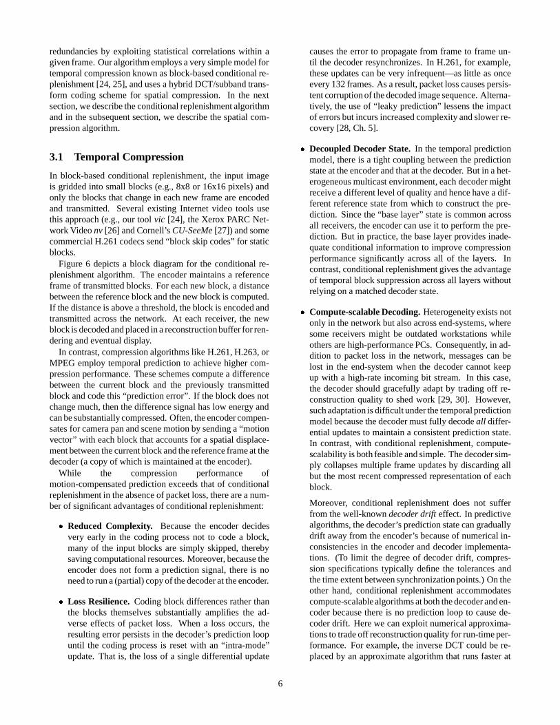
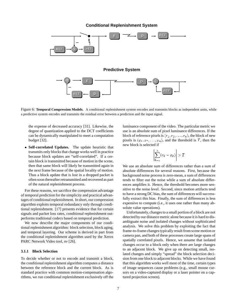
Figure 6 depicts a block diagram for the conditional re-plenishment algorithm. The encoder maintains a referenceframe of transmitted blocks. For each new block, a distancebetween the reference block and the new block is computed.If the distance is above a threshold, the block is encoded andtransmitted across the network. At each receiver, the newblock is decoded and placed in a reconstruction buffer for ren-dering and eventual display.
In contrast, compression algorithms like H.261, H.263, orMPEG employ temporal prediction to achieve higher com-pression performance. These schemes compute a differencebetween the current block and the previously transmittedblock and code this “prediction error”. If the block does notchange much, then the difference signal has low energy andcan be substantially compressed. Often, the encoder compen-sates for camera pan and scene motion by sending a “motionvector” with each block that accounts for a spatial displace-ment between the current block and the reference frame at thedecoder (a copy of which is maintained at the encoder).
While the compression performance ofmotion-compensated prediction exceeds that of conditionalreplenishment in the absence of packet loss, there are a num-ber of significant advantages of conditional replenishment:
� Reduced Complexity. Because the encoder decidesvery early in the coding process not to code a block,many of the input blocks are simply skipped, therebysaving computational resources. Moreover, because theencoder does not form a prediction signal, there is noneed to run a (partial) copy of the decoder at the encoder.
� Loss Resilience. Coding block differences rather thanthe blocks themselves substantially amplifies the ad-verse effects of packet loss. When a loss occurs, theresulting error persists in the decoder’s prediction loopuntil the coding process is reset with an “intra-mode”update. That is, the loss of a single differential update
causes the error to propagate from frame to frame un-til the decoder resynchronizes. In H.261, for example,these updates can be very infrequent—as little as onceevery 132 frames. As a result, packet loss causes persis-tent corruption of the decoded image sequence. Alterna-tively, the use of “leaky prediction” lessens the impactof errors but incurs increased complexity and slower re-covery [28, Ch. 5].
� Decoupled Decoder State. In the temporal predictionmodel, there is a tight coupling between the predictionstate at the encoder and that at the decoder. But in a het-erogeneous multicast environment, each decoder mightreceive a different level of quality and hence have a dif-ferent reference state from which to construct the pre-diction. Since the “base layer” state is common acrossall receivers, the encoder can use it to perform the pre-diction. But in practice, the base layer provides inade-quate conditional information to improve compressionperformance significantly across all of the layers. Incontrast, conditional replenishment gives the advantageof temporal block suppression across all layers withoutrelying on a matched decoder state.
� Compute-scalable Decoding. Heterogeneity exists notonly in the network but also across end-systems, wheresome receivers might be outdated workstations whileothers are high-performance PCs. Consequently, in ad-dition to packet loss in the network, messages can belost in the end-system when the decoder cannot keepup with a high-rate incoming bit stream. In this case,the decoder should gracefully adapt by trading off re-construction quality to shed work [29, 30]. However,such adaptation is difficult under the temporal predictionmodel because the decoder must fully decode all differ-ential updates to maintain a consistent prediction state.In contrast, with conditional replenishment, compute-scalability is both feasible and simple. The decoder sim-ply collapses multiple frame updates by discarding allbut the most recent compressed representation of eachblock.
Moreover, conditional replenishment does not sufferfrom the well-known decoder drift effect. In predictivealgorithms, the decoder’s prediction state can graduallydrift away from the encoder’s because of numerical in-consistencies in the encoder and decoder implementa-tions. (To limit the degree of decoder drift, compres-sion specifications typically define the tolerances andthe time extent between synchronization points.) On theother hand, conditional replenishment accommodatescompute-scalable algorithms at both the decoder and en-coder because there is no prediction loop to cause de-coder drift. Here we can exploit numerical approxima-tions to trade off reconstruction quality for run-time per-formance. For example, the inverse DCT could be re-placed by an approximate algorithm that runs faster at
6
Conditional Replenishment System
Predictive System
REF
E
REF D
E
D
D
>T?
REF
REF
D
>T?
E REF
DREF
E
REF
D
REF
Figure 6: Temporal Compression Models. A conditional replenishment system encodes and transmits blocks as independent units, whilea predictive system encodes and transmits the residual error between a prediction and the input signal.
the expense of decreased accuracy [31]. Likewise, thedegree of quantization applied to the DCT coefficientscan be dynamically manipulated to meet a computationbudget [32].
� Self-correlated Updates. The update heuristic thattransmits only blocks that change works well in practicebecause block updates are “self-correlated”. If a cer-tain block is transmitted because of motion in the scene,then that same block will likely be transmitted again inthe next frame because of the spatial locality of motion.Thus a block update that is lost in a dropped packet isoften soon thereafter retransmitted and recovered as partof the natural replenishment process.
For these reasons, we sacrifice the compression advantageof temporal prediction for the simplicity and practical advan-tages of conditional replenishment. In short, our compressionalgorithm exploits temporal redundancy only through condi-tional replenishment. [17] presents evidence that for certainsignals and packet loss rates, conditional replenishment out-performs traditional codecs based on temporal prediction.
We now describe the major components of our condi-tional replenishment algorithm: block selection, block aging,and temporal layering. Our scheme is derived in part fromthe conditional replenishment algorithm used by the XeroxPARC Network Video tool, nv [26].
3.1.1 Block Selection
To decide whether or not to encode and transmit a block,the conditional replenishment algorithm computes a distancebetween the reference block and the current block. As isstandard practice with common motion-compensation algo-rithms, we run conditional replenishment exclusively off the
luminance component of the video. The particular metric weuse is an absolute sum of pixel luminance differences. If theblock of reference pixels is (r1; r2; : : : ; rn), the block of newpixels is (x1; x2; : : : ; xn), and the threshold is T , then thenew block is selected if
�����
nX
k=1
(rk � xk)
����� > T
We use an absolute sum of differences rather than a sum ofabsolute differences for several reasons. First, because thebackground noise process is zero-mean, a sum of differencestends to filter out the noise while a sum of absolute differ-ences amplifies it. Hence, the threshold becomes more sen-sitive to the noise level. Second, since motion artifacts tendto have a strong DC bias, the sum of differences will success-fully extract this bias. Finally, the sum of differences is lessexpensive to compute (i.e., it uses one rather than many ab-solute value operations).
Unfortunately, changes to a small portion of a block are notdetected by our distance metric alone because it is hard to dis-ambiguate noise and isolated changes without sophisticatedanalysis. We solve this problem by exploiting the fact thatframe-to-frame changes typically result from scene motion orcamera pan, and both of these processes create large spans ofspatially correlated pixels. Hence, we assume that isolatedchanges occur to a block only when there are large changesto an adjacent block. We give up on detecting small, iso-lated changes and simply “spread” the block selection deci-sion from one block to adjacent blocks. While we have foundthat this algorithm works well most of the time, certain typesof image sequences cause problems (e.g., small mouse cur-sors on a video-captured display or a laser pointer on a cap-tured projection screen).
7
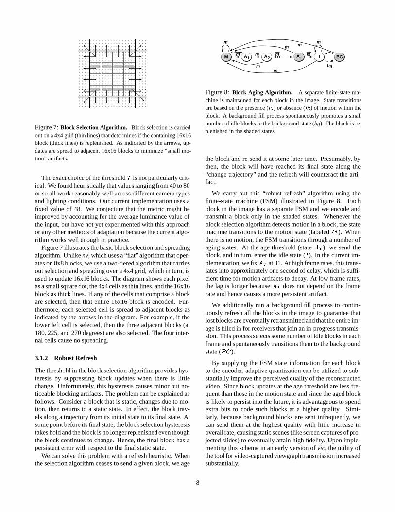
Figure 7: Block Selection Algorithm. Block selection is carriedout on a 4x4 grid (thin lines) that determines if the containing 16x16block (thick lines) is replenished. As indicated by the arrows, up-dates are spread to adjacent 16x16 blocks to minimize “small mo-tion” artifacts.
The exact choice of the threshold T is not particularly crit-ical. We found heuristically that values ranging from 40 to 80or so all work reasonably well across different camera typesand lighting conditions. Our current implementation uses afixed value of 48. We conjecture that the metric might beimproved by accounting for the average luminance value ofthe input, but have not yet experimented with this approachor any other methods of adaptation because the current algo-rithm works well enough in practice.
Figure 7 illustrates the basic block selection and spreadingalgorithm. Unlike nv, which uses a “flat” algorithm that oper-ates on 8x8 blocks, we use a two-tiered algorithm that carriesout selection and spreading over a 4x4 grid, which in turn, isused to update 16x16 blocks. The diagram shows each pixelas a small square dot, the 4x4 cells as thin lines, and the 16x16block as thick lines. If any of the cells that comprise a blockare selected, then that entire 16x16 block is encoded. Fur-thermore, each selected cell is spread to adjacent blocks asindicated by the arrows in the diagram. For example, if thelower left cell is selected, then the three adjacent blocks (at180, 225, and 270 degrees) are also selected. The four inter-nal cells cause no spreading.
3.1.2 Robust Refresh
The threshold in the block selection algorithm provides hys-teresis by suppressing block updates when there is littlechange. Unfortunately, this hysteresis causes minor but no-ticeable blocking artifacts. The problem can be explained asfollows. Consider a block that is static, changes due to mo-tion, then returns to a static state. In effect, the block trav-els along a trajectory from its initial state to its final state. Atsome point before its final state, the block selection hysteresistakes hold and the block is no longer replenished even thoughthe block continues to change. Hence, the final block has apersistent error with respect to the final static state.
We can solve this problem with a refresh heuristic. Whenthe selection algorithm ceases to send a given block, we age
m
m
m m
m
bg
mm
m
m
m
BGM IA TA2A1
Figure 8: Block Aging Algorithm. A separate finite-state ma-chine is maintained for each block in the image. State transitionsare based on the presence (m) or absence (m) of motion within theblock. A background fill process spontaneously promotes a smallnumber of idle blocks to the background state (bg). The block is re-plenished in the shaded states.
the block and re-send it at some later time. Presumably, bythen, the block will have reached its final state along the“change trajectory” and the refresh will counteract the arti-fact.
We carry out this “robust refresh” algorithm using thefinite-state machine (FSM) illustrated in Figure 8. Eachblock in the image has a separate FSM and we encode andtransmit a block only in the shaded states. Whenever theblock selection algorithm detects motion in a block, the statemachine transitions to the motion state (labeled M ). Whenthere is no motion, the FSM transitions through a number ofaging states. At the age threshold (state AT ), we send theblock, and in turn, enter the idle state (I). In the current im-plementation, we fixAT at 31. At high frame rates, this trans-lates into approximately one second of delay, which is suffi-cient time for motion artifacts to decay. At low frame rates,the lag is longer because AT does not depend on the framerate and hence causes a more persistent artifact.
We additionally run a background fill process to contin-uously refresh all the blocks in the image to guarantee thatlost blocks are eventually retransmitted and that the entire im-age is filled in for receivers that join an in-progress transmis-sion. This process selects some number of idle blocks in eachframe and spontaneously transitions them to the backgroundstate (BG).
By supplying the FSM state information for each blockto the encoder, adaptive quantization can be utilized to sub-stantially improve the perceived quality of the reconstructedvideo. Since block updates at the age threshold are less fre-quent than those in the motion state and since the aged blockis likely to persist into the future, it is advantageous to spendextra bits to code such blocks at a higher quality. Simi-larly, because background blocks are sent infrequently, wecan send them at the highest quality with little increase inoverall rate, causing static scenes (like screen captures of pro-jected slides) to eventually attain high fidelity. Upon imple-menting this scheme in an early version of vic, the utility ofthe tool for video-captured viewgraph transmission increasedsubstantially.
8

motion stops here4
1
Time
3
2
Lay
er
Figure 9: Temporal Layering. We extend the conditional replen-ishment algorithm to produce multiple rates by striping block up-dates across different output layers. When a block becomes idle, we“slide it” down the layer hierarchy to guarantee that the most up-to-date version appears on the base layer.
3.1.3 Temporal Layering
The conditional replenishment algorithm described abovegenerates a single rate of block updates for a given inputframe rate. We can extend the algorithm to produce multi-ple rates in a temporal hierarchy by splitting block updatesinto separate layers. One well-known approach for creatinga temporal hierarchy is temporal subband decomposition. Tothis end, we could carry out subband analysis on a block gran-ularity and extend the block update across the next power oftwo interval for which the block remains active. Unfortu-nately, this introduces complexity and extra delay over sim-ple conditional replenishment.
Instead, we utilize our robust block refresh algorithm andstripe block updates across different layers to provide multi-ple frame rates. To produce a graceful degradation in framerates, we arrange the subsampled frames so that any set oflayers produces frames spaced evenly over time. We do thisas follows. Assuming there areM+1 layers, we assign layerLM (n) to all block updates during frame time n, where
LM (n) = M � r(n mod 2M + 2M ) + 1
with
r(n) = minfk > 0 : bn=2kc2k 6= ng � 1
i.e., r(n) is the bit position (numbered from 0) of the right-most non-zero bit in the binary representation of n.
The hierarchy that results in the case for M = 4 is shownin Figure 9. If the receiver processes all four layers, thenthe resulting frame rate is maximal. If the receiver processesonly three layers, the frame rate is half the maximum rate. Fortwo layers, it is one-fourth, and so on.
As long as a block is continuously transmitted, this schemeworks well. But when a block undergoing motion becomesinactive and its last update occurs on any layer k with k > 1,that block position will be inconsistent on all layers l such
that l < k. A simple remedy is to force the block update inthe age-threshold state onto layer 1, thereby limiting the timeextent of the inconsistency. We tried this approach, but thequalitative performance was unsatisfactory because the blockartifacts were too noticeable for too long. Instead, when ablock becomes inactive at time n0, we transmit it addition-ally at times given by
minfn � n0 : LM (n) = kg
for k = 1 : : : LM (n0). In other words, after a block becomesinactive, it “slides down” the layer hierarchy. As indicated bythe gray blocks in Figure 9, we transmit a block update at eachinferior layer down to layer 1. At that point, the block under-goes the aging algorithm and is eventually re-sent on layer 1in the age-threshold state.
The overhead incurred by the redundant block transmis-sions is not as great as it may seem. Because the redundantblock updates only occur after a block under motion becomesinactive, the overall redundancy is inversely proportional thelength of this “active period”. Moreover, the redundancypresent in lower-rate layers, where bandwidth is critical, isless than that in higher-rate layers. For example, layer 1 alonenever has a redundant block update, while the full hierarchycontains the maximum number of redundant updates. [17]contains a detailed analysis of this overhead.
3.2 Spatial Compression
After the conditional replenishment stage selects blocks fortransmission, they are compressed spatially. In this section,we describe the layered spatial compression algorithm that isapplied to each block.
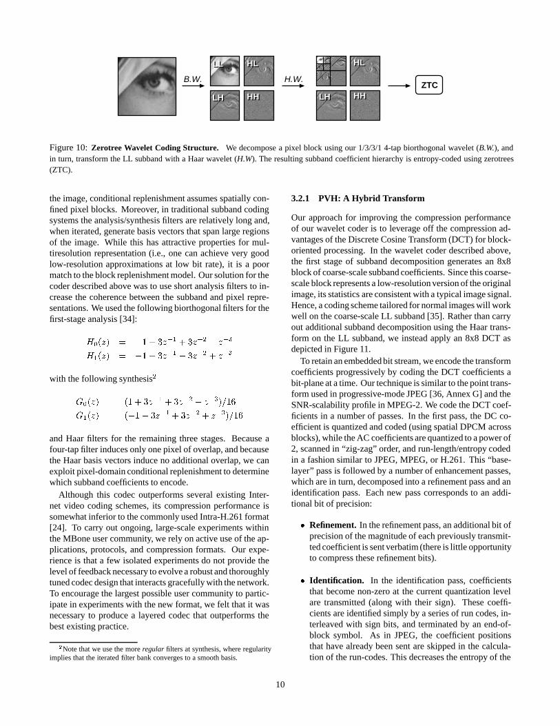
The first version of our coder [5] utilized subband decom-position since this approach induces an inherently layeredrepresentation. In this coder, we carry out subband decompo-sition over the entire image and then use pixel-domain con-ditional replenishment to determine the subband coefficientsto transmit. We first perform subband analysis horizontallyacross the image to yield low- and high-frequency represen-tations of the signal, commonly called the L and H subbands.In turn, we apply the same low/high frequency decomposi-tion vertically yielding a total of four subbands: the coarse-scale LL subband, containing a low resolution version of thesignal, and the enhancement subbands containing horizontaldetail (HL), vertical detail (LH) and diagonal detail (HH). Af-ter subband analysis, we encode those subband coefficientswhose basis vectors are spatially centered over each selectedpixel block. We then group the coefficients across scales withlike orientation into the well-known quad-tree structure, andthen entropy-code them using a variant of Shapiro’s schemefor Embedded Zerotrees of Wavelet coefficients (EZW) [33].This coding structure is illustrated in Figure 10.
Unfortunately, a tension arises between subband decom-position and conditional replenishment. While subband de-composition induces a multiscale structure where transformcoefficients correspond to multiple overlapping regions of
9
LL
LHLH
HL
HH
HL
HH
H.W.B.W.
HL
HH
HL
HH
LL
LHLHZTC
Figure 10: Zerotree Wavelet Coding Structure. We decompose a pixel block using our 1/3/3/1 4-tap biorthogonal wavelet (B.W.), andin turn, transform the LL subband with a Haar wavelet (H.W). The resulting subband coefficient hierarchy is entropy-coded using zerotrees(ZTC).
the image, conditional replenishment assumes spatially con-fined pixel blocks. Moreover, in traditional subband codingsystems the analysis/synthesis filters are relatively long and,when iterated, generate basis vectors that span large regionsof the image. While this has attractive properties for mul-tiresolution representation (i.e., one can achieve very goodlow-resolution approximations at low bit rate), it is a poormatch to the block replenishment model. Our solution for thecoder described above was to use short analysis filters to in-crease the coherence between the subband and pixel repre-sentations. We used the following biorthogonal filters for thefirst-stage analysis [34]:
H0(z) = �1 + 3z�1 + 3z�2 � z�3
H1(z) = �1 + 3z�1 � 3z�2 + z�3
with the following synthesis2
G0(z) = (1 + 3z�1 + 3z�2 + z�3)=16
G1(z) = (�1� 3z�1 + 3z�2 + z�3)=16
and Haar filters for the remaining three stages. Because afour-tap filter induces only one pixel of overlap, and becausethe Haar basis vectors induce no additional overlap, we canexploit pixel-domain conditional replenishment to determinewhich subband coefficients to encode.
Although this codec outperforms several existing Inter-net video coding schemes, its compression performance issomewhat inferior to the commonly used Intra-H.261 format[24]. To carry out ongoing, large-scale experiments withinthe MBone user community, we rely on active use of the ap-plications, protocols, and compression formats. Our expe-rience is that a few isolated experiments do not provide thelevel of feedback necessary to evolve a robust and thoroughlytuned codec design that interacts gracefully with the network.To encourage the largest possible user community to partic-ipate in experiments with the new format, we felt that it wasnecessary to produce a layered codec that outperforms thebest existing practice.
2Note that we use the more regular filters at synthesis, where regularityimplies that the iterated filter bank converges to a smooth basis.
3.2.1 PVH: A Hybrid Transform
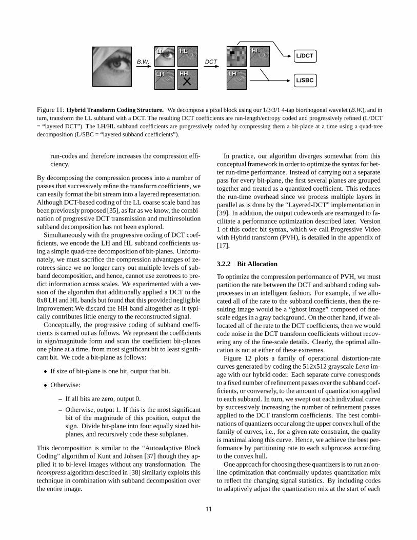
Our approach for improving the compression performanceof our wavelet coder is to leverage off the compression ad-vantages of the Discrete Cosine Transform (DCT) for block-oriented processing. In the wavelet coder described above,the first stage of subband decomposition generates an 8x8block of coarse-scale subband coefficients. Since this coarse-scale block represents a low-resolution version of the originalimage, its statistics are consistent with a typical image signal.Hence, a coding scheme tailored for normal images will workwell on the coarse-scale LL subband [35]. Rather than carryout additional subband decomposition using the Haar trans-form on the LL subband, we instead apply an 8x8 DCT asdepicted in Figure 11.
To retain an embedded bit stream, we encode the transformcoefficients progressively by coding the DCT coefficients abit-plane at a time. Our technique is similar to the point trans-form used in progressive-mode JPEG [36, Annex G] and theSNR-scalability profile in MPEG-2. We code the DCT coef-ficients in a number of passes. In the first pass, the DC co-efficient is quantized and coded (using spatial DPCM acrossblocks), while the AC coefficients are quantized to a power of2, scanned in “zig-zag” order, and run-length/entropy codedin a fashion similar to JPEG, MPEG, or H.261. This “base-layer” pass is followed by a number of enhancement passes,which are in turn, decomposed into a refinement pass and anidentification pass. Each new pass corresponds to an addi-tional bit of precision:
� Refinement. In the refinement pass, an additional bit ofprecision of the magnitude of each previously transmit-ted coefficient is sent verbatim (there is little opportunityto compress these refinement bits).
� Identification. In the identification pass, coefficientsthat become non-zero at the current quantization levelare transmitted (along with their sign). These coeffi-cients are identified simply by a series of run codes, in-terleaved with sign bits, and terminated by an end-of-block symbol. As in JPEG, the coefficient positionsthat have already been sent are skipped in the calcula-tion of the run-codes. This decreases the entropy of the
10
LH
HL
LH
LL HL
HH
B.W. DCTL/DCT
L/SBCHH
HL
LH
HL
LH
LL
Figure 11: Hybrid Transform Coding Structure. We decompose a pixel block using our 1/3/3/1 4-tap biorthogonal wavelet (B.W.), and inturn, transform the LL subband with a DCT. The resulting DCT coefficients are run-length/entropy coded and progressively refined (L/DCT= “layered DCT”). The LH/HL subband coefficients are progressively coded by compressing them a bit-plane at a time using a quad-treedecomposition (L/SBC = “layered subband coefficients”).
run-codes and therefore increases the compression effi-ciency.
By decomposing the compression process into a number ofpasses that successively refine the transform coefficients, wecan easily format the bit stream into a layered representation.Although DCT-based coding of the LL coarse scale band hasbeen previously proposed [35], as far as we know, the combi-nation of progressive DCT transmission and multiresolutionsubband decomposition has not been explored.
Simultaneously with the progressive coding of DCT coef-ficients, we encode the LH and HL subband coefficients us-ing a simple quad-tree decomposition of bit-planes. Unfortu-nately, we must sacrifice the compression advantages of ze-rotrees since we no longer carry out multiple levels of sub-band decomposition, and hence, cannot use zerotrees to pre-dict information across scales. We experimented with a ver-sion of the algorithm that additionally applied a DCT to the8x8 LH and HL bands but found that this provided negligibleimprovement.We discard the HH band altogether as it typi-cally contributes little energy to the reconstructed signal.
Conceptually, the progressive coding of subband coeffi-cients is carried out as follows. We represent the coefficientsin sign/magnitude form and scan the coefficient bit-planesone plane at a time, from most significant bit to least signifi-cant bit. We code a bit-plane as follows:
� If size of bit-plane is one bit, output that bit.
� Otherwise:
– If all bits are zero, output 0.
– Otherwise, output 1. If this is the most significantbit of the magnitude of this position, output thesign. Divide bit-plane into four equally sized bit-planes, and recursively code these subplanes.
This decomposition is similar to the “Autoadaptive BlockCoding” algorithm of Kunt and Johsen [37] though they ap-plied it to bi-level images without any transformation. Thehcompress algorithm described in [38] similarly exploits thistechnique in combination with subband decomposition overthe entire image.
In practice, our algorithm diverges somewhat from thisconceptual framework in order to optimize the syntax for bet-ter run-time performance. Instead of carrying out a separatepass for every bit-plane, the first several planes are groupedtogether and treated as a quantized coefficient. This reducesthe run-time overhead since we process multiple layers inparallel as is done by the “Layered-DCT” implementation in[39]. In addition, the output codewords are rearranged to fa-cilitate a performance optimization described later. Version1 of this codec bit syntax, which we call Progressive Videowith Hybrid transform (PVH), is detailed in the appendix of[17].
3.2.2 Bit Allocation
To optimize the compression performance of PVH, we mustpartition the rate between the DCT and subband coding sub-processes in an intelligent fashion. For example, if we allo-cated all of the rate to the subband coefficients, then the re-sulting image would be a “ghost image” composed of fine-scale edges in a gray background. On the other hand, if we al-located all of the rate to the DCT coefficients, then we wouldcode noise in the DCT transform coefficients without recov-ering any of the fine-scale details. Clearly, the optimal allo-cation is not at either of these extremes.
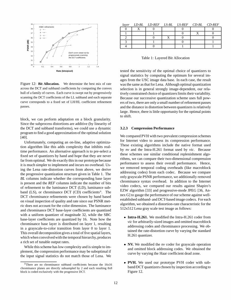
Figure 12 plots a family of operational distortion-ratecurves generated by coding the 512x512 grayscale Lena im-age with our hybrid coder. Each separate curve correspondsto a fixed number of refinement passes over the subband coef-ficients, or conversely, to the amount of quantization appliedto each subband. In turn, we swept out each individual curveby successively increasing the number of refinement passesapplied to the DCT transform coefficients. The best combi-nations of quantizers occur along the upper convex hull of thefamily of curves, i.e., for a given rate constraint, the qualityis maximal along this curve. Hence, we achieve the best per-formance by partitioning rate to each subprocess accordingto the convex hull.
One approach for choosing these quantizers is to run an on-line optimization that continually updates quantization mixto reflect the changing signal statistics. By including codesto adaptively adjust the quantization mix at the start of each
11
Rate (bits/pixel)
PS
NR
(d
B)
Each curve swept out byprogressively scanning
#SBC refinements
the DCT coefficients.
31
0.80.60.40.20 1
0
3
5
4
1.41.2
39
30
32
38
37
36
35
34
33
Figure 12: Bit Allocation. We determine the best mix of rateacross the DCT and subband coefficients by computing the convexhull of a family of curves. Each curve is swept out by progressivelyscanning the DCT coefficients of the LL subband and each separatecurve corresponds to a fixed set of LH/HL coefficient refinementpasses.
block, we can perform adaptation on a block granularity.Since the subprocess distortions are additive (by linearity ofthe DCT and subband transforms), we could use a dynamicprogram to find a good approximation of the optimal solution[40].
Unfortunately, computing an on-line, adaptive optimiza-tion algorithm like this adds complexity that inhibits real-time performance. An alternative approach is to pre-select afixed set of quantizers by hand and hope that they are neverfar from optimal. We do exactly this in our prototype becauseit is much simpler to implement and incurs no overhead. Us-ing the Lena rate-distortion curves from above, we derivethe progressive quantization structure given in Table 1. TheBL columns indicate whether the corresponding base layeris present and the REF columns indicate the number of bitsof refinement to the luminance DCT (LD), luminance sub-band (LS), or chrominance DCT (CD) coefficients3. TheDCT chrominance refinements were chosen by hand basedon visual inspection of quality and rate since our PSNR met-ric does not account for the color dimension. The luminanceand chrominance DCT base-layer coefficients are quantizedwith a uniform quantizer of magnitude 32, while the SBCbase-layer coefficients are quantized by 16. Note how thechrominance base layer is distributed on layer 1, resultingin a grayscale-to-color transition from layer 0 to layer 1.This overall decomposition gives a total of five spatial layers,which when convolved with the temporal hierarchy, producesa rich set of tunable output rates.
While this scheme has low complexity and is simple to im-plement, the compression performance may be suboptimal ifthe input signal statistics do not match those of Lena. We
3There are no chrominance subband coefficients because the 16x16chrominance planes are directly subsampled by 2 and each resulting 8x8block is coded exclusively with the progressive DCT.
layer LD-BL LD-REF LS-BL LS-REF CD-BL CD-REF0 X 0 0 01 1 0 X 02 0 X 0 03 1 0 14 0 1 1
Table 1: Layered Bit Allocation
tested the sensitivity of the optimal choice of quantizers tosignal statistics by computing the optimum for several im-ages from the USC image data base. In each case, the resultwas the same as that for Lena. Although optimal quantizationselection is in general strongly image-dependent, our rela-tively constrained choice of quantizers limits their variability.Because our successive quantization scheme uses full pow-ers of two, there are only a small number of refinement passesand the distance in distortion between quantizers is relativelylarge. Hence, there is little opportunity for the optimal pointsto shift.
3.2.3 Compression Performance
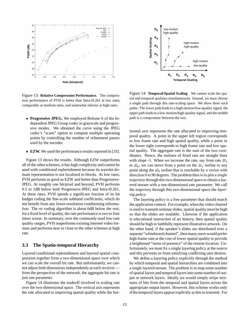
We compared PVH with two prevalent compression schemesfor Internet video to assess its compression performance.These existing algorithms include the native format usedby nv and the Intra-H.261 format used by vic. Becausethese schemes use similar conditional replenishment algo-rithms, we can compare their two-dimensional compressionperformance to assess their overall performance. Hence,we removed temporal coding overheads (like macroblockaddressing codes) from each codec. Because we compareonly grayscale PSNR performance, we additionally removedchrominance syntax overhead. In addition to the Internetvideo codecs, we compared our results against Shapiro’sEZW algorithm [33] and progressive-mode JPEG [36, An-nex G] to gauge the performance of our scheme against well-established subband- and DCT-based image codecs. For eachalgorithm, we obtained a distortion-rate characteristic for the512x512 Lena gray scale test image as follows:
� Intra-H.261. We modified the Intra-H.261 coder fromvic for arbitrarily-sized images and omitted macroblockaddressing codes and chrominance processing. We ob-tained the rate-distortion curve by varying the standardH.261 quantizer.
� NV. We modified the nv coder for grayscale operationand omitted block addressing codes. We obtained thecurve by varying the Haar coefficient dead zone.
� PVH. We used our prototype PVH coder with sub-band/DCT quantizers chosen by inspection according toFigure 12.
12
0.2 0.4 0.6 0.80
36
38
40
42
1
PVHEZW
PS
NR
(d
B)
Rate (bits/pixel)
P-JPG
1.2 1.4 1.6
Intra-H.261NV
34
26
28
30
32
Figure 13: Relative Compression Performance. The compres-sion performance of PVH is better than Intra-H.261 at low rates,comparable at medium rates, and somewhat inferior at high rates.
� Progressive JPEG. We employed Release 6 of the In-dependent JPEG Group codec in grayscale and progres-sive modes. We obtained the curve using the JPEGcodec’s “scans” option to compute multiple operatingpoints by controlling the number of refinement passesused by the encoder.
� EZW. We used the performance results reported in [33].
Figure 13 shows the results. Although EZW outperformsall of the other schemes, it has high complexity and cannot beused with conditional replenishment because its wavelet do-main representation is not localized to blocks. At low rates,PVH performs as good as EZW and better than Progressive-JPEG. At roughly one bit/pixel and beyond, PVH performs0.5 to 1dB below both Progressive-JPEG and Intra-H.261.At these rates, PVH spends a significant fraction of its bitbudget coding the fine-scale subband coefficients, which donot benefit from any lower-resolution conditioning informa-tion. The nv coding algorithm is about 6dB below the rest;for a fixed level of quality, the rate performance is two to fourtimes worse. In summary, over the commonly used low-ratequality ranges, PVH outperforms existing Internet video for-mats and performs near or close to the other schemes at highrate.
3.3 The Spatio-temporal Hierarchy
Layered conditional replenishment and layered spatial com-pression together form a two-dimensional space over whichwe can scale the overall bit rate. But unfortunately, we can-not adjust both dimensions independently at each receiver —from the perspective of the network, the aggregate bit rate isjust one parameter.
Figure 14 illustrates the tradeoff involved in scaling rateover the two-dimensional space. The vertical axis representsthe rate allocated to improving spatial quality while the hor-
R R
R
R
R
R
R
R
2
3
4
5
Temporal Scaling
Sp
atia
l Sca
ling
1
R R1 2 3 4 5
high-motionhigh-quality
high-qualitylow-motion
high-motion
low-quality
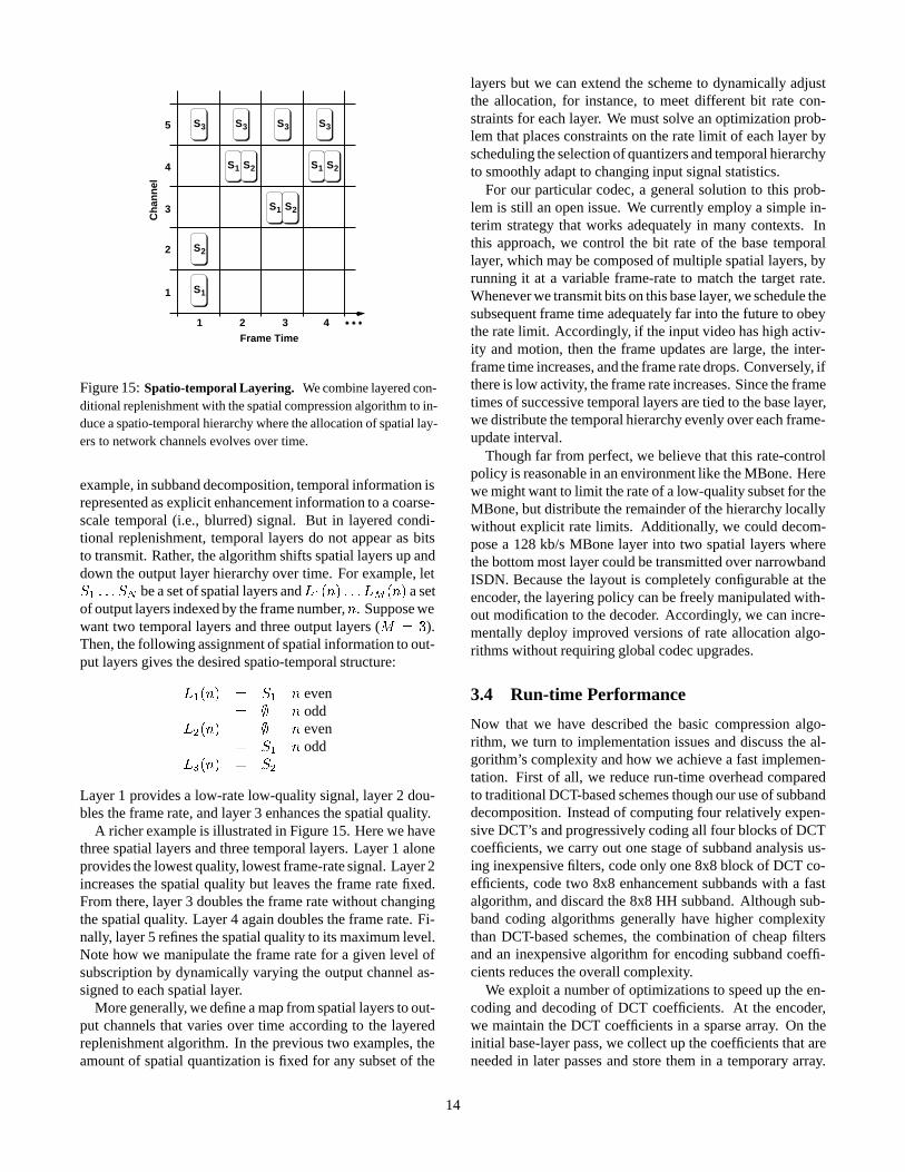
Figure 14: Temporal/Spatial Scaling. We cannot scale the spa-tial and temporal qualities simultaneously. Instead, we must choosea single path through this rate-scaling space. We show three suchpaths: The lower path leads to a high-motion/low-quality signal, theupper path leads to a low-motion/high-quality signal, and the middlepath is a compromise between the two.
izontal axis represents the rate allocated to improving tem-poral quality. A point in the upper left region correspondsto low frame rate and high spatial quality, while a point inthe lower right corresponds to high frame rate and low spa-tial quality. The aggregate rate is the sum of the two coor-dinates. Hence, the isolines of fixed rate are straight lineswith slope -1. When we increase the rate, say from rate R2
to R3, we can move from a point on the R2 isoline to anypoint along the R3 isoline that is reachable by a vector withdirection 0 to 90 degrees. The problem then is to plot a singletrajectory through this two-dimensional space to obtain a lay-ered stream with a one-dimensional rate parameter. We callthe trajectory through this two-dimensional space the layer-ing policy.
The layering policy is a free parameter that should matchthe application context. For example, when the video channelis used to transmit seminar slides, spatial quality must be highso that the slides are readable. Likewise if the applicationis educational instruction of art history, then spatial qualityshould be high to faithfully represent illustrative artwork. Onthe other hand, if the speaker’s slides are distributed over aseparate “whiteboard channel”, then many users would preferhigh frame-rate at the cost of lower spatial quality to providea heightened “sense of presence” of the remote location. Un-fortunately, we must fix a single layering policy at the sourceand this prevents us from satisfying conflicting user desires.
We define a layering policy explicitly through the methodby which temporal and spatial hierarchies are combined intoa single layered stream. The problem is to map some numberof spatial layers and temporal layers into some number of out-put or network layers. Ideally we would simply stripe mix-tures of bits from the temporal and spatial layers across theappropriate output layers. However, this scheme works onlyif the temporal layers appear explicitly as bits to transmit. For
13
S
SS
3
Ch
ann
el
S
4
S
S
2
3 3 3
1 2 1
3
21
Frame Time
1
2
21
5
4
1
2
3
S
S
S S
SS
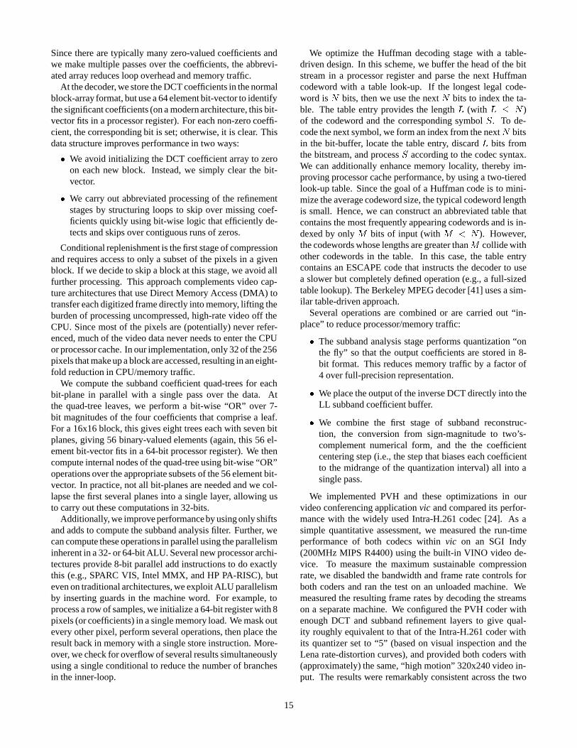
Figure 15: Spatio-temporal Layering. We combine layered con-ditional replenishment with the spatial compression algorithm to in-duce a spatio-temporal hierarchy where the allocation of spatial lay-ers to network channels evolves over time.
example, in subband decomposition, temporal information isrepresented as explicit enhancement information to a coarse-scale temporal (i.e., blurred) signal. But in layered condi-tional replenishment, temporal layers do not appear as bitsto transmit. Rather, the algorithm shifts spatial layers up anddown the output layer hierarchy over time. For example, letS1 : : : SN be a set of spatial layers andL1(n) : : : LM (n) a setof output layers indexed by the frame number,n. Suppose wewant two temporal layers and three output layers (M = 3).Then, the following assignment of spatial information to out-put layers gives the desired spatio-temporal structure:
L1(n) = S1 n even= ; n odd
L2(n) = ; n even= S1 n odd
L3(n) = S2
Layer 1 provides a low-rate low-quality signal, layer 2 dou-bles the frame rate, and layer 3 enhances the spatial quality.
A richer example is illustrated in Figure 15. Here we havethree spatial layers and three temporal layers. Layer 1 aloneprovides the lowest quality, lowest frame-rate signal. Layer 2increases the spatial quality but leaves the frame rate fixed.From there, layer 3 doubles the frame rate without changingthe spatial quality. Layer 4 again doubles the frame rate. Fi-nally, layer 5 refines the spatial quality to its maximum level.Note how we manipulate the frame rate for a given level ofsubscription by dynamically varying the output channel as-signed to each spatial layer.
More generally, we define a map from spatial layers to out-put channels that varies over time according to the layeredreplenishment algorithm. In the previous two examples, theamount of spatial quantization is fixed for any subset of the
layers but we can extend the scheme to dynamically adjustthe allocation, for instance, to meet different bit rate con-straints for each layer. We must solve an optimization prob-lem that places constraints on the rate limit of each layer byscheduling the selection of quantizers and temporal hierarchyto smoothly adapt to changing input signal statistics.
For our particular codec, a general solution to this prob-lem is still an open issue. We currently employ a simple in-terim strategy that works adequately in many contexts. Inthis approach, we control the bit rate of the base temporallayer, which may be composed of multiple spatial layers, byrunning it at a variable frame-rate to match the target rate.Whenever we transmit bits on this base layer, we schedule thesubsequent frame time adequately far into the future to obeythe rate limit. Accordingly, if the input video has high activ-ity and motion, then the frame updates are large, the inter-frame time increases, and the frame rate drops. Conversely, ifthere is low activity, the frame rate increases. Since the frametimes of successive temporal layers are tied to the base layer,we distribute the temporal hierarchy evenly over each frame-update interval.
Though far from perfect, we believe that this rate-controlpolicy is reasonable in an environment like the MBone. Herewe might want to limit the rate of a low-quality subset for theMBone, but distribute the remainder of the hierarchy locallywithout explicit rate limits. Additionally, we could decom-pose a 128 kb/s MBone layer into two spatial layers wherethe bottom most layer could be transmitted over narrowbandISDN. Because the layout is completely configurable at theencoder, the layering policy can be freely manipulated with-out modification to the decoder. Accordingly, we can incre-mentally deploy improved versions of rate allocation algo-rithms without requiring global codec upgrades.
3.4 Run-time Performance
Now that we have described the basic compression algo-rithm, we turn to implementation issues and discuss the al-gorithm’s complexity and how we achieve a fast implemen-tation. First of all, we reduce run-time overhead comparedto traditional DCT-based schemes though our use of subbanddecomposition. Instead of computing four relatively expen-sive DCT’s and progressively coding all four blocks of DCTcoefficients, we carry out one stage of subband analysis us-ing inexpensive filters, code only one 8x8 block of DCT co-efficients, code two 8x8 enhancement subbands with a fastalgorithm, and discard the 8x8 HH subband. Although sub-band coding algorithms generally have higher complexitythan DCT-based schemes, the combination of cheap filtersand an inexpensive algorithm for encoding subband coeffi-cients reduces the overall complexity.
We exploit a number of optimizations to speed up the en-coding and decoding of DCT coefficients. At the encoder,we maintain the DCT coefficients in a sparse array. On theinitial base-layer pass, we collect up the coefficients that areneeded in later passes and store them in a temporary array.
14
Since there are typically many zero-valued coefficients andwe make multiple passes over the coefficients, the abbrevi-ated array reduces loop overhead and memory traffic.
At the decoder, we store the DCT coefficients in the normalblock-array format, but use a 64 element bit-vector to identifythe significant coefficients (on a modern architecture, this bit-vector fits in a processor register). For each non-zero coeffi-cient, the corresponding bit is set; otherwise, it is clear. Thisdata structure improves performance in two ways:
� We avoid initializing the DCT coefficient array to zeroon each new block. Instead, we simply clear the bit-vector.
� We carry out abbreviated processing of the refinementstages by structuring loops to skip over missing coef-ficients quickly using bit-wise logic that efficiently de-tects and skips over contiguous runs of zeros.
Conditional replenishment is the first stage of compressionand requires access to only a subset of the pixels in a givenblock. If we decide to skip a block at this stage, we avoid allfurther processing. This approach complements video cap-ture architectures that use Direct Memory Access (DMA) totransfer each digitized frame directly into memory, lifting theburden of processing uncompressed, high-rate video off theCPU. Since most of the pixels are (potentially) never refer-enced, much of the video data never needs to enter the CPUor processor cache. In our implementation, only 32 of the 256pixels that make up a block are accessed, resulting in an eight-fold reduction in CPU/memory traffic.
We compute the subband coefficient quad-trees for eachbit-plane in parallel with a single pass over the data. Atthe quad-tree leaves, we perform a bit-wise “OR” over 7-bit magnitudes of the four coefficients that comprise a leaf.For a 16x16 block, this gives eight trees each with seven bitplanes, giving 56 binary-valued elements (again, this 56 el-ement bit-vector fits in a 64-bit processor register). We thencompute internal nodes of the quad-tree using bit-wise “OR”operations over the appropriate subsets of the 56 element bit-vector. In practice, not all bit-planes are needed and we col-lapse the first several planes into a single layer, allowing usto carry out these computations in 32-bits.
Additionally, we improve performance by using only shiftsand adds to compute the subband analysis filter. Further, wecan compute these operations in parallel using the parallelisminherent in a 32- or 64-bit ALU. Several new processor archi-tectures provide 8-bit parallel add instructions to do exactlythis (e.g., SPARC VIS, Intel MMX, and HP PA-RISC), buteven on traditional architectures, we exploit ALU parallelismby inserting guards in the machine word. For example, toprocess a row of samples, we initialize a 64-bit register with 8pixels (or coefficients) in a single memory load. We mask outevery other pixel, perform several operations, then place theresult back in memory with a single store instruction. More-over, we check for overflow of several results simultaneouslyusing a single conditional to reduce the number of branchesin the inner-loop.
We optimize the Huffman decoding stage with a table-driven design. In this scheme, we buffer the head of the bitstream in a processor register and parse the next Huffmancodeword with a table look-up. If the longest legal code-word is N bits, then we use the next N bits to index the ta-ble. The table entry provides the length L (with L � N )of the codeword and the corresponding symbol S. To de-code the next symbol, we form an index from the nextN bitsin the bit-buffer, locate the table entry, discard L bits fromthe bitstream, and process S according to the codec syntax.We can additionally enhance memory locality, thereby im-proving processor cache performance, by using a two-tieredlook-up table. Since the goal of a Huffman code is to mini-mize the average codeword size, the typical codeword lengthis small. Hence, we can construct an abbreviated table thatcontains the most frequently appearing codewords and is in-dexed by only M bits of input (with M < N ). However,the codewords whose lengths are greater thanM collide withother codewords in the table. In this case, the table entrycontains an ESCAPE code that instructs the decoder to usea slower but completely defined operation (e.g., a full-sizedtable lookup). The Berkeley MPEG decoder [41] uses a sim-ilar table-driven approach.
Several operations are combined or are carried out “in-place” to reduce processor/memory traffic:
� The subband analysis stage performs quantization “onthe fly” so that the output coefficients are stored in 8-bit format. This reduces memory traffic by a factor of4 over full-precision representation.
� We place the output of the inverse DCT directly into theLL subband coefficient buffer.
� We combine the first stage of subband reconstruc-tion, the conversion from sign-magnitude to two’s-complement numerical form, and the the coefficientcentering step (i.e., the step that biases each coefficientto the midrange of the quantization interval) all into asingle pass.
We implemented PVH and these optimizations in ourvideo conferencing application vic and compared its perfor-mance with the widely used Intra-H.261 codec [24]. As asimple quantitative assessment, we measured the run-timeperformance of both codecs within vic on an SGI Indy(200MHz MIPS R4400) using the built-in VINO video de-vice. To measure the maximum sustainable compressionrate, we disabled the bandwidth and frame rate controls forboth coders and ran the test on an unloaded machine. Wemeasured the resulting frame rates by decoding the streamson a separate machine. We configured the PVH coder withenough DCT and subband refinement layers to give qual-ity roughly equivalent to that of the Intra-H.261 coder withits quantizer set to “5” (based on visual inspection and theLena rate-distortion curves), and provided both coders with(approximately) the same, “high motion” 320x240 video in-put. The results were remarkably consistent across the two
15
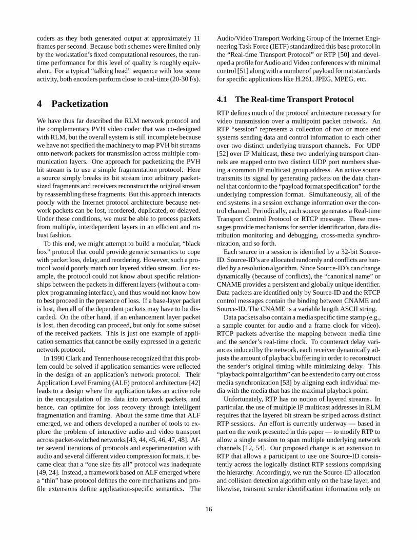
coders as they both generated output at approximately 11frames per second. Because both schemes were limited onlyby the workstation’s fixed computational resources, the run-time performance for this level of quality is roughly equiv-alent. For a typical “talking head” sequence with low sceneactivity, both encoders perform close to real-time (20-30 f/s).
4 Packetization
We have thus far described the RLM network protocol andthe complementary PVH video codec that was co-designedwith RLM, but the overall system is still incomplete becausewe have not specified the machinery to map PVH bit streamsonto network packets for transmission across multiple com-munication layers. One approach for packetizing the PVHbit stream is to use a simple fragmentation protocol. Herea source simply breaks its bit stream into arbitrary packet-sized fragments and receivers reconstruct the original streamby reassembling these fragments. But this approach interactspoorly with the Internet protocol architecture because net-work packets can be lost, reordered, duplicated, or delayed.Under these conditions, we must be able to process packetsfrom multiple, interdependent layers in an efficient and ro-bust fashion.
To this end, we might attempt to build a modular, “blackbox” protocol that could provide generic semantics to copewith packet loss, delay, and reordering. However, such a pro-tocol would poorly match our layered video stream. For ex-ample, the protocol could not know about specific relation-ships between the packets in different layers (without a com-plex programming interface), and thus would not know howto best proceed in the presence of loss. If a base-layer packetis lost, then all of the dependent packets may have to be dis-carded. On the other hand, if an enhancement layer packetis lost, then decoding can proceed, but only for some subsetof the received packets. This is just one example of appli-cation semantics that cannot be easily expressed in a genericnetwork protocol.
In 1990 Clark and Tennenhouse recognized that this prob-lem could be solved if application semantics were reflectedin the design of an application’s network protocol. TheirApplication Level Framing (ALF) protocol architecture [42]leads to a design where the application takes an active rolein the encapsulation of its data into network packets, andhence, can optimize for loss recovery through intelligentfragmentation and framing. About the same time that ALFemerged, we and others developed a number of tools to ex-plore the problem of interactive audio and video transportacross packet-switched networks [43, 44, 45, 46, 47, 48]. Af-ter several iterations of protocols and experimentation withaudio and several different video compression formats, it be-came clear that a “one size fits all” protocol was inadequate[49, 24]. Instead, a framework based on ALF emerged wherea “thin” base protocol defines the core mechanisms and pro-file extensions define application-specific semantics. The
Audio/Video Transport Working Group of the Internet Engi-neering Task Force (IETF) standardized this base protocol inthe “Real-time Transport Protocol” or RTP [50] and devel-oped a profile for Audio and Video conferences with minimalcontrol [51] along with a number of payload format standardsfor specific applications like H.261, JPEG, MPEG, etc.
4.1 The Real-time Transport Protocol
RTP defines much of the protocol architecture necessary forvideo transmission over a multipoint packet network. AnRTP “session” represents a collection of two or more endsystems sending data and control information to each otherover two distinct underlying transport channels. For UDP[52] over IP Multicast, these two underlying transport chan-nels are mapped onto two distinct UDP port numbers shar-ing a common IP multicast group address. An active sourcetransmits its signal by generating packets on the data chan-nel that conform to the “payload format specification” for theunderlying compression format. Simultaneously, all of theend systems in a session exchange information over the con-trol channel. Periodically, each source generates a Real-timeTransport Control Protocol or RTCP message. These mes-sages provide mechanisms for sender identification, data dis-tribution monitoring and debugging, cross-media synchro-nization, and so forth.
Each source in a session is identified by a 32-bit Source-ID. Source-ID’s are allocated randomly and conflicts are han-dled by a resolution algorithm. Since Source-ID’s can changedynamically (because of conflicts), the “canonical name” orCNAME provides a persistent and globally unique identifier.Data packets are identified only by Source-ID and the RTCPcontrol messages contain the binding between CNAME andSource-ID. The CNAME is a variable length ASCII string.
Data packets also contain a media specific time stamp (e.g.,a sample counter for audio and a frame clock for video).RTCP packets advertise the mapping between media timeand the sender’s real-time clock. To counteract delay vari-ances induced by the network, each receiver dynamically ad-justs the amount of playback buffering in order to reconstructthe sender’s original timing while minimizing delay. This“playback point algorithm” can be extended to carry out crossmedia synchronization [53] by aligning each individual me-dia with the media that has the maximal playback point.
Unfortunately, RTP has no notion of layered streams. Inparticular, the use of multiple IP multicast addresses in RLMrequires that the layered bit stream be striped across distinctRTP sessions. An effort is currently underway — based inpart on the work presented in this paper — to modify RTP toallow a single session to span multiple underlying networkchannels [12, 54]. Our proposed change is an extension toRTP that allows a participant to use one Source-ID consis-tently across the logically distinct RTP sessions comprisingthe hierarchy. Accordingly, we run the Source-ID allocationand collision detection algorithm only on the base layer, andlikewise, transmit sender identification information only on
16
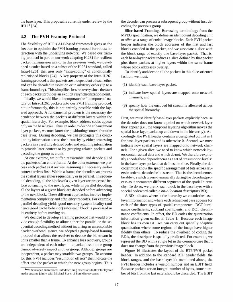
the base layer. This proposal is currently under review by theIETF4 [54].
4.2 The PVH Framing Protocol
The flexibility of RTP’s ALF-based framework gives us thefreedom to optimize the PVH framing protocol for robust in-teraction with the underlying network. We based our fram-ing protocol in part on our work adapting H.261 for resilientpacket transmission in vic. In this previous work, we devel-oped a codec based on a subset of the H.261 standard, calledIntra-H.261, that uses only “intra-coding” of conditionallyreplenished blocks [24]. A key property of the Intra-H.261framing protocol is that packets are independent of each otherand can be decoded in isolation or in arbitrary order (up to aframe boundary). This simplifies loss recovery since the startof each packet provides an explicit resynchronization point.
Ideally, we would like to incorporate the “idempotent” na-ture of Intra-H.261 packets into our PVH framing protocol,but unfortunately, this is not entirely possible with the lay-ered approach. A fundamental problem is the necessary de-pendence between the packets at different layers within thespatial hierarchy. For example, block address codes appearonly on the base layer. Thus, in order to decode enhancementlayer packets, we must know the positioning context from thebase layer. During decoding, we can propagate this condi-tioning information across the hierarchy by either processingpackets in a carefully defined order and retaining informationto provide later context or by grouping related packets anddecoding the group as a unit.
At one extreme, we buffer, reassemble, and decode all ofthe packets of an entire frame. At the other extreme, we pro-cess each packet as it arrives, assuming all necessary earliercontext arrives first. Within a frame, the decoder can processthe spatial layers either sequentially or in parallel. In sequen-tial decoding, all the blocks of a given layer are processed be-fore advancing to the next layer, while in parallel decoding,all the layers of a given block are decoded before advancingto the next block. These different approaches involve imple-mentation complexity and efficiency tradeoffs. For example,parallel decoding yields good memory-system locality (andhence good cache behavior) since each block is processed inits entirety before moving on.
We decided to develop a framing protocol that would pro-vide enough flexibility to allow either the parallel or the se-quential decoding method without incurring an unreasonableheader overhead. Hence, we adopted a group-based framingprotocol that allows the receiver to decode the bit stream inunits smaller than a frame. To enhance loss recovery, groupsare independent of each other — a packet loss in one groupcannot adversely impact another group. Although groups areindependent, a packet may straddle two groups. To accountfor this, PVH includes “resumption offsets” that indicate theoffset into the packet at which the new group begins. Thus
4We developed an Internet Draft describing extensions to RTP for layeredmedia streams jointly with Michael Speer of Sun Microsystems.
the decoder can process a subsequent group without first de-coding the previous group.
Slice-based Framing. Borrowing terminology from theMPEG specification, we define an idempotent decoding unitor slice as a range of coded image blocks. Each PVH packetheader indicates the block addresses of the first and lastblocks encoded in the packet, and we associate a slice withthe block range of exactly one base-layer packet. That is,each base-layer packet induces a slice defined by that packetplus those packets at higher layers within the same framewhose block addresses overlap.
To identify and decode all the packets in this slice-orientedfashion, we must:
(1) identify each base-layer packet,
(2) indicate how spatial layers are mapped onto networkchannels, and
(3) specify how the encoded bit stream is allocated acrossthe spatial hierarchy.
First, we must identify base-layer packets explicitly becausethe decoder does not know a priori on which network layerthey appear (i.e., the temporal layering algorithm moves thespatial base-layer packet up and down in the hierarchy). Ac-cordingly, the PVH header contains a designated bit that is 1for base-layer packets and is otherwise 0. Second, we mustindicate how spatial layers are mapped onto network chan-nels. For a given slice, we need to know which network lay-ers contain actual data and which do not. We therefore explic-itly encode these dependencies as a set of “resumption levels”in the base-layer packet that defines the slice. Finally, the de-coder must know the specific arrangement of bits across lay-ers in order to decode the bit stream. That is, the decoder mustbe able to switch layers dynamically during the decoding pro-cess as it encounters different segments of the spatial hierar-chy. To do so, we prefix each block in the base layer with aspecial codeword called a bit-allocation descriptor (BD).
A BD indicates where in the hierarchy we encode the base-layer information and where each refinement pass appears foreach of the three types of spatial components: DCT lumi-nance coefficients, subband coefficients, and DCT chromi-nance coefficients. In effect, the BD codes the quantizationinformation given earlier in Table 1. Because each imageblock has its own BD, we can carry out spatially adaptivequantization where some regions of the image have higherfidelity than others. To reduce the overhead of coding theBD’s, the descriptor is spatially predicted. For example, werepresent the BD with a single bit in the common case that itdoes not change from the previous image block.
Figure 16 illustrates the layout of the RTP/PVH packetheader. In addition to the standard RTP header fields, theblock ranges, and the base-layer bit mentioned above, thePVH header includes a version number and an EBIT field.Because packets are an integral number of bytes, some num-ber of bits from the last octet should be discarded. The EBIT
17
SBLKEBITV
031
031
EBLKB
MXP CC SEQNOPTV
PVH Payload Header
RTP Header
TS
SSRC
Figure 16: RTP/PVH Packet Headers. The RTP header containsa version number (V), a padding bit (P), an extension bit (X), a countof “contributing sources” (CC), i.e., for audio mixing or video com-positing, a marker bit (M), a payload type (PT), a 16-bit sequencenumber (SEQNO), a media-specific timestamp (TS), and a “Source-ID” (SSRC). If the payload type indicates PVH, then a PVH headerimmediately follows the RTP header and consists of a PVH ver-sion number (V), a base-layer indicator (B), a count of padding bits(EBIT), a start block (SBLK), and an end block (EBLK).
fields explicitly indicates this count. A PVH version num-ber is included to incrementally deploy new versions of thecodec. Also, if the packet is a base-layer packet (i.e., B isset), then an auxiliary header immediately follows the PVHheader. This header includes the width and height (in blocks)of the video image as well as a count and list of the resump-tion levels and offsets described above.
Figure 17 illustrates an example arrangement of packetsin the slice-oriented hierarchy. Although coding layers arespread across network channels according to the temporal hi-erarchy, we simplify the diagram by indicating only the rela-tionship among packets within the spatial hierarchy. Each la-beled box corresponds to a packet header and the pair of num-bers represents the range of macroblocks that are containedwithin the packet.
Each slice is identified by exactly one base-layer packetand the diagram contains two such slices, encircled by thedashed lines. Each base-layer packet additionally containsexplicit pointers to all of the network channels that comprisethe slice as indicated by the solid arrows. Moreover, eachpacket’s resumption pointer and offset is indicated by thedashed arrows. The packet that defines the (88,150) blockrange appears on layer 1 and naturally has its base-layer bitset (B=1). Each packet that is a member of the (88,150) sliceis either wholly contained in or partially covers those blocksand is encircled by the lefthand dashed line. The base-layerpacket additionally contains a count of resumption pointersand their values. For example, the base-layer packet points tosuccessor packets in both layers 2 and 3, while the (101,130)layer 2 packet points to only the (100,130) layer 3 packet. Ifthere were more layers, then the layer 2 packet would containadditional resumption pointers.
Given a base-layer packet, the decoder can extract the layerhierarchy and resumption pointers and offsets to definitivelylocate all the packets and layer offsets in a slice. A naive al-gorithm might perform this relatively complex task by buffer-ing all received packets and scanning the buffer pool on each
packet arrival to determine when slices become complete.Under this scheme, however, the decoder cannot easily dif-ferentiate between a packet that has not yet arrived and onethat has been lost or reordered and hence cannot easily decidewhen to decode a partially received slice.
Instead of this data-driven approach to receiver buffering,we combine the timing recovery algorithm used by RTP-based applications with the slice reassembly algorithm. Inthis model, packets are synchronized across layers usingthe “playback point algorithm” modified to function acrosspacket slices. That is, we schedule the packets from a givenslice to be decoded together and discard the rare packet thatarrives too late. When a slice’s playback point arrives, we de-termine whether it is entirely intact and, if so, simply decodeit. Otherwise, we invoke a loss recovery strategy to patch themissing data, possibly discarding unusable packets. (In prac-tice, the loss recovery mechanism is folded into the decodingprocess.)
In our current implementation, we use the following hy-brid of the data- and timer-driven approaches. We maintaintwo “containers” keyed by the RTP timestamp. Within eachcontainer, we maintain a circular buffer of packets for eachlayer and within each layer, we map packets directly into slotsin a circular buffer using the low bits of the packet’s RTPsequence number (so lookup and insertion are cheap). Wealso track the boundaries of the current “window” of packetsstored in a given layer. This allows us to quickly traverse overall the packets in a layer to check for gaps in the sequencespace. Finally, we store all of the pending base-layer packetsin a hash table for the current frame container.
Whenever a base-layer packet arrives, we check whetherits constituent slice is ready to decode by scanning each layerindicated in the resumption pointer list and checking if a con-tiguous block of packets at each layer “covers” the rangeof blocks in the base layer. If so, we decode the slice im-mediately and all packets wholly contained in the decodedslice are freed. Otherwise, the base layer packet is bufferedand a timer is scheduled whose timeout is proportional to thepacket interarrival time variance. If an enhancement layerpacket arrives and completes the slice, then the slice is de-coded and the timer is canceled. Otherwise if the timer ex-pires, we assume packet loss occurred, invoke a loss recov-ery strategy, and decode the partial slice. When we are com-pletely done with a frame, we free all the packets stored in theframe container data structure.
5 Implementation Status
The PVH codec, spatio-temporal layering, and RTP-basedpacketization scheme are all implemented in an experimen-tal version of our video conferencing application vic. ThePVH codec and framing protocol are implemented as a mod-ular C++ object in the Tcl/Tk-based [55] multimedia toolkitused to build vic. We implemented the RLM protocol in ournetwork simulation testbed [56] and carried out a simulation
18
Layer 3
Layer 1
Layer 2
166 190189172171 212
13010110080
16599868575 100 157156140139
131
88
163162154153 179
151 203150
210180
Figure 17: Sample PVH Packet Stream. Each base-layer packet defines a range of macroblocks that comprise a slice. Here, we show twoslices, each enclosed by a dashed line, that are spread across the layer hierarchy.
study reported in [12, 17].Even with RLM fully integrated into vic, the current frame-
work is still experimental. We are just beginning to un-derstand the interaction between RLM and other adaptivecongestion control schemes, e.g., those in TCP/IP. More-over, RLM requires the “fast leave” mechanism in IGMP toquickly react to network congestion, but this has not yet beenwidely deployed.
While we continue to experiment with, refine, and deployRLM, we can immediately leverage PVH by itself throughthe use of manually configured (hence nonscalable) distribu-tion groups. Since IP multicast provides mechanisms to limitthe “scope” of a group transmission, we can effect layeredtransmission though a hierarchical arrangement of scopes,where the layers in the distribution are allocated to a set ofnested scopes each with a larger reach. That is, we can usedistribution scope to topologically constrain the reach of eachlayer. For example, we might distribute the UCB MBoneseminar by sending 32 kb/s to the “world” scope, 128 kb/s tothe well-connected MBone, 256 kb/s across our campus net-work, and 1 Mb/s throughout the department network.
PVH can also be used in tandem with the Resource Reser-Vation Protocol (RSVP) [57, 58], which supports the notionof layered reservations. In this approach, receivers negotiateexplicitly with the network for bandwidth by adjusting theirreservation to the maximum number of layers that the net-work can deliver [4].
Although transition from one technology to another is of-ten a slow process — even in the MBone where new tools aredeployed simply by distributing them over the network — theoutlook for layered video is promising for several reasons:
� First, the extension of the RTP specification for layeredstreams will enable multiple, interoperable implementa-tions.
� Second, the availability of a fast and efficient layeredvideo codec (PVH) will bootstrap experimentation withlayered media and demonstrate its ability to accommo-date the Internet’s heterogeneity.
� Finally, the widespread deployment of administrativemulticast scope will enable the incremental deploymentof layered transmission while we continue to refine theRLM framework.
We believe that these factors will combine to make layeredvideo transmission commonplace in the Internet within thenext few years.
6 Summary
In this paper, we proposed a framework for the transmis-sion of layered signals over heterogeneous networks using areceiver-driven adaptation protocol, RLM. We described thedetails of our low-complexity, loss-resilient layered sourcecoder, PVH, and presented performance results to show that itperforms as well as or better than the current practice in Inter-net video codecs. Moreover, the run-time performance of oursoftware PVH codec is no worse than our highly tuned H.261implementation (at equivalent signal quality) even though itproduces a layered output format. Existing solutions to het-erogeneous video transmission are either network-orientedorcompression-oriented — in contrast, our focus is on the com-plete systems design and implementation. Together, RLMand PVH provide a comprehensive solution for scalable mul-ticast video transmission in heterogeneous networks.
7 Acknowledgments
Elan Amir’s work on his “Layered-DCT” algorithm [39] in-spired our approach to decomposing the LL subband with aDCT and progressively coding transform coefficients. ElanAmir, Hari Balakrishnan, and Deana McCanne providedthoughtful comments on drafts of this paper. We thank theanonymous reviewers for their excellent feedback. Sup-port for this work was provided by the the Director, Of-fice of Energy Research, Scientific Computing Staff, of the
19
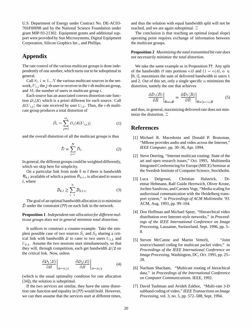
U.S. Department of Energy under Contract No. DE-AC03-76SF00098 and by the National Science Foundation undergrant MIP-93-21302. Equipment grants and additional sup-port were provided by Sun Microsystems, Digital EquipmentCorporation, Silicon Graphics Inc., and Phillips.
Appendix
The rate control of the various multicast groups is done inde-pendently of one another, which turns out to be suboptimal ingeneral.
Call Si; i = 1:::N the various multicast sources in the net-work,Ui;j the j-th user or receiver in the i-th multicast group,and Mi the number of users in multicast group i.
Each source has an associated convex distortion rate func-tion Di(R) which is a priori different for each source. CallR(Ui;j) the rate received by user Ui;j . Thus, the i-th multi-cast group produces a total distortion of
D̂i =
MiX
j=1
Di(R(Ui;j)) (1)
and the overall distortion of all the multicast groups is thus
D̂ =
NX
i=1
D̂i: (2)
In general, the different groups could be weighted differently,which we skip here for simplicity.
On a particular link from node k to l there is bandwidthBk;l available of which a portionBk;l;i is allocated to sourcei, where
Bk;l �NX
i=1
Bk;l;i: (3)
The goal of an optimal bandwidth allocation is to minimizeD̂ under the constraint (??) on each link in the network.
Proposition 1 Independent rate allocation for different mul-ticast groups does not in general minimize total distortion.
It suffices to construct a counter-example. Take the sim-plest possible case of two sources S1 and S2 sharing a crit-ical link with bandwidth B to cater to two users U1;1 andU2;1. Assume the two sessions start simultaneously, so thatthey will, through competition, each get bandwidth B=2 onthe critical link. Now, unless
@D1(R)
@R
����R=B=2
=@D2(R)
@R
����R=B=2
(4)
(which is the usual optimality condition for rate allocation[34]), the solution is suboptimal.
If the two services are similar, they have the same distor-tion rate function and equality in (??) would hold. However,we can then assume that the services start at different times,
and thus the solution with equal bandwidth split will not bereached, and we are again suboptimal. 2
The conclusion is that reaching an optimal (equal slope)operating point requires exchange of information betweenthe multicast groups.
Proposition 2 Maximizing the total transmitted bit rate doesnot necessarily minimize the total distortion.
We take the same example as in Proposition ??. Any splitof the bandwidth B into portions �B and (1 � �)B, � 2[0; 1], maximizes the sum of delivered bandwidth to users 1and 2. Out of this set, only a single specific � minimizes thedistortion, namely the one that achieves
@D1(R)
@R
����R=�B
=@D2(R)
@R
����R=(1��)B
(5)
and thus, in general, maximizing delivered rate does not min-imize the distortion. 2
References
[1] Michael R. Macedonia and Donald P. Brutzman,“MBone provides audio and video across the Internet,”IEEE Computer, pp. 30–36, Apr. 1994.
[2] Steve Deering, “Internet multicast routing: State of theart and open research issues,” Oct. 1993, MultimediaIntegrated Conferencing for Europe (MICE) Seminar atthe Swedish Institute of Computer Science, Stockholm.
[3] Luca Delgrossi, Christian Halstrick, Di-etmar Hehmann, Ralf Guido Herrtwich, Oliver Krone,Jochen Sandvoss, and Carsten Vogt, “Media scaling foraudiovisual communication with the Heidelberg trans-port system,” in Proceedings of ACM Multimedia ’93.ACM, Aug. 1993, pp. 99–104.
[4] Don Hoffman and Michael Speer, “Hierarchical videodistribution over Internet-style networks,” in Proceed-ings of the IEEE International Conference on ImageProcessing, Lausanne, Switzerland, Sept. 1996, pp. 5–8.
[5] Steven McCanne and Martin Vetterli, “Jointsource/channel coding for multicast packet video,” inProceedings of the IEEE International Conference onImage Processing, Washington, DC, Oct. 1995, pp. 25–28.
[6] Nachum Shacham, “Multicast routing of hierachicaldata,” in Proceedings of the International Conferenceon Computer Communications. IEEE, 1992.
[7] David Taubman and Avideh Zakhor, “Multi-rate 3-Dsubband coding of video,” IEEE Transactions on ImageProcessing, vol. 3, no. 5, pp. 572–588, Sept. 1994.
20
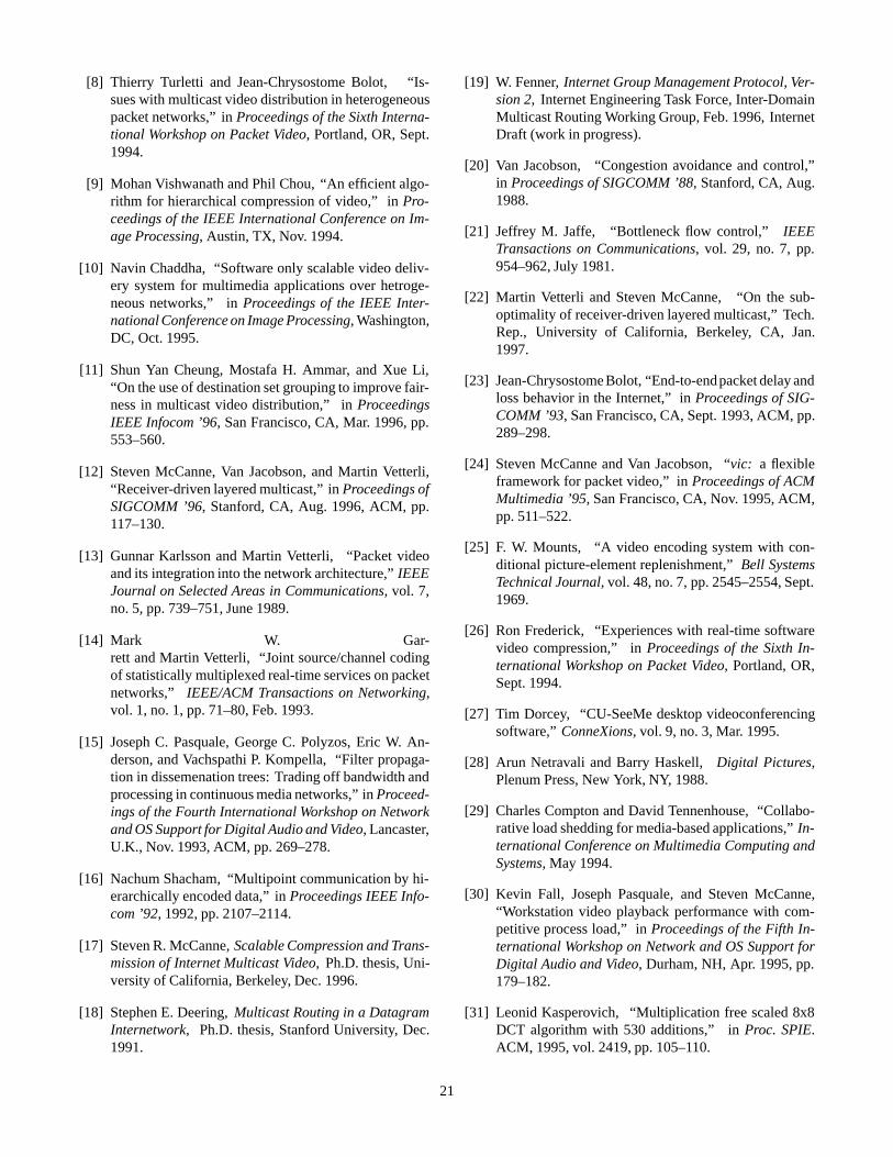
[8] Thierry Turletti and Jean-Chrysostome Bolot, “Is-sues with multicast video distribution in heterogeneouspacket networks,” in Proceedings of the Sixth Interna-tional Workshop on Packet Video, Portland, OR, Sept.1994.
[9] Mohan Vishwanath and Phil Chou, “An efficient algo-rithm for hierarchical compression of video,” in Pro-ceedings of the IEEE International Conference on Im-age Processing, Austin, TX, Nov. 1994.
[10] Navin Chaddha, “Software only scalable video deliv-ery system for multimedia applications over hetroge-neous networks,” in Proceedings of the IEEE Inter-national Conference on Image Processing, Washington,DC, Oct. 1995.
[11] Shun Yan Cheung, Mostafa H. Ammar, and Xue Li,“On the use of destination set grouping to improve fair-ness in multicast video distribution,” in ProceedingsIEEE Infocom ’96, San Francisco, CA, Mar. 1996, pp.553–560.
[12] Steven McCanne, Van Jacobson, and Martin Vetterli,“Receiver-driven layered multicast,” in Proceedings ofSIGCOMM ’96, Stanford, CA, Aug. 1996, ACM, pp.117–130.
[13] Gunnar Karlsson and Martin Vetterli, “Packet videoand its integration into the network architecture,” IEEEJournal on Selected Areas in Communications, vol. 7,no. 5, pp. 739–751, June 1989.
[14] Mark W. Gar-rett and Martin Vetterli, “Joint source/channel codingof statistically multiplexed real-time services on packetnetworks,” IEEE/ACM Transactions on Networking,vol. 1, no. 1, pp. 71–80, Feb. 1993.
[15] Joseph C. Pasquale, George C. Polyzos, Eric W. An-derson, and Vachspathi P. Kompella, “Filter propaga-tion in dissemenation trees: Trading off bandwidth andprocessing in continuous media networks,” in Proceed-ings of the Fourth International Workshop on Networkand OS Support for Digital Audio and Video, Lancaster,U.K., Nov. 1993, ACM, pp. 269–278.
[16] Nachum Shacham, “Multipoint communication by hi-erarchically encoded data,” in Proceedings IEEE Info-com ’92, 1992, pp. 2107–2114.
[17] Steven R. McCanne, Scalable Compression and Trans-mission of Internet Multicast Video, Ph.D. thesis, Uni-versity of California, Berkeley, Dec. 1996.
[18] Stephen E. Deering, Multicast Routing in a DatagramInternetwork, Ph.D. thesis, Stanford University, Dec.1991.
[19] W. Fenner, Internet Group Management Protocol, Ver-sion 2, Internet Engineering Task Force, Inter-DomainMulticast Routing Working Group, Feb. 1996, InternetDraft (work in progress).
[20] Van Jacobson, “Congestion avoidance and control,”in Proceedings of SIGCOMM ’88, Stanford, CA, Aug.1988.
[21] Jeffrey M. Jaffe, “Bottleneck flow control,” IEEETransactions on Communications, vol. 29, no. 7, pp.954–962, July 1981.
[22] Martin Vetterli and Steven McCanne, “On the sub-optimality of receiver-driven layered multicast,” Tech.Rep., University of California, Berkeley, CA, Jan.1997.
[23] Jean-Chrysostome Bolot, “End-to-endpacket delay andloss behavior in the Internet,” in Proceedings of SIG-COMM ’93, San Francisco, CA, Sept. 1993, ACM, pp.289–298.
[24] Steven McCanne and Van Jacobson, “vic: a flexibleframework for packet video,” in Proceedings of ACMMultimedia ’95, San Francisco, CA, Nov. 1995, ACM,pp. 511–522.
[25] F. W. Mounts, “A video encoding system with con-ditional picture-element replenishment,” Bell SystemsTechnical Journal, vol. 48, no. 7, pp. 2545–2554, Sept.1969.
[26] Ron Frederick, “Experiences with real-time softwarevideo compression,” in Proceedings of the Sixth In-ternational Workshop on Packet Video, Portland, OR,Sept. 1994.
[27] Tim Dorcey, “CU-SeeMe desktop videoconferencingsoftware,” ConneXions, vol. 9, no. 3, Mar. 1995.
[28] Arun Netravali and Barry Haskell, Digital Pictures,Plenum Press, New York, NY, 1988.
[29] Charles Compton and David Tennenhouse, “Collabo-rative load shedding for media-based applications,” In-ternational Conference on Multimedia Computing andSystems, May 1994.
[30] Kevin Fall, Joseph Pasquale, and Steven McCanne,“Workstation video playback performance with com-petitive process load,” in Proceedings of the Fifth In-ternational Workshop on Network and OS Support forDigital Audio and Video, Durham, NH, Apr. 1995, pp.179–182.
[31] Leonid Kasperovich, “Multiplication free scaled 8x8DCT algorithm with 530 additions,” in Proc. SPIE.ACM, 1995, vol. 2419, pp. 105–110.
21
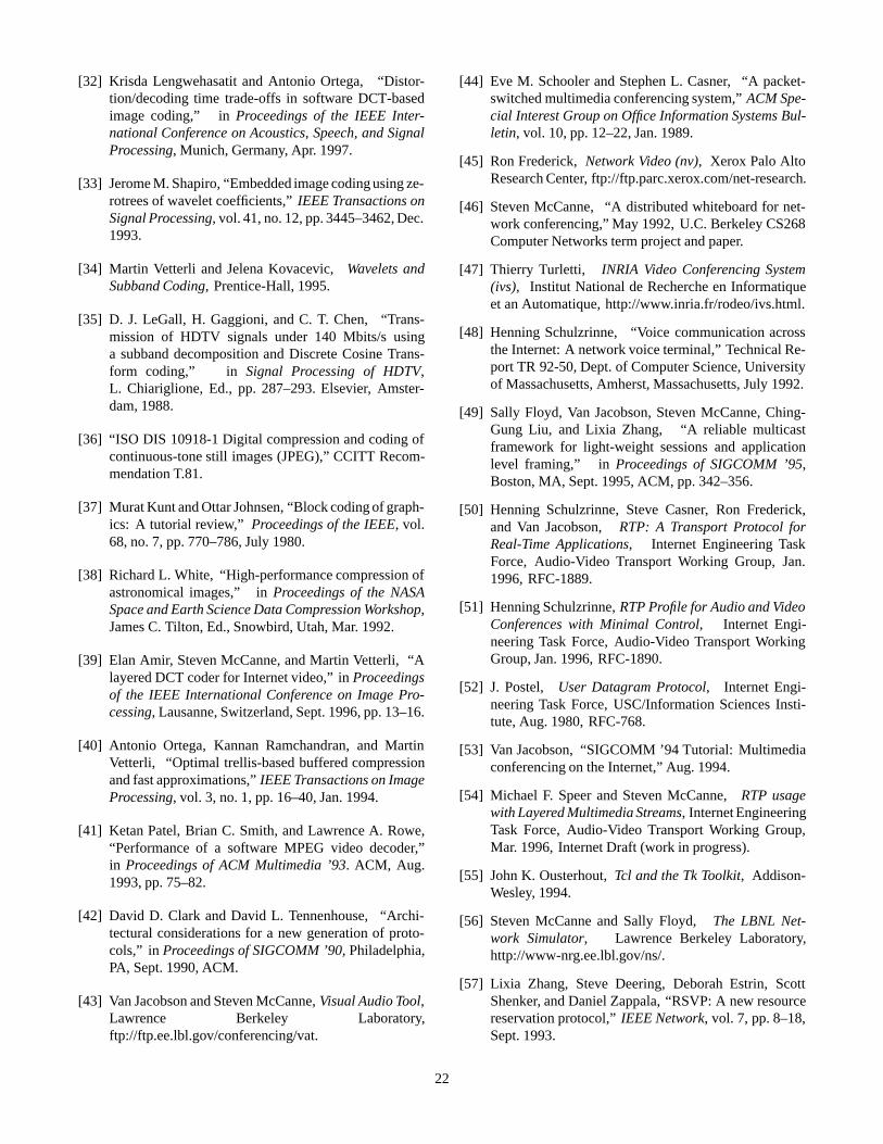
[32] Krisda Lengwehasatit and Antonio Ortega, “Distor-tion/decoding time trade-offs in software DCT-basedimage coding,” in Proceedings of the IEEE Inter-national Conference on Acoustics, Speech, and SignalProcessing, Munich, Germany, Apr. 1997.
[33] Jerome M. Shapiro, “Embedded image coding using ze-rotrees of wavelet coefficients,” IEEE Transactions onSignal Processing, vol. 41, no. 12, pp. 3445–3462, Dec.1993.
[34] Martin Vetterli and Jelena Kovacevic, Wavelets andSubband Coding, Prentice-Hall, 1995.
[35] D. J. LeGall, H. Gaggioni, and C. T. Chen, “Trans-mission of HDTV signals under 140 Mbits/s usinga subband decomposition and Discrete Cosine Trans-form coding,” in Signal Processing of HDTV,L. Chiariglione, Ed., pp. 287–293. Elsevier, Amster-dam, 1988.
[36] “ISO DIS 10918-1 Digital compression and coding ofcontinuous-tone still images (JPEG),” CCITT Recom-mendation T.81.
[37] Murat Kunt and Ottar Johnsen, “Block coding of graph-ics: A tutorial review,” Proceedings of the IEEE, vol.68, no. 7, pp. 770–786, July 1980.
[38] Richard L. White, “High-performance compression ofastronomical images,” in Proceedings of the NASASpace and Earth Science Data Compression Workshop,James C. Tilton, Ed., Snowbird, Utah, Mar. 1992.
[39] Elan Amir, Steven McCanne, and Martin Vetterli, “Alayered DCT coder for Internet video,” in Proceedingsof the IEEE International Conference on Image Pro-cessing, Lausanne, Switzerland, Sept. 1996, pp. 13–16.
[40] Antonio Ortega, Kannan Ramchandran, and MartinVetterli, “Optimal trellis-based buffered compressionand fast approximations,” IEEE Transactions on ImageProcessing, vol. 3, no. 1, pp. 16–40, Jan. 1994.
[41] Ketan Patel, Brian C. Smith, and Lawrence A. Rowe,“Performance of a software MPEG video decoder,”in Proceedings of ACM Multimedia ’93. ACM, Aug.1993, pp. 75–82.
[42] David D. Clark and David L. Tennenhouse, “Archi-tectural considerations for a new generation of proto-cols,” in Proceedings of SIGCOMM ’90, Philadelphia,PA, Sept. 1990, ACM.
[43] Van Jacobson and Steven McCanne, Visual Audio Tool,Lawrence Berkeley Laboratory,ftp://ftp.ee.lbl.gov/conferencing/vat.
[44] Eve M. Schooler and Stephen L. Casner, “A packet-switched multimedia conferencing system,” ACM Spe-cial Interest Group on Office Information Systems Bul-letin, vol. 10, pp. 12–22, Jan. 1989.
[45] Ron Frederick, Network Video (nv), Xerox Palo AltoResearch Center, ftp://ftp.parc.xerox.com/net-research.
[46] Steven McCanne, “A distributed whiteboard for net-work conferencing,” May 1992, U.C. Berkeley CS268Computer Networks term project and paper.
[47] Thierry Turletti, INRIA Video Conferencing System(ivs), Institut National de Recherche en Informatiqueet an Automatique, http://www.inria.fr/rodeo/ivs.html.
[48] Henning Schulzrinne, “Voice communication acrossthe Internet: A network voice terminal,” Technical Re-port TR 92-50, Dept. of Computer Science, Universityof Massachusetts, Amherst, Massachusetts, July 1992.
[49] Sally Floyd, Van Jacobson, Steven McCanne, Ching-Gung Liu, and Lixia Zhang, “A reliable multicastframework for light-weight sessions and applicationlevel framing,” in Proceedings of SIGCOMM ’95,Boston, MA, Sept. 1995, ACM, pp. 342–356.
[50] Henning Schulzrinne, Steve Casner, Ron Frederick,and Van Jacobson, RTP: A Transport Protocol forReal-Time Applications, Internet Engineering TaskForce, Audio-Video Transport Working Group, Jan.1996, RFC-1889.
[51] Henning Schulzrinne, RTP Profile for Audio and VideoConferences with Minimal Control, Internet Engi-neering Task Force, Audio-Video Transport WorkingGroup, Jan. 1996, RFC-1890.
[52] J. Postel, User Datagram Protocol, Internet Engi-neering Task Force, USC/Information Sciences Insti-tute, Aug. 1980, RFC-768.
[53] Van Jacobson, “SIGCOMM ’94 Tutorial: Multimediaconferencing on the Internet,” Aug. 1994.
[54] Michael F. Speer and Steven McCanne, RTP usagewith Layered Multimedia Streams, Internet EngineeringTask Force, Audio-Video Transport Working Group,Mar. 1996, Internet Draft (work in progress).
[55] John K. Ousterhout, Tcl and the Tk Toolkit, Addison-Wesley, 1994.
[56] Steven McCanne and Sally Floyd, The LBNL Net-work Simulator, Lawrence Berkeley Laboratory,http://www-nrg.ee.lbl.gov/ns/.
[57] Lixia Zhang, Steve Deering, Deborah Estrin, ScottShenker, and Daniel Zappala, “RSVP: A new resourcereservation protocol,” IEEE Network, vol. 7, pp. 8–18,Sept. 1993.
22
[58] R. Braden, L. Zhang, D. Estrin, S. Herzog, andS. Jamin, “Resource reservation protocol (RSVP) – ver-sion 1 function specification,” Nov. 1996, Internet Draft(RFC pending).
23
Related Documents