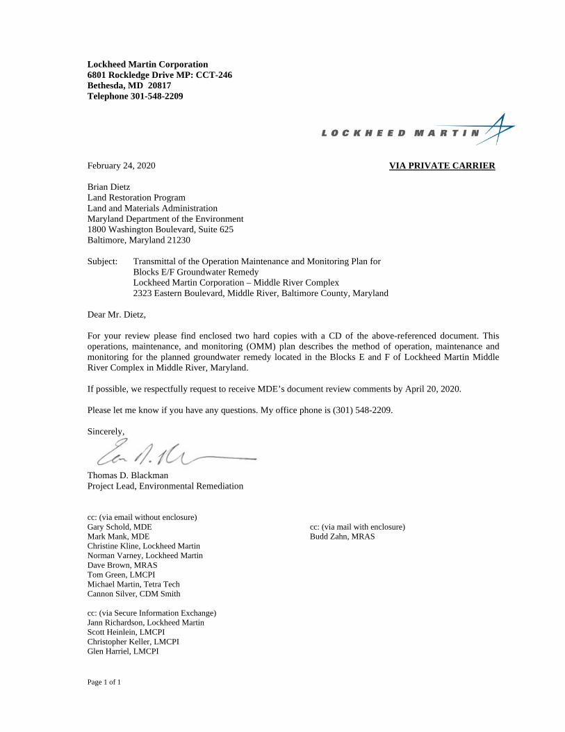
Page 1 of 1 Lockheed Martin Corporation 6801 Rockledge Drive MP: CCT-246 Bethesda, MD 20817 Telephone 301-548-2209 February 24, 2020 VIA PRIVATE CARRIER Brian Dietz Land Restoration Program Land and Materials Administration Maryland Department of the Environment 1800 Washington Boulevard, Suite 625 Baltimore, Maryland 21230 Subject: Transmittal of the Operation Maintenance and Monitoring Plan for Blocks E/F Groundwater Remedy Lockheed Martin Corporation – Middle River Complex 2323 Eastern Boulevard, Middle River, Baltimore County, Maryland Dear Mr. Dietz, For your review please find enclosed two hard copies with a CD of the above-referenced document. This operations, maintenance, and monitoring (OMM) plan describes the method of operation, maintenance and monitoring for the planned groundwater remedy located in the Blocks E and F of Lockheed Martin Middle River Complex in Middle River, Maryland. If possible, we respectfully request to receive MDE’s document review comments by April 20, 2020. Please let me know if you have any questions. My office phone is (301) 548-2209. Sincerely, Thomas D. Blackman Project Lead, Environmental Remediation cc: (via email without enclosure) Gary Schold, MDE Mark Mank, MDE Christine Kline, Lockheed Martin Norman Varney, Lockheed Martin Dave Brown, MRAS Tom Green, LMCPI Michael Martin, Tetra Tech Cannon Silver, CDM Smith cc: (via Secure Information Exchange) Jann Richardson, Lockheed Martin Scott Heinlein, LMCPI Christopher Keller, LMCPI Glen Harriel, LMCPI cc: (via mail with enclosure) Budd Zahn, MRAS

Welcome message from author
This document is posted to help you gain knowledge. Please leave a comment to let me know what you think about it! Share it to your friends and learn new things together.
Transcript
Page 1 of 1
Lockheed Martin Corporation 6801 Rockledge Drive MP: CCT-246 Bethesda, MD 20817 Telephone 301-548-2209
February 24, 2020 VIA PRIVATE CARRIER
Brian Dietz Land Restoration Program Land and Materials Administration Maryland Department of the Environment 1800 Washington Boulevard, Suite 625 Baltimore, Maryland 21230
Subject: Transmittal of the Operation Maintenance and Monitoring Plan for Blocks E/F Groundwater Remedy Lockheed Martin Corporation – Middle River Complex 2323 Eastern Boulevard, Middle River, Baltimore County, Maryland
Dear Mr. Dietz,
For your review please find enclosed two hard copies with a CD of the above-referenced document. This operations, maintenance, and monitoring (OMM) plan describes the method of operation, maintenance and monitoring for the planned groundwater remedy located in the Blocks E and F of Lockheed Martin Middle River Complex in Middle River, Maryland.
If possible, we respectfully request to receive MDE’s document review comments by April 20, 2020.
Please let me know if you have any questions. My office phone is (301) 548-2209.
Sincerely,
Thomas D. Blackman Project Lead, Environmental Remediation
cc: (via email without enclosure) Gary Schold, MDE Mark Mank, MDE Christine Kline, Lockheed Martin Norman Varney, Lockheed Martin Dave Brown, MRAS Tom Green, LMCPI Michael Martin, Tetra Tech Cannon Silver, CDM Smith
cc: (via Secure Information Exchange) Jann Richardson, Lockheed Martin Scott Heinlein, LMCPI Christopher Keller, LMCPI Glen Harriel, LMCPI
cc: (via mail with enclosure) Budd Zahn, MRAS
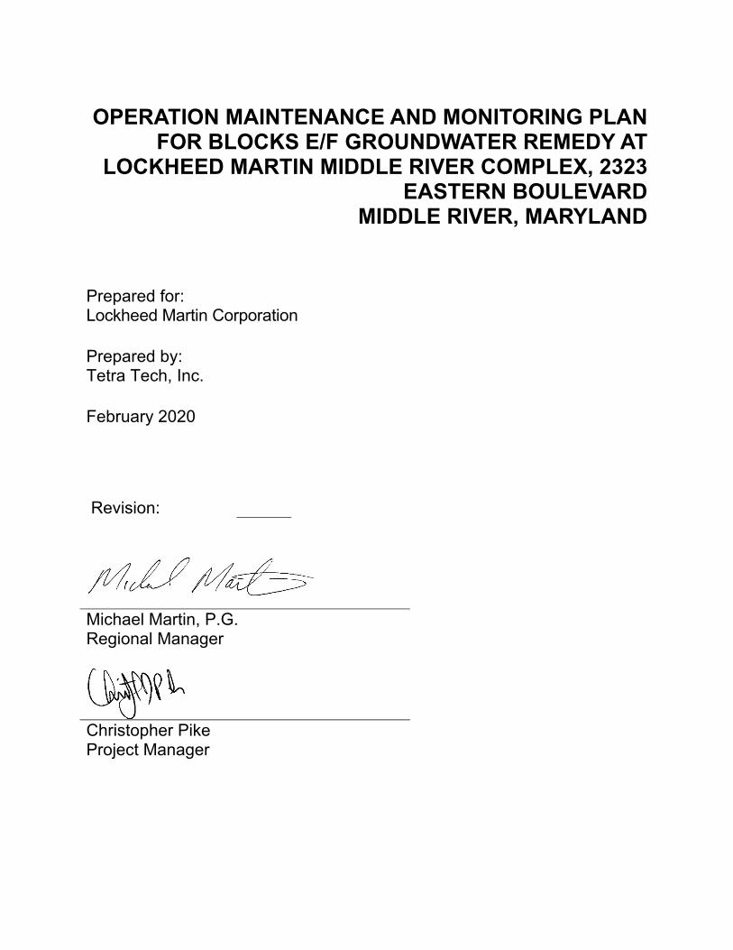
OPERATION MAINTENANCE AND MONITORING PLAN FOR BLOCKS E/F GROUNDWATER REMEDY AT
LOCKHEED MARTIN MIDDLE RIVER COMPLEX, 2323 EASTERN BOULEVARD
MIDDLE RIVER, MARYLAND
Prepared for: Lockheed Martin Corporation
Prepared by: Tetra Tech, Inc.
February 2020
Revision:
Michael Martin, P.G. Regional Manager
Christopher Pike Project Manager
8706 Tetra Tech • Lockheed Martin Middle River Complex • O&MM Plan for Blocks E/F GW Remedy
February 2020 i
TABLE OF CONTENTS Section Page
Table of Contents ........................................................................................................... i
List of TABLES ................................................................... .............................................i
Appendices ......................................................................... ............................................ i
Acronyms ...................................................................................................................... iii
Section 1 Introduction ............................................................................................... 1-1
1.1 Site Location and Background ..................................................................... 1-1
1.2 Purpose and Organization ............................................................................ 1-1
Section 2 Blocks E/F Groundwater Extraction and Treatment System ................. 2-1
2.1 Process Summary ........................................................................................ 2-1
2.2 System Start-up Phase ................................................................................ 2-2
2.2.1 Commissioning ....................................................................................... 2-2
2.2.2 System Start-up ...................................................................................... 2-3
2.2.3 Operations, Maintenance, and Monitoring .............................................. 2-6
2.3 Long-Term Operations and Maintenance ..................................................... 2-8
2.3.1 System Maintenance and Operation ....................................................... 2-8
2.3.2 Interlock Testing ................................................................................... 2-12
2.3.3 Lock-Out/Tag-Out Procedure ................................................................ 2-12
2.3.4 Air Stripper Cleaning ............................................................................. 2-13
2.3.5 Performance Monitoring ........................................................................ 2-13
Section 3 Block F Permeable Reactive Barrier ........................................................ 3-1
3.1 Pilot PRB Monitoring .................................................................................... 3-1
3.2 Full Scale PRB Monitoring ........................................................................... 3-2
Section 4 Block E ARD System Injection Event ...................................................... 4-1
4.1 General Methodology ................................................................................... 4-2
4.2 Injection Volumes and Amendment Dosages ............................................... 4-3
4.3 Injection Sequence ....................................................................................... 4-4
4.4 Performance Monitoring ............................................................................... 4-6
Section 5 Reporting ................................................................................................... 5-1
5.1 GWETS Progress Report ............................................................................. 5-1
8706 Tetra Tech • Lockheed Martin Middle River Complex • O&MM Plan for Blocks E/F GW Remedy
February 2020 ii
TABLE OF CONTENTS (CONTINUED) 5.2 Sanitary Sewer Discharge Report ................................................................ 5-1
5.3 PRB Performance Monitoring Report ........................................................... 5-2
Section 6 References ................................................................................................. 6-1
LIST OF TABLES Table I2-1 Process Parameters Operating Ranges Table I2-2 Start-Up GWETS Sampling Summary Table I2-3 Interlocks Testing Procedure Table I2-4 GWETS 1st Year of Operation Treatment Efficiency Sampling Summary Table I2-5 Block F Groundwater Table Monitoring Locations Table I2-6 GWETS Spare Parts List Table I3-1 Block F PRB Pilot Test Performance Monitoring Frequency and Analytical
Parameters Table I3-2 Block F 1st Year Performance Monitoring Frequency and Analytical
Parameters Table I4-1 Injection Volumes and Amendment Dosages for Block E 1st Injection Table I4-2 Comparison of Original and Revised Parameters for Block E Phase A
Injection Event Table I4-3 1st Injection Event for Block E Remedy Table I4-4 Block E Performance Monitoring Frequency and Analytical Parameters
APPENDICES Appendix A—Design Drawings Appendix B—Standard and Detailed Operating Procedures (SOPs and DOPs)
8706 Tetra Tech • Lockheed Martin Middle River Complex • O&MM Plan for Blocks E/F GW Remedy
February 2020 iii
ACRONYMS ARD anaerobic-reductive dechlorination
cis-1,2 DCE cis-1,2-dichloroethene
DHC dehalococcoides
DOP
GAC
detailed operating procedure
granular activated carbon
gpm gallons per minute
HDPE high-density polyethylene
HMI human-machine interphase
in. WC inches water column
LGAC liquid-phase granular activated carbon
L/min liters per minute
LMC Lockheed Martin Corporation
MDE Maryland Department of the Environment
µg/L microgram per liter
µg/m3 microgram(s) per cubic meter
mg/L milligram per liter
MRC Middle River Complex
OMM operation, maintenance, and monitoring
PID photoionization detector
PLC programmable logic controller
PRB permeable reactive membrane
RTO Remediation Technical Operations
SOP
TCE
standard operating procedure
trichloroethene
Tetra Tech Tetra Tech, Inc.
VFD variable frequency drive
VGAC vapor-phase granular activated carbon

8706 Tetra Tech • Lockheed Martin Middle River Complex • O&MM Plan for Blocks E/F GW Remedy
February 2020 iv
VOC volatile organic compound
8706 Tetra Tech • Lockheed Martin Middle River Complex • O&MM Plan for Blocks E/F GW Remedy
February 2020 Page 1-1
SECTION 1 INTRODUCTION
This operations, maintenance, and monitoring (OMM) plan describes the method of operation,
maintenance and monitoring for the groundwater remedy located in the Blocks E and F of
Lockheed Martin Middle River Complex (MRC) in Middle River, Maryland. Tetra Tech, Inc.,
(Tetra Tech) has prepared this document for Lockheed Martin Corporation (Lockheed Martin).
1.1 SITE LOCATION AND BACKGROUND
The Middle River Complex site, located at 2323 Eastern Boulevard in Middle River, Maryland,
consists of multiple parcels of land designated as tax blocks (referred to as blocks herein), all
owned by Lockheed Martin (Appendix A, Drawing C-1). Block I contains currently operating
facilities; surrounding Block I are the external Blocks A, B, D, E, F, G, and H. Some of these
external blocks are used by Lockheed Martin Corporation for offices and parking or are leased
by others for parking or operations.
The groundwater response action in the Blocks E and F of the Middle River Complex site is
described in the Groundwater Response Action Addendum Number 4 - Blocks E and F (Tetra
Tech, 2018a) and in Groundwater Remedy Blocks E/F Design Report (Tetra Tech, 2019).
The groundwater response action in the Blocks E and F of the Middle River Complex site
involves the implementation of hydraulic containment and a permeable reactive barrier (PRB) in
Block F and operation of the existing anaerobic-reductive dechlorination (ARD) system in
Block E. The operation of the ARD system is by others and is included in this plan for
information purposes only.
1.2 PURPOSE AND ORGANIZATION
This manual describes the operation, maintenance, and monitoring requirements for the Blocks E
and F groundwater response system. It is intended to assist the operator of the system, and to
describe the function of the remediation equipment and components. It is also intended to
8706 Tetra Tech • Lockheed Martin Middle River Complex • O&MM Plan for Blocks E/F GW Remedy
February 2020 Page 1-2
provide operational procedures, maintenance requirements, equipment and instrument
specifications, safety requirements, and system performance monitoring requirements.
Tetra Tech will perform the start-up, operation, maintenance, and monitoring activities for the
Blocks E/F Groundwater Extraction and Treatment System; Standard Operating Procedures
(SOPs), Detailed Operating Procedures (DOPs), check lists, and other required documentation
are attached.
This operation, maintenance and monitoring plan is organized as a single document addressing
the following topics:
Section 1 Introduction—This section presents the background information, objectives, and organization of the operation, maintenance, and monitoring manual.
Section 2 Blocks E/F Groundwater Extraction and Treatment System—This section describes start-up and operation of the Blocks E/F groundwater extraction and treatment system.
Section 3 Block F Permeable Reactive Barrier—This section describes performance monitoring activities related to PRB operation in Block F.
Section 4 Block E ARD System Injection Event—This section describes include activities related to Block E ARD system start-up and operation.
Section 5 Reporting— This section describes reporting procedures.
Section 6 References— This section lists the references used to compile this manual.
8706 Tetra Tech • Lockheed Martin Middle River Complex • O&MM Plan for Blocks E/F GW Remedy
February 2020 Page 2-1
SECTION 2 BLOCKS E/F GROUNDWATER EXTRACTION AND
TREATMENT SYSTEM
This section describes start-up and operation of the Blocks E/F groundwater extraction and
treatment system. The following sub-sections present a system overview, start-up procedures,
and routine operations and maintenance activities.
2.1 PROCESS SUMMARY
The details of the Blocks E/F groundwater extraction and treatment system can be found in the
Groundwater Remedy Blocks E/F Design Report (Tetra Tech, 2019). The Blocks E/F
groundwater extraction and treatment system consists of the following components:
• Installation of submersible pumps with associated controls in existing Block F extraction wells EW-1 and EW-2 (Drawings C-2 and C-4, Appendix A).
• Construction of groundwater treatment building and the treatment process equipment in Block E (Drawing C-2).
• Installation of piping and conduits between the extraction wells in Block F and the groundwater treatment building at Block E (Drawing C-2 and M-3).
• Installation of electric power to the treatment system building from the nearby pump house (with a separate meter) and from the treatment system building to the extraction well pumps and heat trace system in the vault for sanitary sewer tie-in. Final connection logistics are being discussed with the appropriate facility personnel.
• Installation of treated groundwater discharge line between the groundwater treatment building at Block E and the sanitary sewer piping in Block I (Drawing C-3).
• Extraction of groundwater from EW-1 and EW-2; treatment of the extracted groundwater using air stripping, filtration, and liquid-phase granular activated carbon (LGAC); and vapor treatment of the air stripper exhaust using vapor-phase granular activated carbon vessels (VGAC).
• Discharge of the treated groundwater to the Baltimore County sanitary sewer via piping in Block I.
8706 Tetra Tech • Lockheed Martin Middle River Complex • O&MM Plan for Blocks E/F GW Remedy
February 2020 Page 2-2
2.2 SYSTEM START-UP PHASE
This section describes the commissioning, start-up procedures, and operations, maintenance, and
monitoring activities during system start-up.
2.2.1 Commissioning
The objectives for commissioning are to confirm that the system has been installed as designed,
and that the system operates as specified, to facilitate any additional modifications in the system,
and to gather and evaluate initial operational data. A system commissioning check list (SOP-1) to
determine if the system is ready for operation is included in Appendix B. The following describes
the procedures associated with the commissioning of the system.
The commissioning testing process is composed of three primary activities:
• pre-commissioning check
• functional performance tests of individual components
• pre-startup functional performance system test of the combined components using potable water (via a temporary line from the nearby pump house) as described in the project specifications.
The inspection will be performed as detailed in a system commissioning check list (SOP-1) and
will verify that all the components of the system have been properly installed.
The system process and instrumentation diagram (Drawing M-2) and mechanical layouts (M-3
through M-5) will be used to verify that all equipment and piping are installed as designed. As-
built drawings will also be created and updated as necessary. Electrical systems will be checked to
verify that wiring has been completed correctly and according to the applicable code(s). The
electrical one-line diagrams and wiring diagrams will be used to verify electrical and
instrumentation systems.
All equipment and instrumentation will be inspected to verify proper installation and lubrication.
Inspections of equipment lockouts, safety valves and/or other pressure relief devices will also be
completed. Any deficiencies will be corrected to meet operational requirements.
8706 Tetra Tech • Lockheed Martin Middle River Complex • O&MM Plan for Blocks E/F GW Remedy
February 2020 Page 2-3
Checks and individual component testing will be performed to verify integrity before operation.
Equipment functional performance tests will only start after all pre-commissioning checks have
successfully been performed. The functional performance tests will be carried out in a manner that
duplicates the vendor's recommended procedures. If no vendor procedures are provided,
performance test methods will be developed to provide the information specified in the checklist.
Any deficiencies with the system must be corrected and performance checks successfully
completed before the system can be accepted.
After equipment and electrical systems are tested and certified ready for operation, electrical
systems can be energized in preparation for testing equipment and control systems. As part of the
startup process, the operating range and proper operation of each controller will be demonstrated.
Controls will be electrically tested with signal generators to verify operating ranges. Where
controls provide ON/OFF signals, switches will be manually tripped to test control loops. Testing
of control systems will proceed from this point to verify operability. If there are safety shutdown
sequences in the control systems, they will be tested to ensure proper functionality. Motors that
can be started with hand switches will be bump-tested to test equipment rotation. All interlocks
and motor starters controlled by interlocks or the programmable logic controller (PLC) and any
other relationships between equipment will be tested to determine if the responses are consistent
with the design logic. Proper functioning of the local touch-screen human-machine interface
(HMI) and the cellular gateway’s (cellular transmission) ability to enable remote parameter
monitoring and control will be verified. All system interlocks including callout and
uninterruptible power supply system functioning will be tested as described in SOP-2 (Appendix
B). At this point, systems will be considered ready for actual startup operating tests.
2.2.2 System Start-up
Upon completion of the commissioning step, the system will be operated. The strategy for
startup is to conduct these activities sequentially, comparing observations and test data to design
and performance criteria. If necessary, adjustments will be made to the design parameters based
on the actual operational values. Operation of all mechanical equipment and controllers will be
demonstrated in the presence of the designated system operator. Refer to a system start-up check
list in SOP-3 (Appendix B). The startup check-out will demonstrate operation of the following:
8706 Tetra Tech • Lockheed Martin Middle River Complex • O&MM Plan for Blocks E/F GW Remedy
February 2020 Page 2-4
• Electric submersible pumps – achieve design flow rate and pressures for all locations (SP-101 and SP-201, Drawing M-2).
• Air stripper discharge pump (TP-1, Drawing M-2).
• Air stripper blower (B-1, Drawing M-2).
• All valves, gauges, sensors, and controllers.
Startup will proceed slowly with sequenced events. All related health, safety, and emergency
response procedures will be in place and reviewed before this phase of operation. Before process
systems are started, a final check on the alignments and positioning of all motor drives, valves,
and control set points will be made.
The general startup sequence for normal operation of the system is as follows:
Ensure that all valves are in the proper positions as indicated in the commissioning/startup check list.
Ensure that the electrical disconnects are in the energized positions.
Ensure that all alarm conditions are cleared.
Turn air stripper blower B-1 selector switch on HMI panel to the AUTO position (Drawing E-2).
Turn air stripper discharge pump TP-1 on HMI panel selector switch to the AUTO position (Drawing E-2).
Adjust the set-point for variable frequency drive VFD-101 as needed to obtain maximum yield from the extraction well EW-1. This is accomplished by dewatering the well as much as practically possible (approximately 1 foot above the submersible pressure transducer SPT-101). Therefore, the set-point for VFD-101 will be set to 1 foot of water column.
Turn the selector switch for extraction well pump SP-101 on the HMI panel to the AUTO position (Drawing E-2). This should start the well pump SP-101 in EW-1.
Monitor the water levels (SPT-101) and flow rates (FM-101) in extraction well EW-1 using the HMI display. The well pump will slow down as necessary when the set-point is approached. Once the set point is reached the water level in the well (SPT-101) should remain close to a set point (1 foot) and the flow rate (FM-101) will stabilize at approximately 0.5 gpm based on the July 2017 pump test.
Adjust the set-point for variable frequency drive VFD-201 as needed to obtain maximum yield from the extraction well EW-2. This is accomplished by dewatering the well as
8706 Tetra Tech • Lockheed Martin Middle River Complex • O&MM Plan for Blocks E/F GW Remedy
February 2020 Page 2-5
much as practically possible (approximately 1 foot above the submersible pressure transducer SPT-201). Therefore, the set-point for VFD-201 will be set to 1 foot of water column.
Turn the selector switch for extraction well pump SP-201 on the HMI panel to the AUTO position (Drawing E-2). This should start the well pump SP-201 in EW-2.
Monitor the water levels (SPT-201) and flow rates (FM-201) in extraction well EW-2 using the HMI display. The well pump will slow down as necessary when the set-point is approached. Once the set point is reached the water level in the well (SPT-201) will remain close to a set point (1 foot) and the flow rate (FM-201) should stabilize at approximately 4 gpm based on the July 2017 pump test.
Compare combined flow measured by electronic flowmeters FM-101 and FM-201 and the total flow measured by electronic flowmeter FM-1 and the mechanical flow totalizer MFT-1 (Drawing M-2).
The system is now in automatic operation, and the ON/OFF and START/STOP functions of the
system are controlled by control system. Refer to a Detailed Operating Procedure (DOP) in
Appendix B (SOP-008) for routine system start-up/shut down procedures.
The start-up activities terminate when the design and equipment performance is documented to
comply with specifications, and the system is then ready for transition into the routine operation
and maintenance phase.
Level switches will be re-checked in the air stripper and extraction wells to ensure proper
operation, cycling, and shut down of all pumps. Pressure readings between liquid-phase carbon
vessels LGAC-1 and LGAC-2 will be taken, and totalizer readings will be documented.
Exhaust from the air stripper and vapor-phase carbon vessels VGAC-1 and VGAC-2 will be
checked to confirm that the units are operating properly. Observations, sampling, and other
performance testing will be performed during startup to ensure that the system is operating as
expected.
After steady-state operation is achieved, operational efficiency data will be collected. Steady-
state operation will occur when all systems are running without shutdowns, the treatment system
is functioning, and the flow rates have stabilized.
8706 Tetra Tech • Lockheed Martin Middle River Complex • O&MM Plan for Blocks E/F GW Remedy
February 2020 Page 2-6
After the initial data set is evaluated, system adjustments will be made until the system reaches a
steady-state condition wherein all design criteria are satisfied. At that point, startup and
commissioning of the system is complete.
The first batch of the treated groundwater will be collected in a 5,000-gallon holding tank and
then the groundwater treatment system will be shut down pending the results of the holding tank
analytical sampling. The contents of the holding tank will be sampled and when it is confirmed
that the treated effluent meets the sanitary sewer discharge criteria, the groundwater treatment
system will be restarted and the discharge to the sanitary sewer will be initiated, starting with the
water collected in the holding tank (collected water will be treated twice). If the water does not
meet the required standards, it will be re-treated until all standards are met and the system will be
adjusted to provide adequate treatment.
During the first week of system operation and testing, the engineer and equipment vendor
representatives will be on-call if troubleshooting is required. In addition to field activities,
system operations will be monitored remotely throughout the project duration to verify and
ensure appropriate system operations.
2.2.3 Operations, Maintenance, and Monitoring
Operations and maintenance during the start-up phase will be performed to maintain compliance
and proper system operation. The system start-up phase will occur during the first four weeks (28
days) of system operation. During the startup phase, operation and maintenance will be
conducted daily for the first week, and then twice per week for the remainder of the first month
of operation, to ensure that the system is operating as designed. Post-startup operation and
maintenance will be conducted as described in Section 2.3.1.
All operation and maintenance will be documented on site-specific data daily logs and in the
field logbook. Refer to a daily log in DOP-1 (Appendix B)). Routine operation and maintenance
will be conducted as described in Section 2.3.1. Routine system start-up and shut-down will be
conducted as described in SOP-3 (Appendix B).
After the system is running within the expected operating conditions, the entire system will be
checked. Readings for flows and pressure at each extraction well, and operation flows, pressures,
8706 Tetra Tech • Lockheed Martin Middle River Complex • O&MM Plan for Blocks E/F GW Remedy
February 2020 Page 2-7
and temperatures at all monitoring points in the system will be recorded. Operating data will be
compared to equipment performance data and evaluated for discrepancies. The expected
operating parameters, acceptable operating ranges, and criteria for adjustment are summarized in
Table I2-1. Individual pieces of equipment will be inspected for proper mechanical operation.
Groundwater samples will be collected from the following locations:
• Each extraction well (EW-1 and EW-2)
• Air stripper influent
• Air stripper effluent (LGAC-1 influent)
• LGAC-2 influent
• LGAC-2 effluent (treated discharge)
• Vapor-phase samples for VOCs will be collected from the following locations:
• Air stripper effluent (VGAC-1 influent)
• VGAC-2 influent
• VGAC-2 effluent (treated discharge)
Refer to Table I2-2 for a summary of analytical parameters and sampling frequency. Refer to an
SOP-4 in Appendix B for analytical sampling procedures.
Each vapor sampling location will be screened with a photoionization detector (PID) during each
System Operator visit. The screening results will be used as a basis for vapor-phase treatment
performance evaluation.
Levels of pH will be measured at each aqueous sampling location with a pH meter during each
System Operator visit.
If VOCs are detected in the air stripper aqueous effluent samples at concentrations exceeding
design criteria, the system will be shut down, and system evaluation will be conducted until
VOC concentrations in the effluent are less than the design criteria. If exceedances cannot be
addressed, the system will be deactivated until a detailed evaluation is performed.
8706 Tetra Tech • Lockheed Martin Middle River Complex • O&MM Plan for Blocks E/F GW Remedy
February 2020 Page 2-8
2.3 LONG-TERM OPERATIONS AND MAINTENANCE
Following startup, the groundwater extraction and treatment system is anticipated to operate as a
stand-alone system and only require routine operation and maintenance visits. Water level
readings will be viewed on the VFD-101 keypad. All operation and maintenance will be
documented in the daily logs (DOP-1, Appendix B) and in the site log book that will be kept in
the treatment system building. Routine operation and maintenance will be conducted as described
below, and according to the operation, maintenance, and monitoring (OMM) manual and
equipment manufacturer recommendations. A sign-in sheet for all personnel entering the building
will be kept on site.
2.3.1 System Maintenance and Operation
This section describes the routine system maintenance and operation. Maintenance will be
executed in a manner that prevents emergencies or unscheduled shutdowns. Regular site visits
will occur weekly for the first 12 weeks following the start-up phase and bi-weekly thereafter.
Daily reports will be submitted to RTO/LMC each time the system operator visits the system.
However, the system operator will visit the system if an alarm shutdown occurred to evaluate
and alleviate the cause of shutdown and restart the system. Refer to SOP-5 in Appendix B) for
alarm response procedures. LMC and the RTO will be notified within 24 hours when a plant
shutdown occurs.
Drawings showing each unit, piping, valves, and electrical schematics will be available on site
for reference. The manufacturer's maintenance recommendations for each component will be
followed because the manufacturer has developed the maintenance program to protect its
equipment and extend the operating performance and life of the equipment.
Spare parts for several key instruments and equipment items will be maintained and kept in the
treatment system building on the shelves provided for this purpose. Refer to Table I2-6 for the
spare parts lists.
The following subsections summarize the general routine maintenance activities and schedules
for each of the major process components of the system. If electrical power maintenance is
8706 Tetra Tech • Lockheed Martin Middle River Complex • O&MM Plan for Blocks E/F GW Remedy
February 2020 Page 2-9
performed on any energized unit, the electrical disconnect located at the local distribution panel
will be tagged and locked out.
Extraction Wells. The extraction wells may require maintenance when excessive solids have
accumulated within the wells or when yields have diminished. If either of these situations occur,
well rehabilitation may be necessary. Typical issues may be caused by sediment infiltration,
chemical scaling, biomass growth, or physical damage. Well maintenance activities will be
scheduled based on the results of flow monitoring at the wells. The determination of required
maintenance will be on a case-by-case basis, and appropriate actions may include chemical
treatment and/or physical surging.
Extraction Well Submersible Pumps. Extraction well pump maintenance generally includes
pulling the pump from the extraction well, removing the pump casing, and inspecting for wear,
blockages, and damage. Indications that well pump maintenance is required may include reduced
water flow, excessive motor noise, and/or excessive power consumption. Each pump can be shut
down by turning its selector switch to the OFF position.
Close the shutoff valve and bleed water pressure from the sample valve into an appropriate
vessel before performing pump or wellhead maintenance. Pump removal is necessary when a
pump fails or groundwater yield decreases. Refer to SOP-6 in Appendix B for extraction well
pump removal procedures. Lockout/tagout procedures (SOP-7 in Appendix B) shall also be
followed during pump removal.
Pump and motor wear occur over time. Wear of the pump impellers may be accelerated due to
abrasion from fine sediment particles or buildup of organic biomass or mineral deposits. The
wetted surfaces of both the pump and motor are composed of stainless steel, and maintenance of
these components should be limited to cleaning as needed.
Mechanical seals, although designed to be chemically resistant, may wear or deteriorate over
time and may require replacement when an inspection of the seals indicates significant impact.
Air Stripper. With normal operation of the air stripper (in induced draft configuration), the
blower inlet vacuum typically increases over time. This typically indicates that the air stripper
trays are becoming fouled and need to be cleaned as described in DOP-2 (Appendix B).
8706 Tetra Tech • Lockheed Martin Middle River Complex • O&MM Plan for Blocks E/F GW Remedy
February 2020 Page 2-10
Air Stripper Blower. Routine maintenance of the air stripper blower will be conducted in
accordance with the manufacturer’s recommendations. Inspection of the blower will be
conducted and recorded at least monthly. At a minimum, the following inspection activities are
to be performed quarterly:
• Inspect all blower and foundation hardware for tightness
• Inspect blower for excessive vibration
• Inspect inlet filter for particulate fouling
• Inspect blower oil level and lubrication
• Inspect moisture separator and drain any accumulated liquids.
Inlet filters are to be replaced as needed. Routine lubrication is performed per manufacturer’s
recommendations. A lubrication schedule will be finalized in the OMM manual. If excessive
vibration or heat is encountered, troubleshooting per manufacturer recommendations will be
performed.
Air Stripper Discharge Pump. Routine maintenance of the air stripper discharge pump will be
conducted in accordance with the manufacturer’s recommendations. An inspection of the pump
internals will be conducted and recorded at least quarterly. At a minimum, the pump and pump
motor will be routinely checked while in operation for excessive heat, leakage, or unusual noises.
Each pump stator and mechanical seal will be inspected and cleaned quarterly or as necessitated
by pump performance. Routine lubrication is performed per manufacturer’s recommendations. A
lubrication schedule will be established in the final OMM plan.
Vapor-Phase GAC vessels. Exterior surfaces of the VGAC tanks will be inspected monthly for
corrosion and damage. When vapor samples indicate breakthrough in the lead VGAC tank the
VGAC replacement will be scheduled. See Table I2-4 for frequency of sampling.
The VGAC replacement schedule will be based on the timing of breakthrough in the lead VGAC
vessel. A VGAC replacement will be scheduled in approximately 75% of the time that is has
taken for a breakthrough to occur. A breakthrough is defined as a point when the VGAC removal
efficiency for total VOCs becomes less than 90%. For example, if breakthrough in the lead
VGAC occurred after 4 months of system operation, a VGAC changeout would be scheduled
8706 Tetra Tech • Lockheed Martin Middle River Complex • O&MM Plan for Blocks E/F GW Remedy
February 2020 Page 2-11
after 3 additional months of system operation and the VGAC will be replaced in both lead and
lag vessels. Before the change-out, arrangements will be made with the VGAC supplier to
provide replacement VGAC and to verify haul/re-activation services. The spent carbon in both
VGAC vessels will be vacuumed out and placed in the spent carbon container (“super sack bag”)
and the VGAC vessels will be filled with fresh carbon using a vacuum system. Refer to SOP-8 in
Appendix B for VGAC vessel carbon replacement procedures. As indicated in the above
description, under normal conditions a lead/lag vessels swap would not be necessary. However,
if necessary, a lead/lag vessel swap could still be performed as described in SOP-8. To perform
the VGAC vessels lead/lag swap, the VGAC vessels will be disconnected from piping. The
flanged connections provided for this purpose will be used to disconnect the piping. The VGAC
vessels will then be swapped using a fork-lift dolly and placed in the same position to re-connect
the piping. The process piping will be then be re-connected using the flanged connections.
Liquid-Phase GAC vessels. Exterior surfaces of the LGAC tanks will be inspected monthly for
corrosion and damage. The air stripper is expected to remove the VOCs from the effluent liquid
stream to levels below 2 micrograms per liter (µg/L) and thus the LGAC vessels contaminant
loading is expected to be minimal and the LGAC replacement to be rare. See Table I2-4 for
frequency of sampling.
The approach to LGAC replacement will be similar to VGAC replacement described above. The
LGAC replacement schedule will be based on timing of a breakthrough in the lead LGAC vessel.
LGAC replacement will be scheduled in approximately 25% of the time that is has taken for a
breakthrough to occur. A breakthrough is defined as a point when the LGAC removal efficiency
for total VOCs becomes less than 95%. For example, if breakthrough in the lead LGAC occurred
after 8 months of system operation, a LGAC changeout would be scheduled after additional 2
months of system operation and the LGAC will be replaced in both lead and lag vessels. Before a
change-out, arrangements will be made with the LGAC supplier to provide replacement LGAC
and to verify haul/re-activation services. The LGAC vessels will be completely drained and
carbon in both LGAC vessels will be vacuumed out and placed in the spent carbon container
(“super sack bag” or roll-off box). The LGAC vessels will be filled with fresh carbon using a
vacuum system. Refer to SOP-9 in Appendix B for LGAC vessel carbon replacement
procedures. As indicated in the above description, under normal conditions a lead/lag vessel
8706 Tetra Tech • Lockheed Martin Middle River Complex • O&MM Plan for Blocks E/F GW Remedy
February 2020 Page 2-12
swap would not be necessary. However, if necessary, a lead/lag vessels swap could still be
performed as described in SOP-9. To perform LGAC vessel lead/lag swap, the LGAC vessels
will be disconnected from piping. The pipe union connections provided for this purpose will be
used to disconnect the piping. The LGAC vessels will then be swapped using a fork-lift dolly
and placed in the same position to re-connect the piping. The process piping will be then be re-
connected using the pipe union connections.
2.3.2 Interlock Testing
The groundwater extraction and treatment system interlocks will be tested quarterly to ensure
proper functioning by simulating an operating condition (e.g., high liquid level, high/low
pressure, etc.). If warranted, sensors and switches will be cleaned after testing is performed and
before the system components are returned to working condition. The interlocks testing
procedure will be performed at system commissioning and then quarterly. The interlock testing
procedure is summarized in Table I2-3. Refer to SOP-2 in Appendix B for interlock testing
procedures.
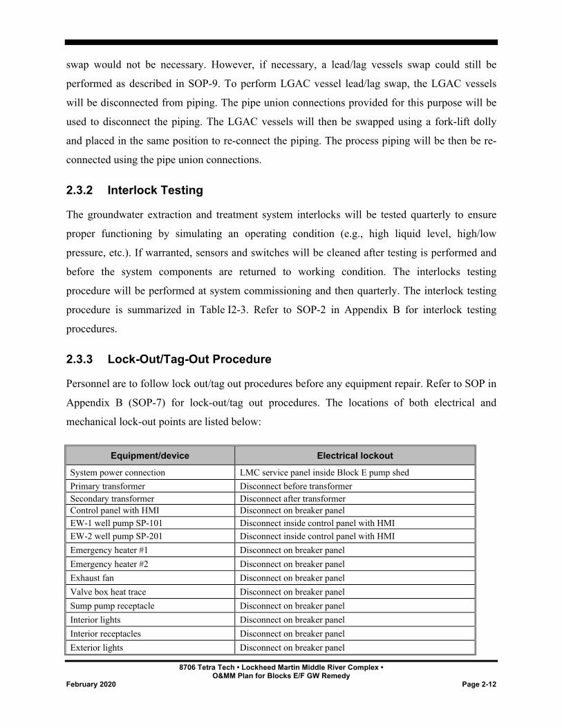
2.3.3 Lock-Out/Tag-Out Procedure
Personnel are to follow lock out/tag out procedures before any equipment repair. Refer to SOP in
Appendix B (SOP-7) for lock-out/tag out procedures. The locations of both electrical and
mechanical lock-out points are listed below:
Equipment/device Electrical lockout
System power connection LMC service panel inside Block E pump shed Primary transformer Disconnect before transformer Secondary transformer Disconnect after transformer Control panel with HMI Disconnect on breaker panel EW-1 well pump SP-101 Disconnect inside control panel with HMI EW-2 well pump SP-201 Disconnect inside control panel with HMI Emergency heater #1 Disconnect on breaker panel Emergency heater #2 Disconnect on breaker panel Exhaust fan Disconnect on breaker panel Valve box heat trace Disconnect on breaker panel Sump pump receptacle Disconnect on breaker panel Interior lights Disconnect on breaker panel Interior receptacles Disconnect on breaker panel Exterior lights Disconnect on breaker panel
8706 Tetra Tech • Lockheed Martin Middle River Complex • O&MM Plan for Blocks E/F GW Remedy
February 2020 Page 2-13
Emergency lights Disconnect on breaker panel
2.3.4 Air Stripper Cleaning
General Information
A shallow tray air stripper (QED EZ 2.6P model) will be used to remove volatile organic
compounds (VOCs) such as trichloroethene (TCE) from groundwater. Refer to Appendix A of
the design report for the general design information and to SOP-2 in Appendix B for cleaning
procedures. Refer to “Air Stripper Manufacturer Manual” for the air stripper operation and
maintenance details,
During operation, the trays of shallow tray air strippers can be fouled by suspended solids and by
solids such as iron that precipitate due to oxidation. Air stripper performance can be reduced by
solids precipitation and fouling to a point when tray cleaning is required.
Cleaning Criteria
During the system startup, a baseline pressure drop for the air stripper will be established. This
can be done by reading the vacuum level at the air stripper outlet. This baseline vacuum should
be approximately 20 inches water column (in. WC). Air stripper cleaning will be considered
when this baseline pressure drop increases by approximately 6 in. WC (or 1 in. WC per tray).
Refer to DOP-2 in Appendix B for air stripper cleaning procedures. All liquid and/or solid
wastes generated during air stripper cleaning would be handled as described in SOP-10 in
Appendix B.).
2.3.5 Performance Monitoring
Performance monitoring for the Blocks E and F groundwater extraction and treatment system
will include three components:
• process parameter monitoring and adjustment
• treatment system efficiency evaluation
• monitoring of hydraulic capture and contaminant distribution in Block F

8706 Tetra Tech • Lockheed Martin Middle River Complex • O&MM Plan for Blocks E/F GW Remedy
February 2020 Page 2-14
Process parameter monitoring and adjustment will consist of monitoring and adjustment of the
process parameters, including: readings for flows and pressures at each extraction well and
operation flows, pressures, and temperatures at all monitoring points in the system. Operating
data will be compared to system performance goals, equipment performance criteria, and other
benchmarks and evaluated for discrepancies. The expected operating parameters, acceptable
operating ranges, and criteria for adjustment are summarized in Table I2-1.
The treatment system efficiency evaluation will be based on the results of the influent and
effluent sampling and will determine the efficiency of the treatment process and contaminant
mass removal. Specifically, the treatment efficiency of the air stripper and VGAC vessels will be
determined. The LGAC vessels are not expected to receive any measurable VOC loading and
thus treatment efficiency of the LGAC units may not be quantifiable. Refer to Table I2-4 for
sampling locations, parameters to be collected and laboratory analytical methods. In addition,
each air sampling location will be screened with a PID during site visits. The screening results
will be used as a basis for vapor-phase treatment performance evaluation.
The sanitary sewer discharge permit for the treatment has not been received yet. However, based
on the sanitary sewer discharge permit requirements for the multi-phase extraction (MPE) system
that operated at this location in 2015 the following discharge monitoring will be required:
Total flow discharged (totalizer meter reading) - monthly
Average daily flow (calculated from total flow) - monthly
Effluent VOCs (grab sample; 2130 ug/L maximum) - monthly
Effluent pH (grab sample; range 6 to 10 units - monthly
Monitoring of hydraulic capture achieved by the groundwater extraction system will consist of
monthly elevation measurements of groundwater table in selected Block F observation wells and
piezometers (Table I2-5), followed by a calculation of the drawdown achieved by pumping in
those locations, and a comparison of the measured drawdown values with the values that are
necessary to achieve a hydraulic capture of the TCE plume as predicted by the groundwater
model. If a hydraulic capture of the TCE plume in Block F cannot be achieved even when
8706 Tetra Tech • Lockheed Martin Middle River Complex • O&MM Plan for Blocks E/F GW Remedy
February 2020 Page 2-15
extraction wells EW-1 and EW-2 are fully stressed (i.e., at maximum pumping rates with water
level near the pumps’ intake), the groundwater extraction system design will be evaluated, and
additional extraction wells may be added to achieve complete hydraulic capture of the TCE
plume. The piping and treatment system design includes such accommodation, such as two spare
one-inch-diameter high-density polyethylene (HDPE) lines for two additional extraction wells
and additional treatment capacity (up to 20 gallons per minute [gpm]).
It is possible that due to fouling of the extraction well screens, the pumping rate from the Block
F extraction wells will decrease to a degree that achieving the design capture zone to intercept
the TCE plume in Block F becomes impossible. In this case, the extraction wells may need to be
re-developed and the screens cleaned using high velocity nozzles. Such well development and
cleaning procedures have been successfully implemented during ARD system operation in
Blocks G and I. Groundwater extraction in Block F is expected to reduce TCE concentrations
and other VOC concentrations in Block F. The baseline groundwater samples for VOCs and
other geochemical parameters will be collected from Block F monitoring wells before system
startup. Sampling at these locations will be continued during the system operation.
It should be noted that a mass discharge study is currently being performed by Lockheed Martin
in the Block E and F area. In January 2019, fourteen (14) mass discharge study monitoring wells
were installed in Block F near the Dark Head Cove as shown on Drawings C-2 and C-5. These
wells will be monitored and sampled under the mass discharge study scope of work. If necessary,
the data collected from these wells could be used as additional information to determine if the
TCE plume in Block F is being intercepted by the groundwater treatment system.
Another element of the groundwater remedy in Block F that is expected to reduce the
concentrations of TCE and other VOCs is the permeable reactive barrier (PRB) to be installed in
Block F (see Section 3). After the PRB is installed, monitoring of the combined effects of
groundwater extraction and PRB operation will continue. Groundwater extraction and PRB
operation will be conducted simultaneously, and both remedies will use the same monitoring
wells for performance monitoring sampling, so sampling will be performed jointly. Refer to
Tables I3-1 and I3-2 for sampling locations, sampling parameters to be collected, and laboratory
analytical methods.
8706 Tetra Tech • Lockheed Martin Middle River Complex • O&MM Plan for Blocks E/F GW Remedy
February 2020 Page 3-1
SECTION 3 BLOCK F PERMEABLE REACTIVE BARRIER
This section describes the activities related to the operations, maintenance and monitoring
(OMM) of the permeable reactive barrier (PRB) in Block F. As described in the Groundwater
Remedy Blocks E/F Design Report (Tetra Tech, 2019), the PRB in Block F will be installed by
injection of reactive media into the subsurface using temporary injection points and a direct-push
drilling method. Therefore, no infrastructure will need to be maintained and operated after the
PRB is installed. Performance monitoring is the only operation, maintenance, and monitoring
(OMM) activity that will be performed during the operation of PRB and is described in this
section.
3.1 PILOT PRB MONITORING
As described in the Groundwater Remedy Blocks E/F Design Report (Tetra Tech, 2019), a pilot
test of the PRB will include a small-scale installation, and its performance will be evaluated
before the full-scale PRB installation. Based on the performance of the pilot PRB, the full-scale
PRB design will be modified (if necessary). To install the pilot PRB, the selected reactive media
(AquaZVI™ supplied by Regenesis or equivalent) will be injected into four locations (designated
as RB-1 through RB-4 on Drawing C-5).
The pilot PRB will be installed approximately ten feet upgradient of new performance
monitoring wells SEMW-10S/I and approximately ten feet downgradient of existing
performance monitoring well SEMW-7I. An additional new performance monitoring well cluster
(SEMW-11S/I) will be installed within the PRB. This monitoring layout allows for a rapid and
direct comparison between the conditions both upgradient, downgradient, and within the pilot
PRB.
As indicated in Section 3.4 of the Groundwater Remedy Blocks E/F Design Report (Tetra Tech,
2019), six DPT borings will be advanced in the locations indicated on Drawing C-5 and soil
8706 Tetra Tech • Lockheed Martin Middle River Complex • O&MM Plan for Blocks E/F GW Remedy
February 2020 Page 3-2
samples collected before the PRB pilot test installation. The sampling of these borings is detailed
in the design report.
Soil samples from the vicinity of each of these six DPT borings will be collected immediately
after the PRB pilot test injection is completed to determine the radius of influence of ZVI
injection. A comparison of the soil iron content before and after ZVI injections will allow for a
direct evaluation of the ROI achieved by the ZVI injections. Soil samples will be sent to an
analytical laboratory to determine total iron content using US EPA analytical method 6010C.
The pilot PRB will be installed before the groundwater treatment system operation begins. The
performance monitoring of the pilot PRB will include the determination of the effectiveness of
TCE removal by the PRB, potential production of vinyl chloride and cis-1,2-dichloroethene (cis-
1,2 DCE), iron particle migration, changes in dissolved and total iron concentrations, and other
parameters. These parameters will be determined by comparing the subsurface conditions
immediately upgradient and downgradient of the PRB. This will include water levels and
groundwater samples for volatile organic compounds (VOCs), iron, dissolved oxygen, oxidation
reduction potential, pH, conductivity, nitrate, sulfate, sulfide, and other biochemical parameters
will be collected in monitoring wells SEMW-7I, SEMW-10S/I and SEMW-11S/I.
It is anticipated that the pilot PRB monitoring duration will last between three and six months,
with the actual pilot duration depending on the performance results. If the conditions
downstream of the pilot PRB stabilize quickly and change little over time, then the pilot test
duration could be reduced. Performance monitoring samples will be collected more frequently at
the beginning of the test and less frequently thereafter. Refer to Table I3-1 for a summary of
sampling parameters to be collected during the pilot PRB operation, and the frequency of
sampling.
3.2 FULL SCALE PRB MONITORING
As described in the Groundwater Remedy Blocks E/F Design Report (Tetra Tech, 2019), the full
scale PRB will be essentially an extension of the pilot PRB shown on Drawing C-5; thus,
performance monitoring of the full scale PRB will be similar to pilot PRB monitoring (described
in Section 3.1 above).
8706 Tetra Tech • Lockheed Martin Middle River Complex • O&MM Plan for Blocks E/F GW Remedy
February 2020 Page 3-3
As indicated in Section 3.5 of the Groundwater Remedy Blocks E/F Design Report (Tetra Tech,
2019), a soil sampling program similar to the PRB pilot test soil sampling (described in Section
3.1 above) will be performed for the full-scale PRB. The main purpose of this soil sampling
program is to perform a direct evaluation of the radius of influence achieved by ZVI injections.
Before the full scale PRB installation, three DPT borings will be advanced approximately 25 feet
to the east of the PRB center line (SEMW-11S/I) and another three DPT borings will be
advanced approximately 25 feet to the west of the PRB center line (SEMW-11S/I). Locations of
these DPT borings are shown on Drawing C-5 as small green crosses. Sampling of these
locations is detailed in the design report.
Soil samples from the vicinity of each of these six DPT borings will be collected immediately
after the full scale ZVI injection is completed to confirm the radius of influence of ZVI injection.
Post ZVI-injection soil sampling intervals will be the same as the pre-injection background
sampling (5 soil samples per DPT boring location). A comparison of the soil iron content before
and after ZVI injections will allow for an evaluation of the ROI achieved by the ZVI injections.
The performance of the full-scale PRB will be evaluated by comparing the subsurface conditions
immediately upgradient and downgradient of the PRB, using monitoring wells SEMW-7I,
SEMW-10S/I and SEMW-11S/I (Drawing C-5). Extraction wells EW-1 and EW-2 will also be
used for the PRB performance monitoring. However, because the full-scale PRB could influence
a wider area, additional monitoring wells will also be used. Although piezometers PZ-1 and PZ-2
are outside the known TCE plume, they will be used to determine changes in total iron and other
biochemical parameters downgradient of the PRB. Monitoring well MW-37B will be used to
determine if VOCs migrate around the PRB during operation. Monitoring wells SEMW-8S/I and
SEMW-9S/I (Drawing C-5) will also be included, as indicated on Table I3-2. As described in
Section 2.3.5, the results of the wells sampling in Block F will be used for performance
monitoring of both the groundwater extraction system and the PRB.
During the PRB installation, Tetra Tech will perform visual monitoring of surface water bodies
for the presence of the injected fluids. If any changes in the surface water bodies are observed,
the PRB installation will be discontinued and Lockheed Martin personnel will be immediately
notified.
8706 Tetra Tech • Lockheed Martin Middle River Complex • O&MM Plan for Blocks E/F GW Remedy
February 2020 Page 3-4
It should be noted that a mass discharge study is currently being performed by Lockheed Martin
in the Block E and F area. In January 2019, fourteen (14) mass discharge study monitoring wells
were installed in Block F near Dark Head Cove as shown on Drawings C-2 and C-5. These wells
will be monitored and sampled under the mass discharge study scope of work. If required, the
analytical sampling results from these wells could be used as additional information for the PRB
performance evaluation.
8706 Tetra Tech • Lockheed Martin Middle River Complex • O&MM Plan for Blocks E/F GW Remedy
February 2020 Page 4-1
SECTION 4 BLOCK E ARD SYSTEM INJECTION EVENT
ARD activities described in this section will not start until after the Block E soil remedy is
completed in late 2021/early 2022.
The groundwater response action at the Middle River Complex (MRC) site is described in the
Groundwater Response Action Plan (Tetra Tech, Inc. [Tetra Tech] 2012) and in the
Groundwater Response Action Design Report (Tetra Tech, 2013). This groundwater response
action employs enhanced anaerobic reductive dechlorination (ARD) technology in three areas
with elevated groundwater concentrations of trichloroethene (TCE): the southeastern
trichloroethene area (Block E), the southwestern trichloroethene area (Block G), and the northern
trichloroethene area (Block I). ARD technology has already been implemented in Blocks G and
I, and the results and recommendations for these areas were presented in the following reports:
First Injection Event Completion Report (Tetra Tech, 2015a), Second Injection-Event
Completion Report, Blocks G and I (Tetra Tech, 2016a), Third Injection-Event Completion
Report, Block I (Tetra Tech, 2018b).
The methods for monitoring, operating, and maintaining the ARD-based groundwater remedy at
the MRC site are presented in the Operations and Maintenance Plan for Groundwater
Remediation System at the Lockheed Martin Middle River Complex (Tetra Tech, 2014).
However, the implementation of ARD in Block E was delayed by the need to address the TCE
source related to the underground storage tank that was discovered in the injection area during
the ARD system construction. Currently, the ARD operation is planned for 2021 after the soil
remediation in Block E is finished. The current operations and maintenance plan (Tetra Tech,
2014) does not contain a section that describes the injection event specifics for Block E, so this
section provides general approach for future ARD implementation in Block E. It should be noted
that details such as injection processes, injection equipment modules description, operating
procedures, troubleshooting, lock-out-tag-out procedures are not presented here. Refer to the
former operations and maintenance plan (Tetra Tech, 2014) for these details.
8706 Tetra Tech • Lockheed Martin Middle River Complex • O&MM Plan for Blocks E/F GW Remedy
February 2020 Page 4-2
In 2016, a tracer study was performed in Block E to develop specific information for ARD
implementation. The tracer study results and recommendations were presented in the Block E
Tracer Study Report (Tetra Tech, 2016b). The details of the ARD injection described in this
section are based on those tracer study results, and on the recommendations and experience
accumulated during the ARD implementation in Blocks G and I between 2013 and 2017.
4.1 GENERAL METHODOLOGY
The injection event in Block E will be performed to achieve more rapid and complete TCE
reduction by injecting the biological amendments (substrate, pH buffer and dehalococcoides
[DHC] cultures) in the areas with elevated TCE concentrations, thus avoiding downgradient
spread of TCE and its degradation products. At the same time, the injection program is down-
scaled in the upgradient area of Block E where the TCE concentrations are very low.
Logistically, the first full-scale injection event will consist of two injection phases with a
relatively short monitoring phase between the injections. The sequence of the first Block E
injection is presented below:
• Perform the injection event in a phased approach.
o Phase A injection— Inject substrate and pH buffer solution to create favorable conditions for bio-augmentation.
o Monitoring phase— Determine if conditions favorable for bio-augmentation are achieved.
o Phase B injection— Perform bio-augmentation with DHC cultures as part of the first injection, using the approach developed for Block G. Based on its success in Block G, DHC injection is expected to accelerate the TCE degradation process in Block E. Injection sequencing is covered in Section 4.3.
• The sodium lactate substrate dosage should be increased from the design values documented in the remedial design report (Tetra Tech 2013), because current aerobic conditions must be overcome quickly to create favorable conditions for bioaugmentation.
• The sodium bicarbonate dosage should likewise be increased as compared to that in the remedial design report (Tetra Tech 2013), because current pH levels are lower than the levels favorable for DHC cultures, and our experience at Block G suggests that the calculations in the remedial design report (Tetra Tech, 2013) underestimate the actual buffer volumes needed.
8706 Tetra Tech • Lockheed Martin Middle River Complex • O&MM Plan for Blocks E/F GW Remedy
February 2020 Page 4-3
• Deliver sodium bicarbonate buffer directly to the injection wells. The experience at Blocks G and I suggest that carbonate-scale precipitate severely impacts injection-manifold instrumentation and prevents increased buffer delivery. Direct placement of sodium bicarbonate was successful at Blocks G and I and did not have any negative impact.
• The injections will be performed on a rotating basis: substrate and buffer will be injected in one group of wells for a specific period, then the injection will be switched to another group of wells.
To minimize groundwater mounding and reduce the risk of injectate release to the surface, the
injection pressures will be monitored and kept at levels below 5 pounds per square inch (psi).
The system interlocks will be adjusted such that an injection well will be turned off if its
injection pressure exceeds 5 psi. The importance of injection pressure monitoring will be stressed
in the system operator training.
Water levels in the Block E monitoring wells will be measured every site visit during the initial 2
weeks of the injection and then bi-weekly. The measured water levels will be used to evaluate
groundwater mounding. The injection rates will be reduced if excessive groundwater mounding
is observed (water levels less than 1 foot below grade surface).
The system operators will also visually examine utilities, outfalls, and channels for the presence
of the injected solution. If the injected solution is detected, corrective actions such as a reduction
in the injection flows and pressures and shutting down the injection wells in the problem areas
will be undertaken.
4.2 INJECTION VOLUMES AND AMENDMENT DOSAGES
The modified injection volumes and amendment dosages are based on the revised
1,000 microgram per liter (µg/L) TCE contour shown on Drawing C-2. The area within the
revised 1,000 µg/L TCE contour is approximately 20,000 square feet, approximately 40%
smaller than the original design value. (Refer to Table 3-2 in the groundwater response action
100% design document [Tetra Tech, 2013] for the original design values.) The target lactate
concentration in pore volume is increased from the original design value (see Table 3-4 in Tetra
Tech, 2013) of 400 milligram per liter (mg/L) to 1,000 mg/L. Note that for the area outside the
revised 1,000 µg/L TCE contour (approximately 15,000 square feet, see Table I4-1) the modified
target pore volume lactate concentration is 50% less (500 mg/L). Table I4-1 contains calculation
8706 Tetra Tech • Lockheed Martin Middle River Complex • O&MM Plan for Blocks E/F GW Remedy
February 2020 Page 4-4
details. A general comparison between the original design values and the modified design is on
Table I4-2.
The target pore volume concentration for sodium bicarbonate is increased from the original
design value of 80 mg/L (Table 3-7 in Tetra Tech, 2013) to 200 mg/L for the area within the
revised 1,000 µg/L TCE contour. Note that the modified sodium bicarbonate concentration is
50% less (100 mg/L) for the area outside the revised contour (approximately 15,000 square feet,
Table I4-1). Refer to Table I4-1 for calculation details. A general comparison between the
original design values and the modified design is on Table I4-2.
The remaining parameters (formation porosity, injection interval, and injection volume to pore
volume ratio) are retained the same as in the original design (Table 3-2 in the original design
document). The modified injection volumes and amendment dosages for Block E are
summarized in Table I4-1, and Table I4-2 includes a comparison of original design values to
modified values.
4.3 INJECTION SEQUENCE
The first injection is phased to include the steps necessary to establish suitable conditions for
bioaugmentation. These conditions (to be achieved for 50-75% of the treatment area) are defined
as follows:
• total organic carbon > 100 mg/L
• oxidation-reduction potential < -50 milliVolts
• dissolved oxygen < 0.5 mg/L
• 8.0 > pH > 6.5
The following phased approach is used to configure the injection sequence for Block E:
• Phase A— Inject sodium lactate substrate and sodium bicarbonate buffer solution into all 28 injection wells. A full design volume with the revised amendment dosages (Table I4-1) will be injected. Refer to Table I4-3 for the solution volumes, injection rates, and amendments dosages. The expected duration of Phase A is approximately six to eight weeks. The injections will be performed in three groups of wells (Group #1 [10 wells], Group #2 [10 wells], and Group #3 [eight wells]).
8706 Tetra Tech • Lockheed Martin Middle River Complex • O&MM Plan for Blocks E/F GW Remedy
February 2020 Page 4-5
• Monitoring phase— Perform monitoring and determine if the conditions suitable for bio-augmentation are achieved within 1,000 µg/L TCE contour. The following monitoring wells will be sampled for total organic carbon and field parameters: SEMW-1I, SEMW-2I, SEMW-3I, SEMW-4I, SEMW-5I, SEMW-6I, SEMW-7I, SEMW-8I, IW-E, MW-72B, and MW-74B. Monitoring wells SEMW-6I, SEMW-7I, and SEMW-8I will also be sampled for VOCs. Go to next step if proper conditions suitable for bio-augmentation are achieved. Otherwise, certain modifications to the injection sequence will be considered, such as a longer pause before implementing Phase B; additional substrate and/or pH buffer injections; changes in the injection volumes, rates, and amendments dosages. The expected duration of monitoring phase is approximately four to six weeks.
• Phase B— Perform bioaugmentation for the wells within the revised 1,000 µg/L TCE contour. Inject 50% of the full design volume and amendments (as shown in Table I4-3). The injections will be performed in two groups of wells (Group #1 [10 wells] and Group #2 [8 wells]). The expected duration of Phase B is approximately two to three weeks. Bioaugmentation for the areas outside the revised 1,000 µg/L TCE contour is not planned.
This general injection sequence is presented in a more detail on Table I4-3. Introducing DHC
cultures (KB-1) for bioaugmentation and preparing the solution will be conducted in the same
manner as for Block G (water prepared in frac tank; oxygen-free environment in frac tank
maintained by argon).
It should be noted that fouling of the injection manifold and injection lines was experienced
during the earlier injection events in Blocks G and I and extensive experience was obtained to
prevent fouling. It was determined that direct placement of sodium bicarbonate in the injection
wells eliminates fouling of the process lines. Sodium bicarbonate will be placed in the injection
wells in small increment batches (10 pounds batch per each well) until the design dosage per
well is reached. Each 10-pound load of sodium bicarbonate will be carried individually to reduce
injury potential due to heavy load lifting to the operators.
If fouling of the injection manifold and/or the individual lines to the injection wells does occur,
the system operators will isolate the affected portion of the piping and flush the affected piping
using treated potable water.
It is possible that due to fouling of the injection well screens, the flows to some injection wells
will decrease and injection pressures increase to a degree that achieving the design injection
volumes becomes impossible. In this case the selected injection wells may need to be re-
developed and screens cleaned using high velocity nozzles. Such well development and cleaning
8706 Tetra Tech • Lockheed Martin Middle River Complex • O&MM Plan for Blocks E/F GW Remedy
February 2020 Page 4-6
procedures have been successfully implemented during ARD system operation in Blocks G and
I. However, due to higher formation permeability in Block E and the 2016 tracer test experience,
it is anticipated that the overall needs for injection well re-development and cleaning in Block E
will be less compared to Blocks G and I.
Sodium lactate drums will be unloaded from a freight truck by the delivery company workers
and then the sodium lactate will be transferred directly from the drums to the lactate dosing tank
using drum transfer pumps. There will be no need to move or handle the full drums of sodium
lactate. However, the system operators will be trained in safe drum handling techniques and
proper drum handling equipment such as drum lifting dollies will be available.
4.4 PERFORMANCE MONITORING
Performance monitoring in Block E after Phase B of the first injection will be conducted similar
to how performance monitoring was conducted in Blocks G and I. The evaluation methodology
and criteria, monitoring parameters, sampling procedures and other details are described in
Appendix B of the Operation and Maintenance Plan for Groundwater Remediation System at
Lockheed Martin Middle River Complex (Tetra Tech, 2014) and not included in this document to
avoid redundancy.
Performance-monitoring sampling for Block E will include the baseline monitoring event and
four follow-up monitoring rounds. Baseline monitoring will include collecting samples from
several injection wells and analysis for VOCs. Additional data from the injection wells in
Block E together will be used together with data from the Block E monitoring wells to determine
the pre-injection TCE plume in Block E, and to evaluate whether any changes in the TCE plume
configuration occurred after the last comprehensive sampling event performed in 2016.
During the ARD injection start-up a Site Operator will perform the visual monitoring of surface
water bodies for a presence of the injected fluids. In case if any changes in the surface water
bodies are observed the injections will be shut down and the LMC personnel will be immediately
notified.
8706 Tetra Tech • Lockheed Martin Middle River Complex • O&MM Plan for Blocks E/F GW Remedy
February 2020 Page 4-7
Follow-up monitoring events will be conducted after Phase B of the first injection is complete, at
one, three, six, and 12 months. A summary of performance monitoring sampling including
sampling locations, analytical parameters, and frequency is included in Table I4-4.
It should be noted that a mass discharge study is currently being performed by Lockheed Martin
in the Block E and F area. In January 2019, nine (9) mass discharge study monitoring wells were
installed in Block E as shown on Drawing C-2. These wells will be monitored and sampled
under the mass discharge study scope of work. If necessary, the data collected from these wells
could be used as additional information for ARD system performance evaluation.
Note that all selected sampling locations are in Block E. However, groundwater sampling results
associated with performance monitoring of the groundwater extraction system and the Block F
PRB (described in Section 3.0) will also be used to evaluate the effects that the first Block E
injection has on conditions in Block F.
Following completion of the ARD and groundwater extraction system operation, Lockheed
Martin will develop a plan for sampling of site soil to determine if there is residual soil
contamination above industrial standards in the treatment area. If present, a plan for addressing
this soil contamination will be developed at that time.
8706 Tetra Tech • Lockheed Martin Middle River Complex • O&MM Plan for Blocks E/F GW Remedy
February 2020 Page 5-1
SECTION 5 REPORTING
Three different types of reports will be prepared during the groundwater remedy operation at
Blocks E and F: Groundwater Extraction and Treatment System (GWETS) Progress Report,
Sanitary Sewer Discharge Report, and Permeable Reactive Barrier (PRB) Performance
Monitoring Report. The description of these reports is presented in the following sections.
5.1 GWETS PROGRESS REPORT
GWETS progress reports will be prepared quarterly and submitted to Remedial Technical
Operations (RTO) and Lockheed Martin Corporation (Lockheed Martin) for review and
approval. The final reports will be submitted to Maryland Department of the Environment
(MDE). These reports will include:
• extracted groundwater volumes for the monitoring period (total and per extraction well)
• treated groundwater volumes for the monitoring period
• efficiency evaluation for treatment system influent, process, and effluent data
• summary of activities performed during the reporting period
• field notes/daily activity logs
• system down time durations and reasons
• results from laboratory analytical samples
• recommendations for continued operation
5.2 SANITARY SEWER DISCHARGE REPORT
Sanitary Sewer Discharge Reports will be prepared quarterly and submitted to RTO and
Lockheed Martin for review and approval. The final reports will be submitted to Baltimore
8706 Tetra Tech • Lockheed Martin Middle River Complex • O&MM Plan for Blocks E/F GW Remedy
February 2020 Page 5-2
County Department of Public Works (Bureau of Utilities, Engineering & Regulation Division).
These reports will include:
• Total discharged groundwater volumes for the monitoring period
• Calculated daily discharge volume
• Analytical data for the treated discharge
5.3 PRB PERFORMANCE MONITORING REPORT
PRB performance monitoring reports will be prepared quarterly and submitted to RTO and
Lockheed Martin for review and approval. The final reports will be submitted to MDE. These
reports will include:
• summary of activities performed during the reporting period
• results from laboratory analytical samples
• field notes
• efficiency evaluation for PRB for the reporting period

8706 Tetra Tech • Lockheed Martin Middle River Complex • O&MM Plan for Blocks E/F GW Remedy
February 2020 Page 6-1
SECTION 6 REFERENCES
Tetra Tech, Inc. (Tetra Tech), 2012. Groundwater Response Action Plan, Lockheed Martin Middle River Complex. Report prepared by Tetra Tech, Inc., Germantown, Maryland for Lockheed Martin Corporation, Bethesda, Maryland. August.
Tetra Tech, Inc. (Tetra Tech), 2013. Groundwater Response Action 100% Design Basis Report. Report prepared by Tetra Tech, Inc., Germantown, Maryland for Lockheed Martin Corporation, Bethesda, Maryland. September.
Tetra Tech Inc. (Tetra Tech), 2014. Operation and Maintenance Plan for Groundwater Remediation System at Lockheed Martin Middle River Complex, 2323 Eastern Boulevard, Middle River, Maryland. Report prepared by Tetra Tech, Inc., Germantown, Maryland for Lockheed Martin Corporation, Bethesda, Maryland. October.
Tetra Tech Inc. (Tetra Tech), 2015a. First Injection Event Completion Report. Report prepared by Tetra Tech, Inc., Germantown, Maryland for Lockheed Martin Corporation, Bethesda, Maryland. November.
Tetra Tech, Inc. (Tetra Tech), 2015b. Groundwater Response Action Plan Addendum No. 2: Response-Action Objective and Project Implementation Schedule, Lockheed Martin Middle River Complex. Report prepared by Tetra Tech, Inc., Germantown, Maryland for Lockheed Martin Corporation, Bethesda, Maryland. September.
Tetra Tech Inc. (Tetra Tech), 2016a. Second Injection-Event Completion Report, Blocks G and I Lockheed Martin Middle River Complex 2323 Eastern Boulevard Middle River, Maryland. Report prepared by Tetra Tech, Inc., Germantown, Maryland for Lockheed Martin Corporation, Bethesda, Maryland. December.
Tetra Tech, Inc. (Tetra Tech), 2016b. Block E Tracer Study Report, Lockheed Martin Middle River Complex. Report prepared by Tetra Tech, Inc., Germantown, Maryland for Lockheed Martin Corporation, Bethesda, Maryland. October.
Tetra Tech, Inc. (Tetra Tech), 2017a. Block E Downgradient Trichloroethene Groundwater Investigation, Lockheed Martin Middle River Complex. Report prepared by Tetra Tech, Inc., Germantown, Maryland for Lockheed Martin Corporation, Bethesda, Maryland. May.
Tetra Tech, Inc. (Tetra Tech), 2017b. Block E Downgradient Trichloroethene Plume Additional Investigation Report, Lockheed Martin Middle River Complex. Report prepared by Tetra Tech, Inc., Germantown, Maryland for Lockheed Martin Corporation, Bethesda, Maryland. December.

8706 Tetra Tech • Lockheed Martin Middle River Complex • O&MM Plan for Blocks E/F GW Remedy
February 2020 Page 6-2
Tetra Tech, Inc. (Tetra Tech), 2018a. Groundwater Response Action Plan Addendum No. 4: Blocks E and F, Lockheed Martin Middle River Complex. Report prepared by Tetra Tech, Inc., Germantown, Maryland for Lockheed Martin Corporation, Bethesda, Maryland. July.
Tetra Tech Inc. (Tetra Tech), 2018b. Third Injection-Event Completion Report, Block I Lockheed Martin Middle River Complex 2323 Eastern Boulevard Middle River, Maryland. Report prepared by Tetra Tech, Inc., Germantown, Maryland for Lockheed Martin Corporation, Bethesda, Maryland. November

8706 Tetra Tech • Lockheed Martin Middle River Complex • O&MM Plan for Blocks E/F GW Remedy
February 2020 Tables
TABLES
8706 Tetra Tech • Lockheed Martin Middle River Complex • O&MM Plan for Blocks E/F GW Remedy
February 2020 Tables
Table I2-1 Process Parameters Operating Ranges
Table I2-2 Start-Up GWETS Sampling Summary
Table I2-3 Interlocks Testing Procedure
Table I2-4 GWETS 1st Year of Operation Treatment Efficiency Sampling Summary
Table I2-5 Block F Groundwater Table Monitoring Locations
Table I2 6 GWETS Spare Parts List
Table I3-1 Block F PRB Pilot Test Performance Monitoring Frequency and Analytical Parameters
Table I3-2Block F 1st Year Performance Monitoring Frequency and Analytical Parameters
Table I4-1 Injection Volumes and Amendment Dosages for Block E 1st Injection
Table I4-2 Comparison of Original and Revised Parameters for Block E Phase A Injection Event
Table I4-3 1st Injection Event for Block E Remedy
Table I4-4 Block E Performance Monitoring Frequency and Analytical Parameters
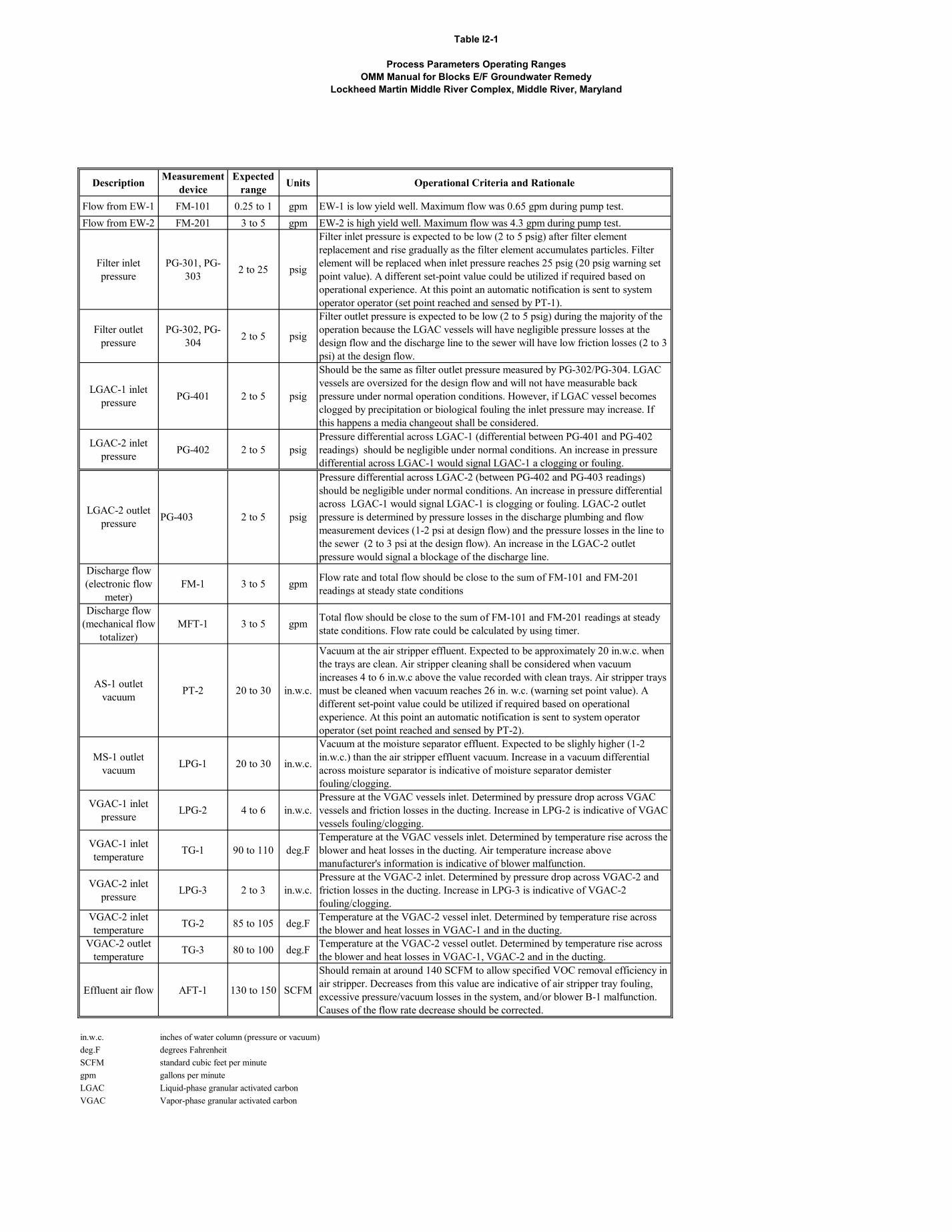
Table I2-1
Process Parameters Operating RangesOMM Manual for Blocks E/F Groundwater Remedy
Lockheed Martin Middle River Complex, Middle River, Maryland
Description Measurement device
Expected range Units Operational Criteria and Rationale
Flow from EW-1 FM-101 0.25 to 1 gpm EW-1 is low yield well. Maximum flow was 0.65 gpm during pump test.Flow from EW-2 FM-201 3 to 5 gpm EW-2 is high yield well. Maximum flow was 4.3 gpm during pump test.
Filter inlet pressure
PG-301, PG-303 2 to 25 psig
Filter inlet pressure is expected to be low (2 to 5 psig) after filter element replacement and rise gradually as the filter element accumulates particles. Filter element will be replaced when inlet pressure reaches 25 psig (20 psig warning set point value). A different set-point value could be utilized if required based on operational experience. At this point an automatic notification is sent to system operator operator (set point reached and sensed by PT-1).
Filter outlet pressure
PG-302, PG-304 2 to 5 psig
Filter outlet pressure is expected to be low (2 to 5 psig) during the majority of the operation because the LGAC vessels will have negligible pressure losses at the design flow and the discharge line to the sewer will have low friction losses (2 to 3 psi) at the design flow.
LGAC-1 inlet pressure PG-401 2 to 5 psig
Should be the same as filter outlet pressure measured by PG-302/PG-304. LGAC vessels are oversized for the design flow and will not have measurable back pressure under normal operation conditions. However, if LGAC vessel becomes clogged by precipitation or biological fouling the inlet pressure may increase. If this happens a media changeout shall be considered.
LGAC-2 inlet pressure PG-402 2 to 5 psig
Pressure differential across LGAC-1 (differential between PG-401 and PG-402 readings) should be negligible under normal conditions. An increase in pressure differential across LGAC-1 would signal LGAC-1 a clogging or fouling.
LGAC-2 outlet pressure PG-403 2 to 5 psig
Pressure differential across LGAC-2 (between PG-402 and PG-403 readings) should be negligible under normal conditions. An increase in pressure differential across LGAC-1 would signal LGAC-1 is clogging or fouling. LGAC-2 outlet pressure is determined by pressure losses in the discharge plumbing and flow measurement devices (1-2 psi at design flow) and the pressure losses in the line to the sewer (2 to 3 psi at the design flow). An increase in the LGAC-2 outlet pressure would signal a blockage of the discharge line.
Discharge flow (electronic flow
meter)FM-1 3 to 5 gpm Flow rate and total flow should be close to the sum of FM-101 and FM-201
readings at steady state conditions
Discharge flow (mechanical flow
totalizer)MFT-1 3 to 5 gpm Total flow should be close to the sum of FM-101 and FM-201 readings at steady
state conditions. Flow rate could be calculated by using timer.
AS-1 outlet vacuum PT-2 20 to 30 in.w.c.
Vacuum at the air stripper effluent. Expected to be approximately 20 in.w.c. when the trays are clean. Air stripper cleaning shall be considered when vacuum increases 4 to 6 in.w.c above the value recorded with clean trays. Air stripper trays must be cleaned when vacuum reaches 26 in. w.c. (warning set point value). A different set-point value could be utilized if required based on operational experience. At this point an automatic notification is sent to system operator operator (set point reached and sensed by PT-2).
MS-1 outlet vacuum LPG-1 20 to 30 in.w.c.
Vacuum at the moisture separator effluent. Expected to be slighly higher (1-2 in.w.c.) than the air stripper effluent vacuum. Increase in a vacuum differential across moisture separator is indicative of moisture separator demister fouling/clogging.
VGAC-1 inlet pressure LPG-2 4 to 6 in.w.c.
Pressure at the VGAC vessels inlet. Determined by pressure drop across VGAC vessels and friction losses in the ducting. Increase in LPG-2 is indicative of VGAC vessels fouling/clogging.
VGAC-1 inlet temperature TG-1 90 to 110 deg.F
Temperature at the VGAC vessels inlet. Determined by temperature rise across the blower and heat losses in the ducting. Air temperature increase above manufacturer's information is indicative of blower malfunction.
VGAC-2 inlet pressure LPG-3 2 to 3 in.w.c.
Pressure at the VGAC-2 inlet. Determined by pressure drop across VGAC-2 and friction losses in the ducting. Increase in LPG-3 is indicative of VGAC-2 fouling/clogging.
VGAC-2 inlet temperature TG-2 85 to 105 deg.F Temperature at the VGAC-2 vessel inlet. Determined by temperature rise across
the blower and heat losses in VGAC-1 and in the ducting.VGAC-2 outlet
temperature TG-3 80 to 100 deg.F Temperature at the VGAC-2 vessel outlet. Determined by temperature rise across the blower and heat losses in VGAC-1, VGAC-2 and in the ducting.
Effluent air flow AFT-1 130 to 150 SCFM
Should remain at around 140 SCFM to allow specified VOC removal efficiency in air stripper. Decreases from this value are indicative of air stripper tray fouling, excessive pressure/vacuum losses in the system, and/or blower B-1 malfunction. Causes of the flow rate decrease should be corrected.
in.w.c. inches of water column (pressure or vacuum)deg.F degrees FahrenheitSCFM standard cubic feet per minutegpm gallons per minuteLGAC Liquid-phase granular activated carbonVGAC Vapor-phase granular activated carbon
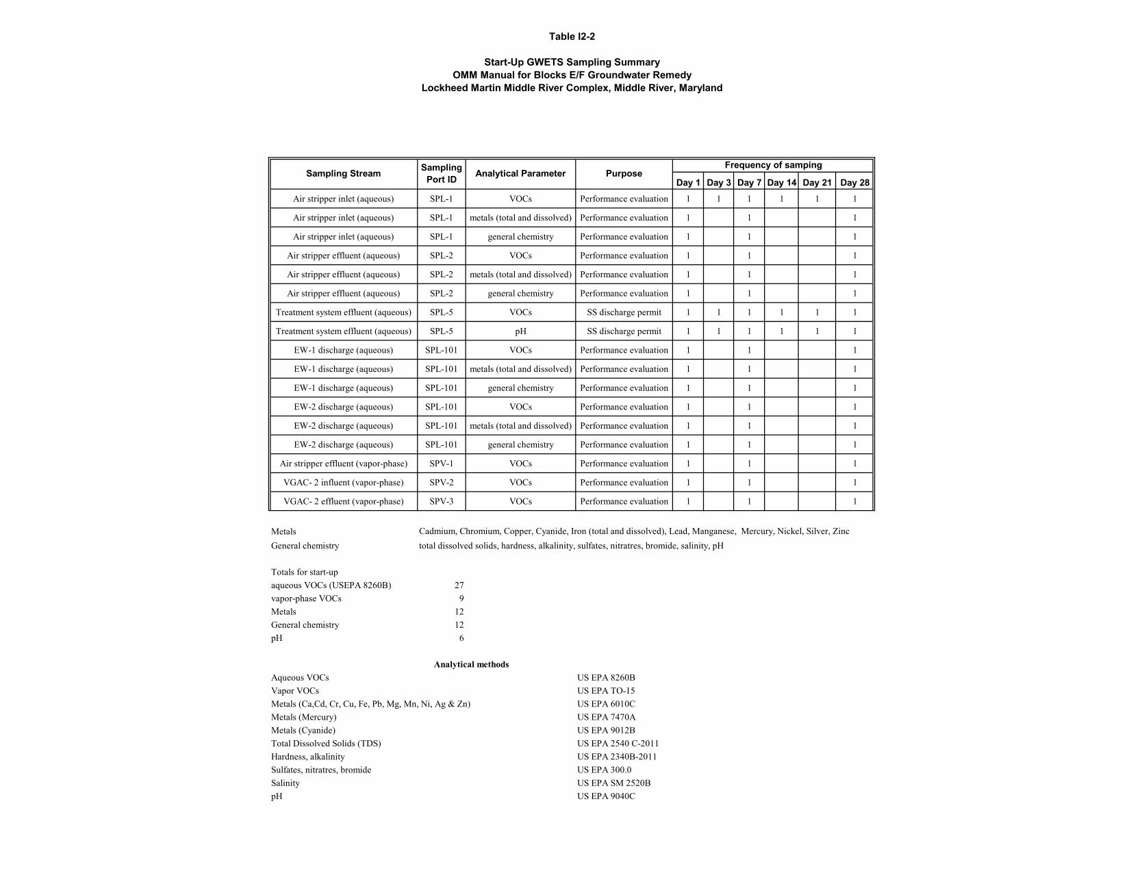
Table I2-2
Start-Up GWETS Sampling SummaryOMM Manual for Blocks E/F Groundwater Remedy
Lockheed Martin Middle River Complex, Middle River, Maryland
Day 1 Day 3 Day 7 Day 14 Day 21 Day 28Air stripper inlet (aqueous) SPL-1 VOCs Performance evaluation 1 1 1 1 1 1
Air stripper inlet (aqueous) SPL-1 metals (total and dissolved) Performance evaluation 1 1 1
Air stripper inlet (aqueous) SPL-1 general chemistry Performance evaluation 1 1 1
Air stripper effluent (aqueous) SPL-2 VOCs Performance evaluation 1 1 1
Air stripper effluent (aqueous) SPL-2 metals (total and dissolved) Performance evaluation 1 1 1
Air stripper effluent (aqueous) SPL-2 general chemistry Performance evaluation 1 1 1
Treatment system effluent (aqueous) SPL-5 VOCs SS discharge permit 1 1 1 1 1 1
Treatment system effluent (aqueous) SPL-5 pH SS discharge permit 1 1 1 1 1 1
EW-1 discharge (aqueous) SPL-101 VOCs Performance evaluation 1 1 1
EW-1 discharge (aqueous) SPL-101 metals (total and dissolved) Performance evaluation 1 1 1
EW-1 discharge (aqueous) SPL-101 general chemistry Performance evaluation 1 1 1
EW-2 discharge (aqueous) SPL-101 VOCs Performance evaluation 1 1 1
EW-2 discharge (aqueous) SPL-101 metals (total and dissolved) Performance evaluation 1 1 1
EW-2 discharge (aqueous) SPL-101 general chemistry Performance evaluation 1 1 1
Air stripper effluent (vapor-phase) SPV-1 VOCs Performance evaluation 1 1 1
VGAC- 2 influent (vapor-phase) SPV-2 VOCs Performance evaluation 1 1 1
VGAC- 2 effluent (vapor-phase) SPV-3 VOCs Performance evaluation 1 1 1
MetalsGeneral chemistry total dissolved solids, hardness, alkalinity, sulfates, nitratres, bromide, salinity, pH
Totals for start-upaqueous VOCs (USEPA 8260B) 27vapor-phase VOCs 9Metals 12General chemistry 12pH 6
Aqueous VOCs US EPA 8260BVapor VOCs US EPA TO-15Metals (Ca,Cd, Cr, Cu, Fe, Pb, Mg, Mn, Ni, Ag & Zn) US EPA 6010CMetals (Mercury) US EPA 7470AMetals (Cyanide) US EPA 9012BTotal Dissolved Solids (TDS) US EPA 2540 C-2011Hardness, alkalinity US EPA 2340B-2011Sulfates, nitratres, bromide US EPA 300.0Salinity US EPA SM 2520BpH US EPA 9040C
Analytical methods
Cadmium, Chromium, Copper, Cyanide, Iron (total and dissolved), Lead, Manganese, Mercury, Nickel, Silver, Zinc
Frequency of sampingSampling Stream Sampling
Port ID Analytical Parameter Purpose
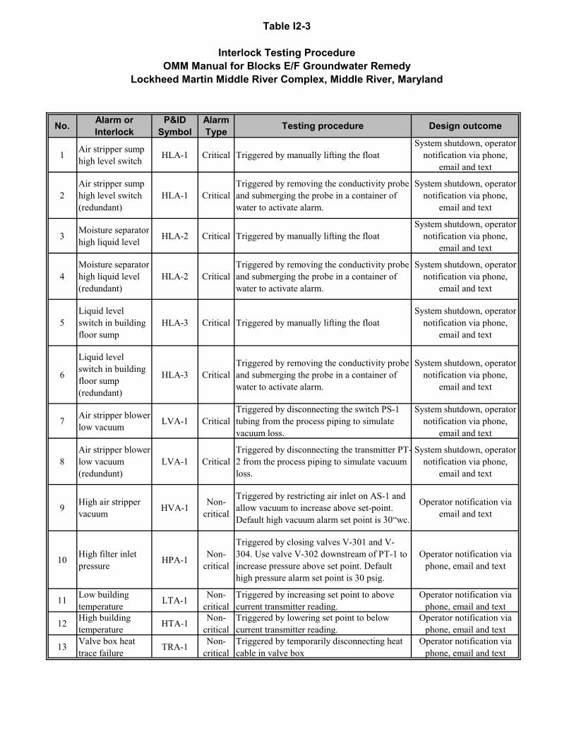
Table I2-3
Interlock Testing ProcedureOMM Manual for Blocks E/F Groundwater Remedy
Lockheed Martin Middle River Complex, Middle River, Maryland
No. Alarm or Interlock
P&ID Symbol
Alarm Type Testing procedure Design outcome
1 Air stripper sump high level switch HLA-1 Critical Triggered by manually lifting the float
System shutdown, operator notification via phone,
email and text
2Air stripper sump high level switch (redundant)
HLA-1 CriticalTriggered by removing the conductivity probe and submerging the probe in a container of water to activate alarm.
System shutdown, operator notification via phone,
email and text
3 Moisture separator high liquid level HLA-2 Critical Triggered by manually lifting the float
System shutdown, operator notification via phone,
email and text
4Moisture separator high liquid level (redundant)
HLA-2 CriticalTriggered by removing the conductivity probe and submerging the probe in a container of water to activate alarm.
System shutdown, operator notification via phone,
email and text
5Liquid level switch in building floor sump
HLA-3 Critical Triggered by manually lifting the floatSystem shutdown, operator
notification via phone, email and text
6
Liquid level switch in building floor sump (redundant)
HLA-3 CriticalTriggered by removing the conductivity probe and submerging the probe in a container of water to activate alarm.
System shutdown, operator notification via phone,
email and text
7 Air stripper blower low vacuum LVA-1 Critical
Triggered by disconnecting the switch PS-1 tubing from the process piping to simulate vacuum loss.
System shutdown, operator notification via phone,
email and text
8Air stripper blower low vacuum (redundunt)
LVA-1 CriticalTriggered by disconnecting the transmitter PT-2 from the process piping to simulate vacuum loss.
System shutdown, operator notification via phone,
email and text
9 High air stripper vacuum HVA-1 Non-
critical
Triggered by restricting air inlet on AS-1 and allow vacuum to increase above set-point. Default high vacuum alarm set point is 30“wc.
Operator notification via email and text
10 High filter inlet pressure HPA-1 Non-
critical
Triggered by closing valves V-301 and V-304. Use valve V-302 downstream of PT-1 to increase pressure above set point. Default high pressure alarm set point is 30 psig.
Operator notification via phone, email and text
11 Low building temperature LTA-1 Non-
criticalTriggered by increasing set point to above current transmitter reading.
Operator notification via phone, email and text
12 High building temperature HTA-1 Non-
criticalTriggered by lowering set point to below current transmitter reading.
Operator notification via phone, email and text
13 Valve box heat trace failure TRA-1 Non-
criticalTriggered by temporarily disconnecting heat cable in valve box
Operator notification via phone, email and text
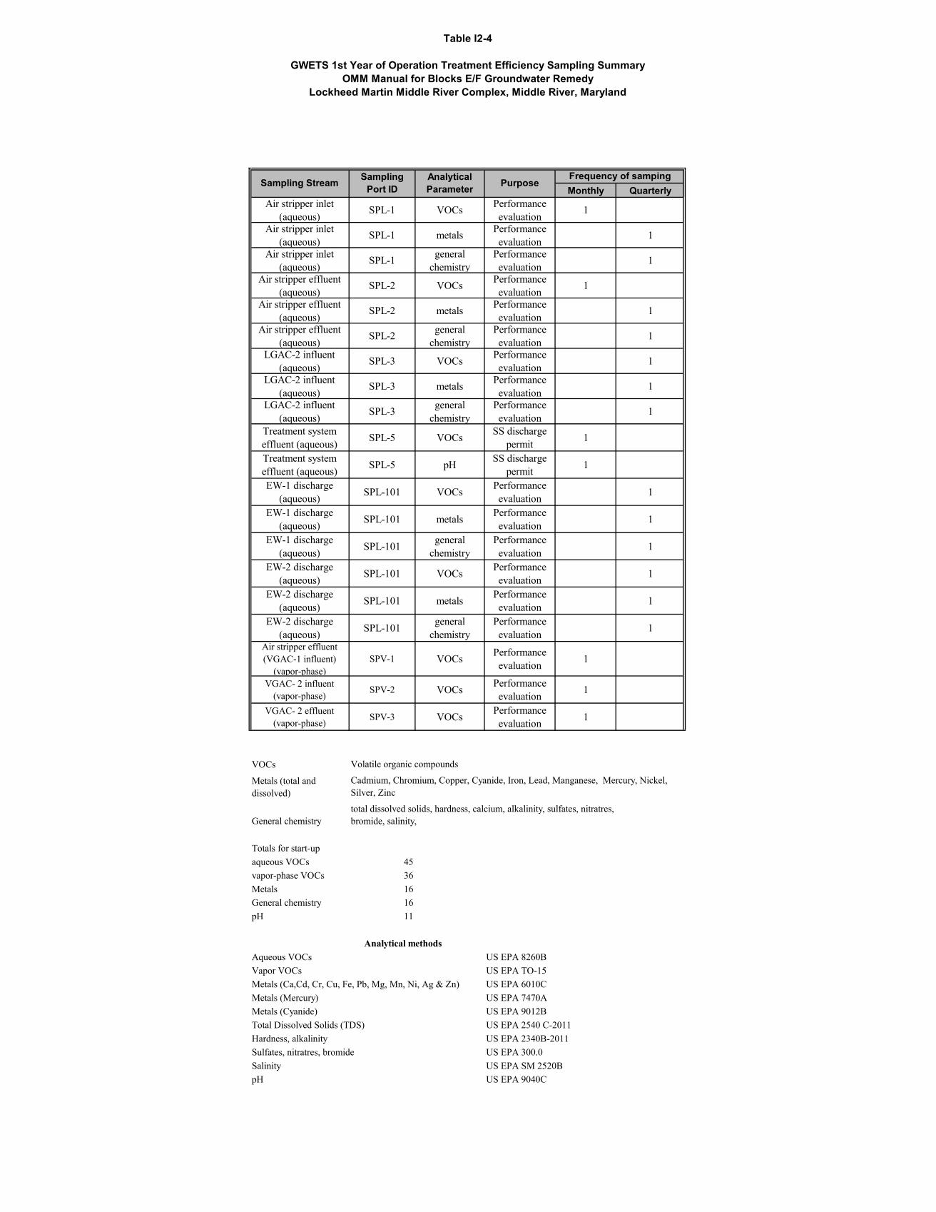
Table I2-4
GWETS 1st Year of Operation Treatment Efficiency Sampling SummaryOMM Manual for Blocks E/F Groundwater Remedy
Lockheed Martin Middle River Complex, Middle River, Maryland
Monthly QuarterlyAir stripper inlet
(aqueous) SPL-1 VOCs Performance evaluation 1
Air stripper inlet (aqueous) SPL-1 metals Performance
evaluation 1
Air stripper inlet (aqueous) SPL-1 general
chemistryPerformance evaluation 1
Air stripper effluent (aqueous) SPL-2 VOCs Performance
evaluation 1
Air stripper effluent (aqueous) SPL-2 metals Performance
evaluation 1
Air stripper effluent (aqueous) SPL-2 general
chemistryPerformance evaluation 1
LGAC-2 influent (aqueous) SPL-3 VOCs Performance
evaluation 1
LGAC-2 influent (aqueous) SPL-3 metals Performance
evaluation 1
LGAC-2 influent (aqueous) SPL-3 general
chemistryPerformance evaluation 1
Treatment system effluent (aqueous) SPL-5 VOCs SS discharge
permit 1
Treatment system effluent (aqueous) SPL-5 pH SS discharge
permit 1
EW-1 discharge (aqueous) SPL-101 VOCs Performance
evaluation 1
EW-1 discharge (aqueous) SPL-101 metals Performance
evaluation 1
EW-1 discharge (aqueous) SPL-101 general
chemistryPerformance evaluation 1
EW-2 discharge (aqueous) SPL-101 VOCs Performance
evaluation 1
EW-2 discharge (aqueous) SPL-101 metals Performance
evaluation 1
EW-2 discharge (aqueous) SPL-101 general
chemistryPerformance evaluation 1
Air stripper effluent (VGAC-1 influent)
(vapor-phase)SPV-1 VOCs Performance
evaluation 1
VGAC- 2 influent (vapor-phase) SPV-2 VOCs Performance
evaluation 1
VGAC- 2 effluent (vapor-phase) SPV-3 VOCs Performance
evaluation 1
VOCs
Metals (total and dissolved)
General chemistry
Totals for start-upaqueous VOCs 45vapor-phase VOCs 36Metals 16General chemistry 16pH 11
Aqueous VOCs US EPA 8260BVapor VOCs US EPA TO-15Metals (Ca,Cd, Cr, Cu, Fe, Pb, Mg, Mn, Ni, Ag & Zn) US EPA 6010CMetals (Mercury) US EPA 7470AMetals (Cyanide) US EPA 9012BTotal Dissolved Solids (TDS) US EPA 2540 C-2011Hardness, alkalinity US EPA 2340B-2011Sulfates, nitratres, bromide US EPA 300.0Salinity US EPA SM 2520BpH US EPA 9040C
Analytical methods
total dissolved solids, hardness, calcium, alkalinity, sulfates, nitratres, bromide, salinity,
Cadmium, Chromium, Copper, Cyanide, Iron, Lead, Manganese, Mercury, Nickel, Silver, Zinc
Sampling Stream Sampling Port ID
Analytical Parameter Purpose
Frequency of samping
Volatile organic compounds
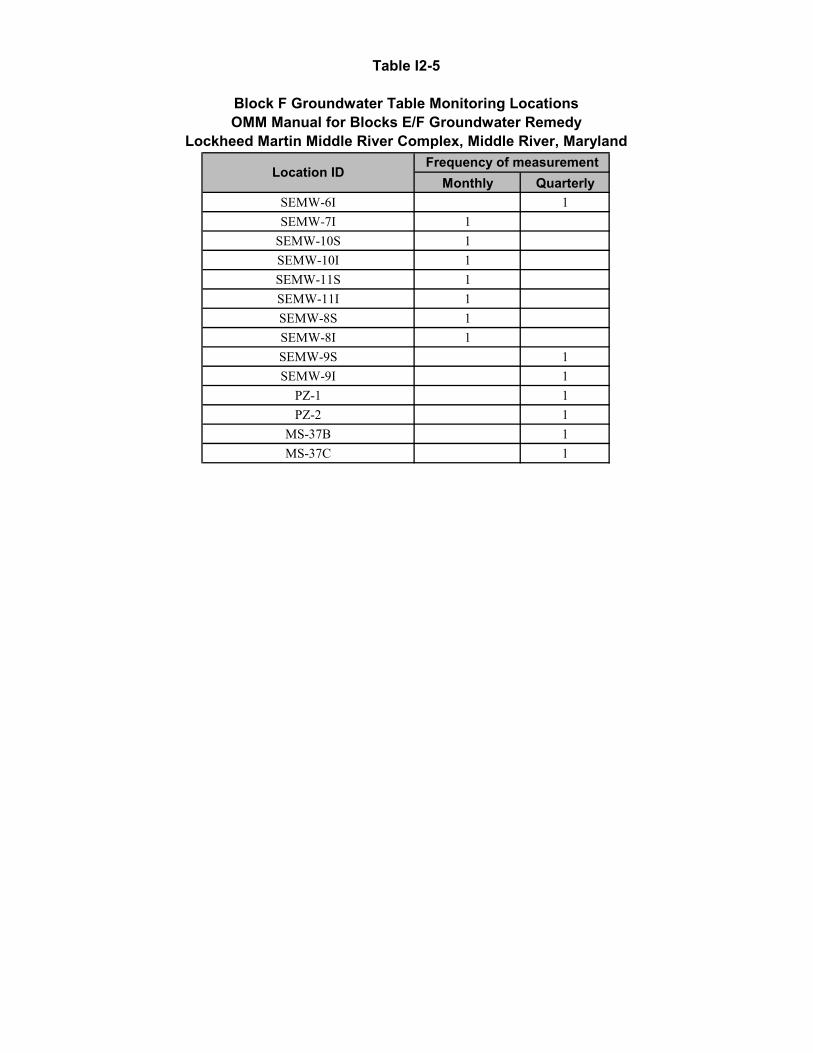
Table I2-5
Block F Groundwater Table Monitoring LocationsOMM Manual for Blocks E/F Groundwater Remedy
Lockheed Martin Middle River Complex, Middle River, Maryland
Monthly QuarterlySEMW-6I 1SEMW-7I 1
SEMW-10S 1SEMW-10I 1SEMW-11S 1SEMW-11I 1SEMW-8S 1SEMW-8I 1SEMW-9S 1SEMW-9I 1
PZ-1 1PZ-2 1
MS-37B 1MS-37C 1
Location IDFrequency of measurement
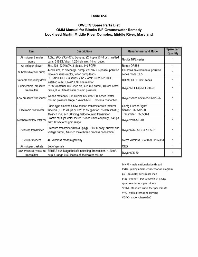
Table I2-6
GWETS Spare Parts ListOMM Manual for Blocks E/F Groundwater Remedy
Lockheed Martin Middle River Complex, Middle River, Maryland
Item Descriptioin Manufacturer and Model Spare part Quantity
Air stripper transfer pump
1.5hp, 208- 230/460V, 3-phase, 22.5 gpm @ 44 psig, wetted parts: 316SS, Viton, 1.25-inch inlet, 1-inch outlet Goulds NPE series 1
Air stripper blower 3hp, 208- 230/460V, 3-phase, 140 SCFM Rotron DR656 1
Submersible well pump 4-inch size, 1" discharge, 1/2hp, 230 VAC, 3-phase, pollution recovery series motor, teflon pump leads
Grundfos environmental pollution series model 5E5 1
Variable frequency drive DURAPULSE GS3 series, 2 hp 7 AMP 230V 3-PHASE, installed with DURAPULSE line reactor DURAPULSE GS3 series 1
Submersible pressure transmitter
316SS material, 0.63-inch dia, 4-20mA output, 40-foot Tefzel cable, 0 to 30 feet water column pressure Dwyer MBLT-S-IVEF-30-50 1
Low pressure transducer Wetted materials: 318 Duplex SS, 0 to 100 inches water column pressure tange, 1/4-inch MNPT process connection Dwyer series 672 model 672-5-A 1
Electronic flow meterPadle-type electronic flow sensor, transmitter with totalizer function (0.3 to 20 fps or 0.25 to 15 gpm for 1/2-inch sch 80); 1/2-inch PVC sch 80 fitting, field-mounted transmitter
Georg Fischer Signet Sensor: 3-8512-P0 Transmitter: 3-8550-1
1
Mechanical flow totalizer Bronze multi-jet water meter, ½-inch union couplings, 145 psi max, 0.125 to 20 gpm range Dwyer WM-A-C-01 1
Pressure transmitter Pressure transmitter (0 to 30 psig), 316SS body, current and voltage output, 1/4-inch male thread process connection Dwyer 626-08-GH-P1-E5-S1 1
Cellular modem 4G Wireless modem/gateway Sierra Wireless ES450/AL-1102383 1
Air stripper gaskets Set of gaskets QED 1Low pressure (vacuum)
transmitterSERIES 605 Magnehelic® Indicating Transmitter, 4-20mA output, range 0-50 inches of feet water column Dwyer 605-50 1
MNPT - male national pipe threadPI&D - piping and instrumentation diagram
psi - pound(s) per square inch
psig - pound(s) per square inch gauge
rpm - revolutions per minute
SCFM - standard cubic feet per minute
VAC - volts alternating current
VGAC - vapor-phase GAC
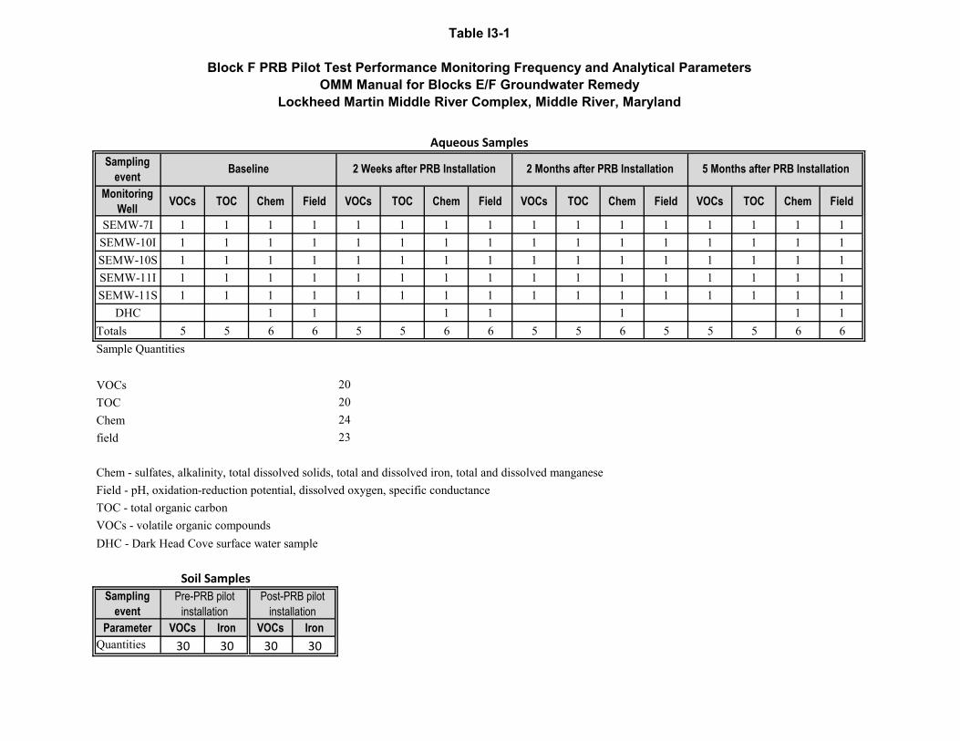
Table I3-1
Block F PRB Pilot Test Performance Monitoring Frequency and Analytical ParametersOMM Manual for Blocks E/F Groundwater Remedy
Lockheed Martin Middle River Complex, Middle River, Maryland
Sampling event
Monitoring Well VOCs TOC Chem Field VOCs TOC Chem Field VOCs TOC Chem Field VOCs TOC Chem Field
SEMW-7I 1 1 1 1 1 1 1 1 1 1 1 1 1 1 1 1SEMW-10I 1 1 1 1 1 1 1 1 1 1 1 1 1 1 1 1SEMW-10S 1 1 1 1 1 1 1 1 1 1 1 1 1 1 1 1SEMW-11I 1 1 1 1 1 1 1 1 1 1 1 1 1 1 1 1SEMW-11S 1 1 1 1 1 1 1 1 1 1 1 1 1 1 1 1
DHC 1 1 1 1 1 1 1Totals 5 5 6 6 5 5 6 6 5 5 6 5 5 5 6 6
VOCsTOCChemfield
DHC - Dark Head Cove surface water sample
Sampling event
Parameter VOCs Iron VOCs IronQuantities 30 30 30 30
Aqueous Samples
Soil SamplesPost-PRB pilot
installation
Chem - sulfates, alkalinity, total dissolved solids, total and dissolved iron, total and dissolved manganeseField - pH, oxidation-reduction potential, dissolved oxygen, specific conductanceTOC - total organic carbonVOCs - volatile organic compounds
20202423
Baseline 2 Weeks after PRB Installation 2 Months after PRB Installation 5 Months after PRB Installation
Sample Quantities
Pre-PRB pilot installation

Table I3-2
Block F 1st Year Performance Monitoring Frequency and Analytical ParametersOMM Manual for Blocks E/F Groundwater Remedy
Lockheed Martin Middle River Complex, Middle River, Maryland
Sampling event
Monitoring Well VOCs TOC Chem Field VOCs TOC Chem Field VOCs TOC Chem Field VOCs TOC Chem Field
SEMW-8I 1 1 1 1 1 1 1 1 1 1 1 1 1 1 1 1SEMW-8S 1 1 1 1 1 1 1 1 1 1 1 1 1 1 1 1SEMW-9I 1 1 1 1 1 1 1 1 1 1 1 1 1 1 1 1SEMW-9S 1 1 1 1 1 1 1 1 1 1 1 1 1 1 1 1
PZ-1 1 1 1 1 1 1 1 1 1 1 1 1 1 1 1 1PZ-1 1 1 1 1 1 1 1 1 1 1 1 1 1 1 1 1
SEMW-7I 1 1 1 1 1 1 1 1 1 1 1 1 1 1 1 1SEMW-10I 1 1 1 1 1 1 1 1 1 1 1 1 1 1 1 1SEMW-10S 1 1 1 1 1 1 1 1 1 1 1 1 1 1 1 1SEMW-11I 1 1 1 1 1 1 1 1 1 1 1 1 1 1 1 1SEMW-11S 1 1 1 1 1 1 1 1 1 1 1 1 1 1 1 1
MW-37B 1 1 1 1 1 1 1 1 1 1 1 1 1 1 1 1DHC 1 1 1 1 1 1 1 1
Totals 12 12 13 13 12 12 13 13 12 12 13 13 12 12 13 13
VOCs: 48 TOC: 48 Chem 52 Field 52
Chem - sulfates, alkalinity, total dissolved solids, total and dissolved iron, total and dissolved manganeseField - pH, oxidation-reduction potential, dissolved oxygen, specific conductanceTOC - total organic carbonVOCs - volatile organic compoundsDHC - Dark Head Cove surface water sample
Sampling event
Parameter VOCs Iron VOCs Iron
Quantities30 30 30 30
1st quarter after PRB installation 2nd quarter after PRB installation 3rd quarter after PRB installation 4th quarter after PRB installation
Sample Quantities
Aqueous Samples
Soil SamplesPre-PRB pilot
installationPost-PRB pilot
installation
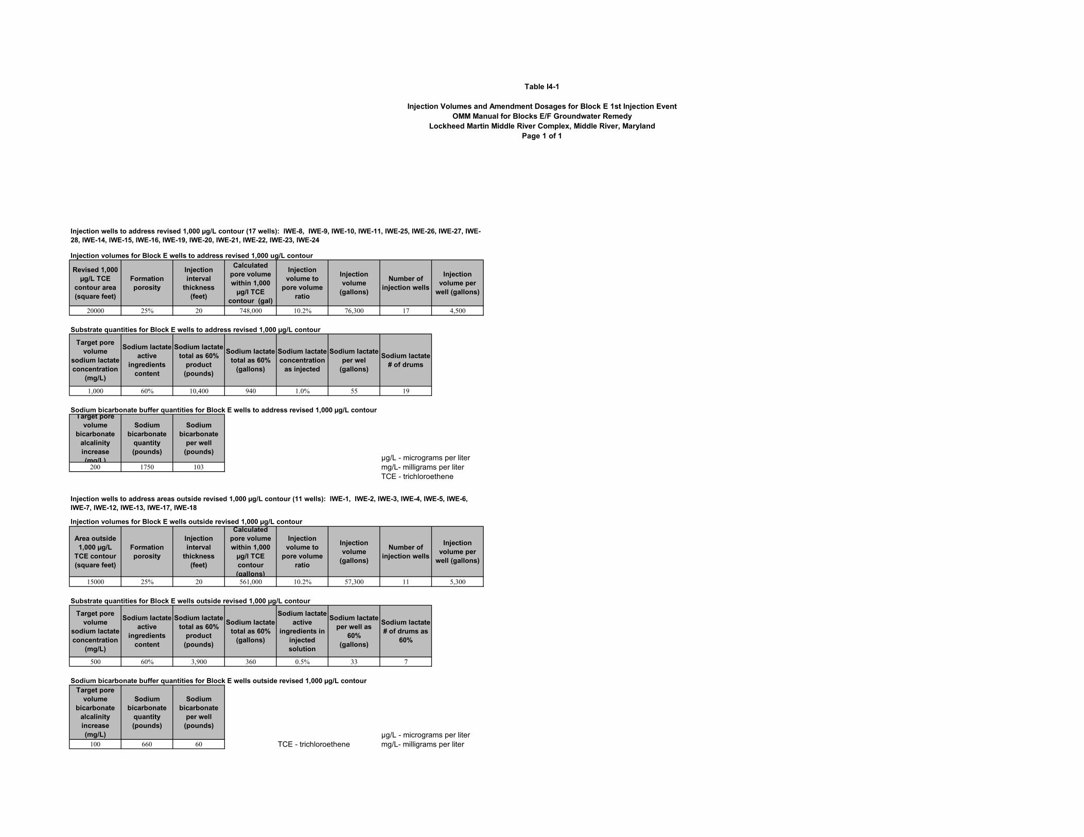
Table I4-1
Injection Volumes and Amendment Dosages for Block E 1st Injection EventOMM Manual for Blocks E/F Groundwater Remedy
Lockheed Martin Middle River Complex, Middle River, MarylandPage 1 of 1
Injection volumes for Block E wells to address revised 1,000 ug/L contour
Revised 1,000 µg/L TCE
contour area (square feet)
Formation porosity
Injection interval
thickness (feet)
Calculated pore volume within 1,000
µg/l TCE contour (gal)
Injection volume to
pore volume ratio
Injection volume
(gallons)
Number of injection wells
Injection volume per
well (gallons)
20000 25% 20 748,000 10.2% 76,300 17 4,500
Substrate quantities for Block E wells to address revised 1,000 µg/L contour
Target pore volume
sodium lactate concentration
(mg/L)
Sodium lactate active
ingredients content
Sodium lactate total as 60%
product (pounds)
Sodium lactate total as 60%
(gallons)
Sodium lactate concentration
as injected
Sodium lactate per wel
(gallons)
Sodium lactate # of drums
1,000 60% 10,400 940 1.0% 55 19
Sodium bicarbonate buffer quantities for Block E wells to address revised 1,000 µg/L contourTarget pore
volume bicarbonate
alcalinity increase (mg/L)
Sodium bicarbonate
quantity (pounds)
Sodium bicarbonate
per well (pounds)
µg/L - micrograms per liter200 1750 103 mg/L- milligrams per liter
TCE - trichloroethene
Injection volumes for Block E wells outside revised 1,000 µg/L contour
Area outside 1,000 µg/L
TCE contour (square feet)
Formation porosity
Injection interval
thickness (feet)
Calculated pore volume within 1,000
µg/l TCE contour (gallons)
Injection volume to
pore volume ratio
Injection volume
(gallons)
Number of injection wells
Injection volume per
well (gallons)
15000 25% 20 561,000 10.2% 57,300 11 5,300
Substrate quantities for Block E wells outside revised 1,000 µg/L contour
Target pore volume
sodium lactate concentration
(mg/L)
Sodium lactate active
ingredients content
Sodium lactate total as 60%
product (pounds)
Sodium lactate total as 60%
(gallons)
Sodium lactate active
ingredients in injected solution
Sodium lactate per well as
60% (gallons)
Sodium lactate # of drums as
60%
500 60% 3,900 360 0.5% 33 7
Sodium bicarbonate buffer quantities for Block E wells outside revised 1,000 µg/L contourTarget pore
volume bicarbonate
alcalinity increase (mg/L)
Sodium bicarbonate
quantity (pounds)
Sodium bicarbonate
per well (pounds)
µg/L - micrograms per liter100 660 60 TCE - trichloroethene mg/L- milligrams per liter
Injection wells to address areas outside revised 1,000 µg/L contour (11 wells): IWE-1, IWE-2, IWE-3, IWE-4, IWE-5, IWE-6, IWE-7, IWE-12, IWE-13, IWE-17, IWE-18
Injection wells to address revised 1,000 µg/L contour (17 wells): IWE-8, IWE-9, IWE-10, IWE-11, IWE-25, IWE-26, IWE-27, IWE-28, IWE-14, IWE-15, IWE-16, IWE-19, IWE-20, IWE-21, IWE-22, IWE-23, IWE-24
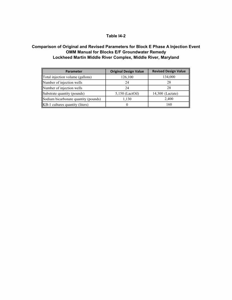
Table I4-2
Comparison of Original and Revised Parameters for Block E Phase A Injection EventOMM Manual for Blocks E/F Groundwater Remedy
Lockheed Martin Middle River Complex, Middle River, Maryland
Parameter Original Design ValueTotal injection volume (gallons) 126,100Number of injection wells 24Number of injection wells 24Substrate quantity (pounds) 5,150 (LactOil) 14,300 (Lactate)Sodium bicarbonate quantity (pounds) 1,130KB-1 cultures quantity (liters) 0
28
2,400160
Revised Design Value134,000
28
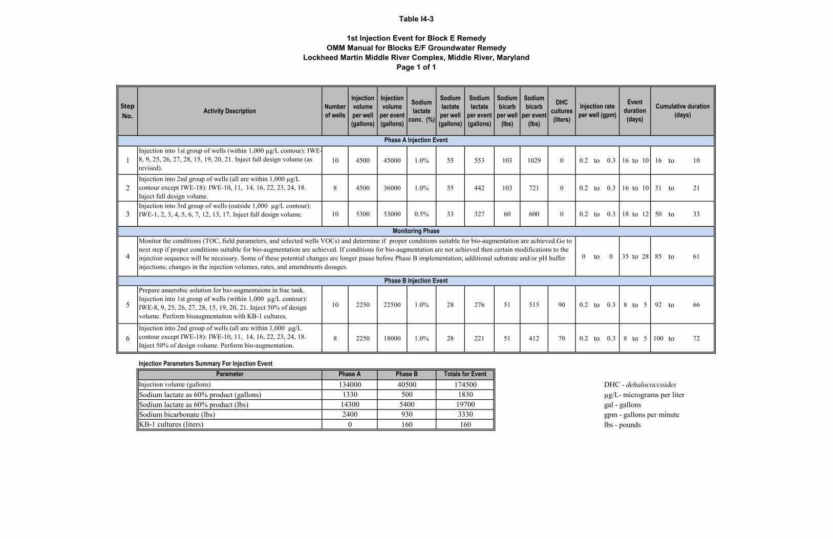
Table I4-3
1st Injection Event for Block E RemedyOMM Manual for Blocks E/F Groundwater Remedy
Lockheed Martin Middle River Complex, Middle River, MarylandPage 1 of 1
Step No.
Activity Description Number of wells
Injection volume per well (gallons)
Injection volume
per event (gallons)
Sodium lactate
conc. (%)
Sodium lactate
per well (gallons)
Sodium lactate
per event (gallons)
Sodium bicarb
per well (lbs)
Sodium bicarb
per event (lbs)
DHC cultures (liters)
1Injection into 1st group of wells (within 1,000 µg/L contour): IWE-8, 9, 25, 26, 27, 28, 15, 19, 20, 21. Inject full design volume (as revised).
10 4500 45000 1.0% 55 553 103 1029 0 0.2 to 0.3 16 to 10 16 to 10
2Injection into 2nd group of wells (all are within 1,000 µg/L contour except IWE-18): IWE-10, 11, 14, 16, 22, 23, 24, 18. Inject full design volume.
8 4500 36000 1.0% 55 442 103 721 0 0.2 to 0.3 16 to 10 31 to 21
3Injection into 3rd group of wells (outside 1,000 µg/L contour): IWE-1, 2, 3, 4, 5, 6, 7, 12, 13, 17. Inject full design volume. 10 5300 53000 0.5% 33 327 60 600 0 0.2 to 0.3 18 to 12 50 to 33
4 0 to 0 35 to 28 85 to 61
5
Prepare anaerobic solution for bio-augmentaiotn in frac tank. Injection into 1st group of wells (within 1,000 µg/L contour): IWE-8, 9, 25, 26, 27, 28, 15, 19, 20, 21. Inject 50% of design volume. Perform bioaugmentaiton with KB-1 cultures.
10 2250 22500 1.0% 28 276 51 515 90 0.2 to 0.3 8 to 5 92 to 66
6Injection into 2nd group of wells (all are within 1,000 µg/L contour except IWE-18): IWE-10, 11, 14, 16, 22, 23, 24, 18. Inject 50% of design volume. Perform bio-augmentation.
8 2250 18000 1.0% 28 221 51 412 70 0.2 to 0.3 8 to 5 100 to 72
ParameterInjection volume (gallons) DHC - dehalococcoides Sodium lactate as 60% product (gallons) µg/L- micrograms per literSodium lactate as 60% product (lbs) gal - gallonsSodium bicarbonate (lbs) gpm - gallons per minuteKB-1 cultures (liters) lbs - pounds0
Injection rate per well (gpm)
Event duration (days)
Injection Parameters Summary For Injection Event
Monitor the conditions (TOC, field parameters, and selected wells VOCs) and determine if proper conditions suitable for bio-augmentation are achieved.Go to next step if proper conditions suitable for bio-augmentation are achieved. If conditions for bio-augmentation are not achieved then certain modifications to the injection sequence will be necessary. Some of these potential changes are longer pause before Phase B implementation; additional substrate and/or pH buffer injections; changes in the injection volumes, rates, and amendments dosages.
Phase A Injection Event
Phase B Injection Event
Monitoring Phase
Cumulative duration (days)
1340001330
143002400 930
160
Totals for Event174500
1830197003330160
Phase A Phase B40500
5005400
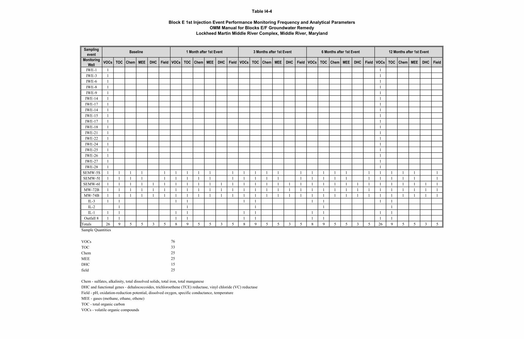
Table I4-4
Block E 1st Injection Event Performance Monitoring Frequency and Analytical Parameters OMM Manual for Blocks E/F Groundwater Remedy
Lockheed Martin Middle River Complex, Middle River, Maryland
Sampling event
Monitoring Well VOCs TOC Chem MEE DHC Field VOCs TOC Chem MEE DHC Field VOCs TOC Chem MEE DHC Field VOCs TOC Chem MEE DHC Field VOCs TOC Chem MEE DHC Field
IWE-1 1 1IWE-3 1 1IWE-6 1 1IWE-8 1 1IWE-9 1 1IWE-14 1 1IWE-17 1 1IWE-14 1 1IWE-15 1 1IWE-17 1 1IWE-18 1 1IWE-21 1 1IWE-22 1 1IWE-24 1 1IWE-25 1 1IWE-26 1 1IWE-27 1 1IWE-28 1 1
SEMW-5S 1 1 1 1 1 1 1 1 1 1 1 1 1 1 1 1 1 1 1 1 1 1 1 1 1SEMW-5I 1 1 1 1 1 1 1 1 1 1 1 1 1 1 1 1 1 1 1 1 1 1 1 1 1SEMW-6I 1 1 1 1 1 1 1 1 1 1 1 1 1 1 1 1 1 1 1 1 1 1 1 1 1 1 1 1 1 1MW-72B 1 1 1 1 1 1 1 1 1 1 1 1 1 1 1 1 1 1 1 1 1 1 1 1 1 1 1 1 1 1MW-74B 1 1 1 1 1 1 1 1 1 1 1 1 1 1 1 1 1 1 1 1 1 1 1 1 1 1 1 1 1 1
IL-3 1 1 1 1 1 1 1 1 1 1IL-2 1 1 1 1 1IL-1 1 1 1 1 1 1 1 1 1 1
Outfall 8 1 1 1 1 1 1 1 1 1 1Totals 26 9 5 5 3 5 8 9 5 5 3 5 8 9 5 5 3 5 8 9 5 5 3 5 26 9 5 5 3 5
VOCsTOCChemMEEDHCfield
Sample Quantities
Baseline 12 Months after 1st Event1 Month after 1st Event 3 Months after 1st Event 6 Months after 1st Event
VOCs - volatile organic compounds
763325251525
Chem - sulfates, alkalinity, total dissolved solids, total iron, total manganeseDHC and functional genes - dehalococcoides, trichloroethene (TCE) reductase, vinyl chloride (VC) reductaseField - pH, oxidation-reduction potential, dissolved oxygen, specific conductance, temperatureMEE - gases (methane, ethane, ethene)TOC - total organic carbon

8706 Tetra Tech • Lockheed Martin Middle River Complex • O&MM Plan for Blocks E/F GW Remedy
February 2020 Appendices
APPENDICES

8706 Tetra Tech • Lockheed Martin Middle River Complex • O&MM Plan for Blocks E/F GW Remedy
February 2020 Appendices
Appendix A—Design Drawings
Appendix B—Standard and Detailed Operating Procedures (SOPs and DOPs)

8706 Tetra Tech • Lockheed Martin Middle River Complex • O&MM Plan for Blocks E/F GW Remedy
February 2020 Appendices
APPENDIX A—DESIGN DRAWINGS

ID # DRAWING TITLE
T-1 TITLE SHEET
C-1 EXISTING CONDITIONS PLAN
C-2 REMEDY LAYOUT PLAN
C-3 SANITARY SEWER DISCHARGE PIPING ROUTING
C-4 EXTRACTION WELLS DESIGN AND TRENCH SECTIONS
C-5 PRB LAYOUT
C-6 REMEDIATION SYSTEM CLOSEOUT PLAN
E-1 ELECTRICAL NOTES AND LEGEND
E-2 SINGLE LINE DIAGRAM
E-3 GROUNDING/LIGHTING PLAN
E-4 CONTROL PANEL LAYOUT
E-5 HMI SCREENS LAYOUT
M-1 PROCESS FLOW DIAGRAM
M-2 PROCESS & INSTRUMENTATION DIAGRAM
M-3 EQUIPMENT ARRANGEMENT PLAN
M-4 LGAC UNITS AND MANIFOLD LAYOUT
M-5 LAYOUT OF VGAC UNITS AND FLOW MEASUREMENT ENCLOSURE
GROUNDWATER REMEDY BLOCKS E/F DESIGN DRAWINGS100% COMPLETION SUBMITTAL
LOCKHEED MARTIN MIDDLE RIVER COMPLEX2323 EASTERN BOULEVARD, MIDDLE RIVER MARYLAND
SITE AREA TOPOGRAPHIC MAP
SITE VICINITY MAP
SITELOCATION
12/23/19 Revision 1 C.P.
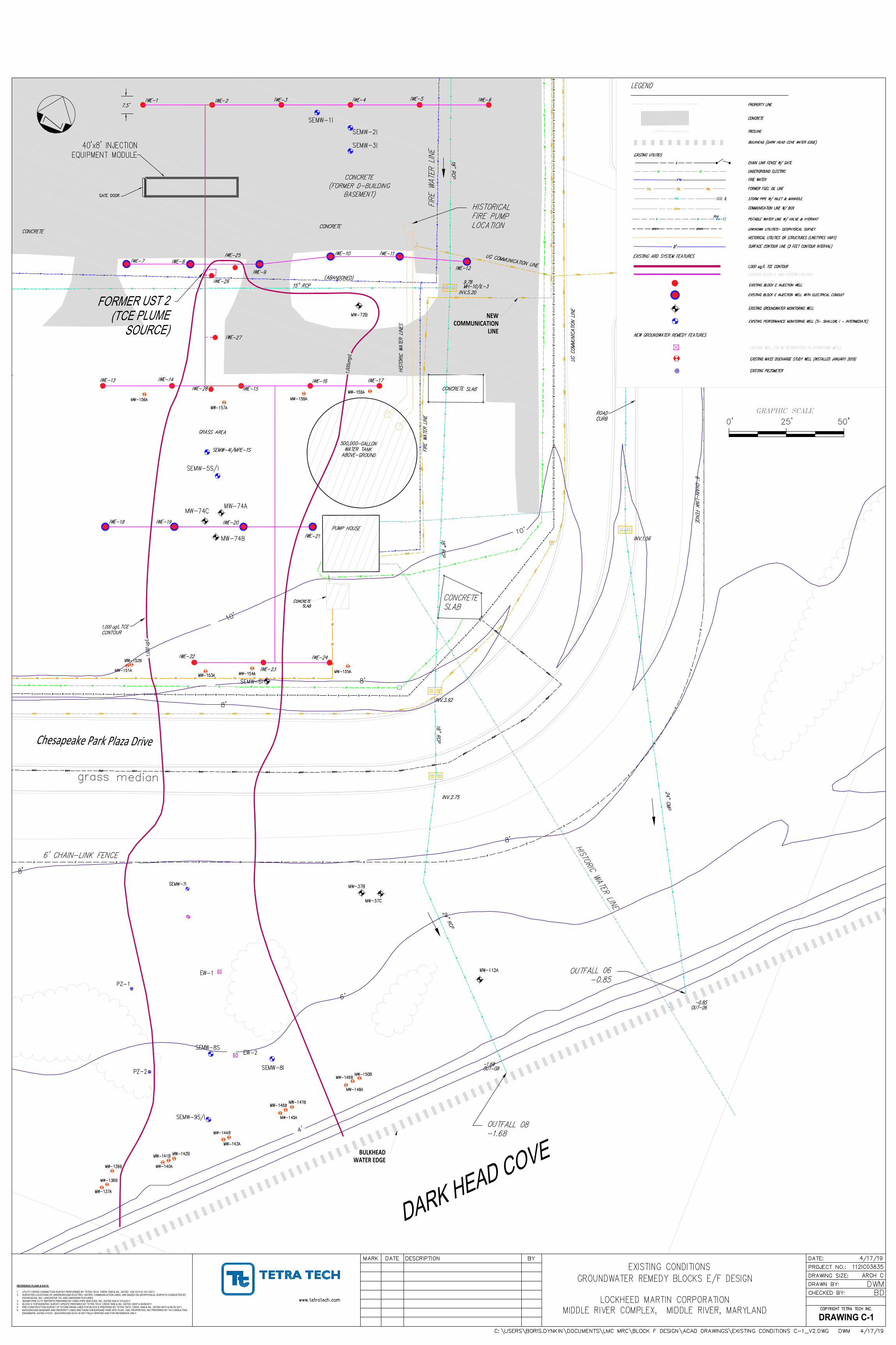
1,000 ug/L TCE
CONTOUR
GRAPHIC SCALE
D
A
R
K
H
E
A
D
C
O
V
E
1,000 ug/L
FORMER UST 2
(TCE PLUME
SOURCE)
Chesapeake Park Plaza Drive
GRAPHIC SCALE
1,000um
g/L
BULKHEADWATER EDGE
NEWCOMMUNICATION
LINE
DRAWING C-1
REFERENCE PLANS & DATA:
1. UTILITY CROSS CONNECTION SURVEY PERFORMED BY TETRA TECH CREW: RAB & AN, DATED 10/6,10/10 & 10/11/2011
2. SURVEYED LOCATIONS OF UNDERGROUND ELECTRIC, WATER, COMMUNICATION LINES, ARE BASED ON GEOPHYSICAL SURVEYS CONDUCTED BY
ENVIROSCAN, INC. LANCASTER, PA, AND UNKNOWN FEATURES.
3. SEWER PIPE CCTV REPORTS PREPARED BY VIDEO PIPE SERVICES, INC. DATED 9/26 & 10/12/2011
4. BLOCK G TOPOGRAPHIC SURVEY UPDATE PREPARED BY TETRA TECH CREW: RAB & AN, DATED: 06/07 & 06/08/2011
5. PRE-CONSTRUCTION SURVEY OF STORM DRAIN LINES FOR BLOCK E PREPARED BY TETRA TECH CREW: RAB & AN, DATED 08/15 & 08/16/ 2011.
6. BACKGROUND BASEMAP AND PROPERTY LINES ARE FROM CHESAPEAKE PARK SITE PLAN - LMC PROPERTIES, INC PREPARED BY TAI CONSULTING
ENGINEERS, DATED 4/15/01. BACKGROUND DATA IS NOT FIELD VERIFIED AND FOR REFERENCE ONLY.
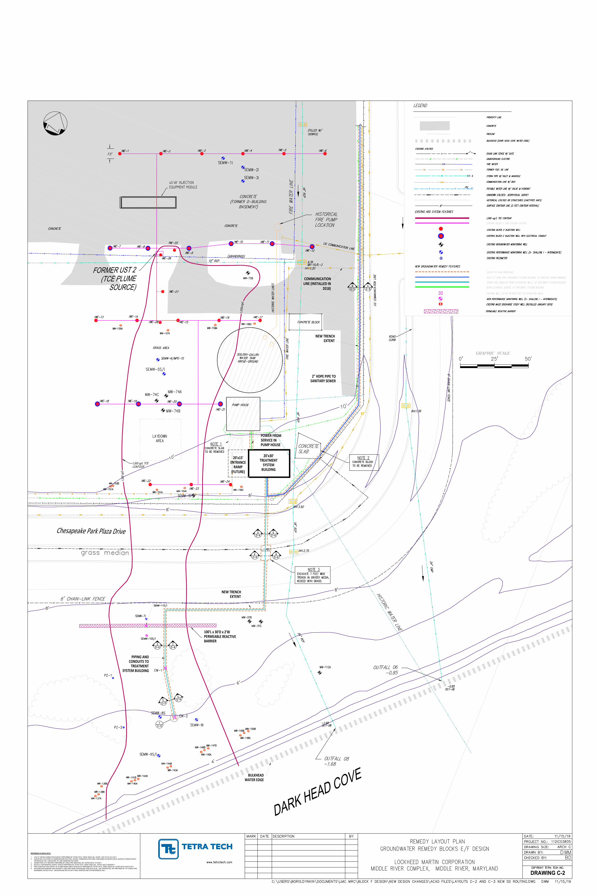
40'x8' INJECTIONEQUIPMENT MODULE
1,000 ug/L TCE
CONTOUR
GRAPHIC SCALE
D
A
R
K
H
E
A
D
C
O
V
E
1,000 ug/L
FORMER UST 2
(TCE PLUME
SOURCE)
Chesapeake Park Plaza Drive
GRAPHIC SCALE
20'x30'TREATMENT
SYSTEMBUILDING
100'L x 30'D x 2'WPERMEABLE REACTIVEBARRIER
NEW TRENCHEXTENT
2" HDPE PIPE TOSANITARY SEWER
NEW TRENCHEXTENT
PIPING ANDCONDUITS TO
TREATMENTSYSTEM BUILDING
POWER FROMSERVICE INPUMP HOUSE
1,000um
g/L
BULKHEADWATER EDGE
COMMUNICATIONLINE (INSTALLED IN
2018)
20'x15'ENTRANCE
RAMP(FUTURE)
DRAWING C-2
REFERENCE PLANS & DATA:
1. UTILITY CROSS CONNECTION SURVEY PERFORMED BY TETRA TECH CREW: RAB & AN, DATED 10/6,10/10 & 10/11/2011
2. SURVEYED LOCATIONS OF UNDERGROUND ELECTRIC, WATER, COMMUNICATION LINES, ARE BASED ON GEOPHYSICAL SURVEYS CONDUCTED BY
ENVIROSCAN, INC. LANCASTER, PA, AND UNKNOWN FEATURES.
3. SEWER PIPE CCTV REPORTS PREPARED BY VIDEO PIPE SERVICES, INC. DATED 9/26 & 10/12/2011
4. BLOCK G TOPOGRAPHIC SURVEY UPDATE PREPARED BY TETRA TECH CREW: RAB & AN, DATED: 06/07 & 06/08/2011
5. PRE-CONSTRUCTION SURVEY OF STORM DRAIN LINES FOR BLOCK E PREPARED BY TETRA TECH CREW: RAB & AN, DATED 08/15 & 08/16/ 2011.
6. BACKGROUND BASEMAP AND PROPERTY LINES ARE FROM CHESAPEAKE PARK SITE PLAN - LMC PROPERTIES, INC PREPARED BY TAI CONSULTING
ENGINEERS, DATED 4/15/01. BACKGROUND DATA IS NOT FIELD VERIFIED AND FOR REFERENCE ONLY.
AutoCAD SHX Text
UG COMMUNICATION LINE
AutoCAD SHX Text
FIRE WATER LINE
AutoCAD SHX Text
CONCRETE SLAB
AutoCAD SHX Text
CONCRETE (FORMER D-BUILDING BASEMENT)
AutoCAD SHX Text
OUTFALL 08 -1.68
AutoCAD SHX Text
OUTFALL 06 -0.85
AutoCAD SHX Text
HISTORICAL FIRE PUMP LOCATION
AutoCAD SHX Text
6' CHAIN-LINK FENCE
AutoCAD SHX Text
HISTORIC WATER LINE
AutoCAD SHX Text
UG COMMUNICATION LINE
AutoCAD SHX Text
UG COMMUNICATION LINE
AutoCAD SHX Text
(ABANDONED)
AutoCAD SHX Text
FIRE WATER LINE
AutoCAD SHX Text
GRASS AREA
AutoCAD SHX Text
CONCRETE BLOCK
AutoCAD SHX Text
500,000-GALLON WATER TANK ABOVE-GROUND
AutoCAD SHX Text
PUMP HOUSE
AutoCAD SHX Text
HISTORIC WATER LINES
AutoCAD SHX Text
6' CHAIN-LINK FENCE
AutoCAD SHX Text
0'
AutoCAD SHX Text
25'
AutoCAD SHX Text
50'
AutoCAD SHX Text
IWE-1
AutoCAD SHX Text
IWE-2
AutoCAD SHX Text
IWE-3
AutoCAD SHX Text
IWE-4
AutoCAD SHX Text
IWE-5
AutoCAD SHX Text
IWE-6
AutoCAD SHX Text
IWE-7
AutoCAD SHX Text
IWE-8
AutoCAD SHX Text
IWE-9
AutoCAD SHX Text
IWE-10
AutoCAD SHX Text
IWE-11
AutoCAD SHX Text
IWE-12
AutoCAD SHX Text
IWE-13
AutoCAD SHX Text
IWE-14
AutoCAD SHX Text
IWE-15
AutoCAD SHX Text
IWE-16
AutoCAD SHX Text
IWE-17
AutoCAD SHX Text
IWE-18
AutoCAD SHX Text
IWE-19
AutoCAD SHX Text
IWE-20
AutoCAD SHX Text
IWE-21
AutoCAD SHX Text
IWE-22
AutoCAD SHX Text
IWE-23
AutoCAD SHX Text
IWE-24
AutoCAD SHX Text
SEMW-1I
AutoCAD SHX Text
SEMW-2I
AutoCAD SHX Text
SEMW-3I
AutoCAD SHX Text
MW-72B
AutoCAD SHX Text
MW-74A
AutoCAD SHX Text
MW-74B
AutoCAD SHX Text
CONCRETE
AutoCAD SHX Text
CONCRETE
AutoCAD SHX Text
7.5'
AutoCAD SHX Text
ROAD CURB
AutoCAD SHX Text
30" RCP
AutoCAD SHX Text
24" CMP
AutoCAD SHX Text
18" RCP
AutoCAD SHX Text
18" RCP
AutoCAD SHX Text
18" RCP
AutoCAD SHX Text
24" RCP
AutoCAD SHX Text
15" RCP
AutoCAD SHX Text
9.78
AutoCAD SHX Text
MH-10/IL-3
AutoCAD SHX Text
-0.85
AutoCAD SHX Text
OUT-06
AutoCAD SHX Text
-1.68
AutoCAD SHX Text
OUT-08
AutoCAD SHX Text
INV.5.20
AutoCAD SHX Text
INV.3.92
AutoCAD SHX Text
INV.2.75
AutoCAD SHX Text
INV.1.56
AutoCAD SHX Text
(FILLED W/ DEBRIS)
AutoCAD SHX Text
IWE-25
AutoCAD SHX Text
IWE-26
AutoCAD SHX Text
IWE-28
AutoCAD SHX Text
IWE-27
AutoCAD SHX Text
MW-112A
AutoCAD SHX Text
MW-74C
AutoCAD SHX Text
grass median
AutoCAD SHX Text
SEMW-4I/MPE-1S
AutoCAD SHX Text
SEMW-5S/I
AutoCAD SHX Text
0'
AutoCAD SHX Text
25'
AutoCAD SHX Text
C-4
AutoCAD SHX Text
2
AutoCAD SHX Text
C-4
AutoCAD SHX Text
2
AutoCAD SHX Text
1
AutoCAD SHX Text
C-4
AutoCAD SHX Text
C-4
AutoCAD SHX Text
4
AutoCAD SHX Text
C-4
AutoCAD SHX Text
4
AutoCAD SHX Text
C-4
AutoCAD SHX Text
5
AutoCAD SHX Text
C-4
AutoCAD SHX Text
5
AutoCAD SHX Text
C-4
AutoCAD SHX Text
3
AutoCAD SHX Text
C-4
AutoCAD SHX Text
3
AutoCAD SHX Text
MW-151A
AutoCAD SHX Text
MW-152B
AutoCAD SHX Text
MW-153A
AutoCAD SHX Text
MW-154A
AutoCAD SHX Text
MW-155A
AutoCAD SHX Text
MW-156A
AutoCAD SHX Text
MW-157A
AutoCAD SHX Text
MW-158A
AutoCAD SHX Text
MW-159A
AutoCAD SHX Text
SEMW-6I
AutoCAD SHX Text
SEMW-7I
AutoCAD SHX Text
EW-1
AutoCAD SHX Text
PZ-1
AutoCAD SHX Text
SEMW-10S/I
AutoCAD SHX Text
SEMW-11S/I
AutoCAD SHX Text
MW-37B
AutoCAD SHX Text
MW-37C
AutoCAD SHX Text
SEMW-8S
AutoCAD SHX Text
SEMW-8I
AutoCAD SHX Text
SEMW-9S/I
AutoCAD SHX Text
EW-2
AutoCAD SHX Text
PZ-2
AutoCAD SHX Text
MW-137A
AutoCAD SHX Text
MW-138B
AutoCAD SHX Text
MW-139B
AutoCAD SHX Text
MW-140A
AutoCAD SHX Text
MW-141B
AutoCAD SHX Text
MW-142B
AutoCAD SHX Text
MW-143A
AutoCAD SHX Text
MW-144B
AutoCAD SHX Text
MW-145A
AutoCAD SHX Text
MW-146B
AutoCAD SHX Text
MW-147B
AutoCAD SHX Text
MW-148A
AutoCAD SHX Text
MW-149B
AutoCAD SHX Text
MW-150B
AutoCAD SHX Text
NOTE 2 CONCRETE BLOCK TO BE REMOVED
AutoCAD SHX Text
7'
AutoCAD SHX Text
NOTE 3 EXCAVATE 7 FEET WIDE TRENCH IN GRASSY MEDIA. RESEED WITH GRASS.
AutoCAD SHX Text
C-4
AutoCAD SHX Text
6
AutoCAD SHX Text
C-4
AutoCAD SHX Text
6
AutoCAD SHX Text
NOTE 1 CONCRETE SLAB TO BE REMOVED
AutoCAD SHX Text
LAYDOWN AREA
AutoCAD SHX Text
10'
AutoCAD SHX Text
8'
AutoCAD SHX Text
8'
AutoCAD SHX Text
6'
AutoCAD SHX Text
8'
AutoCAD SHX Text
10'
AutoCAD SHX Text
4'
AutoCAD SHX Text
8'
AutoCAD SHX Text
TREELINE
AutoCAD SHX Text
CHAIN LINK FENCE W/ GATE
AutoCAD SHX Text
PROPERTY LINE
AutoCAD SHX Text
UNKNOWN UTILITIES- GEOPHYSICAL SURVEY
AutoCAD SHX Text
HISTORICAL UTILITIES OR STRUCTURES (LINETYPES VARY)
AutoCAD SHX Text
EXISTING UTILITIES
AutoCAD SHX Text
EXISTING GROUNDWATER MONITORING WELL
AutoCAD SHX Text
1,000 ug/L TCE CONTOUR
AutoCAD SHX Text
EXISTING BLOCK E INJECTION WELL
AutoCAD SHX Text
EXISTING BLOCK E INJECTION WELL WITH ELECTRICAL CONDUIT
AutoCAD SHX Text
EXISTING PERFORMANCE MONITORING WELL (S- SHALLOW, I - INTERMEDIATE)
AutoCAD SHX Text
EXTENT OF NEW TRENCHING
AutoCAD SHX Text
EXISTING WELL (TO BE RETROFITTED TO EXTRACTION WELL)
AutoCAD SHX Text
EXISTING PIEZOMETER
AutoCAD SHX Text
NEW PERFORMANCE MONITORING WELL (S- SHALLOW, I - INTERMEDIATE)
AutoCAD SHX Text
NEW 1.5" HDPE PIPE TREATMENT SYSTEM BUILDING TO SANITARY SEWER MANHOLE
AutoCAD SHX Text
PIPING AND CONDUITS FROM EXTRACTION WELLS TO TREATMENT SYSTEM BUILDING
AutoCAD SHX Text
EXISTING BLOCK E ARD SYSTEM UTILITIES
AutoCAD SHX Text
PIV
AutoCAD SHX Text
POTABLE WATER LINE W/ VALVE & HYDRANT
AutoCAD SHX Text
UNDERGROUND ELECTRIC
AutoCAD SHX Text
STORM PIPE W/ INLET & MANHOLE
AutoCAD SHX Text
COMMUNICATION LINE W/ BOX
AutoCAD SHX Text
FIRE WATER
AutoCAD SHX Text
IL
AutoCAD SHX Text
FORMER FUEL OIL LINE
AutoCAD SHX Text
EXISTING ARD SYSTEM FEATURES
AutoCAD SHX Text
PERMEABLE REACTIVE BARRIER
AutoCAD SHX Text
LEGEND
AutoCAD SHX Text
NEW GROUNDWATER REMEDY FEATURES
AutoCAD SHX Text
NEW ELECTRICAL SERVISE TO TREATMENT SYSTEM BUILDING
AutoCAD SHX Text
CONCRETE
AutoCAD SHX Text
BULKHEAD (DARK HEAD COVE WATER EDGE)
AutoCAD SHX Text
EXISTING MASS DISCHARGE STUDY WELL (INSTALLED JANUARY 2019)
AutoCAD SHX Text
SURFACE CONTOUR LINE (2 FEET CONTOUR INTERVAL)
AutoCAD SHX Text
8'
AutoCAD SHX Text
MARK
AutoCAD SHX Text
DATE
AutoCAD SHX Text
DESCRIPTION
AutoCAD SHX Text
BY
AutoCAD SHX Text
CHECKED BY:
AutoCAD SHX Text
DRAWN BY:
AutoCAD SHX Text
PROJECT NO.:
AutoCAD SHX Text
www.tetratech.com
AutoCAD SHX Text
DATE:
AutoCAD SHX Text
COPYRIGHT TETRA TECH INC.
AutoCAD SHX Text
112IC03835
AutoCAD SHX Text
11/15/19
AutoCAD SHX Text
BD
AutoCAD SHX Text
DWM
AutoCAD SHX Text
C:\USERS\BORIS.DYNKIN\DOCUMENTS\LMC MRC\BLOCK F DESIGN\NEW DESIGN CHANGES\ACAD FILES\LAYOUTS C-2 AND C-3 NEW SS ROUTING.DWG DWM 11/15/19
AutoCAD SHX Text
REMEDY LAYOUT PLAN GROUNDWATER REMEDY BLOCKS E/F DESIGN LOCKHEED MARTIN CORPORATION MIDDLE RIVER COMPLEX, MIDDLE RIVER, MARYLAND
AutoCAD SHX Text
DRAWING SIZE:
AutoCAD SHX Text
ARCH C
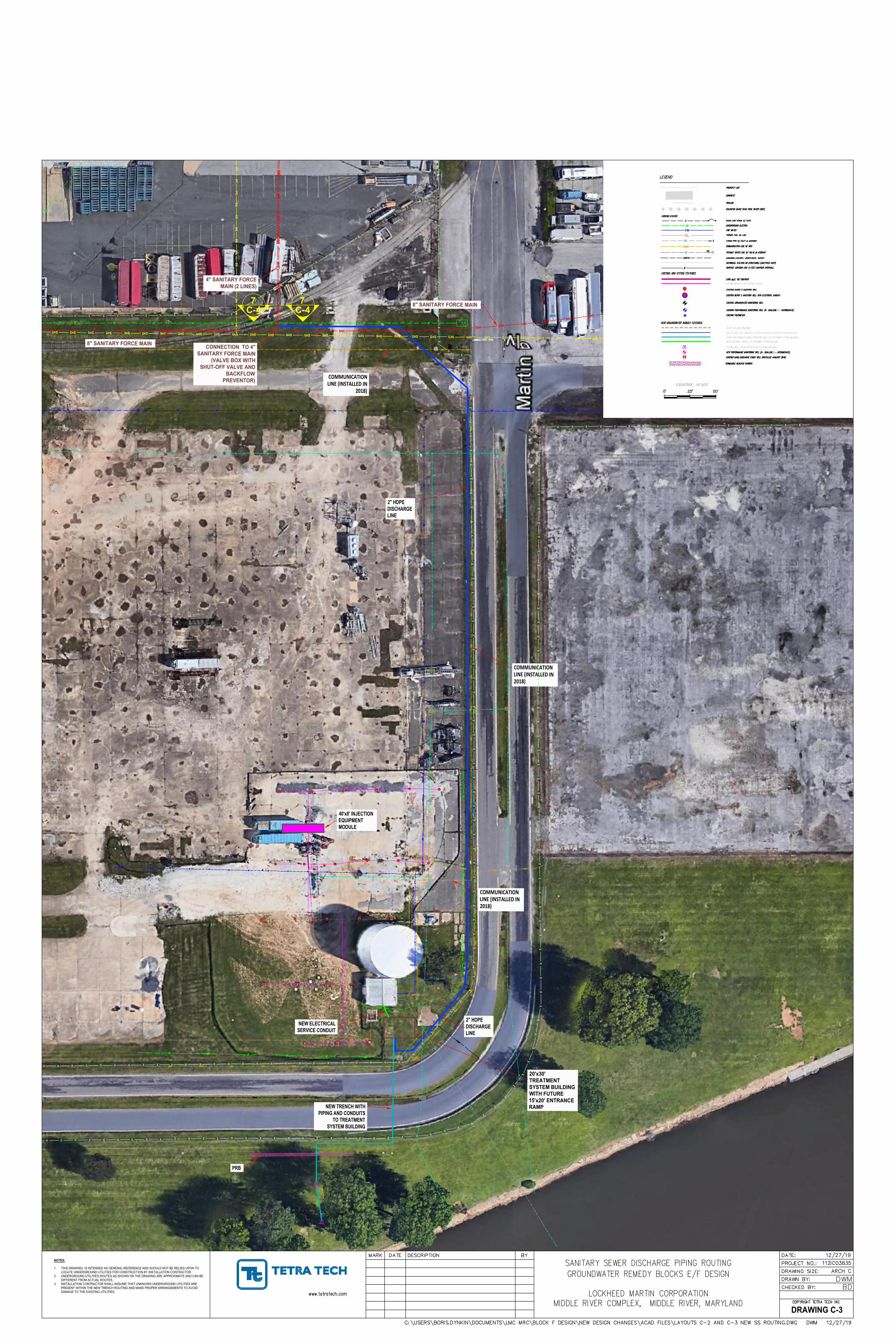
40'x8' INJECTION
EQUIPMENT
MODULE
2" HDPE
DISCHARGE
LINE
PRB
20'x30'
TREATMENT
SYSTEM BUILDING
WITH FUTURE
15'x20' ENTRANCE
RAMP
NEW TRENCH WITH
PIPING AND CONDUITS
TO TREATMENT
SYSTEM BUILDING
2" HDPE
DISCHARGE
LINE
COMMUNICATIONLINE (INSTALLED IN
2018)
COMMUNICATIONLINE (INSTALLED IN2018)
COMMUNICATIONLINE (INSTALLED IN2018)
CONNECTION TO 4"
SANITARY FORCE MAIN
(VALVE BOX WITH
SHUT-OFF VALVE AND
BACKFLOW
PREVENTOR)
C-4
7
8" SANITARY FORCE MAIN
4" SANITARY FORCE
MAIN (2 LINES)
8" SANITARY FORCE MAIN
C-4
7
NEW ELECTRICAL
SERVICE CONDUIT
GRAPHIC SCALE
DRAWING C-3
NOTES:
1. THIS DRAWING IS INTENDED AS GENERAL REFERENCE AND SHOULD NOT BE RELIED UPON TO
LOCATE UNDERGROUND UTILITIES FOR CONSTRUCTION BY INSTALLATION CONTRACTOR.
2. UNDERGROUND UTILITIES ROUTES AS SHOWN ON THE DRAWING ARE APPROXIMATE AND CAN BE
DIFFERENT FROM ACTUAL ROUTES.
3. INSTALLATION CONTRACTOR SHALL ASSUME THAT UNKNOWN UNDERGROUND UTILITIES ARE
PRESENT WITHIN THE NEW TRENCH ROUTING AND MAKE PROPER ARRANGEMENTS TO AVOID
DAMAGE TO THE EXISTING UTILITIES.
AutoCAD SHX Text
TREELINE
AutoCAD SHX Text
CHAIN LINK FENCE W/ GATE
AutoCAD SHX Text
PROPERTY LINE
AutoCAD SHX Text
UNKNOWN UTILITIES- GEOPHYSICAL SURVEY
AutoCAD SHX Text
HISTORICAL UTILITIES OR STRUCTURES (LINETYPES VARY)
AutoCAD SHX Text
EXISTING UTILITIES
AutoCAD SHX Text
EXISTING GROUNDWATER MONITORING WELL
AutoCAD SHX Text
1,000 ug/L TCE CONTOUR
AutoCAD SHX Text
EXISTING BLOCK E INJECTION WELL
AutoCAD SHX Text
EXISTING BLOCK E INJECTION WELL WITH ELECTRICAL CONDUIT
AutoCAD SHX Text
EXISTING PERFORMANCE MONITORING WELL (S- SHALLOW, I - INTERMEDIATE)
AutoCAD SHX Text
EXTENT OF NEW TRENCHING
AutoCAD SHX Text
EXISTING WELL (TO BE RETROFITTED TO EXTRACTION WELL)
AutoCAD SHX Text
EXISTING PIEZOMETER
AutoCAD SHX Text
NEW PERFORMANCE MONITORING WELL (S- SHALLOW, I - INTERMEDIATE)
AutoCAD SHX Text
NEW 2" HDPE PIPE TREATMENT SYSTEM BUILDING TO SANITARY SEWER MANHOLE
AutoCAD SHX Text
PIPING AND CONDUITS FROM EXTRACTION WELLS TO TREATMENT SYSTEM BUILDING
AutoCAD SHX Text
EXISTING BLOCK E ARD SYSTEM UTILITIES
AutoCAD SHX Text
PIV
AutoCAD SHX Text
POTABLE WATER LINE W/ VALVE & HYDRANT
AutoCAD SHX Text
UNDERGROUND ELECTRIC
AutoCAD SHX Text
STORM PIPE W/ INLET & MANHOLE
AutoCAD SHX Text
COMMUNICATION LINE W/ BOX
AutoCAD SHX Text
FIRE WATER
AutoCAD SHX Text
IL
AutoCAD SHX Text
FORMER FUEL OIL LINE
AutoCAD SHX Text
EXISTING ARD SYSTEM FEATURES
AutoCAD SHX Text
PERMEABLE REACTIVE BARRIER
AutoCAD SHX Text
LEGEND
AutoCAD SHX Text
NEW GROUNDWATER REMEDY FEATURES
AutoCAD SHX Text
NEW ELECTRICAL SERVISE TO TREATMENT SYSTEM BUILDING
AutoCAD SHX Text
CONCRETE
AutoCAD SHX Text
BULKHEAD (DARK HEAD COVE WATER EDGE)
AutoCAD SHX Text
EXISTING MASS DISCHARGE STUDY WELL (INSTALLED JANUARY 2019)
AutoCAD SHX Text
SURFACE CONTOUR LINE (2 FEET CONTOUR INTERVAL)
AutoCAD SHX Text
8'
AutoCAD SHX Text
0'
AutoCAD SHX Text
25'
AutoCAD SHX Text
50'
AutoCAD SHX Text
MARK
AutoCAD SHX Text
DATE
AutoCAD SHX Text
DESCRIPTION
AutoCAD SHX Text
BY
AutoCAD SHX Text
CHECKED BY:
AutoCAD SHX Text
DRAWN BY:
AutoCAD SHX Text
PROJECT NO.:
AutoCAD SHX Text
www.tetratech.com
AutoCAD SHX Text
DATE:
AutoCAD SHX Text
COPYRIGHT TETRA TECH INC.
AutoCAD SHX Text
112IC03835
AutoCAD SHX Text
12/27/19
AutoCAD SHX Text
BD
AutoCAD SHX Text
DWM
AutoCAD SHX Text
C:\USERS\BORIS.DYNKIN\DOCUMENTS\LMC MRC\BLOCK F DESIGN\NEW DESIGN CHANGES\ACAD FILES\LAYOUTS C-2 AND C-3 NEW SS ROUTING.DWG DWM 12/27/19
AutoCAD SHX Text
SANITARY SEWER DISCHARGE PIPING ROUTING GROUNDWATER REMEDY BLOCKS E/F DESIGN LOCKHEED MARTIN CORPORATION MIDDLE RIVER COMPLEX, MIDDLE RIVER, MARYLAND
AutoCAD SHX Text
DRAWING SIZE:
AutoCAD SHX Text
ARCH C
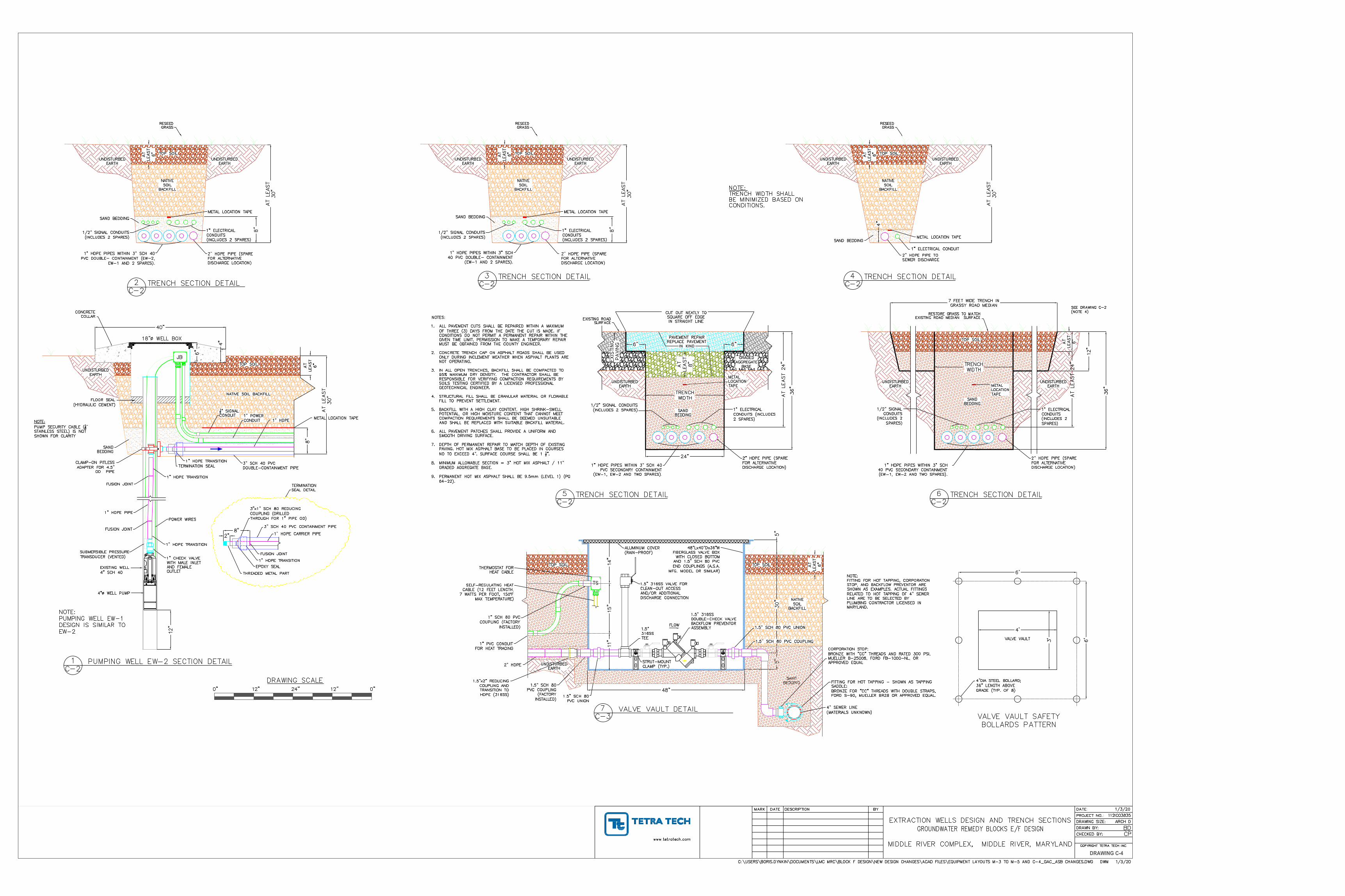
DRAWING C-4
AutoCAD SHX Text
4" WELL PUMP
AutoCAD SHX Text
EXISTING WELL 4" SCH 40
AutoCAD SHX Text
POWER WIRES
AutoCAD SHX Text
FLOOR SEAL (HYDRAULIC CEMENT)
AutoCAD SHX Text
18" WELL BOX
AutoCAD SHX Text
1" HDPE TRANSITION
AutoCAD SHX Text
JB
AutoCAD SHX Text
1" HDPE PIPE
AutoCAD SHX Text
SUBMERSIBLE PRESSURE TRANSDUCER (VENTED)
AutoCAD SHX Text
12" SIGNAL CONDUIT
AutoCAD SHX Text
1" POWER CONDUIT
AutoCAD SHX Text
1" HDPE
AutoCAD SHX Text
SAND BEDDING
AutoCAD SHX Text
NATIVE SOIL BACKFILL
AutoCAD SHX Text
UNDISTURBED EARTH
AutoCAD SHX Text
CONCRETE COLLAR
AutoCAD SHX Text
2
AutoCAD SHX Text
C-2
AutoCAD SHX Text
TRENCH SECTION DETAIL
AutoCAD SHX Text
PUMPING WELL EW-2 SECTION DETAIL
AutoCAD SHX Text
TRENCH SECTION DETAIL
AutoCAD SHX Text
2" HDPE PIPE TO SEWER DISCHARGE
AutoCAD SHX Text
METAL LOCATION TAPE
AutoCAD SHX Text
SAND BEDDING
AutoCAD SHX Text
RESEED GRASS
AutoCAD SHX Text
DRAWING SCALE
AutoCAD SHX Text
0"
AutoCAD SHX Text
24"
AutoCAD SHX Text
12"
AutoCAD SHX Text
0"
AutoCAD SHX Text
12"
AutoCAD SHX Text
NOTE: TRENCH WIDTH SHALL BE MINIMIZED BASED ON CONDITIONS.
AutoCAD SHX Text
3" SCH 40 PVC DOUBLE-CONTAINMENT PIPE
AutoCAD SHX Text
TRENCH SECTION DETAIL
AutoCAD SHX Text
3
AutoCAD SHX Text
C-2
AutoCAD SHX Text
4
AutoCAD SHX Text
C-2
AutoCAD SHX Text
1
AutoCAD SHX Text
C-2
AutoCAD SHX Text
TRENCH SECTION DETAIL
AutoCAD SHX Text
5
AutoCAD SHX Text
C-2
AutoCAD SHX Text
TRENCH SECTION DETAIL
AutoCAD SHX Text
6
AutoCAD SHX Text
C-2
AutoCAD SHX Text
METAL LOCATION TAPE
AutoCAD SHX Text
NOTE: PUMPING WELL EW-1 DESIGN IS SIMILAR TO EW-2
AutoCAD SHX Text
UNDISTURBED EARTH
AutoCAD SHX Text
UNDISTURBED EARTH
AutoCAD SHX Text
NATIVE SOIL BACKFILL
AutoCAD SHX Text
TOP SOIL
AutoCAD SHX Text
CLAMP-ON PITLESS ADAPTER FOR 4.5" OD PIPE
AutoCAD SHX Text
TERMINATION SEAL
AutoCAD SHX Text
TOP SOIL
AutoCAD SHX Text
NOTE: PUMP SECURITY CABLE ( " 18" STAINLESS STEEL) IS NOT SHOWN FOR CLARITY
AutoCAD SHX Text
1" HDPE TRANSITION
AutoCAD SHX Text
THREADED METAL PART
AutoCAD SHX Text
FUSION JOINT
AutoCAD SHX Text
3"x1" SCH 80 REDUCING COUPLING (DRILLED THROUGH FOR 1" PIPE OD)
AutoCAD SHX Text
1" HDPE CARRIER PIPE
AutoCAD SHX Text
3" SCH 40 PVC CONTAINMENT PIPE
AutoCAD SHX Text
EPOXY SEAL
AutoCAD SHX Text
TERMINATION SEAL DETAIL
AutoCAD SHX Text
1" CHECK VALVE WITH MALE INLET AND FEMALE OUTLET
AutoCAD SHX Text
1" HDPE TRANSITION
AutoCAD SHX Text
FUSION JOINT
AutoCAD SHX Text
FUSION JOINT
AutoCAD SHX Text
1" HDPE TRANSITION
AutoCAD SHX Text
VALVE VAULT DETAIL
AutoCAD SHX Text
7
AutoCAD SHX Text
C-3
AutoCAD SHX Text
1" HDPE PIPES WITHIN 3" SCH 40 PVC DOUBLE- CONTAINMENT (EW-2, EW-1 AND 2 SPARES).
AutoCAD SHX Text
METAL LOCATION TAPE
AutoCAD SHX Text
SAND BEDDING
AutoCAD SHX Text
NATIVE SOIL BACKFILL
AutoCAD SHX Text
UNDISTURBED EARTH
AutoCAD SHX Text
UNDISTURBED EARTH
AutoCAD SHX Text
RESEED GRASS
AutoCAD SHX Text
2" HDPE PIPE (SPARE FOR ALTERNATIVE DISCHARGE LOCATION)
AutoCAD SHX Text
TOP SOIL
AutoCAD SHX Text
1" ELECTRICAL CONDUITS (INCLUDES 2 SPARES)
AutoCAD SHX Text
1/2" SIGNAL CONDUITS (INCLUDES 2 SPARES)
AutoCAD SHX Text
1" HDPE PIPES WITHIN 3" SCH 40 PVC DOUBLE- CONTAINMENT (EW-1 AND 2 SPARES).
AutoCAD SHX Text
METAL LOCATION TAPE
AutoCAD SHX Text
SAND BEDDING
AutoCAD SHX Text
NATIVE SOIL BACKFILL
AutoCAD SHX Text
UNDISTURBED EARTH
AutoCAD SHX Text
UNDISTURBED EARTH
AutoCAD SHX Text
2" HDPE PIPE (SPARE FOR ALTERNATIVE DISCHARGE LOCATION)
AutoCAD SHX Text
TOP SOIL
AutoCAD SHX Text
1" ELECTRICAL CONDUITS (INCLUDES 2 SPARES)
AutoCAD SHX Text
1/2" SIGNAL CONDUITS (INCLUDES 2 SPARES)
AutoCAD SHX Text
RESEED GRASS
AutoCAD SHX Text
1" HDPE PIPES WITHIN 3" SCH 40 PVC SECONDARY CONTAINMENT (EW-1, EW-2 AND TWO SPARES).
AutoCAD SHX Text
METAL LOCATION TAPE
AutoCAD SHX Text
SAND BEDDING
AutoCAD SHX Text
2" HDPE PIPE (SPARE FOR ALTERNATIVE DISCHARGE LOCATION)
AutoCAD SHX Text
EXISTING ROAD SURFACE
AutoCAD SHX Text
1" ELECTRICAL CONDUITS (INCLUDES 2 SPARES)
AutoCAD SHX Text
1/2" SIGNAL CONDUITS (INCLUDES 2 SPARES)
AutoCAD SHX Text
METAL LOCATION TAPE
AutoCAD SHX Text
RESTORE GRASS TO MATCH EXISTING ROAD MEDIAN SURFACE
AutoCAD SHX Text
TOP SOIL
AutoCAD SHX Text
SEE DRAWING C-2 (NOTE 4)
AutoCAD SHX Text
UNDISTURBED EARTH
AutoCAD SHX Text
GRADED AGGREGATE BASE
AutoCAD SHX Text
PAVEMENT REPAIR REPLACE PAVEMENT IN KIND
AutoCAD SHX Text
CUT OUT NEATLY TO SQUARE OFF EDGE IN STRAIGHT LINE
AutoCAD SHX Text
NOTES: 1.ALL PAVEMENT CUTS SHALL BE REPAIRED WITHIN A MAXIMUM ALL PAVEMENT CUTS SHALL BE REPAIRED WITHIN A MAXIMUM OF THREE (3) DAYS FROM THE DATE THE CUT IS MADE. IF CONDITIONS DO NOT PERMIT A PERMANENT REPAIR WITHIN THE GIVEN TIME LIMIT, PERMISSION TO MAKE A TEMPORARY REPAIR MUST BE OBTAINED FROM THE COUNTY ENGINEER. 2.CONCRETE TRENCH CAP ON ASPHALT ROADS SHALL BE USED CONCRETE TRENCH CAP ON ASPHALT ROADS SHALL BE USED ONLY DURING INCLEMENT WEATHER WHEN ASPHALT PLANTS ARE NOT OPERATING. 3.IN ALL OPEN TRENCHES, BACKFILL SHALL BE COMPACTED TO IN ALL OPEN TRENCHES, BACKFILL SHALL BE COMPACTED TO 95% MAXIMUM DRY DENSITY. THE CONTRACTOR SHALL BE RESPONSIBLE FOR VERIFYING COMPACTION REQUIREMENTS BY SOILS TESTING CERTIFIED BY A LICENSED PROFESSIONAL GEOTECHNICAL ENGINEER. 4.STRUCTURAL FILL SHALL BE GRANULAR MATERIAL OR FLOWABLE STRUCTURAL FILL SHALL BE GRANULAR MATERIAL OR FLOWABLE FILL TO PREVENT SETTLEMENT. 5.BACKFILL WITH A HIGH CLAY CONTENT, HIGH SHRINK-SWELL BACKFILL WITH A HIGH CLAY CONTENT, HIGH SHRINK-SWELL POTENTIAL, OR HIGH MOISTURE CONTENT THAT CANNOT MEET COMPACTION REQUIREMENTS SHALL BE DEEMED UNSUITABLE AND SHALL BE REPLACED WITH SUITABLE BACKFILL MATERIAL. 6.ALL PAVEMENT PATCHES SHALL PROVIDE A UNIFORM AND ALL PAVEMENT PATCHES SHALL PROVIDE A UNIFORM AND SMOOTH DRIVING SURFACE. 7.DEPTH OF PERMANENT REPAIR TO MATCH DEPTH OF EXISTING DEPTH OF PERMANENT REPAIR TO MATCH DEPTH OF EXISTING PAVING. HOT MIX ASPHALT BASE TO BE PLACED IN COURSES NO TO EXCEED 4". SURFACE COURSE SHALL BE 1 ". 12". 8.MINIMUM ALLOWABLE SECTION = 3" HOT MIX ASPHALT / 11" MINIMUM ALLOWABLE SECTION = 3" HOT MIX ASPHALT / 11" GRADED AGGREGATE BASE. 9.PERMANENT HOT MIX ASPHALT SHALL BE 9.5mm (LEVEL 1) (PG PERMANENT HOT MIX ASPHALT SHALL BE 9.5mm (LEVEL 1) (PG 64-22).
AutoCAD SHX Text
1" HDPE PIPES WITHIN 3" SCH 40 PVC SECONDARY CONTAINMENT (EW-1, EW-2 AND TWO SPARES).
AutoCAD SHX Text
2" HDPE PIPE (SPARE FOR ALTERNATIVE DISCHARGE LOCATION)
AutoCAD SHX Text
UNDISTURBED EARTH
AutoCAD SHX Text
UNDISTURBED EARTH
AutoCAD SHX Text
1.5" 316SS DOUBLE-CHECK VALVE BACKFLOW PREVENTOR ASSEMBLY
AutoCAD SHX Text
FLOW
AutoCAD SHX Text
1.5" 316SS VALVE FOR CLEAN-OUT ACCESS AND/OR ADDITIONAL DISCHARGE CONNECTION
AutoCAD SHX Text
48"Lx40"Dx36"W FIBERGLASS VALVE BOX WITH CLOSED BOTTOM AND 1.5" SCH 80 PVC END COUPLINGS (A.S.A. MFG. MODEL OR SIMILAR)
AutoCAD SHX Text
ALUMINUM COVER (RAIN-PROOF)
AutoCAD SHX Text
1.5" SCH 80 PVC COUPLING
AutoCAD SHX Text
1.5"x2" REDUCING COUPLING AND TRANSITION TO HDPE (316SS)
AutoCAD SHX Text
1.5" SCH 80 PVC UNION
AutoCAD SHX Text
1.5" SCH 80 PVC COUPLING (FACTORY INSTALLED)
AutoCAD SHX Text
1.5" SCH 80 PVC UNION
AutoCAD SHX Text
2" HDPE
AutoCAD SHX Text
30"
AutoCAD SHX Text
SAND BEDDING
AutoCAD SHX Text
UNDISTURBED EARTH
AutoCAD SHX Text
TOP SOIL
AutoCAD SHX Text
TOP SOIL
AutoCAD SHX Text
NATIVE SOIL BACKFILL
AutoCAD SHX Text
4" SEWER LINE (MATERIALS UNKNOWN)
AutoCAD SHX Text
FITTING FOR HOT TAPPING - SHOWN AS TAPPING SADDLE: BRONZE FOR "CC" THREADS WITH DOUBLE STRAPS, FORD S-90, MUELLER BR2B OR APPROVED EQUAL.
AutoCAD SHX Text
CORPORATION STOP: BRONZE WITH "CC" THREADS AND RATED 300 PSI, MUELLER B-25008, FORD FB-1000-NL, OR APPROVED EQUAL
AutoCAD SHX Text
NOTE: FITTING FOR HOT TAPPING, CORPORATION STOP, AND BACKFLOW PREVENTOR ARE SHOWN AS EXAMPLES. ACTUAL FITTINGS RELATED TO HOT TAPPING OF 4" SEWER LINE ARE TO BE SELECTED BY PLUMBING CONTRACTOR LICENSED IN MARYLAND.
AutoCAD SHX Text
1" ELECTRICAL CONDUIT
AutoCAD SHX Text
1.5" 316SS TEE
AutoCAD SHX Text
TS
AutoCAD SHX Text
1" PVC CONDUIT FOR HEAT TRACING
AutoCAD SHX Text
THERMOSTAT FOR HEAT CABLE
AutoCAD SHX Text
1" SCH 80 PVC COUPLING (FACTORY INSTALLED)
AutoCAD SHX Text
STRUT-MOUNT CLAMP (TYP.)
AutoCAD SHX Text
VALVE VAULT
AutoCAD SHX Text
4"DIA STEEL BOLLARD; 36" LENGTH ABOVE GRADE (TYP. OF 8)
AutoCAD SHX Text
VALVE VAULT SAFETY BOLLARDS PATTERN
AutoCAD SHX Text
SELF-REGULATING HEAT CABLE (12 FEET LENGTH, 7 WATTS PER FOOT, 150°FMAX TEMPERATURE)
AutoCAD SHX Text
SAND BEDDING
AutoCAD SHX Text
1" ELECTRICAL CONDUITS (INCLUDES 2 SPARES)
AutoCAD SHX Text
1/2" SIGNAL CONDUITS (INCLUDES 2 SPARES)
AutoCAD SHX Text
MARK
AutoCAD SHX Text
DATE
AutoCAD SHX Text
DESCRIPTION
AutoCAD SHX Text
BY
AutoCAD SHX Text
CHECKED BY:
AutoCAD SHX Text
DRAWN BY:
AutoCAD SHX Text
PROJECT NO.:
AutoCAD SHX Text
www.tetratech.com
AutoCAD SHX Text
DATE:
AutoCAD SHX Text
COPYRIGHT TETRA TECH INC.
AutoCAD SHX Text
112IC03835
AutoCAD SHX Text
1/3/20
AutoCAD SHX Text
CP
AutoCAD SHX Text
BD
AutoCAD SHX Text
EXTRACTION WELLS DESIGN AND TRENCH SECTIONS GROUNDWATER REMEDY BLOCKS E/F DESIGN MIDDLE RIVER COMPLEX, MIDDLE RIVER, MARYLAND
AutoCAD SHX Text
C:\USERS\BORIS.DYNKIN\DOCUMENTS\LMC MRC\BLOCK F DESIGN\NEW DESIGN CHANGES\ACAD FILES\EQUIPMENT LAYOUTS M-3 TO M-5 AND C-4_GAC_ASB CHANGES.DWG DWM 1/3/20
AutoCAD SHX Text
DRAWING SIZE:
AutoCAD SHX Text
ARCH D
GRAPHIC SCALE
D
A
R
K
H
E
A
D
C
O
V
E
DRAWING C-5
AutoCAD SHX Text
OUTFALL 06 -0.85
AutoCAD SHX Text
6' CHAIN-LINK FENCE
AutoCAD SHX Text
HISTORIC WATER LINE
AutoCAD SHX Text
0'
AutoCAD SHX Text
25'
AutoCAD SHX Text
24" RCP
AutoCAD SHX Text
MW-37B
AutoCAD SHX Text
MW-37C
AutoCAD SHX Text
MW-112A
AutoCAD SHX Text
SEMW-7I
AutoCAD SHX Text
SEMW-8S
AutoCAD SHX Text
SEMW-8I
AutoCAD SHX Text
SEMW-9S/I
AutoCAD SHX Text
EW-2
AutoCAD SHX Text
EW-1
AutoCAD SHX Text
PZ-2
AutoCAD SHX Text
PZ-1
AutoCAD SHX Text
PERMEABLE REACTIVE BARRIER 100'L x 30'D
AutoCAD SHX Text
SEMW-10S/I
AutoCAD SHX Text
PIPING AND CONDUITS TO TREATMENT SYSTEM BUILDING
AutoCAD SHX Text
RB-1
AutoCAD SHX Text
RB-2
AutoCAD SHX Text
RB-3
AutoCAD SHX Text
RB-4
AutoCAD SHX Text
PILOT TEST AREA
AutoCAD SHX Text
ROI
AutoCAD SHX Text
SEMW-11S/I
AutoCAD SHX Text
NEW TRENCH EXTENT
AutoCAD SHX Text
MW-137A
AutoCAD SHX Text
MW-138B
AutoCAD SHX Text
MW-139B
AutoCAD SHX Text
MW-140A
AutoCAD SHX Text
MW-141B
AutoCAD SHX Text
MW-142B
AutoCAD SHX Text
MW-143A
AutoCAD SHX Text
MW-144B
AutoCAD SHX Text
MW-145A
AutoCAD SHX Text
MW-146B
AutoCAD SHX Text
MW-147B
AutoCAD SHX Text
MW-148A
AutoCAD SHX Text
MW-149B
AutoCAD SHX Text
MW-150B
AutoCAD SHX Text
6'
AutoCAD SHX Text
4'
AutoCAD SHX Text
LEGEND
AutoCAD SHX Text
CHAIN LINK FENCE W/ GATE
AutoCAD SHX Text
EXISTING GROUNDWATER MONITORING WELL
AutoCAD SHX Text
EXISTING PERFORMANCE MONITORING WELL (S- SHALLOW, I - INTERMEDIATE)
AutoCAD SHX Text
EXTENT OF NEW TRENCHING
AutoCAD SHX Text
PRB PILOT TEST SOIL SAMPLING LOCATION
AutoCAD SHX Text
EXISTING PIEZOMETER
AutoCAD SHX Text
NEW PERFORMANCE MONITORING WELL (S- SHALLOW, I - INTERMEDIATE)
AutoCAD SHX Text
PIPING AND CONDUITS FROM EXTRACTION WELLS TO TREATMENT SYSTEM BUILDING
AutoCAD SHX Text
PILOT TEST PRB INJECTION POINT WITH 3.3 FEET RADIUS OF INFLUENCE
AutoCAD SHX Text
EXISTING MASS DISCHARGE STUDY WELL (INSTALLED JANUARY 2019)
AutoCAD SHX Text
TREELINE
AutoCAD SHX Text
BULKHEAD (DARK HEAD COVE WATER EDGE)
AutoCAD SHX Text
1,000 ug/L TCE CONTOUR
AutoCAD SHX Text
FULL SCALE PRB INJECTION POINT
AutoCAD SHX Text
FULL SCALE PRB TEST SOIL SAMPLING LOCATION
AutoCAD SHX Text
SURFACE CONTOUR LINE (2 FEET CONTOUR INTERVAL)
AutoCAD SHX Text
6'
AutoCAD SHX Text
MARK
AutoCAD SHX Text
DATE
AutoCAD SHX Text
DESCRIPTION
AutoCAD SHX Text
BY
AutoCAD SHX Text
CHECKED BY:
AutoCAD SHX Text
DRAWN BY:
AutoCAD SHX Text
PROJECT NO.:
AutoCAD SHX Text
www.tetratech.com
AutoCAD SHX Text
DATE:
AutoCAD SHX Text
COPYRIGHT TETRA TECH INC.
AutoCAD SHX Text
112IC03835
AutoCAD SHX Text
11/21/19
AutoCAD SHX Text
BD
AutoCAD SHX Text
DWM
AutoCAD SHX Text
C:\USERS\BORIS.DYNKIN\DOCUMENTS\LMC MRC\BLOCK F DESIGN\NEW DESIGN CHANGES\ACAD FILES\PRB LAYOUT C-5_V4.DWG DWM 11/21/19
AutoCAD SHX Text
PRB LAYOUT GROUNDWATER REMEDY BLOCKS E/F DESIGN LOCKHEED MARTIN CORPORATION MIDDLE RIVER COMPLEX, MIDDLE RIVER, MARYLAND
AutoCAD SHX Text
DRAWING SIZE:
AutoCAD SHX Text
ARCH D
GRAPHIC SCALE
PIPING TO EXTRACTION WELLS
ABANDONED IN PLACE.
TERMINATIONS FOR ALL
PIPING AND CONDUITS
PLUGGED. WIRING PULLED
FROM ELECTRICAL CONDUITS.
RESTORE ALL DISTURBED
SURFACES WITH GRASS.
REMOVE ALL
EQUIPMENT FROM
BUILDING. BUILDING
WITH UTILITIES CAN BE
LEFT FOR USE BY LMC.
DISCHARGE PIPING
ABANDONED IN PLACE.
TERMINATIONS FOR
PIPING PLUGGED.
ABANDON
EXTRACTION WELLS
CONNECTION TO 4"
SANITARY FORCE MAIN
(VALVE BOX WITH
SHUT-OFF VALVE AND
BACKFLOW
PREVENTOR)
8" SANITARY FORCE MAIN
DRAWING C-6
NOTES:
1. THIS DRAWING IS INTENDED AS GENERAL REFERENCE AND SHOULD NOT BE RELIED UPON TO
LOCATE UNDERGROUND UTILITIES FOR CONSTRUCTION BY INSTALLATION CONTRACTOR.
2. UNDERGROUND UTILITIES ROUTES AS SHOWN ON THE DRAWING ARE APPROXIMATE AND CAN BE
DIFFERENT FROM ACTUAL ROUTES.
3. INSTALLATION CONTRACTOR SHALL ASSUME THAT UNKNOWN UNDERGROUND UTILITIES ARE
PRESENT WITHIN THE NEW TRENCH ROUTING AND MAKE PROPER ARRANGEMENTS TO AVOID
DAMAGE TO THE EXISTING UTILITIES.
AutoCAD SHX Text
0'
AutoCAD SHX Text
25'
AutoCAD SHX Text
50'
AutoCAD SHX Text
PIPING TO BE ABANDONED IN PLACE ONE (1) 2' HDPE LINE AND 1" PVC CONDUIT FROM TREATMENT SYSTEM BUILDING TO TREATMENT SYSTEM BUILDING TO SEWER DISCHARGE-1000 FEET -1000 FEET 1000 FEET TWO (2) 1" HDPE LINES WITHIN 3" PVC SECONDARY CONTAINMENT FROM TREATMENT SYSTEM BUILDING TO EXTRACTION WELL EW-2-250 FEET -250 FEET 250 FEET ONE (1) 2" HDPE LINE FROM TREATMENT SYSTEM BUILDING TO EXTRACTION WELL EW-2-250 FEET -250 FEET 250 FEET ONE (1) 1" HDPE LINE WITHIN 3" PVC SECONDARY CONTAINMENT FROM TREATMENT SYSTEM BUILDING TO EXTRACTION WELL EW-1-215 FEET -215 FEET 215 FEET TWO (2) 1" PVC CONDUITS AND TWO (2) " CONDUITS FROM 12" CONDUITS FROM TREATMENT SYSTEM BUILDING TO EXTRACTION WELL EW-2-250 FEET -250 FEET 250 FEET ONE (1) 1" PVC CONDUIT AND ONE (1) " CONDUIT FROM 12" CONDUIT FROM TREATMENT SYSTEM BUILDING TO EXTRACTION WELL EW-1-215 FEET -215 FEET 215 FEET MAJOR EQUIPMENT ITEMS TO BE REMOVED FROM TREATMENT SYSTEM BUILDING VAPOR PHASE CARBON VESSELS-TWO (2) -TWO (2) TWO (2) LIQUID PHASE CARBON VESSELS-TWO (2) -TWO (2) TWO (2) AIR STRIPPER-ONE (1) -ONE (1) ONE (1) (1) AIR STRIPPER BLOWER-ONE (1) -ONE (1) ONE (1) (1) AIR STRIPPER TRANSFER PUMP-ONE (1) -ONE (1) ONE (1) (1) PIPING AND INSTRUMENTATION-ONE (1) -ONE (1) ONE (1) (1) EXTRACTION WELLS ABANDONMENT ABANDON IN PLACE EXTRACTION WELLS EW-1 AND EW-2 UNLESS SELECTED TO BE INCLUDED IN LONG-TERM MONITORING PROGRAM. MONITORING WELLS ABANDONMENT ABANDON IN PLACE MONITORING WELLS AS DETERMINED BY LONG-TERM MONITORING PROGRAM.
AutoCAD SHX Text
PIV
AutoCAD SHX Text
LEGEND
AutoCAD SHX Text
POTABLE WATER LINE W/ VALVE & HYDRANT
AutoCAD SHX Text
UNDERGROUND ELECTRIC
AutoCAD SHX Text
STORM PIPE W/ INLET & MANHOLE
AutoCAD SHX Text
SANITARY SEWER
AutoCAD SHX Text
COMMUNICATION LINE W/ BOX
AutoCAD SHX Text
FIRE WATER
AutoCAD SHX Text
TB
AutoCAD SHX Text
IL
AutoCAD SHX Text
MH
AutoCAD SHX Text
EXISTING UTILITIES
AutoCAD SHX Text
EXISTING BLOCK E INJECTION WELL
AutoCAD SHX Text
EXISTING BLOCK E ARD SYSTEM UTILITIES
AutoCAD SHX Text
NEW ELECTRICAL SERVICE
AutoCAD SHX Text
EXISTING EXTRACTION WELL WITH WELL PUMP
AutoCAD SHX Text
NEW 2" HDPE PIPE TREATMENT SYSTEM BUILDING TO SANITARY SEWER MANHOLE
AutoCAD SHX Text
PIPING AND CONDUITS FROM EXTRACTION WELLS TO TREATMENT SYSTEM BUILDING
AutoCAD SHX Text
EXISTING ARD SYSTEM FEATURES
AutoCAD SHX Text
NEW GROUNDWATER REMEDY FEATURES
AutoCAD SHX Text
GAS
AutoCAD SHX Text
FORMER FUEL OIL LINE
AutoCAD SHX Text
PERMEABLE REACTIVE BARRIER
AutoCAD SHX Text
LEGEND
AutoCAD SHX Text
HISTORICAL UTILITIES
AutoCAD SHX Text
MARK
AutoCAD SHX Text
DATE
AutoCAD SHX Text
DESCRIPTION
AutoCAD SHX Text
BY
AutoCAD SHX Text
CHECKED BY:
AutoCAD SHX Text
DRAWN BY:
AutoCAD SHX Text
PROJECT NO.:
AutoCAD SHX Text
www.tetratech.com
AutoCAD SHX Text
DATE:
AutoCAD SHX Text
COPYRIGHT TETRA TECH INC.
AutoCAD SHX Text
112IC03835
AutoCAD SHX Text
12/27/19
AutoCAD SHX Text
BD
AutoCAD SHX Text
DWM
AutoCAD SHX Text
C:\USERS\BORIS.DYNKIN\DOCUMENTS\LMC MRC\BLOCK F DESIGN\NEW DESIGN CHANGES\ACAD FILES\CLOSEOUT C-6_V5.DWG DWM 12/27/19
AutoCAD SHX Text
REMEDIATION SYSTEM CLOSEOUT PLAN GROUNDWATER REMEDY BLOCKS E/F DESIGN LOCKHEED MARTIN CORPORATION MIDDLE RIVER COMPLEX, MIDDLE RIVER, MARYLAND
AutoCAD SHX Text
DRAWING SIZE:
AutoCAD SHX Text
ARCH C
CADWELD CONNECTORS
HARGER NO. 305 - GROUND RODCLAMP OR BURNDY #GAR6434 RODCLAMP.
HARGER NO. GAW910 - TESTWELL
CADWELD CONNECTORS
2'-0"
MIN
.
CADWELD CONNECTORS
CADWELD CONNECTORS
PART NO.
CABLE MOLD
VS
TYPE
1/0
SIZE
WELD
#90
METAL
VSC-2C
VS2/0 #90VSC-2G
VS3/0 #115VSC-2L
VS4/0 #115VSC-2Q
CADWELDCONNECTION
CADWELD CONNECTORS
DRAWING E-2
480V DISTRIBUTION EQUIPMENT (LOCATED AT EXISTING PUMP HOUSE)
AutoCAD SHX Text
MARK
AutoCAD SHX Text
DATE
AutoCAD SHX Text
DESCRIPTION
AutoCAD SHX Text
BY
AutoCAD SHX Text
CHECKED BY:
AutoCAD SHX Text
DRAWN BY:
AutoCAD SHX Text
PROJECT NO.:
AutoCAD SHX Text
www.tetratech.com
AutoCAD SHX Text
DATE:
AutoCAD SHX Text
COPYRIGHT TETRA TECH INC.
AutoCAD SHX Text
112IC03835
AutoCAD SHX Text
12/31/19
AutoCAD SHX Text
WS
AutoCAD SHX Text
KH
AutoCAD SHX Text
SINGLE LINE DIAGRAM GROUNDWATER REMEDY BLOCKS E/F DESIGN MIDDLE RIVER COMPLEX, MIDDLE RIVER, MARYLAND
AutoCAD SHX Text
C:\USERS\BORIS.DYNKIN\DOCUMENTS\LMC MRC\BLOCK F DESIGN\NEW DESIGN CHANGES\ACAD FILES\E-2.DWG DWM 1/7/20
AutoCAD SHX Text
DRAWING SIZE:
AutoCAD SHX Text
ARCH E
AutoCAD SHX Text
3-1/C #1/0 AWG, W/
AutoCAD SHX Text
1-#6 GND 1-1/2" C.
AutoCAD SHX Text
?A, 480V, 3 PHASE, 3 WIRE, 60 HZ, ? KAIC
AutoCAD SHX Text
-
AutoCAD SHX Text
TREATMENT SYSTEM BUILDING - MINI POWER ZONE (MPZ-1)
AutoCAD SHX Text
KVA: VOLTAGE: PHASES: KAIC: MAINS:
AutoCAD SHX Text
BUS RATING: NEUTRAL BUS RATING: MOUNTING: FED FROM:
AutoCAD SHX Text
100A 100A SURFACE MOUNT EXISTING PUMPHOUSE
AutoCAD SHX Text
25 120/240V 1PH, 3W 25 100A MCB (PRI) 125A MCB (SEC)
AutoCAD SHX Text
NEMA ENCLOSURE TYPE: LOCATION: ACCESSORIES: ACCESSORIES:
AutoCAD SHX Text
3R TREATMENT SYSTEM BLDG. - -
AutoCAD SHX Text
KVA
AutoCAD SHX Text
BREAKER
AutoCAD SHX Text
POLE
AutoCAD SHX Text
TRIP
AutoCAD SHX Text
EUH-1
AutoCAD SHX Text
LOAD DESCRIPTION
AutoCAD SHX Text
1
AutoCAD SHX Text
2
AutoCAD SHX Text
LOAD DESCRIPTION
AutoCAD SHX Text
BREAKER
AutoCAD SHX Text
POLE
AutoCAD SHX Text
TRIP
AutoCAD SHX Text
-
AutoCAD SHX Text
KVA
AutoCAD SHX Text
2
AutoCAD SHX Text
30
AutoCAD SHX Text
ELECTRIC UNIT HEATER #1
AutoCAD SHX Text
3
AutoCAD SHX Text
4
AutoCAD SHX Text
5
AutoCAD SHX Text
6
AutoCAD SHX Text
-
AutoCAD SHX Text
1
AutoCAD SHX Text
30*
AutoCAD SHX Text
SUMP PUMP RECEPTACLE
AutoCAD SHX Text
7
AutoCAD SHX Text
8
AutoCAD SHX Text
9
AutoCAD SHX Text
10
AutoCAD SHX Text
11
AutoCAD SHX Text
12
AutoCAD SHX Text
13
AutoCAD SHX Text
14
AutoCAD SHX Text
15
AutoCAD SHX Text
16
AutoCAD SHX Text
17
AutoCAD SHX Text
18
AutoCAD SHX Text
1
AutoCAD SHX Text
20*
AutoCAD SHX Text
1
AutoCAD SHX Text
INTERIOR RECEPTACLES
AutoCAD SHX Text
1
AutoCAD SHX Text
20*
AutoCAD SHX Text
-
AutoCAD SHX Text
-
AutoCAD SHX Text
INTERIOR RECEPTACLES
AutoCAD SHX Text
-
AutoCAD SHX Text
CONTROL PANEL W/HMI
AutoCAD SHX Text
1
AutoCAD SHX Text
1
AutoCAD SHX Text
20
AutoCAD SHX Text
20
AutoCAD SHX Text
CKT
AutoCAD SHX Text
NO
AutoCAD SHX Text
CKT
AutoCAD SHX Text
NO
AutoCAD SHX Text
-
AutoCAD SHX Text
-
AutoCAD SHX Text
-
AutoCAD SHX Text
-
AutoCAD SHX Text
-
AutoCAD SHX Text
-
AutoCAD SHX Text
30**
AutoCAD SHX Text
VALVE VAULT HEAT TRACE
AutoCAD SHX Text
-
AutoCAD SHX Text
20
AutoCAD SHX Text
-
AutoCAD SHX Text
SPARE
AutoCAD SHX Text
-
AutoCAD SHX Text
EXHAUST FAN (1/4HP)
AutoCAD SHX Text
NOTE: "*" INDICATES GFCI TYPE CIRCUIT BREAKER.
AutoCAD SHX Text
-
AutoCAD SHX Text
-
AutoCAD SHX Text
19
AutoCAD SHX Text
20
AutoCAD SHX Text
21
AutoCAD SHX Text
22
AutoCAD SHX Text
23
AutoCAD SHX Text
24
AutoCAD SHX Text
-
AutoCAD SHX Text
-
AutoCAD SHX Text
-
AutoCAD SHX Text
-
AutoCAD SHX Text
-
AutoCAD SHX Text
-
AutoCAD SHX Text
-
AutoCAD SHX Text
-
AutoCAD SHX Text
-
AutoCAD SHX Text
-
AutoCAD SHX Text
-
AutoCAD SHX Text
-
AutoCAD SHX Text
-
AutoCAD SHX Text
-
AutoCAD SHX Text
-
AutoCAD SHX Text
-
AutoCAD SHX Text
1
AutoCAD SHX Text
1
AutoCAD SHX Text
-
AutoCAD SHX Text
-
AutoCAD SHX Text
-
AutoCAD SHX Text
-
AutoCAD SHX Text
-
AutoCAD SHX Text
1
AutoCAD SHX Text
20
AutoCAD SHX Text
EXTERIOR LIGHTS
AutoCAD SHX Text
-
AutoCAD SHX Text
EMERGENCY LIGHTS
AutoCAD SHX Text
1
AutoCAD SHX Text
20
AutoCAD SHX Text
FCB 150A 3P
AutoCAD SHX Text
CONTRACTOR TO INSTALL NEW 150A, 3-POLE FEEDER BREAKER AT EXISTING PUMP HOUSE DISTRIBUTION EQUIPMENT. CONTRACTOR SHALL FIELD DETERMINE EXACT MOUNTING LOCATION AND PROVIDE ALL NECESSARY COMPONENTS REQUIRED FOR PROPER INSTALLATION OF CIRCUIT BREAKER. CONTRACTOR SHALL PROVIDE AS PART OF RECORD DRAWINGS ALL EQUIPMENT RATINGS FOR EXISTING DISTRIBUTION EQUIPMENT.
AutoCAD SHX Text
1
AutoCAD SHX Text
SPECIFIC NOTES:
AutoCAD SHX Text
1
AutoCAD SHX Text
GENERAL NOTES:
AutoCAD SHX Text
1) SEE DRAWING E-1 FOR NOTES AND LEGEND. 2) SEE DRAWING E-3 FOR LIGHTING AND GROUNDING PLAN.
AutoCAD SHX Text
PANEL FABRICATOR SHALL PROVIDE A CONTROL PANEL WITH AN UNINTERRUPTIBLE POWER SUPPLY (UPS) CAPABLE OF PROVIDING A MINIMUM BATTERY RUNTIME OF 120 MINUTES.
AutoCAD SHX Text
2
AutoCAD SHX Text
CB-CP 30A 3P NEMA 12
AutoCAD SHX Text
3-1/C #10 AWG, W/
AutoCAD SHX Text
CONTROL PANEL WITH HMI TOUCH SCREEN
AutoCAD SHX Text
240/120V 1PH, 3W, 24 CKTS.
AutoCAD SHX Text
25KVA XFMR 480-240/120V, 1PH, 3W
AutoCAD SHX Text
PRI. BRKR. 100A 2P
AutoCAD SHX Text
MPZ-1 MINI POWER-ZONE
AutoCAD SHX Text
SEC. BRKR. 125A 2P
AutoCAD SHX Text
4"x4" WIREWAY, NEMA 12, HINGED
AutoCAD SHX Text
#10 GND, 3/4" C.
AutoCAD SHX Text
2-1/C #4 AWG, W/
AutoCAD SHX Text
#8 GND, 1" C.
AutoCAD SHX Text
2
AutoCAD SHX Text
30
AutoCAD SHX Text
EUH-2
AutoCAD SHX Text
ELECTRIC UNIT HEATER #2
AutoCAD SHX Text
UPS
AutoCAD SHX Text
PLC
AutoCAD SHX Text
VFD
AutoCAD SHX Text
2-1/C #12 AWG, W/
AutoCAD SHX Text
#12 GND, 3/4" C.
AutoCAD SHX Text
120V, 1PH, 3W MPZ-1, CKT. #12
AutoCAD SHX Text
HOLD FOR SOURCE INFORMATION
AutoCAD SHX Text
2
AutoCAD SHX Text
PANEL FABRICATOR SHALL PROVIDE MULTIPLE POWER SOURCE WARNING LABEL ON DOOR OF CONTROL PANEL.
AutoCAD SHX Text
3
AutoCAD SHX Text
VALVE BOX HEAT TRACE 120/1/60 (5W/FT.)
AutoCAD SHX Text
5
AutoCAD SHX Text
2-1/C #10 AWG, W/ #10 GND
AutoCAD SHX Text
AND 2-#14AWG, 1" C.
AutoCAD SHX Text
PANEL FABRICATOR SHALL PROVIDE ALL CIRCUIT BREAKERS, FUSES, WIRING, TERMINALS, ETC. AS REQUIRED FOR A COMPLETE CONTROL PANEL..
AutoCAD SHX Text
4
AutoCAD SHX Text
"**" INDICATES GFEP TYPE CIRCUIT BREAKER.
AutoCAD SHX Text
-
AutoCAD SHX Text
-
AutoCAD SHX Text
-
AutoCAD SHX Text
SP-101 EW-1 WELL PUMP FLC=1.1
AutoCAD SHX Text
1/2
AutoCAD SHX Text
1-3/C #12 AWG, W/#12 GND., SHIELDED VFD CABLE, XLPE INSUL. 1"C.
AutoCAD SHX Text
SP-201 EW-2 WELL PUMP FLC=1.1
AutoCAD SHX Text
1-3/C #12 AWG, W/#12 GND., SHIELDED VFD CABLE, XLPE INSUL. 1"C.
AutoCAD SHX Text
TP-1 TRANSFER PUMP FLC=3
AutoCAD SHX Text
1-3/C #12 AWG, W/#12 GND., SHIELDED VFD CABLE, XLPE INSUL. 1"C.
AutoCAD SHX Text
3-1/C #12 AWG, W/#12 GND, 1"C.
AutoCAD SHX Text
B-1 BLOWER FLC=4.8
AutoCAD SHX Text
1/2
AutoCAD SHX Text
1-1/2
AutoCAD SHX Text
3
AutoCAD SHX Text
VFD
AutoCAD SHX Text
VFD
AutoCAD SHX Text
FVNR
AutoCAD SHX Text
2-#14AWG, 3/4" C.
AutoCAD SHX Text
CONTRACTOR SHALL PROVIDE AND INSTALL CHROMALOX SELF-REGULATING HEAT TRACE CABLE SERIES "SRL" AND DIGITAL THERMOSTAT "DTS-HAZ" OR EQUAL. DIGITAL THERMOSTAT SHALL PROVIDE REMOTE ALARM STATUS INDICATION, INCLUDING LOSS OF POWER, HIGH OR LOW TEMPERATURE ALARM AND RTD FAILURE.
AutoCAD SHX Text
5
AutoCAD SHX Text
3
AutoCAD SHX Text
4
AutoCAD SHX Text
PROVIDE HUBBELL SWITCHED SAFETY ENCLOSURE WITH MECHANICALLY INTERLOCKED RECEPTACLE (NEMA L5-30R) AND MATCHING PLUG (NEMA L5-30P), 120VAC, 2-POLE, 3-WIRE OR EQUAL.
AutoCAD SHX Text
6
AutoCAD SHX Text
6
AutoCAD SHX Text
20
AutoCAD SHX Text
INTERIOR LIGHTS
AutoCAD SHX Text
-
AutoCAD SHX Text
-
AutoCAD SHX Text
-
AutoCAD SHX Text
-
AutoCAD SHX Text
-
AutoCAD SHX Text
-
AutoCAD SHX Text
-
AutoCAD SHX Text
-
AutoCAD SHX Text
-
AutoCAD SHX Text
-
AutoCAD SHX Text
-
AutoCAD SHX Text
-

DRAWING SCALE
0"
LIGHTING & GROUNDING PLAN
12"24"12"0"
RA
NG
E:
PR
ES
SU
RE
TR
AN
SM
ITT
ER
MO
DE
L 6
26
-
CA
UT
ION
:
MA
X O
VE
R P
RE
SS
UR
E:
MA
X P
RE
SS
UR
E:
SU
PP
LY
: 13
-35
VD
C O
UT
PU
T: 4
-20
mA
OP
ER
AT
ING
TE
MP
: 0 T
O 1
75
°F(-1
7.8
TO
79
.4°C
)
MOISTURE
SEPARATOR
A/S
BLOWER
DUPLEX
FILTERS
WITH
BY-PASS
10'H
x 8'W
R
OLL-U
P D
OO
R (IN
SU
LA
TE
D)
MAIN CONTROL
PANEL WITH HMI
TOUCH SCREEN
1
"
S
C
H
8
0
P
V
C
1" S
CH
8
0 P
VC
PRE-FABRICATED BUILDING
WITH WALL AND ROOF
INSULATION (AT LEAST 12
R-VALUE)
AIR
STRIPPER
1.5" PVC ELECTRICAL
CONDUIT TO EXISTING
POWER SERVICE IN
PUMP HOUSE
EYEWASH STATION
AND FIRE
EXTINQUISHER
48"x 24"
WORK
BENCH
INTERIOR WALL PANEL
LGAC-2 LGAC-1
LP-11
20A CB-CP
25KVA MINI POWER-ZONE
4
ECLP-6
#6 BCSD
(TYP. 2 PLACES)
DETAIL NO. 6
(TYP. 2 PLACES)
BLP-5
#1/0 BCSD
(TYP. 2 PLACES)
S S
1
WP
DETAIL NO. 2 "D"
ROUTE & CONNECT TO
FACILITY'S EXISTING GROUND
LOOP AT PUMP HOUSE
3
#4/0 BCSD
DETAIL NO. 2 "E"
(TYP. ALL BLDG COLS.)
#1/0 BCSD
(TYP.)
DETAIL NO. 4
(TYP. ALL BLDG COLS.)
LP-11
ALP-11
LP-8
WP
EL LP-6
LP-8
WP
2
(TYP.)
LP-8
WP
LP-8
WP
LP-7
WP
SUMP PUMP
RECEPTACLE
5
DETAIL NO. 6
(TYP. 2 PLACES)
#1/0 BCSD
(TYP. 2 PLACES)
ELLP-6
#4/0 BCSD
GROUND LOOP (TYP.)
#6 BCSD
(TYP. 4 PLACES)
DETAIL NO. 1
(TYP. 2 PLACES)
DETAIL NO. 3
(TYP. 2 PLACES)
DETAIL NO. 4
(TYP. 5 PLACES)
EL
LP-6
AIR
STRIPPER
SKID
#6 BCSD
#6 BCSD
#1/0
BCSD
ELLP-6
A
A
MARK DATE DESCRIPTION BY
CHECKED BY:
DRAWN BY:
PROJECT NO.:
www.tetratech.com
DATE:
COPYRIGHT TETRA TECH INC.
112IC03835
1/7/20
WS
KH
DRAWING E-3
GROUNDING/LIGHTING PLAN
GROUNDWATER REMEDY BLOCKS E/F DESIGN
MIDDLE RIVER COMPLEX, MIDDLE RIVER, MARYLAND
C:\USERS\BORIS.DYNKIN\DOCUMENTS\LMC MRC\BLOCK F DESIGN\NEW DESIGN CHANGES\ACAD FILES\E-3.DWG DWM 1/7/20
DRAWING SIZE: ARCH E
LIGHTING FIXTURE SCHEDULE
FIXTURE
TYPE
DESCRIPTION MOUNTING
LAMPS
NO. WATTS TYPE
MANUFACTURER AND
CATALOG NUMBER
REMARKS
8" x 48" LED FIXTURE,
GASKETED, CORROSION
RESISTANT, SEALED FIXTURE
WITH STAINLESS STEEL LENS
CLIPS.
SUSPENDED 10'-0" AFF
3
A
99 LED
LITHONIA
VAP12000LM-PCL-MD-MVOLT
GZ10-40K-80CRI-VAPPMPK-LSC
OR EQUAL
VOLTS
MVOLT
LED WALL PACK, FULL
CUTOFF FIXTURE, WEATHER-
RESISTANT ALUMINUM
HOUSING, DARK BRONZE
FINISH, 3020 LUMENS AT
5000K, PHOTOCELL
INCLUDED
WALL 9'-6" AG
1 -
B
31 LED
LITHONIA
OLW 23
OR EQUAL
MVOLT
EMERGENCY LIGHTING
FIXTURE, WET LOCATION,
GREY THERMOPLASTIC,
IMPACT, SCRATCH AND
CORROSION RESISTANT, LED
LAMP HEADS W/GLASS LENS,
90 MINUTES NI-CAD
BATTERY, TEST SWITCH,
STATUS INDICATOR.
WALL 9'-6" AFF
4 -
EL
2.7 LED
LITHONIA
WLTU LED
OR EQUAL
120/277
ADJUST LOCATIONS IN FIELD TO
AVOID OBSTRUCTION AND PROVIDE
EVEN LEVEL OF LIGHT
THROUGHOUT THE SPACE.
EXIT/EMERGENCY COMBO
UNIT, WHITE
THERMOPLASTIC, IMPACT
RESISTANT, SCRATCH
RESISTANT AND CORROSION
PROOF HOUSING, LED LAMP
HEADS WITH
POLYCARBONATE LENS, 90
MINUTES NI-CAD BATTERY,
HIGH OUTPUT, SELF
DIAGNOSTIC TESTING
WALL 9'-6" AFF
1PROVIDE ONE (1) WEATHER-PROOF
REMOTE HEAD, GRAY,
SELF-DIAGNOSTICS
MODEL ELA QWP L0309 SD
EC
4.3 LED
LITHONIA
LHQM LED G HO SD
120
AutoCAD SHX Text
GENERAL NOTES: 1.SEE DRAWING E-1 FOR NOTES, LEGEND AND GROUNDING DETAILS. SEE DRAWING E-1 FOR NOTES, LEGEND AND GROUNDING DETAILS. 2.SEE DRAWING E-2 FOR SINGLE LINE DIAGRAM. SEE DRAWING E-2 FOR SINGLE LINE DIAGRAM. 3.SEE LIGHTING FIXTURE SCHEDULE BELOW LEFT FOR FIXTURE TYPES AND SEE LIGHTING FIXTURE SCHEDULE BELOW LEFT FOR FIXTURE TYPES AND MOUNTING HEIGHTS. 4.SIZE ALL JUNCTION BOXES, PULL BOXES AND WIREWAY PER NEC. SIZE ALL JUNCTION BOXES, PULL BOXES AND WIREWAY PER NEC. 5.GROUND CABLE ROUTINGS ARE SHOWN IN A SCHEMATIC FORMAT. GROUND CABLE ROUTINGS ARE SHOWN IN A SCHEMATIC FORMAT. 6.ROUTE EXPOSED GROUNDING TAPS OVERHEAD. CLAMP CABLE TO ROUTE EXPOSED GROUNDING TAPS OVERHEAD. CLAMP CABLE TO STRUCTURAL STEEL WITH APPLETON "K-CLAMPS" OR EQUAL AT 3-FOOT INTERVALS. ROUTE VERTICAL DROPS ALONG PIPE, CONDUIT OR SUPPORT STEEL. 7.EXPOSED GROUNDING CONDUIT SHALL BE GREEN COLOR "XHHW" EXPOSED GROUNDING CONDUIT SHALL BE GREEN COLOR "XHHW" INSULATED, SIZE AS NOTED. 8.MOUNT ALL RECEPTACLES 30" AFF TO BOTTOM OF BOX, UNLESS MOUNT ALL RECEPTACLES 30" AFF TO BOTTOM OF BOX, UNLESS OTHERWISE NOTED. 9.THE ELECTRICAL CONTRACTOR IS RESPONSIBLE FOR AVOIDING ALL THE ELECTRICAL CONTRACTOR IS RESPONSIBLE FOR AVOIDING ALL OBSTRUCTIONS IN DETERMINING THE ACTUAL ROUTINGS. 10.ALL CONDUIT CONNECTIONS TO BE MADE TIGHT TO FORM A CONTINUOUS ALL CONDUIT CONNECTIONS TO BE MADE TIGHT TO FORM A CONTINUOUS PATH FOR GROUND CURRENTS TO EARTH. 11.ALL FIXTURES TO BE GROUNDED. ALL FIXTURES TO BE GROUNDED. 12.ALL LIGHTING CIRCUITS SHALL BE 2-1/2 #12 AWG, W/#12 GND UNLESS ALL LIGHTING CIRCUITS SHALL BE 2-1/2 #12 AWG, W/#12 GND UNLESS OTHERWISE SPECIFIED. ALL RECEPTACLES SHALL BE 2-1/C #12 AWG, W/#12 GND UNLESS OTHERWISE SPECIFIED. 13.ALL LIGHTING CONDUITS TO BE A MINIMUM OF 3/4" RIGID METAL ALL LIGHTING CONDUITS TO BE A MINIMUM OF 3/4" RIGID METAL CONDUIT, UNLESS OTHERWISE NOTED. 14.ALL ELECTRICAL WORK IS TO BE PERFORMED IN STRICT CONFORMANCE ALL ELECTRICAL WORK IS TO BE PERFORMED IN STRICT CONFORMANCE WITH THE NATIONAL ELECTRICAL CODE AND ALL APPLICABLE LOCAL CODES. 15.THE ELECTRICAL CLASSIFICATION OF THE TREATMENT BUILDING IS THE ELECTRICAL CLASSIFICATION OF THE TREATMENT BUILDING IS NON-HAZARDOUS.
AutoCAD SHX Text
SPECIFIC NOTES: MOUNT LIGHT SWITCH AT 4'-6" ABOVE FINISHED FLOOR. EACH LIGHT SWITCH SHALL BE MARKED WITH THE NAME AND CIRCUIT NUMBER OF ITS FEED. EACH RECEPTACLE SHALL BE MARKED WITH THE NAME AND CIRCUIT NUMBER OF ITS FEED. CONTRACTOR SHALL FIELD DETERMINE CONNECTION TYPE REQUIRED AT EXISTING GROUND LOOP AND APPLY APPROPRIATE CONNECTOR. PROVIDE UNISTRUT MOUNTING SUPPORT FOR ELECTRICAL EQUIPMENT AS REQUIRED PROVIDE HUBBELL SWITCHED SAFETY ENCLOSURE WITH MECHANICALLY INTERLOCKED RECEPTACLE (NEMA L5-30R) AND MATCHING PLUG (NEMA L5-30P), 120VAC, 2-POLE, 3-WIRE OR EQUAL.
AutoCAD SHX Text
1
AutoCAD SHX Text
2
AutoCAD SHX Text
3
AutoCAD SHX Text
4
AutoCAD SHX Text
5
AutoCAD SHX Text
NORTH
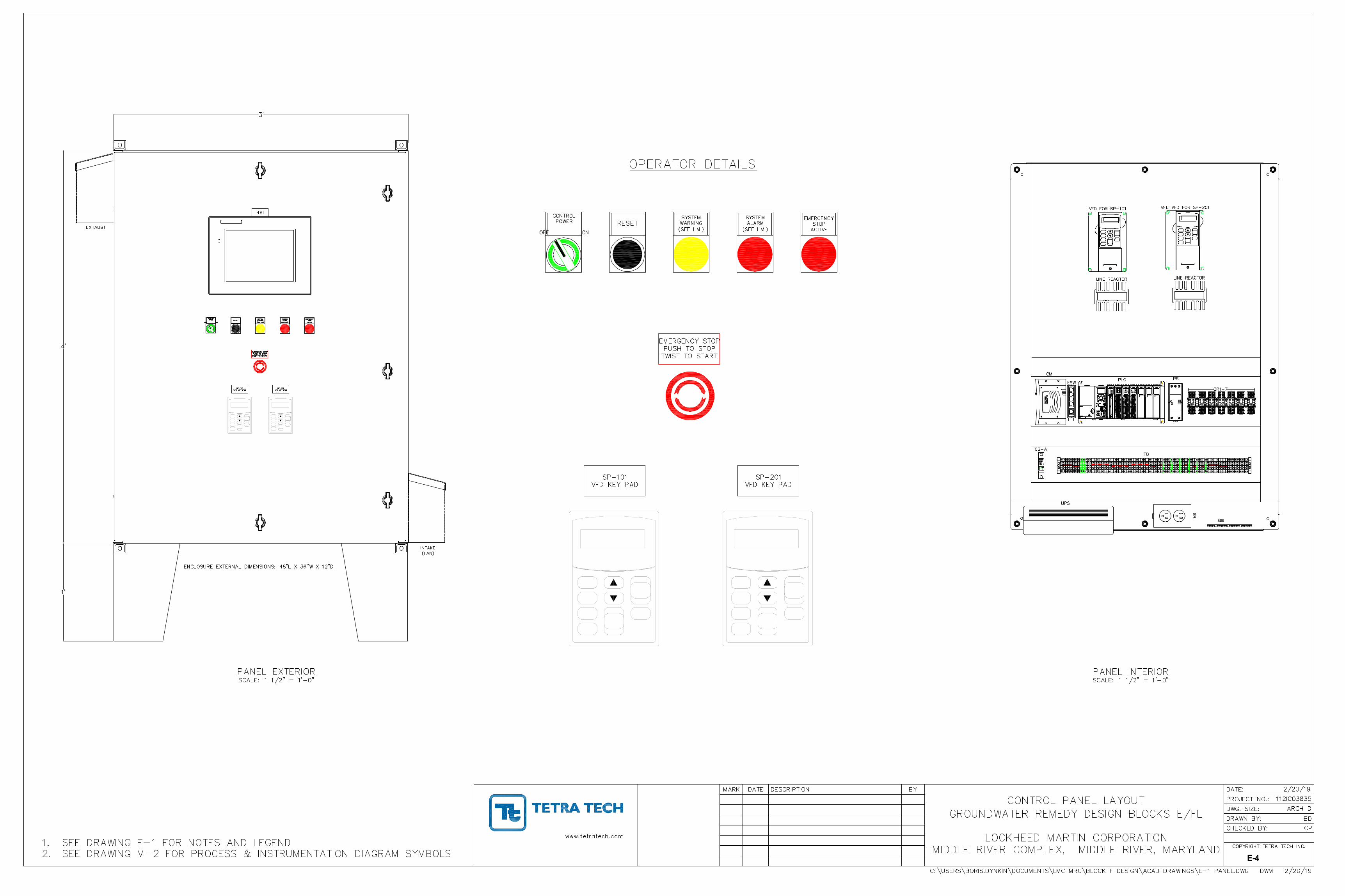
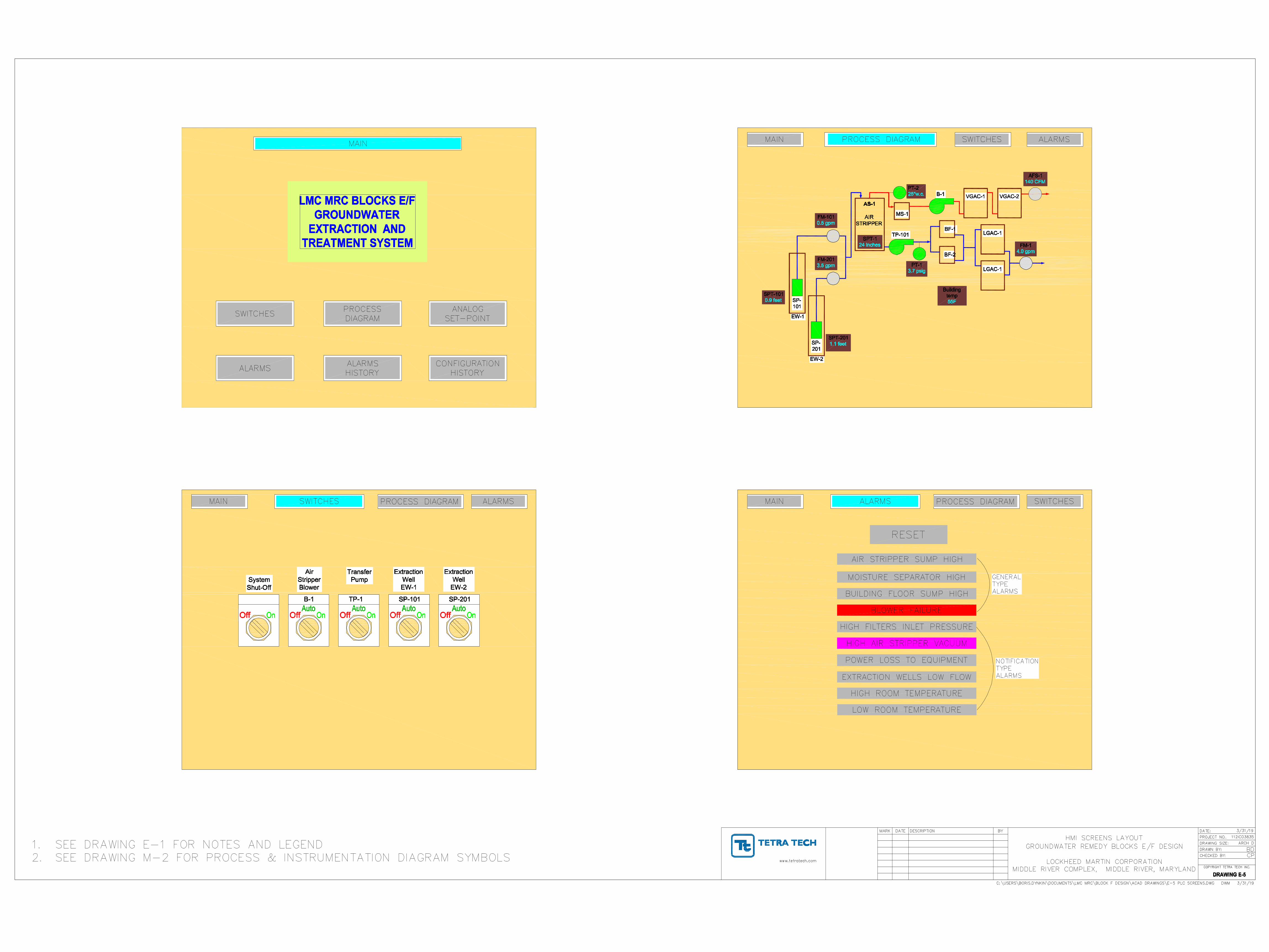
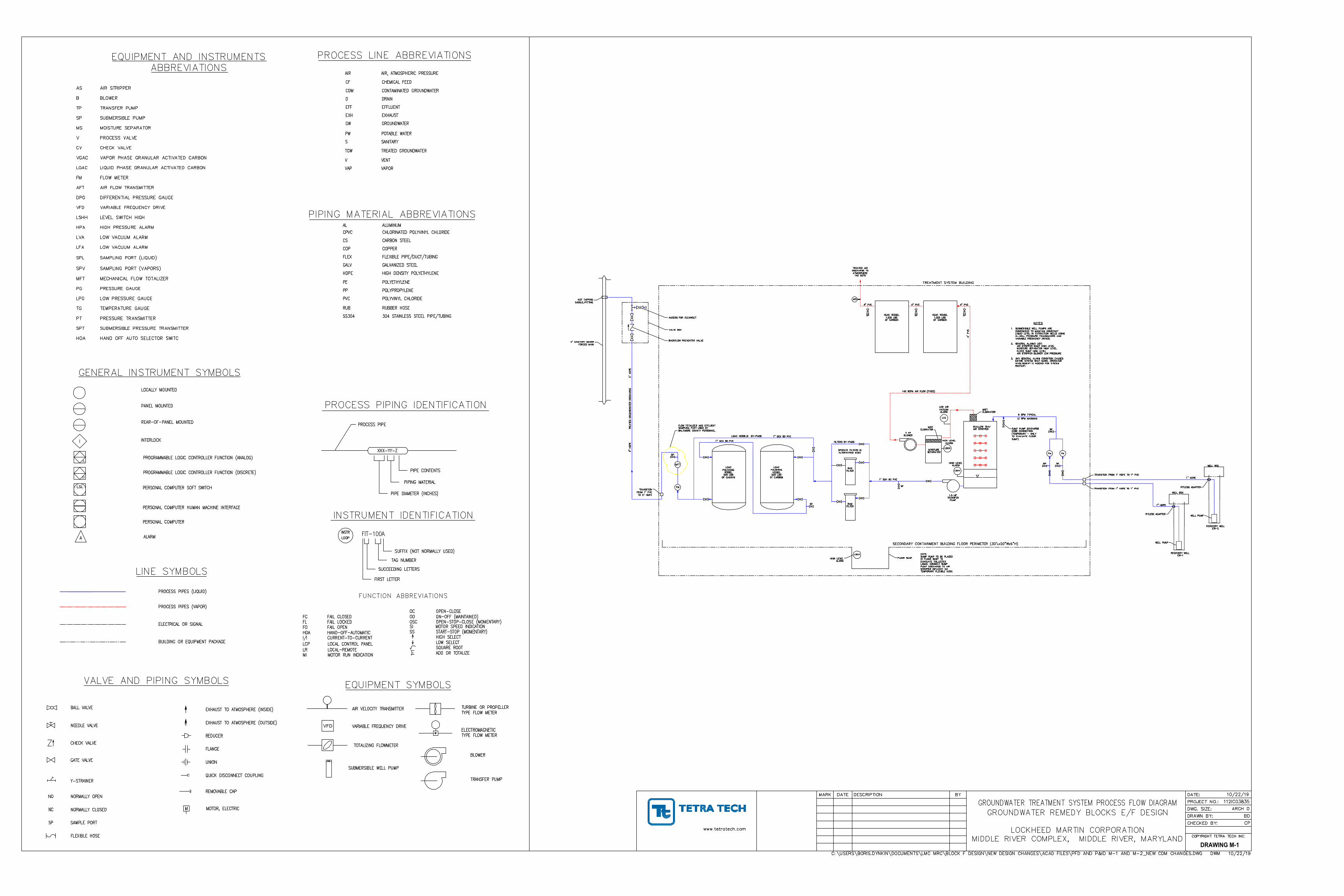
DRAWING M-2
DRAWING M-1
FUNCTION ABBREVIATIONS
VFD
D
A
M
M
AA
A
A
D D
AA
AA
A
M
DA
A
AutoCAD SHX Text
MARK
AutoCAD SHX Text
DATE
AutoCAD SHX Text
DESCRIPTION
AutoCAD SHX Text
BY
AutoCAD SHX Text
CHECKED BY:
AutoCAD SHX Text
DRAWN BY:
AutoCAD SHX Text
PROJECT NO.:
AutoCAD SHX Text
www.tetratech.com
AutoCAD SHX Text
DATE:
AutoCAD SHX Text
COPYRIGHT TETRA TECH INC.
AutoCAD SHX Text
112IC03835
AutoCAD SHX Text
10/22/19
AutoCAD SHX Text
CP
AutoCAD SHX Text
BD
AutoCAD SHX Text
GROUNDWATER TREATMENT SYSTEM PROCESS FLOW DIAGRAM GROUNDWATER REMEDY BLOCKS E/F DESIGN LOCKHEED MARTIN CORPORATION MIDDLE RIVER COMPLEX, MIDDLE RIVER, MARYLAND
AutoCAD SHX Text
C:\USERS\BORIS.DYNKIN\DOCUMENTS\LMC MRC\BLOCK F DESIGN\NEW DESIGN CHANGES\ACAD FILES\PFD AND P&ID M-1 AND M-2_NEW CDM CHANGES.DWG DWM 10/22/19
AutoCAD SHX Text
DWG. SIZE:
AutoCAD SHX Text
ARCH D
AutoCAD SHX Text
3 HP BLOWER
AutoCAD SHX Text
LSHH
AutoCAD SHX Text
1.5 HP TRANSFER PUMP
AutoCAD SHX Text
LVA
AutoCAD SHX Text
LOW AIR VACUUM ALARM
AutoCAD SHX Text
5 GPM TYPICAL 12 GPM MAXIMUM
AutoCAD SHX Text
4" PVC
AutoCAD SHX Text
VGAC VESSEL 1,000 LBS OF CARBON
AutoCAD SHX Text
VGAC VESSEL 1,000 LBS OF CARBON
AutoCAD SHX Text
TREATED AIR DISCHARGE TO ATMOSPHERE 140 SCFM
AutoCAD SHX Text
4" PVC
AutoCAD SHX Text
4" PVC
AutoCAD SHX Text
4" PVC
AutoCAD SHX Text
AFS
AutoCAD SHX Text
BAG FILTER
AutoCAD SHX Text
LGAC POLISHING VESSEL 500 LBS OF CARBON
AutoCAD SHX Text
1" SCH 80 PVC
AutoCAD SHX Text
SECONDARY CONTAINMENT BUILDING FLOOR PERIMETER (30'Lx20"Wx6"H)
AutoCAD SHX Text
HIGH LEVEL ALARM
AutoCAD SHX Text
HIGH LEVEL ALARM
AutoCAD SHX Text
SP
AutoCAD SHX Text
1" HDPE
AutoCAD SHX Text
PITLESS ADAPTER
AutoCAD SHX Text
WELL PUMP
AutoCAD SHX Text
RECOVERY WELL EW-1
AutoCAD SHX Text
WELL BOX
AutoCAD SHX Text
SP
AutoCAD SHX Text
SP
AutoCAD SHX Text
SP
AutoCAD SHX Text
FM
AutoCAD SHX Text
TREATMENT SYSTEM BUILDING
AutoCAD SHX Text
RECOVERY WELL EW-2
AutoCAD SHX Text
WELL PUMP
AutoCAD SHX Text
WELL BOX
AutoCAD SHX Text
PITLESS ADAPTER
AutoCAD SHX Text
LSHH
AutoCAD SHX Text
FLOOR SUMP
AutoCAD SHX Text
MOISTURE SEPARATOR
AutoCAD SHX Text
MIST ELIMINATOR
AutoCAD SHX Text
LSHH
AutoCAD SHX Text
HIGH LEVEL ALARM
AutoCAD SHX Text
MIST ELIMINATOR
AutoCAD SHX Text
140 SCFM AIR FLOW (FIXED)
AutoCAD SHX Text
BAG FILTER
AutoCAD SHX Text
FILTERS BY-PASS
AutoCAD SHX Text
LGAC VESSELS BY-PASS
AutoCAD SHX Text
LGAC POLISHING VESSEL 500 LBS OF CARBON
AutoCAD SHX Text
SP
AutoCAD SHX Text
FM
AutoCAD SHX Text
SP
AutoCAD SHX Text
1" SCH 80 PVC
AutoCAD SHX Text
1" SCH 80 PVC
AutoCAD SHX Text
SP
AutoCAD SHX Text
SP
AutoCAD SHX Text
FM
AutoCAD SHX Text
NOTES 1.SUBMERSIBLE WELL PUMPS ARE SUBMERSIBLE WELL PUMPS ARE CONFIGURED TO MAINTAIN CONSTANT LIQUID LEVEL IN EXTRACTION WELLS USING IN-WELL PRESSURE TRANSDUCERS AND VARIABLE FREQUENCY DRIVES. 2.GENERAL ALARMS LIST: GENERAL ALARMS LIST: AIR STRIPPER SUMP HIGH LEVEL MOISTURE SEPARATOR HIGH LEVEL FLOOR SUMP HIGH LEVEL AIR STRIPPER BLOWER LOW PRESSURE 3.ANY GENERAL ALARM CONDITION CAUSES ANY GENERAL ALARM CONDITION CAUSES ENTIRE SYSTEM SHUT DOWN. OPERATOR INVOLVEMENT IS NEEDED FOR SYSTEM RESTART.
AutoCAD SHX Text
SP
AutoCAD SHX Text
MFT
AutoCAD SHX Text
TREATED GROUNDWATER DISCHARGE
AutoCAD SHX Text
2" HDPE
AutoCAD SHX Text
TRANSITION FROM 1" PVC TO 2" HDPE
AutoCAD SHX Text
TRANSITION FROM 1" HDPE TO 1" PVC
AutoCAD SHX Text
1" HDPE
AutoCAD SHX Text
TRANSITION FROM 1" HDPE TO 1" PVC
AutoCAD SHX Text
FLOW TOTALIZER AND EFFLUENT SAMPLING PORT USED BY BALTIMORE COUNTY PERSONNEL
AutoCAD SHX Text
SHALLOW TRAY AIR STRIPPER
AutoCAD SHX Text
EQUIPMENT AND INSTRUMENTS ABBREVIATIONS ASAIR STRIPPER AIR STRIPPER BBLOWER BLOWER TPTRANSFER PUMP TRANSFER PUMP SPSUBMERSIBLE PUMP SUBMERSIBLE PUMP MSMOISTURE SEPARATOR MOISTURE SEPARATOR VPROCESS VALVE PROCESS VALVE CVCHECK VALVE CHECK VALVE VGACVAPOR PHASE GRANULAR ACTIVATED CARBON VAPOR PHASE GRANULAR ACTIVATED CARBON LGACLIQUID PHASE GRANULAR ACTIVATED CARBON LIQUID PHASE GRANULAR ACTIVATED CARBON FMFLOW METER FLOW METER AFTAIR FLOW TRANSMITTER AIR FLOW TRANSMITTER DPGDIFFERENTIAL PRESSURE GAUGE DIFFERENTIAL PRESSURE GAUGE VFDVARIABLE FREQUENCY DRIVE VARIABLE FREQUENCY DRIVE LSHHLEVEL SWITCH HIGH LEVEL SWITCH HIGH HPAHIGH PRESSURE ALARM HIGH PRESSURE ALARM LVALOW VACUUM ALARM LOW VACUUM ALARM LFALOW VACUUM ALARM LOW VACUUM ALARM SPLSAMPLING PORT (LIQUID) SAMPLING PORT (LIQUID) SPVSAMPLING PORT (VAPORS) SAMPLING PORT (VAPORS) MFTMECHANICAL FLOW TOTALIZER MECHANICAL FLOW TOTALIZER PGPRESSURE GAUGE PRESSURE GAUGE LPGLOW PRESSURE GAUGE LOW PRESSURE GAUGE TGTEMPERATURE GAUGE TEMPERATURE GAUGE PTPRESSURE TRANSMITTER PRESSURE TRANSMITTER SPTSUBMERSIBLE PRESSURE TRANSMITTER SUBMERSIBLE PRESSURE TRANSMITTER HOAHAND OFF AUTO SELECTOR SWITC HAND OFF AUTO SELECTOR SWITC
AutoCAD SHX Text
SANITARY
AutoCAD SHX Text
S
AutoCAD SHX Text
NEEDLE VALVE
AutoCAD SHX Text
EQUIPMENT SYMBOLS
AutoCAD SHX Text
TOTALIZING FLOWMETER
AutoCAD SHX Text
NORMALLY CLOSED
AutoCAD SHX Text
Y-STRAINER
AutoCAD SHX Text
TRANSFER PUMP
AutoCAD SHX Text
SUBMERSIBLE WELL PUMP
AutoCAD SHX Text
AIR VELOCITY TRANSMITTER
AutoCAD SHX Text
M
AutoCAD SHX Text
MOTOR, ELECTRIC
AutoCAD SHX Text
NORMALLY OPEN
AutoCAD SHX Text
SP
AutoCAD SHX Text
NC
AutoCAD SHX Text
FLEXIBLE HOSE
AutoCAD SHX Text
SAMPLE PORT
AutoCAD SHX Text
NO
AutoCAD SHX Text
BALL VALVE
AutoCAD SHX Text
PROGRAMMABLE LOGIC CONTROLLER FUNCTION (DISCRETE)
AutoCAD SHX Text
PERSONAL COMPUTER SOFT SWITCH
AutoCAD SHX Text
PERSONAL COMPUTER HUMAN MACHINE INTERFACE
AutoCAD SHX Text
PERSONAL COMPUTER
AutoCAD SHX Text
ELECTRICAL OR SIGNAL
AutoCAD SHX Text
PROCESS PIPES (LIQUID)
AutoCAD SHX Text
TYPE FLOW METER
AutoCAD SHX Text
TURBINE OR PROPELLER
AutoCAD SHX Text
BLOWER
AutoCAD SHX Text
FLANGE
AutoCAD SHX Text
QUICK DISCONNECT COUPLING
AutoCAD SHX Text
REDUCER
AutoCAD SHX Text
EXHAUST TO ATMOSPHERE (OUTSIDE)
AutoCAD SHX Text
REMOVABLE CAP
AutoCAD SHX Text
EXHAUST TO ATMOSPHERE (INSIDE)
AutoCAD SHX Text
UNION
AutoCAD SHX Text
A
AutoCAD SHX Text
LSL
AutoCAD SHX Text
LINE SYMBOLS
AutoCAD SHX Text
ALARM
AutoCAD SHX Text
XXX-YY-Z
AutoCAD SHX Text
FIRST LETTER
AutoCAD SHX Text
SUFFIX (NOT NORMALLY USED)
AutoCAD SHX Text
TAG NUMBER
AutoCAD SHX Text
SUCCEEDING LETTERS
AutoCAD SHX Text
PIPE DIAMETER (INCHES)
AutoCAD SHX Text
INSTRUMENT IDENTIFICATION
AutoCAD SHX Text
MI
AutoCAD SHX Text
MOTOR RUN INDICATION
AutoCAD SHX Text
LOCAL CONTROL PANEL
AutoCAD SHX Text
LOCAL-REMOTE
AutoCAD SHX Text
CURRENT-TO-CURRENT
AutoCAD SHX Text
HAND-OFF-AUTOMATIC
AutoCAD SHX Text
FAIL OPEN
AutoCAD SHX Text
FAIL LOCKED
AutoCAD SHX Text
FAIL CLOSED
AutoCAD SHX Text
LCP
AutoCAD SHX Text
LR
AutoCAD SHX Text
I/I
AutoCAD SHX Text
HOA
AutoCAD SHX Text
FO
AutoCAD SHX Text
FL
AutoCAD SHX Text
FC
AutoCAD SHX Text
LOOP
AutoCAD SHX Text
INSTR
AutoCAD SHX Text
FIT-100A
AutoCAD SHX Text
START-STOP (MOMENTARY)
AutoCAD SHX Text
OPEN-STOP-CLOSE (MOMENTARY)
AutoCAD SHX Text
MOTOR SPEED INDICATION
AutoCAD SHX Text
ADD OR TOTALIZE
AutoCAD SHX Text
SQUARE ROOT
AutoCAD SHX Text
LOW SELECT
AutoCAD SHX Text
HIGH SELECT
AutoCAD SHX Text
ON-OFF (MAINTAINED)
AutoCAD SHX Text
OPEN-CLOSE
AutoCAD SHX Text
SI
AutoCAD SHX Text
SS
AutoCAD SHX Text
OSC
AutoCAD SHX Text
OO
AutoCAD SHX Text
OC
AutoCAD SHX Text
PIPING MATERIAL
AutoCAD SHX Text
PIPE CONTENTS
AutoCAD SHX Text
HIGH DENSITY POLYETHYLENE
AutoCAD SHX Text
FLEXIBLE PIPE/DUCT/TUBING
AutoCAD SHX Text
CHLORINATED POLYVINYL CHLORIDE
AutoCAD SHX Text
CARBON STEEL
AutoCAD SHX Text
COPPER
AutoCAD SHX Text
GALVANIZED STEEL
AutoCAD SHX Text
POLYETHYLENE
AutoCAD SHX Text
POLYPROPYLENE
AutoCAD SHX Text
POLYVINYL CHLORIDE
AutoCAD SHX Text
RUBBER HOSE
AutoCAD SHX Text
304 STAINLESS STEEL PIPE/TUBING
AutoCAD SHX Text
VAPOR
AutoCAD SHX Text
VENT
AutoCAD SHX Text
TREATED GROUNDWATER
AutoCAD SHX Text
PIPING MATERIAL ABBREVIATIONS
AutoCAD SHX Text
PROCESS PIPING IDENTIFICATION
AutoCAD SHX Text
PROCESS PIPE
AutoCAD SHX Text
PE
AutoCAD SHX Text
PP
AutoCAD SHX Text
PVC
AutoCAD SHX Text
RUB
AutoCAD SHX Text
SS304
AutoCAD SHX Text
HDPE
AutoCAD SHX Text
FLEX
AutoCAD SHX Text
CPVC
AutoCAD SHX Text
CS
AutoCAD SHX Text
COP
AutoCAD SHX Text
GALV
AutoCAD SHX Text
VAP
AutoCAD SHX Text
V
AutoCAD SHX Text
TGW
AutoCAD SHX Text
VALVE AND PIPING SYMBOLS
AutoCAD SHX Text
CHECK VALVE
AutoCAD SHX Text
GATE VALVE
AutoCAD SHX Text
INTERLOCK
AutoCAD SHX Text
REAR-OF-PANEL MOUNTED
AutoCAD SHX Text
PANEL MOUNTED
AutoCAD SHX Text
LOCALLY MOUNTED
AutoCAD SHX Text
%%uGENERAL INSTRUMENT SYMBOLS
AutoCAD SHX Text
I
AutoCAD SHX Text
CHEMICAL FEED
AutoCAD SHX Text
POTABLE WATER
AutoCAD SHX Text
GROUNDWATER
AutoCAD SHX Text
EXHAUST
AutoCAD SHX Text
EFFLUENT
AutoCAD SHX Text
DRAIN
AutoCAD SHX Text
CONTAMINATED GROUNDWATER
AutoCAD SHX Text
AIR, ATMOSPHERIC PRESSURE
AutoCAD SHX Text
PROCESS LINE ABBREVIATIONS
AutoCAD SHX Text
CGW
AutoCAD SHX Text
PW
AutoCAD SHX Text
GW
AutoCAD SHX Text
EXH
AutoCAD SHX Text
EFF
AutoCAD SHX Text
D
AutoCAD SHX Text
CF
AutoCAD SHX Text
AIR
AutoCAD SHX Text
VARIABLE FREQUENCY DRIVE
AutoCAD SHX Text
ALUMINUM
AutoCAD SHX Text
AL
AutoCAD SHX Text
PROGRAMMABLE LOGIC CONTROLLER FUNCTION (ANALOG)
AutoCAD SHX Text
PROCESS PIPES (VAPOR)
AutoCAD SHX Text
BUILDING OR EQUIPMENT PACKAGE
AutoCAD SHX Text
OPERATE FILTERS IN ALTERNATING MODE
AutoCAD SHX Text
NOTE. SUMP PUMP TO BE PLACED IN FLOOR SUMP TO EVACUATE COLLECTED LIQUID. CONNECT SUMP PUMP DISCHARGE TO AIR STRIPPER INFLUENT VIA TEMPORARY FLEXIBLE HOSE.
AutoCAD SHX Text
SUMP PUMP DISCHARGE HOSE CONNECTION (TEMPORARY - ONLY TO EVACUATE FLOOR SUMP)
AutoCAD SHX Text
TYPE FLOW METER
AutoCAD SHX Text
ELECTROMAGNETIC
AutoCAD SHX Text
M
AutoCAD SHX Text
4" SANITARY SEWER FORCED MAIN
AutoCAD SHX Text
BACKFLOW PREVENTOR VALVE
AutoCAD SHX Text
2" HDPE
AutoCAD SHX Text
ACCESS FOR CLEANOUT
AutoCAD SHX Text
VALVE BOX
AutoCAD SHX Text
HOT TAPPING SADDLE/FITTING
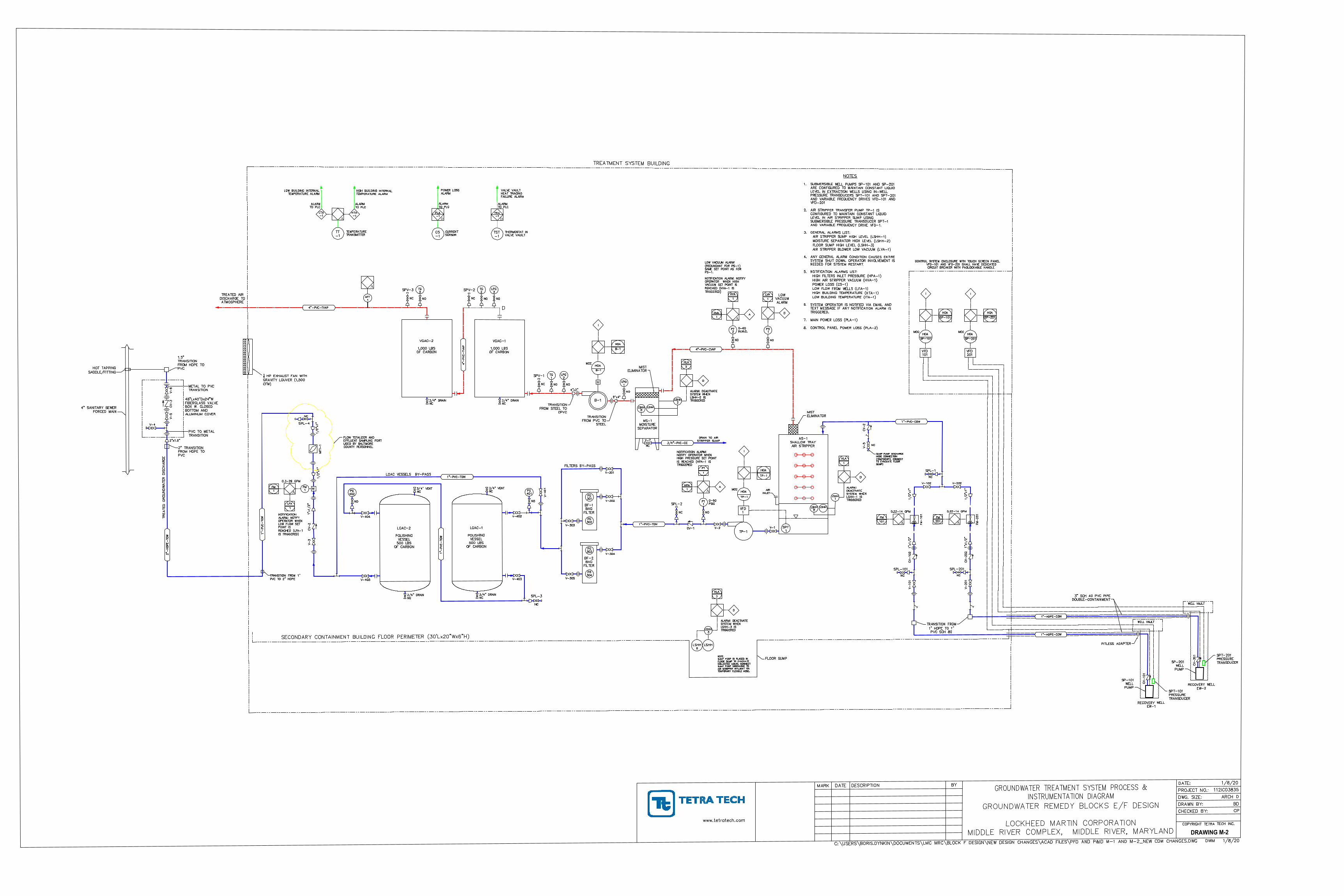
DRAWING M-2
M
M
AA
A
A
D D
AA
AA
A
M
DA
A
D
AutoCAD SHX Text
MARK
AutoCAD SHX Text
DATE
AutoCAD SHX Text
DESCRIPTION
AutoCAD SHX Text
BY
AutoCAD SHX Text
CHECKED BY:
AutoCAD SHX Text
DRAWN BY:
AutoCAD SHX Text
PROJECT NO.:
AutoCAD SHX Text
www.tetratech.com
AutoCAD SHX Text
DATE:
AutoCAD SHX Text
COPYRIGHT TETRA TECH INC.
AutoCAD SHX Text
112IC03835
AutoCAD SHX Text
1/8/20
AutoCAD SHX Text
CP
AutoCAD SHX Text
BD
AutoCAD SHX Text
GROUNDWATER TREATMENT SYSTEM PROCESS & INSTRUMENTATION DIAGRAM GROUNDWATER REMEDY BLOCKS E/F DESIGN LOCKHEED MARTIN CORPORATION MIDDLE RIVER COMPLEX, MIDDLE RIVER, MARYLAND
AutoCAD SHX Text
C:\USERS\BORIS.DYNKIN\DOCUMENTS\LMC MRC\BLOCK F DESIGN\NEW DESIGN CHANGES\ACAD FILES\PFD AND P&ID M-1 AND M-2_NEW CDM CHANGES.DWG DWM 1/8/20
AutoCAD SHX Text
DWG. SIZE:
AutoCAD SHX Text
ARCH D
AutoCAD SHX Text
B-1
AutoCAD SHX Text
TP-1
AutoCAD SHX Text
LOW VACUUM ALARM
AutoCAD SHX Text
VGAC-1 1,000 LBS OF CARBON
AutoCAD SHX Text
VGAC-2 1,000 LBS OF CARBON
AutoCAD SHX Text
TREATED AIR DISCHARGE TO ATMOSPHERE
AutoCAD SHX Text
BF-2 BAG FILTER
AutoCAD SHX Text
LGAC-2 POLISHING VESSEL 500 LBS OF CARBON
AutoCAD SHX Text
SECONDARY CONTAINMENT BUILDING FLOOR PERIMETER (30'Lx20"Wx6"H)
AutoCAD SHX Text
SPL-201
AutoCAD SHX Text
TREATMENT SYSTEM BUILDING
AutoCAD SHX Text
RECOVERY WELL EW-2
AutoCAD SHX Text
SP-201 WELL PUMP
AutoCAD SHX Text
LSHH
AutoCAD SHX Text
FLOOR SUMP
AutoCAD SHX Text
MS-1 MOISTURE SEPARATOR
AutoCAD SHX Text
MIST ELIMINATOR
AutoCAD SHX Text
MIST ELIMINATOR
AutoCAD SHX Text
BF-1 BAG FILTER
AutoCAD SHX Text
FILTERS BY-PASS
AutoCAD SHX Text
LGAC VESSELS BY-PASS
AutoCAD SHX Text
LGAC-1 POLISHING VESSEL 500 LBS OF CARBON
AutoCAD SHX Text
NOTES 1.SUBMERSIBLE WELL PUMPS SP-101 AND SP-201 SUBMERSIBLE WELL PUMPS SP-101 AND SP-201 ARE CONFIGURED TO MAINTAIN CONSTANT LIQUID LEVEL IN EXTRACTION WELLS USING IN-WELL PRESSURE TRANSDUCERS SPT-101 AND SPT-201 AND VARIABLE FREQUENCY DRIVES VFD-101 AND VFD-201 2.AIR STRIPPER TRANSFER PUMP TP-1 IS AIR STRIPPER TRANSFER PUMP TP-1 IS CONFIGURED TO MAINTAIN CONSTANT LIQUID LEVEL IN AIR STRIPPER SUMP USING SUBMERSIBLE PRESSURE TRANSDUCER SPT-1 AND VARIABLE FREQUENCY DRIVE VFD-1. 3.GENERAL ALARMS LIST: GENERAL ALARMS LIST: AIR STRIPPER SUMP HIGH LEVEL (LSHH-1) MOISTURE SEPARATOR HIGH LEVEL (LSHH-2) FLOOR SUMP HIGH LEVEL (LSHH-3) AIR STRIPPER BLOWER LOW VACUUM (LVA-1) 4.ANY GENERAL ALARM CONDITION CAUSES ENTIRE ANY GENERAL ALARM CONDITION CAUSES ENTIRE SYSTEM SHUT DOWN. OPERATOR INVOLVEMENT IS NEEDED FOR SYSTEM RESTART. 5.NOTIFICATION ALARMS LIST: NOTIFICATION ALARMS LIST: HIGH FILTERS INLET PRESSURE (HPA-1) HIGH AIR STRIPPER VACUUM (HVA-1) POWER LOSS (CS-1) LOW FLOW FROM WELLS (LFA-1) HIGH BUILDING TEMPERATURE (HTA-1) LOW BUILDING TEMPERATURE (lTA-1) 6.SYSTEM OPERATOR IS NOTIFIED VIA EMAIL AND SYSTEM OPERATOR IS NOTIFIED VIA EMAIL AND TEXT MESSAGE IF ANY NOTIFICATION ALARM IS TRIGGERED. 7.MAIN POWER LOSS (PLA-1) MAIN POWER LOSS (PLA-1) 8.CONTROL PANEL POWER LOSS (PLA-2)CONTROL PANEL POWER LOSS (PLA-2)
AutoCAD SHX Text
TREATED GROUNDWATER DISCHARGE
AutoCAD SHX Text
2" TRANSITION FROM HDPE TO PVC
AutoCAD SHX Text
AS-1 SHALLOW TRAY AIR STRIPPER
AutoCAD SHX Text
CV-202
AutoCAD SHX Text
1"x1/2"
AutoCAD SHX Text
V-201
AutoCAD SHX Text
FM-201
AutoCAD SHX Text
201
AutoCAD SHX Text
FM
AutoCAD SHX Text
1/2"x1"
AutoCAD SHX Text
NC
AutoCAD SHX Text
SPL-101
AutoCAD SHX Text
CV-102
AutoCAD SHX Text
1"x1/2"
AutoCAD SHX Text
V-101
AutoCAD SHX Text
0.22-14 GPM
AutoCAD SHX Text
FM-101
AutoCAD SHX Text
101
AutoCAD SHX Text
FM
AutoCAD SHX Text
1/2"x1"
AutoCAD SHX Text
NC
AutoCAD SHX Text
TRANSITION FROM 1" HDPE TO 1" PVC SCH 80
AutoCAD SHX Text
SPL-1
AutoCAD SHX Text
NC
AutoCAD SHX Text
V-1
AutoCAD SHX Text
1
AutoCAD SHX Text
LSHH
AutoCAD SHX Text
D
AutoCAD SHX Text
HLA
AutoCAD SHX Text
1
AutoCAD SHX Text
ALARM! DEACTIVATE SYSTEM WHEN LSHH-1 IS TRIGGERED
AutoCAD SHX Text
HOA
AutoCAD SHX Text
MCC
AutoCAD SHX Text
SP-201
AutoCAD SHX Text
HOA
AutoCAD SHX Text
SP-201
AutoCAD SHX Text
I
AutoCAD SHX Text
1"-PVC-CGW
AutoCAD SHX Text
AIR INLET
AutoCAD SHX Text
V-2
AutoCAD SHX Text
CV-1
AutoCAD SHX Text
NO
AutoCAD SHX Text
1
AutoCAD SHX Text
PT
AutoCAD SHX Text
A
AutoCAD SHX Text
NOTIFICATION ALARM! NOTIFY OPERATOR WHEN HIGH PRESSURE SET POINT IS REACHED (HPA-1 IS TRIGGERED
AutoCAD SHX Text
1
AutoCAD SHX Text
PT
AutoCAD SHX Text
1
AutoCAD SHX Text
HPA
AutoCAD SHX Text
0-60 PSIG
AutoCAD SHX Text
1"-PVC-TGW
AutoCAD SHX Text
SPL-2
AutoCAD SHX Text
NC
AutoCAD SHX Text
V-302
AutoCAD SHX Text
V-301
AutoCAD SHX Text
V-304
AutoCAD SHX Text
V-305
AutoCAD SHX Text
V-303
AutoCAD SHX Text
PG 301
AutoCAD SHX Text
PG 302
AutoCAD SHX Text
PG 303
AutoCAD SHX Text
PG 304
AutoCAD SHX Text
1"-PVC-TGW
AutoCAD SHX Text
SPL-3
AutoCAD SHX Text
NC
AutoCAD SHX Text
1"-PVC-TGW
AutoCAD SHX Text
PG 402
AutoCAD SHX Text
NO
AutoCAD SHX Text
PG 401
AutoCAD SHX Text
NO
AutoCAD SHX Text
V-402
AutoCAD SHX Text
V-403
AutoCAD SHX Text
V-405
AutoCAD SHX Text
V-404
AutoCAD SHX Text
V-401
AutoCAD SHX Text
SPL-4
AutoCAD SHX Text
CV-2
AutoCAD SHX Text
1"x1/2"
AutoCAD SHX Text
V-3
AutoCAD SHX Text
0.3-29 GPM
AutoCAD SHX Text
1
AutoCAD SHX Text
FM
AutoCAD SHX Text
1/2"x1"
AutoCAD SHX Text
NC
AutoCAD SHX Text
1/2"x1"
AutoCAD SHX Text
MFT-1
AutoCAD SHX Text
1"-PVC-TGW
AutoCAD SHX Text
3
AutoCAD SHX Text
LSHH
AutoCAD SHX Text
D
AutoCAD SHX Text
HLA
AutoCAD SHX Text
3
AutoCAD SHX Text
ALARM! DEACTIVATE SYSTEM WHEN LSHH-3 IS TRIGGERED
AutoCAD SHX Text
SPT-201 PRESSURE TRANSDUCER
AutoCAD SHX Text
1"-HDPE-CGW
AutoCAD SHX Text
VFD 201
AutoCAD SHX Text
RECOVERY WELL EW-1
AutoCAD SHX Text
SP-101 WELL PUMP
AutoCAD SHX Text
SPT-101 PRESSURE TRANSDUCER
AutoCAD SHX Text
1"-HDPE-CGW
AutoCAD SHX Text
VFD 101
AutoCAD SHX Text
CONTROL SYSTEM ENCLOSURE WITH TOUCH SCREEN PANEL. TOUCH SCREEN PANEL. VFD-101 AND VFD-201 SHALL HAVE DEDICATED CIRCUIT BREAKER WITH PADLOCKABLE HANDLE.
AutoCAD SHX Text
HOA
AutoCAD SHX Text
MCC
AutoCAD SHX Text
SP-101
AutoCAD SHX Text
HOA
AutoCAD SHX Text
SP-101
AutoCAD SHX Text
I
AutoCAD SHX Text
2
AutoCAD SHX Text
LSHH
AutoCAD SHX Text
D
AutoCAD SHX Text
HLA
AutoCAD SHX Text
2
AutoCAD SHX Text
ALARM! DEACTIVATE SYSTEM WHEN LSHH-2 IS TRIGGERED
AutoCAD SHX Text
1
AutoCAD SHX Text
PS
AutoCAD SHX Text
D
AutoCAD SHX Text
LVA
AutoCAD SHX Text
1
AutoCAD SHX Text
NO
AutoCAD SHX Text
2
AutoCAD SHX Text
PT
AutoCAD SHX Text
A
AutoCAD SHX Text
LOW VACUUM ALARM! (REDUNDANT FOR PS-1) SAME SET POINT AS FOR PS-1. NOTIFICATION ALARM! NOTIFY OPERATOR WHEN HIGH VACUUM SET POINT IS REACHED (HVA-1 IS TRIGGERED)
AutoCAD SHX Text
1
AutoCAD SHX Text
HVA
AutoCAD SHX Text
1
AutoCAD SHX Text
HVA
AutoCAD SHX Text
0-60 IN.W.C.
AutoCAD SHX Text
NO
AutoCAD SHX Text
4"-PVC-CVAP
AutoCAD SHX Text
HOA
AutoCAD SHX Text
MCC
AutoCAD SHX Text
TP-1
AutoCAD SHX Text
HOA
AutoCAD SHX Text
TP-1
AutoCAD SHX Text
I
AutoCAD SHX Text
HOA
AutoCAD SHX Text
MCC
AutoCAD SHX Text
B-1
AutoCAD SHX Text
HOA
AutoCAD SHX Text
B-1
AutoCAD SHX Text
I
AutoCAD SHX Text
2"x4"
AutoCAD SHX Text
TRANSITION FROM PVC TO STEEL
AutoCAD SHX Text
TRANSITION FROM STEEL TO CPVC
AutoCAD SHX Text
SPV-1
AutoCAD SHX Text
NC
AutoCAD SHX Text
LPG 2
AutoCAD SHX Text
NO
AutoCAD SHX Text
TG 1
AutoCAD SHX Text
NO
AutoCAD SHX Text
4"x2"
AutoCAD SHX Text
SPV-2
AutoCAD SHX Text
NC
AutoCAD SHX Text
LPG 3
AutoCAD SHX Text
NO
AutoCAD SHX Text
TG 2
AutoCAD SHX Text
NO
AutoCAD SHX Text
4"-PVC-TVAP
AutoCAD SHX Text
SPV-3
AutoCAD SHX Text
NC
AutoCAD SHX Text
AFT 1
AutoCAD SHX Text
NO
AutoCAD SHX Text
4"-PVC-TVAP
AutoCAD SHX Text
CS -1
AutoCAD SHX Text
PLA -1
AutoCAD SHX Text
ALARM TO PLC
AutoCAD SHX Text
POWER LOSS ALARM
AutoCAD SHX Text
TT -1
AutoCAD SHX Text
HTA -1
AutoCAD SHX Text
ALARM TO PLC
AutoCAD SHX Text
HIGH BUILDING INTERNAL TEMPERATURE ALARM
AutoCAD SHX Text
3" SCH 40 PVC PIPE DOUBLE-CONTAINMENT
AutoCAD SHX Text
WELL VAULT
AutoCAD SHX Text
WELL VAULT
AutoCAD SHX Text
SPT 1
AutoCAD SHX Text
VFD 1
AutoCAD SHX Text
LPG 1
AutoCAD SHX Text
NO
AutoCAD SHX Text
NC
AutoCAD SHX Text
LSHH
AutoCAD SHX Text
14 HP EXHAUST FAN WITH GRAVITY LOUVER (1,500 CFM)
AutoCAD SHX Text
TG 3
AutoCAD SHX Text
NOTE. SUMP PUMP IS PLACED IN FLOOR SUMP TO EVACUATE COLLECTED LIQUID. CONNECT SUMP PUMP DISCHARGE TO AIR STRIPPER INFLUENT VIA TEMPORARY FLEXIBLE HOSE.
AutoCAD SHX Text
R
AutoCAD SHX Text
LSHH
AutoCAD SHX Text
LSHH
AutoCAD SHX Text
R
AutoCAD SHX Text
LSHH
AutoCAD SHX Text
LSHH
AutoCAD SHX Text
R
AutoCAD SHX Text
CV-2
AutoCAD SHX Text
SUMP PUMP DISCHARGE HOSE CONNECTION (TEMPORARY: CONNECT TO EVACUATE FLOOR SUMP)
AutoCAD SHX Text
V-5
AutoCAD SHX Text
NC
AutoCAD SHX Text
V-7
AutoCAD SHX Text
NOTIFICATION ALARM! NOTIFY OPERATOR WHEN LOW FLOW SET POINT IS REACHED (LFA-1 IS TRIGGERED)
AutoCAD SHX Text
1
AutoCAD SHX Text
LFA
AutoCAD SHX Text
M
AutoCAD SHX Text
FM 1
AutoCAD SHX Text
3/4"-PVC-CC
AutoCAD SHX Text
DRAIN TO AIR STRIPPER SUMP
AutoCAD SHX Text
2"-HDPE-TGW
AutoCAD SHX Text
V-102
AutoCAD SHX Text
V-202
AutoCAD SHX Text
0.22-14 GPM
AutoCAD SHX Text
CV-101
AutoCAD SHX Text
PITLESS ADAPTER
AutoCAD SHX Text
CV-201
AutoCAD SHX Text
LTA -1
AutoCAD SHX Text
ALARM TO PLC
AutoCAD SHX Text
LOW BUILDING INTERNAL TEMPERATURE ALARM
AutoCAD SHX Text
TRANSITION FROM 1" PVC TO 2" HDPE
AutoCAD SHX Text
FLOW TOTALIZER AND EFFLUENT SAMPLING PORT USED BY BALTIMORE COUNTY PERSONNEL
AutoCAD SHX Text
4" SANITARY SEWER FORCED MAIN
AutoCAD SHX Text
HOT TAPPING SADDLE/FITTING
AutoCAD SHX Text
2"x1.5"
AutoCAD SHX Text
CV-3
AutoCAD SHX Text
V-5
AutoCAD SHX Text
V-4
AutoCAD SHX Text
PVC TO METAL TRANSITION
AutoCAD SHX Text
V-6
AutoCAD SHX Text
1.5" TRANSITION FROM HDPE TO PVC
AutoCAD SHX Text
METAL TO PVC TRANSITION
AutoCAD SHX Text
48"Lx40"Dx24"W FIBERGLASS VALVE BOX W. CLOSED BOTTOM AND ALUMINUM COVER
AutoCAD SHX Text
TST -1
AutoCAD SHX Text
TRA -1
AutoCAD SHX Text
ALARM TO PLC
AutoCAD SHX Text
VALVE VAULT HEAT TRACING FAILURE ALARM
AutoCAD SHX Text
THERMOSTAT IN VALVE VAUILT
AutoCAD SHX Text
CURRENT SENSOR
AutoCAD SHX Text
TEMPERATURE TRANSMITTER
AutoCAD SHX Text
NC
AutoCAD SHX Text
3/4" VENT
AutoCAD SHX Text
NC
AutoCAD SHX Text
3/4" DRAIN
AutoCAD SHX Text
NC
AutoCAD SHX Text
3/4" DRAIN
AutoCAD SHX Text
NC
AutoCAD SHX Text
3/4" VENT
AutoCAD SHX Text
3/4" DRAIN
AutoCAD SHX Text
NC
AutoCAD SHX Text
3/4" DRAIN
AutoCAD SHX Text
NC
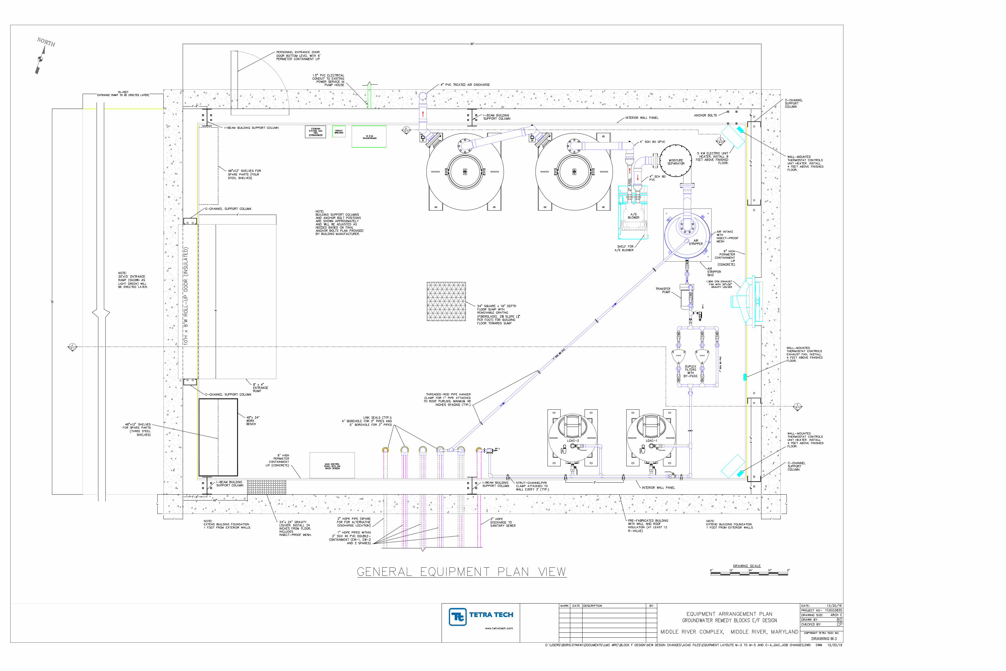
RA
NG
E:
PR
ES
SU
RE
TR
AN
SM
ITT
ER
MO
DE
L 6
26-
CA
UT
ION
:
MA
X O
VE
R P
RE
SS
UR
E:
MA
X P
RE
SS
UR
E:
SU
PP
LY
: 13-3
5V
DC
OU
TP
UT
: 4-2
0m
A
OP
ER
AT
ING
TE
MP
: 0 T
O 1
75°F
(-17.8
TO
79.4
°C
)
DRAWING M-3
AutoCAD SHX Text
PT-1
AutoCAD SHX Text
MOISTURE SEPARATOR
AutoCAD SHX Text
AIR STRIPPER SKID
AutoCAD SHX Text
A/S BLOWER
AutoCAD SHX Text
DUPLEX FILTERS WITH BY-PASS
AutoCAD SHX Text
DRAWING SCALE
AutoCAD SHX Text
0"
AutoCAD SHX Text
24"
AutoCAD SHX Text
12"
AutoCAD SHX Text
0"
AutoCAD SHX Text
12"
AutoCAD SHX Text
GENERAL EQUIPMENT PLAN VIEW
AutoCAD SHX Text
10'H x 8'W ROLL-UP DOOR (INSULATED)
AutoCAD SHX Text
MAIN CONTROL PANEL WITH HMI TOUCH SCREEN
AutoCAD SHX Text
2" HDPE DISCHARGE TO SANITARY SEWER
AutoCAD SHX Text
4" PVC TREATED AIR DISCHARGE
AutoCAD SHX Text
4" SCH 80 PVC
AutoCAD SHX Text
2" STEEL
AutoCAD SHX Text
1" SCH 80 PVC
AutoCAD SHX Text
1" SCH 80 PVC
AutoCAD SHX Text
SHELF FOR A/S BLOWER
AutoCAD SHX Text
8' x 4" ENTRANCE RUMP
AutoCAD SHX Text
PRE-FABRICATED BUILDING WITH WALL AND ROOF INSULATION (AT LEAST 12 R-VALUE)
AutoCAD SHX Text
6" HIGH PERIMETER CONTAINMENT LIP (CONCRETE)
AutoCAD SHX Text
M-4
AutoCAD SHX Text
A'
AutoCAD SHX Text
M-4
AutoCAD SHX Text
A
AutoCAD SHX Text
M-5
AutoCAD SHX Text
B
AutoCAD SHX Text
M-5
AutoCAD SHX Text
B'
AutoCAD SHX Text
TRANSFER PUMP
AutoCAD SHX Text
AIR STRIPPER
AutoCAD SHX Text
24" SQUARE x 18" DEPTH FLOOR SUMP WITH REMOVABLE GRATING (FIBERGLASS). 2% SLOPE ( " 14" PER FOOT) FOR BUILDING FLOOR TOWARDS SUMP
AutoCAD SHX Text
1.5" PVC ELECTRICAL CONDUIT TO EXISTING POWER SERVICE IN PUMP HOUSE
AutoCAD SHX Text
1" HDPE PIPES WITHIN 3" SCH 40 PVC DOUBLE- CONTAINMENT (EW-1, EW-2 AND 2 SPARES)
AutoCAD SHX Text
2" HDPE PIPE (SPARE FOR FOR ALTERNATIVE DISCHARGE LOCATION)
AutoCAD SHX Text
1,500 CFM EXHAUST FAN WITH 30"x30" GRAVITY LOUVER
AutoCAD SHX Text
EYEWASH STATION AND FIRE EXTINQUISHER
AutoCAD SHX Text
PERSONNEL ENTRANCE DOOR DOOR BOTTOM LEVEL WITH 6" PERIMETER CONTAINMENT LIP
AutoCAD SHX Text
48"x12" SHELVES FOR SPARE PARTS (FOUR STEEL SHELVES)
AutoCAD SHX Text
48"x12" SHELVES FOR SPARE PARTS (THREE STEEL SHELVES)
AutoCAD SHX Text
48"x 24" WORK BENCH
AutoCAD SHX Text
LINK SEALS (TYP.): 4" BOREHOLE FOR 2" PIPES AND 5" BOREHOLE FOR 3" PIPES
AutoCAD SHX Text
THREADED-ROD PIPE HANGER CLAMP FOR 1" PIPE ATTACHED TO ROOF PURLINS. MINIMUM 48 INCHES SPACING (TYP.)
AutoCAD SHX Text
24"x 24" GRAVITY LOUVER. INSTALL 24 INCHES FROM FLOOR. INCLUDES INSECT-PROOF MESH.
AutoCAD SHX Text
AIR INTAKE WITH INSECT-PROOF MESH
AutoCAD SHX Text
15 KVA TRANSFORMER
AutoCAD SHX Text
NOTE: EXTEND BUILDING FOUNDATION 1 FOOT FROM EXTERIOR WALLS
AutoCAD SHX Text
NOTE: EXTEND BUILDING FOUNDATION 1 FOOT FROM EXTERIOR WALLS
AutoCAD SHX Text
NOTE: 20'x15' ENTRANCE RAMP (SHOWN AS LIGHT GREEN) WILL BE ERECTED LATER.
AutoCAD SHX Text
5 KW ELECTRIC UNIT HEATER. INSTALL 8 FEET ABOVE FINISHED FLOOR.
AutoCAD SHX Text
WALL-MOUNTED THERMOSTAT CONTROLS EXHAUST FAN. INSTALL 4 FEET ABOVE FINISHED FLOOR.
AutoCAD SHX Text
WALL-MOUNTED THERMOSTAT CONTROLS UNIT HEATER. INSTALL 4 FEET ABOVE FINISHED FLOOR.
AutoCAD SHX Text
4" SCH 80 CPVC
AutoCAD SHX Text
WALL-MOUNTED THERMOSTAT CONTROLS UNIT HEATER. INSTALL 4 FEET ABOVE FINISHED FLOOR.
AutoCAD SHX Text
INTERIOR WALL PANEL
AutoCAD SHX Text
INTERIOR WALL PANEL
AutoCAD SHX Text
I-BEAM BUILDING SUPPORT COLUMN
AutoCAD SHX Text
I-BEAM BUILDING SUPPORT COLUMN
AutoCAD SHX Text
I-BEAM BUILDING SUPPORT COLUMN
AutoCAD SHX Text
I-BEAM BUILDING SUPPORT COLUMN
AutoCAD SHX Text
ANCHOR BOLTS
AutoCAD SHX Text
C-CHANNEL SUPPORT COLUMN
AutoCAD SHX Text
C-CHANNEL SUPPORT COLUMN
AutoCAD SHX Text
C-CHANNEL SUPPORT COLUMN
AutoCAD SHX Text
C-CHANNEL SUPPORT COLUMN
AutoCAD SHX Text
NOTE: BUILDING SUPPORT COLUMNS AND ANCHOR BOLT POSITIONS ARE SHOWN APPROXIMATELY AND WILL BE ADJUSTED AS NEEDED BASED ON FINAL ANCHOR BOLTS PLAN PROVIDED BY BUILDING MANUFACTURER.
AutoCAD SHX Text
LGAC-2
AutoCAD SHX Text
SP-1
AutoCAD SHX Text
LGAC-1
AutoCAD SHX Text
STRUT-CHANNELPIPE CLAMP ATTACHED TO WALL EVERY 3' (TYP.)
AutoCAD SHX Text
CIRCUIT BREAKER
AutoCAD SHX Text
6" HIGH PERIMETER CONTAINMENT LIP (CONCRETE)
AutoCAD SHX Text
MARK
AutoCAD SHX Text
DATE
AutoCAD SHX Text
DESCRIPTION
AutoCAD SHX Text
BY
AutoCAD SHX Text
CHECKED BY:
AutoCAD SHX Text
DRAWN BY:
AutoCAD SHX Text
PROJECT NO.:
AutoCAD SHX Text
www.tetratech.com
AutoCAD SHX Text
DATE:
AutoCAD SHX Text
COPYRIGHT TETRA TECH INC.
AutoCAD SHX Text
112IC03835
AutoCAD SHX Text
12/20/19
AutoCAD SHX Text
CP
AutoCAD SHX Text
BD
AutoCAD SHX Text
EQUIPMENT ARRANGEMENT PLAN GROUNDWATER REMEDY BLOCKS E/F DESIGN MIDDLE RIVER COMPLEX, MIDDLE RIVER, MARYLAND
AutoCAD SHX Text
C:\USERS\BORIS.DYNKIN\DOCUMENTS\LMC MRC\BLOCK F DESIGN\NEW DESIGN CHANGES\ACAD FILES\EQUIPMENT LAYOUTS M-3 TO M-5 AND C-4_GAC_ASB CHANGES.DWG DWM 12/20/19
AutoCAD SHX Text
DRAWING SIZE:
AutoCAD SHX Text
ARCH E
AutoCAD SHX Text
NORTH
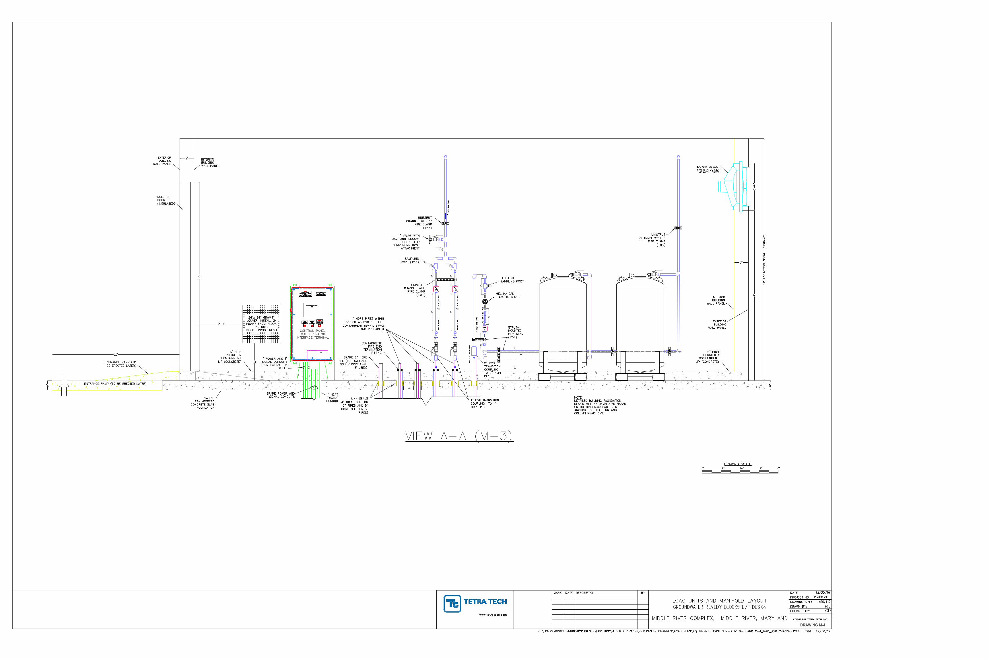
DRAWING M-4
AutoCAD SHX Text
FM 1
AutoCAD SHX Text
TREATED DISCHARGE
AutoCAD SHX Text
6" HIGH PERIMETER CONTAINMENT LIP (CONCRETE)
AutoCAD SHX Text
FROM EW-1 " SCH 80 PVC12" SCH 80 PVC
AutoCAD SHX Text
1" PVC TRANSITION COUPLING TO 1" HDPE PIPE
AutoCAD SHX Text
SPARE 2" HDPE PIPE (FOR SURFACE WATER DISCHARGE IF USED)
AutoCAD SHX Text
UPS
AutoCAD SHX Text
CONTROL PANEL WITH OPERATOR INTERFACE TERMINAL
AutoCAD SHX Text
PDP-XXX, CIRCUIT #X
AutoCAD SHX Text
POWER SUPPLIED FROM BKR. PANEL
AutoCAD SHX Text
120VAC, 1%%C, 20 AMP
AutoCAD SHX Text
CP-XXX
AutoCAD SHX Text
DANGER
AutoCAD SHX Text
ARC FLASH AND SHOCK HAZARD
AutoCAD SHX Text
APPROPRIATE PPE REQUIRED
AutoCAD SHX Text
Do not operate controls or oper covers
AutoCAD SHX Text
without approprite personal protection
AutoCAD SHX Text
equipment.
AutoCAD SHX Text
Failure to comply may result in injury or
AutoCAD SHX Text
death!
AutoCAD SHX Text
Refer to NFPA 70E for minimun PPE requirements
AutoCAD SHX Text
PUSH TO STOP
AutoCAD SHX Text
STOP
AutoCAD SHX Text
EMERGENCY
AutoCAD SHX Text
TWIST TO START
AutoCAD SHX Text
ACTIVE
AutoCAD SHX Text
STOP
AutoCAD SHX Text
EMERGENCY
AutoCAD SHX Text
EXISITS
AutoCAD SHX Text
CONDITION
AutoCAD SHX Text
ALARM
AutoCAD SHX Text
OPERATOR INTERFACE TERMINAL
AutoCAD SHX Text
(OIT)
AutoCAD SHX Text
ENTRANCE RAMP (TO BE ERECTED LATER)
AutoCAD SHX Text
1" SCH 80 PVC
AutoCAD SHX Text
1" SCH 80 PVC
AutoCAD SHX Text
FROM EW-2 " SCH 80 PVC12" SCH 80 PVC
AutoCAD SHX Text
6-INCH RE-INFORCED CONCRETE SLAB FOUNDATION
AutoCAD SHX Text
6" HIGH PERIMETER CONTAINMENT LIP (CONCRETE)
AutoCAD SHX Text
VIEW A-A (M-3)
AutoCAD SHX Text
DRAWING SCALE
AutoCAD SHX Text
0"
AutoCAD SHX Text
24"
AutoCAD SHX Text
12"
AutoCAD SHX Text
0"
AutoCAD SHX Text
12"
AutoCAD SHX Text
FM 101
AutoCAD SHX Text
FM 201
AutoCAD SHX Text
1" HDPE PIPES WITHIN 3" SCH 40 PVC DOUBLE- CONTAINMENT (EW-1, EW-2 AND 2 SPARES)
AutoCAD SHX Text
LINK SEALS 4" BOREHOLE FOR 2" PIPES AND 5" BOREHOLE FOR 3" PIPES)
AutoCAD SHX Text
CONTAINMENT PIPE END TERMINATION FITTING
AutoCAD SHX Text
UNISTRUT CHANNEL WITH PIPE CLAMP (TYP.)
AutoCAD SHX Text
UNISTRUT CHANNEL WITH 1" PIPE CLAMP (TYP.)
AutoCAD SHX Text
ENTRANCE RAMP (TO BE ERECTED LATER)
AutoCAD SHX Text
SAMPLING PORT (TYP.)
AutoCAD SHX Text
1" VALVE WITH CAM-AND-GROOVE COUPLING FOR SUMP PUMP HOSE ATTACHMENT
AutoCAD SHX Text
1/2" SCH 80 PVC
AutoCAD SHX Text
0
AutoCAD SHX Text
7
AutoCAD SHX Text
1
AutoCAD SHX Text
2
AutoCAD SHX Text
1
AutoCAD SHX Text
4
AutoCAD SHX Text
6
AutoCAD SHX Text
9
AutoCAD SHX Text
3
AutoCAD SHX Text
1
AutoCAD SHX Text
0
AutoCAD SHX Text
0
AutoCAD SHX Text
0
AutoCAD SHX Text
0
AutoCAD SHX Text
m
AutoCAD SHX Text
3
AutoCAD SHX Text
0
AutoCAD SHX Text
1
AutoCAD SHX Text
2
AutoCAD SHX Text
3
AutoCAD SHX Text
4
AutoCAD SHX Text
5
AutoCAD SHX Text
6
AutoCAD SHX Text
7
AutoCAD SHX Text
8
AutoCAD SHX Text
9
AutoCAD SHX Text
0
AutoCAD SHX Text
1
AutoCAD SHX Text
2
AutoCAD SHX Text
3
AutoCAD SHX Text
4
AutoCAD SHX Text
5
AutoCAD SHX Text
6
AutoCAD SHX Text
7
AutoCAD SHX Text
8
AutoCAD SHX Text
9
AutoCAD SHX Text
0
AutoCAD SHX Text
1
AutoCAD SHX Text
2
AutoCAD SHX Text
3
AutoCAD SHX Text
4
AutoCAD SHX Text
5
AutoCAD SHX Text
6
AutoCAD SHX Text
7
AutoCAD SHX Text
8
AutoCAD SHX Text
9
AutoCAD SHX Text
0
AutoCAD SHX Text
1
AutoCAD SHX Text
2
AutoCAD SHX Text
3
AutoCAD SHX Text
4
AutoCAD SHX Text
5
AutoCAD SHX Text
6
AutoCAD SHX Text
7
AutoCAD SHX Text
8
AutoCAD SHX Text
9
AutoCAD SHX Text
1
AutoCAD SHX Text
0
AutoCAD SHX Text
0
AutoCAD SHX Text
0
AutoCAD SHX Text
0.
AutoCAD SHX Text
X
AutoCAD SHX Text
1
AutoCAD SHX Text
0.
AutoCAD SHX Text
X
AutoCAD SHX Text
1
AutoCAD SHX Text
0
AutoCAD SHX Text
0.
AutoCAD SHX Text
X
AutoCAD SHX Text
1
AutoCAD SHX Text
0
AutoCAD SHX Text
0
AutoCAD SHX Text
0.
AutoCAD SHX Text
X
AutoCAD SHX Text
EFFLUENT SAMPLING PORT
AutoCAD SHX Text
MECHANICAL FLOW-TOTALIZER
AutoCAD SHX Text
2" PVC TRANSITION COUPLING TO 2" HDPE PIPE
AutoCAD SHX Text
NOTE: DETAILED BUILDING FOUNDATION DESIGN WILL BE DEVELOPED BASED ON BUILDING MANUFACTURER ANCHOR BOLT PATTERN AND COLUMN REACTIONS.
AutoCAD SHX Text
STRUT- MOUNTED PIPE CLAMP (TYP.)
AutoCAD SHX Text
UNISTRUT CHANNEL WITH 1" PIPE CLAMP (TYP.)
AutoCAD SHX Text
INTERIOR BUILDING WALL PANEL
AutoCAD SHX Text
EXTERIOR BUILDING WALL PANEL
AutoCAD SHX Text
INTERIOR BUILDING WALL PANEL
AutoCAD SHX Text
EXTERIOR BUILDING WALL PANEL
AutoCAD SHX Text
24"x 24" GRAVITY LOUVER. INSTALL 24 INCHES FROM FLOOR. INCLUDES INSECT-PROOF MESH.
AutoCAD SHX Text
ROLL-UP DOOR (INSULATED)
AutoCAD SHX Text
1,500 CFM EXHAUST FAN WITH 30"x30" GRAVITY LOUVER
AutoCAD SHX Text
1" POWER AND " 12" SIGNAL CONDUITS FROM EXTRACTION WELLS
AutoCAD SHX Text
SPARE POWER AND SIGNAL CONDUITS
AutoCAD SHX Text
1" HEAT TRACING CONDUIT
AutoCAD SHX Text
MARK
AutoCAD SHX Text
DATE
AutoCAD SHX Text
DESCRIPTION
AutoCAD SHX Text
BY
AutoCAD SHX Text
CHECKED BY:
AutoCAD SHX Text
DRAWN BY:
AutoCAD SHX Text
PROJECT NO.:
AutoCAD SHX Text
www.tetratech.com
AutoCAD SHX Text
DATE:
AutoCAD SHX Text
COPYRIGHT TETRA TECH INC.
AutoCAD SHX Text
112IC03835
AutoCAD SHX Text
12/30/19
AutoCAD SHX Text
CP
AutoCAD SHX Text
BD
AutoCAD SHX Text
LGAC UNITS AND MANIFOLD LAYOUT GROUNDWATER REMEDY BLOCKS E/F DESIGN MIDDLE RIVER COMPLEX, MIDDLE RIVER, MARYLAND
AutoCAD SHX Text
C:\USERS\BORIS.DYNKIN\DOCUMENTS\LMC MRC\BLOCK F DESIGN\NEW DESIGN CHANGES\ACAD FILES\EQUIPMENT LAYOUTS M-3 TO M-5 AND C-4_GAC_ASB CHANGES.DWG DWM 12/30/19
AutoCAD SHX Text
DRAWING SIZE:
AutoCAD SHX Text
ARCH E
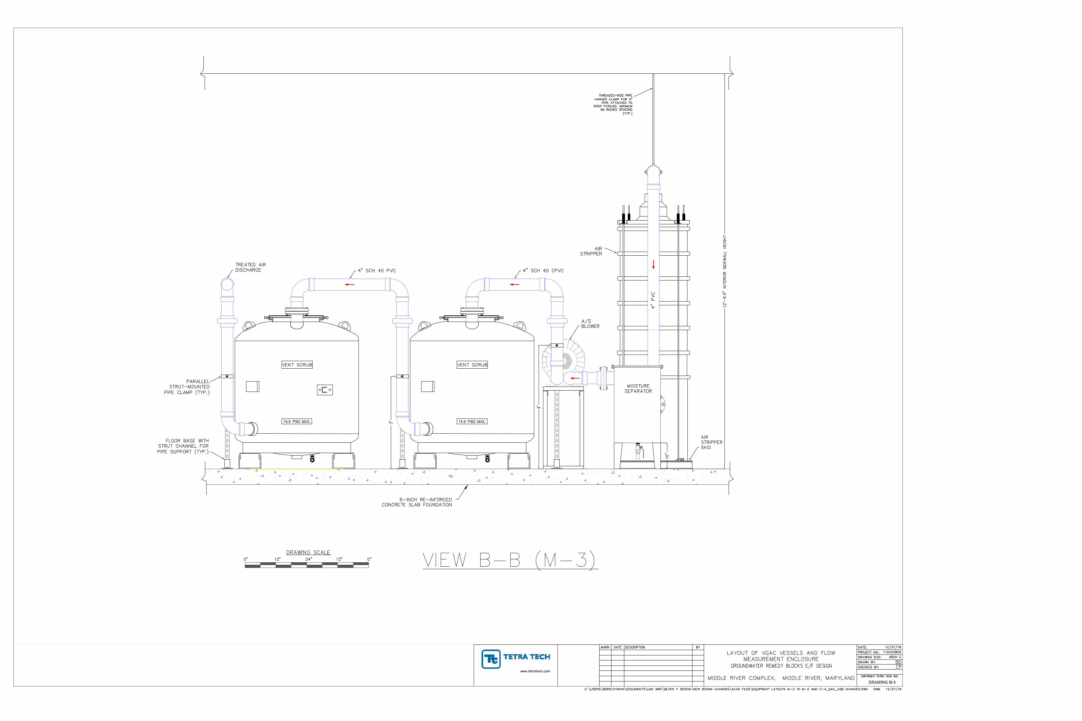
DRAWING M-5
AutoCAD SHX Text
MOISTURE SEPARATOR
AutoCAD SHX Text
AIR STRIPPER
AutoCAD SHX Text
4" PVC
AutoCAD SHX Text
AIR STRIPPER SKID
AutoCAD SHX Text
A/S BLOWER
AutoCAD SHX Text
6-INCH RE-INFORCED CONCRETE SLAB FOUNDATION
AutoCAD SHX Text
DRAWING SCALE
AutoCAD SHX Text
0"
AutoCAD SHX Text
24"
AutoCAD SHX Text
12"
AutoCAD SHX Text
0"
AutoCAD SHX Text
12"
AutoCAD SHX Text
VIEW B-B (M-3)
AutoCAD SHX Text
THREADED-ROD PIPE HANGER CLAMP FOR 4" PIPE ATTACHED TO ROOF PURLINS. MINIMUM 48 INCHES SPACING (TYP.)
AutoCAD SHX Text
4" SCH 40 CPVC
AutoCAD SHX Text
4" SCH 40 PVC
AutoCAD SHX Text
TREATED AIR DISCHARGE
AutoCAD SHX Text
PARALLEL STRUT-MOUNTED PIPE CLAMP (TYP.)
AutoCAD SHX Text
FLOOR BASE WITH STRUT CHANNEL FOR PIPE SUPPORT (TYP.)
AutoCAD SHX Text
MARK
AutoCAD SHX Text
DATE
AutoCAD SHX Text
DESCRIPTION
AutoCAD SHX Text
BY
AutoCAD SHX Text
CHECKED BY:
AutoCAD SHX Text
DRAWN BY:
AutoCAD SHX Text
PROJECT NO.:
AutoCAD SHX Text
www.tetratech.com
AutoCAD SHX Text
DATE:
AutoCAD SHX Text
COPYRIGHT TETRA TECH INC.
AutoCAD SHX Text
112IC03835
AutoCAD SHX Text
12/27/19
AutoCAD SHX Text
CP
AutoCAD SHX Text
BD
AutoCAD SHX Text
LAYOUT OF VGAC VESSELS AND FLOW MEASUREMENT ENCLOSURE GROUNDWATER REMEDY BLOCKS E/F DESIGN MIDDLE RIVER COMPLEX, MIDDLE RIVER, MARYLAND
AutoCAD SHX Text
C:\USERS\BORIS.DYNKIN\DOCUMENTS\LMC MRC\BLOCK F DESIGN\NEW DESIGN CHANGES\ACAD FILES\EQUIPMENT LAYOUTS M-3 TO M-5 AND C-4_GAC_ASB CHANGES.DWG DWM 12/27/19
AutoCAD SHX Text
DRAWING SIZE:
AutoCAD SHX Text
ARCH E

8706 Tetra Tech • Lockheed Martin Middle River Complex • O&MM Plan for Blocks E/F GW Remedy
February 2020 Appendices
APPENDIX B—STANDARD AND DETAILED OPERATING PROCEDURES (SOPs AND DOPs)
Lockheed Martin MRC Blocks E/F GWETS
SYSTEM COMISSIONING Identifier: Revision: Effective Date:
SOP-001 0 TBD Page: 1 of 4
SOP-001 System Commissioning
REVISION LOG
Rev. Date Affected Pages Revision Description 0 1/9/2020 All New Procedure
RESPONSIBLE PERSONNEL LO: Lead Operator OM: Operations Manager
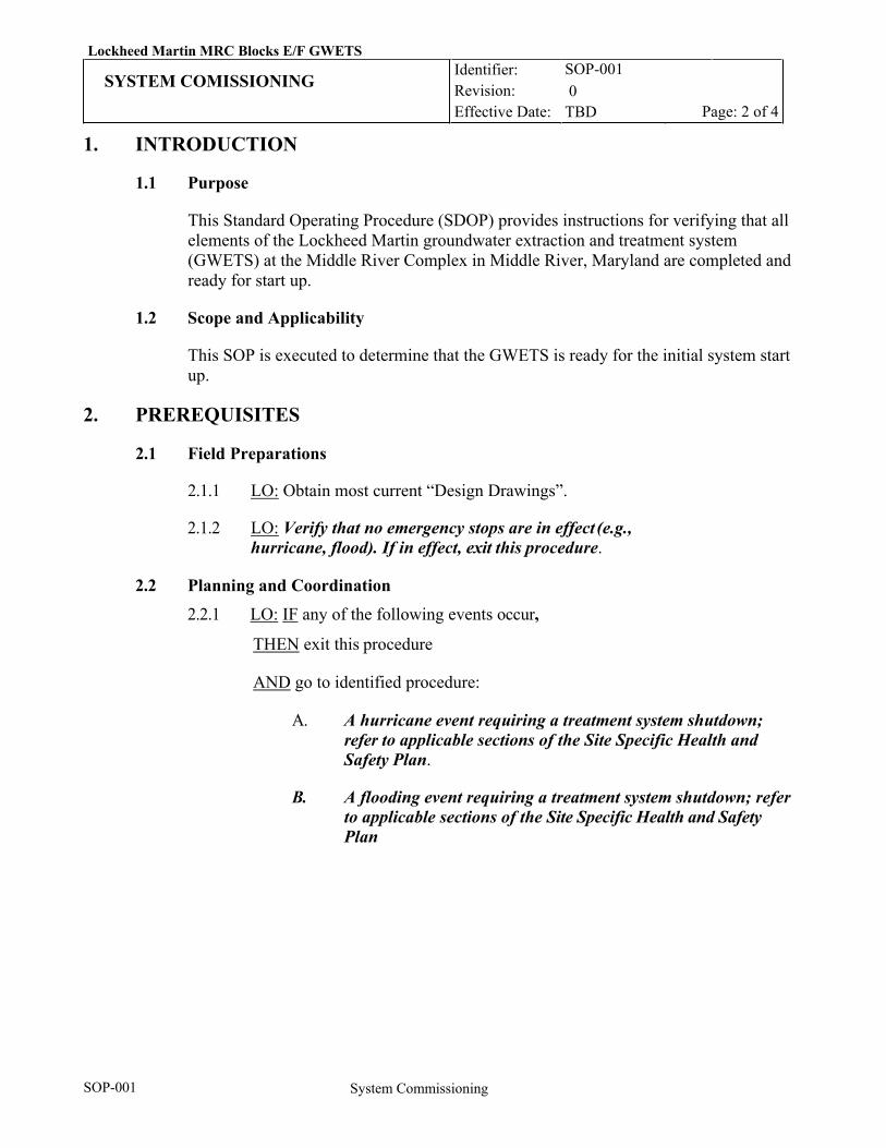
Lockheed Martin MRC Blocks E/F GWETS
SYSTEM COMISSIONING Identifier: Revision: Effective Date:
SOP-001 0 TBD Page: 2 of 4
SOP-001 System Commissioning
1. INTRODUCTION
1.1 Purpose
This Standard Operating Procedure (SDOP) provides instructions for verifying that all elements of the Lockheed Martin groundwater extraction and treatment system (GWETS) at the Middle River Complex in Middle River, Maryland are completed and ready for start up.
1.2 Scope and Applicability
This SOP is executed to determine that the GWETS is ready for the initial system start up.
2. PREREQUISITES
2.1 Field Preparations
2.1.1 LO: Obtain most current “Design Drawings”.
2.1.2 LO: Verify that no emergency stops are in effect (e.g., hurricane, flood). If in effect, exit this procedure.
2.2 Planning and Coordination
2.2.1 LO: IF any of the following events occur,
THEN exit this procedure
AND go to identified procedure:
A. A hurricane event requiring a treatment system shutdown; refer to applicable sections of the Site Specific Health and Safety Plan.
B. A flooding event requiring a treatment system shutdown; refer
to applicable sections of the Site Specific Health and Safety Plan
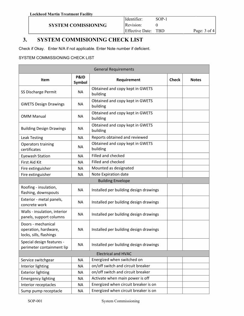
Lockheed Martin Treatment Facility Identifier: Revision: Effective Date:
SOP-1 0 TBD
SYSTEM COMISSIONING
Page: 3 of 4
SOP-001 System Commissioning
3. SYSTEM COMMISIONING CHECK LIST Check if Okay. Enter N/A if not applicable. Enter Note number if deficient. SYSTEM COMMISSIONING CHECK LIST
General Requirements
Item P&ID Symbol Requirement Check Notes
SS Discharge Permit NA Obtained and copy kept in GWETS building
GWETS Design Drawings NA Obtained and copy kept in GWETS building
OMM Manual NA Obtained and copy kept in GWETS building
Building Design Drawings NA Obtained and copy kept in GWETS building
Leak Testing NA Reports obtained and reviewed Operators training certificates NA
Obtained and copy kept in GWETS building
Eyewash Station NA Filled and checked First Aid Kit NA Filled and checked Fire extinguisher NA Mounted as designated Fire extinguisher NA Note Expiration date
Building Envelope Roofing - insulation, flashing, downspouts NA Installed per building design drawings
Exterior - metal panels, concrete work NA Installed per building design drawings
Walls - insulation, interior panels, support columns NA Installed per building design drawings
Doors - mechanical operation, hardware, locks, sills, flashings
NA Installed per building design drawings
Special design features - perimeter containment lip NA Installed per building design drawings
Electrical and HVAC Service switchgear NA Energized when switched on Interior lighting NA on/off switch and circuit breaker Exterior lighting NA on/off switch and circuit breaker Emergency lighting NA Activate when main power is off Interior receptacles NA Energized when circuit breaker is on Sump pump receptacle NA Energized when circuit breaker is on
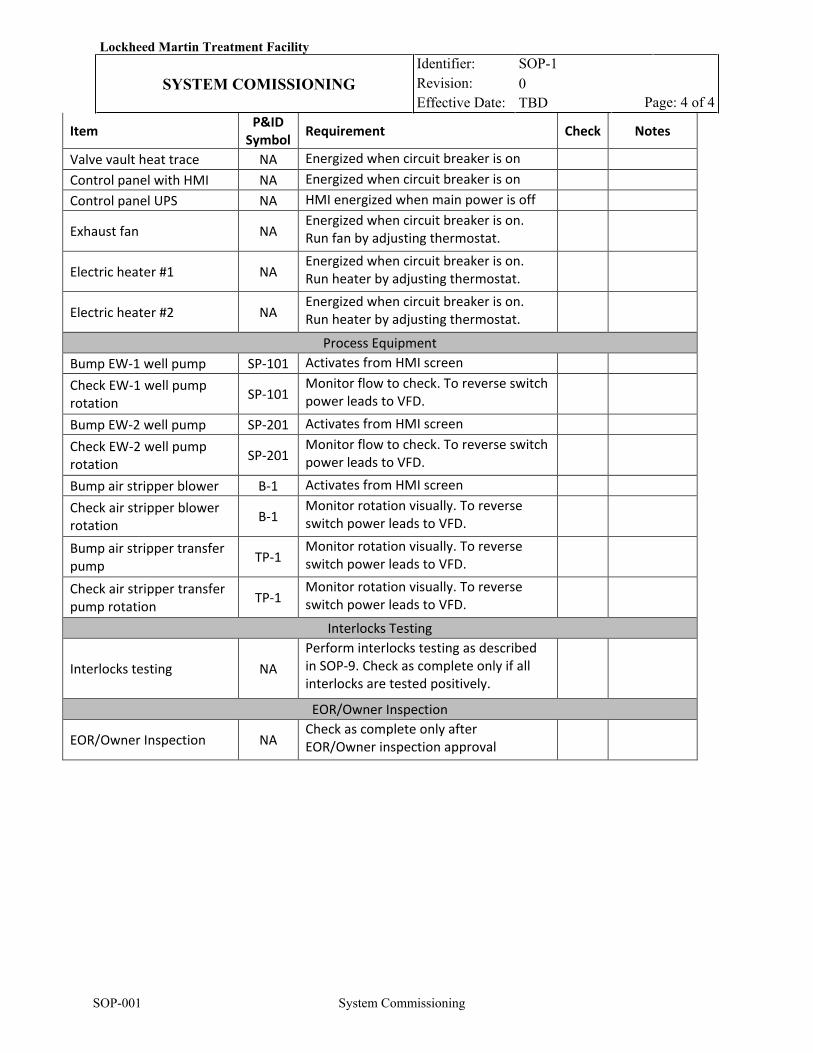
Lockheed Martin Treatment Facility Identifier: Revision: Effective Date:
SOP-1 0 TBD
SYSTEM COMISSIONING
Page: 4 of 4
SOP-001 System Commissioning
Item P&ID Symbol Requirement Check Notes
Valve vault heat trace NA Energized when circuit breaker is on Control panel with HMI NA Energized when circuit breaker is on Control panel UPS NA HMI energized when main power is off
Exhaust fan NA Energized when circuit breaker is on. Run fan by adjusting thermostat.
Electric heater #1 NA Energized when circuit breaker is on. Run heater by adjusting thermostat.
Electric heater #2 NA Energized when circuit breaker is on. Run heater by adjusting thermostat.
Process Equipment Bump EW-1 well pump SP-101 Activates from HMI screen Check EW-1 well pump rotation SP-101
Monitor flow to check. To reverse switch power leads to VFD.
Bump EW-2 well pump SP-201 Activates from HMI screen Check EW-2 well pump rotation SP-201
Monitor flow to check. To reverse switch power leads to VFD.
Bump air stripper blower B-1 Activates from HMI screen Check air stripper blower rotation B-1
Monitor rotation visually. To reverse switch power leads to VFD.
Bump air stripper transfer pump TP-1
Monitor rotation visually. To reverse switch power leads to VFD.
Check air stripper transfer pump rotation TP-1
Monitor rotation visually. To reverse switch power leads to VFD.
Interlocks Testing
Interlocks testing NA Perform interlocks testing as described in SOP-9. Check as complete only if all interlocks are tested positively.
EOR/Owner Inspection
EOR/Owner Inspection NA Check as complete only after EOR/Owner inspection approval
Lockheed Martin MRC Blocks E/F GWETS Identifier: Revision: Effective Date:
SOP-002 TBD INTERLOCKS TESTING
Page: 1 of 6
SOP002 Interlocks Testing
REVISION LOG
Rev. Date Affected Pages Revision Description 0 11/26/19 All New Procedure 1 01/09/20 All RTO comments response
RESPONSIBLE PERSONNEL LO: Lead Operator OM: Operations Manager
Lockheed Martin MRC Blocks E/F GWETS Identifier: Revision: Effective Date:
SOP-002 TBD INTERLOCKS TESTING
Page: 2 of 6
SOP002 Interlocks Testing
1. INTRODUCTION
1.1 Purpose
This Standard Operating Procedure (SOP) presents procedures for performing interlocks testing. Interlocks testing will be performed every four months.
1.2 Scope and Applicability
This SOP applies to the testing of interlocks alarms installed on the Lockheed Martin groundwater extraction and treatment system at the Middle River Complex in Middle River, Maryland.
Interlocks
Interlocks are outlined in Table 2-4 of the Remedial Design and on Drawing M-2.
Interlocks:
HLA-1 (critical alarm, call out, system shut down) Level – Indicates a high water level in AS-1
sump that could indicate transfer pump failure, or other flooding. System is shut down until the
cause can be determined by an operator.
HLA-2 (critical alarm, call out, system shut down) Level - Indicates a high water level in MS-1
that could indicate water carryover from AS-1. System is shut down until the cause can be
determined by an operator.
HLA-3 (critical alarm, call out, system shut down) Level – Indicates a high water level in floor
sump that could indicate water leakage or other flooding. System is shut down until the cause can be
determined by an operator.
LVA-1 (critical alarm, call out, system shut down) Pressure – Indicates low vacuum in the air stripper
indicating blower failure or other reasons to lose air flow requiring an operator to determine the cause.
HVA-1 (call out, operator warning) Pressure – Indicates high vacuum set point in the air stripper
indicating AS-1 clogging or other reasons to restrict air flow requiring an operator to determine the cause.
Lockheed Martin MRC Blocks E/F GWETS Identifier: Revision: Effective Date:
SOP-002 TBD INTERLOCKS TESTING
Page: 3 of 6
SOP002 Interlocks Testing
HPA-1 (call out, operator warning) Pressure – Indicates high pressure set point in bag filters inlet indicating clogging or other reasons to restrict water flow requiring an operator to determine the cause.
LFA-1 (call out, operator warning) Flow – Indicates low effluent flow set point indicating clogging or
other reasons to restrict water flow requiring an operator to determine the cause.
LTA-1 (call out, operator warning) Temp - Indicates a low building temperature indicating
possible heater(s) failure requiring an operator to determine the cause.
HTA-1 (call out, operator warning) Temp - Indicates a high building temperature indicating
possible exhaust fan failure requiring an operator to determine the cause.
PLA-1 (call out, power loss, plant shut down) – Indicates system power loss. This shuts the system
down requiring an operator to determine the cause before the plant can be restarted.
TRA-1 (valve box heat trace failure) – Indicates loss of power to heat trace. This shuts the system
down requiring an operator to determine the cause before the plant can be restarted.
2. PREREQUISITES
2.1 Field Preparations
2.1.1 LO: Obtain current working edition of “Operations Log.”
2.1.2 LO: Refer to “Daily Logs” to ensure that there are no operational issues reported/recorded that would prevent a normal system start up or the testing of critical alarms. If issues are noted, then exit this procedure until resolution is obtained.
2.1.3 LO: Verify that no emergency stops are in effect (e.g. hurricane, flood). If in
effect, exit this procedure.
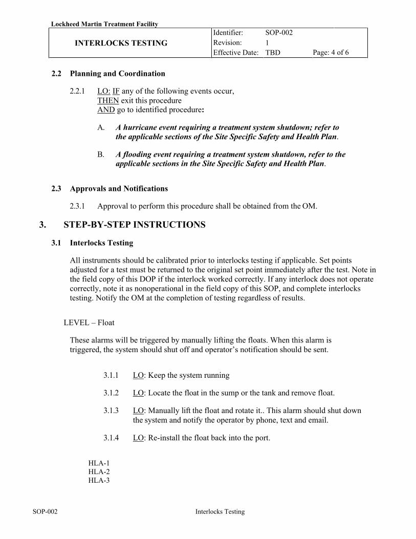
Lockheed Martin Treatment Facility Identifier: Revision: Effective Date:
SOP-002 1 TBD
INTERLOCKS TESTING Page: 4 of 6
SOP-002 Interlocks Testing
2.2 Planning and Coordination
2.2.1 LO: IF any of the following events occur, THEN exit this procedure AND go to identified procedure:
A. A hurricane event requiring a treatment system shutdown; refer to
the applicable sections of the Site Specific Safety and Health Plan.
B. A flooding event requiring a treatment system shutdown, refer to the applicable sections in the Site Specific Safety and Health Plan.
2.3 Approvals and Notifications
2.3.1 Approval to perform this procedure shall be obtained from the OM.
3. STEP-BY-STEP INSTRUCTIONS
3.1 Interlocks Testing
All instruments should be calibrated prior to interlocks testing if applicable. Set points adjusted for a test must be returned to the original set point immediately after the test. Note in the field copy of this DOP if the interlock worked correctly. If any interlock does not operate correctly, note it as nonoperational in the field copy of this SOP, and complete interlocks testing. Notify the OM at the completion of testing regardless of results.
LEVEL – Float
These alarms will be triggered by manually lifting the floats. When this alarm is triggered, the system should shut off and operator’s notification should be sent.
3.1.1 LO: Keep the system running
3.1.2 LO: Locate the float in the sump or the tank and remove float.
3.1.3 LO: Manually lift the float and rotate it.. This alarm should shut down the system and notify the operator by phone, text and email.
3.1.4 LO: Re-install the float back into the port.
HLA-1 HLA-2 HLA-3
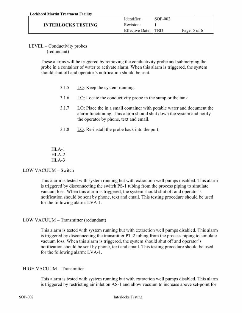
Lockheed Martin Treatment Facility Identifier: Revision: Effective Date:
SOP-002 1 TBD
INTERLOCKS TESTING Page: 5 of 6
SOP-002 Interlocks Testing
LEVEL – Conductivity probes (redundant)
These alarms will be triggered by removing the conductivity probe and submerging the probe in a container of water to activate alarm. When this alarm is triggered, the system should shut off and operator’s notification should be sent.
3.1.5 LO: Keep the system running.
3.1.6 LO: Locate the conductivity probe in the sump or the tank
3.1.7 LO: Place the in a small container with potable water and document the alarm functioning. This alarm should shut down the system and notify the operator by phone, text and email.
3.1.8 LO: Re-install the probe back into the port.
HLA-1 HLA-2 HLA-3
LOW VACUUM – Switch
This alarm is tested with system running but with extraction well pumps disabled. This alarm is triggered by disconnecting the switch PS-1 tubing from the process piping to simulate vacuum loss. When this alarm is triggered, the system should shut off and operator’s notification should be sent by phone, text and email. This testing procedure should be used for the following alarm: LVA-1.
LOW VACUUM – Transmitter (redundant)
This alarm is tested with system running but with extraction well pumps disabled. This alarm is triggered by disconnecting the transmitter PT-2 tubing from the process piping to simulate vacuum loss. When this alarm is triggered, the system should shut off and operator’s notification should be sent by phone, text and email. This testing procedure should be used for the following alarm: LVA-1.
HIGH VACUUM – Transmitter
This alarm is tested with system running but with extraction well pumps disabled. This alarm is triggered by restricting air inlet on AS-1 and allow vacuum to increase above set-point for
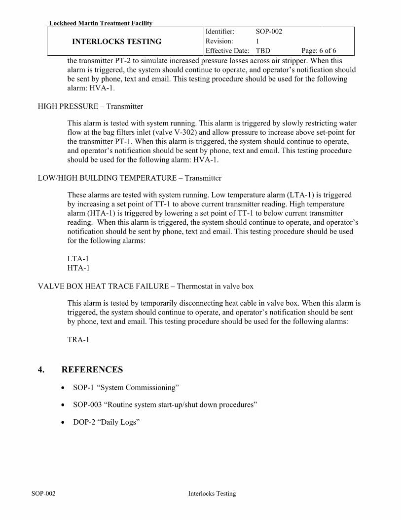
Lockheed Martin Treatment Facility Identifier: Revision: Effective Date:
SOP-002 1 TBD
INTERLOCKS TESTING Page: 6 of 6
SOP-002 Interlocks Testing
the transmitter PT-2 to simulate increased pressure losses across air stripper. When this alarm is triggered, the system should continue to operate, and operator’s notification should be sent by phone, text and email. This testing procedure should be used for the following alarm: HVA-1.
HIGH PRESSURE – Transmitter
This alarm is tested with system running. This alarm is triggered by slowly restricting water flow at the bag filters inlet (valve V-302) and allow pressure to increase above set-point for the transmitter PT-1. When this alarm is triggered, the system should continue to operate, and operator’s notification should be sent by phone, text and email. This testing procedure should be used for the following alarm: HVA-1.
LOW/HIGH BUILDING TEMPERATURE – Transmitter
These alarms are tested with system running. Low temperature alarm (LTA-1) is triggered by increasing a set point of TT-1 to above current transmitter reading. High temperature alarm (HTA-1) is triggered by lowering a set point of TT-1 to below current transmitter reading. When this alarm is triggered, the system should continue to operate, and operator’s notification should be sent by phone, text and email. This testing procedure should be used for the following alarms: LTA-1 HTA-1
VALVE BOX HEAT TRACE FAILURE – Thermostat in valve box
This alarm is tested by temporarily disconnecting heat cable in valve box. When this alarm is triggered, the system should continue to operate, and operator’s notification should be sent by phone, text and email. This testing procedure should be used for the following alarms: TRA-1
4. REFERENCES
• SOP-1 “System Commissioning”
• SOP-003 “Routine system start-up/shut down procedures”
• DOP-2 “Daily Logs”
Lockheed Martin MRC Blocks E/F GWETS Identifier:
Revision: Effective Date:
SOP-003 0 TBD
ROUTINE START/SHUT DOWN Page: 1 of 5
SOP-3 Routine Startup/Shut Down
REVISION LOG
Rev. Date Affected Pages
Revision Description
0 11/26/19 All New Procedure 1 01/09/20 All RTO comments response
RESPONSIBLE PERSONNEL LO: Lead Operator OM: Operations Manager
Lockheed Martin MRC Blocks E/F GWETS Identifier:
Revision: Effective Date:
SOP-003 0 TBD
ROUTINE START/SHUT DOWN Page: 2 of 5
SOP-3 Routine Startup/Shut Down
1. INTRODUCTION
1.1 Purpose
This Standard Operating Procedure (SOP) provides instructions for routine
treatment system startup following shutdown.
1.2 Scope and Applicability
This procedure applies to routine startup and shutdown of the Lockheed Martin
groundwater extraction and treatment system in Middle River, Maryland.
2. PREREQUISITES
2.1 Field Preparations
2.1.1 LO: Refer to current “Daily Logs” to ensure that there are no operational issues reported/recorded that would prevent a normal system start up or startup of individual components. If such issues are noted, exit this procedure until resolution is obtained.
2.1.2 LO: Verify that no emergency stops are in effect (e.g., hurricane, flood). If in effect, exit this procedure.
2.1.3 LO: Ensure that plant utilities (lights, emergency eye washes, and exhaust
system) are operational.
2.1.4 LO: Confirm that all piping connections such as flanges and unions are secured and connected and that three are no leaks in the piping.
2.1.5 LO: Confirm that all process valves are in proper positions for normal
operation as shown in DOP-1 “System Start Up Check List”.
2.1.6 LO: Confirm on human-machine interface (HMI) screen that Air Stripper Transfer Pump TP-1 and Blower B-1 are set to automatic
2.1.7 LO: Confirm on HMI screen that well pumps SP-101 and SP-201 are set to
automatic.
2.1.8 LO: Confirm that thermostat for exhaust fan is set to 75deg F.
2.1.9 LO: Confirm that thermostats for emergency heaters are set to 40degF.
Lockheed Martin MRC Blocks E/F GWETS Identifier:
Revision: Effective Date:
SOP-003 0 TBD
ROUTINE START/SHUT DOWN Page: 3 of 5
SOP-3 Routine Startup/Shut Down
2.2 Planning and Coordination
2.2.1 SO: IF any of the following events occur, THEN exit this procedure AND go to identified procedure.
A. A hurricane event requiring a treatment system shutdown; refer
to applicable section of the Site Specific Health and Safety Plan.
B. A flooding event requiring a treatment system shutdown; refer to
applicable section of the Site Specific Health and Safety Plan.
3. STEP-BY-STEP INSTRUCTIONS
3.9 LO: Treatment plant will be started from the HMI screen. 3.10 LO: Confirm that no alarm conditions exist on the HMI screen. 3.11 LO: Start the system using on/off switch on the HMI screen (switches page). 3.12 LO: Treatment plant will be shut down from the HMI screen. 3.13 LO: Shut down the system using on/off switch on the HMI screen (switches
page). The well pumps SP-101 and SP-201 will be shut down immediately and the air stripper blower will shut down after a pre-programmed delay of approximately 10 minutes.
3.14 Fill out daily logs to document start-up event.
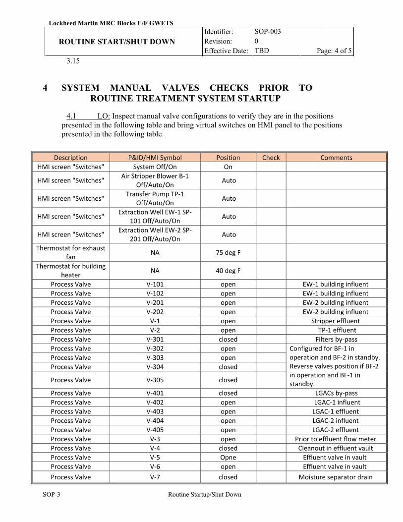
Lockheed Martin MRC Blocks E/F GWETS Identifier:
Revision: Effective Date:
SOP-003 0 TBD
ROUTINE START/SHUT DOWN Page: 4 of 5
SOP-3 Routine Startup/Shut Down
3.15
4 SYSTEM MANUAL VALVES CHECKS PRIOR TO ROUTINE TREATMENT SYSTEM STARTUP
4.1 LO: Inspect manual valve configurations to verify they are in the positions presented in the following table and bring virtual switches on HMI panel to the positions presented in the following table.
Description P&ID/HMI Symbol Position Check Comments HMI screen "Switches" System Off/On On
HMI screen "Switches" Air Stripper Blower B-1 Off/Auto/On Auto
HMI screen "Switches" Transfer Pump TP-1 Off/Auto/On Auto
HMI screen "Switches" Extraction Well EW-1 SP-101 Off/Auto/On Auto
HMI screen "Switches" Extraction Well EW-2 SP-201 Off/Auto/On Auto
Thermostat for exhaust fan NA 75 deg F
Thermostat for building heater NA 40 deg F
Process Valve V-101 open EW-1 building influent Process Valve V-102 open EW-1 building influent Process Valve V-201 open EW-2 building influent Process Valve V-202 open EW-2 building influent Process Valve V-1 open Stripper effluent Process Valve V-2 open TP-1 effluent Process Valve V-301 closed Filters by-pass Process Valve V-302 open Configured for BF-1 in
operation and BF-2 in standby. Reverse valves position if BF-2 in operation and BF-1 in standby.
Process Valve V-303 open Process Valve V-304 closed
Process Valve V-305 closed
Process Valve V-401 closed LGACs by-pass Process Valve V-402 open LGAC-1 influent Process Valve V-403 open LGAC-1 effluent Process Valve V-404 open LGAC-2 influent Process Valve V-405 open LGAC-2 effluent Process Valve V-3 open Prior to effluent flow meter Process Valve V-4 closed Cleanout in effluent vault Process Valve V-5 Opne Effluent valve in vault Process Valve V-6 open Effluent valve in vault Process Valve V-7 closed Moisture separator drain

Lockheed Martin MRC Blocks E/F GWETS Identifier:
Revision: Effective Date:
SOP-003 0 TBD
ROUTINE START/SHUT DOWN Page: 5 of 5
SOP-003 Routine Startup/Shut
5 REFERENCES • Engineering Drawings, M-2 through M-5
Lockheed Martin MRC Blocks E/F GWETS Identifier: Revision: Effective Date:
SOP-004 0 TBD TREATMENT SYSTEM SAMPLING Page: 1 of 5
SOP-004 Treatment System Sampling
REVISION LOG
Rev. Date Affected Pages Revision Description 0 11/26/19 All New Procedure 1 01/09/20 All RTO comments response
RESPONSIBLE PERSONNEL LO: Lead Operator OM: Operations Manager
Lockheed Martin MRC Blocks E/F GWETS Identifier: Revision: Effective Date:
SOP-004 0 TBD TREATMENT SYSTEM SAMPLING Page: 2 of 5
SOP-004 Treatment System Sampling
1. INTRODUCTION
1.1 Purpose
This Standard Operating Procedure (SOP) identifies the activities to be followed when sampling extraction wells or other process locations by way of sample ports within the treatment system building. This SOP presents the procedures to be followed when sampling inside the treatment system building.
1.2 Scope and Applicability
This SOP applies to sampling various sample ports located inside the Lockheed Martin groundwater extraction and treatment system at the Middle River Complex in Middle River, Maryland.
2. PRECAUTIONS AND LIMITATIONS
The extraction wells remove contaminated groundwater from the subsurface; therefore, operators should minimize contact with the groundwater.
3. PREREQUISITES
3.1 Field Preparations
3.1.1 LO: Verify that no emergency stops are in effect (e.g., hurricane, flood). If in effect, exit this procedure.
3.1.2 LO: Verify using Daily Logs that there are no current problems
with the treatment system. If problems exist, discuss with OM on whether to continue with the sampling.
3.1.3 LO: Verify that there is a cooler with ice available to store samples.
3.1.4 LO: Gather all of the necessary equipment (listed below) and locate near the manifold on the northeast wall of the treatment building.
3.1.5 LO: Contact the designated analytical laboratory (s) to convey the timing
of upcoming sampling activities.
Lockheed Martin MRC Blocks E/F GWETS Identifier: Revision: Effective Date:
SOP-004 0 TBD TREATMENT SYSTEM SAMPLING Page: 3 of 5
SOP-004 Treatment System Sampling
3.2 Equipment
The following equipment can be found in the treatment building: 5-gallon container labeled “Purge Water” that has no holes or fractures (except for the main opening), proper lid to seal the 5-gallon container, proper personal protective equipment (PPE; steel-toed boots, nitrile gloves, safety glasses or goggles), spill containment kit, designated bucket or trash bag for temporary storage of used PPE and anything else that has contacted groundwater, sample containers, laboratory bottleware, cooler, ice, ziplock bubble bags, trash bags, and labeling supplies.
3.3 Planning and Coordination
3.3.1 SO: IF any of the following events occur, THEN exit this procedure, AND go to identified procedure.
A. A hurricane event requiring a treatment system shutdown; refer
to the applicable sections of the Site Specific Health and Safety Plan.
B. A flooding event requiring a treatment system shutdown; refer
to the applicable sections of the Site Specific Health and Safety Plan.
3.4 Approvals and Notifications
3.4.1 Approval to perform this procedure shall be obtained from the OM.
4. SAMPLING VIA RESPECTIVE SAMPLE PORTS
4.1 LO: Keep a record of the sampling event in the Log Book. At minimum, record the start and end time when the sampling of each sample port occurred, plus any observations.
4.2 LO: Complete the chain of custody (COC).
4.3 LO: Label sample bottles with indelible marker with sample points, analysis
required, sampler initials, correct sampling times as per the completed COC, and any other requirement listed on the label. Where sample preservation is required, check that the preservative in the bottle is the correct one needed for the sample analysis.
4.4 LO: Line cooler with a heavy-duty garbage bag and place ice inside the garbage
bag. Close the cooler between placement of sample containers.
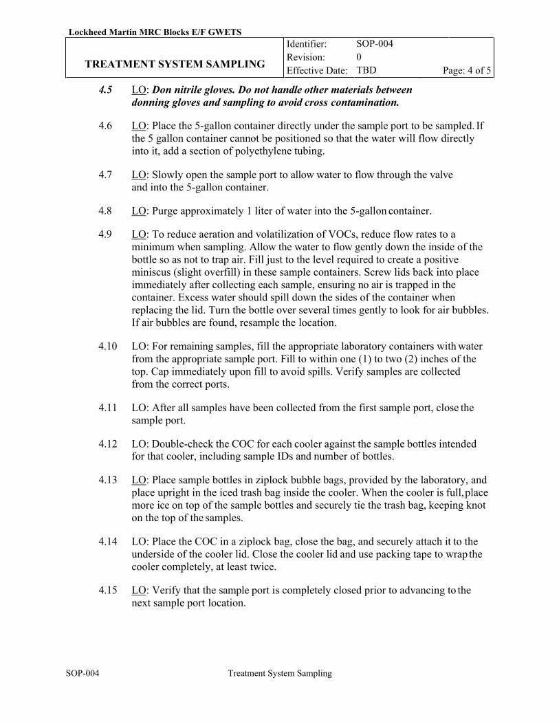
Lockheed Martin MRC Blocks E/F GWETS Identifier: Revision: Effective Date:
SOP-004 0 TBD TREATMENT SYSTEM SAMPLING Page: 4 of 5
SOP-004 Treatment System Sampling
4.5 LO: Don nitrile gloves. Do not handle other materials between donning gloves and sampling to avoid cross contamination.
4.6 LO: Place the 5-gallon container directly under the sample port to be sampled. If the 5 gallon container cannot be positioned so that the water will flow directly into it, add a section of polyethylene tubing.
4.7 LO: Slowly open the sample port to allow water to flow through the valve
and into the 5-gallon container.
4.8 LO: Purge approximately 1 liter of water into the 5-gallon container.
4.9 LO: To reduce aeration and volatilization of VOCs, reduce flow rates to a minimum when sampling. Allow the water to flow gently down the inside of the bottle so as not to trap air. Fill just to the level required to create a positive miniscus (slight overfill) in these sample containers. Screw lids back into place immediately after collecting each sample, ensuring no air is trapped in the container. Excess water should spill down the sides of the container when replacing the lid. Turn the bottle over several times gently to look for air bubbles. If air bubbles are found, resample the location.
4.10 LO: For remaining samples, fill the appropriate laboratory containers with water
from the appropriate sample port. Fill to within one (1) to two (2) inches of the top. Cap immediately upon fill to avoid spills. Verify samples are collected from the correct ports.
4.11 LO: After all samples have been collected from the first sample port, close the
sample port.
4.12 LO: Double-check the COC for each cooler against the sample bottles intended for that cooler, including sample IDs and number of bottles.
4.13 LO: Place sample bottles in ziplock bubble bags, provided by the laboratory, and
place upright in the iced trash bag inside the cooler. When the cooler is full, place more ice on top of the sample bottles and securely tie the trash bag, keeping knot on the top of the samples.
4.14 LO: Place the COC in a ziplock bag, close the bag, and securely attach it to the
underside of the cooler lid. Close the cooler lid and use packing tape to wrap the cooler completely, at least twice.
4.15 LO: Verify that the sample port is completely closed prior to advancing to the
next sample port location.
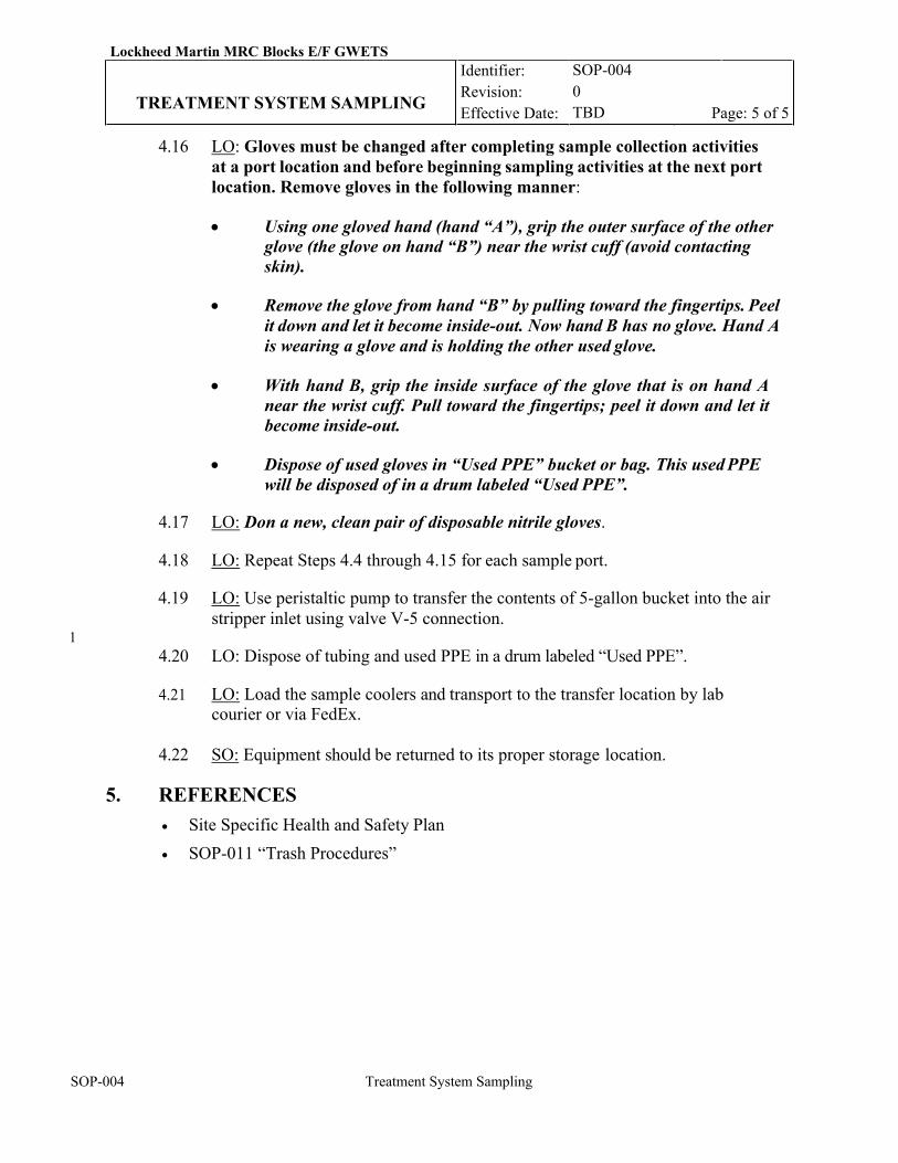
Lockheed Martin MRC Blocks E/F GWETS Identifier: Revision: Effective Date:
SOP-004 0 TBD TREATMENT SYSTEM SAMPLING Page: 5 of 5
SOP-004 Treatment System Sampling
4.16 LO: Gloves must be changed after completing sample collection activities
at a port location and before beginning sampling activities at the next port location. Remove gloves in the following manner:
• Using one gloved hand (hand “A”), grip the outer surface of the other
glove (the glove on hand “B”) near the wrist cuff (avoid contacting skin).
• Remove the glove from hand “B” by pulling toward the fingertips. Peel
it down and let it become inside-out. Now hand B has no glove. Hand A is wearing a glove and is holding the other used glove.
• With hand B, grip the inside surface of the glove that is on hand A
near the wrist cuff. Pull toward the fingertips; peel it down and let it become inside-out.
• Dispose of used gloves in “Used PPE” bucket or bag. This used PPE
will be disposed of in a drum labeled “Used PPE”.
4.17 LO: Don a new, clean pair of disposable nitrile gloves.
4.18 LO: Repeat Steps 4.4 through 4.15 for each sample port.
4.19 LO: Use peristaltic pump to transfer the contents of 5-gallon bucket into the air stripper inlet using valve V-5 connection.
1 4.20 LO: Dispose of tubing and used PPE in a drum labeled “Used PPE”.
4.21 LO: Load the sample coolers and transport to the transfer location by lab
courier or via FedEx.
4.22 SO: Equipment should be returned to its proper storage location.
5. REFERENCES • Site Specific Health and Safety Plan
• SOP-011 “Trash Procedures”
Lockheed Martin MRC Blocks E/F GWETS Identifier: Revision: Effective Date:
SOP-005 SYSTEM ALARM RESPONSE
Page: 1 of 6
SOP-005 System Alarm Response
REVISION LOG
Rev. Date Affected Pages Revision Description 0 11/26/19 All New Procedure 1 01/09/20 All RTO comments response
RESPONSIBLE PERSONNEL LO: Lead Operator OM:
Operations Manager
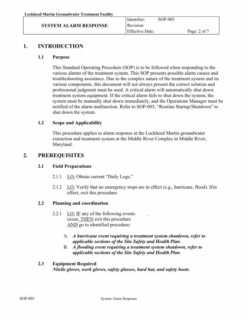
Lockheed Martin Groundwater Treatment Facility Identifier: Revision: Effective Date:
SOP-005 SYSTEM ALARM RESPONSE
Page: 2 of 7
SOP-005 System Alarm Response
1. INTRODUCTION
1.1 Purpose
This Standard Operating Procedure (SOP) is to be followed when responding to the various alarms of the treatment system. This SOP presents possible alarm causes and troubleshooting assistance. Due to the complex nature of the treatment system and its various components, this document will not always present the correct solution and professional judgment must be used. A critical alarm will automatically shut down treatment system equipment. If the critical alarm fails to shut down the system, the system must be manually shut down immediately, and the Operations Manager must be notified of the alarm malfunction. Refer to SOP-003, “Routine Startup/Shutdown” to shut down the system.
1.2 Scope and Applicability
This procedure applies to alarm response at the Lockheed Martin groundwater extraction and treatment system at the Middle River Complex in Middle River, Maryland.
2. PREREQUISITES
2.1 Field Preparations
2.1.1 LO: Obtain current “Daily Logs.”
2.1.2 LO: Verify that no emergency stops are in effect (e.g., hurricane, flood). If in effect, exit this procedure.
2.2 Planning and coordination
2.2.1 LO: IF any of the following events
occur, THEN exit this procedure AND go to identified procedure:
A. A hurricane event requiring a treatment system shutdown, refer to applicable sections of the Site Safety and Health Plan.
B. A flooding event requiring a treatment system shutdown, refer to applicable sections of the Site Safety and Health Plan.
2.3 Equipment Required Nitrile gloves, work gloves, safety glasses, hard hat, and safety boots.
Lockheed Martin Groundwater Treatment Facility Identifier: Revision: Effective Date:
SOP-005 SYSTEM ALARM RESPONSE
Page: 3 of 7
SOP-005 System Alarm Response
3. CRITICAL ALARMS
Refer to SOP-003 Interlocks Testing and the Process and Instrumentation Diagram.
4. STEP BY STEP INSTRUCTIONS
4.1 LO/OM: If a critical alarm occurs during off hours, the LO and OM will determine if a site visit is necessary, or if a remote shut down is appropriate.
4.2 LO: If a critical alarm occurs, verify that the treatment system and extraction wells have automatically shut down as described below. If the critical alarm fails to shut down the system and wells, the system and wells must be manually shut down within 8 hours. In an emergency, use the E-Stop on the control system panel. Never assume that the condition is a false alarm.
4.3 LO: Record the alarm condition and time of the alarm in the operations log book.
4.4 LO: Notify the Operations Manager immediately if the alarm condition is valid, and if
it has caused equipment damage or has resulted in a release of any kind. The Operations Manager can be contacted by phone. Notification numbers are located on the bulletin board in the treatment system building.
4.5 Lockheed Martin and the RTO should be notified within 24 hours of any unplanned
system shutdown.
4.6 Notifications: 1. Record system shutdowns or operational interruptions and document the efforts
employed to return the system to full operation as soon as possible. In all cases, a summary memorandum (or email) shall be prepared and distributed to Lockheed Martin and the RTO within 24 hours after the incident occurred to document the issue. A subsequent email shall be prepared and distributed to Lockheed Martin and the RTO to document the root cause, and to identify steps taken or planned to remedy the problem. If unanticipated activities are required, the Contractor shall prepare a new budget estimate and submit the estimate to Lockheed Martin for written approval before proceeding with the work. Unanticipated activities necessary to prevent injury or release to the environment do not require pre-authorization. The Contractor shall prepare and distribute an email to Lockheed Martin and the RTO prior to taking groundwater treatment and extraction system offline for any reason, and a follow-up email when the system is returned to operation.
2. Report all accidents, environmental releases, spills, and other emergencies
immediately to Lockheed Martin and as specified in the Site Crisis and Emergency Plan (Tetra Tech, 2018).
4.7 In the event of a release, Lockheed Martin and the RTO shall be immediately notified
Lockheed Martin Groundwater Treatment Facility Identifier: Revision: Effective Date:
SOP-005 SYSTEM ALARM RESPONSE
Page: 4 of 7
SOP-005 System Alarm Response
and the Draft Contingency Plan and Emergency Procedures will be followed. Also, The Emergency Coordinator will be notified immediately.
4.8 LO: Determine the cause of the alarm. Take appropriate measures to address the
cause. The following list offers possible causes that may be related to triggering the alarm. NOTE: Start with the assumption that the alarm was triggered for the purpose it was intended. Do not assume that it is a FALSE alarm. NEVER override any alarm function. Do not restart the system if the condition that triggered the alarm cannot be determined or rectified.
4.9 LO: If the treatment system must be manually shut down, the extraction wells should
be shut down (via HMI screen or remotely) prior to disabling the entire treatment system (via HMI screen or remotely).
4.10 LO: Make the appropriate repairs by following the specific SOP or implement the appropriate solutions/notifications.
5. ALARMS AND POSSIBLE CAUSES
5.1 LEVEL
The purpose of these alarms is to alert the operator when the water level reaches a high-level set point. If the water level appears to drastically and quickly change, there may be a problem with the sensor. Verify the high-level set point is set correctly. If the set point is correct and the water level continues to rise, shut down the system and notify the operations manager immediately. Triggering of any alarms listed below requires a restart from the GWETS HMI screen in the building - remote restart is not allowed. Water level may rise for several minutes after shut down due to gravity draining of piping. The high-level alarms are as follows:
• High level in air stripper sump (HLA-1) – If this alarm is tripped, the system will be
automatically shut down. Investigate the cause and rectify the problem. The operator will visit the system on the next business day.. This may be an indication of a transfer pump TP-1 failure or bag filters clogging. When the cause of the alarm is determined, and the situation rectified the system can be restarted. Before the system re-start, operate the air stripper transfer pump in manual mode to remove water from the sump and clear high level alarm condition. Follow SOP-003 to initiate system restart.
High level in moisture separator (HLA-2) – If this alarm is tripped, the system will be automatically shut down. Investigate the cause and rectify the problem. The operator will visit the system on the next business day.. This may be an indication of a water carryover from air stripper AS-1. This may also be an indication of a transfer pump TP-1 failure or bag filters clogging. When the cause of the alarm is determined, and the situation rectified the system can be restarted. Before the system re-start, drain liquid from moisture separator (by gravity, open V-7) to the air stripper sump and clear high-level alarm condition in MS-1. Follow SOP-003 to initiate system
Lockheed Martin Groundwater Treatment Facility Identifier: Revision: Effective Date:
SOP-005 SYSTEM ALARM RESPONSE
Page: 5 of 7
SOP-005 System Alarm Response
restart.
• High level in building floor sump (HLA-3) – If this alarm is tripped the system will be automatically shut down. Investigate the cause within 24 hours. This may be an indication of a piping leak or rain water entering the building. When the cause of the alarm is determined, and the situation rectified the system can be restarted. Before starting the extraction wells, start the air stripper blower B-1in “Hand” mode and place the air stripper transfer pump TP-1 in automatic mode. Remove the floor sump grate, place the utility sump pump in the floor sump and connect the sump pump discharge hose to the air stripper inlet. Activate the sump pump and pump out the liquid collected in the floor sump through the treatment system. This should clear high-level alarm condition in the floor sump.
5.2 FLOW
The purpose of flow alarms is to alert the operator of a low flow condition and perform necessary steps to rectify a problem. Note that a low flow condition should not cause the system shut down.
• Low system effluent flow (LFA-1) – If this alarm is activated the operator will be
notified and the system will continue to operate. The operator must investigate the cause via remote system and rectify the problem during the next scheduled site visit. If it is determined that the alarm could lead to a system upset or equipment damage, the operator will visit the system on the next business day. Some of the causes of low flow condition could be decreased formation yield, well(s) clogging, well pump(s) clogging, bag filter(s) clogging, well transducers malfunction, well control VFD(s) malfunction.
5.3 TEMPERATURE
The purpose of temperature alarms is to alert the operator and perform necessary steps to rectify a problem. Note that a low/high temperature condition should not cause the system shut down.
• Low Building Temperature (LTA-1) - If this alarm is triggered, the temperature of the
building interior reaches the programmed low limit. This may be caused by possible heater(s) failure. The operator must investigate the cause via remote system and rectify the problem during the next scheduled site visit. If it is determined that the alarm could lead to a system upset or equipment damage, the operator will visit the system on the next business day.
• High Building Temperature (HTA-1) - If this alarm is triggered, the temperature of the building interior reaches the programmed high limit. This may be caused by possible exhaust fan failure. The operator must investigate the cause via remote system and rectify the problem during the next scheduled site visit. If it is determined that the alarm could lead to a system upset or equipment damage, the operator will visit the system on the next business day
Lockheed Martin Groundwater Treatment Facility Identifier: Revision: Effective Date:
SOP-005 SYSTEM ALARM RESPONSE
Page: 6 of 7
SOP-005 System Alarm Response
5.4 PRESSURE/VACUUM
The purpose of these alarms is to alert the operator and/or shut down the system in the event of a high- or low-pressure condition.
• Low vacuum condition in the air stripper (LVA-1) – This alarm is triggered by low
vacuum at the air stripper outlet. Most often, this is caused by an air stripper blower failure. If this alarm is tripped, the system will be automatically shut down. Investigate the cause and rectify the problem. The operator will visit the system on the next business day. Air stripper blower or the blower’s motor may need to be replaced.
• High vacuum condition in the air stripper (HVA-1) – This alarm is triggered by
high vacuum at the air stripper outlet. Most often, this is caused by air stripper trays clogging, indicating that air stripper cleaning is needed. If this alarm is tripped, the operator will receive a warning message, but the system will continue to operate. The operator must investigate the cause via remote system and rectify the problem during the next scheduled site visit. If it is determined that the alarm could lead to a system upset or equipment damage, the operator will visit the system on the next business day Air stripper cleaning could be required if excessive pressure losses across the air stripper are confirmed. Refer to DOP-001 for the air stripper cleaning procedures.
• High filter inlet pressure (HPA-1) – If triggered, this alarm indicates an obstruction in the bag filter inlet likely indicating that a filter bag is clogged and needs to be replaced. If this alarm is tripped, the operator will receive a warning message, but the system will continue to operate. The operator must investigate the cause via remote system and rectify the problem during the next scheduled site visit. If it is determined that the alarm could lead to a system upset or equipment damage, the operator will visit the system on the next business day. Upon arriving to the site, the operator shall switch the valves on the bag filters to put on-line the stand-by filter with a fresh filter bag. Replace the clogged filter bag by a fresh bag and leave the filter in a stand-by position for future use. Use plastic sheeting to keep the building floor clean. The spent filter bag shall be placed in a waste collection drum (properly maintained and labeled). Disposal of the spent filter bags shall be handled as described in SOP-010. Dispose of trash and used PPE per SOP-011 “Trash Procedures”.
5.5 POWER LOSS
The purpose of this alarm is to alert the operator to the power loss events.
• System power loss (PLA-1) – This alarm is triggered by a loss of power. If this alarm is
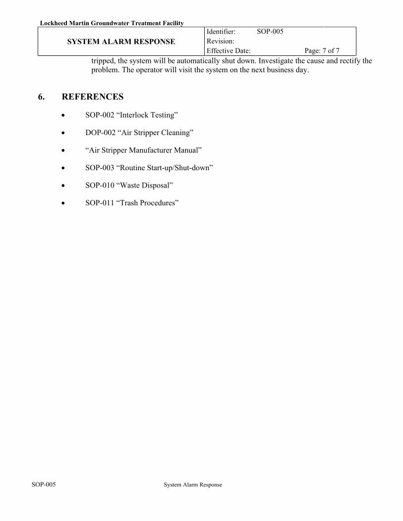
Lockheed Martin Groundwater Treatment Facility Identifier: Revision: Effective Date:
SOP-005 SYSTEM ALARM RESPONSE
Page: 7 of 7
SOP-005 System Alarm Response
tripped, the system will be automatically shut down. Investigate the cause and rectify the problem. The operator will visit the system on the next business day.
6. REFERENCES
• SOP-002 “Interlock Testing”
• DOP-002 “Air Stripper Cleaning”
• “Air Stripper Manufacturer Manual”
• SOP-003 “Routine Start-up/Shut-down”
• SOP-010 “Waste Disposal”
• SOP-011 “Trash Procedures”
Lockheed Martin MRC Blocks E/F GWETS Identifier:
Revision: Effective Date:
SOP-006 0 TBD
EXTRACTION WELL PUMP Page: 1 of 4
SOP-006 Extraction Well Pump Pull
REVISION LOG
Rev. Date Affected Pages
Revision Description
0 11/26/19 All New Procedure 1 01/09/20 All RTO comments response
RESPONSIBLE PERSONNEL LO: Lead Operator OM:
Operations Manager
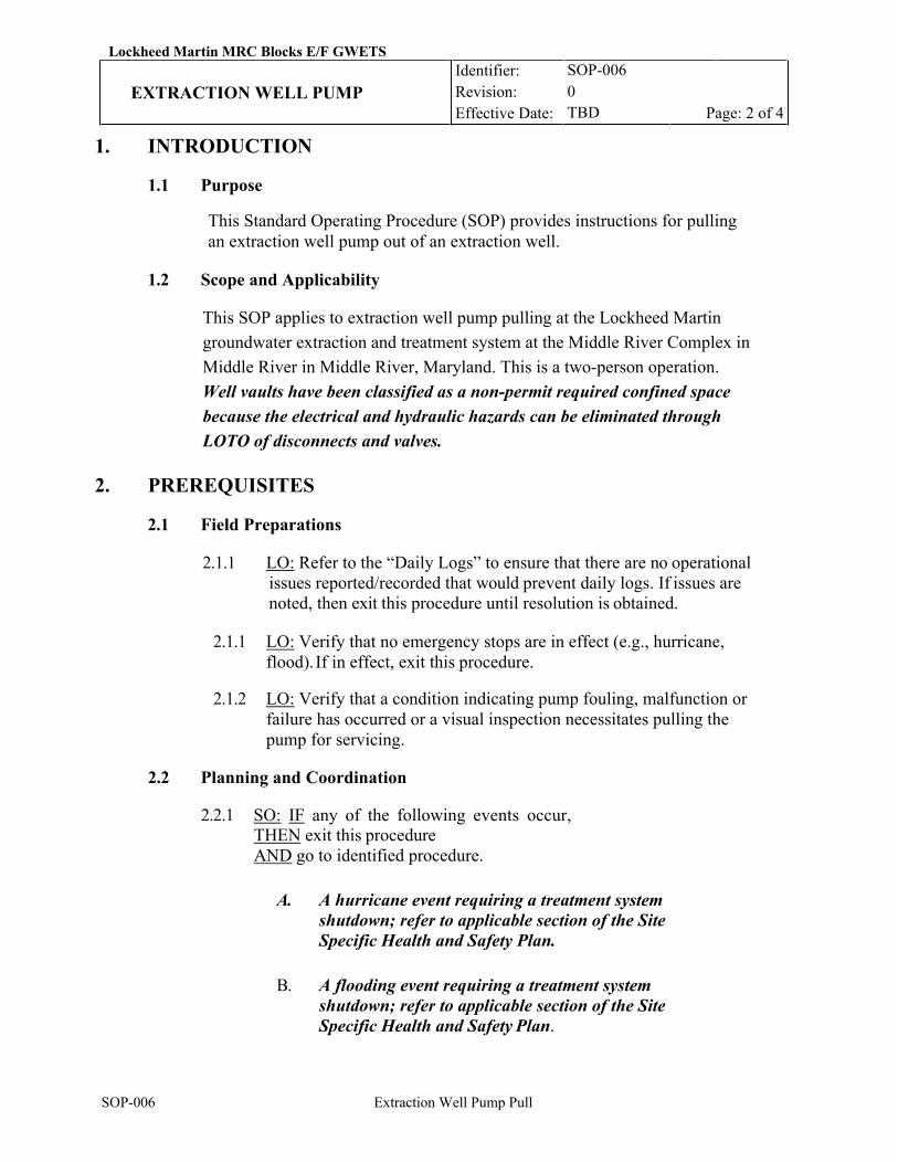
Lockheed Martin MRC Blocks E/F GWETS Identifier:
Revision: Effective Date:
SOP-006 0 TBD
EXTRACTION WELL PUMP Page: 2 of 4
SOP-006 Extraction Well Pump Pull
1. INTRODUCTION
1.1 Purpose
This Standard Operating Procedure (SOP) provides instructions for pulling an extraction well pump out of an extraction well.
1.2 Scope and Applicability
This SOP applies to extraction well pump pulling at the Lockheed Martin groundwater extraction and treatment system at the Middle River Complex in Middle River in Middle River, Maryland. This is a two-person operation. Well vaults have been classified as a non-permit required confined space because the electrical and hydraulic hazards can be eliminated through LOTO of disconnects and valves.
2. PREREQUISITES
2.1 Field Preparations
2.1.1 LO: Refer to the “Daily Logs” to ensure that there are no operational issues reported/recorded that would prevent daily logs. If issues are noted, then exit this procedure until resolution is obtained.
2.1.1 LO: Verify that no emergency stops are in effect (e.g., hurricane,
flood). If in effect, exit this procedure.
2.1.2 LO: Verify that a condition indicating pump fouling, malfunction or failure has occurred or a visual inspection necessitates pulling the pump for servicing.
2.2 Planning and Coordination
2.2.1 SO: IF any of the following events occur,
THEN exit this procedure AND go to identified procedure.
A. A hurricane event requiring a treatment system shutdown; refer to applicable section of the Site Specific Health and Safety Plan.
B. A flooding event requiring a treatment system shutdown; refer to applicable section of the Site Specific Health and Safety Plan.
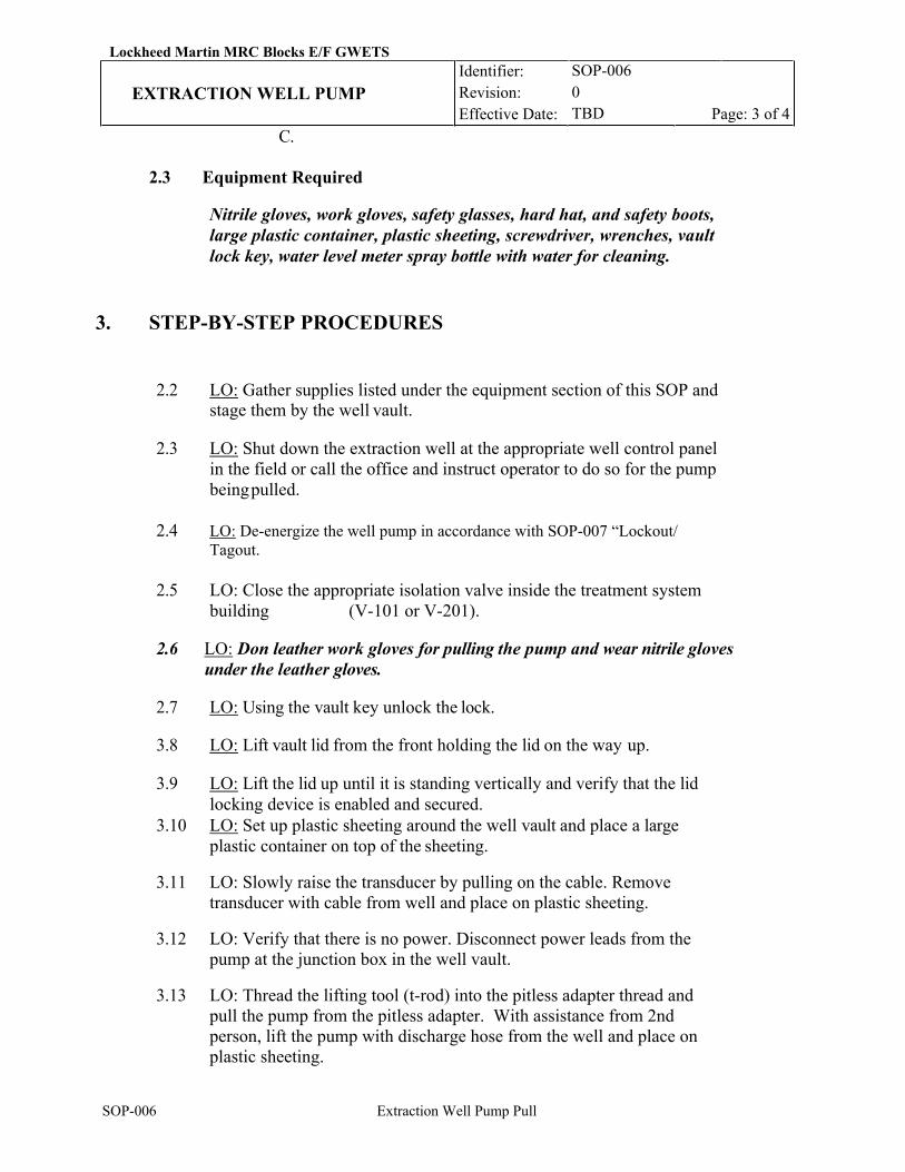
Lockheed Martin MRC Blocks E/F GWETS Identifier:
Revision: Effective Date:
SOP-006 0 TBD
EXTRACTION WELL PUMP Page: 3 of 4
SOP-006 Extraction Well Pump Pull
C.
2.3 Equipment Required
Nitrile gloves, work gloves, safety glasses, hard hat, and safety boots, large plastic container, plastic sheeting, screwdriver, wrenches, vault lock key, water level meter spray bottle with water for cleaning.
3. STEP-BY-STEP PROCEDURES
2.2 LO: Gather supplies listed under the equipment section of this SOP and stage them by the well vault.
2.3 LO: Shut down the extraction well at the appropriate well control panel
in the field or call the office and instruct operator to do so for the pump being pulled.
2.4 LO: De-energize the well pump in accordance with SOP-007 “Lockout/
Tagout.
2.5 LO: Close the appropriate isolation valve inside the treatment system building (V-101 or V-201).
2.6 LO: Don leather work gloves for pulling the pump and wear nitrile gloves
under the leather gloves.
2.7 LO: Using the vault key unlock the lock.
3.8 LO: Lift vault lid from the front holding the lid on the way up.
3.9 LO: Lift the lid up until it is standing vertically and verify that the lid locking device is enabled and secured.
3.10 LO: Set up plastic sheeting around the well vault and place a large plastic container on top of the sheeting.
3.11 LO: Slowly raise the transducer by pulling on the cable. Remove transducer with cable from well and place on plastic sheeting.
3.12 LO: Verify that there is no power. Disconnect power leads from the pump at the junction box in the well vault.
3.13 LO: Thread the lifting tool (t-rod) into the pitless adapter thread and pull the pump from the pitless adapter. With assistance from 2nd person, lift the pump with discharge hose from the well and place on plastic sheeting.
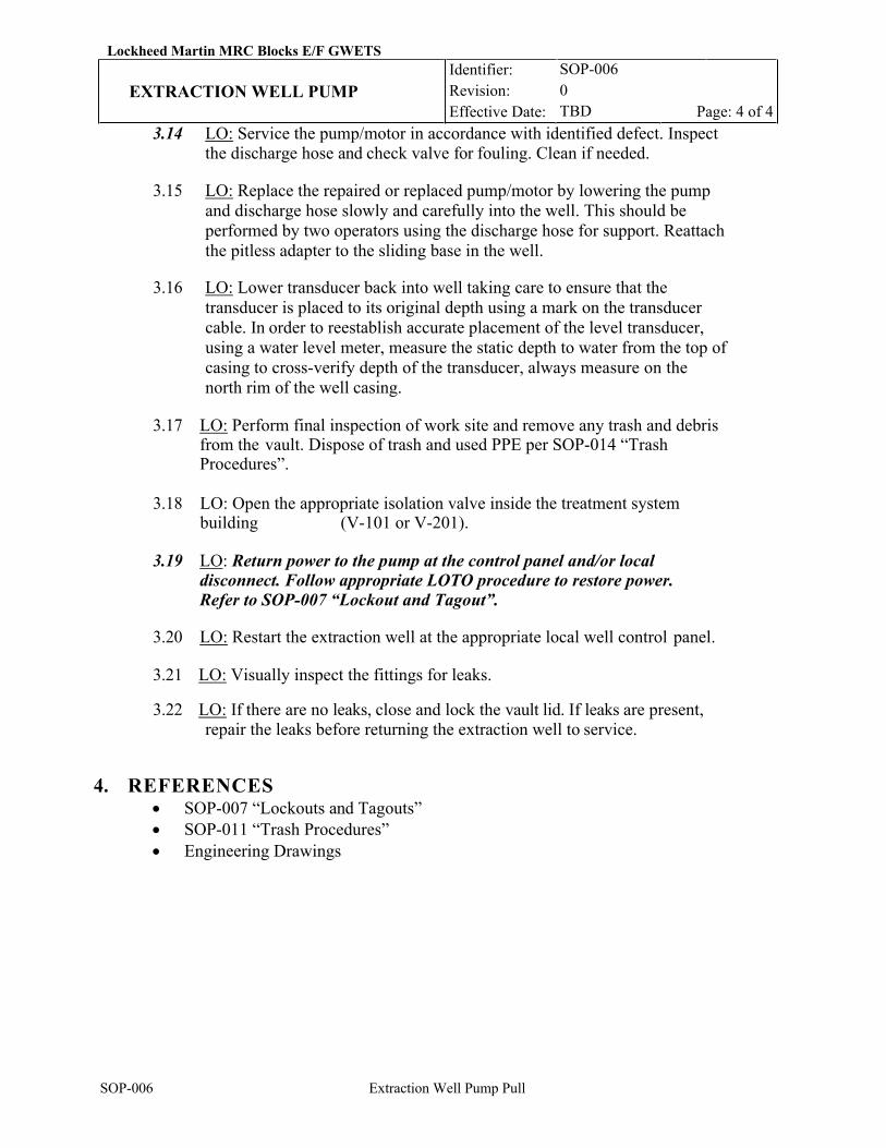
Lockheed Martin MRC Blocks E/F GWETS Identifier:
Revision: Effective Date:
SOP-006 0 TBD
EXTRACTION WELL PUMP Page: 4 of 4
SOP-006 Extraction Well Pump Pull
3.14 LO: Service the pump/motor in accordance with identified defect. Inspect the discharge hose and check valve for fouling. Clean if needed.
3.15 LO: Replace the repaired or replaced pump/motor by lowering the pump
and discharge hose slowly and carefully into the well. This should be performed by two operators using the discharge hose for support. Reattach the pitless adapter to the sliding base in the well.
3.16 LO: Lower transducer back into well taking care to ensure that the transducer is placed to its original depth using a mark on the transducer cable. In order to reestablish accurate placement of the level transducer, using a water level meter, measure the static depth to water from the top of casing to cross-verify depth of the transducer, always measure on the north rim of the well casing.
3.17 LO: Perform final inspection of work site and remove any trash and debris
from the vault. Dispose of trash and used PPE per SOP-014 “Trash Procedures”.
3.18 LO: Open the appropriate isolation valve inside the treatment system
building (V-101 or V-201).
3.19 LO: Return power to the pump at the control panel and/or local disconnect. Follow appropriate LOTO procedure to restore power. Refer to SOP-007 “Lockout and Tagout”.
3.20 LO: Restart the extraction well at the appropriate local well control panel.
3.21 LO: Visually inspect the fittings for leaks.
3.22 LO: If there are no leaks, close and lock the vault lid. If leaks are present, repair the leaks before returning the extraction well to service.
4. REFERENCES
• SOP-007 “Lockouts and Tagouts” • SOP-011 “Trash Procedures” • Engineering Drawings
Lockheed Martin MRC Blocks E/F GWETS Identifier: Revision: Effective Date:
SOP-007 0 TBD
LOCKOUTS AND TAGOUTS Page: 1 of 11
SOP-007 Lockouts and Tagouts
REVISION LOG
Rev. Date Affected Pages Revision Description 0 11/26/19 All New Procedure 1 01/09/20 All RTO comments response
REVIEW LOG
Rev. Date Review Summary
RESPONSIBLE PERSONNEL LO: Lead Operator OM: Operations Manager
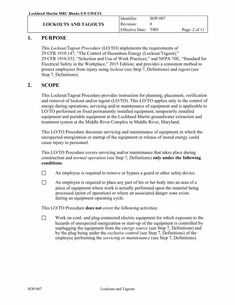
Lockheed Martin MRC Blocks E/F GWETS Identifier: Revision: Effective Date:
SOP-007 0 TBD
LOCKOUTS AND TAGOUTS Page: 2 of 11
SOP-007 Lockouts and Tagouts
1. PURPOSE
This Lockout/Tagout Procedure (LO/TO) implements the requirements of 29 CFR 1910.147, “The Control of Hazardous Energy (Lockout/Tagout);” 29 CFR 1910.333, “Selection and Use of Work Practices;” and NFPA 70E, “Standard for Electrical Safety in the Workplace,” 2015 Edition; and provides a consistent method to protect employees from injury using lockout (see Step 7, Definitions) and tagout (see Step 7, Definitions).
2. SCOPE
This Lockout/Tagout Procedure provides instruction for planning, placement, verification and removal of lockout and/or tagout (LO/TO). This LO/TO applies only to the control of energy during operations, servicing and/or maintenance of equipment and is applicable to LO/TO performed on fixed permanently installed equipment, temporarily installed equipment and portable equipment at the Lockheed Martin groundwater extraction and treatment system at the Middle River Complex in Middle River, Maryland.
This LO/TO Procedure discusses servicing and maintenance of equipment in which the unexpected energization or startup of the equipment or release of stored energy could cause injury to personnel.
This LO/TO Procedure covers servicing and/or maintenance that takes place during construction and normal operation (see Step 7, Definitions) only under the following conditions:
An employee is required to remove or bypass a guard or other safety device.
An employee is required to place any part of his or her body into an area of a piece of equipment where work is actually performed upon the material being processed (point of operation) or where an associated danger zone exists during an equipment operating cycle.
This LO/TO Procedure does not cover the following activities:
Work on cord- and plug-connected electric equipment for which exposure to the
hazards of unexpected energization or start-up of the equipment is controlled by unplugging the equipment from the energy source (see Step 7, Definitions) and by the plug being under the exclusive control (see Step 7, Definitions) of the employee performing the servicing or maintenance (see Step 7, Definitions).
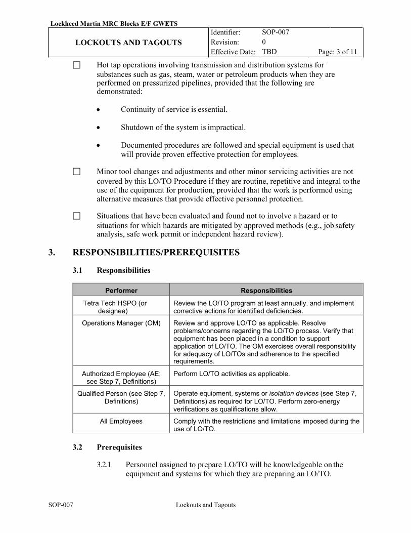
Lockheed Martin MRC Blocks E/F GWETS Identifier: Revision: Effective Date:
SOP-007 0 TBD
LOCKOUTS AND TAGOUTS Page: 3 of 11
SOP-007 Lockouts and Tagouts
Hot tap operations involving transmission and distribution systems for substances such as gas, steam, water or petroleum products when they are performed on pressurized pipelines, provided that the following are demonstrated:
• Continuity of service is essential.
• Shutdown of the system is impractical.
• Documented procedures are followed and special equipment is used that will provide proven effective protection for employees.
Minor tool changes and adjustments and other minor servicing activities are not
covered by this LO/TO Procedure if they are routine, repetitive and integral to the use of the equipment for production, provided that the work is performed using alternative measures that provide effective personnel protection.
Situations that have been evaluated and found not to involve a hazard or to
situations for which hazards are mitigated by approved methods (e.g., job safety analysis, safe work permit or independent hazard review).
3. RESPONSIBILITIES/PREREQUISITES
3.1 Responsibilities
Performer Responsibilities
Tetra Tech HSPO (or designee)
Review the LO/TO program at least annually, and implement corrective actions for identified deficiencies.
Operations Manager (OM) Review and approve LO/TO as applicable. Resolve problems/concerns regarding the LO/TO process. Verify that equipment has been placed in a condition to support application of LO/TO. The OM exercises overall responsibility for adequacy of LO/TOs and adherence to the specified requirements.
Authorized Employee (AE; see Step 7, Definitions)
Perform LO/TO activities as applicable.
Qualified Person (see Step 7, Definitions)
Operate equipment, systems or isolation devices (see Step 7, Definitions) as required for LO/TO. Perform zero-energy verifications as qualifications allow.
All Employees Comply with the restrictions and limitations imposed during the use of LO/TO.
3.2 Prerequisites
3.2.1 Personnel assigned to prepare LO/TO will be knowledgeable on the
equipment and systems for which they are preparing an LO/TO.
Lockheed Martin MRC Blocks E/F GWETS Identifier: Revision: Effective Date:
SOP-007 0 TBD
LOCKOUTS AND TAGOUTS Page: 4 of 11
SOP-007 Lockouts and Tagouts
4. REQUIREMENTS
4.1 General Requirements Controlling LO/TO
4.1.1 Equipment that has been locked out and/or tagged out WILL NOT BE OPERATED by any person.
4.1.2 All employees are required to comply with the restrictions and
limitations imposed upon them during the use of LO/TO.
4.1.3 Each authorized employee working under the protection of LO/TO will be protected by a personal lock (see Step 7, Definitions) and personal “Do Not Operate” tag (see Step 7, Definitions) under the exclusive control of that employee.
4.2 Lockout Devices
4.2.1 If an isolation device is capable of being locked out (see Step 7,
Definitions), then a lockout device will be used to prevent operation of the device and will be affixed in a manner that will hold the energy-isolating device in a “safe” or “off” position.
4.2.2 Isolations will be protected by locks and lockout devices (see Step 7,
Definitions) to the maximum extent possible. Locks used for LO/TO will meet the following requirements:
4.2.2.1 All locking devices will be approved by the Qualified
Person (QP) and meet the requirements defined in OSHA 29 CFR 1910.147. Locking devices shall be used for controlling energy and shall not be used for other purposes. Locking device shall indicate the identity of the employee applying the device.
4.3 Tags and Tagout Devices (see Step 7, Definitions)
4.3.1 Tags used for LO/TO will meet the following requirements:
4.3.1.1 “Do Not Operate” tags (see Step 7, Definitions) are
essentially warning devices affixed to energy-isolating devices and do not provide the physical restraint on those devices that is provided by a lock.
4.3.1.2 When a “Do Not Operate” tag is attached to an
energy-isolating device, it will not be removed without authorization of the authorized employee responsible for it, and will not be bypassed, ignored or otherwise defeated.
Lockheed Martin MRC Blocks E/F GWETS Identifier: Revision: Effective Date:
SOP-007 0 TBD
LOCKOUTS AND TAGOUTS Page: 5 of 11
SOP-007 Lockouts and Tagouts
4.3.1.3 “Do Not Operate” tags must be legible and understandable by all qualified employees and all other employees whose work operations are or may be in the area. Personnel will use only “Do Not Operate” tags approved by the QP for LO/TO.
4.3.1.4 “Do Not Operate” tags and their means of attachment must be
made of materials that will withstand the environmental conditions encountered in the workplace.
4.3.1.5 “Do Not Operate” tags may evoke a false sense of security, and
their meaning must be understood as part of the overall energy control program. “Do Not Operate” tags are reserved for LO/TO use and will not be used for any other purpose. NOTE: “Out of Service” tags will not be substituted for “Do Not Operate” tags.
4.3.1.6 “Do Not Operate” tags will be securely attached to energy-
isolating devices so that they cannot be inadvertently or accidentally detached during use, and so they clearly indicate that operation or movement of the isolation device from the “safe” or “off” position is prohibited.
4.4 Isolation Practices for LO/TO
4.4.1 Electrical Systems
4.4.1.1 Isolation must be provided for any electrical energy equal to or greater than 50 volts (V; ac or dc) unless it can be demonstrated that de-energizing introduces additional or increased hazards, or is infeasible due to equipment design or operational limitations or for performing approved troubleshooting, calibrations or other work activity that requires a system to remain energized (see Step 7, Definitions) to perform the activity. If the electrical circuit(s) cannot be de-energized, an approved work control document must be used to specify applicable safety precautions/instructions and required safety equipment to address hazards from both electrical shock and arc flash.
4.4.1.2 Grounding requirements must be considered as part of the
isolation for any electrical circuit. The grounds must be tagged to ensure that they remain installed until the work is complete and removed prior to re-energizing the equipment or system.
Lockheed Martin MRC Blocks E/F GWETS Identifier: Revision: Effective Date:
SOP-007 0 TBD
LOCKOUTS AND TAGOUTS Page: 6 of 11
SOP-007 Lockouts and Tagouts
4.4.1.3 Control circuit devices (e.g., pushbuttons, selector switches and interlocks) may not be used as the sole means for de- energizing circuits or equipment. Interlocks for electrical equipment may not be used as a substitute for LO/TO.
4.4.1.4 When using lifted leads as an isolation point, the “Danger”
tag used to identify the required condition of the leads should not be placed inside a junction box, as this could be a fire hazard. The “Do Not Operate” tag should be placed on the junction box cover or other appropriate location.
5. INSTRUCTIONS
5.1 Simple LO/TO
NOTE: Documentation of the steps followed for simple LO/TO is not required.
5.1.1 A simple LO/TO may be performed if ALL of the following conditions exist:
A. The equipment has no potential for stored or residual energy, or reaccumulation of stored energy after shutdown that could endanger employees.
B. The equipment has a single energy source that can be readily
identified and isolated.
C. The isolation and locking out of the single energy source will completely de-energize and deactivate the equipment. All capacitors will be drained of their stored energy if present.
D. The equipment is isolated from the single energy source and
locked out during servicing or maintenance.
E. A single lockout device will achieve a locked-out condition.
F. The lockout device is under the exclusive control of the AE performing the servicing or maintenance.
G. The servicing or maintenance does not create hazards for other
employees.
H. The facility has not experienced any unexpected activation or re- energization of the equipment during servicing or maintenance.
Lockheed Martin MRC Blocks E/F GWETS Identifier: Revision: Effective Date:
SOP-007 0 TBD
LOCKOUTS AND TAGOUTS Page: 7 of 11
SOP-007 Lockouts and Tagouts
5.1.2 If all the criteria listed in 5.1.1 A through 5.1.1 H are not satisfied, then the servicing or maintenance cannot be performed using a simple LO/TO.
5.1.3 AE/: Notify all affected employees (see Step 7, Definitions) that
servicing or maintenance is required on the equipment and that the equipment must be shut down and locked out to perform the servicing or maintenance.
5.1.4 AE/: Identify the type(s) and magnitude(s) of energy associated with
performing the servicing or maintenance on the equipment, using up-to- date diagrammatic drawing representations and/or documents and physical walk-down, and identify the isolation device required to de- energize and isolate the equipment from the energy source.
5.1.5 AE/: Obtain permission from the equipment owner to shut down and
perform the LO/TO and the servicing or maintenance.
5.1.6 Qualified Person: If the equipment is operating, shut it down in accordance with approved procedures or other instructions as applicable, ensuring that all operating controls are placed in the neutral, off or other appropriate position.
5.1.7 Qualified Person: Position, as necessary, the isolation device needed to
isolate the equipment from the energy source.
5.1.8 AE: Lock out the energy-isolating device, using Personal Lock and Personal “Do Not Operate” tag.
5.1.9 Qualified Person: Ensure that the equipment is completely de-energized
by performing zero-energy verification(s).
5.1.9.1 For electrical energy sources, use approved methods to verify the absence of electrical energy (voltage).
5.1.9.2 Perform zero-energy verification(s) for other energy sources
as identified in Step 5.1.4.
5.1.10 AE: Perform the servicing or maintenance on the equipment.
5.1.10.1 If it is necessary to leave the job prior to completing the work, other than for lunch or for a break, then perform the following step:
5.1.10.1.1 Turn over the job to an oncoming personnel by
having the oncoming AE install his or her Personal Lock and Personal “Do Not Operate”
Lockheed Martin MRC Blocks E/F GWETS Identifier: Revision: Effective Date:
SOP-007 0 TBD
LOCKOUTS AND TAGOUTS Page: 8 of 11
SOP-007 Lockouts and Tagouts
tag in place of your Personal Lock and Personal “Do Not Operate” tag. This should be done prior to the removal of the departing employee’s lock and tag. Departing employee should also notify the arriving employee of the status of the equipment and the work in progress; inform the arriving employee of any problems or concerns regarding the work in progress; and notify the Qualified Person of all locked out energy sources.
5.1.11 AE: When servicing or maintenance is complete, perform the following
activities:
5.1.11.1 Check the equipment and the immediate area around the equipment to ensure that nonessential items have been removed and that the equipment components are operationally intact.
5.1.11.2 Check the work area to ensure that all employees have been
safely positioned or removed from the area.
5.1.11.3 Verify that the equipment controls are in the neutral, off or other appropriate position.
5.1.11.4 Remove your personal lock, personal “Do Not Operate”
tag (see Step 7, Definitions), and lockout device, as applicable, from the isolation device.
5.1.11.5 Notify all affected employees that the servicing or
maintenance on the equipment has been completed and that the equipment may be placed back into operation.
5.1.11.6 Perform tests and visual inspections per NFPA 70E Article
120.2.(F)(2)(m).
6. ADDITIONAL INSTRUCTIONS
6.1 Documentation of Lock Out/Tag Outs
6.1.1 For each lock out /tag out procedure performed, the Qualified Person shall complete a Lockout/Tagout Log Sheet (Appendix A) to verify that all energy isolation devices have been identified and located. Special instructions associated with application of lockout/tagout of a piece of equipment are also documented on this form.

Lockheed Martin MRC Blocks E/F GWETS Identifier: Revision: Effective Date:
SOP-007 0 TBD
LOCKOUTS AND TAGOUTS Page: 9 of 11
SOP-007 Lockouts and Tagouts
7. DEFINITIONS
All employees/affected employees. Their job requires them to operate or use equipment on which servicing/maintenance is being performed under lockout/tagout or whose job requires him/her to work in an area in which such servicing or maintenance is being performed. An affected employee may NOT perform work under the protection of a LO/TO. They must comply with the restrictions and limitations imposed during the use of LO/TO.
Authorized employee (AE). An individual trained on all aspects of this procedure who prepares, installs, verifies, performs work under and/or removes LOs/TOs.
Capable of being locked out. Refers to an isolation device that has a means to attach a lock or into which a locking mechanism is built.
“Do Not Operate” tag. A numbered tag, red and white with black lettering, used to prohibit operation of equipment or components.
Energized. Connected to an energy source or containing residual or stored energy.
Energy source. Any source of electrical, mechanical, hydraulic, pneumatic, chemical, thermal or other energy.
Exclusive control. Exclusive control means that the employee has physical possession of the key to his/her personal lock and tag, which is attached to the isolation device. For cord- and plug-control equipment, the plug is considered to be under the exclusive control of the employee if it is physically in his/her possession, or within arm’s reach and in line of sight of the employee, or if the employee has affixed an LO/TO device to the plug.
Site supervisor (SS). A general term used to identify the supervisor directly and officially in charge of a facility/area or systems/equipment operation and who has been trained in all aspects of this procedure. The SS can be the equipment owner. For areas that do not have an operating organization, the SS is the maintenance supervisor under whose direction the work will be performed (all references to the SS include the designated alternate).
Lockheed Martin MRC Blocks E/F GWETS Identifier: Revision: Effective Date:
SOP-007 0 TBD
LOCKOUTS AND TAGOUTS Page: 10 of 11
SOP-007 Lockouts and Tagouts
Isolation device. A mechanical device that physically prevents the transmission or release of energy. Examples include a manually operated electrical circuit breaker, fuse block, fuse, disconnect switch, line valve (not a check valve), slip blind, wood or metal block, Halon system control head solenoid or squib/initiator cable connector removal, or any similar device used to block or isolate energy. Push buttons, selector switches and other control circuit type of devices are not isolation devices.
Lockout. Placing a lockout device on an isolation device according to the LO/TO procedure, ensuring that the isolating device and the equipment being controlled cannot be operated until the lockout device is removed.
Lockout device. A device that uses a positive means, such as a padlock, to hold an isolation device in the desired position. Included are blank flanges and bolted slip blinds.
Normal operation. The use of equipment to perform its intended operating function.
Personal “Do Not Operate” tag. A tag placed by an AE on a lockbox/isolation device that clearly indicates his/her name and organization.
Personal lock. A lock, under the exclusive control of the AE who placed it (except where
specifically addressed in this procedure), used to ensure the continuity of energy isolation while work is being performed by the AE.
Qualified person. A person, familiar with the construction and operation of the equipment and the hazards involved, trained and competent in the applicable LOTO procedures and assigned authority for the coordination and overseeing of Authorized Employee(s) implementation of LOTO protection. A Qualified Person may be referred to by a different term depending upon jurisdiction (e.g. Requesting Authority, Lockout Authority, Person in Charge, etc.).
Servicing or maintenance. Workplace activities such as constructing, installing, setting up, adjusting, inspecting, modifying and maintaining and/or servicing equipment. These activities include lubrication, cleaning or clearing jamming of equipment, and making adjustments or tool changes, where the employee may be exposed to the unexpected energization or startup of the equipment or release of hazardous energy.
Tagout. Placing a tag on an isolation device, in accordance with the LO/TO procedure, to indicate that the isolation device and the equipment being controlled cannot be operated until the tag is removed.
Tagout device. A tag and its means of attachment, that can be securely fastened to an isolation device in accordance with the LO/TO procedure, to indicate that the isolation device and the equipment being controlled cannot be operated until the tagout device is removed. The tagout device will meet Article 120.2 (E)(4).
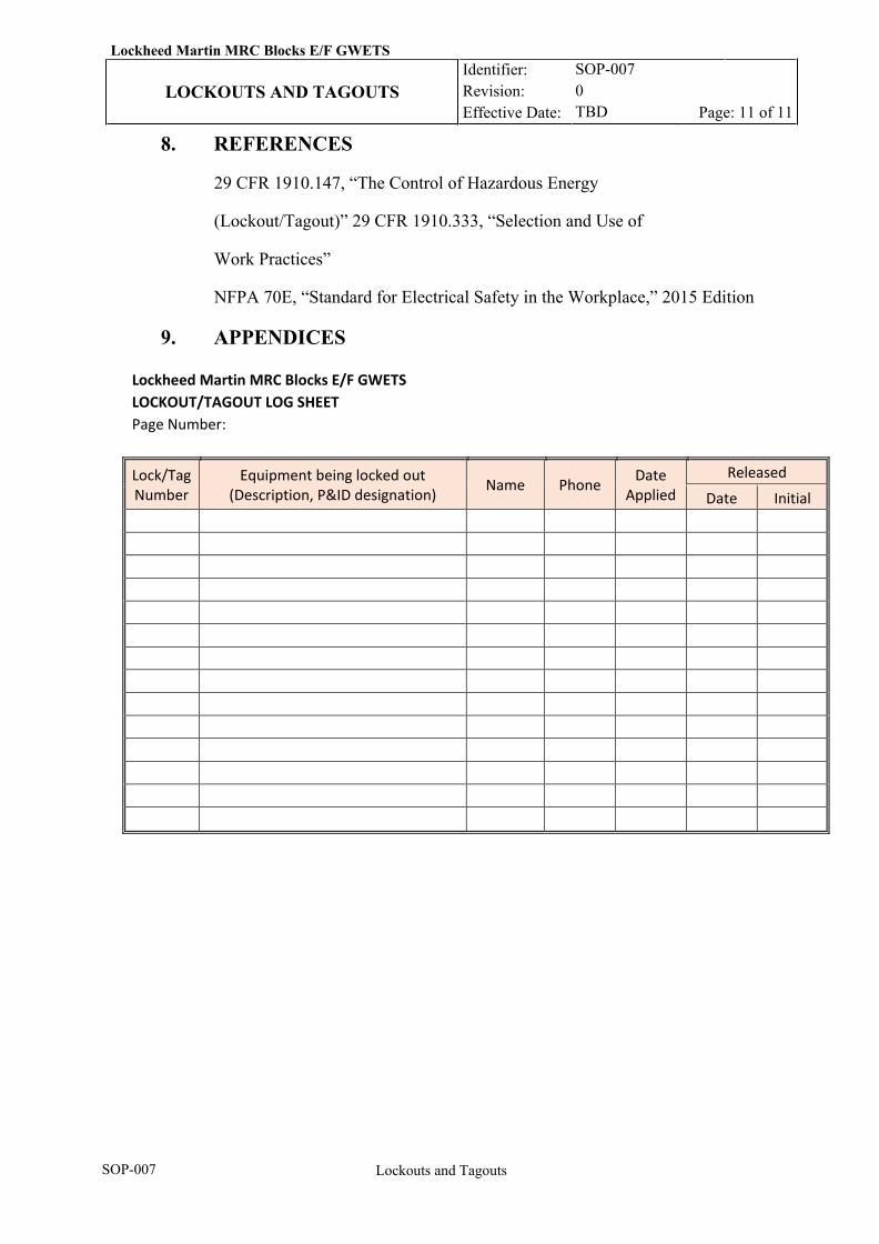
Lockheed Martin MRC Blocks E/F GWETS Identifier: Revision: Effective Date:
SOP-007 0 TBD
LOCKOUTS AND TAGOUTS Page: 11 of 11
SOP-007 Lockouts and Tagouts
8. REFERENCES
29 CFR 1910.147, “The Control of Hazardous Energy
(Lockout/Tagout)” 29 CFR 1910.333, “Selection and Use of
Work Practices”
NFPA 70E, “Standard for Electrical Safety in the Workplace,” 2015 Edition
9. APPENDICES
Lockheed Martin MRC Blocks E/F GWETS LOCKOUT/TAGOUT LOG SHEET Page Number: Lock/Tag Number
Equipment being locked out (Description, P&ID designation) Name Phone Date
Applied Released
Date Initial

Lockheed Martin MRC Blocks E/F GWETS Identifier: Revision: Effective Date:
SOP-008 TBD VAPOR PHASE GAC CHANGE-OUT
Page: 1 of 5
SOP-008 Vapor Phase GAC Change-Out
REVISION LOG
Rev. Date Affected Pages Revision Description 0 11/26/19 All New Procedure 1 01/09/20 All RTO comments response
RESPONSIBLE PERSONNEL LO: Lead Operator OM: Operations Manager SC: Subcontractor
Lockheed Martin MRC Blocks E/F GWETS Identifier: Revision: Effective Date:
SOP-008 TBD VAPOR PHASE GAC CHANGE-OUT
Page: 2 of 5
SOP-008 Vapor Phase GAC Change-Out
1. INTRODUCTION
1.1 Purpose
This Standard Operating Procedure (SOP) provides instructions for removing and
replacing the granular activated carbon (GAC) in the vessels.
1.2 Scope and Applicability
This SOP applies to the operation and maintenance of the VGAC treatment system located
at the Lockheed Martin groundwater extraction and treatment system at the Middle River
Complex in Middle River. A carbon change-out will be performed by contractor personnel
and would occur as required for the treatment system. Under normal circumstances, VGAC
media in both lead and lag vessels would be replaced as this approach is more efficient for
small VGAC vessels. However, if necessary, a lead/lag vessels swap can be performed as
described in Section 4.0.
2. PREREQUISITES
2.1 Field Preparations
2.1.1 LO: Review the Safety Data Sheet (SDS) for the vapor-phase carbon prior to arrival at the facility site.
2.1.2 LO: Conduct on-site Health & Safety meeting with responsible personnel prior to carbon arrival and change-out. No suspended loads are allowed.
2.1.3 SC: Stage equipment listed in the “equipment required” step next to the treatment system building.
2.1.4 LO: Obtain the current working edition of “Daily Logs”.
2.1.5 LO: Refer to the “Daily Logs” to ensure that there are no operational issues reported/recorded that would prevent a normal system shut down or startup. If issues are noted, then exit this procedure until resolution is obtained.
2.1.6 LO: Inspect the GAC material to ensure that it is dry and free flowing.
2.1.7 LO: Shut down the system. 2.1.8 LO: Verify that no emergency stops are in effect (e.g., hurricane, flood). If
in effect, exit this procedure. Verify that weather is such that carbon will not be blown around during wind gusts or rain.
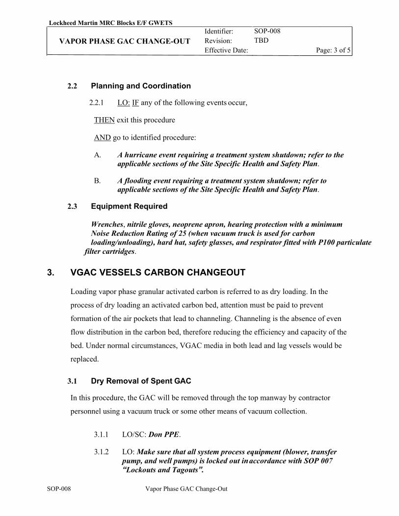
Lockheed Martin MRC Blocks E/F GWETS Identifier: Revision: Effective Date:
SOP-008 TBD VAPOR PHASE GAC CHANGE-OUT
Page: 3 of 5
SOP-008 Vapor Phase GAC Change-Out
2.2 Planning and Coordination
2.2.1 LO: IF any of the following events occur,
THEN exit this procedure
AND go to identified procedure:
A. A hurricane event requiring a treatment system shutdown; refer to the applicable sections of the Site Specific Health and Safety Plan.
B. A flooding event requiring a treatment system shutdown; refer to
applicable sections of the Site Specific Health and Safety Plan.
2.3 Equipment Required
Wrenches, nitrile gloves, neoprene apron, hearing protection with a minimum Noise Reduction Rating of 25 (when vacuum truck is used for carbon
loading/unloading), hard hat, safety glasses, and respirator fitted with P100 particulate filter cartridges.
3. VGAC VESSELS CARBON CHANGEOUT
Loading vapor phase granular activated carbon is referred to as dry loading. In the
process of dry loading an activated carbon bed, attention must be paid to prevent
formation of the air pockets that lead to channeling. Channeling is the absence of even
flow distribution in the carbon bed, therefore reducing the efficiency and capacity of the
bed. Under normal circumstances, VGAC media in both lead and lag vessels would be
replaced.
3.1 Dry Removal of Spent GAC
In this procedure, the GAC will be removed through the top manway by contractor
personnel using a vacuum truck or some other means of vacuum collection.
3.1.1 LO/SC: Don PPE.
3.1.2 LO: Make sure that all system process equipment (blower, transfer
pump, and well pumps) is locked out in accordance with SOP 007 “Lockouts and Tagouts”.
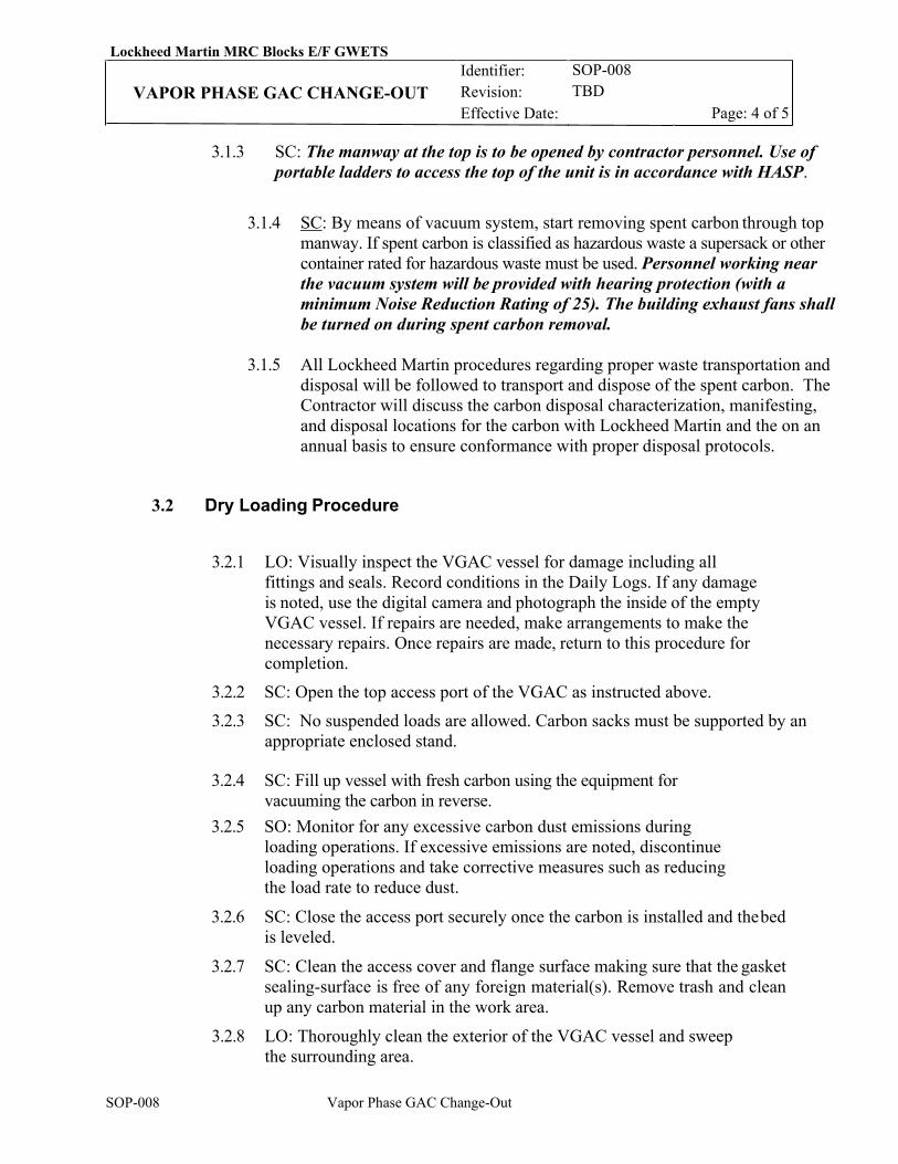
Lockheed Martin MRC Blocks E/F GWETS Identifier: Revision: Effective Date:
SOP-008 TBD VAPOR PHASE GAC CHANGE-OUT
Page: 4 of 5
SOP-008 Vapor Phase GAC Change-Out
3.1.3 SC: The manway at the top is to be opened by contractor personnel. Use of portable ladders to access the top of the unit is in accordance with HASP.
3.1.4 SC: By means of vacuum system, start removing spent carbon through top manway. If spent carbon is classified as hazardous waste a supersack or other container rated for hazardous waste must be used. Personnel working near the vacuum system will be provided with hearing protection (with a minimum Noise Reduction Rating of 25). The building exhaust fans shall be turned on during spent carbon removal.
3.1.5 All Lockheed Martin procedures regarding proper waste transportation and
disposal will be followed to transport and dispose of the spent carbon. The Contractor will discuss the carbon disposal characterization, manifesting, and disposal locations for the carbon with Lockheed Martin and the on an annual basis to ensure conformance with proper disposal protocols.
3.2 Dry Loading Procedure
3.2.1 LO: Visually inspect the VGAC vessel for damage including all fittings and seals. Record conditions in the Daily Logs. If any damage is noted, use the digital camera and photograph the inside of the empty VGAC vessel. If repairs are needed, make arrangements to make the necessary repairs. Once repairs are made, return to this procedure for completion.
3.2.2 SC: Open the top access port of the VGAC as instructed above. 3.2.3 SC: No suspended loads are allowed. Carbon sacks must be supported by an
appropriate enclosed stand.
3.2.4 SC: Fill up vessel with fresh carbon using the equipment for vacuuming the carbon in reverse.
3.2.5 SO: Monitor for any excessive carbon dust emissions during loading operations. If excessive emissions are noted, discontinue loading operations and take corrective measures such as reducing the load rate to reduce dust.
3.2.6 SC: Close the access port securely once the carbon is installed and the bed is leveled.
3.2.7 SC: Clean the access cover and flange surface making sure that the gasket sealing-surface is free of any foreign material(s). Remove trash and clean up any carbon material in the work area.
3.2.8 LO: Thoroughly clean the exterior of the VGAC vessel and sweep the surrounding area.
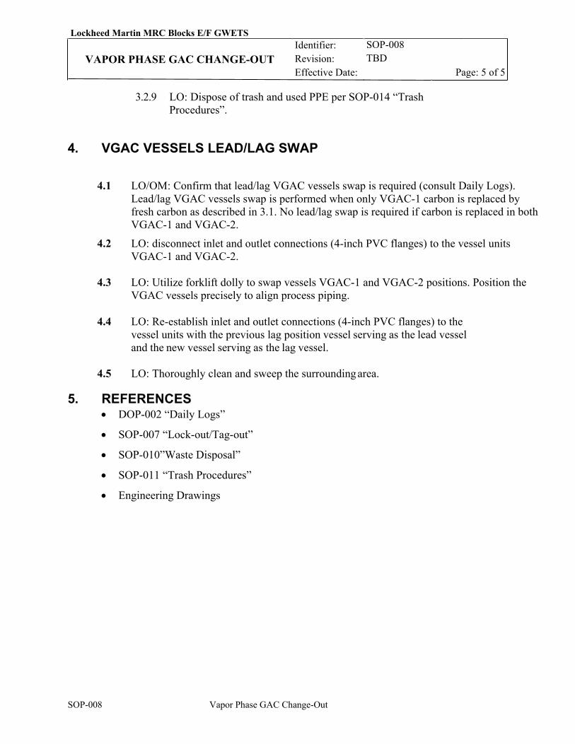
Lockheed Martin MRC Blocks E/F GWETS Identifier: Revision: Effective Date:
SOP-008 TBD VAPOR PHASE GAC CHANGE-OUT
Page: 5 of 5
SOP-008 Vapor Phase GAC Change-Out
3.2.9 LO: Dispose of trash and used PPE per SOP-014 “Trash Procedures”.
4. VGAC VESSELS LEAD/LAG SWAP
4.1 LO/OM: Confirm that lead/lag VGAC vessels swap is required (consult Daily Logs). Lead/lag VGAC vessels swap is performed when only VGAC-1 carbon is replaced by fresh carbon as described in 3.1. No lead/lag swap is required if carbon is replaced in both VGAC-1 and VGAC-2.
4.2 LO: disconnect inlet and outlet connections (4-inch PVC flanges) to the vessel units VGAC-1 and VGAC-2.
4.3 LO: Utilize forklift dolly to swap vessels VGAC-1 and VGAC-2 positions. Position the
VGAC vessels precisely to align process piping.
4.4 LO: Re-establish inlet and outlet connections (4-inch PVC flanges) to the vessel units with the previous lag position vessel serving as the lead vessel and the new vessel serving as the lag vessel.
4.5 LO: Thoroughly clean and sweep the surrounding area.
5. REFERENCES • DOP-002 “Daily Logs”
• SOP-007 “Lock-out/Tag-out”
• SOP-010”Waste Disposal”
• SOP-011 “Trash Procedures”
• Engineering Drawings
Lockheed Martin MRC Blocks E/F GWETS Identifier: Revision: Effective Date:
SOP-009 0 TBD
LIQUID PHASE GAC CHANGE-OUT Page: 1 of 6
SOP-009 Liquid Phase GAC Change-Out
REVISION LOG
Rev. Date Affected Pages Revision Description 0 11/26/19 All New Procedure 1 01/09/20 All RTO comments response
RESPONSIBLE PERSONNEL LO: Lead Operator OM: Operations Manager SC: Subcontractor
Lockheed Martin MRC Blocks E/F GWETS Identifier: Revision: Effective Date:
SOP-009 0 TBD
LIQUID PHASE GAC CHANGE-OUT Page: 2 of 6
SOP-009 Liquid Phase GAC Change-Out
1. INTRODUCTION
1.1 Purpose
This Standard Operating Procedure (SOP) provides instructions for removing and
replacing the granular activated carbon (GAC) in the liquid-phase vessels (LGAC).
1.2 Scope and Applicability
This SOP applies to the operation and maintenance of the LGAC treatment system located
at the Lockheed Martin groundwater extraction and treatment system at the Middle River
Complex in Middle River, Maryland. The carbon change-out will be performed by
contractor personnel and would occur as required for the treatment system. Under normal
circumstances, LGAC media in both lead and lug vessels would be replaced as this
approach is more efficient for small LGAC vessels. However, if necessary, a lead/lag
vessels swap can be performed as described in Section 4.0.
2. PREREQUISITES
2.1 Field Preparations
2.1.1 LO: Review the Safety Data Sheet (SDS) for the liquid-phase carbon prior to arrival at the facility site.
2.1.2 LO: Conduct on-site Health & Safety meeting with responsible personnel prior to carbon arrival and change-out. No suspended loads are allowed.
2.1.3 2.1.4 SC: Stage equipment listed in the “equipment required” step next to the
treatment system building. 2.1.5 LO: Obtain the current working edition of “Daily Logs”.
2.1.6 LO: Refer to the “Daily Logs” to ensure that there are no operational issues reported/recorded that would prevent a normal system startup. If issues are noted, then exit this procedure until resolution is obtained.
2.1.7 LO: Inspect the GAC material to ensure that it is dry and free flowing.
2.1.8 LO: Shut down the system. 2.1.9 LO: Verify that no emergency stops are in effect (e.g., hurricane, flood). If
in effect, exit this procedure. Verify that weather is such that carbon will not be blown around during wind gusts or rain.

Lockheed Martin MRC Blocks E/F GWETS Identifier: Revision: Effective Date:
SOP-009 0 TBD
LIQUID PHASE GAC CHANGE-OUT Page: 3 of 6
SOP-009 Liquid Phase GAC Change-Out
2.2 Planning and Coordination
2.2.1 LO: IF any of the following events occur,
THEN exit this procedure
AND go to identified procedure:
A. A hurricane event requiring a treatment system shutdown; refer to the applicable sections of the Site Specific Health and Safety Plan.
B. A flooding event requiring a treatment system shutdown; refer to
applicable sections of the Site Specific Health and Safety Plan.
2.3 EQUIPMENT REQUIRED
Wrenches, nitrile gloves, neoprene apron, hearing protection with a minimum Noise Reduction Rating of 25 (when vacuum truck is used for carbon
loading/unloading), hard hat, safety glasses, and respirator fitted with P100 particulate filter cartridges, portable air compressor with regulator and flexible air hose.
3. LGAC VESSELS CARBON CHANGEOUT
Loading liquid phase granular activated carbon is referred to as dry loading. In the
process of dry loading an activated carbon bed, attention must be paid to prevent
formation of the air pockets that lead to channeling. Channeling is the absence of even
flow distribution in the carbon bed, therefore reducing the efficiency and capacity of the
bed. Under normal circumstances, LGAC media in both lead and lag vessels would be
replaced.
3.1 Draining of LGAC Vessel
In this procedure, water from the LGAC vessels (LGAC-1 and LGAC-2) will be drained
by using compressed air to displace water from the vessel.
3.1.1 LO: Don PPE.
3.1.2 LO: Shut down the system and make sure that all system process equipment (blower, transfer pump, and well pumps) is locked out in accordance with SOP 007 “Lockouts and Tagouts”.
3.1.3 LO: Close valves V-303 and V-305 to isolate LGAC-1 and LGAC-2 from upstream equipment.
Lockheed Martin MRC Blocks E/F GWETS Identifier: Revision: Effective Date:
SOP-009 0 TBD
LIQUID PHASE GAC CHANGE-OUT Page: 4 of 6
SOP-009 Liquid Phase GAC Change-Out
3.1.4 LO: Connect compressed air hose from a source of compressed air (portable air compressor) to a ¾” vent valve located on top of LGAC-1.
3.1.5 LO: Start air compressor and apply slight air pressure (approximately 5 psig) to LGAC-1. Monitor pressure in LGAC-1 using PG-401 and effluent flow using flow meter FM-1.
3.1.6 LO: Maintain air pressure in LGAC-1 to obtain the effluent flow between 2 to 5 gallons per minute. Do not exceed 5 pounds per square inch gauge (psig) pressure during water displacement.
3.1.7 LO: Monitor sampling port SPL-4 effluent. When air is detected in SPL-4, close ¾” vent valve located on top of LGAC-1 and stop compressed air flow to LGAC-1. At this point LGAC-1 and LGAC-2 are drained.
3.1.8 LO: Disconnect compressed air hose from ¾” vent valve located on top of LGAC-1and carefully de-pressurize LGAC-1 and LGAC-2 using a ¾” vent valve located on top of LGAC vessels.
3.2 Dry Removal of Spent GAC
In this procedure, the GAC will be removed through the top manway by contractor
personnel using a vacuum truck or some other means of vacuum collection.
3.2.1 LO/SC: Don PPE. 3.2.2 LO: Shut down the system and make sure that all system process
equipment (blower, transfer pump, and well pumps) is locked out in accordance with SOP 007 “Lockouts and Tagouts”.
3.2.3 SC: The manway at the top is to be opened by contractor personnel. Use of portable ladders to access the top of the unit is in accordance with HASP.
3.1.5 SC: By means of vacuum system, start removing spent carbon through
top manway. If spent carbon is classified as hazardous waste a supersack or other container rated for hazardous waste must be used. Personnel working near the vacuum system will be provided with hearing protection (with a minimum Noise Reduction Rating of 25). The building exhaust fan shall be turned on during spent carbon removal.
3.1.5 All Lockheed Martin procedures regarding proper waste transportation and disposal will be followed to transport and dispose of the spent carbon .
3.3 Dry Loading Procedure
3.3.1 LO: Visually inspect the LGAC vessel for damage including all fittings and seals. Record conditions in the Daily Logs. If any damage
Lockheed Martin MRC Blocks E/F GWETS Identifier: Revision: Effective Date:
SOP-009 0 TBD
LIQUID PHASE GAC CHANGE-OUT Page: 5 of 6
SOP-009 Liquid Phase GAC Change-Out
is noted, use the digital camera and photograph the inside of the empty LGAC vessel. If repairs are needed, make arrangements to make the necessary repairs. Once repairs are made, return to this procedure for completion.
3.3.2 SC: Open the top access port of the LGAC. 3.3.3 SC: No suspended loads is allowed. At no time shall any personnel reach under a
suspended sack of carbon. Carbon sacks must be supported by an appropriate enclosed stand.
3.3.4 SC: Fill up vessel with fresh carbon using the equipment for
vacuuming the carbon in reverse. 3.3.5 SO: Monitor for any excessive carbon dust emissions during loading
operations. If excessive emissions are noted, discontinue loading operations and take corrective measures such as reducing the load rate to reduce dust.
3.3.6 SC: Close the access port securely once the carbon is installed and the bed is leveled.
3.3.7 SC: Clean the access cover and flange surface making sure that the gasket sealing-surface is free of any foreign material(s). Remove trash and clean up any carbon material in the work area.
3.3.8 SO: Re-start the system to fill up the LGAC vessels with water. Vent air using ¾” vent valves at the top of the LGAC vessels. Shut down the system, wait 24 hours to wet the carbon and restart the system.
3.3.9 LO: Return any tools used during this procedure to the tool cabinet. 3.3.10 LO: Thoroughly clean the exterior of the LGAC vessel and sweep the
surrounding area. 3.3.11 LO: Dispose of trash and used PPE per SOP-014 “Trash Procedures”.
4. LGAC VESSELS LEAD/LAG SWAP
4.1 LO/OM: Confirm that lead/lag LGAC vessels swap is required (consult Daily Logs). Lead/lag LGAC vessel swap is performed when only LGAC-1 carbon is replaced by fresh carbon as described in 3.3. No lead/lag swap is required if carbon is replaced in both LGAC-1 and LGAC-2.
4.2 LO: disconnect inlet and outlet connections (1-inch PVC pipe unions) to the vessel units LGAC-1 and LGAC-2.
4.3 LO: Utilize forklift dolly to swap vessels LGAC-1 and LGAC-2 positions. Position the
LGAC vessels precisely to align process piping.
Lockheed Martin MRC Blocks E/F GWETS Identifier: Revision: Effective Date:
SOP-009 0 TBD
LIQUID PHASE GAC CHANGE-OUT Page: 6 of 6
SOP-009 Liquid Phase GAC Change-Out
4.4 LO: Re-establish inlet and outlet connections (1-inch PVC pipe unions) to the vessel units with the previous lag position vessel serving as the lead vessel and the new vessel serving as the lag vessel.
4.5 LO: Thoroughly clean and sweep the surrounding area.
5. REFERENCES • DOP-002 “Daily Logs”
• SOP-007 “Lock-out/Tag-out”
• SOP-011 “Waste Disposal”
• SOP-011 “Trash Procedures”
• Engineering Drawings
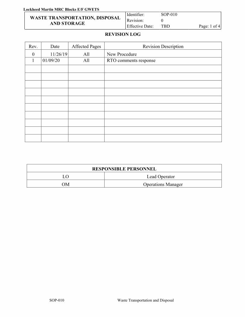
Lockheed Martin MRC Blocks E/F GWETS
WASTE TRANSPORTATION, DISPOSAL AND STORAGE
Identifier: Revision: Effective Date:
SOP-010 0 TBD Page: 1 of 4
SOP-010 Waste Transportation and Disposal
REVISION LOG
Rev. Date Affected Pages Revision Description 0 11/26/19 All New Procedure 1 01/09/20 All RTO comments response
RESPONSIBLE PERSONNEL LO Lead Operator OM Operations Manager
Lockheed Martin MRC Blocks E/F GWETS
WASTE TRANSPORTATION, DISPOSAL AND STORAGE
Identifier: Revision: Effective Date:
SOP-010 0 TBD Page: 2 of 4
SOP-010 Waste Transportation and Disposal
1. INTRODUCTION
1.1 Purpose
This Standard Operating Procedure (SOP) is to be followed when transporting liquid and solid wastes generated during the system operation.
1.2 Scope and Applicability
This SOP is to be used when storing, transporting, and disposing of liquids generated during air stripper cleaning, spent filter bags, and other wastes associated with the operation of Lockheed Martin groundwater extraction and treatment system at the Middle River Complex in Middle River, Maryland.
2. PRECAUTIONS AND LIMITATIONS
Wastes may be contaminated with volatile organic compounds, metals, and acids. Therefore, it is extremely important that the operator use care to avoid inhalation or direct contact with any wastes thereof.
3. PREREQUISITES
3.1 Field Preparations
3.1.1 Gather and stage all needed equipment (listed below).
3.2 Planning and Coordination
3.2.1 FO/ FT: IF any of the following events occur, THEN exit this procedure AND go to identified procedure:
A. A hurricane event; refer to applicable sections of the Site Specific
Health and Safety Plan.
B. A flooding event; refer to applicable sections of the Site Specific Health and Safety Plan.
3.3 Equipment
The following items are located in the Treatment Building unless otherwise stated:
• Spill containment kit including flat shovels
• Labeling supplies
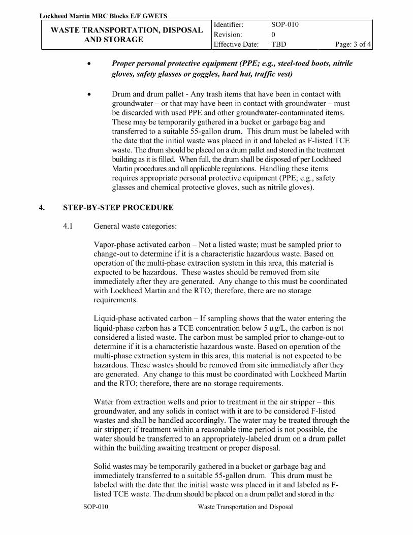
Lockheed Martin MRC Blocks E/F GWETS
WASTE TRANSPORTATION, DISPOSAL AND STORAGE
Identifier: Revision: Effective Date:
SOP-010 0 TBD Page: 3 of 4
SOP-010 Waste Transportation and Disposal
• Proper personal protective equipment (PPE; e.g., steel-toed boots, nitrile gloves, safety glasses or goggles, hard hat, traffic vest)
• Drum and drum pallet - Any trash items that have been in contact with
groundwater – or that may have been in contact with groundwater – must be discarded with used PPE and other groundwater-contaminated items. These may be temporarily gathered in a bucket or garbage bag and transferred to a suitable 55-gallon drum. This drum must be labeled with the date that the initial waste was placed in it and labeled as F-listed TCE waste. The drum should be placed on a drum pallet and stored in the treatment building as it is filled. When full, the drum shall be disposed of per Lockheed Martin procedures and all applicable regulations. Handling these items requires appropriate personal protective equipment (PPE; e.g., safety glasses and chemical protective gloves, such as nitrile gloves).
4. STEP-BY-STEP PROCEDURE 4.1 General waste categories:
Vapor-phase activated carbon – Not a listed waste; must be sampled prior to change-out to determine if it is a characteristic hazardous waste. Based on operation of the multi-phase extraction system in this area, this material is expected to be hazardous. These wastes should be removed from site immediately after they are generated. Any change to this must be coordinated with Lockheed Martin and the RTO; therefore, there are no storage requirements. Liquid-phase activated carbon – If sampling shows that the water entering the liquid-phase carbon has a TCE concentration below 5 µg/L, the carbon is not considered a listed waste. The carbon must be sampled prior to change-out to determine if it is a characteristic hazardous waste. Based on operation of the multi-phase extraction system in this area, this material is not expected to be hazardous. These wastes should be removed from site immediately after they are generated. Any change to this must be coordinated with Lockheed Martin and the RTO; therefore, there are no storage requirements. Water from extraction wells and prior to treatment in the air stripper – this groundwater, and any solids in contact with it are to be considered F-listed wastes and shall be handled accordingly. The water may be treated through the air stripper; if treatment within a reasonable time period is not possible, the water should be transferred to an appropriately-labeled drum on a drum pallet within the building awaiting treatment or proper disposal. Solid wastes may be temporarily gathered in a bucket or garbage bag and immediately transferred to a suitable 55-gallon drum. This drum must be labeled with the date that the initial waste was placed in it and labeled as F-listed TCE waste. The drum should be placed on a drum pallet and stored in the
Lockheed Martin MRC Blocks E/F GWETS
WASTE TRANSPORTATION, DISPOSAL AND STORAGE
Identifier: Revision: Effective Date:
SOP-010 0 TBD Page: 4 of 4
SOP-010 Waste Transportation and Disposal
treatment building as it is filled. When full, the drum shall be disposed of per Lockheed Martin procedures and all applicable regulations. Handling these items requires appropriate personal protective equipment (PPE; e.g., safety glasses and chemical protective gloves, such as nitrile gloves).
4.2 OM: Ensure that all profile and manifests are reviewed by Lockheed Martin and the RTO, and signed by Lockheed Martin Corporation. Ensure that disposal facility and transporter (if necessary) are approved by Lockheed Martin Corporation.
4.3 OM: Work with Lockheed Martin Corporation to determine which waste from the site is considered Listed Waste.
4.4 OM: Follow all site-specific and Lockheed Martin Corporation requirements as provided in the references below.
4.5 LO/OM: Coordinate pick up and replacement of the drum containing F-listed waste when it approaches capacity with designated hauling company. Oversee pick-up.
4.6 LO: Dispose of trash and used PPE per SOP-014 “Trash Procedures”.
5. REFERENCES
• SOP-011 “Trash Procedures”
• Tetra Tech, 2019. Soil Management Plan for Blocks A, B, D, D Panhandle, F, G and H, Lockheed Martin Middle River Complex, 2323 Eastern Boulevard, Middle River, Maryland. April.
• Tetra Tech, 2019. Soil Management Plan for Blocks E and I, Lockheed Martin Middle River Complex, 2323 Eastern Boulevard, Middle River, Maryland. April.
• Tetra Tech, Inc., 2019. 2019 Waste Management Plan, Lockheed Martin Middle River Complex, 2323 Eastern Boulevard Middle River, Maryland. August.
• Lockheed Martin Corporation (Lockheed Martin), 2008. Enterprise Operations (EO)-28 and Lockheed Martin Minimum Requirements for Intrusive Fieldwork Work Plans.
• Lockheed Martin Corporation (Lockheed Martin), 2009. Energy, Environment, Safety, and Health (EESH) Remediation Waste Management Procedure No: EROP-03, Revision 4 (effective April 17, 2009).
• Lockheed Martin Corporation (Lockheed Martin), 2016. Remediation Contractor’s ESH Handbook, Revision 2, effective May 1.
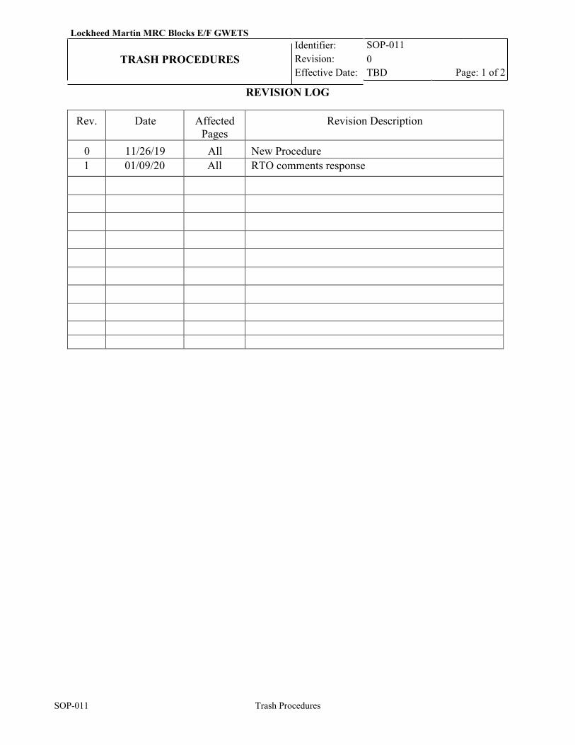
Lockheed Martin MRC Blocks E/F GWETS Identifier: Revision: Effective Date:
SOP-011 0 TBD
TRASH PROCEDURES Page: 1 of 2
SOP-011 Trash Procedures
REVISION LOG
Rev. Date Affected Pages
Revision Description
0 11/26/19 All New Procedure 1 01/09/20 All RTO comments response
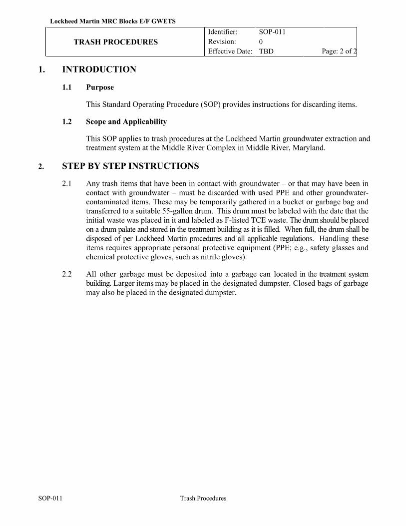
SOP-011 Trash Procedures
Lockheed Martin MRC Blocks E/F GWETS Identifier: Revision: Effective Date:
SOP-011 0 TBD
TRASH PROCEDURES Page: 2 of 2
1. INTRODUCTION
1.1 Purpose
This Standard Operating Procedure (SOP) provides instructions for discarding items.
1.2 Scope and Applicability
This SOP applies to trash procedures at the Lockheed Martin groundwater extraction and treatment system at the Middle River Complex in Middle River, Maryland.
2. STEP BY STEP INSTRUCTIONS
2.1 Any trash items that have been in contact with groundwater – or that may have been in contact with groundwater – must be discarded with used PPE and other groundwater- contaminated items. These may be temporarily gathered in a bucket or garbage bag and transferred to a suitable 55-gallon drum. This drum must be labeled with the date that the initial waste was placed in it and labeled as F-listed TCE waste. The drum should be placed on a drum palate and stored in the treatment building as it is filled. When full, the drum shall be disposed of per Lockheed Martin procedures and all applicable regulations. Handling these items requires appropriate personal protective equipment (PPE; e.g., safety glasses and chemical protective gloves, such as nitrile gloves).
2.2 All other garbage must be deposited into a garbage can located in the treatment system
building. Larger items may be placed in the designated dumpster. Closed bags of garbage may also be placed in the designated dumpster.
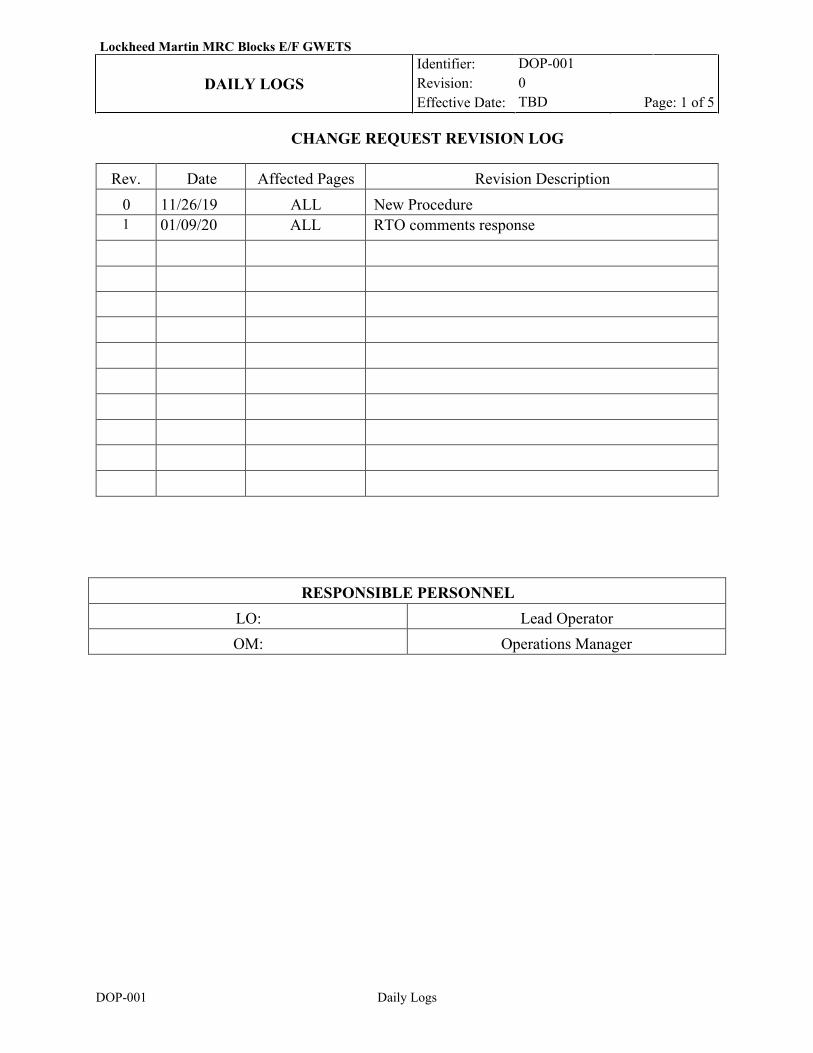
Lockheed Martin MRC Blocks E/F GWETS Identifier:
Revision: Effective Date:
DOP-001 0 TBD
DAILY LOGS Page: 1 of 5
DOP-001 Daily Logs
CHANGE REQUEST REVISION LOG
Rev. Date Affected Pages Revision Description 0 11/26/19 ALL New Procedure 1 01/09/20 ALL RTO comments response
RESPONSIBLE PERSONNEL LO: Lead Operator OM: Operations Manager
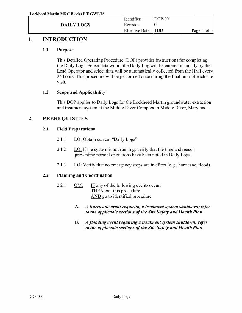
Lockheed Martin MRC Blocks E/F GWETS Identifier:
Revision: Effective Date:
DOP-001 0 TBD
DAILY LOGS Page: 2 of 5
DOP-001 Daily Logs
1. INTRODUCTION
1.1 Purpose
This Detailed Operating Procedure (DOP) provides instructions for completing the Daily Logs. Select data within the Daily Log will be entered manually by the Lead Operator and select data will be automatically collected from the HMI every 24 hours. This procedure will be performed once during the final hour of each site visit.
1.2 Scope and Applicability
This DOP applies to Daily Logs for the Lockheed Martin groundwater extraction and treatment system at the Middle River Complex in Middle River, Maryland.
2. PREREQUISITES
2.1 Field Preparations
2.1.1 LO: Obtain current “Daily Logs”
2.1.2 LO: If the system is not running, verify that the time and reason preventing normal operations have been noted in Daily Logs.
2.1.3 LO: Verify that no emergency stops are in effect (e.g., hurricane, flood).
2.2 Planning and Coordination
2.2.1 OM: IF any of the following events occur, THEN exit this procedure AND go to identified procedure:
A. A hurricane event requiring a treatment system shutdown; refer
to the applicable sections of the Site Safety and Health Plan.
B. A flooding event requiring a treatment system shutdown; refer to the applicable sections of the Site Safety and Health Plan.
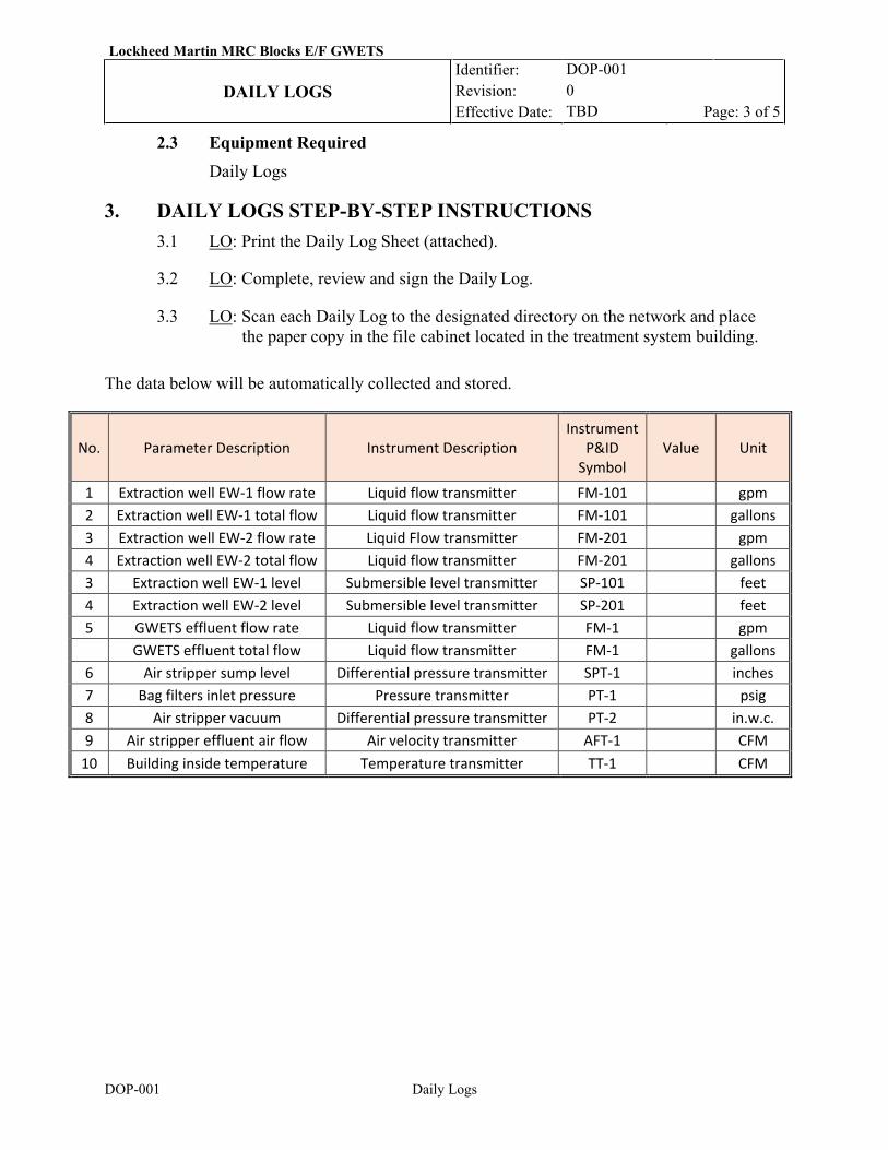
Lockheed Martin MRC Blocks E/F GWETS Identifier:
Revision: Effective Date:
DOP-001 0 TBD
DAILY LOGS Page: 3 of 5
DOP-001 Daily Logs
2.3 Equipment Required Daily Logs
3. DAILY LOGS STEP-BY-STEP INSTRUCTIONS
3.1 LO: Print the Daily Log Sheet (attached).
3.2 LO: Complete, review and sign the Daily Log.
3.3 LO: Scan each Daily Log to the designated directory on the network and place the paper copy in the file cabinet located in the treatment system building.
The data below will be automatically collected and stored.
No. Parameter Description Instrument Description Instrument
P&ID Symbol
Value Unit
1 Extraction well EW-1 flow rate Liquid flow transmitter FM-101 gpm 2 Extraction well EW-1 total flow Liquid flow transmitter FM-101 gallons 3 Extraction well EW-2 flow rate Liquid Flow transmitter FM-201 gpm 4 Extraction well EW-2 total flow Liquid flow transmitter FM-201 gallons 3 Extraction well EW-1 level Submersible level transmitter SP-101 feet 4 Extraction well EW-2 level Submersible level transmitter SP-201 feet 5 GWETS effluent flow rate Liquid flow transmitter FM-1 gpm GWETS effluent total flow Liquid flow transmitter FM-1 gallons
6 Air stripper sump level Differential pressure transmitter SPT-1 inches 7 Bag filters inlet pressure Pressure transmitter PT-1 psig 8 Air stripper vacuum Differential pressure transmitter PT-2 in.w.c. 9 Air stripper effluent air flow Air velocity transmitter AFT-1 CFM
10 Building inside temperature Temperature transmitter TT-1 CFM
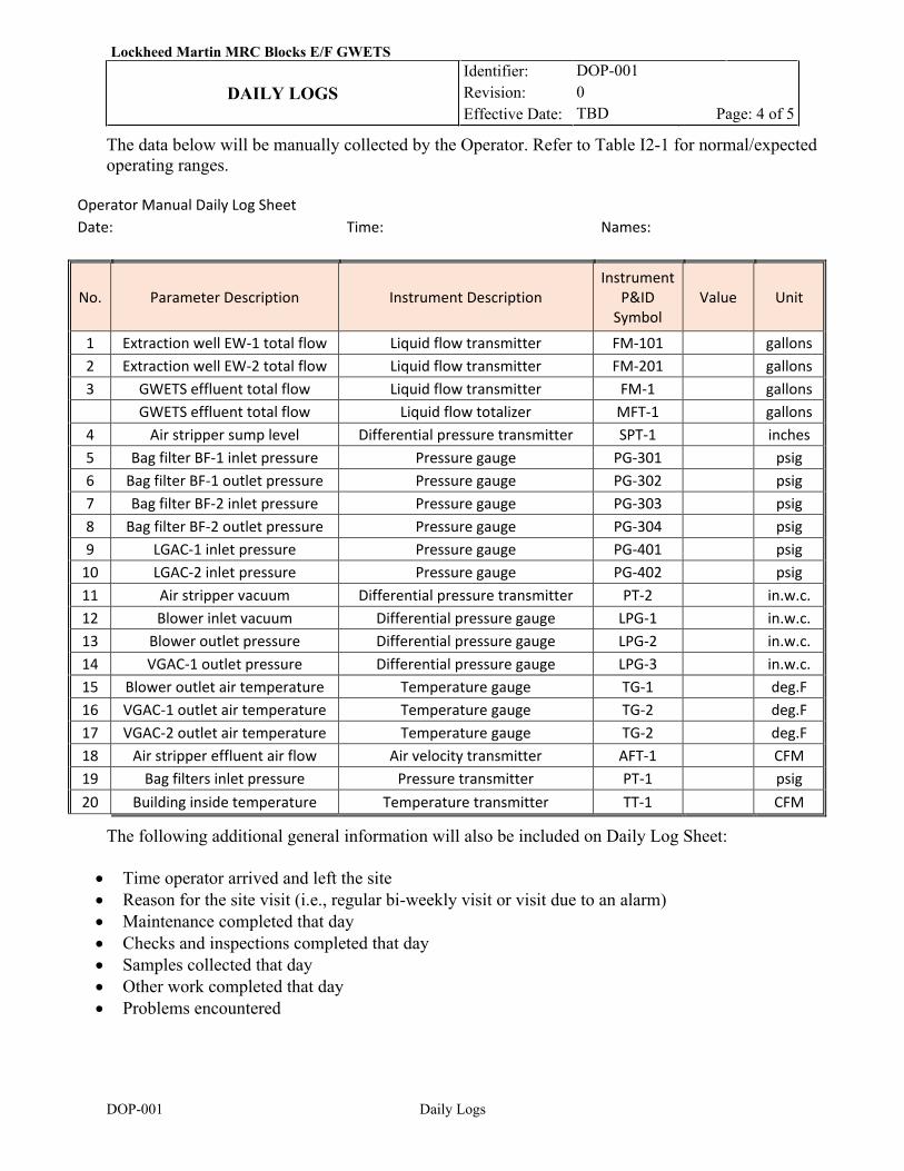
Lockheed Martin MRC Blocks E/F GWETS Identifier:
Revision: Effective Date:
DOP-001 0 TBD
DAILY LOGS Page: 4 of 5
DOP-001 Daily Logs
The data below will be manually collected by the Operator. Refer to Table I2-1 for normal/expected operating ranges.
Operator Manual Daily Log Sheet Date: Time: Names:
No. Parameter Description Instrument Description Instrument
P&ID Symbol
Value Unit
1 Extraction well EW-1 total flow Liquid flow transmitter FM-101 gallons 2 Extraction well EW-2 total flow Liquid flow transmitter FM-201 gallons 3 GWETS effluent total flow Liquid flow transmitter FM-1 gallons GWETS effluent total flow Liquid flow totalizer MFT-1 gallons
4 Air stripper sump level Differential pressure transmitter SPT-1 inches 5 Bag filter BF-1 inlet pressure Pressure gauge PG-301 psig 6 Bag filter BF-1 outlet pressure Pressure gauge PG-302 psig 7 Bag filter BF-2 inlet pressure Pressure gauge PG-303 psig 8 Bag filter BF-2 outlet pressure Pressure gauge PG-304 psig 9 LGAC-1 inlet pressure Pressure gauge PG-401 psig
10 LGAC-2 inlet pressure Pressure gauge PG-402 psig 11 Air stripper vacuum Differential pressure transmitter PT-2 in.w.c. 12 Blower inlet vacuum Differential pressure gauge LPG-1 in.w.c. 13 Blower outlet pressure Differential pressure gauge LPG-2 in.w.c. 14 VGAC-1 outlet pressure Differential pressure gauge LPG-3 in.w.c. 15 Blower outlet air temperature Temperature gauge TG-1 deg.F 16 VGAC-1 outlet air temperature Temperature gauge TG-2 deg.F 17 VGAC-2 outlet air temperature Temperature gauge TG-2 deg.F 18 Air stripper effluent air flow Air velocity transmitter AFT-1 CFM 19 Bag filters inlet pressure Pressure transmitter PT-1 psig 20 Building inside temperature Temperature transmitter TT-1 CFM
The following additional general information will also be included on Daily Log Sheet:
• Time operator arrived and left the site • Reason for the site visit (i.e., regular bi-weekly visit or visit due to an alarm) • Maintenance completed that day • Checks and inspections completed that day • Samples collected that day • Other work completed that day • Problems encountered

Lockheed Martin MRC Blocks E/F GWETS Identifier:
Revision: Effective Date:
DOP-001 0 TBD
DAILY LOGS Page: 5 of 5
DOP-001 Daily Logs
4. REFERENCES • Remediation Contractor’s ESH Handbook, Lockheed Martin Corporation Energy,
Environment, Safety & Health; Revision 2, May, 2014
Lockheed Martin MRC Blocks E/F GWETS Identifier: Revision: Effective Date:
DOP-002 0 TBD
AIR STRIPPER CLEANING Page: 1 of 4
DOP-002 Air Stripper Cleaning
REVISION LOG
Rev. Date Affected Pages Revision Description 0 11/26/19 All New Procedure 1 01/09/20 All RTO comments response
RESPONSIBLE PERSONNEL LO: Lead Operator OM: Operations Manager SC: Subcontractor
Lockheed Martin MRC Blocks E/F GWETS Identifier: Revision: Effective Date:
DOP-002 0 TBD
AIR STRIPPER CLEANING Page: 2 of 4
DOP-002 Air Stripper Cleaning
1. INTRODUCTION
1.1 Purpose
This Detailed Operating Procedure (DOP) provides instructions for cleaning the air stripper.
1.2 Scope and Applicability
This DOP applies to the operation and maintenance of the air stripper located at the Lockheed Martin groundwater extraction and treatment system at the Middle River Complex in Middle River, Maryland. The air stripper cleaning will be performed by the performing contractor personnel and would occur as required for the treatment system.
2. PREREQUISITES
2.1 Field Preparations
2.1.1 LO: Conduct on-site Health & Safety meeting with responsible personnel prior to air stripper cleaning.
2.1.2 LO: Stage cleaning equipment and supplies listed in the “equipment required” inside the treatment system building.
2.1.3 LO: Obtain the current working edition of “Daily Logs”. 2.1.4 LO: Ensure that a copy of “Air Stripper Manufacturer Manual” is
available for reference.
2.1.5 LO: Refer to the “Daily Logs” to ensure that there are no operational issues reported/recorded that would prevent a normal system shut down or startup. If issues are noted, then exit this procedure until resolution is obtained.
2.1.6 LO: Shut down the system. 2.1.7 LO: Verify that no emergency stops are in effect (e.g., hurricane, flood). If
in effect, exit this procedure. Verify that weather is such that carbon will not be blown around during wind gusts or rain.
2.2 Planning and Coordination
2.2.1 LO: IF any of the following events occur,
THEN exit this procedure
AND go to identified procedure:
A. A hurricane event requiring a treatment system shutdown; refer
Lockheed Martin MRC Blocks E/F GWETS Identifier: Revision: Effective Date:
DOP-002 0 TBD
AIR STRIPPER CLEANING Page: 3 of 4
DOP-002 Air Stripper Cleaning
to the applicable sections of the Site Specific Health and Safety Plan.
B. A flooding event requiring a treatment system shutdown; refer to
applicable sections of the Site Specific Health and Safety Plan.
2.3 EQUIPMENT REQUIRED
Wrenches, nitrile gloves, neoprene apron, plastic sheeting, bristle brush, pressure washer, wet vac, 5-foot tall work platform.
3. CLEANING PROCEDURE
Tray fouling due to iron precipitation, solids loading, or bio-fouling is evidenced by increased pressure on the blower inlet, decreased stripper performance (removal rates not being met) or noticeable discoloration on the trays. Stripper cleaning is required when trays are fouled.
3.1 Air Stripper Disassembly
In this procedure, air stripper trays will be disconnected and removed for cleaning.
3.1.1 LO: Don PPE.
3.1.2 LO: Shut down the system and make sure that all system process equipment (blower, transfer pump, and well pumps) is locked out in accordance with SOP 007 “Lockouts and Tagouts”.
3.1.3 LO: Use plastic sheeting to line the floor sump to protect floor but allow the water to drain to the sump.
3.1.4 LO: Disconnect the stripper vapor discharge pipe from the stripper exhaust stack piping and 1-inch PVC groundwater feed line from the top of the stripper.
3.1.5 LO: Unscrew the hold-down rod nuts (cranks) and remove the gasket hold-down ring.
3.1.6 LO: Remove the stripper trays and place them on plastic sheeting. The tray seal pots will have some water remaining in them.
3.2 Cleaning Procedure
In this procedure, the fouled trays will be cleaned using a pressure washer and brush.
3.2.1 LO: Prepare pressure washer for work. Connect a temporary garden hose from the pressure washer to a potable water source in the nearby pump shed.
Lockheed Martin MRC Blocks E/F GWETS Identifier: Revision: Effective Date:
DOP-002 0 TBD
AIR STRIPPER CLEANING Page: 4 of 4
DOP-002 Air Stripper Cleaning
3.2.2 LO: Using a pressure washer and medium bristle brush clean any residue from the tray surfaces, concentrating on the sieve holes. DO NOT USE SOAP or cleaning agents unless they will be thoroughly rinsed from the trays; soap residue can affect stripper performance. Liquid from washing will drain to the floor sump.
3.2.3 LO: For hard to remove scales and precipitates, a dilute (5%-10%) muriatic acid and water solution can be used to rinse or soak the trays. To accomplish this an open top rectangular plastic tank (30”L x 30”W x 12”D) will be used to soak the trays in acid solution. The remaining acid solution will be neutralized before disposal. Be certain to completely rinse the acid solution off the trays before reassembling the unit.
3.2.4 LO: Reassemble the trays--note that they are numbered and that a mark is used
to assist in proper alignment of the trays during reassembly. Check to make sure the gasket is still seated correctly and undamaged.
3.2.5 LO: Reinstall the gasket hold-down ring and the hold-down rod nuts (cranks.)
The hold-down tensioning springs should be compressed to a length of 3-1/2 inches for proper gasket sealing.
3.2.6 LO: Reattach all piping connections.
3.2.7 LO: Use a utility sump pump to pump all liquids accumulated in the floor sump
to a waste collection drum (properly maintained and labeled). Drum’s contents will be disposed in accordance with the procedures described in SOP-013.
3.2.8 LO: Dispose of trash and used PPE per SOP-011 “Trash Procedures”.
3.2.9 LO: Restart the system as described in SOP-003 “Routine Start-up/Shut-down”.
4. REFERENCES • “Air Stripper Manufacturer Manual”
• SOP-007 “Lock-out/Tag-out”
• SOP-003 “Routine Start-up/Shut-down”
• DOP-001 “Daily Logs”
• SOP-010 “Waste Disposal”
• SOP-011 “Trash Procedure

Operation &MaintenanceManual
P.O. Box 3726 Ann Arbor, MI 48106-3726 USA1-800-624-2026 Fax (734) [email protected] www.qedenv.com
EZ-Stacker Air Stripper
P/N 95166 4/10/13

J:\APP-SUP\SOURCES\Treatment\OandM\omgeneric.doc
QED Environmental Systems
IMPORTANT—PLEASE READThank you for choosing QED treatment equipment to handle your air strippingneeds. This manual contains information relating to equipment commonlyordered as part of a QED stripper system. This manual is generic, and yourspecific order may not include all the equipment listed within this manual. Uponreceipt of this equipment, it is important for the customer to do the following:
1. Inspect all the pieces of equipment shipped to verify the order is complete,2. Confirm that vendor-specific instructions are included for each piece of
equipment,3. Remove any additional instructions that have been included in this manual
which are not part of your specific sales order. This will avoid futureconfusion.
A specific example of this relates to the transfer pumps. This manual includesoperation and maintenance instructions for centrifugal transfer pumps, althoughsometimes pumps are not part of the customer’s specific order. Upon inspectionof equipment, if the customer finds that pumps are not part of their order, thepump instructions should be removed from this manual. The other pieces ofequipment should similarly be inspected and checked that the associatedinstructions are included in this manual, and any non-relevant instructions areremoved.
Should you have any questions about your QED equipment, please contact theQED Service Department at 1-800-624-2026 or 734-995-2547. Thank you foryour order and good luck with startup.
2355 Bishop Circle West, Dexter, MI 48130 Phone: 800-624-2026 Fax:734-995-1170
CBeears
1

H:\APP-SUP\SOURCES\Treatment\OandM\ezstackom.doc 2
QED EZ-StackerTM Operations and Maintenance Manual
Introduction
This manual contains instructions for installing, start-up and operation of a QED EZ-StackerTM Air Stripper for the treatment of dissolved-VOC-contaminated waters. TheEZ-StackerTM Air Stripper is a sieve tray type of stripper which accomplishes masstransfer by creating a large amount of fine air bubbles into which volatile organics arestripped. Efficient stripping with this type of a unit is affected by:
• Water temperature-- higher temperature allows better stripping• Specific compound being stripped--higher Henry’s Law constant equals better
stripping• Air to water ratio--the higher the air to water ratio (air flow for a given water flow)
the better the stripping• Stripper efficiency--certain design elements, such as tray design affect stripping
efficiency• Surfactants (soaps, cleaning agents, etc.) and oil/grease can negatively impact
stripping efficiency
From an operation standpoint the single most important factor is ensuring that therecommended amount of clean air is flowing through the stripper. Air flow is mostaffected by tray fouling (typically with precipitated iron oxides) which creates backpressure on the blower and causes it to operate at a lower air flow point on its curve.Maintaining clean trays and using the excess capacity on the blower can help controlfouling conditions. Occasional gasket replacement can be anticipated depending on thefrequency of stripper disassembly and reassembly. The stripper blowers and any transferpumps should be regularly maintained based upon the manufacturer’s maintenanceschedule. All other stripper components are largely maintenance free. Please refer toFigure 1 at the end of this manual for understanding terminology.
Installation
Installing Skid Mounted Systems
Complete skid mounted systems arrive at your site as shown in Figure 1. A system of thistype is mounted, piped and optionally wired at the factory. All components and functionsare 100% wet checked.
Influent piping. Connect system influent piping to the influent feed pump ordirectly to the stripper at the piping connection located on the top of the stripper.Factory piped influent feed pump systems use flexible pressure hose between thepump and the stripper influent piping connection and includes a check valve toprevent air backup into a transfer tanks or oil water separator. If the stripper
H:\APP-SUP\SOURCES\Treatment\OandM\ezstackom.doc 3
influent is plumbed directly on site, a flexible hose connection is recommended toease stripper disassembly and reassembly during use.
Effluent piping. Factory piped effluent discharge pump systems use flexiblepressure hose between the stripper discharge piping connection, located at thebottom of the stripper sump and the effluent discharge pump. Factory installedgravity discharge piping connects at the same discharge point on the stripper sumpand utilizes a gravity drain kit which includes a siphon break and water head seal.If the stripper is plumbed on site connect the discharge pump to the stripper sumpat the discharge connector. Gravity drain piping should be a minimum of 2-3” indiameter (depends on the model) and designed as shown in Figures 4 or 5.
Blower piping. Important! Total sump pressures should never exceed 50” WC!This will void QED Warranty. The blower piping that connects the blower to theair stripper are typically of an inverted-U shape, with a high leg to reduce thechance of flooding the blower in the event of an unforeseen flood condition.
On EZ-2.xP models, QED typically use regenerative blowers sized so that they donot require much, if any, throttling of the airflow. Regenerative blowers arelimited in the amount of throttling that can be applied, since added backpressuresmay cause the blower motor to run above full-load-amp condition and cause theblower motor to overheat. If customer is installing their own piping kit on anoversized regenerative blower, it is recommended that an air dilution/bleed valvebe installed in the blower piping to provide flexibility in controlling airflow.
Stripper Air Discharge Stack. The stripper discharge pipe is located on top ofthe air stripper and is 4”or 6” in diameter (depending upon model). The widersection of the discharge porting contains the demister element which removesentrained water droplets from the air exiting the stripper. Coalesced waterdroplets collect on the demister and then fall back into the stripper top tray.Piping or ducting for the stripper discharge stack should be of equal diameter orlarger to avoid creating excess back pressure on the stripper blower. A flexiblecoupling, such as a Fernco brand, is recommended to connect the discharge pipeto the stripper air discharge stack to ease unit disassembly for cleaning. It is alsoimportant to pipe the air stripper air discharge such that it is not in proximity withthe air stripper blower inlet; this minimizes the risk of sending already-contaminated air back into the air stripper and reducing stripper performance.
Sensors. Normal sensors used with this type of air stripper include a sump highlevel alarm float sensor, sump low air pressure sensor and optional dischargepump on-off float sensor. If these sensors are supplied with the stripper they willbe installed in the stripper sump and piping. Often the system control panel mustbe mounted in a remote location from the stripper (in cases where the location isclassified as an explosion hazard area.) If the panel is to be remotely-mounted alicensed electrician should hook the stripper sensors up to the panel. It is
H:\APP-SUP\SOURCES\Treatment\OandM\ezstackom.doc 4
important that these sensors be tested prior to operating the stripper. A frequentcause of improperly operating systems are float sensors which act in the oppositesense of that which the control panel expects (normally-open vs. normally-closed).It is also important to conform to electrical code requirements for classified areas;sensors may require intrinsically safe barriers.
Installing Bare Stripper Sump and Tray Systems
Bare stripper sump and tray systems are provided in cases where the contractor willmount the stripper to a user supplied skid or concrete pad. These systems are suppliedwith a second gasket compression ring that anchors the gasket compression rods at thebottom of the stripper. The bottom gasket compression ring has tabs protruding aroundits circumference which allow mounting of the ring to a skid or concrete pad.
If the blower is purchased from the factory it is recommended that the blower pipingpackage also be purchased. If the contractor is supplying their own blower it must meetthe typical performance specifications listed below to achieve the desired contaminantremovals. If the air stripper is built to non-standard parameters, the performancespecifications below may not apply.
Air Flow: 140 cfm (for EZ-2.xP) or 280 cfm (for EZ-4.xP) atmaximum system back pressure
Pressure: Sufficient to over come tray, piping and air treatment process back pressures at a flow rate of 140cfm.Important! Total sump pressures should never exceed 50”WC! This will void QED Warranty.
Tray Back Pressures 16-20”H2O for 4-trays; 24-30”H2O for 6-trays (assumingno
add’l pressure from equipment downstream of air stack).
The blower piping should include a high leg which acts to reduce the risk of flooding theblower if the high sump level sensor was to malfunction in the stripper sump. SeeFigures 2 and 3 (for models EZ-2.xP and EZ-4.xP, respectively) for examples of properblower piping configurations.
The EZ-2.xP models typically use regenerative blowers sized so that they do not requiremuch, if any, throttling of the airflow. Regenerative blowers are limited in the amount ofthrottling that can be applied, since added backpressures can cause the blower motor torun above full-load-amp conditions and overheat. If customer is installing their ownpiping kit on an oversized regenerative blower, it is recommended that an airdilution/bleed valve be installed in the blower piping to provide flexibility in controllingairflow. A throttle valve is shown in Figure 1; a dilution/bleed valve is not shown.
H:\APP-SUP\SOURCES\Treatment\OandM\ezstackom.doc 5
Influent and effluent piping and sensor hook-up should be as described in the section onskid mounted systems, above.
Startup
The EZ-StackerTM stripper is designed to start up dry without priming the sealpot orthrottling the blower. The stripper blower should be running before water is introducedto the stripper. Water flows into the top tray and proceeds tray by tray to the strippersump. Stripper seal pots fill with water and allow complete start up during intermittentoperation. IMPORTANT: Before starting the system verify correct blower motor rotation(plus any other motors within the treatment system).
Verify that the sump air pressure is 16-20” H2O for 4-tray systems or 24-30” H2O for 6-tray systems (it is normal to see lower sump pressures at the very start of operation beforethe seal pots and trays fill with water.) Sump pressures lower than these values mayindicate either a blower throttle which is not sufficiently open or insufficiently-compressed tray seal gaskets. If the system configuration includes additionalbackpressure (from vapor phase carbon, for example), the sump pressures will be greaterthan these values. it is important that the blower is sized to accommodate the addedpressures, being careful that air stripper sump pressures never exceed 50” WC. Totalsump pressures exceeding 50” WC will void QED Warranty! Check the blower pipingthrottle valve and make sure the hold-down rods are tightened firmly, but not overtightened. The hold-down tensioning springs should be compressed to a length of 3-1/2inches for proper gasket sealing.
Step by step startup includes:
1. Power the main control panel on.2. Turn the blower on. For QED supplied control panels set the motor operationswitch to AUTO.3. Turn the stripper feed pump on (allow water to enter the stripper for gravityfeed systems.) For QED supplied control panels set the motor operation switch toAUTO (some systems have a delay timer on the feed pump--check control paneldocumentation for details.)4. Turn the discharge pump on. For QED supplied control panels set the motoroperation switch to AUTO.5. Open or close the blower air flow throttle and air dilution valve (if required) toproduce a sump pressure reading of 16-20”H2O for 4-tray systems or 24-30”H2Ofor 6-tray systems (these are typical values, but these may differ dependingwhether any other pressures need to be accounted for. NOTE: It is normal to see
H:\APP-SUP\SOURCES\Treatment\OandM\ezstackom.doc 6
lower sump pressures at the very start of operation due to sealpots and trays fillingwith water.
Operation
Stripper operation is normally automatic. One option for QED supplied control panels isa blower time-out relay which continues to run the blower for several minutes after thefeed pump stops. Continued blower operation insures that any residual water left on thestripper trays has sufficient time to strip before the blower shuts down. A time of at least15 minutes is recommended. Strippers with start-stop cycles of more than 2-4 times perhour should be set to run continuously.
For sites with high dissolved iron content stripper cleaning may be required. Tray foulingis evidenced by increasing sump back pressure. Opening the blower air flow throttle willallow continued operation in some situations and will lengthen the time between traycleanings. It is most important to maintain an air flow of 140cfm through the unit. If thestripper air flow decreases the stripping efficiency decreases. Below 100 cfm air flow thestripper will start begin to “weep” water through the tray holes from upper trays to lowertrays before the water has had sufficient residence time for removal. If stripperperformance falls off, check for tray fouling or a blower air flow throttle that is notopened sufficiently.
Maintenance
Tray fouling due to iron precipitation, solids loading, or bio-fouling is evidenced byincreased sump pressures, decreased stripper performance (removal rates not being met)or noticeable discoloration on the trays. Stripper cleaning is required when trays arefouled.
Step by step cleaning includes:
1. Before working on any equipment lock-out power to the unit.2. Disconnect the stripper discharge pipe from the stripper exhaust stack piping.3. Unscrew the hold-down rod nuts (cranks) and remove the gasket hold-downring.4. Remove the stripper trays. Please note the tray seal pots will have some waterremaining in them.5. Using a pressure washer and medium bristle brush clean any residue from thetrays surfaces, concentrating on the sieve holes. DO NOT USE SOAP or cleaningagents unless they will be thoroughly rinsed from the trays; soap residue can affectstripper performance.
H:\APP-SUP\SOURCES\Treatment\OandM\ezstackom.doc 7
6. For hard to remove scales and precipitates a dilute (5%-10%) muriatic acid andwater solution can be used to rinse or soak the trays. Be certain to completelyrinse the solution off the trays before reassembling the unit.7. Reassemble the trays--note that they are numbered and that a mark is used toassist in proper alignment of the trays during reassembly. Check to make sure thegasket is still seated correctly and undamaged.8. Reinstall the gasket hold-down ring and retension the hold-down rod nuts(cranks.) The hold-down tensioning springs should be compressed to a length of3-1/2 inches for proper gasket sealing.9. Reattach any pipe and exhaust stack connections.10. Follow Start-Up instructions, above.
Other stripper maintenance items include:
1. Periodically check blower for vibration. Bearings may require eventual serviceor conditions of excessive motor start / stop cycles may lead to premature motoror blower failure.2. Check gasket condition during disassembly for cleaning. The gasket isdesigned to allow numerous assembly and disassemblies before requiringreplacement. Contact QED for information and pricing about gasket replacementkits.3. The stripper demister element is essentially maintenance free, although driedinorganic residue can build up within the demister and affect demister operation.This condition is evidenced in water droplets not being removed by the demisterand blowing out of the stripper exhaust stack--occasionally on start-up water isdischarged from the stripper stack, which is normal. The demister may be cleanedwith a dilute muriatic and water solution (5%-10%) as instructed for tray cleaning.4. Solids may build up in the sump. These solids can be suctioned out during traycleaning operations.5. Periodically check the structural integrity of the stripper sump, trays and top.Check bulkhead nuts for snugness. Cracks or loose fittings will normally beevidenced by water leakage.
Troubleshooting
Some common problems include:
1. Leaks. Leaks around trays or at the sump indicate an insufficiently compressedtray gasket. Make sure the hold-down tensioning springs are compressed to alength of 3-1/2 inches for proper gasket sealing. Also check for damaged gaskets(over compressed gaskets, cut gaskets, loose gaskets, etc.) Damaged gaskets

H:\APP-SUP\SOURCES\Treatment\OandM\ezstackom.doc 8
should be replaced with new gaskets. Contact QED for information and pricingabout gasket replacement kits. For leaks at fittings, check for fitting tightness.2. Stripper not meeting removal requirements. Contaminated stripper air is themost common reason for poor stripping performance within the low-ppbconcentration range--make sure that the stripper blower intake is drawing in clean,uncontaminated air. Check for sufficient air flow through the stripper. Check thattrays are clean. Check that demister is not clogged or causing increased blowerback pressure. Check any stripper air discharge treatment units for increased backpressure. Check that stripper influent flow or concentration has not increasedbeyond the design basis used to predict stripper performance. Make sure that theinfluent does not have surfactants (soaps, etc.), oils, grease, or other immisciblephases in the influent stream. Surfactants are evidenced by increased foamingthrough the stripper unit.3. Sump pressure not at recommended levels. Check sump pressure gauge tubingfor accumulated water that could impair gauge performance. Check gaskets fordamage and proper seating. Check for proper hold-down spring tensioning.Check blower piping connections for leakage. Check blower for proper rotation.Check design of gravity drain piping if piping is not QED-supplied. Checkblower intake filter / silencer (if included) for clogging. Order new filter elementsfrom QED.4. Stripper cleaning frequency seems excessive. At sites with high iron loading,consider iron sequestering agents or other technology which will reduce/preventiron precipitation or allow for easier cleaning.
Please investigate all the above-mentioned items while troubleshooting. Foradditional problem solving assistance contact QED Service at:
Phone: 1-800-624-2026FAX: 1-734-995-117024 Hour Service Hot Line: 1-800-272-9559
Please have the following information ready for the QED Service person:1. Identify the product or system involved by QED order number.2. Specify where, when, and from whom the product was purchased.3. Describe the nature of the defect or malfunction.
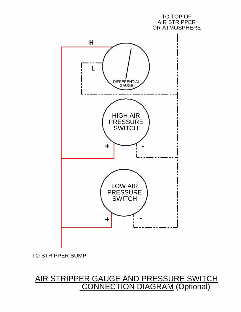
-
+
+
GAUGEDIFFERENTIAL
-
TO TOP OFAIR STRIPPER
OR ATMOSPHERE
TO STRIPPER SUMP
L
HIGH AIRPRESSURE
SWITCH
LOW AIRPRESSURE
SWITCH
H
AIR STRIPPER GAUGE AND PRESSURE SWITCH CONNECTION DIAGRAM (Optional)

H:\APP-SUP\SOURCES\Treatment\OandM\ezstackom.doc 9
QED TREATMENT EQUIPMENT WARRANTY
QED Environmental Systems Inc. (QED) warrants to the original purchaser of its products that, subject tothe limitations and conditions provided below, the products, materials and/or workmanship shall reasonablyconform to descriptions of the products and shall be free of defects in materials and workmanship. Anyfailure of the products to conform to this warranty will be remedied by QED in the manner provided herein.
QED warrants the equipment components of its manufacture for a period of one (1) year from date ofdelivery. Our sole obligation during this warranty will be to repair or replace (at our option) the defectivecomponents. We are not responsible for consequential damages. Labor costs are not included.
Purchaser's exclusive remedy for breach of said warranty shall be as follows: if, and only if, QED isnotified in writing within the applicable warranty period of the existence of any such defects in the saidproducts, and QED upon examination of any such defects, shall find the same to be within the term of andcovered by the warranty running from QED to Purchaser, QED will, at its option, as soon as reasonablypossible, replace or repair any such product, without charge to Purchaser. If QED for any reason, cannotrepair a product covered hereby within four (4) weeks after receipt of the original Purchaser's notification ofa warranty claim, then QED's sole responsibility shall be, at its option, either to replace the defectiveproduct with a comparable new unit at no charge to the Purchaser, or to refund the full purchase price. Inno event shall such allegedly defective products be returned to QED without its consent, and QED'sobligations of repair, replacement or refund are conditioned upon the Purchaser's return of the defectiveproduct to QED.
IN NO EVENT SHALL QED ENVIRONMENTAL SYSTEMS INC. BE LIABLE FORCONSEQUENTIAL OR INCIDENTAL DAMAGES FOR BREACH OF SAID WARRANTY.
The foregoing warranty does not apply to major subassemblies and other equipment, accessories, and otherparts manufactured by others, and such other parts, accessories, and equipment are subject only to thewarranties supplied by their respective manufacturers. In the event of failure of any such product oraccessory, QED will give assistance to Purchaser in obtaining from the respective manufacturer whateveradjustment is reasonable in light of the manufacturer's own warranty.
THE FOREGOING WARRANTY IS IN LIEU OF ALL OTHER WARRANTIES, EXPRESSED,IMPLIED OR STATUTORY (INCLUDING BUT NOT LIMITED TO THE WARRANTIES OFMERCHANT ABILITY AND FITNESS FOR A PARTICULAR PURPOSE), WHICH OTHERWARRANTIES ARE EXPRESSLY EXCLUDED HEREBY, and of any other obligations or liabilitieson the part of QED, and QED neither assumes nor authorizes any person to assume for it any otherobligation or liability in connection with said products, materials and/or workmanship.
It is understood and agreed that QED shall in no event be liable for incidental or consequential damagesresulting from its breach of any of the terms of this agreement, nor for special damages, nor for improperselection of any product described or referred to for a particular application.
This warranty will be void in the event of unauthorized disassembly of component assemblies. Defects inany equipment that result from abuse, operation in any manner outside the recommended procedures, useand applications other than for intended use, or exposure to chemical or physical environment beyond thedesignated limits of materials and construction will also void this warranty.
The equipment is warranted to perform as specified under the conditions specified here and within the airstripper model or QED will make the necessary changes at no cost to the owner. Some restrictions apply.Requirements for warranty consideration include, (but are not limited to):
1. Current operating conditions do not differ from the previously-modeled conditions.2. The system should be cleaned regularly to maintain system performance.
H:\APP-SUP\SOURCES\Treatment\OandM\ezstackom.doc 10
3. The equipment is installed, operated and maintained according to QED's instruction or non-QED manufactured subassembly manufacturer’s instructions.
4. Air stripper influent air is not “dirty” (does not contain VOC’s, etc.).5. No surfactants, oils, greases, or other immiscible phases are present in the water.6. Each influent contaminant does not exceed 25% of its maximum solubility under modeled
conditions.
QED shall be released from all obligations under all warranties if any product covered hereby is repaired ormodified by persons other than QED's service personnel unless such repair by others is made with theconsent of QED. If any product covered hereby is actually defective within the terms of this warranty,Purchaser must contact QED for determination of warranty coverage. If the return of a component isdetermined to be necessary, QED will authorize the return of the component, at owner's expense. If theproduct proves not to be defective within the terms of this warranty, then all costs and expenses inconnection with the processing of the Purchaser's claim and all costs for repair, parts and labor asauthorized by owner hereunder shall be borne by the Purchaser.
In the event of air stripper performance issues, QED may require customer to conduct a variety oftroubleshooting steps. These include, but are not limited to, modifying operational parameters, cleaning airstripper system, modifying (temporarily or permanently) process piping, and obtaining reasonable andnecessary influent/effluent samples. These steps are the responsibility of the customer and will beconducted by customer prior to consideration by QED for a site visit. These steps and the associated costsincurred are the responsibility of the customer, regardless of future action. Should customer request a sitevisit by QED or accept a site visit offer by a QED-trained technician, the visit and associated costs: a) willbe the responsibility of the customer at $500/day, plus travel, lodging, and meals, if the visit finds impropersampling, process piping installation, or equipment operation inconsistent with QED’s Operation andMaintenance Manual; or b) will be the responsibility of QED if the visit finds QED responsible for theperformance issue(s) raised.
The original Purchaser's sole responsibility in the instance of a warranty claim shall be to notify QED of thedefect, malfunction, or other manner in which the terms of this warranty are believed to be violated. Youmay secure performance of obligations hereunder by contacting the Customer Service Department of QEDand:
1. Identify the product or system involved by QED order number.2. Specify where, when, and from whom the product was purchased.3. Describe the nature of the defect or malfunction covered by this warranty.4. If applicable, send the malfunctioning component, after receiving a Return Authorization Code(RAC) Number by the QED Service Department, to:
QED Environmental Systems Inc.
Attn: R.A.C. No.(Return Authorization Code Number provided by QED Service Dept.)
rev 12/21/98
2355 Bishop Circle WestDexter, MI 48130
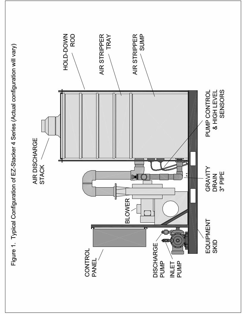
CBeears
CBeears
CBeears
CBeears
CBeears
CBeears
CBeears
CBeears
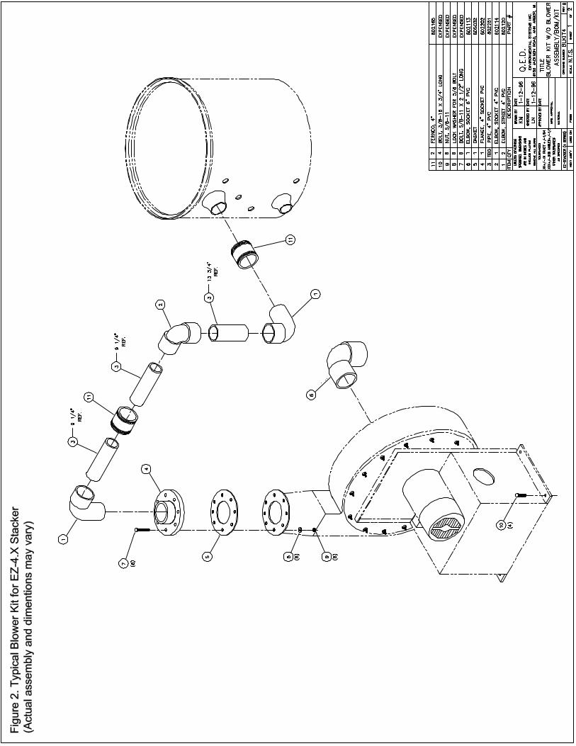
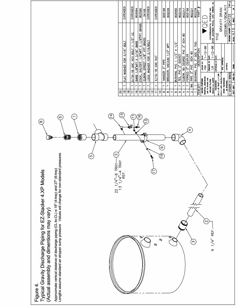
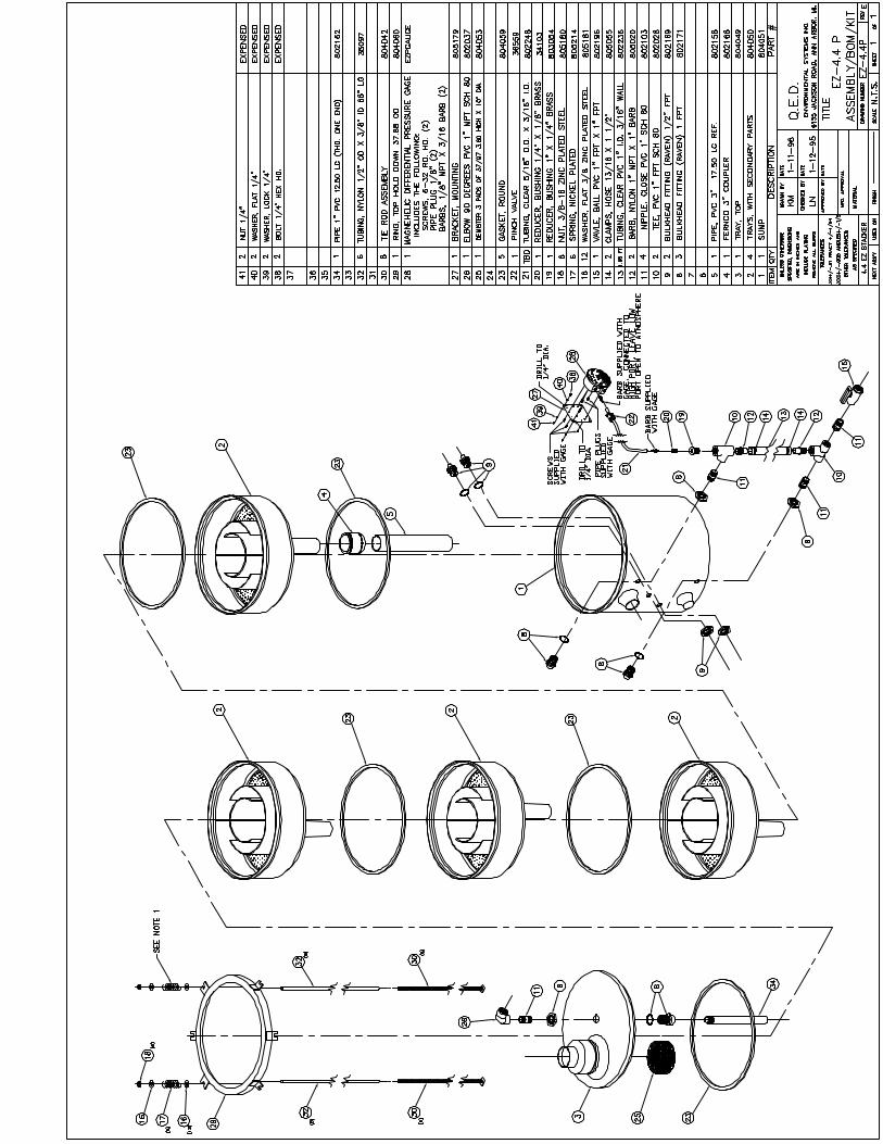
PRESSURE BLOWERSTYPE HP PRESSURE BLOWERS
A WORD ABOUT SAFETY
The above WARNING decal appears on all nyb fans. Air movingequipment involves electrical wiring, moving parts, sound, andair velocity or pressure which can create safety hazards if theequipment is not properly installed, operated and maintained.To minimize this danger, follow these instructions as well as theadditional instructions and warnings on the equipment itself.
All installers, operators and maintenance personnel shouldstudy AMCA Publication 410, "Recommended Safety Practicesfor Air Moving Devices", which is included as part of every ship-ment. Additional copies can be obtained by writing to New YorkBlower Company, 7660 Quincy St., Willowbrook, IL 60527.
ELECTRICAL DISCONNECTS
Every motor driven fan should have an independent disconnectswitch to isolate the unit from the electrical supply. It should benear the fan and must be capable of being locked by mainte-nance personnel while servicing the unit, in accordance withOSHA procedures.
MOVING PARTS
All moving parts must have guards to protect personnel. Safetyrequirements vary, so the number and type of guards needed tomeet company, local and OSHA standards must be determinedand specified by the user. Never start a fan without having allsafety guards installed. Check regularly for damaged or miss-ing guards and do not operate any fan with guards removed.Fans can also become dangerous because of potential “wind-milling”, even though all electrical power is disconnected.Always block the rotating assembly before working on any mov-ing parts.
SOUND
Some fans can generate sound that could be hazardous toexposed personnel. It is the responsibility of the systemdesigner and user to determine sound levels of the system, thedegree of personnel exposure, and to comply with applicablesafety requirements to protect personnel from excessive noise.Consult nyb for fan sound power level ratings.
AIR PRESSURE AND SUCTION
In addition to the normal dangers of rotating machinery, fanspresent another hazard from the suction created at the fan inlet.This suction can draw materials into the fan where they becomehigh velocity projectiles at the outlet. It can also be extremelydangerous to persons in close proximity to the inlet, as theforces involved can overcome the strength of most individuals.Inlets and outlets that are not ducted should be screened toprevent entry and discharge of solid objects.
ACCESS DOORS
The above DANGER decal is placed on all nyb cleanout doors.These doors, as well as access doors to the duct system,should never be opened while the fan is in operation. Seriousinjury could result from the effects of air pressure or suction.
Bolted doors must have the door nuts or fasteners securelytightened to prevent accidental or unauthorized opening.
RECEIVING AND INSPECTION
The fan and accessories should be inspected on receipt for anyshipping damage. Turn the wheel by hand to see that it rotatesfreely and does not bind. If dampers or shutters are provided,check these accessories for free operation of all moving parts.
F.O.B. factory shipping terms require that the receiver beresponsible for inspecting the equipment upon arrival. Notedamage or shortages on the Bill of Lading and file any claimsfor damage or loss in transit. nyb will assist the customer asmuch as possible; however, claims must be originated at thepoint of delivery.
THIS FAN HAS MOVING PARTS THAT CAN CAUSESERIOUS BODILY INJURY. BEFORE OPERATINGOR STARTING MAINTENANCE READ THEINSTALLATION AND MAINTENANCE INSTRUCTIONS AND THE AMCA SAFETYPRACTICES MANUAL PROVIDED WITH THIS FAN.
DURING OPERATION
1. KEEP BODY, HANDS, AND FOREIGN OBJECTSAWAY FROM THE INLET, THE OUTLET, AND THEOTHER MOVING PARTS OF THE FAN SUCH AS SHAFTS, BELTS, AND PULLEYS.
2. DO NOT OPERATE AT EXCESSIVE SPEEDS ORTEMPERATURES.
BEFORE STARTING MAINTENANCE WORK:
LOCK POWER SUPPLY IN OFF POSITION ANDIMMOBILIZE FAN WHEEL.
98-0250
DO NOT OPEN UNTIL THE POWERSUPPLY HAS BEEN LOCKED OFFAND THE SHAFT HAS STOPPEDROTATING.FAILURE TO DO THIS CAN RESULTIN SERIOUS BODILY INJURY.
98-0249
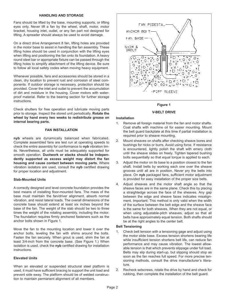
HANDLING AND STORAGE
Fans should be lifted by the base, mounting supports, or liftingeyes only. Never lift a fan by the wheel, shaft, motor, motorbracket, housing inlet, outlet, or any fan part not designed forlifting. A spreader should always be used to avoid damage.
On a direct drive Arrangement 8 fan, lifting holes are providedin the motor base to assist in handling the fan assembly. Theselifting holes should be used in conjunction with the lifting eyeswhen lifting and positioning the fan onto its foundation. A heavyround steel bar or appropriate fixture can be passed through thelifting holes to simplify attachment of the lifting device. Be sureto follow all local safety codes when moving heavy equipment.
Whenever possible, fans and accessories should be stored in aclean, dry location to prevent rust and corrosion of steel com-ponents. If outdoor storage is necessary, protection should beprovided. Cover the inlet and outlet to prevent the accumulationof dirt and moisture in the housing. Cover motors with water-proof material. Refer to the bearing section for further storageinstructions.
Check shutters for free operation and lubricate moving partsprior to storage. Inspect the stored unit periodically. Rotate thewheel by hand every two weeks to redistribute grease oninternal bearing parts.
FAN INSTALLATION
nyb wheels are dynamically balanced when fabricated.Complete assembled fans are test run at operating speeds tocheck the entire assembly for conformance to nyb vibration lim-its. Nevertheless, all units must be adequately supported forsmooth operation. Ductwork or stacks should be indepen-dently supported as excess weight may distort the fanhousing and cause contact between moving parts. Wherevibration isolators are used, consult the nyb certified drawingfor proper location and adjustment.
Slab-Mounted Units
A correctly designed and level concrete foundation provides thebest means of installing floor-mounted fans. The mass of thebase must maintain the fan/driver alignment, absorb normalvibration, and resist lateral loads. The overall dimensions of theconcrete base should extend at least six inches beyond thebase of the fan. The weight of the slab should be two to threetimes the weight of the rotating assembly, including the motor.The foundation requires firmly anchored fasteners such as theanchor bolts shown in Figure 1.
Move the fan to the mounting location and lower it over theanchor bolts, leveling the fan with shims around the bolts.Fasten the fan securely. When grout is used, shim the fan atleast 3/4-inch from the concrete base. (See Figure 1.) Whenisolation is used, check the nyb certified drawing for installationinstructions.
Elevated Units
When an elevated or suspended structural steel platform isused, it must have sufficient bracing to support the unit load andprevent side sway. The platform should be of welded construc-tion to maintain permanent alignment of all members.
Figure 1
V-BELT DRIVE
Installation
1. Remove all foreign material from the fan and motor shafts.Coat shafts with machine oil for easier mounting. Mountthe belt guard backplate at this time if partial installation isrequired prior to sheave mounting.
2. Mount sheaves on shafts after checking sheave bores andbushings for nicks or burrs. Avoid using force. If resistanceis encountered, lightly polish the shaft with emery clothuntil the sheave slides on freely. Tighten tapered bushingbolts sequentially so that equal torque is applied to each.
3. Adjust the motor on its base to a position closest to the fanshaft. Install belts by working each one over the sheavegrooves until all are in position. Never pry the belts intoplace. On nyb packaged fans, sufficient motor adjustmentis provided for easy installation of the proper size belts.
4. Adjust sheaves and the motor shaft angle so that thesheave faces are in the same plane. Check this by placinga straightedge across the face of the sheaves. Any gapbetween the edge and sheave faces indicates misalign-ment. Important: This method is only valid when the widthof the surface between the belt edge and the sheave faceis the same for both sheaves. When they are not equal, orwhen using adjustable-pitch sheaves, adjust so that allbelts have approximately equal tension. Both shafts shouldbe at the right angles to the center belt.
Belt Tensioning
1. Check belt tension with a tensioning gage and adjust usingthe motor slide base. Excess tension shortens bearing lifewhile insufficient tension shortens belt life, can reduce fanperformance and may cause vibration. The lowest allow-able tension is that which prevents slippage under full load.Belts may slip during start-up, but slipping should stop assoon as the fan reaches full speed. For more precise ten-sioning methods, consult the drive manufacturer’s litera-ture.
2. Recheck setscrews, rotate the drive by hand and check forrubbing, then complete the installation of the belt guard.
Page 2
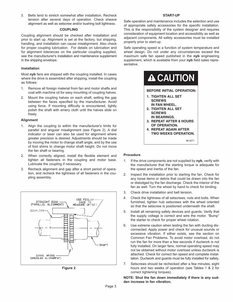
3. Belts tend to stretch somewhat after installation. Rechecktension after several days of operation. Check sheavealignment as well as setscrew and/or bushing bolt tightness.
COUPLING
Coupling alignment should be checked after installation andprior to start up. Alignment is set at the factory, but shipping,handling, and installation can cause misalignment. Also checkfor proper coupling lubrication. For details on lubrication andfor alignment tolerances on the particular coupling supplied,see the manufacturer's installation and maintenance supplementin the shipping envelope.
Installation
Most nyb fans are shipped with the coupling installed. In caseswhere the drive is assembled after shipping, install the couplingas follows:
1. Remove all foreign material from fan and motor shafts andcoat with machine oil for easy mounting of coupling halves.
2. Mount the coupling halves on each shaft, setting the gapbetween the faces specified by the manufacturer. Avoidusing force. If mounting difficulty is encountered, lightlypolish the shaft with emery cloth until the halves slide onfreely.
Alignment
1. Align the coupling to within the manufacturer's limits forparallel and angular misalignment (see Figure 2). A dialindicator or laser can also be used for alignment wheregreater precision is desired. Adjustments should be madeby moving the motor to change shaft angle, and by the useof foot shims to change motor shaft height. Do not movethe fan shaft or bearing.
2. When correctly aligned, install the flexible element andtighten all fasteners in the coupling and motor base.Lubricate the coupling if necessary.
3. Recheck alignment and gap after a short period of opera-tion, and recheck the tightness of all fasteners in the cou-pling assembly.
Figure 2
START-UP
Safe operation and maintenance includes the selection and useof appropriate safety accessories for the specific installation.This is the responsibility of the system designer and requiresconsideration of equipment location and accessibility as well asadjacent components. All safety accessories must be installedproperly prior to start-up.
Safe operating speed is a function of system temperature andwheel design. Do not under any circumstances exceed themaximum safe fan speed published in the nyb engineeringsupplement, which is available from your nyb field sales repre-sentative.
Procedure
1. If the drive components are not supplied by nyb, verify withthe manufacturer that the starting torque is adequate forthe speed and inertia of the fan.
2. Inspect the installation prior to starting the fan. Check forany loose items or debris that could be drawn into the fanor dislodged by the fan discharge. Check the interior of thefan as well. Turn the wheel by hand to check for binding.
3. Check drive installation and belt tension.
4. Check the tightness of all setscrews, nuts and bolts. Whenfurnished, tighten hub setscrews with the wheel orientedso that the setscrew is positioned underneath the shaft.
5. Install all remaining safety devices and guards. Verify thatthe supply voltage is correct and wire the motor. “Bump”the starter to check for proper wheel rotation.
6. Use extreme caution when testing the fan with ducting dis-connected. Apply power and check for unusual sounds orexcessive vibration. If either exists, see the section onCommon Fan Problems. To avoid motor overload, do notrun the fan for more than a few seconds if ductwork is notfully installed. On larger fans, normal operating speed maynot be obtained without motor overload unless ductwork isattached. Check for correct fan speed and complete instal-lation. Ductwork and guards must be fully installed for safety.
7. Setscrews should be rechecked after a few minutes, eighthours and two weeks of operation (see Tables 1 & 2 forcorrect tightening torques).
NOTE: Shut the fan down immediately if there is any sud-den increase in fan vibration.
Page 3
BEFORE INITIAL OPERATION:
1. TIGHTEN ALL SETSCREWSIN FAN WHEEL.
2. TIGHTEN ALL SETSCREWSIN BEARINGS.
3. REPEAT AFTER 8 HOURSOF OPERATION.
4. REPEAT AGAIN AFTER TWO WEEKS OPERATION.
98-0271
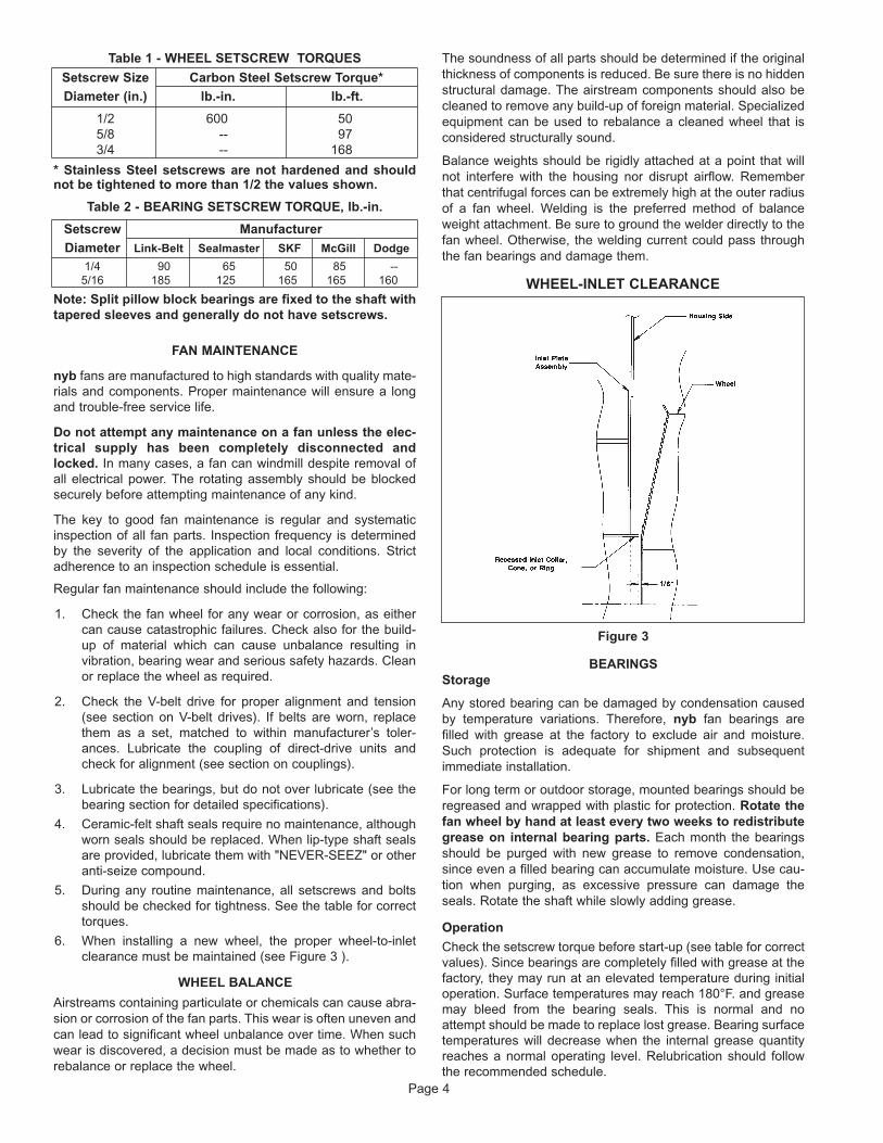
Table 1 - WHEEL SETSCREW TORQUES
Setscrew Size Carbon Steel Setscrew Torque*
Diameter (in.) lb.-in. lb.-ft.
1/2 600 505/8 -- 973/4 -- 168
* Stainless Steel setscrews are not hardened and shouldnot be tightened to more than 1/2 the values shown.
Table 2 - BEARING SETSCREW TORQUE, lb.-in.
Setscrew Manufacturer
Diameter Link-Belt Sealmaster SKF McGill Dodge
1/4 90 65 50 85 --5/16 185 125 165 165 160
Note: Split pillow block bearings are fixed to the shaft withtapered sleeves and generally do not have setscrews.
FAN MAINTENANCE
nyb fans are manufactured to high standards with quality mate-rials and components. Proper maintenance will ensure a longand trouble-free service life.
Do not attempt any maintenance on a fan unless the elec-trical supply has been completely disconnected andlocked. In many cases, a fan can windmill despite removal ofall electrical power. The rotating assembly should be blockedsecurely before attempting maintenance of any kind.
The key to good fan maintenance is regular and systematicinspection of all fan parts. Inspection frequency is determinedby the severity of the application and local conditions. Strictadherence to an inspection schedule is essential.
Regular fan maintenance should include the following:
1. Check the fan wheel for any wear or corrosion, as eithercan cause catastrophic failures. Check also for the build-up of material which can cause unbalance resulting invibration, bearing wear and serious safety hazards. Cleanor replace the wheel as required.
2. Check the V-belt drive for proper alignment and tension(see section on V-belt drives). If belts are worn, replacethem as a set, matched to within manufacturer’s toler-ances. Lubricate the coupling of direct-drive units andcheck for alignment (see section on couplings).
3. Lubricate the bearings, but do not over lubricate (see thebearing section for detailed specifications).
4. Ceramic-felt shaft seals require no maintenance, althoughworn seals should be replaced. When lip-type shaft sealsare provided, lubricate them with "NEVER-SEEZ" or otheranti-seize compound.
5. During any routine maintenance, all setscrews and boltsshould be checked for tightness. See the table for correcttorques.
6. When installing a new wheel, the proper wheel-to-inletclearance must be maintained (see Figure 3 ).
WHEEL BALANCE
Airstreams containing particulate or chemicals can cause abra-sion or corrosion of the fan parts. This wear is often uneven andcan lead to significant wheel unbalance over time. When suchwear is discovered, a decision must be made as to whether torebalance or replace the wheel.
The soundness of all parts should be determined if the originalthickness of components is reduced. Be sure there is no hiddenstructural damage. The airstream components should also becleaned to remove any build-up of foreign material. Specializedequipment can be used to rebalance a cleaned wheel that isconsidered structurally sound.
Balance weights should be rigidly attached at a point that willnot interfere with the housing nor disrupt airflow. Rememberthat centrifugal forces can be extremely high at the outer radiusof a fan wheel. Welding is the preferred method of balanceweight attachment. Be sure to ground the welder directly to thefan wheel. Otherwise, the welding current could pass throughthe fan bearings and damage them.
Figure 3
BEARINGSStorage
Any stored bearing can be damaged by condensation causedby temperature variations. Therefore, nyb fan bearings arefilled with grease at the factory to exclude air and moisture.Such protection is adequate for shipment and subsequentimmediate installation.
For long term or outdoor storage, mounted bearings should beregreased and wrapped with plastic for protection. Rotate thefan wheel by hand at least every two weeks to redistributegrease on internal bearing parts. Each month the bearingsshould be purged with new grease to remove condensation,since even a filled bearing can accumulate moisture. Use cau-tion when purging, as excessive pressure can damage theseals. Rotate the shaft while slowly adding grease.
Operation
Check the setscrew torque before start-up (see table for correctvalues). Since bearings are completely filled with grease at thefactory, they may run at an elevated temperature during initialoperation. Surface temperatures may reach 180°F. and greasemay bleed from the bearing seals. This is normal and noattempt should be made to replace lost grease. Bearing surfacetemperatures will decrease when the internal grease quantityreaches a normal operating level. Relubrication should followthe recommended schedule.
Page 4
WHEEL-INLET CLEARANCE
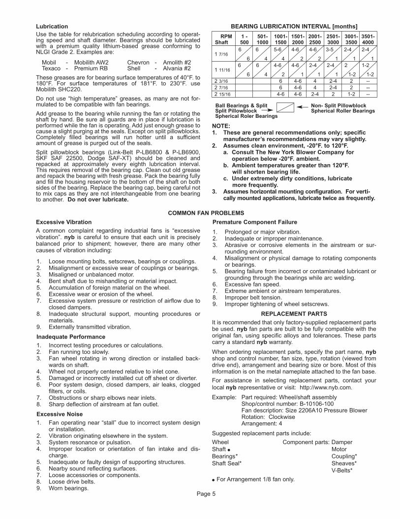
COMMON FAN PROBLEMS
Lubrication Use the table for relubrication scheduling according to operat-ing speed and shaft diameter. Bearings should be lubricatedwith a premium quality lithium-based grease conforming toNLGI Grade 2. Examples are:
Mobil - Mobilith AW2 Chevron - Amolith #2Texaco - Premium RB Shell - Alvania #2
These greases are for bearing surface temperatures of 40°F. to180°F. For surface temperatures of 181°F. to 230°F. useMobilith SHC220.
Do not use “high temperature” greases, as many are not for-mulated to be compatible with fan bearings.
Add grease to the bearing while running the fan or rotating theshaft by hand. Be sure all guards are in place if lubrication isperformed while the fan is operating. Add just enough grease tocause a slight purging at the seals. Except on split pillowblocks.Completely filled bearings will run hotter until a sufficientamount of grease is purged out of the seals.
Split pillowblock bearings (Link-Belt P-LB6800 & P-LB6900,SKF SAF 22500, Dodge SAF-XT) should be cleaned andrepacked at approximately every eighth lubrication interval.This requires removal of the bearing cap. Clean out old greaseand repack the bearing with fresh grease. Pack the bearing fullyand fill the housing reservoir to the bottom of the shaft on bothsides of the bearing. Replace the bearing cap, being careful notto mix caps as they are not interchangeable from one bearingto another. Do not over lubricate.
BEARING LUBRICATION INTERVAL [months]
RPM 1 - 501- 1001- 1501- 2001- 2501- 3001- 3501-Shaft 500 1000 1500 2000 2500 3000 3500 4000
6 6 5-6 4-6 4-6 3-5 2-4 2-41 7/16
6 4 4 2 2 1 1 16 6 4-6 4-6 2-4 2-4 2 1-2
1 11/166 4 2 1 1 1 1-2 1-2
2 3/16 6 4-6 4 2-4 2 --2 7/16 6 4-6 4 2-4 2 --2 15/16 4-6 4-6 2-4 2 1-2 --
Ball Bearings & Split Non- Split PillowblockSplit Pillowblock Spherical Roller BearingsSpherical Roler Bearings
NOTE:1. These are general recommendations only; specific
manufacturer’s recommendations may vary slightly.2. Assumes clean environment, -20°F. to 120°F.
a. Consult The New York Blower Company for operation below -20°F. ambient.
b. Ambient temperatures greater than 120°F.will shorten bearing life.
c. Under extremely dirty conditions, lubricatemore frequently.
3. Assumes horizontal mounting configuration. For verti-cally mounted applications, lubricate twice as frequently.
Excessive Vibration
A common complaint regarding industrial fans is “excessivevibration”. nyb is careful to ensure that each unit is preciselybalanced prior to shipment; however, there are many othercauses of vibration including:
1. Loose mounting bolts, setscrews, bearings or couplings.2. Misalignment or excessive wear of couplings or bearings.3. Misaligned or unbalanced motor.4. Bent shaft due to mishandling or material impact.5. Accumulation of foreign material on the wheel.6. Excessive wear or erosion of the wheel.7. Excessive system pressure or restriction of airflow due to
closed dampers.8. Inadequate structural support, mounting procedures or
materials.9. Externally transmitted vibration.
Inadequate Performance
1. Incorrect testing procedures or calculations.2. Fan running too slowly.3. Fan wheel rotating in wrong direction or installed back-
wards on shaft.4. Wheel not properly centered relative to inlet cone.5. Damaged or incorrectly installed cut off sheet or diverter.6. Poor system design, closed dampers, air leaks, clogged
filters, or coils.7. Obstructions or sharp elbows near inlets.8. Sharp deflection of airstream at fan outlet.
Excessive Noise
1. Fan operating near “stall” due to incorrect system designor installation.
2. Vibration originating elsewhere in the system.3. System resonance or pulsation.4. Improper location or orientation of fan intake and dis-
charge.5. Inadequate or faulty design of supporting structures.6. Nearby sound reflecting surfaces.7. Loose accessories or components.8. Loose drive belts.9. Worn bearings.
Premature Component Failure
1. Prolonged or major vibration.2. Inadequate or improper maintenance.3. Abrasive or corrosive elements in the airstream or sur-
rounding environment.4. Misalignment or physical damage to rotating components
or bearings.5. Bearing failure from incorrect or contaminated lubricant or
grounding through the bearings while arc welding.6. Excessive fan speed.7. Extreme ambient or airstream temperatures.8. Improper belt tension.9. Improper tightening of wheel setscrews.
REPLACEMENT PARTS
It is recommended that only factory-supplied replacement partsbe used. nyb fan parts are built to be fully compatible with theoriginal fan, using specific alloys and tolerances. These partscarry a standard nyb warranty.
When ordering replacement parts, specify the part name, nybshop and control number, fan size, type, rotation (viewed fromdrive end), arrangement and bearing size or bore. Most of thisinformation is on the metal nameplate attached to the fan base.
For assistance in selecting replacement parts, contact yourlocal nyb representative or visit: http://www.nyb.com.
Example: Part required: Wheel/shaft assemblyShop/control number: B-10106-100Fan description: Size 2206A10 Pressure BlowerRotation: ClockwiseArrangement: 4
Suggested replacement parts include:
Wheel Component parts: DamperShaft � MotorBearings* Coupling*Shaft Seal* Sheaves*
V-Belts*
� For Arrangement 1/8 fan only.
Page 5
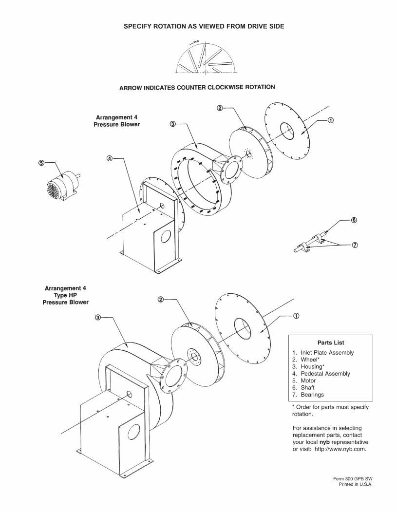
SPECIFY ROTATION AS VIEWED FROM DRIVE SIDE
Parts List
1. Inlet Plate Assembly2. Wheel*3. Housing*4. Pedestal Assembly5. Motor6. Shaft7. Bearings
* Order for parts must specifyrotation.
For assistance in selectingreplacement parts, contactyour local nyb representativeor visit: http://www.nyb.com.
Form 300 GPB SWPrinted in U.S.A.
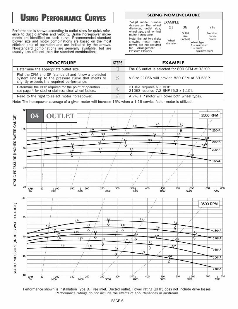
04 OUTLET
PAGE 6
USING PERFORMANCE CURVES
PROCEDURE EXAMPLEDetermine the appropriate outlet size. The 06 outlet is selected for 800 CFM at 32”SP.
Plot the CFM and SP [standard] and follow a projectedsystem line up to the pressure curve that meets orslightly exceeds the required performance.
A Size 2106A will provide 820 CFM at 33.6”SP.
Determine the BHP required for the point of operation . . .see page 4 for steel or stainless-steel wheel factors.
2106A requires 6.3 BHP.2106S requires 7.2 BHP [6.3 x 1.15].
Read to the right to select motor horsepower. A 71⁄2 HP motor will cover both wheel types.
STEPS
11
22
33
44
SIZING NOMENCLATURE
7-digit model numberdesignates the wheeldiameter, outlet size,wheel type, and nominalmotor horsepower.Note: the last two digitsshowing motor horse-power are not requiredfor Arrangement 1Pressure Blowers.
Performance is shown according to outlet sizes for quick refer-ence to duct diameter and velocity. Brake horsepower incre-ments are identified on each curve. Recommended standardblower size and motor combinations are based on the mostefficient area of operation and are indicated by the arrows.Nonstandard combinations are generally available, but areusually less efficient than the standard combinations.
EXAMPLE21
Wheeldiameter
06
Outletsize
[inches]
A
Wheel typeA = aluminumS = steel/
stainless steel
71⁄2
Nominalhorse-power
Note: The horsepower coverage of a given motor will increase 15% when a 1.15 service factor motor is utilized.
Performance shown is installation Type B: Free inlet, Ducted outlet. Power rating (BHP) does not include drive losses.Performance ratings do not include the effects of appurtenances in airstream.
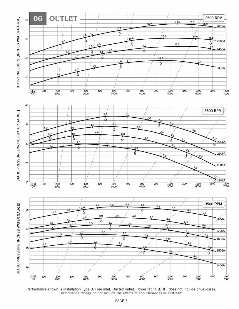
06 OUTLET
PAGE 7
Performance shown is installation Type B: Free inlet, Ducted outlet. Power rating (BHP) does not include drive losses.Performance ratings do not include the effects of appurtenances in airstream.
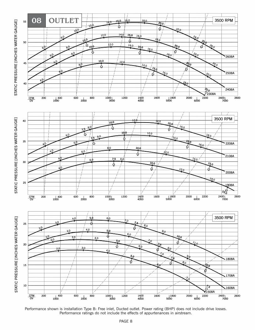
08 OUTLET
PAGE 8
Performance shown is installation Type B: Free inlet, Ducted outlet. Power rating (BHP) does not include drive losses.Performance ratings do not include the effects of appurtenances in airstream.
CBeears
CBeears
CBeears
CBeears
CBeears
CBeears
CBeears
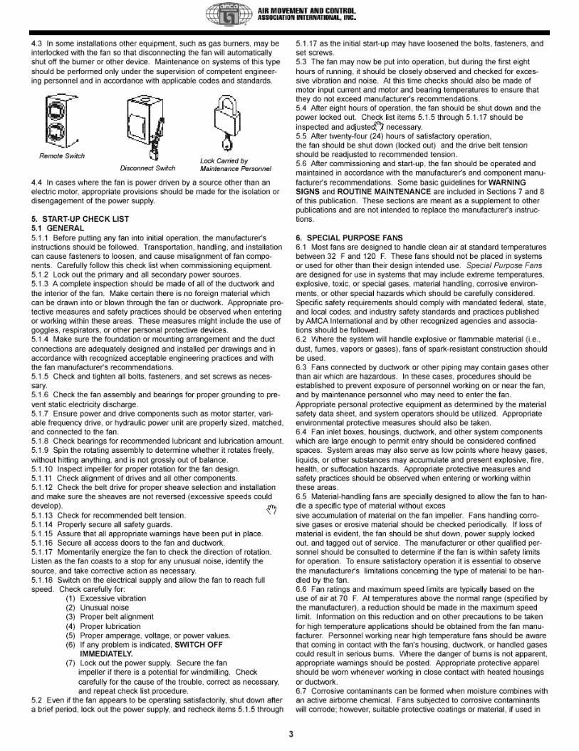
CBeears
CBeears
CBeears

1
Model NPE/NPE-FDESCRIPTION & SPECIFICATIONS:The Models NPE (close-coupled) and NPE-F (frame-mounted) areend suction, single stage centrifugal pumps for general liquidtransfer service, booster applications, etc. Liquid-end construction isall AISI Type 316 stainless steel, stamped and welded. Impellers arefully enclosed, non-trimable to intermediate diameters. Casings arefitted with a diffuser for efficiency and for negligible radial shaftloading.
Close-coupled units have NEMA 48J or 56J motors with C-facemounting and threaded shaft extension. Frame-mounted units canbe coupled to motors through a spacer coupling, or belt driven.
1. Important:1.1. Inspect unit for damage. Report any damage to carrier/dealerimmediately.1.2. Electrical supply must be a separate branch circuit with fuses orcircuit breakers, wire sizes, etc., per National and Local electricalcodes. Install an all-leg disconnect switch near pump.
CAUTIONAlways disconnect electrical power when handling pump orcontrols.1.3. Motors must be wired for proper voltage. Motor wiringdiagram is on motor nameplate. Wire size must limit maximumvoltage drop to 10% of nameplate voltage at motor terminals, ormotor life and pump performance will be lowered.1.4. Always use horsepower-rated switches, contactor and starters.1.5. Motor Protection
1.5.1. Single-phase: Thermal protection for single-phase unitsis sometimes built in (check nameplate). If no built-inprotection is provided, use a contactor with a proper overload.Fusing is permissible.1.5.2. Three-phase: Provide three-leg protection with properlysized magnetic starter and thermal overloads.
1.6. Maximum Operating Limits:Liquid Temperature: 212º F (100º C) with standard seal.
250º F (120º C) with optional hightemp seal.
Pressure: 75 PSI.Starts Per Hour: 20, evenly distributed.1.7. Regular inspection and maintenance will increase service life.Base schedule on operating time. Refer to Section 8.
2. Installation:2.1. General
2.1.1. Locate pump as near liquid source as possible (belowlevel of liquid for automatic operation).2.1.2. Protect from freezing or flooding.2.1.3. Allow adequate space for servicing and ventilation.2.1.4. All piping must be supported independently of thepump, and must “line-up” naturally.
CAUTIONNever draw piping into place by forcing the pump suction anddischarge connections.
2.1.5. Avoid unnecessary fittings. Select sizes to keep frictionlosses to a minimum.
2.2. Close-Coupled Units:2.2.1. Units may be installed horizontally, inclined or vertically.
CAUTIONDo not install with motor below pump. Any leakage orcondensation will affect the motor.
2.2.2. Foundation must be flat and substantial to eliminatestrain when tightening bolts. Use rubber mounts to minimizenoise and vibration.2.2.3. Tighten motor hold-down bolts before connectingpiping to pump.
2.3. Frame-Mounted Units:2.3.1. It is recommended that the bedplate be grouted to afoundation with solid footing. Refer to Fig.1.
Installation, Operation andMaintenance Instructions
IM013R06
Finished grouting(1/4") Grout hole Base
Leveling wedges or shims—left in place
Top of foundation—clean and wet down
Sleeve
Washer
Lug
(1/2 to 3/4")Allowancefor leveling
Woodframe
Figure 1
Grout
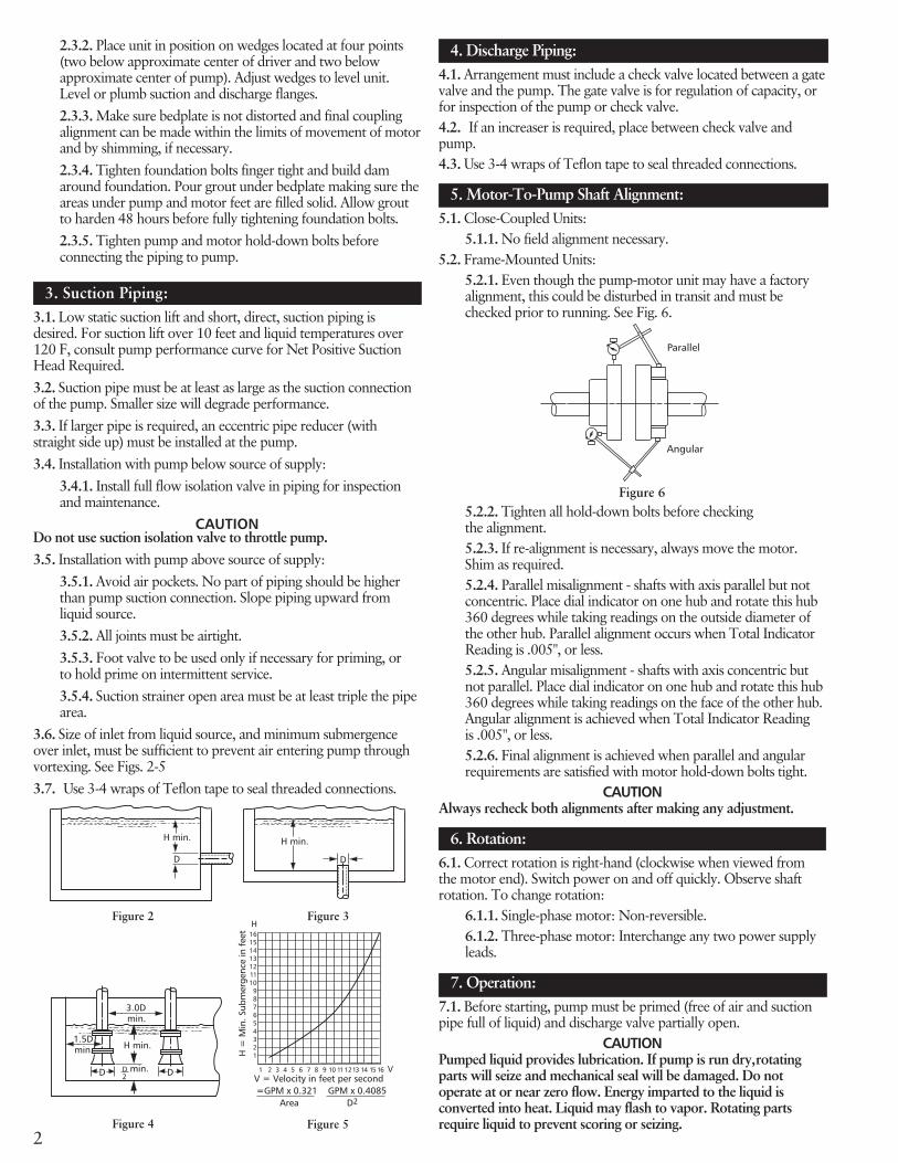
2
2.3.2. Place unit in position on wedges located at four points(two below approximate center of driver and two belowapproximate center of pump). Adjust wedges to level unit.Level or plumb suction and discharge flanges.2.3.3. Make sure bedplate is not distorted and final couplingalignment can be made within the limits of movement of motorand by shimming, if necessary.2.3.4. Tighten foundation bolts finger tight and build damaround foundation. Pour grout under bedplate making sure theareas under pump and motor feet are filled solid. Allow groutto harden 48 hours before fully tightening foundation bolts.2.3.5. Tighten pump and motor hold-down bolts beforeconnecting the piping to pump.
3. Suction Piping:3.1. Low static suction lift and short, direct, suction piping isdesired. For suction lift over 10 feet and liquid temperatures over120 F, consult pump performance curve for Net Positive SuctionHead Required.3.2. Suction pipe must be at least as large as the suction connectionof the pump. Smaller size will degrade performance.3.3. If larger pipe is required, an eccentric pipe reducer (withstraight side up) must be installed at the pump.3.4. Installation with pump below source of supply:
3.4.1. Install full flow isolation valve in piping for inspectionand maintenance.
CAUTIONDo not use suction isolation valve to throttle pump.3.5. Installation with pump above source of supply:
3.5.1. Avoid air pockets. No part of piping should be higherthan pump suction connection. Slope piping upward fromliquid source.3.5.2. All joints must be airtight.3.5.3. Foot valve to be used only if necessary for priming, orto hold prime on intermittent service.3.5.4. Suction strainer open area must be at least triple the pipearea.
3.6. Size of inlet from liquid source, and minimum submergenceover inlet, must be sufficient to prevent air entering pump throughvortexing. See Figs. 2-53.7. Use 3-4 wraps of Teflon tape to seal threaded connections.
4. Discharge Piping:4.1. Arrangement must include a check valve located between a gatevalve and the pump. The gate valve is for regulation of capacity, orfor inspection of the pump or check valve.4.2. If an increaser is required, place between check valve andpump.4.3. Use 3-4 wraps of Teflon tape to seal threaded connections.
5. Motor-To-Pump Shaft Alignment:5.1. Close-Coupled Units:
5.1.1. No field alignment necessary.5.2. Frame-Mounted Units:
5.2.1. Even though the pump-motor unit may have a factoryalignment, this could be disturbed in transit and must bechecked prior to running. See Fig. 6.
Figure 2
Figure 5
16151413121110987654321
H
1 2 3 4 5 6 7 8 9 10 11 12 13 14 15 16 V
H =
Min
. Sub
mer
genc
e in
fee
t
V = Velocity in feet per second =GPM x 0.321 GPM x 0.4085
Area D2
Figure 4
1.5Dmin.
3.0Dmin.
D D
H min.
D min.2
------------------D
H min.
Figure 3
D
H min.
------------------
Parallel
Figure 6
Angular
5.2.2. Tighten all hold-down bolts before checkingthe alignment.5.2.3. If re-alignment is necessary, always move the motor.Shim as required.5.2.4. Parallel misalignment - shafts with axis parallel but notconcentric. Place dial indicator on one hub and rotate this hub360 degrees while taking readings on the outside diameter ofthe other hub. Parallel alignment occurs when Total IndicatorReading is .005", or less.5.2.5. Angular misalignment - shafts with axis concentric butnot parallel. Place dial indicator on one hub and rotate this hub360 degrees while taking readings on the face of the other hub.Angular alignment is achieved when Total Indicator Readingis .005", or less.5.2.6. Final alignment is achieved when parallel and angularrequirements are satisfied with motor hold-down bolts tight.
CAUTIONAlways recheck both alignments after making any adjustment.
6. Rotation:6.1. Correct rotation is right-hand (clockwise when viewed fromthe motor end). Switch power on and off quickly. Observe shaftrotation. To change rotation:
6.1.1. Single-phase motor: Non-reversible.6.1.2. Three-phase motor: Interchange any two power supplyleads.
7. Operation:7.1. Before starting, pump must be primed (free of air and suctionpipe full of liquid) and discharge valve partially open.
CAUTIONPumped liquid provides lubrication. If pump is run dry,rotatingparts will seize and mechanical seal will be damaged. Do notoperate at or near zero flow. Energy imparted to the liquid isconverted into heat. Liquid may flash to vapor. Rotating partsrequire liquid to prevent scoring or seizing.
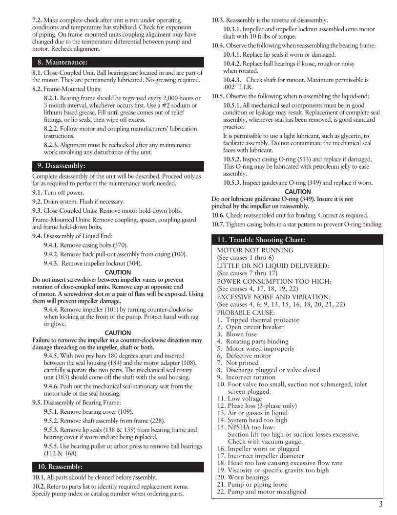
3
7.2. Make complete check after unit is run under operatingconditions and temperature has stabilized. Check for expansionof piping. On frame-mounted units coupling alignment may havechanged due to the temperature differential between pump andmotor. Recheck alignment.
8. Maintenance:8.1. Close-Coupled Unit. Ball bearings are located in and are part ofthe motor. They are permanently lubricated. No greasing required.8.2. Frame-Mounted Units:
8.2.1. Bearing frame should be regreased every 2,000 hours or3 month interval, whichever occurs first. Use a #2 sodium orlithium based grease. Fill until grease comes out of relieffittings, or lip seals, then wipe off excess.8.2.2. Follow motor and coupling manufacturers’ lubricationinstructions.8.2.3. Alignment must be rechecked after any maintenancework involving any disturbance of the unit.
9. Disassembly:Complete disassembly of the unit will be described. Proceed onlyasfar as required to perform the maintenance work needed.9.1. Turn off power.9.2. Drain system. Flush if necessary.9.3. Close-Coupled Units: Remove motor hold-down bolts.Frame-Mounted Units: Remove coupling, spacer, coupling guardand frame hold-down bolts.9.4. Disassembly of Liquid End:
9.4.1. Remove casing bolts (370).9.4.2. Remove back pull-out assembly from casing (100).9.4.3. Remove impeller locknut (304).
CAUTIONDo not insert screwdriver between impeller vanes to preventrotation of close-coupled units. Remove cap at opposite endof motor. A screwdriver slot or a pair of flats will be exposed. Usingthem will prevent impeller damage.
9.4.4. Remove impeller (101) by turning counter-clockwisewhen looking at the front of the pump. Protect hand with ragor glove.
CAUTIONFailure to remove the impeller in a counter-clockwise direction maydamage threading on the impeller, shaft or both.
9.4.5. With two pry bars 180 degrees apart and insertedbetween the seal housing (184) and the motor adapter (108),carefully separate the two parts. The mechanical seal rotaryunit (383) should come off the shaft with the seal housing.9.4.6. Push out the mechanical seal stationary seat from themotor side of the seal housing.
9.5. Disassembly of Bearing Frame:9.5.1. Remove bearing cover (109).9.5.2. Remove shaft assembly from frame (228).9.5.3. Remove lip seals (138 & 139) from bearing frame andbearing cover if worn and are being replaced.9.5.5. Use bearing puller or arbor press to remove ball bearings(112 & 168).
10. Reassembly:10.1. All parts should be cleaned before assembly.10.2. Refer to parts list to identify required replacement items.Specify pump index or catalog number when ordering parts.
10.3. Reassembly is the reverse of disassembly.10.3.1. Impeller and impeller locknut assembled onto motorshaft with 10 ft-lbs of torque.
10.4. Observe the following when reassembling thebearing frame:10.4.1. Replace lip seals if worn or damaged.10.4.2. Replace ball bearings if loose, rough or noisywhen rotated.10.4.3. Check shaft for runout. Maximum permissible is.002" T.I.R.
10.5. Observe the following when reassembling the liquid-end:10.5.1. All mechanical seal components must be in goodcondition or leakage may result. Replacement of complete sealassembly, whenever seal has been removed, is good standardpractice.It is permissible to use a light lubricant, such as glycerin, tofacilitate assembly. Do not contaminate the mechanical sealfaces with lubricant.10.5.2. Inspect casing O-ring (513) and replace if damaged.This O-ring may be lubricated with petroleum jelly to easeassembly.10.5.3. Inspect guidevane O-ring (349) and replace if worn.
CAUTIONDo not lubricate guidevane O-ring (349). Insure it is notpinched by the impeller on reassembly.10.6. Check reassembled unit for binding. Correct as required.10.7. Tighten casing bolts in a star pattern to prevent O-ring binding.
11. Trouble Shooting Chart:MOTOR NOT RUNNING(See causes 1 thru 6)LITTLE OR NO LIQUID DELIVERED:(See causes 7 thru 17)POWER CONSUMPTION TOO HIGH:(See causes 4, 17, 18, 19, 22)EXCESSIVE NOISE AND VIBRATION:(See causes 4, 6, 9, 13, 15, 16, 18, 20, 21, 22)PROBABLE CAUSE:1. Tripped thermal protector2. Open circuit breaker3. Blown fuse4. Rotating parts binding5. Motor wired improperly6. Defective motor7. Not primed8. Discharge plugged or valve closed9. Incorrect rotation10. Foot valve too small, suction not submerged, inlet
screen plugged.11. Low voltage12. Phase loss (3-phase only)13. Air or gasses in liquid14. System head too high15. NPSHA too low:
Suction lift too high or suction losses excessive.Check with vacuum gauge.
16. Impeller worn or plugged17. Incorrect impeller diameter18. Head too low causing excessive flow rate19. Viscosity or specific gravity too high20. Worn bearings21. Pump or piping loose22. Pump and motor misaligned
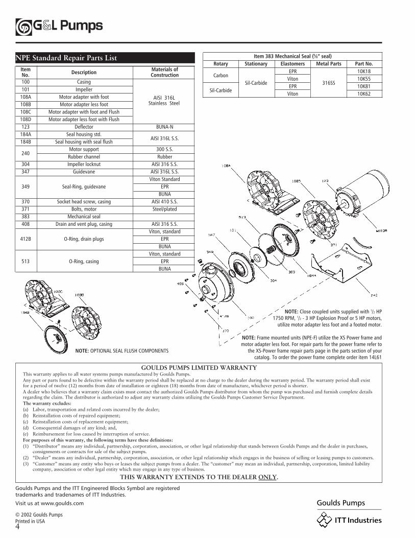
4
Item 383 Mechanical Seal (5⁄8” seal)Rotary Stationary Elastomers Metal Parts Part No.
CarbonEPR 10K18
Sil-CarbideViton
316SS10K55
Sil-CarbideEPR 10K81
Viton 10K62
NPE Standard Repair Parts ListItem Materials ofNo. Description Construction100 Casing101 Impeller
108A Motor adapter with foot108B Motor adapter less foot108C Motor adapter with foot and Flush108D Motor adapter less foot with Flush123 Deflector BUNA-N
184A Seal housing std.AISI 316L S.S.
184B Seal housing with seal flush
240Motor support 300 S.S.Rubber channel Rubber
304 Impeller locknut AISI 316 S.S.347 Guidevane AISI 316L S.S.
Viton Standard349 Seal-Ring, guidevane EPR
BUNA370 Socket head screw, casing AISI 410 S.S.371 Bolts, motor Steel/plated383 Mechanical seal408 Drain and vent plug, casing AISI 316 S.S.
Viton, standard412B O-Ring, drain plugs EPR
BUNAViton, standard
513 O-Ring, casing EPRBUNA
AISI 316LStainless Steel
GOULDS PUMPS LIMITED WARRANTYThis warranty applies to all water systems pumps manufactured by Goulds Pumps.Any part or parts found to be defective within the warranty period shall be replaced at no charge to the dealer during the warranty period. The warranty period shall existfor a period of twelve (12) months from date of installation or eighteen (18) months from date of manufacture, whichever period is shorter.A dealer who believes that a warranty claim exists must contact the authorized Goulds Pumps distributor from whom the pump was purchased and furnish complete detailsregarding the claim. The distributor is authorized to adjust any warranty claims utilizing the Goulds Pumps Customer Service Department.The warranty excludes:(a) Labor, transportation and related costs incurred by the dealer;(b) Reinstallation costs of repaired equipment;(c) Reinstallation costs of replacement equipment;(d) Consequential damages of any kind; and,(e) Reimbursement for loss caused by interruption of service.For purposes of this warranty, the following terms have these definitions:(1) “Distributor” means any individual, partnership, corporation, association, or other legal relationship that stands between Goulds Pumps and the dealer in purchases,
consignments or contracts for sale of the subject pumps.(2) “Dealer” means any individual, partnership, corporation, association, or other legal relationship which engages in the business of selling or leasing pumps to customers.(3) “Customer” means any entity who buys or leases the subject pumps from a dealer. The “customer” may mean an individual, partnership, corporation, limited liability
company, association or other legal entity which may engage in any type of business.
THIS WARRANTY EXTENDS TO THE DEALER ONLY.
NOTE: OPTIONAL SEAL FLUSH COMPONENTS
NOTE: Close coupled units supplied with 1/2 HP1750 RPM, 1/2 - 3 HP Explosion Proof or 5 HP motors,
utilize motor adapter less foot and a footed motor.
NOTE: Frame mounted units (NPE-F) utilize the XS Power frame andmotor adapter less foot. For repair parts for the power frame refer to
the XS-Power frame repair parts page in the parts section of yourcatalog. To order the power frame complete order item 14L61
Goulds Pumps and the ITT Engineered Blocks Symbol are registeredtrademarks and tradenames of ITT Industries.
Visit us at www.goulds.com
© 2002 Goulds PumpsPrinted in USA
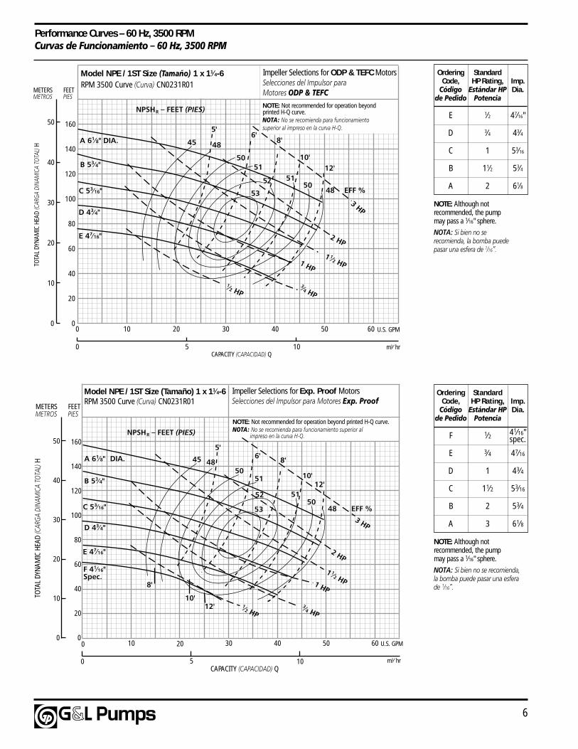
6
Performance Curves – 60 Hz, 3500 RPMCurvas de Funcionamiento – 60 Hz, 3500 RPM
Ordering StandardCode, HP Rating, Imp.
Código Estándar HP Dia.de Pedido Potencia
E 1⁄2 47⁄16"
D 3⁄4 43⁄4
C 1 53⁄16
B 11⁄2 53⁄4
A 2 61⁄8
m3⁄ hr
0
20
40
60
80
100
120
140
0
10
20
30
40
50
6050403020100
1050
160
Model NPE / 1ST Size (Tamaño) 1 x 11⁄4-6RPM 3500 Curve (Curva) CN0231R01
NOTE: Not recommended for operation beyond printed H-Q curve.NOTA: No se recomienda para funcionamiento superior al impreso en la curva H-Q.
Impeller Selections for Exp. Proof MotorsSelecciones del Impulsor para Motores Exp. Proof
45 4850
5048
51
5152
53
1⁄2 HP
10'
8'6'
5'
12'
EFF %
3⁄4 HP
1 1⁄2 HP1 HP
2 HP
8'
10'12'
U.S. GPM
3 HP
B 53⁄4"
C 53⁄16"
D 43⁄4"
E 47⁄16"
F 41⁄16"Spec.
A 61⁄8" DIA.
METERSMETROS
FEETPIES
TOTA
L DY
NAM
IC H
EAD
(CAR
GA D
INAM
ICA
TOTA
L) H
CAPACITY (CAPACIDAD) Q
NPSHR – FEET (PIES)
m3⁄ hr
Model NPE / 1ST Size (Tamaño) 1 x 11⁄4-6RPM 3500 Curve (Curva) CN0231R01
0
20
40
60
80
100
120
140
0
10
20
30
40
50
METERSMETROS
FEETPIES
TOTA
L DY
NAM
IC H
EAD
(CAR
GA D
INAM
ICA
TOTA
L) H
6050403020100
1050CAPACITY (CAPACIDAD) Q
U.S. GPM
45 48
50
5048
515152
53
1⁄2 HP
10'
8'6'
5'
12'
EFF %
NPSHR – FEET (PIES)
160
3⁄4 HP
1 1⁄2 HP1 HP
2 HP
3 HP
A 61⁄8" DIA.
B 53⁄4"
C 53⁄16"
D 43⁄4"
E 47⁄16"
NOTE: Not recommended for operation beyondprinted H-Q curve.NOTA: No se recomienda para funcionamientosuperior al impreso en la curva H-Q.
Impeller Selections for ODP & TEFC MotorsSelecciones del Impulsor paraMotores ODP & TEFC
Ordering StandardCode, HP Rating, Imp.
Código Estándar HP Dia.de Pedido Potencia
F 1⁄2
E 3⁄4 47⁄16
D 1 43⁄4
C 11⁄2 53⁄16
B 2 53⁄4
A 3 61⁄8
41⁄16"spec.
NOTE: Although notrecommended, the pumpmay pass a 1⁄16" sphere.
NOTA: Si bien no se recomienda,la bomba puede pasar una esferade 1⁄16”.
NOTE: Although notrecommended, the pumpmay pass a 1⁄16" sphere.
NOTA: Si bien no serecomienda, la bomba puedepasar una esfera de 1⁄16”.
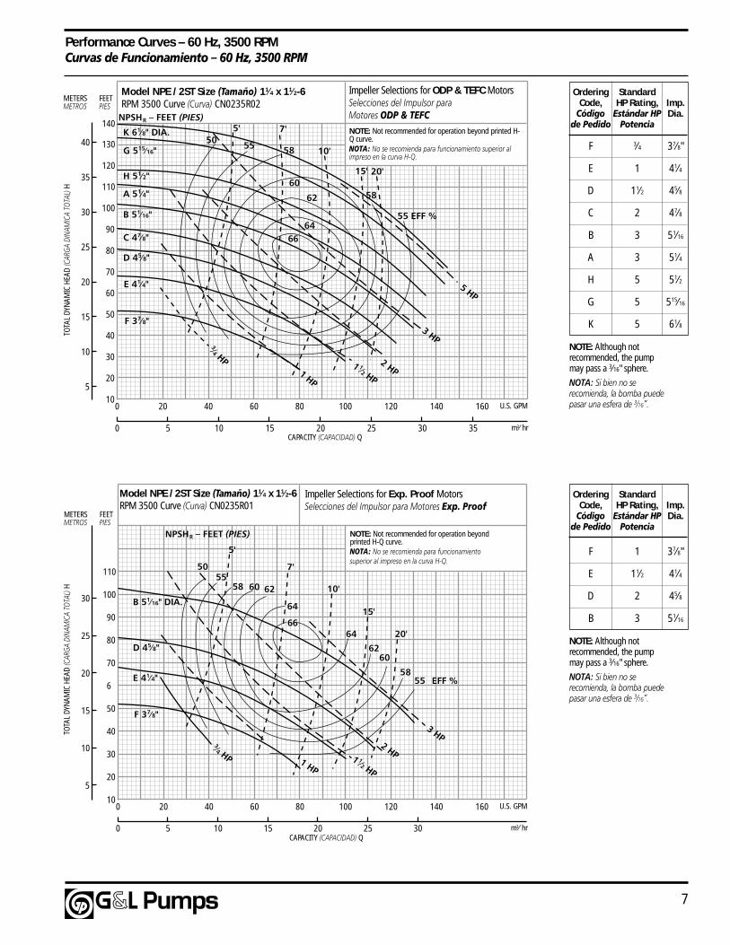
7
Performance Curves – 60 Hz, 3500 RPMCurvas de Funcionamiento – 60 Hz, 3500 RPM
m3⁄ hr
10
20
40
50
6
70
80
90
110
5
10
20
30
160140120100806040200
151050
U.S. GPM
100
20 25 30
30
25
15
3 HP2 HP1 1⁄2 HP
1 HP
3⁄4 HP
5'
7'
10'
15'
20'
5055
58 60 62
64
6664
6260
58EFF %55
Model NPE / 2ST Size (Tamaño) 11⁄4 x 11⁄2-6RPM 3500 Curve (Curva) CN0235R01
B 51⁄16" DIA.
D 45⁄8"
E 41⁄4"
F 37⁄8"
METERSMETROS
FEETPIES
TOTA
L DY
NAM
IC H
EAD
(CAR
GA D
INAM
ICA
TOTA
L) H
CAPACITY (CAPACIDAD) Q
NPSHR – FEET (PIES) NOTE: Not recommended for operation beyondprinted H-Q curve.NOTA: No se recomienda para funcionamientosuperior al impreso en la curva H-Q.
Impeller Selections for Exp. Proof MotorsSelecciones del Impulsor para Motores Exp. Proof
m3⁄ hr
10
20
40
50
60
70
80
90
110
5
10
20
30
160140120100806040200
151050
U.S. GPM
100
20 25 30 35
30
25
15
40
Model NPE / 2ST Size (Tamaño) 11⁄4 x 11⁄2-6RPM 3500 Curve (Curva) CN0235R02
120
130
35
METERSMETROS
FEETPIES
TOTA
L DY
NAM
IC H
EAD
(CAR
GA D
INAM
ICA
TOTA
L) H
CAPACITY (CAPACIDAD) Q
NPSHR – FEET (PIES)NOTE: Not recommended for operation beyond printed H-Q curve.NOTA: No se recomienda para funcionamiento superior alimpreso en la curva H-Q.
Impeller Selections for ODP & TEFC MotorsSelecciones del Impulsor paraMotores ODP & TEFC
140
C 47⁄8"
D 45⁄8"
E 41⁄4"
F 37⁄8"
A 51⁄4"
B 51⁄16"
H 51⁄2"
G 515⁄16"
K 61⁄8" DIA.
58
60
6664
62 58
55
50 55
EFF %
10'
15'
7'5'
20'
3⁄4 HP 1 1⁄2 HP1 HP
2 HP
5 HP
3 HP
Ordering StandardCode, HP Rating, Imp.
Código Estándar HP Dia.de Pedido Potencia
F 1 37⁄8"
E 11⁄2 41⁄4
D 2 45⁄8
B 3 51⁄16
Ordering StandardCode, HP Rating, Imp.
Código Estándar HP Dia.de Pedido Potencia
F 3⁄4 37⁄8"
E 1 41⁄4
D 11⁄2 45⁄8
C 2 47⁄8
B 3 51⁄16
A 3 51⁄4
H 5 51⁄2
G 5 515⁄16
K 5 61⁄8
NOTE: Although notrecommended, the pumpmay pass a 3⁄16" sphere.
NOTA: Si bien no serecomienda, la bomba puedepasar una esfera de 3⁄16”.
NOTE: Although notrecommended, the pumpmay pass a 3⁄16" sphere.
NOTA: Si bien no serecomienda, la bomba puedepasar una esfera de 3⁄16”.
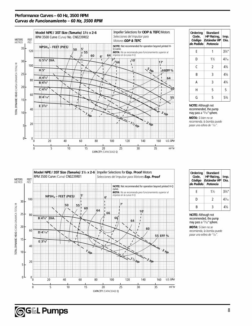
8
Performance Curves – 60 Hz, 3500 RPMCurvas de Funcionamiento – 60 Hz, 3500 RPM
m3⁄ hr
0
20
40
60
80
100
5
10
20
30
160140120100806040200
151050
U.S. GPM
20 25 30 35
25
15
0
10'
7'
6'5'
50 5560
6466
6664
60
3 HP
EFF %55
2 HP1 1⁄2 HP
1 HP
Model NPE / 3ST Size (Tamaño) 11/2 x 2-6RPM 3500 Curve (Curva) CN0239R01
B 45⁄8" DIA.
D 41⁄16"
E 35⁄8"
METERSMETROS
FEETPIES
TOTA
L DY
NAM
IC H
EAD
(CAR
GA D
INAM
ICA
TOTA
L) H
CAPACITY (CAPACIDAD) Q
NPSHR – FEET (PIES)
NOTE: Not recommended for operation beyond printed H-Qcurve.NOTA: No se recomienda para funcionamiento superior alimpreso en la curva H-Q.
Impeller Selections for Exp. Proof MotorsSelecciones del Impulsor para Motores Exp. Proof
m3⁄ hr
Model NPE / 3ST Size (Tamaño) 11⁄2 x 2-6RPM 3500 Curve (Curva) No. CN0239RO2
0
20
40
60
80
100
5
10
20
35
160140120100806040200
151050
U.S. GPM
20 25 30 35
25
15
0
120
30
METERSMETROS
FEETPIES
TOTA
L DY
NAM
IC H
EAD
(CAR
GA D
INAM
ICA
TOTA
L) H
CAPACITY (CAPACIDAD) Q
NPSHR – FEET (PIES) NOTE: Not recommended for operation beyond printed H-Q curve.NOTA: No se recomienda para funcionamiento superior alimpreso en la curva H-Q.
Impeller Selections for ODP & TEFC MotorsSelecciones del Impulsor paraMotores ODP & TEFC
66
66
64
60
55
646055
50
EFF %
1 HP
1 1⁄2 HP2 HP
3 HP
5 HP
5'
6'7' 10' 17'G 53⁄8" DIA.
A 43⁄4"
C 43⁄8"
D 41⁄16"
E 35⁄8"
B 45⁄8"
H 5"
Ordering StandardCode, HP Rating, Imp.
Código Estándar HP Dia.de Pedido Potencia
E 1 35⁄8"
D 11⁄2 41⁄16
C 2 43⁄8
B 3 45⁄8
A 3 43⁄4
H 5 5
G 5 53⁄8
Ordering StandardCode, HP Rating, Imp.
Código Estándar HP Dia.de Pedido Potencia
E 11⁄2 35⁄8"
D 2 41⁄16
B 3 45⁄8
NOTE: Although notrecommended, the pumpmay pass a 11⁄32" sphere.
NOTA: Si bien no serecomienda, la bomba puedepasar una esfera de 11⁄32”.
NOTE: Although notrecommended, the pumpmay pass a 11⁄32" sphere.
NOTA: Si bien no serecomienda, la bomba puedepasar una esfera de 11⁄32”.

Repair Parts
NPE/NPE-FMODEL
© 2003 G&LEffective February, 2003RNPE
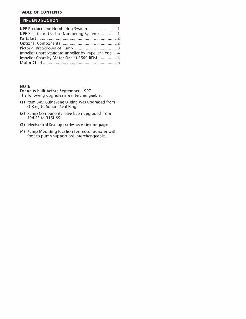
TABLE OF CONTENTS
NPE END SUCTION
NPE Product Line Numbering System .........................1NPE Seal Chart (Part of Numbering System) ...............1Parts List .....................................................................2Optional Components ................................................2Pictorial Breakdown of Pump .....................................3Impeller Chart Standard Impeller by Impeller Code ....4Impeller Chart by Motor Size at 3500 RPM ................4Motor Chart ................................................................5
NOTE:For units built before September, 1997The following upgrades are interchangeable.
(1) Item 349 Guidevane O-Ring was upgraded fromO-Ring to Square Seal Ring.
(2) Pump Components have been upgraded from304 SS to 316L SS
(3) Mechanical Seal upgrades as noted on page 1
(4) Pump Mounting location for motor adapter withfoot to pump support are interchangeable.
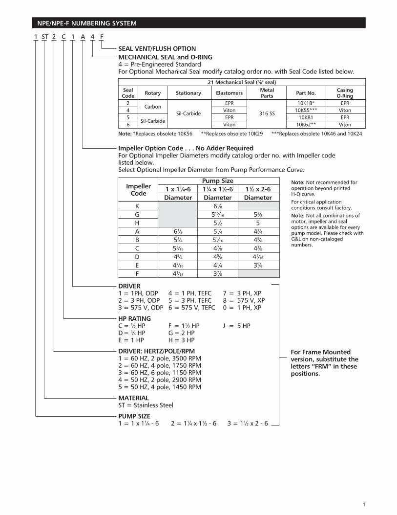
SEAL VENT/FLUSH OPTIONMECHANICAL SEAL and O-RING4 = Pre-Engineered StandardFor Optional Mechanical Seal modify catalog order no. with Seal Code listed below.
21 Mechanical Seal (5⁄8" seal)Seal Rotary Stationary Elastomers Metal Part No. CasingCode Parts O-Ring
2Carbon
EPR 10K18* EPR4 Viton 10K55*** Viton5
Sil-CarbideSil-Carbide
EPR316 SS
10K81 EPR6 Viton 10K62** Viton
Note: *Replaces obsolete 10K56 **Replaces obsolete 10K29 ***Replaces obsolete 10K46 and 10K24
Impeller Option Code . . . No Adder RequiredFor Optional Impeller Diameters modify catalog order no. with Impeller codelisted below.Select Optional Impeller Diameter from Pump Performance Curve.
Pump Size1 x 11⁄4-6 11⁄4 x 11⁄2-6 11⁄2 x 2-6Diameter Diameter Diameter
K 61⁄8G 515⁄16 53⁄8H 51⁄2 5A 61⁄8 51⁄4 43⁄4B 53⁄4 51⁄16 45⁄8C 53⁄16 47⁄8 43⁄8D 43⁄4 45⁄8 41⁄16
E 47⁄16 41⁄4 35⁄8F 41⁄16 37⁄8
DRIVER1 = 1PH, ODP 4 = 1 PH, TEFC 7 = 3 PH, XP2 = 3 PH, ODP 5 = 3 PH, TEFC 8 = 575 V, XP3 = 575 V, ODP 6 = 575 V, TEFC 0 = 1 PH, XP
HP RATINGC = 1⁄2 HP F = 11⁄2 HP J = 5 HPD= 3⁄4 HP G = 2 HPE = 1 HP H = 3 HP
DRIVER: HERTZ/POLE/RPM1 = 60 HZ, 2 pole, 3500 RPM2 = 60 HZ, 4 pole, 1750 RPM3 = 60 HZ, 6 pole, 1150 RPM4 = 50 HZ, 2 pole, 2900 RPM5 = 50 HZ, 4 pole, 1450 RPM
MATERIALST = Stainless Steel
PUMP SIZE1 = 1 x 11⁄4 - 6 2 = 11⁄4 x 11⁄2 - 6 3 = 11⁄2 x 2 - 6
NPE/NPE-F NUMBERING SYSTEM
1 ST 2 C 1 A 4 F
ImpellerCode
Note: Not recommended foroperation beyond printedH-Q curve.For critical applicationconditions consult factory.Note: Not all combinations ofmotor, impeller and sealoptions are available for everypump model. Please check withG&L on non-catalogednumbers.
For Frame Mountedversion, substitute theletters “FRM” in thesepositions.
1
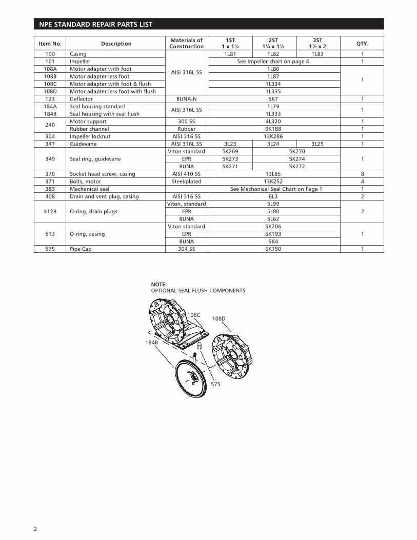
Item No. DescriptionMaterials of 1ST 2ST 3ST
QTY.Construction 1 x 11⁄4 11⁄4 x 11⁄2 11⁄2 x 2100 Casing 1L81 1L82 1L83 1101 Impeller See Impeller chart on page 4 1
108A Motor adapter with footAISI 316L SS
1L80108B Motor adapter less foot 1L87
1108C Motor adapter with foot & flush 1L334108D Motor adapter less foot with flush 1L335123 Deflector BUNA-N 5K7 1
184A Seal housing standardAISI 316L SS
1L791
184B Seal housing with seal flush 1L333
240Motor support 300 SS 4L320 1Rubber channel Rubber 9K188 1
304 Impeller locknut AISI 316 SS 13K286 1347 Guidevane AISI 316L SS 3L23 3L24 3L25 1
Viton standard 5K269 5K270349 Seal ring, guidevane EPR 5K273 5K274 1
BUNA 5K271 5K272370 Socket head screw, casing AISI 410 SS 13L65 8371 Bolts, motor Steel/plated 13K252 4383 Mechanical seal See Mechanical Seal Chart on Page 1 1408 Drain and vent plug, casing AISI 316 SS 6L3 2
Viton, standard 5L99412B O-ring, drain plugs EPR 5L80 2
BUNA 5L62Viton standard 5K206
513 O-ring, casing EPR 5K193 1BUNA 5K4
575 Pipe Cap 304 SS 6K150 1
NPE STANDARD REPAIR PARTS LIST
NOTE:OPTIONAL SEAL FLUSH COMPONENTS
2
108C108D
184B
575
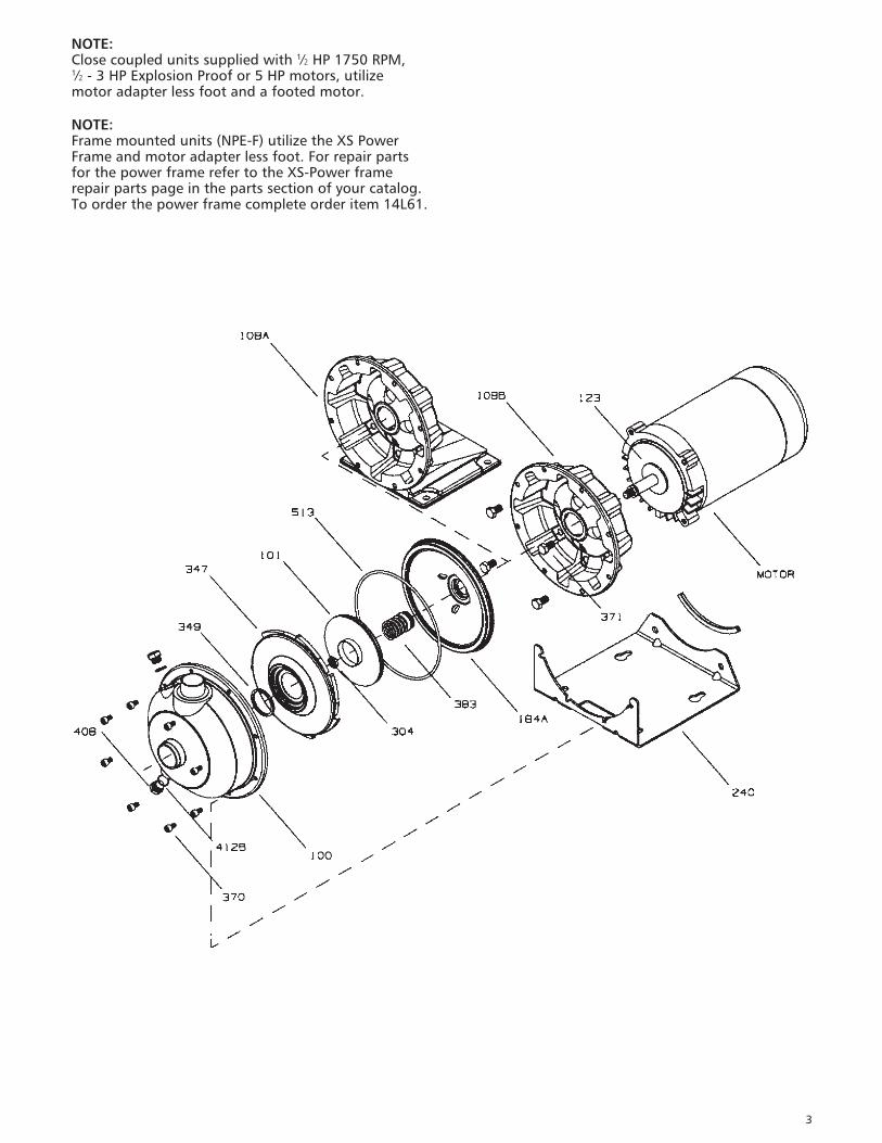
NOTE:Close coupled units supplied with 1⁄2 HP 1750 RPM,1⁄2 - 3 HP Explosion Proof or 5 HP motors, utilizemotor adapter less foot and a footed motor.
NOTE:Frame mounted units (NPE-F) utilize the XS PowerFrame and motor adapter less foot. For repair partsfor the power frame refer to the XS-Power framerepair parts page in the parts section of your catalog.To order the power frame complete order item 14L61.
3
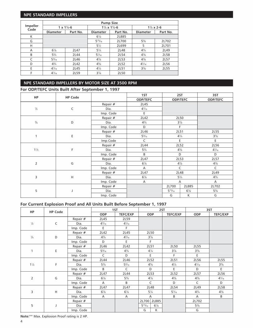
Pump Size1 x 11⁄4-6 11⁄4 x 11⁄2-6 11⁄2 x 2-6
Diameter Part No. Diameter Part No. Diameter Part No.K 61⁄8 2L885G 515⁄16 2L700 53⁄8 2L702H 51⁄2 2L699 5 2L701A 61⁄8 2L47 51⁄4 2L48 43⁄4 2L49B 53⁄4 2L44 51⁄16 2L54 45⁄8 2L58C 53⁄16 2L46 47⁄8 2L53 43⁄8 2L57D 43⁄4 2L42 45⁄8 2L52 41⁄16 2L56E 47⁄16 2L45 41⁄4 2L51 35⁄8 2L55F 41⁄16 2L59 37⁄8 2L50
NPE STANDARD IMPELLERS
For ODP/TEFC Units Built After September 1, 1997
HP HP Code1ST 2ST 3ST
ODP/TEFC ODP/TEFC ODP/TEFCRepair # 2L45
1⁄2 C Dia. 47⁄16
Imp. Code ERepair # 2L42 2L50
3⁄4 D Dia. 43⁄4 37⁄8Imp. Code D FRepair # 2L46 2L51 2L55
1 E Dia. 53⁄16 41⁄4 35⁄8Imp.Code C E ERepair # 2L44 2L52 2L56
11⁄2 F Dia. 53⁄4 45⁄8 41⁄16
Imp. Code B D DRepair # 2L47 2L53 2L57
2 G Dia. 61⁄8 47⁄8 43⁄8Imp. Code A C CRepair # 2L47 2L48 2L49
3 H Dia. 61⁄8 51⁄4 43⁄4Imp. Code A A ARepair # 2L700 2L885 2L702
5 J Dia. 515⁄16 61⁄8 53⁄8Imp. Code G K G
For Current Explosion Proof and All Units Built Before September 1, 1997
HP HP Code1ST 2ST 3ST
ODP TEFC/EXP ODP TEFC/EXP ODP TEFC/EXPRepair # 2L45 2L59
1⁄2 C Dia. 47⁄16 41⁄16
Imp. Code E FRepair # 2L42 2L45 2L50
3⁄4 D Dia. 43⁄4 47⁄16 37⁄8Imp. Code D E FRepair # 2L46 2L42 2L51 2L50 2L55
1 E Dia. 53⁄16 43⁄4 41⁄4 37⁄8 35⁄8Imp. Code C D E F ERepair # 2L44 2L46 2L52 2L51 2L56 2L55
11⁄2 F Dia. 53⁄4 53⁄16 45⁄8 41⁄4 41⁄16 35⁄8Imp. Code B C D E D ERepair # 2L47 2L44 2L53 2L52 2L57 2L56
2 G Dia. 61⁄8 53⁄4 47⁄8 45⁄8 43⁄8 41⁄16
Imp. Code A B C D C DRepair # 2L47 2L47 2L48 2L54 2L49 2L58
3 H Dia. 61⁄8 61⁄8 51⁄4 51⁄16 43⁄4 45⁄8Imp. Code A A A B A BRepair # 2L700 2L885 2L702
5 J Dia. 515⁄16 61⁄8 53⁄8Imp. Code G K G
Note:** Max. Explosion Proof rating is 2 HP.
ImpellerCode
NPE STANDARD IMPELLERS BY MOTOR SIZE AT 3500 RPM
4
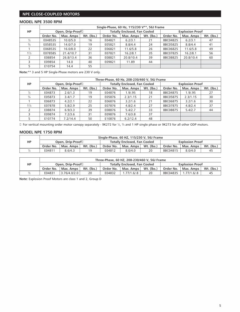
MODEL NPE 3500 RPMSingle-Phase, 60 Hz, 115/230 V**, 56J Frame
HP Open, Drip-Proof➀ Totally Enclosed, Fan Cooled Explosion ProofOrder No. Max. Amps Wt. (lbs.) Order No. Max. Amps Wt. (lbs.) Order No. Max. Amps Wt. (lbs.)
1⁄2 E04853S 10.0/5.0 16 E04821 6.2/3.1 21 BBC04825 6.2/3.1 473⁄4 E05853S 14.0/7.0 19 E05821 8.8/4.4 24 BBC05825 8.8/4.4 411 E06853S 16.0/8.0 22 E06821 11.6/5.8 26 BBC06825 11.6/5.8 49
11⁄2 E07858S 21.4/10.7 31 E07821 16.2/8.1 35 BBC07825 16.2/8.1 562 E08854 26.8/13.4 36 E08821 20.8/10.4 39 BBC08825 20.8/10.4 603 E09854 14.0 40 E09821 11.89 445 E10754 14.4 55
Note:** 3 and 5 HP Single-Phase motors are 230 V only.
Three-Phase, 60 Hz, 208-230/460 V, 56J FrameHP Open, Drip-Proof➀ Totally Enclosed, Fan Cooled Explosion Proof
Order No. Max. Amps Wt. (lbs.) Order No. Max. Amps Wt. (lbs.) Order No. Max. Amps Wt. (lbs.)1⁄2 E04873 2.6/1.3 19 E04876 1.9/.95 18 BBC04875 1.9/.95 273⁄4 E05873 3.4/1.7 19 E05876 2.3/1.15 21 BBC05875 2.3/1.15 301 E06873 4.2/2.1 22 E06876 3.2/1.6 21 BBC06875 3.2/1.6 30
11⁄2 E07878 5.8/2.9 25 E07876 4.8/2.4 27 BBC07875 4.8/2.4 372 E08874 6.9/3.3 39 E08876 5.4/2.7 33 BBC08875 5.4/2.7 443 E09874 7.2/3.6 31 E09876 7.6/3.8 375 E10774 7.2/14.4 50 E10876 6.2/12.4 48
➀ For vertical mounting order motor canopy separately - 9K272 for 1⁄2, 3⁄4 and 1 HP single phase or 9K273 for all other ODP motors.
MODEL NPE 1750 RPMSingle-Phase, 60 HZ, 115/230 V, 56J Frame
HP Open, Drip-Proof➀ Totally Enclosed, Fan Cooled Explosion ProofOrder No. Max. Amps Wt. (lbs.) Order No. Max. Amps Wt. (lbs.) Order No. Max. Amps Wt. (lbs.)
1⁄2 E04811 8.6/4.3 19 E04812 8.0/4.0 20 BBC04815 8.0/4.0 45
Three-Phase, 60 HZ, 208-230/460 V, 56J FrameHP Open, Drip-Proof➀ Totally Enclosed, Fan Cooled Explosion Proof
Order No. Max. Amps Wt. (lbs.) Order No. Max. Amps Wt. (lbs.) Order No. Max. Amps Wt. (lbs.)1⁄2 E04831 3.76/4.0/2.0 20 E04832 1.77/1.6/.8 20 BBC04835 1.77/1.6/.8 45
Note: Explosion Proof Motors are class 1 and 2, Group D
NPE CLOSE-COUPLED MOTORS
5
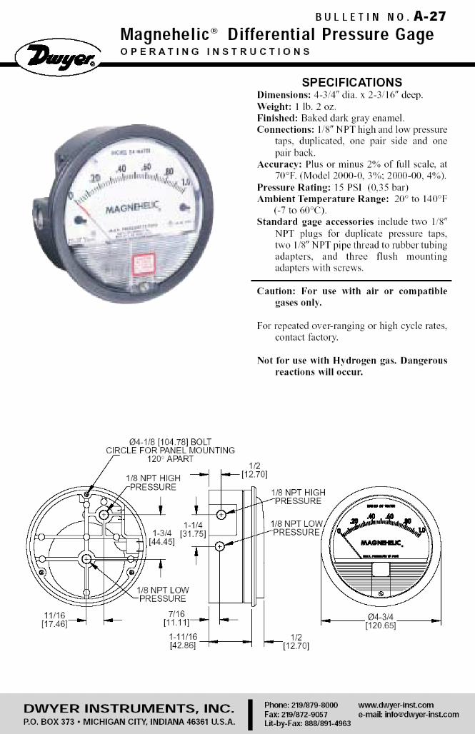
CBeears
CBeears
CBeears
CBeears
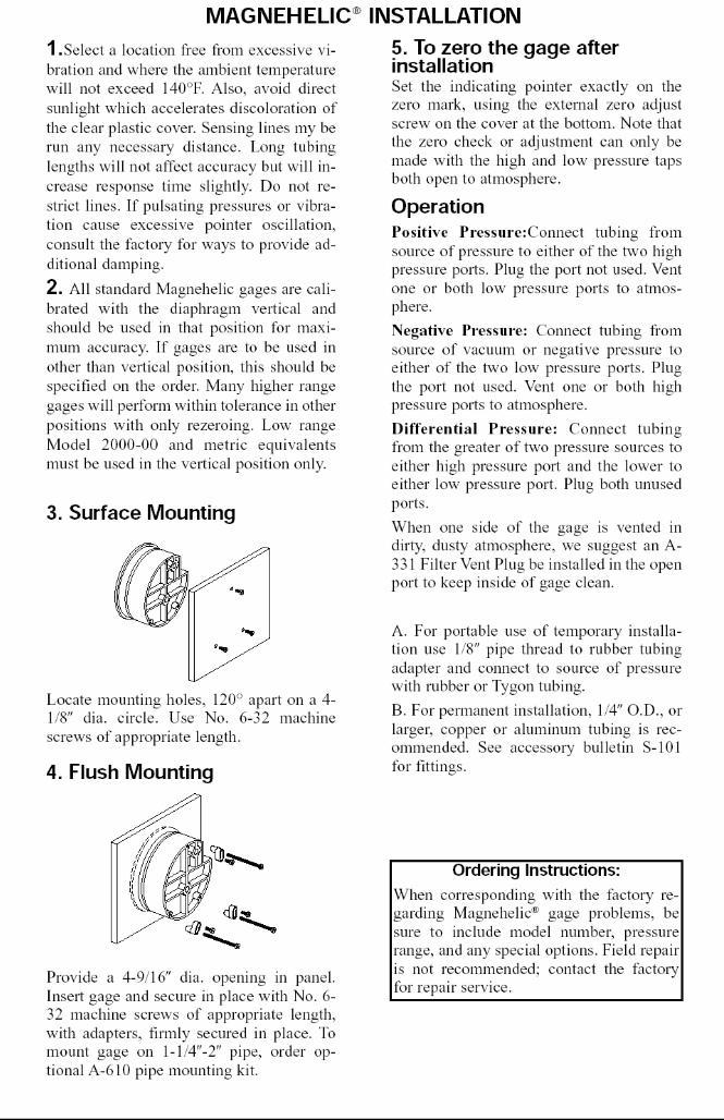
CBeears
CBeears
CBeears
CBeears
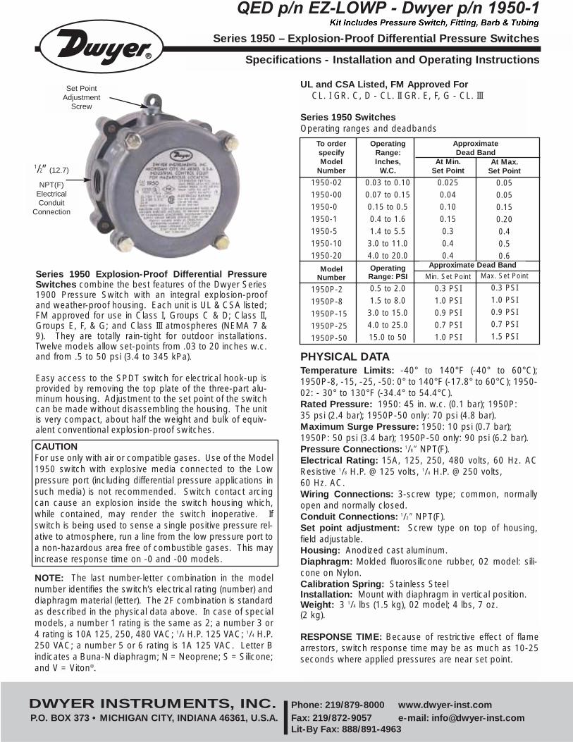
At Min.Set Point
0.0250.040.100.150.30.40.4
Min. Set Point
0.3 PSI1.0 PSI0.9 PSI0.7 PSI1.0 PSI
Series 1950 Explosion-Proof Differential PressureSwitches combine the best features of the Dwyer Series1900 Pressure Switch with an integral explosion-proofand weather-proof housing. Each unit is UL & CSA listed;FM approved for use in Class I, Groups C & D; Class II,Groups E, F, & G; and Class III atmospheres (NEMA 7 &9). They are totally rain-tight for outdoor installations.Twelve models allow set-points from .03 to 20 inches w.c.and from .5 to 50 psi (3.4 to 345 kPa).
Easy access to the SPDT switch for electrical hook-up isprovided by removing the top plate of the three-part alu-minum housing. Adjustment to the set point of the switchcan be made without disassembling the housing. The unitis very compact, about half the weight and bulk of equiv-alent conventional explosion-proof switches.
PHYSICAL DATATemperature Limits: -40° to 140°F (-40° to 60°C);1950P-8, -15, -25, -50: 0° to 140°F (-17.8° to 60°C); 1950-02: - 30° to 130°F (-34.4° to 54.4°C).Rated Pressure: 1950: 45 in. w.c. (0.1 bar); 1950P: 35 psi (2.4 bar); 1950P-50 only: 70 psi (4.8 bar).Maximum Surge Pressure: 1950: 10 psi (0.7 bar); 1950P: 50 psi (3.4 bar); 1950P-50 only: 90 psi (6.2 bar).Pressure Connections: 1/8″ NPT(F).Electrical Rating: 15A, 125, 250, 480 volts, 60 Hz. ACResistive 1/8 H.P. @ 125 volts, 1/4 H.P. @ 250 volts, 60 Hz. AC. Wiring Connections: 3-screw type; common, normallyopen and normally closed.Conduit Connections: 1/2″ NPT(F).Set point adjustment: Screw type on top of housing,field adjustable.Housing: Anodized cast aluminum.Diaphragm: Molded fluorosilicone rubber, 02 model: sili-cone on Nylon.Calibration Spring: Stainless SteelInstallation: Mount with diaphragm in vertical position.Weight: 3 1/4 lbs (1.5 kg), 02 model; 4 lbs, 7 oz. (2 kg).
Series 1950 – Explosion-Proof Differential Pressure Switches
Specifications - Installation and Operating Instructions
QED p/n EZ-LOWP - Dwyer p/n 1950-1
UL and CSA Listed, FM Approved ForCL. I GR. C, D - CL. II GR. E, F, G - CL. III
Series 1950 Switches Operating ranges and deadbands
To orderspecifyModel
Number
1950-021950-001950-01950-11950-51950-101950-20
ModelNumber
1950P-21950P-81950P-151950P-251950P-50
OperatingRange:Inches,
W.C.
0.03 to 0.100.07 to 0.150.15 to 0.50.4 to 1.61.4 to 5.5
3.0 to 11.04.0 to 20.0OperatingRange: PSI
0.5 to 2.01.5 to 8.0
3.0 to 15.04.0 to 25.015.0 to 50
ApproximateDead Band
DWYER INSTRUMENTS, INC. Phone: 219/879-8000 www.dwyer-inst.comP.O. BOX 373 • MICHIGAN CITY, INDIANA 46361, U.S.A. Fax: 219/872-9057 e-mail: [email protected]
Lit-By Fax: 888/891-4963
CAUTIONFor use only with air or compatible gases. Use of the Model1950 switch with explosive media connected to the Lowpressure port (including differential pressure applications insuch media) is not recommended. Switch contact arcingcan cause an explosion inside the switch housing which,while contained, may render the switch inoperative. Ifswitch is being used to sense a single positive pressure rel-ative to atmosphere, run a line from the low pressure port toa non-hazardous area free of combustible gases. This mayincrease response time on -0 and -00 models.
NOTE: The last number-letter combination in the modelnumber identifies the switch’s electrical rating (number) anddiaphragm material (letter). The 2F combination is standardas described in the physical data above. In case of specialmodels, a number 1 rating is the same as 2; a number 3 or4 rating is 10A 125, 250, 480 VAC; 1/8 H.P. 125 VAC; 1/4 H.P.250 VAC; a number 5 or 6 rating is 1A 125 VAC. Letter Bindicates a Buna-N diaphragm; N = Neoprene; S = Silicone;and V = Viton®.
RESPONSE TIME: Because of restrictive effect of flamearrestors, switch response time may be as much as 10-25seconds where applied pressures are near set point.
At Max.Set Point
0.050.050.150.200.40.50.6
Max. Set Point
0.3 PSI1.0 PSI0.9 PSI0.7 PSI1.5 PSI
Approximate Dead Band
Set PointAdjustment
Screw
1/2” (12.7)
NPT(F) Electrical Conduit
Connection
CBEEARS
Kit Includes Pressure Switch, Fitting, Barb & Tubing
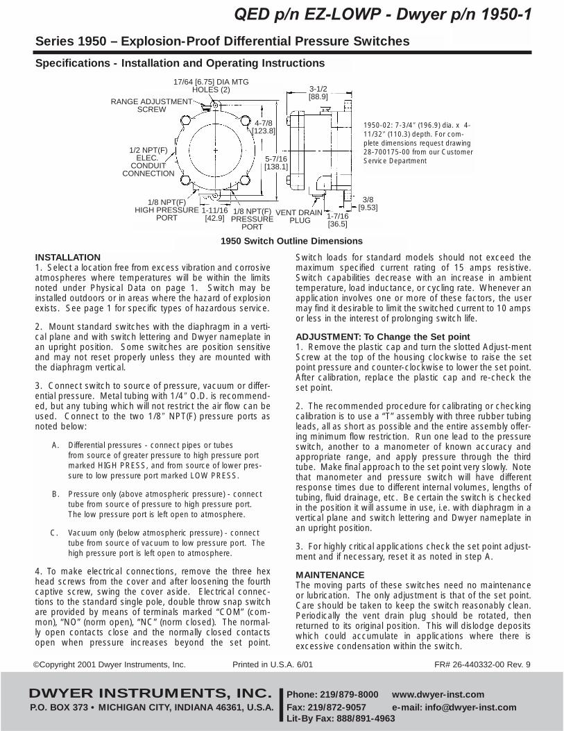
INSTALLATION1. Select a location free from excess vibration and corrosiveatmospheres where temperatures will be within the limitsnoted under Physical Data on page 1. Switch may beinstalled outdoors or in areas where the hazard of explosionexists. See page 1 for specific types of hazardous service.
2. Mount standard switches with the diaphragm in a verti-cal plane and with switch lettering and Dwyer nameplate inan upright position. Some switches are position sensitiveand may not reset properly unless they are mounted withthe diaphragm vertical.
3. Connect switch to source of pressure, vacuum or differ-ential pressure. Metal tubing with 1/4″ O.D. is recommend-ed, but any tubing which will not restrict the air flow can beused. Connect to the two 1/8″ NPT(F) pressure ports asnoted below:
A. Differential pressures - connect pipes or tubes from source of greater pressure to high pressure port marked HIGH PRESS, and from source of lower pres-sure to low pressure port marked LOW PRESS.
B. Pressure only (above atmospheric pressure) - connect tube from source of pressure to high pressure port. The low pressure port is left open to atmosphere.
C. Vacuum only (below atmospheric pressure) - connect tube from source of vacuum to low pressure port. The high pressure port is left open to atmosphere.
4. To make electrical connections, remove the three hexhead screws from the cover and after loosening the fourthcaptive screw, swing the cover aside. Electrical connec-tions to the standard single pole, double throw snap switchare provided by means of terminals marked “COM” (com-mon), “NO” (norm open), “NC” (norm closed). The normal-ly open contacts close and the normally closed contactsopen when pressure increases beyond the set point.
Switch loads for standard models should not exceed themaximum specified current rating of 15 amps resistive.Switch capabilities decrease with an increase in ambienttemperature, load inductance, or cycling rate. Whenever anapplication involves one or more of these factors, the usermay find it desirable to limit the switched current to 10 ampsor less in the interest of prolonging switch life.
ADJUSTMENT: To Change the Set point1. Remove the plastic cap and turn the slotted Adjust-mentScrew at the top of the housing clockwise to raise the setpoint pressure and counter-clockwise to lower the set point.After calibration, replace the plastic cap and re-check theset point.
2. The recommended procedure for calibrating or checkingcalibration is to use a “T” assembly with three rubber tubingleads, all as short as possible and the entire assembly offer-ing minimum flow restriction. Run one lead to the pressureswitch, another to a manometer of known accuracy andappropriate range, and apply pressure through the thirdtube. Make final approach to the set point very slowly. Notethat manometer and pressure switch will have differentresponse times due to different internal volumes, lengths oftubing, fluid drainage, etc. Be certain the switch is checkedin the position it will assume in use, i.e. with diaphragm in avertical plane and switch lettering and Dwyer nameplate inan upright position.
3. For highly critical applications check the set point adjust-ment and if necessary, reset it as noted in step A.
MAINTENANCEThe moving parts of these switches need no maintenanceor lubrication. The only adjustment is that of the set point.Care should be taken to keep the switch reasonably clean.Periodically the vent drain plug should be rotated, thenreturned to its original position. This will dislodge depositswhich could accumulate in applications where there isexcessive condensation within the switch.
Series 1950 – Explosion-Proof Differential Pressure Switches
Specifications - Installation and Operating Instructions
QED p/n EZ-LOWP - Dwyer p/n 1950-1
3-1/2�[88.9]
3/8�[9.53]
1-7/16�[36.5]
1/8 NPT(F)�PRESSURE�
PORT
1-11/16�[42.9]
1/8 NPT(F)�HIGH PRESSURE�
PORT
1/2 NPT(F)�ELEC. �
CONDUIT�CONNECTION
RANGE ADJUSTMENT�SCREW
17/64 [6.75] DIA MTG�HOLES (2)
4-7/8�[123.8]
5-7/16�[138.1]
VENT DRAIN �PLUG
1950 Switch Outline Dimensions
©Copyright 2001 Dwyer Instruments, Inc. Printed in U.S.A. 6/01 FR# 26-440332-00 Rev. 9
DWYER INSTRUMENTS, INC. Phone: 219/879-8000 www.dwyer-inst.comP.O. BOX 373 • MICHIGAN CITY, INDIANA 46361, U.S.A. Fax: 219/872-9057 e-mail: [email protected]
Lit-By Fax: 888/891-4963
1950-02: 7-3/4″ (196.9) dia. x 4-11/32″ (110.3) depth. For com-plete dimensions request drawing28-700175-00 from our CustomerService Department
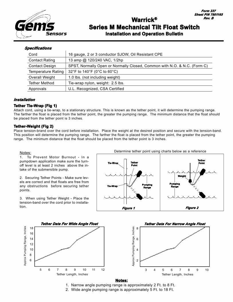
Notes:1. To Prevent Motor Burnout - In apumpdown application make sure the turn-off level is at least 2 inches above the in-take of the submersible pump.
2. Securing Tether Points - Make sure lev-els are correct and that floats are free fromany obstructions before securing tetherpoints.
3. When using Tether Weight - Place thetension-band over the cord prior to installa-tion.
TTTTTether Tether Tether Tether Tether Tie-Wie-Wie-Wie-Wie-Wrap (Fig 1)rap (Fig 1)rap (Fig 1)rap (Fig 1)rap (Fig 1)Attach cord, using a tie-wrap, to a stationary structure. This is known as the tether point, it will determine the pumping range.The farther the float is placed from the tether point, the greater the pumping range. The minimum distance that the float shouldbe placed from the tether point is 3 inches.
TTTTTether-Wether-Wether-Wether-Wether-Weight (Fig 2)eight (Fig 2)eight (Fig 2)eight (Fig 2)eight (Fig 2)Place tension-brand over the cord before installation. Place the weight at the desired position and secure with the tension-band.This position will determine the pumping range. The farther the float is placed from the tether point, the greater the pumpingrange. The minimum distance that the float should be placed from the tether point is 3 inches.
WWWWWarrickarrickarrickarrickarrick®®®®®
Series M Mechanical TSeries M Mechanical TSeries M Mechanical TSeries M Mechanical TSeries M Mechanical Tilt Float Switchilt Float Switchilt Float Switchilt Float Switchilt Float SwitchInstallation and Operation BulletinInstallation and Operation BulletinInstallation and Operation BulletinInstallation and Operation BulletinInstallation and Operation Bulletin
Form 237Form 237Form 237Form 237Form 237Sheet P/N 7801Sheet P/N 7801Sheet P/N 7801Sheet P/N 7801Sheet P/N 7801165165165165165
RevRevRevRevRev. B. B. B. B. B
SpecificationsSpecificationsSpecificationsSpecificationsSpecifications
Cord
Contact Rating
Contact Design
Temperature Rating
Overall Weight
Tether Method
Approvals
16 gauge, 2 or 3 conductor SJOW, Oil Resistant CPE
13 amp @ 120/240 VAC, 1/2hp
SPST, Normally Open or Normally Closed, Common with N.O. & N.C. (Form C)
32°F to 140°F (0°C to 60°C)
1.0 lbs. (not including weight)
Tie-wrap nylon, weight: 2.5 lbs.
U.L. Recognized, CSA Certified
InstallationInstallationInstallationInstallationInstallation
Determine tether point using charts below as a reference
TTTTTetheretheretheretheretherPointPointPointPointPoint
TTTTTie-Wie-Wie-Wie-Wie-Wrapraprapraprap
TTTTTie-Wie-Wie-Wie-Wie-Wrapraprapraprap PumpingPumpingPumpingPumpingPumpingRangeRangeRangeRangeRange
PumpingPumpingPumpingPumpingPumpingRangeRangeRangeRangeRange
TTTTTetheretheretheretheretherPointPointPointPointPoint
WWWWWeighteighteighteighteight
Figure 1Figure 1Figure 1Figure 1Figure 1 Figure 2Figure 2Figure 2Figure 2Figure 2
TTTTTether Data For Wether Data For Wether Data For Wether Data For Wether Data For Wide ide ide ide ide Angle FloatAngle FloatAngle FloatAngle FloatAngle Float
5 6 7 8 9 10 11 12
18
16
14
12
10
8
6
Ap
pro
x P
um
pin
g R
an
ge
, In
che
s
Tether Length, Inches
TTTTTether Data For Narrow ether Data For Narrow ether Data For Narrow ether Data For Narrow ether Data For Narrow Angle FloatAngle FloatAngle FloatAngle FloatAngle Float
3 4 5 6 7 8 9 10
8
6
4
2
Ap
pro
x P
um
pin
g R
an
ge
, In
che
s
Tether Length, Inches
Notes:Notes:Notes:Notes:Notes:1. Narrow angle pumping range is approximately 2 Ft. to 8 Ft.2. Wide angle pumping range is approximately 5 Ft. to 18 Ft.
Contact ConfigurationsContact ConfigurationsContact ConfigurationsContact ConfigurationsContact Configurations
Gems Sensors Inc.One Cowles RoadPlainville, CT 06062-1198Tel: 860-793-4579Fax: 860-793-4580
2-3/8”(6.03 cm)
3-3/8”(8.57 cm)
4-5/8”(11.75 cm)
1/2” (127 cm)
DimensionsDimensionsDimensionsDimensionsDimensions
White Black
N.O.
White Black
N.C.
Red Black White
S.P.D.T.
Important Points:Important Points:Important Points:Important Points:Important Points:• Gems products must be maintained and installed in strict accordance with the National Electrical Code and the applicable Gems Product Instruction Bulletin that covers installation, operation and proper maintenance. Failure to observe this information may result in serious injury or damages.• For hazardous area applications involving such things as, but not limited to, ignitable mixtures, combustible dust and flammable materials, use an appropriate explosionproof enclosure or intrinsically safe interface device.• Please adhere to the pressure and temperature limitations shown throughout this catalog for our level and flow sensors. These limitations must not be exceeded. These pressures and temperatures take into consideration possible system surge pressures/temperatures and their frequencies.• Selection of materials for compatibility with the media is critical to the life and operation of Gems products. Take care in the proper selection of materials of construction, testing is required.• NSF-approved sensors are made of materials approved for potable water applica tions according to Standard 61.• Stainless steel is generally regarded as safe by NSF and FDA.• Life expectancy of switch contacts varies with application. Contact Gems if life cycle testing is required.• Ambient temperature changes do affect switch set points, since the gravity of a liquid can vary with temperature.• Our sensors have been designed to resist shock and vibration. However, shock and vibration should be minimized.• Filter liquid media containing particulate and/or debris to ensure the proper operation of our products.• Electrical entries and mounting points in an enclosed tank may require liquid/vapor sealing.• Our sensors must not be field-repaired.• Physical damage sustained by product may render it unserviceable.
Return PolicyReturn PolicyReturn PolicyReturn PolicyReturn PolicyReturns are accepted on stock items up to 30 days from date of order. You mustcontact our Returns Department for a Return Authorization (RA) number. Returnthe goods - freight prepaid - in the original container and include original packingslip. C. O. D. returns are not accepted. Gems reserves the right to applyrestocking charges.
TTTTTel: 860-793-4357el: 860-793-4357el: 860-793-4357el: 860-793-4357el: 860-793-4357Fax: 860-793-4563Fax: 860-793-4563Fax: 860-793-4563Fax: 860-793-4563Fax: 860-793-4563
Related Documents