USER INSTRUCTIONS LNN, LNNV and LNNC centrifugal pumps Single stage, double suction, horizontally split, volute type centrifugal pumps PCN=71569074 11-09 (E) (Based on C953KH001) Original instructions Installation Operation Maintenance These instructions must be read prior to installing, operating, using and maintaining this equipment.

Welcome message from author
This document is posted to help you gain knowledge. Please leave a comment to let me know what you think about it! Share it to your friends and learn new things together.
Transcript

USER INSTRUCTIONS
LNN, LNNV and LNNC centrifugal pumps Single stage, double suction, horizontally split, volute type centrifugal pumps
PCN=71569074 11-09 (E) (Based on C953KH001) Original instructions
Installation Operation
Maintenance
These instructions must be read prior to installing , operating, using and maintaining this equipment.
LNN, LNNV, LNNC USER INSTRUCTIONS ENGLISH 7156907 4 11-09
Page 2 of 52 flowserve.com
CONTENTS Page
1 INTRODUCTION AND SAFETY............................ 4 1.1 General ........................................................... 4 1.2 CE marking and approvals.............................. 4 1.3 Disclaimer ....................................................... 4 1.4 Copyright......................................................... 4 1.5 Duty conditions................................................ 4 1.6 Safety .............................................................. 5 1.7 Nameplate and safety labels........................... 8 1.8 Specific machine performance........................ 9 1.9 Noise level....................................................... 9
2 TRANSPORT AND STORAGE............................ 10 2.1 Consignment receipt and unpacking............. 10 2.2 Handling ........................................................ 10 2.3 Lifting............................................................. 10 2.4 Storage.......................................................... 10 2.5 Recycling and end of product life.................. 10
3 PUMP DESCRIPTION......................................... 11 3.1 Configurations ............................................... 11 3.2 Name nomenclature...................................... 11 3.3 Design of major parts .................................... 11 3.4 Performance and operating limits ................. 12
4 INSTALLATION.................................................... 12 4.1 Location......................................................... 12 4.2 Part assemblies............................................. 12 4.3 Foundation .................................................... 13 4.4 Grouting ........................................................ 13 4.5 Initial alignment ............................................. 13 4.6 Piping ............................................................ 14 4.7 Final shaft alignment check .......................... 18 4.8 Electrical connections ................................... 18 4.9 Protection systems........................................ 18
5 COMMISSIONING, START-UP, OPERATION AND SHUTDOWN ........................................ 19
5.1 Pre-commissioning procedure ...................... 19 5.2 Pump lubricants ............................................ 19 5.3 Direction of rotation ....................................... 21 5.4 Guarding ....................................................... 21 5.5 Priming and auxiliary supplies ...................... 21 5.6 Starting the pump.......................................... 21 5.7 Running the pump......................................... 21 5.8 Stopping and shutdown................................. 23 5.9 Hydraulic, mechanical and electrical duty..... 23
Page
6 MAINTENANCE ...................................................24 6.1 General ..........................................................24 6.2 Maintenance schedule...................................24 6.3 Spare parts.....................................................26 6.4 Recommended spares
and consumable items ..................................27 6.5 Tools required ................................................27 6.6 Fastener torques............................................27 6.7 Renewal clearances ......................................27 6.8 Disassembly ..................................................28 6.9 Examination of parts ......................................29 6.10 Assembly .....................................................30
7 FAULTS; CAUSES AND REMEDIES...................34
8 PARTS LISTS AND DRAWINGS .........................36 8.1 LNN and LNNC – grease lubricated, gland
packed and component mechanical seal option – sizes up to 350 mm discharge.........36
8.2 LNN and LNNC – grease lubricated and gland packed option – sizes greater than 350 mm discharge.........................................39
8.3 LNNV sleeve bearing type – grease lubricated, component mechanical seal and gland packed option – sizes up to 350 mm discharge.........................................42
8.4 LNNV sleeve bearing type – grease lubricated and gland packed option – sizes greater than 350 mm discharge ....................45
8.5 General arrangement drawing.......................47
9 CERTIFICATION ..................................................48
10 OTHER RELEVANT DOCUMENTATION AND MANUALS.............................................48
10.1 Supplementary User Instructions ................48 10.2 Change notes ..............................................48 10.3 Additional sources of information.................48
LNN, LNNV, LNNC USER INSTRUCTIONS ENGLISH 7156907 4 11-09
Page 3 of 52 flowserve.com
INDEX Page Additional sources (10.3) ......................................... 48 Alignment of shafting (see 4.3, 4.5 and 4.7) Assembly (6.10)....................................................... 30 ATEX marking (1.6.4.2) ............................................. 7 CE marking and approvals (1.2)................................ 4 Certification (9) ........................................................ 48 Change notes (10.2) ................................................ 48 Clearances (see 6.7, Renewal clearances)............. 27 Commissioning and operation (5)............................ 19 Compliance, ATEX (1.6.4.1)...................................... 6 Configurations (3.1) ................................................. 11 Copyright (1.4) ........................................................... 4 Design of major parts (3.3) ...................................... 11 Direction of rotation (5.3) ......................................... 21 Disassembly (6.8) .................................................... 28 Disclaimer (1.3).......................................................... 4 Dismantling (see 6.8, Disassembly) ........................ 28 Drawings (8) ............................................................ 36 Duty conditions (1.5).................................................. 4 Electrical connections (4.8) ..................................... 18 End of product life (2.5) ........................................... 10 Examination of parts (6.9) ....................................... 29 Fastener torques (6.6) ............................................. 27 Faults; causes and remedies (7) ............................. 34 Foundation (4.3) ...................................................... 13 Forces and moments (4.6.2) ................................... 15 General arrangement drawing (8.5) ........................ 47 Grouting (4.4)........................................................... 13 Guarding (5.4).......................................................... 21 Handling (2.2) .......................................................... 10 Hydraulic, mechanical and electrical duty (5.9) ....... 23 Impeller clearance (6.7) ........................................... 27 Inspection (6.2.1 and 6.2.2) ..................................... 24 Installation (4) .......................................................... 12 Lifting (2.3) ............................................................... 10 Location (4.1)........................................................... 12 Lubrication (see 5.1.1, 5.2 and 6.2.3) Lubrication schedule (5.2.3) .................................... 20 Maintenance (6)....................................................... 24 Maintenance schedule (6.2) .................................... 24 Name nomenclature (3.2) ........................................ 11 Nameplate (1.7.1) ...................................................... 8 Operating limits (3.4.1) ............................................ 12 Ordering spare parts (6.3.1) .................................... 26 Part assemblies (4.2)............................................... 12 Parts lists (8)............................................................ 36 Performance (3.4).................................................... 12 Piping (4.6) .............................................................. 14 Pre-commissioning (5.1).......................................... 19 Protection systems (4.9) .......................................... 18 Pump and impeller data (3.4.2) ............................... 12
Page Reassembly (see 6.10, Assembly)...........................30 Receipt and unpacking (2.1) ....................................10 Recommended fill quantities (5.2.4).........................20 Recommended grease lubricants (5.2.2) .................20 Recommended oil lubricants (5.2.1) ........................19 Recommended spares (6.4).....................................27 Recycling (2.5) .........................................................10 Replacement parts (see 6.3 and 6.4).......................26 Running the pump (5.7) ...........................................22 Safety action (1.6.3) ...................................................5 Safety labels (1.7.2) ...................................................8 Safety markings (1.6.1) ..............................................5 Safety, protection systems (see 1.6 and 4.9) Sectional drawings (8)..............................................36 Sound level (see 1.9, Noise level)..............................9 Sources, additional information (10.3) .....................48 Spare parts (6.3) ......................................................26 Specific machine performance (1.8) ..........................8 Starting the pump (5.6).............................................21 Stop/start frequency (5.7.6)......................................23 Stopping and shutdown (5.8) ...................................23 Storage, pump (2.4) .................................................10 Storage, spare parts (6.3.2) .....................................27 Supplementary manuals or information
sources (10) ........................................................48 Thermal expansion (4.5.1) .......................................13 Tools required (6.5) ..................................................27 Torques for fasteners (6.6).......................................27 Trouble-shooting (see 7) ..........................................34 Vibration (5.7.5)........................................................22
LNN, LNNV, LNNC USER INSTRUCTIONS ENGLISH 7156907 4 11-09
Page 4 of 52 flowserve.com
1 INTRODUCTION AND SAFETY 1.1 General
These instructions must always be kept close to the product's operating location or directly with the product. Flowserve products are designed, developed and manufactured with state-of-the-art technologies in modern facilities. The unit is produced with great care and commitment to continuous quality control, utilising sophisticated quality techniques, and safety requirements. Flowserve is committed to continuous quality improvement and being at service for any further information about the product in its installation and operation or about its support products, repair and diagnostic services. These instructions are intended to facilitate familiarization with the product and its permitted use. Operating the product in compliance with these instructions is important to help ensure reliability in service and avoid risks. The instructions may not take into account local regulations; ensure such regulations are observed by all, including those installing the product. Always coordinate repair activity with operations personnel, and follow all plant safety requirements and applicable safety and health laws and regulations.
These instructions must be read prior to installing, operating, using and maintaining the equipment in any region worldwide. The equipment must not be put into service until all the conditions relating to safety noted in the instructions, have been met. Failure to follow and apply the present user instructions is considered to be misuse. Personal injury, product damage, delay or failure caused by misuse are not covered by the Flowserve warranty. 1.2 CE marking and approvals It is a legal requirement that machinery and equipment put into service within certain regions of the world shall conform with the applicable CE Marking Directives covering Machinery and, where applicable, Low Voltage Equipment, Electromagnetic Compatibility (EMC), Pressure Equipment Directive (PED) and Equipment for Potentially Explosive Atmospheres (ATEX). Where applicable, the Directives and any additional Approvals, cover important safety aspects relating to machinery and equipment and the satisfactory provision
of technical documents and safety instructions. Where applicable this document incorporates information relevant to these Directives and Approvals. To confirm the Approvals applying and if the product is CE marked, check the serial number plate markings and the Certification. (See section 9, Certification.) 1.3 Disclaimer Information in these User Instructions is believed to be reliable. In spite of all the efforts of Flowserve Corporation to provide sound and all necessary information the content of this manual may appear insufficient and is not guaranteed by Flowserve as to its completeness or accuracy . Flowserve manufactures products to exacting International Quality Management System Standards as certified and audited by external Quality Assurance organisations. Genuine parts and accessories have been designed, tested and incorporated into the products to help ensure their continued product quality and performance in use. As Flowserve cannot test parts and accessories sourced from other vendors the incorrect incorporation of such parts and accessories may adversely affect the performance and safety features of the products. The failure to properly select, install or use authorised Flowserve parts and accessories is considered to be misuse. Damage or failure caused by misuse is not covered by the Flowserve warranty. In addition, any modification of Flowserve products or removal of original components may impair the safety of these products in their use. 1.4 Copyright All rights reserved. No part of these instructions may be reproduced, stored in a retrieval system or transmitted in any form or by any means without prior permission of Flowserve. 1.5 Duty conditions This product has been selected to meet the specifications of your purchaser order. The acknowledgement of these conditions has been sent separately to the Purchaser. A copy should be kept with these instructions.
The product must not be operated beyond the parameters specified for the application. If there is any doubt as to the suitability of the product for the application intended, contact Flowserve for advice, quoting the serial number.

LNN, LNNV, LNNC USER INSTRUCTIONS ENGLISH 7156907 4 11-09
Page 5 of 52 flowserve.com
If the conditions of service on your purchase order are going to be changed (for example liquid pumped, temperature or duty) it is requested that the user seeks the written agreement of Flowserve before start up. 1.6 Safety 1.6.1 Summary of safety markings These User Instructions contain specific safety markings where non-observance of an instruction would cause hazards. The specific safety markings are:
This symbol indicates electrical safety instructions where non-compliance will involve a high risk to personal safety or the loss of life.
This symbol indicates safety instructions where non-compliance would affect personal safety and could result in loss of life.
This symbol indicates “hazardous and toxic fluid” safety instructions where non-compliance would affect personal safety and could result in loss of life.
This symbol indicates safety instructions where non-compliance will involve some risk to safe operation and personal safety and would damage the equipment or property.
This symbol indicates explosive atmosphere zone marking according to ATEX. It is used in safety instructions where non-compliance in the hazardous area would cause the risk of an explosion.
This symbol is used in safety instructions to remind not to rub non-metallic surfaces with a dry cloth; ensure the cloth is damp. It is used in safety instructions where non-compliance in the hazardous area would cause the risk of an explosion.
This sign is not a safety symbol but indicates an important instruction in the assembly process. 1.6.2 Personnel qualification and training All personnel involved in the operation, installation, inspection and maintenance of the unit must be qualified to carry out the work involved. If the personnel in question do not already possess the necessary knowledge and skill, appropriate training and instruction must be provided. If required the operator may commission the manufacturer/supplier to provide applicable training. Always coordinate repair activity with operations and health and safety personnel, and follow all plant
safety requirements and applicable safety and health laws and regulations. 1.6.3 Safety action This is a summary of conditions and actions to prevent injury to personnel and damage to the environment and to equipment. For products used in potentially explosive atmospheres section 1.6.4 also applies.
NEVER DO MAINTENANCE WORK WHEN THE UNIT IS CONNECTED TO POWER
GUARDS MUST NOT BE REMOVED WHILE THE PUMP IS OPERATIONAL
DRAIN THE PUMP AND ISOLATE PIPEWORK BEFORE DISMANTLING THE PUMP The appropriate safety precautions should be taken where the pumped liquids are hazardous.
FLUORO-ELASTOMERS (When fitted.) When a pump has experienced temperatures over 250 ºC (482 ºF), partial decomposition of fluoro-elastomers (example: Viton) will occur. In this condition these are extremely dangerous and skin contact must be avoided.
HANDLING COMPONENTS Many precision parts have sharp corners and the wearing of appropriate safety gloves and equipment is required when handling these components. To lift heavy pieces above 25 kg (55 lb) use a crane appropriate for the mass and in accordance with current local regulations.
THERMAL SHOCK Rapid changes in the temperature of the liquid within the pump can cause thermal shock, which can result in damage or breakage of components and should be avoided.
NEVER APPLY HEAT TO REMOVE IMPELLER Trapped lubricant or vapor could cause an explosion.
HOT (and cold) PARTS If hot or freezing components or auxiliary heating supplies can present a danger to operators and persons entering the immediate area action must be taken to avoid accidental contact. If complete protection is not possible, the machine access must be limited to maintenance staff only, with clear visual warnings and indicators to those entering the immediate area. Note: bearing housings must not be insulated and drive motors and bearings may be hot.

LNN, LNNV, LNNC USER INSTRUCTIONS ENGLISH 7156907 4 11-09
Page 6 of 52 flowserve.com
If the temperature is greater than 80 °C (175 °F) o r below -5 °C (23 °F) in a restricted zone, or exceed local regulations, action as above shall be taken.
HAZARDOUS LIQUIDS When the pump is handling hazardous liquids care must be taken to avoid exposure to the liquid by appropriate sitting of the pump, limiting personnel access and by operator training. If the liquid is flammable and/or explosive, strict safety procedures must be applied. Gland packing must not be used when pumping hazardous liquids.
PREVENT EXCESSIVE EXTERNAL PIPE LOAD Do not use pump as a support for piping. Do not mount expansion joints, unless allowed by Flowserve in writing, so that their force, due to internal pressure, acts on the pump flange.
ENSURE CORRECT LUBRICATION (See section 5, Commissioning, start up, operation and shutdown.)
START THE PUMP WITH OUTLET VALVE PARTLY OPENED (Unless otherwise instructed at a specific point in the User Instructions.) This is recommended to minimize the risk of overloading and damaging the pump motor at full or zero flow. Pumps may be started with the valve further open only on installations where this situation cannot occur. The pump outlet control valve may need to be adjusted to comply with the duty following the run-up process. (See section 5, Commissioning start-up, operation and shutdown.)
NEVER RUN THE PUMP DRY
INLET VALVES TO BE FULLY OPEN WHEN PUMP IS RUNNING Running the pump at zero flow or below the recommended minimum flow continuously will cause damage to the seal.
DO NOT RUN THE PUMP AT ABNORMALLY HIGH OR LOW FLOW RATES Operating at a flow rate higher than normal or at a flow rate with no back pressure on the pump may overload the motor and cause cavitation. Low flow rates may cause a reduction in pump/bearing life, overheating of the pump, instability and cavitation/vibration.
1.6.4 Products used in potentially explosive atmospheres
The following instructions for pumps and pump units when installed in potentially explosive atmospheres must be followed to help ensure explosion protection. For ATEX, both electrical and non-electrical equipment must meet the requirements 94/9/EC. Always observe the regional legal Ex requirements eg Ex electrical items outside the EU may be required certified to other than ATEX eg IECEx, UL.
Measures are required to: • Avoiding excessive surface temperature • Preventing build up of explosive mixtures • Preventing the generation of sparks • Preventing leakages • Maintaining the pump to avoid hazard 1.6.4.1 Scope of compliance
Use equipment only in the zone for which it is appropriate. Always check that the driver, drive coupling assembly, seal and pump equipment are suitably rated and/or certified for the classification of the specific atmosphere in which they are to be installed. Where Flowserve has supplied only the bare shaft pump, the Ex rating applies only to the pump. The party responsible for assembling the ATEX pump set shall select the coupling, driver and any additional equipment, with the necessary CE Certificate/ Declaration of Conformity establishing it is suitable for the area in which it is to be installed. The output from a variable frequency drive (VFD) can cause additional heating effects in the motor and so, for pumps sets with a VFD, the ATEX Certification for the motor must state that it is covers the situation where electrical supply is from the VFD. This particular requirement still applies even if the VFD is in a safe area.
LNN, LNNV, LNNC USER INSTRUCTIONS ENGLISH 7156907 4 11-09
Page 7 of 52 flowserve.com
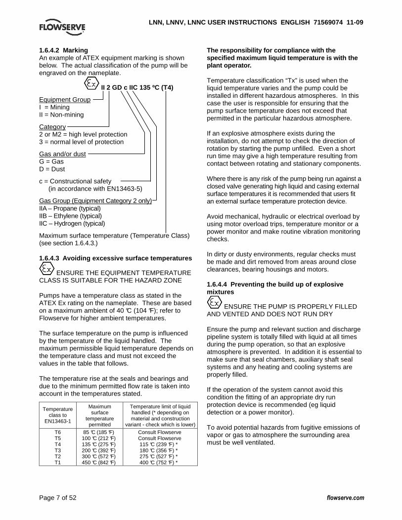
1.6.4.2 Marking An example of ATEX equipment marking is shown below. The actual classification of the pump will be engraved on the nameplate.
II 2 GD c IIC 135 ºC (T4)
Equipment Group I = Mining II = Non-mining
Category 2 or M2 = high level protection 3 = normal level of protection
Gas and/or dust G = Gas D = Dust
c = Constructional safety (in accordance with EN13463-5)
Gas Group (Equipment Category 2 only) IIA – Propane (typical) IIB – Ethylene (typical) IIC – Hydrogen (typical)
Maximum surface temperature (Temperature Class) (see section 1.6.4.3.) 1.6.4.3 Avoiding excessive surface temperatures
ENSURE THE EQUIPMENT TEMPERATURE CLASS IS SUITABLE FOR THE HAZARD ZONE Pumps have a temperature class as stated in the ATEX Ex rating on the nameplate. These are based on a maximum ambient of 40 °C (104 °F); refer to Flowserve for higher ambient temperatures. The surface temperature on the pump is influenced by the temperature of the liquid handled. The maximum permissible liquid temperature depends on the temperature class and must not exceed the values in the table that follows. The temperature rise at the seals and bearings and due to the minimum permitted flow rate is taken into account in the temperatures stated.
Temperature class to
EN13463-1
Maximum surface
temperature permitted
Temperature limit of liquid handled (* depending on material and construction
variant - check which is lower)
T6 T5 T4 T3 T2 T1
85 °C (185 °F) 100 °C (212 °F) 135 °C (275 °F) 200 °C (392 °F) 300 °C (572 °F) 450 °C (842 °F)
Consult Flowserve Consult Flowserve 115 °C (239 °F) * 180 °C (356 °F) * 275 °C (527 °F) * 400 °C (752 °F) *
The responsibility for compliance with the specified maximum liquid temperature is with the plant operator. Temperature classification “Tx” is used when the liquid temperature varies and the pump could be installed in different hazardous atmospheres. In this case the user is responsible for ensuring that the pump surface temperature does not exceed that permitted in the particular hazardous atmosphere. If an explosive atmosphere exists during the installation, do not attempt to check the direction of rotation by starting the pump unfilled. Even a short run time may give a high temperature resulting from contact between rotating and stationary components. Where there is any risk of the pump being run against a closed valve generating high liquid and casing external surface temperatures it is recommended that users fit an external surface temperature protection device. Avoid mechanical, hydraulic or electrical overload by using motor overload trips, temperature monitor or a power monitor and make routine vibration monitoring checks. In dirty or dusty environments, regular checks must be made and dirt removed from areas around close clearances, bearing housings and motors. 1.6.4.4 Preventing the build up of explosive mixtures
ENSURE THE PUMP IS PROPERLY FILLED AND VENTED AND DOES NOT RUN DRY Ensure the pump and relevant suction and discharge pipeline system is totally filled with liquid at all times during the pump operation, so that an explosive atmosphere is prevented. In addition it is essential to make sure that seal chambers, auxiliary shaft seal systems and any heating and cooling systems are properly filled. If the operation of the system cannot avoid this condition the fitting of an appropriate dry run protection device is recommended (eg liquid detection or a power monitor). To avoid potential hazards from fugitive emissions of vapor or gas to atmosphere the surrounding area must be well ventilated.
LNN, LNNV, LNNC USER INSTRUCTIONS ENGLISH 7156907 4 11-09
Page 8 of 52 flowserve.com
1.6.4.5 Preventing sparks
To prevent a potential hazard from mechanical contact, the coupling guard must be non-sparking. To avoid the potential hazard from random induced current generating a spark, the ground contact on the baseplate must be used.
Avoid electrostatic charge: do not rub non-metallic surfaces with a dry cloth; ensure cloth is damp. Where applicable, the coupling must be selected to comply with 94/9/EC and correct alignment must be maintained. Additional requirement for metallic pumps on non-metallic baseplates When metallic components are fitted on a non-metallic baseplate they must be individually earthed. 1.6.4.6 Preventing leakage
The pump must only be used to handle liquids for which it has been approved to have the correct corrosion resistance. Avoid entrapment of liquid in the pump and associated piping due to closing of suction and discharge valves, which could cause dangerous excessive pressures to occur if there is heat input to the liquid. This can occur if the pump is stationary or running. Bursting of liquid containing parts due to freezing must be avoided by draining or protecting the pump and ancillary systems. Where there is the potential hazard of a loss of a seal barrier fluid or external flush, the fluid must be monitored. If leakage of liquid to atmosphere can result in a hazard, the installation of a liquid detection device is recommended. 1.6.4.7 Maintenance to avoid the hazard
CORRECT MAINTENANCE IS REQUIRED TO AVOID POTENTIAL HAZARDS WHICH GIVE A RISK OF EXPLOSION The responsibility for compliance with maintenance instructions is with the plant operator.
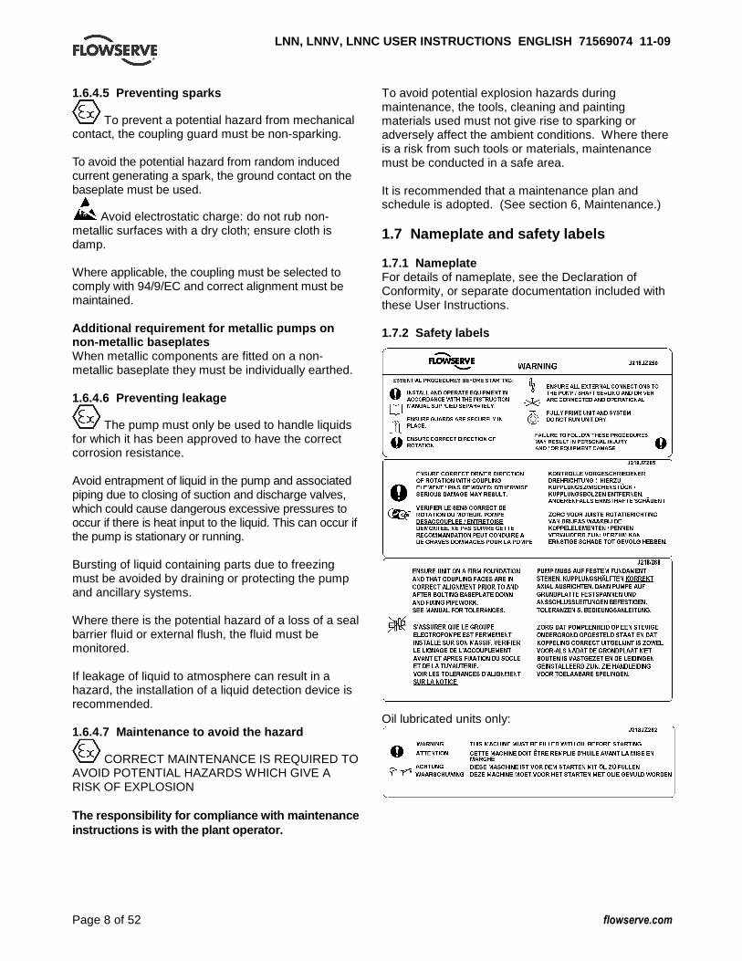
To avoid potential explosion hazards during maintenance, the tools, cleaning and painting materials used must not give rise to sparking or adversely affect the ambient conditions. Where there is a risk from such tools or materials, maintenance must be conducted in a safe area. It is recommended that a maintenance plan and schedule is adopted. (See section 6, Maintenance.) 1.7 Nameplate and safety labels 1.7.1 Nameplate For details of nameplate, see the Declaration of Conformity, or separate documentation included with these User Instructions. 1.7.2 Safety labels
Oil lubricated units only:

LNN, LNNV, LNNC USER INSTRUCTIONS ENGLISH 7156907 4 11-09
Page 9 of 52 flowserve.com
1.8 Specific machine performance For performance parameters see section 1.5, Duty conditions. When the contract requirement specifies these to be incorporated into User Instructions these are included here. Where performance data has been supplied separately to the purchaser these should be obtained and retained with these User Instructions if required. 1.9 Noise level Attention must be given to the exposure of personnel to the noise, and local legislation will define when guidance to personnel on noise limitation is required, and when noise exposure reduction is mandatory. This is typically 80 to 85 dBA. The usual approach is to control the exposure time to the noise or to enclose the machine to reduce emitted sound. You may have already specified a limiting noise level when the equipment was ordered, however if no noise requirements were defined, then attention is drawn to the following table to give an indication of equipment noise level so that you can take the appropriate action in your plant. Pump noise level is dependent on a number of operational factors, flow rate, pipework design and
acoustic characteristics of the building, and so the values given are subject to a 3 dBA tolerance and cannot be guaranteed. Similarly the motor noise assumed in the “pump and motor” noise is that typically expected from standard and high efficiency motors when on load directly driving the pump. Note that a motor driven by an inverter may show an increased noise at some speeds. If a pump unit only has been purchased for fitting with your own driver then the “pump only” noise levels in the table should be combined with the level for the driver obtained from the supplier. Consult Flowserve or a noise specialist if assistance is required in combining the values. It is recommended that where exposure approaches the prescribed limit, then site noise measurements should be made. The values are in sound pressure level LpA at 1 m (3.3 ft) from the machine, for “free field conditions over a reflecting plane”. For estimating sound power level LWA (re 1 pW) then add 17 dBA to the sound pressure value.
Typical sound pressure level L pA at 1 m reference 20 µPa, dBA
3 550 r/min 2 900 r/min 1 750 r/min 1 450 r/min Motor size and speed
kW (hp) Pump only
Pump and motor
Pump only
Pump and motor
Pump only
Pump and motor
Pump only
Pump and motor
5.5 (7.5) 76 77 72 75 66 67 64 65
7.5 (10) 76 77 72 75 66 67 64 65
11(15) 80 81 76 78 70 71 68 69
15 (20) 80 81 76 78 70 71 68 69
18.5 (25) 81 81 77 78 71 71 69 71
22 (30) 81 81 77 79 71 71 69 71
30 (40) 83 83 79 81 73 73 71 73
37 (50) 83 83 79 81 73 73 71 73
45 (60) 86 86 82 84 76 76 74 76
55 (75) 86 86 82 84 76 76 74 76
75 (100) 87 87 83 85 77 77 75 77
90 (120) 87 88 83 85 77 78 75 78
110 (150) 89 90 85 87 79 80 77 80
150 (200) 89 90 85 87 79 80 77 80
200 (270) 1 1 1 1 85 87 83 85
300 (400) 87 90 85 86
500 (670) 88 1 86 1 1 000 (1 300) 90 1 88 1 1 500 (2 000)
–
90 1 90 1 1 The noise level of machines in this range will most likely be of values which require noise exposure control, but typical values are inappropriate. Note: for 1 180 and 960 r/min reduce 1 450 r/min values by 2 dBA. For 880 and 720 r/min reduce 1 450 r/min values by 3 dBA.
LNN, LNNV, LNNC USER INSTRUCTIONS ENGLISH 7156907 4 11-09
Page 10 of 52 flowserve.com
2 TRANSPORT AND STORAGE 2.1 Consignment receipt and unpacking Immediately after receipt of the equipment it must be checked against the delivery and shipping documents for its completeness and that there has been no damage in transportation. Any shortage and or damage must be reported immediately to Flowserve and received in writing within one month of receipt of the equipment. Later claims cannot be accepted. Check any crate, boxes and wrappings for any accessories or spare parts that may be packed separately with the equipment or attached to side walls of the box or equipment. Each product has a unique serial number. Check that this number corresponds with that advised and always quote this number in correspondence as well as when ordering spare parts or further accessories. 2.2 Handling Boxes, crates, pallets or cartons may be unloaded using fork-lift vehicles or slings dependent on their size and construction. 2.3 Lifting
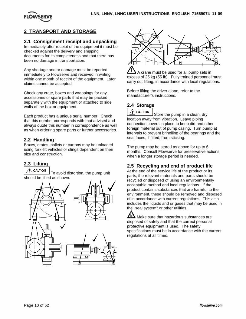
To avoid distortion, the pump unit should be lifted as shown.
A crane must be used for all pump sets in excess of 25 kg (55 lb). Fully trained personnel must carry out lifting, in accordance with local regulations. Before lifting the driver alone, refer to the manufacturer’s instructions. 2.4 Storage
Store the pump in a clean, dry location away from vibration. Leave piping connection covers in place to keep dirt and other foreign material out of pump casing. Turn pump at intervals to prevent brinelling of the bearings and the seal faces, if fitted, from sticking. The pump may be stored as above for up to 6 months. Consult Flowserve for preservative actions when a longer storage period is needed. 2.5 Recycling and end of product life At the end of the service life of the product or its parts, the relevant materials and parts should be recycled or disposed of using an environmentally acceptable method and local regulations. If the product contains substances that are harmful to the environment, these should be removed and disposed of in accordance with current regulations. This also includes the liquids and or gases that may be used in the "seal system" or other utilities.
Make sure that hazardous substances are disposed of safely and that the correct personal protective equipment is used. The safety specifications must be in accordance with the current regulations at all times.
LNN, LNNV, LNNC USER INSTRUCTIONS ENGLISH 7156907 4 11-09
Page 11 of 52 flowserve.com
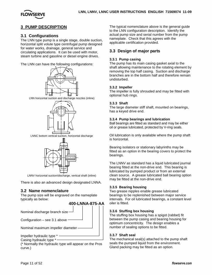
3 PUMP DESCRIPTION 3.1 Configurations The LNN type pump is a single stage, double suction, horizontal split volute type centrifugal pump designed for water works, drainage, general service and circulating applications. It can be used with motor, steam turbine and gasoline or diesel engine drives. The LNN can have the following configurations:
LNN horizontal suction and discharge nozzles (inline)
LNNC bottom vertical suction, horizontal discharge
LNNV horizontal suction/discharge, vertical shaft (inline)
There is also an advanced design designated LNNA. 3.2 Name nomenclature The pump size will be engraved on the nameplate typically as below: 400-LNNA-875-AA Nominal discharge branch size Configuration – see 3.1 above Nominal maximum impeller diameter Impeller hydraulic type * Casing hydraulic type * (* Normally the hydraulic type will appear on the Pros curve.)
The typical nomenclature above is the general guide to the LNN configuration description. Identify the actual pump size and serial number from the pump nameplate. Check that this agrees with the applicable certification provided. 3.3 Design of major parts 3.3.1 Pump casing The pump has its main casing gasket axial to the shaft allowing maintenance to the rotating element by removing the top half casing. Suction and discharge branches are in the bottom half and therefore remain undisturbed. 3.3.2 Impeller The impeller is fully shrouded and may be fitted with optional hub rings. 3.3.3 Shaft The large diameter stiff shaft, mounted on bearings, has a keyed drive end. 3.3.4 Pump bearings and lubrication Ball bearings are fitted as standard and may be either oil or grease lubricated, protected by V-ring seals. Oil lubrication is only available where the pump shaft is horizontal. Bearing isolators or stationary labyrinths may be fitted as an option in the bearing covers to protect the bearings. The LNNV as standard has a liquid lubricated journal bearing fitted at the non-drive end. This bearing is lubricated by pumped product or from an external clean source. A grease lubricated ball bearing option may be fitted at the non-drive end. 3.3.5 Bearing housing Two grease nipples enable grease lubricated bearings to be replenished between major service intervals. For oil lubricated bearings, a constant level oiler is fitted. 3.3.6 Stuffing box housing The stuffing box housing has a spigot (rabbet) fit between the pump casing and bearing housing for optimum concentricity. The design enables a number of sealing options to be fitted. 3.3.7 Shaft seal The mechanical seal(s) attached to the pump shaft seals the pumped liquid from the environment. Gland packing may be fitted as an option.
LNN, LNNV, LNNC USER INSTRUCTIONS ENGLISH 7156907 4 11-09
Page 12 of 52 flowserve.com
3.3.8 Driver The driver is normally an electric motor. Different drive configurations may be fitted such as internal combustion engines, turbines, hydraulic motors etc driving via couplings, belts, gearboxes, drive shafts etc. 3.3.9 Accessories Accessories may be fitted when specified by the customer. 3.4 Performance and operating limits This product has been selected to meet the specifications of your purchase order. See section 1.5. The following data is included as additional information to help with your installation. It is typical, and factors such as temperature, materials, and seal type may influence this data. If required, a definitive statement for your particular application can be obtained from Flowserve. 3.4.1 Operating limits
Pumped liquid temperature limits* - 20 to + 80 ºC (- 4 to + 176 ºF)
Maximum ambient temperature* - 20 to + 40 ºC (- 4 to +104 ºF)
Maximum soft solids in suspension* up to 3 % by volume (refer for size limits)
Maximum pump speed refer to the nameplate * Subject to written agreement from Flowserve. 4 INSTALLATION
Equipment operated in hazardous locations must comply with the relevant explosion protection regulations. See section 1.6.4, Products used in potentially explosive atmospheres. 4.1 Location The pump should be located to allow room for access, ventilation, maintenance and inspection with ample headroom for lifting and should be as close as practicable to the supply of liquid to be pumped. Refer to the general arrangement drawing for the pump set. 4.2 Part assemblies Motors may be supplied loose on LNNV pumps, typically on frame sizes 400 and above. It is the responsibility of the installer to ensure that the motor is assembled to the pump and lined up as detailed in section 4.5.2.
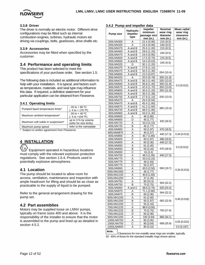
3.4.2 Pump and impeller data
Pump size Hydraulic Impeller
type
Impeller minimum
passage size mm (in.)
Nominal wear ring diameter mm (in.)
Mean radial wear ring clearance mm (in.)
200LNN300 A 22.4 (0.90) 215 (8.5) 200LNN325 A 24.3 (0.96) 240 (9.5) 200LNN375 A and B 25.5 (1.00) 215 (8.5) 200LNN400 A and B 29.6 (1.20) 200LNN475 A and B 24.0 (0.95)
240 (9.5)
200LNN500 A and B 17.5 (0.70) 215 (8.5) 200LNN600 A and B 16.0 (0.63) 250LNN325 D 30.1 (1.20)
240 (9.5)
250LNN375 A and B 27.8 (1.10) 250LNN475 A and B 32.5 (1.30) 250LNN600 A and B 22.0 (0.87)
264 (10.4)
300LNN325 A 20.0 (0.78) 300 (11.8) 300LNN475 A and B 36.3 (1.40) 330 (13.0) 300LNN500 A and B 36.8 (1.40) 300 (11.8) 300LNN575 A and B 42.9 (1.70) 350 (13.8) 300LNN600 A and B 30.0 (1.20) 300 (11.8) 300LNN625 A and B 35.0 (1.38) 300LNN750 A and B 27.9 (1.10) 350LNN375 A 25.0 (0.94)
330 (13.0)
350LNN475 A and B 45.4 (1.80) 350LNN575 A and B 41.2 (1.60) 350LNN725 A and B 48.0 (1.90) 350LNN900 A and B 33.0 (1.30)
380 (15.0)
400LNN600 A 46 (1.80) 400LNN600 D 45 (1.77) 400LNN725 A 53.3 (2.10) 400LNN725 B 45 (1.77)
420 (16.5)
400LNN800 A 50 (1.97) 470 (18.5)
0.3 (0.012)
400LNNA875 A 40 (1.57) 400LNN900 A 45.7 (1.80)
440 (17.3) 0.34 (0.013)
400LNN925 F 50 (1.97) 496 (19.5) 500LNN600 A 60 (2.36) 440 (17.3) 500LNN650 A 61 (2.40) 500LNN650 B 55 (2.16) 500LNN650 C 61 (2.4)
470 (18.5)
500LNN700 A 48.3 (1.90) 440 (17.3)
0.3 (0.012)
500LNN775 A 53.3 (2.10) 500LNN775 B 49 (1.93) 500LNN775 C 50 (1.97) 500LNN950 A 63.5 (2.50) 500LNN1000 A 45 (1.77) 500LNN1150 A 40.6 (1.60) 500LNN1250 A 37 (1.45)
500 (19.7) 0.34 (0.013)
600LNN750 A 80 (31.5) 600LNN750 B 70 (2.75)
564 (22.2)
600LNN950 A and C 68.6 (2.70) 620 (24.4) 600LNN975 A 71.1 (2.80) 600LNN975 B 60 (2.36)
564 (22.2)
600LNN1200 A 61 (2.40) 600LNN1200 B 50 (1.97) 600LNN1200 C 55 (2.16)
582 (22.9)
700LNN1225 A 88.9 (3.50) 700LNN1225 B 70 (2.75) 700LNN1225 D 60 (2.36)
700 (27.6)
900LNN1200 A 100 (3.94) 866 (34.1)
0.45 (0.018)
1000LNN750 A 85 (3.35) 1000LNN750 C 90 (3.54)
0.55 (0.022)
1000LNN800 A 80 (3.15) 658 (25.9)
0.5 (0.197)
Clearances for non-metallic wear rings are smaller, typically 50 - 65% of those for the standard metallic rings shown above.
LNN, LNNV, LNNC USER INSTRUCTIONS ENGLISH 7156907 4 11-09
Page 13 of 52 flowserve.com
4.3 Foundation
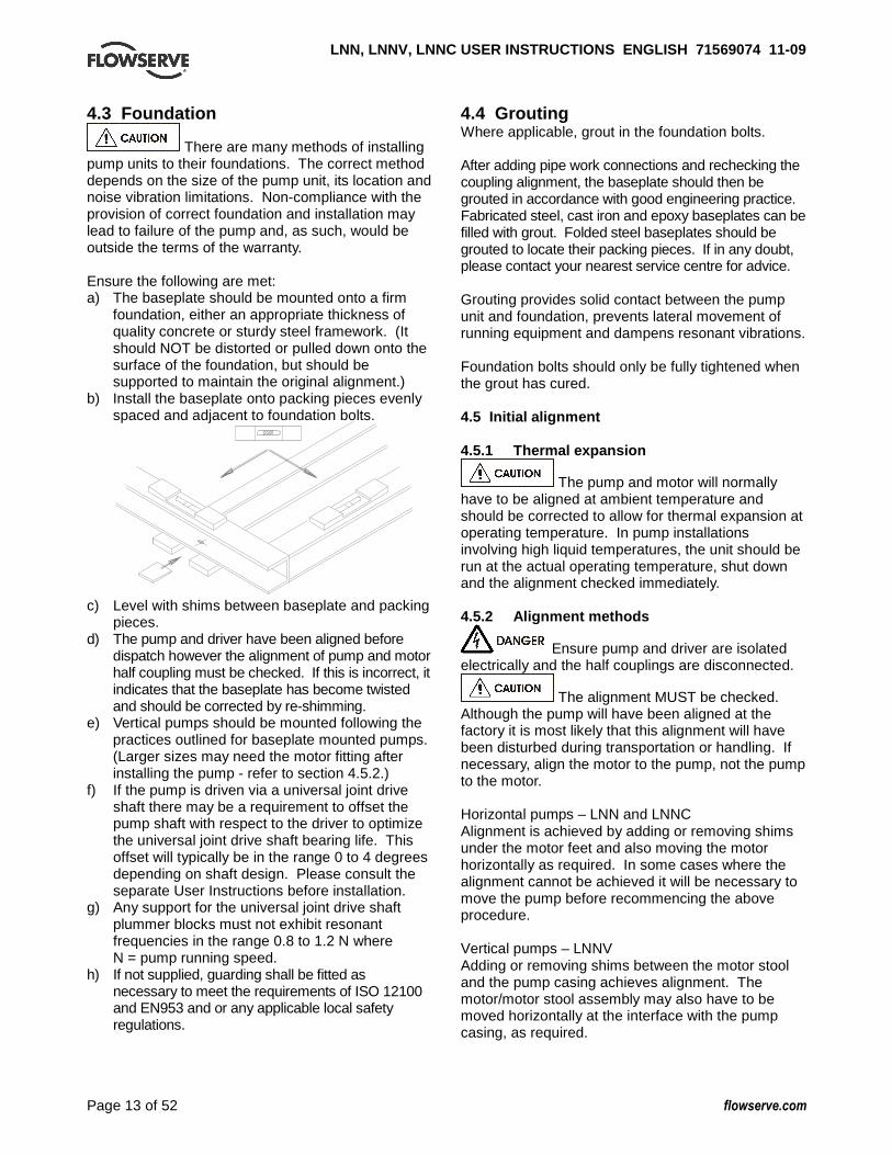
There are many methods of installing pump units to their foundations. The correct method depends on the size of the pump unit, its location and noise vibration limitations. Non-compliance with the provision of correct foundation and installation may lead to failure of the pump and, as such, would be outside the terms of the warranty. Ensure the following are met: a) The baseplate should be mounted onto a firm
foundation, either an appropriate thickness of quality concrete or sturdy steel framework. (It should NOT be distorted or pulled down onto the surface of the foundation, but should be supported to maintain the original alignment.)
b) Install the baseplate onto packing pieces evenly spaced and adjacent to foundation bolts.
c) Level with shims between baseplate and packing
pieces. d) The pump and driver have been aligned before
dispatch however the alignment of pump and motor half coupling must be checked. If this is incorrect, it indicates that the baseplate has become twisted and should be corrected by re-shimming.
e) Vertical pumps should be mounted following the practices outlined for baseplate mounted pumps. (Larger sizes may need the motor fitting after installing the pump - refer to section 4.5.2.)
f) If the pump is driven via a universal joint drive shaft there may be a requirement to offset the pump shaft with respect to the driver to optimize the universal joint drive shaft bearing life. This offset will typically be in the range 0 to 4 degrees depending on shaft design. Please consult the separate User Instructions before installation.
g) Any support for the universal joint drive shaft plummer blocks must not exhibit resonant frequencies in the range 0.8 to 1.2 N where N = pump running speed.
h) If not supplied, guarding shall be fitted as necessary to meet the requirements of ISO 12100 and EN953 and or any applicable local safety regulations.
4.4 Grouting Where applicable, grout in the foundation bolts. After adding pipe work connections and rechecking the coupling alignment, the baseplate should then be grouted in accordance with good engineering practice. Fabricated steel, cast iron and epoxy baseplates can be filled with grout. Folded steel baseplates should be grouted to locate their packing pieces. If in any doubt, please contact your nearest service centre for advice. Grouting provides solid contact between the pump unit and foundation, prevents lateral movement of running equipment and dampens resonant vibrations. Foundation bolts should only be fully tightened when the grout has cured. 4.5 Initial alignment 4.5.1 Thermal expansion
The pump and motor will normally have to be aligned at ambient temperature and should be corrected to allow for thermal expansion at operating temperature. In pump installations involving high liquid temperatures, the unit should be run at the actual operating temperature, shut down and the alignment checked immediately. 4.5.2 Alignment methods
Ensure pump and driver are isolated electrically and the half couplings are disconnected.
The alignment MUST be checked. Although the pump will have been aligned at the factory it is most likely that this alignment will have been disturbed during transportation or handling. If necessary, align the motor to the pump, not the pump to the motor. Horizontal pumps – LNN and LNNC Alignment is achieved by adding or removing shims under the motor feet and also moving the motor horizontally as required. In some cases where the alignment cannot be achieved it will be necessary to move the pump before recommencing the above procedure. Vertical pumps – LNNV Adding or removing shims between the motor stool and the pump casing achieves alignment. The motor/motor stool assembly may also have to be moved horizontally at the interface with the pump casing, as required.

LNN, LNNV, LNNC USER INSTRUCTIONS ENGLISH 7156907 4 11-09
Page 14 of 52 flowserve.com
It should be noted that the motor has a spigot (rabbet) fit into the motor stool and it is therefore not possible to achieve any horizontal movement at this interface. For couplings with narrow flanges use a dial indicator as shown below to check both parallel and angular alignment.
Parallel
Angular
Maximum permissible misalignment at working temperature: Parallel 0.2 mm (0.008 in.) TIR Angular 0.1 mm (0.004 in.) TIR When checking parallel alignment, the total indicator read-out (TIR) shown is twice the value of the actual shaft displacement. Align in the vertical plane first, then horizontally by moving motor. While the pump is capable of operating with the maximum misalignment shown above, maximum pump reliability is obtained by near perfect alignment of 0.05 to 0.10 mm (0.002 to 0.004 in.) TIR parallel and 0.05 mm (0.002 in.) per 100 mm (4 in.) of coupling flange diameter as TIR angular misalignment. This covers the full series of couplings available. Pumps with thick flanged non-spacer couplings can be aligned by using a straight-edge across the outside diameters of the coupling hubs and measuring the gap between the machined faces using feeler gauges, measuring wedge or calipers. When the electric motor has sleeve bearings it is necessary to ensure that the motor is aligned to run on its magnetic centerline.
� Refer to the motor manual for details.
A button (screwed into one of the shaft ends) is normally fitted between the motor and pump shaft ends to fix the axial position.
If the motor does not run in its magnetic centre the resultant additional axial force may overload the pump thrust bearing.
4.5.3 Check for soft foot
This is a check to ensure that there is no undue stress on the driver holding down bolts; due to non-level baseplate or twisting. To check, remove all shims and clean surfaces and tighten down driver to the baseplate. Set a dial indicator as shown in sketch and loosen off the holding down bolt while noting any deflection reading on the Dial Test Indicator - a maximum of 0.05 mm (0.002 in.) is considered acceptable but any more will have to be corrected by adding shims, for example, if the Dial Test Indicator shows the foot lifting 0.15 mm (0.006 in.) then this is the thickness of shim to be placed under that foot. Tighten down and repeat the same procedure on all other feet until all are within tolerance
Complete piping as below and see sections 4.7, Final shaft alignment check up to and including section 5, Commissioning, start up, operation and shutdown before connecting driver and checking actual rotation. 4.6 Piping
Protective covers are fitted to the pipe connections to prevent foreign bodies entering during transportation and installation. Ensure that these covers are removed from the pump before connecting any pipes. 4.6.1 Suction and discharge pipe work In order to minimize friction losses and hydraulic noise in the pipe work it is good practice to choose pipe work that is one or two sizes larger than the pump suction and discharge. Typically main pipe work velocities should not exceed 2 m/s (6 ft/sec) suction and 3 m/s (9 ft/sec) on the discharge.
LNN, LNNV, LNNC USER INSTRUCTIONS ENGLISH 7156907 4 11-09
Page 15 of 52 flowserve.com
Take into account the available NPSH which must be higher than the required NPSH of the pump.
Never use the pump as a support for piping.
Maximum forces and moments allowed on the pump flanges vary with the pump size and type. To minimize these forces and moments that may, if excessive, cause misalignment, hot bearings, worn couplings, vibration and the possible failure of the pump casing, the following points should be strictly followed: • Prevent excessive external pipe load • Never draw piping into place by applying force to
pump flange connections
• Do not mount expansion joints so that their force, due to internal pressure, acts on the pump flange. It is recommended that expansion joints use threaded rod to limit any forces of this type
The tables in 4.6.2 summarize the maximum forces and moments allowed on LNN pump casings. Refer to Flowserve for other configurations.
Ensure piping and fittings are flushed before use.
Ensure piping for hazardous liquids is arranged to allow pump flushing before removal of the pump.
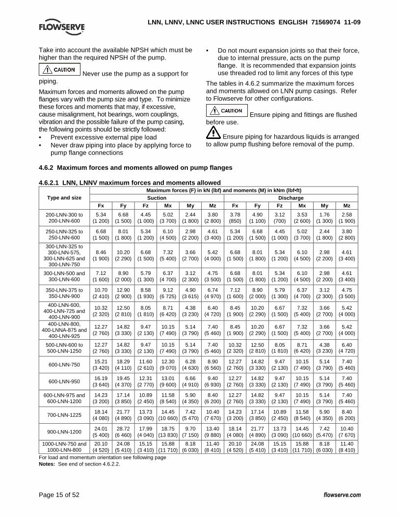
4.6.2 Maximum forces and moments allowed on pump f langes 4.6.2.1 LNN, LNNV maximum forces and moments allow ed
Maximum forces (F) in kN (lbf) and moments (M) in k Nm (lbf•ft) Suction Discharge Type and size
Fx Fy Fz Mx My Mz Fx Fy Fz Mx My Mz
200-LNN-300 to 200-LNN-600
5.34 (1 200)
6.68 (1 500)
4.45 (1 000)
5.02 (3 700)
2.44 (1 800)
3.80 (2 800)
3.78 (850)
4.90 (1 100)
3.12 (700)
3.53 (2 600)
1.76 (1 300)
2.58 (1 900)
250-LNN-325 to 250-LNN-600
6.68 (1 500)
8.01 (1 800)
5.34 (1 200)
6.10 (4 500)
2.98 (2 200)
4.61 (3 400)
5.34 (1 200)
6.68 (1 500)
4.45 (1 000)
5.02 (3 700)
2.44 (1 800)
3.80 (2 800)
300-LNN-325 to 300-LNN-575,
300-LNN-625 and 300-LNN-750
8.46 (1 900)
10.20 (2 290)
6.68 (1 500)
7.32 (5 400)
3.66 (2 700)
5.42 (4 000)
6.68 (1 500)
8.01 (1 800)
5.34 (1 200)
6.10 (4 500)
2.98 (2 200)
4.61 (3 400)
300-LNN-500 and 300-LNN-600
7.12 (1 600)
8.90 (2 000)
5.79 (1 300)
6.37 (4 700)
3.12 (2 300)
4.75 (3 500)
6.68 (1 500)
8.01 (1 800)
5.34 (1 200)
6.10 (4 500)
2.98 (2 200)
4.61 (3 400)
350-LNN-375 to 350-LNN-900
10.70 (2 410)
12.90 (2 900)
8.58 (1 930)
9.12 (6 725)
4.90 (3 615)
6.74 (4 970)
7.12 (1 600)
8.90 (2 000)
5.79 (1 300)
6.37 (4 700)
3.12 (2 300)
4.75 (3 500)
400-LNN-600, 400-LNN-725 and
400-LNN-900
10.32 (2 320)
12.50 (2 810)
8.05 (1 810)
8.71 (6 420)
4.38 (3 230)
6.40 (4 720)
8.45 (1 900)
10.20 (2 290)
6.67 (1 500)
7.32 (5 400)
3.66 (2 700)
5.42 (4 000)
400-LNN-800, 400-LNNA-875 and
400-LNN-925
12.27 (2 760)
14.82 (3 330)
9.47 (2 130)
10.15 (7 490)
5.14 (3 790)
7.40 (5 460)
8.45 (1 900)
10.20 (2 290)
6.67 (1 500)
7.32 (5 400)
3.66 (2 700)
5.42 (4 000)
500-LNN-600 to 500-LNN-1250
12.27 (2 760)
14.82 (3 330)
9.47 (2 130)
10.15 (7 490)
5.14 (3 790)
7.40 (5 460)
10.32 (2 320)
12.50 (2 810)
8.05 (1 810)
8.71 (6 420)
4.38 (3 230)
6.40 (4 720)
600-LNN-750 15.21
(3 420) 18.29
(4 110) 11.60
(2 610) 12.30
(9 070) 6.28
(4 630) 8.90
(6 560) 12.27
(2 760) 14.82
(3 330) 9.47
(2 130) 10.15
(7 490) 5.14
(3 790) 7.40
(5 460)
600-LNN-950 16.19
(3 640) 19.45
(4 370) 12.31
(2 770) 13.01
(9 600) 6.66
(4 910) 9.40
(6 930) 12.27
(2 760) 14.82
(3 330) 9.47
(2 130) 10.15
(7 490) 5.14
(3 790) 7.40
(5 460)
600-LNN-975 and 600-LNN-1200
14.23 (3 200)
17.14 (3 850)
10.89 (2 450)
11.58 (8 540)
5.90 (4 350)
8.40 (6 200)
12.27 (2 760)
14.82 (3 330)
9.47 (2 130)
10.15 (7 490)
5.14 (3 790)
7.40 (5 460)
700-LNN-1225 18.14
(4 080) 21.77
(4 890) 13.73
(3 090) 14.45
(10 660) 7.42
(5 470) 10.40
(7 670) 14.23
(3 200) 17.14
(3 850) 10.89
(2 450) 11.58
(8 540) 5.90
(4 350) 8.40
(6 200)
900-LNN-1200 24.01
(5 400) 28.72
(6 460) 17.99
(4 040) 18.75
(13 830) 9.70
(7 150) 13.40
(9 880) 18.14
(4 080) 21.77
(4 890) 13.73
(3 090) 14.45
(10 660) 7.42
(5.470) 10.40
(7 670)
1000-LNN-750 and 1000-LNN-800
20.10 (4 520)
24.08 (5 410)
15.15 (3 410)
15.88 (11 710)
8.18 (6 030)
11.40 (8 410)
20.10 (4 520)
24.08 (5 410)
15.15 (3 410)
15.88 (11 710)
8.18 (6 030)
11.40 (8 410)
For load and momentum orientation see following page Notes: See end of section 4.6.2.2.
LNN, LNNV, LNNC USER INSTRUCTIONS ENGLISH 7156907 4 11-09
Page 16 of 52 flowserve.com
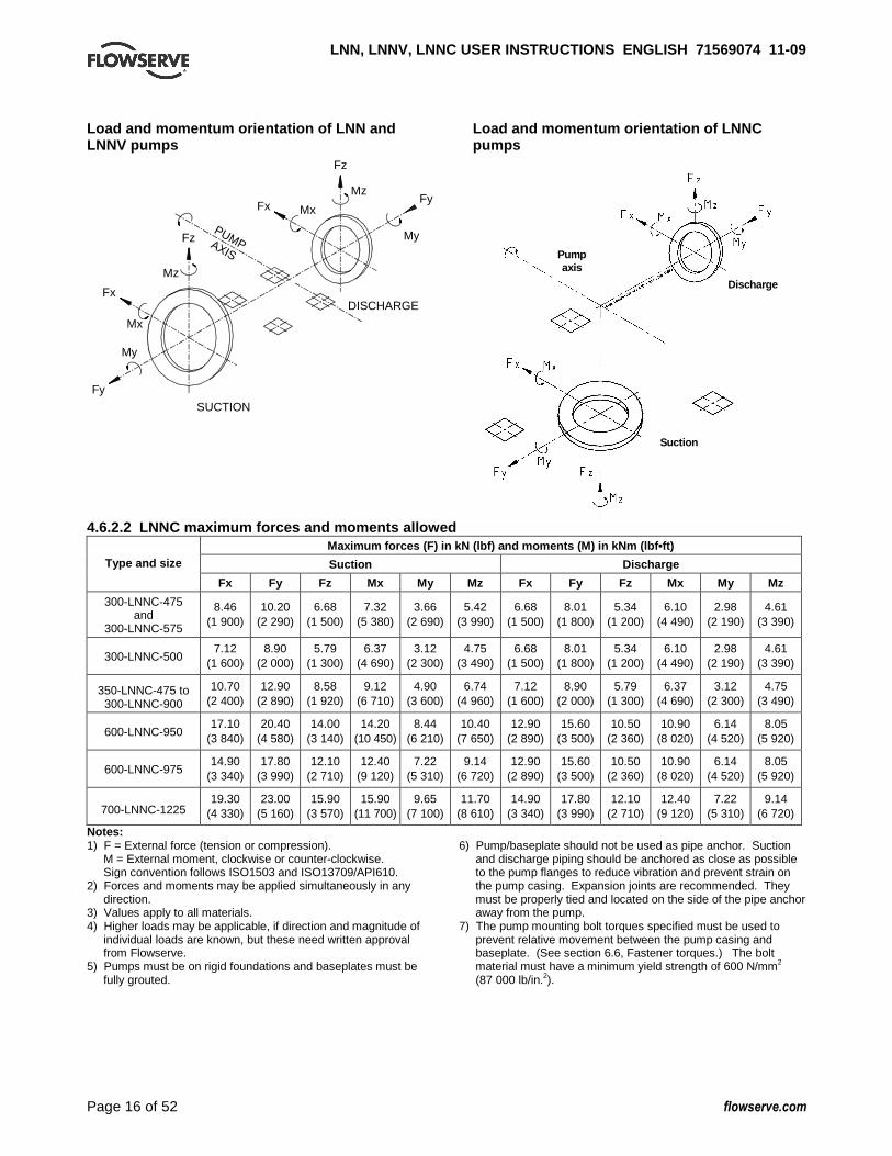
Load and momentum orientation of LNN and LNNV pumps
DISCHARGE
SUCTION
Mx
My
Mz
Fx
Fy
Fz
Mx
My
MzFx
Fy
Fz
PUMPAXIS
Load and momentum orientation of LNNC pumps
Discharge
Suction
Pump axis
4.6.2.2 LNNC maximum forces and moments allowed Maximum forces (F) in kN (lbf) and moments (M) in k Nm (lbf•ft)
Suction Discharge Type and size
Fx Fy Fz Mx My Mz Fx Fy Fz Mx My Mz
300-LNNC-475 and
300-LNNC-575
8.46 (1 900)
10.20 (2 290)
6.68 (1 500)
7.32 (5 380)
3.66 (2 690)
5.42 (3 990)
6.68 (1 500)
8.01 (1 800)
5.34 (1 200)
6.10 (4 490)
2.98 (2 190)
4.61 (3 390)
300-LNNC-500 7.12
(1 600) 8.90
(2 000) 5.79
(1 300) 6.37
(4 690) 3.12
(2 300) 4.75
(3 490) 6.68
(1 500) 8.01
(1 800) 5.34
(1 200) 6.10
(4 490) 2.98
(2 190) 4.61
(3 390)
350-LNNC-475 to 300-LNNC-900
10.70 (2 400)
12.90 (2 890)
8.58 (1 920)
9.12 (6 710)
4.90 (3 600)
6.74 (4 960)
7.12 (1 600)
8.90 (2 000)
5.79 (1 300)
6.37 (4 690)
3.12 (2 300)
4.75 (3 490)
600-LNNC-950 17.10
(3 840) 20.40
(4 580) 14.00
(3 140) 14.20
(10 450) 8.44
(6 210) 10.40
(7 650) 12.90
(2 890) 15.60
(3 500) 10.50
(2 360) 10.90
(8 020) 6.14
(4 520) 8.05
(5 920)
600-LNNC-975 14.90
(3 340) 17.80
(3 990) 12.10
(2 710) 12.40
(9 120) 7.22
(5 310) 9.14
(6 720) 12.90
(2 890) 15.60
(3 500) 10.50
(2 360) 10.90
(8 020) 6.14
(4 520) 8.05
(5 920)
700-LNNC-1225 19.30
(4 330) 23.00
(5 160) 15.90
(3 570) 15.90
(11 700) 9.65
(7 100) 11.70
(8 610) 14.90
(3 340) 17.80
(3 990) 12.10
(2 710) 12.40
(9 120) 7.22
(5 310) 9.14
(6 720)
Notes: 1) F = External force (tension or compression).
M = External moment, clockwise or counter-clockwise. Sign convention follows ISO1503 and ISO13709/API610.
2) Forces and moments may be applied simultaneously in any direction.
3) Values apply to all materials. 4) Higher loads may be applicable, if direction and magnitude of
individual loads are known, but these need written approval from Flowserve.
5) Pumps must be on rigid foundations and baseplates must be fully grouted.
6) Pump/baseplate should not be used as pipe anchor. Suction
and discharge piping should be anchored as close as possible to the pump flanges to reduce vibration and prevent strain on the pump casing. Expansion joints are recommended. They must be properly tied and located on the side of the pipe anchor away from the pump.
7) The pump mounting bolt torques specified must be used to prevent relative movement between the pump casing and baseplate. (See section 6.6, Fastener torques.) The bolt material must have a minimum yield strength of 600 N/mm2 (87 000 lb/in.2).
LNN, LNNV, LNNC USER INSTRUCTIONS ENGLISH 7156907 4 11-09
Page 17 of 52 flowserve.com
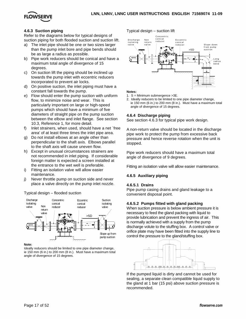
4.6.3 Suction piping Refer to the diagrams below for typical designs of suction piping for both flooded suction and suction lift. a) The inlet pipe should be one or two sizes larger
than the pump inlet bore and pipe bends should be as large a radius as possible.
b) Pipe work reducers should be conical and have a maximum total angle of divergence of 15 degrees.
c) On suction lift the piping should be inclined up towards the pump inlet with eccentric reducers incorporated to prevent air locks.
d) On positive suction, the inlet piping must have a constant fall towards the pump.
e) Flow should enter the pump suction with uniform flow, to minimize noise and wear. This is particularly important on large or high-speed pumps which should have a minimum of five diameters of straight pipe on the pump suction between the elbow and inlet flange. See section 10.3, Reference 1, for more detail.
f) Inlet strainers, when used, should have a net `free area' of at least three times the inlet pipe area.
g) Do not install elbows at an angle other than perpendicular to the shaft axis. Elbows parallel to the shaft axis will cause uneven flow.
h) Except in unusual circumstances strainers are not recommended in inlet piping. If considerable foreign matter is expected a screen installed at the entrance to the wet well is preferable.
i) Fitting an isolation valve will allow easier maintenance.
j) Never throttle pump on suction side and never place a valve directly on the pump inlet nozzle.
Typical design – flooded suction
Discharge isolating valve Non
return valve
Concentric conical reducer
Eccentric conical reducer
Suction isolating valve
Slope up from pump suction
Note: Ideally reducers should be limited to one pipe diameter change, ie 150 mm (6 in.) to 200 mm (8 in.). Must have a maximum total angle of divergence of 15 degrees.
Typical design – suction lift
L on g r ad i us b en d
Sl op e d o wn f r om p u mp s uc t i on >5D
Ec c en t r i c c on i c a l r ed uc er
Di sc h ar g e i s o l a t i n g v a l ve
Conc en t r i c c on i c a l r ed uc er
Non r e t ur n va l ve
Notes: 1. S = Minimum submergence >3E. 2. Ideally reducers to be limited to one pipe diameter change,
ie 150 mm (6 in.) to 200 mm (8 in.). Must have a maximum total angle of divergence of 15 degrees.
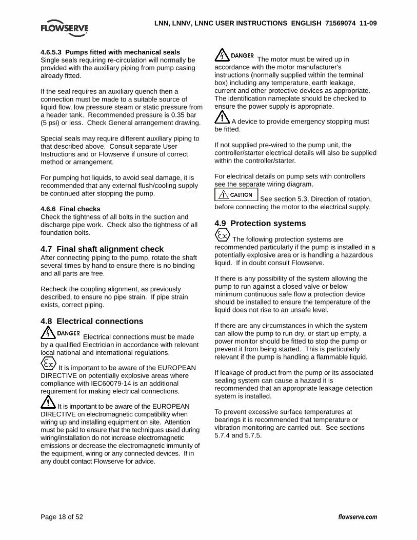
4.6.4 Discharge piping See section 4.6.3 for typical pipe work design. A non-return valve should be located in the discharge pipe work to protect the pump from excessive back pressure and hence reverse rotation when the unit is stopped. Pipe work reducers should have a maximum total angle of divergence of 9 degrees. Fitting an isolation valve will allow easier maintenance. 4.6.5 Auxiliary piping 4.6.5.1 Drains Pipe pump casing drains and gland leakage to a convenient disposal point. 4.6.5.2 Pumps fitted with gland packing When suction pressure is below ambient pressure it is necessary to feed the gland packing with liquid to provide lubrication and prevent the ingress of air. This is normally achieved with a supply from the pump discharge volute to the stuffing box. A control valve or orifice plate may have been fitted into the supply line to control the pressure to the gland/stuffing box.
If the pumped liquid is dirty and cannot be used for sealing, a separate clean compatible liquid supply to the gland at 1 bar (15 psi) above suction pressure is recommended.
>5D
LNN, LNNV, LNNC USER INSTRUCTIONS ENGLISH 7156907 4 11-09
Page 18 of 52 flowserve.com
4.6.5.3 Pumps fitted with mechanical seals Single seals requiring re-circulation will normally be provided with the auxiliary piping from pump casing already fitted. If the seal requires an auxiliary quench then a connection must be made to a suitable source of liquid flow, low pressure steam or static pressure from a header tank. Recommended pressure is 0.35 bar (5 psi) or less. Check General arrangement drawing. Special seals may require different auxiliary piping to that described above. Consult separate User Instructions and or Flowserve if unsure of correct method or arrangement. For pumping hot liquids, to avoid seal damage, it is recommended that any external flush/cooling supply be continued after stopping the pump. 4.6.6 Final checks Check the tightness of all bolts in the suction and discharge pipe work. Check also the tightness of all foundation bolts. 4.7 Final shaft alignment check After connecting piping to the pump, rotate the shaft several times by hand to ensure there is no binding and all parts are free. Recheck the coupling alignment, as previously described, to ensure no pipe strain. If pipe strain exists, correct piping. 4.8 Electrical connections
Electrical connections must be made by a qualified Electrician in accordance with relevant local national and international regulations.
It is important to be aware of the EUROPEAN DIRECTIVE on potentially explosive areas where compliance with IEC60079-14 is an additional requirement for making electrical connections.
It is important to be aware of the EUROPEAN DIRECTIVE on electromagnetic compatibility when wiring up and installing equipment on site. Attention must be paid to ensure that the techniques used during wiring/installation do not increase electromagnetic emissions or decrease the electromagnetic immunity of the equipment, wiring or any connected devices. If in any doubt contact Flowserve for advice.
The motor must be wired up in accordance with the motor manufacturer's instructions (normally supplied within the terminal box) including any temperature, earth leakage, current and other protective devices as appropriate. The identification nameplate should be checked to ensure the power supply is appropriate.
A device to provide emergency stopping must be fitted. If not supplied pre-wired to the pump unit, the controller/starter electrical details will also be supplied within the controller/starter. For electrical details on pump sets with controllers see the separate wiring diagram.
See section 5.3, Direction of rotation, before connecting the motor to the electrical supply. 4.9 Protection systems
The following protection systems are recommended particularly if the pump is installed in a potentially explosive area or is handling a hazardous liquid. If in doubt consult Flowserve. If there is any possibility of the system allowing the pump to run against a closed valve or below minimum continuous safe flow a protection device should be installed to ensure the temperature of the liquid does not rise to an unsafe level. If there are any circumstances in which the system can allow the pump to run dry, or start up empty, a power monitor should be fitted to stop the pump or prevent it from being started. This is particularly relevant if the pump is handling a flammable liquid. If leakage of product from the pump or its associated sealing system can cause a hazard it is recommended that an appropriate leakage detection system is installed. To prevent excessive surface temperatures at bearings it is recommended that temperature or vibration monitoring are carried out. See sections 5.7.4 and 5.7.5.
LNN, LNNV, LNNC USER INSTRUCTIONS ENGLISH 7156907 4 11-09
Page 19 of 52 flowserve.com
5 COMMISSIONING, START-UP, OPERATION AND SHUTDOWN
These operations must be carried out by fully qualified personnel. 5.1 Pre-commissioning procedure 5.1.1 Lubrication Determine the mode of lubrication of the pump set, eg grease, oil, product lubrication etc.
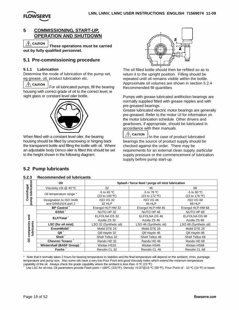
For oil lubricated pumps, fill the bearing housing with correct grade of oil to the correct level, ie sight glass or constant level oiler bottle.
When fitted with a constant level oiler, the bearing housing should be filled by unscrewing or hinging back the transparent bottle and filling the bottle with oil. Where an adjustable body Denco oiler is fitted this should be set to the height shown in the following diagram:
The oil filled bottle should then be refitted so as to return it to the upright position. Filling should be repeated until oil remains visible within the bottle. Approximate oil volumes are shown in section 5.2.4 Recommended fill quantities Pumps with grease lubricated antifriction bearings are normally supplied fitted with grease nipples and with pre-greased bearings. Grease lubricated electric motor bearings are generally pre-greased. Refer to the motor UI for information on the motor lubrication schedule Other drivers and gearboxes, if appropriate, should be lubricated in accordance with their manuals.
In the case of product lubricated bearings the source of product supply should be checked against the order. There may be requirements for an external clean supply, particular supply pressure or the commencement of lubrication supply before pump start-up.
5.2 Pump lubricants 5.2.3 Recommended oil lubricants
* Note that it normally takes 2 hours for bearing temperature to stabilize and the final temperature will depend on the ambient, r/min, pumpage temperature and pump size. Also some oils have a very low Pour Point and good Viscosity Index which extend the minimum temperature capability of the oil. Always check the grade capability where the ambient is less than -5 ºC (23 ºF). † Use LSC for oil mist. Oil parameters provide Flash point > 166ºC (331ºF), Density >0.87@15 ºC (59 ºF), Pour Point of - 10 ºC (14 ºF) or lower.
Oil Splash / force feed / purge oil mist lubrication
Viscosity cSt @ 40 ºC 32 46 68
Oil temperature range * -5 to 65 ºC (23 to 149 ºF)
-5 to 78 ºC (23 to 172 ºF)
-5 to 80 ºC (23 to 176 ºF)
Cen
trifu
gal
pum
p lu
bric
atio
n
Designation to ISO 3448 and DIN51524 part 2
ISO VG 32 32 HLP
ISO VG 46 46 HLP
ISO VG 68 68 HLP
BP Castrol † Energol HLP-HM 32 Energol HLP-HM 46 Energol HLP-HM 68 ESSO † NUTO HP 32 NUTO HP 46 NUTO HP 68
ELF/Total † ELFOLNA DS 32
Azolla ZS 32 ELFOLNA DS 46
Azolla ZS 46 ELFOLNA DS 68
Azolla ZS 68 LSC (for oil mist) LSO 32 (Synthetic oil) LSO 46 (Synthetic oil) LSO 68 (Synthetic oil)
ExxonMobil † Mobil DTE 24 Mobil DTE 25 Mobil DTE 26 Q8 † Q8 Haydn 32 Q8 Haydn 46 Q8 Haydn 68
Shell † Shell Tellus 32 Shell Tellus 46 Shell Tellus 68 Chevron Texaco † Rando HD 32 Rando HD 46 Rando HD 68
Wintershall (BASF Group) † Wiolan HS32 Wiolan HS46 Wiolan HS68
Oil
com
pani
es a
nd
lubr
ican
ts
Fuchs † Renolin CL 32 Renolin CL 46 Renolin CL 68
LNN, LNNV, LNNC USER INSTRUCTIONS ENGLISH 7156907 4 11-09
Page 20 of 52 flowserve.com
5.2.2 Recommended grease lubricants Grease Grade NLGI 2* NLGI 3**
Temp. range ºC (ºF)
-20 to +100 (-4 to +212)
-20 to +100 (-4 to +212)
Designation acc. to DIN KP2K-25 KP3K-20
BP Energrease LS-EP2 Energrease LS-EP3
Elf Multis EP2 Multis EP3
Fuchs RENOLIT EP2 RENOLIT EP3
Esso Beacon EP2 Beacon EP3
Mobil Mobilux EP2 Mobilux EP3
Q8 Rembrandt EP2 Rembrandt EP3
Shell Alvania EP2 Alvania EP2
Texaco Multifak EP2 Multifak EP3
SKF LGEP 2 * NLGI 2 is an alternative grease and is not to be mixed with other grades ** Standard pre-packed grease for fitted antifriction bearings.
5.2.3 Lubrication schedule 5.2.3.1 Oil lubricated bearings Normal oil change intervals are 4 000 operating hours or at least every 6 months. For pumps on hot service or in severely damp or corrosive atmosphere, the oil will require changing more frequently. Lubricant and bearing temperature analysis can be useful in optimizing lubricant change intervals. The lubricating oil should be a high quality mineral oil having foam inhibitors. Synthetic oils may also be used if checks show that the rubber oil seals will not be adversely affected. The bearing temperature may be allowed to rise to 50 ºC (90 ºF).above ambient, but should not exceed 82 ºC (180 ºF). A continuously rising temperature, or an abrupt rise, indicate a fault. 5.2.3.2 Grease lubricated bearings When grease nipples are fitted, one charge between grease changes is advisable for most operating conditions, ie 2 000 hours interval. Normal intervals between grease changes are 4 000 hours or at least every 6 months. The characteristics of the installation and severity of service will determine the frequency of lubrication. Lubricant and bearing temperature analysis can be useful in optimizing lubricant change intervals. The bearing temperature may be allowed to rise to 55 ºC (99 ºF) above ambient but should not exceed 95 °C (204 °F). For most operating conditions a quality grease having a lithium soap base and NLGI
consistency of No 2 or No 3 is recommended. The drop point should exceed 175 ºC (350 ºF).
Never mix greases containing different bases, thickeners or additives.
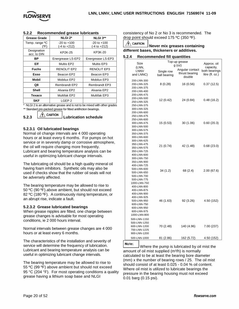
5.2.4 Recommended fill quantities Top-up grease
g (oz) Size
(LNN, LNNV
and LNNC) Single row ball bearing
Angular contact thrust bearing
double
Approx. oil capacity,
both bearings litre (fl. oz.)
200-LNN-300 200-LNN-325 200-LNN-375
8 (0.28) 16 (0.56) 0.37 (12.5)
200-LNN-400 200-LNN-475 200-LNN-500 250-LNN-325 250-LNN-375 300-LNN-325
12 (0.42) 24 (0.84) 0.48 (16.2)
200-LNN-600 250-LNN-475 250-LNN-600 300-LNN-475 300-LNN-500 300-LNN-575 350-LNN-375
15 (0.53) 30 (1.06) 0.60 (20.3)
300-LNN-600 300-LNN-625 350-LNN-475 350-LNN-575 350-LNN-725 400-LNN-600
21 (0.74) 42 (1.48) 0.68 (23.0)
300-LNN-750 350-LNN-900 400-LNN-725 500-LNN-600 500-LNN-650 500-LNN-700 500-LNN-775
1000-LNN-750
34 (1.2) 68 (2.4) 2.00 (67.6)
400-LNN-800 400-LNN-875 400-LNN-900 400-LNN-925 500-LNN-950 600-LNN-750 600-LNN-950 600-LNN-975
1000-LNN-800
46 (1.63) 92 (3.26) 4.50 (152)
500-LNN-1150 500-LNN-1250 600-LNN-1200 700-LNN-1225 900-LNN-1200
70 (2.48) 140 (4.96) 7.00 (237)
500-LNN-1000 81 (2.86) 162 (5.72) 4.50 (152)
Where the pump is lubricated by oil mist the amount of oil mist supplied (m³/h) is normally calculated to be at least the bearing bore diameter (mm) x the number of bearing rows / 25. The oil mist should consist of at least 0.025 - 0.04 % oil content. Where oil mist is utilized to lubricate bearings the pressure in the bearing housing must not exceed 0.01 barg (0.15 psi).
LNN, LNNV, LNNC USER INSTRUCTIONS ENGLISH 7156907 4 11-09
Page 21 of 52 flowserve.com
5.3 Direction of rotation
Ensure the pump is given the same rotation as the pump direction arrow cast on the pump casing. To avoid dry running the pump must either be filled with liquid or have the flexible coupling disconnected before driver is switched on.
If maintenance work has been carried out to the site's electricity supply, the direction of rotation should be re-checked as above in case the supply phasing has been altered. 5.4 Guarding
Guarding is supplied fitted to the pump set. Fasteners for guards must remain captive in the guard to comply with the Machinery Directive 2006/42/EC. When releasing guards, the fasteners must be unscrewed in an appropriate way to ensure that the fasteners remain captive. Whenever guarding is removed or disturbed ensure that all the protective guards are securely refitted prior to start-up.
5.5 Priming and auxiliary supplies
Ensure all electrical, hydraulic, pneumatic, sealant and lubrication systems (as applicable) are connected and operational.
Ensure the inlet pipe and pump casing are completely full of liquid before starting continuous duty operation. 5.5.1 Suction pressure above atmospheric pressure Horizontal pumps: open vent connection (1) on top of the pump upper casing to allow the trapped air to escape. Let liquid run out until free from air bubbles. Vertical pumps: open vent connection (1) at the front of the upper half casing and disconnect the seal flush line at the mechanical seal/stuffing box to allow the trapped air to escape. Let liquid run out until free from air bubbles.
(1) Possibl eprimi ng
points
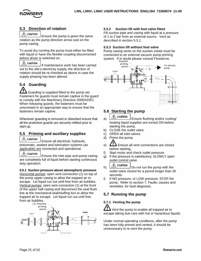
5.5.2 Suction lift with foot valve fitted Fill suction pipe and casing with liquid at a pressure of 1 to 2 bar from an external source. Vent as described in section 5.5.1. 5.5.3 Suction lift without foot valve Pump casing vents on the suction volute must be connected to an external vacuum pump priming system. If in doubt please consult Flowserve.
Possiblepriming
points To vacuum pump
5.6 Starting the pump
a) Ensure flushing and/or cooling/ heating liquid supplies are turned ON before starting the pump.
b) CLOSE the outlet valve. c) OPEN all inlet valves. d) Prime the pump.
e) Ensure all vent connections are closed before starting.
f) Start motor and check outlet pressure. g) If the pressure is satisfactory, SLOWLY open
outlet control valve.
h) Do not run the pump with the outlet valve closed for a period longer than 30 seconds.
i) If NO pressure, or LOW pressure, STOP the pump. Refer to section 7, Faults; causes and remedies, for fault diagnosis.
5.7 Running the pump 5.7.1 Venting the pump
Vent the pump to enable all trapped air to escape taking due care with hot or hazardous liquids. Under normal operating conditions, after the pump has been fully primed and vented, it should be unnecessary to re-vent the pump.
LNN, LNNV, LNNC USER INSTRUCTIONS ENGLISH 7156907 4 11-09
Page 22 of 52 flowserve.com
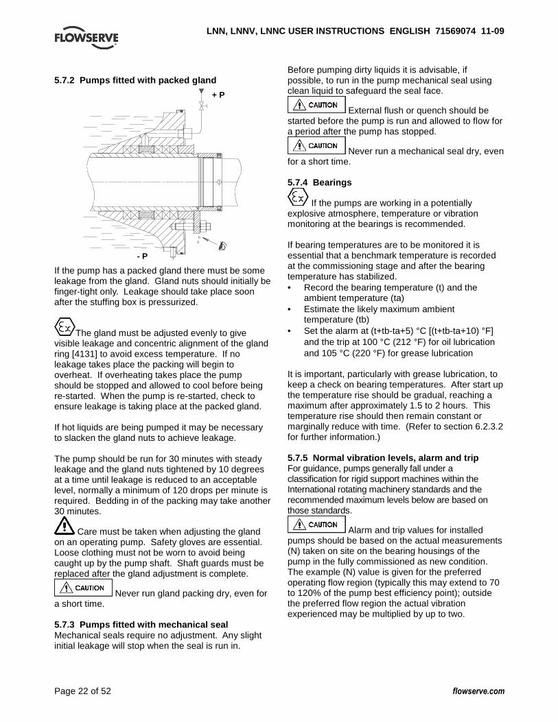
5.7.2 Pumps fitted with packed gland
+ P
- P
If the pump has a packed gland there must be some leakage from the gland. Gland nuts should initially be finger-tight only. Leakage should take place soon after the stuffing box is pressurized.
The gland must be adjusted evenly to give visible leakage and concentric alignment of the gland ring [4131] to avoid excess temperature. If no leakage takes place the packing will begin to overheat. If overheating takes place the pump should be stopped and allowed to cool before being re-started. When the pump is re-started, check to ensure leakage is taking place at the packed gland. If hot liquids are being pumped it may be necessary to slacken the gland nuts to achieve leakage. The pump should be run for 30 minutes with steady leakage and the gland nuts tightened by 10 degrees at a time until leakage is reduced to an acceptable level, normally a minimum of 120 drops per minute is required. Bedding in of the packing may take another 30 minutes.
Care must be taken when adjusting the gland on an operating pump. Safety gloves are essential. Loose clothing must not be worn to avoid being caught up by the pump shaft. Shaft guards must be replaced after the gland adjustment is complete.
Never run gland packing dry, even for a short time. 5.7.3 Pumps fitted with mechanical seal Mechanical seals require no adjustment. Any slight initial leakage will stop when the seal is run in.
Before pumping dirty liquids it is advisable, if possible, to run in the pump mechanical seal using clean liquid to safeguard the seal face.
External flush or quench should be started before the pump is run and allowed to flow for a period after the pump has stopped.
Never run a mechanical seal dry, even for a short time. 5.7.4 Bearings
If the pumps are working in a potentially explosive atmosphere, temperature or vibration monitoring at the bearings is recommended. If bearing temperatures are to be monitored it is essential that a benchmark temperature is recorded at the commissioning stage and after the bearing temperature has stabilized. • Record the bearing temperature (t) and the
ambient temperature (ta) • Estimate the likely maximum ambient
temperature (tb) • Set the alarm at (t+tb-ta+5) °C [(t+tb-ta+10) °F]
and the trip at 100 °C (212 °F) for oil lubrication and 105 °C (220 °F) for grease lubrication
It is important, particularly with grease lubrication, to keep a check on bearing temperatures. After start up the temperature rise should be gradual, reaching a maximum after approximately 1.5 to 2 hours. This temperature rise should then remain constant or marginally reduce with time. (Refer to section 6.2.3.2 for further information.) 5.7.5 Normal vibration levels, alarm and trip For guidance, pumps generally fall under a classification for rigid support machines within the International rotating machinery standards and the recommended maximum levels below are based on those standards.
Alarm and trip values for installed pumps should be based on the actual measurements (N) taken on site on the bearing housings of the pump in the fully commissioned as new condition. The example (N) value is given for the preferred operating flow region (typically this may extend to 70 to 120% of the pump best efficiency point); outside the preferred flow region the actual vibration experienced may be multiplied by up to two.

LNN, LNNV, LNNC USER INSTRUCTIONS ENGLISH 7156907 4 11-09
Page 23 of 52 flowserve.com
These standard values can vary with the rotational speed and the power absorbed by the pump. For any special case, contact your nearest Flowserve office. Measuring vibration at regular intervals will show any deterioration in pump or system operating conditions.
Vibration velocity – unfiltered
Horizontal pumps mm/s (in./s) r.m.s.
Vertical pumps mm/s (in./s)
r.m.s. Normal N ≤ 5.6 (0.22) ≤ 7.1 (0.28) Alarm N x 1.25 ≤ 7.1 (0.28) ≤ 9.0 (0.35) Shutdown trip N x 2.0 ≤ 11.2 (0.44) ≤ 14.2 (0.56)
5.7.6 Stop/start frequency Pump sets are normally suitable for the number of equally spaced stop/starts per hour shown in the table below. Check actual capability of the driver and control/starting system before commissioning.
Motor rating kW (hp) Maximum stop/starts per hour
Up to 15 (20) 15 Between 15 (20) and 90 (120) 10
90 (120) to 150 (200) 6 Above 150 (200) Refer
Where duty and standby pumps are installed it is recommended that they are run alternately every week. 5.8 Stopping and shutdown
a) Close the outlet valve, but ensure that the pump runs in this condition for no more than a few seconds.
b) Stop the pump. c) Switch off flushing and/or cooling/heating liquid
supplies at a time appropriate to the process.
d) For prolonged shut-downs and especially when ambient temperatures are likely to drop below freezing point, the pump and any cooling and flushing arrangements must be drained or otherwise protected.
5.9 Hydraulic, mechanical and electrical duty This product has been supplied to meet the performance specifications of your purchase order, however it is understood that during the life of the product these may change. The following notes may help the user decide how to evaluate the implications of any change. If in doubt contact your nearest Flowserve office.
5.9.1 Specific gravity (SG) Pump capacity and total head in meters (feet) do not change with SG, however pressure displayed on a pressure gauge is directly proportional to SG. Power absorbed is also directly proportional to SG. It is therefore important to check that any change in SG will not overload the pump driver or over-pressurize the pump. 5.9.2 Viscosity For a given flow rate the total head reduces with increased viscosity and increases with reduced viscosity. Also for a given flow rate the power absorbed increases with increased viscosity, and reduces with reduced viscosity. It is important that checks are made with your nearest Flowserve office if changes in viscosity are planned. 5.9.3 Pump speed Changing pump speed effects flow, total head, power absorbed, NPSHR, noise and vibration. Flow varies in direct proportion to pump speed, head varies as speed ratio squared and power varies as speed ratio cubed. The new duty, however, will also be dependent on the system curve. If increasing the speed, it is important therefore to ensure the maximum pump working pressure is not exceeded, the driver is not overloaded, NPSHA > NPSHR, and that noise and vibration are within local requirements and regulations. 5.9.4 Net positive suction head (NPSH A) NPSH available (NPSHA) is a measure of the head available in the pumped liquid, above its vapor pressure, at the pump suction branch. NPSH required (NPSHR) is a measure of the head required in the pumped liquid, above its vapor pressure, to prevent the pump from cavitating. It is important that NPSHA > NPSHR. The margin between NPSHA > NPSHR should be as large as possible. If any change in NPSHA is proposed, ensure these margins are not significantly eroded. Refer to the pump performance curve to determine exact requirements particularly if flow has changed. If in doubt please consult your nearest Flowserve office for advice and details of the minimum allowable margin for your application. 5.9.5 Pumped flow Flow must not fall outside the minimum and maximum continuous safe flow shown on the pump performance curve and or data sheet.

LNN, LNNV, LNNC USER INSTRUCTIONS ENGLISH 7156907 4 11-09
Page 24 of 52 flowserve.com
6 MAINTENANCE 6.1 General
It is the plant operator's responsibility to ensure that all maintenance, inspection and assembly work is carried out by authorized and qualified personnel who have adequately familiarized themselves with the subject matter by studying this manual in detail. (See also section 1.6) Any work on the machine must be performed when it is at a standstill. It is imperative that the procedure for shutting down the machine is followed, as described in section 5.8. Guard fasteners must remain captive during dismantling of guards as described in section 5.4 On completion of work all guards and safety devices must be re-installed and made operative again. Before restarting the machine, the relevant instructions listed in section 5, Commissioning, start up, operation and shut down must be observed. Oil and grease leaks may make the ground slippery. Machine maintenance must always begin and finish by cleaning the ground and the exterior of the machine. If platforms, stairs and guard rails are required for maintenance, they must be placed for easy access to areas where maintenance and inspection are to be carried out. The positioning of these accessories must not limit access or hinder lifting of the part to be serviced. When air or compressed inert gas is used in the maintenance process, the operator and anyone in the vicinity must be careful and have the appropriate protection. Do not spray air or compressed inert gas on skin. Do not direct an air or gas jet towards other people. Never use air or compressed inert gas to clean clothes. Before working on the pump, take measures to prevent an uncontrolled start. Put a warning board on the starting device with the words: "Machine under repair: do not start" . With electric drive equipment, lock the main switch open and withdraw any fuses. Put a warning board on the fuse box or main switch with the words: "Machine under repair: do not connect".
Never clean equipment with inflammable solvents or carbon tetrachloride. Protect yourself against toxic fumes when using cleaning agents. 6.2 Maintenance schedule
It is recommended that a maintenance plan and schedule is adopted, in line with these User Instructions. It should include the following: a) Any auxiliary systems installed must be monitored,
if necessary, to ensure they function correctly. b) Gland packings must be adjusted correctly to
give visible leakage and concentric alignment of the gland follower to prevent excessive temperature of the packing or follower.
c) Check for any leaks from gaskets and seals. The correct functioning of the shaft seal must be checked regularly.
d) Check bearing lubricant level, and if the hours run show a lubricant change is required.
e) Check that the duty condition is in the safe operating range for the pump.
f) Check vibration, noise level and surface temperature at the bearings to confirm satisfactory operation.
g) Check dirt and dust is removed from areas around close clearances, bearing housings and motors.
h) Check coupling alignment and re-align if necessary. Our specialist service personnel can help with preventative maintenance records and provide condition monitoring for temperature and vibration to identify the onset of potential problems. If any problems are found the following sequence of actions should take place: a) Refer to section 7, Faults; causes and remedies,
for fault diagnosis. b) Ensure equipment complies with the
recommendations in this manual. c) Contact Flowserve if the problem persists. 6.2.1 Routine inspection (daily/weekly)
The following checks should be made and the appropriate action taken to remedy any deviations: a) Check operating behaviour. Ensure noise,
vibration and bearing temperatures are normal. b) Check that there are no abnormal fluid or
lubricant leaks (static and dynamic seals) and that any sealant systems (if fitted) are full and operating normally.
c) Check that shaft seal leaks are within acceptable limits.

LNN, LNNV, LNNC USER INSTRUCTIONS ENGLISH 7156907 4 11-09
Page 25 of 52 flowserve.com
d) Check the level and condition of oil lubricant. On grease lubricated pumps, check running hours since last recharge of grease or complete grease change.
e) Check any auxiliary supplies eg heating/cooling, if fitted, are functioning correctly.
� Refer to the manuals of any associated
equipment for routine checks needed. 6.2.2 Periodic inspection (six monthly)
a) Check foundation bolts for security of attachment and corrosion.
b) Check pump running records for hourly usage to determine if bearing lubricant requires changing.
c) The coupling should be checked for correct alignment and worn driving elements.
� Refer to the manuals of any associated
equipment for periodic checks needed. 6.2.3 Re-lubrication Lubricant and bearing temperature analysis can be useful in optimizing lubricant change intervals. In general however, the following is recommended. 6.2.3.1 Oil lubrication
Maintaining the correct oil level is very important. If the pump is supplied with a constant level oiler the oil level will be automatically maintained and as long as oil is visible in the glass bottle there is no need to refill. If however a sight glass has been fitted then regular checks should be made to ensure the level is maintained at the centre of the glass window. Refer to section 5.1.1 for methods of oil fill, section 5.2.1 for oil grade recommendations and 5.2.3 for the schedule and temperature limits. 6.2.3.2 Grease lubrication
See section 5.2.2 for grease recommendations. Regrease - via grease nipples every 2 000 hours or sooner depending on the severity of the application. a) It is important not to under or over grease the
bearings as this will lead to over heating and premature failure. Grease lubricated bearing housings have grease nipples fitted in the bearing covers.
b) Move the axial seal ring back so the gap between
the pump shaft and bearing cover can be seen.
c) Connect grease gun to the nipple.
d) Press grease into the bearing housing until the
first signs of it appear in the gap between the housing and shaft, then stop greasing.
e) V-rings should be seated at the proper distance
from the sealing surface to avoid overheating. f) The maximum allowable operating temperatures
for anti friction bearings will vary from unit to unit, depending on ambient and fluid temperature. The rise above ambient should not normally exceed 55 °C (99 °F) or a combined maximum of 95 °C (204 °F).
g) A continuously rising temperature or an abrupt temperature rise indicates a problem. If these symptoms occur, stop the pump immediately and investigate the cause.
TIME
TE
MP
ER
AT
UR
E
Grease change - every 4 000 hours or sooner depending on the severity of the application. a) Remove the bearing housing from the rotor
assembly. b) Brush the bearing housing with hot kerosene (100
to 115 °C/212 to 240 °F) or other non-toxic solvent . c) Clean and flush out the housing with a light
mineral oil.

LNN, LNNV, LNNC USER INSTRUCTIONS ENGLISH 7156907 4 11-09
Page 26 of 52 flowserve.com
d) Do not use waste oil to clean the housing. To clean the bearings: a) Wipe off as much grease as possible with a clean
lint-free cloth. b) Brush bearings with hot kerosene (80 to 90 °C/ 1 75 to
195 °F) while gently spinning the outer bearing rin g. c) Spin each ball to ensure that it is clean.
To remove badly oxidized grease that refuses to come off: a) Support the rotor in a vertical position and
immerse the bearing in hot kerosene or a mixture of alcohol and light mineral solvent.
b) Gently spin the bearing outer ring.
c) Dry and reflush the bearing with clean light oil. d) It is important not to under or over grease the
bearings as this will lead to over heating and premature failure. It is recommended that the bearings be filled with grease using a suitable spatula. In addition the housings should be no more than half filled.
6.2.4 Mechanical seals No adjustment is possible. When leakage reaches an unacceptable level the seal will need replacement. 6.2.5 Gland packing The stuffing box split gland can be completely removed for re-packing or to enable the addition of extra rings of packing.
The stuffing box is normally supplied with a lantern ring to enable a clean or pressurized flush to the centre of the packing. If not required, this can be replaced by an extra two rings of packing. There must always be a small leakage, normally a minimum of 120 drops per minute to atmosphere to lubricate and cool the packing is required. 6.2.6 Internal coating If the pump has an internal coating, this coating must be inspected periodically. Any wear or cracks of the coating found must be immediately repaired. Failure to do this may lead to accelerated wear of the coating during operation and corrosion of the exposed base metal, depending on the material and pumped liquid. Special attention must be paid to the coating edges. Any loss of coating material is considered to be normal wear and tear on the pump and is not considered as warranty. Flowserve has applied the coatings according to the supplier's instructions but will not be held responsible for coating wear or cracks that may develop over time. 6.3 Spare parts 6.3.1 Ordering of spares Flowserve keep records of all pumps that have been supplied. When ordering spares the following information should be quoted:
1) Pump serial number. 2) Pump size. 3) Part name – taken from section 8. 4) Part number – taken from section 8. 5) Number of parts required.
The pump size and serial number are shown on the pump nameplate. To ensure continued satisfactory operation, replacement parts to the original design specification should be obtained from Flowserve. Any change to the original design specification (modification or use of a non-standard part) will invalidate the pump’s safety certification. 6.3.2 Storage of spares Spares should be stored in a clean dry area away from vibration. Inspection and re-treatment of metallic surfaces (if necessary) with preservative is recommended at 6 monthly intervals.

LNN, LNNV, LNNC USER INSTRUCTIONS ENGLISH 7156907 4 11-09
Page 27 of 52 flowserve.com
6.4 Recommended spares and consumable items For start up purposes:
1 - complete set of gland packing 2 - shaft sleeves 1 - set of gaskets and seals (optional: 2 - mechanical seals)
For 2 years operation:
1 - set of bearings (line and thrust) 2 - sets of gland packing 2 - shaft sleeves 2 - sets of gaskets and seals 2 - lantern rings 2 - casing wear rings (optional: 2 - mechanical seals
2 - impeller wear rings) For 4 years operation:
1 - set of bearings (line and thrust) 2 - sets of gland packing 2 - shaft sleeves 2 - sets of gaskets and seals 2 - lantern rings 2 - casing wear rings 1 - impeller (optional: 2 - mechanical seals
2 - impeller wear rings) 6.5 Tools required A typical range of tools that will be required to maintain these pumps is listed below. Readily available in standard tool kits, and dependent on pump size: • Open ended spanners (wrenches) to suit up to
M 48 screws/nuts • Socket spanners (wrenches), up to M 48 screws • Allen keys, up to 10 mm (A/F) • Range of screwdrivers • Soft mallet More specialized equipment: • Bearing pullers • Bearing induction heater • Dial test indicator • C-spanner (wrench) - for removing shaft nut.
(If difficulties in sourcing are encountered, consult Flowserve.)
6.6 Fastener torques Torque Nm (lbf ����ft)
Bolt size Pump feet fasteners
All other fasteners
M 16 (⅝ in.) M 20 (¾ in.) M 24 (⅞ in.) M 27 (1 in.)
M 30 (1⅛ in.) M 36 (1⅜ in.) M 42 (1⅝ in.) M 48 (1⅞ in.)
170 (125) 340 (250) 590 (435) 770 (570)
1 100 (810) 1 840 (1 350) 2 000 (1 475) 2 240 (1 650)
84 (62) 165 (120) 285 (210) 375 (275) 540 (400) 900 (660)
1 410 (1 040) 2 060 (1 500)
6.7 Renewal clearances As wear takes place between the impeller and casing ring the overall efficiency of the pump set will decrease. To maintain optimum efficiency it is recommended that rings are replaced and the impeller renovated when the radial clearance detailed in section 3.4.2 has doubled to 0.6 to 0.8 mm (0.024 to 0.032 in.), depending on pump size. On LNNV it is recommended that the product lubricated bearing is renewed at a diametrical clearance of 0.5 mm (0.02 in.).
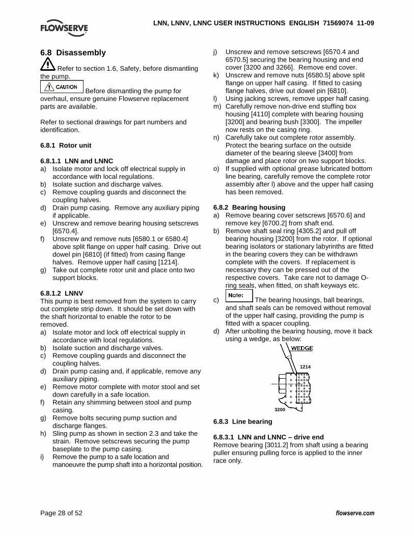
LNN, LNNV, LNNC USER INSTRUCTIONS ENGLISH 7156907 4 11-09
Page 28 of 52 flowserve.com
6.8 Disassembly
Refer to section 1.6, Safety, before dismantling the pump.
Before dismantling the pump for overhaul, ensure genuine Flowserve replacement parts are available. Refer to sectional drawings for part numbers and identification. 6.8.1 Rotor unit 6.8.1.1 LNN and LNNC a) Isolate motor and lock off electrical supply in
accordance with local regulations. b) Isolate suction and discharge valves. c) Remove coupling guards and disconnect the
coupling halves. d) Drain pump casing. Remove any auxiliary piping
if applicable. e) Unscrew and remove bearing housing setscrews
[6570.4]. f) Unscrew and remove nuts [6580.1 or 6580.4]
above split flange on upper half casing. Drive out dowel pin [6810] (if fitted) from casing flange halves. Remove upper half casing [1214].
g) Take out complete rotor unit and place onto two support blocks.
6.8.1.2 LNNV This pump is best removed from the system to carry out complete strip down. It should be set down with the shaft horizontal to enable the rotor to be removed. a) Isolate motor and lock off electrical supply in
accordance with local regulations. b) Isolate suction and discharge valves. c) Remove coupling guards and disconnect the
coupling halves. d) Drain pump casing and, if applicable, remove any
auxiliary piping. e) Remove motor complete with motor stool and set
down carefully in a safe location. f) Retain any shimming between stool and pump
casing. g) Remove bolts securing pump suction and
discharge flanges. h) Sling pump as shown in section 2.3 and take the
strain. Remove setscrews securing the pump baseplate to the pump casing.
i) Remove the pump to a safe location and manoeuvre the pump shaft into a horizontal position.
j) Unscrew and remove setscrews [6570.4 and 6570.5] securing the bearing housing and end cover [3200 and 3266]. Remove end cover.
k) Unscrew and remove nuts [6580.5] above split flange on upper half casing. If fitted to casing flange halves, drive out dowel pin [6810].
l) Using jacking screws, remove upper half casing. m) Carefully remove non-drive end stuffing box
housing [4110] complete with bearing housing [3200] and bearing bush [3300]. The impeller now rests on the casing ring.
n) Carefully take out complete rotor assembly. Protect the bearing surface on the outside diameter of the bearing sleeve [3400] from damage and place rotor on two support blocks.
o) If supplied with optional grease lubricated bottom line bearing, carefully remove the complete rotor assembly after l) above and the upper half casing has been removed.
6.8.2 Bearing housing a) Remove bearing cover setscrews [6570.6] and
remove key [6700.2] from shaft end. b) Remove shaft seal ring [4305.2] and pull off
bearing housing [3200] from the rotor. If optional bearing isolators or stationary labyrinths are fitted in the bearing covers they can be withdrawn complete with the covers. If replacement is necessary they can be pressed out of the respective covers. Take care not to damage O-ring seals, when fitted, on shaft keyways etc.
c) The bearing housings, ball bearings, and shaft seals can be removed without removal of the upper half casing, providing the pump is fitted with a spacer coupling.
d) After unbolting the bearing housing, move it back using a wedge, as below:
1214
3200
6.8.3 Line bearing 6.8.3.1 LNN and LNNC – drive end Remove bearing [3011.2] from shaft using a bearing puller ensuring pulling force is applied to the inner race only.

LNN, LNNV, LNNC USER INSTRUCTIONS ENGLISH 7156907 4 11-09
Page 29 of 52 flowserve.com
6.8.3.2 LNNV – non-drive end If the bearing bush is showing signs of wear it must be removed by pressing out of the lower bearing housing [3200]. If the non-drive end is fitted with the grease lubricated ball bearing option, dismantle circlip [6544] and disc spacer [3645] from the shaft and remove ball bearing, [3011.2] for LNN or [3011.1] for LNNV, using a bearing puller ensuring pulling force is applied to the inner race only. 6.8.4 Thrust bearings a) Unscrew and remove the self locking bearing nut
[3712] and remove the bearing [3011.1] using a puller as in 6.8.3.1 above.
b) On pumps with an unsleeved shaft, check if a bearing distance ring is fitted between the bearing and the shaft shoulder. If so, this MUST be retained for refitting during assembly.
6.8.5 Shaft seal - gland packing a) Remove gland nuts [6580.2] and gland [4120]. b) Lever out gland ring [4131] using its grip groove. c) Remove gland packing [4130] and lantern rings
[4134] using a bent wire. 6.8.6 Shaft seal - component mechanical seal
� Refer to any special instructions supplied with
the mechanical seal. a) Remove seal cover screws [6570.7] and pull off
seal cover [4213] complete with the stationary seal ring that is held in place by the O-ring seal.
b) The mechanical seal cover can also be removed by placing a wedge into the gland chamfer, as below:
4110
c) Mechanical seal assembly [4200.1] can now be
removed. 6.8.7 Shaft seal – cartridge mechanical seal If fitted with optional cartridge mechanical seal.
� Refer to any special instructions supplied with
the mechanical seal.
Remove nuts [6580.2] to detach seal assembly from stuffing box housing [4110] and slide off complete seal assembly [4200]. 6.8.8 Shaft sleeve 6.8.8.1 LNN, LNNC both ends and LNNV drive end a) Loosen grub screw [6814.2] and unscrew shaft
nut [2910]. Remove shaft sleeve [2450] using its pulling groove.
b) If after removing the seal cover, or cartridge seal, there is no shaft nut [2910] visible, this means that an unsleeved shaft is fitted. See sectional drawing for details.
c) The shaft nut and spacer are accessible after removing the stuffing box housing [4110] and should be removed as described in a) above.
6.8.8.2 LNNV non-drive end a) Remove capscrew [6579] and end cap [6415]
from shaft end. b) Remove lower bearing sleeve [3400] and lower
sleeve [2400]. c) If fitted with optional grease lubricated ball
bearing the shaft sleeve should be removed as detailed in Section 6.8.8.1.
6.8.9 Impeller and wear rings a) The impeller and wear rings can now be removed
if required. b) When removing the rotor unit, the casing wear
rings [1500] will be attached to it as they are fixed by two diametrically opposite pins [6811.1] inserted into the casing ring and located in grooves in the lower half casing.
c) If impeller rings [2300] are also fitted, they are shrunk onto the impeller and fixed with grub screws [6814.1] between their diametral mating surfaces.
d) To remove the impeller rings, remove the locking screws and heat up the ring until it slides off easily.
6.9 Examination of parts
Used parts must be inspected before assembly to ensure the pump will subsequently run properly. In particular, fault diagnosis is essential to enhance pump and plant reliability. 6.9.1 Casing, seal housing and impeller Inspect for excessive wear, pitting, corrosion, erosion or damage and any sealing surface irregularities. Replace as necessary.
4110
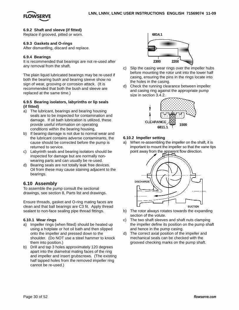
LNN, LNNV, LNNC USER INSTRUCTIONS ENGLISH 7156907 4 11-09
Page 30 of 52 flowserve.com
6.9.2 Shaft and sleeve (if fitted) Replace if grooved, pitted or worn. 6.9.3 Gaskets and O-rings After dismantling, discard and replace. 6.9.4 Bearings It is recommended that bearings are not re-used after any removal from the shaft. The plain liquid lubricated bearings may be re-used if both the bearing bush and bearing sleeve show no sign of wear, grooving or corrosion attack. (It is recommended that both the bush and sleeve are replaced at the same time.) 6.9.5 Bearing isolators, labyrinths or lip seals (if fitted) a) The lubricant, bearings and bearing housing
seals are to be inspected for contamination and damage. If oil bath lubrication is utilized, these provide useful information on operating conditions within the bearing housing.
b) If bearing damage is not due to normal wear and the lubricant contains adverse contaminants, the cause should be corrected before the pump is returned to service.
c) Labyrinth seals and bearing isolators should be inspected for damage but are normally non-wearing parts and can usually be re-used.
d) Bearing seals are not totally leak free devices. Oil from these may cause staining adjacent to the bearings.
6.10 Assembly To assemble the pump consult the sectional drawings, see section 8, Parts list and drawings. Ensure threads, gasket and O-ring mating faces are clean and that ball bearings are C3 fit. Apply thread sealant to non-face sealing pipe thread fittings. 6.10.1 Wear rings a) Impeller rings (when fitted) should be heated up
using a hotplate or hot oil bath and then slipped onto the impeller and pressed down to the shoulder. (Do NOT use a steel hammer to knock them into position.)
b) Drill and tap 3 holes approximately 120 degrees apart into the diametral mating faces of the ring and impeller and insert grubscrews. (The existing half tapped holes from the removed impeller ring cannot be re-used.)
6814.1
2300 2200
c) Slip the casing wear rings over the impeller hubs before mounting the rotor unit into the lower half casing, ensuring the pins in the rings locate into the holes in the casing.
d) Check the running clearance between impeller and casing ring against the appropriate pump size in section 3.4.2.
6811.1 1500
6.10.2 Impeller setting a) When re-assembling the impeller on the shaft, it is
important to mount the impeller so that the vane tips point away from the apparent flow direction.
b) The rotor always rotates towards the expanding
section of the volute. c) The two shaft sleeves and shaft nuts clamping
the impeller define its position on the pump shaft and hence in the pump casing.
d) The correct axial position of the impeller and mechanical seals can be checked with the grooved checking marks on the pump shaft.

LNN, LNNV, LNNC USER INSTRUCTIONS ENGLISH 7156907 4 11-09
Page 31 of 52 flowserve.com
6.10.3 Shaft seal - packed gland a) Fit impeller key and slide impeller onto shaft. b) Insert O-ring into shaft sleeves and slide sleeves
along shaft and into the impeller hubs. Lightly lubricate the shaft and O-ring for easier assembly.
No O-rings are fitted beneath LNNV product lubricated bearing sleeves (see sectional drawing). On unsleeved shaft versions an O-ring is fitted at each end of the spacer.
c) Tighten and adjust shaft nuts so that their distances to the grooved marks are equal at both ends.
d) Lock the shaft nuts in place with grubscrews. Tighten capscrew (LNNV).
e) Slide the stuffing box housings over the shaft and fit the O-ring [4610.6].
This O-ring must be replaced at each and every dismantling.
f) Place the gland ring [4131] over the sleeve. 6.10.4 Shaft seal - component mechanical seal
� Refer to any special instructions supplied with
the mechanical seal. a) Slide the rotating assembly of the mechanical seal
along the shaft sleeve until the retaining ring has reached the correct setting distance along the sleeve. Tighten the grubscrews to lock it into position.
b) Insert O-ring into shaft sleeves and slide sleeves along shaft and into the impeller hubs. Lightly lubricate the shaft and O-ring for easier assembly.
c) Tighten and adjust shaft nuts so that the distances to the grooved marks are equal at both ends.
d) Lock the shaft nuts in place with grubscrews. Tighten capscrew (LNNV).
e) Slide the stuffing box housings over the shaft and fit the O-ring [4610.6].
This O-ring must be replaced at each and every dismantling.
f) Slip the mechanical seal covers [4213] together with their installed stationary seal parts and O-rings over the shaft.
g) If cartridge mechanical seals are to be fitted.
� Refer to any special instructions supplied
with the mechanical seal. Cartridge seals are usually fitted direct to the pump shaft as shown in Section 8.1.2.
6.10.5 Ball bearings - LNN, LNNC Before mounting the bearings, proceed as follows: a) Fit the shaft seal rings [4305.1] onto the shaft and
slide the bearing cover [3260.1] over the shaft. If supplied also fit shaft seal ring [4305.3] into shaft.
b) Pumps with grease lubricated bearings have V-ring seals on the outside of the bearing cover only. Pumps with oil lubricated bearings have, in addition, shaft seal rings [4305.3 and 4305.4] on the inside of the bearing covers. If V-rings are fitted, the inner V-rings have two small perforations in the lip. Inner V-rings engage in the grooves in the shaft.
c) If new optional bearing labyrinth seals are to be fitted, press them into their respective covers before the covers are assembled to the shaft. Take care not to damage O-ring seals. Ensure liquid flinger [2540] is fitted to shaft before bearing cover [3260.1] is slid onto the shaft.
d) � If new optional bearing isolators are to be
fitted in the bearing covers refer to separate instructions supplied with the isolators.
e) Determine the thickness of the laminated shim on the thrust bearing side. Provisionally position the bearing into the bearing housing seated against the circlip and thrust washer.
f) Measure distance 'Y' on the bearing cover. g) Measure distance 'Z' to face of bearing housing. h) Shim thickness to give correct clearance will be
'Y' minus 'Z' = 0.1 to 0.2 mm (0.004 to 0.008 in.) Place correct shims on the shaft.
i) The shim is laminated material with an original thickness (T) of 1.0 mm (0.039 in.) and laminate thickness of 0.05 mm (0.002 in.). This allows the thickness to be varied in 0.05 mm (0.002 in.) increments by peeling off layers to achieve the required axial clearance.

LNN, LNNV, LNNC USER INSTRUCTIONS ENGLISH 7156907 4 11-09
Page 32 of 52 flowserve.com
j) For oil lubricated units only, place shaft seal ring
[4305.3] in the shaft grooves for correct positioning.
k) The bearing should be heated up to 100 °C (212 °F) using a hotplate, hot oil bath or induction heater and then slipped onto the shaft to the shoulder.
l) On the thrust bearing side, mount the self-locking ring type nut.
3011.1
3712 m) Bearing arrangements using a pair of angular
contact bearings should be mounted with the shoulders of the inner rings arranged face to face as shown:
6.10.6 Bearings - LNNV a) Proceed as Section 6.10.5 for the grease lubricated
ball thrust bearing at the drive end, ensuring shim thickness is selected to give correct clearance.
b) If fitted with liquid lubricated bearing at non-drive end press a new bearing bush [3300] into the lower bearing housing [3200.1], making sure the face of the bush is flush with the end of the housing.
c) Secure the lower bearing housing into the stuffing box housing.
d) Slide the stuffing box housing, complete with bearing bush, over the shaft and fit the O-ring [4610.6].
e) If fitted with optional grease lubricated bottom bearing, slide liquid flinger assembly [2540.1, 4610.3, 6814.3] and bearing cover assembly [3260.1, 2500] onto shaft.
f) The bearing should be heated up to 100 °C (212 °F) using a hotplate, hot oil bath or induction heater and then slipped onto the shaft to the shoulder.
g) Secure to shaft with disc spacer [3645.1] and circlip [6544.1].
6.10.7 Rotor unit a) After completion of preceding steps, carefully
place the rotor into the lower half pump casing. Make sure the fixing pins of the casing rings fit correctly in the casing grooves and ensure correct fit of locating pins at the stuffing box housing.
b) Although both stuffing box housings are identical the locating pins in the lower half casing are different for drive and non-drive sides. The stuffing box housing should be rotated so that the correct slot engages with the pin. The long pin with small diameter must engage in the small deep slot whilst the short larger diameter pin engages in the shallower wider groove.
6.10.8 Casing gasket a) The gasket must be cut from asbestos-free sheet
material of 0.8 + 0.1/-0.05 mm (1/32 in.) thickness, by following the actual inner casing contour of the lower half casing.
b) Special care must be exercised at the bores and stuffing box housing.
c) The gasket must be accurately cut and fit flush with these bores to prevent leakage at the O-ring.
d) Position gasket carefully onto the cleaned surface of the lower half casing.
e) Coat the casing bottom half flange surface of the wall between suction and discharge side with a contact adhesive, as below:
1500
To assist assembly, particularly on larger sizes it may be advisable to use further adhesive at key points around this flange.
f) Push gasket flush against fit of stuffing box housing and secure gasket locally again using the above adhesive paste.
g) Place upper half casing onto pump, ensuring
dowels or stuffing box and bearing housing make correct alignment.
h) Tighten upper half casing flange nuts/screws to correct torque.

LNN, LNNV, LNNC USER INSTRUCTIONS ENGLISH 7156907 4 11-09
Page 33 of 52 flowserve.com
6.10.9 Bearing housing a) Insert the circlip [6544] and disc spacer [3645] at
the thrust bearing end.
The circlip and thrust washer must not be fitted at the line bearing end. LNN and LNNC - thrust bearing at non-drive end. LNNV - thrust bearing at drive end.
3645
6544
3126 SHI M
0.1 to 0.2 mm (0.004 to 0.008 in.)
LIQUID SEALANT
Clearance between bearing outer race and bearing cover
b) On oil lubricated units ensure that the shaft seal rings [4305.3] are located in the grooves in the shaft.
c) Slip the bearing housings over their respective bearings and insert them into the recesses of the pump casing.
d) Fit bearing housing setscrews [6570.4] and tighten. e) Apply liquid sealant to bearing cover flange. f) Ensure correct seating of shim. g) Turn bearing cover to correct position:
Grease lubricated units - grease nipple towards top half casing. Oil lubricated units - plug towards bottom half casing.
h) Tighten bearing cover at bearing housing and
push the shaft seal ring [4305.1] against the bearing cover.
The sealing surface of the shaft seal ring must be covered with grease and pushed gently up to the bearing cover, otherwise it may run hot!
4305.1
i) Refit plugs, vents, oiler etc as applicable.
j) On oil lubricated units at the drive end, place the shaft seal ring [4305.4] over the shaft and position in the groove to seal against the end cover.
k) Fit the end cover [3260.2] and the shaft seal ring [4305.2], lubricate it with grease and push it up to the end cover.
l) At the non-drive end, fit the bearing end cover [3266] and tighten the screws [6570.5].
6.10.10 Stuffing box assembly 6.10.10.1 Gland packing Insert inner two rings of packing, then lantern ring halves and finally 2 or 3 more rings of packing. Loosely fit the gland [4120] and connect flush line. 6.10.10.2 Component mechanical seal [4200.1]
� Refer to separate User Instructions supplied
with the mechanical seal. Fasten seal covers [4213] complete with O-ring [4610.9] using screws [6570.7]. Connect flush line. Connect any auxiliary piping. 6.10.10.3 Cartridge mechanical seal [4200]
� If optional cartridge seals are fitted, refer to
separate User Instructions supplied with the seal for securing and activating the seal.
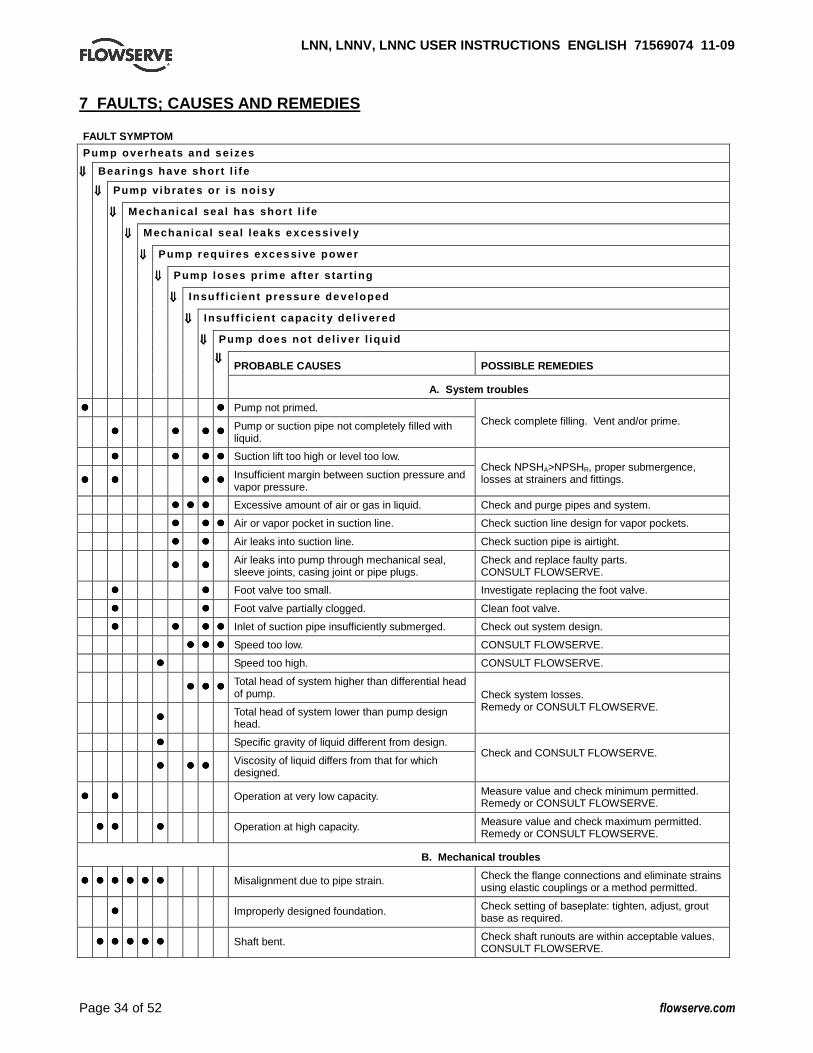
LNN, LNNV, LNNC USER INSTRUCTIONS ENGLISH 7156907 4 11-09
Page 34 of 52 flowserve.com
7 FAULTS; CAUSES AND REMEDIES FAULT SYMPTOM
Pump overhea ts and se izes
⇓⇓⇓⇓⇓⇓⇓⇓ Bear ings have shor t l i f e
⇓⇓⇓⇓⇓⇓⇓⇓ Pump v ib ra tes o r i s no is y
⇓⇓⇓⇓⇓⇓⇓⇓ M echan ica l sea l has shor t l i fe
⇓⇓⇓⇓⇓⇓⇓⇓ M echan ica l sea l l eaks excess ive l y
⇓⇓⇓⇓⇓⇓⇓⇓ Pump requ i res excess ive power
⇓⇓⇓⇓⇓⇓⇓⇓ Pump loses p r ime a fte r s tar t i ng
⇓⇓⇓⇓⇓⇓⇓⇓ I nsu f f i c ien t p ressure deve loped
⇓⇓⇓⇓⇓⇓⇓⇓ I nsu f f i c ien t capac i t y de l i vered
⇓⇓⇓⇓⇓⇓⇓⇓ Pump does no t de l i ver l i qu id
⇓⇓⇓⇓⇓⇓⇓⇓ PROBABLE CAUSES POSSIBLE REMEDIES
A. System troubles ���� ���� Pump not primed.
���� ���� ���� ���� Pump or suction pipe not completely filled with liquid.
Check complete filling. Vent and/or prime.
���� ���� ���� ���� Suction lift too high or level too low.
���� ���� ���� ���� Insufficient margin between suction pressure and vapor pressure.
Check NPSHA>NPSHR, proper submergence, losses at strainers and fittings.
���� ���� ���� Excessive amount of air or gas in liquid. Check and purge pipes and system.
���� ���� ���� Air or vapor pocket in suction line. Check suction line design for vapor pockets.
���� ���� Air leaks into suction line. Check suction pipe is airtight.
���� ���� Air leaks into pump through mechanical seal, sleeve joints, casing joint or pipe plugs.
Check and replace faulty parts. CONSULT FLOWSERVE.
���� ���� Foot valve too small. Investigate replacing the foot valve.
���� ���� Foot valve partially clogged. Clean foot valve.
���� ���� ���� ���� Inlet of suction pipe insufficiently submerged. Check out system design.
���� ���� ���� Speed too low. CONSULT FLOWSERVE.
���� Speed too high. CONSULT FLOWSERVE.
���� ���� ���� Total head of system higher than differential head of pump.
���� Total head of system lower than pump design head.
Check system losses. Remedy or CONSULT FLOWSERVE.
���� Specific gravity of liquid different from design.
���� ���� ���� Viscosity of liquid differs from that for which designed.
Check and CONSULT FLOWSERVE.
���� ���� Operation at very low capacity. Measure value and check minimum permitted. Remedy or CONSULT FLOWSERVE.
���� ���� ���� Operation at high capacity. Measure value and check maximum permitted. Remedy or CONSULT FLOWSERVE.
B. Mechanical troubles
���� ���� ���� ���� ���� ���� Misalignment due to pipe strain. Check the flange connections and eliminate strains using elastic couplings or a method permitted.
���� Improperly designed foundation. Check setting of baseplate: tighten, adjust, grout base as required.
���� ���� ���� ���� ���� Shaft bent. Check shaft runouts are within acceptable values. CONSULT FLOWSERVE.

LNN, LNNV, LNNC USER INSTRUCTIONS ENGLISH 7156907 4 11-09
Page 35 of 52 flowserve.com
FAULT SYMPTOM
Pump overhea ts and se izes
⇓⇓⇓⇓⇓⇓⇓⇓ Bear ings have shor t l i f e
⇓⇓⇓⇓⇓⇓⇓⇓ Pump v ib ra tes o r i s no is y
⇓⇓⇓⇓⇓⇓⇓⇓ M echan ica l sea l has shor t l i fe
⇓⇓⇓⇓⇓⇓⇓⇓ M echan ica l sea l l eaks excess ive l y
⇓⇓⇓⇓⇓⇓⇓⇓ Pump requ i res excess ive power
⇓⇓⇓⇓⇓⇓⇓⇓ Pump loses p r ime a fte r s tar t i ng
⇓⇓⇓⇓⇓⇓⇓⇓ I nsu f f i c ien t p ressure deve loped
⇓⇓⇓⇓⇓⇓⇓⇓ I nsu f f i c ien t capac i t y de l i vered
⇓⇓⇓⇓⇓⇓⇓⇓ Pump does no t de l i ver l i qu id
⇓⇓⇓⇓⇓⇓⇓⇓ PROBABLE CAUSES POSSIBLE REMEDIES
���� ���� ���� ���� Rotating part rubbing on stationary part internally. Check and CONSULT FLOWSERVE, if necessary.
���� ���� ���� ���� ���� Bearings worn. Replace bearings.
���� ���� ���� Wearing ring surfaces worn. Replace worn wear ring/surfaces.
���� ���� ���� Impeller damaged or eroded. Replace or CONSULT FLOWSERVE for improved material selection.
���� Leakage under sleeve due to joint failure. Replace joint and check for damage.
���� ���� Shaft sleeve worn or scored or running off centre. Check and renew defective parts.
���� ���� ���� Mechanical seal improperly installed. Check alignment of faces or damaged parts and assembly method used.
���� ���� ���� Incorrect type of mechanical seal for operating conditions.
CONSULT FLOWSERVE.
���� ���� ���� ���� ���� Shaft running off centre because of worn bearings or misalignment.
Check misalignment and correct if necessary. If alignment satisfactory check bearings for excessive wear.
���� ���� ���� ���� ���� Impeller out of balance resulting in vibration.
���� ���� ���� Abrasive solids in liquid pumped.
���� ���� Internal misalignment of parts preventing seal ring and seat from mating properly.
Check and CONSULT FLOWSERVE.
���� ���� Mechanical seal was run dry. Check mechanical seal condition and source of dry running and repair.
���� ���� Internal misalignment due to improper repairs causing impeller to rub.
Check method of assembly, possible damage or state of cleanliness during assembly. Remedy or CONSULT FLOWSERVE, if necessary.
���� ���� ���� Excessive thrust caused by a mechanical failure inside the pump.
Check wear condition of impeller, its clearances and liquid passages.
���� ���� Excessive grease in ball bearings. Check method of regreasing.
���� ���� Lack of lubrication for bearings. Check hours run since last change of lubricant, the schedule and its basis.
���� ���� Improper installation of bearings (damage during assembly, incorrect assembly, wrong type of bearing etc).
Check method of assembly, possible damage or state of cleanliness during assembly and type of bearing used. Remedy or CONSULT FLOWSERVE, if necessary.
���� ���� Damaged bearings due to contamination. Check contamination source and replace damaged bearings.
C. MOTOR ELECTRICAL PROBLEMS ���� ���� ���� ���� Wrong direction of rotation. Reverse 2 phases at motor terminal box.
���� ���� Motor running on 2 phases only. Check supply and fuses.
���� ���� ���� Motor running too slow. Check motor terminal box connections and voltage.

LNN, LNNV, LNNC USER INSTRUCTIONS ENGLISH 7156907 4 11-09
Page 36 of 52 flowserve.com
8 PARTS LISTS AND DRAWINGS 8.1 LNN and LNNC – grease lubricated, gland packed and component mechanical seal option – sizes up to 350 mm discharge
6569
.4
3712
3126
3011
.1
4213
2450
4610
.145
95.3
1214
1500
4590
2200
6521
3011
.2
4131
4110
4130
3853
3260
.141
3446
10.6
4305
.1
4420
6700
.2
6569
.3
4305
.2
4595
.5
2100
6700
.1
1
3266
'A'
4510
.1
6570
.5
4200
1
6544
3200
6811
.165
80.2
3645
6572
.368
11.2
1213
4305
.3
11
3260
.2
4305
.4
6515
.2
6814
.265
70.4
6811
.365
70.6
4595
.6
2910
4120
� Leak proofing material Casco 145 or Marston Hydrosil 100RTV silicone compound. * Note: items 4305.3 and 4305.4 - oil lubricated arrangement only. (Drawing taken from C751/010.)

LNN, LNNV, LNNC USER INSTRUCTIONS ENGLISH 7156907 4 11-09
Page 37 of 52 flowserve.com
8.1.1 Parts list - LNN and LNNC - sizes up to 350 mm discharge
Ref no Description 1213 Casing half lower 1214 Casing half upper 1500 Casing wear ring 2100 Shaft 2200 Impeller 2450 Shaft sleeve 2910 Shaft nut 3011.1 Ball bearing 3011.2 Ball bearing 3126 Shim 3200 Bearing housing 3260.1 Bearing cover 3260.2 Bearing cover 3266 Bearing end cover 3645 Disc spacer 3712 Bearing nut 3853 Grease nipple 4110 Stuffing box housing 4120 Gland 4130 Gland packing 4131 Follower (gland ring) 4134 Lantern ring 4213 Mechanical seal cover 4305.1 Shaft seal ring 4305.2 Shaft seal ring 4305.3 Shaft seal ring 4305.4 Shaft seal ring 4420 Sealing pipe 4510.1 Joint ring 4590 Gasket 4595.1 Joint ring 4595.2 Joint ring 4595.3 Joint ring 4595.4 Joint ring 4595.5 Joint ring 4595.6 Joint ring 4610.1 O-ring 4610.6 O-ring 6515.1 Drain plug 6515.2 Drain plug 6521 Vent plug 6544 Circlip 6569.1 Plug 6569.2 Plug 6569.3 Plug 6569.4 Plug 6570.1 Screw 6570.2 Screw 6570.3 Screw 6570.4 Screw 6570.5 Screw 6570.6 Screw 6572.1 Stud 6572.2 Stud 6572.3 Stud 6575 Jack screw 6580.1 Nut
6580.2 Nut 6700.1 Key 6700.2 Key 6810 Dowel pin 6811.1 Cylindrical pin 6811.2 Cylindrical pin 6811.3 Cylindrical pin 6814.2 Grub screw
View on Arrow A
6569.1 4595.4
4595.1 6515.1 6569.2
6570.2
6580.16810
6570.1
6572.2
6570.3 6572.1
6575
4595.2
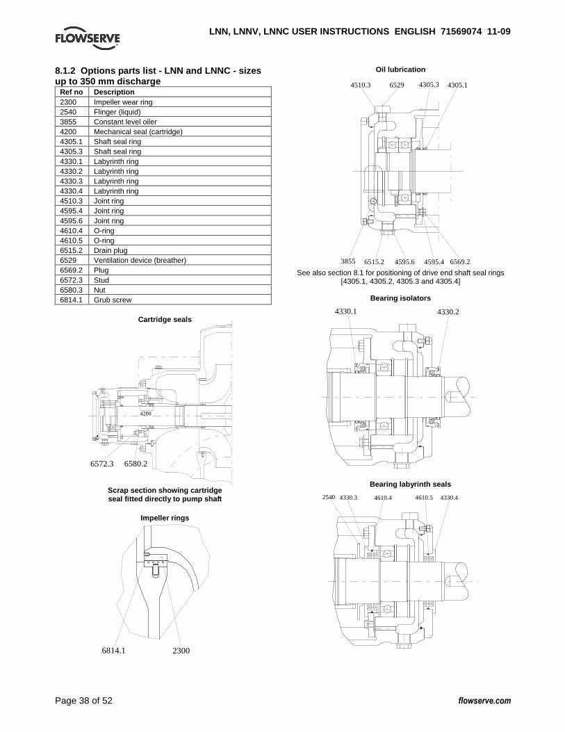
LNN, LNNV, LNNC USER INSTRUCTIONS ENGLISH 7156907 4 11-09
Page 38 of 52 flowserve.com
8.1.2 Options parts list - LNN and LNNC - sizes up to 350 mm discharge
Ref no Description 2300 Impeller wear ring 2540 Flinger (liquid) 3855 Constant level oiler 4200 Mechanical seal (cartridge) 4305.1 Shaft seal ring 4305.3 Shaft seal ring 4330.1 Labyrinth ring 4330.2 Labyrinth ring 4330.3 Labyrinth ring 4330.4 Labyrinth ring 4510.3 Joint ring 4595.4 Joint ring 4595.6 Joint ring 4610.4 O-ring 4610.5 O-ring 6515.2 Drain plug 6529 Ventilation device (breather) 6569.2 Plug 6572.3 Stud 6580.3 Nut 6814.1 Grub screw
Cartridge seals
6572.3 6580.2
4200
Scrap section showing cartridge seal fitted directly to pump shaft
Impeller rings
6814.1 2300
Oil lubrication
4510.3 6529 4305.3
4595.63855 6515.2 6569.24595.4
4305.1
See also section 8.1 for positioning of drive end shaft seal rings
[4305.1, 4305.2, 4305.3 and 4305.4]
Bearing isolators
4330.24330.1
Bearing labyrinth seals
4610.4 4610.5 4330.42540 4330.3
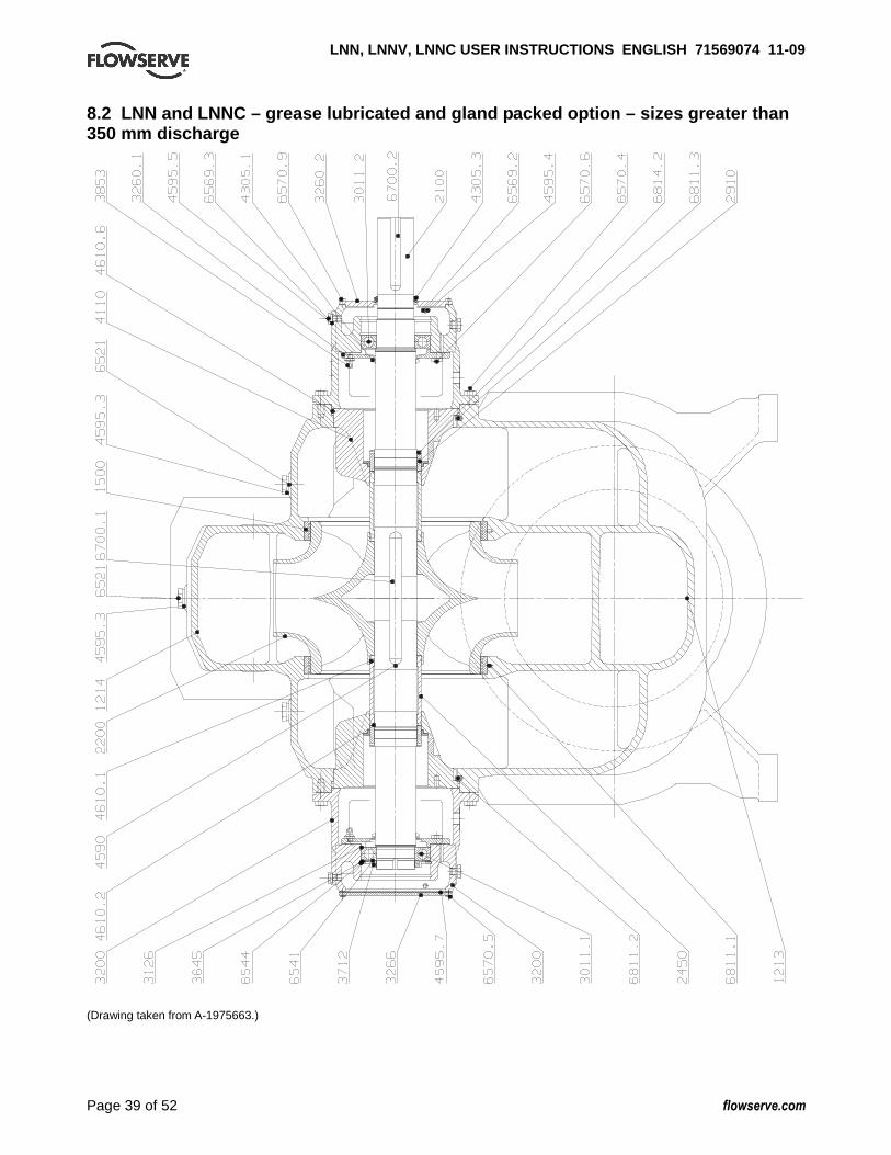
LNN, LNNV, LNNC USER INSTRUCTIONS ENGLISH 7156907 4 11-09
Page 39 of 52 flowserve.com
8.2 LNN and LNNC – grease lubricated and gland pac ked option – sizes greater than 350 mm discharge
(Drawing taken from A-1975663.)
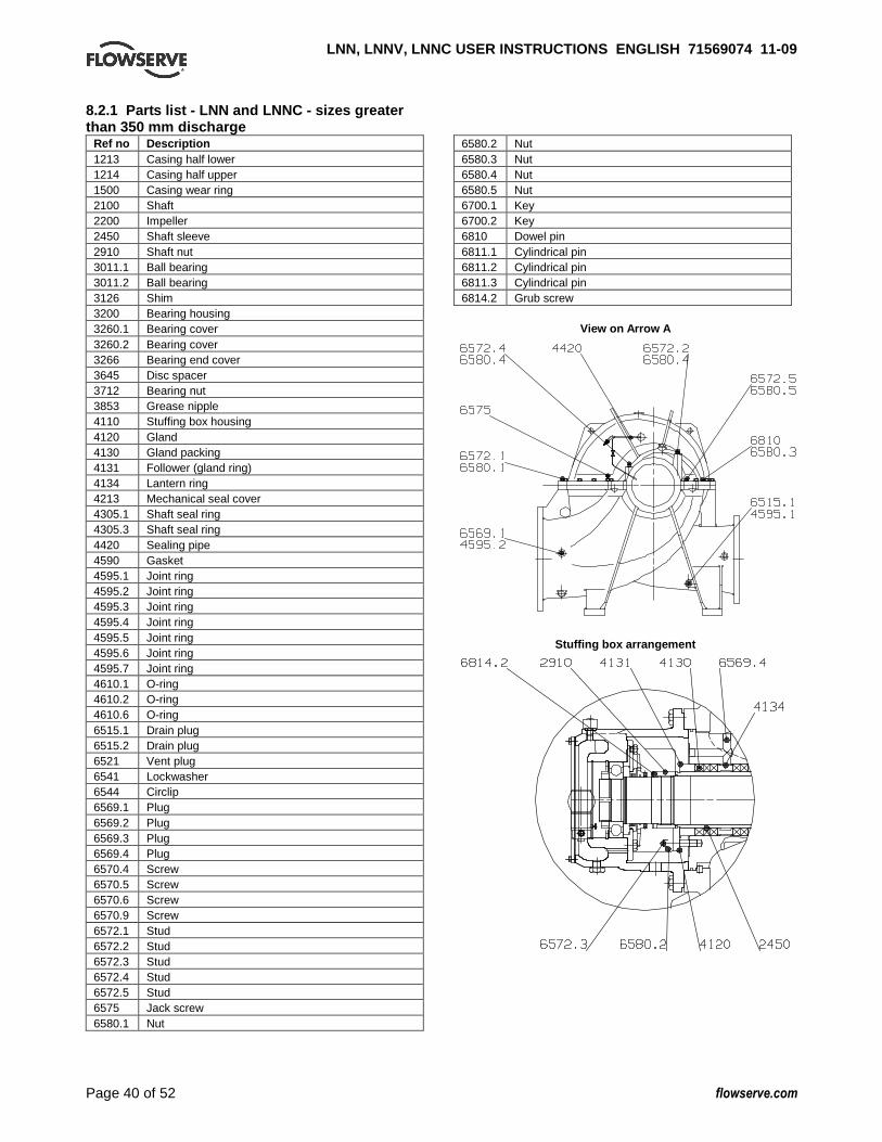
LNN, LNNV, LNNC USER INSTRUCTIONS ENGLISH 7156907 4 11-09
Page 40 of 52 flowserve.com
8.2.1 Parts list - LNN and LNNC - sizes greater than 350 mm discharge
Ref no Description 1213 Casing half lower 1214 Casing half upper 1500 Casing wear ring 2100 Shaft 2200 Impeller 2450 Shaft sleeve 2910 Shaft nut 3011.1 Ball bearing 3011.2 Ball bearing 3126 Shim 3200 Bearing housing 3260.1 Bearing cover 3260.2 Bearing cover 3266 Bearing end cover 3645 Disc spacer 3712 Bearing nut 3853 Grease nipple 4110 Stuffing box housing 4120 Gland 4130 Gland packing 4131 Follower (gland ring) 4134 Lantern ring 4213 Mechanical seal cover 4305.1 Shaft seal ring 4305.3 Shaft seal ring 4420 Sealing pipe 4590 Gasket 4595.1 Joint ring 4595.2 Joint ring 4595.3 Joint ring 4595.4 Joint ring 4595.5 Joint ring 4595.6 Joint ring 4595.7 Joint ring 4610.1 O-ring 4610.2 O-ring 4610.6 O-ring 6515.1 Drain plug 6515.2 Drain plug 6521 Vent plug 6541 Lockwasher 6544 Circlip 6569.1 Plug 6569.2 Plug 6569.3 Plug 6569.4 Plug 6570.4 Screw 6570.5 Screw 6570.6 Screw 6570.9 Screw 6572.1 Stud 6572.2 Stud 6572.3 Stud 6572.4 Stud 6572.5 Stud 6575 Jack screw 6580.1 Nut
6580.2 Nut 6580.3 Nut 6580.4 Nut 6580.5 Nut 6700.1 Key 6700.2 Key 6810 Dowel pin 6811.1 Cylindrical pin 6811.2 Cylindrical pin 6811.3 Cylindrical pin 6814.2 Grub screw
View on Arrow A
Stuffing box arrangement
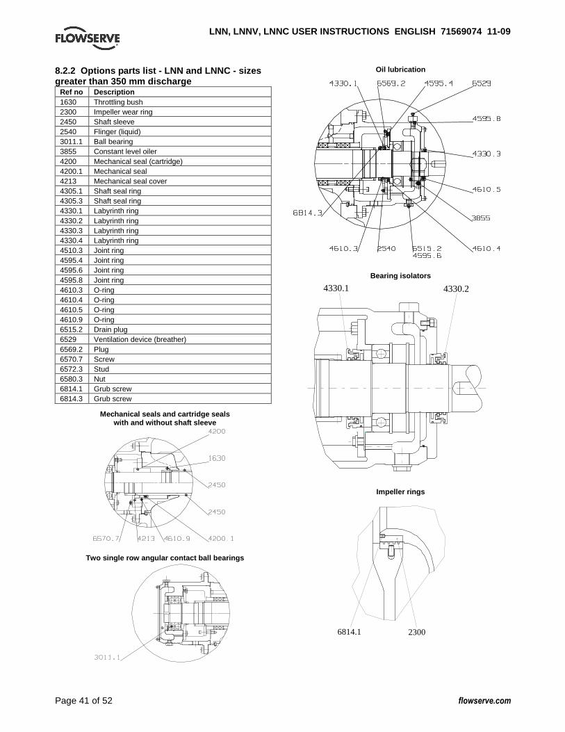
LNN, LNNV, LNNC USER INSTRUCTIONS ENGLISH 7156907 4 11-09
Page 41 of 52 flowserve.com
8.2.2 Options parts list - LNN and LNNC - sizes greater than 350 mm discharge
Ref no Description 1630 Throttling bush 2300 Impeller wear ring 2450 Shaft sleeve 2540 Flinger (liquid) 3011.1 Ball bearing 3855 Constant level oiler 4200 Mechanical seal (cartridge) 4200.1 Mechanical seal 4213 Mechanical seal cover 4305.1 Shaft seal ring 4305.3 Shaft seal ring 4330.1 Labyrinth ring 4330.2 Labyrinth ring 4330.3 Labyrinth ring 4330.4 Labyrinth ring 4510.3 Joint ring 4595.4 Joint ring 4595.6 Joint ring 4595.8 Joint ring 4610.3 O-ring 4610.4 O-ring 4610.5 O-ring 4610.9 O-ring 6515.2 Drain plug 6529 Ventilation device (breather) 6569.2 Plug 6570.7 Screw 6572.3 Stud 6580.3 Nut 6814.1 Grub screw 6814.3 Grub screw
Mechanical seals and cartridge seals
with and without shaft sleeve
Two single row angular contact ball bearings
Oil lubrication
Bearing isolators
4330.24330.1
Impeller rings
6814.1 2300

LNN, LNNV, LNNC USER INSTRUCTIONS ENGLISH 7156907 4 11-09
Page 42 of 52 flowserve.com
8.3 LNNV sleeve bearing type – grease lubricated, component mechanical seal and gland packed option – sizes up to 350 mm discharge
3266
6700.3
3200.1
2400
1214
4595.3
4420
4110
3126
3260.1
6569.3
4305.2 6700.2
4590
1500
2200
6521
4137
4610.2
4305.1
3011.1
4595.5
2100 6570.9
4200
3400
3300
6580.2
6811.3
1213
6811.1
6572.3
6415
2910
6814.2
6515.2
6570.6
4595.6
4595.7
4510.23260.2 3200
6570.4
4120
4131
4130
6700.1
2450
4134
6811.26570.86579
3712
3645
6544
3853
4610.6
6569.46570.5
4213
� Leak proofing material Casco 145 or Marston Hydrosil 100RTV silicone compound. � Screw secured with Casco ML type 119 or Loctite 270. (Drawing taken from C751/011.)
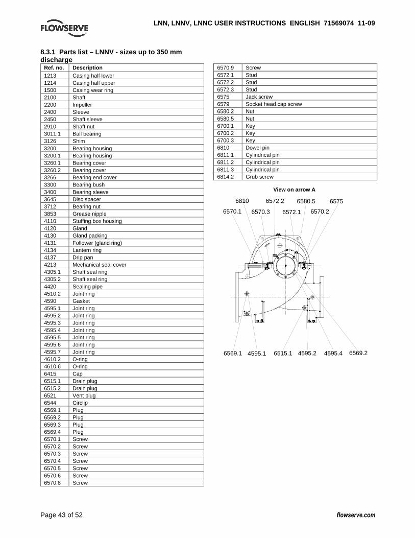
LNN, LNNV, LNNC USER INSTRUCTIONS ENGLISH 7156907 4 11-09
Page 43 of 52 flowserve.com
8.3.1 Parts list – LNNV - sizes up to 350 mm discharge
Ref. no. Description 1213 Casing half lower 1214 Casing half upper 1500 Casing wear ring 2100 Shaft 2200 Impeller 2400 Sleeve 2450 Shaft sleeve 2910 Shaft nut 3011.1 Ball bearing 3126 Shim 3200 Bearing housing 3200.1 Bearing housing 3260.1 Bearing cover 3260.2 Bearing cover 3266 Bearing end cover 3300 Bearing bush 3400 Bearing sleeve 3645 Disc spacer 3712 Bearing nut 3853 Grease nipple 4110 Stuffing box housing 4120 Gland 4130 Gland packing 4131 Follower (gland ring) 4134 Lantern ring 4137 Drip pan 4213 Mechanical seal cover 4305.1 Shaft seal ring 4305.2 Shaft seal ring 4420 Sealing pipe 4510.2 Joint ring 4590 Gasket 4595.1 Joint ring 4595.2 Joint ring 4595.3 Joint ring 4595.4 Joint ring 4595.5 Joint ring 4595.6 Joint ring 4595.7 Joint ring 4610.2 O-ring 4610.6 O-ring 6415 Cap 6515.1 Drain plug 6515.2 Drain plug 6521 Vent plug 6544 Circlip 6569.1 Plug 6569.2 Plug 6569.3 Plug 6569.4 Plug 6570.1 Screw 6570.2 Screw 6570.3 Screw 6570.4 Screw 6570.5 Screw 6570.6 Screw 6570.8 Screw
6570.9 Screw 6572.1 Stud 6572.2 Stud 6572.3 Stud 6575 Jack screw 6579 Socket head cap screw 6580.2 Nut 6580.5 Nut 6700.1 Key 6700.2 Key 6700.3 Key 6810 Dowel pin 6811.1 Cylindrical pin 6811.2 Cylindrical pin 6811.3 Cylindrical pin 6814.2 Grub screw
View on arrow A
6569.2
6572.16570.1
6810 6572.2
6570.3
6580.5
6570.2
6575
6569.1 4595.1 4595.2 4595.46515.1
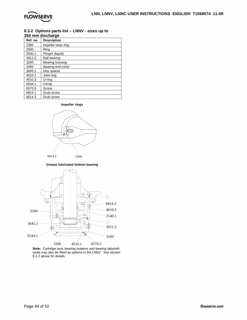
LNN, LNNV, LNNC USER INSTRUCTIONS ENGLISH 7156907 4 11-09
Page 44 of 52 flowserve.com
8.3.2 Options parts list – LNNV - sizes up to 350 mm discharge
Ref. no. Description 2300 Impeller wear ring 2500 Ring 2540.1 Flinger (liquid) 3011.2 Ball bearing 3200 Bearing housing 3266 Bearing end cover 3645.1 Disc spacer 4510.1 Joint ring 4610.3 O-ring 6544.1 Circlip 6570.5 Screw 6814.1 Grub screw 6814.3 Grub screw
Impeller rings
23006814.1
Grease lubricated bottom bearing
4510.13266
6544.1
3645.1
3200
3011.2
6570.5
1
2500 4610.3
2540.1
6814.3
1
Note: Cartridge seal, bearing isolators and bearing labyrinth seals may also be fitted as options to the LNNV. See section 8.1.2 above for details.

LNN, LNNV, LNNC USER INSTRUCTIONS ENGLISH 7156907 4 11-09
Page 45 of 52 flowserve.com
8.4 LNNV sleeve bearing type – grease lubricated a nd gland packed option – sizes greater than 350 mm discharge
(Drawing taken from A-1975665.)
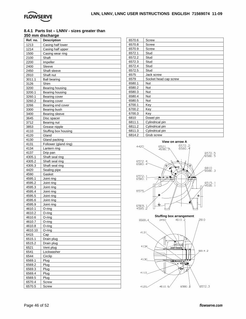
LNN, LNNV, LNNC USER INSTRUCTIONS ENGLISH 7156907 4 11-09
Page 46 of 52 flowserve.com
8.4.1 Parts list – LNNV - sizes greater than 350 mm discharge
Ref. no. Description 1213 Casing half lower 1214 Casing half upper 1500 Casing wear ring 2100 Shaft 2200 Impeller 2400 Sleeve 2450 Shaft sleeve 2910 Shaft nut 3011.1 Ball bearing 3126 Shim 3200 Bearing housing 3200.1 Bearing housing 3260.1 Bearing cover 3260.2 Bearing cover 3266 Bearing end cover 3300 Bearing bush 3400 Bearing sleeve 3645 Disc spacer 3712 Bearing nut 3853 Grease nipple 4110 Stuffing box housing 4120 Gland 4130 Gland packing 4131 Follower (gland ring) 4134 Lantern ring 4137 Drip pan 4305.1 Shaft seal ring 4305.2 Shaft seal ring 4305.3 Shaft seal ring 4420 Sealing pipe 4590 Gasket 4595.1 Joint ring 4595.2 Joint ring 4595.3 Joint ring 4595.4 Joint ring 4595.5 Joint ring 4595.6 Joint ring 4595.9 Joint ring 4610.1 O-ring 4610.2 O-ring 4610.6 O-ring 4610.7 O-ring 4610.8 O-ring 4610.10 O-ring 6415 Cap 6515.1 Drain plug 6515.2 Drain plug 6521 Vent plug 6541 Lockwasher 6544 Circlip 6569.1 Plug 6569.2 Plug 6569.3 Plug 6569.4 Plug 6569.5 Plug 6570.4 Screw 6570.5 Screw
6570.6 Screw 6570.8 Screw 6570.9 Screw 6572.1 Stud 6572.2 Stud 6572.3 Stud 6572.4 Stud 6572.5 Stud 6575 Jack screw 6579 Socket head cap screw 6580.1 Nut 6580.2 Nut 6580.3 Nut 6580.4 Nut 6580.5 Nut 6700.1 Key 6700.2 Key 6700.3 Key 6810 Dowel pin 6811.1 Cylindrical pin 6811.2 Cylindrical pin 6811.3 Cylindrical pin 6814.2 Grub screw
View on arrow A
Stuffing box arrangement

LNN, LNNV, LNNC USER INSTRUCTIONS ENGLISH 7156907 4 11-09
Page 47 of 52 flowserve.com
8.4.2 Options parts list – LNNV - sizes greater than 350 mm discharge
Ref. no. Description 1630 Throttling bush 2300 Impeller wear ring 2450 Shaft sleeve 2500 Ring 2540.1 Flinger (liquid) 3011.2 Ball bearing 3200 Bearing housing 3266 Bearing end cover 3645.1 Disc spacer 4200 Mechanical seal, cartridge 4200.1 Mechanical seal 4213 Mechanical seal cover 4510.1 Joint ring 4610.3 O-ring 4610.9 O-ring 6544.1 Circlip 6570.5 Screw 6570.7 Screw 6814.1 Grub screw 6814.3 Grub screw
Impeller rings
23006814.1
Grease lubricated bottom bearing
4510.13266
6544.1
3645.1
3200
3011.2
6570.5
1
2500 4610.3
2540.1
6814.3
1
Note: Component seal and cartridge seal, bearing isolators and bearing labyrinth seals may also be fitted as options to the LNNV. See section 8.2.2 above for details.
Mechanical seals and cartridge seals with and without shaft sleeve
8.5 General arrangement drawing The typical general arrangement drawing and any specific drawings required by the contract will be sent to the Purchaser separately unless the contract specifically calls for these to be included into the User Instructions. If required, copies of other drawings sent separately to the Purchaser should be obtained from the Purchaser and retained with these User Instructions.
LNN, LNNV, LNNC USER INSTRUCTIONS ENGLISH 7156907 4 11-09
Page 48 of 52 flowserve.com
9 CERTIFICATION Certificates determined from the Contract requirements are provided with these instructions where applicable. Examples are certificates for CE marking, ATEX marking etc. If required, copies of other certificates sent separately to the Purchaser should be obtained from the Purchaser for retention with these User Instructions. 10 OTHER RELEVANT DOCUMENTATION AND MANUALS 10.1 Supplementary User Instructions Supplementary instructions such as for a driver, instrumentation, controller, seals, sealant system etc are provided as separate documents in their original format. If further copies of these are required they should be obtained from the supplier for retention with these User Instructions. 10.2 Change notes If any changes, agreed with Flowserve, are made to the product after its supply, a record of the details should be maintained with these User Instructions. 10.3 Additional sources of information Reference 1: NPSH for Rotordynamic Pumps: a reference guide, Europump Guide No. 1, Europump & World Pumps, Elsevier Science, United Kingdom, 1999. Reference 2: Pumping Manual, 9th edition, T.C. Dickenson, Elsevier Advanced Technology, United Kingdom, 1995. Reference 3: Pump Handbook, 2nd edition, Igor J. Karassik et al, McGraw-Hill Inc., New York, 1993. Reference 4: ANSI/HI 1.1-1.5, Centrifugal Pumps - Nomenclature, Definitions, Application and Operation. Reference 5: ANSI B31.3 - Process Piping.

LNN, LNNV, LNNC USER INSTRUCTIONS ENGLISH 7156907 4 11-09
Page 49 of 52 flowserve.com
Notes:

LNN, LNNV, LNNC USER INSTRUCTIONS ENGLISH 7156907 4 11-09
Page 50 of 52 flowserve.com
Notes:
LNN, LNNV, LNNC USER INSTRUCTIONS ENGLISH 7156907 4 11-09
Page 51 of 52 flowserve.com
Notes:
LNN, LNNV, LNNC USER INSTRUCTIONS ENGLISH 7156907 4 11-09
Your Flowserve factory contacts: Nominal pump discharge <= 350: Flowserve GB Limited PO Box 17, Newark, Notts NG24 3BU United Kingdom
Telephone (24 hours) +44 1636 494 600 Sales & Admin Fax +44 1636 705 991 Repair & Service Fax +44 1636 494 833 E-mail [email protected] Nominal pump discharge > 350: Flowserve Corporation 13, rue Maurice Trintignant 72234 Arnage Cedex France
Telephone (24 hours) +33 43 40 57 75 Sales & Admin +33 43 40 57 57 Repair & Service Fax +33 43 40 58 17
Your local Flowserve representative: North America: Flowserve Pump Division 5310 Taneytown Pike, PO Box 91 Taneytown, MD 21787-0091, USA
Telephone +1 410 756 2602 Customer Service Fax +1 410 756 2615 Parts inquiry/order PH +1 800 526 3569 South America: Flowserve do Brasil Ltda Av. Don Hélder Camara 5451 20771-001 Rio de Janerio, Brasil
Telephone +55 21 599 4000 Fax +55 21 599 4124 To find your local Flowserve representative please use the Sales Support Locator System found at www.flowserve.com
FLOWSERVE REGIONAL SALES OFFICES:
USA and Canada
Flowserve Corporation
5215 North O’Connor Blvd.,
Suite 2300
Irving, Texas 75039-5421, USA
Telephone +1 972 443 6500
Fax +1 972 443 6800
Europe, Middle East, Africa
Worthing S.P.A.
Flowserve Corporation
Via Rossini 90/92
20033 Desio (Milan), Italy
Telephone +39 0362 6121
Fax +39 0362 303 396
Latin America and Caribbean
Flowserve Corporation
6840 Wynnwood Lane
Houston, Texas 77008, USA
Telephone +1 713 803 4434
Fax +1 713 803 4497
Asia Pacific
Flowserve Pte. Ltd
200 Pandan Loop #06-03/04
Pantech 21
Singapore 128388
Telephone +65 6775 3003
Fax +65 6779 4607
Related Documents