0.37 - 4.0kW (0.5 - 5.4HP) 1 and 3 phase 200 - 230 Volts, 3 phase 380 - 460 Volts LG Variable Frequency Drive(VFD) : Inverter ower in Motion Starvert iG5

Welcome message from author
This document is posted to help you gain knowledge. Please leave a comment to let me know what you think about it! Share it to your friends and learn new things together.
Transcript
0.37 - 4.0kW (0.5 - 5.4HP) 1 and 3 phase 200 - 230 Volts, 3 phase 380 - 460 Volts
LG Variable Frequency Drive(VFD) : Inverter
ower in Motion
Starvert iG5

Contents
Overview
Features & Selection Guide
Specifications & Wiring
Terminal Configuration, Keypad & Parameter Navigation�
Program Parameter Descriptions�
Dimension�
DB Resistor, Options & Peripheral Devices
02�
04�
06�
08�
10�
12�
14
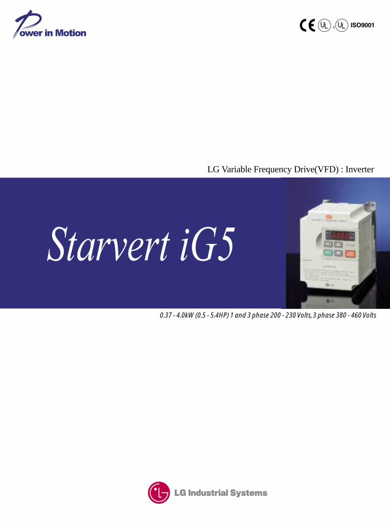
kW / Voltage Ratings: 0.5 ~ 2HP, 200-230VAC, 1phase 0.5 ~ 5HP, 200-230VAC, 3phase 0.5 ~ 5HP, 380-460VAC, 3phaseEnclosure: IP00 ~ IP20Inverter Type: PWM with IGBTControl Method: Volts / Hertz with Space Vector TechnologyBuilt-in RS-485Built-in ModBus-RTU Built-in PID controlRemovable keypad (Able to read & write parameter)150% torque at 0.5HzTrip-free operation algorithm8 preset speeds3 jump(skip) frequencies3 Multifuctional inputs1 Multifuctional outputAnalog output (0~12V)PNP and NPN dual directional signalsSpeed search3 wire operation1 to 10 kHz carrier frequencyBuilt-in Braking transistorManual/Auto torque boost
Standard features
Cable for Remote Keypad Operations(2,3 and 5 meters)DIN rail base for easy installation
Compact iG5,
is the best for a small and cost
effective configuration.
Options
Application
Conformity to global standards
Converting Fan Pump Food processing machine Electric shutter Dryer Running machine Overheat
Commercial washing machine Grinder Textile machine Material handling machine Centrifuge Elevator door Tooling machine
UL and cUL listed for North America CE marked for Europe Quality process controlled by ISO9001, ISO14000
Overview
02
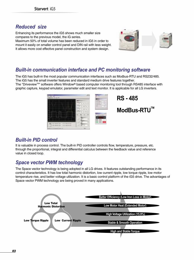
Reduced sizeEnhancing its performance the iG5 shows much smaller size compares to the previous model, the iG series.Maximum 50% of total volume has been reduced in iG5 in order to mount it easily on smaller control panel and DIN rail with less weight. It allows more cost effective panel construction and system design.
Built-in PID controlIt is valuable in process control. The built-in PID controller controls flow, temperature, pressure, etc.through the proportional, integral and differential calculus between the feedback value and referencevalue in closed loop.
Built-in communication interface and PC monitoring softwareThe iG5 has built-in the most popular communication interfaces such as Modbus-RTU and RS232/485.The iG5 has the small inverter features and standard medium drive features together.The "DriveviewTM" software offers Window® based computer monitoring tool through RS485 interface with graphic capture, keypad emulator, parameter edit and text monitor. It is applicable for all LG inverters.
ModBus-RTUTM
RS - 485
Space vector PWM technologyThe Space vector technology is being adopted in all LG drives. It features outstanding performance in its control characteristics. It has low total harmonic distortion, low current ripple, low torque ripple, low motor temperature rise, and better voltage utilization. It is a basic control platform of the iG5 drive. The advantages of Space vector PWM technology are being proved in many applications.
Better Efficiency (Low Iron Loss in Motor)
Low Motor Heat (Extended Motor)
High Voltage Utilization (15.9%)
Stable & Smooth Operation
High and Stable Torque
Low Total
Harmonic Distortion
Low Torque Ripple Low Current Ripple
Starvert iG5
03

Optimum acceleration and decelerationTo achieve a maximum torque during the acceleration and deceleration, "trip free" function is activated. The 32-bit DSP CPU monitors the current transition during the acceleration and deceleration to program an optimum curve that is under the trip-triggering level.
Stopped
CH1=2VDC 10:1
CH3=5VDC 10:1
CH4=2VDC 10:1
1s/div[1s/div]NORM:1kS/s
=Trigger=
Mode : AUTOType : EDGE CH1Delay : 0.0nsHold Off : MINIMUM
=Record Length=
Main : 10kZoom : 500
=Filter=
Smoothing : OFFBW : FULL
=Offset=
Ch1 : 0.00VCh2 : 0.00VCH3 : 0.00VCH4 : 0.00V
=Trigger=
Mode : AUTOType : EDGE CH1Delay : 0.0nsHold Off : MINIMUM
=Record Length=
Main : 10kZoom : 500
=Filter=
Smoothing : OFFBW : FULL
=Offset=
Ch1 : 0.00VCh2 : 0.00VCH3 : 0.00VCH4 : 0.00V
3
Stopped
CH1=2VDC 10:1
CH3=5VDC 10:1
CH4=2VDC 10:1
1s/div[1s/div]NORM:1kS/s
3
Traditional curve Optimum curve
Trip
PNP and NPN switchable duals signalsThe iG5 has both PNP and NPN signals in order to controlled by PLC or outside controller.Regardless the type of PLC or type of control signal, iG5 can work with positive 24Vdc and negative 24Vdc.
Inverter rating selection guide
Inverter type nomenclature
LG Starvert drive
004
008
015
.
220
0.37kW
0.75kW
1.5kW
.
22kW
iG5
iS5
iH
iV5
iG5 series
iS5 series
iH series*
iV5 series
1 phase 200~230V
3 phase 200~230V
3 phase 380~460V
-1
-2
-4
SV 008 iG5 -4
Features & Selection Guide
* iH drive has a different designation in kW.
04
Starvert iG5
V/F control
Digital reference : 0.01 Hz (below 100 Hz), 0.1 Hz (over 100 Hz) Analog reference : 0.03 Hz / 50 Hz
Digital : 0.01% of max. output frequency Analog : 0.1% of max. output frequency
Linear, Square pattern, User V/F
150 % of rated current for 1 min., 200% of rated current for 0.5 sec. (characteristic is inversely proportional to time)
Manual torque boost (0 ~ 15 %), Auto torque boost
Keypad / terminal / communication operation
Analog : 0 ~ 10V / 4 ~ 20 mA Digital : keypad
Forward, Reverse
Up to 8 speeds can be set (use multi-function terminal)
0 ~ 6,000 sec, up to 8 types can be set and selected for each setting (use the multi- function terminal),
Accel/Decel pattern : linear pattern, U pattern, S pattern, Optimum, Minimum
Interrupts the output of the drive
Jog operation
Resets fault when protective function is active
Frequency level detection, Overload alarm, stalling, overvoltage, undervoltage, drive overheating, running, stop,
constant speed, speed searching
Contact output (30A,30C,30B) - AC250V 1A, DC30V 1A
Choose 1 from output frequency, output current, output voltage, DC voltage (Output pulse: 500Hz, Output voltage: 0 ~ 10V)
DC braking, frequency limit, frequency jump, second function, slip compensation, reverse rotation prevention,
auto restart, PID control
Overvoltage, undervoltage, overcurrent, drive overheating, motor over heating, input/output phase loss,
input/output mis-wiring, overload protection, communication error, loss of speed command, hardware fault.
Stall prevention, overload alarm
Less than 15 msec : continuous operation, more than 15 msec : auto restart possible
Output frequency, output current, output voltage, frequency value setting, operating speed, DC voltage
Indicates the fault when the protection function activates, memorizes up to 5 faults
-10 °C ~ 40 °C
-20 °C ~ 65 °C
90 % RH max.(Non condensing)
Below 1,000 m ˙ below 5.9m/sec2(=0.6g)
No corrosive gas, combustible gas, oil mist, or dust
Control method
Frequency setting resolution
Frequency accuracy
V/F ratio
Overload capacity
Torque boost
Operation method
Frequency setting
Start signal
Multi-step
Multi-step accel/decel time
Emergency stop
Jog
Fault reset
Operation status
Fault output
Indicator
Drive trip
Inverter alarm
Momentary power loss
Operation information
Trip information
Ambient temperature
Storage temperature
Ambient humidity
Altitude . Vibration
Application site
Control
Operation
Operation function
Protective function
Inpu
t sig
nal
Out
put s
igna
l
DisplayKeypad
Environment
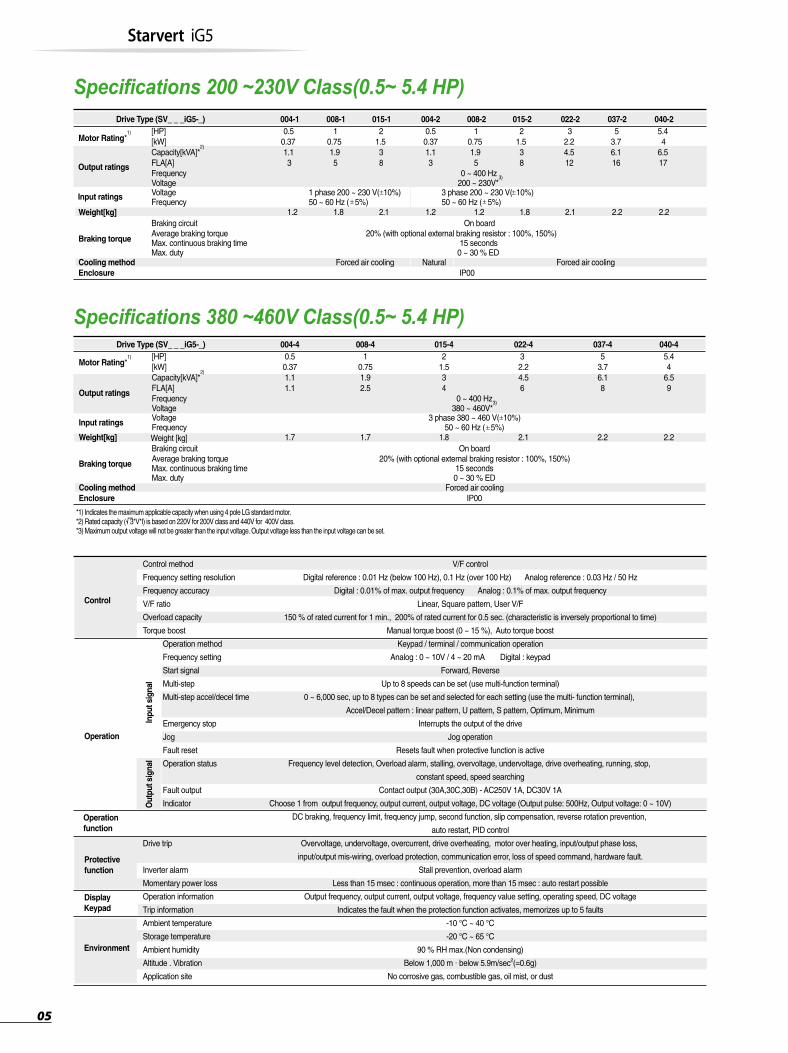
*1) Indicates the maximum applicable capacity when using 4 pole LG standard motor. *2) Rated capacity ( 3*V*I) is based on 220V for 200V class and 440V for 400V class. *3) Maximum output voltage will not be greater than the input voltage. Output voltage less than the input voltage can be set.
05
Specifications 200 ~230V Class(0.5~ 5.4 HP)
Specifications 380 ~460V Class(0.5~ 5.4 HP)
50 ~ 60 Hz ( 5%)Weight[kg]
Drive Type (SV_ _ _iG5-_) 004-4
Motor Rating*1) [HP]
[kW]
Output ratings
Input ratings
Capacity[kVA]*2)
Braking torque
Cooling method Forced air cooling
Average braking torque 20% (with optional external braking resistor : 100%, 150%)Max. continuous braking time 15 secondsMax. duty 0 ~ 30 % ED
Enclosure IP00
Weight [kg]
FLA[A]
0.50.371.11.1
008-41
0.751.92.5
015-42
1.534
022-432.24.56
037-45
3.76.18
040-45.44
6.59
1.7 1.7 1.8 2.1 2.2 2.2
Frequency 0 ~ 400 Hz
Frequency
Braking circuit On board
Voltage 380 ~ 460V*3)
Voltage 3 phase 380 ~ 460 V( 10%)
3 phase 200 ~ 230 V( 10%) 50 ~ 60 Hz ( 5%)50 ~ 60 Hz ( 5%)
Drive Type (SV_ _ _iG5-_) 004-1
Motor Rating*1) [HP]
[kW]
Output ratings
Input ratings
Weight[kg]
Capacity[kVA]*2)
Braking torque
Cooling method Forced air cooling Forced air coolingNatural
Average braking torque 20% (with optional external braking resistor : 100%, 150%)Max. continuous braking time 15 secondsMax. duty 0 ~ 30 % ED
Enclosure IP00
FLA[A]
0.50.371.13
008-11
0.751.95
015-12
1.538
004-20.50.371.13
008-21
0.751.95
015-22
1.538
022-23
2.24.512
037-25
3.76.116
040-25.44
6.517
1.2 1.8 2.1 1.2 1.2 1.8 2.1 2.2 2.2
Frequency 0 ~ 400 Hz
Frequency
Braking circuit On board
Voltage 200 ~ 230V*3)
Voltage 1 phase 200 ~ 230 V( 10%)
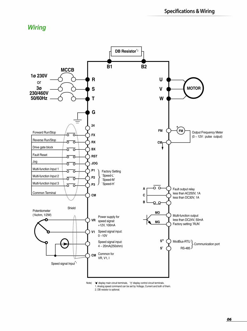
Wiring
Note) " " display main circuit terminals, " " display control circuit terminals. 1. Analog speed command can be set by Voltage, Current and both of them. 2. DB resistor is optional.
DB Resistor*2
MOTOR
U
B2B1
V
W
R
MCCB1ø 230V
3ø230/460V50/60Hz
S
T
G
FX
24
RX
BX
RST
JOG
P1
P2
P3
CM
VR
A
C
B
S+
S-
MO
FM
CM
MG
V1
I
CM
or
Forward Run/Stop
Reverse Run/Stop
Drive gate block
Fault Reset
Jog
Multi-function Input 1
Multi-function Input 2
Multi-function Input 3
Common Terminal
Potentiometer(1kohm, 1/2W)
Shield
Factory Setting`Speed-L``Speed-M``Speed-H`
Power supply forspeed signal:+12V, 100mA
Output Frequency Meter(0 ~ 12V : pulse output)
Fault output relayIess than AC250V, 1AIess than DC30V, 1A
Multi-function outputIess than DC24V, 50mAFactory setting:`RUN`
ModBus-RTU
RS-485
Speed signal input:0 ~10V
Speed signal input:4 ~ 20mA(250ohm)
Common forVR, V1, I
Speed signal Input*1
+
Specifications & Wiring
Communication port
FM
06

Power terminal configurationSymbol
R
S
T
U
V
W
B1
B2
G
AC Line input (1 phase 200~230 Vac for "-1" units 3 phase, 200~230 Vac for "-2" units and 380~460 Vac for "-4" units)
3 phase output terminals to motor
External additional dynamic braking resistor connection terminals.
Chassis ground (The gound terminal("G") may be located on heat sink instead of terminal strip depend on the model name)
Function
Parameter group Group name
Drive Group
Function 1 Group
Function 2 Group
Input / Output Group
Basic parameters of Command frequency, Accel/Decel time etc.
Basic parameters of Max. Frequency, Torque boost etc.
Application parameters of Frequency jump, Frequency limit etc.
Multifunction terminal setting and Sequence operation parameters
Description
Control terminal configurationType
Multi function input 1,2,3Forward run commandReverse run commandJog frequency reference Drive gate block
Fault resetSequence commonFrequency setting power(+12V)Frequency reference (Voltage)Frequency reference(Current)Frequency setting common terminalAnalog/digital output(For external monitoring)
Fault contact output
Multi-function output(Open collector output)Communication port
Used for multi function input. Factory default is set to step frequency 1, 2, 3.Forward run when closed and stop when opened.Reverse run when closed and stop when opened.Runs at jog frequency when the jog signal is on. The direction is set by the FX (or RX) signal.When the BX signal is ON, the output of the drive is cut off. When the motor uses an mechanical brake to stop, BX is used to cut off the output signal. When the BX signal, which does not cut off by latching, is OFF and the FX signal (or the RX signal) is ON, the motor keeps running, so be cautious.Used to release the protective status when the protective circuit is active.Used for the common terminal for contact input terminals.Used as power for the analog frequency setting. Maximum output is +12V, 100mA.Used for frequency reference and uses 0-10V for input. Input resistance is 20 kUsed for frequency reference and uses DC 4-20mA for input. Input resistance is 250Common terminal for the analog frequency reference signal and the FM (for monitoring).Outputs one of the followings: output frequency, output current, output voltage, DC link voltage. Factory default is set to output frequency. Maximum output voltage and output current is 0-12V, 1mA. Output frequency is set to 500Hz.Activates when the protective function is operating. AC250V 1A or less, DC30V 1A or lessFault : 30A-30C short (30B-30C open)Nomal : 30A-30C short (30B-30C open)
Used for multi-function output
Communication ports for RS-485
Symbol Name Descripton
P1, P2, P3
FX
RX
JOG
BX
RST
CM
VR
V1
I
CM
FM.CM
30A, 30C, 30B
MO.MG
S+, S-
Input
sig
nal
Outp
ut
sig
nal
Starting Contact
Function Slection
Analog Frequency
Setting
Contact
Pulse
RS232
Keypad
Starvert iG5
Class Display Name
FUNC
UP
DOWN
RUN
STOP/RESET
REV
FWD
SET
RUN
Program key
Up key
Down key
Run key
STOP/RESET key
Reverse run
Forward run
Setting
Operating
Press to change the parameter setting.
Press to move through codes or to increase the parameter values.
Press to move through codes or to decrease the parameter values.
Use to operate the drive
Press to stop during operation. Press to reset when a fault has occurred.
During reverse run.
During forward run.
When the user is setting the parameters using the FUNC key
When in constant speed and blinks when accelerating or decelerating.
Description
KEY
LED
07
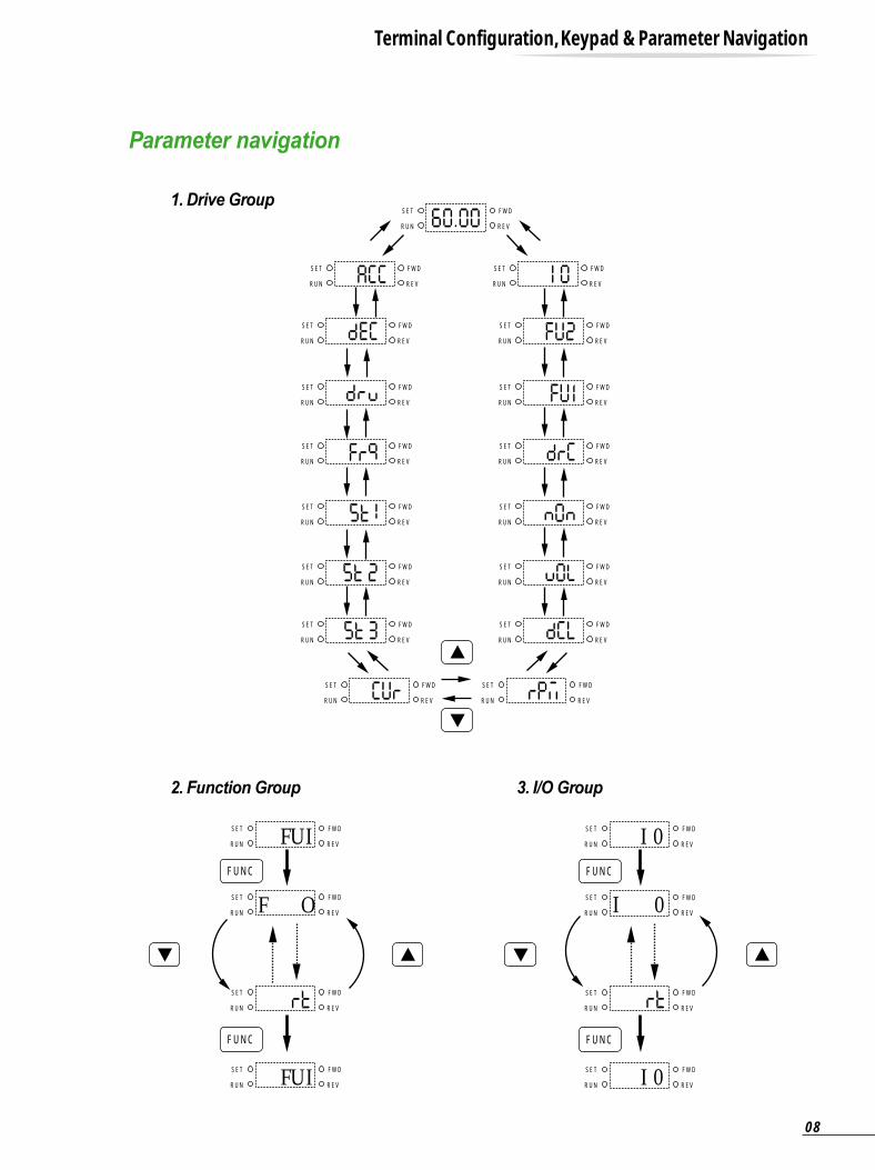
Parameter navigation
1. Drive Group
2. Function Group 3. I/O Group
Terminal Configuration, Keypad & Parameter Navigation
SET
RUN
FWD
REV
SET
RUN
FWD
REV
SET
RUN
FWD
REV
SET
RUN
FWD
REV
FUNC
FUNC
I 0
I 0
I 0
SET
RUN
FWD
REV
SET
RUN
FWD
REV
SET
RUN
FWD
REV
SET
RUN
FWD
REV
FUNC
FUNC
FU I
F O
FU I
SET
RUN
FWD
REV
SET
RUN
FWD
REV
SET
RUN
FWD
REV
SET
RUN
FWD
REV
SET
RUN
FWD
REV
SET
RUN
FWD
REV
SET
RUN
FWD
REV
SET
RUN
FWD
REV
SET
RUN
FWD
REV
SET
RUN
FWD
REV
SET
RUN
FWD
REV
SET
RUN
FWD
REV
SET
RUN
FWD
REV
SET
RUN
FWD
REV
SET
RUN
FWD
REV
SET
RUN
FWD
REV
SET
RUN
FWD
REV
08
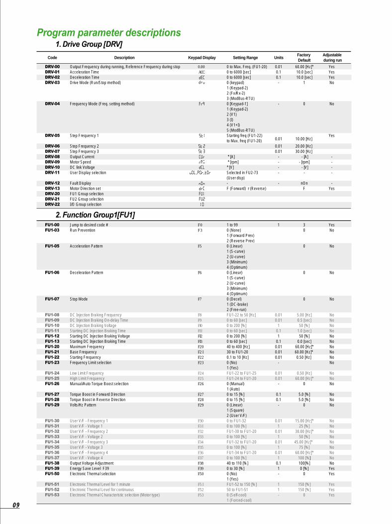
Program parameter descriptions
Code
Output Frequency during running, Reference Frequency during stopAcceleration TimeDeceleration TimeDrive Mode (Run/Stop method)
Frequency Mode (Freq. setting method)
Step Frequency 1
Step Frequency 2Step Frequency 3Output CurrentMotor SpeedDC link VoltageUser Display selection
Fault DisplayMotor Direction setFU1 Group selectionFU2 Group selectionI/O Group selection
0.00 ACC
, ,
0 to Max. Freq. (FU1-20)0 to 6000 [sec]0 to 6000 [sec]0 (keypad)1 (Keypad-2) 2 (Fx/Rx-2) 3 (ModBus-RTU)0 [Keypad-1]1 (Keypad-2) 2 (V1) 3 (I)4 (V1+I) 5 (ModBus-RTU)Starting freq (FU1-22) to Max. freq (FU1-20)
* [A] * [rpm]* [V]Selected in FU2-73 (User disp)-F (Forward) r (Reverse)
0.010.10.1-
-
0.01
0.010.01
----
-
60.00 [Hz]*10.0 [sec]10.0 [sec]
1
0
10.00 [Hz]
20.00 [Hz] 30.00 [Hz]
- [A]- [rpm] - [V]
-
nOnF
YesYesYesNo
No
Yes
----
-Yes
Description Keypad Display Setting Range UnitsFactory Default
Adjustable during run
DRV-00
DRV-01
DRV-02
DRV-03
DRV-04
DRV-05
DRV-06
DRV-07
DRV-08
DRV-09
DRV-10
DRV-11
DRV-12
DRV-13
DRV-20
DRV-21
DRV-22
1. Drive Group [DRV]
Jump to desired code #Run Prevention
Acceleration Pattern
Deceleration Pattern
Stop Mode
DC Injection Braking FrequencyDC Injection Braking On-delay TimeDC Injection Braking VoltageStarting DC Injection Braking TimeStarting DC Injection Braking VoltageStarting DC Injection Braking TimeMaximum FrequencyBase FrequencyStarting FrequencyFrequency Limit selection
Low Limit FrequencyHigh Limit Frequency Manual/Auto Torque Boost selection
Torque Boost in Forward DirectionTorque Boost in Reverse DirectionVolts/Hz Pattern
User V/F - Frequency 1User V/F - Voltage 1User V/F - Frequency 2User V/F - Voltage 2User V/F - Frequency 3User V/F - Voltage 3User V/F - Frequency 4User V/F - Voltage 4Output Voltage AdjustmentEnergy Save Level F39Electronic Thermal selection
Electronic Thermal Level for 1 minuteElectronic Thermal Level for continuousElectronic Thermal Characteristic selection (Motor type)
F 0F 3
F5
F6
F7
F8F9FI0�FI IFI2FI3F20F2 IF22F23
F24F25F26
F27F28F29
F30F3 IF32F33F34�F35�F36�F37�F38�F39�F50
F5 IF52F53
1 to 990 (None) 1 (Forward Prev) 2 (Reverse Prev)0 (Linear) 1 (S-curve) 2 (U-curve) 3 (Minimum) 4 (Optimum)0 (Linear) 1 (S-curve) 2 (U-curve) 3 (Minimum) 4 (Optimum)0 (Decel) 1 (DC-brake) 2 (Free-run)FU1-22 to 50 [Hz]0 to 60 [sec]0 to 200 [%]0 to 60 [sec]0 to 200 [%]0 to 60 [sec] 40 to 400 [Hz]30 to FU1-200.1 to 10 [Hz]0 (No) 1 (Yes)FU1-22 to FU1-25FU1-24 to FU1-200 (Manual) 1 (Auto)0 to 15 [%]0 to 15 [%] 0 (Linear) 1 (Square) 2 (User V/F)0 to FU1-320 to 100 [%]FU1-30 to FU1-200 to 100 [%]FU1-32 to FU1-20 0 to 100 [%]FU1-34 to FU1-200 to 100 [%] 40 to 110 [%] 0 to 30 [%]0 (No) 1 (Yes)FU1-52 to 150 [%]50 to FU1-510 (Self-cool) 1 (Forced-cool)
1
0.010.01
10.11
0.10.010.010.01
-
0.010.01
-
0.10.1-
0.011
0.011
0.011
0.011
0.11-
11-
30
0
0
0
5.00 [Hz]0.5 [sec]50 [%]
1.0 [sec]50 [%]
0.0 [sec]60.00 [Hz]*60.00 [Hz]* 0.50 [Hz]
0.50 [Hz]60.00 [Hz]*
0
5.0 [%]5.0 [%]
0
15.00 [Hz]*25 [%]
30.00 [Hz]*50 [%]
45.00 [Hz]* 75 [%]
60.00 [Hz]*100 [%]100[%]0 [%]
0
150 [%]150 [%]
0
YesNo
No
No
No
NoNoNoNoNoNoNoNoNoNo
NoNoNo
NoNoNo
NoNoNoNoNoNoNoNoNoYesYes
YesYesYes
FU1-00
FU1-03
FU1-05
FU1-06
FU1-07
FU1-08
FU1-09
FU1-10
FU1-11
FU1-12
FU1-13
FU1-20
FU1-21
FU1-22
FU1-23
FU1-24
FU1-25
FU1-26
FU1-27
FU1-28
FU1-29
FU1-30
FU1-31
FU1-32
FU1-33
FU1-34
FU1-35
FU1-36
FU1-37
FU1-38
FU1-39
FU1-50
FU1-51
FU1-52
FU1-53
2. Function Group1[FU1]
09

Code
Overload Warning LevelOverload Warning Hold TimeOverload Trip selection
Overload Trip level Overload Trip Delay TimeStall Prevention Mode selection
Stall Prevention LevelReturn Code
F54�F55�F56�
�F57�F58�F59�
���
F60�
30 to 150 [%] 0 to 30 [sec]0 (No) 1 (Yes)30 to 200 [%]0 to 60 [sec]000 - 111 (bit set)Bit 0: during Accel.Bit 1: during Steady speedBit 2: during Decel.30 to 150 [%]
10.1-
11bit
1-
150 [%]10.0 [sec]
1
180 [%]60.0 [sec]
000
150 [%]-
YesYesYes
Yes
No
No-
Description Keypad Display Setting Range UnitsFactory Default
Adjustable during run
FU1-54
FU1-55
FU1-56
FU1-57
FU1-58
FU1-59
FU1-60
FU1-99
Jump to desired code #Previous Fault History 1Previous Fault History 2Previous Fault History 3Previous Fault History 4Previous Fault History 5Erase Fault History
Dwell FrequencyDwell TimeFrequency Jump selection
Jump Frequency 1 Low Jump Frequency 1 HighJump Frequency 2 Low Jump Frequency 2 HighJump Frequency 3 Low Jump Frequency 3 HighInput/Output Phase Loss Protection
Power ON Start selection
Restart after Fault Reset
Speed Search selection
Current Limit Level during Speed SearchP Gain during Speed SearchI Gain during speed searchNumber of Auto Restart AttemptDelay Time before Auto RestartRated Motor selection
Number of Motor PolesRated Motor SlipRated Motor Current in RMSNo Load Motor Current in RMSMotor EfficiencyLoad InertiaCarrier FrequencyControl Mode selection
PID Feedback Signal selection
P Gain for PID ControlI Gain for PID ControlD Gain for PID ControlLimit Frequency for PID Control Reference Frequency for Accel and Decel
Accel/Decel Time Scale
Power On Display
H 0H IH2H3H4H5H6
H7H8HI0
HI IHI2�HI3�HI4�HI5�HI6HI9
H20
H2 I
H22
H23�H24�H25�H26�H27�H30��H3 I�H32�H33�H34�H36�H37�H39�H40���H50��H5 I�H52�H53�H54�H70��H7 I���H72
1 to 99-
0 (No) 1 (Yes)0 to FU1-200 to 10 [sec] 0 (No) 1 (Yes)FU1-22 to FU2-12FU1-11 to FU2-20FU1-22 to FU2-14FU2-13 to FU1-20FU1-22 to FU2-16FU2-15 to FU1-2000 - 11 (bit set)Bit 0: Output phase loss protectionBit 1: Intput phase loss protection0 (No) 1 (Yes)0 (No) 1 (Yes)0000 - 1111 (bit set)Bit 0: during Accel.Bit 1: after fault resetBit 2: after instant power failure restartBit 3: when FU2-20 is set to 1 (Yes). 80 to 200 [%]0 to 99990 to 99990 to 100 to 60 [sec]0.4 (0.37kW) 0.8 (0.75kW)1.5 (1.5kW) 2.2 (2.2kW)2 to 12 0 to 10 [Hz]0.1 to 99.9 [A]0.1 to 99.9 [A]50 to 100 [%]0 to 21 to 10 [kHz]0 (V/F) 1 (Slip Compen) 2 (PID)0 (I) 1 (V1) 0 to 99990 to 99990 to 99990 to FU1-200 (Max Freq) 1 (Delta Freq)0 (0.01 sec) 1 (0.1 sec) 2 (1 sec)0 (Cmd. Freq) 1 (Acc. Time) 2 (Dec. Time) 3 (Drv mode) 4 (Freq mode) 5 (Step Freq 1) 6 (Step Freq 2) 7 (Step Freq 3) 8 (Current) 9 (Speed) 10(DC link Vtg) 11 (User disp) 12 (Fault Display) 13 (Motor direction)
1-
-
0.010.1-
0.010.010.010.010.010.01
-
-
-
-
1111
0.1-
10.01
11111-
-
111
0.01-
-
1
300
nOnnOnnOnnOn
0
5.00 [Hz]0.0 [sec]
0
0.00 [Hz] 0.00 [Hz] 0.00 [Hz] 0.00 [Hz] 0.00 [Hz] 0.00 [Hz]
00
0
0
0000
100 [%]1001000
01.0 [sec]
4
03 kHz
0
0
30003000
60.00 [Hz]*0
1
0
YesYesYes
Yes
Yes
NoNoNo
NoNoNoNoNoNoYes
Yes
Yes
No
YesYesYesYesYesNo
NoNoNoNoNoNoYesNo
No
YesYesYesYesNo
Yes
Yes
FU2-00
FU2-01�
FU2-02�
FU2-03�
FU2-04�
FU2-05�
FU2-06�
�
FU2-07�
FU2-08�
FU2-10�
�
FU2-11�
FU2-12�
FU2-13�
FU2-14�
FU2-15�
FU2-16�
FU2-19�
�
�
�
�
FU2-20�
FU2-21
FU2-22�
�
�
�
�
�
�
FU2-23�
FU2-24
FU2-25�
FU2-26�
FU2-27�
FU2-30�
�
FU2-31�
FU2-32�
FU2-33�
FU2-34�
FU2-36�
FU2-37�
FU2-39�
FU2-40�
�
�
FU2-50�
�
FU2-51�
FU2-52�
FU2-53�
FU2-54�
FU2-70
FU2-71�
�
�
FU2-72
3. Function Group2 [FU2]
Program Parameter Descriptions
10
SV
015IG5-2
Starvert iG5
Code Description Keypad Display Setting Range UnitsFactory Default
Adjustable during run
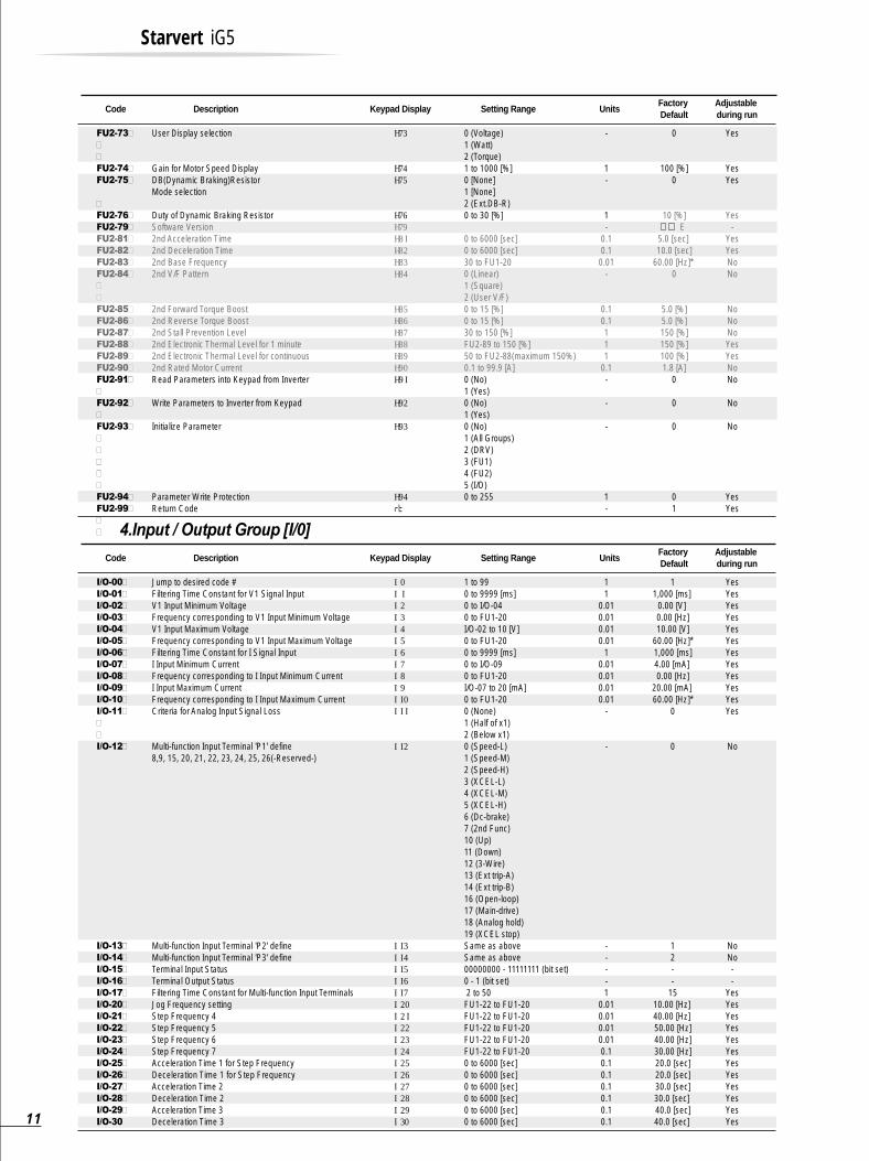
User Display selection
Gain for Motor Speed DisplayDB(Dynamic Braking)ResistorMode selection
Duty of Dynamic Braking Resistor Software Version2nd Acceleration Time 2nd Deceleration Time2nd Base Frequency2nd V/F Pattern
2nd Forward Torque Boost2nd Reverse Torque Boost2nd Stall Prevention Level2nd Electronic Thermal Level for 1 minute2nd Electronic Thermal Level for continuous2nd Rated Motor CurrentRead Parameters into Keypad from Inverter
Write Parameters to Inverter from Keypad
Initialize Parameter
Parameter Write ProtectionReturn Code
H73���H74�H75���H76�H79�H8 IH82�H83�H84���H85�H86�H87�H88�H89�H90�H9 I�H92��H93������H94�
0 (Voltage) 1 (Watt) 2 (Torque)1 to 1000 [%]0 [None]1 [None]2 (Ext.DB-R)0 to 30 [%]
0 to 6000 [sec]0 to 6000 [sec]30 to FU1-200 (Linear) 1 (Square) 2 (User V/F)0 to 15 [%] 0 to 15 [%] 30 to 150 [%]FU2-89 to 150 [%]50 to FU2-88(maximum 150%) 0.1 to 99.9 [A]0 (No) 1 (Yes)0 (No) 1 (Yes)0 (No) 1 (All Groups) 2 (DRV) 3 (FU1) 4 (FU2) 5 (I/O)0 to 255
-
1-
1-
0.10.10.01
-
0.10.1111
0.1-
-
-
1-
0
100 [%]0
10 [%] . E
5.0 [sec] 10.0 [sec]
60.00 [Hz]* 0
5.0 [%]5.0 [%]150 [%]150 [%]100 [%]1.8 [A]
0
0
0
01
Yes
YesYes
Yes-
YesYesNoNo
NoNoNoYesYesNoNo
No
No
YesYes
FU2-73�
�
�
FU2-74�
FU2-75�
�
FU2-76�
FU2-79�
FU2-81�
FU2-82�
FU2-83�
FU2-84�
�
�
FU2-85�
FU2-86�
FU2-87�
FU2-88�
FU2-89�
FU2-90�
FU2-91�
�
FU2-92�
�
FU2-93�
�
�
�
�
�
FU2-94�
FU2-99�
�
�
Code Description Keypad Display Setting Range UnitsFactory Default
Adjustable during run
4.Input / Output Group [I/0]
Jump to desired code #Filtering Time Constant for V1 Signal InputV1 Input Minimum VoltageFrequency corresponding to V1 Input Minimum VoltageV1 Input Maximum VoltageFrequency corresponding to V1 Input Maximum VoltageFiltering Time Constant for I Signal InputI Input Minimum CurrentFrequency corresponding to I Input Minimum CurrentI Input Maximum CurrentFrequency corresponding to I Input Maximum CurrentCriteria for Analog Input Signal Loss
Multi-function Input Terminal 'P1' define8,9, 15, 20, 21, 22, 23, 24, 25, 26(-Reserved-)
Multi-function Input Terminal 'P2' defineMulti-function Input Terminal 'P3' defineTerminal Input StatusTerminal Output StatusFiltering Time Constant for Multi-function Input TerminalsJog Frequency settingStep Frequency 4 Step Frequency 5 Step Frequency 6Step Frequency 7Acceleration Time 1 for Step FrequencyDeceleration Time 1 for Step FrequencyAcceleration Time 2Deceleration Time 2Acceleration Time 3Deceleration Time 3
I 0�I II 2�I 3�I 4�I 5�I 6�I 7�I 8�I 9�I I 0�I I I��I I 2�����������������I I 3�I I 4�I I 5�I I 6�I I 7�I 20�I 2 II 22�I 23�I 24�I 25�I 26�I 27�I 28�I 29�I 30�
1 to 990 to 9999 [ms]0 to I/O-040 to FU1-20I/O-02 to 10 [V]0 to FU1-200 to 9999 [ms]0 to I/O-090 to FU1-20I/O-07 to 20 [mA]0 to FU1-200 (None) 1 (Half of x1) 2 (Below x1)0 (Speed-L) 1 (Speed-M) 2 (Speed-H) 3 (XCEL-L) 4 (XCEL-M) 5 (XCEL-H) 6 (Dc-brake) 7 (2nd Func) 10 (Up) 11 (Down) 12 (3-Wire) 13 (Ext trip-A) 14 (Ext trip-B) 16 (Open-loop) 17 (Main-drive) 18 (Analog hold) 19 (XCEL stop) Same as aboveSame as above00000000 - 11111111 (bit set)0 - 1 (bit set) 2 to 50FU1-22 to FU1-20FU1-22 to FU1-20FU1-22 to FU1-20FU1-22 to FU1-20FU1-22 to FU1-200 to 6000 [sec]0 to 6000 [sec]0 to 6000 [sec]0 to 6000 [sec]0 to 6000 [sec]0 to 6000 [sec]
11
0.010.010.010.01
10.010.010.010.01
-
-
----1
0.010.010.010.010.10.10.10.10.10.10.1
11,000 [ms]
0.00 [V] 0.00 [Hz]10.00 [V]
60.00 [Hz]*1,000 [ms]4.00 [mA] 0.00 [Hz]
20.00 [mA] 60.00 [Hz]*
0
0
12--
1510.00 [Hz] 40.00 [Hz] 50.00 [Hz]40.00 [Hz]30.00 [Hz]20.0 [sec]20.0 [sec]30.0 [sec]30.0 [sec] 40.0 [sec]40.0 [sec]
YesYesYesYesYesYesYesYesYesYesYesYes
No
NoNo--
YesYesYesYesYesYesYesYesYesYesYesYes
I/O-00�
I/O-01�
I/O-02�
I/O-03�
I/O-04�
I/O-05�
I/O-06�
I/O-07�
I/O-08�
I/O-09�
I/O-10�
I/O-11�
�
�
I/O-12�
I/O-13�
I/O-14�
I/O-15�
I/O-16�
I/O-17�
I/O-20�
I/O-21�
I/O-22�
I/O-23�
I/O-24�
I/O-25�
I/O-26�
I/O-27�
I/O-28�
I/O-29�
I/O-3011

Code Description Keypad Display Setting Range UnitsFactory Default
Adjustable during run
Acceleration Time 4Deceleration Time 4Acceleration Time 5Deceleration Time 5Acceleration Time 6Deceleration Time 6Acceleration Time 7Deceleration Time 7FM (Frequency Meter) Output selection
FM Output AdjustmentFrequency Detection LevelFrquency Detection BandwidthMulti-function Output define (MO)15, 16, 18, 19, 20(-Reserved-)
Fault Output Relay setting (30A, 30B, 30C)
Inverter NumberBaud Rate I47
Operating selection at Loss of Freq. Reference
Waiting Time after Loss of Freq. Reference Communication Protocol selection
Return Code
I 3 II 32�I 33�I 34�I 35�I 36�I 37�I 38�I 40����I 4 II 42�I 43�I 44����������������I 45��
I 46�I 47�����I 48�
�I 49�I 50���
0 to 6000 [sec]0 to 6000 [sec]0 to 6000 [sec]0 to 6000 [sec]0 to 6000 [sec]0 to 6000 [sec]0 to 6000 [sec]0 to 6000 [sec]0 (Frequency) 1 (Current) 2 (Voltage) 3 (DC link Vtg)10 to 200 [%] 0 to FU1-200 to FU1-200 (FDT-1) 1 (FDT-2)2 (FDT-3) 3 (FDT-4) 4 (FDT-5) 5 (IOL)6 (IOL) 7 (Stall) 8 (OV) 9 (LV) 10 (OH) 11 (Lost Command) 12 (Run) 13 (Stop) 14 (Steady) 17 (Search)000 - 111 (bit set)Bit 0: LV Bit 1: All TripBit 2: Auto retry1 to 32 0 (1200 bps) 1 (2400 bps) 2 (4800 bps) 3 (9600 bps) 4 (19200 bps) 0 (None) 1 (FreeRun) 2 (Stop)0.1 to 120 [sec] 0 (LG- BUS) 1~6(ModbusASCII) 7~9 (Modbus-RTU)
0.10.10.10.10.10.10.10.1-
10.010.01
-
-
1-
-
0.1
-
50.0 [sec] 50.0 [sec]40.0 [sec]40.0 [sec]30.0 [sec]30.0 [sec]20.0 [sec]20.0 [sec]
0
100 [%]30.00 [Hz] 10.00 [Hz]
12
010
13
0
1.0 [sec] 7
1
YesYesYesYesYesYesYesYesYes
YesYesYesYes
Yes
YesYes
Yes
YesYes
Yes
I/O-31�
I/O-32�
I/O-33�
I/O-34�
I/O-35�
I/O-36�
I/O-37�
I/O-38�
I/O-40�
�
�
�
I/O-41
I/O-42�
I/O-43�
I/O-44�
�
�
�
�
�
�
�
�
�
�
�
�
�
�
�
I/O-45�
�
I/O-46�
I/O-47�
�
�
�
�
I/O-48�
I/O-49�
I/O-50�
�
�
I/O-99
Note: Parameters that are set by bit are ON (1) when the upper LED is lit. (F59, H19, H22, I15, I16, I45 are the parameters that are set by bit.)Note: *marked default value changes depend on the main frequency setting in factory(50 / 60Hz)
4.5 4.5W2
4.5
H2
4D
1
W1
iG5
VARIABLE FREQUENCY DRIVER
CAUTION
Read the manual and follow the safety instruction before installation or operation
Do not the power supply to the drive output terminal (U, V, W)
Before opening the cover, disconnect all power and wait at least 3 minutes untill DC
bus capacitors discharge.
`Risk of Electric Shock`-more than one disconnect switch is required to de -
energize the equipment before servicing.
SO
UR
CE
AC
200-230V 50/60H
zO
UTP
UT C
APA
CITY
1.5kVAC
UR
RE
NT 5A
FRC
QU
EN
CY
0.2-400Hz
SV
015IG5-2
International system Co, Ltd M
ade In Korea
00.00FUNC
RUN STOPRESET
Dimension : mm(inch)
Inverter
SV004iG5-1
SV004iG5-2�
SV008iG5-1�
SV008iG5-2�
SV015iG5-1�
SV015iG5-2�
SV022iG5-2
SV037iG5-2�
SV040iG5-2�
SV004iG5-4�
SV008iG5-4�
SV015iG5-4�
SV022iG5-4�
SV037iG5-4�
SV040iG5-4
0.50.5
112235
5.40.5
1235
5.4
100(3.94)100(3.94)130(5.12)100(3.94)150(5.90)130(5.12)150(5.90)150(5.90)150(5.90)130(5.12)130(5.12)130(5.12)150(5.90)150(5.90)150(5.90)
88(3.46)88(3.46)
118(4.65)88(3.46)
138(5.43)118(4.65)138(5.43)138(5.43)138(5.43)118(4.65)118(4.65)118(4.65)138(5.43)138(5.43)138(5.43)
128(5.04)128(5.04)128(5.04)128(5.04)128(5.04)128(5.04)128(5.04)128(5.04)128(5.04)128(5.04)128(5.04)128(5.04)128(5.04)128(5.04)128(5.04)
117.5(4.63)117.5(4.63)117.5(4.63)117.5(4.63)117.5(4.63)117.5(4.63)117.5(4.63)117.5(4.63)117.5(4.63)117.5(4.63)117.5(4.63)117.5(4.63)117.5(4.63)117.5(4.63)117.5(4.63)
130.9(5.15)130.9(5.15)150.9(5.94)130.9(5.15)
155(6.10)150.9(5.94)
155(6.10)155(6.10)155(6.10)
150.9(5.94)150.9(5.94)150.9(5.94)
155(6.10)155(6.10)155(6.10)
HP W1 W2 H1 H2 D1
Dimension
12
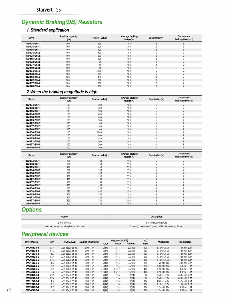
1. Standard application
Options
Drive Resistor capacity[W]
Average brakingtorque[%]
Resistor value[ ] Enable duty[%]Continuous
braking time[sec]
100100100100100100100100100100100100100100100
100100100100100100100100100100100100100100100
400200100400200100604040
1800900450300200200
553553222553222
555555555555555
SV004iG5-1
SV008iG5-1�
SV015iG5-1�
SV004iG5-2
SV008iG5-2�
SV015iG5-2�
SV022iG5-2�
SV037iG5-2�
SV040iG5-2�
SV004iG5-4
SV008iG5-4�
SV015iG5-4�
SV022iG5-4�
SV037iG5-4�
SV040iG5-4
2. When the braking magnitude is high
Drive Resistor capacity[W]
Average brakingtorque[%]
Resistor value[ ] Enable duty[%]Continuous
braking time[sec]
100100200100100200300500500100100200300500500
100100100100100100100100100100100100100100100
400200100400200100604040
1800900450300200200
555555555555555
555555555555555
SV004iG5-1
SV008iG5-1�
SV015iG5-1�
SV004iG5-2
SV008iG5-2�
SV015iG5-2�
SV022iG5-2�
SV037iG5-2�
SV040iG5-2�
SV004iG5-4
SV008iG5-4�
SV015iG5-4�
SV022iG5-4�
SV037iG5-4�
SV040iG5-4
Drive Resistor capacity[W]
Average brakingtorque[%]
Resistor value[ ] Enable duty[%]Continuous
braking time[sec]
150150300150150300400600600150150300400600600
150150150150150150150150150150150150150150150
30015060
30015060503333
1200600300200130130
555555555555555
555555555555555
SV004iG5-1
SV008iG5-1�
SV015iG5-1�
SV004iG5-2
SV008iG5-2�
SV015iG5-2�
SV022iG5-2�
SV037iG5-2�
SV040iG5-2�
SV004iG5-4
SV008iG5-4�
SV015iG5-4�
SV022iG5-4�
SV037iG5-4�
SV040iG5-4
Peripheral devicesDrive Models kW MCCB, ELB Magnetic Contactor AC
InputWire, mm2(AWG)
R,S,T U,V,WAC Reactor DC Reactor
0.370.751.5
0.370.751.52.23.7
40.370.751.52.23.7
4
10A10A10A10A10A15A25A40A40A6A6A
10A10A20A20A
2(14)2(14)2(14)2(14)2(14)2(14)2(14)
3.5(12)3.5(12)
2(14)2(14)2(14)2(14)2(14)2(14)
2(14)2(14)2(14)2(14)2(14)2(14)2(14)
3.5(12)3.5(12)
2(14)2(14)2(14)2(14)2(14)2(14)
3.5(12)3.5(12)3.5(12)3.5(12)3.5(12)3.5(12)3.5(12)3.5(12)3.5(12)
2(14)2(14)2(14)2(14)2(14)2(14)
Ground
ABS33a, EBS33ABS33a, EBS33ABS33a, EBS33ABS33a, EBS33ABS33a, EBS33ABS33a, EBS33ABS33a, EBS33ABS33a, EBS33ABS33a, EBS33ABS33a, EBS33ABS33a, EBS33ABS33a, EBS33ABS33a, EBS33ABS33a, EBS33ABS33a, EBS33
SMC-10PSMC-10PSMC-10PSMC-10PSMC-10PSMC-10PSMC-15PSMC-20PSMC-20PSMC-10PSMC-10PSMC-10PSMC-20PSMC-20PSMC-20P
2.13mH, 5.7A2.13mH, 5.7A2.13mH, 5.7A2.13mH, 5.7A2.13mH, 5.7A1.20mH, 10A0.88mH, 14A0.56mH, 20A0.56mH, 20A8.63mH, 2.8A8.63mH, 2.8A4.81mH, 4.8A3.23mH, 7.5A2.34mH, 10A2.34mH, 10A
7.00mH, 5.4A7.00mH, 5.4A7.00mH, 5.4A7.00mH, 5.4A7.00mH, 5.4A4.05mH, 9.2A2.92mH, 13A1.98mH, 19A1.98mH, 19A
28.62mH, 2.7A28.62mH, 2.7A16.14mH, 4.6A11.66mH, 7.1A
7.83mH, 10A7.83mH, 10A
SV004iG5-1
SV008iG5-1�
SV015iG5-1�
SV004iG5-2
SV008iG5-2�
SV015iG5-2�
SV022iG5-2�
SV037iG5-2�
SV040iG5-2�
SV004iG5-4
SV008iG5-4�
SV015iG5-4�
SV022iG5-4�
SV037iG5-4�
SV040iG5-4
Option Description
DIN Rail base
Remote keypad mounting fixture and cable
Din rail mounting plate
2 meter, 3 meter and 5 meter cable and mounting fixture.
Starvert iG5
Dynamic Braking(DB) Resistors
13
FF Series (Footprint)
FF Series (Footprint)
FE Series (Standard)
FS Series (output chokes)FE Series (Standard)
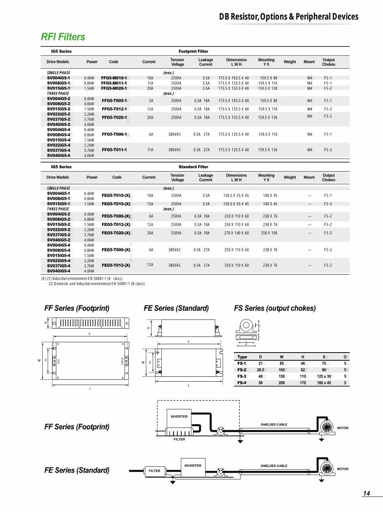
RFI Filters
DB Resistor, Options & Peripheral Devices
Drive Models Power Code Current Tension Voltage
LeakageCurrent
DimensionsL W H
MountingY X
OutputChokes
Weight Mount
0.4kW0.8kW1.5kW
0.4kW0.8kW1.5kW2.2kW3.7kW4.0kW0.4kW0.8kW1.5kW2.2kW3.7kW4.0kW
173.5 X 103.5 X 40173.5 X 133.5 X 40173.5 X 153.5 X 40
173.5 X 103.5 X 40
173.5 X 133.5 X 40
173.5 X 153.5 X 40
173.5 X 133.5 X 40
173.5 X 133.5 X 40
159.5 X 80159.5 X 110159.5 X 130
159.5 X 80
159.5 X 110
159.5 X 130
159.5 X 110
159.5 X 130
M4M4M4
M4
M4
M4
M4
M4
FS-1FS-1FS-2
FS-1
FS-2
FS-2
FS-1
FS-2
3.5A3.5A3.5A
0.3A 18A
0.3A 18A
0.3A 18A
0.5A 27A
0.5A 27A
250VA250VA250VA
250VA
250VA
250VA
380VAC
380VAC
10A11A20A
5A
12A
20A
6A
11A
FFG5-M010-1�
FFG5-M011-1�
FFG5-M020-1�
�
FFG5-T005-1�
�FFG5-T012-1�
FFG5-T020-1��
FFG5-T006-1���
FFG5-T011-1
SINGLE PHASE (max.)SV004iG5-1
SV008iG5-1�
SV015iG5-1�
THREE PHASE (max.)�SV004iG5-2
SV008iG5-2�
SV015iG5-2�
SV022iG5-2�
SV037iG5-2�
SV040iG5-2�
SV004iG5-4
SV008iG5-4�
SV015iG5-4�
SV022iG5-4�
SV037iG5-4
SV040iG5-4
IG5 Series Footprint Filter
Drive Models Power Code Current Tension Voltage
LeakageCurrent
DimensionsL W H
MountingY X
OutputChokes
Weight Mount
0.4kW0.8kW1.5kW
0.4kW0.8kW1.5kW2.2kW3.7kW4.0kW0.4kW0.8kW1.5kW2.2kW3.7kW4.0kW
150.5 X 55 X 45
150.5 X 55 X 45
250 X 110 X 60
250 X 110 X 60
270 X 140 X 60
250 X 110 X 60
250 X 110 X 60
140 X 45
140 X 45
238 X 76
238 X 76
258 X 106
238 X 76
238 X 76
---
---
---
---
---
---
---
FS-1
FS-2
FS-2
FS-2
FS-2
FS-2
FS-2
3.5A
3.5A
0.3A 18A
0.3A 18A
0.3A 18A
0.5A 27A
0.5A 27A
250VA
250VA
250VA
250VA
250VA
380VAC
380VAC
10A
15A
6A
12A
20A
6A
12A
FEG5-T010-(X)��
FEG5-T015-(X)�
�
FEG5-T006-(X)��
FEG5-T012-(X)�
FEG5-T020-(X)�
�
FEG5-T006-(X)�
�
�
FEG5-T012-(X)
SINGLE PHASE (max.)SV004iG5-1
SV008iG5-1�
SV015iG5-1�
THREE PHASE (max.)�SV004iG5-2
SV008iG5-2�
SV015iG5-2�
SV022iG5-2�
SV037iG5-2�
SV040iG5-2�
SV004iG5-4
SV008iG5-4�
SV015iG5-4�
SV022iG5-4�
SV037iG5-4
SV040iG5-4
IG5 Series Standard Filter
(X) (1) Industrial environment EN 50081-1 (A class) (2) Domestic and industrial environment EN 50081-1 (B class)
H
H
W X
Y
L
W X
Y
L
RED
CAR
GA
MOTOR
INVERTER
FILTER
SHIELDED CABLE
INVERTER
FILTER
SHIELDED CABLEMOTOR
WX
Y
HD
Type
FS-1�
FS-2�
FS-3�
FS-4
D
21�
28.5�
48�
58
W
85�
105�
150�
200
H
46�
62�
110�
170
X�
70�
90�
125 x 30�
180 x 45
O�
5�
5�
5�
5
14
LG constantly endeavor to improveour products so that information
in this catalog is subject tochange without notice.
HEAD OFFICELG TWIN TOWERS, 20 Yoido-dong, Youngdungpo-gu, Seoul, 150-721, Korea.Tel.(82-2)3777- 4640 ~ 4649Fax.(82-2)3777- 4648http://www.lgis.comhttp://www.fasolution.com
OVERSEAS BRANCHESBeijing Tel.86-10-6462-3254, 3256, 3259, 6464-8637Shanghai Tel.86-21-6252-3367, 3795, 6240-3477Hanoi Tel.84-4-882-0222Dalian Tel.86-411-730-6495, 730-7580Tokyo Tel.81-3-3582-9126Jakarta Tel.62-21-897-4311New Jersey Tel.1-201-816-2982
Related Documents


![Compact & Powerful Inverter Starvert iG5A1].pdf · Compact & Powerful Inverter Starvert iG5A . 2 ... remote control and monitoring between iG5A and other equipment. Built-in 485 communication](https://static.cupdf.com/doc/110x72/5d2951ad88c99392328d7a62/compact-powerful-inverter-starvert-ig5a-1pdf-compact-powerful-inverter.jpg)