Lesson 2 Chapter Two Three Phase Uncontrolled Rectifier 1. Operating principle of three phase half wave uncontrolled rectifier The half wave uncontrolled converter is the simplest of all three phase rectifier topologies. Although not much used in practice it does provide useful insight into the operation of three phase converters. Fig.1 shows the circuit diagram, conduction table and wave forms of a three phase half wave uncontrolled converter supplying a resistive inductive load. Fig.1: Operation of the three phase half wave uncontrolled rectifier (a) circuit diagram, (b) conduction table, (c) wave forms For simplicity the load current (i o ) has been assumed to be ripple free. As shown in Fig.1 (a), in a three phase half wave uncontrolled converter the anode of

Welcome message from author
This document is posted to help you gain knowledge. Please leave a comment to let me know what you think about it! Share it to your friends and learn new things together.
Transcript
Lesson 2 Chapter Two
Three Phase Uncontrolled Rectifier
1. Operating principle of three phase half wave
uncontrolled rectifier
The half wave uncontrolled converter is the simplest of all three phase
rectifier topologies. Although not much used in practice it does provide useful
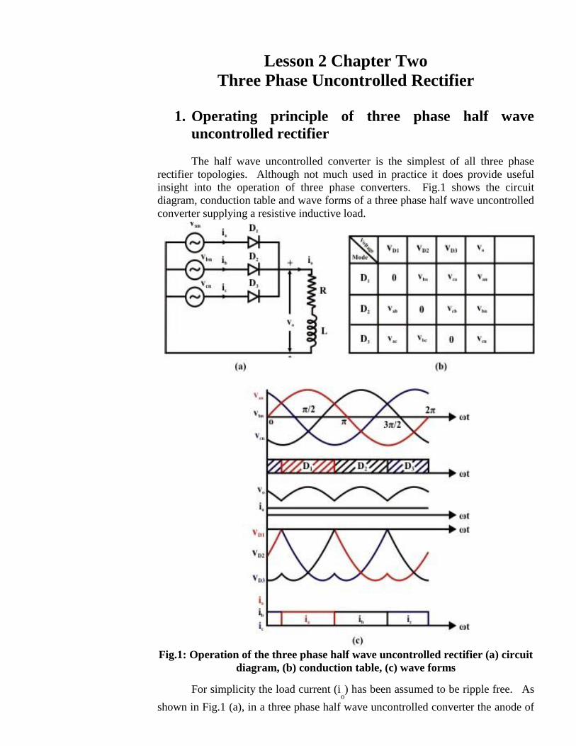
insight into the operation of three phase converters. Fig.1 shows the circuit
diagram, conduction table and wave forms of a three phase half wave uncontrolled
converter supplying a resistive inductive load.
Fig.1: Operation of the three phase half wave uncontrolled rectifier (a) circuit
diagram, (b) conduction table, (c) wave forms
For simplicity the load current (io) has been assumed to be ripple free. As
shown in Fig.1 (a), in a three phase half wave uncontrolled converter the anode of
a diode is connected to each phase voltage source. The cathodes of all three
diodes are connected together to form the positive load terminal. The negative
terminal of the load is connected to the supply neutral.
Fig.1 (b) shows the conduction table of the converter. It should be noted
that for the type of load chosen the converter always operates in the continuous
conduction mode. The conduction diagram for the diodes (as shown in Fig.1 (c)
second waveform) can be drawn easily from the conduction diagram. Since the
diodes can block only negative voltage it follows from the conduction table that a
phase diode conducts only when that phase voltage is maximum of the three. (In
signal electronics the circuit of Fig.1 (a) is also known as the “maximum value”
circuit). Once the conduction diagram is drawn other waveforms of Fig.1 (c) are
easily obtained from the supply voltage waveforms in conjunction with the
conduction table.
The phase current waveforms of Fig.1 (c) deserve special mention. All of
them have a dc component which flows through the ac source. This may cause
“dc saturation” in the ac side transformer. This is one reason for which the
converter configuration is not preferred very much in practice.
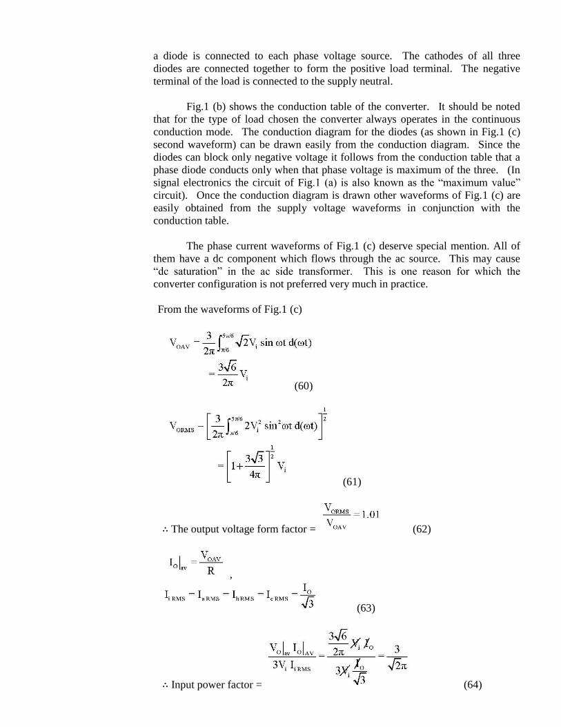
From the waveforms of Fig.1 (c)
(60)
(61)
∴ The output voltage form factor = (62)
,
(63)
∴ Input power factor = (64)
The harmonics present in vo and i
i can be found by Fourier series analysis
of the corresponding waveforms of Fig.1 (c) and is left as an exercise.
Exercise 1
Fill in the blank(s) with the appropriate word(s).
i) Three phase half wave uncontrolled rectifier uses ________ diodes.
ii) Three phase half wave uncontrolled rectifier requires ________ phase
______ wire power supply.
iii) In a three phase half wave uncontrolled rectifier each diode conduct for
_________ radians.
iv) The minimum frequency of the output voltage ripple in a three phase
half wave uncontrolled rectifier is _________ times the input voltage
frequency.
v) The input line current of a three phase half wave uncontrolled rectifier
contain ________ component.
Answers: (i) three; (ii) three, four; (iii) 2π/3; (iv) three; (v) dc.
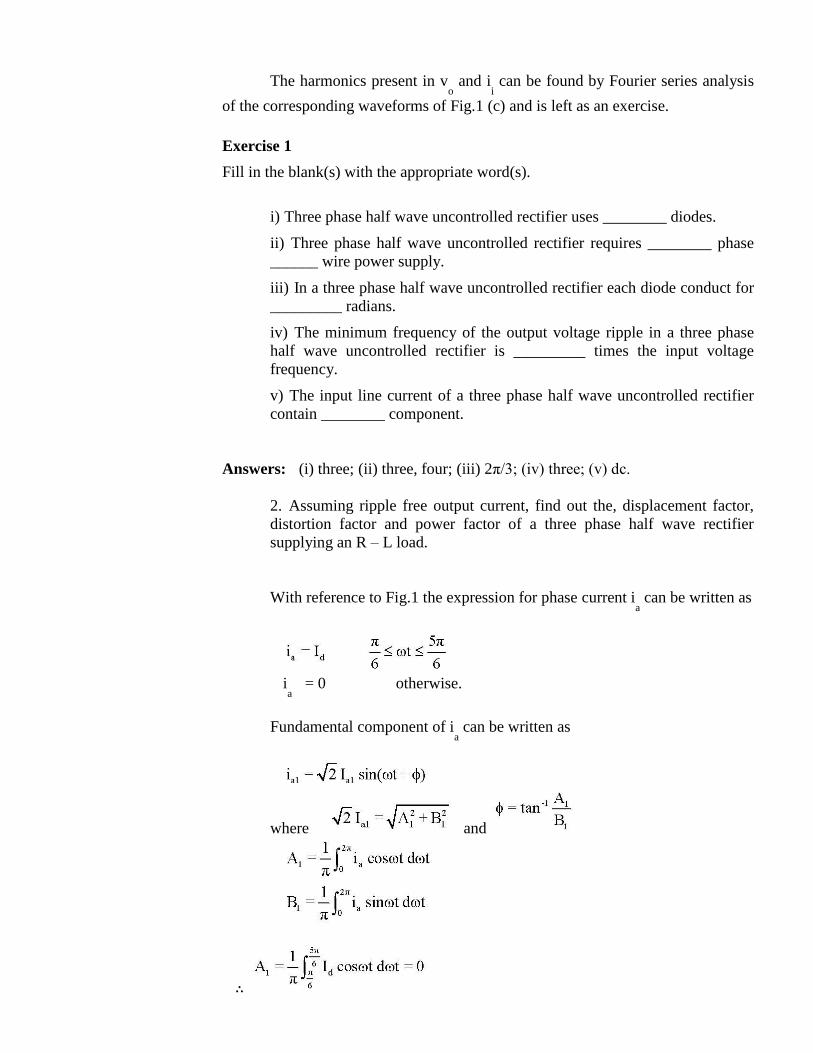
2. Assuming ripple free output current, find out the, displacement factor,
distortion factor and power factor of a three phase half wave rectifier
supplying an R – L load.
With reference to Fig.1 the expression for phase current ia can be written as
i
a = 0 otherwise.
Fundamental component of ia can be written as
where and
∴
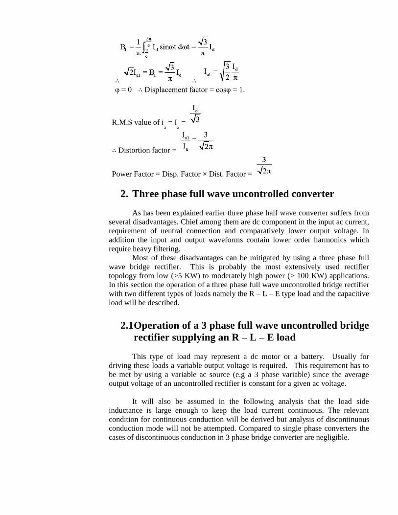
∴ ∴
φ = 0 ∴ Displacement factor = cosφ = 1.
R.M.S value of ia = I
a =
∴ Distortion factor =
Power Factor = Disp. Factor × Dist. Factor =
2. Three phase full wave uncontrolled converter
As has been explained earlier three phase half wave converter suffers from
several disadvantages. Chief among them are dc component in the input ac current,
requirement of neutral connection and comparatively lower output voltage. In
addition the input and output waveforms contain lower order harmonics which
require heavy filtering.
Most of these disadvantages can be mitigated by using a three phase full
wave bridge rectifier. This is probably the most extensively used rectifier
topology from low (>5 KW) to moderately high power (> 100 KW) applications.
In this section the operation of a three phase full wave uncontrolled bridge rectifier
with two different types of loads namely the R – L – E type load and the capacitive
load will be described.
2.1 Operation of a 3 phase full wave uncontrolled bridge
rectifier supplying an R – L – E load
This type of load may represent a dc motor or a battery. Usually for
driving these loads a variable output voltage is required. This requirement has to
be met by using a variable ac source (e.g a 3 phase variable) since the average
output voltage of an uncontrolled rectifier is constant for a given ac voltage.
It will also be assumed in the following analysis that the load side
inductance is large enough to keep the load current continuous. The relevant
condition for continuous conduction will be derived but analysis of discontinuous
conduction mode will not be attempted. Compared to single phase converters the
cases of discontinuous conduction in 3 phase bridge converter are negligible.
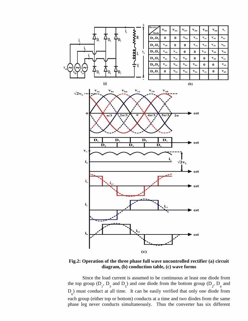
Fig.2: Operation of the three phase full wave uncontrolled rectifier (a) circuit
diagram, (b) conduction table, (c) wave forms
Since the load current is assumed to be continuous at least one diode from
the top group (D1, D
3 and D
5) and one diode from the bottom group (D
2, D
4 and
D6) must conduct at all time. It can be easily verified that only one diode from
each group (either top or bottom) conducts at a time and two diodes from the same
phase leg never conducts simultaneously. Thus the converter has six different
diode conduction modes. These are D1D
2, D
2D
3, D
3D
4, D
4D
5, D
5D
6 and D
6D
1.
Each conduction mode lasts for π/3 rad and each diode conducts for 120º.
Fig. 2 (b) shows voltages across different diodes and the output voltage in
each of these conduction modes. The time interval during which a particular
conduction mode will be effective can be ascertained from this table. For
example the D1D
2 conduction mode will occur when the voltage across all other
diodes (i.e. vba
, vca
and vcb
) are negative. This implies that D1D
2 conducts in the
interval 0 ≤ ωt ≤ π/3 as shown in Fig. 12.2 (c). The diodes have been numbered
such that the conduction sequence is D1 → D
2 → D
3 → D
4 → D
5 → D
6 → D
1---.
When a diode stops conduction its current is commutated to another diode in the
same group (top or bottom). This way the sequence of conduction modes
become, D1D
2 → D
2D
3 → D
3D
4 → D
4D
5 → D
5D
6 → D
6D
1 → D
1D
2 ---. The
conduction diagram in Fig. 2 (c) is constructed accordingly.
The output dc voltage can be constructed from this conduction diagram
using appropriate line voltage segments as specified in the conduction table.
The input ac line currents can be constructed from the conduction diagram
and the output current. For example
ia = i
o for 0 ≤ ωt ≤ π/3 and 5π/3 ≤ ωt ≤ 2π
ia = - i
o for 2π/3 ≤ ωt ≤ 4π/3
ia = 0 otherwise. (65)
The line current wave forms and their fundamental components are shown
in Fig.2 (c).
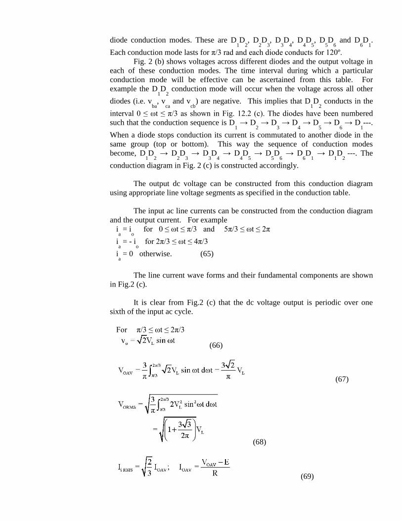
It is clear from Fig.2 (c) that the dc voltage output is periodic over one
sixth of the input ac cycle.
For π/3 ≤ ωt ≤ 2π/3
(66)
(67)
(68)
(69)
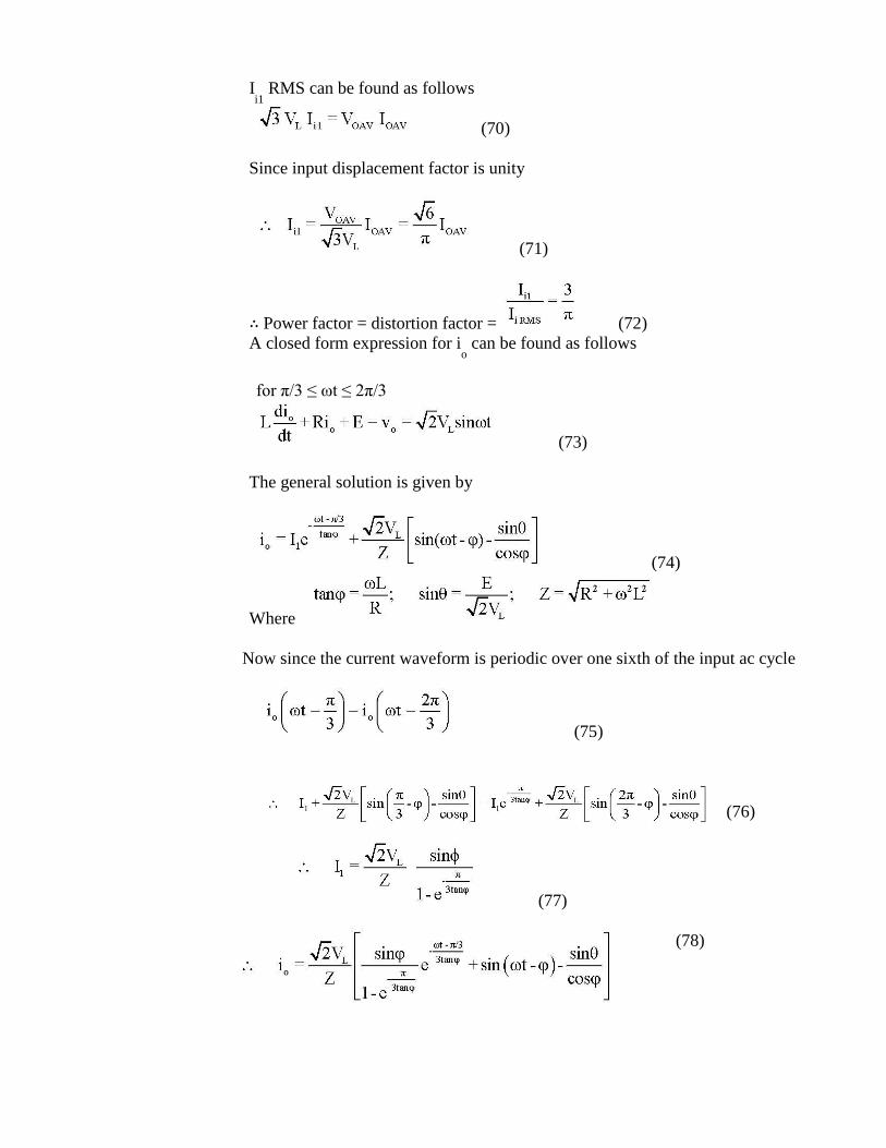
Ii1
RMS can be found as follows
(70)
Since input displacement factor is unity
(71)
∴ Power factor = distortion factor = (72)
A closed form expression for io can be found as follows
for π/3 ≤ ωt ≤ 2π/3
(73)
The general solution is given by
(74)
Where
Now since the current waveform is periodic over one sixth of the input ac cycle
(75)
(76)
(77)
(78)
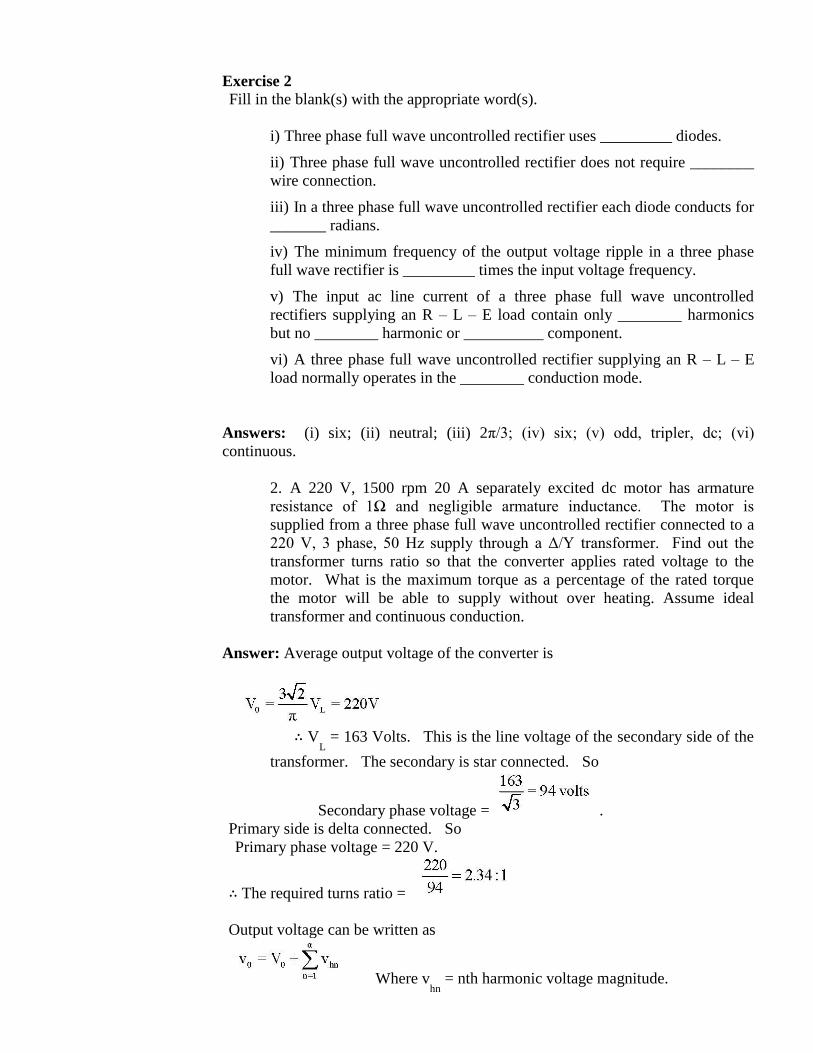
Exercise 2 Fill in the blank(s) with the appropriate word(s).
i) Three phase full wave uncontrolled rectifier uses _________ diodes.
ii) Three phase full wave uncontrolled rectifier does not require ________
wire connection.
iii) In a three phase full wave uncontrolled rectifier each diode conducts for
_______ radians.
iv) The minimum frequency of the output voltage ripple in a three phase
full wave rectifier is _________ times the input voltage frequency.
v) The input ac line current of a three phase full wave uncontrolled
rectifiers supplying an R – L – E load contain only ________ harmonics
but no ________ harmonic or __________ component.
vi) A three phase full wave uncontrolled rectifier supplying an R – L – E
load normally operates in the ________ conduction mode.
Answers: (i) six; (ii) neutral; (iii) 2π/3; (iv) six; (v) odd, tripler, dc; (vi)
continuous.
2. A 220 V, 1500 rpm 20 A separately excited dc motor has armature
resistance of 1Ω and negligible armature inductance. The motor is
supplied from a three phase full wave uncontrolled rectifier connected to a
220 V, 3 phase, 50 Hz supply through a Δ/Y transformer. Find out the
transformer turns ratio so that the converter applies rated voltage to the
motor. What is the maximum torque as a percentage of the rated torque
the motor will be able to supply without over heating. Assume ideal
transformer and continuous conduction.
Answer: Average output voltage of the converter is
∴ V
L = 163 Volts. This is the line voltage of the secondary side of the
transformer. The secondary is star connected. So
Secondary phase voltage = .
Primary side is delta connected. So
Primary phase voltage = 220 V.
∴ The required turns ratio =
Output voltage can be written as
Where vhn
= nth harmonic voltage magnitude.
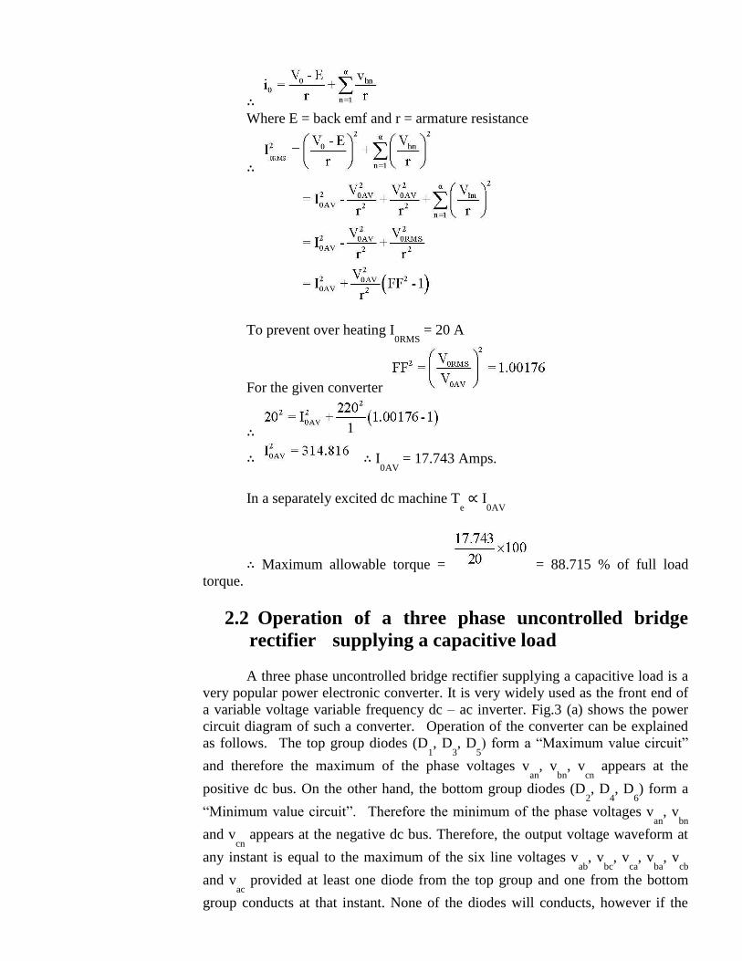
∴ Where E = back emf and r = armature resistance
∴
To prevent over heating I0RMS
= 20 A
For the given converter
∴
∴ ∴ I0AV
= 17.743 Amps.
In a separately excited dc machine Te ∝ I
0AV
∴ Maximum allowable torque = = 88.715 % of full load
torque.
2.2 Operation of a three phase uncontrolled bridge
rectifier supplying a capacitive load
A three phase uncontrolled bridge rectifier supplying a capacitive load is a
very popular power electronic converter. It is very widely used as the front end of
a variable voltage variable frequency dc – ac inverter. Fig.3 (a) shows the power
circuit diagram of such a converter. Operation of the converter can be explained
as follows. The top group diodes (D1, D
3, D
5) form a “Maximum value circuit”
and therefore the maximum of the phase voltages van
, vbn
, vcn
appears at the
positive dc bus. On the other hand, the bottom group diodes (D2, D
4, D
6) form a
“Minimum value circuit”. Therefore the minimum of the phase voltages van
, vbn
and vcn
appears at the negative dc bus. Therefore, the output voltage waveform at
any instant is equal to the maximum of the six line voltages vab
, vbc
, vca
, vba
, vcb
and vac
provided at least one diode from the top group and one from the bottom
group conducts at that instant. None of the diodes will conducts, however if the
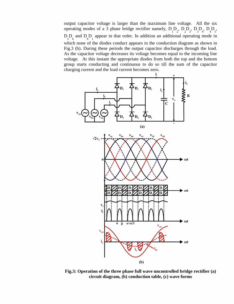
output capacitor voltage is larger than the maximum line voltage. All the six
operating modes of a 3 phase bridge rectifier namely, D1D
2, D
2D
3, D
3D
4, D
4D
5,
D5D
6 and D
6D
1 appear in that order. In addition an additional operating mode in
which none of the diodes conduct appears in the conduction diagram as shown in
Fig.3 (b). During these periods the output capacitor discharges through the load.
As the capacitor voltage decreases its voltage becomes equal to the incoming line
voltage. At this instant the appropriate diodes from both the top and the bottom
group starts conducting and continuous to do so till the sum of the capacitor
charging current and the load current becomes zero.
Fig.3: Operation of the three phase full wave uncontrolled bridge rectifier (a)
circuit diagram, (b) conduction table, (c) wave forms
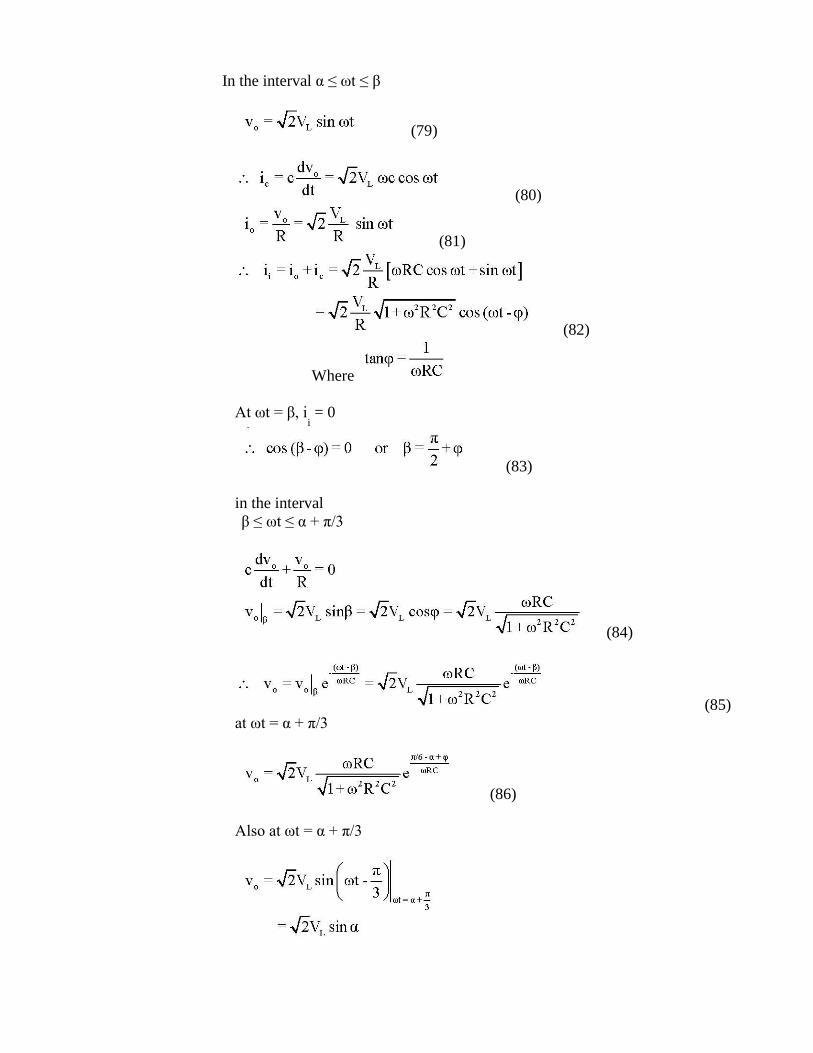
In the interval α ≤ ωt ≤ β
(79)
(80)
(81)
(82)
Where
At ωt = β, ii = 0
(83)
in the interval
β ≤ ωt ≤ α + π/3
(84)
(85)
at ωt = α + π/3
(86)
Also at ωt = α + π/3
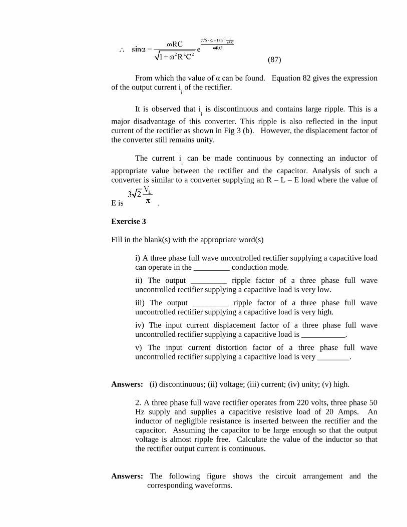
(87)
From which the value of α can be found. Equation 82 gives the expression
of the output current ii of the rectifier.
It is observed that ii is discontinuous and contains large ripple. This is a
major disadvantage of this converter. This ripple is also reflected in the input
current of the rectifier as shown in Fig 3 (b). However, the displacement factor of
the converter still remains unity.
The current ii can be made continuous by connecting an inductor of
appropriate value between the rectifier and the capacitor. Analysis of such a
converter is similar to a converter supplying an R – L – E load where the value of
E is .
Exercise 3
Fill in the blank(s) with the appropriate word(s)
i) A three phase full wave uncontrolled rectifier supplying a capacitive load
can operate in the _________ conduction mode.
ii) The output _________ ripple factor of a three phase full wave
uncontrolled rectifier supplying a capacitive load is very low.
iii) The output _________ ripple factor of a three phase full wave
uncontrolled rectifier supplying a capacitive load is very high.
iv) The input current displacement factor of a three phase full wave
uncontrolled rectifier supplying a capacitive load is ___________.
v) The input current distortion factor of a three phase full wave
uncontrolled rectifier supplying a capacitive load is very ________.
Answers: (i) discontinuous; (ii) voltage; (iii) current; (iv) unity; (v) high.
2. A three phase full wave rectifier operates from 220 volts, three phase 50
Hz supply and supplies a capacitive resistive load of 20 Amps. An
inductor of negligible resistance is inserted between the rectifier and the
capacitor. Assuming the capacitor to be large enough so that the output
voltage is almost ripple free. Calculate the value of the inductor so that
the rectifier output current is continuous.
Answers: The following figure shows the circuit arrangement and the
corresponding waveforms.
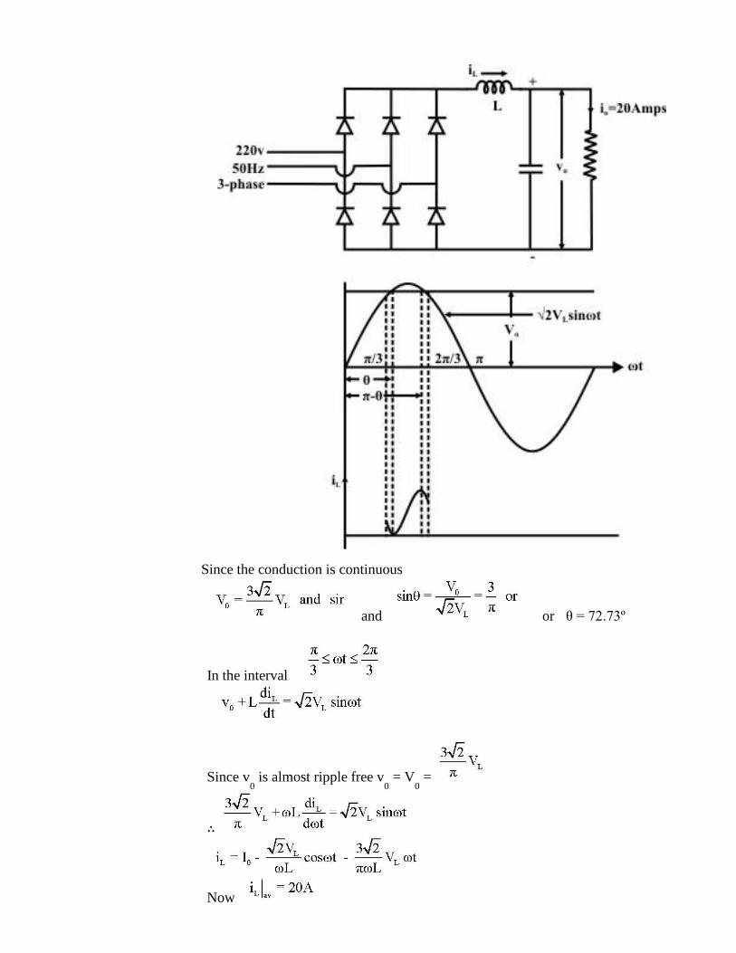
Since the conduction is continuous
and or θ = 72.73º
In the interval
Since v0 is almost ripple free v
0 = V
0 =
∴
Now
∴ or
∴ For just continuous conduction i
L = 0 at ωt = θ
∴ or ωL = 1.0306 Ω or L = 3.28 mH.
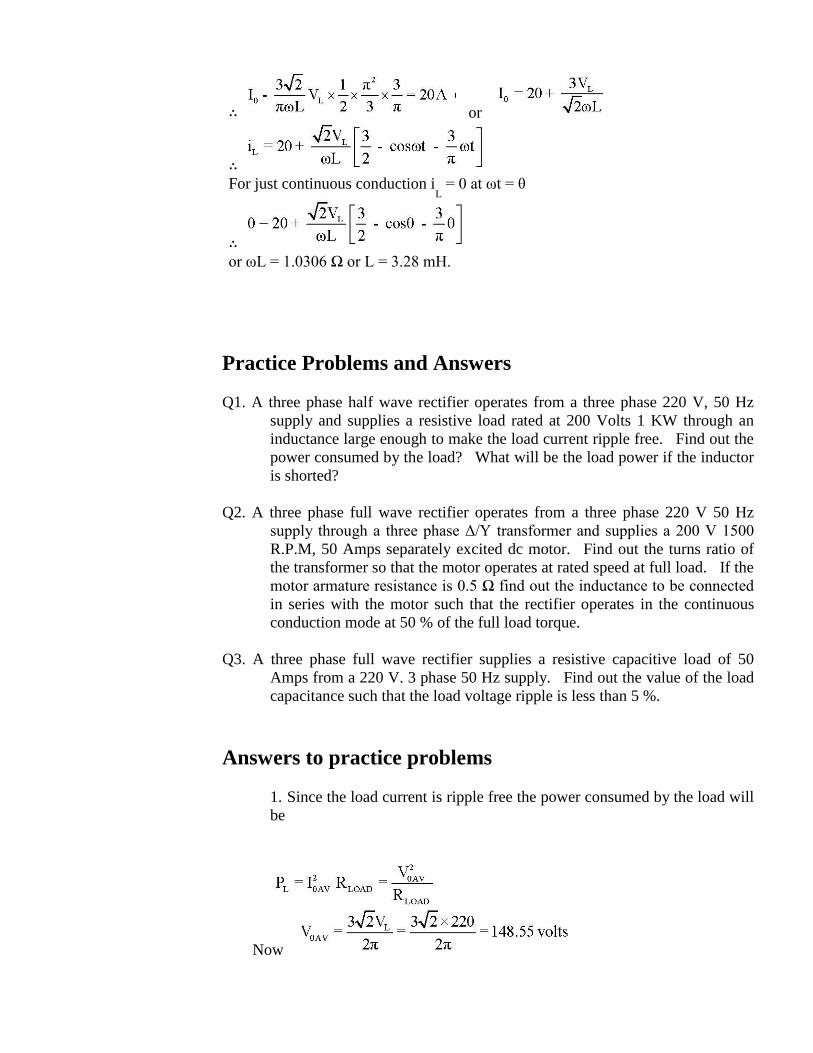
Practice Problems and Answers
Q1. A three phase half wave rectifier operates from a three phase 220 V, 50 Hz
supply and supplies a resistive load rated at 200 Volts 1 KW through an
inductance large enough to make the load current ripple free. Find out the
power consumed by the load? What will be the load power if the inductor
is shorted?
Q2. A three phase full wave rectifier operates from a three phase 220 V 50 Hz
supply through a three phase Δ/Y transformer and supplies a 200 V 1500
R.P.M, 50 Amps separately excited dc motor. Find out the turns ratio of
the transformer so that the motor operates at rated speed at full load. If the
motor armature resistance is 0.5 Ω find out the inductance to be connected
in series with the motor such that the rectifier operates in the continuous
conduction mode at 50 % of the full load torque.
Q3. A three phase full wave rectifier supplies a resistive capacitive load of 50
Amps from a 220 V. 3 phase 50 Hz supply. Find out the value of the load
capacitance such that the load voltage ripple is less than 5 %.
Answers to practice problems
1. Since the load current is ripple free the power consumed by the load will
be
Now
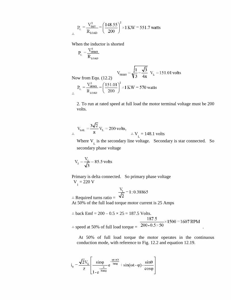
∴
When the inductor is shorted
Now from Equ. (12.2)
∴
2. To run at rated speed at full load the motor terminal voltage must be 200
volts.
∴ ∴ VL = 148.1 volts
Where VL is the secondary line voltage. Secondary is star connected. So
secondary phase voltage
Primary is delta connected. So primary phase voltage
V1 = 220 V
∴ Required turns ratio =
At 50% of the full load torque motor current is 25 Amps
∴ back Emf = 200 – 0.5 × 25 = 187.5 Volts.
∴ speed at 50% of full load torque = .
At 50% of full load torque the motor operates in the continuous
conduction mode, with reference to Fig. 12.2 and equation 12.19.
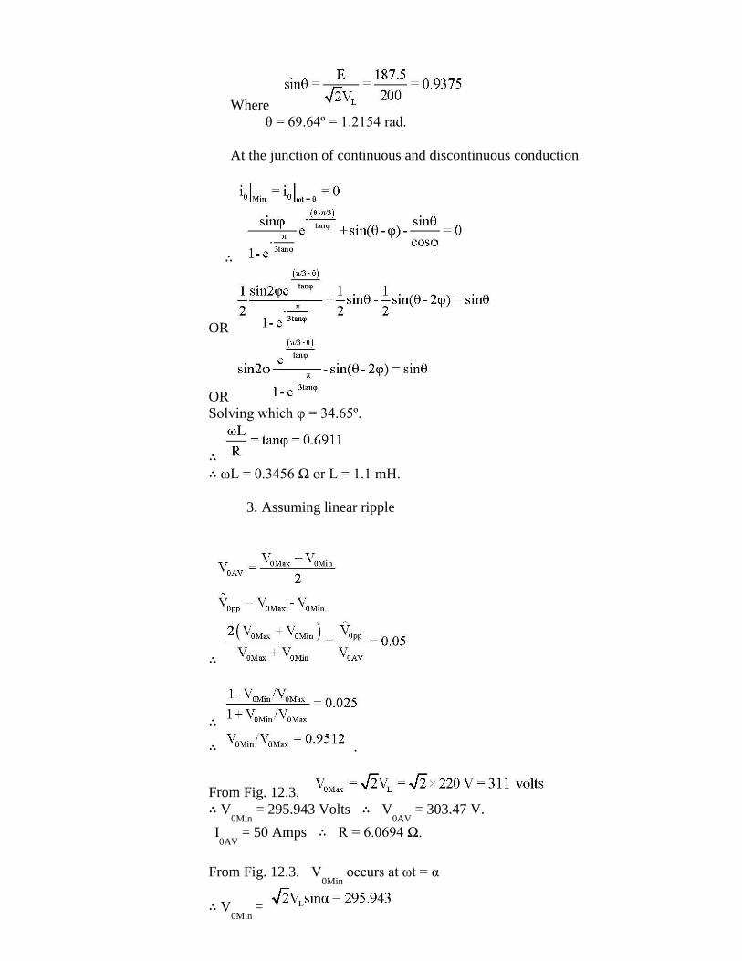
Where
θ = 69.64º = 1.2154 rad.
At the junction of continuous and discontinuous conduction
∴
OR
OR
Solving which φ = 34.65º.
∴
∴ ωL = 0.3456 Ω or L = 1.1 mH.
3. Assuming linear ripple
∴
∴
∴ .
From Fig. 12.3,
∴ V0Min
= 295.943 Volts ∴ V0AV
= 303.47 V.
I0AV
= 50 Amps ∴ R = 6.0694 Ω.
From Fig. 12.3. V0Min
occurs at ωt = α
∴ V0Min
=

∴ sin α = 0.9512 or α = 72º
But from Equation (12.28)
where
from which φ = 3.5º ∴ tanφ = 0.06116
∴ , R = 6.0694 Ω
∴ ωC = 2.6938, ∴ C = 8575 μF.
Related Documents