Lecture 21 – Splices and Lecture 21 – Splices and Shear Shear February 5, 2003 CVEN 444

Lecture 21 – Splices and Shear
Dec 31, 2015
Lecture 21 – Splices and Shear. February 5, 2003 CVEN 444. Lecture Goals. Spice Shear Shear Design. Why do we need bar splices? -- for long spans Types of Splices 1.Butted &Welded 2.Mechanical Connectors 3.Lay Splices. Must develop 125% of yield strength. Bar Splices. - PowerPoint PPT Presentation
Welcome message from author
This document is posted to help you gain knowledge. Please leave a comment to let me know what you think about it! Share it to your friends and learn new things together.
Transcript
Lecture 21 – Splices Lecture 21 – Splices and Shearand Shear
February 5, 2003CVEN 444

Lecture GoalsLecture Goals
Spice Shear Shear Design
Bar SplicesBar Splices
Why do we need bar splices? -- for long spans
Types of Splices
1. Butted &Welded
2. Mechanical Connectors
3. Lay Splices
Must develop 125% of yield strength
Tension Lap SplicesTension Lap SplicesWhy do we need bar splices? -- for long spans
Types of Splices
1. Contact Splice
2. Non Contact Spice (distance 6” and 1/5 splice length)
Splice length is the distance the two bars are overlapped.
Types of SplicesTypes of Splices
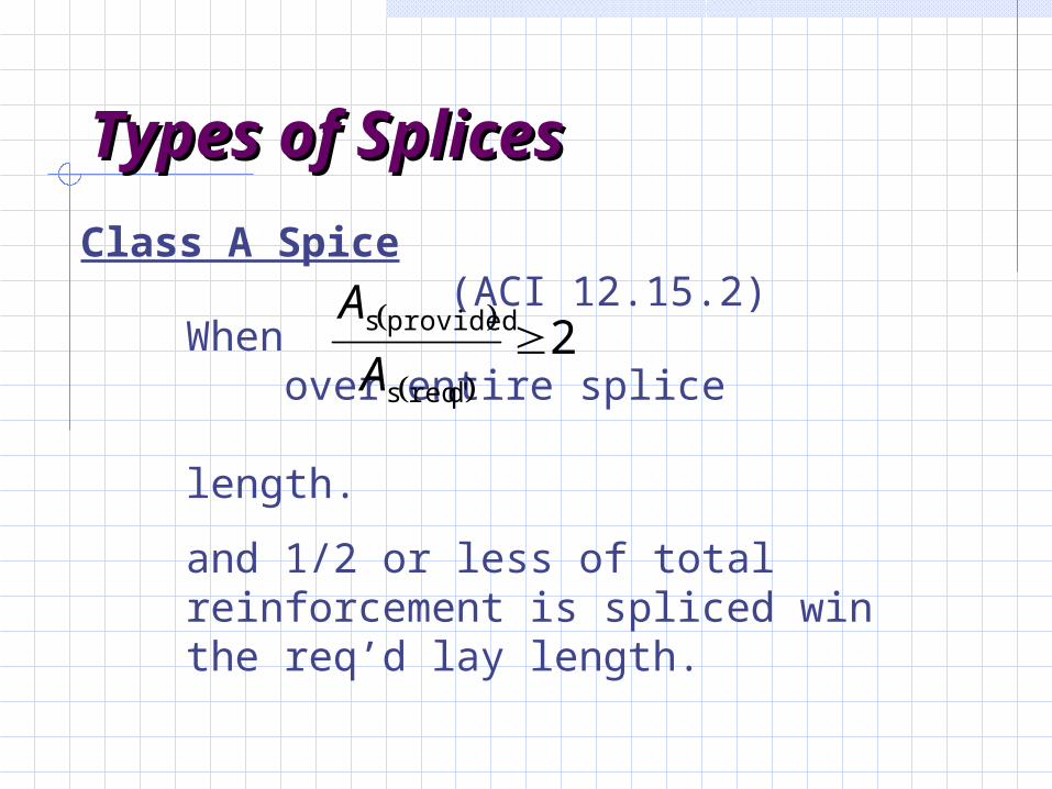
Class A Spice (ACI 12.15.2)
When over entire splice length.
and 1/2 or less of total reinforcement is spliced win the req’d lay length.
2
dreq's
provideds A
A
Types of SplicesTypes of Splices
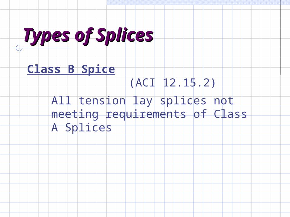
Class B Spice (ACI 12.15.2)
All tension lay splices not meeting requirements of Class A Splices
Tension Lap Splice Tension Lap Splice (ACI 12.15)(ACI 12.15)
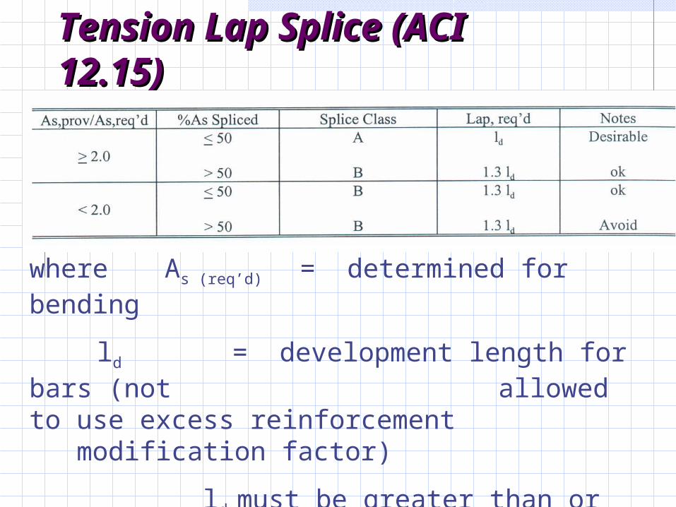
where As (req’d) = determined for bending
ld = development length for bars (not allowed to use excess reinforcement modification factor)
ld must be greater than or equal to 12 in.
Tension Lap Splice (ACI Tension Lap Splice (ACI 12.15)12.15)
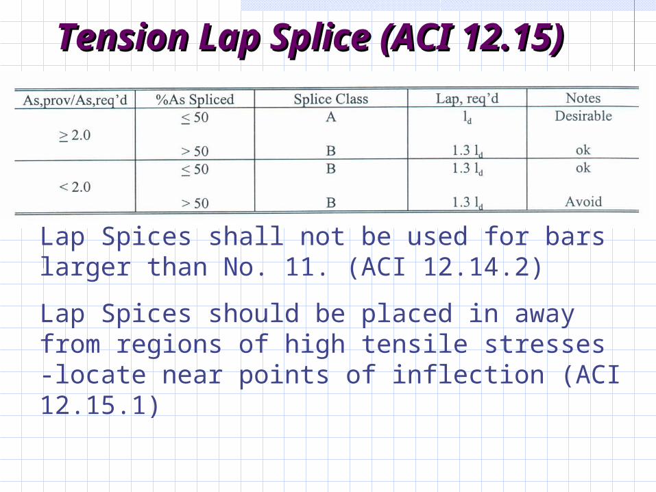
Lap Spices shall not be used for bars larger than No. 11. (ACI 12.14.2)
Lap Spices should be placed in away from regions of high tensile stresses -locate near points of inflection (ACI 12.15.1)
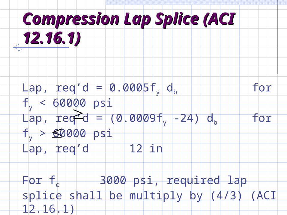
Compression Lap Splice Compression Lap Splice (ACI 12.16.1)(ACI 12.16.1)
Lap, req’d = 0.0005fy db for fy < 60000 psi Lap, req’d = (0.0009fy -24) db for fy > 60000 psi Lap, req’d 12 in
For fc 3000 psi, required lap splice shall be multiply by (4/3) (ACI 12.16.1)
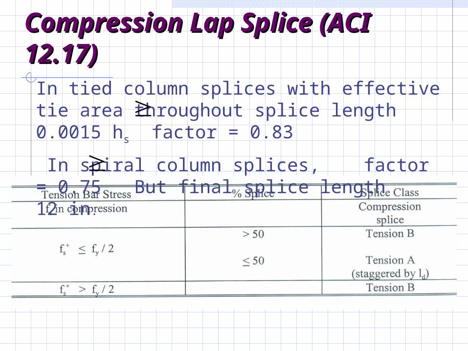
Compression Lap Splice Compression Lap Splice (ACI 12.17)(ACI 12.17)
In tied column splices with effective tie area throughout splice length 0.0015 hs factor = 0.83
In spiral column splices, factor = 0.75 But final splice length 12 in.
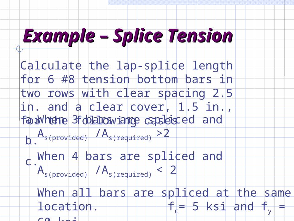
Example – Splice Example – Splice TensionTension
Calculate the lap-splice length for 6 #8 tension bottom bars in two rows with clear spacing 2.5 in. and a clear cover, 1.5 in., for the following cases
When 3 bars are spliced and As(provided) /As(required) >2
When 4 bars are spliced and As(provided) /As(required) < 2
When all bars are spliced at the same location. fc= 5 ksi and fy = 60 ksi
a.
b.
c.
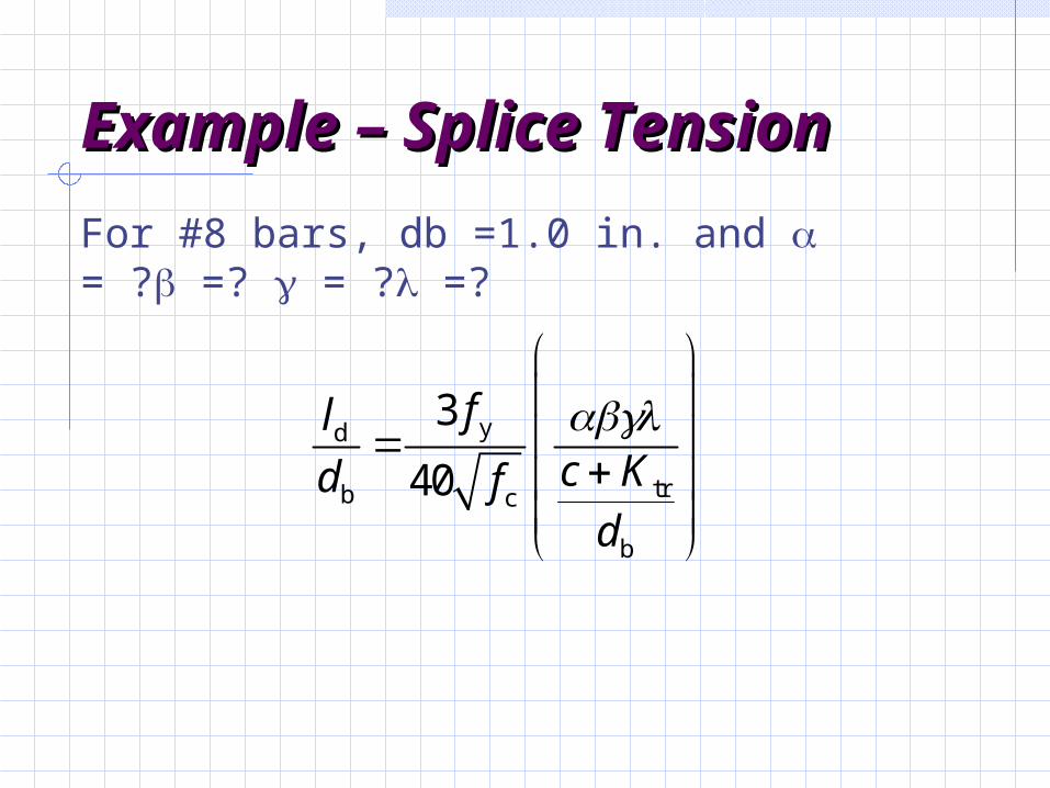
Example – Splice Example – Splice TensionTension
For #8 bars, db =1.0 in. and = ? =? = ? =?
yd
trb c
b
3
40
flc Kd fd
Example – Splice Example – Splice TensionTension
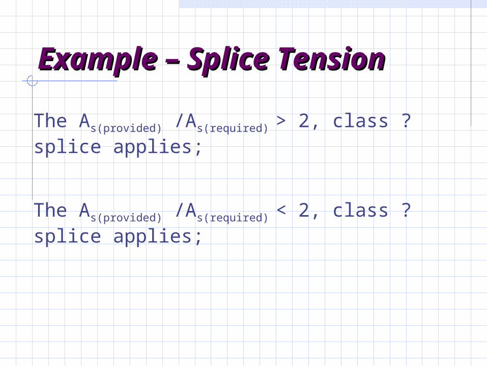
The As(provided) /As(required) > 2, class ? splice applies;
The As(provided) /As(required) < 2, class ? splice applies;
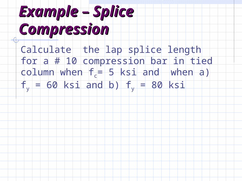
Example – Splice Example – Splice CompressionCompressionCalculate the lap splice length for a # 10 compression bar in tied column when fc= 5 ksi and when a) fy = 60 ksi and b) fy = 80 ksi
Example – Splice Example – Splice CompressionCompression
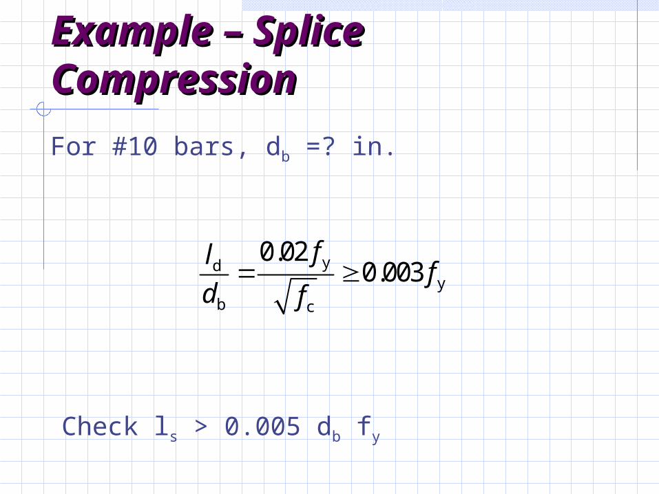
For #10 bars, db =? in.
ydy
b c
0.020.003
flf
d f
Check ls > 0.005 db fy
Example – Splice Example – Splice CompressionCompression
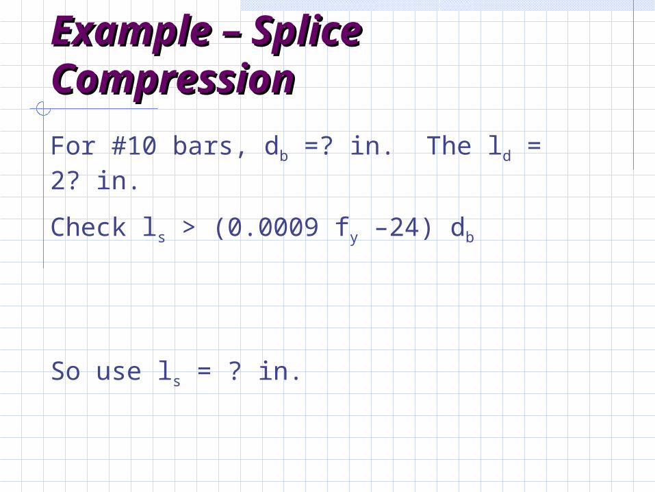
For #10 bars, db =? in. The ld = 2? in.
Check ls > (0.0009 fy –24) db
So use ls = ? in.
Shear DesignShear Design
Uncracked Elastic Beam Uncracked Elastic Beam BehaviorBehavior
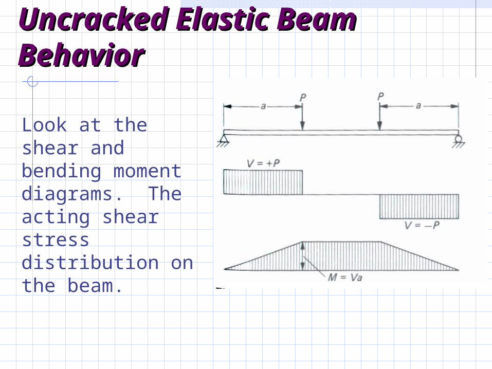
Look at the shear and bending moment diagrams. The acting shear stress distribution on the beam.
Uncracked Elastic Beam Uncracked Elastic Beam BehaviorBehavior
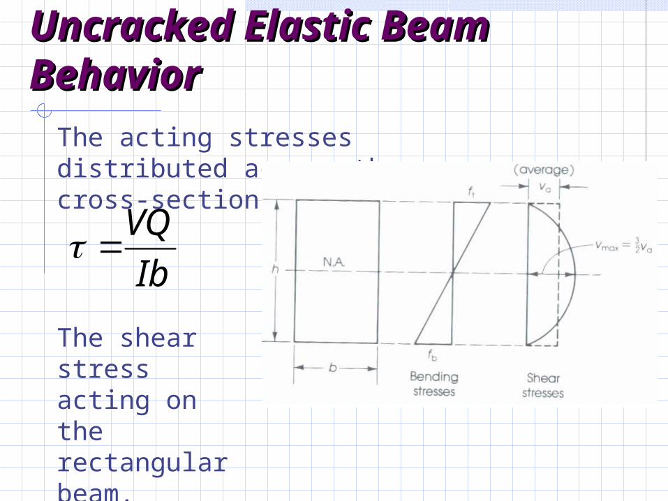
The acting stresses distributed across the cross-section.
The shear stress acting on the rectangular beam.
Ib
VQ
Uncracked Elastic Beam Uncracked Elastic Beam BehaviorBehavior
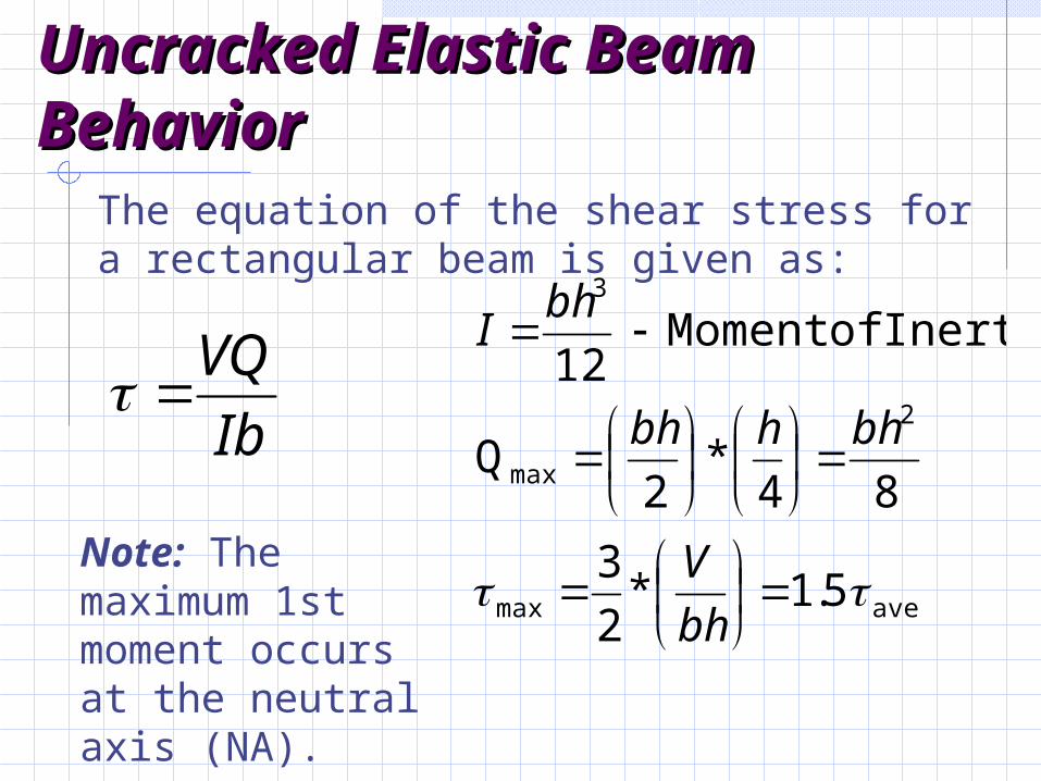
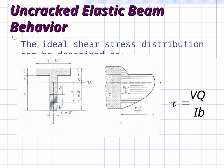
The equation of the shear stress for a rectangular beam is given as:
Note: The maximum 1st moment occurs at the neutral axis (NA).
Ib
VQ
avemax
2
max
3
5.1*2
3
84*
2Q
Inertia ofMoment 12
bh
V
bhhbh
bhI
Uncracked Elastic Beam Uncracked Elastic Beam BehaviorBehavior
The ideal shear stress distribution can be described as:
Ib
VQ
Uncracked Elastic Beam Uncracked Elastic Beam BehaviorBehavior
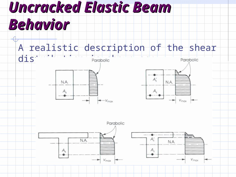
A realistic description of the shear distribution is shown as:
Uncracked Elastic Beam Uncracked Elastic Beam BehaviorBehavior
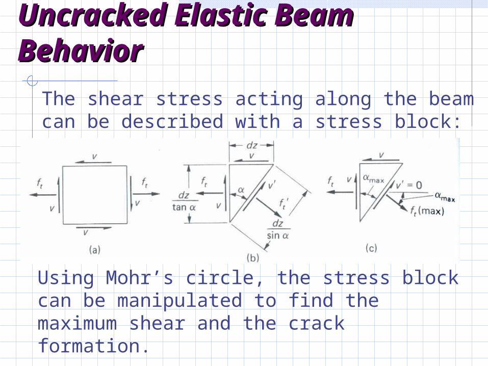
The shear stress acting along the beam can be described with a stress block:
Using Mohr’s circle, the stress block can be manipulated to find the maximum shear and the crack formation.
Inclined Cracking in Inclined Cracking in Reinforced Concrete Reinforced Concrete BeamsBeams
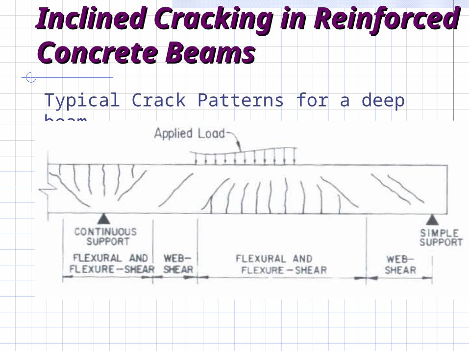
Typical Crack Patterns for a deep beam
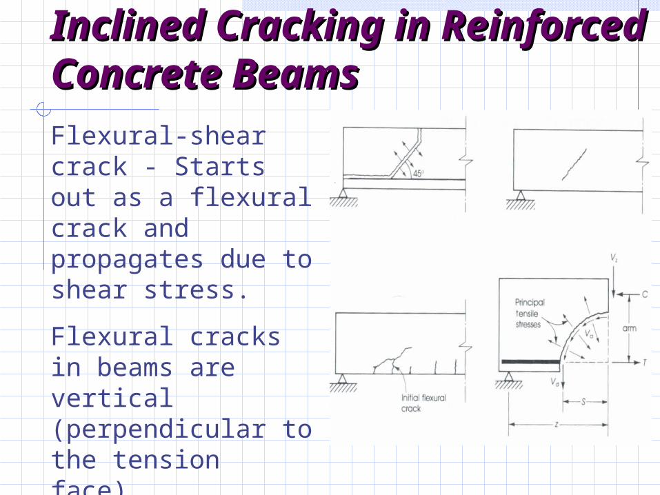
Inclined Cracking in Inclined Cracking in Reinforced Concrete Reinforced Concrete BeamsBeamsFlexural-shear crack - Starts out as a flexural crack and propagates due to shear stress.
Flexural cracks in beams are vertical (perpendicular to the tension face).
Inclined Cracking in Inclined Cracking in Reinforced Concrete Reinforced Concrete BeamsBeams
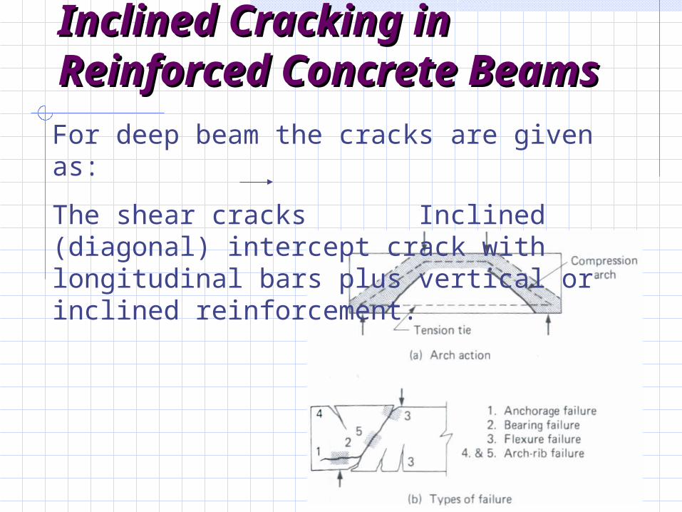
For deep beam the cracks are given as:
The shear cracks Inclined (diagonal) intercept crack with longitudinal bars plus vertical or inclined reinforcement.
Inclined Cracking in Inclined Cracking in Reinforced Concrete Reinforced Concrete BeamsBeams
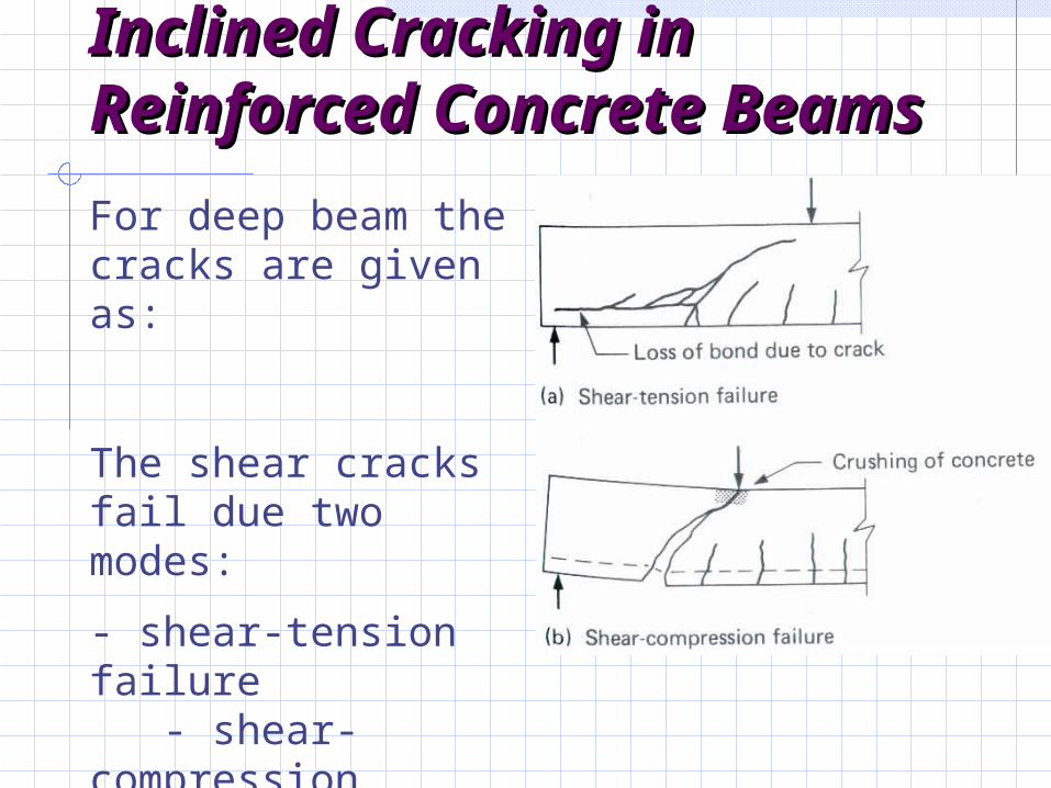
For deep beam the cracks are given as:
The shear cracks fail due two modes:
- shear-tension failure - shear-compression failure
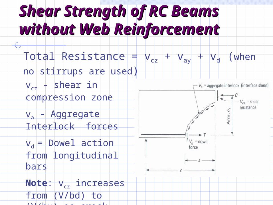
Shear Strength of RC Beams Shear Strength of RC Beams without Web Reinforcementwithout Web Reinforcement
vcz - shear in compression zone
va - Aggregate Interlock forces
vd = Dowel action from longitudinal bars
Note: vcz increases from (V/bd) to (V/by) as crack forms.
Total Resistance = vcz + vay + vd (when no stirrups are used)
Strength of Concrete in Shear Strength of Concrete in Shear (No Shear Reinforcement)(No Shear Reinforcement)
(1) Tensile Strength of concrete affect inclined cracking load
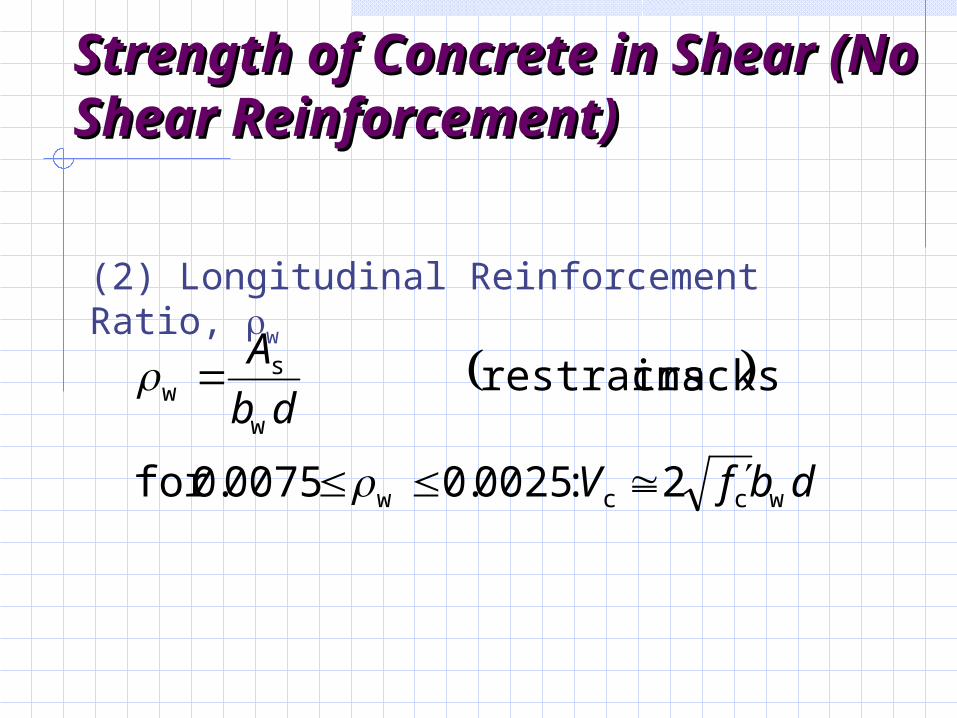
Strength of Concrete in Strength of Concrete in Shear (No Shear Shear (No Shear Reinforcement)Reinforcement)
(2) Longitudinal Reinforcement Ratio, w
dbfV
db
A
wccw
w
sw
2:0025.00075.0for
cracks restrains
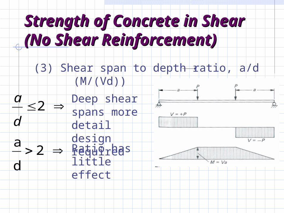
Strength of Concrete in Strength of Concrete in Shear (No Shear Shear (No Shear Reinforcement)Reinforcement)
(3) Shear span to depth ratio, a/d (M/(Vd))
2d
a
2
d
a Deep shear spans more detail design required
Ratio has little effect
Strength of Concrete in Strength of Concrete in Shear (No Shear Shear (No Shear Reinforcement)Reinforcement)
(4) Size of BeamIncrease Depth Reduced shear stress at
inclined cracking
Strength of Concrete in Strength of Concrete in Shear (No Shear Shear (No Shear Reinforcement)Reinforcement)
(5) Axial Forces - Axial tension Decreases inclined cracking load - Axial Compression Increases inclined cracking
load (Delays flexural cracking)
Function and Strength of Function and Strength of Web ReinforcementWeb Reinforcement
Web Reinforcement is provided to ensure that the full flexural capacity can be developed. (desired a flexural failure mode - shear failure is brittle)
- Acts as “clamps” to keep shear cracks from widening
Function:
Function and Strength of Function and Strength of Web ReinforcementWeb Reinforcement
Uncracked Beam Shear is resisted uncracked concrete.
Flexural Cracking Shear is resisted by vcz, vay, vd
bars. allongitudin fromAction Dowl
forceInterlock Aggregate ofcomponent Vertical
zonen compressioin Shear
d
ay
cz
V
V
V
Function and Strength of Function and Strength of Web ReinforcementWeb Reinforcement
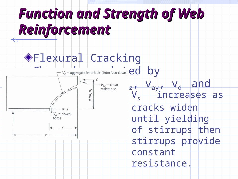
Flexural Cracking Shear is resisted by vcz, vay, vd and vs
Vs increases as cracks widen until yielding of stirrups then stirrups provide constant resistance.
Designing to Resist Designing to Resist ShearShear
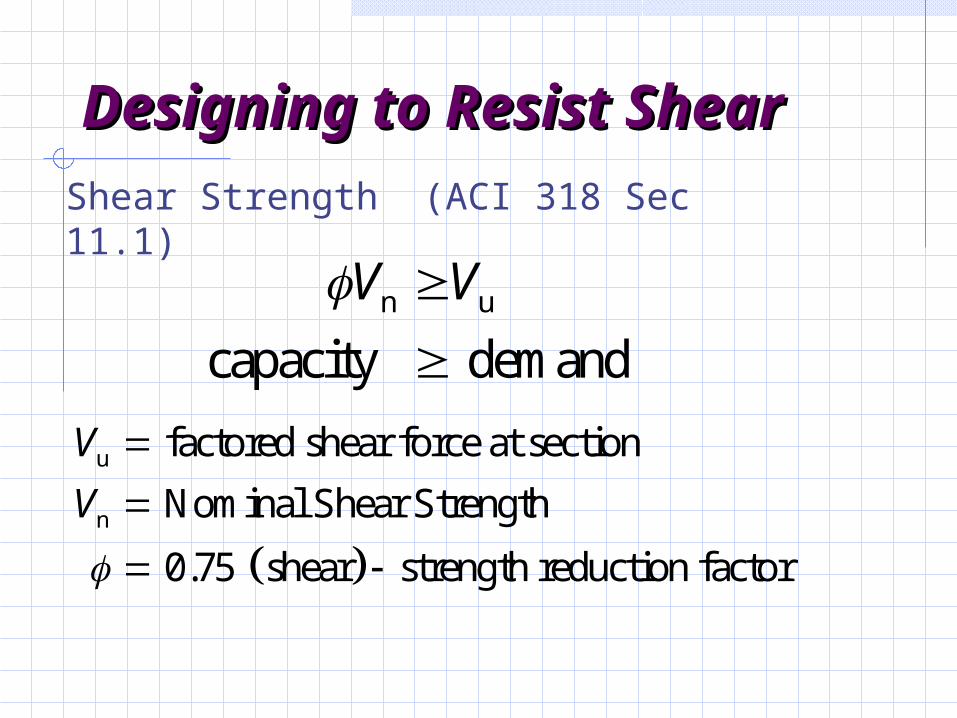
Shear Strength (ACI 318 Sec 11.1)
n u
capacity demand
V V
u
n
factored shear force at section
Nominal Shear Strength
0.75 shear strength reduction factor
V
V
Designing to Resist Designing to Resist ShearShear
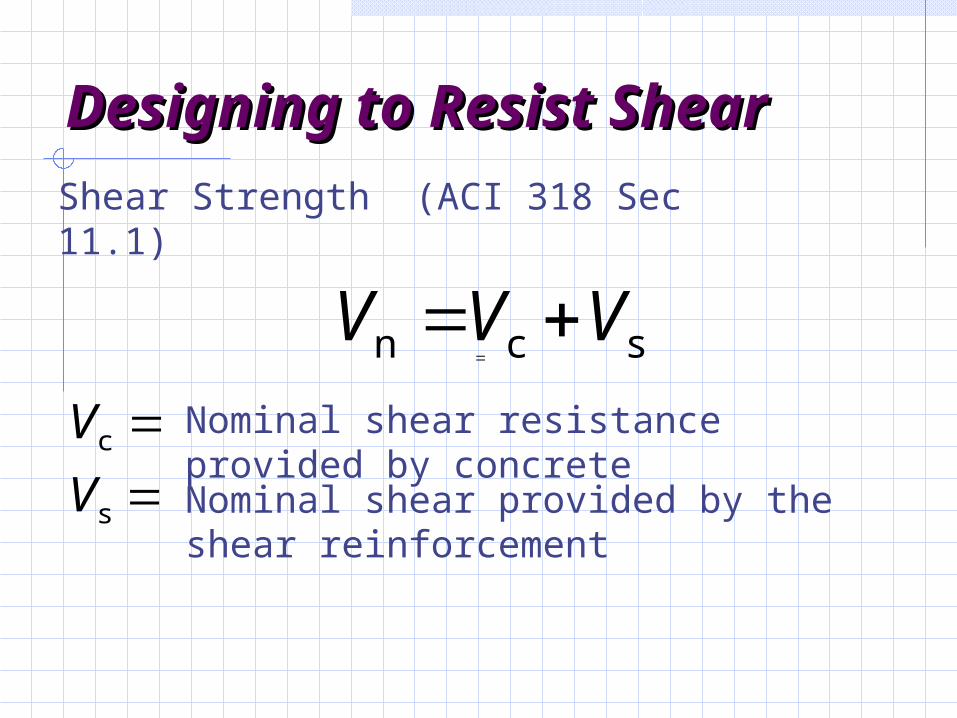
Shear Strength (ACI 318 Sec 11.1)
n c sV V V
c
s
V
V
Nominal shear provided by the shear reinforcement
Nominal shear resistance provided by concrete
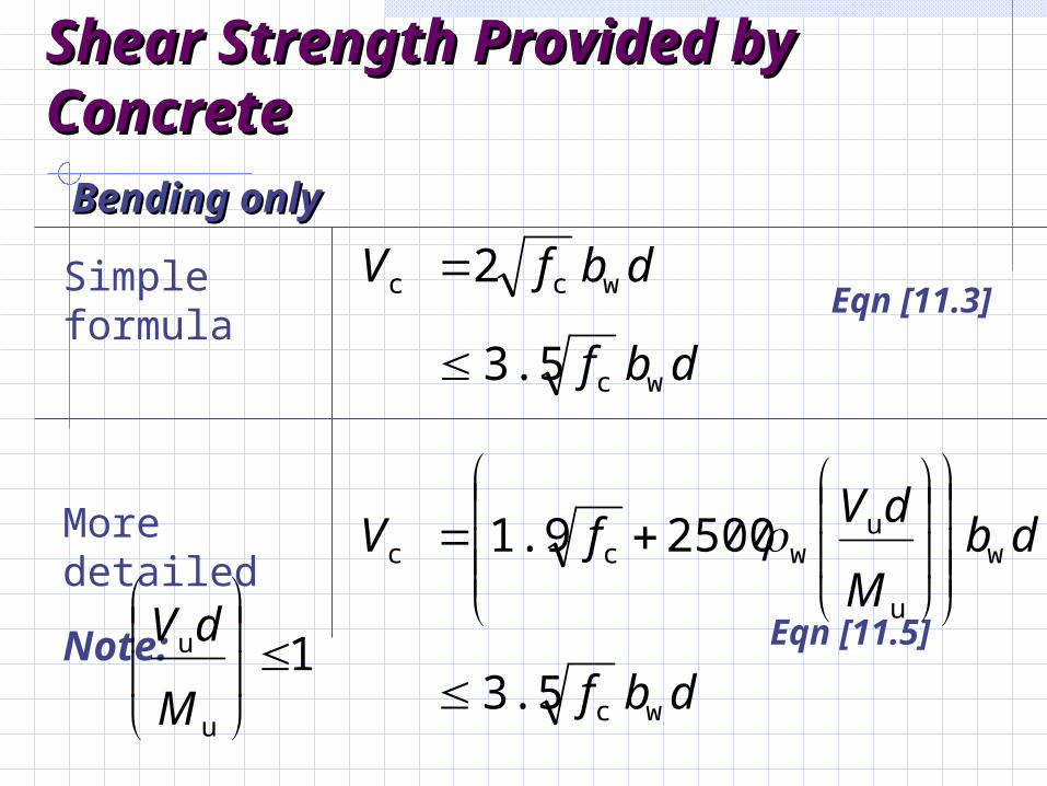
Shear Strength Provided by Shear Strength Provided by ConcreteConcrete
Bending onlyBending only
Simple formula
More detailed
Note:
Eqn [11.5]
Eqn [11.3]
dbf
dbfV
wc
wcc
3.5
2
dbf
dbM
dVfV
wc
w
u
uwcc
3.5
25001.9
1
u
u
M
dV
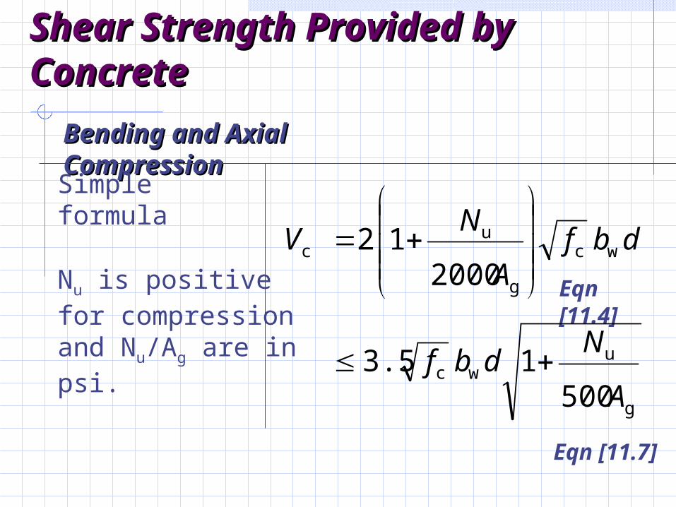
Shear Strength Provided by Shear Strength Provided by ConcreteConcrete
Bending and Axial CompressionBending and Axial Compression
Nu is positive for compression and Nu/Ag are in psi.
Simple formula
Eqn [11.4]
Eqn [11.7]
g
uwc
wc
g
uc
5001 3.5
2000
1 2
A
Ndbf
dbfA
NV
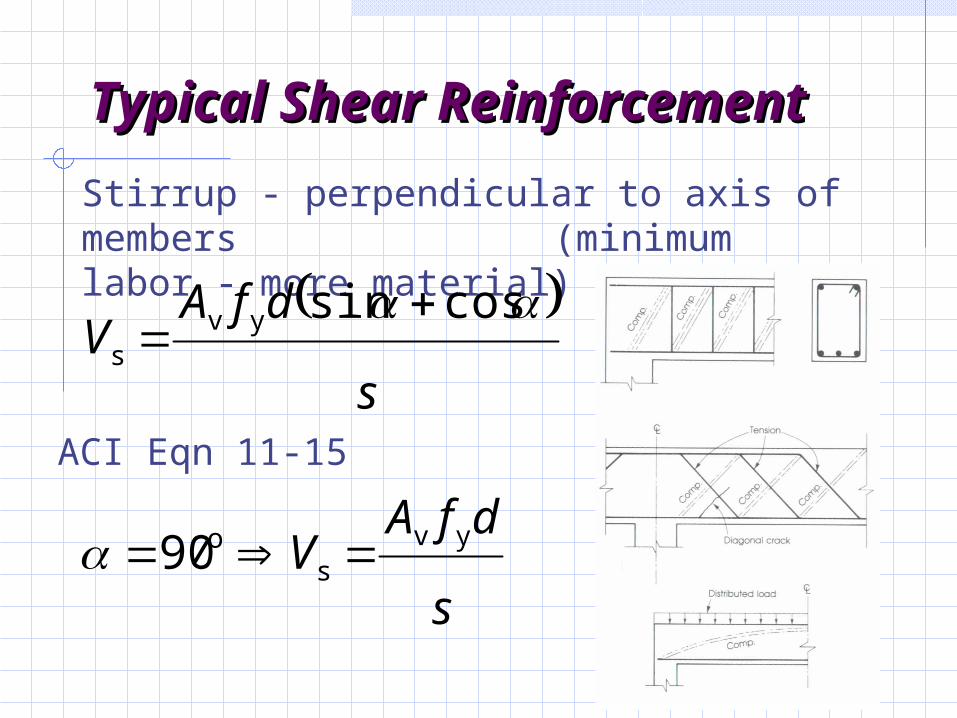
Typical Shear Typical Shear ReinforcementReinforcement
Stirrup - perpendicular to axis of members (minimum labor - more material)
ACI Eqn 11-15
s
dfAV
cossinyvs
s
dfAV yv
so90
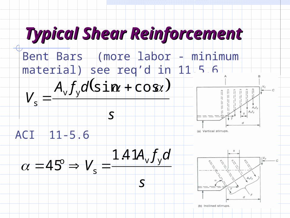
Typical Shear Typical Shear ReinforcementReinforcement
Bent Bars (more labor - minimum material) see req’d in 11.5.6
ACI 11-5.6
s
dfAV
cossinyvs
s
dfAV yv
so 41.1
45
Stirrup Anchorage Stirrup Anchorage RequirementsRequirements
Vs based on assumption stirrups yield
Stirrups must be well anchored.
Stirrup Anchorage Stirrup Anchorage RequirementsRequirements
each bend must enclose a long bar
# 5 and smaller can use standard hooks 90o,135o, 180o
#6, #7,#8( fy = 40 ksi )
#6, #7,#8 ( fy > 40 ksi ) standard hook plus a minimum embedment
Refer to Sec. 12.13 of ACI 318 for development of web reinforcement. Requirements:
Stirrup Anchorage Stirrup Anchorage RequirementsRequirements
Also sec. 7.10 requirement for minimum stirrups in beams with compression reinforcement, beams subject to stress reversals, or beams subject to torsion
Design Procedure for Design Procedure for ShearShear
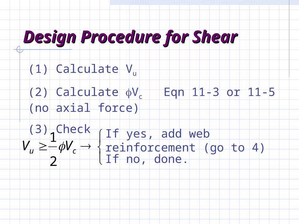
(1) Calculate Vu
(2) Calculate Vc Eqn 11-3 or 11-5 (no axial force)
(3) Check
cu VV 2
1
If yes, add web reinforcement (go to 4)
If no, done.
Design Procedure for Design Procedure for ShearShear
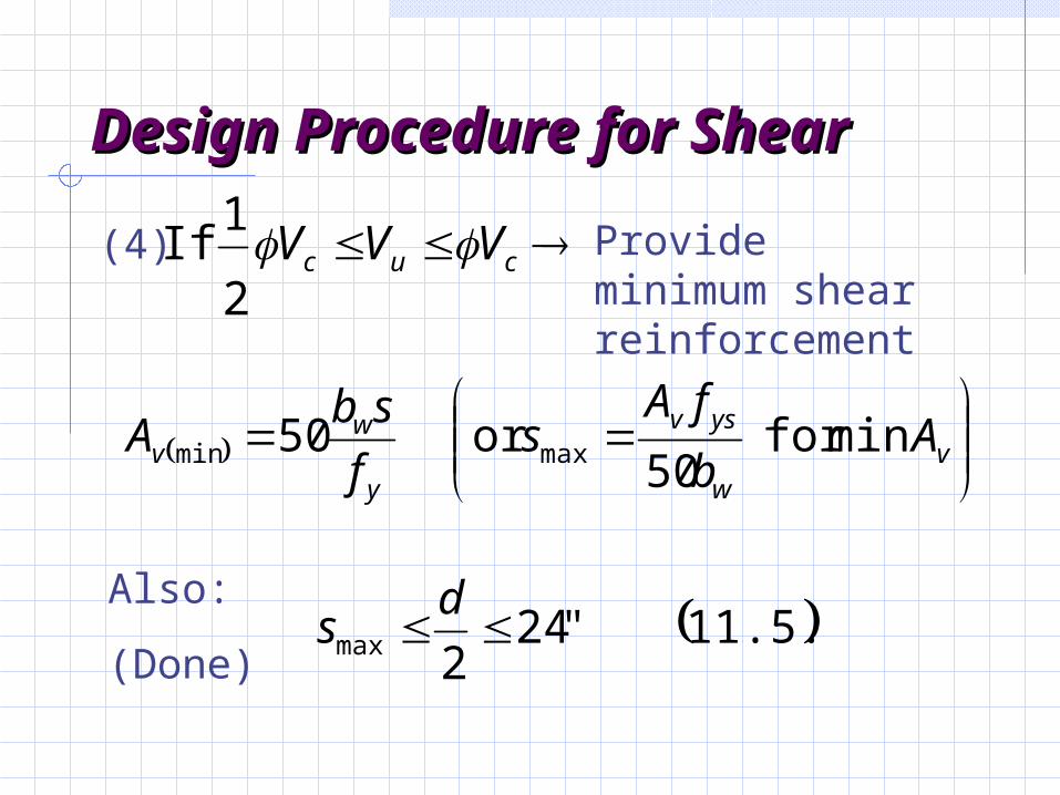
(4) cuc VVV 2
1 If
v
w
ysv
y
wv A
b
fAs
f
sbA min for
50or 50 maxmin
Also:
(Done) 11.5.4 "24
2max d
s
Provide minimum shear reinforcement
Design Procedure for Design Procedure for ShearShear
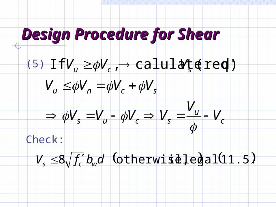
(5)
cu
scus
scnu
scu
VV
VVVV
VVVV
VVV
d)(req' calulate , If
Check:
11.5.4 illegal otherwise, 8 dbfV wcs
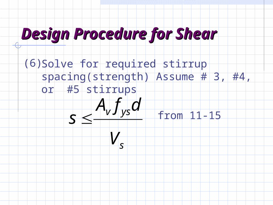
Design Procedure for Design Procedure for ShearShear
Solve for required stirrup spacing(strength) Assume # 3, #4, or #5 stirrups
s
ysv
V
dfAs
(6)
from 11-15
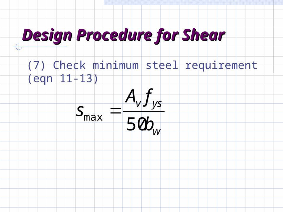
Design Procedure for Design Procedure for ShearShear
(7) Check minimum steel requirement (eqn 11-13)
50max
w
ysv
b
fAs
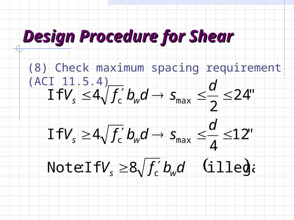
Design Procedure for Design Procedure for ShearShear
(8) Check maximum spacing requirement (ACI 11.5.4)
illegal 8 If :Note
"124
4 If
"242
4 If
c
maxc
maxc
dbfV
dsdbfV
dsdbfV
ws
ws
ws
Design Procedure for Design Procedure for ShearShear
(9) Use smallest spacing from steps 6,7,8
Note: A practical limit to minimum stirrup spacing is 4 inches.
Location of Maximum Shear Location of Maximum Shear for Beam Designfor Beam Design
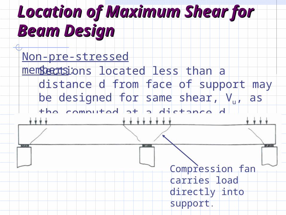
Non-pre-stressed members:Sections located less than a distance d from face of support may be designed for same shear, Vu, as the computed at a distance d.
Compression fan carries load directly into support.
Location of Maximum Shear for Beam Design
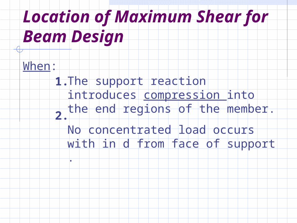
The support reaction introduces compression into the end regions of the member.
No concentrated load occurs with in d from face of support .
1.
2.
When:
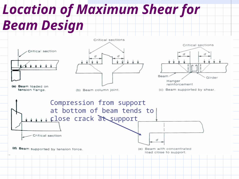
Location of Maximum Shear for Beam Design
Compression from support at bottom of beam tends to close crack at support
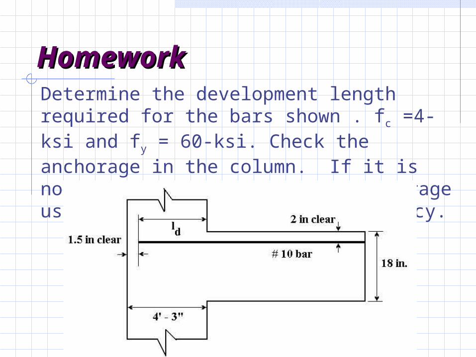
HomeworkHomeworkDetermine the development length required for the bars shown . fc =4-ksi and fy = 60-ksi. Check the anchorage in the column. If it is not satisfactory, design an anchorage using a 180o hook and check adequacy.
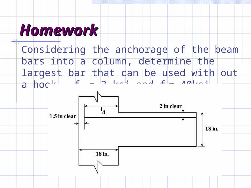
HomeworkHomeworkConsidering the anchorage of the beam bars into a column, determine the largest bar that can be used with out a hook. fc = 3-ksi and fy= 40ksi
HomeworkHomeworkA simple supported uniformly loaded beam carries a total factored design load of 4.8 k/ft (including self-weight) on a clear span of 34 ft. fc =3 ksi and fy=40 ksi. Assume that the supports are 12 in wide and assume that the bars are available in 30 ft lengths.
Design a rectangular beam
Determine bar cutoffs.
Locate splices and determine the lap length.
Related Documents