http://www.candelatech.com [email protected] +1 360 380 1618 [PST, GMT -8] LANforge WiFi RF Attenuator User Guide Overview 1. Features 2. Accuracy and RF Isolation 3. Upgrade Attenuator Firmware 4. Driver installation (Windows) 5. Open Source code and Hardware Files Overview The LANforge-Attenuator is designed to add RF attenuation on 2.4Ghz and 5Ghz WiFi connections. It supports 3 attenuator modules, each capable of adding attenuation to one connection. The attenuation range is 0 to 95.5 dB (see notes on signal strength below). The attenuation may be controlled by knobs on the front of the system, and may also be adjusted programatically over a USB-serial port. Currently, the serial-port option is only available on Linux. Each attenuaton module may be configured independently of the others. The LANforge software suite can also control the attenuator through its GUI and/or CLI for integrated testing scenarios. This includes built-in scripting to automatically adjust attenuation over time. 1. Features The LANforge-Attenuator uses the ATS0760-95 modules from EUBUS. A summary of the technical specifications is below: Type: ATS0760-95 Impedance: 50 Ω Frequency Range: 0.7 GHz – 6.0 GHz Attenuation Range: 0 – 95.5dB Attenuation Steps: 0.5 dB increments Attenuation Accuracy: 1-15db: ±1dB, 16-95.5 dB: ±1.5dB or 4% ref. to Ins. Loss Network Testing and Emulation Solutions

Welcome message from author
This document is posted to help you gain knowledge. Please leave a comment to let me know what you think about it! Share it to your friends and learn new things together.
Transcript
http://[email protected]+13603801618[PST,GMT-8]
LANforgeWiFiRFAttenuatorUserGuideOverview
1. Features
2. AccuracyandRFIsolation
3. UpgradeAttenuatorFirmware
4. Driverinstallation(Windows)
5. OpenSourcecodeandHardwareFiles
OverviewTheLANforge-AttenuatorisdesignedtoaddRFattenuationon2.4Ghzand5GhzWiFiconnections.Itsupports3attenuatormodules,eachcapableofaddingattenuationtooneconnection.Theattenuationrangeis0to95.5dB(seenotesonsignalstrengthbelow).Theattenuationmaybecontrolledbyknobsonthefrontofthesystem,andmayalsobeadjustedprogramaticallyoveraUSB-serialport.Currently,theserial-portoptionisonlyavailableonLinux.Eachattenuatonmodulemaybeconfiguredindependentlyoftheothers.
TheLANforgesoftwaresuitecanalsocontroltheattenuatorthroughitsGUIand/orCLIforintegratedtestingscenarios.Thisincludesbuilt-inscriptingtoautomaticallyadjustattenuationovertime.
1. Features
TheLANforge-AttenuatorusestheATS0760-95modulesfromEUBUS.Asummaryofthetechnicalspecificationsisbelow:
Type: ATS0760-95
Impedance: 50Ω
FrequencyRange: 0.7GHz–6.0GHz
AttenuationRange: 0–95.5dB
AttenuationSteps: 0.5dBincrements
AttenuationAccuracy: 1-15db:±1dB,16-95.5dB:±1.5dBor4%ref.toIns.Loss
NetworkTestingandEmulationSolutions
InsertionLoss: 8dBnominal,10dBmax
max.VSWR: 2:1
MaximumInputPower: +20dBm
OperatingTemperature: 0°Cto+70°C
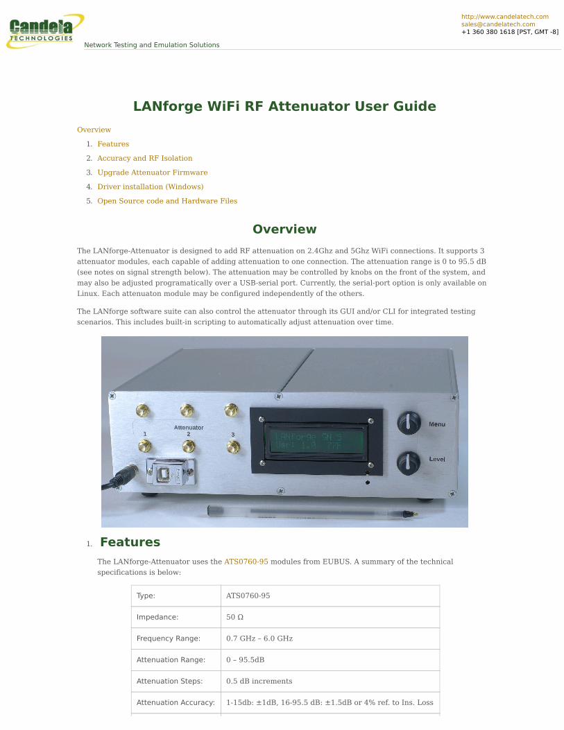
TheLANforge-Attenuatorcontains3ofthesemodules,foratotalof6RP-SMAconnectorsonthefrontpanel.Eachpairofconnectorsprovidesoneattenuationpath.Amicro-controllerprovidesacontrolinterfaceoveraUSBplugthatappearsasaUSB-Serialadaptertotheoperatingsystem.Theattenuatordoesnotrequireanexternalcomputertofunction:Itcanbemanuallyadjustedwithtwoknobs,andhasasmallLCDscreentoprovideinformationtotheuser.
ThetopknobadjuststheLCDmenuitems.ThefirstmenuisInformation,thesecondistoadjustallattenuatormodulesinlock-step,andtherestofthemenusareforadjustingindividualattenuatormodules.
ThebottomknobadjuststheattenuationwhentheselectedmenuisAllorindividualattenuatormodules.Pressingtheknobdownactivatesabuttonthattogglesbetweeneachclickadjustingby5dBmorby0.5dBm.Enablingthex5modeenablesquickadjustmentsoverlargerranges,andthe0.5modeallowsfinetuning.
Thesystemmaybepoweredoffofa500maUSBplug,butmanycomputersonlyprovide100maUSBplugs,soitissuggestedthattheexternalDCpower-brick(9v1-Amp)beusedatalltimes.
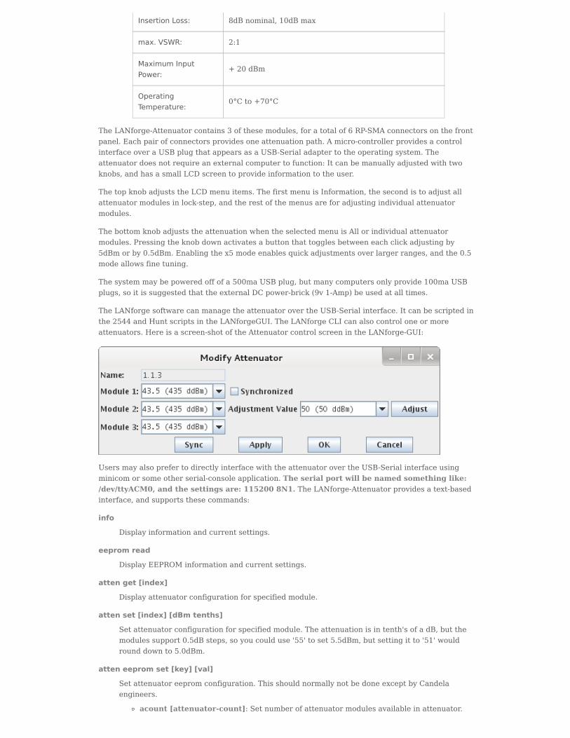
TheLANforgesoftwarecanmanagetheattenuatorovertheUSB-Serialinterface.Itcanbescriptedinthe2544andHuntscriptsintheLANforgeGUI.TheLANforgeCLIcanalsocontroloneormoreattenuators.Hereisascreen-shotoftheAttenuatorcontrolscreenintheLANforge-GUI:
UsersmayalsoprefertodirectlyinterfacewiththeattenuatorovertheUSB-Serialinterfaceusingminicomorsomeotherserial-consoleapplication.Theserialportwillbenamedsomethinglike:/dev/ttyACM0,andthesettingsare:1152008N1.TheLANforge-Attenuatorprovidesatext-basedinterface,andsupportsthesecommands:
info
Displayinformationandcurrentsettings.
eepromread
DisplayEEPROMinformationandcurrentsettings.
attenget[index]
Displayattenuatorconfigurationforspecifiedmodule.
attenset[index][dBmtenths]
Setattenuatorconfigurationforspecifiedmodule.Theattenuationisintenth'sofadB,butthemodulessupport0.5dBsteps,soyoucoulduse'55'toset5.5dBm,butsettingitto'51'wouldrounddownto5.0dBm.
atteneepromset[key][val]
Setattenuatoreepromconfiguration.ThisshouldnormallynotbedoneexceptbyCandelaengineers.
acount[attenuator-count]:Setnumberofattenuatormodulesavailableinattenuator.
test[0|1]:Enable(1)orDisable(0)testmode.Testmodeisonlyusefulwhentheattenuatorconnectorcableshavebeenconnectedtoattenuator-4andoneoftheotherattenuatorconnectorsontheadapterboard.Thetestistoverifythecablesandshieldweremanufacturedproperly.
Whentesting,firstconnectattenuator1headertoattenuator4,pressthebottombuttontostartthetest.Eachtimeyouclickit,adifferentheaderwillbetested.So,whentestingattenuator3header,expect1and2tofail,but3shouldpass.Attenuator4headeristestedindirectlywhentestinganyoftheothers.
serrno[serial-number]:Settheserialnumber.
Themicro-controllerintheLANforgeAttenuatorisconfiguredtoresetitselfeachtimeanewserialconnectionismadetotheAttenuator.Itonlytakesasecondortwotoboot,butthiscouldcauseinterruptionoftestingifyourapplicationoftenopensandclosestheserialconnection.Ifyouarecontrollingtheattenuatorovertheserialconnection,itissuggestedthatyouprogramitinsuchawaythattheserialconnectionremainsupforthedurationofthetest.Pleasecontactsupportifyouhaveanyquestionsonthis.
2. AccuracyandRFIsolation
TheLANforgeAttenuatorhasbeendesignedwithRFIsolationandaccuracyinmind,butintestingwiththeLANforgeCT520WiFiretrafficgeneratorsystems,westillseeabitofsignalleakageevenwhenattenuationissetto95.5.WesuspectthattheCT520systemsleakabitofsignaloutoftheirNICsandcommunicatedirectly,bypassingtheattenuator.
Theinternalattenuatormodulesaretestedbytheirvendorandshouldhaveexcellentisolation.TheSMAcablesconnectingtheattenuatortothefaceplatearedouble-shieldedKSR-100with>90dBisolation.
TheLANforgeattenuatorcomeswith6cablestoconnecttheattenuatortosystemsundertest.ThesecablesuseLMR-195cablewhichalsohasisolationof>90dB.Ifyouuseyourowncables,besuretheyareofhighqualityforoptimalperformance.Ourtestingindicatesthateventhesedouble-shieldedLMR-195cablesmaybeleakingmorethatwehoped,sowewillcontinuetoinvestigatedifferentcabletypes.
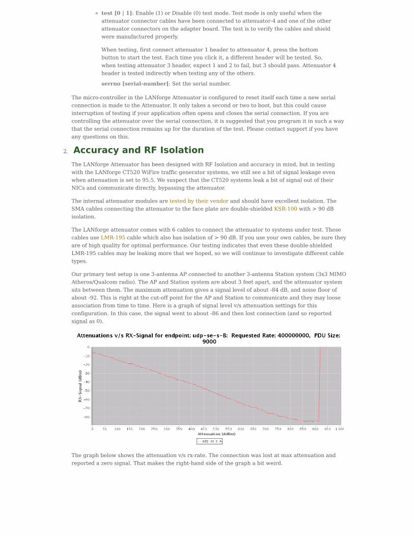
Ourprimarytestsetupisone3-antennaAPconnectedtoanother3-antennaStationsystem(3x3MIMOAtheros/Qualcomradio).TheAPandStationsystemareabout3feetapart,andtheattenuatorsystemsitsbetweenthem.Themaximumattenuationgivesasignallevelofabout-84dB,andnoisefloorofabout-92.Thisisrightatthecut-offpointfortheAPandStationtocommunicateandtheymaylooseassociationfromtimetotime.Hereisagraphofsignallevelv/sattenuationsettingsforthisconfiguration.Inthiscase,thesignalwenttoabout-86andthenlostconnection(andsoreportedsignalas0).
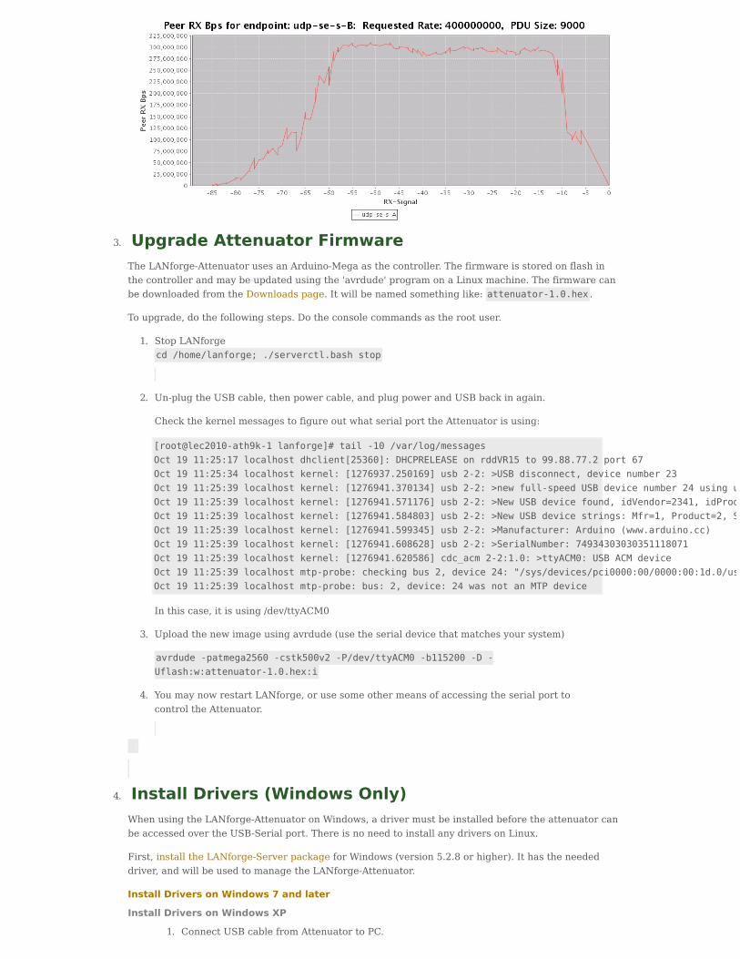
Thegraphbelowshowstheattenuationv/srx-rate.Theconnectionwaslostatmaxattenuationandreportedazerosignal.Thatmakestheright-handsideofthegraphabitweird.
3. UpgradeAttenuatorFirmware
TheLANforge-AttenuatorusesanArduino-Megaasthecontroller.Thefirmwareisstoredonflashinthecontrollerandmaybeupdatedusingthe'avrdude'programonaLinuxmachine.ThefirmwarecanbedownloadedfromtheDownloadspage.Itwillbenamedsomethinglike:attenuator-1.0.hex .
Toupgrade,dothefollowingsteps.Dotheconsolecommandsastherootuser.
1. StopLANforgecd/home/lanforge;./serverctl.bashstop
2. Un-plugtheUSBcable,thenpowercable,andplugpowerandUSBbackinagain.
CheckthekernelmessagestofigureoutwhatserialporttheAttenuatorisusing:
[root@lec2010-ath9k-1lanforge]#tail-10/var/log/messagesOct1911:25:17localhostdhclient[25360]:DHCPRELEASEonrddVR15to99.88.77.2port67Oct1911:25:34localhostkernel:[1276937.250169]usb2-2:>USBdisconnect,devicenumber23Oct1911:25:39localhostkernel:[1276941.370134]usb2-2:>newfull-speedUSBdevicenumber24usinguhci_hcdOct1911:25:39localhostkernel:[1276941.571176]usb2-2:>NewUSBdevicefound,idVendor=2341,idProduct=0042Oct1911:25:39localhostkernel:[1276941.584803]usb2-2:>NewUSBdevicestrings:Mfr=1,Product=2,SerialNumber=220Oct1911:25:39localhostkernel:[1276941.599345]usb2-2:>Manufacturer:Arduino(www.arduino.cc)Oct1911:25:39localhostkernel:[1276941.608628]usb2-2:>SerialNumber:74934303030351118071Oct1911:25:39localhostkernel:[1276941.620586]cdc_acm2-2:1.0:>ttyACM0:USBACMdeviceOct1911:25:39localhostmtp-probe:checkingbus2,device24:"/sys/devices/pci0000:00/0000:00:1d.0/usb2/2-2"Oct1911:25:39localhostmtp-probe:bus:2,device:24wasnotanMTPdevice
Inthiscase,itisusing/dev/ttyACM0
3. Uploadthenewimageusingavrdude(usetheserialdevicethatmatchesyoursystem)
avrdude-patmega2560-cstk500v2-P/dev/ttyACM0-b115200-D-Uflash:w:attenuator-1.0.hex:i
4. YoumaynowrestartLANforge,orusesomeothermeansofaccessingtheserialporttocontroltheAttenuator.
4. InstallDrivers(WindowsOnly)
WhenusingtheLANforge-AttenuatoronWindows,adrivermustbeinstalledbeforetheattenuatorcanbeaccessedovertheUSB-Serialport.ThereisnoneedtoinstallanydriversonLinux.
First,installtheLANforge-ServerpackageforWindows(version5.2.8orhigher).Ithastheneededdriver,andwillbeusedtomanagetheLANforge-Attenuator.
InstallDriversonWindows7andlater
InstallDriversonWindowsXP
1. ConnectUSBcablefromAttenuatortoPC.
2. ClickStart→ControlPanelandchoosethe'AddHardware'option.
3. ItshouldfindanewUSBdeviceinthePorts(COM&LPT)section.Ifnot,continueontothenextstepanyway,perhapsitwasalreadydiscoveredautomatically.
4. Right-Clickon'MyComputer'inthestartmenu,andchoose'Properties'
5. SelecttheHardwareTab.
6. ClickDeviceManager
7. LookforaneworunknownUSBdeviceinthePorts(COM&LPT)section.
8. Right-ClickonthisdeviceandchooseUpdateDriver.
9. Selectthe'Installfromalistorspecificlocation'optionandclick'Next'.
10. Selectthe'Includethislocationinthesearch'checkboxandchoosetheLANforge-Serverdirectory(C:\ProgramFiles\LANforge-Serverbydefault).
11. Click'Next'.Itshouldfindthe"LANforgeAttenuator(ArduinoMega2560R3)driver.Thisdriverisnotsigned,soclickthe'ContinueAnyway'optioninthewarningdialog.
12. ClickFinish.
13. Start(orre-start)theLANforgeManagerand/orLANforgeResourceprocessesthatwerepreviouslyinstalled.ConnecttheLANforge-GUItotheLANforgeManagerandselectthe'Attenuators'tab.YoushouldseetheAttenuatorlistedinthetable.
5. OpenSourcecodeandHardwareFiles
TheLANforgeAttenuatorcontrollogicisbasedontheArduinoMegamicrocontroller.CandelaTechnologiesreleasestheArduinosourcecodeusedtoprogramtheArduinoMegaaswellastheEaglePCBlayoutandroutingfiles.ThesourcecodeisreleasedundertheGPL(GNUPublicLicense),andtheEaglehardwarefilesarereleasedundertheCreativeCommonsAttribution-ShareAlikelicense.YoumaydownloadthecodeandEaglefilesontheDownloadspageaftercreatinganaccountonourwebsite.
CandelaTechnologies,Inc.,2417MainStreet,Suite201,Ferndale,WA98248,USAwww.candelatech.com|[email protected]|+1.360.380.1618
Related Documents