International Journal of Engineering Research and Applications (IJERA) ISSN: 2248-9622 International Conference On Quality Up-gradation in Engineering, Science & Technology (IC-QUEST- 11 th April 2015) Bapurao Deshmukh College of Engineering 31|Page LabVIEW Based Condition Monitoring Of Induction Motor Rushikesh V. Deshmukh 1PG student Prof. Anjali U. Jawadekar 2Asst. professor Department of Electrical Engineering SSGMCE, Shegaon, M.S. (India) Email:[email protected] Abstract: Early detection of faults in stator winding of induction motor is crucial for reliable and economical operation of induction motor in industries. Whereas major winding faults can be easily identified from supply currents, minor faults involving less than 5 % of turns are not readily discernible. The present work reports experimental results for monitoring of minor short circuit faults in stator winding of induction motor. Motor line current has been analyzed using motor current signature analysis.The current signals that obtained was current of three phase of induction motor in load and no load condition.These are reduced in two equivalent current signals by Park’s Transformation and Discrete Wavelet Transform (DWT) in NI LabVIEW 8.5. Feed Forward Artificial Neural (FFANN) based data classification tool is used for fault characterization based on DWT features extracted from Park’s Current Vector Pattern. Keywords: MCSA, FFANN, Discrete wavelet transform, Park’s transform, LabVIEW 8.5 I. INTRODUCTION Induction motor plays a very important role in industrial as well as commercial purpose due to its low cost, ruggedness, low maintenance and construction. Early detection of faults in induction motor in its initial stage can extends the wear out period. Induction motor faces many problems as shown in Figure 1 among that problem inter turn short circuit is the one of the major fault occurred in the induction motor. Figure 1 Various Faults in Induction Motor The various techniques have been proposed for the detection of inter turn short circuit Fault in induction motor. Some of the technique reported [1]-[2] uses mathematical modeling of system. In [1] mathematical modeling of induction motor has been simulated and the result has been reported, the model has been used for all the behavior of motor in load and no load condition. Some of the techniques [3]-[4] uses frequency spectrum for the analysis of inter turn short circuit fault. Fourier transform is not used for analysis of the signals because these signals are non stationary signals. Induction motor faults diagnosis using stator current envelopes has been used for the detection of broken rotor bar and inter turn short circuit fault [5]. In [6] the fault detection of induction motor is based on negative sequence impedance. The higher order spectra of radial machine vibration for detection inter turn fault is proposed in [7]. A wavelet package for the extraction of useful information for the non stationary signals has been employed in [8]. Inter turn fault detection based on neutral voltage has been proposed in [9], but is being limited to the star connected machine with an accessible neutral. The detection of fault in using park’s transform and wavelet has been explained in [10]. In [11] the inter turn fault has been detected by d 1 coefficient that is being proceed through ANN for fault classification. The use of wavelet for the detection of the fault has been use in majority because wavelet deals in both the time and frequency domain. This analysis deals for the stator current during the transient nature of the induction motor. The main advantage of the DWT is that it can be used for the analysis of non-stationary signals. This paper deals with stator current captured from the induction motor in healthy and faulty condition for full load and no- load condition which is non-stationary current signal. The DWT gives the detail and approximate coefficient for those non-stationary signals. RESEARCH ARTICLE OPEN ACCESS

Welcome message from author
This document is posted to help you gain knowledge. Please leave a comment to let me know what you think about it! Share it to your friends and learn new things together.
Transcript
International Journal of Engineering Research and Applications (IJERA) ISSN: 2248-9622
International Conference On Quality Up-gradation in Engineering, Science & Technology
(IC-QUEST- 11th
April 2015)
Bapurao Deshmukh College of Engineering 31|P a g e
LabVIEW Based Condition Monitoring Of Induction Motor
Rushikesh V. Deshmukh1PG student
Prof. Anjali U. Jawadekar2Asst. professor
Department of Electrical Engineering SSGMCE, Shegaon, M.S. (India)
Email:[email protected]
Abstract: Early detection of faults in stator winding of induction motor is crucial for reliable and economical operation of
induction motor in industries. Whereas major winding faults can be easily identified from supply currents, minor
faults involving less than 5 % of turns are not readily discernible. The present work reports experimental results
for monitoring of minor short circuit faults in stator winding of induction motor. Motor line current has been
analyzed using motor current signature analysis.The current signals that obtained was current of three phase of
induction motor in load and no load condition.These are reduced in two equivalent current signals by Park’s
Transformation and Discrete Wavelet Transform (DWT) in NI LabVIEW 8.5. Feed Forward Artificial Neural
(FFANN) based data classification tool is used for fault characterization based on DWT features extracted from
Park’s Current Vector Pattern.
Keywords: MCSA, FFANN, Discrete wavelet transform, Park’s transform, LabVIEW 8.5
I. INTRODUCTION
Induction motor plays a very important role in
industrial as well as commercial purpose due to its
low cost, ruggedness, low maintenance and
construction. Early detection of faults in induction
motor in its initial stage can extends the wear out
period. Induction motor faces many problems as
shown in Figure 1 among that problem inter turn
short circuit is the one of the major fault occurred
in the induction motor.
Figure 1 Various Faults in Induction Motor
The various techniques have been proposed for
the detection of inter turn short circuit Fault in
induction motor. Some of the technique reported
[1]-[2] uses mathematical modeling of system. In
[1] mathematical modeling of induction motor has
been simulated and the result has been reported, the
model has been used for all the behavior of motor
in load and no load condition. Some of the
techniques [3]-[4] uses frequency spectrum for the
analysis of inter turn short circuit fault. Fourier
transform is not
used for analysis of the signals because these
signals are non stationary signals. Induction motor
faults diagnosis using stator current envelopes has
been used for the detection of broken rotor bar and
inter turn short circuit fault [5]. In [6] the fault
detection of induction motor is based on negative
sequence impedance. The higher order spectra of
radial machine vibration for detection inter turn
fault is proposed in [7]. A wavelet package for the
extraction of useful information for the non
stationary signals has been employed in [8]. Inter
turn fault detection based on neutral voltage has
been proposed in [9], but is being limited to the star
connected machine with an accessible neutral. The
detection of fault in using park’s transform and
wavelet has been explained in [10]. In [11] the inter
turn fault has been detected by d1 coefficient that is
being proceed through ANN for fault classification.
The use of wavelet for the detection of the fault
has been use in majority because wavelet deals in
both the time and frequency domain. This analysis
deals for the stator current during the transient
nature of the induction motor. The main advantage
of the DWT is that it can be used for the analysis of
non-stationary signals. This paper deals with stator
current captured from the induction motor in
healthy and faulty condition for full load and no-
load condition which is non-stationary current
signal. The DWT gives the detail and approximate
coefficient for those non-stationary signals.
RESEARCH ARTICLE OPEN ACCESS
International Journal of Engineering Research and Applications (IJERA) ISSN: 2248-9622
International Conference On Quality Up-gradation in Engineering, Science & Technology
(IC-QUEST- 11th
April 2015)
Bapurao Deshmukh College of Engineering 32|P a g e
In this paper FFANN i.e. feed forward
algorithm for the classification of healthy and
faulty condition of 3 phase induction motor has
been successfully carried out. In FFANN the
selection of suitable data for the classification of
the fault is the main judgment. The various
parameters for the creating the network for fault
classification is done on trial and error method.
This paper deals with the energy of each detail
coefficient has been used for the fault
classification.
II. DATA REDUCTION USING PARK’S
TRANSFORMATION In three phase induction motor the stator
current has been captured which are the current of
the three phases i.e. ia, ib & ic. But the analysis of
the three phase current is quite difficult task and
multi resolution analysis of three signals is difficult
in time domain, where as these current signals does
not give any fault feature extraction. That is the
reason park’s transformation is tool used for the
conversion of three phase current quantities into
two equivalent quantities by using (1) & (2) which
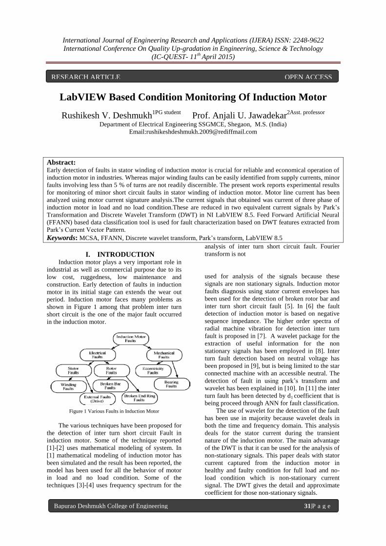
is known as park’s transformation. The fault feature
extracted for full load and no load condition is
shown in figure2 and figure3 respectively.
𝐼𝑑 = 2
3𝐼𝑎 −
1
6𝐼𝑏 −
1
6𝐼𝑐 (1)
𝐼𝑞 =1
2𝐼𝑏 −
1
2𝐼𝑐 (2)
These are the equations that are used for the
conversion of a,b,c phase current into direct axis
and quadrature axis current. The whole operations
for the conversion of three phase current in two
phase quantities are performed in NI LabVIEW
8.5.
Plots For Id & Iq(full load)
Healthy 10 Turns
20 Turns 30 Turns
Figure 2 Plots for Id and Iq for full loading
Plots For Id & Iq(full load)
Healthy
23
10 Turns
20 Turns 30 Turns
Figure 3 Plots for Id and Iq for full loading
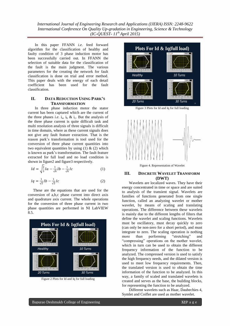
Figure 4. Representation of Wavelet
III. DISCRETE WAVELET TRANSFORM
(DWT) Wavelets are localized waves. They have their
energy concentrated in time or space and are suited
to analysis of the transient signal. Wavelets are
families of functions generated from one single
function, called an analyzing wavelet or mother
wavelet, by means of scaling and translating
operations. The difference between these wavelets
is mainly due to the different lengths of filters that
define the wavelet and scaling functions. Wavelets
must be oscillatory, must decay quickly to zero
(can only be non-zero for a short period), and must
integrate to zero. The scaling operation is nothing
more than performing “stretching” and
“compressing” operations on the mother wavelet,
which in turn can be used to obtain the different
frequency information of the function to be
analyzed. The compressed version is used to satisfy
the high frequency needs, and the dilated version is
used to meet low frequency requirements. Then,
the translated version is used to obtain the time
information of the function to be analyzed. In this
way, a family of scaled and translated wavelets is
created and serves as the base, the building blocks,
for representing the function to be analyzed.
Different wavelets such as Haar, Daubechies 4,
Symlet and Coiflet are used as mother wavelet.
International Journal of Engineering Research and Applications (IJERA) ISSN: 2248-9622
International Conference On Quality Up-gradation in Engineering, Science & Technology
(IC-QUEST- 11th
April 2015)
Bapurao Deshmukh College of Engineering 33|P a g e
DWT is any wavelet transform in which the
wavelet is discretely sampled. It transforms the
distorted signal into different time frequency scales
detecting the disturbances present in the power
signal.
The DWT of f (t) is defined as:
DWT f (a,b) = ∑ f(t) ψa,b(t) (3)
Where, ψa,b(t) is mother wavelet a, b are scale and
translation factor.
Multi resolution analysis is the first main
characteristic of Wavelet transform. Multi
resolution analysis technique is analysis of the
signal at different frequencies with different
resolution. Multi resolution analysis technique
decomposes the given signal into several other
signals with different levels of resolution which
provide valuable information in time and frequency
domain. It uses the wavelet function (ψ) and
scaling function (φ) to decompose the signal into
high frequency component and low frequency
component by processing the signal into high pass
filter and low pass filter. The wavelet function ψ
generates high frequency component (detailed
coefficient) and φ will generate low frequency
component (approximate coefficient). This work
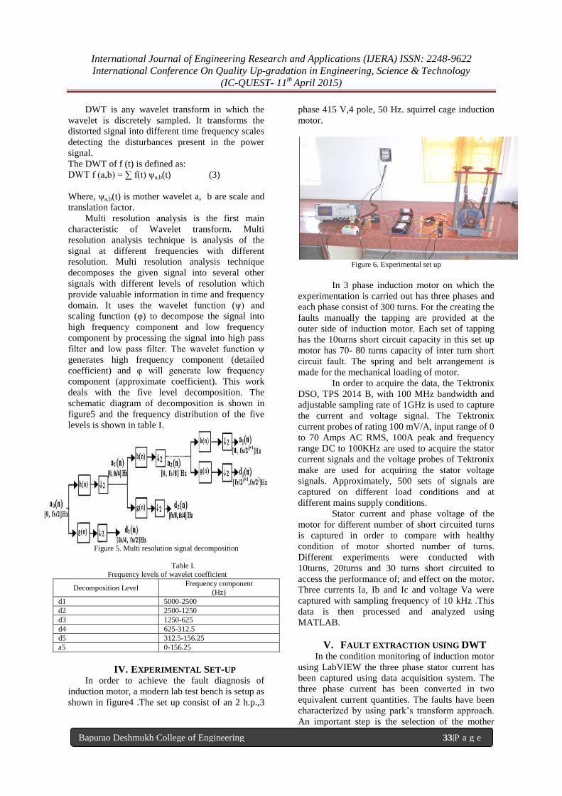
deals with the five level decomposition. The
schematic diagram of decomposition is shown in
figure5 and the frequency distribution of the five
levels is shown in table I.
Figure 5. Multi resolution signal decomposition
Table I.
Frequency levels of wavelet coefficient
Decomposition Level Frequency component
(Hz)
d1 5000-2500
d2 2500-1250
d3 1250-625
d4 625-312.5
d5 312.5-156.25
a5 0-156.25
IV. EXPERIMENTAL SET-UP In order to achieve the fault diagnosis of
induction motor, a modern lab test bench is setup as
shown in figure4 .The set up consist of an 2 h.p.,3
phase 415 V,4 pole, 50 Hz. squirrel cage induction
motor.
Figure 6. Experimental set up
In 3 phase induction motor on which the
experimentation is carried out has three phases and
each phase consist of 300 turns. For the creating the
faults manually the tapping are provided at the
outer side of induction motor. Each set of tapping
has the 10turns short circuit capacity in this set up
motor has 70- 80 turns capacity of inter turn short
circuit fault. The spring and belt arrangement is
made for the mechanical loading of motor.
In order to acquire the data, the Tektronix
DSO, TPS 2014 B, with 100 MHz bandwidth and
adjustable sampling rate of 1GHz is used to capture
the current and voltage signal. The Tektronix
current probes of rating 100 mV/A, input range of 0
to 70 Amps AC RMS, 100A peak and frequency
range DC to 100KHz are used to acquire the stator
current signals and the voltage probes of Tektronix
make are used for acquiring the stator voltage
signals. Approximately, 500 sets of signals are
captured on different load conditions and at
different mains supply conditions.
Stator current and phase voltage of the
motor for different number of short circuited turns
is captured in order to compare with healthy
condition of motor shorted number of turns.
Different experiments were conducted with
10turns, 20turns and 30 turns short circuited to
access the performance of; and effect on the motor.
Three currents Ia, Ib and Ic and voltage Va were
captured with sampling frequency of 10 kHz .This
data is then processed and analyzed using
MATLAB.
V. FAULT EXTRACTION USING DWT In the condition monitoring of induction motor
using LabVIEW the three phase stator current has
been captured using data acquisition system. The
three phase current has been converted in two
equivalent current quantities. The faults have been
characterized by using park’s transform approach.
An important step is the selection of the mother
International Journal of Engineering Research and Applications (IJERA) ISSN: 2248-9622
International Conference On Quality Up-gradation in Engineering, Science & Technology
(IC-QUEST- 11th
April 2015)
Bapurao Deshmukh College of Engineering 34|P a g e
wavelet for the fault extraction. There are different
families of the wavelet viz. Gaussian, Mexican,
Hat, Morlet, Meyer, Daubechies, Coiflet,
Biorthogonal etc. In this method deubechies-4
(DB-4) wavelet has been selected as a mother
wavelet.
When DWT is applied to extract the
scaling and wavelet coefficients from a transient
signal, a large amount of information in terms of
these coefficients is obtained. Although the
information is useful, it is difficult for ANN to
train/validate that large information. Another
alternative is to input the energy contents in the
detailed coefficients according to Parseval’s
Theorem.
ʃ f(t)2= 𝐶𝑗(𝑘)𝑘
2 + 𝑑𝑥(𝑘)
𝑗𝑥=1
2 (3)
Where f (t); Signal to be decomposed, Cj is
approximate coefficient of decomposed signal, d is
detail coefficient to be decomposed.
The meaning of parseval’s theorem is that the
energy contained in the signal is equal to
summation of the energy contained in detail and
approximate coefficient at any jth
level. As only
non stationary waves are concerned only second
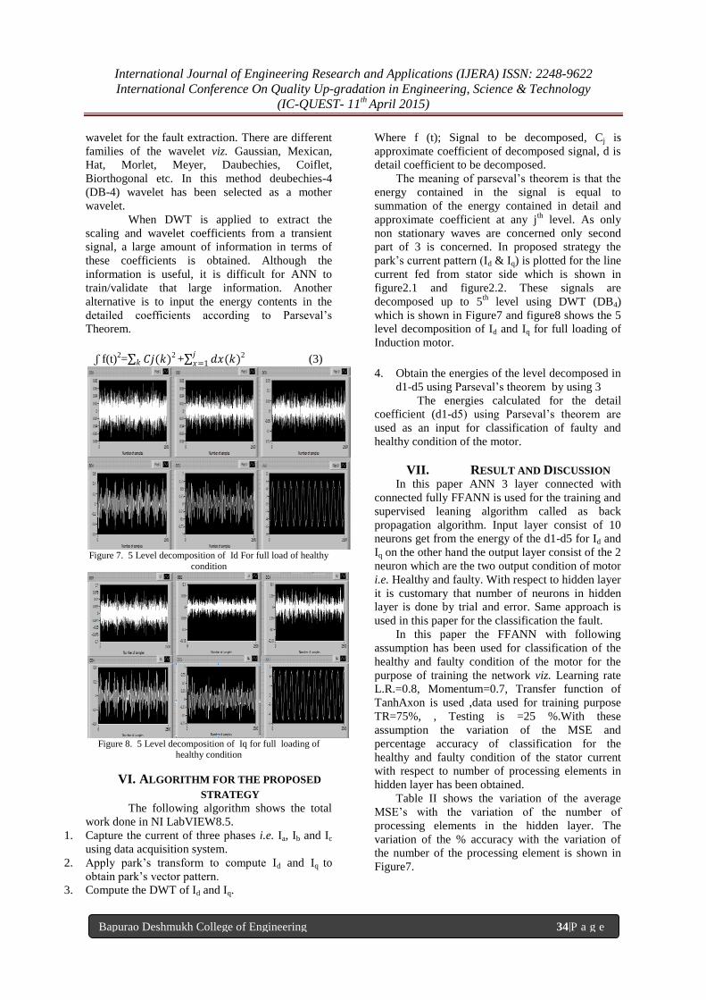
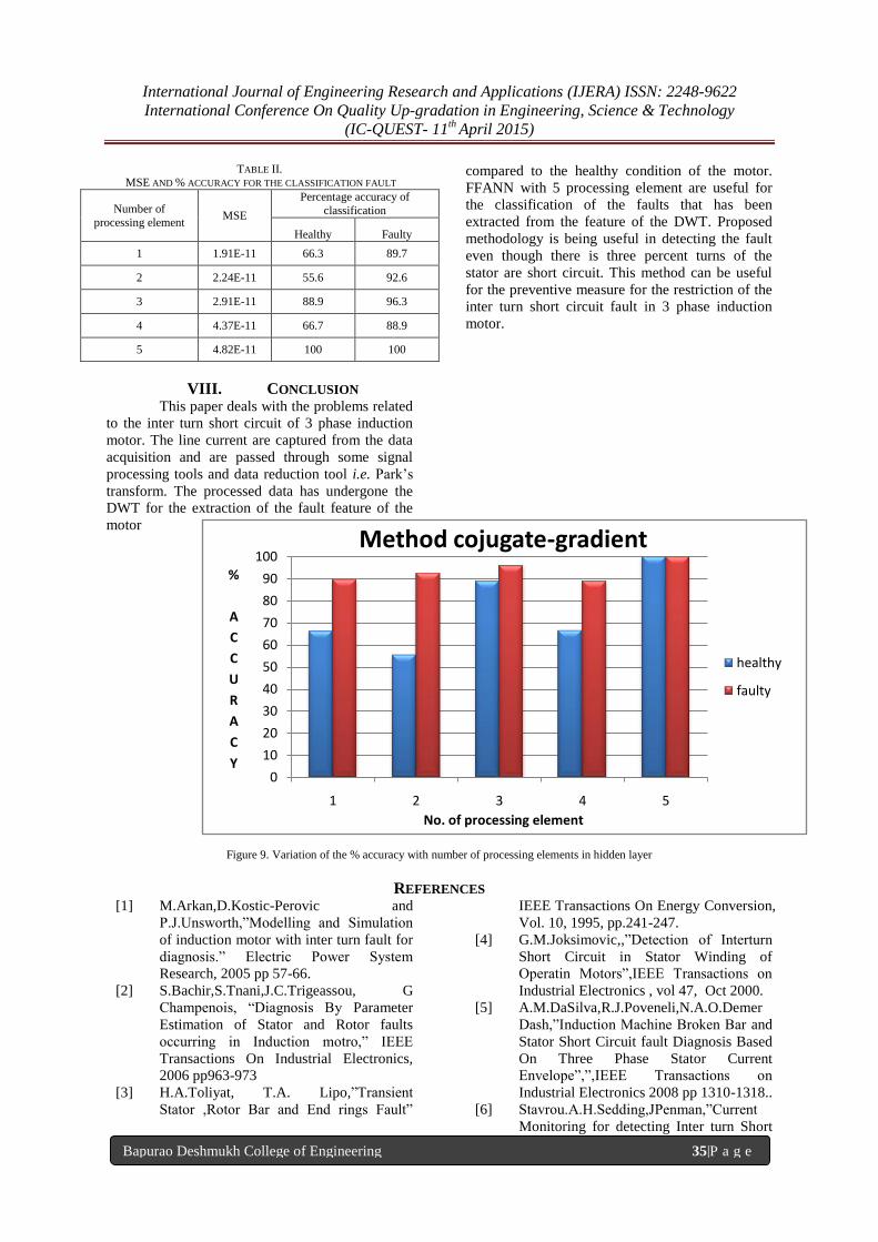
part of 3 is concerned. In proposed strategy the
park’s current pattern (Id & Iq) is plotted for the line
current fed from stator side which is shown in
figure2.1 and figure2.2. These signals are
decomposed up to 5th level using DWT (DB4)
which is shown in Figure7 and figure8 shows the 5
level decomposition of Id and Iq for full loading of
Induction motor.
Figure 7. 5 Level decomposition of Id For full load of healthy
condition
Figure 8. 5 Level decomposition of Iq for full loading of
healthy condition
VI. ALGORITHM FOR THE PROPOSED
STRATEGY The following algorithm shows the total
work done in NI LabVIEW8.5.
1. Capture the current of three phases i.e. Ia, Ib and Ic
using data acquisition system.
2. Apply park’s transform to compute Id and Iq to
obtain park’s vector pattern.
3. Compute the DWT of Id and Iq.
4. Obtain the energies of the level decomposed in
d1-d5 using Parseval’s theorem by using 3
The energies calculated for the detail
coefficient (d1-d5) using Parseval’s theorem are
used as an input for classification of faulty and
healthy condition of the motor.
VII. RESULT AND DISCUSSION In this paper ANN 3 layer connected with
connected fully FFANN is used for the training and
supervised leaning algorithm called as back
propagation algorithm. Input layer consist of 10
neurons get from the energy of the d1-d5 for Id and
Iq on the other hand the output layer consist of the 2
neuron which are the two output condition of motor
i.e. Healthy and faulty. With respect to hidden layer
it is customary that number of neurons in hidden
layer is done by trial and error. Same approach is
used in this paper for the classification the fault.
In this paper the FFANN with following
assumption has been used for classification of the
healthy and faulty condition of the motor for the
purpose of training the network viz. Learning rate
L.R.=0.8, Momentum=0.7, Transfer function of
TanhAxon is used ,data used for training purpose
TR=75%, , Testing is =25 %.With these
assumption the variation of the MSE and
percentage accuracy of classification for the
healthy and faulty condition of the stator current
with respect to number of processing elements in
hidden layer has been obtained.
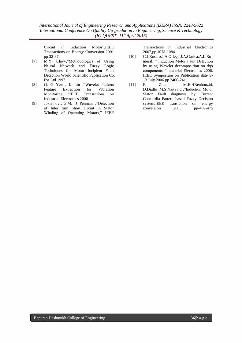
Table II shows the variation of the average
MSE’s with the variation of the number of
processing elements in the hidden layer. The
variation of the % accuracy with the variation of
the number of the processing element is shown in
Figure7.
International Journal of Engineering Research and Applications (IJERA) ISSN: 2248-9622
International Conference On Quality Up-gradation in Engineering, Science & Technology
(IC-QUEST- 11th
April 2015)
Bapurao Deshmukh College of Engineering 35|P a g e
TABLE II. MSE AND % ACCURACY FOR THE CLASSIFICATION FAULT
Number of
processing element MSE
Percentage accuracy of
classification
Healthy Faulty
1 1.91E-11 66.3 89.7
2 2.24E-11 55.6 92.6
3 2.91E-11 88.9 96.3
4 4.37E-11 66.7 88.9
5 4.82E-11 100 100
VIII. CONCLUSION This paper deals with the problems related
to the inter turn short circuit of 3 phase induction
motor. The line current are captured from the data
acquisition and are passed through some signal
processing tools and data reduction tool i.e. Park’s
transform. The processed data has undergone the
DWT for the extraction of the fault feature of the
motor
compared to the healthy condition of the motor.
FFANN with 5 processing element are useful for
the classification of the faults that has been
extracted from the feature of the DWT. Proposed
methodology is being useful in detecting the fault
even though there is three percent turns of the
stator are short circuit. This method can be useful
for the preventive measure for the restriction of the
inter turn short circuit fault in 3 phase induction
motor.
Figure 9. Variation of the % accuracy with number of processing elements in hidden layer
REFERENCES [1] M.Arkan,D.Kostic-Perovic and
P.J.Unsworth,”Modelling and Simulation
of induction motor with inter turn fault for
diagnosis.” Electric Power System
Research, 2005 pp 57-66.
[2] S.Bachir,S.Tnani,J.C.Trigeassou, G
Champenois, “Diagnosis By Parameter
Estimation of Stator and Rotor faults
occurring in Induction motro,” IEEE
Transactions On Industrial Electronics,
2006 pp963-973
[3] H.A.Toliyat, T.A. Lipo,”Transient
Stator ,Rotor Bar and End rings Fault”
IEEE Transactions On Energy Conversion,
Vol. 10, 1995, pp.241-247.
[4] G.M.Joksimovic,,”Detection of Interturn
Short Circuit in Stator Winding of
Operatin Motors”,IEEE Transactions on
Industrial Electronics , vol 47, Oct 2000.
[5] A.M.DaSilva,R.J.Poveneli,N.A.O.Demer
Dash,”Induction Machine Broken Bar and
Stator Short Circuit fault Diagnosis Based
On Three Phase Stator Current
Envelope”,”,IEEE Transactions on
Industrial Electronics 2008 pp 1310-1318..
[6] Stavrou.A.H.Sedding,JPenman,”Current
Monitoring for detecting Inter turn Short
0
10
20
30
40
50
60
70
80
90
100
1 2 3 4 5
%
A
C
C
U
R
A
C
Y
No. of processing element
Method cojugate-gradient
healthy
faulty
International Journal of Engineering Research and Applications (IJERA) ISSN: 2248-9622
International Conference On Quality Up-gradation in Engineering, Science & Technology
(IC-QUEST- 11th
April 2015)
Bapurao Deshmukh College of Engineering 36|P a g e
Circuit in Induction Motor”,IEEE
Transactions on Energy Conversion 2001
pp 32-37.
[7] M.Y. Chow,”Methodologies of Using
Neural Network and Fuzzy Logic
Techniques for Motor Incipient Fault
Detection World Scientific Publication Co.
Pvt Ltd 1997
[8] G. G Yen , K Lin ,”Wavelet Packets
Feature Extraction for Vibration
Monitoring “IEEE Transactions on
Industrial Electronics 2000
[9] Joksimovic,G.M. ,J Penman ,”Detection
of Inter turn Short circuit in Stator
Winding of Operating Motors,” IEEE
Transactions on Industrial Electronics
2007,pp.1078-1084.
[10] C.J.Rosero,J.A.Orlega,J.A.Garica,A.L.Ro
meral, ” Induction Motor Fault Detection
by using Wavelet decomposition on dqo
components “Industrial Electronics 2006,
IEEE Symposium on Publication date 9-
13 July 2006 pp 2406-2411.
[11] F. Zidani, M.E.HBenbouzid,
D.Diallo ,M.S.NaitSaid ,”Induction Motor
Stator Fault diagnosis by Current
Concordia Pattern based Fuzzy Decision
system.IEEE transiction on energy
conversion 2003 pp-469-475
Related Documents