L21/31 Project Guide - Marine Four-stroke GenSet compliant with IMO Tier II

L21-31_GenSet_TierII
Oct 22, 2015
Welcome message from author
This document is posted to help you gain knowledge. Please leave a comment to let me know what you think about it! Share it to your friends and learn new things together.
Transcript

L21/31Project Guide - MarineFour-stroke GenSetcompliant with IMO Tier II

Complete manualdate 2013.11.11
MAN Diesel & Turbo
PlatePage 1 (4)
2013.11.11
Project guide Index
L21/31
Text Index Drawing No
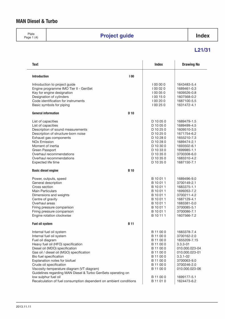
Introduction I 00
Introduction to project guide I 00 00 0 1643483-5.4Engine programme IMO Tier II - GenSet I 00 02 0 1689461-0.3Key for engine designation I 00 05 0 1609526-0.8Designation of cylinders I 00 15 0 1607568-0.2Code identification for instruments I 00 20 0 1687100-5.5Basic symbols for piping I 00 25 0 1631472-4.1
General information D 10
List of capacities D 10 05 0 1689479-1.5List of capacities D 10 05 0 1689499-4.5Description of sound measurements D 10 25 0 1609510-3.5Description of structure-born noise D 10 25 0 1671754-6.2Exhaust gas components D 10 28 0 1655210-7.3NOx Emission D 10 28 0 1689474-2.1Moment of inertia D 10 30 0 1693502-6.1Green Passport D 10 33 0 1699985-1.1Overhaul recommendations D 10 35 0 3700308-6.0Overhaul recommendations D 10 35 0 1683310-4.2Expected life time D 10 35 0 1687150-7.1
Basic diesel engine B 10
Power, outputs, speed B 10 01 1 1689496-9.0General description B 10 01 1 3700149-2.1Cross section B 10 01 1 1683375-1.1Main Particulars B 10 01 1 1699263-7.2Dimensions and weights B 10 01 1 3700211-4.2Centre of gravity B 10 01 1 1687129-4.1Overhaul areas B 10 01 1 1683381-0.0Firing pressure comparison B 10 01 1 3700085-5.1Firing pressure comparison B 10 01 1 3700086-7.1Engine rotation clockwise B 10 11 1 1607566-7.2
Fuel oil system B 11
Internal fuel oil system B 11 00 0 1683378-7.4Internal fuel oil system B 11 00 0 3700162-2.0Fuel oil diagram B 11 00 0 1655209-7.15Heavy fuel oil (HFO) specification B 11 00 0 3.3.3-01Diesel oil (MDO) specification B 11 00 0 010.000.023-04Gas oil / diesel oil (MGO) specification B 11 00 0 010.000.023-01Bio fuel specification B 11 00 0 3.3.1-02Explanation notes for biofuel B 11 00 0 3700063-9.0Crude oil specification B 11 00 0 3700246-2.0Viscosity-temperature diagram (VT diagram) B 11 00 0 010.000.023-06Guidelines regarding MAN Diesel & Turbo GenSets operating onlow sulphur fuel oil B 11 00 0 1699177-5.1Recalculation of fuel consumption dependent on ambient conditions B 11 01 0 1624473-6.2
MAN Diesel & Turbo
PlatePage 2 (4)
2013.11.11
Project guideIndex
L21/31
Text Index Drawing No
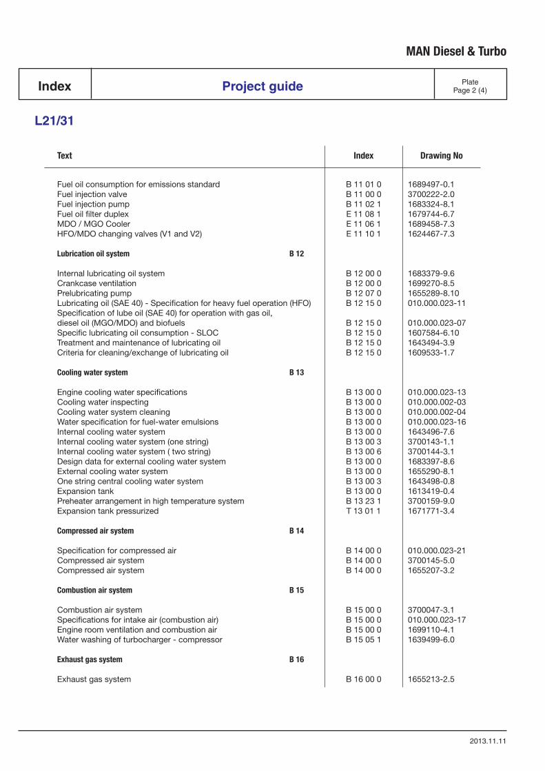
Fuel oil consumption for emissions standard B 11 01 0 1689497-0.1Fuel injection valve B 11 00 0 3700222-2.0Fuel injection pump B 11 02 1 1683324-8.1Fuel oil filter duplex E 11 08 1 1679744-6.7MDO / MGO Cooler E 11 06 1 1689458-7.3HFO/MDO changing valves (V1 and V2) E 11 10 1 1624467-7.3
Lubrication oil system B 12
Internal lubricating oil system B 12 00 0 1683379-9.6Crankcase ventilation B 12 00 0 1699270-8.5Prelubricating pump B 12 07 0 1655289-8.10Lubricating oil (SAE 40) - Specification for heavy fuel operation (HFO) B 12 15 0 010.000.023-11Specification of lube oil (SAE 40) for operation with gas oil, diesel oil (MGO/MDO) and biofuels B 12 15 0 010.000.023-07Specific lubricating oil consumption - SLOC B 12 15 0 1607584-6.10Treatment and maintenance of lubricating oil B 12 15 0 1643494-3.9Criteria for cleaning/exchange of lubricating oil B 12 15 0 1609533-1.7
Cooling water system B 13
Engine cooling water specifications B 13 00 0 010.000.023-13Cooling water inspecting B 13 00 0 010.000.002-03Cooling water system cleaning B 13 00 0 010.000.002-04Water specification for fuel-water emulsions B 13 00 0 010.000.023-16Internal cooling water system B 13 00 0 1643496-7.6Internal cooling water system (one string) B 13 00 3 3700143-1.1Internal cooling water system ( two string) B 13 00 6 3700144-3.1Design data for external cooling water system B 13 00 0 1683397-8.6External cooling water system B 13 00 0 1655290-8.1One string central cooling water system B 13 00 3 1643498-0.8Expansion tank B 13 00 0 1613419-0.4Preheater arrangement in high temperature system B 13 23 1 3700159-9.0Expansion tank pressurized T 13 01 1 1671771-3.4
Compressed air system B 14
Specification for compressed air B 14 00 0 010.000.023-21Compressed air system B 14 00 0 3700145-5.0Compressed air system B 14 00 0 1655207-3.2
Combustion air system B 15
Combustion air system B 15 00 0 3700047-3.1Specifications for intake air (combustion air) B 15 00 0 010.000.023-17Engine room ventilation and combustion air B 15 00 0 1699110-4.1Water washing of turbocharger - compressor B 15 05 1 1639499-6.0
Exhaust gas system B 16
Exhaust gas system B 16 00 0 1655213-2.5
MAN Diesel & Turbo
PlatePage 3 (4)
2013.11.11
Project guide Index
L21/31
Text Index Drawing No
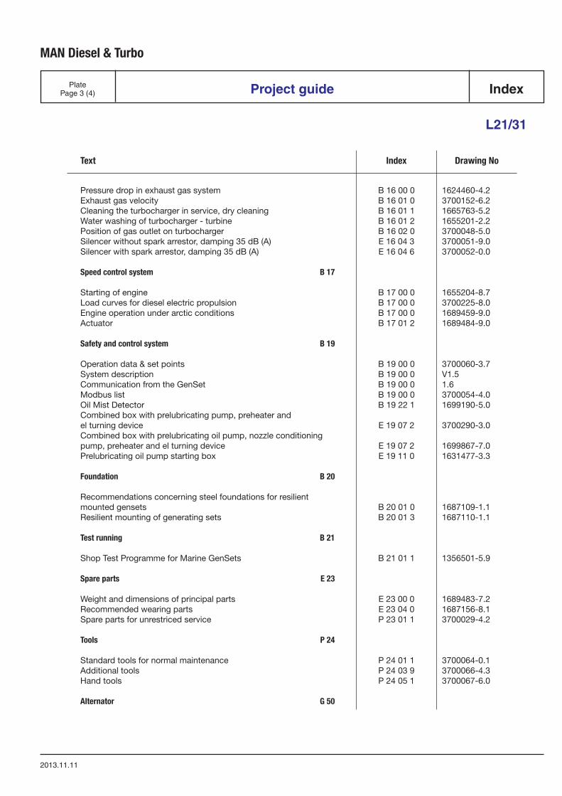
Pressure drop in exhaust gas system B 16 00 0 1624460-4.2Exhaust gas velocity B 16 01 0 3700152-6.2Cleaning the turbocharger in service, dry cleaning B 16 01 1 1665763-5.2Water washing of turbocharger - turbine B 16 01 2 1655201-2.2Position of gas outlet on turbocharger B 16 02 0 3700048-5.0Silencer without spark arrestor, damping 35 dB (A) E 16 04 3 3700051-9.0Silencer with spark arrestor, damping 35 dB (A) E 16 04 6 3700052-0.0
Speed control system B 17
Starting of engine B 17 00 0 1655204-8.7Load curves for diesel electric propulsion B 17 00 0 3700225-8.0Engine operation under arctic conditions B 17 00 0 1689459-9.0Actuator B 17 01 2 1689484-9.0
Safety and control system B 19
Operation data & set points B 19 00 0 3700060-3.7System description B 19 00 0 V1.5Communication from the GenSet B 19 00 0 1.6Modbus list B 19 00 0 3700054-4.0Oil Mist Detector B 19 22 1 1699190-5.0Combined box with prelubricating pump, preheater and el turning device E 19 07 2 3700290-3.0Combined box with prelubricating oil pump, nozzle conditioningpump, preheater and el turning device E 19 07 2 1699867-7.0Prelubricating oil pump starting box E 19 11 0 1631477-3.3
Foundation B 20
Recommendations concerning steel foundations for resilientmounted gensets B 20 01 0 1687109-1.1Resilient mounting of generating sets B 20 01 3 1687110-1.1
Test running B 21
Shop Test Programme for Marine GenSets B 21 01 1 1356501-5.9
Spare parts E 23
Weight and dimensions of principal parts E 23 00 0 1689483-7.2Recommended wearing parts E 23 04 0 1687156-8.1Spare parts for unrestriced service P 23 01 1 3700029-4.2
Tools P 24
Standard tools for normal maintenance P 24 01 1 3700064-0.1Additional tools P 24 03 9 3700066-4.3Hand tools P 24 05 1 3700067-6.0
Alternator G 50
MAN Diesel & Turbo
PlatePage 4 (4)
2013.11.11
Project guideIndex
L21/31
Text Index Drawing No
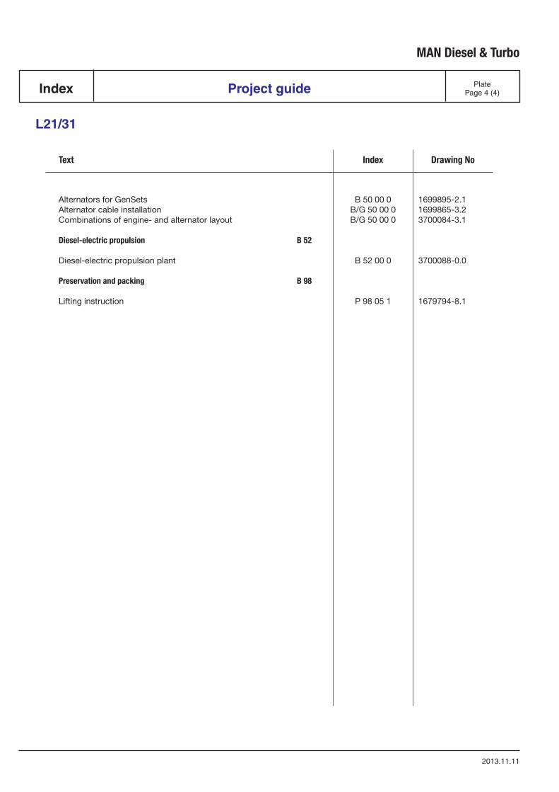
Alternators for GenSets B 50 00 0 1699895-2.1Alternator cable installation B/G 50 00 0 1699865-3.2Combinations of engine- and alternator layout B/G 50 00 0 3700084-3.1
Diesel-electric propulsion B 52
Diesel-electric propulsion plant B 52 00 0 3700088-0.0
Preservation and packing B 98
Lifting instruction P 98 05 1 1679794-8.1

Introduction
I 00

IntroductionOur project guides provide customers and consultants with information and data when planning new plantsincorporating four-stroke engines from the current MAN Diesel & Turbo engine programme. On account of themodifications associated with upgrading of our project guides, the contents of the specific edition hereof willremain valid for a limited time only.
Every care is taken to ensure that all information in this project guide is present and correct.
For actual projects you will receive the latest project guide editions in each case together with our quotationspecification or together with the documents for order processing.
All figures, values, measurements and/or other information about performance stated in the project guides arefor guidance only and shall not be used for detailed design purposes or as a substitute for specific drawingsand instructions prepared for such purposes. MAN Diesel & Turbo makes no representations or warrantieseither express or implied, as to the accuracy, completeness, quality or fitness for any particular purpose of theinformation contained in the project guides.
MAN Diesel & Turbo will issue an Installation Manual with all project related drawings and installation instruc-tions when the contract documentation has been completed.
The Installation Manual will comprise all necessary drawings, piping diagrams, cable plans and specifications ofour supply.
All data provided in this document is non-binding. This data serves informational purposes only and is especially notguaranteed in any way.
Depending on the subsequent specific individual projects, the relevant data may be subject to changes and will beassessed and determined individually for each project. This will depend on the particular characteristics of eachindividual project, especially specific site and operational conditions.
If this document is delivered in another language than English and doubts arise concerning the translation, the Eng-lish text shall prevail.
Original instructions
MAN Diesel & Turbo
1643483-5.4Page 1 (2) Introduction to project guide I 00 00 0
L32/40, L16/24, L23/30H, L28/32H, V28/32H, V28/32S, L21/31, L27/38, L28/32DF
2013.04.17
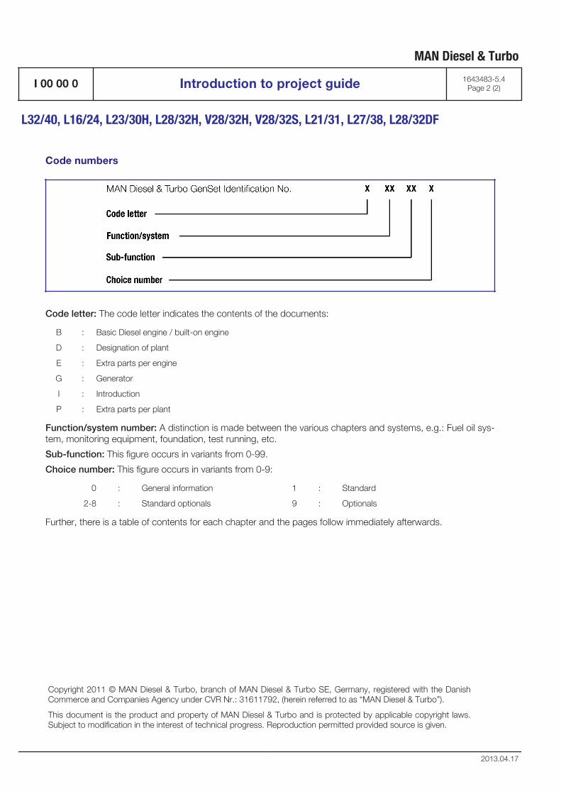
Code numbers
Code letter: The code letter indicates the contents of the documents:
B : Basic Diesel engine / built-on engine
D : Designation of plant
E : Extra parts per engine
G : Generator
I : Introduction
P : Extra parts per plant
Function/system number: A distinction is made between the various chapters and systems, e.g.: Fuel oil sys-tem, monitoring equipment, foundation, test running, etc.
Sub-function: This figure occurs in variants from 0-99.
Choice number: This figure occurs in variants from 0-9:
0 : General information 1 : Standard
2-8 : Standard optionals 9 : Optionals
Further, there is a table of contents for each chapter and the pages follow immediately afterwards.
Copyright 2011 © MAN Diesel & Turbo, branch of MAN Diesel & Turbo SE, Germany, registered with the DanishCommerce and Companies Agency under CVR Nr.: 31611792, (herein referred to as “MAN Diesel & Turbo”).
This document is the product and property of MAN Diesel & Turbo and is protected by applicable copyright laws.Subject to modification in the interest of technical progress. Reproduction permitted provided source is given.
MAN Diesel & Turbo
I 00 00 0 Introduction to project guide 1643483-5.4Page 2 (2)
L32/40, L16/24, L23/30H, L28/32H, V28/32H, V28/32S, L21/31, L27/38, L28/32DF
2013.04.17
Description
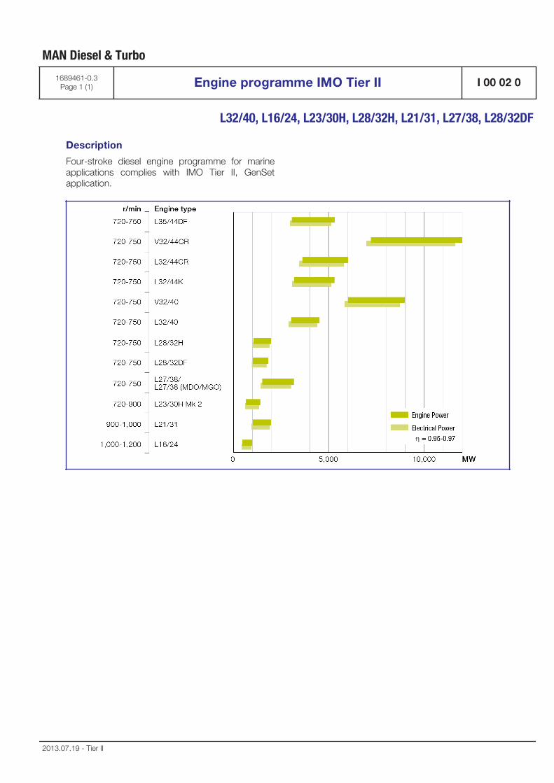
Four-stroke diesel engine programme for marineapplications complies with IMO Tier II, GenSetapplication.
MAN Diesel & Turbo
1689461-0.3Page 1 (1) Engine programme IMO Tier II I 00 02 0
L32/40, L16/24, L23/30H, L28/32H, L21/31, L27/38, L28/32DF
2013.07.19 - Tier II

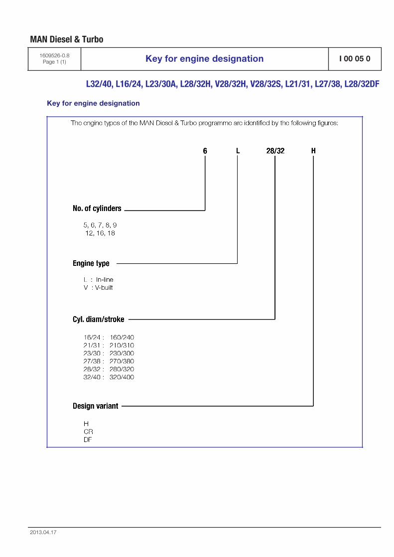
Key for engine designation
MAN Diesel & Turbo
1609526-0.8Page 1 (1) Key for engine designation I 00 05 0
L32/40, L16/24, L23/30A, L28/32H, V28/32H, V28/32S, L21/31, L27/38, L28/32DF
2013.04.17

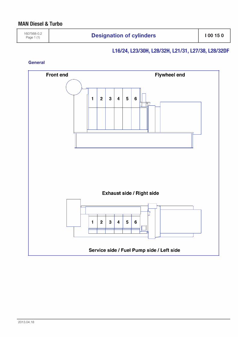
General
MAN Diesel & Turbo
1607568-0.2Page 1 (1) Designation of cylinders I 00 15 0
L16/24, L23/30H, L28/32H, L21/31, L27/38, L28/32DF
2013.04.18

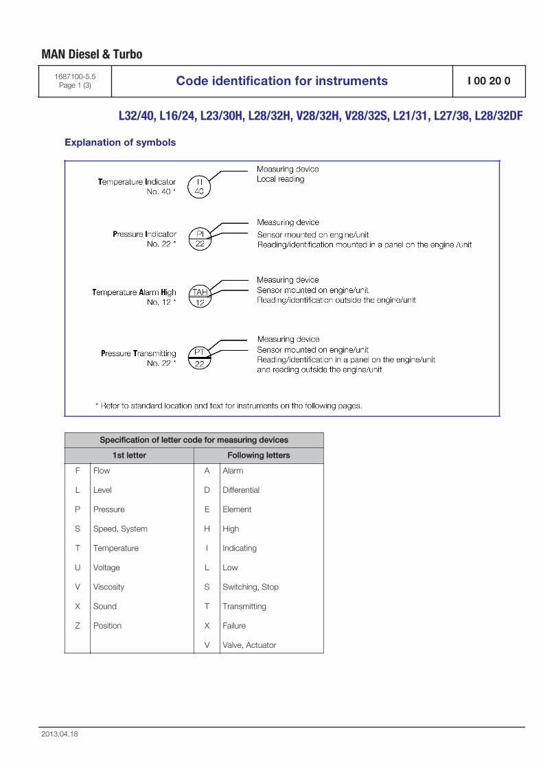
Explanation of symbols
Specification of letter code for measuring devices
1st letter Following letters
F
L
P
S
T
U
V
X
Z
Flow
Level
Pressure
Speed, System
Temperature
Voltage
Viscosity
Sound
Position
A
D
E
H
I
L
S
T
X
V
Alarm
Differential
Element
High
Indicating
Low
Switching, Stop
Transmitting
Failure
Valve, Actuator
MAN Diesel & Turbo
1687100-5.5Page 1 (3) Code identification for instruments I 00 20 0
L32/40, L16/24, L23/30H, L28/32H, V28/32H, V28/32S, L21/31, L27/38, L28/32DF
2013.04.18
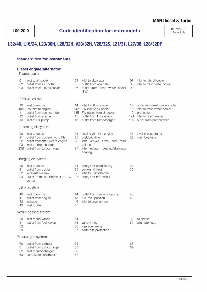
Standard text for instruments
Diesel engine/alternatorLT water system
010203
inlet to air cooleroutlet from air cooleroutlet from lub. oil cooler
040506
inlet to alternatoroutlet from alternatoroutlet from fresh water cooler(SW)
070809
inlet to lub. oil coolerinlet to fresh water cooler
HT water system
1010A111213
inlet to engineFW inlet to engineoutlet from each cylinderoutlet from engineinlet to HT pump
1414A14B1516
inlet to HT air coolerFW inlet to air coolerFW outlet from air cooleroutlet from HT systemoutlet from turbocharger
171819
19A19B
outlet from fresh water coolerinlet to fresh water coolerpreheaterinlet to prechamberoutlet from prechamber
Lubricating oil system
20212223
23B
inlet to cooleroutlet from cooler/inlet to filteroutlet from filter/inlet to engineinlet to turbochargeroutlet from turbocharger
242526
27
sealing oil - inlet engineprelubricatinginlet rocker arms and rollerguidesintermediate bearing/alternatorbearing
2829
level in base framemain bearings
Charging air system
30313233
inlet to cooleroutlet from coolerjet assist systemoutlet from TC filter/inlet to TCcompr.
34353637
charge air conditioningsurplus air inletinlet to turbochargercharge air from mixer
3839
Fuel oil system
40414243
inlet to engineoutlet from engineleakageinlet to filter
44454647
outlet from sealing oil pumpfuel-rack positioninlet to prechamber
4849
Nozzle cooling system
50515253
inlet to fuel valvesoutlet from fuel valves
54555657
valve timinginjection timingearth/diff. protection
5859
oil splashalternator load
Exhaust gas system
60616263
outlet from cylinderoutlet from turbochargerinlet to turbochargercombustion chamber
64656667
6869
MAN Diesel & Turbo
I 00 20 0 Code identification for instruments 1687100-5.5Page 2 (3)
L32/40, L16/24, L23/30H, L28/32H, V28/32H, V28/32S, L21/31, L27/38, L28/32DF
2013.04.18
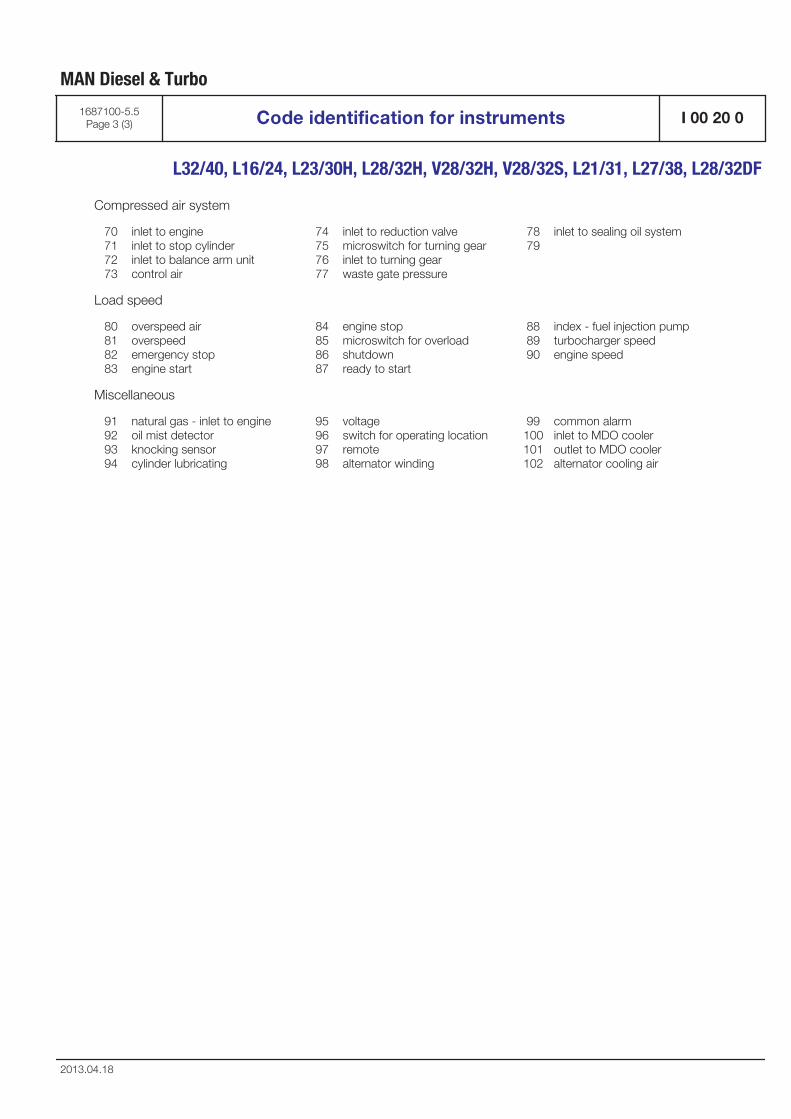
Compressed air system
70717273
inlet to engineinlet to stop cylinderinlet to balance arm unitcontrol air
74757677
inlet to reduction valvemicroswitch for turning gearinlet to turning gearwaste gate pressure
7879
inlet to sealing oil system
Load speed
80818283
overspeed airoverspeedemergency stopengine start
84858687
engine stopmicroswitch for overloadshutdownready to start
888990
index - fuel injection pumpturbocharger speedengine speed
Miscellaneous
91929394
natural gas - inlet to engineoil mist detectorknocking sensorcylinder lubricating
95969798
voltageswitch for operating locationremotealternator winding
99100101102
common alarminlet to MDO cooleroutlet to MDO cooleralternator cooling air
MAN Diesel & Turbo
1687100-5.5Page 3 (3) Code identification for instruments I 00 20 0
L32/40, L16/24, L23/30H, L28/32H, V28/32H, V28/32S, L21/31, L27/38, L28/32DF
2013.04.18

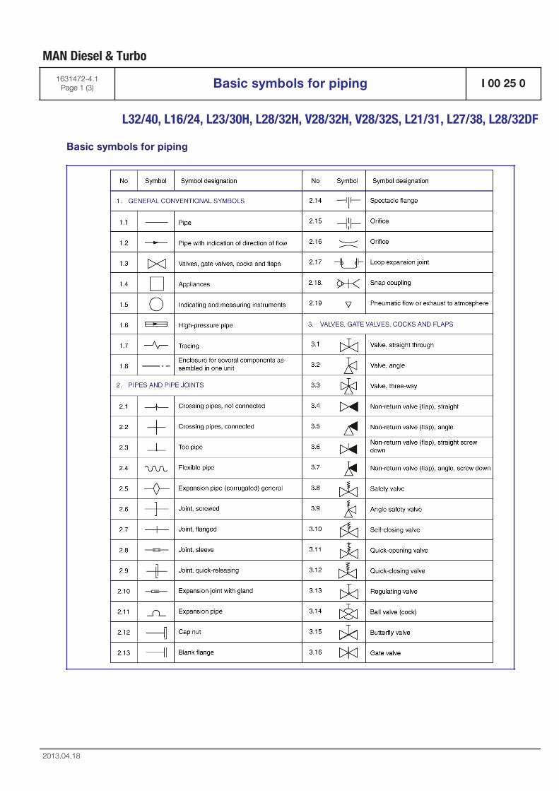
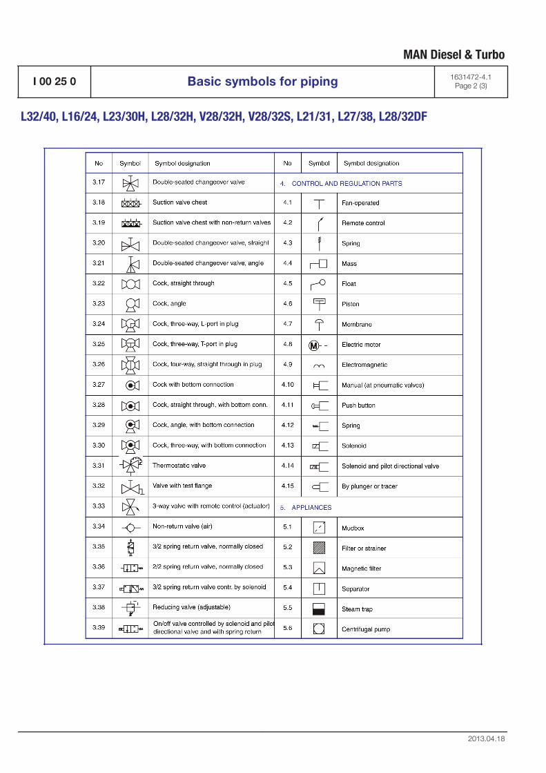
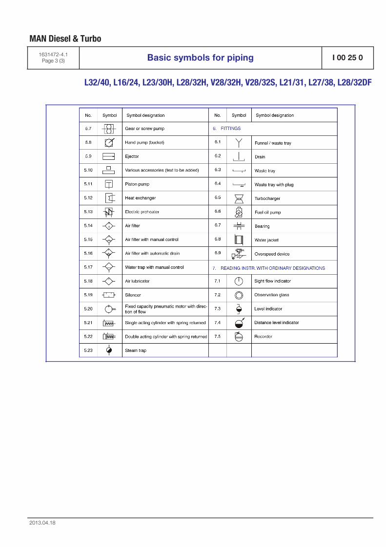
Basic symbols for piping
MAN Diesel & Turbo
1631472-4.1Page 1 (3) Basic symbols for piping I 00 25 0
L32/40, L16/24, L23/30H, L28/32H, V28/32H, V28/32S, L21/31, L27/38, L28/32DF
2013.04.18
MAN Diesel & Turbo
I 00 25 0 Basic symbols for piping 1631472-4.1Page 2 (3)
L32/40, L16/24, L23/30H, L28/32H, V28/32H, V28/32S, L21/31, L27/38, L28/32DF
2013.04.18
MAN Diesel & Turbo
1631472-4.1Page 3 (3) Basic symbols for piping I 00 25 0
L32/40, L16/24, L23/30H, L28/32H, V28/32H, V28/32S, L21/31, L27/38, L28/32DF
2013.04.18


General information
D 10

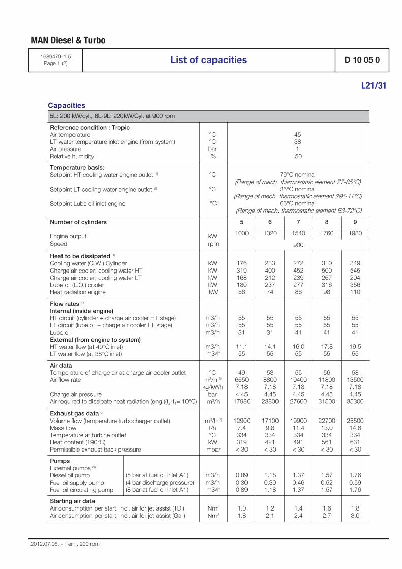
Capacities5L: 200 kW/cyl., 6L-9L: 220kW/Cyl. at 900 rpm
Reference condition : TropicAir temperature LT-water temperature inlet engine (from system) Air pressure Relative humidity
°C °C bar %
45 38 1 50
Temperature basis:Setpoint HT cooling water engine outlet 1)
Setpoint LT cooling water engine outlet 2)
Setpoint Lube oil inlet engine
°C
°C
°C
79°C nominal (Range of mech. thermostatic element 77-85°C)
35°C nominal (Range of mech. thermostatic element 29°-41°C)
66°C nominal (Range of mech. thermostatic element 63-72°C)
Number of cylinders
Engine output Speed
kW rpm
5 6 7 8 9
1000 1320 1540 1760 1980
900
Heat to be dissipated 3)
Cooling water (C.W.) Cylinder Charge air cooler; cooling water HT Charge air cooler; cooling water LT Lube oil (L.O.) cooler Heat radiation engine
kW kW kW kW kW
17631916818056
23340021223774
27245223927786
31050026731698
349545294356110
Flow rates 4)
Internal (inside engine) HT circuit (cylinder + charge air cooler HT stage) LT circuit (lube oil + charge air cooler LT stage) Lube oil External (from engine to system) HT water flow (at 40°C inlet) LT water flow (at 38°C inlet)
m3/h m3/h m3/h
m3/h m3/h
555531
11.155
555531
14.155
555541
16.055
555541
17.855
555541
19.555
Air dataTemperature of charge air at charge air cooler outlet Air flow rate
Charge air pressure Air required to dissipate heat radiation (eng.)(t2-t1= 10°C)
°C m3/h 5)
kg/kWh bar m3/h
4966507.184.45
17980
5388007.184.45
23800
55104007.184.45
27600
56118007.184.45
31500
58135007.184.45
35300
Exhaust gas data 6)
Volume flow (temperature turbocharger outlet) Mass flow Temperature at turbine outlet Heat content (190°C) Permissible exhaust back pressure
m3/h 7)
t/h °C kW mbar
129007.4334319< 30
171009.8334421< 30
1990011.4334491< 30
2270013.0334561< 30
2550014.6334631< 30
PumpsExternal pumps 8) Diesel oil pump Fuel oil supply pump Fuel oil circulating pump
(5 bar at fuel oil inlet A1)(4 bar discharge pressure)(8 bar at fuel oil inlet A1)
m3/h m3/h m3/h
0.890.300.89
1.180.391.18
1.370.461.37
1.570.521.57
1.760.591.76
Starting air dataAir consumption per start, incl. air for jet assist (TDI)Air consumption per start, incl. air for jet assist (Gali)
Nm3
Nm31.01.8
1.22.1
1.42.4
1.62.7
1.83.0
MAN Diesel & Turbo
1689479-1.5Page 1 (2) List of capacities D 10 05 0
L21/31
2012.07.08. - Tier II, 900 rpm

1)2)3)4)5)6)7)8)
HT cooling water flows first through HT stage charge air cooler, then through water jacket and cylinder head, watertemperature outlet engine regulated by mechanical thermostat.LT cooling water flows first through LT stage charge air cooler, then through lube oil cooler, water temperatureoutlet engine regulated by mechanical thermostat.Tolerance: + 10% for rating coolers, - 15% for heat recovery.Basic values for layout of the coolers.Under above mentioned reference conditions.Tolerance: quantity +/- 5%, temperature +/- 20°C.Under below mentioned temperature at turbine outlet and pressure according above mentioned reference condi-tions.Tolerance of the pumps' delivery capacities must be considered by the manufactures.
MAN Diesel & Turbo
D 10 05 0 List of capacities 1689479-1.5Page 2 (2)
L21/31
2012.07.08. - Tier II, 900 rpm
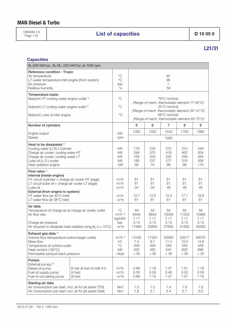
Capacities5L:200 kW/cyl., 6L-9L: 220 kW/Cyl. at 1000 rpm
Reference condition : TropicAir temperature LT-water temperature inlet engine (from system) Air pressure Relative humidity
°C °C bar %
45 38 1 50
Temperature basis:Setpoint HT cooling water engine outlet 1)
Setpoint LT cooling water engine outlet 2)
Setpoint Lube oil inlet engine
°C
°C
°C
79°C nominal (Range of mech. thermostatic element 77-85°C)
35°C nominal (Range of mech. thermostatic element 29°-41°C)
66°C nominal (Range of mech. thermostatic element 63-72°C)
Number of cylinders
Engine output Speed
kW rpm
5 6 7 8 9
1000 1320 1540 1760 1980
1000
Heat to be dissipated 3)
Cooling water (C.W.) Cylinder Charge air cooler; cooling water HT Charge air cooler; cooling water LT Lube oil (L.O.) cooler Heat radiation engine
kW kW kW kW kW
17629416318056
23337020523774
27241823227786
31046225831698
349504284356110
Flow rates 4)
Internal (inside engine) HT circuit (cylinder + charge air cooler HT stage) LT circuit (lube oil + charge air cooler LT stage) Lube oil External (from engine to system) HT water flow (at 40°C inlet) LT water flow (at 38°C inlet)
m3/h m3/h m3/h
m3/h m3/h
616134
10.761
616134
13.561
616146
15.461
616146
17.161
616146
18.861
Air dataTemperature of charge air at charge air cooler outlet Air flow rate
Charge air pressure Air required to dissipate heat radiation (eng.)(t2-t1= 10°C)
°C m3/h 5)
kg/kWh bar m3/h
4965487.174.13
17980
5286447.174.13
23800
54100847.174.13
27600
55115257.174.13
31500
56129657.174.13
35300
Exhaust gas data 6)
Volume flow (temperature turbocharger outlet) Mass flow Temperature at turbine outlet Heat content (190°C) Permissible exhaust back pressure
m3/h 7)
t/h °C kW mbar
131627.4349352< 30
173249.7349463< 30
2036011.4349544< 30
2321713.0349620< 30
2607514.6349696< 30
PumpsExternal pumps 8) Diesel oil pump Fuel oil supply pump Fuel oil circulating pump
(5 bar at fuel oil inlet A1)(4 bar)(8 bar)
m3/h m3/h m3/h
0.890.300.89
1.180.391.18
1.370.461.37
1.570.521.57
1.760.591.76
Starting air dataAir consumption per start, incl. air for jet assist (TDI) Air consumption per start, incl. air for jet assist (Gali)
Nm3
Nm31.01.8
1.22.1
1.42.4
1.62.7
1.83.0
MAN Diesel & Turbo
1689499-4.5Page 1 (2) List of capacities D 10 05 0
L21/31
2012.07.08. - Tier II, 1000 rpm
1)2)3)4)5)6)7)8)
HT cooling water flows first through HT stage charge air cooler, then through water jacket and cylinder head, watertemperature outlet engine regulated by mechanical thermostat.LT cooling water flows first through LT stage charge air cooler, then through lube oil cooler, water temperatureoutlet engine regulated by mechanical thermostat.Tolerance: + 10% for rating coolers, - 15% for heat recovery.Basic values for layout of the coolers.Under above mentioned reference conditions.Tolerance: quantity +/- 5%, temperature +/- 20°C.Under below mentioned temperature at turbine outlet and pressure according above mentioned reference condi-tions.Tolerance of the pumps' delivery capacities must be considered by the manufactures.
MAN Diesel & Turbo
D 10 05 0 List of capacities 1689499-4.5Page 2 (2)
L21/31
2012.07.08. - Tier II, 1000 rpm
General
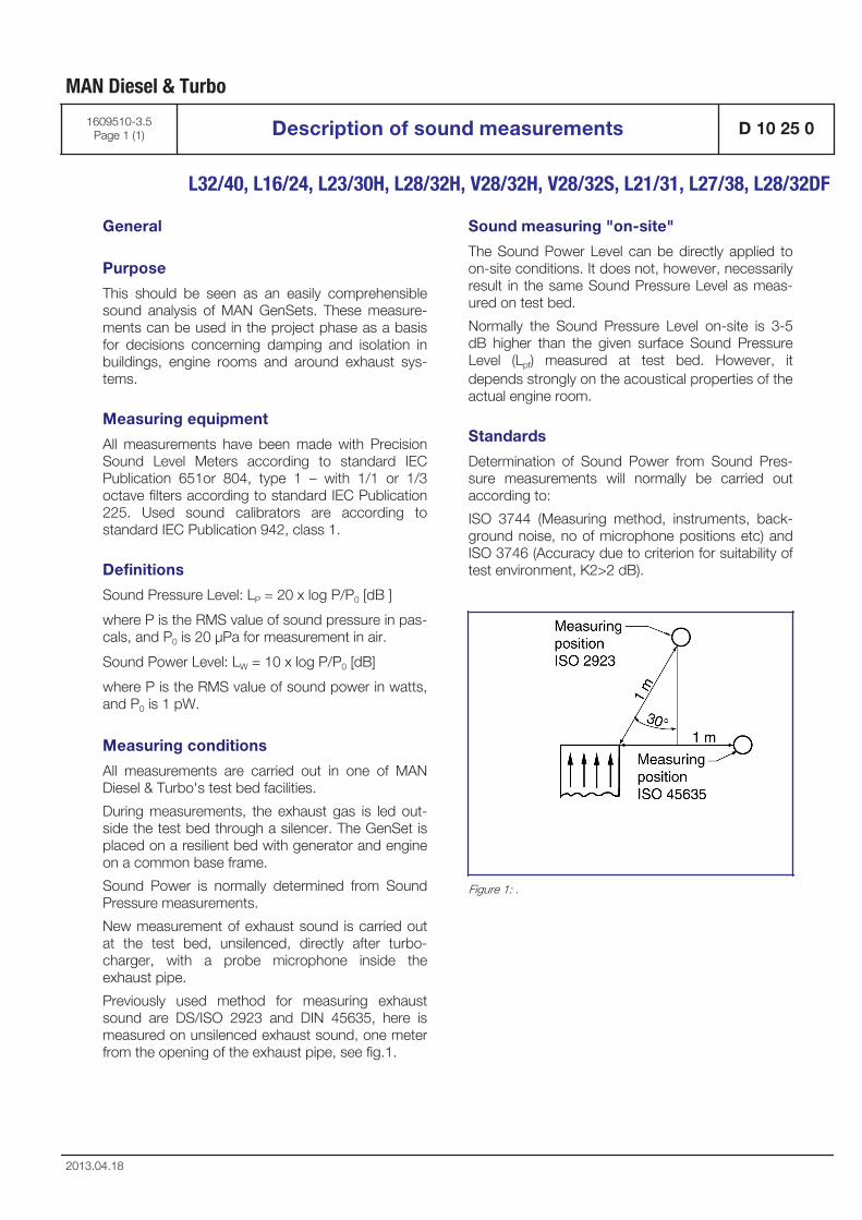
Purpose
This should be seen as an easily comprehensiblesound analysis of MAN GenSets. These measure-ments can be used in the project phase as a basisfor decisions concerning damping and isolation inbuildings, engine rooms and around exhaust sys-tems.
Measuring equipment
All measurements have been made with PrecisionSound Level Meters according to standard IECPublication 651or 804, type 1 – with 1/1 or 1/3octave filters according to standard IEC Publication225. Used sound calibrators are according tostandard IEC Publication 942, class 1.
Definitions
Sound Pressure Level: LP = 20 x log P/P0 [dB ]
where P is the RMS value of sound pressure in pas-cals, and P0 is 20 μPa for measurement in air.
Sound Power Level: LW = 10 x log P/P0 [dB]
where P is the RMS value of sound power in watts,and P0 is 1 pW.
Measuring conditions
All measurements are carried out in one of MANDiesel & Turbo's test bed facilities.
During measurements, the exhaust gas is led out-side the test bed through a silencer. The GenSet isplaced on a resilient bed with generator and engineon a common base frame.
Sound Power is normally determined from SoundPressure measurements.
New measurement of exhaust sound is carried outat the test bed, unsilenced, directly after turbo-charger, with a probe microphone inside theexhaust pipe.
Previously used method for measuring exhaustsound are DS/ISO 2923 and DIN 45635, here ismeasured on unsilenced exhaust sound, one meterfrom the opening of the exhaust pipe, see fig.1.
Sound measuring "on-site"
The Sound Power Level can be directly applied toon-site conditions. It does not, however, necessarilyresult in the same Sound Pressure Level as meas-ured on test bed.
Normally the Sound Pressure Level on-site is 3-5dB higher than the given surface Sound PressureLevel (Lpf) measured at test bed. However, itdepends strongly on the acoustical properties of theactual engine room.
Standards
Determination of Sound Power from Sound Pres-sure measurements will normally be carried outaccording to:
ISO 3744 (Measuring method, instruments, back-ground noise, no of microphone positions etc) andISO 3746 (Accuracy due to criterion for suitability oftest environment, K2>2 dB).
Figure 1: .
MAN Diesel & Turbo
1609510-3.5Page 1 (1) Description of sound measurements D 10 25 0
L32/40, L16/24, L23/30H, L28/32H, V28/32H, V28/32S, L21/31, L27/38, L28/32DF
2013.04.18

Introduction
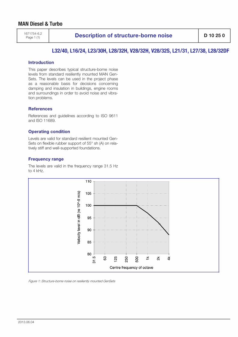
This paper describes typical structure-borne noiselevels from standard resiliently mounted MAN Gen-Sets. The levels can be used in the project phaseas a reasonable basis for decisions concerningdamping and insulation in buildings, engine roomsand surroundings in order to avoid noise and vibra-tion problems.
References
References and guidelines according to ISO 9611and ISO 11689.
Operating condition
Levels are valid for standard resilient mounted Gen-Sets on flexible rubber support of 55° sh (A) on rela-tively stiff and well-supported foundations.
Frequency range
The levels are valid in the frequency range 31.5 Hzto 4 kHz.
Figure 1: Structure-borne noise on resiliently mounted GenSets
MAN Diesel & Turbo
1671754-6.2Page 1 (1) Description of structure-borne noise D 10 25 0
L32/40, L16/24, L23/30H, L28/32H, V28/32H, V28/32S, L21/31, L27/38, L28/32DF
2013.06.04

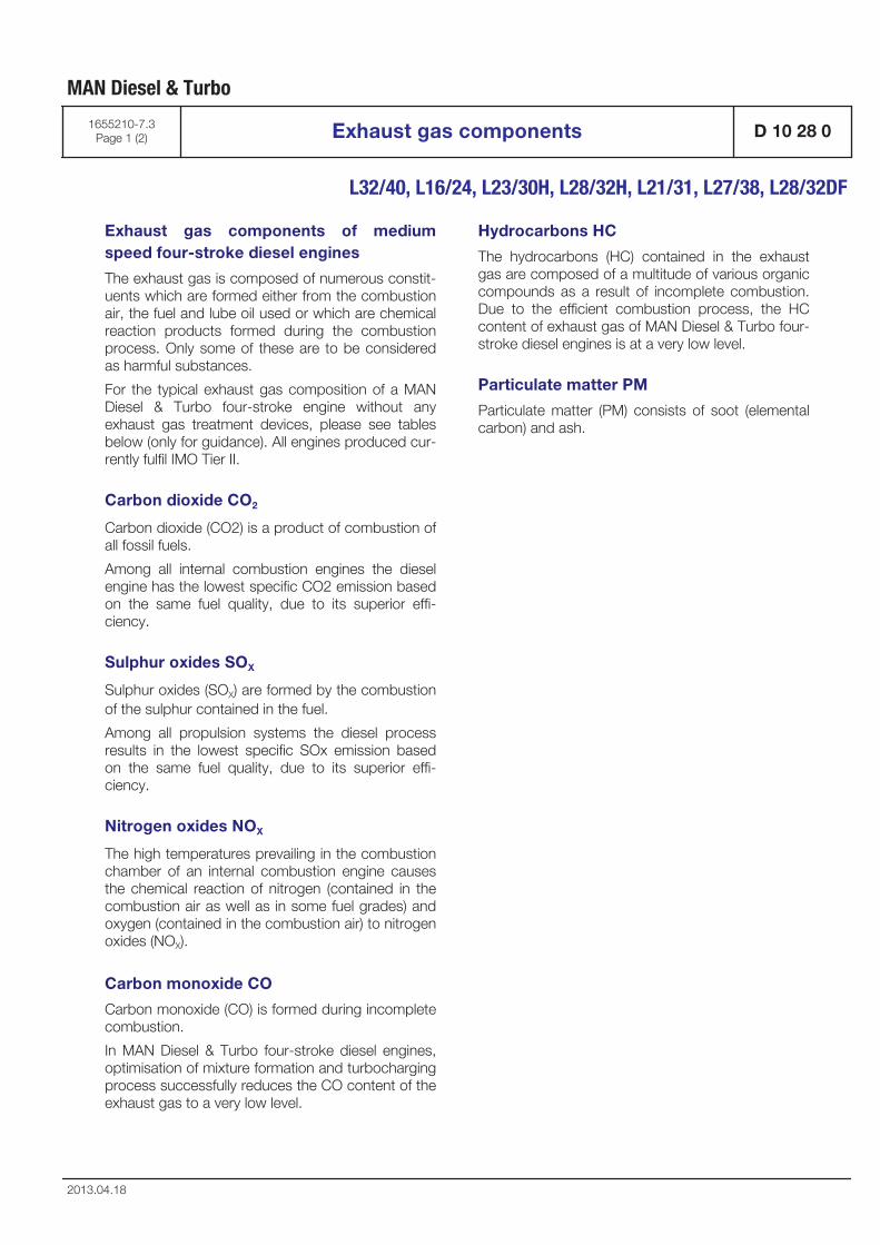
Exhaust gas components of mediumspeed four-stroke diesel engines
The exhaust gas is composed of numerous constit-uents which are formed either from the combustionair, the fuel and lube oil used or which are chemicalreaction products formed during the combustionprocess. Only some of these are to be consideredas harmful substances.
For the typical exhaust gas composition of a MANDiesel & Turbo four-stroke engine without anyexhaust gas treatment devices, please see tablesbelow (only for guidance). All engines produced cur-rently fulfil IMO Tier II.
Carbon dioxide CO2
Carbon dioxide (CO2) is a product of combustion ofall fossil fuels.
Among all internal combustion engines the dieselengine has the lowest specific CO2 emission basedon the same fuel quality, due to its superior effi-ciency.
Sulphur oxides SOX
Sulphur oxides (SOX) are formed by the combustionof the sulphur contained in the fuel.
Among all propulsion systems the diesel processresults in the lowest specific SOx emission basedon the same fuel quality, due to its superior effi-ciency.
Nitrogen oxides NOX
The high temperatures prevailing in the combustionchamber of an internal combustion engine causesthe chemical reaction of nitrogen (contained in thecombustion air as well as in some fuel grades) andoxygen (contained in the combustion air) to nitrogenoxides (NOX).
Carbon monoxide CO
Carbon monoxide (CO) is formed during incompletecombustion.
In MAN Diesel & Turbo four-stroke diesel engines,optimisation of mixture formation and turbochargingprocess successfully reduces the CO content of theexhaust gas to a very low level.
Hydrocarbons HC
The hydrocarbons (HC) contained in the exhaustgas are composed of a multitude of various organiccompounds as a result of incomplete combustion.Due to the efficient combustion process, the HCcontent of exhaust gas of MAN Diesel & Turbo four-stroke diesel engines is at a very low level.
Particulate matter PM
Particulate matter (PM) consists of soot (elementalcarbon) and ash.
MAN Diesel & Turbo
1655210-7.3Page 1 (2) Exhaust gas components D 10 28 0
L32/40, L16/24, L23/30H, L28/32H, L21/31, L27/38, L28/32DF
2013.04.18
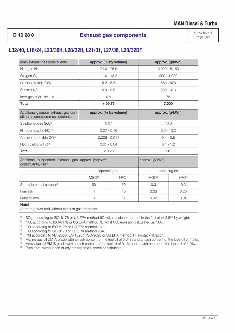
Main exhaust gas constituents approx. [% by volume] approx. [g/kWh]
Nitrogen N2 74.0 - 76.0 5,020 - 5,160
Oxygen O2 11.6 - 13.2 900 - 1,030
Carbon dioxide CO2 5.2 - 5.8 560 - 620
Steam H2O 5.9 - 8.6 260 - 370
Inert gases Ar, Ne, He ... 0.9 75
Total > 99.75 7,000
Additional gaseous exhaust gas con-stituents considered as pollutants
approx. [% by volume] approx. [g/kWh]
Sulphur oxides SOX1) 0.07 10.0
Nitrogen oxides NOX2) 0.07 - 0.10 8.0 - 10.0
Carbon monoxide CO3) 0.006 - 0.011 0.4 - 0.8
Hydrocarbons HC4) 0.01 - 0.04 0.4 - 1.2
Total < 0.25 26
Additional suspended exhaust gasconstituents, PM5)
approx. [mg/Nm3] approx. [g/kWh]
operating on operating on
MGO6) HFO7) MGO6) HFO7)
Soot (elemental carbon)8) 50 50 0.3 0.3
Fuel ash 4 40 0.03 0.25
Lube oil ash 3 8 0.02 0.04
Note!At rated power and without exhaust gas treatment.
1)
2)
3)
4)
5)
6)
7)
8)
SOX, according to ISO-8178 or US EPA method 6C, with a sulphur content in the fuel oil of 2.5% by weight.NOX according to ISO-8178 or US EPA method 7E, total NOX emission calculated as NO2.CO according to ISO-8178 or US EPA method 10.HC according to ISO-8178 or US EPA method 25A.PM according to VDI-2066, EN-13284, ISO-9096 or US EPA method 17; in-stack filtration.Marine gas oil DM-A grade with an ash content of the fuel oil of 0.01% and an ash content of the lube oil of 1.5%.Heavy fuel oil RM-B grade with an ash content of the fuel oil of 0.1% and an ash content of the lube oil of 4.0%.Pure soot, without ash or any other particle-borne constituents.
MAN Diesel & Turbo
D 10 28 0 Exhaust gas components 1655210-7.3Page 2 (2)
L32/40, L16/24, L23/30H, L28/32H, L21/31, L27/38, L28/32DF
2013.04.18
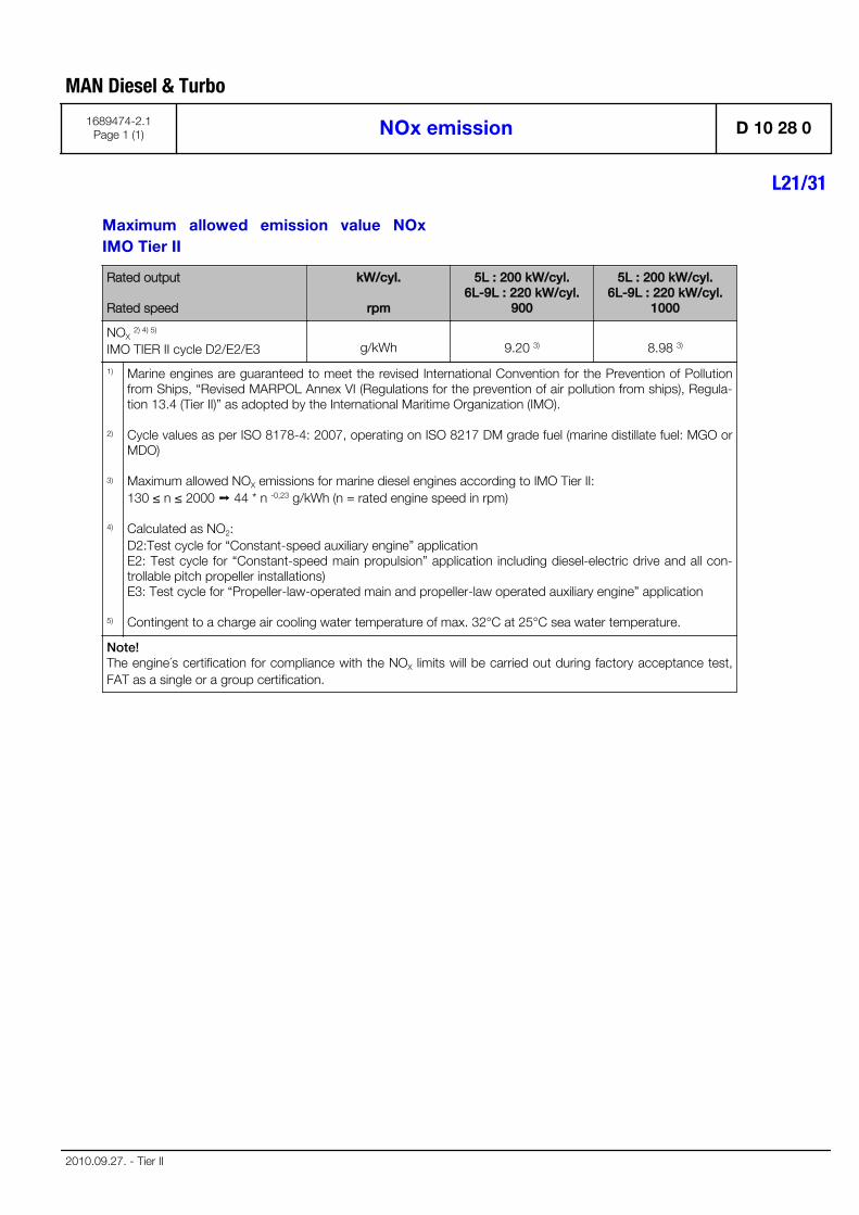
Maximum allowed emission value NOxIMO Tier II
Rated output
Rated speed
kW/cyl.
rpm
5L : 200 kW/cyl.6L-9L : 220 kW/cyl.
900
5L : 200 kW/cyl.6L-9L : 220 kW/cyl.
1000
NOX 2) 4) 5)
IMO TIER II cycle D2/E2/E3 g/kWh 9.20 3) 8.98 3)
1)
2)
3)
4)
5)
Marine engines are guaranteed to meet the revised International Convention for the Prevention of Pollutionfrom Ships, “Revised MARPOL Annex VI (Regulations for the prevention of air pollution from ships), Regula-tion 13.4 (Tier II)” as adopted by the International Maritime Organization (IMO).
Cycle values as per ISO 8178-4: 2007, operating on ISO 8217 DM grade fuel (marine distillate fuel: MGO orMDO)
Maximum allowed NOX emissions for marine diesel engines according to IMO Tier II: 130 ≤ n ≤ 2000 ➝ 44 * n -0,23 g/kWh (n = rated engine speed in rpm)
Calculated as NO2: D2:Test cycle for “Constant-speed auxiliary engine” application E2: Test cycle for “Constant-speed main propulsion” application including diesel-electric drive and all con-trollable pitch propeller installations) E3: Test cycle for “Propeller-law-operated main and propeller-law operated auxiliary engine” application
Contingent to a charge air cooling water temperature of max. 32°C at 25°C sea water temperature.
Note! The engine´s certification for compliance with the NOX limits will be carried out during factory acceptance test,FAT as a single or a group certification.
MAN Diesel & Turbo
1689474-2.1Page 1 (1) NOx emission D 10 28 0
L21/31
2010.09.27. - Tier II

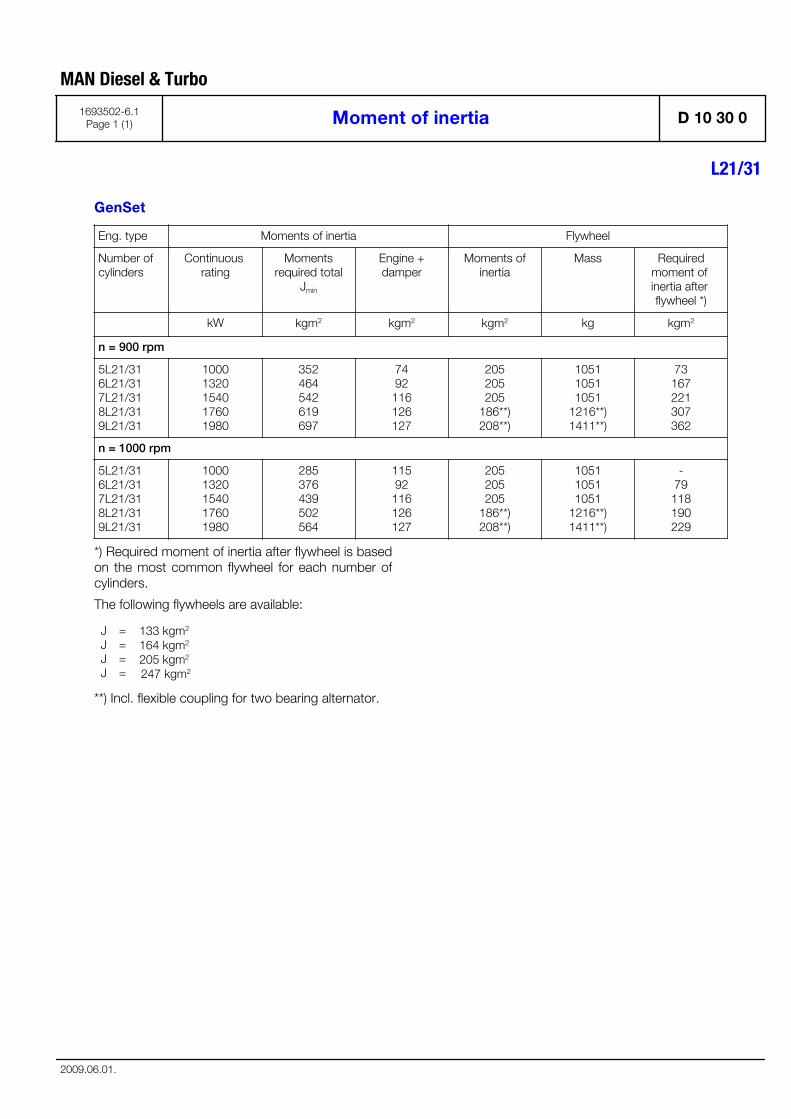
GenSet
Eng. type Moments of inertia Flywheel
Number of cylinders
Continuous rating
Momentsrequired total
Jmin
Engine +damper
Moments ofinertia
Mass Requiredmoment of inertia after flywheel *)
kW kgm2 kgm2 kgm2 kg kgm2
n = 900 rpm
5L21/316L21/317L21/318L21/319L21/31
10001320154017601980
352464542619697
7492116126127
205205205
186**)208**)
105110511051
1216**)1411**)
73167221307362
n = 1000 rpm
5L21/316L21/317L21/318L21/319L21/31
10001320154017601980
285376439502564
11592
116126127
205205205
186**)208**)
105110511051
1216**)1411**)
-79
118190229
*) Required moment of inertia after flywheel is basedon the most common flywheel for each number ofcylinders.
The following flywheels are available:
JJJJ
====
133 kgm2 164 kgm2 205 kgm2 247 kgm2
**) Incl. flexible coupling for two bearing alternator.
MAN Diesel & Turbo
1693502-6.1Page 1 (1) Moment of inertia D 10 30 0
L21/31
2009.06.01.

Green Passport
In 2009 IMO adopted the „Hong Kong InternationalConvention for the Safe and Environmentally SoundRecycling of Ships, 2009“.
Until this convention enters into force the recom-mendatory guidelines “Resolution A.962(23)” (adop-ted 2003) apply. This resolution has been imple-mented by some classification societies as “GreenPassport”.
MAN Diesel & Turbo is able to provide a list of haz-ardous materials complying with the requirementsof the IMO Convention. This list is accepted by clas-sification societies as a material declaration for“Green Passport”.
This material declaration can be provided onrequest.
MAN Diesel & Turbo
1699985-1.1Page 1 (1) Green Passport D 10 33 0
L32/40, L16/24, L23/30H, L28/32H, V28/32H, V28/32S, L21/31, L27/38, L28/32DF
2013.04.18

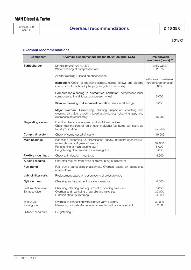
Overhaul recommendations
Component Overhaul Recommendations for 1000/1200 rpm, MDO Time between overhauls (hours) **
Turbocharger Dry cleaning of turbine sideWater washing of compressor side
Air filter cleaning : Based on observations.
Inspection: Check all mounting screws, casing screws and pipelineconnections for tight fit by tapping, retighten if necessary
Compressor cleaning in dismantled condition: compressor innercomponents, final diffusor, compressor wheel
Silencer cleaning in dismantled condition: silencer felt linings
Major overhaul: Dismantling, cleaning, inspection, checking andcleaning cartridge, checking bearing clearances, checking gaps andclearances on reassembly
every week 25-75
with new or overhauledturbocharger once aft
1000
8,000
8,000
16,000
Regulating system Function check of overspeed and shutdown devices. Check that the control rod of each individual fuel pump can easily goto "stop" position monthly
Compr. air system Check of compressed air system 16,000
Main bearings Inspection according to classification survey, normally after 24.000running hours or 4 years of serviceRetightening of main bearing cap *Retightening of screws for counterweights *
32,000 8,000 8,000
Flexible mountings Check anti-vibration mountings 8,000
Autolog reading Only after request from class or dismounting of alternator
Fuel pump Fuel pump barrel/plunger assembly. Overhaul based on operationalobservations
Lub. oil filter cartr. Replacement based on observations of pressure drop
Cylinder head
Fuel injection valve Exhaust valve
Inlet valve Valve guide
Cylinder head nuts
Checking and adjustment of valve clearance
Checking, cleaning and adjustment of opening pressureOverhaul and regrinding of spindle and valve seatFunction check of rotorcap
Overhaul in connection with exhaust valve overhaulMeasuring of inside diameter in connection with valve overhaul
Retightening *
4,000
3,000 32,000 4,000
32,000 32,000
MAN Diesel & Turbo
3700308-6.0Page 1 (2) Overhaul recommendations D 10 35 0
L21/31
2013.09.23 - MDO
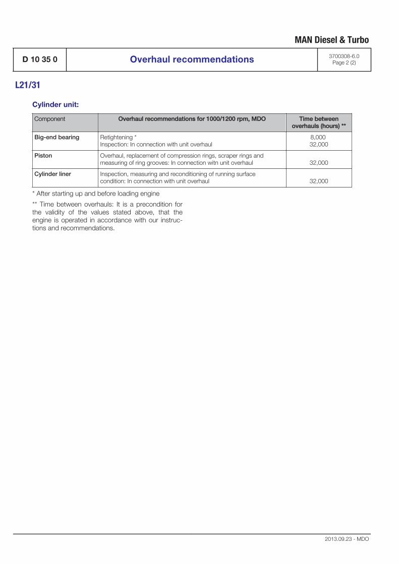
Cylinder unit:
Component Overhaul recommendations for 1000/1200 rpm, MDO Time betweenoverhauls (hours) **
Big-end bearing Retightening *Inspection: In connection with unit overhaul
8,000 32,000
Piston Overhaul, replacement of compression rings, scraper rings and measuring of ring grooves: In connection witn unit overhaul 32,000
Cylinder liner Inspection, measuring and reconditioning of running surface condition: In connection with unit overhaul 32,000
* After starting up and before loading engine
** Time between overhauls: It is a precondition forthe validity of the values stated above, that theengine is operated in accordance with our instruc-tions and recommendations.
MAN Diesel & Turbo
D 10 35 0 Overhaul recommendations 3700308-6.0Page 2 (2)
L21/31
2013.09.23 - MDO
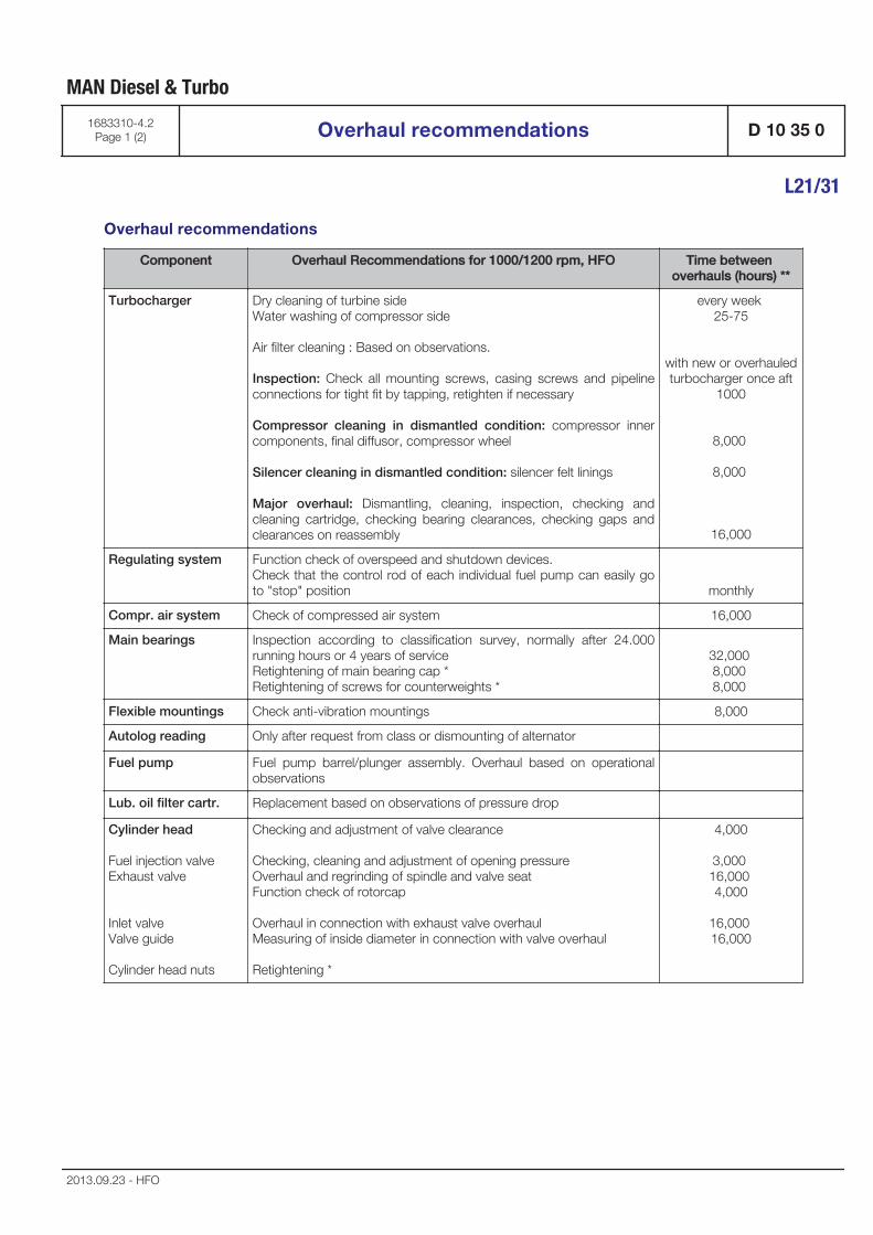
Overhaul recommendations
Component Overhaul Recommendations for 1000/1200 rpm, HFO Time between overhauls (hours) **
Turbocharger Dry cleaning of turbine sideWater washing of compressor side
Air filter cleaning : Based on observations.
Inspection: Check all mounting screws, casing screws and pipelineconnections for tight fit by tapping, retighten if necessary
Compressor cleaning in dismantled condition: compressor innercomponents, final diffusor, compressor wheel
Silencer cleaning in dismantled condition: silencer felt linings
Major overhaul: Dismantling, cleaning, inspection, checking andcleaning cartridge, checking bearing clearances, checking gaps andclearances on reassembly
every week 25-75
with new or overhauledturbocharger once aft
1000
8,000
8,000
16,000
Regulating system Function check of overspeed and shutdown devices. Check that the control rod of each individual fuel pump can easily goto "stop" position monthly
Compr. air system Check of compressed air system 16,000
Main bearings Inspection according to classification survey, normally after 24.000running hours or 4 years of serviceRetightening of main bearing cap *Retightening of screws for counterweights *
32,000 8,000 8,000
Flexible mountings Check anti-vibration mountings 8,000
Autolog reading Only after request from class or dismounting of alternator
Fuel pump Fuel pump barrel/plunger assembly. Overhaul based on operationalobservations
Lub. oil filter cartr. Replacement based on observations of pressure drop
Cylinder head
Fuel injection valve Exhaust valve
Inlet valve Valve guide
Cylinder head nuts
Checking and adjustment of valve clearance
Checking, cleaning and adjustment of opening pressureOverhaul and regrinding of spindle and valve seatFunction check of rotorcap
Overhaul in connection with exhaust valve overhaulMeasuring of inside diameter in connection with valve overhaul
Retightening *
4,000
3,000 16,000 4,000
16,000 16,000
MAN Diesel & Turbo
1683310-4.2Page 1 (2) Overhaul recommendations D 10 35 0
L21/31
2013.09.23 - HFO

Cylinder unit:
Component Overhaul recommendations for 1000/1200 rpm, HFO Time betweenoverhauls (hours) **
Big-end bearing Retightening *Inspection: In connection with unit overhaul
8,000 16,000
Piston Overhaul, replacement of compression rings, scraper rings and measuring of ring grooves: In connection witn unit overhaul 16,000
Cylinder liner Inspection, measuring and reconditioning of running surface condition: In connection with unit overhaul 16,000
* After starting up and before loading engine
** Time between overhauls: It is a precondition forthe validity of the values stated above, that theengine is operated in accordance with our instruc-tions and recommendations.
MAN Diesel & Turbo
D 10 35 0 Overhaul recommendations 1683310-4.2Page 2 (2)
L21/31
2013.09.23 - HFO

Expected life timeComponents Operation on HFO
(hours)Operation on MDO
(hours)
Fuel injection valve 6,000 8,000
Exhaust valve 24,000 32,000
Inlet valve 24,000 32,000
Valve guide 24,000 32,000
Main bearing 36,000 64,000
Big-end bearing 24,000 64,000
Piston 60,000 96,000
Cylinder liner 60,000 96,000
Fuel pump 24,000 As required
It is a precondition for the validity of the values sta-ted above, that the engine is operated in accord-ance with our instructions and recommendations.
MAN Diesel & Turbo
1687150-7.1Page 1 (1) Expected life time D 10 35 0
L21/31
2013.09.23


Basic Diesel Engine
B 10

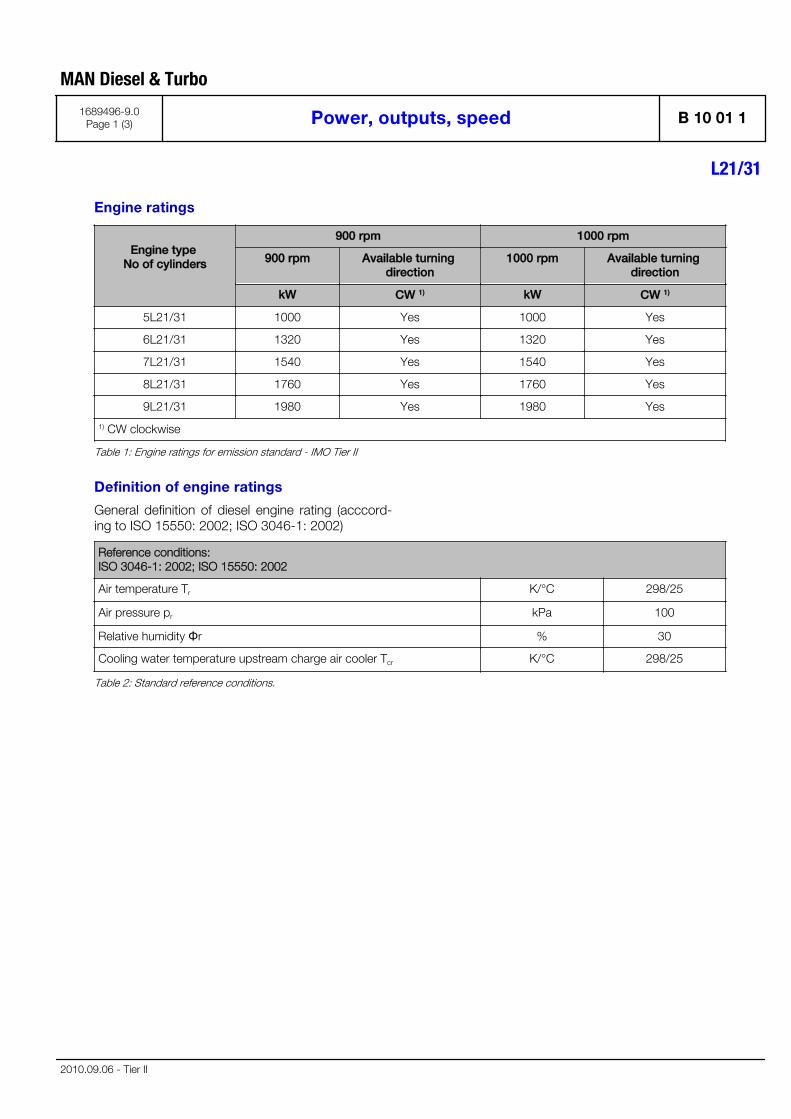
Engine ratings
Engine type No of cylinders
900 rpm 1000 rpm
900 rpm Available turning direction
1000 rpm Available turning direction
kW CW 1) kW CW 1)
5L21/31 1000 Yes 1000 Yes
6L21/31 1320 Yes 1320 Yes
7L21/31 1540 Yes 1540 Yes
8L21/31 1760 Yes 1760 Yes
9L21/31 1980 Yes 1980 Yes
1) CW clockwise
Table 1: Engine ratings for emission standard - IMO Tier II
Definition of engine ratings
General definition of diesel engine rating (acccord-ing to ISO 15550: 2002; ISO 3046-1: 2002)
Reference conditions: ISO 3046-1: 2002; ISO 15550: 2002
Air temperature Tr K/°C 298/25
Air pressure pr kPa 100
Relative humidity Φr % 30
Cooling water temperature upstream charge air cooler Tcr K/°C 298/25
Table 2: Standard reference conditions.
MAN Diesel & Turbo
1689496-9.0Page 1 (3) Power, outputs, speed B 10 01 1
L21/31
2010.09.06 - Tier II
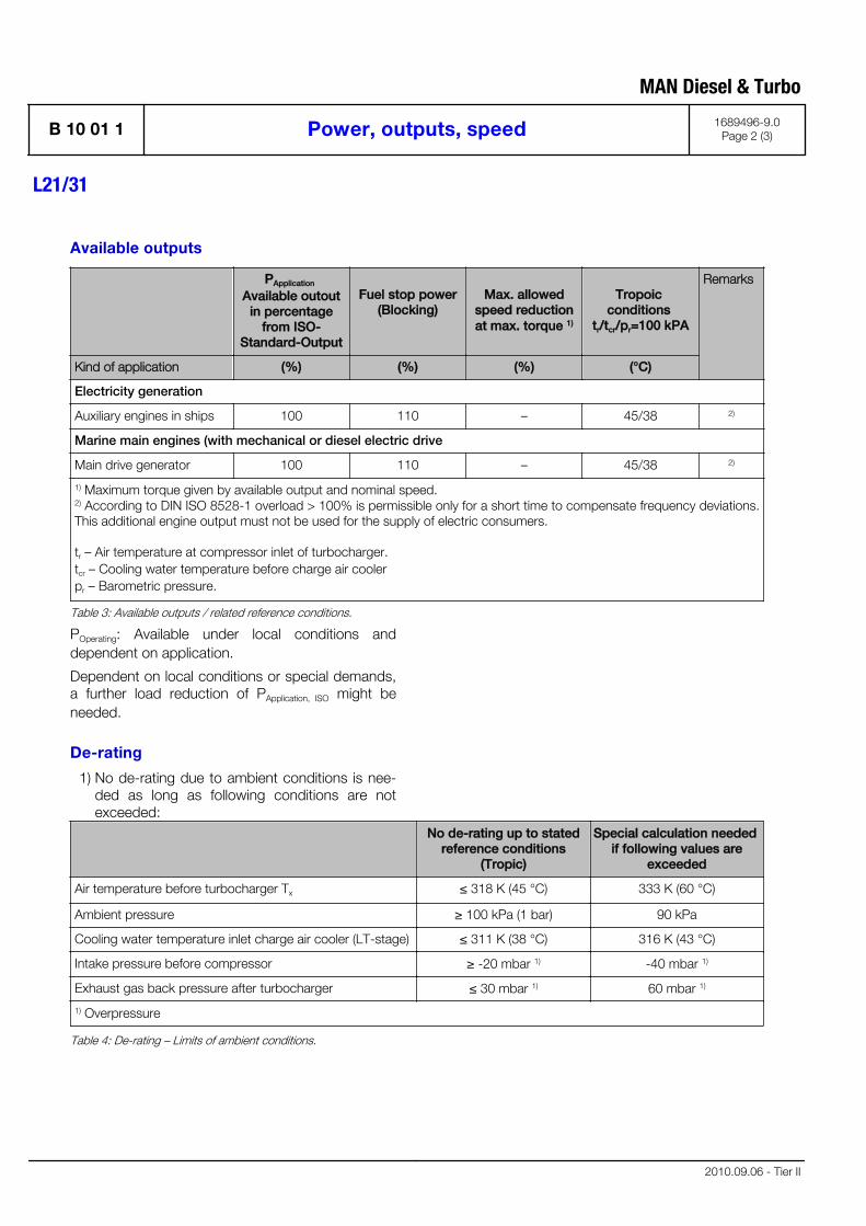
Available outputs
PApplication Available outout
in percentagefrom ISO-
Standard-Output
Fuel stop power(Blocking)
Max. allowedspeed reductionat max. torque 1)
Tropoic conditions
tr/tcr/pr=100 kPA
Remarks
Kind of application (%) (%) (%) (°C)
Electricity generation
Auxiliary engines in ships 100 110 – 45/38 2)
Marine main engines (with mechanical or diesel electric drive
Main drive generator 100 110 – 45/38 2)
1) Maximum torque given by available output and nominal speed. 2) According to DIN ISO 8528-1 overload > 100% is permissible only for a short time to compensate frequency deviations.This additional engine output must not be used for the supply of electric consumers.
tr – Air temperature at compressor inlet of turbocharger. tcr – Cooling water temperature before charge air cooler pr – Barometric pressure.
Table 3: Available outputs / related reference conditions.
POperating: Available under local conditions anddependent on application.
Dependent on local conditions or special demands,a further load reduction of PApplication, ISO might beneeded.
De-rating
1) No de-rating due to ambient conditions is nee-ded as long as following conditions are notexceeded:
No de-rating up to statedreference conditions
(Tropic)
Special calculation needed if following values are
exceeded
Air temperature before turbocharger Tx ≤ 318 K (45 °C) 333 K (60 °C)
Ambient pressure ≥ 100 kPa (1 bar) 90 kPa
Cooling water temperature inlet charge air cooler (LT-stage) ≤ 311 K (38 °C) 316 K (43 °C)
Intake pressure before compressor ≥ -20 mbar 1) -40 mbar 1)
Exhaust gas back pressure after turbocharger ≤ 30 mbar 1) 60 mbar 1)
1) Overpressure
Table 4: De-rating – Limits of ambient conditions.
MAN Diesel & Turbo
B 10 01 1 Power, outputs, speed 1689496-9.0Page 2 (3)
L21/31
2010.09.06 - Tier II

2) De-rating due to ambient conditions and nega-tive intake pressure before compressor orexhaust gas back pressure after turbocharger.
aTx
U
U =
O
O =
Tcx
Tt
Correction factor for ambient conditionsAir temperature before turbocharger [K] beingconsidered (Tx = 273 + tx)Increased negative intake pressure beforecompressor leeds to an de-rating, calculatedas increased air temperature before turbo-charger
(-20mbar – pAir before compressor[mbar]) x 0.25K/mbar
with U ≥ 0
Increased exhaust gas back pressure afterturbocharger leads to a de-rating, calculatedas increased air temperature before turbo-charger:
(PExhaust after Turbine[mbar] – 30mbar) x 0.25K/mbar
with O ≥ 0
Cooling water temperature inlet charge aircooler (LT-stage) [K] being considered (Tcx =273 + tcx)
Temperature in Kelvin [K]Temperature in degree Celsius [°C]
3) De-rating due to special conditions ordemands. Please contact MAN Diesel & Turbo,if:
▪ limits of ambient conditions mentioned in "Table4 De-rating – Limits of ambient conditions" areexceeded
▪ higher requirements for the emission level exist
▪ special requirements of the plant for heat recov-ery exist
▪ special requirements on media temperatures ofthe engine exist
▪ any requirements of MAN Diesel & Turbo men-tioned in the Project Guide can not be kept
MAN Diesel & Turbo
1689496-9.0Page 3 (3) Power, outputs, speed B 10 01 1
L21/31
2010.09.06 - Tier II

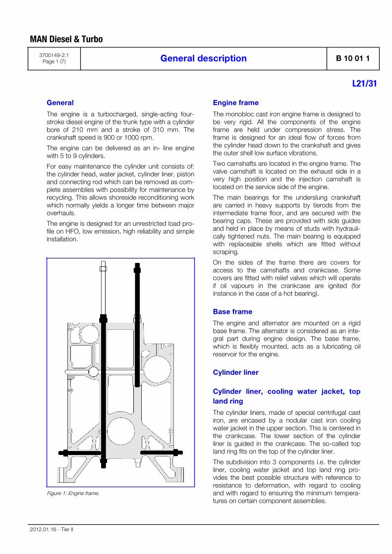
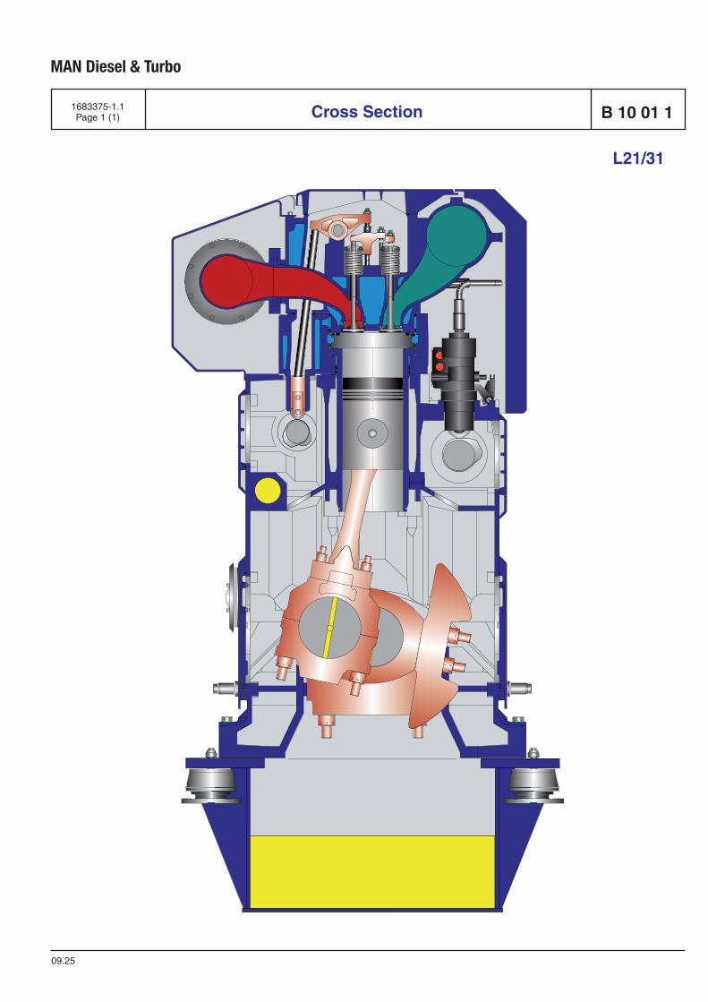
General
The engine is a turbocharged, single-acting four-stroke diesel engine of the trunk type with a cylinderbore of 210 mm and a stroke of 310 mm. Thecrankshaft speed is 900 or 1000 rpm.
The engine can be delivered as an in- line enginewith 5 to 9 cylinders.
For easy maintenance the cylinder unit consists of:the cylinder head, water jacket, cylinder liner, pistonand connecting rod which can be removed as com-plete assemblies with possibility for maintenance byrecycling. This allows shoreside reconditioning workwhich normally yields a longer time between majoroverhauls.
The engine is designed for an unrestricted load pro-file on HFO, low emission, high reliability and simpleinstallation.
Figure 1: Engine frame.
Engine frame
The monobloc cast iron engine frame is designed tobe very rigid. All the components of the engineframe are held under compression stress. Theframe is designed for an ideal flow of forces fromthe cylinder head down to the crankshaft and givesthe outer shell low surface vibrations.
Two camshafts are located in the engine frame. Thevalve camshaft is located on the exhaust side in avery high position and the injection camshaft islocated on the service side of the engine.
The main bearings for the underslung crankshaftare carried in heavy supports by tierods from theintermediate frame floor, and are secured with thebearing caps. These are provided with side guidesand held in place by means of studs with hydrauli-cally tightened nuts. The main bearing is equippedwith replaceable shells which are fitted withoutscraping.
On the sides of the frame there are covers foraccess to the camshafts and crankcase. Somecovers are fitted with relief valves which will operateif oil vapours in the crankcase are ignited (forinstance in the case of a hot bearing).
Base frame
The engine and alternator are mounted on a rigidbase frame. The alternator is considered as an inte-gral part during engine design. The base frame,which is flexibly mounted, acts as a lubricating oilreservoir for the engine.
Cylinder liner
Cylinder liner, cooling water jacket, topland ring
The cylinder liners, made of special centrifugal castiron, are encased by a nodular cast iron coolingwater jacket in the upper section. This is centered inthe crankcase. The lower section of the cylinderliner is guided in the crankcase. The so-called topland ring fits on the top of the cylinder liner.
The subdivision into 3 components i.e. the cylinderliner, cooling water jacket and top land ring pro-vides the best possible structure with reference toresistance to deformation, with regard to coolingand with regard to ensuring the minimum tempera-tures on certain component assemblies.
MAN Diesel & Turbo
3700149-2.1Page 1 (7) General description B 10 01 1
L21/31
2012.01.16 - Tier II
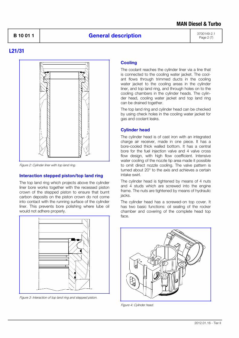
Figure 2: Cylinder liner with top land ring.
Interaction stepped piston/top land ring
The top land ring which projects above the cylinderliner bore works together with the recessed pistoncrown of the stepped piston to ensure that burntcarbon deposits on the piston crown do not comeinto contact with the running surface of the cylinderliner. This prevents bore polishing where lube oilwould not adhere properly.
Figure 3: Interaction of top land ring and stepped piston.
Cooling
The coolant reaches the cylinder liner via a line thatis connected to the cooling water jacket. The cool-ant flows through trimmed ducts in the coolingwater jacket to the cooling areas in the cylinderliner, and top land ring, and through holes on to thecooling chambers in the cylinder heads. The cylin-der head, cooling water jacket and top land ringcan be drained together.
The top land ring and cylinder head can be checkedby using check holes in the cooling water jacket forgas and coolant leaks.
Cylinder head
The cylinder head is of cast iron with an integratedcharge air receiver, made in one piece. It has abore-cooled thick walled bottom. It has a centralbore for the fuel injection valve and 4 valve crossflow design, with high flow coefficient. Intensivewater cooling of the nozzle tip area made it possibleto omit direct nozzle cooling. The valve pattern isturned about 20° to the axis and achieves a certainintake swirl.
The cylinder head is tightened by means of 4 nutsand 4 studs which are screwed into the engineframe. The nuts are tightened by means of hydraulicjacks.
The cylinder head has a screwed-on top cover. Ithas two basic functions: oil sealing of the rockerchamber and covering of the complete head topface.
Figure 4: Cylinder head.
MAN Diesel & Turbo
B 10 01 1 General description 3700149-2.1Page 2 (7)
L21/31
2012.01.16 - Tier II
Air inlet and exhaust valves
The valve spindles are made of heat-resistant mate-rial and the spindle seats are armoured with wel-ded-on hard metal.
All valve spindles are fitted with valve rotators whichturn the spindles each time the valves are activated.The turning of the spindles ensures even tempera-ture levels on the valve discs and prevents depositson the seating surfaces.
The cylinder head is equipped with replaceablevalve seat rings. The exhaust valve seat rings arewater cooled in order to assure low valve tempera-tures.
Valve actuating gear
The rocker arms are actuated through rollers, rollerguides and push rods. The roller guides for inlet andexhaust valves are mounted in the water jacketpart.
Each rocker arm activates two spindles through avalve bridge with thrust screws and adjustingscrews for valve clearance.
The valve actuating gear is pressure-feed lubricatedfrom the centralized lubricating system, through thewater chamber part and from there into the rockerarm shaft to the rocker bearing.
Fuel injection system
The engine is provided with one fuel injection pumpunit, an injection valve, and a high pressure pipe foreach cylinder.
The injection pump unit is mounted on the engineframe. The pump unit consists of a pump housingembracing a roller guide, a centrally placed pumpbarrel and a plunger. The pump is activated by thefuel cam, and the volume injected is controlled byturning the plunger.
The fuel injection valve is located in a valve sleeve inthe centre of the cylinder head. The opening of thevalve is controlled by the fuel oil pressure, and thevalve is closed by a spring.
The high pressure pipe which is led through a borein the cylinder head is surrounded by a shieldingtube.
The shielding tube also acts as a drain channel inorder to ensure any leakage from the fuel valve andthe high pressure pipe will be drained off.
The complete injection equipment including injec-tion pumps and high pressure pipes is wellenclosed behind removable covers.
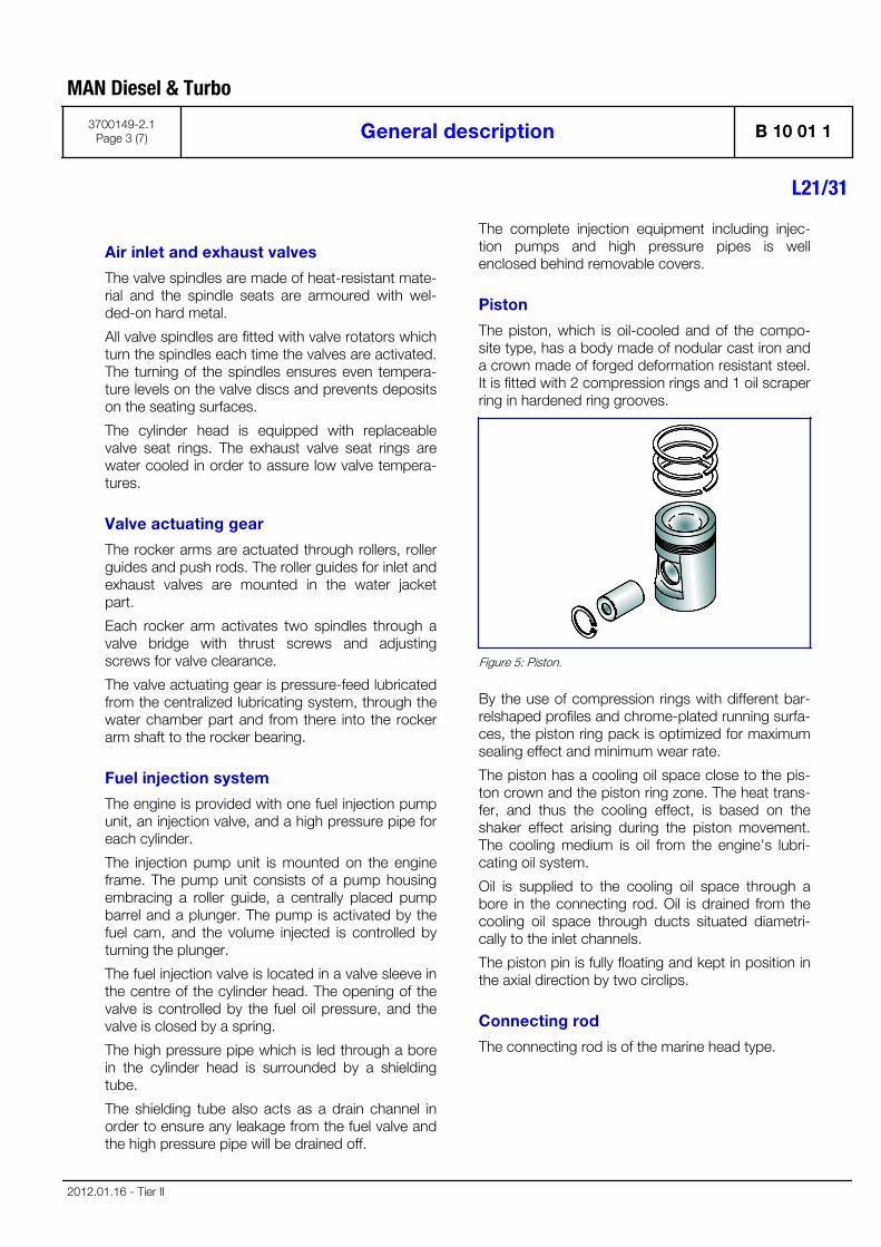
Piston
The piston, which is oil-cooled and of the compo-site type, has a body made of nodular cast iron anda crown made of forged deformation resistant steel.It is fitted with 2 compression rings and 1 oil scraperring in hardened ring grooves.
Figure 5: Piston.
By the use of compression rings with different bar-relshaped profiles and chrome-plated running surfa-ces, the piston ring pack is optimized for maximumsealing effect and minimum wear rate.
The piston has a cooling oil space close to the pis-ton crown and the piston ring zone. The heat trans-fer, and thus the cooling effect, is based on theshaker effect arising during the piston movement.The cooling medium is oil from the engine's lubri-cating oil system.
Oil is supplied to the cooling oil space through abore in the connecting rod. Oil is drained from thecooling oil space through ducts situated diametri-cally to the inlet channels.
The piston pin is fully floating and kept in position inthe axial direction by two circlips.
Connecting rod
The connecting rod is of the marine head type.
MAN Diesel & Turbo
3700149-2.1Page 3 (7) General description B 10 01 1
L21/31
2012.01.16 - Tier II
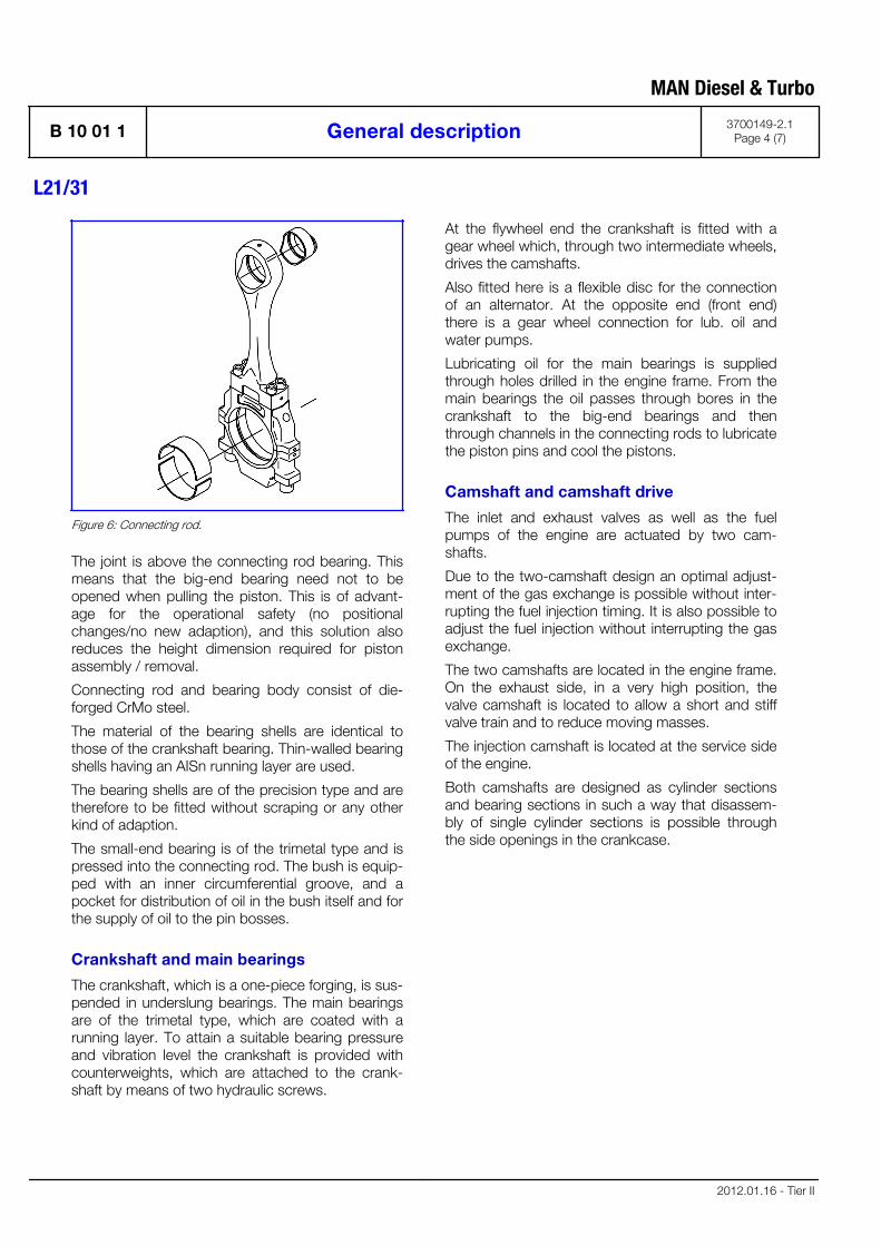
Figure 6: Connecting rod.
The joint is above the connecting rod bearing. Thismeans that the big-end bearing need not to beopened when pulling the piston. This is of advant-age for the operational safety (no positionalchanges/no new adaption), and this solution alsoreduces the height dimension required for pistonassembly / removal.
Connecting rod and bearing body consist of die-forged CrMo steel.
The material of the bearing shells are identical tothose of the crankshaft bearing. Thin-walled bearingshells having an AISn running layer are used.
The bearing shells are of the precision type and aretherefore to be fitted without scraping or any otherkind of adaption.
The small-end bearing is of the trimetal type and ispressed into the connecting rod. The bush is equip-ped with an inner circumferential groove, and apocket for distribution of oil in the bush itself and forthe supply of oil to the pin bosses.
Crankshaft and main bearings
The crankshaft, which is a one-piece forging, is sus-pended in underslung bearings. The main bearingsare of the trimetal type, which are coated with arunning layer. To attain a suitable bearing pressureand vibration level the crankshaft is provided withcounterweights, which are attached to the crank-shaft by means of two hydraulic screws.
At the flywheel end the crankshaft is fitted with agear wheel which, through two intermediate wheels,drives the camshafts.
Also fitted here is a flexible disc for the connectionof an alternator. At the opposite end (front end)there is a gear wheel connection for lub. oil andwater pumps.
Lubricating oil for the main bearings is suppliedthrough holes drilled in the engine frame. From themain bearings the oil passes through bores in thecrankshaft to the big-end bearings and thenthrough channels in the connecting rods to lubricatethe piston pins and cool the pistons.
Camshaft and camshaft drive
The inlet and exhaust valves as well as the fuelpumps of the engine are actuated by two cam-shafts.
Due to the two-camshaft design an optimal adjust-ment of the gas exchange is possible without inter-rupting the fuel injection timing. It is also possible toadjust the fuel injection without interrupting the gasexchange.
The two camshafts are located in the engine frame.On the exhaust side, in a very high position, thevalve camshaft is located to allow a short and stiffvalve train and to reduce moving masses.
The injection camshaft is located at the service sideof the engine.
Both camshafts are designed as cylinder sectionsand bearing sections in such a way that disassem-bly of single cylinder sections is possible throughthe side openings in the crankcase.
MAN Diesel & Turbo
B 10 01 1 General description 3700149-2.1Page 4 (7)
L21/31
2012.01.16 - Tier II
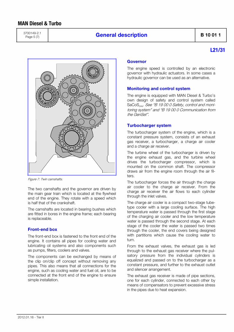
Figure 7: Twin camshafts.
The two camshafts and the governor are driven bythe main gear train which is located at the flywheelend of the engine. They rotate with a speed whichis half that of the crankshaft.
The camshafts are located in bearing bushes whichare fitted in bores in the engine frame; each bearingis replaceable.
Front-end box
The front-end box is fastened to the front end of theengine. It contains all pipes for cooling water andlubricating oil systems and also components suchas pumps, filters, coolers and valves.
The components can be exchanged by means ofthe clip on/clip off concept without removing anypipes. This also means that all connections for theengine, such as cooling water and fuel oil, are to beconnected at the front end of the engine to ensuresimple installation.
Governor
The engine speed is controlled by an electronicgovernor with hydraulic actuators. In some cases ahydraulic governor can be used as an alternative.
Monitoring and control system
The engine is equipped with MAN Diesel & Turbo’sown design of safety and control system calledSaCoSone. See “B 19 00 0 Safety, control and moni-toring system” and “B 19 00 0 Communication fromthe GenSet”.
Turbocharger system
The turbocharger system of the engine, which is aconstant pressure system, consists of an exhaustgas receiver, a turbocharger, a charge air coolerand a charge air receiver.
The turbine wheel of the turbocharger is driven bythe engine exhaust gas, and the turbine wheeldrives the turbocharger compressor, which ismounted on the common shaft. The compressordraws air from the engine room through the air fil-ters.
The turbocharger forces the air through the chargeair cooler to the charge air receiver. From thecharge air receiver the air flows to each cylinderthrough the inlet valves.
The charge air cooler is a compact two-stage tube-type cooler with a large cooling surface. The hightemperature water is passed through the first stageof the charging air cooler and the low temperaturewater is passed through the second stage. At eachstage of the cooler the water is passed two timesthrough the cooler, the end covers being designedwith partitions which cause the cooling water toturn.
From the exhaust valves, the exhaust gas is ledthrough to the exhaust gas receiver where the pul-satory pressure from the individual cylinders isequalized and passed on to the turbocharger as aconstant pressure, and further to the exhaust outletand silencer arrangement.
The exhaust gas receiver is made of pipe sections,one for each cylinder, connected to each other bymeans of compensators to prevent excessive stressin the pipes due to heat expansion.
MAN Diesel & Turbo
3700149-2.1Page 5 (7) General description B 10 01 1
L21/31
2012.01.16 - Tier II
To avoid excessive thermal loss and to ensure areasonably low surface temperature the exhaustgas receiver is insulated.
Compressed air system
The engine is started by means of a built-on airdriven starter.
The compressed air system comprises a dirtstrainer, main starting valve and a pilot valve whichalso acts as an emergency valve, making it possibleto start the engine in case of a power failure.
Fuel oil system
The built-on fuel oil system consists of inlet pipes forfuel oil, mechanical fuel pump units, high-pressurepipes as well as return pipes for fuel oil.
Fuel oil leakages are led to a leakage alarm which isheated by means of the inlet fuel oil.
Lubricating oil system
All moving parts of the engine are lubricated with oilcirculating under pressure.
The lubricating oil pump is of the helical gear type.A pressure control valve is built into the system. Thepressure control valve reduces the pressure beforethe filter with a signal taken after the filter to ensureconstant oil pressure with dirty filters.
The pump draws the oil from the sump in the baseframe, and on the pressure side the oil passesthrough the lubricating oil cooler and the full-flowdepth filter with a nominel fineness of 15 microns.Both the oil pump, oil cooler and the oil filter areplaced in the front end box. The system can also beequipped with a centrifugal filter.
Cooling is carried out by the low temperature cool-ing water system and temperature regulation effec-ted by a thermostatic 3-way valve on the oil side.
The engine is as standard equipped with an electri-cally driven prelubricating pump.
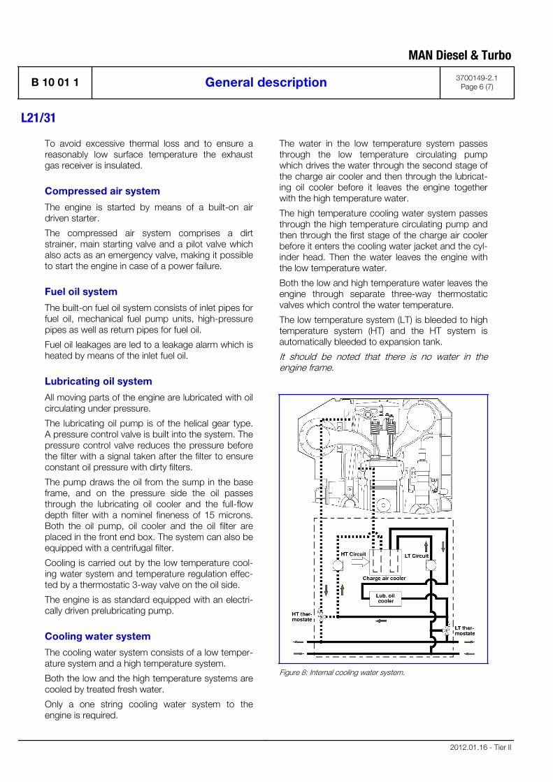
Cooling water system
The cooling water system consists of a low temper-ature system and a high temperature system.
Both the low and the high temperature systems arecooled by treated fresh water.
Only a one string cooling water system to theengine is required.
The water in the low temperature system passesthrough the low temperature circulating pumpwhich drives the water through the second stage ofthe charge air cooler and then through the lubricat-ing oil cooler before it leaves the engine togetherwith the high temperature water.
The high temperature cooling water system passesthrough the high temperature circulating pump andthen through the first stage of the charge air coolerbefore it enters the cooling water jacket and the cyl-inder head. Then the water leaves the engine withthe low temperature water.
Both the low and high temperature water leaves theengine through separate three-way thermostaticvalves which control the water temperature.
The low temperature system (LT) is bleeded to hightemperature system (HT) and the HT system isautomatically bleeded to expansion tank.
It should be noted that there is no water in theengine frame.
Figure 8: Internal cooling water system.
MAN Diesel & Turbo
B 10 01 1 General description 3700149-2.1Page 6 (7)
L21/31
2012.01.16 - Tier II
Tools
The engine can be delivered with all necessary toolsfor the overhaul of each specific plant. Most of thetools can be arranged on steel plate panels.
Turning
The engine is equipped with a manual turningdevice.
MAN Diesel & Turbo
3700149-2.1Page 7 (7) General description B 10 01 1
L21/31
2012.01.16 - Tier II

MAN Diesel & Turbo
Cross Section B 10 01 11683375-1.1Page 1 (1)
L21/31
09.25

MAN Diesel & Turbo
Main Particulars B 10 01 11699263-7.2Page 1 (1)
L21/31
11.36 - 220kW - Tier II - GenSet
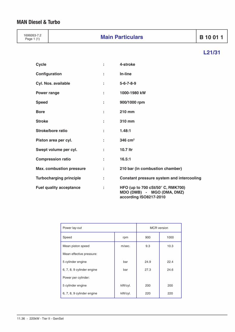
Cycle : 4-stroke
Configuration : In-line
Cyl. Nos. available : 5-6-7-8-9
Power range : 1000-1980 kW
Speed : 900/1000 rpm
Bore : 210 mm
Stroke : 310 mm
Stroke/bore ratio : 1.48:1
Piston area per cyl. : 346 cm2
Swept volume per cyl. : 10.7 ltr
Compression ratio : 16.5:1
Max. combustion pressure : 210 bar (in combustion chamber)
Turbocharging principle : Constant pressure system and inter cool ing
Fuel quality acceptance : HFO (up to 700 cSt/50° C, RMK700) MDO (DMB) - MGO (DMA, DMZ) according ISO8217-2010
Power lay-out
Speed
Mean piston speed
Mean effective pressure:
5 cylinder engine
6, 7, 8, 9 cylinder engine
Power per cylinder:
5 cylinder engine
6, 7, 8, 9 cylinder engine
rpm
m/sec.
bar
bar
kW/cyl.
kW/cyl.
900
9.3
24.9
27.3
200
220
1000
10.3
22.4
24.6
200
220
MCR version
220 kW - Tier II

General
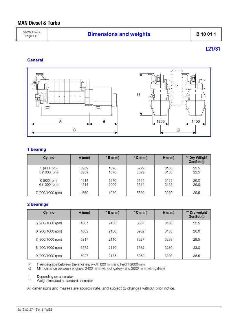
1 bearing
Cyl. no A (mm) * B (mm) * C (mm) H (mm) ** Dry WEightGenSet (t)
5 (900 rpm)5 (1000 rpm)
6 (900 rpm)6 (1000 rpm)
7 (900/1000 rpm)
39593959
43144314
4669
18201870
18702000
1970
57795829
61846314
6639
31833183
31833183
3289
22.522.5
26.026.0
29.5
2 bearings
Cyl. no A (mm) * B (mm) * C (mm) H (mm) ** Dry weightGenSet (t)
5 (900/1000 rpm)
6 (900/1000 rpm)
7 (900/1000 rpm)
8 (900/1000 rpm)
9 (900/1000 rpm)
4507
4862
5217
5572
5927
2100
2100
2110
2110
2135
6607
6962
7327
7682
8062
3183
3183
3289
3289
3289
22.5
26.0
29.5
33.0
36.5
PQ
***
Free passage between the engines, width 600 mm and height 2000 mm.Min. distance between engines: 2400 mm (without gallery) and 2600 mm (with gallery)
Depending on alternatorWeight included a standard alternator
All dimensions and masses are approximate, and subject to changes without prior notice.
MAN Diesel & Turbo
3700211-4.2Page 1 (1) Dimensions and weights B 10 01 1
L21/31
2012.02.27 - Tier II / WB2

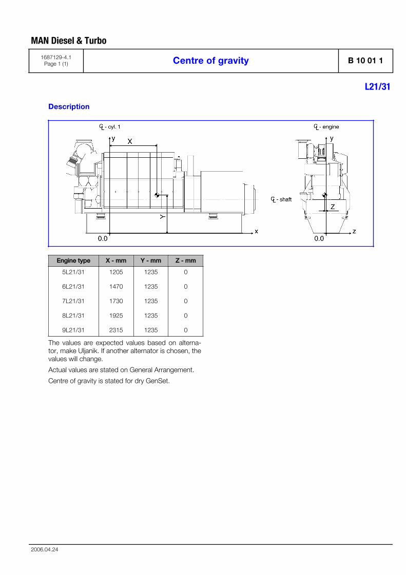
Description
Engine type X - mm Y - mm Z - mm
5L21/31
6L21/31
7L21/31
8L21/31
9L21/31
1205
1470
1730
1925
2315
1235
1235
1235
1235
1235
0
0
0
0
0
The values are expected values based on alterna-tor, make Uljanik. If another alternator is chosen, thevalues will change.
Actual values are stated on General Arrangement.
Centre of gravity is stated for dry GenSet.
MAN Diesel & Turbo
1687129-4.1Page 1 (1) Centre of gravity B 10 01 1
L21/31
2006.04.24

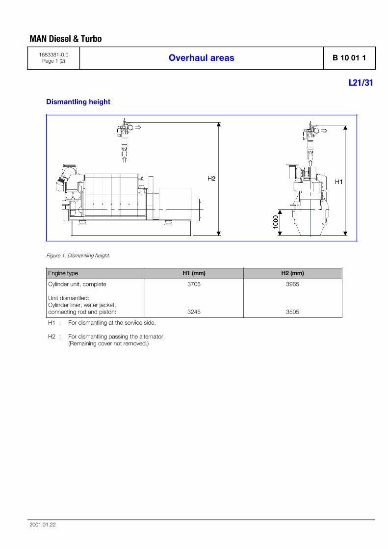
Dismantling height
Figure 1: Dismantling height.
Engine type H1 (mm) H2 (mm)
Cylinder unit, complete
Unit dismantled:Cylinder liner, water jacket,connecting rod and piston:
3705
3245
3965
3505
H1
H2
:
:
For dismantling at the service side.
For dismantling passing the alternator.(Remaining cover not removed.)
MAN Diesel & Turbo
1683381-0.0Page 1 (2) Overhaul areas B 10 01 1
L21/31
2001.01.22
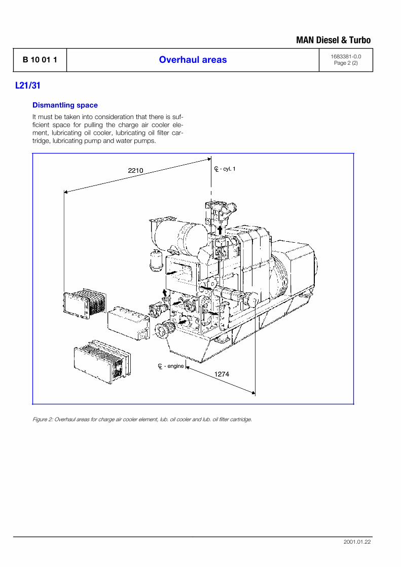
Dismantling space
It must be taken into consideration that there is suf-ficient space for pulling the charge air cooler ele-ment, lubricating oil cooler, lubricating oil filter car-tridge, lubricating pump and water pumps.
Figure 2: Overhaul areas for charge air cooler element, lub. oil cooler and lub. oil filter cartridge.
MAN Diesel & Turbo
B 10 01 1 Overhaul areas 1683381-0.0Page 2 (2)
L21/31
2001.01.22
MAN Diesel & Turbo
Firing Pressure Comparison B 10 01 1
L21/31
3700085-5.1Page 1 (1)
12.10 - Tier II
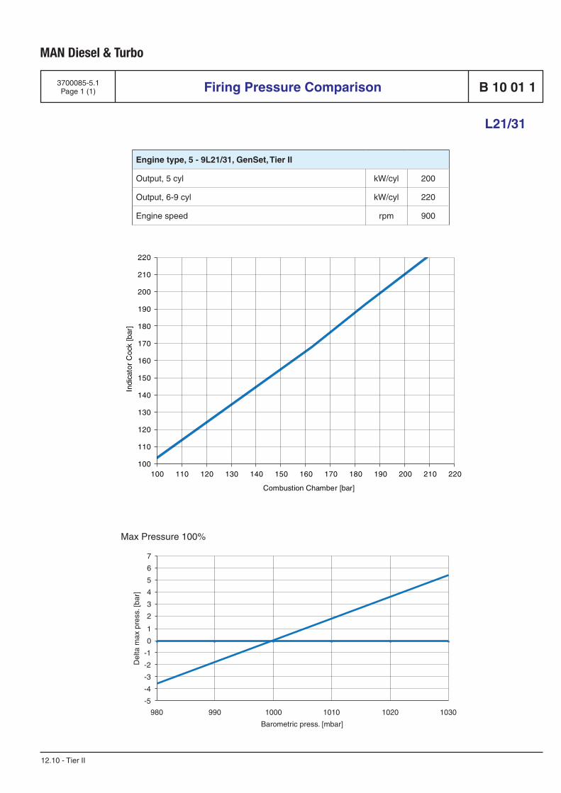
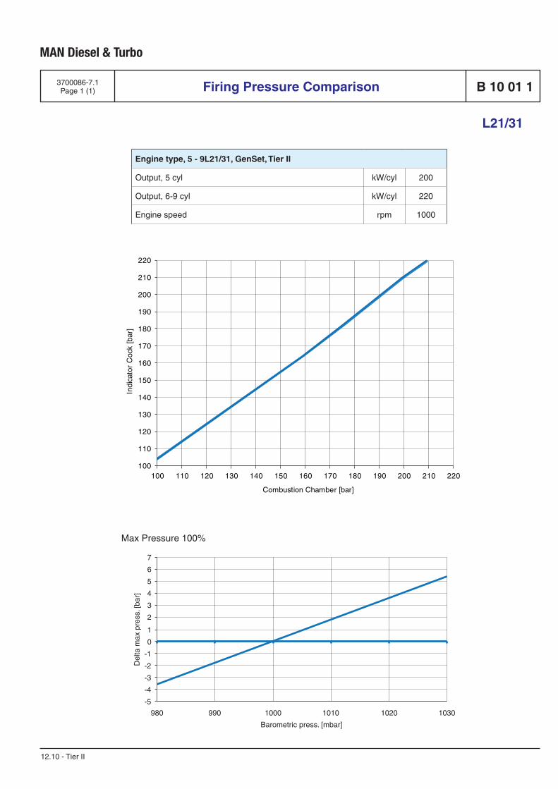
Engine type, 5 - 9L21/31, GenSet, Tier II
Output, 5 cyl kW/cyl 200
Output, 6-9 cyl kW/cyl 220
Engine speed rpm 900
Max Pressure 100%
-5
-4
-3
-2
-1
0
1
2
3
4
5
6
7
980 990 1000 1010 1020 1030
Del
ta m
ax p
ress
. [ba
r]
Barometric press. [mbar]
100
110
120
130
140
150
160
170
180
190
200
210
220
100 110 120 130 140 150 160 170 180 190 200 210 220
Indi
cato
r C
ock
[bar
]
Combustion Chamber [bar]

MAN Diesel & Turbo
Firing Pressure Comparison B 10 01 1
L21/31
3700086-7.1Page 1 (1)
12.10 - Tier II
Engine type, 5 - 9L21/31, GenSet, Tier II
Output, 5 cyl kW/cyl 200
Output, 6-9 cyl kW/cyl 220
Engine speed rpm 1000
Max Pressure 100%
-5
-4
-3
-2
-1
0
1
2
3
4
5
6
7
980 990 1000 1010 1020 1030
Del
ta m
ax p
ress
. [ba
r]
Barometric press. [mbar]
100
110
120
130
140
150
160
170
180
190
200
210
220
100 110 120 130 140 150 160 170 180 190 200 210 220
Indi
cato
r C
ock
[bar
]
Combustion Chamber [bar]

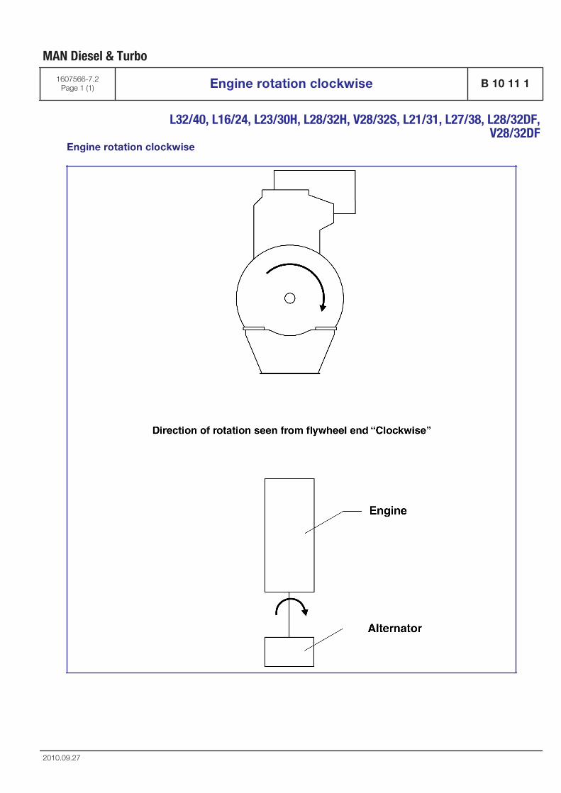
Engine rotation clockwise
MAN Diesel & Turbo
1607566-7.2Page 1 (1) Engine rotation clockwise B 10 11 1
L32/40, L16/24, L23/30H, L28/32H, V28/32S, L21/31, L27/38, L28/32DF,
V28/32DF
2010.09.27


Fuel Oil System
B 11

Internal fuel oil system
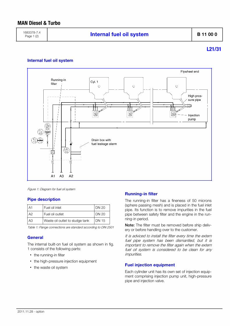
Figure 1: Diagram for fuel oil system
Pipe description
A1 Fuel oil inlet DN 20
A2 Fuel oil outlet DN 20
A3 Waste oil outlet to sludge tank DN 15
Table 1: Flange connections are standard according to DIN 2501
General
The internal built-on fuel oil system as shown in fig.1 consists of the following parts:
▪ the running-in filter
▪ the high-pressure injection equipment
▪ the waste oil system
Running-in filter
The running-in filter has a fineness of 50 microns(sphere passing mesh) and is placed in the fuel inletpipe. Its function is to remove impurities in the fuelpipe between safety filter and the engine in the run-ning-in period.
Note: The filter must be removed before ship deliv-ery or before handling over to the customer.
It is adviced to install the filter every time the externfuel pipe system has been dismantled, but it isimportant to remove the filter again when the externfuel oil system is considered to be clean for anyimpurities.
Fuel injection equipment
Each cylinder unit has its own set of injection equip-ment comprising injection pump unit, high-pressurepipe and injection valve.
MAN Diesel & Turbo
1683378-7.4Page 1 (2) Internal fuel oil system B 11 00 0
L21/31
2011.11.28 - option
The injection equipment and the distribution supplypipes are housed in a fully enclosed compartmentthus minimizing heat losses from the preheated fuel.This arrangement reduces external surface temper-atures and the risk of fire caused by fuel leakage.
The injection pump unit are with integrated rollerguide directly above the camshaft.
The fuel quantity injected into each cylinder unit isadjusted by means of the governor, which main-tains the engine speed at the preset value by a con-tinuous positioning of the fuel pump racks, via acommon regulating shaft and spring-loaded link-ages for each pump.
The injection valve is for "deep" building-in to thecentre of the cylinder head.
The injection oil is supplied from the injection pumpto the injection valve via a double-walled pressurepipe installed in a bore in the cylinder head.
This bore has an external connection to lead theleak oil from the injection valve and high-pressurepipe to the waste oil system, through the doublewalled pressure pipe.
A bore in the cylinder head vents the space belowthe bottom rubber sealing ring on the injectionvalve, thus preventing any pressure build-up due togas leakage, but also unveiling any malfunction ofthe bottom rubber sealing ring due to leak oil.
Waste oil system
Waste and leak oil from the hot box, fuel injectionvalves, fuel injection pumps and high-pressurepipes, is led to the fuel leakage alarm unit, fromwhich it is drained into the sludge tank.
The leakage alarm unit consists of a box, with afloat switch for level monitoring. In case of a leak-age, larger than normal, the float switch will initiatean alarm. The supply fuel oil to the engine is ledthrough the leakage alarm unit in order to keep thisheated up, thereby ensuring free drainage passageeven for high-viscous waste/leak oil.
Sludge tank
In normal operation no fuel should leak out from thecomponents of the fuel system. In connection withmaintenance, or due to unforeseen leaks, fuel orwater may spill in the hot box of the engine. Thespilled liquids are collected and drained by gravityfrom the engine through the dirty fuel connection.
Waste and leak oil from the hot box is drained intothe sludge tank.
The tank and the pipes must be heated and insula-ted, unless the installation is designed for operationexclusively on MDO/MGO.
Data
For pump capacities, see "D 10 05 0 List of capaci-ties"
Fuel oil consumption for emissions standard is sta-ted in "B 11 01 0 Fuel oil consumption for emis-sions standard"
Set points and operating levels for temperature andpressure are stated in "B 19 00 0 operation data &set points"
MAN Diesel & Turbo
B 11 00 0 Internal fuel oil system 1683378-7.4Page 2 (2)
L21/31
2011.11.28 - option
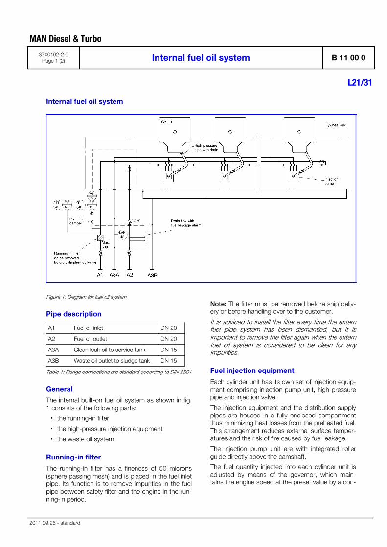
Internal fuel oil system
Figure 1: Diagram for fuel oil system
Pipe description
A1 Fuel oil inlet DN 20
A2 Fuel oil outlet DN 20
A3A Clean leak oil to service tank DN 15
A3B Waste oil outlet to sludge tank DN 15
Table 1: Flange connections are standard according to DIN 2501
General
The internal built-on fuel oil system as shown in fig.1 consists of the following parts:
▪ the running-in filter
▪ the high-pressure injection equipment
▪ the waste oil system
Running-in filter
The running-in filter has a fineness of 50 microns(sphere passing mesh) and is placed in the fuel inletpipe. Its function is to remove impurities in the fuelpipe between safety filter and the engine in the run-ning-in period.
Note: The filter must be removed before ship deliv-ery or before handling over to the customer.
It is adviced to install the filter every time the externfuel pipe system has been dismantled, but it isimportant to remove the filter again when the externfuel oil system is considered to be clean for anyimpurities.
Fuel injection equipment
Each cylinder unit has its own set of injection equip-ment comprising injection pump unit, high-pressurepipe and injection valve.
The injection equipment and the distribution supplypipes are housed in a fully enclosed compartmentthus minimizing heat losses from the preheated fuel.This arrangement reduces external surface temper-atures and the risk of fire caused by fuel leakage.
The injection pump unit are with integrated rollerguide directly above the camshaft.
The fuel quantity injected into each cylinder unit isadjusted by means of the governor, which main-tains the engine speed at the preset value by a con-
MAN Diesel & Turbo
3700162-2.0Page 1 (2) Internal fuel oil system B 11 00 0
L21/31
2011.09.26 - standard
tinuous positioning of the fuel pump racks, via acommon regulating shaft and spring-loaded link-ages for each pump.
The injection valve is for "deep" building-in to thecentre of the cylinder head.
The injection oil is supplied from the injection pumpto the injection valve via a double-walled pressurepipe installed in a bore in the cylinder head.
This bore has an external connection to lead theleak oil from the injection valve and high-pressurepipe to the waste oil system, through the doublewalled pressure pipe.
A bore in the cylinder head vents the space belowthe bottom rubber sealing ring on the injectionvalve, thus preventing any pressure build-up due togas leakage, but also unveiling any malfunction ofthe bottom rubber sealing ring due to leak oil.
Waste oil system
Clean leak oil from the fuel injection valves, fuelinjection pumps and high-pressure pipes, is led tothe fuel leakage alarm unit, from which it is drainedinto the clean leak fuel oil tank.
The leakage alarm unit consists of a box, with afloat switch for level monitoring. In case of a leak-age, larger than normal, the float switch will initiatean alarm. The supply fuel oil to the engine is ledthrough the leakage alarm unit in order to keep thisheated up, thereby ensuring free drainage passageeven for high-viscous waste/leak oil.
Waste and leak oil from the hot box is drained intothe sludge tank.
Clean leak fuel tank
Clean leak fuel is drained by gravity from the engine.The fuel should be collected in a separate cleanleak fuel tank, from where it can be pumped to theservice tank and reused without separation. Thepipes from the engine to the clean leak fuel tankshould be arranged continuously sloping. The tankand the pipes must be heated and insulated, unlessthe installation is designed for operation exclusivelyon MDO/MGO.
The leak fuel piping should be fully closed to pre-vent dirt from entering the system.
Sludge tank
In normal operation no fuel should leak out from thecomponents of the fuel system. In connection withmaintenance, or due to unforeseen leaks, fuel orwater may spill in the hot box of the engine. Thespilled liquids are collected and drained by gravityfrom the engine through the dirty fuel connection.
Waste and leak oil from the hot box is drained intothe sludge tank.
The tank and the pipes must be heated and insula-ted, unless the installation is designed for operationexclusively on MDO/MGO.
Data
For pump capacities, see "D 10 05 0 List of capaci-ties"
Fuel oil consumption for emissions standard is sta-ted in "B 11 01 0 Fuel oil consumption for emis-sions standard"
Set points and operating levels for temperature andpressure are stated in "B 19 00 0 operation data &set points"
MAN Diesel & Turbo
B 11 00 0 Internal fuel oil system 3700162-2.0Page 2 (2)
L21/31
2011.09.26 - standard
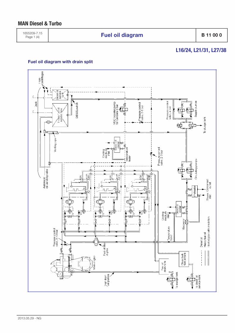
Fuel oil diagram with drain split
MAN Diesel & Turbo
1655209-7.15Page 1 (4) Fuel oil diagram B 11 00 0
L16/24, L21/31, L27/38
2013.05.29 - NG
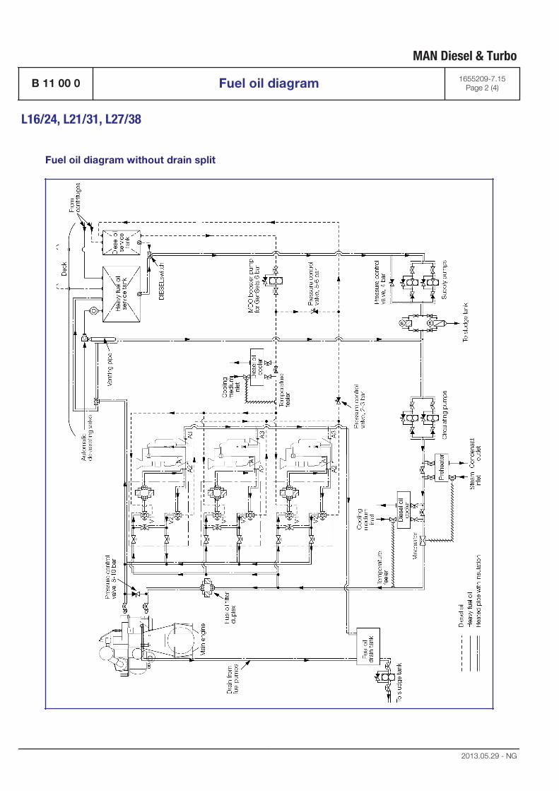
Fuel oil diagram without drain split
MAN Diesel & Turbo
B 11 00 0 Fuel oil diagram 1655209-7.15Page 2 (4)
L16/24, L21/31, L27/38
2013.05.29 - NG
Uni-fuel
The fuel system on page 1 is designed as a uni-fuelsystem indicating that the propulsion engine andthe GenSets are running on the same fuel oil andare fed from the common fuel system. The uni-fuelconcept is a unique possibility for substantial sav-ings in operating costs. It is also the simplest fuelsystem, resulting in lower maintenance and easieroperation. The diagram on page 1 is a guidance. Ithas to be adapted in each case to the actual engineand pipe layout.
Fuel feed system
The common fuel feed system is a pressurised sys-tem, consisting of HFO supply pumps, HFO circu-lating pumps, pre-heater, diesel cooler, DIESEL-switch and equipment for controlling the viscosity,(e.g. a viscorator). The fuel oil is led from the servicetank to one of the electrically driven supply pumps.It delivers the fuel oil with a pressure of approxi-mately 4 bar to the low-pressure side of the fuel oilsystem thus avoiding boiling of the fuel in the vent-ing pipe. From the low-pressure part of the fuel sys-tem the fuel oil is led to one of the electrically drivencirculating pumps which pumps the fuel oil througha pre-heater to the engines. For the propulsionengine please see the specific plant specifications.The internal fuel system for the GenSets is shown in"B 11 00 0 Internal fuel oil system".
To safeguard the injection system components onthe propulsion engine is it recommended to install afuel oil filter duplex with a fineness of max. 50microns (sphere passing mesh) as close as possibleto the propulsion engine.
GenSets with conventional fuel injection system orcommon rail fuel system must have fuel oil filterduplex with a fineness of max. 25 microns (spherepassing mesh) installed as close as possible toeach GenSet as shown in the fuel oil diagram.
GenSets with a common rail fuel system require anautomatic filter with a fineness of max. 10 microns(sphere passing mesh), which needs to be installedin the feeder circle.
It is possible, however not our standard/recommen-dation, to install a common fuel oil filter duplex anda common MDO filter for the entire GenSet plant. Inthis case it must be ensured that the fuel oil systemfulfils the classification rules and protects theengines from impurities.
Note: a filter surface load of 1 l/cm² per hour mustnot be exceeded!
The venting pipe is connected to the service tankvia an automatic deaeration valve that will releaseany gases present. To ensure ample filling of thefuel injection pumps the capacity of the electricallydriven circulating pumps must be three times higherthe amount of fuel consumed by the diesel engineat 100% load. The surplus amount of fuel oil is re-circulated in the engine and back through the vent-ing pipe. To have a constant fuel pressure to thefuel injection pumps during all engine loads aspring-loaded overflow valve is inserted in the fuelsystem. The circulating pump pressure should beas specified in "B 19 00 0, Operation data & setpoints" which provides a pressure margin againstgasification and cavitation in the fuel system even ata temperature of 150°C. The circulating pumps willalways be running; even if the propulsion engineand one or several of the GenSets are stopped. Cir-culation of heated heavy fuel oil through the fuelsystem on the engine(s) keep them ready to startwith preheated fuel injection pumps and the fuelvalves de-aerated.
Depending on system lay-out, viscosity, and volumein the external fuel oil system, unforeseen pressurefluctuations can be observed. In such cases it couldbe necessary to add pressure dampers to the fueloil system. For further assistance, please contactMAN Diesel & Turbo.
MDO operation
The MDO to the GenSets can also be supplied via aseparate pipeline from the service tank through aMDO booster pump. The capacity of the MDObooster pump must be three times higher theamount of MDO consumed by the diesel engines at100% load. The system is designed in such a waythat the fuel type for the GenSets can be changedindependent of the fuel supply to the propulsionengine. As an option the GenSet plant can be deliv-ered with the fuel changing system consisting of aset of remotely controlled, pneumatically actuated3-way fuel changing valves “V1-V2” for each Gen-Set and a fuel changing valve control box commonfor all GenSets. A separate fuel changing system foreach GenSet gives the advantage of individuallychoosing MDO or HFO mode. Such a changeovermay be necessary if the GenSets have to be:
▪ stopped for a prolonged period
▪ stopped for major repair of the fuel system, etc.
MAN Diesel & Turbo
1655209-7.15Page 3 (4) Fuel oil diagram B 11 00 0
L16/24, L21/31, L27/38
2013.05.29 - NG

▪ in case of a blackout / emergency start
If the fuel type for both the propulsion engine andGenSets have to be changed from HFO to MDO/MGO and vice versa, the 3-way valve just after theservice tanks has to be activated – the DIESEL-switch. With the introduction of stricter fuel sulphurcontent regulations the propulsion engine as well asthe GenSets increasingly have to be operated ondistillate fuels, i.e. marine gas oil (MGO) and marinediesel oil (MDO). To maintain the required viscosityat the engine inlet, it is necessary to install a coolerin the fuel system. The lowest viscosity suitable forthe main engine and the GenSets is 2 cSt at engineinlet.
Emergency start
Further, MDO must be available in emergency situa-tions. If a blackout occurs, the GenSets can bestarted up on MDO in two ways:
▪ MDO to be supplied from the MDO boosterpump which can be driven pneumatically orelectrically. If the pump is driven electrically, itmust be connected to the emergency switch-board.
▪ A gravity tank (100 - 200 litres) can be arrangedabove the GenSet. With no pumps available, itis possible to start up the GenSet if a gravitytank is installed minimum 8 metres above theGenSet. However, only if the changeover valve“V1-V2” is placed as near as possible to theGenSet.
MAN Diesel & Turbo
B 11 00 0 Fuel oil diagram 1655209-7.15Page 4 (4)
L16/24, L21/31, L27/38
2013.05.29 - NG
Specification for heavy fuel oil (HFO)
PrerequisitesMAN four-stroke diesel engines can be operated with any heavy fuel oilobtained from crude oil that also satisfies the requirements in Table "The fuelspecification and corresponding characteristics for heavy fuel oil", providingthe engine and fuel processing system have been designed accordingly. Toensure that the relationship between the fuel, spare parts and repair / main-tenance costs remains favorable at all times, the following points should beobserved.
Heavy fuel oil (HFO)The quality of the heavy fuel oil largely depends on the quality of crude oiland on the refining process used. This is why the properties of heavy fuel oilswith the same viscosity may vary considerably depending on the bunkerpositions. Heavy fuel oil is normally a mixture of residual oil and distillates.The components of the mixture are normally obtained from modern refineryprocesses, such as Catcracker or Visbreaker. These processes canadversely affect the stability of the fuel as well as its ignition and combustionproperties. The processing of the heavy fuel oil and the operating result ofthe engine also depend heavily on these factors.
Bunker positions with standardised heavy fuel oil qualities should preferablybe used. If oils need to be purchased from independent dealers, also ensurethat these also comply with the international specifications. The engine oper-ator is responsible for ensuring that suitable heavy fuel oils are chosen.
Fuels intended for use in an engine must satisfy the specifications to ensuresufficient quality. The limit values for heavy fuel oils are specified in Table„The fuel specification and corresponding characteristics for heavy fuel oil“.The entries in the last column of this table provide important backgroundinformation and must therefore be observed.
Different international specifications exist for heavy fuel oils. The most impor-tant specifications are ISO 8217-2010 and CIMAC-2003, which are more orless identical. The ISO 8217 specification is shown in Figure „ISO 8217-2010specification for heavy fuel oil“. All qualities in these specifications up to K700can be used, providing the fuel preparation system has been designedaccordingly. To use any fuels, which do not comply with these specifications(e.g. crude oil), consultation with Technical Service of MAN Diesel & Turbo inAugsburg is required. Heavy fuel oils with a maximum density of 1,010 kg/m3
may only be used if up-to-date separators are installed.
Even though the fuel properties specified in the table entitled "The fuel speci-fication and corresponding properties for heavy fuel oil" satisfy the aboverequirements, they probably do not adequately define the ignition and com-bustion properties and the stability of the fuel. This means that the operatingbehaviour of the engine can depend on properties that are not defined in thespecification. This particularly applies to the oil property that causes forma-tion of deposits in the combustion chamber, injection system, gas ducts andexhaust gas system. A number of fuels have a tendency towards incompati-bility with lubricating oil which leads to deposits being formed in the fueldelivery pump that can block the pumps. It may therefore be necessary toexclude specific fuels that could cause problems.
Origin/Refinery process
Specifications
Important
2013
-02-
13 -
de
Spec
ifica
tion
for h
eavy
fuel
oil
(HFO
)66
80 3
.3.3
-01
Gene
ral
MAN Diesel & Turbo 3.3.3
6680 3.3.3-01 EN 1 (12)
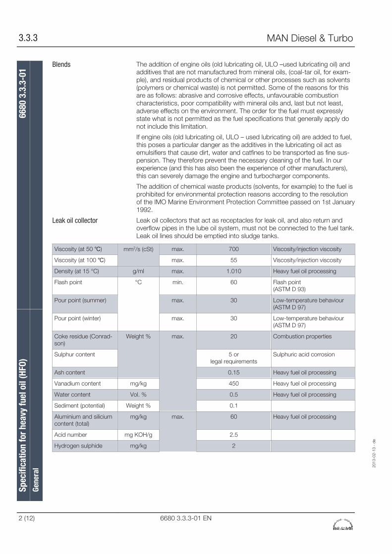
The addition of engine oils (old lubricating oil, ULO –used lubricating oil) andadditives that are not manufactured from mineral oils, (coal-tar oil, for exam-ple), and residual products of chemical or other processes such as solvents(polymers or chemical waste) is not permitted. Some of the reasons for thisare as follows: abrasive and corrosive effects, unfavourable combustioncharacteristics, poor compatibility with mineral oils and, last but not least,adverse effects on the environment. The order for the fuel must expresslystate what is not permitted as the fuel specifications that generally apply donot include this limitation.
If engine oils (old lubricating oil, ULO – used lubricating oil) are added to fuel,this poses a particular danger as the additives in the lubricating oil act asemulsifiers that cause dirt, water and catfines to be transported as fine sus-pension. They therefore prevent the necessary cleaning of the fuel. In ourexperience (and this has also been the experience of other manufacturers),this can severely damage the engine and turbocharger components.
The addition of chemical waste products (solvents, for example) to the fuel isprohibited for environmental protection reasons according to the resolutionof the IMO Marine Environment Protection Committee passed on 1st January1992.
Leak oil collectors that act as receptacles for leak oil, and also return andoverflow pipes in the lube oil system, must not be connected to the fuel tank.Leak oil lines should be emptied into sludge tanks.
Viscosity (at 50 ℃) mm2/s (cSt) max. 700 Viscosity/injection viscosity
Viscosity (at 100 ℃) max. 55 Viscosity/injection viscosity
Density (at 15 °C) g/ml max. 1.010 Heavy fuel oil processing
Flash point °C min. 60 Flash point(ASTM D 93)
Pour point (summer) max. 30 Low-temperature behaviour (ASTM D 97)
Pour point (winter) max. 30 Low-temperature behaviour (ASTM D 97)
Coke residue (Conrad-son)
Weight % max. 20 Combustion properties
Sulphur content 5 orlegal requirements
Sulphuric acid corrosion
Ash content 0.15 Heavy fuel oil processing
Vanadium content mg/kg 450 Heavy fuel oil processing
Water content Vol. % 0.5 Heavy fuel oil processing
Sediment (potential) Weight % 0.1
Aluminium and siliciumcontent (total)
mg/kg max. 60 Heavy fuel oil processing
Acid number mg KOH/g 2.5
Hydrogen sulphide mg/kg 2
Blends
Leak oil collector
Spec
ifica
tion
for h
eavy
fuel
oil
(HFO
)66
80 3
.3.3
-01
Gene
ral
2013
-02-
13 -
de
3.3.3 MAN Diesel & Turbo
2 (12) 6680 3.3.3-01 EN
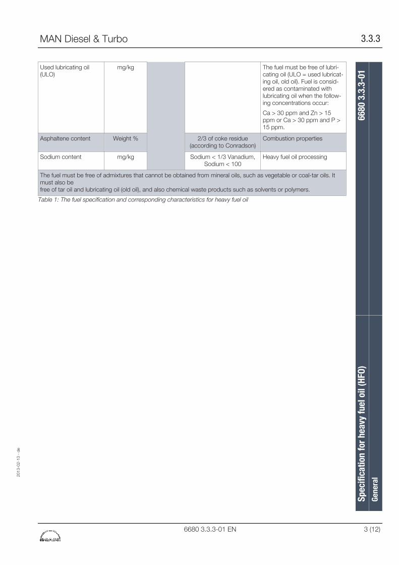
Used lubricating oil(ULO)
mg/kg The fuel must be free of lubri-cating oil (ULO = used lubricat-ing oil, old oil). Fuel is consid-ered as contaminated withlubricating oil when the follow-ing concentrations occur:
Ca > 30 ppm and Zn > 15ppm or Ca > 30 ppm and P >15 ppm.
Asphaltene content Weight % 2/3 of coke residue(according to Conradson)
Combustion properties
Sodium content mg/kg Sodium < 1/3 Vanadium,Sodium < 100
Heavy fuel oil processing
The fuel must be free of admixtures that cannot be obtained from mineral oils, such as vegetable or coal-tar oils. Itmust also be free of tar oil and lubricating oil (old oil), and also chemical waste products such as solvents or polymers.
Table 1: The fuel specification and corresponding characteristics for heavy fuel oil
2013
-02-
13 -
de
Spec
ifica
tion
for h
eavy
fuel
oil
(HFO
)66
80 3
.3.3
-01
Gene
ral
MAN Diesel & Turbo 3.3.3
6680 3.3.3-01 EN 3 (12)
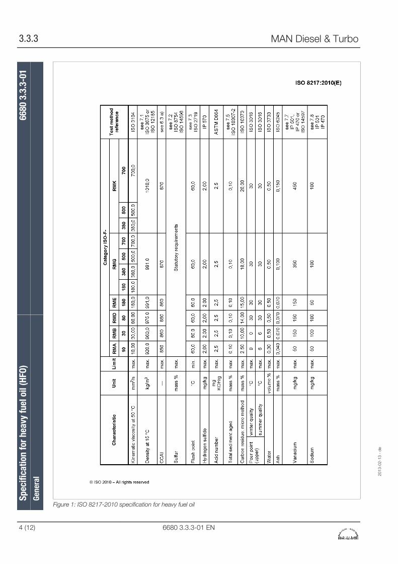
Figure 1: ISO 8217-2010 specification for heavy fuel oil
Spec
ifica
tion
for h
eavy
fuel
oil
(HFO
)66
80 3
.3.3
-01
Gene
ral
2013
-02-
13 -
de
3.3.3 MAN Diesel & Turbo
4 (12) 6680 3.3.3-01 EN
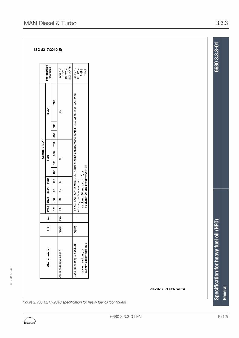
Figure 2: ISO 8217-2010 specification for heavy fuel oil (continued)
2013
-02-
13 -
de
Spec
ifica
tion
for h
eavy
fuel
oil
(HFO
)66
80 3
.3.3
-01
Gene
ral
MAN Diesel & Turbo 3.3.3
6680 3.3.3-01 EN 5 (12)
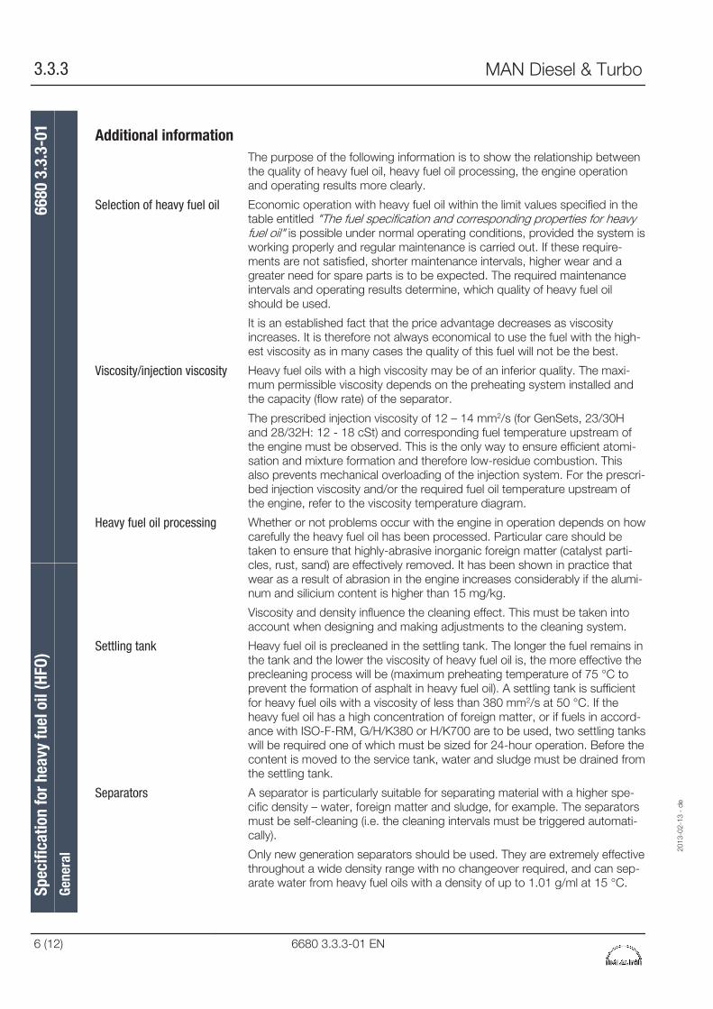
Additional informationThe purpose of the following information is to show the relationship betweenthe quality of heavy fuel oil, heavy fuel oil processing, the engine operationand operating results more clearly.
Economic operation with heavy fuel oil within the limit values specified in thetable entitled "The fuel specification and corresponding properties for heavyfuel oil" is possible under normal operating conditions, provided the system isworking properly and regular maintenance is carried out. If these require-ments are not satisfied, shorter maintenance intervals, higher wear and agreater need for spare parts is to be expected. The required maintenanceintervals and operating results determine, which quality of heavy fuel oilshould be used.
It is an established fact that the price advantage decreases as viscosityincreases. It is therefore not always economical to use the fuel with the high-est viscosity as in many cases the quality of this fuel will not be the best.
Heavy fuel oils with a high viscosity may be of an inferior quality. The maxi-mum permissible viscosity depends on the preheating system installed andthe capacity (flow rate) of the separator.
The prescribed injection viscosity of 12 – 14 mm2/s (for GenSets, 23/30Hand 28/32H: 12 - 18 cSt) and corresponding fuel temperature upstream ofthe engine must be observed. This is the only way to ensure efficient atomi-sation and mixture formation and therefore low-residue combustion. Thisalso prevents mechanical overloading of the injection system. For the prescri-bed injection viscosity and/or the required fuel oil temperature upstream ofthe engine, refer to the viscosity temperature diagram.
Whether or not problems occur with the engine in operation depends on howcarefully the heavy fuel oil has been processed. Particular care should betaken to ensure that highly-abrasive inorganic foreign matter (catalyst parti-cles, rust, sand) are effectively removed. It has been shown in practice thatwear as a result of abrasion in the engine increases considerably if the alumi-num and silicium content is higher than 15 mg/kg.
Viscosity and density influence the cleaning effect. This must be taken intoaccount when designing and making adjustments to the cleaning system.
Heavy fuel oil is precleaned in the settling tank. The longer the fuel remains inthe tank and the lower the viscosity of heavy fuel oil is, the more effective theprecleaning process will be (maximum preheating temperature of 75 °C toprevent the formation of asphalt in heavy fuel oil). A settling tank is sufficientfor heavy fuel oils with a viscosity of less than 380 mm2/s at 50 °C. If theheavy fuel oil has a high concentration of foreign matter, or if fuels in accord-ance with ISO-F-RM, G/H/K380 or H/K700 are to be used, two settling tankswill be required one of which must be sized for 24-hour operation. Before thecontent is moved to the service tank, water and sludge must be drained fromthe settling tank.
A separator is particularly suitable for separating material with a higher spe-cific density – water, foreign matter and sludge, for example. The separatorsmust be self-cleaning (i.e. the cleaning intervals must be triggered automati-cally).
Only new generation separators should be used. They are extremely effectivethroughout a wide density range with no changeover required, and can sep-arate water from heavy fuel oils with a density of up to 1.01 g/ml at 15 °C.
Selection of heavy fuel oil
Viscosity/injection viscosity
Heavy fuel oil processing
Settling tank
Separators
Spec
ifica
tion
for h
eavy
fuel
oil
(HFO
)66
80 3
.3.3
-01
Gene
ral
2013
-02-
13 -
de
3.3.3 MAN Diesel & Turbo
6 (12) 6680 3.3.3-01 EN
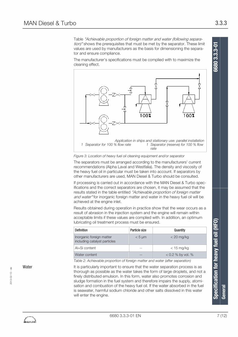
Table "Achievable proportion of foreign matter and water (following separa-tion)" shows the prerequisites that must be met by the separator. These limitvalues are used by manufacturers as the basis for dimensioning the separa-tor and ensure compliance.
The manufacturer's specifications must be complied with to maximize thecleaning effect.
Application in ships and stationary use: parallel installation1 Separator for 100 % flow rate 1 Separator (reserve) for 100 % flow
rate
Figure 3: Location of heavy fuel oil cleaning equipment and/or separator
The separators must be arranged according to the manufacturers' currentrecommendations (Alpha Laval and Westfalia). The density and viscosity ofthe heavy fuel oil in particular must be taken into account. If separators byother manufacturers are used, MAN Diesel & Turbo should be consulted.
If processing is carried out in accordance with the MAN Diesel & Turbo spec-ifications and the correct separators are chosen, it may be assumed that theresults stated in the table entitled "Achievable proportion of foreign matterand water" for inorganic foreign matter and water in the heavy fuel oil will beachieved at the engine inlet.
Results obtained during operation in practiсe show that the wear occurs as aresult of abrasion in the injection system and the engine will remain withinacceptable limits if these values are complied with. In addition, an optimumlubricating oil treatment process must be ensured.
Definition Particle size Quantity
Inorganic foreign matterincluding catalyst particles
< 5 µm < 20 mg/kg
Al+Si content -- < 15 mg/kg
Water content -- < 0.2 % by vol. %
Table 2: Achievable proportion of foreign matter and water (after separation)
It is particularly important to ensure that the water separation process is asthorough as possible as the water takes the form of large droplets, and not afinely distributed emulsion. In this form, water also promotes corrosion andsludge formation in the fuel system and therefore impairs the supply, atomi-sation and combustion of the heavy fuel oil. If the water absorbed in the fuelis seawater, harmful sodium chloride and other salts dissolved in this waterwill enter the engine.
Water
2013
-02-
13 -
de
Spec
ifica
tion
for h
eavy
fuel
oil
(HFO
)66
80 3
.3.3
-01
Gene
ral
MAN Diesel & Turbo 3.3.3
6680 3.3.3-01 EN 7 (12)
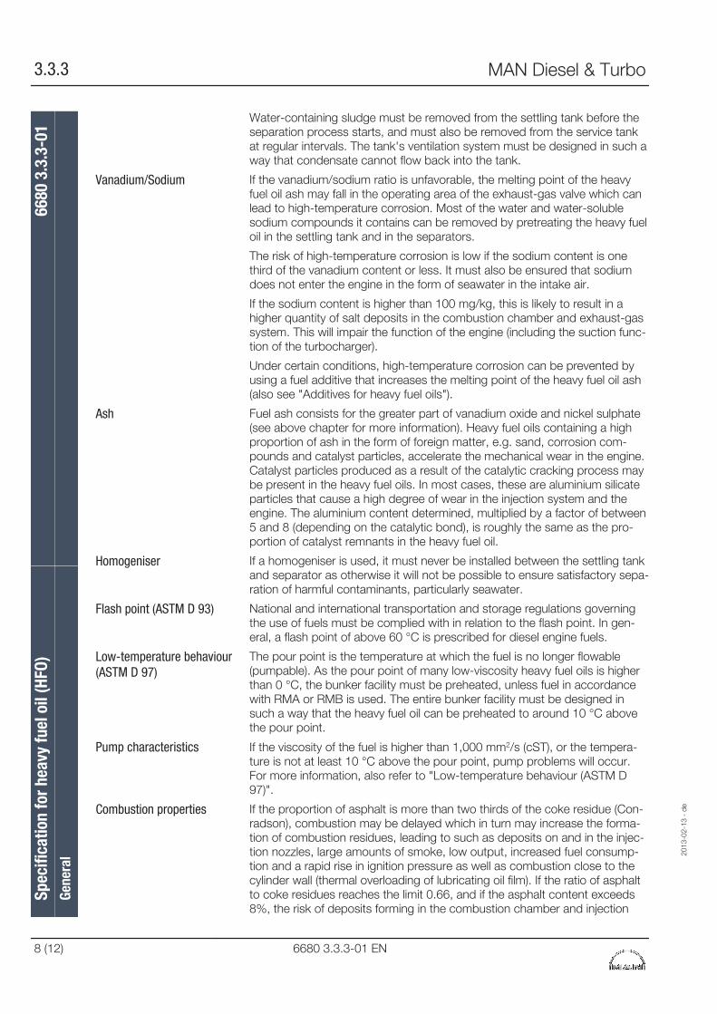
Water-containing sludge must be removed from the settling tank before theseparation process starts, and must also be removed from the service tankat regular intervals. The tank's ventilation system must be designed in such away that condensate cannot flow back into the tank.
If the vanadium/sodium ratio is unfavorable, the melting point of the heavyfuel oil ash may fall in the operating area of the exhaust-gas valve which canlead to high-temperature corrosion. Most of the water and water-solublesodium compounds it contains can be removed by pretreating the heavy fueloil in the settling tank and in the separators.
The risk of high-temperature corrosion is low if the sodium content is onethird of the vanadium content or less. It must also be ensured that sodiumdoes not enter the engine in the form of seawater in the intake air.
If the sodium content is higher than 100 mg/kg, this is likely to result in ahigher quantity of salt deposits in the combustion chamber and exhaust-gassystem. This will impair the function of the engine (including the suction func-tion of the turbocharger).
Under certain conditions, high-temperature corrosion can be prevented byusing a fuel additive that increases the melting point of the heavy fuel oil ash(also see "Additives for heavy fuel oils").
Fuel ash consists for the greater part of vanadium oxide and nickel sulphate(see above chapter for more information). Heavy fuel oils containing a highproportion of ash in the form of foreign matter, e.g. sand, corrosion com-pounds and catalyst particles, accelerate the mechanical wear in the engine.Catalyst particles produced as a result of the catalytic cracking process maybe present in the heavy fuel oils. In most cases, these are aluminium silicateparticles that cause a high degree of wear in the injection system and theengine. The aluminium content determined, multiplied by a factor of between5 and 8 (depending on the catalytic bond), is roughly the same as the pro-portion of catalyst remnants in the heavy fuel oil.
If a homogeniser is used, it must never be installed between the settling tankand separator as otherwise it will not be possible to ensure satisfactory sepa-ration of harmful contaminants, particularly seawater.
National and international transportation and storage regulations governingthe use of fuels must be complied with in relation to the flash point. In gen-eral, a flash point of above 60 °C is prescribed for diesel engine fuels.
The pour point is the temperature at which the fuel is no longer flowable(pumpable). As the pour point of many low-viscosity heavy fuel oils is higherthan 0 °C, the bunker facility must be preheated, unless fuel in accordancewith RMA or RMB is used. The entire bunker facility must be designed insuch a way that the heavy fuel oil can be preheated to around 10 °C abovethe pour point.
If the viscosity of the fuel is higher than 1,000 mm2/s (cST), or the tempera-ture is not at least 10 °C above the pour point, pump problems will occur.For more information, also refer to "Low-temperature behaviour (ASTM D97)".
If the proportion of asphalt is more than two thirds of the coke residue (Con-radson), combustion may be delayed which in turn may increase the forma-tion of combustion residues, leading to such as deposits on and in the injec-tion nozzles, large amounts of smoke, low output, increased fuel consump-tion and a rapid rise in ignition pressure as well as combustion close to thecylinder wall (thermal overloading of lubricating oil film). If the ratio of asphaltto coke residues reaches the limit 0.66, and if the asphalt content exceeds8%, the risk of deposits forming in the combustion chamber and injection
Vanadium/Sodium
Ash
Homogeniser
Flash point (ASTM D 93)
Low-temperature behaviour(ASTM D 97)
Pump characteristics
Combustion properties
Spec
ifica
tion
for h
eavy
fuel
oil
(HFO
)66
80 3
.3.3
-01
Gene
ral
2013
-02-
13 -
de
3.3.3 MAN Diesel & Turbo
8 (12) 6680 3.3.3-01 EN
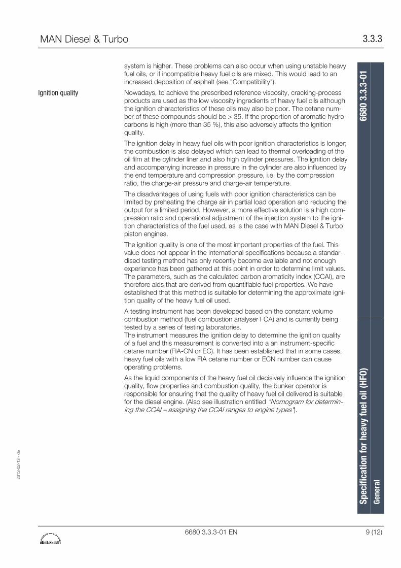
system is higher. These problems can also occur when using unstable heavyfuel oils, or if incompatible heavy fuel oils are mixed. This would lead to anincreased deposition of asphalt (see "Compatibility").
Nowadays, to achieve the prescribed reference viscosity, cracking-processproducts are used as the low viscosity ingredients of heavy fuel oils althoughthe ignition characteristics of these oils may also be poor. The cetane num-ber of these compounds should be > 35. If the proportion of aromatic hydro-carbons is high (more than 35 %), this also adversely affects the ignitionquality.
The ignition delay in heavy fuel oils with poor ignition characteristics is longer;the combustion is also delayed which can lead to thermal overloading of theoil film at the cylinder liner and also high cylinder pressures. The ignition delayand accompanying increase in pressure in the cylinder are also influenced bythe end temperature and compression pressure, i.e. by the compressionratio, the charge-air pressure and charge-air temperature.
The disadvantages of using fuels with poor ignition characteristics can belimited by preheating the charge air in partial load operation and reducing theoutput for a limited period. However, a more effective solution is a high com-pression ratio and operational adjustment of the injection system to the igni-tion characteristics of the fuel used, as is the case with MAN Diesel & Turbopiston engines.
The ignition quality is one of the most important properties of the fuel. Thisvalue does not appear in the international specifications because a standar-dised testing method has only recently become available and not enoughexperience has been gathered at this point in order to determine limit values.The parameters, such as the calculated carbon aromaticity index (CCAI), aretherefore aids that are derived from quantifiable fuel properties. We haveestablished that this method is suitable for determining the approximate igni-tion quality of the heavy fuel oil used.
A testing instrument has been developed based on the constant volumecombustion method (fuel combustion analyser FCA) and is currently beingtested by a series of testing laboratories.The instrument measures the ignition delay to determine the ignition qualityof a fuel and this measurement is converted into a an instrument-specificcetane number (FIA-CN or EC). It has been established that in some cases,heavy fuel oils with a low FIA cetane number or ECN number can causeoperating problems.
As the liquid components of the heavy fuel oil decisively influence the ignitionquality, flow properties and combustion quality, the bunker operator isresponsible for ensuring that the quality of heavy fuel oil delivered is suitablefor the diesel engine. (Also see illustration entitled "Nomogram for determin-ing the CCAI – assigning the CCAI ranges to engine types").
Ignition quality
2013
-02-
13 -
de
Spec
ifica
tion
for h
eavy
fuel
oil
(HFO
)66
80 3
.3.3
-01
Gene
ral
MAN Diesel & Turbo 3.3.3
6680 3.3.3-01 EN 9 (12)
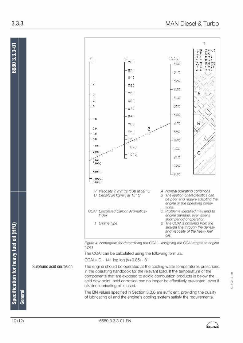
V Viscosity in mm2/s (cSt) at 50° C A Normal operating conditionsD Density [in kg/m3] at 15° C B The ignition characteristics can
be poor and require adapting theengine or the operating condi-tions.
CCAI Calculated Carbon AromaticityIndex
C Problems identified may lead toengine damage, even after ashort period of operation.
1 Engine type 2 The CCAI is obtained from thestraight line through the densityand viscosity of the heavy fueloils.
Figure 4: Nomogram for determining the CCAI – assigning the CCAI ranges to enginetypes
The CCAI can be calculated using the following formula:
CCAI = D - 141 log log (V+0.85) - 81
The engine should be operated at the cooling water temperatures prescribedin the operating handbook for the relevant load. If the temperature of thecomponents that are exposed to acidic combustion products is below theacid dew point, acid corrosion can no longer be effectively prevented, even ifalkaline lubricating oil is used.
The BN values specified in Section 3.3.6 are sufficient, providing the qualityof lubricating oil and the engine's cooling system satisfy the requirements.
Sulphuric acid corrosion
Spec
ifica
tion
for h
eavy
fuel
oil
(HFO
)66
80 3
.3.3
-01
Gene
ral
2013
-02-
13 -
de
3.3.3 MAN Diesel & Turbo
10 (12) 6680 3.3.3-01 EN
The supplier must guarantee that the heavy fuel oil is homogeneous andremains stable, even after the standard storage period. If different bunker oilsare mixed, this can lead to separation and the associated sludge formation inthe fuel system during which large quantities of sludge accumulate in theseparator that block filters, prevent atomisation and a large amount of resi-due as a result of combustion.
This is due to incompatibility or instability of the oils. Therefore heavy fuel oilas much as possible should be removed in the storage tank before bunker-ing again to prevent incompatibility.
If heavy fuel oil for the main engine is blended with gas oil (MGO) to obtainthe required quality or viscosity of heavy fuel oil, it is extremely important thatthe components are compatible (see "Compatibility").
MAN Diesel & Turbo engines can be operated economically without addi-tives. It is up to the customer to decide whether or not the use of additives isbeneficial. The supplier of the additive must guarantee that the engine opera-tion will not be impaired by using the product.
The use of heavy fuel oil additives during the warranty period must be avoi-ded as a basic principle.
Additives that are currently used for diesel engines, as well as their probableeffects on the engine's operation, are summarised in the table below „Addi-tives for heavy fuel oils – classification/effects“.
Precombustion additives ▪ Dispersing agents/stabil-isers
▪ Emulsion breakers
▪ Biocides
Combustion additives ▪ Combustion catalysts(fuel savings, emissions)
Post-combustion additives ▪ Ash modifiers (hot corro-sion)
▪ Soot removers (exhaust-gas system)
Table 3: Additives for heavy fuel oils – Classification/effects
From the point of view of an engine manufacturer, a lower limit for the sul-phur content of heavy fuel oils does not exist. We have not identified anyproblems with the low-sulphur heavy fuel oils currently available on the mar-ket that can be traced back to their sulphur content. This situation maychange in future if new methods are used for the production of low-sulphurheavy fuel oil (desulphurisation, new blending components). MAN Diesel &Turbo will monitor developments and inform its customers if required.
If the engine is not always operated with low-sulphur heavy fuel oil, corre-sponding lubricating oil for the fuel with the highest sulphur content must beselected.
Improper handling of operating fluidsIf operating fluids are improperly handled, this can pose a danger tohealth, safety and the environment. The relevant safety information bythe supplier of operating fluids must be observed.
Compatibility
Blending the heavy fuel oil
Additives to heavy fuel oils
Heavy fuel oils with lowsulphur content
2013
-02-
13 -
de
Spec
ifica
tion
for h
eavy
fuel
oil
(HFO
)66
80 3
.3.3
-01
Gene
ral
MAN Diesel & Turbo 3.3.3
6680 3.3.3-01 EN 11 (12)
TestsTo check whether the specification provided and/or the necessary deliveryconditions are complied with, we recommend you retain at least one sampleof every bunker oil (at least for the duration of the engine's warranty period).To ensure that the samples taken are representative of the bunker oil, a sam-ple should be taken from the transfer line when starting up, halfway throughthe operating period and at the end of the bunker period. "Sample Tec" byMar-Tec in Hamburg is a suitable testing instrument which can be used totake samples on a regular basis during bunkering.
To ensure sufficient cleaning of the fuel via the separator, perform regularfunctional check by sampling up- and downstream of the separator.
Analysis of HFO samples is very important for safe engine operation. We cananalyse fuel for customers at our laboratory (PrimeServLab).
Sampling
Analysis of samples
Spec
ifica
tion
for h
eavy
fuel
oil
(HFO
)66
80 3
.3.3
-01
Gene
ral
2013
-02-
13 -
de
3.3.3 MAN Diesel & Turbo
12 (12) 6680 3.3.3-01 EN
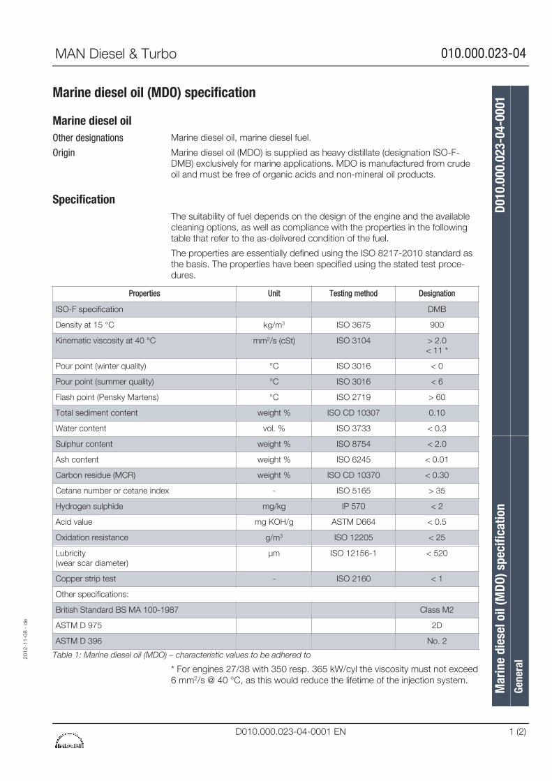
Marine diesel oil (MDO) specification
Marine diesel oilMarine diesel oil, marine diesel fuel.
Marine diesel oil (MDO) is supplied as heavy distillate (designation ISO-F-DMB) exclusively for marine applications. MDO is manufactured from crudeoil and must be free of organic acids and non-mineral oil products.
SpecificationThe suitability of fuel depends on the design of the engine and the availablecleaning options, as well as compliance with the properties in the followingtable that refer to the as-delivered condition of the fuel.
The properties are essentially defined using the ISO 8217-2010 standard asthe basis. The properties have been specified using the stated test proce-dures.
Properties Unit Testing method Designation
ISO-F specification DMB
Density at 15 °C kg/m3 ISO 3675 900
Kinematic viscosity at 40 °C mm2/s (cSt) ISO 3104 > 2.0< 11 *
Pour point (winter quality) °C ISO 3016 < 0
Pour point (summer quality) °C ISO 3016 < 6
Flash point (Pensky Martens) °C ISO 2719 > 60
Total sediment content weight % ISO CD 10307 0.10
Water content vol. % ISO 3733 < 0.3
Sulphur content weight % ISO 8754 < 2.0
Ash content weight % ISO 6245 < 0.01
Carbon residue (MCR) weight % ISO CD 10370 < 0.30
Cetane number or cetane index - ISO 5165 > 35
Hydrogen sulphide mg/kg IP 570 < 2
Acid value mg KOH/g ASTM D664 < 0.5
Oxidation resistance g/m3 ISO 12205 < 25
Lubricity(wear scar diameter)
μm ISO 12156-1 < 520
Copper strip test - ISO 2160 < 1
Other specifications:
British Standard BS MA 100-1987 Class M2
ASTM D 975 2D
ASTM D 396 No. 2
Table 1: Marine diesel oil (MDO) – characteristic values to be adhered to
* For engines 27/38 with 350 resp. 365 kW/cyl the viscosity must not exceed6 mm2/s @ 40 °C, as this would reduce the lifetime of the injection system.
Other designations
Origin
2012
-11-
08 -
de
Mar
ine
dies
el o
il (M
DO) s
peci
ficat
ion
D010
.000
.023
-04-
0001
Gene
ral
MAN Diesel & Turbo 010.000.023-04
D010.000.023-04-0001 EN 1 (2)
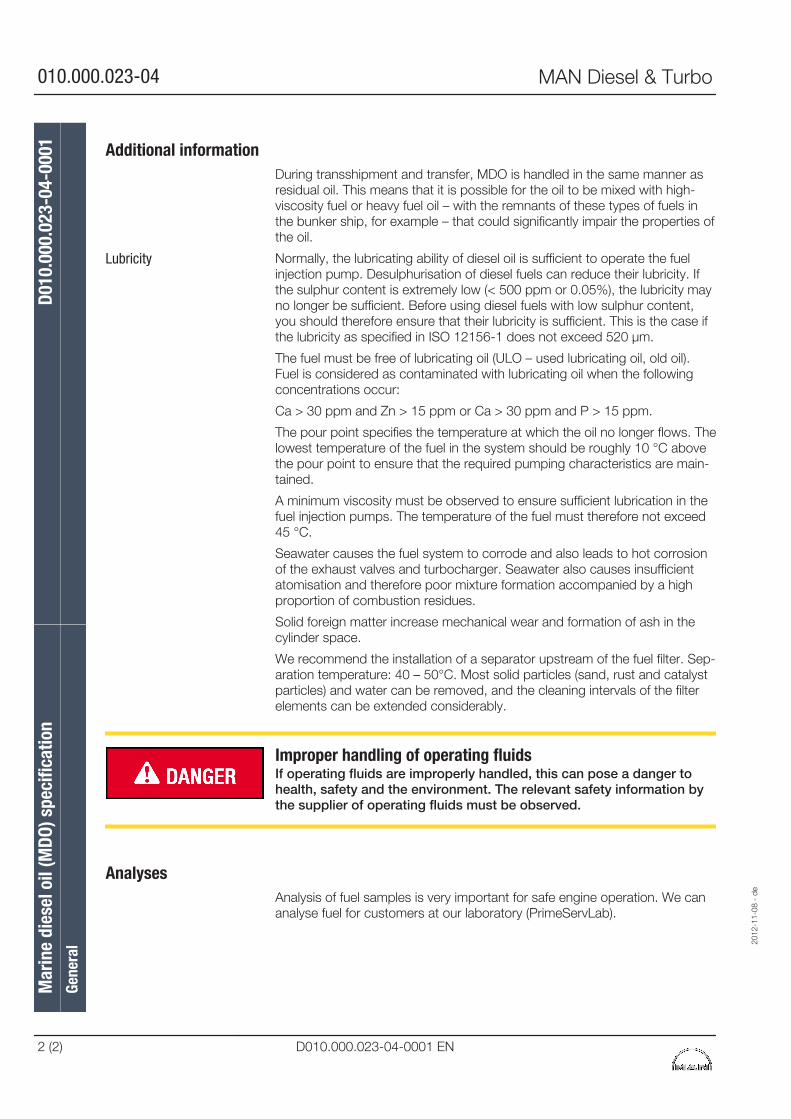
Additional informationDuring transshipment and transfer, MDO is handled in the same manner asresidual oil. This means that it is possible for the oil to be mixed with high-viscosity fuel or heavy fuel oil – with the remnants of these types of fuels inthe bunker ship, for example – that could significantly impair the properties ofthe oil.
Normally, the lubricating ability of diesel oil is sufficient to operate the fuelinjection pump. Desulphurisation of diesel fuels can reduce their lubricity. Ifthe sulphur content is extremely low (< 500 ppm or 0.05%), the lubricity mayno longer be sufficient. Before using diesel fuels with low sulphur content,you should therefore ensure that their lubricity is sufficient. This is the case ifthe lubricity as specified in ISO 12156-1 does not exceed 520 μm.
The fuel must be free of lubricating oil (ULO – used lubricating oil, old oil).Fuel is considered as contaminated with lubricating oil when the followingconcentrations occur:
Ca > 30 ppm and Zn > 15 ppm or Ca > 30 ppm and P > 15 ppm.
The pour point specifies the temperature at which the oil no longer flows. Thelowest temperature of the fuel in the system should be roughly 10 °C abovethe pour point to ensure that the required pumping characteristics are main-tained.
A minimum viscosity must be observed to ensure sufficient lubrication in thefuel injection pumps. The temperature of the fuel must therefore not exceed45 °C.
Seawater causes the fuel system to corrode and also leads to hot corrosionof the exhaust valves and turbocharger. Seawater also causes insufficientatomisation and therefore poor mixture formation accompanied by a highproportion of combustion residues.
Solid foreign matter increase mechanical wear and formation of ash in thecylinder space.
We recommend the installation of a separator upstream of the fuel filter. Sep-aration temperature: 40 – 50°C. Most solid particles (sand, rust and catalystparticles) and water can be removed, and the cleaning intervals of the filterelements can be extended considerably.
Improper handling of operating fluidsIf operating fluids are improperly handled, this can pose a danger tohealth, safety and the environment. The relevant safety information bythe supplier of operating fluids must be observed.
AnalysesAnalysis of fuel samples is very important for safe engine operation. We cananalyse fuel for customers at our laboratory (PrimeServLab).
Lubricity
Mar
ine
dies
el o
il (M
DO) s
peci
ficat
ion
D010
.000
.023
-04-
0001
Gene
ral
2012
-11-
08 -
de
010.000.023-04 MAN Diesel & Turbo
2 (2) D010.000.023-04-0001 EN
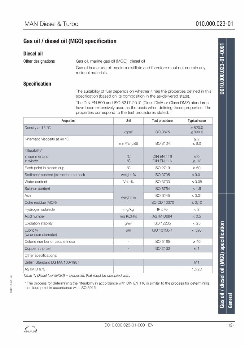
Gas oil / diesel oil (MGO) specification
Diesel oilGas oil, marine gas oil (MGO), diesel oil
Gas oil is a crude oil medium distillate and therefore must not contain anyresidual materials.
SpecificationThe suitability of fuel depends on whether it has the properties defined in thisspecification (based on its composition in the as-delivered state).
The DIN EN 590 and ISO 8217-2010 (Class DMA or Class DMZ) standardshave been extensively used as the basis when defining these properties. Theproperties correspond to the test procedures stated.
Properties Unit Test procedure Typical value
Density at 15 °Ckg/m3 ISO 3675
≥ 820.0≤ 890.0
Kinematic viscosity at 40 °Cmm2/s (cSt) ISO 3104
≥ 2≤ 6.0
Filterability*
in summer andin winter
°C°C
DIN EN 116DIN EN 116
≤ 0≤ -12
Flash point in closed cup °C ISO 2719 ≥ 60
Sediment content (extraction method) weight % ISO 3735 ≤ 0.01
Water content Vol. % ISO 3733 ≤ 0.05
Sulphur content
weight %
ISO 8754 ≤ 1.5
Ash ISO 6245 ≤ 0.01
Coke residue (MCR) ISO CD 10370 ≤ 0.10
Hydrogen sulphide mg/kg IP 570 < 2
Acid number mg KOH/g ASTM D664 < 0.5
Oxidation stability g/m3 ISO 12205 < 25
Lubricity(wear scar diameter)
μm ISO 12156-1 < 520
Cetane number or cetane index - ISO 5165 ≥ 40
Copper strip test - ISO 2160 ≤ 1
Other specifications:
British Standard BS MA 100-1987 M1
ASTM D 975 1D/2D
Table 1: Diesel fuel (MGO) – properties that must be complied with.
* The process for determining the filterability in accordance with DIN EN 116 is similar to the process for determiningthe cloud point in accordance with ISO 3015
Other designations
2012
-11-
08 -
de
Gas
oil /
die
sel o
il (M
GO) s
peci
ficat
ion
D010
.000
.023
-01-
0001
Gene
ral
MAN Diesel & Turbo 010.000.023-01
D010.000.023-01-0001 EN 1 (2)
Additional informationIf distillate intended for use as heating oil is used with stationary enginesinstead of diesel oil (EL heating oil according to DIN 51603 or Fuel No. 1 orno. 2 according to ASTM D 396), the ignition behaviour, stability and behav-iour at low temperatures must be ensured; in other words the requirementsfor the filterability and cetane number must be satisfied.
To ensure sufficient lubrication, a minimum viscosity must be ensured at thefuel pump. The maximum temperature required to ensure that a viscosity ofmore than 1.9 mm2/s is maintained upstream of the fuel pump, depends onthe fuel viscosity. In any case, the fuel temperature upstream of the injectionpump must not exceed 45 °C.
Normally, the lubricating ability of diesel oil is sufficient to operate the fuelinjection pump. Desulphurisation of diesel fuels can reduce their lubricity. Ifthe sulphur content is extremely low (< 500 ppm or 0.05%), the lubricity mayno longer be sufficient. Before using diesel fuels with low sulphur content,you should therefore ensure that their lubricity is sufficient. This is the case ifthe lubricity as specified in ISO 12156-1 does not exceed 520 μm.
You can ensure that these conditions will be met by using motor vehicle die-sel fuel in accordance with EN 590 as this characteristic value is an integralpart of the specification.
Improper handling of operating fluidsIf operating fluids are improperly handled, this can pose a danger tohealth, safety and the environment. The relevant safety information bythe supplier of operating fluids must be observed.
AnalysesAnalysis of fuel samples is very important for safe engine operation. We cananalyse fuel for customers at our laboratory (PrimeServLab).
Use of diesel oil
Viscosity
Lubricity
Gas
oil /
die
sel o
il (M
GO) s
peci
ficat
ion
D010
.000
.023
-01-
0001
Gene
ral
2012
-11-
08 -
de
010.000.023-01 MAN Diesel & Turbo
2 (2) D010.000.023-01-0001 EN
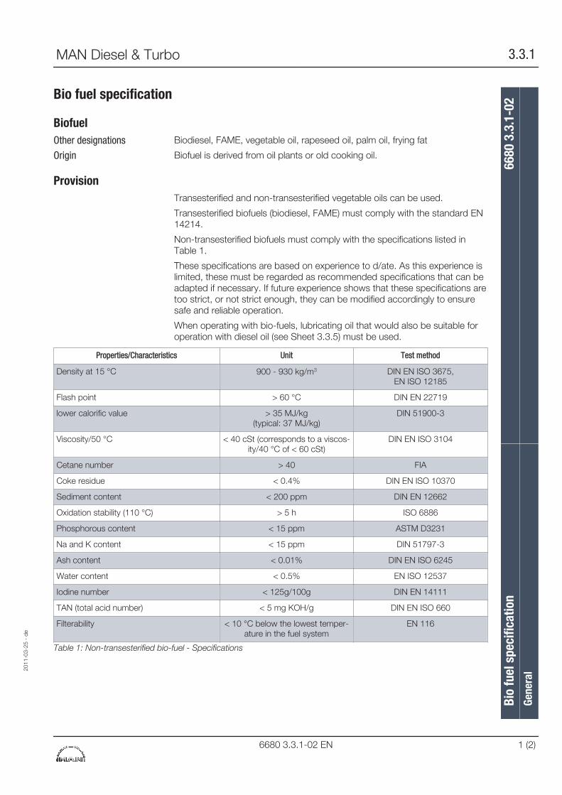
Bio fuel specification
BiofuelBiodiesel, FAME, vegetable oil, rapeseed oil, palm oil, frying fat
Biofuel is derived from oil plants or old cooking oil.
ProvisionTransesterified and non-transesterified vegetable oils can be used.
Transesterified biofuels (biodiesel, FAME) must comply with the standard EN14214.
Non-transesterified biofuels must comply with the specifications listed inTable 1.
These specifications are based on experience to d/ate. As this experience islimited, these must be regarded as recommended specifications that can beadapted if necessary. If future experience shows that these specifications aretoo strict, or not strict enough, they can be modified accordingly to ensuresafe and reliable operation.
When operating with bio-fuels, lubricating oil that would also be suitable foroperation with diesel oil (see Sheet 3.3.5) must be used.
Properties/Characteristics Unit Test method
Density at 15 °C 900 - 930 kg/m3 DIN EN ISO 3675,EN ISO 12185
Flash point > 60 °C DIN EN 22719
lower calorific value > 35 MJ/kg(typical: 37 MJ/kg)
DIN 51900-3
Viscosity/50 °C < 40 cSt (corresponds to a viscos-ity/40 °C of < 60 cSt)
DIN EN ISO 3104
Cetane number > 40 FIA
Coke residue < 0.4% DIN EN ISO 10370
Sediment content < 200 ppm DIN EN 12662
Oxidation stability (110 °C) > 5 h ISO 6886
Phosphorous content < 15 ppm ASTM D3231
Na and K content < 15 ppm DIN 51797-3
Ash content < 0.01% DIN EN ISO 6245
Water content < 0.5% EN ISO 12537
Iodine number < 125g/100g DIN EN 14111
TAN (total acid number) < 5 mg KOH/g DIN EN ISO 660
Filterability < 10 °C below the lowest temper-ature in the fuel system
EN 116
Table 1: Non-transesterified bio-fuel - Specifications
Other designations
Origin
2011
-03-
25 -
de
Bio
fuel
spe
cific
atio
n66
80 3
.3.1
-02
Gene
ral
MAN Diesel & Turbo 3.3.1
6680 3.3.1-02 EN 1 (2)
Improper handling of operating fluidsIf operating fluids are improperly handled, this can pose a danger tohealth, safety and the environment. The relevant safety information bythe supplier of operating fluids must be observed.
AnalysesWe can analyse fuel for customers at our laboratory. A 0.5 l sample isrequired for the test.
Bio
fuel
spe
cific
atio
n66
80 3
.3.1
-02
Gene
ral
2011
-03-
25 -
de
3.3.1 MAN Diesel & Turbo
2 (2) 6680 3.3.1-02 EN
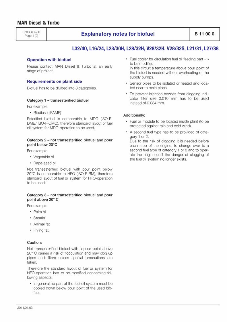
Operation with biofuel
Please contact MAN Diesel & Turbo at an earlystage of project.
Requirements on plant side
Biofuel has to be divided into 3 categories.
Category 1 – transesterified biofuel
For example:
▪ Biodiesel (FAME)
Esterified biofuel is comparable to MDO (ISO-F-DMB/ ISO-F-DMC), therefore standard layout of fueloil system for MDO-operation to be used.
Category 2 – not transesterified biofuel and pourpoint below 20°C
For example:
▪ Vegetable oil
▪ Rape-seed oil
Not transesterified biofuel with pour point below20°C is comparable to HFO (ISO-F-RM), thereforestandard layout of fuel oil system for HFO-operationto be used.
Category 3 – not transesterified biofuel and pourpoint above 20° C
For example:
▪ Palm oil
▪ Stearin
▪ Animal fat
▪ Frying fat
Caution:
Not transesterified biofuel with a pour point above20° C carries a risk of flocculation and may clog uppipes and filters unless special precautions aretaken.
Therefore the standard layout of fuel oil system forHFO-operation has to be modified concerning fol-lowing aspects:
▪ In general no part of the fuel oil system must becooled down below pour point of the used bio-fuel.
▪ Fuel cooler for circulation fuel oil feeding part =>to be modified. In this circuit a temperature above pour point ofthe biofuel is needed without overheating of thesupply pumps.
▪ Sensor pipes to be isolated or heated and loca-ted near to main pipes.
▪ To prevent injection nozzles from clogging indi-cator filter size 0.010 mm has to be usedinstead of 0.034 mm.
Additionally:
▪ Fuel oil module to be located inside plant (to beprotected against rain and cold wind).
▪ A second fuel type has to be provided of cate-gory 1 or 2. Due to the risk of clogging it is needed beforeeach stop of the engine, to change over to asecond fuel type of category 1 or 2 and to oper-ate the engine until the danger of clogging ofthe fuel oil system no longer exists.
MAN Diesel & Turbo
3700063-9.0Page 1 (2) Explanatory notes for biofuel B 11 00 0
L32/40, L16/24, L23/30H, L28/32H, V28/32H, V28/32S, L21/31, L27/38
2011.01.03
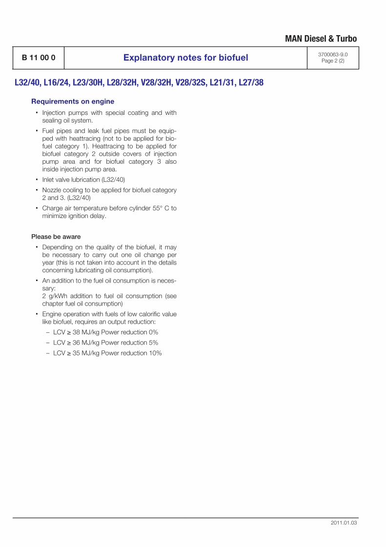
Requirements on engine
▪ Injection pumps with special coating and withsealing oil system.
▪ Fuel pipes and leak fuel pipes must be equip-ped with heattracing (not to be applied for bio-fuel category 1). Heattracing to be applied forbiofuel category 2 outside covers of injectionpump area and for biofuel category 3 alsoinside injection pump area.
▪ Inlet valve lubrication (L32/40)
▪ Nozzle cooling to be applied for biofuel category2 and 3. (L32/40)
▪ Charge air temperature before cylinder 55° C tominimize ignition delay.
Please be aware
▪ Depending on the quality of the biofuel, it maybe necessary to carry out one oil change peryear (this is not taken into account in the detailsconcerning lubricating oil consumption).
▪ An addition to the fuel oil consumption is neces-sary:2 g/kWh addition to fuel oil consumption (seechapter fuel oil consumption)
▪ Engine operation with fuels of low calorific valuelike biofuel, requires an output reduction:
– LCV ≥ 38 MJ/kg Power reduction 0%
– LCV ≥ 36 MJ/kg Power reduction 5%
– LCV ≥ 35 MJ/kg Power reduction 10%
MAN Diesel & Turbo
B 11 00 0 Explanatory notes for biofuel 3700063-9.0Page 2 (2)
L32/40, L16/24, L23/30H, L28/32H, V28/32H, V28/32S, L21/31, L27/38
2011.01.03
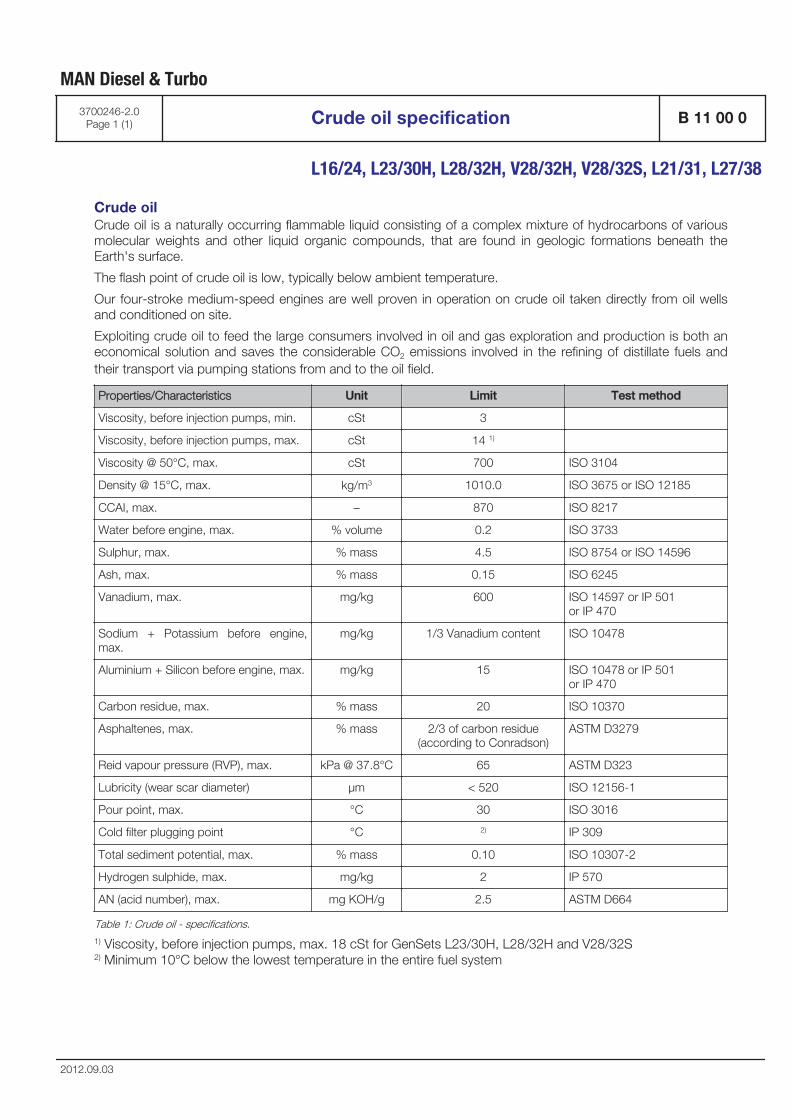
Crude oilCrude oil is a naturally occurring flammable liquid consisting of a complex mixture of hydrocarbons of variousmolecular weights and other liquid organic compounds, that are found in geologic formations beneath theEarth's surface.
The flash point of crude oil is low, typically below ambient temperature.
Our four-stroke medium-speed engines are well proven in operation on crude oil taken directly from oil wellsand conditioned on site.
Exploiting crude oil to feed the large consumers involved in oil and gas exploration and production is both aneconomical solution and saves the considerable CO2 emissions involved in the refining of distillate fuels andtheir transport via pumping stations from and to the oil field.
Properties/Characteristics Unit Limit Test method
Viscosity, before injection pumps, min. cSt 3
Viscosity, before injection pumps, max. cSt 14 1)
Viscosity @ 50°C, max. cSt 700 ISO 3104
Density @ 15°C, max. kg/m3 1010.0 ISO 3675 or ISO 12185
CCAI, max. – 870 ISO 8217
Water before engine, max. % volume 0.2 ISO 3733
Sulphur, max. % mass 4.5 ISO 8754 or ISO 14596
Ash, max. % mass 0.15 ISO 6245
Vanadium, max. mg/kg 600 ISO 14597 or IP 501 or IP 470
Sodium + Potassium before engine,max.
mg/kg 1/3 Vanadium content ISO 10478
Aluminium + Silicon before engine, max. mg/kg 15 ISO 10478 or IP 501 or IP 470
Carbon residue, max. % mass 20 ISO 10370
Asphaltenes, max. % mass 2/3 of carbon residue(according to Conradson)
ASTM D3279
Reid vapour pressure (RVP), max. kPa @ 37.8°C 65 ASTM D323
Lubricity (wear scar diameter) μm < 520 ISO 12156-1
Pour point, max. °C 30 ISO 3016
Cold filter plugging point °C 2) IP 309
Total sediment potential, max. % mass 0.10 ISO 10307-2
Hydrogen sulphide, max. mg/kg 2 IP 570
AN (acid number), max. mg KOH/g 2.5 ASTM D664
Table 1: Crude oil - specifications.1) Viscosity, before injection pumps, max. 18 cSt for GenSets L23/30H, L28/32H and V28/32S2) Minimum 10°C below the lowest temperature in the entire fuel system
MAN Diesel & Turbo
3700246-2.0Page 1 (1) Crude oil specification B 11 00 0
L16/24, L23/30H, L28/32H, V28/32H, V28/32S, L21/31, L27/38
2012.09.03

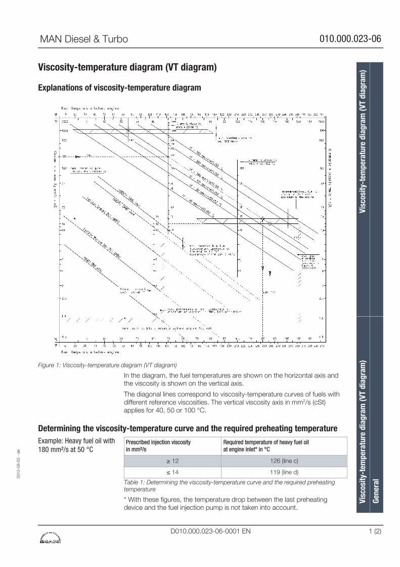
Viscosity-temperature diagram (VT diagram)
Explanations of viscosity-temperature diagram
Figure 1: Viscosity-temperature diagram (VT diagram)
In the diagram, the fuel temperatures are shown on the horizontal axis andthe viscosity is shown on the vertical axis.
The diagonal lines correspond to viscosity-temperature curves of fuels withdifferent reference viscosities. The vertical viscosity axis in mm2/s (cSt)applies for 40, 50 or 100 °C.
Determining the viscosity-temperature curve and the required preheating temperaturePrescribed injection viscosityin mm²/s
Required temperature of heavy fuel oilat engine inlet* in °C
≥ 12 126 (line c)
≤ 14 119 (line d)
Table 1: Determining the viscosity-temperature curve and the required preheatingtemperature
* With these figures, the temperature drop between the last preheatingdevice and the fuel injection pump is not taken into account.
Example: Heavy fuel oil with180 mm²/s at 50 °C
2012
-08-
03 -
de
Visc
osity
-tem
pera
ture
dia
gram
(VT
diag
ram
)Vi
scos
ity-t
empe
ratu
re d
iagr
am (V
T di
agra
m)
Gene
ral
MAN Diesel & Turbo 010.000.023-06
D010.000.023-06-0001 EN 1 (2)
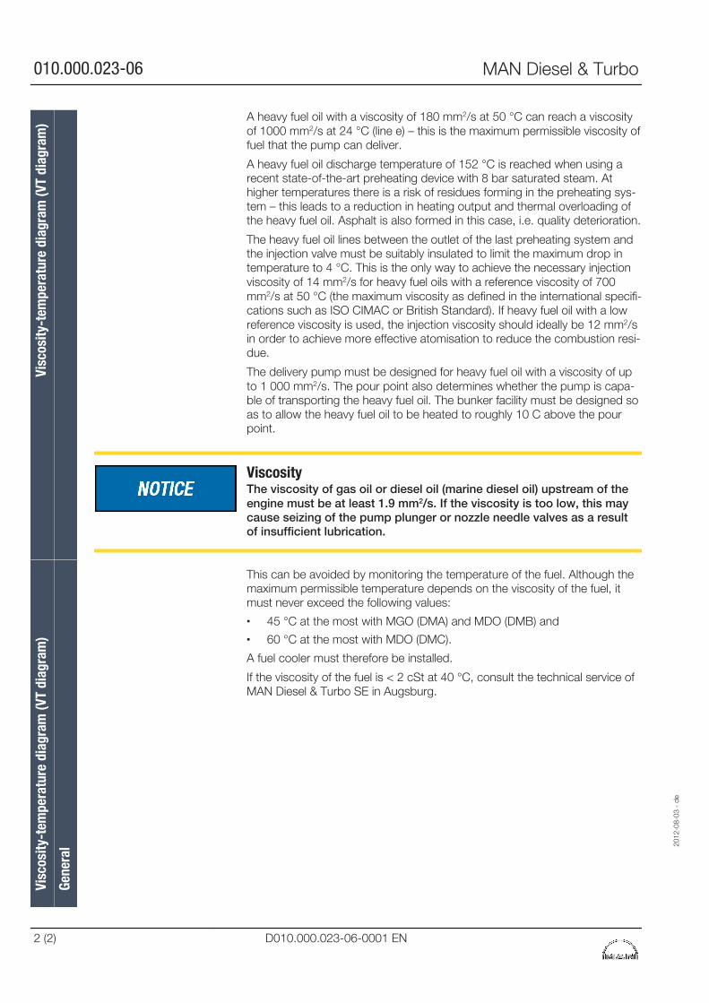
A heavy fuel oil with a viscosity of 180 mm2/s at 50 °C can reach a viscosityof 1000 mm2/s at 24 °C (line e) – this is the maximum permissible viscosity offuel that the pump can deliver.
A heavy fuel oil discharge temperature of 152 °C is reached when using arecent state-of-the-art preheating device with 8 bar saturated steam. Athigher temperatures there is a risk of residues forming in the preheating sys-tem – this leads to a reduction in heating output and thermal overloading ofthe heavy fuel oil. Asphalt is also formed in this case, i.e. quality deterioration.
The heavy fuel oil lines between the outlet of the last preheating system andthe injection valve must be suitably insulated to limit the maximum drop intemperature to 4 °C. This is the only way to achieve the necessary injectionviscosity of 14 mm2/s for heavy fuel oils with a reference viscosity of 700mm2/s at 50 °C (the maximum viscosity as defined in the international specifi-cations such as ISO CIMAC or British Standard). If heavy fuel oil with a lowreference viscosity is used, the injection viscosity should ideally be 12 mm2/sin order to achieve more effective atomisation to reduce the combustion resi-due.
The delivery pump must be designed for heavy fuel oil with a viscosity of upto 1 000 mm2/s. The pour point also determines whether the pump is capa-ble of transporting the heavy fuel oil. The bunker facility must be designed soas to allow the heavy fuel oil to be heated to roughly 10 C above the pourpoint.
ViscosityThe viscosity of gas oil or diesel oil (marine diesel oil) upstream of theengine must be at least 1.9 mm2/s. If the viscosity is too low, this maycause seizing of the pump plunger or nozzle needle valves as a resultof insufficient lubrication.
This can be avoided by monitoring the temperature of the fuel. Although themaximum permissible temperature depends on the viscosity of the fuel, itmust never exceed the following values:
▪ 45 °C at the most with MGO (DMA) and MDO (DMB) and
▪ 60 °C at the most with MDO (DMC).
A fuel cooler must therefore be installed.
If the viscosity of the fuel is < 2 cSt at 40 °C, consult the technical service ofMAN Diesel & Turbo SE in Augsburg.
Visc
osity
-tem
pera
ture
dia
gram
(VT
diag
ram
)Vi
scos
ity-t
empe
ratu
re d
iagr
am (V
T di
agra
m)
Gene
ral
2012
-08-
03 -
de
010.000.023-06 MAN Diesel & Turbo
2 (2) D010.000.023-06-0001 EN
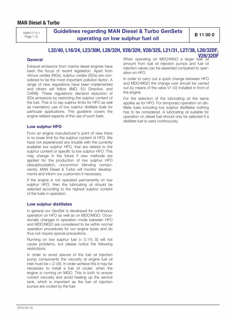
General
Exhaust emissions from marine diesel engines havebeen the focus of recent legislation. Apart fromnitrous oxides (NOx), sulphur oxides (SOx) are con-sidered to be the most important pollution factor. Arange of new regulations have been implementedand others will follow (IMO, EU Directive, andCARB). These regulations demand reduction ofSOx emissions by restricting the sulphur content ofthe fuel. That is to say sulphur limits for HFO as wellas mandatory use of low sulphur distillate fuels forparticular applications. This guideline covers theengine related aspects of the use of such fuels.
Low sulphur HFO
From an engine manufacturer’s point of view thereis no lower limit for the sulphur content of HFO. Wehave not experienced any trouble with the currentlyavailable low sulphur HFO, that are related to thesulphur content or specific to low sulphur HFO. Thismay change in the future if new methods areapplied for the production of low sulphur HFO(desulphurization, uncommon blending compo-nents). MAN Diesel & Turbo will monitor develop-ments and inform our customers if necessary.
If the engine is not operated permanently on lowsulphur HFO, then the lubricating oil should beselected according to the highest sulphur contentof the fuels in operation.
Low sulphur distillates
In general our GenSet is developed for continuousoperation on HFO as well as on MDO/MGO. Occa-sionally changes in operation mode between HFOand MDO/MGO are considered to be within normaloperation procedures for our engine types and dothus not require special precautions.
Running on low sulphur fuel (< 0.1% S) will notcause problems, but please notice the followingrestrictions:
In order to avoid seizure of the fuel oil injectionpump components the viscosity at engine fuel oilinlet must be > 2 cSt. In order achieve this it may benecessary to install a fuel oil cooler, when theengine is running on MGO. This is both to ensurecorrect viscosity and avoid heating up the servicetank, which is important as the fuel oil injectionpumps are cooled by the fuel.
When operating on MDO/MGO a larger leak oilamount from fuel oil injection pumps and fuel oilinjection valves can be expected compared to oper-ation on HFO.
In order to carry out a quick change between HFOand MDO/MGO the change over should be carriedout by means of the valve V1-V2 installed in front ofthe engine.
For the selection of the lubricating oil the sameapplies as for HFO. For temporary operation on dis-tillate fuels including low sulphur distillates nothinghas to be considered. A lubricating oil suitable foroperation on diesel fuel should only be selected if adistillate fuel is used continuously.
MAN Diesel & Turbo
1699177-5.1Page 1 (1)
Guidelines regarding MAN Diesel & Turbo GenSetsoperating on low sulphur fuel oil
B 11 00 0
L32/40, L16/24, L23/30H, L28/32H, V28/32H, V28/32S, L21/31, L27/38, L28/32DF,
V28/32DF
2010.04.19

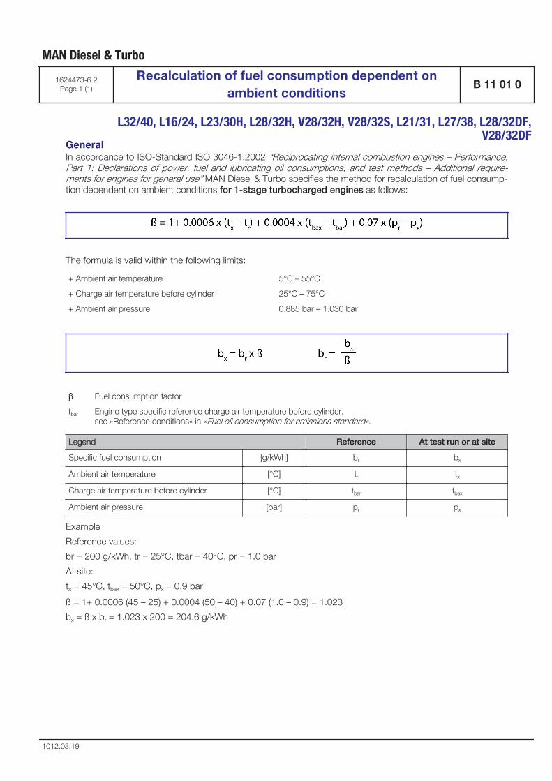
GeneralIn accordance to ISO-Standard ISO 3046-1:2002 “Reciprocating internal combustion engines – Performance,Part 1: Declarations of power, fuel and lubricating oil consumptions, and test methods – Additional require-ments for engines for general use” MAN Diesel & Turbo specifies the method for recalculation of fuel consump-tion dependent on ambient conditions for 1-stage turbocharged engines as follows:
The formula is valid within the following limits:
+ Ambient air temperature 5°C – 55°C
+ Charge air temperature before cylinder 25°C – 75°C
+ Ambient air pressure 0.885 bar – 1.030 bar
β Fuel consumption factor
tbar Engine type specific reference charge air temperature before cylinder, see »Reference conditions« in »Fuel oil consumption for emissions standard«.
Legend Reference At test run or at site
Specific fuel consumption [g/kWh] br bx
Ambient air temperature [°C] tr tx
Charge air temperature before cylinder [°C] tbar tbax
Ambient air pressure [bar] pr px
Example
Reference values:
br = 200 g/kWh, tr = 25°C, tbar = 40°C, pr = 1.0 bar
At site:
tx = 45°C, tbax = 50°C, px = 0.9 bar
ß = 1+ 0.0006 (45 – 25) + 0.0004 (50 – 40) + 0.07 (1.0 – 0.9) = 1.023
bx = ß x br = 1.023 x 200 = 204.6 g/kWh
MAN Diesel & Turbo
1624473-6.2Page 1 (1)
Recalculation of fuel consumption dependent onambient conditions
B 11 01 0
L32/40, L16/24, L23/30H, L28/32H, V28/32H, V28/32S, L21/31, L27/38, L28/32DF,
V28/32DF
1012.03.19

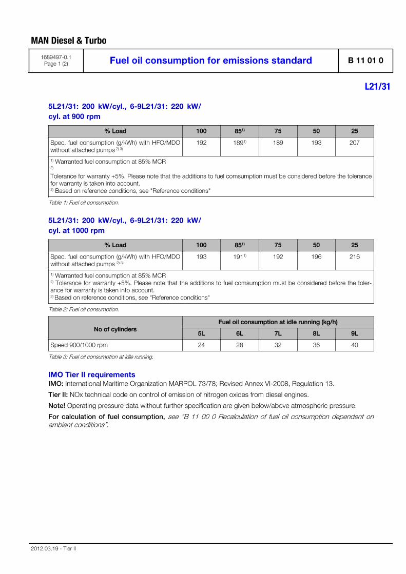
5L21/31: 200 kW/cyl., 6-9L21/31: 220 kW/cyl. at 900 rpm
% Load 100 851) 75 50 25
Spec. fuel consumption (g/kWh) with HFO/MDOwithout attached pumps 2) 3)
192 1891) 189 193 207
1) Warranted fuel consumption at 85% MCR 2)
Tolerance for warranty +5%. Please note that the additions to fuel comsumption must be considered before the tolerancefor warranty is taken into account. 3) Based on reference conditions, see "Reference conditions"
Table 1: Fuel oil consumption.
5L21/31: 200 kW/cyl., 6-9L21/31: 220 kW/cyl. at 1000 rpm
% Load 100 851) 75 50 25
Spec. fuel consumption (g/kWh) with HFO/MDOwithout attached pumps 2) 3)
193 1911) 192 196 216
1) Warranted fuel consumption at 85% MCR 2) Tolerance for warranty +5%. Please note that the additions to fuel comsumption must be considered before the toler-ance for warranty is taken into account. 3) Based on reference conditions, see "Reference conditions"
Table 2: Fuel oil consumption.
No of cylindersFuel oil consumption at idle running (kg/h)
5L 6L 7L 8L 9L
Speed 900/1000 rpm 24 28 32 36 40
Table 3: Fuel oil consumption at idle running.
IMO Tier II requirementsIMO: International Maritime Organization MARPOL 73/78; Revised Annex VI-2008, Regulation 13.
Tier II: NOx technical code on control of emission of nitrogen oxides from diesel engines.
Note! Operating pressure data without further specification are given below/above atmospheric pressure.
For calculation of fuel consumption, see "B 11 00 0 Recalculation of fuel oil consumption dependent onambient conditions".
MAN Diesel & Turbo
1689497-0.1Page 1 (2) Fuel oil consumption for emissions standard B 11 01 0
L21/31
2012.03.19 - Tier II
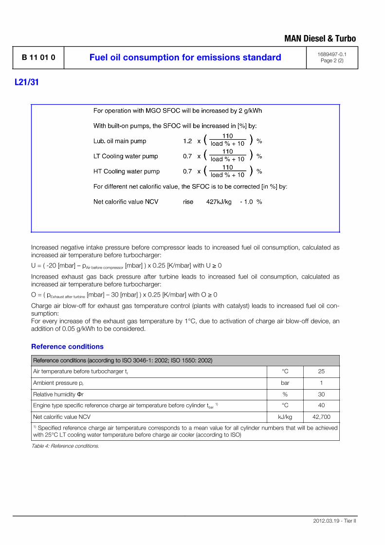
Increased negative intake pressure before compressor leads to increased fuel oil consumption, calculated asincreased air temperature before turbocharger:
U = ( -20 [mbar] – pAir before compressor [mbar] ) x 0.25 [K/mbar] with U ≥ 0
Increased exhaust gas back pressure after turbine leads to increased fuel oil consumption, calculated asincreased air temperature before turbocharger:
O = ( pExhaust after turbine [mbar] – 30 [mbar] ) x 0.25 [K/mbar] with O ≥ 0
Charge air blow-off for exhaust gas temperature control (plants with catalyst) leads to increased fuel oil con-sumption: For every increase of the exhaust gas temperature by 1°C, due to activation of charge air blow-off device, anaddition of 0.05 g/kWh to be considered.
Reference conditions
Reference conditions (according to ISO 3046-1: 2002; ISO 1550: 2002)
Air temperature before turbocharger tr °C 25
Ambient pressure pr bar 1
Relative humidity Φr % 30
Engine type specific reference charge air temperature before cylinder tbar 1) °C 40
Net calorific value NCV kJ/kg 42,700
1) Specified reference charge air temperature corresponds to a mean value for all cylinder numbers that will be achievedwith 25°C LT cooling water temperature before charge air cooler (according to ISO)
Table 4: Reference conditions.
MAN Diesel & Turbo
B 11 01 0 Fuel oil consumption for emissions standard 1689497-0.1Page 2 (2)
L21/31
2012.03.19 - Tier II
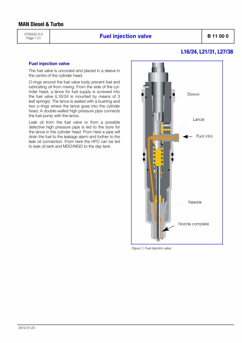
Fuel injection valve
The fuel valve is uncooled and placed in a sleeve inthe centre of the cylinder head.
O-rings around the fuel valve body prevent fuel andlubricating oil from mixing. From the side of the cyl-inder head, a lance for fuel supply is screwed intothe fuel valve (L16/24 is mounted by means of 3leaf springs). The lance is sealed with a bushing andtwo o-rings where the lance goes into the cylinderhead. A double-walled high pressure pipe connectsthe fuel pump with the lance.
Leak oil from the fuel valve or from a possibledefective high pressure pipe is led to the bore forthe lance in the cylinder head. From here a pipe willdrain the fuel to the leakage alarm and further to theleak oil connection. From here the HFO can be ledto leak oil tank and MDO/MGO to the day tank.
Figure 1: Fuel injection valve.
MAN Diesel & Turbo
3700222-2.0Page 1 (1) Fuel injection valve B 11 00 0
L16/24, L21/31, L27/38
2012.01.23

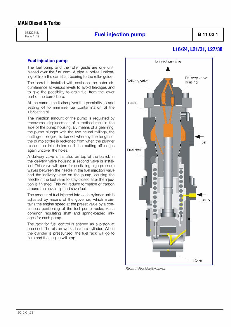
Fuel injection pump
The fuel pump and the roller guide are one unit,placed over the fuel cam. A pipe supplies lubricat-ing oil from the camshaft bearing to the roller guide.
The barrel is installed with seals on the outer cir-cumference at various levels to avoid leakages andto give the possibility to drain fuel from the lowerpart of the barrel bore.
At the same time it also gives the possibility to addsealing oil to minimize fuel contamination of thelubricating oil.
The injection amount of the pump is regulated bytransversal displacement of a toothed rack in theside of the pump housing. By means of a gear ring,the pump plunger with the two helical millings, thecutting-off edges, is turned whereby the length ofthe pump stroke is reckoned from when the plungercloses the inlet holes until the cutting-off edgesagain uncover the holes.
A delivery valve is installed on top of the barrel. Inthe delivery valve housing a second valve is instal-led. This valve will open for oscillating high pressurewaves between the needle in the fuel injection valveand the delivery valve on the pump, causing theneedle in the fuel valve to stay closed after the injec-tion is finished. This will reduce formation of carbonaround the nozzle tip and save fuel.
The amount of fuel injected into each cylinder unit isadjusted by means of the governor, which main-tains the engine speed at the preset value by a con-tinuous positioning of the fuel pump racks, via acommon regulating shaft and spring-loaded link-ages for each pump.
The rack for fuel control is shaped as a piston atone end. The piston works inside a cylinder. Whenthe cylinder is pressurized, the fuel rack will go tozero and the engine will stop.
Figure 1: Fuel injection pump.
MAN Diesel & Turbo
1683324-8.1Page 1 (1) Fuel injection pump B 11 02 1
L16/24, L21/31, L27/38
2012.01.23

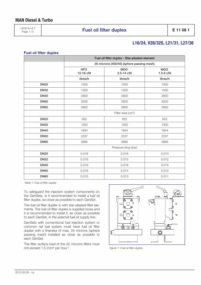
Fuel oil filter duplex Fuel oil filter duplex - Star-pleated element
25 microns (400/40) (sphere passing mesh)
HFO 12-18 cSt
MDO 2.5-14 cSt
MGO 1.5-6 cSt
litres/h litres/h litres/h
DN25 1000 1000 1000
DN32 1500 1500 1500
DN40 2800 2800 2800
DN50 3500 3500 3500
DN65 5800 5800 5800
Filter area (cm2)
DN25 652 652 652
DN32 1000 1000 1000
DN40 1844 1844 1844
DN50 2337 2337 2337
DN65 3885 3885 3885
Pressure drop (bar)
DN25 0.018 0.016 0.013
DN32 0.016 0.015 0.012
DN40 0.019 0.018 0.015
DN50 0.016 0.014 0.012
DN65 0.015 0.013 0.011
Table 1: Fuel oil filter duplex
To safeguard the injection system components onthe GenSets, is it recommended to install a fuel oilfilter duplex, as close as possible to each GenSet.
The fuel oil filter duplex is with star-pleated filter ele-ments. The fuel oil filter duplex is supplied loose andit is recommended to install it, as close as possibleto each GenSet, in the external fuel oil supply line.
GenSets with conventional fuel injection system orcommon rail fuel system must have fuel oil filterduplex with a fineness of max. 25 microns (spherepassing mesh) installed as close as possible toeach GenSet.
The filter surface load of the 25 microns filters mustnot exceed 1.5 l/cm² per hour ! Figure 1: Fuel oil filter duplex.
MAN Diesel & Turbo
1679744-6.7Page 1 (1) Fuel oil filter duplex E 11 08 1
L16/24, V28/32S, L21/31, L27/38
2013.05.28 - ny

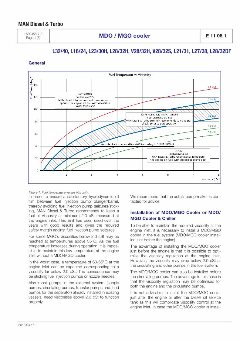
General
Figure 1: Fuel temperature versus viscosity.In order to ensure a satisfactory hydrodynamic oilfilm between fuel injection pump plunger/barrel,thereby avoiding fuel injection pump seizures/stick-ing, MAN Diesel & Turbo recommends to keep afuel oil viscosity at minimum 2.0 cSt measured atthe engine inlet. This limit has been used over theyears with good results and gives the requiredsafety margin against fuel injection pump seizures.
For some MGO´s viscosities below 2.0 cSt may bereached at temperatures above 35°C. As the fueltemperature increases during operation, it is impos-sible to maintain this low temperature at the engineinlet without a MDO/MGO cooler.
In the worst case, a temperature of 60-65°C at theengine inlet can be expected corresponding to aviscosity far below 2.0 cSt. The consequence maybe sticking fuel injection pumps or nozzle needles.
Also most pumps in the external system (supplypumps, circulating pumps, transfer pumps and feedpumps for the separator) already installed in existingvessels, need viscosities above 2.0 cSt to functionproperly.
We recommend that the actual pump maker is con-tacted for advice.
Installation of MDO/MGO Cooler or MDO/MGO Cooler & Chiller
To be able to maintain the required viscosity at theengine inlet, it is necessary to install a MDO/MGOcooler in the fuel system (MDO/MGO cooler instal-led just before the engine).
The advantage of installing the MDO/MGO coolerjust before the engine is that it is possible to opti-mise the viscosity regulation at the engine inlet.However, the viscosity may drop below 2.0 cSt atthe circulating and other pumps in the fuel system.
The MDO/MGO cooler can also be installed beforethe circulating pumps. The advantage in this case isthat the viscosity regulation may be optimised forboth the engine and the circulating pumps.
It is not advisable to install the MDO/MGO coolerjust after the engine or after the Diesel oil servicetank as this will complicate viscosity control at theengine inlet. In case the MDO/MGO cooler is instal-
MAN Diesel & Turbo
1689458-7.3Page 1 (3) MDO / MGO cooler E 11 06 1
L32/40, L16/24, L23/30H, L28/32H, V28/32H, V28/32S, L21/31, L27/38, L28/32DF
2013.04.16
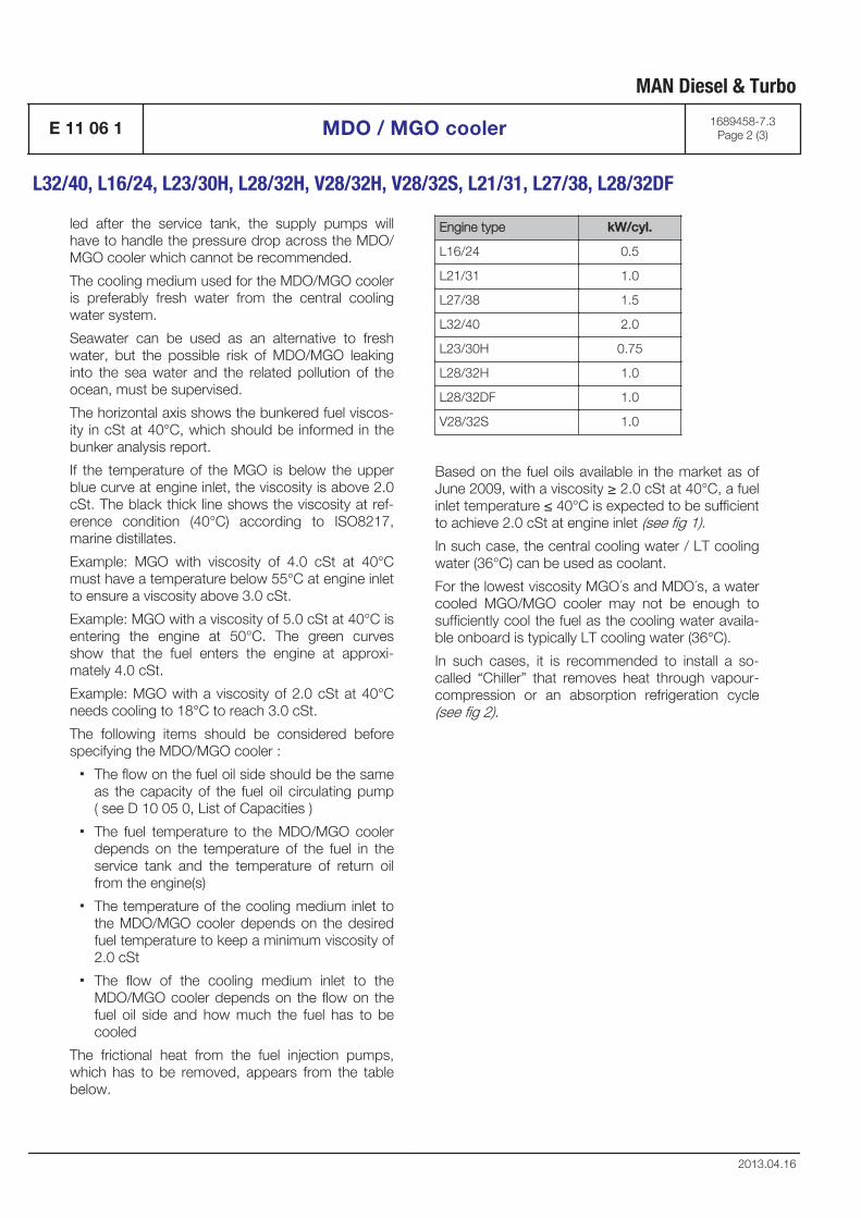
led after the service tank, the supply pumps willhave to handle the pressure drop across the MDO/MGO cooler which cannot be recommended.
The cooling medium used for the MDO/MGO cooleris preferably fresh water from the central coolingwater system.
Seawater can be used as an alternative to freshwater, but the possible risk of MDO/MGO leakinginto the sea water and the related pollution of theocean, must be supervised.
The horizontal axis shows the bunkered fuel viscos-ity in cSt at 40°C, which should be informed in thebunker analysis report.
If the temperature of the MGO is below the upperblue curve at engine inlet, the viscosity is above 2.0cSt. The black thick line shows the viscosity at ref-erence condition (40°C) according to ISO8217,marine distillates.
Example: MGO with viscosity of 4.0 cSt at 40°Cmust have a temperature below 55°C at engine inletto ensure a viscosity above 3.0 cSt.
Example: MGO with a viscosity of 5.0 cSt at 40°C isentering the engine at 50°C. The green curvesshow that the fuel enters the engine at approxi-mately 4.0 cSt.
Example: MGO with a viscosity of 2.0 cSt at 40°Cneeds cooling to 18°C to reach 3.0 cSt.
The following items should be considered beforespecifying the MDO/MGO cooler :
▪ The flow on the fuel oil side should be the sameas the capacity of the fuel oil circulating pump( see D 10 05 0, List of Capacities )
▪ The fuel temperature to the MDO/MGO coolerdepends on the temperature of the fuel in theservice tank and the temperature of return oilfrom the engine(s)
▪ The temperature of the cooling medium inlet tothe MDO/MGO cooler depends on the desiredfuel temperature to keep a minimum viscosity of2.0 cSt
▪ The flow of the cooling medium inlet to theMDO/MGO cooler depends on the flow on thefuel oil side and how much the fuel has to becooled
The frictional heat from the fuel injection pumps,which has to be removed, appears from the tablebelow.
Engine type kW/cyl.
L16/24 0.5
L21/31 1.0
L27/38 1.5
L32/40 2.0
L23/30H 0.75
L28/32H 1.0
L28/32DF 1.0
V28/32S 1.0
Based on the fuel oils available in the market as ofJune 2009, with a viscosity ≥ 2.0 cSt at 40°C, a fuelinlet temperature ≤ 40°C is expected to be sufficientto achieve 2.0 cSt at engine inlet (see fig 1).
In such case, the central cooling water / LT coolingwater (36°C) can be used as coolant.
For the lowest viscosity MGO´s and MDO´s, a watercooled MGO/MGO cooler may not be enough tosufficiently cool the fuel as the cooling water availa-ble onboard is typically LT cooling water (36°C).
In such cases, it is recommended to install a so-called “Chiller” that removes heat through vapour-compression or an absorption refrigeration cycle(see fig 2).
MAN Diesel & Turbo
E 11 06 1 MDO / MGO cooler 1689458-7.3Page 2 (3)
L32/40, L16/24, L23/30H, L28/32H, V28/32H, V28/32S, L21/31, L27/38, L28/32DF
2013.04.16
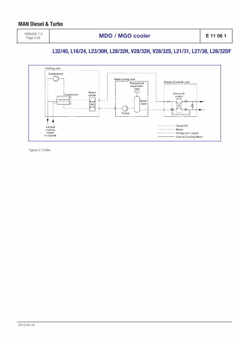
Figure 2: Chiller.
MAN Diesel & Turbo
1689458-7.3Page 3 (3) MDO / MGO cooler E 11 06 1
L32/40, L16/24, L23/30H, L28/32H, V28/32H, V28/32S, L21/31, L27/38, L28/32DF
2013.04.16

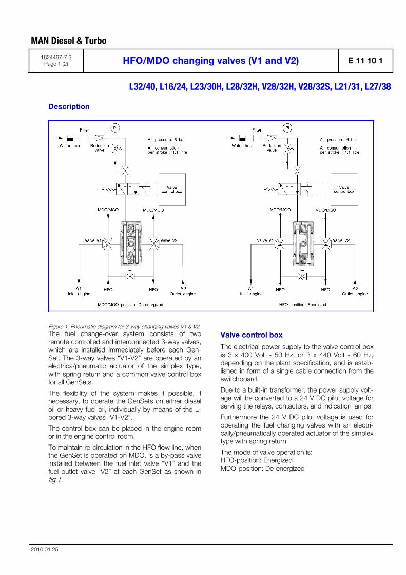
Description
Figure 1: Pneumatic diagram for 3-way changing valves V1 & V2.The fuel change-over system consists of tworemote controlled and interconnected 3-way valves,which are installed immediately before each Gen-Set. The 3-way valves “V1-V2” are operated by anelectrica/pneumatic actuator of the simplex type,with spring return and a common valve control boxfor all GenSets.
The flexibility of the system makes it possible, ifnecessary, to operate the GenSets on either dieseloil or heavy fuel oil, individually by means of the L-bored 3-way valves “V1-V2”.
The control box can be placed in the engine roomor in the engine control room.
To maintain re-circulation in the HFO flow line, whenthe GenSet is operated on MDO, is a by-pass valveinstalled between the fuel inlet valve “V1” and thefuel outlet valve “V2” at each GenSet as shown infig 1.
Valve control box
The electrical power supply to the valve control boxis 3 x 400 Volt - 50 Hz, or 3 x 440 Volt - 60 Hz,depending on the plant specification, and is estab-lished in form of a single cable connection from theswitchboard.
Due to a built-in transformer, the power supply volt-age will be converted to a 24 V DC pilot voltage forserving the relays, contactors, and indication lamps.
Furthermore the 24 V DC pilot voltage is used foroperating the fuel changing valves with an electri-cally/pneumatically operated actuator of the simplextype with spring return.
The mode of valve operation is: HFO-position: Energized MDO-position: De-energized
MAN Diesel & Turbo
1624467-7.3Page 1 (2) HFO/MDO changing valves (V1 and V2) E 11 10 1
L32/40, L16/24, L23/30H, L28/32H, V28/32H, V28/32S, L21/31, L27/38
2010.01.25

In the event of a black-out, or other situationsresulting in dead voltage potential, will the remotecontrolled and interconnected 3-way valves at eachGenSet be de-energized and automatically changeover to the MDO/MGO-position, due to the built-inreturn spring. The internal piping on the GenSetswill then, within a few seconds, be flushed withMDO/MGO and be ready for start up.
MAN Diesel & Turbo
E 11 10 1 HFO/MDO changing valves (V1 and V2) 1624467-7.3Page 2 (2)
L32/40, L16/24, L23/30H, L28/32H, V28/32H, V28/32S, L21/31, L27/38
2010.01.25

Lubrication Oil System
B 12

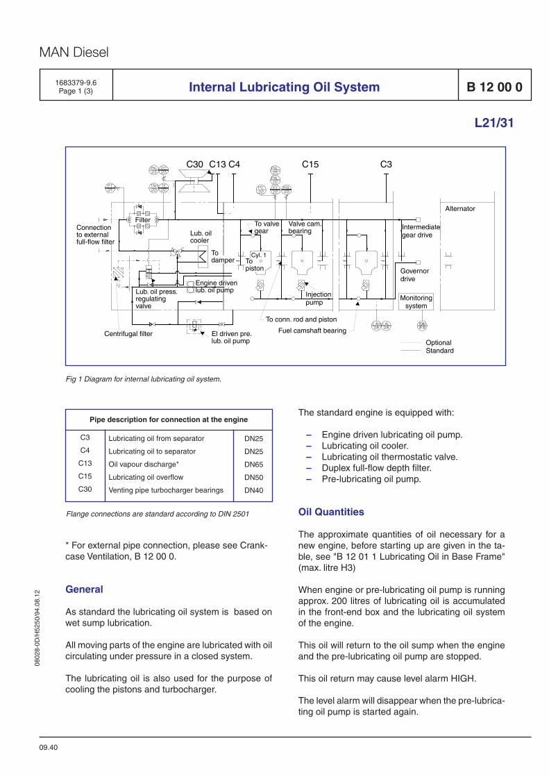
0802
8-0D
/H52
50/9
4.08
.12
MAN Diesel
1683379-9.6Page 1 (3) Internal Lubricating Oil System B 12 00 0
L21/31
09.40
Fig 1 Diagram for internal lubricating oil system.
Pipe description for connection at the engine
DN25
DN25
DN65
DN50
DN40
Lubricating oil from separator
Lubricating oil to separator
Oil vapour discharge*
Lubricating oil overflow
Venting pipe turbocharger bearings
C3
C4
C13
C15
C30
Flange connections are standard according to DIN 2501
* For external pipe connection, please see Crank-case Ventilation, B 12 00 0.
General
As standard the lubricating oil system is based on wet sump lubrication.
All moving parts of the engine are lubricated with oil circulating under pressure in a closed system.
The lubricating oil is also used for the pur pose of cooling the pistons and turbocharger.
The standard engine is equipped with:
– Engine driven lubricating oil pump. – Lubricating oil cooler. – Lubricating oil thermostatic valve. – Duplex full-flow depth filter. – Pre-lubricating oil pump.
Oil Quantities
The approximate quantities of oil necessary for a new engine, before starting up are given in the ta-ble, see "B 12 01 1 Lubricating Oil in Base Frame" (max. litre H3)
When engine or pre-lubricating oil pump is running approx. 200 litres of lubricating oil is accumulated in the front-end box and the lubricating oil system of the engine.
This oil will return to the oil sump when the engine and the pre-lubricating oil pump are stopped.
This oil return may cause level alarm HIGH.
The level alarm will disappear when the pre-lubrica-ting oil pump is started again.
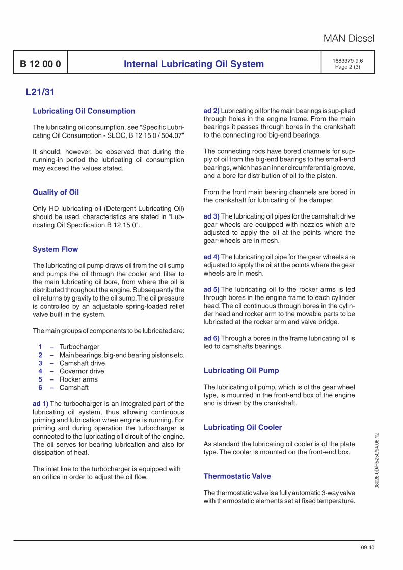
0802
8-0D
/H52
50/9
4.08
.12
MAN Diesel
09.40
1683379-9.6Page 2 (3)Internal Lubricating Oil SystemB 12 00 0
L21/31
Lubricating Oil Consumption
The lubricating oil consumption, see "Specific Lubri-cating Oil Consumption - SLOC, B 12 15 0 / 504.07"
It should, however, be observed that during the running-in period the lubricating oil consumption may exceed the values stated.
Quality of Oil
Only HD lubricating oil (Detergent Lubricating Oil) should be used, characteristics are stated in "Lub-ricating Oil Specification B 12 15 0".
System Flow
The lubricating oil pump draws oil from the oil sump and pumps the oil through the cooler and filter to the main lubricating oil bore, from where the oil is distri buted throughout the engine. Subsequently the oil returns by gravity to the oil sump.The oil pressure is controlled by an adjustable spring-loaded relief valve built in the system.
The main groups of components to be lubricated are:
1 – Turbocharger 2 – Main bearings, big-end bearing pistons etc. 3 – Camshaft drive 4 – Governor drive 5 – Rocker arms 6 – Camshaft
ad 1) The turbocharger is an integrated part of the lubricating oil system, thus allowing continuous priming and lubrication when engine is running. For priming and during operation the tur bo char ger is connected to the lubricating oil circuit of the engine. The oil serves for bearing lubrication and also for dissipation of heat.
The inlet line to the turbocharger is equipped with an orifice in order to adjust the oil flow.
ad 2) Lubricating oil for the main bearings is sup-plied through holes in the engine frame. From the main bearings it passes through bores in the crankshaft to the connecting rod big-end bea rings.
The connecting rods have bored channels for sup-ply of oil from the big-end bearings to the small-end bearings, which has an inner circumferential groove, and a bore for distribution of oil to the piston.
From the front main bearing channels are bored in the crankshaft for lubricating of the damper.
ad 3) The lubricating oil pipes for the camshaft drive gear wheels are equipped with nozzles which are adjusted to apply the oil at the points where the gear-wheels are in mesh.
ad 4) The lubricating oil pipe for the gear wheels are adjusted to apply the oil at the points where the gear wheels are in mesh.
ad 5) The lubricating oil to the rocker arms is led through bores in the engine frame to each cylinder head. The oil continuous through bores in the cylin-der head and rocker arm to the movable parts to be lubricated at the rocker arm and valve bridge.
ad 6) Through a bores in the frame lubricating oil is led to camshafts bearings.
Lubricating Oil Pump
The lubricating oil pump, which is of the gear wheel type, is mounted in the front-end box of the engine and is driven by the crankshaft.
Lubricating Oil Cooler
As standard the lubricating oil cooler is of the plate type. The cooler is mounted on the front-end box.
Thermostatic Valve
The thermostatic valve is a fully automatic 3-way valve with thermostatic elements set at fixed tem pera ture.
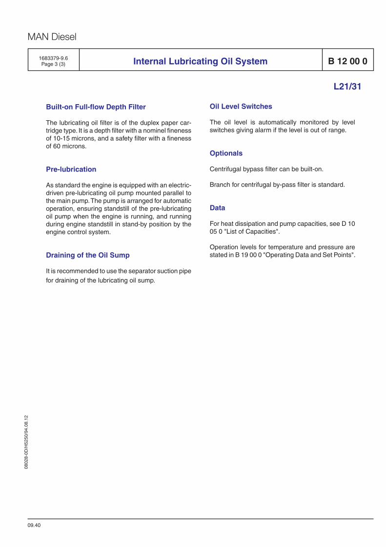
0802
8-0D
/H52
50/9
4.08
.12
MAN Diesel
B 12 00 0
09.40
Internal Lubricating Oil System
L21/31
1683379-9.6Page 3 (3)
Built-on Full-flow Depth Filter
The lubricating oil filter is of the duplex paper car -tridge type. It is a depth filter with a nominel fineness of 10-15 microns, and a safety filter with a fineness of 60 microns.
Pre-lubrication
As standard the engine is equipped with an electric-driven pre-lubricating oil pump mounted parallel to the main pump. The pump is arranged for automatic operation, ensuring standstill of the pre-lubricating oil pump when the engine is running, and running during engine standstill in stand-by position by the engine control system.
Draining of the Oil Sump
It is recommended to use the separator suction pipe for draining of the lubricating oil sump.
Oil Level Switches
The oil level is automatically monitored by level switches giving alarm if the level is out of range.
Optionals
Centrifugal bypass filter can be built-on.
Branch for centrifugal by-pass filter is standard.
Data
For heat dissipation and pump capacities, see D 10 05 0 "List of Capacities".
Operation levels for temperature and pressure are stated in B 19 00 0 "Operating Data and Set Points".

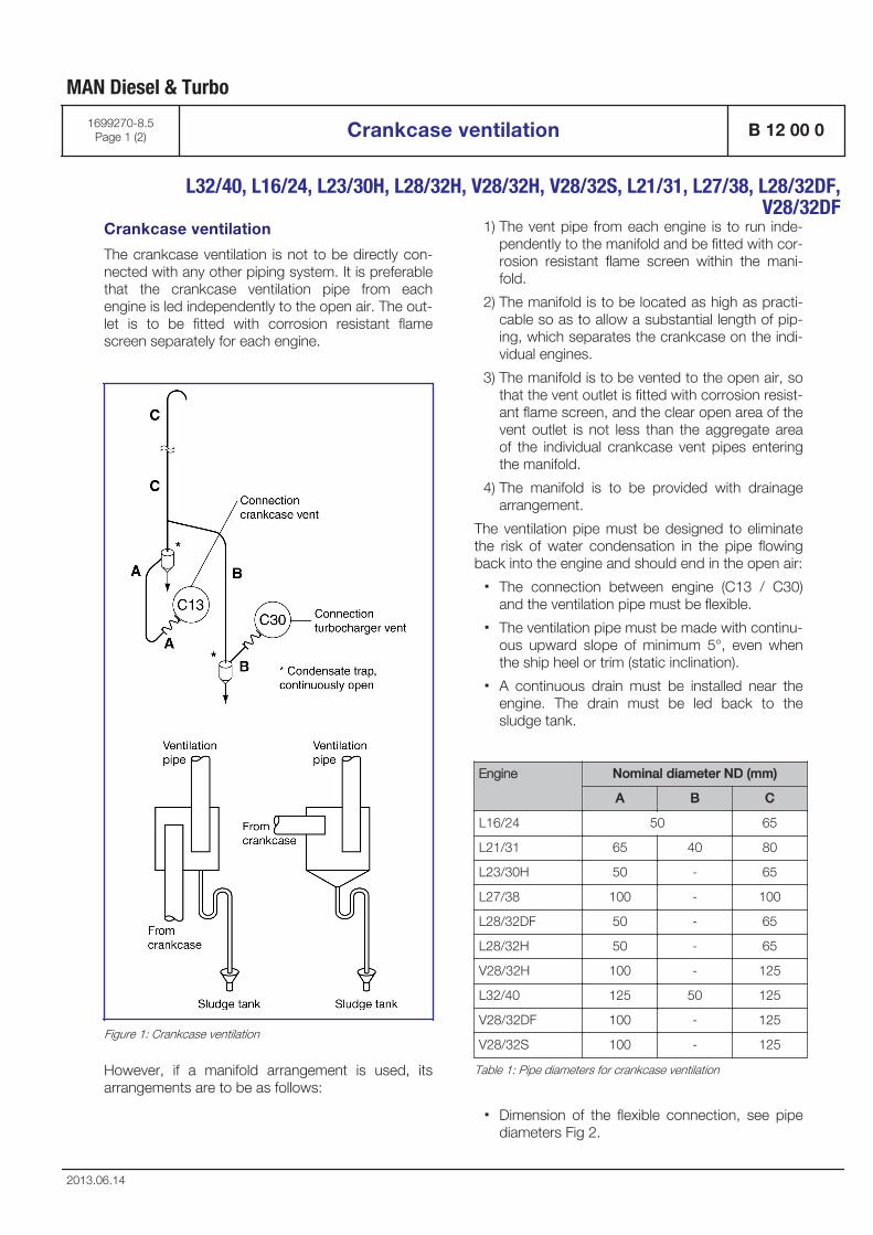
Crankcase ventilation
The crankcase ventilation is not to be directly con-nected with any other piping system. It is preferablethat the crankcase ventilation pipe from eachengine is led independently to the open air. The out-let is to be fitted with corrosion resistant flamescreen separately for each engine.
Figure 1: Crankcase ventilation
However, if a manifold arrangement is used, itsarrangements are to be as follows:
1) The vent pipe from each engine is to run inde-pendently to the manifold and be fitted with cor-rosion resistant flame screen within the mani-fold.
2) The manifold is to be located as high as practi-cable so as to allow a substantial length of pip-ing, which separates the crankcase on the indi-vidual engines.
3) The manifold is to be vented to the open air, sothat the vent outlet is fitted with corrosion resist-ant flame screen, and the clear open area of thevent outlet is not less than the aggregate areaof the individual crankcase vent pipes enteringthe manifold.
4) The manifold is to be provided with drainagearrangement.
The ventilation pipe must be designed to eliminatethe risk of water condensation in the pipe flowingback into the engine and should end in the open air:
▪ The connection between engine (C13 / C30)and the ventilation pipe must be flexible.
▪ The ventilation pipe must be made with continu-ous upward slope of minimum 5°, even whenthe ship heel or trim (static inclination).
▪ A continuous drain must be installed near theengine. The drain must be led back to thesludge tank.
Engine Nominal diameter ND (mm)
A B C
L16/24 50 65
L21/31 65 40 80
L23/30H 50 - 65
L27/38 100 - 100
L28/32DF 50 - 65
L28/32H 50 - 65
V28/32H 100 - 125
L32/40 125 50 125
V28/32DF 100 - 125
V28/32S 100 - 125
Table 1: Pipe diameters for crankcase ventilation
▪ Dimension of the flexible connection, see pipediameters Fig 2.
MAN Diesel & Turbo
1699270-8.5Page 1 (2) Crankcase ventilation B 12 00 0
L32/40, L16/24, L23/30H, L28/32H, V28/32H, V28/32S, L21/31, L27/38, L28/32DF,
V28/32DF
2013.06.14
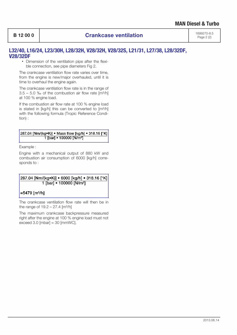
▪ Dimension of the ventilation pipe after the flexi-ble connection, see pipe diameters Fig 2.
The crankcase ventilation flow rate varies over time,from the engine is new/major overhauled, until it istime to overhaul the engine again.
The crankcase ventilation flow rate is in the range of3.5 – 5.0 ‰ of the combustion air flow rate [m³/h]at 100 % engine load.
If the combustion air flow rate at 100 % engine loadis stated in [kg/h] this can be converted to [m³/h]with the following formula (Tropic Reference Condi-tion) :
Example :
Engine with a mechanical output of 880 kW andcombustion air consumption of 6000 [kg/h] corre-sponds to :
The crankcase ventilation flow rate will then be inthe range of 19.2 – 27.4 [m³/h]
The maximum crankcase backpressure measuredright after the engine at 100 % engine load must notexceed 3.0 [mbar] = 30 [mmWC].
MAN Diesel & Turbo
B 12 00 0 Crankcase ventilation 1699270-8.5Page 2 (2)
L32/40, L16/24, L23/30H, L28/32H, V28/32H, V28/32S, L21/31, L27/38, L28/32DF,V28/32DF
2013.06.14
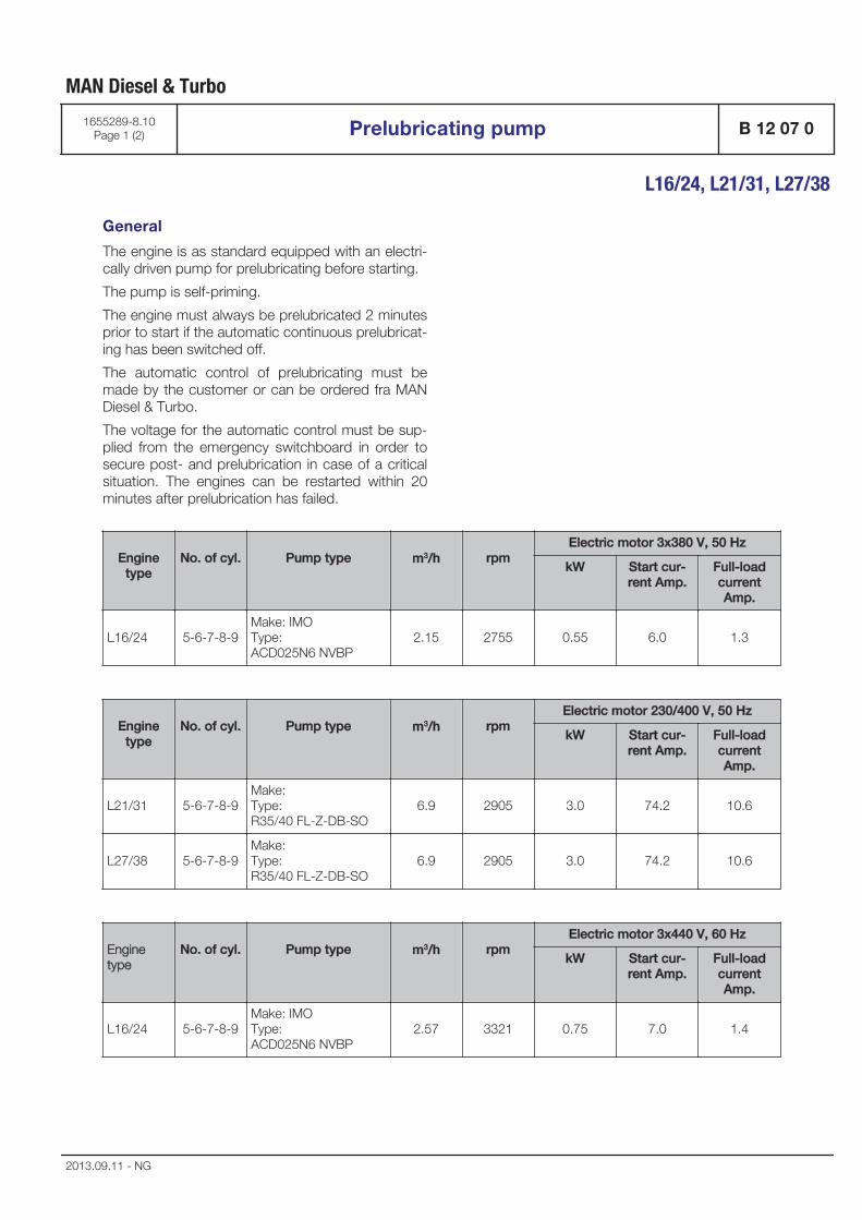
General
The engine is as standard equipped with an electri-cally driven pump for prelubricating before starting.
The pump is self-priming.
The engine must always be prelubricated 2 minutesprior to start if the automatic continuous prelubricat-ing has been switched off.
The automatic control of prelubricating must bemade by the customer or can be ordered fra MANDiesel & Turbo.
The voltage for the automatic control must be sup-plied from the emergency switchboard in order tosecure post- and prelubrication in case of a criticalsituation. The engines can be restarted within 20minutes after prelubrication has failed.
Enginetype
No. of cyl. Pump type m3/h rpmElectric motor 3x380 V, 50 Hz
kW Start cur-rent Amp.
Full-loadcurrentAmp.
L16/24 5-6-7-8-9Make: IMOType:ACD025N6 NVBP
2.15 2755 0.55 6.0 1.3
Enginetype
No. of cyl. Pump type m3/h rpmElectric motor 230/400 V, 50 Hz
kW Start cur-rent Amp.
Full-loadcurrentAmp.
L21/31 5-6-7-8-9Make:Type:R35/40 FL-Z-DB-SO
6.9 2905 3.0 74.2 10.6
L27/38 5-6-7-8-9Make:Type:R35/40 FL-Z-DB-SO
6.9 2905 3.0 74.2 10.6
Enginetype
No. of cyl. Pump type m3/h rpmElectric motor 3x440 V, 60 Hz
kW Start cur-rent Amp.
Full-loadcurrentAmp.
L16/24 5-6-7-8-9Make: IMOType:ACD025N6 NVBP
2.57 3321 0.75 7.0 1.4
MAN Diesel & Turbo
1655289-8.10Page 1 (2) Prelubricating pump B 12 07 0
L16/24, L21/31, L27/38
2013.09.11 - NG
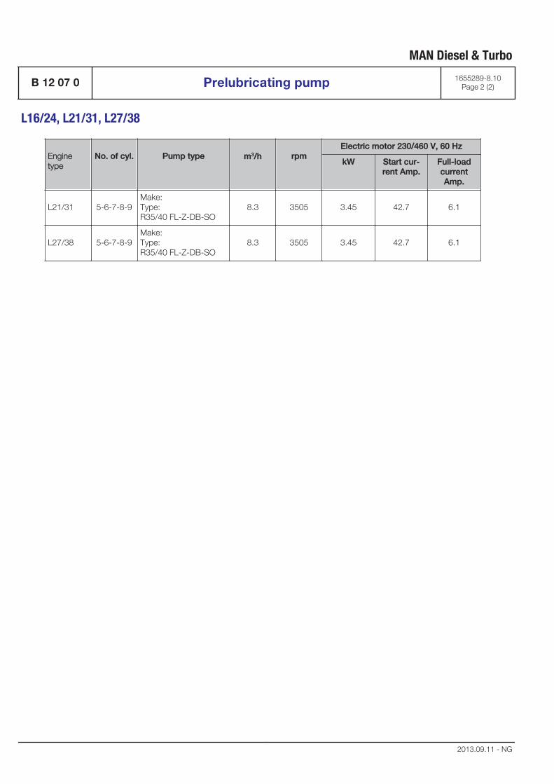
Enginetype
No. of cyl. Pump type m3/h rpmElectric motor 230/460 V, 60 Hz
kW Start cur-rent Amp.
Full-loadcurrentAmp.
L21/31 5-6-7-8-9Make:Type:R35/40 FL-Z-DB-SO
8.3 3505 3.45 42.7 6.1
L27/38 5-6-7-8-9Make:Type:R35/40 FL-Z-DB-SO
8.3 3505 3.45 42.7 6.1
MAN Diesel & Turbo
B 12 07 0 Prelubricating pump 1655289-8.10Page 2 (2)
L16/24, L21/31, L27/38
2013.09.11 - NG
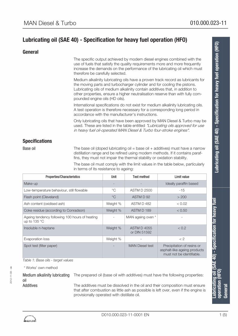
Lubricating oil (SAE 40) - Specification for heavy fuel operation (HFO)
GeneralThe specific output achieved by modern diesel engines combined with theuse of fuels that satisfy the quality requirements more and more frequentlyincrease the demands on the performance of the lubricating oil which musttherefore be carefully selected.
Medium alkalinity lubricating oils have a proven track record as lubricants forthe moving parts and turbocharger cylinder and for cooling the pistons.Lubricating oils of medium alkalinity contain additives that, in addition toother properties, ensure a higher neutralisation reserve than with fully com-pounded engine oils (HD oils).
International specifications do not exist for medium alkalinity lubricating oils.A test operation is therefore necessary for a corresponding long period inaccordance with the manufacturer's instructions.
Only lubricating oils that have been approved by MAN Diesel & Turbo may beused. These are listed in the table entitled "Lubricating oils approved for usein heavy fuel oil-operated MAN Diesel & Turbo four-stroke engines".
SpecificationsThe base oil (doped lubricating oil = base oil + additives) must have a narrowdistillation range and be refined using modern methods. If it contains paraf-fins, they must not impair the thermal stability or oxidation stability.
The base oil must comply with the limit values in the table below, particularlyin terms of its resistance to ageing:
Properties/Characteristics Unit Test method Limit value
Make-up - - Ideally paraffin based
Low-temperature behaviour, still flowable °C ASTM D 2500 -15
Flash point (Cleveland) °C ASTM D 92 > 200
Ash content (oxidised ash) Weight % ASTM D 482 < 0.02
Coke residue (according to Conradson) Weight % ASTM D 189 < 0.50
Ageing tendency following 100 hours of heatingup to 135 °C
- MAN ageing oven * -
Insoluble n-heptane Weight % ASTM D 4055or DIN 51592
< 0.2
Evaporation loss Weight % - < 2
Spot test (filter paper) - MAN Diesel test Precipitation of resins orasphalt-like ageing products
must not be identifiable.
Table 1: Base oils - target values
* Works' own method
The prepared oil (base oil with additives) must have the following properties:
The additives must be dissolved in the oil and their composition must ensurethat after combustion as little ash as possible is left over, even if the engine isprovisionally operated with distillate oil.
Base oil
Medium alkalinity lubricatingoilAdditives
2012
-11-
08 -
de
Lubr
icat
ing
oil (
SAE
40) -
Spe
cific
atio
n fo
r hea
vy fu
elop
erat
ion
(HFO
)Lu
bric
atin
g oi
l (SA
E 40
) - S
peci
ficat
ion
for h
eavy
fuel
ope
ratio
n (H
FO)
Gene
ral
MAN Diesel & Turbo 010.000.023-11
D010.000.023-11-0001 EN 1 (5)
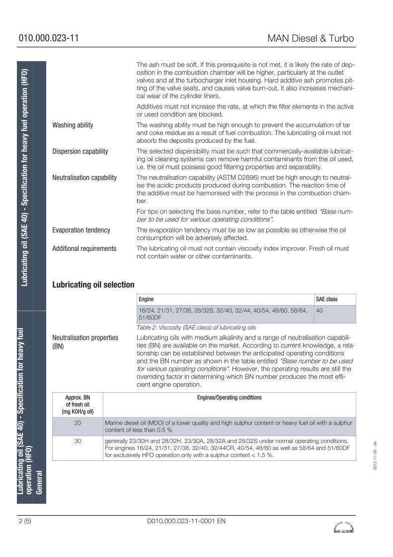
The ash must be soft. If this prerequisite is not met, it is likely the rate of dep-osition in the combustion chamber will be higher, particularly at the outletvalves and at the turbocharger inlet housing. Hard additive ash promotes pit-ting of the valve seats, and causes valve burn-out, it also increases mechani-cal wear of the cylinder liners.
Additives must not increase the rate, at which the filter elements in the activeor used condition are blocked.
The washing ability must be high enough to prevent the accumulation of tarand coke residue as a result of fuel combustion. The lubricating oil must notabsorb the deposits produced by the fuel.
The selected dispersibility must be such that commercially-available lubricat-ing oil cleaning systems can remove harmful contaminants from the oil used,i.e. the oil must possess good filtering properties and separability.
The neutralisation capability (ASTM D2896) must be high enough to neutral-ise the acidic products produced during combustion. The reaction time ofthe additive must be harmonised with the process in the combustion cham-ber.
For tips on selecting the base number, refer to the table entitled “Base num-ber to be used for various operating conditions".
The evaporation tendency must be as low as possible as otherwise the oilconsumption will be adversely affected.
The lubricating oil must not contain viscosity index improver. Fresh oil mustnot contain water or other contaminants.
Lubricating oil selection
Engine SAE class
16/24, 21/31, 27/38, 28/32S, 32/40, 32/44, 40/54, 48/60, 58/64,51/60DF
40
Table 2: Viscosity (SAE class) of lubricating oils
Lubricating oils with medium alkalinity and a range of neutralisation capabili-ties (BN) are available on the market. According to current knowledge, a rela-tionship can be established between the anticipated operating conditionsand the BN number as shown in the table entitled "Base number to be usedfor various operating conditions". However, the operating results are still theoverriding factor in determining which BN number produces the most effi-cient engine operation.
Approx. BNof fresh oil
(mg KOH/g oil)
Engines/Operating conditions
20 Marine diesel oil (MDO) of a lower quality and high sulphur content or heavy fuel oil with a sulphurcontent of less than 0.5 %
30 generally 23/30H and 28/32H. 23/30A, 28/32A and 28/32S under normal operating conditions. For engines 16/24, 21/31, 27/38, 32/40, 32/44CR, 40/54, 48/60 as well as 58/64 and 51/60DFfor exclusively HFO operation only with a sulphur content < 1.5 %.
Washing ability
Dispersion capability
Neutralisation capability
Evaporation tendency
Additional requirements
Neutralisation properties(BN)
Lubr
icat
ing
oil (
SAE
40) -
Spe
cific
atio
n fo
r hea
vy fu
elop
erat
ion
(HFO
)Lu
bric
atin
g oi
l (SA
E 40
) - S
peci
ficat
ion
for h
eavy
fuel
ope
ratio
n (H
FO)
Gene
ral
2012
-11-
08 -
de
010.000.023-11 MAN Diesel & Turbo
2 (5) D010.000.023-11-0001 EN
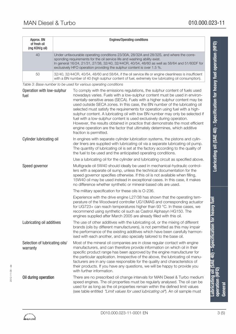
Approx. BNof fresh oil
(mg KOH/g oil)
Engines/Operating conditions
40 Under unfavourable operating conditions 23/30A, 28/32A and 28/32S, and where the corre-sponding requirements for the oil service life and washing ability exist. In general 16/24, 21/31, 27/38, 32/40, 32/44CR, 40/54, 48/60 as well as 58/64 and 51/60DF forexclusively HFO operation providing the sulphur content is over 1.5 %.
50 32/40, 32/44CR, 40/54, 48/60 and 58/64, if the oil service life or engine cleanliness is insufficientwith a BN number of 40 (high sulphur content of fuel, extremely low lubricating oil consumption).
Table 3: Base number to be used for various operating conditions
To comply with the emissions regulations, the sulphur content of fuels usednowadays varies. Fuels with a low-sulphur content must be used in environ-mentally-sensitive areas (SECA). Fuels with a higher sulphur content may beused outside SECA zones. In this case, the BN number of the lubricating oilselected must satisfy the requirements for operation using fuel with a high-sulphur content. A lubricating oil with low BN number may only be selected iffuel with a low-sulphur content is used exclusively during operation.However, the results obtained in practiсe that demonstrate the most efficientengine operation are the factor that ultimately determines, which additivefraction is permitted.
In engines with separate cylinder lubrication systems, the pistons and cylin-der liners are supplied with lubricating oil via a separate lubricating oil pump.The quantity of lubricating oil is set at the factory according to the quality ofthe fuel to be used and the anticipated operating conditions.
Use a lubricating oil for the cylinder and lubricating circuit as specified above.
Multigrade oil 5W40 should ideally be used in mechanical-hydraulic control-lers with a separate oil sump, unless the technical documentation for thespeed governor specifies otherwise. If this oil is not available when filling,15W40 oil may be used instead in exceptional cases. In this case, it makesno difference whether synthetic or mineral-based oils are used.
The military specification for these oils is O-236.
Experience with the drive engine L27/38 has shown that the operating tem-perature of the Woodward controller UG10MAS and corresponding actuatorfor UG723+ can reach temperatures higher than 93 °C. In these cases, werecommend using synthetic oil such as Castrol Alphasyn HG150. Theengines supplied after March 2005 are already filled with this oil.
The use of other additives with the lubricating oil, or the mixing of differentbrands (oils by different manufacturers), is not permitted as this may impairthe performance of the existing additives which have been carefully harmon-ised with each another, and also specially tailored to the base oil.
Most of the mineral oil companies are in close regular contact with enginemanufacturers, and can therefore provide information on which oil in theirspecific product range has been approved by the engine manufacturer forthe particular application. Irrespective of the above, the lubricating oil manu-facturers are in any case responsible for the quality and characteristics oftheir products. If you have any questions, we will be happy to provide youwith further information.
There are no prescribed oil change intervals for MAN Diesel & Turbo mediumspeed engines. The oil properties must be regularly analysed. The oil can beused for as long as the oil properties remain within the defined limit values(see table entitled "Limit values for used lubricating oil“). An oil sample must
Operation with low-sulphurfuel
Cylinder lubricating oil
Speed governor
Lubricating oil additives
Selection of lubricating oils/warranty
Oil during operation
2012
-11-
08 -
de
Lubr
icat
ing
oil (
SAE
40) -
Spe
cific
atio
n fo
r hea
vy fu
elop
erat
ion
(HFO
)Lu
bric
atin
g oi
l (SA
E 40
) - S
peci
ficat
ion
for h
eavy
fuel
ope
ratio
n (H
FO)
Gene
ral
MAN Diesel & Turbo 010.000.023-11
D010.000.023-11-0001 EN 3 (5)
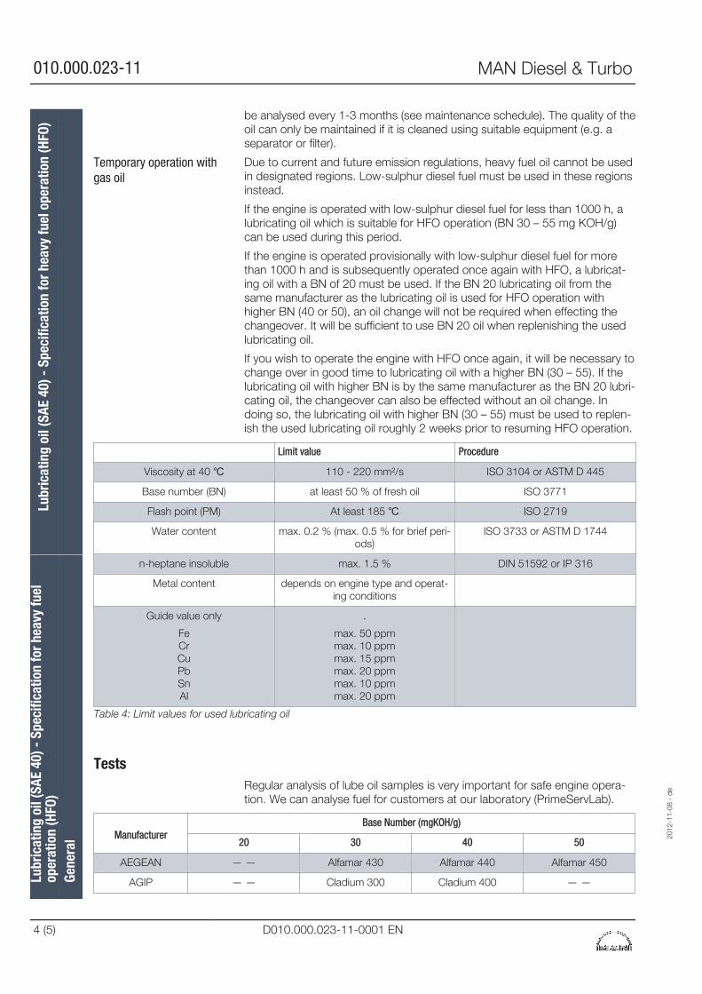
be analysed every 1-3 months (see maintenance schedule). The quality of theoil can only be maintained if it is cleaned using suitable equipment (e.g. aseparator or filter).
Due to current and future emission regulations, heavy fuel oil cannot be usedin designated regions. Low-sulphur diesel fuel must be used in these regionsinstead.
If the engine is operated with low-sulphur diesel fuel for less than 1000 h, alubricating oil which is suitable for HFO operation (BN 30 – 55 mg KOH/g)can be used during this period.
If the engine is operated provisionally with low-sulphur diesel fuel for morethan 1000 h and is subsequently operated once again with HFO, a lubricat-ing oil with a BN of 20 must be used. If the BN 20 lubricating oil from thesame manufacturer as the lubricating oil is used for HFO operation withhigher BN (40 or 50), an oil change will not be required when effecting thechangeover. It will be sufficient to use BN 20 oil when replenishing the usedlubricating oil.
If you wish to operate the engine with HFO once again, it will be necessary tochange over in good time to lubricating oil with a higher BN (30 – 55). If thelubricating oil with higher BN is by the same manufacturer as the BN 20 lubri-cating oil, the changeover can also be effected without an oil change. Indoing so, the lubricating oil with higher BN (30 – 55) must be used to replen-ish the used lubricating oil roughly 2 weeks prior to resuming HFO operation.
Limit value Procedure
Viscosity at 40 ℃ 110 - 220 mm²/s ISO 3104 or ASTM D 445
Base number (BN) at least 50 % of fresh oil ISO 3771
Flash point (PM) At least 185 ℃ ISO 2719
Water content max. 0.2 % (max. 0.5 % for brief peri-ods)
ISO 3733 or ASTM D 1744
n-heptane insoluble max. 1.5 % DIN 51592 or IP 316
Metal content depends on engine type and operat-ing conditions
Guide value only
FeCrCuPbSnAl
.
max. 50 ppmmax. 10 ppmmax. 15 ppmmax. 20 ppmmax. 10 ppmmax. 20 ppm
Table 4: Limit values for used lubricating oil
TestsRegular analysis of lube oil samples is very important for safe engine opera-tion. We can analyse fuel for customers at our laboratory (PrimeServLab).
ManufacturerBase Number (mgKOH/g)
20 30 40 50
AEGEAN — — Alfamar 430 Alfamar 440 Alfamar 450
AGIP — — Cladium 300 Cladium 400 — —
Temporary operation withgas oil
Lubr
icat
ing
oil (
SAE
40) -
Spe
cific
atio
n fo
r hea
vy fu
elop
erat
ion
(HFO
)Lu
bric
atin
g oi
l (SA
E 40
) - S
peci
ficat
ion
for h
eavy
fuel
ope
ratio
n (H
FO)
Gene
ral
2012
-11-
08 -
de
010.000.023-11 MAN Diesel & Turbo
4 (5) D010.000.023-11-0001 EN
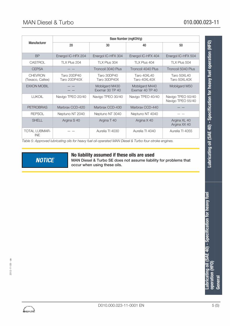
ManufacturerBase Number (mgKOH/g)
20 30 40 50
BP Energol IC-HFX 204 Energol IC-HFX 304 Energol IC-HFX 404 Energol IC-HFX 504
CASTROL TLX Plus 204 TLX Plus 304 TLX Plus 404 TLX Plus 504
CEPSA — — Troncoil 3040 Plus Troncoil 4040 Plus Troncoil 5040 Plus
CHEVRON (Texaco, Caltex)
Taro 20DP40Taro 20DP40X
Taro 30DP40Taro 30DP40X
Taro 40XL40Taro 40XL40X
Taro 50XL40Taro 50XL40X
EXXON MOBIL — —— —
Mobilgard M430Exxmar 30 TP 40
Mobilgard M440Exxmar 40 TP 40
Mobilgard M50
LUKOIL Navigo TPEO 20/40 Navigo TPEO 30/40 Navigo TPEO 40/40 Navigo TPEO 50/40Navigo TPEO 55/40
PETROBRAS Marbrax CCD-420 Marbrax CCD-430 Marbrax CCD-440 — —
REPSOL Neptuno NT 2040 Neptuno NT 3040 Neptuno NT 4040 — —
SHELL Argina S 40 Argina T 40 Argina X 40 Argina XL 40Argina XX 40
TOTAL LUBMAR-INE
— — Aurelia TI 4030 Aurelia TI 4040 Aurelia TI 4055
Table 5: Approved lubricating oils for heavy fuel oil-operated MAN Diesel & Turbo four-stroke engines.
No liability assumed if these oils are usedMAN Diesel & Turbo SE does not assume liability for problems thatoccur when using these oils.
2012
-11-
08 -
de
Lubr
icat
ing
oil (
SAE
40) -
Spe
cific
atio
n fo
r hea
vy fu
elop
erat
ion
(HFO
)Lu
bric
atin
g oi
l (SA
E 40
) - S
peci
ficat
ion
for h
eavy
fuel
ope
ratio
n (H
FO)
Gene
ral
MAN Diesel & Turbo 010.000.023-11
D010.000.023-11-0001 EN 5 (5)

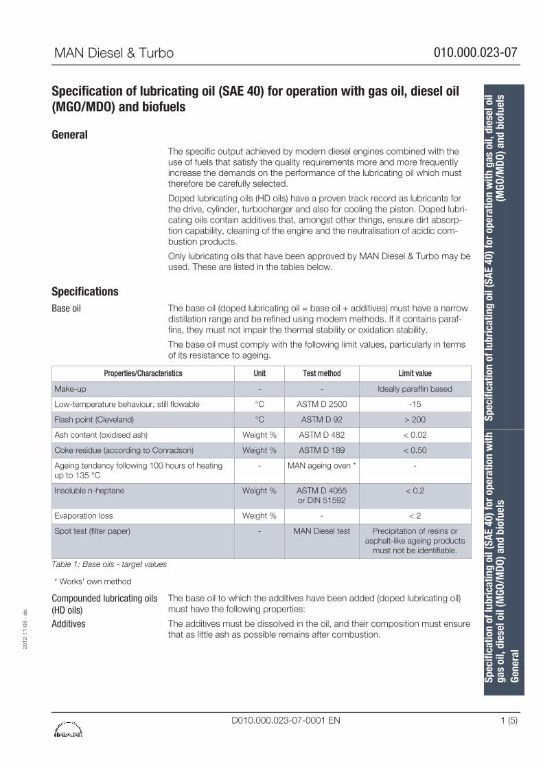
Specification of lubricating oil (SAE 40) for operation with gas oil, diesel oil(MGO/MDO) and biofuels
GeneralThe specific output achieved by modern diesel engines combined with theuse of fuels that satisfy the quality requirements more and more frequentlyincrease the demands on the performance of the lubricating oil which musttherefore be carefully selected.
Doped lubricating oils (HD oils) have a proven track record as lubricants forthe drive, cylinder, turbocharger and also for cooling the piston. Doped lubri-cating oils contain additives that, amongst other things, ensure dirt absorp-tion capability, cleaning of the engine and the neutralisation of acidic com-bustion products.
Only lubricating oils that have been approved by MAN Diesel & Turbo may beused. These are listed in the tables below.
SpecificationsThe base oil (doped lubricating oil = base oil + additives) must have a narrowdistillation range and be refined using modern methods. If it contains paraf-fins, they must not impair the thermal stability or oxidation stability.
The base oil must comply with the following limit values, particularly in termsof its resistance to ageing.
Properties/Characteristics Unit Test method Limit value
Make-up - - Ideally paraffin based
Low-temperature behaviour, still flowable °C ASTM D 2500 -15
Flash point (Cleveland) °C ASTM D 92 > 200
Ash content (oxidised ash) Weight % ASTM D 482 < 0.02
Coke residue (according to Conradson) Weight % ASTM D 189 < 0.50
Ageing tendency following 100 hours of heatingup to 135 °C
- MAN ageing oven * -
Insoluble n-heptane Weight % ASTM D 4055or DIN 51592
< 0.2
Evaporation loss Weight % - < 2
Spot test (filter paper) - MAN Diesel test Precipitation of resins orasphalt-like ageing products
must not be identifiable.
Table 1: Base oils - target values
* Works' own method
The base oil to which the additives have been added (doped lubricating oil)must have the following properties:
The additives must be dissolved in the oil, and their composition must ensurethat as little ash as possible remains after combustion.
Base oil
Compounded lubricating oils(HD oils)Additives
2012
-11-
08 -
de
Spec
ifica
tion
of lu
bric
atin
g oi
l (SA
E 40
) for
ope
ratio
n w
ithga
s oi
l, di
esel
oil
(MGO
/MDO
) and
bio
fuel
sSp
ecifi
catio
n of
lubr
icat
ing
oil (
SAE
40) f
or o
pera
tion
with
gas
oil,
die
sel o
il(M
GO/M
DO) a
nd b
iofu
els
Gene
ral
MAN Diesel & Turbo 010.000.023-07
D010.000.023-07-0001 EN 1 (5)
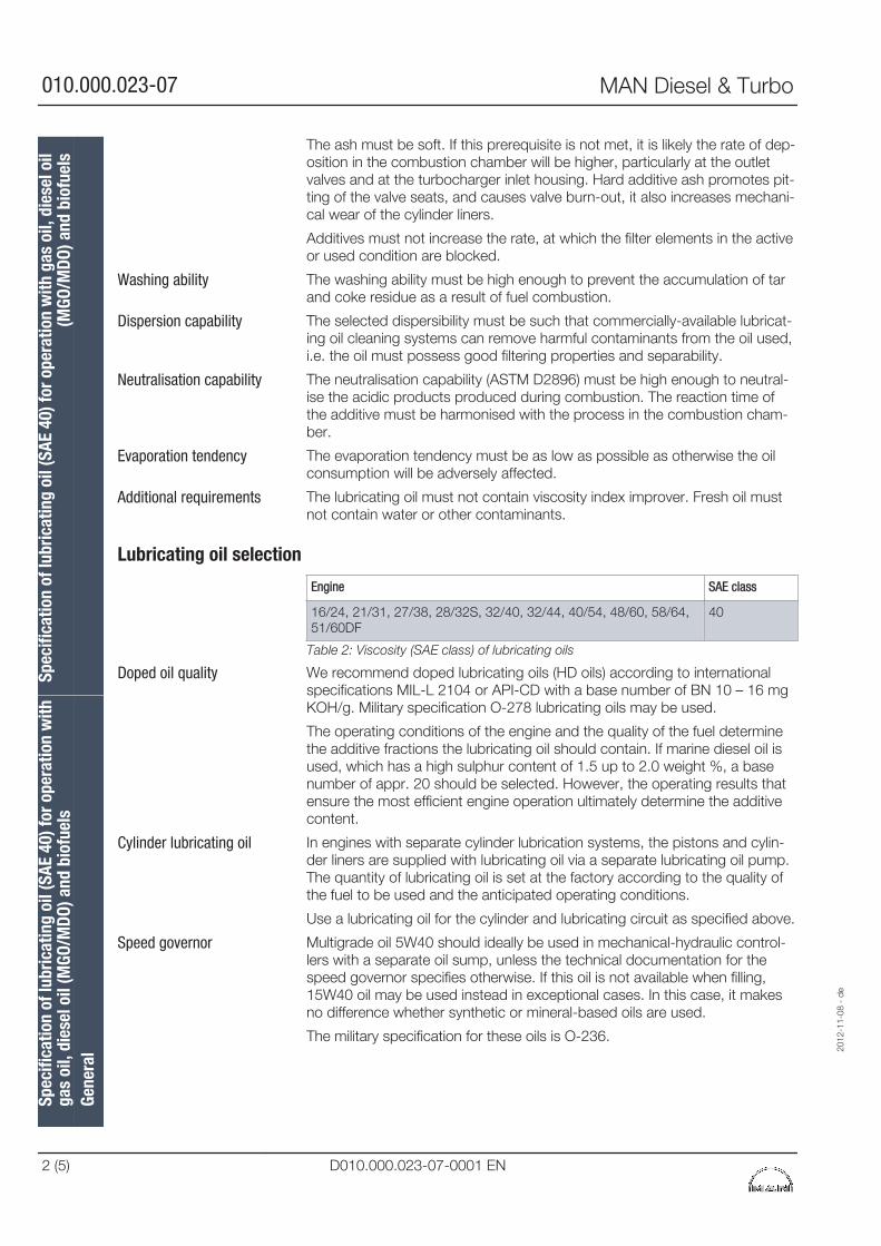
The ash must be soft. If this prerequisite is not met, it is likely the rate of dep-osition in the combustion chamber will be higher, particularly at the outletvalves and at the turbocharger inlet housing. Hard additive ash promotes pit-ting of the valve seats, and causes valve burn-out, it also increases mechani-cal wear of the cylinder liners.
Additives must not increase the rate, at which the filter elements in the activeor used condition are blocked.
The washing ability must be high enough to prevent the accumulation of tarand coke residue as a result of fuel combustion.
The selected dispersibility must be such that commercially-available lubricat-ing oil cleaning systems can remove harmful contaminants from the oil used,i.e. the oil must possess good filtering properties and separability.
The neutralisation capability (ASTM D2896) must be high enough to neutral-ise the acidic products produced during combustion. The reaction time ofthe additive must be harmonised with the process in the combustion cham-ber.
The evaporation tendency must be as low as possible as otherwise the oilconsumption will be adversely affected.
The lubricating oil must not contain viscosity index improver. Fresh oil mustnot contain water or other contaminants.
Lubricating oil selection
Engine SAE class
16/24, 21/31, 27/38, 28/32S, 32/40, 32/44, 40/54, 48/60, 58/64,51/60DF
40
Table 2: Viscosity (SAE class) of lubricating oils
We recommend doped lubricating oils (HD oils) according to internationalspecifications MIL-L 2104 or API-CD with a base number of BN 10 – 16 mgKOH/g. Military specification O-278 lubricating oils may be used.
The operating conditions of the engine and the quality of the fuel determinethe additive fractions the lubricating oil should contain. If marine diesel oil isused, which has a high sulphur content of 1.5 up to 2.0 weight %, a basenumber of appr. 20 should be selected. However, the operating results thatensure the most efficient engine operation ultimately determine the additivecontent.
In engines with separate cylinder lubrication systems, the pistons and cylin-der liners are supplied with lubricating oil via a separate lubricating oil pump.The quantity of lubricating oil is set at the factory according to the quality ofthe fuel to be used and the anticipated operating conditions.
Use a lubricating oil for the cylinder and lubricating circuit as specified above.
Multigrade oil 5W40 should ideally be used in mechanical-hydraulic control-lers with a separate oil sump, unless the technical documentation for thespeed governor specifies otherwise. If this oil is not available when filling,15W40 oil may be used instead in exceptional cases. In this case, it makesno difference whether synthetic or mineral-based oils are used.
The military specification for these oils is O-236.
Washing ability
Dispersion capability
Neutralisation capability
Evaporation tendency
Additional requirements
Doped oil quality
Cylinder lubricating oil
Speed governor
Spec
ifica
tion
of lu
bric
atin
g oi
l (SA
E 40
) for
ope
ratio
n w
ithga
s oi
l, di
esel
oil
(MGO
/MDO
) and
bio
fuel
sSp
ecifi
catio
n of
lubr
icat
ing
oil (
SAE
40) f
or o
pera
tion
with
gas
oil,
die
sel o
il(M
GO/M
DO) a
nd b
iofu
els
Gene
ral
2012
-11-
08 -
de
010.000.023-07 MAN Diesel & Turbo
2 (5) D010.000.023-07-0001 EN
Experience with the drive engine L27/38 has shown that the operating tem-perature of the Woodward controller UG10MAS and corresponding actuatorfor UG723+ can reach temperatures higher than 93 °C. In these cases, werecommend using synthetic oil such as Castrol Alphasyn HG150. Theengines supplied after March 2005 are already filled with this oil.
The use of other additives with the lubricating oil, or the mixing of differentbrands (oils by different manufacturers), is not permitted as this may impairthe performance of the existing additives which have been carefully harmon-ised with each another, and also specially tailored to the base oil.
Most of the mineral oil companies are in close regular contact with enginemanufacturers, and can therefore provide information on which oil in theirspecific product range has been approved by the engine manufacturer forthe particular application. Irrespective of the above, the lubricating oil manu-facturers are in any case responsible for the quality and characteristics oftheir products. If you have any questions, we will be happy to provide youwith further information.
There are no prescribed oil change intervals for MAN Diesel & Turbo mediumspeed engines. The oil properties must be regularly analysed. The oil can beused for as long as the oil properties remain within the defined limit values(see table entitled "Limit values for used lubricating oil“). An oil sample mustbe analysed every 1-3 months (see maintenance schedule). The quality of theoil can only be maintained if it is cleaned using suitable equipment (e.g. aseparator or filter).
Due to current and future emission regulations, heavy fuel oil cannot be usedin designated regions. Low-sulphur diesel fuel must be used in these regionsinstead.
If the engine is operated with low-sulphur diesel fuel for less than 1000 h, alubricating oil which is suitable for HFO operation (BN 30 – 55 mg KOH/g)can be used during this period.
If the engine is operated provisionally with low-sulphur diesel fuel for morethan 1000 h and is subsequently operated once again with HFO, a lubricat-ing oil with a BN of 20 must be used. If the BN 20 lubricating oil from thesame manufacturer as the lubricating oil is used for HFO operation withhigher BN (40 or 50), an oil change will not be required when effecting thechangeover. It will be sufficient to use BN 20 oil when replenishing the usedlubricating oil.
If you wish to operate the engine with HFO once again, it will be necessary tochange over in good time to lubricating oil with a higher BN (30 – 55). If thelubricating oil with higher BN is by the same manufacturer as the BN 20 lubri-cating oil, the changeover can also be effected without an oil change. Indoing so, the lubricating oil with higher BN (30 – 55) must be used to replen-ish the used lubricating oil roughly 2 weeks prior to resuming HFO operation.
TestsRegular analysis of lube oil samples is very important for safe engine opera-tion. We can analyse fuel for customers at our laboratory (PrimeServLab).
Lubricating oil additives
Selection of lubricating oils/warranty
Oil during operation
Temporary operation withgas oil
2012
-11-
08 -
de
Spec
ifica
tion
of lu
bric
atin
g oi
l (SA
E 40
) for
ope
ratio
n w
ithga
s oi
l, di
esel
oil
(MGO
/MDO
) and
bio
fuel
sSp
ecifi
catio
n of
lubr
icat
ing
oil (
SAE
40) f
or o
pera
tion
with
gas
oil,
die
sel o
il(M
GO/M
DO) a
nd b
iofu
els
Gene
ral
MAN Diesel & Turbo 010.000.023-07
D010.000.023-07-0001 EN 3 (5)
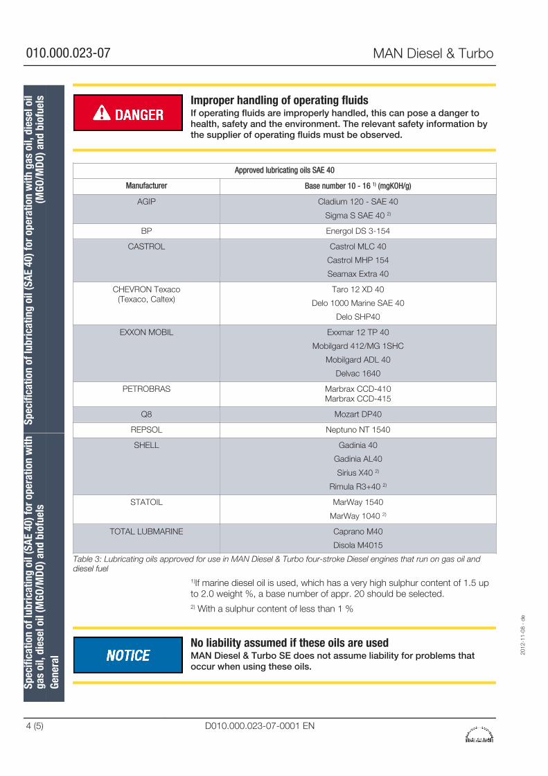
Improper handling of operating fluidsIf operating fluids are improperly handled, this can pose a danger tohealth, safety and the environment. The relevant safety information bythe supplier of operating fluids must be observed.
Approved lubricating oils SAE 40
Manufacturer Base number 10 - 16 1) (mgKOH/g)
AGIP Cladium 120 - SAE 40
Sigma S SAE 40 2)
BP Energol DS 3-154
CASTROL Castrol MLC 40
Castrol MHP 154
Seamax Extra 40
CHEVRON Texaco(Texaco, Caltex)
Taro 12 XD 40
Delo 1000 Marine SAE 40
Delo SHP40
EXXON MOBIL Exxmar 12 TP 40
Mobilgard 412/MG 1SHC
Mobilgard ADL 40
Delvac 1640
PETROBRAS Marbrax CCD-410Marbrax CCD-415
Q8 Mozart DP40
REPSOL Neptuno NT 1540
SHELL Gadinia 40
Gadinia AL40
Sirius X40 2)
Rimula R3+40 2)
STATOIL MarWay 1540
MarWay 1040 2)
TOTAL LUBMARINE Caprano M40
Disola M4015
Table 3: Lubricating oils approved for use in MAN Diesel & Turbo four-stroke Diesel engines that run on gas oil anddiesel fuel
1)If marine diesel oil is used, which has a very high sulphur content of 1.5 upto 2.0 weight %, a base number of appr. 20 should be selected.2) With a sulphur content of less than 1 %
No liability assumed if these oils are usedMAN Diesel & Turbo SE does not assume liability for problems thatoccur when using these oils.
Spec
ifica
tion
of lu
bric
atin
g oi
l (SA
E 40
) for
ope
ratio
n w
ithga
s oi
l, di
esel
oil
(MGO
/MDO
) and
bio
fuel
sSp
ecifi
catio
n of
lubr
icat
ing
oil (
SAE
40) f
or o
pera
tion
with
gas
oil,
die
sel o
il(M
GO/M
DO) a
nd b
iofu
els
Gene
ral
2012
-11-
08 -
de
010.000.023-07 MAN Diesel & Turbo
4 (5) D010.000.023-07-0001 EN
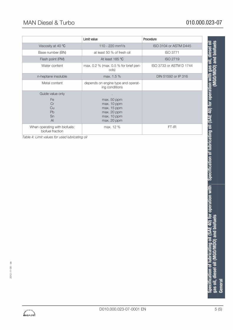
Limit value Procedure
Viscosity at 40 ℃ 110 - 220 mm²/s ISO 3104 or ASTM D445
Base number (BN) at least 50 % of fresh oil ISO 3771
Flash point (PM) At least 185 ℃ ISO 2719
Water content max. 0.2 % (max. 0.5 % for brief peri-ods)
ISO 3733 or ASTM D 1744
n-heptane insoluble max. 1.5 % DIN 51592 or IP 316
Metal content depends on engine type and operat-ing conditions
Guide value only
FeCrCuPbSnAl
.
max. 50 ppmmax. 10 ppmmax. 15 ppmmax. 20 ppmmax. 10 ppmmax. 20 ppm
When operating with biofuels:biofuel fraction
max. 12 % FT-IR
Table 4: Limit values for used lubricating oil
2012
-11-
08 -
de
Spec
ifica
tion
of lu
bric
atin
g oi
l (SA
E 40
) for
ope
ratio
n w
ithga
s oi
l, di
esel
oil
(MGO
/MDO
) and
bio
fuel
sSp
ecifi
catio
n of
lubr
icat
ing
oil (
SAE
40) f
or o
pera
tion
with
gas
oil,
die
sel o
il(M
GO/M
DO) a
nd b
iofu
els
Gene
ral
MAN Diesel & Turbo 010.000.023-07
D010.000.023-07-0001 EN 5 (5)

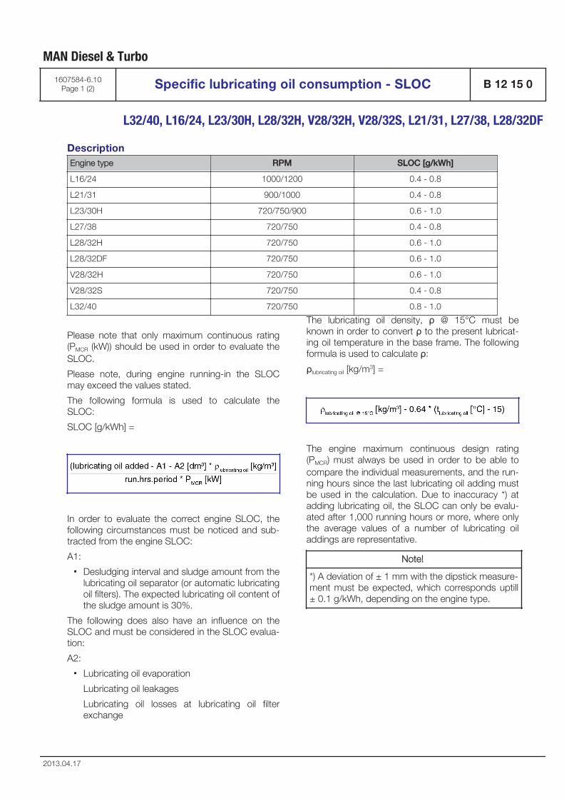
DescriptionEngine type RPM SLOC [g/kWh]
L16/24 1000/1200 0.4 - 0.8
L21/31 900/1000 0.4 - 0.8
L23/30H 720/750/900 0.6 - 1.0
L27/38 720/750 0.4 - 0.8
L28/32H 720/750 0.6 - 1.0
L28/32DF 720/750 0.6 - 1.0
V28/32H 720/750 0.6 - 1.0
V28/32S 720/750 0.4 - 0.8
L32/40 720/750 0.8 - 1.0
Please note that only maximum continuous rating(PMCR (kW)) should be used in order to evaluate theSLOC.
Please note, during engine running-in the SLOCmay exceed the values stated.
The following formula is used to calculate theSLOC:
SLOC [g/kWh] =
In order to evaluate the correct engine SLOC, thefollowing circumstances must be noticed and sub-tracted from the engine SLOC:
A1:
▪ Desludging interval and sludge amount from thelubricating oil separator (or automatic lubricatingoil filters). The expected lubricating oil content ofthe sludge amount is 30%.
The following does also have an influence on theSLOC and must be considered in the SLOC evalua-tion:
A2:
▪ Lubricating oil evaporation
Lubricating oil leakages
Lubricating oil losses at lubricating oil filterexchange
The lubricating oil density, ρ @ 15°C must beknown in order to convert ρ to the present lubricat-ing oil temperature in the base frame. The followingformula is used to calculate ρ:
ρlubricating oil [kg/m3] =
The engine maximum continuous design rating(PMCR) must always be used in order to be able tocompare the individual measurements, and the run-ning hours since the last lubricating oil adding mustbe used in the calculation. Due to inaccuracy *) atadding lubricating oil, the SLOC can only be evalu-ated after 1,000 running hours or more, where onlythe average values of a number of lubricating oiladdings are representative.
Note!
*) A deviation of ± 1 mm with the dipstick measure-ment must be expected, which corresponds uptill± 0.1 g/kWh, depending on the engine type.
MAN Diesel & Turbo
1607584-6.10Page 1 (2) Specific lubricating oil consumption - SLOC B 12 15 0
L32/40, L16/24, L23/30H, L28/32H, V28/32H, V28/32S, L21/31, L27/38, L28/32DF
2013.04.17
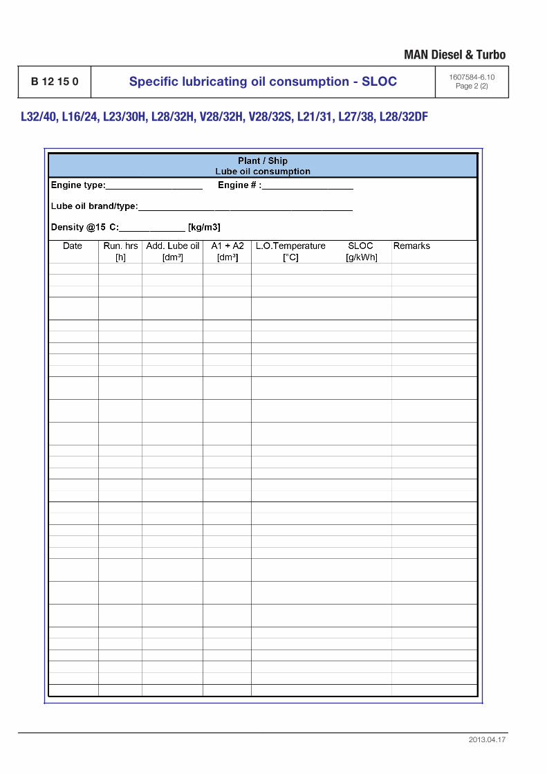
MAN Diesel & Turbo
B 12 15 0 Specific lubricating oil consumption - SLOC 1607584-6.10Page 2 (2)
L32/40, L16/24, L23/30H, L28/32H, V28/32H, V28/32S, L21/31, L27/38, L28/32DF
2013.04.17
General
During operation of trunk engines the lubricating oilwill gradually be contaminated by small particlesoriginating from the combustion.
Engines operated on heavy fuels will normallyincrease the contamination due to the increasedcontent of carbon residues and other contaminants.
Contamination of lubricating oil with either freshwa-ter or seawater can also occur.
A certain amount of contaminants can be kept sus-pended in the lubricating oil without affecting thelubricating properties.
The condition of the lubricating oil must be keptunder observation (on a regular basis) by analyzingoil samples. See Section 504.04 "Criteria for Clean-ing/Exchange of Lubricating Oil".
The moving parts in the engine are protected by thebuilt-on duplex full-flow lubricating oil filter. Thereplaceable paper filter cartridges in each filterchamber has a fineness of 10-15 microns. Thesafety filter, at the centre of each filter chamber, is abasket filter element, with a fineness of 60 microns(sphere passing mesh).
The pressure drop across the replaceable paper fil-ter cartridges is one parameter indicating the con-tamination level. The higher the dirt content in theoil, the shorter the periods between filter cartridgereplacement and cleaning.
The condition of the lubricating oil can be main-tained / re-established by exchanging the lubricat-ing oil at fixed intervals or based on analyzing oilsamples.
Operation on Marine Diesel Oil (MDO) &Marine Gas Oil (MGO)
For engines exclusively operated on MDO/MGO werecommend to install a built-on centrifugal bypassfilter as an additional filter to the built-on full flowdepth filter.
It is advisable to run bypass separator units contin-uously for engines operated on MDO/MGO as sep-arator units present the best cleaning solution.Mesh filters have the disadvantage that they cannotremove water and their elements clog quickly.
Operation on Heavy Fuel Oil (HFO)
HFO-operated engines require effective lubricatingoil cleaning. In order to ensure a safe operation it isnecessary to use supplementary cleaning equip-ment together with the built-on full flow depth filter.
It is mandatory to run bypass separator units con-tinuously for engines operated on HFO, as an opti-mal lubricating oil treatment is fundamental for areliable working condition. Therefore it is mandatoryto clean the lubricating oil with a bypass separatorunit, so that the wear rates are reduced and the life-time of the engine is extended.
Bypass cleaning equipment
As a result of normal operation, the lubricating oilcontains abraded particles and combustion resi-dues which have to be removed by the bypasscleaning system and to a certain extent by theduplex full-flow lubricating oil filter as well.
With automatic mesh filters this can result in anundesirable and hazardous continuous flushing. Inview of the high cost of cleaning equipment forremoving micro impurities, this equipment is onlyrated for a certain proportion of the oil flowingthrough the engine since it is installed in a bypass.
The bypass cleaning equipment is operated
▪ continuously when the engine is in operation orat standstill
For cleaning of lubricating oil the following bypasscleaning equipment can be used:
▪ Separator unit
▪ Decanter unit
▪ Self cleaning automatic bypass mesh filter
▪ Built-on centrifugal bypass filter (standard onMAN Diesel & Turbo, Holeby GenSets)
▪ Bypass depth filter
The decanter unit, the self-cleaning automaticbypass mesh filter and the bypass depth filtercapacity must be adjusted according to maker’srecommendations.
In case full flow filtration equipment is chosen, thismust only be installed as in-line cleaning upstreamto the duplex full-flow lubricating oil filter, built ontothe engine.
MAN Diesel & Turbo
1643494-3.9Page 1 (7) Treatment and maintenance of lubricating oil B 12 15 0
L32/40, L16/24, L23/30H, L28/32H, V28/32S, L21/31, L27/38, L28/32DF,
V28/32DF
2013.10.04
The most appropriate type of equipment for a par-ticular application depends on the engine output,the type and amount of combustion residues, theannual operating time and the operating mode ofthe plant. Even with a relatively low number of oper-ating hours there can be a great deal of combustionresidues if, for instance, the engine is inadequatelypreheated and quickly accelerated and loaded.
Separator unit
Continuous lubricating oil cleaning during engineoperation is mandatory. An optimal lubricating oiltreatment is fundamental for a reliable working con-dition of the engine.
If the lubricating oil is circulating without a separatorunit in operation, the lubricating oil will gradually becontaminated by products of combustion, waterand/or acid. In some instances cat-fines may alsobe present. In order to prolong the lubricating oil lifetime andremove wear elements, water and contaminantsfrom the lubricating oil, it is mandatory to use a by-pass separator unit. The separator unit will reduce the carbon residuecontent and other contaminants from combustionon engines operated on HFO, and keep the amountwithin MDT’s recommendation, on condition thatthe separator unit is operated according to MDT'srecommendations.
When operating a cleaning device, the followingrecommendations must be observed:
▪ The optimum cleaning effect is achieved bykeeping the lubricating oil in a state of low vis-cosity for a long period in the separator bowl.
▪ Sufficiently low viscosity is obtained by preheat-ing the lubricating oil to a temperature of 95°C -98°C, when entering the separator bowl.
▪ The capacity of the separator unit must beadjusted according to MDT's recommenda-tions.
Slow passage of the lubricating oil through the sep-arator unit is obtained by using a reduced flow rateand by operating the separator unit 24 hours a day,stopping only for maintenance, according to mak-er's recommendation.
Lubricating oil preheating
The installed heater on the separator unit ensurescorrect lubricating oil temperature during separa-tion. When the engine is at standstill, the heater canbe used for two functions:
▪ The oil in the sump is preheated to 95 – 98 °Cby the heater and cleaned continuously by theseparator unit.
▪ The heater can also be used to maintain an oiltemperature of at least 40 °C, depending oninstallation of the lubricating oil system.
Cleaning capacity
Normally, it is recommended to use a self-cleaningfiltration unit in order to optimize the cleaning periodand thus also optimize the size of the filtration unit.Separator units for manual cleaning can be usedwhen the reduced effective cleaning time is takeninto consideration by dimensioning the separatorunit capacity.
The required operation and design flow
In order to calculate the required operation flowthrough the separator unit, MDT's recommendationmust be followed.
As a guidance, the following formula should formthe basis for calculating the required operation flowthrough the separator unit:
Q = required operation flow [l/h]
P = MCR (Maximum Continuous Rat-ing) [kW]
t = actual effective separator unit sep-arating time per day [hour] (23.5 h separating time and 0.5 hfor sludge discharge = 24 h/day)
n = number of turnovers per day of thetheoretical oil volume correspond-ing to 1.36 [l/kW] or 1 [l/HP]
The following values for "n" are recommended:
n = 6 for HFO operation (residual)
n = 4 for MDO operation
n = 3 for distillate fuel
MAN Diesel & Turbo
B 12 15 0 Treatment and maintenance of lubricating oil 1643494-3.9Page 2 (7)
L32/40, L16/24, L23/30H, L28/32H, V28/32S, L21/31, L27/38, L28/32DF,V28/32DF
2013.10.04
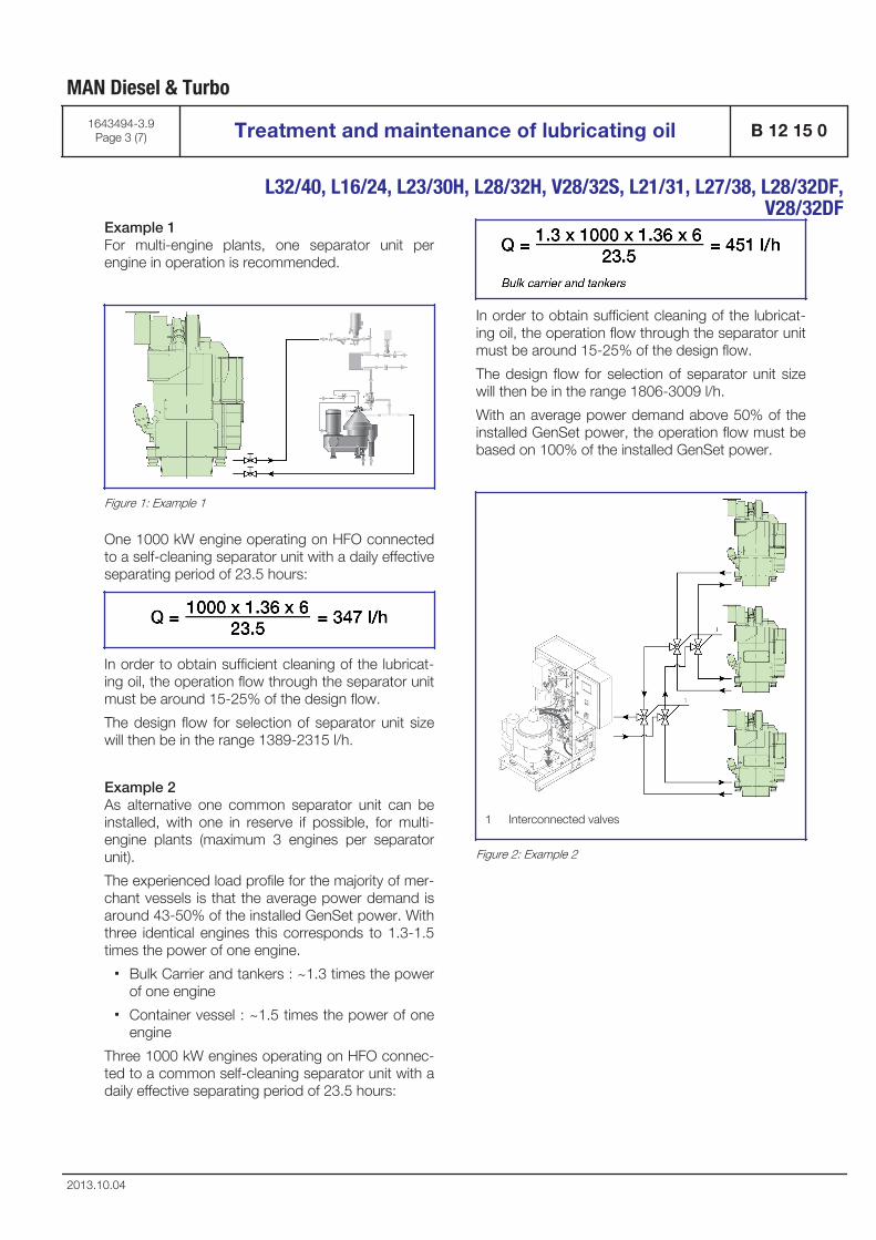
Example 1 For multi-engine plants, one separator unit perengine in operation is recommended.
Figure 1: Example 1
One 1000 kW engine operating on HFO connectedto a self-cleaning separator unit with a daily effectiveseparating period of 23.5 hours:
In order to obtain sufficient cleaning of the lubricat-ing oil, the operation flow through the separator unitmust be around 15-25% of the design flow.
The design flow for selection of separator unit sizewill then be in the range 1389-2315 l/h.
Example 2 As alternative one common separator unit can beinstalled, with one in reserve if possible, for multi-engine plants (maximum 3 engines per separatorunit).
The experienced load profile for the majority of mer-chant vessels is that the average power demand isaround 43-50% of the installed GenSet power. Withthree identical engines this corresponds to 1.3-1.5times the power of one engine.
▪ Bulk Carrier and tankers : ~1.3 times the powerof one engine
▪ Container vessel : ~1.5 times the power of oneengine
Three 1000 kW engines operating on HFO connec-ted to a common self-cleaning separator unit with adaily effective separating period of 23.5 hours:
In order to obtain sufficient cleaning of the lubricat-ing oil, the operation flow through the separator unitmust be around 15-25% of the design flow.
The design flow for selection of separator unit sizewill then be in the range 1806-3009 l/h.
With an average power demand above 50% of theinstalled GenSet power, the operation flow must bebased on 100% of the installed GenSet power.
1 Interconnected valves
Figure 2: Example 2
MAN Diesel & Turbo
1643494-3.9Page 3 (7) Treatment and maintenance of lubricating oil B 12 15 0
L32/40, L16/24, L23/30H, L28/32H, V28/32S, L21/31, L27/38, L28/32DF,
V28/32DF
2013.10.04

Separator unit installation
With multi-engine plants, one separator unit perengine in operation is recommended (see figure 1),but if only one separator unit is in operation, the fol-lowing layout can be used:
▪ A common separator unit (see figure 2) can beinstalled, with one in reserve, if possible, foroperation of all engines through a pipe system,which can be carried out in various ways. Theaim is to ensure that the separator unit is onlyconnected to one engine at a time. Thus therewill be no suction and discharging from oneengine to another.
It is recommended that inlet and outlet valves areconnected so that they can only be changed oversimultaneously.
With only one engine in operation there are noproblems with separating, but if several engines arein operation for some time it is recommended tosplit up the separation time in turns on all operatingengines.
With 2 out of 3 engines in operation the 23.5 hoursseparating time must be split up in around 4-6hours intervals between changeover.
Stokes' law
The operating principles of centrifugal separationare based on Stokes’ Law.
V = settling velocity [m/sec]
rω2 = acceleration in centrifgal field [m/sec2]
d = diameter of particle [m]
ρp = density of particle [kg/m3]
ρl = density of medium [kg/m3]
µ = viscosity of medium [kg/m, sec.]
The rate of settling (V) for a given capacity is deter-mined by Stokes’ Law. This expression takes intoaccount the particle size, the difference betweendensity of the particles and the lubricating oil, andthe viscosity of the lubricating oil.
Density and viscosity are important parameters forefficient separation. The greater the difference indensity between the particle and the lubricating oil,the higher the separation efficiency. The settlingvelocity increases in inverse proportion to viscosity.However, since both density and viscosity vary withtemperature, separation temperature is the criticaloperating parameter.
Particle size is another important factor. The settlingvelocity increases rapidly with particle size. Thismeans that the smaller the particle, the more chal-lenging the separation task. In a centrifuge, the term(rω2) represents the centrifugal force which is sev-eral thousand times greater than the accelerationdue to gravitational force. Centrifugal force enablesthe efficient separation of particles which are only afew microns in size.
The separation efficiency is a function of:
MAN Diesel & Turbo
B 12 15 0 Treatment and maintenance of lubricating oil 1643494-3.9Page 4 (7)
L32/40, L16/24, L23/30H, L28/32H, V28/32S, L21/31, L27/38, L28/32DF,V28/32DF
2013.10.04

Operating parameters
Various operating parameters affect separation effi-ciency. These include temperature, which controlsboth lubricating oil viscosity and density, flow rateand maintenance.
Temperature of lubricating oil beforeseparator unit
It is often seen that the lubricating oil pre-heatersare undersized, have very poor temperature control,the steam supply to the pre-heater is limited or thetemperature set point is too low.
Often the heater surface is partly clogged by depos-its. These factors all lead to reduced separationtemperature and hence the efficiency of the separa-
tor unit. In order to ensure that the centrifugal forcesseparate the heavy contaminants in the relativelylimited time that they are present in the separatorbowl, the separator unit must always be operatedwith an inlet temperature of 95-98°C for lubricatingoil.
A control circuit including a temperature transmitterand a PI-type controller with accuracy of ±2°C mustbe installed. If steam-heated, a correctly sizedsteam valve should be fitted with the right KvSvalue. The steam trap must be a mechanical floattype. The most common heaters on board aresteam heaters. This is due to the fact that steam inmost cases is available at low cost.
Most ships are equipped with an exhaust boiler uti-lizing the exhaust gases to generate steam.
A large proportion of smaller tonnage does, how-ever, use electric heaters.
It is essential to keep the incoming oil temperatureto the separator unit steady with only a small varia-tion in temperature allowed (maximum ±2°C).
The position of the interface between oil and waterin the separator bowl is a result of the density andthe viscosity of the oil, which in turn depends on thetemperature.
Flow rate
It is known that separation efficiency is a function ofthe separator unit’s flow rate. The higher the flowrate, the more particles are left in the oil and there-fore the lower the separation efficiency. As the flowrate is reduced, the efficiency with which particlesare removed increases and cleaning efficiency thusimproves. It is, however, essential to know at whatcapacity adequate separation efficiency is reachedin the specific case.
In principle, there are three ways to control the flow:
▪ Adjustment of the built-in safety valve on thepump.
This method is NOT recommended since thebuilt-on valve is nothing but a safety valve.
The opening pressure is often too high and itscharacteristic far from linear.
In addition, circulation in the pump may result inoil emulsions and cavitation in the pump.
▪ A flow regulating valve arrangement on thepressure side of the pump, which bypasses theseparator unit and re-circulates part of the
MAN Diesel & Turbo
1643494-3.9Page 5 (7) Treatment and maintenance of lubricating oil B 12 15 0
L32/40, L16/24, L23/30H, L28/32H, V28/32S, L21/31, L27/38, L28/32DF,
V28/32DF
2013.10.04
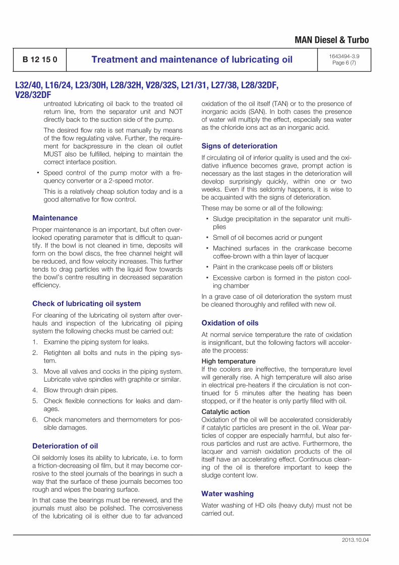
untreated lubricating oil back to the treated oilreturn line, from the separator unit and NOTdirectly back to the suction side of the pump.
The desired flow rate is set manually by meansof the flow regulating valve. Further, the require-ment for backpressure in the clean oil outletMUST also be fulfilled, helping to maintain thecorrect interface position.
▪ Speed control of the pump motor with a fre-quency converter or a 2-speed motor.
This is a relatively cheap solution today and is agood alternative for flow control.
Maintenance
Proper maintenance is an important, but often over-looked operating parameter that is difficult to quan-tify. If the bowl is not cleaned in time, deposits willform on the bowl discs, the free channel height willbe reduced, and flow velocity increases. This furthertends to drag particles with the liquid flow towardsthe bowl’s centre resulting in decreased separationefficiency.
Check of lubricating oil system
For cleaning of the lubricating oil system after over-hauls and inspection of the lubricating oil pipingsystem the following checks must be carried out:
1. Examine the piping system for leaks.
2. Retighten all bolts and nuts in the piping sys-tem.
3. Move all valves and cocks in the piping system.Lubricate valve spindles with graphite or similar.
4. Blow through drain pipes.
5. Check flexible connections for leaks and dam-ages.
6. Check manometers and thermometers for pos-sible damages.
Deterioration of oil
Oil seldomly loses its ability to lubricate, i.e. to forma friction-decreasing oil film, but it may become cor-rosive to the steel journals of the bearings in such away that the surface of these journals becomes toorough and wipes the bearing surface.
In that case the bearings must be renewed, and thejournals must also be polished. The corrosivenessof the lubricating oil is either due to far advanced
oxidation of the oil itself (TAN) or to the presence ofinorganic acids (SAN). In both cases the presenceof water will multiply the effect, especially sea wateras the chloride ions act as an inorganic acid.
Signs of deterioration
If circulating oil of inferior quality is used and the oxi-dative influence becomes grave, prompt action isnecessary as the last stages in the deterioration willdevelop surprisingly quickly, within one or twoweeks. Even if this seldomly happens, it is wise tobe acquainted with the signs of deterioration.
These may be some or all of the following:
▪ Sludge precipitation in the separator unit multi-plies
▪ Smell of oil becomes acrid or pungent
▪ Machined surfaces in the crankcase becomecoffee-brown with a thin layer of lacquer
▪ Paint in the crankcase peels off or blisters
▪ Excessive carbon is formed in the piston cool-ing chamber
In a grave case of oil deterioration the system mustbe cleaned thoroughly and refilled with new oil.
Oxidation of oils
At normal service temperature the rate of oxidationis insignificant, but the following factors will acceler-ate the process:
High temperature If the coolers are ineffective, the temperature levelwill generally rise. A high temperature will also arisein electrical pre-heaters if the circulation is not con-tinued for 5 minutes after the heating has beenstopped, or if the heater is only partly filled with oil.
Catalytic action Oxidation of the oil will be accelerated considerablyif catalytic particles are present in the oil. Wear par-ticles of copper are especially harmful, but also fer-rous particles and rust are active. Furthermore, thelacquer and varnish oxidation products of the oilitself have an accelerating effect. Continuous clean-ing of the oil is therefore important to keep thesludge content low.
Water washing
Water washing of HD oils (heavy duty) must not becarried out.
MAN Diesel & Turbo
B 12 15 0 Treatment and maintenance of lubricating oil 1643494-3.9Page 6 (7)
L32/40, L16/24, L23/30H, L28/32H, V28/32S, L21/31, L27/38, L28/32DF,V28/32DF
2013.10.04
Water in the oil
If the TAN is low, a minor increase in the fresh watercontent of the oil is not immediately detrimentalwhile the engine is in operation. Naturally, it shouldbe brought down again as quickly as possible(below 0.2% water content, which is permissible,see description "B 12 15 0/504.04 criteria forexchange of lube oil”). If the engine is stopped whilecorrosion conditions are unsatisfactory, the crank-shaft must be turned ½ - ¾ revolution once everyhour by means of the turning gear. Please makesure that the crankshaft stops in different positions,to prevent major damage to bearings and journals.The lubricating oil must be circulated and separatedcontinuously to remove water.
Water in the oil may be noted by steam formationon the sight glasses, by appearance, or ascertainedby immersing a piece of glass or a soldering ironheated to 200-300°C in an oil sample. If there is ahissing sound, water is present. If a large quantity ofwater has entered the lubricating oil system, it hasto be removed. Either by sucking up sedimentwater from the bottom, or by replacing the oil in thesump. An oil sample must be analysed immediatelyfor chloride ions.
MAN Diesel & Turbo
1643494-3.9Page 7 (7) Treatment and maintenance of lubricating oil B 12 15 0
L32/40, L16/24, L23/30H, L28/32H, V28/32S, L21/31, L27/38, L28/32DF,
V28/32DF
2013.10.04

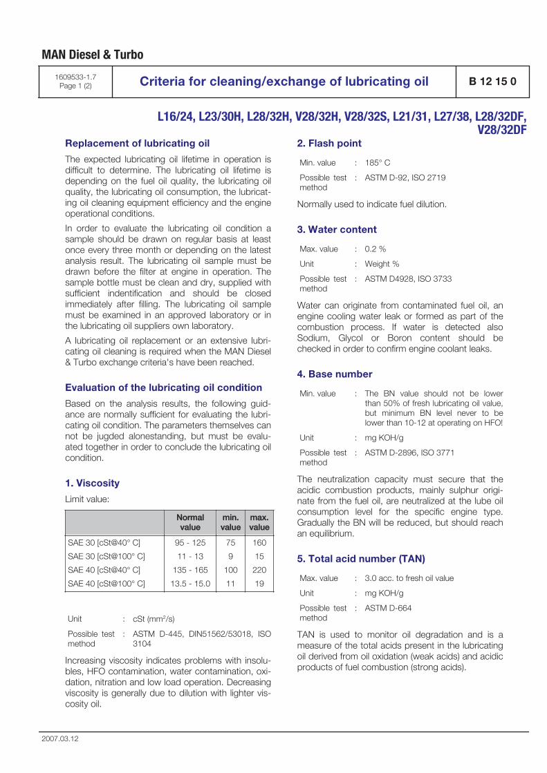
Replacement of lubricating oil
The expected lubricating oil lifetime in operation isdifficult to determine. The lubricating oil lifetime isdepending on the fuel oil quality, the lubricating oilquality, the lubricating oil consumption, the lubricat-ing oil cleaning equipment efficiency and the engineoperational conditions.
In order to evaluate the lubricating oil condition asample should be drawn on regular basis at leastonce every three month or depending on the latestanalysis result. The lubricating oil sample must bedrawn before the filter at engine in operation. Thesample bottle must be clean and dry, supplied withsufficient indentification and should be closedimmediately after filling. The lubricating oil samplemust be examined in an approved laboratory or inthe lubricating oil suppliers own laboratory.
A lubricating oil replacement or an extensive lubri-cating oil cleaning is required when the MAN Diesel& Turbo exchange criteria's have been reached.
Evaluation of the lubricating oil condition
Based on the analysis results, the following guid-ance are normally sufficient for evaluating the lubri-cating oil condition. The parameters themselves cannot be jugded alonestanding, but must be evalu-ated together in order to conclude the lubricating oilcondition.
1. Viscosity
Limit value:
Normalvalue
min.value
max.value
SAE 30 [cSt@40° C]
SAE 30 [cSt@100° C]
SAE 40 [cSt@40° C]
SAE 40 [cSt@100° C]
95 - 125
11 - 13
135 - 165
13.5 - 15.0
75
9
100
11
160
15
220
19
Unit : cSt (mm2/s)
Possible testmethod
: ASTM D-445, DIN51562/53018, ISO3104
Increasing viscosity indicates problems with insolu-bles, HFO contamination, water contamination, oxi-dation, nitration and low load operation. Decreasingviscosity is generally due to dilution with lighter vis-cosity oil.
2. Flash point
Min. value : 185° C
Possible testmethod
: ASTM D-92, ISO 2719
Normally used to indicate fuel dilution.
3. Water content
Max. value : 0.2 %
Unit : Weight %
Possible testmethod
: ASTM D4928, ISO 3733
Water can originate from contaminated fuel oil, anengine cooling water leak or formed as part of thecombustion process. If water is detected alsoSodium, Glycol or Boron content should bechecked in order to confirm engine coolant leaks.
4. Base number
Min. value : The BN value should not be lowerthan 50% of fresh lubricating oil value,but minimum BN level never to belower than 10-12 at operating on HFO!
Unit : mg KOH/g
Possible testmethod
: ASTM D-2896, ISO 3771
The neutralization capacity must secure that theacidic combustion products, mainly sulphur origi-nate from the fuel oil, are neutralized at the lube oilconsumption level for the specific engine type.Gradually the BN will be reduced, but should reachan equilibrium.
5. Total acid number (TAN)
Max. value : 3.0 acc. to fresh oil value
Unit : mg KOH/g
Possible testmethod
: ASTM D-664
TAN is used to monitor oil degradation and is ameasure of the total acids present in the lubricatingoil derived from oil oxidation (weak acids) and acidicproducts of fuel combustion (strong acids).
MAN Diesel & Turbo
1609533-1.7Page 1 (2) Criteria for cleaning/exchange of lubricating oil B 12 15 0
L16/24, L23/30H, L28/32H, V28/32H, V28/32S, L21/31, L27/38, L28/32DF,
V28/32DF
2007.03.12
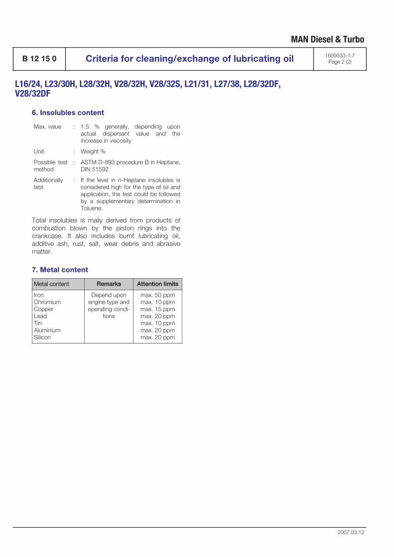
6. Insolubles content
Max. value : 1.5 % generally, depending uponactual dispersant value and theincrease in viscosity
Unit : Weight %
Possible testmethod
: ASTM D-893 procedure B in Heptane,DIN 51592
Additionallytest
: If the level in n-Heptane insolubles isconsidered high for the type of oil andapplication, the test could be followedby a supplementary determination inToluene.
Total insolubles is maily derived from products ofcombustion blown by the piston rings into thecrankcase. It also includes burnt lubricating oil,additive ash, rust, salt, wear debris and abrasivematter.
7. Metal content
Metal content Remarks Attention limits
IronChromiumCopperLeadTinAluminiumSilicon
Depend uponengine type andoperating condi-
tions
max. 50 ppmmax. 10 ppmmax. 15 ppmmax. 20 ppmmax. 10 ppmmax. 20 ppmmax. 20 ppm
MAN Diesel & Turbo
B 12 15 0 Criteria for cleaning/exchange of lubricating oil 1609533-1.7Page 2 (2)
L16/24, L23/30H, L28/32H, V28/32H, V28/32S, L21/31, L27/38, L28/32DF,V28/32DF
2007.03.12

Cooling Water System
B 13

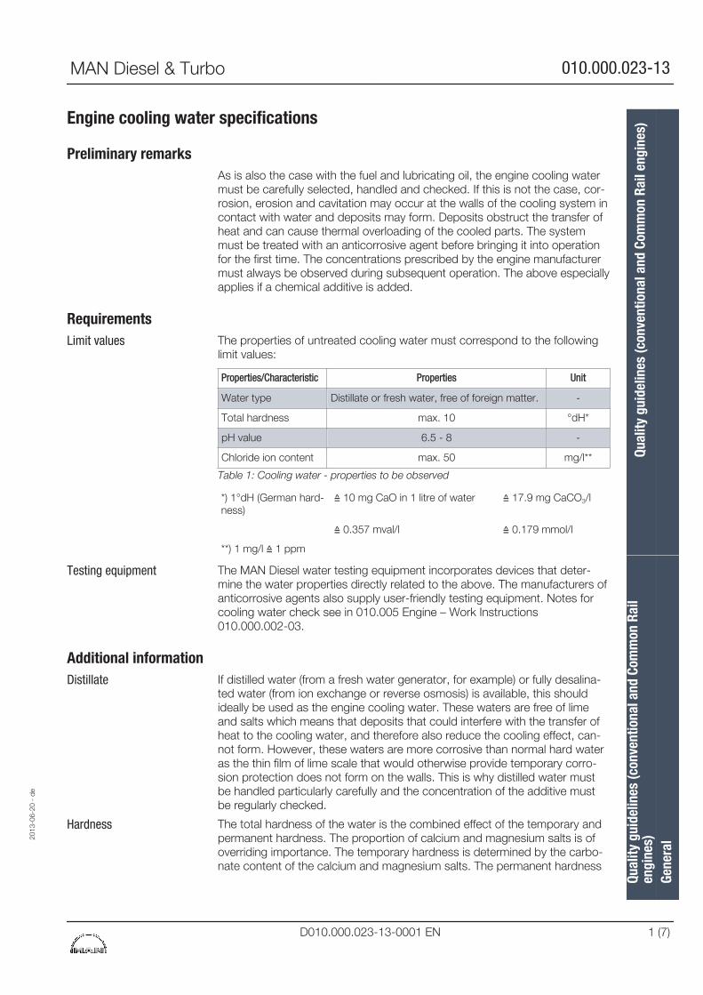
Engine cooling water specifications
Preliminary remarksAs is also the case with the fuel and lubricating oil, the engine cooling watermust be carefully selected, handled and checked. If this is not the case, cor-rosion, erosion and cavitation may occur at the walls of the cooling system incontact with water and deposits may form. Deposits obstruct the transfer ofheat and can cause thermal overloading of the cooled parts. The systemmust be treated with an anticorrosive agent before bringing it into operationfor the first time. The concentrations prescribed by the engine manufacturermust always be observed during subsequent operation. The above especiallyapplies if a chemical additive is added.
RequirementsThe properties of untreated cooling water must correspond to the followinglimit values:
Properties/Characteristic Properties Unit
Water type Distillate or fresh water, free of foreign matter. -
Total hardness max. 10 °dH*
pH value 6.5 - 8 -
Chloride ion content max. 50 mg/l**
Table 1: Cooling water - properties to be observed
*) 1°dH (German hard-ness)
≙ 10 mg CaO in 1 litre of water ≙ 17.9 mg CaCO3/l
≙ 0.357 mval/l ≙ 0.179 mmol/l
**) 1 mg/l ≙ 1 ppm
The MAN Diesel water testing equipment incorporates devices that deter-mine the water properties directly related to the above. The manufacturers ofanticorrosive agents also supply user-friendly testing equipment. Notes forcooling water check see in 010.005 Engine – Work Instructions010.000.002-03.
Additional informationIf distilled water (from a fresh water generator, for example) or fully desalina-ted water (from ion exchange or reverse osmosis) is available, this shouldideally be used as the engine cooling water. These waters are free of limeand salts which means that deposits that could interfere with the transfer ofheat to the cooling water, and therefore also reduce the cooling effect, can-not form. However, these waters are more corrosive than normal hard wateras the thin film of lime scale that would otherwise provide temporary corro-sion protection does not form on the walls. This is why distilled water mustbe handled particularly carefully and the concentration of the additive mustbe regularly checked.
The total hardness of the water is the combined effect of the temporary andpermanent hardness. The proportion of calcium and magnesium salts is ofoverriding importance. The temporary hardness is determined by the carbo-nate content of the calcium and magnesium salts. The permanent hardness
Limit values
Testing equipment
Distillate
Hardness
2013
-06-
20 -
de
Qual
ity g
uide
lines
(con
vent
iona
l and
Com
mon
Rai
len
gine
s)Qu
ality
gui
delin
es (c
onve
ntio
nal a
nd C
omm
on R
ail e
ngin
es)
Gene
ral
MAN Diesel & Turbo 010.000.023-13
D010.000.023-13-0001 EN 1 (7)
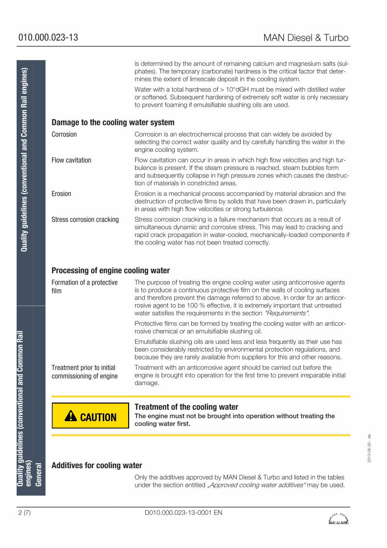
is determined by the amount of remaining calcium and magnesium salts (sul-phates). The temporary (carbonate) hardness is the critical factor that deter-mines the extent of limescale deposit in the cooling system.
Water with a total hardness of > 10°dGH must be mixed with distilled wateror softened. Subsequent hardening of extremely soft water is only necessaryto prevent foaming if emulsifiable slushing oils are used.
Damage to the cooling water systemCorrosion is an electrochemical process that can widely be avoided byselecting the correct water quality and by carefully handling the water in theengine cooling system.
Flow cavitation can occur in areas in which high flow velocities and high tur-bulence is present. If the steam pressure is reached, steam bubbles formand subsequently collapse in high pressure zones which causes the destruc-tion of materials in constricted areas.
Erosion is a mechanical process accompanied by material abrasion and thedestruction of protective films by solids that have been drawn in, particularlyin areas with high flow velocities or strong turbulence.
Stress corrosion cracking is a failure mechanism that occurs as a result ofsimultaneous dynamic and corrosive stress. This may lead to cracking andrapid crack propagation in water-cooled, mechanically-loaded components ifthe cooling water has not been treated correctly.
Processing of engine cooling waterThe purpose of treating the engine cooling water using anticorrosive agentsis to produce a continuous protective film on the walls of cooling surfacesand therefore prevent the damage referred to above. In order for an anticor-rosive agent to be 100 % effective, it is extremely important that untreatedwater satisfies the requirements in the section "Requirements".
Protective films can be formed by treating the cooling water with an anticor-rosive chemical or an emulsifiable slushing oil.
Emulsifiable slushing oils are used less and less frequently as their use hasbeen considerably restricted by environmental protection regulations, andbecause they are rarely available from suppliers for this and other reasons.
Treatment with an anticorrosive agent should be carried out before theengine is brought into operation for the first time to prevent irreparable initialdamage.
Treatment of the cooling waterThe engine must not be brought into operation without treating thecooling water first.
Additives for cooling waterOnly the additives approved by MAN Diesel & Turbo and listed in the tablesunder the section entitled „Approved cooling water additives“ may be used.
Corrosion
Flow cavitation
Erosion
Stress corrosion cracking
Formation of a protectivefilm
Treatment prior to initialcommissioning of engine
Qual
ity g
uide
lines
(con
vent
iona
l and
Com
mon
Rai
len
gine
s)Qu
ality
gui
delin
es (c
onve
ntio
nal a
nd C
omm
on R
ail e
ngin
es)
Gene
ral
2013
-06-
20 -
de
010.000.023-13 MAN Diesel & Turbo
2 (7) D010.000.023-13-0001 EN
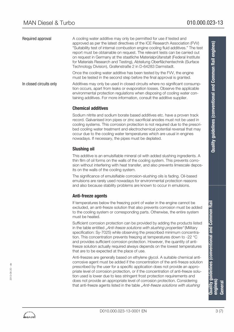
A cooling water additive may only be permitted for use if tested andapproved as per the latest directives of the ICE Research Association (FVV)"Suitability test of internal combustion engine cooling fluid additives.” The testreport must be obtainable on request. The relevant tests can be carried outon request in Germany at the staatliche Materialprüfanstalt (Federal Institutefor Materials Research and Testing), Abteilung Oberflächentechnik (SurfaceTechnology Division), Grafenstraße 2 in D-64283 Darmstadt.
Once the cooling water additive has been tested by the FVV, the enginemust be tested in the second step before the final approval is granted.
Additives may only be used in closed circuits where no significant consump-tion occurs, apart from leaks or evaporation losses. Observe the applicableenvironmental protection regulations when disposing of cooling water con-taining additives. For more information, consult the additive supplier.
Chemical additivesSodium nitrite and sodium borate based additives etc. have a proven trackrecord. Galvanised iron pipes or zinc sacrificial anodes must not be used incooling systems. This corrosion protection is not required due to the prescri-bed cooling water treatment and electrochemical potential reversal that mayoccur due to the cooling water temperatures which are usual in enginesnowadays. If necessary, the pipes must be deplated.
Slushing oilThis additive is an emulsifiable mineral oil with added slushing ingredients. Athin film of oil forms on the walls of the cooling system. This prevents corro-sion without interfering with heat transfer, and also prevents limescale depos-its on the walls of the cooling system.
The significance of emulsifiable corrosion-slushing oils is fading. Oil-basedemulsions are rarely used nowadays for environmental protection reasonsand also because stability problems are known to occur in emulsions.
Anti-freeze agentsIf temperatures below the freezing point of water in the engine cannot beexcluded, an anti-freeze solution that also prevents corrosion must be addedto the cooling system or corresponding parts. Otherwise, the entire systemmust be heated.
Sufficient corrosion protection can be provided by adding the products listedin the table entitled „Anti-freeze solutions with slushing properties“ (Militaryspecification: Sy-7025) while observing the prescribed minimum concentra-tion. This concentration prevents freezing at temperatures down to -22 °Cand provides sufficient corrosion protection. However, the quantity of anti-freeze solution actually required always depends on the lowest temperaturesthat are to be expected at the place of use.
Anti-freezes are generally based on ethylene glycol. A suitable chemical anti-corrosive agent must be added if the concentration of the anti-freeze solutionprescribed by the user for a specific application does not provide an appro-priate level of corrosion protection, or if the concentration of anti-freeze solu-tion used is lower due to less stringent frost protection requirements anddoes not provide an appropriate level of corrosion protection. Consideringthat anti-freeze agents listed in the table „Anti-freeze solutions with slushing
Required approval
In closed circuits only
2013
-06-
20 -
de
Qual
ity g
uide
lines
(con
vent
iona
l and
Com
mon
Rai
len
gine
s)Qu
ality
gui
delin
es (c
onve
ntio
nal a
nd C
omm
on R
ail e
ngin
es)
Gene
ral
MAN Diesel & Turbo 010.000.023-13
D010.000.023-13-0001 EN 3 (7)
properties“ also contain corrosion inhibitors and their compatibility with otheranticorrosive agents is generally not given, only pure glycol may be used asanti-freeze agent in such cases.
Simultaneous use of anticorrosive agent from the table „Chemical additives –nitrite free” together with glycol is not permitted, because monitoring the anti-corrosive agent concentration in this mixture is not more possible.
Anti-freeze solutions may only be mixed with one another with the consent ofthe manufacturer, even if these solutions have the same composition.
Before an anti-freeze solution is used, the cooling system must be thoroughlycleaned.
If the cooling water contains an emulsifiable slushing oil, anti-freeze solutionmust not be added as otherwise the emulsion would break up and oil sludgewould form in the cooling system.
BiocidesIf you cannot avoid using a biocide because the cooling water has been con-taminated by bacteria, observe the following steps:
▪ You must ensure that the biocide to be used is suitable for the specificapplication.
▪ The biocide must be compatible with the sealing materials used in thecooling water system and must not react with these.
▪ The biocide and its decomposition products must not contain corrosion-promoting components. Biocides whose decomposition products con-tain chloride or sulphate ions are not permitted.
▪ Biocides that cause foaming of cooling water are not permitted.
Prerequisite for effective use of an anticorrosive agent
Clean cooling systemAs contamination significantly reduces the effectiveness of the additive, thetanks, pipes, coolers and other parts outside the engine must be free of rustand other deposits before the engine is started up for the first time and afterrepairs of the pipe system. The entire system must therefore be cleaned withthe engine switched off using a suitable cleaning agent (see 010.005 Engine– Work Instructions 010.000.001-01.010.000.002-04).
Loose solid matter in particular must be removed by flushing the systemthoroughly as otherwise erosion may occur in locations where the flow veloc-ity is high.
The cleaning agents must not corrode the seals and materials of the coolingsystem. In most cases, the supplier of the cooling water additive will be ableto carry out this work and, if this is not possible, will at least be able to pro-vide suitable products to do this. If this work is carried out by the engineoperator, he should use the services of a specialist supplier of cleaningagents. The cooling system must be flushed thoroughly after cleaning. Oncethis has been done, the engine cooling water must be immediately treatedwith anticorrosive agent. Once the engine has been brought back into opera-tion, the cleaned system must be checked for leaks.
Qual
ity g
uide
lines
(con
vent
iona
l and
Com
mon
Rai
len
gine
s)Qu
ality
gui
delin
es (c
onve
ntio
nal a
nd C
omm
on R
ail e
ngin
es)
Gene
ral
2013
-06-
20 -
de
010.000.023-13 MAN Diesel & Turbo
4 (7) D010.000.023-13-0001 EN
Regular checks of the cooling water condition and cooling watersystemTreated cooling water may become contaminated when the engine is inoperation, which causes the additive to loose some of its effectiveness. It istherefore advisable to regularly check the cooling system and the coolingwater condition. To determine leakages in the lube oil system, it is advisableto carry out regular checks of water in the compensating tank. Indications ofoil content in water are, e.g. discoloration or a visible oil film on the surface ofthe water sample.
The additive concentration must be checked at least once a week using thetest kits specified by the manufacturer. The results must be documented.
Concentrations of chemical additivesThe chemical additive concentrations shall not be less than theminimum concentrations indicated in the table „Nitrite-containingchemical additives“.
Excessively low concentrations can promote corrosion and must be avoided.If the concentration is slightly above the recommended concentration this willnot result in damage. Concentrations that are more than twice the recom-mended concentration should be avoided.
Every 2 to 6 months send a cooling water sample to an independent labora-tory or to the engine manufacturer for integrated analysis.
Emulsifiable anticorrosive agents must generally be replaced after abt. 12months according to the supplier's instructions. When carrying this out, theentire cooling system must be flushed and, if necessary, cleaned. Once filledinto the system, fresh water must be treated immediately.
If chemical additives or anti-freeze solutions are used, cooling water shouldbe replaced after 3 years at the latest.
If there is a high concentration of solids (rust) in the system, the water mustbe completely replaced and entire system carefully cleaned.
Deposits in the cooling system may be caused by fluids that enter the cool-ing water, or the break up of emulsion, corrosion in the system and limescaledeposits if the water is very hard. If the concentration of chloride ions hasincreased, this generally indicates that seawater has entered the system. Themaximum specified concentration of 50 mg chloride ions per kg must not beexceeded as otherwise the risk of corrosion is too high. If exhaust gas entersthe cooling water, this may lead to a sudden drop in the pH value or to anincrease in the sulphate content.
Water losses must be compensated for by filling with untreated water thatmeets the quality requirements specified in the section Requirements. Theconcentration of the anticorrosive agent must subsequently be checked andadjusted if necessary.
Subsequent checks of cooling water are especially required if the coolingwater had to be drained off in order to carry out repairs or maintenance.
2013
-06-
20 -
de
Qual
ity g
uide
lines
(con
vent
iona
l and
Com
mon
Rai
len
gine
s)Qu
ality
gui
delin
es (c
onve
ntio
nal a
nd C
omm
on R
ail e
ngin
es)
Gene
ral
MAN Diesel & Turbo 010.000.023-13
D010.000.023-13-0001 EN 5 (7)
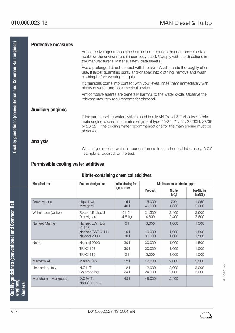
Protective measuresAnticorrosive agents contain chemical compounds that can pose a risk tohealth or the environment if incorrectly used. Comply with the directions inthe manufacturer's material safety data sheets.
Avoid prolonged direct contact with the skin. Wash hands thoroughly afteruse. If larger quantities spray and/or soak into clothing, remove and washclothing before wearing it again.
If chemicals come into contact with your eyes, rinse them immediately withplenty of water and seek medical advice.
Anticorrosive agents are generally harmful to the water cycle. Observe therelevant statutory requirements for disposal.
Auxiliary enginesIf the same cooling water system used in a MAN Diesel & Turbo two-strokemain engine is used in a marine engine of type 16/24, 21/ 31, 23/30H, 27/38or 28/32H, the cooling water recommendations for the main engine must beobserved.
AnalysisWe analyse cooling water for our customers in our chemical laboratory. A 0.5l sample is required for the test.
Permissible cooling water additives
Nitrite-containing chemical additives
Manufacturer Product designation Initial dosing for1,000 litres
Minimum concentration ppm
Product Nitrite(NO2)
Na-Nitrite(NaNO2)
Drew Marine LiquidewtMaxigard
15 l40 l
15,00040,000
7001,330
1,0502,000
Wilhelmsen (Unitor) Rocor NB LiquidDieselguard
21.5 l4.8 kg
21,5004,800
2,4002,400
3,6003,600
Nalfleet Marine Nalfleet EWT Liq(9-108)Nalfleet EWT 9-111Nalcool 2000
3 l
10 l30 l
3,000
10,00030,000
1,000
1,0001,000
1,500
1,5001,500
Nalco Nalcool 2000
TRAC 102
TRAC 118
30 l
30 l
3 l
30,000
30,000
3,000
1,000
1,000
1,000
1,500
1,500
1,500
Maritech AB Marisol CW 12 l 12,000 2,000 3,000
Uniservice, Italy N.C.L.T.Colorcooling
12 l24 l
12,00024,000
2,0002,000
3,0003,000
Marichem – Marigases D.C.W.T. - Non-Chromate
48 l 48,000 2,400 -
Qual
ity g
uide
lines
(con
vent
iona
l and
Com
mon
Rai
len
gine
s)Qu
ality
gui
delin
es (c
onve
ntio
nal a
nd C
omm
on R
ail e
ngin
es)
Gene
ral
2013
-06-
20 -
de
010.000.023-13 MAN Diesel & Turbo
6 (7) D010.000.023-13-0001 EN
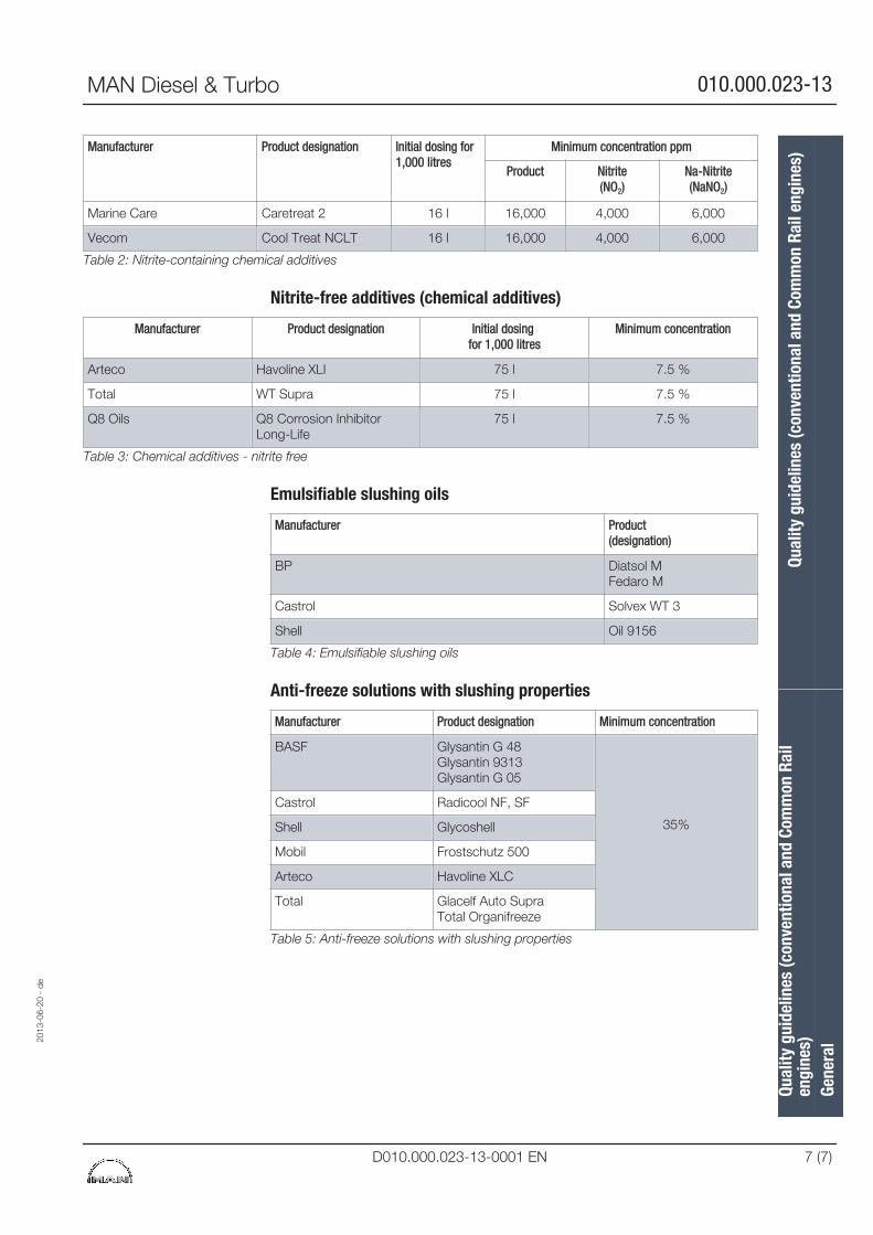
Manufacturer Product designation Initial dosing for1,000 litres
Minimum concentration ppm
Product Nitrite(NO2)
Na-Nitrite(NaNO2)
Marine Care Caretreat 2 16 l 16,000 4,000 6,000
Vecom Cool Treat NCLT 16 l 16,000 4,000 6,000
Table 2: Nitrite-containing chemical additives
Nitrite-free additives (chemical additives)
Manufacturer Product designation Initial dosing for 1,000 litres
Minimum concentration
Arteco Havoline XLI 75 l 7.5 %
Total WT Supra 75 l 7.5 %
Q8 Oils Q8 Corrosion InhibitorLong-Life
75 l 7.5 %
Table 3: Chemical additives - nitrite free
Emulsifiable slushing oils
Manufacturer Product(designation)
BP Diatsol MFedaro M
Castrol Solvex WT 3
Shell Oil 9156
Table 4: Emulsifiable slushing oils
Anti-freeze solutions with slushing properties
Manufacturer Product designation Minimum concentration
BASF Glysantin G 48Glysantin 9313Glysantin G 05
35%
Castrol Radicool NF, SF
Shell Glycoshell
Mobil Frostschutz 500
Arteco Havoline XLC
Total Glacelf Auto SupraTotal Organifreeze
Table 5: Anti-freeze solutions with slushing properties
2013
-06-
20 -
de
Qual
ity g
uide
lines
(con
vent
iona
l and
Com
mon
Rai
len
gine
s)Qu
ality
gui
delin
es (c
onve
ntio
nal a
nd C
omm
on R
ail e
ngin
es)
Gene
ral
MAN Diesel & Turbo 010.000.023-13
D010.000.023-13-0001 EN 7 (7)

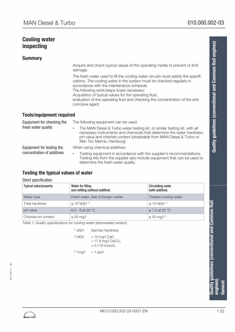
Cooling waterinspecting
SummaryAcquire and check typical values of the operating media to prevent or limitdamage.
The fresh water used to fill the cooling water circuits must satisfy the specifi-cations. The cooling water in the system must be checked regularly inaccordance with the maintenance schedule.The following work/steps is/are necessary:Acquisition of typical values for the operating fluid,evaluation of the operating fluid and checking the concentration of the anti-corrosive agent.
Tools/equipment requiredThe following equipment can be used:
▪ The MAN Diesel & Turbo water testing kit, or similar testing kit, with allnecessary instruments and chemicals that determine the water hardness,pH value and chloride content (obtainable from MAN Diesel & Turbo orMar-Tec Marine, Hamburg)
When using chemical additives:
▪ Testing equipment in accordance with the supplier's recommendations.Testing kits from the supplier also include equipment that can be used todetermine the fresh water quality.
Testing the typical values of water
Typical value/property Water for filling and refilling (without additive)
Circulating water(with additive)
Water type Fresh water, free of foreign matter Treated cooling water
Total hardness ≤ 10°dGH 1) ≤ 10°dGH 1)
pH value 6.5 - 8 at 20 °C ≥ 7.5 at 20 °C
Chloride ion content ≤ 50 mg/l ≤ 50 mg/l 2)
Table 1: Quality specifications for cooling water (abbreviated version)
1) dGH German hardness
1°dGh = 10 mg/l CaO= 17.9 mg/l CaCO3
= 0.179 mmol/L
2) 1mg/l = 1 ppm
Equipment for checking thefresh water quality
Equipment for testing theconcentration of additives
Short specification
2013
-04-
11 -
de
Qual
ity g
uide
lines
(con
vent
iona
l and
Com
mon
Rai
len
gine
s)Qu
ality
gui
delin
es (c
onve
ntio
nal a
nd C
omm
on R
ail e
ngin
es)
Gene
ral
MAN Diesel & Turbo 010.000.002-03
M010.000.002-03-0001 EN 1 (2)
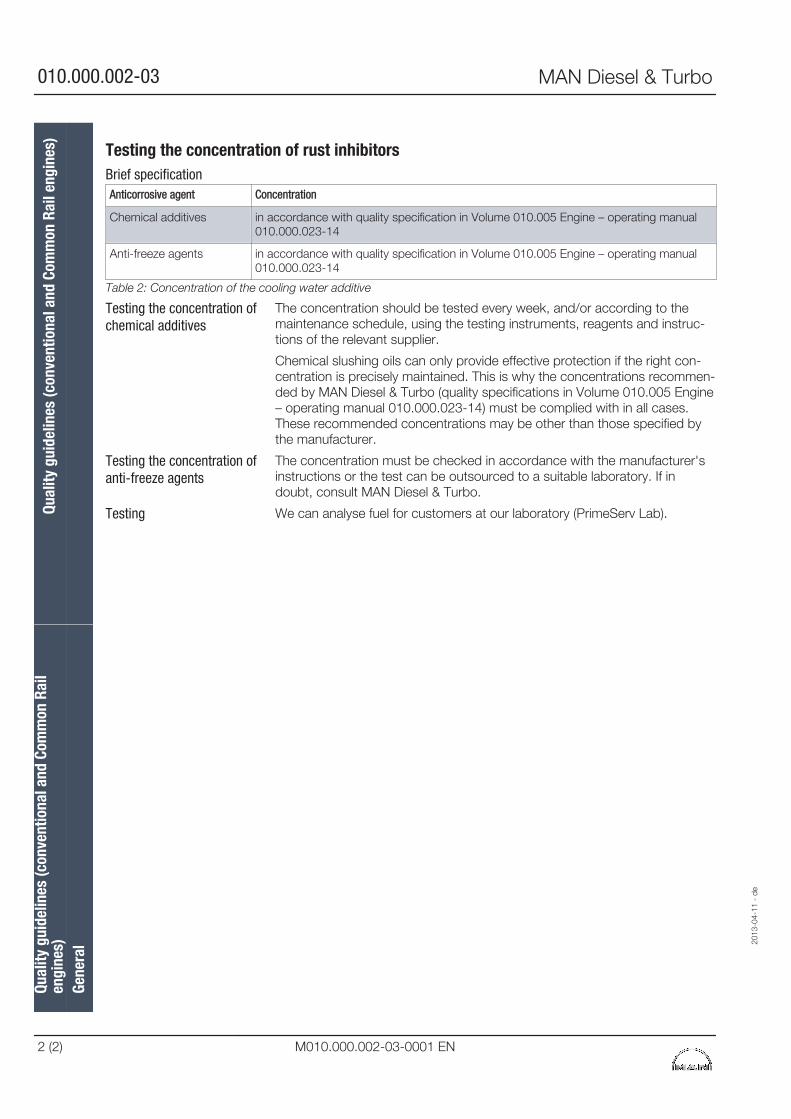
Testing the concentration of rust inhibitors
Anticorrosive agent Concentration
Chemical additives in accordance with quality specification in Volume 010.005 Engine – operating manual010.000.023-14
Anti-freeze agents in accordance with quality specification in Volume 010.005 Engine – operating manual010.000.023-14
Table 2: Concentration of the cooling water additive
The concentration should be tested every week, and/or according to themaintenance schedule, using the testing instruments, reagents and instruc-tions of the relevant supplier.
Chemical slushing oils can only provide effective protection if the right con-centration is precisely maintained. This is why the concentrations recommen-ded by MAN Diesel & Turbo (quality specifications in Volume 010.005 Engine– operating manual 010.000.023-14) must be complied with in all cases.These recommended concentrations may be other than those specified bythe manufacturer.
The concentration must be checked in accordance with the manufacturer'sinstructions or the test can be outsourced to a suitable laboratory. If indoubt, consult MAN Diesel & Turbo.
We can analyse fuel for customers at our laboratory (PrimeServ Lab).
Brief specification
Testing the concentration ofchemical additives
Testing the concentration ofanti-freeze agents
Testing
Qual
ity g
uide
lines
(con
vent
iona
l and
Com
mon
Rai
len
gine
s)Qu
ality
gui
delin
es (c
onve
ntio
nal a
nd C
omm
on R
ail e
ngin
es)
Gene
ral
2013
-04-
11 -
de
010.000.002-03 MAN Diesel & Turbo
2 (2) M010.000.002-03-0001 EN
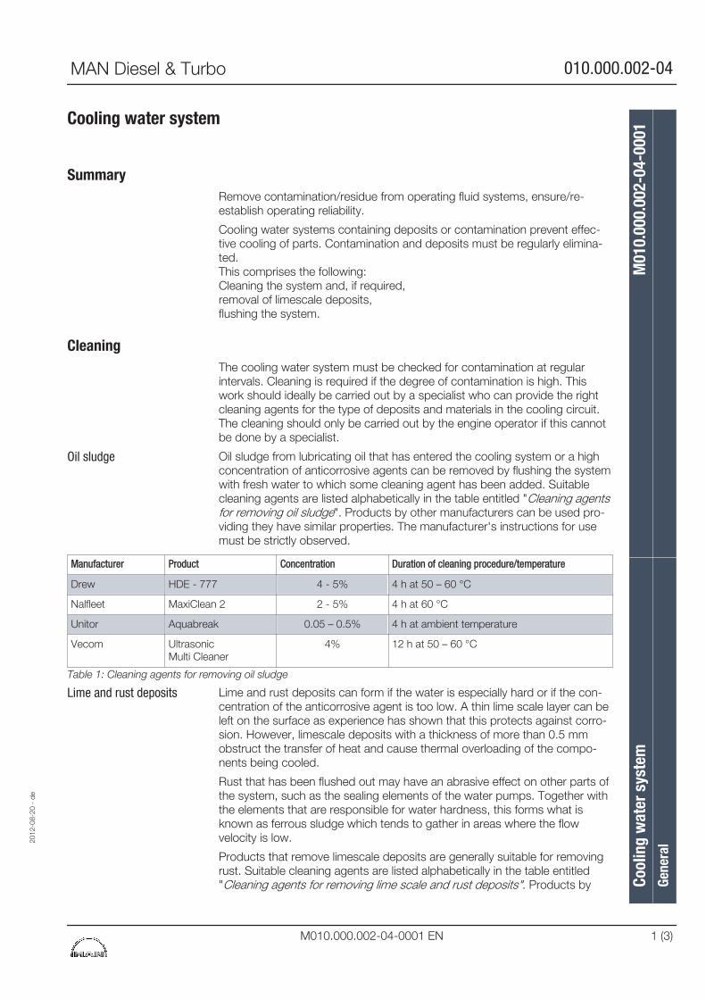
Cooling water system
SummaryRemove contamination/residue from operating fluid systems, ensure/re-establish operating reliability.
Cooling water systems containing deposits or contamination prevent effec-tive cooling of parts. Contamination and deposits must be regularly elimina-ted.This comprises the following:Cleaning the system and, if required,removal of limescale deposits,flushing the system.
CleaningThe cooling water system must be checked for contamination at regularintervals. Cleaning is required if the degree of contamination is high. Thiswork should ideally be carried out by a specialist who can provide the rightcleaning agents for the type of deposits and materials in the cooling circuit.The cleaning should only be carried out by the engine operator if this cannotbe done by a specialist.
Oil sludge from lubricating oil that has entered the cooling system or a highconcentration of anticorrosive agents can be removed by flushing the systemwith fresh water to which some cleaning agent has been added. Suitablecleaning agents are listed alphabetically in the table entitled "Cleaning agentsfor removing oil sludge". Products by other manufacturers can be used pro-viding they have similar properties. The manufacturer's instructions for usemust be strictly observed.
Manufacturer Product Concentration Duration of cleaning procedure/temperature
Drew HDE - 777 4 - 5% 4 h at 50 – 60 °C
Nalfleet MaxiClean 2 2 - 5% 4 h at 60 °C
Unitor Aquabreak 0.05 – 0.5% 4 h at ambient temperature
Vecom Ultrasonic Multi Cleaner
4% 12 h at 50 – 60 °C
Table 1: Cleaning agents for removing oil sludge
Lime and rust deposits can form if the water is especially hard or if the con-centration of the anticorrosive agent is too low. A thin lime scale layer can beleft on the surface as experience has shown that this protects against corro-sion. However, limescale deposits with a thickness of more than 0.5 mmobstruct the transfer of heat and cause thermal overloading of the compo-nents being cooled.
Rust that has been flushed out may have an abrasive effect on other parts ofthe system, such as the sealing elements of the water pumps. Together withthe elements that are responsible for water hardness, this forms what isknown as ferrous sludge which tends to gather in areas where the flowvelocity is low.
Products that remove limescale deposits are generally suitable for removingrust. Suitable cleaning agents are listed alphabetically in the table entitled"Cleaning agents for removing lime scale and rust deposits". Products by
Oil sludge
Lime and rust deposits
2012
-08-
20 -
de
Cool
ing
wat
er s
yste
mM
010.
000.
002-
04-0
001
Gene
ral
MAN Diesel & Turbo 010.000.002-04
M010.000.002-04-0001 EN 1 (3)
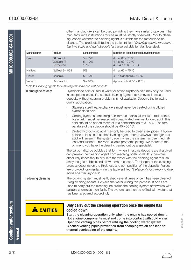
other manufacturers can be used providing they have similar properties. Themanufacturer's instructions for use must be strictly observed. Prior to clean-ing, check whether the cleaning agent is suitable for the materials to becleaned. The products listed in the table entitled "Cleaning agents for remov-ing lime scale and rust deposits" are also suitable for stainless steel.
Manufacturer Product Concentration Duration of cleaning procedure/temperature
Drew SAF-AcidDescale-ITFerroclean
5 - 10%5 - 10%10%
4 h at 60 - 70 °C4 h at 60 - 70 °C4 - 24 h at 60 - 70 °C
Nalfleet Nalfleet 9 - 068 5% 4 h at 60 – 75 ℃
Unitor Descalex 5 - 10% 4 - 6 h at approx. 60 °C
Vecom Descalant F 3 – 10% Approx. 4 h at 50 – 60°C
Table 2: Cleaning agents for removing limescale and rust deposits
Hydrochloric acid diluted in water or aminosulphonic acid may only be usedin exceptional cases if a special cleaning agent that removes limescaledeposits without causing problems is not available. Observe the followingduring application:
▪ Stainless steel heat exchangers must never be treated using dilutedhydrochloric acid.
▪ Cooling systems containing non-ferrous metals (aluminium, red bronze,brass, etc.) must be treated with deactivated aminosulphonic acid. Thisacid should be added to water in a concentration of 3 - 5 %. The tem-perature of the solution should be 40 - 50 °C.
▪ Diluted hydrochloric acid may only be used to clean steel pipes. If hydro-chloric acid is used as the cleaning agent, there is always a danger thatacid will remain in the system, even when the system has been neutral-ised and flushed. This residual acid promotes pitting. We therefore rec-ommend you have the cleaning carried out by a specialist.
The carbon dioxide bubbles that form when limescale deposits are dissolvedcan prevent the cleaning agent from reaching boiler scale. It is thereforeabsolutely necessary to circulate the water with the cleaning agent to flushaway the gas bubbles and allow them to escape. The length of the cleaningprocess depends on the thickness and composition of the deposits. Valuesare provided for orientation in the table entitled "Detergents for removing limescale and rust deposits“.
The cooling system must be flushed several times once it has been cleanedusing cleaning agents. Replace the water during this process. If acids areused to carry out the cleaning, neutralise the cooling system afterwards withsuitable chemicals then flush. The system can then be refilled with water thathas been prepared accordingly.
Only carry out the cleaning operation once the engine hascooled downStart the cleaning operation only when the engine has cooled down.Hot engine components must not come into contact with cold water.Open the venting pipes before refilling the cooling water system.Blocked venting pipes prevent air from escaping which can lead tothermal overloading of the engine.
In emergencies only
Following cleaning
Cool
ing
wat
er s
yste
mM
010.
000.
002-
04-0
001
Gene
ral
2012
-08-
20 -
de
010.000.002-04 MAN Diesel & Turbo
2 (3) M010.000.002-04-0001 EN
Cleaning products can cause damageThe products to be used can endanger health and may be harmful tothe environment.Follow the manufacturer's handling instructions without fail.
The applicable regulations governing the disposal of cleaning agents or acidsmust be observed.
2012
-08-
20 -
de
Cool
ing
wat
er s
yste
mM
010.
000.
002-
04-0
001
Gene
ral
MAN Diesel & Turbo 010.000.002-04
M010.000.002-04-0001 EN 3 (3)

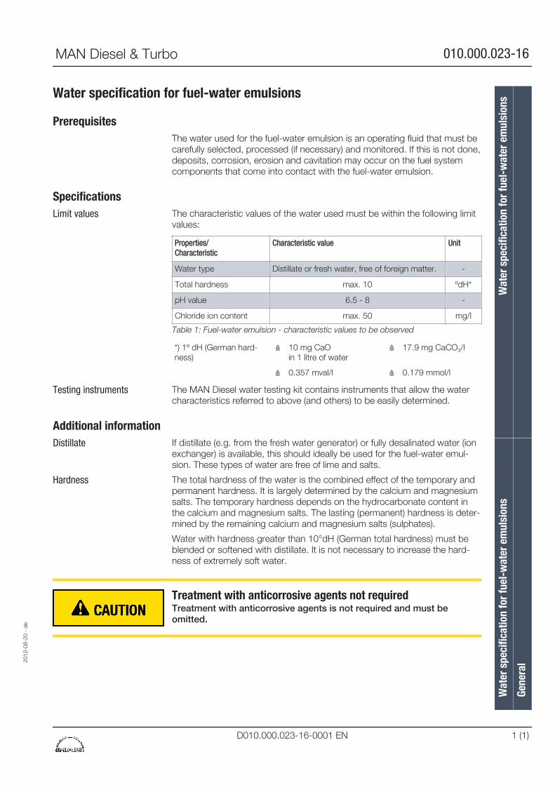
Water specification for fuel-water emulsions
PrerequisitesThe water used for the fuel-water emulsion is an operating fluid that must becarefully selected, processed (if necessary) and monitored. If this is not done,deposits, corrosion, erosion and cavitation may occur on the fuel systemcomponents that come into contact with the fuel-water emulsion.
SpecificationsThe characteristic values of the water used must be within the following limitvalues:
Properties/Characteristic
Characteristic value Unit
Water type Distillate or fresh water, free of foreign matter. -
Total hardness max. 10 ºdH*
pH value 6.5 - 8 -
Chloride ion content max. 50 mg/l
Table 1: Fuel-water emulsion - characteristic values to be observed
*) 1º dH (German hard-ness)
≙ 10 mg CaOin 1 litre of water
≙ 17.9 mg CaCO3/l
≙ 0.357 mval/l ≙ 0.179 mmol/l
The MAN Diesel water testing kit contains instruments that allow the watercharacteristics referred to above (and others) to be easily determined.
Additional informationIf distillate (e.g. from the fresh water generator) or fully desalinated water (ionexchanger) is available, this should ideally be used for the fuel-water emul-sion. These types of water are free of lime and salts.
The total hardness of the water is the combined effect of the temporary andpermanent hardness. It is largely determined by the calcium and magnesiumsalts. The temporary hardness depends on the hydrocarbonate content inthe calcium and magnesium salts. The lasting (permanent) hardness is deter-mined by the remaining calcium and magnesium salts (sulphates).
Water with hardness greater than 10°dH (German total hardness) must beblended or softened with distillate. It is not necessary to increase the hard-ness of extremely soft water.
Treatment with anticorrosive agents not requiredTreatment with anticorrosive agents is not required and must beomitted.
Limit values
Testing instruments
Distillate
Hardness
2012
-08-
20 -
de
Wat
er s
peci
ficat
ion
for f
uel-
wat
er e
mul
sion
sW
ater
spe
cific
atio
n fo
r fue
l-w
ater
em
ulsi
ons
Gene
ral
MAN Diesel & Turbo 010.000.023-16
D010.000.023-16-0001 EN 1 (1)

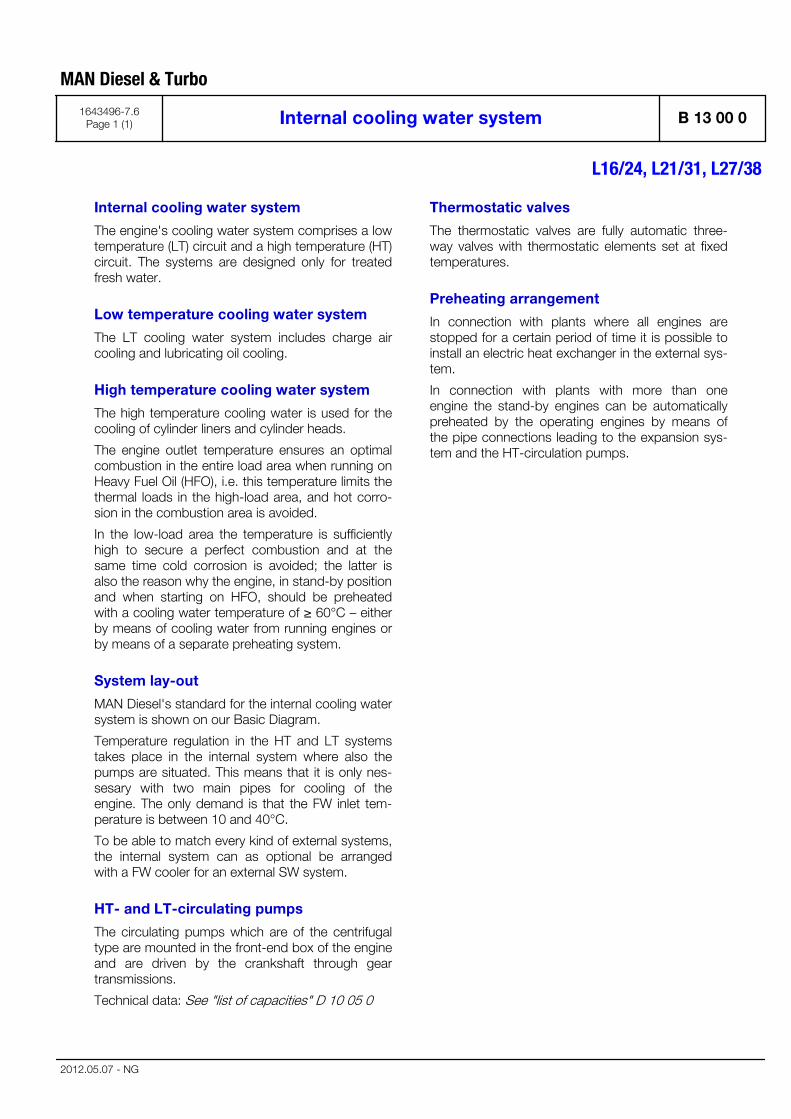
Internal cooling water system
The engine's cooling water system comprises a lowtemperature (LT) circuit and a high temperature (HT)circuit. The systems are designed only for treatedfresh water.
Low temperature cooling water system
The LT cooling water system includes charge aircooling and lubricating oil cooling.
High temperature cooling water system
The high temperature cooling water is used for thecooling of cylinder liners and cylinder heads.
The engine outlet temperature ensures an optimalcombustion in the entire load area when running onHeavy Fuel Oil (HFO), i.e. this temperature limits thethermal loads in the high-load area, and hot corro-sion in the combustion area is avoided.
In the low-load area the temperature is sufficientlyhigh to secure a perfect combustion and at thesame time cold corrosion is avoided; the latter isalso the reason why the engine, in stand-by positionand when starting on HFO, should be preheatedwith a cooling water temperature of ≥ 60°C – eitherby means of cooling water from running engines orby means of a separate preheating system.
System lay-out
MAN Diesel's standard for the internal cooling watersystem is shown on our Basic Diagram.
Temperature regulation in the HT and LT systemstakes place in the internal system where also thepumps are situated. This means that it is only nes-sesary with two main pipes for cooling of theengine. The only demand is that the FW inlet tem-perature is between 10 and 40°C.
To be able to match every kind of external systems,the internal system can as optional be arrangedwith a FW cooler for an external SW system.
HT- and LT-circulating pumps
The circulating pumps which are of the centrifugaltype are mounted in the front-end box of the engineand are driven by the crankshaft through geartransmissions.
Technical data: See "list of capacities" D 10 05 0
Thermostatic valves
The thermostatic valves are fully automatic three-way valves with thermostatic elements set at fixedtemperatures.
Preheating arrangement
In connection with plants where all engines arestopped for a certain period of time it is possible toinstall an electric heat exchanger in the external sys-tem.
In connection with plants with more than oneengine the stand-by engines can be automaticallypreheated by the operating engines by means ofthe pipe connections leading to the expansion sys-tem and the HT-circulation pumps.
MAN Diesel & Turbo
1643496-7.6Page 1 (1) Internal cooling water system B 13 00 0
L16/24, L21/31, L27/38
2012.05.07 - NG

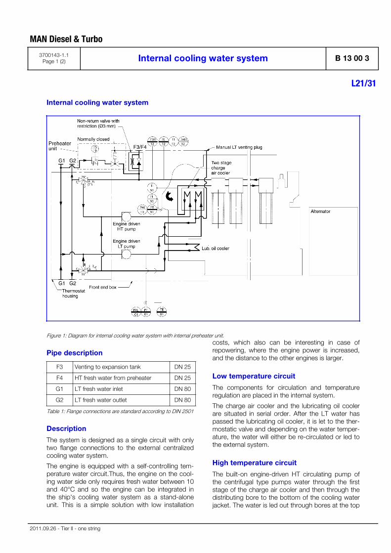
Internal cooling water system
Figure 1: Diagram for internal cooling water system with internal preheater unit.
Pipe description
F3 Venting to expansion tank DN 25
F4 HT fresh water from preheater DN 25
G1 LT fresh water inlet DN 80
G2 LT fresh water outlet DN 80
Table 1: Flange connections are standard according to DIN 2501
Description
The system is designed as a single circuit with onlytwo flange connections to the external centralizedcooling water system.
The engine is equipped with a self-controlling tem-perature water circuit.Thus, the engine on the cool-ing water side only requires fresh water between 10and 40°C and so the engine can be integrated inthe ship's cooling water system as a stand-aloneunit. This is a simple solution with low installation
costs, which also can be interesting in case ofrepowering, where the engine power is increased,and the distance to the other engines is larger.
Low temperature circuit
The components for circulation and temperatureregulation are placed in the internal system.
The charge air cooler and the lubricating oil coolerare situated in serial order. After the LT water haspassed the lubricating oil cooler, it is let to the ther-mostatic valve and depending on the water temper-ature, the water will either be re-circulated or led tothe external system.
High temperature circuit
The built-on engine-driven HT circulating pump ofthe centrifugal type pumps water through the firststage of the charge air cooler and then through thedistributing bore to the bottom of the cooling waterjacket. The water is led out through bores at the top
MAN Diesel & Turbo
3700143-1.1Page 1 (2) Internal cooling water system B 13 00 3
L21/31
2011.09.26 - Tier II - one string

of the cooling water jacket to the bore in the cylin-der head for cooling of this, the exhaust valve seatsand the injector valve.
From the cylinder heads the water is led through tothe thermostatic valve, and depending on theengine load, a smaller or larger amount of the waterwill be led to the external system or will be re-circu-lated.
Data
For heat dissipation and pump capacities, see D 1005 0, "List of Capacities".
Set points and operating levels for temperature andpressure are stated in B 19 00 0, "Operating Dataand Set Points".
Other design data are stated in B 13 00 0, "DesignData for the External Cooling Water System".
MAN Diesel & Turbo
B 13 00 3 Internal cooling water system 3700143-1.1Page 2 (2)
L21/31
2011.09.26 - Tier II - one string
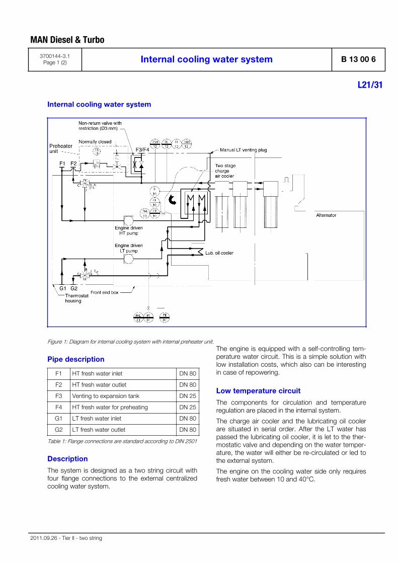
Internal cooling water system
Figure 1: Diagram for internal cooling system with internal preheater unit.
Pipe description
F1 HT fresh water inlet DN 80
F2 HT fresh water outlet DN 80
F3 Venting to expansion tank DN 25
F4 HT fresh water for preheating DN 25
G1 LT fresh water inlet DN 80
G2 LT fresh water outlet DN 80
Table 1: Flange connections are standard according to DIN 2501
Description
The system is designed as a two string circuit withfour flange connections to the external centralizedcooling water system.
The engine is equipped with a self-controlling tem-perature water circuit. This is a simple solution withlow installation costs, which also can be interestingin case of repowering.
Low temperature circuit
The components for circulation and temperatureregulation are placed in the internal system.
The charge air cooler and the lubricating oil coolerare situated in serial order. After the LT water haspassed the lubricating oil cooler, it is let to the ther-mostatic valve and depending on the water temper-ature, the water will either be re-circulated or led tothe external system.
The engine on the cooling water side only requiresfresh water between 10 and 40°C.
MAN Diesel & Turbo
3700144-3.1Page 1 (2) Internal cooling water system B 13 00 6
L21/31
2011.09.26 - Tier II - two string

High temperature circuit
The built-on engine-driven HT-circulating pump ofthe centrifugal type pumps water through the firststage of the charge air cooler and then through thedistributing bore to the bottom of the cooling waterguide jacket. The water is led out through bores atthe top of the cooling water guide jacket to the borecooled cylinder head for cooling of this, the exhaustvalve seats and the injector valve.
From the cylinder heads the water is led through anintegrated collector to the thermostatic valve, anddepending on the engine load, a smaller or largeramount of the water will be led to the external sys-tem or will be re-circulated.
Data
For heat dissipation and pump capacities, see D 1005 0, "List of Capacities".
Set points and operating levels for temperature andpressure are stated in B 19 00 0, "Operating Dataand Set Points".
Other design data are stated in B 13 00 0, "DesignData for the External Cooling Water System".
MAN Diesel & Turbo
B 13 00 6 Internal cooling water system 3700144-3.1Page 2 (2)
L21/31
2011.09.26 - Tier II - two string
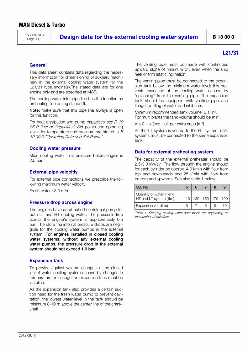
General
This data sheet contains data regarding the neces-sary information for dimensioning of auxiliary machi-nery in the external cooling water system for theL21/31 type engine(s).The stated data are for oneengine only and are specified at MCR.
The cooling water inlet pipe line has the function aspreheating line during standstill.
Note: make sure that this pipe line always is openfor this function.
For heat dissipation and pump capacities see D 1005 0 "List of Capacities". Set points and operatinglevels for temperature and pressure are stated in B19 00 0 "Operating Data and Set Points".
Cooling water pressure
Max. cooling water inlet pressure before engine is2.5 bar.
External pipe velocitiy
For external pipe connections we prescribe the fol-lowing maximum water velocity:
Fresh water : 3.0 m/s
Pressure drop across engine
The engines have an attached centrifugal pump forboth LT and HT cooling water. The pressure dropacross the engine's system is approximately 0.5bar. Therefore the internal pressure drops are negli-gible for the cooling water pumps in the externalsystem. For engines installed in closed coolingwater systems, without any external coolingwater pumps, the pressure drop in the externalsystem should not exceed 1.0 bar.
Expansion tank
To provide against volume changes in the closedjacket water cooling system caused by changes intemperature or leakage, an expansion tank must beinstalled.
As the expansion tank also provides a certain suc-tion head for the fresh water pump to prevent cavi-tation, the lowest water level in the tank should beminimum 8-10 m above the center line of the crank-shaft.
The venting pipe must be made with continuousupward slope of minimum 5°, even when the shipheel or trim (static inclination).
The venting pipe must be connected to the expan-sion tank below the minimum water level; this pre-vents oxydation of the cooling water caused by"splashing" from the venting pipe. The expansiontank should be equipped with venting pipe andflange for filling of water and inhibitors.
Minimum recommended tank volume: 0.1 m³. For multi plants the tank volume should be min.:
V = 0.1 + (exp. vol. per extra eng.) [m³]
As the LT system is vented to the HT system, bothsystems must be connected to the same expansiontank.
Data for external preheating system
The capacity of the external preheater should be2.5-3.0 kW/cyl. The flow through the engine shouldfor each cylinder be approx. 4.0 l/min with flow fromtop and downwards and 25 l/min with flow frombottom and upwards. See also table 1 below.
Cyl. No 5 6 7 8 9
Quantity of water in eng:HT and LT system (litre) 110 130 150 170 190
Expansion vol. (litre) 6 7 8 9 10
Table 1: Showing cooling water data which are depending onthe number of cylinders.
MAN Diesel & Turbo
1683397-8.6Page 1 (1) Design data for the external cooling water system B 13 00 0
L21/31
2012.09.17.

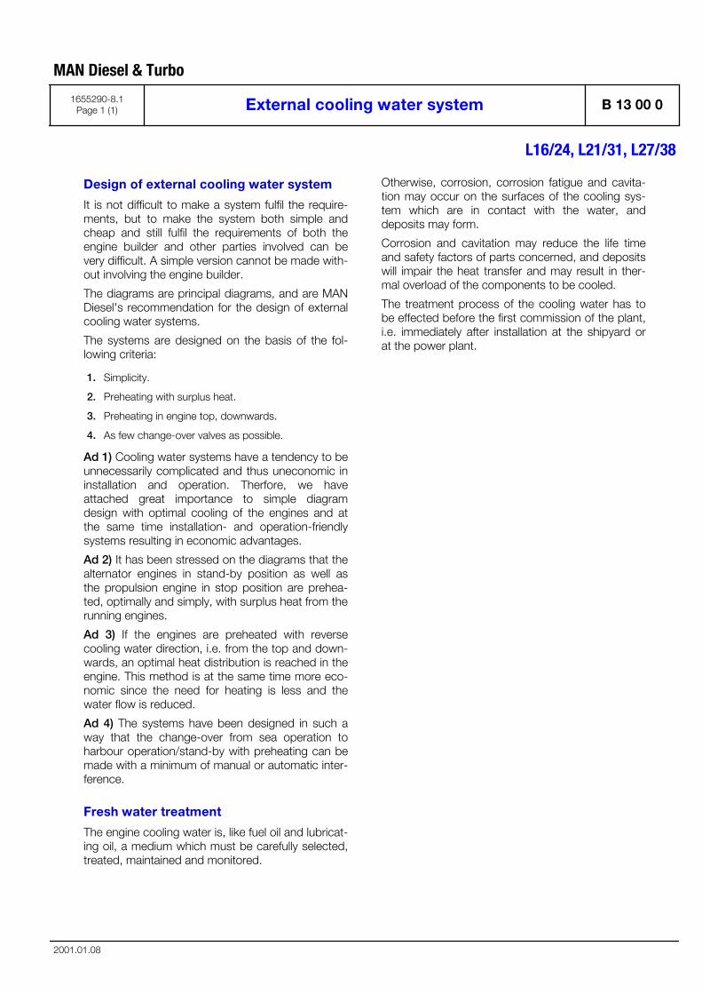
Design of external cooling water system
It is not difficult to make a system fulfil the require-ments, but to make the system both simple andcheap and still fulfil the requirements of both theengine builder and other parties involved can bevery difficult. A simple version cannot be made with-out involving the engine builder.
The diagrams are principal diagrams, and are MANDiesel's recommendation for the design of externalcooling water systems.
The systems are designed on the basis of the fol-lowing criteria:
1. Simplicity.
2. Preheating with surplus heat.
3. Preheating in engine top, downwards.
4. As few change-over valves as possible.
Ad 1) Cooling water systems have a tendency to beunnecessarily complicated and thus uneconomic ininstallation and operation. Therfore, we haveattached great importance to simple diagramdesign with optimal cooling of the engines and atthe same time installation- and operation-friendlysystems resulting in economic advantages.
Ad 2) It has been stressed on the diagrams that thealternator engines in stand-by position as well asthe propulsion engine in stop position are prehea-ted, optimally and simply, with surplus heat from therunning engines.
Ad 3) If the engines are preheated with reversecooling water direction, i.e. from the top and down-wards, an optimal heat distribution is reached in theengine. This method is at the same time more eco-nomic since the need for heating is less and thewater flow is reduced.
Ad 4) The systems have been designed in such away that the change-over from sea operation toharbour operation/stand-by with preheating can bemade with a minimum of manual or automatic inter-ference.
Fresh water treatment
The engine cooling water is, like fuel oil and lubricat-ing oil, a medium which must be carefully selected,treated, maintained and monitored.
Otherwise, corrosion, corrosion fatigue and cavita-tion may occur on the surfaces of the cooling sys-tem which are in contact with the water, anddeposits may form.
Corrosion and cavitation may reduce the life timeand safety factors of parts concerned, and depositswill impair the heat transfer and may result in ther-mal overload of the components to be cooled.
The treatment process of the cooling water has tobe effected before the first commission of the plant,i.e. immediately after installation at the shipyard orat the power plant.
MAN Diesel & Turbo
1655290-8.1Page 1 (1) External cooling water system B 13 00 0
L16/24, L21/31, L27/38
2001.01.08

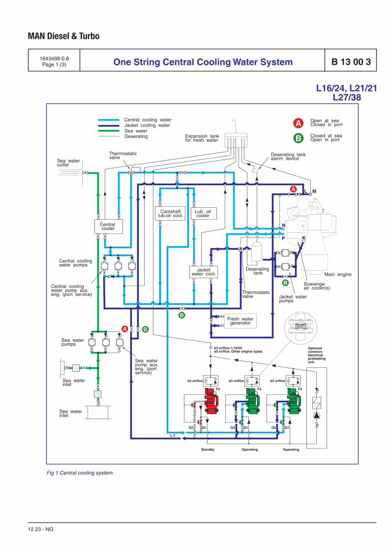
MAN Diesel & Turbo
1643498-0.8Page 1 (3)
12.23 - NG
L16/24, L21/21 L27/38
One String Central Cooling Water System B 13 00 3
Fig 1 Central cooling system.
A
A B
B
B
A
B
Central cooling waterJacket cooling waterSea water
Sea wateroutlet
Thermostatic valve
Thermostatic valve
Scavengeair cooler(s)
Main engine
Expansion tankfor fresh water
Lub. oilcooler
Jacketwater cool.
Fresh watergenerator
Jacket water pumps
P K
ML
NCentral cooler
Central coolingwater pumps
Sea water pumps
Sea water inlet
Sea water inlet
Sea water pump aux.eng. (portservice)
Central coolingwater pump aux.eng. (port service)
Camshaftlub.oil cool.
Deaerating tankalarm device
Deaerating tank
Open at seaClosed in port
Closed at seaOpen in port
Deaerating
G2 G1 G2
F3 F3F3
G1 G2 G1
Standby
L.T.
Operating Operating
Optionalcommonelectricalpreheatingunit
ø3 orifice: L16/24 ø5 orifice: Other engine types
ø3 orifice ø3 orificeø3 orifice
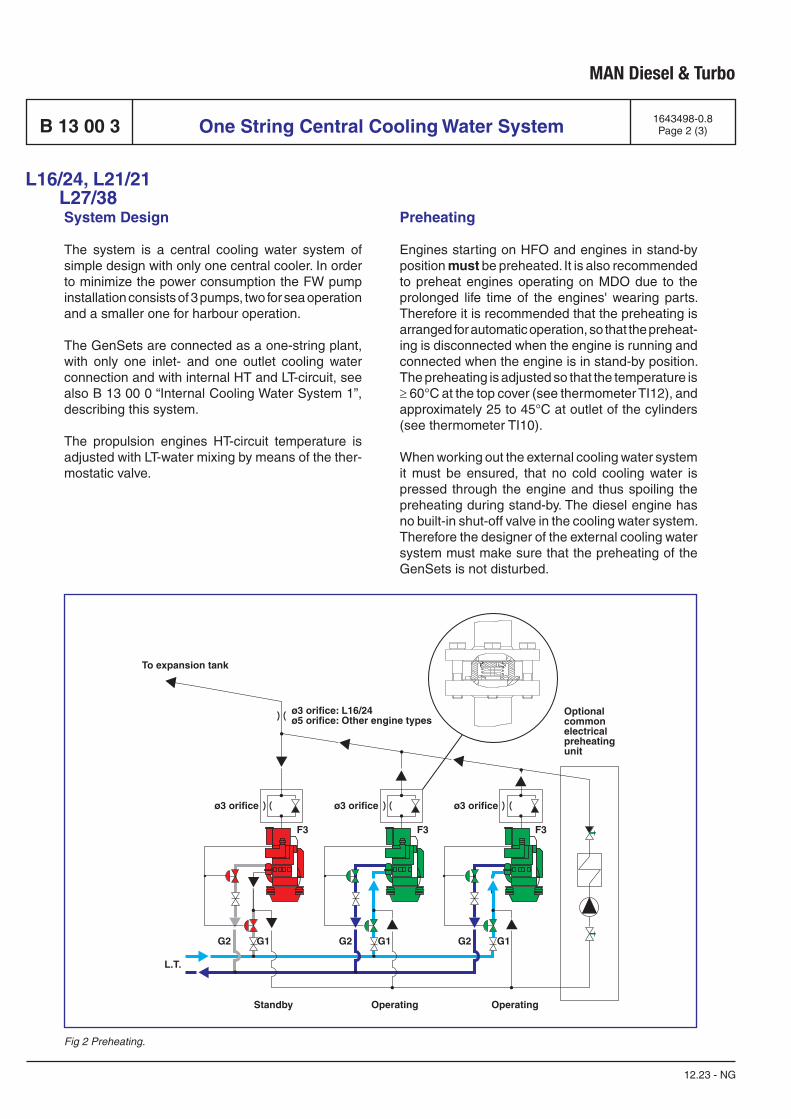
MAN Diesel & Turbo
12.23 - NG
System Design
The system is a central cooling water system of simple design with only one central cooler. In order to minimize the power consumption the FW pump installation consists of 3 pumps, two for sea operation and a smaller one for harbour operation.
The GenSets are connected as a one-string plant, with only one inlet- and one outlet cooling water connection and with internal HT and LT-circuit, see also B 13 00 0 “Internal Cooling Water System 1”, describing this system.
The propulsion engines HT-circuit temperature is adjusted with LT-water mixing by means of the ther-mostatic valve.
Preheating
Engines starting on HFO and engines in stand-by position must be preheated. It is also recommended to preheat engines operating on MDO due to the prolonged life time of the engines' wearing parts. Therefore it is recommended that the preheating is arranged for automatic operation, so that the preheat-ing is disconnected when the engine is running and connected when the engine is in stand-by position. The preheating is adjusted so that the temperature is ≥ 60°C at the top cover (see thermometer TI12), and approximately 25 to 45°C at outlet of the cylinders (see thermometer TI10).
When working out the external cooling water system it must be ensured, that no cold cooling water is pressed through the engine and thus spoiling the preheating during stand-by. The diesel engine has no built-in shut-off valve in the cooling water system. Therefore the designer of the external cooling water system must make sure that the preheating of the GenSets is not disturbed.
B 13 00 3 One String Central Cooling Water System 1643498-0.8Page 2 (3)
Fig 2 Preheating.
G2 G1 G2
F3 F3F3
G1 G2 G1
Standby
L.T.
Operating Operating
Optionalcommonelectricalpreheatingunit
To expansion tank
ø3 orifice: L16/24 ø5 orifice: Other engine types
ø3 orifice ø3 orificeø3 orifice
L16/24, L21/21 L27/38

MAN Diesel & Turbo
1643498-0.8Page 3 (3)
12.23 - NG
One String Central Cooling Water System B 13 00 3
Preheating of Stand-by GenSets during Sea Operation
GenSets in stand-by position are preheated auto-matically via the venting pipe with water from the running engines. This is possible due to the inter-connection of the GenSet's HT-pumps which force the water downwards in the stand-by engines.
It is to be stated that the interconnection between the GenSet L.T. inlets is not to be disturbed. If an on/off valve is built in, a bypass has to be installed. It is then possible to preheat the GenSet automatically in standby position with the running GenSets.
Preheating of Stand-by GenSets and Propulsion Engines during Harbour Operation
During harbour stay the propulsion engine and GenSets are also preheated in stand-by position by the running GenSets. Valve (B) is open and valve (A) is closed. Thus, the propulsion engine is heated from top and downwards, which is the most economical solution.
L16/24, L21/21 L27/38

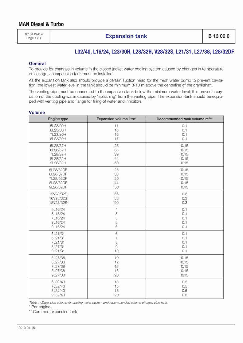
GeneralTo provide for changes in volume in the closed jacket water cooling system caused by changes in temperatureor leakage, an expansion tank must be installed.
As the expansion tank also should provide a certain suction head for the fresh water pump to prevent cavita-tion, the lowest water level in the tank should be minimum 8-10 m above the centerline of the crankshaft.
The venting pipe must be connected to the expansion tank below the minimum water level; this prevents oxy-dation of the cooling water caused by "splashing" from the venting pipe. The expansion tank should be equip-ped with venting pipe and flange for filling of water and inhibitors.
VolumeEngine type Expansion volume litre* Recommended tank volume m3**
5L23/30H6L23/30H7L23/30H8L23/30H
11131517
0.10.10.10.1
5L28/32H6L28/32H7L28/32H8L28/32H9L28/32H
2833394450
0.150.150.150.150.15
5L28/32DF6L28/32DF7L28/32DF8L28/32DF9L28/32DF
2833394450
0.150.150.150.150.15
12V28/32S16V28/32S18V28/32S
668899
0.30.30.3
5L16/246L16/247L16/248L16/249L16/24
45556
0.10.10.10.10.1
5L21/316L21/317L21/318L21/319L21/31
6789
10
0.10.10.10.10.1
5L27/386L27/387L27/388L27/389L27/38
1012131520
0.150.150.150.150.15
6L32/407L32/408L32/409L32/40
13151820
0.50.50.50.5
Table 1: Expansion volume for cooling water system and recommended volume of expansion tank.* Per engine** Common expansion tank
MAN Diesel & Turbo
1613419-0.4Page 1 (1) Expansion tank B 13 00 0
L32/40, L16/24, L23/30H, L28/32H, V28/32S, L21/31, L27/38, L28/32DF
2013.04.15.

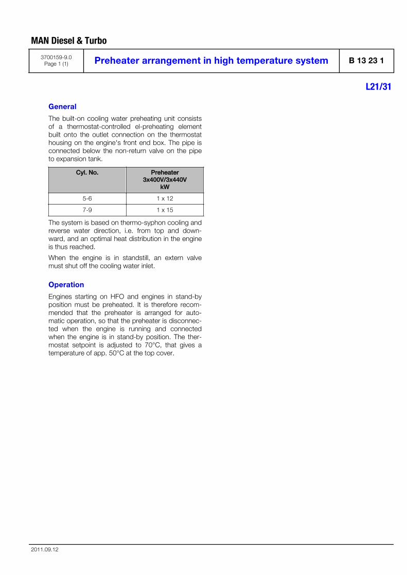
General
The built-on cooling water preheating unit consistsof a thermostat-controlled el-preheating elementbuilt onto the outlet connection on the thermostathousing on the engine's front end box. The pipe isconnected below the non-return valve on the pipeto expansion tank.
Cyl. No. Preheater3x400V/3x440V
kW
5-6 1 x 12
7-9 1 x 15
The system is based on thermo-syphon cooling andreverse water direction, i.e. from top and down-ward, and an optimal heat distribution in the engineis thus reached.
When the engine is in standstill, an extern valvemust shut off the cooling water inlet.
Operation
Engines starting on HFO and engines in stand-byposition must be preheated. It is therefore recom-mended that the preheater is arranged for auto-matic operation, so that the preheater is disconnec-ted when the engine is running and connectedwhen the engine is in stand-by position. The ther-mostat setpoint is adjusted to 70°C, that gives atemperature of app. 50°C at the top cover.
MAN Diesel & Turbo
3700159-9.0Page 1 (1) Preheater arrangement in high temperature system B 13 23 1
L21/31
2011.09.12

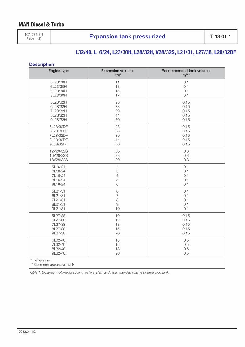
DescriptionEngine type Expansion volume
litre*Recommended tank volume
m3**
5L23/30H6L23/30H7L23/30H8L23/30H
11131517
0.10.10.10.1
5L28/32H6L28/32H7L28/32H8L28/32H9L28/32H
2833394450
0.150.150.150.150.15
5L28/32DF6L28/32DF7L28/32DF8L28/32DF9L28/32DF
2833394450
0.150.150.150.150.15
12V28/32S16V28/32S18V28/32S
668899
0.30.30.3
5L16/246L16/247L16/248L16/249L16/24
45556
0.10.10.10.10.1
5L21/316L21/317L21/318L21/319L21/31
6789
10
0.10.10.10.10.1
5L27/386L27/387L27/388L27/389L27/38
1012131520
0.150.150.150.150.15
6L32/407L32/408L32/409L32/40
13151820
0.50.50.50.5
* Per engine** Common expansion tank
Table 1: Expansion volume for cooling water system and recommended volume of expansion tank.
MAN Diesel & Turbo
1671771-3.4Page 1 (2) Expansion tank pressurized T 13 01 1
L32/40, L16/24, L23/30H, L28/32H, V28/32S, L21/31, L27/38, L28/32DF
2013.04.15.
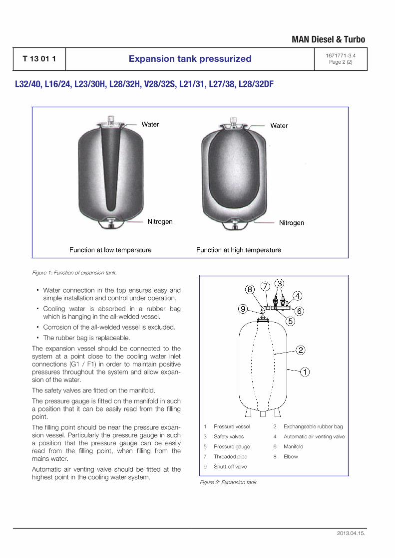
Figure 1: Function of expansion tank.
▪ Water connection in the top ensures easy andsimple installation and control under operation.
▪ Cooling water is absorbed in a rubber bagwhich is hanging in the all-welded vessel.
▪ Corrosion of the all-welded vessel is excluded.
▪ The rubber bag is replaceable.
The expansion vessel should be connected to thesystem at a point close to the cooling water inletconnections (G1 / F1) in order to maintain positivepressures throughout the system and allow expan-sion of the water.
The safety valves are fitted on the manifold.
The pressure gauge is fitted on the manifold in sucha position that it can be easily read from the fillingpoint.
The filling point should be near the pressure expan-sion vessel. Particularly the pressure gauge in sucha position that the pressure gauge can be easilyread from the filling point, when filling from themains water.
Automatic air venting valve should be fitted at thehighest point in the cooling water system.
1 Pressure vessel 2 Exchangeable rubber bag
3 Safety valves 4 Automatic air venting valve
5 Pressure gauge 6 Manifold
7 Threaded pipe 8 Elbow
9 Shutt-off valve
Figure 2: Expansion tank
MAN Diesel & Turbo
T 13 01 1 Expansion tank pressurized 1671771-3.4Page 2 (2)
L32/40, L16/24, L23/30H, L28/32H, V28/32S, L21/31, L27/38, L28/32DF
2013.04.15.

Compressed Air System
B 14

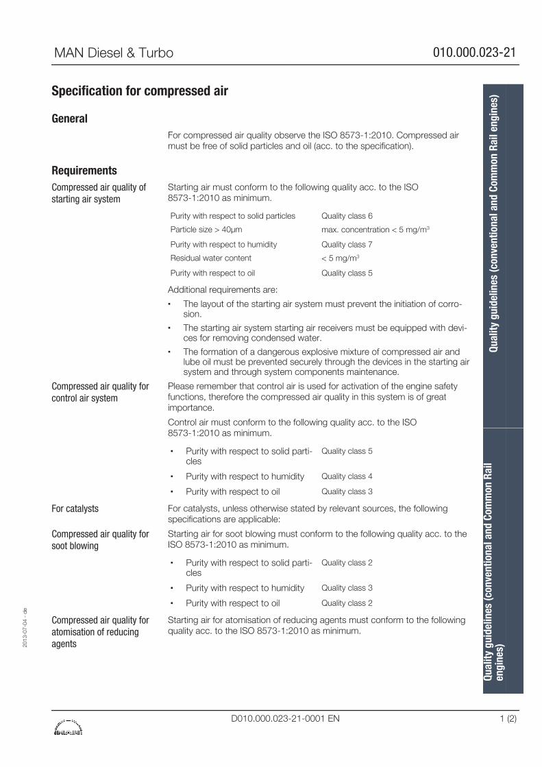
Specification for compressed air
GeneralFor compressed air quality observe the ISO 8573-1:2010. Compressed airmust be free of solid particles and oil (acc. to the specification).
RequirementsStarting air must conform to the following quality acc. to the ISO8573-1:2010 as minimum.
Purity with respect to solid particles
Particle size > 40µm
Quality class 6
max. concentration < 5 mg/m3
Purity with respect to humidity
Residual water content
Quality class 7
< 5 mg/m3
Purity with respect to oil Quality class 5
Additional requirements are:
▪ The layout of the starting air system must prevent the initiation of corro-sion.
▪ The starting air system starting air receivers must be equipped with devi-ces for removing condensed water.
▪ The formation of a dangerous explosive mixture of compressed air andlube oil must be prevented securely through the devices in the starting airsystem and through system components maintenance.
Please remember that control air is used for activation of the engine safetyfunctions, therefore the compressed air quality in this system is of greatimportance.
Control air must conform to the following quality acc. to the ISO8573-1:2010 as minimum.
▪ Purity with respect to solid parti-cles
Quality class 5
▪ Purity with respect to humidity Quality class 4
▪ Purity with respect to oil Quality class 3
For catalysts, unless otherwise stated by relevant sources, the followingspecifications are applicable:
Starting air for soot blowing must conform to the following quality acc. to theISO 8573-1:2010 as minimum.
▪ Purity with respect to solid parti-cles
Quality class 2
▪ Purity with respect to humidity Quality class 3
▪ Purity with respect to oil Quality class 2
Starting air for atomisation of reducing agents must conform to the followingquality acc. to the ISO 8573-1:2010 as minimum.
Compressed air quality ofstarting air system
Compressed air quality forcontrol air system
For catalysts
Compressed air quality forsoot blowing
Compressed air quality foratomisation of reducingagents20
13-0
7-04
- d
e
Qual
ity g
uide
lines
(con
vent
iona
l and
Com
mon
Rai
len
gine
s)Qu
ality
gui
delin
es (c
onve
ntio
nal a
nd C
omm
on R
ail e
ngin
es)
MAN Diesel & Turbo 010.000.023-21
D010.000.023-21-0001 EN 1 (2)

▪ Purity with respect to solid parti-cles
Quality class 2
▪ Purity with respect to humidity Quality class 3
▪ Purity with respect to oil Quality class 2
Clogging of catalystTo prevent clogging of catalyst and catalyst lifetime shortening, thecompressed air specification must always be observed.
Qual
ity g
uide
lines
(con
vent
iona
l and
Com
mon
Rai
len
gine
s)Qu
ality
gui
delin
es (c
onve
ntio
nal a
nd C
omm
on R
ail e
ngin
es)
2013
-07-
04 -
de
010.000.023-21 MAN Diesel & Turbo
2 (2) D010.000.023-21-0001 EN
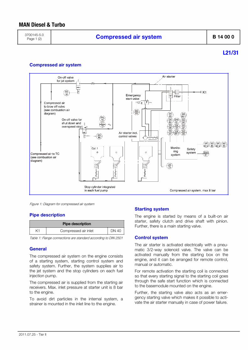
Compressed air system
Figure 1: Diagram for compressed air system
Pipe description
Pipe description
K1 Compressed air inlet DN 40
Table 1: Flange connections are standard according to DIN 2501
General
The compressed air system on the engine consistsof a starting system, starting control system andsafety system. Further, the system supplies air tothe jet system and the stop cylinders on each fuelinjection pump.
The compressed air is supplied from the starting airreceivers. Max. inlet pressure at starter unit is 8 barto the engine.
To avoid dirt particles in the internal system, astrainer is mounted in the inlet line to the engine.
Starting system
The engine is started by means of a built-on airstarter, safety clutch and drive shaft with pinion.Further, there is a main starting valve.
Control system
The air starter is activated electrically with a pneu-matic 3/2-way solenoid valve. The valve can beactivated manually from the starting box on theengine, and it can be arranged for remote control,manual or automatic.
For remote activation the starting coil is connectedso that every starting signal to the starting coil goesthrough the safe start function which is connectedto the basemodule mounted on the engine.
Further, the starting valve also acts as an emer-gency starting valve which makes it possible to acti-vate the air starter manually in case of power failure.
MAN Diesel & Turbo
3700145-5.0Page 1 (2) Compressed air system B 14 00 0
L21/31
2011.07.25 - Tier II
Safety system
Air supply must not be interrupted when theengine is running.
As standard the engine is equipped with a pneu-matic/mechanical stop cylinder, which starts tooperate if the safety system is activated. The sys-tem is activated electrically. One stop cylinder foreach cylinder is intergrated in each fuel injectionpump.
Pneumatic start sequence
When the starting valve is opened, air will be sup-plied to the drive shaft housing of the air starter.
The air supply will – by activating a piston – bringthe drive pinion into engagement with the gear rimon the engine flywheel.
When the pinion is fully engaged, the pilot air willflow to, and open the main starting valve, wherebyair will be led to the air starter, which will start toturn the engine.
When engine rpm exceeds approx. 158 and firinghas taken place, the starting valve is closedwhereby the air starter is disengaged.
Optionals
Besides the standard components, the followingstandard optional can be built-on:
▪ Main valve, inlet engine.
MAN Diesel & Turbo
B 14 00 0 Compressed air system 3700145-5.0Page 2 (2)
L21/31
2011.07.25 - Tier II
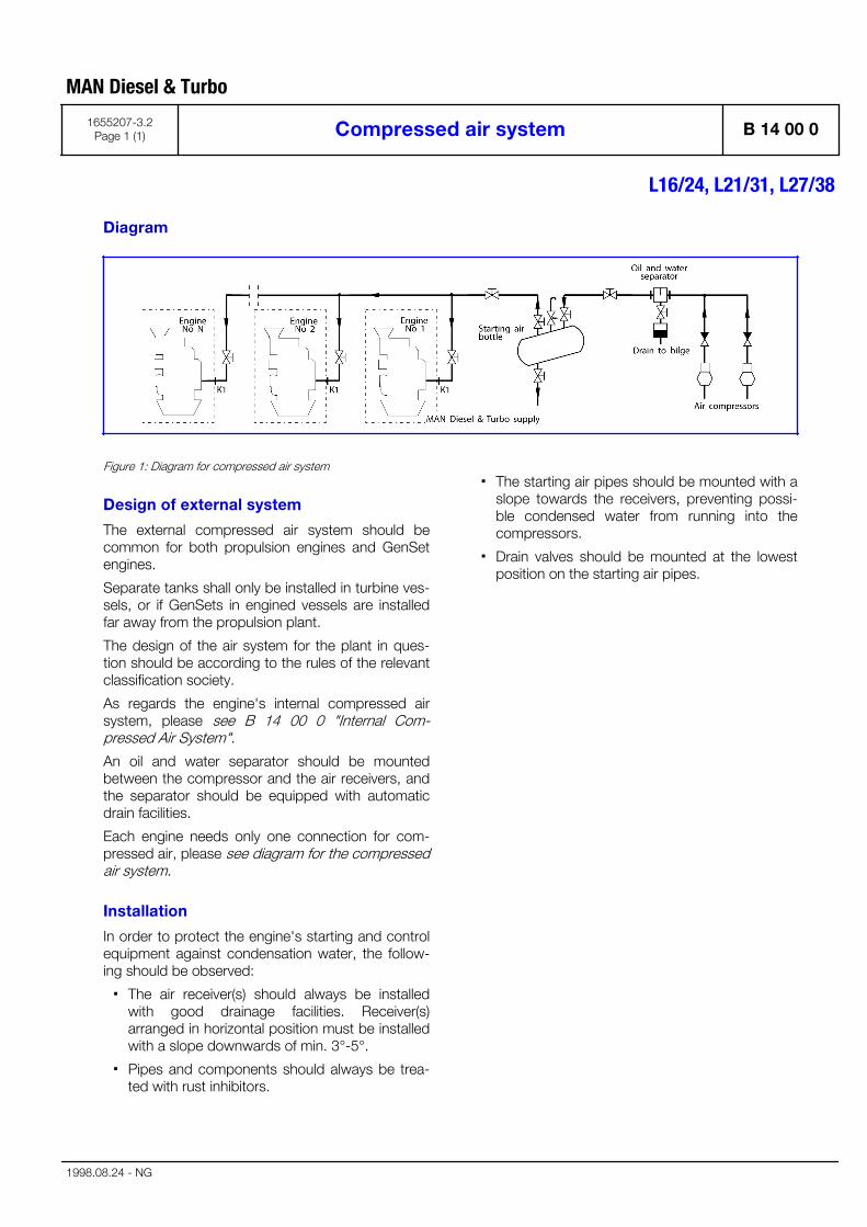
Diagram
Figure 1: Diagram for compressed air system
Design of external system
The external compressed air system should becommon for both propulsion engines and GenSetengines.
Separate tanks shall only be installed in turbine ves-sels, or if GenSets in engined vessels are installedfar away from the propulsion plant.
The design of the air system for the plant in ques-tion should be according to the rules of the relevantclassification society.
As regards the engine's internal compressed airsystem, please see B 14 00 0 "Internal Com-pressed Air System".
An oil and water separator should be mountedbetween the compressor and the air receivers, andthe separator should be equipped with automaticdrain facilities.
Each engine needs only one connection for com-pressed air, please see diagram for the compressedair system.
Installation
In order to protect the engine's starting and controlequipment against condensation water, the follow-ing should be observed:
▪ The air receiver(s) should always be installedwith good drainage facilities. Receiver(s)arranged in horizontal position must be installedwith a slope downwards of min. 3°-5°.
▪ Pipes and components should always be trea-ted with rust inhibitors.
▪ The starting air pipes should be mounted with aslope towards the receivers, preventing possi-ble condensed water from running into thecompressors.
▪ Drain valves should be mounted at the lowestposition on the starting air pipes.
MAN Diesel & Turbo
1655207-3.2Page 1 (1) Compressed air system B 14 00 0
L16/24, L21/31, L27/38
1998.08.24 - NG


Combustion Air System
B 15

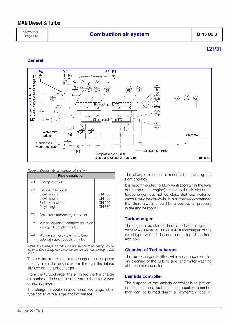
General
Figure 1: Diagram for combustion air system.
Pipe description
M1
P2
P6
P8
P9
Charge air inlet
Exhaust gas outlet:5 cyl. engine6 cyl. engine7+8 cyl. engines9 cyl. engine
Drain from turbocharger - outlet
Water washing compressor sidewith quick coupling - inlet
Working air, dry cleaning turbine side with quick coupling - inlet
DN 400DN 450DN 500DN 550
Table 1: P2 flange connections are standard according to DIN86 044. Other flange connections are standard according to DIN2501.
The air intake to the turbochargers takes placedirectly from the engine room through the intakesilencer on the turbocharger.
From the turbocharger the air is led via the chargeair cooler and charge air receiver to the inlet valvesof each cylinder.
The charge air cooler is a compact two-stage tube-type cooler with a large cooling surface.
The charge air cooler is mounted in the engine'sfront end box.
It is recommended to blow ventilation air in the levelof the top of the engine(s) close to the air inlet of theturbocharger, but not so close that sea water orvapour may be drawn-in. It is further recommendedthat there always should be a positive air pressurein the engine room.
Turbocharger
The engine is as standard equipped with a high-effi-cient MAN Diesel & Turbo TCR turbocharger of theradial type, which is located on the top of the frontend box.
Cleaning of Turbocharger
The turbocharger is fitted with an arrangement fordry cleaning of the turbine side, and water washingof the compressor side.
Lambda controller
The purpose of the lambda controller is to preventinjection of more fuel in the combustion chamberthan can be burned during a momentary load in-
MAN Diesel & Turbo
3700047-3.1Page 1 (2) Combustion air system B 15 00 0
L21/31
2011.09.26 - Tier II
crease. This is carried out by controlling the relationbetween the fuel index and the charge air pressure.The lambda controller has the following advantages:
▪ Reduction of visible smoke in case of suddenmomentary load increases.
▪ Improved load ability.
▪ Less fouling of the engine's exhaust gas ways.
▪ Limitation of fuel oil index during starting proce-dure.
The above states that the working conditions areimproved under difficult circumstances and that themaintenance costs for an engine, working withmany and major load changes, will be reduced.
Data
For charge air heat dissipation and exhaust gasdata, see D 10 05 0 "List of Capacities".
Set points and operating levels for temperature andpressure are stated in B 19 00 0 "Operating Dataand Set Points".
MAN Diesel & Turbo
B 15 00 0 Combustion air system 3700047-3.1Page 2 (2)
L21/31
2011.09.26 - Tier II
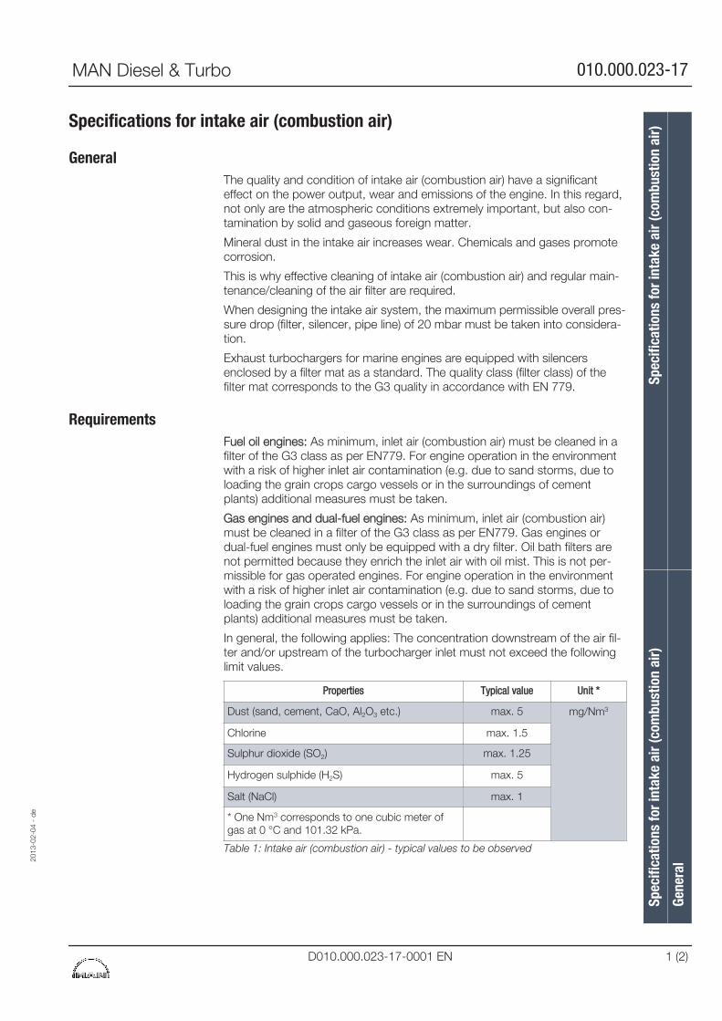
Specifications for intake air (combustion air)
GeneralThe quality and condition of intake air (combustion air) have a significanteffect on the power output, wear and emissions of the engine. In this regard,not only are the atmospheric conditions extremely important, but also con-tamination by solid and gaseous foreign matter.
Mineral dust in the intake air increases wear. Chemicals and gases promotecorrosion.
This is why effective cleaning of intake air (combustion air) and regular main-tenance/cleaning of the air filter are required.
When designing the intake air system, the maximum permissible overall pres-sure drop (filter, silencer, pipe line) of 20 mbar must be taken into considera-tion.
Exhaust turbochargers for marine engines are equipped with silencersenclosed by a filter mat as a standard. The quality class (filter class) of thefilter mat corresponds to the G3 quality in accordance with EN 779.
RequirementsFuel oil engines: As minimum, inlet air (combustion air) must be cleaned in afilter of the G3 class as per EN779. For engine operation in the environmentwith a risk of higher inlet air contamination (e.g. due to sand storms, due toloading the grain crops cargo vessels or in the surroundings of cementplants) additional measures must be taken.
Gas engines and dual-fuel engines: As minimum, inlet air (combustion air)must be cleaned in a filter of the G3 class as per EN779. Gas engines ordual-fuel engines must only be equipped with a dry filter. Oil bath filters arenot permitted because they enrich the inlet air with oil mist. This is not per-missible for gas operated engines. For engine operation in the environmentwith a risk of higher inlet air contamination (e.g. due to sand storms, due toloading the grain crops cargo vessels or in the surroundings of cementplants) additional measures must be taken.
In general, the following applies: The concentration downstream of the air fil-ter and/or upstream of the turbocharger inlet must not exceed the followinglimit values.
Properties Typical value Unit *
Dust (sand, cement, CaO, Al2O3 etc.) max. 5 mg/Nm3
Chlorine max. 1.5
Sulphur dioxide (SO2) max. 1.25
Hydrogen sulphide (H2S) max. 5
Salt (NaCl) max. 1
* One Nm3 corresponds to one cubic meter ofgas at 0 °C and 101.32 kPa.
Table 1: Intake air (combustion air) - typical values to be observed
2013
-02-
04 -
de
Spec
ifica
tions
for i
ntak
e ai
r (co
mbu
stio
n ai
r)Sp
ecifi
catio
ns fo
r int
ake
air (
com
bust
ion
air)
Gene
ral
MAN Diesel & Turbo 010.000.023-17
D010.000.023-17-0001 EN 1 (2)

Intake air shall not contain any flammable gasesIntake air shall not contain any flammable gases. Make sure that thecombustion air is not explosive.
Spec
ifica
tions
for i
ntak
e ai
r (co
mbu
stio
n ai
r)Sp
ecifi
catio
ns fo
r int
ake
air (
com
bust
ion
air)
Gene
ral
2013
-02-
04 -
de
010.000.023-17 MAN Diesel & Turbo
2 (2) D010.000.023-17-0001 EN
Combustion air requirements
▪ The combustion air must be free from waterspray, dust, oil mist and exhaust gases.
▪ The air ventilation fans shoud be designed tomaintain a positive air pressure of 50 Pa (5mmWC) in the auxiliary engine room in all run-ning conditions.
The combustion air is normally taken from theengine room through a filter fitted on the turbo-charger.
In tropical service a sufficient volume of air mustbe supplied to the turbocharger(s) at outside airtemperature. For this purpose there must be an airduct installed for each turbocharger, with the outletof the duct facing the respective intake air silencer.No water of condensation from the air duct must beallowed to be drawn in by the turbocharger.
In arctic service the air must be heated to at least5°C. If necessary air preheaters must be provided.
Ventilator capacity
The capacity of the air ventilators must be largeenough to cover:
▪ The combustion air requirements of all consum-ers.
▪ The air required for carrying off the heat emis-sion.
See "List of Capacities" section D 10 05 0 for infor-mation about required combustion air quantity andheat emission.
For minimum requirements concerning engine roomventilation see applicable standards such as ISO8861.
MAN Diesel & Turbo
1699110-4.1Page 1 (1) Engine room ventilation and combustion air B 15 00 0
L32/40, L16/24, L23/30H, L28/32H, V28/32S, L21/31, L27/38, L28/32DF
2011.06.06

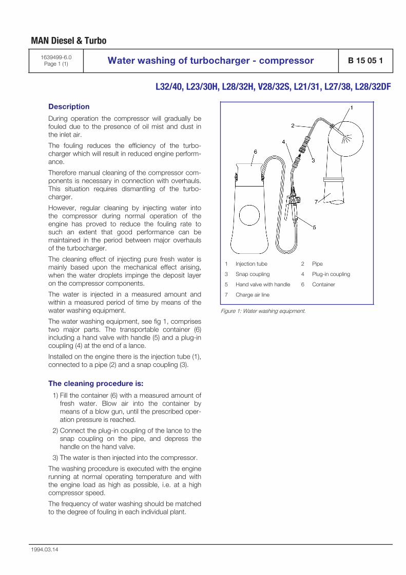
Description
During operation the compressor will gradually befouled due to the presence of oil mist and dust inthe inlet air.
The fouling reduces the efficiency of the turbo-charger which will result in reduced engine perform-ance.
Therefore manual cleaning of the compressor com-ponents is necessary in connection with overhauls.This situation requires dismantling of the turbo-charger.
However, regular cleaning by injecting water intothe compressor during normal operation of theengine has proved to reduce the fouling rate tosuch an extent that good performance can bemaintained in the period between major overhaulsof the turbocharger.
The cleaning effect of injecting pure fresh water ismainly based upon the mechanical effect arising,when the water droplets impinge the deposit layeron the compressor components.
The water is injected in a measured amount andwithin a measured period of time by means of thewater washing equipment.
The water washing equipment, see fig 1, comprisestwo major parts. The transportable container (6)including a hand valve with handle (5) and a plug-incoupling (4) at the end of a lance.
Installed on the engine there is the injection tube (1),connected to a pipe (2) and a snap coupling (3).
The cleaning procedure is:
1) Fill the container (6) with a measured amount offresh water. Blow air into the container bymeans of a blow gun, until the prescribed oper-ation pressure is reached.
2) Connect the plug-in coupling of the lance to thesnap coupling on the pipe, and depress thehandle on the hand valve.
3) The water is then injected into the compressor.
The washing procedure is executed with the enginerunning at normal operating temperature and withthe engine load as high as possible, i.e. at a highcompressor speed.
The frequency of water washing should be matchedto the degree of fouling in each individual plant.
1 Injection tube 2 Pipe
3 Snap coupling 4 Plug-in coupling
5 Hand valve with handle 6 Container
7 Charge air line
Figure 1: Water washing equipment.
MAN Diesel & Turbo
1639499-6.0Page 1 (1) Water washing of turbocharger - compressor B 15 05 1
L32/40, L23/30H, L28/32H, V28/32S, L21/31, L27/38, L28/32DF
1994.03.14


Exhaust Gas System
B 16

Internal exhaust gas system
From the exhaust valves, the gas is led to theexhaust gas receiver where the fluctuating pressurefrom the individual cylinders is equalized and thetotal volume of gas led further on to the turbo-charger, at a constant pressure. After the turbo-charger, the gas is led to the exhaust pipe system.
The exhaust gas receiver is cast sections, one foreach cylinder, connected to each other, by meansof compensators, to prevent excessive stress dueto heat expansion.
After each cylinder a thermosensor for reading theexhaust gas temperature is fitted. The value is indi-cated by means of the MEG-module (MonitorExhaust Gas temperature).
To avoid excessive thermal loss and to ensure areasonably low surface temperature the exhaustgas receiver is insulated.
External exhaust gas system
The exhaust back-pressure should be kept as lowas possible.
It is therefore of the utmost importance that theexhaust piping is made as short as possible andwith few and soft bends.
Long, curved, and narrow exhaust pipes result inhigher back-pressure which will affect the enginecombustion. Exhaust back-pressure is a loss ofenergy and will cause higher fuel comsumption.
The exhaust back-pressure should not exceed 30mbar at MCR. An exhaust gas velocity through thepipe of maximum 35 m/sec is often suitable, butdepends on the actual piping.
During commissioning and maintenance work,checking of the exhaust gas back pressure bymeans of a temporarily connected measuringdevice may become necessary. For this purpose, ameasuring socket must be provided approx. 1-2 mafter the exhaust gas outlet of the turbocharger atan easily accessible place. Usual pressure measur-ing devices require a measuring socket size of ½".This measuring socket must be provided to ensureutilisation without any damage to the exhaust gaspipe insulation.
MAN Diesel & Turbo will be pleased to assist inmaking a calculation of the exhaust back-pressure.
The gas outlet of turbocharger, the expansion bel-lows, the exhaust pipe, and silencer, (in case ofsilencer with spark arrestor care must be taken thatthe cleaning parts are accessible), must be insula-ted with a suitable material.
The insulation should be shielded by a thin plating,and should comply with the requirements of theclassification society and/or the local authorities.
Exhaust pipe dimensions
It should be noted that concerning the maximumexhaust gas velocity the pipe dimension after theexpansion bellows should be increased for some ofthe engines.
The wall thickness of the external exhaust pipeshould be min. 3 mm.
Exhaust pipe mounting
When the exhaust piping is mounted, the radiationof noise and heat must be taken into consideration.
Because of thermal fluctuations in the exhaust pipe,it is necessary to use flexible as well as rigid sus-pension points.
In order to compensate for thermal expansion in thelongitudinal direction, expansion bellows must beinserted. The expansion bellows should preferablybe placed at the rigid suspension points.
Note: The exhaust pipe must not exert any forceagainst the gas outlet on the engine.
One sturdy fixed-point support must be providedfor the expansion bellows on the turbocharger. Itshould be positioned, if possible, immediately abovethe expansion bellows in order to prevent the trans-mission of forces, resulting from the weight, thermalexpansion or lateral displacement of the exhaustpiping, to the turbocharger.
The exhaust piping should be mounted with a slopetowards the gas outlet on the engine. It is recom-mended to have drain facilities in order to be able toremove condensate or rainwater.
Position of gas outlet on turbocharger
B 16 02 0 shows turning alternatives positions ofthe exhaust gas outlet. Before dispatch of theengine exhaust gas outlet will be turned to the wan-ted position.
The turbocharger is, as standard, mounted in thefront end.
MAN Diesel & Turbo
1655213-2.5Page 1 (3) Exhaust gas system B 16 00 0
L16/24, L21/31, L27/38
2012.05.28 - NG
Exhaust gas boiler
To utilize the thermal energy from the exhaust, anexhaust gas boiler producing steam or hot watercan be installed.
Each engine should have a separate exhaust gasboiler or, alternatively, a common boiler with sepa-rate gas ducts. Concerning exhaust gas quantitiesand temperature, see "List of capacities" D 10 05 0,and "Engine performance" D 10 10 0.
The discharge temperature from the exhaust gasboiler should not be lower than 180°C (in order toavoid sulphuric acid formation in the funnel).
The exhaust gas boilers should be installed with by-pass entering in function at low-load operation.
The back-pressure over the boiler must be includedin the back-pressure calculation.
Expansion bellows
The expansion bellows, which is supplied sepa-rately, must be mounted directly on the exhaust gasoutlet, see also E 16 01 1-2.
Exhaust silencer
The position of the silencer in the exhaust gas pip-ing is not decisive for the silencing effect. It wouldbe useful, however, to fit the silencer as high aspossible to reduce fouling. The necessary silencingdepends on the loudness of the exhaust sound andthe discharge from the gas outlet to the bridgewing.
The exhaust silencer, see E 16 04 2-3-5-6, is sup-plied loose with counterflange, gaskets and bolts.
MAN Diesel & Turbo
B 16 00 0 Exhaust gas system 1655213-2.5Page 2 (3)
L16/24, L21/31, L27/38
2012.05.28 - NG
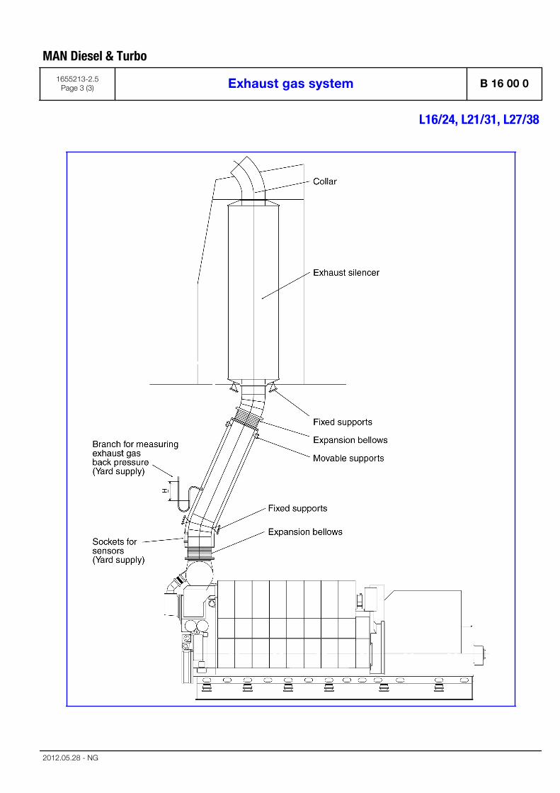
MAN Diesel & Turbo
1655213-2.5Page 3 (3) Exhaust gas system B 16 00 0
L16/24, L21/31, L27/38
2012.05.28 - NG

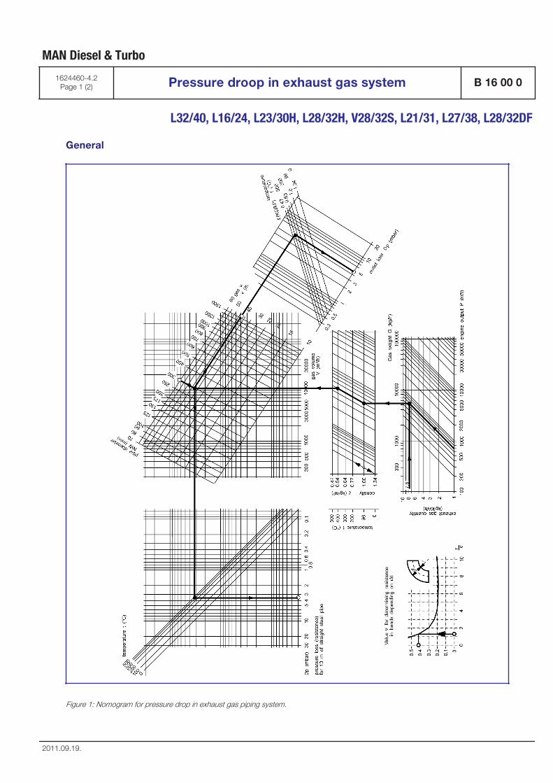
General
Figure 1: Nomogram for pressure drop in exhaust gas piping system.
MAN Diesel & Turbo
1624460-4.2Page 1 (2) Pressure droop in exhaust gas system B 16 00 0
L32/40, L16/24, L23/30H, L28/32H, V28/32S, L21/31, L27/38, L28/32DF
2011.09.19.
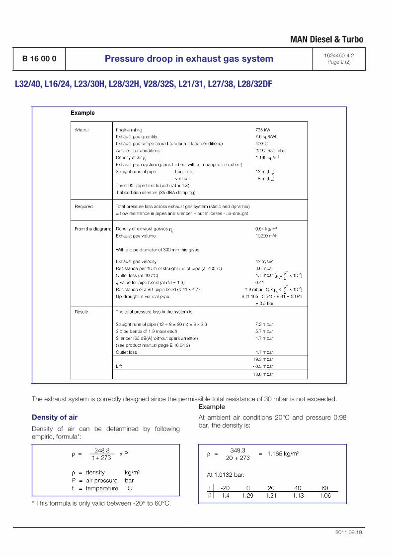
The exhaust system is correctly designed since the permissible total resistance of 30 mbar is not exceeded.
Density of air
Density of air can be determined by followingempiric, formula*:
* This formula is only valid between -20° to 60°C.
Example
At ambient air conditions 20°C and pressure 0.98bar, the density is:
MAN Diesel & Turbo
B 16 00 0 Pressure droop in exhaust gas system 1624460-4.2Page 2 (2)
L32/40, L16/24, L23/30H, L28/32H, V28/32S, L21/31, L27/38, L28/32DF
2011.09.19.
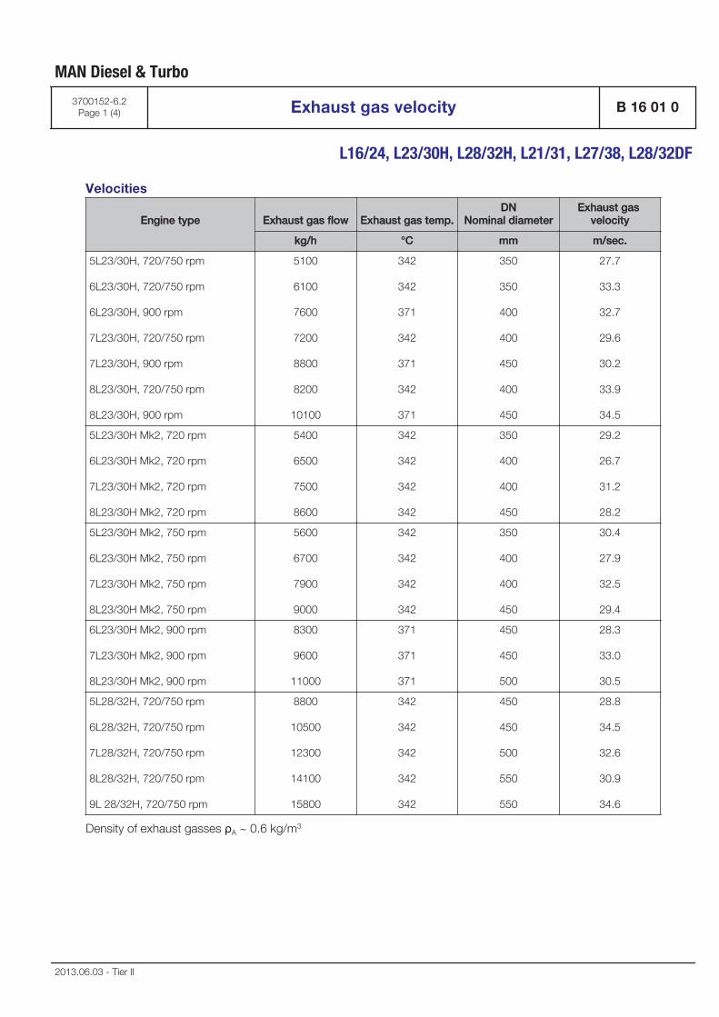
Velocities
Engine type Exhaust gas flow Exhaust gas temp.DN
Nominal diameterExhaust gas
velocity
kg/h °C mm m/sec.
5L23/30H, 720/750 rpm
6L23/30H, 720/750 rpm
6L23/30H, 900 rpm
7L23/30H, 720/750 rpm
7L23/30H, 900 rpm
8L23/30H, 720/750 rpm
8L23/30H, 900 rpm
5100
6100
7600
7200
8800
8200
10100
342
342
371
342
371
342
371
350
350
400
400
450
400
450
27.7
33.3
32.7
29.6
30.2
33.9
34.5
5L23/30H Mk2, 720 rpm
6L23/30H Mk2, 720 rpm
7L23/30H Mk2, 720 rpm
8L23/30H Mk2, 720 rpm
5400
6500
7500
8600
342
342
342
342
350
400
400
450
29.2
26.7
31.2
28.2
5L23/30H Mk2, 750 rpm
6L23/30H Mk2, 750 rpm
7L23/30H Mk2, 750 rpm
8L23/30H Mk2, 750 rpm
5600
6700
7900
9000
342
342
342
342
350
400
400
450
30.4
27.9
32.5
29.4
6L23/30H Mk2, 900 rpm
7L23/30H Mk2, 900 rpm
8L23/30H Mk2, 900 rpm
8300
9600
11000
371
371
371
450
450
500
28.3
33.0
30.5
5L28/32H, 720/750 rpm
6L28/32H, 720/750 rpm
7L28/32H, 720/750 rpm
8L28/32H, 720/750 rpm
9L 28/32H, 720/750 rpm
8800
10500
12300
14100
15800
342
342
342
342
342
450
450
500
550
550
28.8
34.5
32.6
30.9
34.6
Density of exhaust gasses ρA ~ 0.6 kg/m3
MAN Diesel & Turbo
3700152-6.2Page 1 (4) Exhaust gas velocity B 16 01 0
L16/24, L23/30H, L28/32H, L21/31, L27/38, L28/32DF
2013.06.03 - Tier II
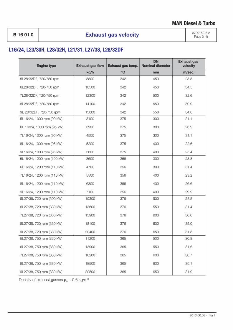
Engine type Exhaust gas flow Exhaust gas temp.DN
Nominal diameterExhaust gas
velocity
kg/h °C mm m/sec.
5L28/32DF, 720/750 rpm
6L28/32DF, 720/750 rpm
7L28/32DF, 720/750 rpm
8L28/32DF, 720/750 rpm
9L 28/32DF, 720/750 rpm
8800
10500
12300
14100
15800
342
342
342
342
342
450
450
500
550
550
28.8
34.5
32.6
30.9
34.6
5L16/24, 1000 rpm (90 kW)
6L 16/24, 1000 rpm (95 kW)
7L16/24, 1000 rpm (95 kW)
8L16/24, 1000 rpm (95 kW)
9L16/24, 1000 rpm (95 kW)
3100
3900
4500
5200
5800
375
375
375
375
375
300
300
300
400
400
21.1
26.9
31.1
22.6
25.4
5L16/24, 1200 rpm (100 kW)
6L16/24, 1200 rpm (110 kW)
7L16/24, 1200 rpm (110 kW)
8L16/24, 1200 rpm (110 kW)
9L16/24, 1200 rpm (110 kW)
3600
4700
5500
6300
7100
356
356
356
356
356
300
300
400
400
400
23.8
31.4
23.2
26.6
29.9
5L27/38, 720 rpm (300 kW)
6L27/38, 720 rpm (330 kW)
7L27/38, 720 rpm (330 kW)
8L27/38, 720 rpm (330 kW)
9L27/38, 720 rpm (330 kW)
10300
13600
15900
18100
20400
376
376
376
376
376
500
550
600
600
650
28.8
31.4
30.6
35.0
31.8
5L27/38, 750 rpm (320 kW)
6L27/38, 750 rpm (330 kW)
7L27/38, 750 rpm (330 kW)
8L27/38, 750 rpm (330 kW)
9L27/38, 750 rpm (330 kW)
11200
13900
16200
18500
20800
365
365
365
365
365
500
550
600
600
650
30.8
31.6
30.7
35.1
31.9
Density of exhaust gasses ρA ~ 0.6 kg/m3
MAN Diesel & Turbo
B 16 01 0 Exhaust gas velocity 3700152-6.2Page 2 (4)
L16/24, L23/30H, L28/32H, L21/31, L27/38, L28/32DF
2013.06.03 - Tier II
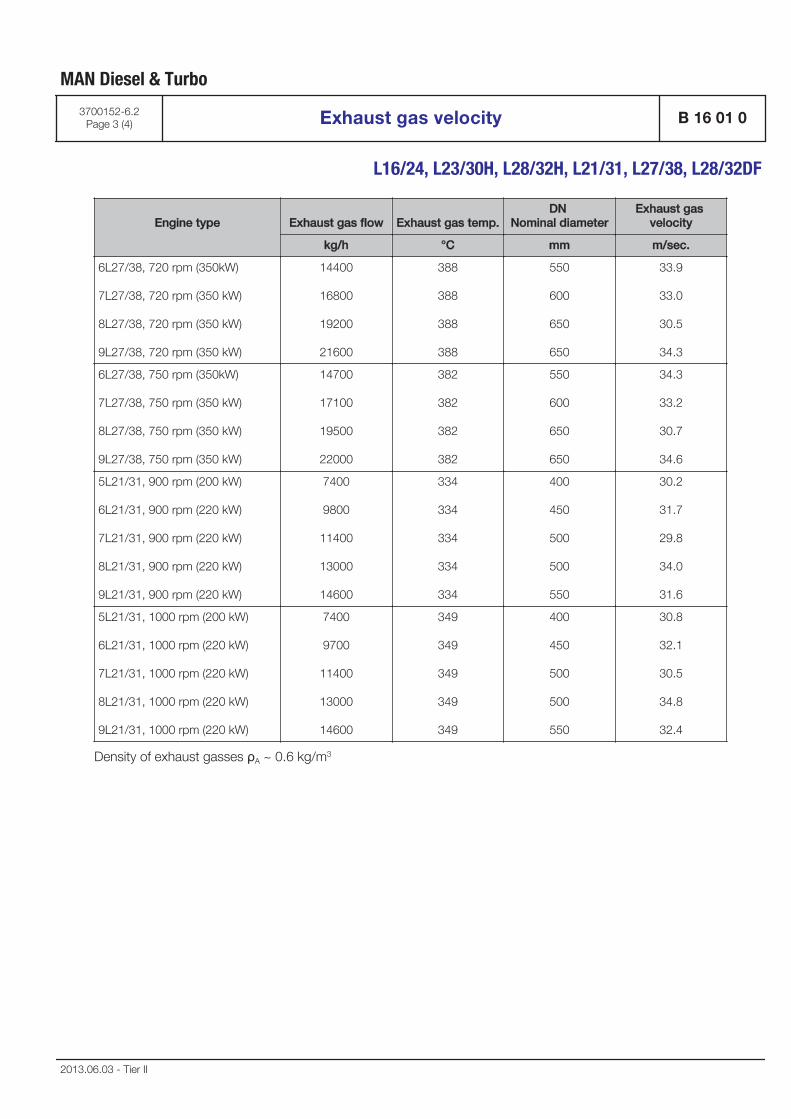
Engine type Exhaust gas flow Exhaust gas temp.DN
Nominal diameterExhaust gas
velocity
kg/h °C mm m/sec.
6L27/38, 720 rpm (350kW)
7L27/38, 720 rpm (350 kW)
8L27/38, 720 rpm (350 kW)
9L27/38, 720 rpm (350 kW)
14400
16800
19200
21600
388
388
388
388
550
600
650
650
33.9
33.0
30.5
34.3
6L27/38, 750 rpm (350kW)
7L27/38, 750 rpm (350 kW)
8L27/38, 750 rpm (350 kW)
9L27/38, 750 rpm (350 kW)
14700
17100
19500
22000
382
382
382
382
550
600
650
650
34.3
33.2
30.7
34.6
5L21/31, 900 rpm (200 kW)
6L21/31, 900 rpm (220 kW)
7L21/31, 900 rpm (220 kW)
8L21/31, 900 rpm (220 kW)
9L21/31, 900 rpm (220 kW)
7400
9800
11400
13000
14600
334
334
334
334
334
400
450
500
500
550
30.2
31.7
29.8
34.0
31.6
5L21/31, 1000 rpm (200 kW)
6L21/31, 1000 rpm (220 kW)
7L21/31, 1000 rpm (220 kW)
8L21/31, 1000 rpm (220 kW)
9L21/31, 1000 rpm (220 kW)
7400
9700
11400
13000
14600
349
349
349
349
349
400
450
500
500
550
30.8
32.1
30.5
34.8
32.4
Density of exhaust gasses ρA ~ 0.6 kg/m3
MAN Diesel & Turbo
3700152-6.2Page 3 (4) Exhaust gas velocity B 16 01 0
L16/24, L23/30H, L28/32H, L21/31, L27/38, L28/32DF
2013.06.03 - Tier II
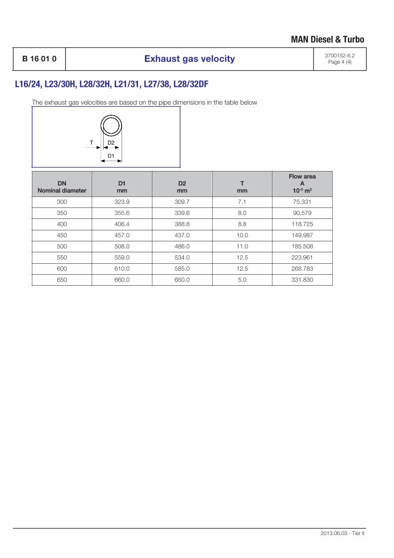
The exhaust gas velocities are based on the pipe dimensions in the table below
DNNominal diameter
D1mm
D2mm
Tmm
Flow areaA
10-3 m2
300 323.9 309.7 7.1 75.331
350 355.6 339.6 8.0 90.579
400 406.4 388.8 8.8 118.725
450 457.0 437.0 10.0 149.987
500 508.0 486.0 11.0 185.508
550 559.0 534.0 12.5 223.961
600 610.0 585.0 12.5 268.783
650 660.0 650.0 5.0 331.830
MAN Diesel & Turbo
B 16 01 0 Exhaust gas velocity 3700152-6.2Page 4 (4)
L16/24, L23/30H, L28/32H, L21/31, L27/38, L28/32DF
2013.06.03 - Tier II
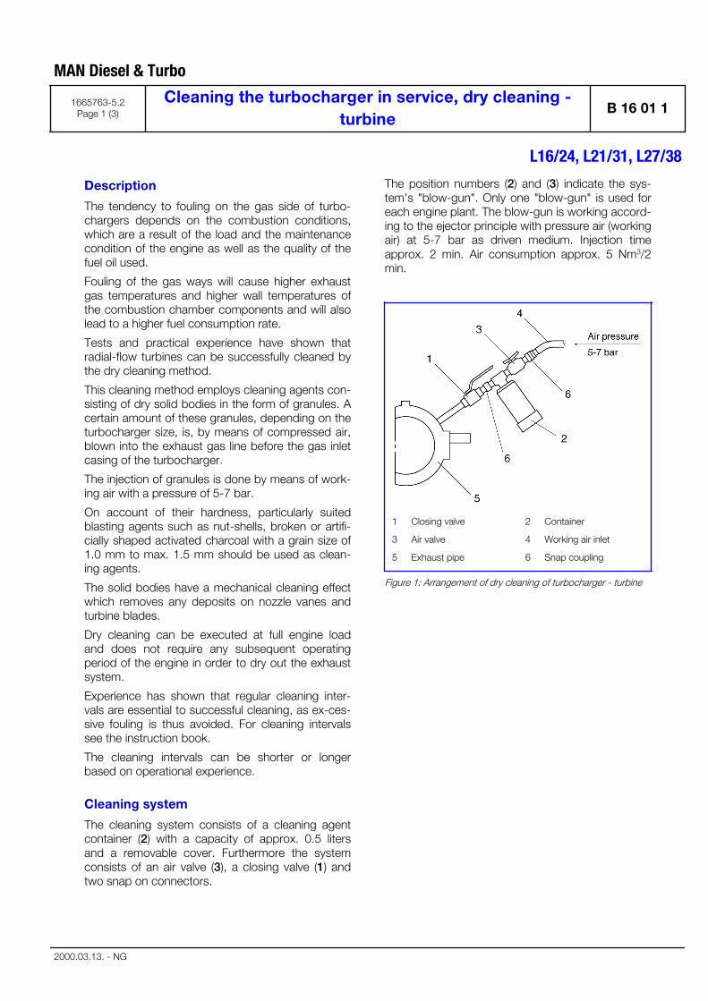
Description
The tendency to fouling on the gas side of turbo-chargers depends on the combustion conditions,which are a result of the load and the maintenancecondition of the engine as well as the quality of thefuel oil used.
Fouling of the gas ways will cause higher exhaustgas temperatures and higher wall temperatures ofthe combustion chamber components and will alsolead to a higher fuel consumption rate.
Tests and practical experience have shown thatradial-flow turbines can be successfully cleaned bythe dry cleaning method.
This cleaning method employs cleaning agents con-sisting of dry solid bodies in the form of granules. Acertain amount of these granules, depending on theturbocharger size, is, by means of compressed air,blown into the exhaust gas line before the gas inletcasing of the turbocharger.
The injection of granules is done by means of work-ing air with a pressure of 5-7 bar.
On account of their hardness, particularly suitedblasting agents such as nut-shells, broken or artifi-cially shaped activated charcoal with a grain size of1.0 mm to max. 1.5 mm should be used as clean-ing agents.
The solid bodies have a mechanical cleaning effectwhich removes any deposits on nozzle vanes andturbine blades.
Dry cleaning can be executed at full engine loadand does not require any subsequent operatingperiod of the engine in order to dry out the exhaustsystem.
Experience has shown that regular cleaning inter-vals are essential to successful cleaning, as ex-ces-sive fouling is thus avoided. For cleaning intervalssee the instruction book.
The cleaning intervals can be shorter or longerbased on operational experience.
Cleaning system
The cleaning system consists of a cleaning agentcontainer (2) with a capacity of approx. 0.5 litersand a removable cover. Furthermore the systemconsists of an air valve (3), a closing valve (1) andtwo snap on connectors.
The position numbers (2) and (3) indicate the sys-tem's "blow-gun". Only one "blow-gun" is used foreach engine plant. The blow-gun is working accord-ing to the ejector principle with pressure air (workingair) at 5-7 bar as driven medium. Injection timeapprox. 2 min. Air consumption approx. 5 Nm3/2min.
1 Closing valve 2 Container
3 Air valve 4 Working air inlet
5 Exhaust pipe 6 Snap coupling
Figure 1: Arrangement of dry cleaning of turbocharger - turbine
MAN Diesel & Turbo
1665763-5.2Page 1 (3)
Cleaning the turbocharger in service, dry cleaning -turbine
B 16 01 1
L16/24, L21/31, L27/38
2000.03.13. - NG
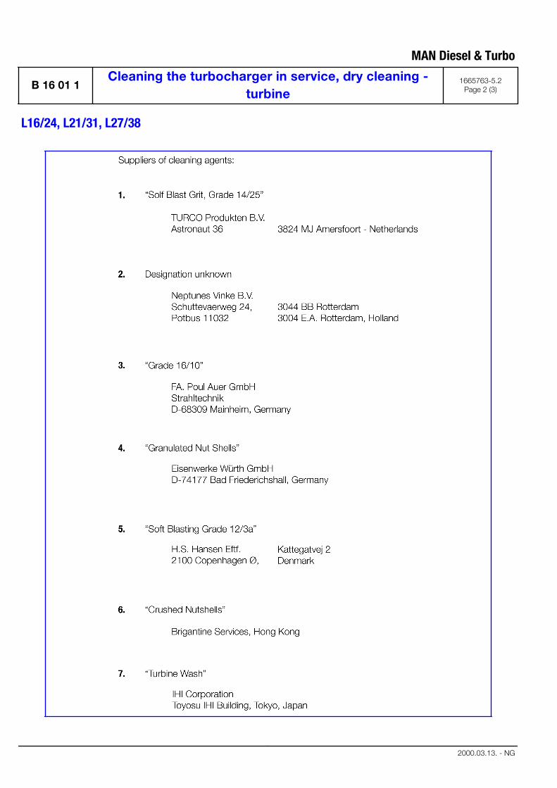
MAN Diesel & Turbo
B 16 01 1Cleaning the turbocharger in service, dry cleaning -
turbine1665763-5.2
Page 2 (3)
L16/24, L21/31, L27/38
2000.03.13. - NG
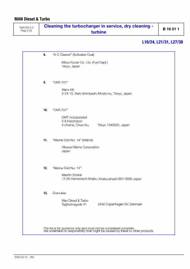
MAN Diesel & Turbo
1665763-5.2Page 3 (3)
Cleaning the turbocharger in service, dry cleaning -turbine
B 16 01 1
L16/24, L21/31, L27/38
2000.03.13. - NG

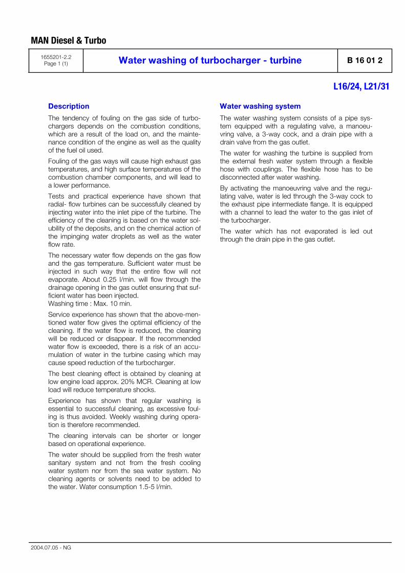
Description
The tendency of fouling on the gas side of turbo-chargers depends on the combustion conditions,which are a result of the load on, and the mainte-nance condition of the engine as well as the qualityof the fuel oil used.
Fouling of the gas ways will cause high exhaust gastemperatures, and high surface temperatures of thecombustion chamber components, and will lead toa lower performance.
Tests and practical experience have shown thatradial- flow turbines can be successfully cleaned byinjecting water into the inlet pipe of the turbine. Theefficiency of the cleaning is based on the water sol-ubility of the deposits, and on the chemical action ofthe impinging water droplets as well as the waterflow rate.
The necessary water flow depends on the gas flowand the gas temperature. Sufficient water must beinjected in such way that the entire flow will notevaporate. About 0.25 l/min. will flow through thedrainage opening in the gas outlet ensuring that suf-ficient water has been injected. Washing time : Max. 10 min.
Service experience has shown that the above-men-tioned water flow gives the optimal efficiency of thecleaning. If the water flow is reduced, the cleaningwill be reduced or disappear. If the recommendedwater flow is exceeded, there is a risk of an accu-mulation of water in the turbine casing which maycause speed reduction of the turbocharger.
The best cleaning effect is obtained by cleaning atlow engine load approx. 20% MCR. Cleaning at lowload will reduce temperature shocks.
Experience has shown that regular washing isessential to successful cleaning, as excessive foul-ing is thus avoided. Weekly washing during opera-tion is therefore recommended.
The cleaning intervals can be shorter or longerbased on operational experience.
The water should be supplied from the fresh watersanitary system and not from the fresh coolingwater system nor from the sea water system. Nocleaning agents or solvents need to be added tothe water. Water consumption 1.5-5 l/min.
Water washing system
The water washing system consists of a pipe sys-tem equipped with a regulating valve, a manoeu-vring valve, a 3-way cock, and a drain pipe with adrain valve from the gas outlet.
The water for washing the turbine is supplied fromthe external fresh water system through a flexiblehose with couplings. The flexible hose has to bedisconnected after water washing.
By activating the manoeuvring valve and the regu-lating valve, water is led through the 3-way cock tothe exhaust pipe intermediate flange. It is equippedwith a channel to lead the water to the gas inlet ofthe turbocharger.
The water which has not evaporated is led outthrough the drain pipe in the gas outlet.
MAN Diesel & Turbo
1655201-2.2Page 1 (1) Water washing of turbocharger - turbine B 16 01 2
L16/24, L21/31
2004.07.05 - NG

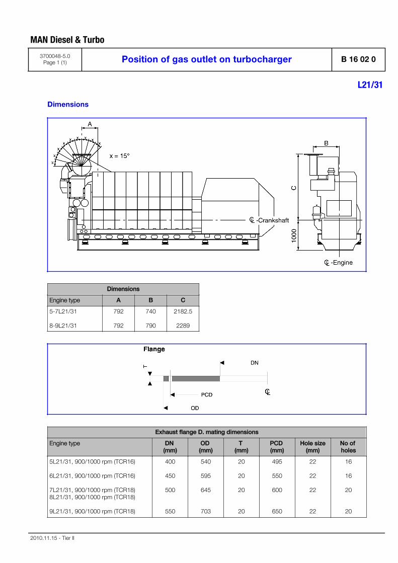
Dimensions
Dimensions
Engine type A B C
5-7L21/31
8-9L21/31
792
792
740
790
2182.5
2289
Exhaust flange D. mating dimensions
Engine type DN (mm)
OD (mm)
T (mm)
PCD (mm)
Hole size(mm)
No of holes
5L21/31, 900/1000 rpm (TCR16)
6L21/31, 900/1000 rpm (TCR16)
7L21/31, 900/1000 rpm (TCR18)8L21/31, 900/1000 rpm (TCR18)
9L21/31, 900/1000 rpm (TCR18)
400
450
500
550
540
595
645
703
20
20
20
20
495
550
600
650
22
22
22
22
16
16
20
20
MAN Diesel & Turbo
3700048-5.0Page 1 (1) Position of gas outlet on turbocharger B 16 02 0
L21/31
2010.11.15 - Tier II

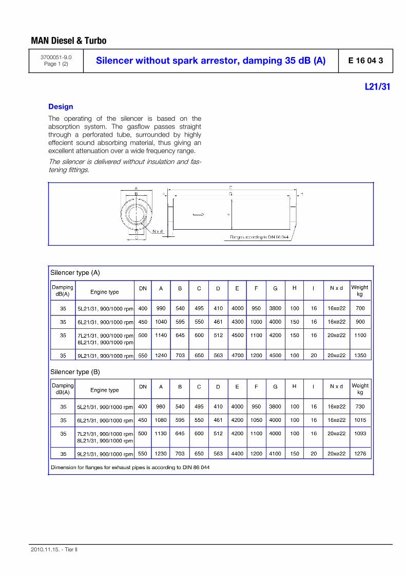
Design
The operating of the silencer is based on theabsorption system. The gasflow passes straightthrough a perforated tube, surrounded by highlyeffecient sound absorbing material, thus giving anexcellent attenuation over a wide frequency range.
The silencer is delivered without insulation and fas-tening fittings.
MAN Diesel & Turbo
3700051-9.0Page 1 (2) Silencer without spark arrestor, damping 35 dB (A) E 16 04 3
L21/31
2010.11.15. - Tier II
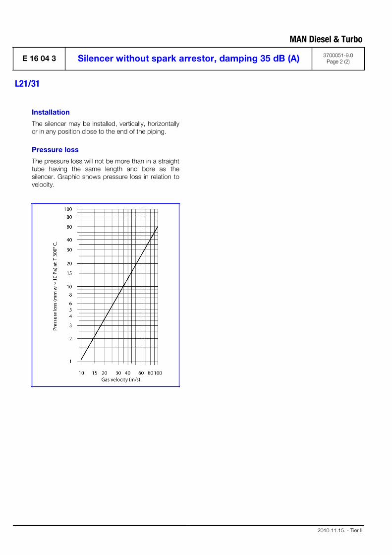
Installation
The silencer may be installed, vertically, horizontallyor in any position close to the end of the piping.
Pressure loss
The pressure loss will not be more than in a straighttube having the same length and bore as thesilencer. Graphic shows pressure loss in relation tovelocity.
MAN Diesel & Turbo
E 16 04 3 Silencer without spark arrestor, damping 35 dB (A) 3700051-9.0Page 2 (2)
L21/31
2010.11.15. - Tier II
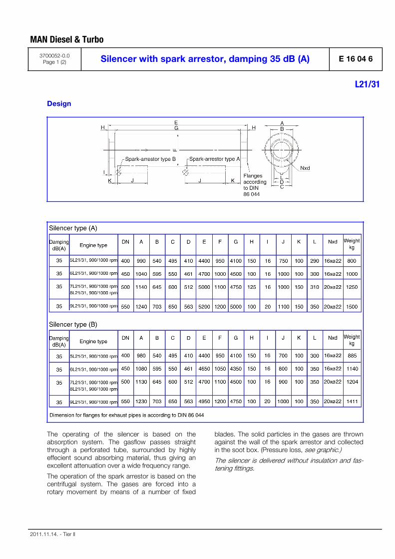
Design
The operating of the silencer is based on theabsorption system. The gasflow passes straightthrough a perforated tube, surrounded by highlyeffecient sound absorbing material, thus giving anexcellent attenuation over a wide frequency range.
The operation of the spark arrestor is based on thecentrifugal system. The gases are forced into arotary movement by means of a number of fixed
blades. The solid particles in the gases are thrownagainst the wall of the spark arrestor and collectedin the soot box. (Pressure loss, see graphic.)
The silencer is delivered without insulation and fas-tening fittings.
MAN Diesel & Turbo
3700052-0.0Page 1 (2) Silencer with spark arrestor, damping 35 dB (A) E 16 04 6
L21/31
2011.11.14. - Tier II
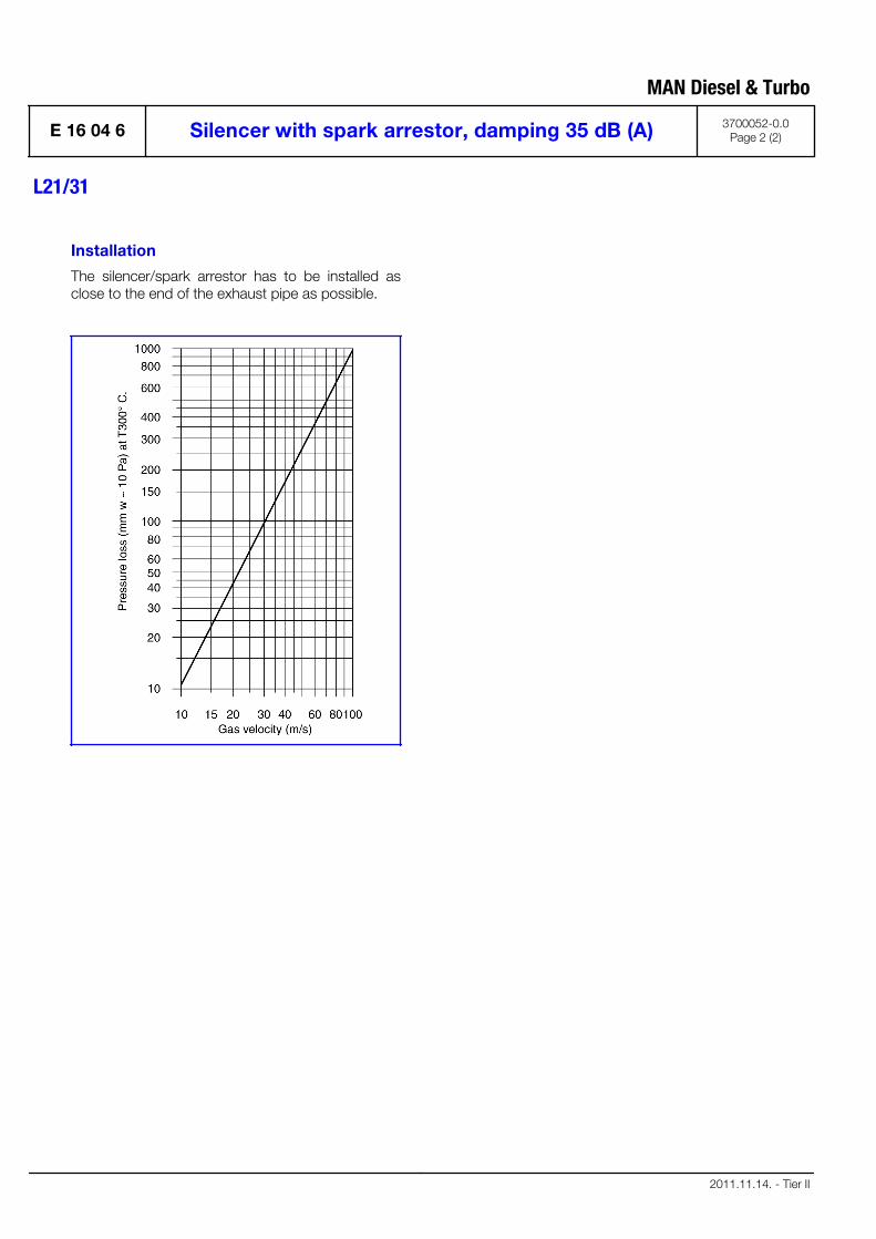
Installation
The silencer/spark arrestor has to be installed asclose to the end of the exhaust pipe as possible.
MAN Diesel & Turbo
E 16 04 6 Silencer with spark arrestor, damping 35 dB (A) 3700052-0.0Page 2 (2)
L21/31
2011.11.14. - Tier II

Speed Control System
B 17

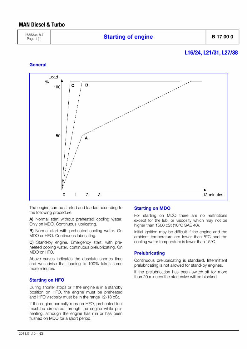
General
The engine can be started and loaded according tothe following procedure:
A) Normal start without preheated cooling water.Only on MDO. Continuous lubricating.
B) Normal start with preheated cooling water. OnMDO or HFO. Continuous lubricating.
C) Stand-by engine. Emergency start, with pre-heated cooling water, continuous prelubricating. OnMDO or HFO.
Above curves indicates the absolute shortes timeand we advise that loading to 100% takes somemore minutes.
Starting on HFO
During shorter stops or if the engine is in a standbyposition on HFO, the engine must be preheatedand HFO viscosity must be in the range 12-18 cSt.
If the engine normally runs on HFO, preheated fuelmust be circulated through the engine while pre-heating, although the engine has run or has beenflushed on MDO for a short period.
Starting on MDO
For starting on MDO there are no restrictionsexcept for the lub. oil viscosity which may not behigher than 1500 cSt (10°C SAE 40).
Initial ignition may be difficult if the engine and theambient temperature are lower than 5°C and thecooling water temperature is lower than 15°C.
Prelubricating
Continuous prelubricating is standard. Intermittentprelubricating is not allowed for stand-by engines.
If the prelubrication has been switch-off for morethan 20 minutes the start valve will be blocked.
MAN Diesel & Turbo
1655204-8.7Page 1 (1) Starting of engine B 17 00 0
L16/24, L21/31, L27/38
2011.01.10 - NG

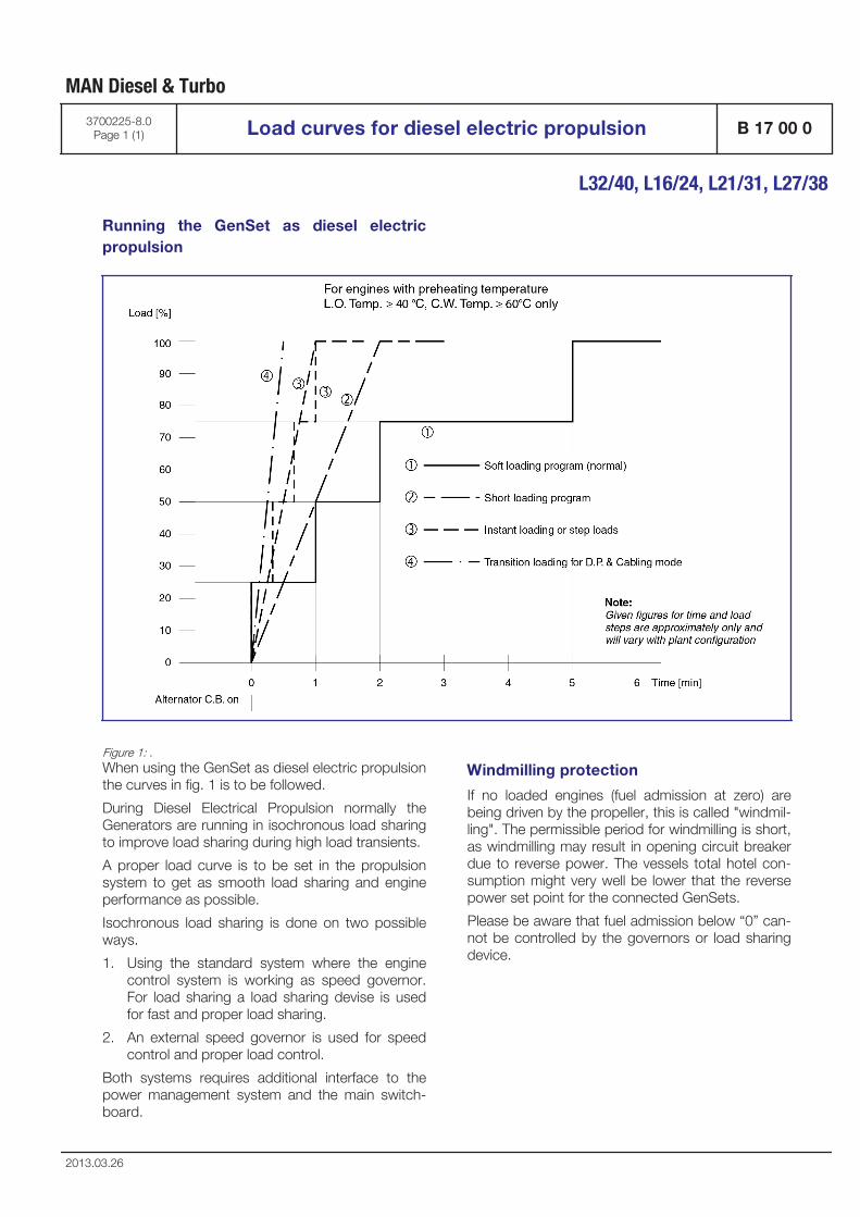
Running the GenSet as diesel electricpropulsion
Figure 1: .When using the GenSet as diesel electric propulsionthe curves in fig. 1 is to be followed.
During Diesel Electrical Propulsion normally theGenerators are running in isochronous load sharingto improve load sharing during high load transients.
A proper load curve is to be set in the propulsionsystem to get as smooth load sharing and engineperformance as possible.
Isochronous load sharing is done on two possibleways.
1. Using the standard system where the enginecontrol system is working as speed governor.For load sharing a load sharing devise is usedfor fast and proper load sharing.
2. An external speed governor is used for speedcontrol and proper load control.
Both systems requires additional interface to thepower management system and the main switch-board.
Windmilling protection
If no loaded engines (fuel admission at zero) arebeing driven by the propeller, this is called "windmil-ling". The permissible period for windmilling is short,as windmilling may result in opening circuit breakerdue to reverse power. The vessels total hotel con-sumption might very well be lower that the reversepower set point for the connected GenSets.
Please be aware that fuel admission below “0” can-not be controlled by the governors or load sharingdevice.
MAN Diesel & Turbo
3700225-8.0Page 1 (1) Load curves for diesel electric propulsion B 17 00 0
L32/40, L16/24, L21/31, L27/38
2013.03.26

Engine operation under arctic conditions
Arctic condition is defined as:
Ambient air temperature below +5°C
If engines operate under arctic conditions (intermit-tently or permanently), the engine equipment andplant installation have to meet special design fea-tures and requirements. They depend on the possi-ble minimum air intake temperature of the engineand the specification of the fuel used.
Special engine design requirements
If arctic fuel oil (with very low lubricating properties)is used, the following actions are required:
Fuel injection pump:
▪ The maximum allowable fuel temperatures haveto be kept.
▪ Only in case of conventional injection system,dependent on engine type installation and acti-vation of sealing oil system may be necessary,because low viscosity of the fuel can cause anincreased leakage and the lube oil will possiblybeing contaminated.
Engine equipment
SaCoS/SaCoSone
SaCoS/SaCoSone equipment is suitable to be storedat minimum ambient temperatures of -15°C.
In case these conditions cannot be met. Protectivemeasures against climatic influences have to betaken for the following electronic components:
▪ EDS Databox APC620
▪ TFT-touchscreen display
▪ Emergency switch module BD5937
These components have to be stored at places,where the temperature is above –15°C.
▪ A minimum operating temperature of ≥ +5°Chas to be ensured. That’s why an optional elec-tric heating has to be used.
Alternators
Alternator operation is possible according to suppli-ers specification.
Plant installation
Intake air conditioning
▪ Air intake of the engine and power house/engine room ventilation have to be two differentsystems to ensure that the power house/engine room temperature is not too low causedby the ambient air temperature.
▪ It is necessary to ensure that the charge aircooler cannot freeze when the engine is out ofoperation (and the cold air is at the air inletside).
An air intake temperature of the engine ≥ 5°Chas to be ensured by preheating.
Ventilation of power house/engine room:
▪ The air of the power house/engine room ventila-tion must not be too cold (preheating is neces-sary) to avoid the freezing of the liquids in thepower house/engine room) systems.
▪ Minimum powerhouse/engine room tempera-ture for design ≥ +5°C
Coolant and lube oil systems:
▪ HT and lube oil system has to be preheated asspecified in the relevant chapters of the projectguide for each individual engine.
▪ If a concentration of anti-freezing agents of > 50% is needed, please contact MAN Diesel &Turbo for approval.
▪ For information regarding engine cooling waterplease see chapter "Cooling water system".
Insulation:
▪ The design of the insulation of the piping sys-tems and other plant parts (tanks, heatexchanger etc.) has to be modified anddesigned for the special requirements of arcticconditions.
Heat tracing:
▪ To support the restart procedures in cold condi-tion (e.g. after unmanned survival mode duringwinter), it is recommended to install a heat trac-ing system in the piping to the engine.
Note! A preheating of the lube oil has to be ensured. If theplant is not equipped with a lube oil separator (e.g.plants only operation on MGO) alternative equip-ment for preheating of the lube oil to be provided.For plants taken out of operation and cooled down
MAN Diesel & Turbo
1689459-9.0Page 1 (2) Engine operation under arctic conditions B 17 00 0
L16/24, L21/31, L27/38
2011.03.212012-10-01 - en

below temperatures of +5°C additional specialmeasures are needed – in this case please contactMAN Diesel & Turbo.
MAN Diesel & Turbo
B 17 00 0 Engine operation under arctic conditions 1689459-9.0Page 2 (2)
L16/24, L21/31, L27/38
2011.03.212012-10-01 - en
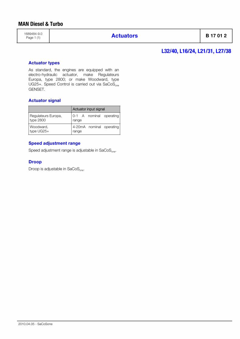
Actuator types
As standard, the engines are equipped with anelectro-hydraulic actuator, make RegulateursEuropa, type 2800; or make Woodward, typeUG25+. Speed Control is carried out via SaCoSone
GENSET.
Actuator signal
Actuator input signal
Regulateurs Europa,type 2800
0-1 A nominal operatingrange
Woodward,type UG25+
4-20mA nominal operatingrange
Speed adjustment range
Speed adjustment range is adjustable in SaCoSone.
Droop
Droop is adjustable in SaCoSone.
MAN Diesel & Turbo
1689484-9.0Page 1 (1) Actuators B 17 01 2
L32/40, L16/24, L21/31, L27/38
2010.04.05 - SaCoSone


Safety and Control System
B 19

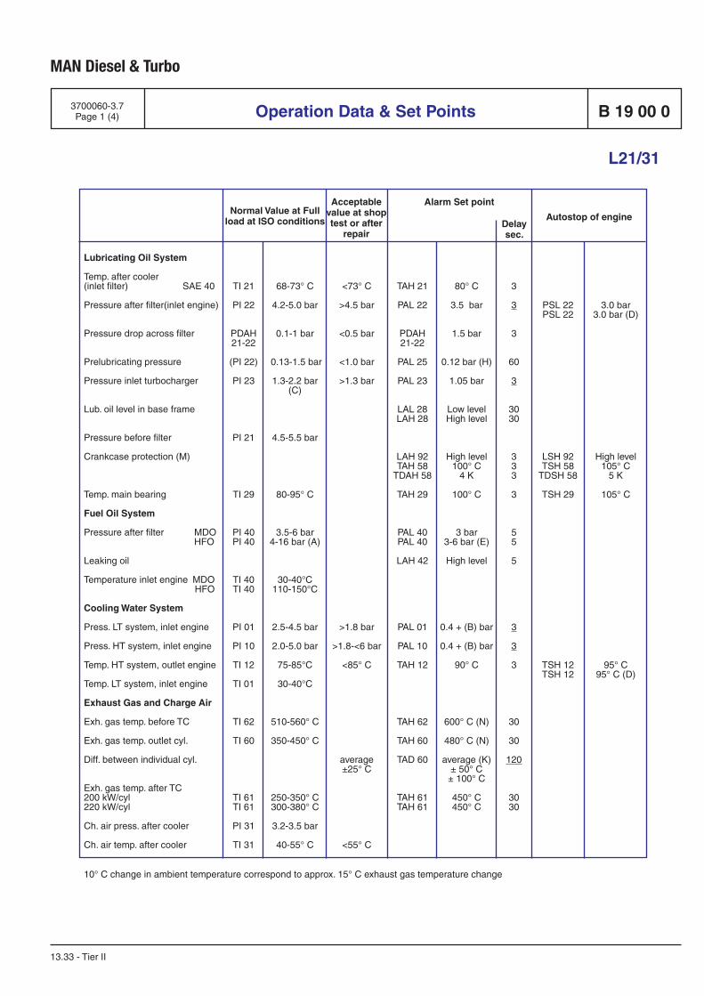
MAN Diesel & Turbo
Normal Value at Full load at ISO conditions
Alarm Set point
Autostop of engine
Acceptable value at shop test or after
repairDelaysec.
Operation Data & Set Points
L21/31
B 19 00 0
13.33 - Tier II
3700060-3.7Page 1 (4)
80° C
3.5 bar
1.5 bar
0.12 bar (H)
1.05 bar
Low levelHigh level
High level100° C
4 K
100° C
3 bar3-6 bar (E)
High level
0.4 + (B) bar
0.4 + (B) bar
90° C
600° C (N)
480° C (N)
average (K)± 50° C± 100° C
450° C450° C
Lubricating Oil System
Temp. after cooler (inlet filter) SAE 40
Pressure after filter(inlet engine)
Pressure drop across filter
Prelubricating pressure
Pressure inlet turbocharger
Lub. oil level in base frame
Pressure before filter
Crankcase protection (M)
Temp. main bearing
Fuel Oil System
Pressure after filter MDO HFO
Leaking oil
Temperature inlet engine MDO HFO
Cooling Water System
Press. LT system, inlet engine
Press. HT system, inlet engine
Temp. HT system, outlet engine
Temp. LT system, inlet engine
Exhaust Gas and Charge Air
Exh. gas temp. before TC
Exh. gas temp. outlet cyl.
Diff. between individual cyl.
Exh. gas temp. after TC200 kW/cyl220 kW/cyl
Ch. air press. after cooler
Ch. air temp. after cooler
TI 21
PI 22
PDAH 21-22
(PI 22)
PI 23
PI 21
TI 29
PI 40PI 40
TI 40TI 40
PI 01
PI 10
TI 12
TI 01
TI 62
TI 60
TI 61TI 61
PI 31
TI 31
68-73° C
4.2-5.0 bar
0.1-1 bar
0.13-1.5 bar
1.3-2.2 bar(C)
4.5-5.5 bar
80-95° C
3.5-6 bar4-16 bar (A)
30-40°C110-150°C
2.5-4.5 bar
2.0-5.0 bar
75-85°C
30-40°C
510-560° C
350-450° C
250-350° C300-380° C
3.2-3.5 bar
40-55° C
TAH 21
PAL 22
PDAH 21-22
PAL 25
PAL 23
LAL 28LAH 28
LAH 92TAH 58
TDAH 58
TAH 29
PAL 40PAL 40
LAH 42
PAL 01
PAL 10
TAH 12
TAH 62
TAH 60
TAD 60
TAH 61TAH 61
<73° C
>4.5 bar
<0.5 bar
<1.0 bar
>1.3 bar
>1.8 bar
>1.8-<6 bar
<85° C
average±25° C
<55° C
PSL 22PSL 22
LSH 92TSH 58
TDSH 58
TSH 29
TSH 12TSH 12
3.0 bar3.0 bar (D)
High level105° C
5 K
105° C
95° C95° C (D)
3
3
3
60
3
3030
333
3
55
5
3
3
3
30
30
120
3030
10° C change in ambient temperature correspond to approx. 15° C exhaust gas temperature change
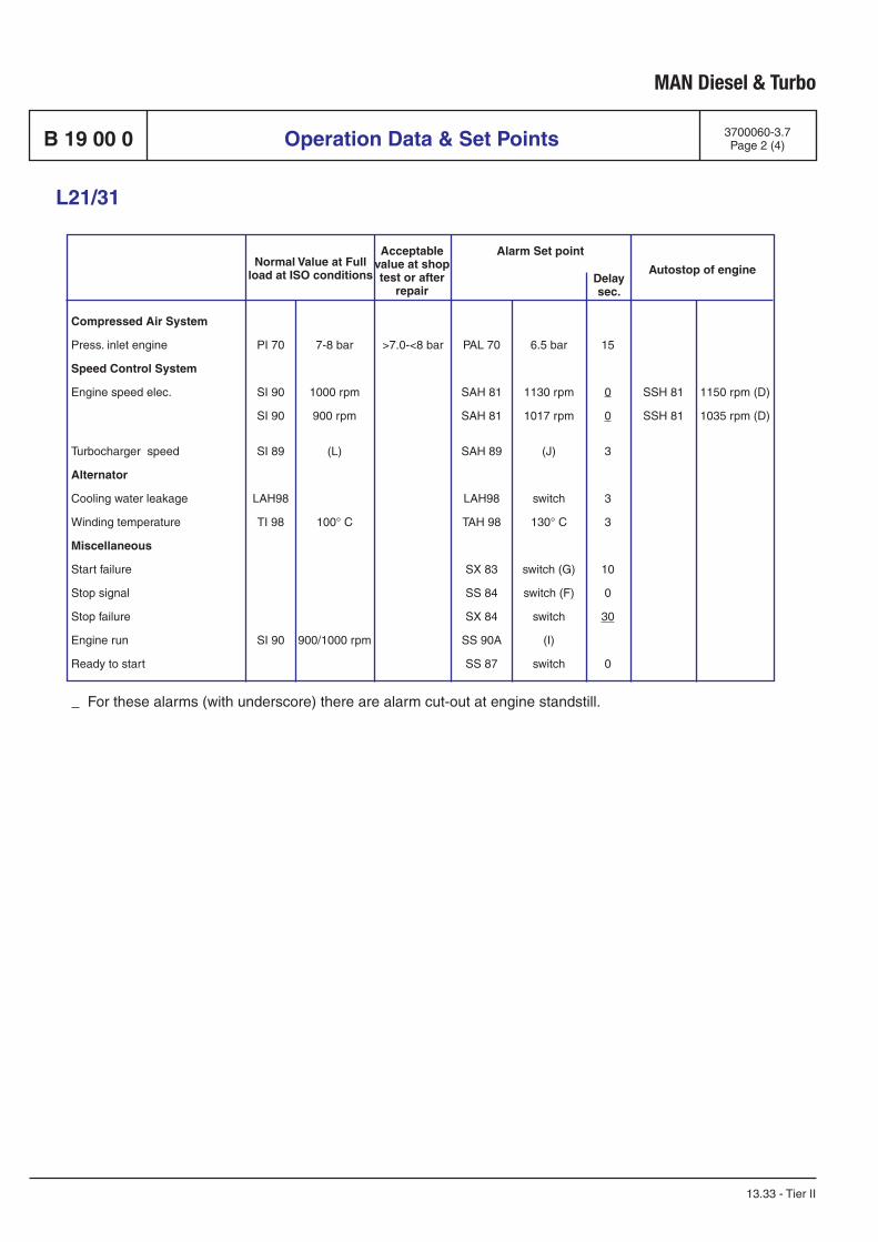
MAN Diesel & Turbo
Normal Value at Full load at ISO conditions
Alarm Set point
Autostop of engine
Acceptable value at shop test or after
repairDelaysec.
For these alarms (with underscore) there are alarm cut-out at engine standstill.
Operation Data & Set PointsB 19 00 0
L21/31
13.33 - Tier II
3700060-3.7Page 2 (4)
Compressed Air System
Press. inlet engine Speed Control System
Engine speed elec.
Turbocharger speed
Alternator
Cooling water leakage
Winding temperature
Miscellaneous
Start failure
Stop signal
Stop failure
Engine run
Ready to start
PI 70
SI 90
SI 90
SI 89
LAH98
TI 98
SI 90
7-8 bar
1000 rpm
900 rpm
(L)
100° C
900/1000 rpm
PAL 70
SAH 81
SAH 81
SAH 89
LAH98
TAH 98
SX 83
SS 84
SX 84
SS 90A
SS 87
6.5 bar
1130 rpm
1017 rpm
(J)
switch
130° C
switch (G)
switch (F)
switch
(I)
switch
15
0
0
3
3
3
10
0
30
0
>7.0-<8 bar
SSH 81
SSH 81
1150 rpm (D)
1035 rpm (D)
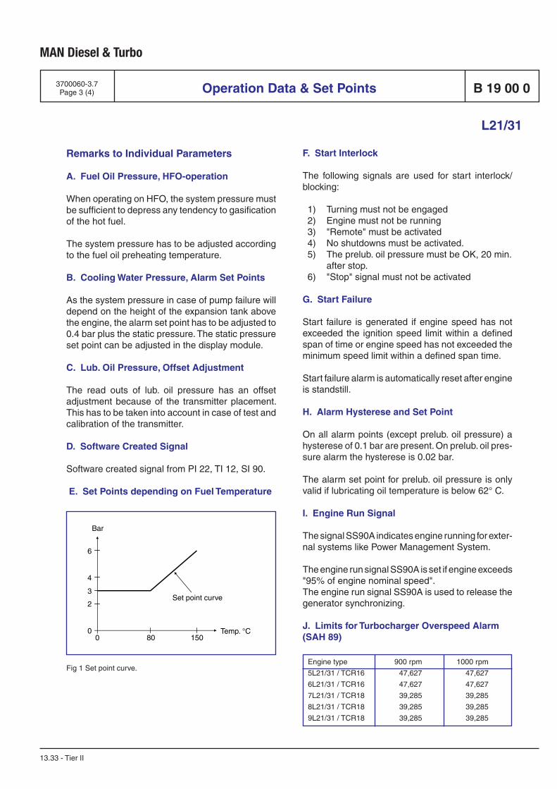
MAN Diesel & Turbo
Fig 1 Set point curve.
Operation Data & Set Points
L21/31
B 19 00 0
13.33 - Tier II
3700060-3.7Page 3 (4)
Remarks to Individual Parameters
A. Fuel Oil Pressure, HFO-operation
When operating on HFO, the system pressure must be sufficient to depress any tendency to gasification of the hot fuel.
The system pressure has to be adjusted according to the fuel oil preheating temperature.
B. Cooling Water Pressure, Alarm Set Points
As the system pressure in case of pump failure will depend on the height of the expansion tank above the engine, the alarm set point has to be adjusted to 0.4 bar plus the static pressure. The static pressure set point can be adjusted in the display module.
C. Lub. Oil Pressure, Offset Adjustment
The read outs of lub. oil pressure has an offset adjustment because of the transmitter placement. This has to be taken into account in case of test and calibration of the transmitter.
D. Software Created Signal
Software created signal from PI 22, TI 12, SI 90.
E. Set Points depending on Fuel Temperature
F. Start Interlock
The following signals are used for start interlock/blocking:
1) Turning must not be engaged 2) Engine must not be running 3) "Remote" must be activated 4) No shutdowns must be activated. 5) The prelub. oil pressure must be OK, 20 min. after stop. 6) "Stop" signal must not be activated
G. Start Failure
Start failure is generated if engine speed has not exceeded the ignition speed limit within a defined span of time or engine speed has not exceeded the minimum speed limit within a defined span time.
Start failure alarm is automatically reset after engine is standstill.
H. Alarm Hysterese and Set Point
On all alarm points (except prelub. oil pressure) a hysterese of 0.1 bar are present. On prelub. oil pres-sure alarm the hysterese is 0.02 bar.
The alarm set point for prelub. oil pressure is only valid if lubricating oil temperature is below 62° C.
I. Engine Run Signal
The signal SS90A indicates engine running for exter-nal systems like Power Management System.
The engine run signal SS90A is set if engine exceeds "95% of engine nominal speed".The engine run signal SS90A is used to release the generator synchronizing.
J. Limits for Turbocharger Overspeed Alarm(SAH 89)
Engine type 900 rpm 1000 rpm
5L21/31 / TCR16 47,627 47,627
6L21/31 / TCR16 47,627 47,627
7L21/31 / TCR18 39,285 39,285
8L21/31 / TCR18 39,285 39,285
9L21/31 / TCR18 39,285 39,285
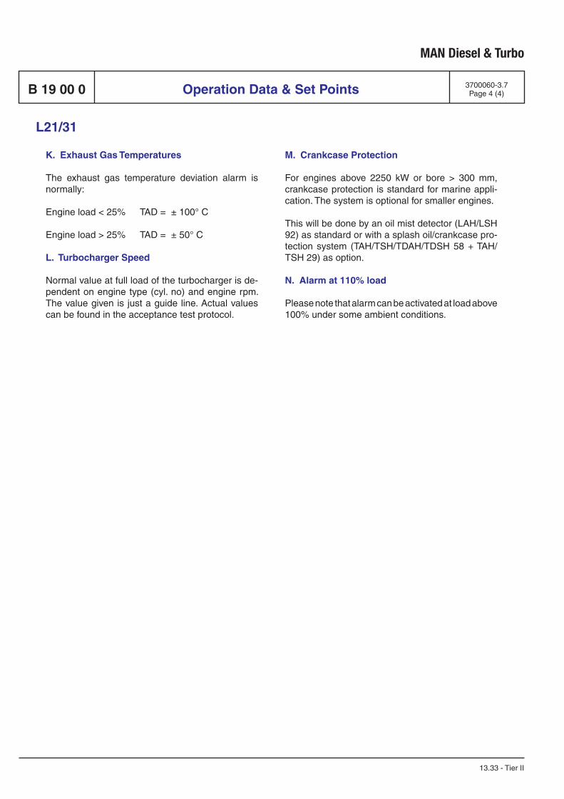
MAN Diesel & Turbo
K. Exhaust Gas Temperatures
The exhaust gas temperature deviation alarm is normally:
Engine load < 25% TAD = ± 100° C
Engine load > 25% TAD = ± 50° C
L. Turbocharger Speed
Normal value at full load of the turbocharger is de-pendent on engine type (cyl. no) and engine rpm. The value given is just a guide line. Actual values can be found in the acceptance test protocol.
Operation Data & Set PointsB 19 00 0
L21/31
13.33 - Tier II
3700060-3.7Page 4 (4)
M. Crankcase Protection
For engines above 2250 kW or bore > 300 mm, crankcase protection is standard for marine appli-cation. The system is optional for smaller engines. This will be done by an oil mist detector (LAH/LSH 92) as standard or with a splash oil/crankcase pro-tection system (TAH/TSH/TDAH/TDSH 58 + TAH/TSH 29) as option.
N. Alarm at 110% load
Please note that alarm can be activated at load above 100% under some ambient conditions.
EN
GIN
E A
UT
OM
AT
ION
MAN Diesel &Turbo SE SaCoSone GENSET System description
Revision 1.5
GS
System description
SaCoSone GENSET
Created: 03.08.2009 Karger This document is property of MAN Diesel & Turbo SE and is entrusted to whom it has been handed over. Copying and communicating to third parties is only permitted with written consent of MAN Diesel & Turbo!
Page 2 of 13 Last change: 16.08.2010 Karger Released:
SaC
oS
one.G
EN
SE
T_
Syste
m d
escrip
tio
n_m
_en_V
1.5
.docx
Revision History
Revision Date Name Comments
0.1 03.08.2009 Karger First issue
0.2 04.08.2009 Karger Interface overview added
0.3 07.08.2009 Brendle Formal modifications
0.4 11.08.2009 Karger Interface overview and description corrected
0.5 14.08.2009 Karger Modbus list added, measurements of the units added,
interface overview modified and corrected, power
supply scheme added
0.6 23.09.2009 Brendle Speed governing signals modified
0.7 04.11.2009 Karger Interface overview modified, detailed interface
description added, Modbus ASCII description added
0.8 12.11.2009 Karger Interface overview modified, GenSet picture corrected
0.9 13.01.2010 Karger Updated due to comments from Mr. Bojtas
0.10 11.02.2010 Karger Interface description outsourced to independent
document
1.0 18.02.2010 Karger Measurements, weight and serial interface added
1.1 20.02.2010 Karger Updated due to comments from H. Cevik
1.2 09.03.2010 Karger Interface description for Crankcase Monitoring Unit
added
1.3 28.05.2010 Karger Chapter “2.3 Speed control system” modified
1.4 14.06.2010 Karger Chapter “2.3 Speed control system” and power supply
modified
1.5 16.08.2010 Karger Chapter 3.8.: corrected power supply for safety system
GS
System description
SaCoSone GENSET
Created: 03.08.2009 Karger This document is property of MAN Diesel & Turbo SE and is entrusted to whom it has been handed over. Copying and communicating to third parties is only permitted with written consent of MAN Diesel & Turbo!
Page 3 of 13 Last change: 16.08.2010 Karger Released:
SaC
oS
one.G
EN
SE
T_
Syste
m d
escrip
tio
n_m
_en_V
1.5
.docx
Table of Contents
1 General information .................................................................................................... 4
1.1 Control Unit ................................................................................................................... 4
1.2 Connection Box ............................................................................................................. 5
1.3 System bus .................................................................................................................... 6
1.4 Technical data ............................................................................................................... 7
2 System description ..................................................................................................... 7
2.1 Safety system ................................................................................................................ 8
2.2 Alarm/monitoring system ............................................................................................. 9
2.3 Speed Control System .................................................................................................. 9
3 Interfaces to external systems ................................................................................. 11
3.1 Overview ...................................................................................................................... 11
3.2 Data Machinery Interface ............................................................................................ 12
3.3 Generator Control ....................................................................................................... 12
3.4 Power Management ..................................................................................................... 12
3.5 Remote control ............................................................................................................ 12
3.6 Ethernet interface ........................................................................................................ 12
3.7 Serial interface............................................................................................................. 12
3.8 Power supply ............................................................................................................... 12
3.9 Crankcase Monitoring Unit (optional) ........................................................................ 13
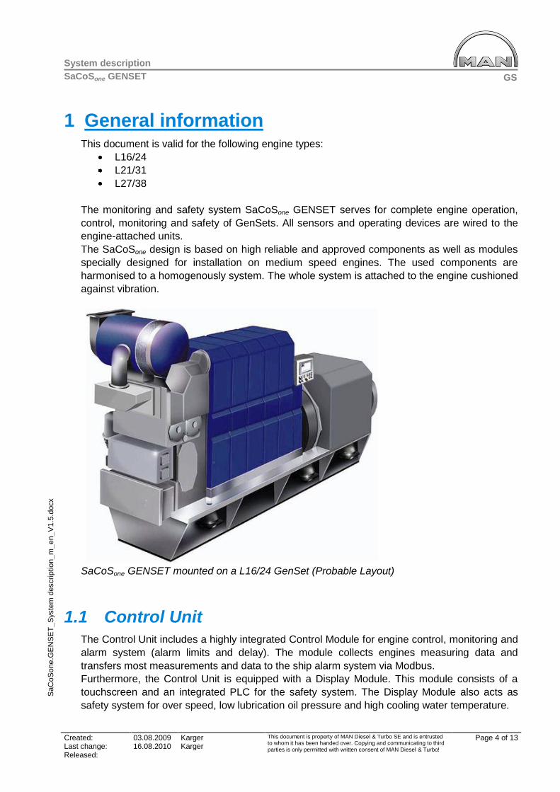
GS
System description
SaCoSone GENSET
Created: 03.08.2009 Karger This document is property of MAN Diesel & Turbo SE and is entrusted to whom it has been handed over. Copying and communicating to third parties is only permitted with written consent of MAN Diesel & Turbo!
Page 4 of 13 Last change: 16.08.2010 Karger Released:
SaC
oS
one.G
EN
SE
T_
Syste
m d
escrip
tio
n_m
_en_V
1.5
.docx
1 General information This document is valid for the following engine types:
L16/24
L21/31
L27/38
The monitoring and safety system SaCoSone GENSET serves for complete engine operation,
control, monitoring and safety of GenSets. All sensors and operating devices are wired to the
engine-attached units.
The SaCoSone design is based on high reliable and approved components as well as modules
specially designed for installation on medium speed engines. The used components are
harmonised to a homogenously system. The whole system is attached to the engine cushioned
against vibration.
SaCoSone GENSET mounted on a L16/24 GenSet (Probable Layout)
1.1 Control Unit
The Control Unit includes a highly integrated Control Module for engine control, monitoring and
alarm system (alarm limits and delay). The module collects engines measuring data and
transfers most measurements and data to the ship alarm system via Modbus.
Furthermore, the Control Unit is equipped with a Display Module. This module consists of a
touchscreen and an integrated PLC for the safety system. The Display Module also acts as
safety system for over speed, low lubrication oil pressure and high cooling water temperature.

GS
System description
SaCoSone GENSET
Created: 03.08.2009 Karger This document is property of MAN Diesel & Turbo SE and is entrusted to whom it has been handed over. Copying and communicating to third parties is only permitted with written consent of MAN Diesel & Turbo!
Page 5 of 13 Last change: 16.08.2010 Karger Released:
SaC
oS
one.G
EN
SE
T_
Syste
m d
escrip
tio
n_m
_en_V
1.5
.docx
The Display Module provides the following functions:
safety system
visualisation of measured values and operating values on a touchscreen
engine operation via touchscreen
The safety system is electrically separated from the control system due to requirements of the
classification societies.
For engine operation, additional hardwired switches are available for relevant functions.
The system configuration can be edited via an Ethernet interface at the Display Module.
Prototype of the SaCoSone GENSET
1.2 Connection Box
The Connection Box is the central connecting and distribution point for the 24 VDC power
supply of the whole system.
Furthermore it connects the Control Unit with the GenSet, the ship alarm system and the
optional crankcase monitoring.
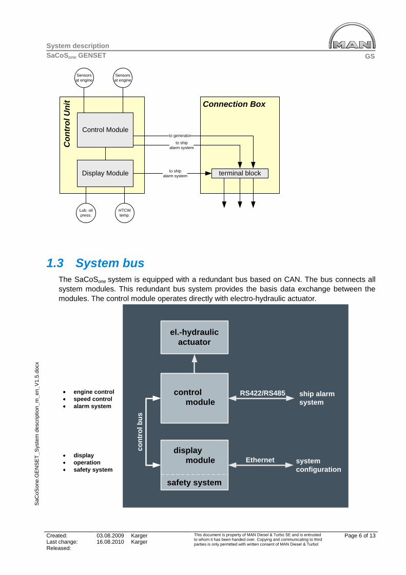
GS
System description
SaCoSone GENSET
Created: 03.08.2009 Karger This document is property of MAN Diesel & Turbo SE and is entrusted to whom it has been handed over. Copying and communicating to third parties is only permitted with written consent of MAN Diesel & Turbo!
Page 6 of 13 Last change: 16.08.2010 Karger Released:
SaC
oS
one.G
EN
SE
T_
Syste
m d
escrip
tio
n_m
_en_V
1.5
.docx
Display Module
Control Module
Sensors
at engine
Sensors
at engine
Connection Box
terminal block
to generator
to ship
alarm systemCo
ntr
ol U
nit
to ship
alarm system
Lub. oil
press.
HTCW
temp.
1.3 System bus
The SaCoSone system is equipped with a redundant bus based on CAN. The bus connects all
system modules. This redundant bus system provides the basis data exchange between the
modules. The control module operates directly with electro-hydraulic actuator.
control
module
display
module
co
ntr
ol b
us
Ethernet system
configuration
el.-hydraulic
actuator
control
moduleRS422/RS485
safety system
ship alarm
system
engine control
speed control
alarm system
display
operation
safety system
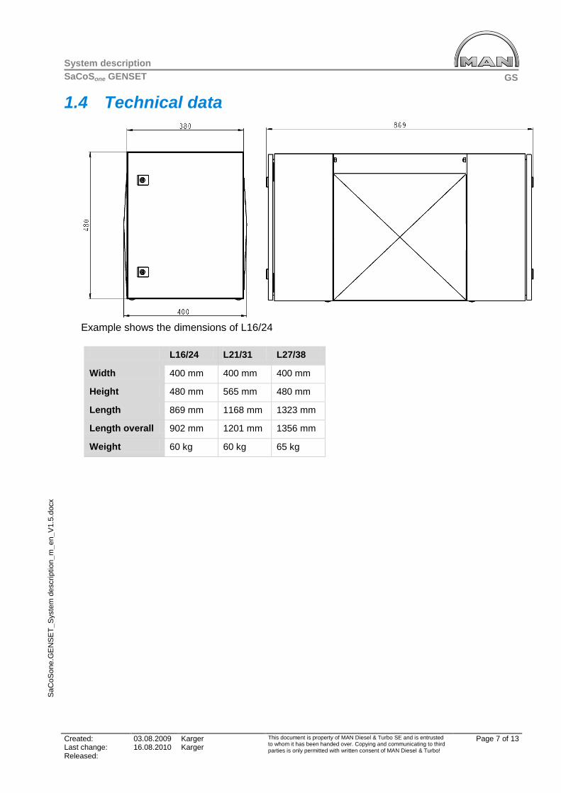
GS
System description
SaCoSone GENSET
Created: 03.08.2009 Karger This document is property of MAN Diesel & Turbo SE and is entrusted to whom it has been handed over. Copying and communicating to third parties is only permitted with written consent of MAN Diesel & Turbo!
Page 7 of 13 Last change: 16.08.2010 Karger Released:
SaC
oS
one.G
EN
SE
T_
Syste
m d
escrip
tio
n_m
_en_V
1.5
.docx
1.4 Technical data
Example shows the dimensions of L16/24
L16/24 L21/31 L27/38
Width 400 mm 400 mm 400 mm
Height 480 mm 565 mm 480 mm
Length 869 mm 1168 mm 1323 mm
Length overall 902 mm 1201 mm 1356 mm
Weight 60 kg 60 kg 65 kg
GS
System description
SaCoSone GENSET
Created: 03.08.2009 Karger This document is property of MAN Diesel & Turbo SE and is entrusted to whom it has been handed over. Copying and communicating to third parties is only permitted with written consent of MAN Diesel & Turbo!
Page 8 of 13 Last change: 16.08.2010 Karger Released:
SaC
oS
one.G
EN
SE
T_
Syste
m d
escrip
tio
n_m
_en_V
1.5
.docx
2 System description
2.1 Safety system
Safety functions
The safety system monitors all operating data of the engine and initiates the required actions,
i.e. engine shut-down, in case the limit values are exceeded. The safety system is integrated
the Display Module.
The safety system directly actuates the emergency shut-down device and the stop facility of
the speed governor.
Auto shutdown
Auto shutdown is an engine shutdown initiated by any automatic supervision of engine internal
parameters.
Emergency stop
Emergency stop is an engine shutdown initiated by an operator manual action like pressing an
emergency stop button. An emergency stop button is placed at the Control Unit on engine. For
connection of an external emergency stop button there is one input channel at the Connection
Box.
Engine shutdown
If an engine shutdown is triggered by the safety system, the emergency stop signal has an
immediate effect on the emergency shut-down device and the speed control. At the same time
the emergency stop is triggered, SaCoSone issues a signal resulting in the generator switch to
be opened.
Shutdown criteria
Engine overspeed
Failure of both engine speed sensors
Lube oil pressure at engine inlet low
HT cooling water temperature outlet too high
High bearing temperature/deviation from Crankcase Monitoring System. (optional)
High oilmist concentration in crankcase. (optional)
Remote Shutdown. (optional)
o Differential protection (optional)
o Earth connector closed (optional)
o Gas leakage (optional)
GS
System description
SaCoSone GENSET
Created: 03.08.2009 Karger This document is property of MAN Diesel & Turbo SE and is entrusted to whom it has been handed over. Copying and communicating to third parties is only permitted with written consent of MAN Diesel & Turbo!
Page 9 of 13 Last change: 16.08.2010 Karger Released:
SaC
oS
one.G
EN
SE
T_
Syste
m d
escrip
tio
n_m
_en_V
1.5
.docx
2.2 Alarm/monitoring system
Alarming
The alarm function of SaCoSone supervises all necessary parameters and generates alarms to
indicate discrepancies when required. The alarms will be transferred to ship alarm system via
Modbus data communication.
Self-monitoring
SaCoSone carries out independent self-monitoring functions. Thus, for example the connected
sensors are checked constantly for function and wire break. In case of a fault SaCoSone reports
the occurred malfunctions in single system components via system alarms.
Control
SaCoSone controls all engine-internal functions as well as external components, for example:
Start/stop sequences: Local and remote start/stop sequence for the GenSet. Activation of start device. Control (auto start/stop signal) regarding prelubrication oil
pump. Monitoring and control of the acceleration period.
Jet system: For air fuel ratio control purposes, compressed air is lead to the turbocharger at start
and at load steps.
Control signals for external functions: Nozzle cooling water pump (only engine type 32/40) HT cooling water preheating unit Prelubrication oil pump control
Redundant shutdown functions: Engine overspeed Low lub. oil pressure inlet engine High cooling water temperature outlet engine
2.3 Speed Control System
Governor
The engine electronic speed control is realized by the Control Module. As standard, the engine
is equipped with an electro-hydraulic actuator.
Speed adjustment
Local, manual speed setting is possible at the Control Unit with a turn switch.
GS
System description
SaCoSone GENSET
Created: 03.08.2009 Karger This document is property of MAN Diesel & Turbo SE and is entrusted to whom it has been handed over. Copying and communicating to third parties is only permitted with written consent of MAN Diesel & Turbo!
Page 10 of 13 Last change: 16.08.2010 Karger Released:
SaC
oS
one.G
EN
SE
T_
Syste
m d
escrip
tio
n_m
_en_V
1.5
.docx
Remote speed setting is either possible via 4-20mA signal or by using hardwired lower/raise
commands.
Speed adjustment range
Between -5% and +10% of the nominal speed at idle running.
Droop
Adjustable by parameterisation tool from 0-5% droop.
Load distribution
By droop setting.
Engine stop
Engine stop can be initiated local at the display module and remote via a hardware channel or
the bus interface.
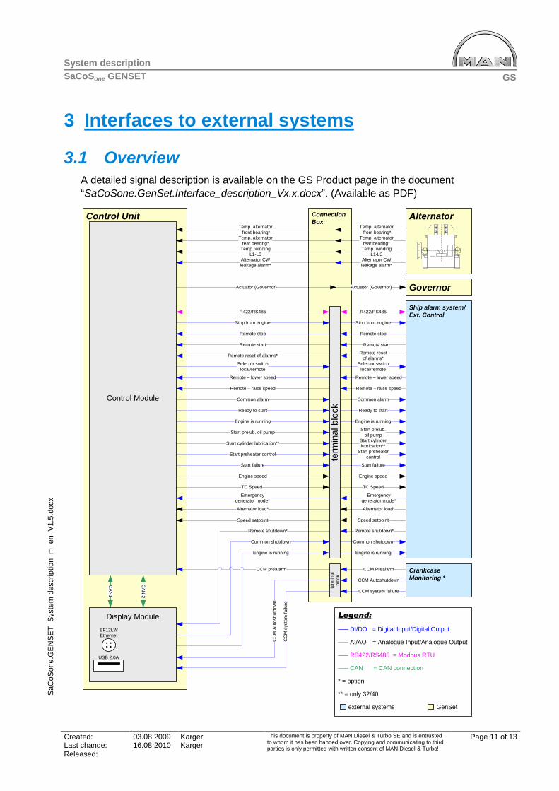
GS
System description
SaCoSone GENSET
Created: 03.08.2009 Karger This document is property of MAN Diesel & Turbo SE and is entrusted to whom it has been handed over. Copying and communicating to third parties is only permitted with written consent of MAN Diesel & Turbo!
Page 11 of 13 Last change: 16.08.2010 Karger Released:
SaC
oS
one.G
EN
SE
T_
Syste
m d
escrip
tio
n_m
_en_V
1.5
.docx
3 Interfaces to external systems
3.1 Overview
A detailed signal description is available on the GS Product page in the document
“SaCoSone.GenSet.Interface_description_Vx.x.docx”. (Available as PDF)
Connection
BoxControl Unit
Control Module
Ship alarm system/
Ext. Control
Alternator
Temp. winding
L1-L3
Temp. alternator
front bearing*Temp. alternator
rear bearing*
CA
N1
CA
N 2
Alternator load*
Alternator CW
leakage alarm*
Emergency
generator mode*
Temp. winding
L1-L3
Temp. alternator
front bearing*Temp. alternator
rear bearing*
Alternator load*
Alternator CW
leakage alarm*
Emergency
generator mode*
Stop from engine
Remote stop
Remote start
Remote reset of alarms*
Actuator (Governor)
Common alarm
Ready to start
Engine is running
Start prelub. oil pump
Start preheater control
Start failure
Remote shutdown*
term
ina
l b
lock
Common shutdown
Engine is running
term
ina
l
blo
ck
CCM prealarm
CC
M A
uto
sh
utd
ow
n
CC
M s
yste
m fa
ilure
Display Module
Crankcase
Monitoring *
Legend:
––– DI/DO = Digital Input/Digital Output
––– AI/AO = Analogue Input/Analogue Output
––– RS422/RS485 = Modbus RTU
––– CAN = CAN connection
* = option
** = only 32/40
external systems GenSet
Remote stop
Remote start
Remote reset
of alarms*
Actuator (Governor)
Common alarm
Ready to start
Engine is running
Start prelub.
oil pump
Start preheater
control
Start failure
Stop from engine
Remote shutdown*
Common shutdown
Engine is running
CCM Prealarm
CCM Autoshutdown
CCM system failure
R422/RS485R422/RS485
USB 2.0A
EF12LW
Ethernet
Selector switch
local/remote
Selector switch
local/remote
Remote – lower speed
Remote – raise speed
Remote – lower speed
Remote – raise speed
Governor
Engine speed
TC Speed
Speed setpoint
Engine speed
TC Speed
Speed setpoint
Start cylinder lubrication**Start cylinder
lubrication**
GS
System description
SaCoSone GENSET
Created: 03.08.2009 Karger This document is property of MAN Diesel & Turbo SE and is entrusted to whom it has been handed over. Copying and communicating to third parties is only permitted with written consent of MAN Diesel & Turbo!
Page 12 of 13 Last change: 16.08.2010 Karger Released:
SaC
oS
one.G
EN
SE
T_
Syste
m d
escrip
tio
n_m
_en_V
1.5
.docx
3.2 Data Machinery Interface
This interface serves for data exchange to ship alarm systems or integrated automation
systems (IAS).
The status messages, alarms and safety actions, which are generated in the system, can be
transferred. All measuring values and alarms acquired by SaCoSone GENSET are available for
transfer.
The following MODBUS protocols are available:
MODBUS RTU (Standard)
MODBUS ASCII (for retrofits)
For a detailed description of these protocols see the document “SaCoSone GENSET,
Communication from the GenSet”.
3.3 Generator Control
SaCoSone provides inputs for all temperature signals for the temperatures of the generator
bearings and generator windings.
3.4 Power Management
Hardwired interface for remote start/stop, speed setting, alternator circuit breaker trip etc.
3.5 Remote control
For remote control several digital inputs are available.
3.6 Ethernet interface
The Ethernet interface at the Display Module can be used for the connection of SaCoSone
EXPERT.
3.7 Serial interface
CoCoS-EDS can be connected to a serial RS485 interface.
3.8 Power supply
The plant has to provide electric power for the automation and monitoring system. In general a
redundant, uninterrupted 24V DC (+20% -30% and max ripple 10%) power supply is required
for SaCoSone.
The alarm system requires a 24V DC, 12,5 A uninterrupted power supply with a 16 A pre-fuse.
The safety system requires a 24V DC, 8,5 A uninterrupted power supply with a 10 A pre-fuse.
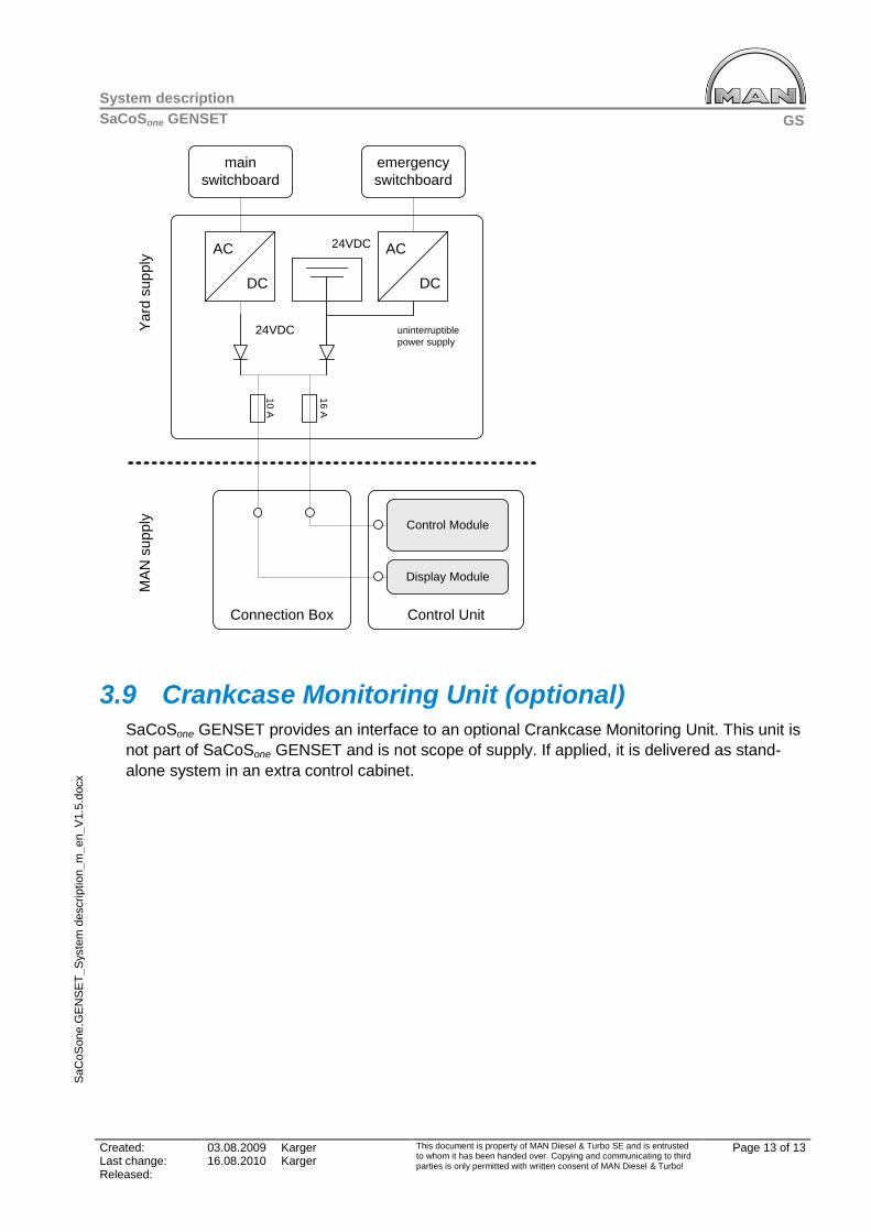
GS
System description
SaCoSone GENSET
Created: 03.08.2009 Karger This document is property of MAN Diesel & Turbo SE and is entrusted to whom it has been handed over. Copying and communicating to third parties is only permitted with written consent of MAN Diesel & Turbo!
Page 13 of 13 Last change: 16.08.2010 Karger Released:
SaC
oS
one.G
EN
SE
T_
Syste
m d
escrip
tio
n_m
_en_V
1.5
.docx
Control Unit
Control Module
Connection Box
main
switchboard
emergency
switchboard
AC
DC
AC
DC
MA
N s
up
ply
uninterruptible
power supply
Ya
rd s
up
ply
24VDC
24VDC
Display Module
10
A
16
A
3.9 Crankcase Monitoring Unit (optional)
SaCoSone GENSET provides an interface to an optional Crankcase Monitoring Unit. This unit is
not part of SaCoSone GENSET and is not scope of supply. If applied, it is delivered as stand-
alone system in an extra control cabinet.


MAN Diesel & Turbo
SaC
oSon
e G
ENS
ET
SaCoSone GENSET
Communication from GenSet
Revision ............................................. 1.6
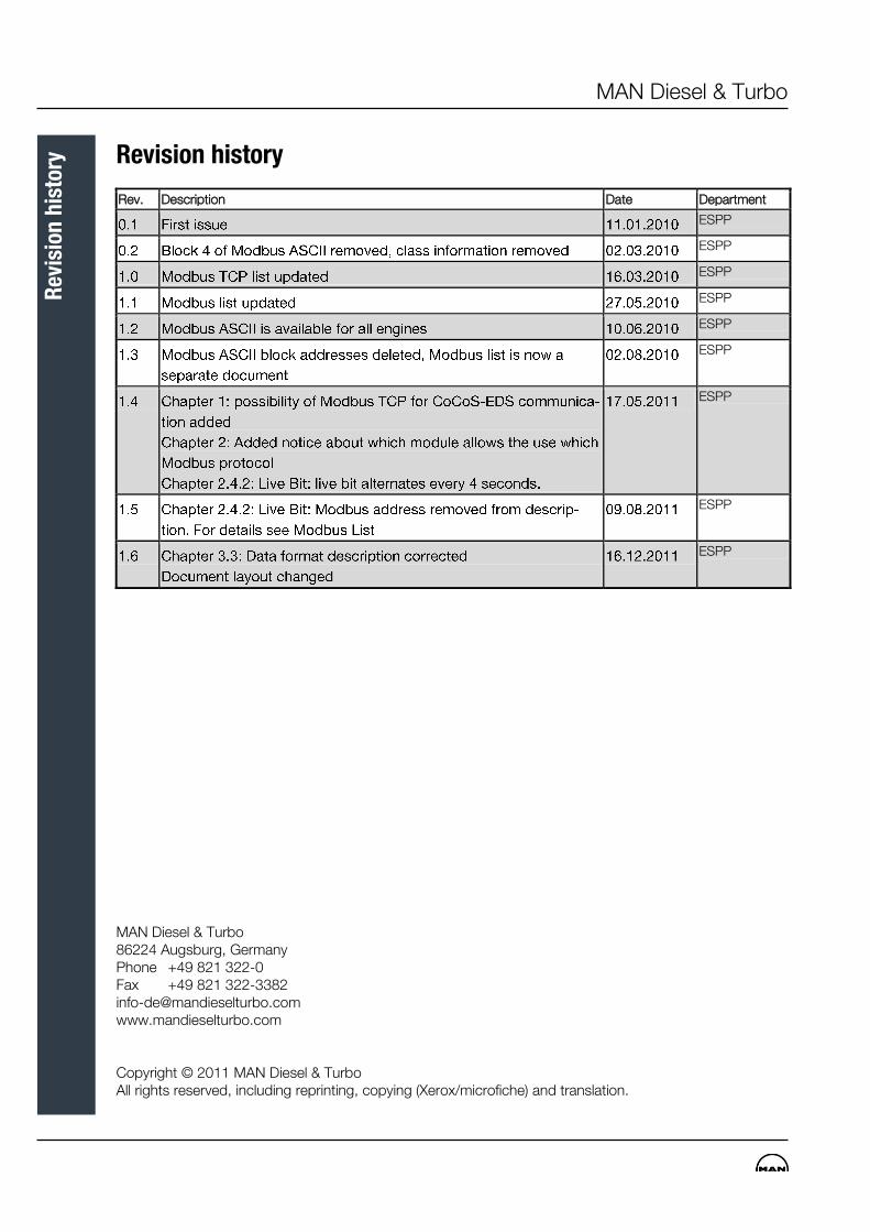
MAN Diesel & Turbo
R
evis
ion
his
tory
Revision history
Rev. Description Date Department
ESPP
ESPP
ESPP
ESPP
ESPP
ESPP
ESPP
ESPP
ESPP
MAN Diesel & Turbo 86224 Augsburg, Germany Phone +49 821 322-0 Fax +49 821 322-3382 [email protected] www.mandieselturbo.com Copyright © 2011 MAN Diesel & Turbo All rights reserved, including reprinting, copying (Xerox/microfiche) and translation.
MAN Diesel & Turbo
Tab
le o
f C
onte
nts
Table of Contents
1 Data Bus Interface (Machinery Alarm System) ................................................................ 1
2 Modbus RTU protocol ......................................................................................................... 2
2.1 Settings ..................................................................................................................................... 2
2.2 Function Codes ......................................................................................................................... 2
2.3 Message Frame Separation ....................................................................................................... 3
2.4 Provided Data ........................................................................................................................... 3
2.4.1 Contents of List of Signals ......................................................................................................... 3
2.4.2 Live Bit ...................................................................................................................................... 3
3 Modbus ASCII protocol ...................................................................................................... 4
3.1 General ..................................................................................................................................... 4
3.2 Protocol Description .................................................................................................................. 4
3.3 Data Format .............................................................................................................................. 6
4 Modbus list ......................................................................................................................... 8

MAN Diesel & Turbo
Ta
ble
of
Con
ten
ts
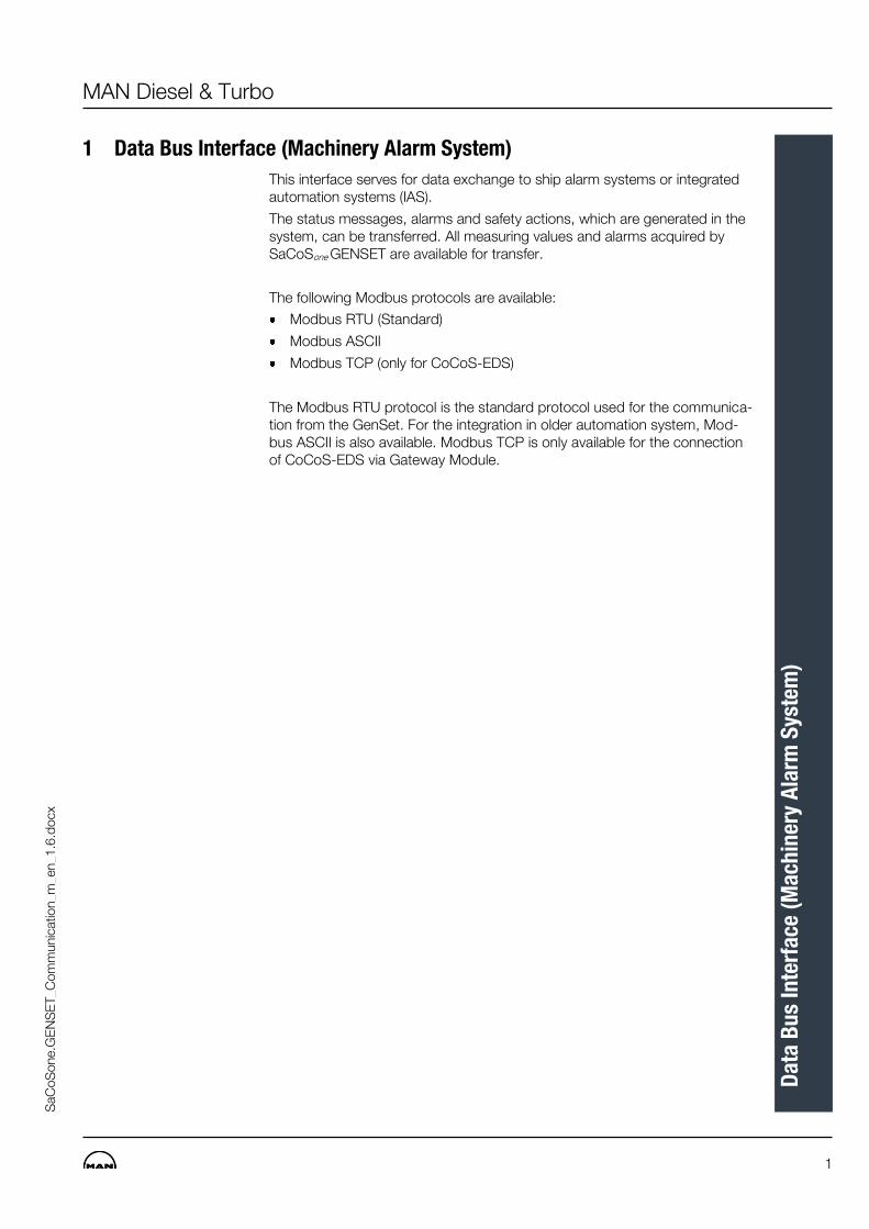
MAN Diesel & Turbo
1
Dat
a B
us
Inte
rfac
e (M
ach
iner
y A
larm
Sys
tem
)
SaC
oS
one.G
EN
SE
T_C
om
munic
atio
n_m
_en_1
.6.d
ocx
1 Data Bus Interface (Machinery Alarm System)
This interface serves for data exchange to ship alarm systems or integrated automation systems (IAS).
The status messages, alarms and safety actions, which are generated in the system, can be transferred. All measuring values and alarms acquired by SaCoSone GENSET are available for transfer.
The following Modbus protocols are available:
Modbus RTU (Standard)
Modbus ASCII
Modbus TCP (only for CoCoS-EDS)
The Modbus RTU protocol is the standard protocol used for the communica-tion from the GenSet. For the integration in older automation system, Mod-bus ASCII is also available. Modbus TCP is only available for the connection of CoCoS-EDS via Gateway Module.
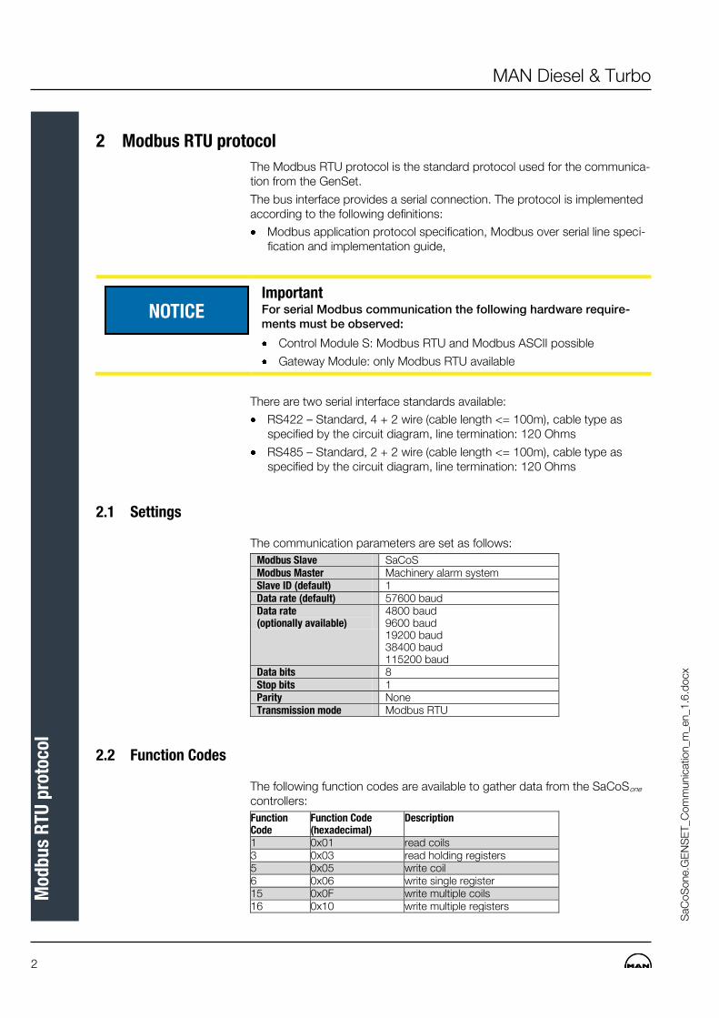
2
MAN Diesel & Turbo
Mod
bu
s R
TU p
roto
col
SaC
oS
one.G
EN
SE
T_C
om
munic
atio
n_m
_en_1
.6.d
ocx
2 Modbus RTU protocol
The Modbus RTU protocol is the standard protocol used for the communica-tion from the GenSet.
The bus interface provides a serial connection. The protocol is implemented according to the following definitions:
Modbus application protocol specification, Modbus over serial line speci-fication and implementation guide,
Important For serial Modbus communication the following hardware require-ments must be observed:
Control Module S: Modbus RTU and Modbus ASCII possible
Gateway Module: only Modbus RTU available
There are two serial interface standards available:
RS422 – Standard, 4 + 2 wire (cable length <= 100m), cable type as specified by the circuit diagram, line termination: 120 Ohms
RS485 – Standard, 2 + 2 wire (cable length <= 100m), cable type as specified by the circuit diagram, line termination: 120 Ohms
2.1 Settings
The communication parameters are set as follows:
Modbus Slave SaCoS Modbus Master Machinery alarm system Slave ID (default) 1 Data rate (default) 57600 baud Data rate (optionally available)
4800 baud 9600 baud 19200 baud 38400 baud 115200 baud
Data bits 8 Stop bits 1 Parity None Transmission mode Modbus RTU
2.2 Function Codes
The following function codes are available to gather data from the SaCoSone controllers:
Function Code
Function Code (hexadecimal)
Description
1 0x01 read coils 3 0x03 read holding registers 5 0x05 write coil 6 0x06 write single register 15 0x0F write multiple coils 16 0x10 write multiple registers
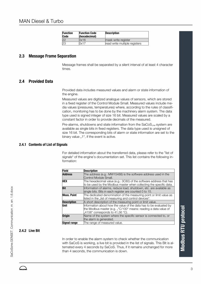
MAN Diesel & Turbo
3
Mod
bu
s R
TU p
roto
col
SaC
oS
one.G
EN
SE
T_C
om
munic
atio
n_m
_en_1
.6.d
ocx
Function Code
Function Code (hexadecimal)
Description
22 0x16 mask write register 23 0x17 read write multiple registers
2.3 Message Frame Separation
Message frames shall be separated by a silent interval of at least 4 character times.
2.4 Provided Data
Provided data includes measured values and alarm or state information of the engine.
Measured values are digitized analogue values of sensors, which are stored in a fixed register of the Control Module Small. Measured values include me-dia values (pressures, temperatures) where, according to the rules of classifi-cation, monitoring has to be done by the machinery alarm system. The data type used is signed integer of size 16 bit. Measured values are scaled by a constant factor in order to provide decimals of the measured.
Pre-alarms, shutdowns and state information from the SaCoSone system are available as single bits in fixed registers. The data type used is unsigned of size 16 bit. The corresponding bits of alarm or state information are set to the binary value „1“, if the event is active.
2.4.1 Contents of List of Signals
For detailed information about the transferred data, please refer to the ”list of signals“ of the engine’s documentation set. This list contains the following in-formation:
Field Description Address The address (e.g.: MW15488) is the software address used in the
Control Module Small. HEX The hexadecimal value (e.g.: 3C80) of the software address that has
to be used by the Modbus master when collecting the specific data. Bit Information of alarms, reduce load, shutdown, etc. are available as
single bits. Bits in each register are counted 0 to 15. Meas. Point The dedicated denomination of the measuring point or limit value as
listed in the „list of measuring and control devices“. Description A short description of the measuring point or limit value. Unit Information about how the value of the data has to be evaluated by
the Modbus master (e.g. „°C/100“ means: reading a data value of „4156“ corresponds to 41,56 °C).
Origin Name of the system where the specific sensor is connected to, or the alarm is generated.
Signal range The range of measured value.
2.4.2 Live Bit
In order to enable the alarm system to check whether the communication with SaCoS is working, a live bit is provided in the list of signals. This Bit is al-ternated every 4 seconds by SaCoS. Thus, if it remains unchanged for more than 4 seconds, the communication is down.
4
MAN Diesel & Turbo
Mod
bu
s A
SC
II p
roto
col
SaC
oS
one.G
EN
SE
T_C
om
munic
atio
n_m
_en_1
.6.d
ocx
3 Modbus ASCII protocol
3.1 General
The communication setup is: 9600 baud, 8 databits, 1 stopbit, no parity.
The Modbus protocol accepts one command (Function Code 03) for reading analogue and digital input values one at a time, or as a block of up to 32 in-puts.
The following chapter describes the commands in the Modbus protocol, which are implemented, and how they work.
3.2 Protocol Description
The ASCII and RTU version of the Modbus protocol is used, where the CMS/DM works as Modbus slave.
All data bytes will be converted to 2-ASCII characters (hex-values). Thus, when below is referred to “bytes“ or “words“, these will fill out 2 or 4 charac-ters, respectively in the protocol. The general “message frame format“ has the following outlook:
[:] [SLAVE] [FCT] [DATA] [CHECKSUM] [CR] [LF]
– [:] 1 char. Begin of frame
– [SLAVE] 2 char. Modbus slave address (Selected on DIP-switch at Display Module)
– [FCT] 2 char. Function code
– [DATA] n X 2 chars data.
– [CHECKSUM] 2 char checksum (LRC)
– [CR] 1 char CR
– [LF] 1 char LF (end of frame)
The following function codes (FCT) is accepted:
– 03H: Read n words at specific address.
– 10H: Write n words at specific address.
In response to the message frame, the slave (CMS) must answer with ap-propriate data. If this is not possible, a package with the most important bit in FCT set to 1 will be returned, followed by an exception code, where the following is supported:
– 01: Illegal function
– 02: Illegal data address
– 03: Illegal data value
– 06: BUSY. Message rejected

MAN Diesel & Turbo
5
Mod
bu
s A
SC
II p
roto
col
SaC
oS
one.G
EN
SE
T_C
om
munic
atio
n_m
_en_1
.6.d
ocx
The master transmits an inquiry to the slave (CMS) to read a number (n) of datawords from a given address. The slave (CMS) replies with the required number (n) of datawords. To read a single register (n) must be set to 1. To read block type register (n)
must be in the range 1...32.
Request (master):
[DATA] = [ADR][n]
[ADR]=Word stating the address in HEX.
[n]=Word stating the number of words to be read.
Answer (slave-CMS):
[DATA] = [bb][1. word][2. word]....[n. word]
[bb]=Byte, stating number of subsequent bytes.
[1. word]=1. dataword
[2. word]=2. dataword
[n. word]=No n. dataword
The master sends data to the slave (CMS/DM) starting from a particular ad-dress. The slave (CMS/DM) returns the written number of bytes, plus echoes the address.
Write data (master):
[DATA] = [ADR][n] [bb][1. word][2. word]....[n word]
[ADR] = Word that gives the address in HEX.
[n] = Word indicating number of words to be written.
[bb] = Byte that gives the number of bytes to follow (2*n)
Please note that 8bb9 is byte size!
[1. word]=1. dataword
[2. word]=2. dataword
[n. word]=No n. dataword
Answer (slave-CMS/DM):
[DATA] = [ADR][bb*2]
[ADR]= Word HEX that gives the address in HEX
[bb*2]=Number of words written.
[1. word]=1. dataword
[2. word]=2. dataword
[n. word]=No n. dataword
FCT = 03H: Read n words
FCT = 10H: Write n words
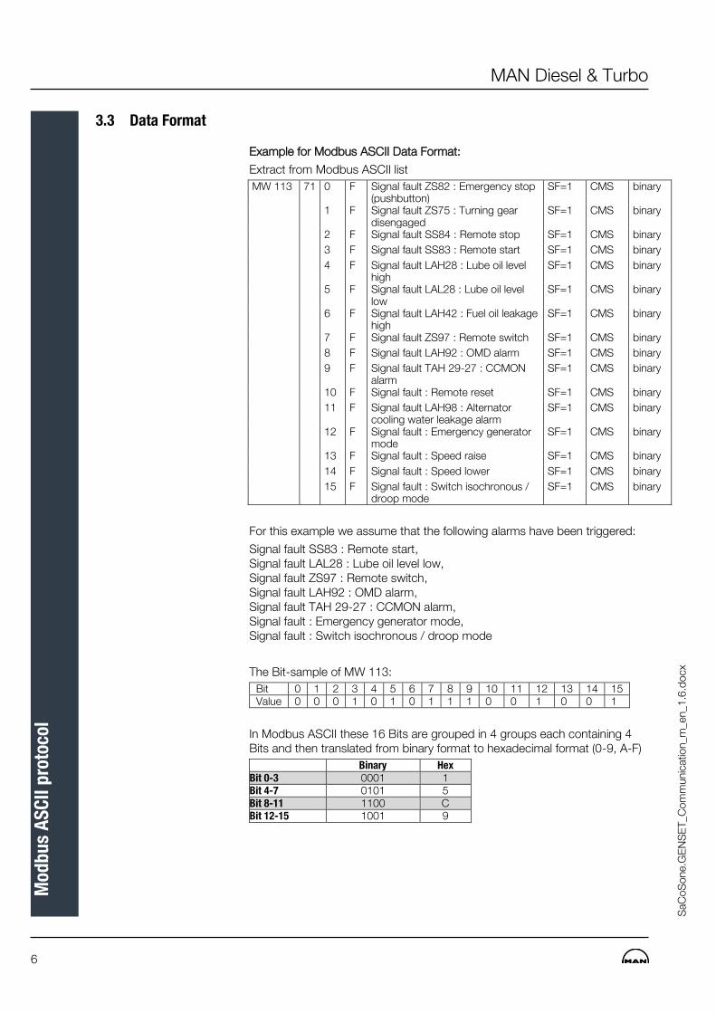
6
MAN Diesel & Turbo
Mod
bu
s A
SC
II p
roto
col
SaC
oS
one.G
EN
SE
T_C
om
munic
atio
n_m
_en_1
.6.d
ocx
3.3 Data Format
Example for Modbus ASCII Data Format:
Extract from Modbus ASCII list
MW 113 71 0 F Signal fault ZS82 : Emergency stop (pushbutton)
SF=1 CMS binary
1 F Signal fault ZS75 : Turning gear disengaged
SF=1 CMS binary
2 F Signal fault SS84 : Remote stop SF=1 CMS binary
3 F Signal fault SS83 : Remote start SF=1 CMS binary
4 F Signal fault LAH28 : Lube oil level high
SF=1 CMS binary
5 F Signal fault LAL28 : Lube oil level low
SF=1 CMS binary
6 F Signal fault LAH42 : Fuel oil leakage high
SF=1 CMS binary
7 F Signal fault ZS97 : Remote switch SF=1 CMS binary
8 F Signal fault LAH92 : OMD alarm SF=1 CMS binary
9 F Signal fault TAH 29-27 : CCMON alarm
SF=1 CMS binary
10 F Signal fault : Remote reset SF=1 CMS binary
11 F Signal fault LAH98 : Alternator cooling water leakage alarm
SF=1 CMS binary
12 F Signal fault : Emergency generator mode
SF=1 CMS binary
13 F Signal fault : Speed raise SF=1 CMS binary
14 F Signal fault : Speed lower SF=1 CMS binary
15 F Signal fault : Switch isochronous / droop mode
SF=1 CMS binary
For this example we assume that the following alarms have been triggered:
Signal fault SS83 : Remote start, Signal fault LAL28 : Lube oil level low, Signal fault ZS97 : Remote switch, Signal fault LAH92 : OMD alarm, Signal fault TAH 29-27 : CCMON alarm, Signal fault : Emergency generator mode, Signal fault : Switch isochronous / droop mode
The Bit-sample of MW 113:
Bit 0 1 2 3 4 5 6 7 8 9 10 11 12 13 14 15 Value 0 0 0 1 0 1 0 1 1 1 0 0 1 0 0 1
In Modbus ASCII these 16 Bits are grouped in 4 groups each containing 4 Bits and then translated from binary format to hexadecimal format (0-9, A-F)
Binary Hex Bit 0-3 0001 1 Bit 4-7 0101 5 Bit 8-11 1100 C Bit 12-15 1001 9
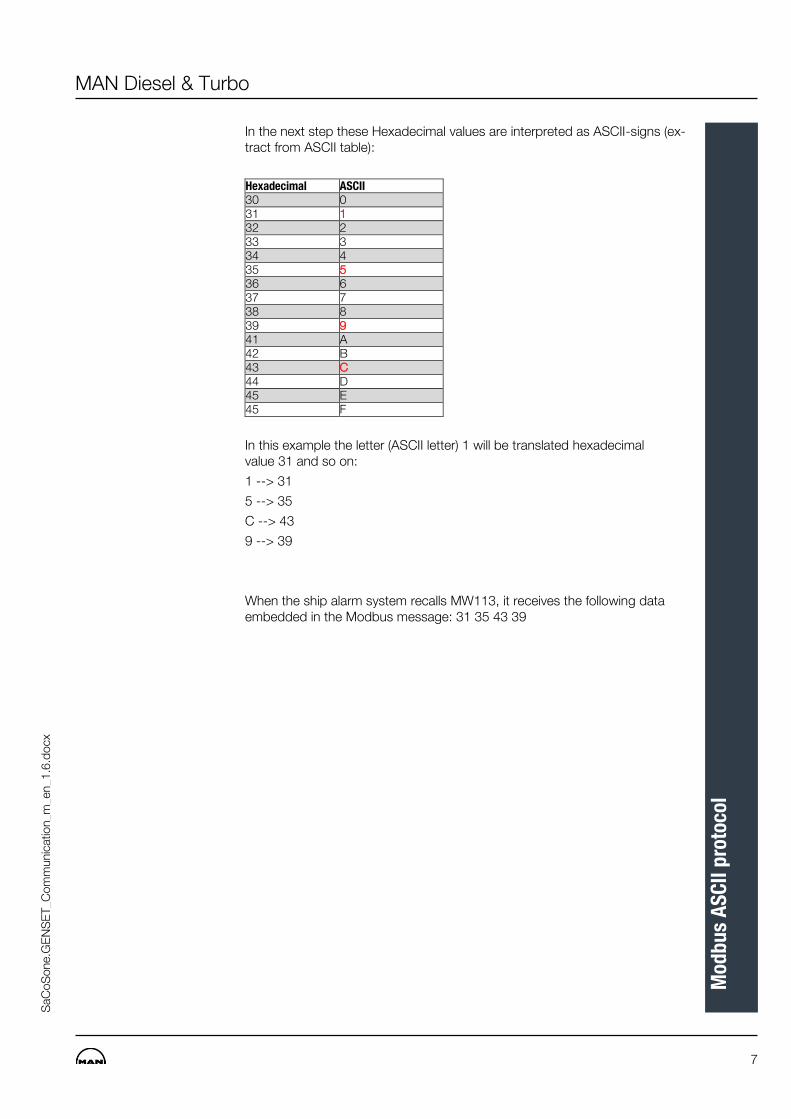
MAN Diesel & Turbo
7
Mod
bu
s A
SC
II p
roto
col
SaC
oS
one.G
EN
SE
T_C
om
munic
atio
n_m
_en_1
.6.d
ocx
In the next step these Hexadecimal values are interpreted as ASCII-signs (ex-tract from ASCII table):
Hexadecimal ASCII 30 0 31 1 32 2 33 3 34 4 35 5 36 6 37 7 38 8 39 9 41 A 42 B 43 C 44 D 45 E 45 F
In this example the letter (ASCII letter) 1 will be translated hexadecimal value 31 and so on:
1 --> 31
5 --> 35
C --> 43
9 --> 39
When the ship alarm system recalls MW113, it receives the following data embedded in the Modbus message: 31 35 43 39

8
MAN Diesel & Turbo
Mod
bu
s lis
t
SaC
oS
one.G
EN
SE
T_C
om
munic
atio
n_m
_en_1
.6.d
ocx
4 Modbus list
The Modbus list is valid for Modbus ASCII and Modbus RTU. The list can be found in the document “SaCoS-one.GENSET_SignListMan_MP_EN_xx.xx.pdf” where “xx.xx” means the ac-tual revision.
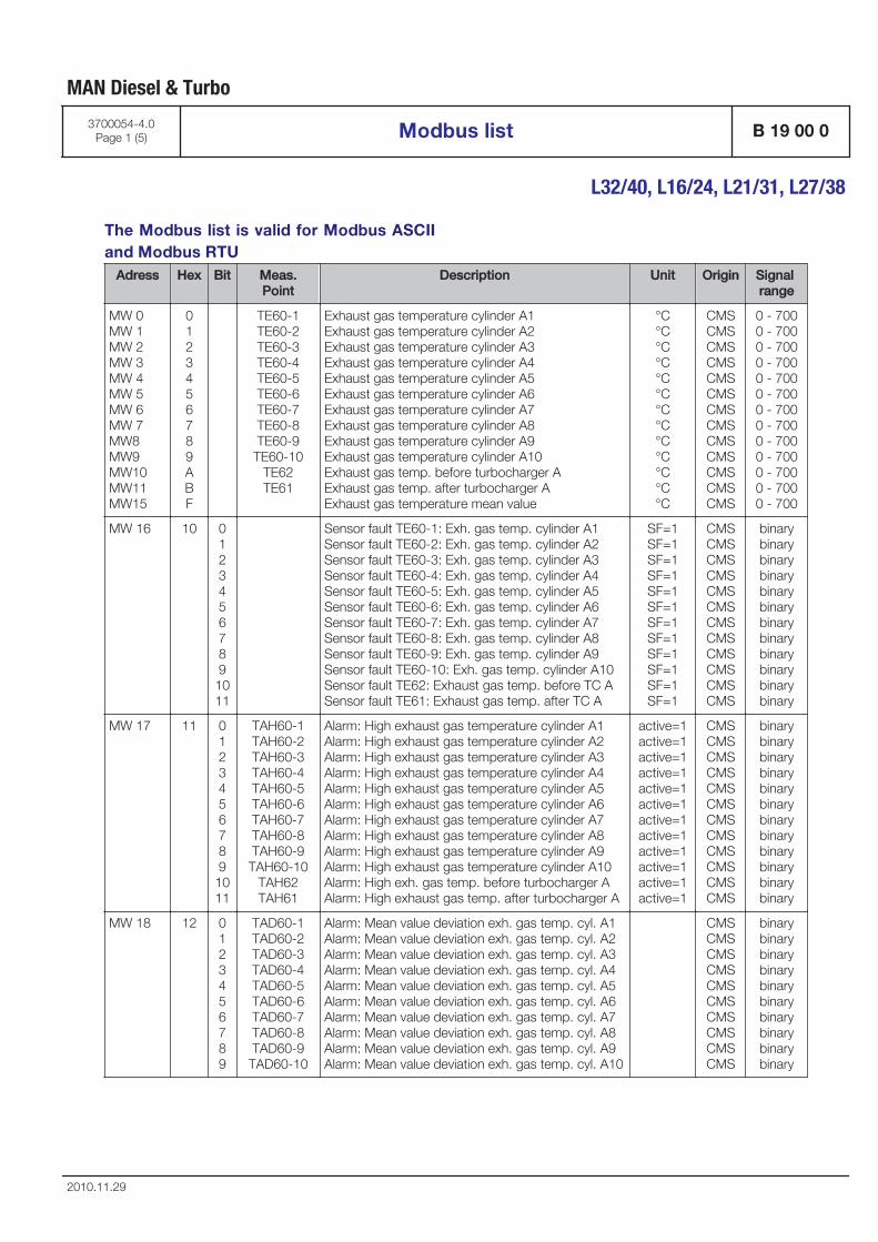
The Modbus list is valid for Modbus ASCIIand Modbus RTU
Adress Hex Bit Meas.Point
Description Unit Origin Signal range
MW 0MW 1MW 2MW 3MW 4MW 5MW 6MW 7MW8MW9MW10MW11MW15
0123456789ABF
TE60-1TE60-2TE60-3TE60-4TE60-5TE60-6TE60-7TE60-8TE60-9TE60-10
TE62TE61
Exhaust gas temperature cylinder A1Exhaust gas temperature cylinder A2Exhaust gas temperature cylinder A3Exhaust gas temperature cylinder A4Exhaust gas temperature cylinder A5Exhaust gas temperature cylinder A6Exhaust gas temperature cylinder A7Exhaust gas temperature cylinder A8Exhaust gas temperature cylinder A9Exhaust gas temperature cylinder A10Exhaust gas temp. before turbocharger AExhaust gas temp. after turbocharger AExhaust gas temperature mean value
°C°C°C°C°C°C°C°C°C°C°C°C°C
CMSCMSCMSCMSCMSCMSCMSCMSCMSCMSCMSCMSCMS
0 - 7000 - 7000 - 7000 - 7000 - 7000 - 7000 - 7000 - 7000 - 7000 - 7000 - 7000 - 7000 - 700
MW 16 10 01234567891011
Sensor fault TE60-1: Exh. gas temp. cylinder A1Sensor fault TE60-2: Exh. gas temp. cylinder A2Sensor fault TE60-3: Exh. gas temp. cylinder A3Sensor fault TE60-4: Exh. gas temp. cylinder A4Sensor fault TE60-5: Exh. gas temp. cylinder A5Sensor fault TE60-6: Exh. gas temp. cylinder A6Sensor fault TE60-7: Exh. gas temp. cylinder A7Sensor fault TE60-8: Exh. gas temp. cylinder A8Sensor fault TE60-9: Exh. gas temp. cylinder A9Sensor fault TE60-10: Exh. gas temp. cylinder A10Sensor fault TE62: Exhaust gas temp. before TC ASensor fault TE61: Exhaust gas temp. after TC A
SF=1SF=1SF=1SF=1SF=1SF=1SF=1SF=1SF=1SF=1SF=1SF=1
CMSCMSCMSCMSCMSCMSCMSCMSCMSCMSCMSCMS
binarybinarybinarybinarybinarybinarybinarybinarybinarybinarybinarybinary
MW 17 11 01234567891011
TAH60-1TAH60-2TAH60-3TAH60-4TAH60-5TAH60-6TAH60-7TAH60-8TAH60-9TAH60-10
TAH62TAH61
Alarm: High exhaust gas temperature cylinder A1Alarm: High exhaust gas temperature cylinder A2Alarm: High exhaust gas temperature cylinder A3Alarm: High exhaust gas temperature cylinder A4Alarm: High exhaust gas temperature cylinder A5Alarm: High exhaust gas temperature cylinder A6Alarm: High exhaust gas temperature cylinder A7Alarm: High exhaust gas temperature cylinder A8Alarm: High exhaust gas temperature cylinder A9Alarm: High exhaust gas temperature cylinder A10Alarm: High exh. gas temp. before turbocharger AAlarm: High exhaust gas temp. after turbocharger A
active=1active=1active=1active=1active=1active=1active=1active=1active=1active=1active=1active=1
CMSCMSCMSCMSCMSCMSCMSCMSCMSCMSCMSCMS
binarybinarybinarybinarybinarybinarybinarybinarybinarybinarybinarybinary
MW 18 12 0123456789
TAD60-1TAD60-2TAD60-3TAD60-4TAD60-5TAD60-6TAD60-7TAD60-8TAD60-9TAD60-10
Alarm: Mean value deviation exh. gas temp. cyl. A1Alarm: Mean value deviation exh. gas temp. cyl. A2Alarm: Mean value deviation exh. gas temp. cyl. A3Alarm: Mean value deviation exh. gas temp. cyl. A4Alarm: Mean value deviation exh. gas temp. cyl. A5Alarm: Mean value deviation exh. gas temp. cyl. A6Alarm: Mean value deviation exh. gas temp. cyl. A7Alarm: Mean value deviation exh. gas temp. cyl. A8Alarm: Mean value deviation exh. gas temp. cyl. A9Alarm: Mean value deviation exh. gas temp. cyl. A10
CMSCMSCMSCMSCMSCMSCMSCMSCMSCMS
binarybinarybinarybinarybinarybinarybinarybinarybinarybinary
MAN Diesel & Turbo
3700054-4.0Page 1 (5) Modbus list B 19 00 0
L32/40, L16/24, L21/31, L27/38
2010.11.29
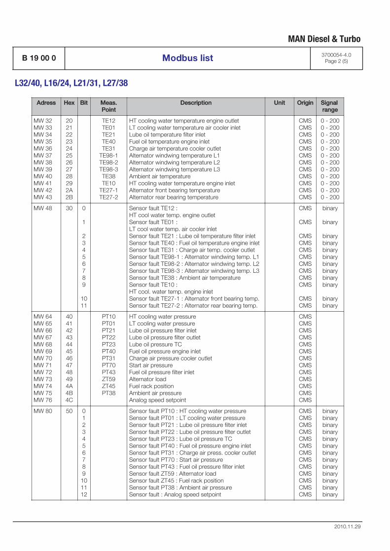
Adress Hex Bit Meas.Point
Description Unit Origin Signal range
MW 32MW 33MW 34MW 35MW 36MW 37MW 38MW 39MW 40MW 41MW 42MW 43
202122232425262728292A2B
TE12TE01TE21TE40TE31
TE98-1TE98-2TE98-3TE38TE10
TE27-1TE27-2
HT cooling water temperature engine outletLT cooling water temperature air cooler inletLube oil temperature filter inletFuel oil temperature engine inletCharge air temperature cooler outletAlternator windwing temperature L1Alternator windwing temperature L2Alternator windwing temperature L3Ambient air temperatureHT cooling water temperature engine inletAlternator front bearing temperatureAlternator rear bearing temperature
CMSCMSCMSCMSCMSCMSCMSCMSCMSCMSCMSCMS
0 - 2000 - 2000 - 2000 - 2000 - 2000 - 2000 - 2000 - 2000 - 2000 - 2000 - 2000 - 200
MW 48 30 0
1
23456789
1011
Sensor fault TE12 : HT cool water temp. engine outletSensor fault TE01 : LT cool water temp. air cooler inletSensor fault TE21 : Lube oil temperature filter inletSensor fault TE40 : Fuel oil temperature engine inletSensor fault TE31 : Charge air temp. cooler outletSensor fault TE98-1 : Alternator windwing temp. L1Sensor fault TE98-2 : Alternator windwing temp. L2Sensor fault TE98-3 : Alternator windwing temp. L3Sensor fault TE38 : Ambient air temperatureSensor fault TE10 : HT cool. water temp. engine inletSensor fault TE27-1 : Alternator front bearing temp.Sensor fault TE27-2 : Alternator rear bearing temp.
CMS
CMS
CMSCMSCMSCMSCMSCMSCMSCMS
CMSCMS
binary
binary
binarybinarybinarybinarybinarybinarybinarybinary
binarybinary
MW 64MW 65MW 66MW 67MW 68MW 69MW 70MW 71MW 72MW 73MW 74MW 75MW 76
404142434445464748494A4B4C
PT10PT01PT21PT22PT23PT40PT31PT70PT43ZT59ZT45PT38
HT cooling water pressure LT cooling water pressure Lube oil pressure filter inlet Lube oil pressure filter outlet Lube oil pressure TC Fuel oil pressure engine inlet Charge air pressure cooler outlet Start air pressure Fuel oil pressure filter inlet Alternator load Fuel rack position Ambient air pressure Analog speed setpoint
CMSCMSCMSCMSCMSCMSCMSCMSCMSCMSCMSCMSCMS
MW 80 50 0123456789101112
Sensor fault PT10 : HT cooling water pressure Sensor fault PT01 : LT cooling water pressure Sensor fault PT21 : Lube oil pressure filter inlet Sensor fault PT22 : Lube oil pressure filter outlet Sensor fault PT23 : Lube oil pressure TC Sensor fault PT40 : Fuel oil pressure engine inlet Sensor fault PT31 : Charge air press. cooler outlet Sensor fault PT70 : Start air pressure Sensor fault PT43 : Fuel oil pressure filter inlet Sensor fault ZT59 : Alternator load Sensor fault ZT45 : Fuel rack position Sensor fault PT38 : Ambient air pressure Sensor fault : Analog speed setpoint
CMSCMSCMSCMSCMSCMSCMSCMSCMSCMSCMSCMSCMS
binarybinarybinarybinarybinarybinarybinarybinarybinarybinarybinarybinarybinary
MAN Diesel & Turbo
B 19 00 0 Modbus list 3700054-4.0Page 2 (5)
L32/40, L16/24, L21/31, L27/38
2010.11.29
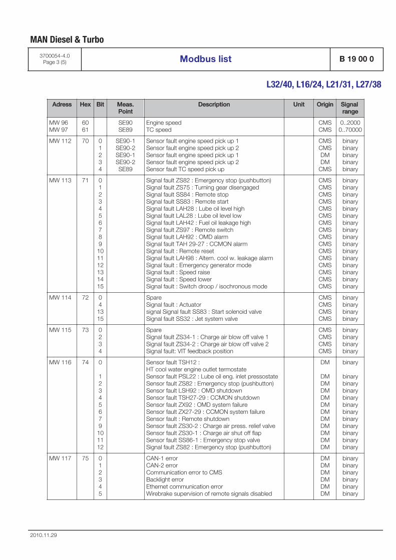
Adress Hex Bit Meas.Point
Description Unit Origin Signal range
MW 96MW 97
6061
SE90SE89
Engine speedTC speed
CMSCMS
0..20000..70000
MW 112 70 01234
SE90-1SE90-2SE90-1SE90-2SE89
Sensor fault engine speed pick up 1 Sensor fault engine speed pick up 2 Sensor fault engine speed pick up 1 Sensor fault engine speed pick up 2 Sensor fault TC speed pick up
CMSCMSDMDM
CMS
binarybinarybinarybinarybinary
MW 113 71 0123456789101112131415
Signal fault ZS82 : Emergency stop (pushbutton) Signal fault ZS75 : Turning gear disengaged Signal fault SS84 : Remote stop Signal fault SS83 : Remote start Signal fault LAH28 : Lube oil level high Signal fault LAL28 : Lube oil level low Signal fault LAH42 : Fuel oil leakage high Signal fault ZS97 : Remote switch Signal fault LAH92 : OMD alarm Signal fault TAH 29-27 : CCMON alarm Signal fault : Remote reset Signal fault LAH98 : Altern. cool w. leakage alarm Signal fault : Emergency generator mode Signal fault : Speed raise Signal fault : Speed lower Signal fault : Switch droop / isochronous mode
CMSCMSCMSCMSCMSCMSCMSCMSCMSCMSCMSCMSCMSCMSCMSCMS
binarybinarybinarybinarybinarybinarybinarybinarybinarybinarybinarybinarybinarybinarybinarybinary
MW 114 72 041315
Spare Signal fault : Actuator signal Signal fault SS83 : Start solenoid valve Signal fault SS32 : Jet system valve
CMSCMSCMSCMS
binarybinarybinarybinary
MW 115 73 0234
Spare Signal fault ZS34-1 : Charge air blow off valve 1 Signal fault ZS34-2 : Charge air blow off valve 2 Signal fault: VIT feedback position
CMSCMSCMSCMS
binarybinarybinarybinary
MW 116 74 0
12345679101112
Sensor fault TSH12 : HT cool water engine outlet termostate Sensor fault PSL22 : Lube oil eng. inlet pressostate Sensor fault ZS82 : Emergency stop (pushbutton) Sensor fault LSH92 : OMD shutdown Sensor fault TSH27-29 : CCMON shutdown Sensor fault ZX92 : OMD system failure Sensor fault ZX27-29 : CCMON system failure Sensor fault : Remote shutdown Sensor fault ZS30-2 : Charge air press. relief valve Sensor fault ZS30-1 : Charge air shut off flap Sensor fault SS86-1 : Emergency stop valve Signal fault ZS82 : Emergency stop (pushbutton)
DM
DMDMDMDMDMDMDMDMDMDMDM
binary
binarybinarybinarybinarybinarybinarybinarybinarybinarybinarybinary
MW 117 75 012345
CAN-1 error CAN-2 error Communication error to CMS Backlight error Ethernet communication error Wirebrake supervision of remote signals disabled
DMDMDMDMDMDM
binarybinarybinarybinarybinarybinary
MAN Diesel & Turbo
3700054-4.0Page 3 (5) Modbus list B 19 00 0
L32/40, L16/24, L21/31, L27/38
2010.11.29
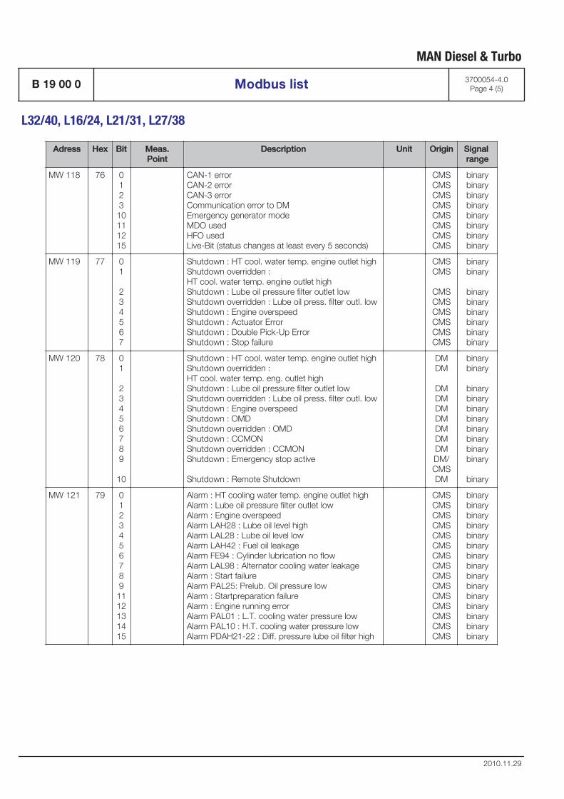
Adress Hex Bit Meas.Point
Description Unit Origin Signal range
MW 118 76 012310111215
CAN-1 error CAN-2 error CAN-3 error Communication error to DM Emergency generator mode MDO used HFO used Live-Bit (status changes at least every 5 seconds)
CMSCMSCMSCMSCMSCMSCMSCMS
binarybinarybinarybinarybinarybinarybinarybinary
MW 119 77 01
234567
Shutdown : HT cool. water temp. engine outlet high Shutdown overridden : HT cool. water temp. engine outlet high Shutdown : Lube oil pressure filter outlet low Shutdown overridden : Lube oil press. filter outl. low Shutdown : Engine overspeed Shutdown : Actuator Error Shutdown : Double Pick-Up Error Shutdown : Stop failure
CMSCMS
CMSCMSCMSCMSCMSCMS
binarybinary
binarybinarybinarybinarybinarybinary
MW 120 78 01
23456789
10
Shutdown : HT cool. water temp. engine outlet high Shutdown overridden : HT cool. water temp. eng. outlet high Shutdown : Lube oil pressure filter outlet low Shutdown overridden : Lube oil press. filter outl. low Shutdown : Engine overspeed Shutdown : OMD Shutdown overridden : OMD Shutdown : CCMON Shutdown overridden : CCMON Shutdown : Emergency stop active
Shutdown : Remote Shutdown
DMDM
DMDMDMDMDMDMDMDM/CMSDM
binarybinary
binarybinarybinarybinarybinarybinarybinarybinary
binary
MW 121 79 01234567891112131415
Alarm : HT cooling water temp. engine outlet high Alarm : Lube oil pressure filter outlet low Alarm : Engine overspeed Alarm LAH28 : Lube oil level high Alarm LAL28 : Lube oil level low Alarm LAH42 : Fuel oil leakage Alarm FE94 : Cylinder lubrication no flow Alarm LAL98 : Alternator cooling water leakage Alarm : Start failure Alarm PAL25: Prelub. Oil pressure low Alarm : Startpreparation failure Alarm : Engine running error Alarm PAL01 : L.T. cooling water pressure low Alarm PAL10 : H.T. cooling water pressure low Alarm PDAH21-22 : Diff. pressure lube oil filter high
CMSCMSCMSCMSCMSCMSCMSCMSCMSCMSCMSCMSCMSCMSCMS
binarybinarybinarybinarybinarybinarybinarybinarybinarybinarybinarybinarybinarybinarybinary
MAN Diesel & Turbo
B 19 00 0 Modbus list 3700054-4.0Page 4 (5)
L32/40, L16/24, L21/31, L27/38
2010.11.29
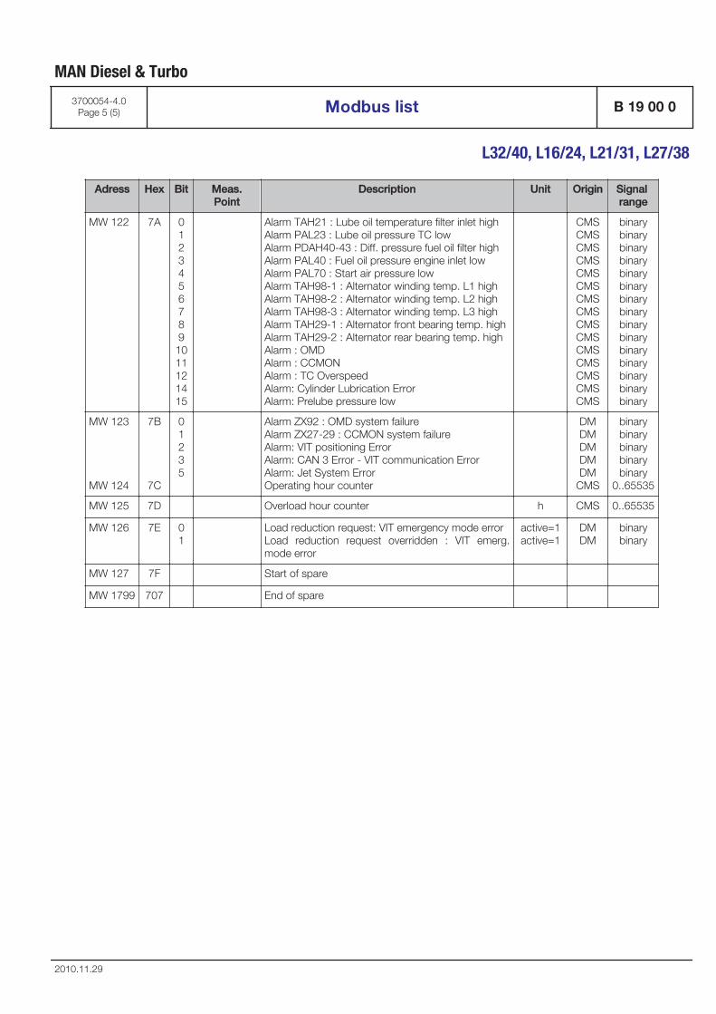
Adress Hex Bit Meas.Point
Description Unit Origin Signal range
MW 122 7A 01234567891011121415
Alarm TAH21 : Lube oil temperature filter inlet high Alarm PAL23 : Lube oil pressure TC low Alarm PDAH40-43 : Diff. pressure fuel oil filter high Alarm PAL40 : Fuel oil pressure engine inlet low Alarm PAL70 : Start air pressure low Alarm TAH98-1 : Alternator winding temp. L1 high Alarm TAH98-2 : Alternator winding temp. L2 high Alarm TAH98-3 : Alternator winding temp. L3 high Alarm TAH29-1 : Alternator front bearing temp. high Alarm TAH29-2 : Alternator rear bearing temp. high Alarm : OMD Alarm : CCMON Alarm : TC Overspeed Alarm: Cylinder Lubrication Error Alarm: Prelube pressure low
CMSCMSCMSCMSCMSCMSCMSCMSCMSCMSCMSCMSCMSCMSCMS
binarybinarybinarybinarybinarybinarybinarybinarybinarybinarybinarybinarybinarybinarybinary
MW 123
MW 124
7B
7C
01235
Alarm ZX92 : OMD system failure Alarm ZX27-29 : CCMON system failure Alarm: VIT positioning Error Alarm: CAN 3 Error - VIT communication Error Alarm: Jet System Error Operating hour counter
DMDMDMDMDM
CMS
binarybinarybinarybinarybinary
0..65535
MW 125 7D Overload hour counter h CMS 0..65535
MW 126 7E 01
Load reduction request: VIT emergency mode error Load reduction request overridden : VIT emerg.mode error
active=1active=1
DMDM
binarybinary
MW 127 7F Start of spare
MW 1799 707 End of spare
MAN Diesel & Turbo
3700054-4.0Page 5 (5) Modbus list B 19 00 0
L32/40, L16/24, L21/31, L27/38
2010.11.29

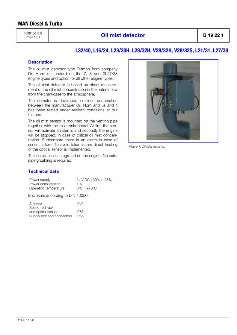
Description
The oil mist detector type Tufmon from companyDr. Horn is standard on the 7, 8 and 9L27/38engine types and option for all other engine types.
The oil mist detector is based on direct measure-ment of the oil mist concentration in the natural flowfrom the crankcase to the atmosphere.
The detector is developed in close cooperationbetween the manufacturer Dr. Horn and us and ithas been tested under realistic conditions at ourtestbed.
The oil mist sensor is mounted on the venting pipetogether with the electronic board. At first the sen-sor will activate an alarm, and secondly the enginewill be stopped, in case of critical oil mist concen-tration. Furthermore there is an alarm in case ofsensor failure. To avoid false alarms direct heatingof the optical sensor is implemented.
The installation is integrated on the engine. No extrapiping/cabling is required.
Technical data
Power supplyPower consumptionOperating temperature
: 24 V DC +30% / -25%: 1 A: 0°C....+70°C
Enclosure according to DIN 40050:
AnalyzerSpeed fuel rackand optical sensorsSupply box and connectors
: IP54
: IP67: IP65
Figure 1: Oil mist detector.
MAN Diesel & Turbo
1699190-5.0Page 1 (1) Oil mist detector B 19 22 1
L32/40, L16/24, L23/30H, L28/32H, V28/32H, V28/32S, L21/31, L27/38
2006.11.20

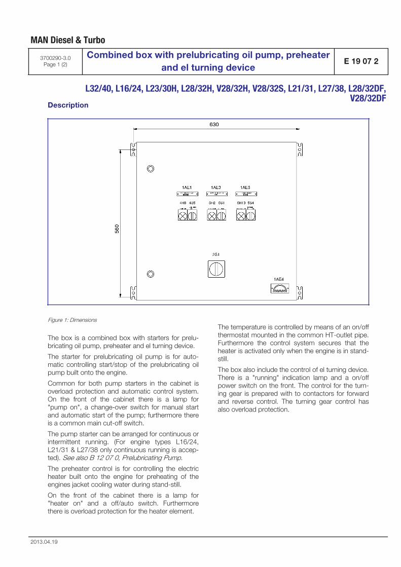
Description
Figure 1: Dimensions
The box is a combined box with starters for prelu-bricating oil pump, preheater and el turning device.
The starter for prelubricating oil pump is for auto-matic controlling start/stop of the prelubricating oilpump built onto the engine.
Common for both pump starters in the cabinet isoverload protection and automatic control system.On the front of the cabinet there is a lamp for"pump on", a change-over switch for manual startand automatic start of the pump; furthermore thereis a common main cut-off switch.
The pump starter can be arranged for continuous orintermittent running. (For engine types L16/24,L21/31 & L27/38 only continuous running is accep-ted). See also B 12 07 0, Prelubricating Pump.
The preheater control is for controlling the electricheater built onto the engine for preheating of theengines jacket cooling water during stand-still.
On the front of the cabinet there is a lamp for"heater on" and a off/auto switch. Furthermorethere is overload protection for the heater element.
The temperature is controlled by means of an on/offthermostat mounted in the common HT-outlet pipe.Furthermore the control system secures that theheater is activated only when the engine is in stand-still.
The box also include the control of el turning device.There is a "running" indication lamp and a on/offpower switch on the front. The control for the turn-ing gear is prepared with to contactors for forwardand reverse control. The turning gear control hasalso overload protection.
MAN Diesel & Turbo
3700290-3.0Page 1 (2)
Combined box with prelubricating oil pump, preheaterand el turning device
E 19 07 2
L32/40, L16/24, L23/30H, L28/32H, V28/32H, V28/32S, L21/31, L27/38, L28/32DF,
V28/32DF
2013.04.19

Figure 2: Wiring diagram
MAN Diesel & Turbo
E 19 07 2Combined box with prelubricating oil pump, preheater
and el turning device3700290-3.0
Page 2 (2)
L32/40, L16/24, L23/30H, L28/32H, V28/32H, V28/32S, L21/31, L27/38, L28/32DF,V28/32DF
2013.04.19
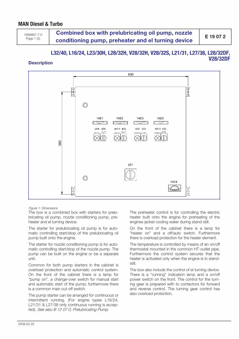
Description
Figure 1: DimensionsThe box is a combined box with starters for prelu-bricating oil pump, nozzle conditioning pump, pre-heater and el turning device.
The starter for prelubricating oil pump is for auto-matic controlling start/stop of the prelubricating oilpump built onto the engine.
The starter for nozzle conditioning pump is for auto-matic controlling start/stop of the nozzle pump. Thepump can be built on the engine or be a separateunit.
Common for both pump starters in the cabinet isoverload protection and automatic control system.On the front of the cabinet there is a lamp for"pump on", a change-over switch for manual startand automatic start of the pump; furthermore thereis a common main cut-off switch.
The pump starter can be arranged for continuous orintermittent running. (For engine types L16/24,L21/31 & L27/38 only continuous running is accep-ted). See also B 12 07 0, Prelubricating Pump.
The preheater control is for controlling the electricheater built onto the engine for preheating of theengines jacket cooling water during stand-still.
On the front of the cabinet there is a lamp for"heater on" and a off/auto switch. Furthermorethere is overload protection for the heater element.
The temperature is controlled by means of an on/offthermostat mounted in the common HT-outlet pipe.Furthermore the control system secures that theheater is activated only when the engine is in stand-still.
The box also include the control of el turning device.There is a "running" indication lamp and a on/offpower switch on the front. The control for the turn-ing gear is prepared with to contactors for forwardand reverse control. The turning gear control hasalso overload protection.
MAN Diesel & Turbo
1699867-7.0Page 1 (2)
Combined box with prelubricating oil pump, nozzleconditioning pump, preheater and el turning device
E 19 07 2
L32/40, L16/24, L23/30H, L28/32H, V28/32H, V28/32S, L21/31, L27/38, L28/32DF,
V28/32DF
2008.02.25
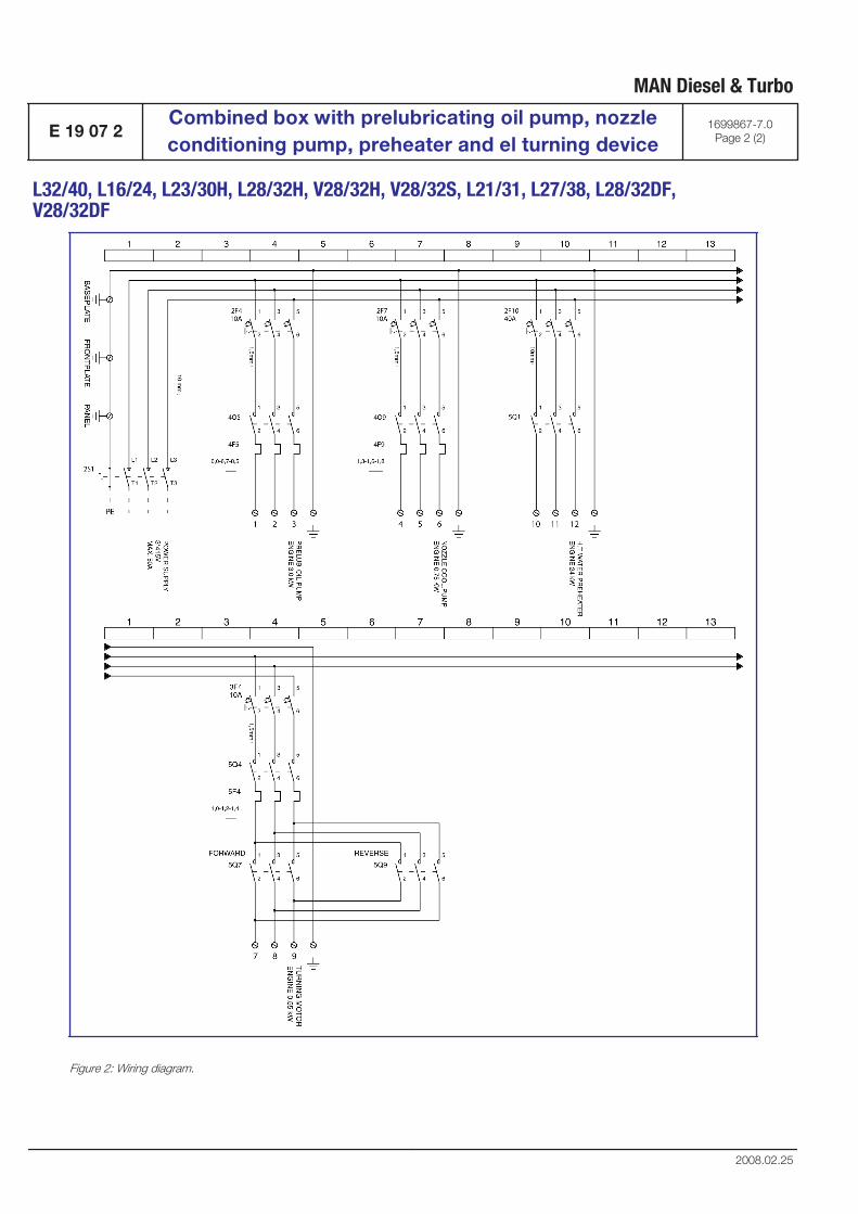
Figure 2: Wiring diagram.
MAN Diesel & Turbo
E 19 07 2Combined box with prelubricating oil pump, nozzleconditioning pump, preheater and el turning device
1699867-7.0Page 2 (2)
L32/40, L16/24, L23/30H, L28/32H, V28/32H, V28/32S, L21/31, L27/38, L28/32DF,V28/32DF
2008.02.25
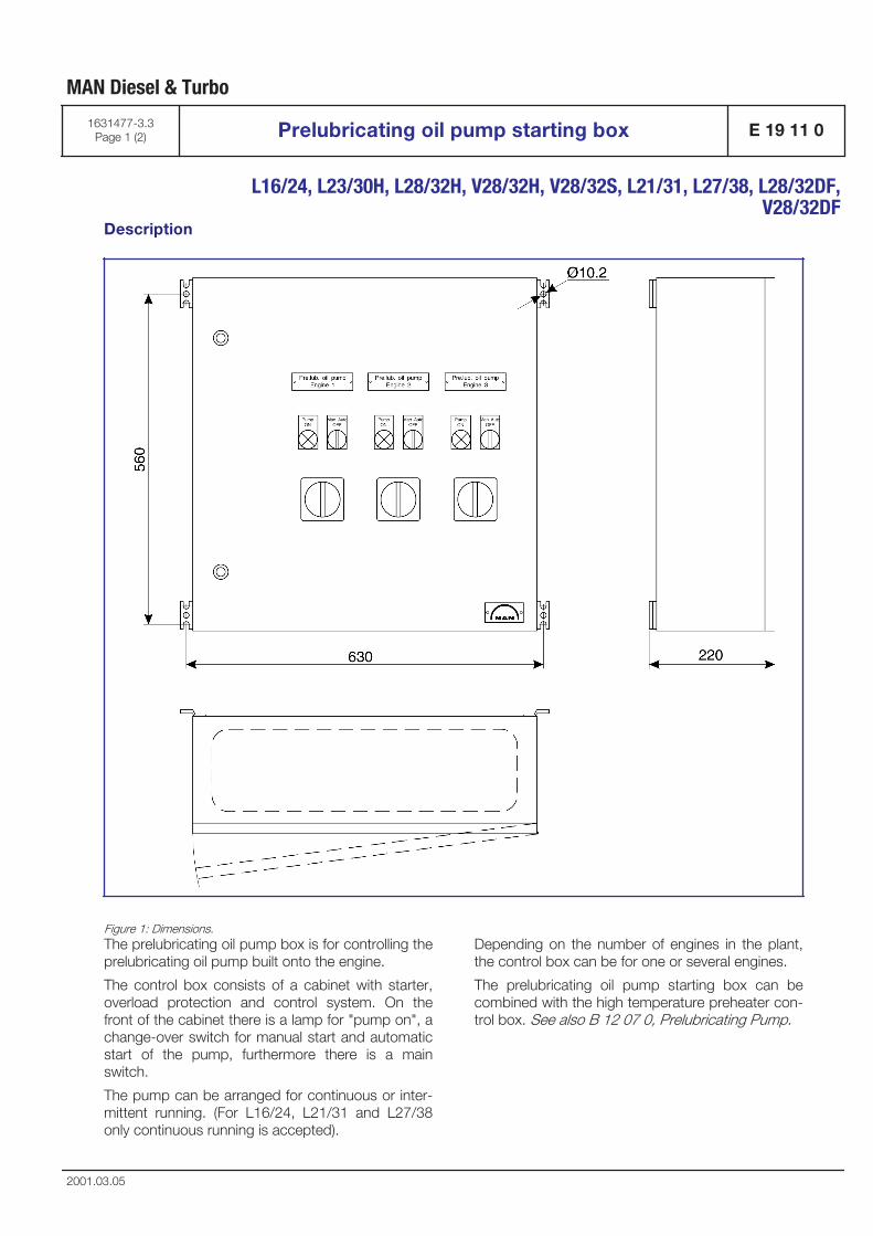
Description
Figure 1: Dimensions.The prelubricating oil pump box is for controlling theprelubricating oil pump built onto the engine.
The control box consists of a cabinet with starter,overload protection and control system. On thefront of the cabinet there is a lamp for "pump on", achange-over switch for manual start and automaticstart of the pump, furthermore there is a mainswitch.
The pump can be arranged for continuous or inter-mittent running. (For L16/24, L21/31 and L27/38only continuous running is accepted).
Depending on the number of engines in the plant,the control box can be for one or several engines.
The prelubricating oil pump starting box can becombined with the high temperature preheater con-trol box. See also B 12 07 0, Prelubricating Pump.
MAN Diesel & Turbo
1631477-3.3Page 1 (2) Prelubricating oil pump starting box E 19 11 0
L16/24, L23/30H, L28/32H, V28/32H, V28/32S, L21/31, L27/38, L28/32DF,
V28/32DF
2001.03.05
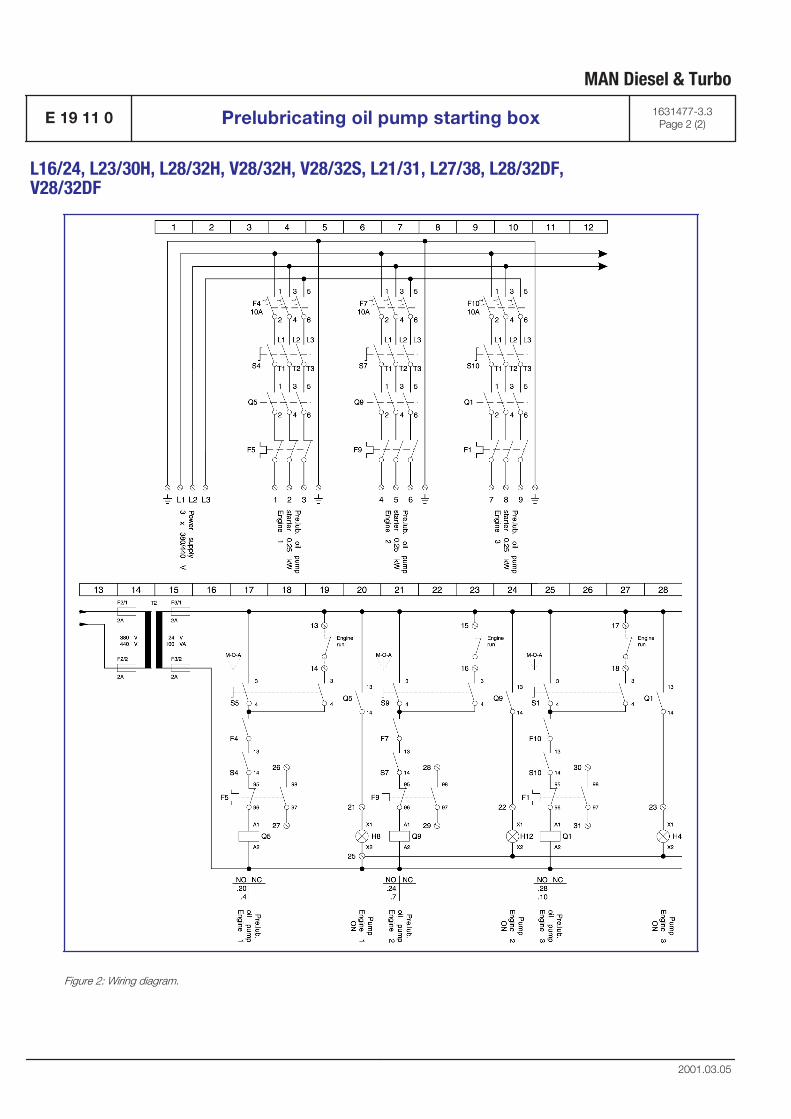
Figure 2: Wiring diagram.
MAN Diesel & Turbo
E 19 11 0 Prelubricating oil pump starting box 1631477-3.3Page 2 (2)
L16/24, L23/30H, L28/32H, V28/32H, V28/32S, L21/31, L27/38, L28/32DF,V28/32DF
2001.03.05

Foundation
B 20

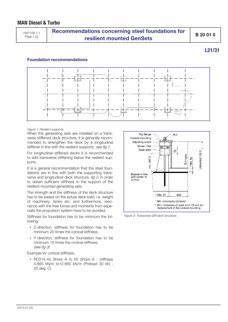
Foundation recommendations
Figure 1: Resilient supports.When the generating sets are installed on a trans-verse stiffened deck structure, it is generally recom-mended to strengthen the deck by a longitudinalstiffener in line with the resilient supports, see fig 1.
For longitudinal stiffened decks it is recommendedto add transverse stiffening below the resilient sup-ports.
It is a general recommendation that the steel foun-dations are in line with both the supporting trans-verse and longitudinal deck structure, fig 2, in orderto obtain sufficient stiffness in the support of theresilient mounted generating sets.
The strength and the stiffness of the deck structurehas to be based on the actual deck load, i.e. weightof machinery, tanks etc. and furthermore, reso-nance with the free forces and moments from espe-cially the propulsion system have to be avoided.
Stiffness for foundation has to be minimum the fol-lowing:
▪ Z-direction, stiffness for foundation has to beminimum 20 times the conical stiffness.
▪ Y-direction, stiffness for foundation has to beminimum 10 times the conical stiffness. (see fig 3)
Example for conical stiffness:
▪ RD314-45 Shore A to 65 Shore A - stiffness4.865 kN/m to12.660 kN/m (Preload 30 kN -20 deg. C)
Figure 2: Transverse stiff deck structure.
MAN Diesel & Turbo
1687109-1.1Page 1 (2)
Recommendations concerning steel foundations forresilient mounted GenSets
B 20 01 0
L21/31
2013.01.29
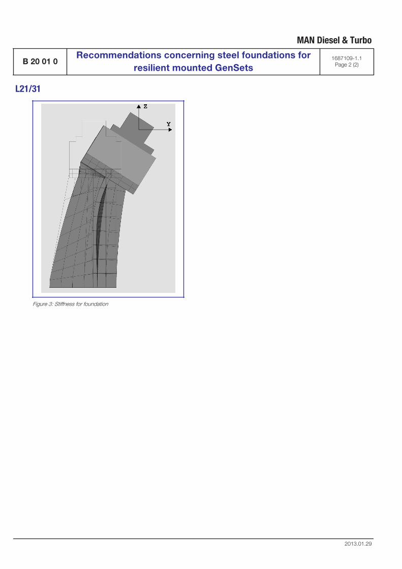
Figure 3: Stiffness for foundation
MAN Diesel & Turbo
B 20 01 0Recommendations concerning steel foundations for
resilient mounted GenSets1687109-1.1
Page 2 (2)
L21/31
2013.01.29
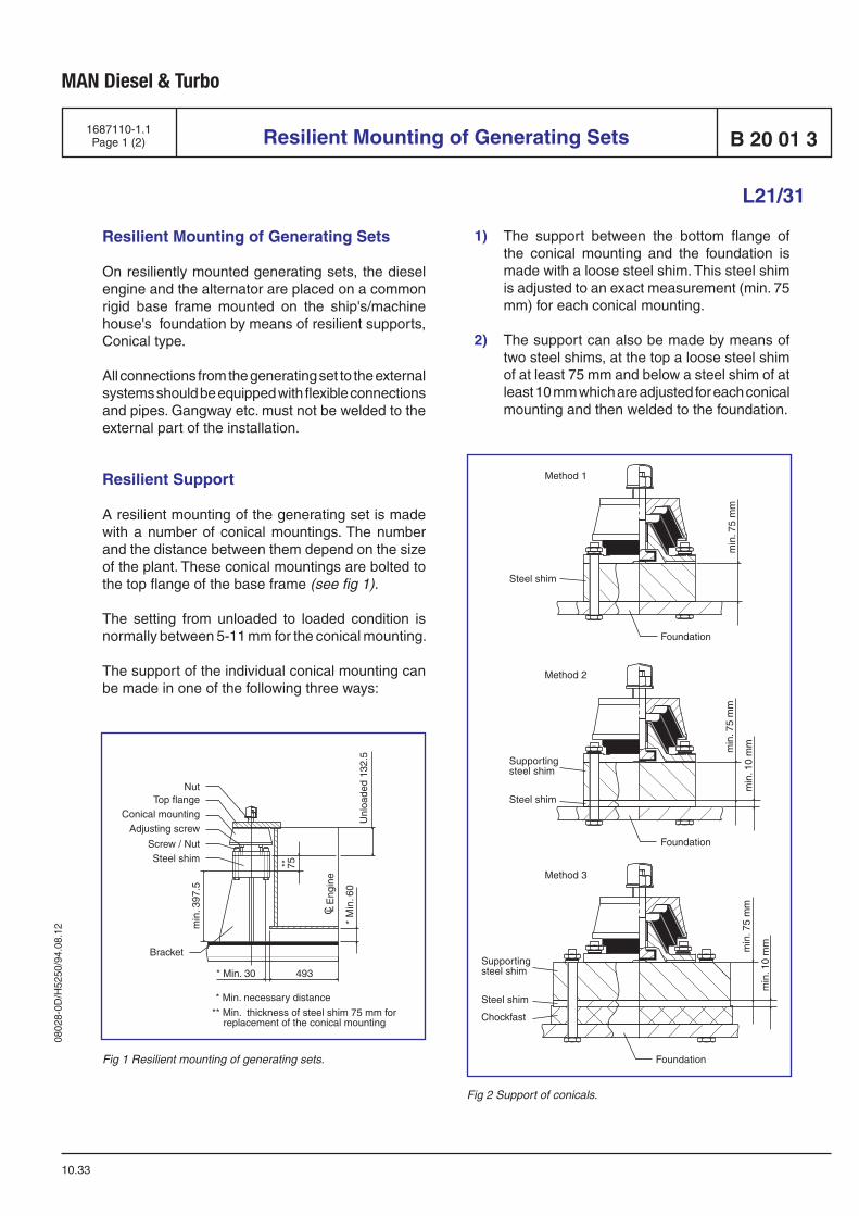
0802
8-0D
/H52
50/9
4.08
.12
MAN Diesel & Turbo
Resilient Mounting of Generating Sets
10.33
Resilient Mounting of Generating Sets
On resiliently mounted generating sets, the diesel engine and the alternator are placed on a common rigid base frame mounted on the ship's/machine house's foundation by means of resilient supports, Conical type.
All connections from the generating set to the ex ter nal systems should be equipped with flexible connections and pipes. Gangway etc. must not be welded to the external part of the installation.
Resilient Support
A resilient mounting of the generating set is made with a number of conical mountings. The number and the distance between them depend on the size of the plant. These conical mountings are bolted to the top flange of the base frame (see fig 1).
The setting from unloaded to loaded condition is normally between 5-11 mm for the conical mounting.
The support of the individual conical mounting can be made in one of the following three ways:
Fig 2 Support of conicals.
L21/31
1687110-1.1Page 1 (2)
Fig 1 Resilient mounting of generating sets.
1) The support between the bottom flange of the conical mounting and the foundation is made with a loose steel shim. This steel shim is adjusted to an exact measurement (min. 75 mm) for each conical mounting.
2) The support can also be made by means of two steel shims, at the top a loose steel shim of at least 75 mm and below a steel shim of at least 10 mm which are adjusted for each conical mounting and then welded to the foundation.
B 20 01 3
75
NutTop flange
Adjusting screw
Screw / Nut
Bracket
Steel shim
Conical mounting
Unl
oade
d 13
2.5
Eng
ine
* M
in. 6
0
* Min. 30 493
* Min. necessary distance
** Min. thickness of steel shim 75 mm for replacement of the conical mounting
C L
**
min
. 397
.5
Foundation
Supportingsteel shim
Supportingsteel shim
Steel shim
Steel shim
Chockfast
Method 2
min
. 75
mm
min
. 10
mm
min
. 75
mm
min
. 10
mm
Method 3
Foundation
Steel shim
Method 1
min
. 75
mm
Foundation
0802
8-0D
/H52
50/9
4.08
.12
MAN Diesel & Turbo
Resilient Mounting of Generating Sets
10.33
3) Finally, the support can be made by means of chockfast. It is necessary to use two steel shims, the top steel shim should be loose and have a minimum thickness of 75 mm and the bottom steel shim should be cast in chockfast with a thickness of at least 10 mm.
Irrespective of the method of support, the 75 mm steel shim is necessary to facilitate a possible future replacement of the conical moun tings, which are always replaced in pairs.
Check of Crankshaft Deflection
The resiliently mounted generating set is normally delivered from the factory with engine and alternator mounted on the common base frame.Eventhough engine and alternator have been ad-justed by the engine builder, with the alternator rotor placed correctly in the stator and the crankshaft de-flection of the engine (autolog) within the prescribed tolerances, it is recommended to check the crankshaft deflection ( autolog) before starting up the GenSet.
1687110-1.1Page 2 (2)
L21/31
B 20 01 3

Test running
B 21

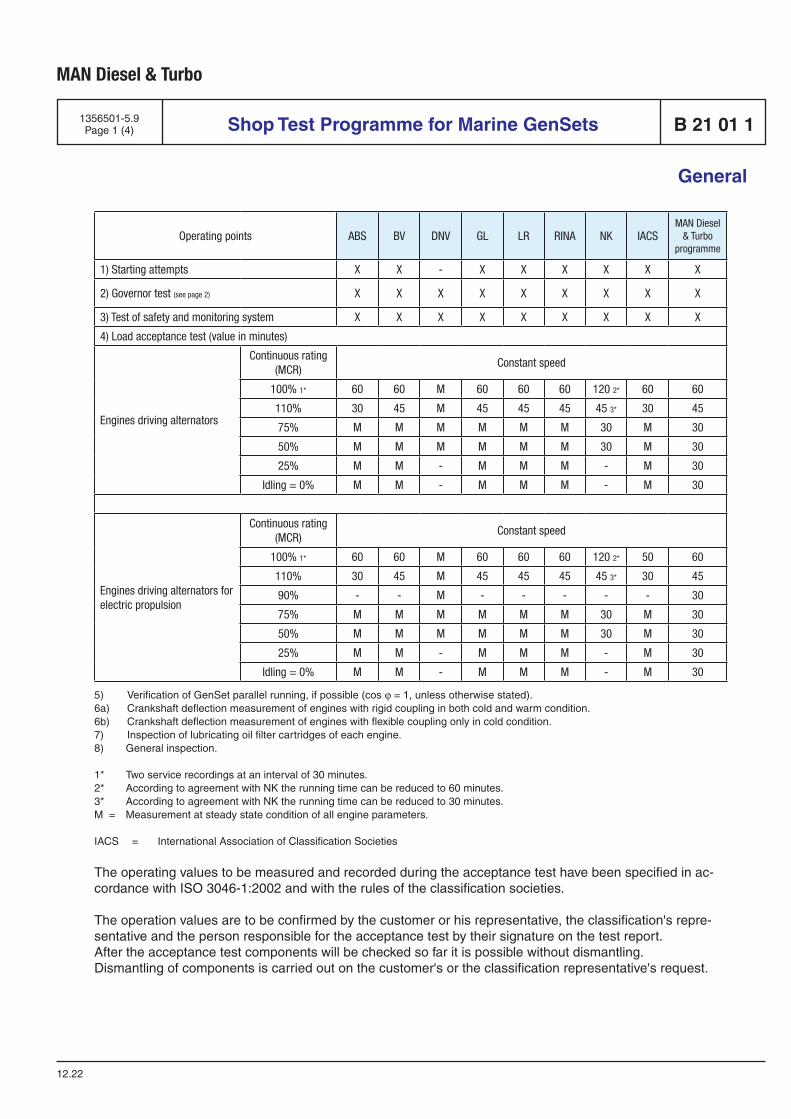
MAN Diesel & Turbo
Shop Test Programme for Marine GenSets1356501-5.9Page 1 (4) B 21 01 1
General
12.22
5) Verification of GenSet parallel running, if possible (cos j = 1, unless otherwise stated).6a) Crankshaft deflection measurement of engines with rigid coupling in both cold and warm condition.6b) Crankshaft deflection measurement of engines with flexible coupling only in cold condition.7) Inspection of lubricating oil filter cartridges of each engine.8) General inspection.
1* Two service recordings at an interval of 30 minutes.2* According to agreement with NK the running time can be reduced to 60 minutes.3* According to agreement with NK the running time can be reduced to 30 minutes.M = Measurement at steady state condition of all engine parameters.
IACS = International Association of Classification Societies
The operating values to be measured and recorded during the acceptance test have been specified in ac-cordance with ISO 3046-1:2002 and with the rules of the classification societies.
The operation values are to be confirmed by the customer or his representative, the classification's repre-sentative and the person responsible for the acceptance test by their signature on the test report.After the acceptance test components will be checked so far it is possible without dismantling.Dismantling of components is carried out on the customer's or the classification representative's request.
Operating points ABS BV DNV GL LR RINA NK IACSMAN Diesel
& Turbo programme
1) Starting attempts X X - X X X X X X
2) Governor test (see page 2) X X X X X X X X X
3) Test of safety and monitoring system X X X X X X X X X
4) Load acceptance test (value in minutes)
Engines driving alternators
Continuous rating (MCR)
Constant speed
100% 1* 60 60 M 60 60 60 120 2* 60 60
110% 30 45 M 45 45 45 45 3* 30 45
75% M M M M M M 30 M 30
50% M M M M M M 30 M 30
25% M M - M M M - M 30
Idling = 0% M M - M M M - M 30
Engines driving alternators for electric propulsion
Continuous rating (MCR)
Constant speed
100% 1* 60 60 M 60 60 60 120 2* 50 60
110% 30 45 M 45 45 45 45 3* 30 45
90% - - M - - - - - 30
75% M M M M M M 30 M 30
50% M M M M M M 30 M 30
25% M M - M M M - M 30
Idling = 0% M M - M M M - M 30
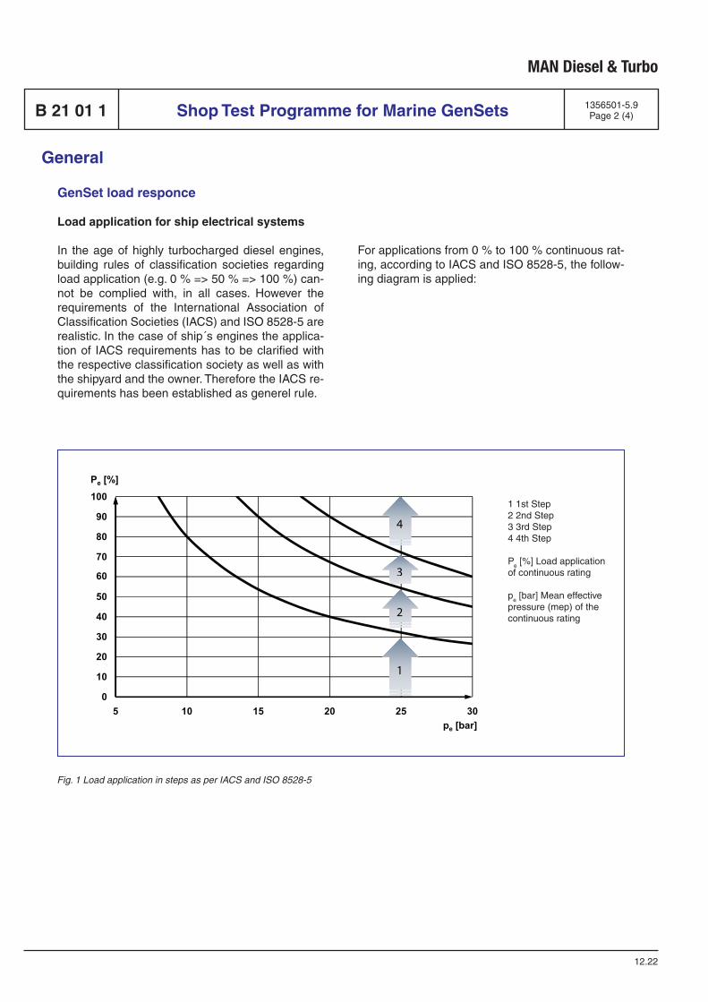
MAN Diesel & Turbo
Shop Test Programme for Marine GenSets 1356501-5.9Page 2 (4)B 21 01 1
General
12.22
GenSet load responce
Load application for ship electrical systems
In the age of highly turbocharged diesel engines, building rules of classification societies regarding load application (e.g. 0 % => 50 % => 100 %) can-not be complied with, in all cases. However the requirements of the International Association of Classification Societies (IACS) and ISO 8528-5 are realistic. In the case of ship´s engines the applica-tion of IACS requirements has to be clarified with the respective classification society as well as with the shipyard and the owner. Therefore the IACS re-quirements has been established as generel rule.
For applications from 0 % to 100 % continuous rat-ing, according to IACS and ISO 8528-5, the follow-ing diagram is applied:
70
60
80
90
100
Pe [%]
0
10
20
30
40
50
5 10 15 20 25 30pe [bar]
1
2
4
3
1 1st Step2 2nd Step3 3rd Step4 4th Step
Pe [%] Load applicationof continuous rating
pe [bar] Mean effectivepressure (mep) of thecontinuous rating
Fig. 1 Load application in steps as per IACS and ISO 8528-5
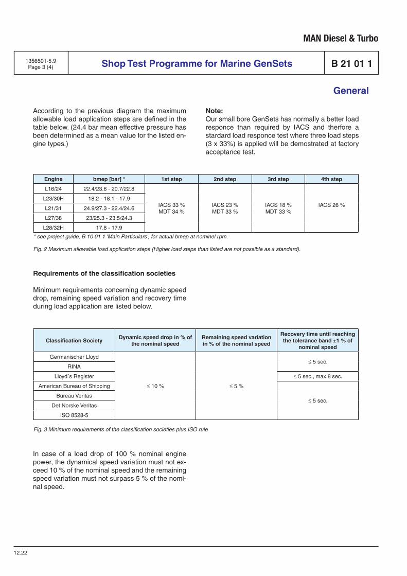
MAN Diesel & Turbo
According to the previous diagram the maximum allowable load application steps are defined in the table below. (24.4 bar mean effective pressure has been determined as a mean value for the listed en-gine types.)
Engine bmep [bar] * 1st step 2nd step 3rd step 4th step
L16/24 22.4/23.6 - 20.7/22.8
IACS 33 %MDT 34 %
IACS 23 %MDT 33 %
IACS 18 %MDT 33 %
IACS 26 %L23/30H 18.2 - 18.1 - 17.9
L21/31 24.9/27.3 - 22.4/24.6
L27/38 23/25.3 - 23.5/24.3
L28/32H 17.8 - 17.9
* see project guide, B 10 01 1 'Main Particulars', for actual bmep at nominel rpm.
Fig. 2 Maximum allowable load application steps (Higher load steps than listed are not possible as a standard).
Requirements of the classification societies
Minimum requirements concerning dynamic speed drop, remaining speed variation and recovery time during load application are listed below.
Note:Our small bore GenSets has normally a better load responce than required by IACS and therfore a stardard load responce test where three load steps (3 x 33%) is applied will be demostrated at factory acceptance test.
Classification SocietyDynamic speed drop in % of
the nominal speedRemaining speed variation in % of the nominal speed
Recovery time until reaching the tolerance band ±1 % of
nominal speed
Germanischer Lloyd
≤ 10 % ≤ 5 %
≤ 5 sec.RINA
Lloyd´s Register ≤ 5 sec., max 8 sec.
American Bureau of Shipping
≤ 5 sec.Bureau Veritas
Det Norske Veritas
ISO 8528-5
Fig. 3 Minimum requirements of the classification societies plus ISO rule
In case of a load drop of 100 % nominal engine power, the dynamical speed variation must not ex-ceed 10 % of the nominal speed and the remaining speed variation must not surpass 5 % of the nomi-nal speed.
Shop Test Programme for Marine GenSets1356501-5.9Page 3 (4) B 21 01 1
General
12.22
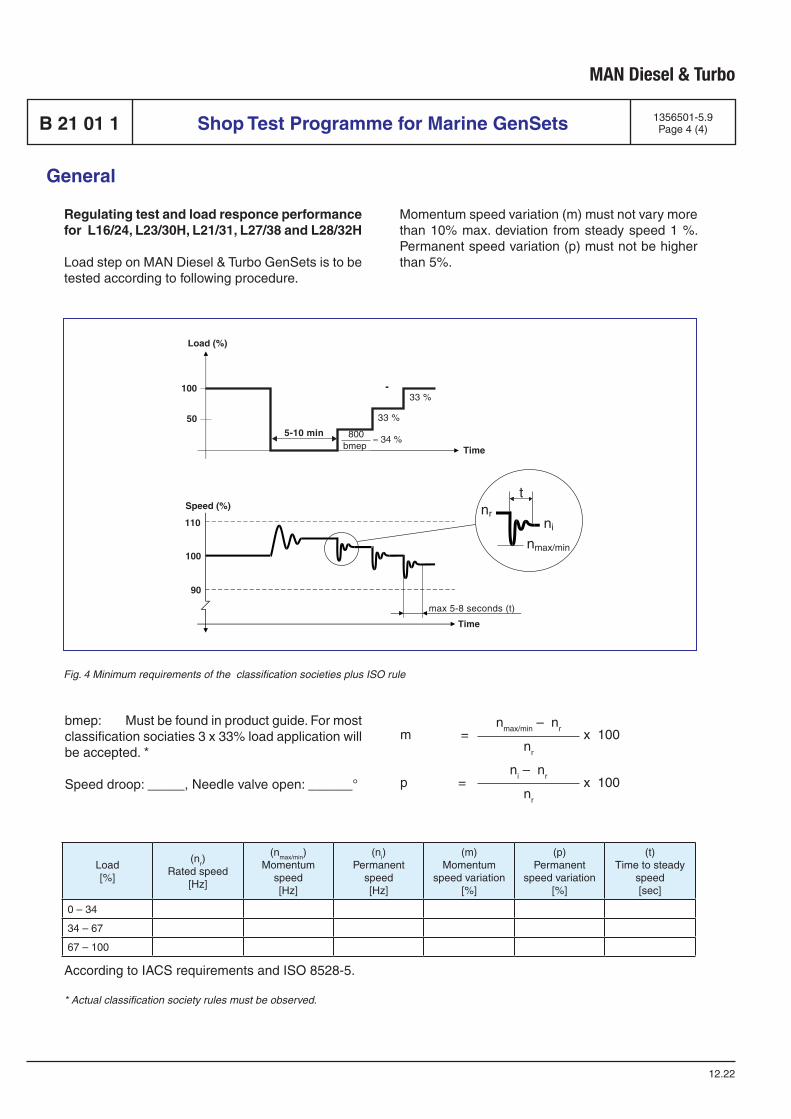
MAN Diesel & Turbo
Regulating test and load responce performance for L16/24, L23/30H, L21/31, L27/38 and L28/32H
Load step on MAN Diesel & Turbo GenSets is to be tested according to following procedure.
Load[%]
(nr)Rated speed
[Hz]
(nmax/min)Momentum
speed[Hz]
(ni)Permanent
speed[Hz]
(m) Momentum
speed variation[%]
(p) Permanent
speed variation [%]
(t)Time to steady
speed[sec]
0 – 34
34 – 67
67 – 100
bmep: Must be found in product guide. For most classification sociaties 3 x 33% load application will be accepted. *
Speed droop: _____, Needle valve open: ______°
Fig. 4 Minimum requirements of the classification societies plus ISO rule
nmax/min – nr
nr
ni – nr
nr
Momentum speed variation (m) must not vary more than 10% max. deviation from steady speed 1 %. Permanent speed variation (p) must not be higher than 5%.
Shop Test Programme for Marine GenSets 1356501-5.9Page 4 (4)B 21 01 1
General
12.22
max 5-8 seconds (t)
nrni
t
nmax/min
5-10 min
33 %
33 %
800bmep
≈ 34 %
100
50
Load (%)
110
90
Speed (%)
100
Time
Time
m = x 100
p = x 100
According to IACS requirements and ISO 8528-5.
* Actual classification society rules must be observed.

Spare Parts
E 23

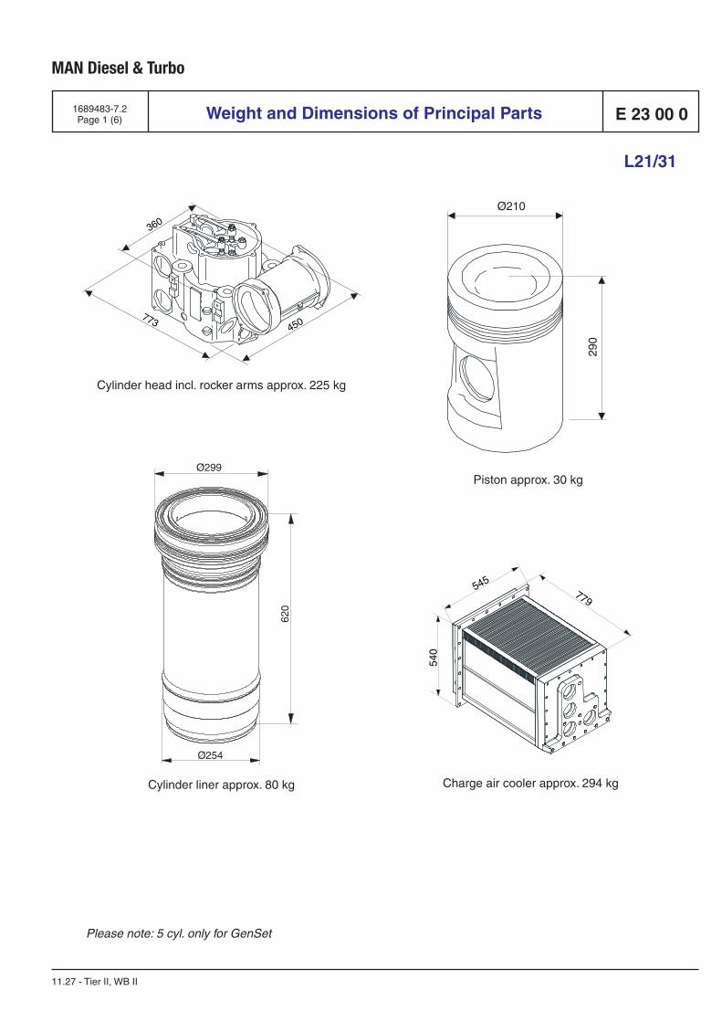
MAN Diesel & Turbo
E 23 00 01689483-7.2Page 1 (6) Weight and Dimensions of Principal Parts
L21/31
11.27 - Tier II, WB II
Cylinder liner approx. 80 kg
Piston approx. 30 kg
Cylinder head incl. rocker arms approx. 225 kg
Charge air cooler approx. 294 kg
360
450773
545779
540
Ø299
Ø254
620
Please note: 5 cyl. only for GenSet
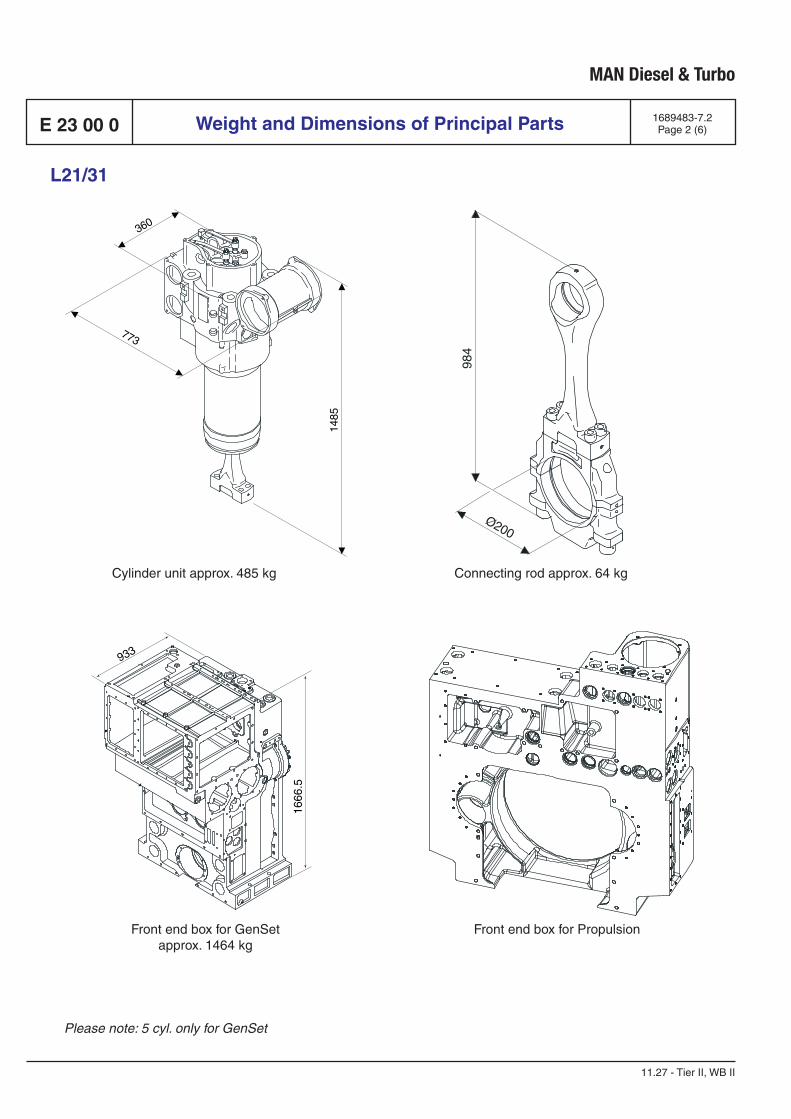
MAN Diesel & Turbo
E 23 00 0 1689483-7.2Page 2 (6)Weight and Dimensions of Principal Parts
L21/31
11.27 - Tier II, WB II
Cylinder unit approx. 485 kg Connecting rod approx. 64 kg
1666
.5
933
Front end box for GenSet approx. 1464 kg
Please note: 5 cyl. only for GenSet
Front end box for Propulsion
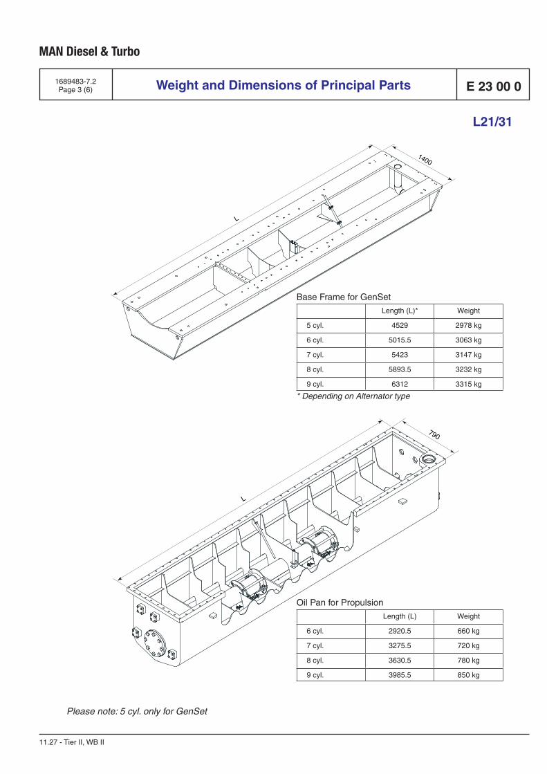
MAN Diesel & Turbo
E 23 00 0
* Depending on Alternator type
L
1400
Base Frame for GenSet
Length (L)* Weight
5 cyl. 4529 2978 kg
6 cyl. 5015.5 3063 kg
7 cyl. 5423 3147 kg
8 cyl. 5893.5 3232 kg
9 cyl. 6312 3315 kg
1689483-7.2Page 3 (6) Weight and Dimensions of Principal Parts
L21/31
11.27 - Tier II, WB II
L
790
Oil Pan for Propulsion
Length (L) Weight
6 cyl. 2920.5 660 kg
7 cyl. 3275.5 720 kg
8 cyl. 3630.5 780 kg
9 cyl. 3985.5 850 kg
Please note: 5 cyl. only for GenSet
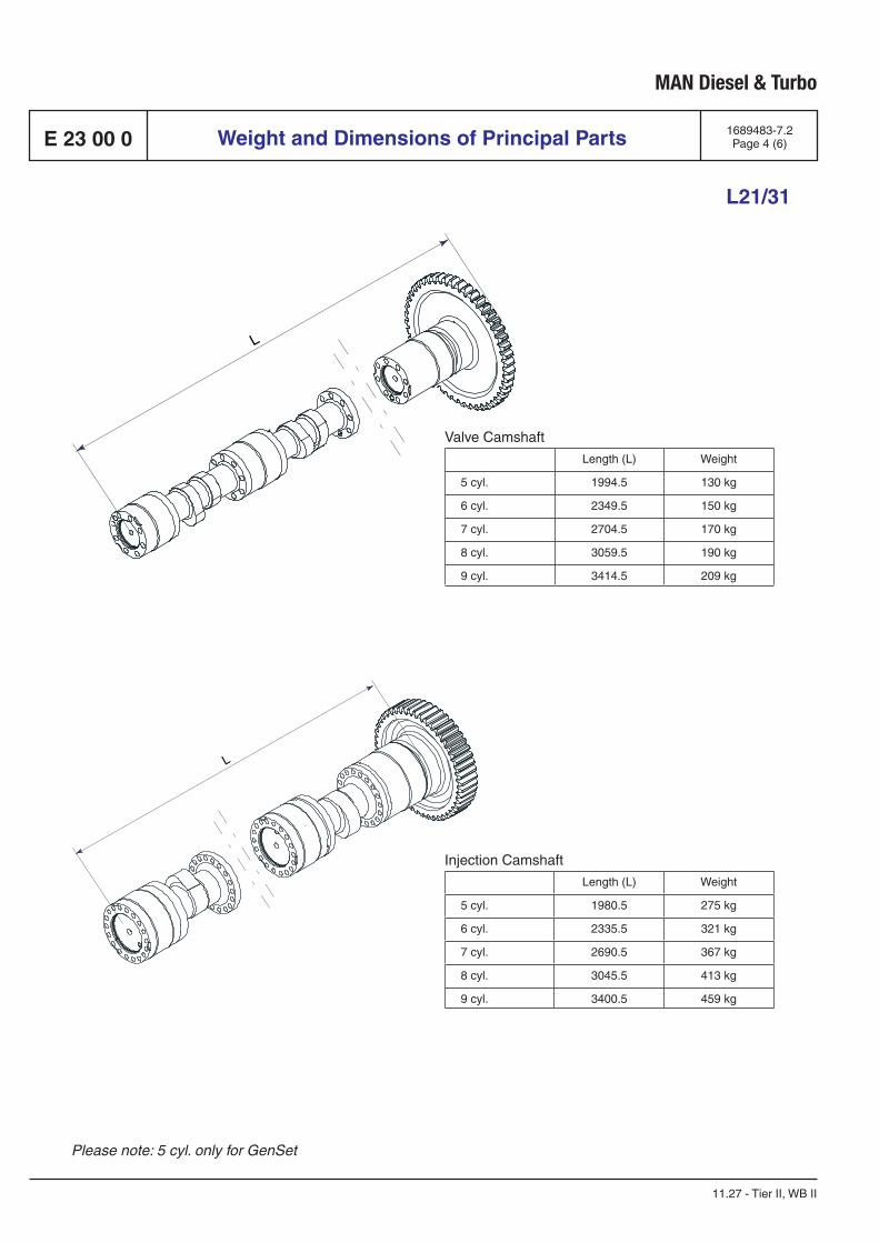
MAN Diesel & Turbo
E 23 00 0
L
Valve Camshaft
Length (L) Weight
5 cyl. 1994.5 130 kg
6 cyl. 2349.5 150 kg
7 cyl. 2704.5 170 kg
8 cyl. 3059.5 190 kg
9 cyl. 3414.5 209 kg
Injection Camshaft
Length (L) Weight
5 cyl. 1980.5 275 kg
6 cyl. 2335.5 321 kg
7 cyl. 2690.5 367 kg
8 cyl. 3045.5 413 kg
9 cyl. 3400.5 459 kg
L
1689483-7.2Page 4 (6)Weight and Dimensions of Principal Parts
L21/31
11.27 - Tier II, WB II
Please note: 5 cyl. only for GenSet
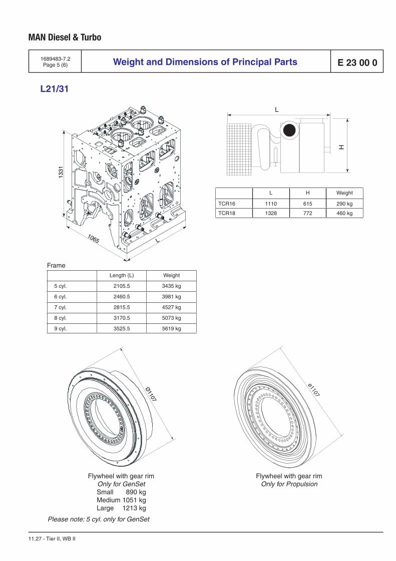
MAN Diesel & Turbo
E 23 00 01689483-7.2Page 5 (6) Weight and Dimensions of Principal Parts
L21/31
11.27 - Tier II, WB II
Frame
Length (L) Weight
5 cyl. 2105.5 3435 kg
6 cyl. 2460.5 3981 kg
7 cyl. 2815.5 4527 kg
8 cyl. 3170.5 5073 kg
9 cyl. 3525.5 5619 kg
1331
1065 LØ
1107
Flywheel with gear rimOnly for GenSet
Small 890 kg Medium 1051 kg Large 1213 kg
L H Weight
TCR16 1110 615 290 kg
TCR18 1328 772 460 kg
L
H
Please note: 5 cyl. only for GenSet
ø1107
Flywheel with gear rimOnly for Propulsion
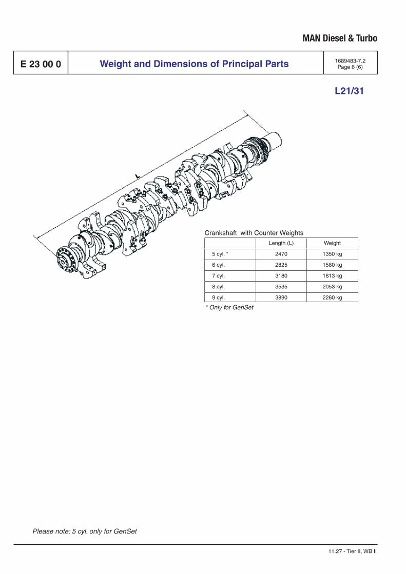
MAN Diesel & Turbo
E 23 00 0
Crankshaft with Counter Weights
Length (L) Weight
5 cyl. * 2470 1350 kg
6 cyl. 2825 1580 kg
7 cyl. 3180 1813 kg
8 cyl. 3535 2053 kg
9 cyl. 3890 2260 kg
* Only for GenSet
1689483-7.2Page 6 (6)Weight and Dimensions of Principal Parts
L21/31
11.27 - Tier II, WB II
Please note: 5 cyl. only for GenSet
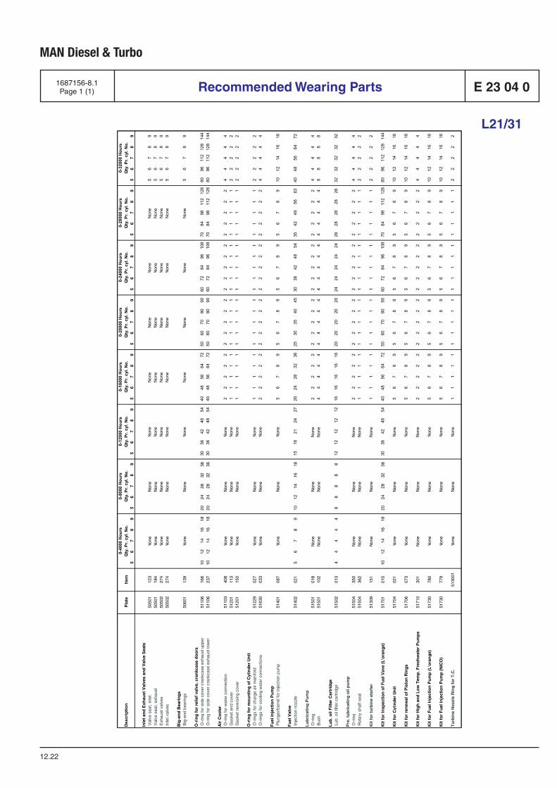
MAN Diesel & Turbo
1687156-8.1Page 1 (1) Recommended Wearing Parts E 23 04 0
L21/31
12.22
Des
crip
tion
Plat
eIte
m5
67
89
56
78
95
67
89
56
78
95
67
89
56
78
95
67
89
56
78
9
Inle
t an
d E
xhau
st V
alve
s an
d V
alve
Sea
ts
Val
ve s
eat,
inle
t 50
501
123
Non
e
Non
e
Non
e
Non
e
Non
e
Non
e
Non
e
56
78
9 V
alve
sea
t, ex
haus
t 50
501
184
Non
e
Non
e
Non
e
Non
e
Non
e
Non
e
Non
e
56
78
9 E
xhau
st v
alve
s
5050
227
4
N
one
N
one
N
one
N
one
N
one
N
one
N
one
5
67
89
Inle
t val
ves
50
502
274
Non
e
Non
e
Non
e
Non
e
Non
e
Non
e
Non
e
56
78
9
Big
-en
d B
eari
ng
s
Big
-end
bea
rings
5060
113
9
N
one
N
one
N
one
N
one
N
one
N
one
N
one
5
67
89
O-r
ing
fo
r re
lief
valv
e, c
ran
kcas
e d
oo
rs
O-r
ing
for
side
cov
er c
rank
case
exh
aust
upp
er
5110
616
610
1214
1618
2024
2832
3630
3642
4854
4048
5664
7250
6070
8090
6072
8496
108
7084
9811
212
680
9611
212
814
4 O
-rin
g fo
r si
de c
over
cra
nkca
se e
xhau
st lo
wer
51
106
237
1012
1416
1820
2428
3236
3036
4248
5440
4856
6472
5060
7080
9060
7284
9610
870
8498
112
126
8096
112
128
144
Air
Co
ole
r
O-r
ing
for
wat
er c
onne
ctio
n
5110
340
8
N
one
N
one
N
one
2
22
22
22
22
22
22
22
22
22
24
44
44
Gas
ket e
nd c
over
51
201
113
Non
e
Non
e
Non
e
11
11
11
11
11
11
11
11
11
11
22
22
2 G
aske
t rev
ersi
ng c
over
51
201
150
Non
e
Non
e
Non
e
11
11
11
11
11
11
11
11
11
11
22
22
2
O-r
ing
fo
r m
ou
nti
ng
of
Cyl
ind
er U
nit
O
-rin
gs fo
r ch
arge
air
man
ifold
51
229
027
Non
e
Non
e
Non
e
11
11
11
11
11
11
11
11
11
11
22
22
2 O
-rin
gs fo
r co
olin
g w
ater
con
nect
ions
51
630
033
Non
e
Non
e
Non
e
22
22
22
22
22
22
22
22
22
22
44
44
4
Fu
el In
ject
ion
Pu
mp
P
lung
er/b
arre
l for
inje
ctio
n pu
mp
51
401
087
Non
e
Non
e
Non
e
56
78
95
67
89
56
78
95
67
89
1012
1416
18
Fu
el V
alve
In
ject
ion
nozz
le
5140
202
15
67
89
1012
1416
1815
1821
2427
2024
2832
3625
3035
4045
3036
4248
5435
4249
5663
4048
5664
72
Lu
bri
cati
ng
Pu
mp
O-r
ing
51
501
018
Non
e
Non
e
N
one
2
22
22
22
22
22
22
22
22
22
24
44
44
Bus
h
5150
110
2 N
one
N
one
Non
e
44
44
44
44
44
44
44
44
44
44
88
88
8
Lu
b. o
il F
ilter
Car
trid
ge
L
ub. o
il fil
ter
cart
ridge
51
502
013
44
44
48
88
88
1212
1212
1216
1616
1616
2020
2020
2024
2424
2424
2828
2828
2832
3232
3232
Pre
. lu
bri
cati
ng
oil
pu
mp
O-r
ing
51
504
350
Non
e
Non
e
Non
e
22
22
22
22
22
22
22
22
22
22
44
44
4 R
otar
y sh
aft s
eal
5150
436
2 N
one
N
one
N
one
1
11
11
11
11
11
11
11
11
11
12
22
22
Kit
fo
r tu
rbin
e st
arte
r
5130
915
1 N
one
N
one
N
one
1
11
11
11
11
11
11
11
11
11
12
22
22
Kit
fo
r In
spec
tio
n o
f F
uel
Vav
e (L
'ora
ng
e)51
701
015
1012
1416
1820
2428
3236
3036
4248
5440
4856
6472
5060
7080
9060
7284
9610
870
8498
112
126
8096
112
128
144
Kit
fo
r C
ylin
der
Un
it51
704
021
Non
e
Non
e
Non
e
56
78
95
67
89
56
78
95
67
89
1012
1416
18
Kit
fo
r re
new
al o
f P
isto
n R
ing
s51
706
073
Non
e
Non
e
Non
e
56
78
95
67
89
56
78
95
67
89
1012
1416
18
Kit
fo
r H
igh
an
d L
ow
Tem
p. F
resh
wat
er P
um
ps
5171
030
1 N
one
N
one
Non
e
22
22
22
22
22
22
22
22
22
22
44
44
4
Kit
fo
r F
uel
Inje
ctio
n P
um
p (
L'o
ran
ge)
5173
078
0
N
one
N
one
N
one
5
67
89
56
78
95
67
89
56
78
910
1214
1618
Kit
fo
r F
uel
Inje
ctio
n P
um
p (
NIC
O)
5173
077
9
N
one
N
one
N
one
5
67
89
56
78
95
67
89
56
78
910
1214
1618
Tu
rbin
e N
ozz
le R
ing
fo
r T
.C.
51
3001
Non
e
Non
e
Non
e
11
11
11
11
11
11
11
11
11
11
22
22
2
Qty
. Pr.
cyl.
No.
Qty
. Pr.
cyl.
No.
Qty
. Pr.
cyl.
No.
0-40
00 H
ours
0-80
00 H
ours
0-12
000
Hou
rsQ
ty. P
r. cy
l. N
o.Q
ty. P
r. cy
l. N
o.Q
ty. P
r. cy
l. N
o.Q
ty. P
r. cy
l. N
o.Q
ty. P
r. cy
l. N
o.0-
1600
0 H
ours
0-20
000
Hou
rs0-
2400
0 H
ours
0-28
000
Hou
rs0-
3200
0 H
ours

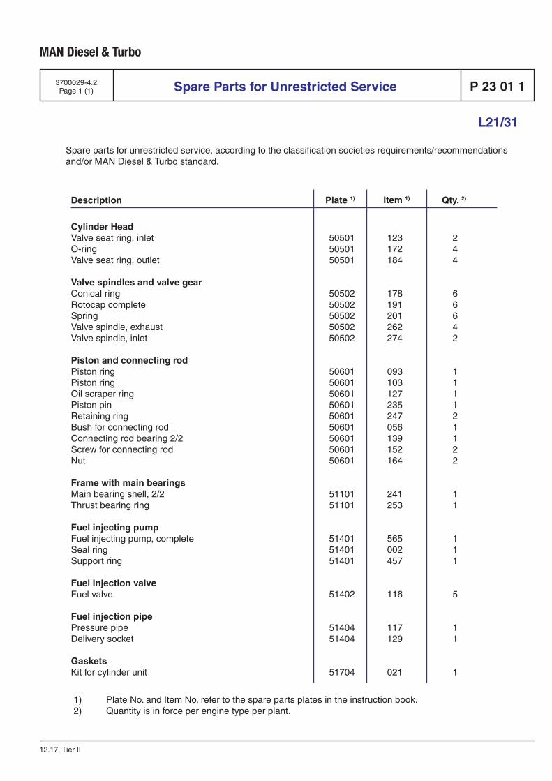
MAN Diesel & Turbo
L21/31
3700029-4.2Page 1 (1)
12.17, Tier II
Spare Parts for Unrestricted Service P 23 01 1
Spare parts for unrestricted service, according to the classification societies requirements/recommendations and/or MAN Diesel & Turbo standard.
Description Qty. 2)Plate 1) Item 1)
Cylinder Head Valve seat ring, inlet 50501 123 2O-ring 50501 172 4Valve seat ring, outlet 50501 184 4 Valve spindles and valve gear Conical ring 50502 178 6Rotocap complete 50502 191 6Spring 50502 201 6Valve spindle, exhaust 50502 262 4Valve spindle, inlet 50502 274 2 Piston and connecting rod Piston ring 50601 093 1Piston ring 50601 103 1Oil scraper ring 50601 127 1Piston pin 50601 235 1Retaining ring 50601 247 2Bush for connecting rod 50601 056 1Connecting rod bearing 2/2 50601 139 1Screw for connecting rod 50601 152 2Nut 50601 164 2 Frame with main bearings Main bearing shell, 2/2 51101 241 1Thrust bearing ring 51101 253 1 Fuel injecting pump Fuel injecting pump, complete 51401 565 1Seal ring 51401 002 1Support ring 51401 457 1 Fuel injection valve Fuel valve 51402 116 5 Fuel injection pipe Pressure pipe 51404 117 1Delivery socket 51404 129 1 Gaskets Kit for cylinder unit 51704 021 1
1) Plate No. and Item No. refer to the spare parts plates in the instruction book.2) Quantity is in force per engine type per plant.


Tools
P 24

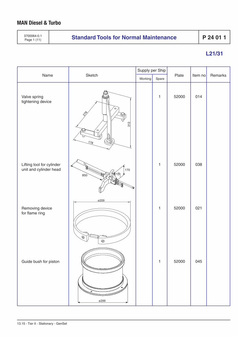
Standard Tools for Normal Maintenance
Supply per Ship
Working Spare Name Sketch Plate Item no Remarks
MAN Diesel & Turbo
13.15 - Tier II - Stationary - GenSet
L21/31
P 24 01 13700064-0.1Page 1 (11)
1 52000 014
1 52000 038
1 52000 021
1 52000 045
Valve springtightening device
Lifting tool for cylinder unit and cylinder head
Removing devicefor flame ring
Guide bush for piston
11.49028-0492
11.49023-0398
11.49021-1167
11.49021-1044
170
850
ø299
278
312
178
ø209

Supply per Ship
Working Spare Name Sketch Plate Item no Remarks
Standard Tools for Normal Maintenance
MAN Diesel & Turbo
13.15 - Tier II - Stationary - GenSet
L21/31
P 24 01 1 3700064-0.1Page 2 (11)
Fit and removal device for conn. rod bearing, incl. eye screws (2 pcs)
Lifting device forcylinder liner
Lifting device for piston and connecting rod
1 52000 069
1 52000 082
1 52000 104
11.49021-0724
11.49023-0424
11.49023-0342
200
1380
948
352
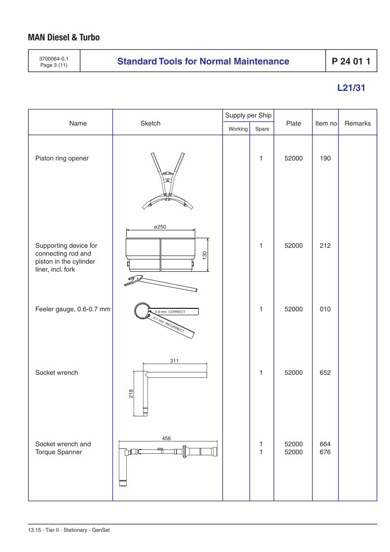
Standard Tools for Normal Maintenance
Supply per Ship
Working Spare Name Sketch Plate Item no Remarks
MAN Diesel & Turbo
13.15 - Tier II - Stationary - GenSet
L21/31
P 24 01 13700064-0.1Page 3 (11)
Piston ring opener
Supporting device for connecting rod and piston in the cylinder liner, incl. fork
Feeler gauge, 0.6-0.7 mm
Socket wrench
Socket wrench and Torque Spanner
1 52000 190
1 52000 212
1 52000 010
1 52000 652
1 52000 664 1 52000 676
11.49002-0045
11.49032-027911.49043-1037
1691690-6
11.49001-0530
11.49001-053208.06411-0021
0.6 mm CORRECT
0.7 mm INCORRECT
456
311
218
ø250
130
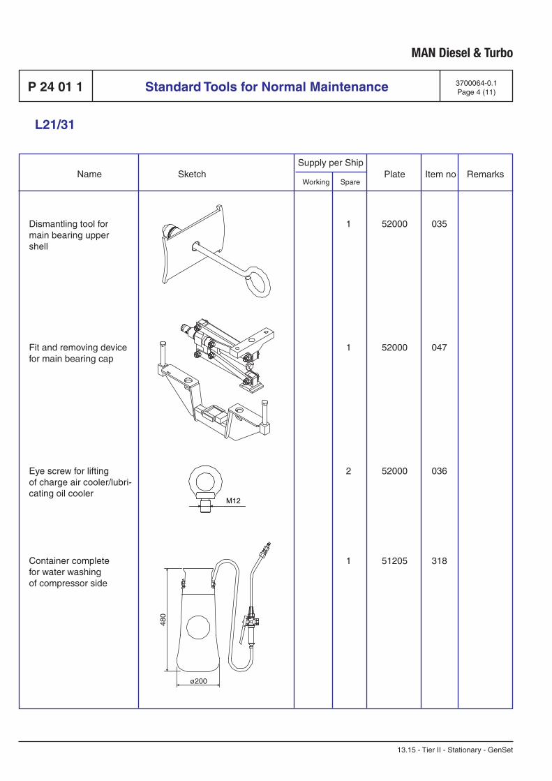
Supply per Ship
Working Spare Name Sketch Plate Item no Remarks
Standard Tools for Normal Maintenance
MAN Diesel & Turbo
13.15 - Tier II - Stationary - GenSet
L21/31
P 24 01 1 3700064-0.1Page 4 (11)
Dismantling tool formain bearing uppershell
Fit and removing devicefor main bearing cap
Eye screw for liftingof charge air cooler/lubri-cating oil cooler
Container completefor water washingof compressor side
1 52000 035
1 52000 047
2 52000 036
1 51205 318
11.49058-060006.56936-0558
11.49023-0338
06.05110-0103
1651568-1
M12
ø200
480
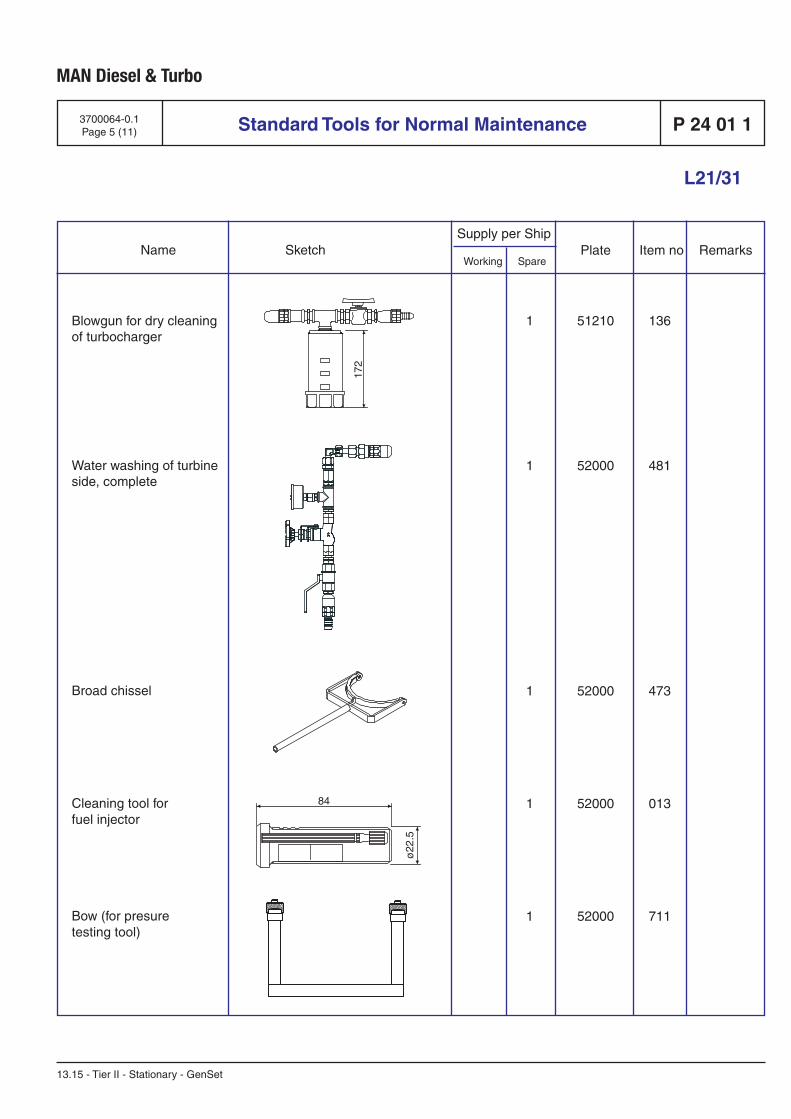
Standard Tools for Normal Maintenance
Supply per Ship
Working Spare Name Sketch Plate Item no Remarks
MAN Diesel & Turbo
13.15 - Tier II - Stationary - GenSet
L21/31
P 24 01 13700064-0.1Page 5 (11)
Blowgun for dry cleaning of turbocharger
Water washing of turbine side, complete
Broad chissel
Cleaning tool forfuel injector
Bow (for presuretesting tool)
1 51210 136
1 52000 481
1 52000 473
1 52000 013
1 52000 711
1612860-3
11.49017-0034
1690252-8
11.49043-1059
ø22
.5
84
172
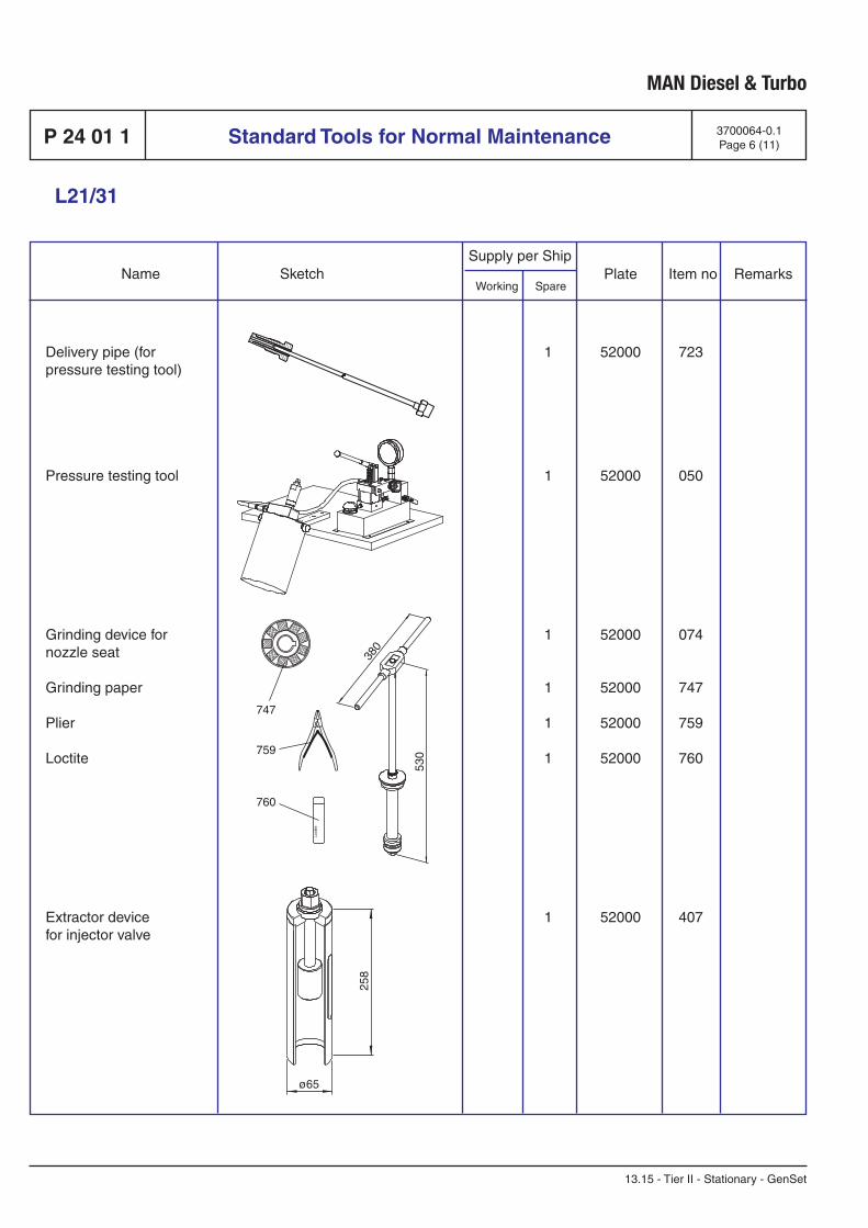
Supply per Ship
Working Spare Name Sketch Plate Item no Remarks
Standard Tools for Normal Maintenance
MAN Diesel & Turbo
13.15 - Tier II - Stationary - GenSet
L21/31
P 24 01 1 3700064-0.1Page 6 (11)
Delivery pipe (forpressure testing tool)
Pressure testing tool
Grinding device fornozzle seat
Grinding paper
Plier
Loctite
Extractor devicefor injector valve
1 52000 723
1 52000 050
1 52000 074
1 52000 747
1 52000 759
1 52000 760
1 52000 407
11.49046-0397
11.49024-0076
11.49008-0333
11.49021-1245
ø65
258
380
530
Loct
ite
747
759
760
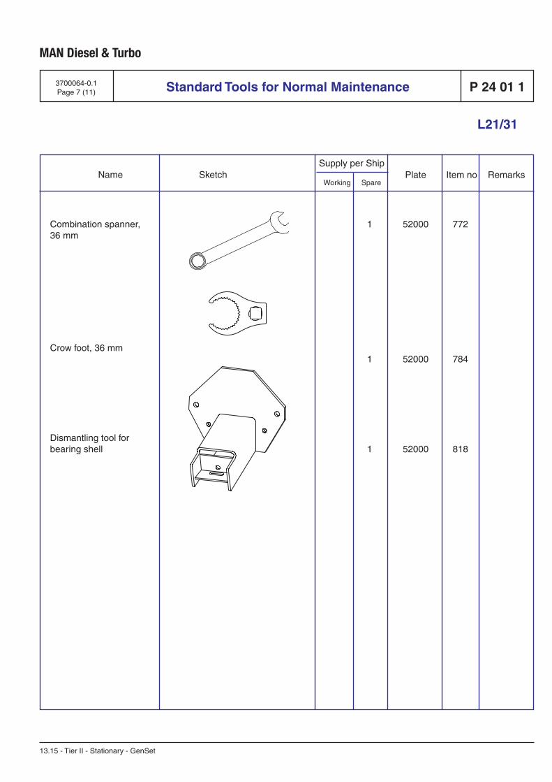
Standard Tools for Normal Maintenance
Supply per Ship
Working Spare Name Sketch Plate Item no Remarks
MAN Diesel & Turbo
13.15 - Tier II - Stationary - GenSet
L21/31
P 24 01 13700064-0.1Page 7 (11)
Combination spanner,36 mm
Crow foot, 36 mm
Dismantling tool forbearing shell
1 52000 772
1 52000 784
1 52000 818
R554K36
08.06411-0601
11.49021-0856
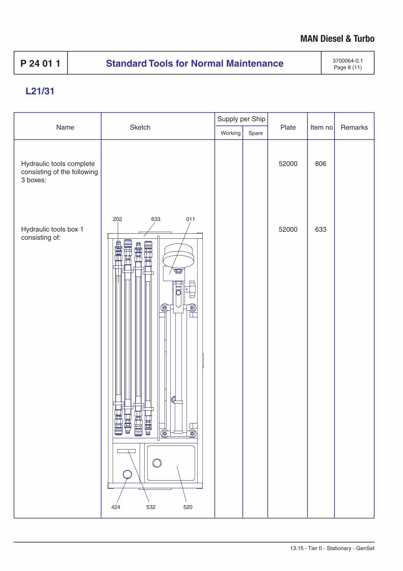
Supply per Ship
Working Spare Name Sketch Plate Item no Remarks
Standard Tools for Normal Maintenance
MAN Diesel & Turbo
13.15 - Tier II - Stationary - GenSet
L21/31
P 24 01 1 3700064-0.1Page 8 (11)
Hydraulic tools complete consisting of the following 3 boxes:
Hydraulic tools box 1consisting of:
52000 806
52000 633
11.49000-2217
11.49028-0505
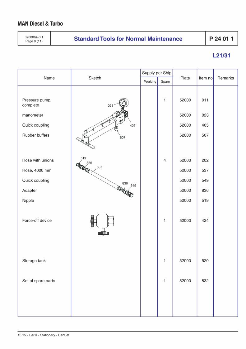
Standard Tools for Normal Maintenance
Supply per Ship
Working Spare Name Sketch Plate Item no Remarks
MAN Diesel & Turbo
13.15 - Tier II - Stationary - GenSet
L21/31
P 24 01 13700064-0.1Page 9 (11)
Pressure pump,complete
manometer
Quick coupling
Rubber buffers
Hose with unions
Hose, 4000 mm
Quick coupling
Adapter
Nipple
Force-off device
Storage tank
Set of spare parts
1 52000 011
52000 023
52000 405
52000 507
4 52000 202
52000 537
52000 549
52000 836
52000 519
1 52000 424
1 52000 520
1 52000 532
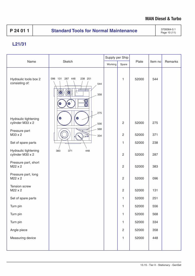
Supply per Ship
Working Spare Name Sketch Plate Item no Remarks
Standard Tools for Normal Maintenance
MAN Diesel & Turbo
13.15 - Tier II - Stationary - GenSet
L21/31
P 24 01 1 3700064-0.1Page 10 (11)
Hydraulic tools box 2consisting of:
Hydraulic tighteningcylinder M33 x 2
Pressure partM33 x 2
Set of spare parts
Hydraulic tighteningcylinder M30 x 2
Pressure part, shortM22 x 2
Pressure part, longM22 x 2
Tension screwM22 x 2
Set of spare parts
Turn pin
Turn pin
Turn pin
Angle piece
Measuring device
1 52000 544
2 52000 275
2 52000 371
1 52000 238
2 52000 287
2 52000 383
2 52000 096
2 52000 131
1 52000 251
1 52000 556
1 52000 568
1 52000 334
2 52000 358
1 52000 448
11.49028-0507
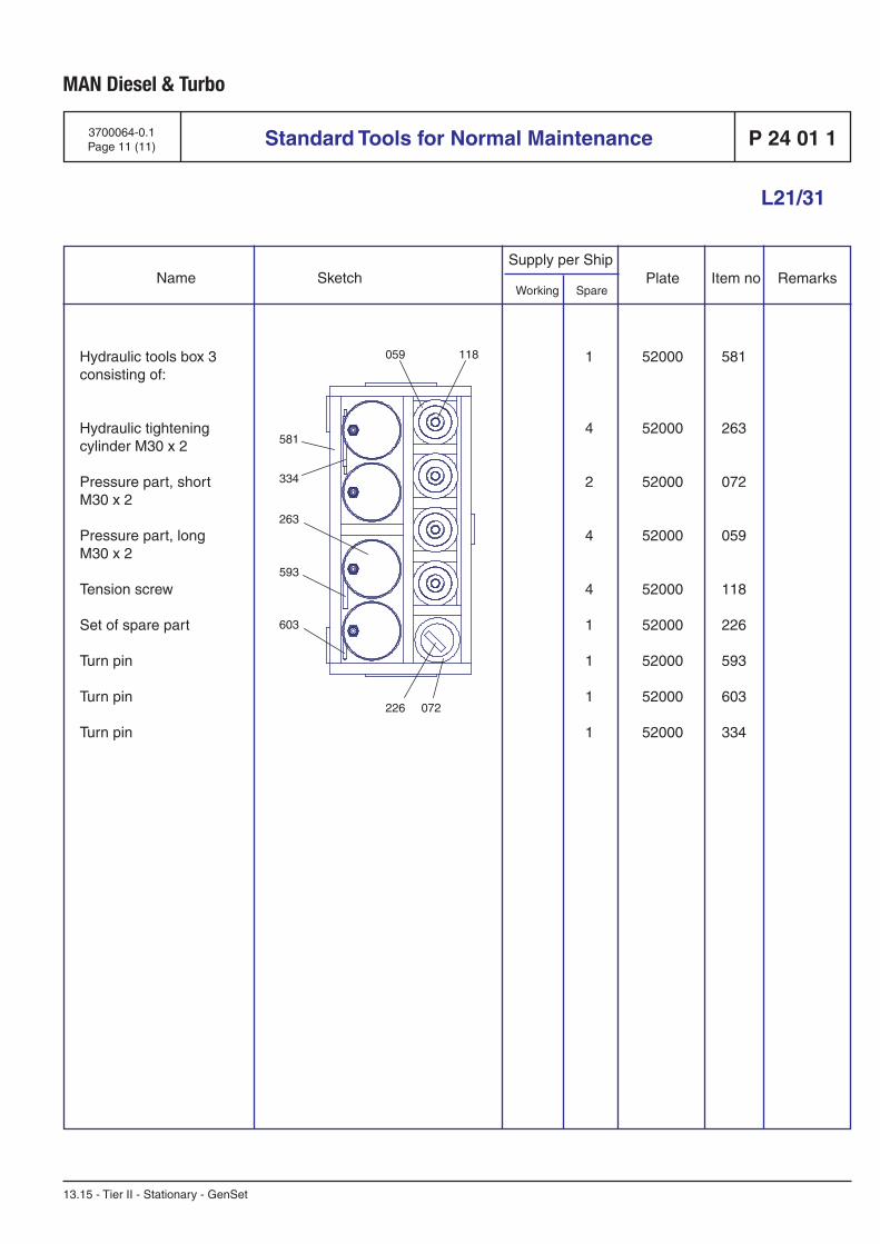
Standard Tools for Normal Maintenance
Supply per Ship
Working Spare Name Sketch Plate Item no Remarks
MAN Diesel & Turbo
13.15 - Tier II - Stationary - GenSet
L21/31
P 24 01 13700064-0.1Page 11 (11)
Hydraulic tools box 3consisting of:
Hydraulic tighteningcylinder M30 x 2
Pressure part, shortM30 x 2
Pressure part, longM30 x 2
Tension screw
Set of spare part
Turn pin
Turn pin
Turn pin
1 52000 581
4 52000 263
2 52000 072
4 52000 059
4 52000 118
1 52000 226
1 52000 593
1 52000 603
1 52000 334
11.49028-0509

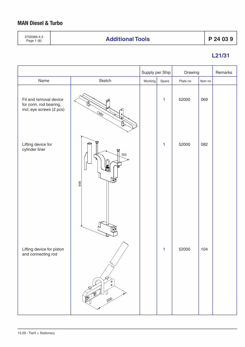
L21/31
Additional Tools
Supply per Ship Drawing Remarks
Working Spare Plate no Item no Name Sketch
MAN Diesel & Turbo
3700066-4.3Page 1 (8) P 24 03 9
13.29 - TierII + Stationary
Fit and removal device for conn. rod bearing, incl. eye screws (2 pcs)
Lifting device forcylinder liner
Lifting device for piston and connecting rod
1 52000 069
1 52000 082
1 52000 104
11.49021-0724
11.49023-0424
11.49023-0342
200
1380
948
352

L21/31
Additional Tools
MAN Diesel & Turbo
Supply per Ship Drawing Remarks
Working Spare Plate no Item no Name Sketch
3700066-4.3Page 2 (8)P 24 03 9
13.29 - TierII + Stationary
Plier for piston pinretaining ring
Piston ring opener
Supporting device for connecting rod and piston in the cylinder liner, incl. fork
Dismantling tool formain bearing uppershell
Fit and removing devicefor main bearing cap
1 52000 759
1 52000 190
1 52000 212
1 52000 035
1 52000 047
EN515D10
11.49002-0045
11.49032-027911.49043-1037
11.49058-060006.56936-0558
11.49023-0338
ø250
130
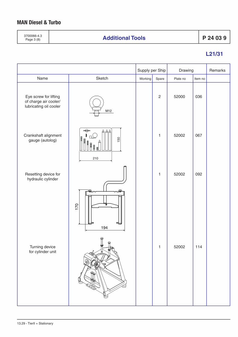
L21/31
Additional Tools
Supply per Ship Drawing Remarks
Working Spare Plate no Item no Name Sketch
MAN Diesel & Turbo
3700066-4.3Page 3 (8) P 24 03 9
13.29 - TierII + Stationary
2 52000 036
1 52002 067
1 52002 092
1 52002 114
Eye screw for liftingof charge air cooler/lubricating oil cooler
Crankshaft alignmentgauge (autolog)
Resetting device forhydraulic cylinder
Turning devicefor cylinder unit
06.05110-0103
2029373-9
11.49025-0223
11.49026-0016
M12
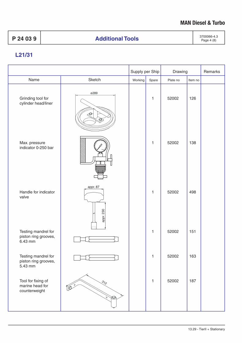
L21/31
Additional Tools
MAN Diesel & Turbo
Supply per Ship Drawing Remarks
Working Spare Plate no Item no Name Sketch
3700066-4.3Page 4 (8)P 24 03 9
13.29 - TierII + Stationary
Grinding tool for cylinder head/liner
Max. pressure indicator 0-250 bar
Handle for indicator valve
Testing mandrel for piston ring grooves, 6.43 mm
Testing mandrel for piston ring grooves, 5.43 mm
Tool for fixing of marine head for counterweight
1 52002 126
1 52002 138
1 52002 498
1 52002 151
1 52002 163
1 52002 187
11.49008-0329
2056299-4
11.49001-0503
1635609-1
1635606-6
11.49043-1020
appr. 87
appr
. 230
0 250
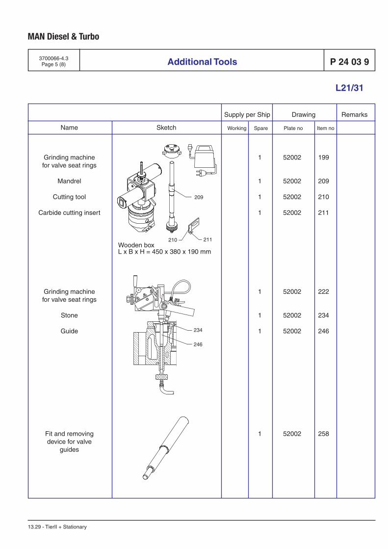
L21/31
Additional Tools
Supply per Ship Drawing Remarks
Working Spare Plate no Item no Name Sketch
MAN Diesel & Turbo
3700066-4.3Page 5 (8) P 24 03 9
13.29 - TierII + Stationary
1685101-8
2142596-6
1350294-4
11.49021-0717
1 52002 199
1 52002 209
1 52002 210
1 52002 211
1 52002 222
1 52002 234
1 52002 246
1 52002 258
Grinding machinefor valve seat rings
Mandrel
Cutting tool
Carbide cutting insert
Grinding machinefor valve seat rings
Stone
Guide
Fit and removingdevice for valve
guides
234
246
Wooden boxL x B x H = 450 x 380 x 190 mm
209
210 211
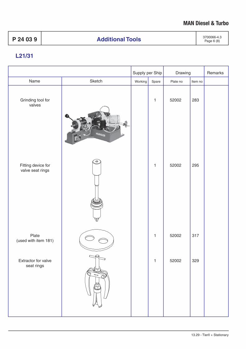
L21/31
Additional Tools
MAN Diesel & Turbo
Supply per Ship Drawing Remarks
Working Spare Plate no Item no Name Sketch
3700066-4.3Page 6 (8)P 24 03 9
13.29 - TierII + Stationary
Grinding tool forvalves
Fitting device forvalve seat rings
Plate(used with item 181)
Extractor for valveseat rings
1 52002 283
1 52002 295
1 52002 317
1 52002 329
11.49000-2304
11.49021-0721
11.49062-2234
11.49025-0214

L21/31
Additional Tools
Supply per Ship Drawing Remarks
Working Spare Plate no Item no Name Sketch
MAN Diesel & Turbo
3700066-4.3Page 7 (8) P 24 03 9
13.29 - TierII + Stationary
1 52002 342
1 52002 366
1 52002 378
1 52002 401
Fit and removing devicefor fuel injection pump
Setting device forfuel injection pump
Cleaning needlesfor fuel injector
(5 pcs)
Fit and removingdevice for cooler
insert
11.49021-0789
11.49022-0235
1630419-4
11.59021-0729
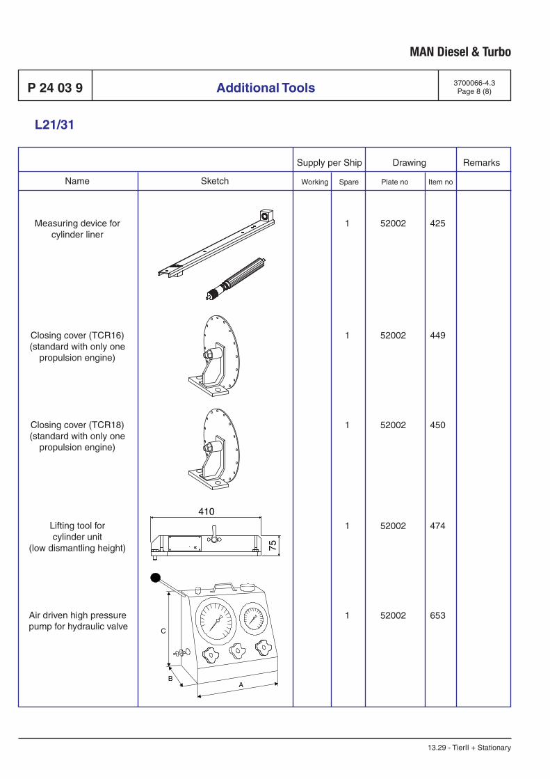
L21/31
Additional Tools
MAN Diesel & Turbo
Supply per Ship Drawing Remarks
Working Spare Plate no Item no Name Sketch
3700066-4.3Page 8 (8)P 24 03 9
13.29 - TierII + Stationary
Measuring device forcylinder liner
Closing cover (TCR16)(standard with only one
propulsion engine)
Closing cover (TCR18)(standard with only one
propulsion engine)
Lifting tool forcylinder unit
(low dismantling height)
Air driven high pressure pump for hydraulic valve
1 52002 425
1 52002 449
1 52002 450
1 52002 474
1 52002 653
11.49022-0242
11.59661-1064
11.59661-0901
11.49023-0315
1675040-2
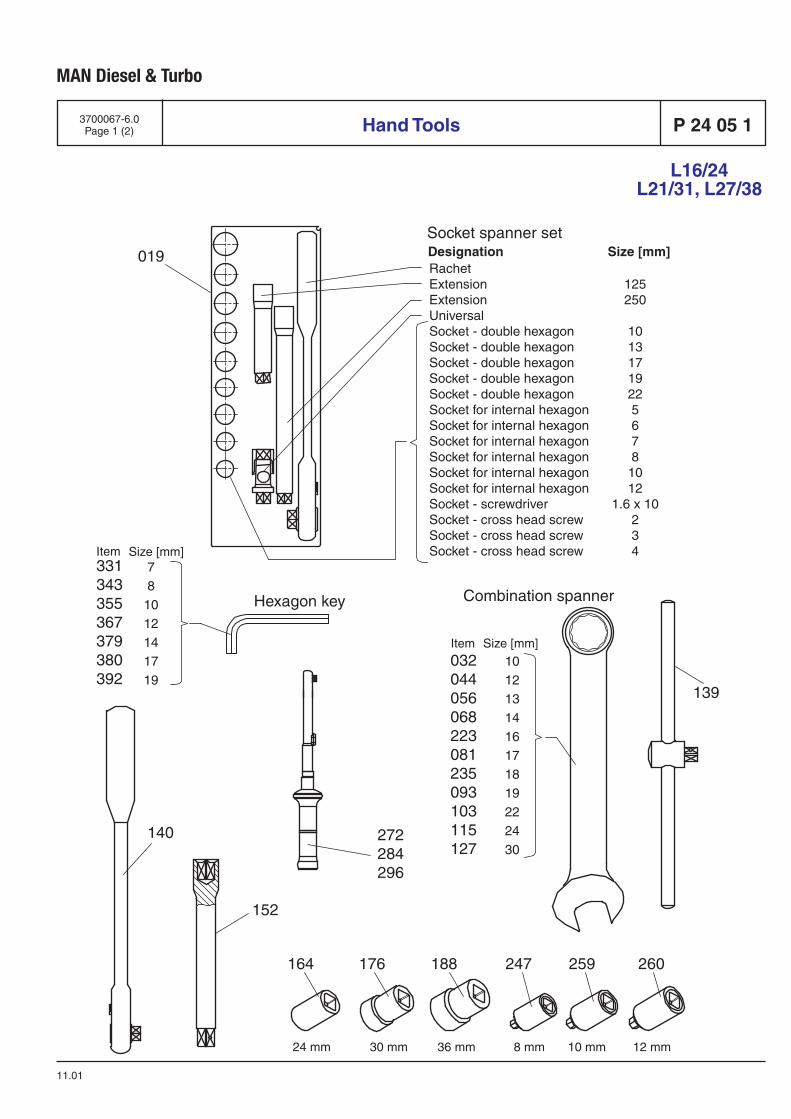
MAN Diesel & Turbo
3700067-6.0Page 1 (2)
11.01
Hand Tools P 24 05 1
L16/24L21/31, L27/38
12 mm10 mm8 mm
164 176 188 247 259 260
30 mm 36 mm24 mm
Size [mm]331343355367379380392
272284296
152
139
Size [mm]Item
Item
019
Socket spanner setDesignation Size [mm]
Combination spannerHexagon key
140
RachetExtension 125Extension 250UniversalSocket - double hexagon 10Socket - double hexagon 13Socket - double hexagon 17Socket - double hexagon 19Socket - double hexagon 22Socket for internal hexagon 5Socket for internal hexagon 6Socket for internal hexagon 7Socket for internal hexagon 8Socket for internal hexagon 10Socket for internal hexagon 12Socket - screwdriver 1.6 x 10Socket - cross head screw 2Socket - cross head screw 3Socket - cross head screw 4
781012141719
1012131416171819222430
032044056068223081235093103115127
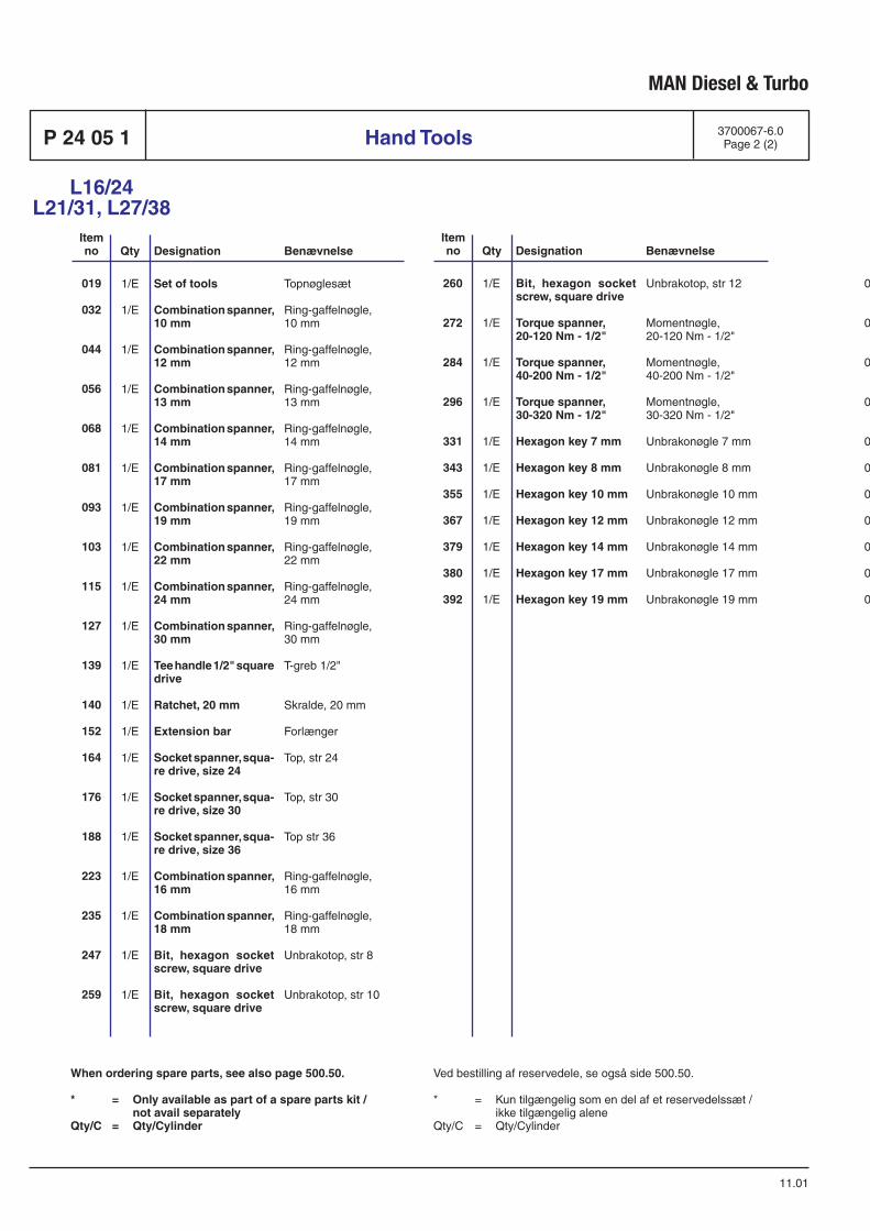
MAN Diesel & Turbo
Hand Tools 3700067-6.0Page 2 (2)P 24 05 1
11.01
L16/24L21/31, L27/38
019
032
044
056
068
081
093
103
115
127
139
140
152
164
176
188
223
235
247
259
Item no Benævnelse
Topnøglesæt
Ring-gaffelnøgle,10 mm
Ring-gaffelnøgle,12 mm
Ring-gaffelnøgle,13 mm
Ring-gaffelnøgle,14 mm
Ring-gaffelnøgle,17 mm
Ring-gaffelnøgle,19 mm
Ring-gaffelnøgle,22 mm
Ring-gaffelnøgle,24 mm
Ring-gaffelnøgle,30 mm
T-greb 1/2"
Skralde, 20 mm
Forlænger
Top, str 24
Top, str 30
Top str 36
Ring-gaffelnøgle,16 mm
Ring-gaffelnøgle,18 mm
Unbrakotop, str 8
Unbrakotop, str 10
Designation
Set of tools
Combination spanner, 10 mm
Combination spanner, 12 mm
Combination spanner, 13 mm
Combination spanner, 14 mm
Combination spanner, 17 mm
Combination spanner, 19 mm
Combination spanner, 22 mm
Combination spanner, 24 mm
Combination spanner, 30 mm
Tee handle 1/2" square drive
Ratchet, 20 mm
Extension bar
Socket spanner, squa-re drive, size 24
Socket spanner, squa-re drive, size 30
Socket spanner, squa-re drive, size 36
Combination spanner,16 mm
Combination spanner,18 mm
Bit, hexagon socket screw, square drive
Bit, hexagon socket screw, square drive
Qty
1/E
1/E
1/E
1/E
1/E
1/E
1/E
1/E
1/E
1/E
1/E
1/E
1/E
1/E
1/E
1/E
1/E
1/E
1/E
1/E
Ved bestilling af reservedele, se også side 500.50.
* = Kun tilgængelig som en del af et reservedelssæt / ikke tilgængelig aleneQty/C = Qty/Cylinder
When ordering spare parts, see also page 500.50.
* = Only available as part of a spare parts kit / not avail separately Qty/C = Qty/Cylinder
Item no BenævnelseDesignationQty
EN563H1
08.06073-0014
08.06073-0016
08.06073-0017
08.06073-0018
08.06073-0021
08.06073-0023
08.06073-0326
08.06073-0328
08.06073-0334
08.06631-0400
08.06631-3600
08.06139-1358
08.06140-6100
08.06140-6300
08.06140-6500
08.06073-0020
08.06073-0022
08.06556-3040
08.06556-3060
08.06556-3080
08.06411-0010
08.06411-0011
08.06411-0013
08.06125-1100
08.06125-1200
08.06125-1400
08.06125-1600
08.06125-1800
08.06125-2100
08.06125-2300
260
272
284
296
331
343
355
367
379
380
392
1/E
1/E
1/E
1/E
1/E
1/E
1/E
1/E
1/E
1/E
1/E
Bit, hexagon socket screw, square drive
Torque spanner,20-120 Nm - 1/2"
Torque spanner,40-200 Nm - 1/2"
Torque spanner,30-320 Nm - 1/2"
Hexagon key 7 mm
Hexagon key 8 mm
Hexagon key 10 mm
Hexagon key 12 mm
Hexagon key 14 mm
Hexagon key 17 mm
Hexagon key 19 mm
Unbrakotop, str 12
Momentnøgle,20-120 Nm - 1/2"
Momentnøgle,40-200 Nm - 1/2"
Momentnøgle,30-320 Nm - 1/2"
Unbrakonøgle 7 mm
Unbrakonøgle 8 mm
Unbrakonøgle 10 mm
Unbrakonøgle 12 mm
Unbrakonøgle 14 mm
Unbrakonøgle 17 mm
Unbrakonøgle 19 mm

G 50 Alternator
B 50

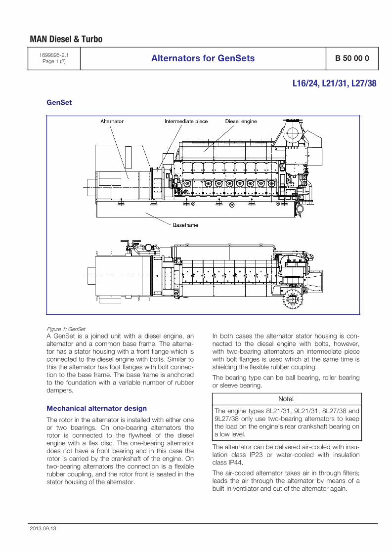
GenSet
Figure 1: GenSetA GenSet is a joined unit with a diesel engine, analternator and a common base frame. The alterna-tor has a stator housing with a front flange which isconnected to the diesel engine with bolts. Similar tothis the alternator has foot flanges with bolt connec-tion to the base frame. The base frame is anchoredto the foundation with a variable number of rubberdampers.
Mechanical alternator design
The rotor in the alternator is installed with either oneor two bearings. On one-bearing alternators therotor is connected to the flywheel of the dieselengine with a flex disc. The one-bearing alternatordoes not have a front bearing and in this case therotor is carried by the crankshaft of the engine. Ontwo-bearing alternators the connection is a flexiblerubber coupling, and the rotor front is seated in thestator housing of the alternator.
In both cases the alternator stator housing is con-nected to the diesel engine with bolts, however,with two-bearing alternators an intermediate piecewith bolt flanges is used which at the same time isshielding the flexible rubber coupling.
The bearing type can be ball bearing, roller bearingor sleeve bearing.
Note!
The engine types 8L21/31, 9L21/31, 8L27/38 and9L27/38 only use two-bearing alternators to keepthe load on the engine’s rear crankshaft bearing ona low level.
The alternator can be delivered air-cooled with insu-lation class IP23 or water-cooled with insulationclass IP44.
The air-cooled alternator takes air in through filters;leads the air through the alternator by means of abuilt-in ventilator and out of the alternator again.
MAN Diesel & Turbo
1699895-2.1Page 1 (2) Alternators for GenSets B 50 00 0
L16/24, L21/31, L27/38
2013.09.13

The water-cooled alternator circulates air internallyin the alternator by means of the ventilator. The air-flow passes through a built-in water cooler, remov-ing the heat from the alternator through the connec-ted cooling water system.
The entrance to the electrical main cables can beplaced on the right or left side of the alternator witha horizontal or vertical inlet.
Electrical alternator design
The alternator is a three-phase AC synchronousalternator – brushless with built-in exciter and auto-matic, electronic voltage regulator (AVR) with poten-tiometer for remote control. (The potentiometer forfinal adjustment of the voltage is included in thestandard delivery and normally part of the controlpanel).
The alternator is intended for parallel running.
The insulation class for the windings can be H/H orlower. H/H corresponds to 180° C on the windingsand 180° C operating temperature.
According to the GL classification rules the alterna-tor must as maximum be used up to 155° C oper-ating temperature – corresponding to insulationclass F. It may also be a customer requirement tokeep the efficiency below class H.
The windings have tropical resistance against highhumidity.
The alternator is equipped with anti-condensatestandstill heater.
For temperature surveillance in the windings, thealternator is equipped with 2x3 PT100 sensors(PT1000 sensors for engines with SaCoSone).PT100/PT1000 sensors are also installed for sur-veillance of the bearing temperature and for watercooled alternators for surveillance of cooling airtemperature. Alternators may also be equipped withvisual thermometers on bearings.
The alternator can be delivered for the voltages 380VAC to 13.8 KVAC. The frequencies are 50 Hz or60 Hz.
The alternator fulfils the requirements for electro-magnetic compatibility protection EMC, is designedand tested according to IEC34 and fulfils the DINEN 60034 / VDE0530 requirements.
MAN Diesel & Turbo
B 50 00 0 Alternators for GenSets 1699895-2.1Page 2 (2)
L16/24, L21/31, L27/38
2013.09.13
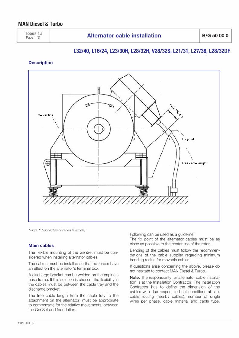
Description
Figure 1: Connection of cables (example)
Main cables
The flexible mounting of the GenSet must be con-sidered when installing alternator cables.
The cables must be installed so that no forces havean effect on the alternator's terminal box.
A discharge bracket can be welded on the engine'sbase frame. If this solution is chosen, the flexibility inthe cables must be between the cable tray and thedischarge bracket.
The free cable length from the cable tray to theattachment on the alternator, must be appropriateto compensate for the relative movements, betweenthe GenSet and foundation.
Following can be used as a guideline:The fix point of the alternator cables must be asclose as possible to the center line of the rotor.
Bending of the cables must follow the recommen-dations of the cable supplier regarding minimumbending radius for movable cables.
If questions arise concerning the above, please donot hesitate to contact MAN Diesel & Turbo.
Note: The responsibility for alternator cable installa-tion is at the Installation Contractor. The InstallationContractor has to define the dimension of thecables with due respect to heat conditions at site,cable routing (nearby cables), number of singlewires per phase, cable material and cable type.
MAN Diesel & Turbo
1699865-3.2Page 1 (3) Alternator cable installation B/G 50 00 0
L32/40, L16/24, L23/30H, L28/32H, V28/32S, L21/31, L27/38, L28/32DF
2013.09.09
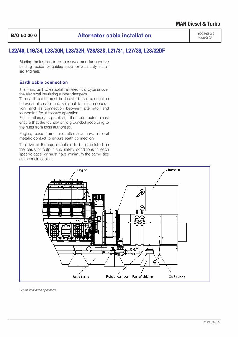
Binding radius has to be observed and furthermorebinding radius for cables used for elastically instal-led engines.
Earth cable connection
It is important to establish an electrical bypass overthe electrical insulating rubber dampers.The earth cable must be installed as a connectionbetween alternator and ship hull for marine opera-tion, and as connection between alternator andfoundation for stationary operation.For stationary operation, the contractor mustensure that the foundation is grounded according tothe rules from local authorities.
Engine, base frame and alternator have internalmetallic contact to ensure earth connection.
The size of the earth cable is to be calculated onthe basis of output and safety conditions in eachspecific case; or must have minimum the same sizeas the main cables.
Figure 2: Marine operation
MAN Diesel & Turbo
B/G 50 00 0 Alternator cable installation 1699865-3.2Page 2 (3)
L32/40, L16/24, L23/30H, L28/32H, V28/32S, L21/31, L27/38, L28/32DF
2013.09.09
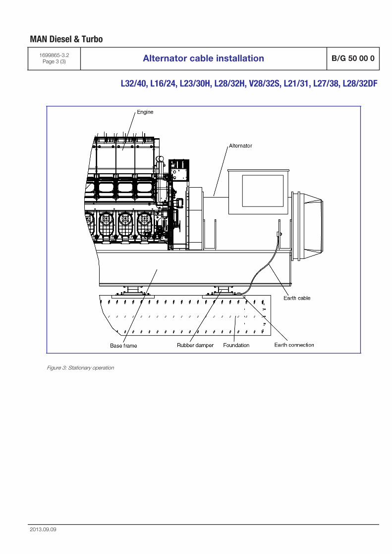
Figure 3: Stationary operation
MAN Diesel & Turbo
1699865-3.2Page 3 (3) Alternator cable installation B/G 50 00 0
L32/40, L16/24, L23/30H, L28/32H, V28/32S, L21/31, L27/38, L28/32DF
2013.09.09

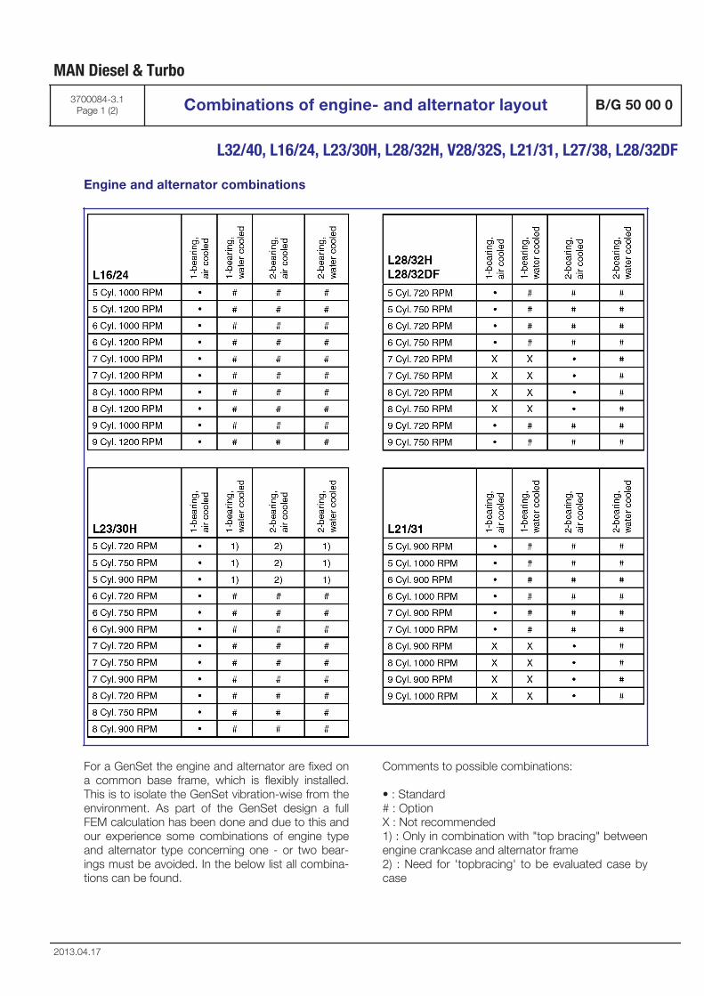
Engine and alternator combinations
For a GenSet the engine and alternator are fixed ona common base frame, which is flexibly installed.This is to isolate the GenSet vibration-wise from theenvironment. As part of the GenSet design a fullFEM calculation has been done and due to this andour experience some combinations of engine typeand alternator type concerning one - or two bear-ings must be avoided. In the below list all combina-tions can be found.
Comments to possible combinations:
• : Standard# : OptionX : Not recommended1) : Only in combination with "top bracing" betweenengine crankcase and alternator frame2) : Need for 'topbracing' to be evaluated case bycase
MAN Diesel & Turbo
3700084-3.1Page 1 (2) Combinations of engine- and alternator layout B/G 50 00 0
L32/40, L16/24, L23/30H, L28/32H, V28/32S, L21/31, L27/38, L28/32DF
2013.04.17
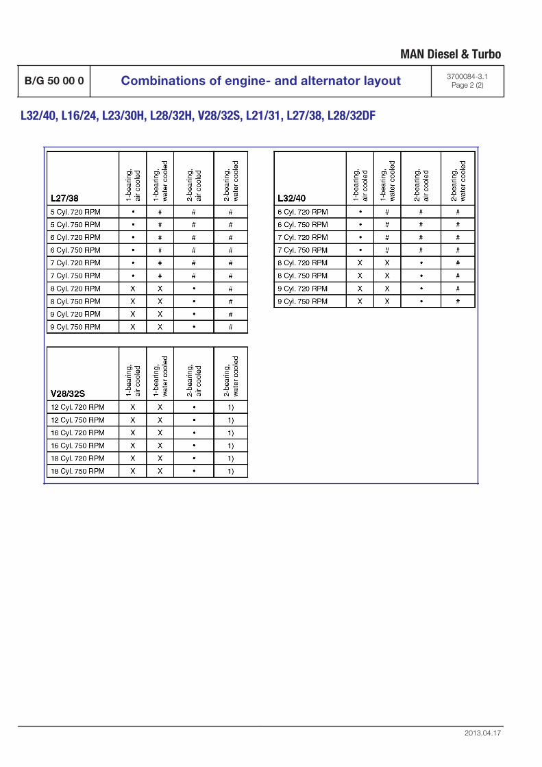
MAN Diesel & Turbo
B/G 50 00 0 Combinations of engine- and alternator layout 3700084-3.1Page 2 (2)
L32/40, L16/24, L23/30H, L28/32H, V28/32S, L21/31, L27/38, L28/32DF
2013.04.17

Diesel-electric propulsion
B 52

MAN Diesel & Turbo
Diesel-electric Propulsion Plants B 52 00 0
L21/31 L27/38
3700088-0.0Page 1 (25)
11.10 - Tier II
1.1 Advantages of diesel-electric propulsion
Due to different and individual types, purposes and operational profiles of diesel-electric driven vessels the design of a diesel-electric propulsion plant differs a lot and has to be evaluated case by case. All the following is for information purpose only and without obligation.
In general the advantages of diesel-electric propulsion can be summarized as follows:
- Lower fuel consumption and emissions due to the possibility to optimize the loading of die-sel engines / gensets. The gensets in operation can run on high loads with high efficiency. This applies especially to vessels which have a large variation in load demand, for example for an offshore supply vessel, which divides its time between transit and station-keeping (DP) operation.
- High reliability, due to multiple engine redundancy. Even if an engine / genset malfunctions, there will be sufficient power to operate the vessel safely. Reduced vulnerability to single point of failure providing the basis to fulfill high redundancy re-quirements.
- Reduced life cycle cost, resulting form lower operational and maintenance costs. - Improved manoeuvrabilty and station-keeping ability, by deploying special propulsors such
as azimuth thrusters or pods. Precise control of the electrical propulsion motors controlled by frequency converters.
- Increased payload, as diesel-electric propulsion plants take less space. - More flexibility in location of diesel engine / gensets and propulsors. The propulsors are
supplied with electric power through cables. They do not need to be adjacent to the diesel engines / gensets.
- Low propulsion noise and reduced vibrations. For example a slow speed E-motors allows to avoid gearboxes and propulsors like pods keep most of the structure bore noise outside of the hull.
- Efficient performance and high motor torques, as the system can provide maximum torque also at slow speeds, which gives advantages for example in icy conditions.
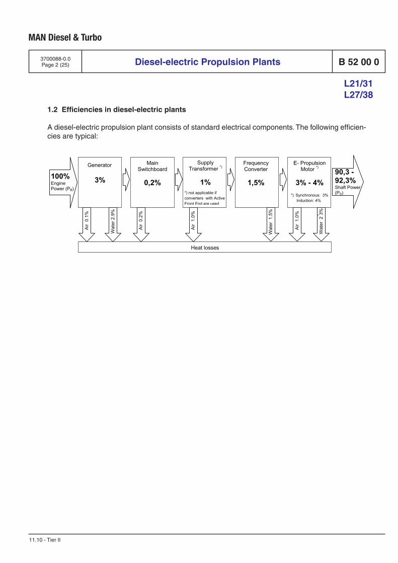
MAN Diesel & Turbo
Diesel-electric Propulsion Plants B 52 00 0
L21/31 L27/38
3700088-0.0Page 2 (25)
11.10 - Tier II
1.2 Efficiencies in diesel-electric plants
A diesel-electric propulsion plant consists of standard electrical components. The following efficien-cies are typical:
100% Engine Power (PB)
90,3 - 92,3% Shaft Power (PS)
Generator
3%
Main Switchboard
0,2%
Supply Transformer *)
1%
*) not applicable if converters with Active Front End are used
Frequency Converter
1,5%
E- Propulsion Motor *)
3% - 4%
*) Synchronous: 3% Induction: 4%
Air 0.
1%
Wat
er 2
.9%
Air 0.
2%
Air 1.
0%
Wat
er 1
.5%
Air 1.
0%
Wat
er 2
- 3%
Heat losses
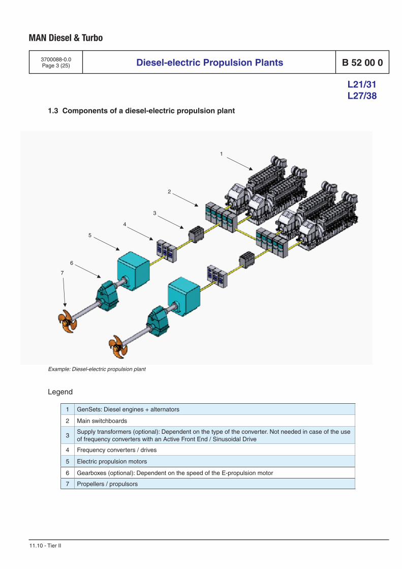
MAN Diesel & Turbo
Diesel-electric Propulsion Plants B 52 00 0
L21/31 L27/38
3700088-0.0Page 3 (25)
11.10 - Tier II
1.3 Components of a diesel-electric propulsion plant
1 GenSets: Diesel engines + alternators
2 Main switchboards
3Supply transformers (optional): Dependent on the type of the converter. Not needed in case of the use of frequency converters with an Active Front End / Sinusoidal Drive
4 Frequency converters / drives
5 Electric propulsion motors
6 Gearboxes (optional): Dependent on the speed of the E-propulsion motor
7 Propellers / propulsors
1
2
3
4
5
6
7
Example: Diesel-electric propulsion plant
Legend
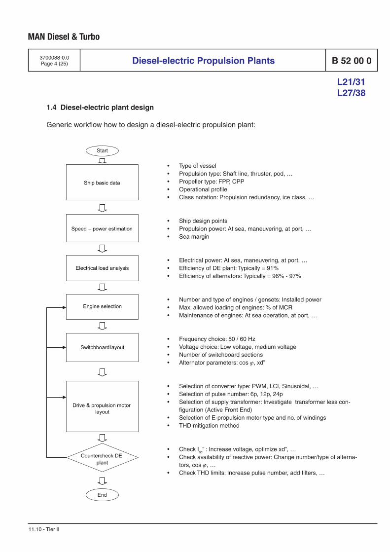
MAN Diesel & Turbo
Diesel-electric Propulsion Plants B 52 00 0
L21/31 L27/38
3700088-0.0Page 4 (25)
11.10 - Tier II
1.4 Diesel-electric plant design
Generic workflow how to design a diesel-electric propulsion plant:
Ship basic data
Speed – power estimation
Electrical load analysis
Switchboard layout
Drive & propulsion motor layout
Engine selection
Countercheck DE plant
Start
End
• Type of vessel• Propulsion type: Shaft line, thruster, pod, …• Propeller type: FPP, CPP• Operational profile• Class notation: Propulsion redundancy, ice class, …
• Ship design points• Propulsion power: At sea, maneuvering, at port, …• Sea margin
• Electrical power: At sea, maneuvering, at port, …• Efficiency of DE plant: Typically = 91%• Efficiency of alternators: Typically = 96% - 97%
• Number and type of engines / gensets: Installed power• Max. allowed loading of engines: % of MCR• Maintenance of engines: At sea operation, at port, …
• Frequency choice: 50 / 60 Hz• Voltage choice: Low voltage, medium voltage• Number of switchboard sections• Alternator parameters: cos ϕ, xd”
• Selection of converter type: PWM, LCI, Sinusoidal, …• Selection of pulse number: 6p, 12p, 24p• Selection of supply transformer: Investigate transformer less con-
figuration (Active Front End)• Selection of E-propulsion motor type and no. of windings• THD mitigation method
• Check Isc” : Increase voltage, optimize xd”, …
• Check availability of reactive power: Change number/type of alterna-tors, cos ϕ, …
• Check THD limits: Increase pulse number, add filters, …
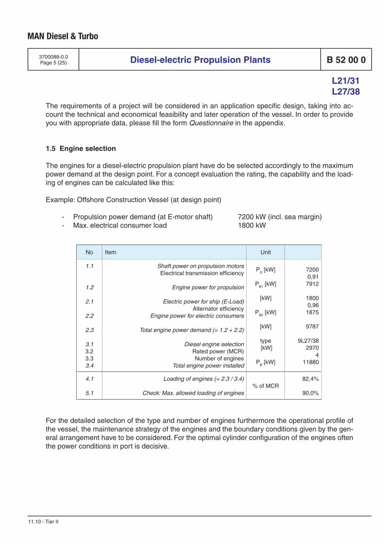
MAN Diesel & Turbo
Diesel-electric Propulsion Plants B 52 00 0
L21/31 L27/38
3700088-0.0Page 5 (25)
11.10 - Tier II
The requirements of a project will be considered in an application specific design, taking into ac-count the technical and economical feasibility and later operation of the vessel. In order to provide you with appropriate data, please fill the form Questionnaire in the appendix.
1.5 Engine selection
The engines for a diesel-electric propulsion plant have do be selected accordingly to the maximum power demand at the design point. For a concept evaluation the rating, the capability and the load-ing of engines can be calculated like this:
Example: Offshore Construction Vessel (at design point)
- Propulsion power demand (at E-motor shaft) 7200 kW (incl. sea margin) - Max. electrical consumer load 1800 kW
No Item Unit
1.1
1.2
2.1
2.2
2.3
3.13.23.33.4
Shaft power on propulsion motorsElectrical transmission efficiency
Engine power for propulsion
Electric power for ship (E-Load)
Alternator efficiencyEngine power for electric consumers
Total engine power demand (= 1.2 + 2.2)
Diesel engine selection
Rated power (MCR)Number of engines
Total engine power installed
PS [kW]
PB1 [kW]
[kW]
PB2 [kW]
[kW]
type [kW]
PB [kW]
72000,91
7912
18000,96
1875
9787
9L27/382970
411880
4.1
5.1
Loading of engines (= 2.3 / 3.4)
Check: Max. allowed loading of engines% of MCR
82,4%
90,0%
For the detailed selection of the type and number of engines furthermore the operational profile of the vessel, the maintenance strategy of the engines and the boundary conditions given by the gen-eral arrangement have to be considered. For the optimal cylinder configuration of the engines often the power conditions in port is decisive.
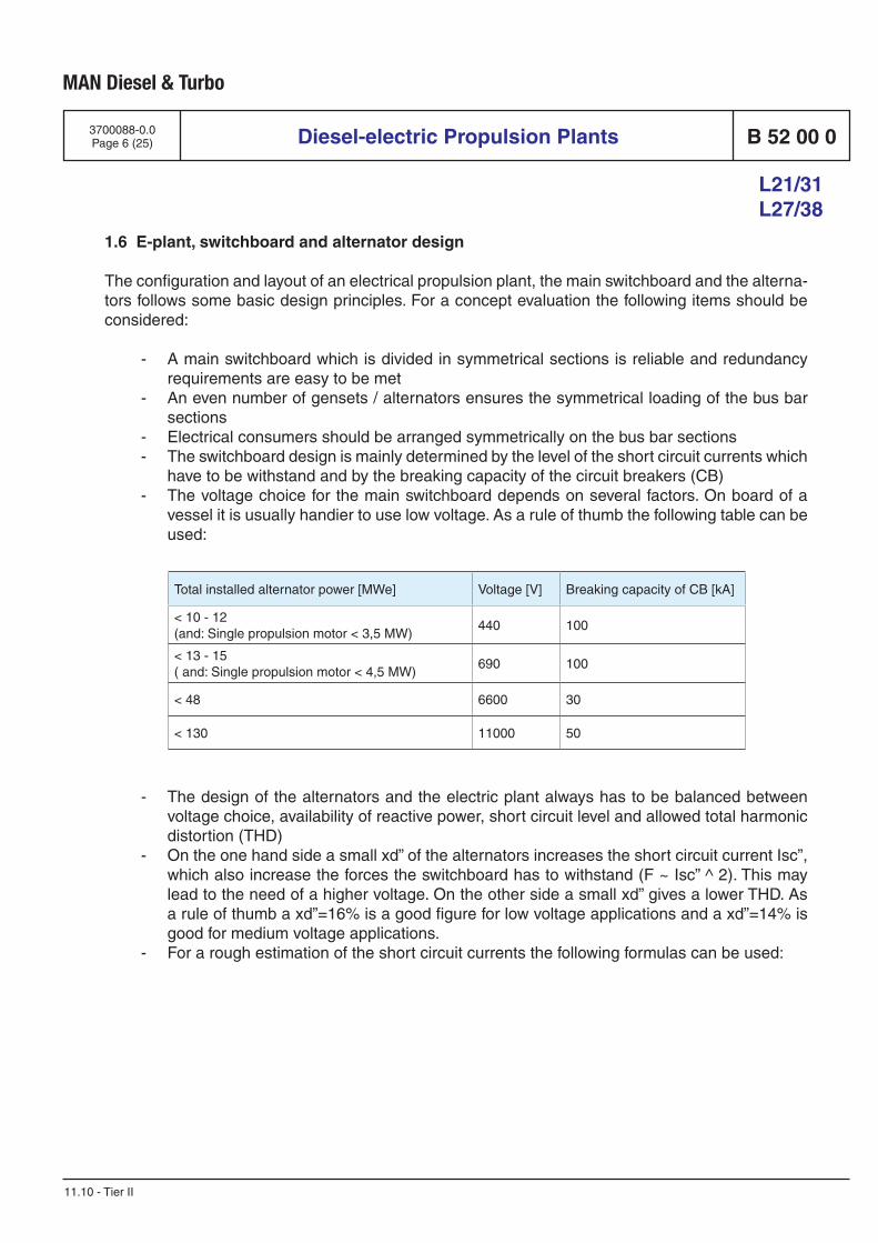
MAN Diesel & Turbo
Diesel-electric Propulsion Plants B 52 00 0
L21/31 L27/38
3700088-0.0Page 6 (25)
11.10 - Tier II
1.6 E-plant, switchboard and alternator design
The configuration and layout of an electrical propulsion plant, the main switchboard and the alterna-tors follows some basic design principles. For a concept evaluation the following items should be considered:
- A main switchboard which is divided in symmetrical sections is reliable and redundancy requirements are easy to be met
- An even number of gensets / alternators ensures the symmetrical loading of the bus bar sections
- Electrical consumers should be arranged symmetrically on the bus bar sections - The switchboard design is mainly determined by the level of the short circuit currents which
have to be withstand and by the breaking capacity of the circuit breakers (CB) - The voltage choice for the main switchboard depends on several factors. On board of a
vessel it is usually handier to use low voltage. As a rule of thumb the following table can be used:
Total installed alternator power [MWe] Voltage [V] Breaking capacity of CB [kA]
< 10 - 12(and: Single propulsion motor < 3,5 MW)
440 100
< 13 - 15( and: Single propulsion motor < 4,5 MW)
690 100
< 48 6600 30
< 130 11000 50
- The design of the alternators and the electric plant always has to be balanced between voltage choice, availability of reactive power, short circuit level and allowed total harmonic distortion (THD)
- On the one hand side a small xd” of the alternators increases the short circuit current Isc”, which also increase the forces the switchboard has to withstand (F ~ Isc” ^ 2). This may lead to the need of a higher voltage. On the other side a small xd” gives a lower THD. As a rule of thumb a xd”=16% is a good figure for low voltage applications and a xd”=14% is good for medium voltage applications.
- For a rough estimation of the short circuit currents the following formulas can be used:
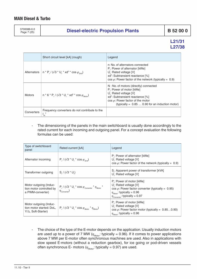
MAN Diesel & Turbo
Diesel-electric Propulsion Plants B 52 00 0
L21/31 L27/38
3700088-0.0Page 7 (25)
11.10 - Tier II
- The dimensioning of the panels in the main switchboard is usually done accordingly to the rated current for each incoming and outgoing panel. For a concept evaluation the following formulas can be used:
Short circuit level [kA] (rough) Legend
Alternators n * Pr / (√3 * Ur * xd” * cos ϕGrid)
n: No. of alternators connectedPr: Power of alternator [kWe] Ur: Rated voltage [V]xd”: Subtransient reactance [%]cos ϕ: Power factor of the network (typically = 0.9)
Motors n * 6 * Pr / (√3 * Ur * xd” * cos ϕMotor)
N : No. of motors (directly) connectedPr: Power of motor [kWe] Ur: Rated voltage [V]xd”: Subtransient reactance [%]cos ϕ: Power factor of the motor (typically = 0.85 … 0.90 for an induction motor)
ConvertersFrequency converters do not contribute to the Isc”
Type of switchboard panel
Rated current [kA] Legend
Alternator incoming Pr / (√3 * Ur * cos ϕGrid)Pr: Power of alternator [kWe] Ur: Rated voltage [V]cos ϕ: Power factor of the network (typically = 0.9)
Transformer outgoing Sr / (√3 * Ur)Sr: Apparent power of transformer [kVA] Ur: Rated voltage [V]
Motor outgoing (Induc-tion motor controlled by a PWM-converter)
Pr / (√3 * Ur * cos ϕConverter * ηMotor * ηConverter)
Pr: Power of motor [kWe] Ur: Rated voltage [V]cos ϕ: Power factor converter (typically = 0.95)ηMotor: typically = 0.96ηConverter: typically = 0.97
Motor outgoing (Induc-tion motor started: DoL, Y/∆, Soft-Starter)
Pr / (√3 * Ur * cos ϕMotor * ηMotor)
Pr: Power of motor [kWe] Ur: Rated voltage [V]cos ϕ: Power factor motor (typically = 0.85…0.90)ηMotor: typically = 0.96
- The choice of the type of the E-motor depends on the application. Usually induction motors are used up to a power of 7 MW (ηMotor: typically = 0.96). If it comes to power applications above 7 MW per E-motor often synchronous machines are used. Also in applications with slow speed E-motors (without a reduction gearbox), for ice going or pod-driven vessels often synchronous E- motors (ηMotor: typically = 0.97) are used.
MAN Diesel & Turbo
Diesel-electric Propulsion Plants B 52 00 0
L21/31 L27/38
3700088-0.0Page 8 (25)
11.10 - Tier II
- In plants with frequency converters based on VSI-technology (PWM type) the converter themselves can deliver reactive power to the E-motor. So often a power factor cos ϕ = 0.9 is a good figure to design the alternator rating. Nevertheless there has to be sufficient reactive power for the ship consumers, so that a lack in reactive power does not lead to unnecessary starts of (standby) alternators.
- The harmonics can be improved (if necessary) by using supply transformers for the fre-quency converters with a 30° phase shift between the two secondary windings, which cancel the dominant 5th and 7th harmonic currents. Also an increase in the pulse number leads to lower THD. Using a 12-pulse configuration with a PWM type of converter the re-sulting harmonic distortion will normally be below the limits defined by the classification societies. When using a transformer less solution with a converter with an Active Front End (Sinusoidal input rectifier) or in a 6-pulse configuration usually THD-filters are necessary to mitigate the THD on the sub-distributions.
The final layout of the electrical plant and the components has always to be based on a detailed analysis and a calculations of the short circuit levels, the load flows and the THD levels as well as on an economical evaluation.
1.7 Over-torque capability
In diesel-electric propulsion plants, which are running with a fix pitch propeller, the dimensioning of the electric propulsion motor has to be done accurately, in order to have sufficient propulsion power available. As an electric motor produces torque, which directly defines the cost (amount of copper), weight and space of the motor, it has to be investigated what amount of over-torque is required to operate the vessel with sufficient power also in situations, where additional power is needed (for example because of heavy weather or icy conditions).
Usually a constant power range of 5-10% is applied on the propulsion (Field weakening range), where constant E-motor power is available.
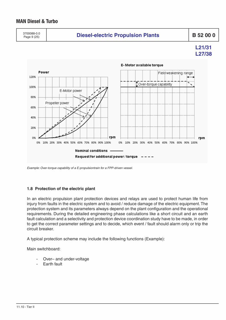
MAN Diesel & Turbo
Diesel-electric Propulsion Plants B 52 00 0
L21/31 L27/38
3700088-0.0Page 9 (25)
11.10 - Tier II
1.8 Protection of the electric plant
In an electric propulsion plant protection devices and relays are used to protect human life from injury from faults in the electric system and to avoid / reduce damage of the electric equipment. The protection system and its parameters always depend on the plant configuration and the operational requirements. During the detailed engineering phase calculations like a short circuit and an earth fault calculation and a selectivity and protection device coordination study have to be made, in order to get the correct parameter settings and to decide, which event / fault should alarm only or trip the circuit breaker.
A typical protection scheme may include the following functions (Example):
Main switchboard:
- Over– and under-voltage - Earth fault
Example: Over-torque capability of a E-propulsiontrain for a FPP-driven vessel.
MAN Diesel & Turbo
Diesel-electric Propulsion Plants B 52 00 0
L21/31 L27/38
3700088-0.0Page 10 (25)
11.10 - Tier II
Alternator:
- Short circuit - Over-current - Stator earth fault - Reverse power - Phase unbalance, Negative phase sequence - Differential protection - Over- and under-frequency - Over- and under-voltage - Alternator windings and bearings over-temperature - Alternator cooling air/water temperature - Synchronizing check - Over- and under-excitation (Loss of excitation)
Bus tie feeder:
- Short circuit - Earth fault - Synchronizing check - Differential protection (in ring networks)
Transformer feeder: - Short circuit - Over-current - Earth fault - Thermal overload/image - Under-voltage - Differential protection (for large transformers)
Motor feeder: - Short circuit - Over-current - Earth fault - Under-voltage - Thermal overload/image - Motor start: Stalling I2t, number of starts - Motor windings and bearings over-temperature - Motor cooling air/water temperature
MAN Diesel & Turbo
Diesel-electric Propulsion Plants B 52 00 0
L21/31 L27/38
3700088-0.0Page 11 (25)
11.10 - Tier II
1.9 Drive control
The drive control system is a computer controlled system for the speed converters / drives, provid-ing network stability in case of sudden / dynamical load changes. It ensures safe operation of the converters with constant and stable power supply to the E-propulsion motors and avoids the loss of power under all operational conditions. Usually the propulsion is speed controlled. So the system keeps the reference speed constant as far as possible within the speed and torque limitations and dynamic capability.
The drive control system normally interfaces with the propulsion control system, the power manage-ment system, the dynamic position system and several other ship control and automation systems. The functionality of the drive control system depends on the plant configuration and the operational requirements.
The main tasks of the drive control system can be summarized as follows:
- Control of the converters / drives, including the speed reference calculation - Control of drive / propeller speed according to the alternator capability, including anti-over-
load prevention - Control of power and torque. It takes care of the limits - Control of the converter cooling
For some applications (e.g. for ice going vessels, for rough sea conditions, etc, where load torque varies much and fast) often a power control mode is applied, which reduces the disturbances on the network and smoothens the load application on the diesel engines.
1.10 Power management
Power reservation
The main function of a power management system is to start and stop gensets / alternators accord-ing to the current network load and the online alternator capacity. The power management system takes care that the next alternator will be started, if the available power (= Installed power of all connected alternators – current load) becomes lower than a preset limit. This triggers a timer and if the available power stays bellow the limit for a certain time period the next genset / alternator in sequence is started. It also blocks heavy consumers to be started or sheds (unnecessary) consum-ers, if there is not enough power is available, in order to avoid unstable situations.
Class rules require from gensets / alternators 45 seconds for starting, synchronizing and beginning of sharing load. So it is always a challenge for the power management system to anticipate the situ-ation in advance and to start gensets / alternators before consumers draw the network and overload the engines. Overloading an engine will soon decrease the speed / frequency with the danger of motoring the engine, as the flow of power will be altered from network to alternator (Reverse power). The electric protection system must disconnect such alternator from the network. An overload situ-ation is always a critical situation for the vessel and a blackout has to be avoided.
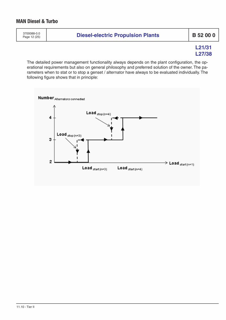
MAN Diesel & Turbo
Diesel-electric Propulsion Plants B 52 00 0
L21/31 L27/38
3700088-0.0Page 12 (25)
11.10 - Tier II
The detailed power management functionality always depends on the plant configuration, the op-erational requirements but also on general philosophy and preferred solution of the owner. The pa-rameters when to stat or to stop a genset / alternator have always to be evaluated individually. The following figure shows that in principle:
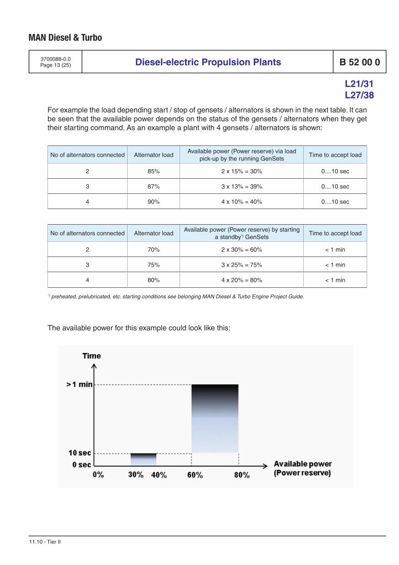
MAN Diesel & Turbo
Diesel-electric Propulsion Plants B 52 00 0
L21/31 L27/38
3700088-0.0Page 13 (25)
11.10 - Tier II
For example the load depending start / stop of gensets / alternators is shown in the next table. It can be seen that the available power depends on the status of the gensets / alternators when they get their starting command. As an example a plant with 4 gensets / alternators is shown:
No of alternators connected Alternator loadAvailable power (Power reserve) via load
pick-up by the running GenSetsTime to accept load
2 85% 2 x 15% = 30% 0....10 sec
3 87% 3 x 13% = 39% 0....10 sec
4 90% 4 x 10% = 40% 0....10 sec
No of alternators connected Alternator loadAvailable power (Power reserve) by starting
a standby*) GenSetsTime to accept load
2 70% 2 x 30% = 60% < 1 min
3 75% 3 x 25% = 75% < 1 min
4 80% 4 x 20% = 80% < 1 min
*) preheated, prelubricated, etc. starting conditions see belonging MAN Diesel & Turbo Engine Project Guide.
The available power for this example could look like this:
MAN Diesel & Turbo
Diesel-electric Propulsion Plants B 52 00 0
L21/31 L27/38
3700088-0.0Page 14 (25)
11.10 - Tier II
Power management system
Derived from the above mentioned main tasks of a power management system the following func-tions are typical:
- Automatic load dependent start / stop of gensets / alternators - Manual starting / stopping of gensets / alternators - Fault dependent start /stop of standby gensets / alternators in cases of under-frequency
and/or under-voltage. - Start of gensets / alternators in case of a blackout (Black-start capability) - Determining and selection of the starting / stopping sequence of gensets / alternators - Start and supervise the automatic synchronization of alternators and bus tie breakers - Balanced and unbalanced load application and sharing between gensets / alternators.
Often an emergency program for quickest possible load acceptance is necessary. - Regulation of the network frequency (with static droop or constant frequency) - Distribution of active load between alternators - Distribution of reactive load between alternators - Handling and blocking of heavy consumers - Automatic load shedding - Tripping of non-essential consumers - Bus tie and breaker monitoring and control
All questions regarding the functionality of the power management system have to be clarified with MAN Diesel & Turbo at an early project stage.
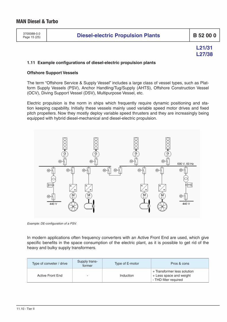
MAN Diesel & Turbo
Diesel-electric Propulsion Plants B 52 00 0
L21/31 L27/38
3700088-0.0Page 15 (25)
11.10 - Tier II
1.11 Example configurations of diesel-electric propulsion plants
Offshore Support Vessels
The term “Offshore Service & Supply Vessel” includes a large class of vessel types, such as Plat-form Supply Vessels (PSV), Anchor Handling/Tug/Supply (AHTS), Offshore Construction Vessel (OCV), Diving Support Vessel (DSV), Multipurpose Vessel, etc.
Electric propulsion is the norm in ships which frequently require dynamic positioning and sta-tion keeping capability. Initially these vessels mainly used variable speed motor drives and fixed pitch propellers. Now they mostly deploy variable speed thrusters and they are increasingly being equipped with hybrid diesel-mechanical and diesel-electric propulsion.
Example: DE-configuration of a PSV.
In modern applications often frequency converters with an Active Front End are used, which give specific benefits in the space consumption of the electric plant, as it is possible to get rid of the heavy and bulky supply transformers.
Type of conveter / driveSupply trans-
formerType of E-motor Pros & cons
Active Front End - Induction+ Transformer less solution+ Less space and weight- THD filter required
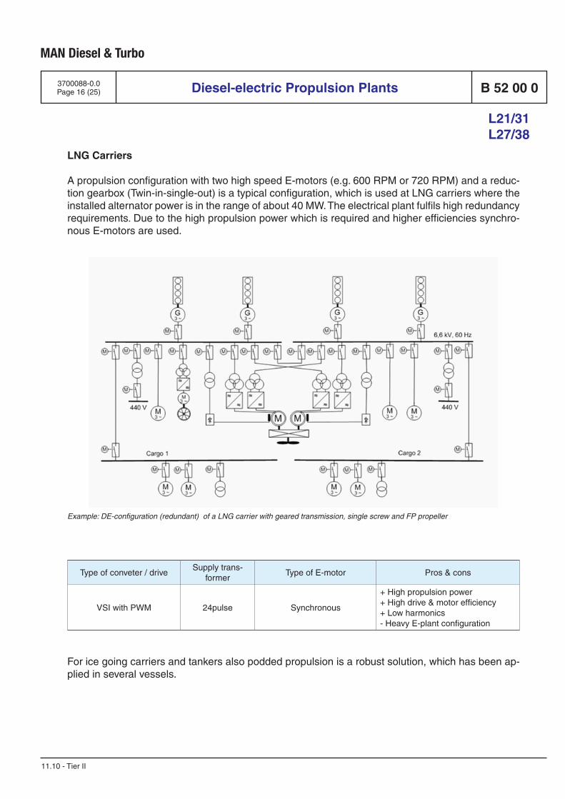
MAN Diesel & Turbo
Diesel-electric Propulsion Plants B 52 00 0
L21/31 L27/38
3700088-0.0Page 16 (25)
11.10 - Tier II
LNG Carriers
A propulsion configuration with two high speed E-motors (e.g. 600 RPM or 720 RPM) and a reduc-tion gearbox (Twin-in-single-out) is a typical configuration, which is used at LNG carriers where the installed alternator power is in the range of about 40 MW. The electrical plant fulfils high redundancy requirements. Due to the high propulsion power which is required and higher efficiencies synchro-nous E-motors are used.
Example: DE-configuration (redundant) of a LNG carrier with geared transmission, single screw and FP propeller
Type of conveter / driveSupply trans-
formerType of E-motor Pros & cons
VSI with PWM 24pulse Synchronous
+ High propulsion power+ High drive & motor efficiency+ Low harmonics- Heavy E-plant configuration
For ice going carriers and tankers also podded propulsion is a robust solution, which has been ap-plied in several vessels.
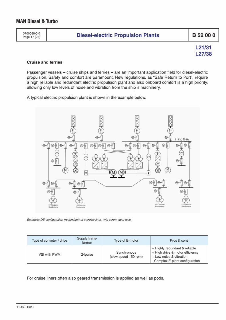
MAN Diesel & Turbo
Diesel-electric Propulsion Plants B 52 00 0
L21/31 L27/38
3700088-0.0Page 17 (25)
11.10 - Tier II
Cruise and ferries
Passenger vessels – cruise ships and ferries – are an important application field for diesel-electric propulsion. Safety and comfort are paramount. New regulations, as “Safe Return to Port”, require a high reliable and redundant electric propulsion plant and also onboard comfort is a high priority, allowing only low levels of noise and vibration from the ship´s machinery.
A typical electric propulsion plant is shown in the example below.
Example: DE-configuration (redundant) of a cruise liner, twin screw, gear less.
Type of conveter / driveSupply trans-
formerType of E-motor Pros & cons
VSI with PWM 24pulseSynchronous
(slow speed 150 rpm)
+ Highly redundant & reliable+ High drive & motor efficiency+ Low noise & vibration- Complex E-plant configuration
For cruise liners often also geared transmission is applied as well as pods.
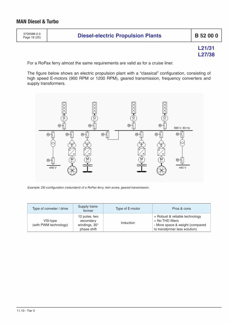
MAN Diesel & Turbo
Diesel-electric Propulsion Plants B 52 00 0
L21/31 L27/38
3700088-0.0Page 18 (25)
11.10 - Tier II
For a RoPax ferry almost the same requirements are valid as for a cruise liner.
The figure below shows an electric propulsion plant with a “classical” configuration, consisting of high speed E-motors (900 RPM or 1200 RPM), geared transmission, frequency converters and supply transformers.
Example: DE-configuration (redundant) of a RoPax ferry, twin screw, geared transmission.
Type of conveter / driveSupply trans-
formerType of E-motor Pros & cons
VSI-type(with PWM technology)
12 pulse, two secondary
windings, 30° phase shift
Induction
+ Robust & reliable technology+ No THD filters- More space & weight (compared to transfprmer less solution)
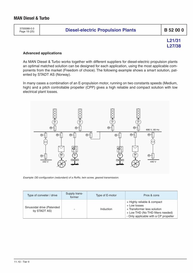
MAN Diesel & Turbo
Diesel-electric Propulsion Plants B 52 00 0
L21/31 L27/38
3700088-0.0Page 19 (25)
11.10 - Tier II
Advanced applications
As MAN Diesel & Turbo works together with different suppliers for diesel-electric propulsion plants an optimal matched solution can be designed for each application, using the most applicable com-ponents from the market (Freedom of choice). The following example shows a smart solution, pat-ented by STADT AS (Norway).
In many cases a combination of an E-propulsion motor, running on two constants speeds (Medium, high) and a pitch controllable propeller (CPP) gives a high reliable and compact solution with low electrical plant losses.
Example: DE-configuration (redundant) of a RoRo, twin screw, geared transmission.
Type of conveter / driveSupply trans-
formerType of E-motor Pros & cons
Sinusoidal drive (Patended by STADT AS)
- Induction
+ Highly reliable & compact+ Low losses+ Transformer less solution+ Low THD (No THD filters needed)- Only applicable with a CP propeller

MAN Diesel & Turbo
Diesel-electric Propulsion Plants B 52 00 0
L21/31 L27/38
3700088-0.0Page 20 (25)
11.10 - Tier II
Questionnaire: Diesel-electric propulsion plants
In order to provide you with appropriate project material and to carry out proposals promptly and accurately, we would kindly request you to fill in as many of the following details as possible and return it with a complete set of arrangement drawings to your sales representative.
General data
Name ____________________________________________________________________________
Address ____________________________________________________________________________
Phone ____________________________________________________________________________
E-mail ____________________________________________________________________________
Project ____________________________________________________________________________
Type of vessel ____________________________________________________________________________
Propulsion principle:
Diesel-electric CODLAD CODLAG
Main particulars:
Length, overall [m] ____________________________________________________________________
Length, pp [m] ____________________________________________________________________
Breadth, moulded [m] ____________________________________________________________________
Depth, moulded [m] ____________________________________________________________________
Draught, design [m] ____________________________________________________________________
Draught, scantling [m] ____________________________________________________________________
DWT, at sct draught [t] ____________________________________________________________________
Gross tonnage [GRT] ____________________________________________________________________
Crew + Passengers ________________ + __________________________________________________
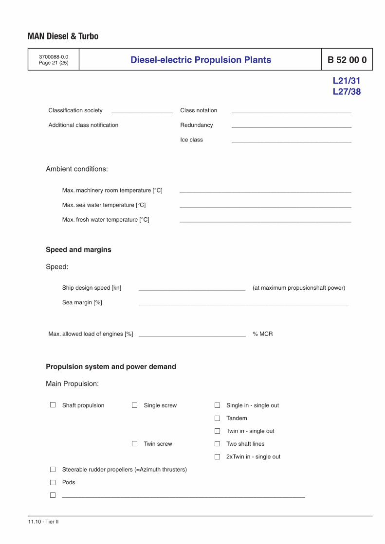
MAN Diesel & Turbo
Diesel-electric Propulsion Plants B 52 00 0
L21/31 L27/38
3700088-0.0Page 21 (25)
11.10 - Tier II
Shaft propulsion Single screw Single in - single out
Tandem
Twin in - single out
Twin screw Two shaft lines
2xTwin in - single out
Steerable rudder propellers (=Azimuth thrusters)
Pods
___________________________________________________________________________
Ambient conditions:
Classification society ___________________ Class notation _____________________________________
Additional class notification Redundancy _____________________________________
Ice class _____________________________________
Max. machinery room temperature [°C] _____________________________________________________
Max. sea water temperature [°C] _____________________________________________________
Max. fresh water temperature [°C] _____________________________________________________
Speed and margins
Speed:
Ship design speed [kn] _________________________________ (at maximum propusionshaft power)
Sea margin [%] _________________________________________________________________
Max. allowed load of engines [%] _________________________________ % MCR
Propulsion system and power demand
Main Propulsion:
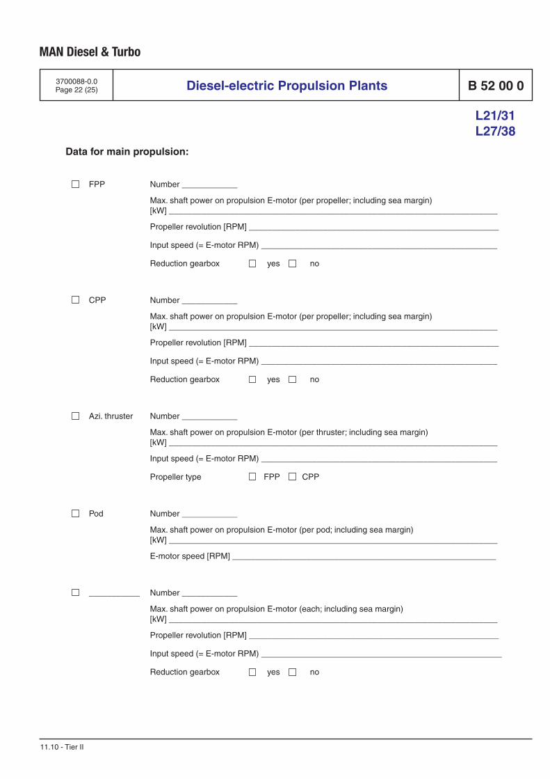
MAN Diesel & Turbo
Diesel-electric Propulsion Plants B 52 00 0
L21/31 L27/38
3700088-0.0Page 22 (25)
11.10 - Tier II
Data for main propulsion:
FPP Number ____________
Max. shaft power on propulsion E-motor (per propeller; including sea margin)[kW] _______________________________________________________________________
Propeller revolution [RPM] ______________________________________________________
Input speed (= E-motor RPM) ___________________________________________________
Reduction gearbox yes no
CPP Number ____________
Max. shaft power on propulsion E-motor (per propeller; including sea margin)[kW] _______________________________________________________________________
Propeller revolution [RPM] ______________________________________________________
Input speed (= E-motor RPM) ___________________________________________________
Reduction gearbox yes no
Azi. thruster Number ____________
Max. shaft power on propulsion E-motor (per thruster; including sea margin)[kW] _______________________________________________________________________
Input speed (= E-motor RPM) ___________________________________________________
Propeller type FPP CPP
Pod Number ____________
Max. shaft power on propulsion E-motor (per pod; including sea margin)[kW] _______________________________________________________________________
E-motor speed [RPM] _________________________________________________________
___________ Number ____________
Max. shaft power on propulsion E-motor (each; including sea margin)[kW] _______________________________________________________________________
Propeller revolution [RPM] ______________________________________________________
Input speed (= E-motor RPM) ____________________________________________________
Reduction gearbox yes no
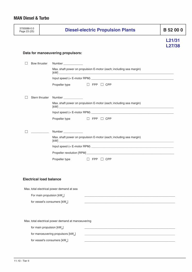
MAN Diesel & Turbo
Diesel-electric Propulsion Plants B 52 00 0
L21/31 L27/38
3700088-0.0Page 23 (25)
11.10 - Tier II
Data for manoeuvering propulsors:
Bow thruster Number ____________
Max. shaft power on propulsion E-motor (each; including sea margin)[kW] _______________________________________________________________________
Input speed (= E-motor RPM) ___________________________________________________
Propeller type FPP CPP
Stern thruster Number ____________
Max. shaft power on propulsion E-motor (each; including sea margin)[kW] _______________________________________________________________________
Input speed (= E-motor RPM) ___________________________________________________
Propeller type FPP CPP
___________ Number ____________
Max. shaft power on propulsion E-motor (each; including sea margin)[kW] _______________________________________________________________________
Input speed (= E-motor RPM) ___________________________________________________
Propeller revolution [RPM] ______________________________________________________
Propeller type FPP CPP
Electrical load balance
Max. total electrical power demand at sea
For main propulsion [kWel] ________________________________________________________
for vessel's consumers [kWel] ________________________________________________________
Max. total electrical power demand at manoeuvering
for main propulsion [kWel] ________________________________________________________
for manoeuvering propulsors [kWel] ________________________________________________________
for vessel's consumers [kWel] ________________________________________________________
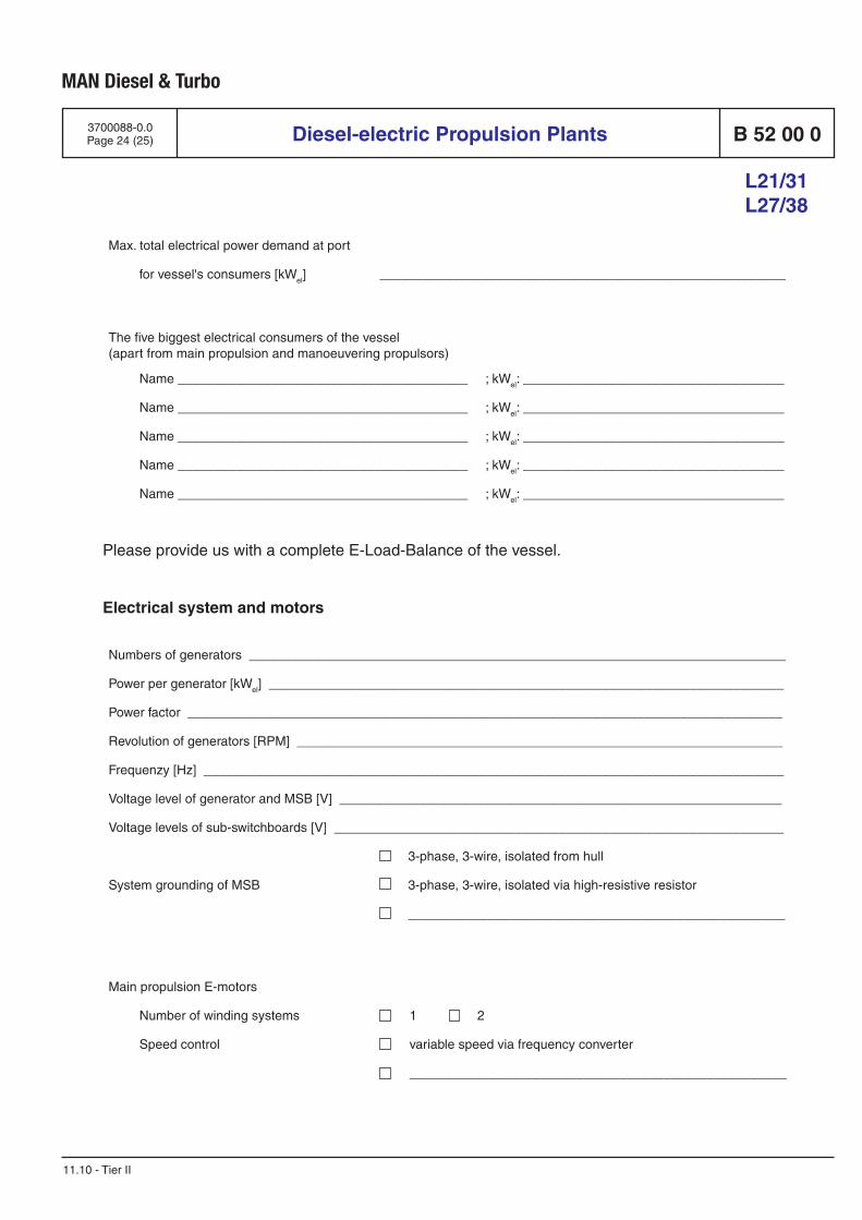
MAN Diesel & Turbo
Diesel-electric Propulsion Plants B 52 00 0
L21/31 L27/38
3700088-0.0Page 24 (25)
11.10 - Tier II
Main propulsion E-motors
Number of winding systems 1 2
Speed control variable speed via frequency converter
____________________________________________________
Max. total electrical power demand at port
for vessel's consumers [kWel] ________________________________________________________
Please provide us with a complete E-Load-Balance of the vessel.
Electrical system and motors
The five biggest electrical consumers of the vessel(apart from main propulsion and manoeuvering propulsors)
Name ________________________________________ ; kWel: ____________________________________
Name ________________________________________ ; kWel: ____________________________________
Name ________________________________________ ; kWel: ____________________________________
Name ________________________________________ ; kWel: ____________________________________
Name ________________________________________ ; kWel: ____________________________________
Numbers of generators __________________________________________________________________________
Power per generator [kWel] _______________________________________________________________________
Power factor __________________________________________________________________________________
Revolution of generators [RPM] ___________________________________________________________________
Frequenzy [Hz] ________________________________________________________________________________
Voltage level of generator and MSB [V] _____________________________________________________________
Voltage levels of sub-switchboards [V] ______________________________________________________________
System grounding of MSB
3-phase, 3-wire, isolated from hull
3-phase, 3-wire, isolated via high-resistive resistor
____________________________________________________
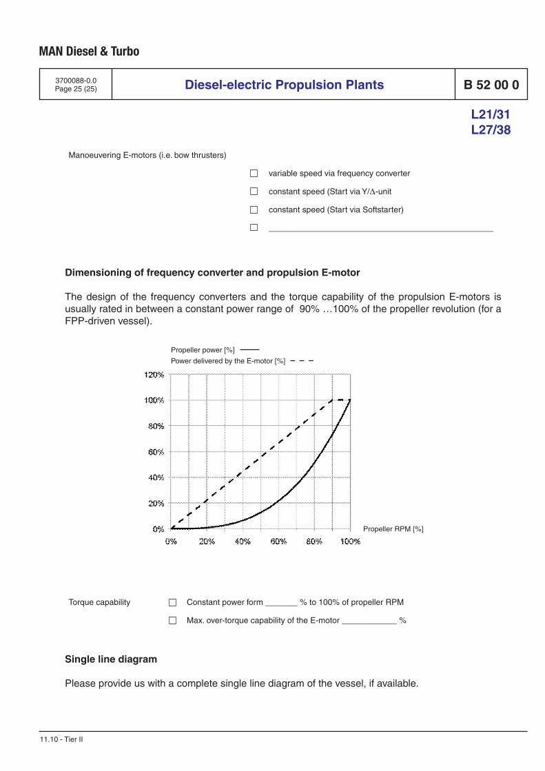
MAN Diesel & Turbo
Diesel-electric Propulsion Plants B 52 00 0
L21/31 L27/38
3700088-0.0Page 25 (25)
11.10 - Tier II
Dimensioning of frequency converter and propulsion E-motor
The design of the frequency converters and the torque capability of the propulsion E-motors is usually rated in between a constant power range of 90% …100% of the propeller revolution (for a FPP-driven vessel).
Manoeuvering E-motors (i.e. bow thrusters)
variable speed via frequency converter
constant speed (Start via Y/∆-unit
constant speed (Start via Softstarter)
_________________________________________________
Propeller RPM [%]
Propeller power [%]
Power delivered by the E-motor [%]
Torque capability Constant power form _______ % to 100% of propeller RPM
Max. over-torque capability of the E-motor ____________ %
Single line diagram
Please provide us with a complete single line diagram of the vessel, if available.


B 25 Preservation and Packing
B 98

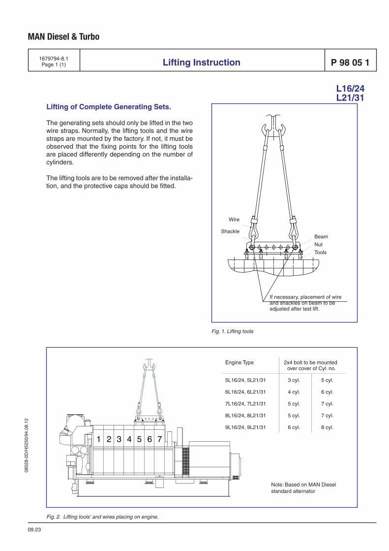
0802
8-0D
/H52
50/9
4.08
.12
MAN Diesel & Turbo
1679794-8.1Page 1 (1)
09.23
Lifting of Complete Generating Sets.
The generating sets should only be lifted in the two wire straps. Normally, the lifting tools and the wire straps are mounted by the factory. If not, it must be observed that the fixing points for the lifting tools are placed differently depending on the number of cylinders.
The lifting tools are to be removed after the installa-tion, and the protective caps should be fitted.
Lifting Instruction P 98 05 1
L16/24L21/31
Fig. 2. Lifting tools' and wires placing on engine.
Fig. 1. Lifting tools
Engine Type 2x4 bolt to be mounted over cover of Cyl. no.
5L16/24, 5L21/31 3 cyl. 5 cyl.
6L16/24, 6L21/31 4 cyl. 6 cyl.
7L16/24, 7L21/31 5 cyl. 7 cyl.
8L16/24, 8L21/31 5 cyl. 7 cyl.
9L16/24, 9L21/31 6 cyl. 8 cyl.
Note: Based on MAN Diesel standard alternator
Beam
Nut
Tools
Wire
Shackle
If necessary, placement of wire and shackles on beam to be adjusted after test lift.

Related Documents