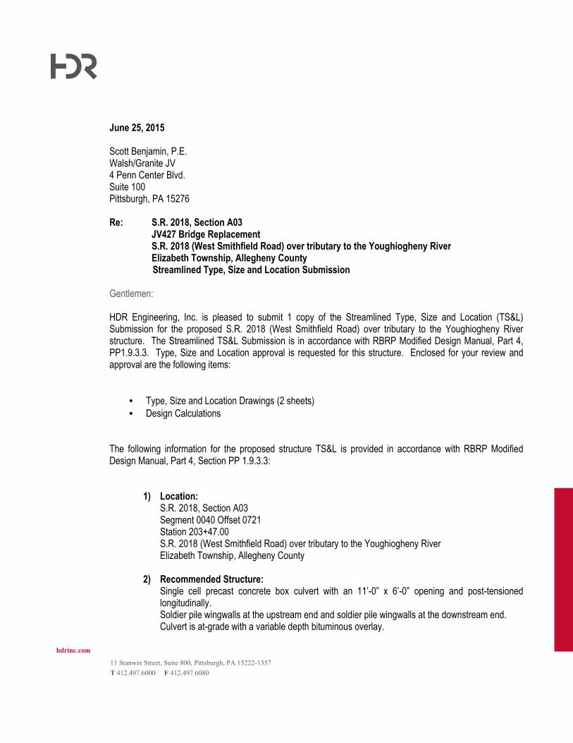
hdrinc.com 11 Stanwix Street, Suite 800, Pittsburgh, PA 15222-1357 T 412.497.6000 F 412.497.6080 June 25, 2015 Scott Benjamin, P.E. Walsh/Granite JV 4 Penn Center Blvd. Suite 100 Pittsburgh, PA 15276 Re: S.R. 2018, Section A03 JV427 Bridge Replacement S.R. 2018 (West Smithfield Road) over tributary to the Youghiogheny River Elizabeth Township, Allegheny County Streamlined Type, Size and Location Submission Gentlemen: HDR Engineering, Inc. is pleased to submit 1 copy of the Streamlined Type, Size and Location (TS&L) Submission for the proposed S.R. 2018 (West Smithfield Road) over tributary to the Youghiogheny River structure. The Streamlined TS&L Submission is in accordance with RBRP Modified Design Manual, Part 4, PP1.9.3.3. Type, Size and Location approval is requested for this structure. Enclosed for your review and approval are the following items: • Type, Size and Location Drawings (2 sheets) • Design Calculations The following information for the proposed structure TS&L is provided in accordance with RBRP Modified Design Manual, Part 4, Section PP 1.9.3.3: 1) Location: S.R. 2018, Section A03 Segment 0040 Offset 0721 Station 203+47.00 S.R. 2018 (West Smithfield Road) over tributary to the Youghiogheny River Elizabeth Township, Allegheny County 2) Recommended Structure: Single cell precast concrete box culvert with an 11’-0” x 6’-0” opening and post-tensioned longitudinally. Soldier pile wingwalls at the upstream end and soldier pile wingwalls at the downstream end. Culvert is at-grade with a variable depth bituminous overlay.

Welcome message from author
This document is posted to help you gain knowledge. Please leave a comment to let me know what you think about it! Share it to your friends and learn new things together.
Transcript
hdrinc.com
11 Stanwix Street, Suite 800, Pittsburgh, PA 15222-1357
T 412.497.6000 F 412.497.6080
June 25, 2015 Scott Benjamin, P.E. Walsh/Granite JV 4 Penn Center Blvd. Suite 100 Pittsburgh, PA 15276 Re: S.R. 2018, Section A03 JV427 Bridge Replacement S.R. 2018 (West Smithfield Road) over tributary to the Youghiogheny River Elizabeth Township, Allegheny County
Streamlined Type, Size and Location Submission Gentlemen: HDR Engineering, Inc. is pleased to submit 1 copy of the Streamlined Type, Size and Location (TS&L) Submission for the proposed S.R. 2018 (West Smithfield Road) over tributary to the Youghiogheny River structure. The Streamlined TS&L Submission is in accordance with RBRP Modified Design Manual, Part 4, PP1.9.3.3. Type, Size and Location approval is requested for this structure. Enclosed for your review and approval are the following items:
• Type, Size and Location Drawings (2 sheets)
• Design Calculations The following information for the proposed structure TS&L is provided in accordance with RBRP Modified Design Manual, Part 4, Section PP 1.9.3.3:
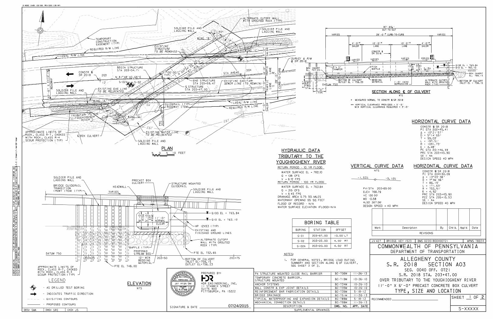
1) Location: S.R. 2018, Section A03 Segment 0040 Offset 0721 Station 203+47.00 S.R. 2018 (West Smithfield Road) over tributary to the Youghiogheny River Elizabeth Township, Allegheny County
2) Recommended Structure: Single cell precast concrete box culvert with an 11’-0” x 6’-0” opening and post-tensioned longitudinally. Soldier pile wingwalls at the upstream end and soldier pile wingwalls at the downstream end. Culvert is at-grade with a variable depth bituminous overlay.
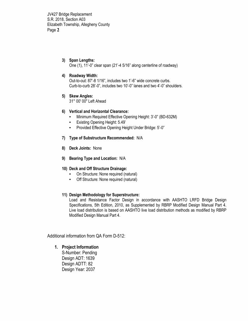
JV427 Bridge Replacement S.R. 2018, Section A03 Elizabeth Township, Allegheny County
Page 2
3) Span Lengths:
One (1), 11’-0” clear span (21’-4 5/16” along centerline of roadway)
4) Roadway Width: Out-to-out: 87’-8 1/16”, includes two 1’-6” wide concrete curbs. Curb-to-curb 28’-0”, includes two 10’-0” lanes and two 4’-0” shoulders.
5) Skew Angles:
31° 00' 00" Left Ahead
6) Vertical and Horizontal Clearance:
• Minimum Required Effective Opening Height: 3’-0” (BD-632M)
• Existing Opening Height: 5.49’
• Provided Effective Opening Height Under Bridge: 5’-0”
7) Type of Substructure Recommended: N/A
8) Deck Joints: None
9) Bearing Type and Location: N/A
10) Deck and Off Structure Drainage:
• On Structure: None required (natural)
• Off Structure: None required (natural)
11) Design Methodology for Superstructure:
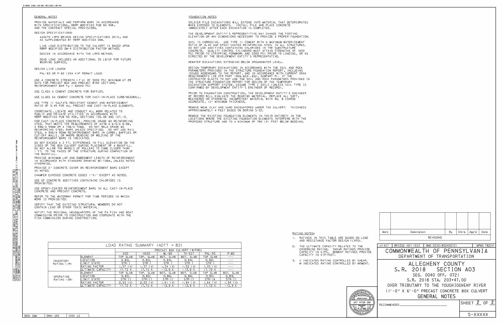
Load and Resistance Factor Design in accordance with AASHTO LRFD Bridge Design Specifications, 5th Edition, 2010, as Supplemented by RBRP Modified Design Manual Part 4. Live load distribution is based on AASHTO live load distribution methods as modified by RBRP Modified Design Manual Part 4.
Additional information from QA Form D-512:
1. Project Information S-Number: Pending Design ADT: 1639 Design ADTT: 82 Design Year: 2037
JV427 Bridge Replacement S.R. 2018, Section A03 Elizabeth Township, Allegheny County
Page 3
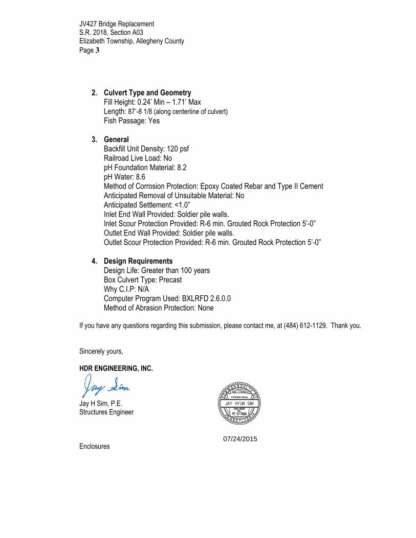
2. Culvert Type and Geometry Fill Height: 0.24’ Min – 1.71’ Max Length: 87’-8 1/8 (along centerline of culvert)
Fish Passage: Yes
3. General Backfill Unit Density: 120 psf Railroad Live Load: No pH Foundation Material: 8.2 pH Water: 8.6 Method of Corrosion Protection: Epoxy Coated Rebar and Type II Cement Anticipated Removal of Unsuitable Material: No Anticipated Settlement: <1.0” Inlet End Wall Provided: Soldier pile walls. Inlet Scour Protection Provided: R-6 min. Grouted Rock Protection 5’-0” Outlet End Wall Provided: Soldier pile walls. Outlet Scour Protection Provided: R-6 min. Grouted Rock Protection 5’-0”
4. Design Requirements Design Life: Greater than 100 years Box Culvert Type: Precast Why C.I.P: N/A Computer Program Used: BXLRFD 2.6.0.0 Method of Abrasion Protection: None
If you have any questions regarding this submission, please contact me, at (484) 612-1129. Thank you. Sincerely yours, HDR ENGINEERING, INC.
Jay H Sim, P.E. Structures Engineer Enclosures
ENGINEER
JAY HYUN SIM
NO.
PE-077886
REGISTERED
PROFESSIONALCO
M
MO
NWEALTH
OF
SYLA
N
IP
E
N
A
NV
07/24/2015
770
770
765
765
765
765
760
13
14
203
204
GM4" GAS LINE
D-9002 CADD (02-90) REVISED (05-97)
DEPARTMENT OF TRANSPORTATION
COMMONWEALTH OF PENNSYLVANIA
SHEET OFRECOMMENDED
DES: DWG: CKD:
BMSBRIDGE KEYJV MPMS
S-
FI
LE:
PA
TH:000001\
CO
N0094634\000000000245782\6.0_
CA
D_
BI
M\6.2_
Work_in_
Progress\6.2.2_
Contract_
Files\6.2.2.1_
Sheet_
Files\
Bridge
MO
DE
L:B
RG
GP
E
Sheet
US
ER:skuchins
PL
OT
DA
TE:
07-15-2015
11:08:55
AM
RB
RP-J
V427-
GP
EL.dgn
PL
OT
DRI
VE
R:
Penn
DO
T_
PD
F_
Mono.pltcfg
Mark Description By Chk'd. App'd. Date
REVISIONS
782241523427
SRCSMK JS
S.R. 2018 STA. 203+47.00
SEG. 0040 OFF. 0721
XXXXX
SECTION A03S.R. 2018
02201800400721
ALLEGHENY COUNTY
11'-0" X 6'-0" PRECAST CONCRETE BOX CULVERT
OVER TRIBUTARY TO THE YOUGHIOGHENY RIVER
DATUM 750
203+25 203+50 203+75
DATUM 750
STA AHEAD
(TYP)
NTS
VERTICAL CURVE DATA HORIZONTAL CURVE DATA
- EXISITING CONTOURS
- PROPOSED CONTOURS
- INDICATES TRAFFIC DIRECTION
- AS DRILLED TEST BORING
LEGEND
BORING STATION OFFSET
BORING TABLE
-1.53% -5.10%
ELEVATION
5 0 5 10 FEET
PLAN
S-01
203+87.00 10.00'LT
LEGAL R/W LINE
(ROADWAY ITEM)
GUIDERAIL (TYP)
SIGNATURE & DATE
PREPARED BY:
PITTSBURGH, PA 15222
SUITE 800
11 STANWIX STREET
HDR ENGINEERING, INC.
RETURN PERIOD - 100 YR FLOOD
V = 6.12 FPS
Q = 138 CFS
WATER SURFACE EL = 762.10
V = 5.45 FPS
Q = 315 CFS
WATER SURFACE EL = 763.84
S-01
REQUIRED R/W LINE
DESIGN SPEED = 40 MPH
HLSD 367.06'
MO -0.58
VC 130.00'
ELEV 766.79
PVI STA 203+65.00
WITH GROUTED ROCK (TYP)
ALTERNATE CUTOFF WALL
ROCK (TYP)
WALL WITH GROUTED
ALTERNATE CUTOFF
WING "C"
WING "B"
WING "A"
WING "D"
LAGGING WALL
SOLDIER PILE AND
Ë BOX CULVERT
LAGGING WALL
SOLDIER PILE AND
LAGGING WALL
SOLDIER PILE AND
LAGGING WALL
SOLDIER PILE AND
SH
LD
R
4'-0"
TR
AF
FI
C
10'-0"
LA
NE
LA
NE
LEGAL R/W LINE
(RDWY ITEM) (TYP)
TRANSITION
BRIDGE GUIDERAIL
LAGGING WALL
SOLDIER PILE AND
STREAM BED
PROPOSED
BAFFLE (TYP)
LAGGING WALL
SOLDIER PILE AND
CULVERT
PRECAST BOX
Q10 EL = 762.10
Q100 EL = 763.84
TO BE REMOVED
STRUCTURE
EXISTING
STA 203+47.00
Ë STRUCTURE
203
+43.90
PR
C
1 2
HORIZONTAL CURVE DATA
TYPE, SIZE AND LOCATION
SEE SHEET 2 OF 2.
SUMMARY AND SECTION ALONG Ë OF CULVERT,
1. FOR GENERAL NOTES, BRIDGE LOAD RATING
NOTES:
GUIDERAIL
STRUCTURE MOUNTED
STA 203+34.71
BEGIN STRUCTURE
STA 203+59.47
END STRUCTURE
REQUIRED R/W LINE
PTE EL 752.65
HP 12X53 (TYP)
VARIES
PTE EL 748.00
SCOUR PROTECTION (TYP)
WITH ROCK, CLASS R-4
ROCK, CLASS R-7, CHOKED
APPROXIMATE LIMITS OF
NTS
VARIESVARIES
VARIES VARIES
SECTION ALONG Ë OF CULVERT
CHAMFER
3"x 3"
* ** *
BAFFLE
FISH
(TYP)
5'-0"
(MI
N)
EL. 759.15
BOX INVERT
EL. 757.23
BOX INVERT
DEPRESSION
1'-0" (MIN)OUTLET EL = 756.23
BOTTOM OF CULVERT
INLET EL = 758.15
BOTTOM OF CULVERT
2.19%
SHLDR
4'-0"
LANE
10'-0"
SHLDR
4'-0"
LANE
10'-0"
VARIES VARIES
RI
SE
6'-0"
ROCK (TYP)
WALL WITH GROUTED
ALTERNATE CUTOFF
OUT-TO-OUT
87'-8„"
90°
19°
90°
SEWER LINE (TO REMAIN)
EXISTING SANITARY
OUTLET EL=756.23
INLET EL=758.15
BOTTOM OF CULVERT
RI
SE
6'-0"
(T
YP)
3'-6"
*
28'-0" CURB-TO-CURB
5'-0"
EF
F
**
MATERIAL
BEDDING
29°
SCOUR PROTECTION (TYP)
WITH ROCK, CLASS R-4
ROCK, CLASS R-7, CHOKED
APPROXIMATE LIMITS OF
RO
AD
WA
Y22'-6"
±
EXI
STI
NG
SUPPLEMENTAL DRAWINGS
10-26-10BC-719MTEMPORARY CONCRETE BARRIER,
STRUCTURE MOUNTED
BC-734M 10-26-10ANCHOR SYSTEMS
BC-735M 10-26-10WALL CONSTR & EXP JOINT DETAILS
BC-736MREINFORCEMENT BAR FABRICATION DETAILS
BC-788MTYPICAL WATERPROOFING AND EXPANSION DETAILS
BC-798MMECHANICAL CONNECTION DETAILS
5-18-12
5-18-12
11-26-13
APP. DATEDWG. NO.DESCRIPTION
11-26-13BC-706M
BC-751MBRIDGE DRAINAGE 11-26-13
DWG. NO. APP. DATE
PA STRUCTURE MOUNTED GUIDE RAIL BARRIER
WATER SURFACE ELEVATION (FLOOD)-N/A
FLOOD OF RECORD - N/A
WATERWAY OPENING 55 SQ. FEET
DRAINAGE AREA 0.75 SQ. MILES
Q100 EL = 763.84
Q10 EL = 762.10
RIVERYOUGHIOGHENYTRIBUTARY TO THE
OUT-TO-
OUT
87'-
8„"
CLEAR
NORMAL
11'-0"EF
F
5'-0"
RI
SE
MATERIAL
BEDDING
12" MIN
YOUGHIOGHENY RIVER
TRIBUTARY TO THE
HYDRAULIC DATA
SR 2018
CONSTR Ì
TO BE RELOCATED
EXISTING WATER LINE
NTS
770
765
765
765
765
765
760
760
765765
S-02S-02A
TO BE RELOCATED
EXISTING GAS LINE
203+22.00 4.00' RT
203+20.00 4.00' RT
S-02
S-02A
Ì SR 2018
SURVEY & R/W
RETURN PERIOD - 10 YR FLOOD
HEADWALL
FINISHED GROUND LINES
EXISTING AND
SH
LD
R
4'-0"
TR
AF
FI
C
10'-0"
CU
RB-
TO-
CU
RB
28'-0"
DESIGN SPEED 40 MPH
SE = NA
PRC STA 203+43.90
PC STA 201+46.39
E = 4.48'
R = 1091.73'
L = 197.51'
T = 99.03'
D = 5°14'53"
` = 10°21'57"
PI STA 202+45.41
CONSTR Ì SR 2018
DESIGN SPEED 40 MPH
SE = NA
PCC STA 205+15.53
PRC STA 203+43.90
E = 4.92'
R = 752.91'
L = 171.63'
T = 86.19'
D = 7°36'36"
` = 13°03'38"
PI STA 204+30.99
CONSTR Ì SR 2018
EASEMENT (TYP)CONSTRUCTION TEMPORARY
SR 2018
CONSTR Ì
MIN VERTICAL CLEARANCE REQUIRED = 3'-0"
** VERTICAL CLEARANCE PROVIDED = 5'-0"
* MEASURED NORMAL TO CONSTR Ì SR 2018
30
ENGINEER
JAY HYUN SIM
NO.
PE-077886
REGISTERED
PROFESSIONALCO
M
MO
NWEALTH
OF
SYLA
N
IP
E
N
A
NV
07/24/2015
D-9002 CADD (02-90) REVISED (05-97)
DEPARTMENT OF TRANSPORTATION
COMMONWEALTH OF PENNSYLVANIA
SHEET OFRECOMMENDED
DES: DWG: CKD:
BMSBRIDGE KEYJV MPMS
S-
FI
LE:
PA
TH:000001\
CO
N0094634\000000000245782\6.0_
CA
D_
BI
M\6.2_
Work_in_
Progress\6.2.2_
Contract_
Files\6.2.2.1_
Sheet_
Files\
Bridge
MO
DE
L:B
RG
DE
T
Sheet
US
ER:jsi
mP
LO
T
DA
TE:
07-13-2015
2:52:18
PM
RB
RP-J
V427-
GE
N-
NO
TE
S.dgn
PL
OT
DRI
VE
R:
Penn
DO
T_
PD
F_
Mono.pltcfg
Mark Description By Chk'd. App'd. Date
REVISIONS
782241523427
SRCSMK JS
S.R. 2018 STA. 203+47.00
SEG. 0040 OFF. 0721
XXXXX
SECTION A03S.R. 2018
02201800400721
ALLEGHENY COUNTY
11'-0" X 6'-0" PRECAST CONCRETE BOX CULVERT
OVER TRIBUTARY TO THE YOUGHIOGHENY RIVER
PHL-93 OR P-82 (204 KIP PERMIT LOAD)
DESIGN IN ACCORDANCE WITH THE LRFD METHOD.
WEARING SURFACE.
DEAD LOAD INCLUDES AN ADDITIONAL 30 LB/SF FOR FUTURE
DESIGN SPECIFICATIONS:
DESIGN LIVE LOADS:
THE BACKFILL.
1 FT. TO THE FACES OF THE STRUCTURE DURING COMPACTION OF
DO NOT ALLOW THE WHEELS OF ROLLERS TO COME CLOSER THAN
SIDES OF THE BOX CULVERT DURING PLACEMENT OF A BACKFILL.
DO NOT EXCEED A 2 FT. DIFFERENCE IN FILL ELEVATION ON THE
CONCRETE AND PRECAST CONCRETE.
USE EPOXY-COATED REINFORCEMENT BARS IN ALL CAST-IN-PLACE
PROHIBITED.
USE OF CONCRETE ADDITIVES CONTAINING CHLORIDES IS
CHAMFER EXPOSED CONCRETE EDGES 1"X1" EXCEPT AS NOTED.
AS NOTED.
PROVIDE 2" CONCRETE COVER ON REINFORCEMENT BARS EXCEPT
OTHERWISE.
IN ACCORDANCE WITH STANDARD DRAWING BC-736M, UNLESS NOTED
PROVIDE MINIMUM LAP AND EMBEDMENT LENGTH OF REINFORCEMENT
M INDICATES RATING CONTROLLED BY MOMENT.
3. V INDICATES RATING CONTROLLED BY SHEAR.
CAPACITY IN KIP-FEET.
CAPACITY IN KIPS. MOMENT RATINGS PROVIDE
GOVERNING RATING. SHEAR RATINGS PROVIDE
2. THE ULTIMATE CAPACITY RELATES TO THE
AND RESISTANCE FACTOR DESIGN (LRFD).
1. RATINGS IN THIS TABLE ARE BASED ON LOAD
ELEMENT
H20
TOP SLAB
HS20
BOT. SLAB
ML-80 TK-527
BOT. SLAB
PHL-93
TOP SLAB
P-82
---
RATING NOTES:
PRECAST BOX CULVERT (W/FWS)
RBRP MODIFIED PUB NO 408, SECTIONS 105.06 AND 107.12.
PUBLIC AND PRIVATE UTILITIES IN ACCORDANCE WITH
COORDINATE, LOCATE AND CONDUCT ALL WORK RELATED TO
AS SUPPLEMENTED BY RBRP MODIFIED DM4.
AASHTO LRFD BRIDGE DESIGN SPECIFICATIONS 2010, AND
RBRP MODIFIED DM-4 DISTRIBUTION FACTOR METHOD.
LIVE LOAD DISTRIBUTION TO THE CULVERT IS BASED UPON
WORK IS PROHIBITED.
REFER TO THE WATERWAY PERMIT FOR TIME PERIODS IN WHICH
FISH COMMISSION DURING CONSTRUCTION.
COMMISSION PRIOR TO CONSTRUCTION AND COOPERATE WITH THE
NOTIFY THE REGIONAL HEADQUARTERS OF THE PA FISH AND BOAT
CONTAIN LEAD OR OTHER TOXIC MATERIAL.
VERIFY THAT THE EXISTING STRUCTURAL MEMBERS DO NOT
RATING (IR)
INVENTORY
RATING (OR)
OPERATING
LOCATION
LIMIT STATE
RATING FACTOR
ULTIMATE CAPACITY
LOCATION
LIMIT STATE
RATING FACTOR
ULTIMATE CAPACITY
TOP SLAB
STR-II STR-II STR-II
BOT. SLAB
STR I STR I
BOT. SLAB
STR-II
STR I
TOP SLAB
STR-IA
---
---
---
---
BOT. SLAB
STR-II
ELEMENT
GENERAL NOTES
AND THE CONTRACT SPECIAL PROVISIONS.
WITH SPECIFICATIONS, RBRP MODIFIED PUB NO 408,
PROVIDE MATERIALS AND PERFORM WORK IN ACCORDANCE
2 2
GENERAL NOTES
0.82L
STR-I
1.57 (V)
0.82L
2.03 (V)
STR-I
1.57 (V)
2.03 (V)
0.84L
1.24 (V)
0.84L
1.61 (V)
0.84L
1.50 (V)
-13.9 K-13.9 K
0.84L
1.94 (V)
-13.9 K-13.9 K
0.82L
1.03 (V)
17.72 K
0.82L
1.64 (V)
17.72 K
0.84L
1.34 (V)
-13.9 K
TOP. SLAB
TOP. SLAB
17.72 K
17.72 K
0.82L
17.72 K
0.82L
17.72 K
LOAD RATING SUMMARY (ADTT = 82)
REINFORCEMENT BARS IS INDICATED.
CUT-OFF WALLS, OR WHERE BENDING OR WELDING OF THE
STEEL A 996/A 996M REINFORCEMENT BARS IN CURBS, BAFFLES OR
REINFORCING STEEL BARS UNLESS SPECIFIED. DO NOT USE RAIL
A 996/A 996M OR A 706/A 706M. DO NOT WELD GRADE 60
STEEL THAT MEETS THE REQUIREMENTS OF ASTM A 615/A 615M,
FOR CAST-IN-PLACE CONCRETE, PROVIDE GRADE 60 REINFORCING
FOUNDATION NOTES
RATIO OF 0.45 FOR ALL PRECAST AND CAST-IN-PLACE ELEMENTS.
USE TYPE II SULFATE RESISTANT CEMENT AND WATER/CEMENT
USE CLASS AA CEMENT CONCRETE FOR CAST-IN-PLACE CURB/HEADWALL.
USE CLASS A CEMENT CONCRETE FOR BAFFLES.
REINFORCEMENT BAR Fy = 60000 PSI
DAYS FOR PRECAST BOX AND PRECAST WING SECTIONS.
USE A CONCRETE STRENGTH (f'c) OF 5000 PSI MINIMUM AT 28
OBTAIN FOUNDATION NOTES FROM GEOTECHNICAL ENGINEER.
PROPOSED STRUCTURE AND TO A MINIMUM OF TWO (2) FEET BELOW BEDDING.
LOCATIONS WHERE THE EXISTING FOUNDATION ELEMENTS INTERFERE WITH THE
REMOVE THE EXISTING FOUNDATION ELEMENTS IN THEIR ENTIRETY IN THE
APPROXIMAMTELY 4 FEET BASED ON BORING S-02.
REMOVE WEAK CLAY AND SAND ENCOUNTERED UNDER THE CULVERT. THICKNESS
AGGREGATE, 12" MINIMUM THICKNESS.
WEATHERED OR OTHERWISE INCOMPETENT MATERIAL WITH NO. 8 COARSE
OF RECORD WILL EVALUATE THE BEARING MATERIAL. REPLACE ALL SOFT,
PRIOR TO FOUNDATION CONSTRUCTION, THE DEVELOPMENT ENTITY'S ENGINEER
CONFIRMED BY DEVELOPMENT ENTITY'S ENGINEER OF RECORD).
EXCAVATION SUPPORT SYSTEM, ASSUME TYPE C SOILS (UNLESS SOIL TYPE IS
THE STRUCTURE FOUNDATION REPORT FOR DESIGN OF THE TEMPORARY
CONTRACTOR ELECTS TO NOT USE THE SOIL AND ROCK PARAMETERS PROVIDED IN
REQUIREMENTS (29 CFR PART 1926.650-.652, SUBPART P). IF THE
ISSUED ADDENDUMS TO THE REPORT, AND IN ACCORDANCE WITH CURRENT OSHA
PARAMETERS PROVIDED IN THE STRUCTURE FOUNDATION REPORT, INCLUDING
DESIGN TEMPORARY EXCAVATIONS IN ACCORDANCE WITH THE SOIL AND ROCK
DEWATER EXCAVATIONS EXTENDING BELOW GROUNDWATER LEVEL.
DIRECTED BY THE DEVELOPMENT ENTITY'S REPRESENTATIVE.
PSI PRIOR TO STRIPPING FORMWORK AND 2000 PSI PRIOR TO LOADING, OR AS
CONCRETE. QUALITY CONTROL CYLINDERS MUST ATTAIN STRENGTHS OF 1500
DO NOT USE ADDITIVES CONTAINING CHLORIDES IN THE SUBSTRUCTURE
RATIO OF 0.45 AND EPOXY COATED REINFORCING STEEL IN ALL STRUCTURES.
SOIL IS CORROSIVE. USE TYPE II CEMENT WITH A MAXIMUM WATER/CEMENT
ELEVATION OR ANY DIMENSIONS NECESSARY TO PROVIDE A PROPER FOUNDATION.
THE DEVELOPMENT ENTITY'S REPRESENTITIVE MAY CHANGE THE FOOTING
IMMEDIATELY AFTER EACH EXCAVATION IS COMPLETED.
WHEN EXPOSED TO ELEMENTS. INSTALL PILE AND PLACE CONCRETE
SOLDIER PILE EXCAVATIONS WILL EXTEND INTO MATERIAL THAT DETERIORATES
ENGINEER
JAY HYUN SIM
NO.
PE-077886
REGISTERED
PROFESSIONALCO
M
MO
NWEALTH
OF
SYLA
N
IP
E
N
A
NV
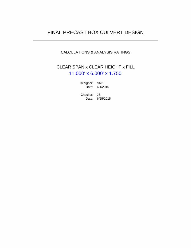
Designer: SMK
Date: 6/1/2015
Checker: JS
Date: 6/25/2015
FINAL PRECAST BOX CULVERT DESIGN
11.000' x 6.000' x 1.750'
CLEAR SPAN x CLEAR HEIGHT x FILL
CALCULATIONS & ANALYSIS RATINGS
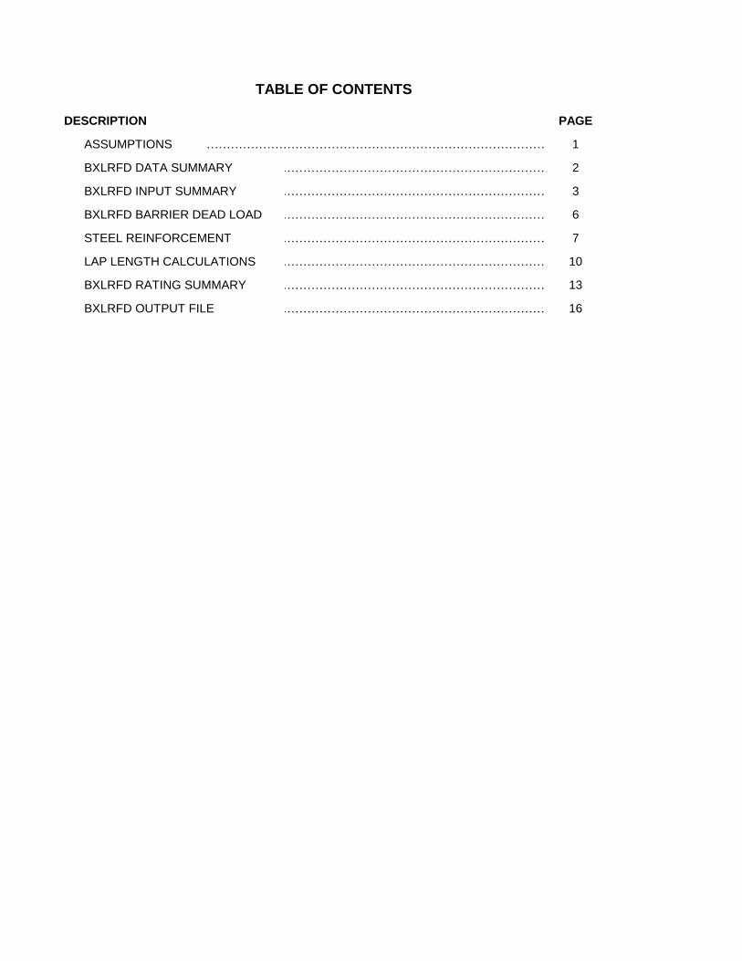
DESCRIPTION PAGE
1
2
3
6
7
10
13
16
TABLE OF CONTENTS
STEEL REINFORCEMENT
LAP LENGTH CALCULATIONS
BXLRFD RATING SUMMARY
ASSUMPTIONS ………………………………………………………………………………...
…………………………………………………………….
…………………………………………………………….
…………………………………………………………….
…………………………………………………………….
BXLRFD DATA SUMMARY
BXLRFD INPUT SUMMARY
BXLRFD BARRIER DEAD LOAD
…………………………………………………………….
…………………………………………………………….
BXLRFD OUTPUT FILE …………………………………………………………….
HDR ComputationProject: PENNDOT P3 Computed: SMK Date: 6/1/2015
Subject: PRECAST BOX CULVERT DESIGN Checked: JS Date: 6/25/2015
Task: PRECAST CULVERT DESIGN ASSUMPTIONS Sheet: 1 Of: 16
ASSUMPTIONS
Single cell precast box culvert.
See Sheet 2/16 for details of precast culvert and roadway geometry.
No shear reinforcement.
Vertical wall barrier is used for all analyses.
12" x 12" Haunches.
Material properties per BD-632M (Sheet 4 of 13) and per these calculations (Sheet 2 of 16).
Concrete clear cover per BD-632M, Sheet 4 of 13:
Top bars in top slab: 2.5" clear cover (all cases considered).
Top bars in bottom slab: 2.0" clear cover.
All other bars: 1.5" clear cover.
Additional 30 PSF included for future wearing surface per PennDOT DM-4, Section 12.11.2.1 and
BD-632M, Sheet 4 of 13, Note #6.
Refer to "BXLRFD Input" summary for additional assumptions.
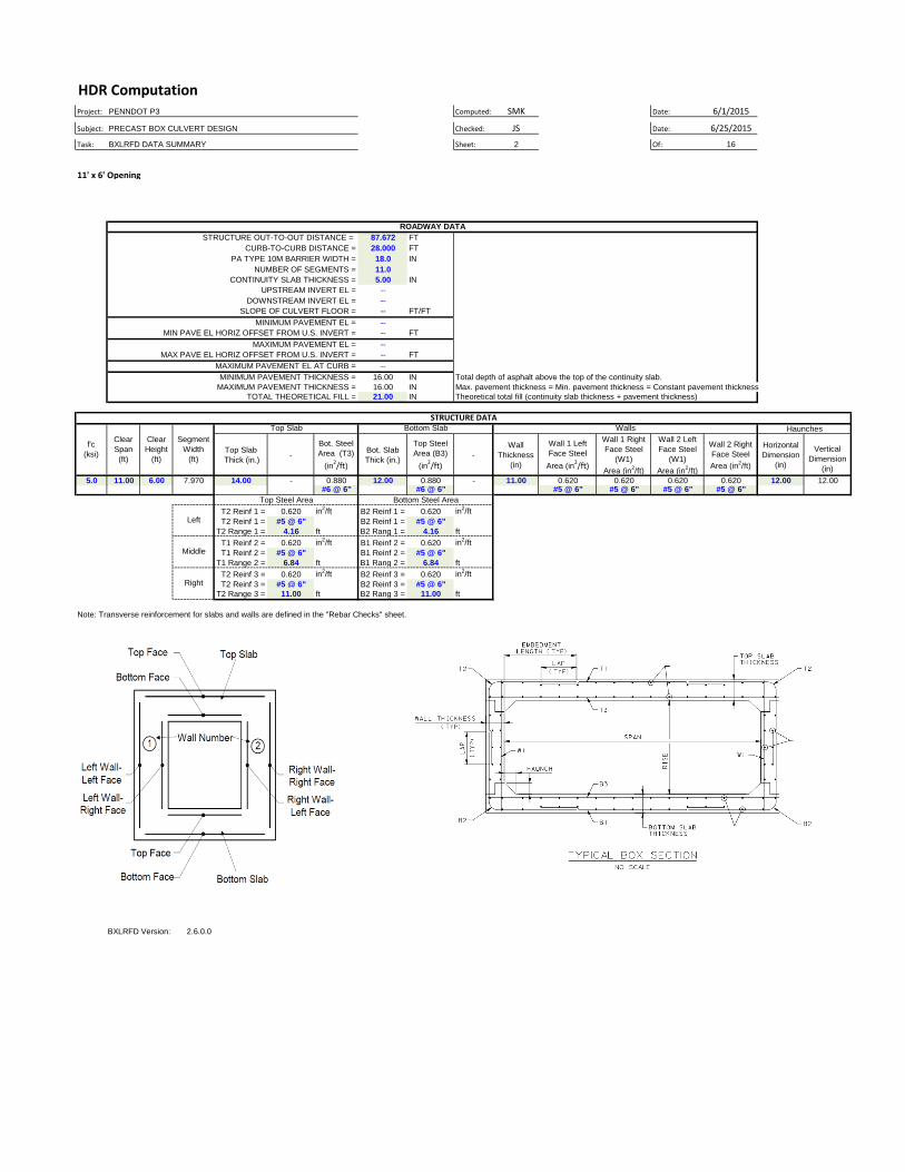
HDR ComputationProject: PENNDOT P3 Computed: SMK Date: 6/1/2015
Subject: PRECAST BOX CULVERT DESIGN Checked: JS Date: 6/25/2015
Task: BXLRFD DATA SUMMARY Sheet: 2 Of: 16
11' x 6' Opening
STRUCTURE OUT-TO-OUT DISTANCE = 87.672 FT
CURB-TO-CURB DISTANCE = 28.000 FT
PA TYPE 10M BARRIER WIDTH = 18.0 IN
NUMBER OF SEGMENTS = 11.0
5.00 IN
UPSTREAM INVERT EL = --
DOWNSTREAM INVERT EL = --
SLOPE OF CULVERT FLOOR = -- FT/FT
MINIMUM PAVEMENT EL = --
MIN PAVE EL HORIZ OFFSET FROM U.S. INVERT = -- FT
MAXIMUM PAVEMENT EL = --
MAX PAVE EL HORIZ OFFSET FROM U.S. INVERT = -- FT
MAXIMUM PAVEMENT EL AT CURB = --
MINIMUM PAVEMENT THICKNESS = 16.00 IN Total depth of asphalt above the top of the continuity slab.
MAXIMUM PAVEMENT THICKNESS = 16.00 IN Max. pavement thickness = Min. pavement thickness = Constant pavement thickness
TOTAL THEORETICAL FILL = 21.00 IN Theoretical total fill (continuity slab thickness + pavement thickness)
Top Slab
Thick (in.)-
Bot. Steel
Area (T3)
(in2/ft)
Bot. Slab
Thick (in.)
Top Steel
Area (B3)
(in2/ft)
-
Wall
Thickness
(in)
Wall 1 Left
Face Steel
Area (in2/ft)
Wall 1 Right
Face Steel
(W1)
Area (in2/ft)
Wall 2 Left
Face Steel
(W1)
Area (in2/ft)
Wall 2 Right
Face Steel
Area (in2/ft)
Horizontal
Dimension
(in)
Vertical
Dimension
(in)
5.0 11.00 6.00 7.970 14.00 - 0.880 12.00 0.880 - 11.00 0.620 0.620 0.620 0.620 12.00 12.00#6 @ 6" #6 @ 6" #5 @ 6" #5 @ 6" #5 @ 6" #5 @ 6"
T2 Reinf 1 = 0.620 in2/ft B2 Reinf 1 = 0.620 in
2/ft
T2 Reinf 1 = #5 @ 6" B2 Reinf 1 = #5 @ 6"
T2 Range 1 = 4.16 ft B2 Rang 1 = 4.16 ft
T1 Reinf 2 = 0.620 in2/ft B1 Reinf 2 = 0.620 in
2/ft
T1 Reinf 2 = #5 @ 6" B1 Reinf 2 = #5 @ 6"
T1 Range 2 = 6.84 ft B1 Rang 2 = 6.84 ft
T2 Reinf 3 = 0.620 in2/ft B2 Reinf 3 = 0.620 in
2/ft
T2 Reinf 3 = #5 @ 6" B2 Reinf 3 = #5 @ 6"
T2 Range 3 = 11.00 ft B2 Rang 3 = 11.00 ft
Note: Transverse reinforcement for slabs and walls are defined in the "Rebar Checks" sheet.
BXLRFD Version: 2.6.0.0
Top Steel Area Bottom Steel Area
Left
Middle
Right
Haunches
STRUCTURE DATA
CONTINUITY SLAB THICKNESS =
Walls
ROADWAY DATA
Segment
Width
(ft)
Clear
Height
(ft)
Clear
Span
(ft)
f'c
(ksi)
Bottom SlabTop Slab
HDR Computation
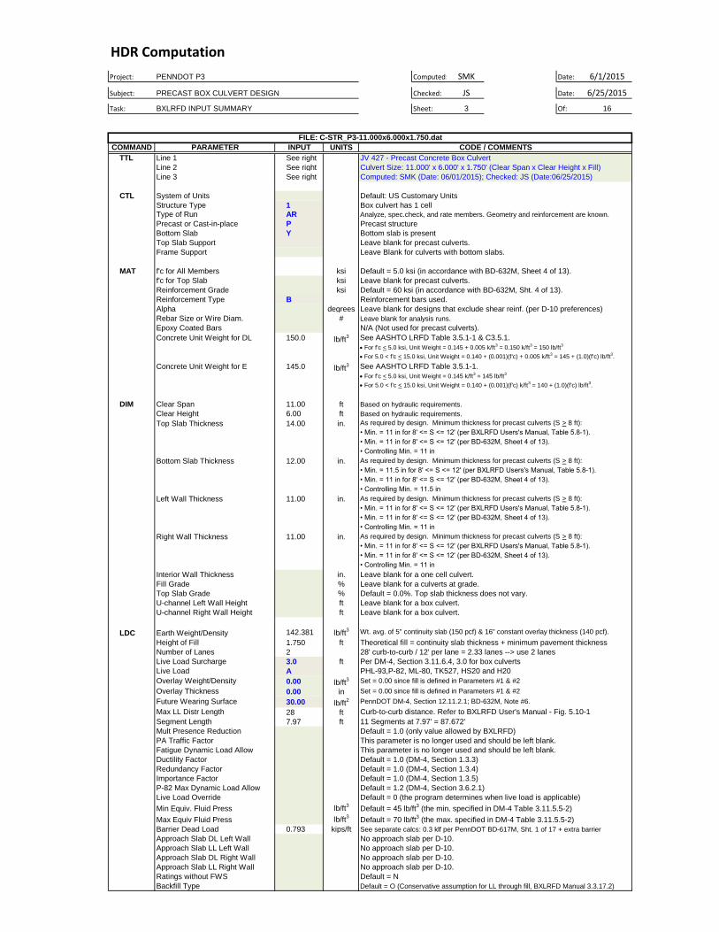
Project: PENNDOT P3 Computed: SMK Date: 6/1/2015
Subject: PRECAST BOX CULVERT DESIGN Checked: JS Date: 6/25/2015
Task: BXLRFD INPUT SUMMARY Sheet: 3 Of: 16
COMMAND INPUT UNITS
TTL See right
See right
See right
CTL
1
AR
P
Y
MAT ksi
ksi
ksi
B
degrees
#
150.0 lb/ft3
145.0 lb/ft3
DIM 11.00 ft
6.00 ft
14.00 in.
12.00 in.
11.00 in.
11.00 in.
in.
%
%
ft
ft
LDC 142.381 lb/ft3
1.750 ft
2
3.0 ft
A
0.00 lb/ft3
0.00 in
30.00 lb/ft2
28 ft
7.97 ft
lb/ft3
lb/ft3
0.793 kips/ft
Default = N
Default = O (Conservative assumption for LL through fill, BXLRFD Manual 3.3.17.2)
FILE: C-STR_P3-11.000x6.000x1.750.dat
PARAMETER
Precast or Cast-in-place
Type of Run
Structure Type
System of Units
Fill Grade
Interior Wall Thickness
Right Wall Thickness
Left Wall Thickness
Bottom Slab Thickness
f'c for All Members
Frame Support
Top Slab Support
f'c for Top Slab
Top Slab Thickness
Clear Height
Clear Span
Epoxy Coated Bars
U-channel Right Wall Height
U-channel Left Wall Height
Fatigue Dynamic Load Allow
PA Traffic Factor
Mult Presence Reduction
Segment Length
Max LL Distr Length
Future Wearing Surface
Overlay Thickness
Leave blank for a box culvert.
PennDOT DM-4, Section 12.11.2.1; BD-632M, Note #6.
Set = 0.00 since fill is defined in Parameters #1 & #2
Set = 0.00 since fill is defined in Parameters #1 & #2
PHL-93,P-82, ML-80, TK527, HS20 and H20
Per DM-4, Section 3.11.6.4, 3.0 for box culverts
28' curb-to-curb / 12' per lane = 2.33 lanes --> use 2 lanes
Theoretical fill = continuity slab thickness + minimum pavement thickness
Wt. avg. of 5" continuity slab (150 pcf) & 16" constant overlay thickness (140 pcf).Earth Weight/Density
Overlay Weight/Density
This parameter is no longer used and should be left blank.
Default = 1.0 (only value allowed by BXLRFD)
Approach Slab LL Right Wall
Default = 45 lb/ft3 (the min. specified in DM-4 Table 3.11.5.5-2)
No approach slab per D-10.
No approach slab per D-10.
Default = 0 (the program determines when live load is applicable)
Default = 1.2 (DM-4, Section 3.6.2.1)
• Controlling Min. = 11 in
Based on hydraulic requirements.
Based on hydraulic requirements.
11 Segments at 7.97' = 87.672'
Curb-to-curb distance. Refer to BXLRFD User's Manual - Fig. 5.10-1
Ductility Factor
Leave blank for a box culvert.
Default = 0.0%. Top slab thickness does not vary.
As required by design. Minimum thickness for precast culverts (S > 8 ft):
As required by design. Minimum thickness for precast culverts (S > 8 ft):
As required by design. Minimum thickness for precast culverts (S > 8 ft):
Leave blank for a culverts at grade.
Leave blank for a one cell culvert.
As required by design. Minimum thickness for precast culverts (S > 8 ft):
• Min. = 11.5 in for 8' <= S <= 12' (per BXLRFD Users's Manual, Table 5.8-1).
• Min. = 11 in for 8' <= S <= 12' (per BD-632M, Sheet 4 of 13).
• Controlling Min. = 11.5 in
• Min. = 11 in for 8' <= S <= 12' (per BXLRFD Users's Manual, Table 5.8-1).
• Min. = 11 in for 8' <= S <= 12' (per BD-632M, Sheet 4 of 13).
• Controlling Min. = 11 in
• Min. = 11 in for 8' <= S <= 12' (per BXLRFD Users's Manual, Table 5.8-1).
Leave blank for precast culverts.
Bottom slab is present
Computed: SMK (Date: 06/01/2015); Checked: JS (Date:06/25/2015)
Concrete Unit Weight for DL
Concrete Unit Weight for E
• Min. = 11 in for 8' <= S <= 12' (per BXLRFD Users's Manual, Table 5.8-1).
• Min. = 11 in for 8' <= S <= 12' (per BD-632M, Sheet 4 of 13).
Box culvert has 1 cell
Default: US Customary Units
Default = 5.0 ksi (in accordance with BD-632M, Sheet 4 of 13).
N/A (Not used for precast culverts).
See AASHTO LRFD Table 3.5.1-1 & C3.5.1.
For f'c < 5.0 ksi, Unit Weight = 0.145 + 0.005 k/ft3 = 0.150 k/ft
3 = 150 lb/ft
3
For 5.0 < f'c < 15.0 ksi, Unit Weight = 0.140 + (0.001)(f'c) + 0.005 k/ft3 = 145 + (1.0)(f'c) lb/ft
3.
See AASHTO LRFD Table 3.5.1-1.
For f'c < 5.0 ksi, Unit Weight = 0.145 k/ft3 = 145 lb/ft
3
For 5.0 < f'c < 15.0 ksi, Unit Weight = 0.140 + (0.001)(f'c) k/ft3 = 140 + (1.0)(f'c) lb/ft
3.
Precast structure
Analyze, spec.check, and rate members. Geometry and reinforcement are known.
Ratings without FWS
Backfill Type
JV 427 - Precast Concrete Box Culvert
CODE / COMMENTS
Bottom Slab
Rebar Size or Wire Diam.
Alpha
Reinforcement Type
Reinforcement Grade
Line 3
Line 1
Leave Blank for culverts with bottom slabs.
Leave blank for analysis runs.
Leave blank for designs that exclude shear reinf. (per D-10 preferences)
Reinforcement bars used.
Default = 60 ksi (in accordance with BD-632M, Sht. 4 of 13).
Leave blank for precast culverts.
Importance Factor
Line 2 Culvert Size: 11.000' x 6.000' x 1.750' (Clear Span x Clear Height x Fill)
• Min. = 11 in for 8' <= S <= 12' (per BD-632M, Sheet 4 of 13).
• Controlling Min. = 11 in
No approach slab per D-10.
No approach slab per D-10.
Approach Slab DL Right Wall
Approach Slab LL Left Wall
Approach Slab DL Left Wall
Barrier Dead Load
Max Equiv Fluid Press
Min Equiv. Fluid Press
Default = 70 lb/ft3 (the max. specified in DM-4 Table 3.11.5.5-2)
Live Load Override
P-82 Max Dynamic Load Allow
See separate calcs: 0.3 klf per PennDOT BD-617M, Sht. 1 of 17 + extra barrier
Redundancy Factor
Top Slab Grade
Live Load
Live Load Surcharge
Number of Lanes
Height of Fill
Default = 1.0 (DM-4, Section 1.3.5)
Default = 1.0 (DM-4, Section 1.3.4)
Default = 1.0 (DM-4, Section 1.3.3)
This parameter is no longer used and should be left blank.
HDR Computation
Project: PENNDOT P3 Computed: JDD Date: 6/1/2015
Subject: PRECAST BOX CULVERT DESIGN Checked: JS Date: 6/25/2015
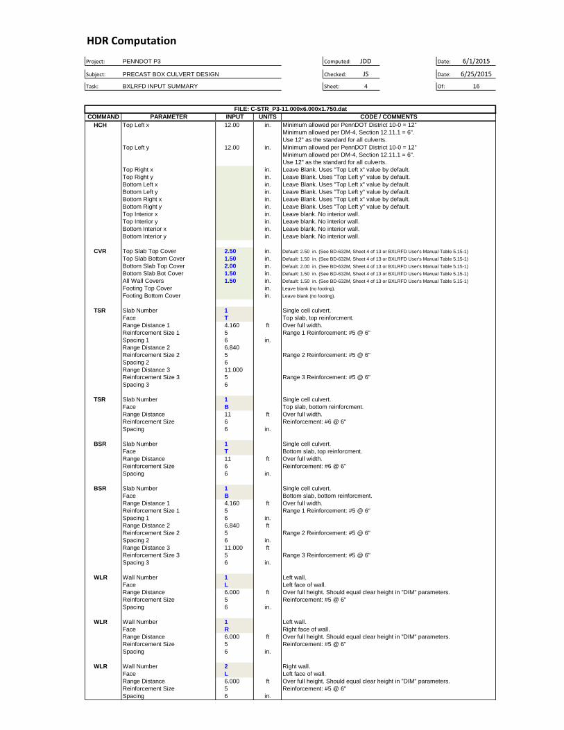
Task: BXLRFD INPUT SUMMARY Sheet: 4 Of: 16
COMMAND INPUT UNITS
HCH 12.00 in.
12.00 in.
in.
in.
in.
in.
in.
in.
in.
in.
in.
in.
CVR 2.50 in.
1.50 in.
2.00 in.
1.50 in.
1.50 in.
in.
in.
TSR 1
T
4.160 ft
5
6 in.
6.840
5
6
11.000
5
6
TSR 1
B
11 ft
6
6 in.
BSR 1
T
11 ft
6
6 in.
BSR 1
B
4.160 ft
5
6 in.
6.840 ft
5
6 in.
11.000 ft
5
6 in.
WLR 1
L
6.000 ft
5
6 in.
WLR 1
R
6.000 ft
5
6 in.
WLR 2
L
6.000 ft
5
6 in.
Spacing 1
Reinforcement Size
Range Distance
Face
Slab Number
Reinforcement: #6 @ 6"
Reinforcement: #6 @ 6"
Bottom slab, bottom reinforcment.
Single cell culvert.
Range 1 Reinforcement: #5 @ 6"
Over full width.
Spacing 3
Range 2 Reinforcement: #5 @ 6"
Range 3 Reinforcement: #5 @ 6"
Left wall.
Range Distance 2
Reinforcement Size 2
Spacing 2
Range Distance 3
Reinforcement Size 3
FILE: C-STR_P3-11.000x6.000x1.750.dat
CODE / COMMENTSPARAMETER
Reinforcement Size 1
Range Distance 1
Face
Slab Number
Reinforcement Size
Range Distance
Face
Wall Number
Reinforcement Size
Range Distance
Face
Wall Number
Bottom Slab Top Cover
Reinforcement Size
Top Slab Bottom Cover
Top Slab Top Cover
Reinforcement Size
Range Distance
Face
Wall Number
Footing Bottom Cover
Footing Top Cover
All Wall Covers
Spacing 1
Spacing
Spacing
Spacing
Slab Number
Bottom Slab Bot Cover
Reinforcement Size 1
Range Distance 1
Face
Range Distance 2
Reinforcement Size 2
Spacing 2
Range Distance 3
Reinforcement Size 3
Spacing 3
Top Left y
Top Left x
Leave Blank. Uses "Top Left y" value by default.
Leave Blank. Uses "Top Left x" value by default.
Default: 1.50 in. (See BD-632M, Sheet 4 of 13 or BXLRFD User's Manual Table 5.15-1)
Default: 1.50 in. (See BD-632M, Sheet 4 of 13 or BXLRFD User's Manual Table 5.15-1)
Default: 2.00 in. (See BD-632M, Sheet 4 of 13 or BXLRFD User's Manual Table 5.15-1)
Default: 1.50 in. (See BD-632M, Sheet 4 of 13 or BXLRFD User's Manual Table 5.15-1)
Default: 2.50 in. (See BD-632M, Sheet 4 of 13 or BXLRFD User's Manual Table 5.15-1)
Leave blank. No interior wall.
Leave blank. No interior wall.
Leave blank. No interior wall.
Leave blank. No interior wall.
Leave Blank. Uses "Top Left y" value by default.
Leave Blank. Uses "Top Left x" value by default.
Bottom Interior y
Bottom Interior x
Top Interior y
Top Interior x
Bottom Right y
Bottom Right x
Bottom Left y
Bottom Left x
Top Right y
Top Right x
Reinforcement: #5 @ 6"
Over full height. Should equal clear height in "DIM" parameters.
Left face of wall.
Right wall.
Leave blank (no footing).
Over full width.
Top slab, bottom reinforcment.
Single cell culvert.
Range 1 Reinforcement: #5 @ 6"
Spacing
Spacing
Range Distance
Face
Slab Number
Reinforcement: #5 @ 6"
Over full height. Should equal clear height in "DIM" parameters.
Right face of wall.
Over full height. Should equal clear height in "DIM" parameters.
Left wall.
Reinforcement: #5 @ 6"
Over full width.
Bottom slab, top reinforcment.
Single cell culvert.
Leave Blank. Uses "Top Left y" value by default.
Leave Blank. Uses "Top Left x" value by default.
Left face of wall.
Range 2 Reinforcement: #5 @ 6"
Range 3 Reinforcement: #5 @ 6"
Minimum allowed per PennDOT District 10-0 = 12"
Minimum allowed per DM-4, Section 12.11.1 = 6".
Use 12" as the standard for all culverts.
Minimum allowed per PennDOT District 10-0 = 12"
Minimum allowed per DM-4, Section 12.11.1 = 6".
Use 12" as the standard for all culverts.
Over full width.
Top slab, top reinforcment.
Single cell culvert.
Leave blank (no footing).
HDR Computation
Project: PENNDOT P3 Computed: JDD Date: 6/1/2015
Subject: PRECAST BOX CULVERT DESIGN Checked: JS Date: 6/25/2015
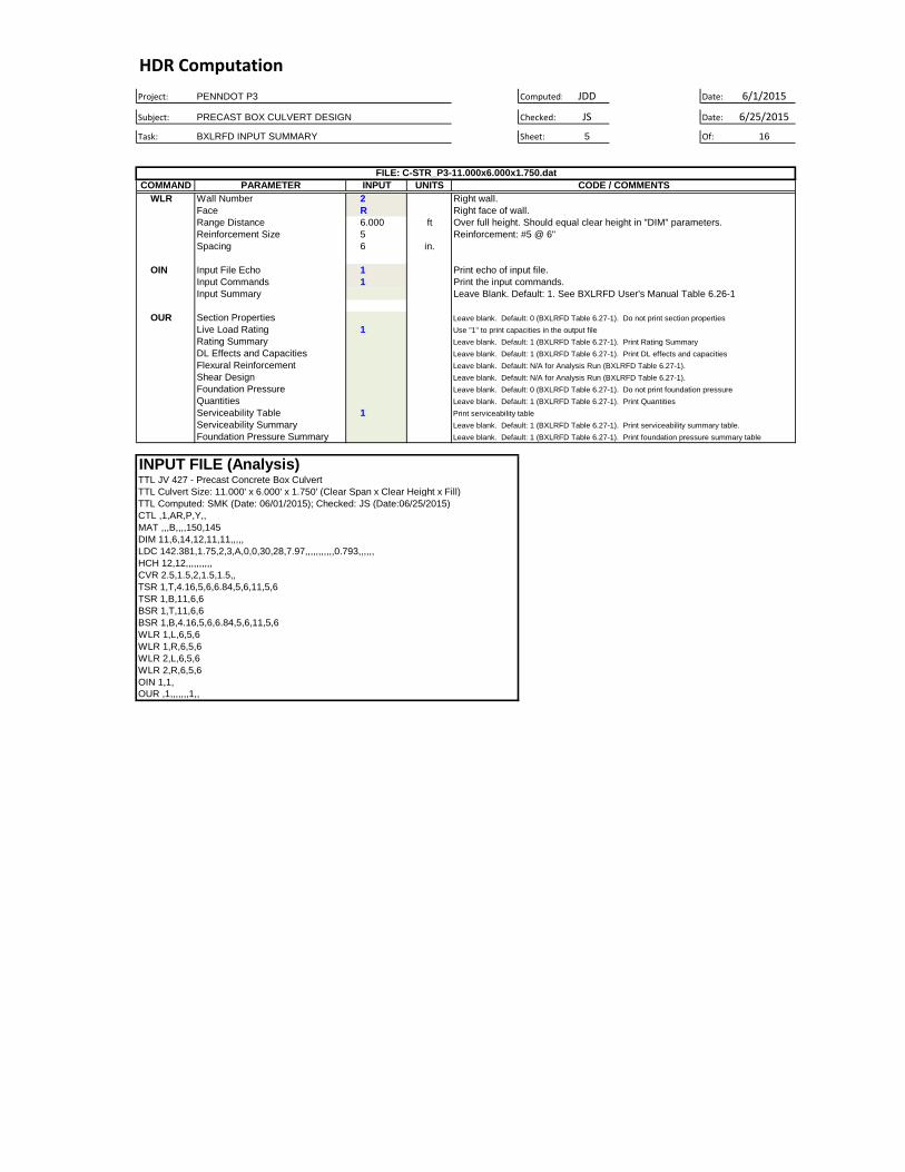
Task: BXLRFD INPUT SUMMARY Sheet: 5 Of: 16
COMMAND INPUT UNITS
WLR 2
R
6.000 ft
5
6 in.
OIN 1
1
OUR
1
1
TTL JV 427 - Precast Concrete Box Culvert
TTL Culvert Size: 11.000' x 6.000' x 1.750' (Clear Span x Clear Height x Fill)
TTL Computed: SMK (Date: 06/01/2015); Checked: JS (Date:06/25/2015)
CTL ,1,AR,P,Y,,
MAT ,,,B,,,,150,145
DIM 11,6,14,12,11,11,,,,,
LDC 142.381,1.75,2,3,A,0,0,30,28,7.97,,,,,,,,,,,0.793,,,,,,
HCH 12,12,,,,,,,,,,
CVR 2.5,1.5,2,1.5,1.5,,
TSR 1,T,4.16,5,6,6.84,5,6,11,5,6
TSR 1,B,11,6,6
BSR 1,T,11,6,6
BSR 1,B,4.16,5,6,6.84,5,6,11,5,6
WLR 1,L,6,5,6
WLR 1,R,6,5,6
WLR 2,L,6,5,6
WLR 2,R,6,5,6
OIN 1,1,
OUR ,1,,,,,,,1,,
Leave blank. Default: 1 (BXLRFD Table 6.27-1). Print serviceability summary table.
Leave blank. Default: 1 (BXLRFD Table 6.27-1). Print foundation pressure summary table
Leave blank. Default: 0 (BXLRFD Table 6.27-1). Do not print section properties
Use "1" to print capacities in the output file
Leave blank. Default: 1 (BXLRFD Table 6.27-1). Print Rating Summary
Leave blank. Default: 1 (BXLRFD Table 6.27-1). Print DL effects and capacities
Leave blank. Default: N/A for Analysis Run (BXLRFD Table 6.27-1).
Leave blank. Default: N/A for Analysis Run (BXLRFD Table 6.27-1).
Leave blank. Default: 0 (BXLRFD Table 6.27-1). Do not print foundation pressure
Leave blank. Default: 1 (BXLRFD Table 6.27-1). Print Quantities
Print serviceability table
Section Properties
Live Load Rating
Rating Summary
DL Effects and Capacities
Flexural Reinforcement
Shear Design
Foundation Pressure
Foundation Pressure Summary
Quantities
Serviceability Table
Serviceability Summary
INPUT FILE (Analysis)
Input Summary
Input Commands
Input File Echo
Reinforcement Size
Range Distance
Face
Wall Number
Spacing
FILE: C-STR_P3-11.000x6.000x1.750.dat
Leave Blank. Default: 1. See BXLRFD User's Manual Table 6.26-1
Print the input commands.
Print echo of input file.
Reinforcement: #5 @ 6"
Over full height. Should equal clear height in "DIM" parameters.
Right face of wall.
Right wall.
PARAMETER CODE / COMMENTS
Related Documents