KF Valves KF Series F/FE Flanged Floating Ball Valves Continuously Improving Flow Control

Welcome message from author
This document is posted to help you gain knowledge. Please leave a comment to let me know what you think about it! Share it to your friends and learn new things together.
Transcript
KF ValvesKF Series F/FE Flanged Floating Ball Valves
Continuously Improving Flow Control
2
KF Valves
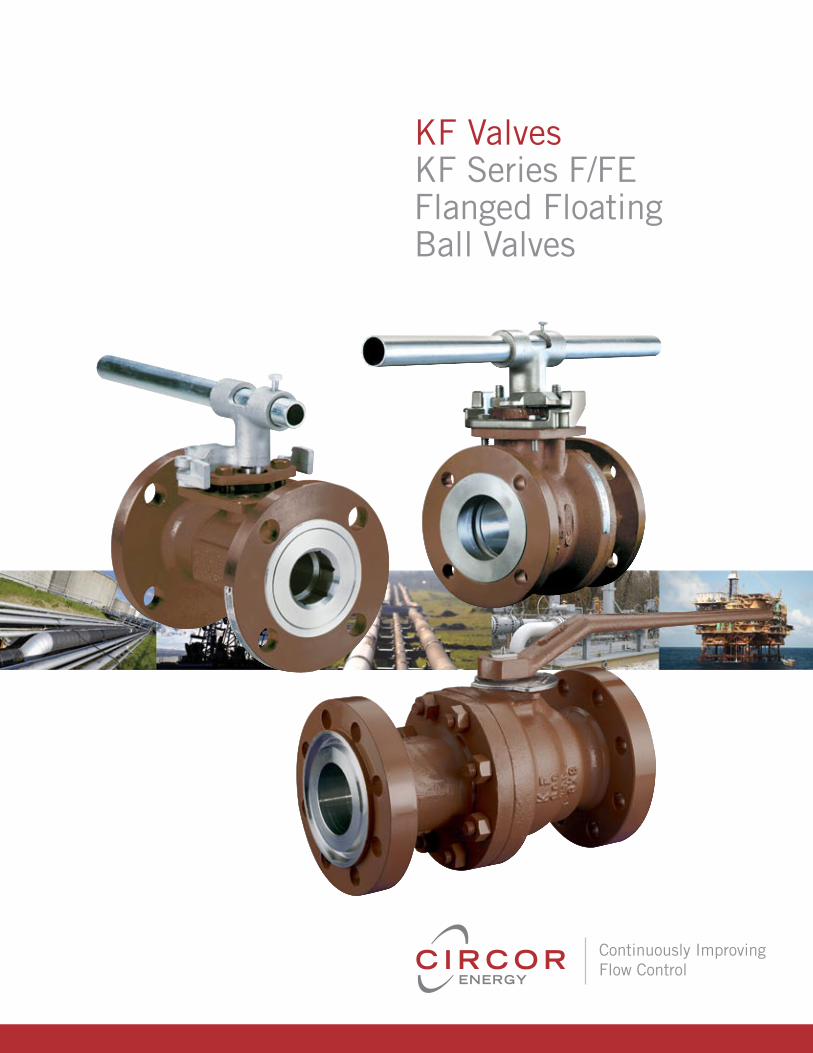
KF Series F/FE Unibody & Two-Piece Floating Ball Valves
KF series F/FE flanged floating ball valves are a prime example of KF's reliability, performance, manufacturing and superior
engineering techniques at work. Featuring a unibody or two-piece bolted design.
Features Anti-blowout stem design
Weather seal (Class 600 & higher)
Actuator mounting pad (4 bolt machined)
Secondary metal-to-metal sealing
Full rated bi-directional dead end service
Antistatic device
Lockable handle
O-Ring design (standard)
Graphite or teflon® packing (optional)
ContentsValve Assembly Part Number Codes . . . . . . . . . . . . . . . . . . . . . . . . . . . . . . . . . . . . . . . . . . . . . . . . . . . . . . . . . . . . . . . . . . . . . . . . . . . . . . . . . . 3
Design Features . . . . . . . . . . . . . . . . . . . . . . . . . . . . . . . . . . . . . . . . . . . . . . . . . . . . . . . . . . . . . . . . . . . . . . . . . . . . . . . . . . . . . . . . . . . . . . . . 4
Applicable Standards . . . . . . . . . . . . . . . . . . . . . . . . . . . . . . . . . . . . . . . . . . . . . . . . . . . . . . . . . . . . . . . . . . . . . . . . . . . . . . . . . . . . . . . . . . . . . 5
Series F Component Parts, Class 150 & 300 . . . . . . . . . . . . . . . . . . . . . . . . . . . . . . . . . . . . . . . . . . . . . . . . . . . . . . . . . . . . . . . . . . . . . . . . . . . 6
Series FE Component Parts, Class 150 & 300 . . . . . . . . . . . . . . . . . . . . . . . . . . . . . . . . . . . . . . . . . . . . . . . . . . . . . . . . . . . . . . . . . . . . . . . . . . 7
Series F/FE Component Parts, Class 600, 900 & 1500 . . . . . . . . . . . . . . . . . . . . . . . . . . . . . . . . . . . . . . . . . . . . . . . . . . . . . . . . . . . . . . . . . . . 8
Series F Unibody Dimensional Data, Class 150 & 300 . . . . . . . . . . . . . . . . . . . . . . . . . . . . . . . . . . . . . . . . . . . . . . . . . . . . . . . . . . . . . . . . . . . 9
Series F/FE Split Body Dimensional Data, Class 150 & 300 . . . . . . . . . . . . . . . . . . . . . . . . . . . . . . . . . . . . . . . . . . . . . . . . . . . . . . . . . . 10 - 11
Series F/FE Split Body Dimensional Data, Class 600, 900 & 1500 . . . . . . . . . . . . . . . . . . . . . . . . . . . . . . . . . . . . . . . . . . . . . . . . . . . . . . . . . 12
Engineering Data . . . . . . . . . . . . . . . . . . . . . . . . . . . . . . . . . . . . . . . . . . . . . . . . . . . . . . . . . . . . . . . . . . . . . . . . . . . . . . . . . . . . . . . . . . . . . . . 13
Topworks . . . . . . . . . . . . . . . . . . . . . . . . . . . . . . . . . . . . . . . . . . . . . . . . . . . . . . . . . . . . . . . . . . . . . . . . . . . . . . . . . . . . . . . . . . . . . . . . . 14 -15
3
KF Valves
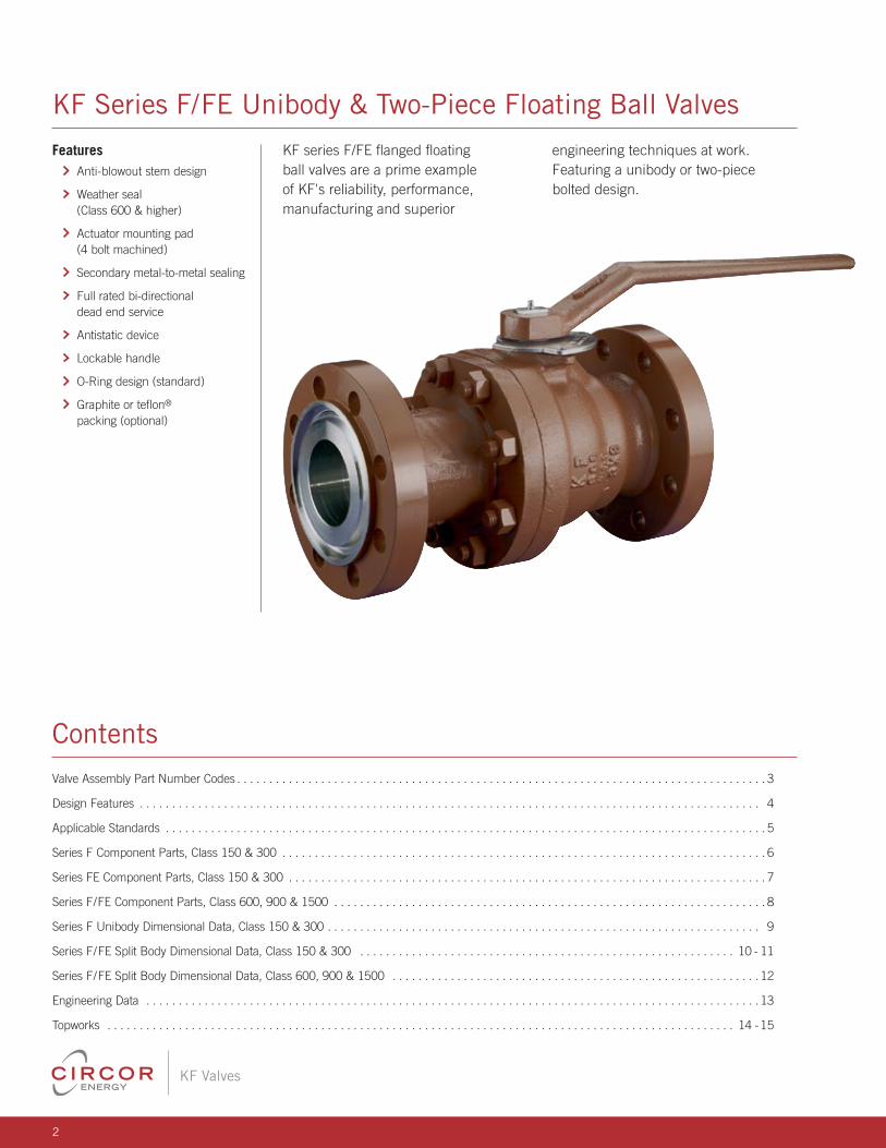
KF Series F/FE Part Number Codes
G 2297 - 1 9 2 2 G 9 1 XX
G • Domestic E • Global
Base NumberSee Chart Below
Body / Bolting Material1 • CS / CS 2 • SS / SS 8 • LTCS (FE) 9 • LTCS / LTCS (F)Note: Bolting material applicable to Split Body (2-Piece) only.
Body Configuration2 • Vented Ball (1"FP- 4"FP Only) 9 • Split Body 8 • Unibody (See Chart on Page 5) (See Chart on Page 5)
Ball / Stem Material1 • CS / CS A • CS 3mil ENP (6"-10" Bore Cl. 150 2 • SS / SS & 300 & 4"- 6" Bore Cl. 600 Only)
Seat Material2 • Uniseal™ / RTFE 5 • HT4 (PEEK™) 9 • Devlon®
Stem Packing / O-RingPacking (Cl. 150 & 300 only)1 • Teflon® V-Ring (Std.) 6 • Graphite
O-RingsA • James Walker® Viton® D • LT Buna N G • HNBRB • EPDM E • Viton® (F) N • LT HNBRC • Aflas® F • Elast -O-Lion® 985 2 • Viton® (FE)
Specification2 • NACE II (Cl. II Bolting) 4 • NACE II w/Enduro-Bond™ Ctg.3 • NACE III w/Enduro-Bond™ Ctg. 9 • Std. (NACE Cl. III Bolting)
Actuation1 • Handle (1"- 4" Bore & 6 • Locking GOP 6" Bore Cl. 150 only) 9 • Bare Stem3 • Gear Operator A • For Actuator
Process Codes(Last two digits used ONLY when Process Codes are required.)
Asterisk ( * ) in lieu of dash ( - ) in Assembly Part Number indicates customer requires source inspection. (i.e. XXXXX * XXXXXXXXX)
(i.e. GXXXX-XXXXXXXXX) - Domestic(i.e. EXXXX-XXXXXXXXX) - Global
Example
Assembly Base Numbers, 1"FP-8"FP Class /End Size (in.) Connection 1 FP 11/2 FP 2 RP 2 FP 21/2 RP 3 RP 3FP 4RP 4 FP 6RP 6FP 8RP 8FP 150RF 2147 2149 2150 2151 2152 2153 2154 2155 2156 2157 1720 1721 1722 300RF 2297 2299 2300 2301 2302 2303 2304 2305 2306 2307 1724 1725 1726 600RF 2597 2599 2600 2601 2602 2603 2604 2605 2606 2618 — — — 600RTJ 2607 2609 2610 2611 2612 2613 2614 2615 2616 2617 — — — 900RF 3348 — 2900 2901 — — — — — — — — — 900RTJ 3349 — 2910 2911 — — — — — — — — — 1500RF 3348 — — — — — — — — — — — — 1500RTJ 3349 — — — — — — — — — — — —
4
KF Valves
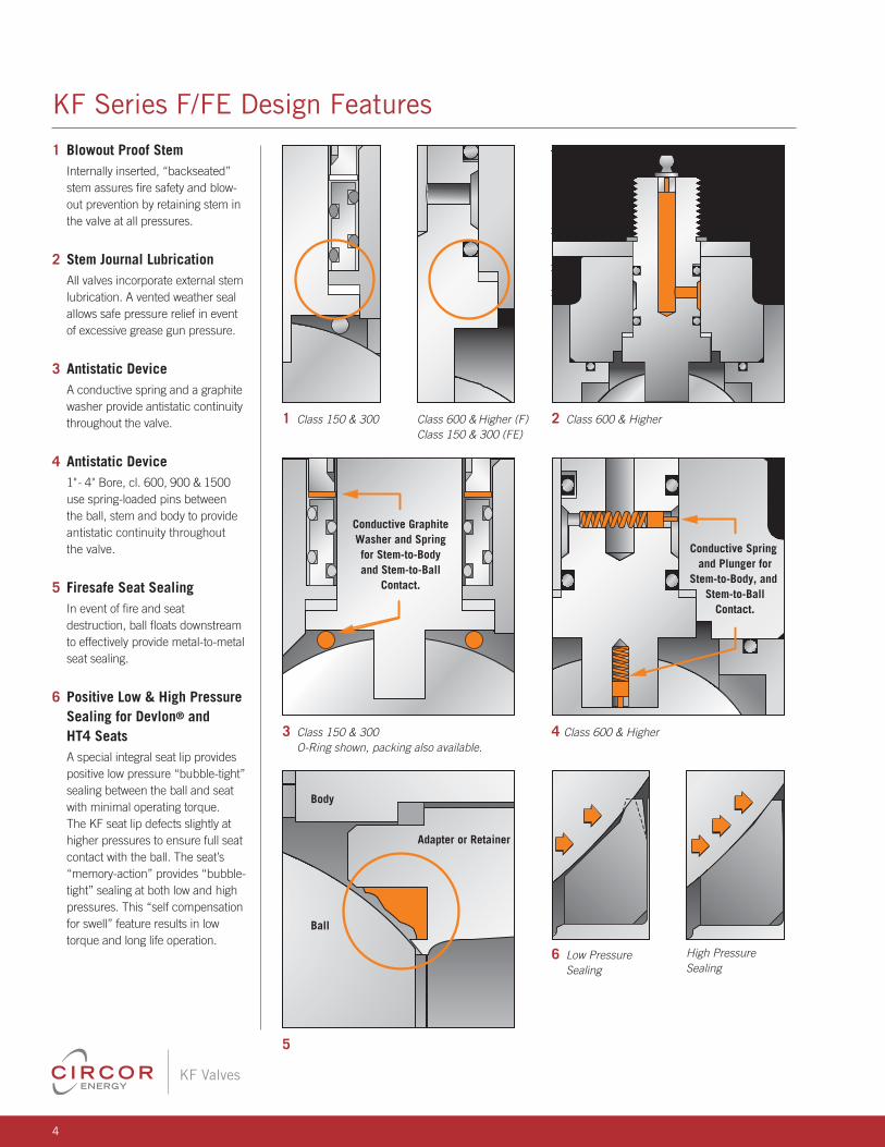
KF Series F/FE Design Features
1 Blowout Proof StemInternally inserted, “backseated” stem assures fire safety and blow-out prevention by retaining stem in the valve at all pressures.
2 Stem Journal LubricationAll valves incorporate external stem lubrication. A vented weather seal allows safe pressure relief in event of excessive grease gun pressure.
3 Antistatic DeviceA conductive spring and a graphite washer provide antistatic continuity throughout the valve.
4 Antistatic Device1"- 4" Bore, cl. 600, 900 & 1500 use spring-loaded pins between the ball, stem and body to provide antistatic continuity throughout the valve.
5 Firesafe Seat SealingIn event of fire and seat destruction, ball floats downstream to effectively provide metal-to-metal seat sealing.
6 Positive Low & High Pressure Sealing for Devlon® and HT4 Seats
A special integral seat lip provides positive low pressure “bubble-tight” sealing between the ball and seat with minimal operating torque. The KF seat lip defects slightly at higher pressures to ensure full seat contact with the ball. The seat’s “memory-action” provides “bubble-tight” sealing at both low and high pressures. This “self compensation for swell” feature results in low torque and long life operation.
1 Class 150 & 300 Class 600 & Higher (F) Class 150 & 300 (FE)
2 Class 600 & Higher
Conductive GraphiteWasher and Springfor Stem-to-Bodyand Stem-to-Ball
Contact.
Conductive Spring and Plunger for
Stem-to-Body, and Stem-to-Ball
Contact.
3 Class 150 & 300 O-Ring shown, packing also available.
4 Class 600 & Higher
Ball
Body
Adapter or Retainer
5
6 Low Pressure Sealing
High Pressure Sealing
5
KF Valves
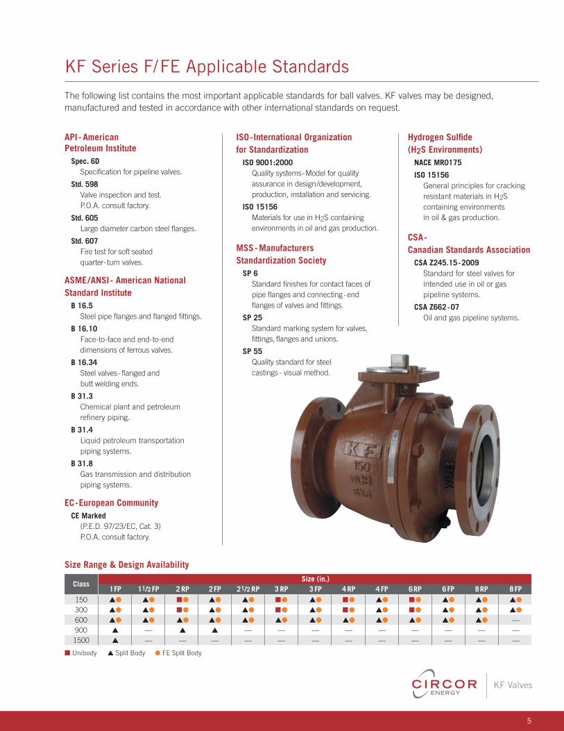
KF Series F/FE Applicable Standards
API- American Petroleum Institute
Spec. 6D Specification for pipeline valves.
Std. 598 Valve inspection and test. P.O.A. consult factory.
Std. 605 Large diameter carbon steel flanges.
Std. 607 Fire test for soft seated quarter-turn valves.
ASME/ANSI- American National Standard Institute
B 16.5 Steel pipe flanges and flanged fittings.
B 16.10 Face-to-face and end-to-end dimensions of ferrous valves.
B 16.34 Steel valves- flanged and butt welding ends.
B 31.3 Chemical plant and petroleum refinery piping.
B 31.4 Liquid petroleum transportation piping systems.
B 31.8 Gas transmission and distribution piping systems.
EC-European CommunityCE Marked (P.E.D. 97/23/EC, Cat. 3) P.O.A. consult factory.
The following list contains the most important applicable standards for ball valves. KF valves may be designed, manufactured and tested in accordance with other international standards on request.
ISO-International Organization for Standardization
ISO 9001:2000 Quality systems-Model for quality assurance in design/development, production, installation and servicing.
ISO 15156 Materials for use in H2S containing environments in oil and gas production.
MSS- Manufacturers Standardization Society
SP 6 Standard finishes for contact faces of pipe flanges and connecting-end flanges of valves and fittings.
SP 25 Standard marking system for valves, fittings, flanges and unions.
SP 55 Quality standard for steel castings - visual method.
Hydrogen Sulfide (H2S Environments)
NACE MR0175
ISO 15156 General principles for cracking resistant materials in H2S containing environments in oil & gas production.
CSA-Canadian Standards Association
CSA Z245.15-2009 Standard for steel valves for intended use in oil or gas pipeline systems.
CSA Z662-07 Oil and gas pipeline systems.
Size Range & Design Availability
Class Size (in.)
1 FP 11/2 FP 2 RP 2 FP 21/2 RP 3 RP 3 FP 4 RP 4 FP 6RP 6FP 8RP 8 FP 150 sl sl nl sl sl nl sl nl sl nl sl sl sl
300 sl sl nl sl sl nl sl nl sl nl sl sl sl 600 sl sl sl sl sl sl sl sl sl sl sl sl — 900 s — s s — — — — — — — — — 1500 s — — — — — — — — — — — —
n Unibody s Split Body lFE Split Body
6
KF Valves
216
76
74
517
11A
11D22
3011E
23
9
8
24
20
2526
1
28
11C
11G
11F
3
10
21
11B
33A
1
33E
33D
3
21
10
25
33C
33F
52
7
7
33G
33B
4
26
Unibody Configuration
Split Body Configuration
28
23
22
30
9
8
24
20
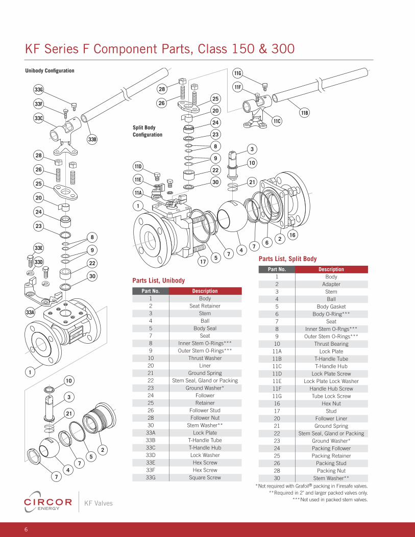
KF Series F Component Parts, Class 150 & 300
Parts List, Unibody Part No. Description 1 Body 2 Seat Retainer 3 Stem 4 Ball 5 Body Seal 7 Seat 8 Inner Stem O-Rings*** 9 Outer Stem O-Rings*** 10 Thrust Washer 20 Liner 21 Ground Spring 22 Stem Seal, Gland or Packing 23 Ground Washer* 24 Follower 25 Retainer 26 Follower Stud 28 Follower Nut 30 Stem Washer** 33A Lock Plate 33B T-Handle Tube 33C T-Handle Hub 33D Lock Washer 33E Hex Screw 33F Hex Screw 33G Square Screw
Parts List, Split Body Part No. Description 1 Body 2 Adapter 3 Stem 4 Ball 5 Body Gasket 6 Body O-Ring*** 7 Seat 8 Inner Stem O-Rngs*** 9 Outer Stem O-Rings*** 10 Thrust Bearing 11A Lock Plate 11B T-Handle Tube 11C T-Handle Hub 11D Lock Plate Screw 11E Lock Plate Lock Washer 11F Handle Hub Screw 11G Tube Lock Screw 16 Hex Nut 17 Stud 20 Follower Liner 21 Ground Spring 22 Stem Seal, Gland or Packing 23 Ground Washer* 24 Packing Follower 25 Packing Retainer 26 Packing Stud 28 Packing Nut 30 Stem Washer**
*Not required with Grafoil® packing in Firesafe valves.**Required in 2" and larger packed valves only.
***Not used in packed stem valves.
7
KF Valves
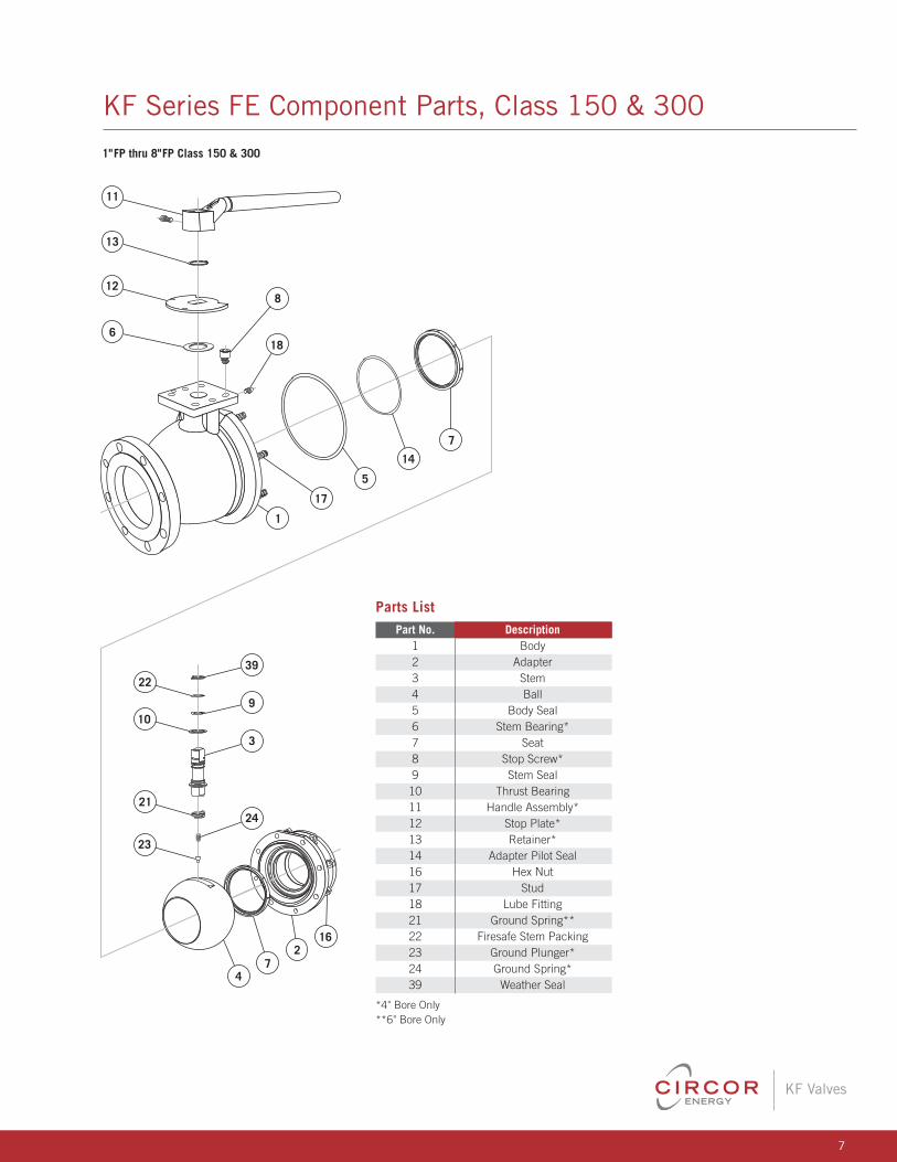
KF Series FE Component Parts, Class 150 & 300
1"FP thru 8"FP Class 150 & 300
216
7
1
17
5
14
7
4
22
10
6
13
8
18
11
39
9
24
3
21
23
12
1"FP thru 8"FP Class 150 & 300
216
7
117
514
74
22
10
6
13
8
18
11
39
9
24
3
21
23
12
Parts List Part No. Description 1 Body 2 Adapter 3 Stem 4 Ball 5 Body Seal 6 Stem Bearing* 7 Seat 8 Stop Screw* 9 Stem Seal 10 Thrust Bearing 11 Handle Assembly* 12 Stop Plate* 13 Retainer* 14 Adapter Pilot Seal 16 Hex Nut 17 Stud 18 Lube Fitting 21 Ground Spring** 22 Firesafe Stem Packing 23 Ground Plunger* 24 Ground Spring* 39 Weather Seal
*4" Bore Only**6" Bore Only
8
KF Valves
25
1
74
7
939
103
13
8
11
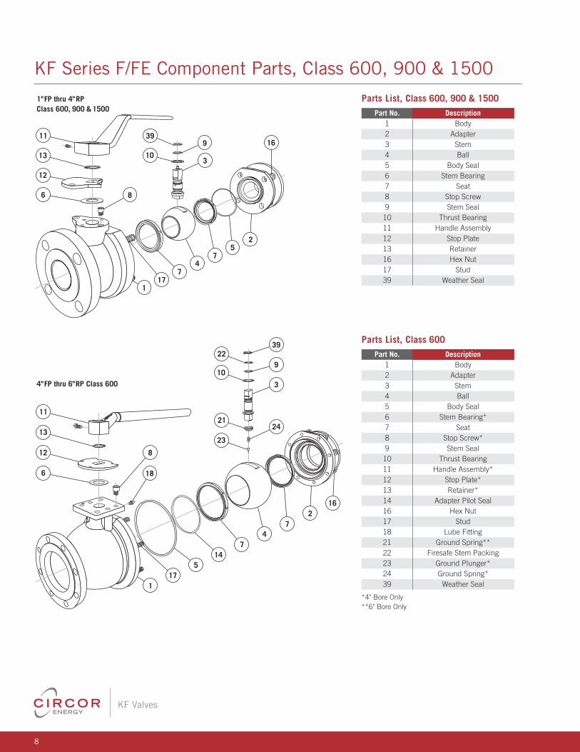
1"FP thru 4"RPClass 600, 900 & 1500
4"FP thru 6"RP Class 600
12
6
216
7
117
514
74
22
10
6
13
8
18
11
39
9
24
3
21
23
12
17
16
Parts List, Class 600, 900 & 1500 Part No. Description 1 Body 2 Adapter 3 Stem 4 Ball 5 Body Seal 6 Stem Bearing 7 Seat 8 Stop Screw 9 Stem Seal 10 Thrust Bearing 11 Handle Assembly 12 Stop Plate 13 Retainer 16 Hex Nut 17 Stud 39 Weather Seal
Parts List, Class 600 Part No. Description 1 Body 2 Adapter 3 Stem 4 Ball 5 Body Seal 6 Stem Bearing* 7 Seat 8 Stop Screw* 9 Stem Seal 10 Thrust Bearing 11 Handle Assembly* 12 Stop Plate* 13 Retainer* 14 Adapter Pilot Seal 16 Hex Nut 17 Stud 18 Lube Fitting 21 Ground Spring** 22 Firesafe Stem Packing 23 Ground Plunger* 24 Ground Spring* 39 Weather Seal
*4" Bore Only**6" Bore Only
KF Series F/FE Component Parts, Class 600, 900 & 1500
9
KF Valves
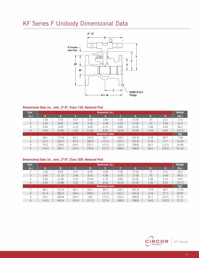
KF Series F Unibody Dimensional Data
H Useable Stem Flats
2"- 6"G
C
B ± .06
AD
DDE
F
U
ASME B16.5Flange
Dimensional Data (in., mm), 2"-6", Class 300, Reduced Port Size Dimension (in.) Weight (in.) A B C D E F G H U (lbs.) 2 1.50 8.50 3.27 6.50 3.69 5.36 17.00 .70 2.31 26.0 3 2.42 11.12 3.96 8.25 4.38 6.05 17.00 .70 3.06 46.0 4 3.00 12.00 4.10 10.00 6.75 8.83 22.00 1.38 4.43 70.0 6 4.50 15.88 5.25 12.50 8.56 10.55 22.00 1.44 6.02 157.0 Dimension (mm) (kg) 2 38.1 215.9 83.1 165.1 93.7 136.1 431.8 17.8 58.7 11.79 3 61.5 282.4 100.6 209.6 111.3 153.7 431.8 17.8 77.7 20.87 4 76.2 304.8 104.1 254 171.5 224.3 558.8 35.1 112.5 31.75 6 114.3 403.4 133.4 317.5 217.4 268.0 558.8 36.6 152.9 71.21
Dimensional Data (in., mm), 2"-6", Class 150, Reduced Port Size Dimension (in.) Weight (in.) A B C D E F G H U (lbs.) 2 1.50 7.00 3.27 6.00 3.69 5.36 17.00 .70 2.31 17.6 3 2.42 8.00 3.46 7.50 4.38 6.05 17.00 .70 3.06 31.5 4 3.00 9.00 4.10 9.00 6.75 8.83 22.00 1.38 4.43 54.2 6 4.50 10.50 5.25 11.00 8.56 10.55 22.00 1.44 6.02 137.0 Dimension (mm) (kg) 2 38.1 177.8 83.1 150.9 93.7 136.1 431.8 17.8 58.7 7.98 3 61.5 203.2 87.9 189.0 111.3 153.7 431.8 17.8 77.7 14.29 4 76.2 228.6 104.1 227.1 171.5 224.3 558.8 35.1 112.5 24.58 6 114.3 266.7 133.4 279.4 217.4 268.0 558.8 36.6 152.9 62.14
10
KF Valves
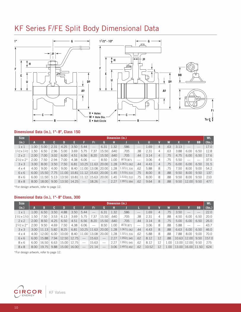
KF Series F/FE Split Body Dimensional Data
G
AD
H
DD
E
U
F
F1
Y
BB
11/2" - 10"1"
JD
L
JD
AD
DD
H
E
U
F
C
B
G
C
B
V • HolesW • Hole Dia.X • Bolt Circle
Dimensional Data (in.), 1"- 8" Class, 300 Size Dimension (in.) Wt. (in.) A B C D E F F1 G H J L U V W X Y BB (lbs.) 1 x 1 1.00 6.50 3.50 4.88 3.50 5.44 — 6.31 1.32 .586 — 1.69 4 .75 3.50 — — 22.0 11/2 x 11/2 1.50 7.50 3.53 6.13 3.69 5.75 7.37 15.50 .640 .705 .38 2.31 4 .88 4.50 6.00 6.50 20.0 2 x 2 2.00 8.50 4.25 6.50 4.51 6.56 8.20 15.50 .640 .705 .44 3.14 8 .75 5.00 6.00 6.50 26.0 21/2 x 2* 2.00 9.50 4.69 7.50 4.38 6.06 — 8.50 1.00 .873/.871 — 3.06 8 .88 5.88 — — 43.7 3 x 3 3.00 11.13 5.82 8.25 6.81 10.25 11.63 20.00 1.28 1.067/1.062 .44 4.43 8 .88 6.63 6.00 6.50 46.0 4 x 4 4.00 12.00 6.00 10.00 8.40 11.00 13.08 20.00 1.28 1.321/1.316 .62 5.88 8 .88 7.88 8.00 9.00 70.0 6 x 6 6.00 15.88 7.94 12.50 12.75 — 15.63 — 2.27 1.950/1.945 .62 8.12 12 .88 10.63 12.00 9.50 157.0 8 x 6 6.00 16.50 6.63 15.00 12.75 — 15.63 — 2.27 1.950/1.945 .62 8.12 12 1.00 13.00 12.00 9.50 275 8 x 8 8.00 19.75 9.88 15.00 16.00 — 21.14 — 3.06 2.497/2.492 .62 10.52 12 1.00 13.00 16.00 11.50 624
*For design artwork, refer to page 12.
Dimensional Data (in.), 1"- 8", Class 150 Size Dimension (in.) Wt. (in.) A B C D E F F1 G H J L U V W X Y BB (lbs.) 1 x 1 1.00 5.00 2.31 4.25 3.50 5.44 — 6.31 1.32 .586 — 1.69 4 .63 3.13 — — 17.0 11/2 x 11/2 1.50 6.50 2.96 5.00 3.69 5.75 7.37 15.50 .640 .705 .38 2.31 4 .63 3.88 6.00 6.50 12.8 2 x 2 2.00 7.00 3.02 6.00 4.51 6.56 8.20 15.50 .640 .705 .44 3.14 4 .75 4.75 6.00 6.50 17.6 21/2 x 2* 2.00 7.50 2.94 7.00 4.38 6.06 — 8.50 1.00 .873/.871 — 3.06 4 .75 5.50 — — 37.5 3 x 3 3.00 8.00 3.50 7.50 6.81 10.25 11.63 20.00 1.28 1.067/1.062 .44 4.43 4 .75 6.00 6.00 6.50 31.5 4 x 4 4.00 9.00 4.00 9.00 8.40 11.00 13.08 20.00 1.28 1.321/1.316 .62 5.88 8 .75 7.50 8.00 9.00 54.2 6 x 6 6.00 15.50 7.75 11.00 10.81 11.12 15.63 20.00 1.45 1.515/1.510 .75 8.00 8 .88 9.50 8.00 9.50 137 8 x 6 6.00 11.50 5.13 13.50 10.81 11.12 15.63 20.00 1.45 1.515/1.510 .75 8.00 8 .88 9.50 8.00 9.50 210 8 x 8 8.00 18.00 9.00 13.50 14.25 — 18.26 — 2.27 1.997/1.994 .62 9.64 8 .88 9.50 12.00 9.50 477
*For design artwork, refer to page 12.
11
KF Valves
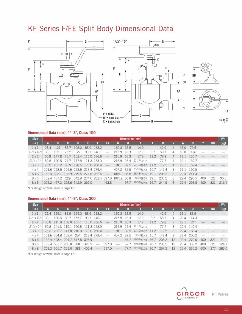
KF Series F/FE Split Body Dimensional Data
G
AD
H
DD
E
U
F
F1
Y
BB
11/2" - 10"1"
JD
L
JD
AD
DD
H
E
U
F
C
B
G
C
B
V • HolesW • Hole Dia.X • Bolt Circle
Dimensional Data (mm), 1"- 8", Class 150 Size Dimension (mm) Wt. (in.) A B C D E F F1 G H J L U V W X Y BB (kg) 1 x 1 25.4 127 58.7 108.0 88.9 138.2 — 160.3 33.5 14.0 — 42.9 4 16.0 79.5 — — — 11/2 x11/2 38.1 165.1 75.2 127 93.7 146.1 — 215.9 16.3 17.9 9.7 58.7 4 16.0 98.6 — — — 2 x 2 50.8 177.8 76.7 152.4 115.0 166.6 — 215.9 16.3 17.9 11.2 79.8 4 19.1 120.7 — — — 21/2 x 2* 50.8 190.5 74.7 177.8 111.3 153.9 — 215.9 25.4 22.17/22.12 — 77.7 4 19.1 139.7 — — — 3 x 3 76.2 203.2 88.9 190.5 173.0 260.4 — 381 32.5 27.10/26.97 11.2 112.5 4 19.1 152.4 — — — 4 x 4 101.6 228.6 101.6 228.6 213.4 279.4 — 457.2 32.5 33.55/33.43 15.7 149.4 8 19.1 190.5 — — — 6 x 6 152.4 393.7 196.9 279.4 274.6 282.4 — 1015.9 36.8 38.48/38.35 19.1 203.2 8 22.4 241.3 — — — 8 x 6 152.4 457.2 229 342.9 274.6 282.4 397.0 1015.9 36.8 38.48/38.35 19.1 203.2 8 22.4 298.5 400 321 95.3 8 x 8 203.2 457.2 228.6 342.9 362.0 — 463.8 — 57.7 49.53/49.40 16.7 244.9 8 22.4 298.5 400 321 216.4
*For design artwork, refer to page 12.
Dimensional Data (mm), 1"- 8", Class 300 Size Dimension (mm) Wt. (in.) A B C D E F F1 G H J L U V W X Y BB (kg) 1 x 1 25.4 165.1 88.9 124.0 88.9 138.2 — 160.3 33.5 14.0 — 42.9 4 19.1 88.9 — — — 11/2 x11/2 38.1 190.5 89.7 155.7 93.7 146.1 — 215.9 16.3 17.9 9.7 58.7 4 22.4 114.3 — — — 2 x 2 50.8 215.9 108.0 165.1 115.0 166.6 — 215.9 16.3 17.9 11.2 79.8 8 19.1 127 — — — 21/2 x 2* 50.8 241.3 119.1 190.5 111.3 153.9 — 215.9 25.4 22.17/22.12 — 77.7 8 22.4 149.4 — — — 3 x 3 76.2 282.7 147.8 210.0 173.0 260.4 — 381 32.5 27.10/26.97 11.2 112.5 8 22.4 168.4 — — — 4 x 4 101.6 304.8 152.4 254 213.4 279.4 — 457.2 32.5 33.55/33.43 15.7 149.4 8 22.4 200.2 — — — 6 x 6 152.4 403.4 201.7 317.5 323.9 — — — 57.7 49.53/49.40 16.7 206.2 12 22.4 270.0 400 321 71.2 8 x 6 152.4 501.7 250.8 381 323.9 — 397.0 — 57.7 49.53/49.40 16.7 206.2 12 25.4 330.2 400 321 124.7 8 x 8 203.2 501.7 251.0 381 406.4 — 537.0 — 77.7 62.31/62.18 16.7 267.2 12 25.4 330.2 600 377 283.0
*For design artwork, refer to page 12.
12
KF Valves
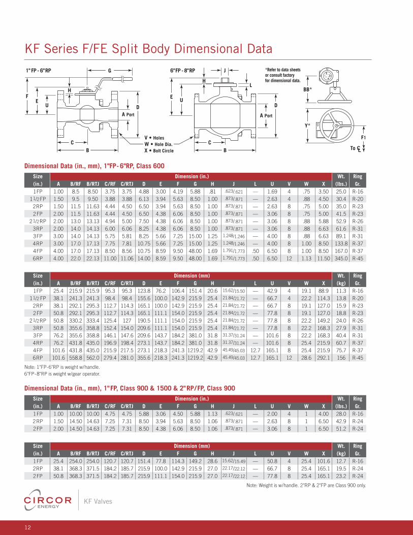
KF Series F/FE Split Body Dimensional Data
1" FP - 6"RP 6"FP - 8"RP J *Refer to data sheets or consult factory for dimensional data.
G
A Port
D
A Port
D
Y*
BB*H
EU
F
H
EU
L
CB
CB
V • HolesW • Hole Dia.X • Bolt Circle
F1
Dimensional Data (in., mm), 1"FP- 6"RP, Class 600 Size Dimension (in.) Wt. Ring (in.) A B/RF B/RTJ C/RF C/RTJ D E F G H J L U V W X (lbs.) Gr. 1FP 1.00 8.5 8.50 3.75 3.75 4.88 3.00 4.19 5.88 .81 .623/.621 — 1.69 4 .75 3.50 25.0 R-16 11/2FP 1.50 9.5 9.50 3.88 3.88 6.13 3.94 5.63 8.50 1.00 .873/.871 — 2.63 4 .88 4.50 30.4 R-20 2RP 1.50 11.5 11.63 4.44 4.50 6.50 3.94 5.63 8.50 1.00 .873/.871 — 2.63 8 .75 5.00 35.0 R-23 2FP 2.00 11.5 11.63 4.44 4.50 6.50 4.38 6.06 8.50 1.00 .873/.871 — 3.06 8 .75 5.00 41.5 R-23 21/2RP 2.00 13.0 13.13 4.94 5.00 7.50 4.38 6.06 8.50 1.00 .873/.871 — 3.06 8 .88 5.88 52.9 R-26 3RP 2.00 14.0 14.13 6.00 6.06 8.25 4.38 6.06 8.50 1.00 .873/.871 — 3.06 8 .88 6.63 61.6 R-31 3FP 3.00 14.0 14.13 5.75 5.81 8.25 5.66 7.25 15.00 1.25 1.248/1.246 — 4.00 8 .88 6.63 89.1 R-31 4RP 3.00 17.0 17.13 7.75 7.81 10.75 5.66 7.25 15.00 1.25 1.248/1.246 — 4.00 8 1.00 8.50 133.8 R-37 4FP 4.00 17.0 17.13 8.50 8.56 10.75 8.59 9.50 48.00 1.69 1.791/1.773 .50 6.50 8 1.00 8.50 167.0 R-37 6RP 4.00 22.0 22.13 11.00 11.06 14.00 8.59 9.50 48.00 1.69 1.791/1.773 .50 6.50 12 1.13 11.50 345.0 R-45
Size Dimension (mm) Wt. Ring (in.) A B/RF B/RTJ C/RF C/RTJ D E F G H J L U V W X (kg) Gr. 1FP 25.4 215.9 215.9 95.3 95.3 123.8 76.2 106.4 151.4 20.6 15.62/15.50 — 42.9 4 19.1 88.9 11.3 R-16 11/2 FP 38.1 241.3 241.3 98.4 98.4 155.6 100.0 142.9 215.9 25.4 21.84/21.72 — 66.7 4 22.2 114.3 13.8 R-20 2RP 38.1 292.1 295.3 112.7 114.3 165.1 100.0 142.9 215.9 25.4 21.84/21.72 — 66.7 8 19.1 127.0 15.9 R-23 2FP 50.8 292.1 295.3 112.7 114.3 165.1 111.1 154.0 215.9 25.4 21.84/21.72 — 77.8 8 19.1 127.0 18.8 R-23 21/2RP 50.8 330.2 333.4 125.4 127 190.5 111.1 154.0 215.9 25.4 21.84/21.72 — 77.8 8 22.2 149.2 24.0 R-26 3RP 50.8 355.6 358.8 152.4 154.0 209.6 111.1 154.0 215.9 25.4 21.84/21.72 — 77.8 8 22.2 168.3 27.9 R-31 3FP 76.2 355.6 358.8 146.1 147.6 209.6 143.7 184.2 381.0 31.8 31.37/31.24 — 101.6 8 22.2 168.3 40.4 R-31 4RP 76.2 431.8 435.0 196.9 198.4 273.1 143.7 184.2 381.0 31.8 31.37/31.24 — 101.6 8 25.4 215.9 60.7 R-37 4FP 101.6 431.8 435.0 215.9 217.5 273.1 218.3 241.3 1219.2 42.9 45.49/45.03 12.7 165.1 8 25.4 215.9 75.7 R-37 6RP 101.6 558.8 562.0 279.4 281.0 355.6 218.3 241.3 1219.2 42.9 45.49/45.03 12.7 165.1 12 28.6 292.1 156 R-45
Note: 1"FP-6"RP is weight w/handle. 6"FP-8"RP is weight w/gear operator.
Dimensional Data (in., mm), 1"FP, Class 900 & 1500 & 2"RP/ FP, Class 900 Size Dimension (in.) Wt. Ring (in.) A B/RF B/RTJ C/RF C/RTJ D E F G H J L U V W X (lbs.) Gr. 1FP 1.00 10.00 10.00 4.75 4.75 5.88 3.06 4.50 5.88 1.13 .623/.621 — 2.00 4 1 4.00 28.0 R-16 2RP 1.50 14.50 14.63 7.25 7.31 8.50 3.94 5.63 8.50 1.06 .873/.871 — 2.63 8 1 6.50 42.9 R-24 2FP 2.00 14.50 14.63 7.25 7.31 8.50 4.38 6.06 8.50 1.06 .873/.871 — 3.06 8 1 6.50 51.2 R-24
Size Dimension (mm) Wt. Ring (in.) A B/RF B/RTJ C/RF C/RTJ D E F G H J L U V W X (kg) Gr. 1FP 25.4 254.0 254.0 120.7 120.7 151.4 77.8 114.3 149.2 28.6 15.62/15.49 — 50.8 4 25.4 101.6 12.7 R-16 2RP 38.1 368.3 371.5 184.2 185.7 215.9 100.0 142.9 215.9 27.0 22.17/22.12 — 66.7 8 25.4 165.1 19.5 R-24 2FP 50.8 368.3 371.5 184.2 185.7 215.9 111.1 154.0 215.9 27.0 22.17/22.12 — 77.8 8 25.4 165.1 23.2 R-24
Note: Weight is w/handle. 2"RP & 2"FP are Class 900 only.
13
KF Valves
2000
3000
4000
1500
2500
3500
1000
500
00
Diff
eren
tial P
ress
ure,
psi
100 200 300 400 500
Temperature, ˚F
Devlon® Seats
Cl. 1500
Cl. 900
Cl. 600
Cl. 300
Cl. 150
LT Buna
HN
BR
Viton ®
Aflas ® or EPD
M Seals &
Packing
ANSI B 16.34WCB Body Material
Pressure Rating
1000
1500
750
1250
1750
500
250
00
Diff
eren
tial P
ress
ure,
psi
100 200 300 400 500
Temperature, ˚F
RTFE Seats, Class 600 Only
1"-2" Max. ∆P
3"- 6" Max. ∆P
LT Buna Seals
HN
BR
Viton ® Seals
Aflas ® or EPD
M Seals &
Packing
ANSI B 16.34WCB Body Material
Pressure Rating
400
600
300
500
700
740
200
100
00
Diff
eren
tial P
ress
ure,
psi
100 200 300 400 500
Temperature, ˚F
Uniseal™ Seats, Class 150/300
LT Buna
HN
BR
Uniseal ™
Viton ®
Viton ® , Aflas ®
or EPDM
Seals & Packing
2000
3000
4000
1500
2500
3500
1000
500
00
Diff
eren
tial P
ress
ure,
psi
100 200 300 400 500
Temperature, ˚F
Cl. 1500
Cl. 900
Cl. 600
Cl. 300
ANSI 300A216 WCB
ANSI 150A216 WCB
ANSI 300A351 CF8M
ANSI 150A351 CF8M
Cl. 150
LT Buna
HN
BR
Viton ® Seals
Aflas ® or EPD
M Seals &
Packing
ANSI B 16.34WCB Body Material
Pressure Rating
HT4 (PEEK™) Seats
Sizes listed indicate bore sizes.
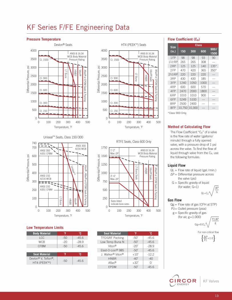
KF Series F/FE Engineering Data
Method of Calculating FlowThe Flow Coefficient “Cv” of a valve is the flow rate of water (gallons/ minute) through a fully opened valve, with a pressure drop of 1 psi across the valve. To find the flow of liquid through valve from the Cv, use the following formulas:
Liquid FlowQL = Flow rate of liquid (gal. /min.) ΔP = Differential pressure across the valve (psi) G = Specific gravity of liquid (for water, G=1)
Gas FlowQg = Flow rate of gas (CFH at STP) P2 = Outlet pressure (psia) g = Specific gravity of gas (for air, g=1.000)
QL=CvG
P
Qg= 61Cv
P2 Pg
For non-critical flow
P2<1.0{ }P
QL=CvG
P
Qg= 61Cv
P2 Pg
For non-critical flow
P2<1.0{ }P
Seal Material ˚F ˚C TFE/GRF Packing -50˚ -45.6 Low Temp Buna N -50˚ -45.6 Viton® -20˚ -28.9 Elast-O-Lion® 985 -50˚ -45.6 J. Walker® Viton® +10˚ -12.2 HNBR -40˚ -40 Aflas® +32˚ 0 EPDM -50˚ -45.6
Pressure Temperature
Low Temperature Limits Body Material ˚F ˚C LCC -50 -45.6 WCB -20 -28.9 CF8M -50 -45.6
Seat Material ˚F ˚C Devlon® V, Teflon®,
-50 -45.6 HT4 (PEEK™)
Flow Coefficient (Cv) Class
Size 900 /
(in.) 150 300 600
1500 1FP 98 98 93 90 11/2 RP 265 265 308 — 2RP 125 125 140 135* 2FP 470 420 365 350* 21/2RP 220 220 220 — 3RP 430 430 185 — 3FP 1240 1050 1000 — 4RP 600 600 570 — 4FP 2470 2000 1800 — 6RP 1010 1010 900 — 6FP 5249 5100 — — 8RP 2500 2400 — — 8FP 10,750 10,300 — —
*Class 900 Only.
14
KF Valves
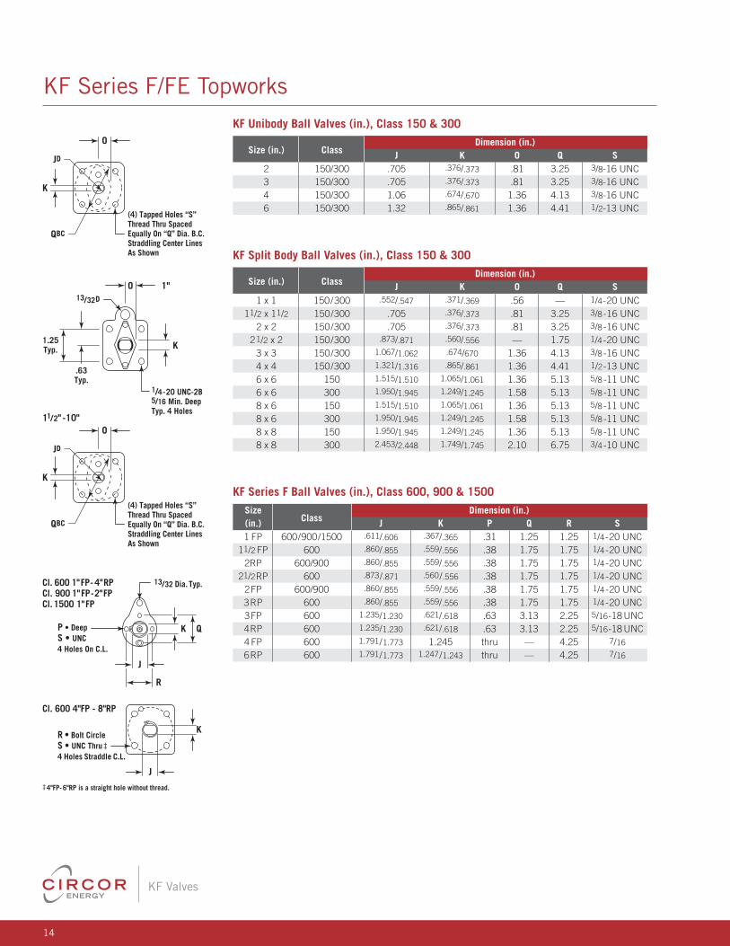
KF Series F/FE Topworks
OO
KK
K
JDJD
JD
QBC
QBC
QBC
(4) Tapped Holes “S” Thread Thru Spaced Equally On “Q” Dia. B.C. Straddling Center Lines As Shown(4) Tapped Holes “S”
Thread Thru Spaced Equally On “Q” Dia. B.C. Straddling Center Lines As Shown 1"
1"
11/2" -10"
11/2" -10"
K
K 1/4-20 UNC-2B 5/16 Min. DeepTyp. 4 Holes
1/4-20 UNC-2B 5/16 Min. DeepTyp. 4 Holes
13/32D
13/32D
.63Typ.
.63Typ.
1.25Typ.
1.25Typ.
O
O
Cl. 600 4"FP - 8"RP
Cl. 600 4"FP - 8"RP
R • Bolt CircleS • UNC Thru‡ 4 Holes Straddle C.L.
R • Bolt CircleS • UNC Thru‡ 4 Holes Straddle C.L.
QK
QK
R
R
J
J
P • DeepS • UNC 4 Holes On C.L.
P • DeepS • UNC 4 Holes On C.L.
Cl. 600 1"FP- 4"RPCl. 900 1"FP-2"FPCl. 1500 1"FP
Cl. 600 1"FP- 4"RPCl. 900 1"FP-2"FPCl. 1500 1"FP
13/32 Dia. Typ.
13/32 Dia. Typ.
J
J
K
K
‡4"FP- 6"RP is a straight hole without thread.
‡4"FP- 6"RP is a straight hole without thread.
O
OK
JD
QBC
(4) Tapped Holes “S” Thread Thru Spaced Equally On “Q” Dia. B.C. Straddling Center Lines As Shown
(4) Tapped Holes “S” Thread Thru Spaced Equally On “Q” Dia. B.C. Straddling Center Lines As Shown
KF Series F Ball Valves (in.), Class 600, 900 & 1500 Size
Class Dimension (in.)
(in.) J K P Q R S 1 FP 600/900/1500 .611/.606 .367/.365 .31 1.25 1.25 1/4-20 UNC 11/2 FP 600 .860/.855 .559/.556 .38 1.75 1.75 1/4-20 UNC 2RP 600/900 .860/.855 .559/.556 .38 1.75 1.75 1/4-20 UNC 21/2RP 600 .873/.871 .560/.556 .38 1.75 1.75 1/4-20 UNC 2FP 600/900 .860/.855 .559/.556 .38 1.75 1.75 1/4-20 UNC 3RP 600 .860/.855 .559/.556 .38 1.75 1.75 1/4-20 UNC 3FP 600 1.235/1.230 .621/.618 .63 3.13 2.25 5/16-18 UNC 4RP 600 1.235/1.230 .621/.618 .63 3.13 2.25 5/16-18 UNC 4 FP 600 1.791/1.773 1.245 thru — 4.25 7/16
6RP 600 1.791/1.773 1.247/1.243 thru — 4.25 7/16
KF Unibody Ball Valves (in.), Class 150 & 300
Size (in.) Class Dimension (in.)
J K O Q S 2 150/300 .705 .376/.373 .81 3.25 3/8-16 UNC 3 150/300 .705 .376/.373 .81 3.25 3/8-16 UNC 4 150/300 1.06 .674/.670 1.36 4.13 3/8-16 UNC 6 150/300 1.32 .865/.861 1.36 4.41 1/2-13 UNC
KF Split Body Ball Valves (in.), Class 150 & 300
Size (in.) Class Dimension (in.)
J K O Q S 1 x 1 150/300 .552/.547 .371/.369 .56 — 1/4-20 UNC 11/2 x 11/2 150/300 .705 .376/.373 .81 3.25 3/8 -16 UNC 2 x 2 150/300 .705 .376/.373 .81 3.25 3/8 -16 UNC 21/2 x 2 150/300 .873/.871 .560/.556 — 1.75 1/4-20 UNC 3 x 3 150/300 1.067/1.062 .674/670 1.36 4.13 3/8 -16 UNC 4 x 4 150/300 1.321/1.316 .865/.861 1.36 4.41 1/2-13 UNC 6 x 6 150 1.515/1.510 1.065/1.061 1.36 5.13 5/8 -11 UNC 6 x 6 300 1.950/1.945 1.249/1.245 1.58 5.13 5/8 -11 UNC 8 x 6 150 1.515/1.510 1.065/1.061 1.36 5.13 5/8 -11 UNC 8 x 6 300 1.950/1.945 1.249/1.245 1.58 5.13 5/8 -11 UNC 8 x 8 150 1.950/1.945 1.249/1.245 1.36 5.13 5/8 -11 UNC 8 x 8 300 2.453/2.448 1.749/1.745 2.10 6.75 3/4 -10 UNC
15
KF Valves
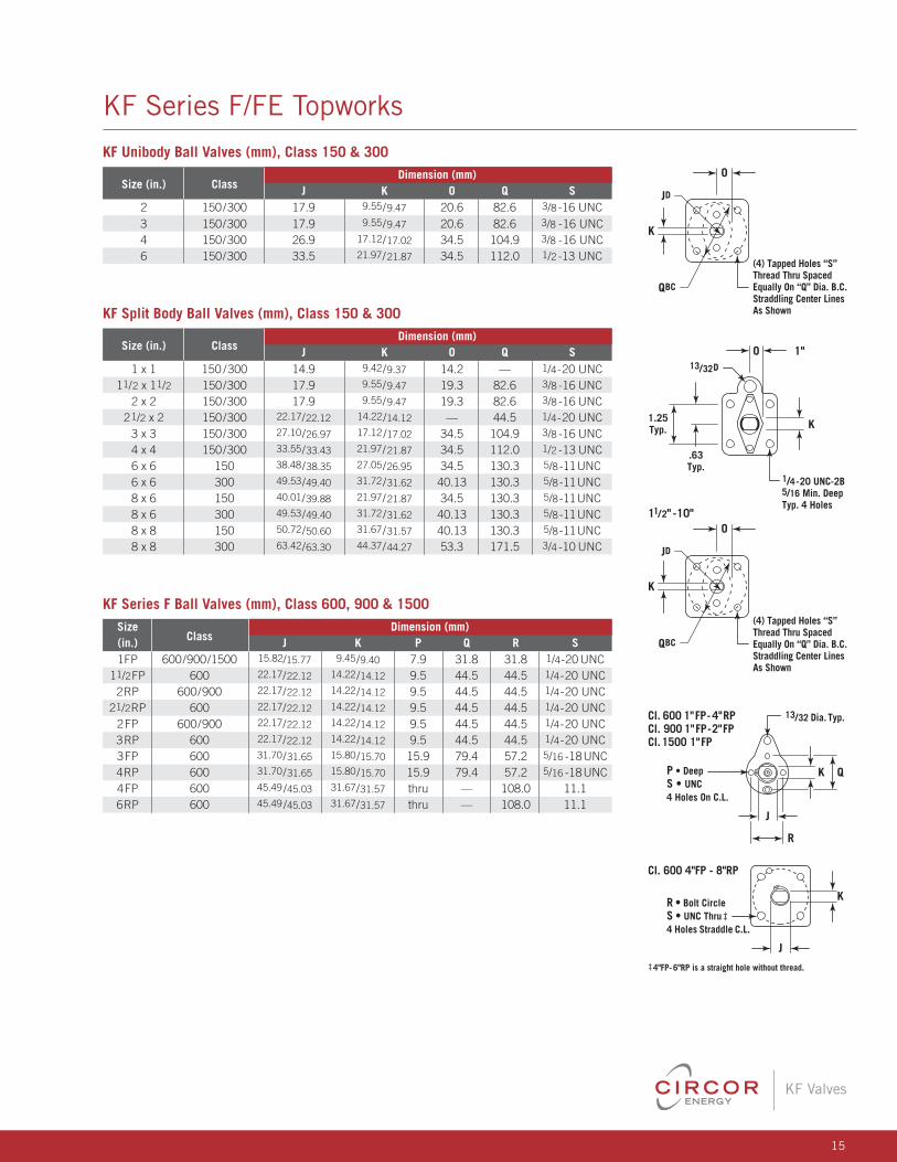
KF Series F/FE Topworks
OO
KK
K
JDJD
JD
QBC
QBC
QBC
(4) Tapped Holes “S” Thread Thru Spaced Equally On “Q” Dia. B.C. Straddling Center Lines As Shown(4) Tapped Holes “S”
Thread Thru Spaced Equally On “Q” Dia. B.C. Straddling Center Lines As Shown 1"
1"
11/2" -10"
11/2" -10"
K
K 1/4-20 UNC-2B 5/16 Min. DeepTyp. 4 Holes
1/4-20 UNC-2B 5/16 Min. DeepTyp. 4 Holes
13/32D
13/32D
.63Typ.
.63Typ.
1.25Typ.
1.25Typ.
O
O
Cl. 600 4"FP - 8"RP
Cl. 600 4"FP - 8"RP
R • Bolt CircleS • UNC Thru‡ 4 Holes Straddle C.L.
R • Bolt CircleS • UNC Thru‡ 4 Holes Straddle C.L.
QK
QK
R
R
J
J
P • DeepS • UNC 4 Holes On C.L.
P • DeepS • UNC 4 Holes On C.L.
Cl. 600 1"FP- 4"RPCl. 900 1"FP-2"FPCl. 1500 1"FP
Cl. 600 1"FP- 4"RPCl. 900 1"FP-2"FPCl. 1500 1"FP
13/32 Dia. Typ.
13/32 Dia. Typ.
J
J
K
K
‡4"FP- 6"RP is a straight hole without thread.
‡4"FP- 6"RP is a straight hole without thread.
O
OK
JD
QBC
(4) Tapped Holes “S” Thread Thru Spaced Equally On “Q” Dia. B.C. Straddling Center Lines As Shown
(4) Tapped Holes “S” Thread Thru Spaced Equally On “Q” Dia. B.C. Straddling Center Lines As Shown
KF Series F Ball Valves (mm), Class 600, 900 & 1500 Size
Class Dimension (mm)
(in.) J K P Q R S 1FP 600/900/1500 15.82/15.77 9.45/9.40 7.9 31.8 31.8 1/4-20 UNC 11/2FP 600 22.17/22.12 14.22/14.12 9.5 44.5 44.5 1/4-20 UNC 2RP 600/900 22.17/22.12 14.22/14.12 9.5 44.5 44.5 1/4-20 UNC 21/2RP 600 22.17/22.12 14.22/14.12 9.5 44.5 44.5 1/4-20 UNC 2FP 600/900 22.17/22.12 14.22/14.12 9.5 44.5 44.5 1/4-20 UNC 3RP 600 22.17/22.12 14.22/14.12 9.5 44.5 44.5 1/4-20 UNC 3FP 600 31.70/31.65 15.80/15.70 15.9 79.4 57.2 5/16 -18 UNC 4RP 600 31.70/31.65 15.80/15.70 15.9 79.4 57.2 5/16 -18 UNC 4FP 600 45.49 /45.03 31.67/31.57 thru — 108.0 11.1 6RP 600 45.49 /45.03 31.67/31.57 thru — 108.0 11.1
KF Unibody Ball Valves (mm), Class 150 & 300
Size (in.) Class Dimension (mm)
J K O Q S 2 150/300 17.9 9.55/9.47 20.6 82.6 3/8 -16 UNC 3 150/300 17.9 9.55/9.47 20.6 82.6 3/8 -16 UNC 4 150/300 26.9 17.12/17.02 34.5 104.9 3/8 -16 UNC 6 150/300 33.5 21.97/21.87 34.5 112.0 1/2 -13 UNC
KF Split Body Ball Valves (mm), Class 150 & 300
Size (in.) Class Dimension (mm)
J K O Q S 1 x 1 150 /300 14.9 9.42/9.37 14.2 — 1/4-20 UNC 11/2 x 11/2 150/300 17.9 9.55/9.47 19.3 82.6 3/8 -16 UNC 2 x 2 150/300 17.9 9.55/9.47 19.3 82.6 3/8 -16 UNC 21/2 x 2 150/300 22.17/22.12 14.22/14.12 — 44.5 1/4-20 UNC 3 x 3 150/300 27.10/26.97 17.12/17.02 34.5 104.9 3/8 -16 UNC 4 x 4 150/300 33.55/33.43 21.97/21.87 34.5 112.0 1/2 -13 UNC 6 x 6 150 38.48/38.35 27.05/26.95 34.5 130.3 5/8-11 UNC 6 x 6 300 49.53/49.40 31.72/31.62 40.13 130.3 5/8-11 UNC 8 x 6 150 40.01/39.88 21.97/21.87 34.5 130.3 5/8-11 UNC 8 x 6 300 49.53/49.40 31.72/31.62 40.13 130.3 5/8-11 UNC 8 x 8 150 50.72/50.60 31.67/31.57 40.13 130.3 5/8-11 UNC 8 x 8 300 63.42/63.30 44.37/44.27 53.3 171.5 3/4 -10 UNC

CIRCOR Energy is a global manufacturer of highly engineered valve and pipeline products that continuously develops precision technologies to improve our customers’ ability to control the flow of the world’s natural
resources, from sub-sea to land, and in severe environments.
Continuously Improving Flow Control. Worldwide.
©2013 CIRCOR Energy. All rights reserved.KF-F/FE-NOVEMBER-2013-2UP-HP
www.circorenergy.com
China
10# Qun Xing San Road
Loufeng District Suzhou
Industry Park
China Post Code: 215006
Tel: +86 512 62516088
Fax: +86 512 62513119
Asia Pacific
10 Woodgrove View
Singapore 738113
Tel: +65 63101595
Fax: +65 62691973
United States
Oklahoma City
1500 S.E. 89th St.
Oklahoma City, OK 73149
Tel: 405.631.1533
Fax: 405.631.5034
Houston
Corporate & Sales
945 Bunker Hill, Suite 650
Houston, TX 77024
Tel: 832.912.8333
U.A.E.
P.O. Box: 263202
Unit FZS5 AA01
Jebel Ali Free Zone
Dubai, UAE.
Tel:+971.4.8866128
Fax: +971.4.8866129
Canada
Calgary
Suite 2604, 308 4th Ave. SW
Calgary, Alberta T2P 0H7
Tel: 403.266.6500
Fax: 403.266.5088
Edmonton
9430-39th Avenue
Edmonton, Alberta T6E 5T9
Tel: 780.463.8633
Fax: 780.461.1588
Brazil
1480, Eugenio Losso District St.
Unileste - 13422-180
Piracicaba - Sao Paulo - Brazil
Tel: +55.19.3124-3124
Fax : +55.19.3414-3722
Latin America
1500 S.E. 89th St.
Oklahoma City, OK 73149
Tel: 405.631.1533
Fax: 405.631.5034
Teflon® is a registered trademark of DuPont. • Devlon® is a registered trademark of Devol Engineering, Ltd. • PEEK™ is a trademark of Victrex Plc. • James Walker® and Elast-O-Lion® are registered trademarks of James Walker. • Viton® is a registered trademark of DuPont Dow Elastomers. • Aflas® is a registered trademark of Asahi Glass. • Enduro-Bond™ is a trademark of Energy & Environmental Services. • Grafoil® is a registered trademark of Union Carbide Corporation.
KF Valves reserves the right to change designs, materials, or specifications without notice or without obligation to furnish or install such changes on products previously or subsequently sold.
Related Documents