INSTALLATION AND OPERATING INSTRUCTIONS KESSEL – Oil / Fuel separator KESSEL – Coalescence separator PE Separators according to Euro-norm EN 858 NS 3-15 Edition 2011/01 Name Date Town ID number 010-619 Subject to technical amendment Easy on-site mobility without the need for heavy machinery Simple and quick installation and hook up Recyclable material Seamless body due to monolith construction – 100% watertight Company - Telephone No. KESSEL – Oil / Fuel separator KESSEL – Coalescence separator According to EN 858 NG 3-15 for underground installation 99 403 - 99 615 (.10/.15/.30/.80) (B/D) 99 503 - 99 715 (.10/.15/.30/.80) (B/D) 99 703 (.04/.10) (B/D) 99706.10 (B/D Installation The installation and service of this unit should be carried out by a licensed professional servicer Commissioning Instruction Product advantages

Welcome message from author
This document is posted to help you gain knowledge. Please leave a comment to let me know what you think about it! Share it to your friends and learn new things together.
Transcript
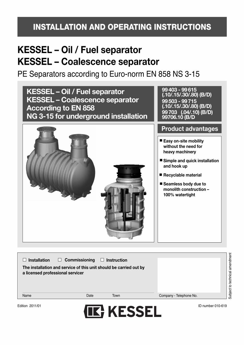
INSTALLATION AND OPERATING INSTRUCTIONS
KESSEL – Oil / Fuel separatorKESSEL – Coalescence separatorPE Separators according to Euro-norm EN 858 NS 3-15
Edition 2011/01
Name Date Town
ID number 010-619
Subje
ctto
techn
icala
mend
ment
Easy on-site mobilitywithout the need forheavy machinery
Simple and quick installationand hook up
Recyclable material
Seamless body due tomonolith construction –100% watertight
Company - Telephone No.
KESSEL – Oil / Fuel separatorKESSEL – Coalescence separatorAccording to EN 858NG 3-15 for underground installation
99403 - 99615(.10/.15/.30/.80) (B/D)99503 - 99715(.10/.15/.30/.80) (B/D)99703 (.04/.10) (B/D)99706.10 (B/D
Installation
The installation and service of this unit should be carried out bya licensed professional servicer
Commissioning Instruction
Product advantages
2
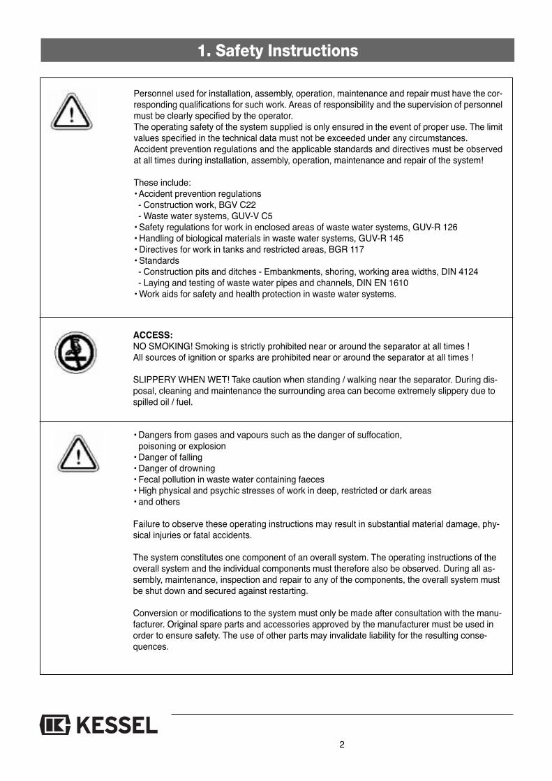
1. Safety Instructions
Personnel used for installation, assembly, operation, maintenance and repair must have the cor-responding qualifications for such work. Areas of responsibility and the supervision of personnelmust be clearly specified by the operator.The operating safety of the system supplied is only ensured in the event of proper use. The limitvalues specified in the technical data must not be exceeded under any circumstances.Accident prevention regulations and the applicable standards and directives must be observedat all times during installation, assembly, operation, maintenance and repair of the system!
These include:• Accident prevention regulations- Construction work, BGV C22- Waste water systems, GUV-V C5
• Safety regulations for work in enclosed areas of waste water systems, GUV-R 126• Handling of biological materials in waste water systems, GUV-R 145• Directives for work in tanks and restricted areas, BGR 117• Standards- Construction pits and ditches - Embankments, shoring, working area widths, DIN 4124- Laying and testing of waste water pipes and channels, DIN EN 1610
• Work aids for safety and health protection in waste water systems.
ACCESS:NO SMOKING! Smoking is strictly prohibited near or around the separator at all times !All sources of ignition or sparks are prohibited near or around the separator at all times !
SLIPPERY WHEN WET! Take caution when standing / walking near the separator. During dis-posal, cleaning and maintenance the surrounding area can become extremely slippery due tospilled oil / fuel.
• Dangers from gases and vapours such as the danger of suffocation,poisoning or explosion
• Danger of falling• Danger of drowning• Fecal pollution in waste water containing faeces• High physical and psychic stresses of work in deep, restricted or dark areas• and others
Failure to observe these operating instructions may result in substantial material damage, phy-sical injuries or fatal accidents.
The system constitutes one component of an overall system. The operating instructions of theoverall system and the individual components must therefore also be observed. During all as-sembly, maintenance, inspection and repair to any of the components, the overall system mustbe shut down and secured against restarting.
Conversion or modifications to the system must only be made after consultation with the manu-facturer. Original spare parts and accessories approved by the manufacturer must be used inorder to ensure safety. The use of other parts may invalidate liability for the resulting conse-quences.
Table of Contents
1. Safety Instructions ................................................................................. Page 2
2. General 2.1 Application................................................................ Page 42.2 Separator description .............................................. Page 4
3. Technical Data 3.1 Installation example Oil-/Fuel Separator........................... Page 63.2 Dimensioned drawings Oil-/Fuel Separator ...................... Page 63.3 Installation example Coalescence Separator ................. Page 73.4 Dimensioned drawings Coalescence Separator................. Page 73.5 Drawing Coalescence Separator Inspection Chamber LW 1000..... Page 83.6 Dimensioned drawings Coalescence Separator
Inspection Chamber LW 1000............................................... Page 8
4. Transport, Storage 4.1 Transport .................................................................. Page 94.3 Storage..................................................................... Page 9
5. Installation and assembly 5.1 Assembly requirements............................................ Page 105.2 Filling Material .......................................................... Page 115.3 Excavation pit........................................................... Page 115.4 Tryouts before assembly ......................................... Page 115.5 Assembly.................................................................. Page 115.6 Alarm unit ................................................................. Page 135.7 Oil and Sludge extraction ......................................... Page 14
6. Operation 6.1 Making the plant ready for operation........................ Page 166.2 Commissioning / Instruction ..................................... Page 166.3 Important info ........................................................... Page 16
7. Disposal .............................................................................................. Page 16
8. Maintenance .............................................................................................. Page 18
9. Accessories / Replacement parts .............................................................................................. Page 20
10. Warranty .............................................................................................. Page 21
11. Separator characteristics .............................................................................................. Page 22
12. Important contacts / info .............................................................................................. Page 23
3
4
Dear Customer,
Before the KESSEL Oil / Fuel or Coalescence separator is installed and placed in operation please carefully read andfollow all of the instructions contained in this Installation, Maintenance and User's Manual.Upon delivery of the KESSEL separator please thoroughly inspect the separator to make sure that it has not beendamaged during shipping. In case damage has occurred to the separator, please follow the instructions listed in the,Guarantee section of this user's manual.
2. General
2. General
2.1 Area of applicationThe separators are intended for use under specified conditi-ons, see the Chapter “Installation and assembly”, for instal-lation underground or below the foundation slab in well-ven-tilated areas.
2.1.1 Oil-fuel separators to Separator Class IIThe separators can be used:a) for the treatment of rainwater contaminated with light
fluids from surfaced areas, e.g. filling stations, oil storageand handling areas, parking areas and streets in water pro-tection areas
b) as a retaining system for light fluids from systems andareas where light fluids are handled, e.g. filling stations, oilstorage and handling areas
c) for preliminary separation of light fluids from waste waterbefore further treatment in subsequent internal wastewater treatment plants.
In cases a) and b), the discharged water from the separatorsis intended to be fed back into the public drainage system.
If the discharged water is to be returned into waters, this isonly possible in individual cases following clarification withthe local water authority.
In the treatment of dirty water contaminated with light fluids(commercial waste water) or waste water from the applicati-on areas of Appendix 49 of the waste water regulations, theobservation of a limit value for hydrocarbons of 20 mg/l can-not be considered to have been observed.
2.1.2 Oil-fuel separators to Separator Class I
Separators for light fluids with coalescence device can beused:a) for the treatment of rainwater contaminated with light
fluids from surfaced areas, e.g. filling stations, oil storageand handling areas, parking areas and streets in water pro-tection areas,
b) as a retaining system for light fluids for the safety of sy-stems and areas where light fluids are handled, e.g. fillingstations, oil storage and handling areas,
c) for the treatment of dirty water contaminated with lightfluids (commercial waste water) produced taking into ac-count the operating conditions of industrial processes,the cleaning of parts contaminated with oil and the clea-ning of floor areas contaminated with oil (except workshopfloors),
d) for the treatment of waste water produced taking into ac-count the operating conditions of automatic vehicle clea-ning (partial flow: outlet from the closed circuit into thedrainage system), manual cleaning (vehicle washing, en-gine washing, underbody washing, chassis cleaning inwashing bays, self-service or commercial washing bays -except for the cleaning of workshop floors contaminatedwith oil) and for the drainage of areas used for the receipt,storage, drying, dismantling and crushing of old vehicles,
e) for preliminary separation of light fluids from waste waterbefore further treatment in subsequent internal wastewater treatment plants.
5
3. Installation
In cases a) to d), the discharged water from the separators isintended to be fed back into the public drainage system.If the discharged water is to be returned into waters, this isonly possible in individual cases following clarification withthe local water authority.
Separators used in case d) are used in systems for the re-striction of hydrocarbons in waste water containing mineraloil in the sense of Part E Paragraph 2 of Appendix 49 of thewaste water regulations.
The level of hydrocarbons required by regulations in casesc) and d) of 20 mg/l is considered to have been observed.
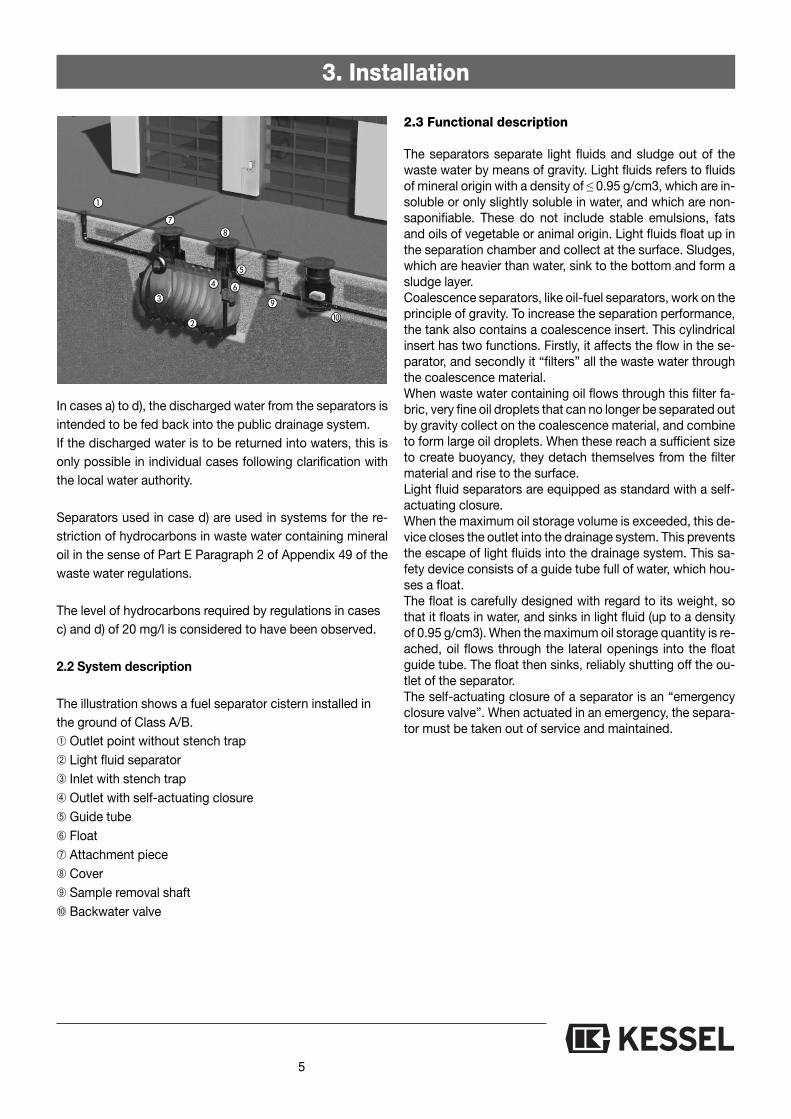
2.2 System description
The illustration shows a fuel separator cistern installed inthe ground of Class A/B.� Outlet point without stench trap� Light fluid separator� Inlet with stench trap� Outlet with self-actuating closure� Guide tube Float Attachment piece� Cover� Sample removal shaft Backwater valve
2.3 Functional description
The separators separate light fluids and sludge out of thewaste water by means of gravity. Light fluids refers to fluidsof mineral origin with a density of ≤ 0.95 g/cm3, which are in-soluble or only slightly soluble in water, and which are non-saponifiable. These do not include stable emulsions, fatsand oils of vegetable or animal origin. Light fluids float up inthe separation chamber and collect at the surface. Sludges,which are heavier than water, sink to the bottom and form asludge layer.Coalescence separators, like oil-fuel separators, work on theprinciple of gravity. To increase the separation performance,the tank also contains a coalescence insert. This cylindricalinsert has two functions. Firstly, it affects the flow in the se-parator, and secondly it “filters” all the waste water throughthe coalescence material.When waste water containing oil flows through this filter fa-bric, very fine oil droplets that can no longer be separated outby gravity collect on the coalescence material, and combineto form large oil droplets. When these reach a sufficient sizeto create buoyancy, they detach themselves from the filtermaterial and rise to the surface.Light fluid separators are equipped as standard with a self-actuating closure.When the maximum oil storage volume is exceeded, this de-vice closes the outlet into the drainage system. This preventsthe escape of light fluids into the drainage system. This sa-fety device consists of a guide tube full of water, which hou-ses a float.The float is carefully designed with regard to its weight, sothat it floats in water, and sinks in light fluid (up to a densityof 0.95 g/cm3). When the maximum oil storage quantity is re-ached, oil flows through the lateral openings into the floatguide tube. The float then sinks, reliably shutting off the ou-tlet of the separator.The self-actuating closure of a separator is an “emergencyclosure valve”. When actuated in an emergency, the separa-tor must be taken out of service and maintained.
�
��
�
�
��
�
6
3. Installation
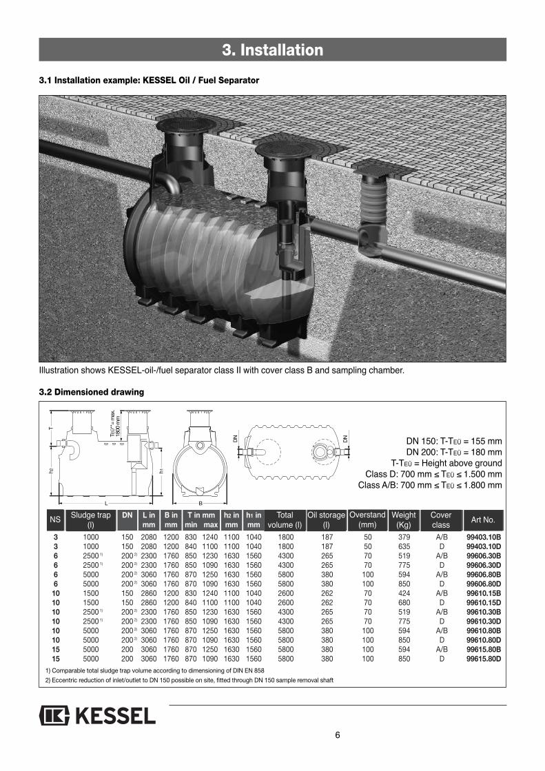
3.1 Installation example: KESSEL Oil / Fuel Separator
Illustration shows KESSEL-oil-/fuel separator class II with cover class B and sampling chamber.
3.2 Dimensioned drawing
DN 150: T-TEÜ = 155 mmDN 200: T-TEÜ = 180 mm
T-TEÜ = Height above groundClass D: 700 mm ≤ TEÜ ≤ 1.500 mm
Class A/B: 700 mm ≤ TEÜ ≤ 1.800 mm
NS Sludge trap(l)
Totalvolume (l)
Oil storage(l)
Overstand(mm)
Weight(Kg)
Coverclass Art No.
1) Comparable total sludge trap volume according to dimensioning of DIN EN 858
2) Eccentric reduction of inlet/outlet to DN 150 possible on site, fitted through DN 150 sample removal shaft
7
3. Installation
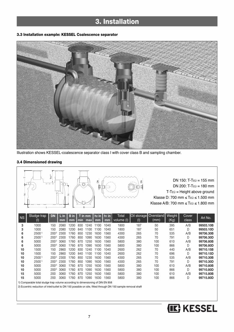
Illustration shows KESSEL-coalescence separator class I with cover class B and sampling chamber.
3.4 Dimensioned drawing
3.3 Installation example: KESSEL Coalescence separator
DN 150: T-TEÜ = 155 mmDN 200: T-TEÜ = 180 mm
T-TEÜ = Height above groundKlasse D: 700 mm ≤ TEÜ ≤ 1.500 mm
Klasse A/B: 700 mm ≤ TEÜ ≤ 1.800 mm
NS Sludge trap(l)
Totalvolume (l)
Oil storage(l)
Overstand(mm)
Weight(Kg)
Coverclass Art No.
1) Comparable total sludge trap volume according to dimensioning of DIN EN 858
2) Eccentric reduction of inlet/outlet to DN 150 possible on site, fitted through DN 150 sample removal shaft
8
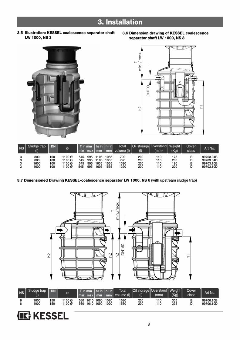
3 800 100 1100 Ø 545 995 1105 1055 790 200 110 175 B 99703.04B3 800 100 1100 Ø 545 995 1105 1055 790 200 110 205 D 99703.04D3 1600 100 1100 Ø 545 995 1605 1555 1390 200 110 190 B 99703.10B3 1600 100 1100 Ø 545 995 1605 1555 1390 200 110 220 D 99703.10D
3. Installation3.6 Dimension drawing of KESSEL coalescence
separator shaft LW 1000, NS 33.5 Illustration: KESSEL coalescence separator shaft
LW 1000, NS 3
NS Ø
3.7 Dimensioned Drawing KESSEL-coalescence separator LW 1000, NS 6 (with upstream sludge trap)
6 1000 150 1100 Ø 560 1010 1090 1020 1580 200 110 305 B 99706.10B6 1000 150 1100 Ø 560 1010 1090 1020 1580 200 110 338 D 99706.10D
NS Ø
Sludge trap(l)
Totalvolume (l)
Oil storage(l)
Overstand(mm)
Weight(Kg)
Coverclass Art No.
Sludge trap(l)
Totalvolume (l)
Oil storage(l)
Overstand(mm)
Weight(Kg)
Coverclass Art No.
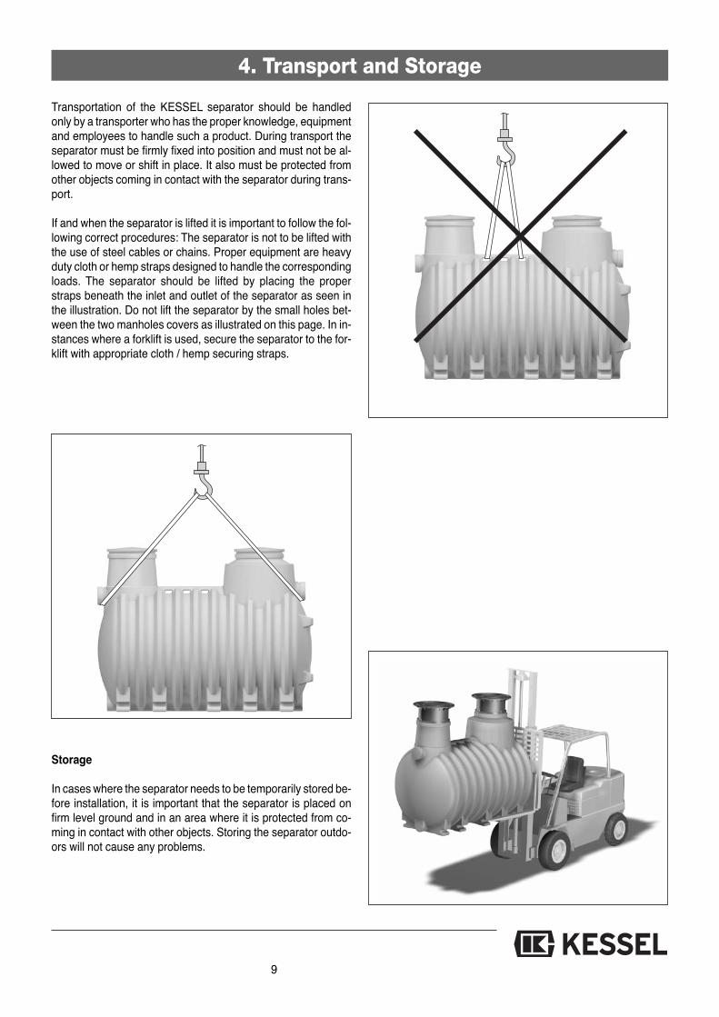
Transportation of the KESSEL separator should be handledonly by a transporter who has the proper knowledge, equipmentand employees to handle such a product. During transport theseparator must be firmly fixed into position and must not be al-lowed to move or shift in place. It also must be protected fromother objects coming in contact with the separator during trans-port.
If and when the separator is lifted it is important to follow the fol-lowing correct procedures: The separator is not to be lifted withthe use of steel cables or chains. Proper equipment are heavyduty cloth or hemp straps designed to handle the correspondingloads. The separator should be lifted by placing the properstraps beneath the inlet and outlet of the separator as seen inthe illustration. Do not lift the separator by the small holes bet-ween the two manholes covers as illustrated on this page. In in-stances where a forklift is used, secure the separator to the for-klift with appropriate cloth / hemp securing straps.
Storage
In cases where the separator needs to be temporarily stored be-fore installation, it is important that the separator is placed onfirm level ground and in an area where it is protected from co-ming in contact with other objects. Storing the separator outdo-ors will not cause any problems.
4. Transport and Storage
9
During interim storage of the separator and up to the endof the installation work, suitable safety measures must betaken on the construction site to avoid accidents and da-mage to the light fluid separator.The Chapter Safety Instructions must be observed!
5.1 Installation requirements
The installation must be carried only by companies who havethe necessary specialist experience, suitable equipment andadequately trained personnel for the task.The soil characteristics must be investigated for technical con-struction suitability (soil classification for technical constructionpurposes, DIN 18196). The maximum ground water level likelyto occur must also be established. The ground water level mustnot exceed the level of the outlet. Adequate drainage of see-page water is also essential in the case of soils impermeable towater. The types of stresses occurring, such as maximum traf-fic loads and installation depth, must also be clarified.
The separators for ground installation should be installed out-side the building, as near as possible to the outlets. If neces-sary, the connection pipes of the inlets to the separator shouldbe laid with heat insulation, or heated. The required frost-freeinstallation depth is achieved by the use of telescopic attach-ment pieces, which also allows easy adjustment to feed and ou-tlet pipes (drainage system). The covers for the load classes A/ B and D are not bolted and comply with EN 124.
Separator systems must be installed close to the point of ori-gin of the light fluids. They must be easily accessible for clea-ning and maintenance purposes.
The use of locked or ventilated covers is prohibited.
Pump or lifting systems must not be installed in the supply linein front of the separator. If these are necessary, they must be in-stalled after the separator.
For the reliable operation of the system, KESSEL recommendsthe installation of a projection, and also a warning system. Thenecessary fitting requirements must be provided before fillingof the construction pit.
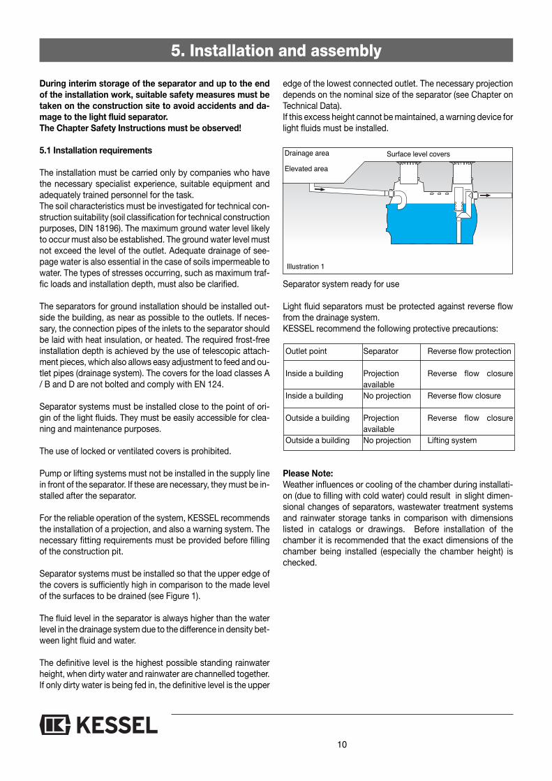
Separator systems must be installed so that the upper edge ofthe covers is sufficiently high in comparison to the made levelof the surfaces to be drained (see Figure 1).
The fluid level in the separator is always higher than the waterlevel in the drainage system due to the difference in density bet-ween light fluid and water.
The definitive level is the highest possible standing rainwaterheight, when dirty water and rainwater are channelled together.If only dirty water is being fed in, the definitive level is the upper
edge of the lowest connected outlet. The necessary projectiondepends on the nominal size of the separator (see Chapter onTechnical Data).If this excess height cannot be maintained, a warning device forlight fluids must be installed.
Separator system ready for use
Light fluid separators must be protected against reverse flowfrom the drainage system.KESSEL recommend the following protective precautions:
Outlet point Separator Reverse flow protection
Inside a building Projection Reverse flow closureavailable
Inside a building No projection Reverse flow closure
Outside a building Projection Reverse flow closureavailable
Outside a building No projection Lifting system
Please Note:Weather influences or cooling of the chamber during installati-on (due to filling with cold water) could result in slight dimen-sional changes of separators, wastewater treatment systemsand rainwater storage tanks in comparison with dimensionslisted in catalogs or drawings. Before installation of thechamber it is recommended that the exact dimensions of thechamber being installed (especially the chamber height) ischecked.
5. Installation and assembly
10
Illustration 1
Surface level coversDrainage area
Elevated area
11
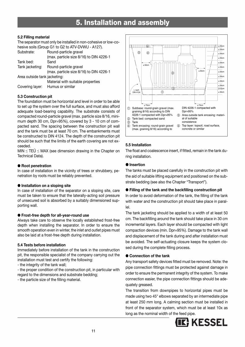
5.2 Filling materialThe separator must only be installed in non-cohesive or low-co-hesive soils (Group G1 to G2 to ATV-DVWU - A127).Substrate: Round-particle gravel
(max. particle size 8/16) to DIN 4226-1Tank bed: SandTank jacketing: Round-particle gravel
(max. particle size 8/16) to DIN 4226-1Area outside tank jacketing:
Material with suitable propertiesCovering layer: Humus or similar
5.3 Construction pitThe foundation must be horizontal and level in order to be ableto set up the system over the full surface, and must also affordadequate load-bearing capability. The substrate consists ofcompacted round-particle gravel (max. particle size 8/16, mini-mum depth 30 cm, Dpr=95%), covered by 3 - 10 cm of com-pacted sand. The spacing between the construction pit walland the tank must be at least 70 cm. The embankments mustbe constructed to DIN 4124. The depth of the construction pitshould be such that the limits of the earth covering are not ex-ceeded.MIN ≤ TEÜ ≤ MAX (see dimension drawing in the Chapter onTechnical Data).
� Root penetrationIn case of installation in the vicinity of trees or shrubbery, pe-netration by roots must be reliably prevented.
� Installation on a sloping siteIn case of installation of the separator on a sloping site, caremust be taken to ensure that the laterally-acting soil pressureof unsecured soil is absorbed by a suitably dimensioned sup-porting wall.
� Frost-free depth for all-year-round useAlways take care to observe the locally established frost-freedepth when installing the separator. In order to ensure thesmooth operation even in winter, the inlet and outlet pipes mustalso be laid at a frost-free depth during installation.
5.4 Tests before installationImmediately before installation of the tank in the constructionpit, the responsible specialist of the company carrying out theinstallation must test and certify the following:- the integrity of the tank wall;- the proper condition of the construction pit, in particular withregard to the dimensions and substrate bedding;- the particle size of the filling material.
5.5 InstallationThe float and coalescence insert, if fitted, remain in the tank du-ring installation.
�� InsertionThe tanks must be placed carefully in the construction pit withthe aid of suitable lifting equipment and positioned on the sub-strate bedding (see also the Chapter “Transport”).
� Filling of the tank and the backfilling construction pitIn order to avoid deformation of the tank, the filling of the tankwith water and the construction pit should take place in paral-lel.The tank jacketing should be applied to a width of at least 50cm. The backfilling around the tank should take place in 30 cmincremental layers. Each layer should be compacted with lightcompaction devices (min. Dpr=95%). Damage to the tank walland displacement of the tank during and after installation mustbe avoided. The self-actuating closure keeps the system clo-sed during the complete filling process.
� Connection of the tankAny transport safety devices fitted must be removed. Note: thepipe connection fittings must be protected against damage inorder to ensure the permanent integrity of the system. To makeconnection easier, the pipe connection fittings should be ade-quately greased.The transition from downpipes to horizontal pipes must bemade using two 45° elbows separated by an intermediate pipeat least 250 mm long. A calming section must be installed infront of the separator system, which must be at least 10x aslong as the nominal width of the feed pipe.
5. Installation and assembly
������������������������������������������������������������������������������������������������
������������������������������������������������������������������������������������������������
����������yyyyyyyyyy����������������������
� Subbase: round-grain gravel (max.graining 8/16) according to DIN4226-1 compacted with Dpr=95%
� Tank bed: compacted sand� Tank� Tank encasing: round-grain gravel
(max. graining 8/16) according to
DIN 4226-1 compacted withDpr=95%
� Area outside tank encasing: materi-al of suitable consistence
� Top layer: topsoil, road surface,concrete or similar
≥ 50cm
≥ 70cm ≥ 70cm
≥ 30cm
≤ 30cm
≤ 30cm
≤ 30cm
≤ 30cm
≤ 30cm
≤ 30cm
≤ 30cm
≤ 30cm
≤ 30cm≤ 20cm
3-10cmb nach
DIN 4124
≥ 50cm
�
��
��
�
12
5. Installation and assembly
When the construction pit has been filled and compacted tothe lower edge of the feed and outlet connections, the feedand outlet pipes are laid frost-free and connected.Instructions for the warning system: Lay the connectioncable or empty pipe during the earthworks.
� Connection of the sample removal shaft. Sample removal devices must be installed in the directionof flow immediately after the separator. The sample removaldevice of the separator system must be freely accessibleand positioned so that only waste water is removed whichhas passed through the separator.
� Connection of the warning system empty pipe,if applicable
The connecting section between the separator and controlunit must be kept as short as possible.Unnecessary changes of direction, in particular those withangles above 45°, should be avoided.The empty pipe for the cable should have a continual slopedown to the separator.The formation of condensation within the empty pipe can beminimised by an airtight closure of the empty pipe on theside of the control unit. A cable pull-through wire can alsobe laid for subsequent cable laying.
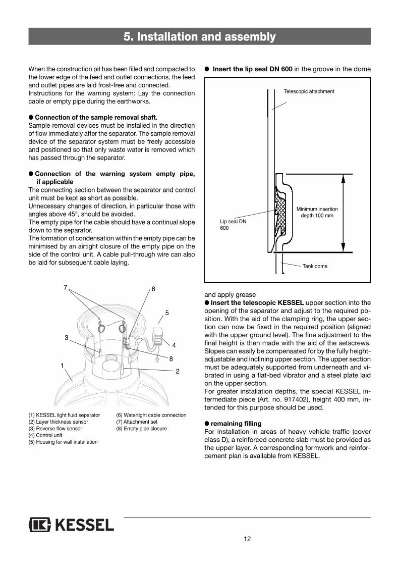
� Insert the lip seal DN 600 in the groove in the dome
and apply grease� Insert the telescopic KESSEL upper section into theopening of the separator and adjust to the required po-sition. With the aid of the clamping ring, the upper sec-tion can now be fixed in the required position (alignedwith the upper ground level). The fine adjustment to thefinal height is then made with the aid of the setscrews.Slopes can easily be compensated for by the fully height-adjustable and inclining upper section. The upper sectionmust be adequately supported from underneath and vi-brated in using a flat-bed vibrator and a steel plate laidon the upper section.For greater installation depths, the special KESSEL in-termediate piece (Art. no. 917402), height 400 mm, in-tended for this purpose should be used.
� remaining fillingFor installation in areas of heavy vehicle traffic (coverclass D), a reinforced concrete slab must be provided asthe upper layer. A corresponding formwork and reinfor-cement plan is available from KESSEL.
1
3
7
5
6
2
(1) KESSEL light fluid separator(2) Layer thickness sensor(3) Reverse flow sensor(4) Control unit(5) Housing for wall installation
(6) Watertight cable connection(7) Attachment set(8) Empty pipe closure
48
Tank dome
Telescopic attachment
Lip seal DN600
Minimum insertiondepth 100 mm
13
5. Installation and assembly
5.6 Warning systemAs specified by DIN EN 858, separator systems must be equip-ped with self-actuating warning devices.
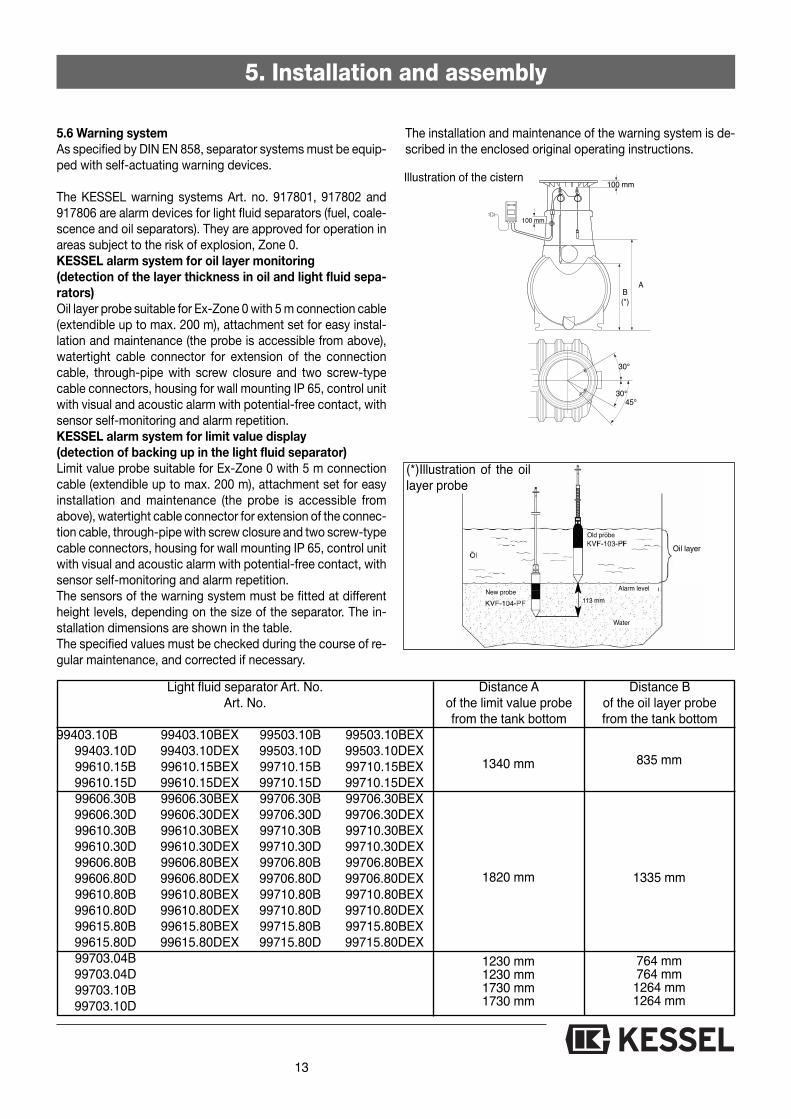
The KESSEL warning systems Art. no. 917801, 917802 and917806 are alarm devices for light fluid separators (fuel, coale-scence and oil separators). They are approved for operation inareas subject to the risk of explosion, Zone 0.KESSEL alarm system for oil layer monitoring(detection of the layer thickness in oil and light fluid sepa-rators)Oil layer probe suitable for Ex-Zone 0 with 5 m connection cable(extendible up to max. 200 m), attachment set for easy instal-lation and maintenance (the probe is accessible from above),watertight cable connector for extension of the connectioncable, through-pipe with screw closure and two screw-typecable connectors, housing for wall mounting IP 65, control unitwith visual and acoustic alarm with potential-free contact, withsensor self-monitoring and alarm repetition.KESSEL alarm system for limit value display(detection of backing up in the light fluid separator)Limit value probe suitable for Ex-Zone 0 with 5 m connectioncable (extendible up to max. 200 m), attachment set for easyinstallation and maintenance (the probe is accessible fromabove), watertight cable connector for extension of the connec-tion cable, through-pipe with screw closure and two screw-typecable connectors, housing for wall mounting IP 65, control unitwith visual and acoustic alarm with potential-free contact, withsensor self-monitoring and alarm repetition.The sensors of the warning system must be fitted at differentheight levels, depending on the size of the separator. The in-stallation dimensions are shown in the table.The specified values must be checked during the course of re-gular maintenance, and corrected if necessary.
The installation and maintenance of the warning system is de-scribed in the enclosed original operating instructions.
100 mm
100 mm
B(*)
A
30°
30°45°
113 mm
(*)Illustration of the oil layer probe
Oil layer
835 mm
1820 mm 1335 mm
Light fluid separator Art. No. Distance A Distance B Art. No. of the limit value probe of the oil layer probe
from the tank bottom from the tank bottom 99403.10B 99403.10BEX 99503.10B 99503.10BEX
99403.10D 99403.10DEX 99503.10D 99503.10DEX99610.15B 99610.15BEX 99710.15B 99710.15BEX99610.15D 99610.15DEX 99710.15D 99710.15DEX99606.30B 99606.30BEX 99706.30B 99706.30BEX99606.30D 99606.30DEX 99706.30D 99706.30DEX99610.30B 99610.30BEX 99710.30B 99710.30BEX99610.30D 99610.30DEX 99710.30D 99710.30DEX99606.80B 99606.80BEX 99706.80B 99706.80BEX99606.80D 99606.80DEX 99706.80D 99706.80DEX99610.80B 99610.80BEX 99710.80B 99710.80BEX99610.80D 99610.80DEX 99710.80D 99710.80DEX99615.80B 99615.80BEX 99715.80B 99715.80BEX99615.80D 99615.80DEX 99715.80D 99715.80DEX99703.04B99703.04D99703.10B99703.10D
1340 mm
Illustration of the cistern
1230 mm1230 mm1730 mm1730 mm
764 mm764 mm1264 mm1264 mm
Old probe
New probe
Water
Alarm level
Note: The holes for the attachment set must be drilled onlyat the specified positions. The holes must be made using a3.5 mm diameter drill. The original attachment screws mustbe used in the attachment, without plugs.The positions of the holes should be adjusted accordingly ifthe seal might be damaged by the drill. Under no circum-stances must the cone of the rotation tank be damaged ordrilled through!The extension of the cable to max. 200 m is only possibleusing original parts (cable and cable connectors).Information can be obtained from the KESSEL CustomerService Department under telephone no. 0 18 05-27 82 82.The use of any parts other than KESSEL original parts willinvalidate the ATEX approval, the construction type appro-val and any guarantee claims against KESSEL.
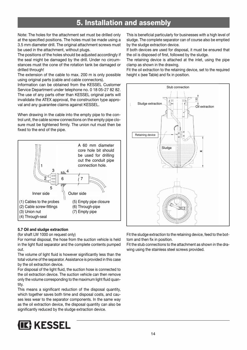
When drawing in the cable into the empty pipe to the con-trol unit, the cable screw connections on the empty pipe clo-sure must be tightened firmly. The union nut must then befixed to the end of the pipe.
5.7 Oil and sludge extraction(for shaft LW 1000 on request only)For normal disposal, the hose from the suction vehicle is heldin the light fluid separator and the complete contents pumpedout.The volume of light fluid is however significantly less than thetotal volume of the separator. Assistance is provided in this caseby the oil extraction device.For disposal of the light fluid, the suction hose is connected tothe oil extraction device. The suction vehicle can then removeonly the volume corresponding to the maximum light fluid quan-tity.This means a significant reduction of the disposal quantity,which together saves both time and disposal costs, and cau-ses less wear to the separator components. In the same wayas the oil extraction device, the disposal quantity can also besignificantly reduced by the sludge extraction device.
This is beneficial particularly for businesses with a high level ofsludge. The complete separator can of course also be emptiedby the sludge extraction device.If both devices are used for disposal, it must be ensured thatthe oil is disposed of first, followed by the sludge.The retaining device is attached at the inlet, using the pipeclamp as shown in the drawing.Fit the oil extraction to the retaining device, set to the requiredheight x (see Table) and fix in position.
Fit the sludge extraction to the retaining device, feed to the bot-tom and then fix in position.Fit the stub connections to the attachment as shown in the dra-wing using the stainless steel screws provided.
5. Installation and assembly
14
2 6 74
5
13
(1) Cables to the probes(2) Cable screw-fittings(3) Union nut(4) Through-seal
(5) Empty pipe closure(6) Through-pipe(7) Empty pipe
Inner side Outer side
Retaining device
Sludge extraction
Stub connection
Oil extraction
SludgeA 60 mm diametercore hole bit shouldbe used for drilling out the conduit pipeconnection hole.
5. Installation and assembly
15
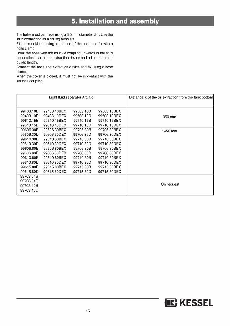
Light fluid separator Art. No. Distance X of the oil extraction from the tank bottom
99403.10B 99403.10BEX 99503.10B 99503.10BEX99403.10D 99403.10DEX 99503.10D 99503.10DEX99610.15B 99610.15BEX 99710.15B 99710.15BEX99610.15D 99610.15DEX 99710.15D 99710.15DEX99606.30B 99606.30BEX 99706.30B 99706.30BEX99606.30D 99606.30DEX 99706.30D 99706.30DEX99610.30B 99610.30BEX 99710.30B 99710.30BEX99610.30D 99610.30DEX 99710.30D 99710.30DEX99606.80B 99606.80BEX 99706.80B 99706.80BEX99606.80D 99606.80DEX 99706.80D 99706.80DEX99610.80B 99610.80BEX 99710.80B 99710.80BEX99610.80D 99610.80DEX 99710.80D 99710.80DEX99615.80B 99615.80BEX 99715.80B 99715.80BEX99615.80D 99615.80DEX 99715.80D 99715.80DEX99703.04B 99703.04D 99703.10B 99703.10D
950 mm
1450 mm
The holes must be made using a 3.5 mm diameter drill. Use thestub connection as a drilling template.Fit the knuckle coupling to the end of the hose and fix with ahose clamp.Hook the hose with the knuckle coupling upwards in the stubconnection, lead to the extraction device and adjust to the re-quired length.Connect the hose and extraction device and fix using a hoseclamp.When the cover is closed, it must not be in contact with theknuckle coupling.
On request
Disposal intervals:The fuel / oil collected in the separator should be collected /disposed when the level has reached 80% of the maximumstorage capacity. Disposal of collected sludge in the base ofthe separator should be collected / disposed when the levelhas reached 50% of the maximum sludge storage capacity.
Important: Timely disposal of the separator is mandatory toinsure proper function and operation of the separator.
A licensed disposal company should be contracted to hand-le disposal of the separator. Disposal should take place whenlittle or no wastewater is entering the separator.
Emptying intervals:The light fluid retained in the separator must be removed at thelatest when the quantity of separated light fluid reaches 80% ofthe maximum storage quantity, or the level is below the retai-ned volume. For separators simultaneously or exclusively usedfor the drainage of systems or areas where light fluids are hand-led (e.g. fuelling areas), the retained volume required understate regulations must also be provided. The separated lightfluid must also be removed at levels below this retained volu-me if the quantity of separated light fluids has not yet reached
80 % of the maximum storage quantity.The disposal of the sludge contained in the sludge trap mustbe removed at the latest when the separated sludge quantityreaches half of the sludge trap volume.
Note: Light fluids and sludge must be removed as specifiedabove in order to ensure the correct operation of the sy-stem.For this reason, a disposal contract should be concluded witha specialist disposal company. The disposal work should becarried out if possible when the system is not in operation.
Expected disposal volumes in accordance with the filling levelcan be estimated by means of the following table.The figures contained in the table are approximate figures onlyfor the purposes of estimating quantities when contracting aspecialist disposal company.
7. Disposal
6. Commissioning
The chapter "Safety instructions" must be heeded.
6.1 Setting up for operationBefore the separator is put into operation, please make surethat:� the separator is clean and the interior is free from any ob-
jects which may have been placed inside during shippingor installation.
� the separator is completely filled with clean cold water.Completely filling the separator is complete when waterbegins to drain from the outlet.
6.2 Initial Instructions
Placing the separator into full operation is normally handledby a licensed tradesman although upon request can be hand-led by a KESSEL representative.The following personnel should be on hand when the initialinstructions for placing the separator into operation are given:
� Building facilities manager� Building maintenance workers� Contracted plumber / tradesman� Contracted disposal company
What to do:� Check to make sure the separator is completely wa-
tertight. Check to make sure that during transport andinstallation that no damage to the separator was caused. Check to make sure all connections to theseparator (inlet, outlet, refill, rinse pipes etc.) are inperfect working order.
� Representative should discuss all necessary infor-mation regarding the disposal.
� Representative should take the customer step by stepthrough all stages of a separator disposal.
� After the separator has been emptied (disposed) allnecessary paperwork and documentation should behanded over to the customer.
� The separator should be returned to service by fillingthe separator with fresh, cold water.
6.4 Hand-over of installation and userʼs manual.
6.5 Completion of the commissioning report.
After commissioning has been completed the separatorshould be placed into normal operation mode.6.3 Commissioning report (see attachment)
16
7. Disposal
17
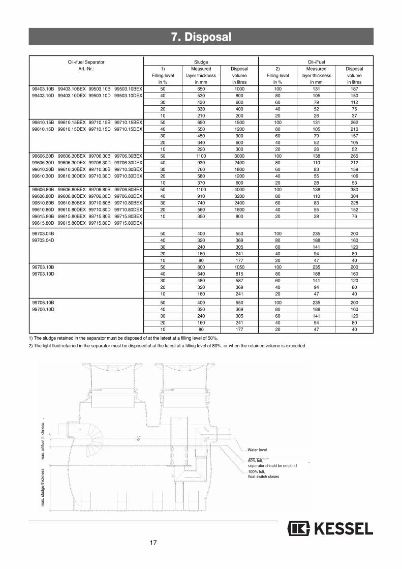
Oil-/fuel Separator Sludge Oil-/FuelArt.-Nr.: 1) Measured Disposal 2) Measured Disposal
Filling level layer thickness volume Filling level layer thickness volumein % in mm in litres in % in mm in litres
99403.10B 99403.10BEX 99503.10B 99503.10BEX 50 650 1000 100 131 18799403.10D 99403.10DEX 99503.10D 99503.10DEX 40 530 800 80 105 150
30 430 600 60 79 11220 330 400 40 52 7510 210 200 20 26 37
99610.15B 99610.15BEX 99710.15B 99710.15BEX 50 650 1500 100 131 26299610.15D 99610.15DEX 99710.15D 99710.15DEX 40 550 1200 80 105 210
30 450 900 60 79 15720 340 600 40 52 10510 220 300 20 26 52
99606.30B 99606.30BEX 99706.30B 99706.30BEX 50 1100 3000 100 138 26599606.30D 99606.30DEX 99706.30D 99706.30DEX 40 930 2400 80 110 21299610.30B 99610.30BEX 99710.30B 99710.30BEX 30 760 1800 60 83 15999610.30D 99610.30DEX 99710.30D 99710.30DEX 20 580 1200 40 55 106
10 370 600 20 28 5399606.80B 99606.80BEX 99706.80B 99706.80BEX 50 1100 4000 100 138 38099606.80D 99606.80DEX 99706.80D 99706.80DEX 40 910 3200 80 110 30499610.80B 99610.80BEX 99710.80B 99710.80BEX 30 740 2400 60 83 22899610.80D 99610.80DEX 99710.80D 99710.80DEX 20 560 1600 40 55 15299615.80B 99615.80BEX 99715.80B 99715.80BEX 10 350 800 20 28 7699615.80D 99615.80DEX 99715.80D 99715.80DEX
99703.04B 50 400 550 100 235 20099703.04D 40 320 369 80 188 160
30 240 305 60 141 12020 160 241 40 94 8010 80 177 20 47 40
99703.10B 50 800 1050 100 235 20099703.10D 40 640 815 80 188 160
30 480 587 60 141 12020 320 369 40 94 8010 160 241 20 47 40
99706.10B 50 400 550 100 235 20099706.10D 40 320 369 80 188 160
30 240 305 60 141 12020 160 241 40 94 8010 80 177 20 47 40
1) The sludge retained in the separator must be disposed of at the latest at a filling level of 50%.2) The light fluid retained in the separator must be disposed of at the latest at a filling level of 80%, or when the retained volume is exceeded.
Water level
80% full, separator should be emptied100% full, float switch closes
max.
sludg
e thic
knes
sma
x. oil
/fuel
thick
ness
8. Maintenance and ControlsIN
STA
LLA
TIO
NS
ELF
-CH
EC
KM
AIN
TEN
AN
CE
DIS
PO
SA
LG
EN
ER
AL
INS
PE
CTI
ON
RE
PA
IR
Who
Spec
ialist
comp
any
Spec
ialist
Spec
ialist
comp
any o
r Di
spos
al co
mpan
yQu
alifie
d bod
ySp
ecial
ist co
mpan
ywo
rks cu
stome
r ser
vice
1
Wha
tMe
asur
emen
t of th
e Me
asur
emen
t of th
eRe
mova
l of li
ght fl
uid�
Comp
lete e
mptyi
nglay
er th
ickne
ss of
:lay
er th
ickne
ss of
:an
d slud
ge�
Clea
ning
· ligh
t fluid
· ligh
t fluid
�
· of th
e slud
ge la
yer
· of th
e slud
ge la
yer
Chec
k of th
e self
-actu
ating
Ch
eck o
f the s
elf-a
ctuati
ng
The w
aste
dispo
sal
closu
re an
d war
ning d
evice
clo
sure
and w
arnin
g dev
icere
gulat
ions m
ust
be ob
serve
d!· E
mptyi
ng an
d clea
ning,
if nec
essa
ry· C
leanin
g of th
e sam
ple
remo
val d
evice
· Che
ck of
the o
pera
ting
logbo
ok
Whe
nmo
nthly
6-mo
nthly
Light
fluid
80%
is re
ache
dBe
fore c
ommi
ssion
ing, th
en ev
ery 5
year
s-A
s req
uired
or th
e lev
el is
below
the re
taine
d volu
meSl
udge
colle
ction
cham
ber
is fu
ll
Docu
-Ins
tallat
ion ce
rtifica
tion o
pera
ting l
ogbo
okMa
inten
ance
repo
rtop
erati
ng lo
gboo
kTe
st re
port
oper
ating
logb
ook
men-
by sp
ecial
istMa
inten
ance
repo
rttat
ion
* If th
e gen
eral
inspe
ction
is ca
rried
out a
t sho
rter in
terva
ls tha
n 5 ye
ars,
the m
ainten
ance
mus
t be c
arrie
d out
by a
spec
ialist
.
18
Chec
k for
prop
er co
nditio
n and
prop
er op
erati
on, a
ndat
least
howe
ver:
- Safe
ty ag
ainst
the es
cape
of lig
ht flu
ids fro
m the
se-
para
tor sy
stem
or th
e sha
ft unit
s (ex
cess
heigh
t)- S
tructu
ral c
ondit
ion an
d inte
grity
of th
e sep
arato
r sy-
stem
- Con
dition
of t
he in
stalle
d pa
rts a
nd th
e ele
ctrica
leq
uipme
nt- C
alibr
ation
of th
e self
-actu
ating
clos
ure d
evice
- Com
pleten
ess a
nd pl
ausib
ility o
f the r
ecor
ds in
the
oper
ating
logb
ook
- Disp
osal
confi
rmati
ons o
f the m
ateria
ls re
move
d- A
vaila
bility
and
com
pleten
ess
of the
req
uired
ap
prov
als an
d doc
umen
tation
If the
sepa
rator
syste
m is
also u
sed f
or th
e tre
atmen
tof
comm
ercia
l was
te wa
ter o
r was
te wa
ter fr
om th
ecle
aning
of ve
hicles
, the f
ollow
ing po
ints m
ust a
lso be
chec
ked:
- Actu
al vo
lume o
f was
te wa
ter (o
rigin,
quan
tity, c
on-
tents,
clea
ning a
gents
, ope
ratin
g mate
rials,
avoid
a-ble
of st
able
emuls
ions)
- Dim
ensio
ning,
suita
bility
and
per
forma
nce
of the
sepa
rator
syste
ms.
8. Maintenance and Controls
19
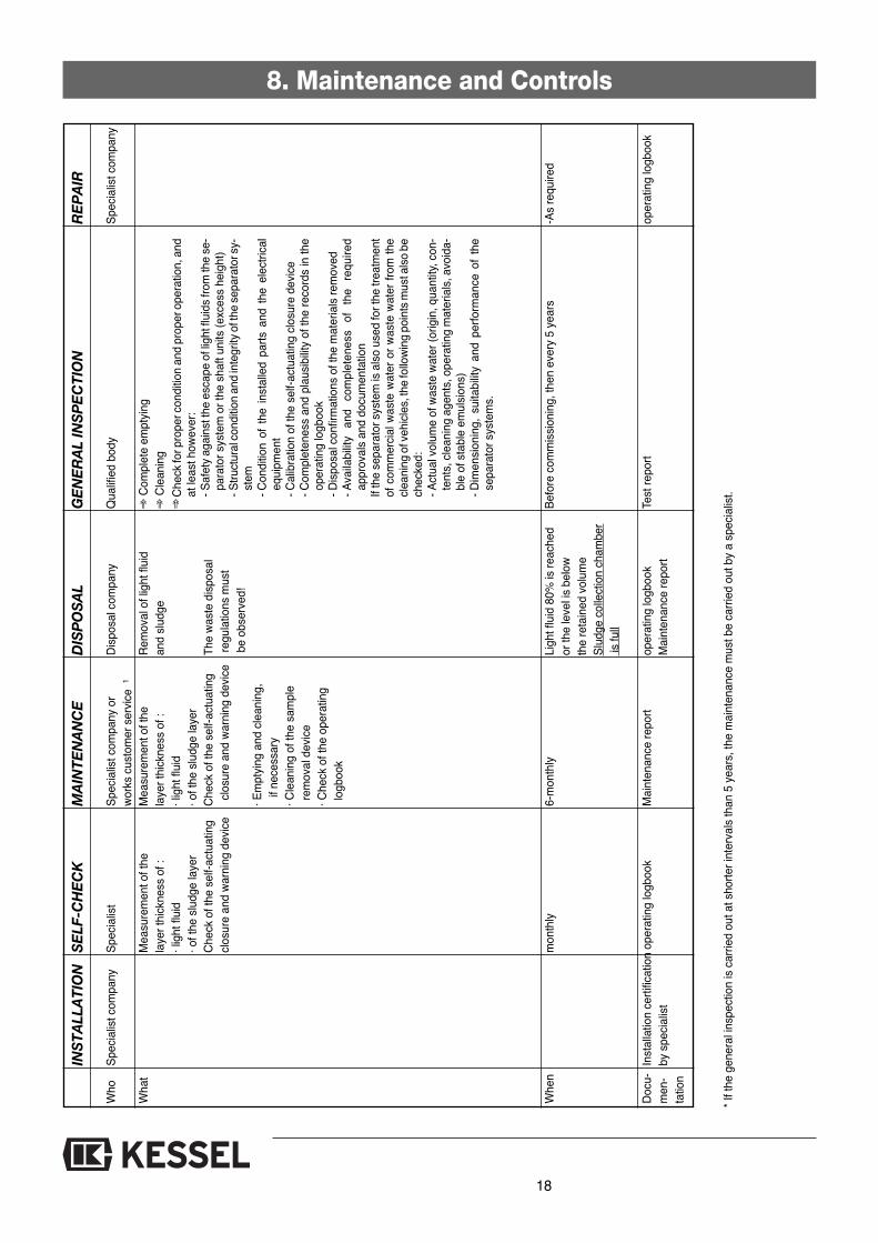
The Chapter “Safety instructions” must be observed!
8.1 Maintenance� The separator system must be maintained semiannual by a
specialist 1).In addition to the removal of materials, the following work mustalso be carried out:- Check of the inner wall surfaces of the sludge trap and the
grease separator,- Functional check of the electrical devices and installations,
if fitted.- The findings and work carried out must be recorded in the
operating logbook and evaluated.
� If fitted, electro-mechanical assemblies such as pumps, val-ves, shut-off devices etc. must be maintained twice yearly inaccordance with the manufacturers’ instructions.
8.2 Checking (general inspection)Before commissioning, and then at regular intervals of nomore than 5 years, the separator system must be completelyemptied and cleaned, and then checked by a specialist 2) forproper condition and operation.The following points at least must be checked and recorded:- Assessment of the separator system- Structural condition and integrity of the separator system- Condition of the inner wall surfaces of the installed parts and
the electrical equipment, if fitted- laying of the feed pipe of the separator system as a ventila-
tion pipe over the roof- Completeness and plausibility of the records in the operating
logbook- Confirmation of the proper disposal of the materials remo-
ved from the separator system- Availability and completeness of the required approvals and
documentation (approvals, drainage plans, operating andmaintenance instructions
A checking report must be compiled on the checks perfor-med, noting any existing faults. If faults are discovered, thesemust be rectified immediately.)
1) A “specialist” in this sense refers to personnel of the opera-tor or other company, who by means of their training, skills andexperience obtained from practical work, ensure that theycarry out assessments or checks in the relevant specialisedfield to the required standard.
A specialist can acquire the specialist knowledge required forthe operation and maintenance of separator systems in a trai-ning course with the following on-site instruction, which is of-fered for example by the corresponding manufacturers, pro-fessional trade associations, chambers of commerce and ex-pert organisations in the field of separator technology.
2) A “specialist” in this sense refers to personnel of businessother than the operator, experts or other institutions which de-monstrably have the specialist skills required for the operati-on, maintenance and checking of separator systems. In indi-vidual cases, such as larger operating units for example, thesechecks can also be carried out by internally independent spe-cialists of the operator not bound by instructions with regardto their area of responsibility, who have equivalent qualificati-ons and technical equipment.
Qualified bodies are specialist businesses independent of theoperator or similar institutions, whose employees demonstra-bly have the specialist skills required for the operation, main-tenance and checking of separator systems to the extent spe-cified here, together with the technical equipment for thechecking of separator systems.In individual cases, such as larger operating units for exam-ple, these checks can also be carried out by internally inde-pendent specialists of the operator not bound by instructionswith regard to their area of responsibility, who have equivalentqualifications and technical equipment.
Article Order No.
General inspection of oil/coalescence separator 917 411/L Operating logbook of oil/coalescence separator 917 812
Art.No.
917 801
Art.No.
917 802
Inlet Art.No.
DN 150 917 803DN 200 917 808
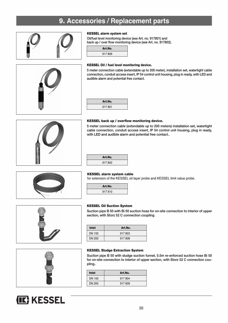
KESSEL Oil / fuel level monitoring device.
5 meter connection cable (extendable up to 200 meter), installation set, watertight cableconnection, conduit access insert, IP 54 control unit housing, plug in ready, with LED andaudible alarm and potential free contact.
KESSEL back up / overflow monitoring device.
5 meter connection cable (extendable up to 200 meters) installation set, watertightcable connection, conduit access insert, IP 54 control unit housing, plug in ready,with LED and audible alarm and potential free contact..
Art.No.
917 810
KESSEL alarm system cablefor extension of the KESSEL oil layer probe and KESSEL limit value probe.
KESSEL Oil Suction System
Suction pipe B 50 with Bi 50 suction hose for on-site connection to interior of uppersection, with Storz 52 C connection coupling.
KESSEL Sludge Extraction System
Suction pipe B 50 with sludge suction funnel, 0.5m re-enforced suction hose Bi 50for on-site connection to interior of upper section, with Storz 52 C connection cou-pling..
9. Accessories / Replacement parts
Inlet Art.No.
DN 150 917 804DN 200 917 809
20
KESSEL alarm system setOil/fuel level monitoring device (see Art. no. 917801) and back up / over flow monitoring device (see Art. no. 917802).
Art.No.
917 806
10. Warranty
1. In the case that a KESSEL product is defective, KESSEL hasthe option of repairing or replacing the product. If the product re-mains defective after the second attempt to repair or replace theproduct or it is economically unfeasible to repair or replace theproduct, the customer has the right to cancel the order / contractor reduce payment accordingly. KESSEL must be notified im-mediately in writing of defects in a product. In the case that thedefect is not visible or difficult to detect, KESSEL must be noti-fied immediately in writing of the defect as soon as it is disco-vered. If the product is repaired or replaced, the newly repairedor replaced product shall receive a new warranty identical to thatwhich the original (defective) product was granted. The term de-fective product refers only to the product or part needing repairor replacement and not necessarily to the entire product or unit.KESSEL products are warranted for a period of 24 month. Thiswarranty period begins on the day the product is shipped formKESSEL to its customer. The warranty only applies to newly ma-nufactured products. Additional information can be found in sec-tion 377 and 378 of the HGB.
In addition to the standard warranty, KESSEL AG offers an ad-ditional 20 year warranty on the polymer bodies of class I / II fuelseparators, grease separators, inspection chambers, wastewa-ter treatment systems and rainwater storage tanks.This additional warranty applies to the watertightness, usabili-ty and structural soundness of the product.
A requirement of this additional warranty is that the product isproperly installed and operated in accordance with the valid in-stallation and user's manual as well as the corresponding norms/ regulations.
2. Wear and tear on a product will not be considered a defect.Problems with products resulting from improper installation,handling or maintenance will also be considered a defect.
21
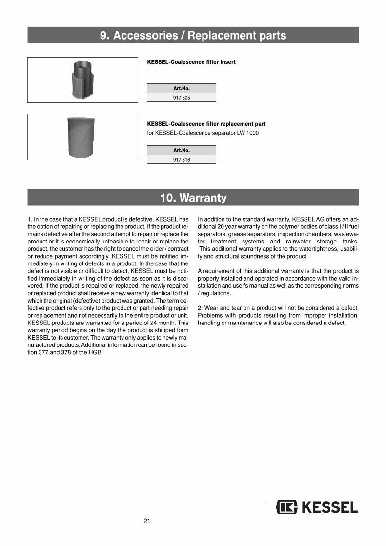
Art.No.
917 816
KESSEL-Coalescence filter replacement part
for KESSEL-Coalescence separator LW 1000
9. Accessories / Replacement parts
Art.No.
917 805
KESSEL-Coalescence filter insert

Separator Characteristics
22
Bahnhofstr. 31D-85101 Lenting
This unit has been checked for watertightness to be sure that it is fully operational before leaving the factory.
Date Name of examiner
Type _____________________________________________________________________________________
Production number / production year_______________________________________________________________
Weight/kg_____________________________length x width X height____________________________________
EN ___ ________________________________________Approval______________________________________
____________________________________________________________________________________________
Sludge trap volume / l _____________________________________Oil/fuel storage volume / l __________________
Control stamp___________________________________Material_______________________________________
(Accessories) ________________________________________________________________________________
23
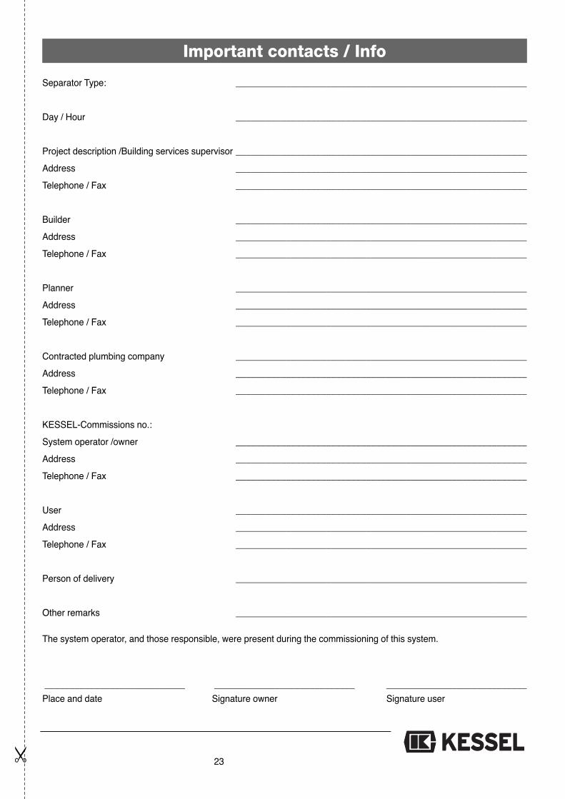
Important contacts / Info
Separator Type: __________________________________________________________
Day / Hour __________________________________________________________
Project description /Building services supervisor __________________________________________________________Address __________________________________________________________Telephone / Fax __________________________________________________________
Builder __________________________________________________________Address __________________________________________________________Telephone / Fax __________________________________________________________
Planner __________________________________________________________Address __________________________________________________________Telephone / Fax __________________________________________________________
Contracted plumbing company __________________________________________________________Address __________________________________________________________Telephone / Fax __________________________________________________________
KESSEL-Commissions no.:System operator /owner __________________________________________________________Address __________________________________________________________Telephone / Fax __________________________________________________________
User __________________________________________________________Address __________________________________________________________Telephone / Fax __________________________________________________________
Person of delivery __________________________________________________________
Other remarks __________________________________________________________
The system operator, and those responsible, were present during the commissioning of this system.
____________________________ ____________________________ ____________________________Place and date Signature owner Signature user
��
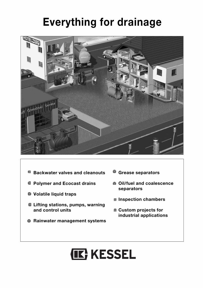
Everything for drainage
Backwater valves and cleanouts
Polymer and Ecocast drains
Volatile liquid traps
Lifting stations, pumps, warningand control units
Rainwater management systems
Grease separators
Oil/fuel and coalescenceseparators
Inspection chambers
Custom projects for industrial applications
Related Documents