Chapter 1: STANDARDS OF MEASUREMENT Definition of Metrology: Metrology (from Ancient Greek metron (measure) and logos (study of)) is the science of measurement. Metrology includes all theoretical and practical aspects of measurement. Metrology is concerned with the establishment, reproduction, conservation and transfer of units of measurement & their standards. For engineering purposes, metrology is restricted to measurements of length and angle & quantities which are expressed in linear or angular terms. Measurement is a process of comparing quantitatively an unknown magnitude with a predefined standard. Objectives of Metrology: The basic objectives of metrology are; 1. To provide accuracy at minimum cost. 2. Thorough evaluation of newly developed products, and to ensure that components are within the specified dimensions. 3. To determine the process capabilities. 4. To assess the measuring instrument capabilities and ensure that they are adequate for their specific measurements. 5. To reduce the cost of inspection & rejections and rework. 6. To standardize measuring methods. 7. To maintain the accuracy of measurements through periodical calibration of the instruments. 8. To prepare designs for gauges and special inspection fixtures. Definition of Standards: A standard is defined as “something that is set up and established by an authority as rule of the measure of quantity, weight, extent, value or quality”. For example, a meter is a standard established by an international organization for measurement of length. Industry, commerce, international trade in modern civilization would be impossible without a good system of standards. Role of Standards: The role of standards is to achieve uniform, consistent and repeatable measurements throughout the world. Today our entire industrial economy is based on the interchangeability of parts the method of manufacture. To achieve this, a measuring system adequate to define the features to the accuracy required & the standards of sufficient accuracy to support the measuring system are necessary. MMM ACE Dpt,of Mechanical engg Babu KN

Welcome message from author
This document is posted to help you gain knowledge. Please leave a comment to let me know what you think about it! Share it to your friends and learn new things together.
Transcript
Chapter 1: STANDARDS OF MEASUREMENTDefinition of Metrology: Metrology (from Ancient Greek metron (measure) and logos (study of)) is the science of measurement. Metrology includes all theoretical and practical aspects of measurement.
Metrology is concerned with the establishment, reproduction, conservation and transfer of units of measurement & their standards.
For engineering purposes, metrology is restricted to measurements of length and angle & quantities which are expressed in linear or angular terms.Measurement is a process of comparing quantitatively an unknown magnitude with a predefined standard.
Objectives of Metrology: The basic objectives of metrology are;1. To provide accuracy at minimum cost.2. Thorough evaluation of newly developed products, and to ensure that components
are within the specified dimensions.3. To determine the process capabilities.4. To assess the measuring instrument capabilities and ensure that they are adequate for
their specific measurements.5. To reduce the cost of inspection & rejections and rework.6. To standardize measuring methods.7. To maintain the accuracy of measurements through periodical calibration of the
instruments.8. To prepare designs for gauges and special inspection fixtures.
Definition of Standards: A standard is defined as “something that is set up and established by an authority as rule of the measure of quantity, weight, extent, value or quality”.
For example, a meter is a standard established by an international organization for measurement of length. Industry, commerce, international trade in modern civilization would be impossible without a good system of standards.
Role of Standards: The role of standards is to achieve uniform, consistent and repeatable measurements throughout the world. Today our entire industrial economy is based on the interchangeability of parts the method of manufacture. To achieve this, a measuring system adequate to define the features to the accuracy required & the standards of sufficient accuracy to support the measuring system are necessary.
MMM ACE
Dpt,of Mechanical engg Babu KN
STANDARDS OF LENGTHIn practice, the accurate measurement must be made by comparison with a standard of known dimension and such a standard is called “Primary Standard”The first accurate standard was made in England and was known as “Imperial Standard yard” which was followed by International Prototype meter” made in France. Since these two standards of length were made of metal alloys they are called ‘material length standards’.
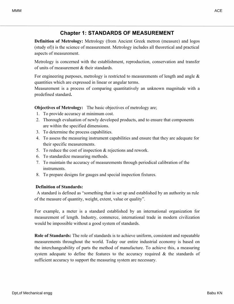
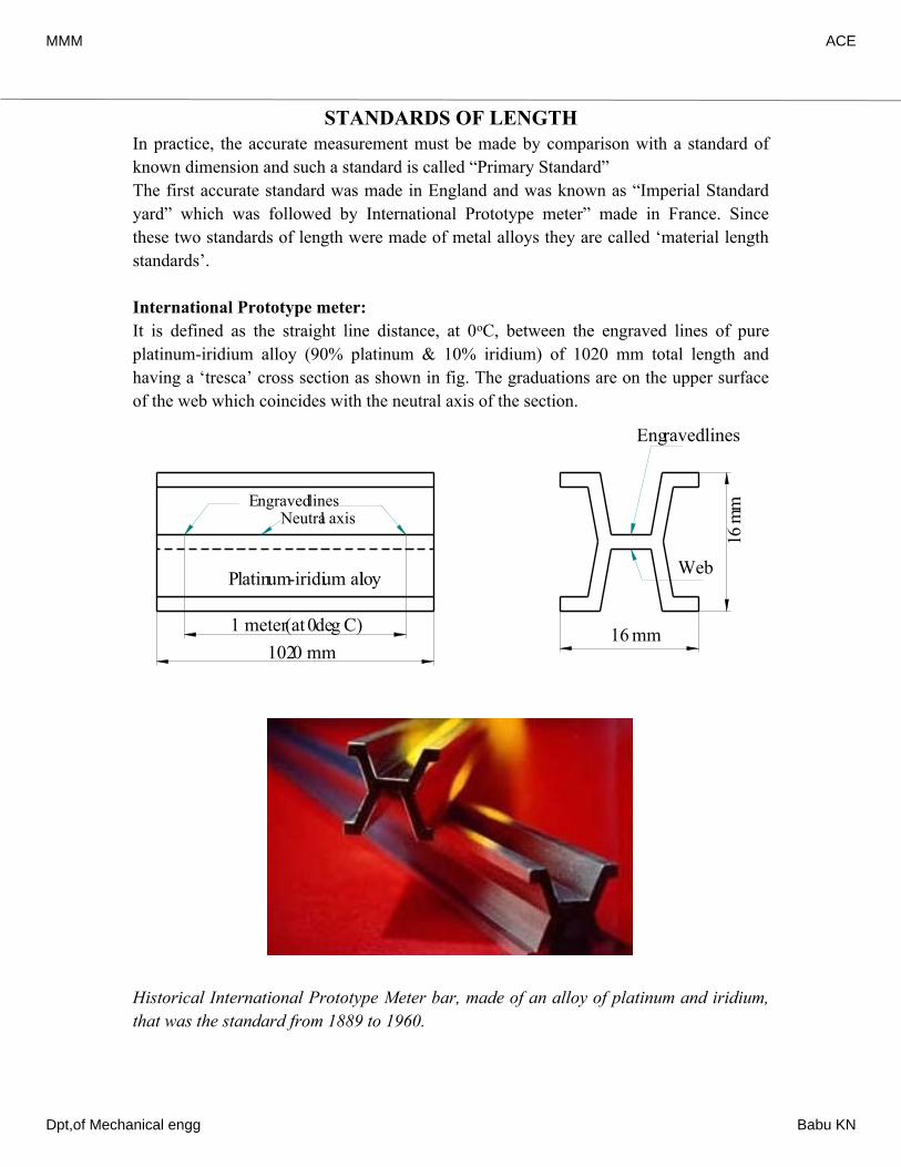
International Prototype meter: It is defined as the straight line distance, at 0oC, between the engraved lines of pure platinum-iridium alloy (90% platinum & 10% iridium) of 1020 mm total length and having a ‘tresca’ cross section as shown in fig. The graduations are on the upper surface of the web which coincides with the neutral axis of the section.
Historical International Prototype Meter bar, made of an alloy of platinum and iridium, that was the standard from 1889 to 1960.
Engraved linesNeutral axis
Platinum-iridium alloy
1 meter (at 0deg C)1020 mm
Web
Engraved lines
16 m
m
16 mm
MMM ACE
Dpt,of Mechanical engg Babu KN
The tresca cross section gives greater rigidity for the amount of material involved and is therefore economic in the use of an expensive metal. The platinum-iridium alloy is used because it is non oxidizable and retains good polished surface required for engraving good quality lines.
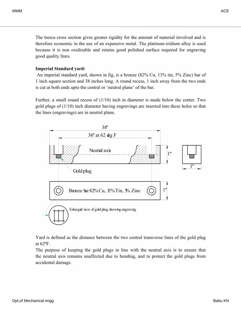
Imperial Standard yard: An imperial standard yard, shown in fig, is a bronze (82% Cu, 13% tin, 5% Zinc) bar of 1 inch square section and 38 inches long. A round recess, 1 inch away from the two ends is cut at both ends upto the central or ‘neutral plane’ of the bar.
Further, a small round recess of (1/10) inch in diameter is made below the center. Two gold plugs of (1/10) inch diameter having engravings are inserted into these holes so that the lines (engravings) are in neutral plane.
Yard is defined as the distance between the two central transverse lines of the gold plug at 620F.The purpose of keeping the gold plugs in line with the neutral axis is to ensure that the neutral axis remains unaffected due to bending, and to protect the gold plugs from accidental damage.
Gold plug
Bronze bar 82% Cu, 13% Tin, 5% Zinc
Neutral axis1"
Enlarged view of gold plug showing engraving
38"36" at 62 deg F
1"
1"
MMM ACE
Dpt,of Mechanical engg Babu KN
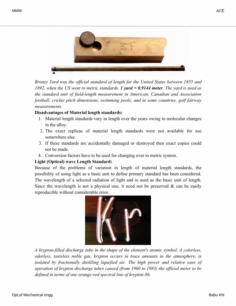
Bronze Yard was the official standard of length for the United States between 1855 and 1892, when the US went to metric standards. 1 yard = 0.9144 meter. The yard is used as the standard unit of field-length measurement in American, Canadian and Association football, cricket pitch dimensions, swimming pools, and in some countries, golf fairway measurements.Disadvantages of Material length standards:
1. Material length standards vary in length over the years owing to molecular changes in the alloy.
2. The exact replicas of material length standards were not available for use somewhere else.
3. If these standards are accidentally damaged or destroyed then exact copies could not be made.
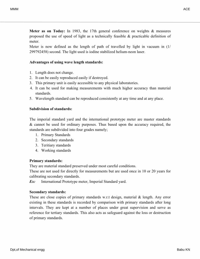
4. Conversion factors have to be used for changing over to metric system.Light (Optical) wave Length Standard:Because of the problems of variation in length of material length standards, the possibility of using light as a basic unit to define primary standard has been considered. The wavelength of a selected radiation of light and is used as the basic unit of length. Since the wavelength is not a physical one, it need not be preserved & can be easily reproducible without considerable error.
A krypton-filled discharge tube in the shape of the element's atomic symbol. A colorless, odorless, tasteless noble gas, krypton occurs in trace amounts in the atmosphere, is isolated by fractionally distilling liquefied air. The high power and relative ease of operation of krypton discharge tubes caused (from 1960 to 1983) the official meter to be defined in terms of one orange-red spectral line of krypton-86.
MMM ACE
Dpt,of Mechanical engg Babu KN
Meter as on Today: In 1983, the 17th general conference on weights & measures proposed the use of speed of light as a technically feasible & practicable definition of meter.Meter is now defined as the length of path of travelled by light in vacuum in (1/299792458) second. The light used is iodine stabilized helium-neon laser.
Advantages of using wave length standards:
1. Length does not change.2. It can be easily reproduced easily if destroyed.3. This primary unit is easily accessible to any physical laboratories.4. It can be used for making measurements with much higher accuracy than material
standards.5. Wavelength standard can be reproduced consistently at any time and at any place.
Subdivision of standards:
The imperial standard yard and the international prototype meter are master standards & cannot be used for ordinary purposes. Thus based upon the accuracy required, the standards are subdivided into four grades namely;
1. Primary Standards2. Secondary standards3. Teritiary standards4. Working standards
Primary standards: They are material standard preserved under most careful conditions. These are not used for directly for measurements but are used once in 10 or 20 years for calibrating secondary standards.Ex: International Prototype meter, Imperial Standard yard.
Secondary standards:These are close copies of primary standards w.r.t design, material & length. Any error existing in these standards is recorded by comparison with primary standards after long intervals. They are kept at a number of places under great supervision and serve as reference for tertiary standards. This also acts as safeguard against the loss or destruction of primary standards.
MMM ACE
Dpt,of Mechanical engg Babu KN
Teritiary standards:The primary or secondary standards exist as the ultimate controls for reference at rare intervals. Tertiary standards are the reference standards employed by National Physical laboratory (N.P.L) and are the first standards to be used for reference in laboratories & workshops. They are made as close copies of secondary standards & are kept as reference for comparison with working standards.
Working standards:These standards are similar in design to primary, secondary & tertiary standards. But being less in cost and are made of low grade materials, they are used for general applications in metrology laboratories.
Sometimes, standards are also classified as;• Reference standards (used as reference purposes)• Calibration standards (used for calibration of inspection & working standards)• Inspection standards (used by inspectors)• Working standards (used by operators)
LINE STANDARDSWhen the length being measured is expressed as the distance between two lines, then it is called “Line Standard”. Examples: Measuring scales, Imperial standard yard, International prototype meter, etc.
Characteristics of Line Standards: 1. Scales can be accurately engraved but it is difficult to take the full advantage of this
accuracy. Ex: A steel rule can be read to about ± 0.2 mm of true dimension.
2. A scale is quick and easy to use over a wide range of measurements.
3. The wear on the leading ends results in ‘under sizing’
4. A scale does not possess a ‘built in’ datum which would allow easy scale alignment
with the axis of measurement, this again results in ‘under sizing’.
5. Scales are subjected to parallax effect, which is a source of both positive & negative
reading errors’
6. Scales are not convenient for close tolerance length measurements except in
conjunction with microscopes.
MMM ACE
Dpt,of Mechanical engg Babu KN
END STANDARDSWhen the length being measured is expressed as the distance between two parallel faces,
then it is called ‘End standard’.
End standards can be made to a very high degree of accuracy.
Ex: Slip gauges, Gap gauges, Ends of micrometer anvils, etc.
Characteristics of End Standards:
1. End standards are highly accurate and are well suited for measurements of close
tolerances as small as 0.0005 mm.
2. They are time consuming in use and prove only one dimension at a time.
3. End standards are subjected to wear on their measuring faces.
4. End standards have a ‘built in’ datum, because their measuring faces are flat &
parallel and can be positively located on a datum surface.
5. They are not subjected to the parallax effect since their use depends on “feel”.
6. Groups of blocks may be “wrung” together to build up any length. But faulty
wringing leads to damage.
7. The accuracy of both end & line standards are affected by temperature change.
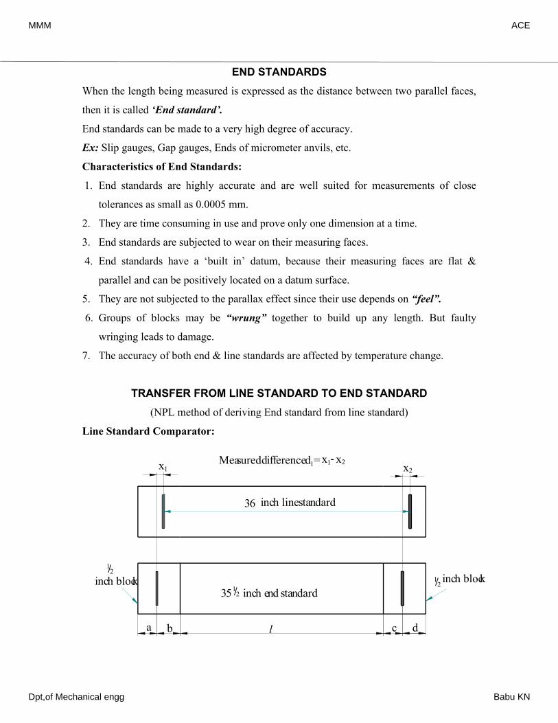
TRANSFER FROM LINE STANDARD TO END STANDARD(NPL method of deriving End standard from line standard)
Line Standard Comparator:
a b c dl
35 inch end standard1/21/2
1/2inch blockinch block
36 inch line standard
Measured difference d =1x1 x2x1- x2
MMM ACE
Dpt,of Mechanical engg Babu KN
A line standard comparator is used to transfer the line standard correctly to the ends of a
bar.
It consists of two microscopes mounted about a yard apart over a table. An end standard
about 351/2 inch in length is produced with flat & parallel faces. Two 1/2 inch blocks
with centrally engraved lines are ‘wrung’ to the ends of this end standard, such that the
distance between the center lines is approximately 36 inches.
The difference of readings between the lines on the line standard & the lines on the end
standard are noted every time, by arranging the end blocks in different ways to eliminate
errors in wringing & of marking of center lines.
If the actual length of the end standard is l, then for the four different ways of wringing
the end blocks, we can write;
l+ b+ c = 36+d1 l+ b+ d = 36+d2
l+ a+ c = 36+d3 l+ a+ d = 36+d4
Where d1, d2, d3 & d4 are the differences noted for the successive positions of the 1/2 inch
blocks respectively.
Taking mean,
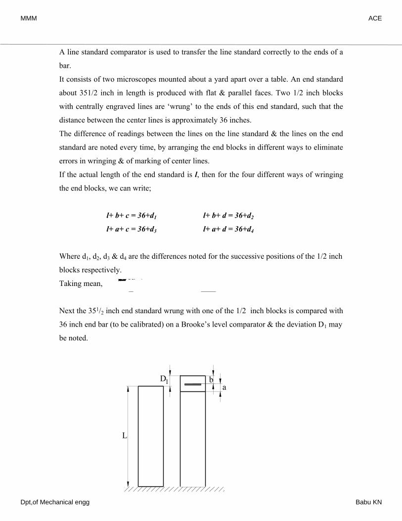
Next the 351/2 inch end standard wrung with one of the 1/2 inch blocks is compared with
36 inch end bar (to be calibrated) on a Brooke’s level comparator & the deviation D1 may
be noted.
()13624dlabcd++++=+∑
L
D1a
b
35 inch end standard1/2
36 inch end barbeing calibrated
1/2 inch block
MMM ACE
Dpt,of Mechanical engg Babu KN
Then the other 1/2 inch block is wrung with it & again is compared with the end bar (to
be calibrated) & the deviation D2 is noted. If L is the actual length of the 36 inch end bar,
then;
l +a +b=L+D1, l+ c+ d =L+D2
Combining the above equations,
CALIBRATION OF END BARSThe actual lengths of end bars can be found by wringing them together and comparing
them with a calibrated standard using a level comparator and also individually comparing
among themselves. This helps to set up a system of linear equations which can be solved
to find the actual lengths of individual bars.
The procedure is clearly explained in the forthcoming numerical problems.
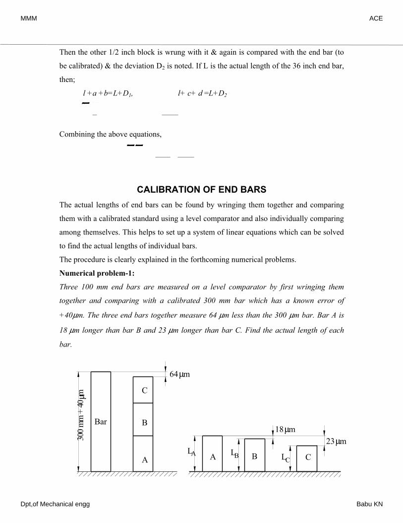
Numerical problem-1:
Three 100 mm end bars are measured on a level comparator by first wringing them
together and comparing with a calibrated 300 mm bar which has a known error of
+40µm. The three end bars together measure 64 µm less than the 300 µm bar. Bar A is
18 µm longer than bar B and 23 µm longer than bar C. Find the actual length of each
bar.
()122DlabcdL++++=+∑
3642dDL=++∑∑
300
mm
+ 4
0 µm
Bar
C
B
A
64µm
A B C
18µm23µm
L L LA B C
MMM ACE
Dpt,of Mechanical engg Babu KN
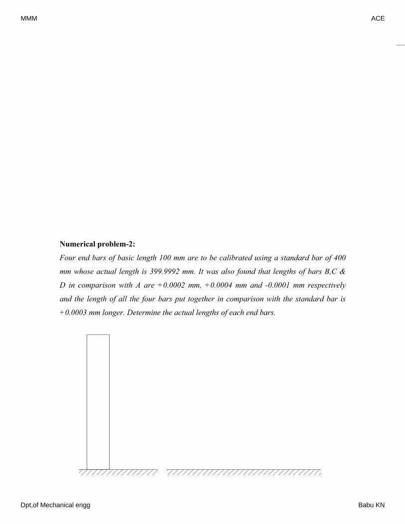
Numerical problem-2:
Four end bars of basic length 100 mm are to be calibrated using a standard bar of 400
mm whose actual length is 399.9992 mm. It was also found that lengths of bars B,C &
D in comparison with A are +0.0002 mm, +0.0004 mm and -0.0001 mm respectively
and the length of all the four bars put together in comparison with the standard bar is
+0.0003 mm longer. Determine the actual lengths of each end bars.
From the fig, ()(3004064) = 30024 (1)and ()18 (2) ()23 (3)Adding Eqns (1), (2) & (3), 3(30017)300.017 ABCABACALLLmmmmmmmLLmLLmLmmmmmµµµµµµ++=+−−−=−==+=⇒LLLLLAL=100.006 mmFrom Eqn (2), ()180.018 ..(100.006) = 0.018 (100.0060.018) From Eqn (3), ()230.023 ..(100.006) = 0.023 ABBBACCLLmmmieLLLLmmmieLµµ−==−⇒=−∴−==−⇒BL=99.988 mmL=99.983 mmC
A
B
C
D
Stan
dard
Cal
ibra
ted b
ar
L=39
9.99
92 m
m
0.0003 mm
A B C D
0.00020.0004
0.0001
MMM ACE
Dpt,of Mechanical engg Babu KN
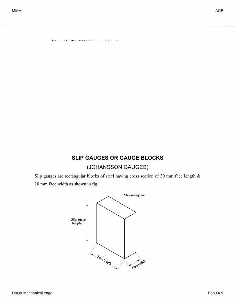
SLIP GAUGES OR GAUGE BLOCKS(JOHANSSON GAUGES)
Slip gauges are rectangular blocks of steel having cross section of 30 mm face length &
10 mm face width as shown in fig.
From the fig, ()(399.99920.0003) = 399.9995 (1)and 0.0002 (2) 0.0004 (3) 0.0001 (4)Substituting Eqns (2), (3) & (4) in Eqn (1),(ABCDBACADAAALLLLLLLLLLLL+++=+=+=+=−++LLLL0.0002)(0.0004)(0.0001)399.9995.. 4399.999 From Eqn (2), 0.000299.99970.0002Similarly 0.000499.99970.0004and 0.0001 AAABACADALLieLLLLLLL+++−==⇒=+∴=+==+∴=+==−∴AL=99.99975 mm99.9999 mm100.0001 mmBCDLLL99.99970.0001=−=99.9996 mm
Slip gauge length l
Face widthFace length
Measuring face
MMM ACE
Dpt,of Mechanical engg Babu KN
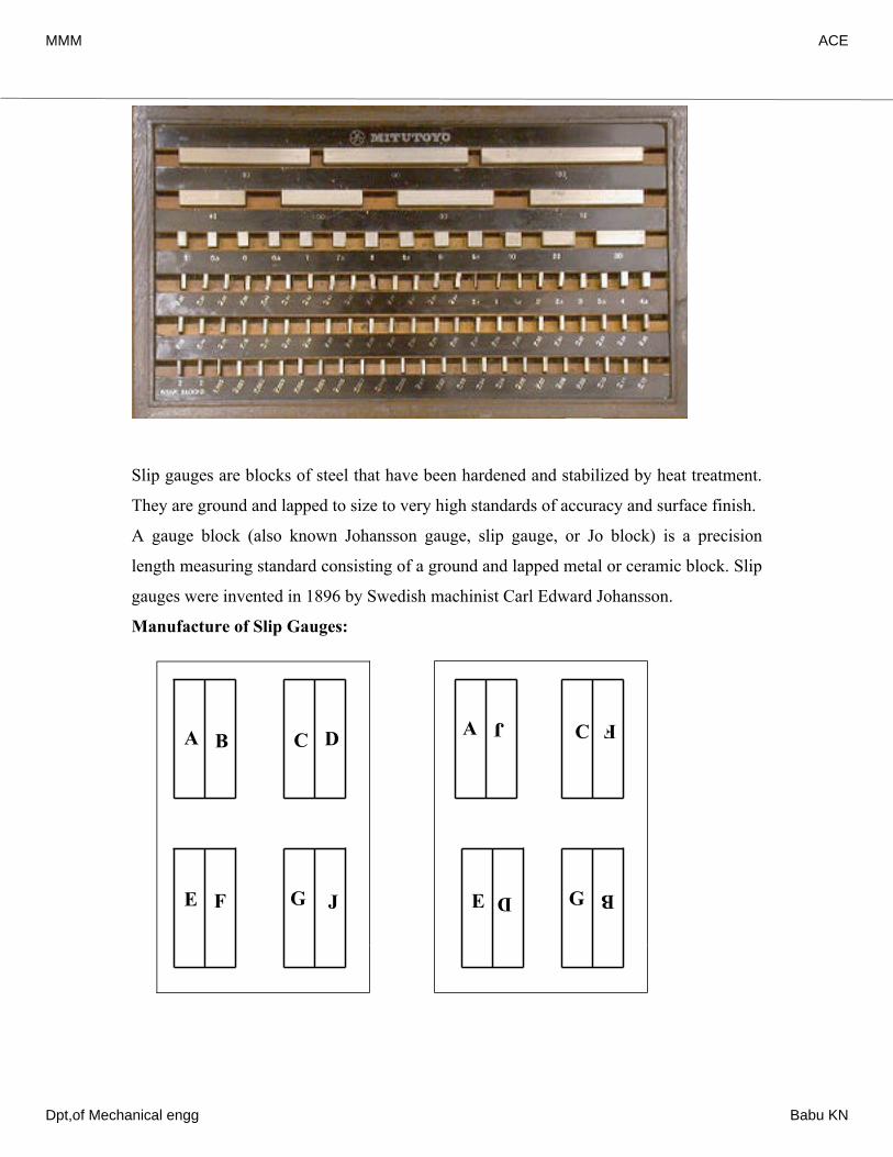
Slip gauges are blocks of steel that have been hardened and stabilized by heat treatment.
They are ground and lapped to size to very high standards of accuracy and surface finish.
A gauge block (also known Johansson gauge, slip gauge, or Jo block) is a precision
length measuring standard consisting of a ground and lapped metal or ceramic block. Slip
gauges were invented in 1896 by Swedish machinist Carl Edward Johansson.
Manufacture of Slip Gauges:
A B
E F JG
DC A J FC
G BE D
MMM ACE
Dpt,of Mechanical engg Babu KN
When correctly cleaned and wrung together, the individual slip gauges adhere to each
other by molecular attraction and, if left like this for too long, a partial cold weld will
take place.
If this is allowed to occur, the gauging surface will be irreparable after use, hence the
gauges should be separated carefully by sliding them apart. They should then be cleaned,
smeared with petroleum jelly (Vaseline) and returned to their case.
Protector Slips:
In addition, some sets also contain protector slips that are 2.50mm thick and are made
from a hard, wear resistant material such as tungsten carbide. These are added to the ends
of the slip gauge stack to protect the other gauge blocks from wear. Allowance must be
made of the thickness of the protector slips when they are used.
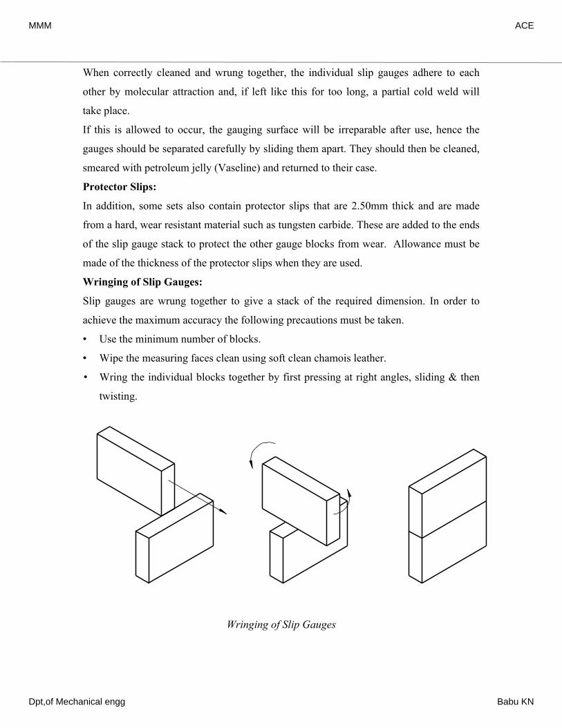
Wringing of Slip Gauges:
Slip gauges are wrung together to give a stack of the required dimension. In order to
achieve the maximum accuracy the following precautions must be taken.
• Use the minimum number of blocks.
• Wipe the measuring faces clean using soft clean chamois leather.
• Wring the individual blocks together by first pressing at right angles, sliding & then
twisting.
Wringing of Slip Gauges
MMM ACE
Dpt,of Mechanical engg Babu KN
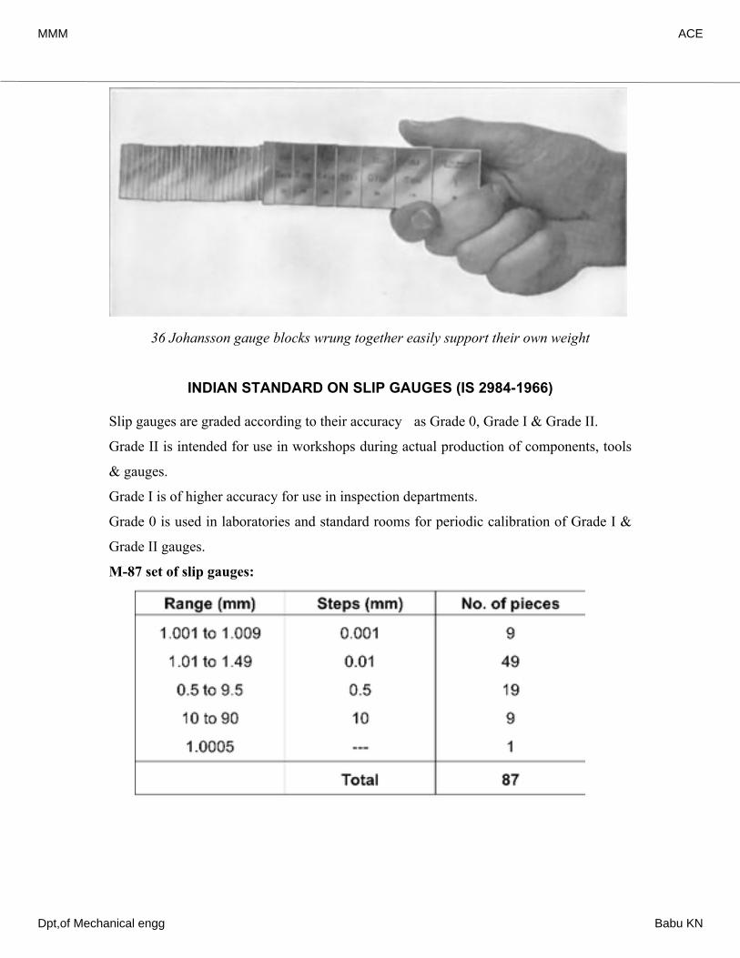
36 Johansson gauge blocks wrung together easily support their own weight
INDIAN STANDARD ON SLIP GAUGES (IS 2984-1966)
Slip gauges are graded according to their accuracy as Grade 0, Grade I & Grade II.
Grade II is intended for use in workshops during actual production of components, tools
& gauges.
Grade I is of higher accuracy for use in inspection departments.
Grade 0 is used in laboratories and standard rooms for periodic calibration of Grade I &
Grade II gauges.
M-87 set of slip gauges:
MMM ACE
Dpt,of Mechanical engg Babu KN
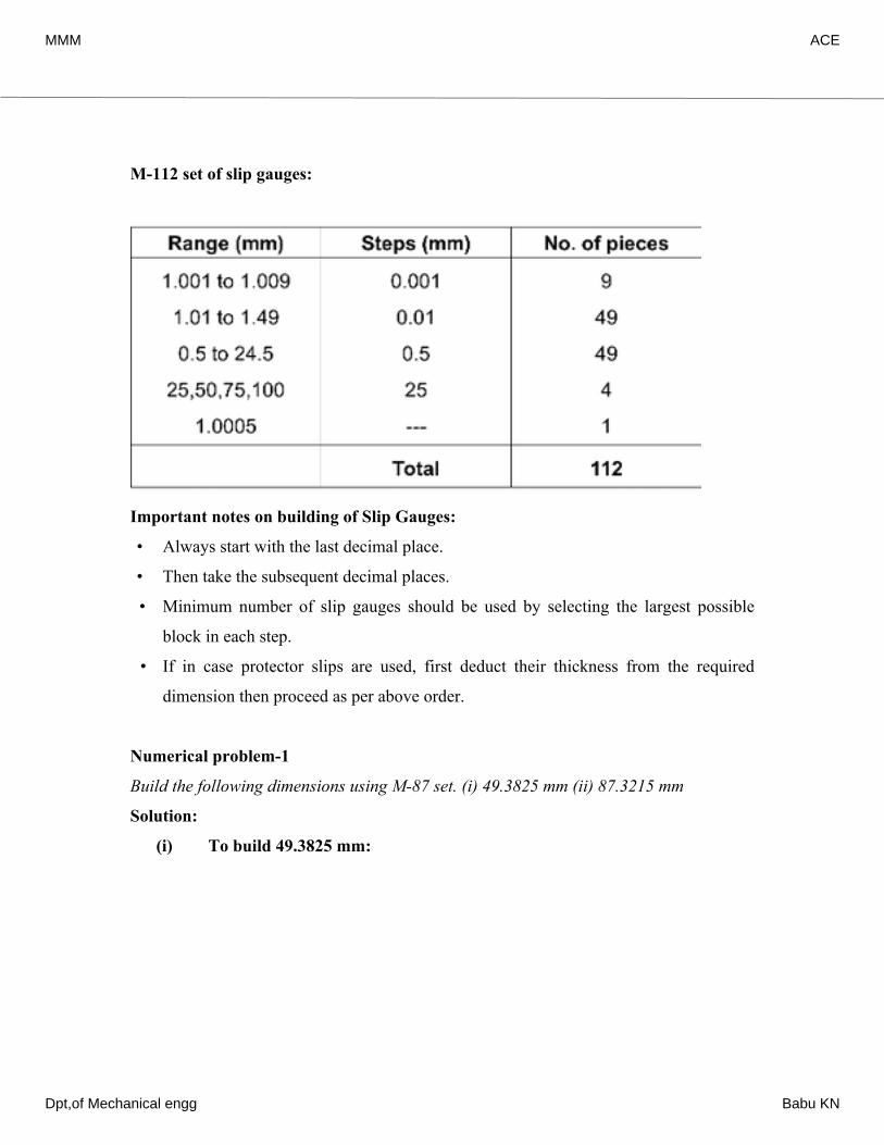
M-112 set of slip gauges:
Important notes on building of Slip Gauges:
• Always start with the last decimal place.
• Then take the subsequent decimal places.
• Minimum number of slip gauges should be used by selecting the largest possible
block in each step.
• If in case protector slips are used, first deduct their thickness from the required
dimension then proceed as per above order.
Numerical problem-1
Build the following dimensions using M-87 set. (i) 49.3825 mm (ii) 87.3215 mm
Solution:
(i) To build 49.3825 mm: Original dimension = 49.38254 decimal place + 1mm 1.0005 48.38203 decimal place + 1mm 1.0020 thrd−− 47.38002 decimal place + 1.3mm 1.3800 46.0000To round off 6.0000 nd−− 40.0000
MMM ACE
Dpt,of Mechanical engg Babu KN
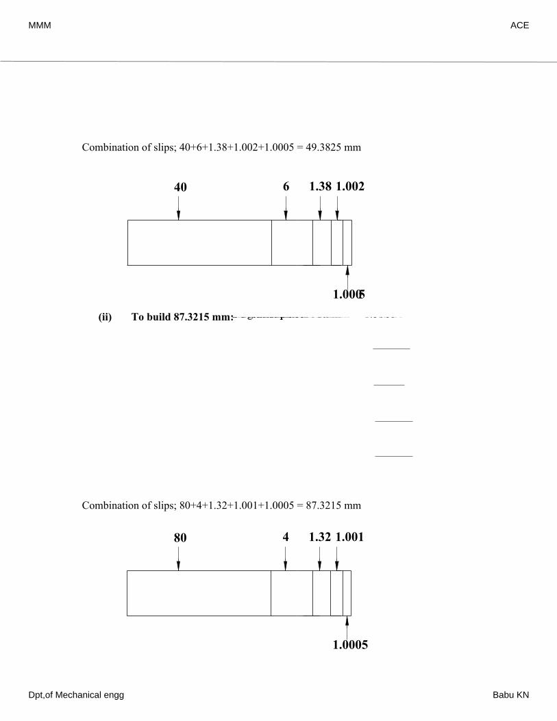
Combination of slips; 40+6+1.38+1.002+1.0005 = 49.3825 mm
(ii) To build 87.3215 mm:
Combination of slips; 80+4+1.32+1.001+1.0005 = 87.3215 mm
40 6 1.38 1.002
1.0005Original dimension = 87.32154 decimal place + 1mm 1.0005 86.32103 decimal place + 1mm 1.0010 thrd−− 85.32002 decimal place + 1.3mm 1.3200 84.0000To round off 4.0000 nd−− 80.0000
80 4 1.32 1.001
1.0005
MMM ACE
Dpt,of Mechanical engg Babu KN
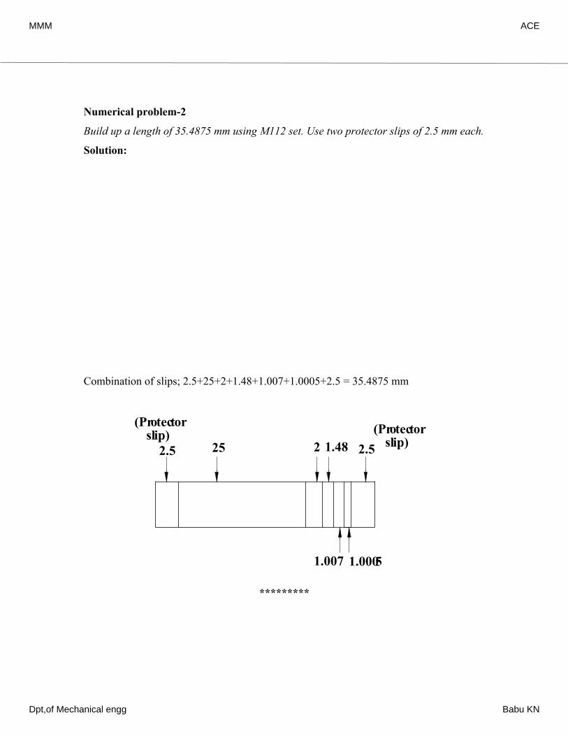
Numerical problem-2
Build up a length of 35.4875 mm using M112 set. Use two protector slips of 2.5 mm each.
Solution:
Combination of slips; 2.5+25+2+1.48+1.007+1.0005+2.5 = 35.4875 mm
*********
Original dimension = 35.4875Two protector slips (of 2.5 mm each) 5.0000 30.48754 decimal place + 1mm 1.0005th−−Less: 29.48703 decimal place + 1mm 1.0070 28.48002 decimal place + 1.4mm 1.4800 rdnd−− 27.0000To round off 2.0000 25.0000−
25 2 1.48
1.007 1.0005
2.5 2.5
(Protector slip) (Protector
slip)
MMM ACE
Dpt,of Mechanical engg Babu KN

MMM ACE
Dpt,of Mechanical engg Babu KN
Chapter 2
SYSTEM OF LIMITS, FITS, TOLERANCE AND GAUGINGLimits & Fits: Why study Limits & Fits?
• Exact size is impossible to achieve.
• Establish boundaries within which deviation from perfect form is allowed but still the
design intent is fulfilled.
• Enable interchangeability of components during assembly
Definition of Limits:
The maximum and minimum permissible sizes within which the actual size of a
component lies are called Limits.
Tolerance:
It is impossible to make anything to an exact size, therefore it is essential to allow a
definite tolerance or permissible variation on every specified dimension.
Why Tolerances are specified?
• Variations in properties of the material being machined introduce errors.
• The production machines themselves may have some inherent inaccuracies.
• It is impossible for an operator to make perfect settings. While setting up the tools
and workpiece on the machine, some errors are likely to creep in.
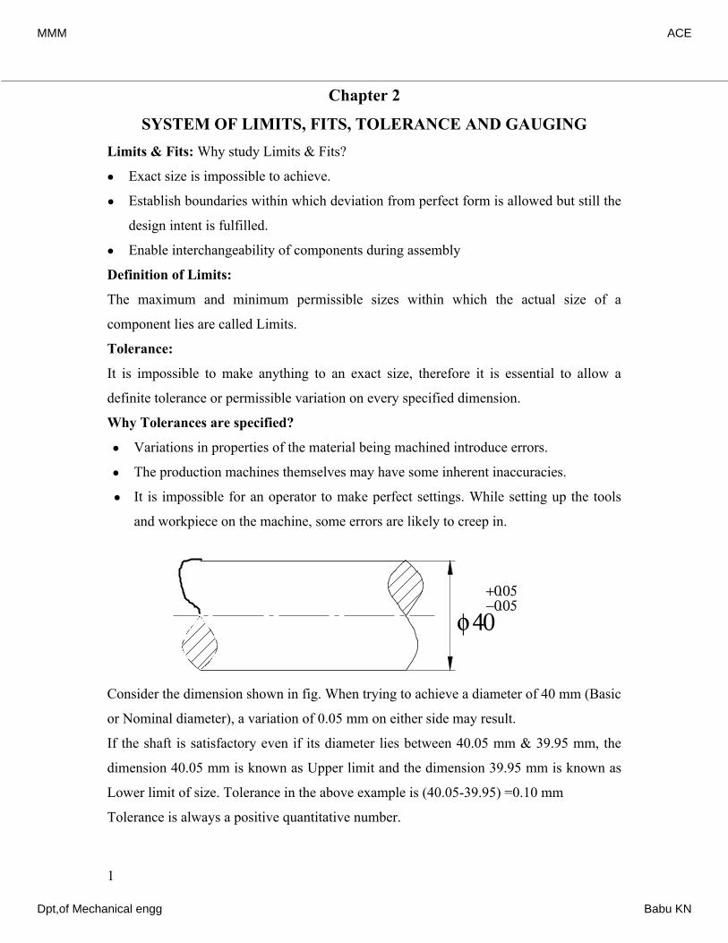
Consider the dimension shown in fig. When trying to achieve a diameter of 40 mm (Basic
or Nominal diameter), a variation of 0.05 mm on either side may result.
If the shaft is satisfactory even if its diameter lies between 40.05 mm & 39.95 mm, the
dimension 40.05 mm is known as Upper limit and the dimension 39.95 mm is known as
Lower limit of size. Tolerance in the above example is (40.05-39.95) =0.10 mm
Tolerance is always a positive quantitative number.
1
+0.05−0.05
φ 40
MMM ACE
Dpt,of Mechanical engg Babu KN
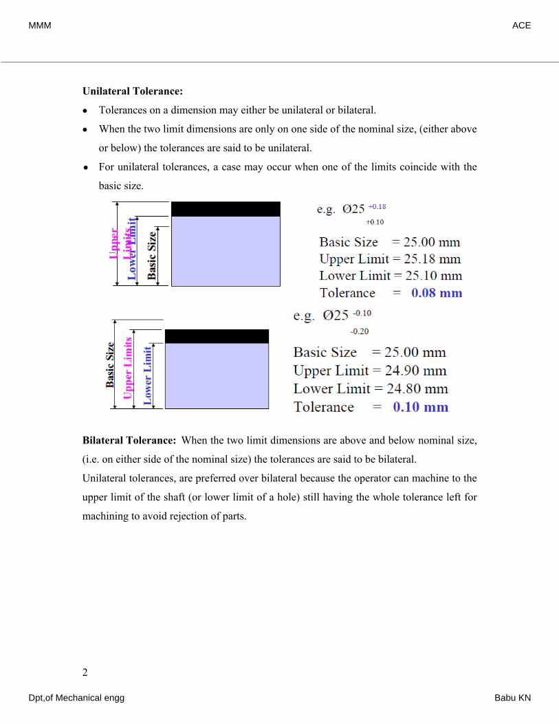
Unilateral Tolerance:
• Tolerances on a dimension may either be unilateral or bilateral.
• When the two limit dimensions are only on one side of the nominal size, (either above
or below) the tolerances are said to be unilateral.
• For unilateral tolerances, a case may occur when one of the limits coincide with the
basic size.
Bilateral Tolerance: When the two limit dimensions are above and below nominal size,
(i.e. on either side of the nominal size) the tolerances are said to be bilateral.
Unilateral tolerances, are preferred over bilateral because the operator can machine to the
upper limit of the shaft (or lower limit of a hole) still having the whole tolerance left for
machining to avoid rejection of parts.
2
MMM ACE
Dpt,of Mechanical engg Babu KN
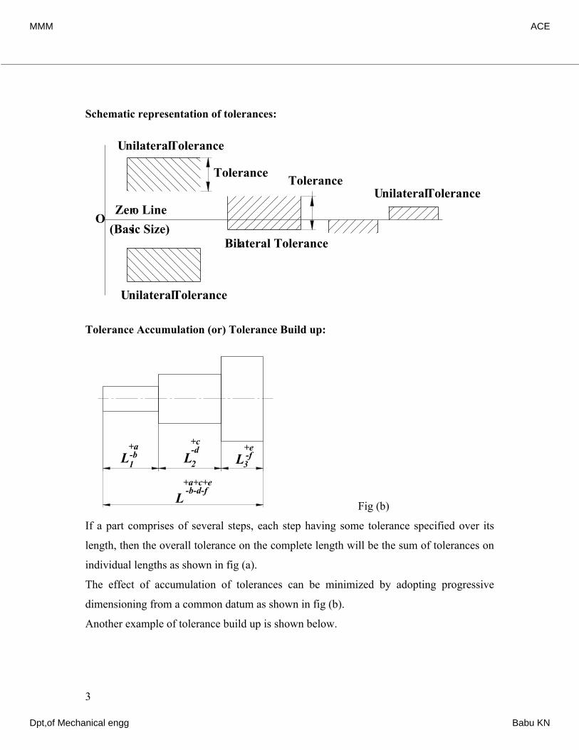
Schematic representation of tolerances:
Tolerance Accumulation (or) Tolerance Build up:
Fig (a) Fig (b)
If a part comprises of several steps, each step having some tolerance specified over its
length, then the overall tolerance on the complete length will be the sum of tolerances on
individual lengths as shown in fig (a).
The effect of accumulation of tolerances can be minimized by adopting progressive
dimensioning from a common datum as shown in fig (b).
Another example of tolerance build up is shown below.
3
OZero Line
Unilateral Tolerance
Bilateral Tolerance(Basic Size)
Tolerance
Unilateral Tolerance
Unilateral ToleranceTolerance
L+c-d +e
-f
+a+c+e-b-d-f
2 3
L
L L1
+a-bL
+c-d +e
-f
+a+c+e-b-d-f
2 3
L
L L1
+a-b
MMM ACE
Dpt,of Mechanical engg Babu KN
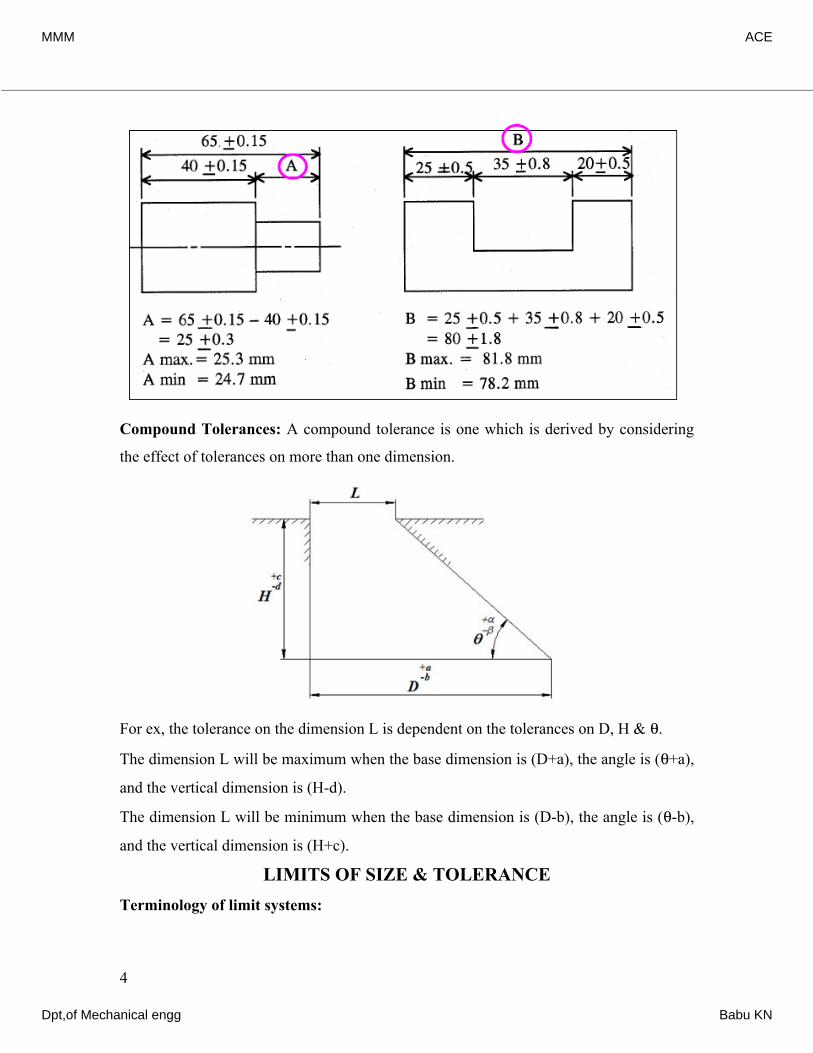
Compound Tolerances: A compound tolerance is one which is derived by considering
the effect of tolerances on more than one dimension.
For ex, the tolerance on the dimension L is dependent on the tolerances on D, H & θ.
The dimension L will be maximum when the base dimension is (D+a), the angle is (θ+a),
and the vertical dimension is (H-d).
The dimension L will be minimum when the base dimension is (D-b), the angle is (θ-b),
and the vertical dimension is (H+c).
LIMITS OF SIZE & TOLERANCETerminology of limit systems:
4
MMM ACE
Dpt,of Mechanical engg Babu KN
Limits of size: The two extreme permissible sizes of a component between which the
actual size should lie including the maximum and minimum sizes of the component.
Nominal size: It is the size of the component by which it is referred to as a matter of
convenience.
Basic size: It is the size of a part in relation to which all limits of variation are
determined.
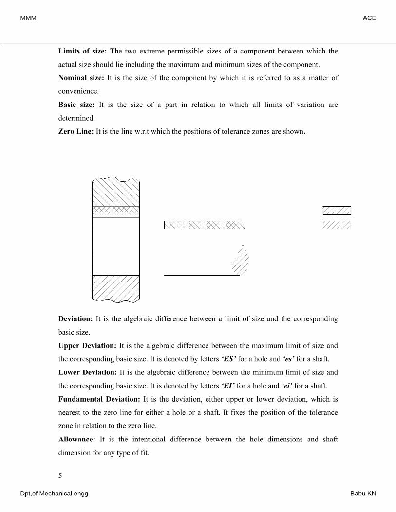
Zero Line: It is the line w.r.t which the positions of tolerance zones are shown.
Deviation: It is the algebraic difference between a limit of size and the corresponding
basic size.
Upper Deviation: It is the algebraic difference between the maximum limit of size and
the corresponding basic size. It is denoted by letters ‘ES’ for a hole and ‘es’ for a shaft.
Lower Deviation: It is the algebraic difference between the minimum limit of size and
the corresponding basic size. It is denoted by letters ‘EI’ for a hole and ‘ei’ for a shaft.
Fundamental Deviation: It is the deviation, either upper or lower deviation, which is
nearest to the zero line for either a hole or a shaft. It fixes the position of the tolerance
zone in relation to the zero line.
Allowance: It is the intentional difference between the hole dimensions and shaft
dimension for any type of fit.
5
Hole
Shaft
Zero line
Max
lim
it of
size
Min
lim
it of
size
Min
lim
it of
size
Max
lim
it of
size
Min
tole
ranc
e
Max
tole
ranc
e
Tol
eran
ce
Tol
eran
ce Schematicrepresentationof Tolerances
Hole Shaft
MMM ACE
Dpt,of Mechanical engg Babu KN
Size of tolerance: It is the difference between the maximum and minimum limits of size.
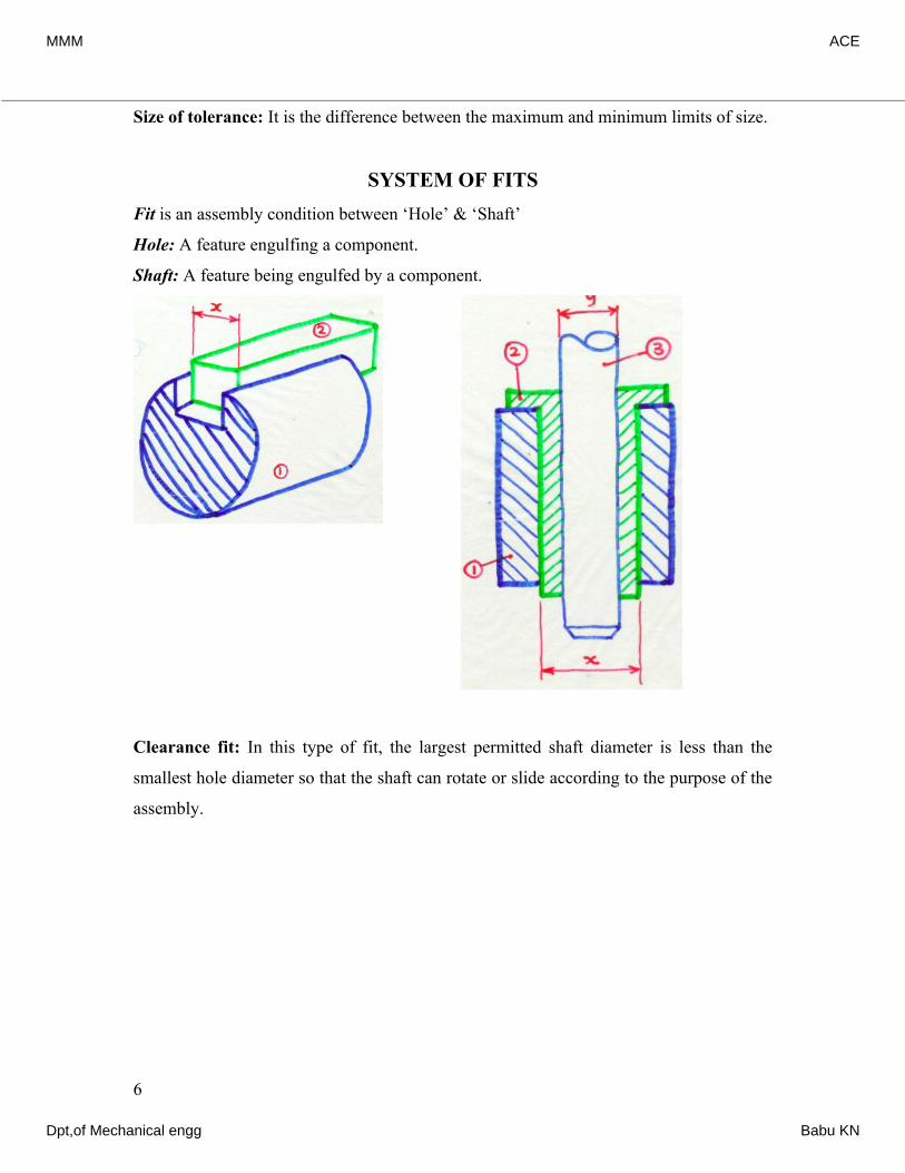
SYSTEM OF FITSFit is an assembly condition between ‘Hole’ & ‘Shaft’
Hole: A feature engulfing a component.
Shaft: A feature being engulfed by a component.
Clearance fit: In this type of fit, the largest permitted shaft diameter is less than the
smallest hole diameter so that the shaft can rotate or slide according to the purpose of the
assembly.
6
MMM ACE
Dpt,of Mechanical engg Babu KN
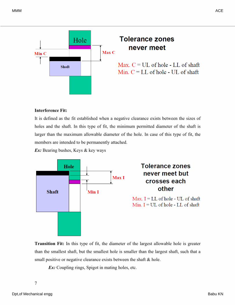
Interference Fit:
It is defined as the fit established when a negative clearance exists between the sizes of
holes and the shaft. In this type of fit, the minimum permitted diameter of the shaft is
larger than the maximum allowable diameter of the hole. In case of this type of fit, the
members are intended to be permanently attached.
Ex: Bearing bushes, Keys & key ways
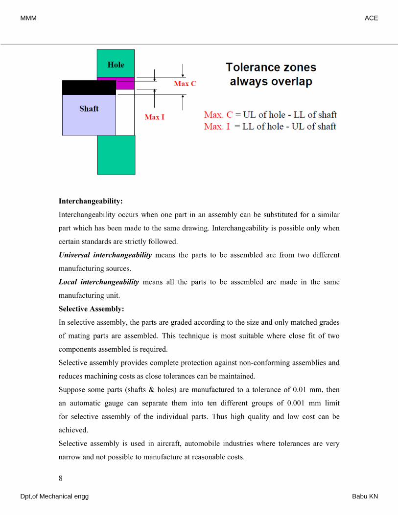
Transition Fit: In this type of fit, the diameter of the largest allowable hole is greater
than the smallest shaft, but the smallest hole is smaller than the largest shaft, such that a
small positive or negative clearance exists between the shaft & hole.
Ex: Coupling rings, Spigot in mating holes, etc.
7
MMM ACE
Dpt,of Mechanical engg Babu KN
Interchangeability:
Interchangeability occurs when one part in an assembly can be substituted for a similar
part which has been made to the same drawing. Interchangeability is possible only when
certain standards are strictly followed.
Universal interchangeability means the parts to be assembled are from two different
manufacturing sources.
Local interchangeability means all the parts to be assembled are made in the same
manufacturing unit.
Selective Assembly:
In selective assembly, the parts are graded according to the size and only matched grades
of mating parts are assembled. This technique is most suitable where close fit of two
components assembled is required.
Selective assembly provides complete protection against non-conforming assemblies and
reduces machining costs as close tolerances can be maintained.
Suppose some parts (shafts & holes) are manufactured to a tolerance of 0.01 mm, then
an automatic gauge can separate them into ten different groups of 0.001 mm limit
for selective assembly of the individual parts. Thus high quality and low cost can be
achieved.
Selective assembly is used in aircraft, automobile industries where tolerances are very
narrow and not possible to manufacture at reasonable costs.
8
MMM ACE
Dpt,of Mechanical engg Babu KN
Geometrical Tolerances:
It is necessary to specify and control the geometric features of a component, such
as straightness, flatness, roundness, etc. in addition to linear dimensions. Geometric
tolerance is concerned with the accuracy of relationship of one component to another and
should be specified separately.
Geometrical tolerance may be defined as the maximum possible variation of form, or
position of form or position of a feature.
Geometric tolerances define the shape of a feature as opposed to its size. There are three
basic types of geometric tolerances:
Form tolerances:
Straightness, flatness, roundness, cylindricity
Orientation tolerances:
Perpendicularity, parallelism, angularity
Position tolerances:
Position, symmetry, concentricity
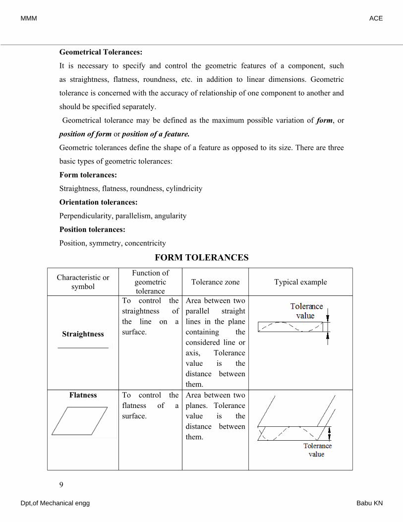
FORM TOLERANCES
Characteristic or symbol
Function of geometric tolerance
Tolerance zone Typical example
Straightness
To control the straightness of the line on a surface.
Area between two parallel straight lines in the plane containing the considered line or axis, Tolerance value is the distance between them.
Flatness To control the flatness of a surface.
Area between two planes. Tolerance value is the distance between them.
9
MMM ACE
Dpt,of Mechanical engg Babu KN
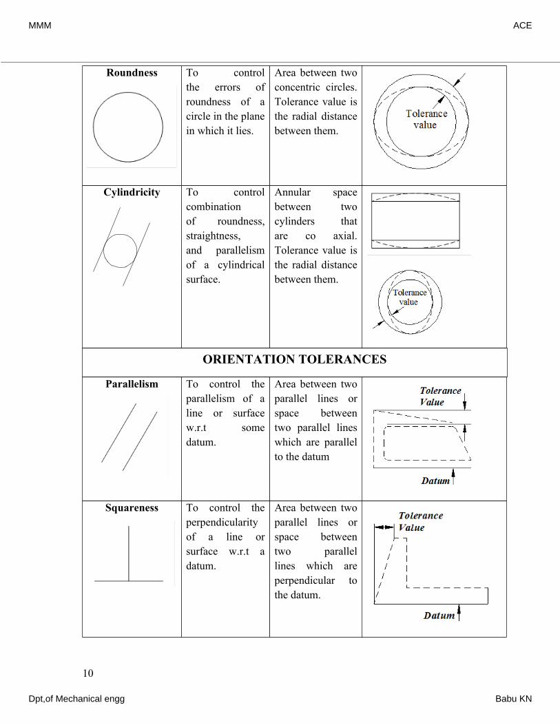
Roundness To control the errors of roundness of a circle in the plane in which it lies.
Area between two concentric circles. Tolerance value is the radial distance between them.
Cylindricity To control combination of roundness, straightness, and parallelism of a cylindrical surface.
Annular space between two cylinders that are co axial. Tolerance value is the radial distance between them.
ORIENTATION TOLERANCES
Parallelism To control the parallelism of a line or surface w.r.t some datum.
Area between two parallel lines or space between two parallel lines which are parallel to the datum
Squareness To control the perpendicularity of a line or surface w.r.t a datum.
Area between two parallel lines or space between two parallel lines which are perpendicular to the datum.
10
MMM ACE
Dpt,of Mechanical engg Babu KN
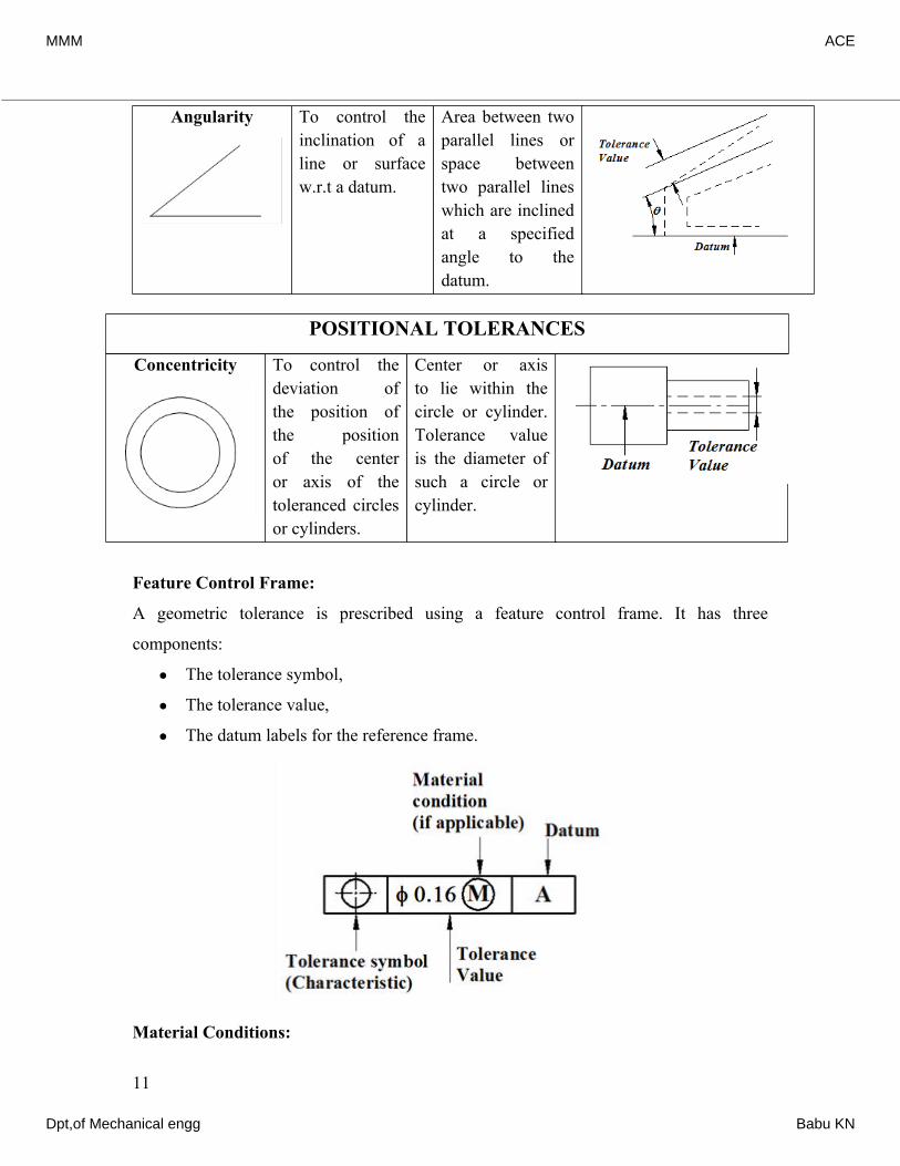
Angularity To control the inclination of a line or surface w.r.t a datum.
Area between two parallel lines or space between two parallel lines which are inclined at a specified angle to the datum.
POSITIONAL TOLERANCES
Concentricity To control the deviation of the position of the position of the center or axis of the toleranced circles or cylinders.
Center or axis to lie within the circle or cylinder. Tolerance value is the diameter of such a circle or cylinder.
Feature Control Frame:
A geometric tolerance is prescribed using a feature control frame. It has three
components:
• The tolerance symbol,
• The tolerance value,
• The datum labels for the reference frame.
Material Conditions:
11
MMM ACE
Dpt,of Mechanical engg Babu KN
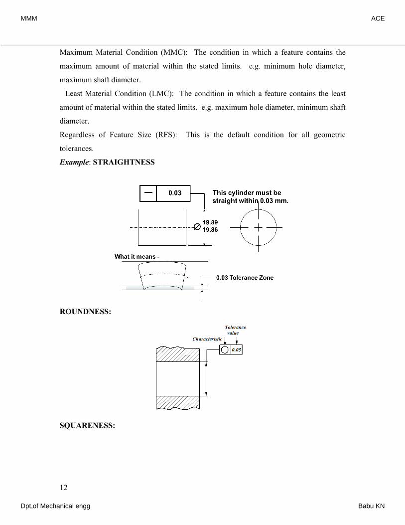
Maximum Material Condition (MMC): The condition in which a feature contains the
maximum amount of material within the stated limits. e.g. minimum hole diameter,
maximum shaft diameter.
Least Material Condition (LMC): The condition in which a feature contains the least
amount of material within the stated limits. e.g. maximum hole diameter, minimum shaft
diameter.
Regardless of Feature Size (RFS): This is the default condition for all geometric
tolerances.
Example: STRAIGHTNESS
ROUNDNESS:
SQUARENESS:
12
MMM ACE
Dpt,of Mechanical engg Babu KN
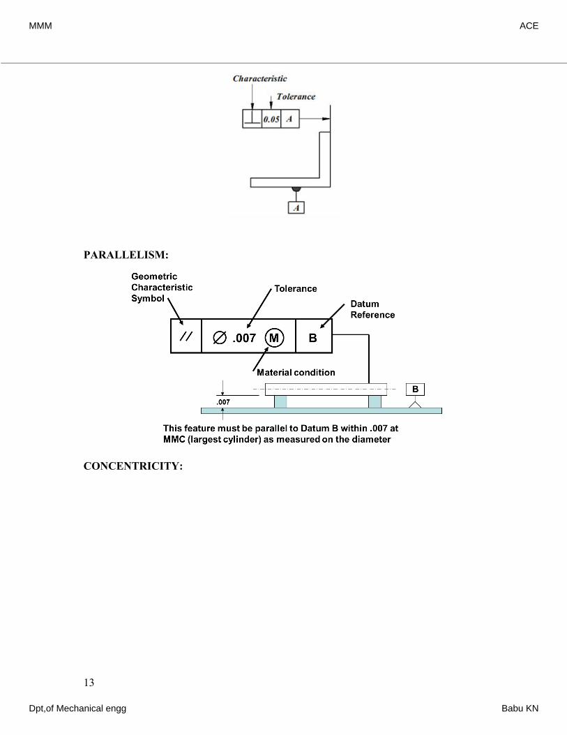
PARALLELISM:
CONCENTRICITY:
13
MMM ACE
Dpt,of Mechanical engg Babu KN
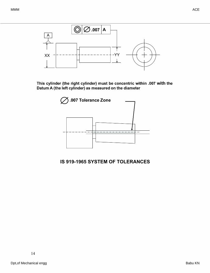
IS 919-1965 SYSTEM OF TOLERANCES
14
MMM ACE
Dpt,of Mechanical engg Babu KN
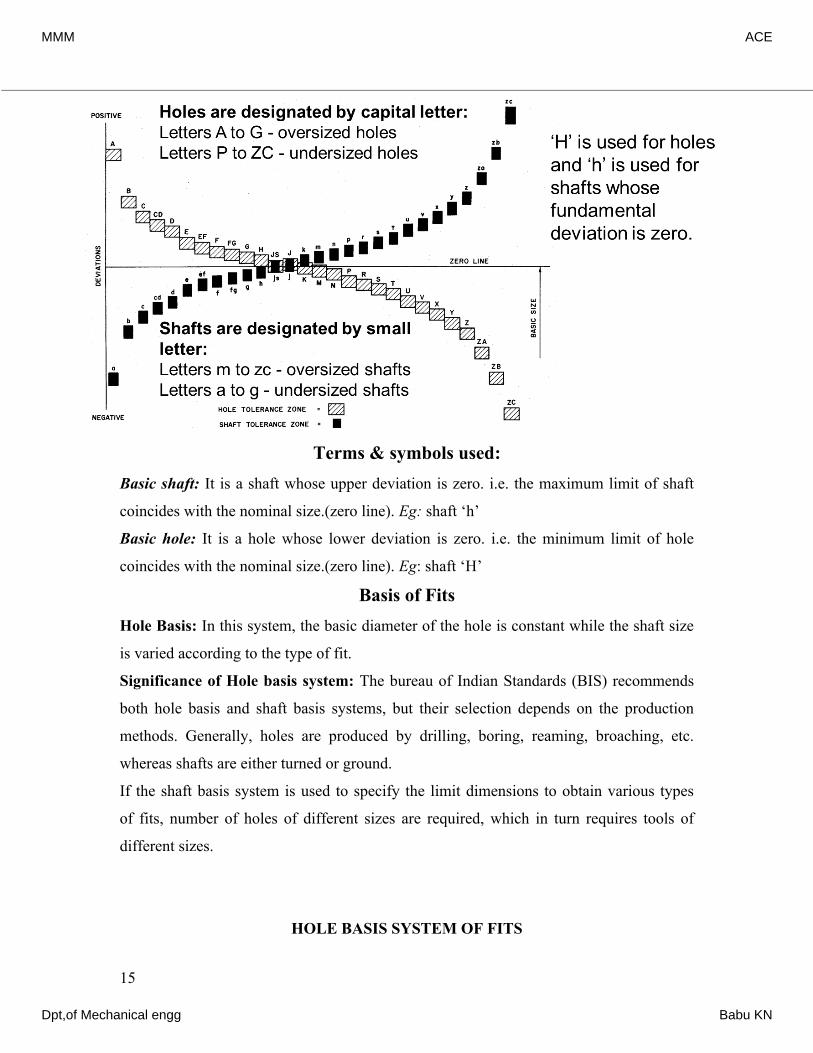
Terms & symbols used:Basic shaft: It is a shaft whose upper deviation is zero. i.e. the maximum limit of shaft
coincides with the nominal size.(zero line). Eg: shaft ‘h’
Basic hole: It is a hole whose lower deviation is zero. i.e. the minimum limit of hole
coincides with the nominal size.(zero line). Eg: shaft ‘H’
Basis of Fits Hole Basis: In this system, the basic diameter of the hole is constant while the shaft size
is varied according to the type of fit.
Significance of Hole basis system: The bureau of Indian Standards (BIS) recommends
both hole basis and shaft basis systems, but their selection depends on the production
methods. Generally, holes are produced by drilling, boring, reaming, broaching, etc.
whereas shafts are either turned or ground.
If the shaft basis system is used to specify the limit dimensions to obtain various types
of fits, number of holes of different sizes are required, which in turn requires tools of
different sizes.
HOLE BASIS SYSTEM OF FITS
15
MMM ACE
Dpt,of Mechanical engg Babu KN
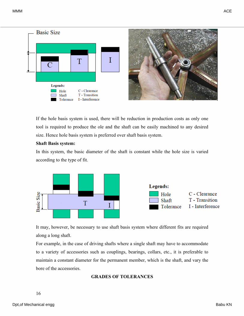
If the hole basis system is used, there will be reduction in production costs as only one
tool is required to produce the ole and the shaft can be easily machined to any desired
size. Hence hole basis system is preferred over shaft basis system.
Shaft Basis system:
In this system, the basic diameter of the shaft is constant while the hole size is varied
according to the type of fit.
It may, however, be necessary to use shaft basis system where different fits are required
along a long shaft.
For example, in the case of driving shafts where a single shaft may have to accommodate
to a variety of accessories such as couplings, bearings, collars, etc., it is preferable to
maintain a constant diameter for the permanent member, which is the shaft, and vary the
bore of the accessories.
GRADES OF TOLERANCES
16
MMM ACE
Dpt,of Mechanical engg Babu KN
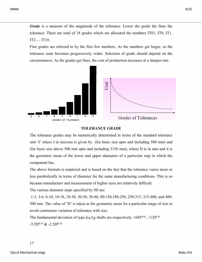
Grade is a measure of the magnitude of the tolerance. Lower the grade the finer the
tolerance. There are total of 18 grades which are allocated the numbers IT01, IT0, IT1,
IT2..... IT16.
Fine grades are referred to by the first few numbers. As the numbers get larger, so the
tolerance zone becomes progressively wider. Selection of grade should depend on the
circumstances. As the grades get finer, the cost of production increases at a sharper rate.
TOLERANCE GRADE
The tolerance grades may be numerically determined in terms of the standard tolerance
unit ‘i’ where i in microns is given by (for basic size upto and including 500 mm) and
(for basic size above 500 mm upto and including 3150 mm), where D is in mm and it is
the geometric mean of the lower and upper diameters of a particular step in which the
component lies.
The above formula is empirical and is based on the fact that the tolerance varies more or
less parabolically in terms of diameter for the same manufacturing conditions. This is so
because manufacture and measurement of higher sizes are relatively difficult.
The various diameter steps specified by ISI are:
1-3, 3-6, 6-10, 10-18, 18-30, 30-50, 50-80, 80-120,180-250, 250-315, 315-400, and 400-
500 mm. The value of ‘D’ is taken as the geometric mean for a particular range of size to
avoid continuous variation of tolerance with size.
The fundamental deviation of type d,e,f,g shafts are respectively -16D0.44, -11D0.41
-5.5D0.41 & -2.5D0.34
17
MMM ACE
Dpt,of Mechanical engg Babu KN
The fundamental deviation of type D,E,F,G shafts are respectively +16D0.44, +11D0.41
+5.5D0.41 & +2.5D0.34.
The relative magnitude of each grade is shown in the table below;
It may be noted that from IT 6 onwards, every 5th step is 10 times the respective grade.
i.e. IT 11=10xIT6=10x10i=100 i, IT12=10xIT7=10x16i=160 i, etc.
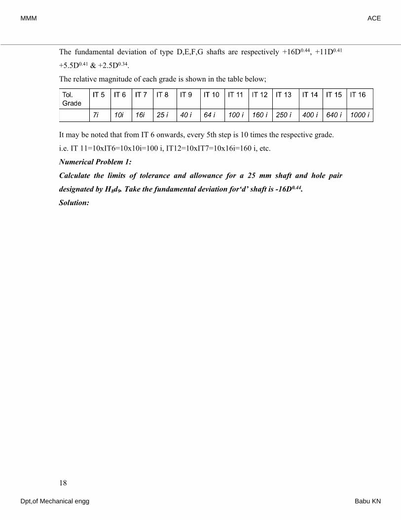
Numerical Problem 1:
Calculate the limits of tolerance and allowance for a 25 mm shaft and hole pair
designated by H8d9. Take the fundamental deviation for‘d’ shaft is -16D0.44.
Solution:
18
33The given size of 25 mm lies in the standard diameter step of 18-30 mm. D=1830The value of fundamental tolerance unit 0.450.001 microns.. 0.4523.2380.001(23.238)For a hoiDDiei∴×==+=+=23.238 mm1.307μle of quality 8, (i.e. IT 8) the standard tolerance value is =25 Tolerance 251.307For the H hole, the fundamental deviation is zero.Hence, the hole limits are 25 mm and (25+0.033)=25.033 mmHei∴×=∴33μ0.440.440.44nce, tolerance on the hole (25.03325)For quality 9 shaft, tolerance = IT9 =40i=401.307=For shaft the fundamental deviation is -16D16D16(23.238)d=−=×=−=−=∴0.033 mm52=0.052 mm-64μ=0.064 mmµThe shaft limits are (250.064) and 25(0.0640.052)Tolerance on the shaft =UL-LL(24.93624.884) −=−+=∴=−=24.9306. mm 24.884 mm052 mm
MMM ACE
Dpt,of Mechanical engg Babu KN
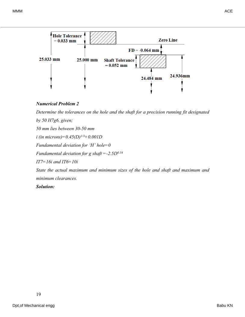
Numerical Problem 2
Determine the tolerances on the hole and the shaft for a precision running fit designated
by 50 H7g6, given;
50 mm lies between 30-50 mm
i (in microns)=0.45(D)1/3+0.001D
Fundamental deviation for ‘H’ hole=0
Fundamental deviation for g shaft =-2.5D0.34
IT7=16i and IT6=10i
State the actual maximum and minimum sizes of the hole and shaft and maximum and
minimum clearances.
Solution:
19
33The given size of 50 mm lies in the diameter step of 30-50 mm. D=3050The value of fundamental tolerance unit 0.450.001 microns.. 0.4538.70.001(38.7)For a hole of quality 7,iDDiei∴×==+=+=38.7 mm1.56μ0.0 (i.e. IT 7) the standard tolerance value is =16 Tolerance 161.56For the H hole, the fundamental deviation is zero.Hence, the hole limits are 50 mm and (50+0.025)=50.025 mm (Or 50i−∴×=25μ=0.025 mm0.025000.34 )Hence, tolerance on the hole (50.02550)For quality 6 shaft, tolerance = IT6=10i =10i=101.56=For shaft the fundamental deviation is 2.5D 2.5(38.7mmg+∴=−=×−=−0.025 mm15.6=0.0156 mmµ0.34)=-8.664μ=0.009 mm
MMM ACE
Dpt,of Mechanical engg Babu KN
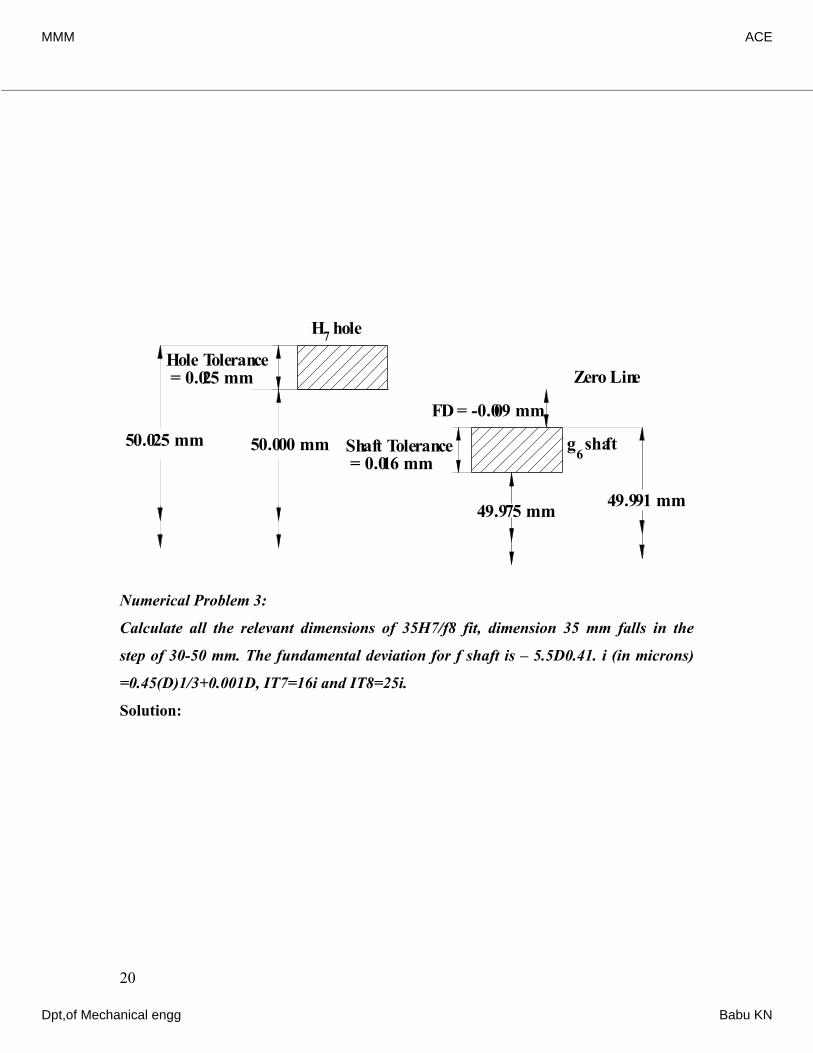
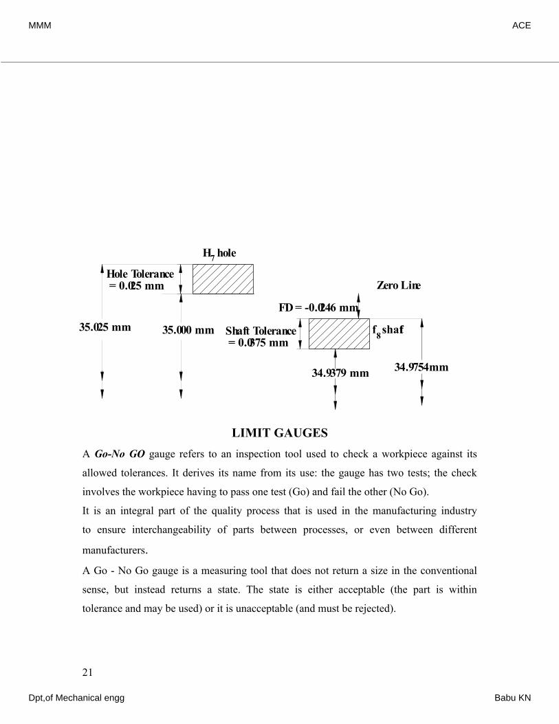
Numerical Problem 3:
Calculate all the relevant dimensions of 35H7/f8 fit, dimension 35 mm falls in the
step of 30-50 mm. The fundamental deviation for f shaft is – 5.5D0.41. i (in microns)
=0.45(D)1/3+0.001D, IT7=16i and IT8=25i.
Solution:
20
0.0090.025The shaft limits are (500.009) and 50(0.0090.016) (Or 50 )Actual maximum and minimum size of hole is 50.025 mmand 50.000 mm, and for shaft is 49.991 mm and 49.mm−−∴−=−+=49.991 mm49.975 mm 975 mm.Maximum clearance =UL of holeLL of shaft = (50.025-49.975)=Minimum clearance = LL of holeUL of shaft = (50.000-49.975)=−−0.05 mm0.009 mm
50.000 mm
FD = -0.009 mm
Hole Tolerance = 0.025 mm
Shaft Tolerance = 0.016 mm
Zero Line
49.991 mm49.975 mm
50.025 mm
H7 hole
g shaft6
33The given size of 35 mm lies in the diameter step of 30-50 mm. D=3050The value of fundamental tolerance unit 0.450.001 microns.. 0.4538.70.001(38.7)For a hole of quality 7,iDDiei∴×==+=+=38.7 mm1.56μ (i.e. IT 7) the standard tolerance value is =16 Tolerance 161.56i∴×=25μ=0.025 mm
MMM ACE
Dpt,of Mechanical engg Babu KN
LIMIT GAUGESA Go-No GO gauge refers to an inspection tool used to check a workpiece against its
allowed tolerances. It derives its name from its use: the gauge has two tests; the check
involves the workpiece having to pass one test (Go) and fail the other (No Go).
It is an integral part of the quality process that is used in the manufacturing industry
to ensure interchangeability of parts between processes, or even between different
manufacturers.A Go - No Go gauge is a measuring tool that does not return a size in the conventional
sense, but instead returns a state. The state is either acceptable (the part is within
tolerance and may be used) or it is unacceptable (and must be rejected).
21
0.0250.000For the H hole, the fundamental deviation (FD) is zero.Hence, the hole limits are 35 mm and (35+0.025)=35.025 mm (Or 35 )Hence, tolerance on the hole (50.02550)For quality 8mm+−∴=−=0.025 mm 0.410.41 shaft, tolerance = IT8=16i =161.56=For shaft the FD is -5.5D5.5(38.7)The shaft limits are (350.0246) and 35(0.02460.0375) (Or 3g×=−=∴−=−+=25 =0.025 mm-24.63μ=0.025 mm34.9754 mm34.9379 mm µ0.02460.06215 )mm−−
35.000 mm
FD = -0.0246 mm
Hole Tolerance = 0.025 mm
Shaft Tolerance = 0.0375 mm
Zero Line
34.9379 mm 34.9754mm
35.025 mm
H7 hole
f shaft8
MMM ACE
Dpt,of Mechanical engg Babu KN
They are well suited for use in the production area of the factory as they require little skill
or interpretation to use effectively and have few, if any, moving parts to be damaged in
the often hostile production environment.
PLAIN GAUGESGauges are inspection tools which serve to check the dimensions of the manufactured
parts. Limit gauges ensure the size of the component lies within the specified limits. They
are non-recording and do not determine the size of the part. Plain gauges are used for
checking plain (Unthreaded) holes and shafts.
Plain gauges may be classified as follows;
According to their type:
(a) Standard gauges are made to the nominal size of the part to be tested and have the
measuring member equal in size to the mean permissible dimension of the part to be
checked. A standard gauge should mate with some snugness.
(b) Limit Gauges These are also called ‘go’ and ‘no go’ gauges. These are made to the
limit sizes of the work to be measured. One of the sides or ends of the gauge is made
to correspond to maximum and the other end to the minimum permissible size. The
function of limit gauges is to determine whether the actual dimensions of the work are
within or outside the specified limits.
According to their purpose:
(a)Work shop gauges: Working gauges are those used at the bench or machine in
gauging the work as it being made.
(b)Inspection gauges: These gauges are used by the inspection personnel to inspect
manufactured parts when finished.
(c) Reference or Master Gauges: These are used only for checking the size or condition
of other gauges.
According to the form of tested surface:
Plug gauges: They check the dimensions of a hole
Snap & Ring gauges: They check the dimensions of a shaft.
According to their design:
Single limit & double limit gauges
Single ended and double ended gauges
22
MMM ACE
Dpt,of Mechanical engg Babu KN
Fixed & adjustable gauges
LIMIT GAUGING
Limit gauging is adopted for checking parts produced by mass production. It has the
advantage that they can be used by unskilled persons.
Instead of measuring actual dimensions, the conformance of product with tolerance
specifications can be checked by a ‘GO’ and ‘NO GO’ gauges.
A ‘GO’ gauge represents the maximum material condition of the product (i.e. minimum
hole size or maximum shaft size) and conversely a ‘NO GO’ represents the minimum
material condition (i.e. maximum hole size or minimum shaft size)
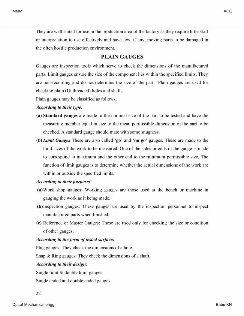
Plug gauges:
Plug gauges are the limit gauges used for checking holes and consist of two cylindrical
wear resistant plugs. The plug made to the lower limit of the hole is known as ‘GO’ end
and this will enter any hole which is not smaller than the lower limit allowed. The plug
made to the upper limit of the hole is known as ‘NO GO’ end and this will not enter any
hole which is smaller than the upper limit allowed. The plugs are arranged on either ends
of a common handle.
Plug gauges are normally double ended for sizes upto 63 mm and for sizes above 63 mm
they are single ended type.
23
MMM ACE
Dpt,of Mechanical engg Babu KN
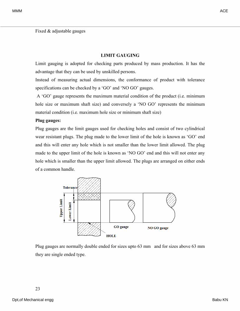
The handles of heavy plug gauges are made of light metal alloys while the handles of
small plug gauges can be made of some nonmetallic materials.
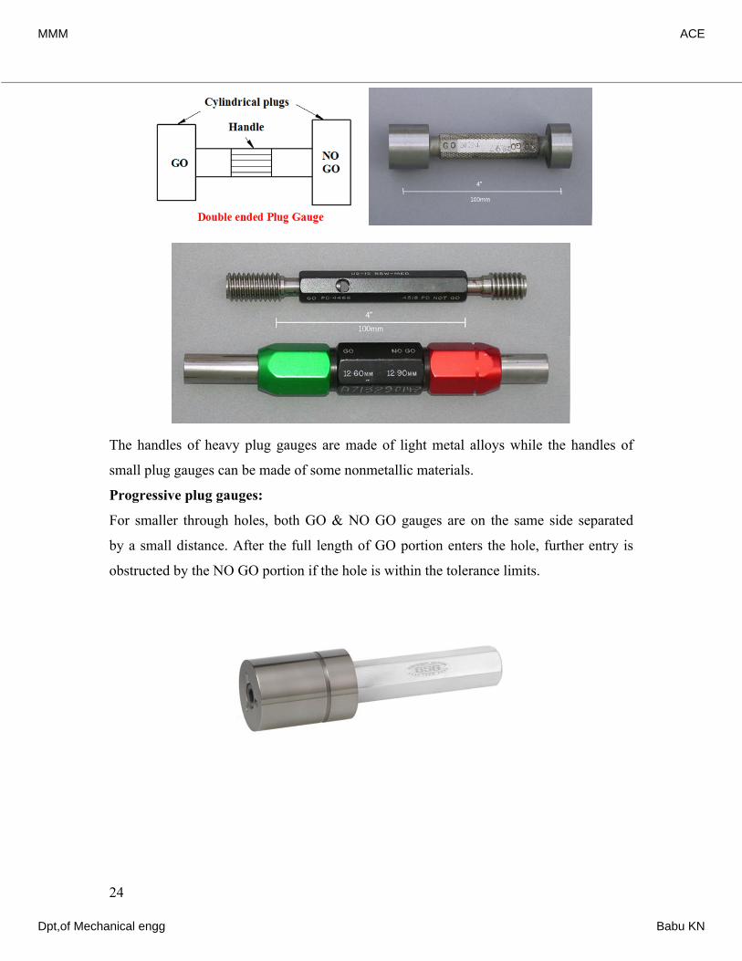
Progressive plug gauges:
For smaller through holes, both GO & NO GO gauges are on the same side separated
by a small distance. After the full length of GO portion enters the hole, further entry is
obstructed by the NO GO portion if the hole is within the tolerance limits.
24
MMM ACE
Dpt,of Mechanical engg Babu KN
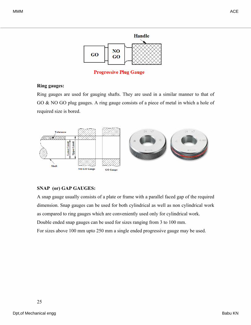
Ring gauges:
Ring gauges are used for gauging shafts. They are used in a similar manner to that of
GO & NO GO plug gauges. A ring gauge consists of a piece of metal in which a hole of
required size is bored.
SNAP (or) GAP GAUGES:
A snap gauge usually consists of a plate or frame with a parallel faced gap of the required
dimension. Snap gauges can be used for both cylindrical as well as non cylindrical work
as compared to ring gauges which are conveniently used only for cylindrical work.
Double ended snap gauges can be used for sizes ranging from 3 to 100 mm.
For sizes above 100 mm upto 250 mm a single ended progressive gauge may be used.
25
MMM ACE
Dpt,of Mechanical engg Babu KN
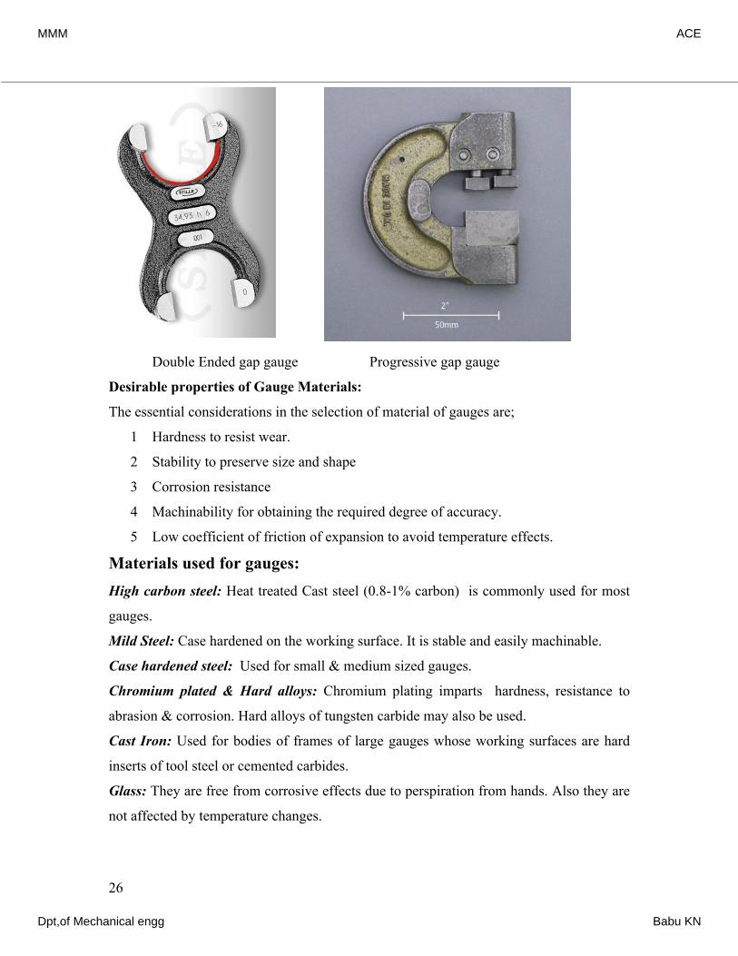
Double Ended gap gauge Progressive gap gauge
Desirable properties of Gauge Materials:
The essential considerations in the selection of material of gauges are;
1 Hardness to resist wear.
2 Stability to preserve size and shape
3 Corrosion resistance
4 Machinability for obtaining the required degree of accuracy.
5 Low coefficient of friction of expansion to avoid temperature effects.
Materials used for gauges: High carbon steel: Heat treated Cast steel (0.8-1% carbon) is commonly used for most
gauges.
Mild Steel: Case hardened on the working surface. It is stable and easily machinable.
Case hardened steel: Used for small & medium sized gauges.
Chromium plated & Hard alloys: Chromium plating imparts hardness, resistance to
abrasion & corrosion. Hard alloys of tungsten carbide may also be used.
Cast Iron: Used for bodies of frames of large gauges whose working surfaces are hard
inserts of tool steel or cemented carbides.
Glass: They are free from corrosive effects due to perspiration from hands. Also they are
not affected by temperature changes.
26
MMM ACE
Dpt,of Mechanical engg Babu KN
Invar: It is a nickel-iron alloy (36% nickel) which has low coefficient of expansion but
not suitable for usage over long periods.
(The name, Invar, comes from the word invariable, referring to its lack of expansion or
contraction with temperature changes. It was invented in 1896 by Swiss scientist Charles Eduard
Guillaume. He received the Nobel Prize in Physics in 1920 for this discovery, which enabled
improvements in scientific instruments.)
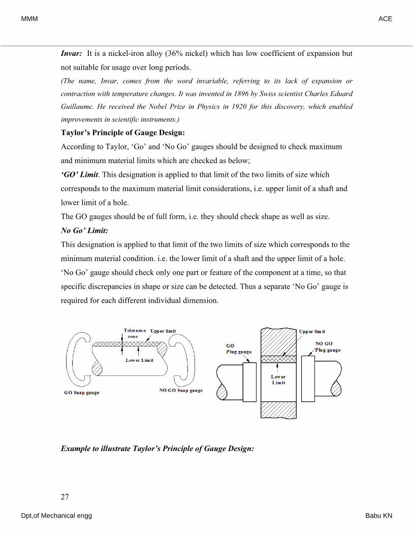
Taylor’s Principle of Gauge Design:
According to Taylor, ‘Go’ and ‘No Go’ gauges should be designed to check maximum
and minimum material limits which are checked as below;
‘GO’ Limit. This designation is applied to that limit of the two limits of size which
corresponds to the maximum material limit considerations, i.e. upper limit of a shaft and
lower limit of a hole.
The GO gauges should be of full form, i.e. they should check shape as well as size.
No Go’ Limit:
This designation is applied to that limit of the two limits of size which corresponds to the
minimum material condition. i.e. the lower limit of a shaft and the upper limit of a hole.
‘No Go’ gauge should check only one part or feature of the component at a time, so that
specific discrepancies in shape or size can be detected. Thus a separate ‘No Go’ gauge is
required for each different individual dimension.
Example to illustrate Taylor’s Principle of Gauge Design:
27
MMM ACE
Dpt,of Mechanical engg Babu KN
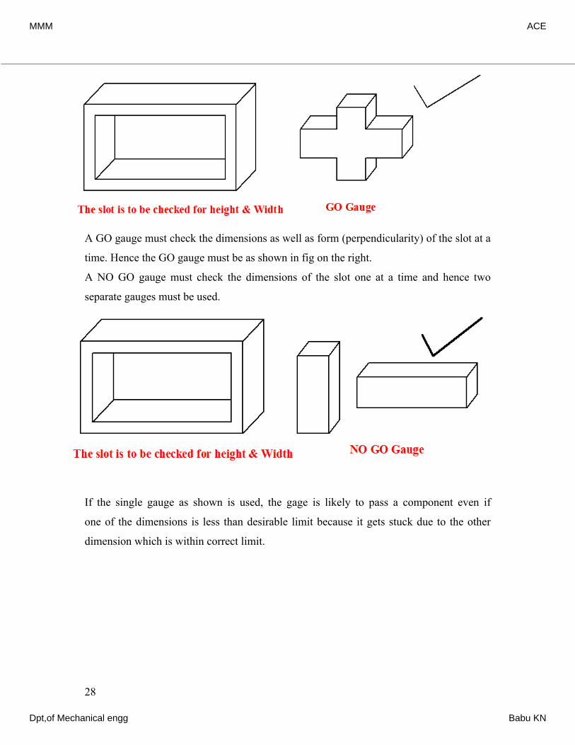
A GO gauge must check the dimensions as well as form (perpendicularity) of the slot at a
time. Hence the GO gauge must be as shown in fig on the right.
A NO GO gauge must check the dimensions of the slot one at a time and hence two
separate gauges must be used.
If the single gauge as shown is used, the gage is likely to pass a component even if
one of the dimensions is less than desirable limit because it gets stuck due to the other
dimension which is within correct limit.
28
MMM ACE
Dpt,of Mechanical engg Babu KN
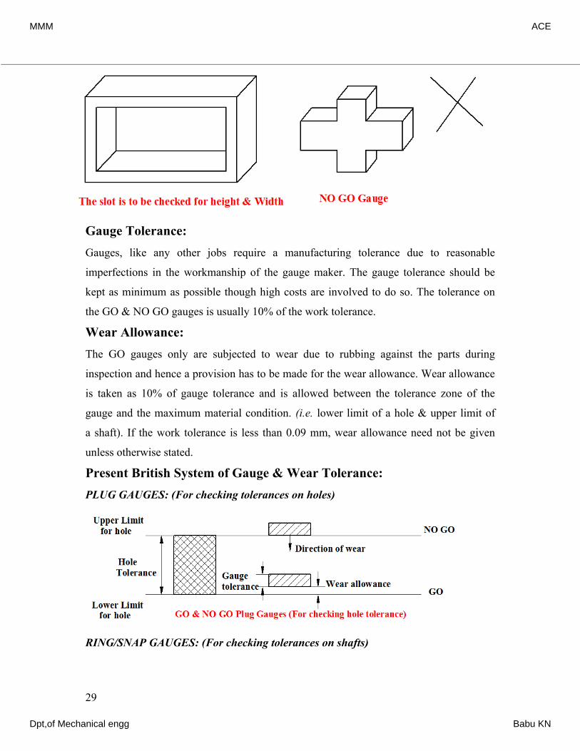
Gauge Tolerance:Gauges, like any other jobs require a manufacturing tolerance due to reasonable
imperfections in the workmanship of the gauge maker. The gauge tolerance should be
kept as minimum as possible though high costs are involved to do so. The tolerance on
the GO & NO GO gauges is usually 10% of the work tolerance.
Wear Allowance:The GO gauges only are subjected to wear due to rubbing against the parts during
inspection and hence a provision has to be made for the wear allowance. Wear allowance
is taken as 10% of gauge tolerance and is allowed between the tolerance zone of the
gauge and the maximum material condition. (i.e. lower limit of a hole & upper limit of
a shaft). If the work tolerance is less than 0.09 mm, wear allowance need not be given
unless otherwise stated.
Present British System of Gauge & Wear Tolerance:PLUG GAUGES: (For checking tolerances on holes)
RING/SNAP GAUGES: (For checking tolerances on shafts)
29
MMM ACE
Dpt,of Mechanical engg Babu KN
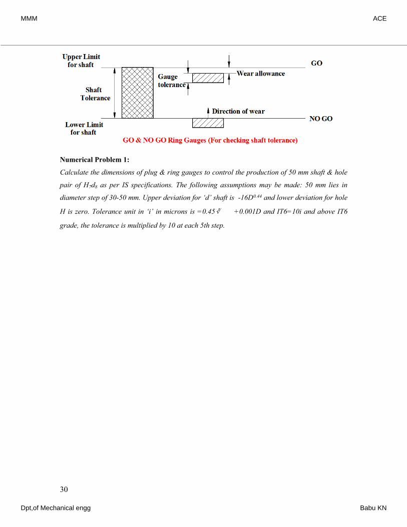
Numerical Problem 1:
Calculate the dimensions of plug & ring gauges to control the production of 50 mm shaft & hole
pair of H7d8 as per IS specifications. The following assumptions may be made: 50 mm lies in
diameter step of 30-50 mm. Upper deviation for ‘d’ shaft is -16D0.44 and lower deviation for hole
H is zero. Tolerance unit in ‘i’ in microns is =0.45∛ +0.001D and IT6=10i and above IT6
grade, the tolerance is multiplied by 10 at each 5th step.
Solution:
30
33() The given size of 50 mm lies in the diameter step of 30-50 mm. D=3050() The value of fundamental tolerance unit 0.450.001 microns .. 0.4538.70.001(38.7)() Given iiiiDDieiiii∴×==+=+=38.7 mm1.56μth1/50.2that for quality 6, i.e. IT 6 =10 and tolerance is 10 times at 5 Step 7610101015.84Tolerance for IT7 =15.841.56For the H hole, the fundamental deviation (FD) is zero.iITITii⇒=×=×=∴×=0.0247 mm0.02470.0000.40.40.4work tolerance on the hole(50.024750)(Or 50 )()For quality 8 shaft, tolerance = IT8 =IT6101010Work tolerance for shaft =(101.56)10= For shaftmmivig+−∴=−=×=×∴××0.0247 mm 0.0391 mm0.440.44 the FD is -16D16(38.73)0.080.0391 Hence lower deviation ==−=−−=-80μ=-0.08 mm-0.1191mm
MMM ACE
Dpt,of Mechanical engg Babu KN
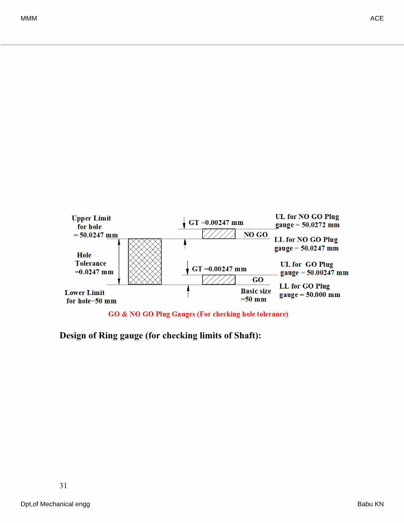
Design of Plug gauge (for checking limits of hole):
Design of Ring gauge (for checking limits of Shaft):
31
() Allowing 10% of work tolerance on hole as gauge tolerance .. gauge tolerance =10% of 0.0247= and neglecting wear tolerance (As work tol <0.09 mm) () , L0.0247 mmmiiieaFor GO plug gaugeits for GO plug gauge are; 50.000+0.000 = and 50.000+0.00247 = mm () , Limits for NO GO plug gauge are; 50.000+0.0247 = and 50.0247+0.50.000 mm50.00024750.0247 mm b∴For NO GO plug gauge50.0024727 = 2 mm
() Allowing 10% of work tolerance on shaft as gauge tolerance .. gauge tolerance =10% of 0.0391= and neglecting wear tolerance (As work tol <0.090.000391mm mm) (a) iiieFor GO Ring gauge:Limits for GO Ring gauge are; 50.0000.08 = and 49.920.0039 = mm() , Limits for NO GO ring gauge are; 50.000(0.08+0.0391) = & (4949.92 .8mm49.916149.8809 mm b−−−For NO GO ring gauge8090.0039) =49.87 70 mm−
MMM ACE
Dpt,of Mechanical engg Babu KN
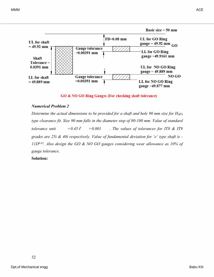
Numerical Problem 2
Determine the actual dimensions to be provided for a shaft and hole 90 mm size for H8e9
type clearance fit. Size 90 mm falls in the diameter step of 80-100 mm. Value of standard
tolerance unit =0.45∛ +0.001 . The values of tolerances for IT8 & IT9
grades are 25i & 40i respectively. Value of fundamental deviation for ‘e’ type shaft is -
11D0.41. Also design the GO & NO GO gauges considering wear allowance as 10% of
gauge tolerance.
Solution:
32
33() The given size of 90 mm lies in the diameter step of 80-100 mm. D=80100() The value of fundamental tolerance unit 0.450.001 microns.. 0.4589.440.001(89.44)0.00iiiiDDieii∴×==+=+=⇒=89.44 mm2.102μ2102 () Given that for quality 8, i.e. IT 8 =25250.002102For the H hole, the fundamental deviation is zero.i.e. lower limit of hole =& upper limit of0.05255 90 mm 90.05255 size of ho=mle mimmmiii=×=0.052550.000Hence, work tolerance on the hole (90.052590)(Or 90 )mmm+−∴=−=0.05255 mm
MMM ACE
Dpt,of Mechanical engg Babu KN
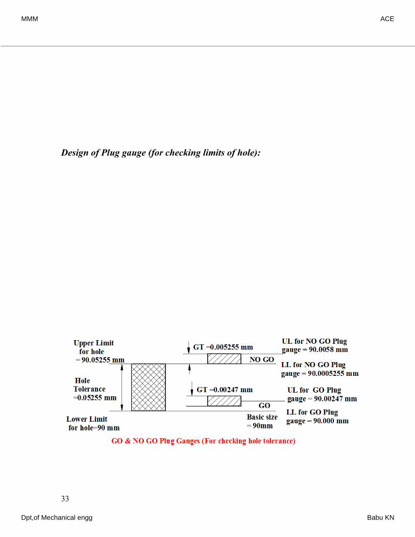
Design of Plug gauge (for checking limits of hole):
33
0.410.41()For quality 9 shaft, tolerance = 40 =400.0021020.08408 ..Work tolerance for shaft = For shaft the fundamental deviation is -11D 11(89.44)Hence tivimmieg×==−=0.08408 mm-69.426μ=-0.0694 mm0.06940.153589.9he limits for shaft size are; Upper limit =(900.0694) Lo3 89.8wer limit =(47 89.930.08408)(OR 90)mmmm−−−=−=
() Allowing 10% of work tolerance on hole as gauge tolerance .. gauge tolerance =10% of 0.05255= and wear allowance =10% of GT=0.005255 mm0.0005255 m (a) , Limits fomr iieFor GO plug gauge90.0005255 mm90.005GO plug gauge are; LL 90.000+0.0005255 = and UL 90.000+0.005255+0.0005255 = (b) , Limits for NO GO plug gauge are; LL 90.000+0.05255+0.8m0005255 = m9For NO-GO plug gauge and UL 90.000+0.05255 =0.0578 mm90.052 55 mm
MMM ACE
Dpt,of Mechanical engg Babu KN

Design of Ring gauges (for checking limits of shaft)
*******
34
() Allowing 10% of work tolerance on shaft as gauge tolerance .. gauge tolerance =10% of 0.080.0084 mm0.00084 mm408= and wear allowance =10% of GT= (a) , Limits for GO riniie GO ring gauge89.9213 mm89.9g gauge are; LL 90.000(0.06950.000840.0084) = and UL 90.000(0.06950.00084) = (b) , Limits for NO GO ring gauge are; LL (90.0000.06950.084080.02970mm−−−−−−−−For NO-GO plug gauge8408) = and UL (90.0000.06950.08408) = 89.838 mm89.8846 5 mm−−
GO & NO GO Ring Gauges (For checking shaft tolerance)
NO GO
GOUpper Limit for shaft
Lower Limit for shaft
Direction of wear
Wear allowanceGaugetolerance Shaft
Tolerance
MMM ACE
Dpt,of Mechanical engg Babu KN
Mechanical Measurements and Metrology
Dr. K V S Rajeswara Rao, Dept. of IEM, RVCE, Bangalore-59. 1
Mechanical Measurements andMetrology – 10ME42B
UNIT - 3
Comparators and AngularMeasurement
Instructor
Dr. K V S Rajeswara RaoAssociate Professor,
Dept. of Industrial Engineering & Management,R V College of Engineering, Mysore Road
Bangalore – 59E-mail – [email protected]
MMM ACE
Dpt,of Mechanical engg Babu KN
Mechanical Measurements and Metrology
Dr. K V S Rajeswara Rao, Dept. of IEM, RVCE, Bangalore-59. 2
Mechanical Measurements and Metrology – 10ME42B
UNIT – 3:Comparators and Angular measurement
Chapter Outline
Comparators
– Introduction to comparators
– Characteristics
– Uses of Comparators
– Classification of comparators
– Mechanical comparators
• Dial indicator
• Johnson Mikrokator
• Sigma comparators
Optical comparators
– Principles,
– Zeiss ultra optimeter,
Electric and electronic comparators principles,
– LVDT,
Pneumatic comparators,
– Back pressure gauges,
– Solex comparators.
Angular Measurements
– Introduction,
– Bevel protractor,
– Sine principle
– Uses of sine bars,
– Sine centre,
– Use of angle gauges
– Numerical on building of angles,
– Clinometers.
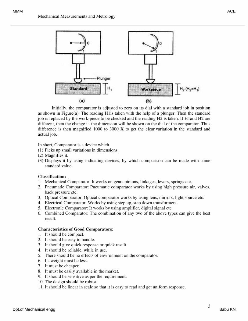
Comparators can give precision measurements, with consistent accuracy by
eliminating human error. They are employed to find out, by how much the dimensions of the
given component differ from that of a known datum. If the indicated difference is small, a
suitable magnification device is selected to obtain the desired accuracy of measurements. It is
an indirect type of instrument and used for linear measurement. If the dimension is less or
greater, than the standard, then the difference will be shown on the dial. It gives only the
difference between actual and standard dimension of the workpiece. To check the height of
the job H2 ,with the standard job of height H1
MMM ACE
Dpt,of Mechanical engg Babu KN
Mechanical Measurements and Metrology
Dr. K V S Rajeswara Rao, Dept. of IEM, RVCE, Bangalore-59. 3
Initially, the comparator is adjusted to zero on its dial with a standard job in position
as shown in Figure(a). The reading H1is taken with the help of a plunger. Then the standard
job is replaced by the work-piece to be checked and the reading H2 is taken. If H1and H2 are
different, then the change i~ the dimension will be shown on the dial of the comparator. Thus
difference is then magnified 1000 to 3000 X to get the clear variation in the standard and
actual job.
In short, Comparator is a device which
(1) Picks up small variations in dimensions.
(2) Magnifies it.
(3) Displays it by using indicating devices, by which comparison can be made with some
standard value.
Classification:
1. Mechanical Comparator: It works on gears pinions, linkages, levers, springs etc.
2. Pneumatic Comparator: Pneumatic comparator works by using high pressure air, valves,
back pressure etc.
3. Optical Comparator: Optical comparator works by using lens, mirrors, light source etc.
4. Electrical Comparator: Works by using step up, step down transformers.
5. Electronic Comparator: It works by using amplifier, digital signal etc.
6. Combined Comparator: The combination of any two of the above types can give the best
result.
Characteristics of Good Comparators:
1. It should be compact.
2. It should be easy to handle.
3. It should give quick response or quick result.
4. It should be reliable, while in use.
5. There should be no effects of environment on the comparator.
6. Its weight must be less.
7. It must be cheaper.
8. It must be easily available in the market.
9. It should be sensitive as per the requirement.
10. The design should be robust.
11. It should be linear in scale so that it is easy to read and get uniform response.
MMM ACE
Dpt,of Mechanical engg Babu KN
Mechanical Measurements and Metrology
Dr. K V S Rajeswara Rao, Dept. of IEM, RVCE, Bangalore-59. 4
12. It should have less maintenance.
13. It should have hard contact point, with long life.
14. It should be free from backlash and wear.
Mechanical Comparator:
It is self controlled and no power or any other form of energy is required. It employs
mechanical means for magnifying the small movement of the measuring stylus. The
movement is due to the difference between the standard and the actual dimension being
checked
The method for magnifying the small stylus movement in all the mechanical
comparators is by means of levers, gear trains or combination of these. They are available of
different make and each has it's own characteristic. The various types of mechanical
comparators are dial indicator, rack and pinion, sigma comparator, Johansson mikrokator.
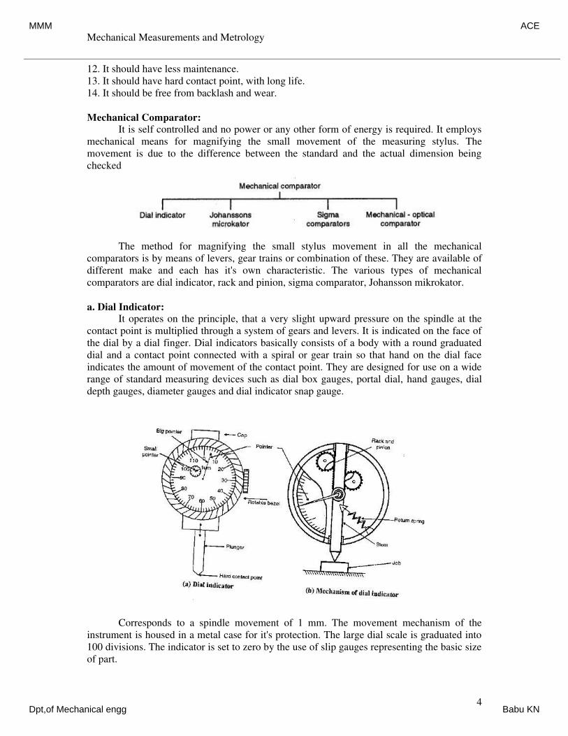
a. Dial Indicator:
It operates on the principle, that a very slight upward pressure on the spindle at the
contact point is multiplied through a system of gears and levers. It is indicated on the face of
the dial by a dial finger. Dial indicators basically consists of a body with a round graduated
dial and a contact point connected with a spiral or gear train so that hand on the dial face
indicates the amount of movement of the contact point. They are designed for use on a wide
range of standard measuring devices such as dial box gauges, portal dial, hand gauges, dial
depth gauges, diameter gauges and dial indicator snap gauge.
Corresponds to a spindle movement of 1 mm. The movement mechanism of the
instrument is housed in a metal case for it's protection. The large dial scale is graduated into
100 divisions. The indicator is set to zero by the use of slip gauges representing the basic size
of part.
MMM ACE
Dpt,of Mechanical engg Babu KN
Mechanical Measurements and Metrology
Dr. K V S Rajeswara Rao, Dept. of IEM, RVCE, Bangalore-59. 5
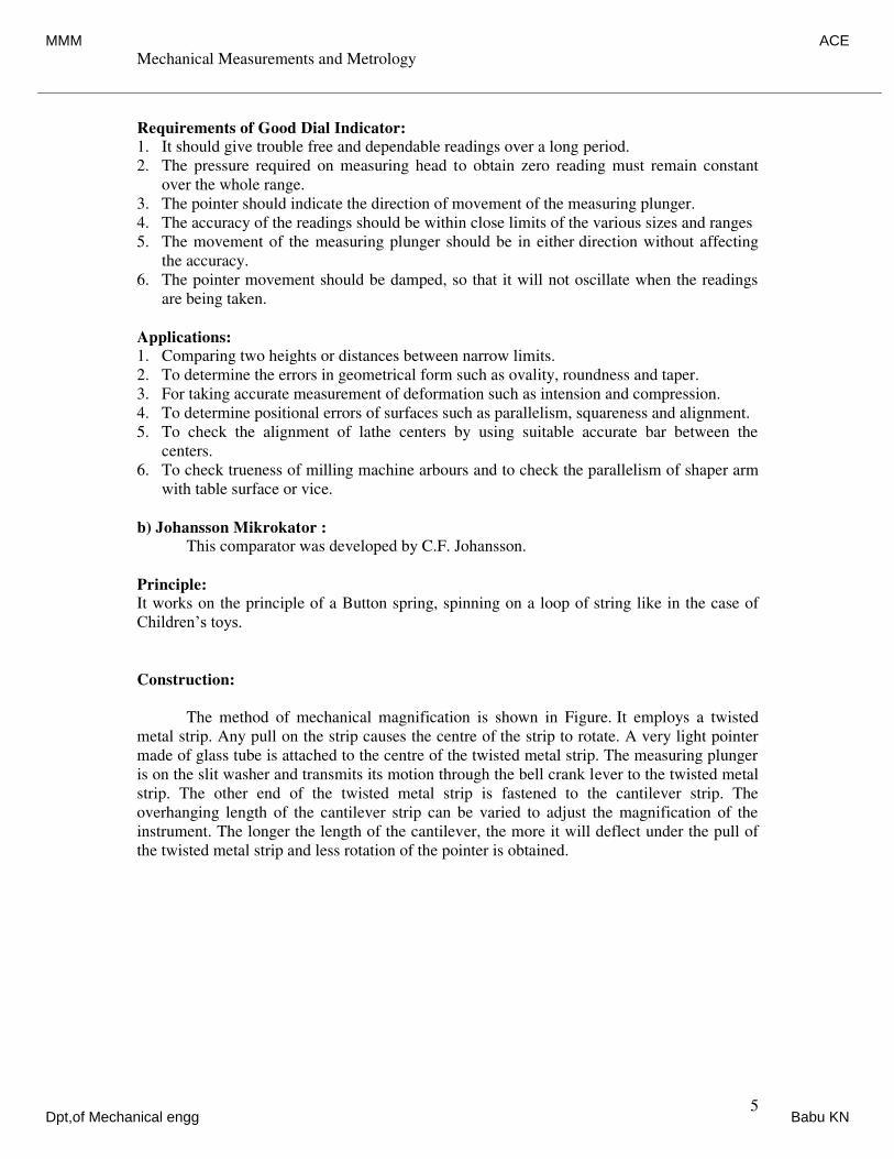
Requirements of Good Dial Indicator:
1. It should give trouble free and dependable readings over a long period.
2. The pressure required on measuring head to obtain zero reading must remain constant
over the whole range.
3. The pointer should indicate the direction of movement of the measuring plunger.
4. The accuracy of the readings should be within close limits of the various sizes and ranges
5. The movement of the measuring plunger should be in either direction without affecting
the accuracy.
6. The pointer movement should be damped, so that it will not oscillate when the readings
are being taken.
Applications:
1. Comparing two heights or distances between narrow limits.
2. To determine the errors in geometrical form such as ovality, roundness and taper.
3. For taking accurate measurement of deformation such as intension and compression.
4. To determine positional errors of surfaces such as parallelism, squareness and alignment.
5. To check the alignment of lathe centers by using suitable accurate bar between the
centers.
6. To check trueness of milling machine arbours and to check the parallelism of shaper arm
with table surface or vice.
b) Johansson Mikrokator :
This comparator was developed by C.F. Johansson.
Principle:
It works on the principle of a Button spring, spinning on a loop of string like in the case of
Children’s toys.
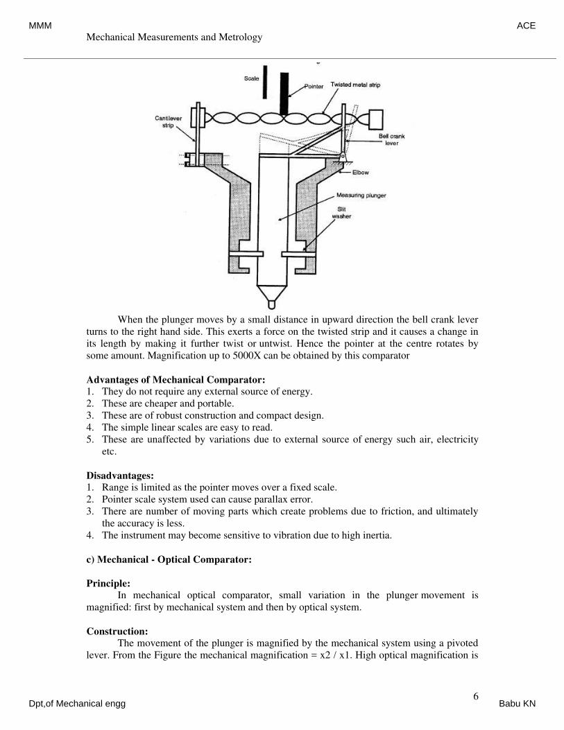
Construction:
The method of mechanical magnification is shown in Figure. It employs a twisted
metal strip. Any pull on the strip causes the centre of the strip to rotate. A very light pointer
made of glass tube is attached to the centre of the twisted metal strip. The measuring plunger
is on the slit washer and transmits its motion through the bell crank lever to the twisted metal
strip. The other end of the twisted metal strip is fastened to the cantilever strip. The
overhanging length of the cantilever strip can be varied to adjust the magnification of the
instrument. The longer the length of the cantilever, the more it will deflect under the pull of
the twisted metal strip and less rotation of the pointer is obtained.
MMM ACE
Dpt,of Mechanical engg Babu KN
Mechanical Measurements and Metrology
Dr. K V S Rajeswara Rao, Dept. of IEM, RVCE, Bangalore-59. 6
When the plunger moves by a small distance in upward direction the bell crank lever
turns to the right hand side. This exerts a force on the twisted strip and it causes a change in
its length by making it further twist or untwist. Hence the pointer at the centre rotates by
some amount. Magnification up to 5000X can be obtained by this comparator
Advantages of Mechanical Comparator:
1. They do not require any external source of energy.
2. These are cheaper and portable.
3. These are of robust construction and compact design.
4. The simple linear scales are easy to read.
5. These are unaffected by variations due to external source of energy such air, electricity
etc.
Disadvantages:
1. Range is limited as the pointer moves over a fixed scale.
2. Pointer scale system used can cause parallax error.
3. There are number of moving parts which create problems due to friction, and ultimately
the accuracy is less.
4. The instrument may become sensitive to vibration due to high inertia.
c) Mechanical - Optical Comparator:
Principle:
In mechanical optical comparator, small variation in the plunger movement is
magnified: first by mechanical system and then by optical system.
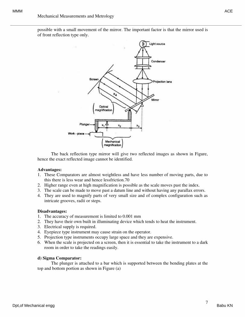
Construction:
The movement of the plunger is magnified by the mechanical system using a pivoted
lever. From the Figure the mechanical magnification = x2 / x1. High optical magnification is
MMM ACE
Dpt,of Mechanical engg Babu KN
Mechanical Measurements and Metrology
Dr. K V S Rajeswara Rao, Dept. of IEM, RVCE, Bangalore-59. 7
possible with a small movement of the mirror. The important factor is that the mirror used is
of front reflection type only.
The back reflection type mirror will give two reflected images as shown in Figure,
hence the exact reflected image cannot be identified.
Advantages:
1. These Comparators are almost weightless and have less number of moving parts, due to
this there is less wear and hence lessfriction.70
2. Higher range even at high magnification is possible as the scale moves past the index.
3. The scale can be made to move past a datum line and without having any parallax errors.
4. They are used to magnify parts of very small size and of complex configuration such as
intricate grooves, radii or steps.
Disadvantages:
1. The accuracy of measurement is limited to 0.001 mm
2. They have their own built in illuminating device which tends to heat the instrument.
3. Electrical supply is required.
4. Eyepiece type instrument may cause strain on the operator.
5. Projection type instruments occupy large space and they are expensive.
6. When the scale is projected on a screen, then it is essential to take the instrument to a dark
room in order to take the readings easily.
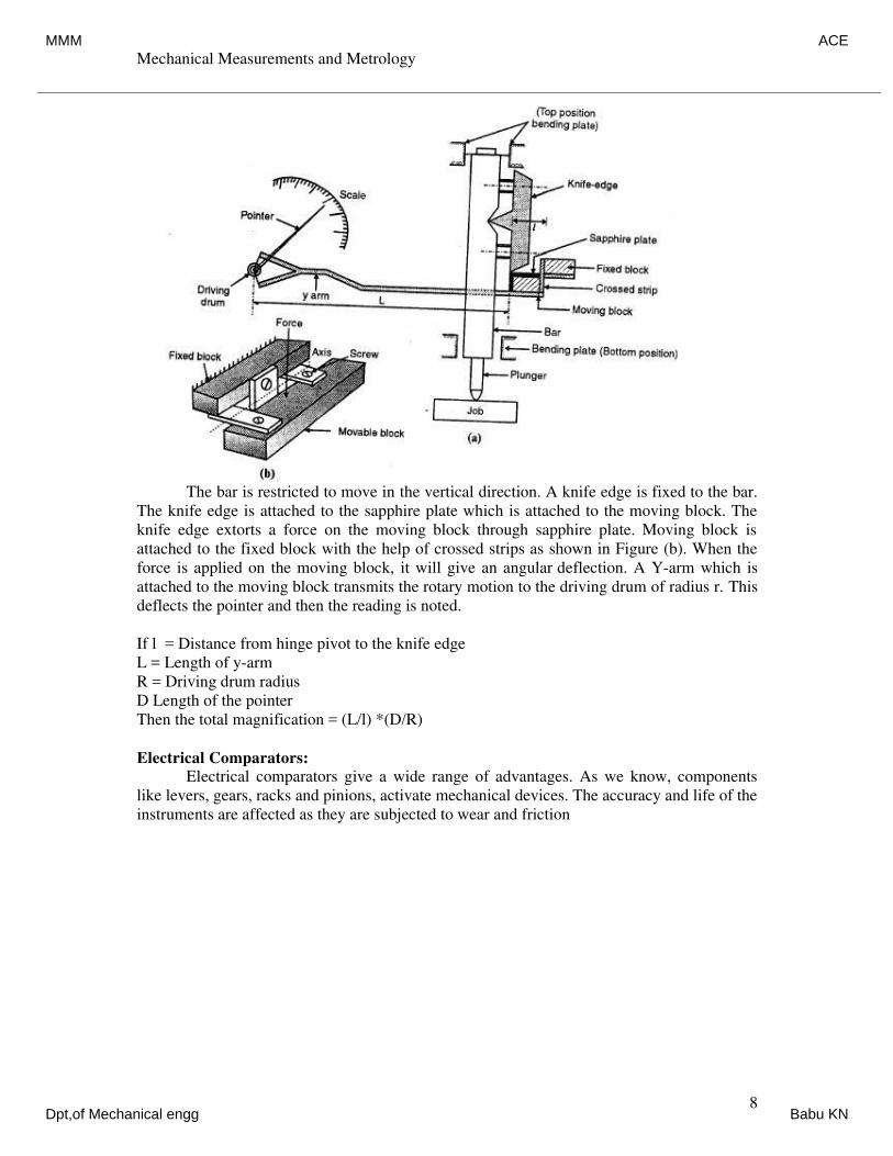
d) Sigma Comparator:
The plunger is attached to a bar which is supported between the bending plates at the
top and bottom portion as shown in Figure (a)
MMM ACE
Dpt,of Mechanical engg Babu KN
Mechanical Measurements and Metrology
Dr. K V S Rajeswara Rao, Dept. of IEM, RVCE, Bangalore-59. 8
The bar is restricted to move in the vertical direction. A knife edge is fixed to the bar.
The knife edge is attached to the sapphire plate which is attached to the moving block. The
knife edge extorts a force on the moving block through sapphire plate. Moving block is
attached to the fixed block with the help of crossed strips as shown in Figure (b). When the
force is applied on the moving block, it will give an angular deflection. A Y-arm which is
attached to the moving block transmits the rotary motion to the driving drum of radius r. This
deflects the pointer and then the reading is noted.
If l = Distance from hinge pivot to the knife edge
L = Length of y-arm
R = Driving drum radius
D Length of the pointer
Then the total magnification = (L/l) *(D/R)
Electrical Comparators:
Electrical comparators give a wide range of advantages. As we know, components
like levers, gears, racks and pinions, activate mechanical devices. The accuracy and life of the
instruments are affected as they are subjected to wear and friction
MMM ACE
Dpt,of Mechanical engg Babu KN
Mechanical Measurements and Metrology
Dr. K V S Rajeswara Rao, Dept. of IEM, RVCE, Bangalore-59. 9
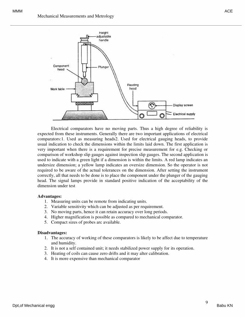
Electrical comparators have no moving parts. Thus a high degree of reliability is
expected from these instruments. Generally there are two important applications of electrical
comparators:1. Used as measuring heads2. Used for electrical gauging heads, to provide
usual indication to check the dimensions within the limits laid down. The first application is
very important when there is a requirement for precise measurement for e.g. Checking or
comparison of workshop slip gauges against inspection slip gauges. The second application is
used to indicate with a green light if a dimension is within the limits. A red lamp indicates an
undersize dimension; a yellow lamp indicates an oversize dimension. So the operator is not
required to be aware of the actual tolerances on the dimension. After setting the instrument
correctly, all that needs to be done is to place the component under the plunger of the gauging
head. The signal lamps provide in standard positive indication of the acceptability of the
dimension under test
Advantages:
1. Measuring units can be remote from indicating units.
2. Variable sensitivity which can be adjusted as per requirement.
3. No moving parts, hence it can retain accuracy over long periods.
4. Higher magnification is possible as compared to mechanical comparator.
5. Compact sizes of probes arc available.
Disadvantages:
1. The accuracy of working of these comparators is likely to be affect due to temperature
and humidity.
2. It is not a self contained unit; it needs stabilized power supply for its operation.
3. Heating of coils can cause zero drifts and it may alter calibration.
4. It is more expensive than mechanical comparator
MMM ACE
Dpt,of Mechanical engg Babu KN
Mechanical Measurements and Metrology
Dr. K V S Rajeswara Rao, Dept. of IEM, RVCE, Bangalore-59. 10
Pneumatic Comparators (Solex Gauge):
Principle:
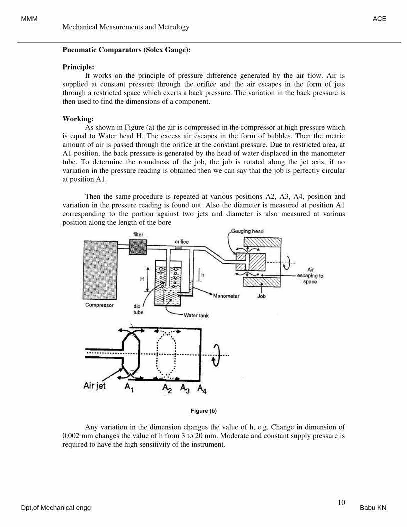
It works on the principle of pressure difference generated by the air flow. Air is
supplied at constant pressure through the orifice and the air escapes in the form of jets
through a restricted space which exerts a back pressure. The variation in the back pressure is
then used to find the dimensions of a component.
Working:
As shown in Figure (a) the air is compressed in the compressor at high pressure which
is equal to Water head H. The excess air escapes in the form of bubbles. Then the metric
amount of air is passed through the orifice at the constant pressure. Due to restricted area, at
A1 position, the back pressure is generated by the head of water displaced in the manometer
tube. To determine the roundness of the job, the job is rotated along the jet axis, if no
variation in the pressure reading is obtained then we can say that the job is perfectly circular
at position A1.
Then the same procedure is repeated at various positions A2, A3, A4, position and
variation in the pressure reading is found out. Also the diameter is measured at position A1
corresponding to the portion against two jets and diameter is also measured at various
position along the length of the bore
Figure (b)
Any variation in the dimension changes the value of h, e.g. Change in dimension of
0.002 mm changes the value of h from 3 to 20 mm. Moderate and constant supply pressure is
required to have the high sensitivity of the instrument.
MMM ACE
Dpt,of Mechanical engg Babu KN
Mechanical Measurements and Metrology
Dr. K V S Rajeswara Rao, Dept. of IEM, RVCE, Bangalore-59. 11
Advantages:
1. It is cheaper, simple to operate and the cost is low.
2. It is free from mechanical hysteresis and wear.
3. The magnification can be obtained as high as 10,000 X.
4. The gauging member is not in direct contact with the work.
5. Indicating and measuring is done at two different places.
6. Tapers and ovality can be easily detected.
7. The method is self cleaning due to continuous flow of air through the jets and this
makes the method ideal to be used on shop floor for online controls.
Disadvantages:
1. They are very sensitive to temperature and humidity changes.
2. The accuracy may be influenced by the surface roughness of the component being
checked.
3. Different gauging heads are needed for different jobs.
4. Auxiliary equipments such as air filters, pressure gauges and regulators are needed.
5. Non-uniformity of scale is a peculiar aspect of air gauging as the variation of back
pressure is linear, over only a small range of the orifice size variation.
Introduction to Angular Measurements:
For measuring the angle, no absolute standard is required. The measurement is done
in degrees, minutes and seconds. The measurement of angular and circular divisions is an
important part of inspection. It is concerned with the measurement of individual angles,
angular changes and deflections on components, gauges and tools. For precision
measurement of angles more skill is required. Like linear measurement, angular
measurements have their own importance. The basic difference between the linear and
angular measurement is that no absolute standard is required for angular measurement. There
are several methods of measuring angles and tapers. The various instruments used are angle
gauges, clinometers, bevel protractor, sine bar, sine centers, taper plug and ring gauges
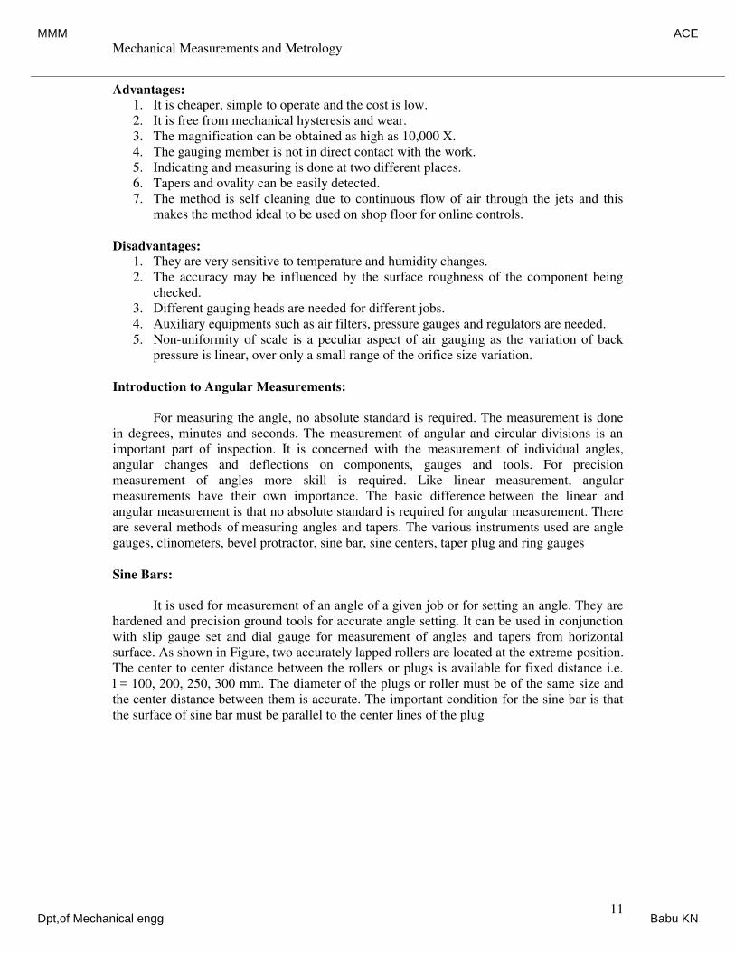
Sine Bars:
It is used for measurement of an angle of a given job or for setting an angle. They are
hardened and precision ground tools for accurate angle setting. It can be used in conjunction
with slip gauge set and dial gauge for measurement of angles and tapers from horizontal
surface. As shown in Figure, two accurately lapped rollers are located at the extreme position.
The center to center distance between the rollers or plugs is available for fixed distance i.e.
l = 100, 200, 250, 300 mm. The diameter of the plugs or roller must be of the same size and
the center distance between them is accurate. The important condition for the sine bar is that
the surface of sine bar must be parallel to the center lines of the plug
MMM ACE
Dpt,of Mechanical engg Babu KN
Mechanical Measurements and Metrology
Dr. K V S Rajeswara Rao, Dept. of IEM, RVCE, Bangalore-59. 12
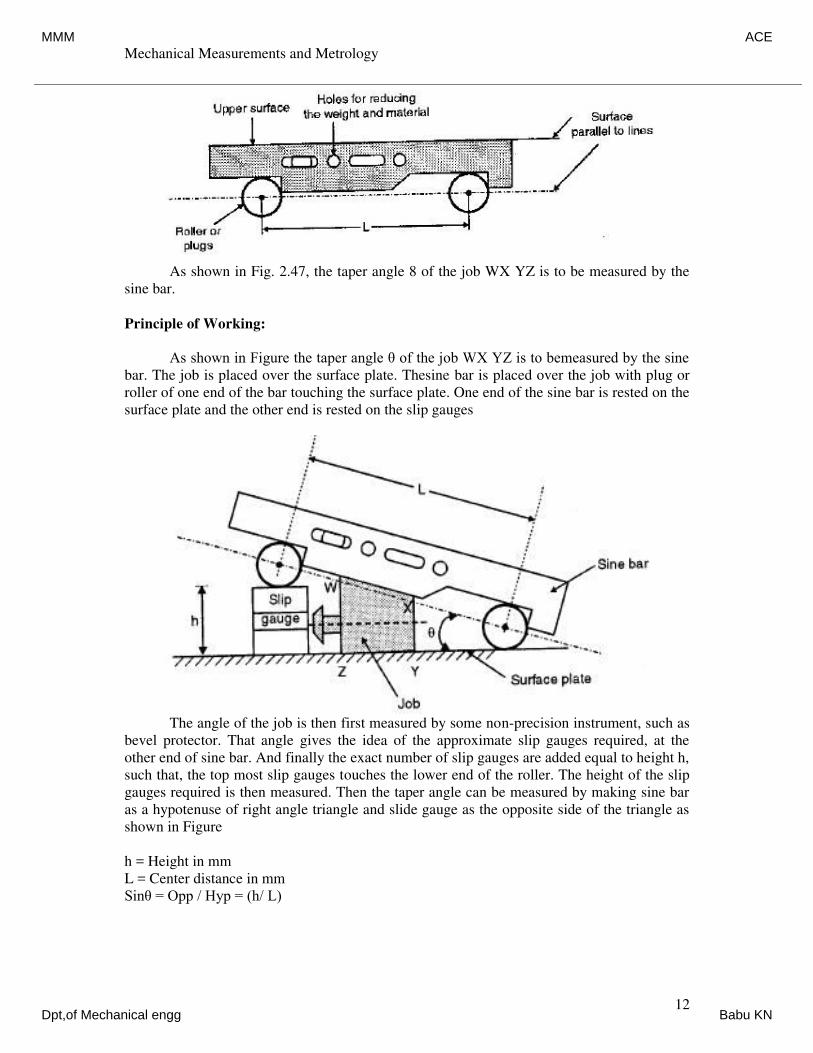
As shown in Fig. 2.47, the taper angle 8 of the job WX YZ is to be measured by the
sine bar.
Principle of Working:
As shown in Figure the taper angle θ of the job WX YZ is to bemeasured by the sine
bar. The job is placed over the surface plate. Thesine bar is placed over the job with plug or
roller of one end of the bar touching the surface plate. One end of the sine bar is rested on the
surface plate and the other end is rested on the slip gauges
The angle of the job is then first measured by some non-precision instrument, such as
bevel protector. That angle gives the idea of the approximate slip gauges required, at the
other end of sine bar. And finally the exact number of slip gauges are added equal to height h,
such that, the top most slip gauges touches the lower end of the roller. The height of the slip
gauges required is then measured. Then the taper angle can be measured by making sine bar
as a hypotenuse of right angle triangle and slide gauge as the opposite side of the triangle as
shown in Figure
h = Height in mm
L = Center distance in mm
Sinθ = Opp / Hyp = (h/ L)
MMM ACE
Dpt,of Mechanical engg Babu KN
Mechanical Measurements and Metrology
Dr. K V S Rajeswara Rao, Dept. of IEM, RVCE, Bangalore-59. 13
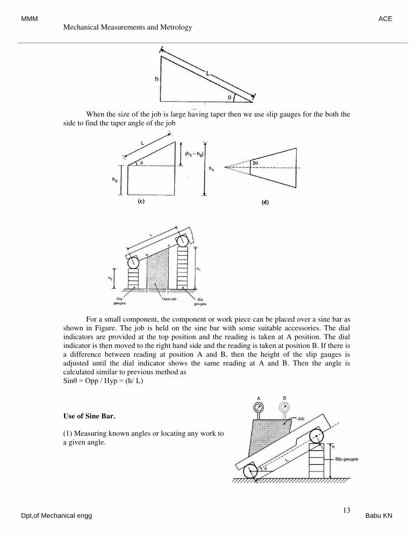
When the size of the job is large having taper then we use slip gauges for the both the
side to find the taper angle of the job
For a small component, the component or work piece can be placed over a sine bar as
shown in Figure. The job is held on the sine bar with some suitable accessories. The dial
indicators are provided at the top position and the reading is taken at A position. The dial
indicator is then moved to the right hand side and the reading is taken at position B. If there is
a difference between reading at position A and B, then the height of the slip gauges is
adjusted until the dial indicator shows the same reading at A and B. Then the angle is
calculated similar to previous method as
Sinθ = Opp / Hyp = (h/ L)
Use of Sine Bar.
(1) Measuring known angles or locating any work to
a given angle.
MMM ACE
Dpt,of Mechanical engg Babu KN
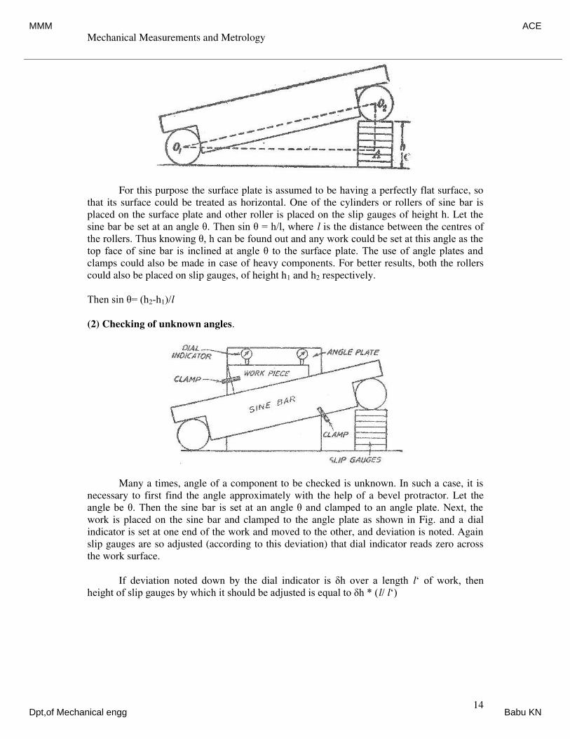
Mechanical Measurements and Metrology
Dr. K V S Rajeswara Rao, Dept. of IEM, RVCE, Bangalore-59. 14
For this purpose the surface plate is assumed to be having a perfectly flat surface, so
that its surface could be treated as horizontal. One of the cylinders or rollers of sine bar is
placed on the surface plate and other roller is placed on the slip gauges of height h. Let the
sine bar be set at an angle θ. Then sin θ = h/l, where l is the distance between the centres of
the rollers. Thus knowing θ, h can be found out and any work could be set at this angle as the
top face of sine bar is inclined at angle θ to the surface plate. The use of angle plates and
clamps could also be made in case of heavy components. For better results, both the rollers
could also be placed on slip gauges, of height h1 and h2 respectively.
Then sin θ= (h2-h1)/l
(2) Checking of unknown angles.
Many a times, angle of a component to be checked is unknown. In such a case, it is
necessary to first find the angle approximately with the help of a bevel protractor. Let the
angle be θ. Then the sine bar is set at an angle θ and clamped to an angle plate. Next, the
work is placed on the sine bar and clamped to the angle plate as shown in Fig. and a dial
indicator is set at one end of the work and moved to the other, and deviation is noted. Again
slip gauges are so adjusted (according to this deviation) that dial indicator reads zero across
the work surface.
If deviation noted down by the dial indicator is δh over a length l‘ of work, then
height of slip gauges by which it should be adjusted is equal to δh * (l/ l‘)
MMM ACE
Dpt,of Mechanical engg Babu KN
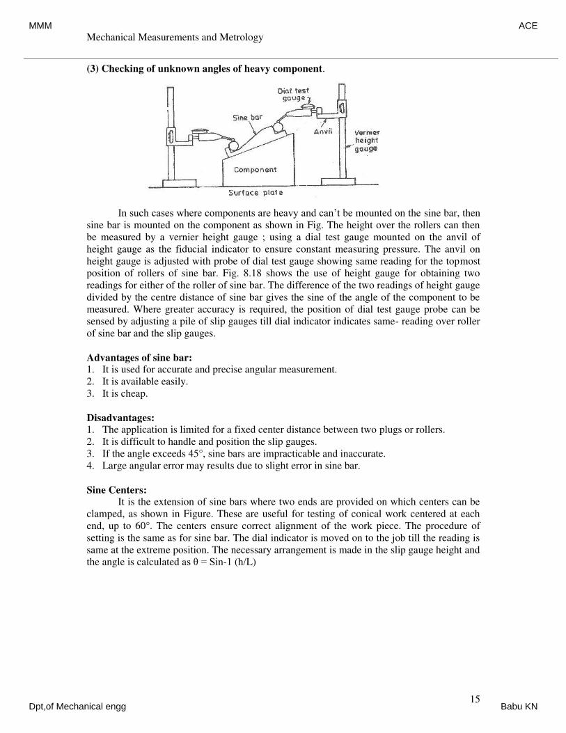
Mechanical Measurements and Metrology
Dr. K V S Rajeswara Rao, Dept. of IEM, RVCE, Bangalore-59. 15
(3) Checking of unknown angles of heavy component.
In such cases where components are heavy and can’t be mounted on the sine bar, then
sine bar is mounted on the component as shown in Fig. The height over the rollers can then
be measured by a vernier height gauge ; using a dial test gauge mounted on the anvil of
height gauge as the fiducial indicator to ensure constant measuring pressure. The anvil on
height gauge is adjusted with probe of dial test gauge showing same reading for the topmost
position of rollers of sine bar. Fig. 8.18 shows the use of height gauge for obtaining two
readings for either of the roller of sine bar. The difference of the two readings of height gauge
divided by the centre distance of sine bar gives the sine of the angle of the component to be
measured. Where greater accuracy is required, the position of dial test gauge probe can be
sensed by adjusting a pile of slip gauges till dial indicator indicates same- reading over roller
of sine bar and the slip gauges.
Advantages of sine bar:
1. It is used for accurate and precise angular measurement.
2. It is available easily.
3. It is cheap.
Disadvantages:
1. The application is limited for a fixed center distance between two plugs or rollers.
2. It is difficult to handle and position the slip gauges.
3. If the angle exceeds 45°, sine bars are impracticable and inaccurate.
4. Large angular error may results due to slight error in sine bar.
Sine Centers:
It is the extension of sine bars where two ends are provided on which centers can be
clamped, as shown in Figure. These are useful for testing of conical work centered at each
end, up to 60°. The centers ensure correct alignment of the work piece. The procedure of
setting is the same as for sine bar. The dial indicator is moved on to the job till the reading is
same at the extreme position. The necessary arrangement is made in the slip gauge height and
the angle is calculated as θ = Sin-1 (h/L)
MMM ACE
Dpt,of Mechanical engg Babu KN
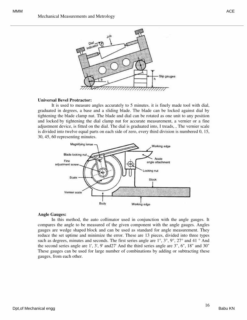
Mechanical Measurements and Metrology
Dr. K V S Rajeswara Rao, Dept. of IEM, RVCE, Bangalore-59. 16
Universal Bevel Protractor:
It is used to measure angles accurately to 5 minutes. it is finely made tool with dial,
graduated in degrees, a base and a sliding blade. The blade can be locked against dial by
tightening the blade clamp nut. The blade and dial can be rotated as one unit to any position
and locked by tightening the dial clamp nut for accurate measurement, a vernier or a fine
adjustment device, is fitted on the dial. The dial is graduated into, I treads, , The vernier scale
is divided into twelve equal parts on each side of zero, every third division is numbered 0, 15,
30, 45, 60 representing minutes.
Angle Gauges:
In this method, the auto collimator used in conjunction with the angle gauges. It
compares the angle to be measured of the given component with the angle gauges. Angles
gauges are wedge shaped block and can be used as standard for angle measurement. They
reduce the set uptime and minimize the error. These are 13 pieces, divided into three types
such as degrees, minutes and seconds. The first series angle are 1°, 3°, 9°, 27° and 41 ° And
the second series angle are 1', 3', 9' and27' And the third series angle are 3", 6", 18" and 30"
These gauges can be used for large number of combinations by adding or subtracting these
gauges, from each other.
MMM ACE
Dpt,of Mechanical engg Babu KN
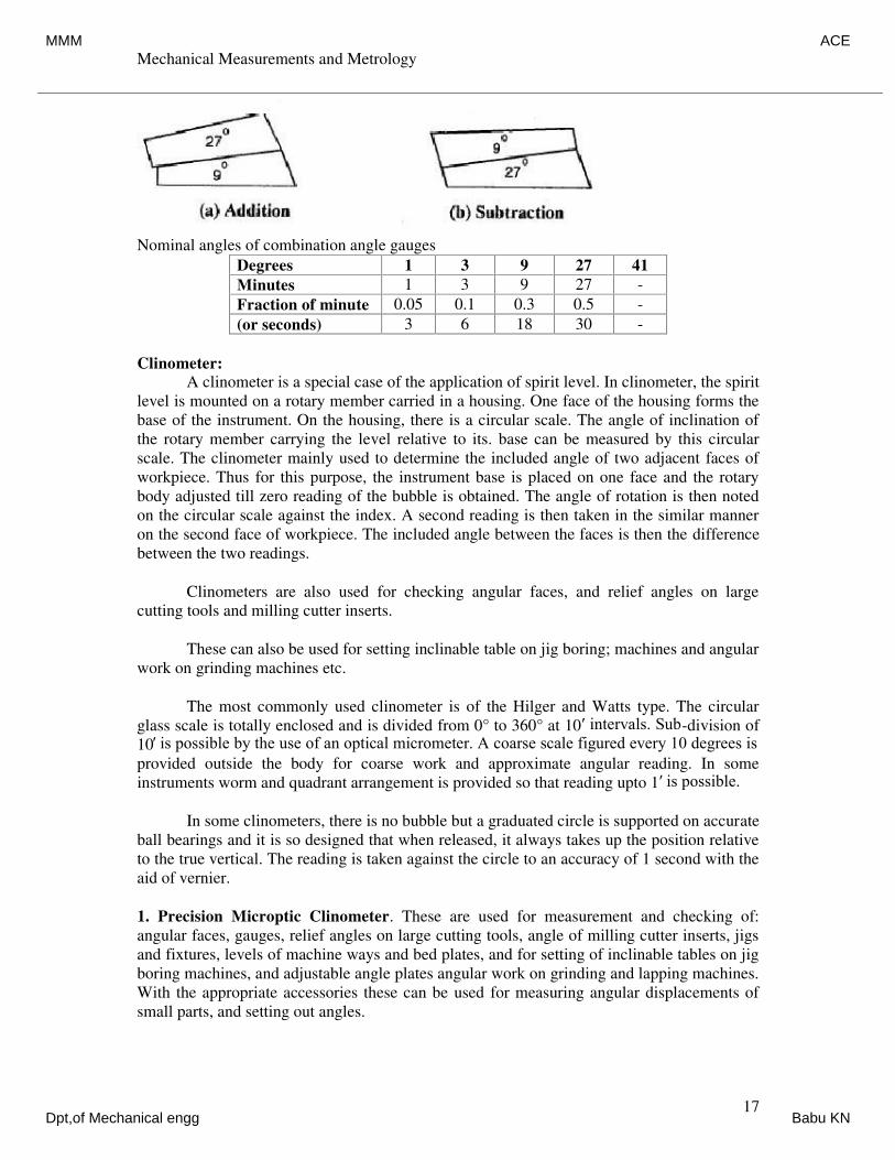
Mechanical Measurements and Metrology
Dr. K V S Rajeswara Rao, Dept. of IEM, RVCE, Bangalore-59. 17
Nominal angles of combination angle gauges
Degrees 1 3 9 27 41
Minutes 1 3 9 27 -
Fraction of minute 0.05 0.1 0.3 0.5 -
(or seconds) 3 6 18 30 -
Clinometer:
A clinometer is a special case of the application of spirit level. In clinometer, the spirit
level is mounted on a rotary member carried in a housing. One face of the housing forms the
base of the instrument. On the housing, there is a circular scale. The angle of inclination of
the rotary member carrying the level relative to its. base can be measured by this circular
scale. The clinometer mainly used to determine the included angle of two adjacent faces of
workpiece. Thus for this purpose, the instrument base is placed on one face and the rotary
body adjusted till zero reading of the bubble is obtained. The angle of rotation is then noted
on the circular scale against the index. A second reading is then taken in the similar manner
on the second face of workpiece. The included angle between the faces is then the difference
between the two readings.
Clinometers are also used for checking angular faces, and relief angles on large
cutting tools and milling cutter inserts.
These can also be used for setting inclinable table on jig boring; machines and angular
work on grinding machines etc.
The most commonly used clinometer is of the Hilger and Watts type. The circular
glass scale is totally enclosed and is divided from 0° to 360° at 10′ intervals. Sub-division of
10′ is possible by the use of an optical micrometer. A coarse scale figured every 10 degrees is
provided outside the body for coarse work and approximate angular reading. In some
instruments worm and quadrant arrangement is provided so that reading upto 1′ is possible.
In some clinometers, there is no bubble but a graduated circle is supported on accurate
ball bearings and it is so designed that when released, it always takes up the position relative
to the true vertical. The reading is taken against the circle to an accuracy of 1 second with the
aid of vernier.
1. Precision Microptic Clinometer. These are used for measurement and checking of:
angular faces, gauges, relief angles on large cutting tools, angle of milling cutter inserts, jigs
and fixtures, levels of machine ways and bed plates, and for setting of inclinable tables on jig
boring machines, and adjustable angle plates angular work on grinding and lapping machines.
With the appropriate accessories these can be used for measuring angular displacements of
small parts, and setting out angles.
MMM ACE
Dpt,of Mechanical engg Babu KN
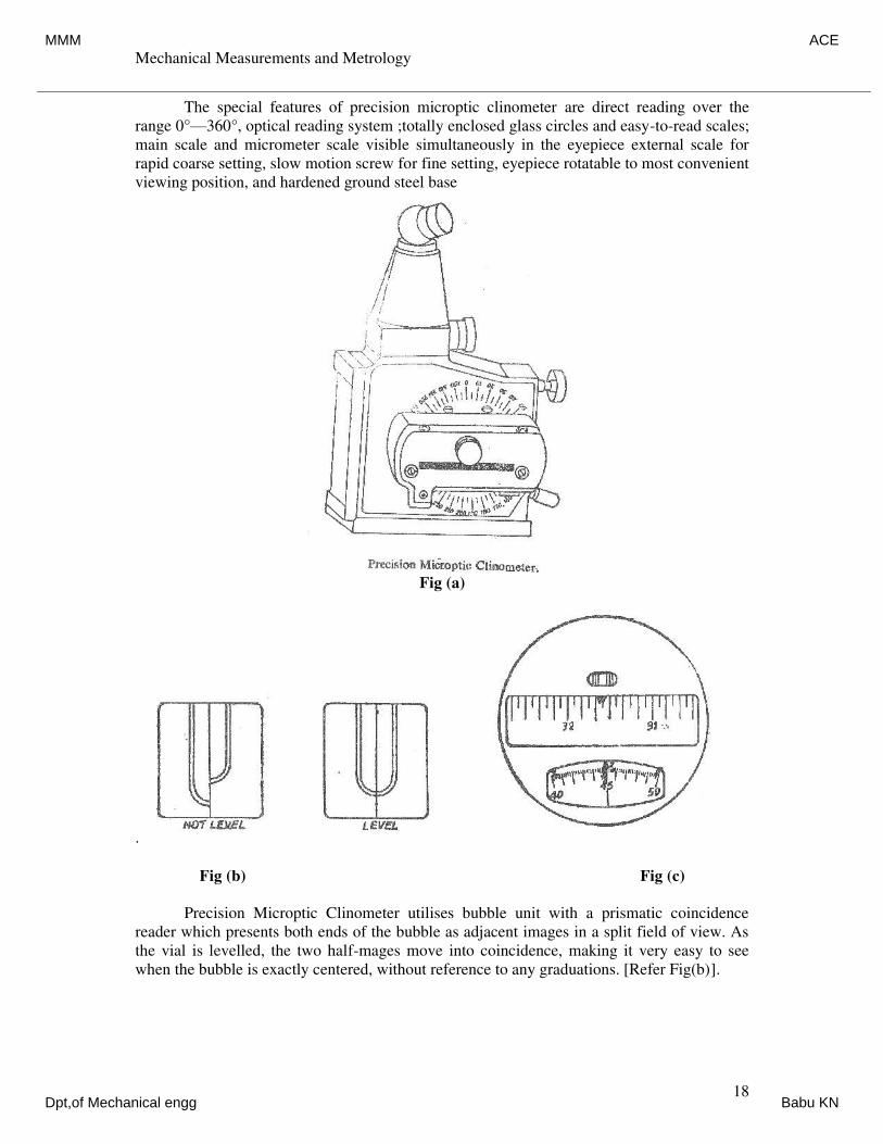
Mechanical Measurements and Metrology
Dr. K V S Rajeswara Rao, Dept. of IEM, RVCE, Bangalore-59. 18
The special features of precision microptic clinometer are direct reading over the
range 0°—360°, optical reading system ;totally enclosed glass circles and easy-to-read scales;
main scale and micrometer scale visible simultaneously in the eyepiece external scale for
rapid coarse setting, slow motion screw for fine setting, eyepiece rotatable to most convenient
viewing position, and hardened ground steel base
Fig (a)
.
Fig (b) Fig (c)
Precision Microptic Clinometer utilises bubble unit with a prismatic coincidence
reader which presents both ends of the bubble as adjacent images in a split field of view. As
the vial is levelled, the two half-mages move into coincidence, making it very easy to see
when the bubble is exactly centered, without reference to any graduations. [Refer Fig(b)].
MMM ACE
Dpt,of Mechanical engg Babu KN
Mechanical Measurements and Metrology
Dr. K V S Rajeswara Rao, Dept. of IEM, RVCE, Bangalore-59. 19
To determine the inclination of the clinometer, the bubb is levelled and the scales
read. On looking through the eyepiece, three apertures can be seen. The upper aperture
contains two pairs of double lines and two single lines ; to set the micrometer, the knob is
turned until the single lines are brought exactly central B between the double lines. The scales
can then be read, the required angle being the sum of the readings of the main scale and the
micrometer scale. [Refer Fig(c)].
The double lines are imaged from one side of the circle and the single ones from a
point diametrically opposite ; by using the double lines as an index for the single line, any
residual centring error of the circle is cancelled out.
The scales are illuminated by an integral low voltage lamp. The bubble unit is
daylight illuminated, but is also provided with a lamp for alternative illumination.
A locating face on the back allows the instrument to be used horizontally with the
accessory worktable or reflector unit.
The reference for inclination is the bubble vial. In order to measure the inclination of
a surface, the vial—to which the circle is attached is turned—until it is approximately level ;
then the slow motion screw is used for a final adjustment to centre the bubble.
To measure the angle between two surfaces, the clinometer is placed on each surface
in turn and the difference in angle can be calculated.
The clinometer can be used as a precision setting tool to set a tool head or table at a
specific angle. First the micrometer scale is set and then the glass scale is rotated to bring the
relevant graduation to the index, using the slow motion screw for final adjustment. This sets
the clinometer for the required angle. Then the work surface it tilted until the bubble is
exactly centred. The work surface is thus set to the specified angle relative to a level plane.
MMM ACE
Dpt,of Mechanical engg Babu KN
Mechanical Measurements and Metrology
Dr. K V S Rajeswara Rao, Dept. of IEM, RVCE, Bangalore-59. 1
Mechanical Measurements andMetrology – 10ME42B
UNIT - 4
Interferometer and Screw Thread,Gear Measurement
Instructor
Dr. K V S Rajeswara RaoAssociate Professor,
Dept. of Industrial Engineering & Management,R V College of Engineering, Mysore Road
Bangalore – 59E-mail – [email protected]
MMM ACE
Dpt,of Mechanical engg Babu KN
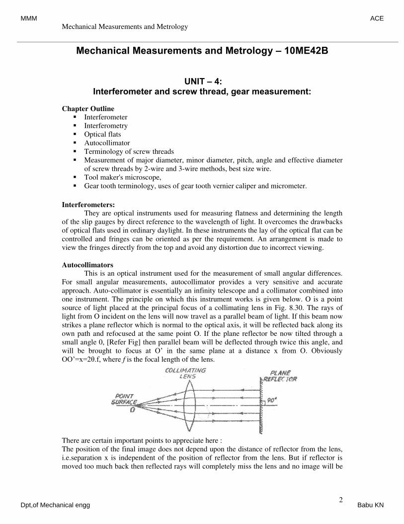
Mechanical Measurements and Metrology
Dr. K V S Rajeswara Rao, Dept. of IEM, RVCE, Bangalore-59. 2
Mechanical Measurements and Metrology – 10ME42B
UNIT – 4:Interferometer and screw thread, gear measurement:
Chapter Outline
Interferometer
Interferometry
Optical flats
Autocollimator
Terminology of screw threads
Measurement of major diameter, minor diameter, pitch, angle and effective diameter
of screw threads by 2-wire and 3-wire methods, best size wire.
Tool maker's microscope,
Gear tooth terminology, uses of gear tooth vernier caliper and micrometer.
Interferometers:
They are optical instruments used for measuring flatness and determining the length
of the slip gauges by direct reference to the wavelength of light. It overcomes the drawbacks
of optical flats used in ordinary daylight. In these instruments the lay of the optical flat can be
controlled and fringes can be oriented as per the requirement. An arrangement is made to
view the fringes directly from the top and avoid any distortion due to incorrect viewing.
Autocollimators
This is an optical instrument used for the measurement of small angular differences.
For small angular measurements, autocollimator provides a very sensitive and accurate
approach. Auto-collimator is essentially an infinity telescope and a collimator combined into
one instrument. The principle on which this instrument works is given below. O is a point
source of light placed at the principal focus of a collimating lens in Fig. 8.30. The rays of
light from O incident on the lens will now travel as a parallel beam of light. If this beam now
strikes a plane reflector which is normal to the optical axis, it will be reflected back along its
own path and refocused at the same point O. If the plane reflector be now tilted through a
small angle 0, [Refer Fig] then parallel beam will be deflected through twice this angle, and
will be brought to focus at O’ in the same plane at a distance x from O. Obviously
OO’=x=2θ.f, where f is the focal length of the lens.
There are certain important points to appreciate here :
The position of the final image does not depend upon the distance of reflector from the lens,
i.e.separation x is independent of the position of reflector from the lens. But if reflector is
moved too much back then reflected rays will completely miss the lens and no image will be
MMM ACE
Dpt,of Mechanical engg Babu KN
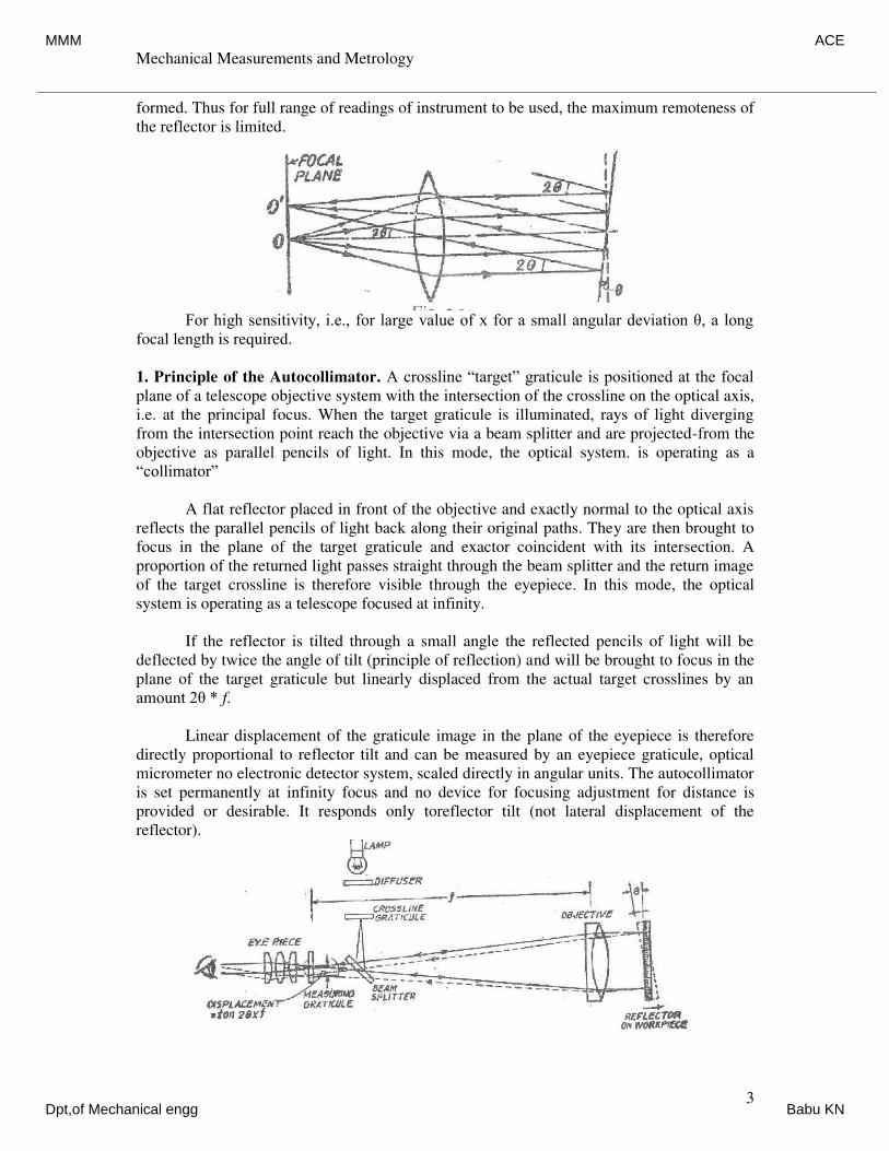
Mechanical Measurements and Metrology
Dr. K V S Rajeswara Rao, Dept. of IEM, RVCE, Bangalore-59. 3
formed. Thus for full range of readings of instrument to be used, the maximum remoteness of
the reflector is limited.
For high sensitivity, i.e., for large value of x for a small angular deviation θ, a long
focal length is required.
1. Principle of the Autocollimator. A crossline “target” graticule is positioned at the focal
plane of a telescope objective system with the intersection of the crossline on the optical axis,
i.e. at the principal focus. When the target graticule is illuminated, rays of light diverging
from the intersection point reach the objective via a beam splitter and are projected-from the
objective as parallel pencils of light. In this mode, the optical system. is operating as a
“collimator”
A flat reflector placed in front of the objective and exactly normal to the optical axis
reflects the parallel pencils of light back along their original paths. They are then brought to
focus in the plane of the target graticule and exactor coincident with its intersection. A
proportion of the returned light passes straight through the beam splitter and the return image
of the target crossline is therefore visible through the eyepiece. In this mode, the optical
system is operating as a telescope focused at infinity.
If the reflector is tilted through a small angle the reflected pencils of light will be
deflected by twice the angle of tilt (principle of reflection) and will be brought to focus in the
plane of the target graticule but linearly displaced from the actual target crosslines by an
amount 2θ * f.
Linear displacement of the graticule image in the plane of the eyepiece is therefore
directly proportional to reflector tilt and can be measured by an eyepiece graticule, optical
micrometer no electronic detector system, scaled directly in angular units. The autocollimator
is set permanently at infinity focus and no device for focusing adjustment for distance is
provided or desirable. It responds only toreflector tilt (not lateral displacement of the
reflector).
MMM ACE
Dpt,of Mechanical engg Babu KN
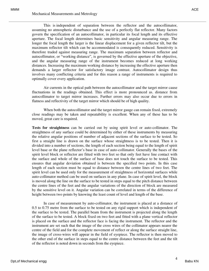
Mechanical Measurements and Metrology
Dr. K V S Rajeswara Rao, Dept. of IEM, RVCE, Bangalore-59. 4
This is independent of separation between the reflector and the autocollimator,
assuming no atmospheric disturbance and the use of a perfectly flat reflector. Many factors
govern the specification of an autocollimator, in particular its focal length and its effective
aperture. The focal length determines basic sensitivity and angular measuring range. The
longer the focal length the larger is the linear displacement for a given reflector tilt, but the
maximum reflector tilt which can be accommodated is consequently reduced. Sensitivity is
therefore traded against measuring range. The maximum separation between reflector and
autocollimator, or “working distance”, is governed by the effective aperture of the objective,
and the angular measuring range of the instrument becomes reduced at long working
distances. Increasing the maximum working distance by increasing the effective aperture then
demands a larger reflector for satisfactory image contrast. Autocollimator design thus
involves many conflicting criteria and for this reason a range of instruments is required to
optimally cover every application.
Air currents in the optical path between the autocollimator and the target mirror cause
fluctuations in the readings obtained. This effect is more pronounced as. distance from
autocollimator to target mirror increases. Further errors may also occur due to errors in
flatness and reflectivity of the target mirror which should be of high quality.
When both the autocollimator and the target mirror gauge can remain fixed, extremely
close readings may be taken and repeatability is excellent. When any of these has to be
moved, great care is required.
Tests for straightness can be carried out by using spirit level or auto-collimator. The
straightness of any surface could be determined by either of these instruments by measuring
the relative angular positions of number of adjacent sections of the surface to be tested. So
first a straight line is drawn on the surface whose straightness is to be tested. Then it is
divided into a number of sections, the length of each section being equal to the length of spirit
level base or the plane reflector’s base in case of auto-collimator. Generally the bases of the
spirit level block or reflector are fitted with two feet so that only feet have line contact with
the surface and whole of the surface of base does not touch the surface to be tested. This
ensures that angular deviation obtained is between the specified two points. In this case
length of each section must be equal to distance between the centre lines of two feet. The
spirit level can be used only for the measurement of straightness of horizontal surfaces while
auto-collimator method can be used on surfaces in any plane. In case of spirit level, the block
is moved along the line on the surface to be tested in steps equal to the pitch distance between
the centre lines of the feet and the angular variations of the direction of block are measured
by the sensitive level on it. Angular variation can be correlated in terms of the difference of
height between two points by knowing the least count of level and length of the base.
In case of measurement by auto-collimator, the instrument is placed at a distance of
0.5 to 0.75 metre from the surface to be tested on any rigid support which is independent of
the surface to be tested. The parallel beam from the instrument is projected along the length
of the surface to be tested. A block fixed on two feet and fitted with a plane vertical reflector
is placed on the surface and the reflector face is facing the instrument. The reflector and the
instrument are set such that the image of the cross wires of the collimator appears nearer the
centre of the field and for the complete movement of reflect or along the surface straight line,
the image of cross-wires will appear in the field of eyepiece. The reflector is then moved to
the other end of the surface in steps equal to the centre distance between the feet and the tilt
of the reflector is noted down in seconds from the eyepiece.
MMM ACE
Dpt,of Mechanical engg Babu KN
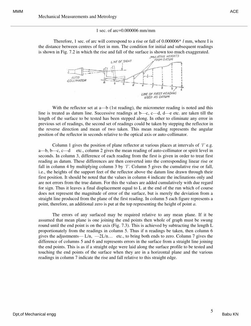
Mechanical Measurements and Metrology
Dr. K V S Rajeswara Rao, Dept. of IEM, RVCE, Bangalore-59. 5
1 sec. of arc=0.000006 mm/mm
Therefore, 1 sec. of arc will correspond to a rise or fall of 0.000006* l mm, where I is
the distance between centres of feet in mm. The condition for initial and subsequent readings
is shown in Fig. 7.2 in which the rise and fall of the surface is shown too much exaggerated.
With the reflector set at a—b (1st reading), the micrometer reading is noted and this
line is treated as datum line. Successive readings at b—c, c—d, d—e etc. are taken till the
length of the surface to be tested has been stepped along. In other to eliminate any error in
previous set of readings, the second set of readings could be taken by stepping the reflector in
the reverse direction and mean of two taken. This mean reading represents the angular
position of the reflector in seconds relative to the optical axis or auto-collimator.
Column 1 gives the position of plane reflector at various places at intervals of ‘l’ e.g.
a—b, b—c, c—d etc., column 2 gives the mean reading of auto-collimator or spirit level in
seconds. In column 3, difference of each reading from the first is given in order to treat first
reading as datum. These differences are then converted into the corresponding linear rise or
fall in column 4 by multiplying column 3 by ‘l’. Column 5 gives the cumulative rise or fall,
i.e., the heights of the support feet of the reflector above the datum line drawn through their
first position. It should be noted that the values in column 4 indicate the inclinations only and
are not errors from the true datum. For this the values are added cumulatively with due regard
for sign. Thus it leaves a final displacement equal to L at the end of the run which of course
does not represent the magnitude of error of the surface, but is merely the deviation from a
straight line produced from the plane of the first reading. In column 5 each figure represents a
point, therefore, an additional zero is put at the top representing the height of point a.
The errors of any surfaced may be required relative to any mean plane. If it be
assumed that mean plane is one joining the end points then whole of graph must be swung
round until the end point is on the axis (Fig. 7.3). This is achieved by subtracting the length L
proportionately from the readings in column 5. Thus if n readings be taken, then column 6
gives the adjustments— L/n, —2L/n… etc., to bring both ends to zero. Column 7 gives the
difference of columns 5 and 6 and represents errors in the surface from a straight line joining
the end points. This is as if a straight edge were laid along the surface profile to be tested and
touching the end points of the surface when they are in a horizontal plane and the various
readings in column 7 indicate the rise and fall relative to this straight edge.
MMM ACE
Dpt,of Mechanical engg Babu KN
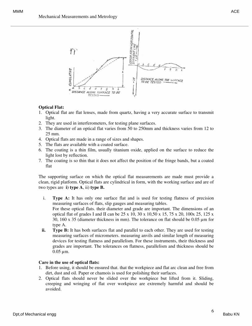
Mechanical Measurements and Metrology
Dr. K V S Rajeswara Rao, Dept. of IEM, RVCE, Bangalore-59. 6
Optical Flat:
1. Optical flat are flat lenses, made from quartz, having a very accurate surface to transmit
light.
2. They are used in interferometers, for testing plane surfaces.
3. The diameter of an optical flat varies from 50 to 250mm and thickness varies from 12 to
25 mm.
4. Optical flats are made in a range of sizes and shapes.
5. The flats are available with a coated surface.
6. The coating is a thin film, usually titanium oxide, applied on the surface to reduce the
light lost by reflection.
7. The coating is so thin that it does not affect the position of the fringe bands, but a coated
flat
The supporting surface on which the optical flat measurements are made must provide a
clean, rigid platform. Optical flats are cylindrical in form, with the working surface and are of
two types are i) type A, ii) type B.
i. Type A: It has only one surface flat and is used for testing flatness of precision
measuring surfaces of flats, slip gauges and measuring tables.
For these optical flats. their diameter and grade are important. The dimensions of an
optical flat of grades I and II can be 25 x 10, 30 x 10,50 x 15, 75 x 20, 100x 25, 125 x
30, 160 x 35 (diameter thickness in mm). The tolerance on flat should be 0.05 µm for
type A.
ii. Type B: It has both surfaces flat and parallel to each other. They are used for testing
measuring surfaces of micrometers. measuring anvils and similar length of measuring
devices for testing flatness and parallelism. For these instruments, their thickness and
grades are important. The tolerances on flatness, parallelism and thickness should be
0.05 µm.
Care in the use of optical flats:
1. Before using, it should be ensured that. that the workpiece and flat arc clean and free from
dirt, dust and oil. Paper or chamois is used for polishing their surfaces.
2. Optical flats should never be slided over the workpiece but lifted from it. Sliding,
creeping and wringing of flat over workpiece are extremely harmful and should be
avoided.
MMM ACE
Dpt,of Mechanical engg Babu KN
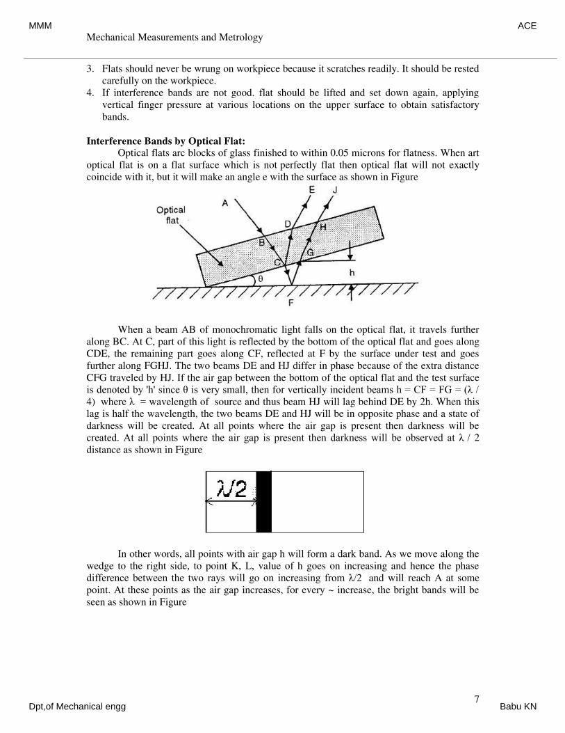
Mechanical Measurements and Metrology
Dr. K V S Rajeswara Rao, Dept. of IEM, RVCE, Bangalore-59. 7
3. Flats should never be wrung on workpiece because it scratches readily. It should be rested
carefully on the workpiece.
4. If interference bands are not good. flat should be lifted and set down again, applying
vertical finger pressure at various locations on the upper surface to obtain satisfactory
bands.
Interference Bands by Optical Flat:
Optical flats arc blocks of glass finished to within 0.05 microns for flatness. When art
optical flat is on a flat surface which is not perfectly flat then optical flat will not exactly
coincide with it, but it will make an angle e with the surface as shown in Figure
When a beam AB of monochromatic light falls on the optical flat, it travels further
along BC. At C, part of this light is reflected by the bottom of the optical flat and goes along
CDE, the remaining part goes along CF, reflected at F by the surface under test and goes
further along FGHJ. The two beams DE and HJ differ in phase because of the extra distance
CFG traveled by HJ. If the air gap between the bottom of the optical flat and the test surface
is denoted by 'h' since θ is very small, then for vertically incident beams h = CF = FG = (λ /
4) where λ = wavelength of source and thus beam HJ will lag behind DE by 2h. When this
lag is half the wavelength, the two beams DE and HJ will be in opposite phase and a state of
darkness will be created. At all points where the air gap is present then darkness will be
created. At all points where the air gap is present then darkness will be observed at λ / 2
distance as shown in Figure
In other words, all points with air gap h will form a dark band. As we move along the
wedge to the right side, to point K, L, value of h goes on increasing and hence the phase
difference between the two rays will go on increasing from λ/2 and will reach A at some
point. At these points as the air gap increases, for every ~ increase, the bright bands will be
seen as shown in Figure
MMM ACE
Dpt,of Mechanical engg Babu KN
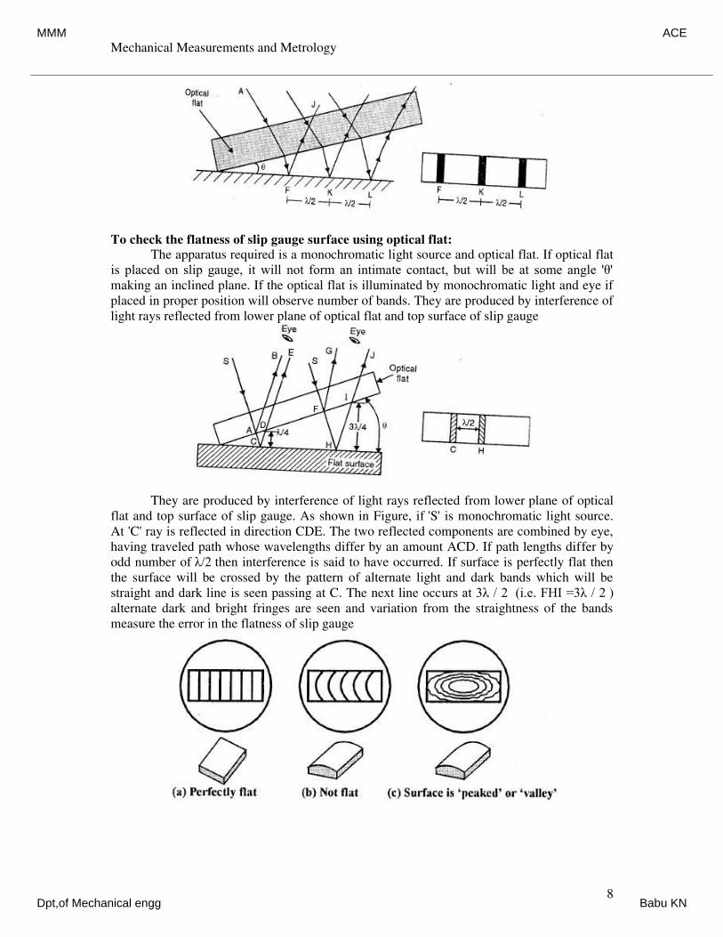
Mechanical Measurements and Metrology
Dr. K V S Rajeswara Rao, Dept. of IEM, RVCE, Bangalore-59. 8
To check the flatness of slip gauge surface using optical flat:
The apparatus required is a monochromatic light source and optical flat. If optical flat
is placed on slip gauge, it will not form an intimate contact, but will be at some angle 'θ'
making an inclined plane. If the optical flat is illuminated by monochromatic light and eye if
placed in proper position will observe number of bands. They are produced by interference of
light rays reflected from lower plane of optical flat and top surface of slip gauge
They are produced by interference of light rays reflected from lower plane of optical
flat and top surface of slip gauge. As shown in Figure, if 'S' is monochromatic light source.
At 'C' ray is reflected in direction CDE. The two reflected components are combined by eye,
having traveled path whose wavelengths differ by an amount ACD. If path lengths differ by
odd number of λ/2 then interference is said to have occurred. If surface is perfectly flat then
the surface will be crossed by the pattern of alternate light and dark bands which will be
straight and dark line is seen passing at C. The next line occurs at 3λ / 2 (i.e. FHI =3λ / 2 )
alternate dark and bright fringes are seen and variation from the straightness of the bands
measure the error in the flatness of slip gauge
MMM ACE
Dpt,of Mechanical engg Babu KN
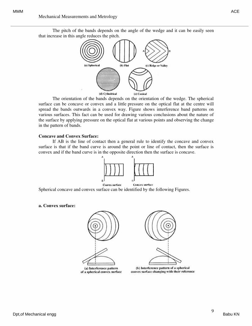
Mechanical Measurements and Metrology
Dr. K V S Rajeswara Rao, Dept. of IEM, RVCE, Bangalore-59. 9
The pitch of the bands depends on the angle of the wedge and it can be easily seen
that increase in this angle reduces the pitch.
The orientation of the bands depends on the orientation of the wedge. The spherical
surface can be concave or convex and a little pressure on the optical flat at the centre will
spread the bands outwards in a convex way. Figure shows interference band patterns on
various surfaces. This fact can be used for drawing various conclusions about the nature of
the surface by applying pressure on the optical flat at various points and observing the change
in the pattern of bands.
Concave and Convex Surface:
If AB is the line of contact then a general rule to identify the concave and convex
surface is that if the band curve is around the point or line of contact, then the surface is
convex and if the band curve is in the opposite direction then the surface is concave.
Spherical concave and convex surface can be identified by the following Figures.
a. Convex surface:
MMM ACE
Dpt,of Mechanical engg Babu KN
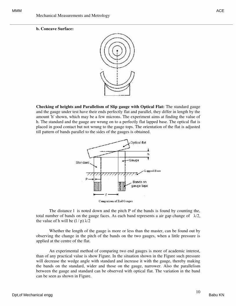
Mechanical Measurements and Metrology
Dr. K V S Rajeswara Rao, Dept. of IEM, RVCE, Bangalore-59. 10
b. Concave Surface:
Checking of heights and Parallelism of Slip gauge with Optical Flat: The standard gauge
and the gauge under test have their ends perfectly flat and parallel, they differ in length by the
amount 'h' shown, which may be a few microns. The experiment aims at finding the value of
h. The standard and the gauge are wrung on to a perfectly flat lapped base. The optical flat is
placed in good contact but not wrung to the gauge tops. The orientation of the flat is adjusted
till pattern of bands parallel to the sides of the gauges is obtained.
The distance l is noted down and the pitch P of the bands is found by counting the,
total number of bands on the gauge faces. As each band represents a air gap change of λ/2,
the value of h will be (l / p) λ/2
Whether the length of the gauge is more or less than the master, can be found out by
observing the change in the pitch of the bands on the two gauges, when a little pressure is
applied at the centre of the flat.
An experimental method of comparing two end gauges is more of academic interest,
than of any practical value is show Figure. In the situation shown in the Figure such pressure
will decrease the wedge angle with standard and increase it with the gauge, thereby making
the bands on the standard, wider and those on the gauge, narrower. Also the parallelism
between the gauge and standard can be observed with optical flat. The variation in the band
can be seen as shown in Figure.
MMM ACE
Dpt,of Mechanical engg Babu KN
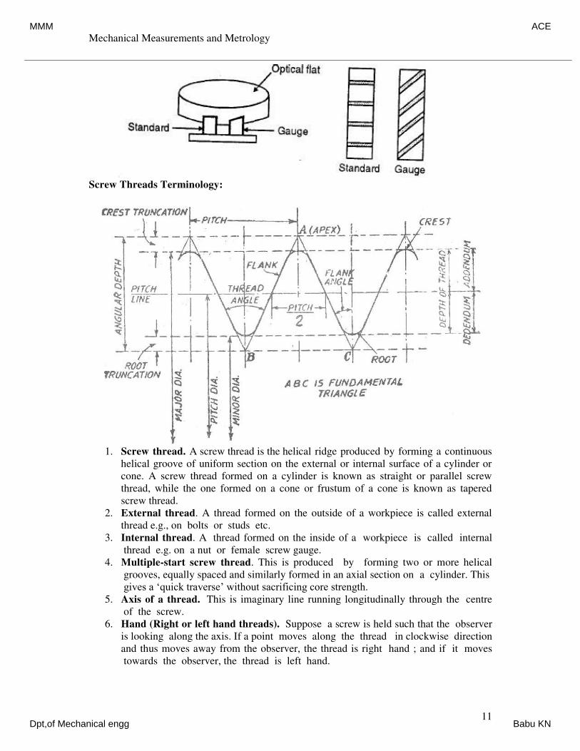
Mechanical Measurements and Metrology
Dr. K V S Rajeswara Rao, Dept. of IEM, RVCE, Bangalore-59. 11
Screw Threads Terminology:
1. Screw thread. A screw thread is the helical ridge produced by forming a continuous
helical groove of uniform section on the external or internal surface of a cylinder or
cone. A screw thread formed on a cylinder is known as straight or parallel screw
thread, while the one formed on a cone or frustum of a cone is known as tapered
screw thread.
2. External thread. A thread formed on the outside of a workpiece is called external
thread e.g., on bolts or studs etc.
3. Internal thread. A thread formed on the inside of a workpiece is called internal
thread e.g. on a nut or female screw gauge.
4. Multiple-start screw thread. This is produced by forming two or more helical
grooves, equally spaced and similarly formed in an axial section on a cylinder. This
gives a ‘quick traverse’ without sacrificing core strength.
5. Axis of a thread. This is imaginary line running longitudinally through the centre
of the screw.
6. Hand (Right or left hand threads). Suppose a screw is held such that the observer
is looking along the axis. If a point moves along the thread in clockwise direction
and thus moves away from the observer, the thread is right hand ; and if it moves
towards the observer, the thread is left hand.
MMM ACE
Dpt,of Mechanical engg Babu KN
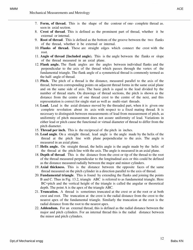
Mechanical Measurements and Metrology
Dr. K V S Rajeswara Rao, Dept. of IEM, RVCE, Bangalore-59. 12
7. Form, of thread. This is the shape of the contour of one- complete thread as.
seen in axial section.
8. Crest of thread. This is defined as the prominent part of thread, whether it be
external or internal.
9. Root of thread. This is defined as the bottom of the groove between the two flanks
of the thread, whether it be external or internal.
10. Flanks of thread. These are straight edges which connect the crest with the
root.
11. Angle of thread {Included angle). This is the angle between the flanks or slope
of the thread measured in an axial plane.
12. Flank angle. The flank angles are the angles between individual flanks and the
perpendicular to the axis of the thread which passes through the vertex of the
fundamental triangle. The flank angle of a symmetrical thread is commonly termed as
the half- angle of thread.
13. Pitch. The pitch of a thread is the distance, measured parallel to the axis of the
thread, between corresponding points on adjacent thread forms in the same axial plane
and on the same side of axis. The basic pitch is equal to the lead divided by the
number of thread starts. On drawings of thread sections, the pitch is shown as the
distance from the centre of one thread crest to the centre of the next, and this
representation is correct for single start as well as multi-start threads.
14. Lead. Lead is the axial distance moved by the threaded part, when it is given one
complete revolution about its axis with respect to a fixed mating thread. It is
necessary to distinguish between measurements of lead from measurement of pitch, as
uniformity of pitch measurement does not assure uniformity of lead. Variations in
either lead or pitch cause the functional or virtual diameter of thread to differ from the
pitch diameter.
15. Thread per inch. This is the reciprocal of the pitch in inches.
16. Lead angle. On a straight thread, lead angle is the angle made by the helix of the
thread at the pitch line with plane perpendicular to the axis. The angle is
measured in an axial plane.
17. Helix angle. On straight thread, the helix angle is the angle made by the helix of
the thread at the pitch line with the axis. The angle is measured in an axial plane.
18. Depth of thread. This is the distance from the crest or tip of the thread to the root
of the thread measured perpendicular to the longitudinal axis or this could be defined
as the distance measured radially between the major and minor cylinders.
19. Axial thickness. This is the distance between the opposite faces of the same
thread measured on the pitch cylinder in a direction parallel to the axis of thread.
20. Fundamental triangle. This is found by extending the flanks and joining the points
B and C. Thus in Fig. 13.2, triangle ABC is referred to as fundamental triangle. Here
BC=pitch and the vertical height of the triangle is called the angular or theoretical
depth. The point A is the apex of the triangle ABC.
21. Truncation. A thread is sometimes truncated at the crest or at the root or at both
crest and root. The truncation at the crest is the radial distance from the crest to the
nearest apex of the fundamental triangle. Similarly the truncation at the root is the
radial distance from the root to the nearest apex.
22. Addendum. For an external thread, this is defined as the radial distance between the
major and pitch cylinders. For an internal thread this is the radial distance between
the minor and pitch cylinders.
MMM ACE
Dpt,of Mechanical engg Babu KN
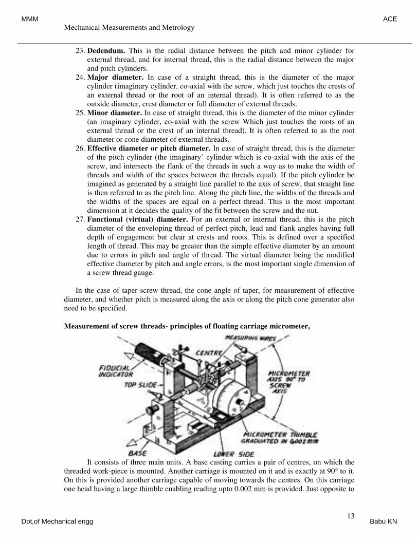
Mechanical Measurements and Metrology
Dr. K V S Rajeswara Rao, Dept. of IEM, RVCE, Bangalore-59. 13
23. Dedendum. This is the radial distance between the pitch and minor cylinder for
external thread, and for internal thread, this is the radial distance between the major
and pitch cylinders.
24. Major diameter. In case of a straight thread, this is the diameter of the major
cylinder (imaginary cylinder, co-axial with the screw, which just touches the crests of
an external thread or the root of an internal thread). It is often referred to as the
outside diameter, crest diameter or full diameter of external threads.
25. Minor diameter. In case of straight thread, this is the diameter of the minor cylinder
(an imaginary cylinder, co-axial with the screw Which just touches the roots of an
external thread or the crest of an internal thread). It is often referred to as the root
diameter or cone diameter of external threads.
26. Effective diameter or pitch diameter. In case of straight thread, this is the diameter
of the pitch cylinder (the imaginary’ cylinder which is co-axial with the axis of the
screw, and intersects the flank of the threads in such a way as to make the width of
threads and width of the spaces between the threads equal). If the pitch cylinder be
imagined as generated by a straight line parallel to the axis of screw, that straight line
is then referred to as the pitch line. Along the pitch line, the widths of the threads and
the widths of the spaces are equal on a perfect thread. This is the most important
dimension at it decides the quality of the fit between the screw and the nut.
27. Functional (virtual) diameter. For an external or internal thread, this is the pitch
diameter of the enveloping thread of perfect pitch, lead and flank angles having full
depth of engagement but clear at crests and roots. This is defined over a specified
length of thread. This may be greater than the simple effective diameter by an amount
due to errors in pitch and angle of thread. The virtual diameter being the modified
effective diameter by pitch and angle errors, is the most important single dimension of
a screw thread gauge.
In the case of taper screw thread, the cone angle of taper, for measurement of effective
diameter, and whether pitch is measured along the axis or along the pitch cone generator also
need to be specified.
Measurement of screw threads- principles of floating carriage micrometer,
It consists of three main units. A base casting carries a pair of centres, on which the
threaded work-piece is mounted. Another carriage is mounted on it and is exactly at 90° to it.
On this is provided another carriage capable of moving towards the centres. On this carriage
one head having a large thimble enabling reading upto 0.002 mm is provided. Just opposite to
MMM ACE
Dpt,of Mechanical engg Babu KN
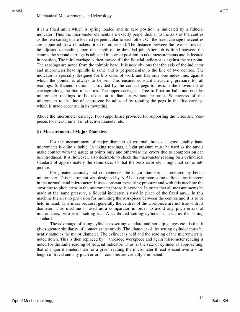
Mechanical Measurements and Metrology
Dr. K V S Rajeswara Rao, Dept. of IEM, RVCE, Bangalore-59. 14
it is a fixed anvil which is spring loaded and its zero position is indicated by a fiducial
indicator. Thus the micrometer elements are exactly perpendicular to the axis of the centres
as the two carriages are located perpendicular to each other. On the fixed carriage the centres
are supported in two brackets fitted on either end. The distance between the two centres can
be adjusted depending upon the length of tie threaded job. After job is fitted between the
centres the second carriage is adjusted in correct position to take measurements and is located
in position, The third carriage is then moved till the fiducial indicator is against the set point.
The readings are noted from the thimble head. It is now obvious that the axis of the indicator
and micrometer head spindle is same and is perpendicular to the line of two centres. The
indicator is specially designed for this class of work and has only one index line, against
which the pointer is always to be set. This ensures constant measuring pressure for all
readings. Sufficient friction is provided by the conical pegs to restrain the movement of
carriage along the line of centres. The upper carriage is free to float on balls and enables
micrometer readings to be taken on a diameter without restraint. Squareness of the
micrometer to the line of centre can be adjusted by rotating the pegs in the first carriage
which is made eccentric in its mounting.
Above the micrometer carriage, two supports are provided for supporting the wires and Vee-
pieces for measurement of effective diameter etc.
(i) Measurement of Major Diameter.
For the measurement of major diameter of external threads, a good quality hand
micrometer is quite suitable. In taking readings, a light pressure must be used as the anvils
make contact with the gauge at points only and otherwise the errors due to compression can
be introduced. It is, however, also desirable to check the micrometer reading on a cylindrical
standard of approximately the same size, so that the zero error etc., might not come into
picture.
For greater accuracy and convenience, the major diameter is measured by bench
micrometer. This instrument was designed by N.P.L. to estimate some deficiencies inherent
in the normal hand micrometer. It uses constant measuring pressure and with this machine the
error due to pitch error in the micrometer thread is avoided. In order that all measurements be
made at the same pressure, a fiducial indicator is used in place of the fixed anvil. In this
machine there is no provision for mounting the workpiece between the centres and it is to be
held in hand. This is so, because, generally the centres of the workpiece are not true with its
diameter. This machine is used as a comparator in order to avoid any pitch errors of
micrometers, zero error setting etc. A calibrated setting cylinder is used as the setting
standard.
The advantage of using cylinder as setting standard and not slip gauges etc., is that it
gives greater similarity of contact at the anvils. The diameter of the setting cylinder must be
nearly same as the major diameter. The cylinder is held and the reading of the micrometer is
noted down. This is then replaced by threaded workpiece and again micrometer reading is
noted for the same reading of fiducial indicator. Thus, if the size of cylinder is approaching,
that of major diameter, then for a given reading the micrometer thread is used over a short
length of travel and any pitch errors it contains are virtually eliminated.
MMM ACE
Dpt,of Mechanical engg Babu KN
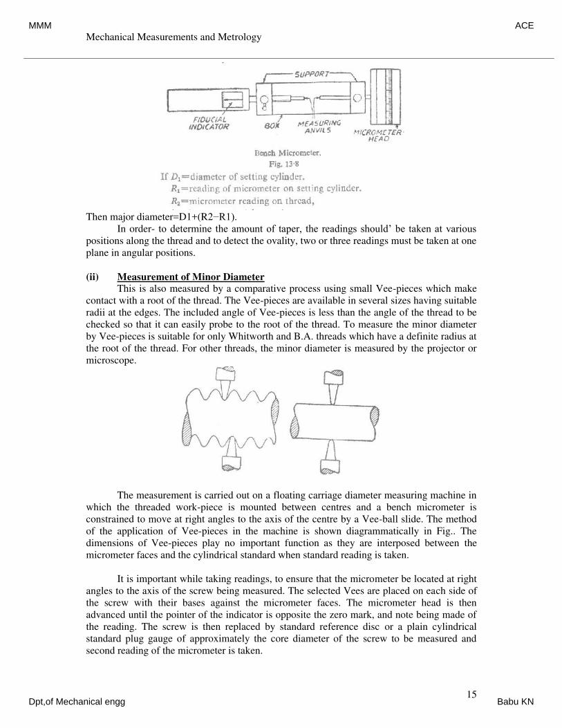
Mechanical Measurements and Metrology
Dr. K V S Rajeswara Rao, Dept. of IEM, RVCE, Bangalore-59. 15
Then major diameter=D1+(R2−R1).
In order- to determine the amount of taper, the readings should’ be taken at various
positions along the thread and to detect the ovality, two or three readings must be taken at one
plane in angular positions.
(ii) Measurement of Minor Diameter
This is also measured by a comparative process using small Vee-pieces which make
contact with a root of the thread. The Vee-pieces are available in several sizes having suitable
radii at the edges. The included angle of Vee-pieces is less than the angle of the thread to be
checked so that it can easily probe to the root of the thread. To measure the minor diameter
by Vee-pieces is suitable for only Whitworth and B.A. threads which have a definite radius at
the root of the thread. For other threads, the minor diameter is measured by the projector or
microscope.
The measurement is carried out on a floating carriage diameter measuring machine in
which the threaded work-piece is mounted between centres and a bench micrometer is
constrained to move at right angles to the axis of the centre by a Vee-ball slide. The method
of the application of Vee-pieces in the machine is shown diagrammatically in Fig.. The
dimensions of Vee-pieces play no important function as they are interposed between the
micrometer faces and the cylindrical standard when standard reading is taken.
It is important while taking readings, to ensure that the micrometer be located at right
angles to the axis of the screw being measured. The selected Vees are placed on each side of
the screw with their bases against the micrometer faces. The micrometer head is then
advanced until the pointer of the indicator is opposite the zero mark, and note being made of
the reading. The screw is then replaced by standard reference disc or a plain cylindrical
standard plug gauge of approximately the core diameter of the screw to be measured and
second reading of the micrometer is taken.
MMM ACE
Dpt,of Mechanical engg Babu KN
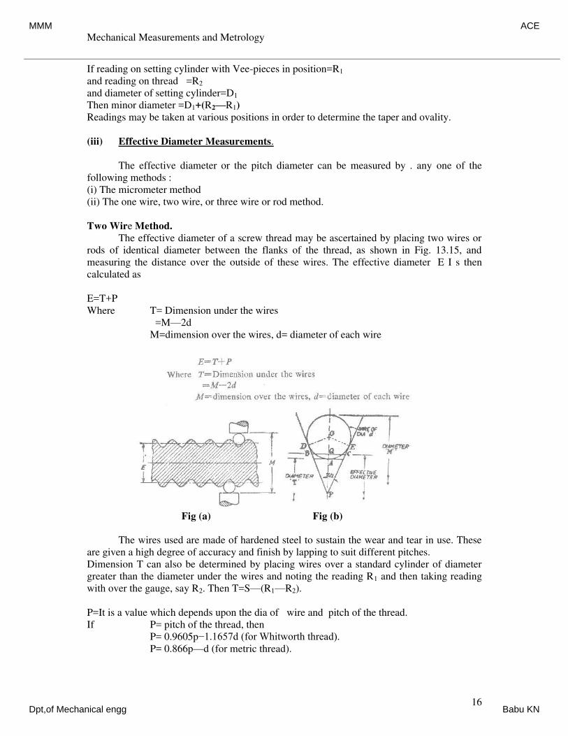
Mechanical Measurements and Metrology
Dr. K V S Rajeswara Rao, Dept. of IEM, RVCE, Bangalore-59. 16
If reading on setting cylinder with Vee-pieces in position=R1
and reading on thread =R2
and diameter of setting cylinder=D1
Then minor diameter =D1+(R2—R1)
Readings may be taken at various positions in order to determine the taper and ovality.
(iii) Effective Diameter Measurements.
The effective diameter or the pitch diameter can be measured by . any one of the
following methods :
(i) The micrometer method
(ii) The one wire, two wire, or three wire or rod method.
Two Wire Method.
The effective diameter of a screw thread may be ascertained by placing two wires or
rods of identical diameter between the flanks of the thread, as shown in Fig. 13.15, and
measuring the distance over the outside of these wires. The effective diameter E I s then
calculated as
E=T+P
Where T= Dimension under the wires
=M—2d
M=dimension over the wires, d= diameter of each wire
Fig (a) Fig (b)
The wires used are made of hardened steel to sustain the wear and tear in use. These
are given a high degree of accuracy and finish by lapping to suit different pitches.
Dimension T can also be determined by placing wires over a standard cylinder of diameter
greater than the diameter under the wires and noting the reading R1 and then taking reading
with over the gauge, say R2. Then T=S—(R1—R2).
P=It is a value which depends upon the dia of wire and pitch of the thread.
If P= pitch of the thread, then
P= 0.9605p−1.1657d (for Whitworth thread).
P= 0.866p—d (for metric thread).
MMM ACE
Dpt,of Mechanical engg Babu KN
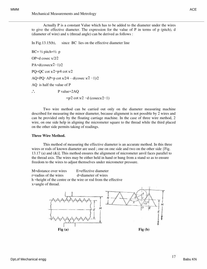
Mechanical Measurements and Metrology
Dr. K V S Rajeswara Rao, Dept. of IEM, RVCE, Bangalore-59. 17
Actually P is a constant Value which has to be added to the diameter under the wires
to give the effective diameter. The expression for the value of P in terms of p (pitch), d
(diameter of wire) and x (thread angle) can be derived as follows :
In Fig.13.15(b), since BC lies on the effective diameter line
BC= ½ pitch=½ p
OP=d cosec x/2∕2
PA=d(cosecx∕2−1)⁄2
PQ=QC cot x∕2=p∕4 cot x∕2
AQ=PQ−AP=p cot x⁄2⁄4 – d(cosec x∕2 −1)⁄2
AQ is half the value of P
.’. P value=2AQ
=p∕2 cot x∕2 −d (cosecx⁄2−1)
Two wire method can be carried out only on the diameter measuring machine
described for measuring the minor diameter, because alignment is not possible by 2 wires and
can be provided only by the floating carriage machine. In the case of three wire method, 2
wire, on one side help in aligning the micrometer square to the thread while the third placed
on the other side permits taking of readings.
Three Wire Method.
This method of measuring the effective diameter is an accurate method. In this three
wires or rods of known diameter are used ; one on one side and two on the other side {Fig.
13.17 (a) and (&)]. This method ensures the alignment of micrometer anvil faces parallel to
the thread axis. The wires may be either held in hand or hung from a stand so as to ensure
freedom to the wires to adjust themselves under micrometer pressure.
M=distance over wires E=effective diameter
r=radius of the wires d=diameter of wires
h =height of the centre or the wire or rod from the effective
x=angle of thread.
Fig (a) Fig (b)
MMM ACE
Dpt,of Mechanical engg Babu KN
Mechanical Measurements and Metrology
Dr. K V S Rajeswara Rao, Dept. of IEM, RVCE, Bangalore-59. 18
From fig.(b),
AD = AB cosec x∕2 = r cosec x∕2
H = DE cot x∕2 = p∕2 cot x∕2
CD = ½H = p∕4 cot x∕2
H = AD−CD
r = cosec x∕2− p⁄4 cot x∕2
Distance over wires=M = E+2h+2r
= E+2(r cosec x∕2 – p∕4 cot x∕2)+2r
= E+2r (l+cosec x∕2 )− p⁄2 cot x⁄2
or M = E+d (1+cosec x∕2) − p⁄2 cot x⁄2
(since 2r = 0 )
(i) In case of Whitworth thread:
X = 55°, depth of thread = 0.64 p, so that
E= D—0.64 p and cosec x∕2 = 2.1657
Cot x∕2 = 1.921
M = E+d(1l+cosec x∕2) — p∕2 cot x∕2
= D−0.64p+d(1+2.1657)−p⁄2(1.921)
= D+3.1657d−1.6005p
M = D+3.1657d—1.6p
where D=outside dia.
(ii) In case of metric threads:
Depth of thread=0.6495p
so, E = D-0.6495p.
x = 60°, cosec x∕2 = 2 ; cot x∕2 = 1.732
M = D−0.6495 p+d(l+2)—p∕2 (1.732)
= D+3d−(0.6495+0.866)p
= D+3d—1.5155p.
We can measure the value of M practically and then compare with the theoretical
values with the help of formulae derived above. After finding the correct value of M and
knowing d, E can be found out.
MMM ACE
Dpt,of Mechanical engg Babu KN
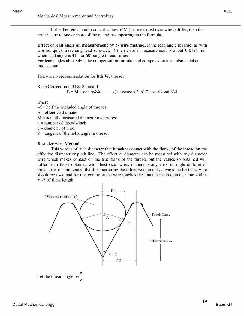
Mechanical Measurements and Metrology
Dr. K V S Rajeswara Rao, Dept. of IEM, RVCE, Bangalore-59. 19
If the theoretical and practical values of M (i.e. measured over wires) differ, then this
error is due to one or more of the quantities appearing in the formula.
Effect of lead angle on measurement by 3- wire method. If the lead angle is large (as with
worms; quick traversing lead screw,etc .) then error in measurement is about 0’0125 mm
when lead angle is 41° for 60° single thread series.
For lead angles above 4£°, the compensation for rake and compression must also be taken
into account.
There is no recommendation for B.S.W. threads.
Rake Correction in U.S. Standard :
E = M + cot x∕2∕2n—- − x(1 +cosec x⁄2+s2
∕2 cos x∕2 cot x∕2)
where
x∕2 =half the included angle of threads.
E = effective diameter
M = actually measured diameter over wires:
n = number of threads/inch.
d = diameter of wire.
S = tangent of the helix angle in thread.
Best size wire Method.
This wire is of such diameter that it makes contact with the flanks of the thread on the
effective diameter or pitch line. The effective diameter can be measured with any diameter
wire which makes contact on the true flank of the thread, but the values so obtained will
differ from those obtained with ‘best size’ wires if there is any error in angle or form of
thread. t is recommended that for measuring the effective diameter, always the best size wire
should be used and for this condition the wire touches the flank at mean diameter line within
±1/5 of flank length
Let the thread angle be
MMM ACE
Dpt,of Mechanical engg Babu KN
Mechanical Measurements and Metrology
Dr. K V S Rajeswara Rao, Dept. of IEM, RVCE, Bangalore-59. 20
Then in ∆le OAP, Sin POA =
Or sin (900
- ) =
OP = = = AP sec
Since, OP = r = AP sec
And wire diameter = Db = 2r = 2AP sec
Since AP lies on the pitch line
AP = where, p is the pitch of the thread
Therefore, Db = sec
Therefore,
Tool Makers Microscope:
The toolmaker's microscope is an optical measuring machine equipped for external and
internal length measurements as well as measurements on screw threads, profiles, curvatures
and angles. For these purposes, the microscope is provide with several measuring attachments
such as
1. Centre stage for mounting of cylindrical components,
2. Revolving and angle measuring oculars,
3. Double image ocular,
4. Optical feeder, and
5. Projection screen.
The applications of the instrument may be· summarized lows: broadly as follows.
1. The determination of the relative position of various Points on work by measuring the
travel necessary to bring a second point to the position previously occupied by the first,
and so on. .
2. Measurement of angles by using a protractor eye-piece.
3. Comparison of thread forms with master profiles engraved in the eyepiece and
measurement of pitch and effective diameter.
4. Comparison of an enlarged, projected image with a scale tracing fixed to the projection
screen.
Figure shows a toolmaker's microscope. The main parts of the instrument are:
1. Rotatable table
2. Swingable head
3. Projection screen
4. Objective lens
5. Measuring stage
6. Ocular
7. Micrometers
8. Prism.
Db = sec
MMM ACE
Dpt,of Mechanical engg Babu KN
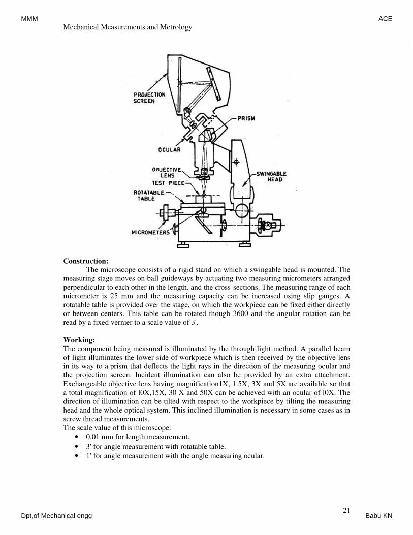
Mechanical Measurements and Metrology
Dr. K V S Rajeswara Rao, Dept. of IEM, RVCE, Bangalore-59. 21
Construction:
The microscope consists of a rigid stand on which a swingable head is mounted. The
measuring stage moves on ball guideways by actuating two measuring micrometers arranged
perpendicular to each other in the length. and the cross-sections. The measuring range of each
micrometer is 25 mm and the measuring capacity can be increased using slip gauges. A
rotatable table is provided over the stage, on which the workpiece can be fixed either directly
or between centers. This table can be rotated though 3600 and the angular rotation can be
read by a fixed vernier to a scale value of 3'.
Working:
The component being measured is illuminated by the through light method. A parallel beam
of light illuminates the lower side of workpiece which is then received by the objective lens
in its way to a prism that deflects the light rays in the direction of the measuring ocular and
the projection screen. Incident illumination can also be provided by an extra attachment.
Exchangeable objective lens having magnification1X, 1.5X, 3X and 5X are available so that
a total magnification of l0X,15X, 30 X and 50X can be achieved with an ocular of l0X. The
direction of illumination can be tilted with respect to the workpiece by tilting the measuring
head and the whole optical system. This inclined illumination is necessary in some cases as in
screw thread measurements.
The scale value of this microscope:
• 0.01 mm for length measurement.
• 3' for angle measurement with rotatable table.
• 1' for angle measurement with the angle measuring ocular.
MMM ACE
Dpt,of Mechanical engg Babu KN
Mechanical Measurements and Metrology
Dr. K V S Rajeswara Rao, Dept. of IEM, RVCE, Bangalore-59. 22
Applications
The applications of the instrument may be summarized broadly as follows.
(1) The determination of the relative position of various Points on work by measuring the
travel necessary to bring a second point to the position previously occupied by the
first, and so on.
(2) Measurement of angles by using a protractor eye-piece.
(3) Comparison of thread forms with master profiles engraved in the eyepiece and
measurement of pitch and effective diameter.
(4) Comparison of an enlarged, projected image with a scale tracing fixed to the
projection screen.
Gear Measurement
Gears is a mechanical drive which transmits power through toothed wheel. In this gear
drive, the driving wheel is in direct contact with driven wheel. The accuracy of gearing is the
very important factor when gears are manufactured. The transmission efficiency is almost 99
in gears. So it is very important to test and measure the gears precisely.
For proper inspection of gear, it is very important to concentrate on the raw materials,
which are used to manufacture the gears, also very important to check the machining the
blanks, heat treatment and the finishing of teeth.
The gear blank should be tested for dimensional accuracy (face width, bore, hub, length,
and outside diameter), and eccentricity. As outside diameter forms the datum from where the
tooth thickness is measured, it forms an important item to be controlled. Concentricity of the
blanks is also essential and the side faces should be true to the bore. On very precise gears
details like tip radius, shape of root provided and surface finish are also measured.
The most commonly used forms of gear teeth are
1. Involute
2. Cycloidal
The involute gears also called as straight tooth or spur gears.
The cycloidal gears are used in heavy and impact loads.
The involute rack has straight teeth.
The involute pressure angle is either 20° or 14.5°
Types of gears
1. Spur gear:-
Cylindrical gear whose tooth traces is straight line.
These are used for transmitting power between parallel shafts.
2. Spiral gear :-
The tooth of the gear traces curved lines.
3. Helical gears:-
These gears used to transmit the power between parallel shafts as well as non-parallel
and non-intersecting shafts.
It is a cylindrical gear whose tooth traces is straight line.
4. Bevel gears:-
The tooth traces are straight-line generators of cone.
The teeth are cut on the conical surface. It is used to connect the shafts at right angles.
5. Worm and Worm wheel :
It is used to connect the shafts whose axes are non-parallel and non-intersecting.
6. Rack and Pinion:-
Rack gears are straight spur gears with infinite radius.
MMM ACE
Dpt,of Mechanical engg Babu KN
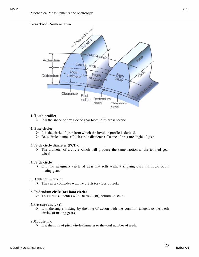
Mechanical Measurements and Metrology
Dr. K V S Rajeswara Rao, Dept. of IEM, RVCE, Bangalore-59. 23
Gear Tooth Nomenclature
1. Tooth profile:
It is the shape of any side of gear tooth in its cross section.
2. Base circle:
It is the circle of gear from which the involute profile is derived.
Base circle diameter Pitch circle diameter x Cosine of pressure angle of gear
3. Pitch circle diameter (PCD):
The diameter of a circle which will produce the same motion as the toothed gear
wheel
4. Pitch circle
It is the imaginary circle of gear that rolls without slipping over the circle of its
mating gear.
5. Addendum circle:
The circle coincides with the crests (or) tops of teeth.
6. Dedendum circle (or) Root circle:
This circle coincides with the roots (or) bottom on teeth.
7.Pressure angle (a):
It is the angle making by the line of action with the common tangent to the pitch
circles of mating gears.
8.Module(m):
It is the ratio of pitch circle diameter to the total number of teeth.
MMM ACE
Dpt,of Mechanical engg Babu KN
Mechanical Measurements and Metrology
Dr. K V S Rajeswara Rao, Dept. of IEM, RVCE, Bangalore-59. 24
Where, d = Pitch circle diameter.
n = Number f teeth
9. Circular pitch
It is the distance along the pitch circle between corresponding points of adjacent teeth
10. Addendum:
Radial distance between tip circle and pitch circle. Addendum value = 1 module.
11. Dedendum:
Radial distance between itch circle and root circle, Dedendum value = 1 .25 module.
12. Clearance (C):
A mount of distance made by the tip of one gear with the root of mating gear.
Clearance = Difference between Dedendum and addendum values
13. Blank diameter:
The diameter of the blank from which gear is out. Blank diameter = PCD + 2m
14. Face:
Part of the tooth in the axial plane lying between tip circle and pitch circle.
15. Flank:
Part of the tooth lying between pitch circle and root circle.
16. Top land:
Top surface of a tooth
17. Lead angle:
The angle between the tangent to the helix and plane perpendicular to the axis
of cylinder.
18. Backlash:
The difference between the tooth thickness and the space into which it meshes.
Gear Tooth Caliper
In gear tooth vernier method the thickness is measured at the pitch line. Gear tooth
thickness varies from the tip of the base circle of the tooth, and the instrument is capable of
measuring the thickness at a specified position on the tooth. The tooth vernier caliper consists
of vernier scale and two perpendicular arms. In the two perpendicular arms one arm is used to
measure the thickness and other arm is used to measure the depth. Horizontal vernier scale
reading gives chordal thickness (W) and vertical vernier scale gives the chordal addendum.
Finally the two values e compared. The theoretical values of ‘W’ and ‘d’ can be found out by
considering one tooth in the gear and it can be verified.
MMM ACE
Dpt,of Mechanical engg Babu KN
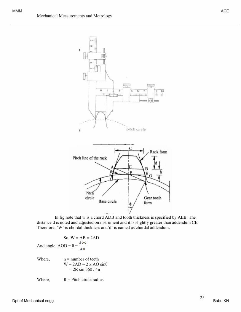
Mechanical Measurements and Metrology
Dr. K V S Rajeswara Rao, Dept. of IEM, RVCE, Bangalore-59. 25
In fig note that w is a chord ADB and tooth thickness is specified by AEB. The
distance d is noted and adjusted on instrument and it is slightly greater than addendum CE
Therefore, ‘W’ is chordal thickness and‘d’ is named as chordal addendum.
So, W = AB = 2AD
And angle, AOD = θ =
Where, n = number of teeth
W = 2AD = 2 x AO sinθ
= 2R sin 360 / 4n
Where, R = Pitch circle radius
MMM ACE
Dpt,of Mechanical engg Babu KN
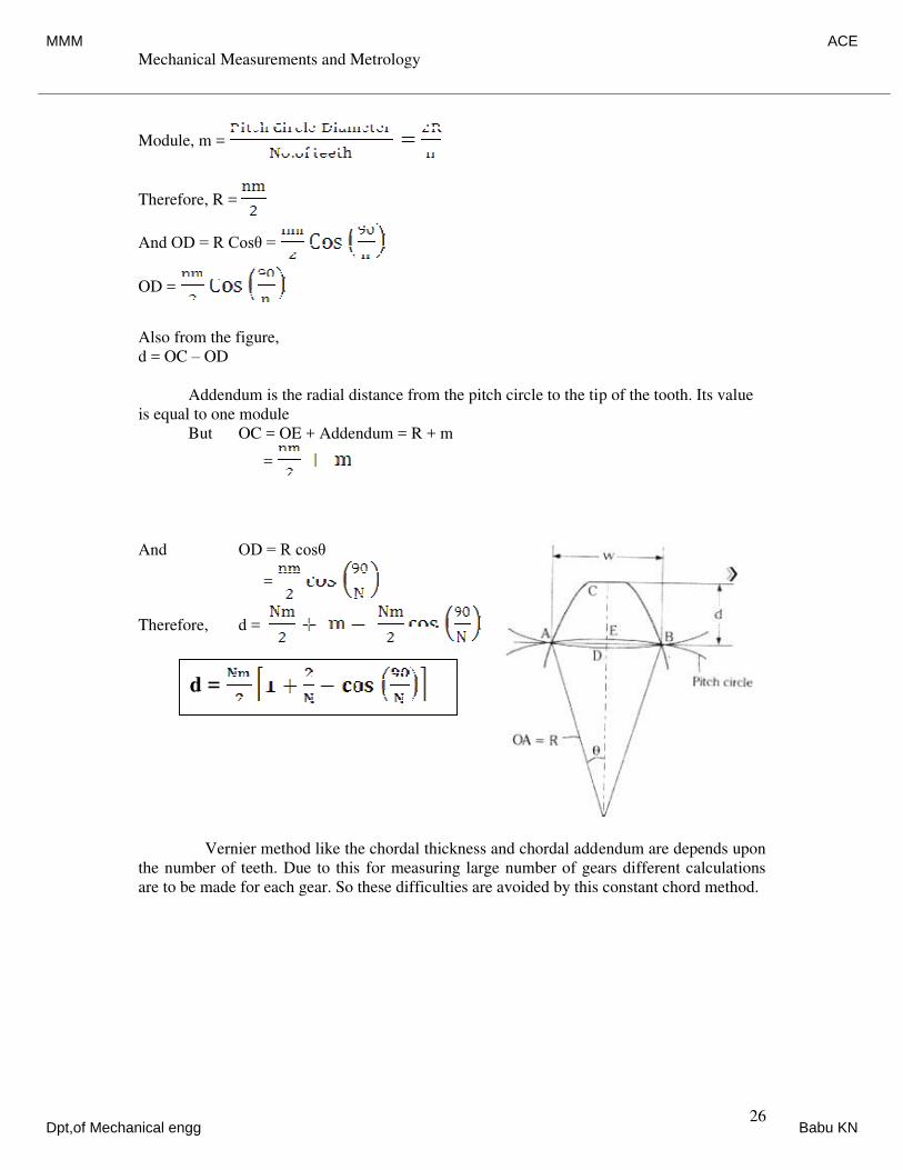
Mechanical Measurements and Metrology
Dr. K V S Rajeswara Rao, Dept. of IEM, RVCE, Bangalore-59. 26
Module, m =
Therefore, R =
And OD = R Cosθ =
OD =
Also from the figure,
d = OC – OD
Addendum is the radial distance from the pitch circle to the tip of the tooth. Its value
is equal to one module
But OC = OE + Addendum = R + m
=
And OD = R cosθ
=
Therefore, d =
Vernier method like the chordal thickness and chordal addendum are depends upon
the number of teeth. Due to this for measuring large number of gears different calculations
are to be made for each gear. So these difficulties are avoided by this constant chord method.
d =
MMM ACE
Dpt,of Mechanical engg Babu KN
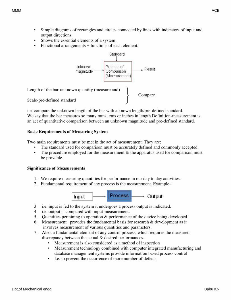
• Simple diagrams of rectangles and circles connected by lines with indicators of input and
output directions.
• Shows the essential elements of a system.
• Functional arrangements + functions of each element.
Length of the bar-unknown quantity (measure and)
Compare
Scale-pre-defined standard
i.e. compare the unknown length of the bar with a known length/pre-defined standard.
We say that the bar measures so many mms, cms or inches in length.Definition-measurement is
an act of quantitative comparison between an unknown magnitude and pre-defined standard.
Basic Requirements of Measuring System
Two main requirements must be met in the act of measurement. They are;
• The standard used for comparison must be accurately defined and commonly accepted.
• The procedure employed for the measurement & the apparatus used for comparison must
be provable.
Significance of Measurements
1. We require measuring quantities for performance in our day to day activities.
2. Fundamental requirement of any process is the measurement. Example-
3 i.e. input is fed to the system it undergoes a process output is indicated.
4 i.e. output is compared with input-measurement.
5. Quantities pertaining to operation & performance of the device being developed.
6. Measurement provides the fundamental basis for research & development as it
involves measurement of various quantities and parameters.
7. Also, a fundamental element of any control process, which requires the measured
discrepancy between the actual & desired performances.
• Measurement is also considered as a method of inspection
• Measurement technology combined with computer integrated manufacturing and
database management systems provide information based process control
• I.e. to prevent the occurrence of more number of defects
MMM ACE
Dpt,of Mechanical engg Babu KN
8) To ensure proper performance in operations of modern power stations to monitor
temperature, pressure, vibration amplitudes etc.
9) Establish the cost of products on the basis of amount of material, power, time & labor,
etc.
10) Place/give realistic tolerance for each of the measured values.
To establish the validity of design
1. Design of manufactured goods
2. Design of machinery to perform manufacturing operations
3. Design of power sources
4. Design of roads, waterways and other system.
5. To study the operation features, limitation and difficulties that are inherent in the
systems.
6. For proper maintenance of the equipment.
7. To determine the system response(Reply of the systems to given input)
8. For correct recording of the output data(weather forecasting, experimental values,
interpretation etc.)
Other applications of measurements
1. Application of theory
• Broaden the engineering knowledge by application of theory.
• Learn to verify a theoretical model or to verify/modify it by conducting experiments.
• Develop ability to apply some basic principle in a variety of engineering studies-
interdisciplinary approach.
2. Techniques of experimentation
• Become acquainted with available experimentation.
• Learn to interpret experimental data.
• Develop competence in sampling data.
3. Communication and reporting
• Learn to organize and direct experimental team.
• Learn procedures and develop abilities in report writing.
• Learn to support conclusions and recommend improvements.
4. Professional
• Provide examples of experimental research and development.
• Develop competence in applying engineering judgment.
Hence considering the above, it can be concluded that measurements are quite essential in the
• Design of a component.
• A process to be operated with minimum cost having maximum efficiency.
Fundamental methods of Measurement
Two basic methods are commonly employed for measurement.
(a) Direct comparison with primary or secondary standard.
(b) Indirect comparison through the use of calibrated system.
MMM ACE
Dpt,of Mechanical engg Babu KN
Two basic methods are commonly employed for measurement.
(a) Direct comparison with primary or secondary standard.
(b) Indirect comparison through the use of calibrated system.
Direct comparison
In this method, measurement is made directly by comparing the unknown magnitude with a
standard & the result is expressed by a number. The simplest example for this would be, length
measurement using a meter scale. Here we compare the bar’s length(unknown quantity/
measure and) with a scale (Standard/predefined one). We say that the bar measures so many
mms, cms or inches in length.
• Direct comparison methods are quite common for measurement of physical quantities
like length, mass, etc.
• It is easy and quick.
Drawbacks of Direct comparison methods
• The main drawback of this method is, the method is not always accurate and reliable.
• Also, human senses are not equipped to make direct comparison of all quantities with
equal facility all the times.
• Also, measurement by direct methods are not always possible, feasible and practicable.
Example: Measurement of temperature, Measurement of weight.
• One can experience or feel the hotness or coldness of a body with respect to a particular
environment.
• But may not be able to exactly predict or say the temperature.
• Further , these measurements in most cases involve human factors.
• Hence this method in general is not preferred and employed for very accurate
measurements.
Indirect comparison
• Most of the measurement systems use indirect method of measurement.
• In this method a chain of devices which is together called as measuring system is
employed.
• The chain of devices transform the sensed signal into a more convenient form & indicate
this transformed signal either on an indicator or a recorder or fed to a controller.
• i.e. it makes use of a transducing device/element which convert the basic form of input
into an analogous form, which it then processes and presents as a known function of
input.
• For example, to measure strain in a machine member, a component senses the strain,
another component transforms the sensed signal into an electrical quantity which is then
processed suitably before being fed to a meter or recorder.
• Further, human senses are not equipped to detect quantities like pressure, force or strain.
• But can feel or sense and cannot predict the exact magnitude of such quantities.
• Hence, we require a system that detects/sense, converts and finally presents the output in
the form of a displacement of a pointer over a scale a , a change in resistance or raise in
liquid level with respect to a graduated stem.
MMM ACE
Dpt,of Mechanical engg Babu KN
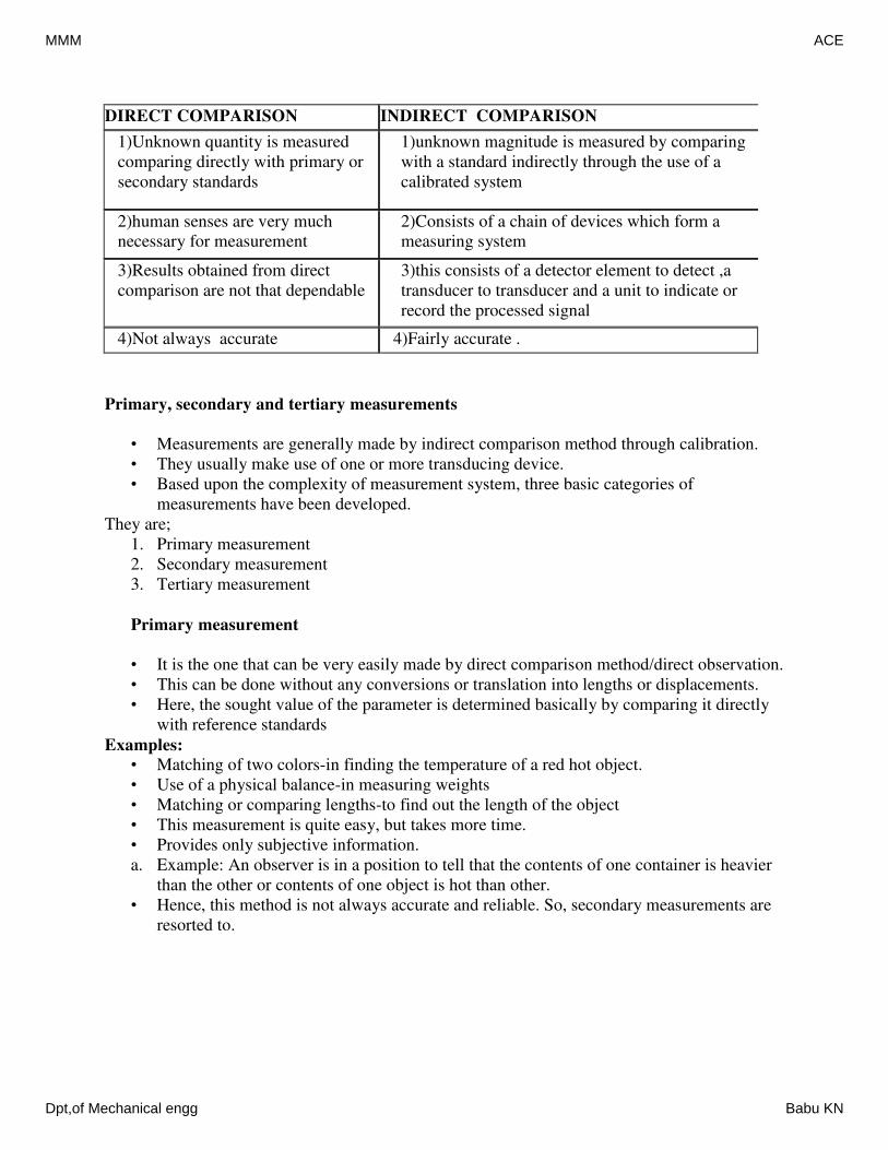
DIRECT COMPARISON INDIRECT COMPARISON
1)Unknown quantity is measured
comparing directly with primary or
secondary standards
1)unknown magnitude is measured by comparing
with a standard indirectly through the use of a
calibrated system
2)human senses are very much
necessary for measurement
2)Consists of a chain of devices which form a
measuring system
3)Results obtained from direct
comparison are not that dependable
3)this consists of a detector element to detect ,a
transducer to transducer and a unit to indicate or
record the processed signal
4)Not always accurate 4)Fairly accurate .
Primary, secondary and tertiary measurements
• Measurements are generally made by indirect comparison method through calibration.
• They usually make use of one or more transducing device.
• Based upon the complexity of measurement system, three basic categories of
measurements have been developed.
They are;
1. Primary measurement
2. Secondary measurement
3. Tertiary measurement
Primary measurement
• It is the one that can be very easily made by direct comparison method/direct observation.
• This can be done without any conversions or translation into lengths or displacements.
• Here, the sought value of the parameter is determined basically by comparing it directly
with reference standards
Examples:
• Matching of two colors-in finding the temperature of a red hot object.
• Use of a physical balance-in measuring weights
• Matching or comparing lengths-to find out the length of the object
• This measurement is quite easy, but takes more time.
• Provides only subjective information.
a. Example: An observer is in a position to tell that the contents of one container is heavier
than the other or contents of one object is hot than other.
• Hence, this method is not always accurate and reliable. So, secondary measurements are
resorted to.
MMM ACE
Dpt,of Mechanical engg Babu KN
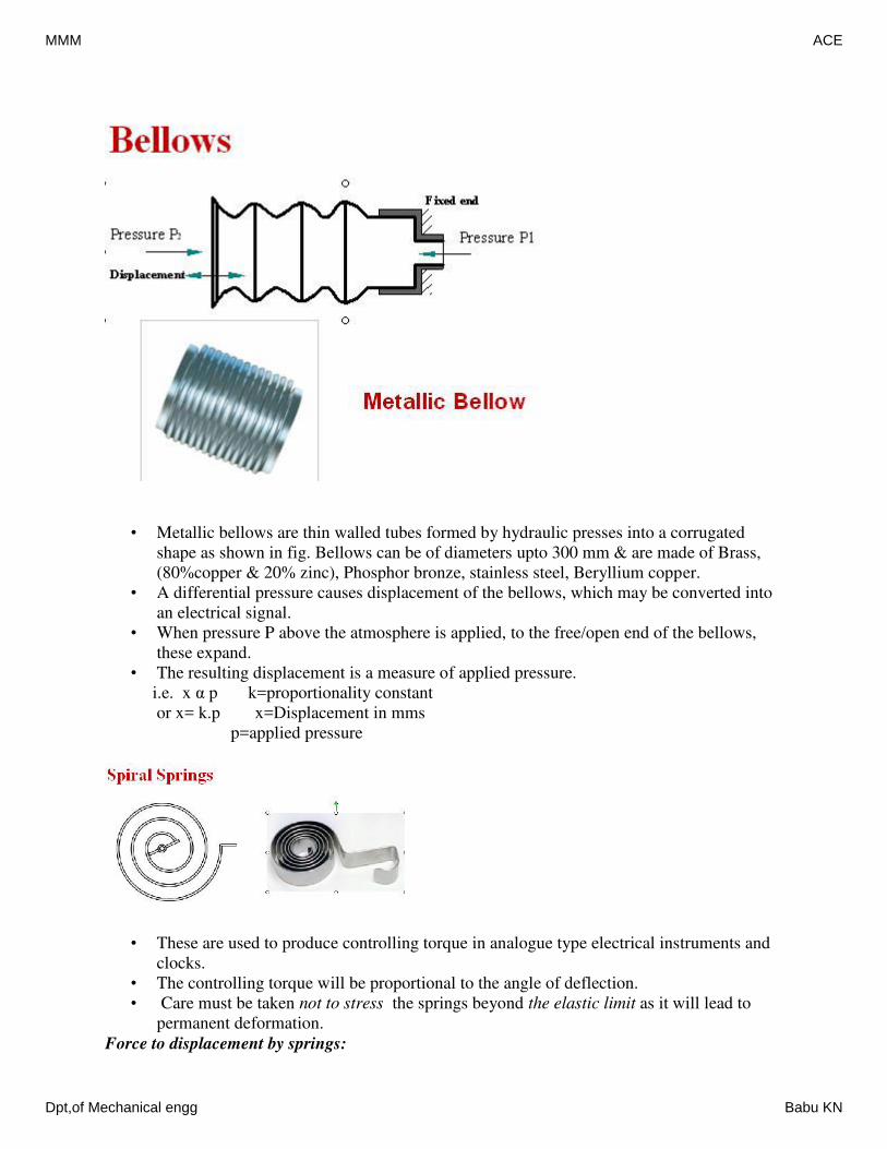
• Metallic bellows are thin walled tubes formed by hydraulic presses into a corrugated
shape as shown in fig. Bellows can be of diameters upto 300 mm & are made of Brass,
(80%copper & 20% zinc), Phosphor bronze, stainless steel, Beryllium copper.
• A differential pressure causes displacement of the bellows, which may be converted into
an electrical signal.
• When pressure P above the atmosphere is applied, to the free/open end of the bellows,
these expand.
• The resulting displacement is a measure of applied pressure.
i.e. x α p k=proportionality constant
or x= k.p x=Displacement in mms
p=applied pressure
• These are used to produce controlling torque in analogue type electrical instruments and
clocks.
• The controlling torque will be proportional to the angle of deflection.
• Care must be taken not to stress the springs beyond the elastic limit as it will lead to
permanent deformation.
Force to displacement by springs:
MMM ACE
Dpt,of Mechanical engg Babu KN
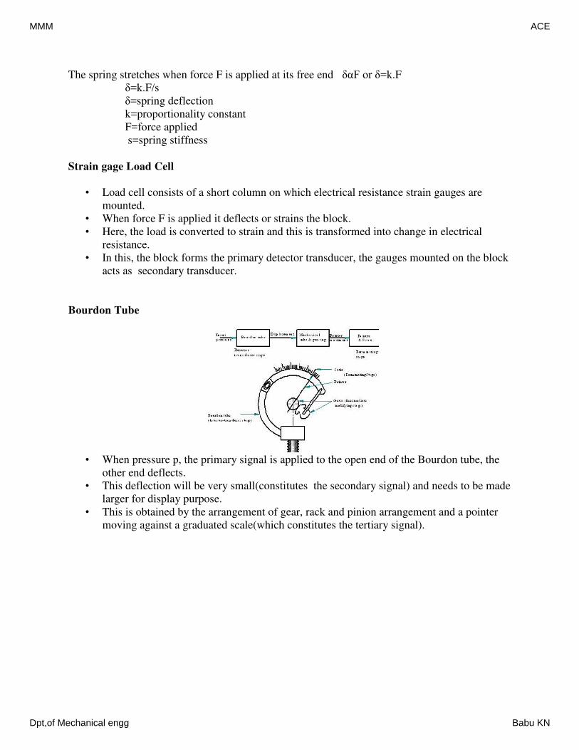
The spring stretches when force F is applied at its free end δαF or δ=k.F
δ=k.F/s
δ=spring deflection
k=proportionality constant
F=force applied
s=spring stiffness
Strain gage Load Cell
• Load cell consists of a short column on which electrical resistance strain gauges are
mounted.
• When force F is applied it deflects or strains the block.
• Here, the load is converted to strain and this is transformed into change in electrical
resistance.
• In this, the block forms the primary detector transducer, the gauges mounted on the block
acts as secondary transducer.
Bourdon Tube
• When pressure p, the primary signal is applied to the open end of the Bourdon tube, the
other end deflects.
• This deflection will be very small(constitutes the secondary signal) and needs to be made
larger for display purpose.
• This is obtained by the arrangement of gear, rack and pinion arrangement and a pointer
moving against a graduated scale(which constitutes the tertiary signal).
MMM ACE
Dpt,of Mechanical engg Babu KN
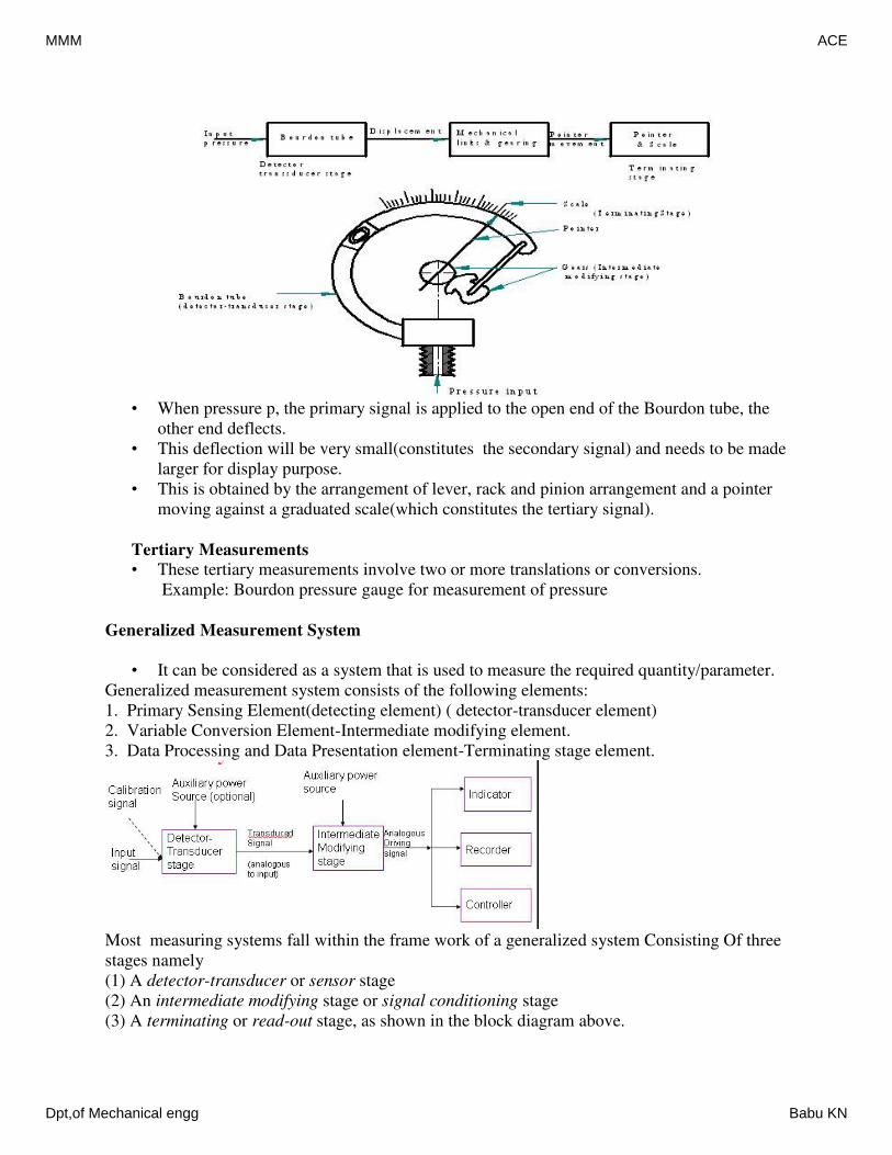
• When pressure p, the primary signal is applied to the open end of the Bourdon tube, the
other end deflects.
• This deflection will be very small(constitutes the secondary signal) and needs to be made
larger for display purpose.
• This is obtained by the arrangement of lever, rack and pinion arrangement and a pointer
moving against a graduated scale(which constitutes the tertiary signal).
Tertiary Measurements
• These tertiary measurements involve two or more translations or conversions.
Example: Bourdon pressure gauge for measurement of pressure
Generalized Measurement System
• It can be considered as a system that is used to measure the required quantity/parameter.
Generalized measurement system consists of the following elements:
1. Primary Sensing Element(detecting element) ( detector-transducer element)
2. Variable Conversion Element-Intermediate modifying element.
3. Data Processing and Data Presentation element-Terminating stage element.
Most measuring systems fall within the frame work of a generalized system Consisting Of three
stages namely
(1) A detector-transducer or sensor stage
(2) An intermediate modifying stage or signal conditioning stage
(3) A terminating or read-out stage, as shown in the block diagram above.
MMM ACE
Dpt,of Mechanical engg Babu KN
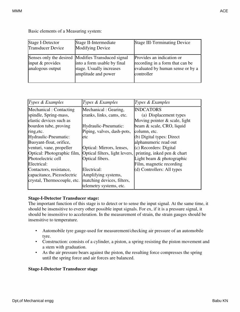
Basic elements of a Measuring system:
Stage I-Detector
Transducer Device
Stage II-Intermediate
Modifying Device
Stage III-Terminating Device
Senses only the desired
input & provides
analogous output
Modifies Transduced signal
into a form usable by final
stage. Usually increases
amplitude and power
Provides an indication or
recording in a form that can be
evaluated by human sense or by a
controller
Types & Examples Types & Examples Types & Examples
Mechanical : Contacting
spindle, Spring-mass,
elastic devices such as
bourdon tube, proving
ring,etc.
Hydraulic-Pneumatic:
Buoyant-float, orifice,
venturi, vane, propeller
Optical: Photographic film,
Photoelectric cell
Electrical:
Contactors, resistance,
capacitance, Piezoelectric
crystal, Thermocouple, etc.
Mechanical : Gearing,
cranks, links, cams, etc.
Hydraulic-Pneumatic:
Piping, valves, dash-pots,
etc
Optical: Mirrors, lenses,
Optical filters, light levers,
Optical fibers.
Electrical:
Amplifying systems,
matching devices, filters,
telemetry systems, etc.
INDCATORS
(a) Displacement types
Moving pointer & scale, light
beam & scale, CRO, liquid
column, etc.
(b) Digital types: Direct
alphanumeric read out
(c) Recorders: Digital
printing, inked pen & chart
Light beam & photographic
Film, magnetic recording
(d) Controllers: All types
Stage-I-Detector Transducer stage:
The important function of this stage is to detect or to sense the input signal. At the same time, it
should be insensitive to every other possible input signals. For ex, if it is a pressure signal, it
should be insensitive to acceleration. In the measurement of strain, the strain gauges should be
insensitive to temperature.
• Automobile tyre gauge-used for measurement/checking air pressure of an automobile
tyre.
• Construction: consists of a cylinder, a piston, a spring resisting the piston movement and
a stem with graduation.
• As the air pressure bears against the piston, the resulting force compresses the spring
until the spring force and air forces are balanced.
Stage-I-Detector Transducer stage
MMM ACE
Dpt,of Mechanical engg Babu KN
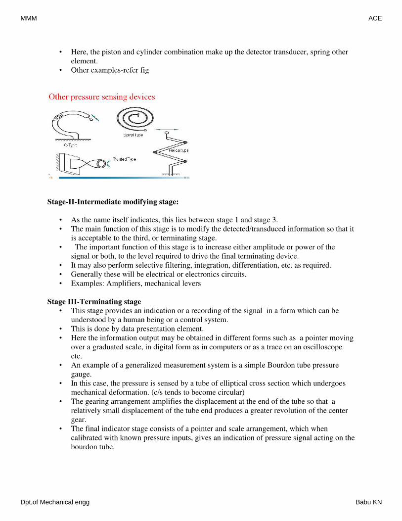
• Here, the piston and cylinder combination make up the detector transducer, spring other
element.
• Other examples-refer fig
Stage-II-Intermediate modifying stage:
• As the name itself indicates, this lies between stage 1 and stage 3.
• The main function of this stage is to modify the detected/transduced information so that it
is acceptable to the third, or terminating stage.
• The important function of this stage is to increase either amplitude or power of the
signal or both, to the level required to drive the final terminating device.
• It may also perform selective filtering, integration, differentiation, etc. as required.
• Generally these will be electrical or electronics circuits.
• Examples: Amplifiers, mechanical levers
Stage III-Terminating stage
• This stage provides an indication or a recording of the signal in a form which can be
understood by a human being or a control system.
• This is done by data presentation element.
• Here the information output may be obtained in different forms such as a pointer moving
over a graduated scale, in digital form as in computers or as a trace on an oscilloscope
etc.
• An example of a generalized measurement system is a simple Bourdon tube pressure
gauge.
• In this case, the pressure is sensed by a tube of elliptical cross section which undergoes
mechanical deformation. (c/s tends to become circular)
• The gearing arrangement amplifies the displacement at the end of the tube so that a
relatively small displacement of the tube end produces a greater revolution of the center
gear.
• The final indicator stage consists of a pointer and scale arrangement, which when
calibrated with known pressure inputs, gives an indication of pressure signal acting on the
bourdon tube.
MMM ACE
Dpt,of Mechanical engg Babu KN
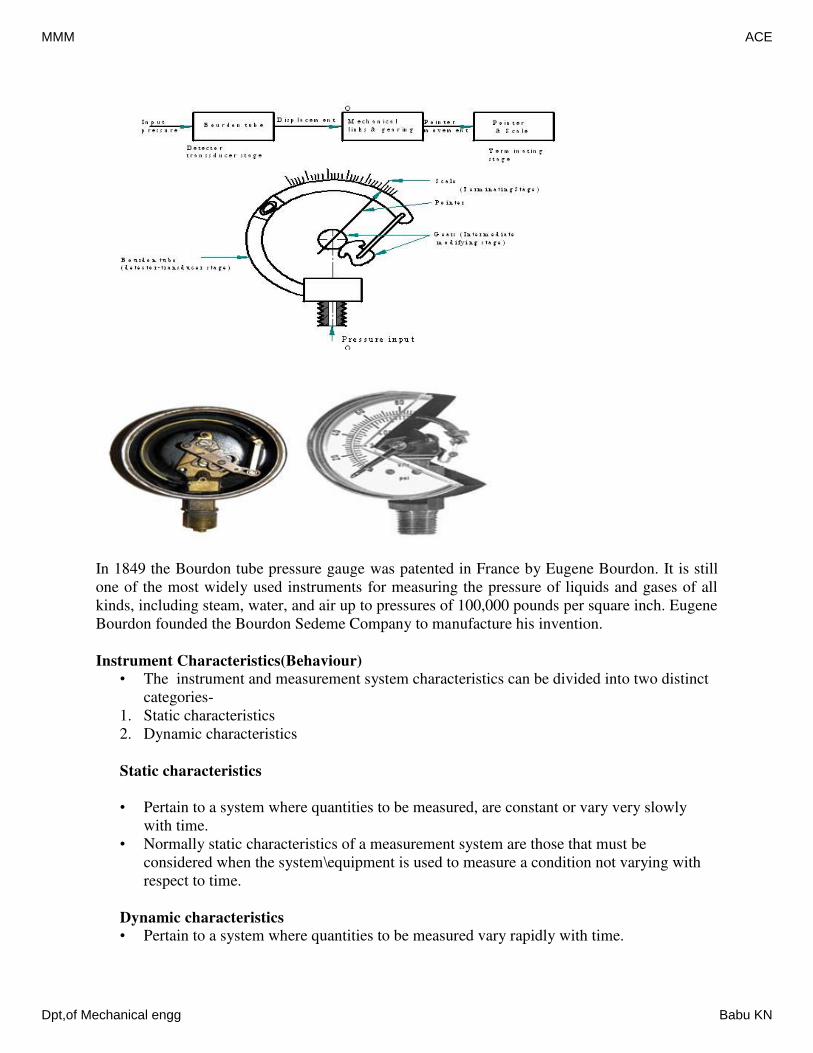
In 1849 the Bourdon tube pressure gauge was patented in France by Eugene Bourdon. It is still
one of the most widely used instruments for measuring the pressure of liquids and gases of all
kinds, including steam, water, and air up to pressures of 100,000 pounds per square inch. Eugene
Bourdon founded the Bourdon Sedeme Company to manufacture his invention.
Instrument Characteristics(Behaviour)
• The instrument and measurement system characteristics can be divided into two distinct
categories-
1. Static characteristics
2. Dynamic characteristics
Static characteristics
• Pertain to a system where quantities to be measured, are constant or vary very slowly
with time.
• Normally static characteristics of a measurement system are those that must be
considered when the system\equipment is used to measure a condition not varying with
respect to time.
Dynamic characteristics
• Pertain to a system where quantities to be measured vary rapidly with time.
MMM ACE
Dpt,of Mechanical engg Babu KN
• There are many phenomenon which can be conveniently described by the static response
while on the other hand there are phenomenon which can only be reported by dynamic
response.
• The overall performance of a system, many a times can be evaluated by semi-qualitative
super position of static and dynamic characteristics.
Definitions & basic concepts
Readability: This term indicates the closeness with which the scale of the instrument may be
read. For ex, an instrument with 30 cm scale has a higher readability than that of a 15 cm scale.
Least count: It is the smallest difference between two indications that can be detected on the
instrument scale.
Range: It represents the highest possible value that can be measured by an instrument or it is the
difference between the largest & the smallest results of measurement. Example-
Data : Elemental items of information obtained by experimental means - assumed to be in
numerical forms. Example-
Population(also called universe): A collection of data, either from finite or infinite in number all
representing the same quantity. Example-
Sample : A portion of a population, represent the time value or should be a representative of the
population.
• Multi sample test: A repeated measurement of a given quantity using altered test
conditions - such as different observers or different instrumentation.
• Merely taking repeated reading with the same procedure and equipments does not
provide multi sample results.
• Example : Many experimenters have conducted experiments to determine the velocity of
light in vacuum.
• This has been done using different apparatus and techniques. Each leading measured is
supposedly a unique quantity. Although, the results vary, taken together, these finding are
multi sample results.
• Single sample test : A single reading or succession of reading taken under identical
conditions except for time.
•
True value or actual value (Va): It is the actual magnitude of the input signal to a measuring
system which may be approximated but never truly be determined. The true value may be
defined as the average of an infinite number of measured values, when the average deviation of
the various contributing factors tend to zero. Indicated value (Vi): The magnitude of the input
signal indicated by a measuring instrument is known as indicated value. This is the supply of raw
or directly recorded data.Correction: It is the revision applied to the indicated value which
improves the worthiness of the result. Such revision may be in the form of either an additive
factor or a multiplier or both.Result (Vr) : It is obtained by making all known corrections to the
indicated value. Vr= AVi + B, where A & B are multiplicative & additive corrections.
Discrepancy : The difference between two indicated values or results determined from a
supposedly fixed time value.
Error: It is the difference between the true value (Va) & the result (Vr). Error=(Vr-Va)
MMM ACE
Dpt,of Mechanical engg Babu KN
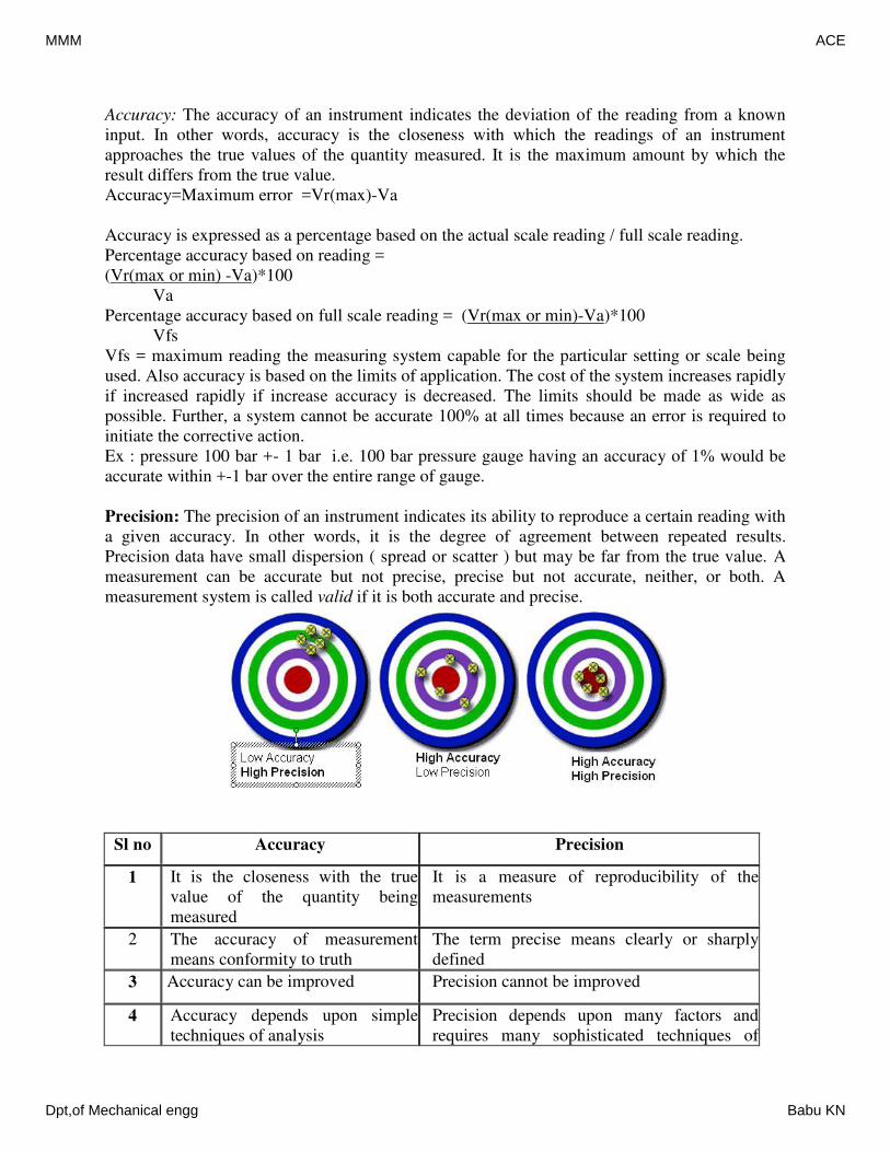
Accuracy: The accuracy of an instrument indicates the deviation of the reading from a known
input. In other words, accuracy is the closeness with which the readings of an instrument
approaches the true values of the quantity measured. It is the maximum amount by which the
result differs from the true value.
Accuracy=Maximum error =Vr(max)-Va
Accuracy is expressed as a percentage based on the actual scale reading / full scale reading.
Percentage accuracy based on reading =
(Vr(max or min) -Va)*100
Va
Percentage accuracy based on full scale reading = (Vr(max or min)-Va)*100
Vfs
Vfs = maximum reading the measuring system capable for the particular setting or scale being
used. Also accuracy is based on the limits of application. The cost of the system increases rapidly
if increased rapidly if increase accuracy is decreased. The limits should be made as wide as
possible. Further, a system cannot be accurate 100% at all times because an error is required to
initiate the corrective action.
Ex : pressure 100 bar +- 1 bar i.e. 100 bar pressure gauge having an accuracy of 1% would be
accurate within +-1 bar over the entire range of gauge.
Precision: The precision of an instrument indicates its ability to reproduce a certain reading with
a given accuracy. In other words, it is the degree of agreement between repeated results.
Precision data have small dispersion ( spread or scatter ) but may be far from the true value. A
measurement can be accurate but not precise, precise but not accurate, neither, or both. A
measurement system is called valid if it is both accurate and precise.
Sl no Accuracy Precision
1 It is the closeness with the true
value of the quantity being
measured
It is a measure of reproducibility of the
measurements
2 The accuracy of measurement
means conformity to truth
The term precise means clearly or sharply
defined
3 Accuracy can be improved Precision cannot be improved
4 Accuracy depends upon simple
techniques of analysis
Precision depends upon many factors and
requires many sophisticated techniques of
MMM ACE
Dpt,of Mechanical engg Babu KN
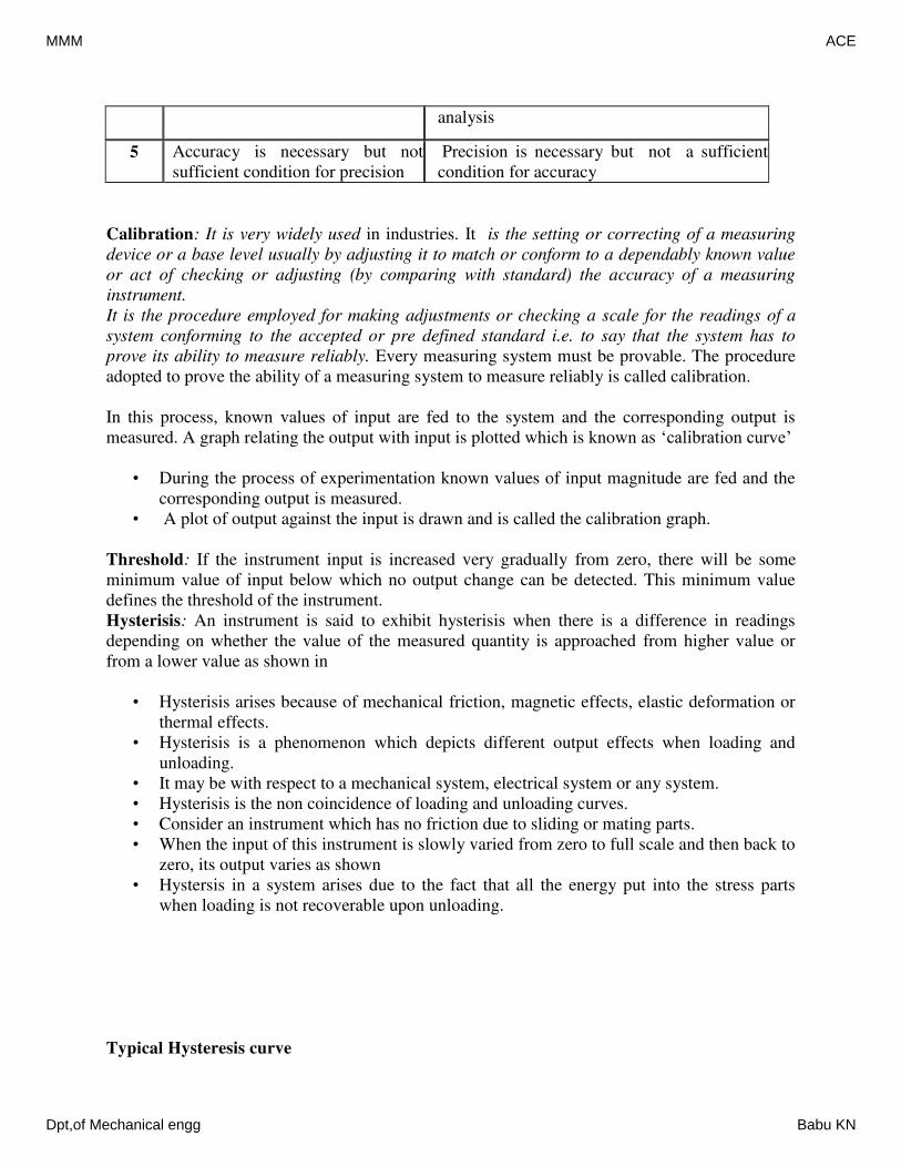
analysis
5 Accuracy is necessary but not
sufficient condition for precision
Precision is necessary but not a sufficient
condition for accuracy
Calibration: It is very widely used in industries. It is the setting or correcting of a measuring
device or a base level usually by adjusting it to match or conform to a dependably known value
or act of checking or adjusting (by comparing with standard) the accuracy of a measuring
instrument.
It is the procedure employed for making adjustments or checking a scale for the readings of a
system conforming to the accepted or pre defined standard i.e. to say that the system has to
prove its ability to measure reliably. Every measuring system must be provable. The procedure
adopted to prove the ability of a measuring system to measure reliably is called calibration.
In this process, known values of input are fed to the system and the corresponding output is
measured. A graph relating the output with input is plotted which is known as ‘calibration curve’
• During the process of experimentation known values of input magnitude are fed and the
corresponding output is measured.
• A plot of output against the input is drawn and is called the calibration graph.
Threshold: If the instrument input is increased very gradually from zero, there will be some
minimum value of input below which no output change can be detected. This minimum value
defines the threshold of the instrument.
Hysterisis: An instrument is said to exhibit hysterisis when there is a difference in readings
depending on whether the value of the measured quantity is approached from higher value or
from a lower value as shown in
• Hysterisis arises because of mechanical friction, magnetic effects, elastic deformation or
thermal effects.
• Hysterisis is a phenomenon which depicts different output effects when loading and
unloading.
• It may be with respect to a mechanical system, electrical system or any system.
• Hysterisis is the non coincidence of loading and unloading curves.
• Consider an instrument which has no friction due to sliding or mating parts.
• When the input of this instrument is slowly varied from zero to full scale and then back to
zero, its output varies as shown
• Hystersis in a system arises due to the fact that all the energy put into the stress parts
when loading is not recoverable upon unloading.
Typical Hysteresis curve
MMM ACE
Dpt,of Mechanical engg Babu KN
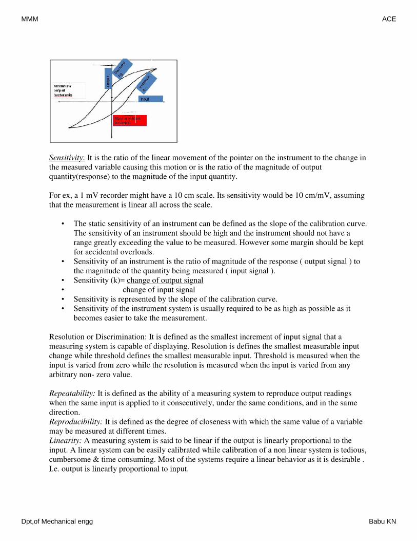
Sensitivity: It is the ratio of the linear movement of the pointer on the instrument to the change in
the measured variable causing this motion or is the ratio of the magnitude of output
quantity(response) to the magnitude of the input quantity.
For ex, a 1 mV recorder might have a 10 cm scale. Its sensitivity would be 10 cm/mV, assuming
that the measurement is linear all across the scale.
• The static sensitivity of an instrument can be defined as the slope of the calibration curve.
The sensitivity of an instrument should be high and the instrument should not have a
range greatly exceeding the value to be measured. However some margin should be kept
for accidental overloads.
• Sensitivity of an instrument is the ratio of magnitude of the response ( output signal ) to
the magnitude of the quantity being measured ( input signal ).
• Sensitivity (k)= change of output signal
• change of input signal
• Sensitivity is represented by the slope of the calibration curve.
• Sensitivity of the instrument system is usually required to be as high as possible as it
becomes easier to take the measurement.
Resolution or Discrimination: It is defined as the smallest increment of input signal that a
measuring system is capable of displaying. Resolution is defines the smallest measurable input
change while threshold defines the smallest measurable input. Threshold is measured when the
input is varied from zero while the resolution is measured when the input is varied from any
arbitrary non- zero value.
Repeatability: It is defined as the ability of a measuring system to reproduce output readings
when the same input is applied to it consecutively, under the same conditions, and in the same
direction.
Reproducibility: It is defined as the degree of closeness with which the same value of a variable
may be measured at different times.
Linearity: A measuring system is said to be linear if the output is linearly proportional to the
input. A linear system can be easily calibrated while calibration of a non linear system is tedious,
cumbersome & time consuming. Most of the systems require a linear behavior as it is desirable .
I.e. output is linearly proportional to input.
MMM ACE
Dpt,of Mechanical engg Babu KN
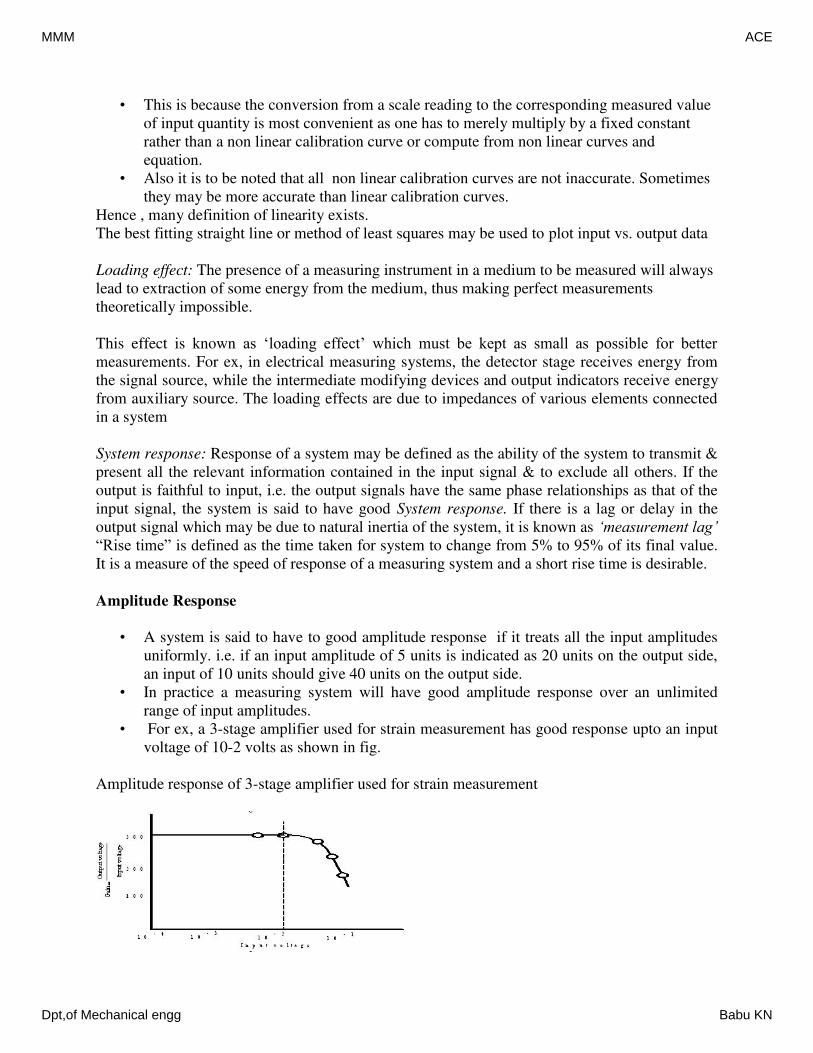
• This is because the conversion from a scale reading to the corresponding measured value
of input quantity is most convenient as one has to merely multiply by a fixed constant
rather than a non linear calibration curve or compute from non linear curves and
equation.
• Also it is to be noted that all non linear calibration curves are not inaccurate. Sometimes
they may be more accurate than linear calibration curves.
Hence , many definition of linearity exists.
The best fitting straight line or method of least squares may be used to plot input vs. output data
Loading effect: The presence of a measuring instrument in a medium to be measured will always
lead to extraction of some energy from the medium, thus making perfect measurements
theoretically impossible.
This effect is known as ‘loading effect’ which must be kept as small as possible for better
measurements. For ex, in electrical measuring systems, the detector stage receives energy from
the signal source, while the intermediate modifying devices and output indicators receive energy
from auxiliary source. The loading effects are due to impedances of various elements connected
in a system
System response: Response of a system may be defined as the ability of the system to transmit &
present all the relevant information contained in the input signal & to exclude all others. If the
output is faithful to input, i.e. the output signals have the same phase relationships as that of the
input signal, the system is said to have good System response. If there is a lag or delay in the
output signal which may be due to natural inertia of the system, it is known as ‘measurement lag’
“Rise time” is defined as the time taken for system to change from 5% to 95% of its final value.
It is a measure of the speed of response of a measuring system and a short rise time is desirable.
Amplitude Response
• A system is said to have to good amplitude response if it treats all the input amplitudes
uniformly. i.e. if an input amplitude of 5 units is indicated as 20 units on the output side,
an input of 10 units should give 40 units on the output side.
• In practice a measuring system will have good amplitude response over an unlimited
range of input amplitudes.
• For ex, a 3-stage amplifier used for strain measurement has good response upto an input
voltage of 10-2 volts as shown in fig.
Amplitude response of 3-stage amplifier used for strain measurement
MMM ACE
Dpt,of Mechanical engg Babu KN
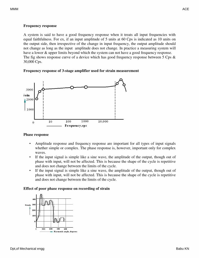
Frequency response
A system is said to have a good frequency response when it treats all input frequencies with
equal faithfulness. For ex, if an input amplitude of 5 units at 60 Cps is indicated as 10 units on
the output side, then irrespective of the change in input frequency, the output amplitude should
not change as long as the input amplitude does not change. In practice a measuring system will
have a lower & upper limits beyond which the system can not have a good frequency response.
The fig shows response curve of a device which has good frequency response between 5 Cps &
30,000 Cps.
Frequency response of 3-stage amplifier used for strain measurement
Phase response
• Amplitude response and frequency response are important for all types of input signals
whether simple or complex. The phase response is, however, important only for complex
waves.
• If the input signal is simple like a sine wave, the amplitude of the output, though out of
phase with input, will not be affected. This is because the shape of the cycle is repetitive
and does not change between the limits of the cycle.
• If the input signal is simple like a sine wave, the amplitude of the output, though out of
phase with input, will not be affected. This is because the shape of the cycle is repetitive
and does not change between the limits of the cycle.
Effect of poor phase response on recording of strain
MMM ACE
Dpt,of Mechanical engg Babu KN
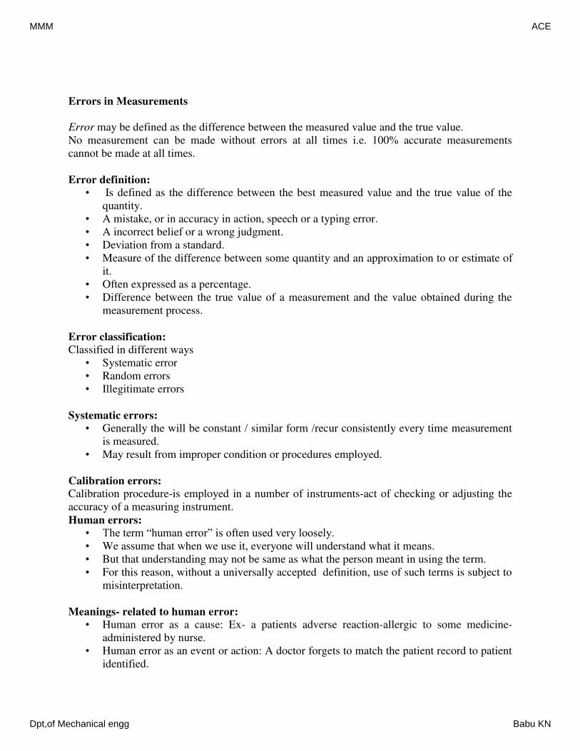
Errors in Measurements
Error may be defined as the difference between the measured value and the true value.
No measurement can be made without errors at all times i.e. 100% accurate measurements
cannot be made at all times.
Error definition:
• Is defined as the difference between the best measured value and the true value of the
quantity.
• A mistake, or in accuracy in action, speech or a typing error.
• A incorrect belief or a wrong judgment.
• Deviation from a standard.
• Measure of the difference between some quantity and an approximation to or estimate of
it.
• Often expressed as a percentage.
• Difference between the true value of a measurement and the value obtained during the
measurement process.
Error classification:
Classified in different ways
• Systematic error
• Random errors
• Illegitimate errors
Systematic errors:
• Generally the will be constant / similar form /recur consistently every time measurement
is measured.
• May result from improper condition or procedures employed.
Calibration errors:
Calibration procedure-is employed in a number of instruments-act of checking or adjusting the
accuracy of a measuring instrument.
Human errors:
• The term “human error” is often used very loosely.
• We assume that when we use it, everyone will understand what it means.
• But that understanding may not be same as what the person meant in using the term.
• For this reason, without a universally accepted definition, use of such terms is subject to
misinterpretation.
Meanings- related to human error:
• Human error as a cause: Ex- a patients adverse reaction-allergic to some medicine-
administered by nurse.
• Human error as an event or action: A doctor forgets to match the patient record to patient
identified.
MMM ACE
Dpt,of Mechanical engg Babu KN
• Human error as a consequence: A nurse leaves some sponge material inside a patient
after surgery.
In all the above, the focus is on the outcome, yet description is of the action. Hence, we must use
the human error term and relate to the event/measurement. Human errors may also be systematic
as in case of an individuals tendency to consistently read high or low values when synchronized
reading are to be taken. The apparatus and equipment itself may cause or lead to built in errors
resulting from incorrect design, fabrication, poor maintenance(Ex-defective gears, linkage
mechanism etc.)
(1) Systematic or fixed errors:
(a) calibration errors
(b) Certain types of consistently recurring human errors
(c) Errors of technique
(d) Uncorrected loading errors
(e) Limits of system resolution Systematic errors are repetitive & of fixed value. They have
a definite magnitude & direction
(2) Random or Accidental errors:
(a) Errors stemming from environmental variations
(b) Certain types of human errors
(c) Due to Variations in definition
(d) Due to Insufficient sensitivity of measuring system
Random errors are distinguishable by their lack of consistency. An observer may not be
consistent in taking readings. Also the process involved may include certain poorly controlled
variables causing changing conditions. The variations in temperature, vibrations of external
medium, etc. cause errors in the instrument. Errors of this type are normally of limited duration
& are inherent to specific environment.
(3) Illegitimate errors:
(a) Blunders or Mistakes
(b) Computational errors
(c) Chaotic errors
Illegitimate errors : should not exist and may be eliminated by careful exercise & repetition of
measurement. Chaotic errors which may be due to extreme vibration, mechanical shock of the
equipment, pick up of extraneous noise make the testing meaningless unless all these
disturbances are eliminated. If a measuring instrument is not calibrated periodically it will lead
to errors in measurement .
Human errors : are due to variation of physical & mental states of a person which may lead to
systematic or random errors.
Errors of technique: are due to improper usage of measuring apparatus. This may include errors
resulting from incorrect design, fabrication or maintenance.
MMM ACE
Dpt,of Mechanical engg Babu KN
Loading errors : result from influence exerted by the act of measurement on the physical system
being tested.
Sources of errors
(1) Noise: It is defined as any signal that does not convey useful information.
(2) Design limitations: These are certain inevitable factors such as friction & resolving power
which lead to uncertainty in measurements.
(3) Response time: It is the time lag between the application of input signal & output
measurement.
4) Deterioration of measuring system: Physical and/or chemical deterioration or other alterations
in characteristics of measuring system constitute a source of error in measurement.
(5) Environmental effects: The change in atmospheric temperature may alter the elastic constant
of a spring, the dimensions of a linkage, electrical resistance etc. similarly other factors such as
humidity, pressure etc. also affect measurements.
(6) Errors in observation & Interpretation: It is the mistake of operators in observing,
interpreting & recording the data.
(7) Poor maintenance of the system
Introduction to Transducers
Transducer is a first stage element of the measurement system. It detects and transforms the
sensed signal into a more useful form.
Transfer efficiency: It is the ratio of output information delivered by the pick up (Sensor) to the
information received by the pick up.
Transfer efficiency
Where Iout=the information delivered by the unit, Iin=information received by the unit
Since the pick up can not generate any information , the transfer efficiency can not be greater
than unity. The detector- transducer stage must be designed to have a high Transfer efficiency to
the extent possible.
Active & Passive Transducers: Active transducers
Also known as self generating type transducers Develop their own voltage or current. Energy
required for production of output signal is obtained by quantity being measured.Ex, Electronic &
Piezo electric transducers.
Passive Transducers:
• Also known as externally powered transducer
• Derive the power for energy conversion from an external power source
• Ex: Bonded electrical resistance strain gauges
Detector Transducer or Primary Transducer
in
out
I
Iη
MMM ACE
Dpt,of Mechanical engg Babu KN
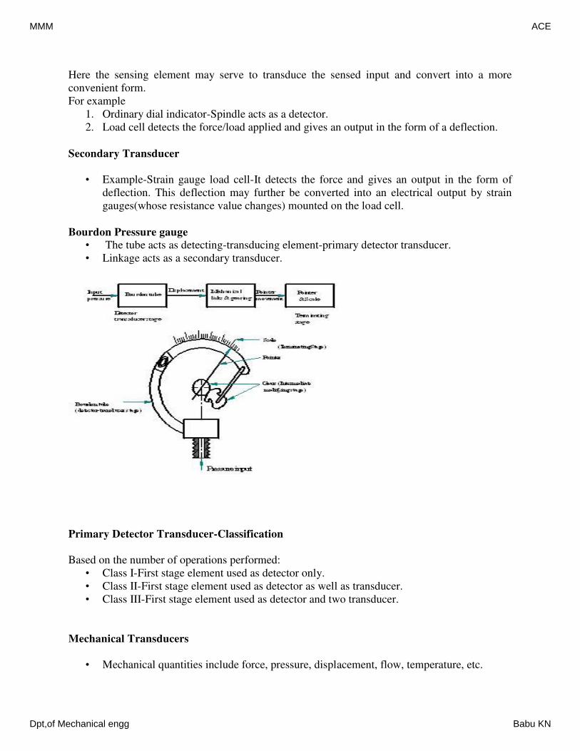
Here the sensing element may serve to transduce the sensed input and convert into a more
convenient form.
For example
1. Ordinary dial indicator-Spindle acts as a detector.
2. Load cell detects the force/load applied and gives an output in the form of a deflection.
Secondary Transducer
• Example-Strain gauge load cell-It detects the force and gives an output in the form of
deflection. This deflection may further be converted into an electrical output by strain
gauges(whose resistance value changes) mounted on the load cell.
Bourdon Pressure gauge
• The tube acts as detecting-transducing element-primary detector transducer.
• Linkage acts as a secondary transducer.
Primary Detector Transducer-Classification
Based on the number of operations performed:
• Class I-First stage element used as detector only.
• Class II-First stage element used as detector as well as transducer.
• Class III-First stage element used as detector and two transducer.
Mechanical Transducers
• Mechanical quantities include force, pressure, displacement, flow, temperature, etc.
MMM ACE
Dpt,of Mechanical engg Babu KN
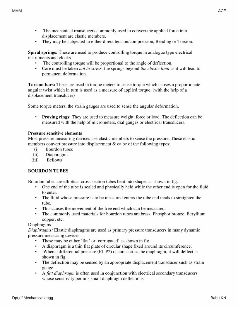
• The mechanical transducers commonly used to convert the applied force into
displacement are elastic members.
• They may be subjected to either direct tension/compression, Bending or Torsion.
Spiral springs: These are used to produce controlling torque in analogue type electrical
instruments and clocks.
• The controlling torque will be proportional to the angle of deflection.
• Care must be taken not to stress the springs beyond the elastic limit as it will lead to
permanent deformation.
Torsion bars: These are used in torque meters to sense torque which causes a proportionate
angular twist which in turn is used as a measure of applied torque. (with the help of a
displacement transducer)
Some torque meters, the strain gauges are used to sense the angular deformation.
• Proving rings: They are used to measure weight, force or load. The deflection can be
measured with the help of micrometers, dial gauges or electrical transducers.
Pressure sensitive elements
Most pressure measuring devices use elastic members to sense the pressure. These elastic
members convert pressure into displacement & ca be of the following types;
(i) Bourdon tubes
(ii) Diaphragms
(iii) Bellows
BOURDON TUBES
Bourdon tubes are elliptical cross section tubes bent into shapes as shown in fig.
• One end of the tube is sealed and physically held while the other end is open for the fluid
to enter.
• The fluid whose pressure is to be measured enters the tube and tends to straighten the
tube.
• This causes the movement of the free end which can be measured.
• The commonly used materials for bourdon tubes are brass, Phosphor bronze, Beryllium
copper, etc.
Diaphragms
Diaphragms: Elastic diaphragms are used as primary pressure transducers in many dynamic
pressure measuring devices.
• These may be either ‘flat’ or ‘corrugated’ as shown in fig.
• A diaphragm is a thin flat plate of circular shape fixed around its circumference.
• When a differential pressure (P1-P2) occurs across the diaphragm, it will deflect as
shown in fig.
• The deflection may be sensed by an appropriate displacement transducer such as strain
gauge.
• A flat diaphragm is often used in conjunction with electrical secondary transducers
whose sensitivity permits small diaphragm deflections.
MMM ACE
Dpt,of Mechanical engg Babu KN
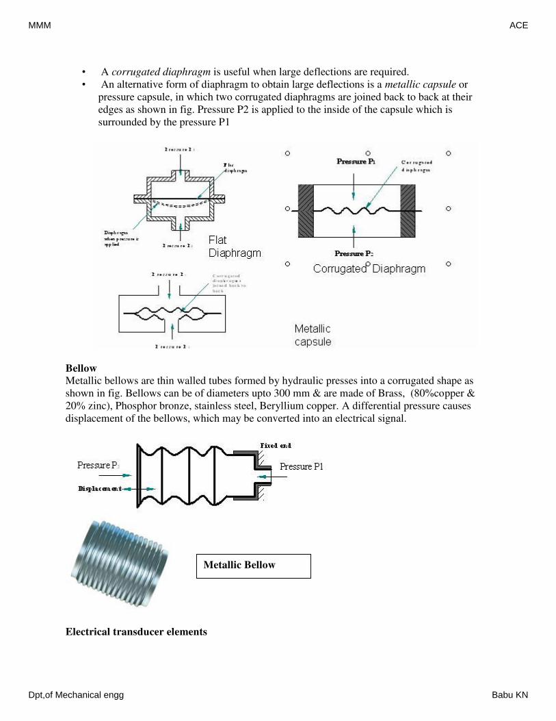
• A corrugated diaphragm is useful when large deflections are required.
• An alternative form of diaphragm to obtain large deflections is a metallic capsule or
pressure capsule, in which two corrugated diaphragms are joined back to back at their
edges as shown in fig. Pressure P2 is applied to the inside of the capsule which is
surrounded by the pressure P1
Bellow
Metallic bellows are thin walled tubes formed by hydraulic presses into a corrugated shape as
shown in fig. Bellows can be of diameters upto 300 mm & are made of Brass, (80%copper &
20% zinc), Phosphor bronze, stainless steel, Beryllium copper. A differential pressure causes
displacement of the bellows, which may be converted into an electrical signal.
Electrical transducer elements
Metallic Bellow
MMM ACE
Dpt,of Mechanical engg Babu KN
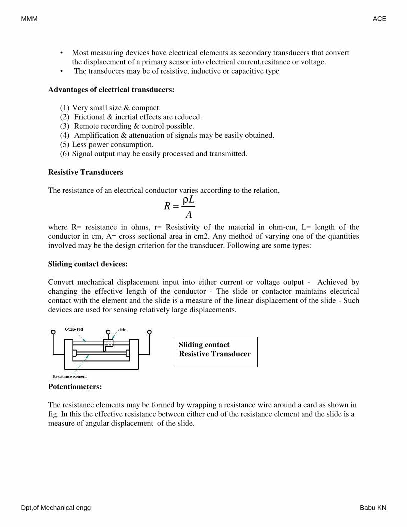
• Most measuring devices have electrical elements as secondary transducers that convert
the displacement of a primary sensor into electrical current,resitance or voltage.
• The transducers may be of resistive, inductive or capacitive type
Advantages of electrical transducers:
(1) Very small size & compact.
(2) Frictional & inertial effects are reduced .
(3) Remote recording & control possible.
(4) Amplification & attenuation of signals may be easily obtained.
(5) Less power consumption.
(6) Signal output may be easily processed and transmitted.
Resistive Transducers
The resistance of an electrical conductor varies according to the relation,
where R= resistance in ohms, r= Resistivity of the material in ohm-cm, L= length of the
conductor in cm, A= cross sectional area in cm2. Any method of varying one of the quantities
involved may be the design criterion for the transducer. Following are some types:
Sliding contact devices:
Convert mechanical displacement input into either current or voltage output - Achieved by
changing the effective length of the conductor - The slide or contactor maintains electrical
contact with the element and the slide is a measure of the linear displacement of the slide - Such
devices are used for sensing relatively large displacements.
Potentiometers:
The resistance elements may be formed by wrapping a resistance wire around a card as shown in
fig. In this the effective resistance between either end of the resistance element and the slide is a
measure of angular displacement of the slide.
A
LR
ρ
Sliding contact
Resistive Transducer
MMM ACE
Dpt,of Mechanical engg Babu KN
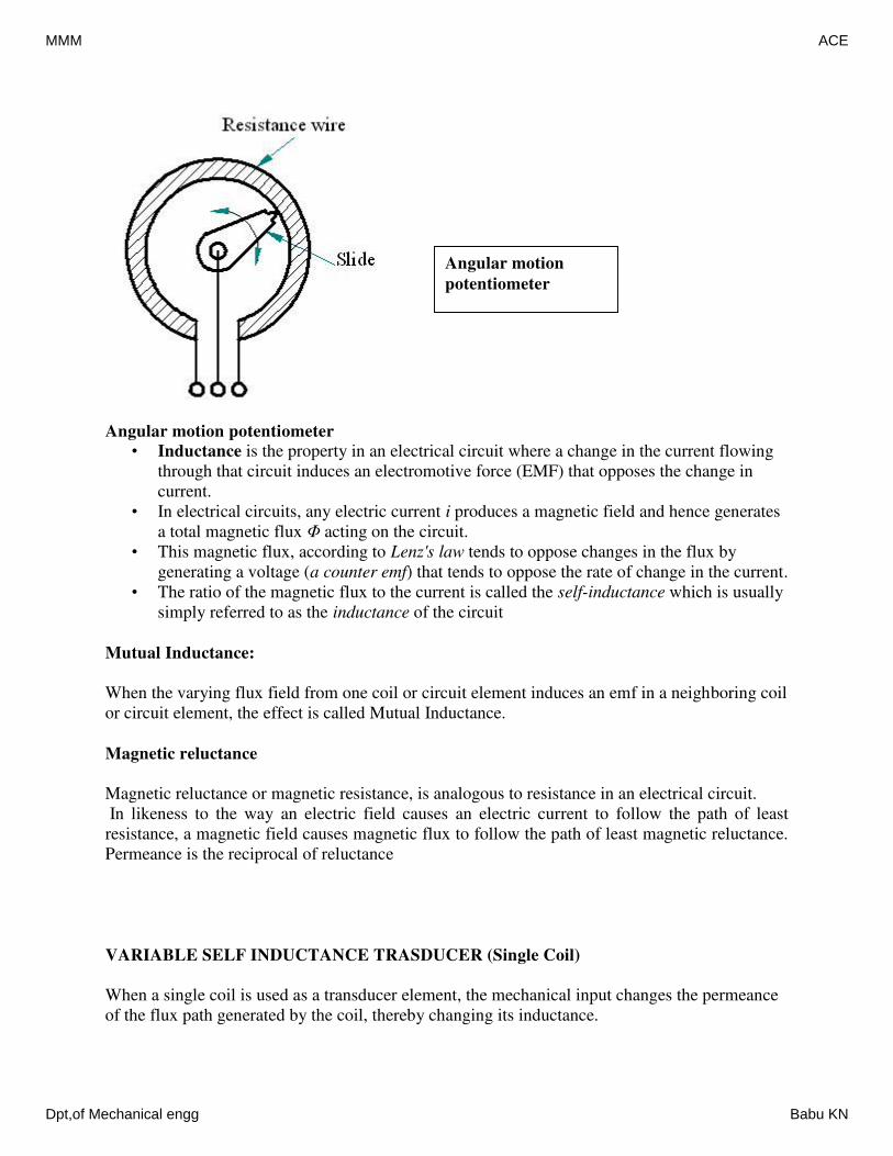
Angular motion potentiometer
• Inductance is the property in an electrical circuit where a change in the current flowing
through that circuit induces an electromotive force (EMF) that opposes the change in
current.
• In electrical circuits, any electric current i produces a magnetic field and hence generates
a total magnetic flux Φ acting on the circuit.
• This magnetic flux, according to Lenz's law tends to oppose changes in the flux by
generating a voltage (a counter emf) that tends to oppose the rate of change in the current.
• The ratio of the magnetic flux to the current is called the self-inductance which is usually
simply referred to as the inductance of the circuit
Mutual Inductance:
When the varying flux field from one coil or circuit element induces an emf in a neighboring coil
or circuit element, the effect is called Mutual Inductance.
Magnetic reluctance
Magnetic reluctance or magnetic resistance, is analogous to resistance in an electrical circuit.
In likeness to the way an electric field causes an electric current to follow the path of least
resistance, a magnetic field causes magnetic flux to follow the path of least magnetic reluctance.
Permeance is the reciprocal of reluctance
VARIABLE SELF INDUCTANCE TRASDUCER (Single Coil)
When a single coil is used as a transducer element, the mechanical input changes the permeance
of the flux path generated by the coil, thereby changing its inductance.
Angular motion
potentiometer
MMM ACE
Dpt,of Mechanical engg Babu KN
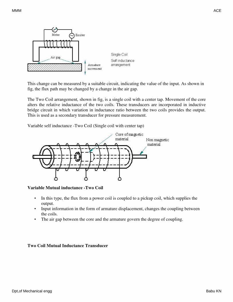
This change can be measured by a suitable circuit, indicating the value of the input. As shown in
fig, the flux path may be changed by a change in the air gap.
The Two Coil arrangement, shown in fig, is a single coil with a center tap. Movement of the core
alters the relative inductance of the two coils. These transducers are incorporated in inductive
bridge circuit in which variation in inductance ratio between the two coils provides the output.
This is used as a secondary transducer for pressure measurement.
Variable self inductance -Two Coil (Single coil with center tap)
Variable Mutual inductance -Two Coil
• In this type, the flux from a power coil is coupled to a pickup coil, which supplies the
output.
• Input information in the form of armature displacement, changes the coupling between
the coils.
• The air gap between the core and the armature govern the degree of coupling.
Two Coil Mutual Inductance Transducer
MMM ACE
Dpt,of Mechanical engg Babu KN
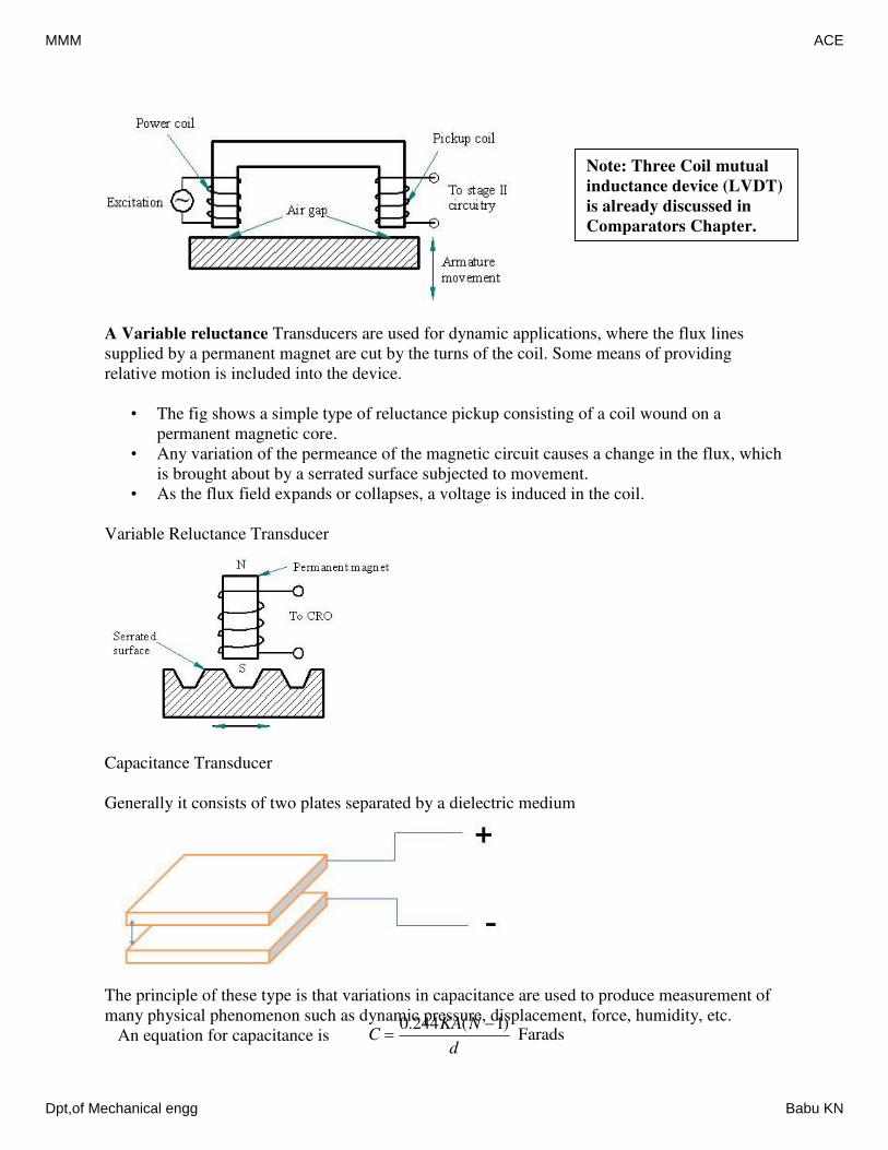
A Variable reluctance Transducers are used for dynamic applications, where the flux lines
supplied by a permanent magnet are cut by the turns of the coil. Some means of providing
relative motion is included into the device.
• The fig shows a simple type of reluctance pickup consisting of a coil wound on a
permanent magnetic core.
• Any variation of the permeance of the magnetic circuit causes a change in the flux, which
is brought about by a serrated surface subjected to movement.
• As the flux field expands or collapses, a voltage is induced in the coil.
Variable Reluctance Transducer
Capacitance Transducer
Generally it consists of two plates separated by a dielectric medium
The principle of these type is that variations in capacitance are used to produce measurement of
many physical phenomenon such as dynamic pressure, displacement, force, humidity, etc.
An equation for capacitance is
Note: Three Coil mutual
inductance device (LVDT)
is already discussed in
Comparators Chapter.
Farads)1(244.0
d
NKAC
MMM ACE
Dpt,of Mechanical engg Babu KN
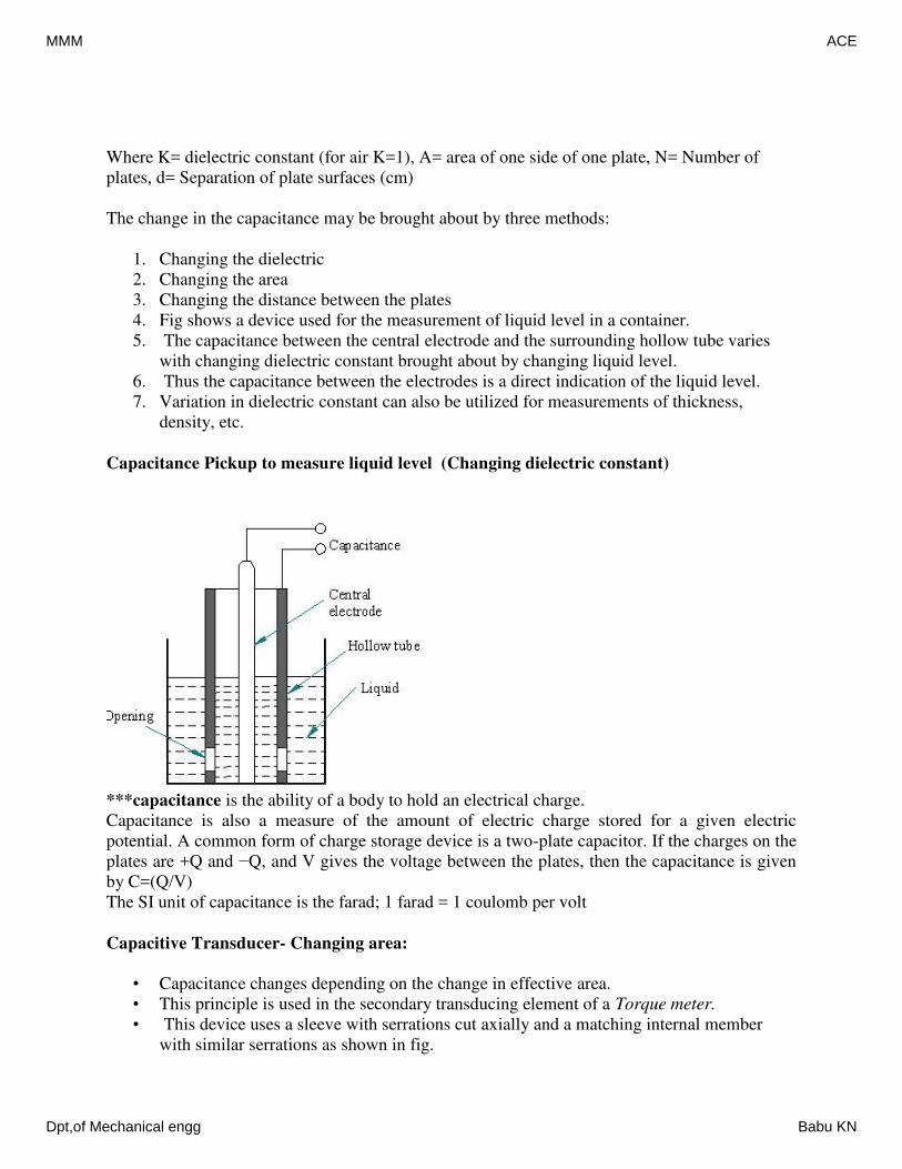
Where K= dielectric constant (for air K=1), A= area of one side of one plate, N= Number of
plates, d= Separation of plate surfaces (cm)
The change in the capacitance may be brought about by three methods:
1. Changing the dielectric
2. Changing the area
3. Changing the distance between the plates
4. Fig shows a device used for the measurement of liquid level in a container.
5. The capacitance between the central electrode and the surrounding hollow tube varies
with changing dielectric constant brought about by changing liquid level.
6. Thus the capacitance between the electrodes is a direct indication of the liquid level.
7. Variation in dielectric constant can also be utilized for measurements of thickness,
density, etc.
Capacitance Pickup to measure liquid level (Changing dielectric constant)
***capacitance is the ability of a body to hold an electrical charge.
Capacitance is also a measure of the amount of electric charge stored for a given electric
potential. A common form of charge storage device is a two-plate capacitor. If the charges on the
plates are +Q and −Q, and V gives the voltage between the plates, then the capacitance is given
by C=(Q/V)
The SI unit of capacitance is the farad; 1 farad = 1 coulomb per volt
Capacitive Transducer- Changing area:
• Capacitance changes depending on the change in effective area.
• This principle is used in the secondary transducing element of a Torque meter.
• This device uses a sleeve with serrations cut axially and a matching internal member
with similar serrations as shown in fig.
MMM ACE
Dpt,of Mechanical engg Babu KN
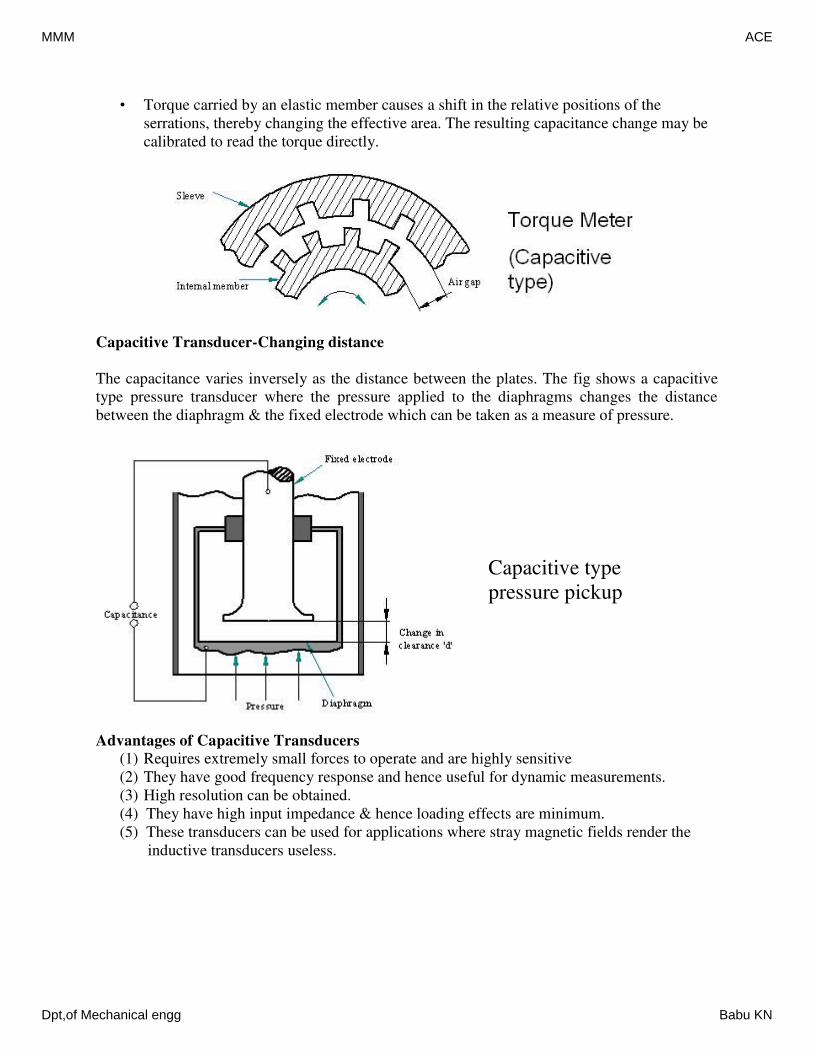
• Torque carried by an elastic member causes a shift in the relative positions of the
serrations, thereby changing the effective area. The resulting capacitance change may be
calibrated to read the torque directly.
Capacitive Transducer-Changing distance
The capacitance varies inversely as the distance between the plates. The fig shows a capacitive
type pressure transducer where the pressure applied to the diaphragms changes the distance
between the diaphragm & the fixed electrode which can be taken as a measure of pressure.
Advantages of Capacitive Transducers
(1) Requires extremely small forces to operate and are highly sensitive
(2) They have good frequency response and hence useful for dynamic measurements.
(3) High resolution can be obtained.
(4) They have high input impedance & hence loading effects are minimum.
(5) These transducers can be used for applications where stray magnetic fields render the
inductive transducers useless.
Capacitive type
pressure pickup
MMM ACE
Dpt,of Mechanical engg Babu KN
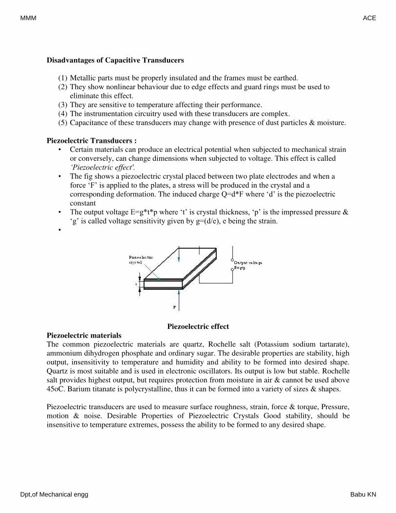
Disadvantages of Capacitive Transducers
(1) Metallic parts must be properly insulated and the frames must be earthed.
(2) They show nonlinear behaviour due to edge effects and guard rings must be used to
eliminate this effect.
(3) They are sensitive to temperature affecting their performance.
(4) The instrumentation circuitry used with these transducers are complex.
(5) Capacitance of these transducers may change with presence of dust particles & moisture.
Piezoelectric Transducers :
• Certain materials can produce an electrical potential when subjected to mechanical strain
or conversely, can change dimensions when subjected to voltage. This effect is called
‘Piezoelectric effect'.
• The fig shows a piezoelectric crystal placed between two plate electrodes and when a
force ‘F’ is applied to the plates, a stress will be produced in the crystal and a
corresponding deformation. The induced charge Q=d*F where ‘d’ is the piezoelectric
constant
• The output voltage E=g*t*p where ‘t’ is crystal thickness, ‘p’ is the impressed pressure &
‘g’ is called voltage sensitivity given by g=(d/e), e being the strain.
•
Piezoelectric effect
Piezoelectric materials
The common piezoelectric materials are quartz, Rochelle salt (Potassium sodium tartarate),
ammonium dihydrogen phosphate and ordinary sugar. The desirable properties are stability, high
output, insensitivity to temperature and humidity and ability to be formed into desired shape.
Quartz is most suitable and is used in electronic oscillators. Its output is low but stable. Rochelle
salt provides highest output, but requires protection from moisture in air & cannot be used above
45oC. Barium titanate is polycrystalline, thus it can be formed into a variety of sizes & shapes.
Piezoelectric transducers are used to measure surface roughness, strain, force & torque, Pressure,
motion & noise. Desirable Properties of Piezoelectric Crystals Good stability, should be
insensitive to temperature extremes, possess the ability to be formed to any desired shape.
MMM ACE
Dpt,of Mechanical engg Babu KN
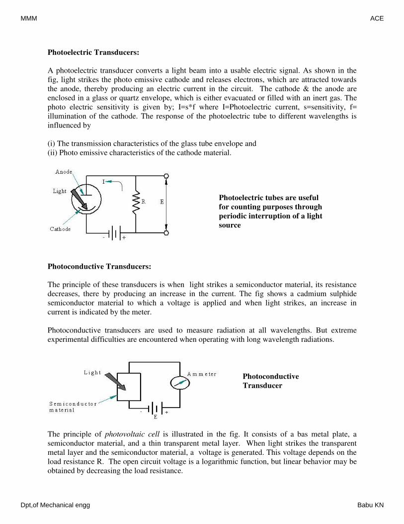
Photoelectric Transducers:
A photoelectric transducer converts a light beam into a usable electric signal. As shown in the
fig, light strikes the photo emissive cathode and releases electrons, which are attracted towards
the anode, thereby producing an electric current in the circuit. The cathode & the anode are
enclosed in a glass or quartz envelope, which is either evacuated or filled with an inert gas. The
photo electric sensitivity is given by; I=s*f where I=Photoelectric current, s=sensitivity, f=
illumination of the cathode. The response of the photoelectric tube to different wavelengths is
influenced by
(i) The transmission characteristics of the glass tube envelope and
(ii) Photo emissive characteristics of the cathode material.
Photoconductive Transducers:
The principle of these transducers is when light strikes a semiconductor material, its resistance
decreases, there by producing an increase in the current. The fig shows a cadmium sulphide
semiconductor material to which a voltage is applied and when light strikes, an increase in
current is indicated by the meter.
Photoconductive transducers are used to measure radiation at all wavelengths. But extreme
experimental difficulties are encountered when operating with long wavelength radiations.
The principle of photovoltaic cell is illustrated in the fig. It consists of a bas metal plate, a
semiconductor material, and a thin transparent metal layer. When light strikes the transparent
metal layer and the semiconductor material, a voltage is generated. This voltage depends on the
load resistance R. The open circuit voltage is a logarithmic function, but linear behavior may be
obtained by decreasing the load resistance.
Photoelectric tubes are useful
for counting purposes through
periodic interruption of a light
source
Photoconductive
Transducer
MMM ACE
Dpt,of Mechanical engg Babu KN
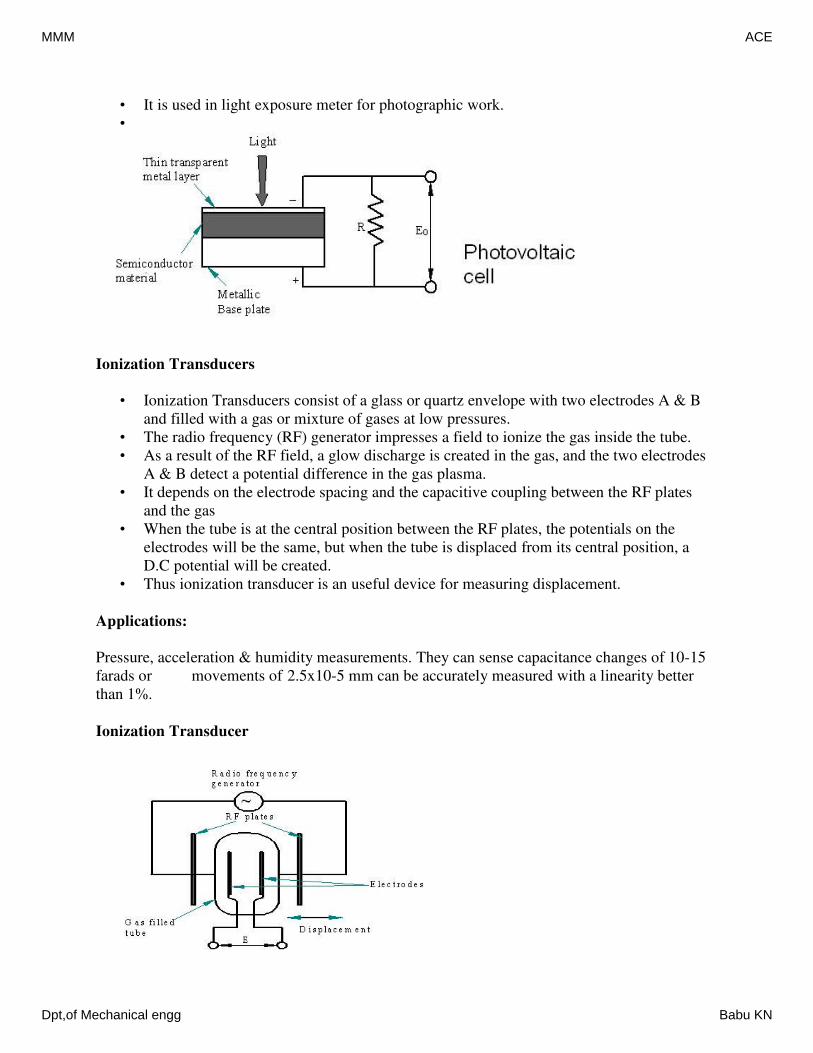
• It is used in light exposure meter for photographic work.
•
Ionization Transducers
• Ionization Transducers consist of a glass or quartz envelope with two electrodes A & B
and filled with a gas or mixture of gases at low pressures.
• The radio frequency (RF) generator impresses a field to ionize the gas inside the tube.
• As a result of the RF field, a glow discharge is created in the gas, and the two electrodes
A & B detect a potential difference in the gas plasma.
• It depends on the electrode spacing and the capacitive coupling between the RF plates
and the gas
• When the tube is at the central position between the RF plates, the potentials on the
electrodes will be the same, but when the tube is displaced from its central position, a
D.C potential will be created.
• Thus ionization transducer is an useful device for measuring displacement.
Applications:
Pressure, acceleration & humidity measurements. They can sense capacitance changes of 10-15
farads or movements of 2.5x10⁻⁵ mm can be accurately measured with a linearity better
than 1%.
Ionization Transducer
MMM ACE
Dpt,of Mechanical engg Babu KN
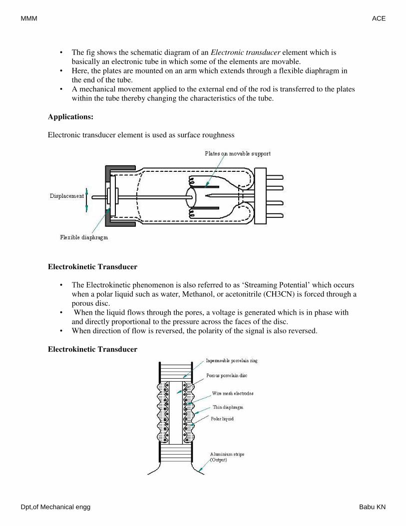
• The fig shows the schematic diagram of an Electronic transducer element which is
basically an electronic tube in which some of the elements are movable.
• Here, the plates are mounted on an arm which extends through a flexible diaphragm in
the end of the tube.
• A mechanical movement applied to the external end of the rod is transferred to the plates
within the tube thereby changing the characteristics of the tube.
Applications:
Electronic transducer element is used as surface roughness
Electrokinetic Transducer
• The Electrokinetic phenomenon is also referred to as ‘Streaming Potential’ which occurs
when a polar liquid such as water, Methanol, or acetonitrile (CH3CN) is forced through a
porous disc.
• When the liquid flows through the pores, a voltage is generated which is in phase with
and directly proportional to the pressure across the faces of the disc.
• When direction of flow is reversed, the polarity of the signal is also reversed.
Electrokinetic Transducer
MMM ACE
Dpt,of Mechanical engg Babu KN
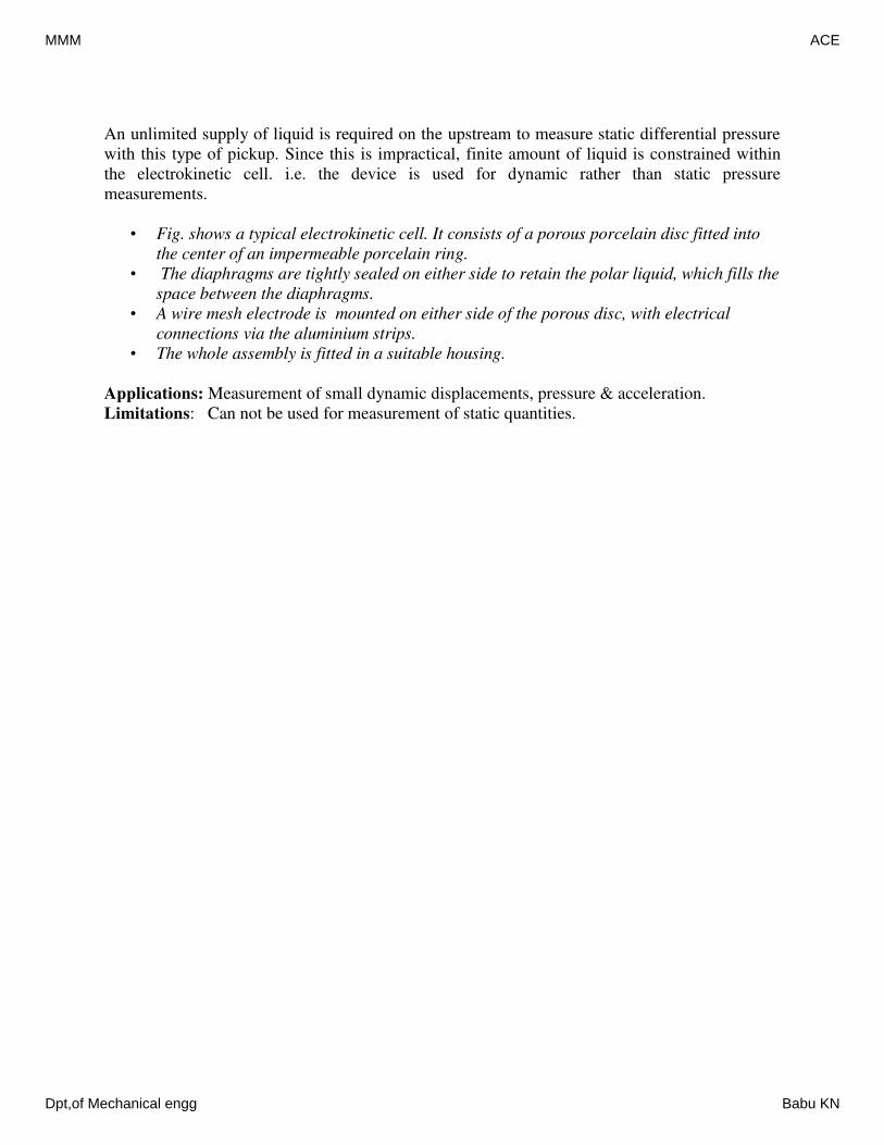
An unlimited supply of liquid is required on the upstream to measure static differential pressure
with this type of pickup. Since this is impractical, finite amount of liquid is constrained within
the electrokinetic cell. i.e. the device is used for dynamic rather than static pressure
measurements.
• Fig. shows a typical electrokinetic cell. It consists of a porous porcelain disc fitted into
the center of an impermeable porcelain ring.
• The diaphragms are tightly sealed on either side to retain the polar liquid, which fills the
space between the diaphragms.
• A wire mesh electrode is mounted on either side of the porous disc, with electrical
connections via the aluminium strips.
• The whole assembly is fitted in a suitable housing.
Applications: Measurement of small dynamic displacements, pressure & acceleration.
Limitations: Can not be used for measurement of static quantities.
MMM ACE
Dpt,of Mechanical engg Babu KN
Slide No -2Intermediate Modifying Devices
• In most cases, the mechanical quantity which is detected will be transduced into an
‘electrical form’.
• The output of the first stage has to be modified (signal conditioning) before it is fed to the
third or terminating stage such as indicators, recorders or control elements.
• So, the modifications are carried out in the intermediate stage commonly called as the
signal conditioning stage.
• Signal conditioning equipment used may be of mechanical, electrical or electronic.
Mechanical types (using elements such as linkages, gearing, cams, etc.) have many
limitations such as friction, inertia, non linearity, backlash, elastic deformation, etc.
• Hence electrical & electronic systems are used which are free from these drawbacks.
• Also they give large voltage & power amplifications required to drive the recording
devices.
The mechanical signals transduced into electrical signals are not only amplified but in special
types, signal conditioning may involve filtering, integration, differentiation, remote recording,
etc Inherent Problems: mechanical intermediate devices or elements pose certain problems of
considerable magnitude especially when measuring dynamic inputs. Frictional amplification,
inertial loading, elastic deformation present problems.
Mechanical Amplification
• {Mechanical advantage or Mechanical Gain}
= output displacement output velocity
input displacement input velocity
Reflected frictional amplification
• Due to mechanical gain, a small frictional force in a mechanism will reflect back as
magnified load.
• As a result of this, the input to the mechanism or mechanical system is reversed.
• This will be equal to the gain between the frictional source and the point of input of
energy to the mechanism, i.e. gain is proportional to the friction.
Total frictional drag reflected to input
Ffr=∑A.Ff
i.e., Reflected frictional amplification=gain *Ff
Ffr=total reflected frictional force at the input of the system
A=mechanical gain or amplification
Ff=frictional force at the source
Reflected inertial amplification
• [inertia-weight-mechanical system-robust construction-hence requires more input-output
loss due to more weight]
• Inertia forces also cause problems similar to those caused by frictional force.
• I.e. their effects may be considered as reflected back to the input in proportion to the
mechanical amplification existing between the source and the input signal.
MMM ACE
Dpt,of Mechanical engg Babu KN
• This is referred to as reflected inertial amplification.
• Fir=∑A.Ffi
• Fir=total inertial force at the system input
• A=mechanical gain or amplification
• Ffi=frictional force at the source
Backlash/Amplification of backlash/and of Elastic deformation
• Backlash results from temporary non-constraint in a linkage caused by clearances
required in mechanical fits, where relative motion occurs.
• Backlash and elastic deformation cause a lost motion at the output signal equal to the
backlash multiplied by the amplification between the source and the output.
• Elastic deformation is brought about by loads and forces, carried by links
Temperature problems
• Cause dimensional changes and changes in the physical properties both elastic and
electric resulting in deviation referred to as “Zero shift and scale error”
• Zero –shift: Results in change in the no-input reading. This depends mainly on
temperature and also primarily a function of linear dimensional changes caused by
expansion or contraction with changing temperatures.
Examples-
Spring scale:
• The indicator on the spring scale should be set to zero whenever there are no weights in
the pan.
• If the temperature changes after the scale has been set to zero, there may be differential
dimensional change both the spring and the spring scale altering the reading.
• This change is referred to as Zero-shift
Scale error-Examples
Springs:
• Temperature changes also affect the spring scale calibration when resilient(capacity to
regain original shape and size) load carrying members are included. When temperature
changes, the coil diameter and the wire diameter will also get altered.
• These variations cause a changed spring constant hence changed load-deflection
calibration resulting in what is referred to as scale error. Also change in temperature
results in change in the resistance of the material and alters the dimensions due to
expansion and contraction
Methods to minimize temperature problems
1. Minimization through careful selection of materials and operating temperatures(Select
materials which have low coefficient of expansion)
2. Compensation: May be made in different forms depending on the basic characteristics of
the system like
• If a mechanical system is used-make use of composite construction i.e. bimetals,
composites etc
MMM ACE
Dpt,of Mechanical engg Babu KN
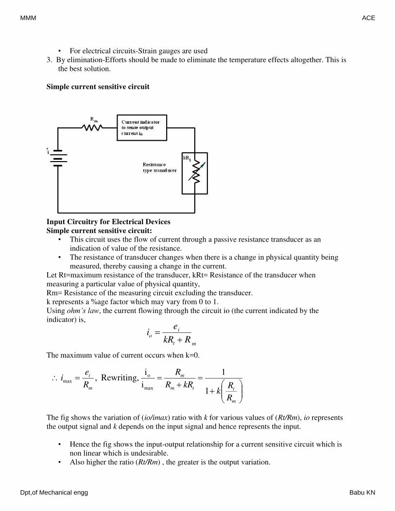
• For electrical circuits-Strain gauges are used
3. By elimination-Efforts should be made to eliminate the temperature effects altogether. This is
the best solution.
Simple current sensitive circuit
Input Circuitry for Electrical Devices
Simple current sensitive circuit:
• This circuit uses the flow of current through a passive resistance transducer as an
indication of value of the resistance.
• The resistance of transducer changes when there is a change in physical quantity being
measured, thereby causing a change in the current.
Let Rt=maximum resistance of the transducer, kRt= Resistance of the transducer when
measuring a particular value of physical quantity,
Rm= Resistance of the measuring circuit excluding the transducer.
k represents a %age factor which may vary from 0 to 1.
Using ohm’s law, the current flowing through the circuit io (the current indicated by the
indicator) is,
The maximum value of current occurs when k=0.
The fig shows the variation of (io/imax) ratio with k for various values of (Rt/Rm), io represents
the output signal and k depends on the input signal and hence represents the input.
• Hence the fig shows the input-output relationship for a current sensitive circuit which is
non linear which is undesirable.
• Also higher the ratio (Rt/Rm) , the greater is the output variation.
mt
io
RkR
ei
m
ttm
m
m
i
R
Rk
kRR
R
R
ei
1
1
i
iRewriting,,
max
omax
MMM ACE
Dpt,of Mechanical engg Babu KN
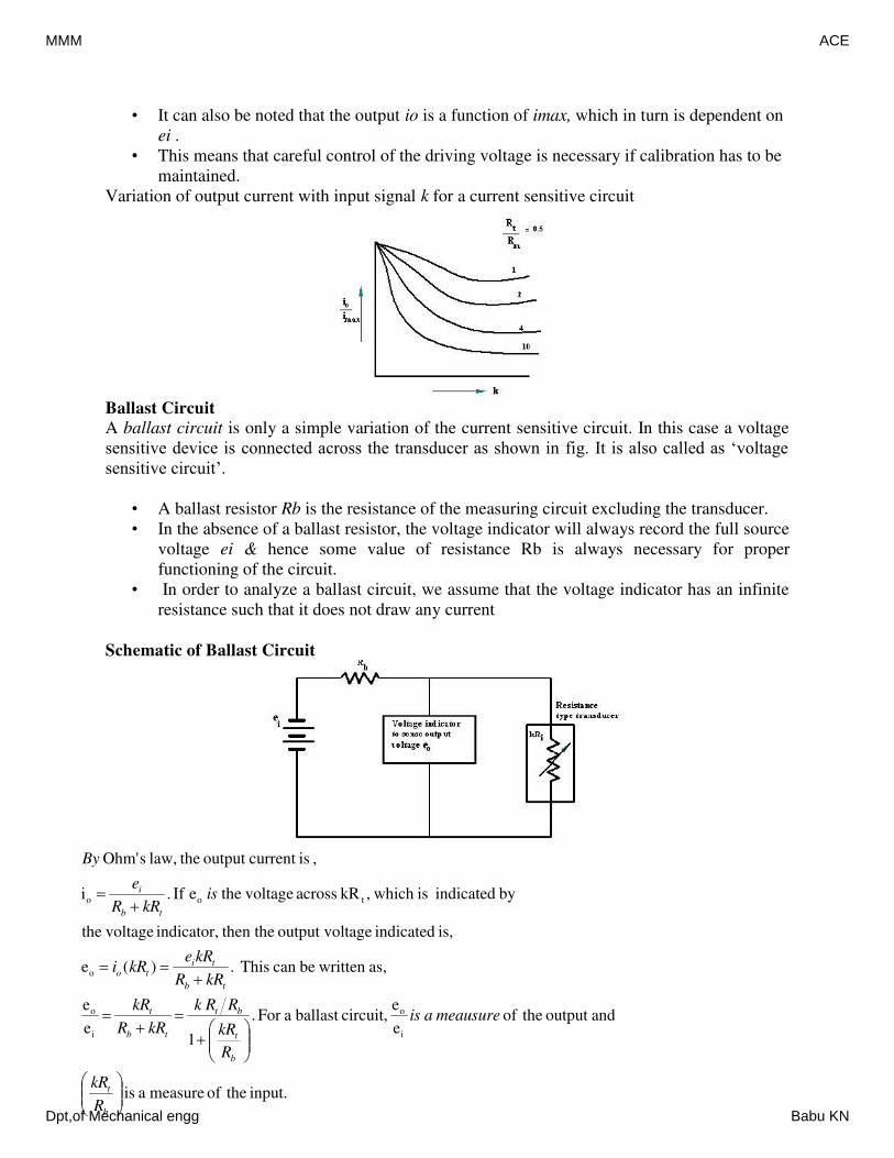
• It can also be noted that the output io is a function of imax, which in turn is dependent on
ei .
• This means that careful control of the driving voltage is necessary if calibration has to be
maintained.
Variation of output current with input signal k for a current sensitive circuit
Ballast Circuit
A ballast circuit is only a simple variation of the current sensitive circuit. In this case a voltage
sensitive device is connected across the transducer as shown in fig. It is also called as ‘voltage
sensitive circuit’.
• A ballast resistor Rb is the resistance of the measuring circuit excluding the transducer.
• In the absence of a ballast resistor, the voltage indicator will always record the full source
voltage ei & hence some value of resistance Rb is always necessary for proper
functioning of the circuit.
• In order to analyze a ballast circuit, we assume that the voltage indicator has an infinite
resistance such that it does not draw any current
Schematic of Ballast Circuit
input. theofmeasureais
andoutput theofe
ecircuit,ballastaFor.
1e
e
as, writtenbecanThis.)(e
is,indicatedtageoutput vol then theindicator, voltagethe
byindicatedis which,kRacross voltage theeIf.i
,iscurrentoutput thelaw,sOhm'
i
o
i
o
o
too
b
t
b
t
bt
tb
t
tb
tito
tb
i
R
kR
meausureais
R
kR
RRk
kRR
kR
kRR
kRekRi
iskRR
e
By
MMM ACE
Dpt,of Mechanical engg Babu KN
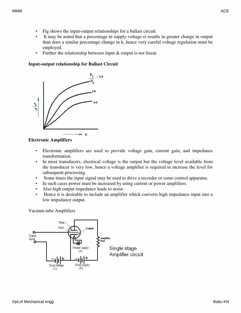
• Fig shows the input-output relationships for a ballast circuit.
• It may be noted that a percentage in supply voltage ei results in greater change in output
than does a similar percentage change in k, hence very careful voltage regulation must be
employed.
• Further the relationship between input & output is not linear.
Input-output relationship for Ballast Circuit
Electronic Amplifiers
• Electronic amplifiers are used to provide voltage gain, current gain, and impedance
transformation.
• In most transducers, electrical voltage is the output but the voltage level available from
the transducer is very low, hence a voltage amplifier is required to increase the level for
subsequent processing.
• Some times the input signal may be used to drive a recorder or some control apparatus.
• In such cases power must be increased by using current or power amplifiers.
• Also high output impedance leads to noise.
• Hence it is desirable to include an amplifier which converts high impedance input into a
low impedance output.
Vacuum tube Amplifiers
MMM ACE
Dpt,of Mechanical engg Babu KN
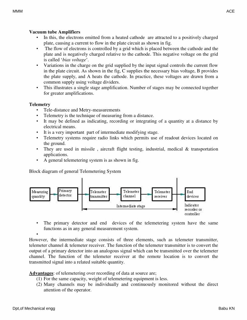
Vacuum tube Amplifiers
• In this, the electrons emitted from a heated cathode are attracted to a positively charged
plate, causing a current to flow in the plate circuit as shown in fig.
• The flow of electrons is controlled by a grid which is placed between the cathode and the
plate and is negatively charged relative to the cathode. This negative voltage on the grid
is called ‘bias voltage’.
• Variations in the charge on the grid supplied by the input signal controls the current flow
in the plate circuit. As shown in the fig, C supplies the necessary bias voltage, B provides
the plate supply, and A heats the cathode. In practice, these voltages are drawn from a
common supply using voltage dividers.
• This illustrates a single stage amplification. Number of stages may be connected together
for greater amplifications.
Telemetry
• Tele-distance and Metry-measurements
• Telemetry is the technique of measuring from a distance.
• It may be defined as indicating, recording or integrating of a quantity at a distance by
electrical means.
• It is a very important part of intermediate modifying stage.
• Telemetry systems require radio links which permits use of readout devices located on
the ground.
• They are used in missile , aircraft flight testing, industrial, medical & transportation
applications.
• A general telemetering system is as shown in fig.
Block diagram of general Telemetering System
• The primary detector and end devices of the telemetering system have the same
functions as in any general measurement system.
•
However, the intermediate stage consists of three elements, such as telemeter transmitter,
telemeter channel & telemeter receiver. The function of the telemeter transmitter is to convert the
output of a primary detector into an analogous signal which can be transmitted over the telemeter
channel. The function of the telemeter receiver at the remote location is to convert the
transmitted signal into a related suitable quantity.
Advantages: of telemetering over recording of data at source are;
(1) For the same capacity, weight of telemetering equipment is less.
(2) Many channels may be individually and continuously monitored without the direct
attention of the operator.
MMM ACE
Dpt,of Mechanical engg Babu KN
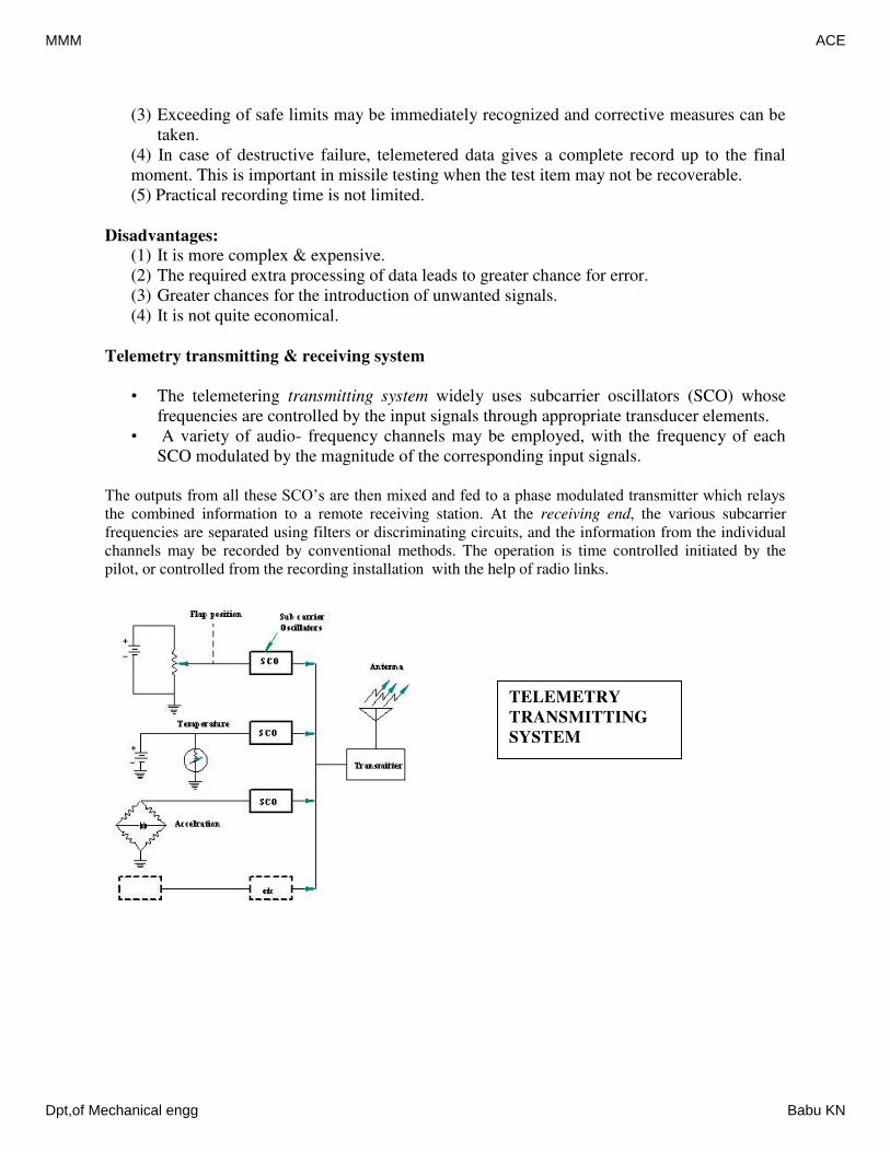
(3) Exceeding of safe limits may be immediately recognized and corrective measures can be
taken.
(4) In case of destructive failure, telemetered data gives a complete record up to the final
moment. This is important in missile testing when the test item may not be recoverable.
(5) Practical recording time is not limited.
Disadvantages:
(1) It is more complex & expensive.
(2) The required extra processing of data leads to greater chance for error.
(3) Greater chances for the introduction of unwanted signals.
(4) It is not quite economical.
Telemetry transmitting & receiving system
• The telemetering transmitting system widely uses subcarrier oscillators (SCO) whose
frequencies are controlled by the input signals through appropriate transducer elements.
• A variety of audio- frequency channels may be employed, with the frequency of each
SCO modulated by the magnitude of the corresponding input signals.
The outputs from all these SCO’s are then mixed and fed to a phase modulated transmitter which relays
the combined information to a remote receiving station. At the receiving end, the various subcarrier
frequencies are separated using filters or discriminating circuits, and the information from the individual
channels may be recorded by conventional methods. The operation is time controlled initiated by the
pilot, or controlled from the recording installation with the help of radio links.
TELEMETRY
TRANSMITTING
SYSTEM
MMM ACE
Dpt,of Mechanical engg Babu KN
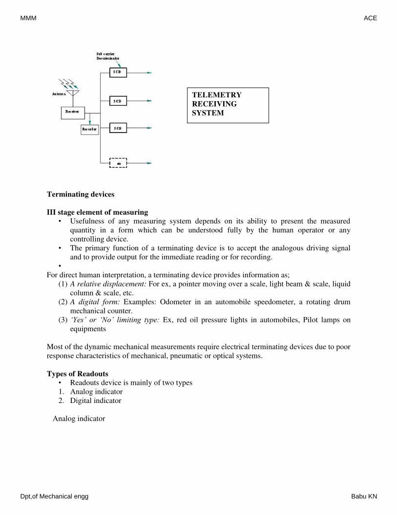
Terminating devices
III stage element of measuring
• Usefulness of any measuring system depends on its ability to present the measured
quantity in a form which can be understood fully by the human operator or any
controlling device.
• The primary function of a terminating device is to accept the analogous driving signal
and to provide output for the immediate reading or for recording.
•
For direct human interpretation, a terminating device provides information as;
(1) A relative displacement: For ex, a pointer moving over a scale, light beam & scale, liquid
column & scale, etc.
(2) A digital form: Examples: Odometer in an automobile speedometer, a rotating drum
mechanical counter.
(3) ‘Yes’ or ‘No’ limiting type: Ex, red oil pressure lights in automobiles, Pilot lamps on
equipments
Most of the dynamic mechanical measurements require electrical terminating devices due to poor
response characteristics of mechanical, pneumatic or optical systems.
Types of Readouts
• Readouts device is mainly of two types
1. Analog indicator
2. Digital indicator
Analog indicator
TELEMETRY
RECEIVING
SYSTEM
MMM ACE
Dpt,of Mechanical engg Babu KN
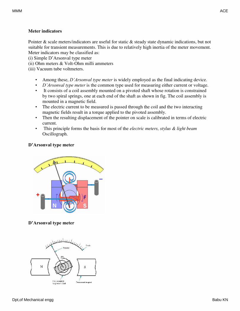
Meter indicators
Pointer & scale meters/indicators are useful for static & steady state dynamic indications, but not
suitable for transient measurements. This is due to relatively high inertia of the meter movement.
Meter indicators may be classified as:
(i) Simple D’Arsonval type meter
(ii) Ohm meters & Volt-Ohm milli ammeters
(iii) Vacuum tube voltmeters.
• Among these, D’Arsonval type meter is widely employed as the final indicating device.
• D’Arsonval type meter is the common type used for measuring either current or voltage.
• It consists of a coil assembly mounted on a pivoted shaft whose rotation is constrained
by two spiral springs, one at each end of the shaft as shown in fig. The coil assembly is
mounted in a magnetic field.
• The electric current to be measured is passed through the coil and the two interacting
magnetic fields result in a torque applied to the pivoted assembly.
• Then the resulting displacement of the pointer on scale is calibrated in terms of electric
current.
• This principle forms the basis for most of the electric meters, stylus & light beam
Oscillograph.
D’Arsonval type meter
D’Arsonval type meter
MMM ACE
Dpt,of Mechanical engg Babu KN
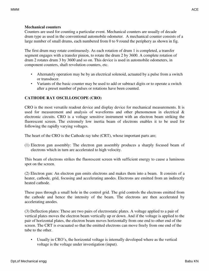
Mechanical counters
Counters are used for counting a particular event. Mechanical counters are usually of decade
drum type as used in the conventional automobile odometer. A mechanical counter consists of a
large number of small drums, each numbered from 0 to 9 round the periphery as shown in fig.
The first drum may rotate continuously. As each rotation of drum 1 is completed, a transfer
segment engages with a transfer pinion, to rotate the drum 2 by 3600. A complete rotation of
drum 2 rotates drum 3 by 3600 and so on. This device is used in automobile odometers, in
component counters, shaft revolution counters, etc.
• Alternately operation may be by an electrical solenoid, actuated by a pulse from a switch
or transducer.
• Variants of the basic counter may be used to add or subtract digits or to operate a switch
after a preset number of pulses or rotations have been counted.
CATHODE RAY OSCILLOSCOPE (CRO)
CRO is the most versatile readout device and display device for mechanical measurements. It is
used for measurement and analysis of waveforms and other phenomenon in electrical &
electronic circuits. CRO is a voltage sensitive instrument with an electron beam striking the
fluorescent screen. The extremely low inertia beam of electrons enables it to be used for
following the rapidly varying voltages.
The heart of the CRO is the Cathode ray tube (CRT), whose important parts are;
(1) Electron gun assembly: The electron gun assembly produces a sharply focused beam of
electrons which in turn are accelerated to high velocity.
This beam of electrons strikes the fluorescent screen with sufficient energy to cause a luminous
spot on the screen.
(2) Electron gun: An electron gun emits electrons and makes them into a beam. It consists of a
heater, cathode, grid, focusing and accelerating anodes. Electrons are emitted from an indirectly
heated cathode.
These pass through a small hole in the control grid. The grid controls the electrons emitted from
the cathode and hence the intensity of the beam. The electrons are then accelerated by
accelerating anodes.
(3) Deflection plates: These are two pairs of electrostatic plates. A voltage applied to a pair of
vertical plates moves the electron beam vertically up or down. And if the voltage is applied to the
pair of horizontal plates, the electron beam moves horizontally from one end to other end of the
screen. The CRT is evacuated so that the emitted electrons can move freely from one end of the
tube to the other.
• Usually in CRO’s, the horizontal voltage is internally developed where as the vertical
voltage is the voltage under investigation (input).
MMM ACE
Dpt,of Mechanical engg Babu KN
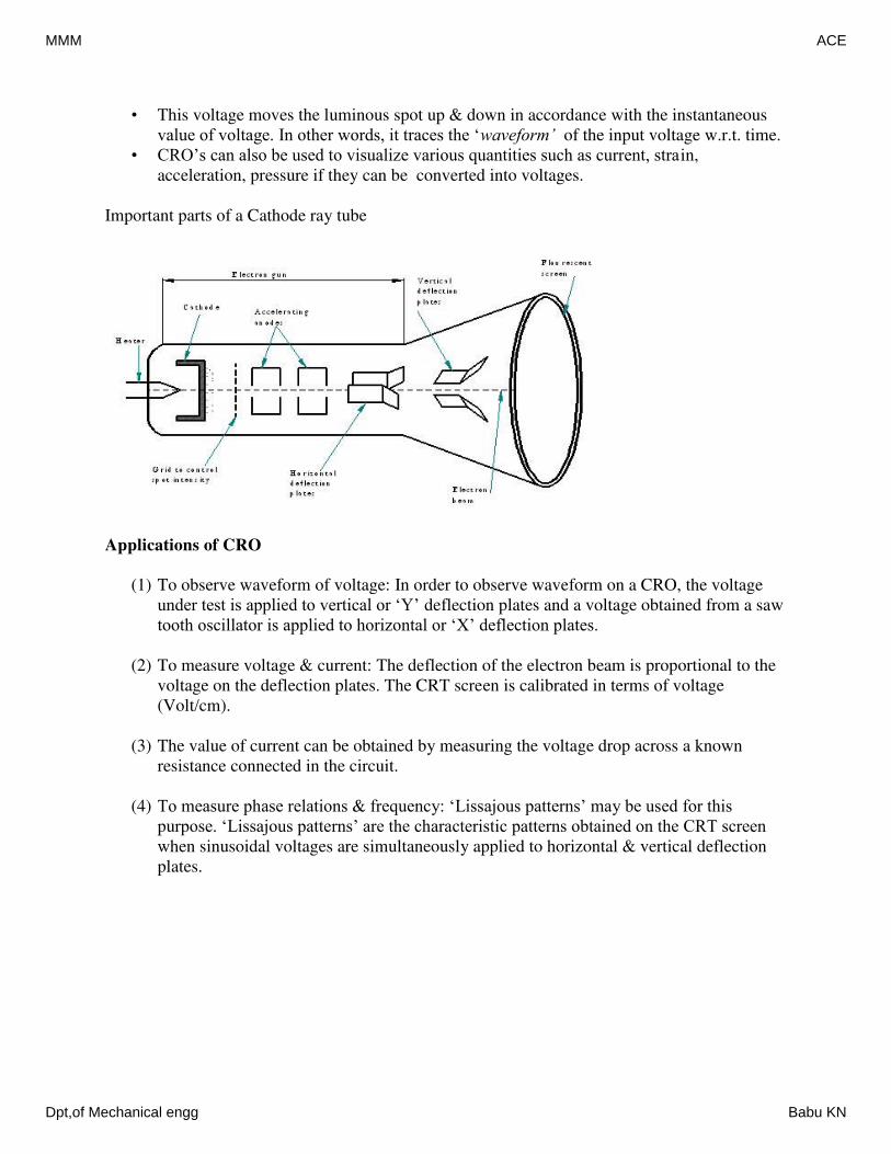
• This voltage moves the luminous spot up & down in accordance with the instantaneous
value of voltage. In other words, it traces the ‘waveform’ of the input voltage w.r.t. time.
• CRO’s can also be used to visualize various quantities such as current, strain,
acceleration, pressure if they can be converted into voltages.
Important parts of a Cathode ray tube
Applications of CRO
(1) To observe waveform of voltage: In order to observe waveform on a CRO, the voltage
under test is applied to vertical or ‘Y’ deflection plates and a voltage obtained from a saw
tooth oscillator is applied to horizontal or ‘X’ deflection plates.
(2) To measure voltage & current: The deflection of the electron beam is proportional to the
voltage on the deflection plates. The CRT screen is calibrated in terms of voltage
(Volt/cm).
(3) The value of current can be obtained by measuring the voltage drop across a known
resistance connected in the circuit.
(4) To measure phase relations & frequency: ‘Lissajous patterns’ may be used for this
purpose. ‘Lissajous patterns’ are the characteristic patterns obtained on the CRT screen
when sinusoidal voltages are simultaneously applied to horizontal & vertical deflection
plates.
MMM ACE
Dpt,of Mechanical engg Babu KN
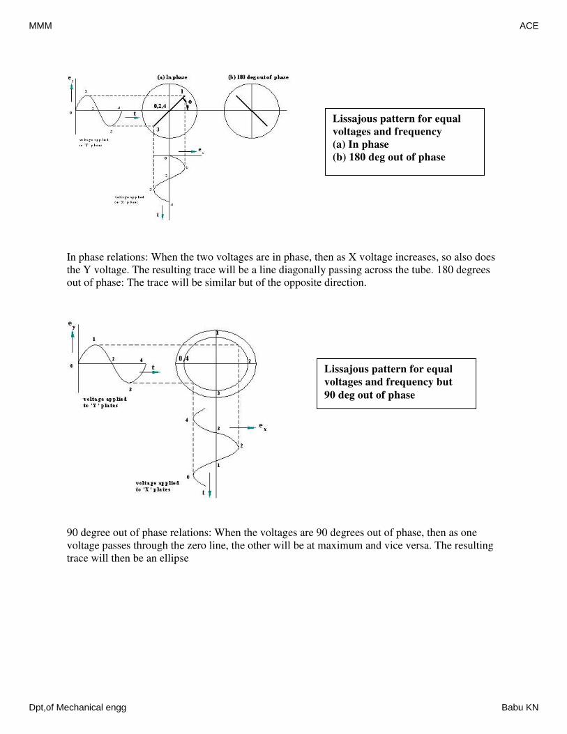
In phase relations: When the two voltages are in phase, then as X voltage increases, so also does
the Y voltage. The resulting trace will be a line diagonally passing across the tube. 180 degrees
out of phase: The trace will be similar but of the opposite direction.
90 degree out of phase relations: When the voltages are 90 degrees out of phase, then as one
voltage passes through the zero line, the other will be at maximum and vice versa. The resulting
trace will then be an ellipse
Lissajous pattern for equal
voltages and frequency
(a) In phase
(b) 180 deg out of phase
Lissajous pattern for equal
voltages and frequency but
90 deg out of phase
MMM ACE
Dpt,of Mechanical engg Babu KN
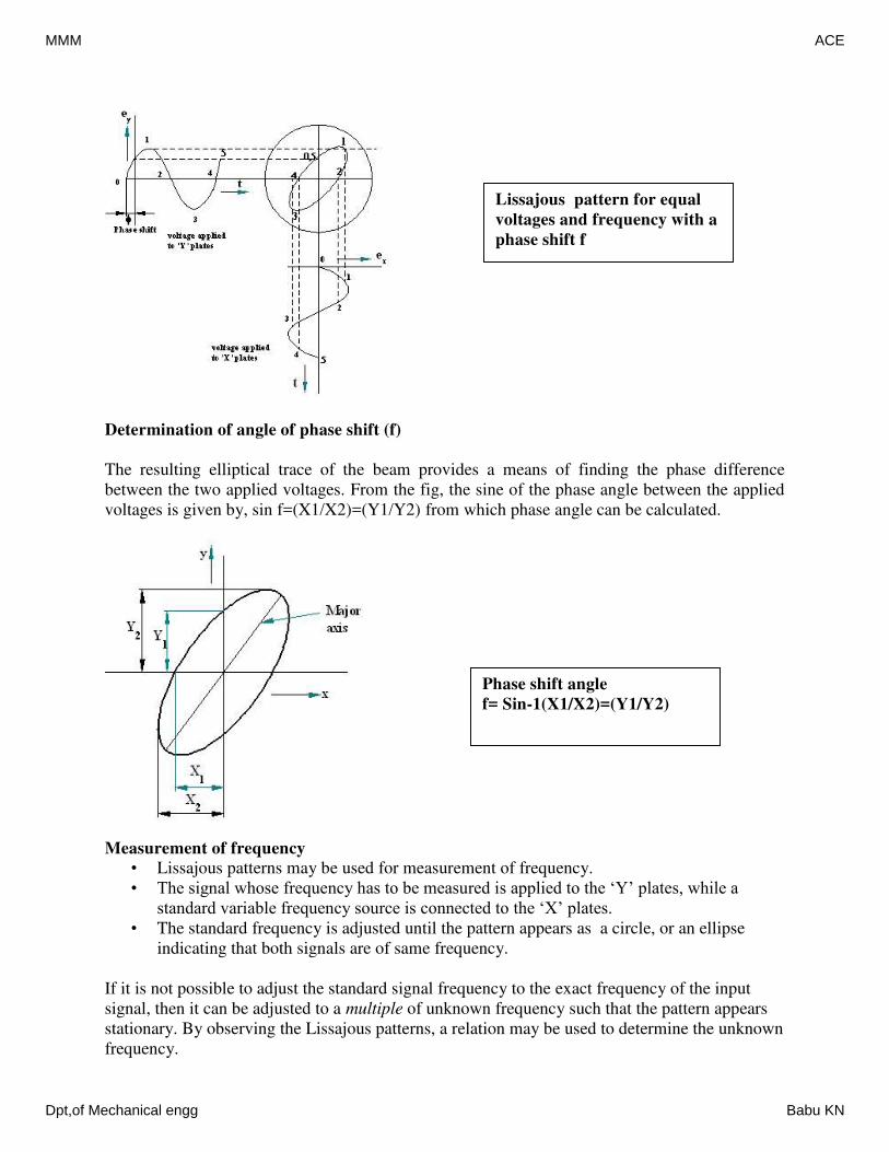
Determination of angle of phase shift (f)
The resulting elliptical trace of the beam provides a means of finding the phase difference
between the two applied voltages. From the fig, the sine of the phase angle between the applied
voltages is given by, sin f=(X1/X2)=(Y1/Y2) from which phase angle can be calculated.
Measurement of frequency
• Lissajous patterns may be used for measurement of frequency.
• The signal whose frequency has to be measured is applied to the ‘Y’ plates, while a
standard variable frequency source is connected to the ‘X’ plates.
• The standard frequency is adjusted until the pattern appears as a circle, or an ellipse
indicating that both signals are of same frequency.
If it is not possible to adjust the standard signal frequency to the exact frequency of the input
signal, then it can be adjusted to a multiple of unknown frequency such that the pattern appears
stationary. By observing the Lissajous patterns, a relation may be used to determine the unknown
frequency.
Lissajous pattern for equal
voltages and frequency with a
phase shift f
Phase shift angle
f= Sin-1(X1/X2)=(Y1/Y2)
MMM ACE
Dpt,of Mechanical engg Babu KN
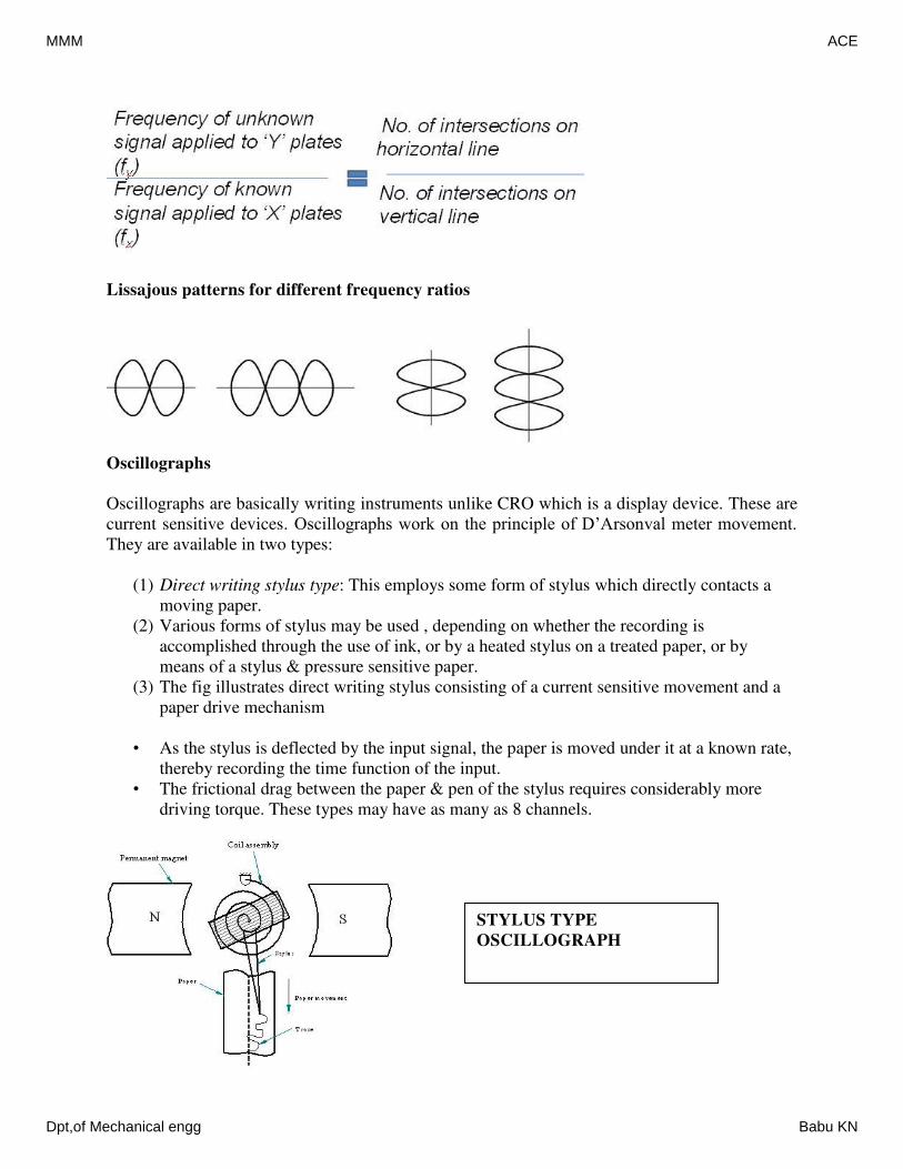
Lissajous patterns for different frequency ratios
Oscillographs
Oscillographs are basically writing instruments unlike CRO which is a display device. These are
current sensitive devices. Oscillographs work on the principle of D’Arsonval meter movement.
They are available in two types:
(1) Direct writing stylus type: This employs some form of stylus which directly contacts a
moving paper.
(2) Various forms of stylus may be used , depending on whether the recording is
accomplished through the use of ink, or by a heated stylus on a treated paper, or by
means of a stylus & pressure sensitive paper.
(3) The fig illustrates direct writing stylus consisting of a current sensitive movement and a
paper drive mechanism
• As the stylus is deflected by the input signal, the paper is moved under it at a known rate,
thereby recording the time function of the input.
• The frictional drag between the paper & pen of the stylus requires considerably more
driving torque. These types may have as many as 8 channels.
STYLUS TYPE
OSCILLOGRAPH
MMM ACE
Dpt,of Mechanical engg Babu KN
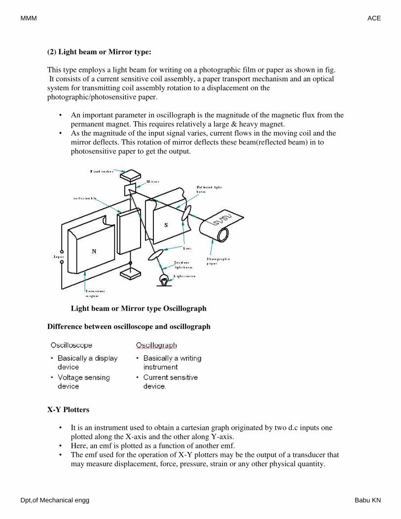
(2) Light beam or Mirror type:
This type employs a light beam for writing on a photographic film or paper as shown in fig.
It consists of a current sensitive coil assembly, a paper transport mechanism and an optical
system for transmitting coil assembly rotation to a displacement on the
photographic/photosensitive paper.
• An important parameter in oscillograph is the magnitude of the magnetic flux from the
permanent magnet. This requires relatively a large & heavy magnet.
• As the magnitude of the input signal varies, current flows in the moving coil and the
mirror deflects. This rotation of mirror deflects these beam(reflected beam) in to
photosensitive paper to get the output.
Light beam or Mirror type Oscillograph
Difference between oscilloscope and oscillograph
X-Y Plotters
• It is an instrument used to obtain a cartesian graph originated by two d.c inputs one
plotted along the X-axis and the other along Y-axis.
• Here, an emf is plotted as a function of another emf.
• The emf used for the operation of X-Y plotters may be the output of a transducer that
may measure displacement, force, pressure, strain or any other physical quantity.
MMM ACE
Dpt,of Mechanical engg Babu KN
Related Documents