O R I G I N A L w w w . g e n v e x . d k Genvex A/S Sverigesvej 6 DK-6100 Haderslev Tlf.: +45 7353 2700 www.genvex.dk Version 2013.05.27 Optima 170 Vanvex R/RS Domestic Hot Water Heat Pump OPERATING INSTRUCTIONS UK

Welcome message from author
This document is posted to help you gain knowledge. Please leave a comment to let me know what you think about it! Share it to your friends and learn new things together.
Transcript

OR
IGINAL
ww
w.genvex.d
k
Genvex A/S � Sver igesvej 6 � DK-6100 � Haders lev � Tlf . : +45 7353 2700 � www.genvex.dk
Vers
ion 2
013.0
5.2
7
Optima 170Vanvex R/RS
Domestic Hot Water Heat Pump
OPER
AT
ING
IN
ST
RU
CT
ION
SUK
2 Technical modifi cations are subject to change in Optima 170
Table of Contents
1. Control Panel .......................................................................... 3
1.1 Operation .................................................................................. 3
1.2 Altering settings in the operating menu .................................... 4
1.3 Operating menu ........................................................................ 4
1.4 Table for set points ................................................................... 6
1.5 Table for defrosting ................................................................... 7
2. Function .................................................................................. 7
2.1 Controlling Optima 170 ............................................................. 7
2.2 Additional capacity .................................................................... 8
2.3 Reliability .................................................................................. 8
2.4 Alarms....................................................................................... 8
3. Maintenance ............................................................................ 8
3.1 Connection to computer ........................................................... 8
3.2 Cooling system and fan ............................................................ 8
3.3 Water circulation and boiler ...................................................... 8
3.4 Disassembly/decommissioning ................................................ 9
4. Troubleshooting ..................................................................... 9
4.1 High pressure switch ................................................................ 9
4.2 Safety breakers for the immersion heater ................................ 9
4.3 The heater pump does not run ................................................. 9
5. System Overview .................................................................. 10
6. Electrical scheme ..................................................................11

3Technical modifi cations are subject to change in Optima 170
1. Control panel
Optima 170 The domestic hot water heat pump Vanvex R/RS is de-livered with an Optima 170 control, which has a factory setting meaning that the heat pump is ready for operation without additional adjustments.The factory setting is a default setting that should be adjusted to the operational needs and requirements for the dwelling in order to achieve optimal performance and utilization of the system.
1.1 Operation
User Menu The set point of the relevant menu item is displayed when the key/key combination is pressed.The value can be changed with the arrow keys when the key/key combination is held down simultaneously.
P1: Level (The “level” key is pressed and held. Then the setting can be changed with the arrow keys).With this key it is possible to switch between: Standby, automatic operation, constant operation and timer con-trolled constant operation (level 0, 1, 2, 3). • Level 0: The heat pump is now turned off and only the
controller is active. The heat pump does not turn on when there is a need for heating.
• Level 1: The fan only runs when the domestic water is being heated. In menu item E25 the desired fan speed is set between 0-100 %.
• Level 2: The fan runs, even when the compressor is shut down. This function is called: Constant extraction from the dwelling. In menu item E25 the desired fan speed is set between 0-100 %.
• Level 3: The fan runs in a chosen period of time, even after the compressor has stopped, before it switches back to normal operation.
In menu item E25 the desired fan speed is set between 0-100 %. In menu item E17 it is selected whether “Level 3” is to run until the next manual change (E17 = 0) or if “Level 3” is to be active in a limited period of time (E17=1 and E18: 0-10 hours) and then return to “Level 2”.Options: 0-3Factory setting: 1
P2: Controlling the immersion heater (The “immersion heater”-key is pressed and held. Then the setting can be changed with the arrow keys).The heat pump is supplied with an immersion heater for heating of the domestic water.At outside temperatures below 0°C it is benefi cial to use
the immersion heater as a supplement to heating the domestic water.
1 = the immersion heater is in operation when there is a need (see set point P5).0 = the immersion heater is not in operation, even though there is a need.Options: 0-1 Factory default: 0.
P3: Operating thermostat (The “operating thermostat”-key is pressed and held. Then the setting can be changed with the arrow keys). Domestic water is heated by the heat pump. The compres-sor starts if the T8 temperature (boiler, bottom) becomes lower than set point P3 minus 5°C and stops again when the T8 temperature is equal to set point P3. Options: 0-55 °C. Factory setting: 52 °C.
P4: Stop defrosting (The “Level”+ “Operating thermostat” keys are pressed and held simultaneously).Defrosting period normally stops when the evaporator has reached a temperature of 10°C. Under special conditions it may be necessary to change this temperature setting.Options: 0-25 °C. Factory setting: 10 °C.
P5: Immersion heater (“Immersion heater”+ “Operating thermostat” keys are pressed and held simultaneously).The immersion heater only heats the upper half of the boiler, while the heat pump continues heating the bottom part of the boiler. The immersion heater starts if the T7 temperature (boiler top) is lower than set point P5 minus 5°C. The immersion heater stops again when the T7 tem-perature is higher than set point P5.Options: 0-65 °C. Factory setting: 50 °C
Display view (main menu) By pressing the arrow buttons the different temperatures will show in the display. Press until the number of the sen-sor of the desired temperature is displayed. After approxi-mately 3 seconds the temperature is displayed. The tem-perature remains for about 30 seconds before the display goes back to normal view. Normal view is set in menu item E49 (blank display, water temperature T7 or clock).
The following values can be displayed:T4/T10: “Forced operation” input (cannot be used for temperature display). When short circuited, the heat pump goes to forced operation.T5: Before evaporatorT6: EvaporatorT7: Boiler, topT8: Boiler, bottomT9: Additional sensor (can be used as solar panel tem- perature sensor) CL: The current time from the built-in clock.
4 Technical modifi cations are subject to change in Optima 170
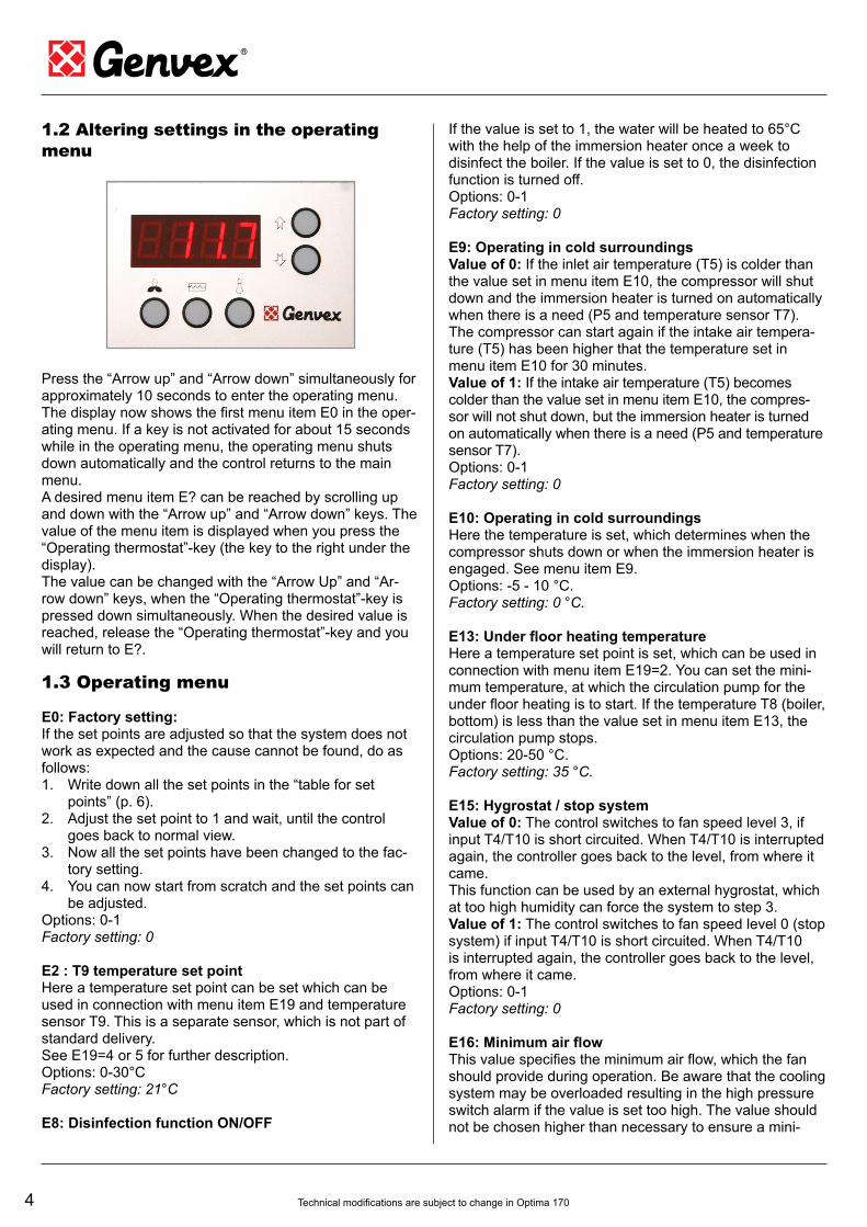
1.2 Altering settings in the operating
menu
Press the “Arrow up” and “Arrow down” simultaneously for approximately 10 seconds to enter the operating menu. The display now shows the fi rst menu item E0 in the oper-ating menu. If a key is not activated for about 15 seconds while in the operating menu, the operating menu shuts down automatically and the control returns to the main menu.A desired menu item E? can be reached by scrolling up and down with the “Arrow up” and “Arrow down” keys. The value of the menu item is displayed when you press the “Operating thermostat”-key (the key to the right under the display).The value can be changed with the “Arrow Up” and “Ar-row down” keys, when the “Operating thermostat”-key is pressed down simultaneously. When the desired value is reached, release the “Operating thermostat”-key and you will return to E?.
1.3 Operating menu
E0: Factory setting:If the set points are adjusted so that the system does not work as expected and the cause cannot be found, do as follows:1. Write down all the set points in the “table for set
points” (p. 6).2. Adjust the set point to 1 and wait, until the control
goes back to normal view. 3. Now all the set points have been changed to the fac-
tory setting. 4. You can now start from scratch and the set points can
be adjusted. Options: 0-1Factory setting: 0
E2 : T9 temperature set pointHere a temperature set point can be set which can be used in connection with menu item E19 and temperature sensor T9. This is a separate sensor, which is not part of standard delivery.See E19=4 or 5 for further description. Options: 0-30°CFactory setting: 21°C
E8: Disinfection function ON/OFF
If the value is set to 1, the water will be heated to 65°C with the help of the immersion heater once a week to disinfect the boiler. If the value is set to 0, the disinfection function is turned off.Options: 0-1Factory setting: 0
E9: Operating in cold surroundingsValue of 0: If the inlet air temperature (T5) is colder than the value set in menu item E10, the compressor will shut down and the immersion heater is turned on automatically when there is a need (P5 and temperature sensor T7). The compressor can start again if the intake air tempera-ture (T5) has been higher that the temperature set in menu item E10 for 30 minutes. Value of 1: If the intake air temperature (T5) becomes colder than the value set in menu item E10, the compres-sor will not shut down, but the immersion heater is turned on automatically when there is a need (P5 and temperature sensor T7).Options: 0-1Factory setting: 0
E10: Operating in cold surroundingsHere the temperature is set, which determines when the compressor shuts down or when the immersion heater is engaged. See menu item E9.Options: -5 - 10 °C. Factory setting: 0 °C.
E13: Under fl oor heating temperatureHere a temperature set point is set, which can be used in connection with menu item E19=2. You can set the mini-mum temperature, at which the circulation pump for the under fl oor heating is to start. If the temperature T8 (boiler, bottom) is less than the value set in menu item E13, the circulation pump stops. Options: 20-50 °C. Factory setting: 35 °C.
E15: Hygrostat / stop systemValue of 0: The control switches to fan speed level 3, if input T4/T10 is short circuited. When T4/T10 is interrupted again, the controller goes back to the level, from where it came. This function can be used by an external hygrostat, which at too high humidity can force the system to step 3. Value of 1: The control switches to fan speed level 0 (stop sys tem) if input T4/T10 is short circuited. When T4/T10 is interrupted again, the controller goes back to the level, from where it came. Options: 0-1Factory setting: 0
E16: Minimum air fl owThis value specifi es the minimum air fl ow, which the fan should provide during operation. Be aware that the cooling system may be overloaded resulting in the high pressure switch alarm if the value is set too high. The value should not be chosen higher than necessary to ensure a mini-

5Technical modifi cations are subject to change in Optima 170
mum air fl ow through the evaporator.Options: 0-100 %. Factory setting: 15 %
E17: Forced operation ON
If P1 is set to level 3, there is a possibility that the system automatically switches to level 2 after the number of hours set in menu item E18. Value of 0: the system runs on P1 level 3, until it is manu-ally changed to a different step. Value of 1: the system starts on level 2 after the number of hours set in menu item E18. Options: 0-1Factory setting: 0
E18: Number of hoursSetting of number of hours for continuous run on speed level 3 before automatically switching back to level 2.This option is used by the menu item E17=1.Options: 1-10 hoursFactory setting: 3.
E19 : Additional functionThis function controls relay R9: Solar panel/Option. Value of 0: This feature is disabled, and the relay is switched off. Value of 1: The solar panel function which activates the solar pump (relais R9). If the T8 temperature (boiler, bot-tom) is lower than the setting in menu item E46 (max. boiler temperature), the solar pump function is activated.The pump will run if the T9 temperature (solar panel) is higher than the T8 temperature (boiler, bottom) + menu item E20 (solar panel hysteresis). The pump stops again when the T9 temperature (solar panel) becomes lower than the T8 temperature (boiler, bottom). This feature is independent of the heat pump run-ning.Value 2: The underfl oor heating function, which activates the circulation pump (relais R9). If the T8 temperature (boiler, bottom) is higher than the setting in menu item E13 (underfl oor heating temperature), the underfl oor heating function is activated. The pump will run, if the T9 tempera-ture (solar panel) is lower than the setting in menu item E2. The pump (relais R9) stops again when the T9 tem-perature (solar panel) is higher than the setting in menu item E2. This feature is independent of the heat pump running.Value of 3: The solar panel function (special RS func-tion) which activates the solar pump (relais R9). The solar panel function has an overall safety feature that can turn off the solar pump. If the T9 temperature (solar panel) is higher than 89 °C, the pump is turned off. The pump starts again if the T9 temperature (solar panel) is less than 87 °C. If the T8 temperature (boiler, bottom) is less than the set point in menu item E46 (max. boiler temperature), the solar pump function is activated. The pump will be running if the T9 temperature (solar panel) is higher than the T8 temperature (boiler, bottom) + menu item E20 (solar panel hysteresis).
The pump (relais R9) stops again when the T9 tempera-ture (solar panel) becomes lower than the T8 temperature (boiler, bottom).
When the pump relais R9 is activated, the heat pump and the immersion heater switches off. After the pump relais R9 is deactivated, 15 min. will pass, and the following hap-pens: • If the T5 temperature (before evaporator) is greater than 5.5 °C, the heat pump is started. • If the T5 temperature (before evaporator) is lower than 4.5 °C, the immersion heater is started.
Value of 4: The cooling function which activates a three-way damper, which directs the cold exhaust air to a room with cooling requirements. This feature is controlled by the temperature set point in menu item E2 and the T9 sensor:
• If the T9 temperature is higher than the set point in menu item E2, relay R9 switches on. • If the T9 temperature is lower than the set point in menu item E2, relay R9 switches off. This feature is independent of the heat pump running.Value 5: The cooling function which activates a three-way damper, which directs the cold exhaust air to a room with cooling requirements. This feature is controlled by the temperature set point in menu item E2 and the T9 sensor, but opposite menu item E19 = 4:
• If the T9 temperature is higher than set point in menu item E2, relay R9 switches off. • If the T9 temperature is lower than set point in menu item E2, relay R9 switches on. This feature is independent of the heat pump running.Value 6: Relay R9 is ON, if the compressor is running and OFF if it is not running. This feature is independent of the heat pump running. Options: 0-6 Factory setting: 0
E20: Solar panel hysteresisHere you can set how much the temperature in the solar panel (T9) is to be above the temperature in the boiler (T8), before the solar pump is to start. See set menu item E19. Options: 1-5 °C. Factory setting: 5 °C
E21: TX set pointIn order to avoid high operating pressures in the cooling system it is necessary to reduce the performance of the system for the last part of the heating period. Here the wa-ter temperature is set at which the reduction must begin.Options: 0-55 °C. Factory setting: 45 °C.
E23: TmopThe value indicates the maximum evaporator temperature allowed. This prevents overloading of the cooling system at high ambient temperatures.Options: 0-30 °C. Factory setting: 25 °C.
6 Technical modifi cations are subject to change in Optima 170
E25: Fan speed level 1 + 2If you want extraction of air for a longer period of time, you can choose level 2 (P1). The fan will now run, until you change it to a different level. Enter the speed, at which the fan is to run when level 2 is chosen. Please note that this option also restricts the maximum speed of the fan. Options: 0-100 %. Factory settingt: 100 %
E26: Fan Speed level 3Enter the speed, at which the fan is to run when level 3 (P1) is chosen. This option is selected if you wish forced extraction from the house for a limited period of time.Please note that this option also restricts the maximum speed of the fan.Options: 0-100 %. Factory setting: 100 %
E45: dTAirHere the least desirable cooling of the air is chosen when the system heats water. The control will regulate the fan speed so that the air is cooled to the exact temperature that is selected. If it is necessary for technical reasons, the controller can cool below the selected temperature. If you want higher fan speed, the cooling temperature can be reduced. Note that too low temperatures will force the fan to run faster with greater energy consumption as a result. Options: 1-15 °C. Factory setting: 3 °C.
E46: Maximum boiler temperatureIn order to avoid too high temperatures in the boiler when it is connected to a solar panel or another heat source, then set the temperature in the bottom of the boiler to the max. allowable temperature.This setting is used in menu item E19.Options: 40-70 °CFactory setting: 60 °C.
E49: Screen Saver (1-3)Here you can select screen saver: 1: Blank display. The point fl ashes to show that there is power on the system. 2: Water temperature T7 (boiler, top) is displayed. 3: The time is displayed. Options: 1-3Factory setting: 2
E50: Internal clock hours (0-23)Here the clock hours are set.
E51: Internal clock minutes (0-59)Here the clock minutes are set.
E52: Budget period (ON/OFF)If this is set to ON (1) the immersion heater and the heat pump will only run during to the specifi ed period of time with the start according to menu item E53 and end accord-ing to menu item E54.If this is set to OFF (0) the immersion heater and the heat pump will run according to need and preferences.
Options: 0-1Factory default: 0
E53: Budget period start time (0-23)The start time of the budget period is set here.E54: Budget period end time (0-23)The start time of the budget period is set here.
E60: Temperature difference between T5 and T6If the T6 temperature (evaporator) is higher than the T5 temperature (before evaporator) + the value set in menu item E60 after one hour with the compressor in operation, the compressor will turn off. “Er06” will show in the display.This is a safety feature that indicates that the heat pump is not running properly.The system has to be switched off to reset the error.Options: 0-10 °C.
Factory setting: 2 °C.
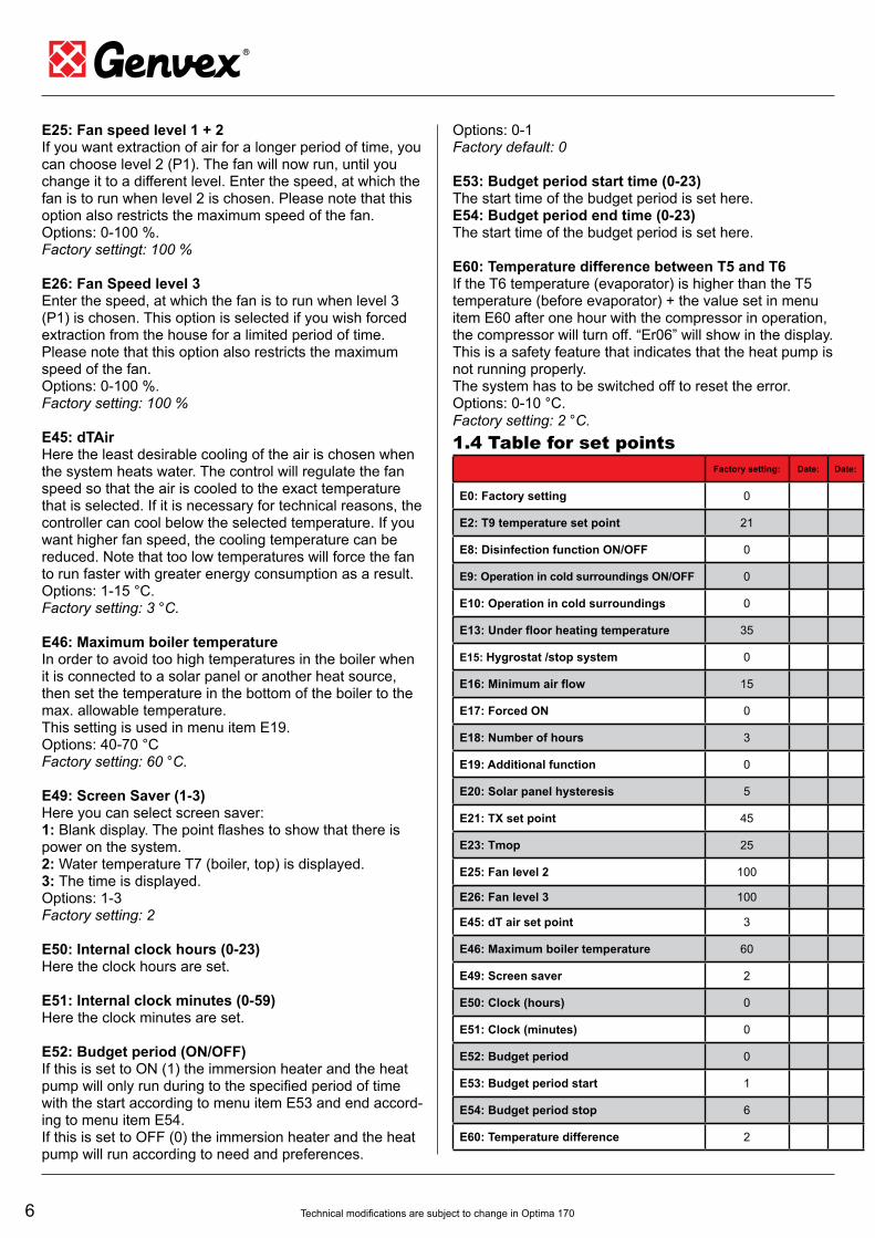
Factory setting: Date: Date:
E0: Factory setting 0
E2: T9 temperature set point 21
E8: Disinfection function ON/OFF 0
E9: Operation in cold surroundings ON/OFF 0
E10: Operation in cold surroundings 0
E13: Under floor heating temperature 35
E15: Hygrostat /stop system 0
E16: Minimum air flow 15
E17: Forced ON 0
E18: Number of hours 3
E19: Additional function 0
E20: Solar panel hysteresis 5
E21: TX set point 45
E23: Tmop 25
E25: Fan level 2 100
E26: Fan level 3 100
E45: dT air set point 3
E46: Maximum boiler temperature 60
E49: Screen saver 2
E50: Clock (hours) 0
E51: Clock (minutes) 0
E52: Budget period 0
E53: Budget period start 1
E54: Budget period stop 6
E60: Temperature difference 2
1.4 Table for set points
7Technical modifi cations are subject to change in Optima 170
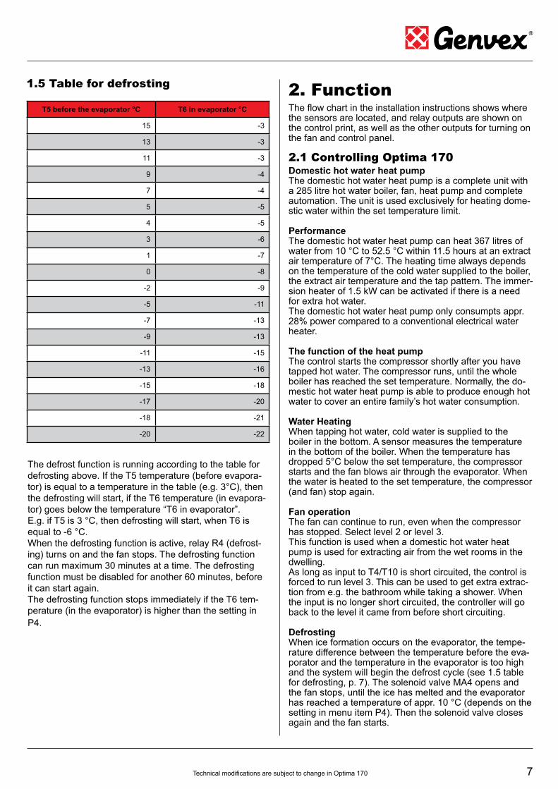
1.5 Table for defrosting
T5 before the evaporator °C T6 in evaporator °C
15 -3
13 -3
11 -3
9 -4
7 -4
5 -5
4 -5
3 -6
1 -7
0 -8
-2 -9
-5 -11
-7 -13
-9 -13
-11 -15
-13 -16
-15 -18
-17 -20
-18 -21
-20 -22
The defrost function is running according to the table for
defrosting above. If the T5 temperature (before evapora-
tor) is equal to a temperature in the table (e.g. 3°C), then
the defrosting will start, if the T6 temperature (in evapora-
tor) goes below the temperature “T6 in evaporator”.
E.g. if T5 is 3 °C, then defrosting will start, when T6 is
equal to -6 °C.
When the defrosting function is active, relay R4 (defrost-
ing) turns on and the fan stops. The defrosting function
can run maximum 30 minutes at a time. The defrosting
function must be disabled for another 60 minutes, before
it can start again.
The defrosting function stops immediately if the T6 tem-
perature (in the evaporator) is higher than the setting in
P4.
2. FunctionThe fl ow chart in the installation instructions shows where the sensors are located, and relay outputs are shown on the control print, as well as the other outputs for turning on the fan and control panel.
2.1 Controlling Optima 170 Domestic hot water heat pumpThe domestic hot water heat pump is a complete unit with a 285 litre hot water boiler, fan, heat pump and complete automation. The unit is used exclusively for heating dome-stic water within the set temperature limit.
Performance The domestic hot water heat pump can heat 367 litres of water from 10 °C to 52.5 °C within 11.5 hours at an extract air temperature of 7°C. The heating time always depends on the temperature of the cold water supplied to the boiler, the extract air temperature and the tap pattern. The immer-sion heater of 1.5 kW can be activated if there is a need for extra hot water.The domestic hot water heat pump only consumpts appr. 28% power compared to a conventional electrical water heater.
The function of the heat pumpThe control starts the compressor shortly after you have tapped hot water. The compressor runs, until the whole boiler has reached the set temperature. Normally, the do-mestic hot water heat pump is able to produce enough hot water to cover an entire family’s hot water consumption.
Water Heating When tapping hot water, cold water is supplied to the boiler in the bottom. A sensor measures the temperature in the bottom of the boiler. When the temperature has dropped 5°C below the set temperature, the compressor starts and the fan blows air through the evaporator. When the water is heated to the set temperature, the compressor (and fan) stop again.
Fan operationThe fan can continue to run, even when the compressor has stopped. Select level 2 or level 3.This function is used when a domestic hot water heat pump is used for extracting air from the wet rooms in the dwelling.As long as input to T4/T10 is short circuited, the control is forced to run level 3. This can be used to get extra extrac-tion from e.g. the bathroom while taking a shower. When the input is no longer short circuited, the controller will go back to the level it came from before short circuiting.
Defrosting When ice formation occurs on the evaporator, the tempe-rature difference between the temperature before the eva-porator and the temperature in the evaporator is too high and the system will begin the defrost cycle (see 1.5 table for defrosting, p. 7). The solenoid valve MA4 opens and the fan stops, until the ice has melted and the evaporator has reached a temperature of appr. 10 °C (depends on the setting in menu item P4). Then the solenoid valve closes again and the fan starts.
8 Technical modifi cations are subject to change in Optima 170
2.2 Additional capacity
If the situation arises where the domestic hot water heat
pump is not able to provide enough hot water, you can
activate the built-in immersion heater. Twice as much
water can now be heated. You can set the temperature to
which the immersion heater is to heat the water.
Only use the immersion heater if necessary. The immer-
sion heater consumpts more energy than the compressor.
The immersion heater can be activated manually on the
control panel.
2.3 Reliability
High pressure switch
In order to ensure that the compressor does not run bey-
ond its scope there is a built-in high pressure switch which
shuts down the compressor when the pressure becomes
too high.
The text ”PE” is shown in the display.
When the cause of the error is found, the power has to be
disconnected 10 seconds in order to reset the pressure
switch, before the unit can be restartet.
Lower the water temperature if necessary 2-3°C to avoid
the recurrence of pressure switch error.
Safety breakers
In the event of a failure on the immersion heater, the
safety breakers will shut down the unit. To re-activate
the safety breakers, press the button in the centre of the
breakers.The safety breakers are positioned in the centre
of the boiler.
Remember to disconnect the power to the unit before
carrying out any repairs on the unit.
Repair of the unit should only be carried out by
authorized personnel.
2.4 Alarms
High pressure switch alarm
When the high pressure switch shuts off, the text ”PE” ap-
pears in the display. By reactivation the power to the unit
must be switched off for 10 seconds and then turned on
again. The “PE” error disappears from the display.
3. MaintenanceTo achieve optimal performance, please follow the points
below:
Before the unit is opened, disconnect the power/
unplug and wait until the fan stops.
A few days after the initial setup, check the installation for
leaks in the water installation or blockage of the conden-
sate drain.
Environmental requirements
When repairing or dismantling the domestic hot water heat
pump please follow the environmental regulations and legal
requirements in relation to recycling and disposal of
materials.
3.1 Connection to computerIn order for the Optima 170 to be able to communicate
with the computer system, a communication box ”Genvex
data logger” is to be installed between the control and the
computer system. Genvex data logger is accessories and
can be purchased from Genvex A/S.
3.2 Cooling System and Fan
Fan
Servicing primarily consists of periodic cleaning of the
evaporator.
Remove the top plate of the unit. Clean the evaporator
and fan with brush or a bottle brush.
Be careful not to remove balance weights on the fan wheel
during this process, as this will cause an imbalance and
lead to a higher noise level as well as wear and tear on
the fan.
Risk of injury from sharp slats. The slats must
not be damaged.
Condensation and condensate drain
Together with inspecting and cleaning the fan, the conden-
sate tray shall be cleaned of dirt.
Fill water into the condensate tray and see if the water
fl ows freely. If not, then drain must be cleaned.
Check also whether the evaporator slats are clean.
3.3 Water circulation and boiler
Pressure relief valve
Your installer has installed a pressure relief valve close the
cold water connection of the domestic hot water boiler to
protect the boiler against over pressure when the domestic
water expands during the heating process.
The back pressure valve (check valve), which is installed
in front of the pressure relief valve on the cold water pipe,
prevents water from fl owing back into the cold water pipe.
Therefore the pressure in the boiler rises to the maximum
setting of the pressure relief valve and the pressure relief
valve opens. The redundant water runs away. If the pres-
sure relief valve did not open, the boiler would burst.
The pressure relief valve must be inspected several times
a year. It is tested by pressing the lever on the pressure
relief valve to ensure that the water can run out. Damage
due to a faulty pressure relief valve is not covered by the
warranty.
9Technical modifi cations are subject to change in Optima 170
Anode
In order to prevent corrosion of the enamelled water tank,
a magnesium anode with 3/4” RG is installed in middle of
the boiler.
The anode has a life expectancy of approximately 2-5
years depending on the water quality.
It is recommended that the anode is inspected every
two years.
• Shut off the cold water
• Connect a hose to the drain valve so the water from
the boiler can run into the nearest drain
• Turn on the hot water (to avoid under pressure in the
boiler)
• When the anode is free of water, it can be removed for
inspection.
The anode shall be replaced, if corroded and the diameter
is about 6-10 mm.
Procedure for assembling the unit:
• The anode is mounted
• Shut off the hot water
• Disconnect the hose from the drain valve
• Turn on the cold water
• When the boiler is fi lled with water, the front panel can
be mounted
• Connect power to the unit
3.4 Disassembly/decommissioning
The following must be done:
The unit must be disconnected from the power - i.e. the
electrical wires removed.
Remove the water and heating pipes and empty the water
out of the boiler.
Shut off the cold water supply and attach a hose to the
drain valve, so the water can run out to the nearest drain.
Remove the air ducts and close all supply and extract air
valves so that no condensation forms in the ducts.
4. TroubleshootingThe domestic hot water heat pump is equipped with the
following safety equipment:
4.1 High pressure switchThe high pressure switch protects the unit against too high
pressure in the cooling circuit. In case of disturbances
caused by the high pressure, the pressure switch will stop
the compressor and the domestic hot water heat pump
stops.
The text ”PE” is shown in the display.
When reactivating, the the power to the unit shall be shut
off for 10 seconds and turned on again.
4.2 Safety breakers for immersion
heaterThe safety breakers protect the domestic hot water instal-
lation against too high temperatures during heating with
the immersion heater. The safety breakers are mounted
on the immersion heater. The corresponding sensor is in
the sensor pocket of the immersion heater.
If the set value (80°C) is exceeded, the immersion heater
will disconnect. The immersion heater can be reactivated
when the temperature is below 80°C. To do this, the power
to the unit must be switched off, the front panel dismant-
led, and the front cover of the immersion heater dismant-
led. Then the reset buttons can be pressed.
Be careful not to damage or tear the cables to the control!
4.3 The heat pump does not run
Check out the following:
• Is the system connected to power?
• Is there power at the wall socket?
• Is the heat pump switched off via the temperature sensor
T8?
• Is the water temperature >55 °C?
• Is the cable between the control and the panel mounted?
If it is not one of the above errors, please contact:
• In the warranty period (0-2 years):
The installer, from which the unit was purchased.
• After the warranty period (2 years ->) :
The installer from which the unit was purchased or
Genvex service centre (tel.: +45 7353 2765).
Please have data from name plate ready (silver plate on
the unit).

10 Technical modifi cations are subject to change in Optima 170
5. System overview
Sensor T4/T10: Exhaust
Sensor T5: Before evaporator
Sensor T6: Evaporator
Sensor T7: Boiler, top
Sensor T8: Boiler, bottom
Sensor T9: Option/solar panel
Relay 1: Compressor
Relay 2: Immersion heater
Relay 4: Defrosting/pressure equalization
Relay 9: Solar panel/option
Kompressor
HøjtrykspressostatHP
Solfanger
Køleflade (fordamper)
Varmvands-beholder
Kondensator på beholder
Varmespiral
T8
T5T6
T9
Betjeningspanel
T7
KvVv
T5: Før kølefladeT6: KølefladeT7: Brugsvand topT8: Brugsvand bundT9: Solfanger
FriskluftAfkast
MA4
Fresh/extract airExhaust
Compressor
Heating coil
Condensor
on boiler
Domestic hot
water boiler Solar panel
Evaporator
High pressure switch

EP
M1
KP
NT
Aux relæAux RelayAux Relais
El-patron 1,5KwElectric heating element 1,5KwHeizstab 1,5KwHøjtrykspressostatHigh pressure switchHochdruckpressostat
Magnetventil afrimningMagnetventile AbtauMagnetic valve DefrostNettilslutning 1x230V 50Hz sikring max. 13 Ampend main: 1x230V 50Hz fuse mx. 13 AmpNetzende: 1x230V 50Hz sicherung max 13 Amp
Skal jordforbindes jvt. stærkstrømsreglementetMust have earth connectionMuss erdung haben
Tilslutning DatalogConnection DatalogAnschluss Datalog
Tilslutning DatalogConnection DatalogAnschluss Datalog
MA4-
NT-
EP-
P-
T5-
T6-
T7-
T8-
T9-
T10-
80°C
Føler før kølefladeSensor before the coilFühler bevor die kühlfläche
Føler KølefladeSensor on the coilKühlfläche fühler
Føler tank topSensor in the top of the tankOberer speicher fühler
Føler tank bundSensor in the bottom of the tankUnterer Speicherfühler
Ekstra funktionEkstra FunktionExtra Funktion
Føler start/stopSensor start/stopFühler start/stop
12
12
H1
12
12 H
2
12
12
H5
12
12
H7
12
12
H8
12
34
12
34
L1
12
34
12
34
L4
12
34
12
34
L5
12
31
23
H3
12
31
23
H6
12
34
51
23
45
L3
12
34
12
34
L6
11 22 3 4L1N PEPE 11 22 3 4L1N PEPE
T5
T6
T7
T8
VL1
MA4
C1 2µF
BU
BNBK
PE BU
BNBK
PE
M1
C PER
S
C PER
S
T9
T10
PE
12 121 21 2
1
1
1
1
1
1 1
1
1
1
1
1
11
2 2
2
2
2
2
2
2
2
2
2
2
2 2
3
3
3
3
3
3
3
3
3
4
4
4
4
4
4
5
PE PEPE PEPE PEPE PE
Q1=1,6A Q2=5A
H1
H2
H3
H4
H5
H6
H7
H8
L1
L2
L4
L5
L3 L6
F
F
F
F
F
F
F
N
N
N
N
N
N1
1
1
1
1
1 1
1
1
1
1
1
11
2 2
2
2
2
2
2
2
2
2
2
2
2 2
3
3
3
3
3
3
3
3
3
4
4
4
4
4
4
5
PE PEPE PEPE PEPE PE
11Technical modifi cations are subject to change in Optima 170
6. Electrical Scheme

Billund Copenhagen
Hamburg
world wide ...
Intelligent ventilation systems
from Genvex
Being a ventilation specialist we offer a product range that
covers all aspects of modern ventilation equipment, from
passive ventilation units with highly effective countercurrent
heat exchangers to units with integrated heat pumps that are
extremely energy effi cient for heating or cooling.
Do you need further information? Please call us!
Published by Genvex A/S, Sverigesvej 6, DK-6100 Haderslev
Denmark
Genvex A/S
DK - 6100 Haderslev
Tel.: +45 73 53 27 00
Fax: +45 73 53 27 07
E-Mail: [email protected]
Germany
Novelan GmbH
D-95359 Kasendorf
Tel.: +49 (0) 92 28 / 99 60 7-0
Fax: +49 (0) 92 28 / 99 60 7-189
E-Mail: [email protected]
Belgium
Artiklima bvba
B - 9220 Hamme
Tel.: +32 (0) 52 41 25 41
Fax: +32 (0) 52 41 29 66
E-Mail: [email protected]
Great Britain
Total Home Environment Ltd
GB- Moreton in Marsh, GL 56 0JQ
Tel.: +44 (0) 845 260 0123
Fax: +44 (0) 1708 652490
E-Mail: [email protected]
Irland / N.I.
ECO Systems Ireland Ltd
Co. Antrim BT54 6PH
Tel.: (UK 028) (ROI 048) +44 2076 8708
Fax: (UK 028) (ROI 048) +44 2076 9781
E-Mail: [email protected]
Austria
J.Pichler Lufttechnik GmbH
A-9021 Klagenfurt
Tel.: +43 (0) 463 / 3 27 69
Fax: +43 (0) 463 / 3 75 48
E-Mail: offi [email protected]
Slovenia
Pichler & CO d.o.o.
2000 Maribor
Tel.: +386/ (0) 2/460 13 50
Fax: +386/ (0) 2/460 13 55
E-Mail: [email protected]
Croatia
Pichler & CO d.o.o.
10000 Zagreb
Tel.: + 385/ (0) 1/ 65 45 407
Fax: + 385/ (0) 1/ 65 45 409
E-Mail: [email protected]
Related Documents