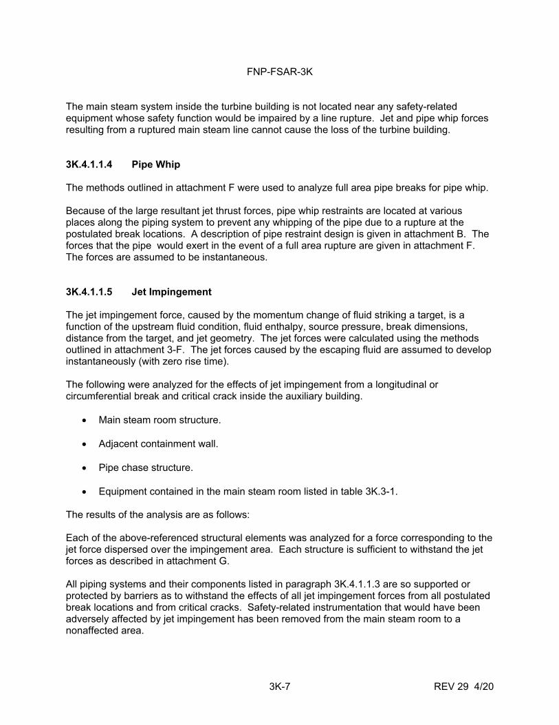
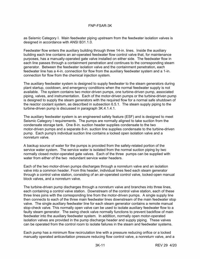
REV 21 5/08 HELB OUTSIDE CONTAINMENT 0.05 ft 2 BREAK AT 102-PERCENT POWER 30-min. OPERATOR ACTION TEMPERATURE VS TIME JOSEPH M. FARLEY NUCLEAR PLANT UNIT 1 AND UNIT 2 FIGURE 3J-1

Welcome message from author
This document is posted to help you gain knowledge. Please leave a comment to let me know what you think about it! Share it to your friends and learn new things together.
Transcript
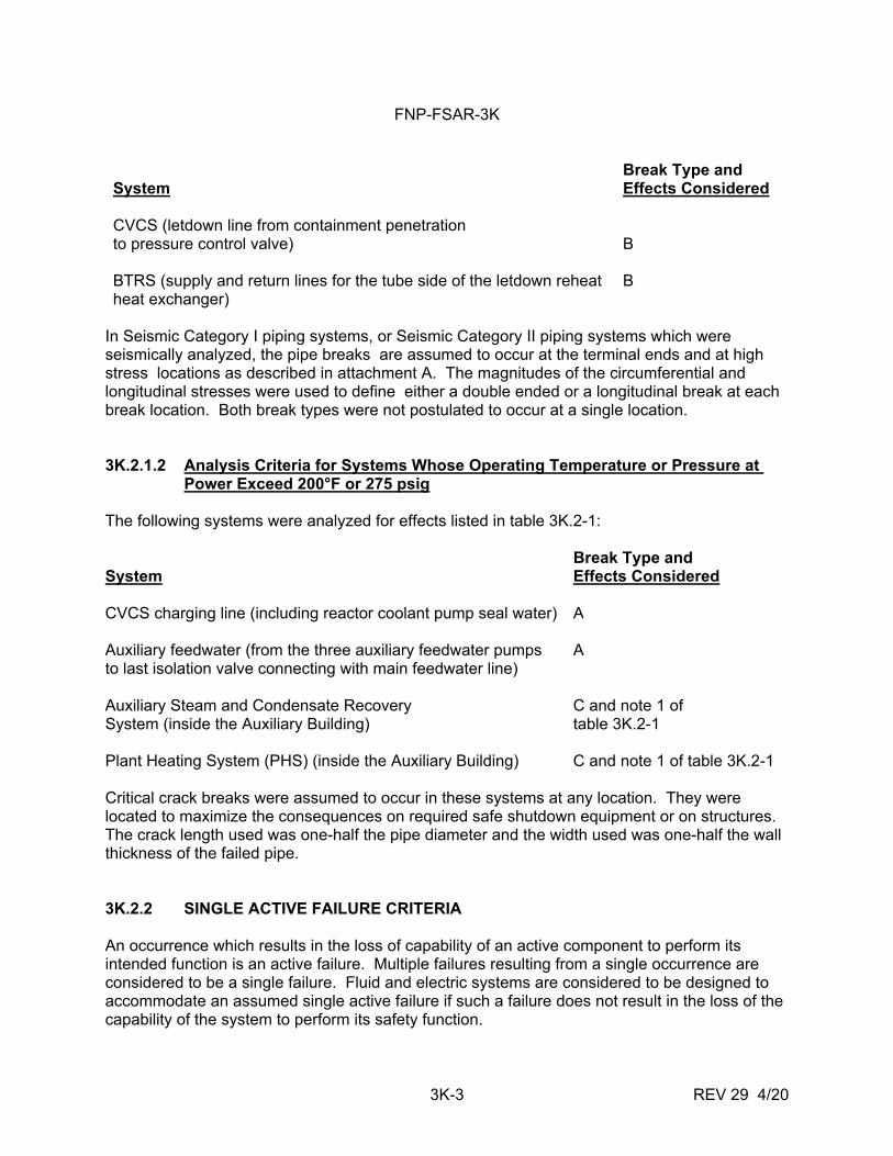
REV 21 5/08 HELB OUTSIDE CONTAINMENT
0.05 ft2 BREAK AT 102-PERCENT POWER 30-min. OPERATOR ACTION TEMPERATURE VS TIME
JOSEPH M. FARLEY NUCLEAR PLANT
UNIT 1 AND UNIT 2 FIGURE 3J-1
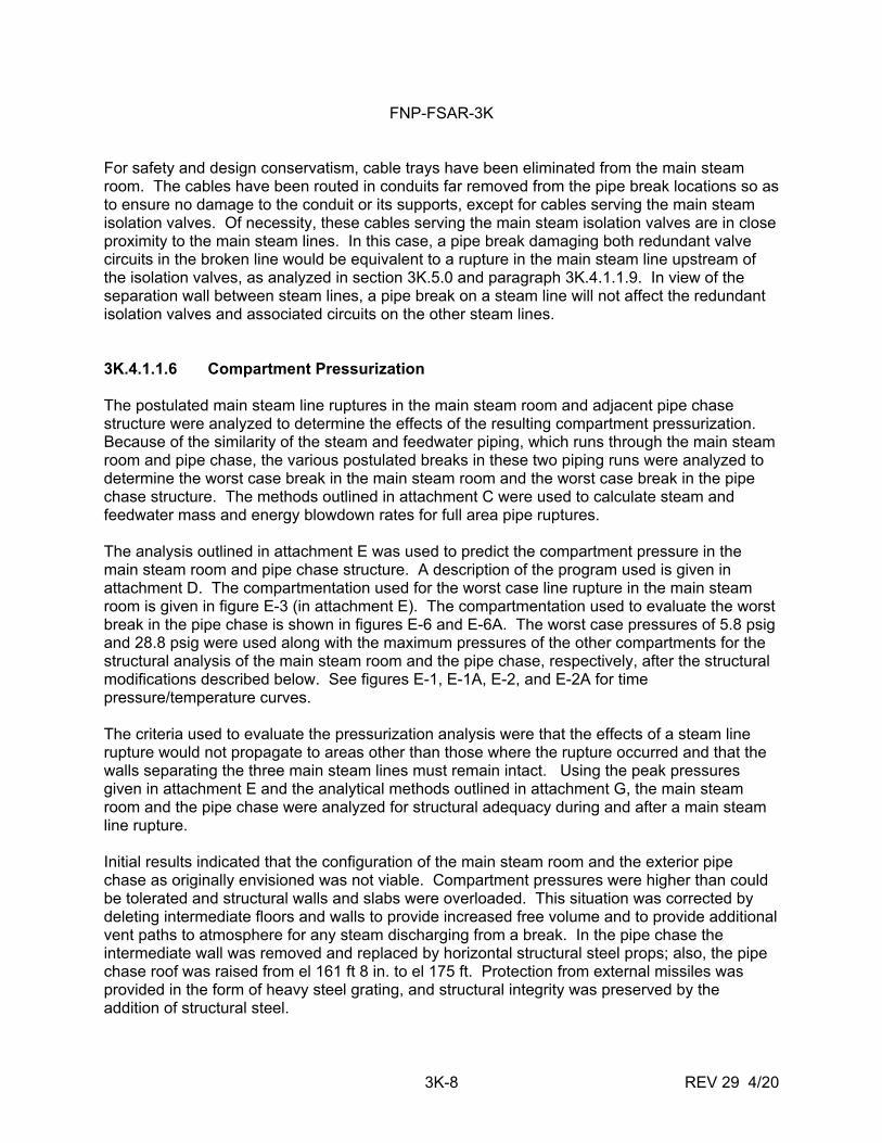
REV 21 5/08 HELB OUTSIDE CONTAINMENT 0.2 ft2
BREAK AT 70-PERCENT POWER TEMPERATURE VS TIME
JOSEPH M. FARLEY NUCLEAR PLANT
UNIT 1 AND UNIT 2 FIGURE 3J-2
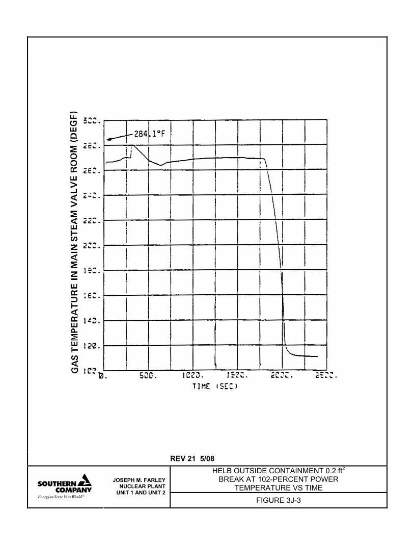
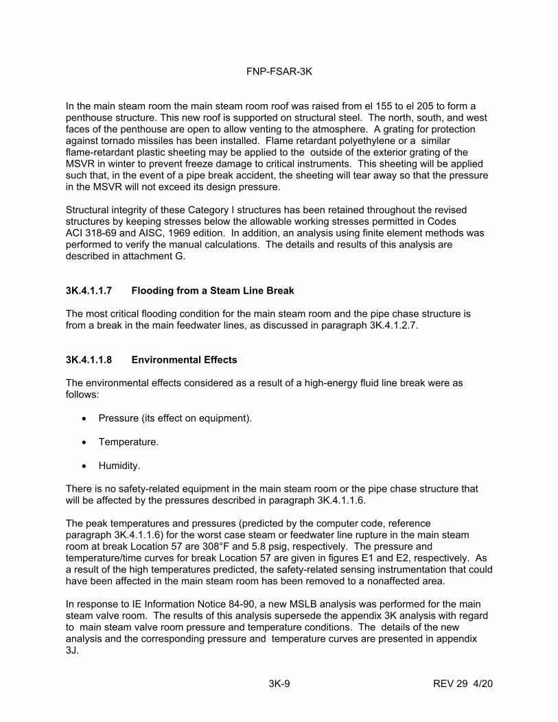
REV 21 5/08
HELB OUTSIDE CONTAINMENT 0.2 ft2 BREAK AT 102-PERCENT POWER
TEMPERATURE VS TIME
JOSEPH M. FARLEY NUCLEAR PLANT
UNIT 1 AND UNIT 2 FIGURE 3J-3
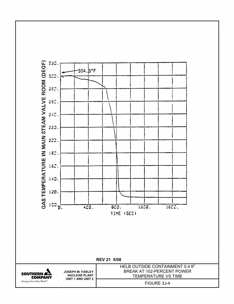
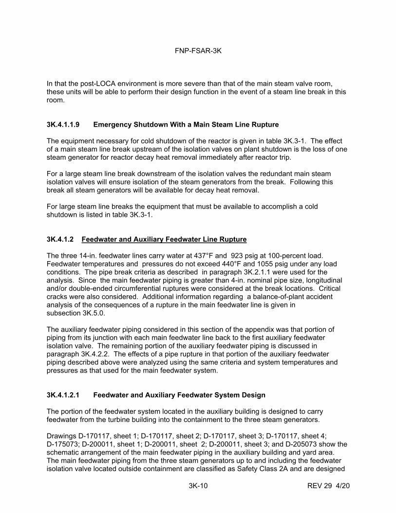
REV 21 5/08
HELB OUTSIDE CONTAINMENT 0.4 ft2 BREAK AT 102-PERCENT POWER
TEMPERATURE VS TIME
JOSEPH M. FARLEY NUCLEAR PLANT
UNIT 1 AND UNIT 2 FIGURE 3J-4
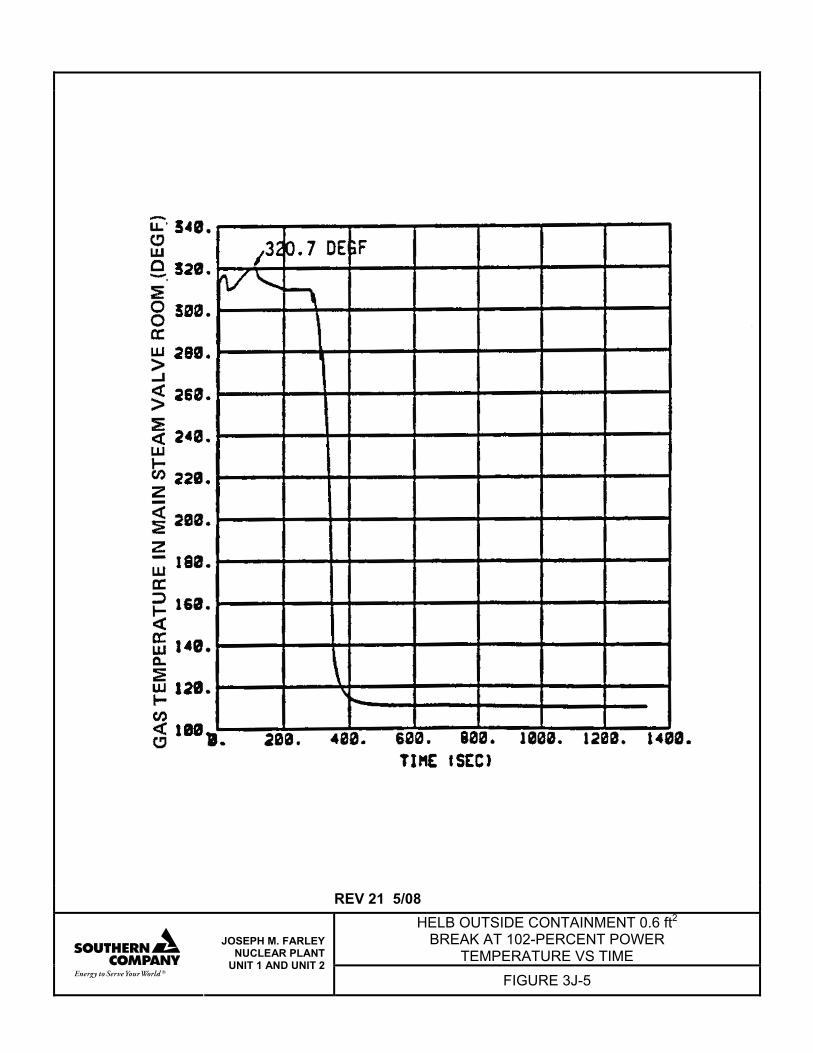
REV 21 5/08 HELB OUTSIDE CONTAINMENT 0.6 ft2
BREAK AT 102-PERCENT POWER TEMPERATURE VS TIME
JOSEPH M. FARLEY NUCLEAR PLANT
UNIT 1 AND UNIT 2 FIGURE 3J-5
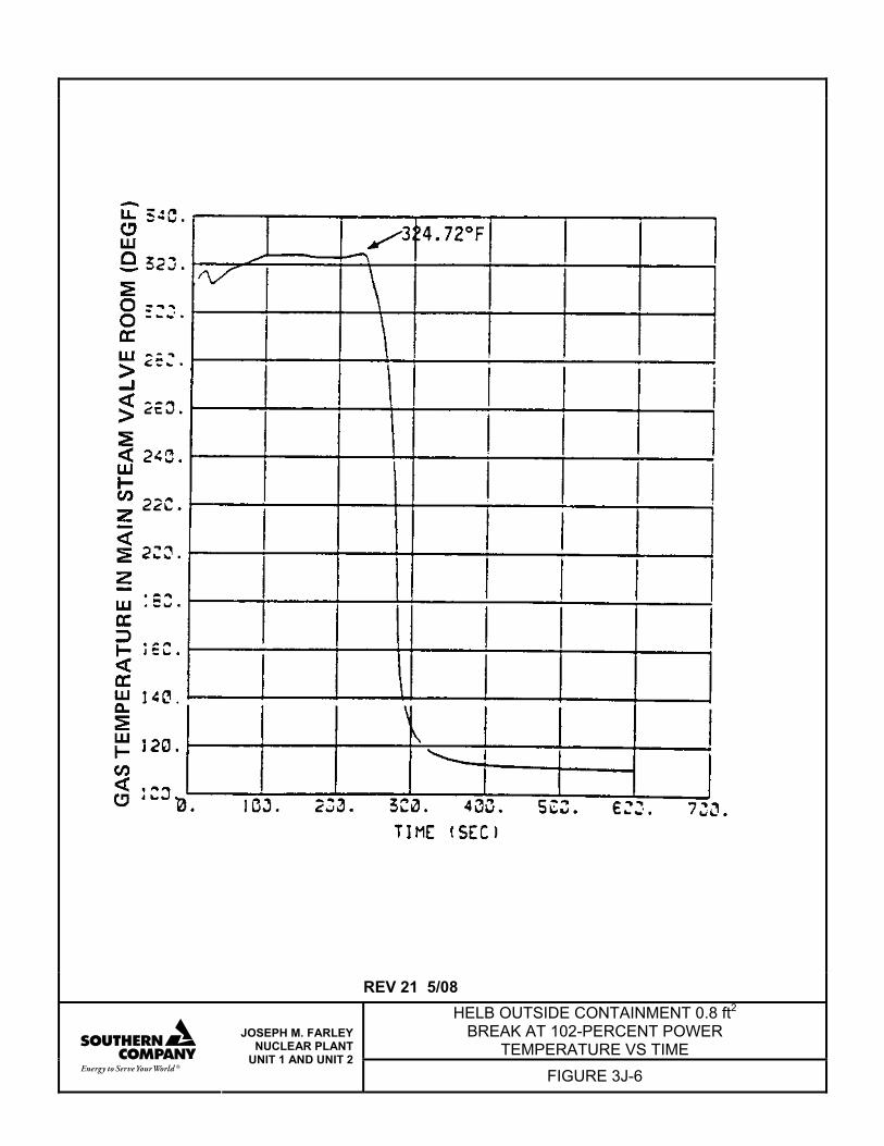
REV 21 5/08
HELB OUTSIDE CONTAINMENT 0.8 ft2 BREAK AT 102-PERCENT POWER
TEMPERATURE VS TIME
JOSEPH M. FARLEY NUCLEAR PLANT
UNIT 1 AND UNIT 2 FIGURE 3J-6
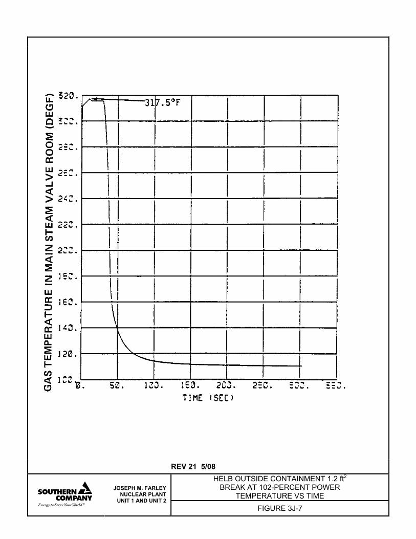
REV 21 5/08 HELB OUTSIDE CONTAINMENT 1.2 ft2
BREAK AT 102-PERCENT POWER TEMPERATURE VS TIME
JOSEPH M. FARLEY NUCLEAR PLANT
UNIT 1 AND UNIT 2 FIGURE 3J-7
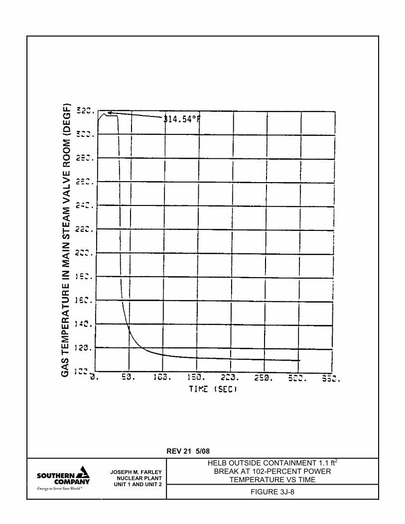
REV 21 5/08
HELB OUTSIDE CONTAINMENT 1.1 ft2 BREAK AT 102-PERCENT POWER
TEMPERATURE VS TIME
JOSEPH M. FARLEY NUCLEAR PLANT
UNIT 1 AND UNIT 2 FIGURE 3J-8
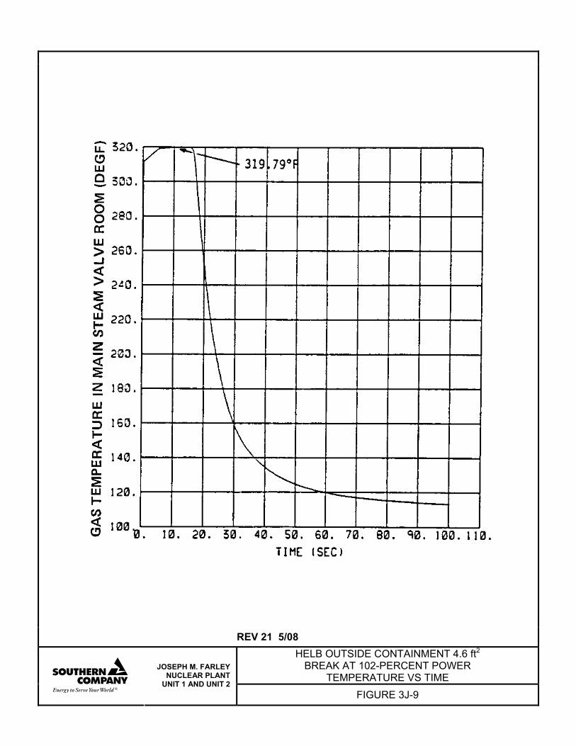
REV 21 5/08 HELB OUTSIDE CONTAINMENT 4.6 ft2
BREAK AT 102-PERCENT POWER TEMPERATURE VS TIME
JOSEPH M. FARLEY NUCLEAR PLANT
UNIT 1 AND UNIT 2 FIGURE 3J-9
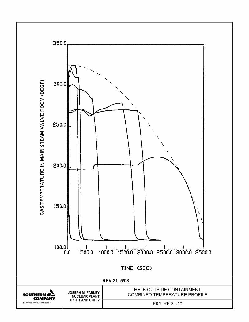
REV 21 5/08
HELB OUTSIDE CONTAINMENT COMBINED TEMPERATURE PROFILE
JOSEPH M. FARLEY NUCLEAR PLANT
UNIT 1 AND UNIT 2 FIGURE 3J-10
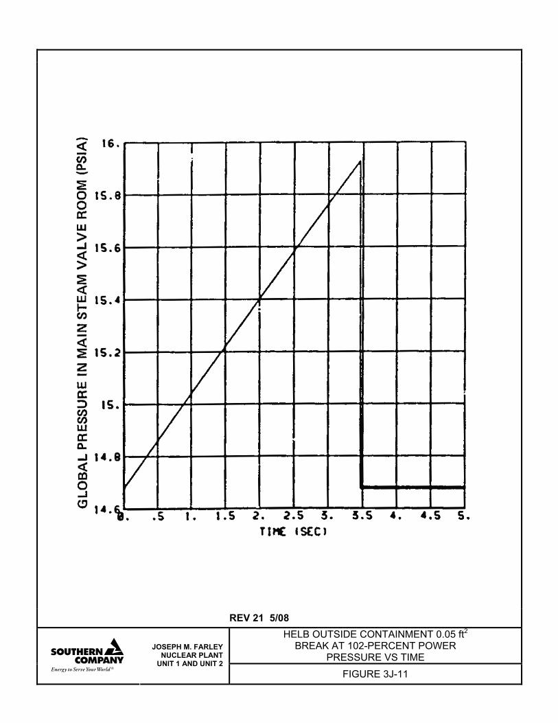
REV 21 5/08 HELB OUTSIDE CONTAINMENT 0.05 ft2
BREAK AT 102-PERCENT POWER PRESSURE VS TIME
JOSEPH M. FARLEY NUCLEAR PLANT
UNIT 1 AND UNIT 2 FIGURE 3J-11
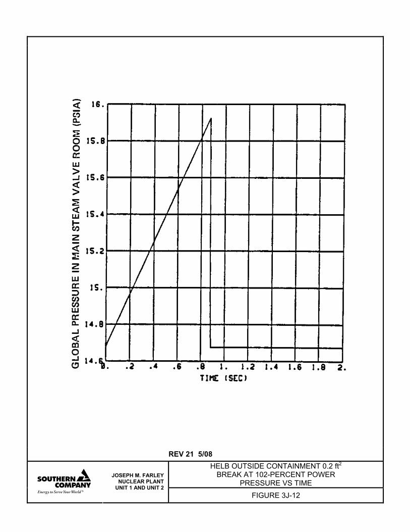
REV 21 5/08 HELB OUTSIDE CONTAINMENT 0.2 ft2
BREAK AT 102-PERCENT POWER PRESSURE VS TIME
JOSEPH M. FARLEY NUCLEAR PLANT
UNIT 1 AND UNIT 2 FIGURE 3J-12
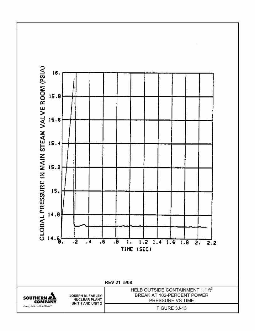
REV 21 5/08 HELB OUTSIDE CONTAINMENT 1.1 ft2
BREAK AT 102-PERCENT POWER PRESSURE VS TIME
JOSEPH M. FARLEY NUCLEAR PLANT
UNIT 1 AND UNIT 2 FIGURE 3J-13
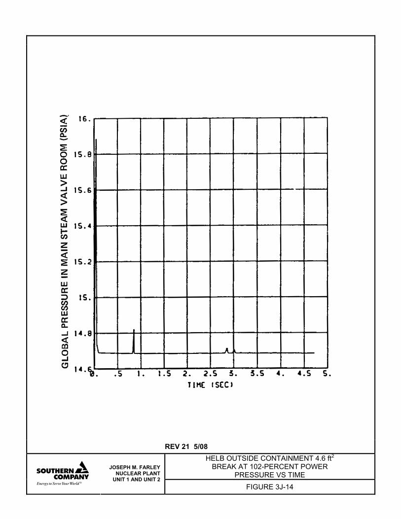
REV 21 5/08 HELB OUTSIDE CONTAINMENT 4.6 ft2
BREAK AT 102-PERCENT POWER PRESSURE VS TIME
JOSEPH M. FARLEY NUCLEAR PLANT
UNIT 1 AND UNIT 2 FIGURE 3J-14
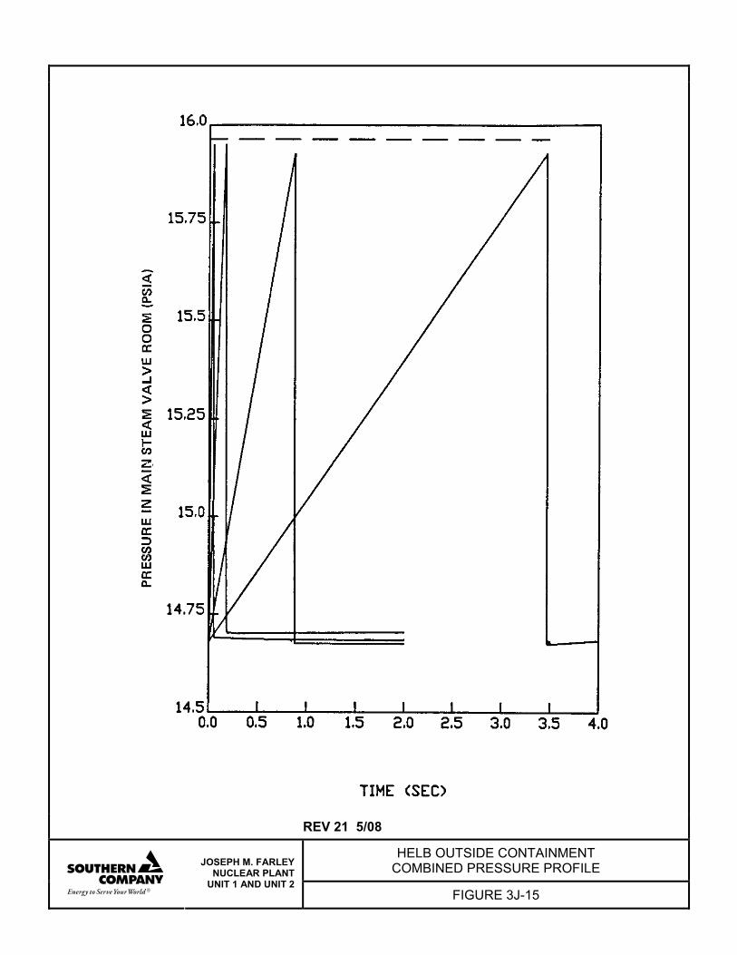
REV 21 5/08
HELB OUTSIDE CONTAINMENT COMBINED PRESSURE PROFILE
JOSEPH M. FARLEY NUCLEAR PLANT
UNIT 1 AND UNIT 2 FIGURE 3J-15
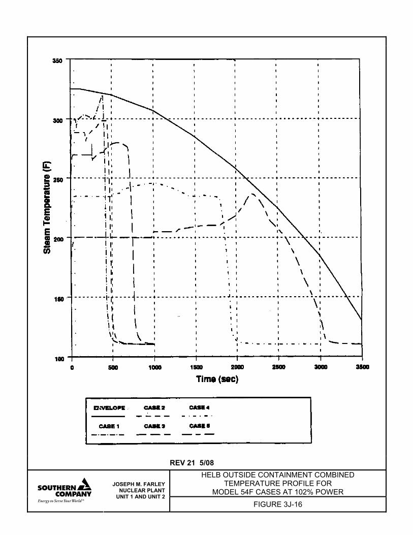
REV 21 5/08
HELB OUTSIDE CONTAINMENT COMBINED TEMPERATURE PROFILE FOR
MODEL 54F CASES AT 102% POWER
JOSEPH M. FARLEY NUCLEAR PLANT
UNIT 1 AND UNIT 2 FIGURE 3J-16

REV 21 5/08
HELB OUTSIDE CONTAINMENT COMBINED TEMPERATURE PROFILE FOR
MODEL 54F CASES AT 70% POWER
JOSEPH M. FARLEY NUCLEAR PLANT
UNIT 1 AND UNIT 2 FIGURE 3J-17
FNP-FSAR-3K
3K-i REV 29 4/20
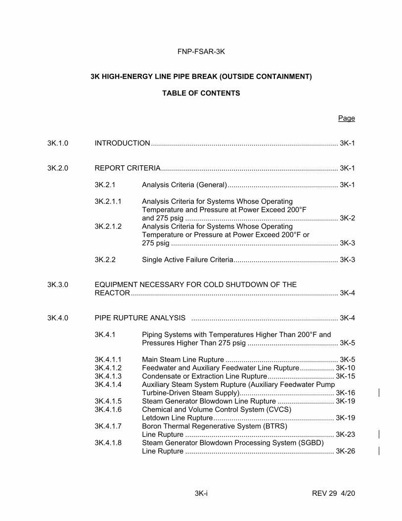
3K HIGH-ENERGY LINE PIPE BREAK (OUTSIDE CONTAINMENT)
TABLE OF CONTENTS Page 3K.1.0 INTRODUCTION ............................................................................................. 3K-1 3K.2.0 REPORT CRITERIA ........................................................................................ 3K-1 3K.2.1 Analysis Criteria (General) ....................................................... 3K-1 3K.2.1.1 Analysis Criteria for Systems Whose Operating
Temperature and Pressure at Power Exceed 200°F and 275 psig ............................................................................ 3K-2
3K.2.1.2 Analysis Criteria for Systems Whose Operating Temperature or Pressure at Power Exceed 200°F or 275 psig ................................................................................... 3K-3
3K.2.2 Single Active Failure Criteria .................................................... 3K-3 3K.3.0 EQUIPMENT NECESSARY FOR COLD SHUTDOWN OF THE REACTOR ....................................................................................................... 3K-4 3K.4.0 PIPE RUPTURE ANALYSIS ......................................................................... 3K-4 3K.4.1 Piping Systems with Temperatures Higher Than 200°F and
Pressures Higher Than 275 psig ............................................. 3K-5 3K.4.1.1 Main Steam Line Rupture ........................................................ 3K-5 3K.4.1.2 Feedwater and Auxiliary Feedwater Line Rupture ................. 3K-10 3K.4.1.3 Condensate or Extraction Line Rupture ................................. 3K-15 3K.4.1.4 Auxiliary Steam System Rupture (Auxiliary Feedwater Pump
Turbine-Driven Steam Supply) ............................................... 3K-16 3K.4.1.5 Steam Generator Blowdown Line Rupture ............................ 3K-19 3K.4.1.6 Chemical and Volume Control System (CVCS)
Letdown Line Rupture ............................................................ 3K-19 3K.4.1.7 Boron Thermal Regenerative System (BTRS)
Line Rupture .......................................................................... 3K-23 3K.4.1.8 Steam Generator Blowdown Processing System (SGBD) Line Rupture .......................................................................... 3K-26
FNP-FSAR-3K
3K-ii REV 29 4/20
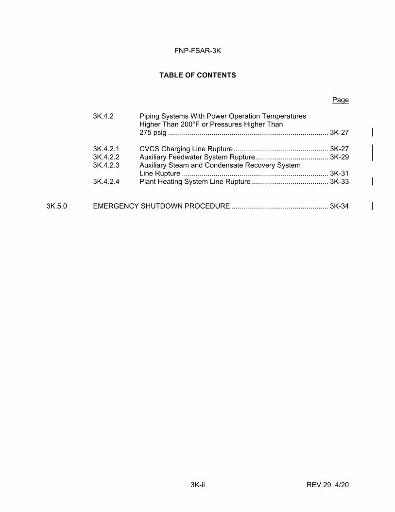
TABLE OF CONTENTS Page 3K.4.2 Piping Systems With Power Operation Temperatures
Higher Than 200°F or Pressures Higher Than 275 psig ................................................................................. 3K-27
3K.4.2.1 CVCS Charging Line Rupture ................................................ 3K-27 3K.4.2.2 Auxiliary Feedwater System Rupture ..................................... 3K-29 3K.4.2.3 Auxiliary Steam and Condensate Recovery System
Line Rupture .......................................................................... 3K-31 3K.4.2.4 Plant Heating System Line Rupture ....................................... 3K-33 3K.5.0 EMERGENCY SHUTDOWN PROCEDURE ................................................. 3K-34
FNP-FSAR-3K
3K-iii REV 29 4/20
LIST OF ATTACHMENTS Attachment A General Information Required for Consideration of Effects of a Piping
System Break Outside Containment Attachment B Pipe Whip Restraint Design Attachment C Methods Used To Calculate Blowdown Rates for High-Energy Fluid Line
Ruptures Attachment D Compartment Pressure Temperature Analysis Computer Program
Description Attachment E Calculation Methods for Compartment Pressurization Attachment F Methods Used To Calculate Pipe Whip Thrust Loads and Jet
Impingement Forces Attachment G Main Steam Room and Pipe Chase Structural Stress Analysis
FNP-FSAR-3K
3K-iv REV 29 4/20
LIST OF TABLES 3K.2-1 Criteria for Identification of High-Energy Lines and Effects Considered 3K.3-1 Equipment Required Following a High-Energy Line Break - Unit 1
(Outside Containment)
FNP-FSAR-3K
3K-1 REV 29 4/20
APPENDIX 3K
HIGH-ENERGY LINE PIPE BREAK (OUTSIDE CONTAINMENT) 3K.1.0 INTRODUCTION This appendix was prepared in response to the NRC letter from A. Giambusso, Deputy Director for Reactor Project - Directorate of Licensing, to the Alabama Power Company, dated December 12, 1972. The Farley Nuclear Plant complies with the criteria set forth in attachment A, parts 1 and II. It describes the analyses performed to determine the effects of a high-energy line break outside containment upon the Farley Nuclear Plant. The appendix applies to Units 1 and 2. Since the Unit 2 main steam room arrangement is similar to the Unit 1 main steam room arrangement, the results and conclusions of these analyses are applicable to both units. On December 7, 1984, the NRC issued Information Notice 84-90, "Main Steam Line Break Effect on Environmental Qualification of Equipment." This notice raised the concern that a large main steam line break may not be the most limiting with respect to peak compartment and equipment temperature. In response to this notice, a new analysis was performed to determine the main steam valve room temperature and pressure response to a spectrum of postulated break sizes. This analysis supersedes the analysis included in this appendix with regard to compartment environmental conditions for the postulated main steam line break inside the main steam valve room. Details of the analysis are presented in appendix 3J. The main steam line break analysis presented in this appendix remains in the FSAR for completeness and to retain the original structural design basis for the main steam valve room. 3K.2.0 REPORT CRITERIA This section describes the criteria considered in assessing the effects of a full area pipe rupture or pipe crack in a high-energy line outside the containment. These criteria were developed from the December 1972 NRC document entitled "General Information Required for Consideration of the Effects of a Piping System Break Outside Containment," the Branch Technical Positions APCSB 3-1 and MEB 3-1 as attached to Standard Review Plans 3.6.1 and 3.6.2, and subsequent discussions with the NRC. These criteria are included as attachment A, parts I and II. 3K.2.1 ANALYSIS CRITERIA (GENERAL) The systems analyzed were those piping systems whose operating temperature exceeds 200°F or whose operating pressure exceeds 275 psig. The effects of pipe whip were considered only for those piping systems whose operating pressure and temperature exceed 275 psig and 200°F, respectively. For piping systems whose pressure exceeds 275 psig, but whose temperature does not exceed 200°F, or whose temperature exceeds 200°F, but whose pressure does not exceed 275 psig, the effects of a critical crack only were considered. Piping systems
FNP-FSAR-3K
3K-2 REV 29 4/20
whose temperatures were less than 200°F and whose pressures were less than 275 psig were not considered. As discussed in attachment A, double ended breaks were not assumed for pipe sizes equal to or less than 1 in., longitudinal breaks were not assumed for pipe sizes less than 4 in., and critical cracks were not assumed for pipe sizes equal to or less than 1 in. Plant conditions prior to rupture were assumed to be power operation or hot shutdown. (Power operation and hot shutdown conditions are described in chapter 15.0.) No other accident was assumed to occur concurrently with the pipe failure. Pipe whip forces and jet impingement loads were derived using the methods outlined in attachment F. The worst case effects of jet impingement from a break or critical crack, as defined in later sections, were analyzed as to their consequences on mechanical or electrical equipment that must be available to bring the plant to hot shutdown and eventually to a cold shutdown condition. Concurrent loss of both preferred offsite power and auxiliary power from the generator was assumed for those accidents that cause a turbine trip. 3K.2.1.1 Analysis Criteria for Systems Whose Operating Temperature and Pressure at
Power Exceed 200º F and 275 psig The following systems were analyzed for the effects listed in table 3K.2-1:
System Break Type and Effects Considered
Main steam B Main feedwater B Auxiliary feedwater (from junction with mainfeedwater line to first isolation valve) B Auxiliary steam (To steam driven auxiliaryfeedwater pump) B Steam generator blowdown B
FNP-FSAR-3K
3K-3 REV 29 4/20
System Break Type and Effects Considered
CVCS (letdown line from containment penetrationto pressure control valve) B BTRS (supply and return lines for the tube side of the letdown reheat heat exchanger)
B
In Seismic Category I piping systems, or Seismic Category II piping systems which were seismically analyzed, the pipe breaks are assumed to occur at the terminal ends and at high stress locations as described in attachment A. The magnitudes of the circumferential and longitudinal stresses were used to define either a double ended or a longitudinal break at each break location. Both break types were not postulated to occur at a single location. 3K.2.1.2 Analysis Criteria for Systems Whose Operating Temperature or Pressure at
Power Exceed 200°F or 275 psig The following systems were analyzed for effects listed in table 3K.2-1:
System Break Type and Effects Considered
CVCS charging line (including reactor coolant pump seal water) A Auxiliary feedwater (from the three auxiliary feedwater pumps to last isolation valve connecting with main feedwater line)
A
Auxiliary Steam and Condensate Recovery C and note 1 of System (inside the Auxiliary Building) table 3K.2-1 Plant Heating System (PHS) (inside the Auxiliary Building) C and note 1 of table 3K.2-1 Critical crack breaks were assumed to occur in these systems at any location. They were located to maximize the consequences on required safe shutdown equipment or on structures. The crack length used was one-half the pipe diameter and the width used was one-half the wall thickness of the failed pipe. 3K.2.2 SINGLE ACTIVE FAILURE CRITERIA An occurrence which results in the loss of capability of an active component to perform its intended function is an active failure. Multiple failures resulting from a single occurrence are considered to be a single failure. Fluid and electric systems are considered to be designed to accommodate an assumed single active failure if such a failure does not result in the loss of the capability of the system to perform its safety function.
FNP-FSAR-3K
3K-4 REV 29 4/20
The analysis in this appendix considers a single active failure within the combined systems required to effect the cold-shutdown condition. The following fluid systems were designed to perform their required functions to bring the plant to a cold shutdown assuming a single failure concurrent with a high-energy line break outside containment: A. Reactor coolant system (RCS). B. Low-head/high-head safety injection system. C. Residual heat removal system (RHRS). D. Auxiliary feedwater system (AFS). E. Service water system (SWS). F. Component cooling water system (CCWS). G. Chemical and volume control system (CVCS). H. Diesel fuel oil system. I. Main steam system (MSS) from steam generators to and including main
steam line isolation valves. J. Main feedwater system (MFS) from steam generators to and including
feedwater isolation valves. 3K.3.0 EQUIPMENT NECESSARY FOR COLD SHUTDOWN OF THE REACTOR Table 3K.3-1 lists the equipment required to mitigate the consequences of a high-energy line rupture outside the containment and obtain a cold shutdown condition. This equipment, as well as any equipment necessary to mitigate the consequences of a high-energy line break, is protected so as not to be adversely affected by the effects of a high-energy line break outside containment. 3K.4.0 PIPE RUPTURE ANALYSIS This section describes, on a system-by-system basis, how Farley Nuclear Plant safety considerations will be implemented. Attachment A, Parts I and II, provides the information required for consideration of a piping system break outside containment. High-energy piping systems within the plant, as described in table 3K.2-1, are classified into two groups for this purpose. Group 1 (subsection 3K.4.1) contains those systems whose operating temperature and pressure will exceed 200°F and 275 psig during power operation or while at hot standby; they are outlined in subsection 3K.4.1. The analysis criteria for all Group 1 piping systems are given in paragraph 3K.2.1.1. Group 2 (subsection 3K.4.2) consists of those systems whose temperature or pressure exceeds either 200°F or 275 psig; they are outlined in
FNP-FSAR-3K
3K-5 REV 29 4/20
subsection 3K.4.2. The analysis criteria for Group 2 piping systems are given in paragraph 3K.2.1.2. Stress analysis results utilized in the criteria for determining pipe break locations are documented in the applicable piping stress calculation for each piping system. Whip restraint locations based on postulated pipe break locations are shown on applicable civil design drawings. 3K.4.1 PIPING SYSTEMS WITH TEMPERATURES HIGHER THAN 200°F AND
PRESSURES HIGHER THAN 275 psig 3K.4.1.1 Main Steam Line Rupture The three main steam lines carry saturated steam at 547°F and 1005 psig for no-load hot standby and 516°F and 775 psig for 100-percent load operation. Since the main steam piping is greater than 4-in. nominal pipe size, both longitudinal and/or double-ended ruptures were considered at the break locations. Critical cracks were also considered. Additional information regarding a balance of plant accident analysis of the consequences of a rupture in the main steam lines is given in subsection 3K.5.0. 3K.4.1.1.1 Main Steam System (MSS) Design The portion of the MSS located in the auxiliary building is designed to carry steam from the three steam generators to the turbine-generator and associated equipment located in the turbine building and to the TDAFWP located in the auxiliary building. Drawings D-175033, sheet 1; D-175033, sheet 2; D-170114, sheet 1; D-170114, sheet 2; D-205033, sheet 1; D-205033, sheet 2; and D-200007 show the schematic arrangement of the MSS piping in the auxiliary building. The main steam piping from the steam generators, up to and including the second isolation valve in each main steam line, and the main steam supply to the TDAFWP have safety-related functions. Those portions of the system are classified as Safety Class 2A and are designed as Seismic Category I. Main steam piping downstream of the main steam line isolation valves is designed in accordance with ANSI B31.1.0 and is Seismic Category II. The design pressure rating of the MSS piping is based on the maximum pressure and temperature that occur at no-load conditions. Saturated steam is generated in the three steam generators and flows out through the containment wall in three 32-in. main steam lines to the main steam isolation valves. Downstream from the main steam isolation valves, the three main steam lines form a common header from which two 36-in. lines conduct steam to the turbine-generator. A flow restrictor, integral with each steam generator, is provided inside the containment to limit steam generator blowdown in the event of a steam line break. The main steam line from each steam generator is provided with five spring loaded safety valves and one power-operated atmospheric relief valve. These valves, which are Safety
FNP-FSAR-3K
3K-6 REV 29 4/20
Class 2A and Seismic Category I, are located between the containment penetration and the first main steam isolation valve on a section of main steam line which has a 34.55-in. outside diameter. The safety valves are direct spring loaded. Each valve is set at a different incremental opening pressure between 1075 psig and 1129 psig. Umbrella-type vent stacks route safety valve discharge through penetrations in the auxiliary building roof. The power-operated atmospheric relief valves are air-operated diaphragm type; they are set to discharge before the first spring loaded safety valve opens. Discharge from the power-operated atmospheric relief valves is piped to the atmosphere through penetrations in the auxiliary building roof. The discharge piping has been analyzed for thermal, seismic, and normal operating loadings. Two pneumatic cylinder operated, swing disc trip, main steam line isolation valves are installed in series in each main steam line outside the containment and downstream from the safety valves. Each pair of isolation valves is bypassed by a 3-in. warming and pressure equalizing line which contains two air-operated isolation valves. The main steam line isolation valves and bypass valves are of a fail close design, are classified as Safety Class 2A, and are designed to meet Seismic Category I requirements. On two of the three main steam lines outside the containment and downstream from the safety valves, and upstream of the main steam line isolation valves, there is a 3-in. takeoff that supplies steam to the TDAFWP. The main steam piping outside the auxiliary building is routed from the auxiliary building across an open area, into the turbine building, and on to the turbine stop and control valves. 3K.4.1.1.2 Main Steam System Piping The MSS piping outside containment was analyzed in accordance with the criteria described in subsection 3K.2.0 and the methods outlined in attachment F. The Seismic Category II portions of the main steam line were analyzed seismically to determine the high stress points and postulated break locations. 3K.4.1.1.3 Areas Affected by a Steam Line Rupture The main steam system piping penetrates the containment wall just above the 127-ft floor level, runs through the main steam room to a pipe chase, runs up the chase, and exits the auxiliary building at el 179 ft 8 in. From the auxiliary building, the two main steam headers proceed across the yard to the turbine building. Each of the three main steam lines between the containment penetrations and the main steam header inside the auxiliary building is separated by a jet impingement wall. Jet impingement barriers are provided where necessary to preclude damage to feedwater control valves and outboard stop-check valves from high-energy line breaks at postulated breakpoints in the main steam and feedwater valve room.
FNP-FSAR-3K
3K-7 REV 29 4/20
The main steam system inside the turbine building is not located near any safety-related equipment whose safety function would be impaired by a line rupture. Jet and pipe whip forces resulting from a ruptured main steam line cannot cause the loss of the turbine building. 3K.4.1.1.4 Pipe Whip The methods outlined in attachment F were used to analyze full area pipe breaks for pipe whip. Because of the large resultant jet thrust forces, pipe whip restraints are located at various places along the piping system to prevent any whipping of the pipe due to a rupture at the postulated break locations. A description of pipe restraint design is given in attachment B. The forces that the pipe would exert in the event of a full area rupture are given in attachment F. The forces are assumed to be instantaneous. 3K.4.1.1.5 Jet Impingement The jet impingement force, caused by the momentum change of fluid striking a target, is a function of the upstream fluid condition, fluid enthalpy, source pressure, break dimensions, distance from the target, and jet geometry. The jet forces were calculated using the methods outlined in attachment 3-F. The jet forces caused by the escaping fluid are assumed to develop instantaneously (with zero rise time). The following were analyzed for the effects of jet impingement from a longitudinal or circumferential break and critical crack inside the auxiliary building.
Main steam room structure.
Adjacent containment wall.
Pipe chase structure.
Equipment contained in the main steam room listed in table 3K.3-1. The results of the analysis are as follows: Each of the above-referenced structural elements was analyzed for a force corresponding to the jet force dispersed over the impingement area. Each structure is sufficient to withstand the jet forces as described in attachment G. All piping systems and their components listed in paragraph 3K.4.1.1.3 are so supported or protected by barriers as to withstand the effects of all jet impingement forces from all postulated break locations and from critical cracks. Safety-related instrumentation that would have been adversely affected by jet impingement has been removed from the main steam room to a nonaffected area.
FNP-FSAR-3K
3K-8 REV 29 4/20
For safety and design conservatism, cable trays have been eliminated from the main steam room. The cables have been routed in conduits far removed from the pipe break locations so as to ensure no damage to the conduit or its supports, except for cables serving the main steam isolation valves. Of necessity, these cables serving the main steam isolation valves are in close proximity to the main steam lines. In this case, a pipe break damaging both redundant valve circuits in the broken line would be equivalent to a rupture in the main steam line upstream of the isolation valves, as analyzed in section 3K.5.0 and paragraph 3K.4.1.1.9. In view of the separation wall between steam lines, a pipe break on a steam line will not affect the redundant isolation valves and associated circuits on the other steam lines. 3K.4.1.1.6 Compartment Pressurization The postulated main steam line ruptures in the main steam room and adjacent pipe chase structure were analyzed to determine the effects of the resulting compartment pressurization. Because of the similarity of the steam and feedwater piping, which runs through the main steam room and pipe chase, the various postulated breaks in these two piping runs were analyzed to determine the worst case break in the main steam room and the worst case break in the pipe chase structure. The methods outlined in attachment C were used to calculate steam and feedwater mass and energy blowdown rates for full area pipe ruptures. The analysis outlined in attachment E was used to predict the compartment pressure in the main steam room and pipe chase structure. A description of the program used is given in attachment D. The compartmentation used for the worst case line rupture in the main steam room is given in figure E-3 (in attachment E). The compartmentation used to evaluate the worst break in the pipe chase is shown in figures E-6 and E-6A. The worst case pressures of 5.8 psig and 28.8 psig were used along with the maximum pressures of the other compartments for the structural analysis of the main steam room and the pipe chase, respectively, after the structural modifications described below. See figures E-1, E-1A, E-2, and E-2A for time pressure/temperature curves. The criteria used to evaluate the pressurization analysis were that the effects of a steam line rupture would not propagate to areas other than those where the rupture occurred and that the walls separating the three main steam lines must remain intact. Using the peak pressures given in attachment E and the analytical methods outlined in attachment G, the main steam room and the pipe chase were analyzed for structural adequacy during and after a main steam line rupture. Initial results indicated that the configuration of the main steam room and the exterior pipe chase as originally envisioned was not viable. Compartment pressures were higher than could be tolerated and structural walls and slabs were overloaded. This situation was corrected by deleting intermediate floors and walls to provide increased free volume and to provide additional vent paths to atmosphere for any steam discharging from a break. In the pipe chase the intermediate wall was removed and replaced by horizontal structural steel props; also, the pipe chase roof was raised from el 161 ft 8 in. to el 175 ft. Protection from external missiles was provided in the form of heavy steel grating, and structural integrity was preserved by the addition of structural steel.
FNP-FSAR-3K
3K-9 REV 29 4/20
In the main steam room the main steam room roof was raised from el 155 to el 205 to form a penthouse structure. This new roof is supported on structural steel. The north, south, and west faces of the penthouse are open to allow venting to the atmosphere. A grating for protection against tornado missiles has been installed. Flame retardant polyethylene or a similar flame-retardant plastic sheeting may be applied to the outside of the exterior grating of the MSVR in winter to prevent freeze damage to critical instruments. This sheeting will be applied such that, in the event of a pipe break accident, the sheeting will tear away so that the pressure in the MSVR will not exceed its design pressure. Structural integrity of these Category I structures has been retained throughout the revised structures by keeping stresses below the allowable working stresses permitted in Codes ACI 318-69 and AISC, 1969 edition. In addition, an analysis using finite element methods was performed to verify the manual calculations. The details and results of this analysis are described in attachment G. 3K.4.1.1.7 Flooding from a Steam Line Break The most critical flooding condition for the main steam room and the pipe chase structure is from a break in the main feedwater lines, as discussed in paragraph 3K.4.1.2.7. 3K.4.1.1.8 Environmental Effects The environmental effects considered as a result of a high-energy fluid line break were as follows:
Pressure (its effect on equipment).
Temperature.
Humidity. There is no safety-related equipment in the main steam room or the pipe chase structure that will be affected by the pressures described in paragraph 3K.4.1.1.6. The peak temperatures and pressures (predicted by the computer code, reference paragraph 3K.4.1.1.6) for the worst case steam or feedwater line rupture in the main steam room at break Location 57 are 308°F and 5.8 psig, respectively. The pressure and temperature/time curves for break Location 57 are given in figures E1 and E2, respectively. As a result of the high temperatures predicted, the safety-related sensing instrumentation that could have been affected in the main steam room has been removed to a nonaffected area. In response to IE Information Notice 84-90, a new MSLB analysis was performed for the main steam valve room. The results of this analysis supersede the appendix 3K analysis with regard to main steam valve room pressure and temperature conditions. The details of the new analysis and the corresponding pressure and temperature curves are presented in appendix 3J.
FNP-FSAR-3K
3K-10 REV 29 4/20
In that the post-LOCA environment is more severe than that of the main steam valve room, these units will be able to perform their design function in the event of a steam line break in this room. 3K.4.1.1.9 Emergency Shutdown With a Main Steam Line Rupture The equipment necessary for cold shutdown of the reactor is given in table 3K.3-1. The effect of a main steam line break upstream of the isolation valves on plant shutdown is the loss of one steam generator for reactor decay heat removal immediately after reactor trip. For a large steam line break downstream of the isolation valves the redundant main steam isolation valves will ensure isolation of the steam generators from the break. Following this break all steam generators will be available for decay heat removal. For large steam line breaks the equipment that must be available to accomplish a cold shutdown is listed in table 3K.3-1. 3K.4.1.2 Feedwater and Auxiliary Feedwater Line Rupture The three 14-in. feedwater lines carry water at 437°F and 923 psig at 100-percent load. Feedwater temperatures and pressures do not exceed 440°F and 1055 psig under any load conditions. The pipe break criteria as described in paragraph 3K.2.1.1 were used for the analysis. Since the main feedwater piping is greater than 4-in. nominal pipe size, longitudinal and/or double-ended circumferential ruptures were considered at the break locations. Critical cracks were also considered. Additional information regarding a balance-of-plant accident analysis of the consequences of a rupture in the main feedwater line is given in subsection 3K.5.0. The auxiliary feedwater piping considered in this section of the appendix was that portion of piping from its junction with each main feedwater line back to the first auxiliary feedwater isolation valve. The remaining portion of the auxiliary feedwater piping is discussed in paragraph 3K.4.2.2. The effects of a pipe rupture in that portion of the auxiliary feedwater piping described above were analyzed using the same criteria and system temperatures and pressures as that used for the main feedwater system. 3K.4.1.2.1 Feedwater and Auxiliary Feedwater System Design The portion of the feedwater system located in the auxiliary building is designed to carry feedwater from the turbine building into the containment to the three steam generators. Drawings D-170117, sheet 1; D-170117, sheet 2; D-170117, sheet 3; D-170117, sheet 4; D-175073; D-200011, sheet 1; D-200011, sheet 2; D-200011, sheet 3; and D-205073 show the schematic arrangement of the main feedwater piping in the auxiliary building and yard area. The main feedwater piping from the three steam generators up to and including the feedwater isolation valve located outside containment are classified as Safety Class 2A and are designed
FNP-FSAR-3K
3K-11 REV 29 4/20
as Seismic Category I. Main feedwater piping upstream from the feedwater isolation valves is designed in accordance with ANSI B31.1.0. Feedwater flow enters the auxiliary building through three 14-in. lines. Inside the auxiliary building each line contains an air-operated feedwater flow control valve that, for maintenance purposes, has a manually-operated gate valve installed on either side. The feedwater flow in each line passes through a containment penetration and continues to the corresponding steam generator. Between the feedwater isolation valve and the containment penetration, each feedwater line has a 4-in. connection for flow from the auxiliary feedwater system and a 1-in. connection for flow from the chemical injection system. The auxiliary feedwater system is designed to supply feedwater to the steam generators during plant startup, cooldown, and emergency conditions when the normal feedwater supply is not available. The system contains two motor-driven pumps, one turbine-driven pump, associated piping, valves, and instrumentation. Each of the motor-driven pumps or the turbine-driven pump is designed to supply the steam generators with the required flow for a normal safe shutdown of the reactor coolant system, as described in subsection 6.5.1. The steam supply piping to the turbine-driven pump is discussed in paragraph 3K.4.1.4.1. The auxiliary feedwater system is an engineered safety feature (ESF) and is designed to meet Seismic Category I requirements. The pumps are normally aligned to take suction from the condensate storage tank. One 8-in. suction header supplies condensate to the two motor-driven pumps and a separate 8-in. suction line supplies condensate to the turbine-driven pump. Each pump's individual suction line contains a locked open isolation valve and a nonreturn valve. A backup source of water for the pumps is provided from the safety-related portion of the service water system. The service water is isolated from the normal suction piping by two normally closed motor-operated gate valves. Each of the three pumps can be supplied with water from either of the two redundant service water headers. Each of the two motor-driven pumps discharges through a nonreturn valve and an isolation valve into a common header. From this header, individual lines feed each steam generator through a control valve station, consisting of an air-operated control valve, locked-open manual block valves, and a nonreturn valve. The turbine-driven pump discharges through a nonreturn valve and branches into three lines, each containing a control valve station. Downstream of the control valve station, each of these three lines joins with the corresponding line from the motor-driven pumps. A single supply line then connects to each of the three main feedwater lines downstream of the main feedwater stop valve. The single auxiliary feedwater line for each steam generator contains a remote manual stop-check valve. This normally open valve can be used to isolate auxiliary feedwater flow to a faulty steam generator. The swing check valve normally functions to prevent backflow of main feedwater into the auxiliary feedwater system. In addition, normally open motor-operated isolation valves are provided in the pump discharge header and supply piping. These valves can be operated from the control room to isolate failures in the steam and feedwater systems. Each pump has a minimum flow recirculation line with a pressure reducing orifice or a locked manually operated anticavitation pressure reducing flow control valve, a nonreturn valve, and a
FNP-FSAR-3K
3K-12 REV 29 4/20
locked open manual block valve. In addition to the minimum flow recirculation line, each pump has a manual locked closed recirculation system and a breakdown orifice for testing of the pump at the design point. The minimum flow recirculation line and the test line for the three pumps are joined together and routed to the condensate storage tank. 3K.4.1.2.2 Feedwater and Auxiliary Feedwater System Piping The main feedwater piping outside containment and inside the auxiliary building and that portion of the auxiliary feedwater piping inside the auxiliary building described in paragraph 3K.4.1.2 were analyzed in accordance with the criteria described in section 3K.2.0. Main feedwater and auxiliary feedwater lines, including the Seismic Category II piping, were seismically analyzed to obtain seismic loading in order to determine the high stress locations. Using this analysis, the pipe break locations were postulated. 3K.4.1.2.3 Areas Affected by a Feedwater or Auxiliary Feedwater Line Rupture The three main feedwater lines penetrate the containment at el 141 ft 6 in. and follow approximately the same path as the main steam lines, as described in paragraph 3K.4.1.1.3. The areas in the auxiliary building affected by a rupture in the main feedwater system and the auxiliary feedwater system will be the same as the main steam system; therefore, the environmental consequences will be limited to the main steam room and the pipe chase, as outlined in paragraph 3K.4.1.1.3. The areas inside the turbine building that would be affected by a feedwater line rupture contain no safety-related equipment whose safety function would be impaired by a line rupture. The forces and flooding resulting from a feedwater line rupture cannot cause the loss of the building. Safety-related equipment and available equipment necessary for a cold shutdown located in the main steam room and the pipe chase are listed in table 3K.3-1. 3K.4.1.2.4 Pipe Whip The methods outlined in attachment F were used to analyze full area pipe breaks for pipe whip and the resultant jet thrust forces. The forces experienced in the event of a full area break are given in attachment F. Because of the large resultant jet thrust forces, pipe whip restraints are located at various places along the pipe system to prevent whipping of the pipe due to rupture at the postulated break locations. A description of pipe restraint design is given in attachment B.
FNP-FSAR-3K
3K-13 REV 29 4/20
3K.4.1.2.5 Jet Impingement The jet impingement force, caused by the momentum change of fluid striking a target, is a function of the upstream fluid conditions, fluid enthalphy, source pressure, break dimensions, distance from the target and jetgeometry; for conservatism, pipe fiction effects from the pressure source to any break in the line were neglected. The jet forces were calculated using the method outlined in attachment F. The jet forces caused by the escaping fluid are assumed to develop instantaneously (with zero rise time). The effects of jet impingement on the structures and equipment listed in paragraph 3K.4.1.1.5 were analyzed. The results were the same as those outlined in that section. The closest line-of-sight distance from postulated breakpoints to valve actuation elements in the main steam room is 11 ft 8 in. Impingement pressure from the break falls to < 1.3 psig at a distance of 5 ft; therefore, no damage will be done to the actuation element. 3K.4.1.2.6 Compartment Pressurization Because of the lower energy release rate associated with a feedwater line break, the compartment pressurization would be less than already presented in the main steam pressure analysis for the main steam room and the pipe chase structure as discussed in paragraph 3K.4.1.1.6. 3K.4.1.2.7 Flooding The main steam room and the pipe chase structure contain equipment available for hot standby and eventual cooldown. Postulated flooding due to a main feedwater line rupture in the main steam room and pipe chase structure was conservatively analyzed using the following assumptions: A. A full circumferential break was assumed in the No. 3 main feedwater line. B. Main feedwater pumps are initially operating, with a portion of the flow flashing
to steam upon exiting the break. The net flow of water to the floor of the main steam room is 24,100 gal/min, based on system resistances between the pump discharges and the break location.
C. All three of the auxiliary feedwater pumps are assumed to be operating at the
time of the break. The net flow of water to the floor of the main steam room is initially a total of 900 gal/min, the flow being based on system resistances between the pump discharges and the break location.
D. The main feedwater pumps and auxiliary feedwater pumps contribute a total
initial combined flow of 25,000 gal/min to the floor. Six redundant level sensors, set to activate at a level not to exceed 6 in. off the 127-ft floor elevation, initiate signals to trip the feedwater pumps and close the feedwater isolation valves. During the 30-s interval required for these isolation valves to
FNP-FSAR-3K
3K-14 REV 29 4/20
close, the combined pumps are conservatively assumed to continue to contribute at their maximum net rate of 25,000 gal/min. The two motor-driven auxiliary feedwater pumps (MDAFWPs) are assumed to contribute through the break for a total of 30 min after the main feedwater isolation signals are initiated, at which time the break is remote manually isolated using the motor-operated valves provided. The turbine-driven pump continues to contribute through the break at a flow rate of 348 gal/min until isolated from the break using manual valves which are located below the main steam room and isolated from the effects of a feedwater or steam line break.
E. The affected steam generator is assumed to be at maximum water level, and
blows down its entire inventory of water to the main steam room with a portion of the water flashing to steam as it exits the break. Total net contribution of water to the main steam room from this source is 2800 ft3.
F. All feedwater lines and heaters between the feedwater pumps and the break
are assumed to drain their entire 1200 ft3 inventory to the main steam room. The net free volume of the pipe chase and main steam room up to the elevation of the lowest safety-related equipment (the solenoid valves associated with MDAFW and TDAFW discharge valves HV-3227A, B, and C and HV-3228A, B, and C located at el 131 ft. 0 in.) is 15,710 ft3. The MDAFWPs discharge to the faulted steam generator (SG) are isolated at 30-min after the main feedwater isolation signals are initiated. The TDAFWP discharge to the faulted SG is isolated at 1 h and 49 min after the 30-min duration for MDAFWP isolation of break flow has elapsed. The bounding operator action times of 30 min (MDAFWPs) and 1 h and 49 min (TDAFWP), respectively, totaling 2 h and 19 min, are the analyzed required times for plant personnel to isolate the motor-driven and turbine-driven pumps discharge from the break before water levels in the main steam room would approach the bottom of the solenoid valves on the AFW pump discharge valves. Additional time would be available before water levels would approach the critical portions of the valve operators, located on top of the valve.
3K.4.1.2.8 Environmental Effects Environmental effects from a feedwater pipe break in the main steam room and pipe chase structure are included in the analysis in paragraph 3K.4.1.1.8. 3K.4.1.2.9 Emergency Shutdown with a Feedwater or Auxiliary Feedwater Rupture A feedwater rupture between the containment and the feedwater check valve is considered to be the worst case feedwater rupture because of the complete blowdown of one steam generator, in addition to almost unrestricted flow out of the break from the feedwater pumps. The equipment necessary for cold shutdown of the reactor is given in table 3K.3-1. For this rupture the following must be available to accomplish their respective safety functions:
FNP-FSAR-3K
3K-15 REV 29 4/20
A. Safety injection to inject borated water into the core and thereby limit the core power transient following the break.
B. For a large feedline break, there will be considerable water carryover from the
affected steam generator. The water loss out of the steam generator lessens the plant's ability to dissipate decay heat. The auxiliary feedwater pumps will automatically start and deliver flow through the auxiliary feedwater flow restriction orifices. The orifices limit flow to the faulted steam generator and establish flow to the intact steam generators. After 10 min, operator action is taken to decrease flow to the faulted steam generator and increase flow to the intact steam generators.
C. Closure of main steam isolation valves. In order to cool the plant down to the residual heat removal system (RHRS) operating temperature and pressure, auxiliary feedwater from at least one auxiliary feedwater pump must be available and the steam generator power-operated relief valves must be accessible for manual local operation. For a large break between the main feedwater pump and the main feedwater check valve, the feedline check valve will prevent water or steam release from any of the steam generators through the break. A large break at this point is, thus, essentially a loss of normal feedwater. In this case, the equipment that must be available to accomplish the safety shutdown is given in table 3K.3-1. Safety injection is not required. This case covers all lesser feedwater and condensate system high-energy line breaks. 3K.4.1.3 Condensate or Extraction Line Rupture The condensate and extraction lines are located in the turbine building. There is no safety-related equipment located in the vicinity of these lines whose safety function would be impaired by a line rupture, and the flooding or forces created by the rupture of these lines are incapable of compromising the integrity of the turbine building. 3K.4.1.4 Auxiliary Steam System Rupture (Auxiliary Feedwater Pump Turbine-
Driven Steam Supply) The auxiliary steam system supplies steam to the auxiliary feedwater pump turbine driver from the No. 2 and No. 3 steam headers upstream of the main steam isolation valves at main steam pressures and temperatures given in paragraph 3K.4.1.1. Where the piping is < 4-in. nominal pipe size, only full area circumferential breaks were considered at the break locations. The analysis criteria used are outlined in paragraph 3K.2.1.1. 3K.4.1.4.1 Auxiliary Steam System Design
FNP-FSAR-3K
3K-16 REV 29 4/20
The steam turbine which drives one of the three auxiliary feedwater pumps is a single stage noncondensing turbine that operates on steam extracted from the main steam system (MSS). Drawing D-175033, sheet 2 shows the schematic arrangement of the supply piping. Three-inch connections for the steam supply to the auxiliary feedwater turbine driver are provided on two of the three main steam lines between the containment penetrations and the main steam isolation valves. Each line is provided with a normally open manual gate valve, a normally closed air-operated isolation valve, and a normally open manual gate valve installed in series. Between the two normally open gate valves, there is a 1-in. normally open bypass line that keeps the supply piping at main steam temperature. The 3-in. lines penetrate the 127 ft elevation floor, increase to 4-in., and then combine to form a single 4-in. line that runs to a control station and trip and throttle valve located at the turbine inlet. Each 3-in. line contains a check valve below el 127 ft. The system piping is Seismic Category I from the main steam line to the turbine. 3K.4.1.4.2 Auxiliary Steam System Piping The auxiliary steam system piping from the No. 2 and No. 3 MSS headers to the auxiliary feedwater pump turbine was analyzed in accordance with the criteria described in paragraph 3K.2.1.1. Each 3-in. auxiliary steam branch line from the main steam line header is increased to a 4-in. line downstream from the air-operated isolation valves. These 4-in. lines then join into a common 4-in. header to the auxiliary feedwater pump turbine driver. 3K.4.1.4.3 Areas Affected by an Auxiliary Steam System Line Rupture The auxiliary steam system provides steam from the No. 2 and No. 3 main steam headers in the main steam room through the floor level at el 127 to the equipment room area at el 100 directly below the main steam room. From the point at which the two lines join in the equipment room, a single 4-in. header proceeds through the ceiling of the steam driven auxiliary feedwater pump room to the turbine driver. The only other room that would be affected at el 100 besides the turbine pump room and equipment room would be the chemical storage room adjacent to motor pump room 1. The areas affected by an auxiliary steam line rupture above el 127 are outlined in paragraph 3K.4.1.1.3. In order to prevent the adverse environmental consequences (i.e., temperature and pressure) of a rupture in the auxiliary steam line at the el 100-ft level from propagating to other areas of the auxiliary building containing available shutdown equipment, and at the same time allowing the adverse environmental effects to vent to the atmosphere, the following structural design changes were initiated: the rollup door to the equipment access shaft on the south wall of the auxiliary building was removed (this allowed discharging steam to vent up the shaft to the atmosphere); and the area containing the TDAFWP was isolated from safety-related equipment by the addition of walls and watertight doors to protect nearby equipment from flooding. 3K.4.1.4.4 Pipe Whip
FNP-FSAR-3K
3K-17 REV 29 4/20
The methods and analyses used for full area pipe breaks for pipe whip are the same as those outlined in paragraph 3K.4.1.1.4. Pipe whip restraints have been so located at the postulated break locations as to prevent whipping of the pipe due to a full area break at those locations. The thrust forces that the pipe would exert in the event of a full area break are given in attachment F. 3K.4.1.4.5 Jet Impingement The methods and analysis used in considering the effects of jet impingement caused by a rupture in the auxiliary steam system are the same as those outlined in paragraph 3K.4.1.1.5. The effects of jet impingement forces on the following structures and equipment were analyzed: A. Main steam room. B. The structural areas at el 100 described in paragraph 3K.4.1.4.3. C. Electrical cables servicing safety-related equipment at el 100. D. Auxiliary feedwater lines E. Service water lines at el 100. F. Safety-related instrumentations at el 100. The results are as follows: The auxiliary feedwater lines and service water lines are supported or protected by appropriate barriers so as to withstand the effects of all jet impingement forces from all postulated break locations and from critical cracks. Each of the above referenced structural elements was investigated for a force corresponding to the jet force dispersed over the impingement area. The capacity of the structures has been shown to be sufficient to safely withstand the jet forces in combination with the static pressure loadings associated with a high-energy line break. Cable trays have been relocated away from break locations so as to reduce jet impingement loads to acceptable levels. Safety-related instrumentation that could be adversely affected by jet impingement has been removed from the areas at el 100 to a nonaffected area. 3K.4.1.4.6 Compartment Pressurization
FNP-FSAR-3K
3K-18 REV 29 4/20
Overpressurization of the compartments outlined in paragraph 3K.4.1.4.3 due to a full area rupture in the auxiliary steam line was considered using the methods and analyses of paragraph 3K.4.1.1.6. A rupture in the main steam line at el 127 is the worst case break for the main steam room, and is discussed in paragraph 3K.4.1.1.6. After making the structural modifications for the areas at el 100 described in paragraph 3K.4.1.4.3, the peak pressure at el 100 in the TDAFWP area was found to be 15.25 psia as shown on figure E-7; this amounts to a differential pressure across walls and slabs of approximately 0.55 psi, which is well within the design strength of the structure. The computer model flow diagram for the above pressure analysis is given on figure E-8, in attachment E, along with the blowdown table E-1. 3K.4.1.4.7 Flooding Flooding accompanying a break in the line carrying auxiliary steam to the TDAFWP at el 100 will affect the steam-driven auxiliary, feedwater pump room, adjacent corridors, equipment room, and chemical storage room. The combined net floor area is calculated to be 1,615 ft2. (For conservatism, for calculating a flood height the floor area for the chemical storage room was neglected.) Flooding is calculated assuming the entire inventory (3,250 ft3 water, 2508 ft3 steam) of one steam generator to empty into the area. The flooding level is calculated at 2 ft above the 100 ft floor elevation throughout the affected areas. The two MDAFWPs will be unaffected since their respective rooms are equipped with watertight doors. Auxiliary feedwater crossconnect valving is located outside the affected space, and required auxiliary feedwater flow can be maintained with the two motor-driven pumps. Indication of flooding would be provided by the equipment room sump high-level alarm. No safety-related equipment is adversely affected, and safe shutdown capability is unimpaired. A rupture in an auxiliary steam line in the main steam room at el 127 ft leads to a less severe case of flooding than does a rupture in the main feedwater system, as outlined in paragraph 3K.4.1.2.7. 3K.4.1.4.8 Environmental Effects Pressure and temperature due to a rupture in the auxiliary steam system at el 100 ft (turbine-driven pump room) are given in figures E-7 and E-7A, respectively. No safety-related equipment in these areas will be affected by the pressures shown in figure E-7. The temperatures shown in figure E-7A approach an asymptotic value of 300°F. The electric cable to safety-related equipment in this area has the same characteristics as that discussed in paragraph 3K.4.1.1.8 and will not be adversely affected by these temperatures. The operators will terminate the transient by closing the appropriate isolation valves located at el 127 ft within 10 min.
FNP-FSAR-3K
3K-19 REV 29 4/20
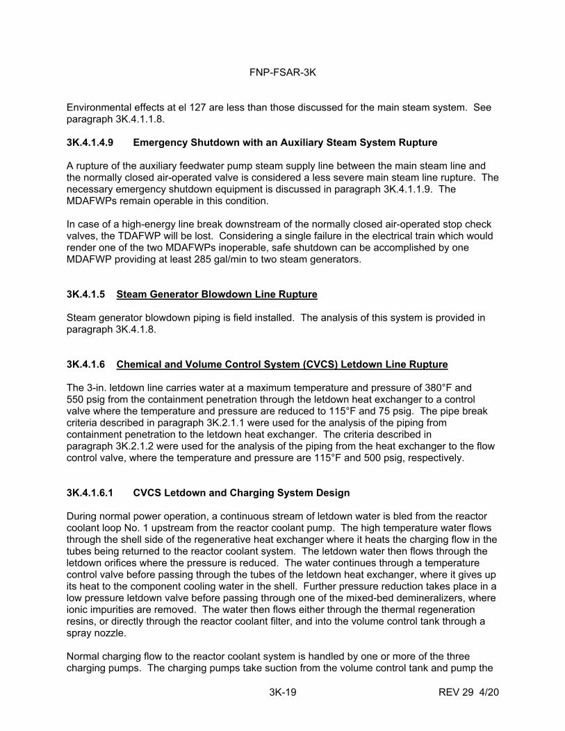
Environmental effects at el 127 are less than those discussed for the main steam system. See paragraph 3K.4.1.1.8. 3K.4.1.4.9 Emergency Shutdown with an Auxiliary Steam System Rupture A rupture of the auxiliary feedwater pump steam supply line between the main steam line and the normally closed air-operated valve is considered a less severe main steam line rupture. The necessary emergency shutdown equipment is discussed in paragraph 3K.4.1.1.9. The MDAFWPs remain operable in this condition. In case of a high-energy line break downstream of the normally closed air-operated stop check valves, the TDAFWP will be lost. Considering a single failure in the electrical train which would render one of the two MDAFWPs inoperable, safe shutdown can be accomplished by one MDAFWP providing at least 285 gal/min to two steam generators. 3K.4.1.5 Steam Generator Blowdown Line Rupture Steam generator blowdown piping is field installed. The analysis of this system is provided in paragraph 3K.4.1.8. 3K.4.1.6 Chemical and Volume Control System (CVCS) Letdown Line Rupture The 3-in. letdown line carries water at a maximum temperature and pressure of 380°F and 550 psig from the containment penetration through the letdown heat exchanger to a control valve where the temperature and pressure are reduced to 115°F and 75 psig. The pipe break criteria described in paragraph 3K.2.1.1 were used for the analysis of the piping from containment penetration to the letdown heat exchanger. The criteria described in paragraph 3K.2.1.2 were used for the analysis of the piping from the heat exchanger to the flow control valve, where the temperature and pressure are 115°F and 500 psig, respectively. 3K.4.1.6.1 CVCS Letdown and Charging System Design During normal power operation, a continuous stream of letdown water is bled from the reactor coolant loop No. 1 upstream from the reactor coolant pump. The high temperature water flows through the shell side of the regenerative heat exchanger where it heats the charging flow in the tubes being returned to the reactor coolant system. The letdown water then flows through the letdown orifices where the pressure is reduced. The water continues through a temperature control valve before passing through the tubes of the letdown heat exchanger, where it gives up its heat to the component cooling water in the shell. Further pressure reduction takes place in a low pressure letdown valve before passing through one of the mixed-bed demineralizers, where ionic impurities are removed. The water then flows either through the thermal regeneration resins, or directly through the reactor coolant filter, and into the volume control tank through a spray nozzle. Normal charging flow to the reactor coolant system is handled by one or more of the three charging pumps. The charging pumps take suction from the volume control tank and pump the
FNP-FSAR-3K
3K-20 REV 29 4/20
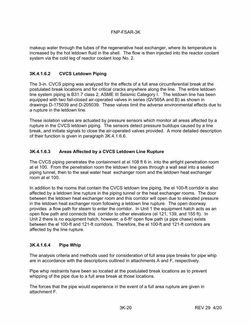
makeup water through the tubes of the regenerative heat exchanger, where its temperature is increased by the hot letdown fluid in the shell. The flow is then injected into the reactor coolant system via the cold leg of reactor coolant loop No. 2. 3K.4.1.6.2 CVCS Letdown Piping The 3-in. CVCS piping was analyzed for the effects of a full area circumferential break at the postulated break locations and for critical cracks anywhere along the line. The entire letdown line system piping is B31.7 class 2, ASME III Seismic Category I. The letdown line has been equipped with two fail-closed air-operated valves in series (QV565A and B) as shown in drawings D-175039 and D-205039. These valves limit the adverse environmental effects due to a rupture in the letdown line. These isolation valves are actuated by pressure sensors which monitor all areas affected by a rupture in the CVCS letdown piping. The sensors detect pressure buildups caused by a line break, and initiate signals to close the air-operated valves provided. A more detailed description of their function is given in paragraph 3K.4.1.6.6. 3K.4.1.6.3 Areas Affected by a CVCS Letdown Line Rupture The CVCS piping penetrates the containment at el 108 ft 6 in. into the airtight penetration room at el 100. From the penetration room the letdown line goes through a wall seal into a sealed piping tunnel, then to the seal water heat exchanger room and the letdown heat exchanger room at el 100. In addition to the rooms that contain the CVCS letdown line piping, the el 100-ft corridor is also affected by a letdown line rupture in the piping tunnel or the heat exchanger rooms. The door between the letdown heat exchanger room and this corridor will open due to elevated pressure in the letdown heat exchanger room following a letdown line rupture. The open doorway provides a flow path for steam to enter the corridor. In Unit 1 the equipment hatch acts as an open flow path and connects this corridor to other elevations (el 121, 139, and 155 ft). In Unit 2 there is no equipment hatch, however, a 6-ft2 open flow path (a pipe chase) exists between the el 100-ft and 121-ft corridors. Therefore, the el 100-ft and 121-ft corridors are affected by the line rupture. 3K.4.1.6.4 Pipe Whip The analysis criteria and methods used for consideration of full area pipe breaks for pipe whip are in accordance with the descriptions outlined in attachments A and F, respectively. Pipe whip restraints have been so located at the postulated break locations as to prevent whipping of the pipe due to a full area break at those locations. The forces that the pipe would experience in the event of a full area rupture are given in attachment F.
FNP-FSAR-3K
3K-21 REV 29 4/20
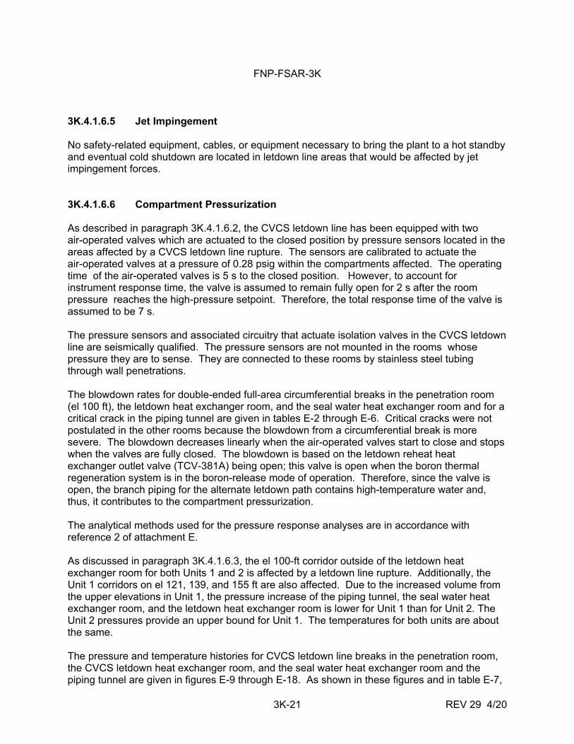
3K.4.1.6.5 Jet Impingement No safety-related equipment, cables, or equipment necessary to bring the plant to a hot standby and eventual cold shutdown are located in letdown line areas that would be affected by jet impingement forces. 3K.4.1.6.6 Compartment Pressurization As described in paragraph 3K.4.1.6.2, the CVCS letdown line has been equipped with two air-operated valves which are actuated to the closed position by pressure sensors located in the areas affected by a CVCS letdown line rupture. The sensors are calibrated to actuate the air-operated valves at a pressure of 0.28 psig within the compartments affected. The operating time of the air-operated valves is 5 s to the closed position. However, to account for instrument response time, the valve is assumed to remain fully open for 2 s after the room pressure reaches the high-pressure setpoint. Therefore, the total response time of the valve is assumed to be 7 s. The pressure sensors and associated circuitry that actuate isolation valves in the CVCS letdown line are seismically qualified. The pressure sensors are not mounted in the rooms whose pressure they are to sense. They are connected to these rooms by stainless steel tubing through wall penetrations. The blowdown rates for double-ended full-area circumferential breaks in the penetration room (el 100 ft), the letdown heat exchanger room, and the seal water heat exchanger room and for a critical crack in the piping tunnel are given in tables E-2 through E-6. Critical cracks were not postulated in the other rooms because the blowdown from a circumferential break is more severe. The blowdown decreases linearly when the air-operated valves start to close and stops when the valves are fully closed. The blowdown is based on the letdown reheat heat exchanger outlet valve (TCV-381A) being open; this valve is open when the boron thermal regeneration system is in the boron-release mode of operation. Therefore, since the valve is open, the branch piping for the alternate letdown path contains high-temperature water and, thus, it contributes to the compartment pressurization. The analytical methods used for the pressure response analyses are in accordance with reference 2 of attachment E. As discussed in paragraph 3K.4.1.6.3, the el 100-ft corridor outside of the letdown heat exchanger room for both Units 1 and 2 is affected by a letdown line rupture. Additionally, the Unit 1 corridors on el 121, 139, and 155 ft are also affected. Due to the increased volume from the upper elevations in Unit 1, the pressure increase of the piping tunnel, the seal water heat exchanger room, and the letdown heat exchanger room is lower for Unit 1 than for Unit 2. The Unit 2 pressures provide an upper bound for Unit 1. The temperatures for both units are about the same. The pressure and temperature histories for CVCS letdown line breaks in the penetration room, the CVCS letdown heat exchanger room, and the seal water heat exchanger room and the piping tunnel are given in figures E-9 through E-18. As shown in these figures and in table E-7,
FNP-FSAR-3K
3K-22 REV 29 4/20
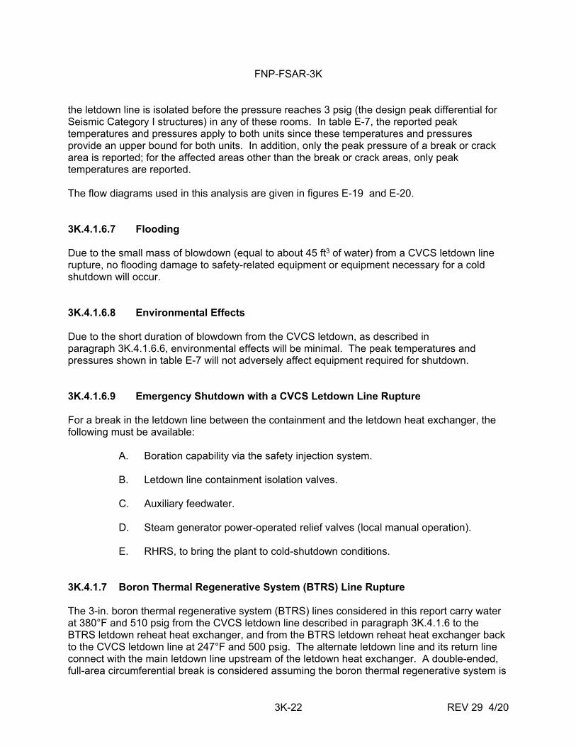
the letdown line is isolated before the pressure reaches 3 psig (the design peak differential for Seismic Category I structures) in any of these rooms. In table E-7, the reported peak temperatures and pressures apply to both units since these temperatures and pressures provide an upper bound for both units. In addition, only the peak pressure of a break or crack area is reported; for the affected areas other than the break or crack areas, only peak temperatures are reported. The flow diagrams used in this analysis are given in figures E-19 and E-20. 3K.4.1.6.7 Flooding Due to the small mass of blowdown (equal to about 45 ft3 of water) from a CVCS letdown line rupture, no flooding damage to safety-related equipment or equipment necessary for a cold shutdown will occur. 3K.4.1.6.8 Environmental Effects Due to the short duration of blowdown from the CVCS letdown, as described in paragraph 3K.4.1.6.6, environmental effects will be minimal. The peak temperatures and pressures shown in table E-7 will not adversely affect equipment required for shutdown. 3K.4.1.6.9 Emergency Shutdown with a CVCS Letdown Line Rupture For a break in the letdown line between the containment and the letdown heat exchanger, the following must be available: A. Boration capability via the safety injection system. B. Letdown line containment isolation valves. C. Auxiliary feedwater. D. Steam generator power-operated relief valves (local manual operation). E. RHRS, to bring the plant to cold-shutdown conditions. 3K.4.1.7 Boron Thermal Regenerative System (BTRS) Line Rupture The 3-in. boron thermal regenerative system (BTRS) lines considered in this report carry water at 380°F and 510 psig from the CVCS letdown line described in paragraph 3K.4.1.6 to the BTRS letdown reheat heat exchanger, and from the BTRS letdown reheat heat exchanger back to the CVCS letdown line at 247°F and 500 psig. The alternate letdown line and its return line connect with the main letdown line upstream of the letdown heat exchanger. A double-ended, full-area circumferential break is considered assuming the boron thermal regenerative system is
FNP-FSAR-3K
3K-23 REV 29 4/20
in operation at the time of the break. The pipe break criteria described in paragraph 3K.2.1.1 were used for the analysis. 3K.4.1.7.1 BTRS System Design The BTRS contains high-energy lines only when boron concentration in the reactor coolant is being increased (the boron-release mode--see paragraph 9.3.4.2.2.). In this mode, high temperature letdown fluid is extracted from the letdown line between the letdown orifices and the letdown heat exchanger. The fluid flows through the tubes of the letdown reheat heat exchanger, where it gives up its heat, to the low temperature letdown fluid in the shell that has had the ionic impurities removed in the mixed-bed demineralizers. The high-temperature letdown fluid in the tubes is then returned to the letdown line upstream from the letdown heat exchanger. During all other modes of normal plant operation, the letdown reheat heat exchanger is valved off and the lines leading to and from the letdown heat exchanger cease to be high-energy lines. Since the worst postulated line break occurs when the BTRS is in the boron-release mode, the BTRS line is assumed to contain high-energy water. 3K.4.1.7.2 BTRS Piping The 3-in. BTRS piping considered in this appendix was analyzed for the effects of a full area circumferential break at the postulated break locations and for critical cracks anywhere along the line. The BTRS piping considered in this appendix is Seismic Category I. 3K.4.1.7.3 Areas Affected by a BTRS Line Rupture The 3-in. BTRS lines join with the CVCS letdown line in the CVCS letdown heat exchanger room. Lines going in and returning from the BTRS letdown reheat heat exchanger exit the CVCS letdown heat exchanger room, enter the piping tunnel, and go on to the recycle holdup tank compartment immediately adjacent to the tunnel. From the recycle holdup tank compartment, both lines traverse two other recycle holdup tank compartments and into the compartment containing the BTRS letdown reheat heat exchanger. Since the CVCS line break analysis was performed for a postulated break in the CVCS heat exchanger rooms and a crack in the piping tunnel (paragraph 3K.4.1.6), it is not necessary to postulate a break in those locations. In addition to the rooms that contain the BTRS alternate letdown line piping, the el 121-ft corridor is also affected by an alternate letdown line rupture in the three recycle holdup tank compartments and the heat exchanger/valve room. There is an open doorway between the heat exchanger/valve room and this corridor that provides a flow path for steam to enter the corridor. In Unit 1, the equipment hatch acts as an open flow path and connects this corridor to other elevations (el 100, 139, and 155 ft). For Unit 2, the same description as in 3K.4.1.6.3 applies.
FNP-FSAR-3K
3K-24 REV 29 4/20
3K.4.1.7.4 Pipe Whip The analysis criteria and methods used for consideration of full area pipe breaks for pipe whip are in accordance with the description outlined in attachments A and F, respectively. Pipe whip restraints have been located at the postulated break location so as to prevent whipping of the pipe due to a full area break at those locations. The forces that the pipe would experience in the event of a full area rupture are given in attachment F. 3K.4.1.7.5 Jet Impingement No safety-related equipment or equipment necessary to bring the plant to a hot standby and eventual cold shutdown that would be damaged by jet impingement forces are located in BTRS line areas. 3K.4.1.7.6 Compartment Pressurization All the compartments affected by a rupture in the BTRS line have been equipped with pressure sensors that will isolate the CVCS letdown line in the event of a rupture in the compartment affected. The sensors are calibrated to actuate at a compartment pressure of 0.28 psig. (See paragraph 3K.4.1.6.6.) As the BTRS is an integral part of the CVCS letdown line during operation, the isolation of the air-operated valves in the CVCS letdown line will also isolate the BTRS alternate letdown line. As discussed in paragraph 3K.4.1.7.3, the el 121-ft corridor outside of the heat exchanger/valve room for both Units 1 and 2 is affected by an alternate letdown line rupture. Additionally, the Unit 1 corridors on el 100, 139, and 155 ft are also affected. Due to the increased volume from the upper elevations in Unit 1, the pressure increase of the recycle holdup tank rooms and the heat exchanger/valve room is lower for Unit 1 than for Unit 2. The blowdown rates for double-ended full-area circumferential breaks in two of the recycle holdup tank rooms (numbers 156 and 157) are given in tables E-8 and E-9. Although these tables are based on Unit 2, the compartment pressurization results are valid for both units. The blowdown rates for the break in the heat exchanger room/valve room are given in table E-10 for Unit 1 and in table E-11 for Unit 2. Since the pressure of the Unit 1 compartments increases slower than the Unit 2 compartments, both the detection of the piping rupture and the closure of the air-operated valve occur later. Therefore, the blowdown for Unit 1 terminates later than that of Unit 2. A critical crack in the heat exchanger/valve room in Unit 1 is postulated to see a long-term temperature response in all the elevations. Its corresponding blowdown rates are given in table E-12. A critical crack in the heat exchanger/valve room in Unit 2 was not postulated since the blowdown from a circumferential break is more severe.
FNP-FSAR-3K
3K-25 REV 29 4/20
The analytical methods used for the pressure response analyses are in accordance with reference 2 of Appendix E. The pressure and temperature histories of BTRS alternate letdown line breaks in recycle holdup tank rooms 156 and 157 are given in figures E-21 through E-24. Only the Unit 2 results are presented here because they provide an upper bound for Unit 1 pressures. The temperatures for both units are approximately the same. The pressure and temperature histories for the break in the heat exchanger/valve room for Units 1 and 2 are given in figures E-25 through E-28. For the critical crack case, the resulting temperature and pressure histories are shown in figures E-29 and E-30. As shown in these figures and in table E-13, the alternate letdown line is isolated before the pressure reaches 3 psig in any of these rooms. The peak temperatures and pressures in table E-13 apply to both units since these temperatures and pressures provide an upper bound for both units. In addition, only the peak pressure of a break or crack area is reported; for the affected areas other than the break or crack areas, only peak temperatures are reported. The flow diagrams used in this analysis are given in figures E-31 through E-33. 3K.4.1.7.7 Flooding Due to the small mass of blowdown (equal to about 61 ft3 of water) from a BTRS alternate letdown line rupture, no flooding damage to safety-related equipment or equipment necessary for a cold shutdown will occur. 3K.4.1.7.8 Environmental Effects Because of the short duration of the blowdown, as described in paragraph 3K.4.1.6.7, environmental effects will be minimal. The peak temperatures and pressure shown in the curves in attachment E will not adversely affect equipment required for shutdown. 3K.4.1.7.9 Emergency Shutdown Procedure with a BTRS Line Rupture Shutdown following a rupture in that portion of BTRS piping considered in this appendix would be the same as that following a rupture in the CVCS letdown line. The emergency shutdown procedure following a CVCS letdown line rupture is discussed in paragraph 3K.4.1.6.9. 3K.4.1.8 Steam Generator Blowdown Processing System (SGBD) Line Rupture Three 2-in. steam generator blowdown processing system (SGBD) lines carry steam generator effluent to the steam generator blowdown processing system, which maintains the plant effluent from the steam generators at a chemical and radiological specification which meets plant discharge regulations. Treated blowdown is suitable for recycle into the main condenser. A complete system description is contained in subsection 10.4.8.
FNP-FSAR-3K
3K-26 REV 29 4/20
3K.4.1.8.1 SGBD Piping The 2-in. SGBD lines considered were analyzed for the effects of a full area circumferential break at the postulated break locations and for critical cracks anywhere along the line. 3K.4.1.8.2 Deleted 3K.4.1.8.3 Jet Impingement The steam generator blowdown lines were analyzed for jet impingement effects, using the methods outlined in attachment F. No safety-related equipment or equipment necessary to bring the plant to a hot standby and eventual cold shutdown that would be damaged by jet impingement forces is affected by the postulated breaks in the SGBD line break. 3K.4.1.8.4 Pipe Whip The analysis criteria and methods of full area pipe breaks are in accordance with the description outlined in attachments A and F. Pipe whip restraints have been so located at the postulated break locations as to prevent whipping of the pipe because of a full area break at those locations. Thrust loads for the line are shown in table F.1. 3K.4.1.8.5 Compartment Pressurization Not all compartments affected by a rupture in the SGBD line have been equipped with pressure sensors that will isolate the SGBD line in the event of a rupture in the compartment affected. However, due to the location and separation of pressure sensors in adjacent compartments, a rupture in any affected compartment will be sensed and the SGBD line will be isolated. The sensors are calibrated to actuate at a compartment pressure of 7.76-in. WG. 3K.4.2 PIPING SYSTEMS WITH POWER OPERATION TEMPERATURES HIGHER THAN
200°F OR PRESSURES HIGHER THAN 275 psig 3K.4.2.1 CVCS Charging Line Rupture The 3-in. CVCS charging line carries water at a temperature of 120°F and a pressure of 2485 psig from the charging pumps to the containment penetration. The CVCS charging line was analyzed in accordance with the criteria in subsection 3K.2.0 and specifically as per paragraph 3K.2.1.2. The CVCS charging system is described in paragraph 3K.4.1.6.1.
FNP-FSAR-3K
3K-27 REV 29 4/20
3K.4.2.1.1 CVCS System Makeup Piping The 3-in. discharge lines from the three respective pumps run to a 4-in. header. From a 4 x 3 reducer the 3-in. charging line proceeds to the containment penetration. The entire CVCS charging line is Seismic Category I. 3K.4.2.1.2 Areas Affected by a CVCS Charging Line Rupture Each charging pump is located in its individual watertight compartment. The common 3-in. header from the boron injection tank area passes through the containment storage area to the penetration room at el 100 ft and into the containment. 3K.4.2.1.3 Jet Impingement The CVCS makeup line and the areas affected were analyzed for critical cracks using the methods outlined in attachment F. Due to the short effectual distance of the jet spray from the pipe, no adverse effects will occur. 3K.4.2.1.4 Flooding Due to a CVCS Charging Line Break Flooding because of a CVCS charging line rupture is limited to the charging/high-head safety injection watertight pump rooms, interconnecting corridors, and piping penetration room at el 100 ft. A line rupture in watertight pump room lA was analyzed for flooding by assuming flow out of a critical crack for 10 min without operator action. The 1100 ft3 of water exiting through the crack is estimated to cover the 220 ft2 of floor area, submerge the pump, and attain a level of 4 ft 6 in. above the floor elevation of 100 ft. Valving necessary to isolate the affected pump from the rest of the system is located above the calculated flood level. Thus, safe shutdown capability can be maintained by the two remaining unaffected pumps. Indication of flooding in pump room lA is a sump high level alarm in the control room. Flooding due to a CVCS charging line rupture in charging/high-head safety injection watertight pump room lB is estimated to reach a level of 5 ft 9 in. This is based on the previous assumptions (1100 ft3 of water in 10 min exiting the crack without operator action) and a net floor area of 178 ft2. All valves necessary to isolate the affected pump are located above the calculated flood level. The floor drain in this space is piped to an otherwise sealed sump in the corridor. This floor drain is the only source of water to the sump. Activation of a sump high level alarm in the control room will provide indication of flooding in pump room lB. Flooding analysis of charging/high-head safety injection pump room lC was identical to those of the other two pump rooms, with an estimated flooding level of 5 ft 6 in. Safe shutdown capability is maintained, as flooding is localized to pump room lC by the watertight door.
FNP-FSAR-3K
3K-28 REV 29 4/20
Valving necessary to isolate the affected pump is located well above the flood level. Indication of flooding is activation of a high sump level alarm in the control room. Since the pump rooms are each equipped with watertight doors, flooding of any one will not impair the operability of either of the other two. Therefore, safe shutdown capability is not impaired. Flooding in the corridors in the area of the charging/high-head safety injection pump rooms is estimated to reach a level of 1 ft 6 in. above el 100 ft, assuming no drainage. No safety-related equipment is located at or below el 101 ft 9 in. Indication of flooding in the corridor adjacent to the charging/high-head safety injection pump rooms (where no sump is available) is a floor drain tank high level alarm accompanied by a charging line low flow alarm. The effects of water backup from a full floor drain tank were analyzed by allowing 10 min of flow (1100 ft3) from a critical crack to back up through the floor drain system into each affected space connected to the floor drain tank. In all spaces considered, no equipment required for safe shutdown is adversely affected. Flooding in the piping penetration room at el 100 would result in an estimated flooding depth of 8 in. No safety-related equipment is adversely affected, and safe shutdown capability is intact. 3K.4.2.1.5 Emergency Procedure with a CVCS Charging Line Critical Crack For a critical crack in the charging line between the containment and the charging pumps, the following must be available:
A. Boration capability via the safety injection system.
B. Auxiliary feedwater.
C. Steam generator power-operated relief valves (local manual operation).
D. RHRS, to bring the plant to cold shutdown conditions. 3K.4.2.2 Auxiliary Feedwater System Rupture The auxiliary feedwater system carries water from three auxiliary feedwater pumps to the three main feedwater lines. The temperature and pressure from the motor driven auxiliary feedwater pumps are 110F and 1231 psig, respectively. The temperature and pressure from the turbine driven auxiliary feedwater pump is 110F and 1227 psig, respectively.
FNP-FSAR-3K
3K-29 REV 29 4/20
A design description of the auxiliary feedwater system is given in paragraph 3K.4.1.2.1. The system was analyzed in accordance with the criteria in subsection 3K.2.0 and specifically as per paragraph 3K.2.1.2. 3K.4.2.2.1 Auxiliary Feedwater System Piping The 6-in. discharge from the steam-driven auxiliary feedwater pump runs to a 4-in. discharge line from the two motor-driven auxiliary pumps. The 4-in. motor-driven pump discharge lines then run to a common 4-in. header where they join the three main feedwater lines on the steam generator side of the first isolation valve on each main feedwater line. 3K.4.2.2.2 Areas Affected by an Auxiliary Feedwater Line Rupture Each MDAFWP is contained in its individual watertight room at el 100. The areas that would be affected by a rupture in any one of the discharge lines from all three pumps would be:
A. The areas for a rupture in the auxiliary steam supply to the steam-driven auxiliary feedwater pump discussed in paragraphs 3K.4.1.4.3 and 3K.4.1.4.7.
B. Each watertight MDAFWP pump room.
C. The chemical storage room adjacent to the MDAFWP room 1.
D. The main steam room.
3K.4.2.2.3 Jet Impingement The auxiliary feedwater lines and the areas affected were analyzed for jet impingement from critical cracks using the methods outlined in attachment F. The results of that analysis are as follows:
A. Due to the short effective distance of the jet spray from the pipe, structural integrity of the separation walls and floors at el 100 and el 127 will not be affected.
B. Any adverse spray effects in close proximity to one auxiliary feedwater pump
will not damage either of the other two. Jet impingement effects at el 127 is the same as those discussed in paragraph 3K.4.1.1.5. 3K.4.2.2.4 Flooding Flooding because of an auxiliary feedwater line rupture at el 100 will affect the individual auxiliary feedwater pump rooms, corridors, the adjacent equipment room, and the chemical tank and pump area.
FNP-FSAR-3K
3K-30 REV 29 4/20
In the case of MDAFWP room No. 1, the flooding level is calculated assuming 10 min of flow at 125 percent of rated turbine-driven pump capacity (1170 ft3) through a critical crack without operator action. The level attained over the estimated 240 ft2 of floor area above el 100 is approximately 4 ft 9 in. The flooding is localized by the watertight door at the entrance to the affected space. Indication of flooding is the room's sump high level alarm. Crossconnect valving in the auxiliary feedwater system in this space is well above the flooding level and, thus, the other two unaffected pumps can be utilized to maintain auxiliary feedwater flow. MDAFWP room No. 2 is also equipped with a watertight door at its entrance. Using the same flooding analysis as above, a flood level of 5 ft 0 in. above the floor was calculated. The crossconnect valving is well above the 5-ft 0-in. flood level, and the flow of auxiliary feedwater can be maintained by the remaining unaffected pumps. A 4-in. drain pipe runs from motor-driven pump room No. 2 through a connecting corridor into the turbine-driven pump room sump. This is the only source of water to this sump, so that a sump high level alarm is indication of flooding in motor-driven pump room No. 2. An auxiliary feedwater line rupture in the TDAFWP room was analyzed using the assumptions as applied to the motor-driven pump rooms (i.e., 10-min flow at 125-percent turbine-driven pump rated capacity, 868 gal/min, without operator action, exiting a critical crack). The 1,170 ft3 of water is assumed to uniformly cover the estimated 1,615 ft2 of floor area of the pump room corridors and adjacent equipment room, resulting in a calculated maximum flood level of 1 ft 0 in. Since no equipment necessary for safe shutdown is located at or below el 101 ft 0 in., safe shutdown capability is unimpaired. Auxiliary feedwater flow can be maintained with the unaffected MDAFWPs. Indication of flooding from a rupture in this area is the equipment room sump high level alarm. For a rupture of the auxiliary feedwater piping in the chemical storage room, the flooding effect will be less than for a rupture in the steam driven auxiliary feedwater pump room. Indication of flooding from a rupture in this area is the equipment room sump high level alarm. 3K.4.2.2.5 Emergency Procedure with an Auxiliary Feedwater Line Rupture The auxiliary feedwater system is an ESF system. It is not only required to mitigate the consequence of accidents, e.g., loss of coolant, feedwater line break, etc., but it is also required as a means of dissipating the energy from the RCS during periods when the main heat sink (main condenser dump and main feedwater system) is unavailable; for example, during a blackout situation. For a critical crack between the auxiliary feedwater pump and the auxiliary feedwater check valve, the check valve will prevent water or steam release from the steam generators through the break. A break at this point is essentially a loss of auxiliary feedwater requiring operator action to isolate the break and align flow to the good steam generators. The equipment necessary to accomplish a safe shutdown is given in table 3K.3-1.
FNP-FSAR-3K
3K-31 REV 29 4/20
3K.4.2.3 Auxiliary Steam and Condensate Recovery System Line Rupture The auxiliary steam and condensate recovery system carries process steam from the turbine building to various heat exchangers located in the auxiliary building and returns the condensate to the turbine building. During normal plant power operation, the steam supply is provided by the main steam system through a reducing valve which modulates to maintain up to approximately 215 psig. 3K.4.2.3.1 Auxiliary Steam and Condensate Recovery System Piping The auxiliary steam and condensate system (ASCS) piping discussed in paragraph 3K.4.2.3.2, below is Seismic Category II and was analyzed in accordance with the criteria discussed in paragraph 3K.2.1.2. In addition to the analysis described in paragraph 3K.2.1.2, an additional analysis was made regarding compartment pressurization. 3K.4.2.3.2 Areas Affected by an Auxiliary Steam Line and Condensate Recovery Line
Rupture A 6-in. line carries steam from the turbine building to the outside wall of the auxiliary building where the line joins with a 6-in. and a 4-in. line. The 4-in. line runs down the critical pipe chase and enters the auxiliary building below the el 127 main steam room. The line runs through a pressure reduction station located in the equipment room at el 100 where system pressure is lowered to 50 psig and then runs to the PHS heat exchanger, also located in the equipment room at el 100. The 6-in. line runs up to el 175 and then runs over the auxiliary building roof. The line passes through a pressure reduction station located on the roof where the system pressure is lowered to 55 psig. Downstream of the pressure reduction station the line size increases to 8 in. The line pierces the auxiliary building roof and drops down below the 139-ft elevation where it splits into two 6-in. lines. One 6-in. line runs to the evaporator portion of the waste evaporator package, and the other 6-in. line runs to the evaporator portion of the recycle evaporator package, both of which are located at el 121. A 2-in. line provides a steam supply to the heating jackets on the boric acid batching tank located on the 100-ft elevation. All low pressure condensate is collected in the auxiliary steam condensate tank located on the 100-ft elevation and is pumped back to the turbine building. 3K.4.2.3.3 Jet Impingement Because of the low energy levels involved in fluid escaping from a critical crack and with adequate separation, jet impingement forces will be too low to affect any system necessary for hot standby and eventual cooldown.
FNP-FSAR-3K
3K-32 REV 29 4/20
3K.4.2.3.4 Flooding and Compartment Pressurization Due to the low energies associated with the system and because of the large volumes and floor areas of the compartments that are affected, no flooding or compartment pressurization effects will damage any equipment necessary for hot standby and eventual cooldown. 3K.4.2.3.5 Environmental Effects. In the event of a pipe crack break in the ASCRS, some safe shutdown equipment may be affected by temperature and steam/moisture conditions. However, at least one train of safe shutdown equipment will be available. Therefore, safe shutdown of the plant can be achieved following a rupture in this system. 3K.4.2.3.6 Emergency Shutdown with a Rupture in the Auxiliary Steam and
Condensate Recovery System. In the event of a pipe crack break in the ASCRS, at least one train of safe shutdown equipment will be available. Manual actions, including isolation of the break, are required to mitigate the consequences of the rupture. Therefore, safe shutdown of the plant can be achieved following a rupture in this system. 3K.4.2.4 Plant Heating System Line Rupture The PHS carries water from the PHS heat exchanger to air handling unit heating coils in the auxiliary building. The PHS has service conditions that meet moderate energy line criteria for postulating cracks since the heat exchanger outlet temperature is 220 F. 3K.4.2.4.1 Plant Heating System Piping The PHS piping discussed in paragraph 3K.4.2.4.2 below is Seismic Category II and was analyzed in accordance with the criteria discussed in paragraph 3K.2.1.2. 3K.4.2.4.2 Areas Affected by a Plant Heating System Line Rupture A 4-in. line circulates water from the PHS heat exchanger at el 100 through auxiliary building 155, 175, and 184 elevations. Smaller diameter piping circulates the water from the 4-in. line through the air handling unit heating coils at the 155, 175, and 184 elevations and back to the 4-in. line.
FNP-FSAR-3K
3K-33 REV 29 4/20
3K.4.2.4.3 Jet Impingement In the event of a pipe crack break, isolation of the system is possible. In addition, at least one train of safe shutdown equipment will be unaffected due to jet impingement forces. Manual actions may be required to mitigate the consequences of the rupture. 3K.4.2.4.4 Flooding and Compartment Pressurization The maximum operating conditions of the PHS are 50 psig and 220F. The length of the blowdown through the PHS break is limited to the capacity of the system surge tank and pump suction piping. Therefore, flooding and compartment pressurization caused by a critical crack in the PHS are insignificant. The effects of the flooding on equipment required for safe shutdown are enveloped by the steam/moisture effects. In addition, at least one train of safe shutdown equipment will be available. 3K.4.2.4.5 Environmental Effects In the event of a pipe crack break in the PHS, some safe shutdown equipment may be affected by temperature and steam/moisture conditions. However, at least one train of safe shutdown equipment will be available. Therefore, safe shutdown of the plant can be achieved following a rupture in this system. 3K.4.2.4.6 Emergency Shutdown with a Rupture in the Plant Heating System In the event of a rupture in the PHS, at least one train of safe shutdown equipment will be available. Manual actions, including isolation of the break, are required to mitigate the consequences of the rupture. Therefore, safe shutdown of the plant can be achieved following a rupture in this system. 3K.5.0 EMERGENCY SHUTDOWN PROCEDURE Farley Nuclear Plant Emergency Event Procedures (EEP) dictate the actions required to bring the reactor to a safe shutdown and maintain it in that condition in the event of a loss of secondary coolant. The procedures were developed based on Westinghouse Owner's Group guidelines for response to a loss of secondary coolant event.
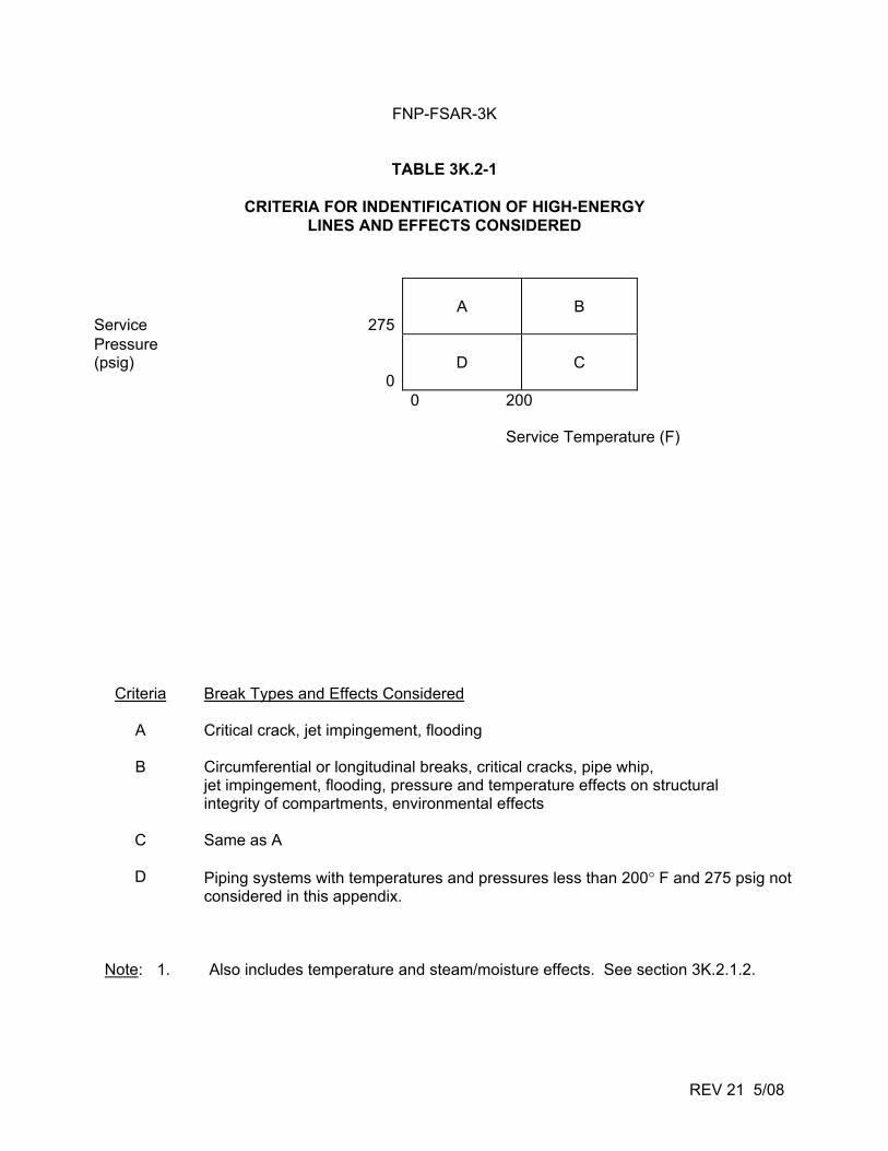
FNP-FSAR-3K
REV 21 5/08
TABLE 3K.2-1
CRITERIA FOR INDENTIFICATION OF HIGH-ENERGY LINES AND EFFECTS CONSIDERED
Criteria Break Types and Effects Considered
A Critical crack, jet impingement, flooding
B Circumferential or longitudinal breaks, critical cracks, pipe whip, jet impingement, flooding, pressure and temperature effects on structural integrity of compartments, environmental effects
C Same as A
D Piping systems with temperatures and pressures less than 200° F and 275 psig not considered in this appendix.
Note: 1. Also includes temperature and steam/moisture effects. See section 3K.2.1.2.
Service
275
A
B
Pressure (psig)
0
D
C
0 200
Service Temperature (F)
FNP-FSAR-3K
REV 21 5/08
TABLE 3K.3-1 (SHEET 1 OF 2)
EQUIPMENT REQUIRED FOLLOWING A HIGH-ENERGY LINE BREAK - UNIT 1(a)(b) (OUTSIDE CONTAINMENT)
Short-Term Long-Term Required for (<10 Min) (Hot Standby) Cooldown Reactor trip and safeguards actuation channels including sensors, Auxiliary feedwater system including pumps, water supply, Steam generator power operated relief valves (can be circuitry, and processing equipment (the protection circuits and system valves and piping (this system must be placed manually operated locally) used to trip the reactor on undervoltage, underfrequency, and in service to supply water to operable steam generators turbine trip may be excluded) within one minute after initiating signal) Controls for defeating automatic safety injection actuation during Safety injection system, including Reactor containment ventilation a cooldown and depressurization. pumps, the refueling water storage cooling units tank, and system valves and Residual heat removal system piping including pumps, heat exchanger and system valves and piping Diesel generators and emergency necessary to cool and maintain power distribution equipment the reactor coolant system in a cold shutdown condition Essential service water system including pumps and system valves and piping Capability for obtaining a reactor coolant system sample Essential component cooling water system including pumps, heat exchanger, and component cooling water surge tank Main feedwater control valves(trip closed feature)(c) Circuits and/or equipment required to trip the) main feedwater pumps(c Main feedwater isolation valves (trip closed feature)(c) Main steam line stop valves (trip closed feature)(d) Main steam line stop valve bypass valves (trip closed feature)(d) Steam generator blowdown isolation valves (automatic closure feature) Batteries Control room ventilation
FNP-FSAR-3K
REV 21 5/08
TABLE 3K.3-1 (SHEET 2 OF 2)
Short-Term Long-Term Required for (<10 Min) (Hot Standby) Cooldown Control room equipment must not be damaged to the extent that any equipment will be spuriously actuated or any of the equipment contained elsewhere in this list cannot be operated Emergency lighting In addition to the instrumentation required to operate the equipment on this list, indication of the following plant parameters should be available to the operator: Wide range Thot or Tcold (preferably Thot) for each reactor coolant loop Pressurizer water level Wide range reactor coolant system pressure Steam line pressure for each steam generator Wide range and narrow range steam generator level for each steam generator Containment pressure
a. Instrumentation, interlocks, and power supplies required to operate the above equipment must be available. b. Support systems for the above equipment such as long-term diesel fuel storage, battery chargers, and a long-term water supply for the auxiliary feedwater system must be available. c. Required for steam line and steam generator blowdown line break only. d. Required for steam line, feed line, and steam generator blowdown line break only.
FNP-FSAR-3K
3K.A-i REV 21 5/08
ATTACHMENT A
GENERAL INFORMATION REQUIRED FOR CONSIDERATION OF EFFECTS OF A PIPING SYSTEM BREAK OUTSIDE CONTAINMENT
FNP-FSAR-3K
3K.A-1 REV 21 5/08
ATTACHMENT A
PART I
GENERAL INFORMATION REQUIRED FOR CONSIDERATION OF THE EFFECTS OF A PIPING SYSTEM BREAK OUTSIDE CONTAINMENT
The following is a general list of information required for NRC review of the effects of a piping system break outside containment, including the double-ended rupture of the largest pipe in the main steam and feedwater systems, and for NRC review of any proposed design changes that may be found necessary. Since piping layouts are substantially different from plant to plant, applicants and licensees should determine on an individual plant basis the applicability of each of the following items for inclusion in their submittals. A. The systems (or portions of systems) for which protection against pipe whip is
required should be identified. Protection from pipe whip need not be provided if any of the following conditions exist:
1. Both of the following piping system conditions are met: a. The service temperature is less than 200°F. b. The design pressure is 275 psig or less. 2. The piping is physically separated (or isolated) from structures, systems,
or components important to safety by protective barriers, or restrained from whipping by plant design features, such as concrete encasement.
3. Following a single break, the unrestrained pipe movement of either end of
the ruptured pipe in any possible direction about a plastic hinge formed at the nearest pipe-whip restraint cannot impact any structure, system, or component important to safety.
FNP-FSAR-3K
3K.A-2 REV 21 5/08
4. The internal energy level(a) associated with the whipping pipe can be demonstrated to be insufficient to impair the safety function of any structure, system, or component to an unacceptable level.
B. Design basis break locations should be selected in accordance with the following
pipe whip protection criteria; however, where pipes carrying high-energy fluid are routed in the vicinity of structures and systems necessary for safe shutdown of the nuclear plant, supplemental protection of those structures and systems shall be provided to cope with the environmental effects (including the effects of jet impingement) of a single postulated open crack at the most adverse location(s) with regard to those essential structures and systems; the length of the crack size is taken to be one-half the pipe diameter in length and one-half the wall thickness in width.
The criteria used to determine the design basis piping break locations in the
piping systems should be equivalent to the following: 1. ASME Section III Code Class I piping(b) breaks should be postulated to
occur at the following locations in each piping run(c) or branch run: a. The terminal ends. a. The internal fluid energy level associated with the pipe- break reaction may take into account any line restrictions (e.g., flow limiter) between the pressure source and break location, and the effects of either single-ended or double- ended flow conditions, as applicable. The energy level in a whipping pipe may be considered as insufficient to rupture an impacted pipe of equal or greater nominal pipe size and equal or heavier wall thickness. b. Piping is a pressure-retaining component consisting of straight or curved pipe and pipe fittings (e.g., elbows, tees, and reducers). c. A piping run interconnects components, such as pressure vessels, pumps, and rigidly fixed valves, that may act to restrain pipe movement beyond that required for design thermal displacement. A branch run differs from a piping run only in that it originates at a piping intersection as a branch of the main pipe run.
FNP-FSAR-3K
3K.A-3 REV 21 5/08
b. Any intermediate locations between terminal ends where the primary plus secondary stress intensities Sn (circumferential or longitudinal) derived on an elastically calculated basis under the loadings associated with 1/2 safe shutdown earthquake and operational plant conditions(a) exceed 2.0 Sm
(b) for ferritic steel and 2.4 Sm for austenitic steel.
c. Any intermediate locations between terminal ends where the
cumulative usage factor (U)(c) derived from the piping fatigue analysis and based on all normal, upset, and testing plant conditions exceeds 0.1.
2. ASME Section III Code Class 2 and 3 piping breaks should be postulated
to occur at the following locations in each piping run or branch run: a. The terminal ends. b. Any intermediate locations between terminal ends where either
the circumferential or longitudinal stresses derived on an elastically calculated basis under the loadings associated with seismic events and operational plant conditions exceed 0.8.
a. Operational plant conditions include normal reactor operation, upset conditions (e.g., anticipated operational occurrences) and testing conditions. b. Sm is the design stress intensity as specified in Section III of the ASME Boiler and Pressure Vessel Code, "Nuclear Plant Components." c. U is the cumulative usage factor as specified in Section III of the ASME Boiler and Pressure Vessel Code, "Nuclear Power Plant Components."
FNP-FSAR-3K
3K.A-4 REV 21 5/08
(Sh + SA)(a) or the expansion stresses exceed 0.8 SA. The requirement to postulate arbitrary intermediate breaks has been
eliminated from the structural design basis (including resultant dynamic and environmental effects) as allowed by NRC Generic Letter 87-11, “Relaxation in Arbitrary Intermediate Pipe Rupture Requirement”.
C. The criteria used to determine the pipe break orientation at the break locations as
specified under (b) above should be equivalent to the following:
1. Longitudinal(b) breaks in piping runs and branch runs, 4-inches nominal pipe size and larger.
2. Circumferential(c) breaks in piping runs and branch runs exceeding 1-inch
nominal pipe size. D. A summary should be provided of the dynamic analyses applicable to the design
of Category I piping and associated supports which determine the resulting loadings as a result of a postulated pipe break including:
a. Sh is the stress calculated by the rules of NC-3600 and ND-3600 for Class 2 and 3 components, respectively, of the ASME Code Section III Winter 1972 Addenda. SA is the allowable stress range for expansion stress calculated by the rules of NC-3600 of the ASME Code, Section III, or the USA Standard Code for Pressure Piping, ANSI B31.1.0-1967. b. Longitudinal breaks are parallel to the pipe axis and oriented at any point around the pipe circumference. The break area is equal to the effective cross-sectional flow area upstream of the break location. Dynamic forces resulting from such breaks are assumed to cause lateral pipe movements in the direction normal to the pipe axis. c. Circumferential breaks are perpendicular to the pipe axis, and the break area is equivalent to the internal cross-sectional area of the ruptured pipe. Dynamic forces resulting from such breaks are assumed to separate the piping axially and cause whipping in any direction normal to the pipe axis.
FNP-FSAR-3K
3K.A-5 REV 21 5/08
1. The locations and number of design basis breaks on which the dynamic analyses are based.
2. The postulated rupture orientation, such as a circumferential and/or
longitudinal break(s), for each postulated design basis break location. 3. A description of the forcing functions used for the pipe-whip dynamic
analyses, including the direction, rise time, magnitude, duration, and initial conditions that adequately represent the jet-stream dynamics and the system-pressure difference.
4. Diagrams of mathematical models used for the dynamic analysis. 5. A summary of the analyses which demonstrates that unrestrained motion of
ruptured lines will not damage, to an unacceptable degree, structures, systems, or components important to safety, such as the control room.
E. A description should be provided of the measures, as applicable, to protect
against pipe whip, blowdown jet, and reactive forces, including: 1. Pipe restraint design to prevent pipe whip impact. 2. Protective provisions for structures, systems, and components required for
safety against pipe whip, blowdown jet, and reactive forces. 3. Separation of redundant features. 4. Provisions to separate physically piping and other components of
redundant features. 5. A description of the typical pipe-whip restraints and a summary of number
and location of all restraints in each system. F. The procedures that will be used to evaluate the structural adequacy of
Category I structures and to design new seismic Category I structures should be provided, including:
1. The method of evaluating stresses, e.g., the working stress method and/or
the ultimate strength method that will be used. 2. The allowable design stresses and/or strains. 3. The load factors and the load combinations. G. The structural design loads should be provided. They include the pressure and
temperature transients; the dead, live, and equipment loads; and the pipe and equipment static, thermal, and dynamic reactions.
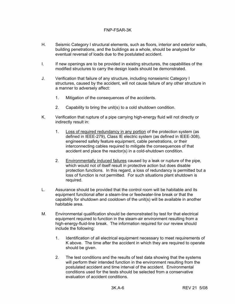
FNP-FSAR-3K
3K.A-6 REV 21 5/08
H. Seismic Category I structural elements, such as floors, interior and exterior walls, building penetrations, and the buildings as a whole, should be analyzed for eventual reversal of loads due to the postulated accident.
I. If new openings are to be provided in existing structures, the capabilities of the
modified structures to carry the design loads should be demonstrated. J. Verification that failure of any structure, including nonseismic Category I
structures, caused by the accident, will not cause failure of any other structure in a manner to adversely affect:
1. Mitigation of the consequences of the accidents. 2. Capability to bring the unit(s) to a cold shutdown condition. K. Verification that rupture of a pipe carrying high-energy fluid will not directly or
indirectly result in: 1. Loss of required redundancy in any portion of the protection system (as
defined in IEEE-279), Class IE electric system (as defined in IEEE-308), engineered safety feature equipment, cable penetrations, or their interconnecting cables required to mitigate the consequences of that accident and place the reactor(s) in a cold-shutdown condition.
2. Environmentally induced failures caused by a leak or rupture of the pipe,
which would not of itself result in protective action but does disable protection functions. In this regard, a loss of redundancy is permitted but a loss of function is not permitted. For such situations plant shutdown is required.
L. Assurance should be provided that the control room will be habitable and its
equipment functional after a steam-line or feedwater-line break or that the capability for shutdown and cooldown of the unit(s) will be available in another habitable area.
M. Environmental qualification should be demonstrated by test for that electrical
equipment required to function in the steam-air environment resulting from a high-energy-fluid-line break. The information required for our review should include the following:
1. Identification of all electrical equipment necessary to meet requirements of
K above. The time after the accident in which they are required to operate should be given.
2. The test conditions and the results of test data showing that the systems
will perform their intended function in the environment resulting from the postulated accident and time interval of the accident. Environmental conditions used for the tests should be selected from a conservative evaluation of accident conditions.
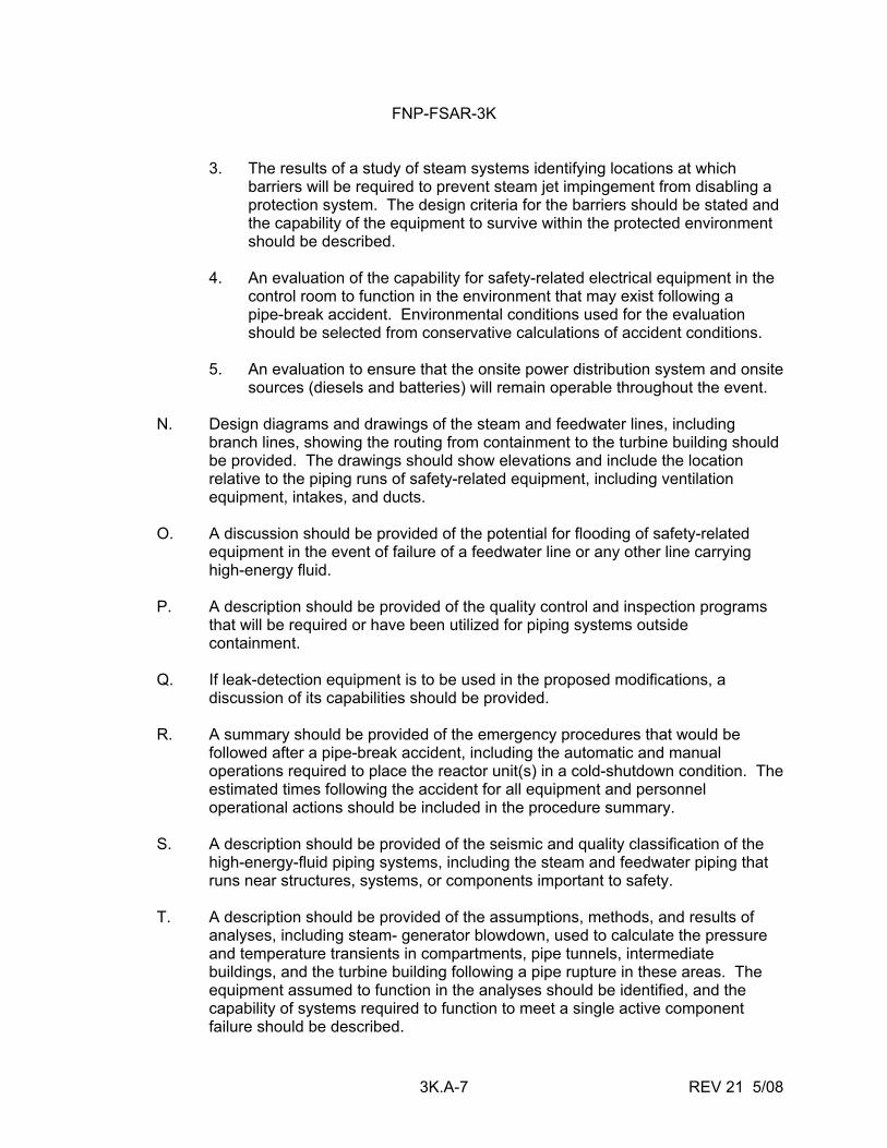
FNP-FSAR-3K
3K.A-7 REV 21 5/08
3. The results of a study of steam systems identifying locations at which barriers will be required to prevent steam jet impingement from disabling a protection system. The design criteria for the barriers should be stated and the capability of the equipment to survive within the protected environment should be described.
4. An evaluation of the capability for safety-related electrical equipment in the
control room to function in the environment that may exist following a pipe-break accident. Environmental conditions used for the evaluation should be selected from conservative calculations of accident conditions.
5. An evaluation to ensure that the onsite power distribution system and onsite
sources (diesels and batteries) will remain operable throughout the event. N. Design diagrams and drawings of the steam and feedwater lines, including
branch lines, showing the routing from containment to the turbine building should be provided. The drawings should show elevations and include the location relative to the piping runs of safety-related equipment, including ventilation equipment, intakes, and ducts.
O. A discussion should be provided of the potential for flooding of safety-related
equipment in the event of failure of a feedwater line or any other line carrying high-energy fluid.
P. A description should be provided of the quality control and inspection programs
that will be required or have been utilized for piping systems outside containment.
Q. If leak-detection equipment is to be used in the proposed modifications, a
discussion of its capabilities should be provided. R. A summary should be provided of the emergency procedures that would be
followed after a pipe-break accident, including the automatic and manual operations required to place the reactor unit(s) in a cold-shutdown condition. The estimated times following the accident for all equipment and personnel operational actions should be included in the procedure summary.
S. A description should be provided of the seismic and quality classification of the
high-energy-fluid piping systems, including the steam and feedwater piping that runs near structures, systems, or components important to safety.
T. A description should be provided of the assumptions, methods, and results of
analyses, including steam- generator blowdown, used to calculate the pressure and temperature transients in compartments, pipe tunnels, intermediate buildings, and the turbine building following a pipe rupture in these areas. The equipment assumed to function in the analyses should be identified, and the capability of systems required to function to meet a single active component failure should be described.

FNP-FSAR-3K
3K.A-8 REV 21 5/08
U. A description should be provided of the methods or analyses performed to demonstrate that there will be no adverse effects on the primary and/or secondary containment structures due to a pipe rupture outside these structures.
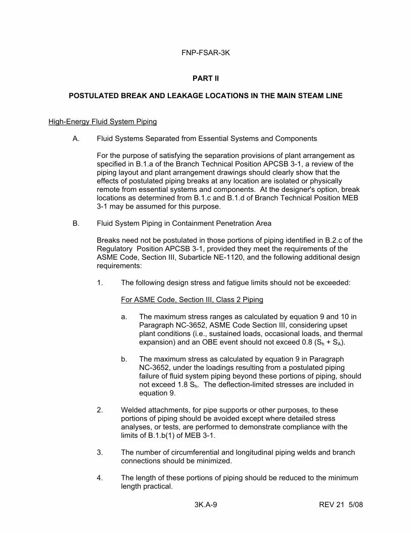
FNP-FSAR-3K
3K.A-9 REV 21 5/08
PART II
POSTULATED BREAK AND LEAKAGE LOCATIONS IN THE MAIN STEAM LINE
High-Energy Fluid System Piping A. Fluid Systems Separated from Essential Systems and Components For the purpose of satisfying the separation provisions of plant arrangement as
specified in B.1.a of the Branch Technical Position APCSB 3-1, a review of the piping layout and plant arrangement drawings should clearly show that the effects of postulated piping breaks at any location are isolated or physically remote from essential systems and components. At the designer's option, break locations as determined from B.1.c and B.1.d of Branch Technical Position MEB 3-1 may be assumed for this purpose.
B. Fluid System Piping in Containment Penetration Area Breaks need not be postulated in those portions of piping identified in B.2.c of the
Regulatory Position APCSB 3-1, provided they meet the requirements of the ASME Code, Section III, Subarticle NE-1120, and the following additional design requirements:
1. The following design stress and fatigue limits should not be exceeded: For ASME Code, Section III, Class 2 Piping a. The maximum stress ranges as calculated by equation 9 and 10 in
Paragraph NC-3652, ASME Code Section III, considering upset plant conditions (i.e., sustained loads, occasional loads, and thermal expansion) and an OBE event should not exceed 0.8 (Sh + SA).
b. The maximum stress as calculated by equation 9 in Paragraph
NC-3652, under the loadings resulting from a postulated piping failure of fluid system piping beyond these portions of piping, should not exceed 1.8 Sh. The deflection-limited stresses are included in equation 9.
2. Welded attachments, for pipe supports or other purposes, to these
portions of piping should be avoided except where detailed stress analyses, or tests, are performed to demonstrate compliance with the limits of B.1.b(1) of MEB 3-1.
3. The number of circumferential and longitudinal piping welds and branch
connections should be minimized. 4. The length of these portions of piping should be reduced to the minimum
length practical.
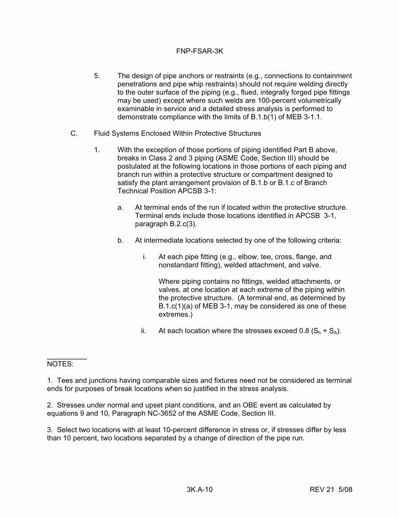
FNP-FSAR-3K
3K.A-10 REV 21 5/08
5. The design of pipe anchors or restraints (e.g., connections to containment penetrations and pipe whip restraints) should not require welding directly to the outer surface of the piping (e.g., flued, integrally forged pipe fittings may be used) except where such welds are 100-percent volumetrically examinable in service and a detailed stress analysis is performed to demonstrate compliance with the limits of B.1.b(1) of MEB 3-1.1.
C. Fluid Systems Enclosed Within Protective Structures 1. With the exception of those portions of piping identified Part B above,
breaks in Class 2 and 3 piping (ASME Code, Section III) should be postulated at the following locations in those portions of each piping and branch run within a protective structure or compartment designed to satisfy the plant arrangement provision of B.1.b or B.1.c of Branch Technical Position APCSB 3-1:
a. At terminal ends of the run if located within the protective structure.
Terminal ends include those locations identified in APCSB 3-1, paragraph B.2.c(3).
b. At intermediate locations selected by one of the following criteria: i. At each pipe fitting (e.g., elbow, tee, cross, flange, and
nonstandard fitting), welded attachment, and valve. Where piping contains no fittings, welded attachments, or
valves, at one location at each extreme of the piping within the protective structure. (A terminal end, as determined by B.1.c(1)(a) of MEB 3-1, may be considered as one of these extremes.)
ii. At each location where the stresses exceed 0.8 (Sh + SA). NOTES: 1. Tees and junctions having comparable sizes and fixtures need not be considered as terminal ends for purposes of break locations when so justified in the stress analysis. 2. Stresses under normal and upset plant conditions, and an OBE event as calculated by equations 9 and 10, Paragraph NC-3652 of the ASME Code, Section III. 3. Select two locations with at least 10-percent difference in stress or, if stresses differ by less than 10 percent, two locations separated by a change of direction of the pipe run.
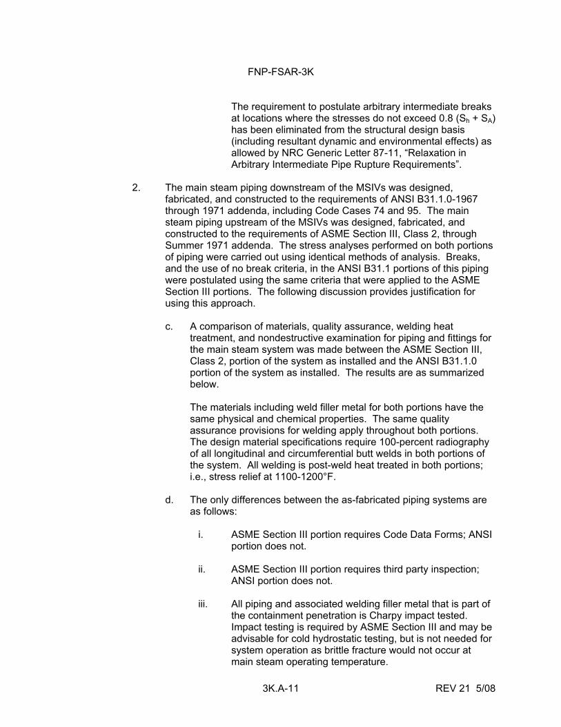
FNP-FSAR-3K
3K.A-11 REV 21 5/08
The requirement to postulate arbitrary intermediate breaks at locations where the stresses do not exceed 0.8 (Sh + SA) has been eliminated from the structural design basis (including resultant dynamic and environmental effects) as allowed by NRC Generic Letter 87-11, “Relaxation in Arbitrary Intermediate Pipe Rupture Requirements”.
2. The main steam piping downstream of the MSIVs was designed,
fabricated, and constructed to the requirements of ANSI B31.1.0-1967 through 1971 addenda, including Code Cases 74 and 95. The main steam piping upstream of the MSIVs was designed, fabricated, and constructed to the requirements of ASME Section III, Class 2, through Summer 1971 addenda. The stress analyses performed on both portions of piping were carried out using identical methods of analysis. Breaks, and the use of no break criteria, in the ANSI B31.1 portions of this piping were postulated using the same criteria that were applied to the ASME Section III portions. The following discussion provides justification for using this approach.
c. A comparison of materials, quality assurance, welding heat
treatment, and nondestructive examination for piping and fittings for the main steam system was made between the ASME Section III, Class 2, portion of the system as installed and the ANSI B31.1.0 portion of the system as installed. The results are as summarized below.
The materials including weld filler metal for both portions have the
same physical and chemical properties. The same quality assurance provisions for welding apply throughout both portions. The design material specifications require 100-percent radiography of all longitudinal and circumferential butt welds in both portions of the system. All welding is post-weld heat treated in both portions; i.e., stress relief at 1100-1200°F.
d. The only differences between the as-fabricated piping systems are
as follows: i. ASME Section III portion requires Code Data Forms; ANSI
portion does not.
ii. ASME Section III portion requires third party inspection; ANSI portion does not.
iii. All piping and associated welding filler metal that is part of the containment penetration is Charpy impact tested. Impact testing is required by ASME Section III and may be advisable for cold hydrostatic testing, but is not needed for system operation as brittle fracture would not occur at main steam operating temperature.
FNP-FSAR-3K
3K.A-12 REV 21 5/08
In summary the ANSI portion of the main steam piping is equivalent to the ASME Section III portion. However, the "N" stamp cannot be applied to ANSI piping because of items i and ii above. This difference does not affect the quality of material or workmanship.
D. Augmented Inservice Inspection Inservice examination and related design provisions in the containment
penetration area and throughout the no break region should be in accordance with the following:
1. The protective measures, structures, and guard pipes should not prevent
the access required to conduct the inservice examinations specified in the ASME Boiler and Pressure Vessel Code, Section XI, Division 1, "Rules for Inspection and Testing of Components in Light-Water Cooled Plants."
2. For those portions of fluid system piping identified in B.2.c of APCSB 3-1,
the extent of inservice examinations completed during each inspection interval (IWA-2400, ASME Code, 1974 Edition with Addenda through Summer 1975, Section XI) should provide 100-percent volumetric examination of circumferential and longitudinal pipe welds within the boundary of these portions of piping to the extent practical.
3. The areas subject to examination should be defined in accordance with
Examination Categories C-F and C-G for Class 2 piping welds in Table IWC-2520.
FNP-FSAR-3K
3K.B-i REV 21 5/08
ATTACHMENT B
PIPE WHIP RESTRAINT DESIGN
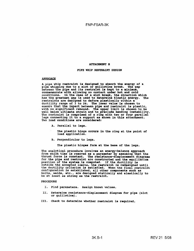
FNP-FSAR-3K
ATTACHMENT B
PIPE WHIP RESTRAINT DESIGN
APPROACH A pipe whip restraint is designed to absorb the energy of a pipe whipping due to a slot or guillotine break. The gap between the pipe and its restraint i• kept to a minimwa, commensurate with allowing no contact under hot and cold conditions. In the case of a slot break, the direction which has the greatest gap is used to deteraine kinetic energy. The restraints are designed to deform plastically within a ductility range of 3 to 26. The lower value is chosen to ensure that the impact between pipe and restraint is plastic, with no significant rebound. The upper limit is chosen to be well below ultimate strain and to preclude bending instability. The restraint is comprised of a ring with two or four parallel legs connecting it to- ·a support as shown in this attachment. Two load conditions are considered:
A. Parallel to legs.
The plastic hinge occurs in the ring at the point of load application.
B. Perpendicular to legs.
The plastic hinges form at the base of the legs.
The analytical procedure involves an energy-balance approach from which time is removed as a parameter by assuming that the thrust force is constant. The resistance-displacement diagrams for the pipe and restraint are constructed and the equilibrium position of the system is computed. If the ductility is outside the accepted limits, the restraint is redesigned until the ductility criterion is satisfied. When the final restraint configuration is established, all other components such as bolts, welds, etc., are designed statically and elastically to be at least as strong as the restraint.
PROCEDURE
I. Find parameters. Assign known values.
II. Determine resistance-displacement diagram for pipe (slot or guillotine).
III. Check to determine whether restraint is required.
3K.B-1 REV 21 5/08
FNP-FSAR-3K
IV. Design reatraint. Deteraine r••i•tance-displac8Jllent diagrams for two load condition•.
v. Find restraint diatortion.
VI. Find restraint ductility. If ductility is not between 3 and 26, return to Step IV.
VII. Design elastic coaponent• statically, uaing the resistance of the restraint as the load.
3K.B-2 REV 21 5/08
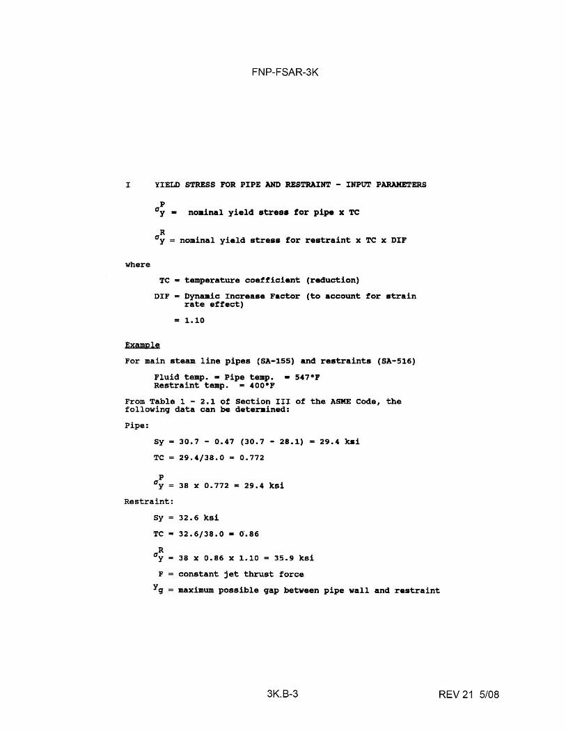
FNP-FSAR-3K
I YIELD STRESS FOR PIPE AND RESTRAINT - INPUT PARAMETERS
where
p 0 y • no•inal yield stress for pipe x TC
R 0 y = nominal yield stress for restraint x TC x DIF
TC• temperature coefficient (reduction)
DIF • Dynamic Increase Factor (to account for strain rate effect)
• 1.10
Example For main steam line pipes (SA-155) and restraints (SA-516)
Fluid temp.• Pipe temp. • 547°F Restraint temp. • 400°F
From Table 1 - 2.1 of Section III of the ASME Coda, the following data can be deterained:
Pipe:
Sy• 30.7 - 0.47 (30.7 - 28.1) • 29.4 ksi
TC= 29.4/38.0 • 0.772
p 0 y = 38 x 0.772 • 29.4 ksi
Restraint:
Sy= 32.6 ksi
TC• 32.6/38.0 = 0.86
R 0 y • 38 x 0.86 x 1.10 = 35.9 ksi
F = constant jet thrust force
Yg = maximum possible gap between pipe wall and restraint
3K.B-3 REV 21 5/08
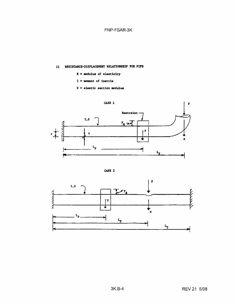
FNP-FSAR-3K
II RESISTANCE-DISPLACEMENT RELATIONSHIP FOR PIPE
E • modulua of elasticity
I • 'IIIOllleDt of inertia
S • elastic section aodulua
CASE l
Restraint
I,S 1 rt t
-~ I
1--
CASE 2
I,S
l i [ill~·. ~
.. I ~
3K.B-4
t
YI I
,. •I
r t T
X
.. , .f
REV 21 5/08
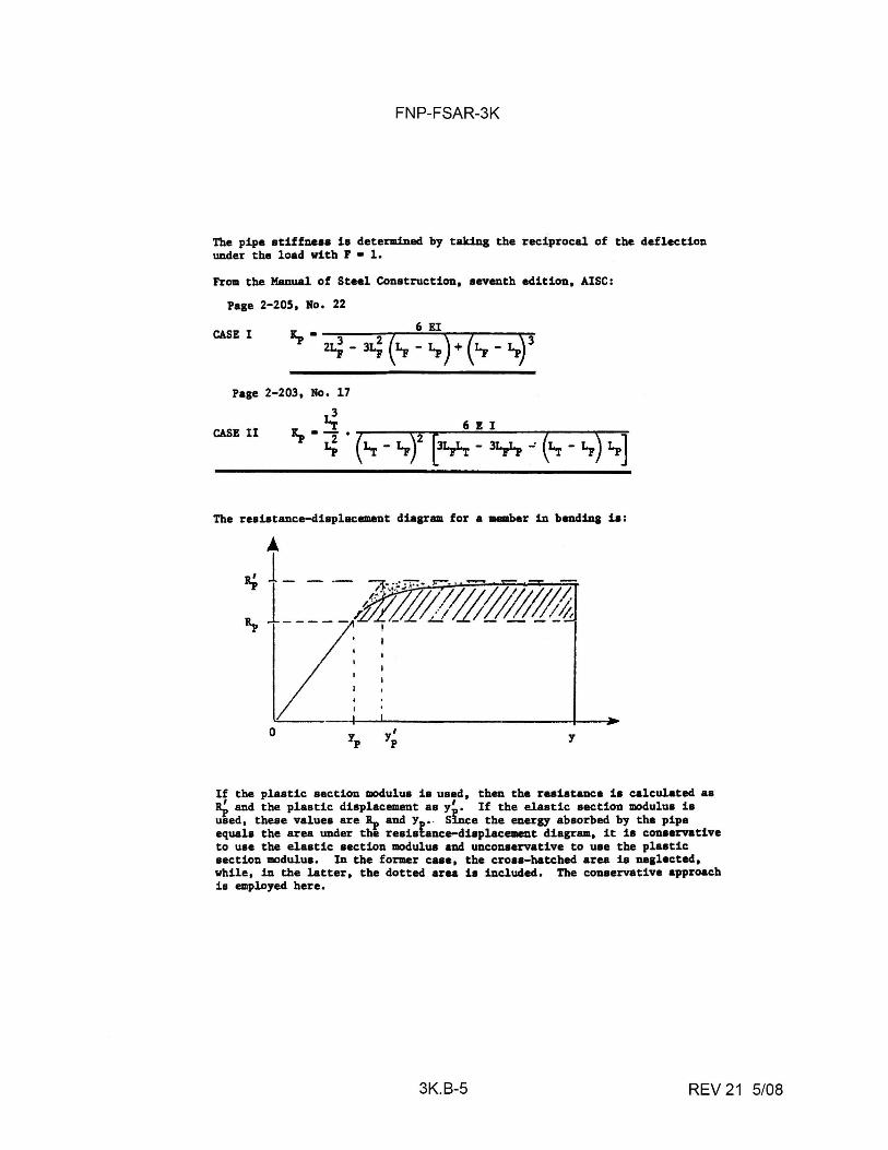
FNP-FSAR-3K
The pipe stiffne•• ia determined by taking the reciprocal of the deflection under the load with F • l.
From the Manual of Steel Construction, seventh edition, AISC:
Page 2-20S, Ho, 22
CASE I
Page 2-203, No, 17
3
CASE II Li 6 I I
~. ~ . (~ - '-F)2 [31-n - 31n.: (~ - Lr) Lp]
The resistance-diaplacement diagram for a member in bending ia:
\!..-~~~-~!~--"~~~~~~~~~~~~-'--~~
0 yp y'
p y
If the plaatic aection modulwi ia used, then the resistance ia calculated aa it;, and the plastic diaplacement as y~. If the elastic aection modulua is used, theae value• are~ and Y , . Suice the energy absorbed by the pipe equals the area under the reaiafance-diapl.&cement diagram, it ia conaarvative to use the elastic section modulus and unconaervative to uae the plastic section modulus, In the former case, the cross-hatched area is nealected, while, in the latter, the dotted area is included. The coneervative approach ia employed here.
3K.B-5 REV 21 5/08
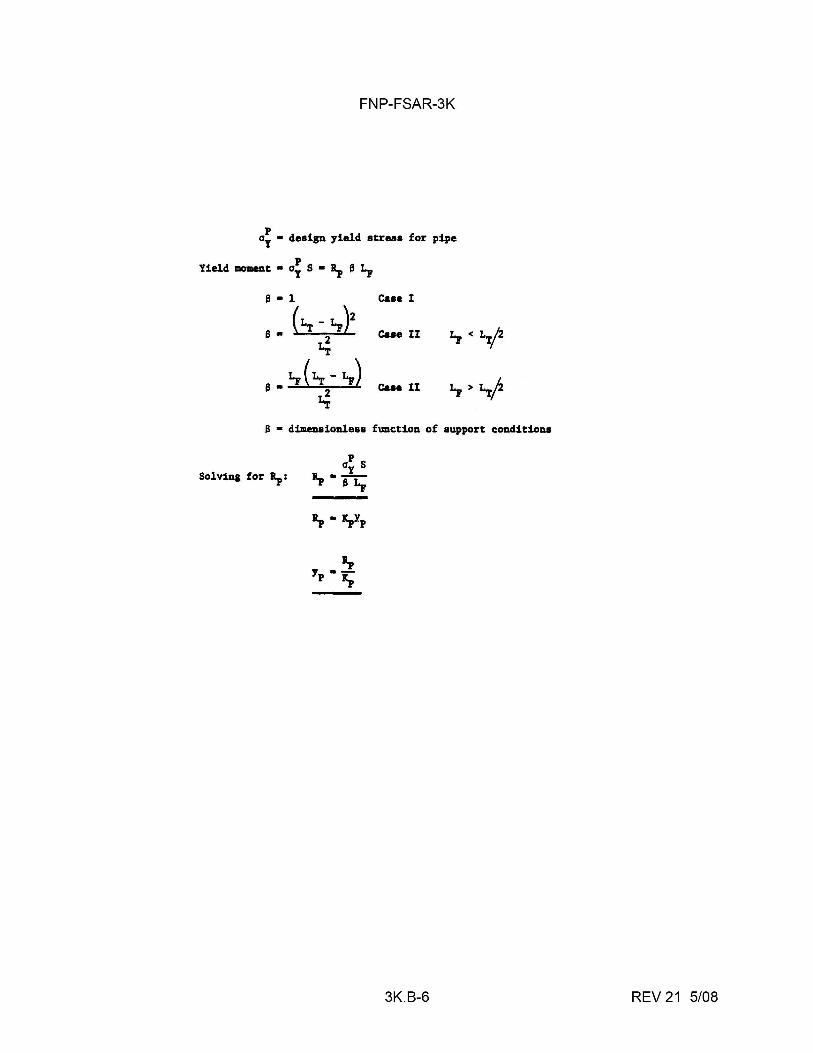
FNP-FSAR-3K
p ay • design yield stress for pipe
Yield moment • ai S • R, S L,
s - l
S• (~-t.,)2 i.;
S•lp(~-Lp) i.;
C&H I
cue II
Case II
S • dimenaionleaa function of support conditions
Solving for R,:
a, y ·-p r,
3K.B-6 REV 21 5/08
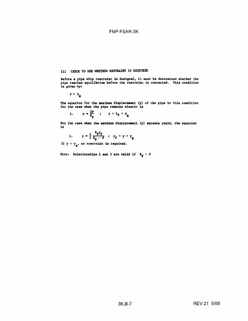
FNP-FSAR-3K
III CHECK TO SEE WHETHER llESTIIAINT IS llEQUiltED
Before a pipe whip reatraiDt 1a deaigned, it must be determined whether the pipe reaches equilibrium before the reatraiDt ia contacted, This condition 1a given by:
The equstion for the maximum diaplacemant (y) for the casa. when the pipe remaina elaatic ia
1, 21 y ·-
"
of the pipe in thia condition
For the caae when the maximum displacement (y) exceed, yield, the equation ia
2. 1 1pYp
y • 21p - F ; Yp < y < YI
If y < y8
, no restraint ia required.
Note: R.elationahipa 1 and 2 are valid if 1p > F
3K.B-7 REV 21 5/08
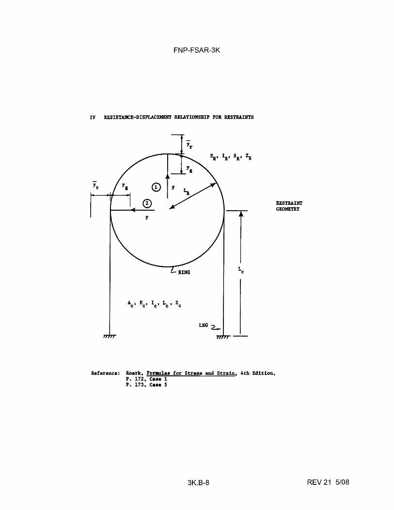
FNP-FSAR-3K
IV RESISTANCE-DISPLACEMENT RELATIONSHIP FOR RESTRAINTS
LEG '2-
Reference: Roark, Formulae for Stress and Strain, 4th Edition, P, 172, Case 1 P. 173, Case 5
3K.B-8
RESTRAINT GEOMETRY
REV 21 5/08
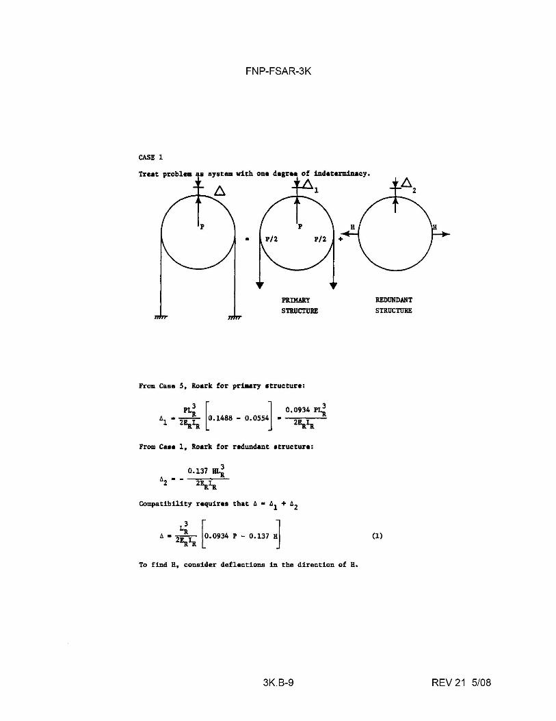
FNP-FSAR-3K
CASE 1
Treat problem aa system with one degree of indeterminacy.
p
P/2
p
PUMAll.Y S'l'B.UCTUBE
From Case S, Roark for primary structure:
Pl.i j l 0.0934 P1i 61 • 2Ea1a lo.14ss - o.oss~. 2Ea1a
From Casa 1, Roark for redundant structure:
Compatibility requires that 6 • 61 + 62
' • ,i,. [ .... ,. P - 0.137 ·]
To find H, consider deflections 1D the direction of H.
3K.B-9
REDUNDANT
STRUCTURE
(1)
REV 21 5/08
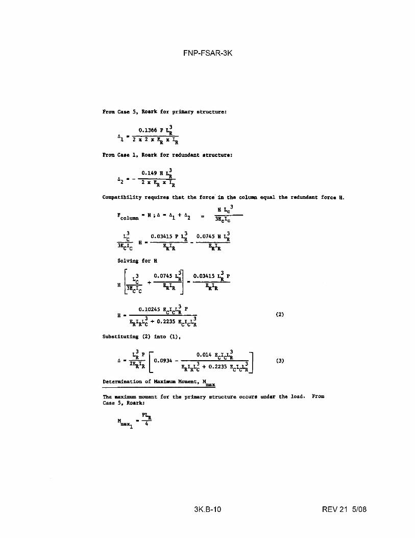
FNP-FSAR-3K
From Case 5, Roark for primary structure:
0.1366 P Li t:,. • ----------1 2x2xEax1tt
From Case 1, Roark for redundant structure:
Compatibility requires that the force ill the column equal the redundant force H,
H Lc:3
L~ 0,03415 P Li 0,0745 H Li -- H• --------3ECIC la1t Ea1tt Solving for H
r L3 0,0745 {I 0.03415 Li P
H rEC~C + la,t J • Ea_1tt
(2)
Substituting (2) into (l),
Li P o.ol4 Ecic!.i 3 [ 3 ti. • -2-- 0.0934 - 3 3 'a'a 'a'aLc + o.ms 'c'c'i]
(3)
Determination of Maximum Moment, Mmax
The maximum mmaent for the primary structure occurs under the load, From Case 5, Roark:
PLa M •-4 max1
3K.B-10 REV 21 5/08
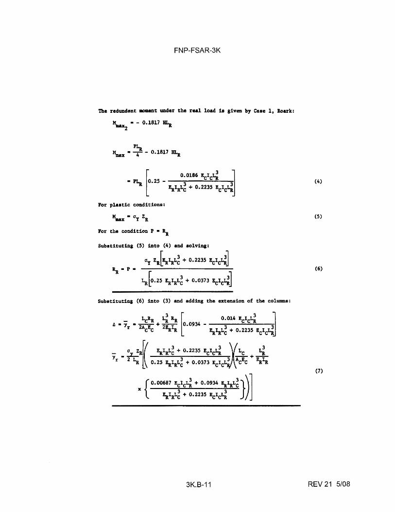
FNP-FSAR-3K
The redundant mmaent under the real load ia given by Caae 1, lloarlt:
M • - 0,1817 HI._ max2 -x
PI.a "max• 4 - 0.1817 Bl.a
Por plaatic conditiona:
Por the condition P • ~
Subatituting (5) into (4) and solving:
ay z1 [z..1itL~ + o.2235 Ecic:1-i] ~ - p -
~[o.2s z..1aL~ + 0.0373 Eclc1i]
Substituting (6) into (3) and adding the extension of the columns:
3K.B-11
(4)
(5)
(6)
(7)
REV 21 5/08
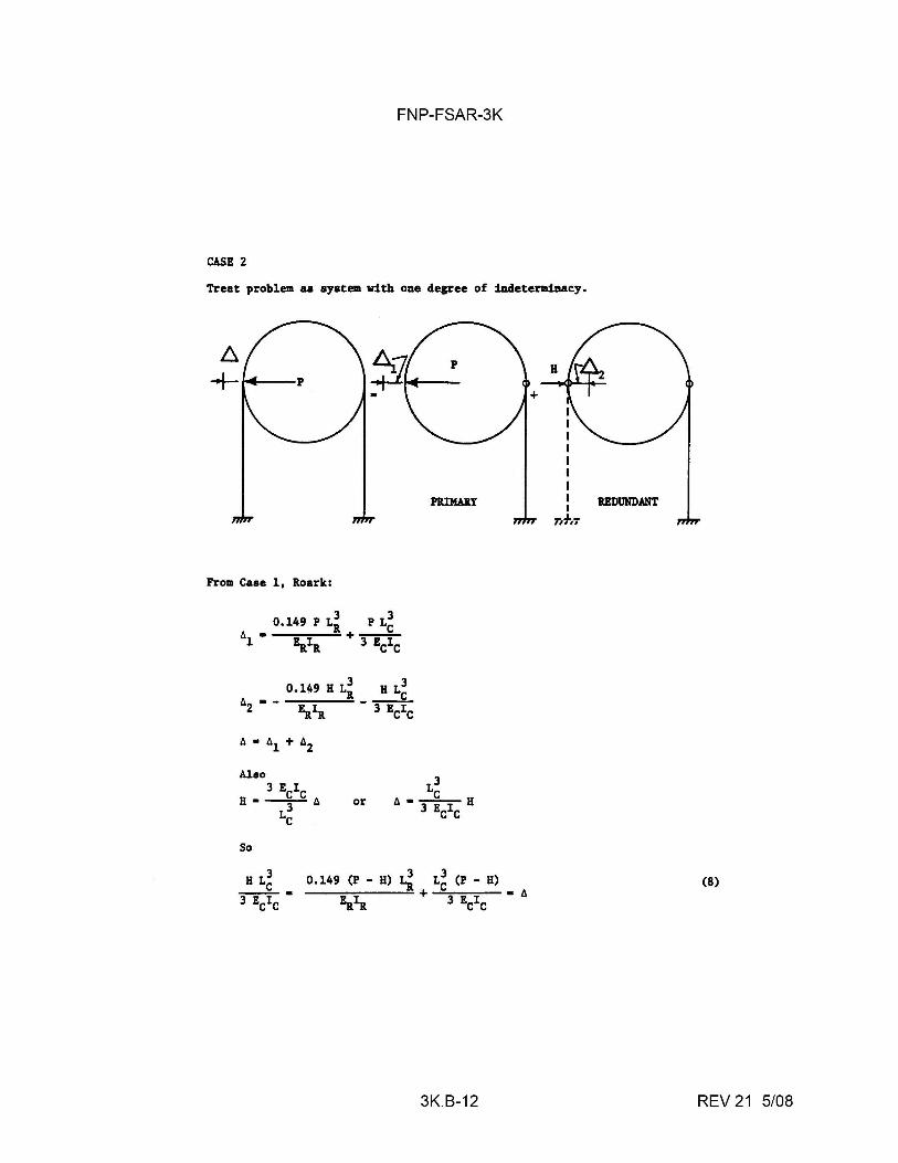
FNP-FSAR-3K
CASE 2
Treat problem aa ayatem with one degree of indeterminacy.
PB.IMilY
From Case 1, Roark:
or
So
H L3 C 0.149 (P - H) Li L~ (P - H)
E,.~ + 3 !CIC • t, 3 Ecic •
3K.B-12
REDUNDANT
(8)
REV 21 5/08
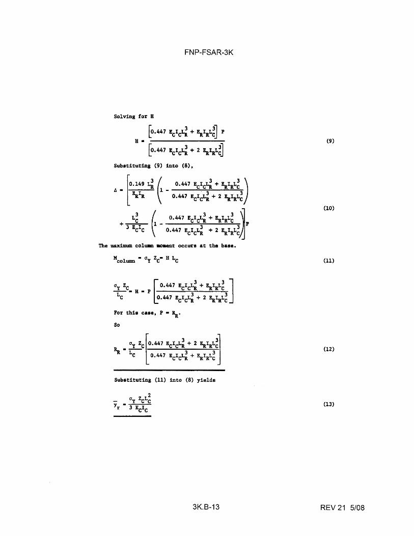
FNP-FSAR-3K
Solving for H
[o.447 ECIC~ + !a1aL~J P H •
[o.447 ECIC~ + 2 !a1aL~J
Sub•tituti.ng (9) into (8),
The maximum column lllOIDeDt occurs at the b•••·
For this case, P • ~·
So
Substituting (11) into (8) yields
3K.B-13
(9)
(10)
(11)
(12)
(13)
REV 21 5/08
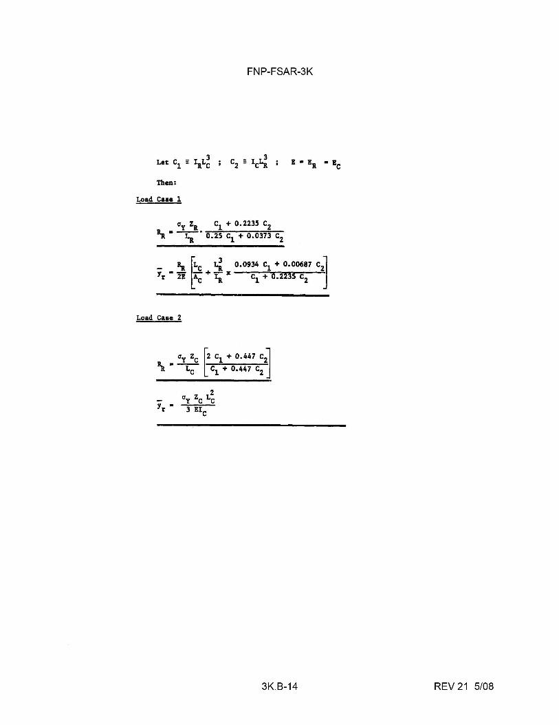
FNP-FSAR-3K
Then:
Load Case l
Load Case 2
-y • r
3K.B-14 REV 21 5/08
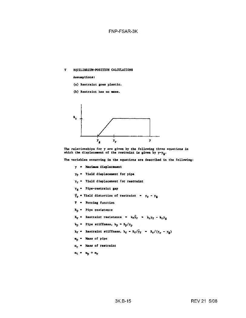
FNP-FSAR-3K
V EQUILIB1I.I11M-POSITION CALCULATIONS
Assumptions:
(a) Restraint goea plastic,
(b) Restraint baa no mass,
The relationships for y are given by the following three equations in which the displacement of the restraint is given by y-y8•
The variables occurring in the equations are described in the following:
y • MaxiDIJm displacement
Yp • Yield displacement for pipe
Yr• Yield displacement for restraint
Yg • Pipe-restraint gap
Yr• Yield distortion of restraint • Yr - Yg
F • Forcing function
Rp • Pipe resistance
Rr • Restraint resistance • kr'Yr • krYr - krYg
kp • Pipe stiffness, kp • Rp/Yp
kr • Restraint stiffness, kr • RrlYr • Rrl<Yr - Yg)
a;,• Ma88 of pipe
lllr • Mass of restraint
3K.B-15 REV 21 5/08
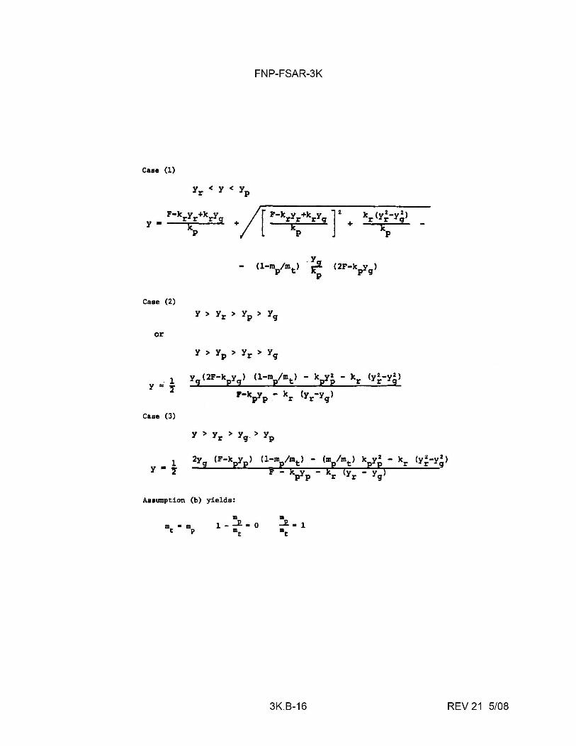
Case (1)
Case (2)
or
.1 y = I
Case (3)
l 1·1
FNP-FSAR-3K
y9
(2F-kpy9
) (l-mp/mt) - kpYp - kr (y~-yg)
P-kpyp - kr (yr-yg)
2y9
(F-k:"P) (1-m /m) - (m /m) k 1 2 - k (y2-y2) _ E:__ p t p t pp r r g
F - k_y - k (y - y) P-P r r g
Assumption (b) yields:
m • m t p
3K.B-16 REV 21 5/08
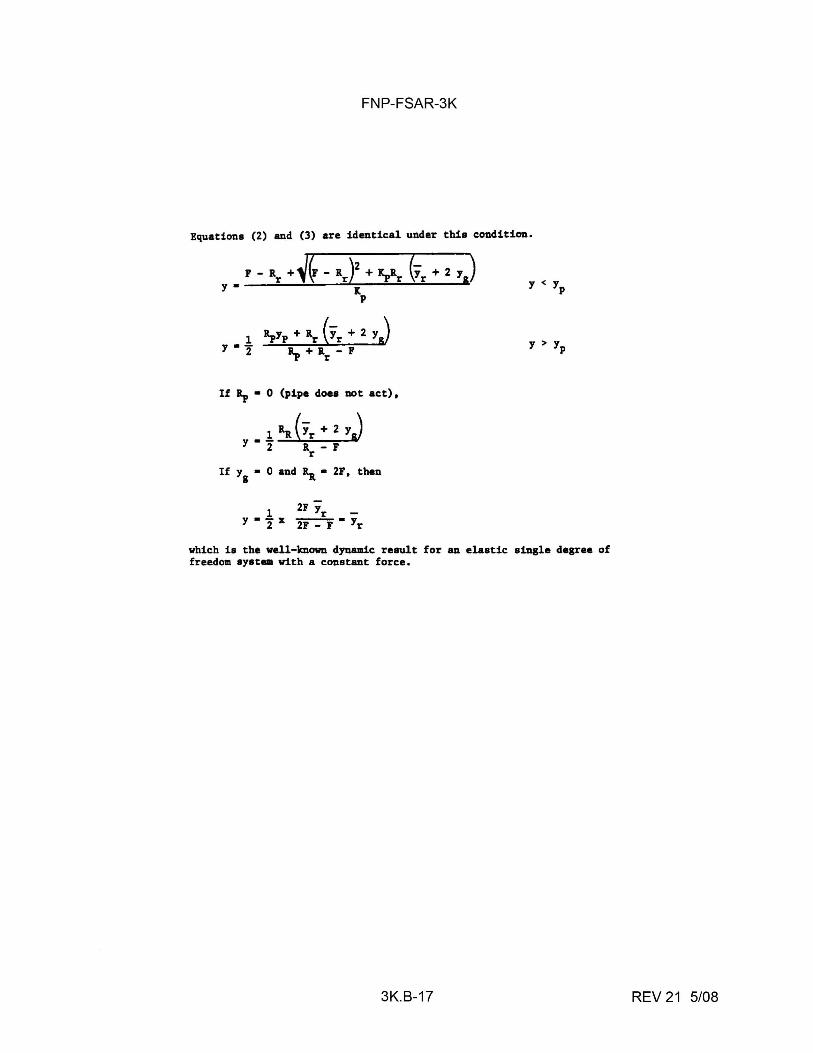
FNP-FSAR-3K
Equations (2) and (3) are identical under this condition.
F - Rr + ~~ - Rr )2
+ ~Rr (Yr + 2 Y J y • K
1 y•2
p
If Ip• 0 (pipe does not act) •
• 1Ra(1r+2yj y 2 R - F
r
If y1
• 0 and Ra• 2F. then
which is the well-known dynamic result for an elastic single degree of freedom system with a constant force.
3K.B-17 REV 21 5/08
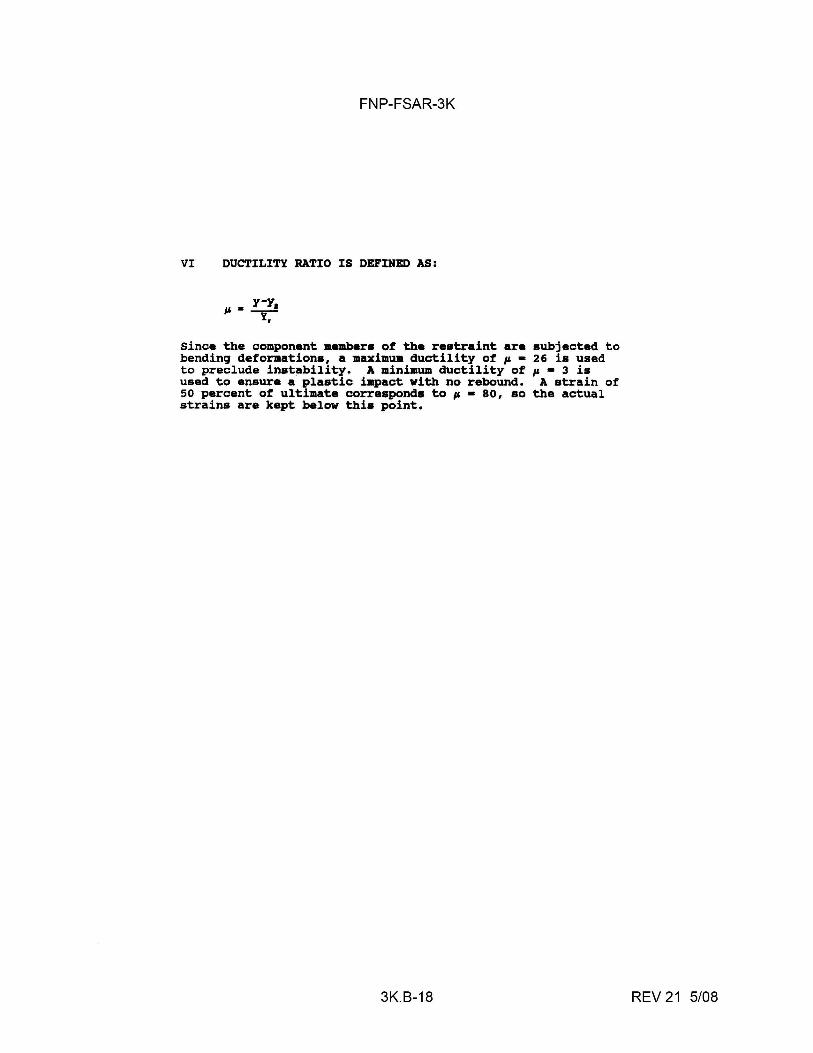
FNP-FSAR-3K
VI DUCTILITY RATIO IS DEFINED AS:
Since the component members of the restraint are subjected to bending deformations, a maximwa ductility ofµ• 26 is used to preclude instability. A minimum ductility ofµ= 3 is used to ensure a plastic impact with no rebound. A strain of so percent of ultimate corresponds toµ• 80, so the actual strains are kept below this point.
3K.B-18 REV 21 5/08
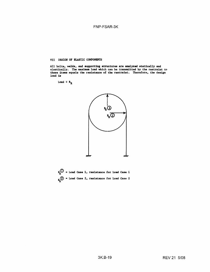
FNP-FSAR-3K
VII DESIGN OF ELASTIC COMPONENTS
All bolts. welds. and supporting structures are analyzed statically and elastically, The maximum load which can be transmitted by the restraint to these iteaa equals the resistance of the restraint, Therefore. the design load is
Load= Ra
Rg~ • Load Case 1. resistance for Loed Case 1
Ra@ • Load Case 2 • resistance for Load Case 2
3K.B-19 REV 21 5/08
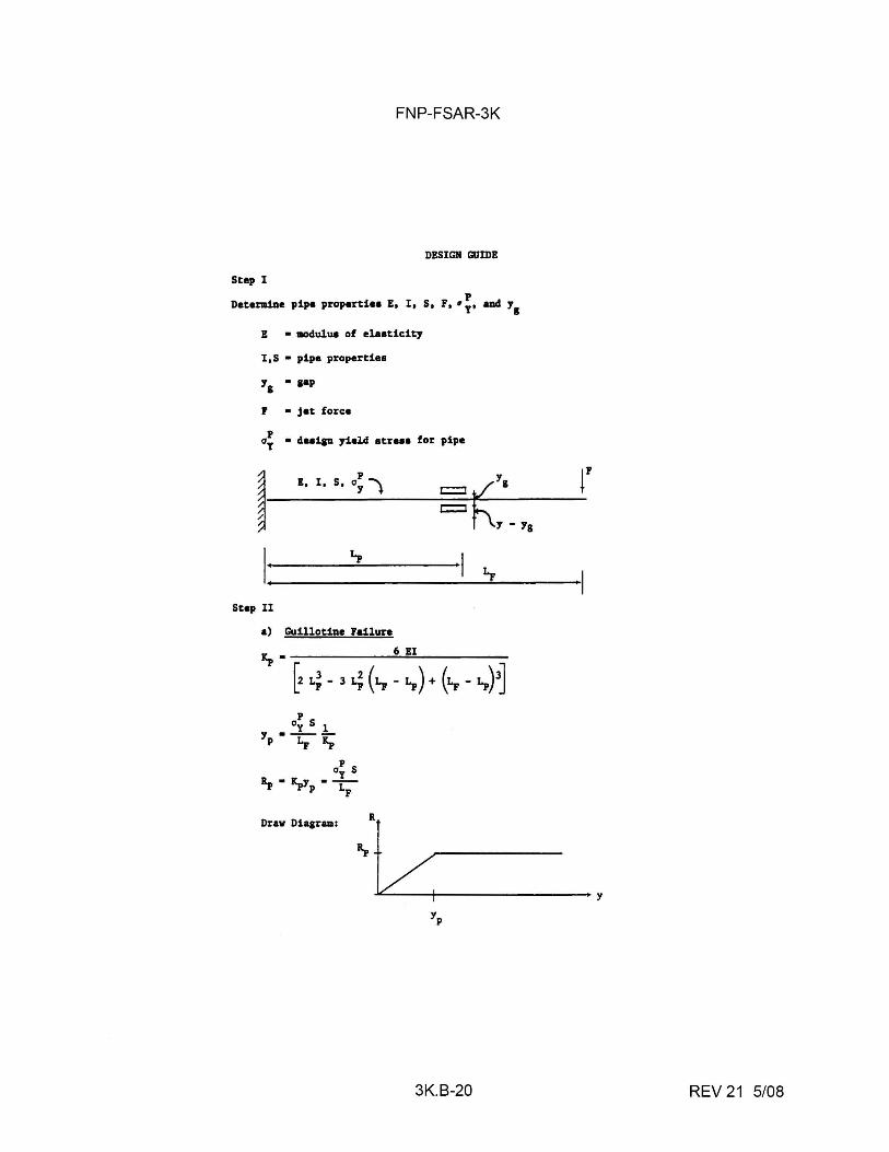
FNP-FSAR-3K
DESIGN GUmE
Step I p
Detemin• pipe properti•• E, I, S, F, • y• and y1
E • aodulua of elaaticity
I,S • pipe propertiea
1, • pp
P • jet force
a~ • deaipi yield atr••• for pipe
p
I I, I, S, a1 l Yg
~K.-,. I r.,
Step II
a) Guillotine Failure
Kp• 6EI
[2 i.: - 3 i.; ( L, - X.,) + ( L, _ x.,)3] p
Dy S l y ----
p i., Kp p
Oy S L • Ly • --"I' -"I' p LF
Draw Dia1ram:
3K.B-20
r
I y
REV 21 5/08
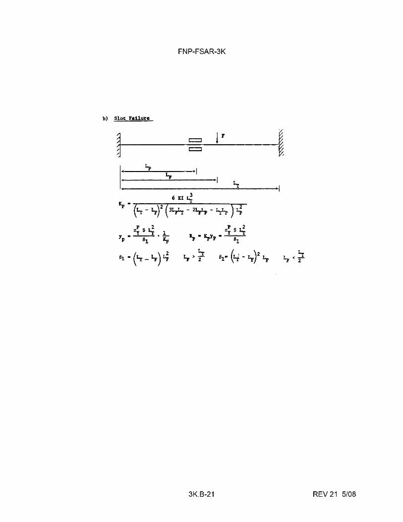
FNP-FSAR-3K
b) Slot Failure
__ c:::::::::::i_l_' -~, ~ = ~
6 EI~
p 2 Oy S Li 1
Yp • 81 • Ip a~ St;
1p • ~Yp • 81
81 • ( ~ _ Lp) i.; Lp > ~ 81• (z..; - 1,,)2 Lp
3K.B-21 REV 21 5/08
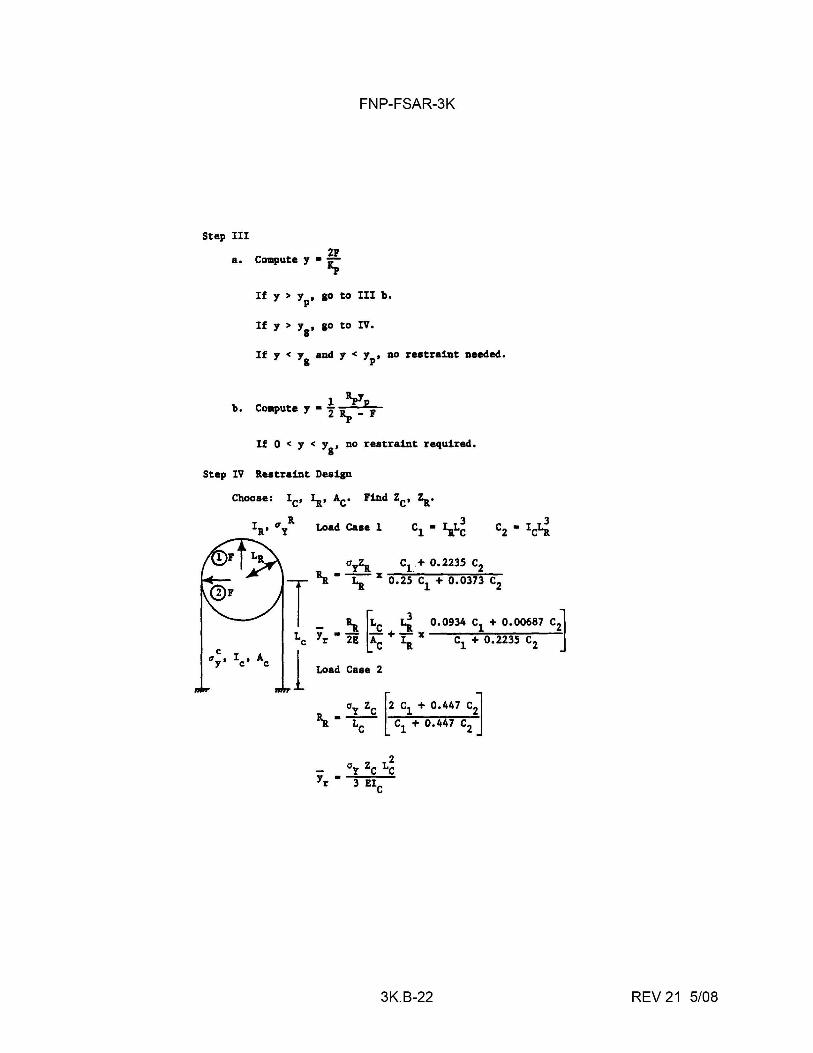
FNP-FSAR-3K
Step Ill
21 a. CD111pute y • Ip
If y > yp, go to III b,
If y > y8
, go to IV,
If y < y8
and y < Yp• no restraint needed,
l lpYP b. CD111pute y • 2 ~ _ 1
If O < y < y1
, no restraint required,
Step IV Restraint Design
Choose: IC' 1a• Ac, Find ZC, Za•
IR' O'y R Load ca .. l cl • 1aL~
3K.B-22 REV 21 5/08
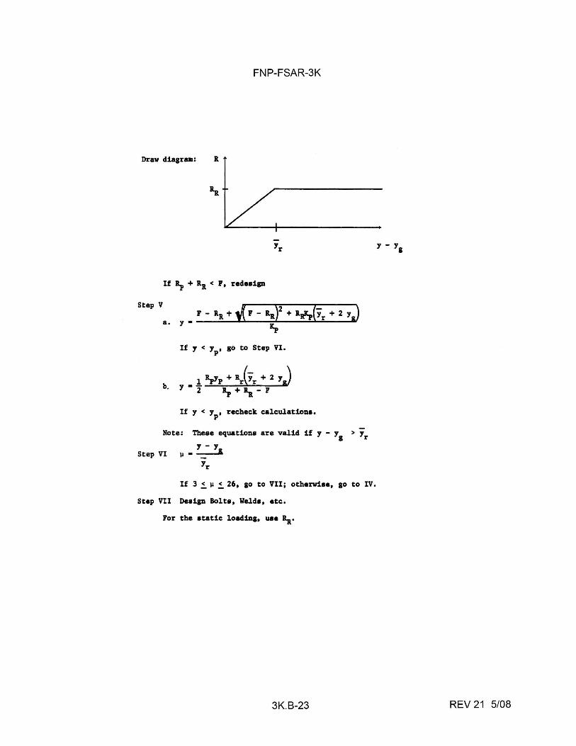
FNP-FSAR-3K
Draw diagram: R
If 1p + 1.1 < P, reduian
Step V
b.
If y < Yp• go to Step VI.
If y < y, recheck calculationa. p
Note: Tbeae equation• are valid if y - y1
> Yr
y - y Step VI µ • =::--,:.&
Yr
If 3 !. µ !. 26, go to VII; otherwiae, go to IV,
Step VII Design Bolts, Welda, etc.
For the atatic loadin&, uae Rw,•
3K.B-23
y - Yg
REV 21 5/08
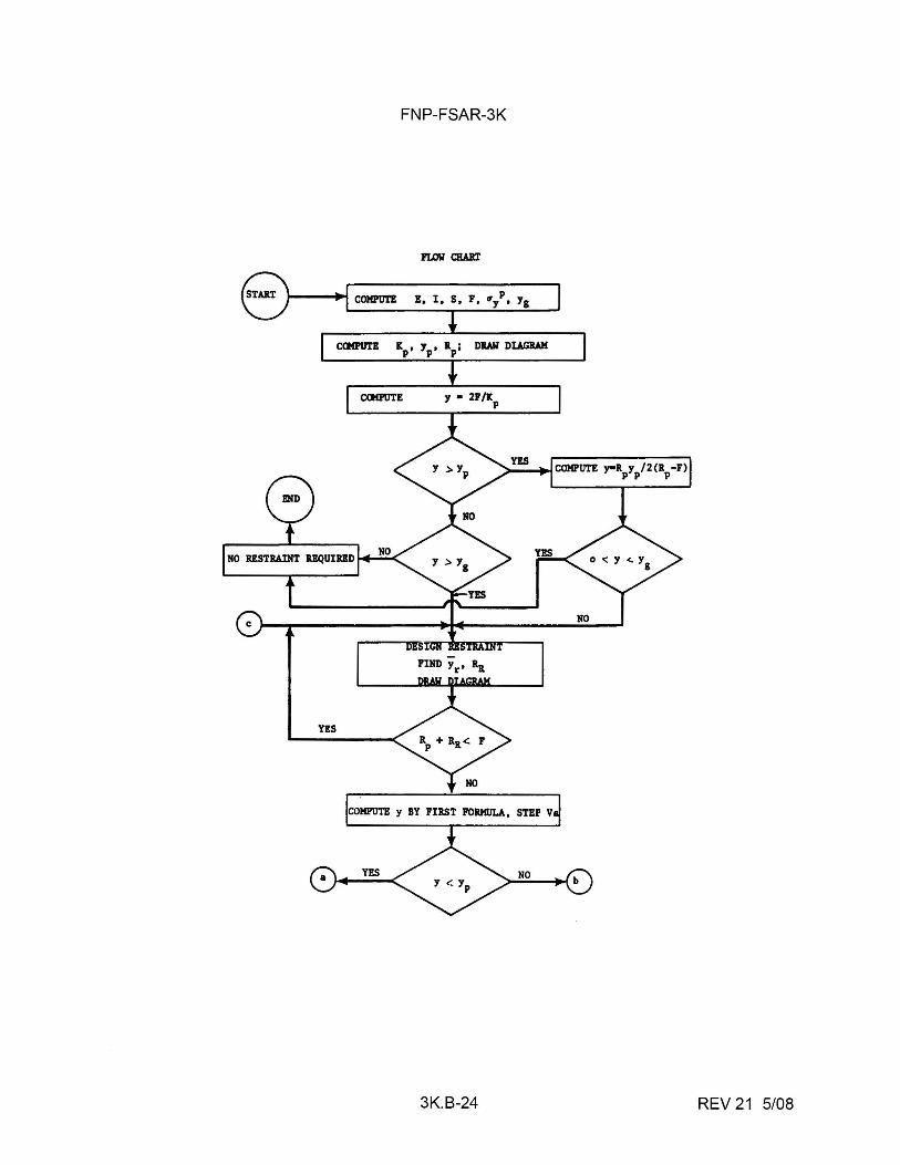
FNP-FSAR-3K
p !, I, S, F, ~y, Yg
DRAW DIAGRAM
3K.B-24 REV 21 5/08
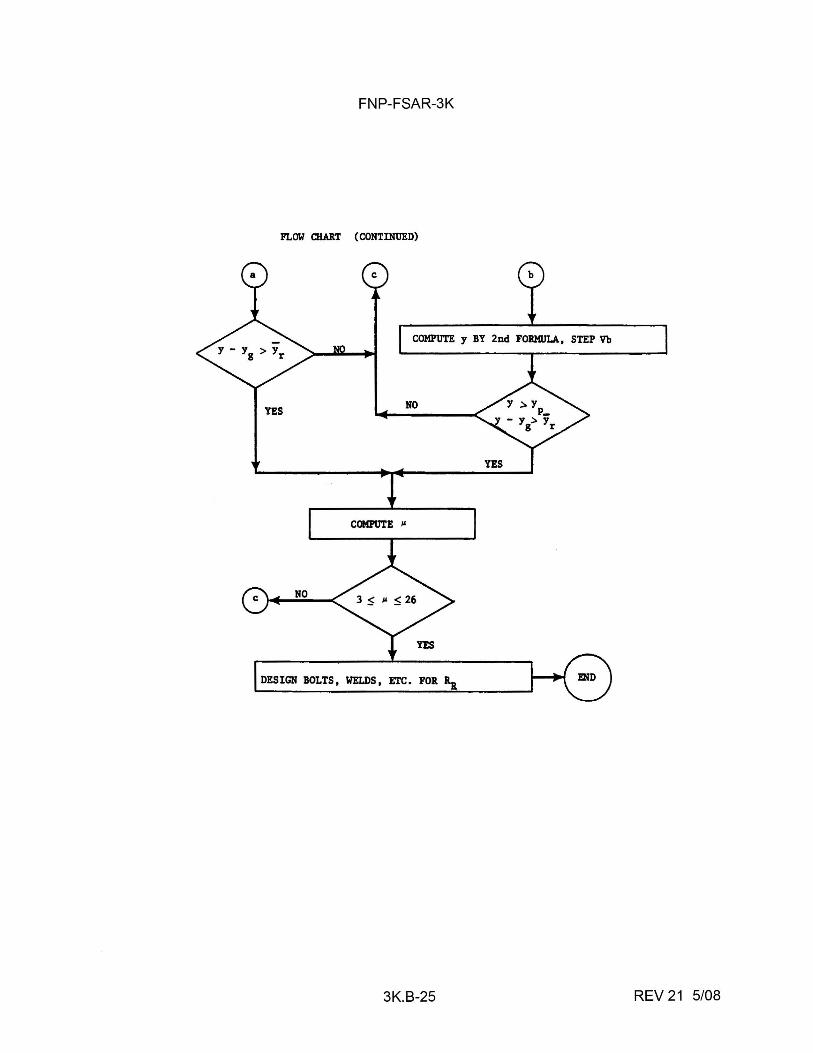
FNP-FSAR-3K
FLOW CHART (CONTINUED)
COMPUTE y BY 2nd FORMULA, STEP Vb
YES NO
C<Jfi'UTE ,.
DESIGN BOLTS, WELDS, ETC. FOR~
3K.B-25 REV 21 5/08

FNP-FSAR-3K
TYPICAL DESIGN EXAMPLE
I. 32 In. O.D. MAIN STEAM PIPE PROPERTIES
CTMT FACE RESTRAINT
I t
I ~ l F • 342 K
------------ 1,, • 126 in
~ 1,, • 62 in
1,, • 5'-
2" • :1 (1,, - 1,,) • 64 in
Ep • 26.000 kai
F • 342 K
y • l in g
L • 10'-6" • 126" F
4 Ip• 12.059.72 in
3 Sp• 753.74 in
p 4 a1
• 29, kai
II. CALCULATION OF Kp• Yp• ~ ip
• (6) (26,000 ksi) (12,059.72 in4) ,
[2(126") 3 - 3(126")2 (64") · + (64") 3]
• 1548.8 K/in
3K.B-26 REV 21 5/08
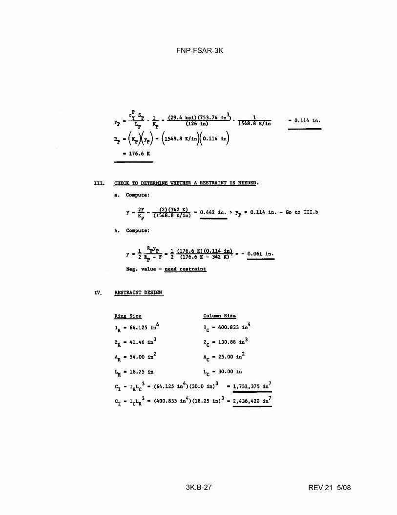
FNP-FSAR-3K
p ay Sp 1 (29.4 kai)(753.74 in3}. 1
Yp • -x:;- • ~ • - (126-in) . 1548.8 K/in
ip • (Kp)(Yp) • (1548.8 K/in~0.114 in)
• 176.6 K
III. cu:rn TO DETEIIMIHE WBETBEll A RESTBADIT IS NEEDED.
a. Compute:
• 0.114 in.
Y • ~ • (l~~A~~4iJ~) • 0.442 in.> Yp • 0.114 in. - Go to III.b
IV,
b. Compute:
• .!. ipYp • .!. (176.6 K)(0.114 inl • _ O 061 i y 2 ip - F 2 (176.6 K - 342 IC) ' • n.
Neg. value - need reatraint
RESTRAINT DESIGN
Rina Size 4 IR• 64.125 in
3 ZR. • 41.46 in
2 '\ • 54.00 in
LR• 18.25 in
Column Size
IC • 400.833 in4
zc • 130.88 in3
AC• 25.00 in2
LC• 30.00 in
3K.B-27
7 • 1,731,375 in
REV 21 5/08
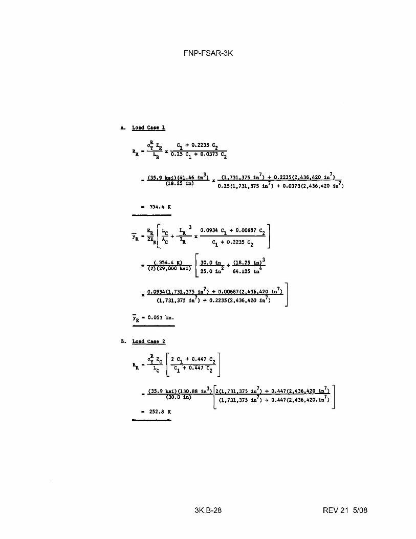
FNP-FSAR-3K
A. Load Case 1
• (35.9 kai)(41,46 in3) X (1 17311375 in7) + 0,2235(2 1436 1420 1n7) <18•25 in) 0,25(1,731,375 in7) + 0,0373(2,436,420 1n7)
• 354,4 K
• (. 354.4 K) 30,0 in + (18,25 in) [
3
(2)(29,000 ka1) 25.0 in2 64.125 in4
X 0,0934(1 1731 1375 in7) + 0,00687(2 1436 1420 in7)]
(1,731,375 in7) + 0.2235(2,436,420 in7)
'a· o.os3 in.
B, Load Case 2
• (35. 9 ka1>Cl30.88 1n3) f.2c1. 731.375 in7
) + 0.447(2.436.420 in7
) ] <3o.o in) l (1,731,375 in1) + 0.447(2,436,420,in7)
• 252.8 K
3K.B-28 REV 21 5/08
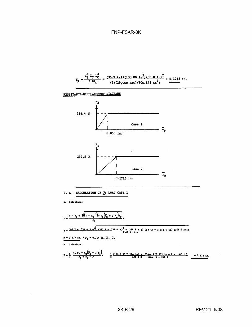
FNP-FSAR-3K
R 2 3 2 y; • 0y Zc Le • (35,9 kai)(l30.88 in )(30.0 in) • o.1213 in.
R 3 !IC (3)(29,000 kai)(400.833 in4)
RESISTANCE-DISPLACEMENT DIAGRAMS
.354.4 K
case 1
0.053 in.
252.8 K
caae 2
0,1213 in,
V. A. CALCULATION or I; LOAD CASE 1
a. Calculaca:
y • 342 It - 354.4 It+~ (342 It - 354,4 Jt) 2 + 354, 4 It (0,053 in + 2 X 1.0 in) 1548,8 1(/111 1548.8 X/in
'1 • o.677 111. > Yp • 0.114 in. N, G,
b. C&lculaca:
.! (176 . 6 It)(0.114 in) + 354.4 lt(0.053 in + 2 x 1.00 in) 2 176.6 It+ 3S4.4 It • 342 It
3K.B-29
• 1. 978 :In.
REV 21 5/08
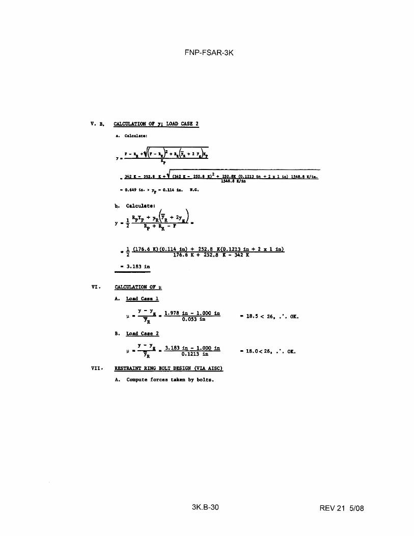
FNP-FSAR-3K
V, B, CALCIJLATION or Yi LOAD CASE 2
VI,
VII,
a. Cal.culua:
• 342 g - zn,• 11: + 1 c;,42 , - 2s2.1 11:,2 + 2,52.g co.1213 ta + 2 "' 1 ta> uu.a xJta.
l.J41, I IC/ SA
• 0,64' ill, > 7, • O,U4 SA, l,C.,
~. Calculate:
l 1pYp + 'lv.(YR + 2y ) Y·z 1i,+i..-r'.
• ! (176,6 X)(O;ll4 in) + 252,8 X(0,1213 in+ 2 x 1 in) 2 176,6 X + 252,8 It - 342 K
• J,183 in
CALCULATION OF Ii
A, Load Cua 1
Y - Y,, 1.978 in - 1.000 in µ•-----'Ya 0.053 in
B, Load Caae 2
:...:...!& J,183 in - 1.000 in 1,1. - • Ya 0,1213 in
USTllAIHT RING BOLT DESIGN (VIA AISC)
A, Compute forces taken by bolts,
3K.B-30
• 18, 5 < 26, ' Olt,
• 18. 0 < 26, , ', Olt,
REV 21 5/08
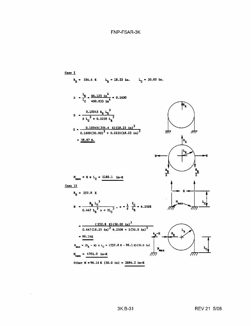
FNP-FSAR-3K
~ • 354.4 IC La• 18.25 in. LC• 30.00 in.
s • 1a. 64.125 in4 • 0.1600 1c 400.833 in4
0.1024S ~ l.a3
H •-.....,,.------~ S LC
3 + 0.223S 1.a3
H • 0.1024S(.3S4.4 K)(l8.25 in)l
0.1600(30.00) 3 + 0.223S(l8.2S in) 3
• 38.87 K.
Case II
~ • 2S2.8 IC
• ( 252.8 K) (30.00 in)J
0.447(18.2S in) 3 6.2508 + 2(30.0 in) 3
K,,-H-1~~ • 96.14K ~
K,..x ~ B) x LC • (252.8 K - 96.1 K) (30.0 in)lMll&X M • 4701.0 in-K max
Other M • 96 .14 It (30. 0 in) • 2884. 2 in-K
3K.B-31
]
REV 21 5/08
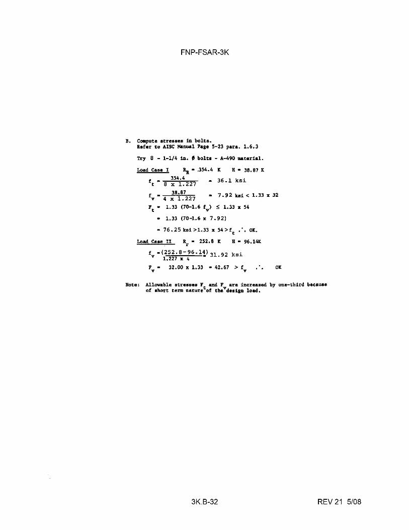
FNP-FSAR-3K
B. Compute stresses in bolts. Refer to AISC Manual Page 5-23 para. 1.6.3
Try 8 - 1-1/4 in. • bolts - A-490 material.
Load Case I Ra• .354.4 K H • 38.87 K
354.4 ft • 8 X 1. 227 • 36.1 ksi
38.87 fv • 4 X 1.227 • 7 • 9 2 kai < 1. 33 X 32
Ft • 1.33 (70-1.6 fv) !> 1.33 x 54
• 1.33 (70-1.6 X 7 • 92)
• 76.25ksi>l.33x54>ft ••• OK.
Load Case II R • 252.8 K r H • 96.14K
f •(252.8-96.11,l 31. 92 ksi V 1.227 X 4
F • 32.00 x 1.33 • 42.67 > f V V
OK
Note: Allowable stresses F and F are increased by one-third because of short term naturetof thevdesign load.
3K.B-32 REV 21 5/08
FNP-FSAR-3K
3K.C-i REV 21 5/08
ATTACHMENT C
METHODS USED TO CALCULATE BLOWDOWN RATES FOR HIGH ENERGY FLUID LINE RUPTURES
FNP-FSAR-3K
ATI'ACHMENT C
METHODS USED TO CALCULATE SLOWDOWN RATES FOR HIGH-ENERGY FLUID LINE RUPTURES
JK.C.l BACKGROUND
JK.c.1.1 Introduction
The following describes a method for obtaining mass flowrates which has been used for determining local pressures resulting from a steam line break outside the containment. The flowrates obtained using this procedure are defensible upper bound values for any break location outside the containment. They are intended to be used for local short term pressure calculations and do not necessarily represent limiting conditions for calculating thrust loads or impingement forces; the latter are nP .. crihPn in ;,tt-;,chment- F. 11.1 .. n, ;n t-he m .. t-hnrJ t-h;,t- fnl lnw .. ,
back flow from the intact steam lines and steam generators is included.
JK.c.1.2 Basis for the Calculations
Since detailed flowrate calculations for steam line breaks outside the containment are a function of plant piping layout and break location, the effort required for transient blowdown analyses for all cases involving assessment of consequential damage resulting from the break becomes quite prohibitive. For this reason, it is desirable to obtain defensible upper bound flowrates which are independent of break location.
The limiting plant condition, in terms of both steam generator mass inventory and initial secondary system pressure, is obtained when the plant is at hot shutdown. Because of the high flowrates associated with a steamline break, frothing in the steam generator causes a rapid increase in water level, resulting in a large decrease in the quality of fluid expelled from the steam generator. Although the enthalpy of this low quality fluid is less than that of dry steam, the critical mass flowrate is much higher, resulting in a net increase in the energy release rate from the break. Current evaluations show this to be the limiting case for determining maximum pressure in vented compartments. The blowdown can be broken up into time required for both forward and back flow from a doubleended break, as discussed below.
3K.C-1 REV 21 5/08
FNP-FSAR-3K
A. Forward flow (steam generator side of the line sustaining the break)
1. Piping decompression - During the time required for the wave to travel to the steam generator nozzle flow restrictor and back to the break, the break flow is limited to sonic velocity of the fluid behind the decompression wave.
2. Dry steam at flow restrictor - Following the piping decompression, the flow will be restricted to critical flow at the steam generator nozzle flow restrictor for dry steam until entrained water from the steam generator reaches the flow restrictor . This time period can be determined assuming half of the initial steam mass generator passes through the flow restrictor before significant water reaches the restrictor.
3. Entrained water through flow restrictor - A defensible lower bound on quality of the liquid passing through the steam generator nozzle flow restrictor is obtained by assuming a homogeneous mixture of the initial steam generator inventory. The flow at this point is determined assuming critical flow at the restrictor.
B. Reverse flow
1. Piping decompression - Since the downstream p1p1ng includes headers which may act as reservoirs during decompression, the flow is calculated assuming critical flow at the break exit for dry steam. Depending on the particular case, it may be more limiting to minimize or maximize this time period. Thus the outlined procedure gives a method for determining both cases.
2. Entrainment through the flow restrictors - As with the forward flow case, the flow will be limited at the steam generator nozzle flow restrictors for the other steam generators (or may choke at another location with an area less than the total restrictor area), given the same assumptions regarding entrained water.
3K.C.l.3 Computational Method
Let A= the cross-sectional flow area of the steam pipe at the location of the break (based on the I.D. of the pipe), ft2
3K.C-2 REV 21 5/08
FNP-FSAR-3K
A., the throat area of the flow venturi, ft2•
P0 no-load secondary system pressure, psia.
x = steam quality, percent.
h enthalpy of flow, Btu/lb.
N number of loops.
3K.C-3 REV 21 5/08
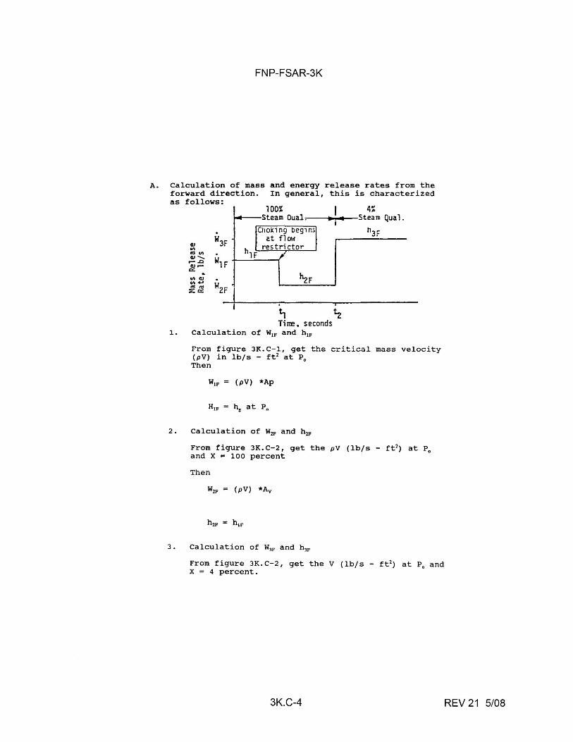
FNP-FSAR-3K
A. Calculation of mass and energy release rates from the forward direction. In general, this is characterized as follows:
I 4% :--~-.~~i••t--~Steam Qua1.
Cll .,, "'"' QJ ...... ,- ..Q
QJ .... a:: . .,, QJ .,, .... "'"' ::.: a::
Ti rre, seconds 1. Calculation of W1p and h 1p
113F
From figure JK.C- 1, get the critical mass velocity (pV) in lb/s - ft 2 at P0
Then
W1p (pV) *Ap
2. Calculation of W2p and h2P
From figure JK.c-2, get the pV (lb/s - ft 2 ) at p0
and X = 100 percent
Then
W2p (pV) *Av
3. Calculation of W3p and hJP
From figure JK.C-2, get the V (lb/s - ft 2 ) at P0
and X = 4 percent.
3K.C-4 REV 21 5/08
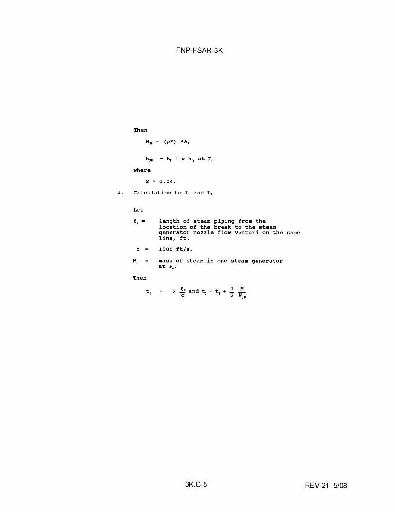
FNP-FSAR-3K
Then
W3p (pV) *Av
where
X = 0.04.
4. Calculation to t 1 and ti
Let
i, = length of steam piping from the location of the break to the steam generator nozzle flow venturi on the same line, ft.
C = 1500 ft/s.
M. =
Then
mass of steam in one steam generator at P
0•
2 i, and ti = t1
+ -21 ..!!_
C W2P
3K.C-5 REV 21 5/08
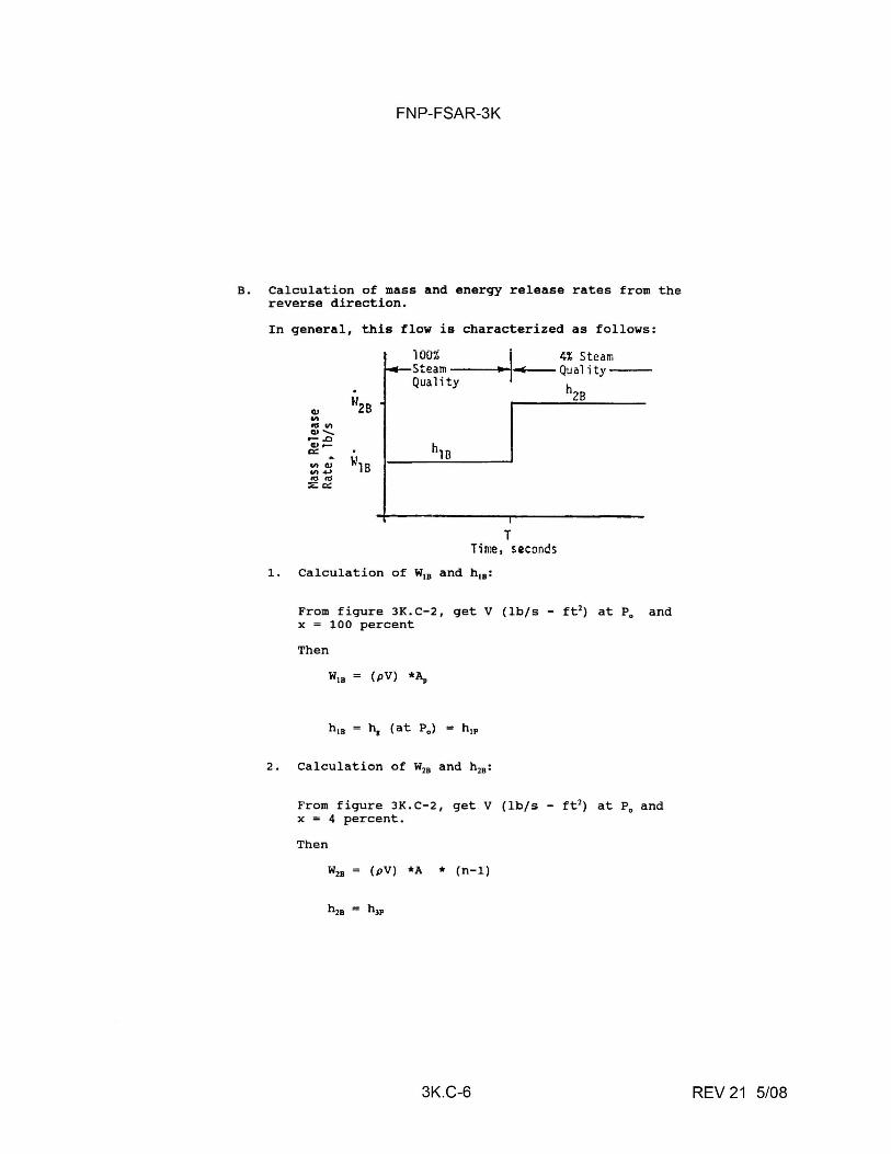
FNP-FSAR-3K
B. Calculation of mass and energy release rates from the reverse direction.
In general, this flow is characterized as follows:
lOOZ . j 4% Steam Steam :---i~ Quality---Quality h
1~~~h..;..;10'---~~--'' 28
. cu "'2s "' tO "' CIJ-..... ,- .0 cu.-c::
a
"'rn "'CIJ "' ..... mm ::.: 0::
T Time, seconds
1. Calculation of W18 and h 18 :
From figure JK.C-2, get V (lb/s - ft2) at P0
and x = 100 percent
Then
W1a (pV) *~
2. Calculation of W28 and h 28 :
From figure JK.C-2, get V (lb/s - ft 2) at P0
and x = 4 percent.
Then
W28 (pV) *A * (n-1)
3K.C-6 REV 21 5/08
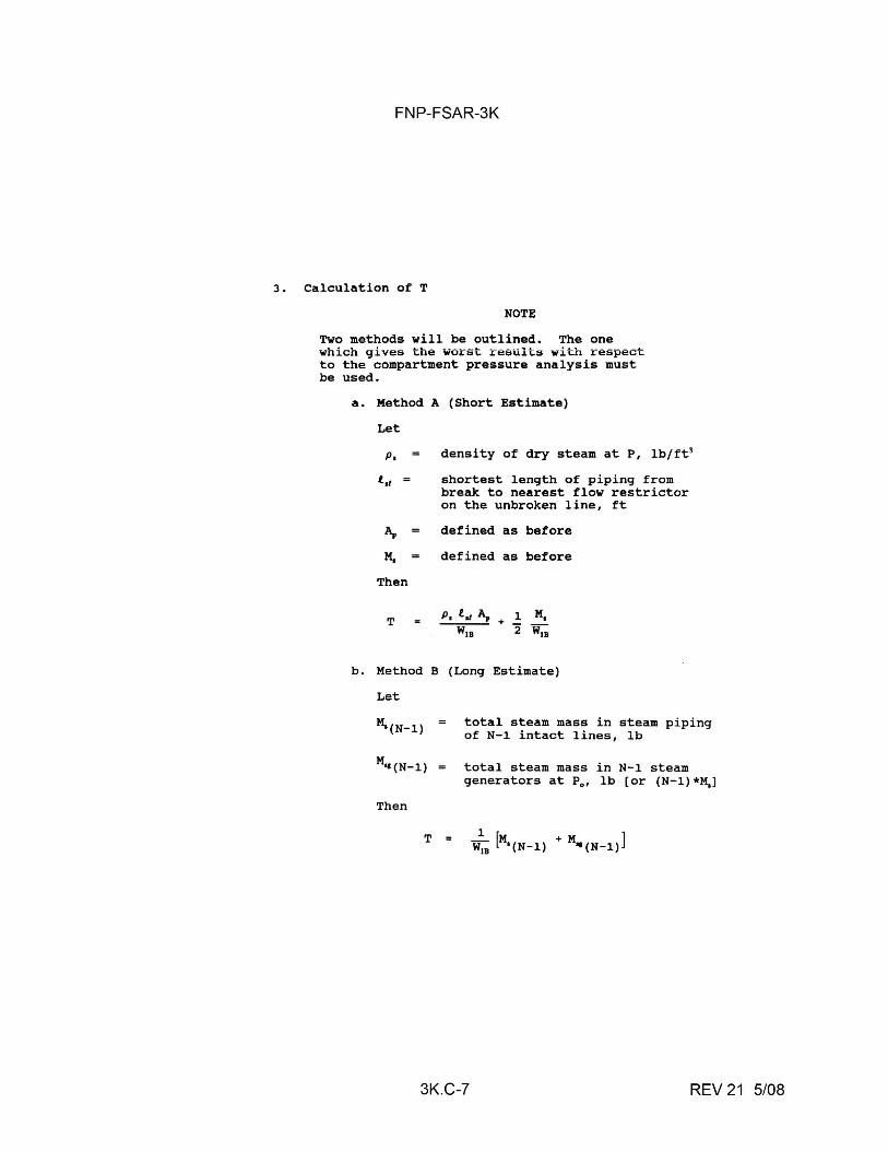
FNP-FSAR-3K
3. Calculation of T
NOTE
Two methods will be outlined. The one which gives the worst results with respect to the compartment pressure analysis must be used.
a. Method A (Short Estimate)
Let
p, density of dry steam at P, lb/ft3
t,1 shortest length of piping from break to nearest flow restrictor on the unbroken line, ft
"' defined as before
M. defined as before
Then
T P, t., A, + 1 M,
WIB 2 WIB
b. Method B (Long Estimate)
Let
M.(N-1) total steam mass in steam piping of N-1 intact lines, lb
Then
total steam mass in N-1 steam generators at P0 , lb (or (N-l)*M.]
3K.C-7 REV 21 5/08
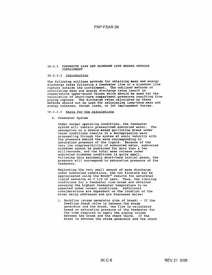
FNP-FSAR-3K
JK.C.2 FEEDWATER LINE AND SLOWDOWN LINE BREAKS OUTSIDE CONTAINMENT
JK.c.2.1 Introduction
The following outlines methods for obtaining mass and energy discharge rates following a feedwater line or a blowdown line rupture outside the containment. The outlined methods of calculating mass and energy discharge rates result in conservative upper-bound values which should be used for the calculation of short-term compartment pressures resulting from piping rupture. The discharge rates calculated by these methods should not be used for calculating long-term mass and energy releases, thrust loads, or jet impingement forces.
JK.c.2.2 Basis for the Calculations
A. Feedwater System
Under normal operating conditions, the feedwater system will contain pressurized subcooled water. The assumption of a double-ended guillotine break under these conditions results in a decompression wave propagating through the system at sonic velocity with the pressure behind the wave corresponding to saturation pressure of the liquid. Because of the very low compressibility of subcooled water, subcooled blowdown cannot be sustained for more than a few milliseconds, and the total mass release under subcooled blowdown conditions is quite small. Following this extremely short-term initial phase, the pressure will correspond to saturation pressure of the feedwater.
Neglecting the very small amount of mass discharge under subcooled conditions, the net flowrate may be approximated using the Moody0> results for saturated liquid assuming an f L/D of zero. Thus, the limiting conditions for a feedwater line break are obtained assuming the highest feedwater temperature to be expected under normal conditions. Additional considerations are dependent on the location of the break being addressed and are discussed below:
1. Backflow (steam generator side of break) - If the feedline check valve is between the steam generator and the break, the flow is calculated based on saturation pressure of the feedwater for the time required to empty the piping volume between the break and the check valve. If the break is between the steam generator and the check
3K.C-8 REV 21 5/08
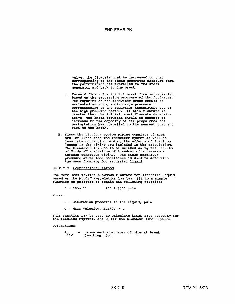
FNP-FSAR-3K
valve, the flowrate must be increased to that corresponding to the steam generator pressure once the perturbation has travelled to the steam generator and back to the break.
2. Forward flow - The initial break flow is estimated based on the saturation pressure of the feedwater. The capacity of the feedwater pumps should be evaluated assuming a discharge pressure corresponding to the feedwater temperature out of the high pressure heater, If this flowrate is greater than the initial break flowrate determined above, the break flowrate should be assumed to increase to the capacity of the pumps once the perturbation has travelled to the nearest pump and back to the break.
B. Since the blowdown system piping consists of much smaller lines than the feedwater system as well as less interconnecting piping, the effects of friction losses in the piping are included in the calculation. The blowdown flowrate is calculated using the results of Moody'sm evaluation of blowdown of a reservoir through connected piping. The steam generator pressure at no load conditions is used to determine the mass flowrate for saturated liquid.
JK.C.2.3 Computational Method
The zero loss maximum blowdown flowrate for saturated liquid based on the Moody0> correlation has been fit to a simple function of pressure to obtain the following relation:
where
G = 250p 112 300<P<l200 psia
P Saturation pressure of the liquid, psia
G Mass Velocity, lbm/ ft2 - s
This function may be used to calculate break mass velocity for the feedline rupture, and G0 for the blowdowTi line rupture.
Definitions:
~fw cross-sectional area of pipe at break location, ft 2
•
3K.C-9 REV 21 5/08
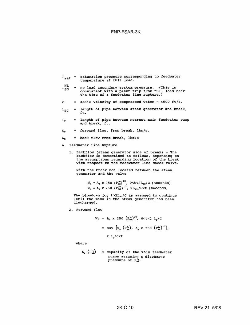
C
FNP-FSAR-3K
saturation pressure corresponding to feedwater temperature at full load.
no load secondary system pressure. (This is consistent with a plant trip from full load near the time of a feedwater line rupture.)
sonic velocity of compressed water - 4500 ft/s.
length of pipe between steam generator and break, ft.
length of pipe between nearest main feedwater pump and break, ft.
forward flow, from break, lbm/s.
back flow from break, lbm/s
A. Feedwater Line Rupture
1. Backflow (steam generator side of break) - The backflow is determined as follows, depending on the assumptions regarding location of the break with respect to the feedwater line check valve.
2.
With the break not located between the steam generator and the valve
WB = Ap X 250 (P!) 112
, O<t<2Lso/C (seconds)
W8 = Ap x 250 (P~)112
, 2L90 /C<t (seconds)
The blowdown for t>2Lso/C is assumed to continue until the mass in the steam generator has been discharged.
Forward Flow
Wp = ( rw)112 Ap X 250 P.., , O<t<2 ~/C
max [wP (P,:), A, X 250 (P,:)112] I
2 ~/c<t
where
WP (P,:) capacity of the main feedwater pumps assumin2_ a discharge pressure of P.., .
3K.C-10 REV 21 5/08
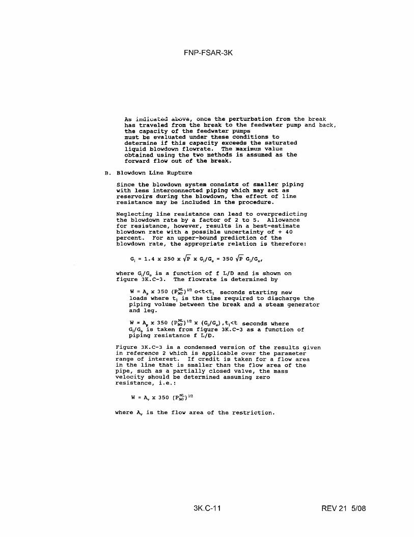
FNP-FSAR-3K
As indicated above, once the perturbation from the break has traveled from the break to the feedwater pump and back, the capacity of the feedwater pumps must be evaluated under these conditions to determine if this capacity exceeds the saturated liquid blowdown flowrate. The maximum value obtained using the two methods is assumed as the forward flow out of the break.
B. Blowdown Line Rupture
Since the blowdown system consists of smaller piping with less interconnected piping which may act as reservoirs during the blowdown, the effect of line resistance may be included in the procedure .
Neglecting line resistance can lead to overpredicting the blowdown rate by a factor of 2 to 5. Allowance for resistance, however, results in a best-estimate blowdown rate with a possible uncertainty of+ 40 percent. For an upper-bound prediction of the blowdown rate, the appropriate relation is therefore:
G, = 1. 4 x 250 X VF X GJG0 = 350 VF GJG0
,
where GJG0 is a function of f L/D and is shown on figure 3K.C-3. The flowrate is determined by
W = ~ x 350 (P:,) 112 o<t<t1 seconds starting new loads where t 1 is the time required to discharge the piping volume between the break and a steam generator and leg.
W = ~ x 350 (P:,) 112 x (GJG0 ) , t 1<t seconds where GJG0 is taken from figure 3K.C-3 as a function of piping resistance f L/D .
Figure 3K.C-3 is a condensed version of the results given in reference 2 which is applicable over the parameter range of interest. If credit is taken for a flow area in the line that is smaller than the flow area of the pipe, such as a partially closed valve, the mass velocity should be determined assuming zero resistance, i.e.:
W = A,, X 350 (P:-) 112
where A,, is the flow area of the restriction.
3K.C-11 REV 21 5/08
FNP-FSAR-3K
Forward and reverse flow out·the break should be determined separately and summed.
For both the feedwater line and the blowdown line ruptures, the energy release is determined by multiplying the mass flowrate by the enthalpy of the fluid being expelled. Note that in the case of backflow from a feedwater line rupture, with the break located between the steam generator and the check valve, the fluid enthalpy will change from that of the feedwater to the enthalpy of saturated water in the steam generator.
3K.C-12 REV 21 5/08
FNP-FSAR-3K
REFERENCES
1. Moody, F. J., "Maximum Flowrate of a Single Component, Two-Phase Mixture," Journal of Heat Transfer, Trans. ASME, Series c, Vol. 86, February 1965, p. 134.
2. Moody, F. J., "Maximum Two-Phase Vessel Blowdown from Pipes," Journal of Heat Transfer, August 1966, p. 285.
3K.C-13 REV 21 5/08
FNP-FSAR-3K
3K.C.3 36-in. STEAM LINE BREAK
3K.c.3.l Introduction
The following outlines a method for obtaining mass flowrates which may be used for determining local pressures resulting from a 36-in. steam line break. The flowrates obtained using this procedure are defensible upper bound values. Note that they are intended to be used for local short-term compartment pressure calculations and are not applicable for calculating long-term mass and energy releases, thrust loads, or jet impingement forces. Also note that in the method that follows, flow from only one side of the break is included. The same procedure is to be used to obtain the flow from the other side.
3K.C.3.2 Basis for the Calculations
Since detailed flowrate calculations for 36-in. steam line breaks are a function of plant piping layout and geometry, the effort required for transient blowdo*"Il analyses for all cases involving assessment of consequential damage resulting from the break becomes quite prohibitive. For this reason, it is desirable to obtain defensible upper bound flowrates which are as independent of piping layout as possible.
Figure 3K.C-4 shows possible steam line header configurations in junction with a 36-in. line. The dashed lines on the figure indicate the assumed break locations. If the header is assumed to rupture, the location of the rupture must be chosen to maximize the mass and energy release rates into the compartments (unless stress calculations or other considerations indicate otherwise).
The limiting plant condition in terms of both steam generator mass inventory and initial secondary system pressure are obtained when the plant is at hot shutdown. Because of the high flowrates associated with a steam line break, frothing in the steam generator causes a rapid increase in water level, resulting in a large decrease in the quality of fluid expelled from the steam generator. Although the enthalpy of this low quality fluid is less than that of dry steam, the critical mass flowrate is much higher, resulting in a net increase in the energy release rate from the break. The piping flow areas will determine however, whether or not this water entrained energy release rate is higher than that for dry steam. A method is suggested in the next section for determining a defensible time of entrainment. The flowrate from either side of the break is to be calculated using the same procedure. Hence, the method will be outlined for calculating the flow from one side of the break. The analyst, however, must calculate the rates from
3K.C-14 REV 21 5/08
FNP-FSAR-3K
each side separately and then sum them to obtain the total. This total mass and energy release rate must be used to determine the compartment pressure.
In general, the mass and energy release rates from one side of the break may be characterized by figures JK.C-4, JK.C-5, and JK.C-6. Note that in figure JK,C-6, the energy release rate may actually decrease at the time of entrainment (t0 ) depending on the area ratios.
Let AH
A.,
'D .. X
h
N
G
m
E
t
t.
L
C
Mso
)1
Ji
cross-sectional area of header piping based on the inside diameter, ft2 •
throat area of the steam line flow restrictor, ft2 •
no-load ~o~~nn~..-y aya~om pressure, psia.
steam quality, percent.
enthalpy of fluid, Btu/lb.
number of flow restrictors upstream of break.
critical mass velocity, lbm/s-ft2•
mass release rate, lb/s.
energy release rate, Btu/s.
time after rupture, s.
time of entrainment, s.
length of piping from break to nearest steam generator, ft.
velocity of sound in dry saturated steam at P0 ,
ft/s.
mass of steam in steam generator at initiation of break, lbm.
denotes parameter before t.
denotes parameter after t.
3K.C-15 REV 21 5/08
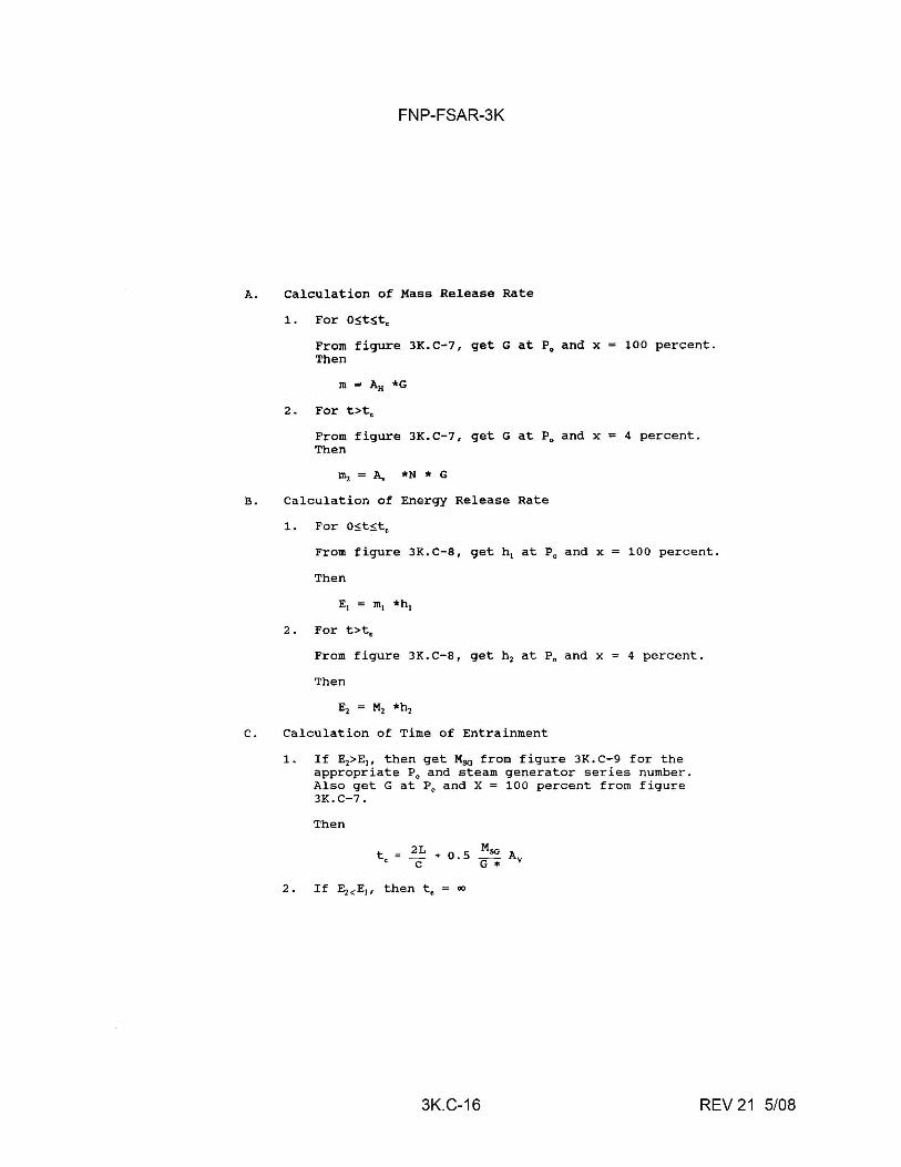
FNP-FSAR-3K
A. Calculation of Mass Release Rate
1. For o~t~t.
From figure JK.C-7, get G at P0 and x Then
100 percent.
2. For t>t.
From figure JK.C-7, get G at P0 and x Then
ffii = A., *N * G
B. Calculation of Energy Release Rate
1. For o~t~t.
4 percent .
From figure JK.C-8, get h 1 at P 0 and x 100 percent.
Then
2. For t>t0
From figure 3K.C-8, get h 2 at P0 and x
Then
4 percent.
C. Calculation of Time of Entrainment
1. If Ei> Ei, then get Mso from figure 3K. C-9 for the appropriate P0 and steam generator series number. Also get G at P0 and X = 100 percent from figure 3K.C-7.
Then
t = 2L + 0. 5 Mso Av • C G*
3K.C-16 REV 21 5/08
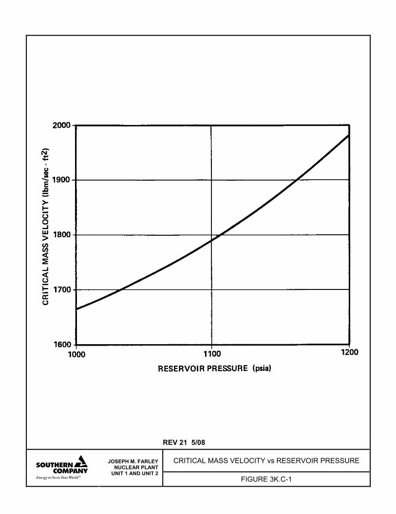
REV 21 5/08
CRITICAL MASS VELOCITY vs RESERVOIR PRESSURE
JOSEPH M. FARLEY NUCLEAR PLANT
UNIT 1 AND UNIT 2 FIGURE 3K.C-1
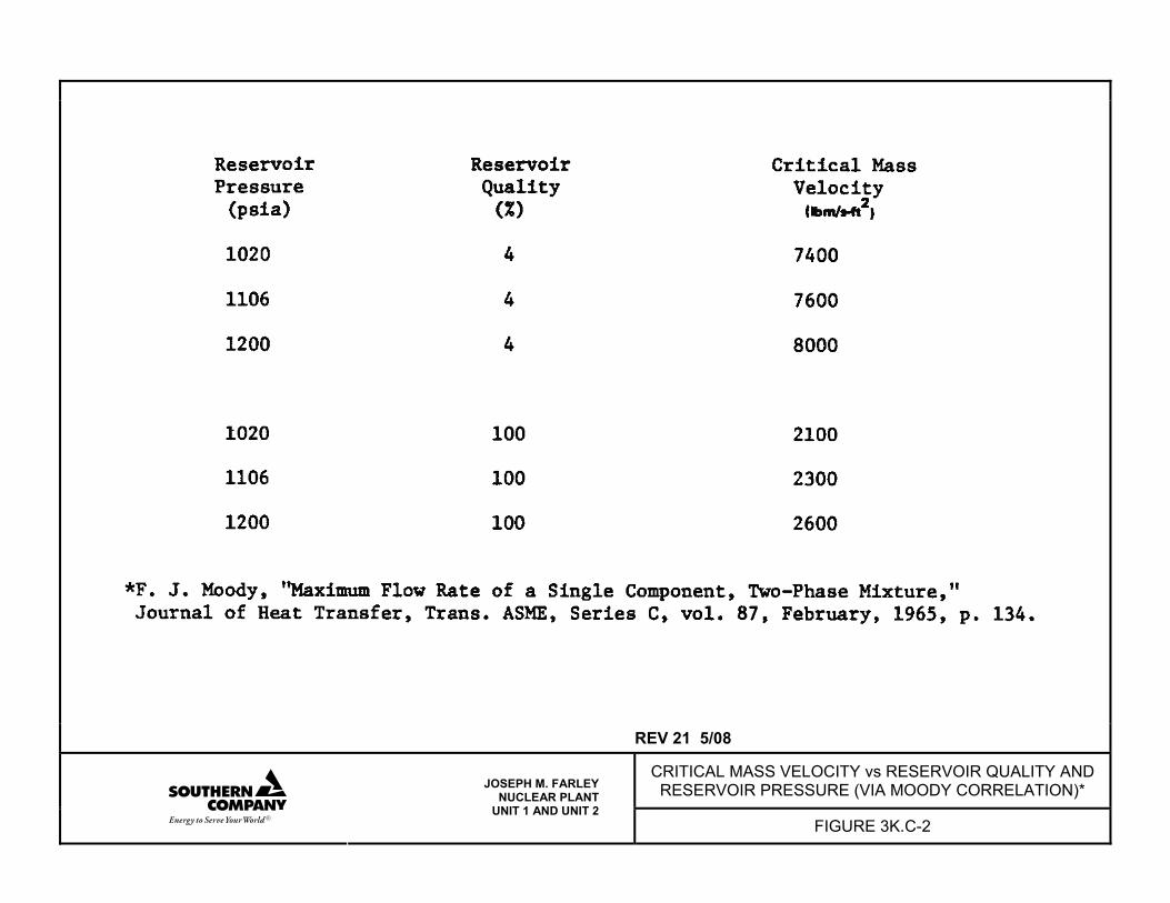
REV 21 5/08
CRITICAL MASS VELOCITY vs RESERVOIR QUALITY AND RESERVOIR PRESSURE (VIA MOODY CORRELATION)*
JOSEPH M. FARLEY NUCLEAR PLANT
UNIT 1 AND UNIT 2 FIGURE 3K.C-2
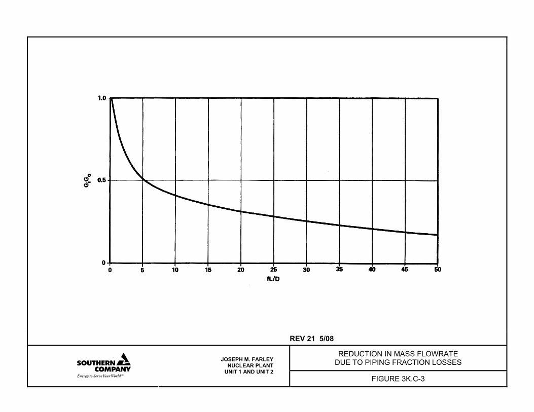
REV 21 5/08
REDUCTION IN MASS FLOWRATE DUE TO PIPING FRACTION LOSSES
JOSEPH M. FARLEY NUCLEAR PLANT
UNIT 1 AND UNIT 2 FIGURE 3K.C-3
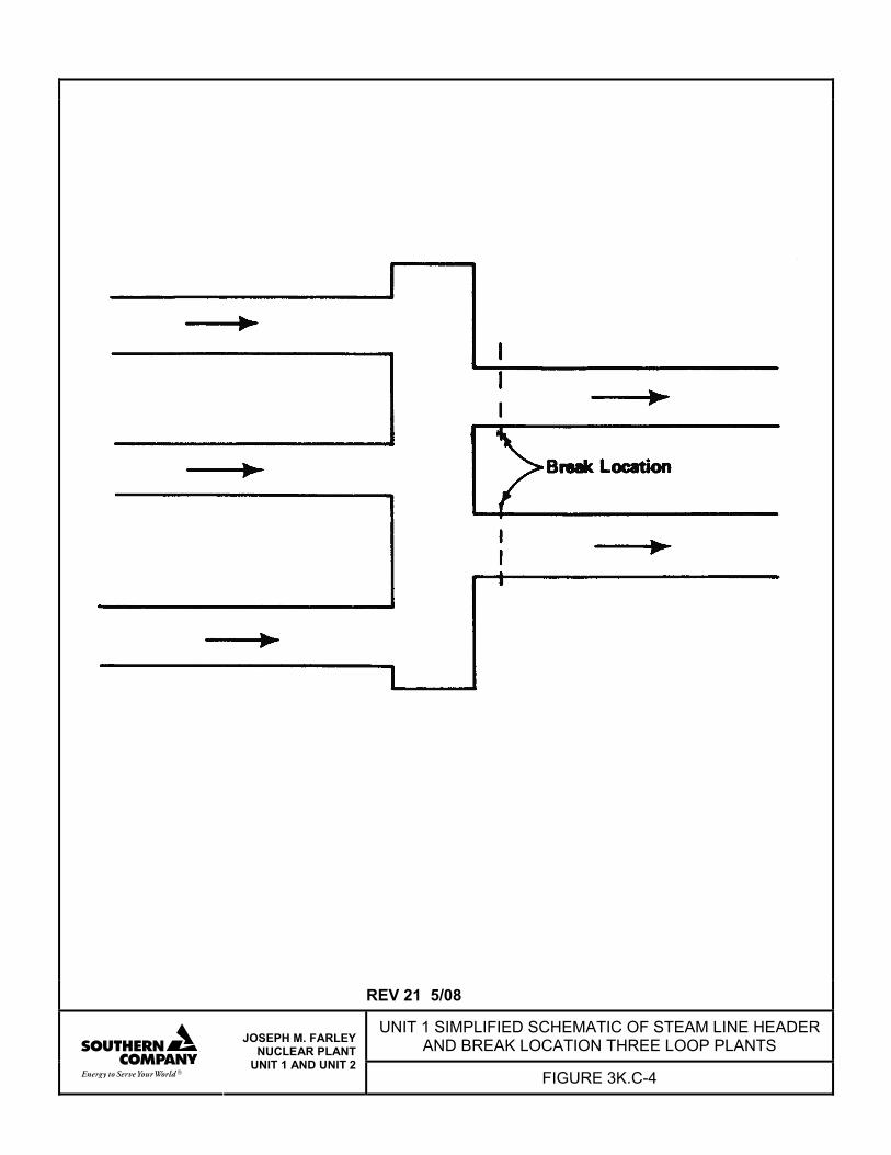
REV 21 5/08
UNIT 1 SIMPLIFIED SCHEMATIC OF STEAM LINE HEADER AND BREAK LOCATION THREE LOOP PLANTS
JOSEPH M. FARLEY NUCLEAR PLANT
UNIT 1 AND UNIT 2 FIGURE 3K.C-4
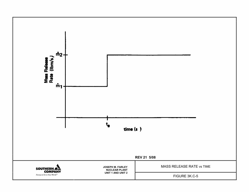
REV 21 5/08
MASS RELEASE RATE vs TIME
JOSEPH M. FARLEY NUCLEAR PLANT
UNIT 1 AND UNIT 2 FIGURE 3K.C-5
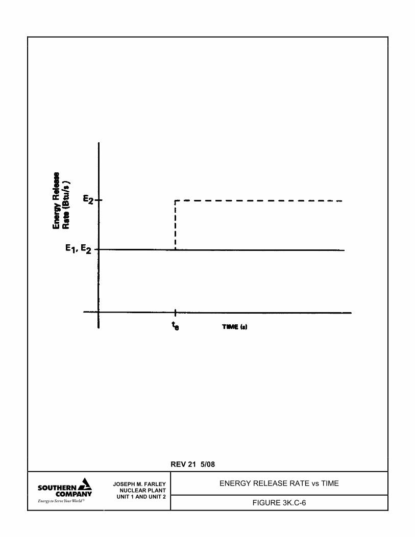
REV 21 5/08
ENERGY RELEASE RATE vs TIME
JOSEPH M. FARLEY NUCLEAR PLANT
UNIT 1 AND UNIT 2 FIGURE 3K.C-6
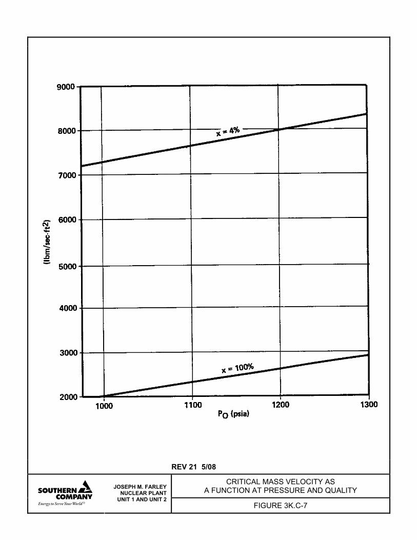
REV 21 5/08
CRITICAL MASS VELOCITY AS A FUNCTION AT PRESSURE AND QUALITY
JOSEPH M. FARLEY NUCLEAR PLANT
UNIT 1 AND UNIT 2 FIGURE 3K.C-7
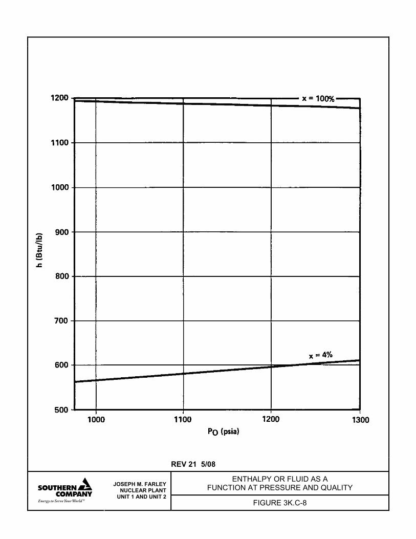
REV 21 5/08
ENTHALPY OR FLUID AS A FUNCTION AT PRESSURE AND QUALITY
JOSEPH M. FARLEY NUCLEAR PLANT
UNIT 1 AND UNIT 2 FIGURE 3K.C-8
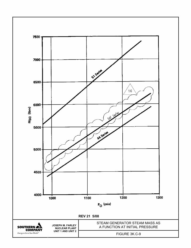
REV 21 5/08
STEAM GENERATOR STEAM MASS AS A FUNCTION AT INITIAL PRESSURE
JOSEPH M. FARLEY NUCLEAR PLANT
UNIT 1 AND UNIT 2 FIGURE 3K.C-9

FNP-FSAR-3K
3K.D-i REV 21 5/08
ATTACHMENT D
COMPARTMENT PRESSURE TEMPERATURE ANALYSIS COMPUTER PROGRAM DESCRIPTION
FNP-FSAR-3K
3K.D-1 REV 21 5/08
ATTACHMENT D
COMPARTMENT PRESSURE TEMPERATURE ANALYSIS COMPUTER PROGRAM DESCRIPTION (COPDA)
3K.D.1 INTRODUCTION This appendix describes the analytical techniques used to evaluate high-energy pipe rupture. 3K.D.2 INITIAL COMPARTMENT CONDITIONS The masses of air and water as steam in the compartments are determined using the initial input conditions of temperature, pressure, relative humidity, and compartment volumes. The specific humidity of saturated air at the compartment temperature is read from a correlation table of temperature and water vapor in saturated air. The compartment specific humidity is obtained by: SH = (RH) x (SSH) where: SH = specific humidity of compartment air, lb steam/lb air RH = relative humidity of compartment air SSH = specific humidity of saturated air at compartment temperature, lb steam/lb air. The vapor pressure of the water is determined by:
PW = SH0.623
(SH)(PT)+
where: PW = vapor pressure of water at compartment temperature, psia PT = total compartment pressure, psia. The air pressure in the compartment is determined by: PA = PT - PW
FNP-FSAR-3K
3K.D-2 REV 21 5/08
The mass of air in the compartment is evaluated using the perfect gas law equation:
MA = (T)
nR
(V)(PA)(144)
⎟⎠⎞
⎜⎝⎛
where: V = volume of compartment, ft3 R = gas constant, 1545.3 T = compartment temperature, °R n = molecular weight of air, 28.97 lb/lb mole PA = partial pressure of the air lb/in2 The mass of water in the compartment, MS, is: MS = (MA)(SH) The masses of air and water in the remaining compartments are determined in the same manner. The internal energy of the air, UA(I), in each compartment is calculated using 0°F as a base: UA(I) = [CV][MA(I)][TP] where: CV = specific heat of air at constant volume, 0.171 Btu/lb-°F TP = compartment temperature, °F The internal energy of the water vapor in each compartment is calculated by the equation: US(I) = [MS(I)][UG] where: UG = internal energy of the steam evaluated from the saturated steam tables at the compartment temperature.
FNP-FSAR-3K
3K.D-3 REV 21 5/08
3K.D.3 CONSERVATION OF MASS AND ENERGY IN COMPARTMENTS The inventory of the total mass and energy in the compartments is maintained from the inlet and exit flows during the time increment:
( ) ( )
( ) ( )
UA(I)UV(I)UV(I)US(I)UW(I)UV(I)
MSOHGOMSIHGI(I)SUUS(I)
MWOHOMWIHI(I)WUUW(I)
UAOUAI(I)AUUA(I)
MA(I)MV(I)MT(I)MS(I)MW(I)MV(I)
MSOMSI(I)SMMS(I)
MWOMWIMW(I)MW(I)
MAOMAI(I)AMMA(I)
NN
NN
NN
NN
NN
NN
+=+=
−+′=
−+′=
−+′=
+=+=
−+′=
−+=
−+′=
∑∑
∑∑
∑∑
∑∑
∑∑
∑∑
where: Primed (′) values refer to end of previous time step; all other values refer to current time step. MA(I) = mass of air in compartment (I), lb MW(I) = mass of water in compartment (I), lb MS(I) = mass of steam in compartment (I), lb MV(I) = mass of water and steam in compartment (I), lb MT(I) = total mass in compartment (I), lb MAI = mass of air entering compartment, lb MAO = mass of air leaving compartment, lb MWI = mass of water entering compartment, lb MWO = mass of water leaving compartment, lb
FNP-FSAR-3K
3K.D-4 REV 21 5/08
MSI = mass of steam entering compartment, lb MSO = mass of steam leaving compartment, lb UAI = total energy of air entering compartment, Btu UAO = total energy of air leaving compartment, Btu HI = enthalpy of water entering compartment (I), Btu/lb HO = enthalpy of water leaving compartment (I), Btu/lb HGI = enthalpy of steam entering compartment (I), Btu/lb HGO = enthalpy of steam leaving compartment (I), Btu/lb UA(I) = energy in air in compartment (I), Btu UW(I) = energy in water in compartment (I), Btu US(I) = energy in steam in compartment (I), Btu UV(I) = energy in two-phase mixture in compartment (I), Btu UT(I) = total energy in compartment (I), Btu. 3K.D.4 COMPARTMENT PRESSURE CALCULATIONS The compartment pressure is calculated using the total mass and energy in the compartment after the flow from the upstream compartments and/or the blowdown has been added to the compartment inventory of mass and energy. A convergence procedure is used to arrive at the equilibrium thermodynamics conditions in the compartment using temperature as the trial argument. The equilibrium thermodynamic state is considered determined when the trial temperature provides properties such that the ratio of the difference between the trial energy balance and the energy inventory is less than 0.001. The state properties of the steam and water mixture at the trial temperature are obtained from the saturation tables. The mass of steam is then determined by:
MS = VG
(VL) (MW) - (V) 1
where: V = volume of compartment, ft3 VL = specific volume of water, ft3/lb
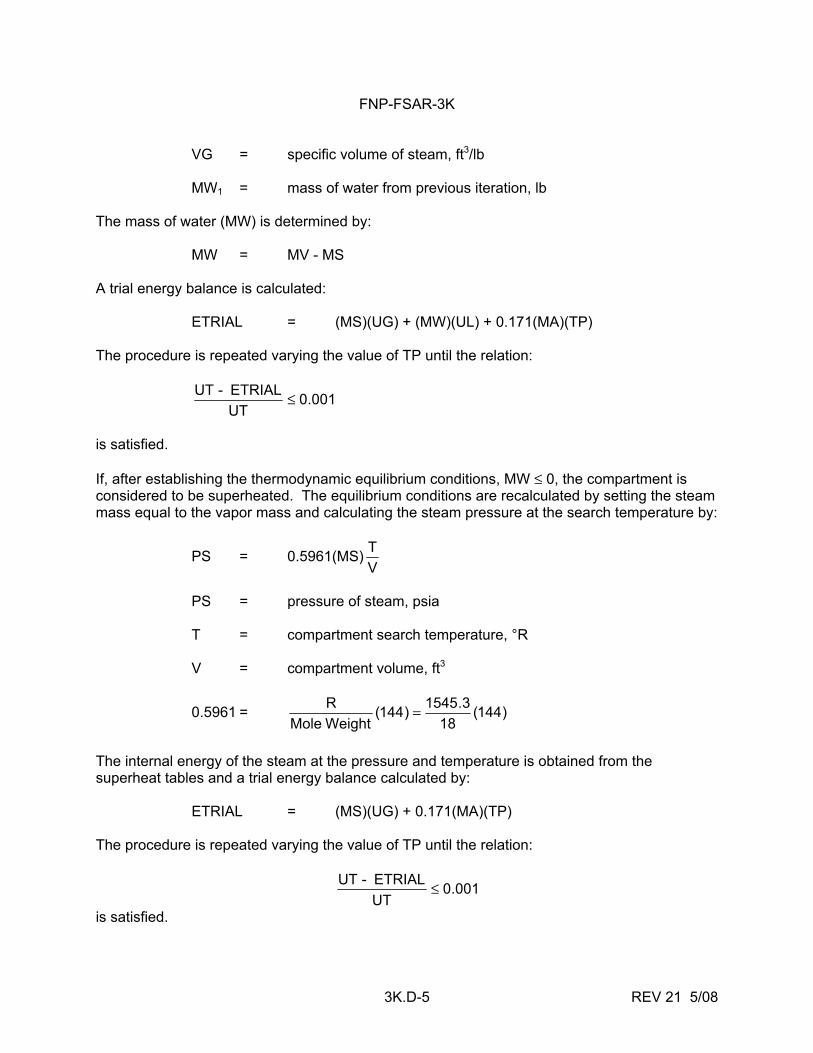
FNP-FSAR-3K
3K.D-5 REV 21 5/08
VG = specific volume of steam, ft3/lb MW1 = mass of water from previous iteration, lb The mass of water (MW) is determined by: MW = MV - MS A trial energy balance is calculated: ETRIAL = (MS)(UG) + (MW)(UL) + 0.171(MA)(TP) The procedure is repeated varying the value of TP until the relation:
001.0UTETRIAL -UT ≤
is satisfied. If, after establishing the thermodynamic equilibrium conditions, MW ≤ 0, the compartment is considered to be superheated. The equilibrium conditions are recalculated by setting the steam mass equal to the vapor mass and calculating the steam pressure at the search temperature by:
PS = 0.5961(MS)VT
PS = pressure of steam, psia T = compartment search temperature, °R V = compartment volume, ft3
0.5961 = )144(18
3.1545)144( WeightMoleR =
The internal energy of the steam at the pressure and temperature is obtained from the superheat tables and a trial energy balance calculated by: ETRIAL = (MS)(UG) + 0.171(MA)(TP) The procedure is repeated varying the value of TP until the relation:
001.0UTETRIAL -UT ≤
is satisfied.
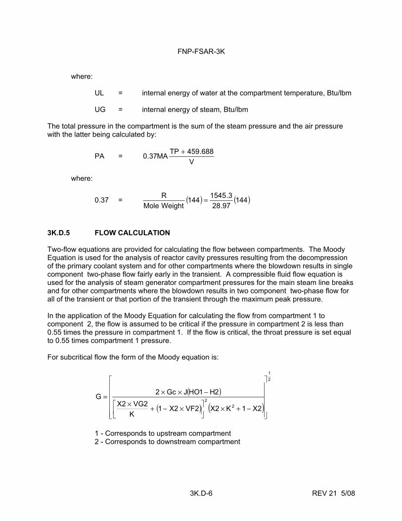
FNP-FSAR-3K
3K.D-6 REV 21 5/08
where: UL = internal energy of water at the compartment temperature, Btu/lbm UG = internal energy of steam, Btu/lbm The total pressure in the compartment is the sum of the steam pressure and the air pressure with the latter being calculated by:
PA = V
688.459TPMA37.0 +
where:
0.37 = ( ) ( )14497.28
3.1545144WeightMoleR =
3K.D.5 FLOW CALCULATION Two-flow equations are provided for calculating the flow between compartments. The Moody Equation is used for the analysis of reactor cavity pressures resulting from the decompression of the primary coolant system and for other compartments where the blowdown results in single component two-phase flow fairly early in the transient. A compressible fluid flow equation is used for the analysis of steam generator compartment pressures for the main steam line breaks and for other compartments where the blowdown results in two component two-phase flow for all of the transient or that portion of the transient through the maximum peak pressure. In the application of the Moody Equation for calculating the flow from compartment 1 to component 2, the flow is assumed to be critical if the pressure in compartment 2 is less than 0.55 times the pressure in compartment 1. If the flow is critical, the throat pressure is set equal to 0.55 times compartment 1 pressure. For subcritical flow the form of the Moody equation is:
( )
( ) ( )
21
22
2X1K2X2VF2X1K
2VG2X2H1HOJGc2G
⎥⎥⎥⎥⎥
⎦
⎤
⎢⎢⎢⎢⎢
⎣
⎡
−+×⎥⎦⎤
⎢⎣⎡ ×−+×
−××=
1 - Corresponds to upstream compartment 2 - Corresponds to downstream compartment
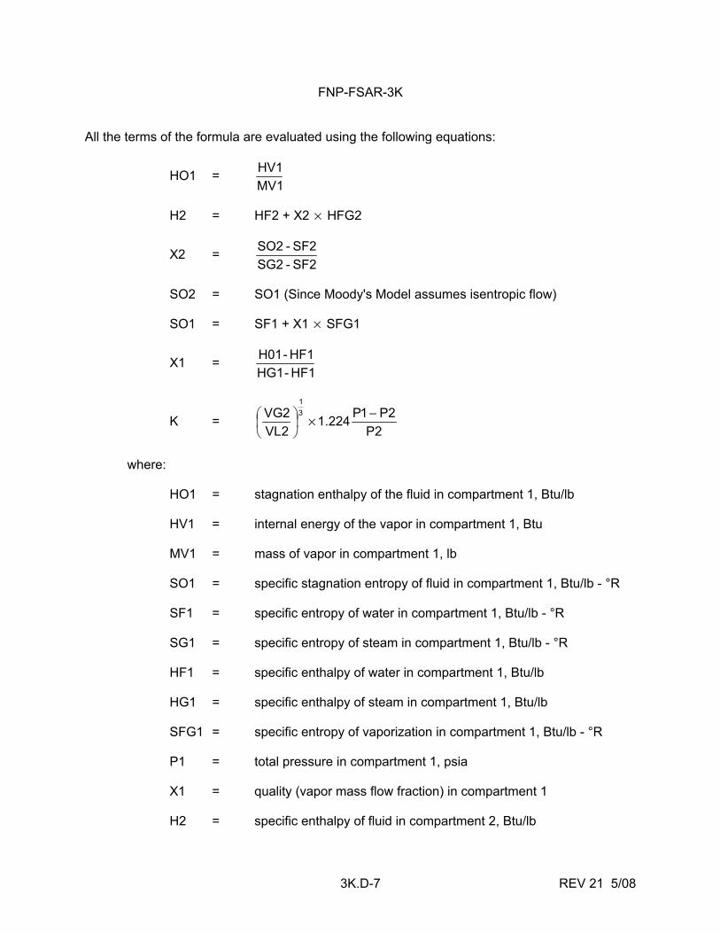
FNP-FSAR-3K
3K.D-7 REV 21 5/08
All the terms of the formula are evaluated using the following equations:
HO1 = MV1HV1
H2 = HF2 + X2 × HFG2
X2 = SF2- SG2SF2 - SO2
SO2 = SO1 (Since Moody's Model assumes isentropic flow) SO1 = SF1 + X1 × SFG1
X1 = HF1 - HG1HF1 - H01
K = 2P
2P1P224.12VL2VG 3
1
−×⎟⎠⎞
⎜⎝⎛
where: HO1 = stagnation enthalpy of the fluid in compartment 1, Btu/lb HV1 = internal energy of the vapor in compartment 1, Btu MV1 = mass of vapor in compartment 1, lb SO1 = specific stagnation entropy of fluid in compartment 1, Btu/lb - °R SF1 = specific entropy of water in compartment 1, Btu/lb - °R SG1 = specific entropy of steam in compartment 1, Btu/lb - °R HF1 = specific enthalpy of water in compartment 1, Btu/lb HG1 = specific enthalpy of steam in compartment 1, Btu/lb SFG1 = specific entropy of vaporization in compartment 1, Btu/lb - °R P1 = total pressure in compartment 1, psia X1 = quality (vapor mass flow fraction) in compartment 1 H2 = specific enthalpy of fluid in compartment 2, Btu/lb
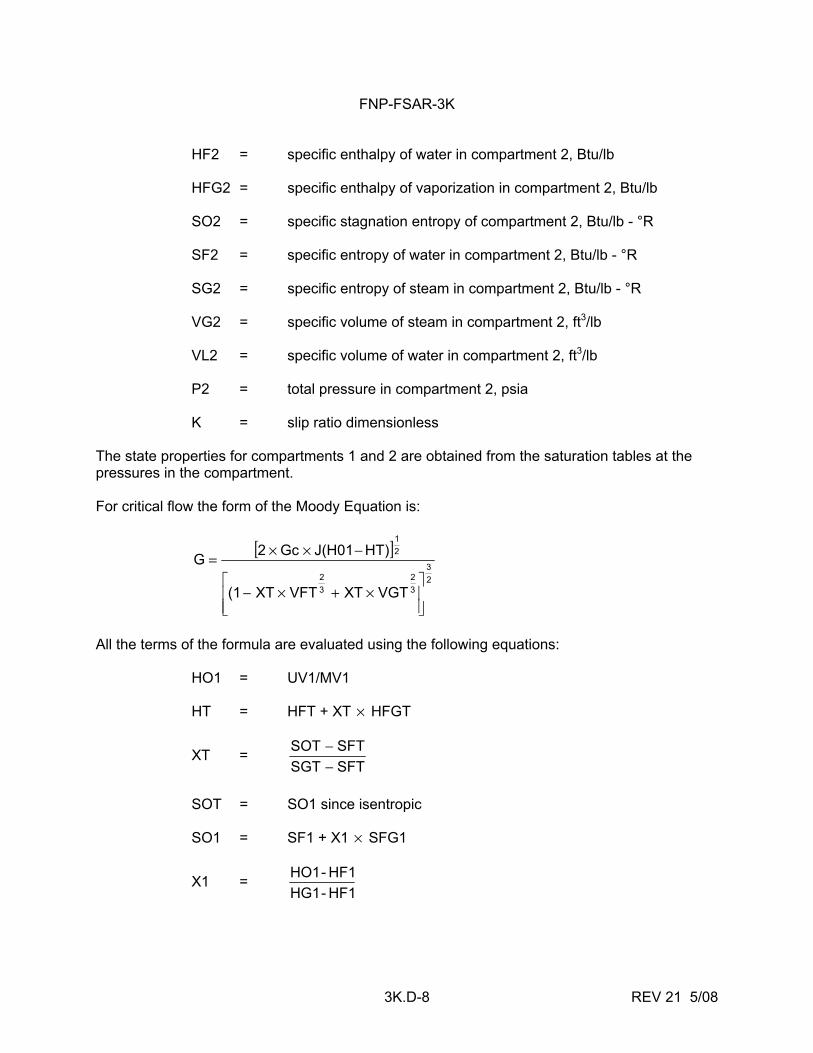
FNP-FSAR-3K
3K.D-8 REV 21 5/08
HF2 = specific enthalpy of water in compartment 2, Btu/lb HFG2 = specific enthalpy of vaporization in compartment 2, Btu/lb SO2 = specific stagnation entropy of compartment 2, Btu/lb - °R SF2 = specific entropy of water in compartment 2, Btu/lb - °R SG2 = specific entropy of steam in compartment 2, Btu/lb - °R VG2 = specific volume of steam in compartment 2, ft3/lb VL2 = specific volume of water in compartment 2, ft3/lb P2 = total pressure in compartment 2, psia K = slip ratio dimensionless The state properties for compartments 1 and 2 are obtained from the saturation tables at the pressures in the compartment. For critical flow the form of the Moody Equation is:
[ ]23
32
32
21
VGTXTVFTXT(1
HT)J(H01Gc2G
⎥⎥⎦
⎤
⎢⎢⎣
⎡×+×−
−××=
All the terms of the formula are evaluated using the following equations: HO1 = UV1/MV1 HT = HFT + XT × HFGT
XT = SFTSGTSFTSOT
−−
SOT = SO1 since isentropic SO1 = SF1 + X1 × SFG1
X1 = HF1 - HG1HF1 - HO1
FNP-FSAR-3K
3K.D-9 REV 21 5/08
where: XT = quality at the throat HT = specific enthalpy of the fluid at the throat HFT = specific enthalpy of the water at the throat HFGT = specific enthalpy of the vaporization at the throat SOT = specific stagnation entropy of the fluid at the throat SGT = specific entropy of the steam at the throat SFT = specific entropy of the water at the throat The other variables were defined previously. The state properties for compartment 1 and the throat are obtained from the saturation tables at the respective pressures in the compartment and throat. The throat pressure is calculated as follows: PT = P1 × 0.55 With Moody flow for both the subcritical and critical flow conditions, the calculated value of the flow is decreased to sixty percent of the flow (Moody Multiplier = 0.6). In the application of the compressible fluid equation, if the ratio of the pressure in compartment 2 to the pressure in compartment 1 is less than RC as obtained by:
RC = 1K
K
K12 −
⎥⎦⎤
⎢⎣⎡
+
the flow is considered to be critical. The form of the flow equation is:
G = 21
1K1K
1K2RH01P1KGc
⎥⎥⎥
⎦
⎤
⎢⎢⎢
⎣
⎡
⎥⎦⎤
⎢⎣⎡
+××××
−+
The isentropic exponent K for the air, steam, and water mixture is calculated by:
K = P1
PA1KA + P1
PS1KGF ××
FNP-FSAR-3K
3K.D-10 REV 21 5/08
where: KA = isentropic value of K for air (= 1.4) KGF = isentropic value of K for steam-water mixture RHO1 = specific density of the mixture in compartment 1, lb/ft3 P1 = total pressure of compartment 1, psia PS1 = pressure of steam in compartment 1 PA1 = pressure of air in compartment 1 RH01 is calculated using the equation: RH01 = MT1/VOL1 where: MT1 = total mass of fluid in compartment 1, lb VOL1 = volume of compartment 1 If the flow is subcritical, the form of the flow equation is:
G = 21
K1K
K2
)R(R1K
KRH01P1Gc2⎥⎥⎦
⎤
⎢⎢⎣
⎡−
−××××
+
where the terms are as previously defined and R = 1
2
PP
The mass flow for both the compressible fluid flow equation and the Moody equation is calculated by: total MF = CAG ××
air MAF = 1MT1MAMF
water MWF = 1MT1MWMF
steam MSF = 1MT1MSMF
FNP-FSAR-3K
3K.D-11 REV 21 5/08
The energy transferred by the flow is: air UAF = T1CPMAF ×× water UWF = HLMWF × steam USF = HGMSF × where: A = area of flow path, ft2 G = mass flow, lb/ft2-s C = flow coefficient calculated external to code CP = specific heat of air at constant pressure HL = enthalpy of water at compartment temperature HG = enthalpy of steam at compartment temperature MA1, MW1, MS1, and MT1 are the same as the one previously defined. The flow coefficient "C" was calculated using the same method as outlined in the COPRA computer program which has been previously submitted for NRC review in NS-731-TN, "Containment Pressure Analysis," Power and Industrial Division, Bechtel Corporation, San Francisco, California, December 1968.
FNP-FSAR-3K
3K.E-i REV 21 5/08
ATTACHMENT E
CALCULATION METHODS FOR COMPARTMENT PRESSURIZATION
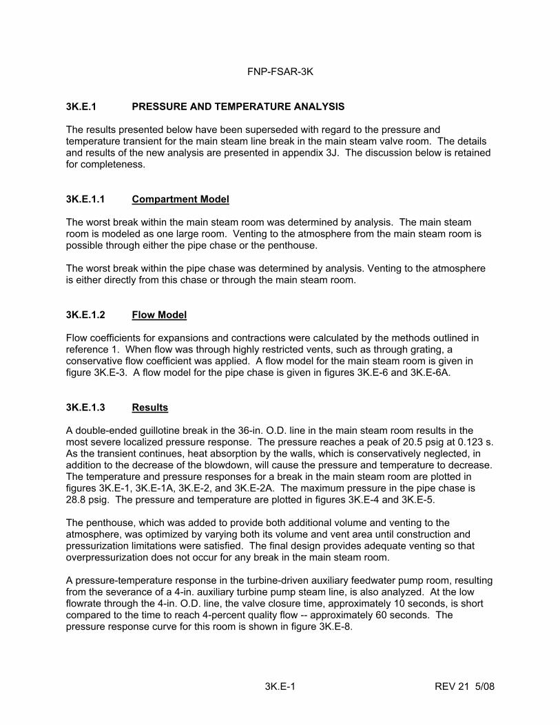
FNP-FSAR-3K
3K.E-1 REV 21 5/08
3K.E.1 PRESSURE AND TEMPERATURE ANALYSIS The results presented below have been superseded with regard to the pressure and temperature transient for the main steam line break in the main steam valve room. The details and results of the new analysis are presented in appendix 3J. The discussion below is retained for completeness. 3K.E.1.1 Compartment Model The worst break within the main steam room was determined by analysis. The main steam room is modeled as one large room. Venting to the atmosphere from the main steam room is possible through either the pipe chase or the penthouse. The worst break within the pipe chase was determined by analysis. Venting to the atmosphere is either directly from this chase or through the main steam room. 3K.E.1.2 Flow Model Flow coefficients for expansions and contractions were calculated by the methods outlined in reference 1. When flow was through highly restricted vents, such as through grating, a conservative flow coefficient was applied. A flow model for the main steam room is given in figure 3K.E-3. A flow model for the pipe chase is given in figures 3K.E-6 and 3K.E-6A. 3K.E.1.3 Results A double-ended guillotine break in the 36-in. O.D. line in the main steam room results in the most severe localized pressure response. The pressure reaches a peak of 20.5 psig at 0.123 s. As the transient continues, heat absorption by the walls, which is conservatively neglected, in addition to the decrease of the blowdown, will cause the pressure and temperature to decrease. The temperature and pressure responses for a break in the main steam room are plotted in figures 3K.E-1, 3K.E-1A, 3K.E-2, and 3K.E-2A. The maximum pressure in the pipe chase is 28.8 psig. The pressure and temperature are plotted in figures 3K.E-4 and 3K.E-5. The penthouse, which was added to provide both additional volume and venting to the atmosphere, was optimized by varying both its volume and vent area until construction and pressurization limitations were satisfied. The final design provides adequate venting so that overpressurization does not occur for any break in the main steam room. A pressure-temperature response in the turbine-driven auxiliary feedwater pump room, resulting from the severance of a 4-in. auxiliary turbine pump steam line, is also analyzed. At the low flowrate through the 4-in. O.D. line, the valve closure time, approximately 10 seconds, is short compared to the time to reach 4-percent quality flow -- approximately 60 seconds. The pressure response curve for this room is shown in figure 3K.E-8.
FNP-FSAR-3K
3K.E-2 REV 21 5/08
In addition to pressure and temperature response curves for the main steam system, additional curves and flow models for the following compartments containing high energy lines have been calculated using the computer model described in attachment D: A. Turbine-driven auxiliary feedwater pump room. B. CVCS letdown heat exchanger room (upper and lower levels). C. Piping tunnel from the letdown line penetration room, elevation 100 to the CVCS
heat exchanger room. D. Letdown line penetration room elevation 100. E. Recycle holdup tank compartments (3). F. BTRS alternate letdown line valve compartment elevation 121.
FNP-FSAR-3K
3K.E-3 REV 21 5/08
REFERENCES 1. "Containment Pressure Analysis," NS-731-TN, Bechtel Corporation, Power and
Industrial Division, San Francisco, California, December 1968. 2. "Subcompartment Pressure and Temperature Transient Analysis," BN-TOP-4, Rev. 1,
Bechtel Power Corporation, October 1977.
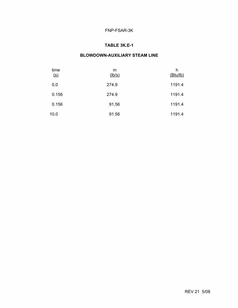
FNP-FSAR-3K
REV 21 5/08
TABLE 3K.E-1
BLOWDOWN-AUXILIARY STEAM LINE
time m h (s) (lb/s) (Btu/lb)
0.0 274.9 1191.4
0.156 274.9 1191.4
0.156 91.56 1191.4
10.0 91.56 1191.4
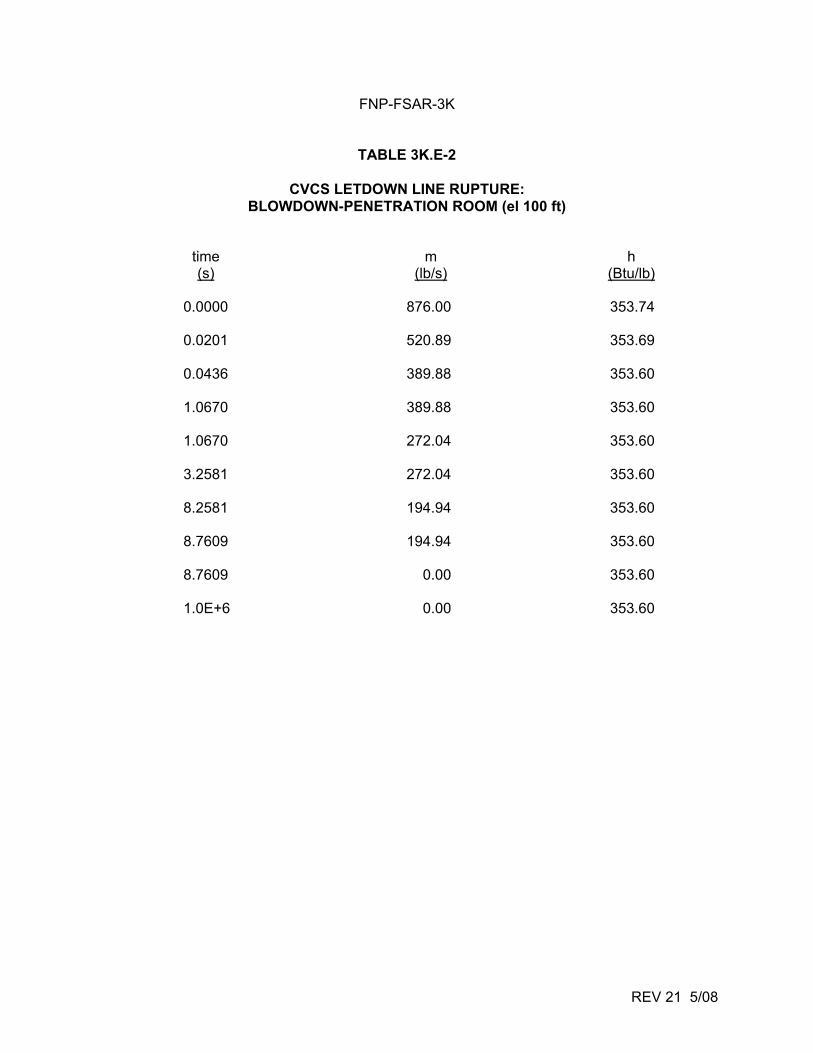
FNP-FSAR-3K
REV 21 5/08
TABLE 3K.E-2
CVCS LETDOWN LINE RUPTURE: BLOWDOWN-PENETRATION ROOM (el 100 ft)
time m h (s) (lb/s) (Btu/lb)
0.0000 876.00 353.74
0.0201 520.89 353.69
0.0436 389.88 353.60
1.0670 389.88 353.60
1.0670 272.04 353.60
3.2581 272.04 353.60
8.2581 194.94 353.60
8.7609 194.94 353.60
8.7609 0.00 353.60
1.0E+6 0.00 353.60
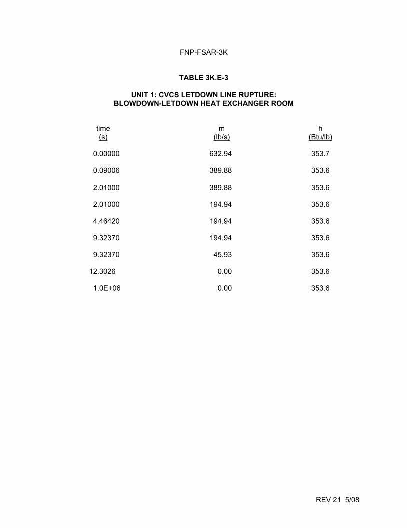
FNP-FSAR-3K
REV 21 5/08
TABLE 3K.E-3
UNIT 1: CVCS LETDOWN LINE RUPTURE: BLOWDOWN-LETDOWN HEAT EXCHANGER ROOM
time m h (s) (lb/s) (Btu/lb)
0.00000 632.94 353.7
0.09006 389.88 353.6
2.01000 389.88 353.6
2.01000 194.94 353.6
4.46420 194.94 353.6
9.32370 194.94 353.6
9.32370 45.93 353.6
12.3026 0.00 353.6
1.0E+06 0.00 353.6
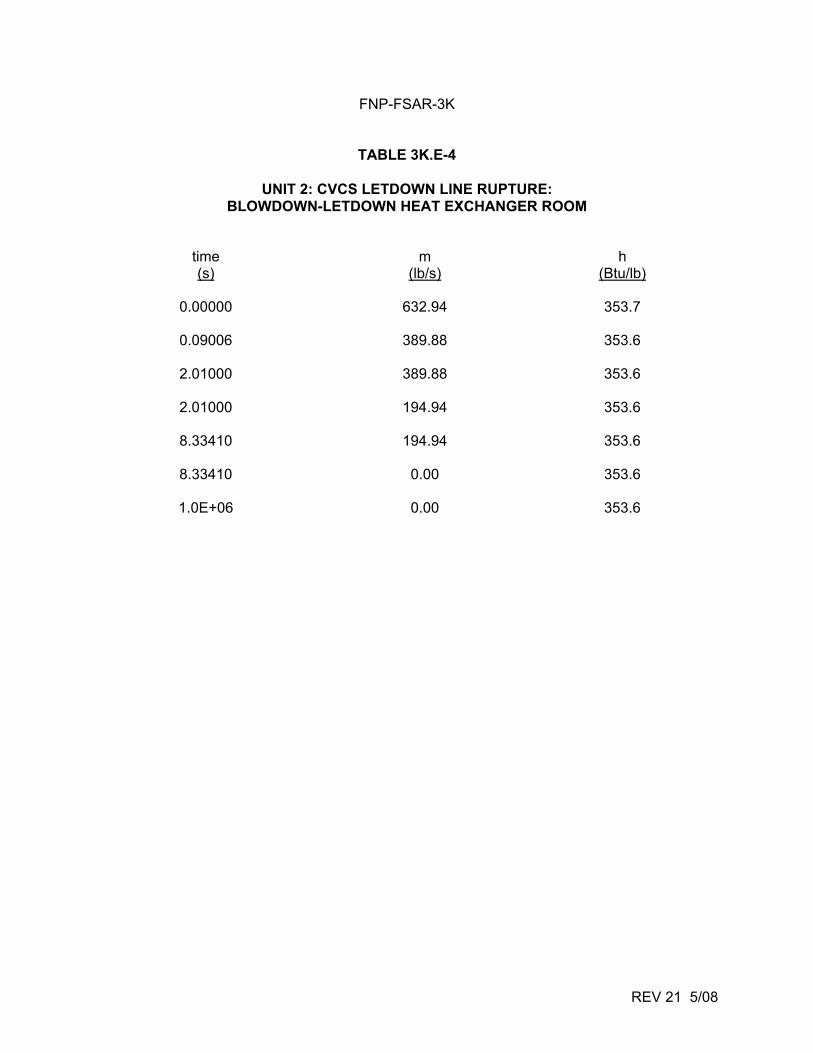
FNP-FSAR-3K
REV 21 5/08
TABLE 3K.E-4
UNIT 2: CVCS LETDOWN LINE RUPTURE: BLOWDOWN-LETDOWN HEAT EXCHANGER ROOM
time m h (s) (lb/s) (Btu/lb)
0.00000 632.94 353.7
0.09006 389.88 353.6
2.01000 389.88 353.6
2.01000 194.94 353.6
8.33410 194.94 353.6
8.33410 0.00 353.6
1.0E+06 0.00 353.6
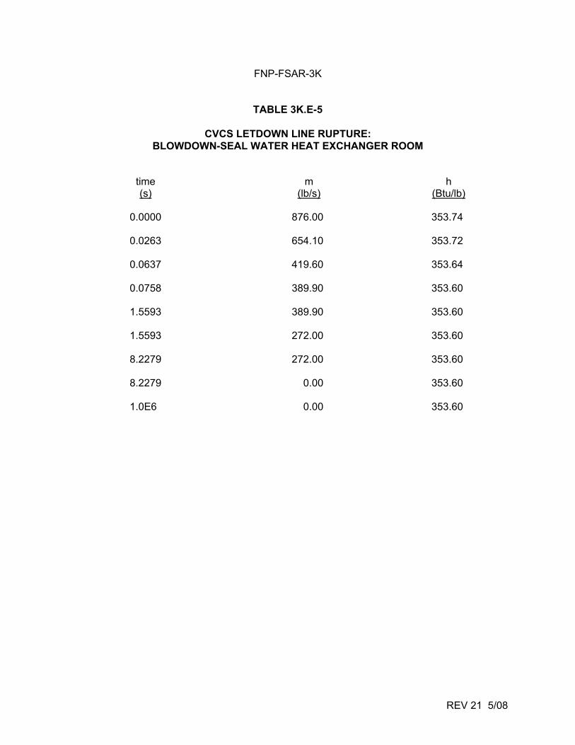
FNP-FSAR-3K
REV 21 5/08
TABLE 3K.E-5
CVCS LETDOWN LINE RUPTURE: BLOWDOWN-SEAL WATER HEAT EXCHANGER ROOM
time m h (s) (lb/s) (Btu/lb)
0.0000 876.00 353.74
0.0263 654.10 353.72
0.0637 419.60 353.64
0.0758 389.90 353.60
1.5593 389.90 353.60
1.5593 272.00 353.60
8.2279 272.00 353.60
8.2279 0.00 353.60
1.0E6 0.00 353.60
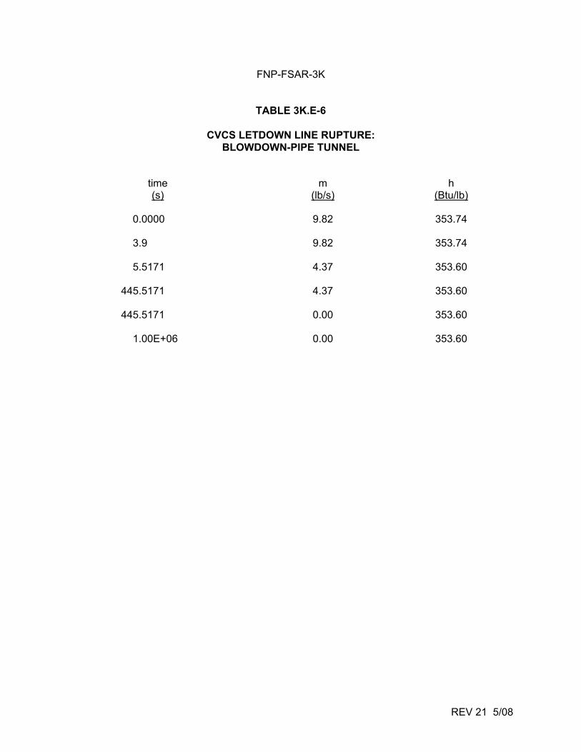
FNP-FSAR-3K
REV 21 5/08
TABLE 3K.E-6
CVCS LETDOWN LINE RUPTURE: BLOWDOWN-PIPE TUNNEL
time m h (s) (lb/s) (Btu/lb)
0.0000 9.82 353.74
3.9 9.82 353.74
5.5171 4.37 353.60
445.5171 4.37 353.60
445.5171 0.00 353.60
1.00E+06 0.00 353.60
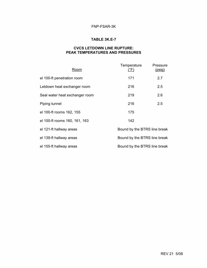
FNP-FSAR-3K
REV 21 5/08
TABLE 3K.E-7
CVCS LETDOWN LINE RUPTURE: PEAK TEMPERATURES AND PRESSURES
Temperature Pressure Room (°F) (psig)
el 100-ft penetration room 171 2.7 Letdown heat exchanger room 216 2.5 Seal water heat exchanger room 219 2.6 Piping tunnel 216 2.5 el 100-ft rooms 162, 155 175 el 100-ft rooms 160, 161, 163 142 el 121-ft hallway areas Bound by the BTRS line break el 139-ft hallway areas Bound by the BTRS line break el 155-ft hallway areas Bound by the BTRS line break
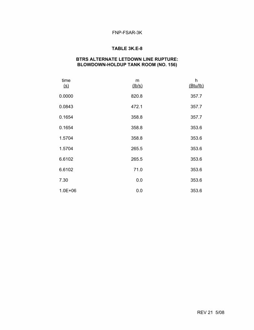
FNP-FSAR-3K
REV 21 5/08
TABLE 3K.E-8
BTRS ALTERNATE LETDOWN LINE RUPTURE: BLOWDOWN-HOLDUP TANK ROOM (NO. 156)
time m h (s) (lb/s) (Btu/lb)
0.0000 820.8 357.7
0.0843 472.1 357.7
0.1654 358.8 357.7
0.1654 358.8 353.6
1.5704 358.8 353.6
1.5704 265.5 353.6
6.6102 265.5 353.6
6.6102 71.0 353.6
7.30 0.0 353.6
1.0E+06 0.0 353.6
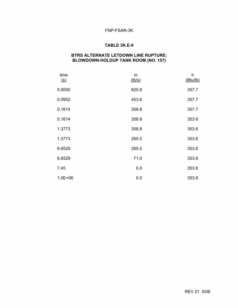
FNP-FSAR-3K
REV 21 5/08
TABLE 3K.E-9
BTRS ALTERNATE LETDOWN LINE RUPTURE: BLOWDOWN-HOLDUP TANK ROOM (NO. 157)
time m h (s) (lb/s) (Btu/lb)
0.0000 820.8 357.7
0.0952 453.6 357.7
0.1614 358.8 357.7
0.1614 358.8 353.6
1.3773 358.8 353.6
1.3773 265.5 353.6
6.6529 265.5 353.6
6.6529 71.0 353.6
7.45 0.0 353.6
1.0E+06 0.0 353.6
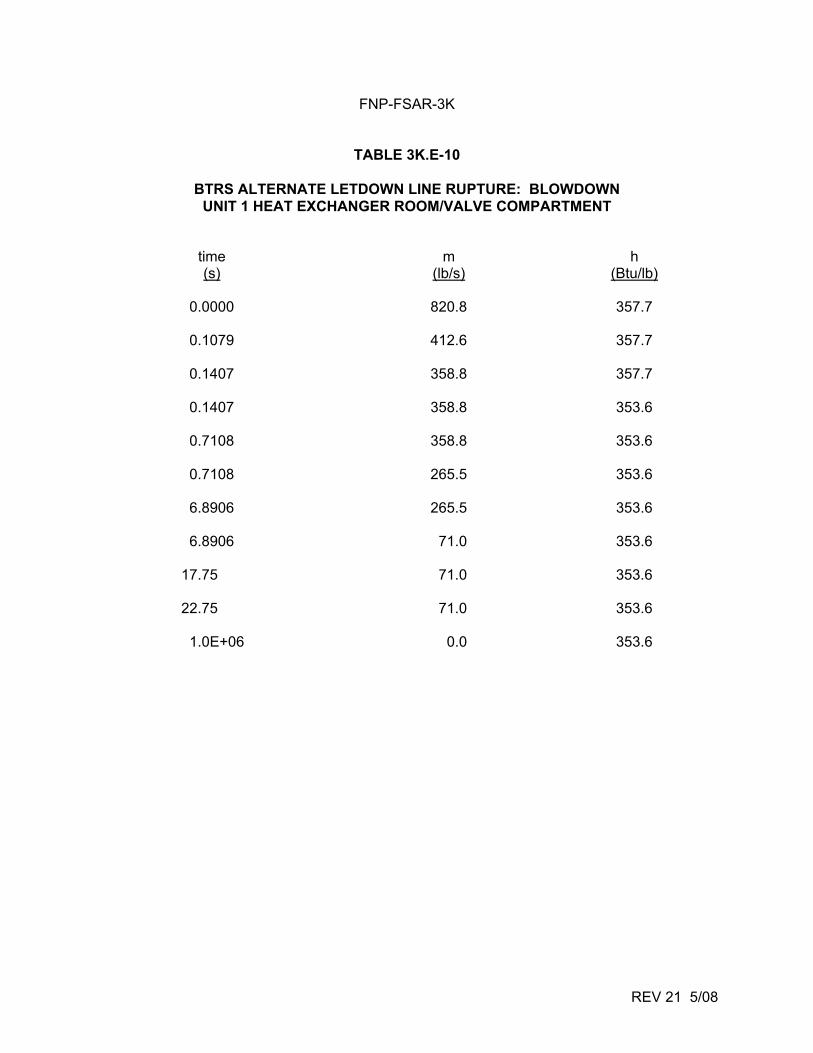
FNP-FSAR-3K
REV 21 5/08
TABLE 3K.E-10
BTRS ALTERNATE LETDOWN LINE RUPTURE: BLOWDOWN UNIT 1 HEAT EXCHANGER ROOM/VALVE COMPARTMENT
time m h (s) (lb/s) (Btu/lb)
0.0000 820.8 357.7
0.1079 412.6 357.7
0.1407 358.8 357.7
0.1407 358.8 353.6
0.7108 358.8 353.6
0.7108 265.5 353.6
6.8906 265.5 353.6
6.8906 71.0 353.6
17.75 71.0 353.6
22.75 71.0 353.6
1.0E+06 0.0 353.6
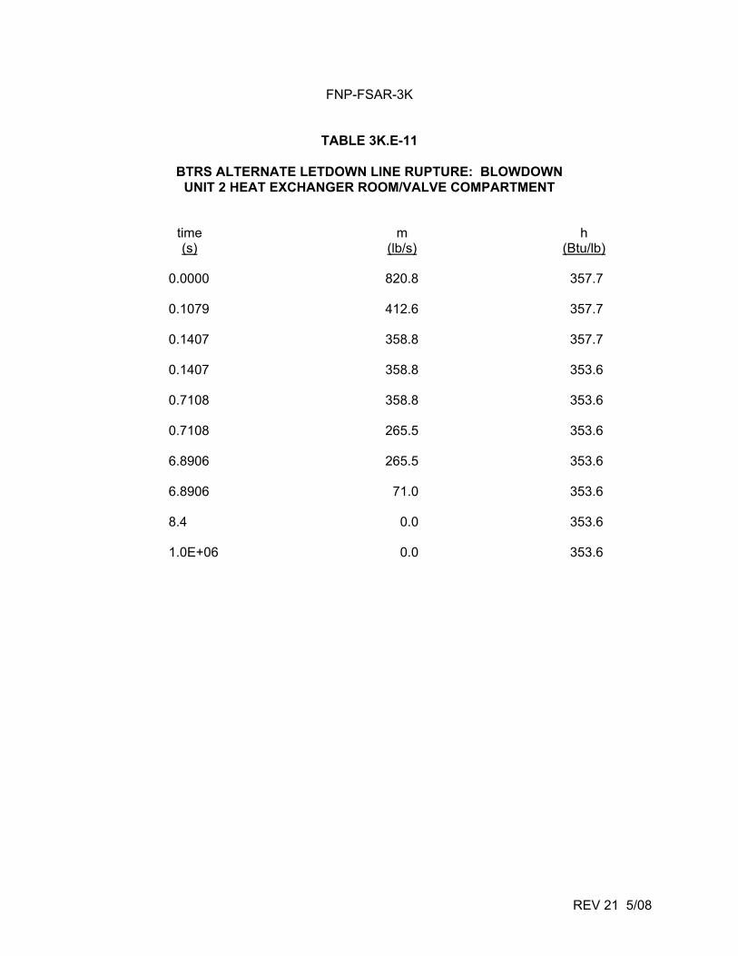
FNP-FSAR-3K
REV 21 5/08
TABLE 3K.E-11
BTRS ALTERNATE LETDOWN LINE RUPTURE: BLOWDOWN UNIT 2 HEAT EXCHANGER ROOM/VALVE COMPARTMENT
time m h (s) (lb/s) (Btu/lb)
0.0000 820.8 357.7
0.1079 412.6 357.7
0.1407 358.8 357.7
0.1407 358.8 353.6
0.7108 358.8 353.6
0.7108 265.5 353.6
6.8906 265.5 353.6
6.8906 71.0 353.6
8.4 0.0 353.6
1.0E+06 0.0 353.6
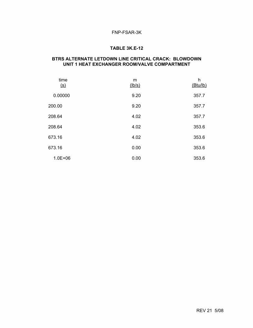
FNP-FSAR-3K
REV 21 5/08
TABLE 3K.E-12
BTRS ALTERNATE LETDOWN LINE CRITICAL CRACK: BLOWDOWN UNIT 1 HEAT EXCHANGER ROOM/VALVE COMPARTMENT
time m h (s) (lb/s) (Btu/lb)
0.00000 9.20 357.7
200.00 9.20 357.7
208.64 4.02 357.7
208.64 4.02 353.6
673.16 4.02 353.6
673.16 0.00 353.6
1.0E+06 0.00 353.6
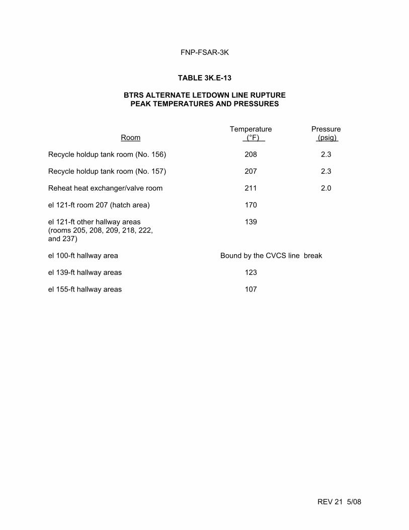
FNP-FSAR-3K
REV 21 5/08
TABLE 3K.E-13
BTRS ALTERNATE LETDOWN LINE RUPTURE PEAK TEMPERATURES AND PRESSURES
Temperature Pressure Room (°F) (psig)
Recycle holdup tank room (No. 156) 208 2.3 Recycle holdup tank room (No. 157) 207 2.3 Reheat heat exchanger/valve room 211 2.0 el 121-ft room 207 (hatch area) 170 el 121-ft other hallway areas 139 (rooms 205, 208, 209, 218, 222, and 237) el 100-ft hallway area Bound by the CVCS line break el 139-ft hallway areas 123 el 155-ft hallway areas 107
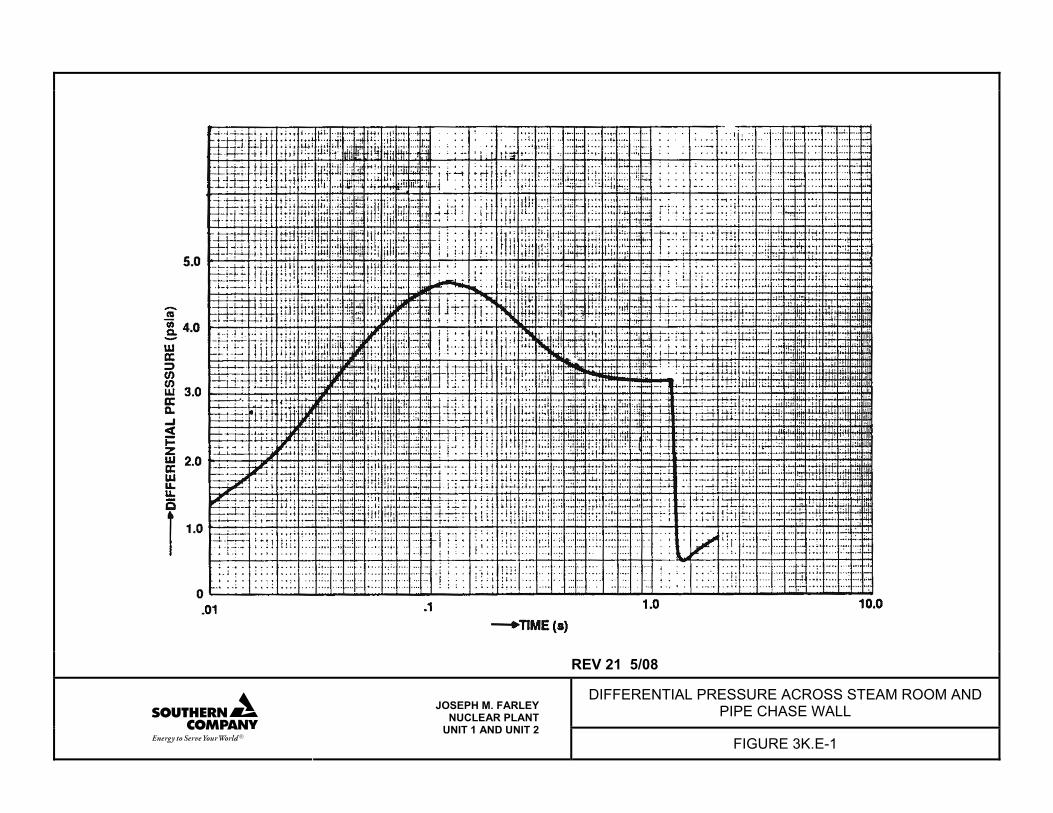
REV 21 5/08
DIFFERENTIAL PRESSURE ACROSS STEAM ROOM AND PIPE CHASE WALL
JOSEPH M. FARLEY NUCLEAR PLANT
UNIT 1 AND UNIT 2 FIGURE 3K.E-1
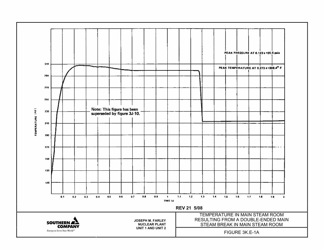
REV 21 5/08
TEMPERATURE IN MAIN STEAM ROOM RESULTING FROM A DOUBLE-ENDED MAIN
STEAM BREAK IN MAIN STEAM ROOM
JOSEPH M. FARLEY NUCLEAR PLANT
UNIT 1 AND UNIT 2 FIGURE 3K.E-1A
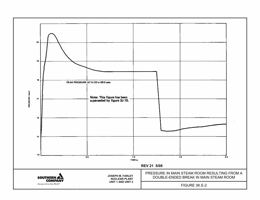
REV 21 5/08
PRESSURE IN MAIN STEAM ROOM RESULTING FROM A DOUBLE-ENDED BREAK IN MAIN STEAM ROOM
JOSEPH M. FARLEY NUCLEAR PLANT
UNIT 1 AND UNIT 2 FIGURE 3K.E-2
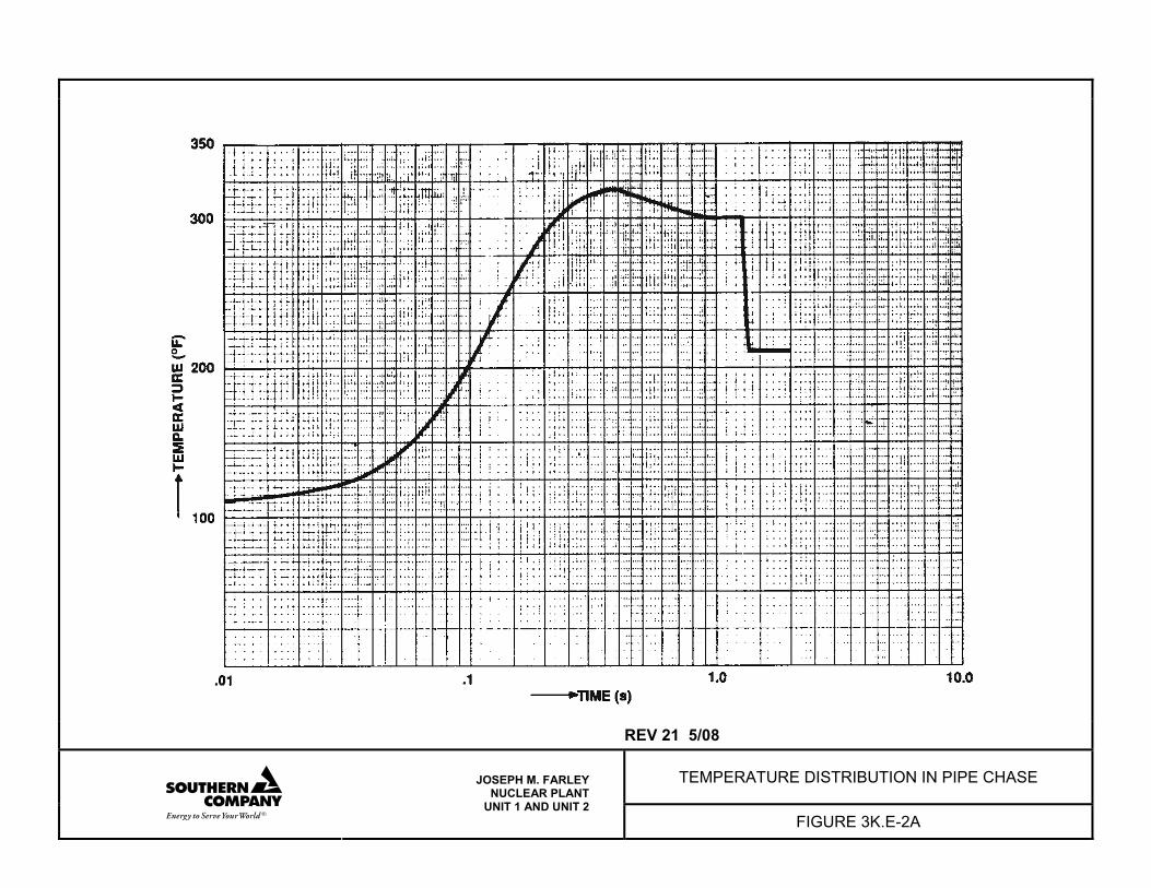
REV 21 5/08
TEMPERATURE DISTRIBUTION IN PIPE CHASE
JOSEPH M. FARLEY NUCLEAR PLANT
UNIT 1 AND UNIT 2 FIGURE 3K.E-2A
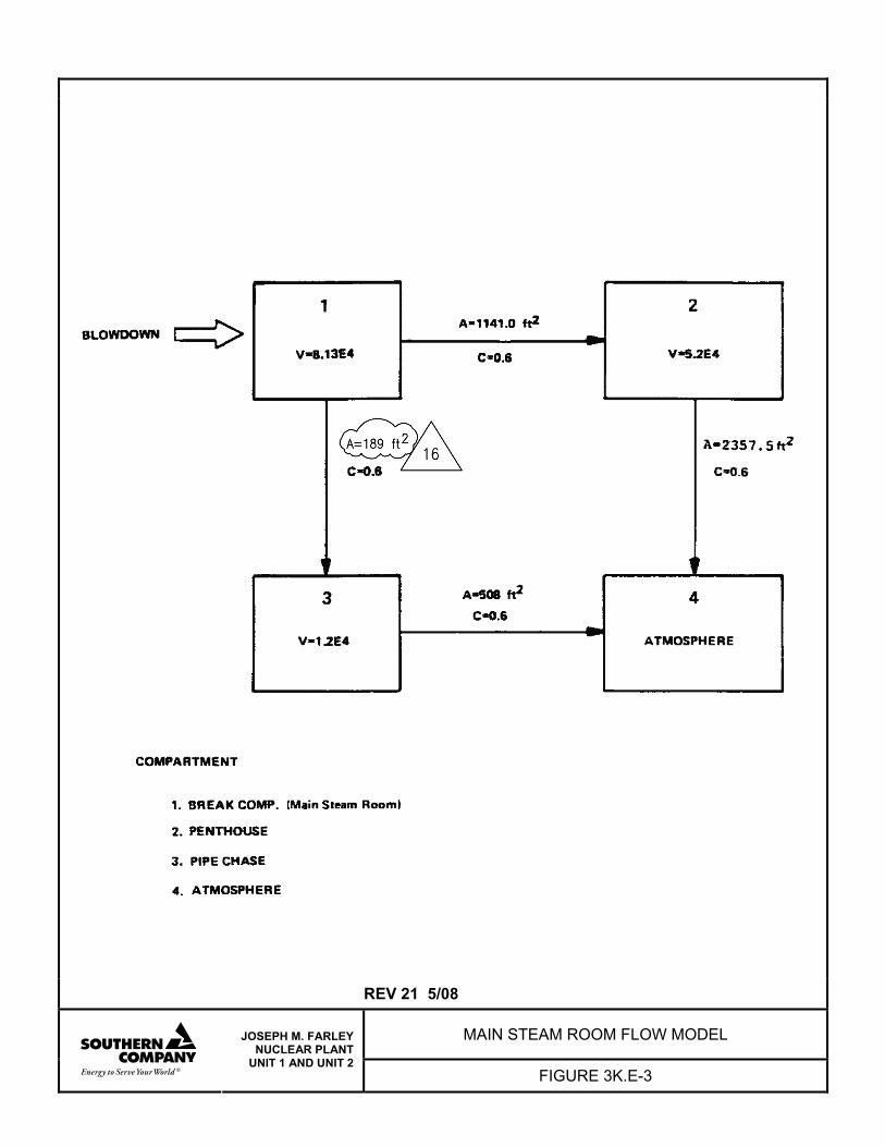
REV 21 5/08
MAIN STEAM ROOM FLOW MODEL
JOSEPH M. FARLEY NUCLEAR PLANT
UNIT 1 AND UNIT 2 FIGURE 3K.E-3
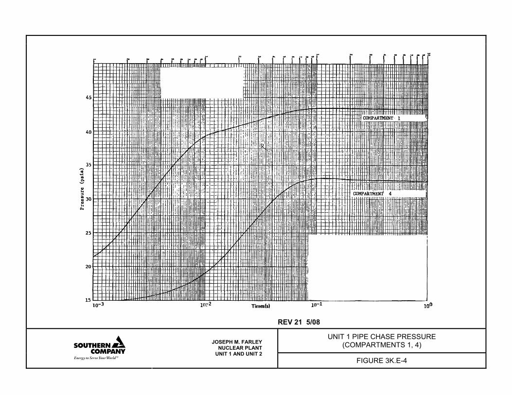
REV 21 5/08
UNIT 1 PIPE CHASE PRESSURE (COMPARTMENTS 1, 4)
JOSEPH M. FARLEY NUCLEAR PLANT
UNIT 1 AND UNIT 2 FIGURE 3K.E-4
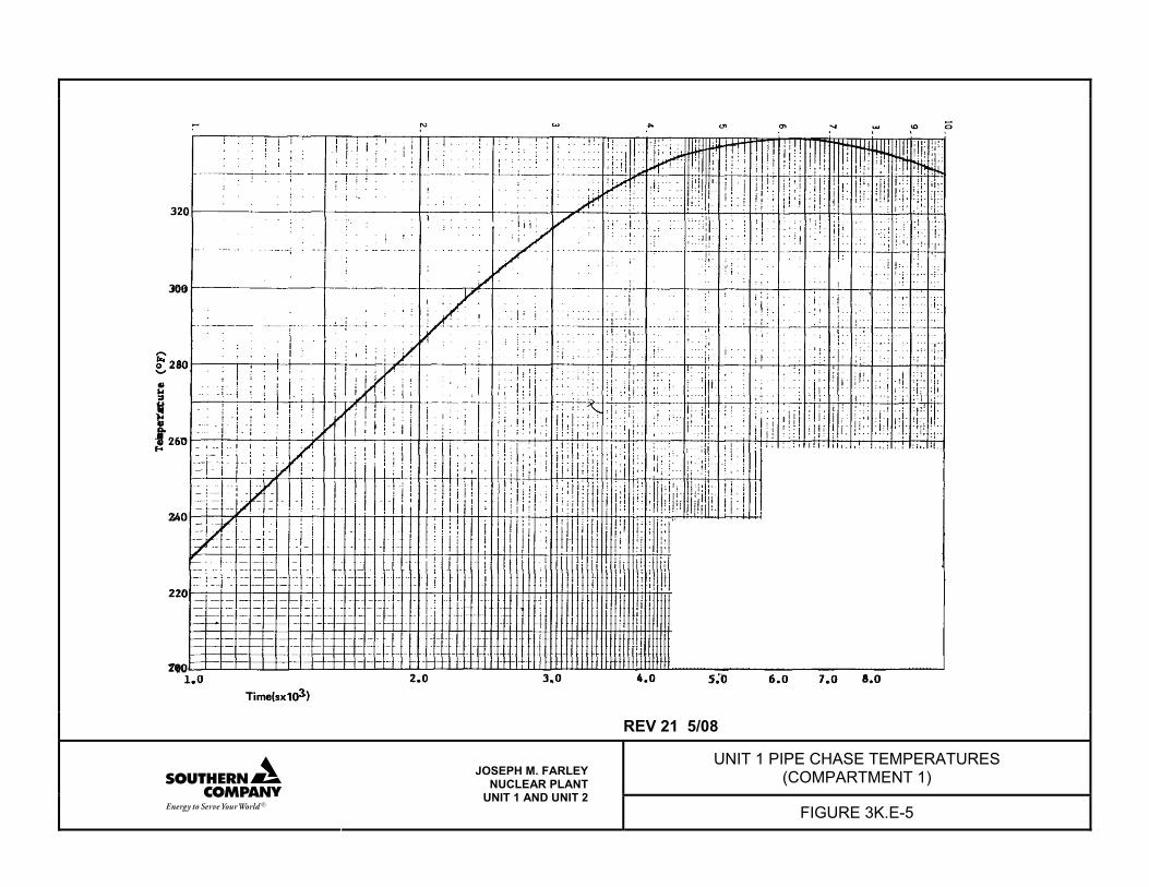
REV 21 5/08
UNIT 1 PIPE CHASE TEMPERATURES (COMPARTMENT 1)
JOSEPH M. FARLEY NUCLEAR PLANT
UNIT 1 AND UNIT 2 FIGURE 3K.E-5
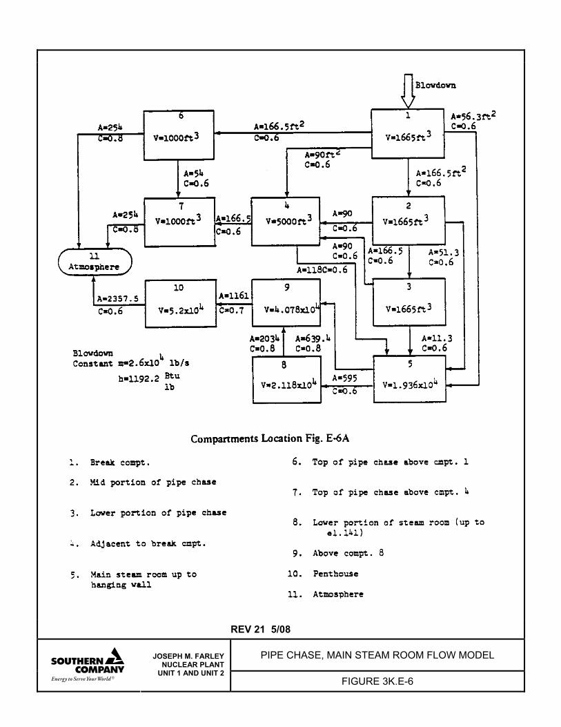
REV 21 5/08
PIPE CHASE, MAIN STEAM ROOM FLOW MODEL
JOSEPH M. FARLEY NUCLEAR PLANT
UNIT 1 AND UNIT 2 FIGURE 3K.E-6
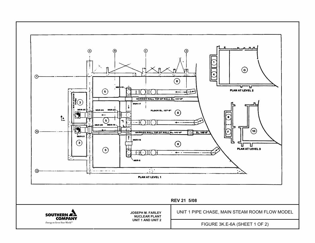
REV 21 5/08
UNIT 1 PIPE CHASE, MAIN STEAM ROOM FLOW MODEL
JOSEPH M. FARLEY NUCLEAR PLANT
UNIT 1 AND UNIT 2 FIGURE 3K.E-6A (SHEET 1 OF 2)
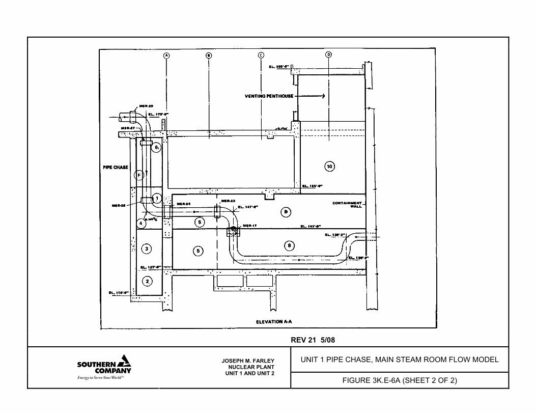
REV 21 5/08
UNIT 1 PIPE CHASE, MAIN STEAM ROOM FLOW MODEL
JOSEPH M. FARLEY NUCLEAR PLANT
UNIT 1 AND UNIT 2 FIGURE 3K.E-6A (SHEET 2 OF 2)
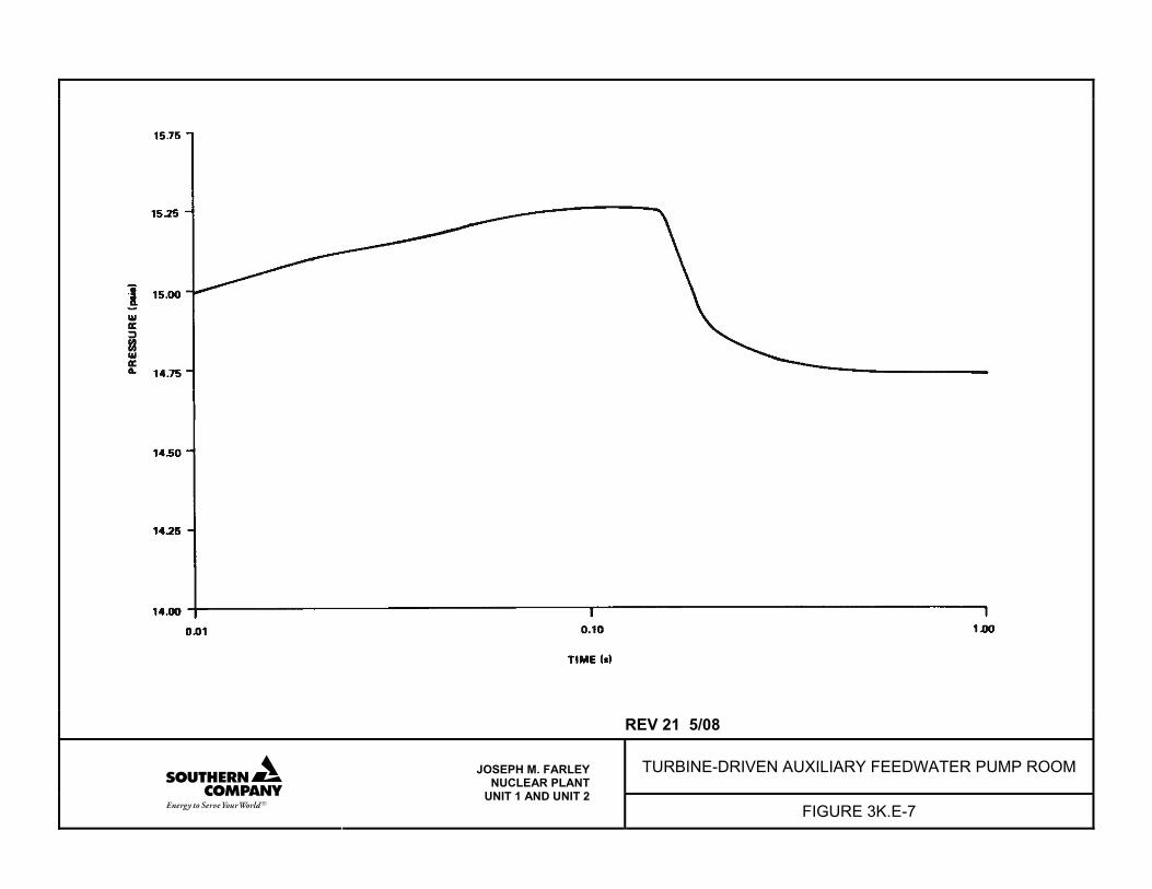
REV 21 5/08
TURBINE-DRIVEN AUXILIARY FEEDWATER PUMP ROOM
JOSEPH M. FARLEY NUCLEAR PLANT
UNIT 1 AND UNIT 2 FIGURE 3K.E-7
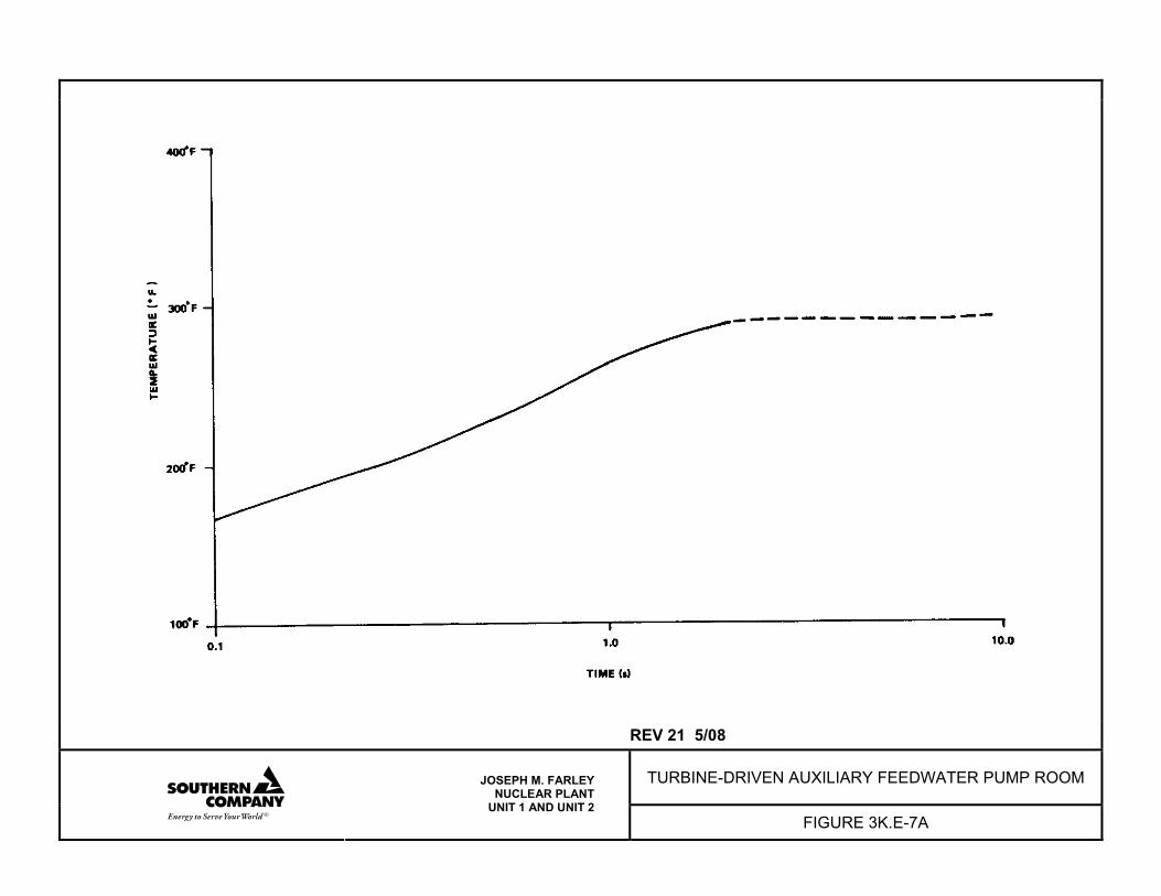
REV 21 5/08
TURBINE-DRIVEN AUXILIARY FEEDWATER PUMP ROOM
JOSEPH M. FARLEY NUCLEAR PLANT
UNIT 1 AND UNIT 2 FIGURE 3K.E-7A
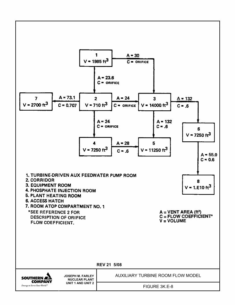
REV 21 5/08
AUXILIARY TURBINE ROOM FLOW MODEL
JOSEPH M. FARLEY NUCLEAR PLANT
UNIT 1 AND UNIT 2 FIGURE 3K.E-8
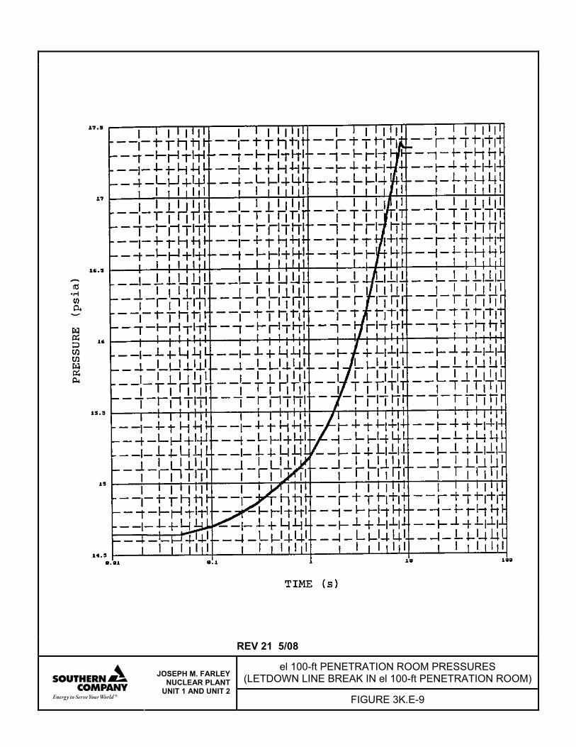
REV 21 5/08
el 100-ft PENETRATION ROOM PRESSURES (LETDOWN LINE BREAK IN el 100-ft PENETRATION ROOM)
JOSEPH M. FARLEY NUCLEAR PLANT
UNIT 1 AND UNIT 2 FIGURE 3K.E-9
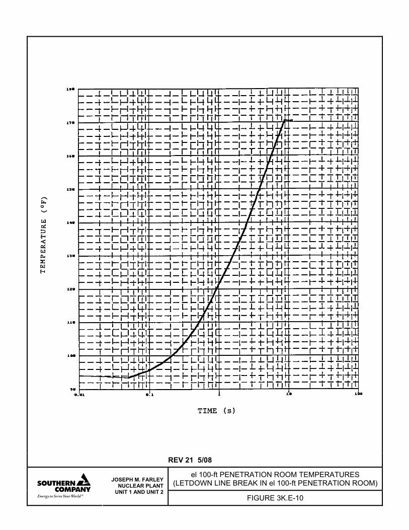
REV 21 5/08
el 100-ft PENETRATION ROOM TEMPERATURES (LETDOWN LINE BREAK IN el 100-ft PENETRATION ROOM)
JOSEPH M. FARLEY NUCLEAR PLANT
UNIT 1 AND UNIT 2 FIGURE 3K.E-10
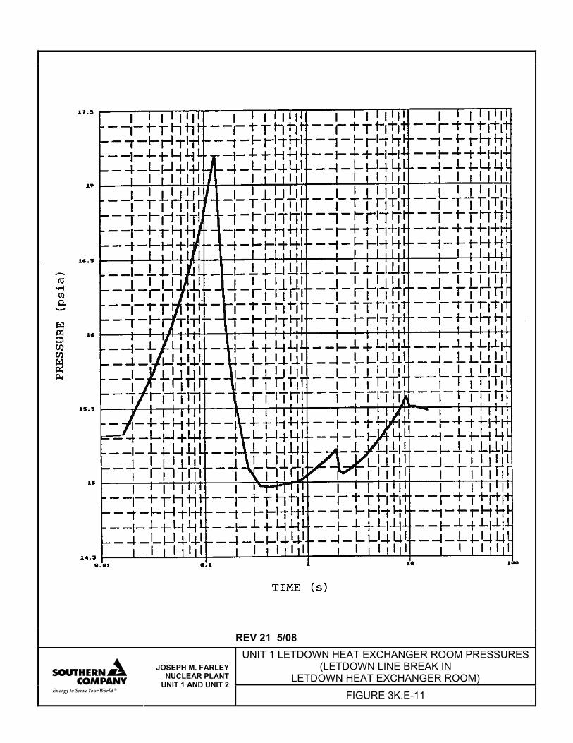
REV 21 5/08
UNIT 1 LETDOWN HEAT EXCHANGER ROOM PRESSURES (LETDOWN LINE BREAK IN
LETDOWN HEAT EXCHANGER ROOM)
JOSEPH M. FARLEY NUCLEAR PLANT
UNIT 1 AND UNIT 2 FIGURE 3K.E-11
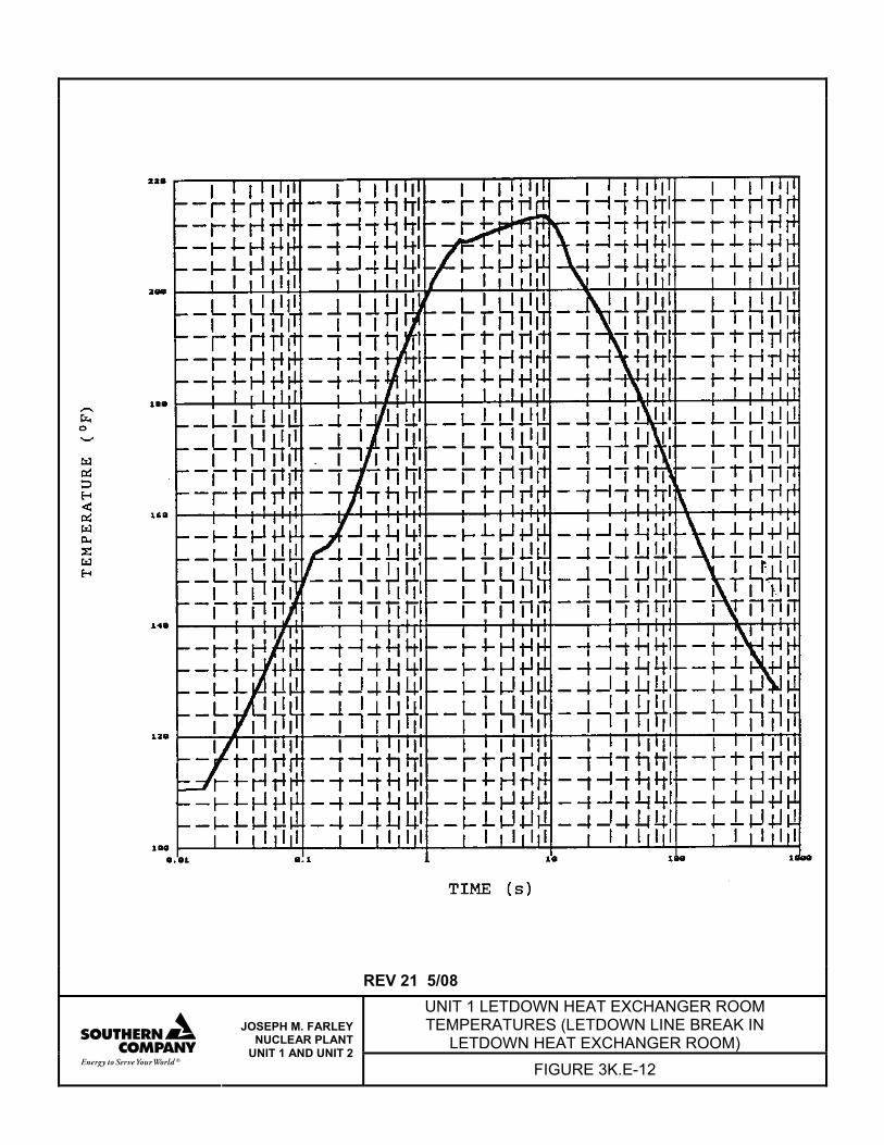
REV 21 5/08 UNIT 1 LETDOWN HEAT EXCHANGER ROOM TEMPERATURES (LETDOWN LINE BREAK IN
LETDOWN HEAT EXCHANGER ROOM)
JOSEPH M. FARLEY NUCLEAR PLANT
UNIT 1 AND UNIT 2 FIGURE 3K.E-12
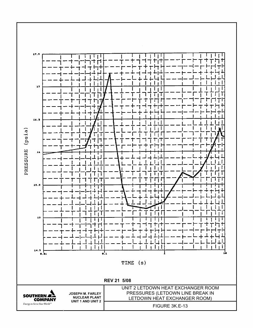
REV 21 5/08
UNIT 2 LETDOWN HEAT EXCHANGER ROOM PRESSURES (LETDOWN LINE BREAK IN LETDOWN HEAT EXCHANGER ROOM)
JOSEPH M. FARLEY NUCLEAR PLANT
UNIT 1 AND UNIT 2 FIGURE 3K.E-13
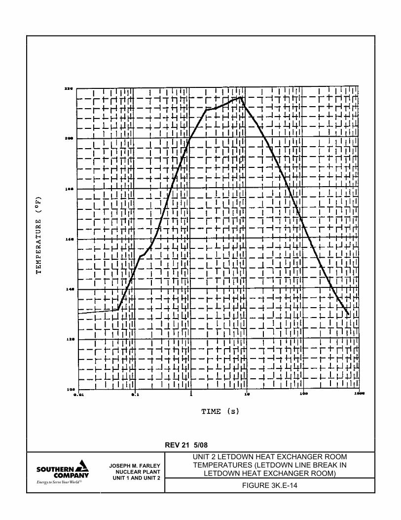
REV 21 5/08 UNIT 2 LETDOWN HEAT EXCHANGER ROOM TEMPERATURES (LETDOWN LINE BREAK IN
LETDOWN HEAT EXCHANGER ROOM)
JOSEPH M. FARLEY NUCLEAR PLANT
UNIT 1 AND UNIT 2 FIGURE 3K.E-14
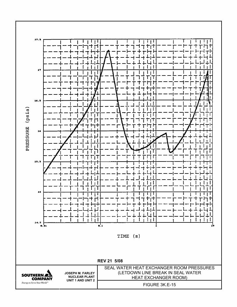
REV 21 5/08 SEAL WATER HEAT EXCHANGER ROOM PRESSURES
(LETDOWN LINE BREAK IN SEAL WATER HEAT EXCHANGER ROOM)
JOSEPH M. FARLEY NUCLEAR PLANT
UNIT 1 AND UNIT 2 FIGURE 3K.E-15
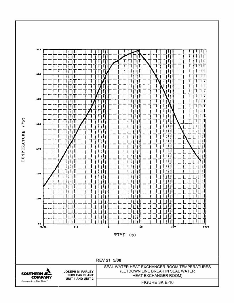
REV 21 5/08 SEAL WATER HEAT EXCHANGER ROOM TEMPERATURES
(LETDOWN LINE BREAK IN SEAL WATER HEAT EXCHANGER ROOM)
JOSEPH M. FARLEY NUCLEAR PLANT
UNIT 1 AND UNIT 2 FIGURE 3K.E-16

REV 21 5/08
PIPING TUNNEL PRESSURES (LETDOWN LINE CRITICAL CRACK IN PIPING TUNNEL)
JOSEPH M. FARLEY NUCLEAR PLANT
UNIT 1 AND UNIT 2 FIGURE 3K.E-17
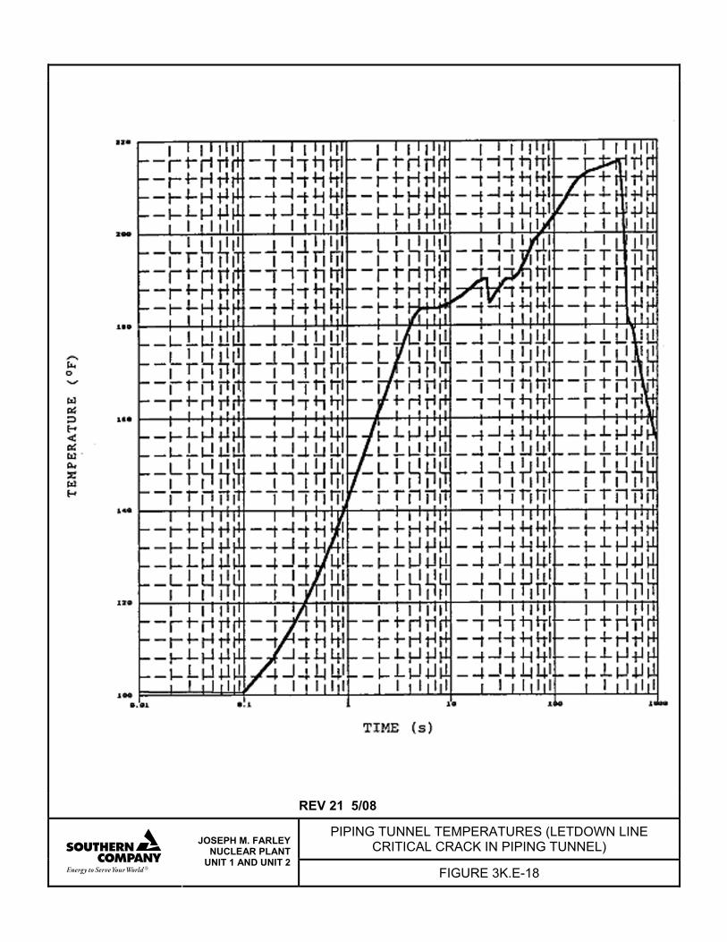
REV 21 5/08
PIPING TUNNEL TEMPERATURES (LETDOWN LINE CRITICAL CRACK IN PIPING TUNNEL)
JOSEPH M. FARLEY NUCLEAR PLANT
UNIT 1 AND UNIT 2 FIGURE 3K.E-18
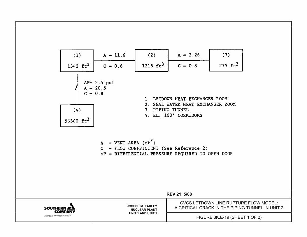
REV 21 5/08
CVCS LETDOWN LINE RUPTURE FLOW MODEL: A CRITICAL CRACK IN THE PIPING TUNNEL IN UNIT 2
JOSEPH M. FARLEY NUCLEAR PLANT
UNIT 1 AND UNIT 2 FIGURE 3K.E-19 (SHEET 1 OF 2)
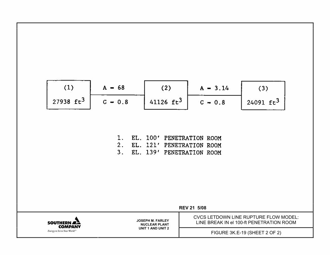
REV 21 5/08
CVCS LETDOWN LINE RUPTURE FLOW MODEL: LINE BREAK IN el 100-ft PENETRATION ROOM
JOSEPH M. FARLEY NUCLEAR PLANT
UNIT 1 AND UNIT 2 FIGURE 3K.E-19 (SHEET 2 OF 2)
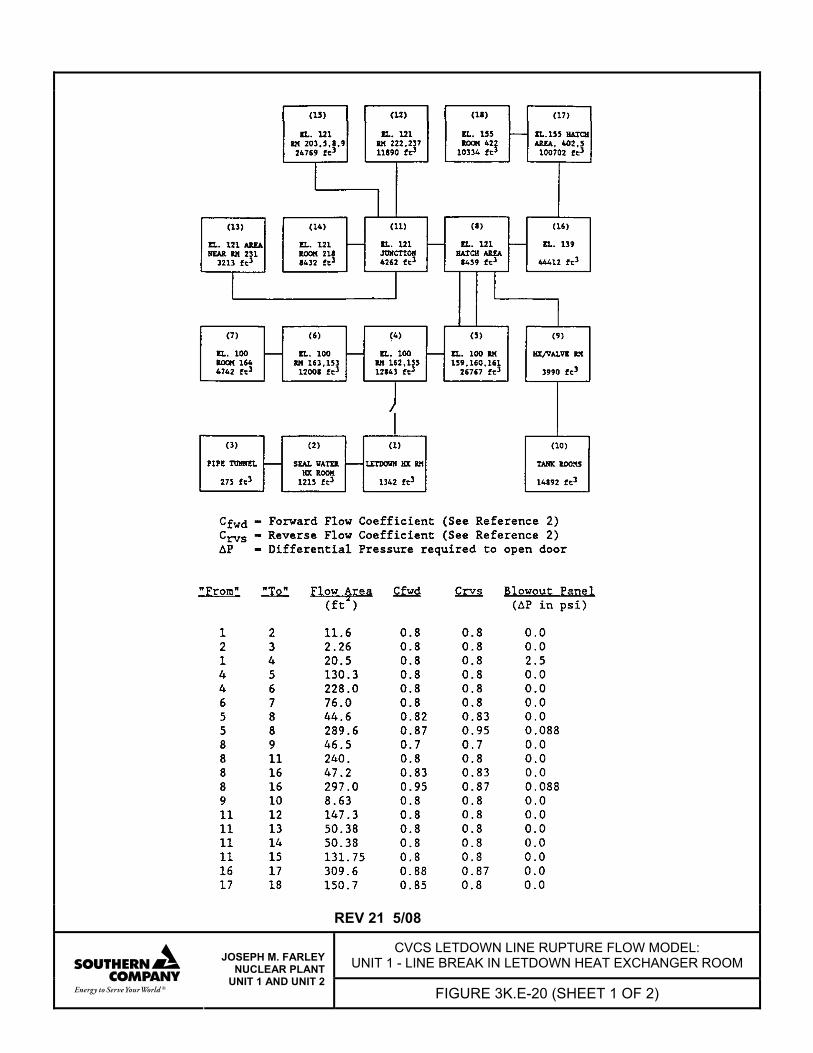
REV 21 5/08
CVCS LETDOWN LINE RUPTURE FLOW MODEL: UNIT 1 - LINE BREAK IN LETDOWN HEAT EXCHANGER ROOM
JOSEPH M. FARLEY NUCLEAR PLANT
UNIT 1 AND UNIT 2 FIGURE 3K.E-20 (SHEET 1 OF 2)
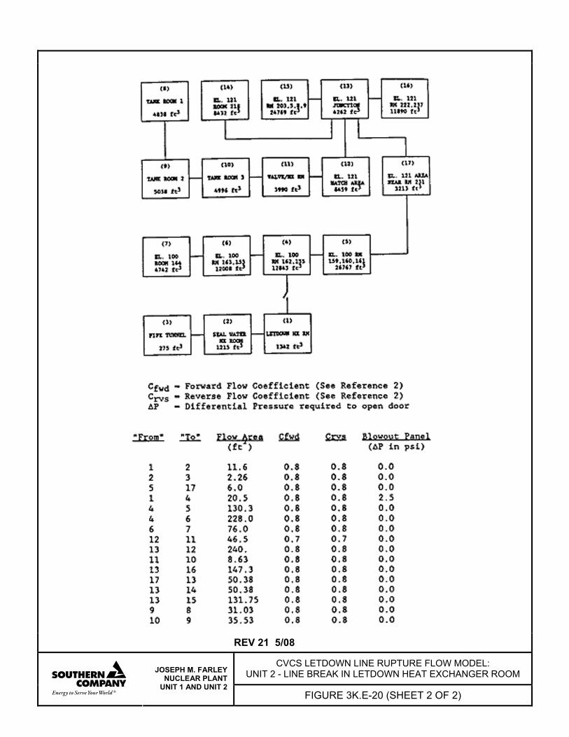
REV 21 5/08
CVCS LETDOWN LINE RUPTURE FLOW MODEL: UNIT 2 - LINE BREAK IN LETDOWN HEAT EXCHANGER ROOM
JOSEPH M. FARLEY NUCLEAR PLANT
UNIT 1 AND UNIT 2 FIGURE 3K.E-20 (SHEET 2 OF 2)
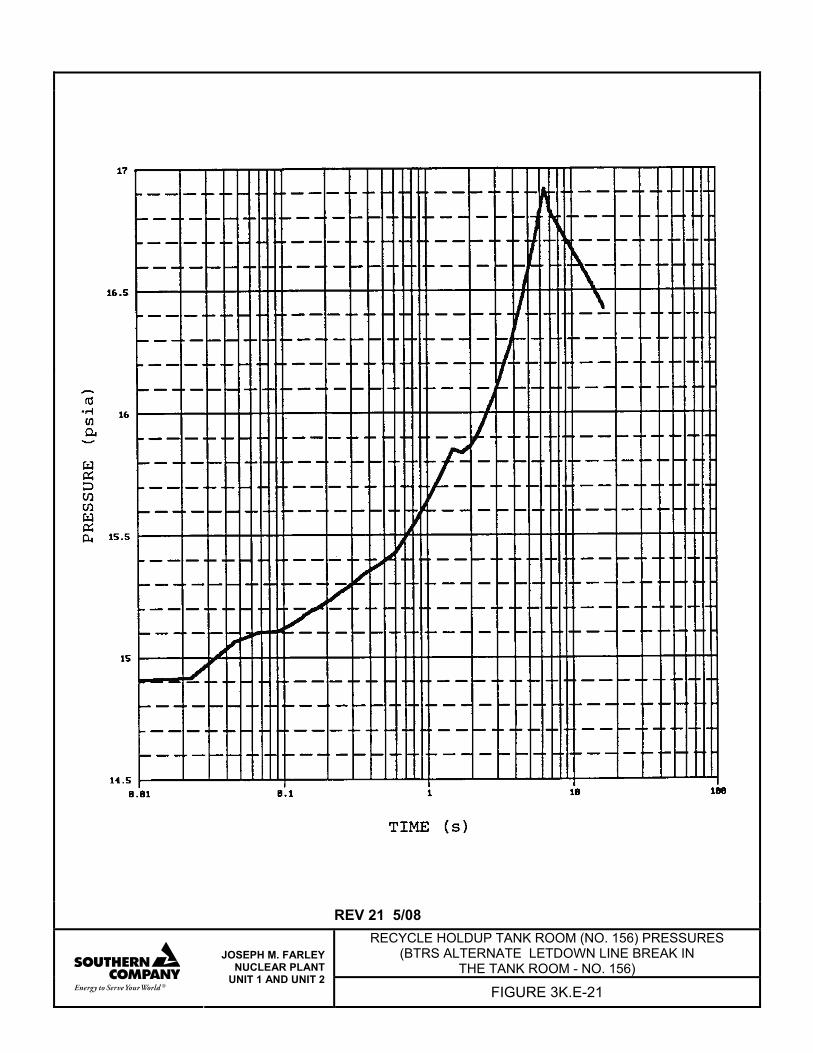
REV 21 5/08 RECYCLE HOLDUP TANK ROOM (NO. 156) PRESSURES
(BTRS ALTERNATE LETDOWN LINE BREAK IN THE TANK ROOM - NO. 156)
JOSEPH M. FARLEY NUCLEAR PLANT
UNIT 1 AND UNIT 2 FIGURE 3K.E-21
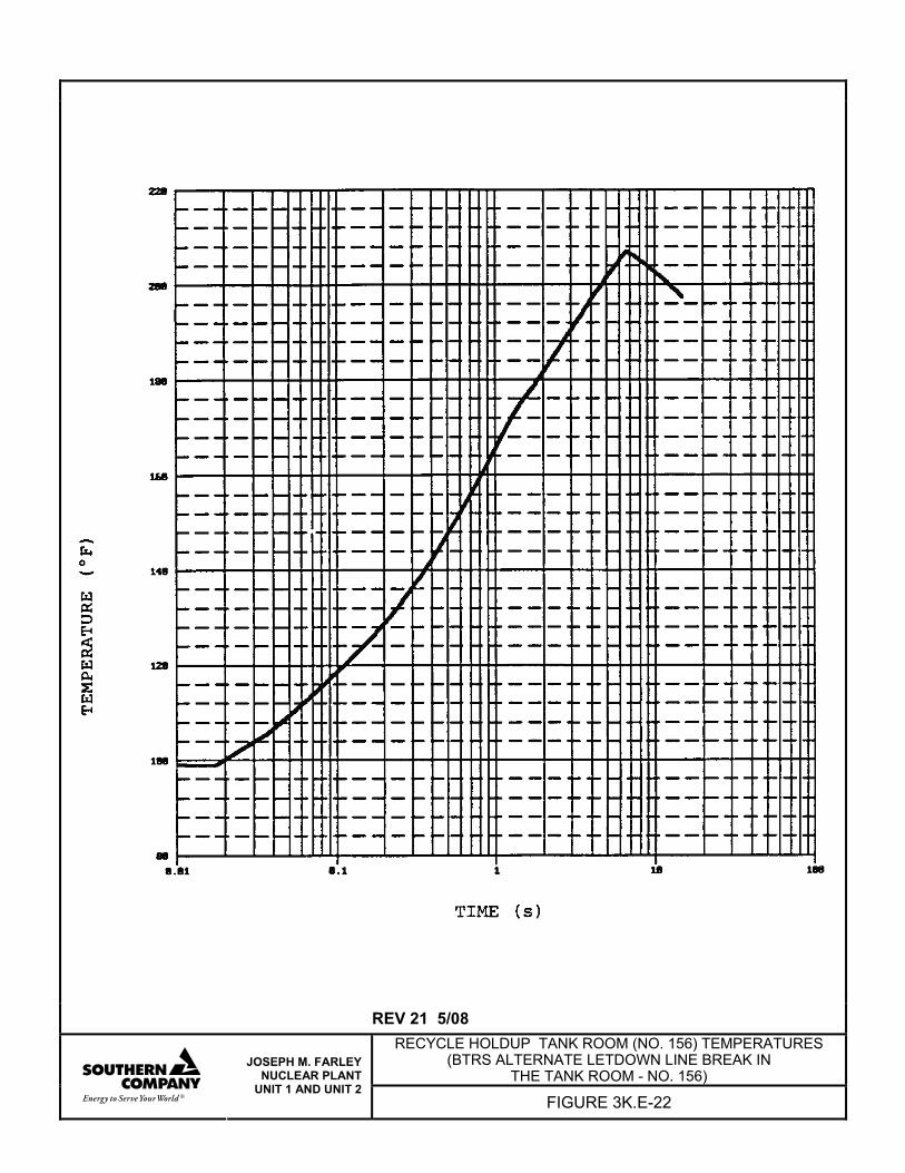
REV 21 5/08 RECYCLE HOLDUP TANK ROOM (NO. 156) TEMPERATURES
(BTRS ALTERNATE LETDOWN LINE BREAK IN THE TANK ROOM - NO. 156)
JOSEPH M. FARLEY NUCLEAR PLANT
UNIT 1 AND UNIT 2 FIGURE 3K.E-22
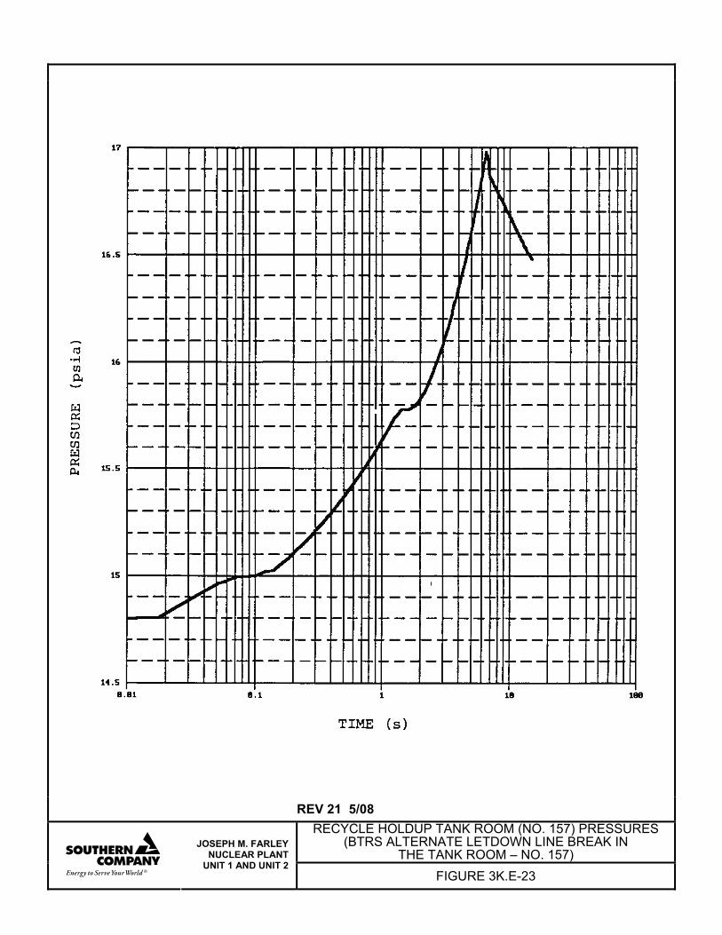
REV 21 5/08 RECYCLE HOLDUP TANK ROOM (NO. 157) PRESSURES
(BTRS ALTERNATE LETDOWN LINE BREAK IN THE TANK ROOM – NO. 157)
JOSEPH M. FARLEY NUCLEAR PLANT
UNIT 1 AND UNIT 2 FIGURE 3K.E-23
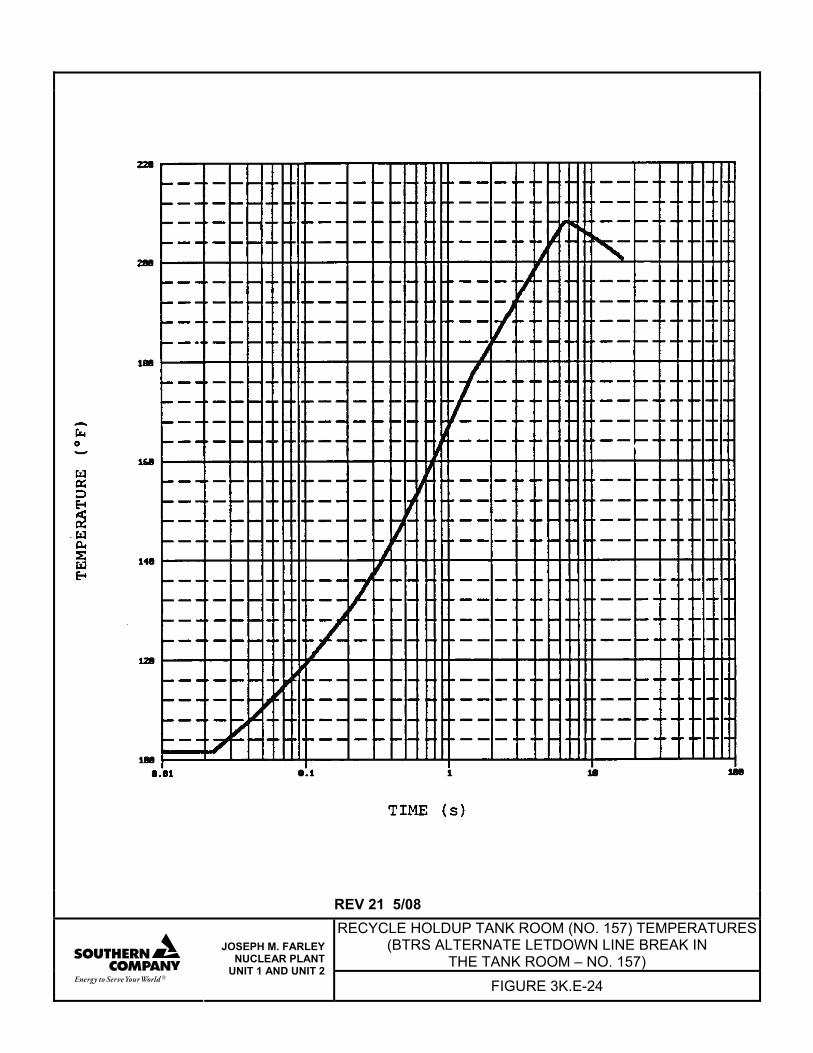
REV 21 5/08 RECYCLE HOLDUP TANK ROOM (NO. 157) TEMPERATURES
(BTRS ALTERNATE LETDOWN LINE BREAK IN THE TANK ROOM – NO. 157)
JOSEPH M. FARLEY NUCLEAR PLANT
UNIT 1 AND UNIT 2 FIGURE 3K.E-24
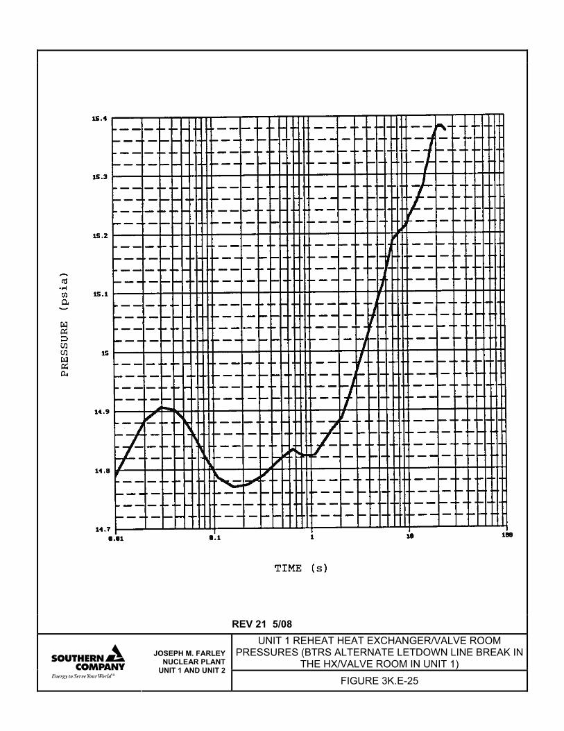
REV 21 5/08
UNIT 1 REHEAT HEAT EXCHANGER/VALVE ROOM PRESSURES (BTRS ALTERNATE LETDOWN LINE BREAK IN
THE HX/VALVE ROOM IN UNIT 1)
JOSEPH M. FARLEY NUCLEAR PLANT
UNIT 1 AND UNIT 2 FIGURE 3K.E-25
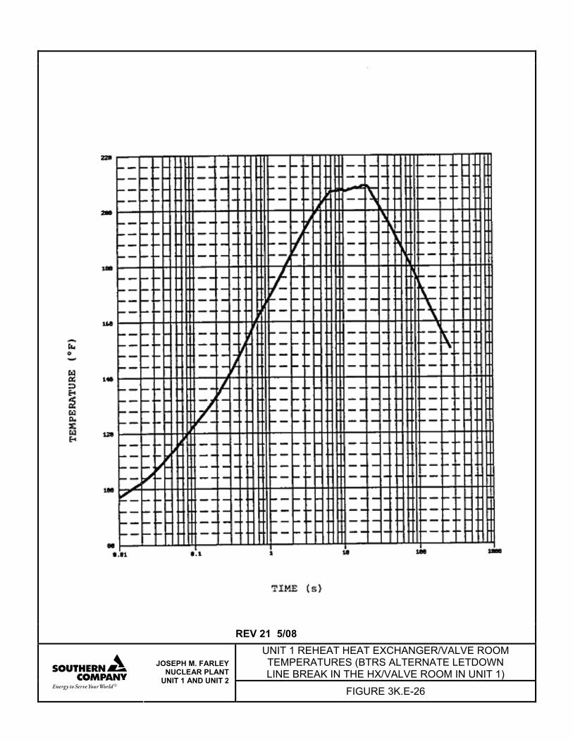
REV 21 5/08
UNIT 1 REHEAT HEAT EXCHANGER/VALVE ROOM TEMPERATURES (BTRS ALTERNATE LETDOWN LINE BREAK IN THE HX/VALVE ROOM IN UNIT 1)
JOSEPH M. FARLEY NUCLEAR PLANT
UNIT 1 AND UNIT 2 FIGURE 3K.E-26
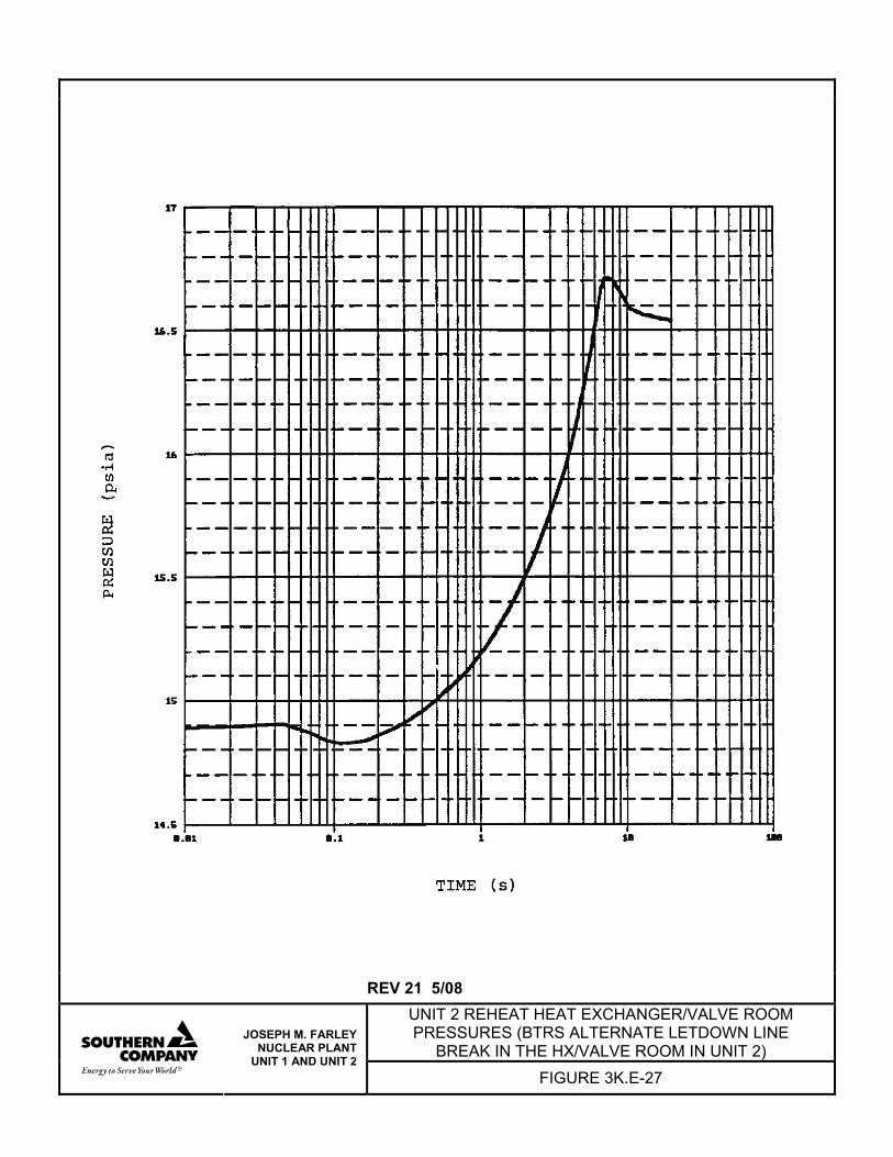
REV 21 5/08
UNIT 2 REHEAT HEAT EXCHANGER/VALVE ROOM PRESSURES (BTRS ALTERNATE LETDOWN LINE
BREAK IN THE HX/VALVE ROOM IN UNIT 2)
JOSEPH M. FARLEY NUCLEAR PLANT
UNIT 1 AND UNIT 2 FIGURE 3K.E-27
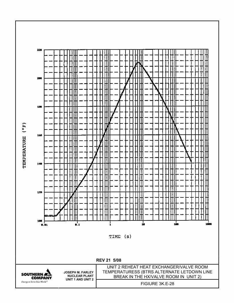
REV 21 5/08 UNIT 2 REHEAT HEAT EXCHANGER/VALVE ROOM
TEMPERATURESS (BTRS ALTERNATE LETDOWN LINE BREAK IN THE HX/VALVE ROOM IN UNIT 2)
JOSEPH M. FARLEY NUCLEAR PLANT
UNIT 1 AND UNIT 2 FIGIURE 3K.E-28
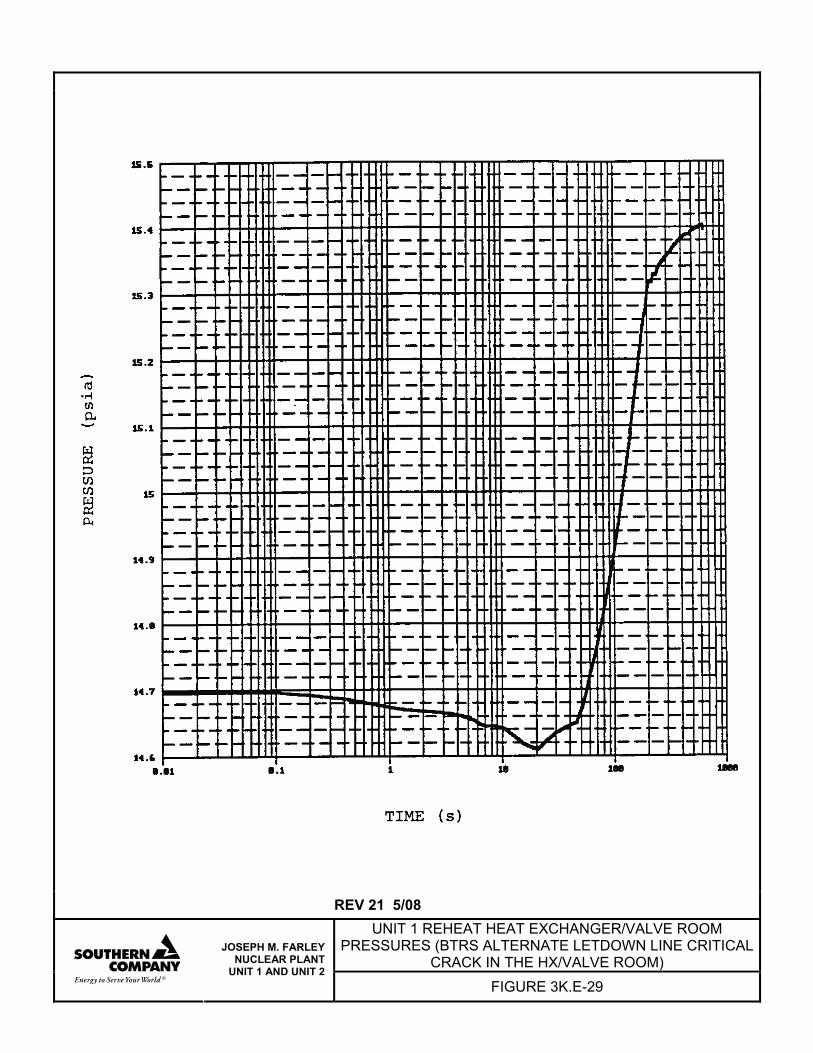
REV 21 5/08 UNIT 1 REHEAT HEAT EXCHANGER/VALVE ROOM
PRESSURES (BTRS ALTERNATE LETDOWN LINE CRITICAL CRACK IN THE HX/VALVE ROOM)
JOSEPH M. FARLEY NUCLEAR PLANT
UNIT 1 AND UNIT 2 FIGURE 3K.E-29
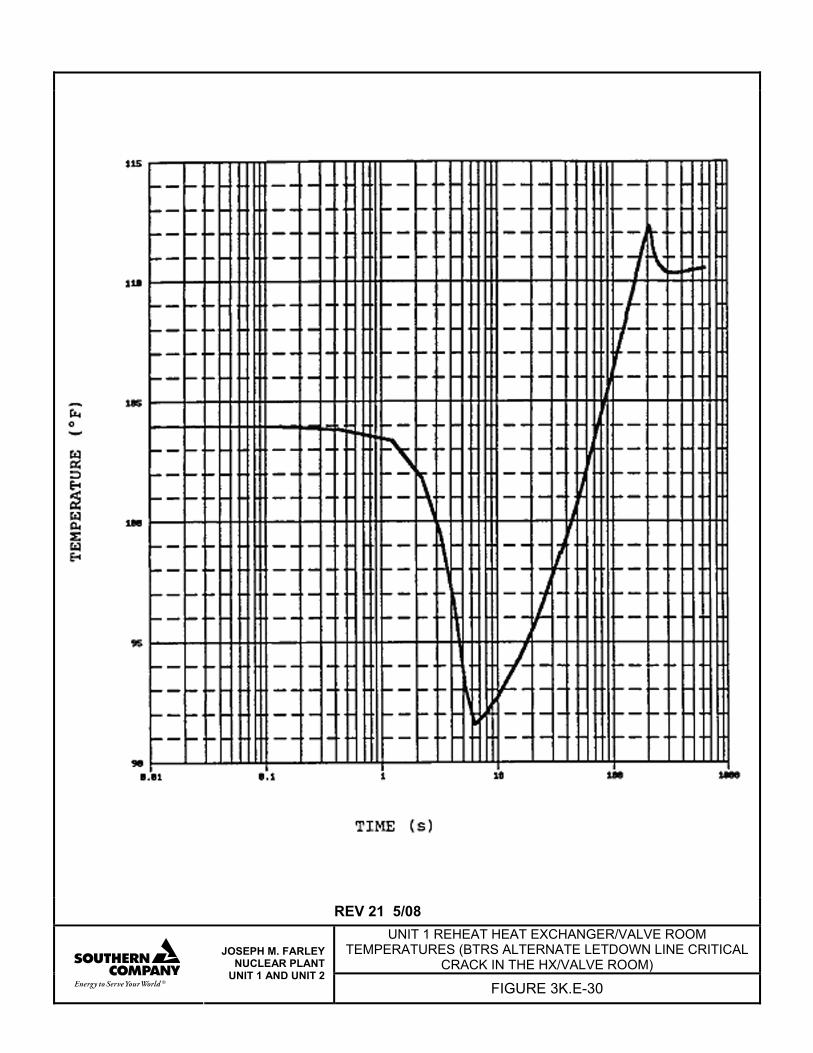
REV 21 5/08 UNIT 1 REHEAT HEAT EXCHANGER/VALVE ROOM
TEMPERATURES (BTRS ALTERNATE LETDOWN LINE CRITICAL CRACK IN THE HX/VALVE ROOM)
JOSEPH M. FARLEY NUCLEAR PLANT
UNIT 1 AND UNIT 2 FIGURE 3K.E-30
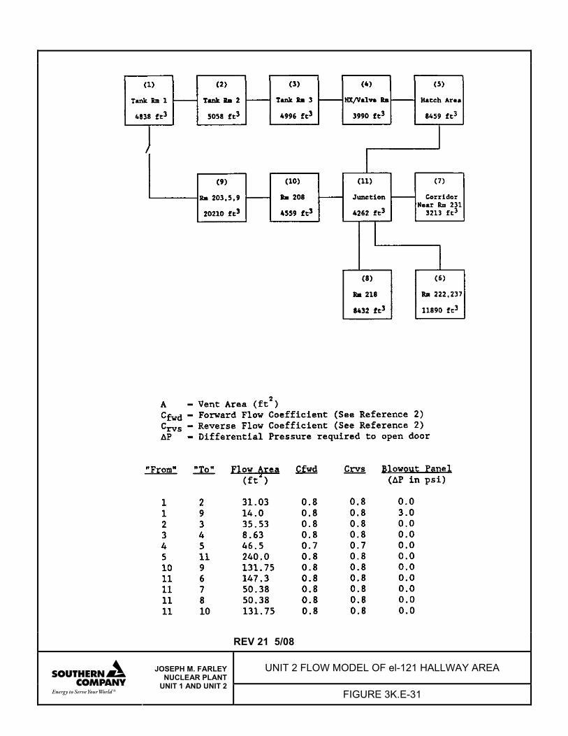
REV 21 5/08
UNIT 2 FLOW MODEL OF el-121 HALLWAY AREA
JOSEPH M. FARLEY NUCLEAR PLANT
UNIT 1 AND UNIT 2 FIGURE 3K.E-31
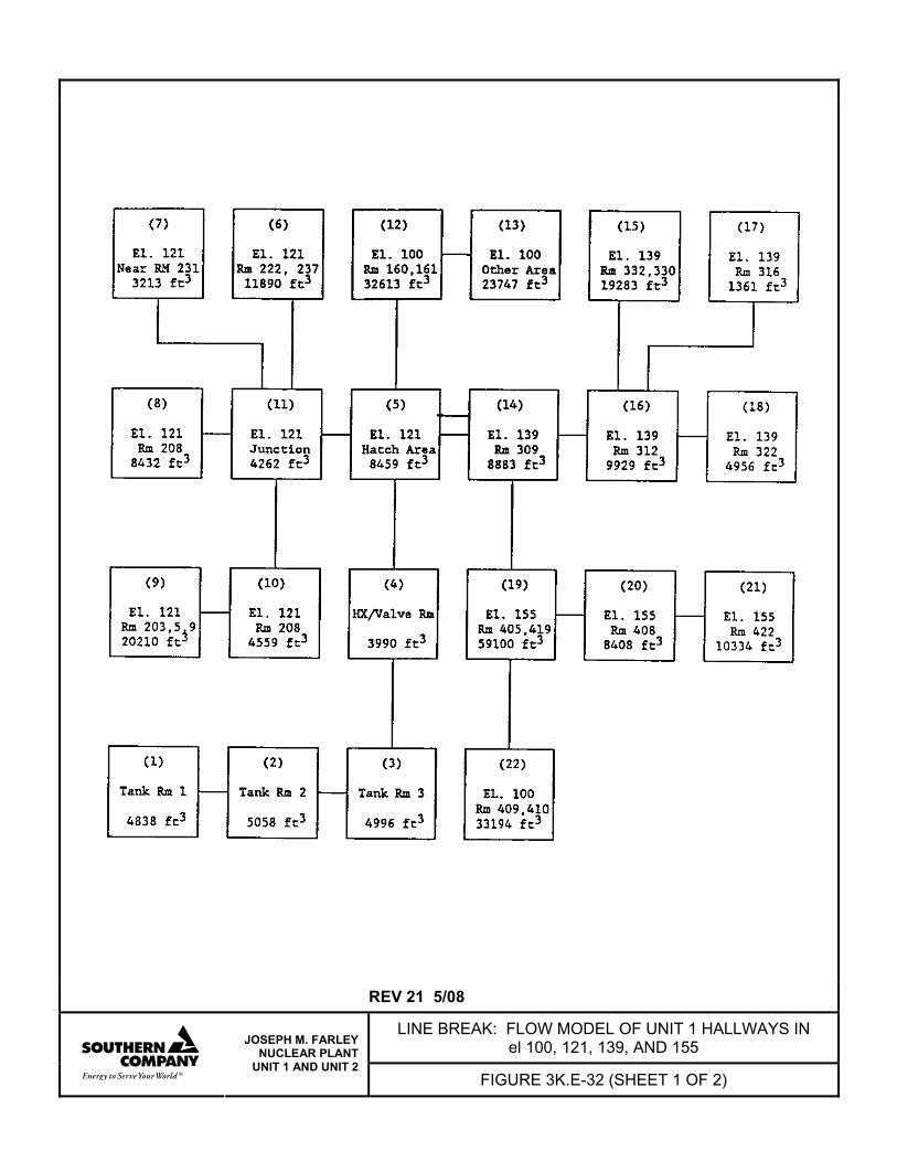
REV 21 5/08
LINE BREAK: FLOW MODEL OF UNIT 1 HALLWAYS IN el 100, 121, 139, AND 155
JOSEPH M. FARLEY NUCLEAR PLANT
UNIT 1 AND UNIT 2 FIGURE 3K.E-32 (SHEET 1 OF 2)
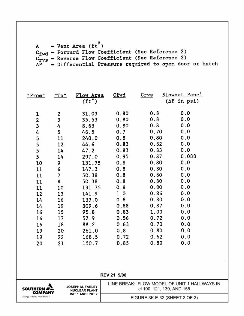
REV 21 5/08
LINE BREAK: FLOW MODEL OF UNIT 1 HALLWAYS IN el 100, 121, 139, AND 155
JOSEPH M. FARLEY NUCLEAR PLANT
UNIT 1 AND UNIT 2 FIGURE 3K.E-32 (SHEET 2 OF 2)
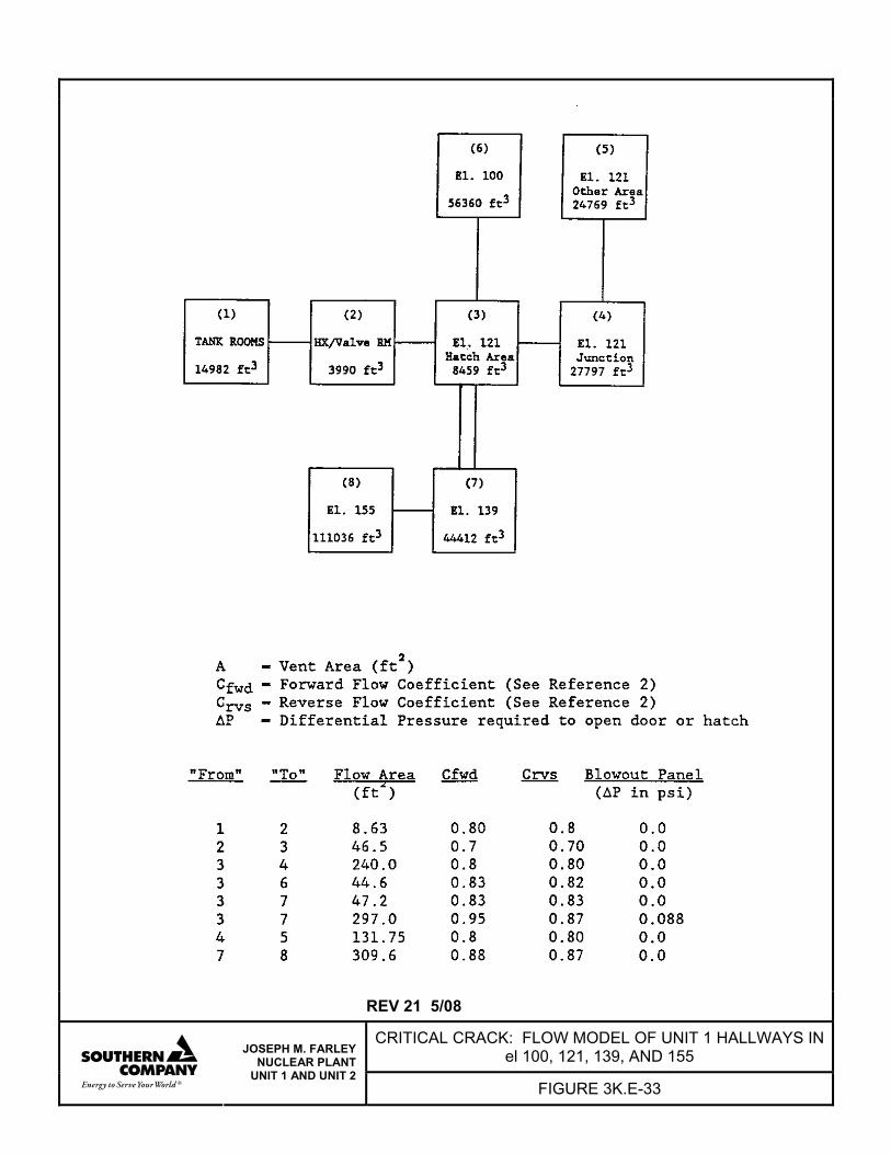
REV 21 5/08
CRITICAL CRACK: FLOW MODEL OF UNIT 1 HALLWAYS IN el 100, 121, 139, AND 155
JOSEPH M. FARLEY NUCLEAR PLANT
UNIT 1 AND UNIT 2 FIGURE 3K.E-33

FNP-FSAR-3K
3K.F-i REV 21 5/08
ATTACHMENT F
METHODS USED TO CALCULATE PIPE WHIP THRUST LOADS AND JET IMPINGEMENT FORCES
FNP-FSAR-3K
3K.F-1 REV 21 5/08
ATTACHMENT F
ANALYSIS OF PIPE RUPTURE THRUST AND JET FORCES
3K.F.1 GENERAL Methods for calculating pipe rupture thrust and jet impingement forces are given in this attachment. Single- and two-phase blowdowns are analyzed to evaluate the nature and magnitude of these forces which result in pipe whip and impingement loads on structures and preventive barriers. 3K.F.2 JET THRUST FORCES In the event of a high energy pipe break, the fluid blowdown and the propagation of pressure disturbance produce jet loads that may result in pipe whip and jet impingement forces. Immediately after the break, while the pressure disturbance propagation is settling down and the blowdown rate is building up, the resulting jet forces are a function of time, asymptotically acquiring steady-state value provided the system stagnation pressure Po remains constant. Methods of calculating the steady-state values of these forces are given in the following: 3K.F.2.1 Steady-State Thrust Calculation The generalized steady-state thrust equation as developed by Shapiro(1) is
( ) eaec
e APPgVm
F −+=&
(1)
where: m& = fluid mass flowrate (lbm/s) Ve = fluid exit velocity (ft/s) gc = gravitational constant (32.2 lbm ft/lbfs2) Pe = fluid exit pressure (psf) Pa = ambient pressure (psf) Ae = exit area (ft2)
FNP-FSAR-3K
3K.F-2 REV 21 5/08
A convenient nondimensional thrust can be defined by dividing through by Po and Ae obtaining
P
P - P + Pg
GV = AP
Fo
ae
oc
e
eo (2)
One-dimensional continuity, m& = ρVA and the definition G = m/A can be used with equation (2) to obtain the alternate expressions
P
P-P +Pg
GV = AP
Fo
ae
oc
e
eo (3)
and
P
P-P+pgρ
G= AP
Fo
ae
oce
2
eo (4)
where ρe is exit mass density (lbm/ft3). Two blowdown situations are considered for rupture of steam and water lines. They are as follows: 1. Blowdown of steam from superheated or saturated conditions. 2. Blowdown of a steam-water mixture or subcooled water. 3K.F.2.2 Saturated Steam Thrust forces associated with the blowdown of saturated steam are obtained from figure 3K.F-1 (when fL/D effects are considered) or from figure 3K.F-2 (when effects of a flow restrictor only are considered). As can be seen from figure 3K.F-2, thrust forces associated with the critical flow of two-phase mixtures through upstream restrictions are lower than those associated with the blowdown of saturated steam through the same restriction. Therefore, the thrust forces associated with the blowdown of saturated steam were used to evaluate the effects of a main steam line rupture.
FNP-FSAR-3K
3K.F-3 REV 21 5/08
3K.F.2.3 Saturated Steam-Water Mixture or Subcooled Water Although fluid escaping from a rupture in a subcooled system involves a two-phase mixture, the subcooled forces only were conservatively used for the analysis applying the following Moody equation from reference 2.
( )c
m2
mm
B
t
gV)(G
PPAF
+∞−= (5)
where Pm = Maximum pressure at the break Gm = Maximum flowrate at the break Vm = Specific volume (Vf) at Pm P∞ = Atmospheric pressure AB = Break Area Gm and Pm were obtained from figures 3K.F-3 and 3K.F-4, respectively, using a stagnation enthalpy (hf) for the system temperatures and the system source pressure Po given in table 3K.F-1. When the corresponding data points did not fall within the envelopes in figures 3K.F-3 and 3K.F-4, a point on the saturated liquid boundary at the system pressure was used to obtain Pm and Gm.
For conservatism, no ⎟⎠⎞
⎜⎝⎛DLf effects were considered for subcooled forces.
3K.F.3 FLUID JET IMPINGEMENT FORCES In the event of a pipe break, the fluid flowing through the pipe emerges out as a jet impinging at nearby structures or equipment. Various blowdown situations considered here are described in subsection 3K.F.2. On emerging from the breakpoint, the jet undergoes free rapid expansion to the ambient pressure at relatively short distance -- a few diameters of break area. For this asymptotic distance, momentum and shear interactions with jet environment can reasonably be neglected. As such, applying forward momentum conservation, the total jet force, Fj, is constant throughout its travel, and therefore, as assumed by Moody;(2) Fj = F (6) where F is the total thrust force defined in subsection 3K.F.2. Methods of calculating F are also given there.
FNP-FSAR-3K
3K.F-4 REV 21 5/08
For the purpose of this attachment, it is further assumed that Fj remains constant for all distances beyond the asymptotic area. This assumption is conservative. Therefore, the jet pressure at any location along the axis of the jet is given by:
(x) AF
(x)Pj
j j = (7)
where Aj (x) is the expanded jet area at location x along the jet axis. See figure 3K.F-5 for system geometry. Moody(2) has developed a simple analytical model for estimating the asymptotic jet area for steam, saturated water, and steam/water blowdown situations. Evaluations of LOFT(5) experimental results tend to indicate that, for subcooled water and steam blowdown situations, the jet area expands uniformly at half angle of about 15 degrees, whereas steam/water blowdown expands much more rapidly because of large-scale water flashing. Results of Moody's analytical analysis agree, at least qualitatively, with LOFT results. In addition, Moody's analytical analysis predicts results of other experiments, as discussed in reference 2. In this attachment, an empirical approach has been adopted combining Moody's analytical model with the uniform half angle approach, as shown in figure 3K.F-5. The half angle is conservatively assumed to be φ = 10 degrees. According to this empirical model, the distance of jet travel is divided into three regions. Region 1 extends to the asymptotic area, at which point the jet expansion area is calculated according to Moody's method; in Region 2, jet area remains constant; then in Region 3, the jet expands at half angle φ = 10 degrees. For subcooled water blowdown, this model assumes half angle approach, φ = 10 degrees, uniformly in all the three regions, since Moody's model is not truly applicable for this case. To follow Moody, the extent of Region 1 is taken as x1 = 5De (8) and the jet area at location x1 is given by the equation: Aj (x1) = πR2j1 (9)
= jc
12e Fg
V G)(A
where: De = Equivalent diameter of pipe break area
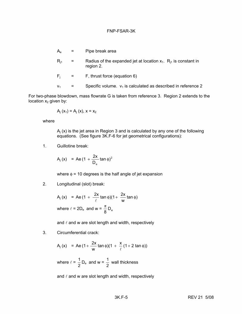
FNP-FSAR-3K
3K.F-5 REV 21 5/08
Ae = Pipe break area Rj1 = Radius of the expanded jet at location x1. Rj1 is constant in region 2. Fj = F, thrust force (equation 6) v1 = Specific volume. v1 is calculated as described in reference 2 For two-phase blowdown, mass flowrate G is taken from reference 3. Region 2 extends to the location x2 given by: Aj (x1) = Aj (x), x = x2 where Aj (x) is the jet area in Region 3 and is calculated by any one of the following equations. (See figure 3K.F-6 for jet geometrical configurations): 1. Guillotine break:
Aj (x) = 2
e
) tanD2x (1 Ae φ+
where φ = 10 degrees is the half angle of jet expansion 2. Longitudinal (slot) break:
Aj (x) = ) tan w2x )(1 tan 2x (1 Ae φ+φ+
l
where l = 2De and w = eD8π
and l and w are slot length and width, respectively 3. Circumferential crack:
Aj (x) = )) tan2(1x )(1 tan w2x (1 Ae φ++φ+
l
where l = 21 De and w =
21 wall thickness
and l and w are slot length and width, respectively
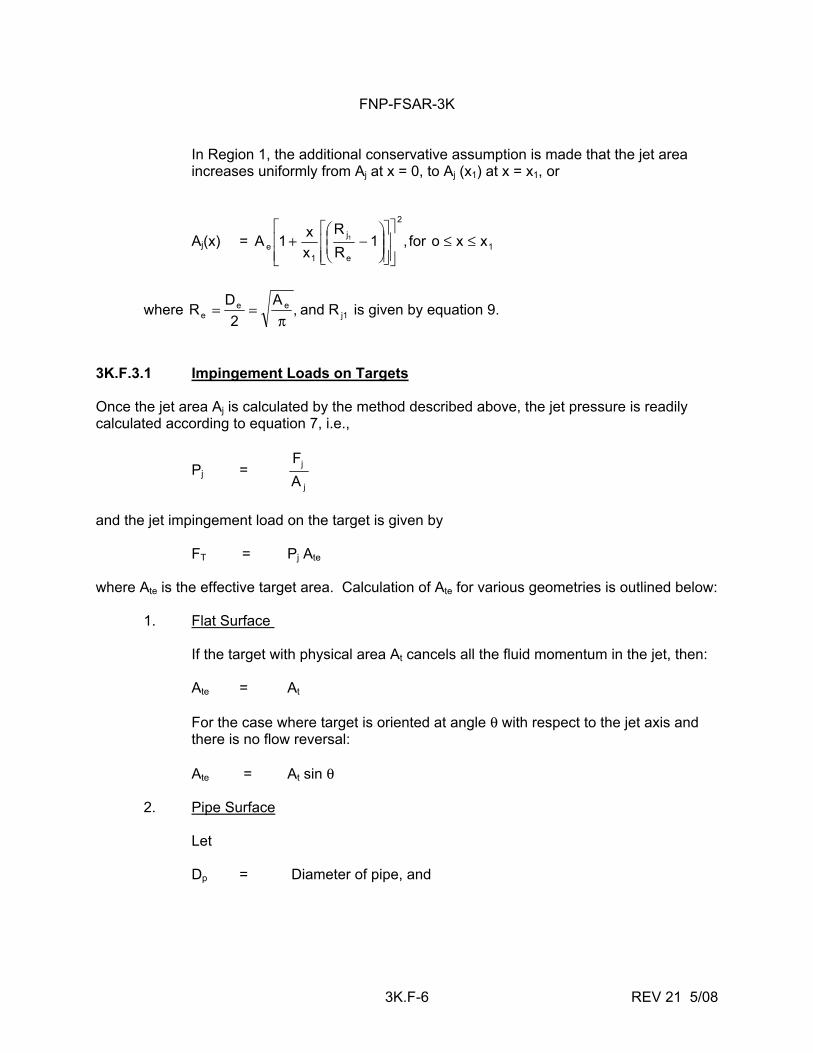
FNP-FSAR-3K
3K.F-6 REV 21 5/08
In Region 1, the additional conservative assumption is made that the jet area increases uniformly from Aj at x = 0, to Aj (x1) at x = x1, or
Aj(x) = 1
2
e
j
1e xxofor,1
RR
xx1A 1 ≤≤
⎥⎥⎦
⎤
⎢⎢⎣
⎡
⎥⎥⎦
⎤
⎢⎢⎣
⎡⎟⎟⎠
⎞⎜⎜⎝
⎛−+
where j1ee
e Rand,A
2D
Rπ
== is given by equation 9.
3K.F.3.1 Impingement Loads on Targets Once the jet area Aj is calculated by the method described above, the jet pressure is readily calculated according to equation 7, i.e.,
Pj = j
j
AF
and the jet impingement load on the target is given by FT = Pj Ate where Ate is the effective target area. Calculation of Ate for various geometries is outlined below: 1. Flat Surface If the target with physical area At cancels all the fluid momentum in the jet, then: Ate = At For the case where target is oriented at angle θ with respect to the jet axis and there is no flow reversal: Ate = At sin θ 2. Pipe Surface Let Dp = Diameter of pipe, and
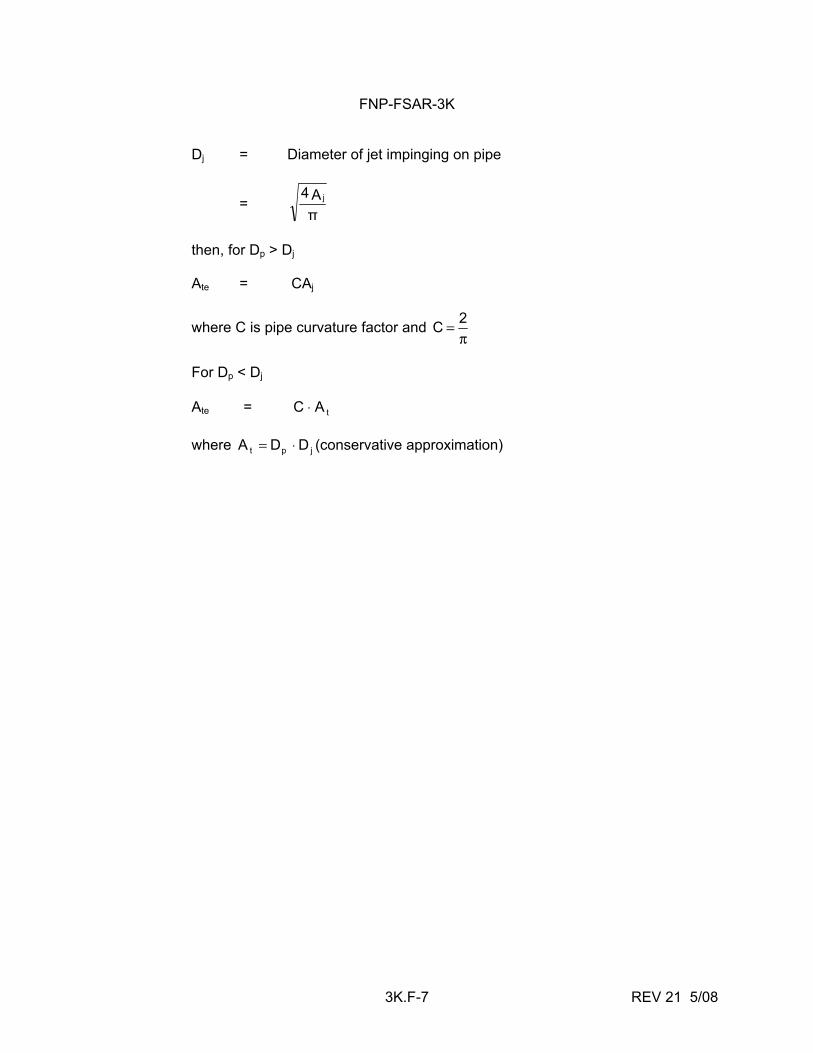
FNP-FSAR-3K
3K.F-7 REV 21 5/08
Dj = Diameter of jet impinging on pipe
= πA4 j
then, for Dp > Dj Ate = CAj
where C is pipe curvature factor and π
= 2 C
For Dp < Dj Ate = tAC ⋅ where jpt DDA ⋅= (conservative approximation)
FNP-FSAR-3K
3K.F-8 REV 21 5/08
REFERENCES 1. Shapiro, A. H., The Dynamics and Thermodynamics of Compressible Fluid Flow, Ronald
Press Co., New York, 1953. 2. Moody, F. J., "Prediction of Blowdown and Jet Thrust Forces," ASME Paper 69 HT-31,
August 6, 1969. 3. Moody, F. J., "Maximum Two-Phase Vessel Blowdown from Pipes,"
APED-4827 (65APE4), General Electric Co., April 20, 1965. 4. Moody, F. J. "Maximum Flow Rate of a Single Component, Two-Phase Mixture,"
APED-4378, General Electric Co., October 25, 1963. 5. Dietz, K. A., Editor, Quarterly Technical Report, Engineering and Test Branch, October 1
through December 31, 1967, Phillips Petroleum Company, IDO-17242, May 1968. 6. Moody, F. J. "Fluid Reaction and Impingement Loads," presented at the Specialty
Conference, Structural Design of Nuclear Plant Facilities at Chicago, Illinois, December 17-18, 1973. (Published in Volume 1 of the conference notes.)
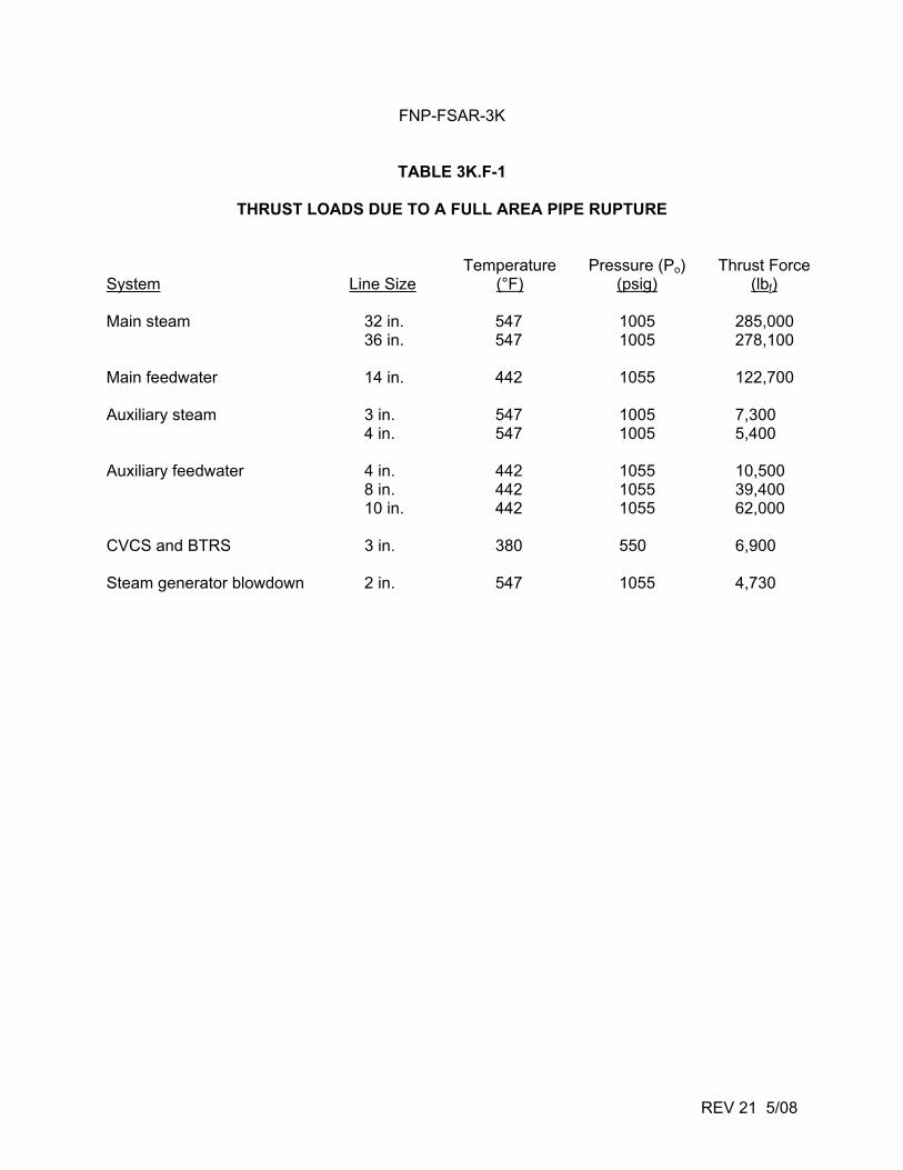
FNP-FSAR-3K
TABLE 3K.F-1
THRUST LOADS DUE TO A FULL AREA PIPE RUPTURE
REV 21 5/08
System Line Size Temperature
(°F) Pressure (Po)
(psig) Thrust Force
(lbf) Main steam 32 in. 547 1005 285,000 36 in. 547 1005 278,100 Main feedwater 14 in. 442 1055 122,700 Auxiliary steam 3 in. 547 1005 7,300 4 in. 547 1005 5,400 Auxiliary feedwater 4 in. 442 1055 10,500 8 in. 442 1055 39,400 10 in. 442 1055 62,000 CVCS and BTRS 3 in. 380 550 6,900 Steam generator blowdown 2 in. 547 1055 4,730
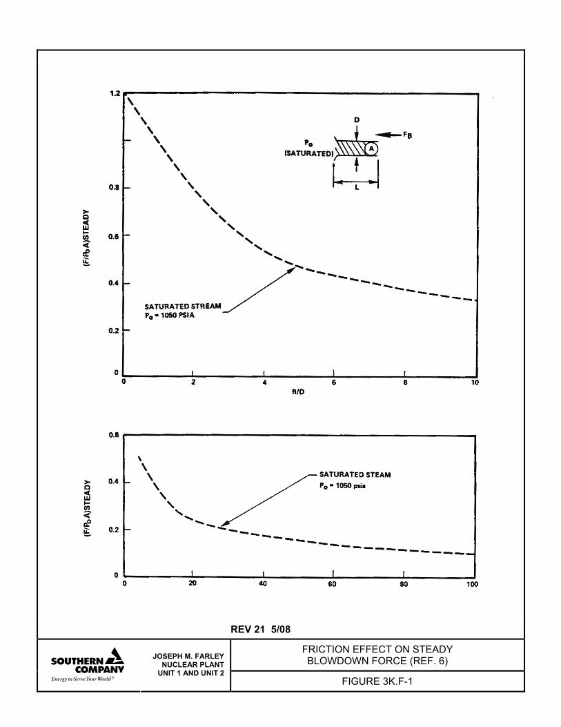
REV 21 5/08
FRICTION EFFECT ON STEADY BLOWDOWN FORCE (REF. 6)
JOSEPH M. FARLEY NUCLEAR PLANT
UNIT 1 AND UNIT 2 FIGURE 3K.F-1
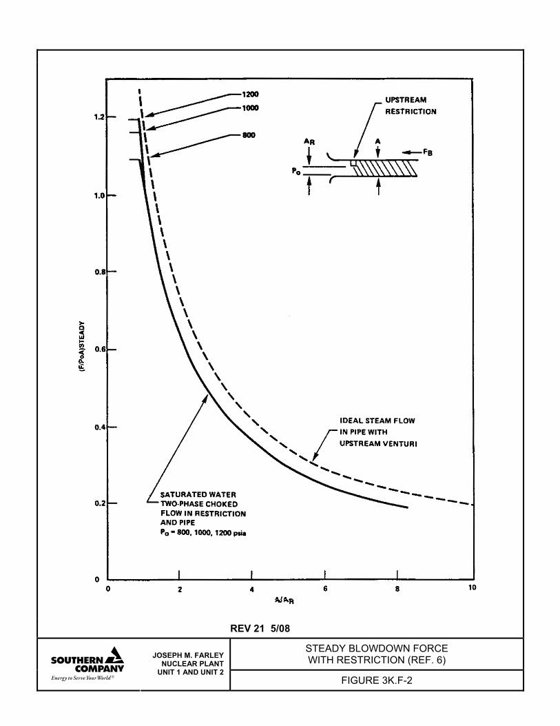
REV 21 5/08
STEADY BLOWDOWN FORCE WITH RESTRICTION (REF. 6)
JOSEPH M. FARLEY NUCLEAR PLANT
UNIT 1 AND UNIT 2 FIGURE 3K.F-2
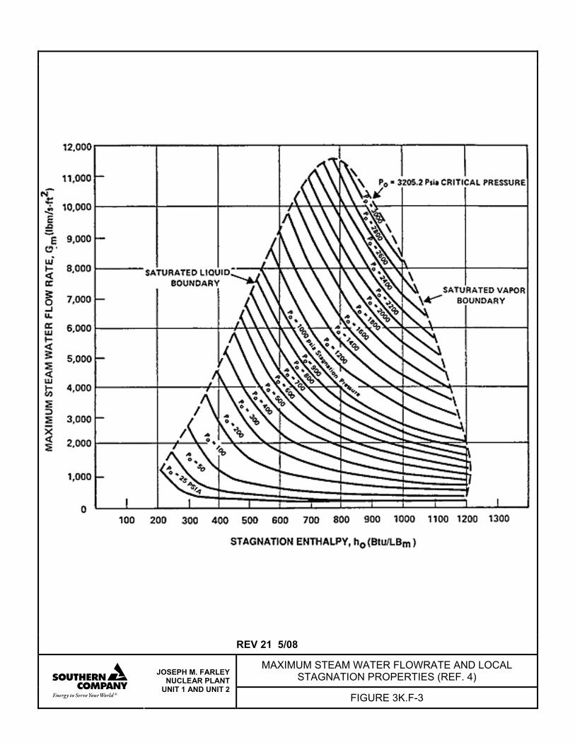
REV 21 5/08
MAXIMUM STEAM WATER FLOWRATE AND LOCAL STAGNATION PROPERTIES (REF. 4)
JOSEPH M. FARLEY NUCLEAR PLANT
UNIT 1 AND UNIT 2 FIGURE 3K.F-3
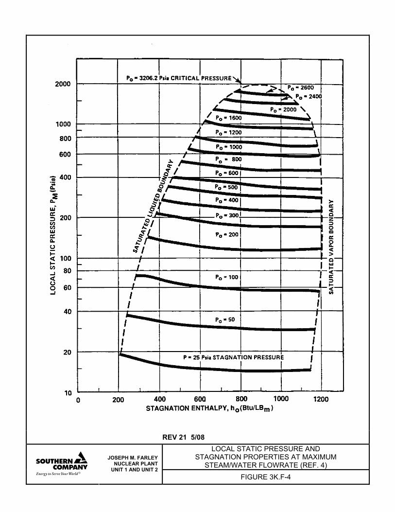
REV 21 5/08
LOCAL STATIC PRESSURE AND STAGNATION PROPERTIES AT MAXIMUM
STEAM/WATER FLOWRATE (REF. 4)
JOSEPH M. FARLEY NUCLEAR PLANT
UNIT 1 AND UNIT 2 FIGURE 3K.F-4
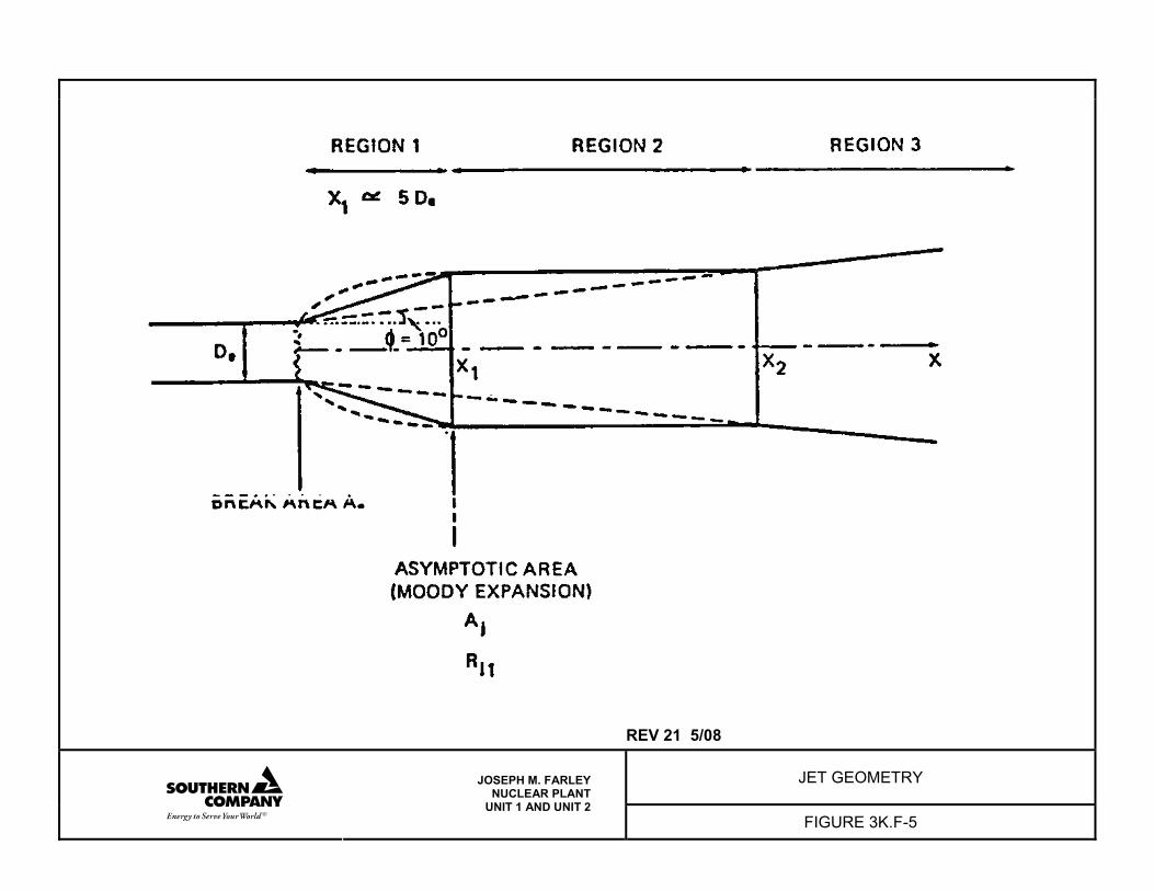
REV 21 5/08
JET GEOMETRY
JOSEPH M. FARLEY NUCLEAR PLANT
UNIT 1 AND UNIT 2 FIGURE 3K.F-5
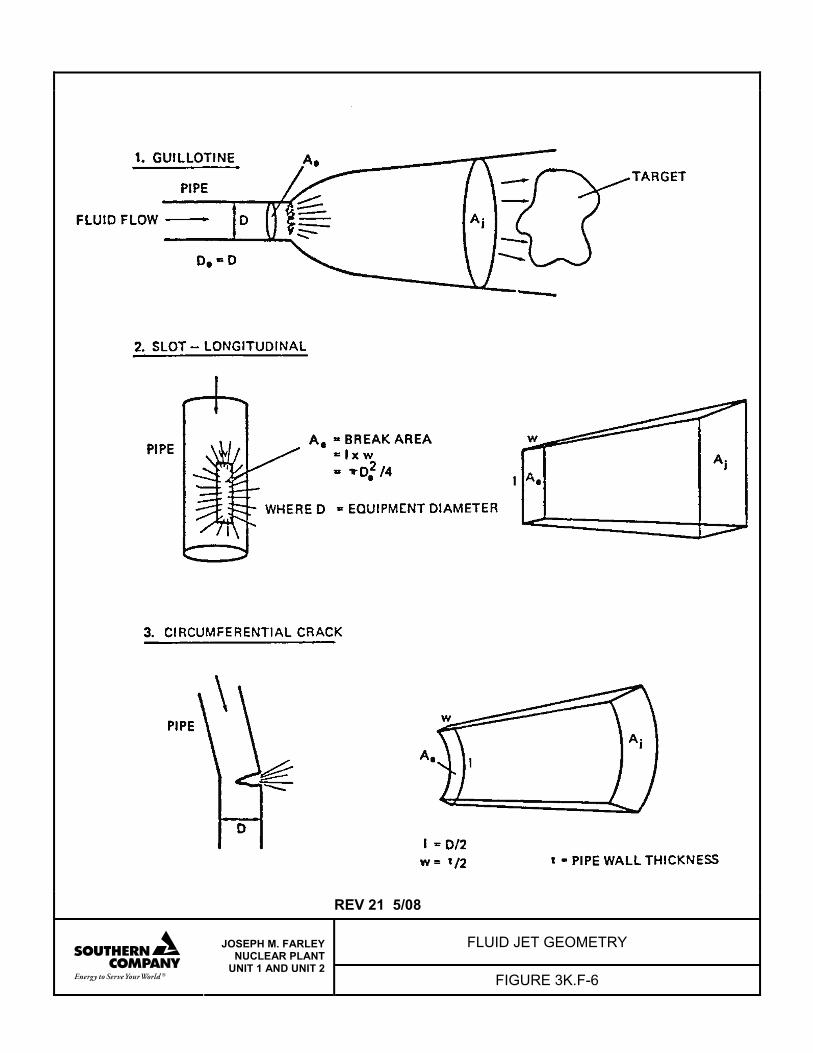
REV 21 5/08
FLUID JET GEOMETRY
JOSEPH M. FARLEY NUCLEAR PLANT
UNIT 1 AND UNIT 2 FIGURE 3K.F-6
FNP-FSAR-3K
3K.G-i REV 21 5/08
ATTACHMENT G
MAIN STEAM ROOM AND PIPE CHASE STRUCTURAL STRESS ANALYSIS
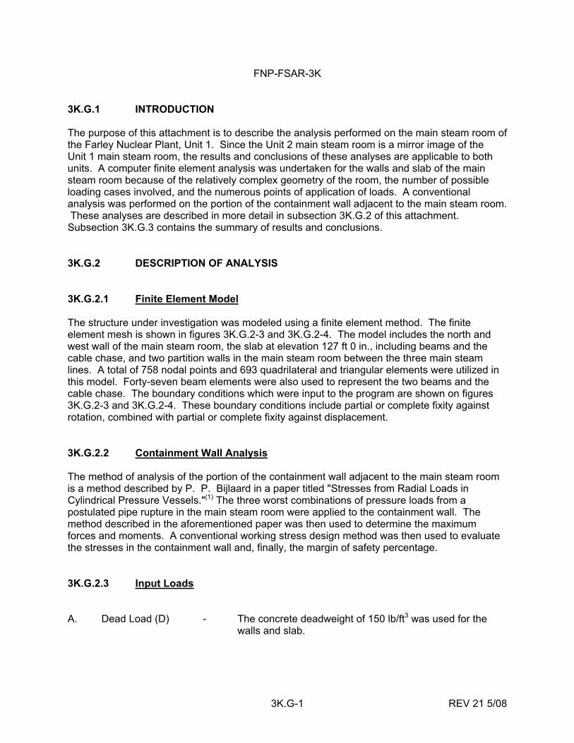
FNP-FSAR-3K
3K.G-1 REV 21 5/08
3K.G.1 INTRODUCTION The purpose of this attachment is to describe the analysis performed on the main steam room of the Farley Nuclear Plant, Unit 1. Since the Unit 2 main steam room is a mirror image of the Unit 1 main steam room, the results and conclusions of these analyses are applicable to both units. A computer finite element analysis was undertaken for the walls and slab of the main steam room because of the relatively complex geometry of the room, the number of possible loading cases involved, and the numerous points of application of loads. A conventional analysis was performed on the portion of the containment wall adjacent to the main steam room. These analyses are described in more detail in subsection 3K.G.2 of this attachment. Subsection 3K.G.3 contains the summary of results and conclusions. 3K.G.2 DESCRIPTION OF ANALYSIS 3K.G.2.1 Finite Element Model The structure under investigation was modeled using a finite element method. The finite element mesh is shown in figures 3K.G.2-3 and 3K.G.2-4. The model includes the north and west wall of the main steam room, the slab at elevation 127 ft 0 in., including beams and the cable chase, and two partition walls in the main steam room between the three main steam lines. A total of 758 nodal points and 693 quadrilateral and triangular elements were utilized in this model. Forty-seven beam elements were also used to represent the two beams and the cable chase. The boundary conditions which were input to the program are shown on figures 3K.G.2-3 and 3K.G.2-4. These boundary conditions include partial or complete fixity against rotation, combined with partial or complete fixity against displacement. 3K.G.2.2 Containment Wall Analysis The method of analysis of the portion of the containment wall adjacent to the main steam room is a method described by P. P. Bijlaard in a paper titled "Stresses from Radial Loads in Cylindrical Pressure Vessels."(1) The three worst combinations of pressure loads from a postulated pipe rupture in the main steam room were applied to the containment wall. The method described in the aforementioned paper was then used to determine the maximum forces and moments. A conventional working stress design method was then used to evaluate the stresses in the containment wall and, finally, the margin of safety percentage. 3K.G.2.3 Input Loads A. Dead Load (D) - The concrete deadweight of 150 lb/ft3 was used for the
walls and slab.
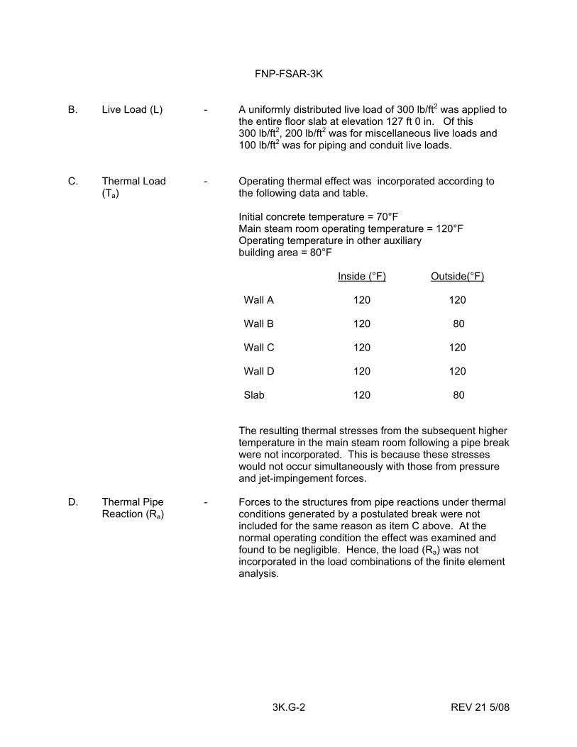
FNP-FSAR-3K
3K.G-2 REV 21 5/08
B. Live Load (L) - A uniformly distributed live load of 300 lb/ft2 was applied to the entire floor slab at elevation 127 ft 0 in. Of this 300 lb/ft2, 200 lb/ft2 was for miscellaneous live loads and 100 lb/ft2 was for piping and conduit live loads.
C. Thermal Load - (Ta)
Operating thermal effect was incorporated according to the following data and table. Initial concrete temperature = 70°F Main steam room operating temperature = 120°F Operating temperature in other auxiliary building area = 80°F Inside (°F) Outside(°F) Wall A 120 120 Wall B 120 80 Wall C 120 120 Wall D 120 120 Slab 120 80
The resulting thermal stresses from the subsequent higher temperature in the main steam room following a pipe break were not incorporated. This is because these stresses would not occur simultaneously with those from pressure and jet-impingement forces.
D. Thermal Pipe - Reaction (Ra)
Forces to the structures from pipe reactions under thermal conditions generated by a postulated break were not included for the same reason as item C above. At the normal operating condition the effect was examined and found to be negligible. Hence, the load (Ra) was not incorporated in the load combinations of the finite element analysis.
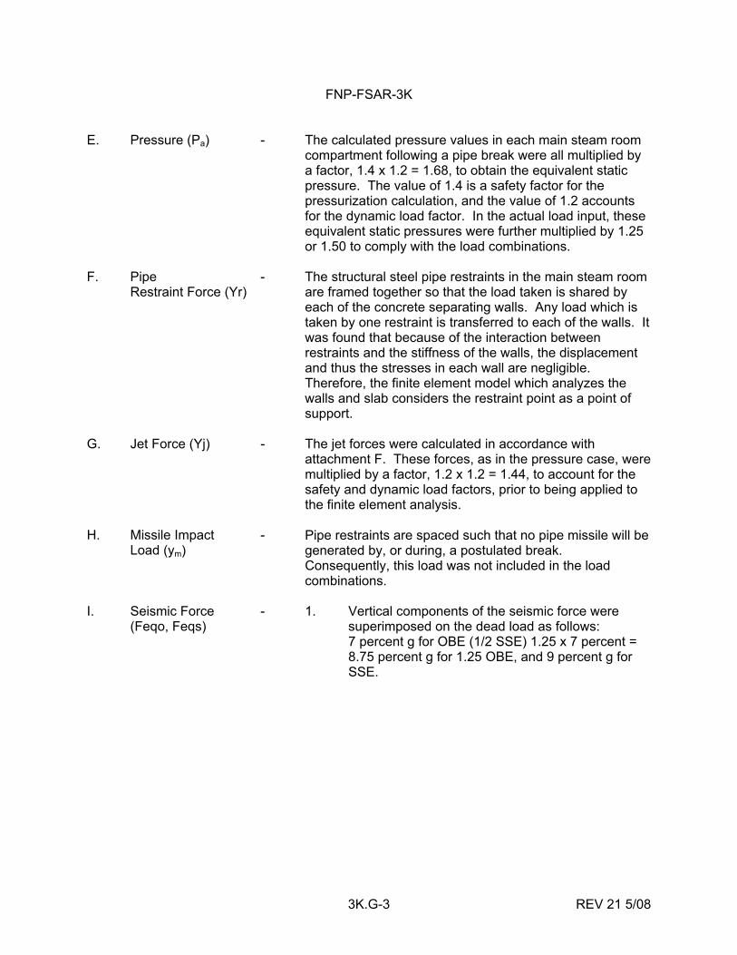
FNP-FSAR-3K
3K.G-3 REV 21 5/08
E. Pressure (Pa) - The calculated pressure values in each main steam room compartment following a pipe break were all multiplied by a factor, 1.4 x 1.2 = 1.68, to obtain the equivalent static pressure. The value of 1.4 is a safety factor for the pressurization calculation, and the value of 1.2 accounts for the dynamic load factor. In the actual load input, these equivalent static pressures were further multiplied by 1.25 or 1.50 to comply with the load combinations.
F. Pipe - Restraint Force (Yr)
The structural steel pipe restraints in the main steam room are framed together so that the load taken is shared by each of the concrete separating walls. Any load which is taken by one restraint is transferred to each of the walls. It was found that because of the interaction between restraints and the stiffness of the walls, the displacement and thus the stresses in each wall are negligible. Therefore, the finite element model which analyzes the walls and slab considers the restraint point as a point of support.
G. Jet Force (Yj) - The jet forces were calculated in accordance with
attachment F. These forces, as in the pressure case, were multiplied by a factor, 1.2 x 1.2 = 1.44, to account for the safety and dynamic load factors, prior to being applied to the finite element analysis.
H. Missile Impact - Load (ym)
Pipe restraints are spaced such that no pipe missile will be generated by, or during, a postulated break. Consequently, this load was not included in the load combinations.
I. Seismic Force - (Feqo, Feqs)
1. Vertical components of the seismic force were superimposed on the dead load as follows: 7 percent g for OBE (1/2 SSE) 1.25 x 7 percent = 8.75 percent g for 1.25 OBE, and 9 percent g for SSE.
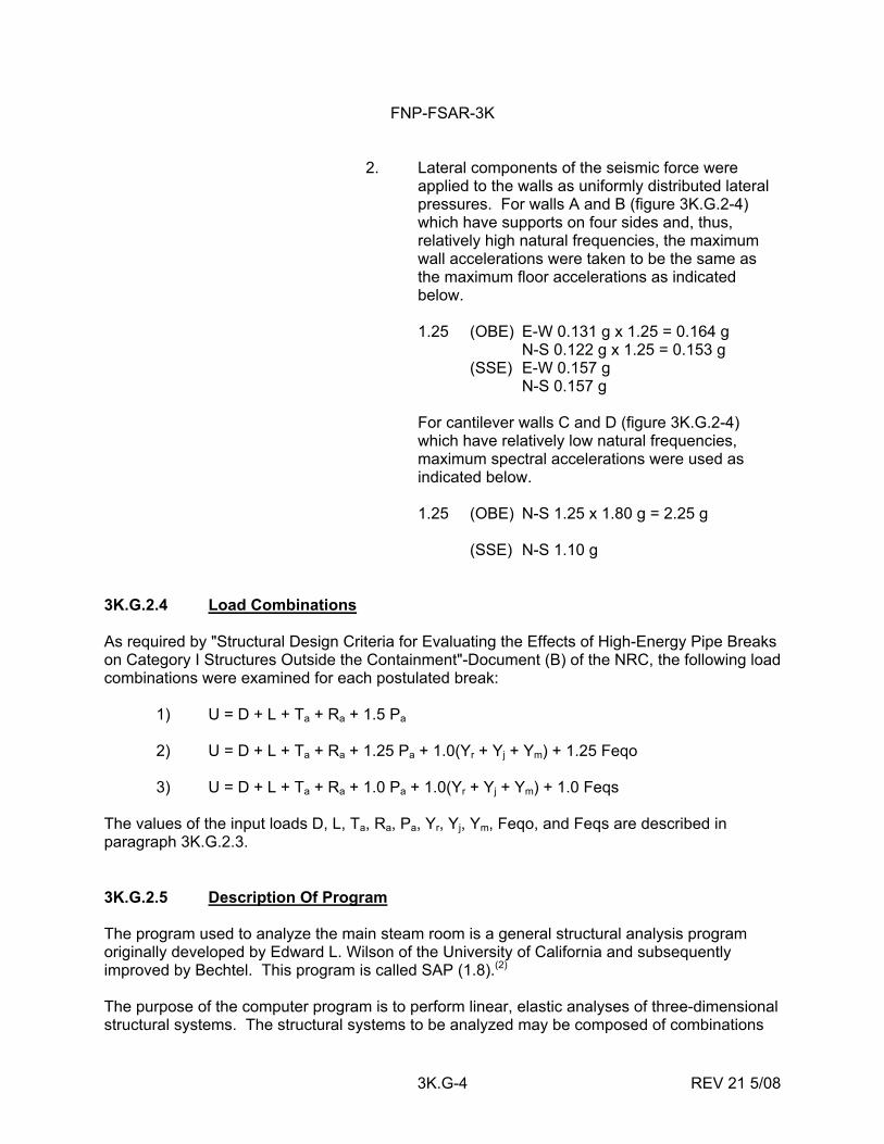
FNP-FSAR-3K
3K.G-4 REV 21 5/08
2. Lateral components of the seismic force were applied to the walls as uniformly distributed lateral pressures. For walls A and B (figure 3K.G.2-4) which have supports on four sides and, thus, relatively high natural frequencies, the maximum wall accelerations were taken to be the same as the maximum floor accelerations as indicated below.
1.25 (OBE) E-W 0.131 g x 1.25 = 0.164 g N-S 0.122 g x 1.25 = 0.153 g (SSE) E-W 0.157 g N-S 0.157 g For cantilever walls C and D (figure 3K.G.2-4) which have relatively low natural frequencies, maximum spectral accelerations were used as indicated below. 1.25 (OBE) N-S 1.25 x 1.80 g = 2.25 g
(SSE) N-S 1.10 g
3K.G.2.4 Load Combinations As required by "Structural Design Criteria for Evaluating the Effects of High-Energy Pipe Breaks on Category I Structures Outside the Containment"-Document (B) of the NRC, the following load combinations were examined for each postulated break: 1) U = D + L + Ta + Ra + 1.5 Pa 2) U = D + L + Ta + Ra + 1.25 Pa + 1.0(Yr + Yj + Ym) + 1.25 Feqo 3) U = D + L + Ta + Ra + 1.0 Pa + 1.0(Yr + Yj + Ym) + 1.0 Feqs The values of the input loads D, L, Ta, Ra, Pa, Yr, Yj, Ym, Feqo, and Feqs are described in paragraph 3K.G.2.3. 3K.G.2.5 Description Of Program The program used to analyze the main steam room is a general structural analysis program originally developed by Edward L. Wilson of the University of California and subsequently improved by Bechtel. This program is called SAP (1.8).(2) The purpose of the computer program is to perform linear, elastic analyses of three-dimensional structural systems. The structural systems to be analyzed may be composed of combinations
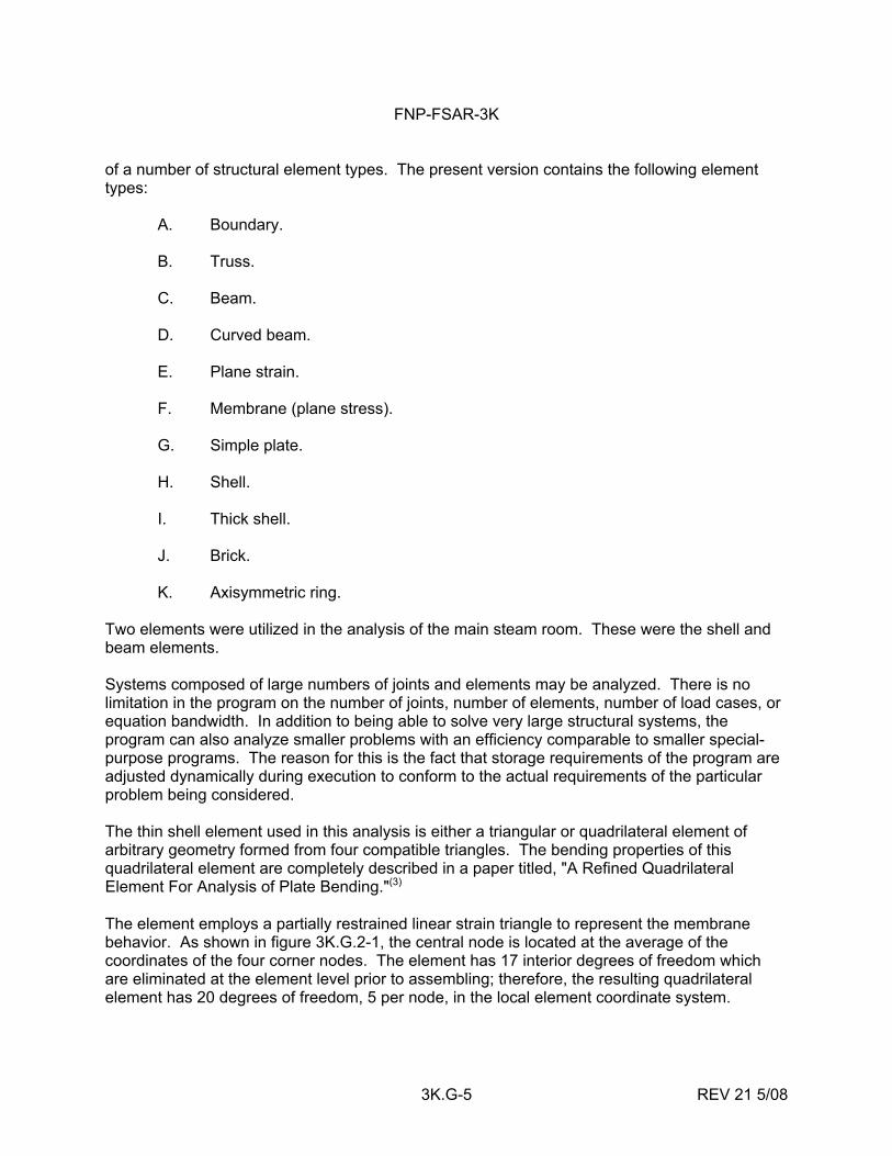
FNP-FSAR-3K
3K.G-5 REV 21 5/08
of a number of structural element types. The present version contains the following element types: A. Boundary. B. Truss. C. Beam. D. Curved beam. E. Plane strain. F. Membrane (plane stress). G. Simple plate. H. Shell. I. Thick shell. J. Brick. K. Axisymmetric ring. Two elements were utilized in the analysis of the main steam room. These were the shell and beam elements. Systems composed of large numbers of joints and elements may be analyzed. There is no limitation in the program on the number of joints, number of elements, number of load cases, or equation bandwidth. In addition to being able to solve very large structural systems, the program can also analyze smaller problems with an efficiency comparable to smaller special- purpose programs. The reason for this is the fact that storage requirements of the program are adjusted dynamically during execution to conform to the actual requirements of the particular problem being considered. The thin shell element used in this analysis is either a triangular or quadrilateral element of arbitrary geometry formed from four compatible triangles. The bending properties of this quadrilateral element are completely described in a paper titled, "A Refined Quadrilateral Element For Analysis of Plate Bending."(3) The element employs a partially restrained linear strain triangle to represent the membrane behavior. As shown in figure 3K.G.2-1, the central node is located at the average of the coordinates of the four corner nodes. The element has 17 interior degrees of freedom which are eliminated at the element level prior to assembling; therefore, the resulting quadrilateral element has 20 degrees of freedom, 5 per node, in the local element coordinate system.
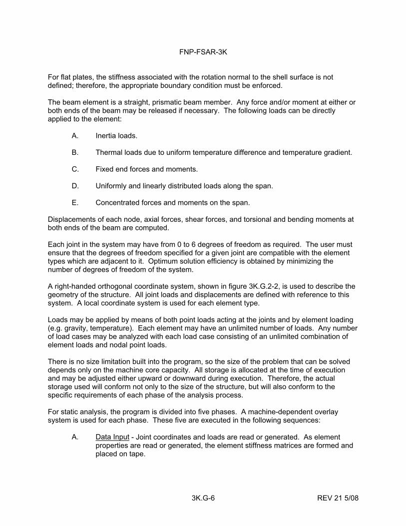
FNP-FSAR-3K
3K.G-6 REV 21 5/08
For flat plates, the stiffness associated with the rotation normal to the shell surface is not defined; therefore, the appropriate boundary condition must be enforced. The beam element is a straight, prismatic beam member. Any force and/or moment at either or both ends of the beam may be released if necessary. The following loads can be directly applied to the element: A. Inertia loads. B. Thermal loads due to uniform temperature difference and temperature gradient. C. Fixed end forces and moments. D. Uniformly and linearly distributed loads along the span. E. Concentrated forces and moments on the span. Displacements of each node, axial forces, shear forces, and torsional and bending moments at both ends of the beam are computed. Each joint in the system may have from 0 to 6 degrees of freedom as required. The user must ensure that the degrees of freedom specified for a given joint are compatible with the element types which are adjacent to it. Optimum solution efficiency is obtained by minimizing the number of degrees of freedom of the system. A right-handed orthogonal coordinate system, shown in figure 3K.G.2-2, is used to describe the geometry of the structure. All joint loads and displacements are defined with reference to this system. A local coordinate system is used for each element type. Loads may be applied by means of both point loads acting at the joints and by element loading (e.g. gravity, temperature). Each element may have an unlimited number of loads. Any number of load cases may be analyzed with each load case consisting of an unlimited combination of element loads and nodal point loads. There is no size limitation built into the program, so the size of the problem that can be solved depends only on the machine core capacity. All storage is allocated at the time of execution and may be adjusted either upward or downward during execution. Therefore, the actual storage used will conform not only to the size of the structure, but will also conform to the specific requirements of each phase of the analysis process. For static analysis, the program is divided into five phases. A machine-dependent overlay system is used for each phase. These five are executed in the following sequences: A. Data Input - Joint coordinates and loads are read or generated. As element
properties are read or generated, the element stiffness matrices are formed and placed on tape.
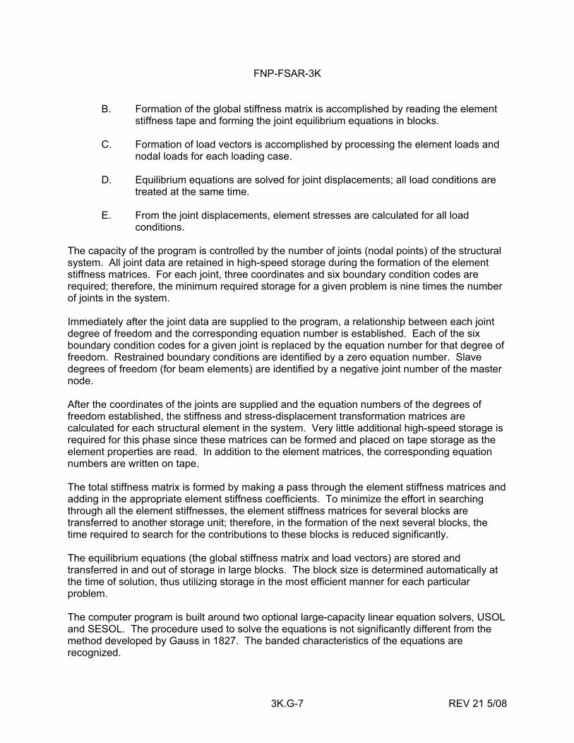
FNP-FSAR-3K
3K.G-7 REV 21 5/08
B. Formation of the global stiffness matrix is accomplished by reading the element stiffness tape and forming the joint equilibrium equations in blocks.
C. Formation of load vectors is accomplished by processing the element loads and
nodal loads for each loading case. D. Equilibrium equations are solved for joint displacements; all load conditions are
treated at the same time. E. From the joint displacements, element stresses are calculated for all load
conditions. The capacity of the program is controlled by the number of joints (nodal points) of the structural system. All joint data are retained in high-speed storage during the formation of the element stiffness matrices. For each joint, three coordinates and six boundary condition codes are required; therefore, the minimum required storage for a given problem is nine times the number of joints in the system. Immediately after the joint data are supplied to the program, a relationship between each joint degree of freedom and the corresponding equation number is established. Each of the six boundary condition codes for a given joint is replaced by the equation number for that degree of freedom. Restrained boundary conditions are identified by a zero equation number. Slave degrees of freedom (for beam elements) are identified by a negative joint number of the master node. After the coordinates of the joints are supplied and the equation numbers of the degrees of freedom established, the stiffness and stress-displacement transformation matrices are calculated for each structural element in the system. Very little additional high-speed storage is required for this phase since these matrices can be formed and placed on tape storage as the element properties are read. In addition to the element matrices, the corresponding equation numbers are written on tape. The total stiffness matrix is formed by making a pass through the element stiffness matrices and adding in the appropriate element stiffness coefficients. To minimize the effort in searching through all the element stiffnesses, the element stiffness matrices for several blocks are transferred to another storage unit; therefore, in the formation of the next several blocks, the time required to search for the contributions to these blocks is reduced significantly. The equilibrium equations (the global stiffness matrix and load vectors) are stored and transferred in and out of storage in large blocks. The block size is determined automatically at the time of solution, thus utilizing storage in the most efficient manner for each particular problem. The computer program is built around two optional large-capacity linear equation solvers, USOL and SESOL. The procedure used to solve the equations is not significantly different from the method developed by Gauss in 1827. The banded characteristics of the equations are recognized.
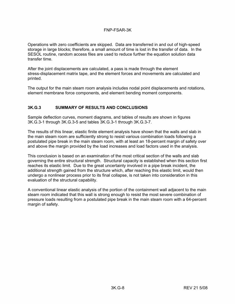
FNP-FSAR-3K
3K.G-8 REV 21 5/08
Operations with zero coefficients are skipped. Data are transferred in and out of high-speed storage in large blocks; therefore, a small amount of time is lost in the transfer of data. In the SESOL routine, random access files are used to reduce further the equation solution data transfer time. After the joint displacements are calculated, a pass is made through the element stress-displacement matrix tape, and the element forces and movements are calculated and printed. The output for the main steam room analysis includes nodal point displacements and rotations, element membrane force components, and element bending moment components. 3K.G.3 SUMMARY OF RESULTS AND CONCLUSIONS Sample deflection curves, moment diagrams, and tables of results are shown in figures 3K.G.3-1 through 3K.G.3-5 and tables 3K.G.3-1 through 3K.G.3-7. The results of this linear, elastic finite element analysis have shown that the walls and slab in the main steam room are sufficiently strong to resist various combination loads following a postulated pipe break in the main steam room, with at least an 18-percent margin of safety over and above the margin provided by the load increases and load factors used in the analysis. This conclusion is based on an examination of the most critical section of the walls and slab governing the entire structural strength. Structural capacity is established when this section first reaches its elastic limit. Due to the great uncertainty involved in a pipe break incident, the additional strength gained from the structure which, after reaching this elastic limit, would then undergo a nonlinear process prior to its final collapse, is not taken into consideration in this evaluation of the structural capability. A conventional linear elastic analysis of the portion of the containment wall adjacent to the main steam room indicated that this wall is strong enough to resist the most severe combination of pressure loads resulting from a postulated pipe break in the main steam room with a 64-percent margin of safety.
FNP-FSAR-3K
3K.G-9 REV 21 5/08
REFERENCES 1. Bijlaard, P. P., "Stresses From Radial Loads in Cylindrical Pressure Vessels,"
Welding Journal Research Supplement, 1954. 2. Structural Analysis Program, Pacific International Computing Corporation. 3. "A Refined Quadrilateral Element for Analysis of Plate Bending,"
Proceedings, (Second) Conference on Matrix Methods in Structural Mechanics, Wright-Patterson AFB, Ohio, 1968.
FNP-FSAR-3K
3K.G-10 REV 21 5/08
NOTES ON VALUES IN TABLES 1. The selected points for tabulation are indicated in figures 3K.G.3-1 through 3K.G.3-5.
These locations are considered the possible critical areas when subjected to various combined loads during a pipe break incident, as described previously.
2. For concrete, tensile stress was not considered. 3. Except from the operating thermal condition, the membrane stresses were found
negligible. Axial compressive forces (Px & Py) indicated in the tables result from pipe restraint forces in some local areas and were combined with bending moments in stress calculation.
4. The resulting operating thermal stress was found to be compressive across the entire
thickness of the walls and slab. To account for the uncertainty involved in the actual temperature distribution, only maximum thermal compressive stress was added to concrete, and no reduction was made for tensile reinforcing stress.
5. The allowable stress was taken as 85 percent of the specified compressive strength for
concrete and 90 percent of the yield strength for reinforcing bars.
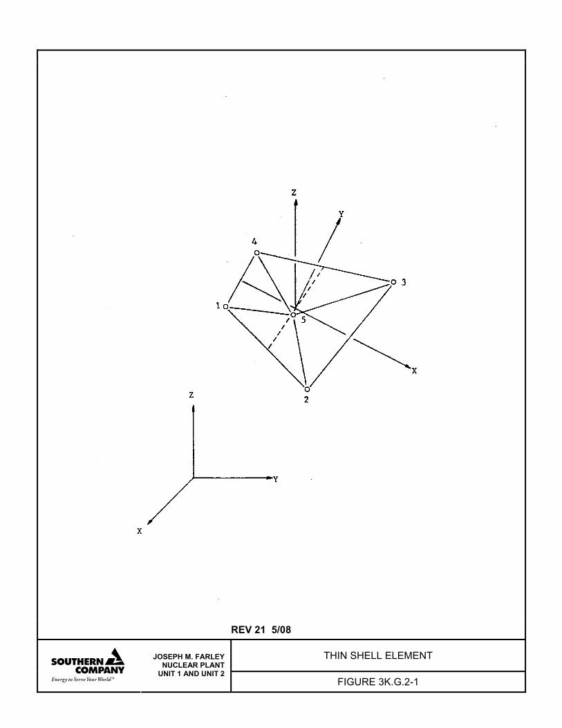
REV 21 5/08
THIN SHELL ELEMENT
JOSEPH M. FARLEY NUCLEAR PLANT
UNIT 1 AND UNIT 2 FIGURE 3K.G.2-1
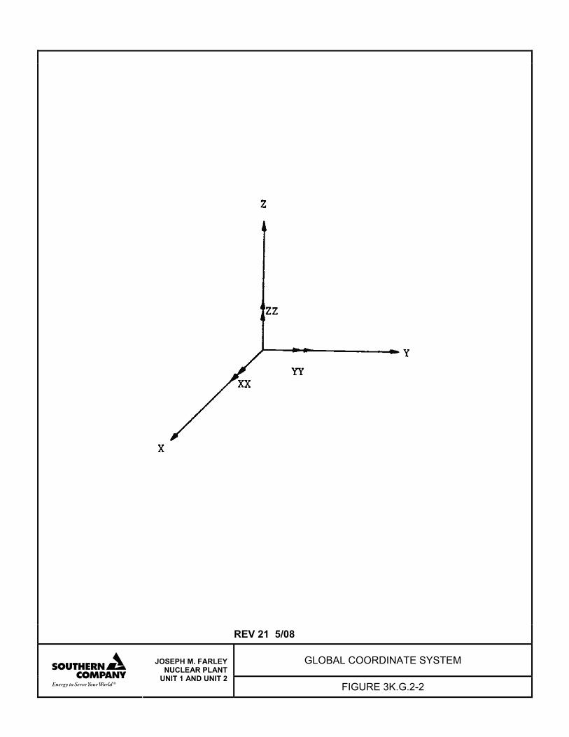
REV 21 5/08
GLOBAL COORDINATE SYSTEM
JOSEPH M. FARLEY NUCLEAR PLANT
UNIT 1 AND UNIT 2 FIGURE 3K.G.2-2
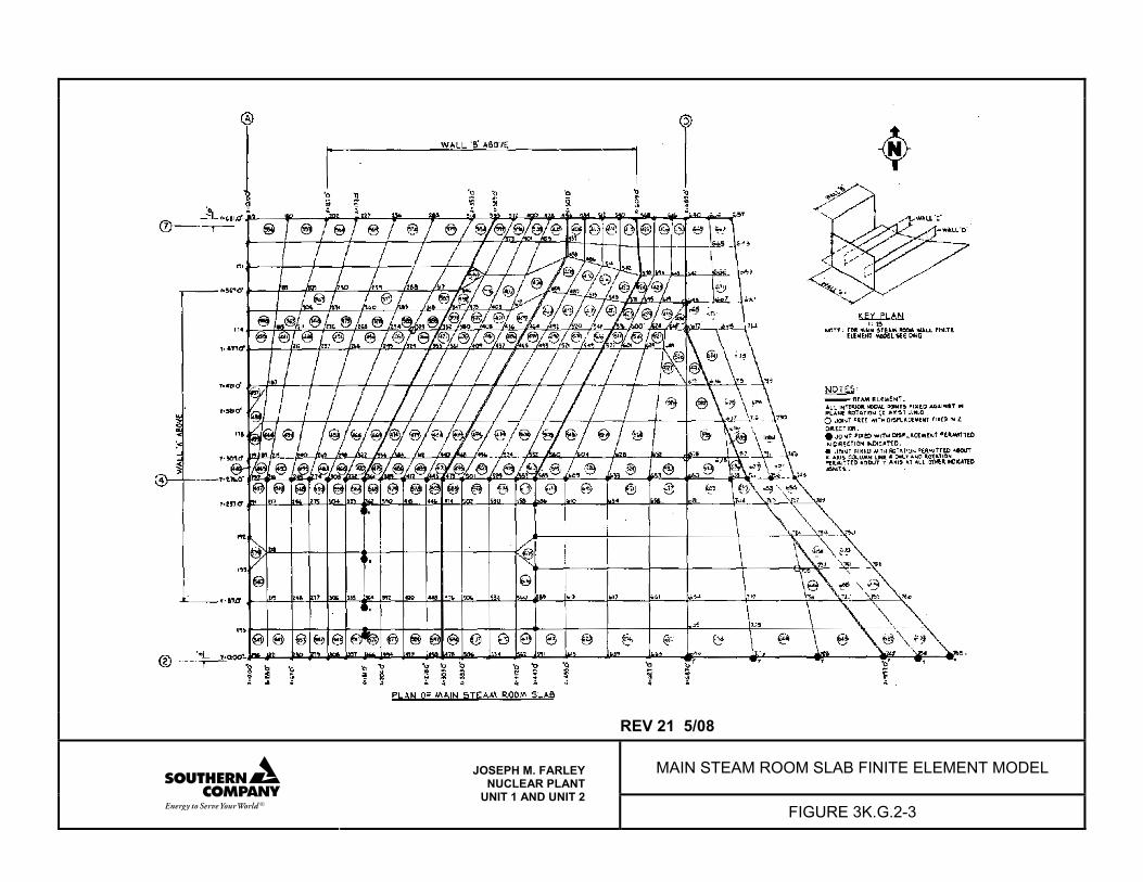
REV 21 5/08
MAIN STEAM ROOM SLAB FINITE ELEMENT MODEL
JOSEPH M. FARLEY NUCLEAR PLANT
UNIT 1 AND UNIT 2 FIGURE 3K.G.2-3
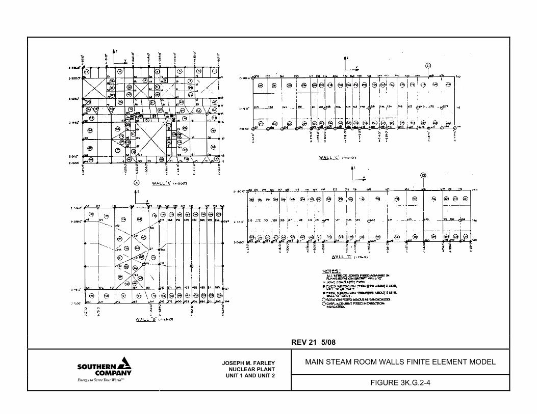
REV 21 5/08
MAIN STEAM ROOM WALLS FINITE ELEMENT MODEL
JOSEPH M. FARLEY NUCLEAR PLANT
UNIT 1 AND UNIT 2 FIGURE 3K.G.2-4
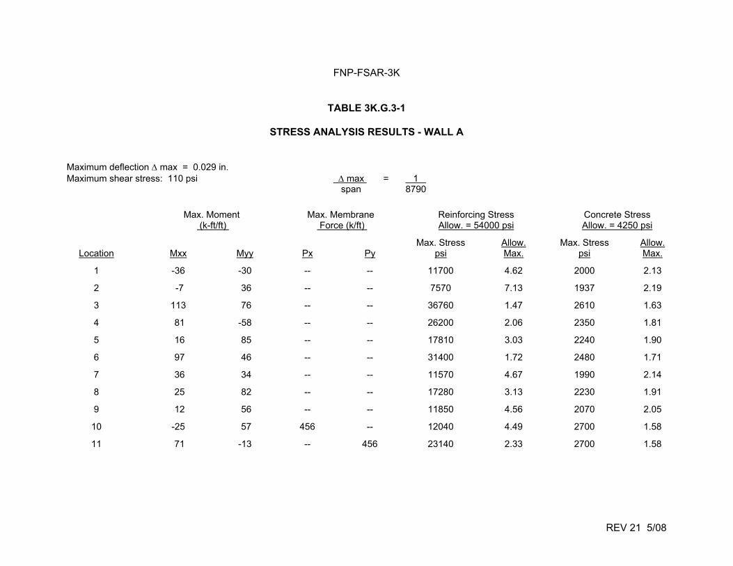
FNP-FSAR-3K
REV 21 5/08
TABLE 3K.G.3-1
STRESS ANALYSIS RESULTS - WALL A Maximum deflection max = 0.029 in. Maximum shear stress: 110 psi max = 1 span 8790
Max. Moment (k-ft/ft)
Max. Membrane Force (k/ft)
Reinforcing Stress Allow. = 54000 psi
Concrete Stress Allow. = 4250 psi
Location
Mxx
Myy
Px
Py
Max. Stress psi
Allow. Max.
Max. Stress psi
Allow. Max.
1 -36 -30 -- -- 11700 4.62 2000 2.13
2 -7 36 -- -- 7570 7.13 1937 2.19
3 113 76 -- -- 36760 1.47 2610 1.63
4 81 -58 -- -- 26200 2.06 2350 1.81
5 16 85 -- -- 17810 3.03 2240 1.90
6 97 46 -- -- 31400 1.72 2480 1.71
7 36 34 -- -- 11570 4.67 1990 2.14
8 25 82 -- -- 17280 3.13 2230 1.91
9 12 56 -- -- 11850 4.56 2070 2.05
10 -25 57 456 -- 12040 4.49 2700 1.58
11 71 -13 -- 456 23140 2.33 2700 1.58
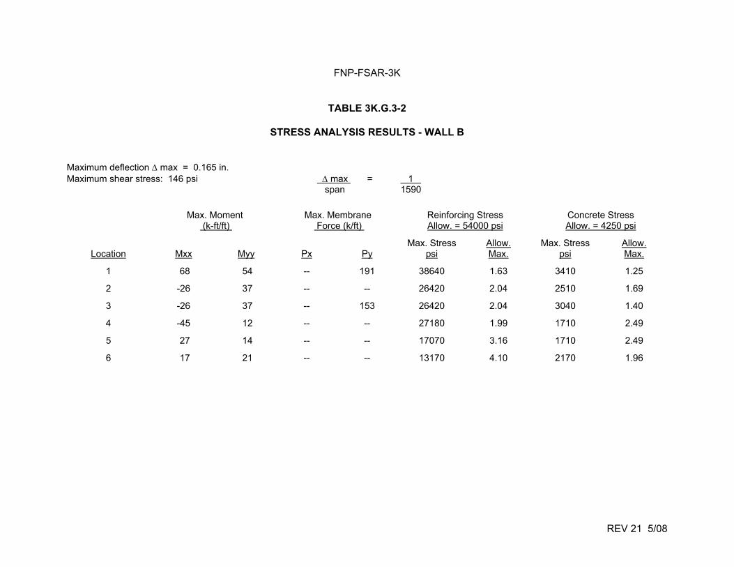
FNP-FSAR-3K
REV 21 5/08
TABLE 3K.G.3-2
STRESS ANALYSIS RESULTS - WALL B Maximum deflection max = 0.165 in. Maximum shear stress: 146 psi max = 1 span 1590
Max. Moment (k-ft/ft)
Max. Membrane Force (k/ft)
Reinforcing Stress Allow. = 54000 psi
Concrete Stress Allow. = 4250 psi
Location
Mxx
Myy
Px
Py
Max. Stress psi
Allow. Max.
Max. Stress psi
Allow. Max.
1 68 54 -- 191 38640 1.63 3410 1.25
2 -26 37 -- -- 26420 2.04 2510 1.69
3 -26 37 -- 153 26420 2.04 3040 1.40
4 -45 12 -- -- 27180 1.99 1710 2.49
5 27 14 -- -- 17070 3.16 1710 2.49
6 17 21 -- -- 13170 4.10 2170 1.96
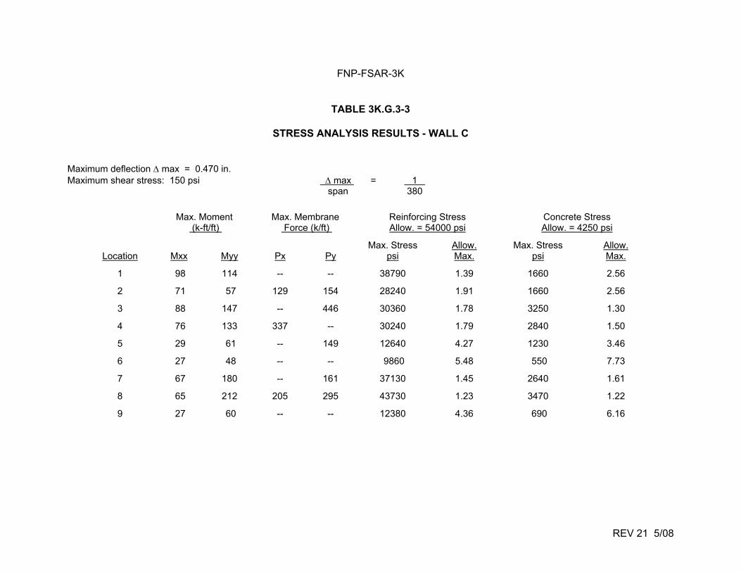
FNP-FSAR-3K
REV 21 5/08
TABLE 3K.G.3-3
STRESS ANALYSIS RESULTS - WALL C Maximum deflection max = 0.470 in. Maximum shear stress: 150 psi max = 1 span 380
Max. Moment (k-ft/ft)
Max. Membrane Force (k/ft)
Reinforcing Stress Allow. = 54000 psi
Concrete Stress Allow. = 4250 psi
Location
Mxx
Myy
Px
Py
Max. Stress psi
Allow. Max.
Max. Stress psi
Allow. Max.
1 98 114 -- -- 38790 1.39 1660 2.56
2 71 57 129 154 28240 1.91 1660 2.56
3 88 147 -- 446 30360 1.78 3250 1.30
4 76 133 337 -- 30240 1.79 2840 1.50
5 29 61 -- 149 12640 4.27 1230 3.46
6 27 48 -- -- 9860 5.48 550 7.73
7 67 180 -- 161 37130 1.45 2640 1.61
8 65 212 205 295 43730 1.23 3470 1.22
9 27 60 -- -- 12380 4.36 690 6.16
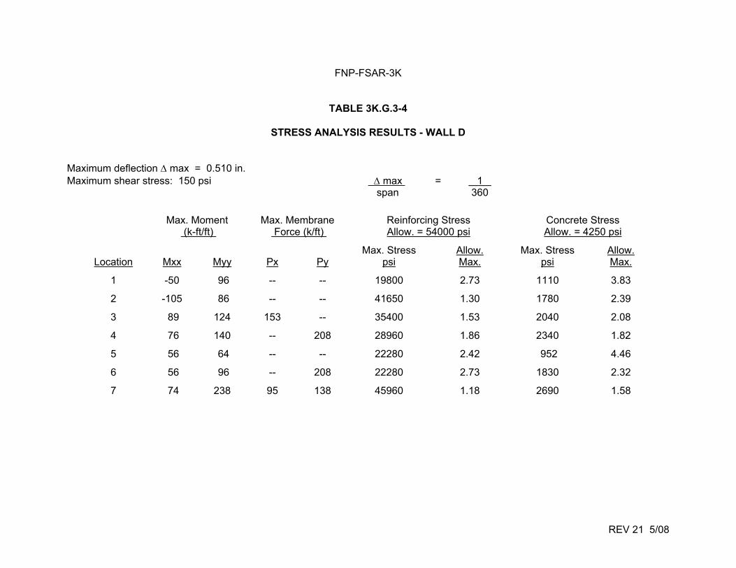
FNP-FSAR-3K
REV 21 5/08
TABLE 3K.G.3-4
STRESS ANALYSIS RESULTS - WALL D Maximum deflection max = 0.510 in. Maximum shear stress: 150 psi max = 1 span 360
Max. Moment (k-ft/ft)
Max. Membrane Force (k/ft)
Reinforcing Stress Allow. = 54000 psi
Concrete Stress Allow. = 4250 psi
Location
Mxx
Myy
Px
Py
Max. Stress psi
Allow. Max.
Max. Stress psi
Allow. Max.
1 -50 96 -- -- 19800 2.73 1110 3.83
2 -105 86 -- -- 41650 1.30 1780 2.39
3 89 124 153 -- 35400 1.53 2040 2.08
4 76 140 -- 208 28960 1.86 2340 1.82
5 56 64 -- -- 22280 2.42 952 4.46
6 56 96 -- 208 22280 2.73 1830 2.32
7 74 238 95 138 45960 1.18 2690 1.58
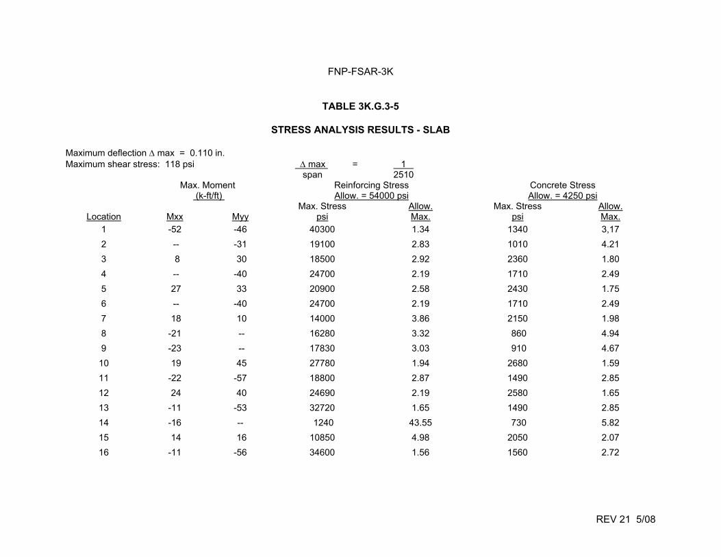
FNP-FSAR-3K
REV 21 5/08
TABLE 3K.G.3-5
STRESS ANALYSIS RESULTS - SLAB Maximum deflection max = 0.110 in. Maximum shear stress: 118 psi max = 1 span 2510
Max. Moment (k-ft/ft)
Reinforcing Stress Allow. = 54000 psi
Concrete Stress Allow. = 4250 psi
Location
Mxx
Myy
Max. Stress psi
Allow. Max.
Max. Stress psi
Allow. Max.
1 -52 -46 40300 1.34 1340 3,17
2 -- -31 19100 2.83 1010 4.21
3 8 30 18500 2.92 2360 1.80
4 -- -40 24700 2.19 1710 2.49
5 27 33 20900 2.58 2430 1.75
6 -- -40 24700 2.19 1710 2.49
7 18 10 14000 3.86 2150 1.98
8 -21 -- 16280 3.32 860 4.94
9 -23 -- 17830 3.03 910 4.67
10 19 45 27780 1.94 2680 1.59
11 -22 -57 18800 2.87 1490 2.85
12 24 40 24690 2.19 2580 1.65
13 -11 -53 32720 1.65 1490 2.85
14 -16 -- 1240 43.55 730 5.82
15 14 16 10850 4.98 2050 2.07
16 -11 -56 34600 1.56 1560 2.72
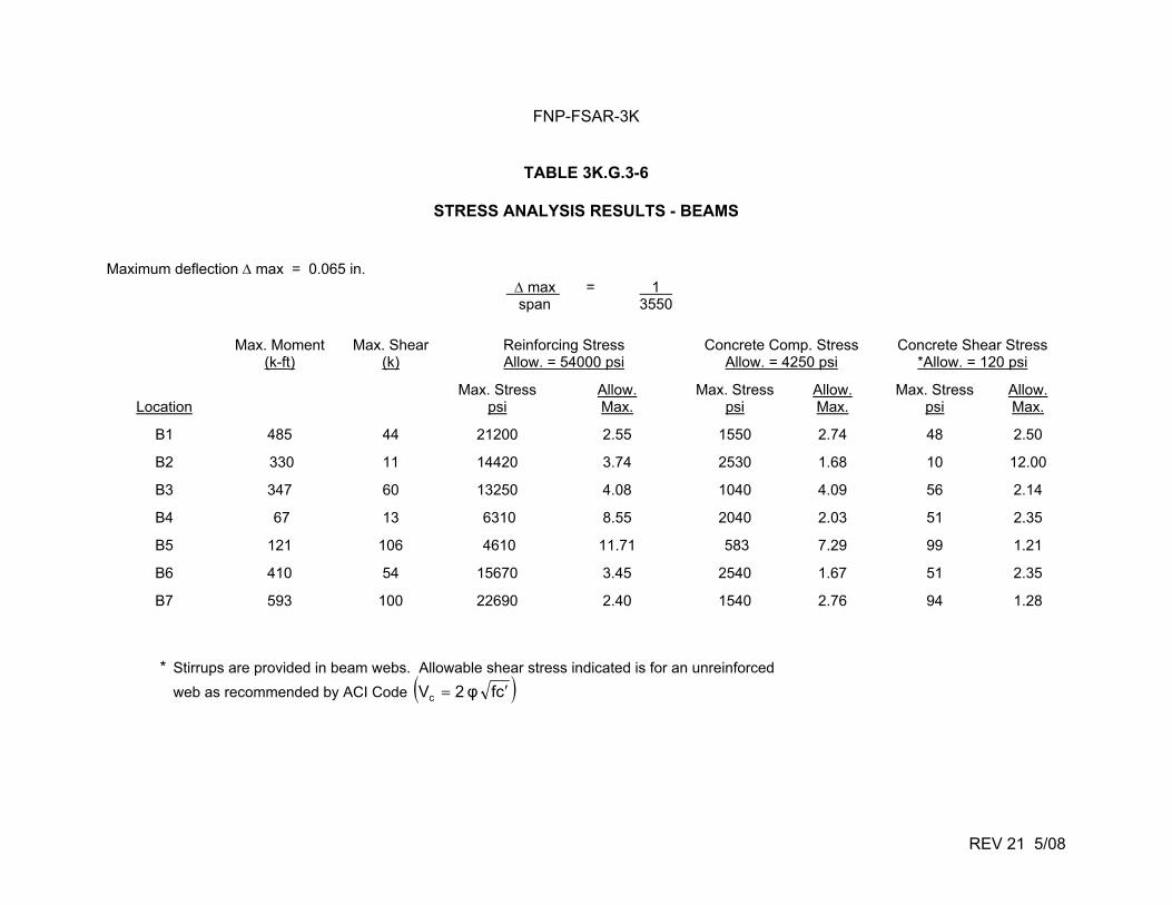
FNP-FSAR-3K
REV 21 5/08
TABLE 3K.G.3-6
STRESS ANALYSIS RESULTS - BEAMS Maximum deflection max = 0.065 in. max = 1 span 3550
Max. Moment (k-ft)
Max. Shear (k)
Reinforcing Stress Allow. = 54000 psi
Concrete Comp. Stress Allow. = 4250 psi
Concrete Shear Stress *Allow. = 120 psi
Location
Max. Stress psi
Allow. Max.
Max. Stress psi
Allow. Max.
Max. Stress psi
Allow. Max.
B1 485 44 21200 2.55 1550 2.74 48 2.50
B2 330 11 14420 3.74 2530 1.68 10 12.00
B3 347 60 13250 4.08 1040 4.09 56 2.14
B4 67 13 6310 8.55 2040 2.03 51 2.35
B5 121 106 4610 11.71 583 7.29 99 1.21
B6 410 54 15670 3.45 2540 1.67 51 2.35
B7 593 100 22690 2.40 1540 2.76 94 1.28
* Stirrups are provided in beam webs. Allowable shear stress indicated is for an unreinforced
web as recommended by ACI Code cfφ2Vc
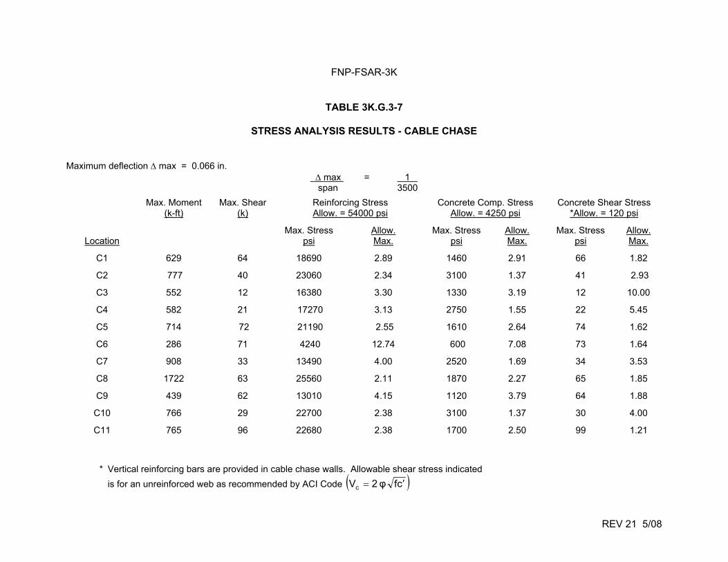
FNP-FSAR-3K
REV 21 5/08
TABLE 3K.G.3-7
STRESS ANALYSIS RESULTS - CABLE CHASE Maximum deflection max = 0.066 in. max = 1 span 3500
Max. Moment
(k-ft) Max. Shear
(k) Reinforcing Stress Allow. = 54000 psi
Concrete Comp. Stress Allow. = 4250 psi
Concrete Shear Stress *Allow. = 120 psi
Location
Max. Stress psi
Allow. Max.
Max. Stress psi
Allow. Max.
Max. Stress psi
Allow. Max.
C1 629 64 18690 2.89 1460 2.91 66 1.82
C2 777 40 23060 2.34 3100 1.37 41 2.93
C3 552 12 16380 3.30 1330 3.19 12 10.00
C4 582 21 17270 3.13 2750 1.55 22 5.45
C5 714 72 21190 2.55 1610 2.64 74 1.62
C6 286 71 4240 12.74 600 7.08 73 1.64
C7 908 33 13490 4.00 2520 1.69 34 3.53
C8 1722 63 25560 2.11 1870 2.27 65 1.85
C9 439 62 13010 4.15 1120 3.79 64 1.88
C10 766 29 22700 2.38 3100 1.37 30 4.00
C11 765 96 22680 2.38 1700 2.50 99 1.21
* Vertical reinforcing bars are provided in cable chase walls. Allowable shear stress indicated
is for an unreinforced web as recommended by ACI Code cfφ2Vc
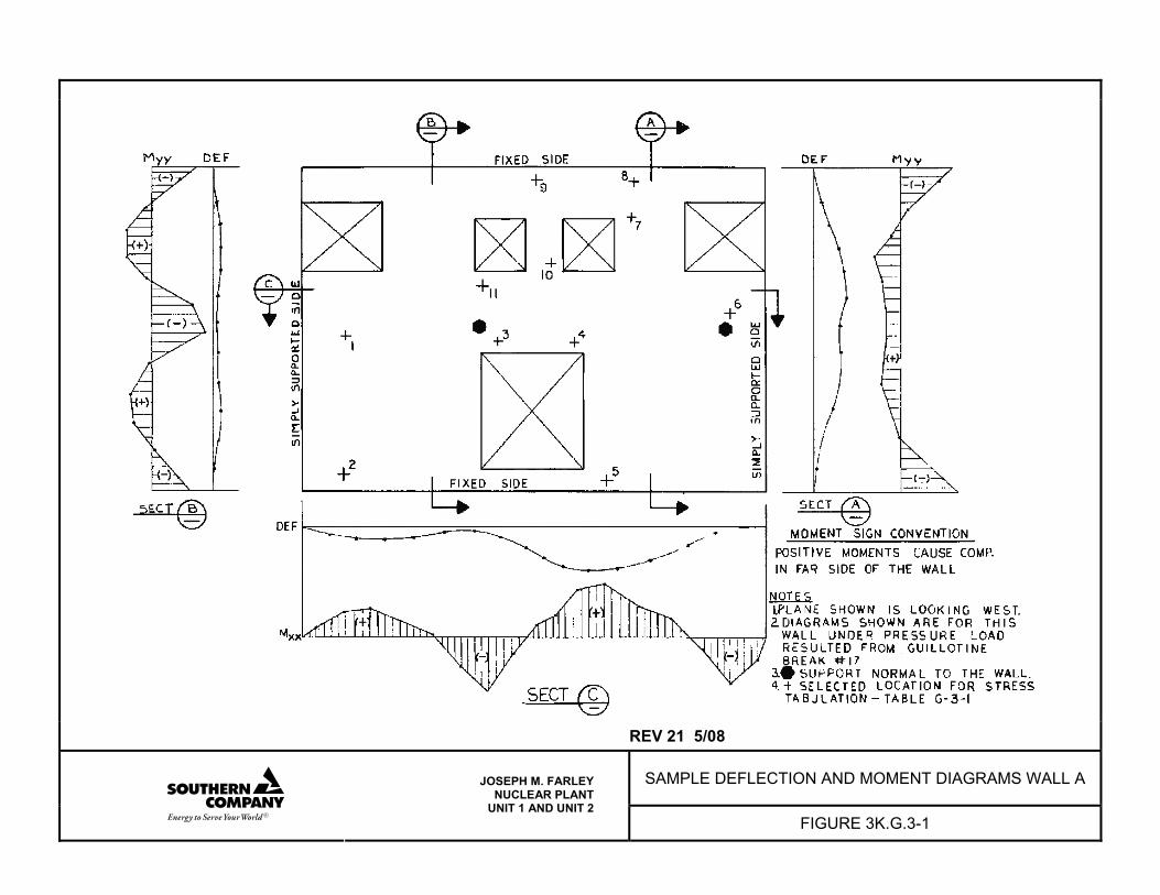
REV 21 5/08
SAMPLE DEFLECTION AND MOMENT DIAGRAMS WALL A
JOSEPH M. FARLEY NUCLEAR PLANT
UNIT 1 AND UNIT 2 FIGURE 3K.G.3-1
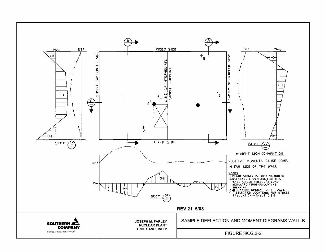
REV 21 5/08
SAMPLE DEFLECTION AND MOMENT DIAGRAMS WALL B
JOSEPH M. FARLEY NUCLEAR PLANT
UNIT 1 AND UNIT 2 FIGURE 3K.G.3-2
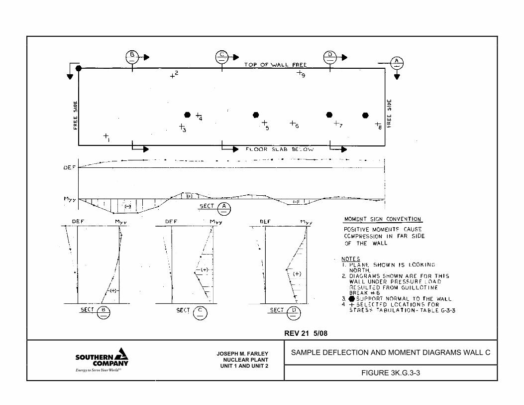
REV 21 5/08
SAMPLE DEFLECTION AND MOMENT DIAGRAMS WALL C
JOSEPH M. FARLEY NUCLEAR PLANT
UNIT 1 AND UNIT 2 FIGURE 3K.G.3-3

REV 21 5/08
SAMPLE DEFLECTION AND MOMENT DIAGRAMS WALL D
JOSEPH M. FARLEY NUCLEAR PLANT
UNIT 1 AND UNIT 2 FIGURE 3K.G.3-4
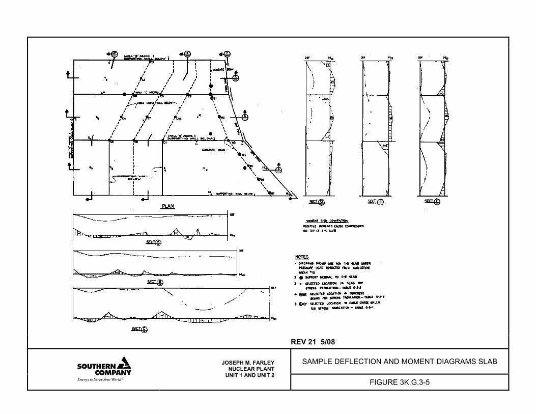
REV 21 5/08
SAMPLE DEFLECTION AND MOMENT DIAGRAMS SLAB
JOSEPH M. FARLEY NUCLEAR PLANT
UNIT 1 AND UNIT 2 FIGURE 3K.G.3-5
FNP-FSAR-3L
3L-i REV 21 5/08
3L ASME SECTION III NUCLEAR CLASS AUXILIARY PIPING STRUCTURE ANALYSIS
TABLE OF CONTENTS Page 3L.1.0 INTRODUCTION....................................................................................................3L-1 3L.2.0 NUCLEAR CLASS 1 ..............................................................................................3L-1 3L.2.1 PIPING CONSIDERED ..........................................................................................3L-1 3L.2.2 METHODS OF ANALYSIS.....................................................................................3L-2 3L.2.2.1 Class 1 Lines (Including Accumulator Lines).....................................3L-2 3L.2.2.2 Safety Injection Lines (Except Accumulator Lines)............................3L-2 3L.2.3 BREAK POINTS AND WHIP RESTRAINT LOCATIONS.......................................3L-6 3L.2.3.1 Class 1 Lines (Including Accumulator Lines).....................................3L-6 3L.2.3.2 Safety Injection Lines (Except Accumulator Lines)............................3L-6 3L.3.0 NUCLEAR CLASS 2 ..............................................................................................3L-6 3L.3.1 PIPING CONSIDERED ..........................................................................................3L-6 3L.3.2 METHODS OF ANALYSIS.....................................................................................3L-7 3L.3.2.1 Piping System Analysis (ME 632)......................................................3L-7 3L.3.2.2 Linear Elastic Analysis of Piping Systems (ME 101) .......................3L-11 3L.3.2.3 Local Stresses in Cylindrical Shells due to External Loadings (ME 210) ..........................................................................3L-12 3L.3.3 BREAK POINTS AND WHIP RESTRAINT LOCATIONS.....................................3L-12
FNP-FSAR-3L
3L-1 REV 21 5/08
APPENDIX 3L
ASME SECTION III NUCLEAR CLASS AUXILIARY PIPING STRUCTURAL ANALYSIS 3L.1.0 INTRODUCTION This appendix was prepared in response to question MEB-2.3A, transmitted by a letter from K. Kniel (NRC) to A. Barton (APC) on June 14, 1974. The appendix presents a summary of the analysis for branch lines in the containment which are ASME Section III, Nuclear Class 1 and 2. The Design Specification for ASME Nuclear Class 1 auxiliary piping requires that a stress analysis be performed according to the ASME Boiler and Pressure Vessel Code, Section III, Nuclear Power Plant Components, 1971 Edition (including applicable addenda). 3L.2.0 NUCLEAR CLASS 1 This section contains the structural evaluation of ASME III Nuclear Class 1 piping connected to the reactor coolant piping and inside the containment building and all fittings connecting the above piping under postulated loading conditions. These loads result from thermal expansion, pressure, weight, earthquake, design basis accident, and plant operational thermal and pressure transients. Criteria for postulated break locations are specified in subsection 3.6.2.3. 3L.2.1 PIPING CONSIDERED The Class 1 piping considered in this appendix consists of the following lines:
Size (in.) Line
14 Pressurizer surge line
12 Residual heat removal line, loop 1
12 Residual heat removal line, loop 3
12 SIS accumulator line, loop 1
12 SIS accumulator line, loop 2
12 SIS accumulator line, loop 3
3 CVCS normal charging line 3 CVCS alternate charging line 3 CVCS normal letdown line
FNP-FSAR-3L
3L-2 REV 21 5/08
In addition to the lines listed above, the safety injection lines (except accumulator lines) were also considered. The stress analysis results for these lines are given in the applicable Class 1 stress reports. 3L.2.2 METHODS OF ANALYSIS 3L.2.2.1 Class 1 Lines (Including Accumulator Lines) The analytical methods used in this analysis are described in subsection 5.2.1.10. They consist of the transfer matrix method and stiffness matrix formation for the static structural analysis, the response spectrum method for seismic dynamic analysis, and a structural analysis for the effect of a reactor coolant loop pipe break. The complexity of the piping systems requires the use of a computer to obtain the displacements, forces, and stresses in the piping and support members. The computer codes used for the Class 1 piping systems are capable of performing an elastic analysis of redundant piping systems subjected to thermal, static, and dynamic loads. A detailed description, the extent of application, and the verification and qualification of the WESTDYN 7 computer code can be found in topical report WCAP-8252, Documentation of Selected Westinghouse Structural Analysis Computer Codes (April 1974). Emergency core cooling system (ECCS) branch lines are analyzed for the effects of postulated reactor coolant pipe breaks as a faulted condition. Emergency core cooling system lines attached to both the unbroken loops and to the unbroken legs of the broken loop were considered. By comparison of the magnitude of the reactor coolant loop (RCL) and reactor pressure vessel (RPV) LOCA displacements, it was determined that the effects of a crossover leg break would be the most severe condition for the safety injection system (SIS) accumulator lines. (The RPV inlet and outlet nozzle breaks impose less severe loading conditions on the accumulator lines; therefore, the crossover leg break is presented as the limiting case.) A dynamic analysis was performed on a linear, elastic basis by applying the time-history displacement output of the RCL analysis to the ECCS lines using program FIXFM. The resultant stresses were combined with other faulted condition stresses to satisfy the ASME code equation 9 faulted stress intensity limit of 3.0 Sm. 3L.2.2.2 Safety Injection Lines (Except Accumulator Lines) The following are descriptions of the computer programs used in stress analysis of the safety injection lines (except accumulator lines). In addition to the following, ME632, described in subsection 3L.3.2.1, was also used. 3L.2.2.2.1 Thermal Stress Program (ME 662) Purpose To determine the temperature and stress distributions within a body as a function of time when subjected to thermal and/or mechanical loads. The program is valid for axisymmetric or plane structures.
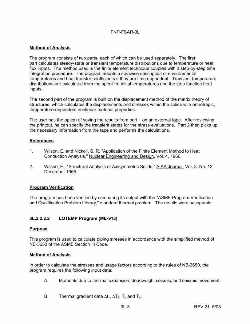
FNP-FSAR-3L
3L-3 REV 21 5/08
Method of Analysis The program consists of two parts, each of which can be used separately. The first part calculates steady-state or transient temperature distributions due to temperature or heat flux inputs. The method used is the finite element technique coupled with a step-by-step time integration procedure. The program adopts a stepwise description of environmental temperatures and heat transfer coefficients if they are time dependent. Transient temperature distributions are calculated from the specified initial temperatures and the step function heat inputs. The second part of the program is built on the displacement method of the matrix theory of structures, which calculates the displacements and stresses within the solids with orthotropic, temperature-dependent nonlinear material properties. The user has the option of saving the results from part 1 on an external tape. After reviewing the printout, he can specify the transient states for the stress evaluations. Part 2 then picks up the necessary information from the tape and performs the calculations. References 1. Wilson, E. and Nickell, S. R. "Application of the Finite Element Method to Heat
Conduction Analysis," Nuclear Engineering and Design, Vol. 4, 1966. 2. Wilson, E., "Structural Analysis of Axisymmetric Solids," AIAA Journal, Vol. 3, No. 12,
December 1965. Program Verification The program has been verified by comparing its output with the "ASME Program Verification and Qualification Problem Library," standard thermal problem. The results were acceptable. 3L.2.2.2.2 LOTEMP Program (ME-913) Purpose This program is used to calculate piping stresses in accordance with the simplified method of NB-3650 of the ASME Section III Code. Method of Analysis In order to calculate the stresses and usage factors according to the rules of NB-3650, the program requires the following input data: A. Moments due to thermal expansion, deadweight seismic, and seismic movement.
B. Thermal gradient data Δt1, ΔT2, Ta and Tb.
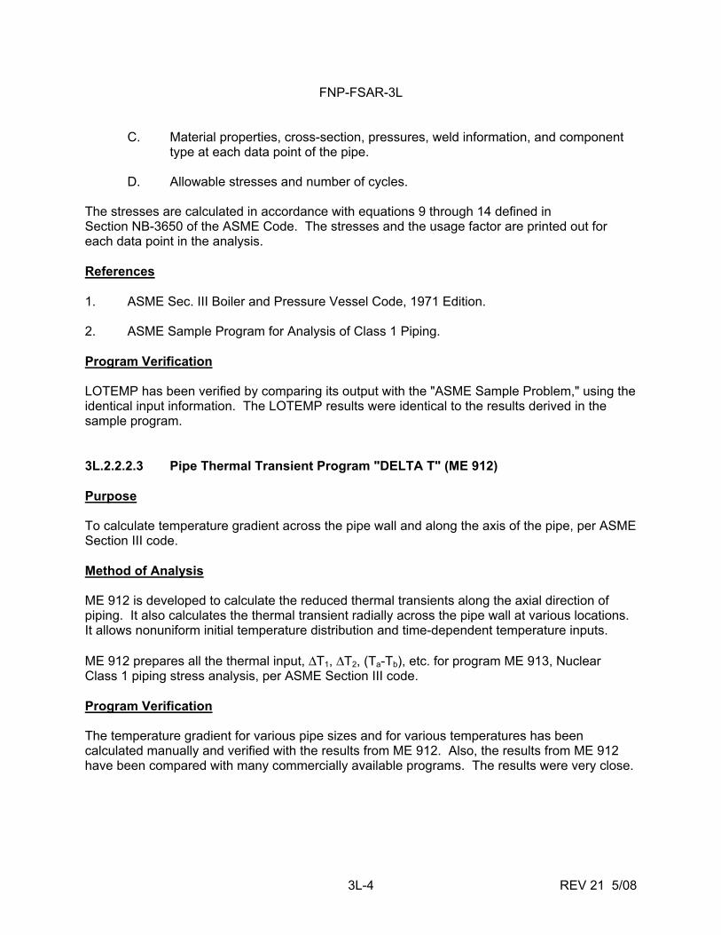
FNP-FSAR-3L
3L-4 REV 21 5/08
C. Material properties, cross-section, pressures, weld information, and component type at each data point of the pipe.
D. Allowable stresses and number of cycles. The stresses are calculated in accordance with equations 9 through 14 defined in Section NB-3650 of the ASME Code. The stresses and the usage factor are printed out for each data point in the analysis. References 1. ASME Sec. III Boiler and Pressure Vessel Code, 1971 Edition. 2. ASME Sample Program for Analysis of Class 1 Piping. Program Verification LOTEMP has been verified by comparing its output with the "ASME Sample Problem," using the identical input information. The LOTEMP results were identical to the results derived in the sample program. 3L.2.2.2.3 Pipe Thermal Transient Program "DELTA T" (ME 912) Purpose To calculate temperature gradient across the pipe wall and along the axis of the pipe, per ASME Section III code. Method of Analysis ME 912 is developed to calculate the reduced thermal transients along the axial direction of piping. It also calculates the thermal transient radially across the pipe wall at various locations. It allows nonuniform initial temperature distribution and time-dependent temperature inputs. ME 912 prepares all the thermal input, ΔT1, ΔT2, (Ta-Tb), etc. for program ME 913, Nuclear Class 1 piping stress analysis, per ASME Section III code. Program Verification The temperature gradient for various pipe sizes and for various temperatures has been calculated manually and verified with the results from ME 912. Also, the results from ME 912 have been compared with many commercially available programs. The results were very close.
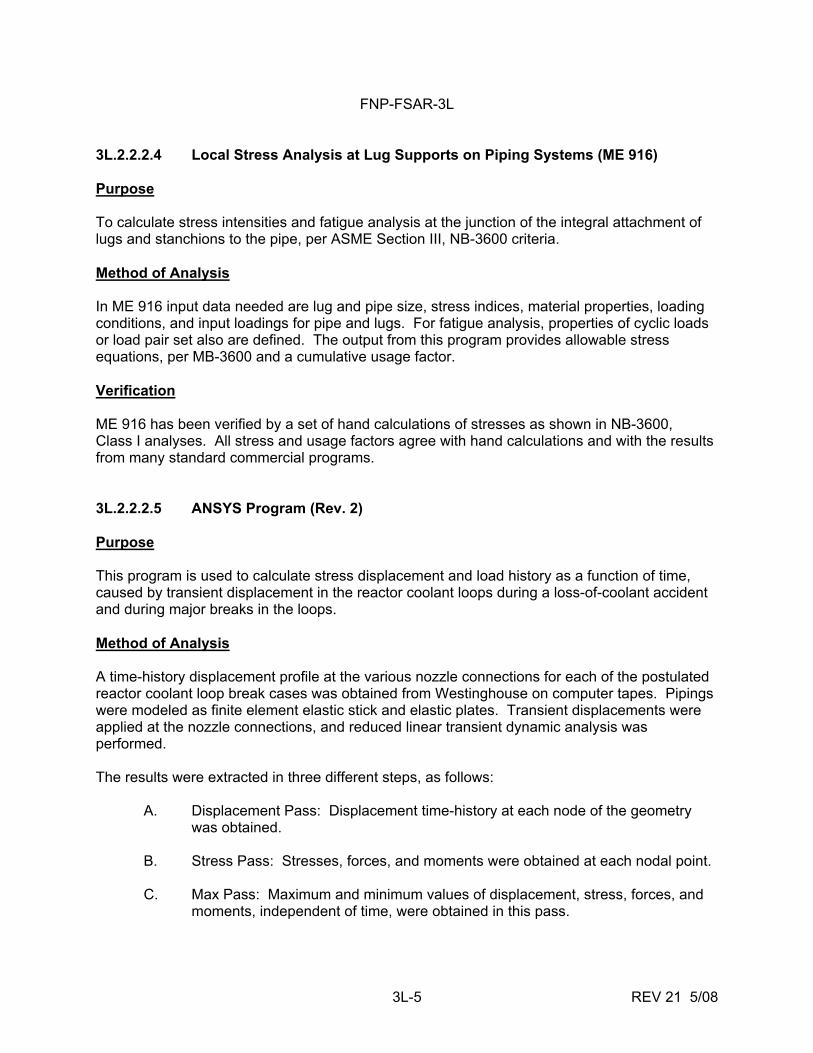
FNP-FSAR-3L
3L-5 REV 21 5/08
3L.2.2.2.4 Local Stress Analysis at Lug Supports on Piping Systems (ME 916) Purpose To calculate stress intensities and fatigue analysis at the junction of the integral attachment of lugs and stanchions to the pipe, per ASME Section III, NB-3600 criteria. Method of Analysis In ME 916 input data needed are lug and pipe size, stress indices, material properties, loading conditions, and input loadings for pipe and lugs. For fatigue analysis, properties of cyclic loads or load pair set also are defined. The output from this program provides allowable stress equations, per MB-3600 and a cumulative usage factor. Verification ME 916 has been verified by a set of hand calculations of stresses as shown in NB-3600, Class I analyses. All stress and usage factors agree with hand calculations and with the results from many standard commercial programs. 3L.2.2.2.5 ANSYS Program (Rev. 2) Purpose This program is used to calculate stress displacement and load history as a function of time, caused by transient displacement in the reactor coolant loops during a loss-of-coolant accident and during major breaks in the loops. Method of Analysis A time-history displacement profile at the various nozzle connections for each of the postulated reactor coolant loop break cases was obtained from Westinghouse on computer tapes. Pipings were modeled as finite element elastic stick and elastic plates. Transient displacements were applied at the nozzle connections, and reduced linear transient dynamic analysis was performed. The results were extracted in three different steps, as follows: A. Displacement Pass: Displacement time-history at each node of the geometry
was obtained. B. Stress Pass: Stresses, forces, and moments were obtained at each nodal point.
C. Max Pass: Maximum and minimum values of displacement, stress, forces, and
moments, independent of time, were obtained in this pass.
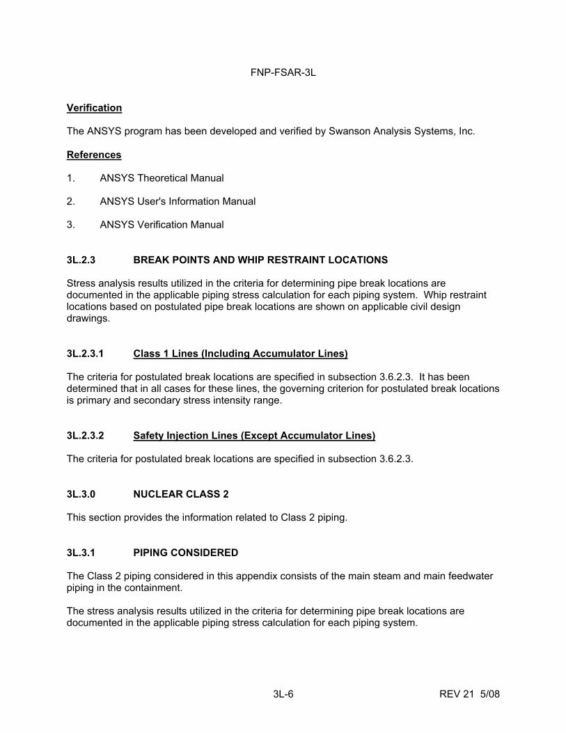
FNP-FSAR-3L
3L-6 REV 21 5/08
Verification The ANSYS program has been developed and verified by Swanson Analysis Systems, Inc. References 1. ANSYS Theoretical Manual 2. ANSYS User's Information Manual 3. ANSYS Verification Manual 3L.2.3 BREAK POINTS AND WHIP RESTRAINT LOCATIONS Stress analysis results utilized in the criteria for determining pipe break locations are documented in the applicable piping stress calculation for each piping system. Whip restraint locations based on postulated pipe break locations are shown on applicable civil design drawings. 3L.2.3.1 Class 1 Lines (Including Accumulator Lines) The criteria for postulated break locations are specified in subsection 3.6.2.3. It has been determined that in all cases for these lines, the governing criterion for postulated break locations is primary and secondary stress intensity range. 3L.2.3.2 Safety Injection Lines (Except Accumulator Lines) The criteria for postulated break locations are specified in subsection 3.6.2.3. 3L.3.0 NUCLEAR CLASS 2 This section provides the information related to Class 2 piping. 3L.3.1 PIPING CONSIDERED The Class 2 piping considered in this appendix consists of the main steam and main feedwater piping in the containment. The stress analysis results utilized in the criteria for determining pipe break locations are documented in the applicable piping stress calculation for each piping system.
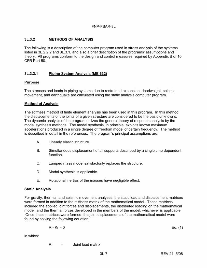
FNP-FSAR-3L
3L-7 REV 21 5/08
3L.3.2 METHODS OF ANALYSIS The following is a description of the computer program used in stress analysis of the systems listed in 3L.2.2.2 and 3L.3.1, and also a brief description of the programs' assumptions and theory. All programs conform to the design and control measures required by Appendix B of 10 CFR Part 50. 3L.3.2.1 Piping System Analysis (ME 632) Purpose The stresses and loads in piping systems due to restrained expansion, deadweight, seismic movement, and earthquake are calculated using the static analysis computer program. Method of Analysis The stiffness method of finite element analysis has been used in this program. In this method, the displacements of the joints of a given structure are considered to be the basic unknowns. The dynamic analysis of the program utilizes the general theory of response analysis by the modal synthesis methods. The modal synthesis, in principle, exploits known maximum accelerations produced in a single degree of freedom model of certain frequency. The method is described in detail in the references. The program's principal assumptions are: A. Linearly elastic structure. B. Simultaneous displacement of all supports described by a single time dependent
function. C. Lumped mass model satisfactorily replaces the structure. D. Modal synthesis is applicable. E. Rotational inertias of the masses have negligible effect. Static Analysis For gravity, thermal, and seismic movement analyses, the static load and displacement matrices were formed in addition to the stiffness matrix of the mathematical model. These matrices included the applied joint forces and displacements, the distributed loading on the mathematical model, and the thermal forces developed in the members of the model, whichever is applicable. Once these matrices were formed, the joint displacements of the mathematical model were found by solving the following equation: R - Kr = 0 Eq. (1) in which: R = Joint load matrix
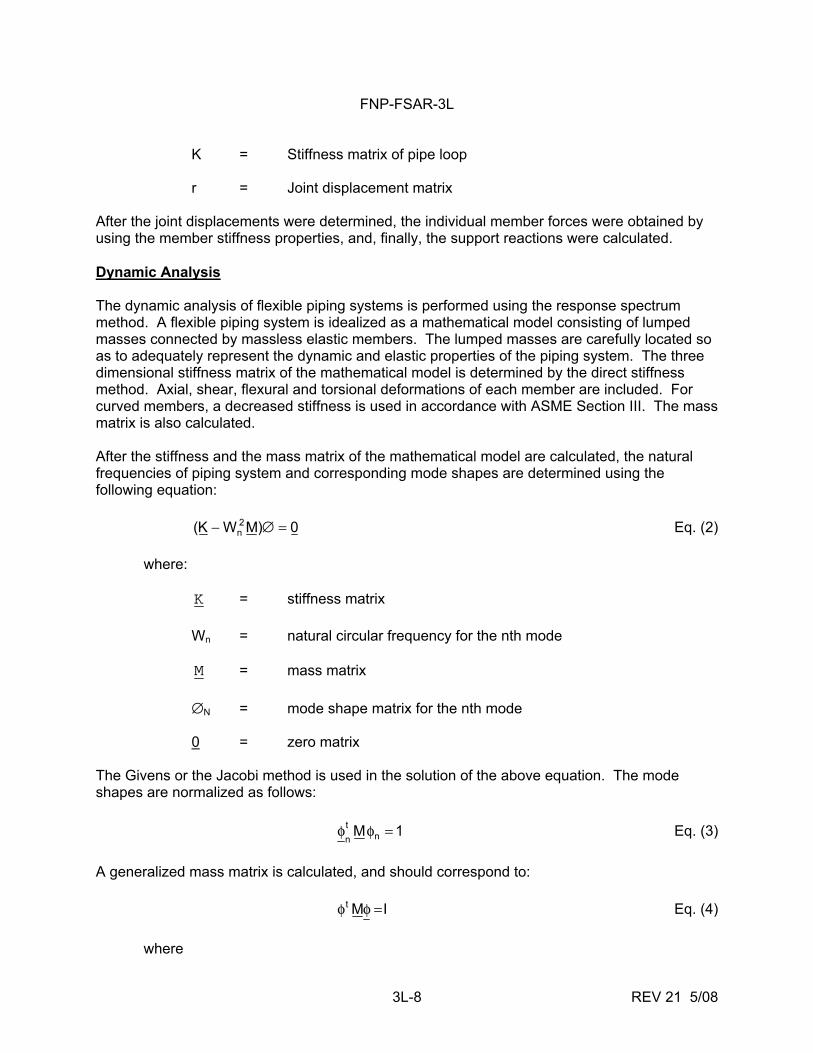
FNP-FSAR-3L
3L-8 REV 21 5/08
K = Stiffness matrix of pipe loop r = Joint displacement matrix After the joint displacements were determined, the individual member forces were obtained by using the member stiffness properties, and, finally, the support reactions were calculated. Dynamic Analysis The dynamic analysis of flexible piping systems is performed using the response spectrum method. A flexible piping system is idealized as a mathematical model consisting of lumped masses connected by massless elastic members. The lumped masses are carefully located so as to adequately represent the dynamic and elastic properties of the piping system. The three dimensional stiffness matrix of the mathematical model is determined by the direct stiffness method. Axial, shear, flexural and torsional deformations of each member are included. For curved members, a decreased stiffness is used in accordance with ASME Section III. The mass matrix is also calculated. After the stiffness and the mass matrix of the mathematical model are calculated, the natural frequencies of piping system and corresponding mode shapes are determined using the following equation: 0)MWK( 2
n =∅− Eq. (2) where: K = stiffness matrix Wn = natural circular frequency for the nth mode M = mass matrix ∅N = mode shape matrix for the nth mode 0 = zero matrix The Givens or the Jacobi method is used in the solution of the above equation. The mode shapes are normalized as follows: 1M n
tn
=φφ Eq. (3) A generalized mass matrix is calculated, and should correspond to: IMt =φφ Eq. (4) where
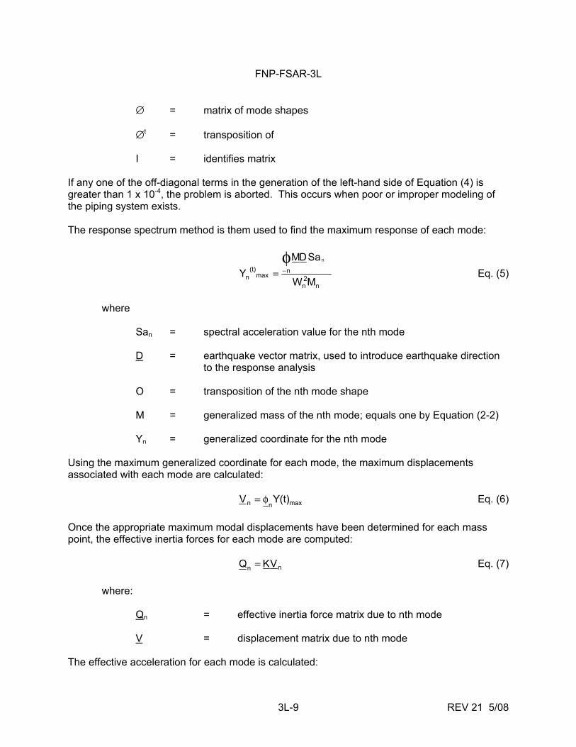
FNP-FSAR-3L
3L-9 REV 21 5/08
∅ = matrix of mode shapes ∅t = transposition of I = identifies matrix If any one of the off-diagonal terms in the generation of the left-hand side of Equation (4) is greater than 1 x 10⁻⁴, the problem is aborted. This occurs when poor or improper modeling of the piping system exists. The response spectrum method is them used to find the maximum response of each mode:
n
2n
nmax
(t)n MW
SaDMY
nφ−= Eq. (5)
where San = spectral acceleration value for the nth mode D = earthquake vector matrix, used to introduce earthquake direction to the response analysis O = transposition of the nth mode shape M = generalized mass of the nth mode; equals one by Equation (2-2) Yn = generalized coordinate for the nth mode Using the maximum generalized coordinate for each mode, the maximum displacements associated with each mode are calculated: maxnn (t)YV φ= Eq. (6) Once the appropriate maximum modal displacements have been determined for each mass point, the effective inertia forces for each mode are computed: nn VKQ = Eq. (7) where: Qn = effective inertia force matrix due to nth mode V = displacement matrix due to nth mode The effective acceleration for each mode is calculated:
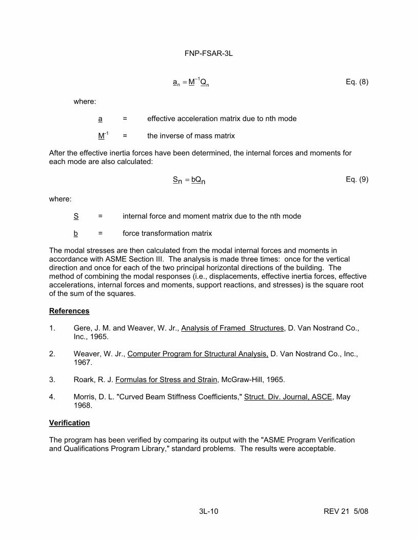
FNP-FSAR-3L
3L-10 REV 21 5/08
n1
n QMa −= Eq. (8) where: a = effective acceleration matrix due to nth mode M-1 = the inverse of mass matrix After the effective inertia forces have been determined, the internal forces and moments for each mode are also calculated: nQbnS = Eq. (9) where: S = internal force and moment matrix due to the nth mode b = force transformation matrix The modal stresses are then calculated from the modal internal forces and moments in accordance with ASME Section III. The analysis is made three times: once for the vertical direction and once for each of the two principal horizontal directions of the building. The method of combining the modal responses (i.e., displacements, effective inertia forces, effective accelerations, internal forces and moments, support reactions, and stresses) is the square root of the sum of the squares. References 1. Gere, J. M. and Weaver, W. Jr., Analysis of Framed Structures, D. Van Nostrand Co.,
Inc., 1965. 2. Weaver, W. Jr., Computer Program for Structural Analysis, D. Van Nostrand Co., Inc.,
1967. 3. Roark, R. J. Formulas for Stress and Strain, McGraw-Hill, 1965. 4. Morris, D. L. "Curved Beam Stiffness Coefficients," Struct. Div. Journal, ASCE, May
1968. Verification The program has been verified by comparing its output with the "ASME Program Verification and Qualifications Program Library," standard problems. The results were acceptable.
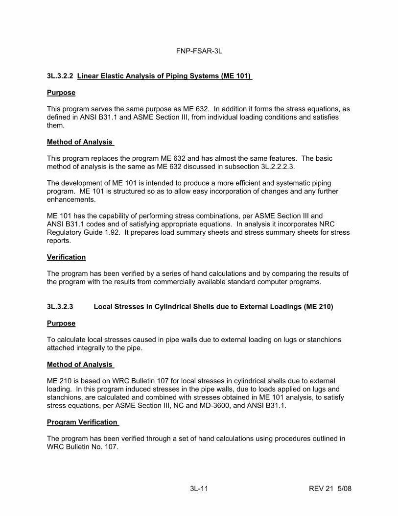
FNP-FSAR-3L
3L-11 REV 21 5/08
3L.3.2.2 Linear Elastic Analysis of Piping Systems (ME 101) Purpose This program serves the same purpose as ME 632. In addition it forms the stress equations, as defined in ANSI B31.1 and ASME Section III, from individual loading conditions and satisfies them. Method of Analysis This program replaces the program ME 632 and has almost the same features. The basic method of analysis is the same as ME 632 discussed in subsection 3L.2.2.2.3. The development of ME 101 is intended to produce a more efficient and systematic piping program. ME 101 is structured so as to allow easy incorporation of changes and any further enhancements. ME 101 has the capability of performing stress combinations, per ASME Section III and ANSI B31.1 codes and of satisfying appropriate equations. In analysis it incorporates NRC Regulatory Guide 1.92. It prepares load summary sheets and stress summary sheets for stress reports. Verification The program has been verified by a series of hand calculations and by comparing the results of the program with the results from commercially available standard computer programs. 3L.3.2.3 Local Stresses in Cylindrical Shells due to External Loadings (ME 210) Purpose To calculate local stresses caused in pipe walls due to external loading on lugs or stanchions attached integrally to the pipe. Method of Analysis ME 210 is based on WRC Bulletin 107 for local stresses in cylindrical shells due to external loading. In this program induced stresses in the pipe walls, due to loads applied on lugs and stanchions, are calculated and combined with stresses obtained in ME 101 analysis, to satisfy stress equations, per ASME Section III, NC and MD-3600, and ANSI B31.1. Program Verification The program has been verified through a set of hand calculations using procedures outlined in WRC Bulletin No. 107.
FNP-FSAR-3L
3L-12 REV 21 5/08
References 1. Forsythe, G. E. and Wasow, W. R., Finite-Difference Methods for Partial Differential
Equations, John Wiley, 1960, pp 101-107, 119-125. 2. Holman, J. P., Heat Transfer, Third Edition, McGraw-Hill, 1972, Eqs. (6.1) and (6.29). 3. McNeill, D. R. and Brock, J. B., "Charts for Transient Temperatures in Pipes," in
Heating/Piping/Air Conditioning, November 1971, pp 107-119. 4. Tung, T. K., "Thermal Gradients in Pipe Walls Due to Ramps in Fluid Temperature,"
Report BR-5853-T-012, Bechtel Power Corporation, San Francisco, 1975. 5. Tung, T. K., "Analysis on Axial Discontinuity Temperature Difference in Pipe Walls," to
be reported. 3L.3.3 BREAK POINTS AND WHIP RESTRAINT LOCATIONS Break points are postulated in accordance with the requirements set forth in attachment A of appendix 3K. Whip restraint locations based on postulated pipe break locations are shown on applicable civil design drawings.
FNP-FSAR-3M
3M-i REV 21 5/08
3M REACTOR PRESSURE VESSEL SUPPORT LOADS
TABLE OF CONTENTS 3M.1 INTRODUCTION.........................................................................................................3M-1 3M.2 INTERFACE INFORMATION......................................................................................3M-1 3M.3 LOADING CONDITIONS.............................................................................................3M-2 3M.4 REACTOR VESSEL AND INTERNALS MODELING..................................................3M-2 3M.5 ANALYTICAL METHODS ...........................................................................................3M-3 3M.6 RESULTS OF THE ANALYSIS...................................................................................3M-4
FNP-FSAR-3M
3M-ii REV 21 5/08
LIST OF TABLES 3M-1 Maximum Reactor Vessel Displacements at Reactor Vessel Centerline 3M-2 Maximum Reactor Vessel Support Loads for Postulated Pipe Rupture Conditions 3M-3 Maximum Reactor Vessel Support Loads for Combined Pipe Rupture Condition, Safe
Shutdown Earthquake, and Deadweight

FNP-FSAR-3M
3M-iii REV 21 5/08
LIST OF FIGURES 3M-1 Reactor Vessel Support Shoe 3M-2 Reactor Vessel Support Box 3M-3 Mathematical Model for Horizontal Response 3M-4 Mathematical Model for Vertical Response
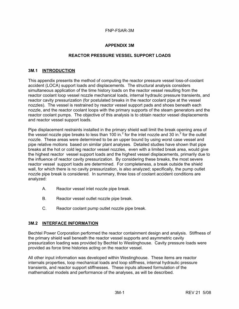
FNP-FSAR-3M
3M-1 REV 21 5/08
APPENDIX 3M
REACTOR PRESSURE VESSEL SUPPORT LOADS 3M.1 INTRODUCTION This appendix presents the method of computing the reactor pressure vessel loss-of-coolant accident (LOCA) support loads and displacements. The structural analysis considers simultaneous application of the time history loads on the reactor vessel resulting from the reactor coolant loop vessel nozzle mechanical loads, internal hydraulic pressure transients, and reactor cavity pressurization (for postulated breaks in the reactor coolant pipe at the vessel nozzles). The vessel is restrained by reactor vessel support pads and shoes beneath each nozzle, and the reactor coolant loops with the primary supports of the steam generators and the reactor coolant pumps. The objective of this analysis is to obtain reactor vessel displacements and reactor vessel support loads. Pipe displacement restraints installed in the primary shield wall limit the break opening area of the vessel nozzle pipe breaks to less than 100 in.2 for the inlet nozzle and 30 in.2 for the outlet nozzle. These areas were determined to be an upper bound by using worst case vessel and pipe relative motions based on similar plant analyses. Detailed studies have shown that pipe breaks at the hot or cold leg reactor vessel nozzles, even with a limited break area, would give the highest reactor vessel support loads and the highest vessel displacements, primarily due to the influence of reactor cavity pressurization. By considering these breaks, the most severe reactor vessel support loads are determined. For completeness, a break outside the shield wall, for which there is no cavity pressurization, is also analyzed; specifically, the pump outlet nozzle pipe break is considered. In summary, three loss of coolant accident conditions are analyzed: A. Reactor vessel inlet nozzle pipe break. B. Reactor vessel outlet nozzle pipe break. C. Reactor coolant pump outlet nozzle pipe break. 3M.2 INTERFACE INFORMATION Bechtel Power Corporation performed the reactor containment design and analysis. Stiffness of the primary shield wall beneath the reactor vessel supports and asymmetric cavity pressurization loading was provided by Bechtel to Westinghouse. Cavity pressure loads were provided as force time histories acting on the reactor vessel. All other input information was developed within Westinghouse. These items are reactor internals properties, loop mechanical loads and loop stiffness, internal hydraulic pressure transients, and reactor support stiffnesses. These inputs allowed formulation of the mathematical models and performance of the analyses, as will be described.
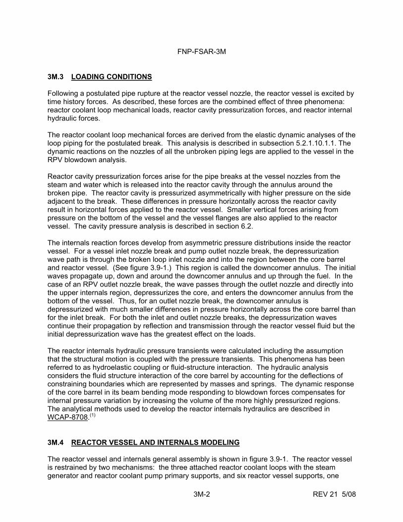
FNP-FSAR-3M
3M-2 REV 21 5/08
3M.3 LOADING CONDITIONS Following a postulated pipe rupture at the reactor vessel nozzle, the reactor vessel is excited by time history forces. As described, these forces are the combined effect of three phenomena: reactor coolant loop mechanical loads, reactor cavity pressurization forces, and reactor internal hydraulic forces. The reactor coolant loop mechanical forces are derived from the elastic dynamic analyses of the loop piping for the postulated break. This analysis is described in subsection 5.2.1.10.1.1. The dynamic reactions on the nozzles of all the unbroken piping legs are applied to the vessel in the RPV blowdown analysis. Reactor cavity pressurization forces arise for the pipe breaks at the vessel nozzles from the steam and water which is released into the reactor cavity through the annulus around the broken pipe. The reactor cavity is pressurized asymmetrically with higher pressure on the side adjacent to the break. These differences in pressure horizontally across the reactor cavity result in horizontal forces applied to the reactor vessel. Smaller vertical forces arising from pressure on the bottom of the vessel and the vessel flanges are also applied to the reactor vessel. The cavity pressure analysis is described in section 6.2. The internals reaction forces develop from asymmetric pressure distributions inside the reactor vessel. For a vessel inlet nozzle break and pump outlet nozzle break, the depressurization wave path is through the broken loop inlet nozzle and into the region between the core barrel and reactor vessel. (See figure 3.9-1.) This region is called the downcomer annulus. The initial waves propagate up, down and around the downcomer annulus and up through the fuel. In the case of an RPV outlet nozzle break, the wave passes through the outlet nozzle and directly into the upper internals region, depressurizes the core, and enters the downcomer annulus from the bottom of the vessel. Thus, for an outlet nozzle break, the downcomer annulus is depressurized with much smaller differences in pressure horizontally across the core barrel than for the inlet break. For both the inlet and outlet nozzle breaks, the depressurization waves continue their propagation by reflection and transmission through the reactor vessel fluid but the initial depressurization wave has the greatest effect on the loads. The reactor internals hydraulic pressure transients were calculated including the assumption that the structural motion is coupled with the pressure transients. This phenomena has been referred to as hydroelastic coupling or fluid-structure interaction. The hydraulic analysis considers the fluid structure interaction of the core barrel by accounting for the deflections of constraining boundaries which are represented by masses and springs. The dynamic response of the core barrel in its beam bending mode responding to blowdown forces compensates for internal pressure variation by increasing the volume of the more highly pressurized regions. The analytical methods used to develop the reactor internals hydraulics are described in WCAP-8708.(1) 3M.4 REACTOR VESSEL AND INTERNALS MODELING The reactor vessel and internals general assembly is shown in figure 3.9-1. The reactor vessel is restrained by two mechanisms: the three attached reactor coolant loops with the steam generator and reactor coolant pump primary supports, and six reactor vessel supports, one
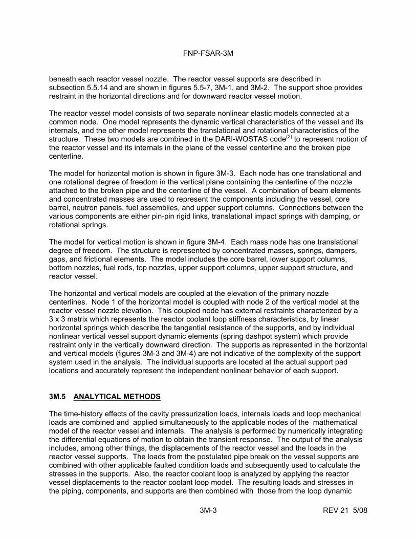
FNP-FSAR-3M
3M-3 REV 21 5/08
beneath each reactor vessel nozzle. The reactor vessel supports are described in subsection 5.5.14 and are shown in figures 5.5-7, 3M-1, and 3M-2. The support shoe provides restraint in the horizontal directions and for downward reactor vessel motion. The reactor vessel model consists of two separate nonlinear elastic models connected at a common node. One model represents the dynamic vertical characteristics of the vessel and its internals, and the other model represents the translational and rotational characteristics of the structure. These two models are combined in the DARI-WOSTAS code(2) to represent motion of the reactor vessel and its internals in the plane of the vessel centerline and the broken pipe centerline. The model for horizontal motion is shown in figure 3M-3. Each node has one translational and one rotational degree of freedom in the vertical plane containing the centerline of the nozzle attached to the broken pipe and the centerline of the vessel. A combination of beam elements and concentrated masses are used to represent the components including the vessel, core barrel, neutron panels, fuel assemblies, and upper support columns. Connections between the various components are either pin-pin rigid links, translational impact springs with damping, or rotational springs. The model for vertical motion is shown in figure 3M-4. Each mass node has one translational degree of freedom. The structure is represented by concentrated masses, springs, dampers, gaps, and frictional elements. The model includes the core barrel, lower support columns, bottom nozzles, fuel rods, top nozzles, upper support columns, upper support structure, and reactor vessel. The horizontal and vertical models are coupled at the elevation of the primary nozzle centerlines. Node 1 of the horizontal model is coupled with node 2 of the vertical model at the reactor vessel nozzle elevation. This coupled node has external restraints characterized by a 3 x 3 matrix which represents the reactor coolant loop stiffness characteristics, by linear horizontal springs which describe the tangential resistance of the supports, and by individual nonlinear vertical vessel support dynamic elements (spring dashpot system) which provide restraint only in the vertically downward direction. The supports as represented in the horizontal and vertical models (figures 3M-3 and 3M-4) are not indicative of the complexity of the support system used in the analysis. The individual supports are located at the actual support pad locations and accurately represent the independent nonlinear behavior of each support. 3M.5 ANALYTICAL METHODS The time-history effects of the cavity pressurization loads, internals loads and loop mechanical loads are combined and applied simultaneously to the applicable nodes of the mathematical model of the reactor vessel and internals. The analysis is performed by numerically integrating the differential equations of motion to obtain the transient response. The output of the analysis includes, among other things, the displacements of the reactor vessel and the loads in the reactor vessel supports. The loads from the postulated pipe break on the vessel supports are combined with other applicable faulted condition loads and subsequently used to calculate the stresses in the supports. Also, the reactor coolant loop is analyzed by applying the reactor vessel displacements to the reactor coolant loop model. The resulting loads and stresses in the piping, components, and supports are then combined with those from the loop dynamic
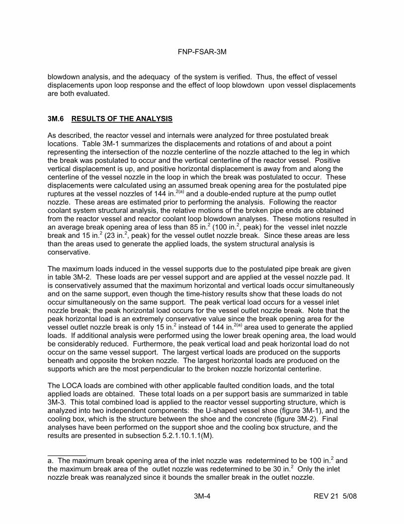
FNP-FSAR-3M
3M-4 REV 21 5/08
blowdown analysis, and the adequacy of the system is verified. Thus, the effect of vessel displacements upon loop response and the effect of loop blowdown upon vessel displacements are both evaluated. 3M.6 RESULTS OF THE ANALYSIS As described, the reactor vessel and internals were analyzed for three postulated break locations. Table 3M-1 summarizes the displacements and rotations of and about a point representing the intersection of the nozzle centerline of the nozzle attached to the leg in which the break was postulated to occur and the vertical centerline of the reactor vessel. Positive vertical displacement is up, and positive horizontal displacement is away from and along the centerline of the vessel nozzle in the loop in which the break was postulated to occur. These displacements were calculated using an assumed break opening area for the postulated pipe ruptures at the vessel nozzles of 144 in.2(a) and a double-ended rupture at the pump outlet nozzle. These areas are estimated prior to performing the analysis. Following the reactor coolant system structural analysis, the relative motions of the broken pipe ends are obtained from the reactor vessel and reactor coolant loop blowdown analyses. These motions resulted in an average break opening area of less than 85 in.2 (100 in.2, peak) for the vessel inlet nozzle break and 15 in.2 (23 in.2, peak) for the vessel outlet nozzle break. Since these areas are less than the areas used to generate the applied loads, the system structural analysis is conservative. The maximum loads induced in the vessel supports due to the postulated pipe break are given in table 3M-2. These loads are per vessel support and are applied at the vessel nozzle pad. It is conservatively assumed that the maximum horizontal and vertical loads occur simultaneously and on the same support, even though the time-history results show that these loads do not occur simultaneously on the same support. The peak vertical load occurs for a vessel inlet nozzle break; the peak horizontal load occurs for the vessel outlet nozzle break. Note that the peak horizontal load is an extremely conservative value since the break opening area for the vessel outlet nozzle break is only 15 in.2 instead of 144 in.2(a) area used to generate the applied loads. If additional analysis were performed using the lower break opening area, the load would be considerably reduced. Furthermore, the peak vertical load and peak horizontal load do not occur on the same vessel support. The largest vertical loads are produced on the supports beneath and opposite the broken nozzle. The largest horizontal loads are produced on the supports which are the most perpendicular to the broken nozzle horizontal centerline. The LOCA loads are combined with other applicable faulted condition loads, and the total applied loads are obtained. These total loads on a per support basis are summarized in table 3M-3. This total combined load is applied to the reactor vessel supporting structure, which is analyzed into two independent components: the U-shaped vessel shoe (figure 3M-1), and the cooling box, which is the structure between the shoe and the concrete (figure 3M-2). Final analyses have been performed on the support shoe and the cooling box structure, and the results are presented in subsection 5.2.1.10.1.1(M). a. The maximum break opening area of the inlet nozzle was redetermined to be 100 in.2 and the maximum break area of the outlet nozzle was redetermined to be 30 in.2 Only the inlet nozzle break was reanalyzed since it bounds the smaller break in the outlet nozzle.
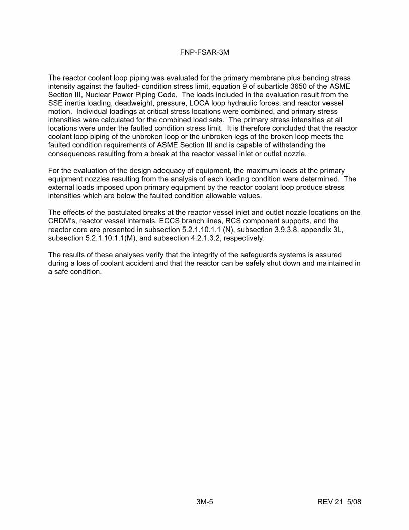
FNP-FSAR-3M
3M-5 REV 21 5/08
The reactor coolant loop piping was evaluated for the primary membrane plus bending stress intensity against the faulted- condition stress limit, equation 9 of subarticle 3650 of the ASME Section III, Nuclear Power Piping Code. The loads included in the evaluation result from the SSE inertia loading, deadweight, pressure, LOCA loop hydraulic forces, and reactor vessel motion. Individual loadings at critical stress locations were combined, and primary stress intensities were calculated for the combined load sets. The primary stress intensities at all locations were under the faulted condition stress limit. It is therefore concluded that the reactor coolant loop piping of the unbroken loop or the unbroken legs of the broken loop meets the faulted condition requirements of ASME Section III and is capable of withstanding the consequences resulting from a break at the reactor vessel inlet or outlet nozzle. For the evaluation of the design adequacy of equipment, the maximum loads at the primary equipment nozzles resulting from the analysis of each loading condition were determined. The external loads imposed upon primary equipment by the reactor coolant loop produce stress intensities which are below the faulted condition allowable values. The effects of the postulated breaks at the reactor vessel inlet and outlet nozzle locations on the CRDM's, reactor vessel internals, ECCS branch lines, RCS component supports, and the reactor core are presented in subsection 5.2.1.10.1.1 (N), subsection 3.9.3.8, appendix 3L, subsection 5.2.1.10.1.1(M), and subsection 4.2.1.3.2, respectively. The results of these analyses verify that the integrity of the safeguards systems is assured during a loss of coolant accident and that the reactor can be safely shut down and maintained in a safe condition.
FNP-FSAR-3M
3M-6 REV 21 5/08
REFERENCES 1. Takeuchi, K., et al, "MULTIFLEX - A Fortran-IV Computer Program for Analyzing
Thermal - Hydraulic-Structure System Dynamics," WCAP-8708, February 1976. 2. WCAP-8252, "Documentation of Selected Westinghouse Structural Analysis Computer
Codes," April 1976.
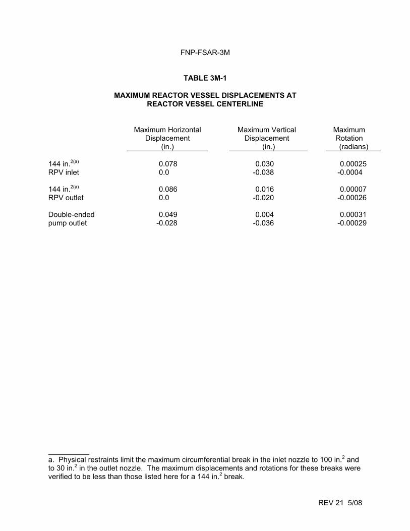
FNP-FSAR-3M
REV 21 5/08
TABLE 3M-1
MAXIMUM REACTOR VESSEL DISPLACEMENTS AT REACTOR VESSEL CENTERLINE
Maximum Horizontal Maximum Vertical Maximum Displacement Displacement Rotation (in.) (in.) (radians)
144 in.2(a) 0.078 0.030 0.00025 RPV inlet 0.0 -0.038 -0.0004 144 in.2(a) 0.086 0.016 0.00007 RPV outlet 0.0 -0.020 -0.00026 Double-ended 0.049 0.004 0.00031 pump outlet -0.028 -0.036 -0.00029 a. Physical restraints limit the maximum circumferential break in the inlet nozzle to 100 in.2 and to 30 in.2 in the outlet nozzle. The maximum displacements and rotations for these breaks were verified to be less than those listed here for a 144 in.2 break.
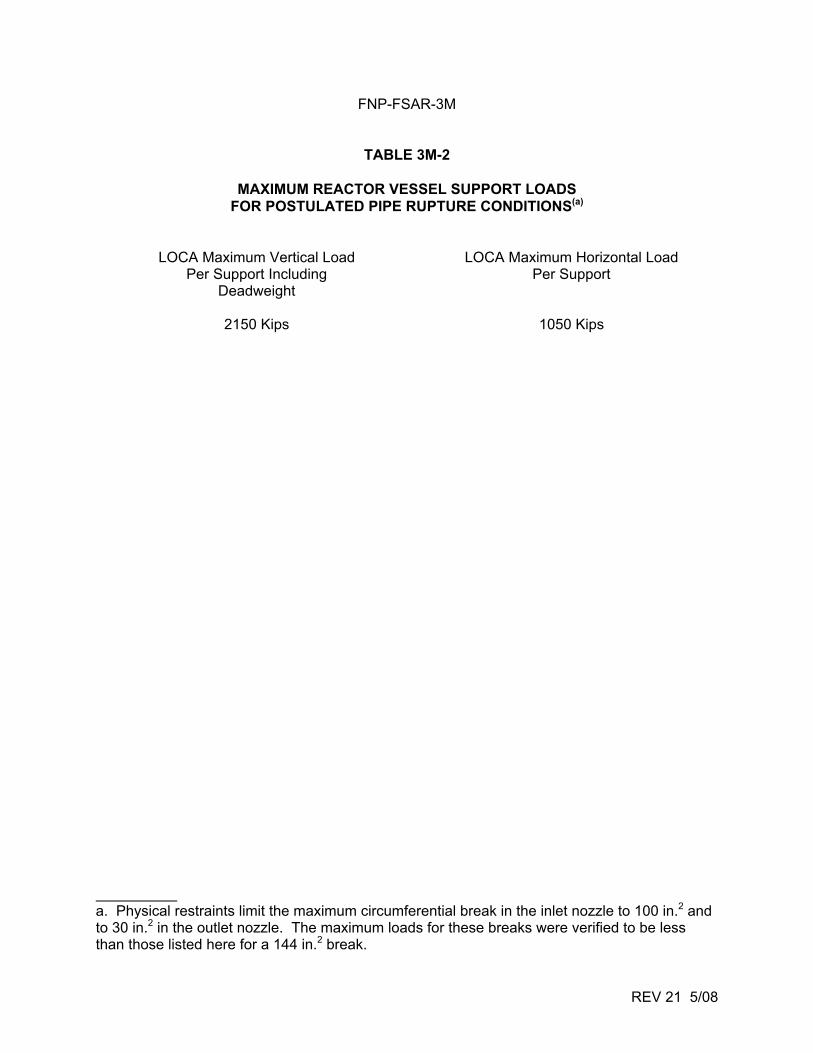
FNP-FSAR-3M
REV 21 5/08
TABLE 3M-2
MAXIMUM REACTOR VESSEL SUPPORT LOADS FOR POSTULATED PIPE RUPTURE CONDITIONS(a)
LOCA Maximum Vertical Load LOCA Maximum Horizontal Load Per Support Including Per Support
Deadweight
2150 Kips 1050 Kips a. Physical restraints limit the maximum circumferential break in the inlet nozzle to 100 in.2 and to 30 in.2 in the outlet nozzle. The maximum loads for these breaks were verified to be less than those listed here for a 144 in.2 break.
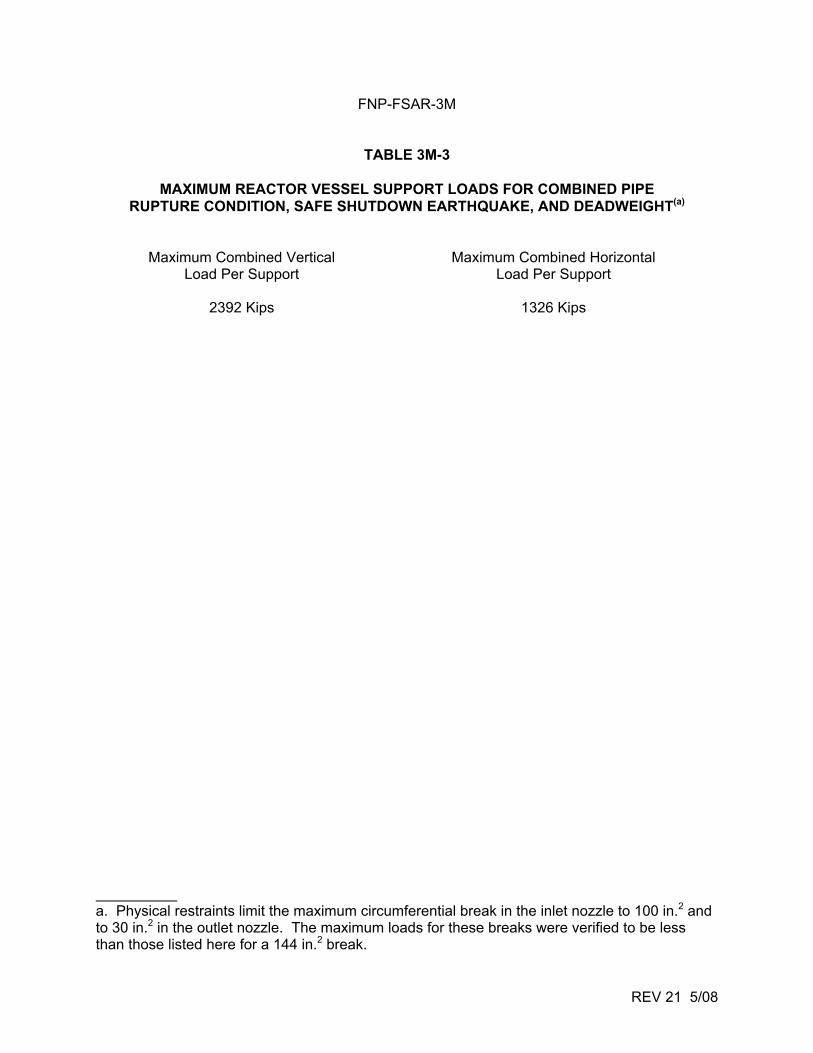
FNP-FSAR-3M
REV 21 5/08
TABLE 3M-3
MAXIMUM REACTOR VESSEL SUPPORT LOADS FOR COMBINED PIPE RUPTURE CONDITION, SAFE SHUTDOWN EARTHQUAKE, AND DEADWEIGHT(a)
Maximum Combined Vertical Maximum Combined Horizontal Load Per Support Load Per Support
2392 Kips 1326 Kips
a. Physical restraints limit the maximum circumferential break in the inlet nozzle to 100 in.2 and to 30 in.2 in the outlet nozzle. The maximum loads for these breaks were verified to be less than those listed here for a 144 in.2 break.
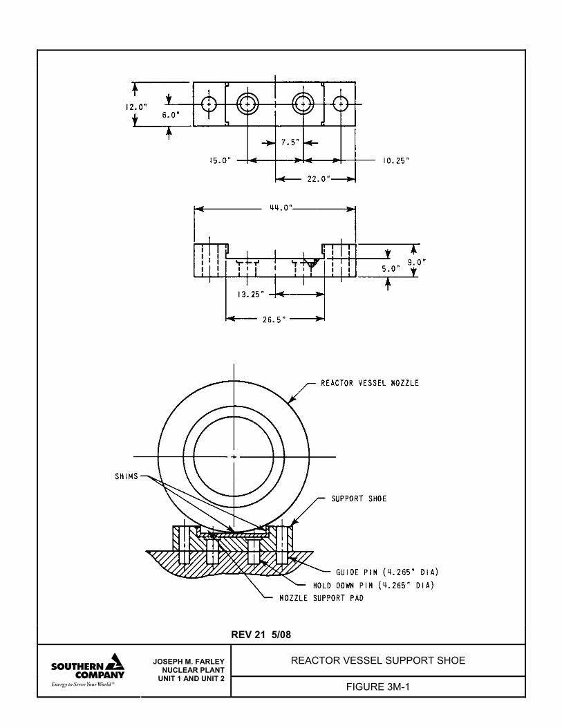
REV 21 5/08
REACTOR VESSEL SUPPORT SHOE
JOSEPH M. FARLEY NUCLEAR PLANT
UNIT 1 AND UNIT 2 FIGURE 3M-1
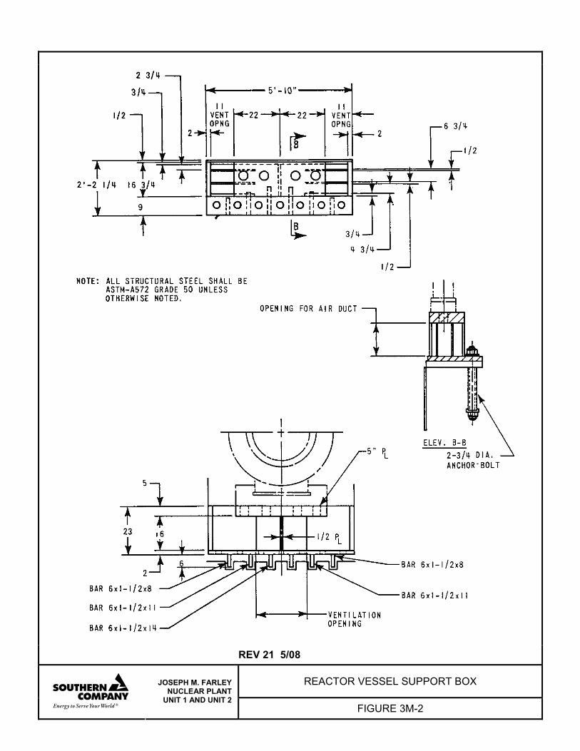
REV 21 5/08
REACTOR VESSEL SUPPORT BOX
JOSEPH M. FARLEY NUCLEAR PLANT
UNIT 1 AND UNIT 2 FIGURE 3M-2
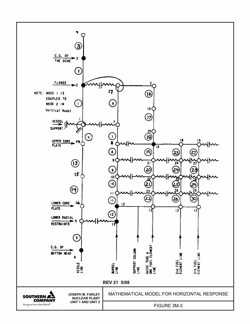
REV 21 5/08
MATHEMATICAL MODEL FOR HORIZONTAL RESPONSE
JOSEPH M. FARLEY NUCLEAR PLANT
UNIT 1 AND UNIT 2 FIGURE 3M-3
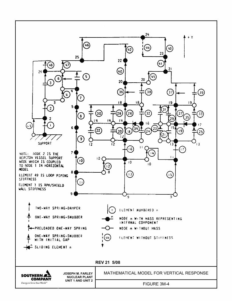
REV 21 5/08
MATHEMATICAL MODEL FOR VERTICAL RESPONSE
JOSEPH M. FARLEY NUCLEAR PLANT
UNIT 1 AND UNIT 2 FIGURE 3M-4
Related Documents