IQ ™ Network Communication Cartridge (IQ-NCC) Installation & User Guide for the IQ ™ Central Control System

Welcome message from author
This document is posted to help you gain knowledge. Please leave a comment to let me know what you think about it! Share it to your friends and learn new things together.
Transcript
IQ™ Network Communication Cartridge (IQ-NCC)Installation & User Guide for the IQ™ Central Control System
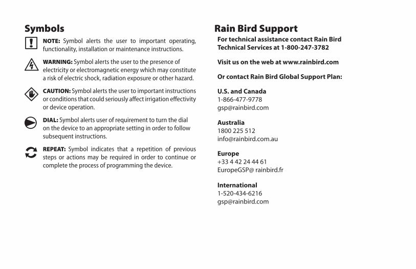
Symbols
� NOTE: Symbol alerts the user to important operating, functionality, installation or maintenance instructions.
� WARNING: Symbol alerts the user to the presence of electricity or electromagnetic energy which may constitute a risk of electric shock, radiation exposure or other hazard.
dCAUTION: Symbol alerts the user to important instructions or conditions that could seriously affect irrigation effectivity or device operation.
g DIAL: Symbol alerts user of requirement to turn the dial on the device to an appropriate setting in order to follow subsequent instructions.
REPEAT: Symbol indicates that a repetition of previous steps or actions may be required in order to continue or complete the process of programming the device.
Rain Bird SupportFor technical assistance contact Rain Bird Technical Services at 1-800-247-3782
Visit us on the web at www.rainbird.com
Or contact Rain Bird Global Support Plan:
U.S. and Canada1-866-477-9778 [email protected]
Australia1800 225 512 [email protected]
Europe+33 4 42 24 44 61 EuropeGSP@ rainbird.fr
International1-520-434-6216 [email protected]
IIQ Network Communication Cartridge
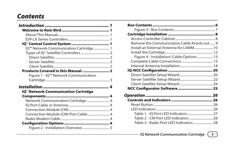
ContentsIntroduction .................................................. 1
Welcome to Rain Bird ........................................... 1About This Manual ................................................................. 1ESP-LX Series Controllers .................................................... 1
IQ™ Central Control System .................................. 1IQ™ Network Communication Cartridge .................... 1Types of IQ™ Satellite Controllers .................................... 2
Direct Satellite ..................................................................... 2Server Satellite ..................................................................... 2Client Satellite ...................................................................... 2
Products Covered in this Manual ........................ 2Figure 1 - IQ™ Network Communication Cartridge ................................................................................ 3
Installation .................................................... 4IQ™ Network Communication Cartridge Components ......................................................... 4
Network Communication Cartridge ............................. 4IQ Port Cable or Antenna ................................................... 4Connection Module (CM) ................................................... 4Connection Module (CM) Port Cable............................ 4Radio Modem Cable ............................................................. 4
Configuration Options ......................................... 4Figure 2 - Installation Overview .................................. 5
Box Contents ........................................................ 6Figure 3 - Box Contents ................................................... 7
Cartridge Installation .......................................... 8Access Controller Cabinet .................................................. 8Remove the Communication Cable Knock-out ...... 9Install an External Antenna for LXMM ........................10Install the Cartridge.............................................................12
Figure 4 - Installation/ Cable Options ....................13Complete Cable Connections ........................................15Internal Antenna Installation ..........................................18
IQ-NCC Configuration ........................................ 20Direct Satellite Setup Wizard ..........................................20Server Satellite Setup Wizard ..........................................22Client Satellite Setup Wizard ...........................................24
NCC Configurator Software ............................... 25
Operation .................................................... 26Controls and Indicators ..................................... 26
Reset Button ...........................................................................26LED Indicators ........................................................................26
Table 1 - IQ Port LED Indicators .................................27Table 2 - CM Port LED Indicators ..............................28Table 3 - Radio Port LED Indicators .........................28
II IQ Network Communication Cartridge
Status Menu ....................................................... 29Direct Satellite Controllers ...............................................29
RS-232, Phone or Ethernet ...........................................29GPRS or WiFi ........................................................................30
Server Satellite Controllers ..............................................31RS-232, Phone or Ethernet ...........................................31GPRS or WiFi ........................................................................32
Client Satellite Controllers ...............................................33IQNet Alarms Menu ............................................ 34
Appendix ..................................................... 36Connection Modules .......................................... 36
Connection Module Options ..........................................36Base Module .......................................................................36Flow Smart Module .........................................................36IQ Connection Module ..................................................37IQ Flow Smart Connection Module .........................37
Connection Module Installation ...................................38Connect IQ-CM Grounding Wire ..............................40
SIM Card Installation ......................................... 41
1IQ Network Communication Cartridge
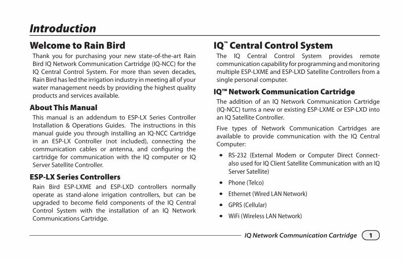
Welcome to Rain BirdThank you for purchasing your new state-of-the-art Rain Bird IQ Network Communication Cartridge (IQ-NCC) for the IQ Central Control System. For more than seven decades, Rain Bird has led the irrigation industry in meeting all of your water management needs by providing the highest quality products and services available.
About This ManualThis manual is an addendum to ESP-LX Series Controller Installation & Operations Guides. The instructions in this manual guide you through installing an IQ-NCC Cartridge in an ESP-LX Controller (not included), connecting the communication cables or antenna, and configuring the cartridge for communication with the IQ computer or IQ Server Satellite Controller.
ESP-LX Series ControllersRain Bird ESP-LXME and ESP-LXD controllers normally operate as stand-alone irrigation controllers, but can be upgraded to become field components of the IQ Central Control System with the installation of an IQ Network Communications Cartridge.
IQ™ Central Control SystemThe IQ Central Control System provides remote communication capability for programming and monitoring multiple ESP-LXME and ESP-LXD Satellite Controllers from a single personal computer.
IQ™ Network Communication CartridgeThe addition of an IQ Network Communication Cartridge (IQ-NCC) turns a new or existing ESP-LXME or ESP-LXD into an IQ Satellite Controller.
Five types of Network Communication Cartridges are available to provide communication with the IQ Central Computer:
l RS-232 (External Modem or Computer Direct Connect-also used for IQ Client Satellite Communication with an IQ Server Satellite)
l Phone (Telco)
l Ethernet (Wired LAN Network)
l GPRS (Cellular)
l WiFi (Wireless LAN Network)
Introduction
2 IQ Network Communication Cartridge
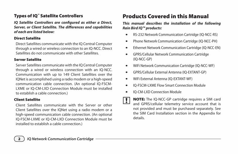
Types of IQ™ Satellite ControllersIQ Satellite Controllers are configured as either a Direct, Server, or Client Satellite. The differences and capabilities of each are listed below:
Direct SatelliteDirect Satellites communicate with the IQ Central Computer through a wired or wireless connection to an IQ-NCC. Direct Satellites do not communicate with other Satellites.
Server SatelliteServer Satellites communicate with the IQ Central Computer through a wired or wireless connection with an IQ-NCC. Communication with up to 149 Client Satellites over the IQNet is accomplished using a radio modem or a high-speed communication cable connection. (An optional IQ-FSCM-LXME or IQ-CM-LXD Connection Module must be installed to establish a cable connection.)
Client SatelliteClient Satellites communicate with the Server or other Client Satellites over the IQNet using a radio modem or a high-speed communication cable connection. (An optional IQ-FSCM-LXME or IQ-CM-LXD Connection Module must be installed to establish a cable connection.)
Products Covered in this ManualThis manual describes the installation of the following Rain Bird IQ™ products: l RS-232 Network Communication Cartridge (IQ-NCC-RS)
l Phone Network Communication Cartridge (IQ-NCC-PH)
l Ethernet Network Communication Cartridge (IQ-NCC-EN)
l GPRS/Cellular Network Communication Cartridge (IQ-NCC-GP)
l WiFi Network Communication Cartridge (IQ-NCC-WF)
l GPRS/Cellular External Antenna (IQ-EXTANT-GP)
l WiFi External Antenna (IQ-EXTANT-WF)
l IQ-FSCM-LXME Flow Smart Connection Module
l IQ-CM-LXD Connection Module
� NOTE: The IQ-NCC-GP cartridge requires a SIM card and GPRS/cellular telemetry service account that is not provided and must be purchased separately. See the SIM Card Installation section in the Appendix for details.
3IQ Network Communication Cartridge
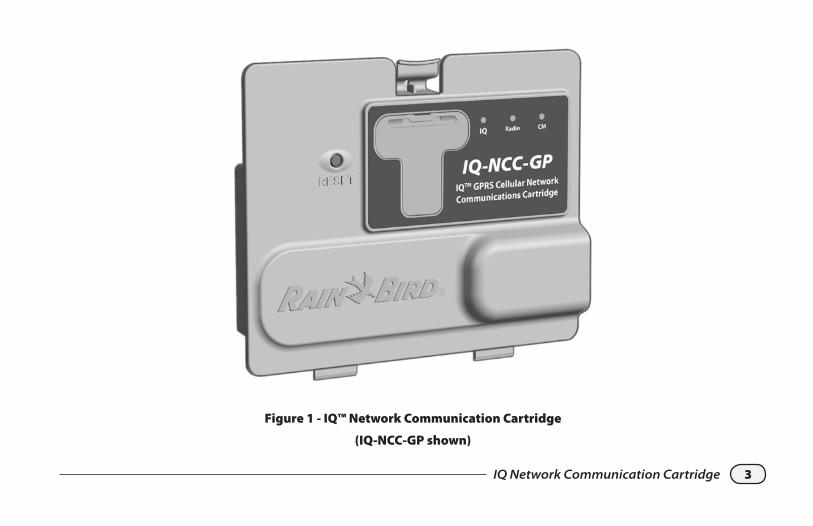
Figure 1 - IQ™ Network Communication Cartridge
(IQ-NCC-GP shown)
4 IQ Network Communication Cartridge
InstallationThis section provides instructions for installing and configuring an IQ Network Communication Cartridge into an ESP-LXME or ESP-LXD controller.
IQ™ Network Communication Cartridge ComponentsNetwork Communication Cartridge
Five types of cartridges are available to communicate with the IQ Central Computer through a direct cable connection, external modem, phone line, wired or wireless LAN, or a GPRS/Cellular network.
IQ Port Cable or AntennaThe IQ Port cable or antenna provides communication with the IQ Central Computer.
Connection Module (CM)The Connection Module (CM) installed in your ESP-LX Controller allows high-speed cable communication between Server and Client Satellites on the IQNet.
Connection Module (CM) Port CableThe Connection Module (CM) Port cable provides the connection between the IQ-NCC and the CM.
Radio Modem CableA radio modem can also be connected to the IQ-NCC to provide wireless radio communication between Server and Client Satellites on the IQNet.
Configuration OptionsBefore beginning installation, the following configuration options need to be determined and/or identified:
l Type of Cartridge (RS, PH, EN, GP, or WF)
l Type of Satellite Controller (Direct, Server, Client)
l Type of communication with other satellites (wireless connection using a radio modem, wired connection using an IQNet PE Communication Cable, or none)
l Controller model (ESP-LXME or ESP-LXD)
l Type of connection to the IQ computer (direct cable connect, external modem, phone cord, Ethernet cable, cellular or WiFi antenna)
5IQ Network Communication Cartridge
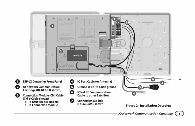
Figure 2 - Installation Overview
3
A ESP-LX Controller Front Panel
B IQ Network Communication Cartridge (IQ-NCC-EN shown)
C Connection Module (CM) Cable (CM Y-Cable shown) a. To IQNet Radio Modem b. To Connection Module
D IQ Port Cable (or Antenna)
E Ground Wire (to earth ground)
F IQNet PE Communication Cable to other Satellites
G Connection Module (FSCM-LXME shown)
3
4
56
37
1
2
b.
a.
6 IQ Network Communication Cartridge
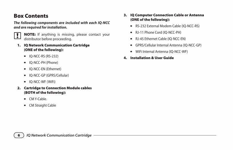
Box ContentsThe following components are included with each IQ-NCC and are required for installation.
� NOTE: If anything is missing, please contact your distributor before proceeding.
1. IQ Network Communication Cartridge (ONE of the following):
l IQ-NCC-RS (RS-232)
l IQ-NCC-PH (Phone)
l IQ-NCC-EN (Ethernet)
l IQ-NCC-GP (GPRS/Cellular)
l IQ-NCC-WF (WiFi)
2. Cartridge to Connection Module cables (BOTH of the following):
l CM Y-Cable.
l CM Straight Cable
3. IQ Computer Connection Cable or Antenna (ONE of the following):
l RS-232 External Modem Cable (IQ-NCC-RS)
l RJ-11 Phone Cord (IQ-NCC-PH)
l RJ-45 Ethernet Cable (IQ-NCC-EN)
l GPRS/Cellular Internal Antenna (IQ-NCC-GP)
l WiFi Internal Antenna (IQ-NCC-WF)
4. Installation & User Guide
7IQ Network Communication Cartridge
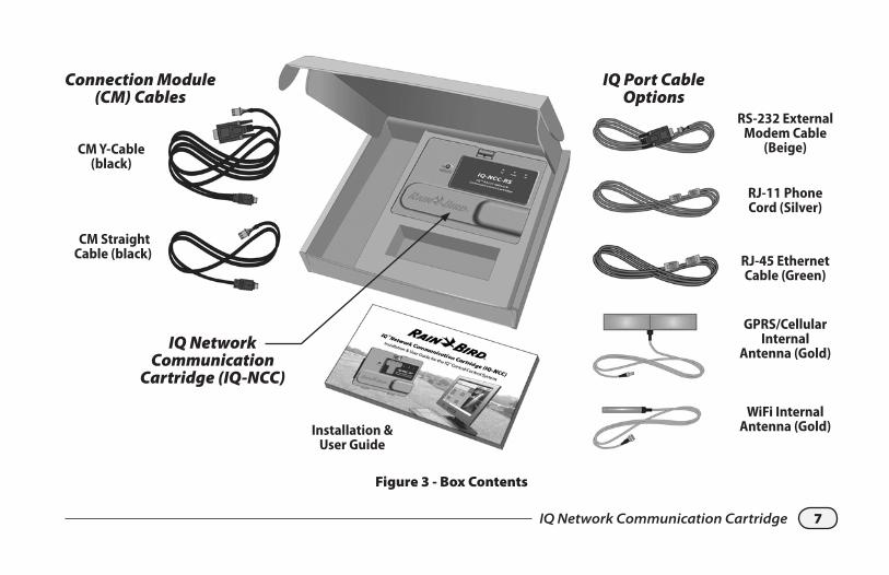
Figure 3 - Box Contents
CM Y-Cable (black)
CM Straight Cable (black)
RS-232 External Modem Cable
(Beige)
RJ-11 Phone Cord (Silver)
RJ-45 Ethernet Cable (Green)
GPRS/Cellular Internal
Antenna (Gold)
WiFi Internal Antenna (Gold)Installation &
User Guide
IQ Network Communication
Cartridge (IQ-NCC)
Connection Module (CM) Cables
IQ Port Cable Options
8 IQ Network Communication Cartridge
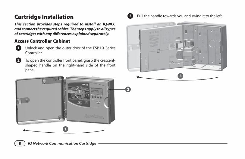
Cartridge InstallationThis section provides steps required to install an IQ-NCC and connect the required cables. The steps apply to all types of cartridges with any differences explained separately.
Access Controller Cabinet
A Unlock and open the outer door of the ESP-LX Series Controller.
B To open the controller front panel; grasp the crescent-shaped handle on the right-hand side of the front panel.
1
2
C Pull the handle towards you and swing it to the left.
3
9IQ Network Communication Cartridge
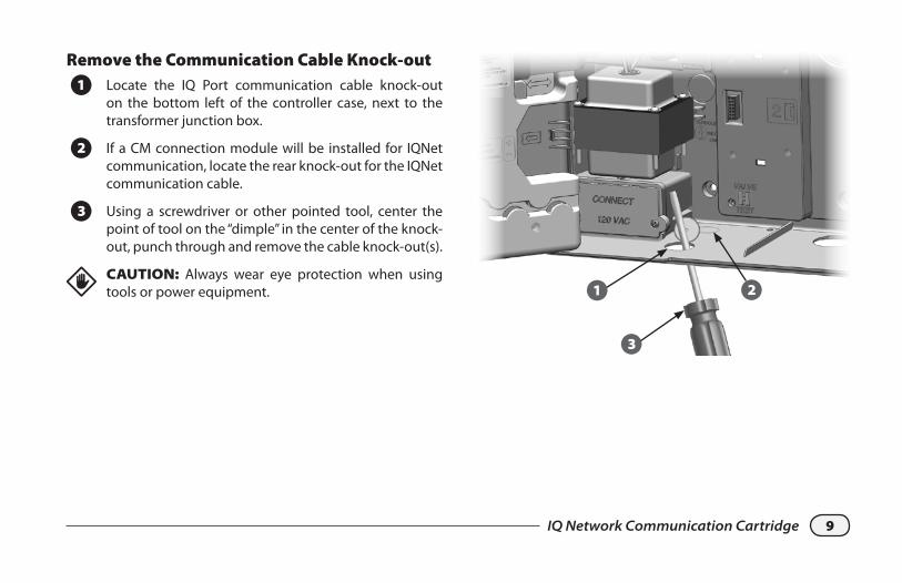
Remove the Communication Cable Knock-out
A Locate the IQ Port communication cable knock-out on the bottom left of the controller case, next to the transformer junction box.
B If a CM connection module will be installed for IQNet communication, locate the rear knock-out for the IQNet communication cable.
C Using a screwdriver or other pointed tool, center the point of tool on the “dimple” in the center of the knock-out, punch through and remove the cable knock-out(s).
dCAUTION: Always wear eye protection when using tools or power equipment. 1 2
3
10 IQ Network Communication Cartridge
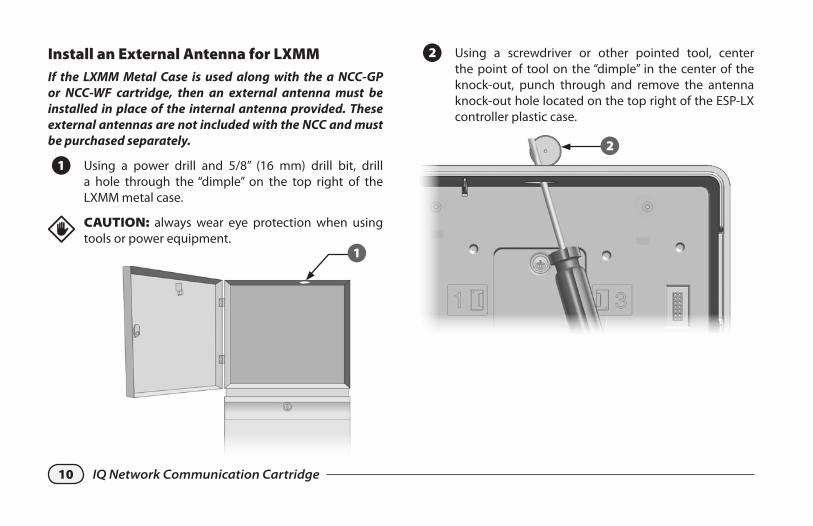
Install an External Antenna for LXMMIf the LXMM Metal Case is used along with the a NCC-GP or NCC-WF cartridge, then an external antenna must be installed in place of the internal antenna provided. These external antennas are not included with the NCC and must be purchased separately.
A Using a power drill and 5/8” (16 mm) drill bit, drill a hole through the “dimple” on the top right of the LXMM metal case.
dCAUTION: always wear eye protection when using tools or power equipment.
1
B Using a screwdriver or other pointed tool, center the point of tool on the “dimple” in the center of the knock-out, punch through and remove the antenna knock-out hole located on the top right of the ESP-LX controller plastic case.
2
11IQ Network Communication Cartridge
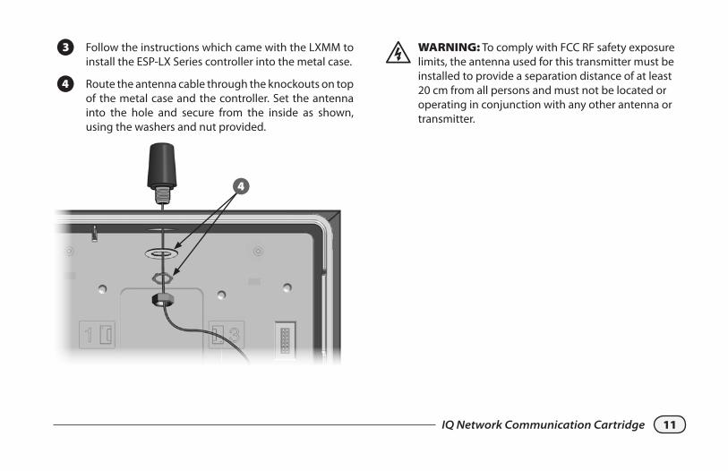
C Follow the instructions which came with the LXMM to install the ESP-LX Series controller into the metal case.
D Route the antenna cable through the knockouts on top of the metal case and the controller. Set the antenna into the hole and secure from the inside as shown, using the washers and nut provided.
4
� WARNING: To comply with FCC RF safety exposure limits, the antenna used for this transmitter must be installed to provide a separation distance of at least 20 cm from all persons and must not be located or operating in conjunction with any other antenna or transmitter.
12 IQ Network Communication Cartridge
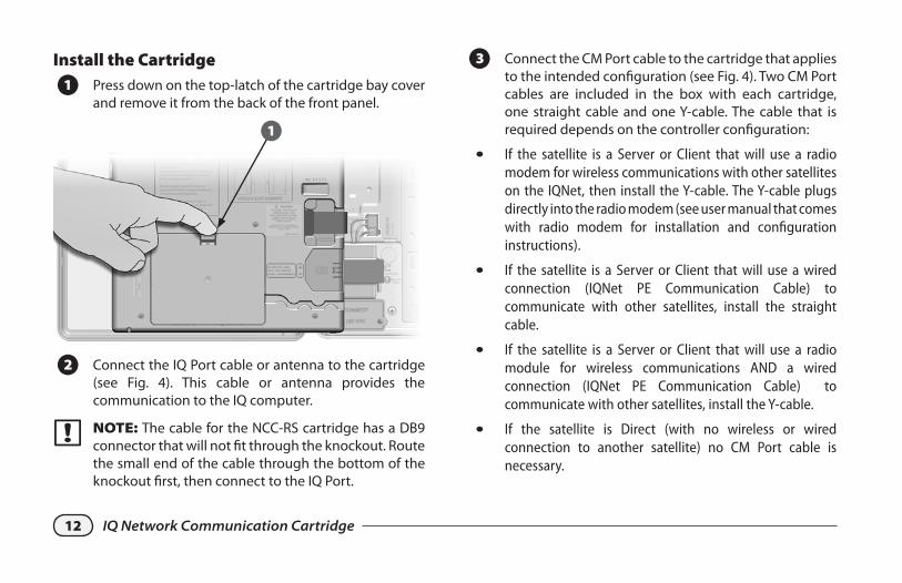
Install the Cartridge
A Press down on the top-latch of the cartridge bay cover and remove it from the back of the front panel.
1
B Connect the IQ Port cable or antenna to the cartridge (see Fig. 4). This cable or antenna provides the communication to the IQ computer.
� NOTE: The cable for the NCC-RS cartridge has a DB9 connector that will not fit through the knockout. Route the small end of the cable through the bottom of the knockout first, then connect to the IQ Port.
C Connect the CM Port cable to the cartridge that applies to the intended configuration (see Fig. 4). Two CM Port cables are included in the box with each cartridge, one straight cable and one Y-cable. The cable that is required depends on the controller configuration:
l If the satellite is a Server or Client that will use a radio modem for wireless communications with other satellites on the IQNet, then install the Y-cable. The Y-cable plugs directly into the radio modem (see user manual that comes with radio modem for installation and configuration instructions).
l If the satellite is a Server or Client that will use a wired connection (IQNet PE Communication Cable) to communicate with other satellites, install the straight cable.
l If the satellite is a Server or Client that will use a radio module for wireless communications AND a wired connection (IQNet PE Communication Cable) to communicate with other satellites, install the Y-cable.
l If the satellite is Direct (with no wireless or wired connection to another satellite) no CM Port cable is necessary.
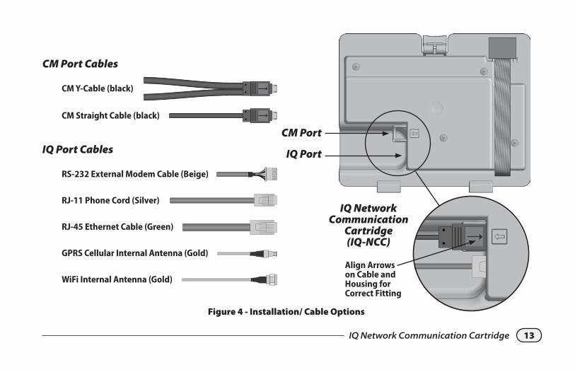
13IQ Network Communication Cartridge
CM Port
IQ Port
RS-232 External Modem Cable (Beige)
RJ-11 Phone Cord (Silver)
RJ-45 Ethernet Cable (Green)
GPRS Cellular Internal Antenna (Gold)
WiFi Internal Antenna (Gold)
IQ Network Communication
Cartridge (IQ-NCC)
CM Y-Cable (black)
CM Straight Cable (black)
Align Arrows on Cable and Housing for Correct Fitting
CM Port Cables
IQ Port Cables
Figure 4 - Installation/ Cable Options
14 IQ Network Communication Cartridge
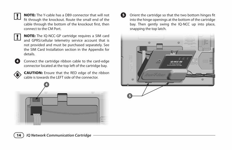
� NOTE: The Y-cable has a DB9 connector that will not fit through the knockout. Route the small end of the cable through the bottom of the knockout first, then connect to the CM Port.
� NOTE: The IQ-NCC-GP cartridge requires a SIM card and GPRS/cellular telemetry service account that is not provided and must be purchased separately. See the SIM Card Installation section in the Appendix for details.
D Connect the cartridge ribbon cable to the card-edge connector located at the top left of the cartridge bay.
dCAUTION: Ensure that the RED edge of the ribbon cable is towards the LEFT side of the connector.
4
E Orient the cartridge so that the two bottom hinges fit into the hinge openings at the bottom of the cartridge bay. Then gently swing the IQ-NCC up into place, snapping the top latch.
5
15IQ Network Communication Cartridge
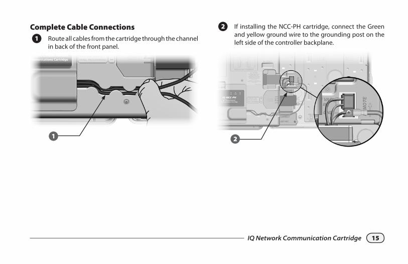
B If installing the NCC-PH cartridge, connect the Green and yellow ground wire to the grounding post on the left side of the controller backplane.
2
Complete Cable Connections
A Route all cables from the cartridge through the channel in back of the front panel.
1
16 IQ Network Communication Cartridge
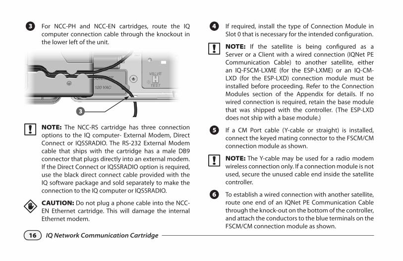
C For NCC-PH and NCC-EN cartridges, route the IQ computer connection cable through the knockout in the lower left of the unit.
3
� NOTE: The NCC-RS cartridge has three connection options to the IQ computer- External Modem, Direct Connect or IQSSRADIO. The RS-232 External Modem cable that ships with the cartridge has a male DB9 connector that plugs directly into an external modem. If the Direct Connect or IQSSRADIO option is required, use the black direct connect cable provided with the IQ software package and sold separately to make the connection to the IQ computer or IQSSRADIO.
dCAUTION: Do not plug a phone cable into the NCC-EN Ethernet cartridge. This will damage the internal Ethernet modem.
D If required, install the type of Connection Module in Slot 0 that is necessary for the intended configuration.
� NOTE: If the satellite is being configured as a Server or a Client with a wired connection (IQNet PE Communication Cable) to another satellite, either an IQ-FSCM-LXME (for the ESP-LXME) or an IQ-CM-LXD (for the ESP-LXD) connection module must be installed before proceeding. Refer to the Connection Modules section of the Appendix for details. If no wired connection is required, retain the base module that was shipped with the controller. (The ESP-LXD does not ship with a base module.)
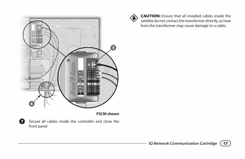
E If a CM Port cable (Y-cable or straight) is installed, connect the keyed mating connector to the FSCM/CM connection module as shown.
� NOTE: The Y-cable may be used for a radio modem wireless connection only. If a connection module is not used, secure the unused cable end inside the satellite controller.
F To establish a wired connection with another satellite, route one end of an IQNet PE Communication Cable through the knock-out on the bottom of the controller, and attach the conductors to the blue terminals on the FSCM/CM connection module as shown.
17IQ Network Communication Cartridge
6
5
FSCM shown
G Secure all cables inside the controller and close the front panel.
dCAUTION: Ensure that all installed cables inside the satellite do not contact the transformer directly, as heat from the transformer may cause damage to a cable.
18 IQ Network Communication Cartridge
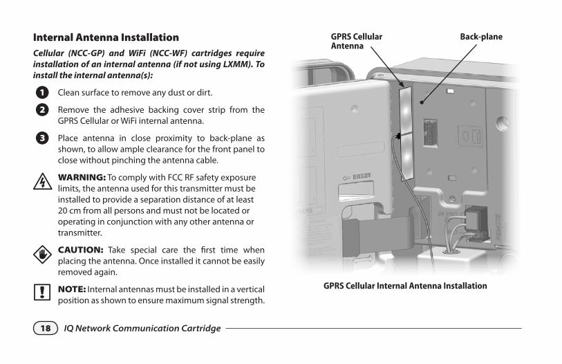
Internal Antenna InstallationCellular (NCC-GP) and WiFi (NCC-WF) cartridges require installation of an internal antenna (if not using LXMM). To install the internal antenna(s):
A Clean surface to remove any dust or dirt.
B Remove the adhesive backing cover strip from the GPRS Cellular or WiFi internal antenna.
C Place antenna in close proximity to back-plane as shown, to allow ample clearance for the front panel to close without pinching the antenna cable.
� WARNING: To comply with FCC RF safety exposure limits, the antenna used for this transmitter must be installed to provide a separation distance of at least 20 cm from all persons and must not be located or operating in conjunction with any other antenna or transmitter.
dCAUTION: Take special care the first time when placing the antenna. Once installed it cannot be easily removed again.
� NOTE: Internal antennas must be installed in a vertical position as shown to ensure maximum signal strength.
Back-planeGPRS Cellular Antenna
GPRS Cellular Internal Antenna Installation
19IQ Network Communication Cartridge
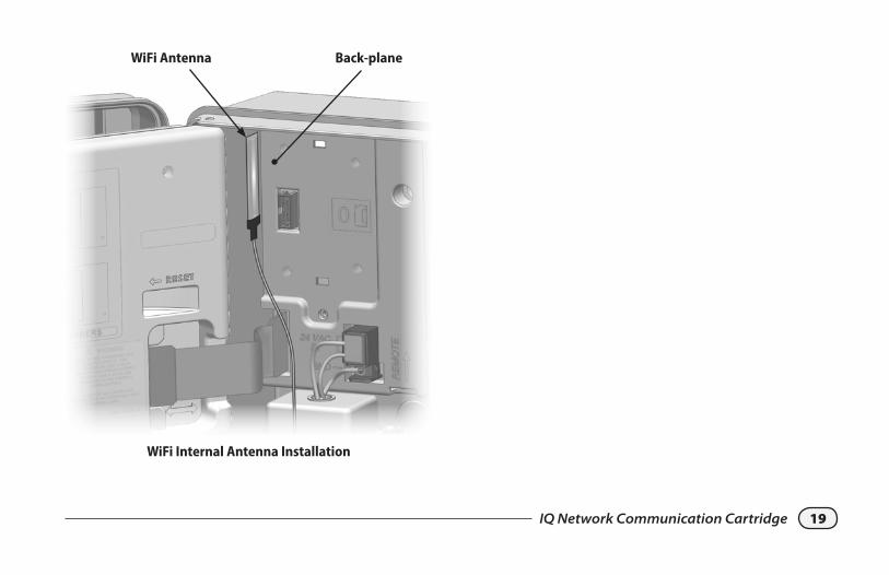
Back-planeWiFi Antenna
WiFi Internal Antenna Installation
20 IQ Network Communication Cartridge
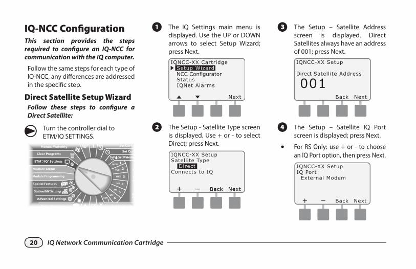
IQ-NCC ConfigurationThis section provides the steps required to configure an IQ-NCC for communication with the IQ computer.
Follow the same steps for each type of IQ-NCC, any differences are addressed in the specific step.
Direct Satellite Setup WizardFollow these steps to configure a Direct Satellite:
g Turn the controller dial to ETM/IQ SETTINGS.
A The IQ Settings main menu is displayed. Use the UP or DOWN arrows to select Setup Wizard; press Next.
NCC Configurator
B The Setup - Satellite Type screen is displayed. Use + or - to select Direct; press Next.
C The Setup – Satellite Address screen is displayed. Direct Satellites always have an address of 001; press Next.
Direct
D The Setup – Satellite IQ Port screen is displayed; press Next.
l For RS Only: use + or - to choose an IQ Port option, then press Next.
21IQ Network Communication Cartridge
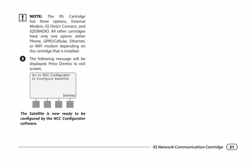
� NOTE: The RS Cartridge has three options, External Modem, IQ Direct Connect, and IQSSRADIO. All other cartridges have only one option, either Phone, GPRS/Cellular, Ethernet, or WiFi modem depending on the cartridge that is installed.
E The following message will be displayed. Press Dismiss to exit screen.
Dismiss
NCC Configurator
The Satellite is now ready to be configured by the NCC Configurator software.
22 IQ Network Communication Cartridge
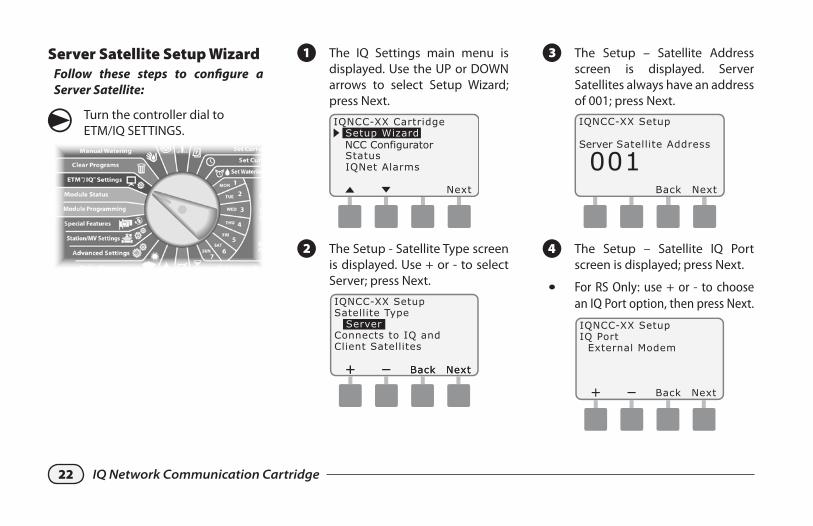
Server Satellite Setup WizardFollow these steps to configure a Server Satellite:
g Turn the controller dial to ETM/IQ SETTINGS.
A The IQ Settings main menu is displayed. Use the UP or DOWN arrows to select Setup Wizard; press Next.
NCC Configurator
B The Setup - Satellite Type screen is displayed. Use + or - to select Server; press Next.
C The Setup – Satellite Address screen is displayed. Server Satellites always have an address of 001; press Next.
Server
D The Setup – Satellite IQ Port screen is displayed; press Next.
l For RS Only: use + or - to choose an IQ Port option, then press Next.
23IQ Network Communication Cartridge
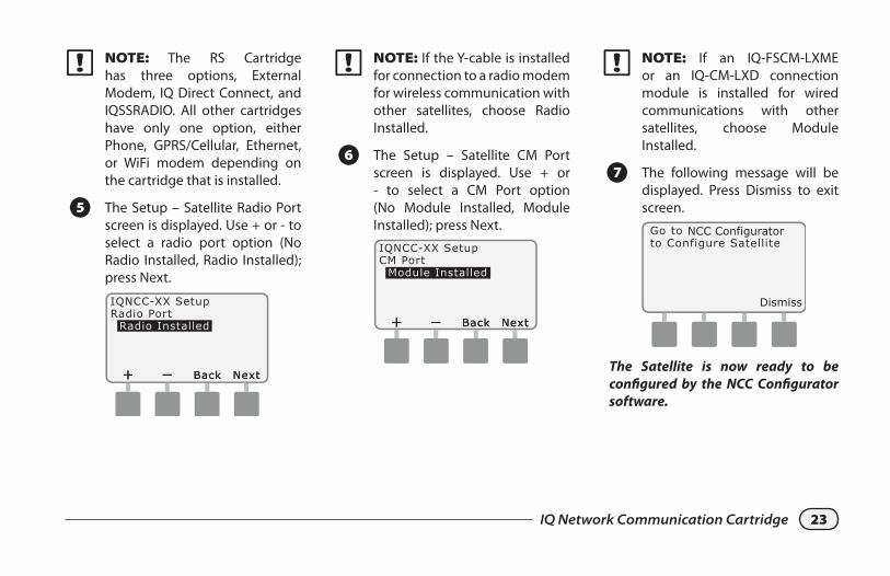
� NOTE: If the Y-cable is installed for connection to a radio modem for wireless communication with other satellites, choose Radio Installed.
F The Setup – Satellite CM Port screen is displayed. Use + or - to select a CM Port option (No Module Installed, Module Installed); press Next.
� NOTE: The RS Cartridge has three options, External Modem, IQ Direct Connect, and IQSSRADIO. All other cartridges have only one option, either Phone, GPRS/Cellular, Ethernet, or WiFi modem depending on the cartridge that is installed.
E The Setup – Satellite Radio Port screen is displayed. Use + or - to select a radio port option (No Radio Installed, Radio Installed); press Next.
� NOTE: If an IQ-FSCM-LXME or an IQ-CM-LXD connection module is installed for wired communications with other satellites, choose Module Installed.
G The following message will be displayed. Press Dismiss to exit screen.
Dismiss
NCC Configurator
The Satellite is now ready to be configured by the NCC Configurator software.
24 IQ Network Communication Cartridge
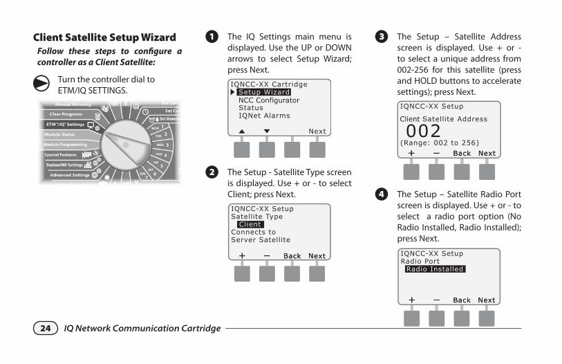
Client Satellite Setup WizardFollow these steps to configure a controller as a Client Satellite:
g Turn the controller dial to ETM/IQ SETTINGS.
A The IQ Settings main menu is displayed. Use the UP or DOWN arrows to select Setup Wizard; press Next.
NCC Configurator
B The Setup - Satellite Type screen is displayed. Use + or - to select Client; press Next.
C The Setup – Satellite Address screen is displayed. Use + or - to select a unique address from 002-256 for this satellite (press and HOLD buttons to accelerate settings); press Next.
Client
D The Setup – Satellite Radio Port screen is displayed. Use + or - to select a radio port option (No Radio Installed, Radio Installed); press Next.
25IQ Network Communication Cartridge
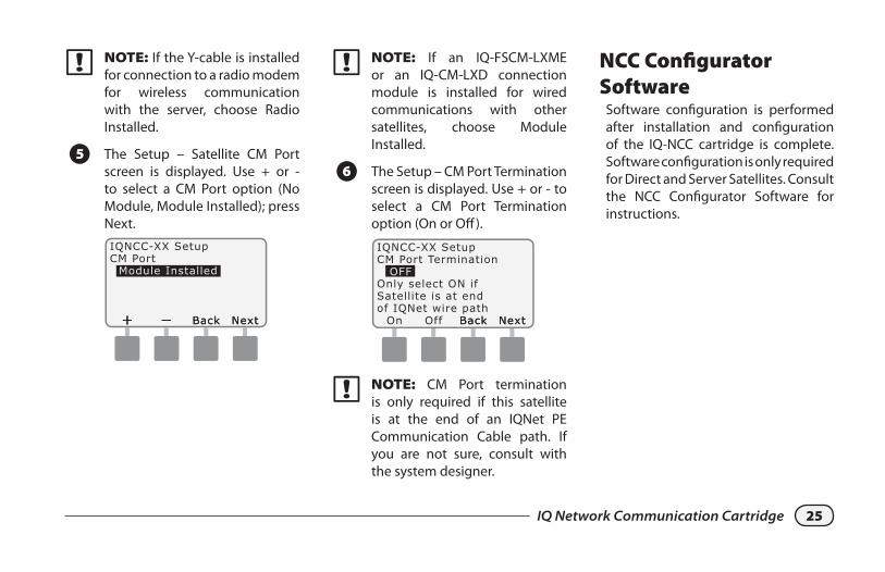
� NOTE: If the Y-cable is installed for connection to a radio modem for wireless communication with the server, choose Radio Installed.
E The Setup – Satellite CM Port screen is displayed. Use + or - to select a CM Port option (No Module, Module Installed); press Next.
� NOTE: If an IQ-FSCM-LXME or an IQ-CM-LXD connection module is installed for wired communications with other satellites, choose Module Installed.
F The Setup – CM Port Termination screen is displayed. Use + or - to select a CM Port Termination option (On or Off).
� NOTE: CM Port termination is only required if this satellite is at the end of an IQNet PE Communication Cable path. If you are not sure, consult with the system designer.
NCC Configurator Software
Software configuration is performed after installation and configuration of the IQ-NCC cartridge is complete. Software configuration is only required for Direct and Server Satellites. Consult the NCC Configurator Software for instructions.
26 IQ Network Communication Cartridge
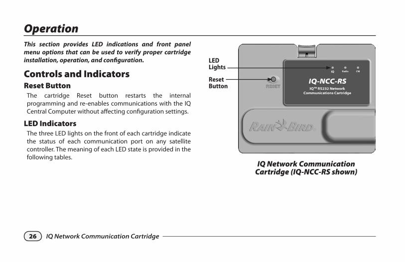
OperationThis section provides LED indications and front panel menu options that can be used to verify proper cartridge installation, operation, and configuration.
Controls and IndicatorsReset Button
The cartridge Reset button restarts the internal programming and re-enables communications with the IQ Central Computer without affecting configuration settings.
LED IndicatorsThe three LED lights on the front of each cartridge indicate the status of each communication port on any satellite controller. The meaning of each LED state is provided in the following tables.
Reset Button
LED Lights
IQ Network Communication Cartridge (IQ-NCC-RS shown)
27IQ Network Communication Cartridge
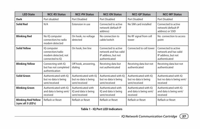
LED State NCC-RS Status NCC-PH Status NCC-EN Status NCC-GP Status NCC-WF Status
Dark Port disabled Port Disabled Port Disabled Port Disabled Port Disabled
Solid Red N/A Extension in use Connected to active network (default IP address)
No SIM card installed Connected to active network (default IP address) or SSID
Blinking Red No IQ computer connection/no radio modem detected
On hook, no voltage detected
No connection to cable/switch
No RF signal from cell tower
No connection to access point
Solid Yellow IQ computer connection/radio modem detected, not connected to IQ
On hook, live line Connected to active network and has valid IP address, but not authenticated
Connected to cell tower Connected to active network and has valid IP address, but not authenticated
Blinking Yellow Connecting with IQ but has not completed authentication
Off hook, answering, dialing
Receiving data but not authenticated
Receiving data but not authenticated
Receiving data but not authenticated
Solid Green Authenticated with IQ but no data is being sent/received
Authenticated with IQ but no data is being sent/received
Authenticated with IQ but no data is being sent/received
Authenticated with IQ but no data is being sent/received
Authenticated with IQ but no data is being sent/received
Blinking Green Authenticated with IQ and data is being sent/received
Authenticated with IQ and data is being sent/received
Authenticated with IQ and data is being sent/received
Authenticated with IQ and data is being sent/received
Authenticated with IQ and data is being sent/received
Blinking Red/Yellow (sync all 3 LED’s)
Reflash or Reset Reflash or Reset Reflash or Reset Reflash or Reset Reflash or Reset
Table 1 - IQ Port LED Indicators
28 IQ Network Communication Cartridge
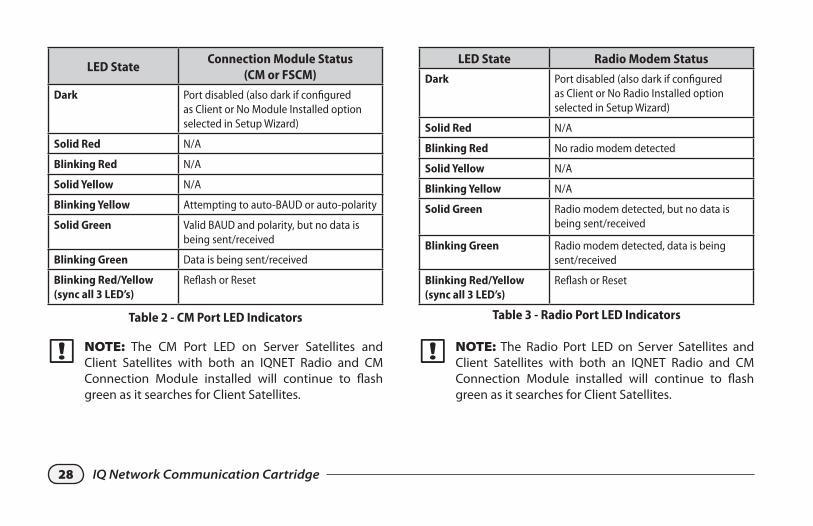
LED StateConnection Module Status
(CM or FSCM)
Dark Port disabled (also dark if configured as Client or No Module Installed option selected in Setup Wizard)
Solid Red N/A
Blinking Red N/A
Solid Yellow N/A
Blinking Yellow Attempting to auto-BAUD or auto-polarity
Solid Green Valid BAUD and polarity, but no data is being sent/received
Blinking Green Data is being sent/received
Blinking Red/Yellow (sync all 3 LED’s)
Reflash or Reset
Table 2 - CM Port LED Indicators
LED State Radio Modem Status
Dark Port disabled (also dark if configured as Client or No Radio Installed option selected in Setup Wizard)
Solid Red N/A
Blinking Red No radio modem detected
Solid Yellow N/A
Blinking Yellow N/A
Solid Green Radio modem detected, but no data is being sent/received
Blinking Green Radio modem detected, data is being sent/received
Blinking Red/Yellow (sync all 3 LED’s)
Reflash or Reset
Table 3 - Radio Port LED Indicators
� NOTE: The CM Port LED on Server Satellites and Client Satellites with both an IQNET Radio and CM Connection Module installed will continue to flash green as it searches for Client Satellites.
� NOTE: The Radio Port LED on Server Satellites and Client Satellites with both an IQNET Radio and CM Connection Module installed will continue to flash green as it searches for Client Satellites.
29IQ Network Communication Cartridge
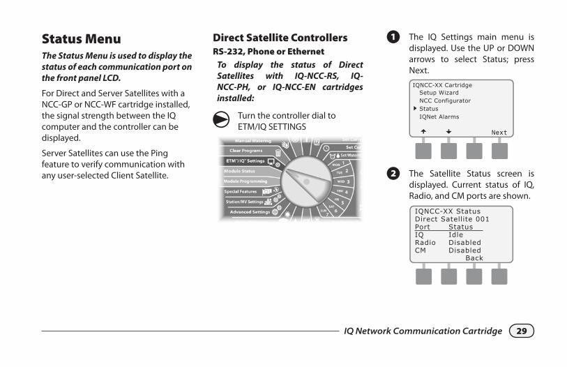
Status MenuThe Status Menu is used to display the status of each communication port on the front panel LCD.
For Direct and Server Satellites with a NCC-GP or NCC-WF cartridge installed, the signal strength between the IQ computer and the controller can be displayed.
Server Satellites can use the Ping feature to verify communication with any user-selected Client Satellite.
Direct Satellite ControllersRS-232, Phone or Ethernet
To display the status of Direct Satellites with IQ-NCC-RS, IQ-NCC-PH, or IQ-NCC-EN cartridges installed:
g Turn the controller dial to ETM/IQ SETTINGS
A The IQ Settings main menu is displayed. Use the UP or DOWN arrows to select Status; press Next.IQNCC-XX Cartridge
Setup WizardNCC ConfiguratorStatusIQNet Alarms
B The Satellite Status screen is displayed. Current status of IQ, Radio, and CM ports are shown.
30 IQ Network Communication Cartridge
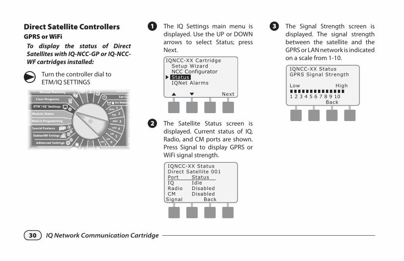
Direct Satellite ControllersGPRS or WiFi
To display the status of Direct Satellites with IQ-NCC-GP or IQ-NCC-WF cartridges installed:
g Turn the controller dial to ETM/IQ SETTINGS
A The IQ Settings main menu is displayed. Use the UP or DOWN arrows to select Status; press Next.
NCC Configurator
B The Satellite Status screen is displayed. Current status of IQ, Radio, and CM ports are shown. Press Signal to display GPRS or WiFi signal strength.
C The Signal Strength screen is displayed. The signal strength between the satellite and the GPRS or LAN network is indicated on a scale from 1-10.
31IQ Network Communication Cartridge
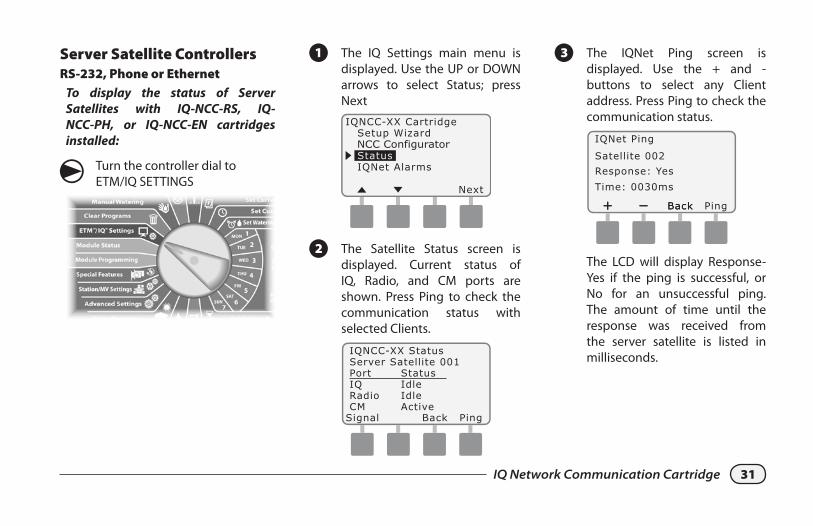
Server Satellite ControllersRS-232, Phone or Ethernet
To display the status of Server Satellites with IQ-NCC-RS, IQ-NCC-PH, or IQ-NCC-EN cartridges installed:
g Turn the controller dial to ETM/IQ SETTINGS
A The IQ Settings main menu is displayed. Use the UP or DOWN arrows to select Status; press Next
NCC Configurator
B The Satellite Status screen is displayed. Current status of IQ, Radio, and CM ports are shown. Press Ping to check the communication status with selected Clients.
C The IQNet Ping screen is displayed. Use the + and - buttons to select any Client address. Press Ping to check the communication status.
The LCD will display Response-Yes if the ping is successful, or No for an unsuccessful ping. The amount of time until the response was received from the server satellite is listed in milliseconds.
32 IQ Network Communication Cartridge
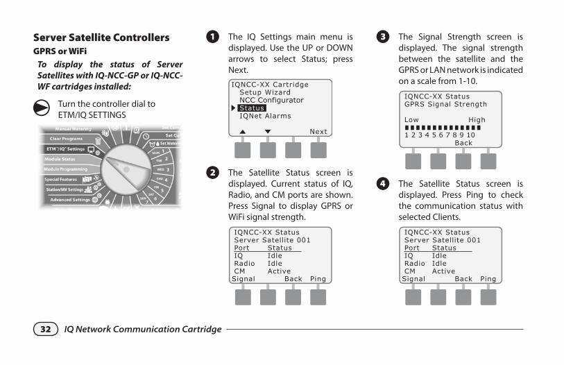
Server Satellite ControllersGPRS or WiFi
To display the status of Server Satellites with IQ-NCC-GP or IQ-NCC-WF cartridges installed:
g Turn the controller dial to ETM/IQ SETTINGS
A The IQ Settings main menu is displayed. Use the UP or DOWN arrows to select Status; press Next.
NCC Configurator
B The Satellite Status screen is displayed. Current status of IQ, Radio, and CM ports are shown. Press Signal to display GPRS or WiFi signal strength.
C The Signal Strength screen is displayed. The signal strength between the satellite and the GPRS or LAN network is indicated on a scale from 1-10.
D The Satellite Status screen is displayed. Press Ping to check the communication status with selected Clients.
33IQ Network Communication Cartridge
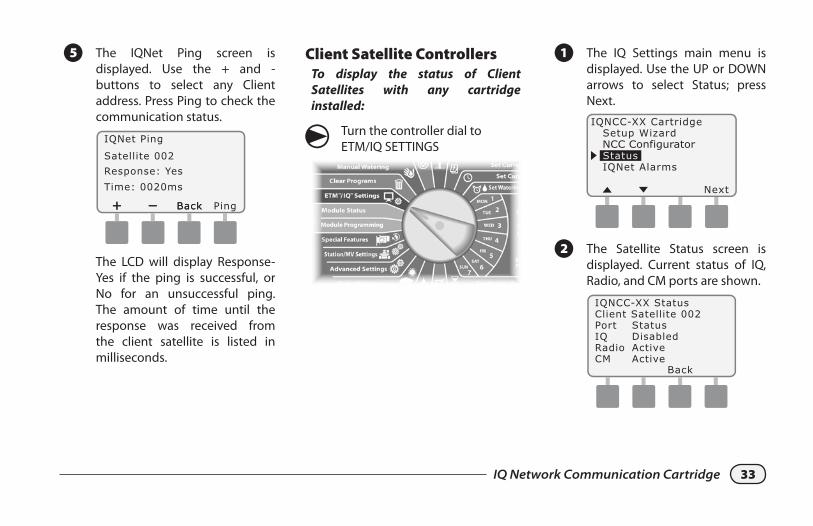
E The IQNet Ping screen is displayed. Use the + and - buttons to select any Client address. Press Ping to check the communication status.
The LCD will display Response-Yes if the ping is successful, or No for an unsuccessful ping. The amount of time until the response was received from the client satellite is listed in milliseconds.
Client Satellite ControllersTo display the status of Client Satellites with any cartridge installed:
g Turn the controller dial to ETM/IQ SETTINGS
A The IQ Settings main menu is displayed. Use the UP or DOWN arrows to select Status; press Next.
NCC Configurator
B The Satellite Status screen is displayed. Current status of IQ, Radio, and CM ports are shown.
34 IQ Network Communication Cartridge
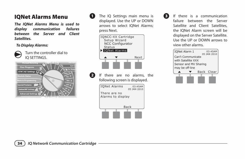
IQNet Alarms MenuThe IQNet Alarms Menu is used to display communication failures between the Server and Client Satellites.
To Display Alarms:
g Turn the controller dial to IQ SETTINGS.
A The IQ Settings main menu is displayed. Use the UP or DOWN arrows to select IQNet Alarms; press Next.
NCC Configurator
B If there are no alarms, the following screen is displayed.
03:45AM05 JAN 2010
C If there is a communication failure between the Server Satellite and Client Satellites, the IQNet Alarm screen will be displayed on the Server Satellite. Use the UP or DOWN arrows to view other alarms.
03:45AM05 JAN 2010
IQNet Alarm 1
Can’t Communicatewith Satellite XXXSensor and MV Sharingmay be off-line

35IQ Network Communication Cartridge
D If there is a communication failure between a Client Satellite and the Server Satellite, the IQNet Alarm screen will be displayed on the Client Satellite. Use the UP or DOWN arrows to view other alarms.
03:45AM05 JAN 2010
E On either IQNet Alarm screen, press Clear to clear all alarms. Press Yes to confirm.
36 IQ Network Communication Cartridge
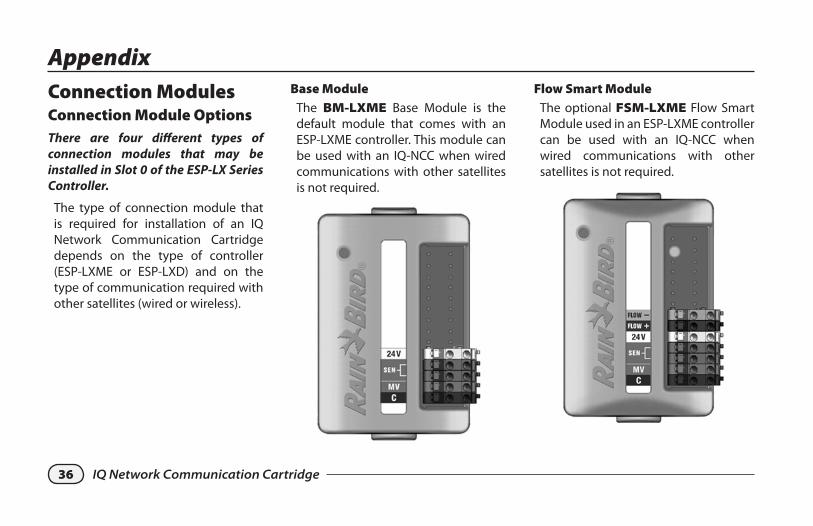
Flow Smart ModuleThe optional FSM-LXME Flow Smart Module used in an ESP-LXME controller can be used with an IQ-NCC when wired communications with other satellites is not required.
AppendixConnection ModulesConnection Module OptionsThere are four different types of connection modules that may be installed in Slot 0 of the ESP-LX Series Controller.
The type of connection module that is required for installation of an IQ Network Communication Cartridge depends on the type of controller (ESP-LXME or ESP-LXD) and on the type of communication required with other satellites (wired or wireless).
Base ModuleThe BM-LXME Base Module is the default module that comes with an ESP-LXME controller. This module can be used with an IQ-NCC when wired communications with other satellites is not required.

37IQ Network Communication Cartridge
IQ Connection ModuleIf wired communications (IQNet PE Communication Cable) is required between an ESP-LXD satellite and other satellites, an IQ-CM-LXD Connection Module must be installed in the ESP-LXD satellite to make the connection.
IQ Flow Smart Connection ModuleIf wired communications (IQNet PE Communication Cable) is required between an ESP-LXME satellite and other satellites, an IQ-FSCM-LXME Connection Module must be installed in the ESP-LXME satellite to make the connection.
� NOTE: See the ESP-LXME Con-troller manual for instructions on configuring the Flow Smart Module.
38 IQ Network Communication Cartridge
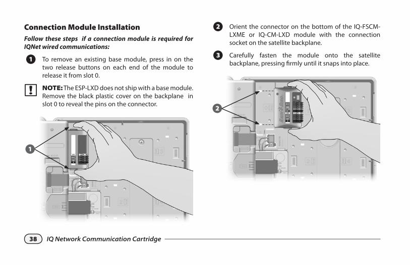
Connection Module InstallationFollow these steps if a connection module is required for IQNet wired communications:
A To remove an existing base module, press in on the two release buttons on each end of the module to release it from slot 0.
� NOTE: The ESP-LXD does not ship with a base module. Remove the black plastic cover on the backplane in slot 0 to reveal the pins on the connector.
1
B Orient the connector on the bottom of the IQ-FSCM-LXME or IQ-CM-LXD module with the connection socket on the satellite backplane.
C Carefully fasten the module onto the satellite backplane, pressing firmly until it snaps into place.
2
39IQ Network Communication Cartridge
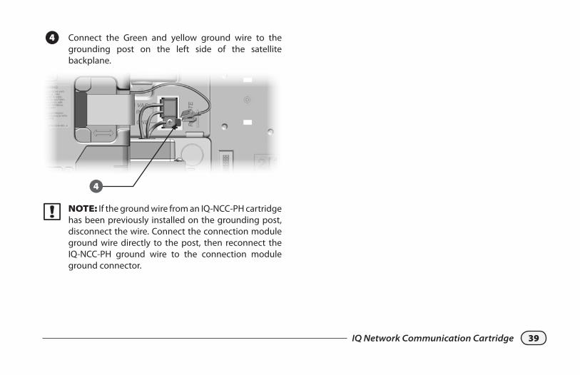
D Connect the Green and yellow ground wire to the grounding post on the left side of the satellite backplane.
4
� NOTE: If the ground wire from an IQ-NCC-PH cartridge has been previously installed on the grounding post, disconnect the wire. Connect the connection module ground wire directly to the post, then reconnect the IQ-NCC-PH ground wire to the connection module ground connector.
40 IQ Network Communication Cartridge
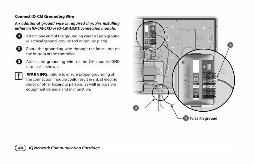
Connect IQ-CM Grounding Wire
An additional ground wire is required if you’re installing either an IQ-CM-LXD or IQ-CM-LXME connection module.
A Attach one end of the grounding wire to Earth ground (electrical ground, ground rod or ground plate).
B Route the grounding wire through the knock-out on the bottom of the controller.
C Attach the grounding wire to the CM module GND terminal as shown.
� WARNING: Failure to ensure proper grounding of the connection module could result in risk of electric shock or other hazard to persons, as well as possible equipment damage and malfunction.
1To Earth ground
2
3
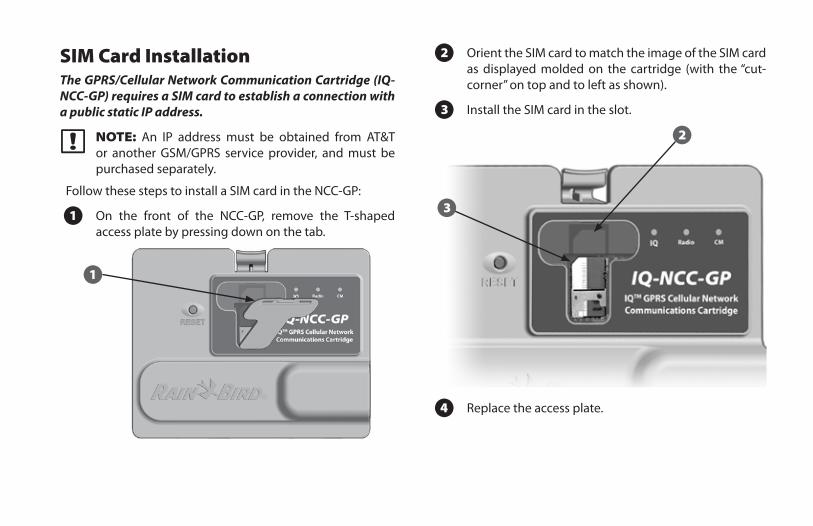
SIM Card InstallationThe GPRS/Cellular Network Communication Cartridge (IQ-NCC-GP) requires a SIM card to establish a connection with a public static IP address.
� NOTE: An IP address must be obtained from AT&T or another GSM/GPRS service provider, and must be purchased separately.
Follow these steps to install a SIM card in the NCC-GP:
A On the front of the NCC-GP, remove the T-shaped access plate by pressing down on the tab.
1
B Orient the SIM card to match the image of the SIM card as displayed molded on the cartridge (with the “cut-corner” on top and to left as shown).
C Install the SIM card in the slot.
3
2
D Replace the access plate.
Regulatory InformationEMC Requirements for the United StatesThis equipment has been tested and found to comply with the limits for a Class B digital device, pursuant to Part 15 of the FCC Rules. These limits are designed to provide reasonable protection against harmful interference in a residential installation.
This equipment generates, uses, and can radiate radio frequency energy and, if not installed and used in accordance with the instructions, may cause harmful interference to radio communications. However, there is no guarantee that interference will not occur in a particular installation.
If the equipment does cause harmful interference to radio or television reception, which can be determined by turning the equipment off and on, the user is encouraged to try to correct the interference by the following measures: � Reorient or relocate the receiving antenna. � Increase the separation between the equipment and the receiver. � Connect the equipment into an outlet on a circuit different from that to which the receiver is connected. � Consult the dealer or an experienced radio/TV technician for help.
This device complies with 47 CFR – FCC Part 15 rules. Operation of this device is subject to the following conditions:
1. This device may not cause harmful interference, and
2. This device must accept any interference that may cause undesired operation.
This product was FCC certified under test conditions that included the use of shielded I/O cables and connectors between system components. To be in compliance with FCC regulations, the user must use shielded cables and connectors and install them per instructions.
WARNING: Changes or modifications not expressly approved by Rain Bird Corporation could void the user’s authority to operate the equipment.
EMC Requirements for Industry CanadaThis product meets the applicable Industry Canada technical specifications
This Class B digital apparatus meets all requirements of the Canadian Interference-Causing Equipment Regulations.
Cet appareil numérique de la classe B respecte toutes les exigences du Reglement Canadien sur le matériel brouilleur.
Requirements for the South AfricaThis modem must be used in conjunction with an approved surge protection device (applies to PH cartridge only).
Analog Telecom Safety WarningsApplies to PH cartridge only:
1. Never install telephone wiring during a lightning storm.
2. Never install a telephone jack in wet locations unless the jack is specifically designed for wet locations.
3. This product is to be used with UL and cUL listed computers.
4. Never touch uninsulated telephone wires or terminals unless the telephone line has been disconnected at the network interface.
5. Use caution when installing or modifying telephone lines.
6. Avoid using a telephone during an electrical storm. There may be a remote risk of electrical shock from lightning.
7. Do not use a telephone in the vicinity of a gas leak.
8. To reduce the risk of fire, use only 26 AWG or larger telecommunication line cord.
9. This product must be disconnected from its power source and telephone network interface when servicing.
The wireless carrier will require the device’s IMEI (International Mobile Equipment Identity) number. This IMEI number is printed on the label on the backside of the modem cartridge.
Complies with 47 CFR Part 68.Reg. No: US:AU7MM01BMT5692SMIREN: 0.1B

RAIN BIRD CORPORATION6991 E. Southpoint Road
Tucson, AZ 85756
Copyright © 2010 by Rain Bird Corporation. All rights reserved.This material may not be published or reproduced without permission.
“Rain Bird” and “IQ Central Control System”are registered trademarks of Rain Bird Corporation.
www.rainbird.com
12/10 P/N: 638085-01
Related Documents