Intel® Server System BIOS Setup Utility Guide Target Platform: Intel® Server Systems supporting the Intel® Xeon® processor E5-2600 v3 product family Revision 1.0 Aug 4, 2014 Intel® Server Boards and Systems – Technical Support and Services

Welcome message from author
This document is posted to help you gain knowledge. Please leave a comment to let me know what you think about it! Share it to your friends and learn new things together.
Transcript

Intel® Server System BIOS Setup
Utility Guide
Target Platform:
Intel® Server Systems supporting the Intel®
Xeon® processor E5-2600 v3 product family
Revision 1.0
Aug 4, 2014
Intel® Server Boards and Systems – Technical Support and Services

Intel® Server System BIOS Setup Utility Guide
Revision History
Revision 1.0 ii
Revision History
Date Revision
Number
Modifications
Aug 4, 2014 1.0 Initial Revision 1.0 released for distribution.
Intel® Server System BIOS Setup Utility Guide
Disclaimers
Revision 1.0 iii
Disclaimers
INFORMATION IN THIS DOCUMENT IS PROVIDED IN CONNECTION WITH INTEL PRODUCTS. NO LICENSE,
EXPRESS OR IMPLIED, BY ESTOPPEL OR OTHERWISE, TO ANY INTELLECTUAL PROPERTY RIGHTS IS GRANTED BY
THIS DOCUMENT. EXCEPT AS PROVIDED IN INTEL'S TERMS AND CONDITIONS OF SALE FOR SUCH PRODUCTS,
INTEL ASSUMES NO LIABILITY WHATSOEVER AND INTEL DISCLAIMS ANY EXPRESS OR IMPLIED WARRANTY,
RELATING TO SALE AND/OR USE OF INTEL PRODUCTS INCLUDING LIABILITY OR WARRANTIES RELATING TO
FITNESS FOR A PARTICULAR PURPOSE, MERCHANTABILITY, OR INFRINGEMENT OF ANY PATENT, COPYRIGHT OR
OTHER INTELLECTUAL PROPERTY RIGHT.
A "Mission Critical Application" is any application in which failure of the Intel Product could result, directly or
indirectly, in personal injury or death. SHOULD YOU PURCHASE OR USE INTEL'S PRODUCTS FOR ANY SUCH
MISSION CRITICAL APPLICATION, YOU SHALL INDEMNIFY AND HOLD INTEL AND ITS SUBSIDIARIES,
SUBCONTRACTORS AND AFFILIATES, AND THE DIRECTORS, OFFICERS, AND EMPLOYEES OF EACH, HARMLESS
AGAINST ALL CLAIMS COSTS, DAMAGES, AND EXPENSES AND REASONABLE ATTORNEYS' FEES ARISING OUT OF,
DIRECTLY OR INDIRECTLY, ANY CLAIM OF PRODUCT LIABILITY, PERSONAL INJURY, OR DEATH ARISING IN ANY
WAY OUT OF SUCH MISSION CRITICAL APPLICATION, WHETHER OR NOT INTEL OR ITS SUBCONTRACTOR WAS
NEGLIGENT IN THE DESIGN, MANUFACTURE, OR WARNING OF THE INTEL PRODUCT OR ANY OF ITS PARTS.
Intel may make changes to specifications and product descriptions at any time, without notice. Designers must not
rely on the absence or characteristics of any features or instructions marked "reserved" or "undefined". Intel
reserves these for future definition and shall have no responsibility whatsoever for conflicts or incompatibilities
arising from future changes to them. The information here is subject to change without notice. Do not finalize a
design with this information.
The products described in this document may contain design defects or errors known as errata, which may cause
the product to deviate from published specifications. Current characterized errata are available on request.
Contact your local Intel sales office or your distributor to obtain the latest specifications and before placing your
product order.
Copies of documents that have an order number and are referenced in this document, or other Intel literature, may
be obtained by calling 1-800-548-4725, or go to http://www.intel.com/design/literature.
Intel and Xeon are trademarks of Intel Corporation in the U.S. and/or other countries.
*Other names and brands may be claimed as the property of others.
Copyright © 2015 Intel Corporation. All rights reserved.
Intel® Server System BIOS Setup Utility Guide
Table of Contents
Revision 1.0 iv
Table of Contents
1 Introduction ........................................................................................................................................ 1
1.1 Summary ................................................................................................................................................. 1
1.2 Audience ................................................................................................................................................. 1
1.3 Purpose of Document ....................................................................................................................... 1
1.4 Conventions Used in This Document ......................................................................................... 1
1.4.1 Typographical Conventions ............................................................................................................ 1
1.4.2 Acronyms and Abbreviations ......................................................................................................... 2
1.4.3 Distinctive Terminology ................................................................................................................... 2
2 BIOS Setup Utility .............................................................................................................................. 5
2.1 BIOS Setup Operation ....................................................................................................................... 5
2.1.1 Setup Page Layout .............................................................................................................................. 5
2.1.2 Entering BIOS Setup .......................................................................................................................... 6
2.1.3 Setup Navigation Keyboard Commands ................................................................................... 7
2.1.4 Setup Screen Menu Selection Bar ................................................................................................ 8
2.2 BIOS Setup Utility Screens .............................................................................................................. 8
2.2.1 BIOS Information Screen (Tab) ...................................................................................................... 9
2.2.2 Setup Menu Screen (Tab) ............................................................................................................. 10
2.2.3 Main Screen (Tab) ............................................................................................................................ 13
2.2.4 Advanced Screen (Tab) .................................................................................................................. 17
2.2.5 Processor Configuration ............................................................................................................... 20
2.2.6 Power & Performance .................................................................................................................... 27
2.2.7 QPI Configuration............................................................................................................................. 37
2.2.8 Memory Configuration ................................................................................................................... 39
2.2.9 Integrated IO Configuration ......................................................................................................... 47
2.2.10 Mass Storage Controller Configuration .................................................................................. 50
2.2.11 Serial Port Configuration .............................................................................................................. 56
2.2.12 USB Configuration ........................................................................................................................... 59
2.2.13 System Acoustic and Performance Configuration ............................................................. 63
2.2.14 Security Screen (Tab) ...................................................................................................................... 65
2.2.15 BMC LAN Configuration ................................................................................................................. 70
2.2.16 Boot Maintenance Manager Screen (Tab) .............................................................................. 82
2.2.17 Boot Manager Screen (Tab)....................................................................................................... 105
2.2.18 Error Manager Screen (Tab) ...................................................................................................... 107
2.2.19 Save & Exit Screen (Tab) ............................................................................................................. 109
Intel® Server System BIOS Setup Utility Guide
List of Figures
Revision 1.0 v
List of Figures
Figure 1. Setup Menu ................................................................................................................................................. 10
Figure 2. Main Screen ................................................................................................................................................ 13
Figure 3. Advanced Screen ...................................................................................................................................... 17
Figure 4. Processor Configuration Screen ........................................................................................................ 20
Figure 5. Power & Performance Screen ............................................................................................................. 27
Figure 6. Uncore Power Management Screen ................................................................................................. 30
Figure 7. CPU P State Control Screen ................................................................................................................. 32
Figure 8. CPU C State Control Screen ................................................................................................................. 35
Figure 9. QPI Configuration Screen ..................................................................................................................... 37
Figure 10. Memory Configuration Screen ......................................................................................................... 39
Figure 11. Integrated IO Configuration Screen ............................................................................................... 47
Figure 12. Mass Storage Controller Configuration Screen ........................................................................ 50
Figure 13. SATA Port Configuration Screen ..................................................................................................... 52
Figure 14. Serial Port Configuration Screen .................................................................................................... 56
Figure 15. USB Configuration Screen ................................................................................................................. 59
Figure 16. System Acoustic and Performance Configuration................................................................... 63
Figure 17. Security Screen ....................................................................................................................................... 65
Figure 18. BMC LAN Configuration Screen ....................................................................................................... 71
Figure 19. User Configuration Screen ................................................................................................................ 79
Figure 20. Boot Maintenance Manager Screen ............................................................................................... 83
Figure 21. Advanced Boot Options Screen ...................................................................................................... 86
Figure 22. Legacy CDROM Order Screen........................................................................................................... 90
Figure 23. Legacy Hard Disk Order Screen ....................................................................................................... 92
Figure 24. Legacy Floppy Order Screen ............................................................................................................ 94
Figure 25. Legacy Network Device Order Screen .......................................................................................... 96
Figure 26. Legacy BEV Device Order Screen ................................................................................................... 98
Figure 27. Add EFI Boot Option Screen .......................................................................................................... 100
Figure 28. Delete EFI Boot Option Screen ..................................................................................................... 101
Figure 29. Change Boot Order Screen ............................................................................................................. 103
Figure 30. Boot Manager Screen........................................................................................................................ 105
Figure 31. Error Manager Screen ....................................................................................................................... 107
Figure 32. Save & Exit Screen .............................................................................................................................. 109

Intel® Server System BIOS Setup Utility Guide
List of Tables
Revision 1.0 vi
List of Tables
Table 1. BIOS Setup: Keyboard Command Bar ................................................................................................. 7
Table 2. Screen Map................................................................................................................................................... 10

Intel® Server System BIOS Setup Utility Guide
List of Tables
Revision 1.0 vii
< This page intentionally left blank. >
Intel® Server System BIOS Setup Utility Guide
Introduction
Revision 1.0 1
1 Introduction
1.1 Summary
This BIOS Setup Utility Guide describes the functionality of the Basic Input/Output System
(BIOS) setup utility for a related family of server products, which have been designed around
processors from the Fourth Generation Intel® Core™ Processor Family in combination with the
Intel® C610 Series Chipset.
These Intel® Server Boards have been specifically designed to take advantage of the new and
improved capabilities of the Fourth Generation Intel® Core™ Processor Family, which for these
servers consists of the Intel® Xeon® Processor E5-2600 v3 Product Families.
The BIOS firmware component is a critical element of each server board, since it controls the
initialization of the hardware and transition to an Operating System (OS) that provides the
intended runtime environment for the server system. The BIOS also provides the interface
that allows local and remote configuration of the server hardware and system options.
1.2 Audience
This BIOS Setup Utility Guide is written for those involved in design, development, validation,
integration, production, and support of Intel® Server Boards and Systems in which they are
installed. It is assumed that the reader is familiar with Intel® processors and the standards that
define the server architecture.
1.3 Purpose of Document
This document contains a description of the BIOS implementation for the Intel® Server Boards
designed for the Intel® Xeon® Processor E5-2600 v3 Product Families with the C610 Series
Chipset. It is intended to specify how the BIOS should behave, and what interfaces and
functions it provides to other system components.
This BIOS Setup Utility Guide is not intended to describe other system components beyond
what is necessary to understand the BIOS setup implementation and interfaces. For each
other system component, there are specification documents, which describe it in detail. Where
necessary, references are made in this document to other more detailed specifications.
1.4 Conventions Used in This Document
This document uses typographic and illustrative conventions described below.
1.4.1 Typographical Conventions
1.4.1.1 Function Keys and Special Characters
There are a number of keys on computer keyboards for which there are no normal
typographic character representation. For example, there is no typographic character for the
shift keys or control keys.
Intel® Server System BIOS Setup Utility Guide
Introduction
Revision 1.0 2
Those characters will be represented by a key name (as usually shown on the keyboard) within
angle brackets. For example, <Shift> represents pressing either Shift key on the keyboard,
<F2> represents pressing the F2 function key, and <Esc> represents pressing the Escape key.
In cases where there are two keys with the same name and it matters which one is pressed,
they will be further distinguished. For example the Control keys on the left and right sides of
the keyboard may be represented as <L.Ctrl> and <R.Ctrl>.
When a “composite character” requires multiple keys to be pressed together, they will be
represented as a single hyphenated set of characters like <Ctrl-Alt-Del> (for example, to
reboot the system) which represents pressing the Control key, Alt key, and Delete key
simultaneously.
Multiple keys that must be pressed in sequence, as an “escape sequence”, are represented as
a series of characters in sequence, including both special key representations and normal
keys. For example <CR><LF> stands for “Carriage Return” followed by “Line Feed”, commonly
used at the end of a line of text on the display screen, or <Esc>[A means pressing the Escape
key followed by the “[” and “A” characters for a PC-ANSI or VT-100+ representation of an “Up
Arrow”.
1.4.1.2 Hyperlinks
The document text has a number of hyperlinks to other related information within the
document. There are also a number of external Uniform Resource Locator (URL) linkages to
material available through the Internet.
These linkages are rendered differently in Microsoft* Word* “doc” format versus Abode*
Acrobat Portable Document Format (PDF).
In Microsoft* Word* format, hyperlinks in the text are indicated by a 25% Gray Screen
shading plus Blue text color, like Hyperlink Text.
In Adobe* PDF format, hyperlinks in the text are indicated by Blue text color alone, like
Hyperlink Text.
For both formats, external URLs are indicated by Blue text color, like Internet URL.
1.4.2 Acronyms and Abbreviations
Commonly used acronyms and abbreviations are used in this document where the use
contributes to brevity and narrative flow. Any such acronyms and abbreviations will be spelled
out in the use, with the shortened version following in parentheses. Succeeding usage may be
the acronym or abbreviation alone.
1.4.3 Distinctive Terminology
Within this document, there are some terms that are used to distinguish between closely
related meanings. We have tried to use this distinctive terminology as consistently as possible
to maintain clarity in descriptions. In particular:
Intel® Server System BIOS Setup Utility Guide
Introduction
Revision 1.0 3
“Platform” – “Board”/“Server Board” – “Family/Series” – “System” – “SKU”
- Platform is used to indicate a general design concept utilizing a specific
combination of processor family and chipset family hardware.
- Board or Server Board is used to indicate specific product circuit boards, server
motherboards or main boards, which are designed around a given platform
concept.
- Family or Series is used to indicate a related group of products with a common
design factor. For example, the processors used in these boards are from the
Fourth Generation Intel® Core™ Processor Family.
- System is used to indicate a combination of a board and chassis and associated
hardware, with processor(s) and memory installed.
- SKU (derived from “Stock Keeping Unit) will generally not be used, since it indicates
a specific marketing package. While a SKU may be based on a specific board, this
document does not generally address that level of product differentiation.
“Socket” – “Processor”/“Processor Package” – “Core”/“Processor Core” –
“Thread”/”Processor Thread”
- Socket is used to indicate socket on a board into which a processor, memory, or
other equipment can be inserted. In the context of processors, “sockets” determine
how many processors can be installed on a board.
o Single Socket (1S) boards have only one processor socket and support
installation of a single processor package.
o Dual Socket (2S) boards have two processor sockets and support installation of
two interconnected processor packages.
o Quad Socket (4S or MP) boards have four processor sockets and support
installation of four interconnected processor packages. “MP” is an abbreviation
for “Multiprocessor”, meaning a board with four or more processor sockets.
- Processor or Processor Package is used to indicate a single integrated processor
hardware unit, which installs into a processor socket on a board. A board may
support multiple processors, and a processor may contain multiple cores.
- Core or Processor Core is used in the context of a processor package to indicate
one independent hardware execution unit contained within the processor package.
A processor package may contain multiple cores, which can execute
simultaneously, and a single core may support multiple processor threads.
- Thread or Processor Thread is used to indicate an independently executing
instruction stream within a processor core, which shares certain core resources
with any other threads contained within the same core (Intel® Hyper-Theading
Technology).
“Bytes”/“~B” – “Bits”/“~b” and “Kilo~”/“K~”– “Mega~”/“M~” – “Giga~”/“G~”
- Bytes in combination with a quantifier like K or M or G is abbreviated as uppercase
B. KB means kilobytes, MB means megabytes, and GB means gigabytes.

Intel® Server System BIOS Setup Utility Guide
Introduction
Revision 1.0 4
- Bits in combination with a quantifier like K or M or G is abbreviated as lowercase b.
Kb means kilobits, Mb means megabits, and Gb means gigabits.
- Kilo~ as a quantifier prefix, abbreviated as K~, correctly means 1024. So “2
kilobytes” or “2 KB” is (2 * 1024) bytes, or 2048 bytes. However, “kilo~” is often
used loosely to mean “thousand” (1000, i.e. 1024 rounded off). In this document,
“kilo~” means 1024 unless otherwise stated.
- Mega~ as a quantifier prefix, abbreviated as M~, correctly means (1024 * 1024),
that is, (1024 * kilo~) or 1,048,576. So “2 megabytes” or “2 MB” is (2 * 1,048,576)
bytes, or 2,097,152 bytes. However, “mega~” is often used loosely to mean
“million” (1,000,000 –1,048,576 rounded off). In this document, “mega~” means
1,048,576 unless otherwise stated.
- Giga~ as a quantifier prefix, abbreviated as G~, correctly means (1024 * 1024 *
1024), that is, (1024 * mega~), or 1,073,741,824. So “2 gigabytes” or “2 GB” is (2 *
1,073,741,824) bytes, or 2,147,483,648 bytes. However, “giga~” is often used
loosely to mean “billion” (1,000,000,000 – 1,073,741,824 rounded off). In this
document, “giga~” means 1,073,741,824 in the context of memory size, or “billion”
in the context of disk drive capacity (GB) or processor speed (GHz), unless otherwise
stated.
Intel® Server System BIOS Setup Utility Guide
BIOS Setup Utility
Revision 1.0 5
2 BIOS Setup Utility
The BIOS Setup utility is a text-based utility that allows the user to configure the system and
view current settings and environment information for the platform devices. The Setup utility
controls the platform's built-in devices, the boot manager, and error manager.
The BIOS Setup interface consists of a number of pages or screens. Each page contains
information or links to other pages. The advanced tab in Setup displays a list of general
categories as links. These links lead to pages containing a specific category’s configuration.
The following sections describe the look and behavior for the platform setup.
2.1 BIOS Setup Operation
The BIOS Setup Utility has the following features:
Localization – The Intel® Server Board BIOS is only available in English.
Console Redirection – BIOS Setup is functional via Console Redirection over various
terminal emulation standards. When Console Redirection is enabled, the POST display
out is in purely Text Mode due to Redirection data transfer in a serial port data terminal
emulation mode. This may limit some functionality for compatibility, for example,
usage of colors or some keys or key sequences or support of pointing devices.
Setup screens are designed to be displayable in a 100-character x 31-line format in
order to work with Console Redirection, although that screen layout should display
correctly on any format with longer lines or more lines on the screen.
Password protection – BIOS Setup may be protected from unauthorized changes by
setting an Administrative Password in the Security screen. When an Administrative
Password has been set, all selection and data entry fields in Setup (except System
Time and Date) are grayed out and cannot be changed unless the Administrative
Password has been entered.
Note: If an Administrative Password has not been set, anyone who boots the system to
Setup has access to all selection and data entry fields in Setup and can change any of
them.
2.1.1 Setup Page Layout
The Setup page layout is sectioned into functional areas. Each occupies a specific area of the
screen and has dedicated functionality. The following table lists and describes each functional
area.
The Setup page is designed to a format of 80 x 24 (24 lines of 80 characters each). The typical
display screen in a Legacy mode or in a terminal emulator mode is actually 80 characters by
25 lines but with “line wrap” enabled (which it usually is); the 25th line cannot be used with the
Setup page.
Intel® Server System BIOS Setup Utility Guide
BIOS Setup Utility
Revision 1.0 6
Table 1. BIOS Setup Page Layout
Functional Area Description
Title (Tab) Bar The Title Bar is located at the top of the screen and displays “Tabs” with the titles
of the top-level pages or screens that can be selected. Using the left and right
arrow keys moves from page to page through the Tabs.
When there are more Tabs than can be displayed on the Title (Tab) Bar, they will
scroll off to the left or right of the screen and temporarily disappear from the
visible Title Bar. Using the arrow keys will scroll them back onto the visible Title
Bar. When the arrow keys reach either end of the Title Bar, they will “wrap around”
to the other end of the Title Bar.
For multi-level hierarchies, this shows only the top-level page above the page
which the user is currently viewing. The Page Title gives further information.
Page Title In a multi-level hierarchy of pages beneath one of the top-level Tabs, the Page
Title identifying the specific page which the user is viewing is located in the upper
left corner of the page. Using the <ESC> (Escape) key will return the user to the
higher level in the hierarchy, until the top-level Tab page is reached.
Setup Item List The Setup Item List is a set of control entries and informational items. The list is
displayed in two columns. For each item in the list:
The left column of the list contains Prompt String (or Label String), a character
string which identifies the item. The Prompt String may be up to 34 characters
long in the 80 x 24 page format.
The right column contains a data field which may be an informational data
display, a data input field, or a multiple choice field. Data input or multiple-
choice fields are demarcated by square brackets “[....]”. This field may be up to
90 characters long but only the first 22 characters can be displayed on the 80 x
24 page (24 characters for an informational display-only field).
The operator navigates up and down the right hand column through the available
input or choice fields.
A Setup Item may also represent a selection to open a new screen with a further
group of options for specific functionality. In this case, the operator navigates to
the desired selection and presses <Enter> to go to the new screen.
Item-Specific Help Area The Item-specific Help Area is located on the right side of the screen and contains
Help Text specific to the highlighted Setup Item. Help information may include the
meaning and usage of the item, allowable values, effects of the options, etc.
The Help Area is a 29 character by 11 line section of the 80 x 24 page. The Help
Text may have explicit line-breaks within it. When the text is longer than 29
characters, it is also broken to a new line, dividing the text at the last space (blank)
character before the 29th character. An unbroken string of more than 29
characters will be arbitrarily wrapped to a new line after the 29th character. Text
that extends beyond the end of the 11th line will not be displayed.
Keyboard Command Area The Keyboard Command Area is located at the bottom right of the screen and
continuously displays help for keyboard special keys and navigation keys.
2.1.2 Entering BIOS Setup
To enter the BIOS Setup using a keyboard (or emulated keyboard), press the <F2> function
key during boot time when the OEM or Intel Logo Screen or the POST Diagnostic Screen is
displayed.

Intel® Server System BIOS Setup Utility Guide
BIOS Setup Utility
Revision 1.0 7
The following instructional message is displayed on the Diagnostic Screen or under the Quiet
Boot Logo Screen:
Press <F2> to enter setup, <F6> Boot Menu, <F12> Network Boot
Note: With a USB keyboard, it is important to wait until the BIOS “discovers” the keyboard and
beeps – until the USB Controller has been initialized and the USB keyboard activated, key
presses will not be read by the system.
When the Setup Utility is entered, the Main screen is displayed initially. However, serious
errors cause the system to display the Error Manager screen instead of the Main screen.
It is also possible to cause a boot directly to Setup using an IPMI 2.0 command “Get/Set
System Boot Options”. For details on that capability, see the explanation in the IPMI
description.
2.1.3 Setup Navigation Keyboard Commands
The bottom right portion of the Setup screen provides a list of commands that are used to
navigate through the Setup utility. These commands are displayed at all times.
Each Setup menu page contains a number of features. Each feature is associated with a value
field, except those used for informative purposes. Each value field contains configurable
parameters. Depending on the security option chosen and in effect by the password, a menu
feature’s value may or may not be changed. If a value cannot be changed, its field is made
inaccessible and appears grayed out.
Table 1. BIOS Setup: Keyboard Command Bar
Key Option Description
<Enter> Execute
Command
The <Enter> key is used to activate submenus when the selected feature is a
submenu, or to display a pick list if a selected option has a value field, or to select
a subfield for multi-valued features like time and date. If a pick list is displayed,
the <Enter> key selects the currently highlighted item, undoes the pick list, and
returns the focus to the parent menu.
<Esc> Exit The <Esc> key provides a mechanism for backing out of any field. When the
<Esc> key is pressed while editing any field or selecting features of a menu, the
parent menu is re-entered.
When the <Esc> key is pressed in any submenu, the parent menu is re-entered.
When the <Esc> key is pressed in any major menu, the exit confirmation window
is displayed and the user is asked whether changes can be discarded. If “No” is
selected and the <Enter> key is pressed, or if the <Esc> key is pressed, the user is
returned to where they were before <Esc> was pressed, without affecting any
existing settings. If “Yes” is selected and the <Enter> key is pressed, the setup is
exited and the BIOS returns to the main System Options Menu screen.
Select Item The up arrow is used to select the previous value in a pick list, or the previous
option in a menu item's option list. The selected item must then be activated by
pressing the <Enter> key.
Intel® Server System BIOS Setup Utility Guide
BIOS Setup Utility
Revision 1.0 8
Key Option Description
Select Item The down arrow is used to select the next value in a menu item’s option list, or a
value field’s pick list. The selected item must then be activated by pressing the
<Enter> key.
<Tab> Select Field The <Tab> key is used to move between fields. For example, <Tab> can be used
to move from hours to minutes in the time item in the main menu.
- Change Value The minus key on the keypad is used to change the value of the current item to
the previous value. This key scrolls through the values in the associated pick list
without displaying the full list.
+ Change Value The plus key on the keypad is used to change the value of the current menu item
to the next value. This key scrolls through the values in the associated pick list
without displaying the full list. On 106-key Japanese keyboards, the plus key has
a different scan code than the plus key on the other keyboards but will have the
same effect.
<F9> Setup Defaults Pressing the <F9> key causes the following to display:
Load Optimized Defaults?
Yes No
If “Yes” is highlighted and <Enter> is pressed, all Setup fields are set to their
default values. If “No” is highlighted and <Enter> is pressed, or if the <Esc> key is
pressed, the user is returned to where they were before <F9> was pressed
without affecting any existing field values.
<F10> Save and Exit Pressing the <F10> key causes the following message to display:
Save configuration and reset?
Yes No
If “Yes” is highlighted and <Enter> is pressed, all changes are saved and the Setup
is exited. If “No” is highlighted and <Enter> is pressed, or the <Esc> key is
pressed, the user is returned to where they were before <F10> was pressed
without affecting any existing values.
2.1.4 Setup Screen Menu Selection Bar
The Setup Screen Menu selection bar is located at the top of the BIOS Setup Utility screen. It
displays tabs showing the major screen selections available to the user. By using the left and
right arrow keys, the user can select the listed screens. Some screen selections are out of the
visible menu space, and become available by scrolling to the left or right of the current
selections displayed.
2.2 BIOS Setup Utility Screens
The following sections describe the screens available in the BIOS Setup utility for the
configuration of the server platform.

Intel® Server System BIOS Setup Utility Guide
BIOS Setup Utility
Revision 1.0 9
For each of these screens, there is an image of the screen with a list of Field Descriptions
which describe the contents of each item on the screen. Each Field Description is hyperlinked
back to the screen image.
These lists follow the following guidelines:
The text heading for each Field Description is the actual text as displayed on the BIOS
Setup screen.
The text shown in the Option Values and Help Text entries in each Field Description are
the actual text and values are displayed on the BIOS Setup screens.
In the Option Values entries, the text for default values is shown with an underline.
These values do not appear underline on the BIOS Setup screen. The underlined text in
this document is to serve as a reference to which value is the default value.
The Help Text entry is the actual text which appears on the screen to accompany the
item when the item is the one in focus (active on the screen).
The Comments entry provides additional information where it may be helpful. This
information does not appear on the BIOS Setup screens.
Information enclosed in angular brackets (< >) in the screen shots identifies text that
can vary, depending on the option(s) installed. For example, <Amount of memory
installed> is replaced by the actual value for “Total Memory”.
Information enclosed in square brackets ([ ]) in the tables identifies areas where the
user must type in text instead of selecting from a provided option.
Whenever information is changed (except Date and Time), the systems requires a save
and reboot to take place in order for the changes to take effect. Alternatively, pressing
<ESC> discards the changes and resumes POST to continue to boot the system
according to the boot order set from the last boot.
2.2.1 BIOS Information Screen (Tab)
BIOS Information Screen is the first screen that appears when the BIOS Setup configuration
utility is entered and it contains the entry to BIOS Setup Menu.
Intel® Server System BIOS Setup Utility Guide
BIOS Setup Utility
Revision 1.0 10
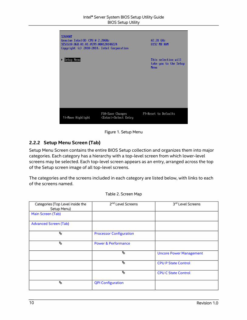
Figure 1. Setup Menu
2.2.2 Setup Menu Screen (Tab)
Setup Menu Screen contains the entire BIOS Setup collection and organizes them into major
categories. Each category has a hierarchy with a top-level screen from which lower-level
screens may be selected. Each top-level screen appears as an entry, arranged across the top
of the Setup screen image of all top-level screens.
The categories and the screens included in each category are listed below, with links to each
of the screens named.
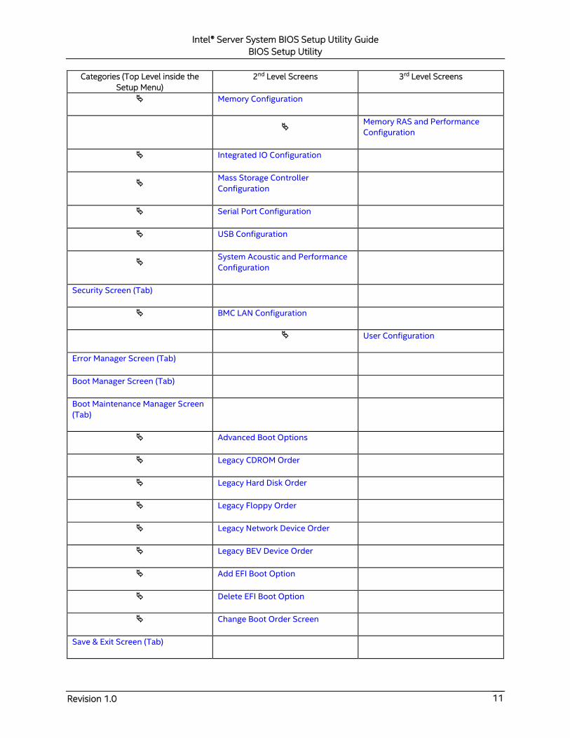
Table 2. Screen Map
Categories (Top Level inside the
Setup Menu)
2nd Level Screens 3rd Level Screens
Main Screen (Tab)
Advanced Screen (Tab)
Processor Configuration
Power & Performance
Uncore Power Management
CPU P State Control
CPU C State Control
QPI Configuration
Intel® Server System BIOS Setup Utility Guide
BIOS Setup Utility
Revision 1.0 11
Categories (Top Level inside the
Setup Menu)
2nd Level Screens 3rd Level Screens
Memory Configuration
Memory RAS and Performance
Configuration
Integrated IO Configuration
Mass Storage Controller
Configuration
Serial Port Configuration
USB Configuration
System Acoustic and Performance
Configuration
Security Screen (Tab)
BMC LAN Configuration
User Configuration
Error Manager Screen (Tab)
Boot Manager Screen (Tab)
Boot Maintenance Manager Screen
(Tab)
Advanced Boot Options
Legacy CDROM Order
Legacy Hard Disk Order
Legacy Floppy Order
Legacy Network Device Order
Legacy BEV Device Order
Add EFI Boot Option
Delete EFI Boot Option
Change Boot Order Screen
Save & Exit Screen (Tab)

Intel® Server System BIOS Setup Utility Guide
BIOS Setup Utility
Revision 1.0 12

Intel® Server System BIOS Setup Utility Guide
BIOS Setup Utility
Revision 1.0 13
2.2.3 Main Screen (Tab)
The Main Screen is the first screen that appears when the BIOS Setup configuration utility is
entered, unless an error has occurred. If an error has occurred, the Error Manager Screen
appears instead (Figure 31).
Figure 2. Main Screen
Screen Field Descriptions:
1. Logged in as:
Option Values: <Administrator/User>
Help Text: <None>
Comments: Information only. Displays password level that setup is running in:
Administrator or User. With no passwords set, Administrator is the default mode.
Back to [Main Screen] — [Screen Map]
2. Platform ID
Option Values: <Platform ID>
Help Text: <None>
Comments: Information only. Displays the Platform ID (Board ID) for the
board on which the BIOS is executing POST.
The Platform ID is limited to 8 characters, because it is also used in the ACPI Tables
which have that limitation. In some cases, this means that the Platform ID is
abbreviated from the marketing designation (for example, MFS2600KI is abbreviated
to S2600KI).
Intel® Server System BIOS Setup Utility Guide
BIOS Setup Utility
Revision 1.0 14
Back to [Main Screen] — [Screen Map]
3. BIOS Boot From
Option Values: <Primary/Backup>
Help Text: <None>
Comments: Information only. Displays the exact BIOS portion on the board
which is executing POST.
Boot from Backup BIOS means the BIOS is running in Recovery mode and the Primary
BIOS may be corrupted.
Back to [Main Screen] — [Screen Map]
4. Primary BIOS Version
Option Values: <Primary BIOS version ID>
Help Text: <None>
Comments: Information only. The BIOS version displayed uniquely identifies
the BIOS that is currently installed and operational on the board. The version
information displayed is taken from the BIOS ID String, with the timestamp segment
dropped off. The segments displayed are:
Platform: Identifies that this is the correct platform BIOS
86B: Identifies this BIOS as being an Intel® Server BIOS
xx: Major Revision level of the BIOS
yy: Release Revision level for this BIOS
zzzz: Release Number for this BIOS
Back to [Main Screen] — [Screen Map]
5. Primary BIOS Build Date
Option Values: <Date and time when the currently installed Primary BIOS was
created (built)>
Help Text: <None>
Comments: Information only. The time and date displayed are taken from the
timestamp segment of the BIOS ID String.
Back to [Main Screen] — [Screen Map]
6. Backup BIOS Version
Option Values: <Primary BIOS version ID>
Help Text: <None>
Comments: Information only. The BIOS version displayed uniquely identifies
the Backup BIOS that is currently installed and operational on the board. The version
information displayed is taken from the BIOS ID String, with the timestamp segment
dropped off. The segments displayed are:

Intel® Server System BIOS Setup Utility Guide
BIOS Setup Utility
Revision 1.0 15
Platform: Identifies that this is the correct platform BIOS
86B: Identifies this BIOS as being an Intel® Server BIOS
xx: Major Revision level of the BIOS
yy: Release Revision level for this BIOS
zzzz: Release Number for this BIOS
Back to [Main Screen] — [Screen Map]
7. Backup BIOS Build Date
Option Values: <Date and time when the currently installed Backup BIOS was
created (built)>
Help Text: <None>
Comments: Information only. The time and date displayed are taken from the
timestamp segment of the BIOS ID String.
Back to [Main Screen] — [Screen Map]
8. Total Memory
Option Values: <Amount of memory installed in the system>
Help Text: <None>
Comments: Information only. Displays the total physical memory installed in
the system, in MB or GB. The term physical memory indicates the total memory
discovered in the form of installed DDR4 DIMMs.
Back to [Main Screen] — [Screen Map]
9. Quiet Boot
Option Values: Enabled
Disabled
Help Text:
[Enabled] – Display the logo screen during POST.
[Disabled] – Display the diagnostic screen during POST.
Comments: This field controls whether the full diagnostic information is
displayed on the screen during POST. When Console Redirection is enabled, the Quiet
Boot setting is disregarded and the text mode Diagnostic Screen is displayed
unconditionally.
Back to [Main Screen] — [Screen Map]
10. POST Error Pause
Option Values: Enabled
Disabled
Help Text:
[Enabled] – Go to the Error Manager for critical POST errors.

Intel® Server System BIOS Setup Utility Guide
BIOS Setup Utility
Revision 1.0 16
[Disabled] – Attempt to boot and do not go to the Error Manager for critical
POST errors.
Comments: If enabled, the POST Error Pause option takes the system to the
error manager to review the errors when major errors occur. Minor and fatal error
displays are not affected by this setting.
Back to [Main Screen] — [Screen Map]
11. System Date
Option Values: <System Date initially displays the current system calendar date,
including the day of the week>
Help Text:
System Date has configurable fields for the current Month, Day, and Year.
The year must be between 2013 and 2099.
Use [Enter] to select the next field.
Use [+] or [-] key to modify the selected field.
Comments: This field initially displays the current system day of week and
date. It may be edited to change the system date. When the System Date is reset by the
“BIOS Defaults” jumper, BIOS Recovery Flash Update, or other method, the date will be
the earliest date in the allowed range – Saturday 01/01/2013.
Back to [Main Screen] — [Screen Map]
12. System Time
Option Values: <System Time initially displays the current system time of day, in
24-hour format>
Help Text:
System Time has configurable fields for Hours, Minutes, and Seconds.
Hours are in 24-hour format.
Use the [Enter] key to select the next field.
Use the [+] or [-] key to modify the selected field.
Comments: This field initially displays the current system time (24-hour time).
It may be edited to change the system time. When the System Time is reset by the
“BIOS Defaults” jumper, BIOS Recovery Flash Update, or other method, the time will be
the earliest time of day in the allowed range – 00:00:00 (although the time will be
updated beginning from when it is reset early in POST).
Back to [Main Screen] — [Screen Map]
Intel® Server System BIOS Setup Utility Guide
BIOS Setup Utility
Revision 1.0 17
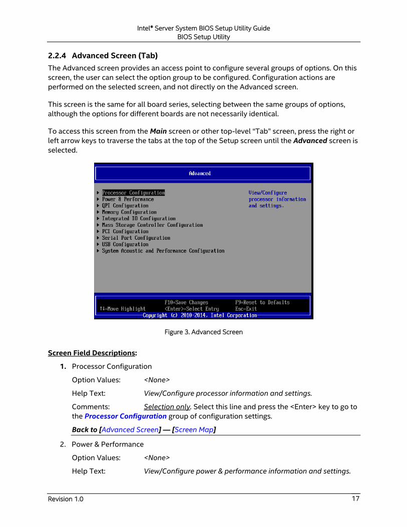
2.2.4 Advanced Screen (Tab)
The Advanced screen provides an access point to configure several groups of options. On this
screen, the user can select the option group to be configured. Configuration actions are
performed on the selected screen, and not directly on the Advanced screen.
This screen is the same for all board series, selecting between the same groups of options,
although the options for different boards are not necessarily identical.
To access this screen from the Main screen or other top-level “Tab” screen, press the right or
left arrow keys to traverse the tabs at the top of the Setup screen until the Advanced screen is
selected.
Figure 3. Advanced Screen
Screen Field Descriptions:
1. Processor Configuration
Option Values: <None>
Help Text: View/Configure processor information and settings.
Comments: Selection only. Select this line and press the <Enter> key to go to
the Processor Configuration group of configuration settings.
Back to [Advanced Screen] — [Screen Map]
2. Power & Performance
Option Values: <None>
Help Text: View/Configure power & performance information and settings.

Intel® Server System BIOS Setup Utility Guide
BIOS Setup Utility
Revision 1.0 18
Comments: Selection only. Select this line and press the <Enter> key to go to
the Power & Performance group of configuration settings.
Back to [Advanced Screen] — [Screen Map]
3. QPI Configuration
Option Values: <None>
Help Text: View/Configure QPI information and settings.
Comments: Selection only. Select this line and press the <Enter> key to go to
the QPI Configuration group of configuration settings.
Back to [Advanced Screen] — [Screen Map]
4. Memory Configuration
Option Values: <None>
Help Text: View/Configure memory information and settings.
Comments: Selection only. Select this line and press the <Enter> key to go to
the Memory Configuration group of configuration settings.
Back to [Advanced Screen] — [Screen Map]
5. Integrated IO Configuration
Option Values: <None>
Help Text: View/Configure Integrated IO information and settings.
Comments: Selection only. Select this line and press the <Enter> key to go to
the Integrated IO Configuration group of configuration settings.
Back to [Advanced Screen] — [Screen Map]
6. Mass Storage Controller Configuration
Option Values: <None>
Help Text: View/Configure mass storage controller information and settings.
Comments: Selection only. Select this line and press the <Enter> key to go to
the Mass Storage Controller Configuration group of configuration settings.
Back to [Advanced Screen] — [Screen Map]
7. PCI Configuration
Option Values: <None>
Help Text: View/Configure PCI information and settings.
Comments: Selection only. Select this line and press the <Enter> key to go to
the group of configuration settings.
Back to [Advanced Screen] — [Screen Map]
Intel® Server System BIOS Setup Utility Guide
BIOS Setup Utility
Revision 1.0 19
8. Serial Port Configuration
Option Values: <None>
Help Text: View/Configure serial port information and settings.
Comments: Selection only. Select this line and press the <Enter> key to go to
the Serial Port Configuration group of configuration settings.
Back to [Advanced Screen] — [Screen Map]
9. USB Configuration
Option Values: <None>
Help Text: View/Configure USB information and settings.
Comments: Selection only. Select this line and press the <Enter> key to go to
the USB Configuration group of configuration settings.
Back to [Advanced Screen] — [Screen Map]
10. System Acoustic and Performance Configuration
Option Values: <None>
Help Text: View/Configure system acoustic and performance information
and settings.
Comments: Selection only. Select this line and press the <Enter> key to go to
the System Acoustic and Performance Configuration group of configuration settings.
Back to [Advanced Screen] — [Screen Map]
Intel® Server System BIOS Setup Utility Guide
BIOS Setup Utility
Revision 1.0 20
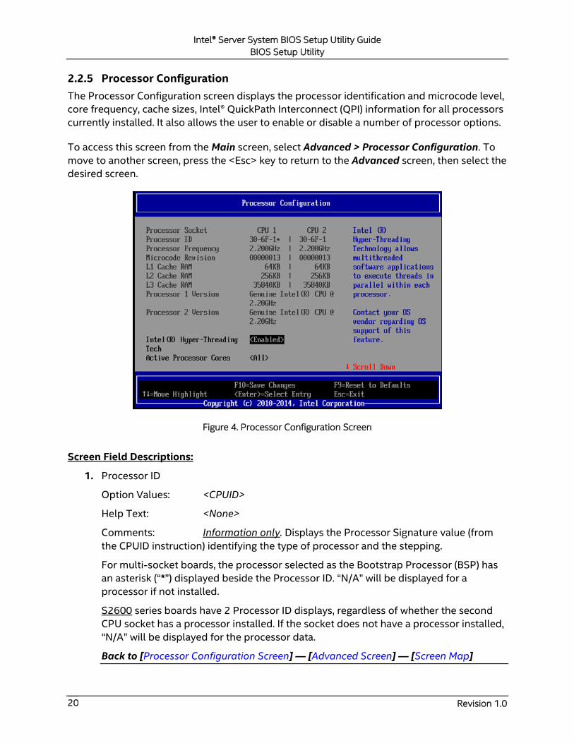
2.2.5 Processor Configuration
The Processor Configuration screen displays the processor identification and microcode level,
core frequency, cache sizes, Intel® QuickPath Interconnect (QPI) information for all processors
currently installed. It also allows the user to enable or disable a number of processor options.
To access this screen from the Main screen, select Advanced > Processor Configuration. To
move to another screen, press the <Esc> key to return to the Advanced screen, then select the
desired screen.
Figure 4. Processor Configuration Screen
Screen Field Descriptions:
1. Processor ID
Option Values: <CPUID>
Help Text: <None>
Comments: Information only. Displays the Processor Signature value (from
the CPUID instruction) identifying the type of processor and the stepping.
For multi-socket boards, the processor selected as the Bootstrap Processor (BSP) has
an asterisk (“*”) displayed beside the Processor ID. “N/A” will be displayed for a
processor if not installed.
S2600 series boards have 2 Processor ID displays, regardless of whether the second
CPU socket has a processor installed. If the socket does not have a processor installed,
“N/A” will be displayed for the processor data.
Back to [Processor Configuration Screen] — [Advanced Screen] — [Screen Map]
Intel® Server System BIOS Setup Utility Guide
BIOS Setup Utility
Revision 1.0 21
2. Processor Frequency
Option Values: <Current Processor Operating Frequency>
Help Text: <None>
Comments: Information only. Displays current operating frequency of the
processor.
Single-socket boards have a single processor display; 2-socket or 4-socket boards
have a display column for each socket, showing “N/A” for empty sockets where
processors are not installed.
Back to [Processor Configuration Screen] — [Advanced Screen] — [Screen Map]
3. Microcode Revision
Option Values: <Microcode Revision Number>
Help Text: <None>
Comments: Information only. Displays Revision Level of the currently loaded
processor microcode.
Single-socket boards have a single processor display; 2-socket or 4-socket boards
have a display column for each socket, showing “N/A” for empty sockets where
processors are not installed.
Back to [Processor Configuration Screen] — [Advanced Screen] — [Screen Map]
4. L1 Cache RAM
Option Values: <L1 cache size>
Help Text: <None>
Comments: Information only. Displays size in KB of the processor L1 Cache.
Since L1 cache is not shared between cores, this is shown as the amount of L1 cache
per core. There are two types of L1 cache, so this amount is the total of L1 Instruction
Cache plus L1 Data Cache for each core.
Single-socket boards have a single processor display; 2-socket or 4-socket boards
have a display column for each socket, showing “N/A” for empty sockets where
processors are not installed.
Back to [Processor Configuration Screen] — [Advanced Screen] — [Screen Map]
5. L2 Cache RAM
Option Values: <L2 cache size>
Help Text: <None>
Comments: Information only. Displays size in KB of the processor L2 Cache.
Since L2 cache is not shared between cores, this is shown as the amount of L2 cache
per core.
Intel® Server System BIOS Setup Utility Guide
BIOS Setup Utility
Revision 1.0 22
Single-socket boards have a single processor display; 2-socket or 4-socket boards
have a display column for each socket, showing “N/A” for empty sockets where
processors are not installed.
Back to [Processor Configuration Screen] — [Advanced Screen] — [Screen Map]
6. L3 Cache RAM
Option Values: <L3 cache size>
Help Text: <None>
Comments: Information only. Displays size in MB of the processor L3 Cache.
Since L3 cache is shared between all cores in a processor package, this is shown as the
total amount of L3 cache per processor package.
Single-socket boards have a single processor display; 2-socket or 4-socket boards
have a display column for each socket, showing “N/A” for empty sockets where
processors are not installed.
Back to [Processor Configuration Screen] — [Advanced Screen] — [Screen Map]
7. Processor 1 Version
8. Processor 2 Version
Option Values: <ID string from processor>
Help Text: <None>
Comments: Information only. Displays Brand ID string read from processor
with CPUID instruction.
Single-socket boards have a single processor display; 2-socket or 4-socket boards
have a display line for each socket, showing “N/A” for empty sockets where processors
are not installed.
Back to [Processor Configuration Screen] — [Advanced Screen] — [Screen Map]
9. Intel(R) Hyper-Threading Tech
Option Values: Enabled
Disabled
Help Text:
Intel(R) Hyper-Threading Technology allows multithreaded software
applications to execute threads in parallel within each processor.
Contact your OS vendor regarding OS support of this feature.
Comments: This option is only visible if all processors installed in the system
support Intel® Hyper-Threading Technology.
Back to [Processor Configuration Screen] — [Advanced Screen] — [Screen Map]

Intel® Server System BIOS Setup Utility Guide
BIOS Setup Utility
Revision 1.0 23
10. Active Processor Cores
Option Values: All
1
2
3
4
N minus 1 (N is the number of cores in the processor package)
Help Text: Number of cores to enable in each processor package.
Comments: The number of cores that appear as selections depends on the
number of cores available in the processors installed. Boards may have as many as 8
cores in each of 1, 2, or 4 processors. The same number of cores must be active in each
processor package.
This Setup screen should begin with the number of currently active cores as the
number displayed. See note below – this may be different from the number previously
set by the user.
Note: The ME can control the number of active cores independently of the BIOS Setup
setting. If the ME disables or enables processor cores, that will override the BIOS
setting, and the number selected by the BIOS will be disregarded.
Back to [Processor Configuration Screen] — [Advanced Screen] — [Screen Map]
11. Execute Disable Bit
Option Values: Enabled
Disabled
Help Text:
Execute Disable Bit can help prevent certain classes of malicious buffer overflow
attacks.
Contact your OS vendor regarding OS support of this feature.
Comments: This option is only visible if all processors installed in the system
support the Execute Disable Bit. The OS and applications installed must support this
feature in order for it to be enabled.
Back to [Processor Configuration Screen] — [Advanced Screen] — [Screen Map]
12. Intel(R) Virtualization Technology
Option Values: Enabled
Disabled
Help Text:
Intel(R) Virtualization Technology allows a platform to run multiple operating
systems and applications in independent partitions.
Note: A change to this option requires the system to be powered off and then
back on before the setting takes effect.
Intel® Server System BIOS Setup Utility Guide
BIOS Setup Utility
Revision 1.0 24
Comments: This option is only visible if all processors installed in the system
support Intel® VT. The software configuration installed on the system must support
this feature in order for it to be enabled.
Back to [Processor Configuration Screen] — [Advanced Screen] — [Screen Map]
13. Intel(R) TXT
Option Values: Enabled
Disabled
Help Text: Enable/Disable Intel(R) Trusted Execution Technology. Takes
effect after reboot.
Comments: Intel® TXT only appears with products and processors which
have TXT support capability. This option is only available when both Intel®
Virtualization Technology and Intel® VT for Directed IO are enabled and on models
equipped with a TPM. The TPM must be active in order to support Intel® TXT.
Note: Changing the setting for Intel® TXT requires the system to perform a Hard Reset
in order for the new setting to become effective.
Back to [Processor Configuration Screen] — [Advanced Screen] — [Screen Map]
14. DPR Memory Size
Option Values: 1M DPR
3M DPR
64M DPR
128M DPR
255M DPR
Help Text: Allows selection of the TXT DPR Memory size in the system.
Comments: This option is only visible when Intel® TXT is enabled.
Back to [Processor Configuration Screen] — [Advanced Screen] — [Screen Map]
15. Enhanced Error Containment Mode
Option Values: Enabled
Disabled
Help Text:
Enable Enhanced Error Containment Mode (Data Poisoning) – Erroneous data
coming from memory will be poisoned. If disabled (default), will be in Legacy
Mode – No data poisoning support available.
Comments: Enhanced Error Containment (Data Poisoning) is not supported
by all models of processors, and this option will not appear unless all installed
processors support Enhanced Error Containment. This option globally enables or
disables both Core and Uncore Data Poisoning, for processors which support them.
Back to [Processor Configuration Screen] — [Advanced Screen] — [Screen Map]
Intel® Server System BIOS Setup Utility Guide
BIOS Setup Utility
Revision 1.0 25
16. MLC Streamer
Option Values: Enabled
Disabled
Help Text:
MLC Streamer is a speculative prefetch unit within the processor(s).
Note: Modifying this setting may affect performance.
Comments: MLC Streamer is normally Enabled, for best efficiency in L2
Cache and Memory Channel use but disabling it may improve performance for some
processing loads and on certain benchmarks.
Back to [Processor Configuration Screen] — [Advanced Screen] — [Screen Map]
17. MLC Spatial Prefetcher
Option Values: Enabled
Disabled
Help Text:
[Enabled] – Fetches adjacent cache line (128 bytes) when required data is not
currently in cache.
[Disabled] – Only fetches cache line with data required by the processor (64
bytes).
Comments: MLC Spatial Prefetcher is normally Enabled, for best efficiency in
L2 Cache and Memory Channel use but disabling it may improve performance for
some processing loads and on certain benchmarks.
Back to [Processor Configuration Screen] — [Advanced Screen] — [Screen Map]
18. DCU Data Prefetcher
Option Values: Enabled
Disabled
Help Text:
The next cache line will be prefetched into L1 data cache from L2 or system
memory during unused cycles if it sees that the processor core has accessed
several bytes sequentially in a cache line as data.
[Disabled] – Only fetches cache line with data required by the processor (64
bytes).
Comments: DCU Data Prefetcher is normally Enabled, for best efficiency in
L1 Data Cache and Memory Channel use but disabling it may improve performance for
some processing loads and on certain benchmarks.
Back to [Processor Configuration Screen] — [Advanced Screen] — [Screen Map]
Intel® Server System BIOS Setup Utility Guide
BIOS Setup Utility
Revision 1.0 26
19. DCU Instruction Prefetcher
Option Values: Enabled
Disabled
Help Text:
The next cache line will be prefetched into L1 instruction cache from L2 or
system memory during unused cycles if it sees that the processor core has
accessed several bytes sequentially in a cache line as data.
Comments: DCU Instruction Prefetcher is normally Enabled, for best
efficiency in L1 Instruction Cache and Memory Channel use but disabling it may
improve performance for some processing loads and on certain benchmarks.
Back to [Processor Configuration Screen] — [Advanced Screen] — [Screen Map]
20. Direct Cache Access (DCA)
Option Values: Enabled
Disabled
Help Text:
Allows processors to increase the I/O performance by placing data from I/O
devices directly into the processor cache.
Comments: System performance is usually best with Direct Cache Access
Enabled. In certain unusual cases, disabling this may give improved results.
Back to [Processor Configuration Screen] — [Advanced Screen] — [Screen Map]
21. Extended ATR
Option Values: 0x03
0x01
Help Text: Extended Timeout value for PCIe tuning.
Comments: Adjust ATR value to PCIe performance improvement.
Back to [Processor Configuration Screen] — [Advanced Screen] — [Screen Map]
22. PFloor Tuning
Option Values: [Entry Field maximum Non-Turbo Frequency minus 3 of installed
Processors – 12, 12 is default]
Help Text: Adjustment of CPU idle frequency for PCIe Bus tuning.
Comments: Adjustment of CPU idle frequency for PCIe performance tuning.
Back to [Processor Configuration Screen] — [Advanced Screen] — [Screen Map]
Intel® Server System BIOS Setup Utility Guide
BIOS Setup Utility
Revision 1.0 27
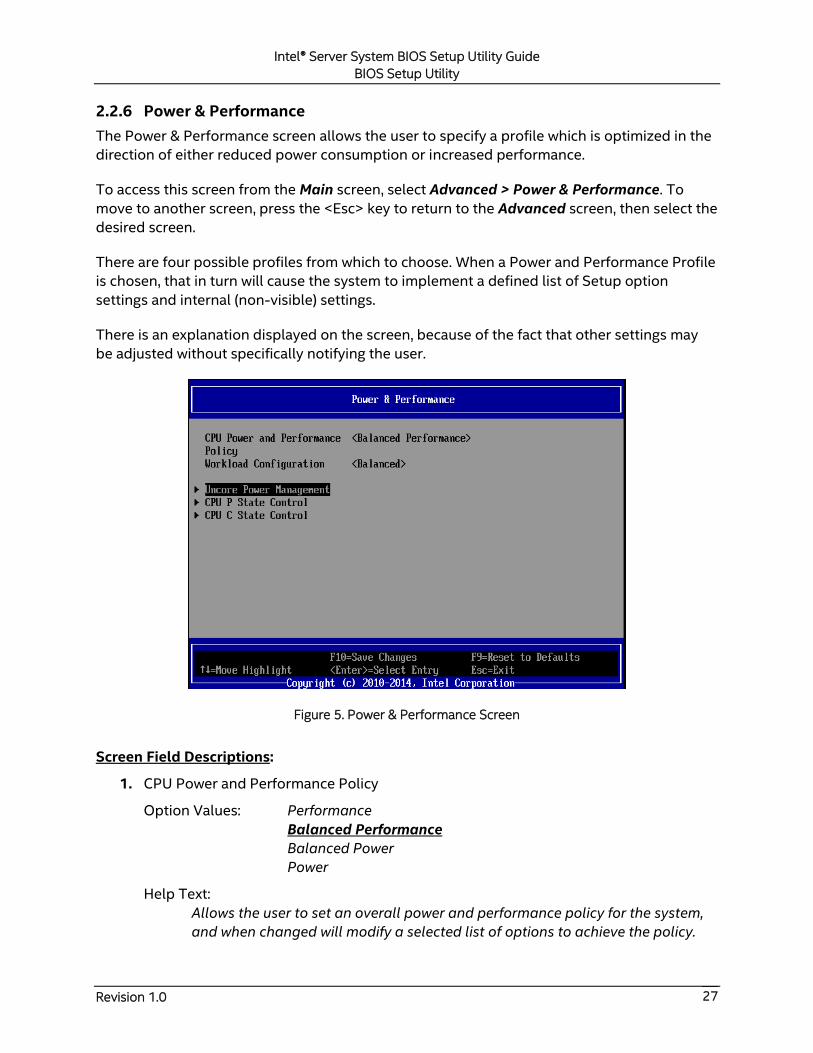
2.2.6 Power & Performance
The Power & Performance screen allows the user to specify a profile which is optimized in the
direction of either reduced power consumption or increased performance.
To access this screen from the Main screen, select Advanced > Power & Performance. To
move to another screen, press the <Esc> key to return to the Advanced screen, then select the
desired screen.
There are four possible profiles from which to choose. When a Power and Performance Profile
is chosen, that in turn will cause the system to implement a defined list of Setup option
settings and internal (non-visible) settings.
There is an explanation displayed on the screen, because of the fact that other settings may
be adjusted without specifically notifying the user.
Figure 5. Power & Performance Screen
Screen Field Descriptions:
1. CPU Power and Performance Policy
Option Values: Performance
Balanced Performance
Balanced Power
Power
Help Text:
Allows the user to set an overall power and performance policy for the system,
and when changed will modify a selected list of options to achieve the policy.
Intel® Server System BIOS Setup Utility Guide
BIOS Setup Utility
Revision 1.0 28
These options are still changeable outside of the policy but do reflect the
changes that the policy makes when a new policy is selected.
[Performance] Optimization is strongly toward performance, even at the
expense of energy efficiency.
[Balanced Performance] Weights optimization toward performance, while
conserving energy.
[Balanced Power] Weights optimization toward energy conservation, with good
performance.
[Power] Optimization is strongly toward energy efficiency, even at the expense
of performance.
Comments: Choosing one of these four Power and Performance Profiles
implements a number of changes in BIOS settings, both visible settings in the Setup
screens and non-visible internal settings.
Back to [Power & Performance Screen] — [Advanced Screen] — [Screen Map]
2. Workload Configuration
Option Values: Balanced
I/O Sensitive
Help Text:
Controls the aggressiveness of the energy performance BIOS settings. This bit
field allows the BIOS to choose a configuration that may improve performance
on certain workloads.
Comments: IVR enables fine granularity voltage regulation and allows the
voltage and frequency of Uncore to be programmed independently. The Uncore
activity is monitored to optimize the frequency in real-time. This option is only visible
when Enhanced Intel SpeedStep® is enabled by the BIOS.
Back to [Power & Performance Screen] — [Advanced Screen] — [Screen Map]
3. Uncore Power Management
Option Values: <None>
Help Text: View/Configure Uncore Power Management information and
settings.
Comments: Selection only. Select this line and press the <Enter> key to go to
the Uncore Power Management group of configuration settings.
Back to [Power & Performance Screen] — [Advanced Screen] — [Screen Map]
4. CPU P State Control
Option Values: <None>
Help Text: View/Configure CPU P State Control information and settings.
Intel® Server System BIOS Setup Utility Guide
BIOS Setup Utility
Revision 1.0 29
Comments: Selection only. Select this line and press the <Enter> key to go to
the CPU P State Control group of configuration settings.
Back to [Power & Performance Screen] — [Advanced Screen] — [Screen Map]
5. CPU C State Control
Option Values: <None>
Help Text: View/Configure CPU C State Control information and settings.
Comments: Selection only. Select this line and press the <Enter> key to go to
the CPU C State Control group of configuration settings.
Back to [Power & Performance Screen] — [Advanced Screen] — [Screen Map]
Intel® Server System BIOS Setup Utility Guide
BIOS Setup Utility
Revision 1.0 30
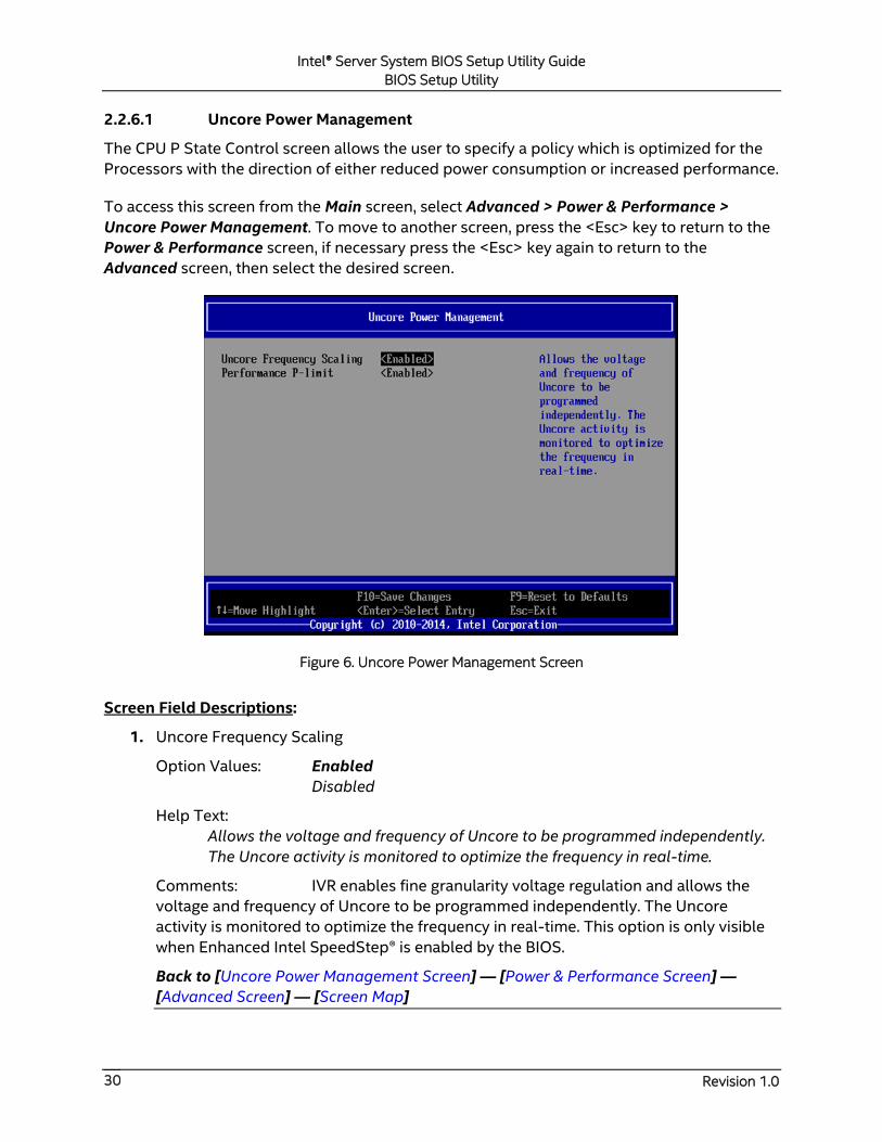
2.2.6.1 Uncore Power Management
The CPU P State Control screen allows the user to specify a policy which is optimized for the
Processors with the direction of either reduced power consumption or increased performance.
To access this screen from the Main screen, select Advanced > Power & Performance >
Uncore Power Management. To move to another screen, press the <Esc> key to return to the
Power & Performance screen, if necessary press the <Esc> key again to return to the
Advanced screen, then select the desired screen.
Figure 6. Uncore Power Management Screen
Screen Field Descriptions:
1. Uncore Frequency Scaling
Option Values: Enabled
Disabled
Help Text:
Allows the voltage and frequency of Uncore to be programmed independently.
The Uncore activity is monitored to optimize the frequency in real-time.
Comments: IVR enables fine granularity voltage regulation and allows the
voltage and frequency of Uncore to be programmed independently. The Uncore
activity is monitored to optimize the frequency in real-time. This option is only visible
when Enhanced Intel SpeedStep® is enabled by the BIOS.
Back to [Uncore Power Management Screen] — [Power & Performance Screen] —
[Advanced Screen] — [Screen Map]

Intel® Server System BIOS Setup Utility Guide
BIOS Setup Utility
Revision 1.0 31
2. Performance P-limit
Option Values: Enabled
Disabled
Help Text:
Allows the Uncore frequency coordination of two processors when enabled.
Comments: This option is only visible if two processors are installed in the
system. In a two-socket system, it may be desirable to have the two processors running
at similar Uncore frequencies. The Performance P-limit feature does this by
coordinating frequency between the two sockets. This avoids latency increases caused
by an “idle” socket running at a low CLR frequency, slowing down accesses from a
“busy” socket.
Back to [Uncore Power Management Screen] — [Power & Performance Screen] —
[Advanced Screen] — [Screen Map]
Intel® Server System BIOS Setup Utility Guide
BIOS Setup Utility
Revision 1.0 32
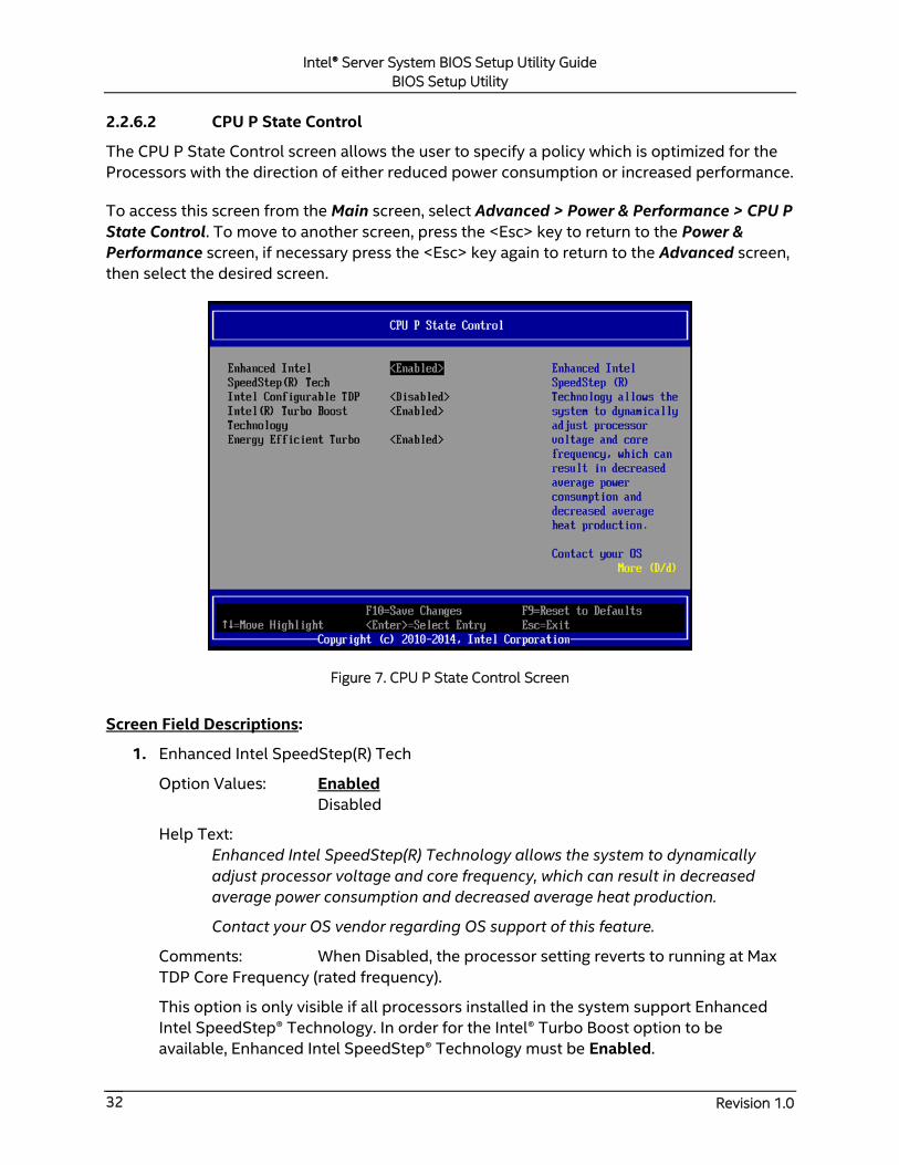
2.2.6.2 CPU P State Control
The CPU P State Control screen allows the user to specify a policy which is optimized for the
Processors with the direction of either reduced power consumption or increased performance.
To access this screen from the Main screen, select Advanced > Power & Performance > CPU P
State Control. To move to another screen, press the <Esc> key to return to the Power &
Performance screen, if necessary press the <Esc> key again to return to the Advanced screen,
then select the desired screen.
Figure 7. CPU P State Control Screen
Screen Field Descriptions:
1. Enhanced Intel SpeedStep(R) Tech
Option Values: Enabled
Disabled
Help Text:
Enhanced Intel SpeedStep(R) Technology allows the system to dynamically
adjust processor voltage and core frequency, which can result in decreased
average power consumption and decreased average heat production.
Contact your OS vendor regarding OS support of this feature.
Comments: When Disabled, the processor setting reverts to running at Max
TDP Core Frequency (rated frequency).
This option is only visible if all processors installed in the system support Enhanced
Intel SpeedStep® Technology. In order for the Intel® Turbo Boost option to be
available, Enhanced Intel SpeedStep® Technology must be Enabled.
Intel® Server System BIOS Setup Utility Guide
BIOS Setup Utility
Revision 1.0 33
Back to [CPU P State Control Screen] — [Power & Performance Screen] — [Advanced
Screen] — [Screen Map]
2. Intel Configurable TDP
Option Values: Enabled
Disabled
Help Text: Allows the user to disable/enable Intel Config TDP.
Comments: This option is only visible if all processors installed in the system
support Intel® Configurable TDP Technology. In order for this option to be available,
Enhanced Intel SpeedStep® Technology must be Enabled.
Back to [CPU P State Control Screen] — [Power & Performance Screen] — [Advanced
Screen] — [Screen Map]
3. Configurable TDP Level
Option Values: Nominal
Level 1
Level 2
Help Text:
Allows the user to select Intel Config TDP level – Nominal is the default TDP.
Comments: This option is only visible if all processors installed in the system
support Intel® Configurable TDP Technology. In order for the Intel® Turbo Boost option
to be available, Enhanced Intel SpeedStep® Technology and Intel Configurable TDP
must be Enabled.
Back to [CPU P State Control Screen] — [Power & Performance Screen] — [Advanced
Screen] — [Screen Map]
4. Intel(R) Turbo Boost Technology
Option Values: Enabled
Disabled
Help Text:
Intel(R) Turbo Boost Technology allows the processor to automatically increase
its frequency if it is running below power, temperature, and current
specifications.
Comments: This option is only visible if all processors installed in the system
support Intel® Turbo Boost Technology. In order for this option to be available,
Enhanced Intel SpeedStep® Technology must be Enabled.
Back to [CPU P State Control Screen] — [Power & Performance Screen] — [Advanced
Screen] — [Screen Map]

Intel® Server System BIOS Setup Utility Guide
BIOS Setup Utility
Revision 1.0 34
5. Energy Efficient Turbo
Option Values: Enabled
Disabled
Help Text:
When Energy Efficient Turbo is enabled, the CPU cores only enter the turbo
frequency when the PCU detects high utilization.
Comments: This option is only visible if all processors installed in the system
support Intel® Turbo Boost Technology. In order for this option to be available, Intel®
Turbo Boost Technology must be Enabled.
Back to [CPU P State Control Screen] — [Power & Performance Screen] — [Advanced
Screen] — [Screen Map]
Intel® Server System BIOS Setup Utility Guide
BIOS Setup Utility
Revision 1.0 35
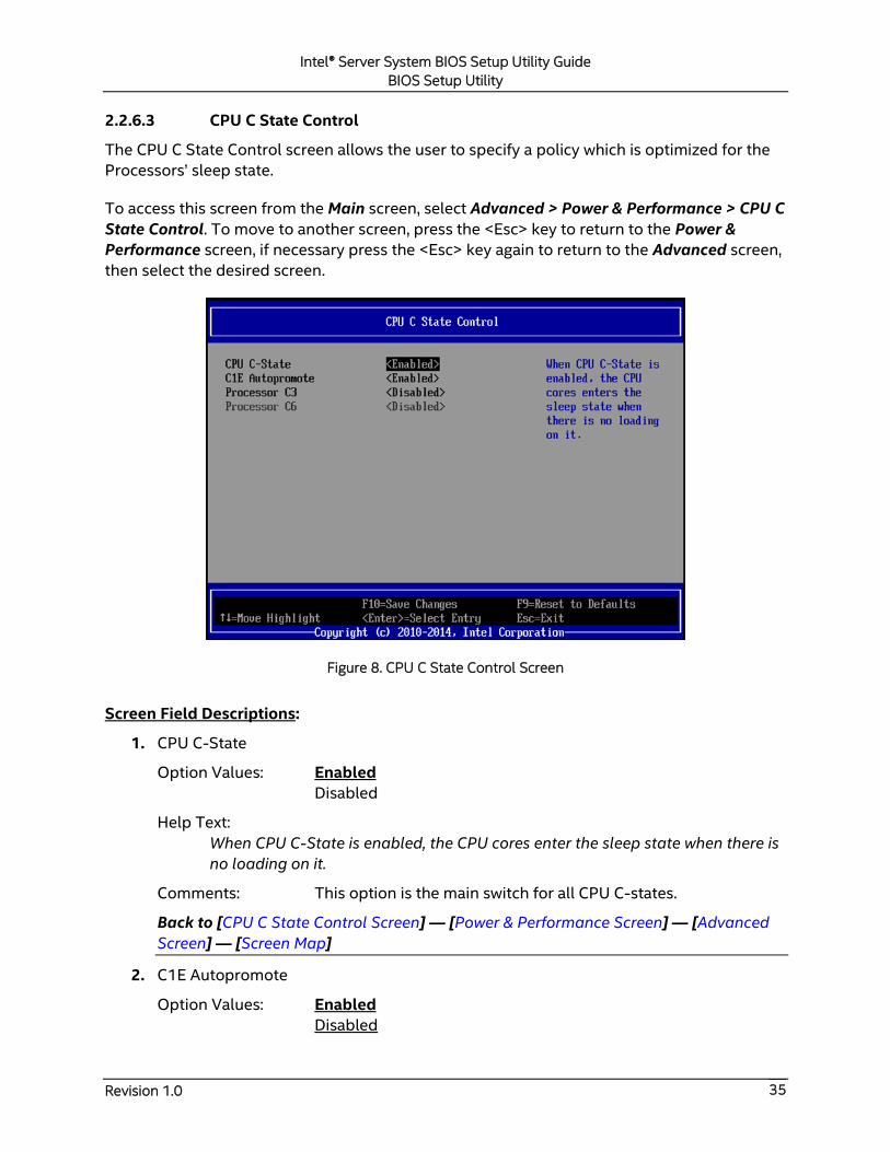
2.2.6.3 CPU C State Control
The CPU C State Control screen allows the user to specify a policy which is optimized for the
Processors’ sleep state.
To access this screen from the Main screen, select Advanced > Power & Performance > CPU C
State Control. To move to another screen, press the <Esc> key to return to the Power &
Performance screen, if necessary press the <Esc> key again to return to the Advanced screen,
then select the desired screen.
Figure 8. CPU C State Control Screen
Screen Field Descriptions:
1. CPU C-State
Option Values: Enabled
Disabled
Help Text:
When CPU C-State is enabled, the CPU cores enter the sleep state when there is
no loading on it.
Comments: This option is the main switch for all CPU C-states.
Back to [CPU C State Control Screen] — [Power & Performance Screen] — [Advanced
Screen] — [Screen Map]
2. C1E Autopromote
Option Values: Enabled
Disabled
Intel® Server System BIOS Setup Utility Guide
BIOS Setup Utility
Revision 1.0 36
Help Text:
When Enabled, the CPU will switch to the Minimum Enhanced Intel SpeedStep®
Technology operating point when all execution cores enter C1. Frequency will
switch immediately, followed by gradual Voltage switching.
When Disabled, the CPU will not transition to the minimum Enhanced Intel
SpeedStep® Technology operating point when all cores enter C1.
Comments: This is normally Disabled but can be Enabled for improved
performance on certain benchmarks and in certain situations.
Back to [CPU C State Control Screen] — [Power & Performance Screen] — [Advanced
Screen] — [Screen Map]
3. Processor C3
Option Values: Enabled
Disabled
Help Text: Enable/Disable Processor C3 (ACPI C2/C3) report to OS.
Comments: This is normally Disabled but can be Enabled for improved
performance on certain benchmarks and in certain situations.
Back to [CPU C State Control Screen] — [Power & Performance Screen] — [Advanced
Screen] — [Screen Map]
4. Processor C6
Option Values: Enabled
Disabled
Help Text: Enable/Disable Processor C6 (ACPI C3) report to OS.
Comments: This is normally Enabled but can be Disabled for improved
performance on certain benchmarks and in certain situations.
Back to [CPU C State Control Screen] — [Power & Performance Screen] — [Advanced
Screen] — [Screen Map]
Intel® Server System BIOS Setup Utility Guide
BIOS Setup Utility
Revision 1.0 37
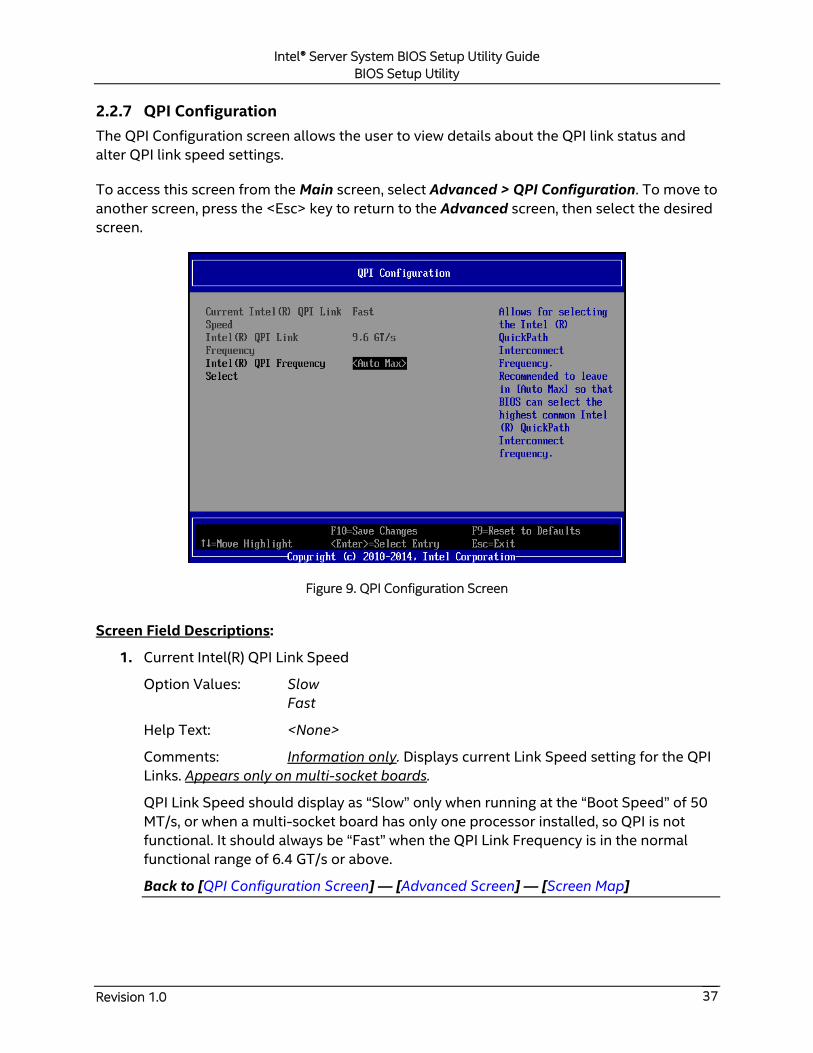
2.2.7 QPI Configuration
The QPI Configuration screen allows the user to view details about the QPI link status and
alter QPI link speed settings.
To access this screen from the Main screen, select Advanced > QPI Configuration. To move to
another screen, press the <Esc> key to return to the Advanced screen, then select the desired
screen.
Figure 9. QPI Configuration Screen
Screen Field Descriptions:
1. Current Intel(R) QPI Link Speed
Option Values: Slow
Fast
Help Text: <None>
Comments: Information only. Displays current Link Speed setting for the QPI
Links. Appears only on multi-socket boards.
QPI Link Speed should display as “Slow” only when running at the “Boot Speed” of 50
MT/s, or when a multi-socket board has only one processor installed, so QPI is not
functional. It should always be “Fast” when the QPI Link Frequency is in the normal
functional range of 6.4 GT/s or above.
Back to [QPI Configuration Screen] — [Advanced Screen] — [Screen Map]
Intel® Server System BIOS Setup Utility Guide
BIOS Setup Utility
Revision 1.0 38
2. Intel(R) QPI Link Frequency
Option Values: N/A
6.4 GT/s
8.0GT/s
9.6 GT/s
Unknown GT/s
Help Text: <None>
Comments: Information only. Displays current frequency at which the QPI
Links are operating. Appears only on multi-socket boards.
When a multi-socket board has only one processor installed, QPI Link Frequency will
be shown as “N/A”.
Back to [QPI Configuration Screen] — [Advanced Screen] — [Screen Map]
3. Intel(R) QPI Frequency Select
Option Values: Auto Max
6.4 GT/s
8.0 GT/s
9.6 GT/s
Help Text:
Allows for selecting the Intel(R) QuickPath Interconnect Frequency.
Recommended to leave in [Auto Max] so that the BIOS can select the highest
common Intel(R) QuickPath Interconnect frequency.
Comments: Lowering the QPI frequency may improve performance per watt
for some processing loads and on certain benchmarks. [Auto Max] will give the
maximum QPI performance available. Appears only on multi-socket boards.
When a multi-socket board has only one processor installed, this will be grayed out,
with the previous value remaining displayed.
Changes in QPI Link Frequency will not take effect until the system reboots, so this will
not immediately change the QPI Link Frequency display. Changing QPI Link Frequency
does not affect the QPI Link Speed.
Back to [QPI Configuration Screen] — [Advanced Screen] — [Screen Map]
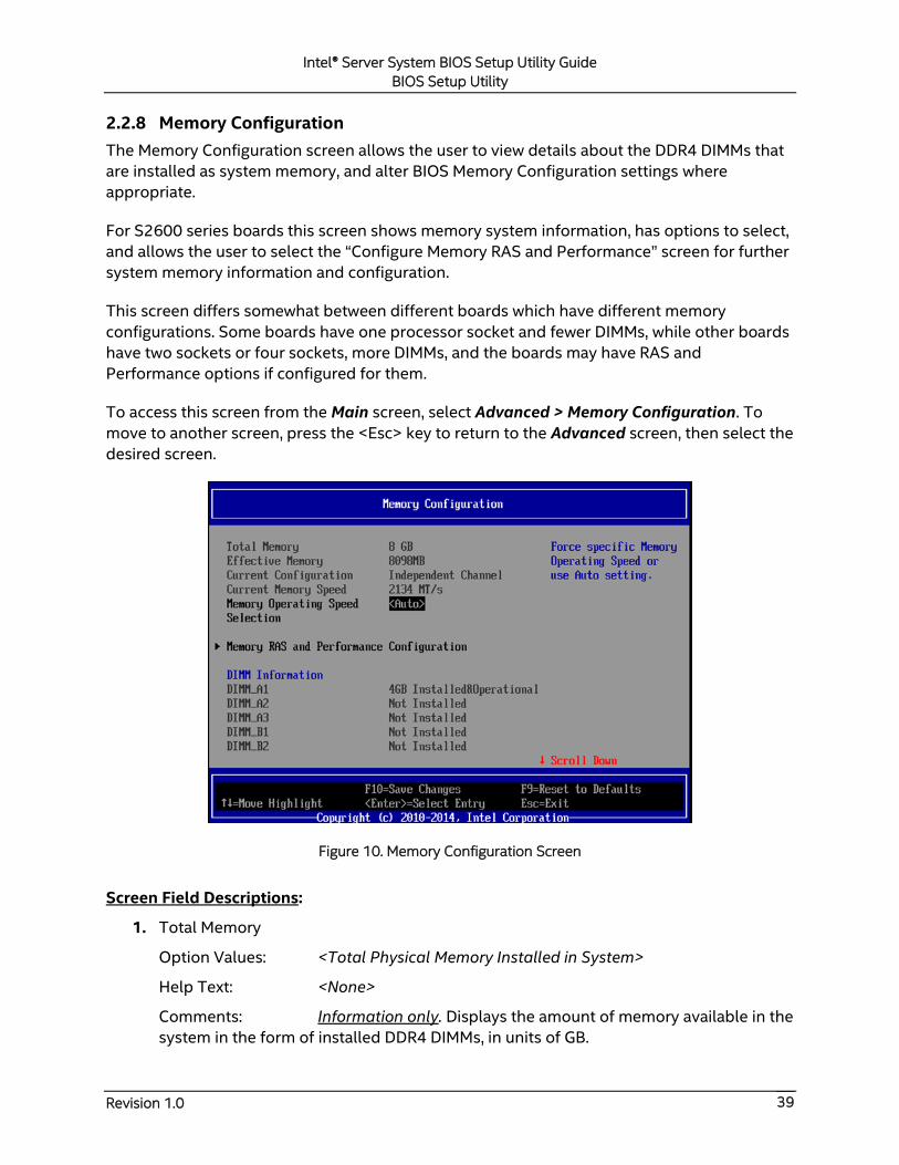
Intel® Server System BIOS Setup Utility Guide
BIOS Setup Utility
Revision 1.0 39
2.2.8 Memory Configuration
The Memory Configuration screen allows the user to view details about the DDR4 DIMMs that
are installed as system memory, and alter BIOS Memory Configuration settings where
appropriate.
For S2600 series boards this screen shows memory system information, has options to select,
and allows the user to select the “Configure Memory RAS and Performance” screen for further
system memory information and configuration.
This screen differs somewhat between different boards which have different memory
configurations. Some boards have one processor socket and fewer DIMMs, while other boards
have two sockets or four sockets, more DIMMs, and the boards may have RAS and
Performance options if configured for them.
To access this screen from the Main screen, select Advanced > Memory Configuration. To
move to another screen, press the <Esc> key to return to the Advanced screen, then select the
desired screen.
Figure 10. Memory Configuration Screen
Screen Field Descriptions:
1. Total Memory
Option Values: <Total Physical Memory Installed in System>
Help Text: <None>
Comments: Information only. Displays the amount of memory available in the
system in the form of installed DDR4 DIMMs, in units of GB.
Intel® Server System BIOS Setup Utility Guide
BIOS Setup Utility
Revision 1.0 40
Back to [Memory Configuration Screen] — [Advanced Screen] — [Screen Map]
2. Effective Memory
Option Values: <Total Effective Memory>
Help Text: <None>
Comments: Information only. Displays the amount of memory available to
the OS in MB or GB.
The Effective Memory is the Total Physical Memory minus the sum of all memory
reserved for internal usage, RAS redundancy, and SMRAM.
Note: Some server operating systems do not display the total physical memory
installed.
Back to [Memory Configuration Screen] — [Advanced Screen] — [Screen Map]
3. Current Configuration
Option Values: Independent Channel
Mirror
Rank Sparing
Lockstep
Help Text: <None>
Comments: Information only. Displays one of the following:
Independent Channel – DIMMs are operating in Independent Channel Mode,
the default configuration when there is no RAS Mode configured.
Mirror – Mirroring RAS Mode has been configured and is operational.
Rank Sparing – Rank Sparing RAS Mode has been configured and is
operational.
Lockstep – Lockstep RAS Mode has been configured and is operational.
Back to [Memory Configuration Screen] — [Advanced Screen] — [Screen Map]
4. Current Memory Speed
Option Values: <Operational Memory Speed in MT/s>
Help Text: <None>
Comments: Information only. Displays the speed in MT/s at which the
memory is currently running.
The supported memory speeds are 1333 MT/s, 1600 MT/s, 1866 MT/s, and 2133
MT/s. The actual memory speed capability depends on the memory configuration.
Back to [Memory Configuration Screen] — [Advanced Screen] — [Screen Map]
Intel® Server System BIOS Setup Utility Guide
BIOS Setup Utility
Revision 1.0 41
5. Memory Operating Speed Selection
Option Values: Auto
1333
1600
1866
2133
Help Text: Force specific Memory Operating Speed or use Auto setting.
Comments: Allows the user to select a specific speed at which memory will
operate. Only speeds that are legitimate are available, that is, the user can only specify
speeds less than or equal to the auto-selected Memory Operating Speed. The default
Auto setting will select the highest achievable Memory Operating Speed consistent
with the DIMMs and processors installed.
Back to [Memory Configuration Screen] — [Advanced Screen] — [Screen Map]
6. Memory RAS and Performance Configuration
Option Values: <None>
Help Text:
Configure memory RAS (Reliability, Availability, and Serviceability) and view
current memory performance information and settings.
Comments: Selection only. Select this line and press the <Enter> key to go to
the Memory RAS and Performance Configuration group of configuration settings.
Back to [Memory Configuration Screen] — [Advanced Screen] — [Screen Map]
7. DIMM_A1
8. DIMM_A2
9. DIMM_A3
10. DIMM_B1
(DIMM_B2 through DIMM_H2 omitted)
11. DIMM_H3
(DIMM_J1 through DIMM_T2 omitted)
12. DIMM_T3
Option Values: <DIMM Size> <DIMM Status>
Where DIMM Size is:
Size of DIMM in GB
Where DIMM Status is:
Installed&Operational
Not Installed
Failed/Disabled
Help Text: <None>
Comments: Information only. Displays the status of each DIMM socket
present on the board. There is one line for each DIMM socket present on the board.
Intel® Server System BIOS Setup Utility Guide
BIOS Setup Utility
Revision 1.0 42
For each DIMM socket, the DIMM Status reflects one of the following three possible
states:
Installed&Operational – There is a DDR4 DIMM installed and operational in
this slot.
Not Installed – There is no DDR4 DIMM installed in this slot.
Failed/Disabled – The DIMM installed in this slot has failed during
initialization and/or was disabled during initialization.
For each DIMM that is in the Installed & Operational state, the DIMM Size in GB of that
DIMM is displayed. This is the physical size of the DIMM, regardless of how it is counted
in the Effective Memory size.
Note: In “DIMM_XY”, X denotes the Channel Identifier A-P, and Y denotes the DIMM
Slot identifier 1-3 within the Channel. DIMM_A2 is the DIMM socket on Channel A, Slot
2. Not all boards have the same number of channels and slots – this is dependent on
the board features.
S2600 boards can have DIMMs A1, A2, A3 to H1, H2, H3 (max 2 CPU/4 chan/3 DPC).
Back to [Memory Configuration Screen] — [Advanced Screen] — [Screen Map]
Intel® Server System BIOS Setup Utility Guide
BIOS Setup Utility
Revision 1.0 43
2.2.8.1 Memory RAS and Performance Configuration
The Memory RAS and Performance Configuration screen allows the user to customize several
memory configuration options, such as whether to use Memory Mirroring or Memory Sparing.
To access this screen from the Main screen, select Advanced > Memory Configuration >
Memory RAS and Performance Configuration. To move to another screen, press the <Esc>
key to return to the Memory Configuration screen, if necessary press the <Esc> key again to
return to the Advanced screen, then select the desired screen.
Screen Field Descriptions:
1. Memory Mirroring Possible
Option Values: Yes
No
Help Text: <None>
Comments: Information only. Displays whether the current DIMM
configuration is capable of Memory Mirroring. For Memory Mirroring to be possible,
DIMM configurations on all paired channels must be identical between the channel pair
(Mirroring Domain).
[Memory Configuration Screen] — [Advanced Screen] — [Screen Map]
2. Memory Rank Sparing Possible
Option Values: Yes
No
Help Text: <None>
Comments: Information only. Displays whether the current DIMM
configuration is capable of Rank Sparing. For Rank Sparing to be possible, DIMM
configurations on all channels must be capable of supporting Rank Sparing.
Note: The Correctable Error Threshold value is also the Sparing Fail Over threshold
value. Threshold values of “All” or “None” are not valid for Rank Sparing. If the
Correctable Error Threshold is set to either of those values, Rank Spring will not be
possible.
[Memory Configuration Screen] — [Advanced Screen] — [Screen Map]
3. Memory Lockstep Possible
Option Values: Yes
No
Help Text: <None>
Comments: Information only. Displays whether the current DIMM
configuration is capable of Memory Lockstep. For Memory Lockstep to be possible,
Intel® Server System BIOS Setup Utility Guide
BIOS Setup Utility
Revision 1.0 44
DIMM configurations on all paired channels must be identical between the channel
pair.
[Memory Configuration Screen] — [Advanced Screen] — [Screen Map]
4. Select Memory RAS Configuration
Option Values: Maximum Performance
Mirroring
Rank Sparing
Lockstep
Help Text:
Allows the user to select the memory RAS Configuration to be applied for the
next boot.
Comments: Available modes depend on the current memory population.
Modes which are not listed as “possible” should not be available as choices. If the only
valid choice is “Maximum Performance”, then this option should be grayed out and
unavailable.
Maximum Performance – (default) No RAS but best memory utilization since
full amount of memory is available, operating in Independent Channel Mode.
Mirroring – Most reliability by using half of memory as a mirror image, can
survive an Uncorrectable ECC Error.
Rank Sparing – Offers reliability by reserving spare ranks to replace failing
ranks which are generating excessive Correctable ECC Errors.
Lockstep – Allows SDDC capability with x8 DIMMs installed. No memory size
impact but does have a performance and power penalty.
Note: Since only RAS Modes which are listed as “possible” are available for selection, it
is not possible to select a RAS Mode without first installing an appropriate DIMM
configuration.
[Memory Configuration Screen] — [Advanced Screen] — [Screen Map]
5. Multi-Rank Sparing
Option Values: 1 Rank
2 Rank
3Rank
Auto
Help Text:
The Rank number used when Rank Sparing is enabled.
Comments: This option is only present when Select Memory RAS
Configuration is Rank Sparing.
Intel® Server System BIOS Setup Utility Guide
BIOS Setup Utility
Revision 1.0 45
[Memory Configuration Screen] — [Advanced Screen] — [Screen Map]
6. NUMA Optimized
Option Values: Enabled
Disabled
Help Text:
If enabled, the BIOS includes ACPI tables that are required for NUMA-aware
Operating Systems.
Comments: This option is only present for boards which have two or more
processor sockets. When a multi-socket board has only a single processor without
Cluster-on-Die support installed, this option is grayed out and set as Disabled; when a
multi-socket board has only a single processor with Cluster-on-Die support installed,
this option is grayed out and set the same as Cluster-on-Die option below.
When enabled, the SRAT and SLIT ACPI tables are provided that show the locality of
systems resources, especially memory, which allows a “NUMA Aware” OS to optimize
which processor threads are used by processes which can benefit by having the best
access to those resources.
[Memory Configuration Screen] — [Advanced Screen] — [Screen Map]
7. Cluster-on-Die
Option Values: Enabled
Disabled
Help Text:
When NUMA and COD are both enabled, the BIOS will publish one NUMA
domain per cluster i.e., two NUMA domains per socket in the ACPI SLIT/SRAT
tables.
Comments: This option is only available for processors with Cluster-on-Die
capability. When NUMA option is disabled, this option will be disabled and hidden.
[Memory Configuration Screen] — [Advanced Screen] — [Screen Map]
8. Patrol Scrub
Option Values: Enabled
Disabled
Help Text:
When enabled, performs periodic checks on memory cells and proactively walks
through populated memory space, to seek and correct soft ECC errors.
Comments: When enabled, Patrol Scrub is initialized to read through all of
memory in a 24-hour period, correcting any Correctable ECC Errors it encounters by
writing back the corrected data to memory.
Intel® Server System BIOS Setup Utility Guide
BIOS Setup Utility
Revision 1.0 46
[Memory Configuration Screen] — [Advanced Screen] — [Screen Map]
9. Demand Scrub
Option Values: Enabled
Disabled
Help Text:
When enabled, executes when an ECC error is encountered during a normal
read/write of data and corrects that data.
Comments: When enabled, Demand Scrub automatically corrects a
Correctable ECC Error encountered during a fetch from memory by writing back the
corrected data to memory.
[Memory Configuration Screen] — [Advanced Screen] — [Screen Map]
10. Correctable Error Threshold
Option Values: 20
10
5
All
None
Help Text:
Threshold value for logging Correctable Errors (CE) – Threshold of 10 (default)
logs 10th CE, "All" logs every CE, and “None”’ means no CE logging. All and
None are not valid with Rank Sparing.
Comments: Specifies how many Correctable Errors must occur before
triggering the logging of a SEL Correctable Error Event. Only the first threshold
crossing is logged, unless “All” is selected. “All” causes every CE that occurs to be
logged. “None” suppresses CE logging completely.
When Rank Sparing RAS Mode is configured, “All” and “None” are not valid, so they will
not be present as choices.
This threshold is applied on a per-rank basis. The Correctable Error occurrences are
counted for each memory rank. When any one rank accumulates a CE count equal to
the CE Threshold, then a single CE SEL Event is logged, and all further CE logging is
suppressed.
Note that the CE counts are subject to a “leaky bucket” mechanism that reduces the
count as a function of time, to keep from accumulating counts unnecessarily over the
term of a long operational run.
This is also the Correctable Error threshold used when Rank Sparing RAS Mode is
configured. When a CE threshold crossing occurs in Rank Sparing Mode on a channel
which is in Redundant state, it causes a Sparing Fail Over (SFO) event to occur. That
threshold crossing will also be logged as a Correctable Error event if it is the first to
occur in the system.
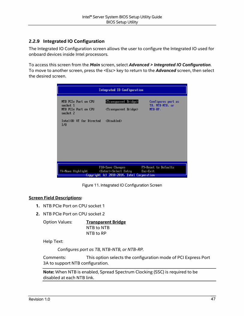
Intel® Server System BIOS Setup Utility Guide
BIOS Setup Utility
Revision 1.0 47
2.2.9 Integrated IO Configuration
The Integrated IO Configuration screen allows the user to configure the Integrated IO used for
onboard devices inside Intel processors.
To access this screen from the Main screen, select Advanced > Integrated IO Configuration.
To move to another screen, press the <Esc> key to return to the Advanced screen, then select
the desired screen.
Figure 11. Integrated IO Configuration Screen
Screen Field Descriptions:
1. NTB PCIe Port on CPU socket 1
2. NTB PCIe Port on CPU socket 2
Option Values: Transparent Bridge
NTB to NTB
NTB to RP
Help Text:
Configures port as TB, NTB-NTB, or NTB-RP.
Comments: This option selects the configuration mode of PCI Express Port
3A to support NTB configuration.
Note: When NTB is enabled, Spread Spectrum Clocking (SSC) is required to be
disabled at each NTB link.

Intel® Server System BIOS Setup Utility Guide
BIOS Setup Utility
Revision 1.0 48
Back to [Integrated IO Configuration Screen] — [Advanced Screen] — [Screen Map]
3. Enable NTB Bars
Option Values: Disabled
Enabled
Help Text:
If disabled, the BIOS will not program NTB BAR size registers.
Comments: This option allows the BIOS to program NTB BAR registers with
default values when Enabled. If disabled, the BIOS will not program NTB BAR registers
and the task is left to drivers.
This option only appears when NTB PCIe Port on CPU socket1/2 is not configured as
“Transparent Bridge”.
Back to [Integrated IO Configuration Screen] — [Advanced Screen] — [Screen Map]
4. Crosslink control override
Option Values: DSD/USP
USD/DSP
Help Text:
Configure NTB port as DSP/USP, USD/DSP, or use external pins.
Comments: This option configures the Crosslink configuration of the NTB
port.
This option only appears when NTB PCIe Port on CPU socket1/2 is not configured as
“Transparent Bridge”.
Back to [Integrated IO Configuration Screen] — [Advanced Screen] — [Screen Map]
5. Intel(R) VT for Directed I/O
Option Values: Enabled
Disabled
Help Text:
Enable/Disable Intel(R) Virtualization Technology for Directed I/O (Intel(R) VT-d).
Report the I/O device assignment to VMM through DMAR ACPI Tables.
Comments: This option is only visible if all processors installed in the system
support Intel® VT-d. The software configuration installed on the system must support
this feature in order for it to be enabled.
Back to [Integrated IO Configuration Screen] — [Advanced Screen] — [Screen Map]
6. Interrupt Remapping
Option Values: Enabled
Disabled
Intel® Server System BIOS Setup Utility Guide
BIOS Setup Utility
Revision 1.0 49
Help Text:
Enable/Disable Intel(R) VT-d Interrupt Remapping support. For some processors,
this option may be "always enabled".
Comments: This option only appears when Intel® Virtualization Technology
for Directed I/O is Enabled. For some processors this will be enabled unconditionally
whenever Intel® VT-d is enabled. In that case, this option will be shown as "Enabled",
and grayed out and not changeable.
Back to [Integrated IO Configuration Screen] — [Advanced Screen] — [Screen Map]
7. Coherency Support
Option Values: Enabled
Disabled
Help Text:
Enable/Disable Intel(R) VT-d Coherency support.
Comments: This option only appears when Intel® Virtualization Technology
for Directed I/O is Enabled.
Back to [Integrated IO Configuration Screen] — [Advanced Screen] — [Screen Map]

Intel® Server System BIOS Setup Utility Guide
BIOS Setup Utility
Revision 1.0 50
2.2.10 Mass Storage Controller Configuration
The Mass Storage Configuration screen allows the user to configure the Mass Storage
controllers that are integrated into the server board on which the BIOS is executing. This
includes only onboard Mass Storage controllers. Mass Storage controllers on add-in cards are
not included in this screen, nor are other storage mechanisms such as USB-attached storage
devices or Network Attached Storage.
There are two SATA Port configured in this screen, representing the SATA controller and the
sSATA controller 2 with SATA drive support and RAID support. There are also informational
displays of two AHCI controller’s configuration, and SATA Drive Information when applicable.
If the presence of an Intel® Storage Module is detected, the type of Storage Module is
displayed as information-only.
To access this screen from the Main screen, select Advanced > Mass Storage Controller
Configuration. To move to another screen, press the <Esc> key to return to the Advanced
screen, then select the desired screen.
Figure 12. Mass Storage Controller Configuration Screen
Screen Field Descriptions:
1. SATA Port 0-5
2. sSATA Port 0-3
Option Values: <None>
Help Text: Configure the SATA Port 0-5 (sSATA Port 0-3) and view current
disk drive information.
Intel® Server System BIOS Setup Utility Guide
BIOS Setup Utility
Revision 1.0 51
Comments: Selection only. Select this line and press the <Enter> key to go to
the SATA Port Configuration group of configuration settings.
Back to [Mass Storage Controller Configuration Screen] — [Advanced Screen] —
[Screen Map]
3. SAS Controller
Option Values: Enabled
Disabled
Help Text: Enable or Disable the LSI SAS controller.
Comments: This Option is for Cotton Wood Pass Server Board to
enable/disable onboard LSI SAS controller.
Back to [Mass Storage Controller Configuration Screen] — [Advanced Screen] —
[Screen Map]
4. Intel(R) Storage Module
Option Values: None
<Name of Storage Module detected>
Names of Storage Modules supported at this time are:
Intel(R) Integrated RAID Module
Intel(R) Integrated RAID Module RMS25PB040
Intel(R) Integrated RAID Module RMT3PB080
Intel(R) Integrated RAID Module RMS25CB080
Intel(R) Integrated RAID Module RMS25CB040
Intel(R) Integrated RAID Module RMT3CB080
Intel(R) Integrated RAID Module RMS25JB080
Intel(R) Integrated RAID Module RMS25JB040
Intel(R) Integrated RAID Module RMS25KB080
Intel(R) Integrated RAID Module RMS25KB040
Intel(R) Integrated RAID Module RMS3CC080
Intel(R) Integrated RAID Module RMS3CC040
Intel(R) Integrated RAID Module RMS3HC080
Intel(R) Integrated RAID Module RMS3JC080
Help Text: <None>
Comments: Information only. If no Intel® Storage Module is detected, then
None is displayed. This shows the customer the product name of the module installed,
which helps in identifying drivers, support, documentation, etc.
Back to [Mass Storage Controller Configuration Screen] — [Advanced Screen] —
[Screen Map]
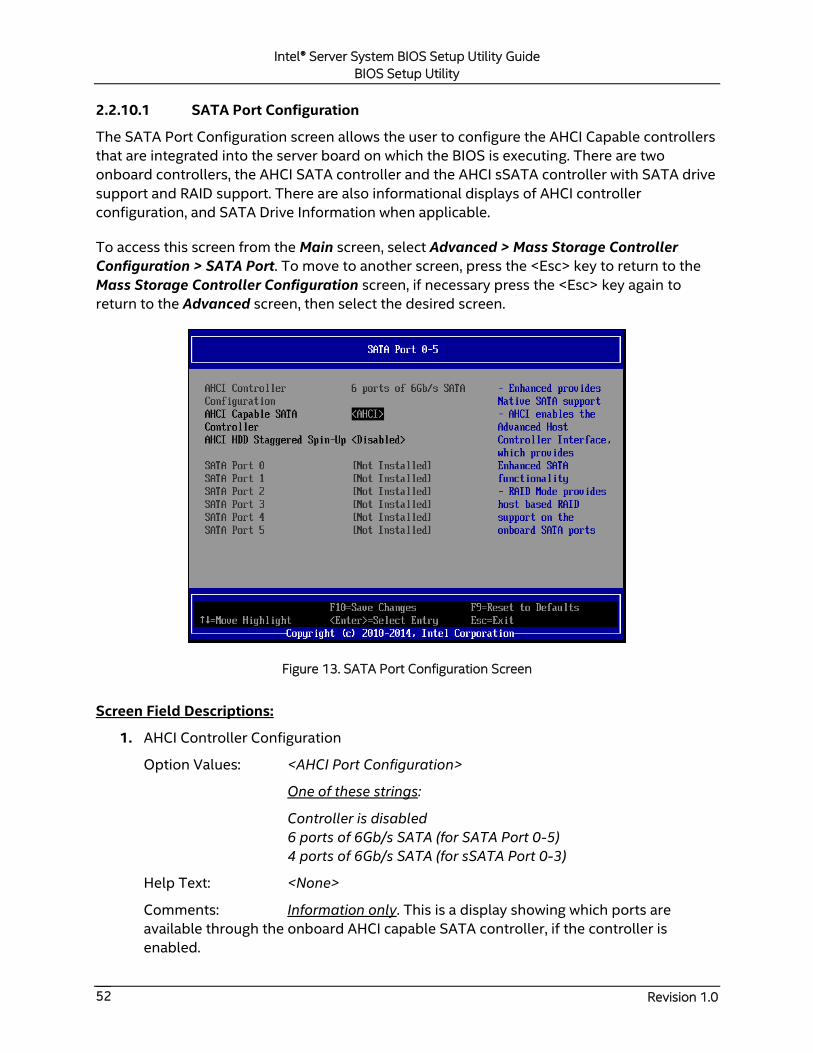
Intel® Server System BIOS Setup Utility Guide
BIOS Setup Utility
Revision 1.0 52
2.2.10.1 SATA Port Configuration
The SATA Port Configuration screen allows the user to configure the AHCI Capable controllers
that are integrated into the server board on which the BIOS is executing. There are two
onboard controllers, the AHCI SATA controller and the AHCI sSATA controller with SATA drive
support and RAID support. There are also informational displays of AHCI controller
configuration, and SATA Drive Information when applicable.
To access this screen from the Main screen, select Advanced > Mass Storage Controller
Configuration > SATA Port. To move to another screen, press the <Esc> key to return to the
Mass Storage Controller Configuration screen, if necessary press the <Esc> key again to
return to the Advanced screen, then select the desired screen.
Figure 13. SATA Port Configuration Screen
Screen Field Descriptions:
1. AHCI Controller Configuration
Option Values: <AHCI Port Configuration>
One of these strings:
Controller is disabled
6 ports of 6Gb/s SATA (for SATA Port 0-5)
4 ports of 6Gb/s SATA (for sSATA Port 0-3)
Help Text: <None>
Comments: Information only. This is a display showing which ports are
available through the onboard AHCI capable SATA controller, if the controller is
enabled.
Intel® Server System BIOS Setup Utility Guide
BIOS Setup Utility
Revision 1.0 53
This information is also displayed during POST in the POST Diagnostic Screen.
The number of SATA ports available from the integrated AHCI-capable SATA
Controller is dependent on the specific server board installed in the system. Different
server board designs expose different SATA port configurations. The Platform ID
(Board ID) is displayed in the Main Screen.
Back to [SATA Port Configuration Screen] — [Mass Storage Controller Configuration
Screen] — [Advanced Screen] — [Screen Map]
2. AHCI Capable SATA Controller
Option Values: Disabled
Enhanced
AHCI
RAID Mode
Help Text:
- Enhanced provides Native SATA support.
- AHCI enables the Advanced Host Controller Interface, which provides
Enhanced SATA functionality.
- RAID Mode provides host based RAID support on the onboard SATA ports.
Comments: This option configures the onboard AHCI-capable SATA
controller, which is distinct from the SCU. The number and type of ports it controls
differ between board series.
If the SATA Controller is Disabled, the SATA Ports will not operate and any installed
SATA devices will be unavailable.
Enhanced provides Native SATA support using native SATA drivers included with the
vast majority of current OSes. AHCI enables the Advanced Host Controller Interface,
which provides Enhanced SATA functionality plus possible additional functionality
(Native Command Queuing, Hot Plug, and Staggered Spin Up). It uses AHCI drivers
available for the majority of current OSes.
RAID Mode provides host based RAID support on the onboard SATA ports. RAID levels
supported and required drivers depend on the RAID stack selected.
Back to [SATA Port Configuration Screen] — [Mass Storage Controller Configuration
Screen] — [Advanced Screen] — [Screen Map]
3. AHCI Capable RAID Options
Option Values: Intel(R) ESRT2 (LSI*)
Intel(R) RSTe
Help Text:
- Intel(R) ESRT2 (Powered By LSI*): Supports RAID 0/1/10 and optional RAID 5
with Intel® RAID5 Upgrade Keys. Uses Intel® ESRT2 drivers (based on LSI*
MegaSR).
Intel® Server System BIOS Setup Utility Guide
BIOS Setup Utility
Revision 1.0 54
- Intel(R) RSTe: Provides pass-through drive support. Also provides host based
RAID 0/1/10/5 support. Uses Intel(R) RSTe iastor drivers.
Comments: This option only appears when the SATA Controller is enabled,
and RAID Mode has been selected as the operational SATA Mode. This setting selects
the RAID stack to be used for SATA RAID with the onboard AHCI SATA controller.
If a RAID Volume has not previously been created that is compatible with the RAID
stack selected, it will be necessary to Save and Exit and reboot in order to create a
RAID Volume.
Note: This option does not appear on all boards.
Back to [SATA Port Configuration Screen] — [Mass Storage Controller Configuration
Screen] — [Advanced Screen] — [Screen Map]
4. AHCI HDD Staggered Spin-Up
Option Values: Enabled
Disabled
Help Text:
If enabled for the AHCI Capable SATA controller, Staggered Spin-Up will be
performed on drives attached to it. Otherwise these drives will all spin up at
boot.
Comments: This option enables or disables Staggered Spin-up only for disk
drives attached to ports on the AHCI Capable SATA Controller. Disk drives attached to
SATA/SAS ports on the Storage Control Unit are controlled by a different method for
Staggered Spin-Up and this option does not affect them.
This option is only visible when the SATA Controller is enabled and AHCI or RAID has
been selected as the operational SATA Mode.
Staggered Spin-Up is needed when there are enough HDDs attached to the system to
cause a marked startup power demand surge when all drives start spin-up together.
Since the power demand is greatest just as the drive spinning is started, the overall
startup power demand can be leveled off by starting up each drive at a slightly
different time, so the power demand surges for multiple drives do not coincide and
cause too great a power draw.
When Staggered Spin-Up is enabled, it does have a possibility of increasing boot time
if there are many HDDs attached, because of the interval between starting drives
spinning. However, that is exactly the scenario in which Staggered Spin-Up is most
needed, because the more disk drives attached, the greater the startup demand surge.
Setting the external eSATA connector Enabled (when available) does not invalidate the
Staggered Spin-Up option, although there may be less need for Staggered Spin-Up in a
system configured for eSATA use.

Intel® Server System BIOS Setup Utility Guide
BIOS Setup Utility
Revision 1.0 55
Back to [SATA Port Configuration Screen] — [Mass Storage Controller Configuration
Screen] — [Advanced Screen] — [Screen Map]
5. SATA Port
(For Port numbers 0-5 on AHCI SATA controller and Port number 0-3 on the AHCI
sSATA controller)
Option Values: Not Installed
<Drive Information>
Help Text: <None>
Comments: Information only. The Drive Information, when present, typically
consists of the drive model identification and size for the disk drive installed on a
particular port.
This Drive Information line is repeated for the SATA Ports for the two onboard AHCI
capable SATA Controllers. However, for any given board, only the ports which are
physically populated on the board are shown. That is, a board which only implements
the two 6 GB/s ports 0 and 1 only shows those two ports in this Drive Information list.
This section for Drive Information does not appear at all when the SATA operational
mode is RAID Mode.
Back to [SATA Port Configuration Screen] — [Mass Storage Controller Configuration
Screen] — [Advanced Screen] — [Screen Map]

Intel® Server System BIOS Setup Utility Guide
BIOS Setup Utility
Revision 1.0 56
2.2.11 Serial Port Configuration
The Serial Port Configuration screen allows the user to configure the Serial A and Serial B
ports. In Legacy ISA nomenclature, these are ports COM1 and COM2 respectively.
To access this screen from the Main screen, select Advanced > Serial Port Configuration. To
move to another screen, press the <Esc> key to return to the Advanced screen, then select the
desired screen.
The primary usage for these serial ports is to enable Serial Console Redirection and Serial
Over LAN (SOL) capabilities. Either port can be used for Serial Console Redirection but SOL is
only supported on Serial A.
Figure 14. Serial Port Configuration Screen
Screen Field Descriptions:
1. Serial A Enable
Option Values: Enabled
Disabled
Help Text: Enable or Disable Serial port A.
Comments: Serial Port A can be used for either Serial Over LAN or Serial
Console Redirection.
Back to [Serial Port Configuration Screen] — [Advanced Screen] — [Screen Map]
Intel® Server System BIOS Setup Utility Guide
BIOS Setup Utility
Revision 1.0 57
2. Address
Option Values: 3F8h
2F8h
3E8h
2E8h
Help Text: Select Serial port A base I/O address.
Comments: Legacy I/O port address. This field will not appear when Serial A
port enable/disable does not appear.
Back to [Serial Port Configuration Screen] — [Advanced Screen] — [Screen Map]
3. IRQ
Option Values: 3
4
Help Text: Select Serial port A interrupt request (IRQ) line.
Comments: Legacy IRQ. This field will not appear when Serial A port
enable/disable does not appear.
Back to [Serial Port Configuration Screen] — [Advanced Screen] — [Screen Map]
4. Serial B Enable
Option Values: Enabled
Disabled
Help Text: Enable or Disable Serial port B.
Comments: Serial Port B can be used for Serial Console Redirection.
Back to [Serial Port Configuration Screen] — [Advanced Screen] — [Screen Map]
5. Address
Option Values: 3F8h
2F8h
3E8h
2E8h
Help Text: Select Serial port B base I/O address.
Comments: Legacy I/O port address.
Back to [Serial Port Configuration Screen] — [Advanced Screen] — [Screen Map]
6. IRQ
Option Values: 3
4
Help Text: Select Serial port B interrupt request (IRQ) line.
Comments: Legacy IRQ.

Intel® Server System BIOS Setup Utility Guide
BIOS Setup Utility
Revision 1.0 58
Back to [Serial Port Configuration Screen] — [Advanced Screen] — [Screen Map]
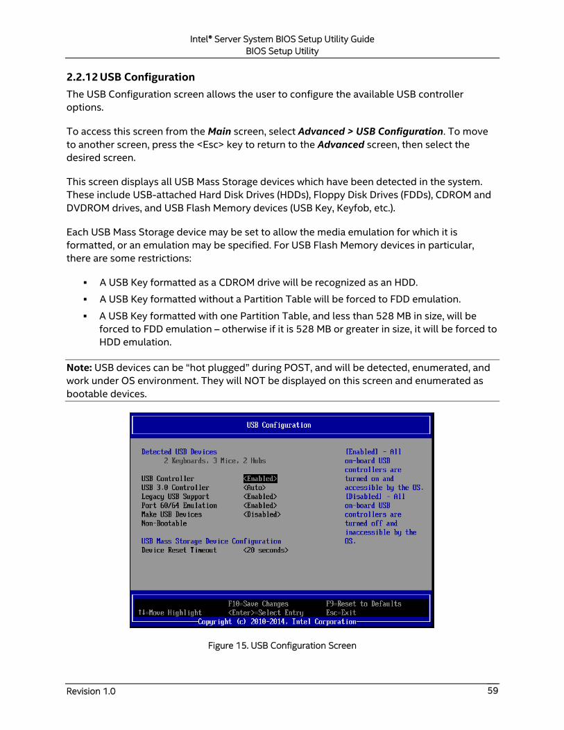
Intel® Server System BIOS Setup Utility Guide
BIOS Setup Utility
Revision 1.0 59
2.2.12 USB Configuration
The USB Configuration screen allows the user to configure the available USB controller
options.
To access this screen from the Main screen, select Advanced > USB Configuration. To move
to another screen, press the <Esc> key to return to the Advanced screen, then select the
desired screen.
This screen displays all USB Mass Storage devices which have been detected in the system.
These include USB-attached Hard Disk Drives (HDDs), Floppy Disk Drives (FDDs), CDROM and
DVDROM drives, and USB Flash Memory devices (USB Key, Keyfob, etc.).
Each USB Mass Storage device may be set to allow the media emulation for which it is
formatted, or an emulation may be specified. For USB Flash Memory devices in particular,
there are some restrictions:
A USB Key formatted as a CDROM drive will be recognized as an HDD.
A USB Key formatted without a Partition Table will be forced to FDD emulation.
A USB Key formatted with one Partition Table, and less than 528 MB in size, will be
forced to FDD emulation – otherwise if it is 528 MB or greater in size, it will be forced to
HDD emulation.
Note: USB devices can be “hot plugged” during POST, and will be detected, enumerated, and
work under OS environment. They will NOT be displayed on this screen and enumerated as
bootable devices.
Figure 15. USB Configuration Screen
Intel® Server System BIOS Setup Utility Guide
BIOS Setup Utility
Revision 1.0 60
Screen Field Descriptions:
1. Detected USB Devices
Option Values: <Number of USB devices detected in system>
Help Text: <None>
Comments: Information only. Displays the total number of USB devices of all
types which have been detected in POST.
Note: There is one USB keyboard and one USB mouse detected from the BMC KVM
function under this item even if no USB devices are connected to the system.
Back to [USB Configuration Screen] — [Advanced Screen] — [Screen Map]
2. USB Controller
Option Values: Enabled
Disabled
Help Text:
[Enabled] – All on-board USB controllers are turned on and accessible by the OS.
[Disabled] – All on-board USB controllers are turned off and inaccessible by the
OS.
Comments: When the USB controllers are Disabled, there is no USB IO
available for either POST or the OS. In that case, all following fields on this screen are
grayed out and inactive.
Back to [USB Configuration Screen] — [Advanced Screen] — [Screen Map]
3. USB 3.0 Controller
Option Values: Auto
Enabled
Disabled
Help Text:
Auto – USB 3.0 port always boots with USB 2.0 controller in BIOS POST and only
switches to USB 3.0 after OS USB 3.0 driver is loaded.
Disabled – Hide XHCI.
Enabled – During the first boot, USB 3.0 port starts with USB 2.0 controller in
BIOS POST; if OS driver USB 3.0 is loaded, it switches to XHCI and continues
using as USB 3.0 speed during BIOS POST when next boot.
Back to [USB Configuration Screen] — [Advanced Screen] — [Screen Map]
Intel® Server System BIOS Setup Utility Guide
BIOS Setup Utility
Revision 1.0 61
4. Legacy USB Support
Option Values: Enabled
Disabled
Auto
Help Text:
Enables Legacy USB support. AUTO option disables legacy support if no USB
devices are connected. Disable option will only keep USB Keyboard devices
available for EFI applications.
Comments: When Legacy USB Support is Disabled, USB devices are available
only through OS drivers.
If the USB controller setting is Disabled, this field is grayed out and inactive.
Back to [USB Configuration Screen] — [Advanced Screen] — [Screen Map]
5. Port 60/64 Emulation
Option Values: Enabled
Disabled
Help Text:
Enables I/O port 60h/64h emulation support.
This may be needed for legacy USB keyboard support when using an OS that is
USB unaware.
Comments: If the USB controller setting is Disabled, this field is grayed out
and inactive.
Back to [USB Configuration Screen] — [Advanced Screen] — [Screen Map]
6. Make USB Devices Non-Bootable
Option Values: Enabled
Disabled
Help Text:
Exclude USB in Boot Table.
[Enabled] – This will remove all USB Mass Storage devices as Boot options.
[Disabled] – This will allow all USB Mass Storage devices as Boot options.
Comments: This is a security option. When Disabled, the system cannot be
booted directly to a USB device of any kind. USB Mass Storage devices may still be
used for data storage.
If the USB controller setting is Disabled, this field is grayed out and inactive.
Back to [USB Configuration Screen] — [Advanced Screen] — [Screen Map]
Intel® Server System BIOS Setup Utility Guide
BIOS Setup Utility
Revision 1.0 62
7. Device Reset Timeout
Option Values: 10 seconds
20 seconds
30 seconds
40 seconds
Help Text:
USB Mass Storage device Start Unit command timeout.
Setting to a larger value provides more time for a mass storage device to be
ready, if needed.
Comments: If the USB controller setting is Disabled, this field is grayed out
and inactive.
Back to [USB Configuration Screen] — [Advanced Screen] — [Screen Map]
8. Mass Storage Devices:
Option Values: Auto
Floppy
Forced FDD
Hard Disk
CD-ROM
Help Text:
[Auto] – USB devices less than 530 MB are emulated as floppies.
[Forced FDD] – HDD formatted drive is emulated as an FDD (e.g., ZIP drive).
Comments: This field is hidden if no USB Mass Storage devices are detected.
This setup screen can show a maximum of eight USB Mass Storage devices on the
screen. If more than eight devices are installed in the system, the “USB Devices
Enabled” displays the correct count but only the first eight devices discovered are
displayed in this list.
If the USB controller setting is Disabled, this field is grayed out and inactive.
Back to [USB Configuration Screen] — [Advanced Screen] — [Screen Map]
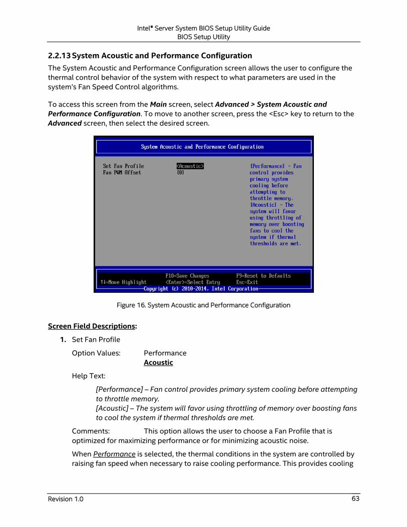
Intel® Server System BIOS Setup Utility Guide
BIOS Setup Utility
Revision 1.0 63
2.2.13 System Acoustic and Performance Configuration
The System Acoustic and Performance Configuration screen allows the user to configure the
thermal control behavior of the system with respect to what parameters are used in the
system’s Fan Speed Control algorithms.
To access this screen from the Main screen, select Advanced > System Acoustic and
Performance Configuration. To move to another screen, press the <Esc> key to return to the
Advanced screen, then select the desired screen.
Figure 16. System Acoustic and Performance Configuration
Screen Field Descriptions:
1. Set Fan Profile
Option Values: Performance
Acoustic
Help Text:
[Performance] – Fan control provides primary system cooling before attempting
to throttle memory.
[Acoustic] – The system will favor using throttling of memory over boosting fans
to cool the system if thermal thresholds are met.
Comments: This option allows the user to choose a Fan Profile that is
optimized for maximizing performance or for minimizing acoustic noise.
When Performance is selected, the thermal conditions in the system are controlled by
raising fan speed when necessary to raise cooling performance. This provides cooling
Intel® Server System BIOS Setup Utility Guide
BIOS Setup Utility
Revision 1.0 64
without impacting system performance but may impact system acoustic performance –
fans running faster are typically louder.
When Acoustic is selected, then rather than increasing fan speed for additional cooling,
the system will attempt first to control thermal conditions by throttling memory to
reduce heat production. This regulates the system’s thermal condition without
changing the acoustic performance but throttling memory may impact system
performance.
Back to [System Acoustic and Performance Configuration] — [Advanced Screen] —
[Screen Map]
2. Fan PWM Offset
Option Values: [Entry Field 0-100, 0 is default]
Help Text:
Valid Offset 0-100. This number is added to the calculated PWM value to
increase Fan Speed.
Comments: This is a percentage by which the calculated fan speed will be
increased. The user can apply positive offsets that result in increasing the minimum fan
speeds.
Back to [System Acoustic and Performance Configuration] — [Advanced Screen] —
[Screen Map]
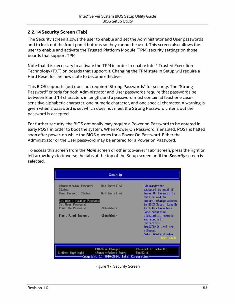
Intel® Server System BIOS Setup Utility Guide
BIOS Setup Utility
Revision 1.0 65
2.2.14 Security Screen (Tab)
The Security screen allows the user to enable and set the Administrator and User passwords
and to lock out the front panel buttons so they cannot be used. This screen also allows the
user to enable and activate the Trusted Platform Module (TPM) security settings on those
boards that support TPM.
Note that it is necessary to activate the TPM in order to enable Intel® Trusted Execution
Technology (TXT) on boards that support it. Changing the TPM state in Setup will require a
Hard Reset for the new state to become effective.
This BIOS supports (but does not require) “Strong Passwords” for security. The “Strong
Password” criteria for both Administrator and User passwords require that passwords be
between 8 and 14 characters in length, and a password must contain at least one case-
sensitive alphabetic character, one numeric character, and one special character. A warning is
given when a password is set which does not meet the Strong Password criteria but the
password is accepted.
For further security, the BIOS optionally may require a Power on Password to be entered in
early POST in order to boot the system. When Power On Password is enabled, POST is halted
soon after power-on while the BIOS queries for a Power On Password. Either the
Administrator or the User password may be entered for a Power on Password.
To access this screen from the Main screen or other top-level “Tab” screen, press the right or
left arrow keys to traverse the tabs at the top of the Setup screen until the Security screen is
selected.
Figure 17. Security Screen
Intel® Server System BIOS Setup Utility Guide
BIOS Setup Utility
Revision 1.0 66
Screen Field Descriptions:
1. Administrator Password Status
Option Values: Installed
Not Installed
Help Text: <None>
Comments: Information only. Indicates the status of the Administrator
Password.
Back to [Security Screen] — [Screen Map]
2. User Password Status
Option Values: Installed
Not Installed
Help Text: <None>
Comments: Information only. Indicates the status of the User Password.
Back to [Security Screen] — [Screen Map]
3. Set Administrator Password
Option Values: [Entry Field – 0-14 characters]
Help Text:
Administrator password is used if Power On Password is enabled and to control
change access in BIOS Setup. Length is 1-14 characters. Case sensitive
alphabetic, numeric, and special characters !@#$%^&*()-_+=? are allowed.
Note: Administrator password must be set in order to use the User account.
Comments: This password controls “change” access to Setup. The
Administrator has full access to change settings for any Setup options, including
setting the Administrator and User passwords.
When Power On Password protection is enabled, the Administrator password may be
used to allow the BIOS to complete POST and boot the system.
Deleting all characters in the password entry field removes a password previously set.
Clearing the Administrator Password also clears the User Password.
If invalid characters are present in the password entered, it will not be accepted, and
there will be popup error message:
Password entered is not valid. Only case sensitive alphabetic, numeric and
special characters !@#$%^&*()-_+=? are allowed.
The Administrator and User passwords must be different. If the password entered is
the same as the User password, it will not be accepted, and there will be popup error
message:
Intel® Server System BIOS Setup Utility Guide
BIOS Setup Utility
Revision 1.0 67
Password entered is not valid. Administrator and User passwords must be
different.
Strong passwords are encouraged, although not mandatory. If a password is entered
which does not meet the “Strong Password” criteria, there will be a popup warning
message:
Warning – a Strong Password should include at least one each case sensitive
alphabetic, numeric, and special character. Length should be 8 to 14 characters.
Back to [Security Screen] — [Screen Map]
4. Set User Password
Option Values: [Entry Field – 0-14 characters]
Help Text:
User password is used if Power On Password is enabled and to allow restricted
access to BIOS Setup. Length is 1-14 characters. Case sensitive alphabetic,
numeric, and special characters !@#$%^&*()-_+=? are allowed.
Note: Removing the administrator password also removes the user password.
Comments: The User password is available only if the Administrator
Password has been installed. This option protects Setup settings as well as boot
choices. The User Password only allows limited access to the Setup options, and no
choice of boot devices.
When Power On Password protection is enabled, the User password may be used to
allow the BIOS to complete POST and boot the system.
The password format and entry rules and popup error and warning message are the
same for the User password as for the Administrator password (see above).
Back to [Security Screen] — [Screen Map]
5. Power On Password
Option Values: Enabled
Disabled
Help Text:
Enable Power On Password support. If enabled, password entry is required in
order to boot the system.
Comments: When Power On Password security is enabled, the system will
halt soon after power-on and the BIOS will ask for a password before continuing POST
and booting. Either the Administrator or User password may be used.
If an Administrator password has not been set, this option will be grayed out and
unavailable. If this option is enabled and the Administrator password is removed, that
will also disable this option.
Back to [Security Screen] — [Screen Map]
Intel® Server System BIOS Setup Utility Guide
BIOS Setup Utility
Revision 1.0 68
6. Front Panel Lockout
Option Values: Enabled
Disabled
Help Text:
If enabled, locks the power button OFF function and the reset and NMI
Diagnostic Interrupt buttons on the system’s front panel. If [Enabled] is selected,
power-off and reset must be controlled via a system management interface, and
the NMI Diagnostic Interrupt is not available.
Back to [Security Screen] — [Screen Map]
7. TPM State
Option Values: <Displays current TPM Device State>
May be:
Enabled & Activated
Enabled & Deactivated
Disabled & Activated
Disabled & Deactivated
Help Text: <None>
Comments: Information only. Shows the current TPM device state.
A Disabled TPM device does not execute commands that use the TPM functions and
TPM security operations are not available.
An Enabled & Deactivated TPM is in the same state as a disabled TPM, except that
setting of the TPM ownership is allowed if it is not present already.
An Enabled & Activated TPM executes all commands that use the TPM functions and
TPM security operations are also available.
Note: This option appears only on boards equipped with a TPM.
Back to [Security Screen] — [Screen Map]
8. TPM Administrative Control
Option Values: No Operation
Turn On
Turn Off
Clear Ownership
Help Text:
[No Operation] – No changes to current state.
[Turn On] – Enables and activates TPM.
[Turn Off] – Disables and deactivates TPM.
[Clear Ownership] – Removes TPM ownership & returns TPM to factory default

Intel® Server System BIOS Setup Utility Guide
BIOS Setup Utility
Revision 1.0 69
state.
Note: Setting returns to [No Operation] on every boot.
Comments: Any Administrative Control operation selected will require the
system to perform a Hard Reset in order to become effective.
Note: This option appears only on boards equipped with a TPM.
Back to [Security Screen] — [Screen Map]
Intel® Server System BIOS Setup Utility Guide
BIOS Setup Utility
Revision 1.0 70
2.2.15 BMC LAN Configuration
To access this screen from the Main screen, select Server Management > BMC LAN
Configuration. To move to another screen, press the <Esc> key to return to the Server
Management screen, then select the desired screen.
The BMC configuration screen allows the user to configure the BMC Baseboard LAN channel
and an Dedicated Management LAN channel, and to manage BMC User settings for up to five
BMC Users.
An Dedicated Management NIC Module (DMN) may be installed in the server system.
In that case, the LAN settings for the DMN NIC may be configured.
This screen has a choice of IPv4 or IPv6 addressing. IPv6 and IPv4 addressing options appear
and are configured simultaneously. This is true for both the Baseboard LAN configuration and
the Dedicated Server Management NIC Module.
IP addresses for either IPv4 or IPv6 addressing can be assigned by static IP addresses
manually typed in, or by dynamic IP addresses supplied by a Dynamic Host Configuration
Protocol (DHCP) server. IPv6 addressing can also be provided by “stateless auto configuration”
which does not require a DHCP server.
The BMC LAN Configuration screen is unusual in that the LAN Configuration parameters are
maintained by the BMC itself, so this screen is just a User Interface to the BMC configuration.
As such, the initial values of the LAN options shown on the screen are acquired from the BMC
when this screen is initially accessed by a user. Any values changed by the user are
communicated back to the BMC when a “Save Changes” or “Save Changes and Exit” action is
performed. If a “Discard Changes” or “Discard Changes and Exit” action is performed instead,
any accumulated changes from this screen will be disregarded and lost.
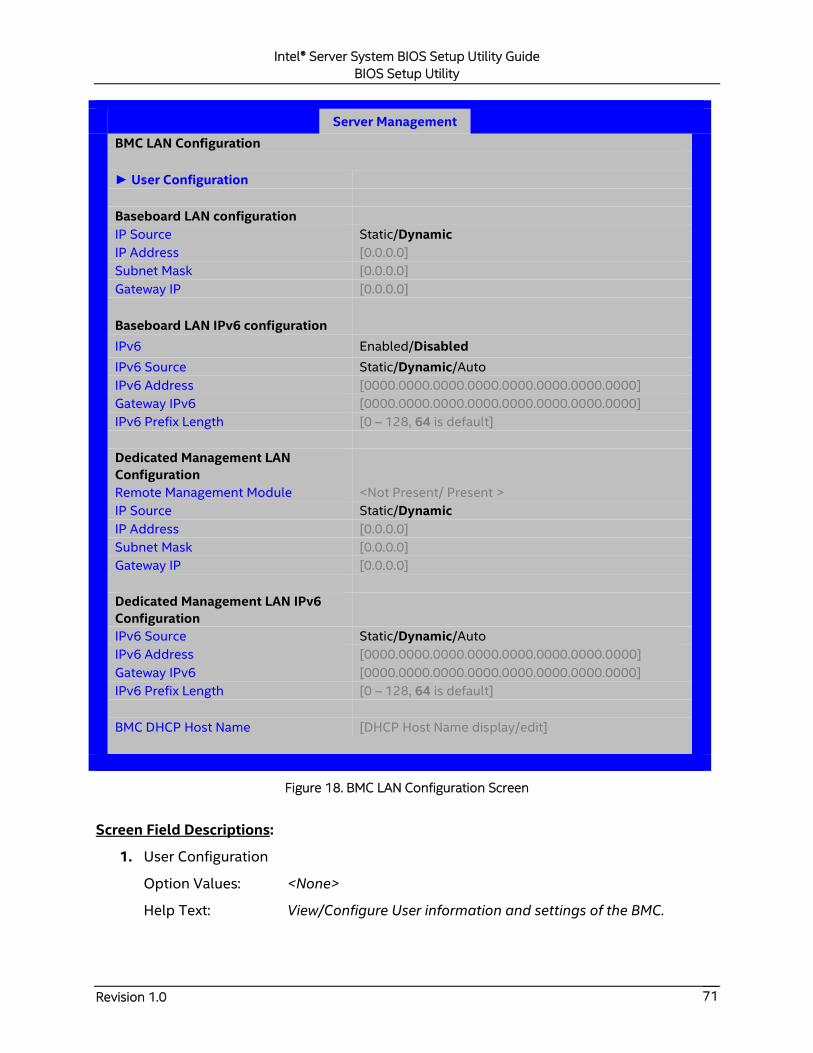
Intel® Server System BIOS Setup Utility Guide
BIOS Setup Utility
Revision 1.0 71
Server Management
BMC LAN Configuration
► User Configuration
Baseboard LAN configuration
IP Source Static/Dynamic
IP Address [0.0.0.0]
Subnet Mask [0.0.0.0]
Gateway IP [0.0.0.0]
Baseboard LAN IPv6 configuration
IPv6 Enabled/Disabled
IPv6 Source Static/Dynamic/Auto
IPv6 Address [0000.0000.0000.0000.0000.0000.0000.0000]
Gateway IPv6 [0000.0000.0000.0000.0000.0000.0000.0000]
IPv6 Prefix Length [0 – 128, 64 is default]
Dedicated Management LAN
Configuration
Remote Management Module <Not Present/ Present >
IP Source Static/Dynamic
IP Address [0.0.0.0]
Subnet Mask [0.0.0.0]
Gateway IP [0.0.0.0]
Dedicated Management LAN IPv6
Configuration
IPv6 Source Static/Dynamic/Auto
IPv6 Address [0000.0000.0000.0000.0000.0000.0000.0000]
Gateway IPv6 [0000.0000.0000.0000.0000.0000.0000.0000]
IPv6 Prefix Length [0 – 128, 64 is default]
BMC DHCP Host Name [DHCP Host Name display/edit]
Figure 18. BMC LAN Configuration Screen
Screen Field Descriptions:
1. User Configuration
Option Values: <None>
Help Text: View/Configure User information and settings of the BMC.

Intel® Server System BIOS Setup Utility Guide
BIOS Setup Utility
Revision 1.0 72
Comments: Selection only. Select this line and press the <Enter> key to go to
the User Configuration group of configuration settings.
Back to [BMC LAN Configuration Screen] — [Screen Map]
2. IP Source
Option Values: Static
Dynamic
Help Text:
Select BMC IP Source. If [Static], IP parameters may be edited. If [Dynamic],
these fields are display-only and IP address is acquired automatically (DHCP).
Comments: This specifies the IP Source for IPv4 addressing for the
Baseboard LAN. There is a separate IP Source field for the Dedicated Management LAN
configuration.
When IPv4 addressing is used, the initial value for this field is acquired from the BMC,
and its setting determines whether the other Baseboard LAN IPv4 addressing fields are
display-only (when Dynamic) or can be edited (when Static).
Back to [BMC LAN Configuration Screen] — [Screen Map]
3. IP Address
Option Values: [Entry Field 0.0.0.0, 0.0.0.0 is default]
Help Text: View/Edit IP Address. Press <Enter> to edit.
Comments: This specifies the IPv4 Address for the Baseboard LAN. There is a
separate IPv4 Address field for the Dedicated Management LAN configuration.
When IPv4 addressing is used, the initial value for this field is acquired from the BMC.
The setting of IP Source determines whether this field is display-only (when Dynamic)
or can be edited (when Static).
Back to [BMC LAN Configuration Screen]— [Screen Map]
4. Subnet Mask
Option Values: [Entry Field 0.0.0.0, 0.0.0.0 is default]
Help Text: View/Edit Subnet Mask. Press <Enter> to edit.
Comments: This specifies the IPv4 addressing Subnet Mask for the
Baseboard LAN. There is a separate IPv4 Subnet Mask field for the Dedicated
Management LAN configuration.
When IPv4 addressing is used, the initial value for this field is acquired from the BMC.
The setting of IP Source determines whether this field is display-only (when Dynamic)
or can be edited (when Static).
Back to [BMC LAN Configuration Screen] — [Screen Map]
Intel® Server System BIOS Setup Utility Guide
BIOS Setup Utility
Revision 1.0 73
5. Gateway IP
Option Values: [Entry Field 0.0.0.0, 0.0.0.0 is default]
Help Text: View/Edit Gateway IP. Press <Enter> to edit.
Comments: This specifies the IPv4 addressing Gateway IP for the Baseboard
LAN. There is a separate IPv4 Gateway IP field for the Dedicated Management LAN
configuration.
When IPv4 addressing is used, the initial value for this field is acquired from the BMC.
The setting of IP Source determines whether this field is display-only (when Dynamic)
or can be edited (when Static).
Back to [BMC LAN Configuration Screen] — [Screen Map]
6. IPv6
Option Values: Enabled
Disabled
Help Text:
Option to Enable/Disable IPv6 addressing and any IPv6 network traffic on these
channels.
Comments: The initial value for this field is acquired from the BMC. It may be
changed in order to switch between IPv4 and IPv6 addressing technologies.
When this option is set to Disabled, all other IPv6 fields will not be visible for the
Baseboard LAN and Dedicated Management DMN (if installed). When IPv6 addressing
is Enabled, all IPv6 fields for the Baseboard LAN and Dedicated Management DMN will
become visible.
Back to [BMC LAN Configuration Screen]— [Screen Map]
7. IPv6 Source
Option Values: Static
Dynamic
Auto
Help Text:
Select BMC IPv6 source. If [Static], IPv6 parameters may be edited. If [Dynamic],
these fields are display-only and IPv6 address is acquired automatically (DHCP).
If [Auto], these fields are display-only and IPv6 address is acquired using
ICMPv6 router / neighbor discovery.
Comments: This specifies the IP Source for IPv6 addressing for the
Baseboard LAN configuration. There is a separate IPv6 Source field for the Dedicated
Management LAN configuration.
This option is only visible when the IPv6 option is set to Enabled.

Intel® Server System BIOS Setup Utility Guide
BIOS Setup Utility
Revision 1.0 74
When IPv6 addressing is Enabled, the initial value for this field is acquired from the
BMC, and its setting determines whether the other Baseboard LAN IPv6 addressing
fields are display-only (when Dynamic or Auto) or can be edited (when Static).
Back to [BMC LAN Configuration Screen]— [Screen Map]
8. IPv6 Address
Option Values: [Entry Field 0000:0000:0000:0000:0000:0000:0000:0000,
0000:0000:0000:0000:0000:0000:0000:0000 is default]
Help Text:
View/Edit IPv6 address. Press <Enter> to edit. IPv6 addresses consist of 8
hexadecimal 4-digit numbers separated by colons.
Comments: This specifies the IPv6 Address for the Baseboard LAN. There is a
separate IPv6 Address field for the Dedicated Management LAN configuration.
This option is only visible when the IPv6 option is set to Enabled.
When IPv6 addressing is used, the initial value for this field is acquired from the BMC.
The setting of IPv6 Source determines whether this field is display-only (when
Dynamic or Auto) or can be edited (when Static).
Back to [BMC LAN Configuration Screen]— [Screen Map]
9. Gateway IPv6
Option Values: [Entry Field 0000:0000:0000:0000:0000:0000:0000:0000,
0000:0000:0000:0000:0000:0000:0000:0000 is default]
Help Text:
View/Edit Gateway IPv6 address. Press <Enter> to edit. Gateway IPv6 addresses
consist of 8 hexadecimal 4-digit numbers separated by colons.
Comments: This specifies the Gateway IPv6 Address for the Baseboard LAN.
There is a separate Gateway IPv6 Address field for the Dedicated Management LAN
configuration.
This option is only visible when the IPv6 option is set to Enabled.
When IPv6 addressing is used, the initial value for this field is acquired from the BMC.
The setting of IPv6 Source determines whether this field is display-only (when
Dynamic or Auto) or can be edited (when Static).
Back to [BMC LAN Configuration Screen]— [Screen Map]
10. IPv6 Prefix Length
Option Values: [Entry Field 0-128, 64 is default]
Help Text:
View/Edit IPv6 Prefix Length from 0 to 128 (default 64). Press <Enter> to edit.

Intel® Server System BIOS Setup Utility Guide
BIOS Setup Utility
Revision 1.0 75
Comments: This specifies the IPv6 Prefix Length for the Baseboard LAN.
There is a separate IPv6 Prefix Length field for the Dedicated Management LAN
configuration.
This option is only visible when the IPv6 option is set to Enabled.
When IPv6 addressing is used, the initial value for this field is acquired from the BMC.
The setting of IPv6 Source determines whether this field is display-only (when
Dynamic or Auto) or can be edited (when Static).
Back to [BMC LAN Configuration Screen]— [Screen Map]
11. Remote Management Module
Option Values: Not Present
Present
Help Text: <None>
Comments: Information only. Displays whether a Dedicated Management Lan
component is currently installed. This information may come from querying the BMC.
Back to [BMC LAN Configuration Screen]— [Screen Map]
12. IP Source
Option Values: Static
Dynamic
Help Text:
Select Dedicated Management LAN IP source. If [Static], IP parameters may be
edited. If [Dynamic], these fields are display-only and IP address is acquired
automatically (DHCP).
Comments: This specifies the IP Source for IPv4 addressing for the DMN LAN
connection. There is a separate IP Source field for the Baseboard LAN configuration.
When IPv4 addressing is used, the initial value for this field is acquired from the BMC,
and its setting determines whether the other DMN LAN IPv4 addressing fields are
display-only (when Dynamic) or can be edited (when Static).
Back to [BMC LAN Configuration Screen]— [Screen Map]
13. IP Address
Option Values: [Entry Field 0.0.0.0, 0.0.0.0 is default]
Help Text: View/Edit IP Address. Press <Enter> to edit.
Comments: This specifies the IPv4 Address for the DMN LAN. There is a
separate IPv4 Address field for the Baseboard LAN configuration.
When IPv4 addressing is used, the initial value for this field is acquired from the BMC.
The setting of IP Source determines whether this field is display-only (when Dynamic)
or can be edited (when Static).
Intel® Server System BIOS Setup Utility Guide
BIOS Setup Utility
Revision 1.0 76
Back to [BMC LAN Configuration Screen]— [Screen Map]
14. Subnet Mask
Option Values: [Entry Field 0.0.0.0, 0.0.0.0 is default]
Help Text: View/Edit Subnet Mask. Press <Enter> to edit.
Comments: This specifies the IPv4 addressing Subnet Mask for the DMN LAN.
There is a separate IPv4 Subnet Mask field for the Baseboard LAN configuration.
When IPv4 addressing is used, the initial value for this field is acquired from the BMC.
The setting of IP Source determines whether this field is display-only (when Dynamic)
or can be edited (when Static).
Back to [BMC LAN Configuration Screen]— [Screen Map]
15. Gateway IP
Option Values: [Entry Field 0.0.0.0, 0.0.0.0 is default]
Help Text: View/Edit Gateway IP. Press <Enter> to edit.
Comments: This specifies the IPv4 addressing Gateway IP for the DMN LAN.
There is a separate IPv4 Gateway IP field for the Baseboard LAN configuration.
When IPv4 addressing is used, the initial value for this field is acquired from the BMC.
The setting of IP Source determines whether this field is display-only (when Dynamic)
or can be edited (when Static).
Back to [BMC LAN Configuration Screen]— [Screen Map]
16. IPv6 Source
Option Values: Static
Dynamic
Auto
Help Text:
Select DMN LAN IPv6 source. If [Static], IPv6 parameters may be edited. If
[Dynamic], these fields are display-only and IPv6 address is acquired
automatically (DHCP). If [Auto], these fields are display-only and IPv6 address is
acquired using ICMPv6 router / neighbor discovery.
Comments: This specifies the IP Source for IPv6 addressing for the DMN LAN
configuration. There is a separate IPv6 Source field for the Baseboard LAN
configuration.
This option is only visible when the IPv6 option is set to Enabled.
When IPv6 addressing is Enabled, the initial value for this field is acquired from the
BMC, and its setting determines whether the other DMN LAN IPv6 addressing fields are
display-only (when Dynamic or Auto) or can be edited (when Static).
Back to [BMC LAN Configuration Screen]— [Screen Map]

Intel® Server System BIOS Setup Utility Guide
BIOS Setup Utility
Revision 1.0 77
17. IPv6 Address
Option Values: [Entry Field 0000:0000:0000:0000:0000:0000:0000:0000,
0000:0000:0000:0000:0000:0000:0000:0000 is default]
Help Text:
View/Edit IPv6 address. Press <Enter> to edit. IPv6 addresses consist of 8
hexadecimal 4-digit numbers separated by colons.
Comments: This specifies the IPv6 Address for the DMN LAN. There is a
separate IPv6 Address field for the Baseboard LAN configuration.
This option is only visible when the IPv6 option is set to Enabled.
When IPv6 addressing is used, the initial value for this field is acquired from the BMC.
The setting of IPv6 Source determines whether this field is display-only (when
Dynamic or Auto) or can be edited (when Static).
Back to [BMC LAN Configuration Screen]— [Screen Map]
18. Gateway IPv6
Option Values: [Entry Field 0000:0000:0000:0000:0000:0000:0000:0000,
0000:0000:0000:0000:0000:0000:0000:0000 is default]
Help Text:
View/Edit Gateway IPv6 address. Press <Enter> to edit. Gateway IPv6 addresses
consist of 8 hexadecimal 4-digit numbers separated by colons.
Comments: This specifies the Gateway IPv6 Address for the DMN LAN. There
is a separate Gateway IPv6 Address field for the Baseboard LAN configuration.
This option is only visible when the IPv6 option is set to Enabled.
When IPv6 addressing is used, the initial value for this field is acquired from the BMC.
The setting of IPv6 Source determines whether this field is display-only (when
Dynamic or Auto) or can be edited (when Static).
Back to [BMC LAN Configuration Screen]— [Screen Map]
19. IPv6 Prefix Length
Option Values: [Entry Field 0-128, 64 is default]
Help Text:
View/Edit IPv6 Prefix Length from 0 to 128 (default 64). Press <Enter> to edit.
Comments: This specifies the IPv6 Prefix Length for the DMN LAN. There is a
separate IPv6 Prefix Length field for the Baseboard LAN configuration.
This option is only visible when the IPv6 option is set to Enabled.

Intel® Server System BIOS Setup Utility Guide
BIOS Setup Utility
Revision 1.0 78
When IPv6 addressing is used, the initial value for this field is acquired from the BMC.
The setting of IPv6 Source determines whether this field is display-only (when
Dynamic or Auto) or can be edited (when Static).
Back to [BMC LAN Configuration Screen]— [Screen Map]
20. BMC DHCP Host Name
Option Values: [Entry Field, 2-63 characters]
Help Text:
View/Edit BMC DHCP host name. Press <Enter> to edit. Host name should start
with an alphabetic, remaining can be alphanumeric characters. Host name
length may be from 2 to 63 characters.
Comments: This field is active and may be edited whenever at least one of
the IP Source or IPv6 Source options is set to Dynamic. This is the name of the DHCP
Host from which dynamically assigned IPv4 or IPv6 addressing parameters are
acquired.
The initial value for this field is supplied from the BMC, if there is a DHCP Host available.
The user can edit the existing Host or enter a different DHCP Host Name.
If none of the IP/IPv6 Source fields is set to Dynamic, then this BMC DHCP Host Name
field will be grayed out and inactive.
Back to [BMC LAN Configuration Screen]— [Screen Map]

Intel® Server System BIOS Setup Utility Guide
BIOS Setup Utility
Revision 1.0 79
2.2.15.1 User Configuration
The User Configuration screen allows the user to manage BMC User settings for up to five
BMC Users.
Server Management
User Configuration
User ID anonymous
Privilege Callback/ User/Operator/Administrator
User Status Disable/Enable
User Password
User ID root
Privilege Administrator
User Status Disable/Enable
User Password
User ID User3
Privilege Callback/ User/Operator/Administrator
User Status Disable/Enable
User Name [User Name display/edit]
User Password
User ID User4
Privilege Callback/ User/Operator/Administrator
User Status Disable/Enable
User Name [User Name display/edit]
User Password
User ID User5
Privilege Callback/ User/Operator/Administrator
User Status Disable/Enable
User Name [User Name display/edit]
User Password
Figure 19. User Configuration Screen
Intel® Server System BIOS Setup Utility Guide
BIOS Setup Utility
Revision 1.0 80
Screen Field Descriptions:
1. User ID
Option Values: anonymous
root
User3
User4
User5
Help Text: <None>
Comments: Information only. These 5 User IDs are fixed choices and cannot
be changed. The BMC supports 15 User IDs natively but only the first 5 are supported
through this interface.
Back to [User Configuration Screen] — [BMC LAN Configuration Screen]— [Screen Map]
2. Privilege
Option Values: Callback
User
Operator
Administrator
Help Text:
View/Select user privilege. User2 (root) privilege is "Administrator" and cannot
be changed. The default privilege of User3 is User.
Comments: The level of privilege that is assigned for a User ID affects which
functions that user may perform.
Back to [User Configuration Screen] — [BMC LAN Configuration Screen]— [Screen Map]
3. User Status
Option Values: Enabled
Disabled
Help Text:
Enable/Disable LAN access for selected user. Also enables/disables SOL, KVM,
and media redirection.
Comments: Note that status setting is Disabled by default until set to
Enabled.
Back to [User Configuration Screen] — [BMC LAN Configuration Screen] —[Screen Map]
4. User Name
Option Values: [Entry Field, 4-16 characters]

Intel® Server System BIOS Setup Utility Guide
BIOS Setup Utility
Revision 1.0 81
Help Text:
Press <Enter> to edit User Name. User Name is a string of 4 to 16 alphanumeric
characters, and must begin with an alphabetic character. User Name cannot be
changed for User1 (anonymous) and User2 (root).
Comments: User Name can only be edited for users other than “anonymous”
and “root”. Those two User Names may not be changed.
Back to [User Configuration Screen] — [BMC LAN Configuration Screen] — [Screen
Map]
5. User Password
Option Values: [Popup Entry Field, 0-20 characters]
Help Text:
Press <Enter> key to enter password. Maximum length is 20 characters. Any
ASCII printable characters can be used: case-sensitive alphabetic, numeric, and
special characters.
Note: Password entered will override any previously set password.
Comments: This field will not indicate whether there is a password set
already. There is no display – just press <Enter> for a popup with an entry field to enter
a new password. Any new password entered will override the previous password, if
there was one.
Back to [User Configuration Screen] — [BMC LAN Configuration Screen] — [Screen
Map]
Intel® Server System BIOS Setup Utility Guide
BIOS Setup Utility
Revision 1.0 82
2.2.16 Boot Maintenance Manager Screen (Tab)
The Boot Maintenance Manager screen contains all bootable media encountered during POST,
and allows the user to configure the desired order in which boot devices are to be tried.
To access this screen from the Main screen or other top-level “Tab” screen, press the right or
left arrow keys to traverse the tabs at the top of the Setup screen until the Boot Maintenance
Manager screen is selected.
The first boot device in the specified Boot Order which is present and is bootable during POST
will be used to boot the system, and will continue to be used to reboot the system until the
boot device configuration has changed (that is, which boot devices are present), or until the
system has been powered down and booted in a “cold” power-on boot.
Note: USB devices can be “hot plugged” during POST, and will be detected and “beeped”.
They will be enumerated and displayed on the USB Configuration Setup screen. However, they
may not be enumerated as bootable devices, depending on when in POST they were hot
plugged. If they were recognized before the enumeration of bootable devices, they will appear
as Boot Devices if appropriate. If they were recognized after Boot Device enumeration, they
will not appear as a bootable device for the Boot Maintenance Manager screen, the Boot
Manager screen, or the F6 Boot Menu.
There are two main types of boot order control, Legacy Boot and UEFI boot. These are
mutually exclusive – when UEFI Boot is enabled, Legacy Boot (the default) is disabled. Within
Legacy Boot operation, there are two further methods of ordering boot devices, Dynamic Boot
Order and Static Boot Order.
The default for Boot Order control is Legacy Boot, with Dynamic Boot Order. If all types of
bootable devices are installed in the system, then the default Boot Order is as follows:
Legacy CD/DVD-ROM
Legacy Floppy Disk Drive
Legacy Hard Disk Drive
Legacy PXE Network Device
Legacy BEV (Boot Entry Vector) Device
EFI Shell and EFI Boot paths
In this default Boot Order, a USB device may appear in any of several Device Classes, due to
the flexibility of USB connections and USB emulation of various types of devices.
Note: A USB Key (USB Flash Drive) can be formatted to emulate either a Floppy Drive or a
Hard Drive and will appear in that Boot Device Class. However, although it can be formatted as
a CDROM Drive, it will not be detected as such. It will be treated as a Hard Disk and will appear
in the list of available Hard Drives.
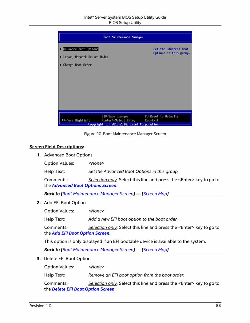
Intel® Server System BIOS Setup Utility Guide
BIOS Setup Utility
Revision 1.0 83
Figure 20. Boot Maintenance Manager Screen
Screen Field Descriptions:
1. Advanced Boot Options
Option Values: <None>
Help Text: Set the Advanced Boot Options in this group.
Comments: Selection only. Select this line and press the <Enter> key to go to
the Advanced Boot Options Screen.
Back to [Boot Maintenance Manager Screen] — [Screen Map]
2. Add EFI Boot Option
Option Values: <None>
Help Text: Add a new EFI boot option to the boot order.
Comments: Selection only. Select this line and press the <Enter> key to go to
the Add EFI Boot Option Screen.
This option is only displayed if an EFI bootable device is available to the system.
Back to [Boot Maintenance Manager Screen] — [Screen Map]
3. Delete EFI Boot Option
Option Values: <None>
Help Text: Remove an EFI boot option from the boot order.
Comments: Selection only. Select this line and press the <Enter> key to go to
the Delete EFI Boot Option Screen.
Intel® Server System BIOS Setup Utility Guide
BIOS Setup Utility
Revision 1.0 84
This option is only displayed if an EFI boot path is included in the Boot Order.
Back to [Boot Maintenance Manager Screen] — [Screen Map]
4. Legacy CDROM Order
Option Values: <None>
Help Text: Set the order of the legacy devices in this group.
Comments: Selection only. Select this line and press the <Enter> key to go to
the Legacy CDROM Order Screen.
This option appears when one or more bootable CDROM drives are available in the
system and the Boot Mode options is chosen as Legacy. This includes USB CDROM
devices but not USB Keys formatted for CRDOM emulation, which are seen as Hard
Disk drives.
Back to [Boot Maintenance Manager Screen] — [Screen Map]
5. Legacy Hard Disk Order
Option Values: <None>
Help Text: Set the order of the legacy devices in this group.
Comments: Selection only. Select this line and press the <Enter> key to go to
the Legacy Hard Disk Order Screen.
This option appears when one or more bootable Hard Disk drives are available in the
system and the Boot Mode options is chosen as Legacy. This includes USB Hard Disk
devices and USB Keys formatted for Hard Disk or CRDOM emulation.
Back to [Boot Maintenance Manager Screen] — [Screen Map]
6. Legacy Floppy Order
Option Values: <None>
Help Text: Set the order of the legacy devices in this group.
Comments: Selection only. Select this line and press the <Enter> key to go to
the Legacy Floppy Order Screen.
This option appears when one or more bootable Floppy Disk drives are available in the
system and the Boot Mode options is chosen as Legacy. This includes USB Floppy Disk
devices and USB Keys formatted for Floppy Disk emulation.
Back to [Boot Maintenance Manager Screen] — [Screen Map]
7. Legacy Network Device Order
Option Values: <None>
Help Text: Set the order of the legacy devices in this group.
Comments: Selection only. Select this line and press the <Enter> key to go to
the Legacy Network Device Order Screen.
Intel® Server System BIOS Setup Utility Guide
BIOS Setup Utility
Revision 1.0 85
This option appears when one or more bootable Network Devices are available in the
system and the Boot Mode options is chosen as Legacy.
Back to [Boot Maintenance Manager Screen] — [Screen Map]
8. Legacy BEV Device Order
Option Values: <None>
Help Text: Set the order of the legacy devices in this group.
Comments: Selection only. Select this line and press the <Enter> key to go to
the Legacy BEV Device Order Screen.
This option appears when one or more bootable BEV Devices are available in the
system and the Boot Mode options is chosen as Legacy.
Back to [Boot Maintenance Manager Screen] — [Screen Map]
9. Change Boot Order
Option Values: <None>
Help Text: Set the Boot Order in this group.
Comments: Selection only. Select this line and press the <Enter> key to go to
the Change Boot Order Screen.
Back to [Boot Maintenance Manager Screen] — [Screen Map]
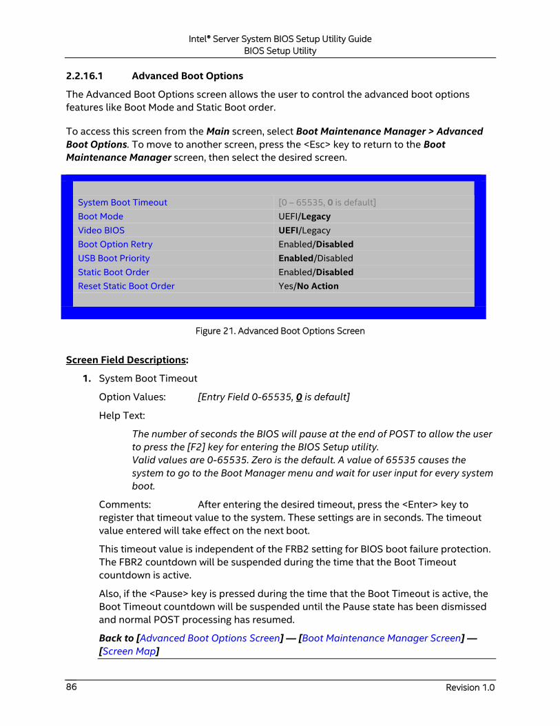
Intel® Server System BIOS Setup Utility Guide
BIOS Setup Utility
Revision 1.0 86
2.2.16.1 Advanced Boot Options
The Advanced Boot Options screen allows the user to control the advanced boot options
features like Boot Mode and Static Boot order.
To access this screen from the Main screen, select Boot Maintenance Manager > Advanced
Boot Options. To move to another screen, press the <Esc> key to return to the Boot
Maintenance Manager screen, then select the desired screen.
System Boot Timeout [0 – 65535, 0 is default]
Boot Mode UEFI/Legacy
Video BIOS UEFI/Legacy
Boot Option Retry Enabled/Disabled
USB Boot Priority Enabled/Disabled
Static Boot Order Enabled/Disabled
Reset Static Boot Order Yes/No Action
Figure 21. Advanced Boot Options Screen
Screen Field Descriptions:
1. System Boot Timeout
Option Values: [Entry Field 0-65535, 0 is default]
Help Text:
The number of seconds the BIOS will pause at the end of POST to allow the user
to press the [F2] key for entering the BIOS Setup utility.
Valid values are 0-65535. Zero is the default. A value of 65535 causes the
system to go to the Boot Manager menu and wait for user input for every system
boot.
Comments: After entering the desired timeout, press the <Enter> key to
register that timeout value to the system. These settings are in seconds. The timeout
value entered will take effect on the next boot.
This timeout value is independent of the FRB2 setting for BIOS boot failure protection.
The FBR2 countdown will be suspended during the time that the Boot Timeout
countdown is active.
Also, if the <Pause> key is pressed during the time that the Boot Timeout is active, the
Boot Timeout countdown will be suspended until the Pause state has been dismissed
and normal POST processing has resumed.
Back to [Advanced Boot Options Screen] — [Boot Maintenance Manager Screen] —
[Screen Map]

Intel® Server System BIOS Setup Utility Guide
BIOS Setup Utility
Revision 1.0 87
2. Boot Mode
Option Values: UEFI
Legacy
Help Text:
When Boot Mode is Legacy, the BIOS only loads modules required for booting
Legacy Operating Systems.
When Boot Mode is UEFI, the BIOS only loads modules required for booting
UEFI-aware Operating Systems.
Comments: When Boot Mode is Legacy, only Legacy Option ROMs and
Legacy OS Boot are supported; UEFI OPROMs and UEFI OS Boot are not supported.
When Boot Mode is UEFI, Only UEFI OPROMs and UEFI OS boot are supported; Legacy
OPROMs and Legacy OS Boot are NOT supported.
Back to [Advanced Boot Options Screen] — [Boot Maintenance Manager Screen] —
[Screen Map]
3. Video BIOS
Option Values: UEFI
Legacy
Help Text:
If Video BIOS is Legacy, the BIOS uses the legacy video ROM instead of the EFI
video ROM when Boot Mode is UEFI.
Comments: This option appears only when Boot Mode option is chosen as
UEFI. The default – UEFI – is to use UEFI Graphic Output Protocol (GOP); if it is Legacy,
legacy video ROM is used.
If Boot Mode changes to Legacy, Video BIOS will change to Legacy and be hidden
automatically.
Back to [Advanced Boot Options Screen] — [Boot Maintenance Manager Screen] —
[Screen Map]
4. Boot Option Retry
Option Values: Enabled
Disabled
Help Text:
If enabled, this continually retries non-EFI-based boot options without waiting
for user input.
Comments: This option is intended to keep retrying for cases where the boot
devices could possibly be slow to initially respond, e.g., if the devices were “asleep”
and did not wake quickly enough. However, if none of the devices in the Boot Order
ever responds, the BIOS will continue to reboot indefinitely.

Intel® Server System BIOS Setup Utility Guide
BIOS Setup Utility
Revision 1.0 88
Back to [Advanced Boot Options Screen] — [Boot Maintenance Manager Screen] —
[Screen Map]
5. USB Boot Priority
Option Values: Enabled
Disabled
Help Text:
If enabled, newly discovered USB devices are moved to the top of their boot
device category.
If disabled, newly discovered USB devices are moved to the bottom of their boot
device category.
Comments: This option enables or disables the “USB Reorder” functionality.
USB Boot Priority, if enabled, is intended for the case where a user wants to be able to
plug in a USB device and immediately boot to it, for example in case of a maintenance
or System Administration operation. If a User Password is installed, USB Boot Priority
action is suspended when a User Password is installed.
Back to [Advanced Boot Options Screen] — [Boot Maintenance Manager Screen] —
[Screen Map]
6. Static Boot Order
Option Values: Enabled
Disabled
Help Text:
[Disabled] – Devices removed from the system are deleted from Boot Order
Tables.
[Enabled] – Devices removed have positions in Boot Order Tables retained for
later reinsertion.
Comments: This option appears only when Boot Mode option is chosen as
Legacy. When the option changes to “Enabled” from “Disabled”, it will enable Static
Boot Order (SBO) from the next boot onward, and also the current Boot Order will be
stored as the SBO template.
When the option changes from “Enabled” to “Disabled”, this will disable SBO and the
SBO template will be cleared.
Otherwise it will retain the current Enabled/Disabled state.
Back to [Advanced Boot Options Screen] — [Boot Maintenance Manager Screen] —
[Screen Map]
7. Reset Static Boot Order
Option Values: Yes
No Action
Intel® Server System BIOS Setup Utility Guide
BIOS Setup Utility
Revision 1.0 89
Help Text:
[Yes] Take snapshot of current boot order to save as Static Boot Order
Template.
Comments: This option appears only when Boot Mode option is chosen as
Legacy. This option allows you to save the Boot Order list as the Static Boot Order
template without disabling and re-enabling the Static Boot Order option.
Select Yes to snapshot the current Boot Options list into the Static Boot Options list on
the next boot. After saving Static Boot Options list, this option will change back to No
Action automatically.
This option is available only when the Static Boot Order option is Enabled. Otherwise it
will grayed out and unavailable.
Back to [Advanced Boot Options Screen] — [Boot Maintenance Manager Screen] —
[Screen Map]

Intel® Server System BIOS Setup Utility Guide
BIOS Setup Utility
Revision 1.0 90
2.2.16.2 Legacy CDROM Order
The Legacy CDROM Order screen allows the user to control the order in which the BIOS
attempts to boot from the Legacy CDROM drives installed in the system. This screen is only
available when there is at least one CDROM device available in the system configuration and
the Boot Mode options is chosen as Legacy.
Note: A USB attached CDROM device will appear in this section. However, a USB Key
formatted as a CRDOM device will not – it will be detected as a Hard Disk device and will be
included in the Hard Disk Order Screen.
To access this screen from the Main screen, select Boot Maintenance Manager > Legacy
CDROM Order. To move to another screen, press the <Esc> key to return to the Boot
Maintenance Manager screen, then select the desired screen.
Boot Maintenance Manager
Legacy CDROM Order
CDROM #1 <Available CDROM devices>
CDROM #2 <Available CDROM devices>
Save Changes and Exit this sub-menu
Discard Changes and Exit this sub-menu
Figure 22. Legacy CDROM Order Screen
Screen Field Descriptions:
1. CDROM #1
2. CDROM #2
Option Values: <Available CDROM devices>
Help Text:
Set system boot order by selecting the boot option for this position.
Warning: Pressing F10 or select 'Save Changes and Exit this sub-menu' is
required to save the changes in this screen before you exit it. This behavior only
applies in the Boot Order pages, other pages are not affected.
Comments: Choose the order of booting among CDROM devices by choosing
which available CDROM device should be in each position in the order.
Back to [Legacy CDROM Order Screen] — [Boot Maintenance Manager Screen] —
[Screen Map]
Intel® Server System BIOS Setup Utility Guide
BIOS Setup Utility
Revision 1.0 91
3. Save Changes and Exit this sub-menu
Option Values: <None>
Help Text: <None>
Comments: Selection only. Select this line and press the <Enter> key to exit
current Setup Screen with any changes in Legacy CDROM Boot Order settings saved.
The <F10 > function key may also be used in current Setup screen to initiate a “Save
Changes” action.
Back to [Save & Exit Screen] — [Screen Map]
4. Discard Changes and Exit this sub-menu
Option Values: <None>
Help Text: <None>
Comments: Selection only. Select this line and press the <Enter> key to exit
current Setup Screen without saving any changes in Legacy CDROM Boot Order
settings.
Back to [Save & Exit Screen] — [Screen Map]
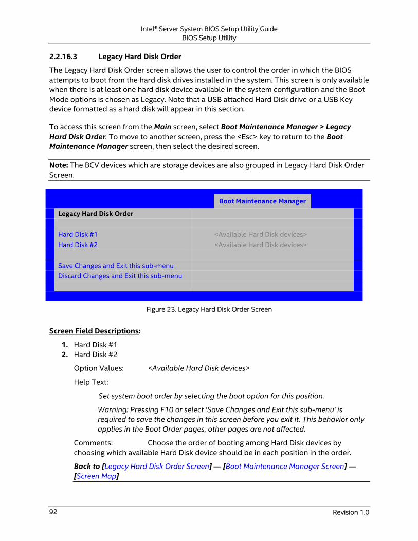
Intel® Server System BIOS Setup Utility Guide
BIOS Setup Utility
Revision 1.0 92
2.2.16.3 Legacy Hard Disk Order
The Legacy Hard Disk Order screen allows the user to control the order in which the BIOS
attempts to boot from the hard disk drives installed in the system. This screen is only available
when there is at least one hard disk device available in the system configuration and the Boot
Mode options is chosen as Legacy. Note that a USB attached Hard Disk drive or a USB Key
device formatted as a hard disk will appear in this section.
To access this screen from the Main screen, select Boot Maintenance Manager > Legacy
Hard Disk Order. To move to another screen, press the <Esc> key to return to the Boot
Maintenance Manager screen, then select the desired screen.
Note: The BCV devices which are storage devices are also grouped in Legacy Hard Disk Order
Screen.
Boot Maintenance Manager
Legacy Hard Disk Order
Hard Disk #1 <Available Hard Disk devices>
Hard Disk #2 <Available Hard Disk devices>
Save Changes and Exit this sub-menu
Discard Changes and Exit this sub-menu
Figure 23. Legacy Hard Disk Order Screen
Screen Field Descriptions:
1. Hard Disk #1
2. Hard Disk #2
Option Values: <Available Hard Disk devices>
Help Text:
Set system boot order by selecting the boot option for this position.
Warning: Pressing F10 or select 'Save Changes and Exit this sub-menu' is
required to save the changes in this screen before you exit it. This behavior only
applies in the Boot Order pages, other pages are not affected.
Comments: Choose the order of booting among Hard Disk devices by
choosing which available Hard Disk device should be in each position in the order.
Back to [Legacy Hard Disk Order Screen] — [Boot Maintenance Manager Screen] —
[Screen Map]

Intel® Server System BIOS Setup Utility Guide
BIOS Setup Utility
Revision 1.0 93
3. Save Changes and Exit this sub-menu
Option Values: <None>
Help Text: <None>
Comments: Selection only. Select this line and press the <Enter> key to exit
current Setup Screen with any changes in Legacy Hard Disk Boot Order settings saved.
The <F10 > function key may also be used in current Setup screen to initiate a “Save
Changes” action.
Back to [Save & Exit Screen] — [Screen Map]
4. Discard Changes and Exit this sub-menu
Option Values: <None>
Help Text: <None>
Comments: Selection only. Select this line and press the <Enter> key to exit
current Setup Screen without saving any changes in Legacy Hard Disk Boot Order
settings.
Back to [Save & Exit Screen] — [Screen Map]

Intel® Server System BIOS Setup Utility Guide
BIOS Setup Utility
Revision 1.0 94
2.2.16.4 Legacy Floppy Order
The Legacy Floppy Order screen allows the user to control the order in which the BIOS
attempts to boot from the Legacy Floppy Disk drives installed in the system. This screen is
only available when there is at least one Floppy Disk (diskette) device available in the system
configuration and the Boot Mode options is chosen as Legacy. Note that a USB attached
diskette drive or a USB Key device formatted as a diskette drive will appear in this section.
To access this screen from the Main screen, select Boot Maintenance Manager > Legacy
Floppy Order. To move to another screen, press the <Esc> key to return to the Boot
Maintenance Manager screen, then select the desired screen.
Boot Maintenance Manager
Legacy Floppy Order
Floppy Disk #1 <Available Floppy Disk devices>
Floppy Disk #2 <Available Floppy Disk devices>
Save Changes and Exit this sub-menu
Discard Changes and Exit this sub-menu
Figure 24. Legacy Floppy Order Screen
Screen Field Descriptions:
1. Floppy Disk #1
2. Floppy Disk #2
Option Values: <Available Floppy Disk devices>
Help Text:
Set system boot order by selecting the boot option for this position.
Warning: Pressing F10 or select 'Save Changes and Exit this sub-menu' is
required to save the changes in this screen before you exit it. This behavior only
applies in the Boot Order pages, other pages are not affected.
Comments: Choose the order of booting among Floppy Disk devices by
choosing which available Floppy Disk device should be in each position in the order.
Back to [Legacy Floppy Order Screen] — [Boot Maintenance Manager Screen] —
[Screen Map]
3. Save Changes and Exit this sub-menu
Option Values: <None>
Help Text: <None>

Intel® Server System BIOS Setup Utility Guide
BIOS Setup Utility
Revision 1.0 95
Comments: Selection only. Select this line and press the <Enter> key to exit
current Setup Screen with any changes in Legacy Floppy Boot Order settings saved.
The <F10 > function key may also be used in current Setup screen to initiate a “Save
Changes” action.
Back to [Save & Exit Screen] — [Screen Map]
4. Discard Changes and Exit this sub-menu
Option Values: <None>
Help Text: <None>
Comments: Selection only. Select this line and press the <Enter> key to exit
current Setup Screen without saving any changes in Legacy Floppy Boot Order settings.
Back to [Save & Exit Screen] — [Screen Map]

Intel® Server System BIOS Setup Utility Guide
BIOS Setup Utility
Revision 1.0 96
2.2.16.5 Legacy Network Device Order
The Legacy Network Device Order screen allows the user to control the order in which the
BIOS attempts to boot from the network bootable devices installed in the system. This screen
is only available when there is at least one network bootable device available in the system
configuration and the Boot Mode options is chosen as Legacy.
To access this screen from the Main screen, select Boot Maintenance Manager > Legacy
Network Device Order. To move to another screen, press the <Esc> key to return to the Boot
Maintenance Manager screen, then select the desired screen.
Boot Maintenance Manager
Legacy Network Device Order
Network Device #1 <Available bootable Network devices>
Network Device #2 <Available bootable Network devices>
Save Changes and Exit this sub-menu
Discard Changes and Exit this sub-menu
Figure 25. Legacy Network Device Order Screen
Screen Field Descriptions:
1. Network Device #1
2. Network Device #2
Option Values: <Available Network Devices>
Help Text:
Set system boot order by selecting the boot option for this position.
Warning: Pressing F10 or select 'Save Changes and Exit this sub-menu' is
required to save the changes in this screen before you exit it. This behavior only
applies in the Boot Order pages, other pages are not affected.
Comments: Choose the order of booting among Network Devices by
choosing which available Network Device should be in each position in the order.
Back to [Legacy Network Device Order Screen] — [Boot Maintenance Manager Screen]
— [Screen Map]
3. Save Changes and Exit this sub-menu
Option Values: <None>
Help Text: <None>

Intel® Server System BIOS Setup Utility Guide
BIOS Setup Utility
Revision 1.0 97
Comments: Selection only. Select this line and press the <Enter> key to exit
current Setup Screen with any changes in Legacy Network Device Boot Order settings
saved.
The <F10 > function key may also be used in current Setup screen to initiate a “Save
Changes” action.
Back to [Save & Exit Screen] — [Screen Map]
4. Discard Changes and Exit this sub-menu
Option Values: <None>
Help Text: <None>
Comments: Selection only. Select this line and press the <Enter> key to exit
current Setup Screen without saving any changes in Legacy Network Device Boot Order
settings.
Back to [Save & Exit Screen] — [Screen Map]

Intel® Server System BIOS Setup Utility Guide
BIOS Setup Utility
Revision 1.0 98
2.2.16.6 Legacy BEV Device Order
The Legacy BEV Device Order screen allows the user to control the order in which the BIOS
attempts to boot from the BEV Devices installed in the system. This screen is only available
when there is at least one BEV device available in the system configuration and the Boot Mode
options is chosen as Legacy.
To access this screen from the Main screen, select Boot Maintenance Manager > Legacy BEV
Device Order. To move to another screen, press the <Esc> key to return to the Boot
Maintenance Manager screen, then select the desired screen.
Boot Maintenance Manager
Legacy BEV Device Order
BEV Device #1 <Available BEV devices>
BEV Device #2 <Available BEV devices>
Save Changes and Exit this sub-menu
Discard Changes and Exit this sub-menu
Figure 26. Legacy BEV Device Order Screen
Screen Field Descriptions:
1. BEV Device #1
2. BEV Device #2
Option Values: <Available BEV Devices>
Help Text:
Set system boot order by selecting the boot option for this position.
Warning: Pressing F10 or select 'Save Changes and Exit this sub-menu' is
required to save the changes in this screen before you exit it. This behavior only
applies in the Boot Order pages, other pages are not affected.
Comments: Choose the order of booting among BEV Devices by choosing
which available BEV Device should be in each position in the order.
Back to [Legacy BEV Device Order Screen] — [Boot Maintenance Manager Screen] —
[Screen Map]
3. Save Changes and Exit this sub-menu
Option Values: <None>
Help Text: <None>

Intel® Server System BIOS Setup Utility Guide
BIOS Setup Utility
Revision 1.0 99
Comments: Selection only. Select this line and press the <Enter> key to exit
current Setup Screen with any changes in Legacy BEV Device Boot Order settings
saved.
The <F10 > function key may also be used in current Setup screen to initiate a “Save
Changes” action.
Back to [Save & Exit Screen] — [Screen Map]
4. Discard Changes and Exit this sub-menu
Option Values: <None>
Help Text: <None>
Comments: Selection only. Select this line and press the <Enter> key to exit
current Setup Screen without saving any changes in Legacy BEV Device Boot Order
settings.
Back to [Save & Exit Screen] — [Screen Map]
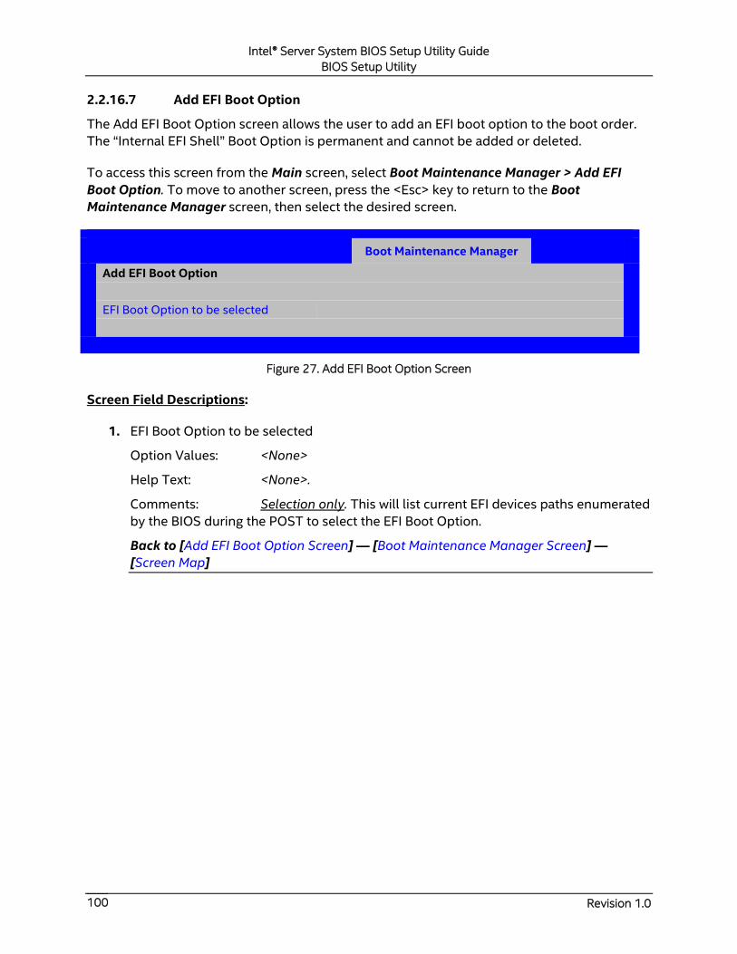
Intel® Server System BIOS Setup Utility Guide
BIOS Setup Utility
Revision 1.0 100
2.2.16.7 Add EFI Boot Option
The Add EFI Boot Option screen allows the user to add an EFI boot option to the boot order.
The “Internal EFI Shell” Boot Option is permanent and cannot be added or deleted.
To access this screen from the Main screen, select Boot Maintenance Manager > Add EFI
Boot Option. To move to another screen, press the <Esc> key to return to the Boot
Maintenance Manager screen, then select the desired screen.
Boot Maintenance Manager
Add EFI Boot Option
EFI Boot Option to be selected
Figure 27. Add EFI Boot Option Screen
Screen Field Descriptions:
1. EFI Boot Option to be selected
Option Values: <None>
Help Text: <None>.
Comments: Selection only. This will list current EFI devices paths enumerated
by the BIOS during the POST to select the EFI Boot Option.
Back to [Add EFI Boot Option Screen] — [Boot Maintenance Manager Screen] —
[Screen Map]
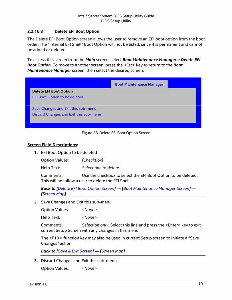
Intel® Server System BIOS Setup Utility Guide
BIOS Setup Utility
Revision 1.0 101
2.2.16.8 Delete EFI Boot Option
The Delete EFI Boot Option screen allows the user to remove an EFI boot option from the boot
order. The “Internal EFI Shell” Boot Option will not be listed, since it is permanent and cannot
be added or deleted.
To access this screen from the Main screen, select Boot Maintenance Manager > Delete EFI
Boot Option. To move to another screen, press the <Esc> key to return to the Boot
Maintenance Manager screen, then select the desired screen.
Boot Maintenance Manager
Delete EFI Boot Option
EFI Boot Option to be deleted
Save Changes and Exit this sub-menu
Discard Changes and Exit this sub-menu
Figure 28. Delete EFI Boot Option Screen
Screen Field Descriptions:
1. EFI Boot Option to be deleted
Option Values: [CheckBox]
Help Text: Select one to delete.
Comments: Use the checkbox to select the EFI Boot Option to be deleted.
This will not allow a user to delete the EFI Shell.
Back to [Delete EFI Boot Option Screen] — [Boot Maintenance Manager Screen] —
[Screen Map]
2. Save Changes and Exit this sub-menu
Option Values: <None>
Help Text: <None>
Comments: Selection only. Select this line and press the <Enter> key to exit
current Setup Screen with any changes in this menu.
The <F10 > function key may also be used in current Setup screen to initiate a “Save
Changes” action.
Back to [Save & Exit Screen] — [Screen Map]
3. Discard Changes and Exit this sub-menu
Option Values: <None>

Intel® Server System BIOS Setup Utility Guide
BIOS Setup Utility
Revision 1.0 102
Help Text: <None>
Comments: Selection only. Select this line and press the <Enter> key to exit
current Setup Screen without saving any changes in this menu.
Back to [Save & Exit Screen] — [Screen Map]
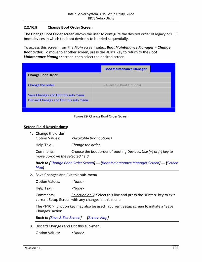
Intel® Server System BIOS Setup Utility Guide
BIOS Setup Utility
Revision 1.0 103
2.2.16.9 Change Boot Order Screen
The Change Boot Order screen allows the user to configure the desired order of legacy or UEFI
boot devices in which the boot device is to be tried sequentially.
To access this screen from the Main screen, select Boot Maintenance Manager > Change
Boot Order. To move to another screen, press the <Esc> key to return to the Boot
Maintenance Manager screen, then select the desired screen.
Boot Maintenance Manager
Change Boot Order
Change the order <Available Boot Options>
Save Changes and Exit this sub-menu
Discard Changes and Exit this sub-menu
Figure 29. Change Boot Order Screen
Screen Field Descriptions:
1. Change the order
Option Values: <Available Boot options>
Help Text: Change the order.
Comments: Choose the boot order of booting Devices. Use [+] or [-] key to
move up/down the selected field.
Back to [Change Boot Order Screen] — [Boot Maintenance Manager Screen] — [Screen
Map]
2. Save Changes and Exit this sub-menu
Option Values: <None>
Help Text: <None>
Comments: Selection only. Select this line and press the <Enter> key to exit
current Setup Screen with any changes in this menu.
The <F10 > function key may also be used in current Setup screen to initiate a “Save
Changes” action.
Back to [Save & Exit Screen] — [Screen Map]
3. Discard Changes and Exit this sub-menu
Option Values: <None>

Intel® Server System BIOS Setup Utility Guide
BIOS Setup Utility
Revision 1.0 104
Help Text: <None>
Comments: Selection only. Select this line and press the <Enter> key to exit
current Setup Screen without saving any changes in this menu.
Back to [Save & Exit Screen] — [Screen Map]

Intel® Server System BIOS Setup Utility Guide
BIOS Setup Utility
Revision 1.0 105
2.2.17 Boot Manager Screen (Tab)
The Boot Manager screen allows the user to view a list of devices available for booting, and to
select a boot device for immediately booting the system. There is no predetermined order for
listing bootable devices. They are simply listed in order of discovery.
Regardless of whether any other bootable devices are available, the “Internal EFI Shell” will
always be available.
Note: This list is not in order according to the system Boot Option order. Reordering Boot
Devices or even removing them from the Boot Order completely has no effect on the Boot
Manager.
To access this screen from the Main screen or other top-level “Tab” screen, press the right or
left arrow keys to traverse the tabs at the top of the Setup screen until the Boot Manager
screen is selected.
Main Advanced Security Server Management Boot Maintenance
Manager
Boot
Manager
Launch EFI Shell
Legacy Floppy Driver
<Boot Device #1>
Legacy HardDisk Driver
<Boot Device #2>
Legacy CD-ROM Driver
<Boot Device #n>
Legacy NET Driver
<Boot Device #n>
Legacy BEV Driver
<Boot Device #n>
Figure 30. Boot Manager Screen
Screen Field Descriptions:
1. Launch EFI Shell
Option Values: <None>
Help Text:
Select this option to boot now.
Note: This list is not the system boot option order. Use the Boot Options menu to
view and configure the system boot option order.
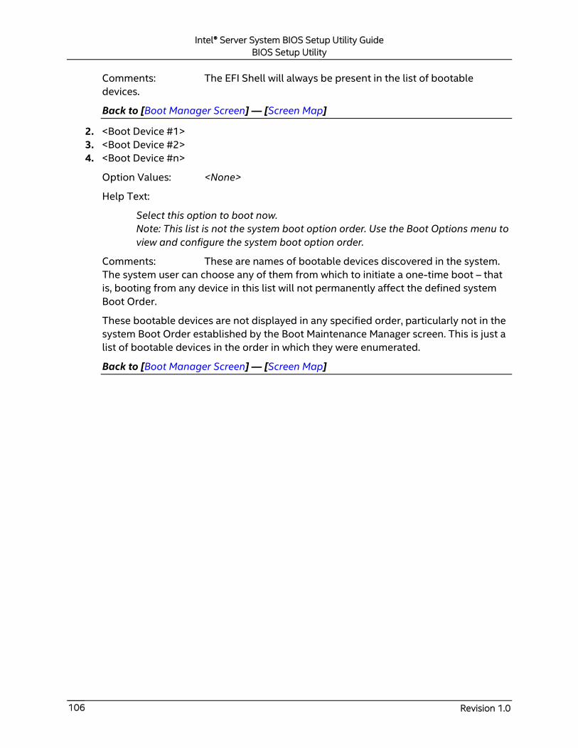
Intel® Server System BIOS Setup Utility Guide
BIOS Setup Utility
Revision 1.0 106
Comments: The EFI Shell will always be present in the list of bootable
devices.
Back to [Boot Manager Screen] — [Screen Map]
2. <Boot Device #1>
3. <Boot Device #2>
4. <Boot Device #n>
Option Values: <None>
Help Text:
Select this option to boot now.
Note: This list is not the system boot option order. Use the Boot Options menu to
view and configure the system boot option order.
Comments: These are names of bootable devices discovered in the system.
The system user can choose any of them from which to initiate a one-time boot – that
is, booting from any device in this list will not permanently affect the defined system
Boot Order.
These bootable devices are not displayed in any specified order, particularly not in the
system Boot Order established by the Boot Maintenance Manager screen. This is just a
list of bootable devices in the order in which they were enumerated.
Back to [Boot Manager Screen] — [Screen Map]
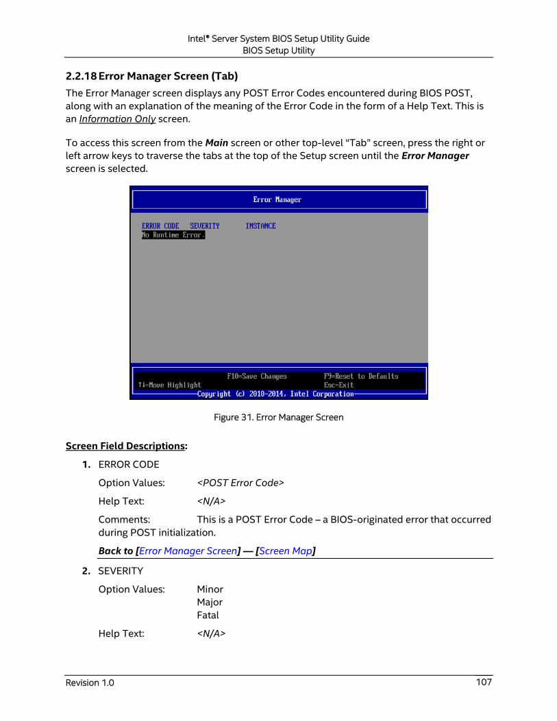
Intel® Server System BIOS Setup Utility Guide
BIOS Setup Utility
Revision 1.0 107
2.2.18 Error Manager Screen (Tab)
The Error Manager screen displays any POST Error Codes encountered during BIOS POST,
along with an explanation of the meaning of the Error Code in the form of a Help Text. This is
an Information Only screen.
To access this screen from the Main screen or other top-level “Tab” screen, press the right or
left arrow keys to traverse the tabs at the top of the Setup screen until the Error Manager
screen is selected.
Figure 31. Error Manager Screen
Screen Field Descriptions:
1. ERROR CODE
Option Values: <POST Error Code>
Help Text: <N/A>
Comments: This is a POST Error Code – a BIOS-originated error that occurred
during POST initialization.
Back to [Error Manager Screen] — [Screen Map]
2. SEVERITY
Option Values: Minor
Major
Fatal
Help Text: <N/A>

Intel® Server System BIOS Setup Utility Guide
BIOS Setup Utility
Revision 1.0 108
Comments: Each POST Error Code has a Severity associated with it.
Back to [Error Manager Screen] — [Screen Map]
3. INSTANCE
Option Values: <Depends on error code>
Help Text: <N/A>
Comments: Where applicable, this field shows a value indicating which one
of a group of components was responsible for generating the POST Error Code that is
being reported.
Back to [Error Manager Screen] — [Screen Map]
4. DESCRIPTION
Option Values: <N/A>
Help Text: <Description of POST Error Code>
Comments: This is a description of the meaning of the POST Error Code that
is being reported. This text actually appears in the screen space that is usually reserved
for “Help” messages.
Back to [Error Manager Screen] — [Screen Map]
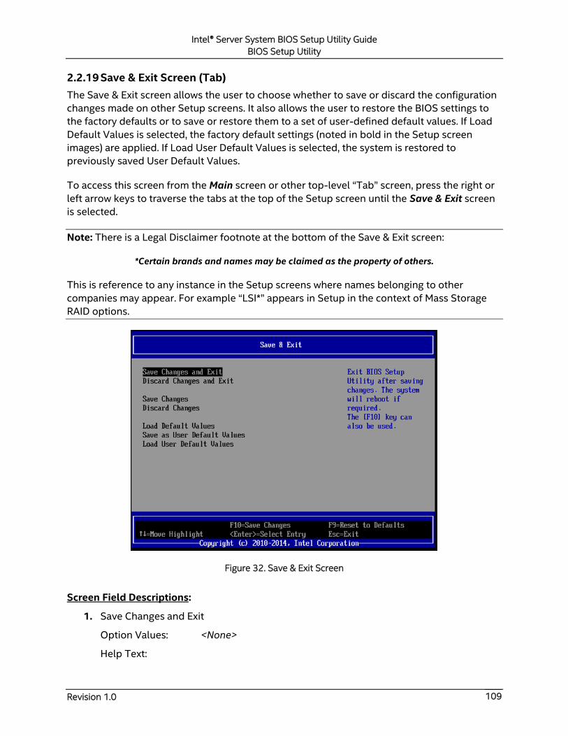
Intel® Server System BIOS Setup Utility Guide
BIOS Setup Utility
Revision 1.0 109
2.2.19 Save & Exit Screen (Tab)
The Save & Exit screen allows the user to choose whether to save or discard the configuration
changes made on other Setup screens. It also allows the user to restore the BIOS settings to
the factory defaults or to save or restore them to a set of user-defined default values. If Load
Default Values is selected, the factory default settings (noted in bold in the Setup screen
images) are applied. If Load User Default Values is selected, the system is restored to
previously saved User Default Values.
To access this screen from the Main screen or other top-level “Tab” screen, press the right or
left arrow keys to traverse the tabs at the top of the Setup screen until the Save & Exit screen
is selected.
Note: There is a Legal Disclaimer footnote at the bottom of the Save & Exit screen:
*Certain brands and names may be claimed as the property of others.
This is reference to any instance in the Setup screens where names belonging to other
companies may appear. For example “LSI*” appears in Setup in the context of Mass Storage
RAID options.
Figure 32. Save & Exit Screen
Screen Field Descriptions:
1. Save Changes and Exit
Option Values: <None>
Help Text:
Intel® Server System BIOS Setup Utility Guide
BIOS Setup Utility
Revision 1.0 110
Exit BIOS Setup Utility after saving changes. The system will reboot if required.
The [F10] key can also be used.
Comments: Selection only. Select this line and press the <Enter> key to exit
Setup with any changes in BIOS settings saved. If there have been no changes made in
the settings, the BIOS will resume executing POST.
If changes have been made in BIOS settings, a confirmation pop-up will appear. If the
“Save Changes & Exit” action is positively confirmed, any persistent changes will be
applied and saved to the BIOS settings in NVRAM storage, then the system will reboot
if necessary (which is normally the case). If the “Save Changes & Exit” action is not
confirmed, the BIOS will resume executing Setup.
The <F10 > function key may also be used from anyplace in Setup to initiate a “Save
Changes & Exit” action.
Back to [Save & Exit Screen] — [Screen Map]
2. Discard Changes and Exit
Option Values: <None>
Help Text:
Exit BIOS Setup Utility without saving changes.
The [Esc] key can also be used.
Comments: Selection only. Select this line and press the <Enter> key to exit
Setup without saving any changes in BIOS settings. If there have been no changes
made in the settings, the BIOS will resume executing POST.
If changes have been made in BIOS settings, a confirmation pop-up will appear. If the
“Discard Changes & Exit” action is positively confirmed,, all pending changes will be
discarded and the BIOS will resume executing POST. If the “Discard Changes & Exit”
action is not confirmed, the BIOS will resume executing Setup without discarding any
changes.
The <Esc > key may also be used in Setup to initiate a “Discard Changes & Exit” action.
Back to [Save & Exit Screen] — [Screen Map]
3. Save Changes
Option Values: <None>
Help Text: Save Changes made so far to any of the setup options.
Comments: Selection only. Select this line and press the <Enter> key to save
any pending changes in BIOS settings. If there have been no changes made in the
settings, the BIOS will resume executing POST.
Also, the user should be aware that most changes require a reboot to become active. If
changes have been made and saved, without exiting Setup, the system should be
rebooted later even if no additional changes are made.
Intel® Server System BIOS Setup Utility Guide
BIOS Setup Utility
Revision 1.0 111
Back to [Save & Exit Screen] — [Screen Map]
4. Discard Changes
Option Values: <None>
Help Text: Discard Changes made so far to any of the setup options.
Comments: Selection only. Select this line and press the <Enter> key to
discard any pending unsaved changes in BIOS settings. If there have been no changes
made in the settings, the BIOS will resume executing POST.
If changes have been made in BIOS settings and not yet saved, a confirmation pop-up
will appear. If the “Discard Changes” action is positively confirmed, all pending changes
will be discarded and the BIOS will resume executing POST. If the “Discard Changes”
action is not confirmed, the BIOS will resume executing Setup without discarding
pending changes.
Back to [Save & Exit Screen] — [Screen Map]
5. Load Default Values
Option Values: <None>
Help Text: Load Defaults Values for all the setup options.
Comments: Selection only. Select this line and press the <Enter> key to load
default values for all BIOS settings. These are the initial factory settings (“failsafe”
settings) for all BIOS parameters.
There will be a confirmation popup to verify that the user really meant to take this
action.
After initializing all BIOS settings to default values, the BIOS will resume executing
Setup, so the user may make additional changes in the BIOS settings if necessary (for
example, Boot Order) before doing a “Save Changes and Exit” with a reboot to make
the default settings take effect, including any changes made after loading the defaults.
The <F9> function key may also be used from anyplace in Setup to initiate a “Load
Default Values” action.
Back to [Save & Exit Screen] — [Screen Map]
6. Save as User Default Values
Option Values: <None>
Help Text: Save the changes made so far as User Default Values.
Comments: Selection only. Select this line and press the <Enter> key to save
the current state of the settings for all BIOS parameters as a customized set of “User
Default Values”.
These are a user-determined set of BIOS default settings that can be used as an
alternative instead of the initial factory settings (“failsafe” settings) for all BIOS
parameters.
Intel® Server System BIOS Setup Utility Guide
BIOS Setup Utility
Revision 1.0 112
By changing the BIOS settings to values that the user prefers to have for defaults, and
then using this operation to save them as “User Default Values”, that version of BIOS
settings can be restored at any time by using the following “Load User Default Values”
operation.
There will be a confirmation popup to verify that the user really intended to take this
action.
Loading the “factory default” values with F9 or the “Load Default Values” – or by any
other means – does not affect the User Default Values. They remain set to whatever
values they were saved as.
Back to [Save & Exit Screen] — [Screen Map]
7. Load User Default Values
Option Values: <None>
Help Text: Load the User Default Values to all the setup options.
Comments: Selection only. Select this line and press the <Enter> key to load
User Default Values for all BIOS settings. These are user-customized BIOS default
settings for all BIOS parameters, previously established by doing a “Save User Defaults”
action (see above).
There will be a confirmation popup to verify that the user really intended to take this
action.
Back to [Save & Exit Screen] — [Screen Map]
Related Documents