_ V9.12. 225 Technical Notes Intel 8085 Family In-Circuit Emulation iSYSTEM, May 2015 1/13 This document is intended to be used together with the CPU reference manual provided by the silicon vendor. This document assumes knowledge of the CPU functionality and the terminology and concepts defined and explained in the CPU reference manual. Basic knowledge of winIDEA is also necessary. This document deals with specifics and advanced details and it is not meant as a basic or introductory text. Contents Contents 1 1 In-Circuit and Active Emulation introduction 2 1.1 Differences from a standard environment 2 1.2 Common Guidelines 2 2 Emulation Options 3 2.1 Hardware Options 3 2.2 CPU Configuration 4 2.3 Power Source and Clock 5 2.4 Initialization Sequence 6 2.5 Pattern Generator 6 3 Setting CPU options 9 3.1 Reset Options 9 3.2 Memory Mapping 10 4 Debugging Interrupt Routines 12 5 Memory Access 12 6 Emulation Notes 13

Welcome message from author
This document is posted to help you gain knowledge. Please leave a comment to let me know what you think about it! Share it to your friends and learn new things together.
Transcript

_ V9.12. 225
Technical Notes
Intel 8085 Family In-Circuit Emulation
iSYSTEM, May 2015 1/13
This document is intended to be used together with the CPU reference manual provided by the silicon vendor. This document assumes knowledge of the CPU functionality and the terminology and concepts defined and explained in the CPU reference manual. Basic knowledge of winIDEA is also necessary. This document deals with specifics and advanced details and it is not meant as a basic or introductory text.
Contents
Contents 1
1 In-Circuit and Active Emulation introduction 2 1.1 Differences from a standard environment 2 1.2 Common Guidelines 2
2 Emulation Options 3 2.1 Hardware Options 3 2.2 CPU Configuration 4 2.3 Power Source and Clock 5 2.4 Initialization Sequence 6 2.5 Pattern Generator 6
3 Setting CPU options 9 3.1 Reset Options 9 3.2 Memory Mapping 10
4 Debugging Interrupt Routines 12
5 Memory Access 12
6 Emulation Notes 13

iSYSTEM, May 2015 2/13
1 In-Circuit and Active Emulation introduction
Debug Features
Unlimited breakpoints
Access breakpoint
Real-time access
Trace
Execution profiler
Execution coverage
1.1 Differences from a standard environment
The In-Circuit Emulator and the Active Emulator can emulate a processor or a micro-controller. Beside the CPU, additional logic is integrated on the POD. The amount of additional logic depends on the emulated CPU and the type of emulation. A buffer on a data bus is always used (minimal logic) and when rebuilding ports on the POD, maximum logic is used. As soon as a POD is inserted in the target instead of the CPU, electrical and timing characteristics are changed. Different electrical and timing characteristics of used elements on the POD and prolonged lines from the target to the CPU on the POD contribute to different target (the whole system) characteristics. Consequently, signal cross-talks and reflections can occur, capacitance changes, etc.
Besides that, pull-up and pull-down resistors are added to some signals. Pull-up/pull-down resistors are required to define the inactive state of signals like reset and interrupt inputs, while the POD is not connected to the target. Because of this, the POD can operate as standalone without the target.
1.2 Common Guidelines
Here are some general guidelines that you should follow.
Use external (target) Vcc/GND if possible (to prevent GND bouncing),
Make an additional GND connection from POD to the target if the Emulator behaves strangely,
Use the reset output line on the POD to reset the target whenever Emulator resets the CPU,
Make sure the appropriate CPU is used on the POD. Please refer to the POD Hardware reference received with your POD.
No on-chip or external watchdog timers can be used during emulation (unless explicitly permitted). Disable them all.
When interrupts in background are enabled, take note that the interrupt routine must return in 25 ms, otherwise the Emulator will assume that the program is hung.

iSYSTEM, May 2015 3/13
2 Emulation Options
2.1 Hardware Options
In-Circuit Emulator Options dialog, Hardware page
Emulation Memory
Defines the size of emulation memory available on the In-Circuit emulation module.
Note: You must specify the memory size correctly, otherwise the Emulator will not initialize.
Clear Emulation Memory
This option allows you to force clearing (with the specified value) of emulation memory after the emulation unit is initialized.
Clearing emulation memory takes about 2 seconds per megabyte, so use it only when you want to make sure that previous emulation memory contents don't affect the current debug session.
iSYSTEM, May 2015 4/13
2.2 CPU Configuration
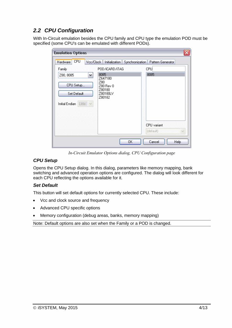
With In-Circuit emulation besides the CPU family and CPU type the emulation POD must be specified (some CPU's can be emulated with different PODs).
In-Circuit Emulator Options dialog, CPU Configuration page
CPU Setup
Opens the CPU Setup dialog. In this dialog, parameters like memory mapping, bank switching and advanced operation options are configured. The dialog will look different for each CPU reflecting the options available for it.
Set Default
This button will set default options for currently selected CPU. These include:
Vcc and clock source and frequency
Advanced CPU specific options
Memory configuration (debug areas, banks, memory mapping)
Note: Default options are also set when the Family or a POD is changed.

iSYSTEM, May 2015 5/13
2.3 Power Source and Clock
The Vcc/Clock Setup page determines the CPU's power and clock source.
In-Circuit Emulator Options dialog, Vcc/Clock Setup page
Note: When either of these settings is set to External, the corresponding line is routed directly to the CPU from the target system.
Clock Source
Clock source can be either used internal from the emulator or external from the target. It is recommended to use the internal clock when possible. When using the clock from the target, it may happen that the emulator cannot initialize any more.
It is dissuaded to use a crystal in the target as a clock source during the emulation. It is recommended that the oscillator be used instead. Normally, a crystal and two capacitors are connected to the CPU's clock inputs in the target application as stated in the CPU datasheets. A length of clock paths is critical and must be taken into consideration when designing the target. During the emulation, the distance between the crystal in the target and the CPU (on the POD) is furthermore increased; therefore the impedance may change in a manner that the crystal doesn't oscillate anymore. In such case, a standalone crystal circuit, oscillating already without the CPU must be built or an oscillator must be used.
When the clock source is set to Internal, the clock is provided by the emulator and you may control its frequency in steps of 1kHz. Depending on the Emulator and its oscillator version, you will be able to use clock from 1MHz to 33 MHz (on iC181) or up to 100MHz on iC2000 emulation units.
Note: The clock frequency is the frequency of the signal on the CPU's clock input pin. Any internal manipulation of it (division or multiplication) depends entirely on the emulated CPU.
If the clock source is set to external, the clock is provided by the target system. In certain applications, for instance, a 32.786kHz clock is used. Since the minimal clock the Emulator can generate is 1MHz, an external clock source must be used and the clock source set to external.

iSYSTEM, May 2015 6/13
Vcc Source
Determines whether emulator or the target system provides power supply for the CPU.
2.4 Initialization Sequence
Usually, there is no need to use initialization sequence when debugging with an In-Circuit Emulator (ICE) a single chip application. Primarily, initialization sequence is used on On-Chip Debug systems to initialize the CPU after reset to be able to download the code to the target (CPU or CPU external) memory. With an ICE system, the initialization sequence may be required for instance to enable memory access to the CPU internal EEPROM or to some external target memory, which is not accessible by default after the CPU reset. The user can also disable CPU internal COP using initialization sequence if there is a need for that, etc.
Initialization sequence is executed immediately after the CPU reset and then the code is downloaded. Detailed information may be found in the Initialization Sequence help topic.
2.5 Pattern Generator
iC1000, iC2000 and iC4000 provide an 8-channel waveform programmable pattern generator capable of continuous or single shot operation at up to 10MHz-clock rate with up to 512 samples.
Note: when using the iC4000 system, it has in certain configurations two Pattern Generators: one on the base module and one on the Power Emulator module. The Pattern Generator on the base module is active when the debugging type is set to ‘Active Emulation’ or ‘BDM/JTAG Emulation’, the Pattern Generator on the Power Emulator Module is active when ‘In-circuit Emulation’ is selected..
You can configure any number of patterns using 'New…' and 'Remove' buttons. The currently selected pattern is displayed in the combo box as indicated in the above figure.
State of a disabled channel can be configured either to high or low.
Every individual channel can be enabled or disabled by configuring the check box next to its name. When a channel is disabled you can still configure its state, which remains unchanged throughout its period.
Waveforms are configured easily by clicking and moving the mouse cursor on the desired channel and position.

iSYSTEM, May 2015 7/13
In-Circuit Emulator Options dialog, iC1000/iC2000/iC4000 Pattern Generator page
Properties
This button opens a dialog where parameters for the current pattern can be configured.
Pattern Generator Parameters
Parameters of a pattern are valid for all of its eight channels. This means that all channels are of the same length and all use the same clock.
iC1000/iC2000/iC4000 Pattern Generator Parameters dialog
Name
Defines the name of the current pattern
Frames
Defines number of frames used in the pattern. Frames multiplied by pattern clock define the period of the pattern. The number of frames is limited to 512.
Pattern clock
Defines the clock rate by, which the waveform progresses.

iSYSTEM, May 2015 8/13
Operation mode
Defines whether the pattern is to run continuously or to execute only a single shot on demand. In any case, pattern operation is controlled from the Hardware menu by selecting the 'Run Pattern' command.
When continuous mode is selected, the 'Run Pattern' command will either stop pattern execution (at the last frame), or resume it.
In single shot mode selecting the 'Run Pattern' executes a single pattern shot.
Note: Pattern generator operation can be controlled by an external device through the TRIG/CLKEN pin on the pattern generator connector. Refer to the Hardware User’s Manual for more information.

iSYSTEM, May 2015 9/13
3 Setting CPU options
3.1 Reset Options
The CPU Setup, Reset page provides some emulation settings, common to most CPU families and all emulation modes. Settings that are not valid for currently selected CPU or emulation mode are disabled. If none of these settings is valid, this page is not shown.
CPU Setup, Reset page
RESET From Target Enabled
When checked, the target's RESET line can reset the CPU while the CPU is running.

iSYSTEM, May 2015 10/13
3.2 Memory Mapping
The mapping page displays currently configured memory mapping.
CPU Setup dialog, Mapping page
Gray blocks in mapping configuration area indicate memory ranges that are either outside the CPU's range (bank systems) or aren't covered by emulation memory.
Colored blocks define current mapping of the covered area:
dark blue for target
brown for Emulator ROM - CPU can read from it but not write to it.
yellow for Emulator RAM - read and write access
cyan for blocks with mixed mapping - use zoom to view where exactly such blocks map.
To change the mapping type of a block, select desired Mapping Type and click on the block that you wish to map to the select type.
Note: Clicking on a block with mixed mapping, clears all underlying mapping configuration and sets mapping for the entire block to selected mapping.
To configure and view mapping at higher resolution:
click the 'Zoom In' button
position the mouse cursor over the block that you wish to zoom in; the mouse cursor will change to indicate zoom mode.
click on the block.
You can configure mapping options with 4k resolution on iC181 and 2 bytes resolution on iC1000, iC2000 and iC4000, while the ActivePOD does not provide memory mapping since this is a single-chip CPU. The mapping configuration area always shows a grid of 256 blocks. In the bottom left corner the current block size is displayed and current ranges are visible to the left of the mapping configuration area. You can zoom in and out and scroll the current range to reach the desired address and resolution.

iSYSTEM, May 2015 11/13
In general you should configure your mapping as follows:
where read only devices containing target program are located, set mapping to Emulator ROM. This allows you to download the program quickly without programming EPROMs, while preventing the program from overwriting itself.
areas occupied by on-chip or off-chip, memory addressable peripherals must always be mapped to target. Otherwise the CPU will not be able to write to them.
areas occupied by RAM devices can be mapped either to target or to Emulator RAM. You will want to have them mapped to Emulator if the target system is not being used, or when using advanced debugging features like real-time watches. Otherwise map them to target.
Write Protect
Prevents the memory, mapped to the Emulator ROM, from being written to. If this option is checked, a write to the Emulator ROM area results in an error message.
Note: This option is available only for the Emulator ROM type of memory.

iSYSTEM, May 2015 12/13
4 Debugging Interrupt Routines An interrupt routine can only be debugged when the interrupt source for this routine has been disabled, otherwise you will keep reentering the routine and thus run out of system stack. For example, there is an interrupt routine with 10 source lines. Let’s say that interrupt routine is called periodically by free running timer is an interrupt source. A breakpoint is set on the first source line in the interrupt routine. Program execution stops at the breakpoint. Now source step is executed. Source step is actually executed using RUN command with prior setting of breakpoint on adequate source line. In this particular case, while source step is executed, the CPU executes the code and before source step finishes, new interrupt call occurs. New values are pushed on to the stack and the CPU stops on breakpoint again. If you repeat source steps in such interrupt routine new values are pushed to the stack and you can easily run out of stack. An interrupt source can be disabled in two ways:
Disable the interrupt process in the stopped mode. The stopped mode is entered whenever CPU is stopped, and the emulator remains in stopped mode until the Run command is executed. (During Step, Step over, etc. commands, the stopped mode persists).
Do not place a breakpoint on any instruction in the interrupt routine where interrupts are not yet disabled. Also, you must not step over any instruction that re-enables the current interrupt, but run the program before the instruction is executed.
Note: On all 8 bit CPUs the emulator allows interrupt nesting up to 15 levels in depth, representing no limitations in practice. Nesting will occur only if interrupt servicing is interrupted by another interrupt before the servicing is completed. While any nested interrupt is serviced by the CPU, the emulator has no access to the CPU therefore debug windows cannot be refreshed in the meantime.
To allow background interrupt execution on 8 bit CPUs, interrupt routines must meet the following conditions:
All CPU registers must be preserved,
Interrupt routines must return with the corresponding return-from-interrupt instruction (RETI, RFI, etc.). Do not assume that your compiler gets it right always. Interrupt routine exiting with jump or call instruction cannot be debugged.
The return address must not be changed in the interrupt routine.
5 Memory Access
8085 development tool features standard monitor memory access, which require user program to be stopped and real-time memory access based on shadow memory, which allows reading the memory while the application is running.
Real-Time Memory Access
Real-time memory access is available on PowerEmulator unit with shadow memory. Data area can only be read in real-time.
Real-time write memory access is not possible due to shadow memory use. Monitor access must be used to write to the memory.
iSYSTEM, May 2015 13/13
Monitor Access
When monitor access to the CPU’s memory is requested, the emulator stops the CPU and instructs it to read the requested number of bytes.
Since all accesses are performed using the CPU, all memory available to the CPU can be accessed. The drawback to this method is that memory cannot be accessed while the CPU is running. Stopping the CPU, accessing memory and running the CPU is an option, which, however, affects the real time execution considerably.
The time the CPU is stopped for is relative and cannot be exactly determined. The software has full control over it. It stops the CPU, updates all required windows and sets the CPU back to running. Therefore the time depends on the communication type used, PC's frequency, CPU's clock, number of updated memory locations (memory window, SFR window, watches, variables window), etc.
6 Emulation Notes
Reserved CPU Resources
No CPU resources are used.
Note: No interrupt, restart or trap can be executed when the CPU is stopped.
Disclaimer: iSYSTEM assumes no responsibility for any errors which may appear in this document, reserves the right to change devices or specifications detailed herein at any time without notice, and does not make any commitment to update the information herein.
iSYSTEM. All rights reserved.
Related Documents