Computation Visualization Programming For Use with MATLAB ® User’s Guide Version 1 Instrument Control Toolbox

Welcome message from author
This document is posted to help you gain knowledge. Please leave a comment to let me know what you think about it! Share it to your friends and learn new things together.
Transcript
Computation
Visualization
Programming
For Use with MATLAB®
User’s GuideVersion 1
Instrument ControlToolbox
How to Contact The MathWorks:
508-647-7000 Phone
508-647-7001 Fax
The MathWorks, Inc. Mail3 Apple Hill DriveNatick, MA 01760-2098
http://www.mathworks.com Webftp.mathworks.com Anonymous FTP servercomp.soft-sys.matlab Newsgroup
[email protected] Technical [email protected] Product enhancement [email protected] Bug [email protected] Documentation error [email protected] Subscribing user [email protected] Order status, license renewals, [email protected] Sales, pricing, and general information
Instrument Control Toolbox User’s Guide COPYRIGHT 2000 by The MathWorks, Inc.The software described in this document is furnished under a license agreement. The software may be usedor copied only under the terms of the license agreement. No part of this manual may be photocopied or repro-duced in any form without prior written consent from The MathWorks, Inc.
FEDERAL ACQUISITION: This provision applies to all acquisitions of the Program and Documentation byor for the federal government of the United States. By accepting delivery of the Program, the governmenthereby agrees that this software qualifies as "commercial" computer software within the meaning of FARPart 12.212, DFARS Part 227.7202-1, DFARS Part 227.7202-3, DFARS Part 252.227-7013, and DFARS Part252.227-7014. The terms and conditions of The MathWorks, Inc. Software License Agreement shall pertainto the government’s use and disclosure of the Program and Documentation, and shall supersede anyconflicting contractual terms or conditions. If this license fails to meet the government’s minimum needs oris inconsistent in any respect with federal procurement law, the government agrees to return the Programand Documentation, unused, to MathWorks.
MATLAB, Simulink, Stateflow, Handle Graphics, and Real-Time Workshop are registered trademarks, andTarget Language Compiler is a trademark of The MathWorks, Inc.
Other product or brand names are trademarks or registered trademarks of their respective holders.
Printing History: November 2000 First printing New for Version 1 (Release 12)
i
Contents
Preface
What Is the Instrument Control Toolbox? . . . . . . . . . . . . . . . . xiiExploring the Toolbox . . . . . . . . . . . . . . . . . . . . . . . . . . . . . . . . . . xii
Related Products . . . . . . . . . . . . . . . . . . . . . . . . . . . . . . . . . . . . . xiiiSystem Requirements . . . . . . . . . . . . . . . . . . . . . . . . . . . . . . . . . xiiiAssociated Products . . . . . . . . . . . . . . . . . . . . . . . . . . . . . . . . . . . xiii
Using This Guide . . . . . . . . . . . . . . . . . . . . . . . . . . . . . . . . . . . . . . xvExpected Background . . . . . . . . . . . . . . . . . . . . . . . . . . . . . . . . . . xvLearning the Instrument Control Toolbox . . . . . . . . . . . . . . . . . . xvHow This Guide Is Organized . . . . . . . . . . . . . . . . . . . . . . . . . . . xvi
Installation Information . . . . . . . . . . . . . . . . . . . . . . . . . . . . . . xviiToolbox Installation . . . . . . . . . . . . . . . . . . . . . . . . . . . . . . . . . . xviiHardware and Driver Installation . . . . . . . . . . . . . . . . . . . . . . xvii
Typographical Conventions . . . . . . . . . . . . . . . . . . . . . . . . . . xviii
1Getting Started
Toolbox Components . . . . . . . . . . . . . . . . . . . . . . . . . . . . . . . . . . 1-2M-File Functions . . . . . . . . . . . . . . . . . . . . . . . . . . . . . . . . . . . . . 1-3The Interface Driver Adaptor . . . . . . . . . . . . . . . . . . . . . . . . . . . 1-4
Communicating with Your Instrument . . . . . . . . . . . . . . . . . 1-5Communicating with a GPIB Instrument . . . . . . . . . . . . . . . . . 1-5Communicating with a GPIB-VXI Instrument . . . . . . . . . . . . . 1-6Communicating with a Serial Port Instrument . . . . . . . . . . . . . 1-7
ii Contents
Understanding the Toolbox Capabilities . . . . . . . . . . . . . . . . 1-9The Contents M-File . . . . . . . . . . . . . . . . . . . . . . . . . . . . . . . . . . 1-9Documentation Examples . . . . . . . . . . . . . . . . . . . . . . . . . . . . . . 1-9Demos . . . . . . . . . . . . . . . . . . . . . . . . . . . . . . . . . . . . . . . . . . . . . . 1-9
Examining Your Hardware Resources . . . . . . . . . . . . . . . . . 1-13General Toolbox Information . . . . . . . . . . . . . . . . . . . . . . . . . . 1-13Interface Information . . . . . . . . . . . . . . . . . . . . . . . . . . . . . . . . . 1-13Adaptor Information . . . . . . . . . . . . . . . . . . . . . . . . . . . . . . . . . 1-14Instrument Object Information . . . . . . . . . . . . . . . . . . . . . . . . . 1-16
Getting Help . . . . . . . . . . . . . . . . . . . . . . . . . . . . . . . . . . . . . . . . . 1-17The instrhelp Function . . . . . . . . . . . . . . . . . . . . . . . . . . . . . . . 1-17The propinfo Function . . . . . . . . . . . . . . . . . . . . . . . . . . . . . . . . 1-18
2The Instrument Control Session
Overview . . . . . . . . . . . . . . . . . . . . . . . . . . . . . . . . . . . . . . . . . . . . . 2-2
Creating an Instrument Object . . . . . . . . . . . . . . . . . . . . . . . . . 2-3Configuring Properties During Object Creation . . . . . . . . . . . . 2-4Creating an Array of Instrument Objects . . . . . . . . . . . . . . . . . . 2-4
Connecting to the Instrument . . . . . . . . . . . . . . . . . . . . . . . . . . 2-6
Configuring and Returning Properties . . . . . . . . . . . . . . . . . . 2-7Returning Property Names and Property Values . . . . . . . . . . . 2-7Configuring Property Values . . . . . . . . . . . . . . . . . . . . . . . . . . . 2-10Specifying Property Names . . . . . . . . . . . . . . . . . . . . . . . . . . . . 2-10Default Property Values . . . . . . . . . . . . . . . . . . . . . . . . . . . . . . 2-11
Writing and Reading Data . . . . . . . . . . . . . . . . . . . . . . . . . . . . 2-12Writing Data . . . . . . . . . . . . . . . . . . . . . . . . . . . . . . . . . . . . . . . 2-13Reading Data . . . . . . . . . . . . . . . . . . . . . . . . . . . . . . . . . . . . . . . 2-18
iii
Disconnecting and Cleaning Up . . . . . . . . . . . . . . . . . . . . . . . 2-23Disconnecting an Instrument Object . . . . . . . . . . . . . . . . . . . . 2-23Cleaning Up the MATLAB Environment . . . . . . . . . . . . . . . . . 2-23
3Controlling GPIB Instruments
GPIB Overview . . . . . . . . . . . . . . . . . . . . . . . . . . . . . . . . . . . . . . . 3-2What Is GPIB? . . . . . . . . . . . . . . . . . . . . . . . . . . . . . . . . . . . . . . . 3-2Important GPIB Features . . . . . . . . . . . . . . . . . . . . . . . . . . . . . . 3-3GPIB Lines . . . . . . . . . . . . . . . . . . . . . . . . . . . . . . . . . . . . . . . . . . 3-4Status and Event Reporting . . . . . . . . . . . . . . . . . . . . . . . . . . . . 3-9Using Vendor Tools to Identify and Test Your Resources . . . . 3-14
Creating a GPIB Object . . . . . . . . . . . . . . . . . . . . . . . . . . . . . . . 3-18The GPIB Object Display . . . . . . . . . . . . . . . . . . . . . . . . . . . . . . 3-19
Configuring the GPIB Address . . . . . . . . . . . . . . . . . . . . . . . . 3-20
Writing and Reading Data . . . . . . . . . . . . . . . . . . . . . . . . . . . . 3-21Rules for Completing Write and Read Operations . . . . . . . . . . 3-21Example: Writing and Reading Text Data . . . . . . . . . . . . . . . . 3-22Example: Reading Binary Data . . . . . . . . . . . . . . . . . . . . . . . . . 3-24Example: Parsing Input Data Using strread . . . . . . . . . . . . . . 3-26Example: Understanding EOI and EOS . . . . . . . . . . . . . . . . . . 3-27
Using Events and Actions . . . . . . . . . . . . . . . . . . . . . . . . . . . . . 3-30Example: Introduction to Events and Actions . . . . . . . . . . . . . 3-30Event Types and Action Properties . . . . . . . . . . . . . . . . . . . . . . 3-31Storing Event Information . . . . . . . . . . . . . . . . . . . . . . . . . . . . 3-32Creating and Executing Action Functions . . . . . . . . . . . . . . . . 3-33Enabling Action Functions After They Error . . . . . . . . . . . . . . 3-34Example: Using Events and Actions to Read Binary Data . . . 3-34
Triggers . . . . . . . . . . . . . . . . . . . . . . . . . . . . . . . . . . . . . . . . . . . . . 3-36Example: Executing a Trigger . . . . . . . . . . . . . . . . . . . . . . . . . . 3-36
iv Contents
Serial Polls . . . . . . . . . . . . . . . . . . . . . . . . . . . . . . . . . . . . . . . . . . 3-38Example: Executing a Serial Poll . . . . . . . . . . . . . . . . . . . . . . . 3-38
4Controlling Instruments Using the VISA Standard
VISA Overview . . . . . . . . . . . . . . . . . . . . . . . . . . . . . . . . . . . . . . . . 4-2Using Vendor Tools to Identify and Test Your Resources . . . . . 4-3
The GPIB Interface . . . . . . . . . . . . . . . . . . . . . . . . . . . . . . . . . . . 4-5Creating a VISA-GPIB Object . . . . . . . . . . . . . . . . . . . . . . . . . . . 4-5The VISA-GPIB Address . . . . . . . . . . . . . . . . . . . . . . . . . . . . . . . 4-7
The VXI Interface . . . . . . . . . . . . . . . . . . . . . . . . . . . . . . . . . . . . . 4-9Creating a VISA-VXI Object . . . . . . . . . . . . . . . . . . . . . . . . . . . 4-10The VISA-VXI Address . . . . . . . . . . . . . . . . . . . . . . . . . . . . . . . 4-12Register-Based Communication . . . . . . . . . . . . . . . . . . . . . . . . 4-13
The GPIB-VXI Interface . . . . . . . . . . . . . . . . . . . . . . . . . . . . . . 4-21Creating a VISA-GPIB-VXI Object . . . . . . . . . . . . . . . . . . . . . . 4-22The VISA-GPIB-VXI Address . . . . . . . . . . . . . . . . . . . . . . . . . . 4-24
The Serial Port Interface . . . . . . . . . . . . . . . . . . . . . . . . . . . . . 4-26Creating a VISA-Serial Object . . . . . . . . . . . . . . . . . . . . . . . . . 4-26Configuring Communication Settings . . . . . . . . . . . . . . . . . . . 4-28
5Controlling Serial Port Instruments
Serial Port Overview . . . . . . . . . . . . . . . . . . . . . . . . . . . . . . . . . . 5-2What Is Serial Communication? . . . . . . . . . . . . . . . . . . . . . . . . . 5-2The Serial Port Interface Standard . . . . . . . . . . . . . . . . . . . . . . 5-2Connecting Two Devices with a Serial Cable . . . . . . . . . . . . . . . 5-3Serial Port Signals and Pin Assignments . . . . . . . . . . . . . . . . . . 5-5
v
Serial Data Format . . . . . . . . . . . . . . . . . . . . . . . . . . . . . . . . . . . 5-9Finding Serial Port Information for Your Platform . . . . . . . . . 5-13
Creating a Serial Port Object . . . . . . . . . . . . . . . . . . . . . . . . . 5-16The Serial Port Object Display . . . . . . . . . . . . . . . . . . . . . . . . . 5-17
Configuring Communication Settings . . . . . . . . . . . . . . . . . . 5-18
Writing and Reading Data . . . . . . . . . . . . . . . . . . . . . . . . . . . . 5-19Asynchronous Write and Read Operations . . . . . . . . . . . . . . . . 5-19Rules for Completing Write and Read Operations . . . . . . . . . . 5-20Example: Writing and Reading Text Data . . . . . . . . . . . . . . . . 5-21
Using Events and Actions . . . . . . . . . . . . . . . . . . . . . . . . . . . . . 5-24Event Types and Action Properties . . . . . . . . . . . . . . . . . . . . . . 5-24Storing Event Information . . . . . . . . . . . . . . . . . . . . . . . . . . . . 5-25Example: Using Events and Actions . . . . . . . . . . . . . . . . . . . . . 5-27
Using Control Pins . . . . . . . . . . . . . . . . . . . . . . . . . . . . . . . . . . . 5-29Signaling the Presence of Connected Devices . . . . . . . . . . . . . 5-29Controlling the Flow of Data: Handshaking . . . . . . . . . . . . . . 5-32
6Saving and Loading the Session
Overview . . . . . . . . . . . . . . . . . . . . . . . . . . . . . . . . . . . . . . . . . . . . . 6-2
Saving and Loading Instrument Objects . . . . . . . . . . . . . . . . 6-3Saving Instrument Objects to an M-File . . . . . . . . . . . . . . . . . . 6-3Saving Instrument Objects to a MAT-File . . . . . . . . . . . . . . . . . 6-5
Debugging: Recording Information to Disk . . . . . . . . . . . . . . 6-6Example: Introduction to Recording Information . . . . . . . . . . . 6-6Creating Multiple Record Files . . . . . . . . . . . . . . . . . . . . . . . . . . 6-7Specifying a Filename . . . . . . . . . . . . . . . . . . . . . . . . . . . . . . . . . 6-7The Record File Format . . . . . . . . . . . . . . . . . . . . . . . . . . . . . . . . 6-8Example: Recording Information to Disk . . . . . . . . . . . . . . . . . 6-10
vi Contents
7Function Reference
Overview . . . . . . . . . . . . . . . . . . . . . . . . . . . . . . . . . . . . . . . . . . . . . 7-2Getting Command Line Function Help . . . . . . . . . . . . . . . . . . . 7-2
Functions Grouped by Category . . . . . . . . . . . . . . . . . . . . . . . . 7-4Base Functions . . . . . . . . . . . . . . . . . . . . . . . . . . . . . . . . . . . . . . . 7-4Object-Specific Functions . . . . . . . . . . . . . . . . . . . . . . . . . . . . . . 7-7
Functions Listed Alphabetically . . . . . . . . . . . . . . . . . . . . . . . 7-10clear . . . . . . . . . . . . . . . . . . . . . . . . . . . . . . . . . . . . . . . . . . . . . . 7-11clrdevice . . . . . . . . . . . . . . . . . . . . . . . . . . . . . . . . . . . . . . . . . . . 7-12delete . . . . . . . . . . . . . . . . . . . . . . . . . . . . . . . . . . . . . . . . . . . . . . 7-13disp . . . . . . . . . . . . . . . . . . . . . . . . . . . . . . . . . . . . . . . . . . . . . . . 7-14fclose . . . . . . . . . . . . . . . . . . . . . . . . . . . . . . . . . . . . . . . . . . . . . . 7-15fgetl . . . . . . . . . . . . . . . . . . . . . . . . . . . . . . . . . . . . . . . . . . . . . . . 7-16fgets . . . . . . . . . . . . . . . . . . . . . . . . . . . . . . . . . . . . . . . . . . . . . . . 7-19flushinput . . . . . . . . . . . . . . . . . . . . . . . . . . . . . . . . . . . . . . . . . . 7-22flushoutput . . . . . . . . . . . . . . . . . . . . . . . . . . . . . . . . . . . . . . . . . 7-23fopen . . . . . . . . . . . . . . . . . . . . . . . . . . . . . . . . . . . . . . . . . . . . . . 7-24fprintf . . . . . . . . . . . . . . . . . . . . . . . . . . . . . . . . . . . . . . . . . . . . . 7-26fread . . . . . . . . . . . . . . . . . . . . . . . . . . . . . . . . . . . . . . . . . . . . . . 7-29fscanf . . . . . . . . . . . . . . . . . . . . . . . . . . . . . . . . . . . . . . . . . . . . . . 7-33fwrite . . . . . . . . . . . . . . . . . . . . . . . . . . . . . . . . . . . . . . . . . . . . . . 7-37get . . . . . . . . . . . . . . . . . . . . . . . . . . . . . . . . . . . . . . . . . . . . . . . . 7-41gpib . . . . . . . . . . . . . . . . . . . . . . . . . . . . . . . . . . . . . . . . . . . . . . . 7-43instraction . . . . . . . . . . . . . . . . . . . . . . . . . . . . . . . . . . . . . . . . . 7-46instrcomm . . . . . . . . . . . . . . . . . . . . . . . . . . . . . . . . . . . . . . . . . . 7-47instrcreate . . . . . . . . . . . . . . . . . . . . . . . . . . . . . . . . . . . . . . . . . 7-50instrfind . . . . . . . . . . . . . . . . . . . . . . . . . . . . . . . . . . . . . . . . . . . 7-55instrhelp . . . . . . . . . . . . . . . . . . . . . . . . . . . . . . . . . . . . . . . . . . . 7-57instrhwinfo . . . . . . . . . . . . . . . . . . . . . . . . . . . . . . . . . . . . . . . . . 7-59instrreset . . . . . . . . . . . . . . . . . . . . . . . . . . . . . . . . . . . . . . . . . . 7-61instrschool . . . . . . . . . . . . . . . . . . . . . . . . . . . . . . . . . . . . . . . . . 7-62isvalid . . . . . . . . . . . . . . . . . . . . . . . . . . . . . . . . . . . . . . . . . . . . . 7-63length . . . . . . . . . . . . . . . . . . . . . . . . . . . . . . . . . . . . . . . . . . . . . 7-64load . . . . . . . . . . . . . . . . . . . . . . . . . . . . . . . . . . . . . . . . . . . . . . . 7-65memmap . . . . . . . . . . . . . . . . . . . . . . . . . . . . . . . . . . . . . . . . . . . 7-67mempeek . . . . . . . . . . . . . . . . . . . . . . . . . . . . . . . . . . . . . . . . . . . 7-69
vii
mempoke . . . . . . . . . . . . . . . . . . . . . . . . . . . . . . . . . . . . . . . . . . . 7-71memread . . . . . . . . . . . . . . . . . . . . . . . . . . . . . . . . . . . . . . . . . . . 7-73memunmap . . . . . . . . . . . . . . . . . . . . . . . . . . . . . . . . . . . . . . . . . 7-75memwrite . . . . . . . . . . . . . . . . . . . . . . . . . . . . . . . . . . . . . . . . . . 7-76obj2mfile . . . . . . . . . . . . . . . . . . . . . . . . . . . . . . . . . . . . . . . . . . . 7-78propinfo . . . . . . . . . . . . . . . . . . . . . . . . . . . . . . . . . . . . . . . . . . . . 7-80query . . . . . . . . . . . . . . . . . . . . . . . . . . . . . . . . . . . . . . . . . . . . . . 7-82readasync . . . . . . . . . . . . . . . . . . . . . . . . . . . . . . . . . . . . . . . . . . 7-84record . . . . . . . . . . . . . . . . . . . . . . . . . . . . . . . . . . . . . . . . . . . . . 7-87save . . . . . . . . . . . . . . . . . . . . . . . . . . . . . . . . . . . . . . . . . . . . . . . 7-89serial . . . . . . . . . . . . . . . . . . . . . . . . . . . . . . . . . . . . . . . . . . . . . . 7-91serialbreak . . . . . . . . . . . . . . . . . . . . . . . . . . . . . . . . . . . . . . . . . 7-93set . . . . . . . . . . . . . . . . . . . . . . . . . . . . . . . . . . . . . . . . . . . . . . . . 7-94size . . . . . . . . . . . . . . . . . . . . . . . . . . . . . . . . . . . . . . . . . . . . . . . 7-96spoll . . . . . . . . . . . . . . . . . . . . . . . . . . . . . . . . . . . . . . . . . . . . . . . 7-97stopasync . . . . . . . . . . . . . . . . . . . . . . . . . . . . . . . . . . . . . . . . . . 7-99trigger . . . . . . . . . . . . . . . . . . . . . . . . . . . . . . . . . . . . . . . . . . . . 7-100visa . . . . . . . . . . . . . . . . . . . . . . . . . . . . . . . . . . . . . . . . . . . . . . 7-101
8Property Reference
Overview . . . . . . . . . . . . . . . . . . . . . . . . . . . . . . . . . . . . . . . . . . . . . 8-2Getting Command Line Property Help . . . . . . . . . . . . . . . . . . . . 8-2
Properties Grouped by Category . . . . . . . . . . . . . . . . . . . . . . . 8-3Base Properties . . . . . . . . . . . . . . . . . . . . . . . . . . . . . . . . . . . . . . 8-3Object-Specific Properties . . . . . . . . . . . . . . . . . . . . . . . . . . . . . . 8-6
Properties Listed Alphabetically . . . . . . . . . . . . . . . . . . . . . . 8-15BaudRate . . . . . . . . . . . . . . . . . . . . . . . . . . . . . . . . . . . . . . . . . . 8-16BoardIndex . . . . . . . . . . . . . . . . . . . . . . . . . . . . . . . . . . . . . . . . . 8-17BreakInterruptAction . . . . . . . . . . . . . . . . . . . . . . . . . . . . . . . . 8-18BusManagementStatus . . . . . . . . . . . . . . . . . . . . . . . . . . . . . . . 8-19ByteOrder . . . . . . . . . . . . . . . . . . . . . . . . . . . . . . . . . . . . . . . . . . 8-21BytesAvailable . . . . . . . . . . . . . . . . . . . . . . . . . . . . . . . . . . . . . . 8-22BytesAvailableAction . . . . . . . . . . . . . . . . . . . . . . . . . . . . . . . . . 8-23
viii Contents
BytesAvailableActionCount . . . . . . . . . . . . . . . . . . . . . . . . . . . . 8-26BytesAvailableActionMode . . . . . . . . . . . . . . . . . . . . . . . . . . . . 8-27BytesToOutput . . . . . . . . . . . . . . . . . . . . . . . . . . . . . . . . . . . . . . 8-29ChassisIndex . . . . . . . . . . . . . . . . . . . . . . . . . . . . . . . . . . . . . . . 8-30CompareBits . . . . . . . . . . . . . . . . . . . . . . . . . . . . . . . . . . . . . . . . 8-31DataBits . . . . . . . . . . . . . . . . . . . . . . . . . . . . . . . . . . . . . . . . . . . 8-32DataTerminalReady . . . . . . . . . . . . . . . . . . . . . . . . . . . . . . . . . . 8-33EOIMode . . . . . . . . . . . . . . . . . . . . . . . . . . . . . . . . . . . . . . . . . . . 8-34EOSCharCode . . . . . . . . . . . . . . . . . . . . . . . . . . . . . . . . . . . . . . 8-35EOSMode . . . . . . . . . . . . . . . . . . . . . . . . . . . . . . . . . . . . . . . . . . 8-36ErrorAction . . . . . . . . . . . . . . . . . . . . . . . . . . . . . . . . . . . . . . . . . 8-38FlowControl . . . . . . . . . . . . . . . . . . . . . . . . . . . . . . . . . . . . . . . . 8-39HandshakeStatus . . . . . . . . . . . . . . . . . . . . . . . . . . . . . . . . . . . . 8-40InputBufferSize . . . . . . . . . . . . . . . . . . . . . . . . . . . . . . . . . . . . . 8-41InterruptAction . . . . . . . . . . . . . . . . . . . . . . . . . . . . . . . . . . . . . 8-42LogicalAddress . . . . . . . . . . . . . . . . . . . . . . . . . . . . . . . . . . . . . . 8-43MappedMemoryBase . . . . . . . . . . . . . . . . . . . . . . . . . . . . . . . . . 8-44MappedMemorySize . . . . . . . . . . . . . . . . . . . . . . . . . . . . . . . . . . 8-45MemoryBase . . . . . . . . . . . . . . . . . . . . . . . . . . . . . . . . . . . . . . . . 8-46MemorySize . . . . . . . . . . . . . . . . . . . . . . . . . . . . . . . . . . . . . . . . 8-48MemorySpace . . . . . . . . . . . . . . . . . . . . . . . . . . . . . . . . . . . . . . . 8-49Name . . . . . . . . . . . . . . . . . . . . . . . . . . . . . . . . . . . . . . . . . . . . . . 8-51OutputBufferSize . . . . . . . . . . . . . . . . . . . . . . . . . . . . . . . . . . . . 8-52OutputEmptyAction . . . . . . . . . . . . . . . . . . . . . . . . . . . . . . . . . . 8-53Parity . . . . . . . . . . . . . . . . . . . . . . . . . . . . . . . . . . . . . . . . . . . . . 8-54PinStatus . . . . . . . . . . . . . . . . . . . . . . . . . . . . . . . . . . . . . . . . . . 8-55PinStatusAction . . . . . . . . . . . . . . . . . . . . . . . . . . . . . . . . . . . . . 8-56Port . . . . . . . . . . . . . . . . . . . . . . . . . . . . . . . . . . . . . . . . . . . . . . . 8-57PrimaryAddress . . . . . . . . . . . . . . . . . . . . . . . . . . . . . . . . . . . . . 8-58ReadAsyncMode . . . . . . . . . . . . . . . . . . . . . . . . . . . . . . . . . . . . . 8-59RecordDetail . . . . . . . . . . . . . . . . . . . . . . . . . . . . . . . . . . . . . . . . 8-61RecordMode . . . . . . . . . . . . . . . . . . . . . . . . . . . . . . . . . . . . . . . . 8-62RecordName . . . . . . . . . . . . . . . . . . . . . . . . . . . . . . . . . . . . . . . . 8-64RecordStatus . . . . . . . . . . . . . . . . . . . . . . . . . . . . . . . . . . . . . . . 8-65RequestToSend . . . . . . . . . . . . . . . . . . . . . . . . . . . . . . . . . . . . . . 8-66RsrcName . . . . . . . . . . . . . . . . . . . . . . . . . . . . . . . . . . . . . . . . . . 8-67SecondaryAddress . . . . . . . . . . . . . . . . . . . . . . . . . . . . . . . . . . . 8-69Slot . . . . . . . . . . . . . . . . . . . . . . . . . . . . . . . . . . . . . . . . . . . . . . . 8-71Status . . . . . . . . . . . . . . . . . . . . . . . . . . . . . . . . . . . . . . . . . . . . . 8-72StopBits . . . . . . . . . . . . . . . . . . . . . . . . . . . . . . . . . . . . . . . . . . . 8-73
ix
Tag . . . . . . . . . . . . . . . . . . . . . . . . . . . . . . . . . . . . . . . . . . . . . . . 8-74Terminator . . . . . . . . . . . . . . . . . . . . . . . . . . . . . . . . . . . . . . . . . 8-75Timeout . . . . . . . . . . . . . . . . . . . . . . . . . . . . . . . . . . . . . . . . . . . . 8-77TimerAction . . . . . . . . . . . . . . . . . . . . . . . . . . . . . . . . . . . . . . . . 8-78TimerPeriod . . . . . . . . . . . . . . . . . . . . . . . . . . . . . . . . . . . . . . . . 8-79TransferStatus . . . . . . . . . . . . . . . . . . . . . . . . . . . . . . . . . . . . . . 8-80TriggerAction . . . . . . . . . . . . . . . . . . . . . . . . . . . . . . . . . . . . . . . 8-81TriggerLine . . . . . . . . . . . . . . . . . . . . . . . . . . . . . . . . . . . . . . . . . 8-82TriggerType . . . . . . . . . . . . . . . . . . . . . . . . . . . . . . . . . . . . . . . . 8-83Type . . . . . . . . . . . . . . . . . . . . . . . . . . . . . . . . . . . . . . . . . . . . . . 8-84UserData . . . . . . . . . . . . . . . . . . . . . . . . . . . . . . . . . . . . . . . . . . 8-85ValuesReceived . . . . . . . . . . . . . . . . . . . . . . . . . . . . . . . . . . . . . 8-86ValuesSent . . . . . . . . . . . . . . . . . . . . . . . . . . . . . . . . . . . . . . . . . 8-88
ASelected Bibliography

x Contents
Preface
What Is the Instrument Control Toolbox? . . . . . . . .xiiExploring the Toolbox . . . . . . . . . . . . . . . . . .xii
Related Products . . . . . . . . . . . . . . . . . . xiiiSystem Requirements . . . . . . . . . . . . . . . . . xiiiAssociated Products . . . . . . . . . . . . . . . . . xiii
Using This Guide . . . . . . . . . . . . . . . . . . . xvExpected Background . . . . . . . . . . . . . . . . . . xvLearning the Instrument Control Toolbox . . . . . . . . . xvHow This Guide Is Organized . . . . . . . . . . . . . xvi
Installation Information . . . . . . . . . . . . . . xviiToolbox Installation . . . . . . . . . . . . . . . . . xviiHardware and Driver Installation . . . . . . . . . . . . xvii
Typographical Conventions . . . . . . . . . . . . . xviii

Preface
xii
What Is the Instrument Control Toolbox?The Instrument Control Toolbox is a collection of M-file functions built on theMATLAB® Technical Computing Environment. The toolbox provides you withthese features:
• A framework for communicating with instruments that support the GPIBinterface (IEEE-488, HPIB), the VISA standard, or the serial port interface(RS-232, RS-422, and RS-485). Note that the toolbox extends the basic serialport features included with MATLAB.
• Functions for transferring data between MATLAB and your instrument:
- The data can be binary (numerical) or text.
- Text data can be any command used by your instrument such as acommand given by the Standard Commands for ProgrammableInstruments (SCPI) language.
- The transfer can be synchronous and block the MATLAB command line, orasynchronous and not block the MATLAB command line.
• Event-based communication
• Functions for recording data and event information to a text file
• Tools that facilitate instrument control in an easy-to-use graphicalenvironment
Exploring the ToolboxA list of the toolbox functions is available to you by typing
help instrument
You can view the code for any function by typing
type function_name
You can view the help for any function by typing
instrhelp function_name
You can change the way any toolbox function works by copying and renamingthe M-file, then modifying your copy. You can also extend the toolbox by addingyour own M-files, or by using it in combination with other products such as theMATLAB Report Generator or the Data Acquisition Toolbox.
Related Products
xiii
Related Products
System RequirementsThe Instrument Control Toolbox is a multiplatform product that you install ona host computer running Microsoft Windows 95, Windows 98, Windows 2000,Windows NT 4.0, Linux, or Sun Solaris.
The toolbox requires:
• MATLAB 6.0 (Release 12)
• An instrument from a supported vendor that uses the GPIB interface, theVISA standard, or the serial port interface. Additionally, you may need toinstall:
- Hardware such as a GPIB controller
- Software such as drivers, support libraries, and so on.
For a complete listing of all supported vendors, refer to “The Interface DriverAdaptor” on page 1-4.
Associated ProductsThe MathWorks provides several associated products that are especiallyrelevant to the kinds of tasks you can perform with the Instrument ControlToolbox. For more information about any of these products, see either:
• The online documentation for that product, if it is installed or if you arereading the documentation from the CD
• The MathWorks Web site, at http://www.mathworks.com; see the “products”section
Note The toolboxes listed below include functions that extend MATLAB’scapabilities.
Preface
xiv
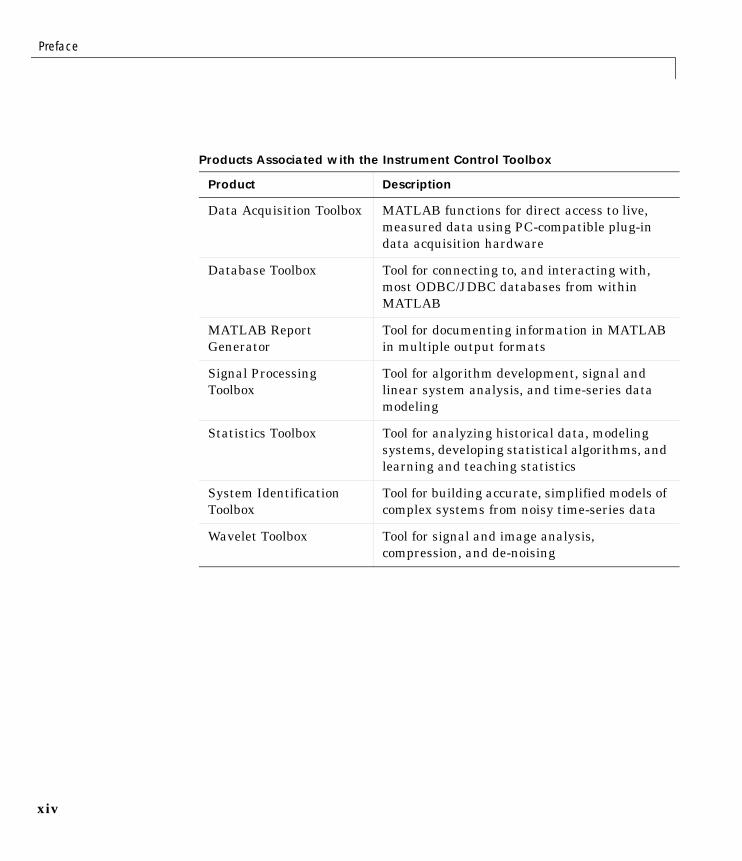
Products Associated with the Instrument Control Toolbox
Product Description
Data Acquisition Toolbox MATLAB functions for direct access to live,measured data using PC-compatible plug-indata acquisition hardware
Database Toolbox Tool for connecting to, and interacting with,most ODBC/JDBC databases from withinMATLAB
MATLAB ReportGenerator
Tool for documenting information in MATLABin multiple output formats
Signal ProcessingToolbox
Tool for algorithm development, signal andlinear system analysis, and time-series datamodeling
Statistics Toolbox Tool for analyzing historical data, modelingsystems, developing statistical algorithms, andlearning and teaching statistics
System IdentificationToolbox
Tool for building accurate, simplified models ofcomplex systems from noisy time-series data
Wavelet Toolbox Tool for signal and image analysis,compression, and de-noising
Using This Guide
xv
Using This Guide
Expected BackgroundTo use the Instrument Control Toolbox, you should have some familiarity with:
• The basic features of MATLAB
• The commands used to communicate with your instrument; these commandsmay use the SCPI language or some other vendor-specific language
• The features of the interface associated with your instrument
Learning the Instrument Control ToolboxStart with Chapter 1, “Getting Started,” which describes how to examine yourhardware resources, how to communicate with your instrument, how to getonline help, and so on. Then read Chapter 2, “The Instrument Control Session,”which provides a framework for constructing instrument control applications.Depending on the interface used by your instrument, you may then want toread the appropriate interface-specific chapter. These chapters are described inthe next section.
If you want detailed information about a specific function, refer to Chapter 7,“Function Reference.” If you want detailed information about a specificproperty, refer to Chapter 8, “Property Reference.”
Using the Documentation Examples with Your InstrumentThe examples in this guide use specific peripheral instruments such as aTektronix TDS 210 two-channel oscilloscope or an Agilent 33120A functiongenerator. Additionally, the GPIB examples use a National Instruments GPIBcontroller and the serial port examples use the COM1 serial port. The stringcommands written to these instruments are often unique to the vendor, and theaddress information such as the board index or primary address associatedwith the hardware reflects a specific configuration.
If your instrument accepts different string commands, or if your hardware isconfigured to use different address information, then you should modify theexamples accordingly.
Preface
xvi
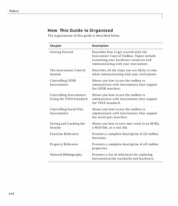
How This Guide Is OrganizedThe organization of this guide is described below.
Chapter Description
Getting Started Describes how to get started with theInstrument Control Toolbox. Topics includeexamining your hardware resources andcommunicating with your instrument.
The Instrument ControlSession
Describes all the steps you are likely to takewhen communicating with your instrument.
Controlling GPIBInstruments
Shows you how to use the toolbox tocommunicate with instruments that supportthe GPIB interface.
Controlling InstrumentsUsing the VISA Standard
Shows you how to use the toolbox tocommunicate with instruments that supportthe VISA standard.
Controlling Serial PortInstruments
Shows you how to use the toolbox tocommunicate with instruments that supportthe serial port interface.
Saving and Loading theSession
Shows you how to save your work to an M-file,a MAT-file, or a text file.
Function Reference Presents a complete description of all toolboxfunctions.
Property Reference Presents a complete description of all toolboxproperties.
Selected Bibliography Presents a list of references for exploringinstrumentation standards and hardware.

Installation Information
xvii
Installation InformationTo communicate with your GPIB, VXI, or serial port instrument from theMATLAB environment, you must install these three components:
• The Instrument Control Toolbox
• Instrumentation hardware; this may be a plug-in device such as a GPIBcontroller, or an external instrument such as a signal generator
• Software associated with your instrument such as interface drivers, supportlibraries, and so on
Toolbox InstallationTo determine if the Instrument Control Toolbox is installed on your system,type
ver
at the MATLAB prompt. MATLAB displays information about the version ofMATLAB you are running, including a list of installed add-on products andtheir version numbers. Check the list to see if the Instrument Control Toolboxappears.
For information about installing the toolbox, refer to the MATLAB InstallationGuide for your platform. If you experience installation difficulties and haveWeb access, look for the installation and license information at the MathWorksWeb site (http://www.mathworks.com/support).
Hardware and Driver InstallationInstallation of hardware devices such as GPIB controllers, instrument drivers,support libraries, and so on is described in the documentation provided by theinstrument vendor. Many vendors provide the latest drivers through their Website. For a list of vendor driver requirements and limitations, refer to“Instrument Control Toolbox 1.0” in the Release Notes.
Note You must install all necessary device-specific software provided by theinstrument vendor in addition to the Instrument Control Toolbox.
Preface
xviii
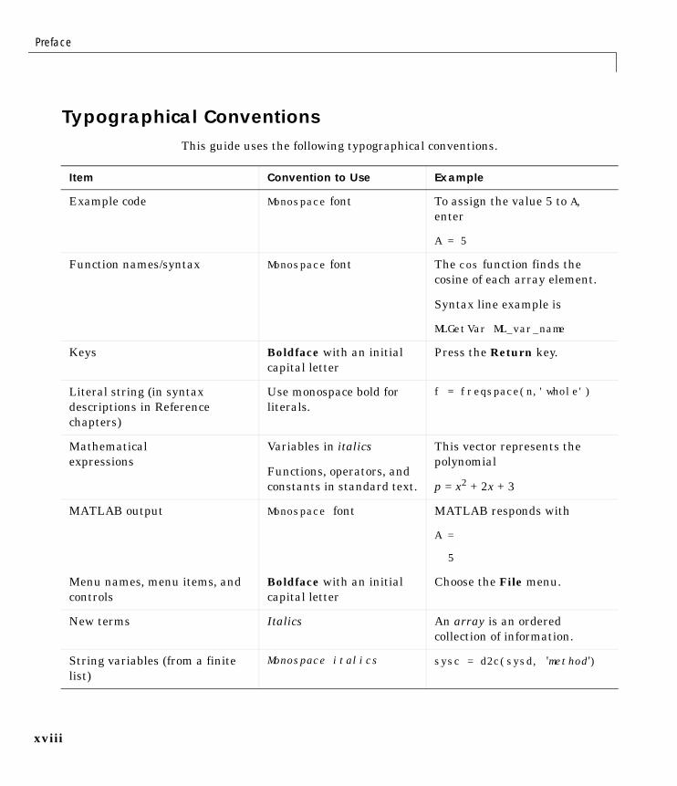
Typographical ConventionsThis guide uses the following typographical conventions.
Item Convention to Use Example
Example code Monospace font To assign the value 5 to A,enter
A = 5
Function names/syntax Monospace font The cos function finds thecosine of each array element.
Syntax line example is
MLGetVar ML_var_name
Keys Boldface with an initialcapital letter
Press the Return key.
Literal string (in syntaxdescriptions in Referencechapters)
Use monospace bold forliterals.
f = freqspace(n,'whole')
Mathematicalexpressions
Variables in italics
Functions, operators, andconstants in standard text.
This vector represents thepolynomial
p = x2 + 2x + 3
MATLAB output Monospace font MATLAB responds with
A =
5
Menu names, menu items, andcontrols
Boldface with an initialcapital letter
Choose the File menu.
New terms Italics An array is an orderedcollection of information.
String variables (from a finitelist)
Monospace italics sysc = d2c(sysd, 'method')
1
Getting Started
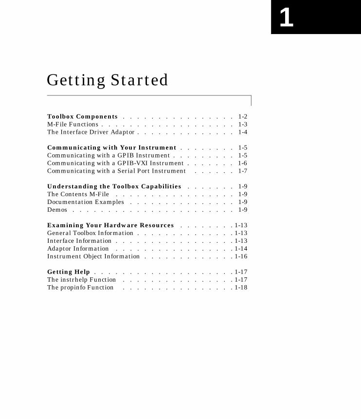
Toolbox Components . . . . . . . . . . . . . . . . 1-2M-File Functions . . . . . . . . . . . . . . . . . . . 1-3The Interface Driver Adaptor . . . . . . . . . . . . . . 1-4
Communicating with Your Instrument . . . . . . . . 1-5Communicating with a GPIB Instrument . . . . . . . . . 1-5Communicating with a GPIB-VXI Instrument . . . . . . . 1-6Communicating with a Serial Port Instrument . . . . . . 1-7
Understanding the Toolbox Capabilities . . . . . . . 1-9The Contents M-File . . . . . . . . . . . . . . . . . 1-9Documentation Examples . . . . . . . . . . . . . . . 1-9Demos . . . . . . . . . . . . . . . . . . . . . . . 1-9
Examining Your Hardware Resources . . . . . . . . 1-13General Toolbox Information . . . . . . . . . . . . . . 1-13Interface Information . . . . . . . . . . . . . . . . . 1-13Adaptor Information . . . . . . . . . . . . . . . . . 1-14Instrument Object Information . . . . . . . . . . . . . 1-16
Getting Help . . . . . . . . . . . . . . . . . . . . 1-17The instrhelp Function . . . . . . . . . . . . . . . . 1-17The propinfo Function . . . . . . . . . . . . . . . . 1-18
1 Getting Started
1-2
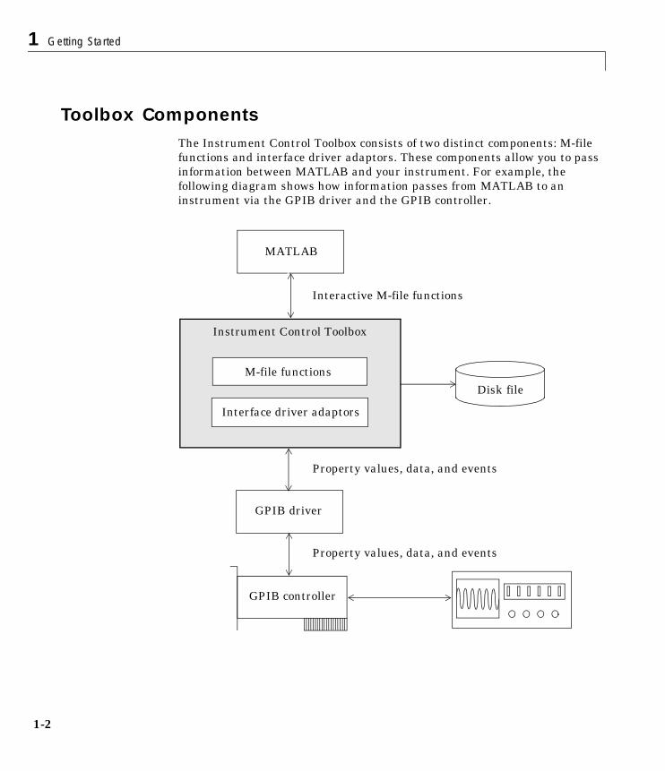
Toolbox ComponentsThe Instrument Control Toolbox consists of two distinct components: M-filefunctions and interface driver adaptors. These components allow you to passinformation between MATLAB and your instrument. For example, thefollowing diagram shows how information passes from MATLAB to aninstrument via the GPIB driver and the GPIB controller.
Instrument Control Toolbox
GPIB driver
MATLAB
M-file functions
GPIB controller
Interface driver adaptors
Disk file
Interactive M-file functions
Property values, data, and events
Property values, data, and events
Toolbox Components
1-3
The preceding diagram illustrates how information flows from component tocomponent. Information consists of:
• Property values
You define the behavior of your instrument control application byconfiguring property values. In general, you can think of a property as acharacteristic of the toolbox or of the instrument that can be configured tosuit your needs.
• Data
You can write data to the instrument and read data from the instrument.Data can be binary (numerical) or formatted as text. For example, writingtext often involves writing string commands that change hardware settings,or prepare the instrument to return data or status information, while writingbinary data involves writing numerical values such as calibration orwaveform data.
• Events
An event occurs after a condition is met and may result in one or moreactions. Events can be generated only after you configure the associatedproperties. For example, you can use events to analyze data after a certainnumber of bytes are read from the instrument, or display a message to theMATLAB command line after an error occurs.
M-File FunctionsTo perform any task within your instrument control application, you must callM-file functions from the MATLAB environment. Among other things, thesefunctions allow you to:
• Create instrument objects, which provide a gateway to your instrument’scapabilities and allow you to control the behavior of your application
• Connect the object to the instrument
• Configure property values
• Write data to the instrument, and read data from the instrument
• Evaluate your application status and examine your hardware resources
1 Getting Started
1-4
For a listing of all Instrument Control Toolbox functions, refer to Chapter 7,“Function Reference.” You can also display all the toolbox functions by typing
help instrument
The Interface Driver AdaptorThe interface driver adaptor (or just adaptor) is the link between the toolboxand the interface driver. The adaptor’s main purpose is to pass informationbetween MATLAB and the interface driver. Interface drivers are provided byyour instrument vendor. For example, if you are communicating with aninstrument using a National Instruments GPIB controller, then an interfacedriver such as NI-488.2 must be installed on your platform. Note that interfacedrivers are not installed as part of the Instrument Control Toolbox.
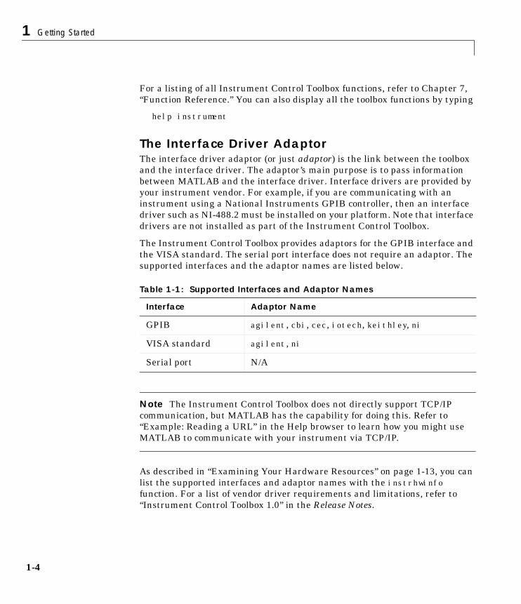
The Instrument Control Toolbox provides adaptors for the GPIB interface andthe VISA standard. The serial port interface does not require an adaptor. Thesupported interfaces and the adaptor names are listed below.
Note The Instrument Control Toolbox does not directly support TCP/IPcommunication, but MATLAB has the capability for doing this. Refer to“Example: Reading a URL” in the Help browser to learn how you might useMATLAB to communicate with your instrument via TCP/IP.
As described in “Examining Your Hardware Resources” on page 1-13, you canlist the supported interfaces and adaptor names with the instrhwinfofunction. For a list of vendor driver requirements and limitations, refer to“Instrument Control Toolbox 1.0” in the Release Notes.
Table 1-1: Supported Interfaces and Adaptor Names
Interface Adaptor Name
GPIB agilent, cbi, cec, iotech, keithley, ni
VISA standard agilent, ni
Serial port N/A

Communicating with Your Instrument
1-5
Communicating with Your InstrumentPerhaps the most effective way to get started with the Instrument ControlToolbox is to communicate with your instrument. This section provides simpleexamples that show you how to communicate with a:
• GPIB instrument
• GPIB-VXI instrument
• Serial port instrument
Each example illustrates a typical instrument control session. The instrumentcontrol session comprises all the steps you are likely to take whencommunicating with a supported instrument. You should keep these steps inmind when constructing your own instrument control applications.
The examples also use specific instrument addresses, SCPI commands, and soon. If your instrument requires different parameters, or if it does not supportthe SCPI language, you should modify the examples accordingly.
If you want detailed information about any functions that are used, refer toChapter 7, “Function Reference.” If you want detailed information about anyproperties that are used, refer to Chapter 8, “Property Reference.”
Communicating with a GPIB InstrumentThis example illustrates how to communicate with a GPIB instrument. TheGPIB controller is a National Instruments AT-GPIB card. The instrument isan Agilent 33120A Function Generator, which is outputting a 2 voltpeak-to-peak signal.
You should modify this example to suit your specific instrument controlapplication needs. If you want detailed information about communicating withan instrument via GPIB, refer to Chapter 3, “Controlling GPIB Instruments.”
1. Create an instrument object – Create the GPIB object g associated with aNational Instruments GPIB board with board index 0, and an instrument withprimary address 1.
g = gpib('ni',0,1);
2. Connect to the instrument – Connect g to the instrument.
fopen(g)
1 Getting Started
1-6
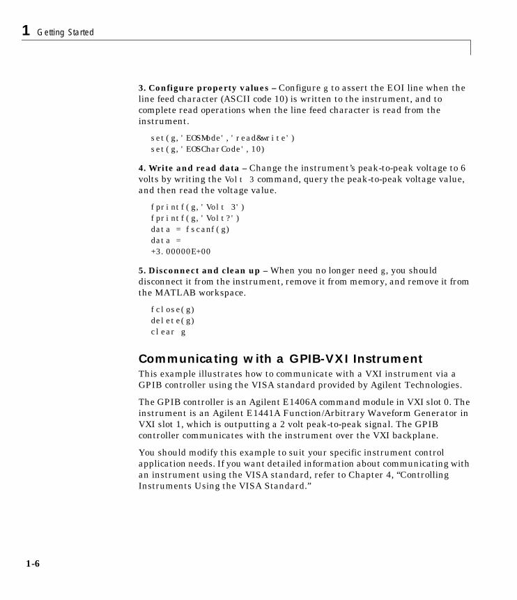
3. Configure property values – Configure g to assert the EOI line when theline feed character (ASCII code 10) is written to the instrument, and tocomplete read operations when the line feed character is read from theinstrument.
set(g,'EOSMode','read&write')set(g,'EOSCharCode',10)
4. Write and read data – Change the instrument’s peak-to-peak voltage to 6volts by writing the Volt 3 command, query the peak-to-peak voltage value,and then read the voltage value.
fprintf(g,'Volt 3')fprintf(g,'Volt?')data = fscanf(g)data =+3.00000E+00
5. Disconnect and clean up – When you no longer need g, you shoulddisconnect it from the instrument, remove it from memory, and remove it fromthe MATLAB workspace.
fclose(g)delete(g)clear g
Communicating with a GPIB-VXI InstrumentThis example illustrates how to communicate with a VXI instrument via aGPIB controller using the VISA standard provided by Agilent Technologies.
The GPIB controller is an Agilent E1406A command module in VXI slot 0. Theinstrument is an Agilent E1441A Function/Arbitrary Waveform Generator inVXI slot 1, which is outputting a 2 volt peak-to-peak signal. The GPIBcontroller communicates with the instrument over the VXI backplane.
You should modify this example to suit your specific instrument controlapplication needs. If you want detailed information about communicating withan instrument using the VISA standard, refer to Chapter 4, “ControllingInstruments Using the VISA Standard.”
Communicating with Your Instrument
1-7
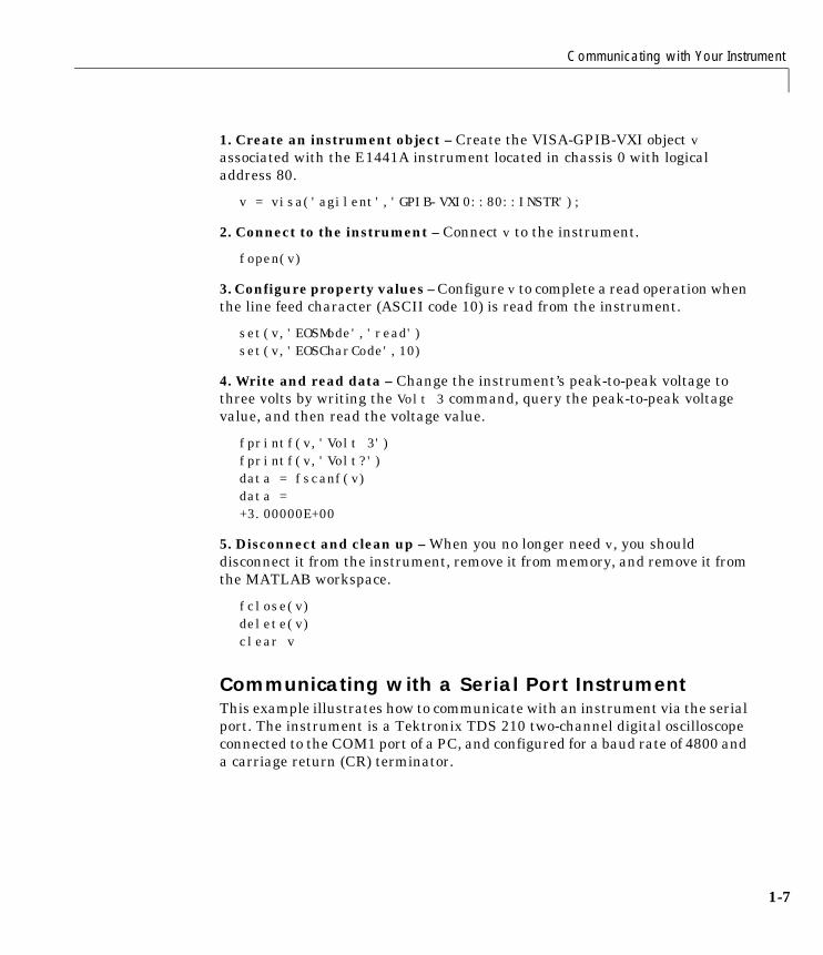
1. Create an instrument object – Create the VISA-GPIB-VXI object vassociated with the E1441A instrument located in chassis 0 with logicaladdress 80.
v = visa('agilent','GPIB-VXI0::80::INSTR');
2. Connect to the instrument – Connect v to the instrument.
fopen(v)
3. Configure property values – Configure v to complete a read operation whenthe line feed character (ASCII code 10) is read from the instrument.
set(v,'EOSMode','read')set(v,'EOSCharCode',10)
4. Write and read data – Change the instrument’s peak-to-peak voltage tothree volts by writing the Volt 3 command, query the peak-to-peak voltagevalue, and then read the voltage value.
fprintf(v,'Volt 3')fprintf(v,'Volt?')data = fscanf(v)data =+3.00000E+00
5. Disconnect and clean up – When you no longer need v, you shoulddisconnect it from the instrument, remove it from memory, and remove it fromthe MATLAB workspace.
fclose(v)delete(v)clear v
Communicating with a Serial Port InstrumentThis example illustrates how to communicate with an instrument via the serialport. The instrument is a Tektronix TDS 210 two-channel digital oscilloscopeconnected to the COM1 port of a PC, and configured for a baud rate of 4800 anda carriage return (CR) terminator.
1 Getting Started
1-8
You should modify this example to suit your specific instrument controlapplication needs. If you want detailed information about communicating withan instrument connected to the serial port, refer to Chapter 5, “ControllingSerial Port Instruments.”
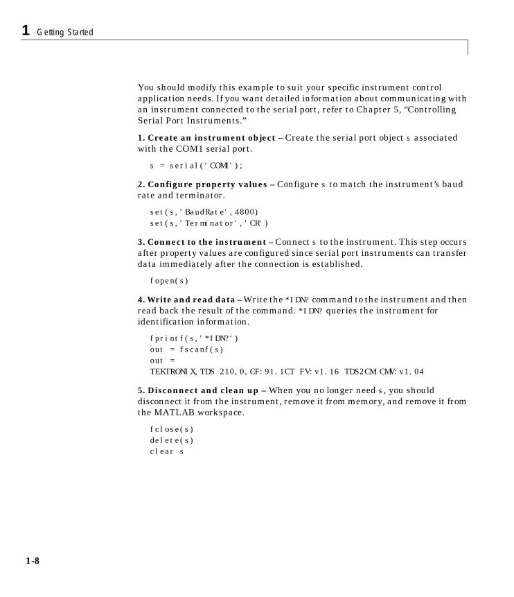
1. Create an instrument object – Create the serial port object s associatedwith the COM1 serial port.
s = serial('COM1');
2. Configure property values – Configure s to match the instrument’s baudrate and terminator.
set(s,'BaudRate',4800)set(s,'Terminator','CR')
3. Connect to the instrument – Connect s to the instrument. This step occursafter property values are configured since serial port instruments can transferdata immediately after the connection is established.
fopen(s)
4. Write and read data – Write the *IDN? command to the instrument and thenread back the result of the command. *IDN? queries the instrument foridentification information.
fprintf(s,'*IDN?')out = fscanf(s)out =TEKTRONIX,TDS 210,0,CF:91.1CT FV:v1.16 TDS2CM:CMV:v1.04
5. Disconnect and clean up – When you no longer need s, you shoulddisconnect it from the instrument, remove it from memory, and remove it fromthe MATLAB workspace.
fclose(s)delete(s)clear s
Understanding the Toolbox Capabilities
1-9
Understanding the Toolbox CapabilitiesIn addition to the printed and online documentation, the Instrument ControlToolbox provides these resources to help you understand the productcapabilities:
• The Contents M-file
• Documentation examples
• Demos
The Contents M-FileThe ContentsM-file lists the toolbox functions and demos. You can display thisinformation by typing
help instrument
Documentation ExamplesThis guide provides detailed examples that show you how to communicate withall supported interface types. These examples are collected in the exampleindex, which is available through the Help browser.
The examples use specific peripheral instruments, GPIB controllers, stringcommands, address information, and so on. If your instrument acceptsdifferent string commands, or if your hardware is configured to use differentaddress information, then you should modify the examples accordingly.
DemosThe toolbox includes a large collection of demos, which are available throughthe instrschool interface. To launch this interface, type instrschool at thecommand line.
instrschool
Note instrschool uses prerecorded data. Therefore, you do not need aninstrument connected to your computer to use these demos.
1 Getting Started
1-10
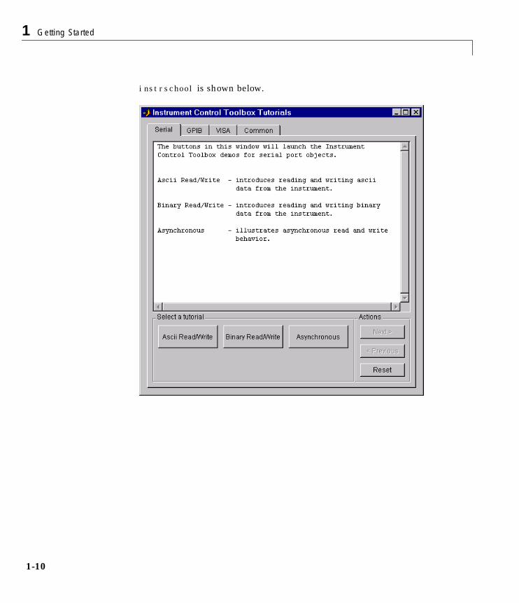
instrschool is shown below.
Understanding the Toolbox Capabilities
1-11
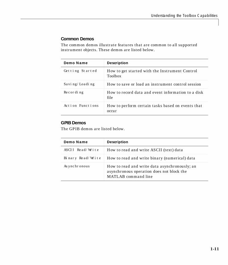
Common DemosThe common demos illustrate features that are common to all supportedinstrument objects. These demos are listed below.
GPIB DemosThe GPIB demos are listed below.
Demo Name Description
Getting Started How to get started with the Instrument ControlToolbox
Saving/Loading How to save or load an instrument control session
Recording How to record data and event information to a diskfile
Action Functions How to perform certain tasks based on events thatoccur
Demo Name Description
ASCII Read/Write How to read and write ASCII (text) data
Binary Read/Write How to read and write binary (numerical) data
Asynchronous How to read and write data asynchronously; anasynchronous operation does not block theMATLAB command line
1 Getting Started
1-12
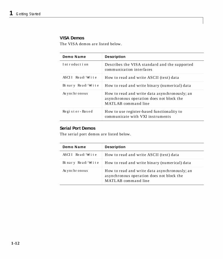
VISA DemosThe VISA demos are listed below.
Serial Port DemosThe serial port demos are listed below.
Demo Name Description
Introduction Describes the VISA standard and the supportedcommunication interfaces
ASCII Read/Write How to read and write ASCII (text) data
Binary Read/Write How to read and write binary (numerical) data
Asynchronous How to read and write data asynchronously; anasynchronous operation does not block theMATLAB command line
Register-Based How to use register-based functionality tocommunicate with VXI instruments
Demo Name Description
ASCII Read/Write How to read and write ASCII (text) data
Binary Read/Write How to read and write binary (numerical) data
Asynchronous How to read and write data asynchronously; anasynchronous operation does not block theMATLAB command line
Examining Your Hardware Resources
1-13
Examining Your Hardware ResourcesYou can examine the hardware-related resources visible to the toolbox with theinstrhwinfo function. The returned information includes installed adaptors,driver versions, and the syntax for creating instrument objects. Forinstruments associated with the VISA standard, instrhwinfo also returnsaddress information such as the GPIB board index, the VXI logical address, theVXI chassis, and so on.
The specific information returned by instrhwinfo depends on the suppliedarguments, and is divided into these four categories:
• General toolbox information
• Interface information
• Adaptor information
• Instrument object information
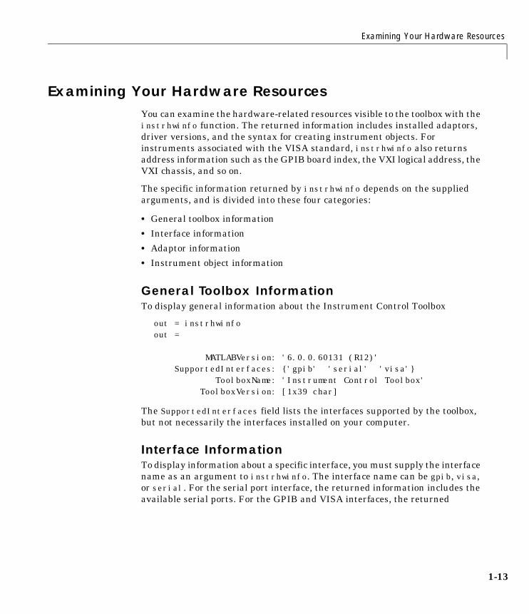
General Toolbox InformationTo display general information about the Instrument Control Toolbox
out = instrhwinfoout =
MATLABVersion: '6.0.0.60131 (R12)' SupportedInterfaces: {'gpib' 'serial' 'visa'} ToolboxName: 'Instrument Control Toolbox' ToolboxVersion: [1x39 char]
The SupportedInterfaces field lists the interfaces supported by the toolbox,but not necessarily the interfaces installed on your computer.
Interface InformationTo display information about a specific interface, you must supply the interfacename as an argument to instrhwinfo. The interface name can be gpib, visa,or serial. For the serial port interface, the returned information includes theavailable serial ports. For the GPIB and VISA interfaces, the returned
1 Getting Started
1-14
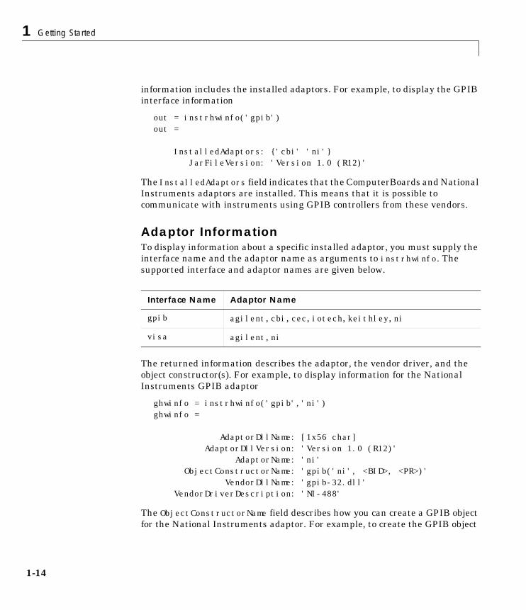
information includes the installed adaptors. For example, to display the GPIBinterface information
out = instrhwinfo('gpib')out =
InstalledAdaptors: {'cbi' 'ni'} JarFileVersion: 'Version 1.0 (R12)'
The InstalledAdaptors field indicates that the ComputerBoards and NationalInstruments adaptors are installed. This means that it is possible tocommunicate with instruments using GPIB controllers from these vendors.
Adaptor InformationTo display information about a specific installed adaptor, you must supply theinterface name and the adaptor name as arguments to instrhwinfo. Thesupported interface and adaptor names are given below.
The returned information describes the adaptor, the vendor driver, and theobject constructor(s). For example, to display information for the NationalInstruments GPIB adaptor
ghwinfo = instrhwinfo('gpib','ni')ghwinfo =
AdaptorDllName: [1x56 char] AdaptorDllVersion: 'Version 1.0 (R12)' AdaptorName: 'ni' ObjectConstructorName: 'gpib('ni', <BID>, <PR>)' VendorDllName: 'gpib-32.dll' VendorDriverDescription: 'NI-488'
The ObjectConstructorName field describes how you can create a GPIB objectfor the National Instruments adaptor. For example, to create the GPIB object
Interface Name Adaptor Name
gpib agilent, cbi, cec, iotech, keithley, ni
visa agilent, ni
Examining Your Hardware Resources
1-15
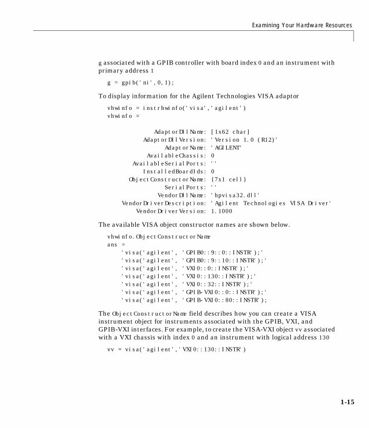
g associated with a GPIB controller with board index 0 and an instrument withprimary address 1
g = gpib('ni',0,1);
To display information for the Agilent Technologies VISA adaptor
vhwinfo = instrhwinfo('visa','agilent')vhwinfo =
AdaptorDllName: [1x62 char] AdaptorDllVersion: 'Version 1.0 (R12)' AdaptorName: 'AGILENT' AvailableChassis: 0 AvailableSerialPorts: '' InstalledBoardIds: 0 ObjectConstructorName: {7x1 cell} SerialPorts: '' VendorDllName: 'hpvisa32.dll' VendorDriverDescription: 'Agilent Technologies VISA Driver' VendorDriverVersion: 1.1000
The available VISA object constructor names are shown below.
vhwinfo.ObjectConstructorNameans = 'visa('agilent', 'GPIB0::9::0::INSTR');' 'visa('agilent', 'GPIB0::9::10::INSTR');' 'visa('agilent', 'VXI0::0::INSTR');' 'visa('agilent', 'VXI0::130::INSTR');' 'visa('agilent', 'VXI0::32::INSTR');' 'visa('agilent', 'GPIB-VXI0::0::INSTR');' 'visa('agilent', 'GPIB-VXI0::80::INSTR');
The ObjectConstructorName field describes how you can create a VISAinstrument object for instruments associated with the GPIB, VXI, andGPIB-VXI interfaces. For example, to create the VISA-VXI object vv associatedwith a VXI chassis with index 0 and an instrument with logical address 130
vv = visa('agilent','VXI0::130::INSTR')
1 Getting Started
1-16
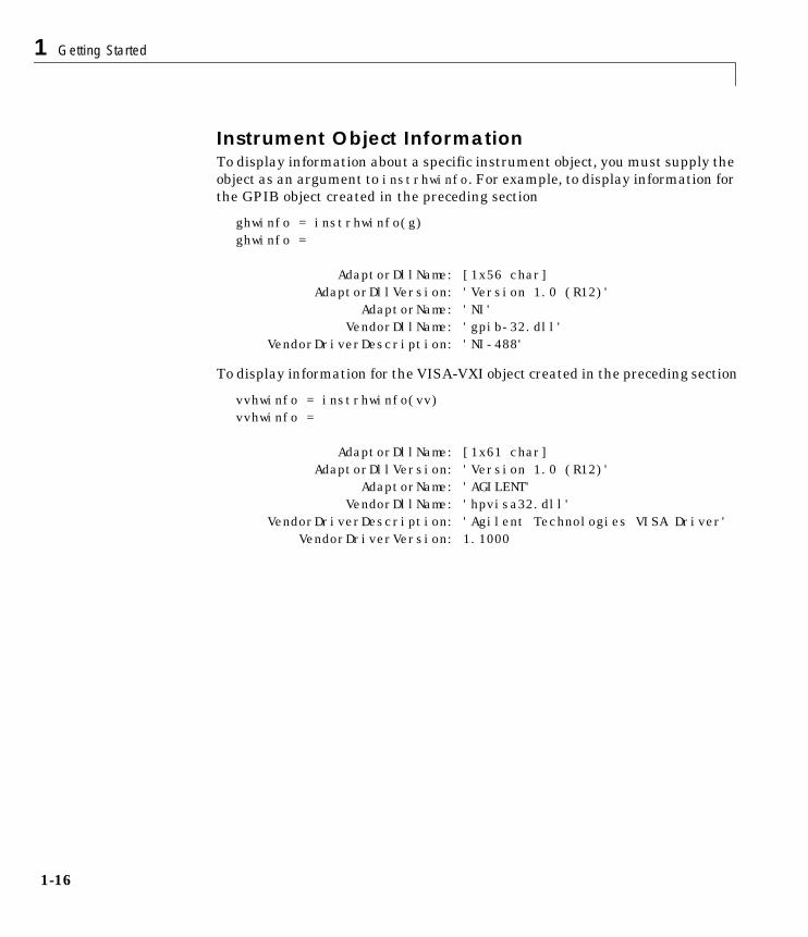
Instrument Object InformationTo display information about a specific instrument object, you must supply theobject as an argument to instrhwinfo. For example, to display information forthe GPIB object created in the preceding section
ghwinfo = instrhwinfo(g)ghwinfo =
AdaptorDllName: [1x56 char] AdaptorDllVersion: 'Version 1.0 (R12)' AdaptorName: 'NI' VendorDllName: 'gpib-32.dll' VendorDriverDescription: 'NI-488'
To display information for the VISA-VXI object created in the preceding section
vvhwinfo = instrhwinfo(vv)vvhwinfo =
AdaptorDllName: [1x61 char] AdaptorDllVersion: 'Version 1.0 (R12)' AdaptorName: 'AGILENT' VendorDllName: 'hpvisa32.dll' VendorDriverDescription: 'Agilent Technologies VISA Driver' VendorDriverVersion: 1.1000
Getting Help
1-17
Getting HelpThe Instrument Control Toolbox provides you with these help resources:
• The HTML and PDF versions of this guide, which are available through theHelp browser
• M-file function help, which you can display with the help command (sincemany toolbox functions are overloaded, you may need to specify theappropriate pathname as well)
• The instrhelp function
• The propinfo function
The instrhelp FunctionYou can use the instrhelp function to:
• Display command line help for functions and properties
• List all the functions and properties associated with a specific instrumentobject
An instrument object need not exist for you to obtain this information. Forexample, to display all the functions and properties associated with a GPIBobject, as well as the constructor M-file help
instrhelp gpib
To display help for the EOIMode property
instrhelp EOIMode
You can also display help for an existing instrument object. For example, todisplay help for the MemorySpace property associated with a VISA-GPIB-VXIobject
v = visa('agilent','GPIB-VXI0::80::INSTR');out = instrhelp(v,'MemorySpace');
1 Getting Started
1-18
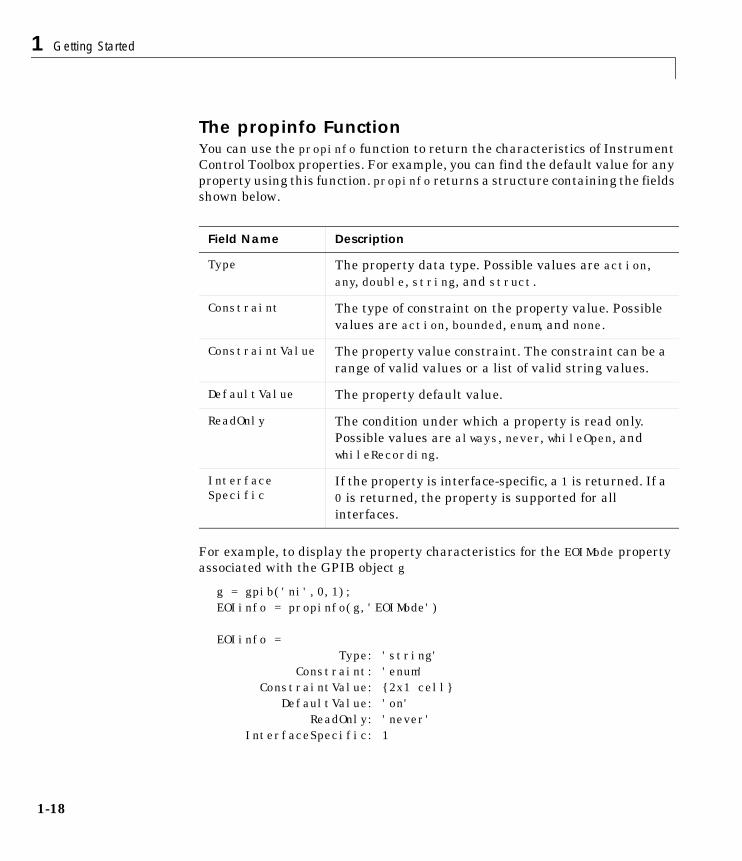
The propinfo FunctionYou can use the propinfo function to return the characteristics of InstrumentControl Toolbox properties. For example, you can find the default value for anyproperty using this function. propinfo returns a structure containing the fieldsshown below.
For example, to display the property characteristics for the EOIMode propertyassociated with the GPIB object g
g = gpib('ni',0,1);EOIinfo = propinfo(g,'EOIMode')
EOIinfo = Type: 'string' Constraint: 'enum' ConstraintValue: {2x1 cell} DefaultValue: 'on' ReadOnly: 'never' InterfaceSpecific: 1
Field Name Description
Type The property data type. Possible values are action,any, double, string, and struct.
Constraint The type of constraint on the property value. Possiblevalues are action, bounded, enum, and none.
ConstraintValue The property value constraint. The constraint can be arange of valid values or a list of valid string values.
DefaultValue The property default value.
ReadOnly The condition under which a property is read only.Possible values are always, never, whileOpen, andwhileRecording.
InterfaceSpecific
If the property is interface-specific, a 1 is returned. If a0 is returned, the property is supported for allinterfaces.
Getting Help
1-19
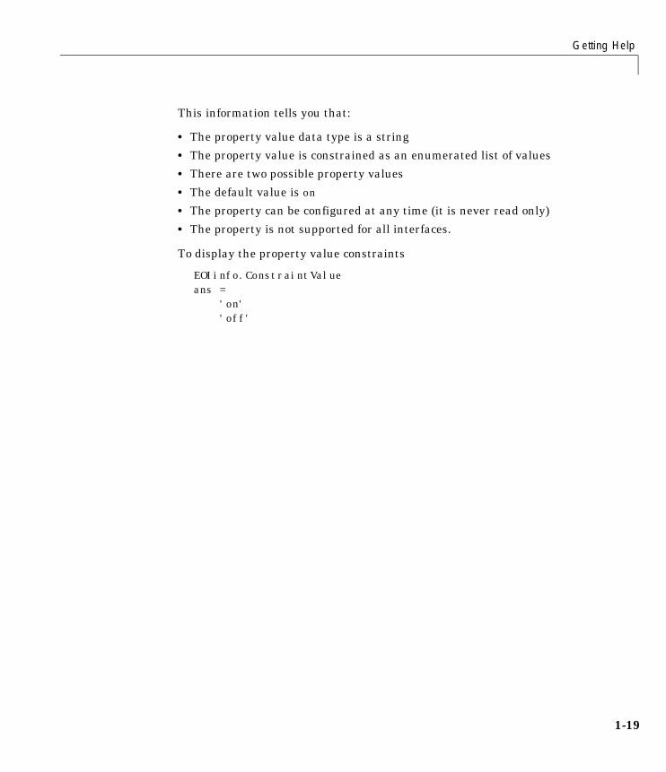
This information tells you that:
• The property value data type is a string
• The property value is constrained as an enumerated list of values
• There are two possible property values
• The default value is on
• The property can be configured at any time (it is never read only)
• The property is not supported for all interfaces.
To display the property value constraints
EOIinfo.ConstraintValueans = 'on' 'off'

1 Getting Started
1-20
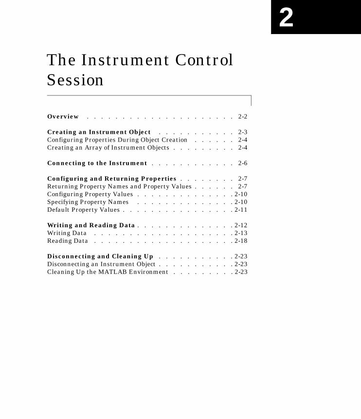
2The Instrument ControlSession
Overview . . . . . . . . . . . . . . . . . . . . . 2-2
Creating an Instrument Object . . . . . . . . . . . 2-3Configuring Properties During Object Creation . . . . . . 2-4Creating an Array of Instrument Objects . . . . . . . . . 2-4
Connecting to the Instrument . . . . . . . . . . . . 2-6
Configuring and Returning Properties . . . . . . . . 2-7Returning Property Names and Property Values . . . . . . 2-7Configuring Property Values . . . . . . . . . . . . . . 2-10Specifying Property Names . . . . . . . . . . . . . . 2-10Default Property Values . . . . . . . . . . . . . . . . 2-11
Writing and Reading Data . . . . . . . . . . . . . . 2-12Writing Data . . . . . . . . . . . . . . . . . . . . 2-13Reading Data . . . . . . . . . . . . . . . . . . . . 2-18
Disconnecting and Cleaning Up . . . . . . . . . . . 2-23Disconnecting an Instrument Object . . . . . . . . . . . 2-23Cleaning Up the MATLAB Environment . . . . . . . . . 2-23
2 The Instrument Control Session
2-2
OverviewThe instrument control session comprises all the steps you are likely to takewhen communicating with your instrument. These steps are:
1 Create an instrument object – You create an instrument object using thegpib, visa, or serial creation functions.
You can also configure properties during object creation. For example, youmay want to configure properties associated with serial portcommunications such as the baud rate, the number of data bits, and so on.
2 Connect to the instrument – You connect the object to the instrumentusing the fopen function.
After the object is connected, you can read data, write data, or alterinstrument settings by configuring property values.
3 Configure properties – To establish the instrument object behavior, youassign values to properties using the set function or dot notation.
In practice, you can configure many of the properties at any time includingduring – or just after – object creation. Conversely, depending on yourinstrument settings and the requirements of your application, you may beable to accept the default property values and skip this step.
4 Write and read data – You can now write data to the instrument using thefprintf and fwrite function, and read data from the instrument using thefgetl, fgets, fread, fscanf, and readasync function.
The instrument object behaves according to the previously configured ordefault property values.
5 Disconnect and clean up – When you no longer need the object, you shoulddisconnect it from the instrument using the fclose function, remove it frommemory using the delete function, and remove it from the MATLABworkspace using the clear command.
The instrument control session is used in many of the documentation examplesincluded in this guide.
Creating an Instrument Object
2-3
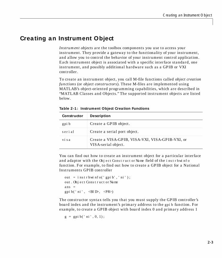
Creating an Instrument ObjectInstrument objects are the toolbox components you use to access yourinstrument. They provide a gateway to the functionality of your instrument,and allow you to control the behavior of your instrument control application.Each instrument object is associated with a specific interface standard, oneinstrument, and possibly additional hardware such as a GPIB or VXIcontroller.
To create an instrument object, you call M-file functions called object creationfunctions (or object constructors). These M-files are implemented usingMATLAB’s object-oriented programming capabilities, which are described in“MATLAB Classes and Objects.” The supported instrument objects are listedbelow.
You can find out how to create an instrument object for a particular interfaceand adaptor with the ObjectConstructorName field of the instrhwinfofunction. For example, to find out how to create a GPIB object for a NationalInstruments GPIB controller
out = instrhwinfo('gpib','ni');out.ObjectConstructorNameans =gpib('ni', <BID>, <PR>)
The constructor syntax tells you that you must supply the GPIB controller’sboard index and the instrument’s primary address to the gpib function. Forexample, to create a GPIB object with board index 0 and primary address 1
g = gpib('ni',0,1);
Table 2-1: Instrument Object Creation Functions
Constructor Description
gpib Create a GPIB object.
serial Create a serial port object.
visa Create a VISA-GPIB, VISA-VXI, VISA-GPIB-VXI, orVISA-serial object.
2 The Instrument Control Session
2-4
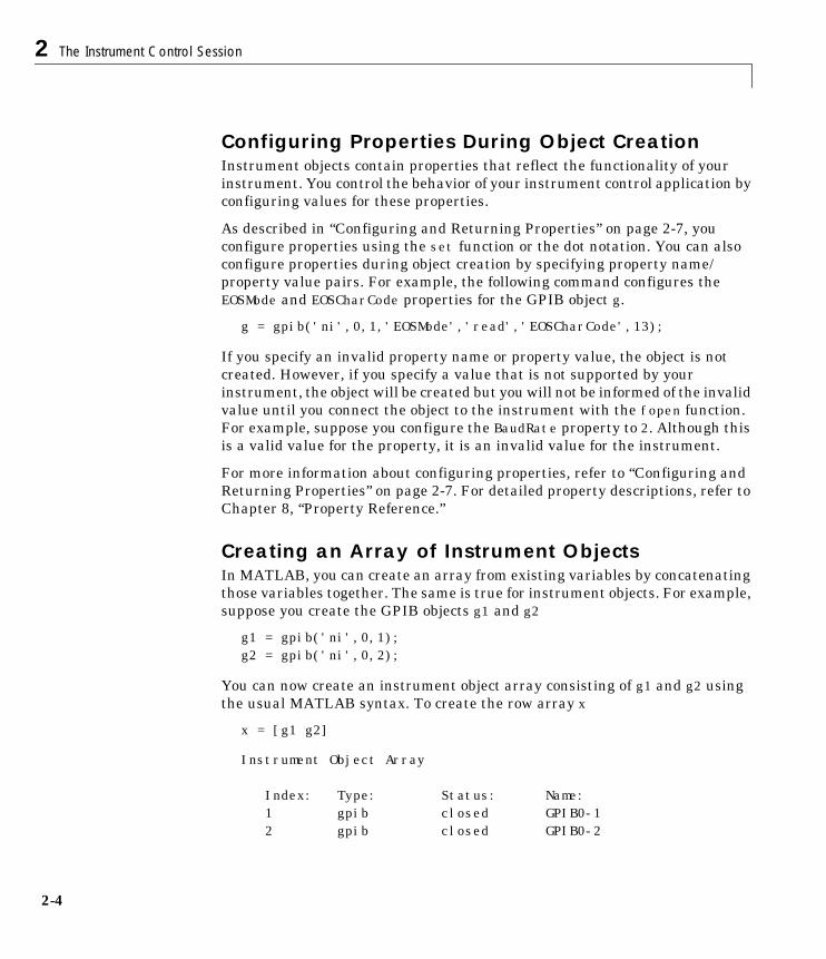
Configuring Properties During Object CreationInstrument objects contain properties that reflect the functionality of yourinstrument. You control the behavior of your instrument control application byconfiguring values for these properties.
As described in “Configuring and Returning Properties” on page 2-7, youconfigure properties using the set function or the dot notation. You can alsoconfigure properties during object creation by specifying property name/property value pairs. For example, the following command configures theEOSMode and EOSCharCode properties for the GPIB object g.
g = gpib('ni',0,1,'EOSMode','read','EOSCharCode',13);
If you specify an invalid property name or property value, the object is notcreated. However, if you specify a value that is not supported by yourinstrument, the object will be created but you will not be informed of the invalidvalue until you connect the object to the instrument with the fopen function.For example, suppose you configure the BaudRate property to 2. Although thisis a valid value for the property, it is an invalid value for the instrument.
For more information about configuring properties, refer to “Configuring andReturning Properties” on page 2-7. For detailed property descriptions, refer toChapter 8, “Property Reference.”
Creating an Array of Instrument ObjectsIn MATLAB, you can create an array from existing variables by concatenatingthose variables together. The same is true for instrument objects. For example,suppose you create the GPIB objects g1 and g2
g1 = gpib('ni',0,1);g2 = gpib('ni',0,2);
You can now create an instrument object array consisting of g1 and g2 usingthe usual MATLAB syntax. To create the row array x
x = [g1 g2]
Instrument Object Array
Index: Type: Status: Name: 1 gpib closed GPIB0-1 2 gpib closed GPIB0-2
Creating an Instrument Object
2-5
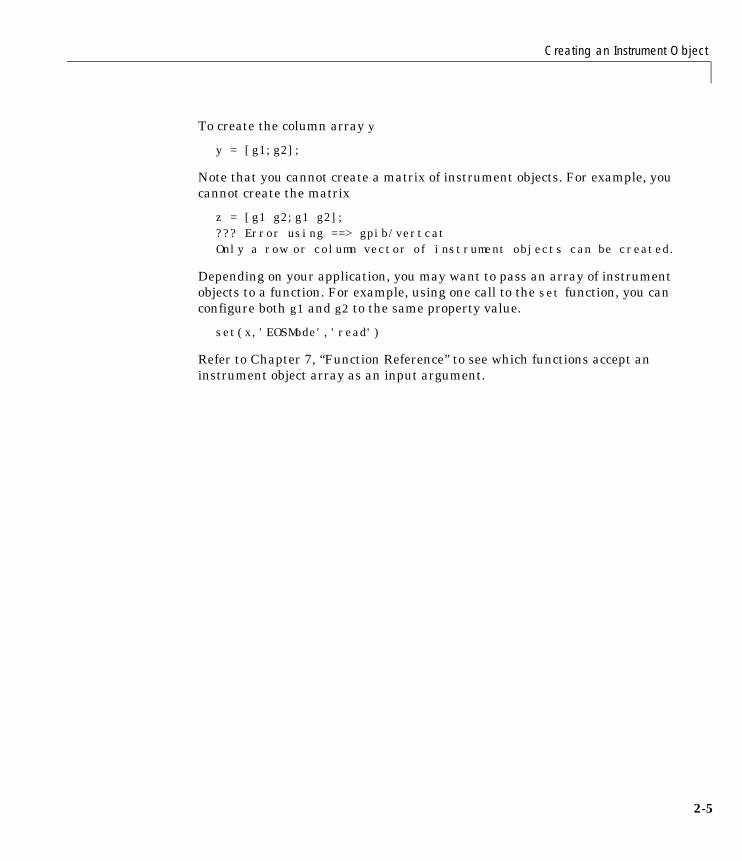
To create the column array y
y = [g1;g2];
Note that you cannot create a matrix of instrument objects. For example, youcannot create the matrix
z = [g1 g2;g1 g2];??? Error using ==> gpib/vertcatOnly a row or column vector of instrument objects can be created.
Depending on your application, you may want to pass an array of instrumentobjects to a function. For example, using one call to the set function, you canconfigure both g1 and g2 to the same property value.
set(x,'EOSMode','read')
Refer to Chapter 7, “Function Reference” to see which functions accept aninstrument object array as an input argument.

2 The Instrument Control Session
2-6
Connecting to the InstrumentBefore you can use the instrument object to write or read data, you mustconnect it to the instrument whose address or port is specified in the creationfunction. You connect an instrument object to the instrument with the fopenfunction.
fopen(g)
Some properties are read-only while the instrument object is connected andmust be configured before using fopen. Examples include theInputBufferSize and the OutputBufferSize properties. You can determinewhen a property is configurable with the propinfo function, or by referring toChapter 8, “Property Reference.”
Note You can create any number of instrument objects. However, at anytime, you can connect only one instrument object to an instrument with agiven address or port.
You can examine the Status property to verify that the instrument object isconnected to the instrument.
g.Statusans =open
As illustrated below, the connection between the instrument object and theinstrument is complete, and you can write and read data.
GPIB Board
g=gpib('ni',0,1);fopen(g)
01.00
InstrumentMATLAB
NI PCI-GPIB
Configuring and Returning Properties
2-7
Configuring and Returning PropertiesYou establish the desired instrument object behavior by configuring propertyvalues. You can configure property values using the set function or the dotnotation, or by specifying property name/property value pairs during objectcreation. You can return property values using the get function or the dotnotation.
Instrument objects possess two types of properties: base properties andobject-specific properties. Base properties are supported for all instrumentobjects (serial port, GPIB, VISA-VXI, and so on). For example, the Timeoutproperty is supported for all instrument objects. Object-specific properties aresupported only for instrument objects of a given type. For example, theBaudRate property is supported only for serial port and VISA-serial objects.
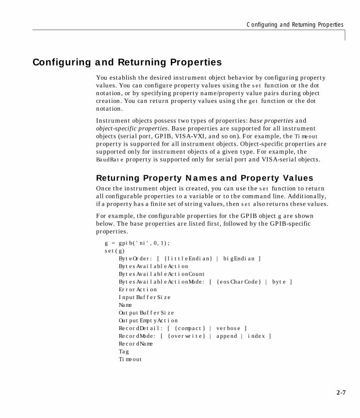
Returning Property Names and Property ValuesOnce the instrument object is created, you can use the set function to returnall configurable properties to a variable or to the command line. Additionally,if a property has a finite set of string values, then set also returns these values.
For example, the configurable properties for the GPIB object g are shownbelow. The base properties are listed first, followed by the GPIB-specificproperties.
g = gpib('ni',0,1);set(g) ByteOrder: [ {littleEndian} | bigEndian ] BytesAvailableAction BytesAvailableActionCount BytesAvailableActionMode: [ {eosCharCode} | byte ] ErrorAction InputBufferSize Name OutputBufferSize OutputEmptyAction RecordDetail: [ {compact} | verbose ] RecordMode: [ {overwrite} | append | index ] RecordName Tag Timeout
2 The Instrument Control Session
2-8
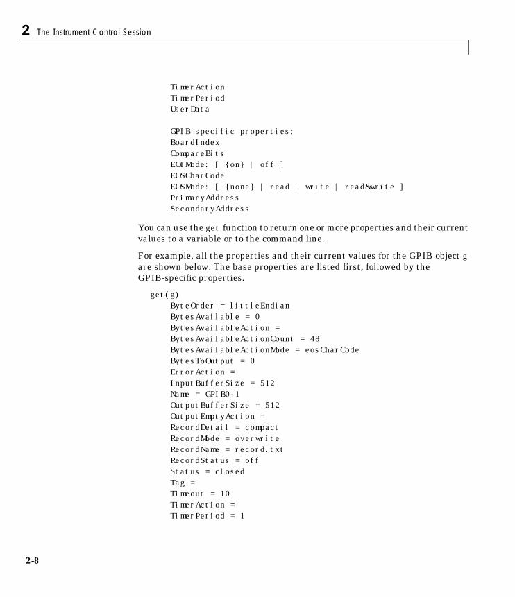
TimerAction TimerPeriod UserData GPIB specific properties: BoardIndex CompareBits EOIMode: [ {on} | off ] EOSCharCode EOSMode: [ {none} | read | write | read&write ] PrimaryAddress SecondaryAddress
You can use the get function to return one or more properties and their currentvalues to a variable or to the command line.
For example, all the properties and their current values for the GPIB object gare shown below. The base properties are listed first, followed by theGPIB-specific properties.
get(g) ByteOrder = littleEndian BytesAvailable = 0 BytesAvailableAction = BytesAvailableActionCount = 48 BytesAvailableActionMode = eosCharCode BytesToOutput = 0 ErrorAction = InputBufferSize = 512 Name = GPIB0-1 OutputBufferSize = 512 OutputEmptyAction = RecordDetail = compact RecordMode = overwrite RecordName = record.txt RecordStatus = off Status = closed Tag = Timeout = 10 TimerAction = TimerPeriod = 1
Configuring and Returning Properties
2-9
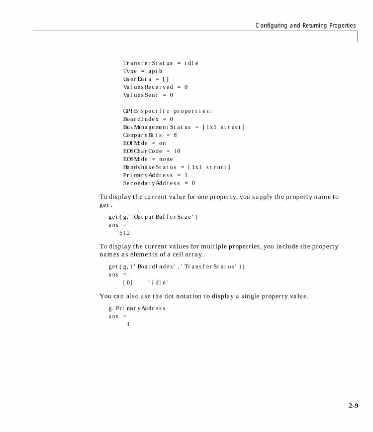
TransferStatus = idle Type = gpib UserData = [] ValuesReceived = 0 ValuesSent = 0
GPIB specific properties: BoardIndex = 0 BusManagementStatus = [1x1 struct] CompareBits = 8 EOIMode = on EOSCharCode = 10 EOSMode = none HandshakeStatus = [1x1 struct] PrimaryAddress = 1 SecondaryAddress = 0
To display the current value for one property, you supply the property name toget.
get(g,'OutputBufferSize')ans = 512
To display the current values for multiple properties, you include the propertynames as elements of a cell array.
get(g,{'BoardIndex','TransferStatus'})ans = [0] 'idle'
You can also use the dot notation to display a single property value.
g.PrimaryAddressans = 1
2 The Instrument Control Session
2-10
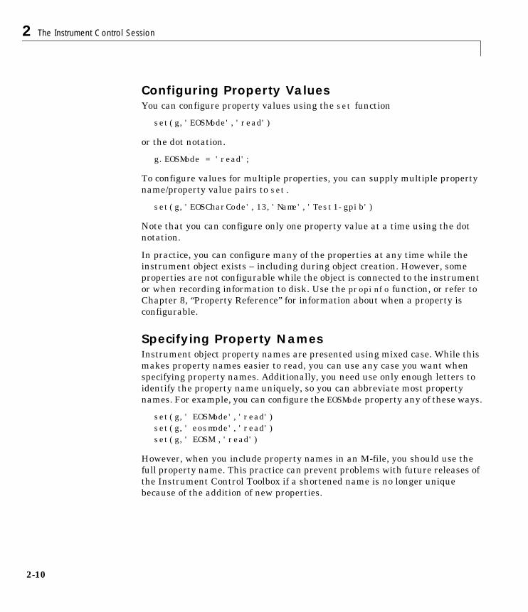
Configuring Property ValuesYou can configure property values using the set function
set(g,'EOSMode','read')
or the dot notation.
g.EOSMode = 'read';
To configure values for multiple properties, you can supply multiple propertyname/property value pairs to set.
set(g,'EOSCharCode',13,'Name','Test1-gpib')
Note that you can configure only one property value at a time using the dotnotation.
In practice, you can configure many of the properties at any time while theinstrument object exists – including during object creation. However, someproperties are not configurable while the object is connected to the instrumentor when recording information to disk. Use the propinfo function, or refer toChapter 8, “Property Reference” for information about when a property isconfigurable.
Specifying Property NamesInstrument object property names are presented using mixed case. While thismakes property names easier to read, you can use any case you want whenspecifying property names. Additionally, you need use only enough letters toidentify the property name uniquely, so you can abbreviate most propertynames. For example, you can configure the EOSMode property any of these ways.
set(g,' EOSMode','read')set(g,' eosmode','read')set(g,' EOSM','read')
However, when you include property names in an M-file, you should use thefull property name. This practice can prevent problems with future releases ofthe Instrument Control Toolbox if a shortened name is no longer uniquebecause of the addition of new properties.
Configuring and Returning Properties
2-11
Default Property ValuesIf you do not explicitly define a value for a property, then the default value isused. All configurable properties have default values.
Note Default values are provided for many instrument object properties. Forserial port objects, the default values are provided by your operating system.For GPIB and VISA instrument objects, the default values are provided byvendor-supplied tools. However, these settings are overridden by yourMATLAB code, and will have no effect on your instrument control application.
If a property has a finite set of string values, then the default value is enclosedby {} (curly braces). For example, the default value for the EOSMode property isnone.
set(g,'EOSMode')[ {none} | read | write | read&write ]
You can also use the propinfo function, or refer to Chapter 8, “PropertyReference” to find the default value for any property.
2 The Instrument Control Session
2-12
Writing and Reading DataCommunicating with your instrument involves writing and reading data. Forexample, you might write a text command to a function generator that queriesits peak-to-peak voltage, and then read back the voltage value as adouble-precision array.
Before performing a write or read operation, you should consider these threequestions:
• What is the process by which data flows from MATLAB to the instrument,and from the instrument to MATLAB?
The Instrument Control Toolbox automatically manages the datatransferred between MATLAB and the instrument. For many commonapplications, you can ignore the buffering and data flow process. However, ifyou are transferring a large number of values, executing an asynchronousread or write operation, or debugging your application, you may need to beaware of how this process works.
• Is the data to be transferred binary (numerical) or text (ASCII)?
For many instruments, writing text data means writing string commandsthat change instrument settings, prepare the instrument to return data orstatus information, and so on. Writing binary data means writing numericalvalues to the instrument such as calibration or waveform data.
• Will the write or read function block access to the MATLAB command line?
You control access to the MATLAB command line by specifying whether aread or write operation is synchronous or asynchronous. A synchronousoperation blocks access to the command line until the read or write functioncompletes execution. An asynchronous operation does not block access to thecommand, and you can issue additional commands while the read or writefunction executes in the background.
Note that there are other issues to consider when reading and writing datasuch as the conditions under which read or write operation completes. Sincethese issues vary among the supported interfaces, they are described in therespective interface-specific chapters.
Writing and Reading Data
2-13
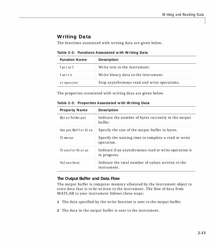
Writing DataThe functions associated with writing data are given below.
The properties associated with writing data are given below.
The Output Buffer and Data FlowThe output buffer is computer memory allocated by the instrument object tostore data that is to be written to the instrument. The flow of data fromMATLAB to your instrument follows these steps:
1 The data specified by the write function is sent to the output buffer.
2 The data in the output buffer is sent to the instrument.
Table 2-2: Functions Associated with Writing Data
Function Name Description
fprintf Write text to the instrument.
fwrite Write binary data to the instrument.
stopasync Stop asynchronous read and write operations.
Table 2-3: Properties Associated with Writing Data
Property Name Description
BytesToOutput Indicate the number of bytes currently in the outputbuffer.
OutputBufferSize Specify the size of the output buffer in bytes.
Timeout Specify the waiting time to complete a read or writeoperation.
TransferStatus Indicate if an asynchronous read or write operation isin progress.
ValuesSent Indicate the total number of values written to theinstrument.
2 The Instrument Control Session
2-14
The OutputBufferSize property specifies the maximum number of bytes thatyou can store in the output buffer. The BytesToOutput property indicates thenumber of bytes currently in the output buffer. The default values for theseproperties are given below.
g = gpib('ni',0,1);get(g,{'OutputBufferSize','BytesToOutput'})ans = [512] [0]
If you attempt to write more data than can fit in the output buffer, an error isreturned and no data is written.
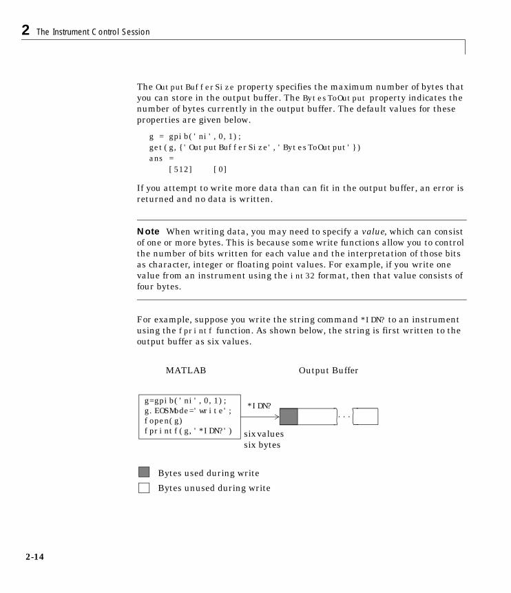
Note When writing data, you may need to specify a value, which can consistof one or more bytes. This is because some write functions allow you to controlthe number of bits written for each value and the interpretation of those bitsas character, integer or floating point values. For example, if you write onevalue from an instrument using the int32 format, then that value consists offour bytes.
For example, suppose you write the string command *IDN? to an instrumentusing the fprintf function. As shown below, the string is first written to theoutput buffer as six values.
g=gpib('ni',0,1);g.EOSMode='write';fopen(g)fprintf(g,'*IDN?')
...*IDN?
sixvaluessix bytes
MATLAB Output Buffer
Bytes used during write
Bytes unused during write
Writing and Reading Data
2-15
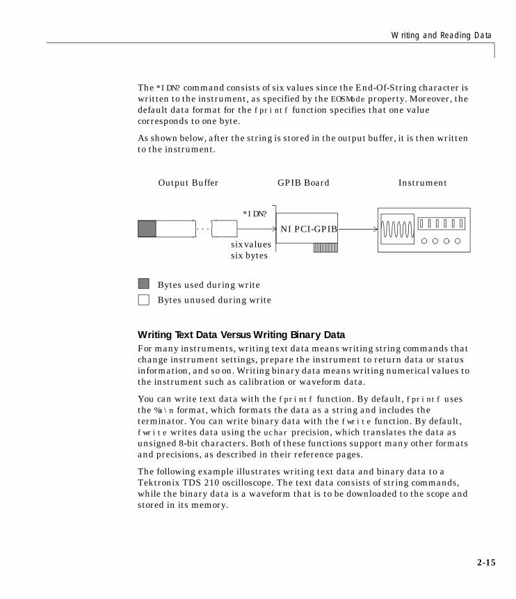
The *IDN? command consists of six values since the End-Of-String character iswritten to the instrument, as specified by the EOSMode property. Moreover, thedefault data format for the fprintf function specifies that one valuecorresponds to one byte.
As shown below, after the string is stored in the output buffer, it is then writtento the instrument.
Writing Text Data Versus Writing Binary DataFor many instruments, writing text data means writing string commands thatchange instrument settings, prepare the instrument to return data or statusinformation, and so on. Writing binary data means writing numerical values tothe instrument such as calibration or waveform data.
You can write text data with the fprintf function. By default, fprintf usesthe %s\n format, which formats the data as a string and includes theterminator. You can write binary data with the fwrite function. By default,fwrite writes data using the uchar precision, which translates the data asunsigned 8-bit characters. Both of these functions support many other formatsand precisions, as described in their reference pages.
The following example illustrates writing text data and binary data to aTektronix TDS 210 oscilloscope. The text data consists of string commands,while the binary data is a waveform that is to be downloaded to the scope andstored in its memory.
...
Output Buffer
Bytes used during write
Bytes unused during write
sixvaluessix bytes
Instrument
*IDN?
GPIB Board
NI PCI-GPIB
2 The Instrument Control Session
2-16
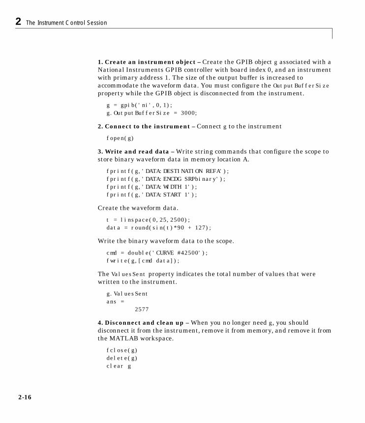
1. Create an instrument object – Create the GPIB object g associated with aNational Instruments GPIB controller with board index 0, and an instrumentwith primary address 1. The size of the output buffer is increased toaccommodate the waveform data. You must configure the OutputBufferSizeproperty while the GPIB object is disconnected from the instrument.
g = gpib('ni',0,1);g.OutputBufferSize = 3000;
2. Connect to the instrument – Connect g to the instrument
fopen(g)
3. Write and read data – Write string commands that configure the scope tostore binary waveform data in memory location A.
fprintf(g,'DATA:DESTINATION REFA');fprintf(g,'DATA:ENCDG SRPbinary');fprintf(g,'DATA:WIDTH 1');fprintf(g,'DATA:START 1');
Create the waveform data.
t = linspace(0,25,2500);data = round(sin(t)*90 + 127);
Write the binary waveform data to the scope.
cmd = double('CURVE #42500');fwrite(g,[cmd data]);
The ValuesSent property indicates the total number of values that werewritten to the instrument.
g.ValuesSentans = 2577
4. Disconnect and clean up – When you no longer need g, you shoulddisconnect it from the instrument, remove it from memory, and remove it fromthe MATLAB workspace.
fclose(g)delete(g)clear g
Writing and Reading Data
2-17
Synchronous Versus Asynchronous Write OperationsBy default, all write functions operate synchronously and block the MATLABcommand line until the operation completes. To perform an asynchronouswrite operation, you must supply the async input argument to the fprintf orfwrite functions.
For example, you use the following syntax to modify the fprintf commandsused in the preceding example to write text data asynchronously.
fprintf(g,'DATA:DESTINATION REFA','async');
Similarly, you use the following syntax to modify the fwrite command used inthe preceding example to write binary data asynchronously.
fwrite(g,[cmd data],'async');
You can monitor the status of the asynchronous write operation with theTransferStatus property. A value of idle indicates that no asynchronousoperations are in progress.
g.TransferStatusans =write
You can use the BytesToOutput property to indicate the numbers of bytes thatexist in the output buffer waiting to be written to the instrument.
g.BytesToOutputans =
2512
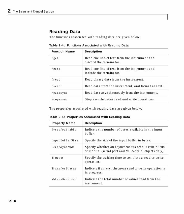
2 The Instrument Control Session
2-18
Reading DataThe functions associated with reading data are given below.
The properties associated with reading data are given below.
Table 2-4: Functions Associated with Reading Data
Function Name Description
fgetl Read one line of text from the instrument anddiscard the terminator.
fgets Read one line of text from the instrument andinclude the terminator.
fread Read binary data from the instrument.
fscanf Read data from the instrument, and format as text.
readasync Read data asynchronously from the instrument.
stopasync Stop asynchronous read and write operations.
Table 2-5: Properties Associated with Reading Data
Property Name Description
BytesAvailable Indicate the number of bytes available in the inputbuffer.
InputBufferSize Specify the size of the input buffer in bytes.
ReadAsyncMode Specify whether an asynchronous read is continuousor manual (serial port and VISA-serial objects only).
Timeout Specify the waiting time to complete a read or writeoperation.
TransferStatus Indicate if an asynchronous read or write operation isin progress.
ValuesReceived Indicate the total number of values read from theinstrument.
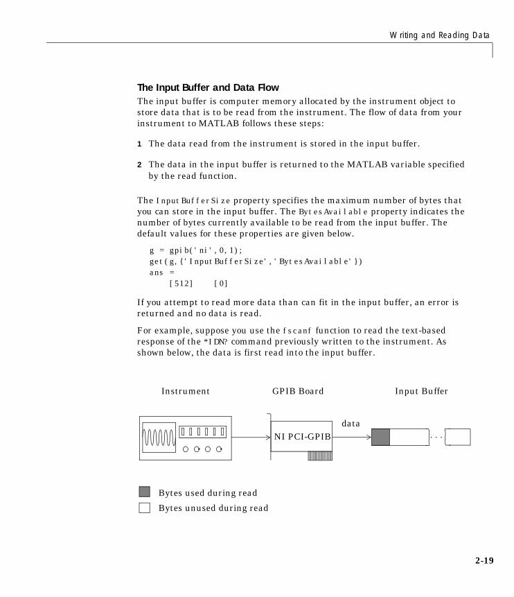
Writing and Reading Data
2-19
The Input Buffer and Data FlowThe input buffer is computer memory allocated by the instrument object tostore data that is to be read from the instrument. The flow of data from yourinstrument to MATLAB follows these steps:
1 The data read from the instrument is stored in the input buffer.
2 The data in the input buffer is returned to the MATLAB variable specifiedby the read function.
The InputBufferSize property specifies the maximum number of bytes thatyou can store in the input buffer. The BytesAvailable property indicates thenumber of bytes currently available to be read from the input buffer. Thedefault values for these properties are given below.
g = gpib('ni',0,1);get(g,{'InputBufferSize','BytesAvailable'})ans = [512] [0]
If you attempt to read more data than can fit in the input buffer, an error isreturned and no data is read.
For example, suppose you use the fscanf function to read the text-basedresponse of the *IDN? command previously written to the instrument. Asshown below, the data is first read into the input buffer.
...
Input Buffer
Bytes used during read
Bytes unused during read
Instrument
data
GPIB Board
NI PCI-GPIB
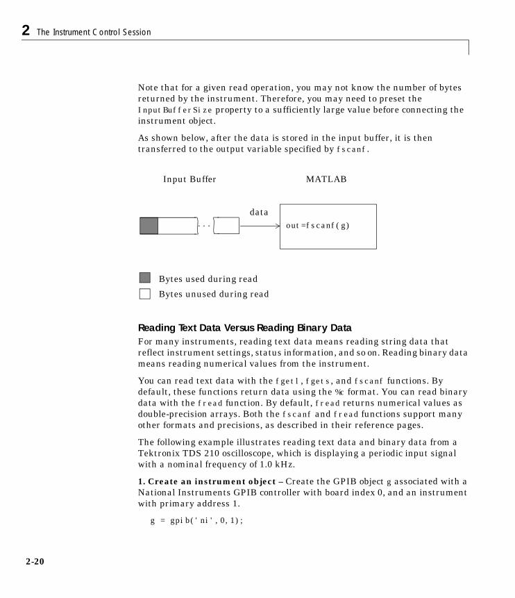
2 The Instrument Control Session
2-20
Note that for a given read operation, you may not know the number of bytesreturned by the instrument. Therefore, you may need to preset theInputBufferSize property to a sufficiently large value before connecting theinstrument object.
As shown below, after the data is stored in the input buffer, it is thentransferred to the output variable specified by fscanf.
Reading Text Data Versus Reading Binary DataFor many instruments, reading text data means reading string data thatreflect instrument settings, status information, and so on. Reading binary datameans reading numerical values from the instrument.
You can read text data with the fgetl, fgets, and fscanf functions. Bydefault, these functions return data using the %c format. You can read binarydata with the fread function. By default, fread returns numerical values asdouble-precision arrays. Both the fscanf and fread functions support manyother formats and precisions, as described in their reference pages.
The following example illustrates reading text data and binary data from aTektronix TDS 210 oscilloscope, which is displaying a periodic input signalwith a nominal frequency of 1.0 kHz.
1. Create an instrument object – Create the GPIB object g associated with aNational Instruments GPIB controller with board index 0, and an instrumentwith primary address 1.
g = gpib('ni',0,1);
out=fscanf(g)...
MATLABInput Buffer
Bytes used during read
Bytes unused during read
data
Writing and Reading Data
2-21
2. Connect to the instrument – Connect g to the instrument
fopen(g)
3. Write and read data – Write the *IDN? command to the scope, and read backthe identification information as text.
fprintf(g,'*IDN?')idn = fscanf(g)idn =TEKTRONIX,TDS 210,0,CF:91.1CT FV:v1.16 TDS2CM:CMV:v1.04
Configure the scope to return the period of the input signal, and then read theperiod as a binary value. MATLAB’s output display format is configured to useshort exponential notation for doubles.
fprintf(g,'MEASUREMENT:MEAS1:TYPE PERIOD')fprintf(g,'MEASUREMENT:MEAS1:VALUE?')format short eperiod = fread(g,9)'period = 49 46 48 48 54 69 45 51 10
period consists of positive integers representing character codes, where 10 is alinefeed. To convert the voltage value to a string, use the char function.
char(period)ans =1.006E-3
The ValuesReceived property indicates the total number of values that wereread from the instrument.
g.ValuesReceivedans =
65
4. Disconnect and clean up – When you no longer need g, you shoulddisconnect it from the instrument, remove it from memory, and remove it fromthe MATLAB workspace.
fclose(g)delete(g)clear g
2 The Instrument Control Session
2-22
Synchronous Versus Asynchronous Read OperationsThe fgetl, fgets, fscanf, and fread functions operate synchronously andblock the MATLAB command line until the operation completes. To perform anasynchronous read operation, you must use the readasync function. readasyncasynchronously reads data from the instrument and stores it in the inputbuffer. To transfer the data from the input buffer to a MATLAB variable, youmust use one of the synchronous read functions.
Note For serial port and VISA-serial objects, you can also perform anasynchronous read operation by configuring the ReadAsyncMode property tocontinuous.
For example, to modify the preceding example to asynchronously read thescope’s identification information, you would issue the readasync functionafter the *IDN? command is written.
fprintf(g,'*IDN?')readasync(g)
You can monitor the status of the asynchronous read operation with theTransferStatus property. A value of idle indicates that no asynchronousoperations are in progress.
g.TransferStatusans =read
You can use the BytesAvailable property to indicate the number of bytes thatexist in the input buffer waiting to be transferred to MATLAB.
g.BytesAvailableans =
56
When the read completes, you can transfer the data as text to a MATLABvariable using the fscanf function.
idn = fscanf(g);
Disconnecting and Cleaning Up
2-23
Disconnecting and Cleaning UpWhen you no longer need an instrument object, you should disconnect it fromthe instrument, and clean up the MATLAB environment by removing theobject from memory and from the workspace. These are the steps you take toend an instrument control session.
Disconnecting an Instrument ObjectWhen you no longer need to communicate with the instrument, you shoulddisconnect it with the fclose function.
fclose(g)
You can examine the Status property to verify that the object and theinstrument are disconnected.
g.Statusans =closed
After fclose is issued, the resources associated with g are made available, andyou can once again connect an instrument object to the instrument with fopen.
Cleaning Up the MATLAB EnvironmentWhen you no longer need the instrument object, you should remove it frommemory with the delete function.
delete(g)
Before using delete, you must disconnect the object from the instrument withthe fclose function.
A deleted instrument object is invalid, which means that you cannot connect itto the instrument. In this case, you should remove the object from theMATLAB workspace. To remove instrument objects and other variables fromthe MATLAB workspace, use the clear command.
clear g
If you use clear on an object that is connected to an instrument, the object isremoved from the workspace but remains connected to the instrument. You canrestore cleared instrument objects to MATLAB with the instrfind function.

2 The Instrument Control Session
2-24
3Controlling GPIBInstruments
GPIB Overview . . . . . . . . . . . . . . . . . . . 3-2What Is GPIB? . . . . . . . . . . . . . . . . . . . 3-2Important GPIB Features . . . . . . . . . . . . . . . 3-3GPIB Lines . . . . . . . . . . . . . . . . . . . . . 3-4Status and Event Reporting . . . . . . . . . . . . . . 3-9Using Vendor Tools to Identify and Test Your Resources . . 3-14
Creating a GPIB Object . . . . . . . . . . . . . . . 3-18The GPIB Object Display . . . . . . . . . . . . . . . 3-19
Configuring the GPIB Address . . . . . . . . . . . . 3-20
Writing and Reading Data . . . . . . . . . . . . . . 3-21Rules for Completing Write and Read Operations . . . . . 3-21Example: Writing and Reading Text Data . . . . . . . . 3-22Example: Reading Binary Data . . . . . . . . . . . . . 3-24Example: Parsing Input Data Using strread . . . . . . . 3-26Example: Understanding EOI and EOS . . . . . . . . . 3-27
Using Events and Actions . . . . . . . . . . . . . . 3-30Example: Introduction to Events and Actions . . . . . . . 3-30Event Types and Action Properties . . . . . . . . . . . 3-31Storing Event Information . . . . . . . . . . . . . . . 3-32Creating and Executing Action Functions . . . . . . . . . 3-33Enabling Action Functions After They Error . . . . . . . 3-34Example: Using Events and Actions to Read Binary Data . . 3-34
Triggers . . . . . . . . . . . . . . . . . . . . . . 3-36Example: Executing a Trigger . . . . . . . . . . . . . 3-36
Serial Polls . . . . . . . . . . . . . . . . . . . . 3-38Example: Executing a Serial Poll . . . . . . . . . . . . 3-38
3 Controlling GPIB Instruments
3-2
GPIB OverviewThis section provides an overview of the General Purpose Interface Bus(GPIB). Topics include:
• What is GPIB?
• Important GPIB Features
• GPIB Lines
• Status and Event Reporting
• Using Vendor Tools to Identify and Test Your Resources
For many GPIB applications, you can communicate with your instrumentwithout detailed knowledge of how GPIB works. Communication is establishedthrough a GPIB object, which you create in the MATLAB workspace.
If your application is straightforward, or if you are already familiar with thetopics mentioned above, you may want to begin with “Creating a GPIB Object”on page 3-18. If you want a high-level description of all the steps you are likelyto take when communicating with your instrument, refer to Chapter 2, “TheInstrument Control Session.”
What Is GPIB?The GPIB is a standardized interface that allows you to connect and controlmultiple devices from various vendors. GPIB is also referred to by its originalname HP-IB, or by its IEEE designation IEEE-488. The GPIB functionality hasevolved over time, and is described in several specifications:
• The IEEE 488.1-1975 specification defines the electrical and mechanicalcharacteristics of the interface and its basic functional characteristics.
• The IEEE-488.2-1987 specification builds on the IEEE 488.1 specification todefine an acceptable minimum configuration and a basic set of instrumentcommands and common data formats.
• The Standard Commands for Programmable Instrumentation (SCPI)specification builds on the commands given by the IEEE 488.2 specificationto define a standard instrument command set that can be used by GPIB orother interfaces.
Some of the GPIB functionality is required for all GPIB devices, while otherGPIB functionality is optional. Additionally, many devices support only a
GPIB Overview
3-3
subset of the SCPI command set, or use a different vendor-specific commandset. Refer to your device documentation for a complete list of its GPIBcapabilities and its command set.
Important GPIB FeaturesThe important GPIB features are described below. For detailed informationabout GPIB functionality, refer to the appropriate references in Appendix A,“Selected Bibliography.”
The Bus and Connector The GPIB bus is a cable with two 24-pin connectors that allow you to connectmultiple devices to each other. The bus and connector have these features andlimitations:
• You can connect up to fifteen devices to a bus.
• You can connect devices in a star configuration, a linear configuration, or acombination of configurations.
• To achieve maximum data transfer rates, the cable length should not exceed20 meters total or an average of 2 meters per device. You can eliminate theserestrictions by using a bus extender.
GPIB Devices Each GPIB device must be some combination of a Talker, a Listener, or aController. A Controller is typically a board that you install in your computer.Talkers and Listeners are typically instruments such as oscilloscopes, functiongenerators, multimeters, and so on. Most modern instruments are both Talkersand Listeners.
• Talkers – A Talker transmits data over the interface when addressed to talkby the Controller. There can be only one Talker at a given time.
• Listeners – A Listener receives data over the interface when addressed tolisten by the Controller. There can be up to 14 Listeners at a given time.Typically, the Controller is a Talker while one or more instruments on theGPIB are Listeners.
• Controllers – The Controller specifies which devices are Talkers or Listeners.A GPIB system can contain multiple Controllers – one of which is designatedthe System Controller. However, only one Controller can be active at a given
3 Controlling GPIB Instruments
3-4
time. The current active controller is the Controller-In-Charge (CIC). TheCIC can pass control to an idle Controller, but only the System Controller canmake itself the CIC.
When the Controller is not sending messages, then a Talker can sendmessages. Typically, the CIC is a Listener while another device is enabled asa Talker.
Each Controller is identified by a unique board index number. Each Talker/Listener is identified by a unique primary address ranging from 0 to 30, and byan optional secondary address, which can be 0 or can range from 96 to 126.
GPIB DataThere are two types of data that can be transferred over the GPIB: instrumentdata and interface messages.
• Instrument data – Instrument data consists of vendor-specific commandsthat configure your instrument, return measurement results, and so on. Fora complete list of commands supported by your instrument, refer to itsdocumentation.
• Interface messages – Interface messages are defined by the GPIB standardand consist of commands that clear the GPIB bus, address devices, returnself-test results, and so on.
Data transfer consists of one byte (8 bits) sent in parallel.The data transfer rateacross the interface is limited to 1 megabyte per second. However, this datarate is usually not achieved in practice, and is limited by the slowest device onthe bus.
GPIB LinesThe GPIB consists of 24 lines, which are shared by all instruments connectedto the bus. 16 lines are used for signals, while 8 lines are for ground. The signallines are divided into these groups:
• Eight data lines
• Five interface management lines
• Three handshake lines
The signal lines use a low-true (negative) logic convention with TTL levels.This means that a line is low (true or asserted) when it is a TTL low level, and
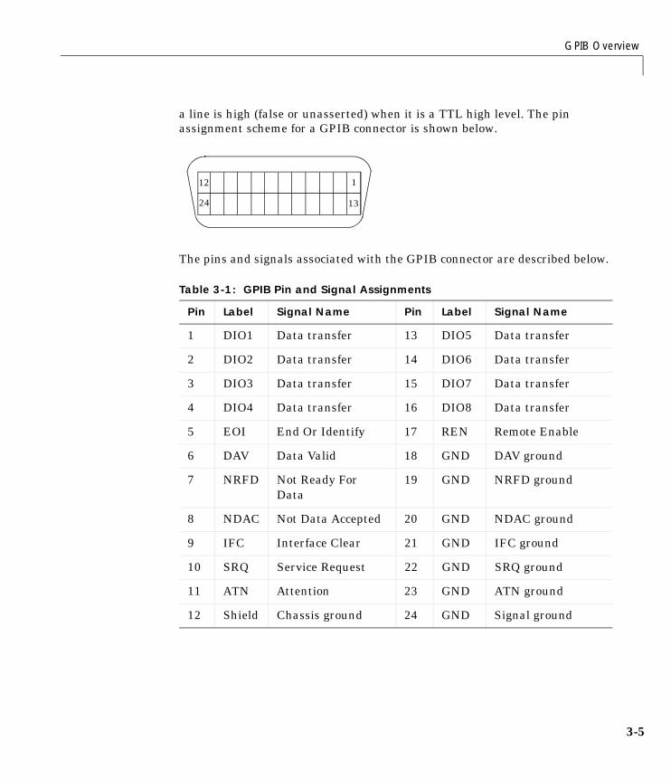
GPIB Overview
3-5
a line is high (false or unasserted) when it is a TTL high level. The pinassignment scheme for a GPIB connector is shown below.
The pins and signals associated with the GPIB connector are described below.
Table 3-1: GPIB Pin and Signal Assignments
Pin Label Signal Name Pin Label Signal Name
1 DIO1 Data transfer 13 DIO5 Data transfer
2 DIO2 Data transfer 14 DIO6 Data transfer
3 DIO3 Data transfer 15 DIO7 Data transfer
4 DIO4 Data transfer 16 DIO8 Data transfer
5 EOI End Or Identify 17 REN Remote Enable
6 DAV Data Valid 18 GND DAV ground
7 NRFD Not Ready ForData
19 GND NRFD ground
8 NDAC Not Data Accepted 20 GND NDAC ground
9 IFC Interface Clear 21 GND IFC ground
10 SRQ Service Request 22 GND SRQ ground
11 ATN Attention 23 GND ATN ground
12 Shield Chassis ground 24 GND Signal ground
112
1324
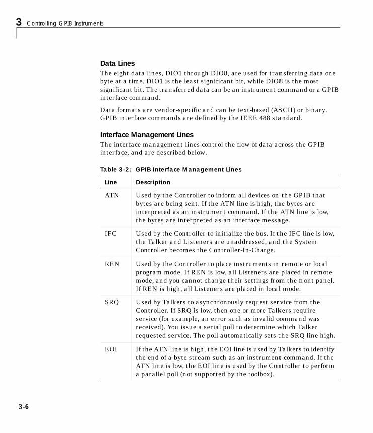
3 Controlling GPIB Instruments
3-6
Data LinesThe eight data lines, DIO1 through DIO8, are used for transferring data onebyte at a time. DIO1 is the least significant bit, while DIO8 is the mostsignificant bit. The transferred data can be an instrument command or a GPIBinterface command.
Data formats are vendor-specific and can be text-based (ASCII) or binary.GPIB interface commands are defined by the IEEE 488 standard.
Interface Management LinesThe interface management lines control the flow of data across the GPIBinterface, and are described below.
Table 3-2: GPIB Interface Management Lines
Line Description
ATN Used by the Controller to inform all devices on the GPIB thatbytes are being sent. If the ATN line is high, the bytes areinterpreted as an instrument command. If the ATN line is low,the bytes are interpreted as an interface message.
IFC Used by the Controller to initialize the bus. If the IFC line is low,the Talker and Listeners are unaddressed, and the SystemController becomes the Controller-In-Charge.
REN Used by the Controller to place instruments in remote or localprogram mode. If REN is low, all Listeners are placed in remotemode, and you cannot change their settings from the front panel.If REN is high, all Listeners are placed in local mode.
SRQ Used by Talkers to asynchronously request service from theController. If SRQ is low, then one or more Talkers requireservice (for example, an error such as invalid command wasreceived). You issue a serial poll to determine which Talkerrequested service. The poll automatically sets the SRQ line high.
EOI If the ATN line is high, the EOI line is used by Talkers to identifythe end of a byte stream such as an instrument command. If theATN line is low, the EOI line is used by the Controller to performa parallel poll (not supported by the toolbox).
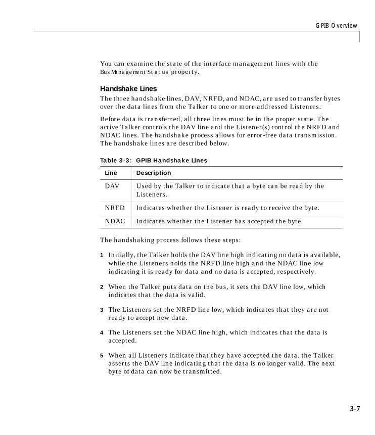
GPIB Overview
3-7
You can examine the state of the interface management lines with theBusManagementStatus property.
Handshake LinesThe three handshake lines, DAV, NRFD, and NDAC, are used to transfer bytesover the data lines from the Talker to one or more addressed Listeners.
Before data is transferred, all three lines must be in the proper state. Theactive Talker controls the DAV line and the Listener(s) control the NRFD andNDAC lines. The handshake process allows for error-free data transmission.The handshake lines are described below.
The handshaking process follows these steps:
1 Initially, the Talker holds the DAV line high indicating no data is available,while the Listeners holds the NRFD line high and the NDAC line lowindicating it is ready for data and no data is accepted, respectively.
2 When the Talker puts data on the bus, it sets the DAV line low, whichindicates that the data is valid.
3 The Listeners set the NRFD line low, which indicates that they are notready to accept new data.
4 The Listeners set the NDAC line high, which indicates that the data isaccepted.
5 When all Listeners indicate that they have accepted the data, the Talkerasserts the DAV line indicating that the data is no longer valid. The nextbyte of data can now be transmitted.
Table 3-3: GPIB Handshake Lines
Line Description
DAV Used by the Talker to indicate that a byte can be read by theListeners.
NRFD Indicates whether the Listener is ready to receive the byte.
NDAC Indicates whether the Listener has accepted the byte.
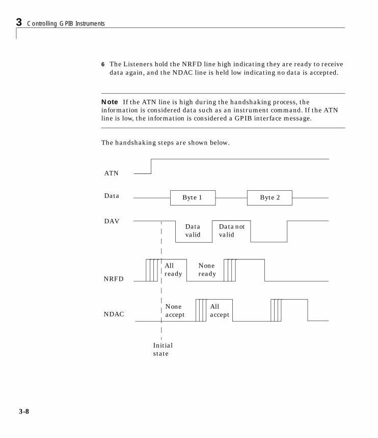
3 Controlling GPIB Instruments
3-8
6 The Listeners hold the NRFD line high indicating they are ready to receivedata again, and the NDAC line is held low indicating no data is accepted.
Note If the ATN line is high during the handshaking process, theinformation is considered data such as an instrument command. If the ATNline is low, the information is considered a GPIB interface message.
The handshaking steps are shown below.
Data
NRFD
NDAC
ATN
DAV
Initialstate
Byte 1 Byte 2
Datavalid
Datanotvalid
Noneready
Noneaccept
Allaccept
Allready
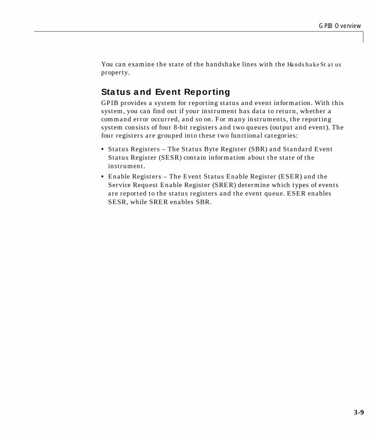
GPIB Overview
3-9
You can examine the state of the handshake lines with the HandshakeStatusproperty.
Status and Event ReportingGPIB provides a system for reporting status and event information. With thissystem, you can find out if your instrument has data to return, whether acommand error occurred, and so on. For many instruments, the reportingsystem consists of four 8-bit registers and two queues (output and event). Thefour registers are grouped into these two functional categories:
• Status Registers – The Status Byte Register (SBR) and Standard EventStatus Register (SESR) contain information about the state of theinstrument.
• Enable Registers – The Event Status Enable Register (ESER) and theService Request Enable Register (SRER) determine which types of eventsare reported to the status registers and the event queue. ESER enablesSESR, while SRER enables SBR.
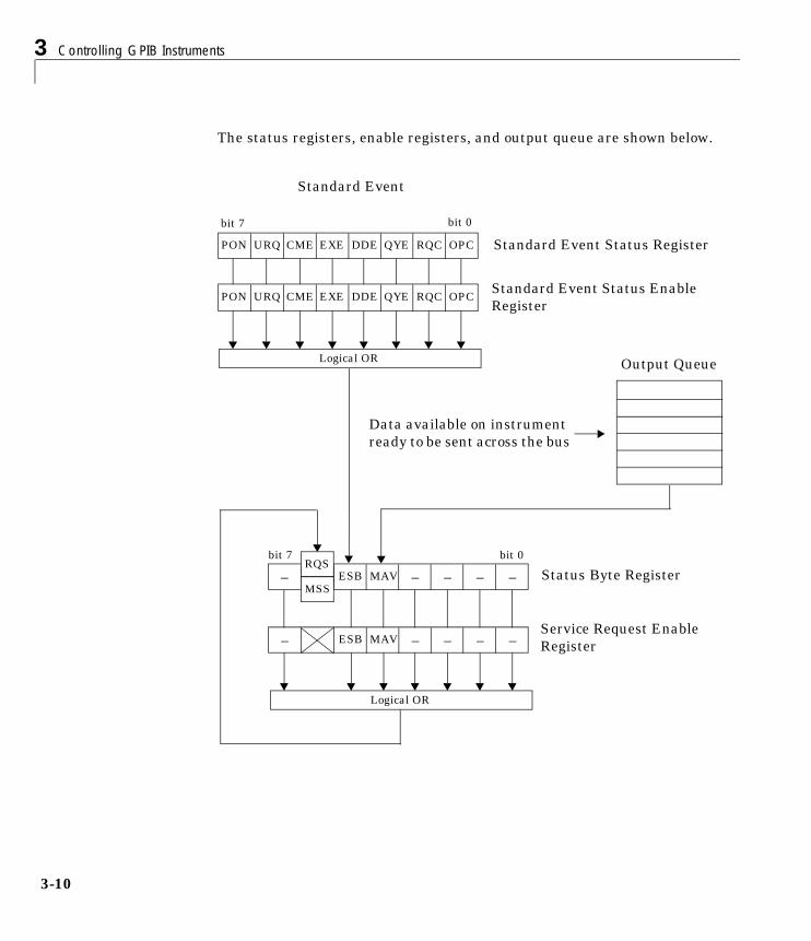
3 Controlling GPIB Instruments
3-10
The status registers, enable registers, and output queue are shown below.
Standard Event
Output Queue
PON URQ CME EXE DDE QYE RQC OPC
bit 7 bit 0
PON URQ CME EXE DDE QYE RQC OPC
Logical OR
– ESB MAV – – – –
– ESB MAV – – – –
Standard Event Status Register
Standard Event Status EnableRegister
Service Request EnableRegister
bit 0bit 7
Status Byte RegisterRQS
MSS
Logical OR
Data available on instrumentready to be sent across the bus
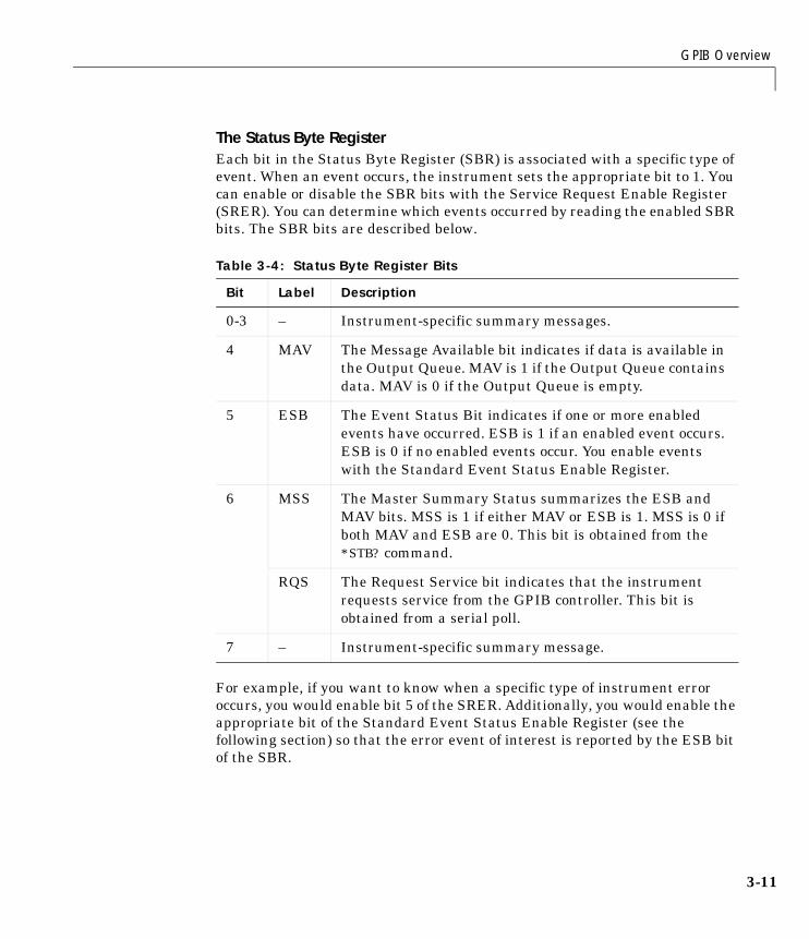
GPIB Overview
3-11
The Status Byte RegisterEach bit in the Status Byte Register (SBR) is associated with a specific type ofevent. When an event occurs, the instrument sets the appropriate bit to 1. Youcan enable or disable the SBR bits with the Service Request Enable Register(SRER). You can determine which events occurred by reading the enabled SBRbits. The SBR bits are described below.
For example, if you want to know when a specific type of instrument erroroccurs, you would enable bit 5 of the SRER. Additionally, you would enable theappropriate bit of the Standard Event Status Enable Register (see thefollowing section) so that the error event of interest is reported by the ESB bitof the SBR.
Table 3-4: Status Byte Register Bits
Bit Label Description
0-3 – Instrument-specific summary messages.
4 MAV The Message Available bit indicates if data is available inthe Output Queue. MAV is 1 if the Output Queue containsdata. MAV is 0 if the Output Queue is empty.
5 ESB The Event Status Bit indicates if one or more enabledevents have occurred. ESB is 1 if an enabled event occurs.ESB is 0 if no enabled events occur. You enable eventswith the Standard Event Status Enable Register.
6 MSS The Master Summary Status summarizes the ESB andMAV bits. MSS is 1 if either MAV or ESB is 1. MSS is 0 ifboth MAV and ESB are 0. This bit is obtained from the*STB? command.
RQS The Request Service bit indicates that the instrumentrequests service from the GPIB controller. This bit isobtained from a serial poll.
7 – Instrument-specific summary message.
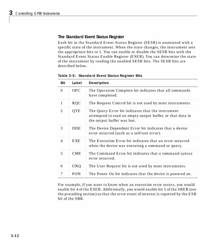
3 Controlling GPIB Instruments
3-12
The Standard Event Status RegisterEach bit in the Standard Event Status Register (SESR) is associated with aspecific state of the instrument. When the state changes, the instrument setsthe appropriate bits to 1. You can enable or disable the SESR bits with theStandard Event Status Enable Register (ESER). You can determine the stateof the instrument by reading the enabled SESR bits. The SESR bits aredescribed below.
For example, if you want to know when an execution error occurs, you wouldenable bit 4 of the ESER. Additionally, you would enable bit 5 of the SRER (seethe preceding section) so that the error event of interest is reported by the ESBbit of the SBR.
Table 3-5: Standard Event Status Register Bits
Bit Label Description
0 OPC The Operation Complete bit indicates that all commandshave completed.
1 RQC The Request Control bit is not used by most instruments.
2 QYE The Query Error bit indicates that the instrumentattempted to read an empty output buffer, or that data inthe output buffer was lost.
3 DDE The Device Dependent Error bit indicates that a deviceerror occurred (such as a self-test error).
4 EXE The Execution Error bit indicates that an error occurredwhen the device was executing a command or query.
5 CME The Command Error bit indicates that a command syntaxerror occurred.
6 URQ The User Request bit is not used by most instruments.
7 PON The Power On bit indicates that the device is powered on.
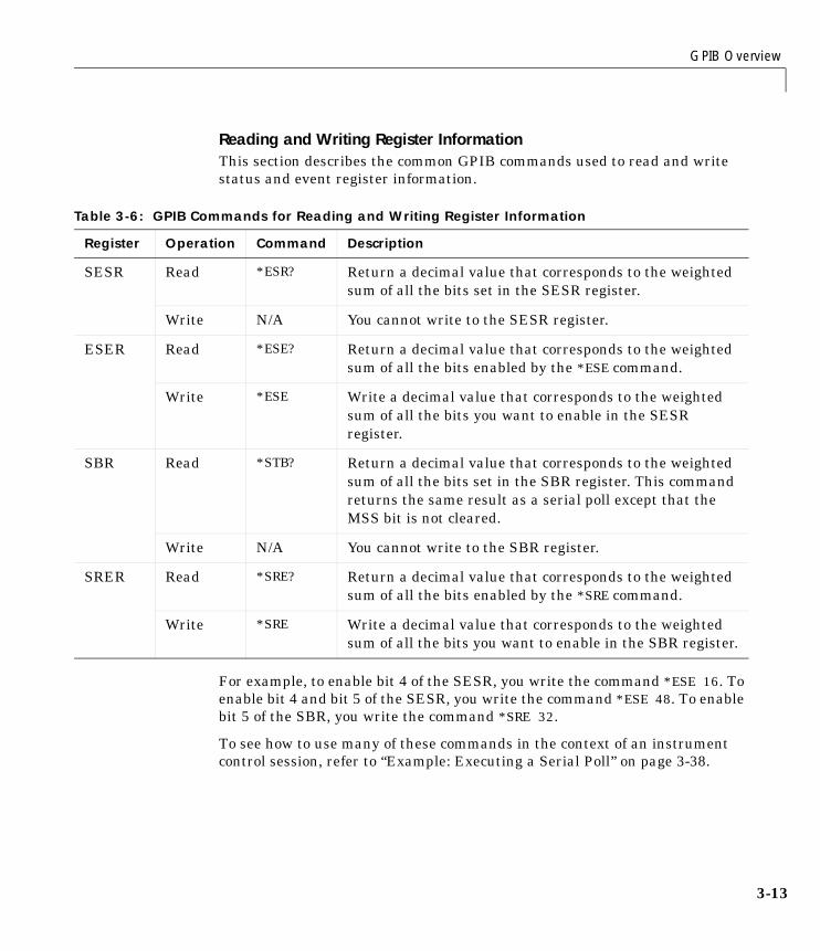
GPIB Overview
3-13
Reading and Writing Register InformationThis section describes the common GPIB commands used to read and writestatus and event register information.
For example, to enable bit 4 of the SESR, you write the command *ESE 16. Toenable bit 4 and bit 5 of the SESR, you write the command *ESE 48. To enablebit 5 of the SBR, you write the command *SRE 32.
To see how to use many of these commands in the context of an instrumentcontrol session, refer to “Example: Executing a Serial Poll” on page 3-38.
Table 3-6: GPIB Commands for Reading and Writing Register Information
Register Operation Command Description
SESR Read *ESR? Return a decimal value that corresponds to the weightedsum of all the bits set in the SESR register.
Write N/A You cannot write to the SESR register.
ESER Read *ESE? Return a decimal value that corresponds to the weightedsum of all the bits enabled by the *ESE command.
Write *ESE Write a decimal value that corresponds to the weightedsum of all the bits you want to enable in the SESRregister.
SBR Read *STB? Return a decimal value that corresponds to the weightedsum of all the bits set in the SBR register. This commandreturns the same result as a serial poll except that theMSS bit is not cleared.
Write N/A You cannot write to the SBR register.
SRER Read *SRE? Return a decimal value that corresponds to the weightedsum of all the bits enabled by the *SRE command.
Write *SRE Write a decimal value that corresponds to the weightedsum of all the bits you want to enable in the SBR register.
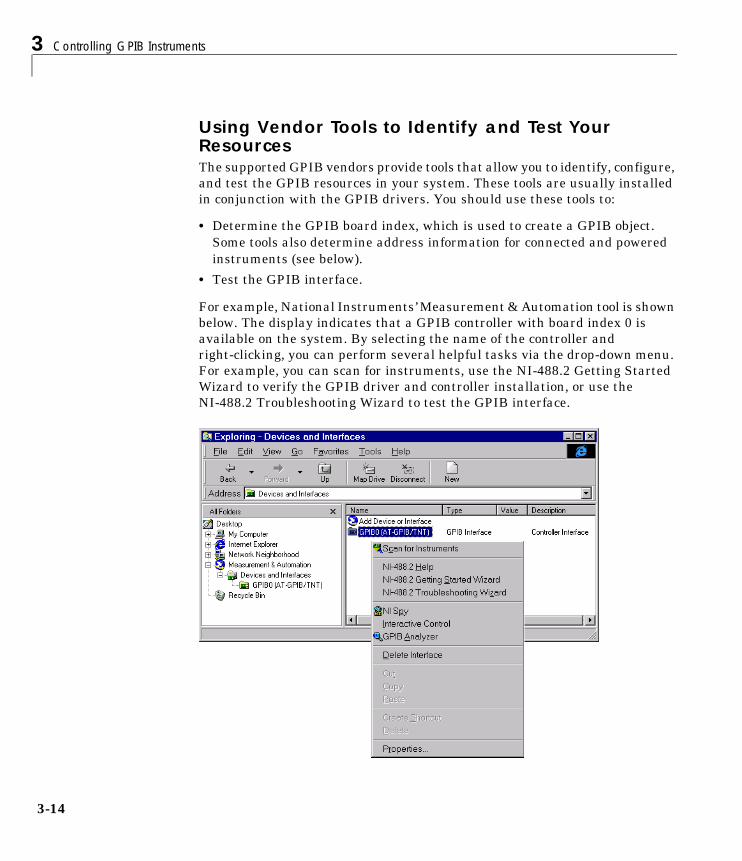
3 Controlling GPIB Instruments
3-14
Using Vendor Tools to Identify and Test Your ResourcesThe supported GPIB vendors provide tools that allow you to identify, configure,and test the GPIB resources in your system. These tools are usually installedin conjunction with the GPIB drivers. You should use these tools to:
• Determine the GPIB board index, which is used to create a GPIB object.Some tools also determine address information for connected and poweredinstruments (see below).
• Test the GPIB interface.
For example, National Instruments’ Measurement & Automation tool is shownbelow. The display indicates that a GPIB controller with board index 0 isavailable on the system. By selecting the name of the controller andright-clicking, you can perform several helpful tasks via the drop-down menu.For example, you can scan for instruments, use the NI-488.2 Getting StartedWizard to verify the GPIB driver and controller installation, or use theNI-488.2 Troubleshooting Wizard to test the GPIB interface.
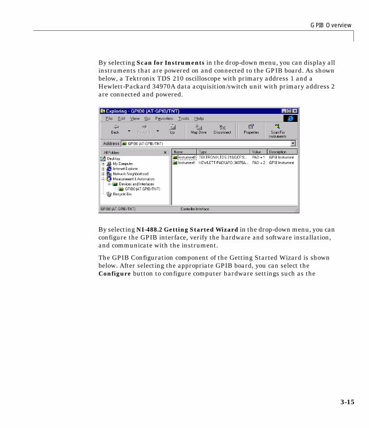
GPIB Overview
3-15
By selecting Scan for Instruments in the drop-down menu, you can display allinstruments that are powered on and connected to the GPIB board. As shownbelow, a Tektronix TDS 210 oscilloscope with primary address 1 and aHewlett-Packard 34970A data acquisition/switch unit with primary address 2are connected and powered.
By selecting NI-488.2 Getting Started Wizard in the drop-down menu, you canconfigure the GPIB interface, verify the hardware and software installation,and communicate with the instrument.
The GPIB Configuration component of the Getting Started Wizard is shownbelow. After selecting the appropriate GPIB board, you can select theConfigure button to configure computer hardware settings such as the
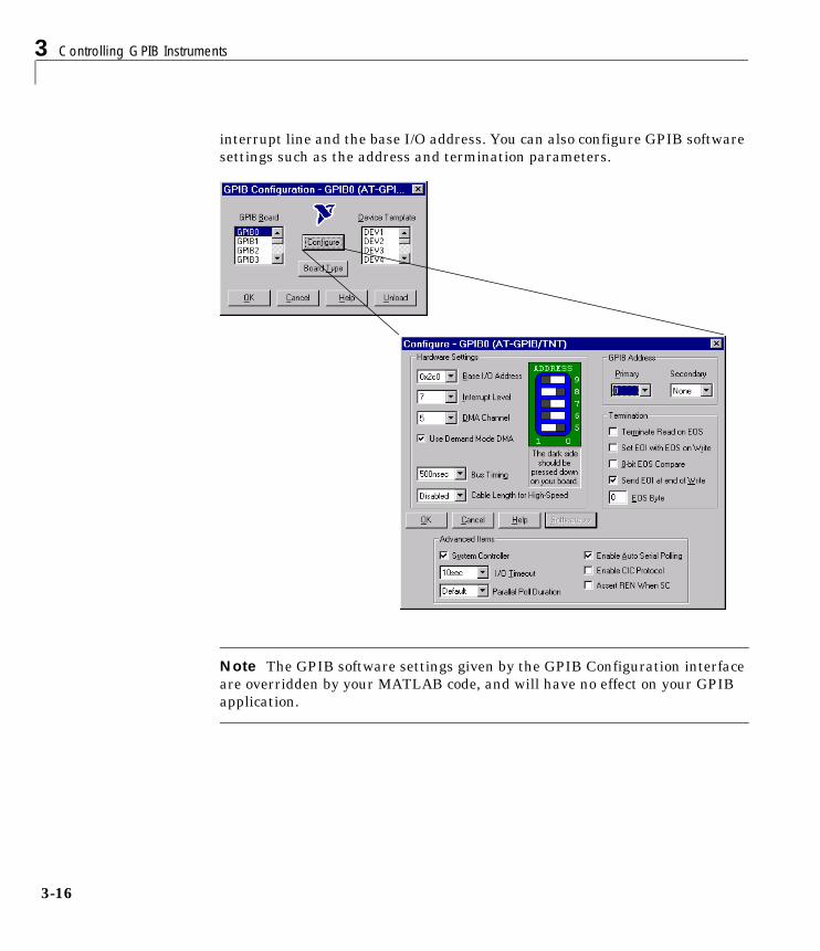
3 Controlling GPIB Instruments
3-16
interrupt line and the base I/O address. You can also configure GPIB softwaresettings such as the address and termination parameters.
Note The GPIB software settings given by the GPIB Configuration interfaceare overridden by your MATLAB code, and will have no effect on your GPIBapplication.
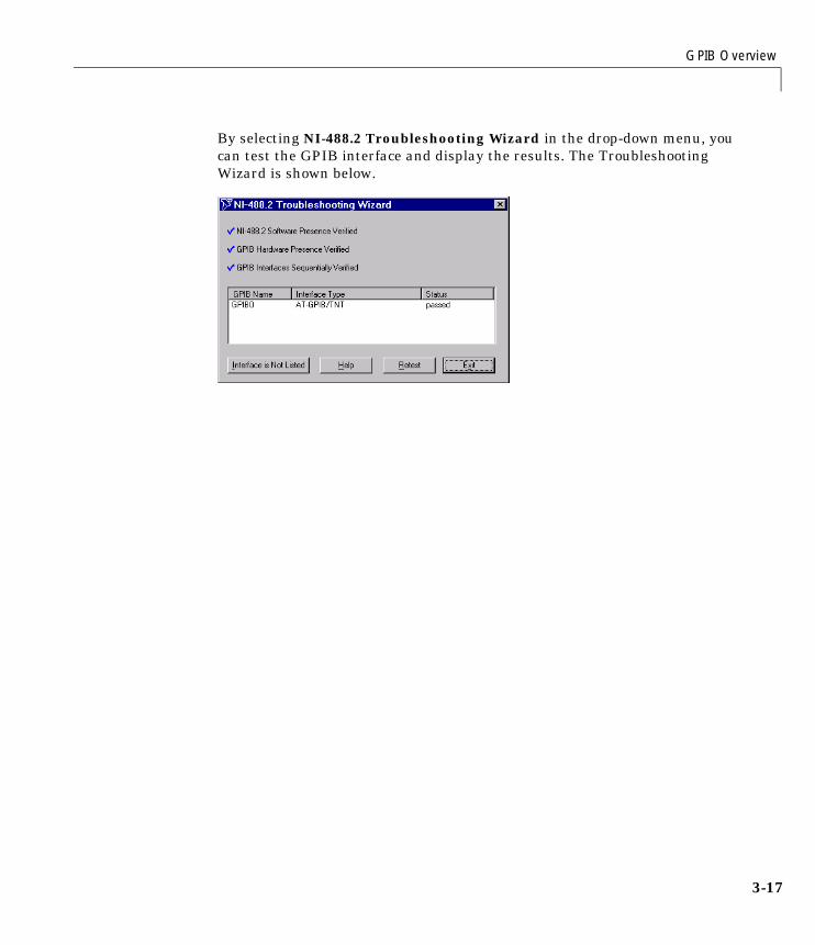
GPIB Overview
3-17
By selecting NI-488.2 Troubleshooting Wizard in the drop-down menu, youcan test the GPIB interface and display the results. The TroubleshootingWizard is shown below.
3 Controlling GPIB Instruments
3-18
Creating a GPIB ObjectYou create a GPIB object with the gpib function. gpib requires the adaptorname, the GPIB board index, and the primary address of the instrument. Asdescribed in “Configuring Properties During Object Creation” on page 2-4, youcan also configure property values during object creation. For a list ofsupported adaptors, refer to “The Interface Driver Adaptor” on page 1-4.
Each GPIB object is associated with one controller and one instrument. Forexample, to create a GPIB object associated with a National Instrumentscontroller with board index 0, and an instrument with primary address 1
g = gpib('ni',0,1);
The GPIB object g now exists in the MATLAB workspace. You can display theclass of g with the whos command.
whos g Name Size Bytes Class
g 1x1 636 gpib object
Grand total is 14 elements using 636 bytes
Once the GPIB object is created, the properties listed below are automaticallyassigned values. These general purpose properties provide descriptiveinformation about the object based on its class type and address information.
You can display the values of these properties for g with the get function.
get(g,{'Name','Type'})ans = 'GPIB0-1' 'gpib'
Table 3-7: GPIB Descriptive Properties
Property Name Description
Name Specify a descriptive name for the GPIB object.
Type Indicate the object type.
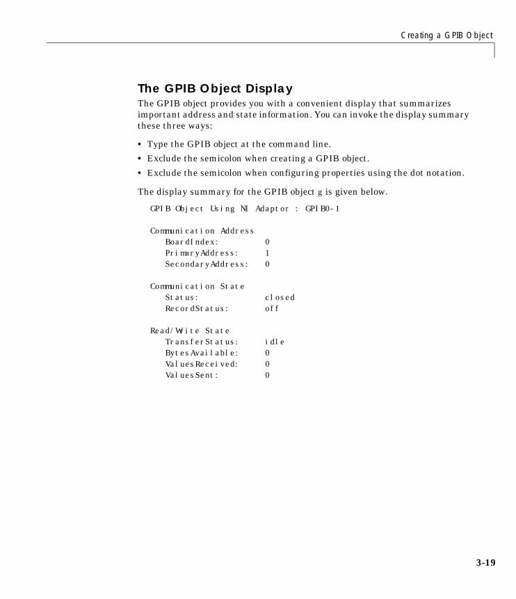
Creating a GPIB Object
3-19
The GPIB Object DisplayThe GPIB object provides you with a convenient display that summarizesimportant address and state information. You can invoke the display summarythese three ways:
• Type the GPIB object at the command line.
• Exclude the semicolon when creating a GPIB object.
• Exclude the semicolon when configuring properties using the dot notation.
The display summary for the GPIB object g is given below.
GPIB Object Using NI Adaptor : GPIB0-1
Communication Address BoardIndex: 0PrimaryAddress: 1SecondaryAddress: 0
Communication State Status: closedRecordStatus: off
Read/Write State TransferStatus: idleBytesAvailable: 0ValuesReceived: 0ValuesSent: 0
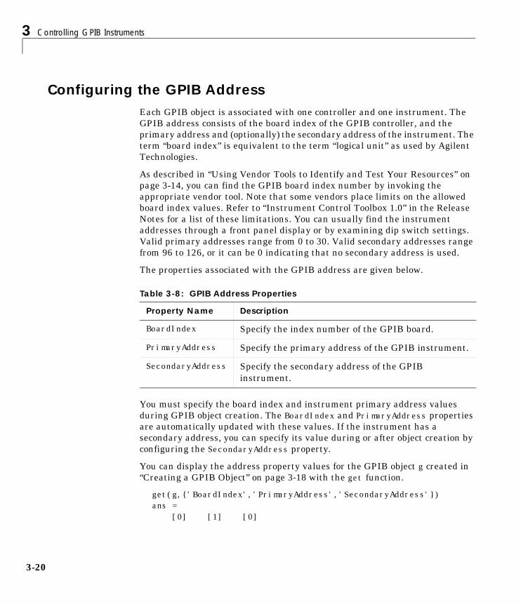
3 Controlling GPIB Instruments
3-20
Configuring the GPIB AddressEach GPIB object is associated with one controller and one instrument. TheGPIB address consists of the board index of the GPIB controller, and theprimary address and (optionally) the secondary address of the instrument. Theterm “board index” is equivalent to the term “logical unit” as used by AgilentTechnologies.
As described in “Using Vendor Tools to Identify and Test Your Resources” onpage 3-14, you can find the GPIB board index number by invoking theappropriate vendor tool. Note that some vendors place limits on the allowedboard index values. Refer to “Instrument Control Toolbox 1.0” in the ReleaseNotes for a list of these limitations. You can usually find the instrumentaddresses through a front panel display or by examining dip switch settings.Valid primary addresses range from 0 to 30. Valid secondary addresses rangefrom 96 to 126, or it can be 0 indicating that no secondary address is used.
The properties associated with the GPIB address are given below.
You must specify the board index and instrument primary address valuesduring GPIB object creation. The BoardIndex and PrimaryAddress propertiesare automatically updated with these values. If the instrument has asecondary address, you can specify its value during or after object creation byconfiguring the SecondaryAddress property.
You can display the address property values for the GPIB object g created in“Creating a GPIB Object” on page 3-18 with the get function.
get(g,{'BoardIndex','PrimaryAddress','SecondaryAddress'})ans = [0] [1] [0]
Table 3-8: GPIB Address Properties
Property Name Description
BoardIndex Specify the index number of the GPIB board.
PrimaryAddress Specify the primary address of the GPIB instrument.
SecondaryAddress Specify the secondary address of the GPIBinstrument.
Writing and Reading Data
3-21
Writing and Reading DataThis section describes interface-specific issues related to writing and readingdata with a GPIB object. Topics include:
• The rules for completing write and read operations
• Examples that illustrate writing and reading text data and binary data
For a general overview about writing and reading data, as well as a list of allassociated functions and properties, refer to “Writing and Reading Data” onpage 2-12.
Rules for Completing Write and Read OperationsThe rules for completing synchronous and asynchronous read and writeoperations are described below.
Completing Write OperationsA write operation using fprintf or fwrite completes when one of theseconditions is satisfied:
• The specified data is written.
• The time specified by the Timeout property passes.
Additionally, you can stop an asynchronous write operation at any time withthe stopasync function.
An instrument determines if a write operation is complete based on theEOSMode, EOIMode, and EOSCharCode property values. If EOSMode is configuredto either write or read&write, each occurrence of \n in a text command isreplaced with the End-Of-String (EOS) character specified by the EOSCharCodevalue. Therefore, when you use the default fprintf format of %s\n, all textcommands written to the instrument will end with that value. The defaultEOSCharCode value is 10, which corresponds to the line feed character. The EOScharacter required by your instrument will be described in its documentation.
If EOIMode is on, then the End Or Identify (EOI) line is asserted when the lastbyte is written to the instrument. The last byte can be part of a binary datastream or a text data stream. If EOSMode is configured to either write orread&write, then the last byte written is the EOSCharCode value and the EOIline is asserted when the instrument receives this byte.
3 Controlling GPIB Instruments
3-22
Completing Read OperationsA read operation with fgetl, fgets, fread, fscanf, or readasync completeswhen one of these conditions is satisfied:
• The EOI line is asserted.
• The terminator specified by the EOSCharCode property is read. This can occuronly when the EOSMode property is configured to either read or read&write.
• The time specified by the Timeout property passes.
• The specified number of values is read (fread, fscanf, and readasync only).
• The input buffer is filled (if the number of values is not specified).
In addition to these rules, you can stop an asynchronous read operation at anytime with the stopasync function.
Example: Writing and Reading Text DataThis example illustrates how to communicate with a GPIB instrument bywriting and reading text data.
The instrument is a Tektronix TDS 210 two-channel oscilloscope. Therefore,many of the commands used are specific to this instrument. A sine wave isinput into channel 2 of the oscilloscope, and your job is to measure thepeak-to-peak voltage of the input signal.
1. Create an instrument object – Create the GPIB object g associated with aNational Instruments GPIB controller with board index 0, and an instrumentwith primary address 1.
g = gpib('ni',0,1);
2. Connect to the instrument – Connect g to the oscilloscope, and return thedefault values for the EOSMode and EOIMode properties.
fopen(g)get(g,{'EOSMode','EOIMode'})ans = 'none' 'on'
Using these property values, write operations complete when the last byte iswritten to the instrument, and read operations complete when the EOI line isasserted by the instrument.
Writing and Reading Data
3-23
3. Write and read data – Write the *IDN? command to the instrument usingfprintf, and then read back the result of the command using fscanf.
fprintf(g,'*IDN?')idn = fscanf(g)idn =TEKTRONIX,TDS 210,0,CF:91.1CT FV:v1.16 TDS2CM:CMV:v1.04
Determine the measurement source. Possible measurement sources includechannel 1 and channel 2 of the oscilloscope.
fprintf(g,'MEASUREMENT:IMMED:SOURCE?')source = fscanf(g)source =CH1
The scope is configured to return a measurement from channel 1. Since theinput signal is connected to channel 2, you must configure the instrument toreturn a measurement from this channel.
fprintf(g,'MEASUREMENT:IMMED:SOURCE CH2')fprintf(g,'MEASUREMENT:IMMED:SOURCE?')source = fscanf(g)source =CH2
You can now configure the scope to return the peak-to-peak voltage, requestthe value of this measurement, and then return the voltage value to MATLABusing fscanf.
fprintf(g,'MEASUREMENT:MEAS1:TYPE PK2PK')fprintf(g,'MEASUREMENT:MEAS1:VALUE?')ptop = fscanf(g)ptop =2.0199999809E0
4. Disconnect and clean up – When you no longer need g, you shoulddisconnect it from the instrument, and remove it from memory and from theMATLAB workspace.
fclose(g)delete(g)clear g
3 Controlling GPIB Instruments
3-24
Example: Reading Binary DataThis example illustrates how you can download the TDS 210 oscilloscopescreen display to MATLAB. The screen display data is transferred to MATLABand saved to disk using the Windows bitmap format. This data provides apermanent record of your work, and is an easy way to document importantsignal and scope parameters.
1. Create an instrument object – Create the GPIB object g associated with aNational Instruments GPIB controller with board index 0, and an instrumentwith primary address 1.
g = gpib('ni',0,1);
2. Configure property values – Configure the input buffer to accept areasonably large number of bytes, and configure the timeout value to twominutes to account for slow data transfer.
g.InputBufferSize = 50000;g.Timeout = 120;
3. Connect to the instrument – Connect g to the oscilloscope.
fopen(g)
4. Write and read data – Configure the scope to transfer the screen display asa bitmap.
fprintf(g,'HARDCOPY:PORT GPIB')fprintf(g,'HARDCOPY:FORMAT BMP')fprintf(g,'HARDCOPY START')
Asynchronously transfer the data from the instrument to the input buffer.
readasync(g)
Wait until the read operation completes, and then transfer the data to theMATLAB workspace as unsigned 8-bit integers.
g.TransferStatusans =idleout = fread(g,g.BytesAvailable,'uint8');
Writing and Reading Data
3-25
5. Disconnect and clean up – When you no longer need g, you shoulddisconnect it from the instrument, and remove it from memory and from theMATLAB workspace.
fclose(g)delete(g)clear g
Viewing the Bitmap DataTo view the bitmap data, you should follow these steps:
1 Open a disk file.
2 Write the data to the disk file.
3 Close the disk file.
4 Read the data using MATLAB’s imread function.
5 Scale and display the data using MATLAB’s imagesc function.
Note that MATLAB’s file I/O versions of the fopen, fwrite, and fclosefunctions are used.
fid = fopen('test1.bmp','w');fwrite(fid,out,'uint8');fclose(fid)a = imread('test1.bmp','bmp');imagesc(fliplr(a'))
Since the scope returns the screen display data using only two colors, anappropriate colormap is selected.
mymap = [0 0 0; 1 1 1]; colormap(mymap)
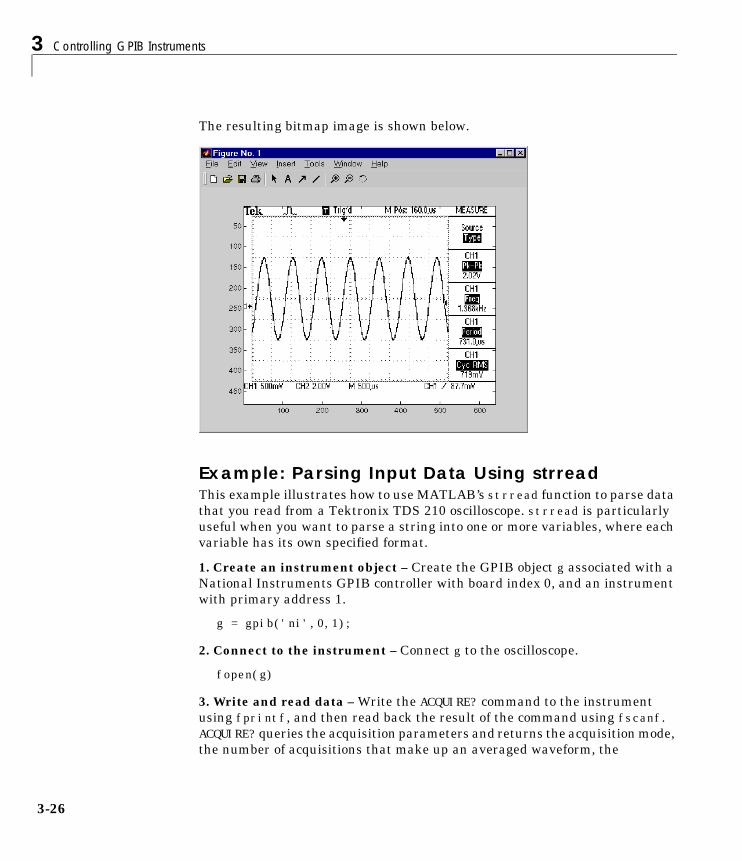
3 Controlling GPIB Instruments
3-26
The resulting bitmap image is shown below.
Example: Parsing Input Data Using strreadThis example illustrates how to use MATLAB’s strread function to parse datathat you read from a Tektronix TDS 210 oscilloscope. strread is particularlyuseful when you want to parse a string into one or more variables, where eachvariable has its own specified format.
1. Create an instrument object – Create the GPIB object g associated with aNational Instruments GPIB controller with board index 0, and an instrumentwith primary address 1.
g = gpib('ni',0,1);
2. Connect to the instrument – Connect g to the oscilloscope.
fopen(g)
3. Write and read data – Write the ACQUIRE? command to the instrumentusing fprintf, and then read back the result of the command using fscanf.ACQUIRE? queries the acquisition parameters and returns the acquisition mode,the number of acquisitions that make up an averaged waveform, the
Writing and Reading Data
3-27
acquisition state (whether it is running or not), and the condition under whichthe acquisition stops.
fprintf(g,'ACQUIRE?')data = fscanf(g)data =SAMPLE;128;1;RUNSTOP
Use the strread function to parse and format the data variable into four newvariables.
[mode,navg,state,con] = strread(data,'%s%d%d%s','delimiter',';')mode = 'SAMPLE'navg = 128state = 1con =
'RUNSTOP'
4. Disconnect and clean up – When you no longer need g, you shoulddisconnect it from the instrument, and remove it from memory and from theMATLAB workspace.
fclose(g)delete(g)clear g
Example: Understanding EOI and EOSThis example illustrates how the EOI line and the EOS character are used tocomplete read and write operations, and how the EOIMode, EOSMode, andEOSCharCode properties are related to each other. In most cases, you cansuccessfully communicate with your instrument by accepting the defaultvalues for these properties.
The default value for EOIMode is on, which means that the EOI line is assertedwhen the last byte is written to the instrument. The default value for EOSModeis none, which means that the EOSCharCode value is not written to theinstrument, and read operations will not complete when the EOSCharCode
3 Controlling GPIB Instruments
3-28
value is read. Therefore, when you use the default values for EOIMode andEOSMode:
• Write operations complete when the last byte is written to the instrument.
• Read operations complete when the EOI line is asserted by the instrument.
1. Create an instrument object – Create the GPIB object g associated with aNational Instruments GPIB controller with board index 0, and an instrumentwith primary address 1.
g = gpib('ni',0,1);
2. Connect to the instrument – Connect g to the oscilloscope.
fopen(g)
3. Write and read data – Configure g so that the EOI line is not asserted afterthe last byte is written to the instrument, and the EOS character is used tocomplete write operations. The default format for fprintf is %s\n, where \n isreplaced by the EOS character as given by EOSCharCode.
g.EOIMode = 'off';g.EOSMode = 'write';fprintf(g,'*IDN?')out = fscanf(g)out =
TEKTRONIX,TDS 210,0,CF:91.1CT FV:v1.16 TDS2CM:CMV:v1.04
Although EOSMode is configured so that read operations will not complete afterreceiving the EOS character, the preceding read operation succeeded becausethe EOI line was asserted.
Writing and Reading Data
3-29
Now configure g so that the EOS character is not used to complete read or writeoperations. Since the EOI line is not asserted and the EOS character is notwritten, the instrument cannot interpret the *IDN? command and a timeoutoccurs.
g.EOSMode = 'none';fprintf(g,'*IDN?')out = fscanf(g)
Warning: GPIB: NI: An I/O operation has been canceled mostly likely due to a timeout.
Now configure g so that the read operation terminates after the “X” characteris read. The EOIMode property is configured to on so that the EOI line isasserted after the last byte is written. The EOSMode property is configured toread so that the read operation completes when the EOSCharCode value is read.
g.EOIMode = 'on';g.EOSMode = 'read';g.EOSCharCode = double('X');fprintf(g,'*IDN?')out = fscanf(g)out =
TEKTRONIX
Note that the rest of the identification string remains in the instrument’shardware buffer. If you do not want to return this data during the next readoperation, you should clear it from the instrument buffer with the clrdevicefunction.
clrdevice(g)
4. Disconnect and clean up – When you no longer need g, you shoulddisconnect it from the instrument, and remove it from memory and from theMATLAB workspace.
fclose(g)delete(g)clear g
3 Controlling GPIB Instruments
3-30
Using Events and ActionsYou can enhance the power and flexibility of your instrument controlapplication by using events. An event occurs after a condition is met, and mayresult in one or more actions.
While the instrument object is connected to the instrument, you can use eventsto display a message, display data, analyze data, or perform just about anyother action. Actions are controlled through action properties and actionfunctions. All event types have an associated action property. Action functionsare M-file functions that you construct to suit your specific application needs.
You execute an action when a particular event occurs by specifying the nameof the M-file action function as the value for the associated action property.
Example: Introduction to Events and ActionsThis example uses the M-file action function instraction to display a messageto the command line when a bytes-available event occurs. The event isgenerated when the EOSCharCode property value is read.
g = gpib('ni',0,1);fopen(g)g.BytesAvailableActionMode = 'eosCharCode';g.BytesAvailableAction = 'instraction';fprintf(g,'*IDN?')readasync(g)
The resulting display from instraction is shown below.
BytesAvailable event occurred at 17:30:11 for the object: GPIB0-1.
End the GPIB session.
fclose(g)delete(g)clear g
You can use the type command to display instraction at the command line.
Using Events and Actions
3-31
Event Types and Action PropertiesThe GPIB event types and associated action properties are described below.
Bytes-Available Event. A bytes-available event is generated immediately after apredetermined number of bytes are available in the input buffer or theEnd-Of-String character is read, as determined by theBytesAvailableActionMode property.
If BytesAvailableActionMode is byte, the bytes-available event executes theaction function specified for the BytesAvailableAction property every timethe number of bytes specified by BytesAvailableActionCount is stored in theinput buffer. If BytesAvailableActionMode is eosCharCode, then the actionfunction executes every time the character specified by the EOSCharCodeproperty is read.
This event can be generated only during an asynchronous read operation.
Error Event. An error event is generated immediately after an error, such as atimeout, occurs. A timeout occurs if a read or write operation does notsuccessfully complete within the time specified by the Timeout property. Anerror event is not generated for configuration errors such as setting an invalidproperty value.
This event executes the action function specified for the ErrorAction property.It can be generated only during an asynchronous read or write operation.
Table 3-9: GPIB Event Types and Action Properties
Event Type Associated Property Name
Bytes available BytesAvailableAction
BytesAvailableActionCount
BytesAvailableActionMode
Error ErrorAction
Output empty OutputEmptyAction
Timer TimerAction
TimerPeriod
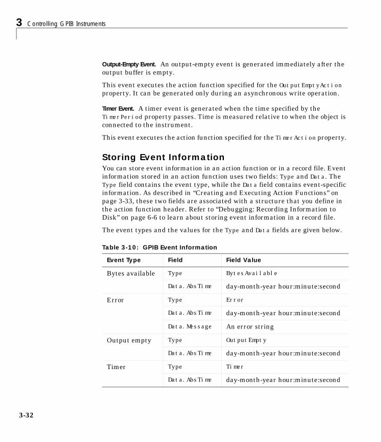
3 Controlling GPIB Instruments
3-32
Output-Empty Event. An output-empty event is generated immediately after theoutput buffer is empty.
This event executes the action function specified for the OutputEmptyActionproperty. It can be generated only during an asynchronous write operation.
Timer Event. A timer event is generated when the time specified by theTimerPeriod property passes. Time is measured relative to when the object isconnected to the instrument.
This event executes the action function specified for the TimerAction property.
Storing Event InformationYou can store event information in an action function or in a record file. Eventinformation stored in an action function uses two fields: Type and Data. TheType field contains the event type, while the Data field contains event-specificinformation. As described in “Creating and Executing Action Functions” onpage 3-33, these two fields are associated with a structure that you define inthe action function header. Refer to “Debugging: Recording Information toDisk” on page 6-6 to learn about storing event information in a record file.
The event types and the values for the Type and Data fields are given below.
Table 3-10: GPIB Event Information
Event Type Field Field Value
Bytes available Type BytesAvailable
Data.AbsTime day-month-year hour:minute:second
Error Type Error
Data.AbsTime day-month-year hour:minute:second
Data.Message An error string
Output empty Type OutputEmpty
Data.AbsTime day-month-year hour:minute:second
Timer Type Timer
Data.AbsTime day-month-year hour:minute:second
Using Events and Actions
3-33
The Data field values are described below.
The AbsTime Field. AbsTime is defined for all events, and indicates the absolutetime the event occurred. The absolute time is returned using MATLAB’s clockformat.
day-month-year hour:minute:second
The Message Field. Message is used by the error event to store the descriptivemessage that is generated when an error occurs.
Creating and Executing Action FunctionsYou can specify the action function to be executed when a specific event typeoccurs by including the name of the M-file as the value for the associated actionproperty. For example, to execute the action function myaction every time theEOSCharCode property value is read from your instrument
g.BytesAvailableActionMode = 'eosCharCode';g.BytesAvailableAction = 'myaction';
M-file action functions require at least two input arguments. The firstargument is the instrument object. The second argument is a variable thatcaptures the event information given in Table 3-10, GPIB Event Information,on page 3-32. This event information pertains only to the event that caused theaction function to execute. The function header for myaction is shown below.
function myaction(obj,event)
You can pass additional parameters to the action function by including themas elements of a cell array. For example, to pass the MATLAB variable time tomyaction
time = datestr(now,0);g.BytesAvailableActionMode = 'eosCharCode';g.BytesAvailableAction = {'myaction',time};
The corresponding function header is
function myaction(obj,event,time)
If you pass additional parameters to the action function, then they must beincluded in the function header after the two required arguments.
3 Controlling GPIB Instruments
3-34
Enabling Action Functions After They ErrorIf an error occurs while an action function is executing, then:
• The action function is automatically disabled.
• A warning is displayed at the command line, indicating that the actionfunction is disabled.
If you want to enable the same action function, then you must disconnect theobject with the fclose function. If you want to use a different action function,then the action will be enabled when you configure the action property to thenew value.
Example: Using Events and Actions to Read Binary DataThis example extends “Example: Reading Binary Data” on page 3-24 by usingthe M-file action function instraction to display event-related information tothe command line when a bytes-available event occurs during a binary readoperation.
1. Create an instrument object – Create the GPIB object g associated with aNational Instruments GPIB controller with board index 0, and an instrumentwith primary address 1.
g = gpib('ni',0,1);
2. Configure properties – Configure the input buffer to accept a reasonablylarge number of bytes, and configure the timeout value to two minutes toaccount for slow data transfer.
g.InputBufferSize = 50000;g.Timeout = 120;
Configure g to execute the action function instraction every time 5000 bytesis stored in the input buffer.
g.BytesAvailableActionMode = 'byte';g.BytesAvailableActionCount = 5000;g.BytesAvailableAction = 'instraction';
3. Connect to the instrument – Connect g to the oscilloscope.
fopen(g)
Using Events and Actions
3-35
4. Write and read data – Configure the scope to transfer the screen display asa bitmap.
fprintf(g,'HARDCOPY:PORT GPIB')fprintf(g,'HARDCOPY:FORMAT BMP')fprintf(g,'HARDCOPY START')
Initiate the asynchronous read operation, and begin generating events.
readasync(g)
instraction is called every time 5000 bytes is stored in the input buffer. Theresulting displays are shown below.
BytesAvailable event occurred at 09:41:42 for the object: GPIB0-1.BytesAvailable event occurred at 09:41:50 for the object: GPIB0-1.BytesAvailable event occurred at 09:41:58 for the object: GPIB0-1.BytesAvailable event occurred at 09:42:06 for the object: GPIB0-1.BytesAvailable event occurred at 09:42:14 for the object: GPIB0-1.BytesAvailable event occurred at 09:42:22 for the object: GPIB0-1.BytesAvailable event occurred at 09:42:30 for the object: GPIB0-1.
Wait until all the data is sent to the input buffer, and then transfer the data toMATLAB as unsigned 8-bit integers.
g.TransferStatusans =idleout = fread(g,g.BytesAvailable,'uint8');
5. Disconnect and clean up – When you no longer need g, you shoulddisconnect it from the instrument, and remove it from memory and from theMATLAB workspace.
fclose(g)delete(g)clear g
3 Controlling GPIB Instruments
3-36
TriggersYou can execute a trigger with the trigger function. This function isequivalent to writing the GET (Group Execute Trigger) GPIB command to theinstrument.
trigger instructs all the addressed Listeners to perform someinstrument-specific function such as taking a measurement. Refer to yourinstrument documentation to learn how to use its triggering capabilities.
Example: Executing a TriggerThis example illustrates GPIB triggering using an Agilent 33120A functiongenerator. The output of the function generator is displayed with anoscilloscope so that the trigger can be observed.
1. Create an instrument object – Create the GPIB object g associated with aNational Instruments GPIB controller with board index 0, and an instrumentwith primary address 1.
g = gpib('ni',0,1);
2. Connect to the instrument – Connect g to the function generator.
fopen(g)
3. Write and read data – Configure the function generator to produce a 5000Hz sine wave, with 6 volts peak-to-peak.
fprintf(g,'Func:Shape Sin')fprintf(g,'Volt 3')fprintf(g,'Freq 5000')
Configure the burst of the trigger to display the sine wave for five seconds,configure the function generator to expect the trigger from the GPIB board, andenable the burst mode.
fprintf(g,'BM:NCycles 25000')fprintf(g,'Trigger:Source Bus')fprintf(g,'BM:State On')
Trigger the instrument.
trigger(g)
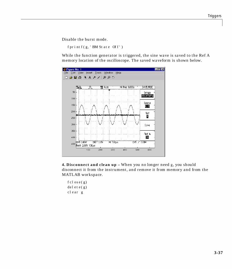
Triggers
3-37
Disable the burst mode.
fprintf(g,'BM:State Off')
While the function generator is triggered, the sine wave is saved to the Ref Amemory location of the oscilloscope. The saved waveform is shown below.
4. Disconnect and clean up – When you no longer need g, you shoulddisconnect it from the instrument, and remove it from memory and from theMATLAB workspace.
fclose(g)delete(g)clear g
3 Controlling GPIB Instruments
3-38
Serial PollsYou can execute a serial poll with the spoll function. In a serial poll, theController asks (polls) each addressed Listener to send back a status byte thatindicates whether it has asserted the SRQ line and needs servicing. Theseventh bit of this byte (the RQS bit) is set if the instrument is requestingservice.
The Controller performs the following steps for every addressed Listener:
1 The Listener is addressed to talk and the Serial Poll Enable (SPE) commandbyte is sent.
2 The ATN line is set high and the Listener returns the status byte.
3 The ATN line is set low and the Serial Poll Disable (SPD) command byte issent to end the poll sequence.
Refer to “Status and Event Reporting” on page 3-9 for more information on theGPIB bus lines and the RQS bit.
Example: Executing a Serial PollThis example shows you how to execute a serial poll for a Agilent 33120Afunction generator, and a Tektronix TDS 210 oscilloscope. In doing so, theexample shows you how to configure many of the status bits described in “TheStandard Event Status Register” on page 3-12.
1. Create instrument objects – Create a GPIB object associated with a Agilent33120A function generator at primary address 1.
g1 = gpib('ni',0,1);
Create a GPIB object associated with a Tektronix TDS 210 oscilloscope atprimary address 2.
g2 = gpib('ni',0,2);
2. Connect to the instrument – Connect g1 to the function generator andconnect g2 to the oscilloscope.
fopen([g1 g2])
Serial Polls
3-39
3. Configure property values – Configure both objects to time out after 1second.
set([g1 g2],'Timeout',1)
4. Write and read data – Configure the function generator to request servicewhen a command error occurs.
fprintf(g1,'*CLS'); fprintf(g1,'*ESE 32'); fprintf(g1,'*SRE 32');
Configure the oscilloscope to request service when a command error occurs.
fprintf(g2,'*CLS') fprintf(g2,'*PSC 0') fprintf(g2,'*ESE 32') fprintf(g2,'DESE 32') fprintf(g2,'*SRE 32')
Determine if any instrument needs servicing.
spoll([g1 g2])ans =[]
Query the voltage value for each instrument.
fprintf(g1,'Volt?') fprintf(g2,'Volt?')
Determine if either instrument produced an error due to the preceding query.
out = spoll([g1 g2]);
Since Volt? is an invalid command for the oscilloscope, it is requesting service.
out == [g1 g2]ans =0 1
Since Volt? is a valid command for the function generator, the value is readback successfully.
volt1 = fscanf(g1)
3 Controlling GPIB Instruments
3-40
volt1 =+1.00000E-01
However, the oscilloscope read operation times out after 1 second.
volt2 = fscanf(g2) Warning: GPIB: NI: An I/O operation has been canceled, most likely due to a timeout.
volt2 =''
5. Disconnect and clean up – When you no longer need g1 and g2, you shoulddisconnect them from the instruments, and remove them from memory andfrom the MATLAB workspace.
fclose([g1 g2])delete([g1 g2])clear g1 g2
4Controlling InstrumentsUsing the VISA Standard
VISA Overview . . . . . . . . . . . . . . . . . . . 4-2Using Vendor Tools to Identify and Test Your Resources . . 4-3
The GPIB Interface . . . . . . . . . . . . . . . . . 4-5Creating a VISA-GPIB Object . . . . . . . . . . . . . 4-5The VISA-GPIB Address . . . . . . . . . . . . . . . 4-7
The VXI Interface . . . . . . . . . . . . . . . . . 4-9Creating a VISA-VXI Object . . . . . . . . . . . . . . 4-10The VISA-VXI Address . . . . . . . . . . . . . . . . 4-12Register-Based Communication . . . . . . . . . . . . . 4-13
The GPIB-VXI Interface . . . . . . . . . . . . . . . 4-21Creating a VISA-GPIB-VXI Object . . . . . . . . . . . 4-22The VISA-GPIB-VXI Address . . . . . . . . . . . . . . 4-24
The Serial Port Interface . . . . . . . . . . . . . . 4-26Creating a VISA-Serial Object . . . . . . . . . . . . . 4-26Configuring Communication Settings . . . . . . . . . . 4-28
4 Controlling Instruments Using the VISA Standard
4-2
VISA OverviewVirtual Instrument Standard Architecture (VISA) is a standard defined byAgilent Technologies and National Instruments for communicating withinstruments regardless of the interface.
The Instrument Control Toolbox supports the GPIB, VXI, GPIB-VXI, andserial port interfaces using the VISA standard. Communication is establishedthrough a VISA instrument object, which you create in the MATLABworkspace. For example, a VISA-GPIB object allows you to use the VISAstandard to communicate with an instrument that possesses a GPIB interface.
Note Most features associated with VISA instrument objects are identical tothe features associated with GPIB and serial port objects. Therefore, thischapter presents only interface-specific functions and properties. For example,register-based communication is discussed for VISA-VXI objects, butmessage-based communication is not discussed since this topic is coveredelsewhere in this guide.
For many VISA applications, you can communicate with your instrumentwithout detailed knowledge of how the interface works. In this case, you maywant to begin with one of these topics:
• “The GPIB Interface” on page 4-5
• “The VXI Interface” on page 4-9
• “The GPIB-VXI Interface” on page 4-21
• “The Serial Port Interface” on page 4-26
If you want a high-level description of all the steps you are likely to take whencommunicating with your instrument, refer to Chapter 2, “The InstrumentControl Session.”
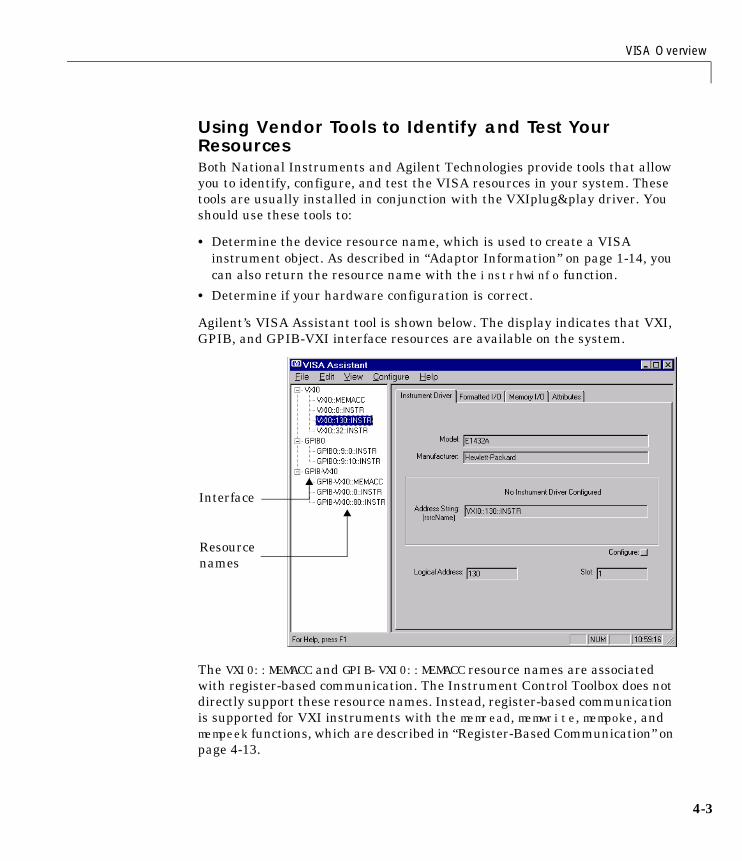
VISA Overview
4-3
Using Vendor Tools to Identify and Test Your ResourcesBoth National Instruments and Agilent Technologies provide tools that allowyou to identify, configure, and test the VISA resources in your system. Thesetools are usually installed in conjunction with the VXIplug&play driver. Youshould use these tools to:
• Determine the device resource name, which is used to create a VISAinstrument object. As described in “Adaptor Information” on page 1-14, youcan also return the resource name with the instrhwinfo function.
• Determine if your hardware configuration is correct.
Agilent’s VISA Assistant tool is shown below. The display indicates that VXI,GPIB, and GPIB-VXI interface resources are available on the system.
The VXI0::MEMACC and GPIB-VXI0::MEMACC resource names are associatedwith register-based communication. The Instrument Control Toolbox does notdirectly support these resource names. Instead, register-based communicationis supported for VXI instruments with the memread, memwrite, mempoke, andmempeek functions, which are described in “Register-Based Communication” onpage 4-13.
Resourcenames
Interface
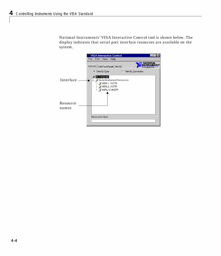
4 Controlling Instruments Using the VISA Standard
4-4
National Instruments’ VISA Interactive Control tool is shown below. Thedisplay indicates that serial port interface resources are available on thesystem.
Resourcenames
Interface
The GPIB Interface
4-5
The GPIB InterfaceThe GPIB interface is supported through a VISA-GPIB object. The featuresassociated with a VISA-GPIB object are similar to the features associated witha GPIB object. Therefore, only functions and properties that are unique toVISA’s GPIB interface are discussed in this section. These unique features areassociated with:
• Creating a VISA-GPIB object
• The VISA-GPIB address
Refer to Chapter 3, “Controlling GPIB Instruments” to learn about the GPIBinterface, writing and reading text and binary data, using events and actions,using triggers, and so on.
Note The VISA-GPIB object does not support the spoll function, theBusManagementStatus property, and the HandshakeStatus property.
Creating a VISA-GPIB ObjectYou create a VISA-GPIB object with the visa function. Each VISA-GPIB objectis associated with:
• A GPIB controller installed in your computer
• An instrument with a GPIB interface
visa requires the vendor name and the resource name as input arguments. Thevendor name is either agilent or ni. The resource name consists of the GPIBboard index, the instrument primary address, and the instrument secondaryaddress. You can find the VISA-GPIB resource name for a given instrumentwith the configuration tool provided by your vendor, or with the instrhwinfofunction. As described in “Configuring Properties During Object Creation” onpage 2-4, you can also configure property values during object creation.
For example, to create a VISA-GPIB object associated with a NationalInstruments controller with board index 0, and a Tektronix TDS 210 digitaloscilloscope with primary address 1 and secondary address 0
vg = visa('ni','GPIB0::1::0::INSTR');
4 Controlling Instruments Using the VISA Standard
4-6
The VISA-GPIB object vg now exists in the MATLAB workspace. You candisplay the class of vg with the whos command.
whos vg Name Size Bytes Class
vg 1x1 636 visa object
Grand total is 14 elements using 636 bytes
After you create the VISA-GPIB object, the properties listed below areautomatically assigned values. These properties provide descriptiveinformation about the object based on its class type and address information.
You can display the values of these properties for vg with the get function.
get(vg,{'Name','RsrcName','Type'})ans = 'VISA-GPIB0-1' 'GPIB0::1::0::INSTR' 'visa-gpib'
The VISA-GPIB Object DisplayThe VISA-GPIB object provides you with a convenient display thatsummarizes important address and state information. You can invoke thedisplay summary these three ways:
• Type the VISA-GPIB object at the command line.
• Exclude the semicolon when creating a VISA-GPIB object.
• Exclude the semicolon when configuring properties using the dot notation.
Table 4-1: VISA-GPIB Descriptive Properties
Property Name Description
Name Specify a descriptive name for the VISA-GPIB object.
RsrcName Indicate the resource name for a VISA instrument.
Type Indicate the object type.
The GPIB Interface
4-7
The display summary for the VISA-GPIB object vg is given below.
VISA-GPIB Object Using NI Adaptor : VISA-GPIB0-1
Communication Address BoardIndex: 0PrimaryAddress: 1SecondaryAddress: 0
Communication State Status: closedRecordStatus: off
Read/Write State TransferStatus: idleBytesAvailable: 0ValuesReceived: 0ValuesSent: 0
The VISA-GPIB AddressThe VISA-GPIB address consists of:
• The board index of the GPIB controller installed in your computer.
• The primary address and secondary address of the instrument. Validprimary addresses range from 0 to 30. Valid secondary addresses range from0 to 30, where the value 0 indicates that the secondary address is not used.
You must specify the primary address value via the resource name duringVISA-GPIB object creation. Additionally, you must include the board index andsecondary address values as part of the resource name if they differ from thedefault value of 0.
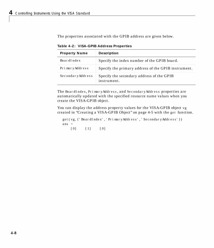
4 Controlling Instruments Using the VISA Standard
4-8
The properties associated with the GPIB address are given below.
The BoardIndex, PrimaryAddress, and SecondaryAddress properties areautomatically updated with the specified resource name values when youcreate the VISA-GPIB object.
You can display the address property values for the VISA-GPIB object vgcreated in “Creating a VISA-GPIB Object” on page 4-5 with the get function.
get(vg,{'BoardIndex','PrimaryAddress','SecondaryAddress'})ans = [0] [1] [0]
Table 4-2: VISA-GPIB Address Properties
Property Name Description
BoardIndex Specify the index number of the GPIB board.
PrimaryAddress Specify the primary address of the GPIB instrument.
SecondaryAddress Specify the secondary address of the GPIBinstrument.
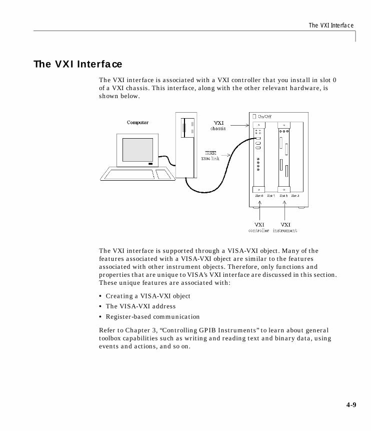
The VXI Interface
4-9
The VXI InterfaceThe VXI interface is associated with a VXI controller that you install in slot 0of a VXI chassis. This interface, along with the other relevant hardware, isshown below.
The VXI interface is supported through a VISA-VXI object. Many of thefeatures associated with a VISA-VXI object are similar to the featuresassociated with other instrument objects. Therefore, only functions andproperties that are unique to VISA’s VXI interface are discussed in this section.These unique features are associated with:
• Creating a VISA-VXI object
• The VISA-VXI address
• Register-based communication
Refer to Chapter 3, “Controlling GPIB Instruments” to learn about generaltoolbox capabilities such as writing and reading text and binary data, usingevents and actions, and so on.
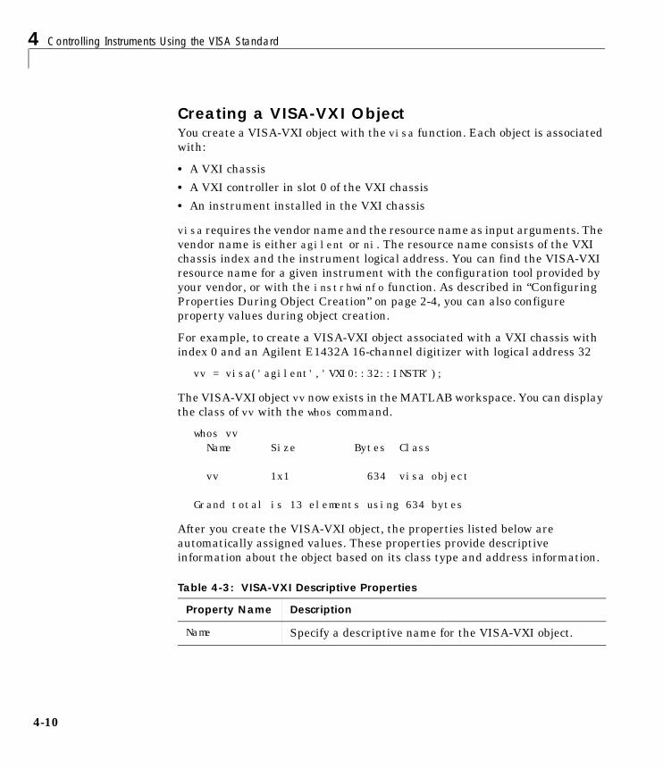
4 Controlling Instruments Using the VISA Standard
4-10
Creating a VISA-VXI ObjectYou create a VISA-VXI object with the visa function. Each object is associatedwith:
• A VXI chassis
• A VXI controller in slot 0 of the VXI chassis
• An instrument installed in the VXI chassis
visa requires the vendor name and the resource name as input arguments. Thevendor name is either agilent or ni. The resource name consists of the VXIchassis index and the instrument logical address. You can find the VISA-VXIresource name for a given instrument with the configuration tool provided byyour vendor, or with the instrhwinfo function. As described in “ConfiguringProperties During Object Creation” on page 2-4, you can also configureproperty values during object creation.
For example, to create a VISA-VXI object associated with a VXI chassis withindex 0 and an Agilent E1432A 16-channel digitizer with logical address 32
vv = visa('agilent','VXI0::32::INSTR');
The VISA-VXI object vv now exists in the MATLAB workspace. You can displaythe class of vv with the whos command.
whos vv Name Size Bytes Class
vv 1x1 634 visa object
Grand total is 13 elements using 634 bytes
After you create the VISA-VXI object, the properties listed below areautomatically assigned values. These properties provide descriptiveinformation about the object based on its class type and address information.
Table 4-3: VISA-VXI Descriptive Properties
Property Name Description
Name Specify a descriptive name for the VISA-VXI object.
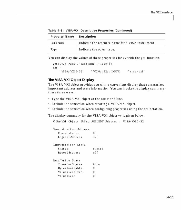
The VXI Interface
4-11
You can display the values of these properties for vv with the get function.
get(vv,{'Name','RsrcName','Type'})ans = 'VISA-VXI0-32' 'VXI0::32::INSTR' 'visa-vxi'
The VISA-VXI Object DisplayThe VISA-VXI object provides you with a convenient display that summarizesimportant address and state information. You can invoke the display summarythese three ways:
• Type the VISA-VXI object at the command line.
• Exclude the semicolon when creating a VISA-VXI object.
• Exclude the semicolon when configuring properties using the dot notation.
The display summary for the VISA-VXI object vv is given below.
VISA-VXI Object Using AGILENT Adaptor : VISA-VXI0-32
Communication Address ChassisIndex: 0LogicalAddress: 32
Communication State Status: closedRecordStatus: off
Read/Write State TransferStatus: idleBytesAvailable: 0ValuesReceived: 0ValuesSent: 0
RsrcName Indicate the resource name for a VISA instrument.
Type Indicate the object type.
Table 4-3: VISA-VXI Descriptive Properties (Continued)
Property Name Description

4 Controlling Instruments Using the VISA Standard
4-12
The VISA-VXI AddressThe VISA-VXI address consists of:
• The chassis index of the VXI chassis
• The logical address of the instrument installed in the VXI chassis
You must specify the logical address value via the resource name duringVISA-VXI object creation. Additionally, you must include the chassis indexvalue as part of the resource name if it differs from the default value of 0. Theproperties associated with the chassis and instrument address are given below.
The ChassisIndex and LogicalAddress properties are automatically updatedwith the specified resource name values when you create the VISA-VXI object.The Slot property is automatically updated after the object is connected to theinstrument with the fopen function.
You can display the address property values for the VISA-VXI object vv createdin “Creating a VISA-VXI Object” on page 4-10 with the get function.
fopen(vv)get(vv,{'ChassisIndex','LogicalAddress','Slot'})ans = [0] [32] [2]
Table 4-4: VISA-VXI Address Properties
Property Name Description
ChassisIndex Indicate the index number of the VXI chassis.
LogicalAddress Specify the logical address of the VXI instrument.
Slot Indicate the slot location of the VXI instrument.
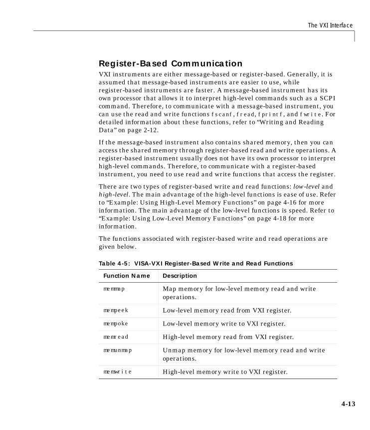
The VXI Interface
4-13
Register-Based CommunicationVXI instruments are either message-based or register-based. Generally, it isassumed that message-based instruments are easier to use, whileregister-based instruments are faster. A message-based instrument has itsown processor that allows it to interpret high-level commands such as a SCPIcommand. Therefore, to communicate with a message-based instrument, youcan use the read and write functions fscanf, fread, fprintf, and fwrite. Fordetailed information about these functions, refer to “Writing and ReadingData” on page 2-12.
If the message-based instrument also contains shared memory, then you canaccess the shared memory through register-based read and write operations. Aregister-based instrument usually does not have its own processor to interprethigh-level commands. Therefore, to communicate with a register-basedinstrument, you need to use read and write functions that access the register.
There are two types of register-based write and read functions: low-level andhigh-level. The main advantage of the high-level functions is ease of use. Referto “Example: Using High-Level Memory Functions” on page 4-16 for moreinformation. The main advantage of the low-level functions is speed. Refer to“Example: Using Low-Level Memory Functions” on page 4-18 for moreinformation.
The functions associated with register-based write and read operations aregiven below.
Table 4-5: VISA-VXI Register-Based Write and Read Functions
Function Name Description
memmap Map memory for low-level memory read and writeoperations.
mempeek Low-level memory read from VXI register.
mempoke Low-level memory write to VXI register.
memread High-level memory read from VXI register.
memunmap Unmap memory for low-level memory read and writeoperations.
memwrite High-level memory write to VXI register.
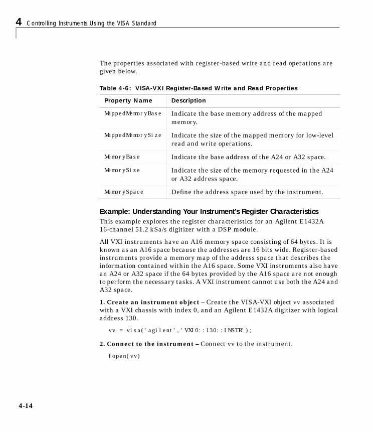
4 Controlling Instruments Using the VISA Standard
4-14
The properties associated with register-based write and read operations aregiven below.
Example: Understanding Your Instrument’s Register CharacteristicsThis example explores the register characteristics for an Agilent E1432A16-channel 51.2 kSa/s digitizer with a DSP module.
All VXI instruments have an A16 memory space consisting of 64 bytes. It isknown as an A16 space because the addresses are 16 bits wide. Register-basedinstruments provide a memory map of the address space that describes theinformation contained within the A16 space. Some VXI instruments also havean A24 or A32 space if the 64 bytes provided by the A16 space are not enoughto perform the necessary tasks. A VXI instrument cannot use both the A24 andA32 space.
1. Create an instrument object – Create the VISA-VXI object vv associatedwith a VXI chassis with index 0, and an Agilent E1432A digitizer with logicaladdress 130.
vv = visa('agilent','VXI0::130::INSTR');
2. Connect to the instrument – Connect vv to the instrument.
fopen(vv)
Table 4-6: VISA-VXI Register-Based Write and Read Properties
Property Name Description
MappedMemoryBase Indicate the base memory address of the mappedmemory.
MappedMemorySize Indicate the size of the mapped memory for low-levelread and write operations.
MemoryBase Indicate the base address of the A24 or A32 space.
MemorySize Indicate the size of the memory requested in the A24or A32 address space.
MemorySpace Define the address space used by the instrument.
The VXI Interface
4-15
The MemorySpace property indicates the type of memory space the instrumentsupports. By default, all instruments support A16 memory space. However,this property can be A16/A24 or A16/A32 if the instrument also supports A24or A32 memory space, respectively.
get(vv,'MemorySpace')ans =A16/A24
If the VISA-VXI object is not connected to the instrument, MemorySpace alwaysreturns the default value of A16.
The MemoryBase property indicates the base address of the A24 or A32 space,and is defined as a hexadecimal string. The MemorySize property indicates thesize of the A24 or A32 space. If the VXI instrument supports only the A16memory space, MemoryBase defaults to 0H and MemorySize defaults to 0.
get(vv,{'MemoryBase','MemorySize'})ans = '200000H' [262144]
3. Disconnect and clean up – When you no longer need vv, you shoulddisconnect it from the instrument, and remove it from memory and from theMATLAB workspace.
fclose(vv)delete(vv)clear vv
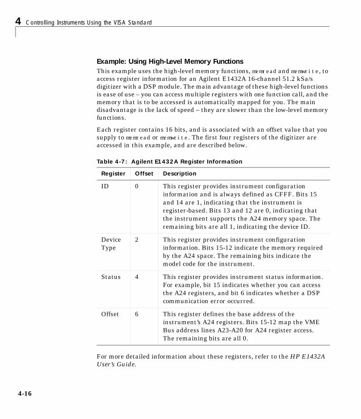
4 Controlling Instruments Using the VISA Standard
4-16
Example: Using High-Level Memory FunctionsThis example uses the high-level memory functions, memread and memwrite, toaccess register information for an Agilent E1432A 16-channel 51.2 kSa/sdigitizer with a DSP module. The main advantage of these high-level functionsis ease of use – you can access multiple registers with one function call, and thememory that is to be accessed is automatically mapped for you. The maindisadvantage is the lack of speed – they are slower than the low-level memoryfunctions.
Each register contains 16 bits, and is associated with an offset value that yousupply to memread or memwrite. The first four registers of the digitizer areaccessed in this example, and are described below.
For more detailed information about these registers, refer to the HP E1432AUser’s Guide.
Table 4-7: Agilent E1432A Register Information
Register Offset Description
ID 0 This register provides instrument configurationinformation and is always defined as CFFF. Bits 15and 14 are 1, indicating that the instrument isregister-based. Bits 13 and 12 are 0, indicating thatthe instrument supports the A24 memory space. Theremaining bits are all 1, indicating the device ID.
DeviceType
2 This register provides instrument configurationinformation. Bits 15-12 indicate the memory requiredby the A24 space. The remaining bits indicate themodel code for the instrument.
Status 4 This register provides instrument status information.For example, bit 15 indicates whether you can accessthe A24 registers, and bit 6 indicates whether a DSPcommunication error occurred.
Offset 6 This register defines the base address of theinstrument’s A24 registers. Bits 15-12 map the VMEBus address lines A23-A20 for A24 register access.The remaining bits are all 0.
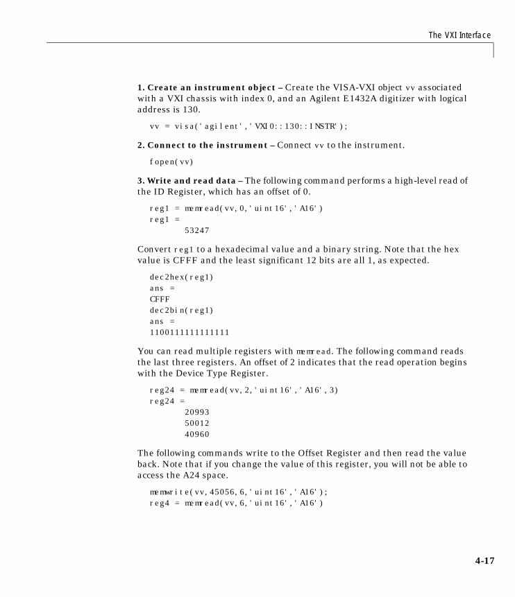
The VXI Interface
4-17
1. Create an instrument object – Create the VISA-VXI object vv associatedwith a VXI chassis with index 0, and an Agilent E1432A digitizer with logicaladdress is 130.
vv = visa('agilent','VXI0::130::INSTR');
2. Connect to the instrument – Connect vv to the instrument.
fopen(vv)
3. Write and read data – The following command performs a high-level read ofthe ID Register, which has an offset of 0.
reg1 = memread(vv,0,'uint16','A16')reg1 = 53247
Convert reg1 to a hexadecimal value and a binary string. Note that the hexvalue is CFFF and the least significant 12 bits are all 1, as expected.
dec2hex(reg1)ans =CFFFdec2bin(reg1)ans =1100111111111111
You can read multiple registers with memread. The following command readsthe last three registers. An offset of 2 indicates that the read operation beginswith the Device Type Register.
reg24 = memread(vv,2,'uint16','A16',3)reg24 = 20993 50012 40960
The following commands write to the Offset Register and then read the valueback. Note that if you change the value of this register, you will not be able toaccess the A24 space.
memwrite(vv,45056,6,'uint16','A16'); reg4 = memread(vv,6,'uint16','A16')
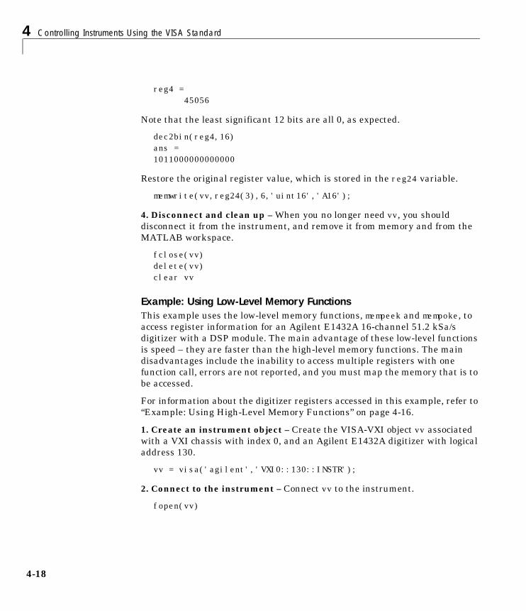
4 Controlling Instruments Using the VISA Standard
4-18
reg4 =45056
Note that the least significant 12 bits are all 0, as expected.
dec2bin(reg4,16)ans =1011000000000000
Restore the original register value, which is stored in the reg24 variable.
memwrite(vv,reg24(3),6,'uint16','A16');
4. Disconnect and clean up – When you no longer need vv, you shoulddisconnect it from the instrument, and remove it from memory and from theMATLAB workspace.
fclose(vv)delete(vv)clear vv
Example: Using Low-Level Memory FunctionsThis example uses the low-level memory functions, mempeek and mempoke, toaccess register information for an Agilent E1432A 16-channel 51.2 kSa/sdigitizer with a DSP module. The main advantage of these low-level functionsis speed – they are faster than the high-level memory functions. The maindisadvantages include the inability to access multiple registers with onefunction call, errors are not reported, and you must map the memory that is tobe accessed.
For information about the digitizer registers accessed in this example, refer to“Example: Using High-Level Memory Functions” on page 4-16.
1. Create an instrument object – Create the VISA-VXI object vv associatedwith a VXI chassis with index 0, and an Agilent E1432A digitizer with logicaladdress 130.
vv = visa('agilent','VXI0::130::INSTR');
2. Connect to the instrument – Connect vv to the instrument.
fopen(vv)
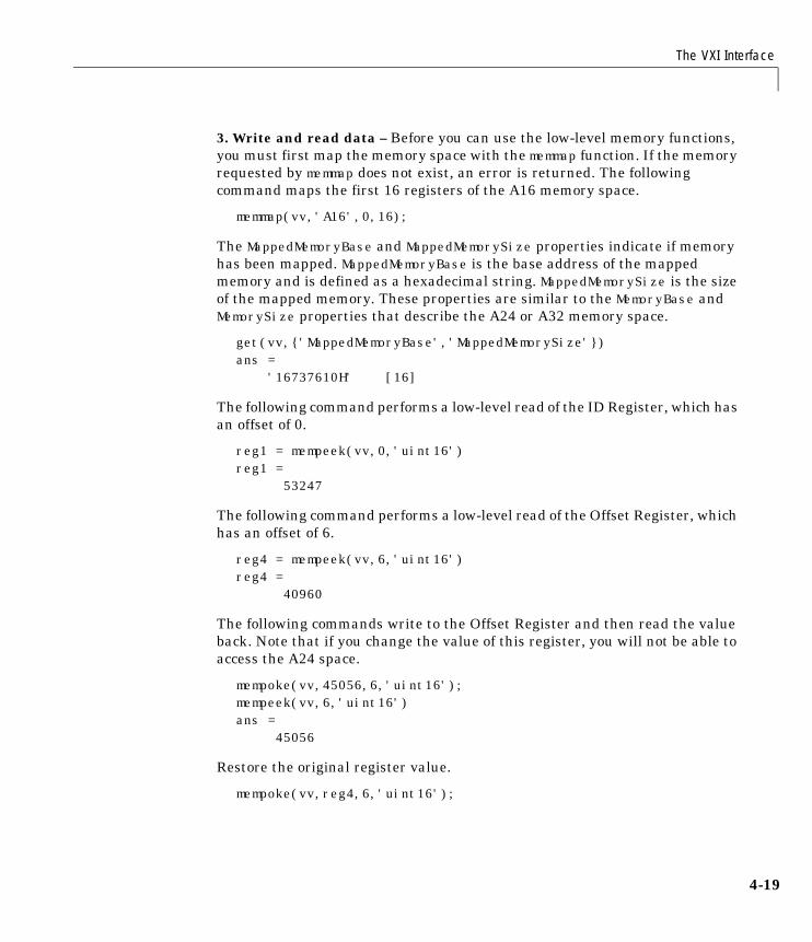
The VXI Interface
4-19
3. Write and read data – Before you can use the low-level memory functions,you must first map the memory space with the memmap function. If the memoryrequested by memmap does not exist, an error is returned. The followingcommand maps the first 16 registers of the A16 memory space.
memmap(vv,'A16',0,16);
The MappedMemoryBase and MappedMemorySize properties indicate if memoryhas been mapped. MappedMemoryBase is the base address of the mappedmemory and is defined as a hexadecimal string. MappedMemorySize is the sizeof the mapped memory. These properties are similar to the MemoryBase andMemorySize properties that describe the A24 or A32 memory space.
get(vv,{'MappedMemoryBase','MappedMemorySize'})ans = '16737610H' [16]
The following command performs a low-level read of the ID Register, which hasan offset of 0.
reg1 = mempeek(vv,0,'uint16')reg1 = 53247
The following command performs a low-level read of the Offset Register, whichhas an offset of 6.
reg4 = mempeek(vv,6,'uint16')reg4 = 40960
The following commands write to the Offset Register and then read the valueback. Note that if you change the value of this register, you will not be able toaccess the A24 space.
mempoke(vv,45056,6,'uint16');mempeek(vv,6,'uint16')ans = 45056
Restore the original register value.
mempoke(vv,reg4,6,'uint16');
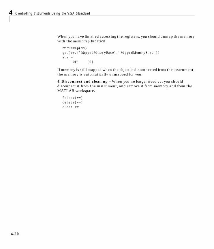
4 Controlling Instruments Using the VISA Standard
4-20
When you have finished accessing the registers, you should unmap the memorywith the memunmap function.
memunmap(vv)get(vv,{'MappedMemoryBase','MappedMemorySize'})ans = '0H' [0]
If memory is still mapped when the object is disconnected from the instrument,the memory is automatically unmapped for you.
4. Disconnect and clean up – When you no longer need vv, you shoulddisconnect it from the instrument, and remove it from memory and from theMATLAB workspace.
fclose(vv)delete(vv)clear vv
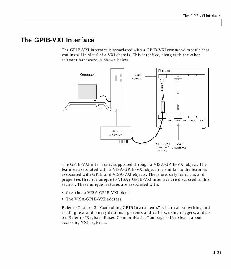
The GPIB-VXI Interface
4-21
The GPIB-VXI InterfaceThe GPIB-VXI interface is associated with a GPIB-VXI command module thatyou install in slot 0 of a VXI chassis. This interface, along with the otherrelevant hardware, is shown below.
The GPIB-VXI interface is supported through a VISA-GPIB-VXI object. Thefeatures associated with a VISA-GPIB-VXI object are similar to the featuresassociated with GPIB and VISA-VXI objects. Therefore, only functions andproperties that are unique to VISA’s GPIB-VXI interface are discussed in thissection. These unique features are associated with:
• Creating a VISA-GPIB-VXI object
• The VISA-GPIB-VXI address
Refer to Chapter 3, “Controlling GPIB Instruments” to learn about writing andreading text and binary data, using events and actions, using triggers, and soon. Refer to “Register-Based Communication” on page 4-13 to learn aboutaccessing VXI registers.
4 Controlling Instruments Using the VISA Standard
4-22
Note The VISA-GPIB-VXI object does not support the spoll and triggerfunctions, or the BusManagementStatus, HandshakeStatus, InterruptAction,TriggerAction, TriggerLine, and TriggerType properties.
Creating a VISA-GPIB-VXI ObjectYou create a VISA-GPIB-VXI object with the visa function. As shown in thepreceding figure, each object is associated with:
• A GPIB controller installed in your computer
• A VXI chassis
• A GPIB-VXI command module in slot 0 of the VXI chassis
• An instrument installed in the VXI chassis
visa requires the vendor name and the resource name as input arguments. Thevendor name is either agilent or ni. The resource name consists of the VXIchassis index and the instrument logical address. You can find theVISA-GPIB-VXI resource name for a given instrument with the configurationtool provided by your vendor, or with the instrhwinfo function. As describedin “Configuring Properties During Object Creation” on page 2-4, you can alsoconfigure property values during object creation.
For example, to create a VISA-GPIB-VXI object associated with a VXI chassiswith index 0, an Agilent E1406A Command Module in slot 0, and an AgilentE1441A Arbitrary Waveform Generator in slot 2 with logical address 80
vgv = visa('agilent','GPIB-VXI0::80::INSTR');
The VISA-GPIB-VXI object vgvnow exists in the MATLAB workspace. You candisplay the class of vgv with the whos command.
whos vgv Name Size Bytes Class
vgv 1x1 644 visa object
Grand total is 18 elements using 644 bytes
The GPIB-VXI Interface
4-23
After you create the VISA-GPIB-VXI object, the properties listed below areautomatically assigned values. These properties provide descriptiveinformation about the object based on its class type and address information.
You can display the values of these properties for vgv with the get function.
get(vgv,{'Name','RsrcName','Type'})ans = 'VISA-GPIB-VXI0-80' 'GPIB-VXI0::80::INSTR' 'visa-gpib-vxi'
Note The GPIB-VXI communication interface is a combination of the GPIBand VXI interfaces. Therefore, you can also use a VISA-GPIB object tocommunicate with instruments installed in the VXI chassis, or tocommunicate with non-VXI instruments connected to the slot 0 controller.
The VISA-GPIB-VXI Object DisplayThe VISA-GPIB-VXI object provides you with a convenient display thatsummarizes important address and state information. You can invoke thedisplay summary these three ways:
• Type the VISA-GPIB-VXI object at the command line.
• Exclude the semicolon when creating a VISA-GPIB-VXI object.
• Exclude the semicolon when configuring properties using the dot notation.
Table 4-8: VISA-GPIB-VXI Descriptive Properties
Property Name Description
Name Specify a descriptive name for the VISA-GPIB-VXIobject.
RsrcName Indicate the resource name for a VISA instrument.
Type Indicate the object type.
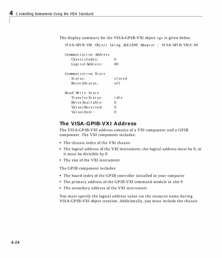
4 Controlling Instruments Using the VISA Standard
4-24
The display summary for the VISA-GPIB-VXI object vgv is given below.
VISA-GPIB-VXI Object Using AGILENT Adaptor : VISA-GPIB-VXI0-80
Communication Address ChassisIndex: 0LogicalAddress: 80
Communication State Status: closedRecordStatus: off
Read/Write State TransferStatus: idleBytesAvailable: 0ValuesReceived: 0ValuesSent: 0
The VISA-GPIB-VXI AddressThe VISA-GPIB-VXI address consists of a VXI component and a GPIBcomponent. The VXI component includes:
• The chassis index of the VXI chassis
• The logical address of the VXI instrument; the logical address must be 0, orit must be divisible by 8
• The slot of the VXI instrument
The GPIB component includes:
• The board index of the GPIB controller installed in your computer
• The primary address of the GPIB-VXI command module in slot 0
• The secondary address of the VXI instrument
You must specify the logical address value via the resource name duringVISA-GPIB-VXI object creation. Additionally, you must include the chassis
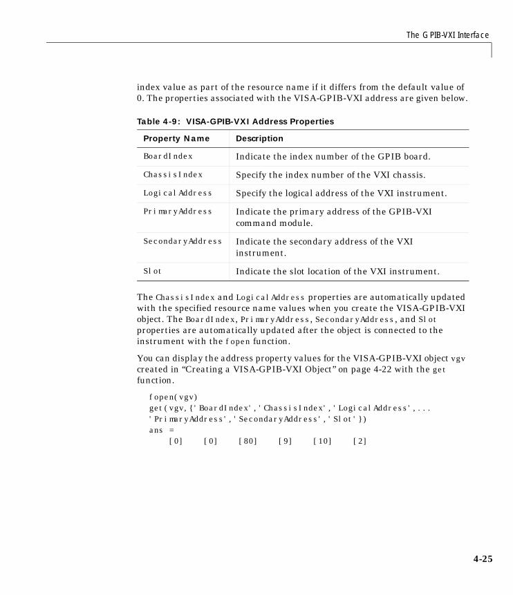
The GPIB-VXI Interface
4-25
index value as part of the resource name if it differs from the default value of0. The properties associated with the VISA-GPIB-VXI address are given below.
The ChassisIndex and LogicalAddress properties are automatically updatedwith the specified resource name values when you create the VISA-GPIB-VXIobject. The BoardIndex, PrimaryAddress, SecondaryAddress, and Slotproperties are automatically updated after the object is connected to theinstrument with the fopen function.
You can display the address property values for the VISA-GPIB-VXI object vgvcreated in “Creating a VISA-GPIB-VXI Object” on page 4-22 with the getfunction.
fopen(vgv)get(vgv,{'BoardIndex','ChassisIndex','LogicalAddress',...'PrimaryAddress','SecondaryAddress','Slot'})ans = [0] [0] [80] [9] [10] [2]
Table 4-9: VISA-GPIB-VXI Address Properties
Property Name Description
BoardIndex Indicate the index number of the GPIB board.
ChassisIndex Specify the index number of the VXI chassis.
LogicalAddress Specify the logical address of the VXI instrument.
PrimaryAddress Indicate the primary address of the GPIB-VXIcommand module.
SecondaryAddress Indicate the secondary address of the VXIinstrument.
Slot Indicate the slot location of the VXI instrument.

4 Controlling Instruments Using the VISA Standard
4-26
The Serial Port InterfaceThe serial port interface is supported through a VISA-serial object. Thefeatures associated with a VISA-serial object are similar to the featuresassociated with a serial port object. Therefore, only functions and propertiesthat are unique to VISA’s serial port interface are discussed in this section.These unique features are associated with:
• Creating a VISA-serial object
• Configuring communication settings
Refer to Chapter 5, “Controlling Serial Port Instruments” to learn aboutwriting and reading text and binary data, using events and actions, usingserial port control lines, and so on.
Note The VISA-serial object does not support the serialbreak function, theBreakInterruptAction property, and the PinStatusAction property.
Creating a VISA-Serial ObjectYou create a VISA-serial object with the visa function. Each VISA-serial objectis associated with an instrument connected to a serial port on your computer.
visa requires the vendor name and the resource name as input arguments. Thevendor name is either agilent or ni. The resource name consists of the nameof the serial port connected to your instrument. You can find the VISA-serialresource name for a given instrument with the configuration tool provided byyour vendor, or with the instrhwinfo function. As described in “ConfiguringProperties During Object Creation” on page 2-4, you can also configureproperty values during object creation.
For example, to create a VISA-serial object that is associated with the COM1port, and that uses National Instruments VISA
vs = visa('ni','ASRL1::INSTR');
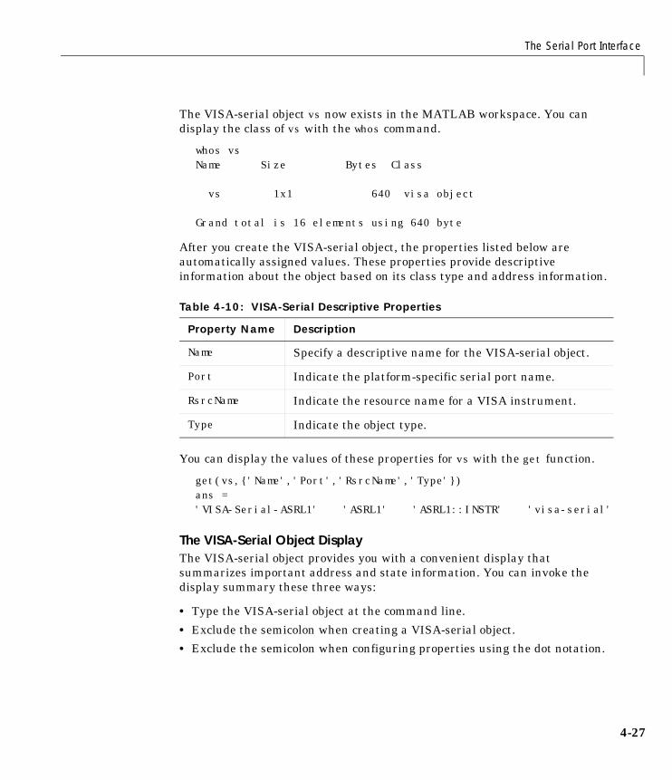
The Serial Port Interface
4-27
The VISA-serial object vs now exists in the MATLAB workspace. You candisplay the class of vs with the whos command.
whos vsName Size Bytes Class
vs 1x1 640 visa object
Grand total is 16 elements using 640 byte
After you create the VISA-serial object, the properties listed below areautomatically assigned values. These properties provide descriptiveinformation about the object based on its class type and address information.
You can display the values of these properties for vs with the get function.
get(vs,{'Name','Port','RsrcName','Type'})ans = 'VISA-Serial-ASRL1' 'ASRL1' 'ASRL1::INSTR' 'visa-serial'
The VISA-Serial Object DisplayThe VISA-serial object provides you with a convenient display thatsummarizes important address and state information. You can invoke thedisplay summary these three ways:
• Type the VISA-serial object at the command line.
• Exclude the semicolon when creating a VISA-serial object.
• Exclude the semicolon when configuring properties using the dot notation.
Table 4-10: VISA-Serial Descriptive Properties
Property Name Description
Name Specify a descriptive name for the VISA-serial object.
Port Indicate the platform-specific serial port name.
RsrcName Indicate the resource name for a VISA instrument.
Type Indicate the object type.
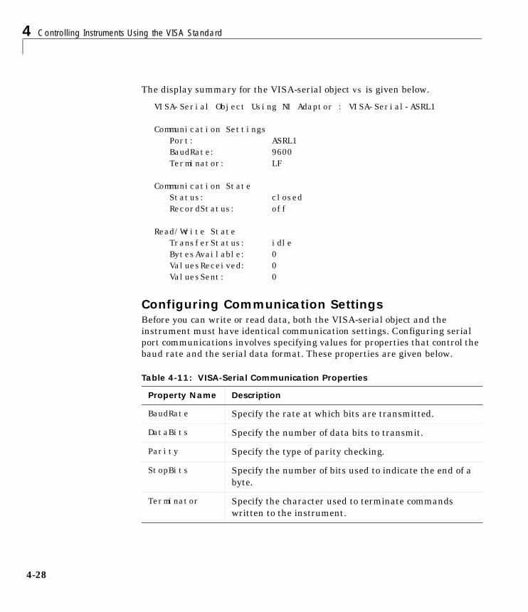
4 Controlling Instruments Using the VISA Standard
4-28
The display summary for the VISA-serial object vs is given below.
VISA-Serial Object Using NI Adaptor : VISA-Serial-ASRL1
Communication Settings Port: ASRL1BaudRate: 9600Terminator: LF
Communication State Status: closedRecordStatus: off
Read/Write State TransferStatus: idleBytesAvailable: 0ValuesReceived: 0ValuesSent: 0
Configuring Communication SettingsBefore you can write or read data, both the VISA-serial object and theinstrument must have identical communication settings. Configuring serialport communications involves specifying values for properties that control thebaud rate and the serial data format. These properties are given below.
Table 4-11: VISA-Serial Communication Properties
Property Name Description
BaudRate Specify the rate at which bits are transmitted.
DataBits Specify the number of data bits to transmit.
Parity Specify the type of parity checking.
StopBits Specify the number of bits used to indicate the end of abyte.
Terminator Specify the character used to terminate commandswritten to the instrument.
The Serial Port Interface
4-29
Refer to your instrument documentation for an explanation of its supportedcommunication settings. Note that the valid values for StopBits are 1 and 2,and the valid values for Terminator are CR and LF. These values differ from thevalues supported for the serial port object.
You can display the default communication property values for the VISA-serialobject vs created in “Creating a VISA-Serial Object” on page 4-26 with the getfunction.
get(vs,{'BaudRate','DataBits','Parity','StopBits','Terminator'})ans =
[9600] [8] 'none' [1] 'LF'

4 Controlling Instruments Using the VISA Standard
4-30
5Controlling Serial PortInstruments
Serial Port Overview . . . . . . . . . . . . . . . . 5-2What Is Serial Communication? . . . . . . . . . . . . 5-2The Serial Port Interface Standard . . . . . . . . . . . 5-2Connecting Two Devices with a Serial Cable . . . . . . . 5-3Serial Port Signals and Pin Assignments . . . . . . . . . 5-5Serial Data Format . . . . . . . . . . . . . . . . . . 5-9Finding Serial Port Information for Your Platform . . . . . 5-13
Creating a Serial Port Object . . . . . . . . . . . . 5-16The Serial Port Object Display . . . . . . . . . . . . . 5-17
Configuring Communication Settings . . . . . . . . 5-18
Writing and Reading Data . . . . . . . . . . . . . . 5-19Asynchronous Write and Read Operations . . . . . . . . 5-19Rules for Completing Write and Read Operations . . . . . 5-20Example: Writing and Reading Text Data . . . . . . . . 5-21
Using Events and Actions . . . . . . . . . . . . . . 5-24Event Types and Action Properties . . . . . . . . . . . 5-24Storing Event Information . . . . . . . . . . . . . . . 5-25Example: Using Events and Actions . . . . . . . . . . . 5-27
Using Control Pins . . . . . . . . . . . . . . . . . 5-29Signaling the Presence of Connected Devices . . . . . . . 5-29Controlling the Flow of Data: Handshaking . . . . . . . . 5-32
5 Controlling Serial Port Instruments
5-2
Serial Port OverviewThis section provides an overview of the serial port. Topics include:
• What is Serial Communication?
• The Serial Port Interface Standard
• Connecting Two Devices with a Serial Cable
• Serial Port Signals and Pin Assignments
• Serial Data Format
• Finding Serial Port Information for Your Platform
For many serial port applications, you can communicate with your instrumentwithout detailed knowledge of how the serial port works. Communication isestablished through a serial port object, which you create in the MATLABworkspace.
If your application is straightforward, or if you are already familiar with thetopics mentioned above, you may want to begin with “Creating a Serial PortObject” on page 5-16. If you want a high-level description of all the steps youare likely to take when communicating with your instrument, refer to Chapter2, “The Instrument Control Session.”
What Is Serial Communication?Serial communication is the most common low-level protocol forcommunicating between two or more devices. Normally, one device is acomputer, while the other device can be a modem, a printer, another computer,or a scientific instrument such as an oscilloscope or a function generator.
As the name suggests, the serial port sends and receives bytes of informationin a serial fashion – one bit at a time. These bytes are transmitted using eithera binary format or a text (ASCII) format.
The Serial Port Interface StandardOver the years, several serial port interface standards for connectingcomputers to peripheral devices have been developed. These standards includeRS-232, RS-422, and RS-485 – all of which are supported by the serial portobject. Of these, the most widely used standard is RS-232, which stands forRecommended Standard number 232.

Serial Port Overview
5-3
The current version of this standard is designated as TIA/EIA-232C, which ispublished by the Telecommunications Industry Association. However, the term“RS-232” is still in popular use, and is used in this guide when referring to aserial communication port that follows the TIA/EIA-232 standard. RS-232defines these serial port characteristics:
• The maximum bit transfer rate and cable length
• The names, electrical characteristics, and functions of signals
• The mechanical connections and pin assignments
Primary communication is accomplished using three pins: the Transmit Datapin, the Receive Data pin, and the Ground pin. Other pins are available fordata flow control, but are not required.
Note In this guide, it is assumed you are using the RS-232 standard. Refer toyour device documentation to see which interface standard you can use.
Connecting Two Devices with a Serial CableThe RS-232 standard defines the two devices connected with a serial cable asthe Data Terminal Equipment (DTE) and Data Circuit-TerminatingEquipment (DCE). This terminology reflects the RS-232 origin as a standardfor communication between a computer terminal and a modem.
Throughout this guide, your computer is considered a DTE, while peripheraldevices such as modems and printers are considered DCE’s. Note that manyscientific instruments function as DTE’s.
Since RS-232 mainly involves connecting a DTE to a DCE, the pin assignmentsare defined such that straight-through cabling is used, where pin 1 is connectedto pin 1, pin 2 is connected to pin 2, and so on. A DTE to DCE serial connectionusing the transmit data (TD) pin and the receive data (RD) pin is shown below.
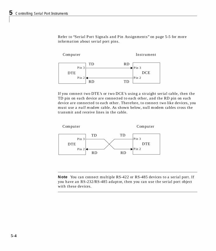
5 Controlling Serial Port Instruments
5-4
Refer to “Serial Port Signals and Pin Assignments” on page 5-5 for moreinformation about serial port pins.
If you connect two DTE’s or two DCE’s using a straight serial cable, then theTD pin on each device are connected to each other, and the RD pin on eachdevice are connected to each other. Therefore, to connect two like devices, youmust use a null modem cable. As shown below, null modem cables cross thetransmit and receive lines in the cable.
Note You can connect multiple RS-422 or RS-485 devices to a serial port. Ifyou have an RS-232/RS-485 adaptor, then you can use the serial port objectwith these devices.
DTE DCEPin 2
Pin 3
Pin 2
Pin 3
RD TD
TD RD
Computer Instrument
DTE DTE
TD
Pin 2
Pin 3
Pin 2
Pin 3TD
RDRD
Computer Computer
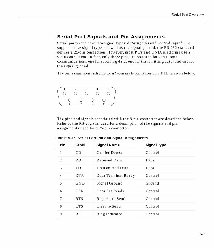
Serial Port Overview
5-5
Serial Port Signals and Pin AssignmentsSerial ports consist of two signal types: data signals and control signals. Tosupport these signal types, as well as the signal ground, the RS-232 standarddefines a 25-pin connection. However, most PC’s and UNIX platforms use a9-pin connection. In fact, only three pins are required for serial portcommunications: one for receiving data, one for transmitting data, and one forthe signal ground.
The pin assignment scheme for a 9-pin male connector on a DTE is given below.
The pins and signals associated with the 9-pin connector are described below.Refer to the RS-232 standard for a description of the signals and pinassignments used for a 25-pin connector.
Table 5-1: Serial Port Pin and Signal Assignments
Pin Label Signal Name Signal Type
1 CD Carrier Detect Control
2 RD Received Data Data
3 TD Transmitted Data Data
4 DTR Data Terminal Ready Control
5 GND Signal Ground Ground
6 DSR Data Set Ready Control
7 RTS Request to Send Control
8 CTS Clear to Send Control
9 RI Ring Indicator Control
1 2 3 4 5
6 7 8 9
5 Controlling Serial Port Instruments
5-6
The term “data set” is synonymous with “modem” or “device,” while the term“data terminal” is synonymous with “computer.”
Note The serial port pin and signal assignments are with respect to the DTE.For example, data is transmitted from the TD pin of the DTE to the RD pin ofthe DCE.
Signal StatesSignals can be in either an active state or an inactive state. An active statecorresponds to the binary value 1, while an inactive state corresponds to thebinary value 0. An active signal state is often described as logic 1, on, true, ora mark. An inactive signal state is often described as logic 0, off, false, or aspace.
For data signals, the “on” state occurs when the received signal voltage is morenegative than -3 volts, while the “off” state occurs for voltages more positivethan 3 volts. For control signals, the “on” state occurs when the received signalvoltage is more positive than 3 volts, while the “off” state occurs for voltagesmore negative than -3 volts. The voltage between -3 volts and +3 volts isconsidered a transition region, and the signal state is undefined.
To bring the signal to the “on” state, the controlling device unasserts (or lowers)the value for data pins and asserts (or raises) the value for control pins.Conversely, to bring the signal to the “off” state, the controlling device assertsthe value for data pins and unasserts the value for control pins.
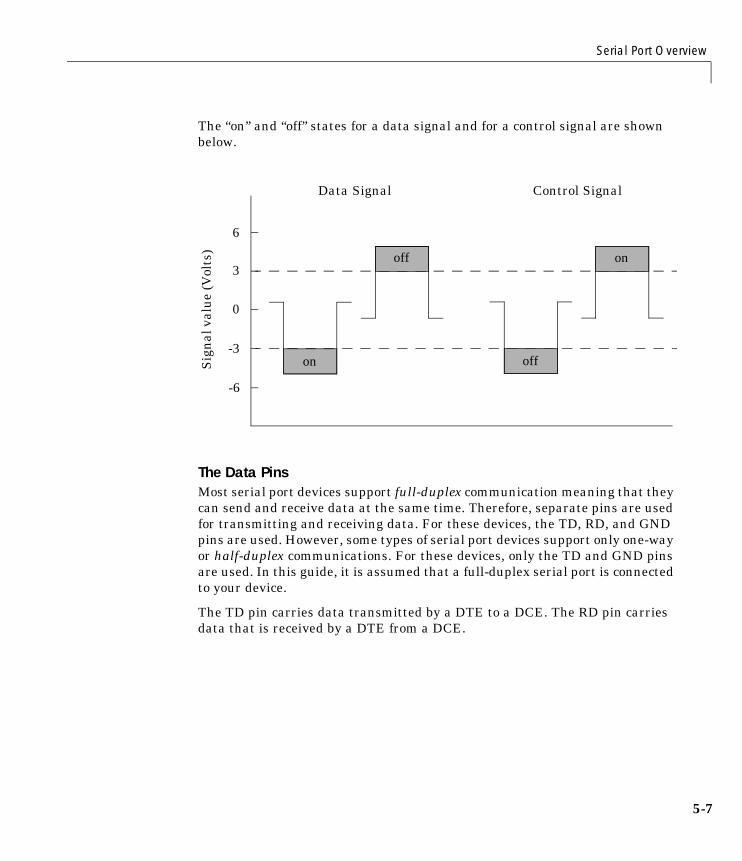
Serial Port Overview
5-7
The “on” and “off” states for a data signal and for a control signal are shownbelow.
The Data PinsMost serial port devices support full-duplex communication meaning that theycan send and receive data at the same time. Therefore, separate pins are usedfor transmitting and receiving data. For these devices, the TD, RD, and GNDpins are used. However, some types of serial port devices support only one-wayor half-duplex communications. For these devices, only the TD and GND pinsare used. In this guide, it is assumed that a full-duplex serial port is connectedto your device.
The TD pin carries data transmitted by a DTE to a DCE. The RD pin carriesdata that is received by a DTE from a DCE.
-6
Sig
nal
valu
e(V
olts
)
-3
0
3
6
Data Signal Control Signal
on
off
off
on
5 Controlling Serial Port Instruments
5-8
The Control Pins9-pin serial ports provide several control pins that:
• Signal the presence of connected devices
• Control the flow of data
The control pins include RTS and CTS, DTR and DSR, CD, and RI.
The RTS and CTS Pins. The RTS and CTS pins are used to signal whether thedevices are ready to send or receive data. This type of data flow control – calledhardware handshaking – is used to prevent data loss during transmission.When enabled for both the DTE and DCE, hardware handshaking using RTSand CTS follows these steps:
1 The DTE asserts the RTS pin to instruct the DCE that it is ready to receivedata.
2 The DCE asserts the CTS pin indicating that it is clear to send data over theTD pin. If data can no longer be sent, the CTS pin is unasserted.
3 The data is transmitted to the DTE over the TD pin. If data can no longer beaccepted, the RTS pin is unasserted by the DTE and the data transmissionis stopped.
To enable hardware handshaking, refer to “Controlling the Flow of Data:Handshaking” on page 5-32.
The DTR and DSR Pins. Many devices use the DSR and DTR pins to signal if theyare connected and powered. Signaling the presence of connected devices usingDTR and DSR follows these steps:
1 The DTE asserts the DTR pin to request that the DCE connect to thecommunication line.
2 The DCE asserts the DSR pin to indicate it’s connected.
3 DCE unasserts the DSR pin when it’s disconnected from the communicationline.
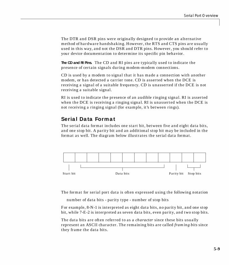
Serial Port Overview
5-9
The DTR and DSR pins were originally designed to provide an alternativemethod of hardware handshaking. However, the RTS and CTS pins are usuallyused in this way, and not the DSR and DTR pins. However, you should refer toyour device documentation to determine its specific pin behavior.
The CD and RI Pins. The CD and RI pins are typically used to indicate thepresence of certain signals during modem-modem connections.
CD is used by a modem to signal that it has made a connection with anothermodem, or has detected a carrier tone. CD is asserted when the DCE isreceiving a signal of a suitable frequency. CD is unasserted if the DCE is notreceiving a suitable signal.
RI is used to indicate the presence of an audible ringing signal. RI is assertedwhen the DCE is receiving a ringing signal. RI is unasserted when the DCE isnot receiving a ringing signal (for example, it’s between rings).
Serial Data FormatThe serial data format includes one start bit, between five and eight data bits,and one stop bit. A parity bit and an additional stop bit may be included in theformat as well. The diagram below illustrates the serial data format.
The format for serial port data is often expressed using the following notation
number of data bits - parity type - number of stop bits
For example, 8-N-1 is interpreted as eight data bits, no parity bit, and one stopbit, while 7-E-2 is interpreted as seven data bits, even parity, and two stop bits.
The data bits are often referred to as a character since these bits usuallyrepresent an ASCII character. The remaining bits are called framing bits sincethey frame the data bits.
Start bit Data bits Parity bit Stop bits
5 Controlling Serial Port Instruments
5-10
Bytes Versus ValuesThe collection of bits that comprise the serial data format is called a byte. Atfirst, this term may seem inaccurate since a byte is 8 bits and the serial dataformat can range between 7 bits and 12 bits. However, when serial data isstored on your computer, the framing bits are stripped away, and only the databits are retained. Moreover, eight data bits are always used regardless of thenumber of data bits specified for transmission, with the unused bits assigned avalue of 0.
When reading or writing data, you may need to specify a value, which canconsist of one or more bytes. For example, if you read one value from a deviceusing the int32 format, then that value consists of four bytes. For moreinformation about reading and writing values, refer to “Writing and ReadingData” on page 5-19.
Synchronous and Asynchronous CommunicationThe RS-232 standard supports two types of communication protocols:synchronous and asynchronous.
Using the synchronous protocol, all transmitted bits are synchronized to acommon clock signal. The two devices initially synchronize themselves to eachother, and then continually send characters to stay synchronized. Even whenactual data is not really being sent, a constant flow of bits allows each deviceto know where the other is at any given time. That is, each bit that is sent iseither actual data or an idle character. Synchronous communications allowsfaster data transfer rates than asynchronous methods, because additional bitsto mark the beginning and end of each data byte are not required.
Using the asynchronous protocol, each device uses its own internal clockresulting in bytes that are transferred at arbitrary times. So, instead of usingtime as a way to synchronize the bits, the data format is used.
In particular, the data transmission is synchronized using the start bit of theword, while one or more stop bits indicate the end of the word. The requirementto send these additional bits causes asynchronous communications to beslightly slower than synchronous. However, it has the advantage that theprocessor does not have to deal with the additional idle characters. Most serialports operate asynchronously.
Serial Port Overview
5-11
Note When used in this guide, the terms “synchronous” and “asynchronous”refer to whether read or write operations block access to the MATLABcommand line.
How Are the Bits Transmitted?By definition, serial data is transmitted one bit at a time. The order in whichthe bits are transmitted follows these steps:
1 The start bit is transmitted with a value of 0.
2 The data bits are transmitted. The first data bit corresponds to the leastsignificant bit (LSB), while the last data bit corresponds to the mostsignificant bit (MSB).
3 The parity bit (if defined) is transmitted.
4 One or two stop bits are transmitted, each with a value of 1.
The number of bits transferred per second is given by the baud rate. Thetransferred bits include the start bit, the data bits, the parity bit (if defined),and the stop bits.
Start and Stop BitsAs described in “Synchronous and Asynchronous Communication” onpage 5-10, most serial ports operate asynchronously. This means that thetransmitted byte must be identified by start and stop bits. The start bitindicates when the data byte is about to begin and the stop bit(s) indicateswhen the data byte has been transferred. The process of identifying bytes withthe serial data format follows these steps:
1 When a serial port pin is idle (not transmitting data), then it is in an “on”state.
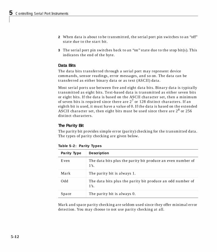
5 Controlling Serial Port Instruments
5-12
2 When data is about to be transmitted, the serial port pin switches to an “off”state due to the start bit.
3 The serial port pin switches back to an “on” state due to the stop bit(s). Thisindicates the end of the byte.
Data BitsThe data bits transferred through a serial port may represent devicecommands, sensor readings, error messages, and so on. The data can betransferred as either binary data or as text (ASCII) data.
Most serial ports use between five and eight data bits. Binary data is typicallytransmitted as eight bits. Text-based data is transmitted as either seven bitsor eight bits. If the data is based on the ASCII character set, then a minimumof seven bits is required since there are 27 or 128 distinct characters. If aneighth bit is used, it must have a value of 0. If the data is based on the extendedASCII character set, then eight bits must be used since there are 28 or 256distinct characters.
The Parity BitThe parity bit provides simple error (parity) checking for the transmitted data.The types of parity checking are given below.
Mark and space parity checking are seldom used since they offer minimal errordetection. You may choose to not use parity checking at all.
Table 5-2: Parity Types
Parity Type Description
Even The data bits plus the parity bit produce an even number of1’s.
Mark The parity bit is always 1.
Odd The data bits plus the parity bit produce an odd number of1’s.
Space The parity bit is always 0.
Serial Port Overview
5-13
The parity checking process follows these steps:
1 The transmitting device sets the parity bit to 0 or to 1 depending on the databit values and the type of parity checking selected.
2 The receiving device checks if the parity bit is consistent with thetransmitted data. If it is, then the data bits are accepted. If it is not, then anerror is returned.
Note Parity checking can detect only 1-bit errors. Multiple-bit errors canappear as valid data.
For example, suppose the data bits 01110001 are transmitted to yourcomputer. If even parity is selected, then the parity bit is set to 0 by thetransmitting device to produce an even number of 1’s. If odd parity is selected,then the parity bit is set to 1 by the transmitting device to produce an oddnumber of 1’s.
Finding Serial Port Information for Your PlatformThis section describes how to find serial port information using the resourcesprovided by Windows and UNIX platforms.
Note Your operating system provides default values for all serial portsettings. However, these settings are overridden by your MATLAB code, andwill have no effect on your serial port application.
You can also use the instrhwinfo function to programmatically return theavailable serial ports.
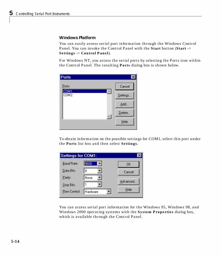
5 Controlling Serial Port Instruments
5-14
Windows PlatformYou can easily access serial port information through the Windows ControlPanel. You can invoke the Control Panel with the Start button (Start ->Settings -> Control Panel).
For Windows NT, you access the serial ports by selecting the Ports icon withinthe Control Panel. The resulting Ports dialog box is shown below.
To obtain information on the possible settings for COM1, select this port underthe Ports list box and then select Settings.
You can access serial port information for the Windows 95, Windows 98, andWindows 2000 operating systems with the System Properties dialog box,which is available through the Control Panel.
Serial Port Overview
5-15
UNIX PlatformTo find serial port information for UNIX platforms, you need to know the serialport names. These names may vary between different operating systems.
On Linux, serial port devices are typically named ttyS0, ttyS1, and so on. Youcan use the setserial command to display or configure serial port information.For example, to display which serial ports are available
setserial -bg /dev/ttyS*/dev/ttyS0 at 0x03f8 (irq = 4) is a 16550A/dev/ttyS1 at 0x02f8 (irq = 3) is a 16550A
To display detailed information about ttyS0
setserial -ag /dev/ttyS0/dev/ttyS0, Line 0, UART: 16550A, Port: 0x03f8, IRQ: 4 Baud_base: 115200, close_delay: 50, divisor: 0 closing_wait: 3000, closing_wait2: infinte Flags: spd_normal skip_test session_lockout
Note If the setserial -ag command does not work, make sure that youhave read and write permission for the port.
For all supported UNIX platforms, you can use the stty command to displayor configure serial port information. For example, to display serial portproperties for ttyS0
stty -a < /dev/ttyS0
To configure the baud rate to 4800 bits per second
stty speed 4800 < /dev/ttyS0 > /dev/ttyS0
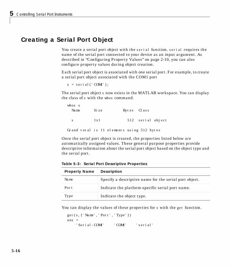
5 Controlling Serial Port Instruments
5-16
Creating a Serial Port ObjectYou create a serial port object with the serial function. serial requires thename of the serial port connected to your device as an input argument. Asdescribed in “Configuring Property Values” on page 2-10, you can alsoconfigure property values during object creation.
Each serial port object is associated with one serial port. For example, to createa serial port object associated with the COM1 port
s = serial('COM1');
The serial port object s now exists in the MATLAB workspace. You can displaythe class of s with the whos command.
whos s Name Size Bytes Class
s 1x1 512 serial object
Grand total is 11 elements using 512 bytes
Once the serial port object is created, the properties listed below areautomatically assigned values. These general purpose properties providedescriptive information about the serial port object based on the object type andthe serial port.
You can display the values of these properties for s with the get function.
get(s,{'Name','Port','Type'})ans = 'Serial-COM1' 'COM1' 'serial'
Table 5-3: Serial Port Descriptive Properties
Property Name Description
Name Specify a descriptive name for the serial port object.
Port Indicate the platform-specific serial port name.
Type Indicate the object type.
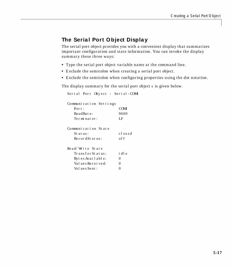
Creating a Serial Port Object
5-17
The Serial Port Object DisplayThe serial port object provides you with a convenient display that summarizesimportant configuration and state information. You can invoke the displaysummary these three ways:
• Type the serial port object variable name at the command line.
• Exclude the semicolon when creating a serial port object.
• Exclude the semicolon when configuring properties using the dot notation.
The display summary for the serial port object s is given below.
Serial Port Object : Serial-COM1
Communication Settings Port: COM1BaudRate: 9600Terminator: LF
Communication State Status: closedRecordStatus: off
Read/Write State TransferStatus: idleBytesAvailable: 0ValuesReceived: 0ValuesSent: 0
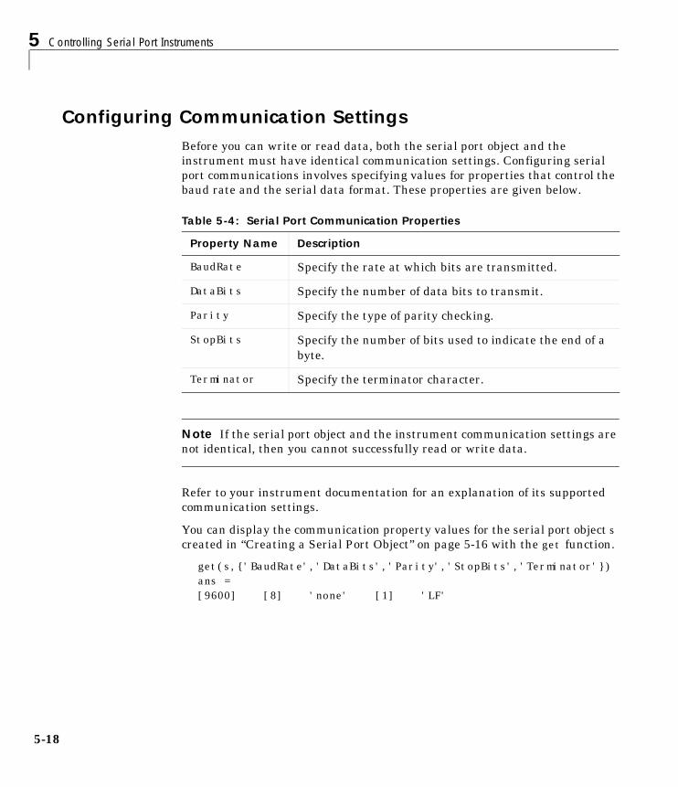
5 Controlling Serial Port Instruments
5-18
Configuring Communication SettingsBefore you can write or read data, both the serial port object and theinstrument must have identical communication settings. Configuring serialport communications involves specifying values for properties that control thebaud rate and the serial data format. These properties are given below.
Note If the serial port object and the instrument communication settings arenot identical, then you cannot successfully read or write data.
Refer to your instrument documentation for an explanation of its supportedcommunication settings.
You can display the communication property values for the serial port object screated in “Creating a Serial Port Object” on page 5-16 with the get function.
get(s,{'BaudRate','DataBits','Parity','StopBits','Terminator'})ans = [9600] [8] 'none' [1] 'LF'
Table 5-4: Serial Port Communication Properties
Property Name Description
BaudRate Specify the rate at which bits are transmitted.
DataBits Specify the number of data bits to transmit.
Parity Specify the type of parity checking.
StopBits Specify the number of bits used to indicate the end of abyte.
Terminator Specify the terminator character.
Writing and Reading Data
5-19
Writing and Reading DataThis section describes interface-specific issues related to writing and readingdata with a serial port object. Topics include:
• Asynchronous write and read operations
• Rules for completing write and read operations
• An example that illustrates writing and reading text data
For a general overview about writing and reading data, as well as a list of allassociated functions and properties, refer to “Writing and Reading Data” onpage 2-12.
Asynchronous Write and Read OperationsAsynchronous write and read operations do not block access to the MATLABcommand line. Additionally, while an asynchronous operation is in progressyou can:
• Execute a read (write) operation while an asynchronous write (read)operation is in progress. This is because serial ports have separate pins forreading and writing.
• Make use of all supported action properties. Refer to “Using Events andActions” on page 5-24 for more information about the action propertiessupported by serial port objects.
The process of writing data asynchronously is given in “Synchronous VersusAsynchronous Write Operations” on page 2-17. The process of reading dataasynchronously is described in the next section.
Asynchronous Read OperationsFor serial port objects, you specify whether read operations are synchronous orasynchronous with the ReadAsyncMode property. You can configureReadAsyncMode to continuous or manual.
If ReadAsyncMode is continuous (the default value), the serial port objectcontinuously queries the instrument to determine if data is available to beread. If data is available, it is asynchronously stored in the input buffer. Totransfer the data from the input buffer to MATLAB, you use one of the
5 Controlling Serial Port Instruments
5-20
synchronous (blocking) read functions such as fgetl, fgets, fscanf, or fread.If data is available in the input buffer, these functions will return quickly.
s = serial('COM1');fopen(s)s.ReadAsyncMode = 'continuous';fprintf(s,'*IDN?')s.BytesAvailableans = 56out = fscanf(s);
If ReadAsyncMode is manual, the serial port object does not continuously querythe instrument to determine if data is available to be read. To read dataasynchronously, you use the readasync function. You then use one of thesynchronous read functions to transfer data from the input buffer to MATLAB.
s.ReadAsyncMode = 'manual';fprintf(s,'*IDN?')s.BytesAvailableans = 0readasync(s)s.BytesAvailableans = 56out = fscanf(s);
Rules for Completing Write and Read OperationsThe rules for completing synchronous and asynchronous read and writeoperations are described below.
Completing Write OperationsA write operation using fprintf or fwrite completes when one of theseconditions is satisfied:
• The specified data is written.
• The time specified by the Timeout property passes.
Writing and Reading Data
5-21
In addition to these rules, you can stop an asynchronous write operation at anytime with the stopasync function.
A text command is processed by the instrument only when it receives therequired terminator. For serial port objects, each occurrence of \n in thecommand is replaced with the Terminator property value. Since the defaultformat for fprintf is %s\n, all commands written to the instrument will endwith the Terminator value. The default value of Terminator is the line feedcharacter. The terminator required by your instrument will be described in itsdocumentation.
Completing Read OperationsA read operation with fgetl, fgets, fscanf, or readasync completes when oneof these conditions is satisfied:
• The terminator specified by the Terminator property is read.
• The time specified by the Timeout property passes.
• The input buffer is filled.
• The specified number of values is read (fscanf and readasync only).
A read operation with fread completes when one of these conditions issatisfied:
• The time specified by the Timeout property passes.
• The specified number of values is read.
In addition to these rules, you can stop an asynchronous read operation at anytime with the stopasync function.
Example: Writing and Reading Text DataThis example illustrates how to communicate with a serial port instrument bywriting and reading text data.
The instrument is a Tektronix TDS 210 two-channel oscilloscope connected tothe serial port COM1. Therefore, many of the commands given below arespecific to this instrument. A sine wave is input into channel 2 of theoscilloscope, and your job is to measure the peak-to-peak voltage of the inputsignal.
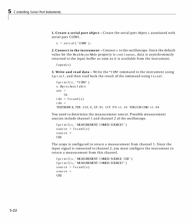
5 Controlling Serial Port Instruments
5-22
1. Create a serial port object – Create the serial port object s associated withserial port COM1.
s = serial('COM1');
2. Connect to the instrument – Connect s to the oscilloscope. Since the defaultvalue for the ReadAsyncMode property is continuous, data is asynchronouslyreturned to the input buffer as soon as it is available from the instrument.
fopen(s)
3. Write and read data – Write the *IDN? command to the instrument usingfprintf, and then read back the result of the command using fscanf.
fprintf(s,'*IDN?')s.BytesAvailableans = 56idn = fscanf(s)idn =TEKTRONIX,TDS 210,0,CF:91.1CT FV:v1.16 TDS2CM:CMV:v1.04
You need to determine the measurement source. Possible measurementsources include channel 1 and channel 2 of the oscilloscope.
fprintf(s,'MEASUREMENT:IMMED:SOURCE?')source = fscanf(s)source =CH1
The scope is configured to return a measurement from channel 1. Since theinput signal is connected to channel 2, you must configure the instrument toreturn a measurement from this channel.
fprintf(s,'MEASUREMENT:IMMED:SOURCE CH2')fprintf(s,'MEASUREMENT:IMMED:SOURCE?')source = fscanf(s)source =CH2
Writing and Reading Data
5-23
You can now configure the scope to return the peak-to-peak voltage, and thenrequest the value of this measurement.
fprintf(s,'MEASUREMENT:MEAS1:TYPE PK2PK')fprintf(s,'MEASUREMENT:MEAS1:VALUE?')
Transfer data from the input buffer to MATLAB using fscanf.
ptop = fscanf(s)ptop =2.0199999809E0
4. Disconnect and clean up – When you no longer need s, you shoulddisconnect it from the instrument, and remove it from memory and from theMATLAB workspace.
fclose(s)delete(s)clear s
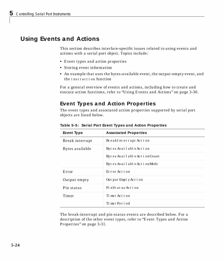
5 Controlling Serial Port Instruments
5-24
Using Events and ActionsThis section describes interface-specific issues related to using events andactions with a serial port object. Topics include:
• Event types and action properties
• Storing event information
• An example that uses the bytes-available event, the output-empty event, andthe instraction function
For a general overview of events and actions, including how to create andexecute action functions, refer to “Using Events and Actions” on page 3-30.
Event Types and Action PropertiesThe event types and associated action properties supported by serial portobjects are listed below.
The break-interrupt and pin-status events are described below. For adescription of the other event types, refer to “Event Types and ActionProperties” on page 3-31.
Table 5-5: Serial Port Event Types and Action Properties
Event Type Associated Properties
Break interrupt BreakInterruptAction
Bytes available BytesAvailableAction
BytesAvailableActionCount
BytesAvailableActionMode
Error ErrorAction
Output empty OutputEmptyAction
Pin status PinStatusAction
Timer TimerAction
TimerPeriod
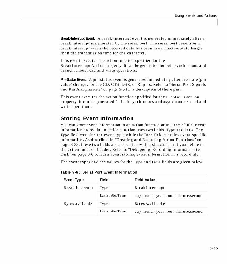
Using Events and Actions
5-25
Break-Interrupt Event. A break-interrupt event is generated immediately after abreak interrupt is generated by the serial port. The serial port generates abreak interrupt when the received data has been in an inactive state longerthan the transmission time for one character.
This event executes the action function specified for theBreakInterruptAction property. It can be generated for both synchronous andasynchronous read and write operations.
Pin-Status Event. A pin-status event is generated immediately after the state (pinvalue) changes for the CD, CTS, DSR, or RI pins. Refer to “Serial Port Signalsand Pin Assignments” on page 5-5 for a description of these pins.
This event executes the action function specified for the PinStatusActionproperty. It can be generated for both synchronous and asynchronous read andwrite operations.
Storing Event InformationYou can store event information in an action function or in a record file. Eventinformation stored in an action function uses two fields: Type and Data. TheType field contains the event type, while the Data field contains event-specificinformation. As described in “Creating and Executing Action Functions” onpage 3-33, these two fields are associated with a structure that you define inthe action function header. Refer to “Debugging: Recording Information toDisk” on page 6-6 to learn about storing event information in a record file.
The event types and the values for the Type and Data fields are given below.
Table 5-6: Serial Port Event Information
Event Type Field Field Value
Break interrupt Type BreakInterrupt
Data.AbsTime day-month-year hour:minute:second
Bytes available Type BytesAvailable
Data.AbsTime day-month-year hour:minute:second
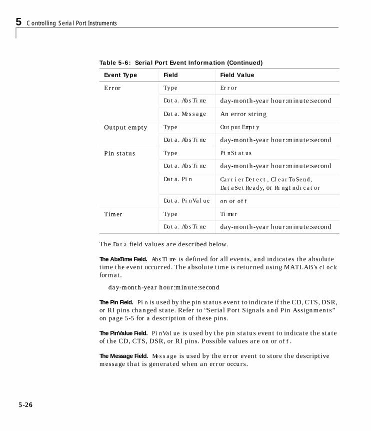
5 Controlling Serial Port Instruments
5-26
The Data field values are described below.
The AbsTime Field. AbsTime is defined for all events, and indicates the absolutetime the event occurred. The absolute time is returned using MATLAB’s clockformat.
day-month-year hour:minute:second
The Pin Field. Pin is used by the pin status event to indicate if the CD, CTS, DSR,or RI pins changed state. Refer to “Serial Port Signals and Pin Assignments”on page 5-5 for a description of these pins.
The PinValue Field. PinValue is used by the pin status event to indicate the stateof the CD, CTS, DSR, or RI pins. Possible values are on or off.
The Message Field. Message is used by the error event to store the descriptivemessage that is generated when an error occurs.
Error Type Error
Data.AbsTime day-month-year hour:minute:second
Data.Message An error string
Output empty Type OutputEmpty
Data.AbsTime day-month-year hour:minute:second
Pin status Type PinStatus
Data.AbsTime day-month-year hour:minute:second
Data.Pin CarrierDetect, ClearToSend,DataSetReady, or RingIndicator
Data.PinValue on or off
Timer Type Timer
Data.AbsTime day-month-year hour:minute:second
Table 5-6: Serial Port Event Information (Continued)
Event Type Field Field Value
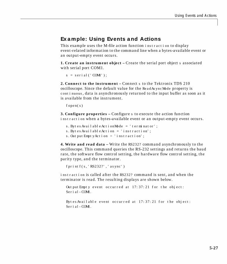
Using Events and Actions
5-27
Example: Using Events and ActionsThis example uses the M-file action function instraction to displayevent-related information to the command line when a bytes-available event oran output-empty event occurs.
1. Create an instrument object – Create the serial port object s associatedwith serial port COM1.
s = serial('COM1');
2. Connect to the instrument – Connect s to the Tektronix TDS 210oscilloscope. Since the default value for the ReadAsyncMode property iscontinuous, data is asynchronously returned to the input buffer as soon as itis available from the instrument.
fopen(s)
3. Configure properties – Configure s to execute the action functioninstraction when a bytes-available event or an output-empty event occurs.
s.BytesAvailableActionMode = 'terminator';s.BytesAvailableAction = 'instraction';s.OutputEmptyAction = 'instraction';
4. Write and read data – Write the RS232? command asynchronously to theoscilloscope. This command queries the RS-232 settings and returns the baudrate, the software flow control setting, the hardware flow control setting, theparity type, and the terminator.
fprintf(s,'RS232?','async')
instraction is called after the RS232? command is sent, and when theterminator is read. The resulting displays are shown below.
OutputEmpty event occurred at 17:37:21 for the object: Serial-COM1.
BytesAvailable event occurred at 17:37:21 for the object: Serial-COM1.
5 Controlling Serial Port Instruments
5-28
Read the data from the input buffer.
out = fscanf(s)out =9600;0;0;NONE;LF
5. Disconnect and clean up – When you no longer need s, you shoulddisconnect it from the instrument, and remove it from memory and from theMATLAB workspace.
fclose(s)delete(s)clear s
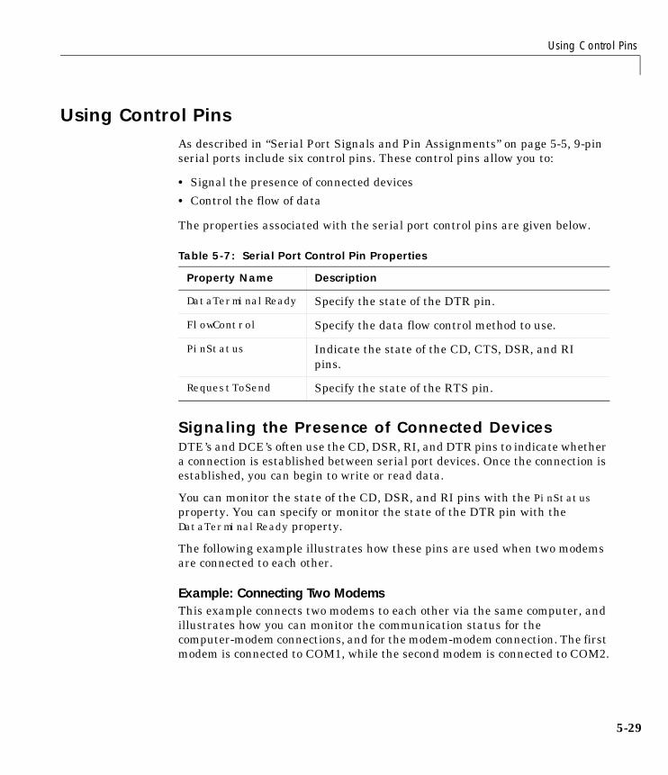
Using Control Pins
5-29
Using Control PinsAs described in “Serial Port Signals and Pin Assignments” on page 5-5, 9-pinserial ports include six control pins. These control pins allow you to:
• Signal the presence of connected devices
• Control the flow of data
The properties associated with the serial port control pins are given below.
Signaling the Presence of Connected DevicesDTE’s and DCE’s often use the CD, DSR, RI, and DTR pins to indicate whethera connection is established between serial port devices. Once the connection isestablished, you can begin to write or read data.
You can monitor the state of the CD, DSR, and RI pins with the PinStatusproperty. You can specify or monitor the state of the DTR pin with theDataTerminalReady property.
The following example illustrates how these pins are used when two modemsare connected to each other.
Example: Connecting Two ModemsThis example connects two modems to each other via the same computer, andillustrates how you can monitor the communication status for thecomputer-modem connections, and for the modem-modem connection. The firstmodem is connected to COM1, while the second modem is connected to COM2.
Table 5-7: Serial Port Control Pin Properties
Property Name Description
DataTerminalReady Specify the state of the DTR pin.
FlowControl Specify the data flow control method to use.
PinStatus Indicate the state of the CD, CTS, DSR, and RIpins.
RequestToSend Specify the state of the RTS pin.
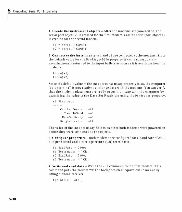
5 Controlling Serial Port Instruments
5-30
1. Create the instrument objects – After the modems are powered on, theserial port object s1 is created for the first modem, and the serial port object s2is created for the second modem.
s1 = serial('COM1');s2 = serial('COM2');
2. Connect to the instruments – s1 and s2 are connected to the modems. Sincethe default value for the ReadAsyncMode property is continuous, data isasynchronously returned to the input buffers as soon as it is available from themodems.
fopen(s1)fopen(s2)
Since the default value of the DataTerminalReady property is on, the computer(data terminal) is now ready to exchange data with the modems. You can verifythat the modems (data sets) are ready to communicate with the computer byexamining the value of the Data Set Ready pin using the PinStatus property.
s1.Pinstatusans = CarrierDetect: 'off' ClearToSend: 'on' DataSetReady: 'on' RingIndicator: 'off'
The value of the DataSetReady field is on since both modems were powered onbefore they were connected to the objects.
3. Configure properties – Both modems are configured for a baud rate of 2400bits per second and a carriage return (CR) terminator.
s1.BaudRate = 2400;s1.Terminator = 'CR';s2.BaudRate = 2400;s2.Terminator = 'CR';
4. Write and read data – Write the atd command to the first modem. Thiscommand puts the modem “off the hook,” which is equivalent to manuallylifting a phone receiver.
fprintf(s1,'atd')
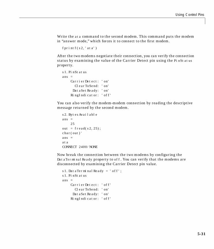
Using Control Pins
5-31
Write the ata command to the second modem. This command puts the modemin “answer mode,” which forces it to connect to the first modem.
fprintf(s2,'ata')
After the two modems negotiate their connection, you can verify the connectionstatus by examining the value of the Carrier Detect pin using the PinStatusproperty.
s1.PinStatusans = CarrierDetect: 'on' ClearToSend: 'on' DataSetReady: 'on' RingIndicator: 'off'
You can also verify the modem-modem connection by reading the descriptivemessage returned by the second modem.
s2.BytesAvailableans = 25out = fread(s2,25);char(out)'ans =ataCONNECT 2400/NONE
Now break the connection between the two modems by configuring theDataTerminalReady property to off. You can verify that the modems aredisconnected by examining the Carrier Detect pin value.
s1.DataTerminalReady = 'off';s1.PinStatusans = CarrierDetect: 'off' ClearToSend: 'on' DataSetReady: 'on' RingIndicator: 'off'
5 Controlling Serial Port Instruments
5-32
5. Disconnect and clean up – Disconnect the objects from the modems, andremove the objects from memory and from the MATLAB workspace.
fclose([s1 s2])delete([s1 s2])clear s1 s2
Controlling the Flow of Data: HandshakingData flow control or handshaking is a method used for communicating betweena DCE and a DTE to prevent data loss during transmission. For example,suppose your computer can receive only a limited amount of data before it mustbe processed. As this limit is reached, a handshaking signal is transmitted tothe DCE to stop sending data. When the computer can accept more data,another handshaking signal is transmitted to the DCE to resume sending data.
If supported by your device, you can control data flow using one of thesemethods:
• Hardware handshaking
• Software handshaking
Note Although you may be able to configure your device for both hardwarehandshaking and software handshaking at the same time, the InstrumentControl Toolbox does not support this behavior.
You can specify the data flow control method with the FlowControl property.If FlowControl is hardware, then hardware handshaking is used to controldata flow. If FlowControl is software, then software handshaking is used tocontrol data flow. If FlowControl is none, then no handshaking is used.
Hardware HandshakingHardware handshaking uses specific serial port pins to control data flow. Inmost cases, these are the RTS and CTS pins. Hardware handshaking usingthese pins is described in “The RTS and CTS Pins” on page 5-8.
If FlowControl is hardware, then the RTS and CTS pins are automaticallymanaged by the DTE and DCE. You can return the CTS pin value with the
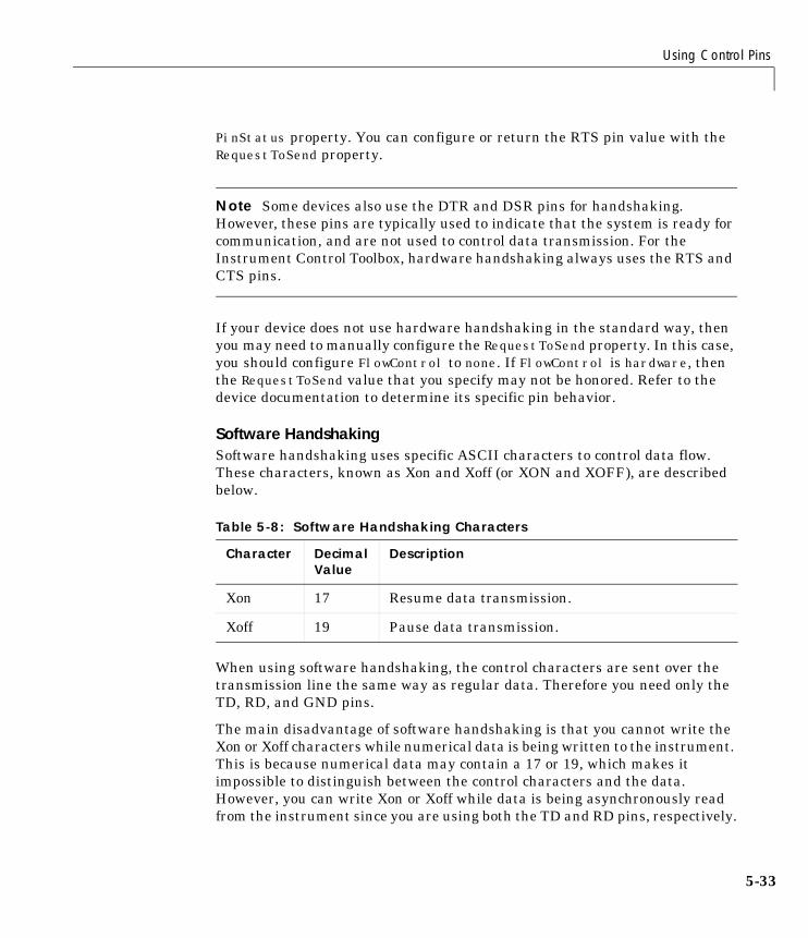
Using Control Pins
5-33
PinStatus property. You can configure or return the RTS pin value with theRequestToSend property.
Note Some devices also use the DTR and DSR pins for handshaking.However, these pins are typically used to indicate that the system is ready forcommunication, and are not used to control data transmission. For theInstrument Control Toolbox, hardware handshaking always uses the RTS andCTS pins.
If your device does not use hardware handshaking in the standard way, thenyou may need to manually configure the RequestToSend property. In this case,you should configure FlowControl to none. If FlowControl is hardware, thenthe RequestToSend value that you specify may not be honored. Refer to thedevice documentation to determine its specific pin behavior.
Software HandshakingSoftware handshaking uses specific ASCII characters to control data flow.These characters, known as Xon and Xoff (or XON and XOFF), are describedbelow.
When using software handshaking, the control characters are sent over thetransmission line the same way as regular data. Therefore you need only theTD, RD, and GND pins.
The main disadvantage of software handshaking is that you cannot write theXon or Xoff characters while numerical data is being written to the instrument.This is because numerical data may contain a 17 or 19, which makes itimpossible to distinguish between the control characters and the data.However, you can write Xon or Xoff while data is being asynchronously readfrom the instrument since you are using both the TD and RD pins, respectively.
Table 5-8: Software Handshaking Characters
Character Decimal Value
Description
Xon 17 Resume data transmission.
Xoff 19 Pause data transmission.
5 Controlling Serial Port Instruments
5-34
Example: Using Software HandshakingSuppose you want to use software flow control in conjunction with your serialport application. To do this, you must configure the instrument and the serialport object for software flow control. For a serial port object s connected to aTektronix TDS 210 oscilloscope, this configuration is accomplished with thefollowing commands.
fprintf(s,'RS232:SOFTF ON')s.FlowControl = 'software';
To pause data transfer, you write the numerical value 19 (Xoff) to theinstrument.
fwrite(s,19)
To resume data transfer, you write the numerical value 17 (Xon) to theinstrument.
fwrite(s,17)
6Saving and Loading theSession
Overview . . . . . . . . . . . . . . . . . . . . . 6-2
Saving and Loading Instrument Objects . . . . . . . 6-3Saving Instrument Objects to an M-File . . . . . . . . . 6-3Saving Instrument Objects to a MAT-File . . . . . . . . 6-5
Debugging: Recording Information to Disk . . . . . . 6-6Example: Introduction to Recording Information . . . . . . 6-6Creating Multiple Record Files . . . . . . . . . . . . . 6-7Specifying a Filename . . . . . . . . . . . . . . . . . 6-7The Record File Format . . . . . . . . . . . . . . . . 6-8Example: Recording Information to Disk . . . . . . . . . 6-10
6 Saving and Loading the Session
6-2
OverviewDuring an instrument control session, you may want to save your work to oneor more disk files in order to document or debug your application, post-processdata, and so on. The components of an instrument control session that you cansave to disk are divided into two separate parts:
• Instrument objects and their associated property values
• Information associated with instrument communication including:
- The number of values written to the instrument, the number of valuesread from the instrument, and the data type of the values
- Data written to the instrument, and data read from the instrument
- Event information
You can save specific components of your session to an M-file using theobj2mfile function, to a MAT-file using the save command, or to a text fileusing the record function.
Saving and Loading Instrument Objects
6-3
Saving and Loading Instrument ObjectsYou can save an instrument object to disk using two possible formats:
• As an M-file using the obj2mfile function
• As a MAT-file using the save command
You can also save data transferred between the object and the instrumentusing these two functions. However, it is easier to use the record function forthis purpose as described in “Debugging: Recording Information to Disk” onpage 6-6.
Saving Instrument Objects to an M-FileYou can save an instrument object to an M-file using the obj2mfile function.obj2mfile provides you with these options:
• Save all property values or save only those property values that differ fromtheir default values.
Read-only property values are not saved. Therefore, read-only properties usetheir default values when you load the instrument object into the MATLABworkspace. To determine if a property is read-only, use the propinfofunction or examine the property reference pages.
• Save property values using the set syntax or the dot notation.
If the UserData property is not empty, or if action properties are set to a cellarray of values, then the data stored in these properties is written to aMAT-file when the instrument object is saved. The MAT-file has the samename as the M-file containing the instrument object code.
For example, suppose you create the GPIB object g, return instrumentidentification information to the variable out, and store out in the UserDataproperty.
g = gpib('ni',0,1);g.Tag = 'My GPIB object';fopen(g)cmd = '*IDN?';fprintf(g,cmd)out = fscanf(g);g.UserData = out;
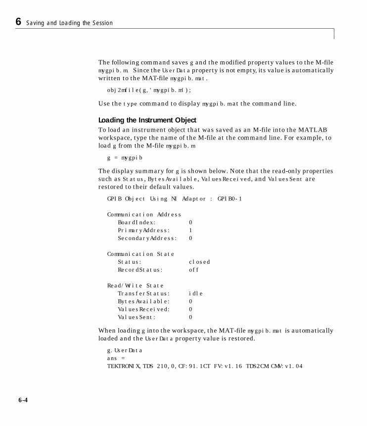
6 Saving and Loading the Session
6-4
The following command saves g and the modified property values to the M-filemygpib.m. Since the UserData property is not empty, its value is automaticallywritten to the MAT-file mygpib.mat.
obj2mfile(g,'mygpib.m');
Use the type command to display mygpib.m at the command line.
Loading the Instrument ObjectTo load an instrument object that was saved as an M-file into the MATLABworkspace, type the name of the M-file at the command line. For example, toload g from the M-file mygpib.m
g = mygpib
The display summary for g is shown below. Note that the read-only propertiessuch as Status, BytesAvailable, ValuesReceived, and ValuesSent arerestored to their default values.
GPIB Object Using NI Adaptor : GPIB0-1
Communication Address BoardIndex: 0PrimaryAddress: 1SecondaryAddress: 0
Communication State Status: closedRecordStatus: off
Read/Write State TransferStatus: idleBytesAvailable: 0ValuesReceived: 0ValuesSent: 0
When loading g into the workspace, the MAT-file mygpib.mat is automaticallyloaded and the UserData property value is restored.
g.UserDataans =TEKTRONIX,TDS 210,0,CF:91.1CT FV:v1.16 TDS2CM:CMV:v1.04
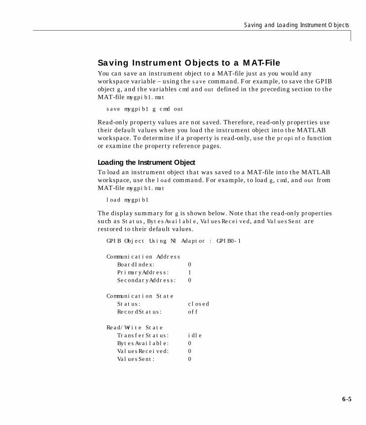
Saving and Loading Instrument Objects
6-5
Saving Instrument Objects to a MAT-FileYou can save an instrument object to a MAT-file just as you would anyworkspace variable – using the save command. For example, to save the GPIBobject g, and the variables cmd and out defined in the preceding section to theMAT-file mygpib1.mat
save mygpib1 g cmd out
Read-only property values are not saved. Therefore, read-only properties usetheir default values when you load the instrument object into the MATLABworkspace. To determine if a property is read-only, use the propinfo functionor examine the property reference pages.
Loading the Instrument ObjectTo load an instrument object that was saved to a MAT-file into the MATLABworkspace, use the load command. For example, to load g, cmd, and out fromMAT-file mygpib1.mat
load mygpib1
The display summary for g is shown below. Note that the read-only propertiessuch as Status, BytesAvailable, ValuesReceived, and ValuesSent arerestored to their default values.
GPIB Object Using NI Adaptor : GPIB0-1
Communication Address BoardIndex: 0PrimaryAddress: 1SecondaryAddress: 0
Communication State Status: closedRecordStatus: off
Read/Write State TransferStatus: idleBytesAvailable: 0ValuesReceived: 0ValuesSent: 0
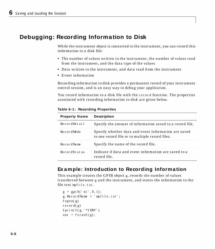
6 Saving and Loading the Session
6-6
Debugging: Recording Information to DiskWhile the instrument object is connected to the instrument, you can record thisinformation to a disk file:
• The number of values written to the instrument, the number of values readfrom the instrument, and the data type of the values
• Data written to the instrument, and data read from the instrument
• Event information
Recording information to disk provides a permanent record of your instrumentcontrol session, and is an easy way to debug your application.
You record information to a disk file with the record function. The propertiesassociated with recording information to disk are given below.
Example: Introduction to Recording InformationThis example creates the GPIB object g, records the number of valuestransferred between g and the instrument, and stores the information to thefile text myfile.txt.
g = gpib('ni',0,1);g.RecordName = 'myfile.txt';fopen(g)record(g)fprintf(g,'*IDN?')out = fscanf(g);
Table 6-1: Recording Properties
Property Name Description
RecordDetail Specify the amount of information saved to a record file.
RecordMode Specify whether data and event information are savedto one record file or to multiple record files.
RecordName Specify the name of the record file.
RecordStatus Indicate if data and event information are saved to arecord file.
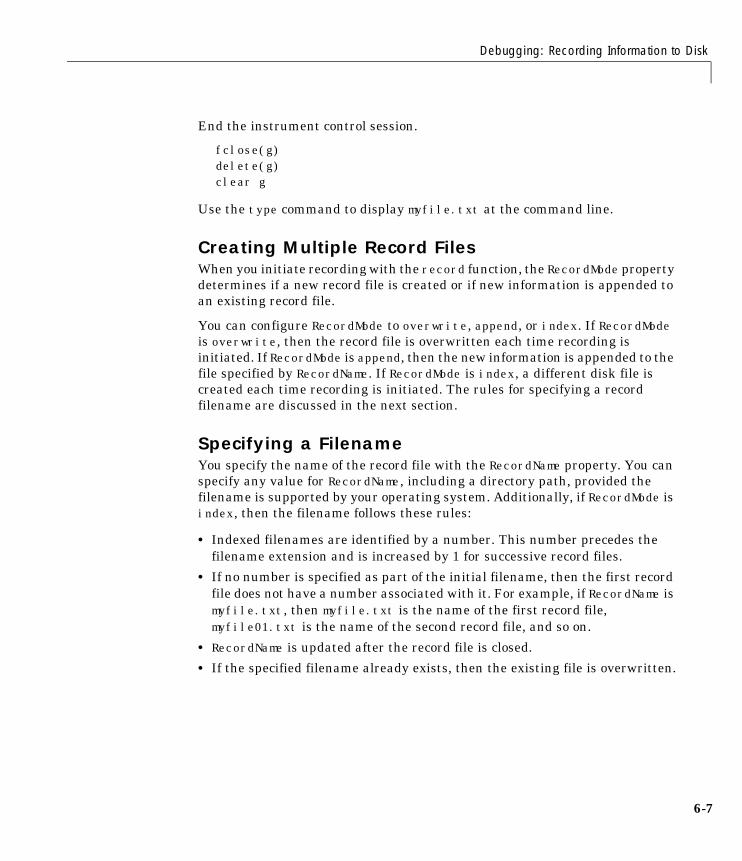
Debugging: Recording Information to Disk
6-7
End the instrument control session.
fclose(g)delete(g)clear g
Use the type command to display myfile.txt at the command line.
Creating Multiple Record FilesWhen you initiate recording with the record function, the RecordMode propertydetermines if a new record file is created or if new information is appended toan existing record file.
You can configure RecordMode to overwrite, append, or index. If RecordModeis overwrite, then the record file is overwritten each time recording isinitiated. If RecordMode is append, then the new information is appended to thefile specified by RecordName. If RecordMode is index, a different disk file iscreated each time recording is initiated. The rules for specifying a recordfilename are discussed in the next section.
Specifying a FilenameYou specify the name of the record file with the RecordName property. You canspecify any value for RecordName, including a directory path, provided thefilename is supported by your operating system. Additionally, if RecordMode isindex, then the filename follows these rules:
• Indexed filenames are identified by a number. This number precedes thefilename extension and is increased by 1 for successive record files.
• If no number is specified as part of the initial filename, then the first recordfile does not have a number associated with it. For example, if RecordName ismyfile.txt, then myfile.txt is the name of the first record file,myfile01.txt is the name of the second record file, and so on.
• RecordName is updated after the record file is closed.
• If the specified filename already exists, then the existing file is overwritten.
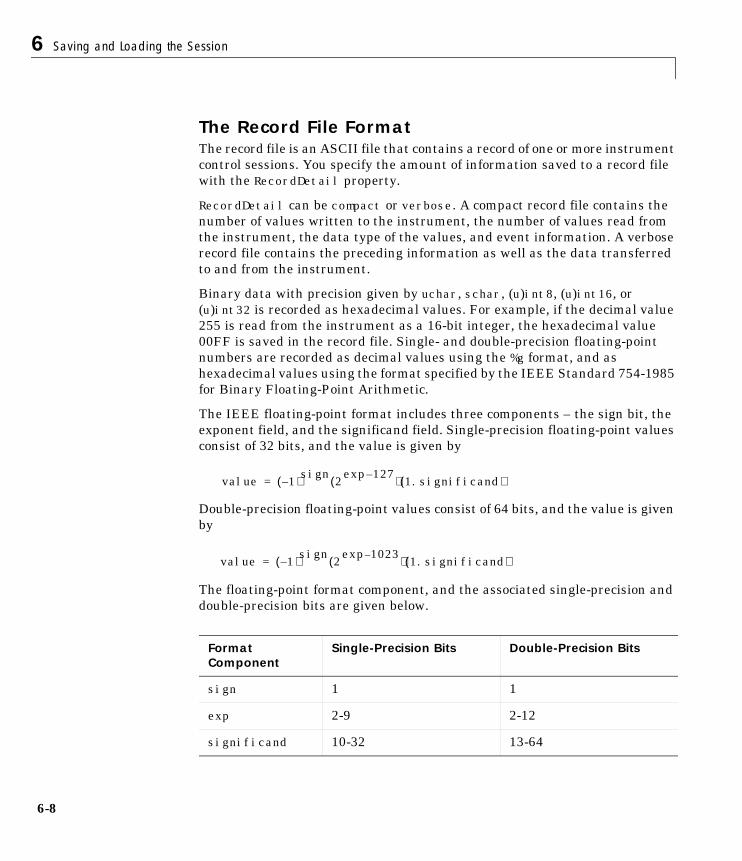
6 Saving and Loading the Session
6-8
The Record File FormatThe record file is an ASCII file that contains a record of one or more instrumentcontrol sessions. You specify the amount of information saved to a record filewith the RecordDetail property.
RecordDetail can be compact or verbose. A compact record file contains thenumber of values written to the instrument, the number of values read fromthe instrument, the data type of the values, and event information. A verboserecord file contains the preceding information as well as the data transferredto and from the instrument.
Binary data with precision given by uchar, schar, (u)int8, (u)int16, or(u)int32 is recorded as hexadecimal values. For example, if the decimal value255 is read from the instrument as a 16-bit integer, the hexadecimal value00FF is saved in the record file. Single- and double-precision floating-pointnumbers are recorded as decimal values using the %g format, and ashexadecimal values using the format specified by the IEEE Standard 754-1985for Binary Floating-Point Arithmetic.
The IEEE floating-point format includes three components – the sign bit, theexponent field, and the significand field. Single-precision floating-point valuesconsist of 32 bits, and the value is given by
Double-precision floating-point values consist of 64 bits, and the value is givenby
The floating-point format component, and the associated single-precision anddouble-precision bits are given below.
Format Component
Single-Precision Bits Double-Precision Bits
sign 1 1
exp 2-9 2-12
significand 10-32 13-64
value 1–( )sign 2127–exp( ) 1.significand( )=
value 1–( )sign 21023–exp( ) 1.significand( )=
Debugging: Recording Information to Disk
6-9
For example, suppose you record the decimal value 4.25 using thesingle-precision format. The record file stores 4.25 as the hex value 40880000,which is calculated from the IEEE single-precision floating-point format. Toreconstruct the original value, convert the hex value to a decimal value usinghex2dec
dval = hex2dec('40880000')dval = 1.082654720000000e+009
Convert the decimal value to a binary value using dec2bin
bval = dec2bin(dval,32)bval =01000000100010000000000000000000
The interpretation of bval is given by the preceding table. The left most bitindicates that value is positive since (-1)0 = 1. The next 8 bits correspond to theexponent, which is given by
exp = bval(2:9)exp =10000001
The decimal value of exp is 27+20 = 129. The remaining bits correspond to thesignificand, which is given by
significand = bval(10:32)significand =00010000000000000000000
The decimal value of significand is 2-4 = 0.0625. You reconstruct the originalvalue by plugging the decimal values of exp and significand into the formulafor IEEE singles
value = (-1)0(2129 - 127)(1.0625)value = 4.25
6 Saving and Loading the Session
6-10
Example: Recording Information to DiskThis example extends “Example: Reading Binary Data” on page 3-24 byrecording the associated information to a record file. Additionally, thestructure of the resulting record file is presented.
1. Create an instrument object – Create the GPIB object g associated with aNational Instruments GPIB controller with board index 0, and an instrumentwith primary address 1.
g = gpib('ni',0,1);
2. Configure properties – Configure the input buffer to accept a reasonablylarge number of bytes, and configure the timeout value to two minutes toaccount for slow data transfer.
g.InputBufferSize = 50000;g.Timeout = 120;
Configure g to execute the action function instraction every time 5000 bytesare stored in the input buffer.
g.BytesAvailableActionMode = 'byte';g.BytesAvailableActionCount = 5000;g.BytesAvailableAction = 'instraction';
Configure g to record information to multiple disk files using the verboseformat. The first disk file is defined as WaveForm1.txt.
g.RecordMode = 'index';g.RecordDetail = 'verbose';g.RecordName = 'WaveForm1.txt';
3. Connect to the instrument – Connect g to the oscilloscope.
fopen(g)
4. Write and read data – Initiate recording.
record(g)
Configure the scope to transfer the screen display as a bitmap.
fprintf(g,'HARDCOPY:PORT GPIB')fprintf(g,'HARDCOPY:FORMAT BMP')fprintf(g,'HARDCOPY START')
Debugging: Recording Information to Disk
6-11
Initiate the asynchronous read operation, and begin generating events.
readasync(g)
instraction is called every time 5000 bytes are stored in the input buffer. Theresulting displays are shown below.
BytesAvailable event occurred at 09:04:33 for the object: GPIB0-1.BytesAvailable event occurred at 09:04:42 for the object: GPIB0-1.BytesAvailable event occurred at 09:04:51 for the object: GPIB0-1.BytesAvailable event occurred at 09:05:00 for the object: GPIB0-1.BytesAvailable event occurred at 09:05:10 for the object: GPIB0-1.BytesAvailable event occurred at 09:05:19 for the object: GPIB0-1.BytesAvailable event occurred at 09:05:28 for the object: GPIB0-1.
Wait until all the data is stored in the input buffer, and then transfer the datato MATLAB as unsigned 8-bit integers.
out = fread(g,g.BytesAvailable,'uint8');
Toggle the recording state from on to off. Since the RecordMode value is index,the record filename is automatically updated.
record(g)g.RecordStatusans =offg.RecordNameans =WaveForm2.txt
5. Disconnect and clean up – When you no longer need g, you shoulddisconnect it from the instrument, and remove it from memory and from theMATLAB workspace.
fclose(g)delete(g)clear g
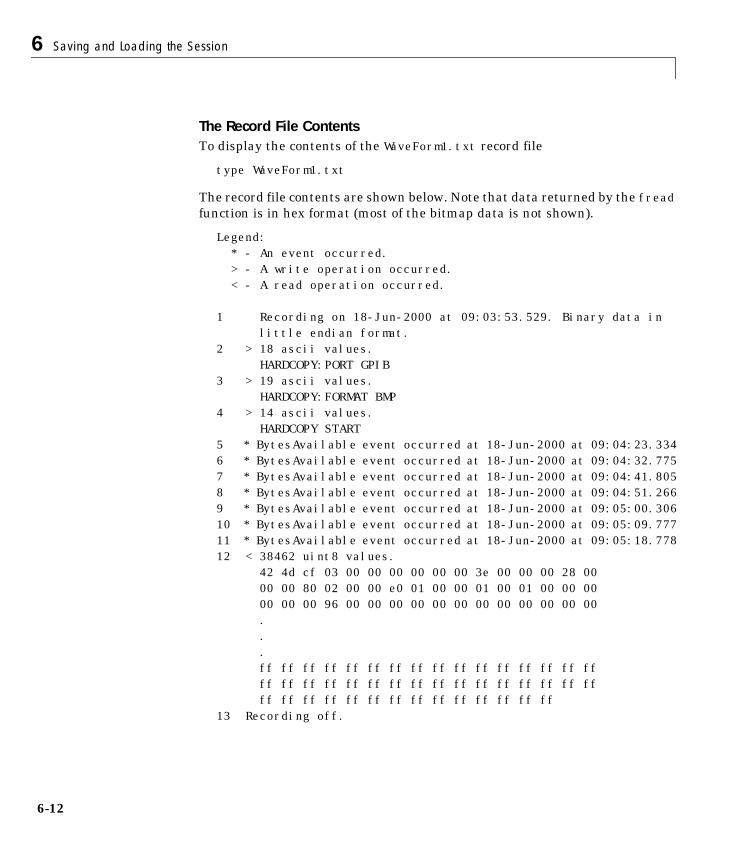
6 Saving and Loading the Session
6-12
The Record File ContentsTo display the contents of the WaveForm1.txt record file
type WaveForm1.txt
The record file contents are shown below. Note that data returned by the freadfunction is in hex format (most of the bitmap data is not shown).
Legend: * - An event occurred. > - A write operation occurred. < - A read operation occurred. 1 Recording on 18-Jun-2000 at 09:03:53.529. Binary data in
little endian format.2 > 18 ascii values.
HARDCOPY:PORT GPIB3 > 19 ascii values.
HARDCOPY:FORMAT BMP4 > 14 ascii values.
HARDCOPY START5 * BytesAvailable event occurred at 18-Jun-2000 at 09:04:23.3346 * BytesAvailable event occurred at 18-Jun-2000 at 09:04:32.7757 * BytesAvailable event occurred at 18-Jun-2000 at 09:04:41.8058 * BytesAvailable event occurred at 18-Jun-2000 at 09:04:51.2669 * BytesAvailable event occurred at 18-Jun-2000 at 09:05:00.30610 * BytesAvailable event occurred at 18-Jun-2000 at 09:05:09.77711 * BytesAvailable event occurred at 18-Jun-2000 at 09:05:18.77812 < 38462 uint8 values.
42 4d cf 03 00 00 00 00 00 00 3e 00 00 00 28 00 00 00 80 02 00 00 e0 01 00 00 01 00 01 00 00 00 00 00 00 96 00 00 00 00 00 00 00 00 00 00 00 00 ...ff ff ff ff ff ff ff ff ff ff ff ff ff ff ff ff ff ff ff ff ff ff ff ff ff ff ff ff ff ff ff ffff ff ff ff ff ff ff ff ff ff ff ff ff ff
13 Recording off.
7
Function Reference
Overview . . . . . . . . . . . . . . . . . . . . . 7-2Getting Command Line Function Help . . . . . . . . . . 7-2
Functions Grouped by Category . . . . . . . . . . . 7-4Base Functions . . . . . . . . . . . . . . . . . . . 7-4Object-Specific Functions . . . . . . . . . . . . . . . 7-7
Functions Listed Alphabetically . . . . . . . . . . . 7-10
7 Function Reference
7-2
OverviewThe following sections provide descriptions of all toolbox functions that you canuse directly. In “Base Functions” on page 7-4, the base functions aresummarized using several categories according to usage. In “Object-SpecificFunctions” on page 7-7, object-specific functions are summarized by object typeand usage in these sections:
• “GPIB Functions” on page 7-7
• “VISA-GPIB Functions” on page 7-8
• “VISA-VXI Functions” on page 7-8
• “VISA-GPIB-VXI Functions” on page 7-9
• “VISA-Serial Functions” on page 7-9
• “Serial Port Functions” on page 7-9
Following these sections, detailed function descriptions are provided in“Functions Listed Alphabetically” on page 7-10.
Getting Command Line Function HelpTo get command line function help, you should use the instrhelp function. Forexample, to get help for the query function, type
instrhelp query
Alternatively, you can use the help command.
help query
However, the Instrument Control Toolbox provides “overloaded” versions ofmany MATLAB functions. That is, it provides toolbox-specific implementationsof these functions using the same function name.
To get command line help for an overloaded toolbox function using help, youmust supply the class directory.
help instrument/function_name
For example, the Instrument Control Toolbox provides an overloaded versionof the fopen function used for file I/O. To obtain help for the file I/O version ofthis function, type
Overview
7-3
help fopen
You can determine if a function is overloaded by examining the last section ofthe help. For fopen, the help contains the following information.
Overloaded methods help instrument/fopen
So, to obtain help on the toolbox version of this function, type
help instrument/fopen
For more information on overloaded functions and class directories, refer to“MATLAB Classes and Objects” in the Help browser.
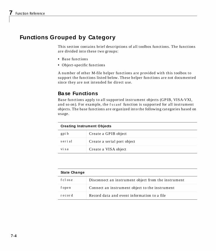
7 Function Reference
7-4
Functions Grouped by CategoryThis section contains brief descriptions of all toolbox functions. The functionsare divided into these two groups:
• Base functions
• Object-specific functions
A number of other M-file helper functions are provided with this toolbox tosupport the functions listed below. These helper functions are not documentedsince they are not intended for direct use.
Base FunctionsBase functions apply to all supported instrument objects (GPIB, VISA-VXI,and so on). For example, the fscanf function is supported for all instrumentobjects. The base functions are organized into the following categories based onusage.
Creating Instrument Objects
gpib Create a GPIB object
serial Create a serial port object
visa Create a VISA object
State Change
fclose Disconnect an instrument object from the instrument
fopen Connect an instrument object to the instrument
record Record data and event information to a file
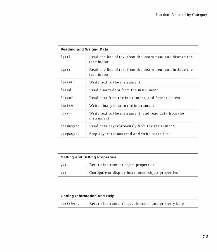
Functions Grouped by Category
7-5
Reading and Writing Data
fgetl Read one line of text from the instrument and discard theterminator
fgets Read one line of text from the instrument and include theterminator
fprintf Write text to the instrument
fread Read binary data from the instrument
fscanf Read data from the instrument, and format as text
fwrite Write binary data to the instrument
query Write text to the instrument, and read data from theinstrument
readasync Read data asynchronously from the instrument
stopasync Stop asynchronous read and write operations
Getting and Setting Properties
get Return instrument object properties
set Configure or display instrument object properties
Getting Information and Help
instrhelp Return instrument object function and property help
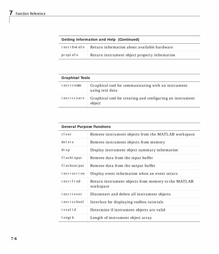
7 Function Reference
7-6
instrhwinfo Return information about available hardware
propinfo Return instrument object property information
Graphical Tools
instrcomm Graphical tool for communicating with an instrumentusing text data
instrcreate Graphical tool for creating and configuring an instrumentobject
General Purpose Functions
clear Remove instrument objects from the MATLAB workspace
delete Remove instrument objects from memory
disp Display instrument object summary information
flushinput Remove data from the input buffer
flushoutput Remove data from the output buffer
instraction Display event information when an event occurs
instrfind Return instrument objects from memory to the MATLABworkspace
instrreset Disconnect and delete all instrument objects
instrschool Interface for displaying toolbox tutorials
isvalid Determine if instrument objects are valid
length Length of instrument object array
Getting Information and Help (Continued)
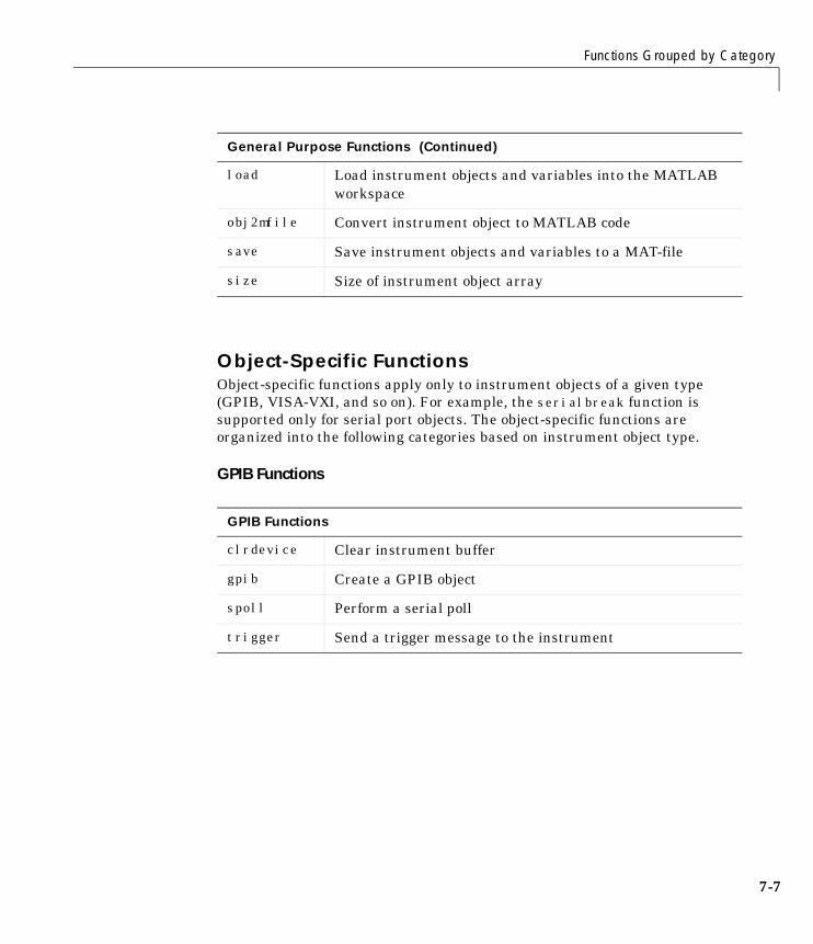
Functions Grouped by Category
7-7
Object-Specific FunctionsObject-specific functions apply only to instrument objects of a given type(GPIB, VISA-VXI, and so on). For example, the serialbreak function issupported only for serial port objects. The object-specific functions areorganized into the following categories based on instrument object type.
GPIB Functions
load Load instrument objects and variables into the MATLABworkspace
obj2mfile Convert instrument object to MATLAB code
save Save instrument objects and variables to a MAT-file
size Size of instrument object array
GPIB Functions
clrdevice Clear instrument buffer
gpib Create a GPIB object
spoll Perform a serial poll
trigger Send a trigger message to the instrument
General Purpose Functions (Continued)
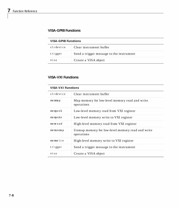
7 Function Reference
7-8
VISA-GPIB Functions
VISA-VXI Functions
VISA-GPIB Functions
clrdevice Clear instrument buffer
trigger Send a trigger message to the instrument
visa Create a VISA object
VISA-VXI Functions
clrdevice Clear instrument buffer
memmap Map memory for low-level memory read and writeoperations
mempeek Low-level memory read from VXI register
mempoke Low-level memory write to VXI register
memread High-level memory read from VXI register
memunmap Unmap memory for low-level memory read and writeoperations
memwrite High-level memory write to VXI register
trigger Send a trigger message to the instrument
visa Create a VISA object
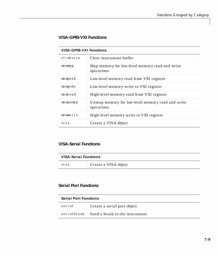
Functions Grouped by Category
7-9
VISA-GPIB-VXI Functions
VISA-Serial Functions
Serial Port Functions
VISA-GPIB-VXI Functions
clrdevice Clear instrument buffer
memmap Map memory for low-level memory read and writeoperations
mempeek Low-level memory read from VXI register
mempoke Low-level memory write to VXI register
memread High-level memory read from VXI register
memunmap Unmap memory for low-level memory read and writeoperations
memwrite High-level memory write to VXI register
visa Create a VISA object
VISA-Serial Functions
visa Create a VISA object
Serial Port Functions
serial Create a serial port object
serialbreak Send a break to the instrument
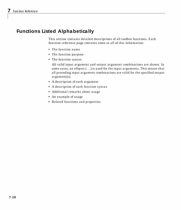
7 Function Reference
7-10
Functions Listed AlphabeticallyThis section contains detailed descriptions of all toolbox functions. Eachfunction reference page contains some or all of this information:
• The function name
• The function purpose
• The function syntax
All valid input argument and output argument combinations are shown. Insome cases, an ellipsis (. . .) is used for the input arguments. This means thatall preceding input argument combinations are valid for the specified outputargument(s).
• A description of each argument
• A description of each function syntax
• Additional remarks about usage
• An example of usage
• Related functions and properties
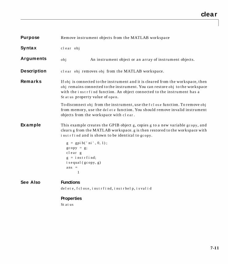
clear
7-11
7clearPurpose Remove instrument objects from the MATLAB workspace
Syntax clear obj
Arguments
Description clear obj removes obj from the MATLAB workspace.
Remarks If obj is connected to the instrument and it is cleared from the workspace, thenobj remains connected to the instrument. You can restore obj to the workspacewith the instrfind function. An object connected to the instrument has aStatus property value of open.
To disconnect obj from the instrument, use the fclose function. To remove objfrom memory, use the delete function. You should remove invalid instrumentobjects from the workspace with clear.
Example This example creates the GPIB object g, copies g to a new variable gcopy, andclears g from the MATLAB workspace. g is then restored to the workspace withinstrfind and is shown to be identical to gcopy.
g = gpib('ni',0,1);gcopy = g;clear gg = instrfind;isequal(gcopy,g)ans = 1
See Also Functionsdelete, fclose, instrfind, instrhelp, isvalid
PropertiesStatus
obj An instrument object or an array of instrument objects.
clrdevice
7-12
7clrdevicePurpose Clear instrument buffer
Syntax clrdevice(obj)
Arguments
Description clrdevice(obj) clears the hardware buffer of the instrument connected toobj.
Remarks Before you can clear the hardware buffer, the instrument must be connected toobj with the fopen function. A connected object has a Status property value ofopen. If you issue clrdevice when obj is disconnected from the instrument,then an error is returned.
You can clear the software input buffer using the flushinput function. You canclear the software output buffer using the flushoutput function.
See Also Functionsflushinput, flushoutput, fopen
PropertiesStatus
obj A GPIB, VISA-GPIB, VISA-VXI, or VISA-GPIB-VXI object.
delete
7-13
7deletePurpose Remove instrument objects from memory
Syntax delete(obj)
Arguments
Description delete(obj) removes obj from memory.
Remarks When you delete obj, it becomes an invalid object. Since you cannot connect aninvalid object to the instrument, you should remove it from the workspace withthe clear command. If multiple references to obj exist in the workspace, thendeleting one reference invalidates the remaining references.
If you attempt to delete obj while it is connected to the instrument, then anerror is returned. A connected object has a Status property value of open. Youcan disconnect obj from the instrument with the fclose function.
Example This example creates the GPIB object g, connects g to the instrument, writesand reads text data, disconnects g, removes g from memory using delete, andthen removes g from the workspace using clear.
g = gpib('ni',0,1);fopen(g)fprintf(g,'*IDN?')idn = fscanf(g);fclose(g)delete(g)clear g
See Also Functionsclear, fclose, instrhelp, isvalid, stopasync
PropertiesStatus
obj An instrument object or an array of instrument objects.
disp
7-14
7dispPurpose Display instrument object summary information
Syntax objdisp(obj)
Arguments
Description obj or disp(obj) displays summary information for obj.
Remarks In addition to the syntax shown above, you can display summary informationfor obj by excluding the semicolon when:
• Creating an instrument object
• Configuring property values using the dot notation
Use the display summary to quickly view communication settings or addressinformation, communication state information, and information associatedwith read and write operations.
Example The following commands display summary information for the GPIB object g.
g = gpib('ni',0,1)g.EOSMode = 'read'g
obj An instrument object or an array of instrument objects.
fclose
7-15
7fclosePurpose Disconnect an instrument object from the instrument
Syntax fclose(obj)
Arguments
Description fclose(obj) disconnects obj from the instrument.
Remarks If obj was successfully disconnected, then the Status property is configured toclosed and the RecordStatus property is configured to off. You can reconnectobj to the instrument using the fopen function.
An error is returned if you issue fclose while data is being writtenasynchronously. In this case, you should abort the write operation with thestopasync function, or wait for the write operation to complete.
Example This example creates the GPIB object g, connects g to the instrument, writesand reads text data, and then disconnects g from the instrument using fclose.
g = gpib('ni',0,1);fopen(g)fprintf(g,'*IDN?')idn = fscanf(g);fclose(g)
At this point, you can once again connect an instrument object to theinstrument. If you no longer need g, you should remove it from memory withthe delete function, and remove it from the workspace with the clearcommand.
See Also Functionsclear, delete, fopen, instrhelp, record, stopasync
PropertiesRecordStatus, Status
obj An instrument object or an array of instrument objects.
fgetl
7-16
7fgetlPurpose Read one line of text from the instrument and discard the terminator
Syntax tline = fgetl(obj)[tline,count] = fgetl(obj)[tline,count,msg] = fgetl(obj)
Arguments
Description tline = fgetl(obj) reads one line of text from the instrument connected toobj, and returns the data to tline. The returned data does not include theterminator with the text line. To include the terminator, use fgets.
[tline,count] = fgetl(obj) returns the number of values read to count.
[tline,count,msg] = fgetl(obj) returns a warning message to msg if theread operation was unsuccessful.
Remarks Before you can read text from the instrument, it must be connected to obj withthe fopen function. A connected instrument object has a Status property valueof open. An error is returned if you attempt to perform a read operation whileobj is not connected to the instrument.
If msg is not included as an output argument and the read operation was notsuccessful, then a warning message is returned to the command line.
The ValuesReceived property value is increased by the number of values read– including the terminator – each time fgetl is issued.
Rules for Completing a Read Operation with fgetlA read operation with fgetl blocks access to the MATLAB command line until:
• The terminator is read. For serial port and VISA-serial objects, theterminator is given by the Terminator property. For all other instrumentobjects, the terminator is given by the EOSCharCode property.
obj An instrument object.
tline The text read from the instrument, excluding the terminator.
count The number of values read, including the terminator.
msg A message indicating if the read operation was unsuccessful.
fgetl
7-17
• The EOI line is asserted (GPIB and VXI instruments only).
• The time specified by the Timeout property passes.
• The input buffer is filled.
More About the GPIB and VXI TerminatorThe EOSCharCode property value is recognized only when the EOSMode propertyis configured to read or read&write. For example, if EOSMode is configured toread and EOSCharCode is configured to 10, then one of the ways that the readoperation terminates is when the linefeed character is received.
If EOSMode is none or write, then there is no terminator defined for readoperations. In this case, fgetl will complete execution and return control to thecommand line when another criteria, such as a timeout, is met.
Example Create the GPIB object g, connect g to a Tektronix TDS 210 oscilloscope,configure g to complete read operations when the End-Of-String character isread, and write the *IDN? command with the fprintf function. *IDN? instructsthe scope to return identification information.
g = gpib('ni',0,1);fopen(g)g.EOSMode = 'read';fprintf(g,'*IDN?')
Asynchronously read the identification information from the instrument.
readasync(g)g.BytesAvailableans = 56
Use fgetl to transfer the data from the input buffer to the MATLABworkspace, and discard the terminator.
idn = fgetl(g)idn =TEKTRONIX,TDS 210,0,CF:91.1CT FV:v1.16 TDS2CM:CMV:v1.04
length(idn)ans = 55
fgetl
7-18
Disconnect g from the scope, and remove g from memory and the workspace.
fclose(g)delete(g)clear g
See Also Functionsfgets, fopen, instrhelp
PropertiesBytesAvailable, EOSCharCode, EOSMode, InputBufferSize, Status,Terminator, Timeout, ValuesReceived
fgets
7-19
7fgetsPurpose Read one line of text from the instrument and include the terminator
Syntax tline = fgets(obj)[tline,count] = fgets(obj)
[tline,count,msg] = fgets(obj)
Arguments
Description tline = fgets(obj) reads one line of text from the instrument connected toobj, and returns the data to tline. The returned data includes the terminatorwith the text line. To exclude the terminator, use fgetl.
[tline,count] = fgets(obj) returns the number of values read to count.
[tline,count,msg] = fgets(obj) returns a warning message to msg if theread operation was unsuccessful.
Remarks Before you can read text from the instrument, it must be connected to obj withthe fopen function. A connected instrument object has a Status property valueof open. An error is returned if you attempt to perform a read operation whileobj is not connected to the instrument.
If msg is not included as an output argument and the read operation was notsuccessful, then a warning message is returned to the command line.
The ValuesReceived property value is increased by the number of values read– including the terminator – each time fgets is issued.
obj An instrument object.
tline The text read from the instrument, including the terminator.
count The number of values read.
msg A message indicating that the read operation did notcomplete successfully.
fgets
7-20
Rules for Completing a Read Operation with fgetsA read operation with fgets blocks access to the MATLAB command line until:
• The terminator is read. For serial port and VISA-serial objects, theterminator is given by the Terminator property. For all other instrumentobjects, the terminator is given by the EOSCharCode property.
• The EOI line is asserted (GPIB and VXI instruments only).
• The time specified by the Timeout property passes.
• The input buffer is filled.
More About the GPIB and VXI TerminatorThe EOSCharCode property value is recognized only when the EOSMode propertyis configured to read or read&write. For example, if EOSMode is configured toread and EOSCharCode is configured to 10, then one of the ways that the readoperation terminates is when the linefeed character is received.
If EOSMode is none or write, then there is no terminator defined for readoperations. In this case, fgets will complete execution and return control to thecommand line when another criteria, such as a timeout, is met.
Example Create the GPIB object g, connect g to a Tektronix TDS 210 oscilloscope,configure g to complete read operations when the End-Of-String character isread, and write the *IDN? command with the fprintf function. *IDN? instructsthe scope to return identification information.
g = gpib('ni',0,1);fopen(g)g.EOSMode = 'read';fprintf(g,'*IDN?')
Asynchronously read the identification information from the instrument.
readasync(g)g.BytesAvailableans = 56
fgets
7-21
Use fgets to transfer the data from the input buffer to the MATLABworkspace, and include the terminator.
idn = fgets(g)idn =TEKTRONIX,TDS 210,0,CF:91.1CT FV:v1.16 TDS2CM:CMV:v1.04length(idn)ans = 56
Disconnect g from the scope, and remove g from memory and the workspace.
fclose(g)delete(g)clear g
See Also Functionsfgetl, fopen, instrhelp, query
PropertiesBytesAvailable, EOSCharCode, EOSMode, InputBufferSize, Status,Terminator, Timeout, ValuesReceived
flushinput
7-22
7flushinputPurpose Remove data from the input buffer
Syntax flushinput(obj)
Arguments
Description flushinput(obj) removes data from the input buffer associated with obj.
Remarks After the input buffer is flushed, the BytesAvailable property is automaticallyconfigured to 0.
If flushinput is called during an asynchronous (nonblocking) read operation,the data currently stored in the input buffer is flushed and the read operationcontinues. You can read data asynchronously from the instrument using thereadasync function.
The input buffer is automatically flushed when you connect an object to theinstrument with the fopen function.
You can clear the output buffer with the flushoutput function. You can clearthe hardware buffer for GPIB and VXI instruments with the clrdevicefunction.
See Also Functionsclrdevice, flushoutput, fopen, readasync
PropertiesBytesAvailable
obj An instrument object or an array of instrument objects.
flushoutput
7-23
7flushoutputPurpose Remove data from the output buffer
Syntax flushoutput(obj)
Arguments
Description flushoutput(obj) removes data from the output buffer associated with obj.
Remarks After the output buffer is flushed, the BytesToOutput property is automaticallyconfigured to 0.
If flushoutput is called during an asynchronous (nonblocking) write operation,the data currently stored in the output buffer is flushed and the write operationis aborted. Additionally, the M-file action function specified for theOutputEmptyAction property is executed. You can write data asynchronouslyto the instrument using the fprintf or fwrite functions.
The output buffer is automatically flushed when you connect an object to theinstrument with the fopen function.
You can clear the input buffer with the flushinput function. You can clear thehardware buffer for GPIB and VXI instruments with the clrdevice function.
See Also Functionsclrdevice, flushinput, fopen, fprintf, fwrite
PropertiesBytesToOutput, OutputEmptyAction
obj An instrument object or an array of instrument objects.
fopen
7-24
7fopenPurpose Connect an instrument object to the instrument
Syntax fopen(obj)
Arguments
Description fopen(obj) connects obj to the instrument.
Remarks Before you can perform a read or write operation, obj must be connected to theinstrument with the fopen function. When obj is connected to the instrument:
• Data remaining in the input buffer or the output buffer is flushed.
• The Status property is set to open.
• The BytesAvailable, ValuesReceived, ValuesSent, and BytesToOutputproperties are set to 0.
An error is returned if you attempt to perform a read or write operation whileobj is not connected to the instrument. You can connect only one instrumentobject to the same instrument. For example, you can connect only one serialport object to an instrument associated with the COM1 port. Similarly, you canconnect only one GPIB object to an instrument with a given board index,primary address, and secondary address.
Some properties are read-only while the instrument object is open (connected),and must be configured before using fopen. Examples includeInputBufferSize and OutputBufferSize. Refer to the property referencepages or use the propinfo function to determine which properties have thisconstraint.
The values for some properties are verified only after obj is connected to theinstrument. If any of these properties are incorrectly configured, then an erroris returned when fopen is issued and obj is not connected to the instrument.Properties of this type include BaudRate and SecondaryAddress, and areassociated with instrument settings.
obj An instrument object or an array of instrument objects.
fopen
7-25
Example This example creates the GPIB object g, connects g to the instrument usingfopen, writes and reads text data, and then disconnects g from the instrument.
g = gpib('ni',0,1);fopen(g)fprintf(g,'*IDN?')idn = fscanf(g);fclose(g)
See Also Functionsfclose, instrhelp, propinfo
PropertiesBytesAvailable, BytesToOutput, Status, ValuesReceived, ValuesSent
fprintf
7-26
7fprintfPurpose Write text to the instrument
Syntax fprintf(obj,'cmd')fprintf(obj,'format','cmd')fprintf(obj,'cmd','mode')fprintf(obj,'format','cmd','mode')
Arguments
Description fprintf(obj,'cmd') writes the string cmd to the instrument connected to obj.The default format is %s\n. The write operation is synchronous and blocks thecommand line until execution is complete.
fprintf(obj,'format','cmd') writes the string using the format specified byformat.
format is a C language conversion specification. Conversion specificationsinvolve the % character and the conversion characters d, i, o, u, x, X, f, e, E, g,G, c, and s. Refer to the sprintf file I/O format specifications or a C manual formore information.
fprintf(obj,'cmd','mode') writes the string with command line accessspecified by mode. If mode is sync, cmd is written synchronously and thecommand line is blocked. If mode is async, cmd is written asynchronously andthe command line is not blocked. If mode is not specified, the write operation issynchronous.
fprintf(obj,'format','cmd','mode') writes the string using the specifiedformat. If mode is sync, cmd is written synchronously. If mode is async, cmd iswritten asynchronously.
obj An instrument object.
'cmd' The string written to the instrument.
'format' C language conversion specification.
'mode' Specifies whether data is written synchronously orasynchronously.
fprintf
7-27
Remarks Before you can write text to the instrument, it must be connected to obj withthe fopen function. A connected instrument object has a Status property valueof open. An error is returned if you attempt to perform a write operation whileobj is not connected to the instrument.
The ValuesSent property value is increased by the number of values writteneach time fprintf is issued.
An error occurs if the output buffer cannot hold all the data to be written. Youcan specify the size of the output buffer with the OutputBufferSize property.
Synchronous Versus Asynchronous Write OperationsBy default, text is written to the instrument synchronously and the commandline is blocked until the operation completes. You can perform an asynchronouswrite by configuring the mode input argument to be async. For asynchronouswrites:
• The BytesToOutput property value is continuously updated to reflect thenumber of bytes in the output buffer.
• The M-file action function specified for the OutputEmptyAction property isexecuted when the output buffer is empty.
You can determine whether an asynchronous write operation is in progresswith the TransferStatus property.
Synchronous and asynchronous write operations are discussed in more detailin “Synchronous Versus Asynchronous Write Operations” on page 2-17.
Rules for Completing a Write Operation with fprintfA write operation using fprintf completes when:
• The specified data is written.
• The time specified by the Timeout property passes.
Rules for Writing the TerminatorFor serial port and VISA-serial objects, all occurrences of \n in cmd are replacedwith the Terminator property value. Therefore, when using the default format%s\n, all commands written to the instrument will end with this propertyvalue.
fprintf
7-28
For GPIB, VISA-GPIB, VISA-VXI, and VISA-GPIB-VXI objects, alloccurrences of \n in cmd are replaced with the EOSCharCode property value ifthe EOSMode property is set to write or read&write. For example, if EOSMode isset to write and EOSCharCode is set to 10, then all occurrences of \n arereplaced with a linefeed character. Additionally, for GPIB objects, the End OrIdentify (EOI) line is asserted when the terminator is written out.
Note The terminator required by your instrument will be described in itsdocumentation.
Example Create the serial port object s, connect s to a Tektronix TDS 210 oscilloscope,and write the RS232? command with the fprintf function. RS232? instructsthe scope to return serial port communications settings.
s = serial('COM1');fopen(s)fprintf(s,'RS232?')settings = fscanf(s)settings =9600;1;0;NONE;LF
Since the default format for fprintf is %s\n, the terminator specified by theTerminator property was automatically written. However, in some cases youmay want to suppress writing the terminator. To do so, you must explicitlyspecify a format for the data that does not include the terminator.
fprintf(s,'%s','RS232?')
See Also Functionsfopen, fwrite, instrhelp, query, sprintf
PropertiesBytesToOutput, EOSCharCode, EOSMode, OutputBufferSize,OutputEmptyAction, Status, TransferStatus, ValuesSent
fread
7-29
7freadPurpose Read binary data from the instrument
Syntax A = fread(obj,size)A = fread(obj,size,'precision')[A,count] = fread(...)
[A,count,msg] = fread(...)
Arguments
Description A = fread(obj,size) reads binary data from the instrument connected toobj, and returns the data to A. The maximum number of values to read isspecified by size. Valid options for size are:
size cannot be inf, and an error is returned if the specified number of valuescannot be stored in the input buffer. You specify the size, in bytes, of the inputbuffer with the InputBufferSize property. A value is defined as a bytemultiplied by the precision (see below).
A = fread(obj,size,'precision') reads binary data with precisionspecified by precision.
precision controls the number of bits read for each value and theinterpretation of those bits as integer, floating-point, or character values. Ifprecision is not specified, uchar (an 8-bit unsigned character) is used. By
obj An instrument object.
size The number of values to read.
'precision' The number of bits read for each value, and the interpretationof the bits as character, integer, or floating-point values.
A Binary data returned from the instrument.
count The number of values read.
msg A message indicating if the read operation was unsuccessful.
n Read at most n values into a column vector.
[m,n] Read at most m–by–n values filling an m–by–n matrix in columnorder.
fread
7-30
default, numeric values are returned in double-precision arrays. The supportedvalues for precision are listed below in Remarks.
[A,count] = fread(...) returns the number of values read to count.
[A,count,msg] = fread(...) returns a warning message to msg if the readoperation was unsuccessful.
Remarks Before you can read data from the instrument, it must be connected to obj withthe fopen function. A connected instrument object has a Status property valueof open. An error is returned if you attempt to perform a read operation whileobj is not connected to the instrument.
If msg is not included as an output argument and the read operation was notsuccessful, then a warning message is returned to the command line.
The ValuesReceived property value is increased by the number of values read,each time fread is issued.
Rules for Completing a Binary Read OperationA read operation with fread blocks access to the MATLAB command line until:
• The specified number of values are read.
• The time specified by the Timeout property passes.
• The EOI line is asserted (GPIB and VXI instruments only).
• The EOSCharCode is received (GPIB and VXI instruments only).
More About the GPIB and VXI TerminatorThe EOSCharCode property value is recognized only when the EOSMode propertyis configured to read or read&write. For example, if EOSMode is configured toread and EOSCharCode is configured to 10, then one of the ways that the readoperation terminates is when the linefeed character is received.
If EOSMode is none or write, then there is no terminator defined for readoperations. In this case, fread will complete execution and return control to thecommand when another criteria, such as a timeout, is met.
fread
7-31
Supported PrecisionsThe supported values for precision are listed below.
Data Type Precision Interpretation
Character uchar 8-bit unsigned character
schar 8-bit signed character
char 8-bit signed or unsigned character
Integer int8 8-bit integer
int16 16-bit integer
int32 32-bit integer
uint8 8-bit unsigned integer
uint16 16-bit unsigned integer
uint32 32-bit unsigned integer
short 16-bit integer
int 32-bit integer
long 32- or 64-bit integer
ushort 16-bit unsigned integer
uint 32-bit unsigned integer
ulong 32- or 64-bit unsigned integer
Floating-point single 32-bit floating point
float32 32-bit floating point
float 32-bit floating point
double 64-bit floating point
float64 64-bit floating point

fread
7-32
See Also Functionsfgetl, fgets, fopen, fscanf, instrhelp
PropertiesBytesAvailable, InputBufferSize, Status, ValuesReceived
fscanf
7-33
7fscanfPurpose Read data from the instrument, and format as text
Syntax A = fscanf(obj)A = fscanf(obj,'format')A = fscanf(obj,'format',size)[A,count] = fscanf(...)[A,count,msg] = fscanf(...)
Arguments
Description A = fscanf(obj) reads data from the instrument connected to obj, andreturns it to A. The data is converted to text using the %c format.
A = fscanf(obj,'format') reads data and converts it according to format.
format is a C language conversion specification. Conversion specificationsinvolve the % character and the conversion characters d, i, o, u, x, X, f, e, E, g,G, c, and s. Refer to the sscanf file I/O format specifications or a C manual formore information.
A = fscanf(obj,'format',size) reads the number of values specified bysize. Valid options for size are:
size cannot be inf, and an error is returned if the specified number of valuescannot be stored in the input buffer. If size is not of the form [m,n], and acharacter conversion is specified, then A is returned as a row vector. You specify
obj An instrument object.
'format' C language conversion specification.
size The number of values to read.
A Data read from the instrument and formatted as text.
count The number of values read.
msg A message indicating if the read operation was unsuccessful.
n Read at most n values into a column vector.
[m,n] Read at most m–by–n values filling an m–by–n matrix in columnorder.
fscanf
7-34
the size, in bytes, of the input buffer with the InputBufferSize property. AnASCII value is one byte.
[A,count] = fscanf(...) returns the number of values read to count.
[A,count,msg] = fscanf(...) returns a warning message to msg if the readoperation did not complete successfully.
Remarks Before you can read data from the instrument, it must be connected to obj withthe fopen function. A connected instrument object has a Status property valueof open. An error is returned if you attempt to perform a read operation whileobj is not connected to the instrument.
If msg is not included as an output argument and the read operation was notsuccessful, then a warning message is returned to the command line.
The ValuesReceived property value is increased by the number of values read– including the terminator – each time fscanf is issued.
Rules for Completing a Read Operation with fscanfA read operation with fscanf blocks access to the MATLAB command lineuntil:
• The terminator is read. For serial port and VISA-serial objects, theterminator is given by the Terminator property. For all other instrumentobjects, the terminator is given by the EOSCharCode property.
• The time specified by the Timeout property passes.
• The number of values specified by size is read.
• The input buffer is filled.
• The EOI line is asserted (GPIB and VXI instruments only).
More About the GPIB and VXI TerminatorThe EOSCharCode property value is recognized only when the EOSMode propertyis configured to read or read&write. For example, if EOSMode is configured toread and EOSCharCode is configured to 10, then one of the ways that the readoperation terminates is when the linefeed character is received.
fscanf
7-35
If EOSMode is none or write, then there is no terminator defined for readoperations. In this case, fscanf will complete execution and return control tothe command when another criteria, such as a timeout, is met.
Example Create the serial port object s and connect s to a Tektronix TDS 210oscilloscope, which is displaying a sine wave.
s = serial('COM1');fopen(s)
Use the fprintf function to configure the scope to measure the peak-to-peakvoltage of the sine wave, return the measurement type, and return thepeak-to-peak voltage.
fprintf(s,'MEASUREMENT:IMMED:TYPE PK2PK')fprintf(s,'MEASUREMENT:IMMED:TYPE?')fprintf(s,'MEASUREMENT:IMMED:VAL?')
Since the default value for the ReadAsyncMode property is continuous, dataassociated with the two query commands is automatically returned to the inputbuffer.
s.BytesAvailableans = 13
Use fscanf to read the measurement type. The operation will complete whenthe first terminator is read.
meas = fscanf(s)meas =PK2PK
Use fscanf to read the peak-to-peak voltage as a floating-point number, andexclude the terminator.
pk2pk = fscanf(s,'%e',6)pk2pk = 2.0200
fscanf
7-36
Disconnect s from the scope, and remove s from memory and the workspace.
fclose(s)delete(s)clear s
See Also Functionsfgetl, fgets, fopen, fread, instrhelp, sscanf, strread
PropertiesBytesAvailable, BytesAvailableAction, EOSCharCode, EOSMode,InputBufferSize, Status, Terminator, Timeout, TransferStatus
fwrite
7-37
7fwritePurpose Write binary data to the instrument
Syntax fwrite(obj,A)fwrite(obj,A,'precision')fwrite(obj,A,’mode')fwrite(obj,A,'precision',’mode')
Arguments
Description fwrite(obj,A) writes the binary data A to the instrument connected to obj.
fwrite(obj,A,'precision') writes binary data with precision specified byprecision.
precision controls the number of bits written for each value and theinterpretation of those bits as integer, floating-point, or character values. Ifprecision is not specified, uchar (an 8-bit unsigned character) is used. Thesupported values for precision are listed below in Remarks.
fwrite(obj,A,'mode') writes binary data with command line access specifiedby mode. If mode is sync, A is written synchronously and the command line isblocked. If mode is async, A is written asynchronously and the command line isnot blocked. If mode is not specified, the write operation is synchronous.
fwrite(obj,A,'precision','mode') writes binary data with precisionspecified by precision and command line access specified by mode.
Remarks Before you can write data to the instrument, it must be connected to obj withthe fopen function. A connected instrument object has a Status property valueof open. An error is returned if you attempt to perform a write operation whileobj is not connected to the instrument.
obj An instrument object.
A The binary data written to the instrument.
'precision' The number of bits written for each value, and theinterpretation of the bits as character, integer, orfloating-point values.
'mode' Specifies whether data is written synchronously orasynchronously.
fwrite
7-38
The ValuesSent property value is increased by the number of values writteneach time fwrite is issued.
An error occurs if the output buffer cannot hold all the data to be written. Youcan specify the size of the output buffer with the OutputBufferSize property.
Synchronous Versus Asynchronous Write OperationsBy default, data is written to the instrument synchronously and the commandline is blocked until the operation completes. You can perform an asynchronouswrite by configuring the mode input argument to be async. For asynchronouswrites:
• The BytesToOutput property value is continuously updated to reflect thenumber of bytes in the output buffer.
• The M-file action function specified for the OutputEmptyAction property isexecuted when the output buffer is empty.
You can determine whether an asynchronous write operation is in progresswith the TransferStatus property.
Synchronous and asynchronous write operations are discussed in more detailin “Synchronous Versus Asynchronous Write Operations” on page 2-17.
Rules for Completing a Write Operation with fwriteA binary write operation using fwrite completes when:
• The specified data is written.
• The time specified by the Timeout property passes.
Note The Terminator and EOSCharCode properties are not used with binarywrite operations.
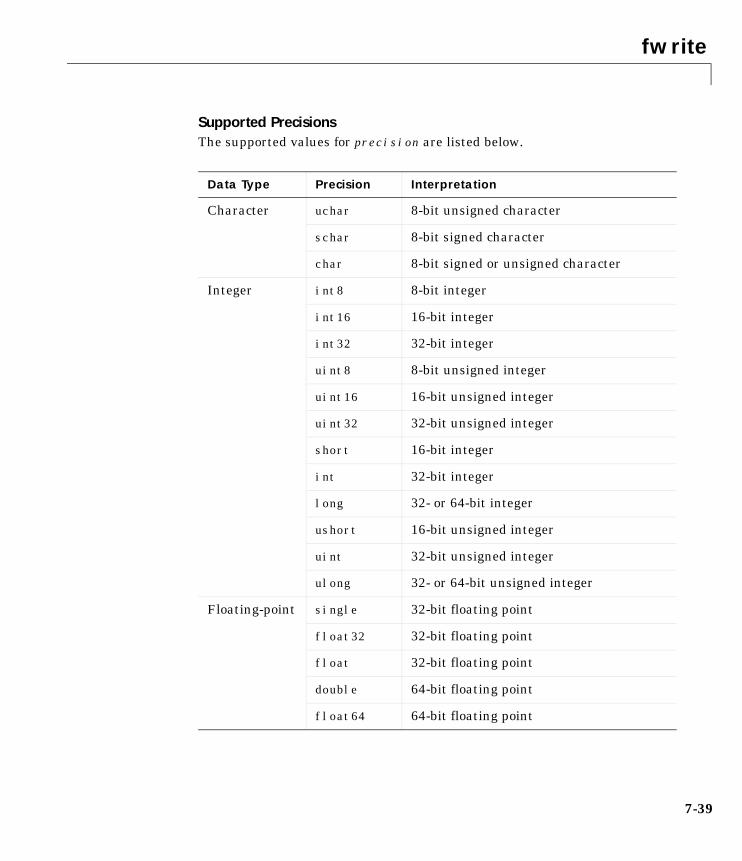
fwrite
7-39
Supported PrecisionsThe supported values for precision are listed below.
Data Type Precision Interpretation
Character uchar 8-bit unsigned character
schar 8-bit signed character
char 8-bit signed or unsigned character
Integer int8 8-bit integer
int16 16-bit integer
int32 32-bit integer
uint8 8-bit unsigned integer
uint16 16-bit unsigned integer
uint32 32-bit unsigned integer
short 16-bit integer
int 32-bit integer
long 32- or 64-bit integer
ushort 16-bit unsigned integer
uint 32-bit unsigned integer
ulong 32- or 64-bit unsigned integer
Floating-point single 32-bit floating point
float32 32-bit floating point
float 32-bit floating point
double 64-bit floating point
float64 64-bit floating point

fwrite
7-40
See Also Functionsfopen, fprintf, instrhelp
PropertiesOutputBufferSize, OutputEmptyAction, Status, Timeout, TransferStatus, ValuesSent
get
7-41
7getPurpose Return instrument object properties
Syntax get(obj)out = get(obj)out = get(obj,'PropertyName')
Arguments
Description get(obj) returns all property names and their current values to the commandline for obj. The properties are divided into two sections. The base propertiesare listed first and the object-specific properties are listed second.
out = get(obj) returns the structure out where each field name is the nameof a property of obj, and each field contains the value of that property.
out = get(obj,'PropertyName') returns the value out of the propertyspecified by PropertyName for obj. If PropertyName is replaced by a 1-by-n orn-by-1 cell array of strings containing property names, then get returns a1-by-n cell array of values to out. If obj is an array of instrument objects, thenout will be a m-by-n cell array of property values where m is equal to the lengthof obj and n is equal to the number of properties specified.
Remarks When you specify a property name, you can do so without regard to case, andyou can make use of property name completion. For example, if g is a GPIBobject, then these commands are all valid.
out = get(g,'EOSMode');out = get(g,'eosmode');out = get(g,'EOSM');
obj An instrument object or an array of instrument objects.
'PropertyName' A property name or a cell array of property names.
out A single property value, a structure of property values, ora cell array of property values.
get
7-42
Example This example illustrates some of the ways you can use get to return propertyvalues for the GPIB object g.
g = gpib('ni',0,1);out1 = get(g);out2 = get(g,{'PrimaryAddress','EOSCharCode'});get(g,'EOIMode')ans =on
See Also Functionsinstrhelp, propinfo, set
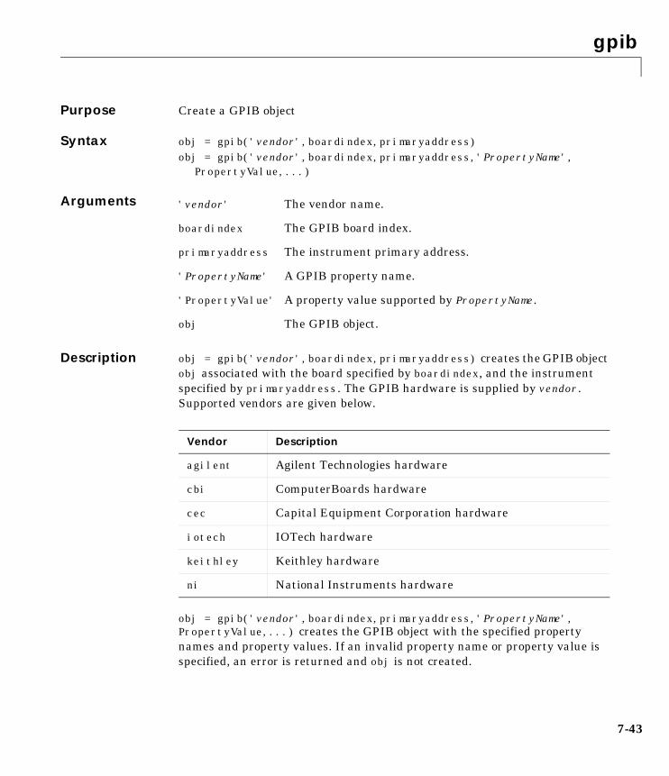
gpib
7-43
7gpibPurpose Create a GPIB object
Syntax obj = gpib('vendor',boardindex,primaryaddress)obj = gpib('vendor',boardindex,primaryaddress,'PropertyName',
PropertyValue,...)
Arguments
Description obj = gpib('vendor',boardindex,primaryaddress) creates the GPIB objectobj associated with the board specified by boardindex, and the instrumentspecified by primaryaddress. The GPIB hardware is supplied by vendor.Supported vendors are given below.
obj = gpib('vendor',boardindex,primaryaddress,'PropertyName', PropertyValue,...) creates the GPIB object with the specified propertynames and property values. If an invalid property name or property value isspecified, an error is returned and obj is not created.
'vendor' The vendor name.
boardindex The GPIB board index.
primaryaddress The instrument primary address.
'PropertyName' A GPIB property name.
'PropertyValue' A property value supported by PropertyName.
obj The GPIB object.
Vendor Description
agilent Agilent Technologies hardware
cbi ComputerBoards hardware
cec Capital Equipment Corporation hardware
iotech IOTech hardware
keithley Keithley hardware
ni National Instruments hardware
gpib
7-44
Remarks At any time, you can use the instrhelp function to view a complete listing ofproperties and functions associated with GPIB objects.
instrhelp('gpib')
When you create a GPIB object, these property value are automaticallyconfigured:
• The Type property is given by gpib.
• The Name property is given by concatenating GPIB with the board index andthe primary address specified in the gpib function. If the secondary addressis specified, then this value is also used in Name.
• The BoardIndex and PrimaryAddress property values are given by thevalues supplied to gpib.
You can specify the property names and property values using any formatsupported by the set function. For example, you can use property name/property value cell array pairs. Additionally, you can specify property nameswithout regard to case, and you can make use of property name completion. Forexample, these commands are all valid:
g = gpib(ni,0,1,'SecondaryAddress',96)g = gpib(ni,0,1,'secondaryaddress',96)g = gpib(ni,0,1,'SECOND',96)
Before you can communicate with the instrument, it must be connected to objwith the fopen function. A connected instrument object has a Status propertyvalue of open. An error is returned if you attempt to perform a read or writeoperation while obj is not connected to the instrument.
You cannot connect multiple GPIB objects to the same instrument. A GPIBinstrument is uniquely identified by its board index, primary address, andsecondary address.
Example This example creates the GPIB object g1 associated with a NationalInstruments board at index 0 with primary address 1, and then connects g1 tothe instrument.
g1 = gpib('ni',0,1);fopen(g1)
gpib
7-45
The Type, Name, BoardIndex, and PrimaryAddress properties are automaticallyconfigured.
get(g1, {'Type','Name','BoardIndex','PrimaryAddress'})ans = 'gpib' 'GPIB0-1' [0] [1]
To specify the secondary address during object creation
g2 = gpib('ni',0,1,'SecondaryAddress',96);
See Also Functionsfopen, instrhelp, instrhwinfo
PropertiesBoardIndex, Name, PrimaryAddress, SecondaryAddress, Status, Type
instraction
7-46
7instractionPurpose Display event information when an event occurs
Syntax instraction(obj, event)
Arguments
Description instraction(obj, event) displays a message that contains the event type,the time the event occurred, and the name of the instrument object that causedthe event to occur.
For error events, the error message is also displayed. For pin status events, thepin that changed value and its value are also displayed. For trigger events, thetrigger line is also displayed.
Remarks You should use instraction as a template from which you create actionfunctions that suit your specific application needs.
Example The following example creates the serial port objects s, and configures s toexecute instraction when an output-empty event occurs. The event occursafter the *IDN? command is written to the instrument.
s = serial('COM1');set(s,'OutputEmptyAction','instraction')fopen(s)fprintf(s,'*IDN?','async')
The resulting display from instraction is shown below.
OutputEmpty event occurred at 08:37:49 for the object: Serial-COM1
Read the identification information from the input buffer and end the serialport session.
idn = fscanf(s);fclose(s)delete(s)clear s
obj An instrument object.
event The event that caused the action to execute.
instrcomm
7-47
7instrcommPurpose Graphical tool for communicating with an instrument using text data
Syntax instrcomm(obj)
instrcomm
Arguments
Description instrcomm(obj) launches the Instrument Control ASCII Communication Toolfor the instrument object obj. instrcomm provides you with these features andcapabilities:
• Connect obj to the instrument, and disconnect obj from the instrument.
• Initiate and terminate recording.
• Perform synchronous read, write, and query operations for text commands.A history of transferred data is also provided.
• Flush the input buffer.
• Monitor the values sent and values received.
instrcomm launches the Instrument Control Configuration Tool, instrcreate.After you create an instrument object, it is automatically passed to theInstrument Control ASCII Communication Tool.
Example This example uses instrcomm to communicate with a Tektronix TDS 210oscilloscope, and saves the data to a record file. The read and write operationsare taken from “Example: Writing and Reading Text Data” on page 3-22.
First, create the GPIB object g at the command line. Note that you can alsocreate this object using instrcreate.
g = gpib('ni',0,1);
Launch the Instrument Control ASCII Communication Tool for g.
instrcomm(g)
obj An instrument object
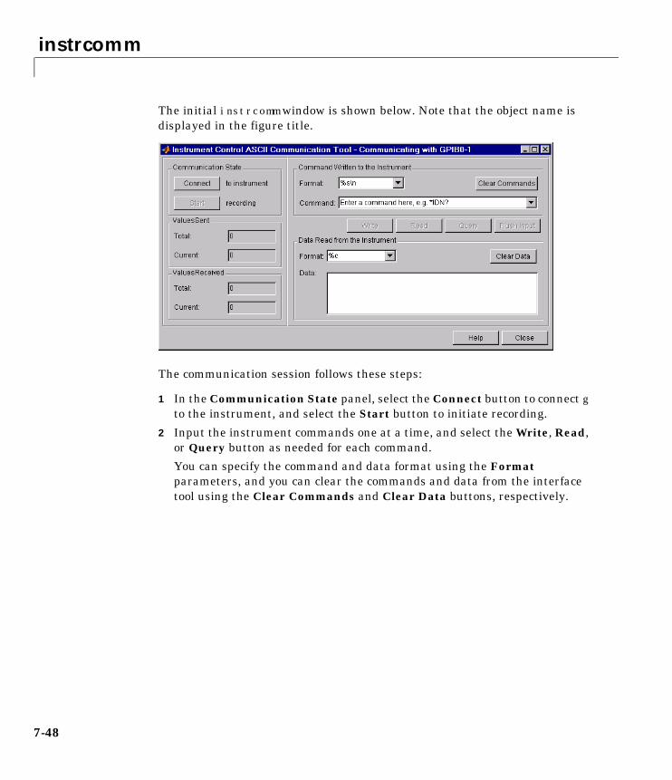
instrcomm
7-48
The initial instrcomm window is shown below. Note that the object name isdisplayed in the figure title.
The communication session follows these steps:
1 In the Communication State panel, select the Connect button to connect gto the instrument, and select the Start button to initiate recording.
2 Input the instrument commands one at a time, and select the Write, Read,or Query button as needed for each command.
You can specify the command and data format using the Formatparameters, and you can clear the commands and data from the interfacetool using the Clear Commands and Clear Data buttons, respectively.
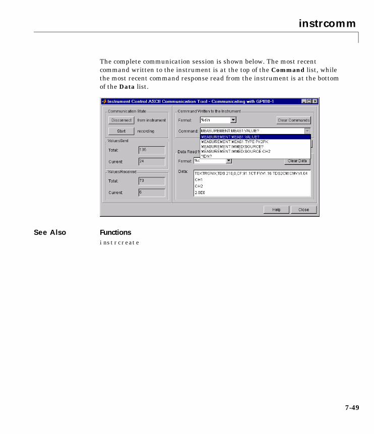
instrcomm
7-49
The complete communication session is shown below. The most recentcommand written to the instrument is at the top of the Command list, whilethe most recent command response read from the instrument is at the bottomof the Data list.
See Also Functionsinstrcreate
instrcreate
7-50
7instrcreatePurpose Graphical tool for creating and configuring an instrument object
Syntax instrcreateobj = instrcreate
Arguments
Description instrcreate launches the Instrument Control Configuration Tool. Using thistool, you can create and configure an instrument object. You can then save theinstrument object to the MATLAB workspace, convert it to the equivalentM-code, or save it to a MAT-file. Using this syntax, you have access to theMATLAB command line.
After the object is created, you can use it from the command line, or use it inconjunction with the Instrument Control ASCII Communication Tool,instrcomm. instrcreate is automatically launched if you call instrcommwithout an input argument.
obj = instrcreate saves the configured instrument object to obj if the TheMATLAB workspace check box is selected (see example below). Otherwise,obj is empty. Using this syntax, you do not have access to the MATLABcommand line until you save the instrument object to the workspace, convertit to the equivalent M-Code, save it to a MAT-file, or select the Close button.
Example This example uses instrcreate to create a GPIB object that will communicatewith a Tektronix TDS 210 oscilloscope. The configuration steps are taken from“Example: Reading Binary Data” on page 3-24.
The first step is to launch the Instrument Control Configuration Tool
instrcreate
obj An instrument object.
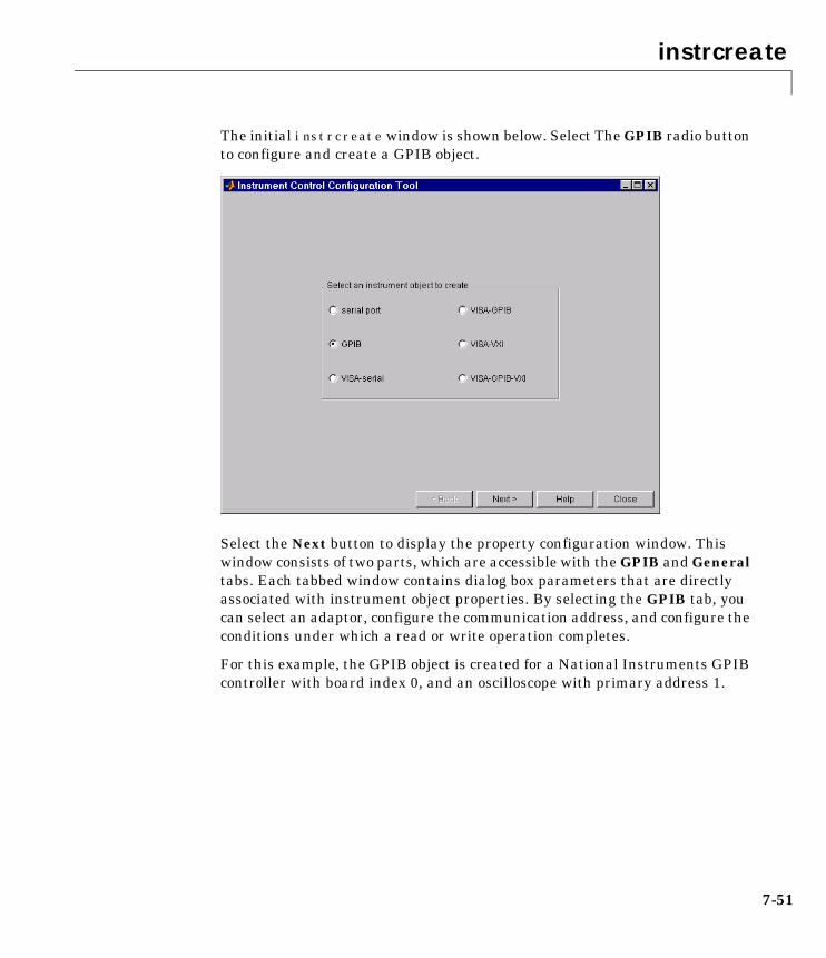
instrcreate
7-51
The initial instrcreate window is shown below. Select The GPIB radio buttonto configure and create a GPIB object.
Select the Next button to display the property configuration window. Thiswindow consists of two parts, which are accessible with the GPIB and Generaltabs. Each tabbed window contains dialog box parameters that are directlyassociated with instrument object properties. By selecting the GPIB tab, youcan select an adaptor, configure the communication address, and configure theconditions under which a read or write operation completes.
For this example, the GPIB object is created for a National Instruments GPIBcontroller with board index 0, and an oscilloscope with primary address 1.
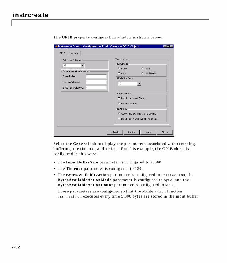
instrcreate
7-52
The GPIB property configuration window is shown below.
Select the General tab to display the parameters associated with recording,buffering, the timeout, and actions. For this example, the GPIB object isconfigured in this way:
• The InputBufferSize parameter is configured to 50000.
• The Timeout parameter is configured to 120.
• The BytesAvailableAction parameter is configured to instraction, theBytesAvailableActionMode parameter is configured to byte, and theBytesAvailableActionCount parameter is configured to 5000.
These parameters are configured so that the M-file action functioninstraction executes every time 5,000 bytes are stored in the input buffer.
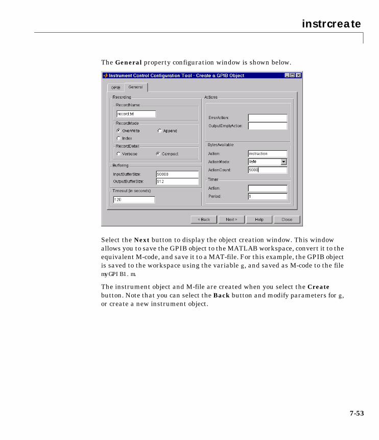
instrcreate
7-53
The General property configuration window is shown below.
Select the Next button to display the object creation window. This windowallows you to save the GPIB object to the MATLAB workspace, convert it to theequivalent M-code, and save it to a MAT-file. For this example, the GPIB objectis saved to the workspace using the variable g, and saved as M-code to the filemyGPIB1.m.
The instrument object and M-file are created when you select the Createbutton. Note that you can select the Back button and modify parameters for g,or create a new instrument object.
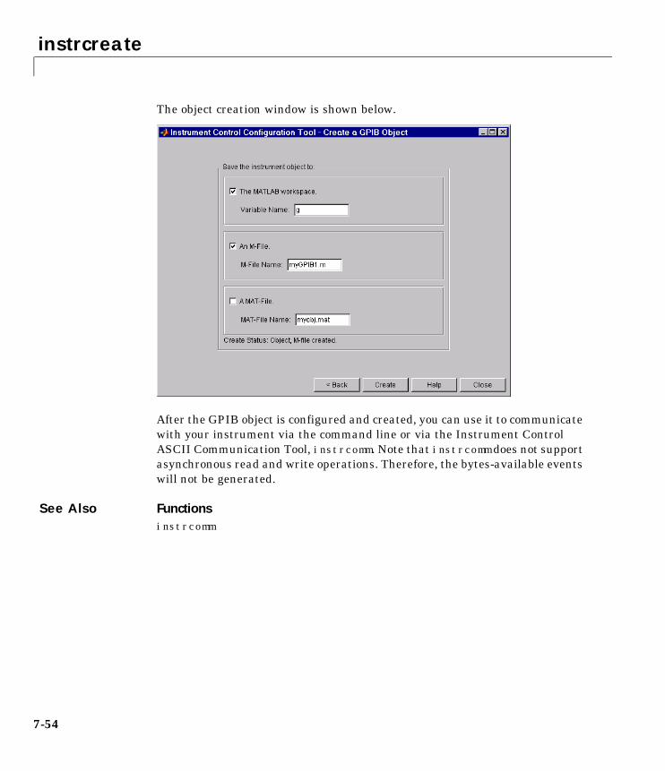
instrcreate
7-54
The object creation window is shown below.
After the GPIB object is configured and created, you can use it to communicatewith your instrument via the command line or via the Instrument ControlASCII Communication Tool, instrcomm. Note that instrcomm does not supportasynchronous read and write operations. Therefore, the bytes-available eventswill not be generated.
See Also Functionsinstrcomm
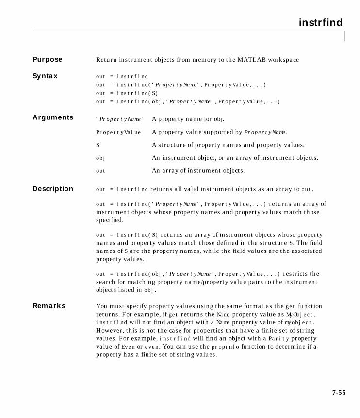
instrfind
7-55
7instrfindPurpose Return instrument objects from memory to the MATLAB workspace
Syntax out = instrfind out = instrfind('PropertyName',PropertyValue,...) out = instrfind(S)out = instrfind(obj,'PropertyName',PropertyValue,...)
Arguments
Description out = instrfind returns all valid instrument objects as an array to out.
out = instrfind('PropertyName',PropertyValue,...) returns an array ofinstrument objects whose property names and property values match thosespecified.
out = instrfind(S) returns an array of instrument objects whose propertynames and property values match those defined in the structure S. The fieldnames of S are the property names, while the field values are the associatedproperty values.
out = instrfind(obj,'PropertyName',PropertyValue,...) restricts thesearch for matching property name/property value pairs to the instrumentobjects listed in obj.
Remarks You must specify property values using the same format as the get functionreturns. For example, if get returns the Name property value as MyObject,instrfind will not find an object with a Name property value of myobject.However, this is not the case for properties that have a finite set of stringvalues. For example, instrfind will find an object with a Parity propertyvalue of Even or even. You can use the propinfo function to determine if aproperty has a finite set of string values.
'PropertyName' A property name for obj.
PropertyValue A property value supported by PropertyName.
S A structure of property names and property values.
obj An instrument object, or an array of instrument objects.
out An array of instrument objects.
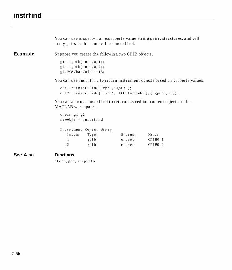
instrfind
7-56
You can use property name/property value string pairs, structures, and cellarray pairs in the same call to instrfind.
Example Suppose you create the following two GPIB objects.
g1 = gpib('ni',0,1);g2 = gpib('ni',0,2);g2.EOSCharCode = 13;
You can use instrfind to return instrument objects based on property values.
out1 = instrfind('Type','gpib');out2 = instrfind({'Type','EOSCharCode'},{'gpib',13});
You can also use instrfind to return cleared instrument objects to theMATLAB workspace.
clear g1 g2newobjs = instrfind
Instrument Object Array Index: Type: Status: Name: 1 gpib closed GPIB0-1 2 gpib closed GPIB0-2
See Also Functionsclear, get, propinfo
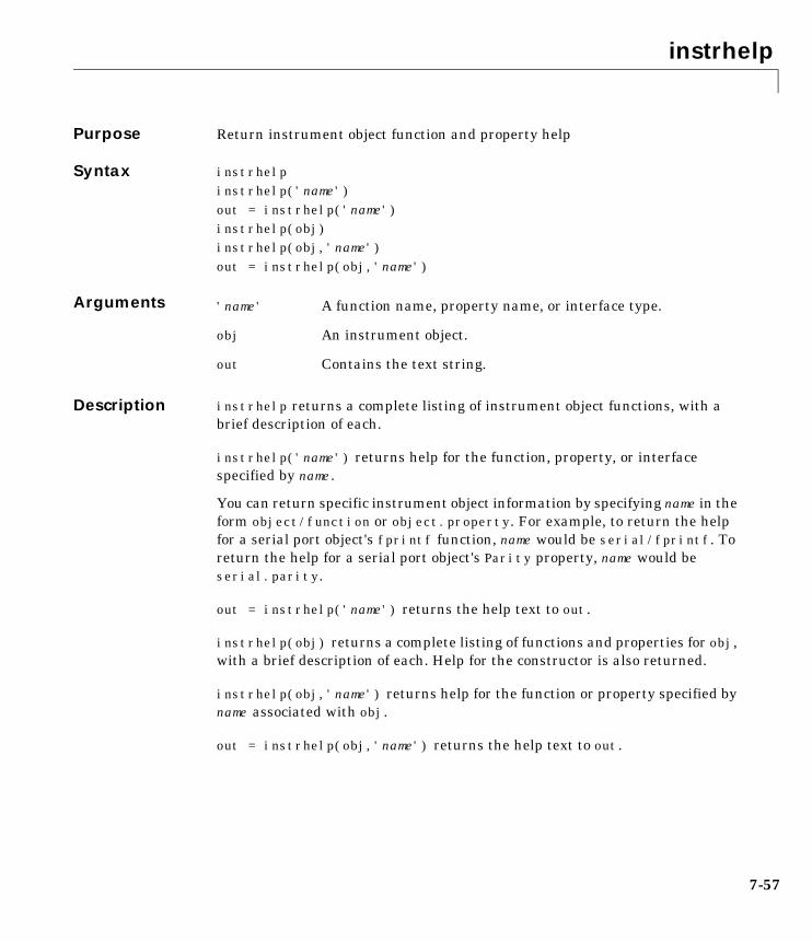
instrhelp
7-57
7instrhelpPurpose Return instrument object function and property help
Syntax instrhelpinstrhelp('name')out = instrhelp('name') instrhelp(obj)instrhelp(obj,'name')out = instrhelp(obj,'name')
Arguments
Description instrhelp returns a complete listing of instrument object functions, with abrief description of each.
instrhelp('name') returns help for the function, property, or interfacespecified by name.
You can return specific instrument object information by specifying name in theform object/function or object.property. For example, to return the helpfor a serial port object's fprintf function, name would be serial/fprintf. Toreturn the help for a serial port object's Parity property, name would beserial.parity.
out = instrhelp('name') returns the help text to out.
instrhelp(obj) returns a complete listing of functions and properties for obj,with a brief description of each. Help for the constructor is also returned.
instrhelp(obj,'name') returns help for the function or property specified byname associated with obj.
out = instrhelp(obj,'name') returns the help text to out.
'name' A function name, property name, or interface type.
obj An instrument object.
out Contains the text string.
instrhelp
7-58
Remarks When returning property help, the names in the See Also section that containall upper case letters are function names. The names that contain a mixture ofupper and lower case letters are property names.
When returning function help, the See Also section contains only functionnames.
Example The following commands illustrate some of the ways you can get function andproperty help without creating an instrument object.
instrhelp('gpib')out = instrhelp('gpib.m');instrhelp setinstrhelp('gpib/set')instrhelp EOSCharCodeinstrhelp('gpib.eoscharcode')
The following commands illustrate some of the ways you can get function andproperty help for an existing instrument object.
g = gpib('ni',0,1);instrhelp(g)instrhelp(g,'EOSMode');out = instrhelp(g,'trigger');
See Also Functionspropinfo
instrhwinfo
7-59
7instrhwinfoPurpose Return information about available hardware
Syntax out = instrhwinfoout = instrhwinfo('interface') out = instrhwinfo('interface','adaptor') out = instrhwinfo(obj)out = instrhwinfo(obj,'FieldName')
Arguments
Description out = instrhwinfo returns hardware information to the structure out. Thisinformation includes the toolbox version, MATLAB version and supportedinterfaces.
out = instrhwinfo('interface') returns information related to theinterface specified by interface. interface can be serial, gpib, or visa. Forthe GPIB and VISA interfaces, the returned information includes installedadaptors. For the serial port interface, the returned information includes theavailable ports and the object constructor name.
out = instrhwinfo('interface','adaptor') returns information related tothe adaptor specified by adaptor, and for the interface specified by interface.interface can be gpib or visa. The returned information includes the adaptorversion and available hardware. The GPIB adaptors are agilent, ni, cbi, cec,iotech, and keithley. The VISA adaptors are agilent and ni.
out = instrhwinfo(obj) returns information on the adaptor andvendor-supplied DLL associated with the VISA or GPIB object obj. If obj is aserial port object, then JAR file information is returned
'interface' A supported instrument interface.
'adaptor' A supported GPIB or VISA adaptor.
obj An instrument object.
'FieldName' A field name or cell array of field names associated with obj.
out A structure or array containing hardware information.
instrhwinfo
7-60
out = instrhwinfo(obj,'FieldName') returns hardware information for thefield name specified by FieldName. FieldName can be a single string or a cellarray of strings. out is a 1-by-N cell array where N is the length of FieldName.You can return the supported values for FieldName using theinstrhwinfo(obj) syntax.
Example The following commands illustrate some of the ways you can gethardware-related information without creating an instrument object.
out1 = instrhwinfo;out2 = instrhwinfo('serial');out3 = instrhwinfo('gpib','ni');out4 = instrhwinfo('visa','agilent');
The following commands illustrate some of the ways you can gethardware-related information for an existing instrument object.
vs = visa('agilent','ASRL1::INSTR');out5 = instrhwinfo(vs)out5 = AdaptorDllName: [1x67 char] AdaptorDllVersion: 'Version 1.0 (R12)' AdaptorName: 'AGILENT' VendorDriverDescription: 'Agilent Technologies VISA Driver' VendorDriverVersion: '1.1000'
vsdll = instrhwinfo(vs,'AdaptorDllName')vsdll = D:\V6\toolbox\instrument\instrumentadaptors\win32\ mwagilentvisa.dll
instrreset
7-61
7instrresetPurpose Disconnect and delete all instrument objects
Syntax instrreset
Description instrreset disconnects and deletes all instrument objects.
Remarks If data is being written or read asynchronously, the asynchronous operation isstopped.
instrreset is equivalent to issuing the stopasync (if needed), fclose, anddelete functions for all instrument objects.
When you delete an instrument object, it becomes invalid. Since you cannotconnect an invalid object to the instrument, you should remove it from theworkspace with the clear command.
See Also Functionsclear, delete, fclose, isvalid, stopasync
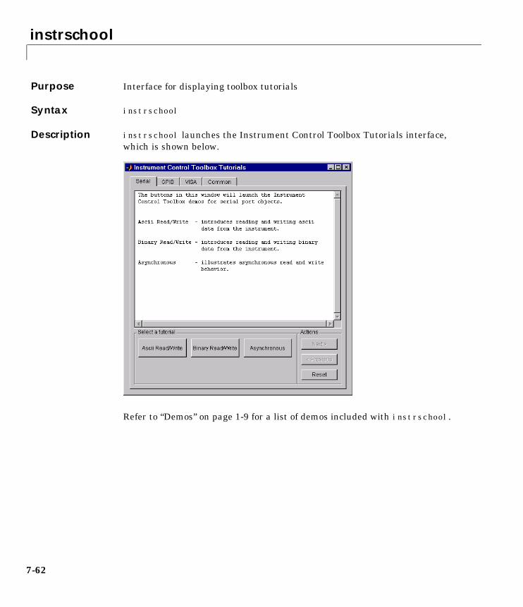
instrschool
7-62
7instrschoolPurpose Interface for displaying toolbox tutorials
Syntax instrschool
Description instrschool launches the Instrument Control Toolbox Tutorials interface,which is shown below.
Refer to “Demos” on page 1-9 for a list of demos included with instrschool.
isvalid
7-63
7isvalidPurpose Determine if instrument objects are valid
Syntax out = isvalid(obj)
Arguments
Description out = isvalid(obj) returns the logical array out, which contains a 0 wherethe elements of obj are invalid instrument objects and a 1 where the elementsof obj are valid instrument objects.
Remarks obj becomes invalid after it is removed from memory with the delete function.Since you cannot connect an invalid object to the instrument, you shouldremove it from the workspace with the clear command.
Example Suppose you create the following two GPIB objects
g1 = gpib('ni',0,1);g2 = gpib('ni',0,2);
g2 becomes invalid after it is deleted.
delete(g2)
isvalid verifies that g1 is valid and g2 is invalid.
garray = [g1 g2];isvalid(garray)ans = 1 0
See Also Functionsclear, delete
obj An instrument object or array of instrument objects.
out A logical array.
length
7-64
7lengthPurpose Length of instrument object array
Syntax length(obj)
Arguments
Description length(obj) returns the length of obj. It is equivalent to the commandmax(size(obj)).
See Also Functionsinstrhelp, size
obj An instrument object or an array of instrument objects.
load
7-65
7loadPurpose Load instrument objects and variables into the MATLAB workspace
Syntax load filenameload filename obj1 obj2 ...out = load('filename','obj1','obj2',...)
Arguments
Description load filename returns all variables from the MAT-file specified by filenameinto the MATLAB workspace.
load filename obj1 obj2 ... returns the instrument objects specified byobj1 obj2... from the MAT-file filename into the MATLAB workspace.
out = load('filename','obj1','obj2',...) returns the specified instrumentobjects from the MAT-file filename as a structure to out instead of directlyloading them into the workspace. The field names in out match the names ofthe loaded instrument objects.
Remarks Values for read-only properties are restored to their default values uponloading. For example, the Status property is restored to closed. To determineif a property is read-only, examine its reference pages or use the propinfofunction.
Example Suppose you create the GPIB objects g1 and g2, configure a few properties forg1, and connect both objects to their associated instruments.
g1 = gpib('ni',0,1);g2 = gpib('ni',0,2);set(g1,'EOSMode','read','EOSCharCode',13)fopen([g1 g2])
filename The MAT-file name.
obj1 obj2 ... Instrument objects or arrays of instrument objects.
out A structure containing the specified instrument objects.
load
7-66
The read-only Status property is automatically configured to open.
get([g1 g2],'Status')ans = 'open' 'open'
Save g1 and g2 to the file MyObject.mat, and then load the objects into theMATLAB workspace.
save MyObject g1 g2load MyObject g1 g2
Values for read-only properties are restored to their default values uponloading, while all other property values are honored.
get([g1 g2],{'EOSMode','EOSCharCode','Status'})ans = 'read' [13] 'closed' 'none' [10] 'closed'
See Also Functionsinstrhelp, propinfo, save
memmap
7-67
7memmapPurpose Map memory for low-level memory read and write operations
Syntax memmap(obj,'adrspace',offset,size);
Arguments
Description memmap(obj,'adrspace',offset,size) maps the amount of memory specifiedby size in address space, adrspace with an offset, offset. You can configureadrspace to A16 (A16 address space), A24 (A24 address space), or A32 (A32address space).
Remarks Before you can map memory, objmust be connected to the instrument with thefopen function. A connected instrument object has a Status property value ofopen. An error is returned if you attempt to map memory while obj is notconnected to the instrument.
To unmap the memory, use the memunmap function. If memory is mapped andfclose is called, the memory is unmapped before the object is disconnectedfrom the instrument.
The MappedMemorySize property returns the size of the memory space mapped.You must map the memory space before using the mempoke or mempeek function.
Example Create the VISA-VXI object vv associated with a VXI chassis with index 0, andan Agilent E1432A digitizer with logical address 130.
vv = visa('agilent','VXI0::130::INSTR');fopen(vv)
Use memmap to map 16 bytes in the A16 address space.
memmap(vv,'A16',0,16)
obj A VISA-VXI or VISA-GPIB-VXI object.
'adrspace' The memory address space.
offset Offset for the memory address space.
size Number of bytes to map.
memmap
7-68
Read the first and second instrument registers.
reg1 = mempeek(vv,0,'uint16');reg2 = mempeek(vv,2,'uint16');
Unmap the memory and disconnect vv from the instrument.
memunmap(vv)fclose(vv)
See Also Functionsfopen, fclose, mempeek, mempoke, memunmap
PropertiesMappedMemorySize, Status
mempeek
7-69
7mempeekPurpose Low-level memory read from VXI register
Syntax out = mempeek(obj,offset);out = mempeek(obj,offset,'precision');
Arguments
Description out = mempeek(obj,offset) reads a uint8 value from the mapped memoryspace specified by offset for the object obj. The value is returned to out.
out = mempeek(obj,offset,'precision') reads the number of bits specifiedby precision, from the mapped memory space specified by offset. precisioncan be uint8, uint16, or uint32, which instructs mempeek to read 8, 16 or 32bits of data, respectively.
Remarks Before you can read from the VXI register, obj must be connected to theinstrument with the fopen function. A connected instrument object has aStatus property value of open. An error is returned if you attempt a readoperation while obj is not connected to the instrument.
You must map the memory space using the memmap function before usingmempeek. The MappedMemorySize property returns the size of the memory spacemapped.
offset indicates the offset in the mapped memory space from which the datawill be read. For example, if the mapped memory space begins at 200H, theoffset is 2, and the precision is uint8, then the data at memory location 202His read. If the precision is uint16, the data at 204H is read.
To increase speed, mempeek does not return error messages from theinstrument.
obj A VISA-VXI or VISA-GPIB-VXI object.
offset The offset in the mapped memory space from which thedata is read.
'precision' The number of bits to read from the memory address.
out An array containing the returned value.
mempeek
7-70
Example Create the VISA-VXI object vv associated with a VXI chassis with index 0, andan Agilent E1432A digitizer with logical address 130.
vv = visa('agilent','VXI0::130::INSTR');fopen(vv)
Use memmap to map 16 bytes in the A16 address space.
memmap(vv,'A16',0,16)
Perform a low-level read the first and second instrument registers.
reg1 = mempeek(vv,0,'uint16')reg1 = 53247reg2 = mempeek(vv,2,'uint16')reg2 = 20993
Unmap the memory and disconnect vv from the instrument.
memunmap(vv)fclose(vv)
Refer to “Example: Using High-Level Memory Functions” on page 4-16 for adescription of the first four registers of the E1432A digitizer.
See Also Functionsfopen, memmap, mempoke, memunmap
PropertiesMappedMemorySize, Status
mempoke
7-71
7mempokePurpose Low-level memory write to VXI register
Syntax mempoke(obj,data,offset);mempoke(obj,data,offset,'precision');
Arguments
Description mempoke(obj,data,offset) writes the uint8 value specified by data to themapped memory address specified by offset for the object obj.
mempoke(obj,data,offset,'precision') writes data using the number ofbits specified by precision. precision can be uint8, uint16, or uint32, whichinstructs mempoke to write 8, 16 or 32 bits of data, respectively.
Remarks Before you can write to the VXI register, obj must be connected to theinstrument with the fopen function. A connected instrument object has aStatus property value of open. An error is returned if you attempt a writeoperation while obj is not connected to the instrument.
You must map the memory space using the memmap function before usingmempoke. The MappedMemorySize property returns the size of the memory spacemapped.
offset indicates the offset in the mapped memory space to which the data iswritten. For example, if the mapped memory space begins at 200H, the offsetis 2, and the precision is uint8, then the data at memory location 202H is read.If the precision is uint16, the data at 204H is read.
To increase speed, mempoke does not return error messages from theinstrument.
obj A VISA-VXI or VISA-GPIB-VXI object.
data The data written to the memory address.
offset The offset in the mapped memory space to which the datais written.
'precision' The number of bits to write to the memory address.
mempoke
7-72
Example Create the VISA-VXI object vv associated with a VXI chassis with index 0, andan Agilent E1432A digitizer with logical address 130.
vv = visa('agilent','VXI0::130::INSTR');fopen(vv)
Use memmap to map 16 bytes in the A16 address space.
memmap(vv,'A16',0,16)
Perform a low-level write to the fourth instrument register.
mempoke(vv,45056,6,'uint16')
Unmap the memory and disconnect vv from the instrument.
memunmap(vv)fclose(vv)
Refer to “Example: Using High-Level Memory Functions” on page 4-16 for adescription of the first four registers of the E1432A digitizer.
See Also Functionsfopen, memmap, mempeek
PropertiesMappedMemorySize, Status

memread
7-73
7memreadPurpose High-level memory read from VXI register
Syntax out = memread(obj);out = memread(obj,offset);out = memread(obj,offset,'precision');out = memread(obj,offset,'precision','adrspace');out = memread(obj,offset,'precision','adrspace',size);
Arguments
Description out = memread(obj) reads a uint8 value from the A16 address space with anoffset of 0 for the object obj.
out = memread(obj,offset) reads a uint8 value from the A16 address spacewith an offset specified by offset. You must specify offset as a decimal value.
out = memread(obj,offset,'precision') reads the number of bits specifiedby precision from the A16 address space. precision can be uint8, uint16, oruint32, which instructs memread to read 8, 16 or 32 bits of data, respectively.
out = memread(obj,offset,'precision','adrspace') reads the specifiednumber of bits from the address space specified by adrspace. adrspace can beA16, A24 or A32. The MemorySpace property indicates which VXI addressspace(s) are used by the instrument.
out = memread(obj,offset,'precision','adrspace',size) reads a block ofdata with a size specified by size.
obj A VISA-VXI or VISA-GPIB-VXI object.
offset Offset for the memory address space.
'precision' The number of bits to read from the memory address.
'adrspace' The memory address space.
offset Offset for the memory address space.
size The size of the data block to read.
out An array containing the returned value.
memread
7-74
Remarks Before you can read data from the VXI register, obj must be connected to theinstrument with the fopen function. A connected instrument object has aStatus property value of open. An error is returned if you attempt to readmemory while obj is not connected to the instrument.
Example Create the VISA-VXI object vv associated with a VXI chassis with index 0, andan Agilent E1432A digitizer with logical address 130.
vv = visa('agilent','VXI0::130::INSTR');fopen(vv)
Perform a high-level read of the first instrument register.
reg1 = memread(vv,0,'uint16')reg1 = 53247
Perform a high-level read of the next three instrument registers.
reg24 = memread(vv,2,'uint16','A16',3)reg24 = 20993 50012 40960
Disconnect vv from the instrument.
fclose(vv)
Refer to “Example: Using High-Level Memory Functions” on page 4-16 for adescription of the first four registers of the E1432A digitizer.
See Also Functionsfopen, mempeek, memwrite
PropertiesMemorySpace, Status
memunmap
7-75
7memunmapPurpose Unmap memory for low-level memory read and write operations
Syntax memunmap(obj);
Arguments
Description memunmap(obj) unmaps memory space previously mapped by the memmapfunction.
Remarks When the memory space is unmapped. the MappedMemorySize property is setto 0 and the MappedMemoryBase property is set to 0H.
Example Create the VISA-VXI object vv associated with a VXI chassis with index 0, andan Agilent E1432A digitizer with logical address 130.
vv = visa('agilent','VXI0::130::INSTR');fopen(vv)
Map 16 bytes in the A16 address space.
memmap(vv,'A16',0,16)
Read the first and second instrument registers.
reg1 = mempeek(vv,0,'uint16');reg2 = mempeek(vv,2,'uint16');
Use memunmap to unmap the memory, and disconnect vv from the instrument.
memunmap(vv)fclose(vv)
See Also Functionsmemmap, mempeek, mempoke
PropertiesMappedMemoryBase, MappedMemorySize
obj A VISA-VXI or VISA-GPIB-VXI object.
memwrite
7-76
7memwritePurpose High-level memory write to VXI register
Syntax memwrite(obj,data);memwrite(obj,data,offset);memwrite(obj,data,offset,'precision');memwrite(obj,data,offset,'precision','adrspace');
Arguments
Description memwrite(obj,data) writes the uint8 value specified by data to the A16address space with an offset of 0 for the object obj. data can be an array ofuint8 values.
memwrite(obj,data,offset) writes data to the A16 address space with anoffset specified by offset. offset is specified as a decimal value.
memwrite(obj,data,offset,'precision') writes data with precisionspecified by precision. precision can be uint8, uint16, or uint32, whichinstructs memwrite to write data as an 8-, 16-, or 32-bit value, respectively.
memwrite(obj,data,offset,'precision','adrspace') writes data to theaddress space specified by adrspace. adrspace can be A16, A24 or A32. TheMemorySpace property indicates which VXI address space(s) are used by theinstrument.
Remarks Before you can write to the VXI register, obj must be connected to theinstrument with the fopen function. A connected instrument object has aStatus property value of open. An error is returned if you attempt a writeoperation while obj is not connected to the instrument.
obj A VISA-VXI or VISA-GPIB-VXI object.
data The data written to the memory address.
offset Offset for the memory address space.
'precision' The number of bits to write to the memory address.
'adrspace' The memory address space.
memwrite
7-77
Example Create the VISA-VXI object vv associated with a VXI chassis with index 0, andan Agilent E1432A digitizer with logical address 130.
vv = visa('agilent','VXI0::130::INSTR');fopen(vv)
Perform a high-level write to the fourth instrument register.
memwrite(vv,45056,6,'uint16','A16')
Disconnect vv from the instrument.
fclose(vv)
Refer to “Example: Using High-Level Memory Functions” on page 4-16 for adescription of the first four registers of the E1432A digitizer.
See Also Functionsfopen, memread, mempoke
PropertiesMemorySpace, Status
obj2mfile
7-78
7obj2mfilePurpose Convert instrument object to MATLAB code
Syntax obj2mfile(obj,'filename') obj2mfile(obj,'filename','syntax') obj2mfile(obj,'filename','mode')obj2mfile(obj,'filename','syntax','mode')
Arguments
Description obj2mfile(obj,'filename') converts obj to the equivalent MATLAB codeusing the set syntax and saves the code to filename. Only those properties notset to their default value are saved.
obj2mfile(obj,'filename','syntax') converts obj to the equivalentMATLAB code using the syntax specified by syntax. You can specify syntax tobe set or dot. set uses the set syntax, while dot uses the dot notation.
obj2mfile(obj,'filename','mode') converts the properties specified bymode. You can specify mode to be all or modified. If mode is all, then allproperties are converted to code. If mode is modified, then only those propertiesnot set to their default value are converted to code.
obj2mfile(obj,'filename','syntax','mode') converts the specifiedproperties to code using the specified syntax.
Remarks You can recreate a saved instrument object by typing the name of the M-file atthe MATLAB command line.
obj An instrument object or an array of instrument objects.
'filename' The name of the file that the MATLAB code is written to.You can specify the full pathname. If an extension is notspecified, the .m extension is used.
'syntax' Syntax of the converted MATLAB code. By default, theset syntax is used. If dot is specified, then the dotnotation is used.
'mode' Specifies whether all properties are converted to code, oronly modified properties are converted to code.
obj2mfile
7-79
If the UserData property is not empty or if any of the action properties are setto a cell array of values, then the data stored in those properties is written to aMAT-file when the instrument object is converted and saved. The MAT-file hasthe same name as the M-file containing the instrument object code (see theexample below).
Read-only properties are restored with their default value. For example,suppose an instrument object is saved with a Status property value of open.When the object is recreated, Status is set to its default value of closed.
Example Suppose you create the GPIB object g, and configure several property values.
g = gpib('ni',0,1);set(g,'Tag','MyGPIB object','EOSMode','read','EOSCharCode',13)set(g,'UserData',{'test',2,magic(10)})
The following command writes MATLAB code to the files MyGPIB.m andMyGPIB.mat.
obj2mfile(g,'MyGPIB.m','dot')
MyGPIB.m contains code that recreates the commands shown above using thedot notation for all properties that have their default values changed. SinceUserData is set to a cell array of values, this property appears in MyGPIB.m as
obj1.UserData = userdata;
It is saved in MyGPIB.mat as
userdata = {'test', 2, magic(10)};
To recreate g in the MATLAB workspace using a new variable, gnew
gnew = MyGPIB;
The associated MAT-file, MyGPIB.mat, is automatically run and UserData isassigned the appropriate values.
gnew.UserDataans = 'test' [2] [10x10 double]
See Also Functionspropinfo
propinfo
7-80
7propinfoPurpose Return instrument object property information
Syntax out = propinfo(obj)out = propinfo(obj,'PropertyName')
Arguments
Description out = propinfo(obj) returns the structure out with field names given by theproperty names for obj. Each property name in out contains the fields shownbelow.
out = propinfo(obj,'PropertyName') returns the structure out for theproperty specified by PropertyName. The field names of out are given in thetable shown above. If PropertyName is a cell array of property names, a cellarray of structures is returned for each property.
obj An instrument object.
'PropertyName' A property name or cell array of property names.
out A structure containing property information.
Field Name Description
Type The property data type. Possible values are action,any, double, string, and struct.
Constraint The type of constraint on property values. Possiblevalues are action, bounded, enum, and none.
ConstraintValue Property value constraint. The constraint can be arange of valid values or a list of valid string values.
DefaultValue The property default value.
ReadOnly The condition under which a property is read-only.Possible values are always, never, whileOpen, andwhileRecording.
InterfaceSpecific
If the property is interface-specific, a 1 is returned. If a0 is returned, the property is supported for allinterfaces.
propinfo
7-81
Remarks You can get help for instrument object properties with the instrhelp function.
You can display all instrument object property names and their current valuesusing the get function. You can display all configurable properties and theirpossible values using the set function.
When you specify property names, you can do so without regard to case, andyou can make use of property name completion. For example, if g is a GPIBobject, then the following commands are all valid.
out = propinfo(g,'EOSMode');out = propinfo(g,'eosmode');out = propinfo(g,'EOSM');
Example To return all property information for the GPIB object g
g = gpib('ni',0,1);out = propinfo(g);
To display all the property information for the InputBufferSize property
out.InputBufferSizeans = Type: 'double' Constraint: 'none' ConstraintValue: '' DefaultValue: 512 ReadOnly: 'whileOpen'
InterfaceSpecific: 0
To display the default value for the EOSMode property
out.EOSMode.DefaultValueans =none
See Also Functionsget, instrhelp, set
query
7-82
7queryPurpose Write text to the instrument, and read data from the instrument
Syntax out = query(obj,'cmd')out = query(obj,'cmd','wformat')out = query(obj,'cmd','wformat','rformat')[out,count] = query(...)[out,count,msg] = query(...)
Arguments
Description out = query(obj,'cmd') writes the string cmd to the instrument connected toobj. The data read from the instrument is returned to out. By default, the %s\nformat is used for cmd, and the %c format is used for the returned data.
out = query(obj,'cmd','wformat') writes the string cmd using the formatspecified by wformat.
wformat is a C language conversion specification. Conversion specificationsinvolve the % character and the conversion characters d, i, o, u, x, X, f, e, E, g,G, c, and s. Refer to the sprintf file I/O format specifications or a C manual formore information.
out = query(obj,'cmd','wformat','rformat') writes the string cmd usingthe format specified by wformat. The data read from the instrument is returnedto out using the format specified by rformat.
rformat is a C language conversion specification. The supported conversionspecifications are identical to those supported by wformat.
obj An instrument object.
'cmd' String that is written to the instrument.
'wformat' Format for written data.
'rformat' Format for read data.
out Contains data read from the instrument.
count The number of values read.
msg A message indicating if the read operation wasunsuccessful.
query
7-83
[A,count] = query(...) returns the number of values read to count.
[A,count,msg] = query(...) returns a warning message to msg if the readoperation did not complete successfully.
Remarks Before you can write or read data, obj must be connected to the instrumentwith the fopen function. A connected instrument object has a Status propertyvalue of open. An error is returned if you attempt to perform a query operationwhile obj is not connected to the instrument.
query operates only in synchronous mode, and blocks the command line untilthe write and read operations complete execution.
Using query is equivalent to using the fprintf and fgets functions. The rulesfor completing a write operation are described in the fprintf reference pages.The rules for completing a read operation are described in the fgets referencepages.
Example This example creates the GPIB object g, connects g to a Tektronix TDS 210oscilloscope, writes and reads text data using query, and then disconnects gfrom the instrument.
g = gpib('ni',0,1);fopen(g)idn = query(g,'*IDN?')idn =TEKTRONIX,TDS 210,0,CF:91.1CT FV:v1.16 TDS2CM:CMV:v1.04fclose(g)
See Also Functionsfopen, fprintf, fgets, sprintf
PropertiesStatus
readasync
7-84
7readasyncPurpose Read data asynchronously from the instrument
Syntax readasync(obj)readasync(obj,size)
Arguments
Description readasync(obj) initiates an asynchronous read operation.
readasync(obj,size) asynchronously reads, at most, the number of bytesspecified by size. If size is greater than the difference between theInputBufferSize property value and the BytesAvailable property value, anerror is returned.
Remarks Before you can read data, you must connect obj to the instrument with thefopen function. A connected instrument object has a Status property value ofopen. An error is returned if you attempt to perform a read operation while objis not connected to the instrument.
For serial port and VISA-serial objects, you should use readasync only whenyou configure the ReadAsyncMode property to manual. readasync is ignored ifused when ReadAsyncMode is continuous.
The TransferStatus property indicates if an asynchronous read or writeoperation is in progress. For all instrument objects, you cannot use readasyncwhile a read operation is in progress. For serial port and VISA-serial objects,you can write data while an asynchronous read is in progress since serial portshave separate read and write pins. You can stop asynchronous read and writeoperations with the stopasync function.
You can monitor the amount of data stored in the input buffer with theBytesAvailable property. Additionally, you can use theBytesAvailableAction property to execute an M-file action function when theterminator or the specified amount of data is read.
obj An instrument object.
size The number of bytes to read from the instrument.
readasync
7-85
Rules for Completing an Asynchronous Read OperationAn asynchronous read operation with readasync completes when one of theseconditions is met:
• The terminator is read. For serial port and VISA-serial objects, theterminator is given by the Terminator property. For all other instrumentobjects, the terminator is given by the EOSCharCode property.
• The time specified by the Timeout property passes.
• The specified number of bytes are read.
• The input buffer is filled.
• The EOI line is asserted (GPIB and VXI instruments only).
For serial port and VISA-serial objects, readasync can be slow since it checksfor the terminator. To increase speed, you may want to configureReadAsyncMode to continuous and continuously return data to the input bufferas soon as it is available from the instrument.
Example This example creates the serial port object s, connects s to a Tektronix TDS 210oscilloscope, configures s to read data asynchronously only if readasync isissued, and configures the instrument to return the peak-to-peak value of thesignal on channel 1.
s = serial('COM1');fopen(s)s.ReadAsyncMode = 'manual';fprintf(s,'Measurement:Meas1:Source CH1')fprintf(s,'Measurement:Meas1:Type Pk2Pk')fprintf(s,'Measurement:Meas1:Value?')
Initially, there is no data in the input buffer
s.BytesAvailableans = 0
readasync
7-86
Begin reading data asynchronously from the instrument using readasync.When the read operation is complete, return the data to the MATLABworkspace using fscanf.
readasync(s)s.BytesAvailableans = 15out = fscanf(s)out =2.0399999619E0fclose(s)
See Also Functionsfopen, stopasync
PropertiesBytesAvailable, BytesAvailableAction, ReadAsyncMode, Status,TransferStatus
record
7-87
7recordPurpose Record data and event information to a file
Syntax record(obj)record(obj,'switch')
Arguments
Description record(obj) toggles the recording state for obj.
record(obj,'switch') initiates or terminates recording for obj. switch canbe on or off. If switch is on, recording is initiated. If switch is off, recordingis terminated.
Remarks Before you can record information to disk, obj must be connected to theinstrument with the fopen function. A connected instrument object has aStatus property value of open. An error is returned if you attempt to recordinformation while obj is not connected to the instrument. Each instrumentobject must record information to a separate file. Recording is automaticallyterminated when obj is disconnected from the instrument with fclose.
The RecordName and RecordMode properties are read-only while obj isrecording, and must be configured before using record.
For a detailed description of the record file format and the propertiesassociated with recording data and event information to a file, refer to“Debugging: Recording Information to Disk” on page 6-6.
Example This example creates the GPIB object g, connects g to the instrument, andconfigures g to record detailed information to the disk file MyGPIBFile.txt.
g = gpib('ni',0,1);fopen(g)g.RecordDetail = 'verbose';g.RecordName = 'MyGPIBFile.txt';
obj An instrument object.
'switch' Switch recording capabilities on or off.
record
7-88
Initiate recording, write the *IDN? command to the instrument, and read backthe identification information.
record(g,'on')fprintf(g,'*IDN?')out = fscanf(g);
Terminate recording and disconnect g from the instrument.
record(g,'off')fclose(g)
See Also Functionsfclose, fopen, propinfo
PropertiesRecordMode, RecordName, RecordStatus, Status
save
7-89
7savePurpose Save instrument objects and variables to a MAT-file.
Syntax save filenamesave filename obj1 obj2...
Arguments
Description save filename saves all MATLAB variables to the MAT-file filename. If anextension is not specified for filename, then a .mat extension is used.
save filename obj1 obj2,... saves the instrument objects obj1 obj2 ... to theMAT-file filename.
Remarks You can use save in the functional form as well as the command form shownabove. When using the functional form, you must specify the filename andinstrument objects as strings. For example. to save the serial port object s tothe file MySerial.mat
s = serial('COM1');save('MySerial','s')
Any data that is associated with the instrument object is not automaticallystored in the MAT-file. For example, suppose there is data in the input bufferfor obj. To save that data to a MAT-file, you must bring the data into theMATLAB workspace using one of the synchronous read functions, and thensave the data to the MAT-file using a separate variable name. You can alsosave data to a text file with the record function.
You return objects and variables to the MATLAB workspace with the loadcommand. Values for read-only properties are restored to their default valuesupon loading. For example, the Status property is restored to closed. Todetermine if a property is read-only, examine its reference pages or use thepropinfo function.
filename The MAT-file name.
obj1 obj2... Instrument objects or arrays of instrument objects.
save
7-90
Example This example illustrates how to use the command form and the functional formof save.
s = serial('COM1');set(s,'BaudRate',2400,'StopBits',1)save MySerial1 sset(s,'BytesAvailableAction','MyAction')save('MySerial2','s')
See Also Functionsinstrhelp, load, propinfo, record
PropertiesStatus
serial
7-91
7serialPurpose Create a serial port object
Syntax obj = serial('port')obj = serial('port','PropertyName',PropertyValue,...)
Arguments
Description obj = serial('port') creates a serial port object associated with the serialport specified by port. If port does not exist, or if it is in use, you will not beable to connect the serial port object to the instrument with the fopen function.
obj = serial('port','PropertyName',PropertyValue,...) creates a serialport object with the specified property names and property values. If an invalidproperty name or property value is specified, an error is returned and the serialport object is not created.
Remarks At any time, you can use the instrhelp function to view a complete listing ofproperties and functions associated with serial port objects.
instrhelp('serial')
When you create a serial port object, these property values are automaticallyconfigured:
• The Type property is given by serial.
• The Name property is given by concatenating Serial with the port specifiedin the serial function.
• The Port property is given by the port specified in the serial function.
You can specify the property names and property values using any formatsupported by the set function. For example, you can use property name/property value cell array pairs. Additionally, you can specify property names
'port' The serial port name.
'PropertyName' A serial port property name.
PropertyValue A property value supported by PropertyName.
obj The serial port object.
serial
7-92
without regard to case, and you can make use of property name completion. Forexample, the following commands are all valid.
s = serial('COM1','BaudRate',4800)s = serial('COM1','baudrate',4800)s = serial('COM1','BAUD',4800)
Before you can communicate with the instrument, it must be connected to objwith the fopen function. A connected serial port object has a Status propertyvalue of open. An error is returned if you attempt a read or write operationwhile obj is not connected to the instrument. You can connect only one serialport object to a given serial port.
Example This example creates the serial port object s1 associated with the serial portCOM1.
s1 = serial('COM1');
The Type, Name, and Port properties are automatically configured.
get(s1,{'Type','Name','Port'})ans = 'serial' 'Serial-COM1' 'COM1'
To specify properties during object creation
s2 = serial('COM2','BaudRate',1200,'DataBits',7);
See Also Functionsfclose, fopen, propinfo
PropertiesName, Port, Status, Type
serialbreak
7-93
7serialbreakPurpose Send a break to the instrument
Syntax serialbreak(obj)serialbreak(obj,time)
Arguments
Description serialbreak(obj) sends a break of 10 milliseconds to the instrumentconnected to obj.
serialbreak(obj,time) sends a break to the instrument with a duration, inmilliseconds, specified by time. Note that the duration of the break may beinaccurate under some operating systems.
Remarks For some instruments, the break signal provides a way to clear the hardwarebuffer.
Before you can send a break to the instrument, it must be connected to objwiththe fopen function. A connected serial port object has a Status property valueof open. An error is returned if you attempt to send a break while obj is notconnected to the instrument.
serialbreak is a synchronous function, and blocks the command line untilexecution is complete.
If you issue serialbreak while data is being asynchronously written, an erroris returned. In this case, you must call the stopasync function or wait for thewrite operation to complete.
See Also Functionsfopen, stopasync
PropertiesStatus
obj A serial port object.
time The duration of the break, in milliseconds.
set
7-94
7setPurpose Configure or display instrument object properties
Syntax set(obj)props = set(obj)set(obj,'PropertyName')props = set(obj,'PropertyName')set(obj,'PropertyName',PropertyValue,...)set(obj,PN,PV)set(obj,S)
Arguments
Description set(obj) displays all configurable properties values for obj. If a property hasa finite list of possible string values, then these values are also displayed.
props = set(obj) returns all configurable properties and their possiblevalues for obj to props. props is a structure whose field names are the propertynames of obj, and whose values are cell arrays of possible property values. Ifthe property does not have a finite set of possible values, then the cell array isempty.
set(obj,'PropertyName') displays the valid values for PropertyName if itpossesses a finite list of string values.
props = set(obj,'PropertyName') returns the valid values forPropertyName to props. props is a cell array of possible string values or anempty cell array if PropertyName does not have a finite list of possible values.
obj An instrument object or an array of instrument objects.
'PropertyName' A property name for obj.
PropertyValue A property value supported by PropertyName.
PN A cell array of property names.
PV A cell array of property values.
S A structure with property names and property values.
props A structure array whose field names are the propertynames for obj, or cell array of possible values.
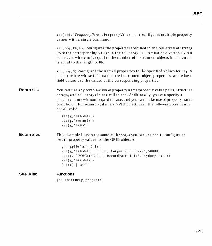
set
7-95
set(obj,'PropertyName',PropertyValue,...) configures multiple propertyvalues with a single command.
set(obj,PN,PV) configures the properties specified in the cell array of stringsPN to the corresponding values in the cell array PV. PN must be a vector. PV canbe m-by-n where m is equal to the number of instrument objects in obj and nis equal to the length of PN.
set(obj,S) configures the named properties to the specified values for obj. Sis a structure whose field names are instrument object properties, and whosefield values are the values of the corresponding properties.
Remarks You can use any combination of property name/property value pairs, structurearrays, and cell arrays in one call to set. Additionally, you can specify aproperty name without regard to case, and you can make use of property namecompletion. For example, if g is a GPIB object, then the following commandsare all valid.
set(g,'EOSMode')set(g,'eosmode')set(g,'EOSM')
Examples This example illustrates some of the ways you can use set to configure orreturn property values for the GPIB object g.
g = gpib('ni',0,1);set(g,'EOSMode','read','OutputBufferSize',50000)set(g,{'EOSCharCode','RecordName'},{13,'sydney.txt'})set(g,'EOIMode')[ {on} | off ]
See Also Functionsget, instrhelp, propinfo
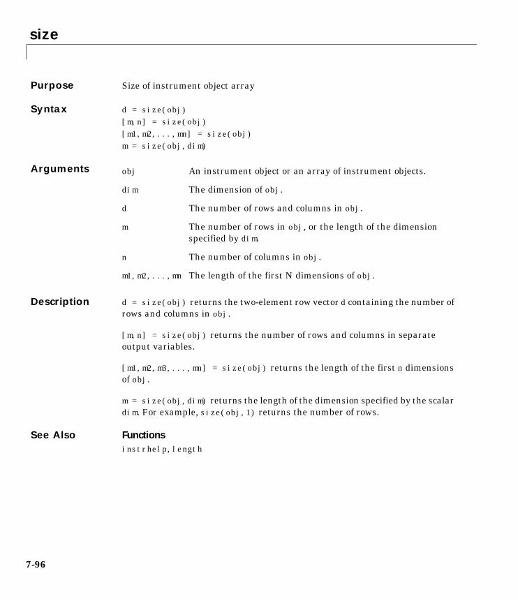
size
7-96
7sizePurpose Size of instrument object array
Syntax d = size(obj)[m,n] = size(obj)[m1,m2,...,mn] = size(obj)m = size(obj,dim)
Arguments
Description d = size(obj) returns the two-element row vector d containing the number ofrows and columns in obj.
[m,n] = size(obj) returns the number of rows and columns in separateoutput variables.
[m1,m2,m3,...,mn] = size(obj) returns the length of the first n dimensionsof obj.
m = size(obj,dim) returns the length of the dimension specified by the scalardim. For example, size(obj,1) returns the number of rows.
See Also Functionsinstrhelp, length
obj An instrument object or an array of instrument objects.
dim The dimension of obj.
d The number of rows and columns in obj.
m The number of rows in obj, or the length of the dimensionspecified by dim.
n The number of columns in obj.
m1,m2,...,mn The length of the first N dimensions of obj.
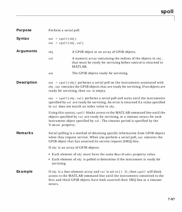
spoll
7-97
7spollPurpose Perform a serial poll
Syntax out = spoll(obj)out = spoll(obj,val)
Arguments
Description out = spoll(obj) performs a serial poll on the instruments associated withobj. out contains the GPIB objects that are ready for servicing. If no objects areready for servicing, then out is empty.
out = spoll(obj,val) performs a serial poll and waits until the instrumentsspecified by val are ready for servicing. An error is returned if a value specifiedin val does not match an index value in obj.
Using this syntax, spoll blocks access to the MATLAB command line until theobjects specified by val are ready for servicing, or a timeout occurs for eachinstrument object specified by val. The timeout period is specified by theTimeout property.
Remarks Serial polling is a method of obtaining specific information from GPIB objectswhen they request service. When you perform a serial poll, out contains theGPIB object that has asserted its service request (SRQ) line.
If obj is an array of GPIB objects:
• Each element of obj must have the same BoardIndex property value.
• Each element of obj is polled to determine if the instrument is ready forservicing.
Example If obj is a four-element array and val is set to [1 3], then spoll will blockaccess to the MATLAB command line until the instruments connected to thefirst and third GPIB objects have both asserted their SRQ line or a timeoutoccurs.
obj A GPIB object or an array of GPIB objects.
val A numeric array containing the indices of the objects in obj,that must be ready for servicing before control is returned toMATLAB.
out The GPIB objects ready for servicing.

spoll
7-98
See Also Functionsgpib, length
PropertiesBoardIndex, Timeout
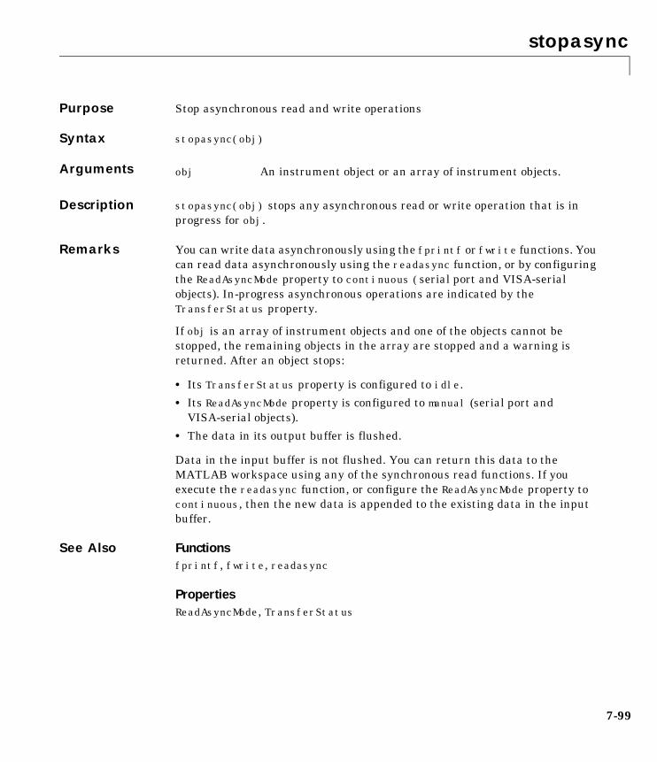
stopasync
7-99
7stopasyncPurpose Stop asynchronous read and write operations
Syntax stopasync(obj)
Arguments
Description stopasync(obj) stops any asynchronous read or write operation that is inprogress for obj.
Remarks You can write data asynchronously using the fprintf or fwrite functions. Youcan read data asynchronously using the readasync function, or by configuringthe ReadAsyncMode property to continuous (serial port and VISA-serialobjects). In-progress asynchronous operations are indicated by theTransferStatus property.
If obj is an array of instrument objects and one of the objects cannot bestopped, the remaining objects in the array are stopped and a warning isreturned. After an object stops:
• Its TransferStatus property is configured to idle.
• Its ReadAsyncMode property is configured to manual (serial port andVISA-serial objects).
• The data in its output buffer is flushed.
Data in the input buffer is not flushed. You can return this data to theMATLAB workspace using any of the synchronous read functions. If youexecute the readasync function, or configure the ReadAsyncMode property tocontinuous, then the new data is appended to the existing data in the inputbuffer.
See Also Functionsfprintf, fwrite, readasync
PropertiesReadAsyncMode, TransferStatus
obj An instrument object or an array of instrument objects.
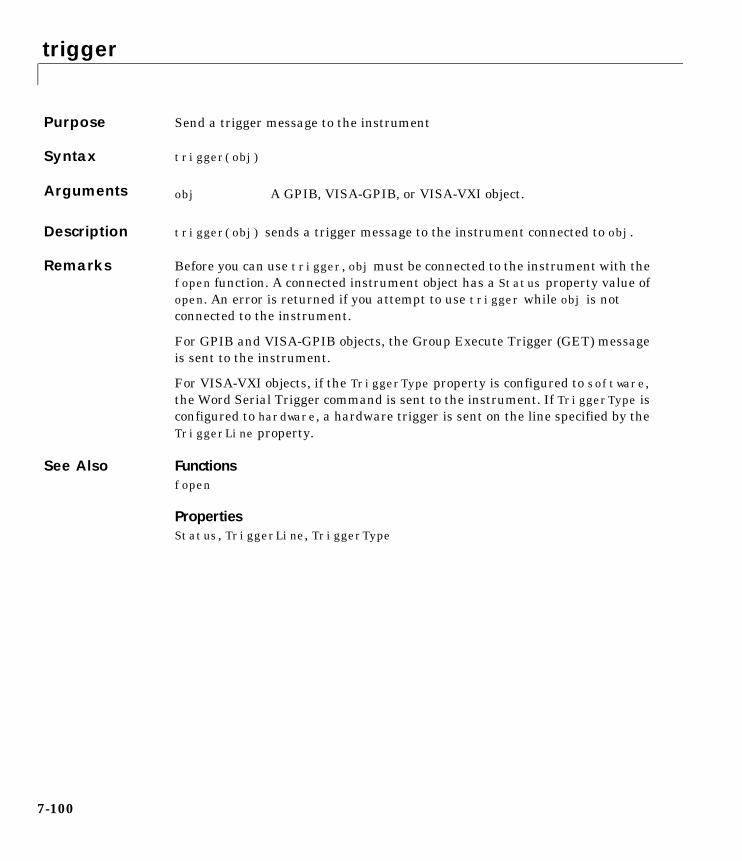
trigger
7-100
7triggerPurpose Send a trigger message to the instrument
Syntax trigger(obj)
Arguments
Description trigger(obj) sends a trigger message to the instrument connected to obj.
Remarks Before you can use trigger, obj must be connected to the instrument with thefopen function. A connected instrument object has a Status property value ofopen. An error is returned if you attempt to use trigger while obj is notconnected to the instrument.
For GPIB and VISA-GPIB objects, the Group Execute Trigger (GET) messageis sent to the instrument.
For VISA-VXI objects, if the TriggerType property is configured to software,the Word Serial Trigger command is sent to the instrument. If TriggerType isconfigured to hardware, a hardware trigger is sent on the line specified by theTriggerLine property.
See Also Functionsfopen
PropertiesStatus, TriggerLine, TriggerType
obj A GPIB, VISA-GPIB, or VISA-VXI object.
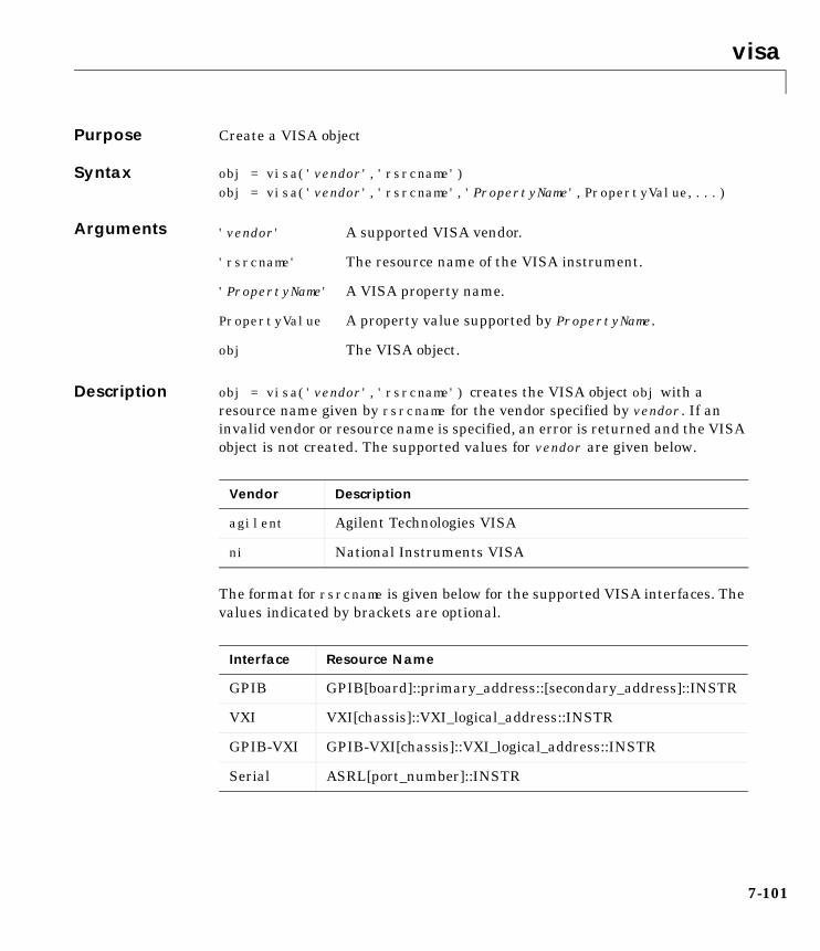
visa
7-101
7visaPurpose Create a VISA object
Syntax obj = visa('vendor','rsrcname')obj = visa('vendor','rsrcname','PropertyName',PropertyValue,...)
Arguments
Description obj = visa('vendor','rsrcname') creates the VISA object obj with aresource name given by rsrcname for the vendor specified by vendor. If aninvalid vendor or resource name is specified, an error is returned and the VISAobject is not created. The supported values for vendor are given below.
The format for rsrcname is given below for the supported VISA interfaces. Thevalues indicated by brackets are optional.
'vendor' A supported VISA vendor.
'rsrcname' The resource name of the VISA instrument.
'PropertyName' A VISA property name.
PropertyValue A property value supported by PropertyName.
obj The VISA object.
Vendor Description
agilent Agilent Technologies VISA
ni National Instruments VISA
Interface Resource Name
GPIB GPIB[board]::primary_address::[secondary_address]::INSTR
VXI VXI[chassis]::VXI_logical_address::INSTR
GPIB-VXI GPIB-VXI[chassis]::VXI_logical_address::INSTR
Serial ASRL[port_number]::INSTR
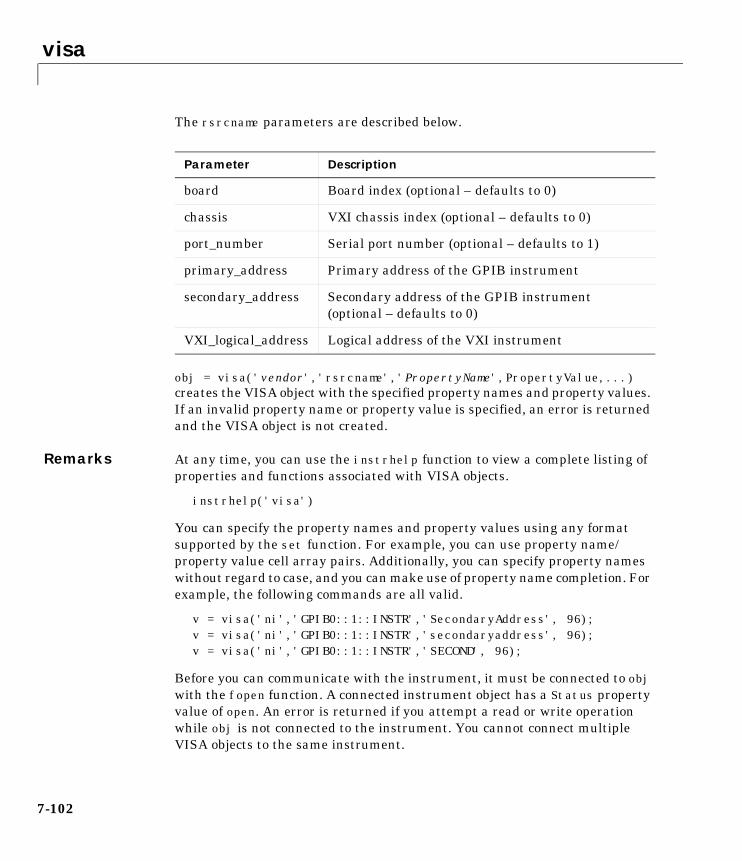
visa
7-102
The rsrcname parameters are described below.
obj = visa('vendor','rsrcname','PropertyName',PropertyValue,...)creates the VISA object with the specified property names and property values.If an invalid property name or property value is specified, an error is returnedand the VISA object is not created.
Remarks At any time, you can use the instrhelp function to view a complete listing ofproperties and functions associated with VISA objects.
instrhelp('visa')
You can specify the property names and property values using any formatsupported by the set function. For example, you can use property name/property value cell array pairs. Additionally, you can specify property nameswithout regard to case, and you can make use of property name completion. Forexample, the following commands are all valid.
v = visa('ni','GPIB0::1::INSTR','SecondaryAddress', 96);v = visa('ni','GPIB0::1::INSTR','secondaryaddress', 96);v = visa('ni','GPIB0::1::INSTR','SECOND', 96);
Before you can communicate with the instrument, it must be connected to objwith the fopen function. A connected instrument object has a Status propertyvalue of open. An error is returned if you attempt a read or write operationwhile obj is not connected to the instrument. You cannot connect multipleVISA objects to the same instrument.
Parameter Description
board Board index (optional – defaults to 0)
chassis VXI chassis index (optional – defaults to 0)
port_number Serial port number (optional – defaults to 1)
primary_address Primary address of the GPIB instrument
secondary_address Secondary address of the GPIB instrument(optional – defaults to 0)
VXI_logical_address Logical address of the VXI instrument
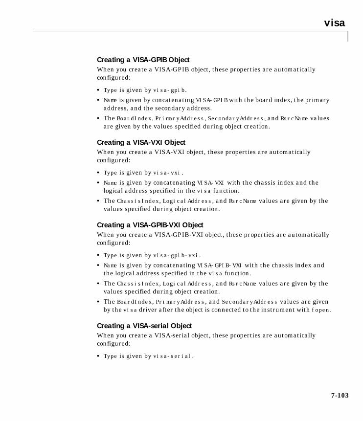
visa
7-103
Creating a VISA-GPIB ObjectWhen you create a VISA-GPIB object, these properties are automaticallyconfigured:
• Type is given by visa-gpib.
• Name is given by concatenating VISA-GPIB with the board index, the primaryaddress, and the secondary address.
• The BoardIndex, PrimaryAddress, SecondaryAddress, and RsrcName valuesare given by the values specified during object creation.
Creating a VISA-VXI ObjectWhen you create a VISA-VXI object, these properties are automaticallyconfigured:
• Type is given by visa-vxi.
• Name is given by concatenating VISA-VXI with the chassis index and thelogical address specified in the visa function.
• The ChassisIndex, LogicalAddress, and RsrcName values are given by thevalues specified during object creation.
Creating a VISA-GPIB-VXI ObjectWhen you create a VISA-GPIB-VXI object, these properties are automaticallyconfigured:
• Type is given by visa-gpib-vxi.
• Name is given by concatenating VISA-GPIB-VXI with the chassis index andthe logical address specified in the visa function.
• The ChassisIndex, LogicalAddress, and RsrcName values are given by thevalues specified during object creation.
• The BoardIndex, PrimaryAddress, and SecondaryAddress values are givenby the visa driver after the object is connected to the instrument with fopen.
Creating a VISA-serial ObjectWhen you create a VISA-serial object, these properties are automaticallyconfigured:
• Type is given by visa-serial.

visa
7-104
• Name is given by concatenating VISA-Serial with the port specified in thevisa function.
• The Port and RsrcName values are given by the values specified during objectcreation.
Example Create a VISA-serial object connected to serial port COM1 using NationalInstruments VISA interface.
vs = visa('ni','ASRL1::INSTR');
Create a VISA-GPIB object connected to board 0 with primary address 1 andsecondary address 30 using Agilent Technologies VISA interface.
vg = visa('agilent','GPIB0::1::30::INSTR');
Create a VISA-VXI object connected to a VXI instrument located at logicaladdress 8 in the first VXI chassis.
vv = visa('agilent','VXI0::8::INSTR');
Create a VISA-GPIB-VXI object connected to a GPIB-VXI instrument locatedat logical address 72 in the second VXI chassis.
vgv = visa('agilent','GPIB-VXI1::72::INSTR');
See Also Functionsfclose, fopen, instrhelp, instrhwinfo
PropertiesBoardIndex, ChassisIndex, LogicalAddress, Name, Port, PrimaryAddress,RsrcName, SecondaryAddress, Status, Type
8
Property Reference
Overview . . . . . . . . . . . . . . . . . . . . . 8-2Getting Command Line Property Help . . . . . . . . . . 8-2
Properties Grouped by Category . . . . . . . . . . . 8-3Base Properties . . . . . . . . . . . . . . . . . . . 8-3Object-Specific Properties . . . . . . . . . . . . . . . 8-6
Properties Listed Alphabetically . . . . . . . . . . . 8-15
8 Property Reference
8-2
OverviewThe following sections provide descriptions of all toolbox properties. In “BaseProperties” on page 8-3, the base properties are summarized using severalcategories according to usage. In “Object-Specific Properties” on page 8-6, theobject-specific properties are summarized by object type and usage in thesesections:
• “GPIB Properties” on page 8-6
• “VISA-GPIB Properties” on page 8-7
• “VISA-VXI Properties” on page 8-8
• “VISA-GPIB-VXI Properties” on page 8-10
• “VISA-Serial Properties” on page 8-12
• “Serial Port Properties” on page 8-13
Following these sections, detailed property descriptions are provided in“Properties Listed Alphabetically” on page 8-15.
Getting Command Line Property HelpTo get command line property help, you should use the instrhelp function. Forexample, to get help for the EOSMode property
instrhelp EOSMode
Note You can use instrhelp without creating an instrument object.
You can also get property characteristics, such as the default property value,using the propinfo function. For example, suppose you create the GPIB objectg and want to find the default value for the EOSMode property.
g = gpib('ni',0,1);out = propinfo(g,'EOSMode');out.DefaultValueans =none

Properties Grouped by Category
8-3
Properties Grouped by CategoryThis section contains brief descriptions of all toolbox properties. The propertiesare divided into these two groups:
• Base properties
• Object-specific properties
Base PropertiesBase properties apply to all supported instrument objects (GPIB, VISA-VXI,and so on). For example, the Timeout property is supported for all instrumentobjects. The base properties are organized into the following categories basedon usage.
Write Properties
BytesToOutput Indicate the number of bytes currently in the outputbuffer
OutputBufferSize Specify the size of the output buffer in bytes
Timeout Specify the waiting time to complete a read or writeoperation
TransferStatus Indicate if an asynchronous read or write operationis in progress
ValuesSent Indicate the total number of values written to theinstrument
Read Properties
BytesAvailable Indicate the number of bytes available in the inputbuffer
InputBufferSize Specify the size of the input buffer in bytes
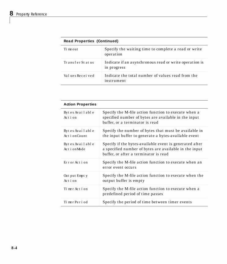
8 Property Reference
8-4
Timeout Specify the waiting time to complete a read or writeoperation
TransferStatus Indicate if an asynchronous read or write operation isin progress
ValuesReceived Indicate the total number of values read from theinstrument
Action Properties
BytesAvailableAction
Specify the M-file action function to execute when aspecified number of bytes are available in the inputbuffer, or a terminator is read
BytesAvailableActionCount
Specify the number of bytes that must be available inthe input buffer to generate a bytes-available event
BytesAvailableActionMode
Specify if the bytes-available event is generated aftera specified number of bytes are available in the inputbuffer, or after a terminator is read
ErrorAction Specify the M-file action function to execute when anerror event occurs
OutputEmptyAction
Specify the M-file action function to execute when theoutput buffer is empty
TimerAction Specify the M-file action function to execute when apredefined period of time passes
TimerPeriod Specify the period of time between timer events
Read Properties (Continued)
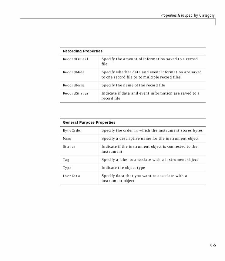
Properties Grouped by Category
8-5
Recording Properties
RecordDetail Specify the amount of information saved to a recordfile
RecordMode Specify whether data and event information are savedto one record file or to multiple record files
RecordName Specify the name of the record file
RecordStatus Indicate if data and event information are saved to arecord file
General Purpose Properties
ByteOrder Specify the order in which the instrument stores bytes
Name Specify a descriptive name for the instrument object
Status Indicate if the instrument object is connected to theinstrument
Tag Specify a label to associate with a instrument object
Type Indicate the object type
UserData Specify data that you want to associate with ainstrument object
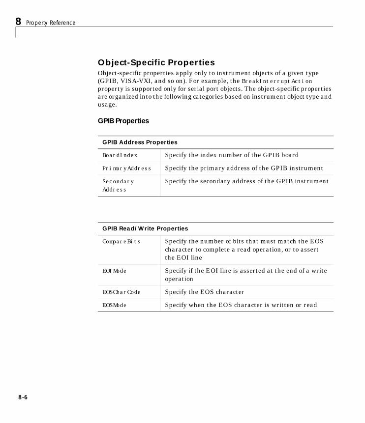
8 Property Reference
8-6
Object-Specific PropertiesObject-specific properties apply only to instrument objects of a given type(GPIB, VISA-VXI, and so on). For example, the BreakInterruptActionproperty is supported only for serial port objects. The object-specific propertiesare organized into the following categories based on instrument object type andusage.
GPIB Properties
GPIB Address Properties
BoardIndex Specify the index number of the GPIB board
PrimaryAddress Specify the primary address of the GPIB instrument
SecondaryAddress
Specify the secondary address of the GPIB instrument
GPIB Read/Write Properties
CompareBits Specify the number of bits that must match the EOScharacter to complete a read operation, or to assertthe EOI line
EOIMode Specify if the EOI line is asserted at the end of a writeoperation
EOSCharCode Specify the EOS character
EOSMode Specify when the EOS character is written or read
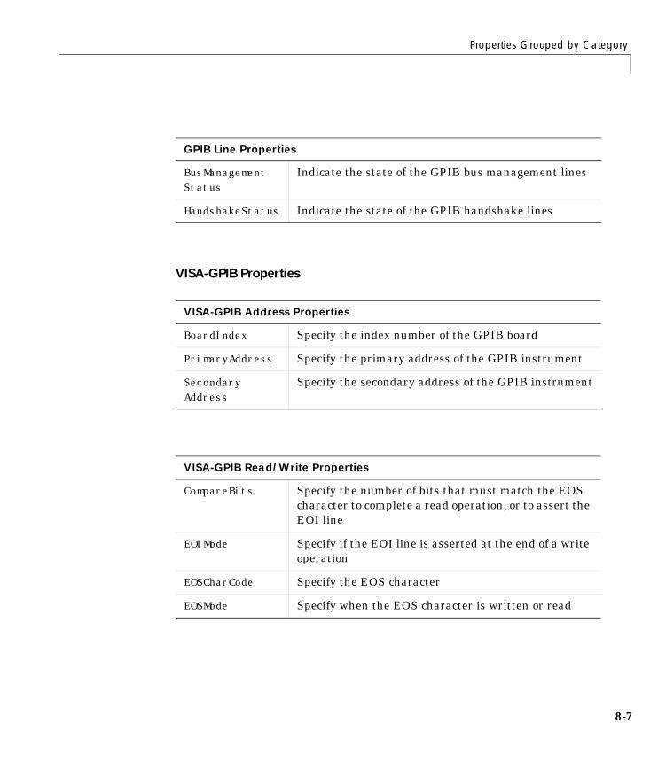
Properties Grouped by Category
8-7
VISA-GPIB Properties
GPIB Line Properties
BusManagementStatus
Indicate the state of the GPIB bus management lines
HandshakeStatus Indicate the state of the GPIB handshake lines
VISA-GPIB Address Properties
BoardIndex Specify the index number of the GPIB board
PrimaryAddress Specify the primary address of the GPIB instrument
SecondaryAddress
Specify the secondary address of the GPIB instrument
VISA-GPIB Read/Write Properties
CompareBits Specify the number of bits that must match the EOScharacter to complete a read operation, or to assert theEOI line
EOIMode Specify if the EOI line is asserted at the end of a writeoperation
EOSCharCode Specify the EOS character
EOSMode Specify when the EOS character is written or read
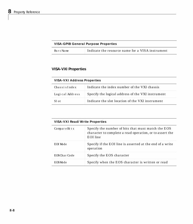
8 Property Reference
8-8
VISA-VXI Properties
VISA-GPIB General Purpose Properties
RsrcName Indicate the resource name for a VISA instrument
VISA-VXI Address Properties
ChassisIndex Indicate the index number of the VXI chassis
LogicalAddress Specify the logical address of the VXI instrument
Slot Indicate the slot location of the VXI instrument
VISA-VXI Read/Write Properties
CompareBits Specify the number of bits that must match the EOScharacter to complete a read operation, or to assert theEOI line
EOIMode Specify if the EOI line is asserted at the end of a writeoperation
EOSCharCode Specify the EOS character
EOSMode Specify when the EOS character is written or read
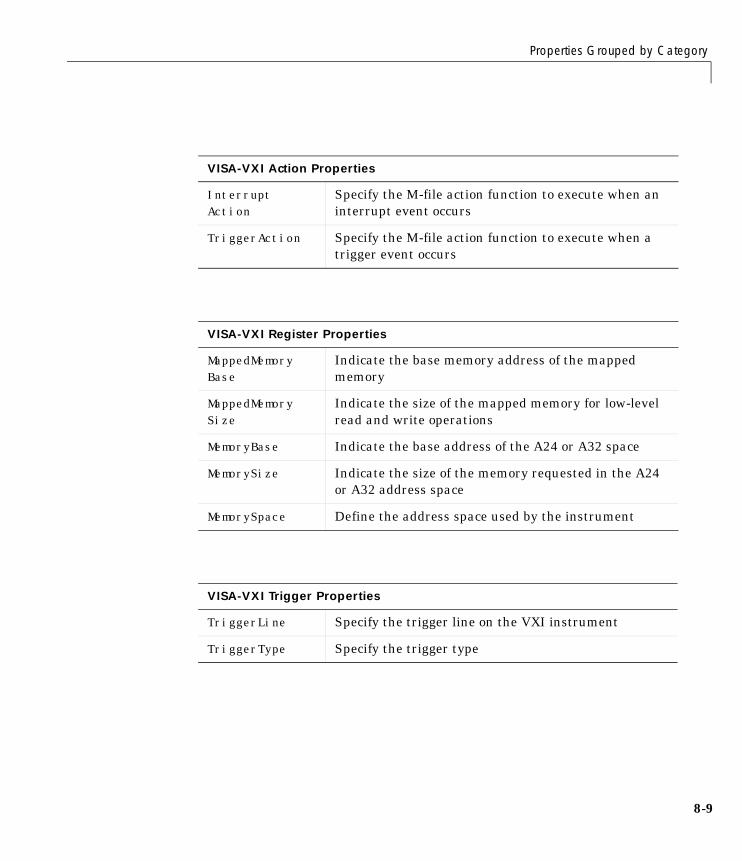
Properties Grouped by Category
8-9
VISA-VXI Action Properties
InterruptAction
Specify the M-file action function to execute when aninterrupt event occurs
TriggerAction Specify the M-file action function to execute when atrigger event occurs
VISA-VXI Register Properties
MappedMemoryBase
Indicate the base memory address of the mappedmemory
MappedMemorySize
Indicate the size of the mapped memory for low-levelread and write operations
MemoryBase Indicate the base address of the A24 or A32 space
MemorySize Indicate the size of the memory requested in the A24or A32 address space
MemorySpace Define the address space used by the instrument
VISA-VXI Trigger Properties
TriggerLine Specify the trigger line on the VXI instrument
TriggerType Specify the trigger type
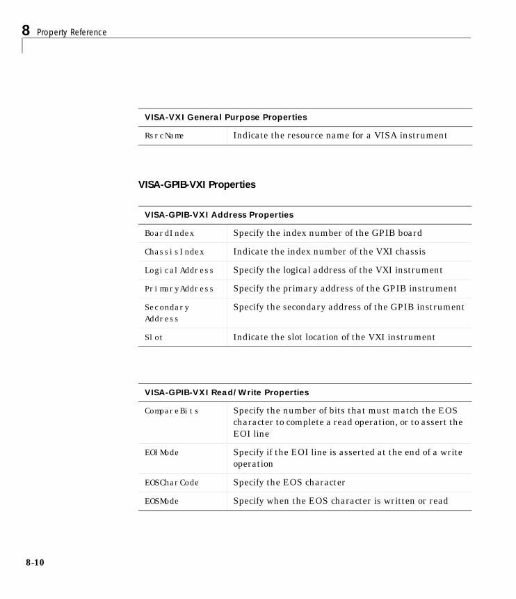
8 Property Reference
8-10
VISA-GPIB-VXI Properties
VISA-VXI General Purpose Properties
RsrcName Indicate the resource name for a VISA instrument
VISA-GPIB-VXI Address Properties
BoardIndex Specify the index number of the GPIB board
ChassisIndex Indicate the index number of the VXI chassis
LogicalAddress Specify the logical address of the VXI instrument
PrimaryAddress Specify the primary address of the GPIB instrument
SecondaryAddress
Specify the secondary address of the GPIB instrument
Slot Indicate the slot location of the VXI instrument
VISA-GPIB-VXI Read/Write Properties
CompareBits Specify the number of bits that must match the EOScharacter to complete a read operation, or to assert theEOI line
EOIMode Specify if the EOI line is asserted at the end of a writeoperation
EOSCharCode Specify the EOS character
EOSMode Specify when the EOS character is written or read
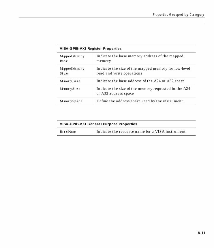
Properties Grouped by Category
8-11
VISA-GPIB-VXI Register Properties
MappedMemoryBase
Indicate the base memory address of the mappedmemory
MappedMemorySize
Indicate the size of the mapped memory for low-levelread and write operations
MemoryBase Indicate the base address of the A24 or A32 space
MemorySize Indicate the size of the memory requested in the A24or A32 address space
MemorySpace Define the address space used by the instrument
VISA-GPIB-VXI General Purpose Properties
RsrcName Indicate the resource name for a VISA instrument
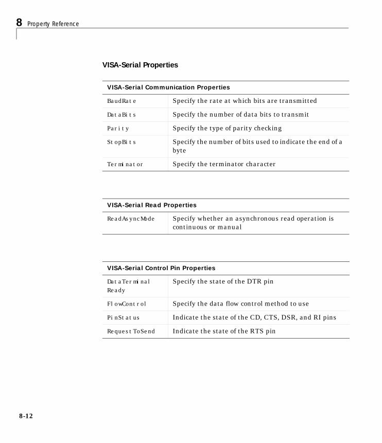
8 Property Reference
8-12
VISA-Serial Properties
VISA-Serial Communication Properties
BaudRate Specify the rate at which bits are transmitted
DataBits Specify the number of data bits to transmit
Parity Specify the type of parity checking
StopBits Specify the number of bits used to indicate the end of abyte
Terminator Specify the terminator character
VISA-Serial Read Properties
ReadAsyncMode Specify whether an asynchronous read operation iscontinuous or manual
VISA-Serial Control Pin Properties
DataTerminalReady
Specify the state of the DTR pin
FlowControl Specify the data flow control method to use
PinStatus Indicate the state of the CD, CTS, DSR, and RI pins
RequestToSend Indicate the state of the RTS pin
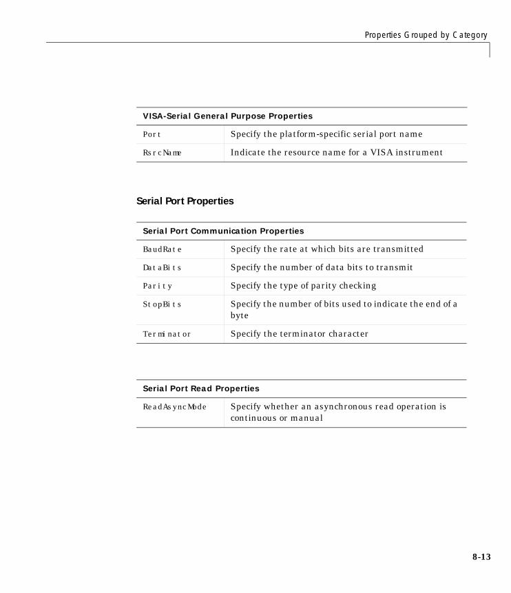
Properties Grouped by Category
8-13
Serial Port Properties
VISA-Serial General Purpose Properties
Port Specify the platform-specific serial port name
RsrcName Indicate the resource name for a VISA instrument
Serial Port Communication Properties
BaudRate Specify the rate at which bits are transmitted
DataBits Specify the number of data bits to transmit
Parity Specify the type of parity checking
StopBits Specify the number of bits used to indicate the end of abyte
Terminator Specify the terminator character
Serial Port Read Properties
ReadAsyncMode Specify whether an asynchronous read operation iscontinuous or manual
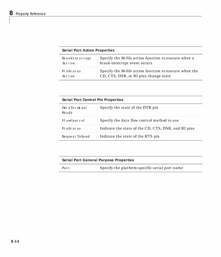
8 Property Reference
8-14
Serial Port Action Properties
BreakInterruptAction
Specify the M-file action function to execute when abreak-interrupt event occurs
PinStatusAction
Specify the M-file action function to execute when theCD, CTS, DSR, or RI pins change state
Serial Port Control Pin Properties
DataTerminalReady
Specify the state of the DTR pin
FlowControl Specify the data flow control method to use
PinStatus Indicate the state of the CD, CTS, DSR, and RI pins
RequestToSend Indicate the state of the RTS pin
Serial Port General Purpose Properties
Port Specify the platform-specific serial port name

Properties Listed Alphabetically
8-15
Properties Listed AlphabeticallyThis section contains detailed descriptions of all toolbox properties. Eachproperty reference page contains some or all of this information:
• The property name
• A description of the property
• The property characteristics, including:
- Usage – the instrument object(s) the property is associated with
- Read only – the condition under which the property is read-only
A property can be read-only always, never, while the instrument object isopen, or while the instrument object is recording. You can configure aproperty value using the set command or dot notation. You can return thecurrent property value using the get command or dot notation.
- Data type – the property data type
This is the data type you use when specifying a property value
• Valid property values including the default value
When property values are given by a predefined list, the default value isusually indicated by {} (curly braces).
• An example using the property
• Related properties and functions
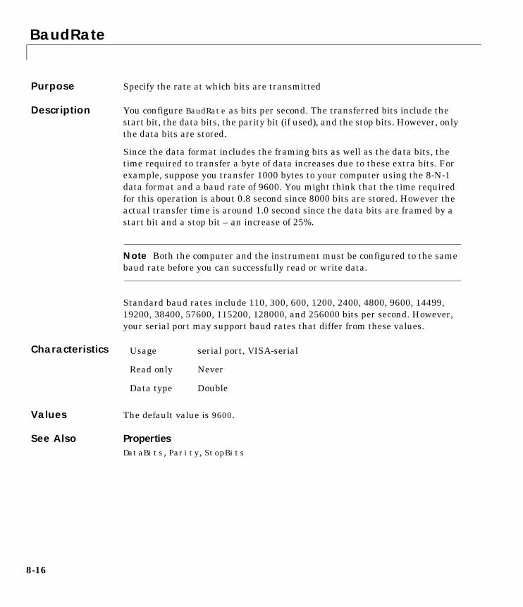
BaudRate
8-16
8BaudRatePurpose Specify the rate at which bits are transmitted
Description You configure BaudRate as bits per second. The transferred bits include thestart bit, the data bits, the parity bit (if used), and the stop bits. However, onlythe data bits are stored.
Since the data format includes the framing bits as well as the data bits, thetime required to transfer a byte of data increases due to these extra bits. Forexample, suppose you transfer 1000 bytes to your computer using the 8-N-1data format and a baud rate of 9600. You might think that the time requiredfor this operation is about 0.8 second since 8000 bits are stored. However theactual transfer time is around 1.0 second since the data bits are framed by astart bit and a stop bit – an increase of 25%.
Note Both the computer and the instrument must be configured to the samebaud rate before you can successfully read or write data.
Standard baud rates include 110, 300, 600, 1200, 2400, 4800, 9600, 14499,19200, 38400, 57600, 115200, 128000, and 256000 bits per second. However,your serial port may support baud rates that differ from these values.
Characteristics
Values The default value is 9600.
See Also PropertiesDataBits, Parity, StopBits
Usage serial port, VISA-serial
Read only Never
Data type Double
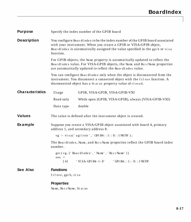
BoardIndex
8-17
8BoardIndexPurpose Specify the index number of the GPIB board
Description You configure BoardIndex to be the index number of the GPIB board associatedwith your instrument. When you create a GPIB or VISA-GPIB object,BoardIndex is automatically assigned the value specified in the gpib or visafunction.
For GPIB objects, the Name property is automatically updated to reflect theBoardIndex value. For VISA-GPIB objects, the Name and RsrcName propertiesare automatically updated to reflect the BoardIndex value.
You can configure BoardIndex only when the object is disconnected from theinstrument. You disconnect a connected object with the fclose function. Adisconnected object has a Status property value of closed.
Characteristics
Values The value is defined after the instrument object is created.
Example Suppose you create a VISA-GPIB object associated with board 4, primaryaddress 1, and secondary address 8.
vg = visa('agilent','GPIB4::1::8::INSTR');
The BoardIndex, Name, and RsrcName properties reflect the GPIB board indexnumber.
get(vg,{'BoardIndex','Name','RsrcName'})ans = [4] 'VISA-GPIB4-1-8' 'GPIB4::1::8::INSTR'
See Also Functionsfclose, gpib, visa
PropertiesName, RsrcName, Status
Usage GPIB, VISA-GPIB, VISA-GPIB-VXI
Read only While open (GPIB, VISA-GPIB), always (VISA-GPIB-VXI)
Data type double
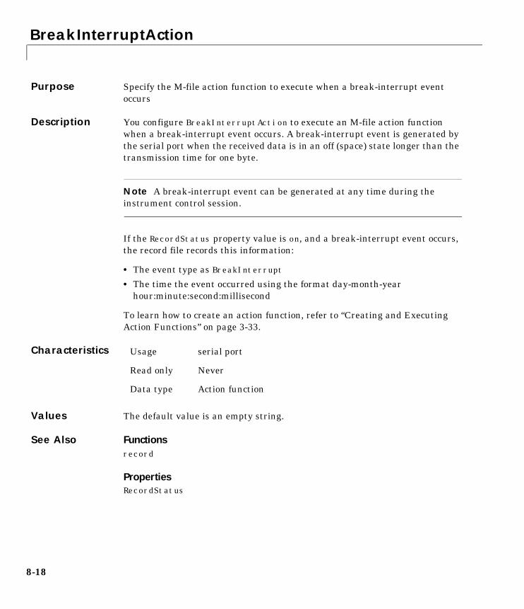
BreakInterruptAction
8-18
8BreakInterruptActionPurpose Specify the M-file action function to execute when a break-interrupt eventoccurs
Description You configure BreakInterruptAction to execute an M-file action functionwhen a break-interrupt event occurs. A break-interrupt event is generated bythe serial port when the received data is in an off (space) state longer than thetransmission time for one byte.
Note A break-interrupt event can be generated at any time during theinstrument control session.
If the RecordStatus property value is on, and a break-interrupt event occurs,the record file records this information:
• The event type as BreakInterrupt
• The time the event occurred using the format day-month-yearhour:minute:second:millisecond
To learn how to create an action function, refer to “Creating and ExecutingAction Functions” on page 3-33.
Characteristics
Values The default value is an empty string.
See Also Functionsrecord
PropertiesRecordStatus
Usage serial port
Read only Never
Data type Action function
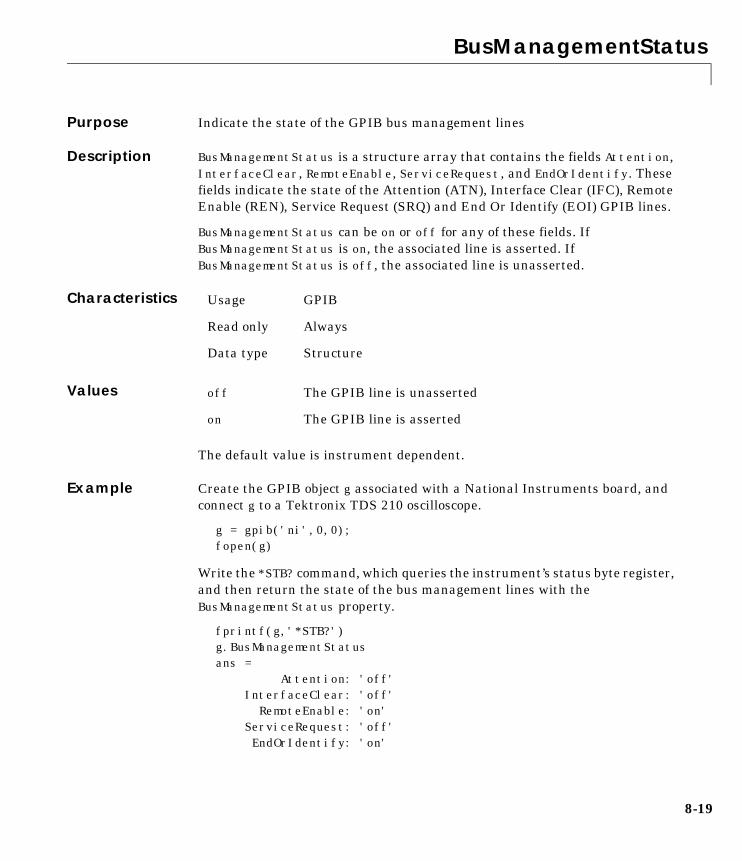
BusManagementStatus
8-19
8BusManagementStatusPurpose Indicate the state of the GPIB bus management lines
Description BusManagementStatus is a structure array that contains the fields Attention,InterfaceClear, RemoteEnable, ServiceRequest, and EndOrIdentify. Thesefields indicate the state of the Attention (ATN), Interface Clear (IFC), RemoteEnable (REN), Service Request (SRQ) and End Or Identify (EOI) GPIB lines.
BusManagementStatus can be on or off for any of these fields. IfBusManagementStatus is on, the associated line is asserted. IfBusManagementStatus is off, the associated line is unasserted.
Characteristics
Values
The default value is instrument dependent.
Example Create the GPIB object g associated with a National Instruments board, andconnect g to a Tektronix TDS 210 oscilloscope.
g = gpib('ni',0,0);fopen(g)
Write the *STB? command, which queries the instrument’s status byte register,and then return the state of the bus management lines with theBusManagementStatus property.
fprintf(g,'*STB?')g.BusManagementStatusans = Attention: 'off' InterfaceClear: 'off' RemoteEnable: 'on' ServiceRequest: 'off' EndOrIdentify: 'on'
Usage GPIB
Read only Always
Data type Structure
off The GPIB line is unasserted
on The GPIB line is asserted
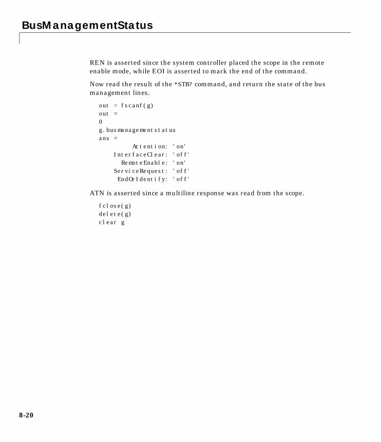
BusManagementStatus
8-20
REN is asserted since the system controller placed the scope in the remoteenable mode, while EOI is asserted to mark the end of the command.
Now read the result of the *STB? command, and return the state of the busmanagement lines.
out = fscanf(g)out =0g.busmanagementstatusans = Attention: 'on' InterfaceClear: 'off' RemoteEnable: 'on' ServiceRequest: 'off' EndOrIdentify: 'off'
ATN is asserted since a multiline response was read from the scope.
fclose(g)delete(g)clear g
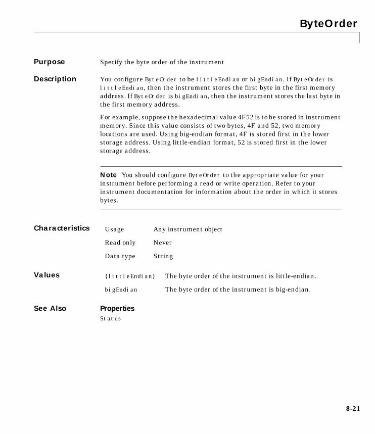
ByteOrder
8-21
8ByteOrderPurpose Specify the byte order of the instrument
Description You configure ByteOrder to be littleEndian or bigEndian. If ByteOrder islittleEndian, then the instrument stores the first byte in the first memoryaddress. If ByteOrder is bigEndian, then the instrument stores the last byte inthe first memory address.
For example, suppose the hexadecimal value 4F52 is to be stored in instrumentmemory. Since this value consists of two bytes, 4F and 52, two memorylocations are used. Using big-endian format, 4F is stored first in the lowerstorage address. Using little-endian format, 52 is stored first in the lowerstorage address.
Note You should configure ByteOrder to the appropriate value for yourinstrument before performing a read or write operation. Refer to yourinstrument documentation for information about the order in which it storesbytes.
Characteristics
Values
See Also PropertiesStatus
Usage Any instrument object
Read only Never
Data type String
{littleEndian} The byte order of the instrument is little-endian.
bigEndian The byte order of the instrument is big-endian.
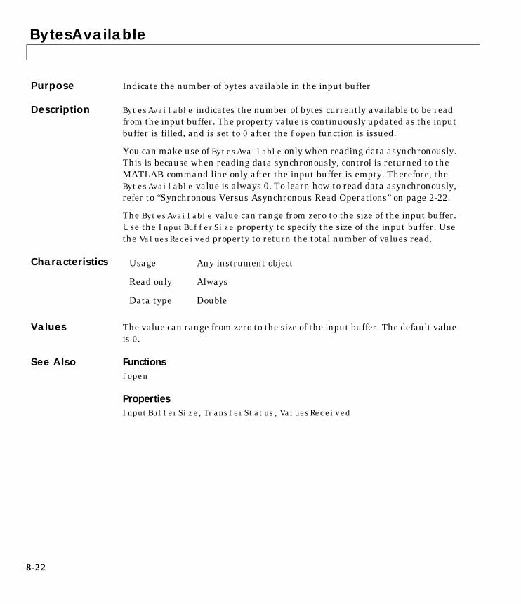
BytesAvailable
8-22
8BytesAvailablePurpose Indicate the number of bytes available in the input buffer
Description BytesAvailable indicates the number of bytes currently available to be readfrom the input buffer. The property value is continuously updated as the inputbuffer is filled, and is set to 0 after the fopen function is issued.
You can make use of BytesAvailable only when reading data asynchronously.This is because when reading data synchronously, control is returned to theMATLAB command line only after the input buffer is empty. Therefore, theBytesAvailable value is always 0. To learn how to read data asynchronously,refer to “Synchronous Versus Asynchronous Read Operations” on page 2-22.
The BytesAvailable value can range from zero to the size of the input buffer.Use the InputBufferSize property to specify the size of the input buffer. Usethe ValuesReceived property to return the total number of values read.
Characteristics
Values The value can range from zero to the size of the input buffer. The default valueis 0.
See Also Functionsfopen
PropertiesInputBufferSize, TransferStatus, ValuesReceived
Usage Any instrument object
Read only Always
Data type Double
BytesAvailableAction
8-23
8BytesAvailableActionPurpose Specify the M-file action function to execute when a specified number of bytesare available in the input buffer, or a terminator is read
Description You configure BytesAvailableAction to execute an M-file action functionwhen a bytes-available event occurs. A bytes-available event occurs when thenumber of bytes specified by the BytesAvailableActionCount property isavailable in the input buffer, or after a terminator is read, as determined by thethe BytesAvailableActionMode property.
Note A bytes-available event can be generated only for asynchronous readoperations.
If the RecordStatus property value is on, and a bytes-available event occurs,the record file records this information:
• The event type as BytesAvailable
• The time the event occurred using the format day-month-yearhour:minute:second:millisecond
To learn how to create an action function, refer to “Creating and ExecutingAction Functions” on page 3-33.
Characteristics
Values The default value is an empty string.
Example Create the serial port object s for a Tektronix TDS 210 two-channel oscilloscopeconnected to the serial port COM1.
s = serial('COM1');
Configure s to execute the M-file action function instraction when 40 bytesare available in the input buffer.
s.BytesAvailableActionCount = 40;
Usage Any instrument object
Read only Never
Data type Action function
BytesAvailableAction
8-24
s.BytesAvailableActionMode = 'byte';s.BytesAvailableAction = 'instraction';
Connect s to the oscilloscope.
fopen(s)
Write the *IDN? command, which instructs the scope to return identificationinformation. Since the default value for the ReadAsyncMode property iscontinuous, data is read as soon as it is available from the instrument.
fprintf(s,'*IDN?')
The resulting output from instraction is shown below.
BytesAvailable event occurred at 18:33:35 for the object: Serial-COM1.
56 bytes are read and instraction is called once. The resulting display isshown above.
s.BytesAvailableans = 56
Suppose you remove 25 bytes from the input buffer and issue the MEASUREMENT?command, which instructs the scope to return its measurement settings.
out = fscanf(s,'%c',25);fprintf(s,'MEASUREMENT?')
The resulting output from instraction is shown below.
BytesAvailable event occurred at 18:33:48 for the object: Serial-COM1.
BytesAvailable event occurred at 18:33:48 for the object: Serial-COM1.
BytesAvailableAction
8-25
There are now 102 bytes in the input buffer, 31 of which are left over from the*IDN? command. instraction is called twice; once when 40 bytes are availableand once when 80 bytes are available.
s.BytesAvailableans = 102
See Also Functionsrecord
PropertiesBytesAvailableActionCount, BytesAvailableActionMode, EOSCharCode,RecordStatus, Terminator, TransferStatus
BytesAvailableActionCount
8-26
8BytesAvailableActionCountPurpose Specify the number of bytes that must be available in the input buffer togenerate a bytes-available event
Description You configure BytesAvailableActionCount to the number of bytes that mustbe available in the input buffer before a bytes-available event is generated.
Use the BytesAvailableActionMode property to specify whether thebytes-available event occurs after a certain number of bytes are available orafter a terminator is read.
The bytes-available event executes the M-file action function specified for theBytesAvailableAction property.
You can configure BytesAvailableActionCount only when the object isdisconnected from the instrument. You disconnect an object with the fclosefunction. A disconnected object has a Status property value of closed.
Characteristics
Values The default value is 48.
See Also Functionsfclose
PropertiesBytesAvailableAction, BytesAvailableActionMode, EOSCharCode, Status,Terminator
Usage Any instrument object
Read only While open
Data type Double
BytesAvailableActionMode
8-27
8BytesAvailableActionModePurpose Specify if the bytes-available event is generated after a specified number ofbytes are available in the input buffer, or after a terminator is read
Description For serial port or VISA-serial objects, you can configureBytesAvailableActionMode to be terminator or byte. For all otherinstrument objects, you can configure BytesAvailableActionMode to beeosCharCode or byte.
If BytesAvailableActionMode is terminator, a bytes-available event occurswhen the terminator specified by the Terminator property is read. IfBytesAvailableActionMode is eosCharCode, a bytes-available event occurswhen the End-Of-String character specified by the EOSCharCode property isread. If BytesAvailableActionMode is byte, a bytes-available event occurswhen the number of bytes specified by the BytesAvailableActionCountproperty is available.
The bytes-available event executes the M-file action function specified for theBytesAvailableAction property.
You can configure BytesAvailableActionMode only when the object isdisconnected from the instrument. You disconnect an object with the fclosefunction. A disconnected object has a Status property value of closed.
Characteristics
Values Serial and VISA-serial
Usage Any instrument object
Read only While open
Data type String
{terminator} A bytes-available event is generated when the terminatoris reached.
byte A bytes-available event is generated when the specifiednumber of bytes are available.
BytesAvailableActionMode
8-28
GPIB, VISA-GPIB, VISA-VXI, and VISA-GPIB-VXI
See Also Functionsfclose
PropertiesBytesAvailableAction, BytesAvailableActionCount, EOSCharCode, Status,Terminator
{eosCharCode} A bytes-available event is generated when the EOS(End-Of-String) character is reached.
byte A bytes-available event is generated when the specifiednumber of bytes are available.
BytesToOutput
8-29
8BytesToOutputPurpose Indicate the number of bytes currently in the output buffer
Description BytesToOutput indicates the number of bytes currently in the output bufferwaiting to be written to the instrument. The property value is continuouslyupdated as the output buffer is filled and emptied, and is set to 0 after thefopen function is issued.
You can make use of BytesToOutput only when writing data asynchronously.This is because when writing data synchronously, control is returned to theMATLAB command line only after the output buffer is empty. Therefore, theBytesToOutput value is always 0. To learn how to write data asynchronously,Refer to “Synchronous Versus Asynchronous Write Operations” on page 2-17.
Use the ValuesSent property to return the total number of values written tothe instrument.
Note If you attempt to write out more data than can fit in the output buffer,then an error is returned and BytesToOutput is 0. You specify the size of theoutput buffer with the OutputBufferSize property.
Characteristics
Values The default value is 0.
See Also Functionsfopen
PropertiesOutputBufferSize, TransferStatus, ValuesSent
Usage Any instrument object
Read only Always
Data type Double
ChassisIndex
8-30
8ChassisIndexPurpose Specify the index number of the VXI chassis
Description You configure ChassisIndex to be the index number of the VXI chassisassociated with your instrument.
When you create a VISA-VXI or VISA-GPIB-VXI object, ChassisIndex isautomatically assigned the value specified in the visa function. For both objecttypes, the Name and RsrcName properties are automatically updated to reflectthe ChassisIndex value.
You can configure ChassisIndex only when the object is disconnected from theinstrument. You disconnect a connected object with the fclose function. Adisconnected object has a Status property value of closed.
Characteristics
Values The value is defined after the instrument object is created.
Example Suppose you create a VISA-GPIB-VXI object associated with chassis 0 andlogical address 32.
v = visa('agilent','GPIB-VXI0::32::INSTR');
The ChassisIndex, Name, and RsrcName properties reflect the VXI chassis indexnumber.
get(v,{'ChassisIndex','Name','RsrcName'})ans = [0] 'VISA-GPIB-VXI0-32' 'GPIB-VXI0::32::INSTR'
See Also Functionsfclose, visa
PropertiesName, RsrcName, Status
Usage VISA-VXI, VISA-GPIB-VXI
Read only While open
Data type double
CompareBits
8-31
8CompareBitsPurpose Specify the number of bits that must match the EOS character to complete aread operation, or to assert the EOI line
Description For GPIB objects, you can configure CompareBits to be 7 or 8. If CompareBitsis 7, the read operation completes when a byte that matches the low seven bitsof the End-Of-String (EOS) character is received. The End Or Identify (EOI)line is asserted when a byte that matches the low seven bits of the EOScharacter is written.
If CompareBits is 8, the read operation completes when a byte that matches alleight bits of the EOS character is received. The EOI line is asserted when abyte that matches the low seven bits of the EOS character is written.
For VISA-GPIB, VISA-VXI, and VISA-GPIB-VXI objects, CompareBits canonly be 8.
You can specify the EOS character with the EOSCharCode property. You canspecify when the EOS character is used (read operation, write operation, orboth) with the EOSMode property.
Characteristics
Values GPIB
VISA-GPIB, VISA-VXI, VISA-GPIB-VXI
See Also PropertiesEOSCharCode, EOSMode
Usage GPIB, VISA-GPIB, VISA-VXI, VISA-GPIB-VXI
Read only Never
Data type Double
{8} Compare all eight EOS bits.
7 Compare the lower seven EOS bits.
{8} Compare all eight EOS bits
DataBits
8-32
8DataBitsPurpose Specify the number of data bits to transmit
Description You can configure DataBits to be 5, 6, 7, or 8. Data is transmitted as a seriesof five, six, seven, or eight bits with the least significant bit sent first. At leastseven data bits are required to transmit ASCII characters. Eight bits arerequired to transmit binary data. Five and six bit data formats are used forspecialized communication equipment.
Note Both the computer and the instrument must be configured to transmitthe same number of data bits.
In addition to the data bits, the serial data format consists of a start bit, one ortwo stop bits, and possibly a parity bit. You specify the number of stop bits withthe StopBits property, and the type of parity checking with the Parityproperty.
Characteristics
Values DataBits can be 5, 6, 7, or 8. The default value is 8.
See Also PropertiesParity, StopBits
Usage serial port, VISA-serial
Read only Never
Data type Double
DataTerminalReady
8-33
8DataTerminalReadyPurpose Specify the state of the DTR pin
Description You can configure DataTerminalReady to be on or off. If DataTerminalReadyis on, the Data Terminal Ready (DTR) pin is asserted. If DataTerminalReady isoff, the DTR pin is unasserted.
In normal usage, the DTR and Data Set Ready (DSR) pins work together, andare used to signal if instruments are connected and powered. However, thereis nothing in the RS-232 standard that states the DTR pin must be used in anyspecific way. For example, DTR and DSR may be used for handshaking. Youshould refer to your instrument documentation to determine its specific pinbehavior.
You can return the value of the DSR pin with the PinStatus property.Handshaking is described in “The Control Pins” on page 5-8.
Characteristics
Values
See Also PropertiesFlowControl, PinStatus
Usage serial port, VISA-serial
Read only Never
Data type String
{on} The DTR pin is asserted.
off The DTR pin is unasserted.
EOIMode
8-34
8EOIModePurpose Specify if the EOI line is asserted at the end of a write operation
Description You can configure EOIMode to be on or off. If EOIMode is on, the End Or Identify(EOI) line is asserted at the end of a write operation. If EOIMode is off, the EOIline is not asserted at the end of a write operation. EOIMode applies to bothbinary and text write operations.
A write operation completes when:
• The specified number of values is written.
• A timeout occurs.
Characteristics
Values
See Also PropertiesBusManagementStatus
Usage GPIB, VISA-GPIB, VISA-VXI, VISA-GPIB-VXI
Read only Never
Data type String
{on} The EOI line is asserted at the end of a write operation.
off The EOI line is not asserted at the end of a write operation.
EOSCharCode
8-35
8EOSCharCodePurpose Specify the EOS character
Description You configure EOSCharCode to be the End-Of-String (EOS) character. The valuecan range from 0 to 255, which represents the ASCII code for the character. Forexample, if EOSCharCode is 13, then the EOS character is a carriage return.
EOSCharCode replaces \n wherever it appears in the command sent to theinstrument. Note that %s\n is the default format for the fprintf function.
For many practical applications, you will configure both EOSCharCode and theEOSMode property. EOSMode specifies when the EOS character is used. IfEOSMode is write or read&write (writing is enabled), the EOI line is assertedevery time the EOSCharCode value is written to the instrument. If EOSMode isread or read&write (reading is enabled), then the read operation mayterminate when the EOSCharCode value is detected. The CompareBits propertyspecifies the number of bits that must match the EOS character to complete aread or write operation.
To see how EOSCharCode and EOSMode work together, refer to the example givenin the EOSMode property description.
Characteristics
Values EOSCharCode can range from 0 to 255. The default value is 10, whichcorresponds to a line feed.
See Also Functionsfprintf
PropertiesCompareBits, EOSMode
Usage GPIB, VISA-GPIB, VISA-VXI, VISA-GPIB-VXI
Read only Never
Data type Double
EOSMode
8-36
8EOSModePurpose Specify when the EOS character is written or read
Description For GPIB, VISA-GPIB, VISA-VXI, and VISA-GPIB-VXI objects, you canconfigure EOSMode to be none, read, write, or read&write.
If EOSMode is none, the End Of String (EOS) character is ignored. If EOSMode isread, the EOS character is used to terminate a read operation. If EOSMode iswrite, the EOS character is appended to the command being written whenever\n is encountered. If EOSMode is read&write, the EOS character is used in bothread and write operations. If the EOS character is written to the instrumentthen the End Or Identify (EOI) line is asserted.
The EOS character is specified by the EOSCharCode property. The CompareBitsproperty specifies the number of bits that must match the EOS character tocomplete a read operation, or to assert the EOI line.
Rules for Completing a Read OperationFor any EOSMode value, the read operation completes when:
• The EOI line is asserted.
• Specified number of values is read.
• A timeout occurs.
Additionally, if EOSMode is read or read&write (reading is enabled), then theread operation can complete when the EOSCharCode property value is detected.
Rules for Completing a Write OperationRegardless of the EOSMode value, a write operation completes when:
• The specified number of values are written.
• A timeout occurs.
Additionally, if EOSMode is write or read&write, the EOI line is asserted eachtime the EOSCharCode property value is written to the instrument.
Characteristics Usage GPIB, VISA-GPIB, VISA-VXI, VISA-GPIB-VXI
Read only Never
Data type String
EOSMode
8-37
Values
Example Suppose you input a nominal voltage signal of 2.0 volts into a functiongenerator, and read back the voltage value using fscanf.
g = gpib('ni',0,1); fopen(g) fprintf(g,'Volt?') out = fscanf(g) out = +2.00000E+00
To illustrate how you use the EOSMode and EOSCharCode properties, thefollowing commands configure the read operation to end on the E character. Todo this, the ASCII code for E is determined with the double function.
double('E')ans = 69
EOSMode and EOSCharCode are configured to terminate the read operation whenASCII code 69 is encountered.
set(g,'EOSMode','read')set(g,'EOSCharCode',69) fprintf(g,'Volt?')out = fscanf(g)out = +2.00000
See Also PropertiesCompareBits, EOIMode, EOSCharCode
{none} The EOS character is ignored.
read The EOS character is used for each read operation.
write The EOS character is used for each write operation.
read&write The EOS character is used for each read and writeoperation.
ErrorAction
8-38
8ErrorActionPurpose Specify the M-file action function to execute when an error event occurs
Description You configure ErrorAction to execute an M-file action function when an errorevent occurs.
Note An error event is generated only for asynchronous read and writeoperations.
An error event is generated when a timeout occurs. A timeout occurs if a reador write operation does not successfully complete within the time specified bythe Timeout property. An error event is not generated for configuration errorssuch as setting an invalid property value.
If the RecordStatus property value is on, and an error event occurs, the recordfile records this information:
• The event type as Error
• The error message
• The time the event occurred using the format day-month-yearhour:minute:second:millisecond
To learn how to create an action function, refer to “Creating and ExecutingAction Functions” on page 3-33.
Characteristics
Values The default value is an empty string.
See Also Functionsrecord
PropertiesRecordStatus, Timeout
Usage Any instrument object
Read only Never
Data type Action function
FlowControl
8-39
8FlowControlPurpose Specify the data flow control method to use
Description You can configure FlowControl to be none, hardware, or software. IfFlowControl is none, then data flow control (handshaking) is not used. IfFlowControl is hardware, then hardware handshaking is used to control dataflow. If FlowControl is software, then software handshaking is used to controldata flow.
Hardware handshaking typically utilizes the Request to Send (RTS) and Clearto Send (CTS) pins to control data flow. Software handshaking uses controlcharacters (Xon and Xoff) to control data flow. To learn more about hardwareand software handshaking, refer to “Using Control Pins” on page 5-29.
You can return the value of the CTS pin with the PinStatus property. You canspecify the value of the RTS pin with the RequestToSend property. However, ifFlowControl is hardware, and you specify a value for RequestToSend, then thatvalue may not be honored.
Note Although you may be able to configure your instrument for bothhardware handshaking and software handshaking at the same time, thetoolbox does not support this behavior.
Characteristics
Values
See Also PropertiesPinStatus, RequestToSend
Usage serial port, VISA-serial
Read only Never
Data type String
{none} No flow control is used.
hardware Hardware flow control is used.
software Software flow control is used.
HandshakeStatus
8-40
8HandshakeStatusPurpose Indicate the state of the GPIB handshake lines
Description HandshakeStatus is a structure array that contains the fields DataValid,NotDataAccepted, and NotReadyForData. These fields indicate the state of theData Valid (DAV), Not Data Accepted (NDAC) and Not Ready For Data(NRFD) GPIB lines, respectively.
HandshakeStatus can be on or off for any of these fields. A value of on indicatesthe associated line is asserted. A value of off indicates the associated line isunasserted.
Characteristics
Values
The default value is instrument dependent.
Usage GPIB
Read only Never
Data type Structure
on The associated handshake line is asserted
off The associated handshake line is unasserted
InputBufferSize
8-41
8InputBufferSizePurpose Specify the size of the input buffer in bytes
Description You configure InputBufferSize as the total number of bytes that can be storedin the software input buffer during a read operation.
A read operation is terminated if the amount of data stored in the input bufferequals the InputBufferSize value. You can read text data with the fgetl,fgets, or fscanf functions. You can read binary data with the fread function.
You can configure InputBufferSize only when the instrument object isdisconnected from the instrument. You disconnect an object with the fclosefunction. A disconnected object has a Status property value of closed.
If you configure InputBufferSize while there is data in the input buffer, thenthat data is flushed.
Characteristics
Values The default value is 512.
See Also Functionsfclose, fgetl, fgets, fopen, fread, fscanf
PropertiesStatus
Usage Any instrument object
Read only While open
Data type Double
InterruptAction
8-42
8InterruptActionPurpose Specify the M-file action function to execute when an interrupt event occurs
Description You configure InterruptAction to execute an M-file action function when aninterrupt event occurs. An interrupt event is generated when a VXI bus signalor a VXI bus interrupt is received from the instrument.
Note An interrupt event can be generated at any time during the instrumentcontrol session.
If the RecordStatus property value is on, and an interrupt event occurs, therecord file records:
• The event type as Interrupt
• The time the event occurred using the format day-month-yearhour:minute:second:millisecond
Characteristics
Values The default value is an empty string.
See Also Functionsrecord
PropertiesRecordStatus
Usage VISA-VXI
Read only Never
Data type String
LogicalAddress
8-43
8LogicalAddressPurpose Specify the logical address of the VXI instrument
Description For VISA-VXI and VISA-GPIB-VXI objects, you configure LogicalAddress tobe the logical address of the VXI instrument. You must include the logicaladdress as part of the resource name during object creation using the visafunction.
The Name and RsrcName properties are automatically updated to reflect theLogicalAddress value.
You can configure LogicalAddress only when the object is disconnected fromthe instrument. You disconnect a connected object with the fclose function. Adisconnected object has a Status property value of closed.
Characteristics
Values The value is defined when the instrument object is created.
Example This example creates a VISA-VXI object associated with chassis 4 and logicaladdress 1, and then returns the logical address.
vv = visa('agilent','VXI4::1::INSTR');vv.LogicalAddressans = 1
See Also Functionsfclose, visa
PropertiesName, RsrcName, Status
Usage VISA-VXI, VISA-GPIB-VXI
Read only While open
Data type Double
MappedMemoryBase
8-44
8MappedMemoryBasePurpose Indicate the base memory address of the mapped memory
Description MappedMemoryBase is the base address of the mapped memory used for lowlevel read and write operations.
The memory address is returned as a string representing a hexadecimal value.For example, if the mapped memory base is 200000, then MappedMemoryBasereturns 200000H. If no memory is mapped, MappedMemoryBase is 0H.
Use the memmap function to map the specified amount of memory in thespecified address space (A16, A24, or A32) with the specified offset. Use thememunmap function to unmap the memory space.
Characteristics
Values The default value is 0H.
Example Create the VISA-VXI object vv associated with a VXI chassis with index 0, andan Agilent E1432A digitizer with logical address 130.
vv = visa('agilent','VXI0::130::INSTR');fopen(vv)
Map 16 bytes in the A16 address space with no offset, and then return the baseaddress of the mapped memory.
memmap(vv,'A16',0,16)vv.MappedMemoryBaseans = 16737610H
See Also Functionsmemmap, memunmap
PropertiesMappedMemorySize
Usage VISA-VXI, VISA-GPIB-VXI
Read only Always
Data type String
MappedMemorySize
8-45
8MappedMemorySizePurpose Indicate the size of the mapped memory for low-level read and write operations
Description MappedMemorySize indicates the amount of memory mapped for low-level readand write operations.
Use the memmap function to map the specified amount of memory in thespecified address space (A16, A24, or A32) with the specified offset. Use thememunmap function to unmap the memory space.
Characteristics
Values The default value is 0.
Example Create the VISA-VXI object vv associated with a VXI chassis with index 0, andan Agilent E1432A digitizer with logical address 130.
vv = visa('agilent','VXI0::130::INSTR');fopen(vv)
Map 16 bytes in the A16 address space with no offset, and then return the sizeof the mapped memory.
memmap(vv,'A16',0,16)vv.MappedMemorySizeans = 16
See Also Functionsmemmap, memunmap
PropertiesMappedMemoryBase,
Usage VISA-VXI, VISA-GPIB-VXI
Read only Always
Data type Double
MemoryBase
8-46
8MemoryBasePurpose Indicate the base address of the A24 or A32 space
Description MemoryBase indicates the base address of the A24 or A32 space. The value isreturned as a string representing a hexadecimal value.
All VXI instruments have an A16 address space that is 16 bits wide. There arealso 24- and 32-bit wide address spaces known as A24 and A32. Someinstruments require the additional memory associated with the A24 or A32address space when the 64 bytes of A16 space are insufficient for performingnecessary functions. A bit in the A16 address space is set allowing theinstrument to recognize commands to its A24 or A32 space.
An instrument cannot use both the A24 and A32 address space. The addressspace is given by the MemorySpace property. If MemorySpace is A16, thenMemoryBase is 0H.
Characteristics
Values The default value is 0H.
Example Create the VISA-VXI object vv associated with a VXI chassis with index 0, andan Agilent E1432A digitizer with logical address 130.
vv = visa('agilent','VXI0::130::INSTR');fopen(vv)
The MemorySpace property indicates that the A24 memory space is supported.
vv.MemorySpaceans =A16/A24
Usage VISA-VXI, VISA-GPIB-VXI
Read only Always
Data type String

MemoryBase
8-47
The base address of the A24 space is
vv.MemoryBaseans ='200000H'
See Also PropertiesMemorySpace
MemorySize
8-48
8MemorySizePurpose Indicate the size of the memory requested in the A24 or A32 address space
Description MemorySize indicates the size of the memory requested by the instrument inthe A24 or A32 address space.
Some instruments use the A24 or A32 address space when the 64 bytes of A16space are not enough for performing necessary functions. An instrumentcannot use both the A24 and A32 address space. The address space is given bythe MemorySpace property. If MemorySpace is A16, then MemorySize is 0.
Characteristics
Values The default value is 0.
Example Create the VISA-VXI object vv associated with a VXI chassis with index 0, andan Agilent E1432A digitizer with logical address 130.
vv = visa('agilent','VXI0::130::INSTR');fopen(vv)
The MemorySpace property indicates that the A24 memory space is supported.
vv.MemorySpaceans =A16/A24
The size of the A24 space is
vv.MemorySizeans =262144
See Also PropertiesMemorySpace
Usage VISA-VXI, VISA-GPIB-VXI
Read only Always
Data type Double
MemorySpace
8-49
8MemorySpacePurpose Indicate the address space used by the instrument
Description MemorySpace indicates the address space requested by the instrument.MemorySpace can be A16, A16/A24, or A16/A32. If MemorySpace is A16, theinstrument uses only the A16 address space. If MemorySpace is A16/A24, theinstrument uses the A16 and A24 address space. If MemorySpace is A16/A32,the instrument uses the A16 and A32 address space.
All VXI instruments have an A16 address space that is 16 bits wide. There arealso 24- and 32-bit wide address spaces known as A24 and A32, respectively.Some instruments use this memory when the 64 bytes of A16 space are notenough for performing necessary functions. An instrument cannot use both theA24 and A32 address space.
The size of the memory is given by the MemorySize property. The base addressof the memory is given by the MemoryBase property.
Characteristics
Values
Example Create the VISA-VXI object vv associated with a VXI chassis with index 0, andan Agilent E1432A digitizer with logical address 130.
vv = visa('agilent','VXI0::130::INSTR');fopen(vv)
Return the memory space supported by the instrument.
vv.MemorySpaceans =A16/A24
Usage VISA-VXI, VISA-GPIB-VXI
Read only Always
Data type String
{A16} The instrument uses the A16 address space.
A16/A24 The instrument uses the A16 and A24 address space.
A16/A32 The instrument uses the A16 and A32 address space.

MemorySpace
8-50
This value indicates that the instrument supports A24 memory space inaddition to the A16 memory space.
See Also PropertiesMemoryBase, MemorySize
Name
8-51
8NamePurpose Specify a descriptive name for the instrument object
Description You configure Name to be a descriptive name for an instrument object.
When you create an instrument object, a descriptive name is automaticallygenerated and stored in Name. However, you can change this value at any time.As shown below, the components of Name reflect the instrument object type andthe input arguments you supply to the creation function.
If the secondary address is not specified when a GPIB or VISA-GPIB object iscreated, then Name will not include this component.
If you change the value of any property that is a component of Name (forexample, Port or PrimaryAddress), then Name is automatically updated toreflect those changes.
Characteristics
Values Name is automatically defined at object creation time. The value of Namedepends on the specific instrument object you create.
Instrument Object Default Value of Name
GPIB GPIB and BoardIndex-PrimaryAddress- SecondaryAddress
VISA-serial VISA-Serial and Port
VISA-GPIB VISA-GPIB and BoardIndex-PrimaryAddress- SecondaryAddress
VISA-VXI VISA-VXI and ChassisIndex-LogicalAddress
VISA-GPIB-VXI VISA-GPIB-VXI and ChassisIndex-LogicalAddress
serial port Serial and Port
Usage Any instrument object
Read only Never
Data type String
OutputBufferSize
8-52
8OutputBufferSizePurpose Specify the size of the output buffer in bytes
Description You configure OutputBufferSize as the total number of bytes that can bestored in the software output buffer during a write operation.
An error occurs if the output buffer cannot hold all the data to be written. Youwrite text data with the fprintf function. You write binary data with thefwrite function.
You can configure OutputBufferSize only when the instrument object isdisconnected from the instrument. You disconnect an object with the fclosefunction. A disconnected object has a Status property value of closed.
Characteristics
Values The default value is 512.
See Also Functionsfprintf, fwrite
PropertiesStatus
Usage Any instrument object
Read only While open
Data type Double
OutputEmptyAction
8-53
8OutputEmptyActionPurpose Specify the M-file action function to execute when the output buffer is empty
Description You configure OutputEmptyAction to execute an M-file action function when anoutput-empty event occurs. An output-empty event is generated when the lastbyte is sent from the output buffer to the instrument.
Note An output-empty event can be generated only for asynchronous writeoperations.
If the RecordStatus property value is on, and an output-empty event occurs,the record file records this information:
• The event type as OutputEmpty
• The time the event occurred using the format day-month-yearhour:minute:second:millisecond
To learn how to create an action function, refer to “Creating and ExecutingAction Functions” on page 3-33.
Characteristics
Values The default value is an empty string.
See Also Functionsrecord
PropertiesRecordStatus
Usage Any instrument object
Read only Never
Data type Action function
Parity
8-54
8ParityPurpose Specify the type of parity checking
Description You can configure Parity to be none, odd, even, mark, or space. If Parity isnone, parity checking is not performed and the parity bit is not transmitted. IfParity is odd, the number of mark bits (1’s) in the data is counted, and theparity bit is asserted or unasserted to obtain an odd number of mark bits. IfParity is even, the number of mark bits in the data is counted, and the paritybit is asserted or unasserted to obtain an even number of mark bits. If Parityis mark, the parity bit is asserted. If Parity is space, the parity bit isunasserted.
Parity checking can detect errors of one bit only. An error in two bits may causethe data to have a seemingly valid parity, when in fact it is incorrect. To learnmore about parity checking, refer to “The Parity Bit” on page 5-12.
In addition to the parity bit, the serial data format consists of a start bit,between five and eight data bits, and one or two stop bits. You specify thenumber of data bits with the DataBits property, and the number of stop bitswith the StopBits property.
Characteristics
Values
See Also PropertiesDataBits, StopBits
Usage serial port, VISA-serial
Read only Never
Data type String
{none} No parity checking
odd Odd parity checking
even Even parity checking
mark Mark parity checking
space Space parity checking
PinStatus
8-55
8PinStatusPurpose Indicate the state of the CD, CTS, DSR, and RI pins
Description PinStatus is a structure array that contains the fields CarrierDetect,ClearToSend, DataSetReady and RingIndicator. These fields indicate thestate of the Carrier Detect (CD), Clear to Send (CTS), Data Set Ready (DSR)and Ring Indicator (RI) pins, respectively. Refer to “The Control Pins” on page5-8 to learn more about these pins.
PinStatus can be on or off for any of these fields. A value of on indicates theassociated pin is asserted. A value of off indicates the associated pin isunasserted. For serial port objects, a pin status event occurs when any of thesepins changes its state. A pin status event executes the M-file specified byPinStatusAction.
In normal usage, the Data Terminal Ready (DTR) and DSR pins work together,while the Request To Send (RTS) and CTS pins work together. You can specifythe state of the DTR pin with the DataTerminalReady property. You can specifythe state of the RTS pin with the RequestToSend property.
Refer to “Example: Connecting Two Modems” on page 5-29 for an example thatuses PinStatus.
Characteristics
Values
The default value is instrument dependent.
See Also PropertiesDataTerminalReady, PinStatusAction, RequestToSend
Usage serial port, VISA-serial
Read only Always
Data type Structure
off The associated pin is asserted
on The associated pin is asserted
PinStatusAction
8-56
8PinStatusActionPurpose Specify the M-file action function to execute when the CD, CTS, DSR, or RI pinschange state
Description You configure PinStatusAction to execute an M-file action function when a pinstatus event occurs. A pin status event occurs when the Carrier Detect (CD),Clear to Send (CTS), Data Set Ready (DSR) or Ring Indicator (RI) pin changesstate. A serial port pin changes state when it is asserted or unasserted.Information about the state of these pins is recorded in the PinStatusproperty.
Note A pin status event can be generated at any time during the instrumentcontrol session.
If the RecordStatus property value is on, and a pin status event occurs, therecord file records this information:
• The event type as PinStatus
• The pin that changed its state, and pin state as either on or off
• The time the event occurred using the format day-month-yearhour:minute:second:millisecond
To learn how to create an action function, refer to “Creating and ExecutingAction Functions” on page 3-33.
Characteristics
Values The default value is an empty string.
See Also Functionsrecord
PropertiesPinStatus, RecordStatus
Usage serial port
Read only Never
Data type Action function
Port
8-57
8PortPurpose Specify the platform-specific serial port name
Description You configure Port to be the name of a serial port on your platform. Portspecifies the physical port associated with the object and the instrument.
When you create a serial port or VISA-serial object, Port is automaticallyassigned the port name specified for the serial or visa function.
You can configure Port only when the object is disconnected from theinstrument. You disconnect an object with the fclose function. A disconnectedobject has a Status property value of closed.
Characteristics
Values The Port value is determined when the instrument object is created.
Example Suppose you create a serial port and VISA-serial object associated with serialport COM1.
s = serial('COM1') vs = visa('ni','ASRL1::INSTR')
The Port property values are given below.
get([s vs],'Port')ans = 'COM1' 'ASRL1'
See Also Functionsfclose, serial, visa
PropertiesName, RsrcName, Status
Usage serial port, VISA-serial
Read only While open
Data type String
PrimaryAddress
8-58
8PrimaryAddressPurpose Specify the primary address of the GPIB instrument
Description For GPIB and VISA-GPIB objects, you configure PrimaryAddress to be theGPIB primary address associated with your instrument. The primary addresscan range from 0 to 30, and you must specify it during object creation using thegpib or visa function. For VISA-GPIB-VXI objects, PrimaryAddress isread-only, and the value is returned automatically by the VISA interface afterthe object is connected to the instrument with the fopen function.
For GPIB and VISA-GPIB objects, the Name property is automatically updatedto reflect the PrimaryAddress value. For VISA-GPIB objects, the RsrcNameproperty is automatically updated to reflect the PrimaryAddress value.
You can configure PrimaryAddress only when the GPIB or VISA-GPIB objectis disconnected from the instrument. You disconnect a connected object withthe fclose function. A disconnected object has a Status property value ofclosed.
Characteristics
Values PrimaryAddress can range from 0 to 30. The value is determined when theinstrument object is created.
Example This example creates a VISA-GPIB object associated with board 0, primaryaddress 1, and secondary address 8, and then returns the primary address.
vg = visa('agilent','GPIB0::1::8::INSTR');vg.PrimaryAddressans = 1
See Also Functionsfclose, gpib, visa
PropertiesName, RsrcName, Status
Usage GPIB, VISA-GPIB, VISA-GPIB-VXI
Read only While open (GPIB, VISA-GPIB), always (VISA-GPIB-VXI)
Data type Double
ReadAsyncMode
8-59
8ReadAsyncModePurpose Specify whether an asynchronous read operation is continuous or manual
Description You can configure ReadAsyncMode to be continuous or manual. IfReadAsyncMode is continuous, the object continuously queries the instrumentto determine if data is available to be read. If data is available, it isautomatically read and stored in the input buffer. If issued, the readasyncfunction is ignored.
If ReadAsyncMode is manual, the object will not query the instrument todetermine if data is available to be read. Instead, you must manually issue thereadasync function to perform an asynchronous read operation. Sincereadasync checks for the terminator, this function can be slow. To increasespeed, you should configure ReadAsyncMode to continuous.
Note If the instrument is ready to transmit data, then it will do so regardlessof the ReadAsyncMode value. Therefore, if ReadAsyncMode is manual and a readoperation is not in progress, then data may be lost. To guarantee that alltransmitted data is stored in the input buffer, you should configureReadAsyncMode to continuous.
You can determine the amount of data available in the input buffer with theBytesAvailable property. For either ReadAsyncMode value, you can bring datainto the MATLAB workspace with one of the synchronous read functions suchas fscanf, fgetl, fgets, or fread.
Characteristics
Values
Usage serial port, VISA-serial
Read only Never
Data type String
{continuous} Continuously query the instrument to determine if data isavailable to be read.
manual Manually read data from the instrument using thereadasync function.

ReadAsyncMode
8-60
See Also Functionsfgetl, fgets, fread, fscanf, readasync
PropertiesBytesAvailable, InputBufferSize
RecordDetail
8-61
8RecordDetailPurpose Specify the amount of information saved to a record file
Description You can configure RecordDetail to be compact or verbose. If RecordDetail iscompact, the number of values written to the instrument, the number of valuesread from the instrument, the data type of the values, and event informationare saved to the record file. If RecordDetail is verbose, the data transferred toand from the instrument is also saved to the record file.
The verbose record file structure is shown in “Example: Recording Informationto Disk” on page 6-10.
Characteristics
Values
See Also Functionsrecord
PropertiesRecordMode, RecordName, RecordStatus
Usage Any instrument object
Read only Never
Data type String
{compact} The number of values written to the instrument, thenumber of values read from the instrument, the data typeof the values, and event information are saved to the recordfile.
verbose The data written to the instrument, and the data read fromthe instrument are also saved to the record file.
RecordMode
8-62
8RecordModePurpose Specify whether data and event information are saved to one record file or tomultiple record files
Description You can configure RecordMode to be overwrite, append, or index. IfRecordMode is overwrite, then the record file is overwritten each timerecording is initiated. If RecordMode is append, then data is appended to therecord file each time recording is initiated. If RecordMode is index, a differentrecord file is created each time recording is initiated, each with an indexedfilename.
You can configure RecordMode only when the object is not recording. Youterminate recording with the record function. A object that is not recordinghas a RecordStatus property value of off.
You specify the record filename with the RecordName property. The indexedfilename follows a prescribed set of rules. Refer to “Specifying a Filename” onpage 6-7 for a description of these rules.
Characteristics
Values
Example Suppose you create the serial port object s associated with the serial portCOM1.
s = serial('COM1');fopen(s)
Specify the record filename with the RecordName property, configureRecordMode to index, and initiate recording.
s.RecordName = 'myrecord.txt';
Usage Any instrument object
Read only While recording
Data type String
{overwrite} The record file is overwritten.
append Data is appended to the record file.
index Multiple record files are written, each with an indexedfilename.
RecordMode
8-63
s.RecordMode = 'index';record(s)
The record filename is automatically updated with an indexed filename afterrecording is turned off.
record(s,'off')s.RecordNameans =myrecord01.txt
Disconnect s from the instrument, and remove s from memory and from theMATLAB workspace.
fclose(s)delete(s)clear s
See Also Functionsrecord
PropertiesRecordDetail, RecordName, RecordStatus
RecordName
8-64
8RecordNamePurpose Specify the name of the record file
Description You configure RecordName to be the name of the record file. You can specify anyvalue for RecordName – including a directory path – provided the filename issupported by your operating system.
MATLAB supports any filename supported by your operating system.However, if you access the file through MATLAB, you may need to specify thefilename using single quotes. For example, suppose you name the record file my record.txt. To type this file at the MATLAB command line, you must includethe name in quotes.
type('my record.txt')
You can specify whether data and event information are saved to one disk fileor to multiple disk files with the RecordMode property. If RecordMode is index,then the filename follows a prescribed set of rules. Refer to “Specifying aFilename” on page 6-7 for a description of these rules.
You can configure RecordName only when the object is not recording. Youterminate recording with the record function. An object that is not recordinghas a RecordStatus property value of off.
Characteristics
Values The default record file name is record.txt.
See Also Functionsrecord
PropertiesRecordDetail, RecordMode, RecordStatus
Usage Any instrument object
Read only While recording
Data type String
RecordStatus
8-65
8RecordStatusPurpose Indicate if data and event information are saved to a record file
Description You can configure RecordStatus to be off or on with the record function. IfRecordStatus is off, then data and event information are not saved to a recordfile. If RecordStatus is on, then data and event information are saved to therecord file specified by RecordName.
Use the record function to initiate or complete recording. RecordStatus isautomatically configured to reflect the recording state.
Characteristics
Values
See Also Functionsrecord
PropertiesRecordDetail, RecordMode, RecordName
Usage Any instrument object
Read only Always
Data type String
{off} Data and event information are not written to a record file
on Data and event information are written to a record file
RequestToSend
8-66
8RequestToSendPurpose Specify the state of the RTS pin
Description You can configure RequestToSend to be on or off. If RequestToSend is on, theRequest to Send (RTS) pin is asserted. If RequestToSend is off, the RTS pin isunasserted.
In normal usage, the RTS and Clear to Send (CTS) pins work together, and areused as standard handshaking pins for data transfer. In this case, RTS andCTS are automatically managed by the DTE and DCE. However, there isnothing in the RS-232 standard that states the RTS pin must to be used in anyspecific way. Therefore, if you manually configure the RequestToSend value, itis probably for nonstandard operations.
If your instrument does not use hardware handshaking in the standard way,and you need to manually configure RequestToSend, then you should configurethe FlowControl property to none. Otherwise, the RequestToSend value thatyou specify may not be honored. Refer to your instrument documentation todetermine its specific pin behavior.
You can return the value of the CTS pin with the PinStatus property.Handshaking is described in “The Control Pins” on page 5-8.
Characteristics
Values
See Also PropertiesFlowControl, PinStatus
Usage serial port, VISA-serial
Read only Never
Data type String
{on} The RTS pin is asserted.
off The RTS pin is unasserted.
RsrcName
8-67
8RsrcNamePurpose Indicate the resource name for a VISA instrument
Description RsrcName indicates the resource name for a VISA instrument. When you createa VISA object, RsrcName is automatically assigned the value specified in thevisa function.
The resource name is a symbolic name for the instrument. The resource nameyou supply to visa depends on the interface and has the format shown below.The components in brackets are optional and have a default value of 0 exceptport_number, which has a default value of 1.
If you change the BoardIndex, PrimaryAddress, SecondaryAddress,ChassisIndex, LogicalAddress, or Port property values, RsrcName isautomatically updated to reflect these changes.
Characteristics
Values The value is defined when the instrument object is created.
Example To create a VISA-GPIB object associated with a GPIB controller with boardindex 0 and an instrument with primary address 1, you supply the followingresource name to the visa function.
vg = visa('ni','GPIB0::1::INSTR');
Interface Resource Name
GPIB GPIB[board]::primary_address::[secondary_address]::INSTR
VXI VXI[chassis]::VXI_logical_address::INSTR
GPIB-VXI GPIB-VXI[chassis]::VXI_logical_address::INSTR
Serial ASRL[port_number]::INSTR
Usage VISA-serial, VISA-GPIB, VISA-VXI, VISA-GPIB-VXI
Read only Always
Data type String

RsrcName
8-68
To create a VISA-VXI object associated with a VXI chassis with index 0 and aninstrument with logical address 130, you supply the following resource nameto the visa function.
vv = visa('agilent','VXI0::130::INSTR');
To create a VISA-GPIB-VXI object associated with a VXI chassis with index 0and an instrument with logical address 80, you supply the following resourcename to the visa function.
vgv = visa('agilent','GPIB-VXI0::80::INSTR');
To create a VISA-serial object associated with the COM1 serial port, you supplythe following resource name to the visa function.
vs = visa('ni','ASRL1::INSTR');
See Also Functionsvisa
PropertiesBoardIndex, ChassisIndex, LogicalAddress, Port, PrimaryAddress,SecondaryAddress
SecondaryAddress
8-69
8SecondaryAddressPurpose Specify the secondary address of the GPIB instrument
Description For GPIB and VISA-GPIB objects, you configure SecondaryAddress to be theGPIB secondary address associated with your instrument. You can initiallyspecify the secondary address during object creation using the gpib or visafunction. For VISA-GPIB-VXI objects, SecondaryAddress is read-only, and thevalue is returned automatically by the VISA interface after the object isconnected to the instrument with the fopen function.
For GPIB objects, SecondaryAddress can range from 96 to 126, or it can be 0indicating that no secondary address is used. For VISA-GPIB objects,SecondaryAddress can range from 0 to 30. If your instrument does not have asecondary address, then SecondaryAddress is 0.
For GPIB and VISA-GPIB objects, the Name property is automatically updatedto reflect the SecondaryAddress value. For VISA-GPIB objects, the RsrcNameproperty is automatically updated to reflect the SecondaryAddress value.
You can configure SecondaryAddress only when the GPIB or VISA-GPIBobject is disconnected from the instrument. You disconnect a connected objectwith the fclose function. A disconnected object has a Status property value ofclosed.
Characteristics
Values For GPIB objects, SecondaryAddress can range from 96 to 126, or it can be 0.For VISA-GPIB objects, SecondaryAddress can range from 0 to 30. The defaultvalue is 0.
Usage GPIB, VISA-GPIB, VISA-GPIB-VXI
Read only While open (GPIB, VISA-GPIB), always (VISA-GPIB-VXI)
Data type double
SecondaryAddress
8-70
Example This example creates a VISA-GPIB object associated with board 0, primaryaddress 1, and secondary address 8, and then returns the secondary address.
vg = visa('agilent','GPIB0::1::8::INSTR');vg.SecondaryAddressans = 8
See Also Functionsfclose, gpib, visa
PropertiesName, RsrcName, Status
Slot
8-71
8SlotPurpose Indicate the slot location of the VXI instrument
Description Slot indicates the physical slot of the VXI instrument. Slot can be any valuebetween 0 and 12.
Characteristics
Values The property value is defined when the instrument object is created.
Usage VISA-VXI, VISA-GPIB-VXI
Read only Always
Data type Double
Status
8-72
8StatusPurpose Indicate if the object is connected to the instrument
Description Status can be open or closed. If Status is closed, the object is not connectedto the instrument. If Status is open, the object is connected to the instrument.
Before you can write or read data, you must connect the object to theinstrument with the fopen function. You use the fclose function to disconnectan object from the instrument.
Characteristics
Values
See Also Functionsfclose, fopen
Usage Any instrument object
Read only Always
Data type String
{closed} The object is not connected to the instrument
open The object is connected to the instrument
StopBits
8-73
8StopBitsPurpose Specify the number of bits used to indicate the end of a byte
Description You can configure StopBits to be 1, 1.5, or 2 for serial port objects, or 1 or 2 forVISA-serial objects If StopBits is 1, one stop bit is used to indicate the end ofdata transmission. If StopBits is 2, two stop bits are used to indicate the endof data transmission. If StopBits is 1.5, the stop bit is transferred for 150% ofthe normal time used to transfer one bit.
Note Both the computer and the instrument must be configured to transmitthe same the number of stop bits.
In addition to the stop bits, the serial data format consists of a start bit,between five and eight data bits, and possibly a parity bit. You specify thenumber of data bits with the DataBits property, and the type of paritychecking with the Parity property.
Characteristics
Values Serial Port
VISA-serial
See Also PropertiesDataBits, Parity
Usage serial port, VISA-serial
Read only Never
Data type double
{1} One stop bit is transmitted to indicate the end of a byte.
1.5 The stop bit is transferred for 150% of the normal time usedto transfer one bit.
2 Two stop bits are transmitted to indicate the end of a byte.
{1} One stop bit is transmitted to indicate the end of a byte.
2 Two stop bits are transmitted to indicate the end of a byte
Tag
8-74
8TagPurpose Specify a label to associate with an instrument object
Description You configure Tag to be a string value that uniquely identifies an instrumentobject.
Tag is particularly useful when constructing programs that would otherwiseneed to define the instrument object as a global variable, or pass the object asan argument between callback routines.
You can return the instrument object with the instrfind function byspecifying the Tag property value.
Characteristics
Values The default value is an empty string.
Example Suppose you create a serial port object associated with the serial port COM1.
s = serial('COM1');fopen(s);
You can assign s a unique label using Tag.
set(s,'Tag','MySerialObj')
You can access s in the MATLAB workspace or in an M-file using theinstrfind function and the Tag property value.
s1 = instrfind('Tag','MySerialObj');
See Also Functionsinstrfind
Usage Any instrument object
Read only Never
Data type String
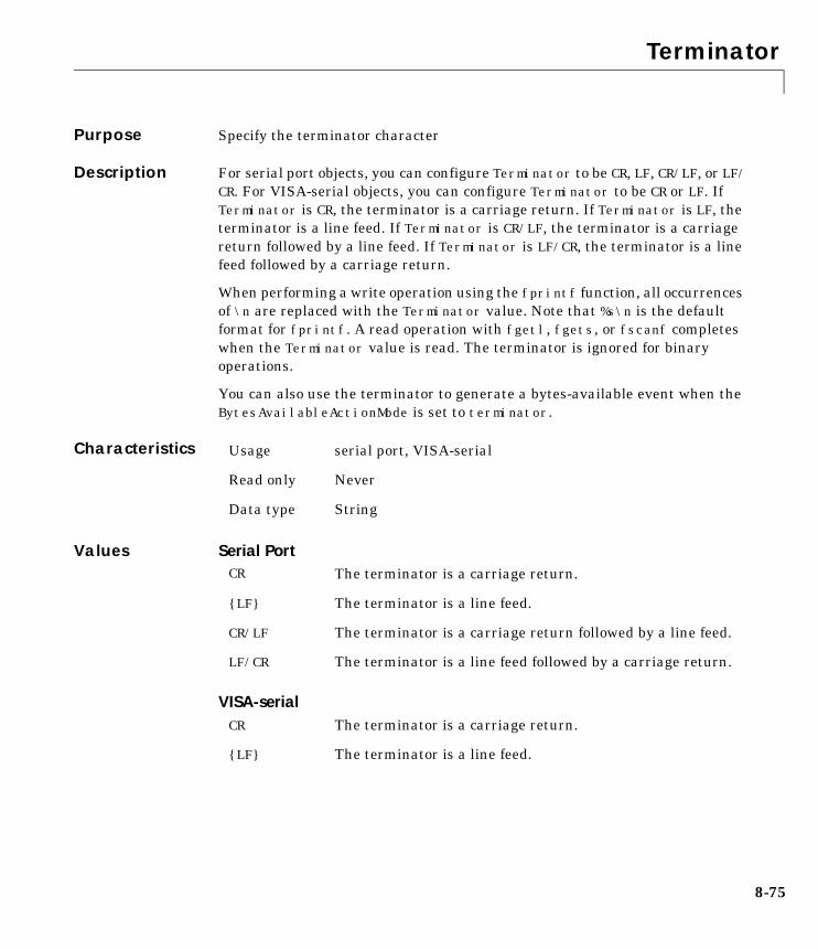
Terminator
8-75
8TerminatorPurpose Specify the terminator character
Description For serial port objects, you can configure Terminator to be CR, LF, CR/LF, or LF/CR. For VISA-serial objects, you can configure Terminator to be CR or LF. IfTerminator is CR, the terminator is a carriage return. If Terminator is LF, theterminator is a line feed. If Terminator is CR/LF, the terminator is a carriagereturn followed by a line feed. If Terminator is LF/CR, the terminator is a linefeed followed by a carriage return.
When performing a write operation using the fprintf function, all occurrencesof \n are replaced with the Terminator value. Note that %s\n is the defaultformat for fprintf. A read operation with fgetl, fgets, or fscanf completeswhen the Terminator value is read. The terminator is ignored for binaryoperations.
You can also use the terminator to generate a bytes-available event when theBytesAvailableActionMode is set to terminator.
Characteristics
Values Serial Port
VISA-serial
Usage serial port, VISA-serial
Read only Never
Data type String
CR The terminator is a carriage return.
{LF} The terminator is a line feed.
CR/LF The terminator is a carriage return followed by a line feed.
LF/CR The terminator is a line feed followed by a carriage return.
CR The terminator is a carriage return.
{LF} The terminator is a line feed.

Terminator
8-76
See Also Functionsfgetl, fgets, fprintf, fscanf
PropertiesBytesAvailableActionMode
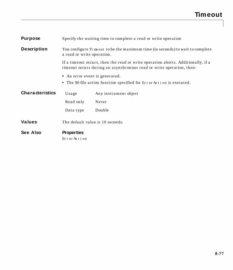
Timeout
8-77
8TimeoutPurpose Specify the waiting time to complete a read or write operation
Description You configure Timeout to be the maximum time (in seconds) to wait to completea read or write operation.
If a timeout occurs, then the read or write operation aborts. Additionally, if atimeout occurs during an asynchronous read or write operation, then:
• An error event is generated.
• The M-file action function specified for ErrorAction is executed.
Characteristics
Values The default value is 10 seconds.
See Also PropertiesErrorAction
Usage Any instrument object
Read only Never
Data type Double
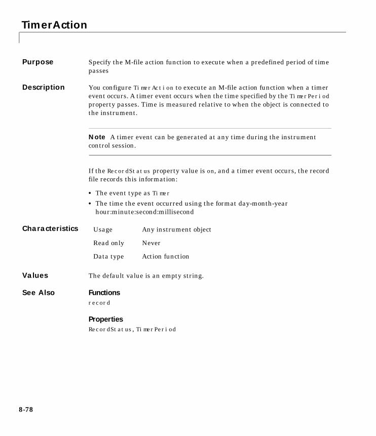
TimerAction
8-78
8TimerActionPurpose Specify the M-file action function to execute when a predefined period of timepasses
Description You configure TimerAction to execute an M-file action function when a timerevent occurs. A timer event occurs when the time specified by the TimerPeriodproperty passes. Time is measured relative to when the object is connected tothe instrument.
Note A timer event can be generated at any time during the instrumentcontrol session.
If the RecordStatus property value is on, and a timer event occurs, the recordfile records this information:
• The event type as Timer
• The time the event occurred using the format day-month-yearhour:minute:second:millisecond
Characteristics
Values The default value is an empty string.
See Also Functionsrecord
PropertiesRecordStatus, TimerPeriod
Usage Any instrument object
Read only Never
Data type Action function
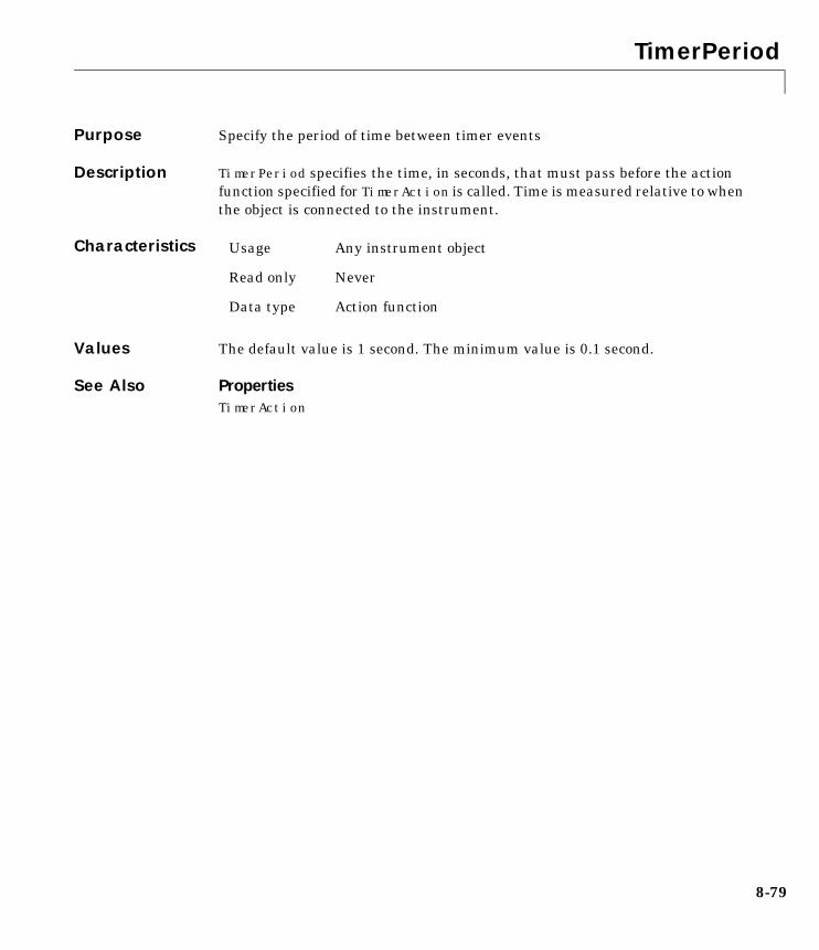
TimerPeriod
8-79
8TimerPeriodPurpose Specify the period of time between timer events
Description TimerPeriod specifies the time, in seconds, that must pass before the actionfunction specified for TimerAction is called. Time is measured relative to whenthe object is connected to the instrument.
Characteristics
Values The default value is 1 second. The minimum value is 0.1 second.
See Also PropertiesTimerAction
Usage Any instrument object
Read only Never
Data type Action function
TransferStatus
8-80
8TransferStatusPurpose Indicate if an asynchronous read or write operation is in progress
Description TransferStatus can be idle, read, write, or read&write. If TransferStatusis idle, then no asynchronous read or write operations are in progress. IfTransferStatus is read, then an asynchronous read operation is in progress.If TransferStatus is write, then an asynchronous write operation is inprogress. If TransferStatus is read&write, then both an asynchronous readand asynchronous write operation are in progress.
You can write data asynchronously using the fprintf or fwrite functions. Youcan read data asynchronously using the readasync function, or by configuringReadAsyncMode to continuous (serial and VISA-serial objects only). Fordetailed information about asynchronous read and write operations, refer to“Writing and Reading Data” on page 2-12.
While readasync is executing for any instrument object, TransferStatus mayindicate that data is being read even though data is not filling the input buffer.However, if ReadAsyncMode is continuous, TransferStatus indicates that datais being read only when data is actually filling the input buffer.
Characteristics
Values
See Also Functionsfprintf, fwrite, readasync
PropertiesReadAsyncMode
Usage Any instrument object
Read only Always
Data type String
{idle} No asynchronous operations are in progress.
read An asynchronous read operation is in progress.
write An asynchronous write operation is in progress.
read&write Asynchronous read and write operations are in progress.
TriggerAction
8-81
8TriggerActionPurpose Specify the M-file action function to execute when a trigger event occurs
Description You configure TriggerAction to execute an M-file action function when atrigger event occurs. A trigger event is generated when a trigger occurs insoftware, or on one of the VXI hardware trigger lines. You configure the triggertype with the TriggerType property.
Note A trigger event can be generated at any time during the instrumentcontrol session.
If the RecordStatus property value is on, and a trigger event occurs, the recordfile records:
• The event type as Trigger
• The time the event occurred using the format day-month-yearhour:minute:second:millisecond
Characteristics
Values The default value is an empty string.
See Also Functionsrecord
PropertiesRecordStatus, TriggerLine, TriggerType
Usage VISA-VXI
Read only Never
Data type String
TriggerLine
8-82
8TriggerLinePurpose Specify the trigger line on the VXI instrument
Description You can configure TriggerLine to be TTL0 through TTL7, ECL0, or ECL1. You canuse only one trigger line at a time.
You can specify the trigger type with the TriggerType property. WhenTriggerType is hardware, the line triggered is given by the TriggerLine value.When the TriggerType is software, the TriggerLine value is ignored.
You execute a trigger for a VISA-VXI object with the trigger function.
Characteristics
Values TriggerLine can be TTL0 through TTL7, ECL0, or ECL1. The default value isTTL0.
See Also Functionstrigger
PropertiesTriggerType
Usage VISA-VXI
Read only Never
Data type String
TriggerType
8-83
8TriggerTypePurpose Specify the trigger type
Description You can configure TriggerType to be software or hardware. If TriggerType issoftware, then a software trigger is used. If TriggerType is hardware, then thetrigger line specified by the TriggerLine property is used.
You execute a trigger for a VISA-VXI object with the trigger function.
Characteristics
Values
See Also Functionstrigger
PropertiesTriggerLine
Usage VISA-VXI
Read only Never
Data type String
{hardware} A hardware trigger is used
software A software trigger is used
Type
8-84
8TypePurpose Indicate the instrument object type
Description Type indicates the type of the object. Type is automatically defined after theinstrument object is created with the serial, gpib, or visa function. The valueis automatically determined when the instrument object is created.
Using the instrfind function and the Type value, you can quickly identifyinstrument objects of a given type.
Characteristics
Values
The value is automatically determined when the instrument object is created.
Example Suppose you create a serial port object associated with the serial port COM1.
s = serial('COM1');
The value of the Type property is serial, which is the object class.
s.Typeans =serial
See Also Functionsinstrfind, serial, gpib, visa
Usage Any instrument object
Read only Always
Data type String
gpib The object type is GPIB
visa-gpib The object type is VISA-GPIB
visa-vxi The object type is VISA-VXI
visa-gpib-vxi The object type is VISA-GPIB-VXI
visa-serial The object type is VISA-serial
serial The object type is serial
UserData
8-85
8UserDataPurpose Specify data that you want to associate with an instrument object
Description You configure UserData to store data that you want to associate with aninstrument object. The object does not use this data directly, but you can accessit using the get function or the dot notation.
Characteristics
Values The default value is an empty vector.
Example Suppose you create the serial port object associated with the serial port COM1.
s = serial('COM1');
You can associate data with s by storing it in UserData.
coeff.a = 1.0;coeff.b = -1.25;s.UserData = coeff
Usage Any instrument object
Read only Never
Data type Any type
ValuesReceived
8-86
8ValuesReceivedPurpose Indicate the total number of values read from the instrument
Description ValuesReceived indicates the total number of values read from theinstrument. The value is updated after each successful read operation, and isset to 0 after the fopen function is issued. If the terminator is read from theinstrument, then this value is reflected by ValuesReceived.
If you are reading data asynchronously, use the BytesAvailable property toreturn the number of bytes currently available in the input buffer.
When performing a read operation, the received data is represented by valuesrather than bytes. A value consists of one or more bytes. For example, oneuint32 value consists of four bytes. Refer to “The Output Buffer and DataFlow” on page 2-13 for more information about bytes and values.
Characteristics
Values The default value is 0.
Example Suppose you create a serial port object associated with the serial port COM1.
s = serial('COM1');fopen(s)
If you write the RS232? command, and then read back the response usingfscanf, ValuesReceived is 17 since the instrument is configured to send the LFterminator.
fprintf(s,'RS232?')out = fscanf(s)out =9600;0;0;NONE;LFs.ValuesReceivedans = 17
Usage Any instrument object
Read only Always
Data type Double

ValuesReceived
8-87
See Also Functionsfopen
PropertiesBytesAvailable
ValuesSent
8-88
8ValuesSentPurpose Indicate the total number of values written to the instrument
Description ValuesSent indicates the total number of values written to the instrument.The value is updated after each successful write operation, and is set to 0 afterthe fopen function is issued. If you are writing the terminator, thenValuesSent reflects this value.
If you are writing data asynchronously, use the BytesToOutput property toreturn the number of bytes currently in the output buffer.
When performing a write operation, the transmitted data is represented byvalues rather than bytes. A value consists of one or more bytes. For example,one uint32 value consists of four bytes. Refer to “The Output Buffer and DataFlow” on page 2-13 for more information about bytes and values.
Characteristics
Values The default value is 0.
Example Suppose you create a serial port object associated with the serial port COM1.
s = serial('COM1');fopen(s)
If you write the *IDN? command using the fprintf function, then ValuesSentis 6 since the default data format is %s\n, and the terminator was written.
fprintf(s,'*IDN?')s.ValuesSentans = 6
See Also Functionsfopen
PropertiesBytesToOutput
Usage Any instrument object
Read only Always
Data type Double

A
Selected Bibliography
A Selected Bibliography
A-2
1 Axelson, Jan. Serial Port Complete, Lakeview Research, Madison, WI, 1998.
2 Courier High Speed Modems User’s Manual, U.S. Robotics, Inc., Skokie, IL,1994.
3 TIA/EIA-232-F, Interface Between Data Terminal Equipment and DataCircuit-Terminating Equipment Employing Serial Binary Data Interchange.
4 Getting Started with Your AT Serial Hardware and Software for Windows98/95, National Instruments, Inc., Austin, TX, 1998.
5 HP E1432A User’s Guide, Hewlett-Packard Company, Palo Alto, CA, 1997.
6 HP 33120A Function Generator/Arbitrary Wavefrom Generator User’sGuide, Hewlett-Packard Company, Palo Alto, CA, 1997.
7 HP VISA User’s Guide, Hewlett-Packard Company, Palo Alto, CA, 1998.
8 NI-488.2MTM User Manual for Windows 95 and Windows NT, NationalInstruments, Inc., Austin, TX, 1996.
9 NI-VISATM User Manual, National Instruments, Inc., Austin, TX, 1998.
10 IEEE Std 488.2-1992, IEEE Standard Codes, Formats, Protocols, andCommon Commands for Use with IEEE Std 4881.-1987, IEEE StandardDigital Interface for Programmable Instrumentation, Institute of Electricaland Electronics Engineers, New York, NY, 1992.
11 Instrument Communication Handbook, IOTech, Inc., Cleveland, OH, 1991.
12 TDS 200-Series Two Channel Digital Oscilloscope Programmer Manual,Tektronix, Inc., Wilsonville, OR.
I-1
Index
AA16/A24/A32 memory space 4-14action functions
creating 3-33enabling after they error 3-34executing 3-33instraction, example of 3-30
action propertiesGPIB object 3-31saving property values to a MAT-file 6-3serial port object 5-24
active state, serial port 5-6adaptors 1-4
finding with instrhwinfo 1-13address configuration
GPIB object 3-20VISA-GPIB object 4-7VISA-GPIB-VXI object 4-24VISA-VXI object 4-12
Agilent Technologiesadaptors 1-4E1432A registers, example of 4-16VISA Assistant tool 4-3
array, instrument objectcreating 2-4example of 3-38
ASCIIcontrol characters 5-33read operations 2-20, 3-22serial data 5-9write operations 2-15, 3-22
ASCII Communication Tool 7-47asynchronous
read operations 2-22readasync, example of 3-24, 3-35ReadAsyncMode, example of 5-20
serial port 5-10
write operations 2-17ATN line 3-6
serial poll 3-38
Bbase properties 2-7
list of all 8-3BaudRate 8-16binary
floating-point arithmetic standard 6-8read operations 2-20, 3-24write operations 2-15
BoardIndex 8-17GPIB object 3-20VISA-GPIB object 4-8VISA-GPIB-VXI object 4-25
break-interrupt event 5-25BreakInterruptAction 8-18buffer
clearing hardware 3-29input 2-19output 2-13values versus bytes 2-14
bus and connector, GPIB 3-3BusManagementStatus 8-19
example of 8-19GPIB interface management lines 3-6
ByteOrder 8-21bytes versus values 2-14BytesAvailable 8-22
example of 2-22input buffer 2-19
bytes-available event 3-31example of 3-34
BytesAvailableAction 8-23
Index
I-2
BytesAvailableActionCount 8-26BytesAvailableActionMode 8-27BytesToOutput 8-29
output buffer 2-14
CCD pin 5-9ChassisIndex 8-30clear 7-11
cleaning up the MATLAB environment 2-23clrdevice 7-12
example of 3-29CompareBits 8-31Configuration Tool 7-50configuring property values 2-10connecting to the instrument 2-6constructor 2-3
finding with instrhwinfo 1-14Contents 1-9control characters 5-33control pins 5-8, 5-29controllers, GPIB 3-3creation function 2-3CTS pin 5-8
Ddata bits 5-12data format
serial port 5-9data lines 3-5DataBits 8-32DataTerminalReady 8-33DAV line 3-7DCE 5-3dec2bin 6-9
default property values 2-11delete 7-13
cleaning up the MATLAB environment 2-23demos 1-9DIO lines 3-5disconnecting from the instrument 2-23disp 7-14display summary
GPIB object 3-19serial port object 5-17VISA-GPIB object 4-6VISA-GPIB-VXI object 4-23VISA-serial object 4-27VISA-VXI object 4-11
documentation examples 1-9dot notation
configuring property values 2-10returning property values 2-9saving property values to an M-file 6-3
DSR pin 5-8DTE 5-3DTR pin 5-8
Eenable registers 3-9EOI line 3-6
example of 3-27EOIMode 8-34
example of 3-27EOS character 3-27
EOSCharCode 8-35EOSCharCode 8-35
example of 3-27EOSMode 8-36
example of 3-27error event 3-31
Index
I-3
ErrorAction 8-38ESER 3-12even parity 5-12event reporting 3-9event types
GPIB object 3-31serial port object 5-24
events 1-3example index 1-9examples
communicating with a GPIB instrument 1-5communicating with a GPIB-VXI instrument
1-6communicating with a serial port instrument
1-7connecting two modems 5-29executing a serial poll 3-38executing a trigger, GPIB 3-36parsing input data using strread 3-26reading binary data, GPIB 3-24reading text data versus reading binary data
2-20recording information to disk 6-10understanding EOI and EOS 3-27using events and actions, GPIB 3-34using events and actions, serial port 5-27using software handshaking 5-34writing and reading text data, GPIB 3-22writing and reading text data, serial port 5-21writing text data versus writing binary data
2-15
Ffclose 7-15
disconnecting from the instrument 2-23fgetl 7-16
example of 7-17reading text data 2-20
fgets 7-19example of 7-20reading text data 2-20
FlowControl 8-39example of 5-34
flushinput 7-22flushoutput 7-23fopen 7-24
connecting to the instrument 2-6format
record file 6-8serial data 5-9
fprintf 7-26example of 3-23writing text data 2-15
fread 7-29example of 3-24reading binary data 2-20
fscanf 7-33example of 3-23reading text data 2-20
full-duplex 5-7functions
clear 2-23, 7-11clrdevice 3-29, 7-12delete 2-23, 7-13disp 7-14fclose 2-23, 7-15fgetl 2-20, 7-16fgets 2-20, 7-19flushinput 7-22flushoutput 7-23fopen 2-6, 7-24fprintf 2-15, 3-23, 7-26fread 2-20, 3-24, 7-29
Index
I-4
fscanf 2-20, 3-23, 7-33fwrite 2-15, 7-37get 2-8, 7-41gpib 3-18, 7-43instraction 3-30, 3-34, 7-46instrbreak 7-93instrcomm 7-47instrcreate 7-50instrfind 7-55instrhelp 1-17, 7-57instrhwinfo 1-13, 7-59instrreset 7-61instrschool 1-9, 7-62isvalid 7-63length 7-64load 6-5, 7-65memmap 7-67mempeek 7-69mempoke 7-71memread 7-73memunmap 7-75memwrite 7-76obj2mfile 6-3, 7-78propinfo 1-18, 7-80query 7-82readasync 2-22, 3-24, 3-35, 7-84record 6-10, 7-87save 7-89serial 5-16, 7-91set 2-7, 2-10, 7-94size 7-96spoll 3-39, 7-97stopasync 7-99trigger 3-36, 7-100visa 7-101
fwrite 7-37example of 2-16
writing binary data 2-15
Gget 7-41
GPIB object properties 2-8gpib 7-43
creating a GPIB object 3-18GPIB object
action properties 3-31address configuration 3-20base properties 8-3creation 3-18display summary 3-19event types 3-31events and actions 3-30object-specific properties 8-6
GPIB standard 3-2bus and connector 3-3controllers 3-3data 3-4data lines 3-5enable registers 3-9event reporting 3-9handshake lines 3-7interface management lines 3-6listeners 3-3status registers 3-9talkers 3-3
GPIB-VXI interface 4-21graphical tools
instrcomm 7-47instrcreate 7-50Measurement & Automation tool, NI 3-14VISA Assistant tool, Agilent 4-3VISA Interactive Control tool, NI 4-4
Group Execute Trigger 3-36
Index
I-5
Hhalf-duplex 5-7handshake lines 3-7HandshakeStatus 8-40
GPIB handshake lines 3-8handshaking
hardware 5-32serial port object 5-32software 5-33
hardware handshaking 5-32hardware resources 1-13help 1-17hex2dec 6-9hexadecimal values
converting to decimal values 6-9saved to record file 6-12
high-level memory functions, VXI 4-16HP-IB 3-2
IIEEE
488 standard 3-2754 standard 6-8format saved to record file 6-8
IFC line 3-6inactive state, serial port 5-6input buffer 2-19InputBufferSize 8-41
input buffer 2-19instraction 7-46
example of 3-30, 3-34instrbreak 7-93instrcomm 7-47instrcreate 7-50instrfind 7-55
example of 7-56
instrhelp 7-57example of 1-17
instrhwinfo 7-59adaptors, finding 1-13example of 1-13object constructors, finding 1-14
instrreset 7-61instrschool 7-62
example of 1-9instrument control session 2-2
loading 6-3saving 6-3
instrument object 2-3array
creating 2-4example of 3-38
base properties 8-3configuring property values 2-10
during object creation 2-4connecting to instrument 2-6creating 2-3disconnecting from instrument 2-23input buffer 2-19invalid 2-23loading 6-3object-specific properties 8-6output buffer 2-13reading data 2-18returning from memory 7-55returning property values 2-7saving 6-3specifying property names 2-10writing data 2-13
interfacedriver adaptor 1-4GPIB object 3-18serial port object 5-16
Index
I-6
VISA-GPIB object 4-5VISA-GPIB-VXI object 4-22VISA-serial object 4-26VISA-VXI object 4-10
interface management lines 3-6InterruptAction 8-42invalid instrument object 2-23isvalid 7-63
Llength 7-64listeners 3-3load 6-5, 7-65loading instrument objects
MAT-file, from 6-5M-file, from 6-4
logical unit 3-20LogicalAddress 8-43low-level memory functions, VXI 4-18
MMappedMemoryBase 8-44MappedMemorySize 8-45mark parity 5-12MAT-file
instrument objects, saving to 6-5properties, saving to 6-3
Measurement & Automation tool, NI 3-14memmap 7-67memory mapping, VXI 4-18MemoryBase 8-46MemorySize 8-48MemorySpace 8-49mempeek 7-69mempoke 7-71
memread 7-73memunmap 7-75memwrite 7-76message-based communication, VXI 4-13
NName 8-51National Instruments
adaptors 1-4Measurement & Automation tool 3-14VISA Interactive Control tool 4-4
NDAC line 3-7NRFD line 3-7null modem cable 5-4
Oobj2mfile 7-78
example of 6-3object constructor 2-3
finding with instrhwinfo 1-14object-specific properties 2-7
list by object type 8-6odd parity 5-12online help 1-17output buffer 2-13OutputBufferSize 8-52
output buffer 2-14output-empty event 3-32OutputEmptyAction 8-53overloaded functions 7-2
PParity 8-54parity bit 5-12
Index
I-7
parsing input data 3-26PinStatus 8-55
example of 5-30pin-status event 5-25PinStatusAction 8-56Port 8-57PrimaryAddress 8-58
GPIB object 3-20VISA-GPIB object 4-8VISA-GPIB-VXI object 4-25
propertiesBaudRate 8-16BoardIndex 3-20, 8-17BreakInterruptAction 8-18BusManagementStatus 3-6, 8-19ByteOrder 8-21BytesAvailable 2-19, 8-22BytesAvailableAction 8-23BytesAvailableActionCount 8-26BytesAvailableActionMode 8-27BytesToOutput 2-14, 8-29characteristics 1-18ChassisIndex 8-30CompareBits 8-31DataBits 8-32DataTerminalReady 8-33EOIMode 3-27, 8-34EOSCharCode 3-27, 8-35EOSMode 3-27, 8-36ErrorAction 8-38FlowControl 8-39HandshakeStatus 3-8, 8-40InputBufferSize 2-19, 8-41InterruptAction 8-42LogicalAddress 8-43MappedMemoryBase 8-44MappedMemorySize 8-45
MemoryBase 8-46MemorySize 8-48MemorySpace 8-49Name 3-18, 8-51OutputBufferSize 2-14, 8-52OutputEmptyAction 8-53Parity 8-54PinStatus 8-55PinStatusAction 8-56Port 8-57PrimaryAddress 3-20, 8-58ReadAsyncMode 8-59RecordDetail 6-8, 6-10, 8-61RecordMode 6-7, 6-10, 8-62RecordName 6-7, 6-10, 8-64RecordStatus 8-65RequestToSend 8-66RsrcName 8-67SecondaryAddress 3-20, 8-69Slot 8-71Status 2-6, 8-72StopBits 8-73Tag 8-74Terminator 5-30, 8-75Timeout 8-77TimerAction 8-78TimerPeriod 8-79TransferStatus 8-80TriggerAction 8-81TriggerLine 8-82TriggerType 8-83Type 3-18, 8-84UserData 8-85ValuesReceived 8-86ValuesSent 8-88
property valuesbase 2-7, 8-3
Index
I-8
configuring 2-10during object creation 2-4
default 2-11object-specific 2-7, 8-6returning 2-7saving 6-3specifying names 2-10
propinfo 7-80example of 1-18
Qquery 7-82
Rread operations
asynchronous 2-22, 3-24, 3-35binary 2-20, 3-24completing
GPIB object 3-22serial port object 5-21
GPIB registers 3-13register-based, VXI 4-13synchronous 2-22text 2-20, 3-22
readasync 7-84asynchronous read operations 2-22example of 3-24, 3-35
ReadAsyncMode 8-59asynchronous read operations 5-19example of 5-20
record 7-87example of 6-10
record filecreating multiple files 6-7filename 6-7
format 6-8RecordDetail 8-61
example of 6-10format, record file 6-8
RecordMode 8-62example of 6-10multiple record files, creating 6-7
RecordName 8-64example of 6-10specifying a record file name 6-7
RecordStatus 8-65register-based communication, VXI 4-13
high-level memory functions, example of 4-16low-level memory functions, example of 4-18
registersAgilent E1432A, example of 4-16reading and writing 3-13, 3-39Service Request Enable 3-11Standard Event Status 3-12Standard Event Status Enable 3-12Status Byte 3-11
REN line 3-6RequestToSend 8-66resource name
finding with vendor tools 4-3visa input argument 7-101
returning objects from memory 7-55returning property values 2-7RI pin 5-9RS-232 standard 5-2RsrcName 8-67RTS pin 5-8
Ssave 7-89saving instrument objects
Index
I-9
MAT-file, to 6-5M-file, to 6-3
SBR 3-11SCPI 3-2SecondaryAddress 8-69
GPIB object 3-20VISA-GPIB object 4-8VISA-GPIB-VXI object 4-25
serial 7-91creating a serial port object 5-16
serial poll 3-38serial port
configuring via operating system 5-13connecting two devices 5-3data format 5-9RS-232 standard 5-2signal and pin assignments 5-5
serial port objectaction properties 5-24base properties 8-3configuring communications 5-18control pins 5-8, 5-29creation 5-16display summary 5-17event types 5-24events and actions 5-24handshaking 5-32object-specific properties 8-13writing data 5-19
Service Request Enable Register 3-11SESR 3-12session 2-2
loading 6-3saving 6-3
set 7-94configuring property values 2-10GPIB object properties 2-7
saving property values to an M-file 6-3setserial 5-15signal state
GPIB 3-4serial port 5-6
size 7-96Slot 8-71software handshaking 5-33space parity 5-12spoll 3-39, 7-97SRER 3-11SRQ line 3-6
serial poll 3-38Standard Event Status Enable Register 3-12Standard Event Status Register 3-12start bit 5-11Status 2-6, 8-72Status Byte Register 3-11status registers 3-9stop bit 5-11stopasync 7-99StopBits 8-73strread 3-26stty 5-15synchronous
read operations 2-22serial port 5-10write operations 2-17
TTag 8-74talkers 3-3TCP/IP 1-4termination
EOSCharCode, example of 3-29read operations
Index
I-10
GPIB object 3-22serial port object 5-21
Terminator, example of 5-30write operations
GPIB object 3-21serial port object 5-20
Terminator 8-75example of 5-30
textread operations 2-20, 3-22write operations 2-15, 3-22
Timeout 8-77timer event 3-32toolbox components
interface driver adaptor 1-4M-files 1-3
TransferStatus 8-80trigger 7-100
example of 3-36TriggerAction 8-81TriggerLine 8-82TriggerType 8-83troubleshooting
GPIB instruments 3-14serial ports 5-13VISA instruments 4-3
Type 8-84
UUserData 8-85
saving values to a MAT-file 6-3
Vvalues versus bytes 2-14ValuesReceived 8-86
ValuesSent 8-88vendor tools
Measurement & Automation tool, NI 3-14VISA Assistant tool, Agilent 4-3VISA Interactive Control tool, NI 4-4
visa 7-101VISA Assistant tool, Agilent 4-3VISA Interactive Control tool, NI 4-4VISA-GPIB object
address configuration 4-7base properties 8-3creation 4-5display summary 4-6object-specific properties 8-7
VISA-GPIB-VXI objectaddress configuration 4-24base properties 8-3creation 4-22display summary 4-23object-specific properties 8-10
VISA-serial objectbase properties 8-3communication configuration 4-28creation 4-26display summary 4-27object-specific properties 8-12
VISA-VXI objectaddress configuration 4-12base properties 8-3creation 4-10display summary 4-11object-specific properties 8-8register-based communication 4-13
VXI interface 4-9
Index
I-11
Wwrite operations
asynchronous 2-17binary 2-15completing
GPIB object 3-21serial port object 5-20
GPIB registers 3-13, 3-39register-based, VXI 4-13synchronous 2-17text 2-15, 3-22values versus bytes 2-14
XXoff 5-33Xon 5-33

Index
I-12
Related Documents