1 Connection and Programming Manual for Stag-200 & Stag-300 controllers (also available from the Help menu and at www.ac.com.pl ) ver. 1.4 2007-09-10 1. Set-up 1.1. Stag-200 Connection Diagram Fig. 1 Stag-200 Connection Diagram for Vehicle Installation

Welcome message from author
This document is posted to help you gain knowledge. Please leave a comment to let me know what you think about it! Share it to your friends and learn new things together.
Transcript
1
Connection and Programming Manual for Stag-200 & Stag-300 controllers
(also available from the Help menu and at www.ac.com.pl)
ver. 1.4 2007-09-10 1. Set-up
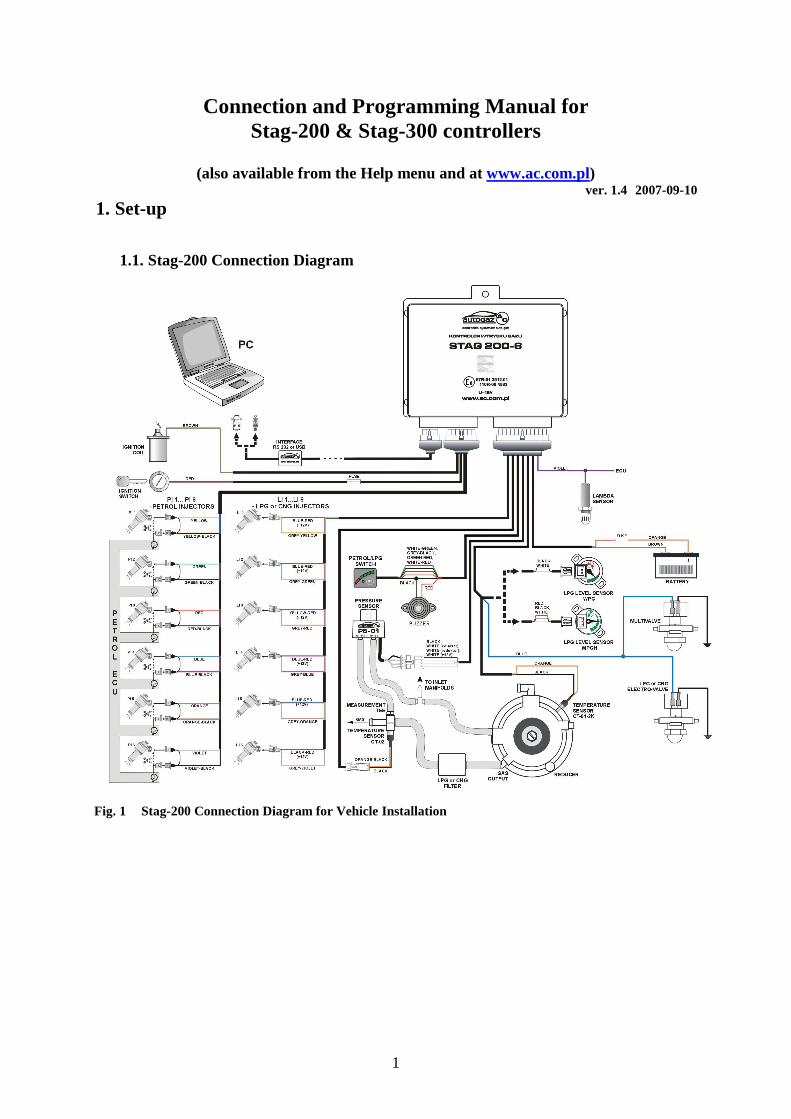
1.1. Stag-200 Connection Diagram
Fig. 1 Stag-200 Connection Diagram for Vehicle Installation
2
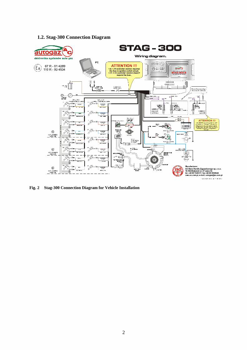
1.2. Stag-300 Connection Diagram
Fig. 2 Stag-300 Connection Diagram for Vehicle Installation
3
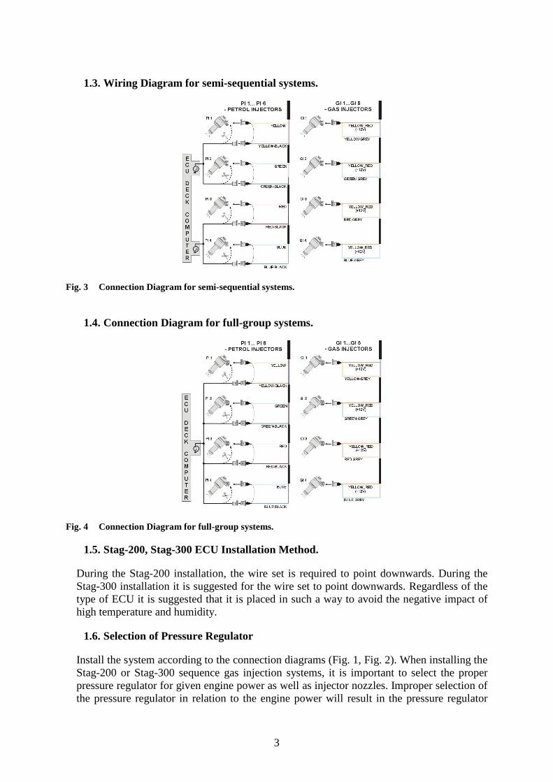
1.3. Wiring Diagram for semi-sequential systems.
Fig. 3 Connection Diagram for semi-sequential systems.
1.4. Connection Diagram for full-group systems.
Fig. 4 Connection Diagram for full-group systems.
1.5. Stag-200, Stag-300 ECU Installation Method.
During the Stag-200 installation, the wire set is required to point downwards. During the Stag-300 installation it is suggested for the wire set to point downwards. Regardless of the type of ECU it is suggested that it is placed in such a way to avoid the negative impact of high temperature and humidity.
1.6. Selection of Pressure Regulator
Install the system according to the connection diagrams (Fig. 1, Fig. 2). When installing the Stag-200 or Stag-300 sequence gas injection systems, it is important to select the proper pressure regulator for given engine power as well as injector nozzles. Improper selection of the pressure regulator in relation to the engine power will result in the pressure regulator
4
inability to ensure nominal LPG pressure, i.e. it will result in pressure drops when the LPG delivery is high (i.e. when the throttle is fully open). When the LPG pressure drops below the minimum value programmed in the controller, the system will switch to gasoline.
1.7. Selection of injector nozzles
The injector nozzles selection should also be based on the engine power. The selection of injector nozzles should ensure that at high engine loads and high rpm, the multiplier for a given injection time should be close to 1. For the majority of engines, the injection times equal roughly 15 [ms]. The table below presents the nozzles’ diameters depending on the engine power per 1 cylinder. To select the right diameter of nozzles, the engine power needs to be divided by the number of its cylinders. Nozzle diameter [mm] Reducer pressure 1 [bar] Engine power per cylinder [KM]
1,8-2 12 – 17 2,1-2,3 18 – 24 2,4-2,6 25 – 32 2,7-2,9 33 – 40
3,0 41 – 48 Note: the above values are estimates only and do not necessarily always reflect the reality. This can occur e.g. in vehicles with semi-sequential or full group (all injectors activated simultaneously) injection. In such cases, the nozzles’ diameters will be smaller than those presented in the table above as in these systems the amount of supplied LPG is higher than in full sequence systems – two times higher for semi-sequential injectors and four times higher for full group injectors.
2. Ac Gas Synchro diagnostic software - description
2.1. Controller-PC connection
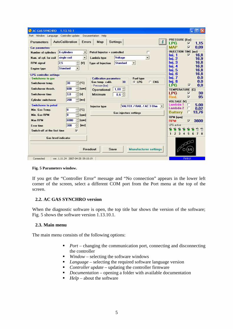
Upon installing the Stag-200/Stag-300 controller in the vehicle, connect it to a PC with the Ac Gas Synchro software installed via an RS interface manufactured by AC BHZ. Prior to starting the software, turn the ignition on (in order to supply voltage to the controller); this is necessary as the controller switches to sleep mode (when it will not communicate with the PC) after app. 10 minutes without power supply. After starting the software – provided the COM port is selected properly – the controller will establish connection with the diagnostic software and “Connected” will appear in the lower left corner of the screen. Fig. 5 shows the Parameters window.
5
Fig. 5 Parameters window. If you get the “Controller Error” message and “No connection” appears in the lower left corner of the screen, select a different COM port from the Port menu at the top of the screen.
2.2. AC GAS SYNCHRO version
When the diagnostic software is open, the top title bar shows the version of the software; Fig. 5 shows the software version 1.13.10.1.
2.3. Main menu
The main menu consists of the following options:
� Port – changing the communication port, connecting and disconnecting the controller
� Window – selecting the software windows � Language – selecting the required software language version � Controller update – updating the controller firmware � Documentation – opening a folder with available documentation � Help – about the software
6
2.4. Controller Parameters
The controller firmware version is shown at the bottom of the screen (Fig. 5); „ver.” is followed by the firmware version, where: 1.11 - is the controller’s PCB version (necessary for controller’s update) 24 - is the controller’s current firmware version 2007-03-22 09:24:45 – date and time of the firmware compilation
Clicking the button in the upper right corner will bring up the Controller Info window. A detailed description of the Controller Info window is presented later in this manual. The Parameters window lists a number of parameters which need to be set individually for each vehicle.
The Vehicle parameters group contains:
� Number of cylinders – number of engine cylinders. Ver. 24 and later of the controller firmware additionally list the following options:
- 1 Cylinder (motor-bike) - 2 Cylinders (motor-bike)
These are used for 1- and 2-cylinder engines, e.g. motor-bike engines.
� No. of cylinders per ignition coil – the number of cylinders for each ignition coil
� RPM signal – RPM signal source In controller’s ver. 1.10 or older: 12 V – signal from the ignition coil 5V – signal from the vehicle’s computer In ver. 1.11 and later:
RPM detection threshold in Volts. Set the detection threshold to a value ensuring proper revolutions reading from the controller. E.g. for impulses originating in a gasoline engine usually equal app. 5 [V], set the detection threshold to app. 2,5 [V]. For impulses originating from the ignition coil, set the threshold to app. 7 [V].
Nissan Micra is an exception. Its computer ignition impulses equal app. 1,4 [V], in which case the detection threshold needs to be set at app. 1,0 [V].
For some Renault Megan models, the detection setting needs to be set at app. 10 [V]
� Engine type – engine type, Standard – standard engine with no
supercharger, Turbo – for supercharged engines � Gasoline Injection controlled with „+” - injection signals reading in
systems where signals are “positive”, i.e. grounding is the common signal for all injectors and the controlling signals are up to 12 [V].
� Lambda type – type of the installed lambda probe:
7
- voltage – standard voltage probe. Two voltage probes can be connected simultaneously.
- UEGO -> voltage – wide-band UEGO lambda (current). The controller shows on an oscilloscope values from the probe in the same form as for a voltage probe. Only 1 wide-band lambda can be connected at any given time.
- UEGO -> full ramge – wide-band UEGO lambda (current). The controller shows on an oscilloscope values in Volts. This makes it possible to watch the entire working range of the UEGO probe, i.e. from lean to rich mixtures. Only 1 broad-band probe can be connected at any given time.
Do not select “UEGO probe” for a voltage probe as this may damage the probe. Refer to the Connection Diagram!!!
� Injection type – type of injection used in the car, - Standard – standard indirect injection, gasoline injectors with no current limit. - Renix – indirect injection system, gasoline injectors with “Renix” current limit
The LPG Control Settings window lists the following groups of parameters: Switching to LPG – parameters related to switching from gasoline to LPG.
� Switching temperature – LPG pressure regulator temperature required
for the controller to switch to LPG, � Switching threshold – engine rpm required for the controller to switch
to LPG. For rpm set to <700, the controller switches to LPG at idle run. � Switching time – time after starting the engine when the controller can
switch to LPG. � Cylinder Switching– time elapsing between the switching of subsequent
cylinders. E.g. with the setting at 200[ms] for a 4-cylinder engine, the switching from gasoline to LPG or LPG to gasoline will take 4*200[ms]. This works regardless of whether the gasoline injection system is the so-called full sequence or not. Setting the switching time to 0 will result in the switching from gasoline to LPG or vice versa and turning on and off of the solenoid valves without any delay.
Switching to gasoline - parameters related to switching from LPG to gasoline.
� Min. LPG temperature – min. LPG temperature; when lower, the
controller will switch over to gasoline. � Min. LPG rpm – min rpm; when lower, the controller will switch over
to gasoline. � Max rpm – engine rpm; when higher, the controller will switch to
gasoline � Pressure Error Time – amount of time with the LPG pressure lower
than minimal before the controller switches to gasoline and reports: “LPG pressure too low”.
8
� Switch to gasoline with first Pressure Drop – with this option selected, the controller will switch to gasoline when the LPG pressure drop is detected. When unselected, the controller will switch some cylinders to gasoline when the LPG pressure is detected to lower LPG usage.
Calibration parameters – parameters related to controller calibration.
� LPG temperature at Calibration – LPG temperature at which the controller was calibrated.
� Pressure - Operational – LPG pressure at which the controller was calibrated. This setting can be altered manually. However, each change of the operational LPG pressure requires multiplier map calibration!!! Minimum – when the pressure is lower than minimum, the controller will switch to gasoline if the duration of min. pressure exceeds the Pressure Error Time.
Remaining parameters in the LPG Controller Settings group:
� Fuel Type – type of fuel in the LPG system � Injector Type – type of the LPG injector. Changing the injector type
requires re-auto-calibration or multiplier map cali bration!!! � LPG Injectors Settings – calibration of particular LGP injectors. � LPG level indicator– LED thresholds setting. This button is used to set
the low LPG LED on/off threshold settings as well as to select the LPG level sensor (this is explained in more details later in the manual).
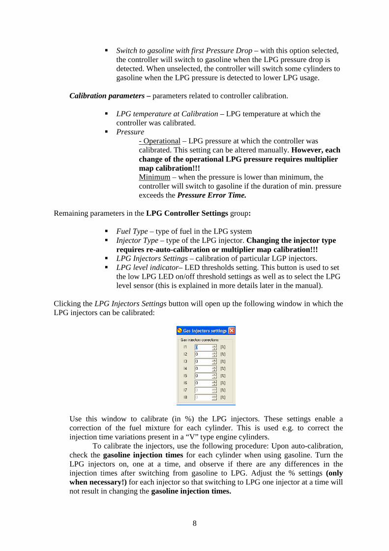
Clicking the LPG Injectors Settings button will open up the following window in which the LPG injectors can be calibrated:
Use this window to calibrate (in %) the LPG injectors. These settings enable a correction of the fuel mixture for each cylinder. This is used e.g. to correct the injection time variations present in a “V” type engine cylinders. To calibrate the injectors, use the following procedure: Upon auto-calibration, check the gasoline injection times for each cylinder when using gasoline. Turn the LPG injectors on, one at a time, and observe if there are any differences in the injection times after switching from gasoline to LPG. Adjust the % settings (only when necessary!) for each injector so that switching to LPG one injector at a time will not result in changing the gasoline injection times.
9
WARNING!!! Use this option as a last resort, i.e. when sure that the installation was performed properly, all mechanical issues have been eliminated and injection times variations for given injectors are still present when using LPG. Do not ever use injection strip-collector pipes of different lengths and then the injectors’ calibration to accommodate this difference!!! Also never use this option when the system is not in a perfect working condition or when some of its elements have worn out. Using this option in a manner not consistent with the above instructions may result in damage to the car!!!
The correction window may be opened regardless of the selected tab, i.e. the map tab may be opened and the correction window on top of it. There are 3 buttons at the bottom of the Settings tab used to perform the following actions:
� Read – read the controller settings from a file � Save – save the controller settings to a file � Default – restore default controller settings
10
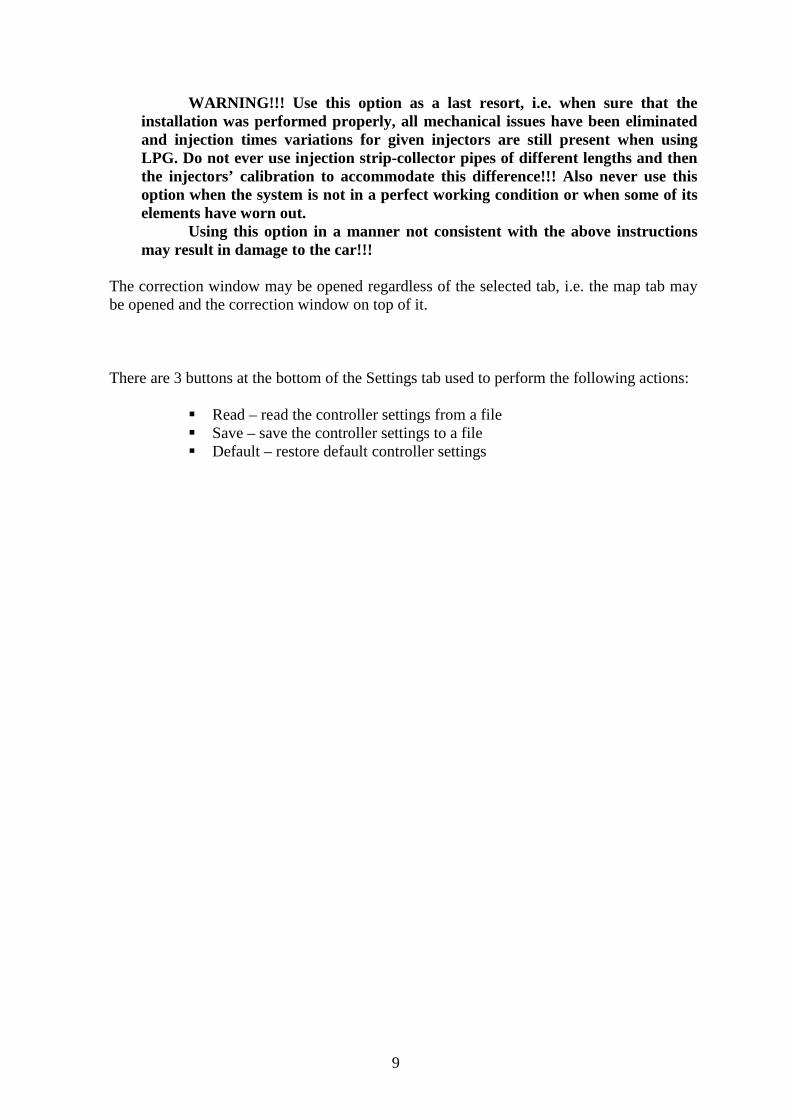
2.5. Controller Info
To bring up the Controller Info window, click the button in the upper right corner of the screen or select “Controller Info” in the Help menu.
Fig. 6 Controller Info window.
The Controller Info window (Fig. 6) shows the following parameters:
11
Controller Work Time:
� Gasoline – total working time of the controller using gasoline listed in the following format: H – hours, M – minutes, S – seconds.
� Since last connection – working time of the controller using gasoline since its last connection with a PC.
� LPG - total working time of the controller using LPG � Since last connection– working time of the controller using LPG since
its last connection with a PC. � Inspection – Service Schedule. When the controller reaches the
working time using LPG set in this field, every time the ignition key is switched-off the controller will produce an acoustic signal reminding of the inspection. Clearing the Inspection Schedule is explained below.
To set the Service Schedule, click the “Set” button in the Controller Info window. The following window will pop up (Fig. 7):
Fig. 7 Inspection Schedule window.
The next service visit time is calculated on the basis of mileage. The default setting is 1 h = 50 km, yet it is configurable. The above window shows the next service visit set to 1000 km, which in this case equals 20 hours of work. To clear the service schedule, select “Disabled”, in which case the controller will not monitor the service schedule. Below the working times, the Controller Info lists the following types of registered events:
� First PC Connection – date of the first controller-PC connection. � First Settings Modification. – first modification of the controller
settings. If these fields do not show dates but instead the „???” symbols, it means an error occurred in the Controller Info. Time information has been lost and the controller will start counting the times from the beginning.
� Mod. date 1 – Mod. date 5 – a list of controller settings modifications. From the most recent ones till the oldest.
� Unknown Settings Mod. – This happens when the controller’s settings modification is performed with a date earlier than a previously performed modification.
Each event is also accompanied by a “code” linked to the PC on which the modification was made. Thus knowing the modification date as well as the PC code, it is easy to determine whether any modifications have been performed by anyone else.
12
The bottom of this window shows additional information:
� Controller S/N – the serial number of the controller. Not available for older versions of controllers.
� PC code – The code of the PC on which the AcGasSynchro software is currently used.
2.6. Signals, injectors, switchboard
On the right side of the window (Fig. 5) there are the “Signals” and “Injectors” windows. The “Signals” window shows the following signals measured by the controller:
� LPG pressure [bar] – LPG pressure value (the difference in the pressure regulator pressure and the suction collector pressure)
� MAP pressure [bar] – pressure inside the suction collector (absolute pressure value)
� Injection time [ms] – gasoline injection time - Inj. 1 – Gasoline injection time for Injector 1 - Inj. 2 – Gasoline injection time for Injector 2 - Inj. 3 – Gasoline injection time for Injector 3 - Inj. 4 – Gasoline injection time for Injector 4 - Inj. 5 – Gasoline injection time for Injector 5 - Inj. 6 – Gasoline injection time for Injector 6 - Inj. 7 – Gasoline injection time for Injector 7 - Inj. 8 – Gasoline injection time for Injector 8
� LPG Injection time [ms] – LPG injection time (for the first cylinder) � LPG temperature[°C] – LPG temperature at the pressure regulator
output � Red. Temp. [°C] – liquid temperature at the reducer � Lambda 1 voltage [V] – voltage at the lambda probe 1 � Lambda 2 voltage [V] – voltage at the lambda probe 2 � Power Supply voltage [V] – voltage at the controller’s power supply � RPM [rev/min] – engine revolutions
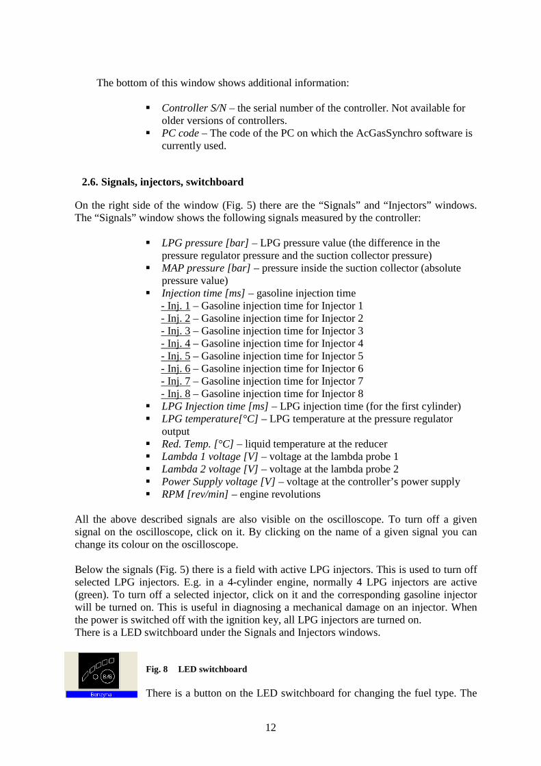
All the above described signals are also visible on the oscilloscope. To turn off a given signal on the oscilloscope, click on it. By clicking on the name of a given signal you can change its colour on the oscilloscope. Below the signals (Fig. 5) there is a field with active LPG injectors. This is used to turn off selected LPG injectors. E.g. in a 4-cylinder engine, normally 4 LPG injectors are active (green). To turn off a selected injector, click on it and the corresponding gasoline injector will be turned on. This is useful in diagnosing a mechanical damage on an injector. When the power is switched off with the ignition key, all LPG injectors are turned on. There is a LED switchboard under the Signals and Injectors windows.
Fig. 8 LED switchboard There is a button on the LED switchboard for changing the fuel type. The
13
LED next to the switch signals the controller status:
� off – gasoline � on – LPG � blinking – auto mode
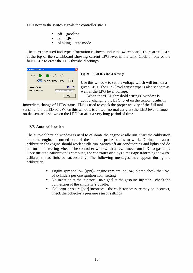
The currently used fuel type information is shown under the switchboard. There are 5 LEDs at the top of the switchboard showing current LPG level in the tank. Click on one of the four LEDs to enter the LED threshold settings.
Fig. 9 LED threshold settings Use this window to set the voltage which will turn on a given LED. The LPG level sensor type is also set here as well as the LPG level voltage.
When the “LED threshold settings” window is active, changing the LPG level on the sensor results in
immediate change of LEDs status. This is used to check the proper activity of the full tank sensor and the LED bar. When this window is closed (normal activity) the LED level change on the sensor is shown on the LED bar after a very long period of time.
2.7. Auto-calibration
The auto-calibration window is used to calibrate the engine at idle run. Start the calibration after the engine is turned on and the lambda probe begins to work. During the auto-calibration the engine should work at idle run. Switch off air-conditioning and lights and do not turn the steering wheel. The controller will switch a few times from LPG to gasoline. Once the auto-calibration is complete, the controller displays a message informing the auto-calibration has finished successfully. The following messages may appear during the calibration:
� Engine rpm too low [rpm]– engine rpm are too low, please check the “No. of cylinders per one ignition coil” setting
� No injection at the injector – no signal at the gasoline injector – check the connection of the emulator’s bundle.
� Collector pressure [bar] incorrect – the collector pressure may be incorrect, check the collector’s pressure sensor settings.

14
2.8. Oscilloscope
Fig. 10 Oscilloscope view When the auto-calibration map tab is selected, the oscilloscope is visible. The oscilloscope shows all the signals described in point 2.5. The control buttons have the following functions (from left to right):
� Start the oscilloscope � Stop the oscilloscope � Save current oscilloscope display � Load saved oscilloscope display � Decrease the number of displayed points (only for loaded graphs) � Increase the number of displayed points (only for loaded graphs)
When the controller works with LPG, a continuous line appears at the top of the oscilloscope; its colour corresponding to the LPG ignition time.
2.9. Errors
The Error window shows the following field:
� Continuous signal for errors – if selected, acoustic signals will inform of an error until manually turned off by the user. If unselected, the acoustic signals will remain on only for a set amount of time.
The Current Errors window shows current errors recorded by the controller and the Recorded Errors window shows errors recorded during the controller’s operation. The following errors may appear during operation:
� Injector No. […] Error – no LPG injector No. […] or injector damage � Voltage Error – voltage at the controller’s power supply lower than 9 [V] � LPG pressure too high– the LPG pressure has been two times higher than
operational pressure for 60 seconds (a reducer problem) � LPG pressure too low – the LPG pressure has dropped under the min. pressure
value for a set amount of time. � No gasoline injection – the controller has detected a lack of gasoline injector
signal for one or more gasoline injectors. � Data error, check settings! – the controller has detected a settings error, check all
controller settings. � Power supply voltage too low for LPG! – the controller power supply is too low
to work with LPG. � Time Error – Controller Info has been damaged and automatically deleted. In this
case, the First PC Connection and First Settings Modifications info will not be shown.
The following warnings may appear in the Warnings window:
15
� LPJ injectors fully open!!! – Check the lambda probe at full engine load – LPG injection loop, i.e. an LPG injection’s started before the previous LPG injection ended. If the lambda probe is “rich” at the time of this message, this warning may be ignored. Otherwise, replace the injectors’ nozzles with higher diameter ones to decrease the multiplier.
� Inspection required!!! The installation requires a periodical service visit. To delete this message, go to the Controller Info settings, click “Set Inspection” and either set the next service visit in kilometres or select “Off” in which case the service reminder will be inactive.
There is a “Delete” button at the bottom of the screen used to delete all registered errors.
2.10. Map
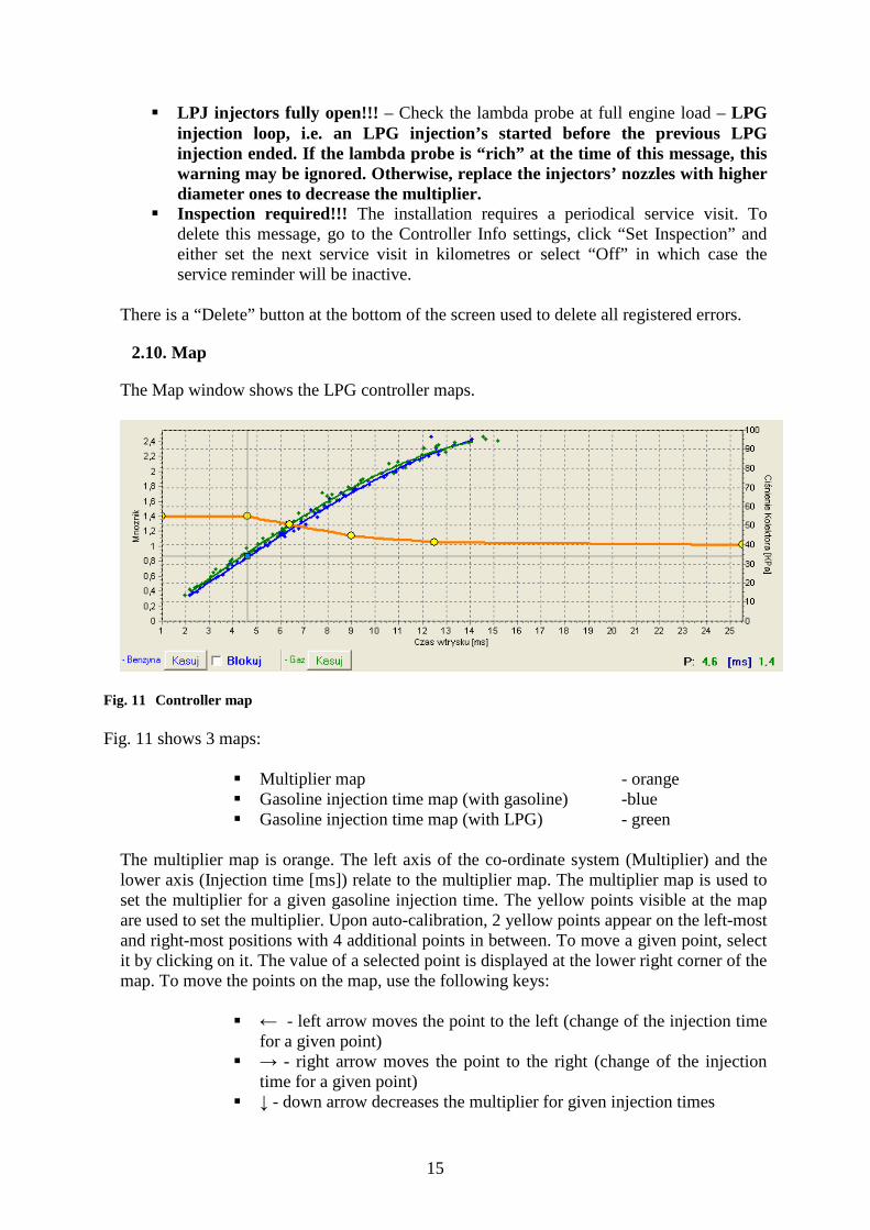
The Map window shows the LPG controller maps.
Fig. 11 Controller map Fig. 11 shows 3 maps:
� Multiplier map - orange � Gasoline injection time map (with gasoline) -blue � Gasoline injection time map (with LPG) - green
The multiplier map is orange. The left axis of the co-ordinate system (Multiplier) and the lower axis (Injection time [ms]) relate to the multiplier map. The multiplier map is used to set the multiplier for a given gasoline injection time. The yellow points visible at the map are used to set the multiplier. Upon auto-calibration, 2 yellow points appear on the left-most and right-most positions with 4 additional points in between. To move a given point, select it by clicking on it. The value of a selected point is displayed at the lower right corner of the map. To move the points on the map, use the following keys:
� ← - left arrow moves the point to the left (change of the injection time for a given point)
� → - right arrow moves the point to the right (change of the injection time for a given point)
� ↓ - down arrow decreases the multiplier for given injection times
16
� ↑ - up arrow increases the multiplier for given injection times � „Insert” (when a point is active) or right mouse button– add a new point � „Delete” – delete a point from the map � „Page Up” – move the map up � „Page Down” – move the map down � „Ctrl” + ← , or „Ctrl” + → change the active point (move to the next
one) When the „Shift” key is pressed in, the map movement speed is multiplied by 10 (fast movement). When no point is selected, the ↑ ↓ arrows move the entire map. Apart from the multiplier map, there are two other maps in the window. The blue map represents the gasoline injection times (with gasoline). The right axis Collector pressure [Kpa] and the lower axis Injection Time [ms] relate to this map. The map consists of blue points. After collecting the data, the controller turns these points into a continuous line. The same applies to the so-called LPG map, i.e. the map of gasoline injection times (with LPG) which is green. After the controller collects both maps, i.e. the gasoline and LPG maps, the Deviation tab becomes active where a red line shows the difference between gasoline and LPG. The map window on Fig. 11 shows a blue square marker; its position changes horizontally depending on the collector pressure and vertically depending on the gasoline injection times. It is very useful during map collection as it shows the load and injection times of the engine. The “Delete” button is used to delete the gasoline and LPG maps. The “Lock” button situated next to it is used to block the gasoline map once it is collected by the controller, i.e. the controller will not modify the gasoline map once it is collected (drawn with a continuous line).
2.11. Controller update
To update the controller, connect it to the diagnostic software and turn the engine off. Select “Controller update” from the main menu. The “Controller update” window will pop up. The “Controller Parameters” window shows the information on current controller firmware version. Click “Load update” and select the update file depending on the PCB (board) version of the controller. The controller PCB version is represented by the first two digits in the code versions, i.e. in a controller with the software version 1.6.18:
� 1.6 – is the controller PCB (board) version � 18 – the controller firmware version
In this particular case, the update file should be named 1.6.x, where x stands for the new version of the firmware. Once the update file is loaded, click “Update”. When the progress bar reaches 100%, the controller will disconnect and then re-connect. The new version number should appear at the bottom of the screen and should reflect the version number of the update file. Should the update go wrong and it be impossible to connect with the controller (for firmware ver. 19 and older):
17
� Close the diagnostic software � Turn the ignition off � Disconnect the RS-232 cable from the PC � Start the diagnostic software (the “No LPG controller” message will
appear) � Connect RS-232 to the PC � Take out and then reinsert the main fuse (LED on the switchboard will
turn on) � Before the LED turns off, press the button on the LED switchboard
(LED will turn off now) � Go to Controller Update, select the update file and click “Update” � When the progress bar reaches 100%, the controller should connect
with the diagnostic software. (For firmware ver. 20 and later): The diagnostic software will detect an update error and – upon connecting with the controller – will open the update window. Perform the update procedure again.
18
3. Programming the Stag-200, Stag-300 controllers
There are two ways to program the Stag-200 and Stag-300 controllers:
� Programming with the gasoline and LPG maps. See 3.1 to 3.4 � Manual programming of the controller. See 0
Programming with the gasoline and LPG maps consists of the following stages:
� Auto-calibration of the Stag-200, Stag-300 controller � Collection of the gasoline injection times with gasoline (gasoline map) � Collection of the gasoline injection times with LPG (LPG map) � Making sure both maps match and checking deviations
3.1. Auto-calibration
Prior to starting the auto-calibration, start the engine and wait until the lambda probe begins to work. During the auto-calibration the engine should work at idle run; do not increase rpm, switch off air-conditioning and lights and do not turn the steering wheel as this may cause errors during the auto-calibration. During the auto-calibration, watch carefully gasoline and LPG injection times. If LPG injection times are shorter than gasoline injection times, the injector nozzles may be too large and should be replaced with smaller diameter ones. When the auto-calibration is complete, 2 extreme yellow points and 4 additional points in between will show up on the multiplier map. The second left point is the point of engine operation at idle run i.e. the point of operation during auto-calibration. The multiplier’s value for this point should be between 1.1 and 1.6; if the value is greater than 1.6, longer times of gasoline injection i.e. greater load and high rpm, may cause overlapping of injection times i.e. one LPG injection will begin before the previous one ends (looped injections). In such a case, the controller will display the „Injection time too long” error message. However, in such a case, check the operation of the lambda probe; if it is in the “rich” mode and the vehicle drives without problems, the error can be ignored.
3.2. Collection of the gasoline injection map with gasoline (gasoline map)
Having finished the auto-calibration, switch over to gasoline and drive the vehicle for app. 4 km to collect the gasoline map. During the collection of the map try to drive without changing gears e.g. at the 4th gear and in a way making the lambda probe to “work” i.e. changing its mode from weak to rich. Blue points should appear during the collection of the map. To collect the map quicker, adjust vehicle load in such a way causing new points to be collected in places which are still empty. Collection of maps is performed without participation of the diagnostic software, thus can be done with the PC disconnected. However, collecting the map while the PC is connected and the diagnostic software running is quicker and enables the operator to see what is actually happening to the vehicle. When the controller collects sufficient number of points, the map will be drawn with a continuous line and the gasoline map collection is finished.
3.3. Collection of the gasoline injection map with LPG (LPG map)
19
Having collected the gasoline map, switch to LPG and collect the LPG map in the same way the gasoline map was collected. The LPG map should be collected in the same road conditions and with similar loads as the gasoline map. The LPG map is drawn with green points. Having collected sufficient number of green points, the map will be drawn with a continuous green line. If the controller is set properly (the multiplier characteristics selected properly), the gasoline and the LPG maps should match. If the maps do not match, the multiplier characteristic should be corrected at the points where the maps do not match (the lower axis of co-ordinates for injection times). If the LPG map is collected with the PC connected and the diagnostic software running, it is possible to immediately correct the multiplier characteristics when the collected green points do not match with the gasoline map. It is even strongly recommended to use the PC in this way as if the multiplier characteristics differ strongly from the required ones, the controller starts to switch over and – in the extreme case – can activate the “check” signal lamp. When correcting the multiplier characteristics, make the points on the LPG map match with the gasoline map. Once both maps match, the characteristics are properly set.
3.4. Checking if maps match, verification of deviations
Having collected the gasoline and LPG maps (both maps drawn with continuous lines) check the deviation between them. In the Map window there is the “Deviation” button located on the right. Press it to see the deviation graph drawn with a red line. If the deviation fits within ± 10%, the controller is programmed properly; otherwise, the multiplier characteristics should be corrected at points where maps do not match.
3.5. Controller manual setting
The controller may also be set up manually, which – provided sufficient experience has been gained – may prove quicker than the above described procedure. Start with the auto-calibration in the same way as described above (this is necessary to ensure the controller works properly, see 3.1). If the auto-calibration finishes properly and the multiplier values are correct for the calibration point, switch the engine to gasoline and take it for a ride. The multiplier characteristics need to be set in the following way: Drive the car with a constant load, i.e. the gasoline injection times should be stable. Adjust the engine loads so that the injection times equal e.g. app. 5 [ms]. The blue marker will help determine the injection times as it is location on the horizontal axis is determined by the injection times. Next, switch the car to LPG and watch the blue marker for variations in injection times when compared with the earlier gasoline injection times. If the injection times decreased (the marker moved to the left) it means that for the selected injection times the multiplier is too high (the mixture is too rich). In this case, lower the multiplier value for the 5 [ms] injection time (in our case). If upon switching to LPG the blue marker moves to the right, it means the mixture is not reach enough and the multiplier needs to be brought up for given injection times. The procedure described above should be performed for a few different injection times, starting at the calibration point all the way until heavy load injections. You can check the

20
multiplier map e.g. every 2 [ms] starting at the calibration point. If necessary, add a point at the multiplier map to set it more precisely. Once the manual setting is complete, both maps – gasoline and LPG – should match.
21
4. LED switchboard operation and acoustic signals (User Manual)
4.1. LED switchboard
The LED switchboard consists of:
� LED line indicating LPG level � the LED indicating type of fuel � button
LED line– shows current LPG level in the tank. 4 green LEDs indicate a full tank; a red LED indicates “reserve”. The LED – shows current operating status:
� off – the engine runs on gasoline � slow blinking (once per second) – awaiting engine
temperature reading � normal blinking (twice per second) – the controller is in the
auto-mode (waiting for required rpm before switching to LPG)
� fast blinking (4 times per second) – controller error (no LPG in the tank)
� on – the engine runs on LPG Push button – for switching from one fuel type to another The controller “remembers” the last fuel type setting before switching the ignition switch off. In order to start the engine on LPG (e.g. when the gasoline pump is damaged), press in and hold the button on the LED switchboard while turning the ignition on. The LED should come on. When the engine revolutions are detected, the controller turns the solenoid valves on and the engine starts on LPG. In this mode, it is not possible to turn back to gasoline. Turn the ignition off to turn this special mode off.
4.2. Acoustic signals
The controller generates the following acoustic signals:
22
� Three acoustic signals – when switching from LPG to gasoline because of low LPG level in the tank
� Three short acoustic signals followed by a long one – when a controller error occurs
� When switching the ignition off – two short signals followed by a long one indicate a scheduled service visit. Visit a service station to have your system checked.
Related Documents