Aalto University School of Electrical Engineering Metrology Research Institute Version 1.0 31/07/2015 Tomi Pulli Instruction manual for Konica Minolta CS-1000 and CS-2000 spectroradiometers

Welcome message from author
This document is posted to help you gain knowledge. Please leave a comment to let me know what you think about it! Share it to your friends and learn new things together.
Transcript
Aalto University
School of Electrical Engineering
Metrology Research Institute
Version 1.0
31/07/2015
Tomi Pulli
Instruction manual for Konica Minolta CS-1000 andCS-2000 spectroradiometers
Instruction manual forKonica Minolta CS-1000
and CS-2000 spectroradi-ometers
Page 2 (14)
Version: 1.0 Date: November 24, 2016 Last edited by: ToP
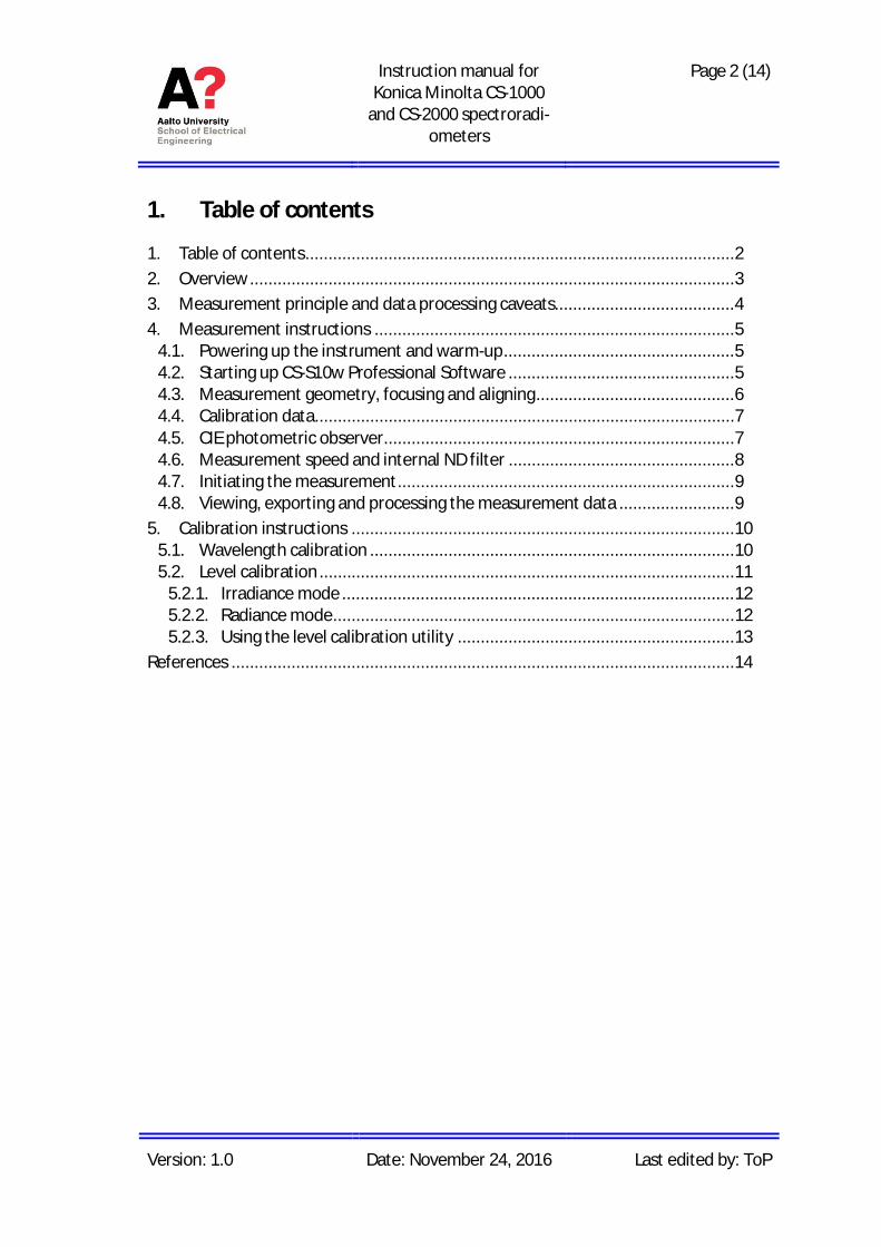
1. Table of contents
1. Table of contents ............................................................................................. 22. Overview ......................................................................................................... 33. Measurement principle and data processing caveats....................................... 44. Measurement instructions .............................................................................. 5
4.1. Powering up the instrument and warm-up .................................................. 54.2. Starting up CS-S10w Professional Software ................................................. 54.3. Measurement geometry, focusing and aligning ........................................... 64.4. Calibration data........................................................................................... 74.5. CIE photometric observer............................................................................ 74.6. Measurement speed and internal ND filter ................................................. 84.7. Initiating the measurement ......................................................................... 94.8. Viewing, exporting and processing the measurement data ......................... 9
5. Calibration instructions ................................................................................... 105.1. Wavelength calibration ............................................................................... 105.2. Level calibration .......................................................................................... 11
5.2.1. Irradiance mode ..................................................................................... 125.2.2. Radiance mode ....................................................................................... 125.2.3. Using the level calibration utility ............................................................ 13
References ............................................................................................................. 14
Instruction manual forKonica Minolta CS-1000
and CS-2000 spectroradi-ometers
Page 3 (14)
Version: 1.0 Date: November 24, 2016 Last edited by: ToP
2. Overview
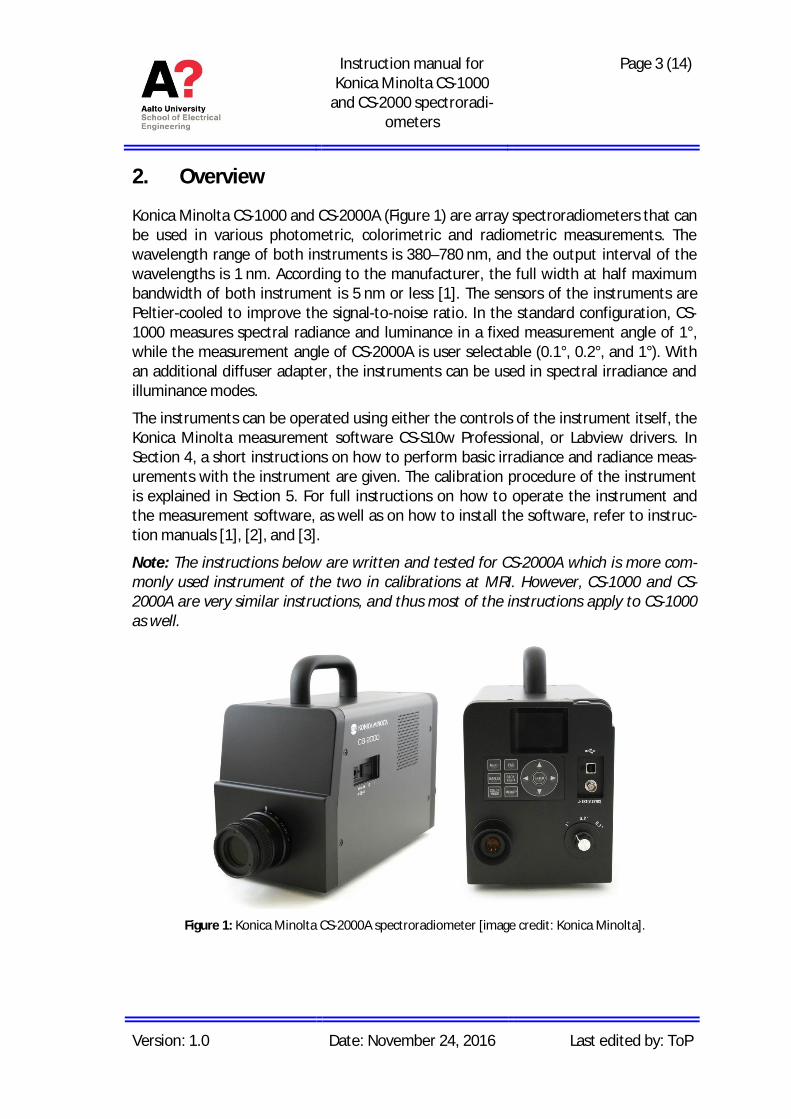
Konica Minolta CS-1000 and CS-2000A (Figure 1) are array spectroradiometers that canbe used in various photometric, colorimetric and radiometric measurements. Thewavelength range of both instruments is 380–780 nm, and the output interval of thewavelengths is 1 nm. According to the manufacturer, the full width at half maximumbandwidth of both instrument is 5 nm or less [1]. The sensors of the instruments arePeltier-cooled to improve the signal-to-noise ratio. In the standard configuration, CS-1000 measures spectral radiance and luminance in a fixed measurement angle of 1°,while the measurement angle of CS-2000A is user selectable (0.1°, 0.2°, and 1°). Withan additional diffuser adapter, the instruments can be used in spectral irradiance andilluminance modes.
The instruments can be operated using either the controls of the instrument itself, theKonica Minolta measurement software CS-S10w Professional, or Labview drivers. InSection 4, a short instructions on how to perform basic irradiance and radiance meas-urements with the instrument are given. The calibration procedure of the instrumentis explained in Section 5. For full instructions on how to operate the instrument andthe measurement software, as well as on how to install the software, refer to instruc-tion manuals [1], [2], and [3].
Note: The instructions below are written and tested for CS-2000A which is more com-monly used instrument of the two in calibrations at MRI. However, CS-1000 and CS-2000A are very similar instructions, and thus most of the instructions apply to CS-1000as well.
Figure 1: Konica Minolta CS-2000A spectroradiometer [image credit: Konica Minolta].
Instruction manual forKonica Minolta CS-1000
and CS-2000 spectroradi-ometers
Page 4 (14)
Version: 1.0 Date: November 24, 2016 Last edited by: ToP
3. Measurement principle and data processing caveats
The instrument performs various automated operations before, during, and after themeasurement that the user should be aware of when interpreting the results.
Before the actual measurement, the instrument performs a pre-measurement to de-termine the optimal integration time for the measurement. The instrument also hasan internal neutral density (ND) filter that is used when the light level reaches a cer-tain threshold. These behaviors can be modified in the measurement settings as will bediscussed in Section 4.6. If the internal ND filter is utilized in the calibration of the in-strument but not in the actual measurement (or vice versa), the uncertainty of themeasurement may be increased due to the uncertainty of the transmittance calibra-tion of the internal ND filter. Since it is hard to determine whether the internal ND fil-ter is used in the measurement or not, it is recommended to force the instrument touse the same filter setting in both the calibration and the measurement by manuallysetting the internal ND filter on or off, in measurements where very low uncertainty isrequired.
After the measurement, the instrument blocks the beam with an internal shutter andcarries out a dark signal measurement. The dark signal of the array is then subtractedfrom the measured spectrum. This behavior cannot be modified. An additional darkmeasurement may be needed if straylight is present in the measurement, as straylightis not subtracted from the spectrum in this automated process. When performing amanual dark signal measurement, it is advisable to use the same integration time as inthe actual measurement.
The instrument performs straylight, linearity and possibly other corrections on themeasured spectrum. These correction cannot be turned off, modified, or inspected. Theraw counts of the diode array cannot be extracted, and the output spectrum is alwayscorrected by either the factory or a user calibration. The wavelengths in the outputarray do not correspond with the exact locations of the pixels in the diode array.
The instrument calculates various photometric, colorimetric, and other parametersfrom the measured spectrum. It was discovered that the correlated color temperature(CCT) reported by the instrument deviates somewhat from the value obtained by itera-tively searching for the chromaticity point in the Planckian locus which minimizes thedistance to the chromaticity coordinates of the source. It is possible that the instru-ment uses one of the approximation formulas that have been developed for efficientdetermination of CCT. As an example, it was found that for an incandescent lamp withCCT at around 2856 K – the CCT of CIE Standard Illuminant A – the value reported bythe instrument was about 1.5 K above the value calculated from the measured spec-trum using the iterative method. The difference between the two results depends onthe color coordinates, and consequently on the CCT, of the source. Therefore, inmeasurements requiring very accurate knowledge of the CCT, the CCT value calculatedby the instrument should not be utilized directly.
Instruction manual forKonica Minolta CS-1000
and CS-2000 spectroradi-ometers
Page 5 (14)
Version: 1.0 Date: November 24, 2016 Last edited by: ToP
4. Measurement instructions
Below is a step-by-step guide to measuring with the instrument:
1. Turn on the instrument (warm-up time of 20 minutes or more is required).2. Connect the instrument and the USB copy protection key to the computer.3. When measuring in irradiance mode, attach the diffuser adapter.4. Select the measurement angle.5. Focus and align the instrument.6. Select the correct calibration file.7. Select the CIE Photometric Observer (typically: 2° observer).8. Select the speed mode and internal ND filter options.9. Initiate the measurement.10. Save the measurement data.
More detailed information of each step is given in the following subsections. For fulldescription of each step as well as information on other measurement modes, such asobject color measurement mode, refer to instruction manuals [1] and [2].
4.1. Powering up the instrument and warm-up
The power plug and the power switch are located on the side of the instrument. Onlythe dedicated Konica Minolta AC power adapter (model AC-A312, labelled CS-2000A)should be used to power up the instrument.
Note: The minimum warm-up time of the instrument is 20 minutes, as recommendedby the manufacturer. This is the minimum warm-up time even if the instrument hasbeen turned off only briefly before turning it on again [1].
4.2. Starting up CS-S10w Professional Software
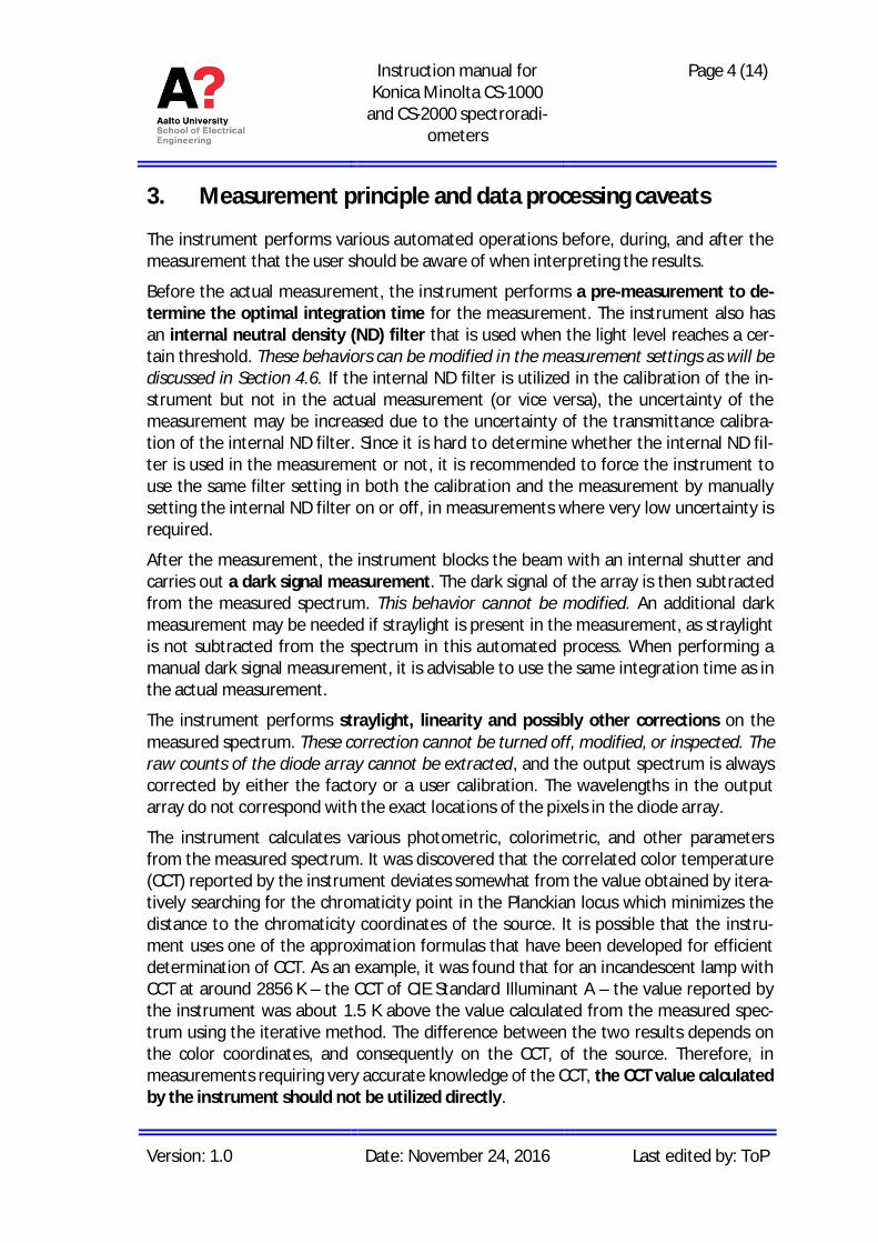
If the instrument is to be used with a computer, make sure the measurement softwareCS-S10w Professional and the USB copy protection key driver are installed on the com-puter [3]. Connect CS-2000A to the computer with a USB cable and insert the USB copyprotection key (Figure 2) in the USB port of the computer. In case of CS-1000, a serial-to-USB adapter is required.
Upon opening, the software asks the user to choose the document type. In typicalmeasurements, Light-source Color – Normal Mode should be selected. Before connect-ing to the instrument, open Instrument > Communication Setup…, select CS-2000 in theinstrument dropdown menu, press Comm…, and select the correct COM port. Establisha connection by selecting Instrument > Connect or by pressing the Connect button inthe user interface. When the connection is established, select File > New to open anew measurement sheet.
Note: After use, return the USB key to the USB strap that is tied to the handle of theinstrument (see Figure 2)! The measurement software can only be operated if the USBkey is plugged in, and replacement keys are expensive.
Instruction manual forKonica Minolta CS-1000
and CS-2000 spectroradi-ometers
Page 6 (14)
Version: 1.0 Date: November 24, 2016 Last edited by: ToP
Figure 2: USB copy protection key in its correct place in between measurements.
4.3. Measurement geometry, focusing and aligning
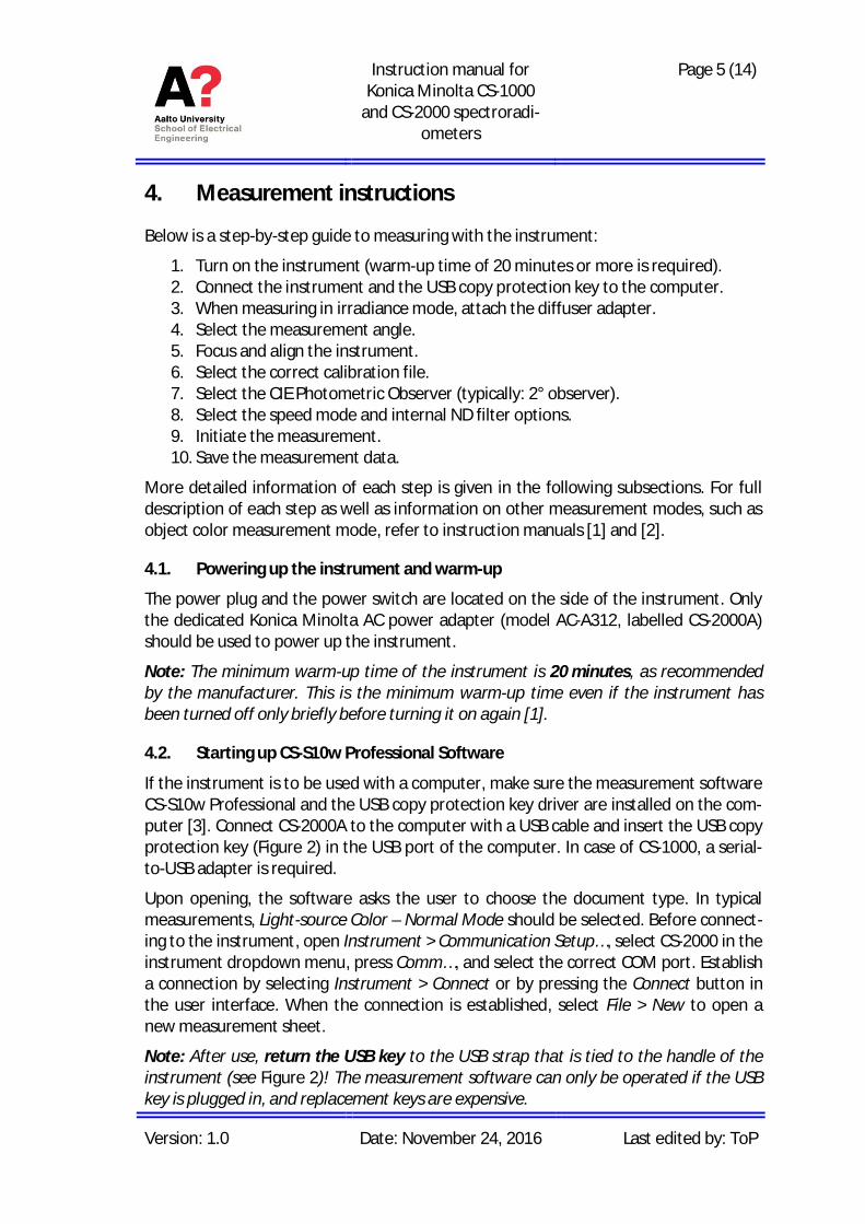
Before the measurement, remove the lens cap of the instrument. Select the measure-ment angle (0.1°, 0.2°, or 1°) using the rotary switch at the back of the instrument. Themeasurement angle corresponds to the black circle that can be seen through the view-finder of the instrument (see Figure 3). Adjust the diopter if the edge of the black circlein the viewfinder is not sharp by rotating the black ring around the viewfinder. Do thisbefore aligning and focusing the instrument.
Figure 3: View of the viewfinder. Black circle in the middle corresponds to the 1° measurement spot.
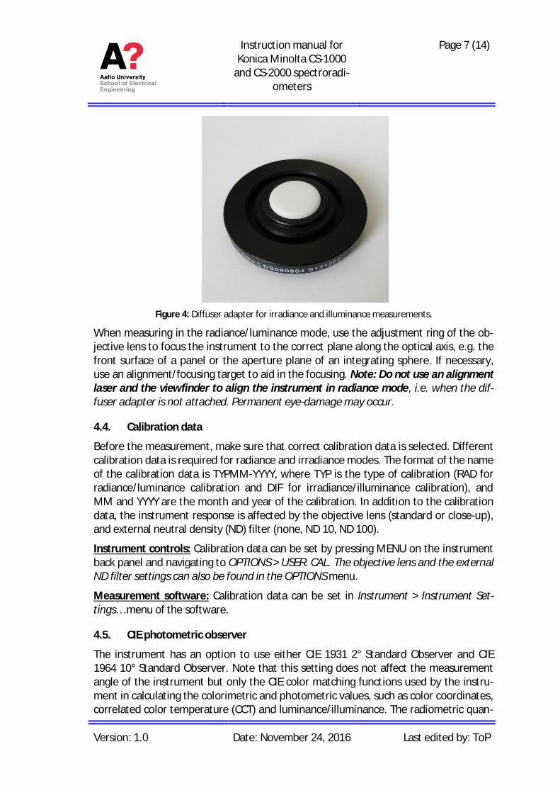
When measuring in the irradiance/illuminance mode, attach the diffuser adapter(Figure 4) to the objective lens and set the focus of the instrument to infinity (∞). Inirradiance/illuminance mode, the instrument can be aligned with help of a two-beamalignment laser.
Instruction manual forKonica Minolta CS-1000
and CS-2000 spectroradi-ometers
Page 7 (14)
Version: 1.0 Date: November 24, 2016 Last edited by: ToP
Figure 4: Diffuser adapter for irradiance and illuminance measurements.
When measuring in the radiance/luminance mode, use the adjustment ring of the ob-jective lens to focus the instrument to the correct plane along the optical axis, e.g. thefront surface of a panel or the aperture plane of an integrating sphere. If necessary,use an alignment/focusing target to aid in the focusing. Note: Do not use an alignmentlaser and the viewfinder to align the instrument in radiance mode, i.e. when the dif-fuser adapter is not attached. Permanent eye-damage may occur.
4.4. Calibration data
Before the measurement, make sure that correct calibration data is selected. Differentcalibration data is required for radiance and irradiance modes. The format of the nameof the calibration data is TYPMM-YYYY, where TYP is the type of calibration (RAD forradiance/luminance calibration and DIF for irradiance/illuminance calibration), andMM and YYYY are the month and year of the calibration. In addition to the calibrationdata, the instrument response is affected by the objective lens (standard or close-up),and external neutral density (ND) filter (none, ND 10, ND 100).
Instrument controls: Calibration data can be set by pressing MENU on the instrumentback panel and navigating to OPTIONS > USER. CAL. The objective lens and the externalND filter settings can also be found in the OPTIONS menu.
Measurement software: Calibration data can be set in Instrument > Instrument Set-tings… menu of the software.
4.5. CIE photometric observer
The instrument has an option to use either CIE 1931 2° Standard Observer and CIE1964 10° Standard Observer. Note that this setting does not affect the measurementangle of the instrument but only the CIE color matching functions used by the instru-ment in calculating the colorimetric and photometric values, such as color coordinates,correlated color temperature (CCT) and luminance/illuminance. The radiometric quan-
Instruction manual forKonica Minolta CS-1000
and CS-2000 spectroradi-ometers
Page 8 (14)
Version: 1.0 Date: November 24, 2016 Last edited by: ToP
tities are not affected by this option. Note: CIE 1931 2° Standard Observer should beused in typical measurements.
Instrument controls: The CIE photometric observer can be set by pressing MENU andnavigating to SETUP > OBSERVER.
Measurement software: The CIE photometric observer can be set in Instrument >Standalone Configuration… menu of the software.
4.6. Measurement speed and internal ND filter
When a measurement is initiated, the instrument first carries out a short measure-ment to determine the optimal integration time, and then carries out the actual meas-urement using that integration time. This behavior can be constrained or overriddenby the measurement speed settings. The speed options are:
· Normal: Integration time automatically adjusted between 0.005 and 120 s.· Fast: Integration time automatically adjusted between 0.005 and 16 s.· Multi-Normal: Multiple cycles of Normal measurements. Option INTEG TIME
determines the combined integration time of the measurements and can be setbetween 1 and 16 s. Note: INTEG TIME does not correspond to the number ofcycles. If the automatically determined integration time is longer than the oneset in the options, the integration time will be the same as in Normal measure-ment.
· Multi-Fast: As with Multi-Normal but with multiple cycles of FAST measure-ments.
· Manual: Fixed integration time between 0.005 and 120 s. Value is given in ms.
The instrument has an internal ND filter that extends the measurement range of theinstrument to higher radiation levels. The available options for the internal ND filterare Auto, Off, and On.
Note: If the instrument gives an error message “OVER” during the measurement, theobject is too bright for the measurement range. To overcome this issue, enable the in-ternal ND filter, decrease the integration time if in Manual speed mode, and/or de-crease the measurement angle of the instrument.
Instrument controls: The measurement speed can be set by pressing MENU and navi-gating to MEAS > SPEED. After selecting the measurement speed, there is an option toset the internal ND filter to AUTO, OFF, or ON.
Measurement software: The measurement speed and internal ND filter can be set inInstrument > Instrument settings… menu of the software. In addition, the instrumentcan be set to repeat the measurement multiple times in Instrument > MeasurementOptions… > Averaging Measurement Setting.
Instruction manual forKonica Minolta CS-1000
and CS-2000 spectroradi-ometers
Page 9 (14)
Version: 1.0 Date: November 24, 2016 Last edited by: ToP
4.7. Initiating the measurement
Instrument controls: Press the MEASURE button on top of the instrument.
Measurement software: Select Instrument > Measure or press the Measure button inthe user interface.
4.8. Viewing, exporting and processing the measurement data
The measured spectrum in the wavelength range of 380–780 nm can be viewed bothin the display of the instrument and in the measurement software. In addition toshowing the radiometric data, the instrument also calculates the corresponding pho-tometric quantity (luminance or illuminance depending on the configuration) as well asvarious colorimetric and other quantities from the measured spectrum.
Instrument controls: The display mode of the instrument can be changed by repeated-ly pressing the COLOR MODE button on the back panel. You can save the data to oneof the 100 memory slots of the instrument by pressing MEMORY, selecting the slot,and pressing ENTER.
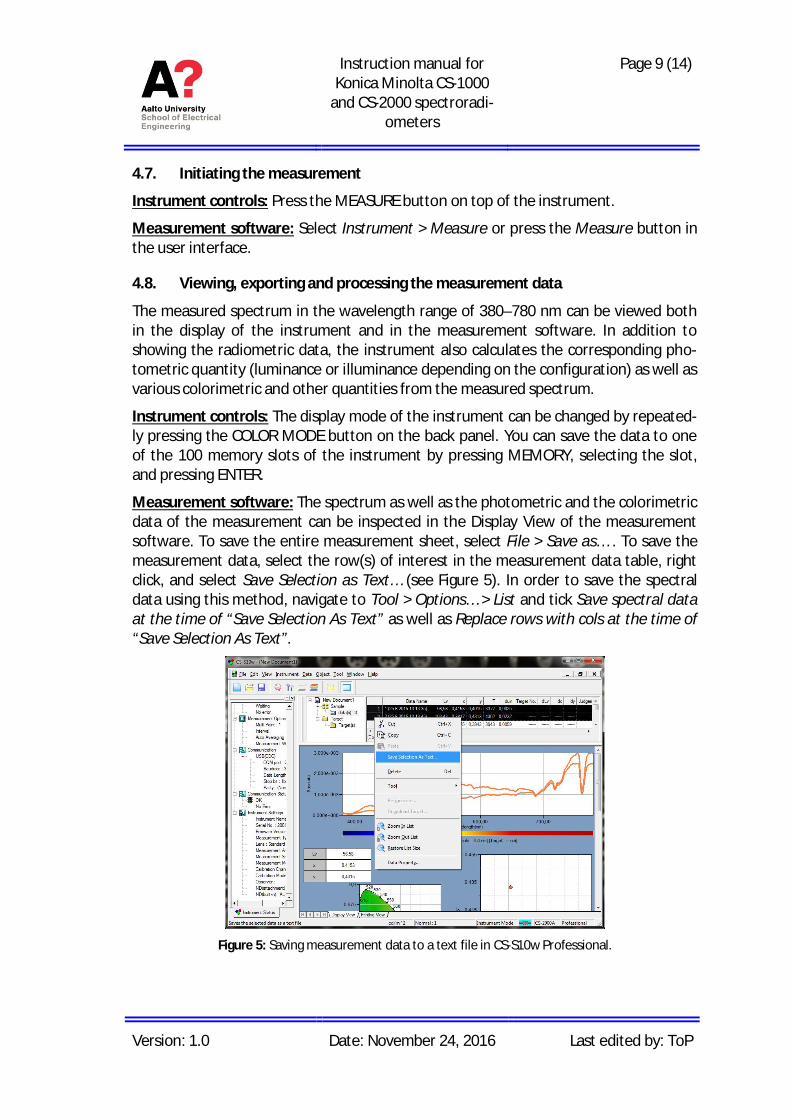
Measurement software: The spectrum as well as the photometric and the colorimetricdata of the measurement can be inspected in the Display View of the measurementsoftware. To save the entire measurement sheet, select File > Save as… . To save themeasurement data, select the row(s) of interest in the measurement data table, rightclick, and select Save Selection as Text… (see Figure 5). In order to save the spectraldata using this method, navigate to Tool > Options… > List and tick Save spectral dataat the time of “Save Selection As Text” as well as Replace rows with cols at the time of“Save Selection As Text”.
Figure 5: Saving measurement data to a text file in CS-S10w Professional.

Instruction manual forKonica Minolta CS-1000
and CS-2000 spectroradi-ometers
Page 10 (14)
Version: 1.0 Date: November 24, 2016 Last edited by: ToP
5. Calibration instructions
This section provides instructions on how to calibrate the instrument using CS-S10wProfessional software. For instructions on how to initiate the software, refer to Sec-tion 4.2. More detailed instructions on the software side of instrument calibration canbe found in [2]. General instructions on irradiance and radiance calibrations can befound in [4] and [5], respectively.
The instrument has a permanent factory calibration (calibration channel 00) and addi-tional 10 slots for user calibrations (channels 01 to 10). New calibration data should bestored in first empty calibration channel of the instrument, in order to make checkingfor the stability of the calibration easier. Once all the calibration channels have beenfilled, the calibration channel containing the oldest calibration data should be over-written first.
The calibration utility can be accessed by navigating to Instrument > User Calibration…in CS-S10w Professional software. If the calibration channel needs to be overwritten,select the channel and press Clear. The name of the channel can be set by pressing theEdit ID… button.
Note: The format of the name of the calibration data should be TYPMM-YYYY, whereTYP is the type of calibration (RAD for radiance/luminance calibration and DIF for irra-diance/luminance calibration), and MM and YYYY are the month and year of the cali-bration.
Each calibration channel comprises both the wavelength and the level calibration data.If both calibrations are to be carried out, the wavelength calibration has to be per-formed before the level calibration. It is also possible to skip the wavelength calibra-tion and only carry out the level calibration. If necessary, the wavelength scale of theinstrument can then be corrected afterwards by manipulating the measured spectrum.
5.1. Wavelength calibration
The wavelength calibration of the instrument is carried out using a source with narrowintensity peaks whose wavelength is well-known. These sources include gas dischargelamps, such as mercury-vapor (Hg) lamp, as well as various lasers in the visible wave-length range. When possible, the wavelength scale should be calibrated at severalwavelengths over the wavelength range of the instrument 380-780 nm. Note: TheFWHM bandwidth of the instrument is about 5 nm which means that closely spacedintensity peaks of some gas discharge lamps cannot be used in the wavelength calibra-tion.
The wavelength calibration is initiated by pressing the Wave Cal… button in the UserCalibration window of the measurement software. Wavelength Calibration window(see Figure 6) should open. With the instrument pointing at the source, press Measure.Isolate the intensity peak whose wavelength is well known, by adjusting the Wave-length Range settings, and pressing Zoom. When Add button is pressed, the utility cal-
Instruction manual forKonica Minolta CS-1000
and CS-2000 spectroradi-ometers
Page 11 (14)
Version: 1.0 Date: November 24, 2016 Last edited by: ToP
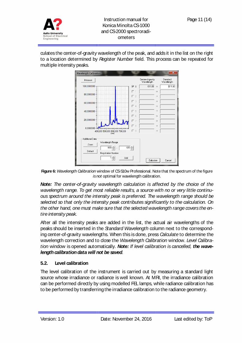
culates the center-of-gravity wavelength of the peak, and adds it in the list on the rightto a location determined by Register Number field. This process can be repeated formultiple intensity peaks.
Figure 6: Wavelength Calibration window of CS-S10w Professional. Note that the spectrum of the figureis not optimal for wavelength calibration.
Note: The center-of-gravity wavelength calculation is affected by the choice of thewavelength range. To get most reliable results, a source with no or very little continu-ous spectrum around the intensity peak is preferred. The wavelength range should beselected so that only the intensity peak contributes significantly to the calculation. Onthe other hand, one must make sure that the selected wavelength range covers the en-tire intensity peak.
After all the intensity peaks are added in the list, the actual air wavelengths of thepeaks should be inserted in the Standard Wavelength column next to the correspond-ing center-of-gravity wavelengths. When this is done, press Calculate to determine thewavelength correction and to close the Wavelength Calibration window. Level Calibra-tion window is opened automatically. Note: If level calibration is cancelled, the wave-length calibration data will not be saved.
5.2. Level calibration
The level calibration of the instrument is carried out by measuring a standard lightsource whose irradiance or radiance is well known. At MRI, the irradiance calibrationcan be performed directly by using modelled FEL lamps, while radiance calibration hasto be performed by transferring the irradiance calibration to the radiance geometry.
Instruction manual forKonica Minolta CS-1000
and CS-2000 spectroradi-ometers
Page 12 (14)
Version: 1.0 Date: November 24, 2016 Last edited by: ToP
5.2.1. Irradiance mode
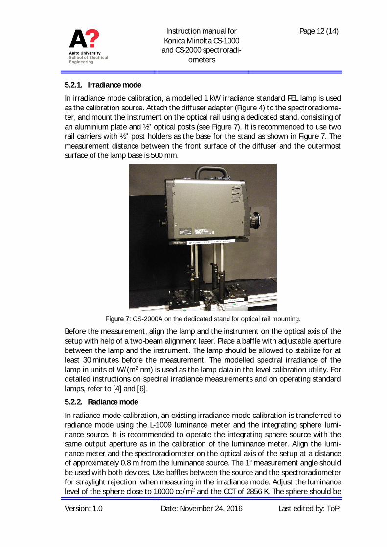
In irradiance mode calibration, a modelled 1 kW irradiance standard FEL lamp is usedas the calibration source. Attach the diffuser adapter (Figure 4) to the spectroradiome-ter, and mount the instrument on the optical rail using a dedicated stand, consisting ofan aluminium plate and ½” optical posts (see Figure 7). It is recommended to use tworail carriers with ½” post holders as the base for the stand as shown in Figure 7. Themeasurement distance between the front surface of the diffuser and the outermostsurface of the lamp base is 500 mm.
Figure 7: CS-2000A on the dedicated stand for optical rail mounting.
Before the measurement, align the lamp and the instrument on the optical axis of thesetup with help of a two-beam alignment laser. Place a baffle with adjustable aperturebetween the lamp and the instrument. The lamp should be allowed to stabilize for atleast 30 minutes before the measurement. The modelled spectral irradiance of thelamp in units of W/(m2 nm) is used as the lamp data in the level calibration utility. Fordetailed instructions on spectral irradiance measurements and on operating standardlamps, refer to [4] and [6].
5.2.2. Radiance mode
In radiance mode calibration, an existing irradiance mode calibration is transferred toradiance mode using the L-1009 luminance meter and the integrating sphere lumi-nance source. It is recommended to operate the integrating sphere source with thesame output aperture as in the calibration of the luminance meter. Align the lumi-nance meter and the spectroradiometer on the optical axis of the setup at a distanceof approximately 0.8 m from the luminance source. The 1° measurement angle shouldbe used with both devices. Use baffles between the source and the spectroradiometerfor straylight rejection, when measuring in the irradiance mode. Adjust the luminancelevel of the sphere close to 10000 cd/m2 and the CCT of 2856 K. The sphere should be
Instruction manual forKonica Minolta CS-1000
and CS-2000 spectroradi-ometers
Page 13 (14)
Version: 1.0 Date: November 24, 2016 Last edited by: ToP
allowed to stabilize for at least 1 hour before the measurements. For detailed instruc-tions on how to operate the combined luminance and radiance setup, refer to the in-struction manual [5].
Measure the luminance of the sphere output using the luminance meter with the 1°measurement angle. After that, measure the relative spectral irradiance using thespectroradiometer with the diffuser adapter. Note: Before the measurement, makesure that the latest irradiance calibration file is selected in CS-2000A, as described inSection 4.4.
Next, calculate the spectral radiance Le(λ) of the source based on the measured spec-tral irradiance Ee(λ) and luminance Lv as
)()()(
)( enm780
nm380em
ve l
llll E
dVEK
LL
ò=
where V(λ) is the luminous efficiency function, Km = 683.002 lm/W is the maximum lu-minous efficacy of photopic vision, and λ is the wavelength in standard air. Save thecalculated spectral radiance to a text file in units of W/(m2 nm sr). For detailed expla-nation of the calculation refer to Section 3.2 in [5].
Finally, remove the diffuser and focus the spectroradiometer to the center of the aper-ture plane of the sphere using the 1° measurement angle. Launch the level calibrationutility and use the previously generated radiance text file as the lamp data.
5.2.3. Using the level calibration utility
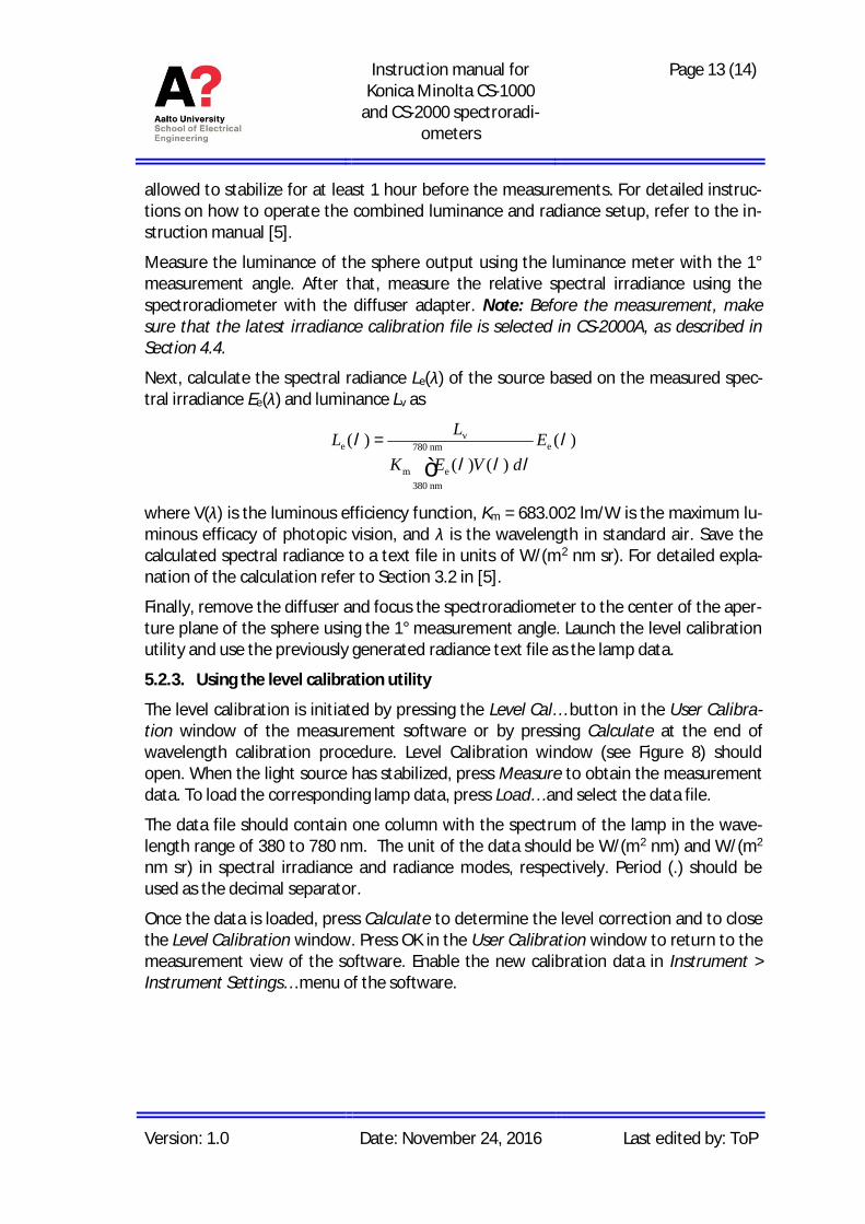
The level calibration is initiated by pressing the Level Cal… button in the User Calibra-tion window of the measurement software or by pressing Calculate at the end ofwavelength calibration procedure. Level Calibration window (see Figure 8) shouldopen. When the light source has stabilized, press Measure to obtain the measurementdata. To load the corresponding lamp data, press Load… and select the data file.
The data file should contain one column with the spectrum of the lamp in the wave-length range of 380 to 780 nm. The unit of the data should be W/(m2 nm) and W/(m2
nm sr) in spectral irradiance and radiance modes, respectively. Period (.) should beused as the decimal separator.
Once the data is loaded, press Calculate to determine the level correction and to closethe Level Calibration window. Press OK in the User Calibration window to return to themeasurement view of the software. Enable the new calibration data in Instrument >Instrument Settings… menu of the software.
Instruction manual forKonica Minolta CS-1000
and CS-2000 spectroradi-ometers
Page 14 (14)
Version: 1.0 Date: November 24, 2016 Last edited by: ToP
Figure 8: Level Calibration window of CS-S10w Professional. Note that the spectrum of the figure is forillustration purposes only.
References
1. Konica Minolta “Spectroradiometer CS-2000/CS-2000A,” Instruction manual.
2. Konica Minolta “Data Management Software CS-S10w Professional,” Instructionmanual.
3. Konica Minolta “Data Management Software CS-S10w Professional,” Installationguide.
4. Quality Manual of Spectral Irradiance Measurements.
5. Instruction Manual of Luminance and Spectral Radiance Calibrations.
6. Instruction Manual of Operating Standard Lamps.
Related Documents