A WORLD OF COMFORT DE EN INSTALLATION INSTRUCTIONS EASYSTART CALL VEHICLE HEATERS | TECHNICAL DOCUMENTATION TELEPHONE REMOTE CONTROL FOR EBERSPäCHER PARKING HEATERS

Welcome message from author
This document is posted to help you gain knowledge. Please leave a comment to let me know what you think about it! Share it to your friends and learn new things together.
Transcript

A W O R L D O F C O M F O R T
DEEN
InsTALLATIOn InsTRuCTIOns
EAsysTART CALL
V E h i c l E h E at E r s | T E C h n I C A L D O C u M E n TAT I O n
TELEphOnE REMOTE COnTROL FOR EbERspäChER pARkIng hEATERs
2 | VEhICLE hEATERs – TEChnICAL DOCuMEnTATIOn
COnTEnTs
ChApTER TITLE COnTEnT pAgE
1 InTRODuCTIOn please read first 4
general information 4
safety information 5
purpose 5
statutory regulations 5
– Approval 5
Technical data 7
2 InsTALLATIOn
InsTRuCTIOns before installing 8
– Information on usable sIM cards 8
prepare the sIM card 8
– prepare the sIM card with a mobile telephone 8
– Change the pIn of Easystart Call to the sIM pIn of the sIM card with the EDiTh basic diagnostic tool 9
notes on operation with a prepaid card 9
– Charging the prepaid card 9
Installation 10
– Insert the sIM card into the gsM MODuLE. 10
– Install gsM module 10
– Install antenna 11
– Install button 11
– Connect the “button” cable loom to the 12-pin connector 12
– Connect the “Control” cable loom to the 9-pin connector 12
– Connect the “Room temperature sensor” cable loom to the 12-pin connector 12
VEhICLE hEATERs – TEChnICAL DOCuMEnTATIOn | 3
3 InITIAL sTART-up Configure Easystart Call 13
– Configure the Easystart Call with the EDiTh diagnostic tool (version s4V1-F) 13
– Configure the Easystart Call with a mobile phone 13
– Display / delete current error, error memory 16
– pre-adjustments for the customer 17
– set the day of the week and the time 19
After configuration 20
4 nOTEs notes 21
notes on smartphone apps 21
5 DIAgnOsIs Diagnosis 22
6 CIRCuIT DIAgRAM Circuit diagram for connecting to the hydronic and hydronic II 24
Circuit diagram for the connecting to the hydronic II C 25
Circuit diagram for connecting to the hydronic M II 26
Circuit diagram for connecting to the Airtronic / Airtronic M / Airtronic L 27
COnTEnTs
4 | VEhICLE hEATERs – TEChnICAL DOCuMEnTATIOn
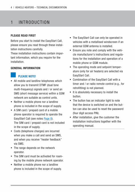
PlEasE rEaD first
before you start to install the Easystart Call, please ensure you read through these instal-lation instructions carefully.These installation instructions contain impor-tant information, which you require for the installation.
GENEral iNformatioN
PlEasE NotE!
� All mobile and landline telephones which allow you to transmit DTMF (dual tone multi-frequency) signals and / or send an sMs (short message service) within a gsM network are suitable as control units.
� neither a mobile phone nor a landline phone is included in the scope of supply.
� A sIM card / prepaid card of a mobile phone operator is required to operate the Easystart Call (see notes page 8). The sIM card / prepaid card is not included in the scope of supply.
� Costs (telephone charges) are incurred when you make a call and send an sMs, and when you receive “heater feedback” via sMs.
� The range depends on the network operator.
� The sIM card must be activated for roam-ing by the mobile phone network operator.
� neither a mobile phone nor a landline phone is included in the scope of supply.
1 InTRODuCTIOn
� The Easystart Call can only be operated in vehicles with a metallised windscreen if an external gsM antenna is installed.
� Ensure you note and comply with the vehi-cle manufacturer's instructions and regula-tions for the installation and operation of a mobile phone or gsM module.
� The operating mode and setpoint temper-ature (only for air heaters) are selected via Easystart Call.
� Combination of the Easystart Call with a timer and / or radio remote control (e.g., for retrofitting) is not planned.
� It is absolutely necessary to install the button.
� The button has an indicator light to note that the device is switched on and the but-ton can also be used to reset the password (four digit access pIn).
� After installation, give the customer the installation instructions together with the operating manual.
VEhICLE hEATERs – TEChnICAL DOCuMEnTATIOn | 5
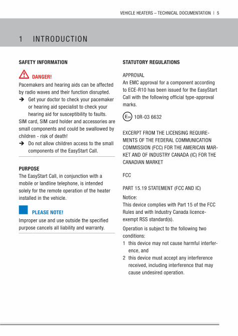
safEty iNformatioN
DaNGEr!
pacemakers and hearing aids can be affected by radio waves and their function disrupted.
Î get your doctor to check your pacemaker or hearing aid specialist to check your hearing aid for susceptibility to faults.
sIM card, sIM card holder and accessories are small components and could be swallowed by children - risk of death!
Î Do not allow children access to the small components of the Easystart Call.
PurPosEThe Easystart Call, in conjunction with a mobile or landline telephone, is intended solely for the remote operation of the heater installed in the vehicle.
PlEasE NotE!
Improper use and use outside the specified purpose cancels all liability and warranty.
1 InTRODuCTIOn
statutory rEGulatioNs
AppROVALAn EMC approval for a component according to ECE-R10 has been issued for the Easystart Call with the following official type-approval marks.
10R-03 6632
ExCERpT FROM ThE LICEnsIng REquIRE-MEnTs OF ThE FEDERAL COMMunICATIOn COMMIssIOn (FCC) FOR ThE AMERICAn MAR-kET AnD OF InDusTRy CAnADA (IC) FOR ThE CAnADIAn MARkET
FCC
pART 15.19 sTATEMEnT (FCC AnD IC)
notice:This device complies with part 15 of the FCC Rules and with Industry Canada licence-exempt Rss standard(s).
Operation is subject to the following two conditions:1 this device may not cause harmful interfer-
ence, and 2 this device must accept any interference
received, including interference that may cause undesired operation.
6 | VEhICLE hEATERs – TEChnICAL DOCuMEnTATIOn
1 InTRODuCTIOn
pART 15.21 sTATEMEnT
notice:Changes or modifications made to this equip-ment not expressly approved by Teltronic Ag may void the FCC authorization to operate this equipment.
pART 15.105 sTATEMEnT
note: This equipment has been tested and found to comply with the limits for a Class b digital device, pursuant to part 15 of the FCC Rules. These limits are designed to provide reason-able protection against harmful interference in a residential installation. This equipment gen-erates, uses and can radiate radio frequency energy and, if not installed and used in accordance with the instructions, may cause harmful interference to radio communications. however, there is no guarantee that interfer-ence will not occur in a particular installation. If this equipment does cause harmful interfer-ence to radio or television reception, which can be determined by turning the equipment off and on, the user is encouraged to try to correct the interference by one or more of the following measures: � Reorient or relocate the receiving antenna. � Increase the separation between the equip-
ment and receiver. � Connect the equipment into an outlet on
a circuit different from that to which the receiver is connected.
� Consult the dealer or an experienced radio/TV technician for help.
IC
notice: This Class b digital apparatus complies with Canadian ICEs-003.
RF ExpOsuRE InFORMATIOn ACCORDIng 2.1091 / 2.1093 / OET buLLETIn 65
Radiofrequency radiation exposure Informa-tion:This equipment complies with FCC radiation exposure limits set forth for an uncontrolled environment. This equipment should be installed and operated with minimum distance of 20 cm between the radiator and your body.This transmitter must not be co-located or operating in conjunction with any other antenna or transmitter.
VEhICLE hEATERs – TEChnICAL DOCuMEnTATIOn | 7
tEchNical Data
Operating voltage 9 – 32 volt
Closed-circuit power consumption 0.005 A
Current consumptionData transfer and connection to the gsM network
max. 0.5 A
Input voltage max. 32 volt
permissible ambient temperature (without sIM card*) – 40 °C to +85 °C
storage temperature (without sIM card) – 40 °C to 85 °C
gsM quad band EgsM 850/900/1800/1900 Mhz
Transmit power Class 4 (2W) @ 850/900 MhzClass 1 (1W) @ 1800/1900 Mhz
Dimensions (without mounting straps) W: 77 mm, h: 106 mm, D: 25 mm
* Mind the permissible ambient temperature of the sIM card.
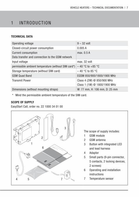
scoPE of suPPlyEasystart Call, order no. 22 1000 34 01 00
1
2
3
4 5
6
7
The scope of supply includes:1 gsM module2 gsM antenna3 button with integrated LED
and lead harness4 Adapter5 small parts (9-pin connector,
5 contacts, 2 locking devices, 2 screws)
6 Operating and installation instructions
7 Temperature sensor
1 InTRODuCTIOn
8 | VEhICLE hEATERs – TEChnICAL DOCuMEnTATIOn
2 InsTALLATIOn InsTR uCTIOns
PrEParE thE sim carD
before the sIM card is inserted into the gsM module, it must be prepared by a mobile telephone or the EDiTh basic diagnostic tool (order no. 22 1541 89 00 00) for it to operate with the Easystart Call.
pREpARE ThE sIM CARD WITh A MObILE TELEphOnE
Insert the sIM card into a mobile phone and activate according to the instructions of the mobile phone network operator.
Additional settings required: � Deactivate the sIM pIn query � If the sIM pIn cannot be deactivated, it
must be changed to 1865.
PlEasE NotE!
� If the mobile phone is blocked for other mobile phone network operators by a sIM lock, the purchased sIM card must be acti-vated using a mobile phone without sIM lock.
� If you are using a prepaid card, please be sure that the card has sufficient credit.
� The sIM card should be activated with a mobile phone approx. 24 hours before installation into the Easystart Call.
BEforE iNstalliNG
InFORMATIOn On usAbLE sIM CARDs
The Easystart Call can be operated with a 1.8 V or 3 V sIM card of a mobile phone network operator which supports the mobile phone standard gsM quad band - EgsM 850/900/1800/1900 Mhz mobile phone standard.
cautioN!
� When Easystart Call is placed into opera-tion, all data on the sIM card are deleted.
� When selecting a sIM card make sure that you choose a gsM sIM card and not a uMTs sIM card (usIM).
PlEasE NotE!
� When signing a contract with a mobile phone network operator, ensure that the pIn query of the sIM card can be deactivated.
� The accessibility of the Easystart Call depends on the relevant mobile phone net-work operator.
� If using previously used sIM cards, delete all data from the card first, such as phone numbers, sMs, photos, etc.
� Roaming must be activated for the sIM card.
VEhICLE hEATERs – TEChnICAL DOCuMEnTATIOn | 9
ChAngE ThE pIn OF EAsysTART CALL TO ThE sIM pIn OF ThE sIM CARD WITh ThE EDITh bAsIC DIAgnOsTIC TOOL
� Connect the gsM module without the sIM card to the EDiTh basic diagnostic tool using an adapter cable.
� Connect the gsM module to the power supply.
� start the EDiTh software on the pC. � select Easystart Call in the window “heat-
ers and testing selection”. Then select “Configuration” in the testing rubric, enter the 4-digit pIn for the sIM card and save it in the Easystart Call.
� Return the gsM module to a currentless state.
� Insert the sIM card into the gsM module (see page 10).
� Reconnect the gsM module to the power supply and proceed with the configuration as described from page 14.
PlEasE NotE!
The sIM pIn query cannot be deactivated with the EDiTh software.
NotEs oN oPEratioN with a PrEPaiD carD
If a prepaid card is used, note the term (valid-ity period of the card units). If the prepaid card has expired, the Easystart Call cannot be operated.
please ask your mobile phone network opera-tor how often you need to charge your pre-paid card to prevent it from being deactivated.
ChARgIng ThE pREpAID CARD
To charge the pre-paid card, remove it from the Easystart Call and proceed as follows: � Disconnect the gsM module from the
power supply (Remove the 12-pin con-nector).
� Remove the prepaid card from the Easystart Call, see page 10.
� Load units onto the prepaid card using a mobile phone according to the conditions of the mobile phone network operator.
2 InsTALLATIOn InsTR uCTIOns
10 | VEhICLE hEATERs – TEChnICAL DOCuMEnTATIOn
2 InsTALLATIOn InsTR uCTIOns
iNstallatioN
cautioN!
Do not insert the sIM card into the sIM card holder or remove it while a voltage is applied to the gsM module.This can cause damage to the sIM card or gsM module.
Î Disconnect the gsM module from the voltage supply!
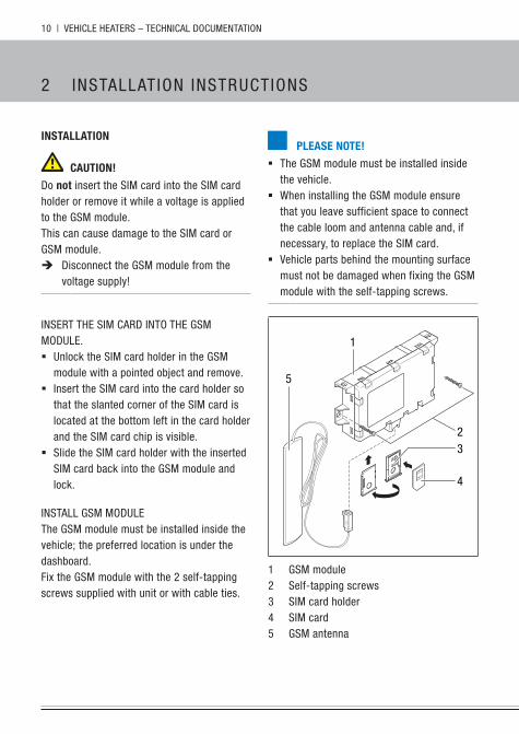
InsERT ThE sIM CARD InTO ThE gsM MODuLE. � unlock the sIM card holder in the gsM
module with a pointed object and remove. � Insert the sIM card into the card holder so
that the slanted corner of the sIM card is located at the bottom left in the card holder and the sIM card chip is visible.
� slide the sIM card holder with the inserted sIM card back into the gsM module and lock.
InsTALL gsM MODuLEThe gsM module must be installed inside the vehicle; the preferred location is under the dashboard.Fix the gsM module with the 2 self-tapping screws supplied with unit or with cable ties.
PlEasE NotE!
� The gsM module must be installed inside the vehicle.
� When installing the gsM module ensure that you leave sufficient space to connect the cable loom and antenna cable and, if necessary, to replace the sIM card.
� Vehicle parts behind the mounting surface must not be damaged when fixing the gsM module with the self-tapping screws.
3
4
2
5
1
1 gsM module2 self-tapping screws3 sIM card holder4 sIM card5 gsM antenna

VEhICLE hEATERs – TEChnICAL DOCuMEnTATIOn | 11
InsTALL AnTEnnA
The antenna must be fixed to the front wind-screen, however, never fix it in the tinted area or on the heating wires of the wind-screen heating or the wires of the windscreen antenna. � Thoroughly clean the windscreen with a
cleaning cloth. � pull off the protective film on the antenna
and stick the antenna onto the screen. � Lay the antenna cable to the gsM module
and connect it.
PlEasE NotE!
� Do not shorten or bend the antenna cable. � When positioning the antenna, maintain
a minimum distance of 3 cm from metal parts.
InsTALL buTTOn
� The button included in the scope of supply must be installed. For this, drill an Ø 8 mm hole in an easily accessible location that the driver can reach, e.g., in the dashboard or in the centre console.
� Insert the button in the Ø 8 mm hole.
PlEasE NotE!
If necessary, discuss the possible mounting position with the vehicle owner.
48 mm
1
3
5
6
2
7
1 button with cable loom2 12-pin connector3 9-pin connector4 gsM module5 9-pin connector, yellow6 “Control” cable loom7 Temperature sensor
2 InsTALLATIOn InsTR uCTIOns
12 | VEhICLE hEATERs – TEChnICAL DOCuMEnTATIOn
2 InsTALLATIOn InsTR uCTIOns
COnnECT ThE “buTTOn” CAbLE LOOM TO ThE 12-pIn COnnECTOR
� Clip the 3 connectors of the “button” cable loom into the 12-pin connector housing of the adapter cable as described in the following:
– Cable br/ge in chamber 7 – Cable rt/ge in chamber 6 – Cable br in chamber 8.
� Then secure the connectors in the connec-tor housing with the locking device.
� Connect the 12-pin connector housing of the adapter cable to the gsM module.
COnnECT ThE “COnTROL” CAbLE LOOM TO ThE 9-pIn COnnECTOR
� Crimp 3 connectors to the “Control” cable loom (of the heater cable harness) and clip it into the 9-pin connector housing received in the scope of delivery as described in the following:
– Cable rt in chamber 1 – Cable br in chamber 3 – Cable bl/ws in chamber 5
� Then secure the connectors in the connec-tor housing with the locking device.
� Connect the 9-pin connector to the adapter cable.
PlEasE NotE!
note and follow the circuit diagrams from page 27.
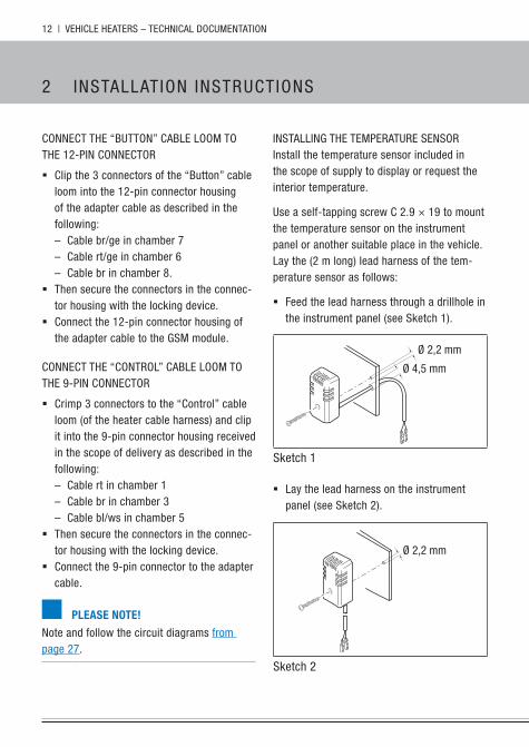
InsTALLIng ThE TEMpERATuRE sEnsORInstall the temperature sensor included in the scope of supply to display or request the interior temperature.
use a self-tapping screw C 2.9 × 19 to mount the temperature sensor on the instrument panel or another suitable place in the vehicle.Lay the (2 m long) lead harness of the tem-perature sensor as follows:
� Feed the lead harness through a drillhole in the instrument panel (see sketch 1).
Ø 2,2 mm
Ø 4,5 mm
sketch 1
� Lay the lead harness on the instrument panel (see sketch 2).
Ø 2,2 mm
sketch 2
VEhICLE hEATERs – TEChnICAL DOCuMEnTATIOn | 13
PlEasE NotE!
� Do not mount the temperature sensor near a hot air outlet.
� Do not mount the temperature sensor in the hot air stream.
� Mount the temperature sensor in a place protected from draughts.
� Mount the temperature sensor in a place protected from direct sunshine.
COnnECT ThE “TEMpERATuRE sEnsOR” CAbLE LOOM TO ThE 12-pIn COnnECTOR
� Clip the temperature sensor into the 12-pin connector housing of the adapter cable as described in the following:
– Cable br in chamber 9 – Cable ws in chamber 10.
� Then secure the connectors in the connec-tor housing with the locking device.
� Connect the 12-pin connector housing of the adapter cable to the gsM module.
2 InsTALLATIOn InsTR uCTIOns
14 | VEhICLE hEATERs – TEChnICAL DOCuMEnTATIOn
3 In IT IAL sTART-up
PlEasE NotE!
� If the call number, which the Easystart Call calls, is authorised, the password (four digit access pIn) 1234 does not need to precede the input command.
� A space must be entered between the input commands to separate them.
� If the Easystart Call is not configured, then the factory settings apply:
– Language English (En) – Duration 30 minutes – Temperature 21 °C.
see also page 16 “Revert to factory settings”
� both upper and lower case letters are accepted.
� The Easystart Call can determine the cur-rent time automatically if the provider sup-ports this function; see page 21.
� The day of the week and the time must be reset after every interruption of the power supply.
� you must manually change the time from summer time to winter time and vice versa.
coNfiGurE Easystart call
The configuration of the Easystart Call can be carried out with the EDiTh basic diagnos-tic tool (order no. 22 1541 89 00 00) and an adapter cable (order no. 22 1000 34 11 00) or with a mobile telephone via sMs.
COnFIguRE ThE EAsysTART CALL WITh ThE EDITh DIAgnOsTIC TOOL (version s4V1-F)
After the sIM card has been inserted into the gsM module and the voltage supply has been established and after the gsM module has connected to the network, the configuration can be carried out.The functions available for selection are dis-played on the pC and are identical to those for configuration via sMs (see from page 15).
COnFIguRE ThE EAsysTART CALL WITh A MObILE phOnE
After inserting the sIM card and installing the gsM module, you must establish the power supply by inserting the fuse (2.7.1 in the heater circuit diagram) in the fuse bracket.
select the desired function from the ones listed (see from page 15) and send the appropriate input command via sMs to the Easystart Call.
The Easystart Call can send an sMs back as confirmation. “heater feedback” must be activated; see page 18.
VEhICLE hEATERs – TEChnICAL DOCuMEnTATIOn | 15
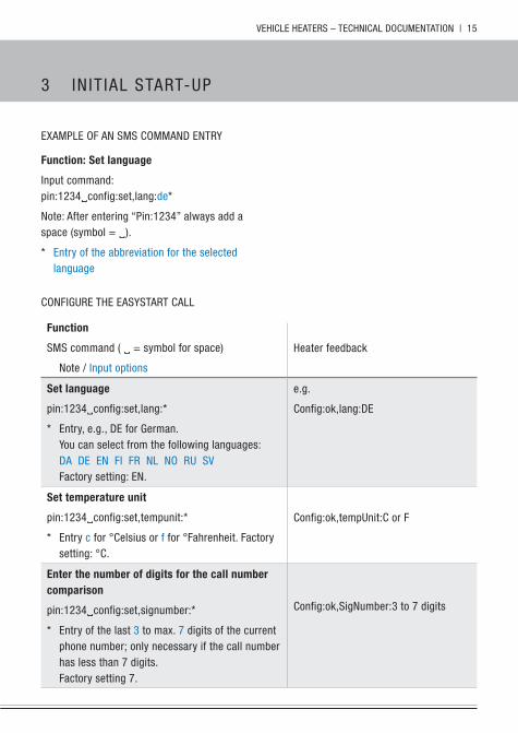
ExAMpLE OF An sMs COMMAnD EnTRy
function: set language
Input command:pin:1234config:set,lang:de*
note: After entering “pin:1234” always add a space (symbol = ).
* Entry of the abbreviation for the selected language
COnFIguRE ThE EAsysTART CALL
function
sMs command ( = symbol for space)
note / Input options
heater feedback
set language
pin:1234config:set,lang:*
* Entry, e.g., DE for german. you can select from the following languages:DA DE En FI FR nL nO Ru sVFactory setting: En.
e.g.
Config:ok,lang:DE
set temperature unit
pin:1234config:set,tempunit:*
* Entry c for °Celsius or f for °Fahrenheit. Factory setting: °C.
Config:ok,tempunit:C or F
Enter the number of digits for the call number comparison
pin:1234config:set,signumber:*
* Entry of the last 3 to max. 7 digits of the current phone number; only necessary if the call number has less than 7 digits.Factory setting 7.
Config:ok,signumber:3 to 7 digits
3 In IT IAL sTART-up
16 | VEhICLE hEATERs – TEChnICAL DOCuMEnTATIOn
3 In IT IAL sTART-up
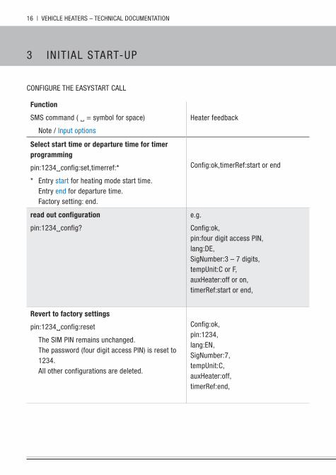
COnFIguRE ThE EAsysTART CALL
function
sMs command ( = symbol for space)
note / Input options
heater feedback
select start time or departure time for timer programming
pin:1234config:set,timerref:*
* Entry start for heating mode start time.Entry end for departure time.Factory setting: end.
Config:ok,timerRef:start or end
read out configuration
pin:1234config?
e.g.
Config:ok,pin:four digit access pIn,lang:DE,signumber:3 – 7 digits,tempunit:C or F,auxheater:off or on,timerRef:start or end,
revert to factory settings
pin:1234config:reset
The sIM pIn remains unchanged. The password (four digit access pIn) is reset to 1234.All other configurations are deleted.
Config:ok,pin:1234,lang:En,signumber:7,tempunit:C,auxheater:off,timerRef:end,
VEhICLE hEATERs – TEChnICAL DOCuMEnTATIOn | 17
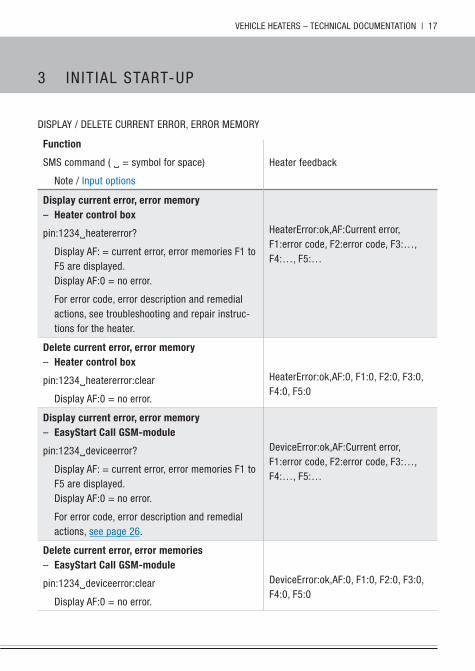
DIspLAy / DELETE CuRREnT ERROR, ERROR MEMORy
function
sMs command ( = symbol for space)
note / Input options
heater feedback
Display current error, error memory – heater control box
pin:1234heatererror?
Display AF: = current error, error memories F1 to F5 are displayed.Display AF:0 = no error.
For error code, error description and remedial actions, see troubleshooting and repair instruc-tions for the heater.
heaterError:ok,AF:Current error, F1:error code, F2:error code, F3:…, F4:…, F5:…
Delete current error, error memory – heater control box
pin:1234heatererror:clear
Display AF:0 = no error.
heaterError:ok,AF:0, F1:0, F2:0, F3:0, F4:0, F5:0
Display current error, error memory – Easystart call Gsm-module
pin:1234deviceerror?
Display AF: = current error, error memories F1 to F5 are displayed.Display AF:0 = no error.
For error code, error description and remedial actions, see page 26.
DeviceError:ok,AF:Current error, F1:error code, F2:error code, F3:…, F4:…, F5:…
Delete current error, error memories – Easystart call Gsm-module
pin:1234deviceerror:clear
Display AF:0 = no error.
DeviceError:ok,AF:0, F1:0, F2:0, F3:0, F4:0, F5:0
3 In IT IAL sTART-up
18 | VEhICLE hEATERs – TEChnICAL DOCuMEnTATIOn
3 In IT IAL sTART-up
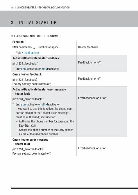
pRE-ADjusTMEnTs FOR ThE CusTOMER
function
sMs command ( = symbol for space)
note / Input options
heater feedback
activate/Deactivate heater feedback
pin:1234feedback:*
* Entry on (activate) or off (deactivate)
Feedback:on or off
Query heater feedback
pin:1234feedback?Factory setting: deactivated (off)
Feedback:on or off
activate/Deactivate heater error message– heater fault
pin:1234errorfeedback:*
* Entry on (activate) or off (deactivate). If you want to use this function, the phone num-ber for receipt of the “heater error message” must be authorised; see function:
– Authorise the phone number for operating the Easystart Call
– Accept the phone number of the sMs sender as the authorised phone number.
ErrorFeedback:on or off
Query heater error message– heater fault
pin:1234errorfeedback?Factory setting: deactivated (off)
ErrorFeedback:on or off
VEhICLE hEATERs – TEChnICAL DOCuMEnTATIOn | 19
function
sMs command ( = symbol for space)
note / Input options
heater feedback
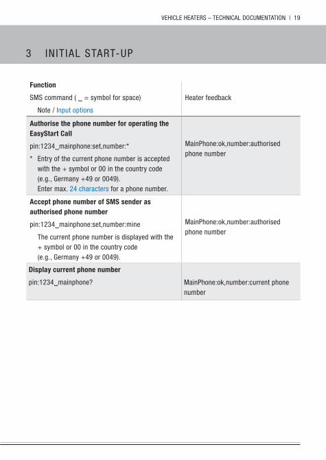
authorise the phone number for operating the Easystart call
pin:1234mainphone:set,number:*
* Entry of the current phone number is accepted with the + symbol or 00 in the country code (e.g., germany +49 or 0049).Enter max. 24 characters for a phone number.
Mainphone:ok,number:authorised phone number
accept phone number of sms sender as authorised phone number
pin:1234mainphone:set,number:mine
The current phone number is displayed with the + symbol or 00 in the country code (e.g., germany +49 or 0049).
Mainphone:ok,number:authorised phone number
Display current phone number
pin:1234mainphone? Mainphone:ok,number:current phone number
3 In IT IAL sTART-up
20 | VEhICLE hEATERs – TEChnICAL DOCuMEnTATIOn
3 In IT IAL sTART-up
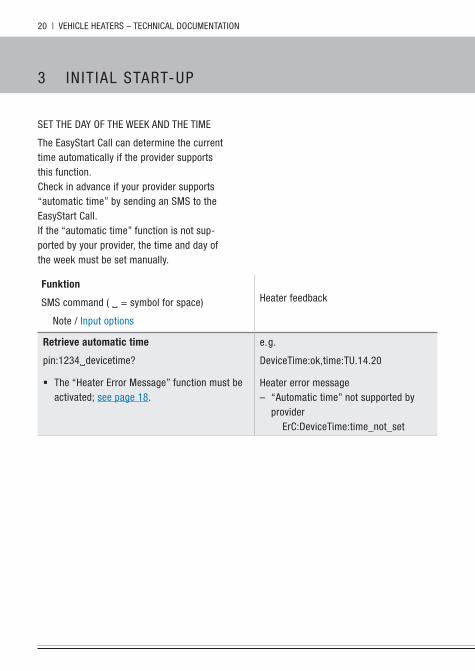
sET ThE DAy OF ThE WEEk AnD ThE TIME
The Easystart Call can determine the current time automatically if the provider supports this function.Check in advance if your provider supports “automatic time” by sending an sMs to the Easystart Call.If the “automatic time” function is not sup-ported by your provider, the time and day of the week must be set manually.
funktion
sMs command ( = symbol for space)
note / Input options
heater feedback
retrieve automatic time
pin:1234devicetime?
� The “heater Error Message” function must be activated; see page 18.
e. g.
DeviceTime:ok,time:Tu.14.20
heater error message – “Automatic time” not supported by
providerErC:DeviceTime:time_not_set
VEhICLE hEATERs – TEChnICAL DOCuMEnTATIOn | 21
function
sMs command ( = symbol for space)
note / Input options
heater feedback
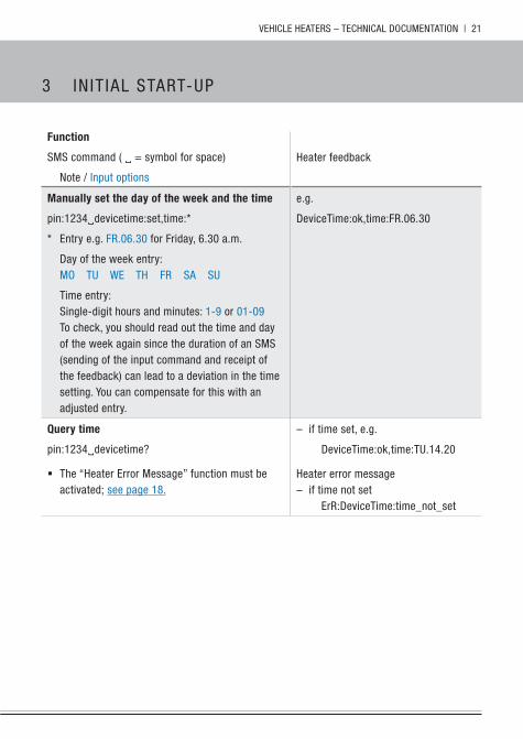
manually set the day of the week and the time
pin:1234devicetime:set,time:*
* Entry e.g. FR.06.30 for Friday, 6.30 a.m.
Day of the week entry:MO Tu WE Th FR sA su
Time entry:single-digit hours and minutes: 1-9 or 01-09To check, you should read out the time and day of the week again since the duration of an sMs (sending of the input command and receipt of the feedback) can lead to a deviation in the time setting. you can compensate for this with an adjusted entry.
e.g.
DeviceTime:ok,time:FR.06.30
Query time
pin:1234devicetime?
� The “heater Error Message” function must be activated; see page 18.
– if time set, e.g.
DeviceTime:ok,time:Tu.14.20
heater error message – if time not set
ErR:DeviceTime:time_not_set
3 In IT IAL sTART-up
22 | VEhICLE hEATERs – TEChnICAL DOCuMEnTATIOn
3 In IT IAL sTART-up
kOnFIguRATIOn AbFRAgEn / zuRüCksETzEn
function
sMs command ( = symbol for space)
note / Input options
heater feedback
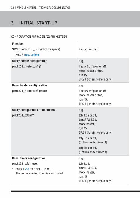
Query heater configuration
pin:1234heaterconfig?
e. g.
heaterConfig:on or off,mode:heater or fan,run:45,sp:24 (for air heaters only)
reset heater configuration
pin:1234heaterconfig:reset
e. g.
heaterConfig:on or off,mode:heater or fan,run:45,sp:24 (for air heaters only)
Query configuration of all timers
pin:1234tcfgall?
e. g.
tcfg1:on or off,time:FR.06.30,mode:heater,run:45sp:24 (for air heaters only)
tcfg2:on or off,(Options as for timer 1)
tcfg3:on or off,(Options as for timer 1)
reset timer configuration
pin:1234tcfg*:reset
* Entry 1 2 3 for timer 1, 2 or 3.The corresponding timer is deactivated.
e. g.
tcfg1:off,time:FR.06.30,mode:heater,run:45sp:24 (for air heaters only)
VEhICLE hEATERs – TEChnICAL DOCuMEnTATIOn | 23
3 In IT IAL sTART-up
function
sMs command ( = symbol for space)
note / Input options
heater feedback
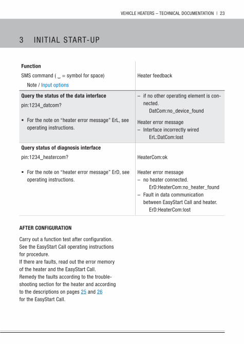
Query the status of the data interface
pin:1234datcom?
� For the note on “heater error message” ErL, see operating instructions.
– if no other operating element is con-nected.
DatCom:no_device_found
heater error message – Interface incorrectly wired
ErL:DatCom:lost
Query status of diagnosis interface
pin:1234heatercom?
� For the note on “heater error message” ErD, see operating instructions.
heaterCom:ok
heater error message – no heater connected.
ErD:heaterCom:no_heater_found – Fault in data communication
between Easystart Call and heater.ErD:heaterCom:lost
aftEr coNfiGuratioN
Carry out a function test after configuration.see the Easystart Call operating instructions for procedure.If there are faults, read out the error memory of the heater and the Easystart Call.Remedy the faults according to the trouble-shooting section for the heater and according to the descriptions on pages 25 and 26 for the Easystart Call.
24 | VEhICLE hEATERs – TEChnICAL DOCuMEnTATIOn
4 nOTEs
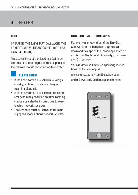
NotEs oN smartPhoNE aPPs
For even easier operation of the Easystart Call, we offer a smartphone app. you can download this app at the iphone App store or via google play for Android smartphones (ver-sion 2.3 or new).
you can download detailed operating instruc-tions for the new app at
www.eberspaecher-standheizungen.com
under Download / bedienungsanleitungen.
NotEs
OpERATIng ThE EAsysTART CALL ALOng ThE bOARDER AnD WhILE AbROAD (EuROpE, usA, CAnADA, RussIA).
The accessibility of the Easystart Call in bor-der areas and in foreign countries depends on the relevant mobile phone network operator.
PlEasE NotE!
� If the Easystart Call is called in a foreign country, additional costs are charged (roaming charges).
� If the Easystart Call is called in the border area with a neighbouring country, roaming charges can also be incurred due to over-lapping network coverage.
� The sIM card must be activated for roam-ing by the mobile phone network operator.
VEhICLE hEATERs – TEChnICAL DOCuMEnTATIOn | 25
5 D IAgnOsIs
DiaGNosisThe Easystart Call has a diagnostic function. If errors occur, they are stored and can be read out as needed with the EDiTh basic diagnostic tool in conjunction with the EDiTh software (version s4V1-F or newer). The adapter cable (order no.: 22 1000 34 11 00) is also required.
PErform thE DiaGNosisseparate the Easystart Call / heater cable loom interface, connect the EDiTh basic diag-nostic tool with the adapter cable and start the diagnosis.
thE followiNG actioNs arE PossiBlE: � Read out the current error and the error
memory for the Easystart Call and for the heater.
� Delete the error memory for the Easystart Call and for the heater.
� query software version. � query hardware version. � query the operating hours of the heater. � Carry out, read out and change the configu-
ration of the Easystart Call. � Revert to factory settings for the Easystart
Call.
PlEasE NotE!
The error memory can only be read out with the EDiTh diagnostic tool (version s4V1-F or newer).
26 | VEhICLE hEATERs – TEChnICAL DOCuMEnTATIOn
5 D IAgnOsIs
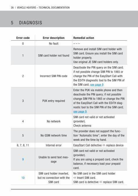
Error code Error description remedial action
0 no fault – – –
1 sIM card holder not found
Remove and install sIM card holder with sIM card. Ensure you install the sIM card holder properly.use original jE sIM card holders only.
2 Incorrect sIM pIn code
Deactivate the pIn query on the sIM card; if not possible change sIM pIn to 1865 or change the pIn of the Easystart Call with the EDiTh diagnostic tool to the sIM pIn of the sIM card; see page 9
3 puk entry required
Enter the puk via mobile phone and then deactivate the pIn query; if not possible change sIM pIn to 1865 or change the pIn of the Easystart Call with the EDiTh diag-nostic tool to the sIM pIn of the sIM card; see page 9.
4 no networksIM card not valid or not activated (provider).Check antenna
5 no gsM network timeThe provider does not support the func-tion “Automatic time”; enter the day of the week and the time by hand.
6, 7, 8, 11 Internal error Easystart Call defective replace device
9unable to send text mes-
sage
sIM card not valid or not activated (provider).If you are using a prepaid card, check the balance, if necessary load your prepaid card.
10sIM card holder inserted,
but no connection with the sIM card
no sIM card in the sIM card holder Insert sIM card.sIM card is defective replace sIM card.
VEhICLE hEATERs – TEChnICAL DOCuMEnTATIOn | 27
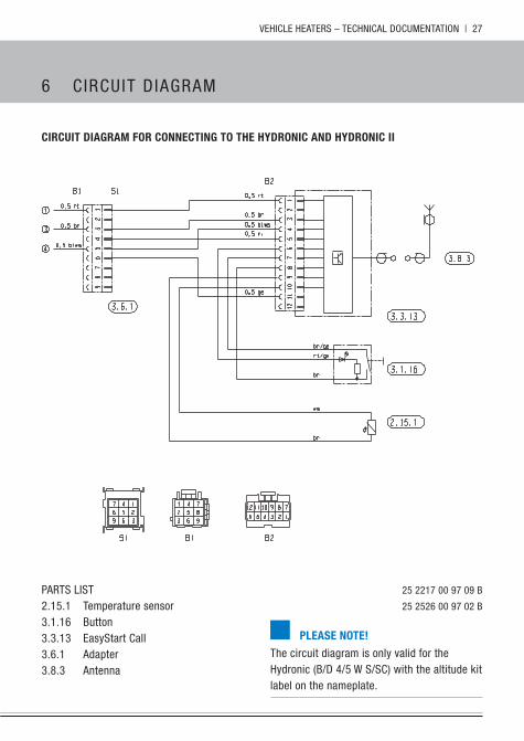
circuit DiaGram for coNNEctiNG to thE hyDroNic aND hyDroNic ii
pARTs LIsT 25 2217 00 97 09 b
2.15.1 Temperature sensor 25 2526 00 97 02 b
3.1.16 button3.3.13 Easystart Call3.6.1 Adapter3.8.3 Antenna
6 C IRCuIT D IAgRAM
PlEasE NotE!
The circuit diagram is only valid for the hydronic (b/D 4/5 W s/sC) with the altitude kit label on the nameplate.
28 | VEhICLE hEATERs – TEChnICAL DOCuMEnTATIOn
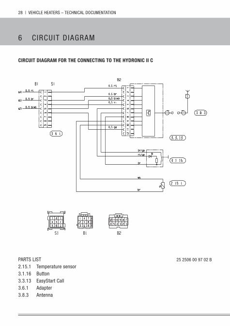
circuit DiaGram for thE coNNEctiNG to thE hyDroNic ii c
pARTs LIsT 25 2506 00 97 02 b
2.15.1 Temperature sensor3.1.16 button3.3.13 Easystart Call3.6.1 Adapter3.8.3 Antenna
6 C IRCuIT D IAgRAM
VEhICLE hEATERs – TEChnICAL DOCuMEnTATIOn | 29
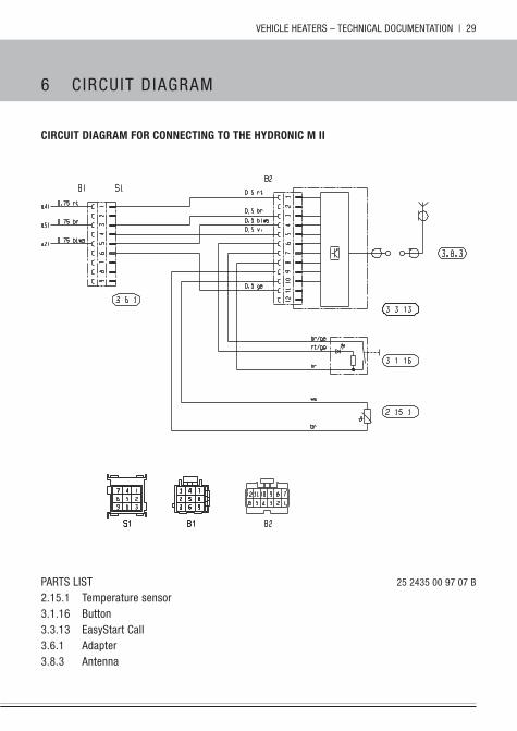
circuit DiaGram for coNNEctiNG to thE hyDroNic m ii
pARTs LIsT 25 2435 00 97 07 b
2.15.1 Temperature sensor3.1.16 button3.3.13 Easystart Call3.6.1 Adapter3.8.3 Antenna
6 C IRCuIT D IAgRAM
30 | VEhICLE hEATERs – TEChnICAL DOCuMEnTATIOn
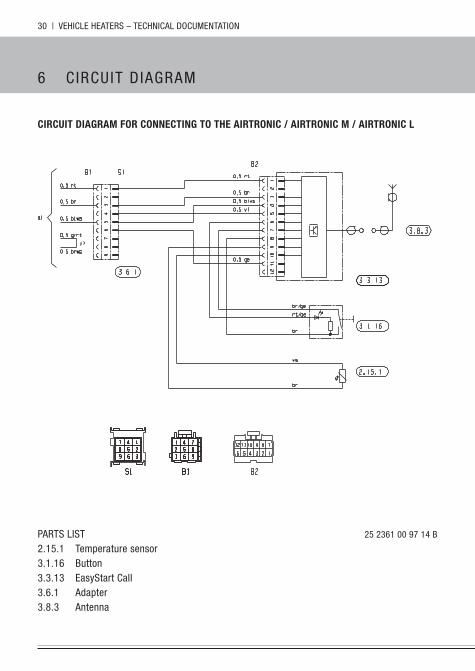
circuit DiaGram for coNNEctiNG to thE airtroNic / airtroNic m / airtroNic l
pARTs LIsT 25 2361 00 97 14 b
2.15.1 Temperature sensor3.1.16 button3.3.13 Easystart Call3.6.1 Adapter3.8.3 Antenna
6 C IRCuIT D IAgRAM


headquarters:
j. Eberspächer gmbh & Co. kg
Eberspächerstraße 24
73730 Esslingen
hotline: 0800 1234300
Fax hotline: 01805 262624
www.eberspaecher.com 22 1
000
34 0
1 04
En
08.2
012
su
bjec
t to
chan
ge w
ithou
t not
ice
©
j. E
bers
päch
er g
mbh
& C
o. k
g
prin
ted
in g
erm
any
Related Documents