September 2018 Installation Best Practices Guide – Residential Portfolios Developed by the SEIA Quality Assurance Working Group www.seia.org

Welcome message from author
This document is posted to help you gain knowledge. Please leave a comment to let me know what you think about it! Share it to your friends and learn new things together.
Transcript
September 2018
Installation Best Practices Guide – Residential Portfolios Developed by the SEIA Quality Assurance Working Group
www.seia.org

Installation Best Practices – Residential Portfolios 2 | www.seia.org
Background The Solar Quality Assurance Working Group (QAWG) seeks to evaluate, develop and encourage adoption of industry best practices in solar asset design, production estimate, installation, commissioning and O&M, and contractor qualification. The QAWG represents a wide variety of solar industry stakeholders.
The following document was designed to update installation best practices originally developed by the Solar Access to Public Capital (SAPC) working group organized by the National Renewable Energy Laboratory, and is intended to be updated as proper protocol dictates.
The primary intention of this document is to provide recommended best practices to facilitate high-quality and consistent residential solar projects. The broader objective in developing and maintaining this document is to build confidence among potential solar customers, regulators, investors, rating agencies, and other stakeholders in the concept that residential solar systems are a valuable home improvement, a consistent and long-term electric generating resource, and credit-worthy investment asset class.
Contributors As a follow-up to the 2015 National Renewable Energy Laboratory (NREL) published “Best Practices for PV System Installation” under the Solar Access to Public Capital (SAPC) initiative, the Solar Energy Industries Association (SEIA) member-based Quality Assurance Working Group convened industry members to review and update the original best practices guide. SEIA’s Quality Assurance Working Group was formed to bring together industry experts and colleagues to identify opportunities for improved processes and activities in the solar finance and associated quality and standards spaces. The working group is co-chaired by Christopher Doyle of SiteCapture and Richard Lawrence of IBTS; staff leads from SEIA include Evelyn Butler, Amir Yazdi, and Michael Mendelsohn (now with Solar Finance Council).
We are grateful and appreciative of the work and effort contributed by members of the working group and additional industry colleagues in the update of this document. A consensus approach was utilized to develop the information and approaches included herein. The working group included the following section leads:
Co-Chairs: Christopher Doyle, SiteCapture and Richard Lawrence, IBTS
Contractor Qualifications: Mike Ricci, CTEC Solar
Design & Installations Best Practices: Brendan Smith and Cody Oram, Vivint Solar
Finance Provider Best Practices: Aidan Foley, BlueWave Solar
References & Resources: Rudy Saporite, IBTS
Additional key contributors included: ● Andrew Truitt of Distributed Resource Ventures ● Nick Korth and Todd Fries of HellermanTyton ● Sumanth Lokanath and Sandra Laird of First Solar ● Milton Nogueira of Roof Tech Inc.

Installation Best Practices – Residential Portfolios 3 | www.seia.org
● John Reiser of Sherwin-Williams ● Michael Jimenez of REC Solar ● Justin Sherman and Raymond Szylko of Omnidian ● Brian Vickers of Renewable Projects LLC ● Jeff Wang of : Stäubli Electrical Connectors ● Jason S. Trager, Ph.D. of Sustainabilist ● Doug Jones of TerraGen Solar ● David Compaan and James Cormican of RBI Solar
SEIA would also like to recognize and thank the following industry colleagues who contributed to the review and content of the document.
Shawn Shaw and Matt Piantedosi of The Cadmus Group
Market Actors and Role Definitions The solar financing marketplace can be complex and involve multiple parties in transactions related to residential solar installations. For the purposes of this document, the following roles are defined:
Investor The investor originates funds to underwrite portfolios of residential PV installations. They generally have little day to day involvement in managing the portfolio but may have particular due diligence requirements that would apply during transactions, such as purchasing a portfolio of solar loans or leases.
Finance Provider A Finance Provider will take funds and originate loans, leases, or other financing products that are executed with host customers (i.e., homeowners). While the Finance Provider may have a role in managing PV installations, they more typically will work with contractors who handle day to day customer interaction and installation activities until the PV system is operating.
Contractor Contractors (also referred to as Installers) will typically have the physical resources (e.g., staff, equipment, licensing) to complete PV installations. These installations may be completed by Contractor staff and/or using subcontractors (including electricians, laborers, roofers, and other tradespeople) and the Contractor will bear responsibility for the PV installations, including holding relevant warranties and agreements with the Finance Provider to install and maintain the PV systems. The subcontractor individuals will not generally have direct contact with Financing Providers or Investors.
Though this list is not exhaustive and many variations exist, these groups represent the major general categories that will be addressed in this document.
Authority Having Jurisdiction (AHJ) As defined in the 2014 NFPA 70: National Electrical Code, “An organization, office, or individual responsible for enforcing the requirements of a code or standard, or for approving equipment, materials, an installation, or a procedure.” This is typically a local (e.g., town, city or county) authority responsible for the permitting and approval of solar PV installations. Examples of

Installation Best Practices – Residential Portfolios 4 | www.seia.org
these individuals include electrical and / or building inspectors, fire marshals, and/or local utility representatives.
Contractor Qualifications This section documents the requirements that should be met by a Contractor for a Finance Provider to provide system financing.
Work History The Contractor shall have a work performance experience that demonstrates its ability to install safe and reliable solar PV systems. The Contractor should provide the number of systems and total kW installed for each year of the past 3 years of experience to demonstrate transparency regarding work experience. The Contractor can demonstrate required experience through one of the following:
• 3 years of company work experience installing residential solar PV systems or • 5 years of personnel work experience installing residential solar PV systems (in a
leadership role in both former and current company)
If a Contractor does not have applicable experience above, it is recommended that they demonstrate additional measures to ensure they are capable to install safe and reliable solar PV systems. Suggestions on additional qualification include:
• Complete third-party quality assurance inspections for no less than ten percent (10%) of projects completed in the last six (6) months with a minimum of eighty percent (80%) passing score,
• Site Supervisor complete OSHA 10-hour safety course and 40 hours of solar PV technical course training
Financial Transparency Contractor shall provide documentation that communicates their financial solvency. Documents should be kept on file by the Finance Provider. Sample documents include:
• Two years of financial statements (income statement and balance sheet, audited preferred)
• Last three (3) months of bank statements • Supplier references with credit terms provided • Bonding Letter with bonding capacity listed • Scoring from a well-regarded third-party credit risk assessment entity may be required
by some financiers. Others may require specific financial metrics are met regarding cash liquidity and other facets of financial stability.
The purpose of these references is to demonstrate that the installation Contractor is/was not in financial distress at the time of installation. Installation Contractor financial distress could have a negative impact on the level of system quality and bankability of warranties and other representations made by the Contractor to the Homeowner (consumer).
Health and Safety A Contractor should create and maintain a health and safety manual which establishes appropriate rules and procedures concerning workplace safety, including rules related to: the

Installation Best Practices – Residential Portfolios5 | www.seia.org
reporting of health and safety problems, injuries, and unsafe conditions; risk assessment; and first aid and emergency response.
Some examples of typical rules and procedures follow below:
• Contractor Site Supervisor completed a minimum of Occupational Safety and HealthAdministration (OSHA) 30-hour Construction Industry training, and all site personnelcompleted a minimum of OSHA 10-hour Construction Industry training
• Additional training should be supplemented to provide sufficient knowledge forinstallers to identify hazards, provide corrective actions, and prevent reoccurrencespecific to solar PV systems
• All site personnel should be equipped with complete personal protective equipment(PPE) and trained on any specific hazards associated with their jobs (should bemandatory)
• Contractor Site Supervisor completed a Job Hazard Analysis (JHA) Contractor SiteSupervisor completed a jobsite orientation with all workers onsite
• The Contractor should maintain an OSHA total case incident rate (TCIR) of 5.001 or less ora similar rate based on a substantially equivalent, accepted measure used to reportworkplace injuries.
• Contractor shall maintain a company published IIPP manual and conduct regularlyscheduled training to all operations impacting employees.
Insurance A Contractor should maintain current and appropriate business insurances, including liability insurance, workers’ compensation insurance, and commercial vehicle insurance. This requirement outlines basic standards for worksite safety to mitigate construction risk and potential liability during the construction phase.
• General liability - $1,000,000 per occurrence, $2,000,000 aggregate• Workers’ compensation - $1,000,000 each accident, each employee, policy limit• Automobile Liability: bodily injury, death, and property damage combined single limits
of at least $1,000,000 per occurrence covering vehicles owned, hired, or non-owned• Consider adding an Excess/Umbrella insurance component with limits ranging from
$2MM to $5MM for typical Contractors and typical projects.• If Contractor is also designing the system, Professional Liability of $1MM and up
(depends on size of engagement and size of the Contractor)• If the contractor is storing confidential customer data, it should procure Cyber Liability
insurance• Insurance policies should name the Finance Provider and any intermediaries as
additional insured(s) and certificate holder(s). Additionally:• Subrogation should be waived• Notice of cancellation to additional insured should be required• Contractor’s policies should be primary to and not require contribution from any other
applicable coverages.
1 Per NABCEP http://www.nabcep.org/accredited; http://www.nabcep.org/wp-content/uploads/2012/04/nabcep_handbook_final.pdf

Installation Best Practices – Residential Portfolios6 | www.seia.org
Personnel Qualifications The Contractor Site Supervisor or designated responsible party should have one of the following professional certifications:
• North American Board of Certified Energy Practitioners (NABCEP) Certified PVInstallation Professional
• Professional or Licensed electrician (master or journeyman as applicable by state)
Some Contractors may have proprietary training and education programs that are more specific to the job duties performed by their personnel, which may meet or exceed training and experience requirements for the certifications above.
Additional certifications that installation personnel may hold to ensure a high level of quality workmanship and safety include:
• Roof Integrated Solar Energy (RISE), Certified Solar Roofing Professional• Underwriters Laboratories (UL) Certified PV System Installer• NABCEP PV Associate Credential• Licensed electrician (apprentice)• Proprietary technology training offered by an original equipment manufacturer• Other NABCEP certifications PV Design Specialist, PV Installer Specialist, and PV
Commissioning and Maintenance Specialist
Trade License The Contractor should have all professional and trade licenses required by the state and local AHJ. Required solar PV licenses can be found through the Interstate Renewable Energy Council’s (IREC) Solar Licensing Database. All updated trade licenses shall be stored electronically by Contractor and Finance Provider.
Business License The Contractor should have all applicable business licenses required to sell and install residential solar PV in each state of current operation. These requirements will vary by state and may be different requirements to either sell or install solar PV. A Contractor should not have a Better Business Bureau rating of less than C. Better Business Bureau ratings explanation can be found at https://www.bbb.org/council/overview-of-bbb-grade
Program Requirements In some states, outside of professional license and business license requirements, the Contractor may need to be registered with or pre-approved by a state agency so that a consumer can participate in an incentive program or other renewable energy program. In these cases, the Contractor must maintain and be able to provide proof of good standing and eligibility to secure incentives under such programs if those incentives are included in the sale.
Design and Installation Best Practices
Site Data The Contractor is responsible for gathering relevant site-specific information such that the PV system designer can design a PV system appropriate for the application. The Contractor shall ensure that system design and production estimates are made using reliable data. A possible

Installation Best Practices – Residential Portfolios7 | www.seia.org
guide in gathering data is the NABCEP PV Installation Professional Resource Guide, which can be downloaded for free at http://www.nabcep.org/resources. The NABCEP Resource Guide which is available at no cost and addresses many of the key factors and current industry best practices regarding PV system design. Below are brief summaries of major design topics, with references to existing documentation that provide further detail. Relevant information from the following list should be noted on the construction plans submitted for permit application.
Array Location Structure Electric Equipment Locations
Roof-Mounted
● Building footprint● Age of roof covering (1)● Dimensions, pitch, and
azimuth orientation● Locally required minimum
roof setback dimensions fromridge, hips/valleys (2)
● Type of roof covering● Underlayment type and lap
dimensions● Roof condition assessment● Safety or liability
considerations● Tilt/Azimuth of roof planes
Ground-Mounted
● Soil type/condition● Accessibility to
unqualified persons● Ground slope suitable for
safe construction● Distance to property lines● Easements/wetlands
All Sites
● Obstructions and shading (3)
● Local design windspeed and exposure(and source of info)
● Local ground snowload (and source ofinfo)
● Design roof snowload
● Framing lumberdimensions
● Rafter or trussspacing
● Max. rafter span orlongest truss topchord panel lengthbetween struts
● Lumber species andgrade (4)
● Sheathing thicknessand type
● Type of service(overhead vs.underground)
● Location of servicedisconnect and/ormain service panel
● Size (in Amperes)and voltage ofservice
● Rating of serviceequipment(includingovercurrent device,enclosure, busbar,etc.).
● Service panel makeand model
● Availability ofbreaker spaces
● Meter locationrelative to home
● Existing PVequipment, cable,connectors, etc
● Inverter● Conduit● PV Modules● Service
Disconnect● Monitoring
equipment● Rapid
shutdowninitiationdevice
1. To avoid unnecessary cost to the Contractor or the homeowner, the roof covering shouldhave sufficient life remaining such that re-roofing is unlikely to be needed during thecontract term (if a TPO project), or during the payback period (if owned by the customer).Document any existing roof issues based on customer input.
2. From 2012 IFC or local AHJ.3. Vents, equipment, skylights, satellite dishes, snow guards, roof heaters, etc.4. Indicate whether identified in field or assumed.

Installation Best Practices – Residential Portfolios8 | www.seia.org
Solar Resource Measurement Both on-site (using an industry standard handheld tool) or remote (using software verified by a third-party to deliver results similar to a handheld device) shade analysis tools are acceptable. The pitch and azimuth orientation of each array section should be measured and recorded.
For on-site shade tools, multiple locations per array section shall be measured. The goal is to accurately capture the shading profile of each array section so that modules can be placed to minimize shading and so that shading can be accurately accounted for in energy production simulations. Examples of shade location policies include:
1) The shade measurement locations for each array section shall include at least theapproximate corner locations of the proposed array(s) and along long edges of the proposedarray(s), as needed, such that there is no more than 20 feet in between measurements along theedge;
2) If the approximate location of the array(s) is not known at the time of the shade survey, thenmeasurement locations shall be at the corners of the roof section setback regions and along longedges of the roof section set back regions, as needed, such that there is no more than 20 feet inbetween measurements along the edge. Problem areas, such as the north side of tallobstructions (e.g. chimneys), shall also be measured. Problem areas shall be measured at theapproximate point on the proposed array that is nearest the obstruction.
When calculating the Total Solar Resource Fraction (TSRF) or equivalent system-level metrics, each individual TSRF reading shall be weighted by the planned array capacity such that the overall TSRF represents a weighted average of all array planes included in the design.
Refer to NABCEP PV Installation Professional Resource Guide2 for further guidance on performing an accurate shade analysis.
Remote shade analysis tools are relatively new to the industry and should be verified by an objective 3rd party (e.g. NREL, Leidos, NYSERDA, MASSCEC) for accuracy. The resolution of shade measurements from a remote shade tool should be one (1) meter or less between readings. Data should be no more than three (3) years old to accurately account for tree growth and new construction. When the remote shade tool generates shade readings from a 3D CAD model, care shall be taken to accurately measure the height and shape of all obstructions that are less than a distance (D) from the nearest point of the proposed array where (D) equals 2 times the height of the obstruction above the array. The remote shade tool should provide monthly shade readings for each location on the roof.
Regardless of the shading tool used, the site assessor will provide a copy of a shading report to the system designer and ensure that a copy of all shading measurements and reports is securely stored with other project files.
Two primary sources of data are typically utilized, ground based and satellite measurements. The list below includes examples of some of the available solar resource and weather data. The geographic location used in the weather data should be reasonably proximate to, and relevant to the location of the proposed installation, and generally should be the closest available.
1. Ground Based measurements - TMY2 and TMY32. Satellite Based measurements - NREL NSRDB PSM model and Solar Anywhere
2 See Section 2.2.3

Installation Best Practices – Residential Portfolios9 | www.seia.org
Production and Savings Estimates The Contractor needs to substantiate and have a reasonable basis for their production estimate. A production estimate must use inputs consistent with the proposed system’s characteristics like weather data, shading, tilt and azimuth, and module performance degradation. The production estimate should list each month’s production for the first year of operation, total production for the first year of operation, and total production over the system’s life or contract term.
Like production estimates, savings estimates need to be substantiated and have a reasonable basis. For example, a Contractor should not use rules of thumb to estimate annual utility rate increases. Instead, they should use official sources, such as past utility rates or government publications, that reflect the customer’s utility and rate class. Also important is the need for the Contractor to explain assumptions used in the savings estimate, such as government incentives.
Estimating Tools Production modeling software is available to generate estimated monthly energy production for a proposed system design. There are several software options of varying complexity and detail that can be utilized to generate monthly production estimates. A detailed production estimate should produce monthly energy production estimates and account for the following factors:
• Accurate local historical or predicted weather data• Site-specific shading• Component hardware selection (inverter and modules)• Array orientation (azimuth and tilt)• Adjustable system derate and loss factors (wire loss, mismatch, soiling, etc.)
The info below is based on the standard breakdown of system loss sources available on the NREL PV Watts production estimator with typical ranges of each criteria.
Loss Source Typical Loss Value Typical Loss Range
Soiling (%) 2% 2% - 7%
Shading (%) 3% 0% - 20%
Snow (%) 0% 0% - 5%
Mismatch (%) 2% 0% - 3%
Wiring (%) 2% 1% - 4%
Connections (%) 0.5% 0.5% - 1%
Light-Induced Degradation (%) 1.5% 0% - 2%
Nameplate Rating (%) 1% 0% - 3%
Availability (%) 3% 0% - 3%
Contractors or third-party designers should document and disclose changes to the derate factors to the Contractor or Finance Provider.
System Design Contractors should ensure that system design and feasibility estimates are made using reliable data. NABCEP’s PV Installation Professional Resource Guide addresses many of the key factors

Installation Best Practices – Residential Portfolios10 | www.seia.org
and current industry best practices regarding PV system design and can be used as a resource. Below is a brief description of components of system design. System designs may vary in content, scope, and location depending on customer and local requirements. The Contractor is responsible for the PV system design (outsourcing is acceptable, provided the details of the design are confirmed onsite). Key factors of PV system design include:
• System design in accordance to state and local (AHJ) building and safety requirements• Accuracy of collected site data (e.g., roof dimensions and slope, existing electrical
equipment locations, shade analysis)• Proper application of applicable codes (e.g., National Electrical Code [NEC], International
Residential Code [IRC], International Fire Code [IFC], and International Building Code[IBC])
• Consideration of customer priorities (e.g., aesthetics, maximizing power production,offsetting electrical bills, equipment manufacturer preferences, equipment locationpreferences)
• Maximizing value of system to avoid expensive scopes of work that are proportionallyinefficient based on economics of the system owner (unless system owner specificallystates preference)
• Necessary information for applicable AHJs for procuring all permits and approvals,which could include:
o Site plano System Sizeo Electrical diagram (1- or 3-line)o Roofing system elevation drawing (including roof type and flashing/attachment)o Structural design inputs (e.g., design wind speed, and design snow load)o Foundation and support structure details (ground mount)o Electrical system details (e.g., interconnection method, conductor and OCPD
calculations, conductor and conduit sizes, grounding/bonding topology, andequipment ratings)
o Installation detail for mounting system stand-off and roof penetrationo Roof framing details (type of sheathing and thickness, i.e. OSB 7/16”, Ply ½”, etc.)
and design checks (e.g., span tables or calculations)o Equipment data sheets
• Necessary information for interconnection filing with utility, which could include:o Annual electrical consumptiono Single line diagram; although three-lines may be preferredo Equipment specificationso Site Plan
In regions prone to sliding snow and ice, consider using a module with an appropriate pressure rating and snow guards in specific areas where homeowners are at risk of snow/ice shedding. Examples of sensitive areas for hazards of sliding snow and ice include roofs over building entries, driveways, and decks. When installing arrays in high snow regions it is also important to follow the manufacturer instructions when mounting modules. For example, many manufacturers specify what parts of the module need to be supported in order to prevent the module from deflecting under heavy loads. Modules that flex or deflect under these loads can experience internal short circuits or fracture front glass, leading to water ingress or other damage to the module.

Installation Best Practices – Residential Portfolios 11 | www.seia.org
Equipment Requirements This section is focused on providing various industry standards to develop a minimum requirement for common components of a solar PV system. These are generally optional and not required by specific AHJ building or electrical code.
Reasonable expectations of component manufacturers:
• Manufacturer should remain willing to participate in third-party audits and provide third party warranties if required by the Contractor or Capital provider.
• Manufacturer should assist with reasonable return merchandise authorization (RMA) requests resulting from product deficiencies or degradation within warrantied timeline.
There are various quasi-public entity qualified equipment lists (modules and inverters) that are actively maintained as approved equipment for their respective solar programs. If the Contractor of Finance Provider does not have a robust equipment qualification expertise or resources, these lists should be referenced as source for bankable equipment:
● CA Energy Commission
● NYSERDA Approved Equipment List
Lists of equipment standards that can be used to assess the quality of solar PV components can be found below.
Equipment - Solar Photovoltaic Modules Baseline Requirements:
● UL 1703 Flat-Plate Photovoltaic Modules and Panels; UL 61730-1 and -2; for U.S. Market ● IEC 61730-1: 2016 - Photovoltaic (PV) module safety qualification - Part 1: Requirements
for construction; mainly for international markets ● IEC 61730-2: 2016 - Photovoltaic (PV) module safety qualification - Part 2: Requirements
for testing; mainly for international markets ● IEC 61215 or UL 61215 ZZ Crystalline Silicon Terrestrial PV Modules; mainly for
international markets ● IEC 61646 or UL 61646 Thin-Film Terrestrial PV Modules; mainly for international
markets ● ASTM E2481-06, Standard Test Method for Hot Spot Protection Testing of Photovoltaic
Modules ● Manufactured using an ISO-9001 quality management system ● Manufactured using an ISO-14001 Environmental Management System ● Pollution Degree requirements as included in UL / IEC 61730 standards ● If installed in Hazardous Locations as defined by 29 CFR 1926, complies with OSHA
1926.407 ● Modules are free from “Conflict Minerals” and avoid child labor ● Modules are certified by relevant state authorities / commissions to qualify for consumer
incentives (California Energy Commission, Florida Solar Energy Center, etc)
PV System accessories such as snow and animal guards may be utilized; these products may or may not be certified for safety or performance and may affect the performance of the system for wind, snow, mechanical and / or dynamic loading performance as well as an effect on the certification of the system and / or its components. Due diligence is highly recommended to assess these effects. Manufacturer’s warranties may be voided with the use of certain products as well.

Installation Best Practices – Residential Portfolios12 | www.seia.org
Equipment - Inverter Baseline Requirements:
● UL 1741 Inverters, Converters, Controllers and Interconnection System Equipment forUse with Distributed Energy Resources; UL 1741 SA (Supplement A) for advancedinverter functions; post-harmonization, UL 62108
● IEEE 1547 Standard for Interconnecting Distributed Resources with Electric PowerSystems
● IEEE 1547.1 Standard for Conformance Test Procedures for Equipment InterconnectingDistributed Resources with Electric Power Systems
● IEEE 2030.5 2018 Smart Energy Profile 2.0 for DER integration● Inverter installation requirements are governed by the National Electrical Code Articles
690 and 705, Part II lists requirements of Utility Interactive inverters, including circuitsizing and overcurrent protection; see relevant state adopted codes for appropriateversion in effect
● UL3003 listed Distributed Generation Cable● Manufactured using an ISO-9001 quality management system● Manufactured using an ISO-14001 Environmental Management System● Inverters are free from “Conflict Minerals” and avoid child labor● Inverters are certified by relevant state authorities / commissions for consumer
incentives (California Energy Commission, Florida Solar Energy Center, etc.)
Direct current arc fault protection is required for inverters in jurisdictions subject to NEC 2011 or beyond. In addition, various jurisdictions have inverter-specific requirements including:
● For systems connecting under the Customer Self Supply (CSS) tariff in HI, invertersshould be on the Qualified Equipment List
● Systems subject to Rule 21 in CA should provide certain smart inverter functions (e.g.voltage / frequency ride-through, volt / VAR control, energy storage dispatch) inaccordance with UL 1741 and IEEE 1547 updates which are being implemented inphases. IEEE 2030.5 defines the communications protocols and IEEE 1815 addressesdirect SCADA control and management.
Equipment - Disconnect Baseline Requirements
● A disconnect should be installed to isolate the PV system from the rest of a building’selectrical system for the purpose of safety during installation, maintenance, service, andfor first responders.
● AC disconnects should be located near the main utility interconnection for accessibility.● AC disconnects are required to have a visible-break and lockable per NEC 110.25.● PV disconnects should meet the requirements of NEC 690.17
Equipment - Conductor Type Baseline Requirements
● Conductor type/insulation should be suitable for the environment in which it is installedand compatible with the ratings of the PV system equipment and terminals.
● Wiring methods shall meet the specific requirements of NEC 690.31 and Chapter 3 in theNEC.
● UL3003 listed Distributed Generation Cable● For outdoor PV cable, tinned copper wire should be used. IEC-62852● PV connectors from different manufacturers should not be cross-mated. (connecting one
brand to another brand.) Cross-mating often voids warranties, violates installationinstructions.
● For connections on the supply (utility) side of the service disconnecting means, wiringmethods shall follow NEC 230.43.

Installation Best Practices – Residential Portfolios13 | www.seia.org
Equipment - Storage Baseline Requirements
The 2017 NEC has sound guidance for the installation of energy storage systems. These systems are now covered in Article 706. The informational note in 706.1 suggests utilizing the following standards for Energy Storage Systems, where applicable:
Design Standards
● NFPA 111-2013, Standard on Stored Electrical Energy Emergency and Standby PowerSystems, if applicable
● IEEE 484-2008, Recommended Practice for Installation Design and Installation of VentedLead-Acid Batteries for Stationary Applications
● IEEE 485-1997, Recommended Practice for Sizing Vented Lead-Acid Storage Batteries forStationary Applications
● IEEE 1187-2013, Recommended Practice for Installation Design and Installation of Valve-Regulated Lead-Acid Batteries for Stationary Applications
● IEEE 1578-2007, Recommended Practice for Stationary Battery Electrolyte SpillContainment and Management
● IEEE 1635/ASHRAE 21-2012, Guide for the Ventilation and Thermal Management ofBatteries for Stationary Applications
Product Safety Standards
● UL 9540, Safety of Energy Storage Systems and Equipment● UL 1989, Standard for Standby Batteries● UL Subject 2436, Spill Containment For Stationary Lead Acid Battery Systems
Equipment - Racking Baseline Requirements
● Grounding, Bonding, and Fire Testing.o UL 2703 - installation criteria for rack mounting PV systems and clamping
devices for flat-plate PV modules and panels that comply with UL 1703. Appliesto products installed on or integral with buildings, or for freestanding systems(i.e., not attached to buildings, ground mounted), in accordance with theNational Electrical Code, ANSI/NFPA 70, and Model Building Codes.
● Roof Connection Design.o EC 002-2016 – published by the International Association of Plumbing and
Mechanical Officials (IAPMO). EC-002 can be used to do an evaluation reporton the connectors only while AC428 would be used for the evaluation of metalmodular framing systems.
● Structural Design Requirements.o ASCE/SEI 7 – racking design shall consider all four directions of load: upward,
downward, down-slope, and cross-slope loading. At a minimum in the UnitedStates, the, Minimum Design Loads for Buildings and Other Structures, and AC428, Acceptance Criteria for Modular Framing Systems Used to Support PVModules, should be utilized to design the racking system. Additionalrequirements, such as those prescribed in the IRC, IBC, and SEAOC PV, shallalso be considered and utilized as required by the reviewing jurisdiction. TheNBC, National Building Code of Canada, and other applicable documents shallbe utilized for appropriate design in Canada.

Installation Best Practices – Residential Portfolios14 | www.seia.org
Equipment - Monitoring System Requirements
To support performance verification and O&M services, a monitoring system is highly recommended. This ensures the ability of a provider to proactively identify performance issues in a timely, effective manner. Key features of a residential PV monitoring system include:
● Listedo For field installed equipment, production metering devices shall be listed. Should
comply with relevant safety standard (e.g., UL 916, UL 2735 or as appropriate)● Reliable communications
o Cellular preferred, premises network acceptable but prone to issues● Labeling
o Identify and label solar monitoring devices/equipment for customers (ethernetcables, powerline adapters, range extenders) to avoid disconnections and 3rd party(internet service providers, cable company, etc.) interference.
● Remote data access functionalityo Established workflow to provide third-party users (such as installer, TPO firm,
bank investor) authorization to access system datao APIs available to access monitoring data
● Minimum Data Intervalso Performance data should be captured in a minimum of hourly intervals and
exported to the PV monitoring portal.o Historical performance data should be made immediately available on-line
● Accurate measurement of PV system power and energyo Revenue Grade (ANSI C12.20) accuracy preferred but not requiredo Some state programs may have specific accuracy requirements
● User-friendly customer-facing on-line interface, may be optionalo Mobile app, may be optional
● Flexible fleet management / O&M on-line interfaceo Should facilitate automated performance issue identification and fleet-wide
reporting● Additional measured data points of value:
o AC voltage, current and frequencyo DC (string or MPPT channel) voltage and currento Inverter fault-codeso Irradiance and temperature (cell and ambient)o Inverter internal temperatureo Cellular signal strengtho Irradiance as measured in w/m2
Monitoring and Metering Hardware
Metering hardware should meet the ANSI C12.20 standard for safety, design, and accuracy (either Class 0.5 or better, such as Class 0.2). This specification includes build and design standards for the hardware to withstand typical environmental conditions and accuracy standards that provide revenue-grade data that is suitable for billing and governmental reporting requirements. System data should be collected at a minimum interval of 15 minutes and should be reported daily to an offsite system. Onboard meter storage should be at a minimum of 30 calendar days with the capability to report the interval and accumulation data on a system request. Hardware should also have the ability to report, on event, disaster issues such as power supply loss or metering/system tampering.

Installation Best Practices – Residential Portfolios 15 | www.seia.org
Monitoring Hardware Communication
A typical setup has three distinct parts: the backhaul connection from the meter to the AMI (advanced metering infrastructure), the AMI head end itself, and an MDMS (meter data management system). The backhaul connection is IP-based communication over RF Mesh (ZigBee) or cellular (2G, 3G, 4G). In the solar market cellular is becoming the most common backhaul used. The AMI head end handles all remote commands sent to and received from the meter. This includes reading register and load profile data and energizing/de-energizing the remote disconnects, among others. The AMI head end is also responsible for reporting events such as power loss or tampering alarms. The MDMS is responsible for aggregating the information and interfacing with any line of business applications. Usually it is best for an established, reliable company to retain control of this infrastructure for the sake of business continuity. In some cases, if that business were to fail, it would mean no production data until a replacement AMI, backhaul, and MDMS could be built and deployed. In the case of cellular, it is important to develop protocols for the portability of cellular service and legal ownership of the cellular connection would also have to be established with the new company to enable the timely restoration before communications with a site could be restored.
It is preferred that the monitoring system be API compatible with SunSpec Alliance’s Best Practices in Solar Performance Monitoring guidelines and Data Structures conforming to the SunSpec Alliance Plant Extract Document to support compatibility of the system lifetime.
Equipment - Electrical Components Baseline Requirements
● National Electrical Code version as currently required in the installation locale ● IEC 62852 – UV exposure for connectors/cables ● IEC 62790 – UV exposure for junction boxes ● UL 1565 Wire Positioning Devices ● UL 2703 Mounting Systems and Supporting Device ● NEMA- and/or IP-rated enclosures ● Documentation (white papers) showing all applicable product “listings” (e.g. UL) should be made
available by manufacturer to be provided to AHJ upon request
Defined Installation Best Practices The following resources define solar PV installation best practices. Additionally, installations should be compliant with all state, utility, and local AHJ requirements, as well as equipment manufacturers’ installation requirements.
Installation - System Grounding and Bonding
● Proper grounding and bonding is an important safety element of an installed PV system. Grounding and bonding for PV systems is covered in NEC 690(V), along with many sections of Article 250. Article 690.35 allows ungrounded PV systems of compliant voltage, if conditions are met, particularly ground fault protection (see below). A grounding system consists of:
o Equipment-Grounding Conductors o Grounding-Electrode o Grounding-Electrode Conductor
● The purpose for the Equipment Grounding (EG) system is to ensure that there is no hazardous voltage between non-current carrying metal parts of a system and Earth (NEC 690.43). If a system is properly “earthed,” a barefoot person standing on the ground and touching any exposed metal surface of the system will not experience an electrical shock. Non-current carrying metallic equipment (both DC and AC) should be grounded per the

Installation Best Practices – Residential Portfolios16 | www.seia.org
requirements of the NEC 250 and equipment manufacturer. This includes metal raceways, enclosures, mounting hardware, module frames, conduit fittings, etc.
● If there is a Lightning Protection System (LPS) existing on the building, the Engineer ofrecord for the PV system should make a determination as to whether, and how, to bondthe array EG to the LPS main ground.
● It is essential that if a current-carrying conductor of a PV output circuit is grounded (a“grounded system”), that it be bonded to ground at only one point (as per NECrequirements).
● “Ungrounded” systems (commonly referenced as Functionally Grounded) do not have abonding connection between a current-carrying conductor of the PV output circuit andground. They are becoming increasingly common due to lower equipment costs andhigher efficiency. Note all equipment grounding and bonding requirements still apply.
Installation - Ground-fault Detection
A particular hazard still exists for systems using inverters with “fused” ground fault detector interrupter (GFDI) protection, which many string inverters still incorporate (see Solar ABC’s Ground Fault Detection Blind Spot for details). The situation of having a blown GFDI fuse, with no defined path for any fault current to earth, can have severe consequences for safety of personnel, structures, and equipment. The industry is gradually moving away from fused ground fault detectors, and toward differential (“residual”) current sensors that don’t open the path to earth (as with “ungrounded” inverters). The 2017 NEC required arc-fault detection and interruption protection for systems of 80Vdc or more.
Installation - Labeling Best Practices
Strict conformance to system marking (or labeling) requirements of PV systems and their components is crucial for the safety of operators, service personnel, emergency responders, and others. PV system general labeling requirements are covered in NEC 2017 690 Ch. VI, as well as specific accompanying requirements throughout Articles 690 and 705. Ideally, required and desired labeling language is included in the design drawings. Electrical equipment and components used in PV systems have markings identifying the manufacturer, size, type, ratings, hazard warnings, and other specifications. Equipment markings should never be removed, and equipment markings should be durable for the environment in which the equipment is installed per NEC 110.21. This is also referenced similarly in the IFC 2012 labeling requirements. It is recommended that the adhesives used in non-riveted labels meet the UL969 labeling standards. In addition, markings should be visible or easily accessible during and after installation.
Field-applied markings are required for certain components and for the inclusive PV system. These markings should be designed to withstand the environment in which they are installed (e.g., “UV rated” for outdoor labels (i.e. ANSI Z535 and NEC 110.21) and permanently affixed to the respective equipment in a manner appropriate for the environment and compatible with the substrate materials, while not obscuring manufacturer-applied labeling.
Field-applied markings are required on many types of equipment and components, and may include (but are not limited to):
● Conductors● Circuits● Connectors● Raceways/cables/conduits● Disconnecting means● Point of utility connection

Installation Best Practices – Residential Portfolios17 | www.seia.org
● Bi-polar arrays and ungrounded arrays● Battery storage systems● Standalone inverters providing a single 120-volt supply● Rapid shutdown equipment● Other marking as required by codes and local AHJ requirements.
Installation - Mechanical Components
Though a PV system’s purpose is electrical in nature, it is very important that the components are mechanically installed in a manner appropriate for the local environment. This holds true for all types of installations, but is particularly important for residential rooftop installations due to the load forces to which they may be exposed (e.g., wind and snow), and the potential damage to life or property that could occur if mechanical connections were to fail.
Applicable codes for the installation of mechanical components include:
● International Building Code (IBC)● International Residential Code (IRC)● International Fire Code (IFC)
Installation – Mounting/Racking Systems
PV modules are typically attached to roofs via purpose-built metal (usually aluminum) mounting systems. Module mounting systems should be certified (Listed) for the application and capable of withstanding the uplift (due to wind) and downward forces (e.g., snow-load) to which they could potentially be exposed based on the specific location of the installation.
Consider the following important items when installing the mounting system:
● Appropriate flashing and weather sealing of all penetrations of the building envelope,including conduit, lag bolts, screws for mounting equipment, and other types ofpenetrations
● codes guidelines on array setbacks (requirements vary based on roof design)● Lateral loads to which mounting system might be exposed (e.g. wind, seismic, and sliding
snow)● Compliance with local guidelines when navigating existing vents or equipment on the
roof● Comprehension of best practices for working with a given roof covering as per the
National Roofing Contractors Association Roofing Manual● A balance of customer aesthetics expectations with code requirements and airflow
directives from the module or racking manufacturer● Assessment of the roof structure (usually via attic or crawl space inspection) for lumber
type, dimension, and condition● Assessment of the condition of the roof covering. If the roof covering will need
replacement before the end of the expected PV system lifetime (20-25 years), thehomeowner should consider roof replacement prior to PV system installation. Thecontractor should notify the customer of any estimated re-racking costs if removing andinstalling new equipment for the PV system if required as part of the roof replacementprocess .
● Usage of the appropriate size and type of fasteners for the application, and achieving theproper embedment in the substrate
● Use of rigid flashing materials and/or sealants, with the recognition that these are twoseparate products that serve different functions based upon the PV system design.

Installation Best Practices – Residential Portfolios18 | www.seia.org
● Comprehension of the cause and effect of inter-row shading in tilted arrays, and beingable to identify when it may become an issue
● Comprehension of the span and cantilever limitations of the mounting system● Comprehension and achievement of all fastener torque specifications
For further information on PV mounting structure installation can be found in resources such as the NABCEP Resource Guide, Solar Energy International’s Solar Electric Handbook, and Jim Dunlop’s Photovoltaic Systems.
Installation - PV Modules
There are a variety of module construction types available today (e.g., metal-framed, frameless, building-integrated, “peel and stick”), but the majority of PV modules used in residential applications are aluminum-framed, poly- or mono-crystalline, glass-enclosed laminates. Regardless of construction type, care should be taken to comply with all manufacturers’ instructions concerning the transportation, storage, mounting, grounding, and connecting of the PV modules. Failure to do so could result in voiding of the module warranty, underproduction of the PV system over time, and increased shock- or fire-hazard risk.
Important items to consider when installing the PV modules include:
● Awareness of any specific mounting location stipulations from the modulemanufacturer, which may or may not vary based on the potential wind load at the site
● Understanding of the different module mounting options, such as bolting the moduleframe to the mounting structure or clamping the frame with the appropriate hardwareand compression force
● Appropriate use of fall protection equipment is particularly important during arrayinstallation because PV modules tend to be large and unwieldy, presenting elevated riskfor installer injury and to workers on the ground if any equipment is dropped. This riskis further exacerbated on steeper roofs
● Knowledge of electrical safety protocols, such as ensuring that homerun conductors arenot connected during installation to ensure the safety of any personnel wiring electricalequipment
● Understanding the module bonding requirements● Adjustment of rail spacing based on whether the modules are landscape or portrait,
considering the expected snow load● Ensuring wire management is completed in a neat and workmanlike manner using long-
lasting materials, such as stainless steel clips, to prevent conductors from contactingsharp edges or abrasive surfaces
● Minimizing the chance of module short circuits by maintaining clearance between themodule backsheet and protrusions such as bolts, screws, lay in lugs, or other hardwarethat could compress the module backsheet.
● Follow manufacturer requirements for clamp installation and spacing, including theminimum spacing between modules, minimum distance between end clamps and railends, and relevant torque specifications for mounting hardware.
Installation - Systems with Module-Level Power Electronics
For future O&M purposes, the serial numbers of module-level power electronics (e.g., power optimizers, microinverters) should be mapped during installation (e.g., Enphase installation Guide). There are numerous technology solutions to capturing equipment barcode information through mobile technology, such as SiteCapture.

Installation Best Practices – Residential Portfolios19 | www.seia.org
Installation - Waterproofing
Roof penetration baseline requirements:
● Weather Protection (IBC 2015 Section 1503.2)-Flashings should be installed in a mannerthat prevents moisture from entering penetrations through the roofing membrane.
● The IBC 2015 section 1510.7.3 code states that a roof top structure should be installedaccording to the manufacturer’s printed instructions.
● There are no standards or codes specific to the flashing of solar mounts. Since the codedoes not address it, a method that validates the flashing system is a Third PartyEvaluation Report for a specific manufactured product. National laboratories such asIAPMO, ICC ESR, UL, Intertek and other certification laboratories can design the testcriteria and certify a specific solar flashing product. Bases of recognition are IBC 2015Section 104.11 and IRC 2015 Section R104.11 for such conditions where the codes do notaddress the necessary requirements.
● Sealant should be applied to unflashed penetrations (e.g. equipment mounting screws) tokeep the moisture from entering the structure. A quality sealant with an appropriateservice temperature that is compatible with the substrate (roofing material) is required.
● In regions prone to sliding snow and ice modules should be rated for the design snow-load and snow guards should be installed in areas where homeowners are at risk ofsnow/ice shedding. Examples of sensitive areas for hazards of sliding snow and iceinclude roofs over building entries, driveways, and decks. Fully waterproof flashings arerecommended on ice dam prone areas.
Installation – PV Ground Mount (Pilings) Installation of Pilings in Corrosive Soils
● Soil testing shall be considered on a project by project basis and when it is known the soilto be corrosive or acidic. The American Galvanizers Association states – “ Galvanizedsteel performs best in solutions with a pH in the range of 5.5 to 12, pHs between 3 and 5(acidic or 12 and 13.5 (basic) are corrosive to galvanized steel, but the galvanized coatingwill still give corrosion protection to bare steel, although the protection will only last fora few years. If longer service life is desired, then a duplex system using an acid or baseresistant paint or epoxy over the galvanized coating is recommended” . Note: thegalvanizing process typically leaves 4.7 mils dft of zinc on the metal.
● Awareness of Corrosion Engineers who specialize in the field of soil testing can provideaccurate soil testing for the Owner to review.
● Understanding the availability of Ultra High Solids amine cured epoxies or hybridpolyurethanes are available from many manufacturers of protective coatings. This typeof coating technology has a low rate of moisture absorption through the coating film,ensuring the substrate has a barrier for isolating it from the corrosive serviceenvironment.
● Consideration for modifying base of piling to have a bevel edge, reducing potentialdamage to the coating during installation.
● Understanding the benefits of cathodic protection.
Interconnection Before a PV system is allowed to operate legally, the appropriate utility provider should approve the system for operation. Similar to PV permitting, PV interconnection requirements vary around the country, but are generally based on one or a combination of the following three major interconnection standards:

Installation Best Practices – Residential Portfolios20 | www.seia.org
● FERC’s Small Generator Interconnection Standards (SGIP)● California’s Rule 21● IREC’s Model Interconnection Standards
The interconnection of a distributed generation system, such as a PV system with the local utility, depends upon state regulations and utility policies and practices. Interconnection guidelines and state- and utility-specific rules can usually be accessed by installers through utility websites. Contractual aspects of interconnection include fees, metering requirements, billing arrangements, and size restrictions on the system. Understanding the local utility’s requirements is a very important process, and varies for each local utility. In addition, national and local codes have interconnection and system equipment and labeling requirements so that the system can be easily identified and/or shut off. For example, some states or utilities require an easily accessible external disconnect switch.
The NEC specifies how the output of a PV system can be connected to the utility in Article 705. The two relevant connections would be:
1. Supply side (similar to installing another service onsite and is usually found for largerinstallations) of the service disconnecting means.
2. Load side (most commonly used for smaller systems and requires a dedicated circuitbreaker or overcurrent device) of the service disconnecting means. Please note that loadside connection requirements can vary by AHJ. It is imperative to understand theserequirements to prevent complications during the final inspection.
Before investing in a solar PV system, the Contractor should apply for interconnection approval as early in the process as possible. This allows added costs or barriers to be factored into the decision to install at a particular location, as it can impact decisions about system design. With PV market penetration increasing, there are emerging issues around the need for transformer or other equipment upgrades on local circuits and the question of who is responsible for paying. These factors can change the economics of a project and should be identified as early as possible.
Further details on interconnection requirements can be found on the Database of State Incentives for Renewable Energy. Additional information on interconnection requirements can be found on the Freeing the Grid website.
System Documentation Contractors should store basic homeowner and system information for the term of the initial customer agreement. Data naming methodology should follow the Orange Button taxonomy.
Outlining the minimum documentation that should be provided for grid-tied residential PV systems will ensure transparency to investors of basic system components, information on design and installation, and O&M requirements. Additional data may be required by financiers, including consumer credit metrics and EPC cost, but are not included here for brevity.
Contractor shall maintain a photo inventory of all active systems. Photos may be captured through the installation Contractor, third-party inspector, or in-house personnel. A photo inventory allows the Contractor to have a strong understanding of onsite conditions and overall level of quality. It will also reduce O&M costs, and may even assist an AHJ during an inspection. Photos shall be stored through the life of the service contract and retrievable through customer/address query. Electronic capture and cataloguing of site information is preferred to ensure consistency and accuracy.
See Required Information Matrix located in References below.

Installation Best Practices – Residential Portfolios21 | www.seia.org
Nonpublic Personal Information Disclosure
As a best practice, Contractors should not collect, share or retain nonpublic personal information, unless they are prepared to meet the Gramm-Leach-Bliley Act (GLBA) and other federal and state consumer protection requirements. Examples include, but not limited to, social security number, birthday, income, and any documentation showing this information (driver’s license, utility bill, etc.). It is important to understand that complying with GLBA takes enterprise controls and compliance management capabilities, therefore, if the Contractor business is not able to accommodate these requirements then it should not retain any of this data.
Finance Provider Best Practices Example Financing Types:
● Loans● Lease/PPA● PACE
Defined Quality Management Plan The Finance Provider shall have a quality management plan that includes all elements of the company’s customer service policy and other quality assurance practices. A Quality Management Plan should include:
● Roles, responsibilities, and quality management workflow (e.g., how issues found duringinspections are addressed, who is in charge of internal quality assurance)
● Defined Approved Equipment List (see Approved Equipment List requirements above)● Defined Contractor qualification requirements● Defined Inspection protocol/inspector qualification● Clear process for quality-related penalties and rewards, noting specific finance provider
requirements (e.g., maintaining a certain “pass rate” on inspections or a minimuminspection score)
● Defined Design requirements or best practices● Finance Providers’ installation guidelines with explicit quality standards (this document
can/should be used)● Safety Policies● O&M Plan Requirements● Standardized equipment recall protocol
Site specific warranty documentation is critical for the Operations and Maintenance of a solar PV system. Warranties by the Contractor should specify the home address and clear terms of the warranty and/or O&M services included in the initial purchase transaction. Many manufacturer warranties require registration with the manufacturer for the warranty to be valid. Many manufacturers also have specific transferability clauses that require notice in the event of a change in ownership of the system. It is always encouraged for all warranties to be 1) site specific, listing the address and system owner name and 2) to be kept on files by the Contractor and Finance Provider during either the lifespan of the system or term of the financing.

Installation Best Practices – Residential Portfolios 22 | www.seia.org
System Documentation (system data points, photos, etc.) Finance Providers should ensure that system design and feasibility estimates are made using reliable data. Below are brief summaries of major design topics, with references to existing documentation, which provide further detail. A complete list of required data and documentation for each system financed is listed below in the Required Documentation section.
Finance Providers should store basic homeowner and system information for the term of the initial customer agreement. Data naming methodology should follow the Orange Button taxonomy. Outlining the minimum documentation that should be provided for grid-tied residential PV systems will ensure transparency to investors of basic system components, information on design and installation, and O&M requirements. Additional data representing the consumer credit worthiness is not included in this list.
When storing these datasets, it is important to remember that certain combinations of customer information-such as utility bill numbers combined with name and address-are considered Personally Identifiable Information (PII) and may be subject to regulations and privacy laws. These factors should be considered when designing a data storage/filing system and establishing company policies related to emailing and transferring information.
The Contractor is responsible for the PV system design, though outsourcing is acceptable provided that the Contractor remains responsible for all subcontracted work, and relevant facts are confirmed onsite. Key factors of PV system design include:
● System design in accordance to state with the requirements of AHJ ● Accurate collection and site data (e.g., roof dimensions and slope, existing electrical
equipment locations, shade analysis) ● Adherence to all applicable codes (e.g., National Electrical Code [NEC], International
Residential Code [IRC], International Fire Code [IFC]) ● Consideration of customer priorities (e.g., aesthetics, maximizing power production,
equipment manufacturer preferences, equipment location preferences) ● Appropriate level of detail in the design drawings such that the installation team
encounters a minimum number of unknown obstacles onsite ● Proficiency with design software ● Preparation and delivery of a close-out package including paper and electronic versions
of all key documents such as warranties, operational manuals, serial numbers and as-built drawings. The package should be provided to the occupant of the building and to an interested financing party.
Third-party Inspection and Verification (sampling rate, scoring, etc.) Finance Providers should measure and verify installed asset quality through a continuous process of third-party field inspection verification (FIV) of the Finance Provider’s completed systems. For purposes of this document, a third-party inspector shall mean any technically qualified party that was not directly involved in the system installation or design. The third-party inspector can be part of the installation company (e.g., part of the O&M division) or an entirely separate entity.
The FIV process includes onsite inspections of completed system installations to verify the systems have been installed in accordance with specifications, codes, and installation best practices. This process is essential to the checks and balances of solar as an asset class. Inspection results should be shared with the Contractor for a continuous improvement process for installation quality.
Installation Best Practices – Residential Portfolios 23 | www.seia.org
Third-party Inspector Qualifications
The third-party inspector should have one of the following professional certifications and have specific knowledge of solar PV design and installation.
● NABCEP Certified Installer ● UL Certified PV System Installer ● Licensed Professional Engineer ● Licensed Electrician ● ICC Certified Electrical Inspector and/or Plans Examiner ● Equivalent proprietary training programs.
Sampling Protocols
Inspection determination should be performed using a stratified random sampling method of completed systems per quarter. The variables used for the stratified, random selection process should include: 1) installation Contractor and 2) asset geographic region. The stratified sampling method ensures that the random sampling collects a statistically meaningful sample population. The sample population should serve as a statistical representation of the overall population of the Finance Provider’s fleet. Quality metrics collected through inspections should be gathered on a regular basis so that the Finance Provider and Contractor can make continuous adjustments to improve the overall results.
The minimum sampling protocol shall be no lower than three percent (3%), per contractor, on a rolling annual basis. Additional percentages may be used for Finance Providers to properly mitigate risks. Field inspections may also be supplemented with independent desktop reviews of onsite photos, however such desktop inspections should not be used as a substitute for onsite inspections.
Inspection Checklist and Scoring System
The FIV should result in a system quality scoring metric that can be used as a quantifiable quality assessment of the initial installation.
● Pass/Fail – For each inspection, a report shall be issued that summarizes the issues identified and provides the Contractor with a list of deficiencies requiring corrective action. The report shall also include the overall quality score.
● Define System Components – Data and photos collected on the FIV shall include inverter, modules, conduit/junction box, AC disconnects, DC disconnects, PV system labeling, grounding/bonding, wire management, roof conditions, flashing, shading, and system layout.
Fleet Monitoring O&M plans rely heavily on accurate and timely data and as such, monitoring systems should be designed to meet those needs for the long term. Hardware, communication, backend meter data management system/support, and data presentation should be well thought out so that all the components work together seamlessly and transfer of responsibility is painless.
Monitoring systems should be setup in such a manner that the production data for each system is authorized to be accessed via a dedicated login by the Contractor. Finance Providers may also have direct access to systems financed but shall, at minimum, have the contractual rights to access the monitoring at the Finance Providers’ request. System production monitoring is

Installation Best Practices – Residential Portfolios 24 | www.seia.org
primarily a function that involves only the Contractor and System Owner, however, there are many reasons such as asset reliability and disaster response in servicing, that a Finance Provider may need direct access to system monitoring.
References and Resources
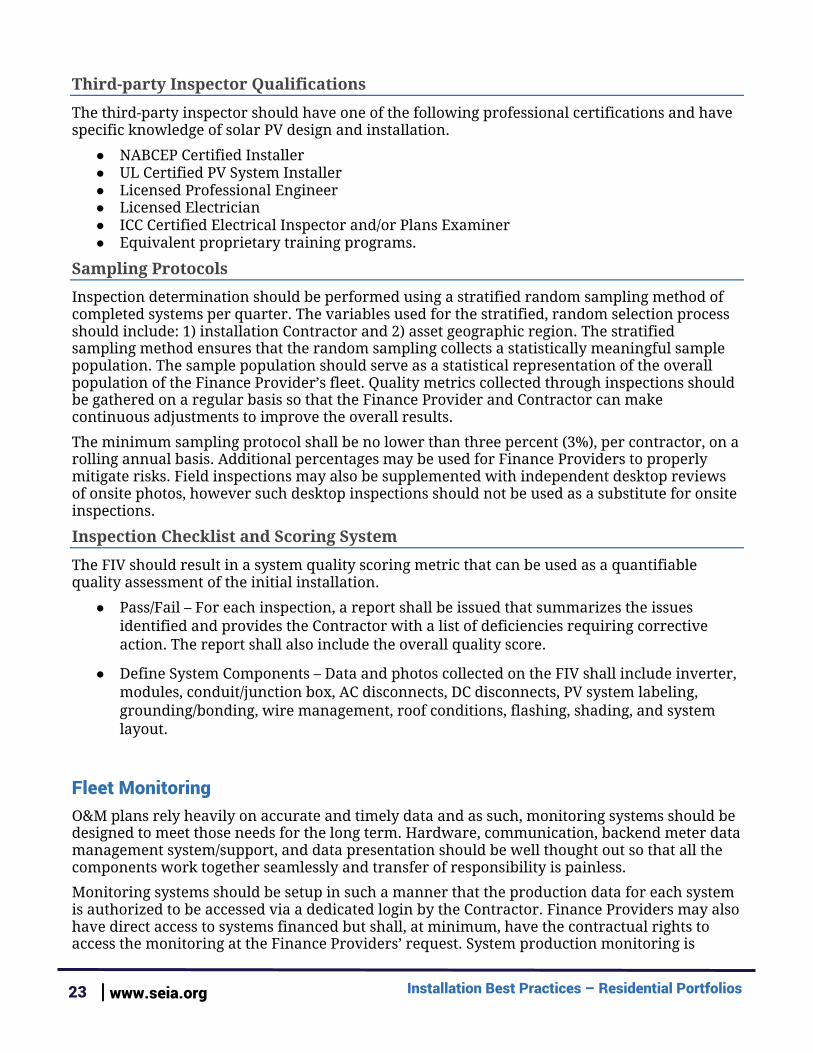
Required Information Matrix The following matrix guides Contractors and Finance Providers with 1) which data they should record and store for servicing and 2) provide to the System Owner.
Data Type Contractor System Owner
Finance Provider
Required System Documentation - Site Information
Plant identifier X X X
Site owner name X X X
Site owner address X X X
Site owner city X X X
Site owner state X X X
Site owner zip code X X X
Site owner phone number X X X
Site owner email address X X X
Site owner’s utility company X X X
System’s Commercial Operations Date / PTO Date
X X X
Required System Documentation - System Information
Design and Production Estimation Tool Used (PVWatts, Aurora, etc.)
X X X
System Capacity kWDC X X X
System Output kWAC X X X
Derate factor X X X
Total number of arrays X X X
Array tilt (per array) X X X
Array azimuth (per array) X X X
Module manufacturer X X X
Installation Best Practices – Residential Portfolios 25 | www.seia.org
Module model X X X
Module capacity (DC-STC) X X X
Module quantity X X X
Inverter manufacturer X X X
Inverter model(s) X X X
Inverter capacity (Max. AC output) X X X
Inverter number of units X X X
Racking manufacturer X X X
Racking model X X X
Solar availability (%) X X X
Number of Strings X X X
String Configuration per Maximum Power Point Tracker (MPPT)
X X
Monitoring Hardware Manufacturer X X X
Monitoring Hardware Model X X X
Monitoring System Provider X X X
Required System Documentation - As-Built Photo Inventory
Overall Array (showing all modules from above)
X X X
Array Horizon (shading) X X X
Module Nameplate (one for each unique make/model used)
X X
Conduit Runs and Support (with at least 3 examples of mounting/supporting hardware shown with close-up images)
X
Junction Box Locations X X X
Junction Box Interior X
Under Array and Circuit Wire Management X
Flashing of Roof Penetrations (with at least 3 examples shown in close-up photos)
X
Balance of System (taken standing back to provide single image of all new BOS components)
X X X
DC Disconnect Location X X X
DC Disconnect Interior X

Installation Best Practices – Residential Portfolios 26 | www.seia.org
Inverter Location X X X
Inverter Nameplate X X X
AC Disconnect location and interior X X
Main service panel (cover open) X
Main service panel (cover closed) X
Connection to premises grounding X X
Production Meter X X X
Monitoring system X X
Utility Meter X X
Interconnection Point (line/load taps) X X
Required System Documentation - Documents (PDF)
Design Drawings (One Line Diagram) X X
Permit Approval from AHJ X X X
Contractor Warranty Terms X X X
Solar PV module Warranty Documentation X X X
Inverter Warranty Information X X X
Third-party Warranty or Service Plan Documentation (as applicable)
X X X
Operations and Maintenance System Manual X X
Utility Permission to Operate X X X
FIV Report (with documentation of issues resolution)
X X X
Additional Resources Installation - Additional Resources
Note that the resources below were suggested by different members of the working group as helpful references and should used with discretion.
● International Building Code Section 1504 ● PV Racking and Attachment Criteria for Effective Asphalt Shingle Roof System
Integration ● A Guide to Photovoltaic (PV) System Design and Installation ● Field Inspection Guidelines for PV Systems ● Photovoltaic Power Systems, 2005 National Electric Code: Suggested Best Practices ● Southwest Technology Development Institute, Codes and Standards Resources ● NABCEP Photovoltaic (PV) Installer Resource Guide
Installation Best Practices – Residential Portfolios 27 | www.seia.org
● Best Practices for Solar Photovoltaic Installations - Renewable Energy Vermont Partnership Program
● IEC 62446 Commissioning Standard ● Green Job Hazards: Solar Energy ● Solar Construction Safety ● Structural Seismic Requirements and Commentary for Rooftop Solar Photovoltaic
Arrays by the Structural Engineers Association of California (SEAoC). ● Mike Holt’s Solar Photovoltaic Systems - NEC Requirements for Solar Photovoltaic
Systems (textbook), 2017 NEC ● Solar PV System Code Compliance Best Practices Webinar (The Cadmus Group)
Installation – Labeling Additional Resources
● ANSI.org, ANSI Z535.4-2011, Product Safety Signs and Labels ● Hellermann Tyton PV System Labeling Guide ● IBTS Guide to System Labeling
Interconnection Additional Resources
● IEEE 1547 - Standard for Interconnecting Distributed Resources with Electric Power Systems
● IEEE 1547.1 - Standard for Conformance Tests Procedures for Equipment Interconnecting Distributed Resources with Electric Power Systems
● IEEE 1547.2 - Application Guide for IEEE 1547 Standard for Interconnecting DIstributed Resources with Electric Power Systems
● IEEE 1547.3 - Guide for Monitoring, Information Exchange, and Control of Distributed Resources Interconnected with Electric Power Systems
● IEEE 1547.4 - Guide for Design, Operation, and Integration of Distributed Resource Island Systems with Electric Power Systems
● IEEE 1547.6 - Recommended Practice For Interconnecting Distributed Resources With Electric Power Systems Distribution Secondary Networks
● NEC 690, 705

Installation Best Practices – Residential Portfolios 28 | www.seia.org
About SEIA The Solar Energy Industries Association (SEIA®) is the driving
force behind solar energy and is building a strong solar industry to power America through advocacy and education. As the
national trade association of the U.S. solar energy industry, which now employs more than 250,000 Americans, we represent all
organizations that promote, manufacture, install and support the development of solar energy. SEIA works with its 1,000 member companies to build jobs and diversity, champion the use of cost-
competitive solar in America, remove market barriers and educate the public on the benefits of solar energy.
1425 K Street, NW
Suite 1000
Washington, D.C. 20005
www.seia.org
Related Documents