Initial Qualification Training (IQT) SIMulated Air Force U-28A 318th Special Operations Squadron

Welcome message from author
This document is posted to help you gain knowledge. Please leave a comment to let me know what you think about it! Share it to your friends and learn new things together.
Transcript
Initial Qualification Training
(IQT)
SIMulated Air Force
U-28A
318th Special Operations Squadron

SIMulated United States Air Force www.simairforce.org
INTRODUCTION
Welcome to Cannon AFB, NM, home to the 27th Special Operations Wing and specifically the 318th
Special Operations Squadron. The 318th plan, prepare, and execute Non Standard Aviation (NSAv)
missions in support of joint special operations forces while directly supporting theater special operations
commanders by conducting night vision infiltration, exfiltration, resupply and other combat taskings on
unimproved runways.
This course is Phase 4 training and covers the BAQ and BMC required prior to undertaking Phase 5
MQT.
This course covers the primary airframe of the 318th SOS, the U-28A. The M-28 Sky Truck is covered in
a separate document.
Pre-Requisites
Prior to undertaking this course participants must have either had dispensation from the AFSOC
Commander, or successfully completed Phase 3 Training in the C-12 Huron.
Objective
The objective of this course is to provide you the Basic Airframe Qualification and become Basic Mission
Capable.
Training Time
Approximately 5 hours. This includes ground training and flight training.
Reference Material
The following documents have been used in preparing this course and can be used to gain additional
information;
1. AFI13-217 Drop Zone and Landing Zone Operations 2. www.skyvector.com 3. www.pilatus-aircraft.com 4. Flight1 PC-12 Operators Handbook
Aircraft
PAYWARE: Flight1 (www.flight1.com) FS 9 and X
FREEWARE: AFG (www.alliedfsgroup.com) FS 9 and X
Simviation (www.simviation.com) FS 9 and X
Textures: AFSOC Textures are available for Flight1, and possibly the freeware ones.
SIMulated United States Air Force www.simairforce.org
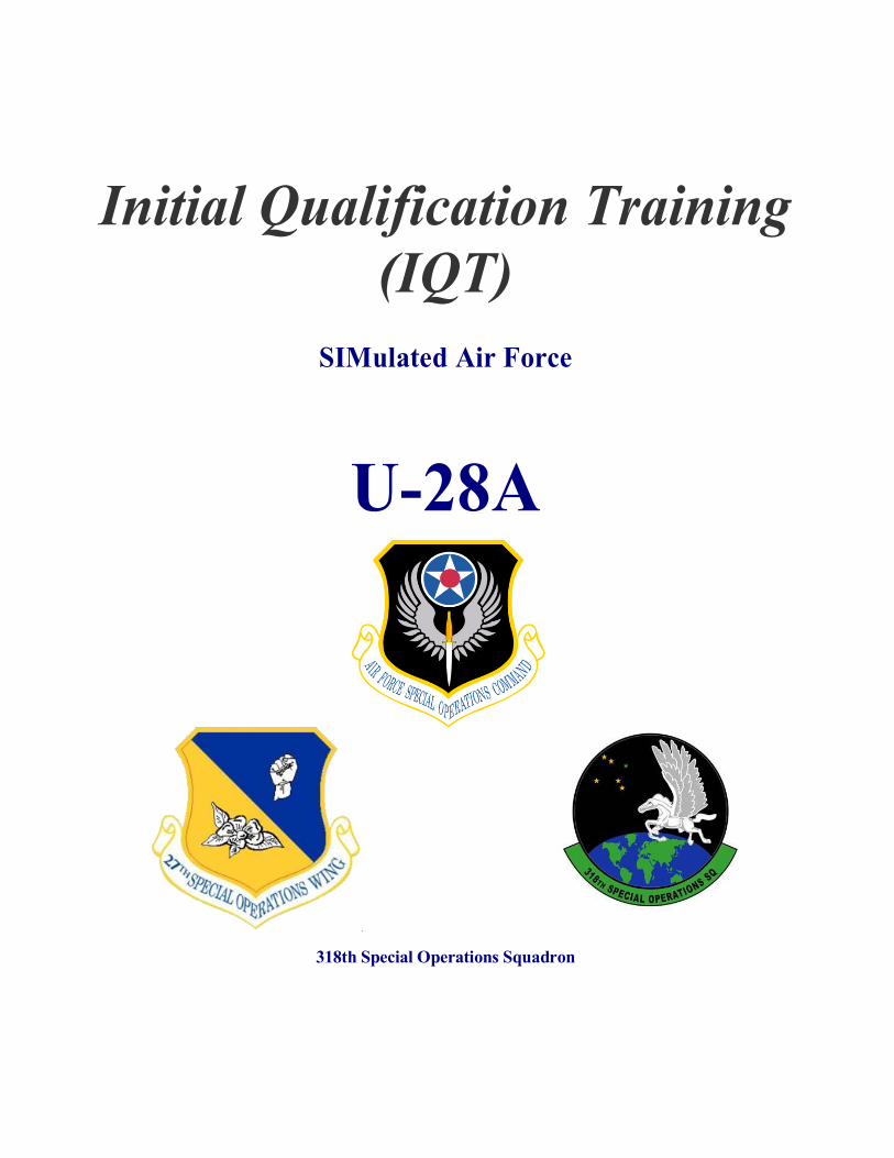
CANNON AFB, New Mexico (KCVS)
Runways
The Primary Runway is 04/22, which is 10,000‟ by 150‟, concrete, PCN 62/R/C/W/T
The Secondary is 13/31, which is 8,200‟ by 150‟, concrete touchdowns, PCN 47/R/B/W/T
Parking
318th SOS parking is located on the Northern end of the ramp, adjacent to the rwy 22 threshold.
Restrictions
All departing aircraft from Cannon AFB must remain below 5,300‟ until passing departure end of their
runway.
Communications
TOWER: 120.400 269.900
GROUND: 121.900 275.800
APPROACH: 121.050 352.100
DEPARTURE: 121.050 307.175
Albuquerque Center:
Navigation Aids
ID Name Freq Radial Range
CVS Cannon 111.60 356 0.1
TXO Texico 112.20 243 24.9
TCC Tucumcari 113.60 151 49.8
LIU Littlefield 212.00 110 54.2
HRX Hereford 341.00 049 57.0
PVW Plainview 112.90 272 78.3
LB Pollo 219.00 107 83.9
AirSpace
The facility is within Class D, and Class E with a floor of 700‟ AGL out to approximately 25Nm Radius.

SIMulated United States Air Force www.simairforce.org
Pilatus PC-12 (U-28A)
The U-28A is a militarised version of the popular Swiss engineered single engine low wing PC-12.
Because of it‟s excellent construction and flight dynamics, it has found it‟s way into almost every type of
government operation. The following are the type specifications;
Basic Operating Weight: 6,782 lb 3,076 kg
MTOW: 10,450 lb 4,740 kg
MLW: 9,921 lb 4,500 kg
Max Payload: 2,257 lb 1,024 kg
Payload with 100% fuel: 1,009 lb 458 kg
TKOF Distance (50‟ obs) 2,650 ft 808 m
LDG Distance (50‟ obs) 1,830 ft 558 m
Max Op Altitude: 30,000 ft 9,144 m
Max Range: 1,560 Nm 2,889 km
Wing Span: 53‟ 4” 16.28 m
Length: 47‟ 3” 14.40 m
Height: 14‟ 0” 4.26 m
Undercarriage span: 14‟ 10” 4.53 m
Max ROC: 1,920 fpm
Max Cruise 280 KTAS
Stall Speed 67 KIAS
VMO (maximum operating speed) 240 KCAS
MM0 (maximum operating Mach number) 0.48 Mach
VD (maximum diving speed) 280 KCAS
MD (maximum operating Mach number) 0.60 Mach
Va (maneuvering speed) 170 KCAS
Vo (max. maneuvering operating speed) 9,039 lb 154 KCAS

SIMulated United States Air Force www.simairforce.org
7,055 lb 136 KCAS
5,732 lb 123 KCAS
Vfe (max. flap extended speed) up to 15° 165 KCAS
Above 15° 130 KCAS
Vfo (max. flap operating speed) up to 15° 165 KCAS
Above 15° 130 KCAS
Vlo (maximum landing gear operating speed) 180 KCAS
Vle (maximum landing gear extended speed) 240 KCAS
Equipment
PW Canada PT6A-67B Turbo-prop engine driving a Hartzell four-blade constant speed variable pitch
prop
Later models have been fitted with the fully Honeywell Primus APEX glass cockpit.
Serials
USAF Factory C/N Prior Regos Type
08-0822 822 HB-FRK, N822BM U-28A
08-835 835 HB-FRW, N100MS U-28A
07-0711
07-736 736 N72EA U-28B
07-0821 821 N821PE U-28A
07-0838 838 N838PE U-28A
06-0692 PC-12/47
05-0409 409 N922RG U-28A
05-0419 419 N419WA U-28A
05-0424 424 N424PB U-28A
05-0447 447 N447PC U-28A
05-0482 482 N482WA U-28A
05-0573 573 N666GT U-28A
05-0646 646 Crashed
04-0602 602 N901TR U-28A
SIMulated United States Air Force www.simairforce.org
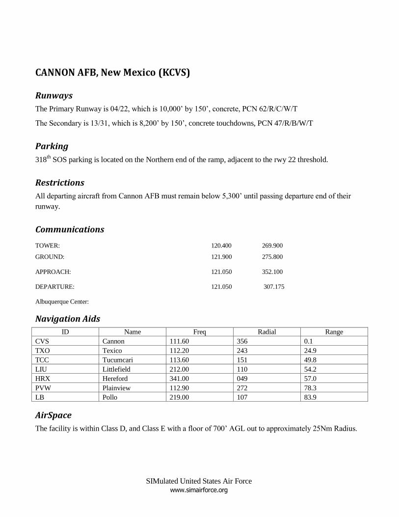
Departure SPEED'S (from Flight1 Manuals)
MTOW (ISA) at Sea Level
Vr
15o Flaps 79 KIAS
30o Flaps 73 KIAS
Max Climb (Vx)
110 KIAS
Best ROC (Vy) (no flaps)
< 10,000 ft 120 KIAS
10,000 – 20,000 ft 115 KIAS
> 20,000 ft 110 KIAS

SIMulated United States Air Force www.simairforce.org
SIMulated United States Air Force www.simairforce.org
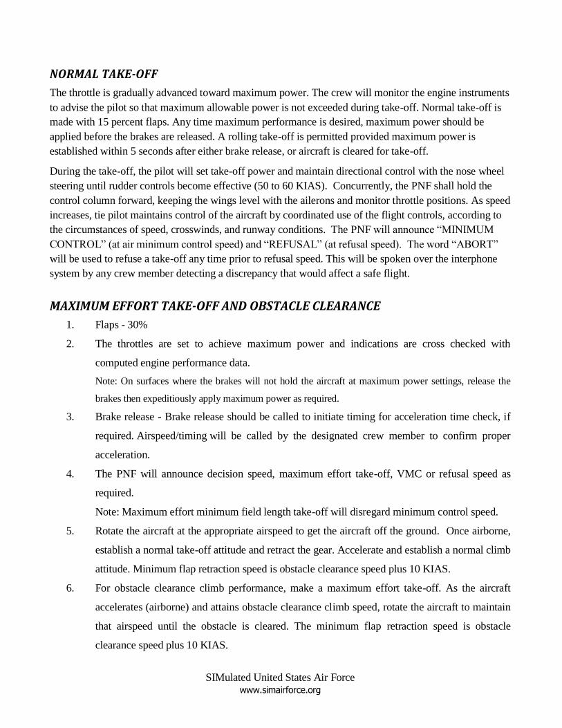
NORMAL TAKE-OFF
The throttle is gradually advanced toward maximum power. The crew will monitor the engine instruments
to advise the pilot so that maximum allowable power is not exceeded during take-off. Normal take-off is
made with 15 percent flaps. Any time maximum performance is desired, maximum power should be
applied before the brakes are released. A rolling take-off is permitted provided maximum power is
established within 5 seconds after either brake release, or aircraft is cleared for take-off.
During the take-off, the pilot will set take-off power and maintain directional control with the nose wheel
steering until rudder controls become effective (50 to 60 KIAS). Concurrently, the PNF shall hold the
control column forward, keeping the wings level with the ailerons and monitor throttle positions. As speed
increases, tie pilot maintains control of the aircraft by coordinated use of the flight controls, according to
the circumstances of speed, crosswinds, and runway conditions. The PNF will announce “MINIMUM
CONTROL” (at air minimum control speed) and “REFUSAL” (at refusal speed). The word “ABORT”
will be used to refuse a take-off any time prior to refusal speed. This will be spoken over the interphone
system by any crew member detecting a discrepancy that would affect a safe flight.
MAXIMUM EFFORT TAKE-OFF AND OBSTACLE CLEARANCE
1. Flaps - 30%
2. The throttles are set to achieve maximum power and indications are cross checked with
computed engine performance data.
Note: On surfaces where the brakes will not hold the aircraft at maximum power settings, release the
brakes then expeditiously apply maximum power as required.
3. Brake release - Brake release should be called to initiate timing for acceleration time check, if
required. Airspeed/timing will be called by the designated crew member to confirm proper
acceleration.
4. The PNF will announce decision speed, maximum effort take-off, VMC or refusal speed as
required.
Note: Maximum effort minimum field length take-off will disregard minimum control speed.
5. Rotate the aircraft at the appropriate airspeed to get the aircraft off the ground. Once airborne,
establish a normal take-off attitude and retract the gear. Accelerate and establish a normal climb
attitude. Minimum flap retraction speed is obstacle clearance speed plus 10 KIAS.
6. For obstacle clearance climb performance, make a maximum effort take-off. As the aircraft
accelerates (airborne) and attains obstacle clearance climb speed, rotate the aircraft to maintain
that airspeed until the obstacle is cleared. The minimum flap retraction speed is obstacle
clearance speed plus 10 KIAS.

SIMulated United States Air Force www.simairforce.org
7. Upon completion of the maximum effort and/or obstacle clearance procedure, lower the nose to
a normal take-off attitude and climb out normally.
Note: All normal take-off aircrew coordination/responsibilities apply to maximum take-offs.
CROSSWIND TAKE-OFF
Crosswind take-offs, with regard to directional control of the aircraft, are made essentially the same as
normal take-offs. Initially, the pilot maintains directional control with nose wheel steering and differential
power while the PNF maintains a wing-level attitude with the ailerons. In higher crosswinds, a greater
amount of ailerons must be applied. After lift-off, the line of flight should be aligned with the runway
until crossing the airfield boundary.
NORMAL DESCENT
This type of descent is made by retarding all throttles to flight idle with gear and flaps retracted and
descending at maximum level flight (VH) speeds. The normal descent chart presented in the performance
data is based on maximum level flight (VH) speeds.
MAXIMUM RANGE DESCENT
This type of descent is made by retarding all throttles to flight idle with gear and flaps retracted and
descending at maximum lift over drag speeds as presented in the performance chart. This type of descent
will provide a moderate rate of sink (approximately 1,500 fpm) for en route letdown.
TRAFFIC PATTERN
Every landing should be planned according to runway length available and the general prevailing
operating conditions. Normal landings should also be planned so as to use all of the available runway
length to promote safe, smooth, and unhurried operating practices; to preclude abrupt reverse power
changes; and to save wear and tear on brakes.
On final approach/turning final, begin deceleration to 70 kts approximately 0.75 to 0.5 nm and 300 to 500
feet AGL from touchdown to attain 100 percent threshold speed at runway threshold.
Touchdown shall be planned at the speed computed from the appropriate landing speed chart. After the
main wheels touch down, lower the nose wheel smoothly to the run- way before elevator control is lost.
When the main and nose landing gear are firmly on the ground, the PNF must hold forward pressure on
the control column and maintain a wing-level attitude with ailerons, as needed. Concurrently, the pilot
maintains directional control and decelerates the aircraft through the coordinated use of the rudder,
differential power, nose wheel steering, and differential brakes according to the speed, wind, and runway
conditions.
Reverse thrust is applied by moving the throttles from FLIGHT IDLE and then into REVERSE range in
coordination with nose wheel steering. Brakes must be checked during the landing roll.

SIMulated United States Air Force www.simairforce.org
Normal Reverse Thrust Landing
The following procedure is recommended for a normal reverse thrust landing:
1. When the nose wheel contacts the ground, the PNF holds the control column forward to ensure
steering control. The PNF also holds wings level. Flaps should not be brought up until clearing
the duty runway. Any deviation from this will be specifically briefed prior to landing by the
pilot in command.
2. The pilot pulls the throttle back to the REVERSE range and steers with the steering wheel.
Although propeller reversing is most effective at the higher speeds, reversing propellers at
speeds of 115 KIAS or above could result in engine flame out.
3. After the aircraft has slowed down, and reverse thrust is no longer needed, the pilot will use the
throttles in ground operating range as necessary for taxiing.
WIND SHEAR
Wind shear is a complex phenomenon. It can affect the airplane in all phases of flight, but is most critical
during the approach and landing phase. Wind shear can exist as a rapid change in wind velocity and
direction as well as vertical air movement. There are certain conditions which indicate the possibility of
wind shear being present. As a general rule, the amount of shear is greater ahead of warm fronts although
the most common occurrences follow the passage of cold fronts during periods of gusty surface winds.
When a temperature change of 10°F or more is reported across the front or if the front is moving at 30
knots or more, conditions are excellent for wind shear. In addition, when thunderstorms are present in the
area of intended landing, the possibility of encountering wind shear is increased. The power required,
vertical speed, and pitch attitude, used in conjunction with the wind reported on the ground, provide an
indication of potential wind shear.
In relation to a known surface wind, be alert for:
1. An unusually steep or shallow rate of descent required to maintain glide path.
2. An unusually high or low power setting required to maintain approach airspeed.
3. A large variation between actual and computed ground speed.
When a reported surface wind would not justify an increased airspeed (for example: calm wind on the
surface), but wind shear is suspected, adjustment of approach speed may be used to provide an increased
speed margin. The following are two wind shear phenomena which are commonly found on final
approach.
Decreasing Headwind
Initial reactions of the airplane, when suddenly encountering a decreasing headwind (or an increasing
tailwind), is a drop in indicated airspeed and a decrease in pitch attitude resulting in a loss of altitude. The

SIMulated United States Air Force www.simairforce.org
pilot must add power and increase pitch to regain the proper glide path. Once speed and glide path are
regained, however, prompt reduction of power is necessary. It will now require less power and a greater
rate of descent to maintain the proper profile in the decreased headwind. If the initial corrections of
increased power/pitch are not promptly removed after regaining glide path and airspeed, a long landing at
high speed will result.
Increasing Headwind
The initial airplane reaction to an increasing headwind (decreasing tailwind) is an increase in indicated
airspeed and an increase in pitch attitude resulting in a gain in altitude. The pilot should reduce pitch and
power to regain the proper glide path. As glide path is regained, the pilot must immediately compensate
for the increasing headwind by increasing pitch and power. It will now require more power and a
decreased rate of descent to maintain the proper profile. Be very cautious in making reductions of power
and pitch to avoid a low-power, high-sink condition which could lead to a correction through the glide
path from which a recovery could not be made.
WARNING
If the airplane becomes unstable on final approach due to wind shear and the approach profile can not be
promptly reestablished, a go-around should be immediately accomplished.
MINIMUM RUN LANDING (Maximum Effort Landing)
All procedures for a normal landing apply to a maximum effort landing except touchdown is planned
between 100 and 300 feet past the threshold. In no case shall the touchdown be greater than 500 feet, if
utilizing minimum length runways. Additionally, upon touchdown and with all landing gear firmly on the
deck, promptly apply full reverse thrust and minimize nose gear loads with elevator back pressure.
CAUTION
Extremely rapid throttle movement from flight idle to maximum reverse may cause power loss and/or
engine flame out above 115 kts.
LANDING ON WET RUNWAYS
The anti-skid braking system and reverse thrust capabilities minimize the normal hazards associated with
wet runways. Directional control should be maintained by the coordinated use of rudder and ailerons,
differential power, differential braking, and nose wheel steering. Heavy reliance on differential braking
and/or nose wheel steering for directional control should be avoided since their effectiveness, as a
function of friction available, will be greatly reduced. In addition, the nose wheel may exhibit a tendency
to skid when turned at a speed higher than taxi speed.
CAUTION
If airfield conditions are such that deep puddles of water will be encountered during the early part of the
landing roll out, nose wheel touchdown may be delayed until the later pan of the roll out.
SIMulated United States Air Force www.simairforce.org
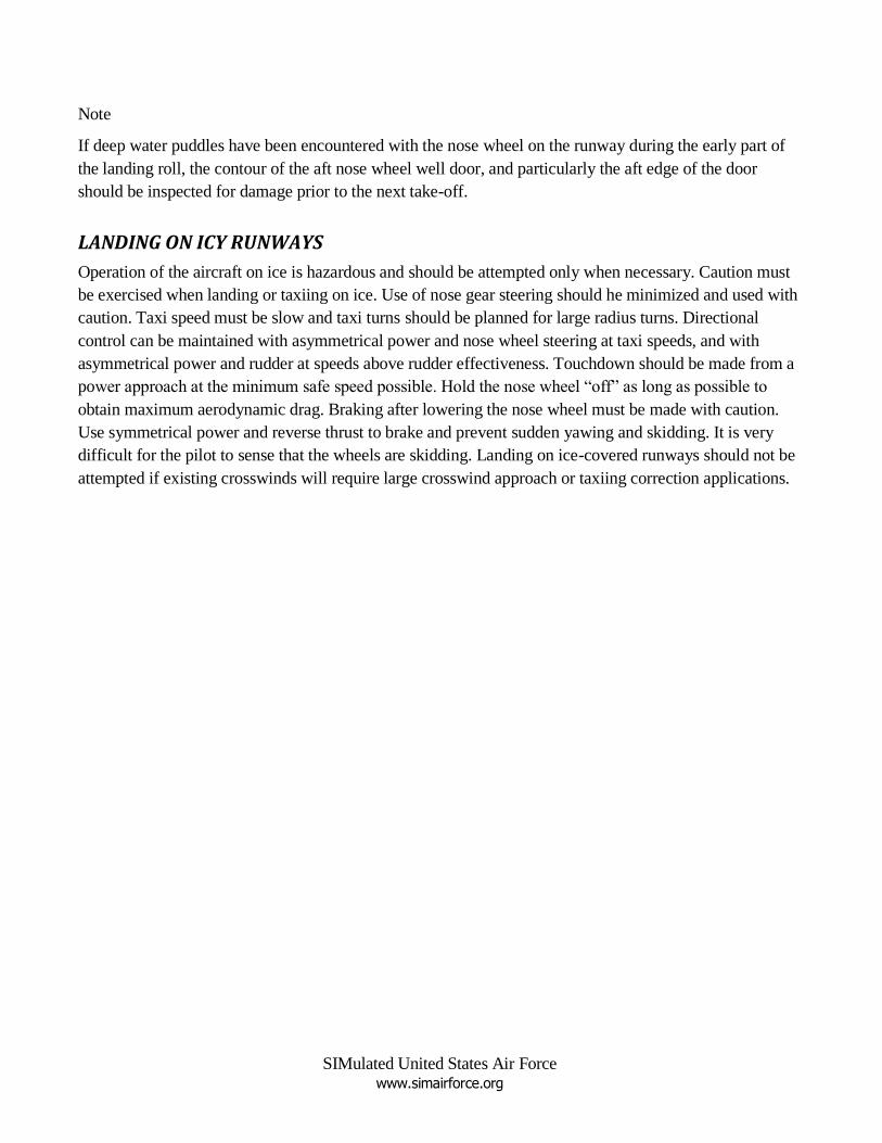
Note
If deep water puddles have been encountered with the nose wheel on the runway during the early part of
the landing roll, the contour of the aft nose wheel well door, and particularly the aft edge of the door
should be inspected for damage prior to the next take-off.
LANDING ON ICY RUNWAYS
Operation of the aircraft on ice is hazardous and should be attempted only when necessary. Caution must
be exercised when landing or taxiing on ice. Use of nose gear steering should he minimized and used with
caution. Taxi speed must be slow and taxi turns should be planned for large radius turns. Directional
control can be maintained with asymmetrical power and nose wheel steering at taxi speeds, and with
asymmetrical power and rudder at speeds above rudder effectiveness. Touchdown should be made from a
power approach at the minimum safe speed possible. Hold the nose wheel “off” as long as possible to
obtain maximum aerodynamic drag. Braking after lowering the nose wheel must be made with caution.
Use symmetrical power and reverse thrust to brake and prevent sudden yawing and skidding. It is very
difficult for the pilot to sense that the wheels are skidding. Landing on ice-covered runways should not be
attempted if existing crosswinds will require large crosswind approach or taxiing correction applications.
SIMulated United States Air Force www.simairforce.org
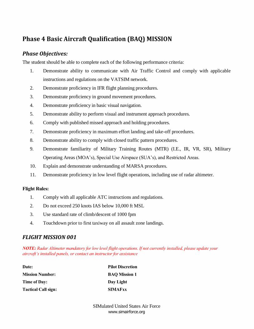
Phase 4 Basic Aircraft Qualification (BAQ) MISSION
Phase Objectives:
The student should be able to complete each of the following performance criteria:
1. Demonstrate ability to communicate with Air Traffic Control and comply with applicable
instructions and regulations on the VATSIM network.
2. Demonstrate proficiency in IFR flight planning procedures.
3. Demonstrate proficiency in ground movement procedures.
4. Demonstrate proficiency in basic visual navigation.
5. Demonstrate ability to perform visual and instrument approach procedures.
6. Comply with published missed approach and holding procedures.
7. Demonstrate proficiency in maximum effort landing and take-off procedures.
8. Demonstrate ability to comply with closed traffic pattern procedures.
9. Demonstrate familiarity of Military Training Routes (MTR) (I.E., IR, VR, SR), Military
Operating Areas (MOA‟s), Special Use Airspace (SUA‟s), and Restricted Areas.
10. Explain and demonstrate understanding of MARSA procedures.
11. Demonstrate proficiency in low level flight operations, including use of radar altimeter.
Flight Rules:
1. Comply with all applicable ATC instructions and regulations.
2. Do not exceed 250 knots IAS below 10,000 ft MSL
3. Use standard rate of climb/descent of 1000 fpm
4. Touchdown prior to first taxiway on all assault zone landings.
FLIGHT MISSION 001
NOTE: Radar Altimeter mandatory for low level flight operations. If not currently installed, please update your
aircraft’s installed panels, or contact an instructor for assistance
Date: Pilot Discretion
Mission Number: BAQ Mission 1
Time of Day: Day Light
Tactical Call sign: SIMAFxx
SIMulated United States Air Force www.simairforce.org
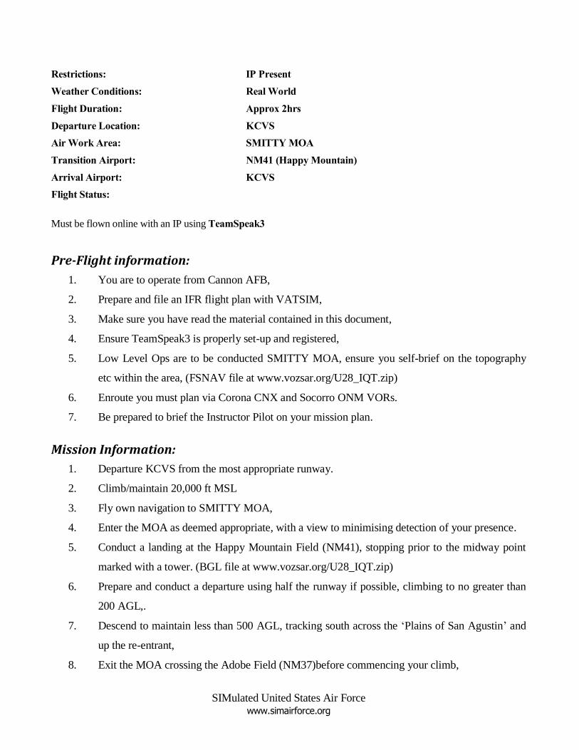
Restrictions: IP Present
Weather Conditions: Real World
Flight Duration: Approx 2hrs
Departure Location: KCVS
Air Work Area: SMITTY MOA
Transition Airport: NM41 (Happy Mountain)
Arrival Airport: KCVS
Flight Status:
Must be flown online with an IP using TeamSpeak3
Pre-Flight information:
1. You are to operate from Cannon AFB,
2. Prepare and file an IFR flight plan with VATSIM,
3. Make sure you have read the material contained in this document,
4. Ensure TeamSpeak3 is properly set-up and registered,
5. Low Level Ops are to be conducted SMITTY MOA, ensure you self-brief on the topography
etc within the area, (FSNAV file at www.vozsar.org/U28_IQT.zip)
6. Enroute you must plan via Corona CNX and Socorro ONM VORs.
7. Be prepared to brief the Instructor Pilot on your mission plan.
Mission Information:
1. Departure KCVS from the most appropriate runway.
2. Climb/maintain 20,000 ft MSL
3. Fly own navigation to SMITTY MOA,
4. Enter the MOA as deemed appropriate, with a view to minimising detection of your presence.
5. Conduct a landing at the Happy Mountain Field (NM41), stopping prior to the midway point
marked with a tower. (BGL file at www.vozsar.org/U28_IQT.zip)
6. Prepare and conduct a departure using half the runway if possible, climbing to no greater than
200 AGL,.
7. Descend to maintain less than 500 AGL, tracking south across the „Plains of San Agustin‟ and
up the re-entrant,
8. Exit the MOA crossing the Adobe Field (NM37)before commencing your climb,
SIMulated United States Air Force www.simairforce.org
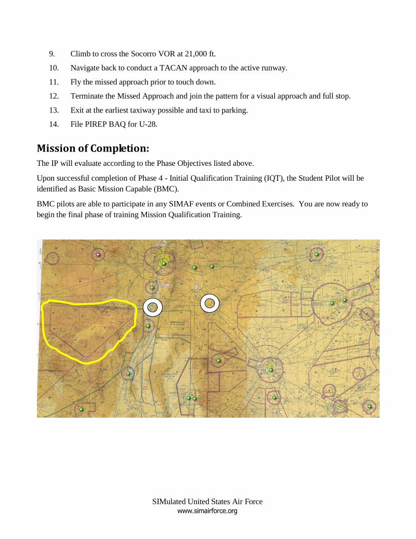
9. Climb to cross the Socorro VOR at 21,000 ft.
10. Navigate back to conduct a TACAN approach to the active runway.
11. Fly the missed approach prior to touch down.
12. Terminate the Missed Approach and join the pattern for a visual approach and full stop.
13. Exit at the earliest taxiway possible and taxi to parking.
14. File PIREP BAQ for U-28.
Mission of Completion:
The IP will evaluate according to the Phase Objectives listed above.
Upon successful completion of Phase 4 - Initial Qualification Training (IQT), the Student Pilot will be
identified as Basic Mission Capable (BMC).
BMC pilots are able to participate in any SIMAF events or Combined Exercises. You are now ready to
begin the final phase of training Mission Qualification Training.

SIMulated United States Air Force www.simairforce.org
Related Documents