Athens Journal of Technology & Engineering June 2016 133 Influence of Strengthening the Infill Walls with Perforated Steel Plates on the Behavior of RC Frames By Sabahattin Aykac Eray Ozbek ‡ Bengi Aykac Ilker Kalkan † The Strengthening of the non-bearing elements of a structure not only increases the overall lateral strength and stiffness of the structure, but also causes a major amount of the earthquake energy to be absorbed by the nonbearing members and therefore reduces the risk of damage in the structural components. The present paper focuses on a number of experiments carried out within an extensive research program, investigating the influence of strengthening the brick infill walls of an RC frame with perforated steel plates on the seismic behavior of the frame. Perforated steel plates are adopted in strengthening due to their several advantages including the great ductilities and deformation capacities of these plates, the fire resistant, recyclable and non-cancerogenic nature of steel and the ease of application of this technique. A total of 14 half-scale specimens, each composed of a strong foundation, two columns, a beam, and a brick wall, were tested. Plate thickness, bolt spacing and plate-column connection were chosen as the test parameters. The observations from previous experiments conducted on individual brick wall specimens were used for detailing the strengthening plates and the plate-wall connections. Additional column and joint strengthening applications provided significant improvements in the seismic behavior of the specimens. Keywords: Brick Wall, Earthquake Behavior, Steel Plate, Structural Strengthening Introduction A significant number of structures around the globe needs seismic strengthening due to improper design and construction practices and noncompliance with the structural design codes, standards and regulations. Strengthening and repair applications on existing structures have two main Associate Professor, Gazi University, Turkey. ‡ Research Assistant, Gazi University, Turkey. Associate Professor, Gazi University, Turkey. † Associate Professor, Kirikkale University, Turkey.

Welcome message from author
This document is posted to help you gain knowledge. Please leave a comment to let me know what you think about it! Share it to your friends and learn new things together.
Transcript
Athens Journal of Technology & Engineering June 2016
133
Influence of Strengthening the Infill Walls with
Perforated Steel Plates on the Behavior of
RC Frames
By Sabahattin Aykac
Eray Ozbek‡
Bengi Aykac
Ilker Kalkan†
The Strengthening of the non-bearing elements of a structure not only increases
the overall lateral strength and stiffness of the structure, but also causes a major
amount of the earthquake energy to be absorbed by the nonbearing members and
therefore reduces the risk of damage in the structural components. The present
paper focuses on a number of experiments carried out within an extensive
research program, investigating the influence of strengthening the brick infill
walls of an RC frame with perforated steel plates on the seismic behavior of the
frame. Perforated steel plates are adopted in strengthening due to their several
advantages including the great ductilities and deformation capacities of these
plates, the fire resistant, recyclable and non-cancerogenic nature of steel and the
ease of application of this technique. A total of 14 half-scale specimens, each
composed of a strong foundation, two columns, a beam, and a brick wall, were
tested. Plate thickness, bolt spacing and plate-column connection were chosen as
the test parameters. The observations from previous experiments conducted on
individual brick wall specimens were used for detailing the strengthening plates
and the plate-wall connections. Additional column and joint strengthening
applications provided significant improvements in the seismic behavior of the
specimens.
Keywords: Brick Wall, Earthquake Behavior, Steel Plate, Structural
Strengthening
Introduction
A significant number of structures around the globe needs seismic
strengthening due to improper design and construction practices and
noncompliance with the structural design codes, standards and regulations.
Strengthening and repair applications on existing structures have two main
Associate Professor, Gazi University, Turkey. ‡ Research Assistant, Gazi University, Turkey.
Associate Professor, Gazi University, Turkey.
† Associate Professor, Kirikkale University, Turkey.
Vol. 3, No. 2 Aykac et al.: Influence of Strengthening the Infill Walls...
134
purposes. First, the lateral rigidity and strength of the structure is aimed to be
increased to enhance the ability of the structure to withstand greater lateral loads
with limited displacement. Secondly, the earthquake-induced energy is desired to
result in minimal damage in components of the gravity and lateral load-resisting
system of the structure. To achieve these goals, two main types of structural
retrofit techniques have been implemented in the past, namely strengthening the
lateral load-resisting system by adding new members or fortifying the existing
ones and strengthening the non-structural elements, i.e. the infill walls.
Strengthening the infill walls has been and is the subject of several studies in the
literature due to two main reasons:
1. The infill walls have a very small or no contribution to the overall lateral
strength and rigidity of a structure since they fail in a quite brittle manner as
soon as the diagonal tension capacity of the wall is exceeded. The infill
walls strengthening applications aim at increasing the overall lateral strength
and rigidity of the structure by providing the infill walls with greater
diagonal load capacity and rigidity.
2. These applications also aim at providing the infill walls with ductile load-
deflection behavior so that a major portion of the earthquake-induced energy
is absorbed by the infill walls and the gravity and the lateral-load bearing
system of the structure is liable to less damage.
The CFRP sheets and GFRP laminates (Triantafillou, 1998; Erdem et al.,
2006; El-Dakhakhni et al., 2006; Ozcebe et al., 2003); FRP textile reinforced
mortar (TRM) (Triantafillou and Papanicolaou, 2006; Triantafillou et al., 2006;
Prota et al., 2006; Papanicolaou et al., 2011); shotcrete reinforced with steel mesh
(Kahn, 1984; ElGawady et al., 2006); fiber-reinforced mortar (Sevil et al., 2011);
precast concrete and precast reinforced concrete panels (Frosch et al., 1996; Baran
and Tankut, 2011); and ferrocement layers (Topcu et al., 2005; Amanat et al.,
2007) are among the materials used for strengthening infill walls by previous
researchers. The use of FRP reinforcement, sheets and laminates has been widely
adopted by previous researchers due to their high strength and good bonding
performance with concrete. Nonetheless, several shortcomings of this method,
including the high cost, low fire resistance, need for skilled labor and the
problems related to bonding FRP composites to the wall surface caused FRP
strengthening to not become common in practice. Furthermore, the use of epoxy
adhesives as the bonding agent also reduces the practicality, effectiveness and
economy of the method and increases the vulnerability of the strengthening layers
to fire, which is crucial in fire protection of historical structures. Despite being
effective in improving the seismic performances of the infill walls, the
aforementioned strengthening methods are not easily applicable to real structures,
in which a great number of infill walls need to be strengthened.
In search for an economical, easy-to-apply and convenient method, steel
strips, profiles and plates were utilized in a number of studies (Taghdi et al., 2000;
Farooq, Ilyas and Ghaffar, 2006; Ozbek and Can, 2012; Aykac et al., 2014;
Kalkan et al., 2013; Ozbek et al., 2014) for strengthening infill walls. Aykac and
Athens Journal of Technology & Engineering June 2016
135
his companions (Aykac et al., 2014; Kalkan et al., 2013; Ozbek et al., 2014)
proposed the use of perforated steel plates for strengthening hollow brick infill
walls and conducted a series of tests on the wall specimens. Perforated steel plates
were adopted due to their following advantages and superiorities over the existing
strengthening materials and methods:
i. The ductile stress-strain properties of mild steel and the additional ductility
provided by the perforations improve the ductility and energy absorption
capacity of the strengthened wall.
ii. Perforated steel plates on both faces of the wall have a two-fold effect on
the strength of the wall. First, the tensile stresses are resisted by the plates
after the formation of diagonal tension cracks in the wall. Secondly, the
confining effect of the plates increases the compressive strength of the
wall itself.
iii. The perforated steel plates can be covered with plaster to improve the
aesthetic quality of the structure
iv. The perforations increase the bonding surface area between the wall and
the plaster and improve composite behavior in the plated wall
v. The plates are connected to the wall only with the help of steel bolts. The
lack of epoxy adhesives in strengthening contributes to the ease of
application and economy of the method.
vi. The method is also applicable to structures with a high risk of fire or which
need to be protected against fire (historical structures) thanks to the higher
fire resistance of steel compared to the composites and the lack of
chemical adhesives in the method.
vii. The recyclable and non-cancerogenic nature of steel can also be counted
among the superiorities of the method over the existing methods.
viii. The presence of perforations in the plates facilitates the installation,
removal and replacement of the strengthening plates and drilling of the
holes for bolts in the wall. These perforations also avoid any possible
damage for the water and sanitary fixtures in the wall if the locations of
these fixtures are marked on the wall before drilling the holes
The present paper summarizes 14 experiments conducted within the third
stage of an experimental program (Ozbek et al., 2014). In the first stage of the
program, individual brick wall specimens were tested under monotonic diagonal
loading (Aykac et al., 2014), similar to the loading condition of infill walls in the
case of lateral seismic loading. Based upon the promising results obtained in the
first stage, individual wall specimens were tested under reversed cyclic lateral
loading in the second stage (Kalkan et al., 2013). The first and second stages of
the program indicated that the perforated steel plates are quite effective in
improving the behavior of brick infill walls. In the third stage, on the other hand,
the influence of this wall strengthening technique on the overall performance of
an RC frame was investigated. The findings and observations from the first and
second stages enabled the authors to design the details of the strengthening
procedure.
Vol. 3, No. 2 Aykac et al.: Influence of Strengthening the Infill Walls...
136
Experimental Study
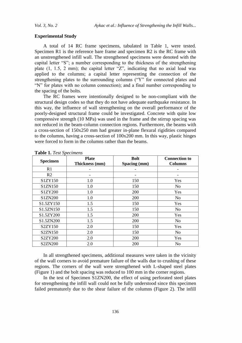
A total of 14 RC frame specimens, tabulated in Table 1, were tested.
Specimen R1 is the reference bare frame and specimen R2 is the RC frame with
an unstrengthened infill wall. The strengthened specimens were denoted with the
capital letter “S”; a number corresponding to the thickness of the strengthening
plate (1, 1.5, 2 mm); the capital letter “Z”, indicating that no axial load was
applied to the columns; a capital letter representing the connection of the
strengthening plates to the surrounding columns (“Y” for connected plates and
“N” for plates with no column connection); and a final number corresponding to
the spacing of the bolts.
The RC frames were intentionally designed to be non-compliant with the
structural design codes so that they do not have adequate earthquake resistance. In
this way, the influence of wall strengthening on the overall performance of the
poorly-designed structural frame could be investigated. Concrete with quite low
compressive strength (10 MPa) was used in the frame and the stirrup spacing was
not reduced in the beam-column connection regions. Furthermore, the beams with
a cross-section of 150x250 mm had greater in-plane flexural rigidities compared
to the columns, having a cross-section of 100x200 mm. In this way, plastic hinges
were forced to form in the columns rather than the beams.
Table 1. Test Specimens
Specimen Plate
Thickness (mm)
Bolt
Spacing (mm)
Connection to
Columns
R1 - - -
R2 - - -
S1ZY150 1.0 150 Yes
S1ZN150 1.0 150 No
S1ZY200 1.0 200 Yes
S1ZN200 1.0 200 No
S1.5ZY150 1.5 150 Yes
S1.5ZN150 1.5 150 No
S1.5ZY200 1.5 200 Yes
S1.5ZN200 1.5 200 No
S2ZY150 2.0 150 Yes
S2ZN150 2.0 150 No
S2ZY200 2.0 200 Yes
S2ZN200 2.0 200 No
In all strengthened specimens, additional measures were taken in the vicinity
of the wall corners to avoid premature failure of the walls due to crushing of these
regions. The corners of the wall were strengthened with L-shaped steel plates
(Figure 1) and the bolt spacing was reduced to 100 mm in the corner regions.
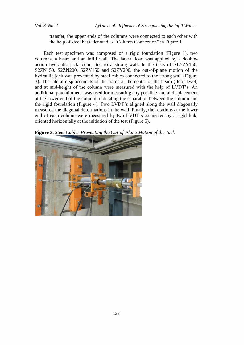
In the test of Specimen S1ZN200, the effect of using perforated steel plates
for strengthening the infill wall could not be fully understood since this specimen
failed prematurely due to the shear failure of the columns (Figure 2). The infill
Athens Journal of Technology & Engineering June 2016
137
wall did not undergo significant damage till the end of the test with the exception
of limited crushing in the corners (Figure 2). To avoid the premature failure of the
weak columns and to allow the strengthened wall to contribute to the frame
behavior, the columns and the beam-column joints in the remaining specimens,
were strengthened, in addition to the infill wall. Accordingly, the following
additional strengthening measures were undertaken in the remaining strengthened
specimens:
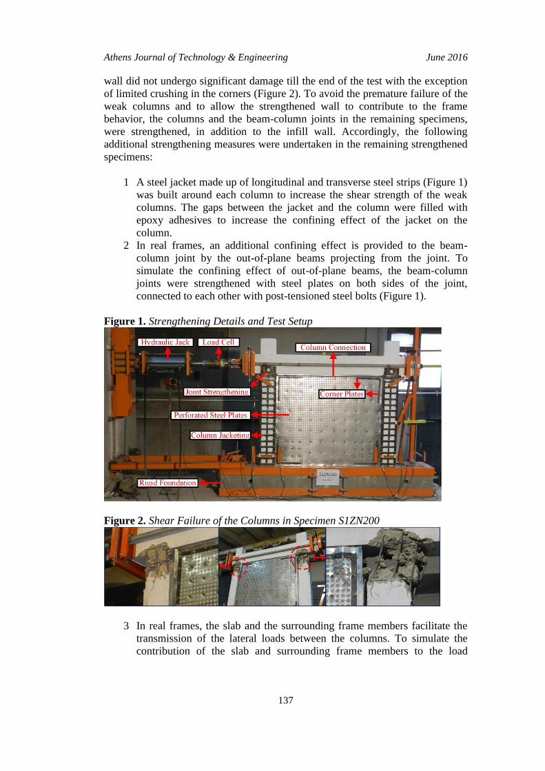
1 A steel jacket made up of longitudinal and transverse steel strips (Figure 1)
was built around each column to increase the shear strength of the weak
columns. The gaps between the jacket and the column were filled with
epoxy adhesives to increase the confining effect of the jacket on the
column.
2 In real frames, an additional confining effect is provided to the beam-
column joint by the out-of-plane beams projecting from the joint. To
simulate the confining effect of out-of-plane beams, the beam-column
joints were strengthened with steel plates on both sides of the joint,
connected to each other with post-tensioned steel bolts (Figure 1).
Figure 1. Strengthening Details and Test Setup
Figure 2. Shear Failure of the Columns in Specimen S1ZN200
3 In real frames, the slab and the surrounding frame members facilitate the
transmission of the lateral loads between the columns. To simulate the
contribution of the slab and surrounding frame members to the load
Vol. 3, No. 2 Aykac et al.: Influence of Strengthening the Infill Walls...
138
transfer, the upper ends of the columns were connected to each other with
the help of steel bars, denoted as “Column Connection” in Figure 1.
Each test specimen was composed of a rigid foundation (Figure 1), two
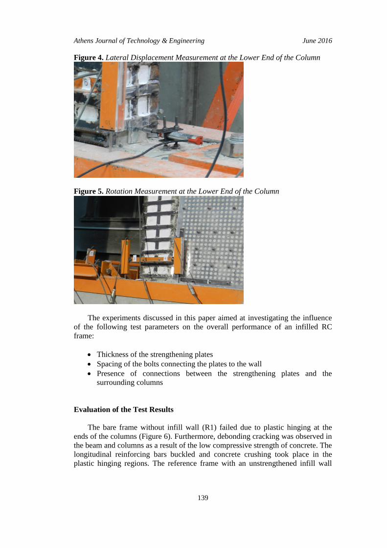
columns, a beam and an infill wall. The lateral load was applied by a double-
action hydraulic jack, connected to a strong wall. In the tests of S1.5ZY150,
S2ZN150, S2ZN200, S2ZY150 and S2ZY200, the out-of-plane motion of the
hydraulic jack was prevented by steel cables connected to the strong wall (Figure
3). The lateral displacements of the frame at the center of the beam (floor level)
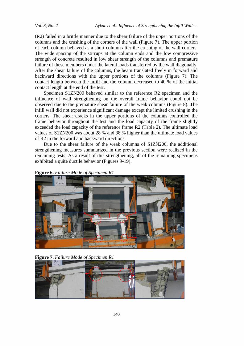
and at mid-height of the column were measured with the help of LVDT’s. An
additional potentiometer was used for measuring any possible lateral displacement
at the lower end of the column, indicating the separation between the column and
the rigid foundation (Figure 4). Two LVDT’s aligned along the wall diagonally
measured the diagonal deformations in the wall. Finally, the rotations at the lower
end of each column were measured by two LVDT’s connected by a rigid link,
oriented horizontally at the initiation of the test (Figure 5).
Figure 3. Steel Cables Preventing the Out-of-Plane Motion of the Jack
Athens Journal of Technology & Engineering June 2016
139
Figure 4. Lateral Displacement Measurement at the Lower End of the Column
Figure 5. Rotation Measurement at the Lower End of the Column
The experiments discussed in this paper aimed at investigating the influence
of the following test parameters on the overall performance of an infilled RC
frame:
Thickness of the strengthening plates
Spacing of the bolts connecting the plates to the wall
Presence of connections between the strengthening plates and the
surrounding columns
Evaluation of the Test Results
The bare frame without infill wall (R1) failed due to plastic hinging at the
ends of the columns (Figure 6). Furthermore, debonding cracking was observed in
the beam and columns as a result of the low compressive strength of concrete. The
longitudinal reinforcing bars buckled and concrete crushing took place in the
plastic hinging regions. The reference frame with an unstrengthened infill wall
Vol. 3, No. 2 Aykac et al.: Influence of Strengthening the Infill Walls...
140
(R2) failed in a brittle manner due to the shear failure of the upper portions of the
columns and the crushing of the corners of the wall (Figure 7). The upper portion
of each column behaved as a short column after the crushing of the wall corners.
The wide spacing of the stirrups at the column ends and the low compressive
strength of concrete resulted in low shear strength of the columns and premature
failure of these members under the lateral loads transferred by the wall diagonally.
After the shear failure of the columns, the beam translated freely in forward and
backward directions with the upper portions of the columns (Figure 7). The
contact length between the infill and the column decreased to 40 % of the initial
contact length at the end of the test.
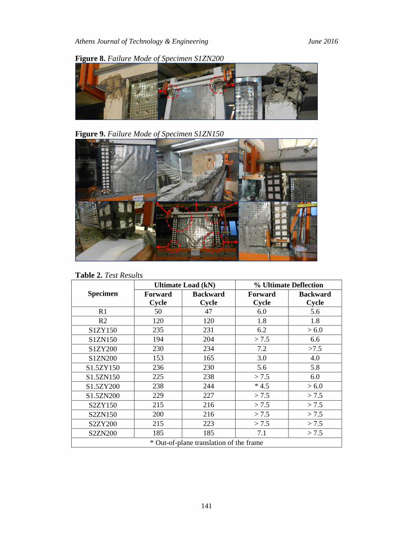
Specimen S1ZN200 behaved similar to the reference R2 specimen and the
influence of wall strengthening on the overall frame behavior could not be
observed due to the premature shear failure of the weak columns (Figure 8). The
infill wall did not experience significant damage except the limited crushing in the
corners. The shear cracks in the upper portions of the columns controlled the
frame behavior throughout the test and the load capacity of the frame slightly
exceeded the load capacity of the reference frame R2 (Table 2). The ultimate load
values of S1ZN200 was about 28 % and 38 % higher than the ultimate load values
of R2 in the forward and backward directions.
Due to the shear failure of the weak columns of S1ZN200, the additional
strengthening measures summarized in the previous section were realized in the
remaining tests. As a result of this strengthening, all of the remaining specimens
exhibited a quite ductile behavior (Figures 9-19).
Figure 6. Failure Mode of Specimen R1
Figure 7. Failure Mode of Specimen R1
Athens Journal of Technology & Engineering June 2016
141
Figure 8. Failure Mode of Specimen S1ZN200
Figure 9. Failure Mode of Specimen S1ZN150
Table 2. Test Results
Specimen
Ultimate Load (kN) % Ultimate Deflection
Forward
Cycle
Backward
Cycle
Forward
Cycle
Backward
Cycle
R1 50 47 6.0 5.6
R2 120 120 1.8 1.8
S1ZY150 235 231 6.2 > 6.0
S1ZN150 194 204 > 7.5 6.6
S1ZY200 230 234 7.2 >7.5
S1ZN200 153 165 3.0 4.0
S1.5ZY150 236 230 5.6 5.8
S1.5ZN150 225 238 > 7.5 6.0
S1.5ZY200 238 244 * 4.5 > 6.0
S1.5ZN200 229 227 > 7.5 > 7.5
S2ZY150 215 216 > 7.5 > 7.5
S2ZN150 200 216 > 7.5 > 7.5
S2ZY200 215 223 > 7.5 > 7.5
S2ZN200 185 185 7.1 > 7.5
* Out-of-plane translation of the frame
Vol. 3, No. 2 Aykac et al.: Influence of Strengthening the Infill Walls...
142
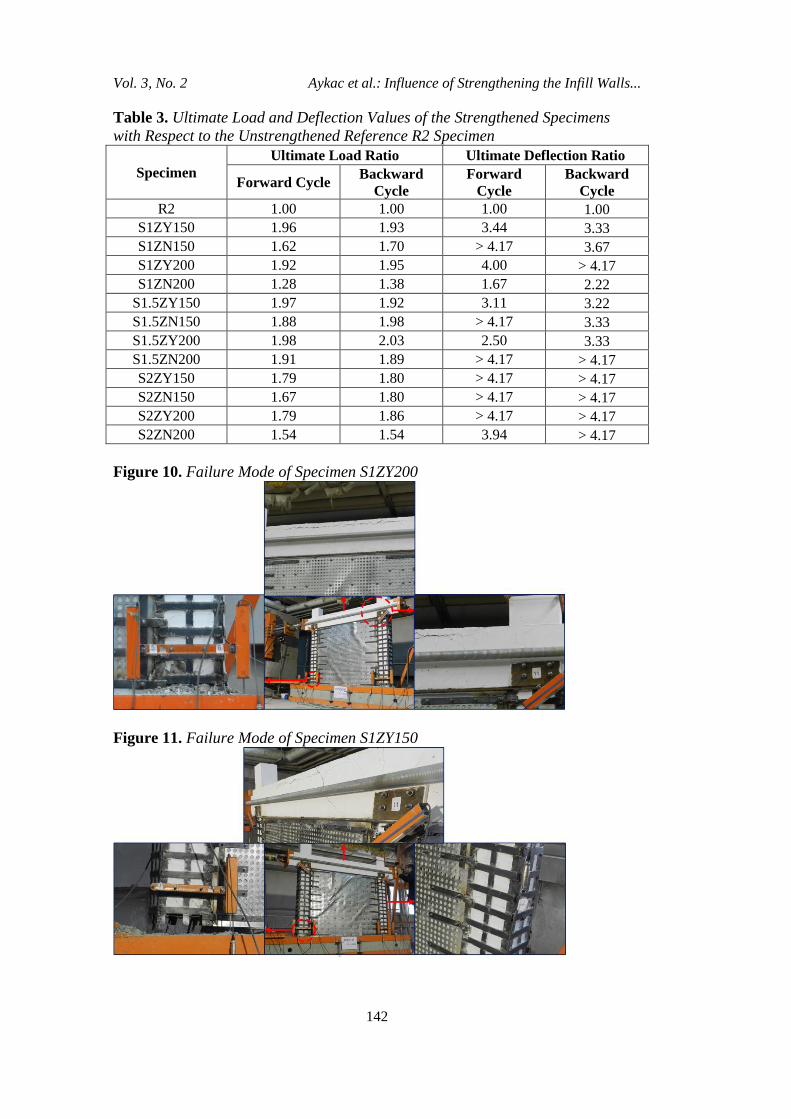
Table 3. Ultimate Load and Deflection Values of the Strengthened Specimens
with Respect to the Unstrengthened Reference R2 Specimen
Specimen
Ultimate Load Ratio Ultimate Deflection Ratio
Forward Cycle Backward
Cycle
Forward
Cycle
Backward
Cycle
R2 1.00 1.00 1.00 1.00
S1ZY150 1.96 1.93 3.44 3.33
S1ZN150 1.62 1.70 > 4.17 3.67
S1ZY200 1.92 1.95 4.00 > 4.17
S1ZN200 1.28 1.38 1.67 2.22
S1.5ZY150 1.97 1.92 3.11 3.22
S1.5ZN150 1.88 1.98 > 4.17 3.33
S1.5ZY200 1.98 2.03 2.50 3.33
S1.5ZN200 1.91 1.89 > 4.17 > 4.17
S2ZY150 1.79 1.80 > 4.17 > 4.17
S2ZN150 1.67 1.80 > 4.17 > 4.17
S2ZY200 1.79 1.86 > 4.17 > 4.17
S2ZN200 1.54 1.54 3.94 > 4.17
Figure 10. Failure Mode of Specimen S1ZY200
Figure 11. Failure Mode of Specimen S1ZY150
Athens Journal of Technology & Engineering June 2016
143
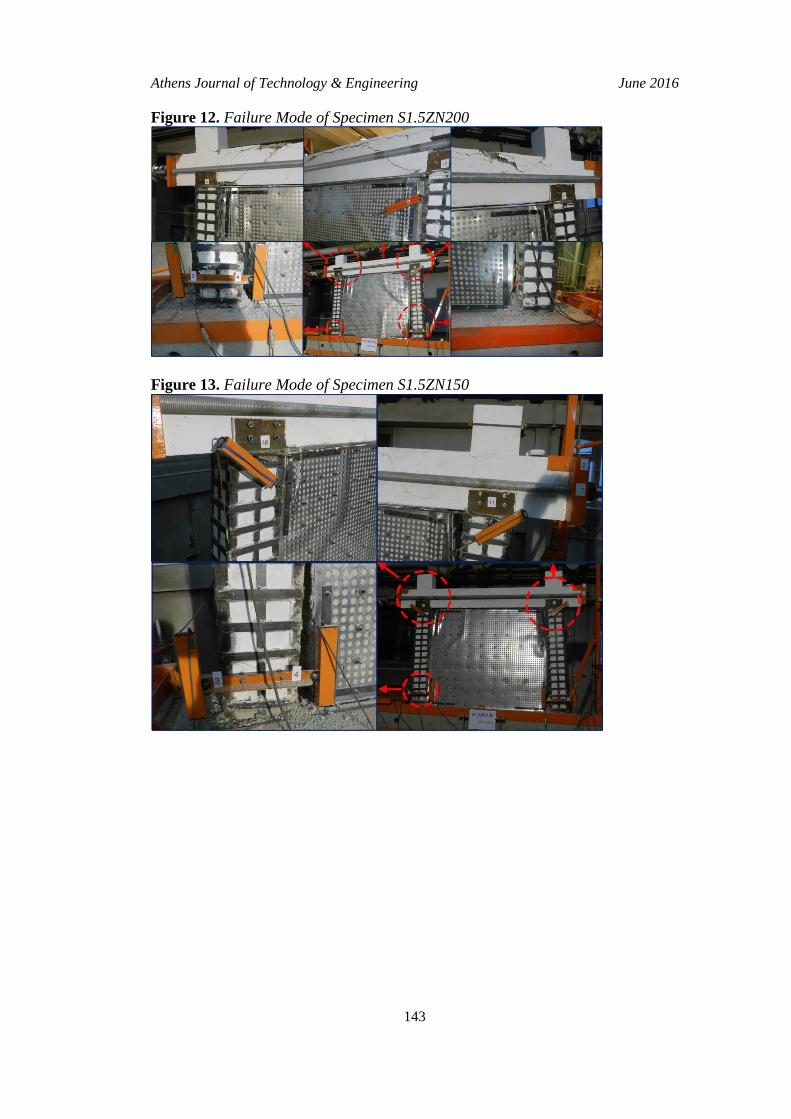
Figure 12. Failure Mode of Specimen S1.5ZN200
Figure 13. Failure Mode of Specimen S1.5ZN150

Vol. 3, No. 2 Aykac et al.: Influence of Strengthening the Infill Walls...
144
Figure 14. Failure Mode of Specimen S1.5ZY200
Figure 15. Failure Mode of Specimen S1.5ZY150
Athens Journal of Technology & Engineering June 2016
145
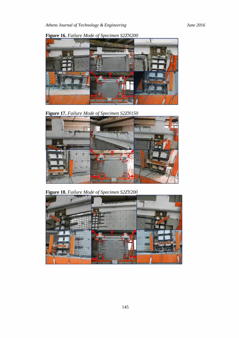
Figure 16. Failure Mode of Specimen S2ZN200
Figure 17. Failure Mode of Specimen S2ZN150
Figure 18. Failure Mode of Specimen S2ZY200
Vol. 3, No. 2 Aykac et al.: Influence of Strengthening the Infill Walls...
146
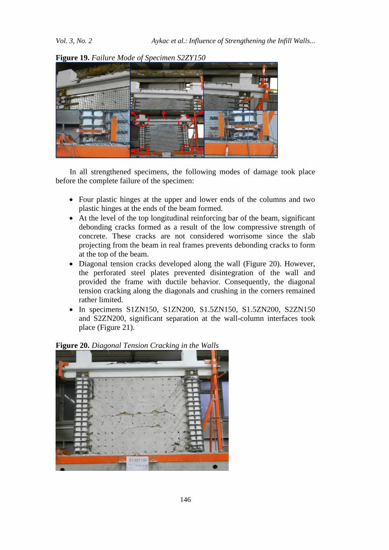
Figure 19. Failure Mode of Specimen S2ZY150
In all strengthened specimens, the following modes of damage took place
before the complete failure of the specimen:
Four plastic hinges at the upper and lower ends of the columns and two
plastic hinges at the ends of the beam formed.
At the level of the top longitudinal reinforcing bar of the beam, significant
debonding cracks formed as a result of the low compressive strength of
concrete. These cracks are not considered worrisome since the slab
projecting from the beam in real frames prevents debonding cracks to form
at the top of the beam.
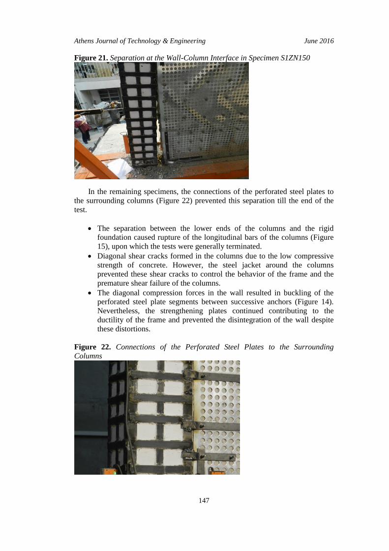
Diagonal tension cracks developed along the wall (Figure 20). However,
the perforated steel plates prevented disintegration of the wall and
provided the frame with ductile behavior. Consequently, the diagonal
tension cracking along the diagonals and crushing in the corners remained
rather limited.
In specimens S1ZN150, S1ZN200, S1.5ZN150, S1.5ZN200, S2ZN150
and S2ZN200, significant separation at the wall-column interfaces took
place (Figure 21).
Figure 20. Diagonal Tension Cracking in the Walls
Athens Journal of Technology & Engineering June 2016
147
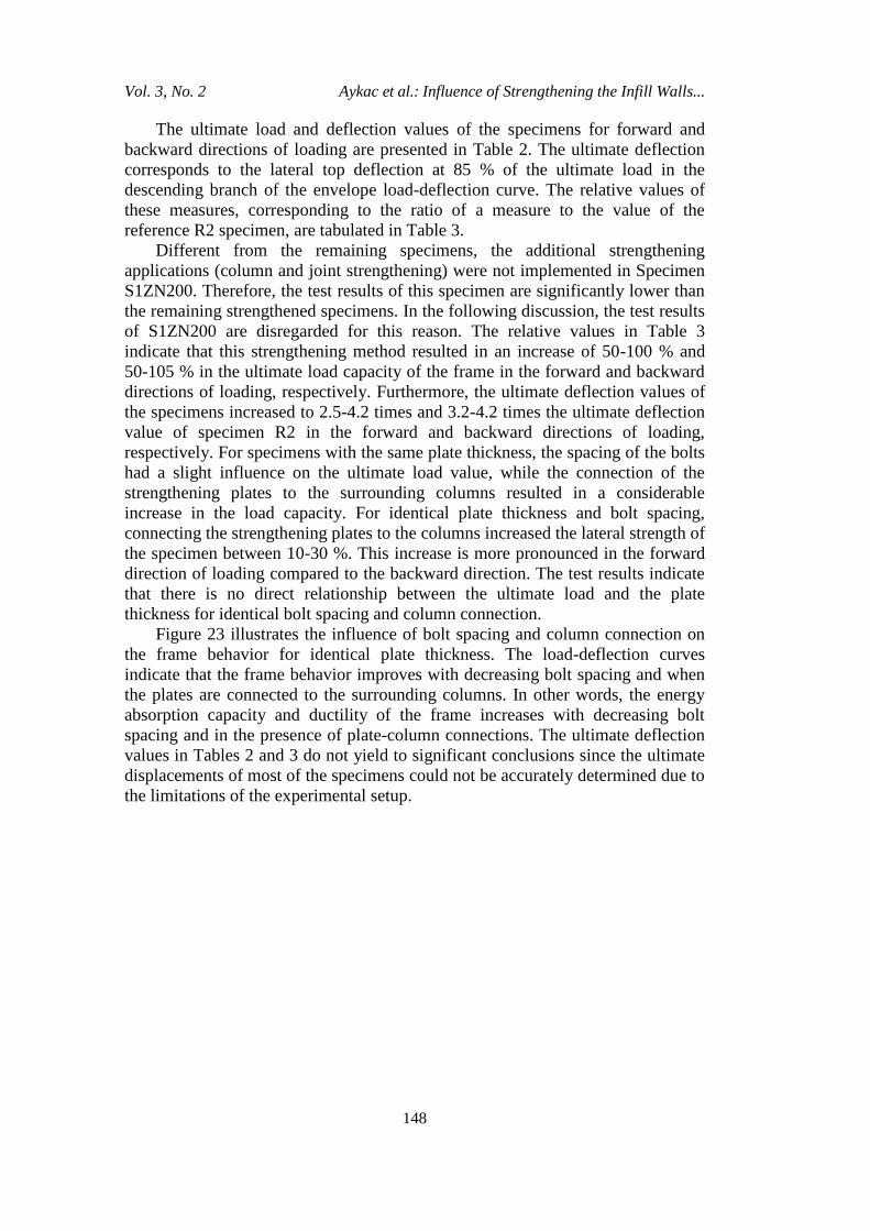
Figure 21. Separation at the Wall-Column Interface in Specimen S1ZN150
In the remaining specimens, the connections of the perforated steel plates to
the surrounding columns (Figure 22) prevented this separation till the end of the
test.
The separation between the lower ends of the columns and the rigid
foundation caused rupture of the longitudinal bars of the columns (Figure
15), upon which the tests were generally terminated.
Diagonal shear cracks formed in the columns due to the low compressive
strength of concrete. However, the steel jacket around the columns
prevented these shear cracks to control the behavior of the frame and the
premature shear failure of the columns.
The diagonal compression forces in the wall resulted in buckling of the
perforated steel plate segments between successive anchors (Figure 14).
Nevertheless, the strengthening plates continued contributing to the
ductility of the frame and prevented the disintegration of the wall despite
these distortions.
Figure 22. Connections of the Perforated Steel Plates to the Surrounding
Columns
Vol. 3, No. 2 Aykac et al.: Influence of Strengthening the Infill Walls...
148
The ultimate load and deflection values of the specimens for forward and
backward directions of loading are presented in Table 2. The ultimate deflection
corresponds to the lateral top deflection at 85 % of the ultimate load in the
descending branch of the envelope load-deflection curve. The relative values of
these measures, corresponding to the ratio of a measure to the value of the
reference R2 specimen, are tabulated in Table 3.
Different from the remaining specimens, the additional strengthening
applications (column and joint strengthening) were not implemented in Specimen
S1ZN200. Therefore, the test results of this specimen are significantly lower than
the remaining strengthened specimens. In the following discussion, the test results
of S1ZN200 are disregarded for this reason. The relative values in Table 3
indicate that this strengthening method resulted in an increase of 50-100 % and
50-105 % in the ultimate load capacity of the frame in the forward and backward
directions of loading, respectively. Furthermore, the ultimate deflection values of
the specimens increased to 2.5-4.2 times and 3.2-4.2 times the ultimate deflection
value of specimen R2 in the forward and backward directions of loading,
respectively. For specimens with the same plate thickness, the spacing of the bolts
had a slight influence on the ultimate load value, while the connection of the
strengthening plates to the surrounding columns resulted in a considerable
increase in the load capacity. For identical plate thickness and bolt spacing,
connecting the strengthening plates to the columns increased the lateral strength of
the specimen between 10-30 %. This increase is more pronounced in the forward
direction of loading compared to the backward direction. The test results indicate
that there is no direct relationship between the ultimate load and the plate
thickness for identical bolt spacing and column connection.
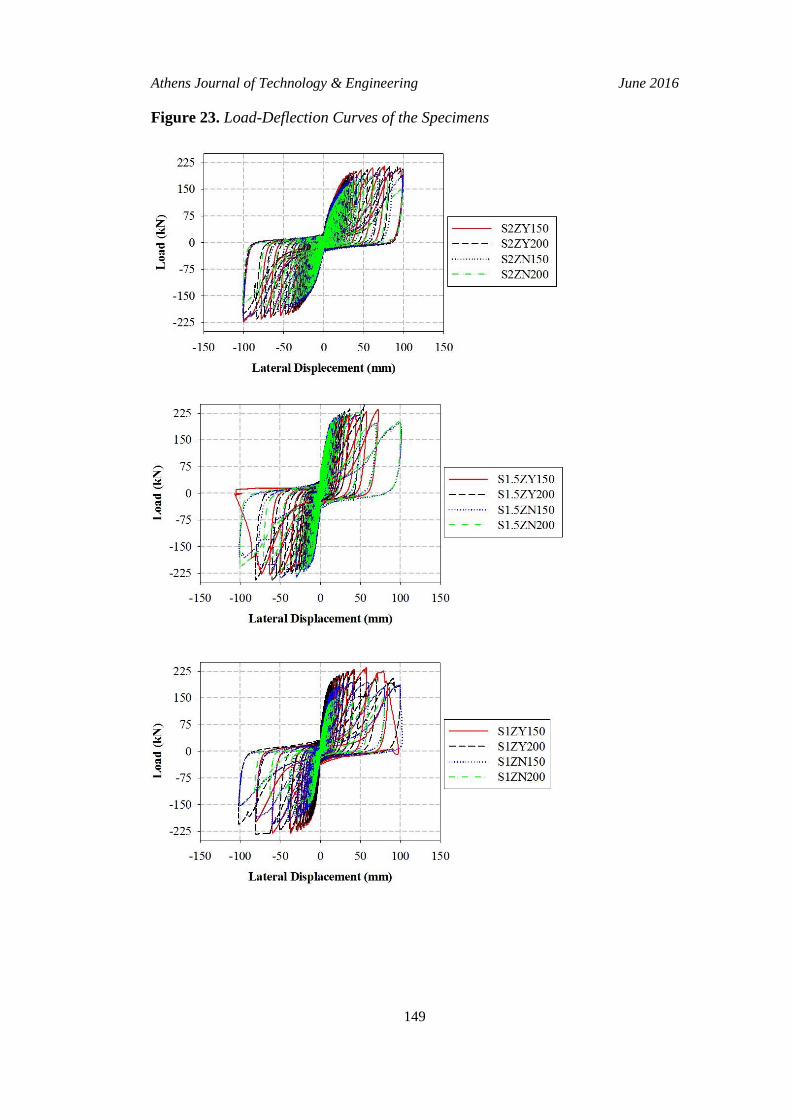
Figure 23 illustrates the influence of bolt spacing and column connection on
the frame behavior for identical plate thickness. The load-deflection curves
indicate that the frame behavior improves with decreasing bolt spacing and when
the plates are connected to the surrounding columns. In other words, the energy
absorption capacity and ductility of the frame increases with decreasing bolt
spacing and in the presence of plate-column connections. The ultimate deflection
values in Tables 2 and 3 do not yield to significant conclusions since the ultimate
displacements of most of the specimens could not be accurately determined due to
the limitations of the experimental setup.
Athens Journal of Technology & Engineering June 2016
149
Figure 23. Load-Deflection Curves of the Specimens
Vol. 3, No. 2 Aykac et al.: Influence of Strengthening the Infill Walls...
150
Conclusions
A total of 14 infilled RC frame specimens were tested to investigate the
influence of strengthening the infill wall with perforated steel plates on the overall
frame behavior. The thickness of the strengthening plates, spacing of the bolts and
connections between the perforated steel plates and the columns were adopted as
test parameters. By comparing the test results of the specimens with strengthened
infill wall to the results of the bare reference frame and the reference frame with
an unstrengthened infill wall, the following conclusions were drawn:
The proposed method considerably increases the lateral strength and
ultimate deformation values of infilled RC frames. The influence of this
strengthening method on the overall lateral strength and the deformation
capacity of the frame is rather limited if the columns of the frame with
inadequate earthquake resistance are not strengthened. The present
experiments indicated that the contribution of the perforated steel plates of
the infill wall on the overall behavior of the frame can be increased by
strengthening the columns and the beam-column connections of the frame
against shear. Otherwise, the shear failure of the columns prevent the
strengthened infill wall to fully develop its lateral capacity.
Among the investigated test parameters, connecting the perforated steel
plates to the surrounding columns was found to have the most considerable
positive influence on the lateral strength of the infilled RC frame.
Connecting the strengthening plates to the surrounding columns and
decreasing the bolt spacing contribute to the deformation capacity,
ductility and energy absorption capacity of an infilled RC frame
significantly.
Connecting the strengthening plates to the surrounding columns is an
effective measure for limiting the separation at the wall-column interfaces
during seismic excitations.
The present paper summarizes 14 experiments carried out within the final
stage of a research program. In the remaining experiments of this stage, the frame
specimens subjected to axial column loading as well as lateral seismic loads will
be tested.
References
Amanat, KM, Alam, MMM & Alam, MS 2007, ‘Experimental investigation of the use of
ferrocement laminates for repairing masonry infilled RC frames’ Journal of Civil
Engineering, (IEB), vol. 35, no. 2, pp. 71-80.
Aykac, S, Kalkan, I & Seydanlioglu, M 2014, ‘Strengthening of hollow brick infill walls
with perforated steel plates’ Earthquakes and Structures, vol. 6, no. 2, pp. 181-199.
Baran, M & Tankut, T 2011, ‘Experimental study on seismic strengthening of RC frames
by precast concrete panels’ ACI Structural Journal, vol. 108, no. 2, pp. 227-237.
Athens Journal of Technology & Engineering June 2016
151
El-Dakhakhni, WW, Hamid, AA, Hakam, ZHR & Elgaaly, M 2006, ‘Hazard mitigation
and strengthening of unreinforced masonry walls using composites’ Composite
Structures, vol. 73, no. 4, pp. 458-477.
ElGawady, MA, Lestuzzi, P & Badoux, M 2006, ‘Retrofitting of masonry walls using
shotcrete’ Proceedings of the New Zealand Society Earthquake Engineering
Conference, Napier, New Zealand.
Erdem, I, Akyuz, U, Ersoy, U & Ozcebe, G 2006, ‘An experimental study on two
different strengthening techniques for RC frames’ Engineering Structures, vol. 28,
no. 13, pp. 1843-1851.
Farooq, SH, Ilyas, M & Ghaffar, A 2006, ‘Technique for strengthening of masonry wall
panels using steel strips’ Asian Journal of Civil Engineering, vol. 7, no. 6, pp. 621-
638.
Frosch, RJ, Li, W, Jirsa, JO & Kreger, ME 1996, ‘Retrofit of non-ductile moment-
resisting frames using precast infill wall panels’ Earthquake Spectra, vol. 12, no. 4,
pp. 741-760.
Kahn, LF 1984, ‘Shotcrete strengthening of brick masonry walls’ ACI Structural Journal,
vol. 6, no. 7, pp. 34-40.
Kalkan, I, Aykac, B, Baran, M, Babayani, R & Aykac, S 2013, ‘Delikli çelik levhalarla
güçlendirilmiş dolgu duvarların deprem davranışı (in Turkish)’ The Turkish
Chamber of Civil Engineers 5th Symposium on Steel Structures, Istanbul, Turkey.
Ozbek, E & Can, H 2012, ‘Strengthening of infill brick walls using steel profiles (in
Turkish)’ Journal of the Faculty of Engineering and Architecture of Gazi University,
vol. 27, no. 4, pp. 921-929.
Ozbek, E, Kalkan, I, Akbas, SO & Aykac, S 2014, ‘Influence of strengthening with
perforated steel plates on the behavior of infill walls and RC frame’ International
Journal of Civil, Structure, Construction and Architectural Engineering, vol. 8, no.
5, pp. 494-499.
Ozcebe, G, Ersoy, U, Tankut, T, Erduran, E, Keskin, RSO & Mertol, HC 2003,
Strengthening of brick infilled RC frames with CFRP, Technical Report No. 2003/1,
Structural Engineering Research Unit, Middle East Technical University, Ankara,
Turkey.
Papanicolaou, CG, Triantafillou, TC & Lekka, M 2011, ‘Externally bonded grids as
strengthening and seismic retrofitting materials of masonry panels’ Construction and
Building Materials, vol. 25, no. 2, pp. 504-514.
Prota, A, Marcari, G, Fabbrocino, G, Manfredi, G & Aldea, C 2006, ‘Experimental in-
plane behavior of tuff masonry strengthened with cementitious matrix-grid
composites’ ASCE Journal of Composites for Construction, vol. 10, no. 3, pp. 223-
233.
Sevil, T, Baran, M, Bilir, T & Canbay, E 2011, ‘Use of steel fiber reinforced mortar for
seismic strengthening’ Construction and Building Materials, vol. 25, no. 2, 892-899.
Taghdi, M, Bruneau, M & Saatcioglu, M 2000, ‘Seismic retrofitting of low-rise masonry
and concrete walls using steel strips’ ASCE Journal of Structural Engineering, vol.
126, no. 9, pp. 1017-1025.
Topcu, IB, Isikdag, B, Tatar, O & Abi, E 2005, ‘Depremde hasar görmüş binaların
ferrocement panellerle güçlendirilmesi (in Turkish)’ Earthquake Symposium,
Kocaeli, Turkey.
Triantafillou, TC 1998, ‘Strengthening of masonry structures using epoxy-bonded FRP
laminates’ ASCE Journal of Composites for Construction, vol. 2, no. 2, pp. 96-104.
Triantafillou, TC & Papanicolaou, CG 2006, ‘Shear strengthening of reinforced concrete
members with textile reinforced mortar (TRM) jackets’ Materials and Structures,
vol. 39, no. 1, pp. 93-103.

Vol. 3, No. 2 Aykac et al.: Influence of Strengthening the Infill Walls...
152
Triantafillou, TC, Papanicolaou, CG, Zissimopoulos, P & Laourdekis, T 2006, ‘Concrete
confinement with textile-reinforced mortar jackets’ ACI Structural Journal, vol. 103,
no. 1, pp. 28-37.
Related Documents