Influence of friction stir welding process and tool parameters on strength properties of AA7075-T 6 aluminium alloy joints S. Rajakumar a,⇑ , C. Muralidharan b , V. Balasubramanian a a Center for Materials Joining & Research (CEMAJOR), Department of Manufacturing Engineering, Annamalai University, Annamalainagar 608 002, Chidambaram, Tamil Nadu, India b Department of Manufacturing Engineering, Annamalai University, Annamalainagar 608 002, Chidambaram, Tamil Nadu, India article info Article history: Received 30 April 2010 Accepted 16 August 2010 Available online xxxx Keywords: A. Non ferrous metals and alloys D. Welding F. Microstructure abstract The aircraft aluminium alloys generally present low weldability by traditional fusion welding process. The development of the friction stir welding has provided an alternative improved way of satisfactorily producing aluminium joints, in a faster and reliable manner. In this present work, the influence of process and tool parameters on tensile strength properties of AA7075-T 6 joints produced by friction stir welding was analysed. Square butt joints were fabricated by varying process parameters and tool parameters. Strength properties of the joints were evaluated and correlated with the microstructure, microhardness of weld nugget. From this investigation it is found that the joint fabricated at a tool rotational speed of 1400 rpm, welding speed of 60 mm/min, axial force of 8 kN, using the tool with 15 mm shoulder diam- eter, 5 mm pin diameter, 45 HRc tool hardness yielded higher strength properties compared to other joints. Ó 2010 Elsevier Ltd. All rights reserved. 1. Introduction Aluminium alloy AA7075 (Al–Zn–Mg–Cu) is one of the stron- gest aluminium alloys in industrial use today. Its high strength- to weight ratio, together with its natural aging characteristics, makes it attractive for a number of aircraft structural applications [1]. The alloy derives its strength from precipitation of Mg 2 Zn and Al 2 CuMg phases. A major problem with this alloy is that it is not fusion weldable. It is extremely sensitive to weld solidification cracking as well as heat-affected zone (HAZ) liquation cracking due to the presence of copper. While it is possible to overcome the problem of weld solidification cracking using a suitable non- heat-treatable aluminium alloy filler (for example, Al–Mg or Al–Si), the resulting joint efficiencies are unacceptably low [2]. Further, oxidation and/or vaporization of zinc present several problems during welding, such as porosity, lack-of-fusion, and hazardous fumes. Therefore, use of alloy AA7075 is currently limited to applications that do not involve welding [3]. During friction stir welding (FSW), a rotating tool moves along joint interface, generates heat and results in recirculating flow of plasticized material near the tool surface. This softened material is subjected to extrusion by the tool pin rotational and traverse movements leading to formation of friction stir processing (FSP) zone [4]. The formation of FSP zone is affected by the material flow behaviour under the action of rotating tool. However, the material flow behaviour is predominantly influenced by the material properties such as yield strength, ductility and hardness of the base metal, tool design, and FSW process parameters. Compared to fusion welding techniques, friction stir welding strongly reduces the presence of distortions and residual stresses [5–7]. Hatamleh and Singh [8] have reported the effect of shot-peened and laser-peened on weld microstructure and mechanical proper- ties of AA7075-T 6 aluminium alloy joints. The metallographic sec- tion show a classic weld nugget region and the stirring marks, commonly denoted as ‘‘onion rings,” typically found in this region of the weld. A more recent investigation by Cai et al. [9] revealed that the grains in the nugget zone are not 3d equiaxial but 2d rod-like. The grain structure in Thermo-Mechanical Affected Zone (TMAZ) region was elongated and distorted due to the mechanical action from the welding tool. The heat-affected zone was unaf- fected by the mechanical effects from the welding tool, and the grain structure in that region resembles the parent material grain structure. There have been lot of efforts to understand the effect of process parameters on material flow behaviour, microstructure formation and mechanical properties of friction stir welded joints. Finding the most effective parameters on properties of friction stir welds as well as realizing their influence on the weld properties has been major topics for researchers [10–12]. The influence of some of the 0261-3069/$ - see front matter Ó 2010 Elsevier Ltd. All rights reserved. doi:10.1016/j.matdes.2010.08.025 ⇑ Corresponding author. Tel.: +91 4144 231053 (R), mobile: +91 09486870051; fax: +91 4144 238080/238275. E-mail addresses: [email protected] (S. Rajakumar), [email protected] (C. Muralidharan), [email protected] (V. Balasubramanian). Materials and Design xxx (2010) xxx–xxx Contents lists available at ScienceDirect Materials and Design journal homepage: www.elsevier.com/locate/matdes Please cite this article in press as: Rajakumar S et al. Influence of friction stir welding process and tool parameters on strength properties of AA7075-T 6 aluminium alloy joints. J Mater Design (2010), doi:10.1016/j.matdes.2010.08.025

Welcome message from author
This document is posted to help you gain knowledge. Please leave a comment to let me know what you think about it! Share it to your friends and learn new things together.
Transcript
Materials and Design xxx (2010) xxx–xxx
Contents lists available at ScienceDirect
Materials and Design
journal homepage: www.elsevier .com/locate /matdes
Influence of friction stir welding process and tool parameters on strengthproperties of AA7075-T6 aluminium alloy joints
S. Rajakumar a,⇑, C. Muralidharan b, V. Balasubramanian a
a Center for Materials Joining & Research (CEMAJOR), Department of Manufacturing Engineering, Annamalai University, Annamalainagar 608 002,Chidambaram, Tamil Nadu, Indiab Department of Manufacturing Engineering, Annamalai University, Annamalainagar 608 002, Chidambaram, Tamil Nadu, India
a r t i c l e i n f o a b s t r a c t
Article history:Received 30 April 2010Accepted 16 August 2010Available online xxxx
Keywords:A. Non ferrous metals and alloysD. WeldingF. Microstructure
0261-3069/$ - see front matter � 2010 Elsevier Ltd. Adoi:10.1016/j.matdes.2010.08.025
⇑ Corresponding author. Tel.: +91 4144 231053 (R)fax: +91 4144 238080/238275.
E-mail addresses: [email protected] (S. Raja(C. Muralidharan), [email protected] (V. Balasubr
Please cite this article in press as: Rajakumar Saluminium alloy joints. J Mater Design (2010),
The aircraft aluminium alloys generally present low weldability by traditional fusion welding process.The development of the friction stir welding has provided an alternative improved way of satisfactorilyproducing aluminium joints, in a faster and reliable manner. In this present work, the influence of processand tool parameters on tensile strength properties of AA7075-T6 joints produced by friction stir weldingwas analysed. Square butt joints were fabricated by varying process parameters and tool parameters.Strength properties of the joints were evaluated and correlated with the microstructure, microhardnessof weld nugget. From this investigation it is found that the joint fabricated at a tool rotational speed of1400 rpm, welding speed of 60 mm/min, axial force of 8 kN, using the tool with 15 mm shoulder diam-eter, 5 mm pin diameter, 45 HRc tool hardness yielded higher strength properties compared to otherjoints.
� 2010 Elsevier Ltd. All rights reserved.
1. Introduction
Aluminium alloy AA7075 (Al–Zn–Mg–Cu) is one of the stron-gest aluminium alloys in industrial use today. Its high strength-to weight ratio, together with its natural aging characteristics,makes it attractive for a number of aircraft structural applications[1]. The alloy derives its strength from precipitation of Mg2Zn andAl2CuMg phases. A major problem with this alloy is that it is notfusion weldable. It is extremely sensitive to weld solidificationcracking as well as heat-affected zone (HAZ) liquation crackingdue to the presence of copper. While it is possible to overcomethe problem of weld solidification cracking using a suitable non-heat-treatable aluminium alloy filler (for example, Al–Mg or Al–Si),the resulting joint efficiencies are unacceptably low [2]. Further,oxidation and/or vaporization of zinc present several problemsduring welding, such as porosity, lack-of-fusion, and hazardousfumes. Therefore, use of alloy AA7075 is currently limited toapplications that do not involve welding [3].
During friction stir welding (FSW), a rotating tool moves alongjoint interface, generates heat and results in recirculating flow ofplasticized material near the tool surface. This softened materialis subjected to extrusion by the tool pin rotational and traverse
ll rights reserved.
, mobile: +91 09486870051;
kumar), [email protected]).
et al. Influence of friction stir wdoi:10.1016/j.matdes.2010.08.0
movements leading to formation of friction stir processing (FSP)zone [4]. The formation of FSP zone is affected by the material flowbehaviour under the action of rotating tool. However, the materialflow behaviour is predominantly influenced by the materialproperties such as yield strength, ductility and hardness of the basemetal, tool design, and FSW process parameters. Compared tofusion welding techniques, friction stir welding strongly reducesthe presence of distortions and residual stresses [5–7].
Hatamleh and Singh [8] have reported the effect of shot-peenedand laser-peened on weld microstructure and mechanical proper-ties of AA7075-T6 aluminium alloy joints. The metallographic sec-tion show a classic weld nugget region and the stirring marks,commonly denoted as ‘‘onion rings,” typically found in this regionof the weld. A more recent investigation by Cai et al. [9] revealedthat the grains in the nugget zone are not 3d equiaxial but 2drod-like. The grain structure in Thermo-Mechanical Affected Zone(TMAZ) region was elongated and distorted due to the mechanicalaction from the welding tool. The heat-affected zone was unaf-fected by the mechanical effects from the welding tool, and thegrain structure in that region resembles the parent material grainstructure.
There have been lot of efforts to understand the effect of processparameters on material flow behaviour, microstructure formationand mechanical properties of friction stir welded joints. Findingthe most effective parameters on properties of friction stir weldsas well as realizing their influence on the weld properties has beenmajor topics for researchers [10–12]. The influence of some of the
elding process and tool parameters on strength properties of AA7075-T6
25
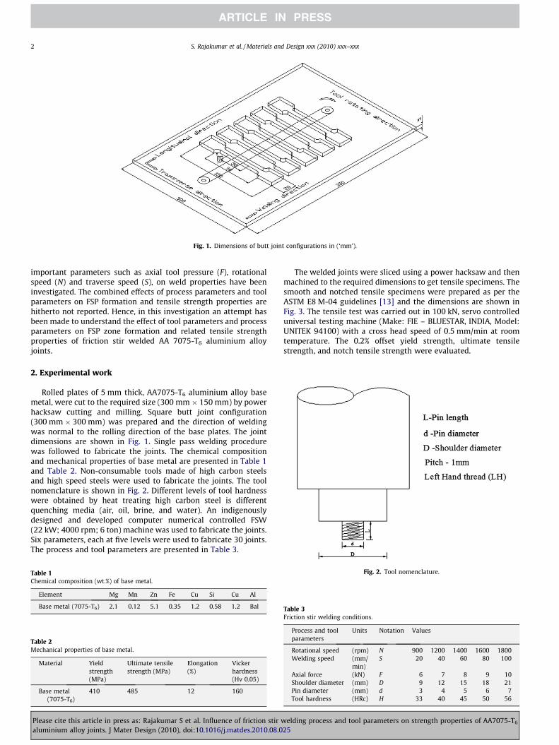
Fig. 1. Dimensions of butt joint configurations in (‘mm’).
2 S. Rajakumar et al. / Materials and Design xxx (2010) xxx–xxx
important parameters such as axial tool pressure (F), rotationalspeed (N) and traverse speed (S), on weld properties have beeninvestigated. The combined effects of process parameters and toolparameters on FSP formation and tensile strength properties arehitherto not reported. Hence, in this investigation an attempt hasbeen made to understand the effect of tool parameters and processparameters on FSP zone formation and related tensile strengthproperties of friction stir welded AA 7075-T6 aluminium alloyjoints.
2. Experimental work
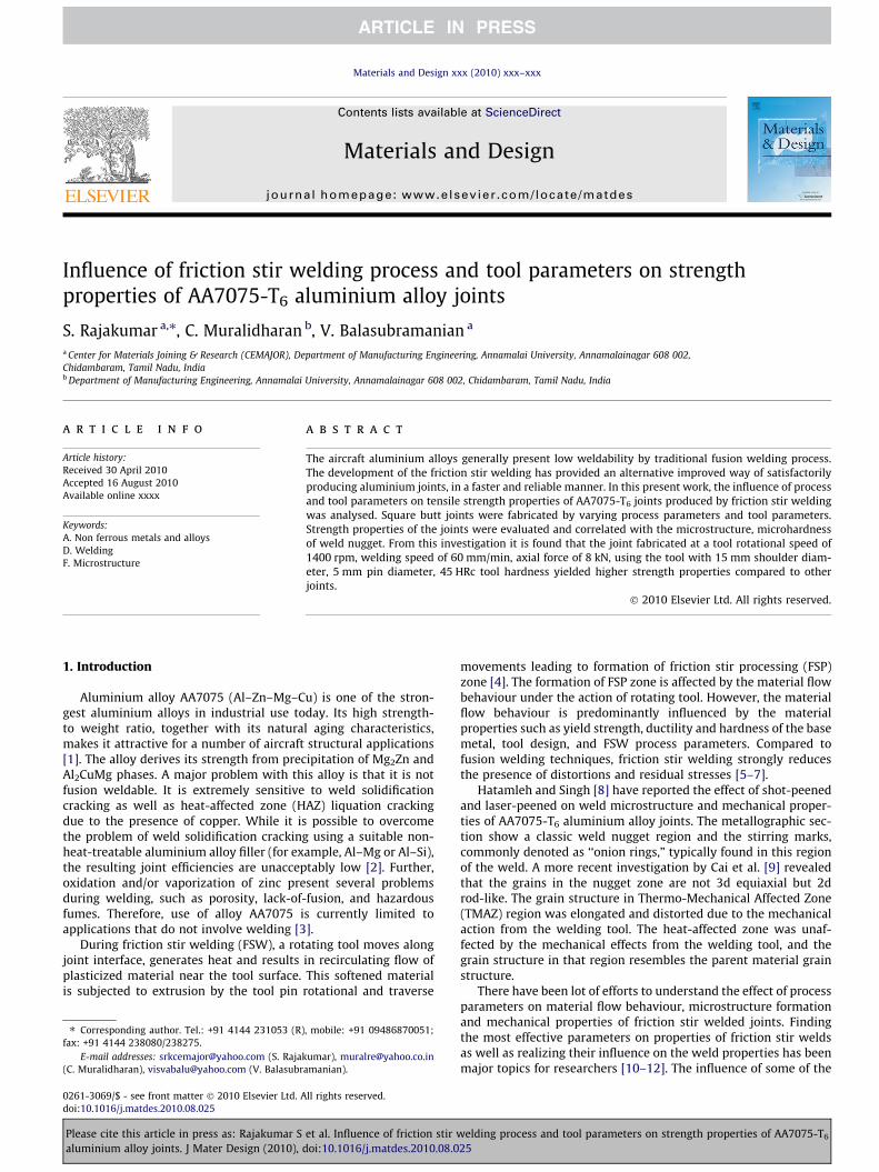
Rolled plates of 5 mm thick, AA7075-T6 aluminium alloy basemetal, were cut to the required size (300 mm � 150 mm) by powerhacksaw cutting and milling. Square butt joint configuration(300 mm � 300 mm) was prepared and the direction of weldingwas normal to the rolling direction of the base plates. The jointdimensions are shown in Fig. 1. Single pass welding procedurewas followed to fabricate the joints. The chemical compositionand mechanical properties of base metal are presented in Table 1and Table 2. Non-consumable tools made of high carbon steelsand high speed steels were used to fabricate the joints. The toolnomenclature is shown in Fig. 2. Different levels of tool hardnesswere obtained by heat treating high carbon steel is differentquenching media (air, oil, brine, and water). An indigenouslydesigned and developed computer numerical controlled FSW(22 kW; 4000 rpm; 6 ton) machine was used to fabricate the joints.Six parameters, each at five levels were used to fabricate 30 joints.The process and tool parameters are presented in Table 3.
Table 1Chemical composition (wt.%) of base metal.
Element Mg Mn Zn Fe Cu Si Cu Al
Base metal (7075-T6) 2.1 0.12 5.1 0.35 1.2 0.58 1.2 Bal
Table 2Mechanical properties of base metal.
Material Yieldstrength(MPa)
Ultimate tensilestrength (MPa)
Elongation(%)
Vickerhardness(Hv 0.05)
Base metal(7075-T6)
410 485 12 160
Please cite this article in press as: Rajakumar S et al. Influence of friction stir waluminium alloy joints. J Mater Design (2010), doi:10.1016/j.matdes.2010.08.0
The welded joints were sliced using a power hacksaw and thenmachined to the required dimensions to get tensile specimens. Thesmooth and notched tensile specimens were prepared as per theASTM E8 M-04 guidelines [13] and the dimensions are shown inFig. 3. The tensile test was carried out in 100 kN, servo controlleduniversal testing machine (Make: FIE – BLUESTAR, INDIA, Model:UNITEK 94100) with a cross head speed of 0.5 mm/min at roomtemperature. The 0.2% offset yield strength, ultimate tensilestrength, and notch tensile strength were evaluated.
Fig. 2. Tool nomenclature.
Table 3Friction stir welding conditions.
Process and toolparameters
Units Notation Values
Rotational speed (rpm) N 900 1200 1400 1600 1800Welding speed (mm/
min)S 20 40 60 80 100
Axial force (kN) F 6 7 8 9 10Shoulder diameter (mm) D 9 12 15 18 21Pin diameter (mm) d 3 4 5 6 7Tool hardness (HRc) H 33 40 45 50 56
elding process and tool parameters on strength properties of AA7075-T6
25
(a) Unnotched tensile specimen dimensions
(b) Notched tensile specimen
Fig. 3. Dimensions of tensile specimen.
S. Rajakumar et al. / Materials and Design xxx (2010) xxx–xxx 3
The specimens for metallographic examination were sectionedto the required sizes from the joint comprising FSP zone, TMAZ,HAZ and base metal regions and then polished using differentgrades of emery papers. Final polishing was done using thediamond compound (1 lm particle size) in the disc polishingmachine. The polished samples were etched using 10% NaOH toshow general flow structure of the alloy. A standard Keller’s re-agent made of 5 ml HNO3 (95% concentration), 2 ml HF, 3 ml HCl,190 ml H2O was used to reveal the microstructure of the weldedjoints. Macro and micro-structural analysis have been carried outusing a light optical microscope (VERSAMET-3) incorporated withan image analysing software (Clemex-Vision). The fractured sur-faces of the tensile tested specimens were examined by a ScanningElectron Microscope (SEM) to reveal the fracture surfacemorphology.
3. Results
3.1. Macrostructure
Tables 4–9, show the effects of process and tool parameters onmacrostructure of the friction stir welded joints. It is generallyknown that the fusion welding of aluminium alloys accompaniedby the defects like porosity, slag inclusion, solidification cracks,etc., deteriorates the weld quality and joint properties. Usually,friction stir welded joints are free from solidification related de-fects since, there is no melting takes place during welding andthe metals are joined in solid state itself due to the heat generatedby the friction and flow of metal by the stirring action. However,FSW joints are prone to other defects like pin hole, tunnel defect,piping defect, kissing bond, Zig-Zag line and cracks, etc., due toimproper flow of metal and insufficient consolidation of metal inthe FSP (weld nugget) region.
The kissing bond generally means a partial remnant of theunwelded butt surface below the stir zone, which is mainly attrib-uted to insufficient plunging of the welding tool during FSW [14].The mechanism of the kissing bond is related to the insufficientbreakup of oxide layer by the insufficient stretch of the contacting
Please cite this article in press as: Rajakumar S et al. Influence of friction stir waluminium alloy joints. J Mater Design (2010), doi:10.1016/j.matdes.2010.08.0
surfaces around the welding pin. The reduction of the heat inputresults in the insufficient breakup of the oxide layer during FSW.There is a high possibility that the sufficient breakup of the oxidelayer is not achieved in the root part of the weld. It is observed thatthe continuous oxide film, which resulted due to insufficientstirring hence, the oxide layers on the initial butt surfaces, couldbe directly bonded without the metallic bond between oxide freesurfaces in the root part of the weld. Therefore, continuous oxidefilm is a feature of the kissing bond and is possible to fracture alongthe Zig-Zag line [15].
All the joints fabricated in this investigation were examined atlow magnification (10�) using stereo zoom microscope to revealthe quality of weld nugget region. The cross-section macrographsof the FSW joints are presented in Tables 4–9. When unsuitableFSW parameters are used (see Table 4), the plasticized materialcannot be refilled to the advancing side from the retreating sidenear the back surface of tool pin, therefore, a continuously distrib-uting pin hole defect is formed on the advancing side (Table 4),thus resulting in a degradation of mechanical properties. Of thefive tool rotation speed used to fabricate the joints, rotationalspeed of 1400 rpm produced defect free joint (see Table 4). Thejoint fabricated using a welding speed of 60 mm/min contains nodefect (see Table 5). An axial force of 8 kN yielded defect free joint(see Table 6). The joints fabricated using a tool with 15 mm shoul-der diameter (see Table 7), 5 mm pin diameter (see Table 8) andtool hardness 45 HRc (see Table 9) were completely free frommacro level defects. From the macrostructure analysis, it can be in-ferred that the formation of defect free FSP zone is a function oftool parameters and process parameters.
3.2. Microstructure and fractographs
The investigated material, as it is well known, is an alloy ofaluminium and zinc; it had undergone a T6 heat treatment, whichis composed of a solution treatment, a quench in water and anartificial aging. In this way an MgZn2 precipitation hardeningphenomenon occurs. The microstructure of base metal (AA7075-T6 aluminium alloy) consists of acicular eutectic precipitates
elding process and tool parameters on strength properties of AA7075-T6
25
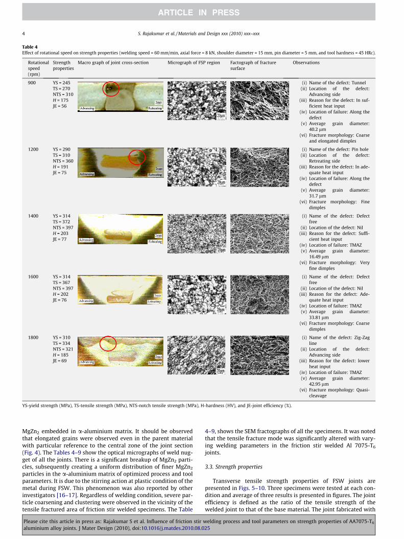
Table 4Effect of rotational speed on strength properties (welding speed = 60 mm/min, axial force = 8 kN, shoulder diameter = 15 mm, pin diameter = 5 mm, and tool hardness = 45 HRc).
Rotationalspeed(rpm)
Strengthproperties
Macro graph of joint cross-section Micrograph of FSP region Factograph of fracturesurface
Observations
900 YS = 245TS = 270NTS = 310H = 175JE = 56
(i) Name of the defect: Tunnel(ii) Location of the defect:
Advancing side(iii) Reason for the defect: In suf-
ficient heat input(iv) Location of failure: Along the
defect(v) Average grain diameter:
40.2 lm(vi) Fracture morphology: Coarse
and elongated dimples
1200 YS = 290TS = 310NTS = 360H = 191JE = 75
(i) Name of the defect: Pin hole(ii) Location of the defect:
Retreating side(iii) Reason for the defect: In ade-
quate heat input(iv) Location of failure: Along the
defect(v) Average grain diameter:
31.7 lm(vi) Fracture morphology: Fine
dimples
1400 YS = 314TS = 372NTS = 397H = 203JE = 77
(i) Name of the defect: Defectfree
(ii) Location of the defect: Nil(iii) Reason for the defect: Suffi-
cient heat input(iv) Location of failure: TMAZ(v) Average grain diameter:
16.49 lm(vi) Fracture morphology: Very
fine dimples
1600 YS = 314TS = 367NTS = 397H = 202JE = 76
(i) Name of the defect: Defectfree
(ii) Location of the defect: Nil(iii) Reason for the defect: Ade-
quate heat input(iv) Location of failure: TMAZ(v) Average grain diameter:
33.81 lm(vi) Fracture morphology: Coarse
dimples
1800 YS = 310TS = 334NTS = 321H = 185JE = 69
(i) Name of the defect: Zig-Zagline
(ii) Location of the defect:Advancing side
(iii) Reason for the defect: lowerheat input
(iv) Location of failure: TMAZ(v) Average grain diameter:
42.95 lm(vi) Fracture morphology: Quasi-
cleavage
YS-yield strength (MPa), TS-tensile strength (MPa), NTS-notch tensile strength (MPa), H-hardness (HV), and JE-joint efficiency (%).
4 S. Rajakumar et al. / Materials and Design xxx (2010) xxx–xxx
MgZn2 embedded in a-aluminium matrix. It should be observedthat elongated grains were observed even in the parent materialwith particular reference to the central zone of the joint section(Fig. 4). The Tables 4–9 show the optical micrographs of weld nug-get of all the joints. There is a significant breakup of MgZn2 parti-cles, subsequently creating a uniform distribution of finer MgZn2
particles in the a-aluminium matrix of optimized process and toolparameters. It is due to the stirring action at plastic condition of themetal during FSW. This phenomenon was also reported by otherinvestigators [16–17]. Regardless of welding condition, severe par-ticle coarsening and clustering were observed in the vicinity of thetensile fractured area of friction stir welded specimens. The Table
Please cite this article in press as: Rajakumar S et al. Influence of friction stir waluminium alloy joints. J Mater Design (2010), doi:10.1016/j.matdes.2010.08.0
4–9, shows the SEM fractographs of all the specimens. It was notedthat the tensile fracture mode was significantly altered with vary-ing welding parameters in the friction stir welded Al 7075-T6
joints.
3.3. Strength properties
Transverse tensile strength properties of FSW joints arepresented in Figs. 5–10. Three specimens were tested at each con-dition and average of three results is presented in figures. The jointefficiency is defined as the ratio of the tensile strength of thewelded joint to that of the base material. The joint fabricated with
elding process and tool parameters on strength properties of AA7075-T6
25
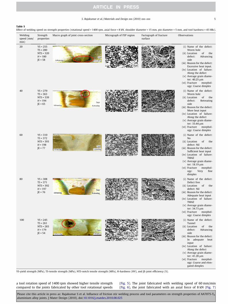
Table 5Effect of welding speed on strength properties (rotational speed = 1400 rpm, axial force = 8 kN, shoulder diameter = 15 mm, pin diameter = 5 mm, and tool hardness = 45 HRc).
Weldingspeed (mm/min)
Strengthproperties
Macro graph of joint cross-section Micrograph of FSP region Factograph of fracturesurface
Observations
20 YS = 255TS = 280NTS = 320H = 180JE = 58
(i) Name of the defect:Worm hole
(ii) Location of thedefect: Advancingside
(iii) Reason for the defect:Excessive heat input.
(iv) Location of failure:Along the defect
(v) Average grain diame-ter: 40.25 lm
(vi) Fracture morphol-ogy: Coarse dimples
40 YS = 279TS = 363NTS = 339H = 194JE = 65
(i) Name of the defect:Worm hole
(ii) Location of thedefect: Retreatingside
(iii) Reason for the defect:More heat input
(iv) Location of failure:Along the defect
(v) Average grain diame-ter: 33.44 lm
(vi) Fracture morphol-ogy: Coarse dimples
60 YS = 310TS = 372NTS = 393H = 198JE = 77
(i) Name of the defect:No
(ii) Location of thedefect: Nil
(iii) Reason for the defect:Sufficient heat input
(iv) Location of failure:TMAZ
(v) Average grain diame-ter: 18.19 lm
(vi) Fracture morphol-ogy: Very finedimples
80 YS = 308TS = 371NTS = 392H = 197JE = 76
(i) Name of the defect:Defect free
(ii) Location of thedefect: Nil
(iii) Reason for the defect:Adequate heat input
(iv) Location of failure:TMAZ
(v) Average grain diame-ter: 34.73 lm
(vi) Fracture morphol-ogy: Coarse dimples
100 YS = 245TS = 261NTS = 283H = 179JE = 54
(i) Name of the defect:Tunnel
(ii) Location of thedefect: Advancingside
(iii) Reason for the defect:In adequate heatinput
(iv) Location of failure:Along the defect
(v) Average grain diame-ter: 41.28 lm
(vi) Fracture morphol-ogy: Coarse and elon-gated dimples
YS-yield strength (MPa), TS-tensile strength (MPa), NTS-notch tensile strength (MPa), H-hardness (HV), and JE-joint efficiency (%).
S. Rajakumar et al. / Materials and Design xxx (2010) xxx–xxx 5
a tool rotation speed of 1400 rpm showed higher tensile strengthcompared to the joints fabricated by other tool rotational speeds
Please cite this article in press as: Rajakumar S et al. Influence of friction stir waluminium alloy joints. J Mater Design (2010), doi:10.1016/j.matdes.2010.08.0
(Fig. 5). The joint fabricated with welding speed of 60 mm/min(Fig. 6), the joint fabricated with an axial force of 8 kN (Fig. 7)
elding process and tool parameters on strength properties of AA7075-T6
25
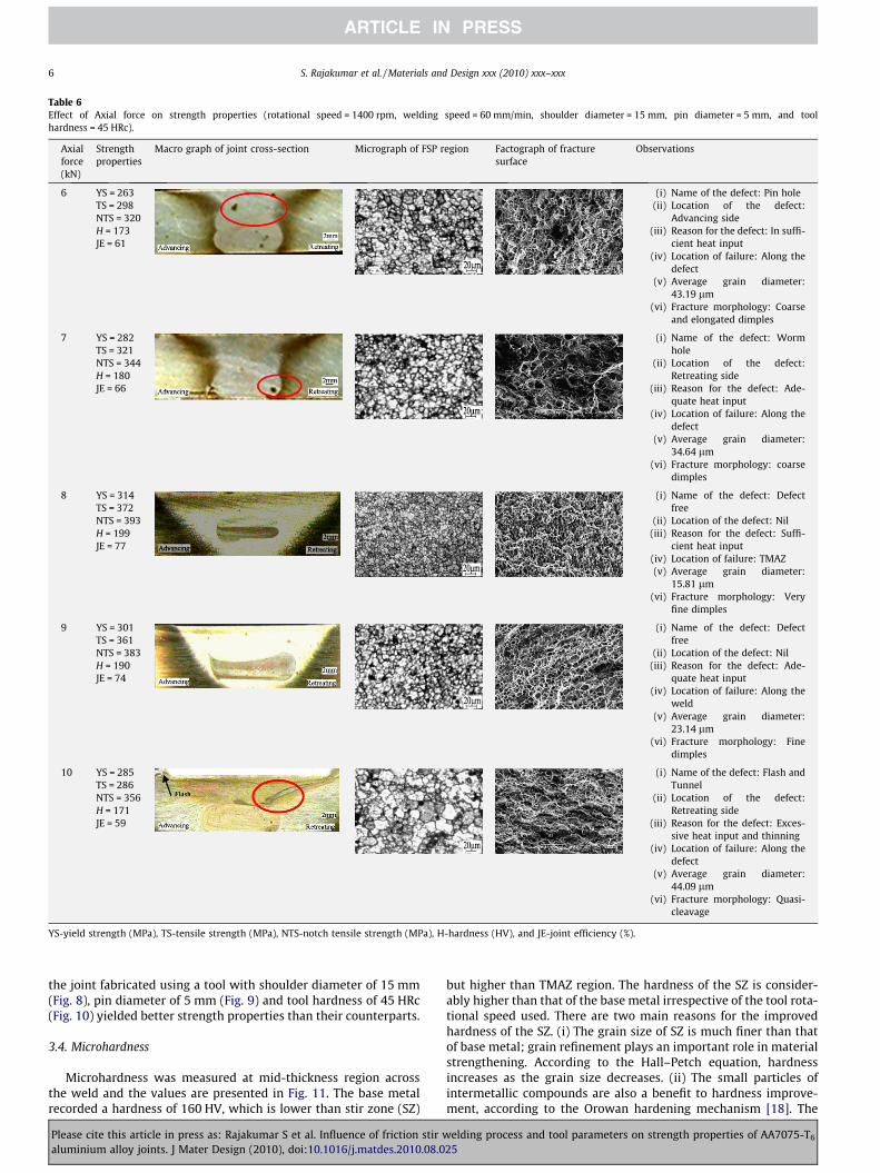
Table 6Effect of Axial force on strength properties (rotational speed = 1400 rpm, welding speed = 60 mm/min, shoulder diameter = 15 mm, pin diameter = 5 mm, and toolhardness = 45 HRc).
Axialforce(kN)
Strengthproperties
Macro graph of joint cross-section Micrograph of FSP region Factograph of fracturesurface
Observations
6 YS = 263TS = 298NTS = 320H = 173JE = 61
(i) Name of the defect: Pin hole(ii) Location of the defect:
Advancing side(iii) Reason for the defect: In suffi-
cient heat input(iv) Location of failure: Along the
defect(v) Average grain diameter:
43.19 lm(vi) Fracture morphology: Coarse
and elongated dimples
7 YS = 282TS = 321NTS = 344H = 180JE = 66
(i) Name of the defect: Wormhole
(ii) Location of the defect:Retreating side
(iii) Reason for the defect: Ade-quate heat input
(iv) Location of failure: Along thedefect
(v) Average grain diameter:34.64 lm
(vi) Fracture morphology: coarsedimples
8 YS = 314TS = 372NTS = 393H = 199JE = 77
(i) Name of the defect: Defectfree
(ii) Location of the defect: Nil(iii) Reason for the defect: Suffi-
cient heat input(iv) Location of failure: TMAZ(v) Average grain diameter:
15.81 lm(vi) Fracture morphology: Very
fine dimples
9 YS = 301TS = 361NTS = 383H = 190JE = 74
(i) Name of the defect: Defectfree
(ii) Location of the defect: Nil(iii) Reason for the defect: Ade-
quate heat input(iv) Location of failure: Along the
weld(v) Average grain diameter:
23.14 lm(vi) Fracture morphology: Fine
dimples
10 YS = 285TS = 286NTS = 356H = 171JE = 59
(i) Name of the defect: Flash andTunnel
(ii) Location of the defect:Retreating side
(iii) Reason for the defect: Exces-sive heat input and thinning
(iv) Location of failure: Along thedefect
(v) Average grain diameter:44.09 lm
(vi) Fracture morphology: Quasi-cleavage
YS-yield strength (MPa), TS-tensile strength (MPa), NTS-notch tensile strength (MPa), H-hardness (HV), and JE-joint efficiency (%).
6 S. Rajakumar et al. / Materials and Design xxx (2010) xxx–xxx
the joint fabricated using a tool with shoulder diameter of 15 mm(Fig. 8), pin diameter of 5 mm (Fig. 9) and tool hardness of 45 HRc(Fig. 10) yielded better strength properties than their counterparts.
3.4. Microhardness
Microhardness was measured at mid-thickness region acrossthe weld and the values are presented in Fig. 11. The base metalrecorded a hardness of 160 HV, which is lower than stir zone (SZ)
Please cite this article in press as: Rajakumar S et al. Influence of friction stir waluminium alloy joints. J Mater Design (2010), doi:10.1016/j.matdes.2010.08.0
but higher than TMAZ region. The hardness of the SZ is consider-ably higher than that of the base metal irrespective of the tool rota-tional speed used. There are two main reasons for the improvedhardness of the SZ. (i) The grain size of SZ is much finer than thatof base metal; grain refinement plays an important role in materialstrengthening. According to the Hall–Petch equation, hardnessincreases as the grain size decreases. (ii) The small particles ofintermetallic compounds are also a benefit to hardness improve-ment, according to the Orowan hardening mechanism [18]. The
elding process and tool parameters on strength properties of AA7075-T6
25
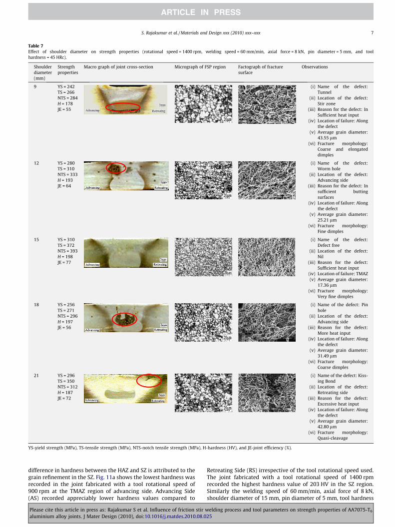
Table 7Effect of shoulder diameter on strength properties (rotational speed = 1400 rpm, welding speed = 60 mm/min, axial force = 8 kN, pin diameter = 5 mm, and toolhardness = 45 HRc).
Shoulderdiameter(mm)
Strengthproperties
Macro graph of joint cross-section Micrograph of FSP region Factograph of fracturesurface
Observations
9 YS = 242TS = 266NTS = 284H = 178JE = 55
(i) Name of the defect:Tunnel
(ii) Location of the defect:Stir zone
(iii) Reason for the defect: InSufficient heat input
(iv) Location of failure: Alongthe defect
(v) Average grain diameter:43.55 lm
(vi) Fracture morphology:Coarse and elongateddimples
12 YS = 280TS = 310NTS = 333H = 193JE = 64
(i) Name of the defect:Worm hole
(ii) Location of the defect:Advancing side
(iii) Reason for the defect: Insufficient buttingsurfaces
(iv) Location of failure: Alongthe defect
(v) Average grain diameter:25.21 lm
(vi) Fracture morphology:Fine dimples
15 YS = 310TS = 372NTS = 393H = 198JE = 77
(i) Name of the defect:Defect free
(ii) Location of the defect:Nil
(iii) Reason for the defect:Sufficient heat input
(iv) Location of failure: TMAZ(v) Average grain diameter:
17.36 lm(vi) Fracture morphology:
Very fine dimples
18 YS = 256TS = 271NTS = 296H = 197JE = 56
(i) Name of the defect: Pinhole
(ii) Location of the defect:Advancing side
(iii) Reason for the defect:More heat input
(iv) Location of failure: Alongthe defect
(v) Average grain diameter:31.49 lm
(vi) Fracture morphology:Coarse dimples
21 YS = 296TS = 350NTS = 312H = 187JE = 72
(i) Name of the defect: Kiss-ing Bond
(ii) Location of the defect:Retreating side
(iii) Reason for the defect:Excessive heat input
(iv) Location of failure: Alongthe defect
(v) Average grain diameter:42.80 lm
(vi) Fracture morphology:Quasi-cleavage
YS-yield strength (MPa), TS-tensile strength (MPa), NTS-notch tensile strength (MPa), H-hardness (HV), and JE-joint efficiency (%).
S. Rajakumar et al. / Materials and Design xxx (2010) xxx–xxx 7
difference in hardness between the HAZ and SZ is attributed to thegrain refinement in the SZ. Fig. 11a shows the lowest hardness wasrecorded in the joint fabricated with a tool rotational speed of900 rpm at the TMAZ region of advancing side. Advancing Side(AS) recorded appreciably lower hardness values compared to
Please cite this article in press as: Rajakumar S et al. Influence of friction stir waluminium alloy joints. J Mater Design (2010), doi:10.1016/j.matdes.2010.08.0
Retreating Side (RS) irrespective of the tool rotational speed used.The joint fabricated with a tool rotational speed of 1400 rpmrecorded the highest hardness value of 203 HV in the SZ region.Similarly the welding speed of 60 mm/min, axial force of 8 kN,shoulder diameter of 15 mm, pin diameter of 5 mm, tool hardness
elding process and tool parameters on strength properties of AA7075-T6
25
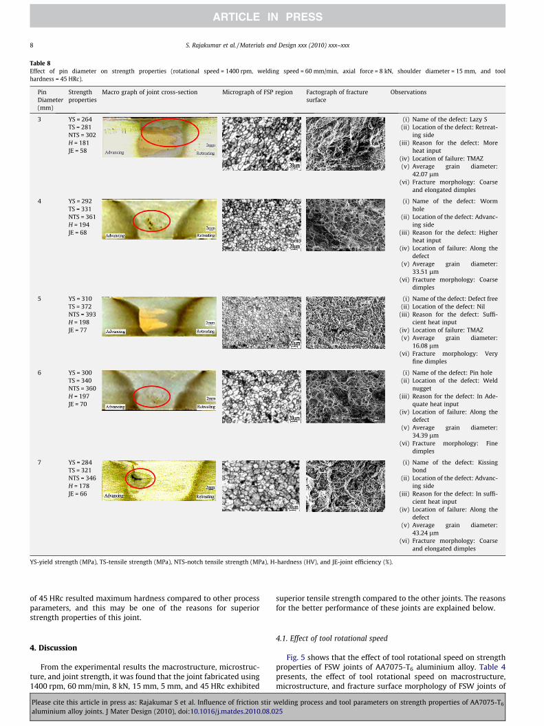
Table 8Effect of pin diameter on strength properties (rotational speed = 1400 rpm, welding speed = 60 mm/min, axial force = 8 kN, shoulder diameter = 15 mm, and toolhardness = 45 HRc).
PinDiameter(mm)
Strengthproperties
Macro graph of joint cross-section Micrograph of FSP region Factograph of fracturesurface
Observations
3 YS = 264TS = 281NTS = 302H = 181JE = 58
(i) Name of the defect: Lazy S(ii) Location of the defect: Retreat-
ing side(iii) Reason for the defect: More
heat input(iv) Location of failure: TMAZ(v) Average grain diameter:
42.07 lm(vi) Fracture morphology: Coarse
and elongated dimples
4 YS = 292TS = 331NTS = 361H = 194JE = 68
(i) Name of the defect: Wormhole
(ii) Location of the defect: Advanc-ing side
(iii) Reason for the defect: Higherheat input
(iv) Location of failure: Along thedefect
(v) Average grain diameter:33.51 lm
(vi) Fracture morphology: Coarsedimples
5 YS = 310TS = 372NTS = 393H = 198JE = 77
(i) Name of the defect: Defect free(ii) Location of the defect: Nil
(iii) Reason for the defect: Suffi-cient heat input
(iv) Location of failure: TMAZ(v) Average grain diameter:
16.08 lm(vi) Fracture morphology: Very
fine dimples
6 YS = 300TS = 340NTS = 360H = 197JE = 70
(i) Name of the defect: Pin hole(ii) Location of the defect: Weld
nugget(iii) Reason for the defect: In Ade-
quate heat input(iv) Location of failure: Along the
defect(v) Average grain diameter:
34.39 lm(vi) Fracture morphology: Fine
dimples
7 YS = 284TS = 321NTS = 346H = 178JE = 66
(i) Name of the defect: Kissingbond
(ii) Location of the defect: Advanc-ing side
(iii) Reason for the defect: In suffi-cient heat input
(iv) Location of failure: Along thedefect
(v) Average grain diameter:43.24 lm
(vi) Fracture morphology: Coarseand elongated dimples
YS-yield strength (MPa), TS-tensile strength (MPa), NTS-notch tensile strength (MPa), H-hardness (HV), and JE-joint efficiency (%).
8 S. Rajakumar et al. / Materials and Design xxx (2010) xxx–xxx
of 45 HRc resulted maximum hardness compared to other processparameters, and this may be one of the reasons for superiorstrength properties of this joint.
4. Discussion
From the experimental results the macrostructure, microstruc-ture, and joint strength, it was found that the joint fabricated using1400 rpm, 60 mm/min, 8 kN, 15 mm, 5 mm, and 45 HRc exhibited
Please cite this article in press as: Rajakumar S et al. Influence of friction stir waluminium alloy joints. J Mater Design (2010), doi:10.1016/j.matdes.2010.08.0
superior tensile strength compared to the other joints. The reasonsfor the better performance of these joints are explained below.
4.1. Effect of tool rotational speed
Fig. 5 shows that the effect of tool rotational speed on strengthproperties of FSW joints of AA7075-T6 aluminium alloy. Table 4presents, the effect of tool rotational speed on macrostructure,microstructure, and fracture surface morphology of FSW joints of
elding process and tool parameters on strength properties of AA7075-T6
25
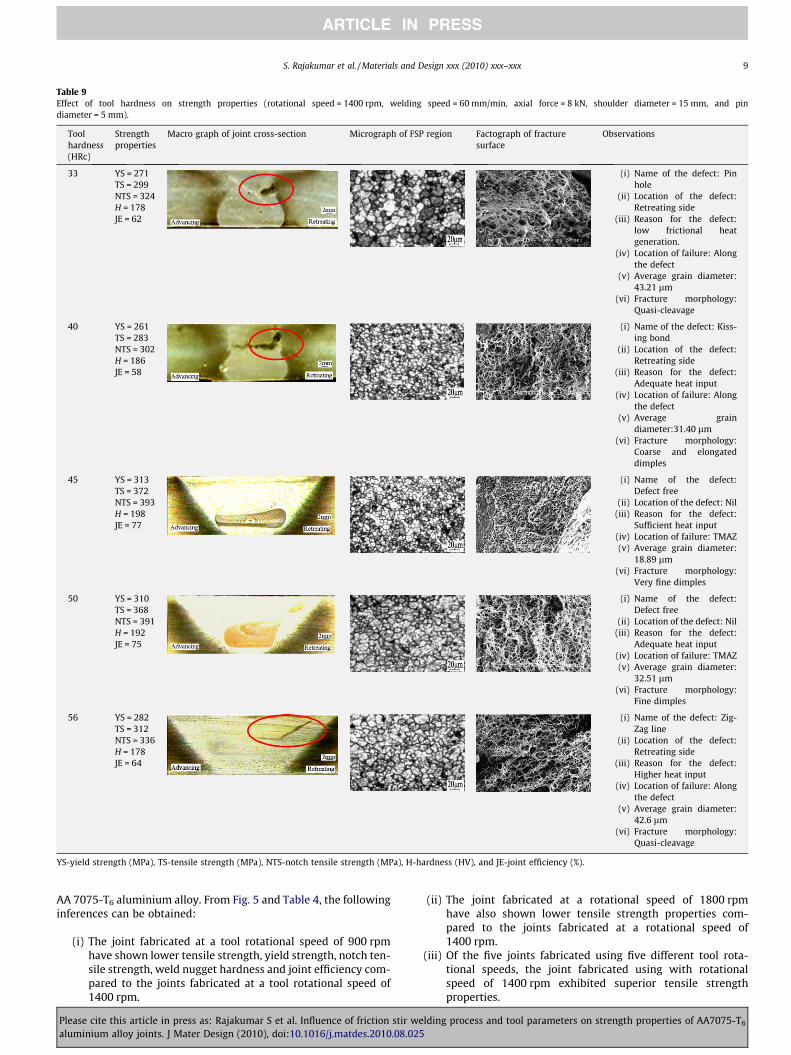
Table 9Effect of tool hardness on strength properties (rotational speed = 1400 rpm, welding speed = 60 mm/min, axial force = 8 kN, shoulder diameter = 15 mm, and pindiameter = 5 mm).
Toolhardness(HRc)
Strengthproperties
Macro graph of joint cross-section Micrograph of FSP region Factograph of fracturesurface
Observations
33 YS = 271TS = 299NTS = 324H = 178JE = 62
(i) Name of the defect: Pinhole
(ii) Location of the defect:Retreating side
(iii) Reason for the defect:low frictional heatgeneration.
(iv) Location of failure: Alongthe defect
(v) Average grain diameter:43.21 lm
(vi) Fracture morphology:Quasi-cleavage
40 YS = 261TS = 283NTS = 302H = 186JE = 58
(i) Name of the defect: Kiss-ing bond
(ii) Location of the defect:Retreating side
(iii) Reason for the defect:Adequate heat input
(iv) Location of failure: Alongthe defect
(v) Average graindiameter:31.40 lm
(vi) Fracture morphology:Coarse and elongateddimples
45 YS = 313TS = 372NTS = 393H = 198JE = 77
(i) Name of the defect:Defect free
(ii) Location of the defect: Nil(iii) Reason for the defect:
Sufficient heat input(iv) Location of failure: TMAZ(v) Average grain diameter:
18.89 lm(vi) Fracture morphology:
Very fine dimples
50 YS = 310TS = 368NTS = 391H = 192JE = 75
(i) Name of the defect:Defect free
(ii) Location of the defect: Nil(iii) Reason for the defect:
Adequate heat input(iv) Location of failure: TMAZ(v) Average grain diameter:
32.51 lm(vi) Fracture morphology:
Fine dimples
56 YS = 282TS = 312NTS = 336H = 178JE = 64
(i) Name of the defect: Zig-Zag line
(ii) Location of the defect:Retreating side
(iii) Reason for the defect:Higher heat input
(iv) Location of failure: Alongthe defect
(v) Average grain diameter:42.6 lm
(vi) Fracture morphology:Quasi-cleavage
YS-yield strength (MPa), TS-tensile strength (MPa), NTS-notch tensile strength (MPa), H-hardness (HV), and JE-joint efficiency (%).
S. Rajakumar et al. / Materials and Design xxx (2010) xxx–xxx 9
AA 7075-T6 aluminium alloy. From Fig. 5 and Table 4, the followinginferences can be obtained:
(i) The joint fabricated at a tool rotational speed of 900 rpmhave shown lower tensile strength, yield strength, notch ten-sile strength, weld nugget hardness and joint efficiency com-pared to the joints fabricated at a tool rotational speed of1400 rpm.
Please cite this article in press as: Rajakumar S et al. Influence of friction stir waluminium alloy joints. J Mater Design (2010), doi:10.1016/j.matdes.2010.08.0
(ii) The joint fabricated at a rotational speed of 1800 rpmhave also shown lower tensile strength properties com-pared to the joints fabricated at a rotational speed of1400 rpm.
(iii) Of the five joints fabricated using five different tool rota-tional speeds, the joint fabricated using with rotationalspeed of 1400 rpm exhibited superior tensile strengthproperties.
elding process and tool parameters on strength properties of AA7075-T6
25
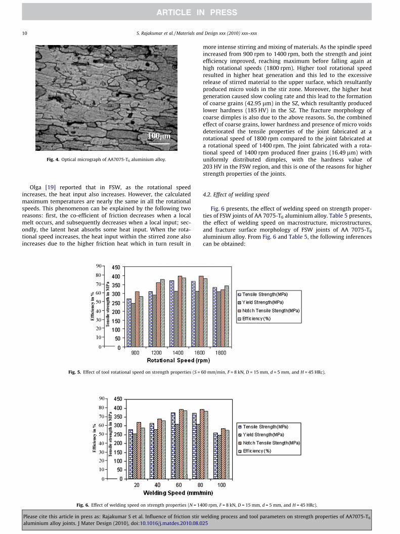
Fig. 4. Optical micrograph of AA7075-T6 aluminium alloy.
10 S. Rajakumar et al. / Materials and Design xxx (2010) xxx–xxx
Olga [19] reported that in FSW, as the rotational speedincreases, the heat input also increases. However, the calculatedmaximum temperatures are nearly the same in all the rotationalspeeds. This phenomenon can be explained by the following tworeasons: first, the co-efficient of friction decreases when a localmelt occurs, and subsequently decreases when a local input; sec-ondly, the latent heat absorbs some heat input. When the rota-tional speed increases, the heat input within the stirred zone alsoincreases due to the higher friction heat which in turn result in
Fig. 5. Effect of tool rotational speed on strength properties (S = 6
Fig. 6. Effect of welding speed on strength properties (N = 14
Please cite this article in press as: Rajakumar S et al. Influence of friction stir waluminium alloy joints. J Mater Design (2010), doi:10.1016/j.matdes.2010.08.0
more intense stirring and mixing of materials. As the spindle speedincreased from 900 rpm to 1400 rpm, both the strength and jointefficiency improved, reaching maximum before falling again athigh rotational speeds (1800 rpm). Higher tool rotational speedresulted in higher heat generation and this led to the excessiverelease of stirred material to the upper surface, which resultantlyproduced micro voids in the stir zone. Moreover, the higher heatgeneration caused slow cooling rate and this lead to the formationof coarse grains (42.95 lm) in the SZ, which resultantly producedlower hardness (185 HV) in the SZ. The fracture morphology ofcoarse dimples is also due to the above reasons. So, the combinedeffect of coarse grains, lower hardness and presence of micro voidsdeteriorated the tensile properties of the joint fabricated at arotational speed of 1800 rpm compared to the joint fabricated ata rotational speed of 1400 rpm. The joint fabricated with a rota-tional speed of 1400 rpm produced finer grains (16.49 lm) withuniformly distributed dimples, with the hardness value of203 HV in the FSW region, and this is one of the reasons for higherstrength properties of the joints.
4.2. Effect of welding speed
Fig. 6 presents, the effect of welding speed on strength proper-ties of FSW joints of AA 7075-T6 aluminium alloy. Table 5 presents,the effect of welding speed on macrostructure, microstructures,and fracture surface morphology of FSW joints of AA 7075-T6
aluminium alloy. From Fig. 6 and Table 5, the following inferencescan be obtained:
0 mm/min, F = 8 kN, D = 15 mm, d = 5 mm, and H = 45 HRc).
00 rpm, F = 8 kN, D = 15 mm, d = 5 mm, and H = 45 HRc).
elding process and tool parameters on strength properties of AA7075-T6
25
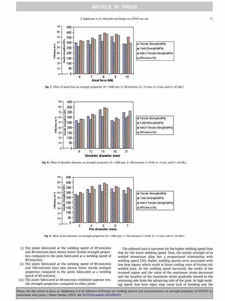
Fig. 7. Effect of axial force on strength properties (N = 1400 rpm, S = 60 mm/min, D = 15 mm, d = 5 mm, and H = 45 HRc).
Fig. 8. Effect of shoulder diameter on strength properties (N = 1400 rpm, S = 60 mm/min, F = 8 kN, d = 5 mm, and H = 45 HRc).
Fig. 9. Effect of pin diameter on strength properties (N = 1400 rpm, S = 60 mm/min, F = 8 kN, D = 15 mm, and H = 45 HRc).
S. Rajakumar et al. / Materials and Design xxx (2010) xxx–xxx 11
(i) The joints fabricated at the welding speed of 20 mm/minand 40 mm/min have shown lower tensile strength proper-ties compared to the joint fabricated at a welding speed of60 mm/min.
(ii) The joints fabricated at the welding speed of 80 mm/minand 100 mm/min have also shown lower tensile strengthproperties compared to the joints fabricated at a weldingspeed of 60 mm/min.
(iii) The joints fabricated at 60 mm/min exhibited superior ten-sile strength properties compared to other joints.
Please cite this article in press as: Rajakumar S et al. Influence of friction stir waluminium alloy joints. J Mater Design (2010), doi:10.1016/j.matdes.2010.08.0
The softened area is narrower for the higher welding speed thanthat for the lower welding speed. Thus, the tensile strength of aswelded aluminium alloy has a proportional relationship withwelding speed [20]. Higher welding speeds were associated withlow heat inputs, which result in faster cooling rates of friction stirwelded joint. As the welding speed increased, the width of thestrained region and the value of the maximum strain decreasedand the location of the maximum strain gradually moved to theretreating side from the advancing side of the joint. At high weld-ing speed, low heat input may cause lack of bonding and the
elding process and tool parameters on strength properties of AA7075-T6
25
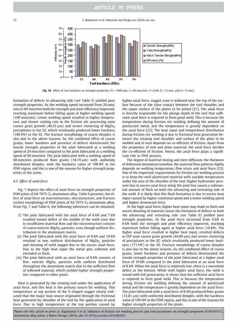
Fig. 10. Effect of tool hardness on strength properties (N = 1400 rpm, S = 60 mm/min, F = 8 kN, D = 15 mm, and d = 15 mm).
12 S. Rajakumar et al. / Materials and Design xxx (2010) xxx–xxx
formation of defects in advancing side (see Table 5) yielded poorstrength properties. As the welding speed increased from 20 mm/min to 60 mm/min both the strength and joint efficiency improved,reaching maximum before falling again at higher welding speeds(100 mm/min). Lower welding speed resulted in higher tempera-ture and slower cooling rate in the friction stir processing zonecauses grain growth (40.25 lm) and severe clustering of MgZn2
precipitates in the SZ, which resultantly produced lower hardness(180 HV) in the SZ. The fracture morphology of coarse dimples isalso due to the above reasons. So, the combined effect of coarsegrains, lower hardness and presence of defects deteriorated thetensile strength properties of the joint fabricated at a weldingspeed of 20 mm/min compared to the joint fabricated at a weldingspeed of 60 mm/min. The joint fabricated with a welding speed of60 mm/min produced finer grains (18.19 lm) with uniformlydistributed dimples, with the hardness value of 198 HV in theFSW region, and this is one of the reasons for higher strength prop-erties of the joints.
4.3. Effect of axial force
Fig. 7 depicts the effect of axial force on strength properties ofFSW joints of AA 7075-T6 aluminium alloy. Table 6 presents, the ef-fect of axial force on macrostructure, microstructure, and fracturesurface morphology of FSW joints of AA 7075-T6 aluminium alloy.From Fig. 7 and Table 6, the following inferences can be obtained:
(i) The joint fabricated with the axial force of 6 kN and 7 kNresulted tunnel defect at the middle of the weld zone dueto insufficient material flow and the microstructure consistsof coarse eutectic MgZn2 particles, even though uniform dis-tribution in the aluminium matrix.
(ii) The joint fabricated with the axial force of 9 kN and 10 kNresulted in non uniform distribution of MgZn2 particlesand thinning of weld nugget due to the excess axial force.Due to the high heat input the metal gets softened andextruded as flash.
(iii) The joint fabricated with an axial force of 8 kN consists offine, eutectic MgZn2 particles with uniform distributedthroughout the aluminium matrix due to the sufficient flowof softened material, which yielded higher strength proper-ties compared to other joints.
Heat is generated by the rotating tool under the application ofaxial force, and this heat is the primary source for welding. Thistemperature at top portion of the V-shaped nugget clearly indi-cated that the major heat source originated through the frictionalheat generated by shoulder of the tool by the application of axialforce. Due to high temperature at the top portion caused by
Please cite this article in press as: Rajakumar S et al. Influence of friction stir waluminium alloy joints. J Mater Design (2010), doi:10.1016/j.matdes.2010.08.0
higher axial force, nugget zone is widened near the top of the sur-face because of the close contact between the tool shoulder andthe upper surface of the plates to be joined [21]. The axial forceis directly responsible for the plunge depth of the tool that suffi-cient axial force is required to form good weld. This is because thetemperature during friction stir welding defining the amount ofplasticized metal, and the temperature is greatly dependent onthe axial force [22]. The heat input and temperature distributionduring friction stir welding is due to frictional heat generation be-tween the rotating tool shoulder and surface of the plate to bewelded and in turn depends on co-efficient of friction. Apart fromthe properties of tool and plate material, the axial force decidesthe co-efficient of friction. Hence, the axial force plays a signifi-cant role in FSW process.
The degree of material mixing and inter diffusion, the thicknessof deformed aluminium lamellae, the material flow patterns highlydepends on welding temperature, flow stress and axial force [23].One of the important requirements for friction stir welding processis to keep the well-plasticized material with suitable temperatureunder the area of the shoulder of the tool. Higher hydrostatic pres-sure due to excess axial force along the joint line causes a substan-tial amount of flash on both the advancing and retreating side ofthe weld. It is likely that this flash formation is due to excess heatinput caused by higher rotational speed and a lower welding speedand higher downward force.
At the high axial force, higher heat input may leads to flash andexcess thinning of material causes the formation of defects in boththe advancing and retreating side (see Table 6) yielded poorstrength properties. As the axial force increased from 6 kN to8 kN both the strength and joint efficiency improved, reachingmaximum before falling again at higher axial force (10 kN). Thehigher axial force resulted in higher heat input, resulted defectsin FSP zone causes grain growth (44.09 lm) and severe clusteringof precipitates in the SZ, which resultantly produced lower hard-ness (171 HV) in the SZ. Fracture morphology of coarse dimplesis also due to the above reasons. So, the combined effect of coarsegrains, lower hardness and presence of defects deteriorated thetensile strength properties of the joint fabricated at a higher axialforce of 10 kN compared to the joint fabricated at an axial forceof 8 kN. When the axial force is relatively low, there is a wormholedefect at the bottom. While with higher axial force, the weld issound with full penetration. It shows that the sufficient axial forceis required to form good weld. This is because the temperatureduring friction stir welding defining the amount of plasticizedmetal and the temperature is greatly dependent on the axial force.The joint fabricated with a axial force of 8 kN produced finer grains(15.81 lm) with uniformly distributed dimples, with the hardnessvalue of 199 HV in the FSW region, and this is one of the reasons forhigher strength properties of the joints.
elding process and tool parameters on strength properties of AA7075-T6
25
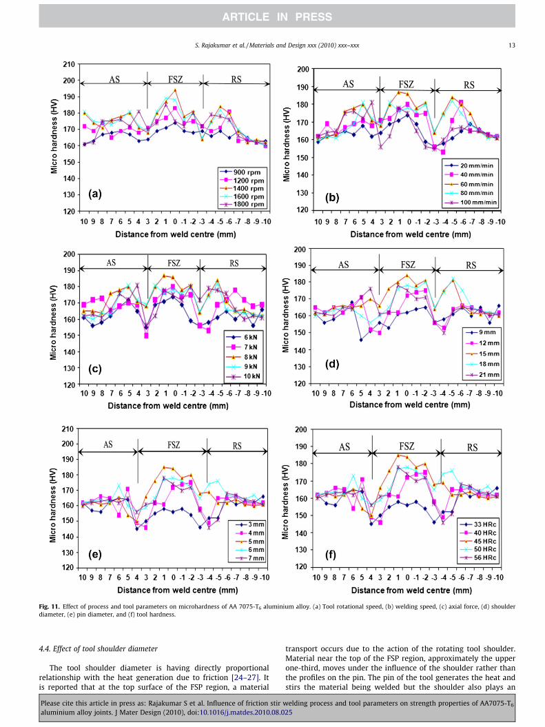
Fig. 11. Effect of process and tool parameters on microhardness of AA 7075-T6 aluminium alloy. (a) Tool rotational speed, (b) welding speed, (c) axial force, (d) shoulderdiameter, (e) pin diameter, and (f) tool hardness.
S. Rajakumar et al. / Materials and Design xxx (2010) xxx–xxx 13
4.4. Effect of tool shoulder diameter
The tool shoulder diameter is having directly proportionalrelationship with the heat generation due to friction [24–27]. Itis reported that at the top surface of the FSP region, a material
Please cite this article in press as: Rajakumar S et al. Influence of friction stir waluminium alloy joints. J Mater Design (2010), doi:10.1016/j.matdes.2010.08.0
transport occurs due to the action of the rotating tool shoulder.Material near the top of the FSP region, approximately the upperone-third, moves under the influence of the shoulder rather thanthe profiles on the pin. The pin of the tool generates the heat andstirs the material being welded but the shoulder also plays an
elding process and tool parameters on strength properties of AA7075-T6
25
14 S. Rajakumar et al. / Materials and Design xxx (2010) xxx–xxx
important part by providing additional frictional treatment as wellas preventing the plasticized material from escaping from the weldregion. The friction between the shoulder and work piece results inthe biggest component of heating. From the heating aspect, the rel-ative size of pin and shoulder is important. The shoulder also pro-vides confinement for the heated volume of material. The secondfunction of the tool shoulder is to ‘stir’ and ‘move’ the material.The uniformity of microstructure and properties as well as processloads is governed by the tool design. Fig. 8 displays the effect ofshoulder diameter on strength properties of FSW joints of AA7075-T6 aluminium alloy. Table 7 presents the effect of shoulderdiameter on macrostructure, microstructures, and fracture surfacemorphology of FSW joints of AA 7075-T6 aluminium alloy. FromFig. 8 and Table 7, the following inferences can be obtained:
(i) The larger tool shoulder diameter (21 mm) lead to widercontact area and resulted in wider TMAZ region and HAZregion and subsequently the strength properties of the jointsare deteriorated.
(ii) The smaller tool shoulder diameter (9 mm) lead to narrowcontact area and resulted in less frictional heat generationand hence the weld metal consolidation is not good in theFSP region and subsequently resulted in lowest strengthproperties.
(iii) Of the five joints fabricated using different tool shoulderdiameters, the joint fabricated using the tool with 15 mmshoulder diameter exhibited superior strength properties.
At larger shoulder diameter, may leads to wider contact areaand resulted in wider TMAZ region and HAZ region and subse-quently the tensile strength properties of the joints are deterio-rated. As the shoulder diameter increased from 9 mm to 15 mmboth the strength and joint efficiency improved, reaching maxi-mum before falling again at larger shoulder diameter (21 mm).Smaller shoulder diameter resulted in sufficient heat generationdue to smaller contact area, cause’s defects in FSP zone causesgrain growth (43.55 lm) and severe clustering of precipitates inthe SZ, which resultantly produced lower hardness (178 HV) inthe SZ. The fracture morphology of coarse dimples is also due tothe above reasons. So, the combined effect of coarse grains, lowerhardness and presence of defects deteriorated the tensile strengthproperties of the joint fabricated at a larger shoulder diameter of21 mm compared to the joint fabricated at a shoulder diameterof 15 mm. The joint fabricated with a shoulder diameter of15 mm produced finer grains (17.36 lm) with uniformly distrib-uted dimples, and the hardness value of 198 HV in the FSP region,and this is one of the reasons for higher strength properties of thejoints.
4.5. Effect of pin diameter
Fig. 9 reveals the effect of pin diameter on strength properties ofFSW joints of AA 7075-T6 aluminium alloy. Table 8 presents the ef-fect of pin diameter on macrostructure, microstructure, and frac-ture surface morphology of FSW joints of AA 7075-T6 aluminiumalloy. From Fig. 9 and Table 8, the following inferences can beobtained:
(i) The joints fabricated with the pin diameter of 3 mm and4 mm have shown lower tensile strength, yield strength,notch tensile strength, weld nugget hardness and joint effi-ciency compared to the joint fabricated with 5 mm pindiameter.
(ii) The joints fabricated with pin diameter greater than 5 mm,resulted in lower tensile strength compared to the joint fab-ricated with 5 mm pin diameter.
Please cite this article in press as: Rajakumar S et al. Influence of friction stir waluminium alloy joints. J Mater Design (2010), doi:10.1016/j.matdes.2010.08.0
(iii) Of the five joints fabricated using five pin diameter tool usedin this investigation to fabricate the joints, the joint fabri-cated with 5 mm pin diameter showed superior strengthproperties.
In FSW, the pin diameter decides the volume of material that isbeing plasticized stirred. If the pin diameter is larger, then the vol-ume of material stirred will be higher and vice versa. The smallerpin diameter to cause higher heat supplied to a smaller volumeof material. This will lead to turbulent material flow and graincoarsening in the weld region. On the other hand, the higher pindiameter to cause lower heat supplied to a larger volume of mate-rial. This will lead to insufficient material flow and inadequateplasticization. Both this conditions lead to the lower tensilestrength. The joint fabricated with smaller pin diameters of3 mm and 4 mm produced higher heat generation, the strengthproperties are deteriorated. As the pin diameter increased from3 mm to 5 mm both the strength and joint efficiency improved,reaching maximum before falling again at larger pin diameter(7 mm). Larger pin diameter resulted in sufficient heat generationdue to wider contact area, produced defects in advancing side ofTMAZ region, causes grain growth (43.24 lm) and severe cluster-ing of precipitates in the SZ, which resultantly produced lowerhardness (178 HV) in the SZ. The fracture morphology of coarseand elongated dimples is also due to the above reasons. So, thecombined effect of coarse grains, lower hardness and presence ofdefects deteriorated the tensile strength properties of the joint fab-ricated at a larger pin diameter of 7 mm compared to the joint fab-ricated at a pin diameter of 5 mm. The joint fabricated with a pindiameter of 5 mm produced finer grains (16.08 lm) with uni-formly distributed dimples, and the hardness value of 198 HV inthe FSW region, and this is one of the reasons for higher strengthproperties of the joints.
4.6. Effect of tool hardness
In FSW, the tool hardness will decide the co-efficient of friction‘l’. If ‘l’ is higher, then friction between tool and base metal will bemore and the resultant heat generation will be higher [28]. If ‘l’ islower, then friction will be less and the resultant heat generationwill be lower. Hence, the co-efficient of friction, in other words,the tool hardness will control the heat generation in FSW process.The lower tool hardness will produce less heat generation; subse-quently heat supplied to the base material will be less, which willdeteriorate strength properties of the joint. The higher tool hard-ness will produce higher heat generation subsequently heat sup-plied to the base material will be higher, which again willdeteriorate strength properties of the joint. The higher heat inputproduced defects in retreating side of TMAZ region, causes graingrowth (42.6 lm) and severe clustering of precipitates in the SZ,which resultantly produced lower hardness (179 HV) in the SZ.Fracture morphology of coarse dimples is also due to the abovereasons. So, the combined effect of coarse grains, lower hardnessand presence of defects deteriorated the tensile strength propertiesof the joint fabricated at a higher tool hardness of 56 HRc com-pared to the joint fabricated at a tool hardness of 45 HRc. The jointfabricated with a tool hardness of 45 HRc produced finer grains(18.89 lm) with uniformly distributed dimples, and the hardnessvalue of 199 HV in the FSW region, and this is one of the reasonsfor higher strength properties of the joints.
From Fig. 10 and Table 9, following inference can be obtained;
(i) The joints fabricated with the tool having hardness of33 HRc and 40 HRc exhibited lower tensile strength proper-ties than the joint fabricated with the tool having hardnessof 45 HRc.
elding process and tool parameters on strength properties of AA7075-T6
25
S. Rajakumar et al. / Materials and Design xxx (2010) xxx–xxx 15
(ii) The joints fabricated with the tool having hardness of 50 HRcand 56 HRc yielded the lower strength properties than thejoint fabricated with the tool having hardness of 45 HRc.
(iii) Of the five joints fabricated using five tools having differenthardness, the joint fabricated with a tool having tool hard-ness of 45 HRc showed superior strength properties.
5. Conclusions
(1) The joint fabricated using the FSW process parameters of1400 rpm (tool rotational speed), 60 mm/min (weldingspeed), 8 kN (axial force), with the tool parameters of15 mm (shoulder diameter), 5 mm (pin diameter), 45 HRc(tool hardness) yielded higher strength properties comparedto other joints.
(2) The maximum strength properties of 315 MPa yieldstrength, 373 MPa of tensile strength, 397 MPa of notch ten-sile strength, 203 HV of hardness and 77% of joint efficiencyrespectively was attained for the joint fabricated usingabove the process and tool parameters.
(3) Defect free fine grained microstructure of weld nugget anduniformly distributed finer MgZn2 particles in the weld nug-get are found to be the important factors responsible for thehigher tensile strength of the above joint.
Acknowledgements
The authors are grateful to the Department of ManufacturingEngineering, Annamalai University, Annamalainagar, India forextending the facilities of Material Testing Laboratory to carryout this investigation. The authors wish to place their sincerethanks to Clean Technology Division of Ministry of Environmentand Forest, Government of India, New Delhi for financial supportrendered through a R&D Project No. MoEF1-9/2005-CT. Authorswould like to thank Mr. E. Balamurugan, Post Graduate student,Manufacturing Engineering, Mr. S. Muthukumaran, Mr. N. Sair-aman, Mr. John and Mr. A.K. Thillaiparaman of Project Assistants,Centre for Materials Joining and Research (CEMAJOR) for their helpand support.
References
[1] Jha Abhay K, Sreekumar K. Metallurgical studies on cracked Al–5.5Zn–2.5Mg–1.5Cu aluminum alloy injector disc of turbine rotor. J Fail Anal Prev2008;8(4):327–32.
[2] Balasubramanian V, Ravisankar V, Madhusudhan Reddy G. Effect of post weldaging treatment on fatigue behavior of pulsed current welded AA7075aluminum alloy joints. J Mater Eng Perform 2008;7(2):224–33.
[3] Gupta RK, Ramkumar P, Ghosh BR. Investigation of internal cracks inaluminum alloy AA7075 forging. Eng Fail Anal 2006;13:1–8.
Please cite this article in press as: Rajakumar S et al. Influence of friction stir waluminium alloy joints. J Mater Design (2010), doi:10.1016/j.matdes.2010.08.0
[4] Soundarajan Vijay, Zekovic Srdja, Kovacevic Radovan. Thermo-mechanicalmodel with adaptive boundary conditions for friction stir welding of Al 6061.Int J Mach Tools Manuf 2005;45:1577–87.
[5] Bussu G, Irving PE. The role of residual stress and heat affected zone propertieson fatigue crack propagation in friction stir welded 2024–T351 aluminiumjoints. Int J Fatigue 2003;25:77–88.
[6] John R, Jata KV, Sadananda K. Residual stress effects on near-threshold fatiguecrack growth in friction stir welds in aerospace alloys. Int J Fatigue2003;25:939–48.
[7] Jata KV, Sankaran KK, Ruschau J. Friction stir welding effects on microstructureand fatigue of aluminum alloy 7050–T7451. Metall Mater Trans A2000;31:2181–92.
[8] Hatamleh Omar, Singh Preet M, Garmestani Hamid. Corrosion susceptibility ofpeened friction stir welded 7075 aluminum alloy joints. Correct Sci2009;51:135–43.
[9] Cai M, Huang D, Adams BL, Nelson TW. Microstructure characteristics offriction stir processes Al 7075 via macroscopic approach. Frict Stir Weld Proc IIITMS 2005:269–75.
[10] Peel M, Steuwer A, Preuss M, Withers PJ. Microstructure, mechanicalproperties and residual stresses as a function of welding speed in AA5083friction stir welds. Acta Mater 2003;51:4791–801.
[11] Chen CM, Kovacevic R. Finite element modeling of friction stir welding–thermal and thermomechanical analysis. J Mach Tools Manuf2003;43:1319–26.
[12] Schmidt H, Hattel J, Wert J. An analytical model for the heat generation infriction stir welding. Mater Sci Eng 2004;12:143–57.
[13] ASTM E8 M-04. Standard test method for tension testing of metallic materials.ASTM International; 2006.
[14] Zhou Caizhi, Yang Xinqi. Effect of kissing bond on fatigue behavior of frictionstir welds on Al 5083 alloy. J Mater Sci 2006;41:2771–7.
[15] Sato Yutaka S, Takauchi Hideaki, Park Seung Hwan C, Kokawa Hiroyuki.Characteristics of the kissing-bond in friction stir welded Al alloy 1050. MaterSci Eng A 2005;405:333–8.
[16] Barcellona A, Buffa G, Fratini L, Palmeri D. On microstructural phenomenaoccurring in friction stir welding of aluminium alloys. J Mater Process Technol2006;177:340–3.
[17] Lim Sunggon, Kim Sangshik, Lee Chang-Gil, Kim Sungjoon. Tensile behavior offriction-stir-welded Al 6061-T651. Metall Mater Trans A 2004;35:2829–35.
[18] Wang XH, Wang KS. Microstructure and properties of friction stir butt-weldedAZ31 magnesium alloy. Mater Sci Eng A 2006;431:114–7.
[19] Olga VF. Microstructural issues in a friction-stir-welded aluminum alloy.Scripta Mater 1998;38(5):703–8.
[20] Lee WonBae, Yeon YM, Jung SB. Effect of friction welding parameters onmechanical and metallurgical properties of aluminum alloy 5052–A36 steeljoint. Mater Sci Technol 2003;19:1513–8.
[21] Fonda RW, Lambrakos SG. Analysis of friction stir welds using an inverseproblem approach. Sci Technol Weld Join 2002;7(3):177–81.
[22] Colligan J, Paul J, Konkol, James J, Fisher, Joseph R, et al. Friction stir weldingdemonstrated for combat vehicle construction. Weld J 2002:1–6.
[23] Thomas WM, Nicholas ED. Friction stir welding for the transportationindustries. Mater Des 1997;18:269–73.
[24] Lima EBF, Wegener J, Dalle Donne, Goerigk G, Wroblewski T, Buslaps T.Dependence of the microstructure, residual stresses and texture of AA6013friction stir welds on the welding processes. Z Metallkd 2003;94(8):908–15.
[25] Oosterkamp A, Djapic Oosterkamp L, Nordeide A. Kissing bond phenomena insolid state welds of aluminum alloys. Weld J 2004;83:225–31.
[26] Chen Yingchun, Liu Huijie, Feng Jicai. Friction stir welding characteristics ofdifferent heat-treated-state 2219 aluminum alloy plates. Mater Sci Eng A2006;420:21–5.
[27] Elangovan K, Balasubramanian V. Influences of tool pin profile and toolshoulder diameter on the formation of friction stir processing zone in AA6061aluminium alloy. Mater Des 2008;293:362–73.
[28] Padmanaban G, Balasubramanian V. Selection of FSW tool pin profile, shoulderdiameter and material for joining AZ31B magnesium alloy – an experimentalapproach. Mater Des 2009;30:2647–56.
elding process and tool parameters on strength properties of AA7075-T6
25
Related Documents


![Combined Corrosion and Wear of Aluminium Alloy 7075-T6 · 2017. 8. 28. · Many researchers have studied the localized corrosion of AA7075-T6 [7, 9–12]. The susceptibility, to localized](https://static.cupdf.com/doc/110x72/6117227e83526d73256dd28f/combined-corrosion-and-wear-of-aluminium-alloy-7075-t6-2017-8-28-many-researchers.jpg)