Industrial robot manipulator guarding using artiicial vision 429 X Industrial robot manipulator guarding using artificial vision Fevery Brecht 1 , Wyns Bart 1 , Boullart Luc 1 Llata García José Ramón 2 and Torre Ferrero Carlos 2 1 Ghent University Belgium 2 University of Cantabria Spain 1. Introduction Since a long time, the public opinion on robotics is that humans and robots work together, side by side, sharing and interacting in a common space (Oestreicher & Eklundh, 2006). However, until recently reality was quite different. Robots were introduced in the work place in the sixties as very effective, but simple-minded workers. For a long time, there was a lack of concern for safety and for human-robot interaction. Therefore industrial robots have been far too dangerous to share the workspace with humans. It is only since the nineties that academics and researchers from industry started to investigate the possibilities of implementing intelligent security systems in the robot’s operating system in order to allow for this human-robot interaction in the future. In this chapter an artificial vision based security system for safeguarding an industrial robot is introduced. As in many electromechanical devices also robots suffer from malfunctioning of machinery e.g. electrical potential drops, falling parts, pressurized fluids, etc. But more important are risks specific to robots and that occur during execution of a robot movement, such as a collision or undesired manipulator acceleration. These events can happen because of human errors, control errors, unauthorized access to the workspace, mechanical failures or improper work cell installation. As mentioned in (Hirschfeld et al., 1993) the robot users in the greatest danger for a nearby robot are by far the operators and maintenance workers, since they spend a lot of time in the robot’s presence. Main safety methods employed in industrial robots can be divided in two categories, that is, passive protection and active protection. Passive protection or passive safety refers to safety devices that improve the human safety without changing the robot’s behaviour. Passive safety is static and simple to design; therefore it is very reliable but easily bypassed. Examples of these devices are visual devices such as warning lights, warning signs, boundary chains and painted boundaries, also physical devices such as fences, barriers and robot cages. On the other hand, active protection or active safety systems refer to safety devices that modify the robot’s behaviour, or the environment, in order to avoid dangerous situations. In fact, they sense and react to changes in the cell’s environment. The most 23 www.intechopen.com

Welcome message from author
This document is posted to help you gain knowledge. Please leave a comment to let me know what you think about it! Share it to your friends and learn new things together.
Transcript
Industrial robot manipulator guarding using artiicial vision 429
Industrial robot manipulator guarding using artiicial vision
Fevery Brecht, Wyns Bart, Boullart Luc Llata García José Ramón and Torre Ferrero Carlos
X
Industrial robot manipulator guarding using artificial vision
Fevery Brecht1, Wyns Bart1, Boullart Luc1
Llata García José Ramón2 and Torre Ferrero Carlos2 1Ghent University
Belgium 2 University of Cantabria
Spain
1. Introduction
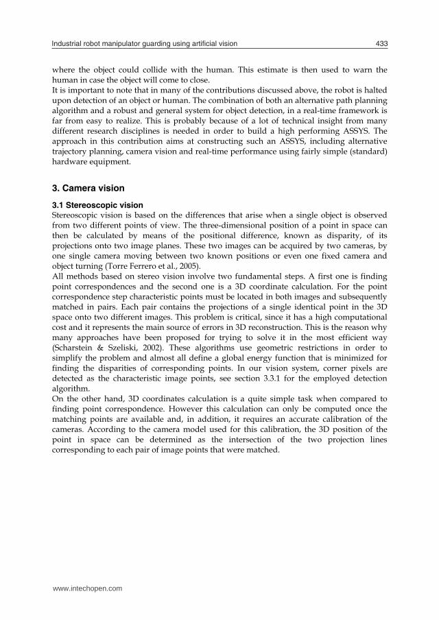
Since a long time, the public opinion on robotics is that humans and robots work together, side by side, sharing and interacting in a common space (Oestreicher & Eklundh, 2006). However, until recently reality was quite different. Robots were introduced in the work place in the sixties as very effective, but simple-minded workers. For a long time, there was a lack of concern for safety and for human-robot interaction. Therefore industrial robots have been far too dangerous to share the workspace with humans. It is only since the nineties that academics and researchers from industry started to investigate the possibilities of implementing intelligent security systems in the robot’s operating system in order to allow for this human-robot interaction in the future. In this chapter an artificial vision based security system for safeguarding an industrial robot is introduced. As in many electromechanical devices also robots suffer from malfunctioning of machinery e.g. electrical potential drops, falling parts, pressurized fluids, etc. But more important are risks specific to robots and that occur during execution of a robot movement, such as a collision or undesired manipulator acceleration. These events can happen because of human errors, control errors, unauthorized access to the workspace, mechanical failures or improper work cell installation. As mentioned in (Hirschfeld et al., 1993) the robot users in the greatest danger for a nearby robot are by far the operators and maintenance workers, since they spend a lot of time in the robot’s presence. Main safety methods employed in industrial robots can be divided in two categories, that is, passive protection and active protection. Passive protection or passive safety refers to safety devices that improve the human safety without changing the robot’s behaviour. Passive safety is static and simple to design; therefore it is very reliable but easily bypassed. Examples of these devices are visual devices such as warning lights, warning signs, boundary chains and painted boundaries, also physical devices such as fences, barriers and robot cages. On the other hand, active protection or active safety systems refer to safety devices that modify the robot’s behaviour, or the environment, in order to avoid dangerous situations. In fact, they sense and react to changes in the cell’s environment. The most
23
www.intechopen.com
Robot Vision430
popular examples of active safety devices are laser curtains, pressure mats, interlocked gates, ultrasonic or infrared barriers, capacitance devices, etc. All these sensorial elements try to detect undesired presence in the work cell of the robot. When a presence is detected the robot is stopped through an emergency stop and by cutting the power. In order to reactivate the robot national and international standard regulations require both removing the presence and deliberative reactivating the robot (ISO 10218-1, 2006). All these safety devices try to enforce segregation between robots and humans. It is on this philosophy that the earliest technical literature on the topic of robotic safety is based (Bixby, 1991; Graham, 1991; Dhillon, 1991) as well as the robotics safety regulations and standards (ANSI/RIA, 1986). However, this philosophy is getting old and even impossible to fulfil because in many cases, such as teaching, trouble-shooting, repairs and maintenance, operators have to work inside the robot work cell (OSHA, 2006). For this reason, new safety systems have been developed and, nowadays, robot safety equipment also includes a wide range of additional subsystems such as emergency robot braking, work cell limitation, load limitation, motor and voltage monitoring, deadman function and, of course, an emergency stop system, in case the robot needs to be stopped immediately. However, safety still is subject to discussion and the situation is changing radically because new applications such as assisted industrial manipulation, collaborative assembly, domestic work, entertainment, rehabilitation or medical applications, etc. ask for a larger interaction between human and robot. In all of these cases, robot and human, or robot with other robots, have to work together, sharing the same physical environment. Therefore, a new safety paradigm is needed where an active security/safety system (ASSYS) gets the control of the industrial robot in order to analyse the possibility of collision with the detected object, human or robot and, if this is the case, to generate a new alternative trajectory. In this way, the ASSYS is able to adapt the robot behaviour to the actual situation of a dynamical environment in real-time. It is clearly much more useful for human-robot interaction and for robots collaborating compared to previous safety systems. In order to obtain a proper ASSYS, three key issues must be fulfilled. Firstly, three-dimensional perception of the dynamical environment is needed. A flexible solution is to use a camera-based vision system to obtain a global view on the robot’s work cell. However, it is important to obtain a good synchronisation among all the cameras and to keep in mind that the image processing time must be very small compared with the robot and environment dynamics. Secondly, an alternative path planner is constructed. Nowadays, several options, such as artificial intelligence techniques, servoing control techniques, optimization, etc. are being analyzed. Finally, a fast communication system for moving data among cameras, processing system and robot controller is also needed. The goal of this chapter is to introduce an ASSYS, based on artificial vision. A set of ceiling-mounted, static cameras is used to build a three-dimensional representation of the environment and to detect obstacles in the robot’s work cell. With a stereoscopic reconstruction algorithm, the obstacle’s location and dimensions are obtained. This ASSYS includes an artificial intelligence decision taking process. It is based on fuzzy logic and it is used for calculating an alternative path to the desired workspace point but avoiding the detected obstacle. This is one of the principal contributions of this paper because the robot keeps doing its task although dynamic obstacles are present in the workspace.
www.intechopen.com
Industrial robot manipulator guarding using artiicial vision 431
This chapter is organized as follows. Initially, an ASSYS literature overview is carried out in section 2, introducing different solutions and the most interesting existing technologies for vision-based ASSYS. Next, a detailed explanation on the stereoscopic 3D vision system used in this ASSYS is given. In section 4, the artificial intelligence system based on fuzzy logic, used for calculating the alternative trajectory is presented. Then, the experimental setup (section 5) and the results (section 6) obtained for the proposed ASSYS are discussed. Finally, in section 7 conclusions are summarized and future improvements are proposed.
2. Literature overview
As stated in the introduction, active security systems are formed by many different subsystems all closely working together to guarantee human safety. Among the most important and critical subsystems is the sensor system. Using sensory equipment the robot senses the environment looking for objects (static or dynamic, human or not) blocking the path of its normal pre-programmed trajectory. Without question a sensor system is a fundamental component based on which the manipulator will make his next move in case of a possible collision. Given the scope of this contribution, this section will mainly focus on sensor systems, more specifically on vision techniques. Sophisticated solutions for sensing the work cell exist, like laser curtains, light barriers, scanner or safety mats, etc. often hardwired to a safety PLC (programmable logic controller) for fast intervention in case of problems. See (Ogorodnikova, 2006) for a technical overview of current safeguarding systems. (Novak & Feddema, 1992; Feddema & Novak, 1994) used capacitance sensors as artificial sensor skin for collision avoidance. In (Llata et al., 1998) a set of ultrasonic sensors, located near the end effector is used for detecting the local environment of the robot’s grip. In (Yu & Gupta, 1999) a wrist-mounted laser scanner was used for a similar purpose. All of these approaches are based on local information only. Therefore, only surroundings to the current robot position can be examined. Then, using local information only local path planning is possible. So obstacles farther away from the robot arm (out of the reach of the sensor system) cannot be detected. A more flexible solution is to use a vision system mounted in such a way that a good overview of the work cell is obtained. A camera network based human-robot coexistence system was already proposed in (Baerveldt, 1992) in the early nineties. He used computer vision to obtain the location of the operator. Robot and operator communicated through speech allowing a fast and safe intervention when needed. (Noborio & Nishino, 2001) used a wrist-mounted camera for path planning. Unfortunately an important prerequisite was that the image taken by the camera has to be known within the target configuration. Also, only local information is gathered because of the position of the camera on the wrist. Several techniques exist to obtain a global view on the robot’s work cell. Backprojection is a widely used technique to reconstruct an object by collating multiple camera images of the work cell. Eckert (2000) used this method for accurately reconstructing a single object in 3D space, including texture information giving a very realistic view of the object. In case of an ASSYS such a high level of detail is not necessary and more attention should be given to the object’s contours. Noborio & Urakawa (1999) used backprojection in the context of robotics with multiple objects. They used colour cameras and were able to separate objects having sufficiently different colours only. In (Ebert & Henrich, 2001) a look-up-table-based sensor fusion algorithm for performing image-based collision tests based on backprojection into
www.intechopen.com
Robot Vision432
configuration space was presented. They use reference images for detecting human operators and other obstacles. Their approach was not very optimized with regard to computation time and memory requirements. This work was further extended and applied in several other contributions (Ebert & Henrich, 2002; Gecks & Henrich, 2005). The former contribution presented a method for avoiding collisions based on difference images. Part of this method uses epipolar lines for resolving unknown and error pixels in the images. They also developed a technique to filter out the robot arm, possibly occluding an object. The image difference method was applied to a pick-and-place application several stationary gray scale cameras to safeguard operators moving into the work cell (Gecks & Henrich, 2005). For the method to work properly objects had to be substantially different from the background pixels. In (Kuhn et al., 2006) the authors extended the same method to secure guided robot motion. Velocity of the manipulator was decreased when a human operator came too close to the arm. A combination of both local and global sensors can be found in the MEPHISTO system (Steinhaus et al., 1999). Laser scanners were mounted on the robots (local information) and a couple of colour cameras were surveying the robot’s work cell to acquire global information. They also apply reference images that are updated at run-time. The difference between the reference image and the current image is mapped in the form of a polygonal region. MEPHISTO also provides a distributed redundant environment model allowing straightforward local path planning and reducing communication transmission problems. Panoramic cameras (fisheye) are used in (Cervera et al., 2008). According to the authors the 360° field of view can seriously simplify safety issues for a robot arm moving in close proximity to human beings. The proposed technique tracks both manipulator and human based on a combination of an adaptive background model at pixel level and an improved classification at frame level filtering global illumination. Although this technique was used in the context of visual servoing it clearly shows that also in that area of research safety is an important concern. A safety system also using a network of cameras in an on-line manner was presented in (D. Ebert et al., 2005). A specialized tracking-vision-chip was designed obtaining a cycle time of more than 500Hz using only a small 8-bit microcontroller for the vision-chip. Unfortunately, the robot was immediately stopped when a human entered the work cell. Additional reviews on safety and computer vision for use in industrial settings can be found in (Piggin 2005;Wöhler, 2009). In the future robots will increasingly become part of everyday life (Weng et al., 2009). Safety already is an important issue in industrial robotics dealing with heavy payloads and fast execution. But many authors also realize that safety is becoming an important issue in service robots (Oestreicher & Eklundh, 2006; Burghart et al., 2007; Burghart et al., 2005) or even toys. ASSYS, although designed for industrial purposes, could hence also be (partially) reused in this context as well. Service robots are intended for close interaction with humans and hence all actions performed by such a robot should never harm the human they assist. An example of this can already be found in (Ohta & Amano, 2008). Both authors propose a technique predicting the collision of a human with surrounding objects, using a physical simulator and a stereo vision system. Based on the input data from the vision system, the physical simulator tries to model the object’s speed and direction and estimates when and
www.intechopen.com
Industrial robot manipulator guarding using artiicial vision 433
where the object could collide with the human. This estimate is then used to warn the human in case the object will come to close. It is important to note that in many of the contributions discussed above, the robot is halted upon detection of an object or human. The combination of both an alternative path planning algorithm and a robust and general system for object detection, in a real-time framework is far from easy to realize. This is probably because of a lot of technical insight from many different research disciplines is needed in order to build a high performing ASSYS. The approach in this contribution aims at constructing such an ASSYS, including alternative trajectory planning, camera vision and real-time performance using fairly simple (standard) hardware equipment.
3. Camera vision
3.1 Stereoscopic vision Stereoscopic vision is based on the differences that arise when a single object is observed from two different points of view. The three-dimensional position of a point in space can then be calculated by means of the positional difference, known as disparity, of its projections onto two image planes. These two images can be acquired by two cameras, by one single camera moving between two known positions or even one fixed camera and object turning (Torre Ferrero et al., 2005). All methods based on stereo vision involve two fundamental steps. A first one is finding point correspondences and the second one is a 3D coordinate calculation. For the point correspondence step characteristic points must be located in both images and subsequently matched in pairs. Each pair contains the projections of a single identical point in the 3D space onto two different images. This problem is critical, since it has a high computational cost and it represents the main source of errors in 3D reconstruction. This is the reason why many approaches have been proposed for trying to solve it in the most efficient way (Scharstein & Szeliski, 2002). These algorithms use geometric restrictions in order to simplify the problem and almost all define a global energy function that is minimized for finding the disparities of corresponding points. In our vision system, corner pixels are detected as the characteristic image points, see section 3.3.1 for the employed detection algorithm. On the other hand, 3D coordinates calculation is a quite simple task when compared to finding point correspondence. However this calculation can only be computed once the matching points are available and, in addition, it requires an accurate calibration of the cameras. According to the camera model used for this calibration, the 3D position of the point in space can be determined as the intersection of the two projection lines corresponding to each pair of image points that were matched.
www.intechopen.com
Robot Vision434
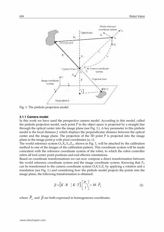
Fig. 1. The pinhole projection model
3.1.1 Camera model In this work we have used the perspective camera model. According to this model, called the pinhole projection model, each point P in the object space is projected by a straight line through the optical center into the image plane (see Fig. 1.). A key parameter in this pinhole model is the focal distance f, which displays the perpendicular distance between the optical center and the image plane. The projection of the 3D point P is projected into the image plane in the image point p with pixel coordinates (u, v). The world reference system OwXwYwZw, shown in Fig. 1, will be attached by the calibration method to one of the images of the calibration pattern. This coordinate system will be made coincident with the reference coordinate system of the robot, to which the robot controller refers all tool center point positions and end effector orientations. Based on coordinate transformations we can now compose a direct transformation between the world reference coordinate system and the image coordinate system. Knowing that Pw can be transformed to the camera coordinate system OcXcYcZc by applying a rotation and a translation (see Fig. 1.) and considering how the pinhole model projects the points into the image plane, the following transformation is obtained:
ww PMP
TKRKp ~1
~
(1)
where wP~
and p~ are both expressed in homogeneous coordinates.
www.intechopen.com
Industrial robot manipulator guarding using artiicial vision 435
M, known as the projection matrix of the camera system, allows projecting any arbitrary object point in the reference system into the image plane. It is composed of both intrinsic and extrinsic camera parameters: the first 3x3 matrix describes a rotation and the right 3x1 column vector represents a translation. The matrix K, known as the calibration matrix of the camera, contains the intrinsic parameters that describe, without taking into account projection errors due to lens distortion, how object points expressed in the camera reference system are projected into the image plane. These parameters describe a specific camera and are independent of the camera’s position and orientation in space. On the other hand, the extrinsic parameters (rotation matrix R and translation vector T) depend on the camera’s position and orientation in space, since they describe the relationship between the chosen world reference coordinate system and the camera reference system. The presented pinhole projection model is only an approximation of a real camera model since distortion of image coordinates, due to imperfect lens manufacturing and camera assembly, is not taken into account. When higher accuracy is required, a more comprehensive camera model can be used that describes the systematical distortions of image coordinates. These lens distortions cause the actual image point to be displaced both radially and tangentially in the image plane. In their paper on camera calibration, Heikkilä & Silvén (1997) proposed an approximation of both radial and tangential distortions that was used in this project. The set of camera parameters that have been presented describes the mapping between 3D reference coordinates and 2D image coordinates. Calibration of our camera system is done using a software camera calibration toolbox that is based on the calibration principles introduced by (Heikkilä & Silvén, 1997). For an exhaustive review of calibration methods (Salvi et al., 2002) can be consulted.
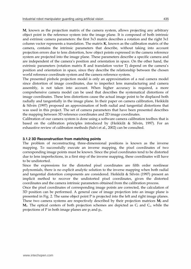
3.1.2 3D Reconstruction from matching points The problem of reconstructing three-dimensional positions is known as the inverse mapping. To successfully execute an inverse mapping, the pixel coordinates of two corresponding image points must be known. Since the pixel coordinates tend to be distorted due to lens imperfections, in a first step of the inverse mapping, these coordinates will have to be undistorted. Since the expressions for the distorted pixel coordinates are fifth order nonlinear polynomials, there is no explicit analytic solution to the inverse mapping when both radial and tangential distortion components are considered. Heikkilä & Silvén (1997) present an implicit method to recover the undistorted pixel coordinates, given the distorted coordinates and the camera intrinsic parameters obtained from the calibration process. Once the pixel coordinates of corresponding image points are corrected, the calculation of 3D position can be performed. A general case of image projection into an image plane is presented in Fig. 2. The same object point P is projected into the left and right image planes. These two camera systems are respectively described by their projection matrices Ml and Mr. The optical centers of both projection schemes are depicted as Cl and Cr, while the projections of P in both image planes are pl and pr.
www.intechopen.com
Robot Vision436
P(X,Y,Z)
Cl Cr
pl pr
Ml Mr
Fig. 2. Object point projection in two image planes Given the pixel coordinates of pl and pr, (ul,vl) and (ur,vr) , the homogeneous coordinates of the 3D point can be calculated by solving the following equation:
0~~
23
13
23
13
PAP
mmvmmummvmmu
rrr
rrr
lll
lll
(2)
where mkl and mkr (k=1, 2, 3) are the rows of matrices Ml and Mr respectively. The solution P~ of (2) is the one that minimizes the squared distance norm 2~PA . The
solution to this minimization problem can be identified as the unit norm eigenvector of the matrix AAT , that corresponds to its smallest eigenvalue. Dividing the first three coordinates by the scaling factor, Euclidean 3D coordinates of the point P are obtained.
3.2 Geometry of a stereo pair Before any 3D position can be reconstructed, the correspondence of characteristic image points has to be searched for in all images involved in the reconstruction process. Typically, geometrical restrictions in the considered image planes will be used since they simplify the correspondence (Hartley & Zisserman, 2004). We will focus on epipolar lines, given that they can considerably reduce the time needed to find correspondences in the images. Often used in combination with epipolar lines, specific detection methods are employed to identify objects that have certain characteristics. E.g. an object that is constituted of clearly separated surfaces will be easy to detect using edge detection methods. Because separated surfaces are illuminated in a different way, regions with different colour intensity will be displayed in the object’s image.
www.intechopen.com
Industrial robot manipulator guarding using artiicial vision 437
P1P2
ErEl Cl
Cr
pl
pr2
pr1
epipolar line associated to pr1 and pr2
epipolar line associated to pl
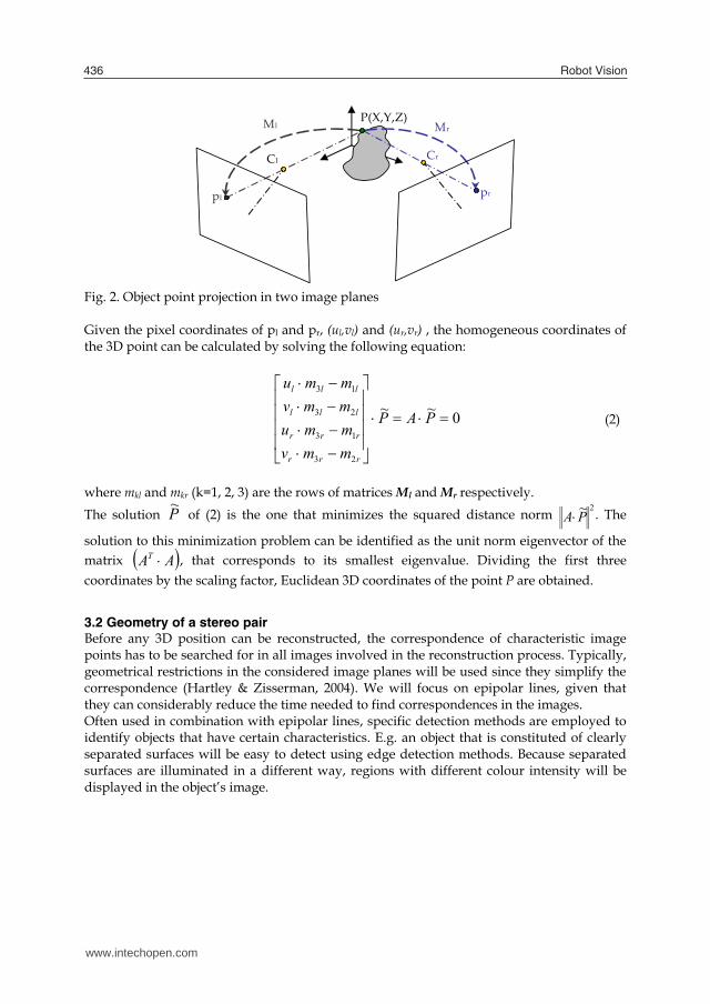
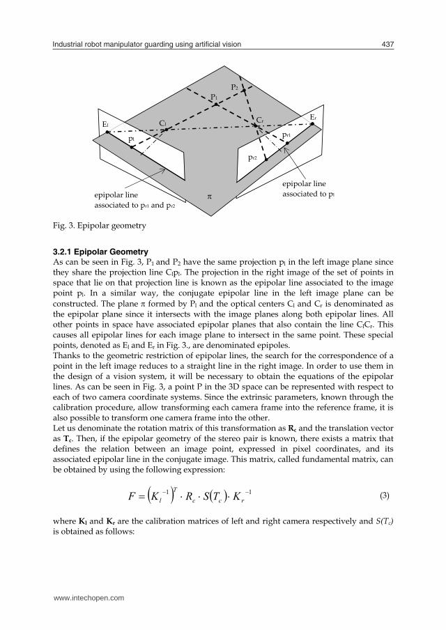
Fig. 3. Epipolar geometry
3.2.1 Epipolar Geometry As can be seen in Fig. 3, P1 and P2 have the same projection pl in the left image plane since they share the projection line Clpl. The projection in the right image of the set of points in space that lie on that projection line is known as the epipolar line associated to the image point pl. In a similar way, the conjugate epipolar line in the left image plane can be constructed. The plane formed by Pl and the optical centers Cl and Cr is denominated as the epipolar plane since it intersects with the image planes along both epipolar lines. All other points in space have associated epipolar planes that also contain the line ClCr. This causes all epipolar lines for each image plane to intersect in the same point. These special points, denoted as El and Er in Fig. 3., are denominated epipoles. Thanks to the geometric restriction of epipolar lines, the search for the correspondence of a point in the left image reduces to a straight line in the right image. In order to use them in the design of a vision system, it will be necessary to obtain the equations of the epipolar lines. As can be seen in Fig. 3, a point P in the 3D space can be represented with respect to each of two camera coordinate systems. Since the extrinsic parameters, known through the calibration procedure, allow transforming each camera frame into the reference frame, it is also possible to transform one camera frame into the other. Let us denominate the rotation matrix of this transformation as Rc and the translation vector as Tc. Then, if the epipolar geometry of the stereo pair is known, there exists a matrix that defines the relation between an image point, expressed in pixel coordinates, and its associated epipolar line in the conjugate image. This matrix, called fundamental matrix, can be obtained by using the following expression: 11 rcc
Tl KTSRKF
(3)
where Kl and Kr are the calibration matrices of left and right camera respectively and S(Tc) is obtained as follows:
www.intechopen.com
Robot Vision438
00
0
xy
xz
yz
c
tttttt
TS , with
z
y
x
c
ttt
T (4)
Given an image point lp~ in the left image, expressed in homogeneous pixel coordinates, the
parameter vector sr of its associated epipolar line can be obtained as,
lr pFs ~ (5) Therefore, all the points that lie on the epipolar line in the right image plane must satisfy the following equation,
0~ rTr sp (6)
In an equivalent way, the equation of the epipolar line in the left image associated to the projection pr in the right image can be obtained by changing the subscripts.
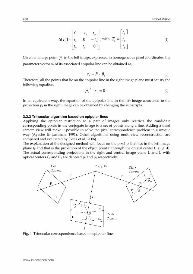
3.2.2 Trinocular algorithm based on epipolar lines Applying the epipolar restriction to a pair of images only restricts the candidate corresponding pixels in the conjugate image to a set of points along a line. Adding a third camera view will make it possible to solve the pixel correspondence problem in a unique way (Ayache & Lustman, 1991). Other algorithms using multi-view reconstruction are compared and evaluated by (Seitz et al., 2006). The explanation of the designed method will focus on the pixel pl that lies in the left image plane Il, and that is the projection of the object point P through the optical center Cl (Fig. 4). The actual corresponding projections in the right and central image plane Ir and Ic with optical centers Cr and Cc are denoted pr and pc respectively.
Fig. 4. Trinocular correspondence based on epipolar lines
www.intechopen.com
Industrial robot manipulator guarding using artiicial vision 439
Knowing the intrinsic and extrinsic parameters of the camera triplet, the epipolar lines corresponding to the projection pl of P in the left image can be constructed in the right and central image plane. These epipolar lines are denoted Sr and Sc for right and central image plane respectively. In the right image plane we now consider the pixels that have been previously detected as characteristic ones (e.g. corner pixels) and select those that lie on the epipolar line Sr or sufficiently close to it. A set of so called candidate pixels arises in the image plane Ir and they are denoted in Fig. 4 as Pri, i=1…m. In the central image plane we can now construct the epipolar lines that correspond to the pixels Pri. This set of epipolar lines is denoted as {Sci, i=1…m}. The correct pixel correspondence is now found by intersecting Sc with the epipolar lines of the set {Sci} and selecting the central image pixel that lies on the intersection of Sc and a line Scj in the set {Sci}. Once this pixel is detected, the unique corresponding pixel triplet {pl, pc, pr} is found. In practice, correspondent pixels will never lie perfectly on the intersection of the epipolar lines constructed in the third image. Therefore, we have to define what pixel distance can be considered as sufficiently small to conclude a pixel correspondence. Furthermore, extra attention has to be paid to the noise effect in images, which tends to promote the detection of untrue characteristic pixels. In the ideal case, no pixel correspondence will be detected for an untrue characteristic pixel, because it hasn’t been detected in the other images and its epipolar line doesn’t come close to one of the true or untrue characteristic pixels in the other images. When the algorithm does detect a correspondence that originates from one or more untrue characteristic pixels, a matched triplet is obtained. However, the algorithm can be taught to only look within the boundaries of the visible world coordinate frame and to discard the untrue correspondence after reconstructing its 3D location. This is possible because it is more probable that the resulting 3D point will lie far from the 3D workspace in which the object is supposed to be detected.
3.3 Parallelepiped object detection An important step in the overall vision method is the identification of an object in a camera image. A priori knowledge about the object’s colour and shape is therefore often used to detect obstacles in the robot’s workspace as quickly as possible. For example the detection of a table is easier compared to a human because of its rectangular surfaces which allows edge and corner detection. In this research, we worked with a foam obstacle of parallelepiped structure. Here, we will explain how such objects are detected and reconstructed.
3.3.1 Observation of parallelepiped structures As will be explained in section 5.1, images from all three cameras are continuously (each 50 milliseconds) extracted and stored in the control software. The obstacle of parallelepiped form is detected in one of those images (for time-saving) by first converting the image into binary form. Subsequently, the program searches for contours of squared form. Because a square has equal sides the relation between its area and its perimeter reduces to:
1642
22 aa
areaperimeter (7)
www.intechopen.com
Robot Vision440
In an image of binary form, the perimeter and area of closed contours can be calculated at low computational costs. Shadow effects can cause the real object shapes to be slightly deformed. This may result in deviations of the contour’s area and perimeter. To incorporate for this, a lower and upper threshold have to be set, e.g. 14 as lower and 18 as upper threshold. Of course, other solutions to quickly detect the presence of an obstacle exist. Detection based on the object’s colour is a common alternative approach. When an obstacle is detected, images are taken out of the video stream of the same camera until the obstacle is motionless. Motion of the obstacle is easily checked by subtracting two subsequent image matrices. As soon as the obstacle is motionless, images are drawn out of the video stream of all three cameras and saved for further processing.
3.3.2 Detection of corner pixels and object reconstruction The 3D reconstruction of the foam obstacle is then started by looking for corners in the three images. An edge detector is applied to detect edges and contours within the image. The curvature of identified contours along their lengths is computed using a curvature scale space corner detector (He & Yung, 2004). Local maxima of the curvature are considered as corner candidates. After discarding rounded corners and corners due to boundary noise and details, the true image corners remain. We typically reconstruct the 3D location of the obstacle’s four upper corners. Because the curvature maxima calculation consumes a lot of computaton time, it is good practice to restrict the search window in the images. By again applying the square detecting criterion, this window can be placed around the top of the parallellepiped obstacle to reduce the search area from an original 640x480 matrix to e.g. a 320x240 matrix. Once characteristic points —true and also false object corners due to image noise or nearby objects— are detected, the epipolar lines algorithm introduced in section 3.2.2 is applied to determine the corresponding corners. Summarizing, starting with the images returned by the obstacle detection procedure, the following steps are undertaken: 1. Application of a corner detection function to detect corner candidates in all three
images as described in (He & Yung, 2004); 2. For every assumed corner pixel in the first image, execution of the following steps
(see section 3.2 for a detailed explanation): a. Construction of the associated epipolar lines in images two and three; b. Search for corner pixels in the second image that lie close to the epipolar line; c. Construction in the third image of the epipolar lines that correspond to pixels
found in (b); d. Calculation of intersections between epipolar lines; e. Detection of corner pixels in the third image that lie sufficiently close to the
calculated intersections; f. Formation of triplets of pixel correspondences;
3. Application of inverse camera projection model to undo pixel distortions of all pixel correspondences (as described in section 3.1.1);
4. Reconstruction of 3D positions using the obtained pixel correspondences; 5. Elimination of false pixel correspondences by discarding of 3D positions that lie
outside the expected 3D range of the obstacle; 6. Ordering the 3D positions to a structured set that describes the location of the
obstacle in the robot’s workspace.
www.intechopen.com
Industrial robot manipulator guarding using artiicial vision 441
4. Adding robot intelligence
A motion planning algorithm that guarantees a collision-free path for robot movement is an important step when integrating both humans and robots (or multiple robots) in a single work cell. In this section we will introduce a fuzzy logic based technique to solve the obstacle avoidance problem. Fuzzy logic controllers (FLC) are a useful tool to transform linguistic control strategies based on expertise into an automated control strategy and are very popular in robotics (Surdhar & White, 2003; Kumar & Garg, 2005; Cojbašic & Nikolic, 2008; Alavandar & Nigam, 2008; Hitam, 2001; Ghalia & Alouani, 1995). The basic idea is to assign linguistic labels to physical properties. The process that converts a numerical value into a linguistic description is the fuzzification process. Using a rule base that simulates human reasoning in decision taking, a number of linguistic control actions is computed and subsequently defuzzified or converted to numerical control actions. In what follows each step of this process will be briefly described. For more information and a detailed introduction on fuzzy controllers, please consult (Cordon et al., 2001; Driankow et al., 1996). As main reasons for implementing an obstacle avoidance strategy based on fuzzy logic we indicate that a fuzzy algorithm and its rule base can be constructed relatively easily and in an intuitive, experimental way. It is easier to encode human expert knowledge in the FLC without the necessity of precise mathematical modelling. Furthermore, the fuzzy operators that are used to link the inputs of the fuzzy system to its output can be chosen as basic operators such as sum, product, min and max.
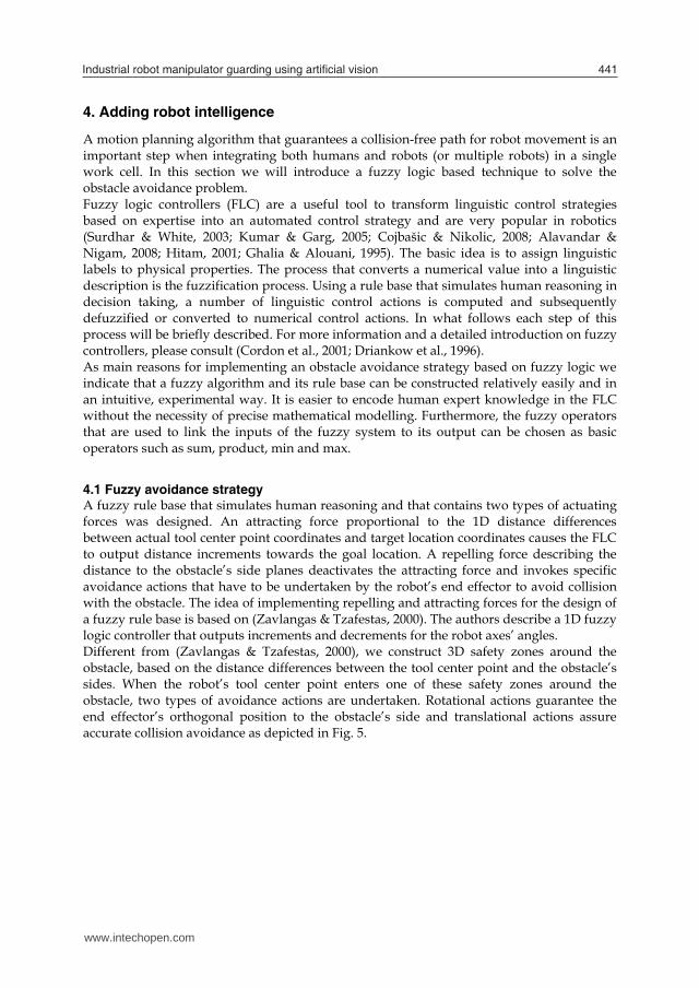
4.1 Fuzzy avoidance strategy A fuzzy rule base that simulates human reasoning and that contains two types of actuating forces was designed. An attracting force proportional to the 1D distance differences between actual tool center point coordinates and target location coordinates causes the FLC to output distance increments towards the goal location. A repelling force describing the distance to the obstacle’s side planes deactivates the attracting force and invokes specific avoidance actions that have to be undertaken by the robot’s end effector to avoid collision with the obstacle. The idea of implementing repelling and attracting forces for the design of a fuzzy rule base is based on (Zavlangas & Tzafestas, 2000). The authors describe a 1D fuzzy logic controller that outputs increments and decrements for the robot axes’ angles. Different from (Zavlangas & Tzafestas, 2000), we construct 3D safety zones around the obstacle, based on the distance differences between the tool center point and the obstacle’s sides. When the robot’s tool center point enters one of these safety zones around the obstacle, two types of avoidance actions are undertaken. Rotational actions guarantee the end effector’s orthogonal position to the obstacle’s side and translational actions assure accurate collision avoidance as depicted in Fig. 5.
www.intechopen.com
Robot Vision442
Fig. 5. A graphical example of the robot’s end effector, tool center point (denoted by the black dot) , and the target behaviour of the robot arm using a fuzzy avoidance strategy.
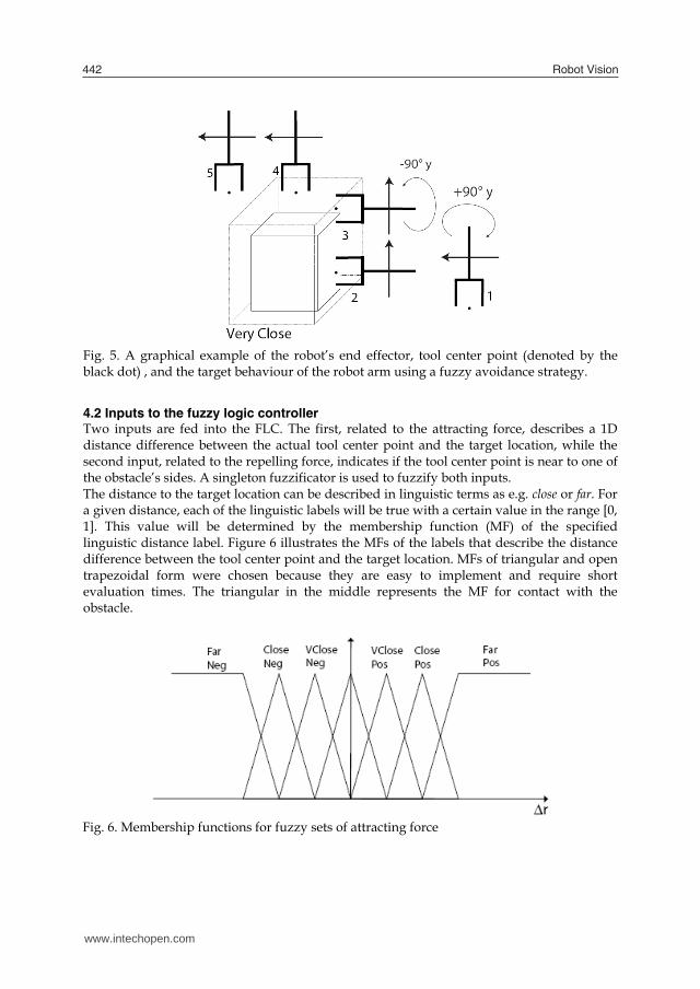
4.2 Inputs to the fuzzy logic controller Two inputs are fed into the FLC. The first, related to the attracting force, describes a 1D distance difference between the actual tool center point and the target location, while the second input, related to the repelling force, indicates if the tool center point is near to one of the obstacle’s sides. A singleton fuzzificator is used to fuzzify both inputs. The distance to the target location can be described in linguistic terms as e.g. close or far. For a given distance, each of the linguistic labels will be true with a certain value in the range [0, 1]. This value will be determined by the membership function (MF) of the specified linguistic distance label. Figure 6 illustrates the MFs of the labels that describe the distance difference between the tool center point and the target location. MFs of triangular and open trapezoidal form were chosen because they are easy to implement and require short evaluation times. The triangular in the middle represents the MF for contact with the obstacle.
Fig. 6. Membership functions for fuzzy sets of attracting force
www.intechopen.com
Industrial robot manipulator guarding using artiicial vision 443
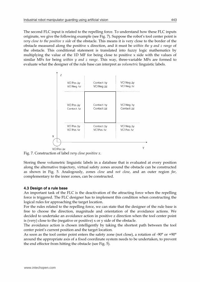
The second FLC input is related to the repelling force. To understand how these FLC inputs originate, we give the following example (see Fig. 7). Suppose the robot’s tool center point is very close to the positive x side of the obstacle. This means it is very close to the border of the obstacle measured along the positive x direction, and it must be within the y and z range of the obstacle. This conditional statement is translated into fuzzy logic mathematics by multiplying the value of the 1D MF for being close to positive x side with the values of similar MFs for being within y and z range. This way, three-variable MFs are formed to evaluate what the designer of the rule base can interpret as volumetric linguistic labels.
Fig. 7. Construction of label very close positive x. Storing these volumetric linguistic labels in a database that is evaluated at every position along the alternative trajectory, virtual safety zones around the obstacle can be constructed as shown in Fig. 5. Analogously, zones close and not close, and an outer region far, complementary to the inner zones, can be constructed.
4.3 Design of a rule base An important task of the FLC is the deactivation of the attracting force when the repelling force is triggered. The FLC designer has to implement this condition when constructing the logical rules for approaching the target location. For the rules related to the repelling force, we can state that the designer of the rule base is free to choose the direction, magnitude and orientation of the avoidance actions. We decided to undertake an avoidance action in positive z direction when the tool center point is (very) close to the (negative or positive) x or y side of the obstacle. The avoidance action is chosen intelligently by taking the shortest path between the tool center point’s current position and the target location. As soon as the tool center point enters the safety zone (not close), a rotation of -90° or +90° around the appropriate axis of a fixed coordinate system needs to be undertaken, to prevent the end effector from hitting the obstacle (see Fig. 5).
www.intechopen.com
Robot Vision444
To resolve the fuzzy intersection operator we used a T-norm of the product type. In the aggregation of rule consequents an S-norm for the fuzzy union operator was chosen. We implemented the maximum operator for this S-norm.
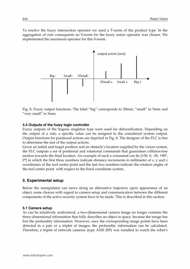
Fig. 8. Fuzzy output functions. The label “big” corresponds to 30mm, “small” to 5mm and “very small” to 3mm.
4.4 Outputs of the fuzzy logic controller Fuzzy outputs of the Sugeno singleton type were used for defuzzification. Depending on the output of a rule, a specific value can be assigned to the considered system output. Output functions for positional actions are depicted in Fig. 8. The designer of the FLC is free to determine the size of the output actions. Given an initial and target position and an obstacle’s location supplied by the vision system, the FLC outputs a set of positional and rotational commands that guarantees collision-free motion towards the final location. An example of such a command can be [+50, 0, -50, +90°, 0°] in which the first three numbers indicate distance increments in millimeter of x, y and z coordinates of the tool center point and the last two numbers indicate the rotation angles of the tool center point with respect to the fixed coordinate system.
5. Experimental setup
Before the manipulator can move along an alternative trajectory upon appearance of an object, some choices with regard to camera setup and communication between the different components of the active security system have to be made. This is described in this section.
5.1 Camera setup As can be intuitively understood, a two-dimensional camera image no longer contains the three-dimensional information that fully describes an object in space, because the image has lost the profundity information. However, once the corresponding image points have been detected in a pair or a triplet of images, the profundity information can be calculated. Therefore, a triplet of network cameras (type AXIS 205) was installed to watch the robot’s
www.intechopen.com
Industrial robot manipulator guarding using artiicial vision 445
workspace. The cameras were positioned in a triangular pattern and mounted on the ceiling above the robot’s workspace. Camera images (sized 480 x 640 x 3 bytes in Red Green Blue image space) are obtained by sending an image request signal to their IP address over a Local Area Network (LAN). More details on the LAN’s setup are given in 5.2. After installation, every camera is calibrated according to (Heikkilä and Silvén, 1997) as explained in section 3.1.1. Storing and transferring images (i.e. a matrix of dimension 480x640x3 bytes) between various components of the ASSYS is time-consuming. Many image acquisition software routines set up a connection between the pc and the camera, each time a function call is made. After the picture has been saved, this connection is closed again. Opening and closing each time an image is requested is a waste of computation time. Experiments in the TEISA lab showed that this delay sometimes takes up to 0.5 seconds. Faster picture storage is possible through maintaining the connection pc – camera open as long as new images are processed. This was implemented by C. Torre Ferrero using the ActiveX component of the AXIS camera software making it possible to view motion JPEG video streams. Using the ActiveX components, subsequent picture images are stored in processing times never exceeding 80 milliseconds.
5.2 Real-time communication network Fast access to the network cameras and communication of an alternative trajectory is very important for safety reasons. To obtain correct pixel correspondences, we need a picture frame of each one of the three cameras, ideally taken at the very same moment in time. When registering moving objects, the smallest time interval between grabbing the three picture frames, will lead to incorrect pixel correspondences and therefore incorrect 3D position calculations. Also, robotic control applications often have cycle times of typically tens of milliseconds. When operational data needs to be exchanged between a robot and an operator’s pc, the speed and the guarantee of data transmission is very important. For many years, Ethernet was banned as a communication medium in industry, because data packages that are sent by devices connected to a same local area network can collide. Due to the network’s media access control protocol (CSMA/CD) retransmission is non-deterministic and offers no guarantees with respect to time. Nowadays, fast Ethernet switches can be used to isolate network devices into their own collision domain, hereby eliminating the chance for collision and loss of data packages. Ethernet switches together with the development of fast Ethernet (100Mbps) and gigabit Ethernet (1Gbps) have made Ethernet popular as a real-time communication medium in industrial settings (Decotignie, 2005; Piggin & Brandt 2006). In this application, five devices are connected to a single fast Ethernet switch (100Mbps): the three Axis network cameras, the robot controller and the pc from which control actions are monitored. On top of Ethernet the Transmission Control Protocol (TCP) is used. TCP supports error recovery and assures the correct order of data packages received. This is, however, time consuming due to the exchange of supplementary control information, such as sending acknowledgements, retransmission if errors occurred, etc. This makes the TCP protocol less suitable for time critical applications. However, together with fast Ethernet, a limited number of devices connected to a dedicated switch (no in-between routers) and short cable lengths, the overhead of TCP is negligible and better reliability was obtained. The robot manipulator provides TCP connection-oriented communication options, such as socket messaging (combination of IP address and TCP port number), which makes it easy to program.
www.intechopen.com
Robot Vision446
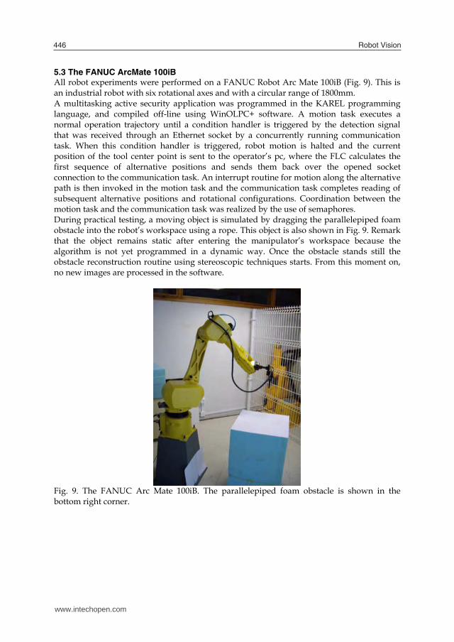
5.3 The FANUC ArcMate 100iB All robot experiments were performed on a FANUC Robot Arc Mate 100iB (Fig. 9). This is an industrial robot with six rotational axes and with a circular range of 1800mm. A multitasking active security application was programmed in the KAREL programming language, and compiled off-line using WinOLPC+ software. A motion task executes a normal operation trajectory until a condition handler is triggered by the detection signal that was received through an Ethernet socket by a concurrently running communication task. When this condition handler is triggered, robot motion is halted and the current position of the tool center point is sent to the operator’s pc, where the FLC calculates the first sequence of alternative positions and sends them back over the opened socket connection to the communication task. An interrupt routine for motion along the alternative path is then invoked in the motion task and the communication task completes reading of subsequent alternative positions and rotational configurations. Coordination between the motion task and the communication task was realized by the use of semaphores. During practical testing, a moving object is simulated by dragging the parallelepiped foam obstacle into the robot’s workspace using a rope. This object is also shown in Fig. 9. Remark that the object remains static after entering the manipulator’s workspace because the algorithm is not yet programmed in a dynamic way. Once the obstacle stands still the obstacle reconstruction routine using stereoscopic techniques starts. From this moment on, no new images are processed in the software.
Fig. 9. The FANUC Arc Mate 100iB. The parallelepiped foam obstacle is shown in the bottom right corner.
www.intechopen.com
Industrial robot manipulator guarding using artiicial vision 447
6. Results and discussion
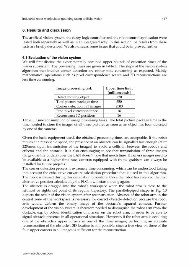
The artificial vision system, the fuzzy logic controller and the robot control application were tested both separately as well as in an integrated way. In this section the results from these tests are briefly described. We also discuss some issues that could be improved further. 6.1 Evaluation of the vision system We will first discuss the experimentally obtained upper bounds of execution times of the vision subsystem. The processing times are given in table 1. The steps of the vision system algorithm that involve corner detection are rather time consuming as expected. Mainly mathematical operations such as pixel correspondence search and 3D reconstructions are less time consuming.
Image processing task Upper time limit [milliseconds]
Detect moving object 220 Total picture package time 350 Corner detection in 3 images 2500 Find pixel correspondence 16 Reconstruct 3D positions 16
Table 1. Time consumption of image processing tasks. The total picture package time is the time needed to store the images of all three pictures as soon as an object has been detected by one of the cameras. Given the basic equipment used, the obtained processing times are acceptable. If the robot moves at a reasonable speed, the presence of an obstacle can be signalled fast enough (after 220msec upon transmission of the images) to avoid a collision between the robot’s end effector and the obstacle. It is also encouraging to see that transmission of three images (large quantity of data) over the LAN doesn’t take that much time. If camera images need to be available at a higher time rate, cameras equipped with frame grabbers can always be installed for future projects. The corner detection process is extremely time-consuming, which can be understood taking into account the exhaustive curvature calculation procedure that is used in this algorithm. The robot is paused during this calculation procedure. Once the robot has received the first alternative position calculated by the FLC, it will start moving again. The obstacle is dragged into the robot’s workspace when the robot arm is close to the leftmost or rightmost point of its regular trajectory. The parallelepiped shape in Fig. 10 depicts the result of the vision system after reconstruction. Absence of the robot arm in the central zone of the workspace is necessary for correct obstacle detection because the robot arm would deform the binary image of the obstacle’s squared contour. Further development of the vision system is therefore needed to distinguish the robot arm from the obstacle, e.g. by colour identification or marker on the robot arm, in order to be able to signal obstacle presence in all operational situations. However, if the robot arm is occulting one of the obstacle’s upper corners in one of the three images, performing an accurate reconstruction of the obstacle’s 3D location is still possible, since a free view on three of the four upper corners in all images is sufficient for the reconstruction.
www.intechopen.com
Robot Vision448
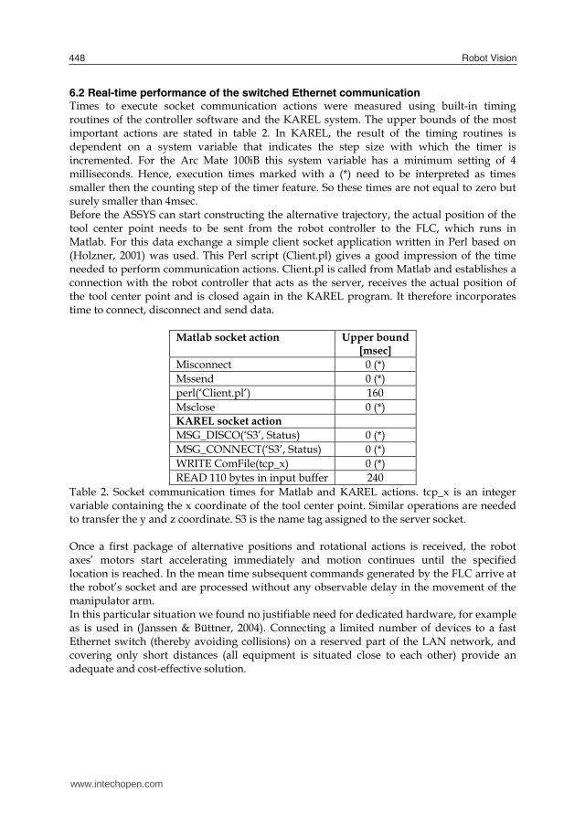
6.2 Real-time performance of the switched Ethernet communication Times to execute socket communication actions were measured using built-in timing routines of the controller software and the KAREL system. The upper bounds of the most important actions are stated in table 2. In KAREL, the result of the timing routines is dependent on a system variable that indicates the step size with which the timer is incremented. For the Arc Mate 100iB this system variable has a minimum setting of 4 milliseconds. Hence, execution times marked with a (*) need to be interpreted as times smaller then the counting step of the timer feature. So these times are not equal to zero but surely smaller than 4msec. Before the ASSYS can start constructing the alternative trajectory, the actual position of the tool center point needs to be sent from the robot controller to the FLC, which runs in Matlab. For this data exchange a simple client socket application written in Perl based on (Holzner, 2001) was used. This Perl script (Client.pl) gives a good impression of the time needed to perform communication actions. Client.pl is called from Matlab and establishes a connection with the robot controller that acts as the server, receives the actual position of the tool center point and is closed again in the KAREL program. It therefore incorporates time to connect, disconnect and send data.
Matlab socket action Upper bound [msec]
Misconnect 0 (*) Mssend 0 (*) perl(‘Client.pl’) 160 Msclose 0 (*) KAREL socket action MSG_DISCO(‘S3’, Status) 0 (*) MSG_CONNECT(‘S3’, Status) 0 (*) WRITE ComFile(tcp_x) 0 (*) READ 110 bytes in input buffer 240
Table 2. Socket communication times for Matlab and KAREL actions. tcp_x is an integer variable containing the x coordinate of the tool center point. Similar operations are needed to transfer the y and z coordinate. S3 is the name tag assigned to the server socket. Once a first package of alternative positions and rotational actions is received, the robot axes’ motors start accelerating immediately and motion continues until the specified location is reached. In the mean time subsequent commands generated by the FLC arrive at the robot’s socket and are processed without any observable delay in the movement of the manipulator arm. In this particular situation we found no justifiable need for dedicated hardware, for example as is used in (Janssen & Büttner, 2004). Connecting a limited number of devices to a fast Ethernet switch (thereby avoiding collisions) on a reserved part of the LAN network, and covering only short distances (all equipment is situated close to each other) provide an adequate and cost-effective solution.
www.intechopen.com
Industrial robot manipulator guarding using artiicial vision 449
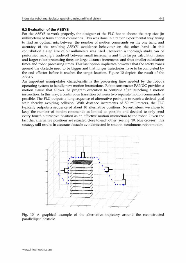
6.3 Evaluation of the ASSYS For the ASSYS to work properly, the designer of the FLC has to choose the step size (in millimeters) of translational commands. This was done in a rather experimental way trying to find an optimal mix between the number of motion commands on the one hand and accuracy of the resulting ASSYS’ avoidance behaviour on the other hand. In this contribution a step size of 50 millimeters was used. However, a thorough study can be performed making a trade-off between small increments and thus larger calculation times and larger robot processing times or large distance increments and thus smaller calculation times and robot processing times. This last option implicates however that the safety zones around the obstacle need to be bigger and that longer trajectories have to be completed by the end effector before it reaches the target location. Figure 10 depicts the result of the ASSYS. An important manipulator characteristic is the processing time needed by the robot’s operating system to handle new motion instructions. Robot constructor FANUC provides a motion clause that allows the program execution to continue after launching a motion instruction. In this way, a continuous transition between two separate motion commands is possible. The FLC outputs a long sequence of alternative positions to reach a desired goal state thereby avoiding collision. With distance increments of 50 millimeters, the FLC typically outputs a sequence of about 40 alternative positions. Nevertheless, we chose to keep the number of motion commands as limited as possible and decided to only send every fourth alternative position as an effective motion instruction to the robot. Given the fact that alternative positions are situated close to each other (see Fig. 10, blue crosses), this strategy still results in accurate obstacle avoidance and in smooth, continuous robot motion.
Fig. 10. A graphical example of the alternative trajectory around the reconstructed parallelliped obstacle
www.intechopen.com
Robot Vision450
The robot application in KAREL was implemented in a non-cyclic way; upon reaching the goal position, program execution is aborted. In an industrial environment it would be desirable that robot motion continues when a safe location (where no collision with the obstacle is possible) is reached. This can be easily implemented by running the obstacle detection routine again. This routine would then tell if the obstacle is still present or not and make sure the robot executes an alternative path (in case a new obstacle is blocking the robot’s path) or the regular, predetermined path in case of a free workspace. The FLC only takes the tool center point’s position as an input. Collision of the robot’s arm is prevented by rotating the end effector by +90° or -90° when it enters the safety zone not close. For the majority of practically executable robot trajectories, this precautionary action has proven to be sufficient. In general situations, the distance to the obstacle of extra points on the robot’s arm will have to be monitored to guarantee safer motion. Also, the rotation over 90° is not entirely independent of the shape of the object.
7. Conclusion
In this contribution the design of an active security system for an industrial FANUC manipulator was introduced. Stereo vision techniques were used to design a vision method that can identify and localize obstacles of certain predefined shape in the robot’s workspace. A fuzzy logic controller was successfully applied for the design of a 3D obstacle avoidance strategy. With some help from a fairly simple communication system, alternative path positions and rotational configurations could be transferred to the robot’s system at a time-critical rate. Although experiments showed good performance of the ASSYS, there still are quite a few issues that have to be solved before using this system in a real-life environment. Basic methods for object recognition were employed. In future work, advanced identification methods can be used, e.g. to distinguish the robot’s end effector from foreign objects and to design an approach that isn’t based on a-priori knowledge on the obstacle’s shape. So far, only static objects are supported. In an advanced stadium, detection criteria for human operators can also be elaborated. In the current setting, the time needed to calculate the characteristic positions of a parallelepiped obstacle was rather high, in some cases up to 2.5 seconds. A better technique can be developed for detecting obstacle corners. As mentioned at the end of the previous chapter, a more automated KAREL application can be designed in which robot motion continues when the final position of the alternative path is reached. For this application, a more thorough interaction between the KAREL communication task and the vision system would be required to signal the presence or the absence of an obstacle in the robot’s work space. Subsequently, the decision to return to the normal robot task or to follow a new alternative path has to be undertaken. For industrial settings, where small robot motion execution times are very important, a trade-off study between more commands because of smaller step sizes, and less commands with larger step sizes is an interesting topic. More specifically, a time efficient and distance optimal path construction algorithm can be designed.
www.intechopen.com
Industrial robot manipulator guarding using artiicial vision 451
8. References
Alavandar, S. & Nigam, M. J. (2008). Neuro-fuzzy based approach for inverse kinematics solution of industrial robot manipulators. International journal of Computers, Communications & Control, 3, 3, 224-234, 1841-9836
ANSI/RIA R15, 06-1986. Robot and Robot Systems-Safety Requirements. American National Standards Institute. New York, 1986.
Ayache, N. & Lustman, F. (1991). Trinocular stereo vision for robotics. IEEE Transactions on Pattern Analysis and Machine Intelligence, 13, 1, 73-85, ISSN:0162-8828
Baerveldt, A.-J. (1992). Cooperation between Man and Robot : Interface and Safety, Proceedings of the IEEE international workshop on robot and human communication, pp. 183-187, 0-7803-0753-4, Tokyo, Japan, September 1992, IEEE Press.
Bicchi, A.; Peshkin, M.A. & Colgate, J.E. (2008). Safety for Physical Human–Robot Interaction, In: Springer Handbook of Robotics, Siciliano, B. & Khatib, O. (Eds.), pp. 1335-1348, Springer, 978-3-540-23957-4, Berlin-Heidelberg, Germany
Bixby, K. (1991). Proactive safety design and implementation criteria, Proceedings of National Robot Safety Conference
Burghart, C.; Holzapfel, H.; Haeussling, R. & Breuer, S. (2007). Coding interaction patterns between human and receptionist robot, Proceedings of the 7th IEEE-RAS Conference on Humanoid Robots, pp. 454-460, Pittsburgh, PA, November 2007
Burghart, C.; Mikut, R.; Stiefelhagen, R.; Asfour, T.; Holzapfel, H.; Steinhaus, P. & Ruediger Dillmann (2005). A Cognitive Architecture for a Humanoid Robot: A First Approach, Proceedings of 5th IEEE-RAS International Conference on Humanoid Robots, pp. 357-362, Tsukuba, Japan, December 2005, IEEE Press
Cervera, E.; Garcia-Aracil, N.; Martínez, E.; Nomdedeu, L. & del Pobil, A.P. (2008). Safety for a robot arm moving amidst humans by using panoramic vision, Proceedings of the IEEE International Conference on Robotics and Automation, pp. 2183-2188, 978-1-4244-1646-2, Pasadena, CA, USA, May 2008, IEEE Press
Cojbašic, Ž. M. & Nikolic, V. D. (2008). Hybrid industrial robot motion control. Automatic Control and Robotics, 7, 1, pp. 99 – 110
Cordon, O.; Herrera, F.; Hoffmann, F. & Magdalena, L. (2001). Genetic Fuzzy Systems. Evolutionary tuning and learning of fuzzy knowledge bases, In Advances in Fuzzy Systems: Applications and Theory
Decotignie, J. D. (2005). Ethernet-based real-time and industrial communications. Proceedings of the IEEE, 93, 6, June 2005, 1102-1117, 0018-9219.
Dhillon, B.S. (1991). Robot Reliability and Safety, Springer-Verlag, 038-7-975-357, New York, USA
Driankow, D.; Hellendoorn, H. & Reinfrank, M. (1996). An introduction to fuzzy control - Second edition, Springer-Verlag
Ebert, D. & Heinrich, D. (2001). Safe human-robot-cooperation: problem analysis, system concept and fast sensor fusion, Proceedings of the international conference on Multisensor Fusion and Integration for Intelligent Systems, pp. 239- 244, ISBN: 3-00-008260-3, Kongresshaus Baden-Baden, Germany, August 2001
Ebert, D. & Henrich, D. (2002). Safe Human-Robot-Cooperation: image-based collision detection for industrial robots, Proceedings of the IEEE/RSJ International conference on intelligent robots and systems, pp. 1826-1831, Lausanne, France, October 2002, IEEE Press
www.intechopen.com
Robot Vision452
Ebert, D.; Komuro, T.; Namiki, A. & Ishikawa, M. (2005). Safe human-robot-coexistence: emergency-stop using a high-speed vision-chip, Proceedings of the IEEE/RSJ International Conference on In Intelligent Robots and Systems, pp. 2923-2928, Edmonton, Alberta, Canada, August 2005, IEEE Press.
Eckert, G. (2000). Automatic Shape Reconstruction of Rigid 3-D Objects from Multiple Calibrated Images, Proceedings of the European Signal Processing Conference, pp. 2105-2108, 952-15-0443-9, Tampere, Finland, September 2000, TTKK-Paino, Tampere, FINLAND.
Feddema, J.T. & Novak, J.L. (1994). Whole arm obstacle avoidance for teleoperated robots, Proceedings of the IEEE International Conference on Robotics and Automation, pp. 3303-3309 vol.4, 0-8186-5330-2, San Diego, CA, USA, May 1994, IEEE Press
Gecks, T. & Henrich, D. (2005). Human-robot corporation: safe pick-and-place operations, Proceedings of the IEEE International Workshop on Robots and Human Interactive Communication, pp. 549-554, ISBN, Nashville, Tennesse, USA, August 2005, IEEE Press
Ghalia, M.B. & Alouani, A. T. (1995). A robust trajectory tracking control of industrial robot manipulators using fuzzy logic. Proceedings of the 27th Southeastern Symposium on System Theory, 268
Graham, J.H. (1991). Safety, Reliability and Human Factors in Robotics Systems, John Wiley & Sons, Inc., 0442002807, New York, USA.
Hartley, R. I. & Zisserman, A. (2004). Multiple View Geometry in Computer Vision, Cambridge University Press, ISBN: 0521540518, Cambridge, UK.
He, X. C. & Yung, N. H. C. (2004). Curvature scale space corner detector with adaptive threshold and dynamic region of support, Proceedings of the 17th International Conference on Pattern Recognition - Volume 2, pp.791-794, 0-7695-2128-2, Cambridge, UK, August 2004
Heinzmann, J. & Zelinsky, A. (1999). Building Human-Friendly Robot Systems, Proceedings of the International Symposium of Robotics Research, pp. 9-12, Salt Lake City (UT), USA, October 1999
Hirschfeld, R.A.; Aghazadeh, F. & Chapleski, R.C. (1993). Survey of Robot Safety in Industry. The International Journal of Human Factors in Manufacturing, 3, 4, pp. 369-379, 1045-2699/93/040369-11. John Wiley & Sons, Inc.
Hitam, M.S. (2001). Fuzzy logic control of an industrial robot. Proceedings of Joint 9th IFSA World Congress and 20th NAFIPS International Conference, 257-262 vol. 1, July 2001
Holzner, S. (2001). Perl Black Book, Second Edition, Paraglyph Press, 978-1-932-11110-1, USA Heikkilä, J. & Silvén, O. (1997). A Four-step Camera Calibration Procedure with Implicit
Image Correction. Proceedings of the 1997 Conference on Computer Vision and Pattern Recognition, 1106--1112, 0-8186-7822-4
ISO 10218-1:2006(E). Robot for Industrial Environments, Safety requirements, Part1: Robot. International Organization for Standardization. Switzerland, 2006.
Janssen, D.; Büttner, H. (2004). Real-time Ethernet: the EtherCAT solution. Computing & Control Engineering Journal, 15, pp. 16-21
Kuhn, S.; Gecks, T. & Henrich, D. (2006). Velocity control for safe robot guidance based on fused vision and force/torque data, Proceedings of the IEEE International Conference on Multisensor Fusion and Integration for Intelligent Systems, pp. 485-492, Heidelberg, Germany, September 2006
www.intechopen.com
Industrial robot manipulator guarding using artiicial vision 453
Kumar, M. & Garg, D. P. (2005). Neuro-fuzzy control applied to multiple cooperating robots. Industrial Robot: An International Journal, 32, 3, 234 – 239
Llata, J.R.; Sarabia, E.G.; Arce, J. & Oria, J.P. (1998). Fuzzy controller for obstacle avoidance in robotic manipulators using ultrasonic sensors, Proceedings of the 5th International Workshop on Advanced Motion Control, pp. 647-652, 9780780344846, Coimbra, Portugal, June 1998
Noborio, H. & Urakawa, K. (1999). Three or more dimensional sensor-based path planning algorithm HD-I, Proceedings of the IEEE/RSI Int. Conf. on Intelligent Robots and Systems vol. 3, pp. 1699-1706, October 1999, IEEE Press
Noborio, H. & Nishino, Y. (2001). Image-Based Path-Planning Algorithm on the Joint Space, Proceedings of the 2001 IEEE International Conference on Robotics and Automation, pp. 1180-1187 vol. 2, 0-7803-6576-3, Seoul, Korea, May 2001
Novak, J.L. & Feddema, J.T. (1992). A capacitance-based proximity sensor for whole arm obstacle avoidance, Proceedings of the IEEE International conference on Robotics and Automation, pp. 1307-1314 vol. 2, 0-8186-2720-4, Nice, France, May 1992
Oestreicher, L. & Eklundh, K. S. (2006). User Expectations on Human-Robot Cooperation, Proceedings of the 15th IEEE International Symposium on Robot and Human Interactive Communication, pp. 91-96, ISBN, Hatfield, UK, September 2006
Ogorodnikova, O. (2006). Human-Robot Interaction. Safety problems, Proceedings of the 15th International Workshop on Robotics in Alpe-Adria-Danube Region, pp. 63-68, Balatonfüred, Hungary, June, 2006
Ohta, A. & Amano, N. (2008). Collision prediction using physical simulator and stereo vision system for human support robot, Proceedings of the international conference on instrumentation, control and information technology, pp. 2286-2290, The University Electro-Communications, August 2008, Chofu, Tokyo, Japan
OSHA (2006). Industrial Robots and Robot System Safety. In United states department of labor, occupational safety & health administration technical manual, Section IV, Chapter 4.
Piggin, R. (2005). Developments in industrial robotic safety. Industrial robot, 32, 4, pp. 303-311, 0143-991X.
Piggin, R. & Brandt, D. (2006). Wireless ethernet for industrial applications. Assembly Automation, 26, 3, 205-215.
Salvi, J.; Armangu, X. & Batlle, J. (2002). A Comparative Review of Camera Calibrating Methods with Accuracy Evaluation. Pattern Recognition, 35, 7, pp. 1617-1635, ISSN: 0031-3203.
Scharstein, D. & Szeliski, R. (2002). A taxonomy and evaluation of dense two-frame stereo correspondence algorithms. International Journal of Computer Vision, 47, 7-42, ISSN:0920-5691.
Seitz, S. M.; Curless, B.; Diebel, J.; Scharstein, D. & Szeliski, R. (2006). A Comparison and Evaluation of Multi-View Stereo Reconstruction Algorithms, Proceedings of the IEEE Computer Society Conference on Computer Vision and Pattern Recognition, pp. 519-528, (vol. 1) ISBN: 0-7695-2597-0, New York, USA, June 2006, IEEE Press.
Steinhaus, P.; Ehrenmann, M. & Dillmann R. (1999). MEPHISTO: A modular and existensible path planning system using observation, In: Lecture Notes in Computer Science 1542, EDITOR (Ed.), pp. 361-375, Springer-Verlag, 3-540-65459-3, London, UK
www.intechopen.com
Robot Vision454
Surdhar, J. S. & White A. S. (2003). A parallel fuzzy-controlled flexible manipulator using optical tip feedback. Robotics and Computer-Integrated Manufacturing, 19, 3, June 2003, 273-282
Torre-Ferrero, C.; Llata García, J. & González Saro, A. (2005). Monocular 3d reconstruction by applying a clustering algorithm to the Hough parameter space, Proceedings of the 7th IASTED International Conference on Control and Applications, pp. 82-87, 0-88986-502-7, Cancun, Mexico, May 2005, Acta Press
Yu, Y. & Gupta, K. (1999). Sensor-based roadmaps for motion planning for articulated robots in unknown environments: some experiments with an eye-in-hand system, Proceedings of IEEE/RSJ International Conference on Intelligent Robots and Systems, pp. 1707-1714, ISBN, Kyongju, South Korea, October 1999, IEEE Press
Weng, Y.-H.; Chen, C.-H. & Sun, C.-T. (2009). Toward the human-robot co-existence society: on safety intelligence for Next Generation Robots. Accepted for publication in International Journal of Social Robotics, 1875-4791 (Print) 1875-4805 (Online)
Wöhler, C. (2009). Applications to Safe Human–Robot Interaction, In 3D Computer Vision: efficient methods and applications, Wöhler, C. (Ed.), pp. 277-301, Springer, 978-3-642-01731-5 (Print) 978-3-642-01732-2 (Online), Berlin Heidelberg
Zavlangas, P. G. & Tzafestas, S. G. (2000). Industrial robot navigation and obstacle avoidance employing fuzzy logic. Journal of Intelligent and Robotic Systems, 27, 1-2, January 2000, 85-97, 0921-0296
www.intechopen.com
Robot VisionEdited by Ales Ude
ISBN 978-953-307-077-3Hard cover, 614 pagesPublisher InTechPublished online 01, March, 2010Published in print edition March, 2010
InTech EuropeUniversity Campus STeP Ri Slavka Krautzeka 83/A 51000 Rijeka, Croatia Phone: +385 (51) 770 447 Fax: +385 (51) 686 166www.intechopen.com
InTech ChinaUnit 405, Office Block, Hotel Equatorial Shanghai No.65, Yan An Road (West), Shanghai, 200040, China
Phone: +86-21-62489820 Fax: +86-21-62489821
The purpose of robot vision is to enable robots to perceive the external world in order to perform a large rangeof tasks such as navigation, visual servoing for object tracking and manipulation, object recognition andcategorization, surveillance, and higher-level decision-making. Among different perceptual modalities, vision isarguably the most important one. It is therefore an essential building block of a cognitive robot. This bookpresents a snapshot of the wide variety of work in robot vision that is currently going on in different parts of theworld.
How to referenceIn order to correctly reference this scholarly work, feel free to copy and paste the following:
Fevery Brecht, Wyns Bart, Boullart Luc, Llata Garcia Jose Ramon and Torre Ferrero Carlos (2010). IndustrialRobot Manipulator Guarding Using Artificial Vision, Robot Vision, Ales Ude (Ed.), ISBN: 978-953-307-077-3,InTech, Available from: http://www.intechopen.com/books/robot-vision/industrial-robot-manipulator-guarding-using-artificial-vision

© 2010 The Author(s). Licensee IntechOpen. This chapter is distributedunder the terms of the Creative Commons Attribution-NonCommercial-ShareAlike-3.0 License, which permits use, distribution and reproduction fornon-commercial purposes, provided the original is properly cited andderivative works building on this content are distributed under the samelicense.
Related Documents