Industrial Heat-Tracing Installation and Maintenance Manual Self-Regulating and Power-Limiting Heating Cable Systems

Welcome message from author
This document is posted to help you gain knowledge. Please leave a comment to let me know what you think about it! Share it to your friends and learn new things together.
Transcript
Industrial Heat-TracingInstallation andMaintenance Manual
Self-Regulating and Power-LimitingHeating Cable Systems
iiiii
Table of Contents
General Information 1
Heating Cable Selection 3
Heating Cable Installation 4
Heating Cable Components 16
Control and Monitoring 18
Thermal Insulation 19
Power Supply and Electrical Protection 20
Commissioning and Preventive Maintenance 21
Test Procedures 23
Troubleshooting Guide 32
Installation and Inspection Records 361110987654321
WARNING: Fire and shock hazard.
Raychem® heat-tracing systems must be installed cor-rectly to ensure proper operation and to prevent shockand fire. Read these important warnings and carefullyfollow all the installation instructions.• To minimize the danger of fire from sustained electrical
arcing if the heating cable is damaged or improperlyinstalled, and to comply with Tyco Thermal Controlsrequirements, agency certifications, and the nationalelectrical codes, ground-fault equipment protection mustbe used on each heating-cable branch circuit. Arcingmay not be stopped by conventional circuit breakers.
• Approvals and performance of the heat-tracing systemsare based on the use of Tyco Thermal Controls speci-fied parts only. Do not substitute parts or use vinylelectrical tape.
• Bus wires will short if they contact each other. Keep buswires separated.
• Components and cable ends must be kept dry beforeand during installation.
• The black heating-cable core and fibers areconductive and can short. They must be properlyinsulated and kept dry.
• Damaged bus wires can overheat or short. Do notbreak bus wire strands when preparing the cable forconnection.
• Damaged heating cable can cause electrical arcing orfire. Do not use metal attachments such as pipestraps or tie wire. Use only Raychem approved tapesand cable ties to secure the cable to the pipe.
• Do not attempt to repair or energize damaged cable.Remove damaged cable at once and replace with anew length using the appropriate Raychem splice kit.Replace damaged components.
• Re-use of the grommets, or use of the wrong grommet,can cause leaks, cracked components, shock, or fire.Be sure the type of grommet is correct for the heatingcable being installed. Use a new grommet wheneverthe cable has been pulled out of the component.
• Use only fire-resistant insulation which is compatiblewith the application and the maximum exposuretemperature of the system to be traced.
• To prevent fire or explosion in hazardous locations,verify that the maximum sheath temperature of theheating cable is below the auto-ignition temperatureof the gases in the area. For further information, seethe design documentation.
• Material Safety Data Sheets (MSDSs) are available fromthe Tyco Thermal Controls Customer Service Center.
General Information
1.1 Use of the ManualThis installation and maintenance manual is for RaychemSelf-Regulating and Power-Limiting heat-tracing systems onthermally insulated pipes and vessels only. This includesRaychem BTV, QTVR, XTV, and VPL heating cables and theappropriate Raychem components.
For information regarding other applications, design assis-tance or technical support, contact your Tyco ThermalControls representative or Tyco Thermal Controls directly.
Tyco Thermal Controls300 Constitution DriveMenlo Park, CA 94025-1164USATel (800) 545-6258Fax (800) 527-5703Technical Support (650) [email protected]
Important: For the Tyco Thermal Controls warranty andagency approvals to apply, the instructions that are includedin this manual and product packages must be followed.
1.2 Safety GuidelinesThe safety and reliability of any heat-tracing systemdepends on proper design, installation and maintenance.Incorrect handling, installation, or maintenance of any ofthe system components can cause underheating or over-heating of the pipe or damage to the heating-cable systemand may result in system failure, electric shock or fire.
1.3 Electrical CodesSections 427 (pipelines and vessels) and 500 (classifiedlocations) of the National Electrical Code (NEC), and Part 1of the Canadian Electrical Code, Sections 18 (hazardouslocations) and 62 (Fixed Electric Space and SurfaceHeating), govern the installation of electrical heat-tracingsystems. All heat-tracing-system installations must be incompliance with these and any other applicable national orlocal codes.
1
1
General Information
1.4 Warranty and ApprovalsRaychem heating cables and components are approved foruse in hazardous and non-hazardous locations. Refer tothe specific product data sheets for details.
1.5 General Installation NotesThese notes are provided to assist the installer throughoutthe installation process and should be reviewed before theinstallation begins.
• Read all instruction sheets to familiarize yourself withthe products.
• Select the heating-cable type and rating in accordancewith the Industrial Product Selection and Design Guide(Tyco Thermal Controls literature #H56550), orTraceCalc® Pro software, or the website design software.
• Ensure all pipes, tanks, etc., have been released by theclient for tracing prior to installation of the heatingcables.
• Typically, heating cables are installed at the 4 and 8o’clock positions on a pipe.
• All heat-traced pipes, tanks, vessels and equipment mustbe thermally insulated.
• Do not install heating cables on equipment operatingabove the heating cable’s maximum rated temperature.
• The minimum bending radius for VPL Power-Limitingcables is 3/4 inch (19 mm). The minimum bendingradius for Self-Regulating cables is 1/2 inch (13 mm).
• Never install heating cables over expansion joints with-out leaving slack in the cable.
• Do not energize cable when it is coiled or on the reel.
• Never use tie wire or pipe straps to secure heating cables.
• The minimum installation temperature for heating cablesis –40°F (–40°C).
1
2
Heating Cable Selection
Check the design specification to make sure the properheating cable is installed on each pipe or vessel. Refer tothe Industrial Product Selection and Design Guide,TraceCalc Pro or the Tyco Thermal Controls web site,www.tycothermal.com, to select the proper heating cablefor your application.
2
3
Heating Cable Installation
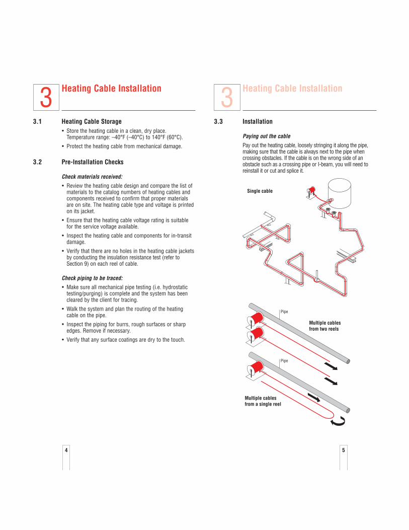
3.3 Installation
Paying out the cable
Pay out the heating cable, loosely stringing it along the pipe,making sure that the cable is always next to the pipe whencrossing obstacles. If the cable is on the wrong side of anobstacle such as a crossing pipe or I-beam, you will need toreinstall it or cut and splice it.
Pipe
Pipe
Multiple cablesfrom two reels
Multiple cablesfrom a single reel
Single cable
3
5
Heating Cable Installation
3.1 Heating Cable Storage• Store the heating cable in a clean, dry place.
Temperature range: –40°F (–40°C) to 140°F (60°C).
• Protect the heating cable from mechanical damage.
3.2 Pre-Installation Checks
Check materials received:
• Review the heating cable design and compare the list ofmaterials to the catalog numbers of heating cables andcomponents received to confirm that proper materialsare on site. The heating cable type and voltage is printedon its jacket.
• Ensure that the heating cable voltage rating is suitablefor the service voltage available.
• Inspect the heating cable and components for in-transit damage.
• Verify that there are no holes in the heating cable jacketsby conducting the insulation resistance test (refer toSection 9) on each reel of cable.
Check piping to be traced:
• Make sure all mechanical pipe testing (i.e. hydrostatictesting/purging) is complete and the system has beencleared by the client for tracing.
• Walk the system and plan the routing of the heatingcable on the pipe.
• Inspect the piping for burrs, rough surfaces or sharpedges. Remove if necessary.
• Verify that any surface coatings are dry to the touch.
3
4
76
Heating Cable Installation
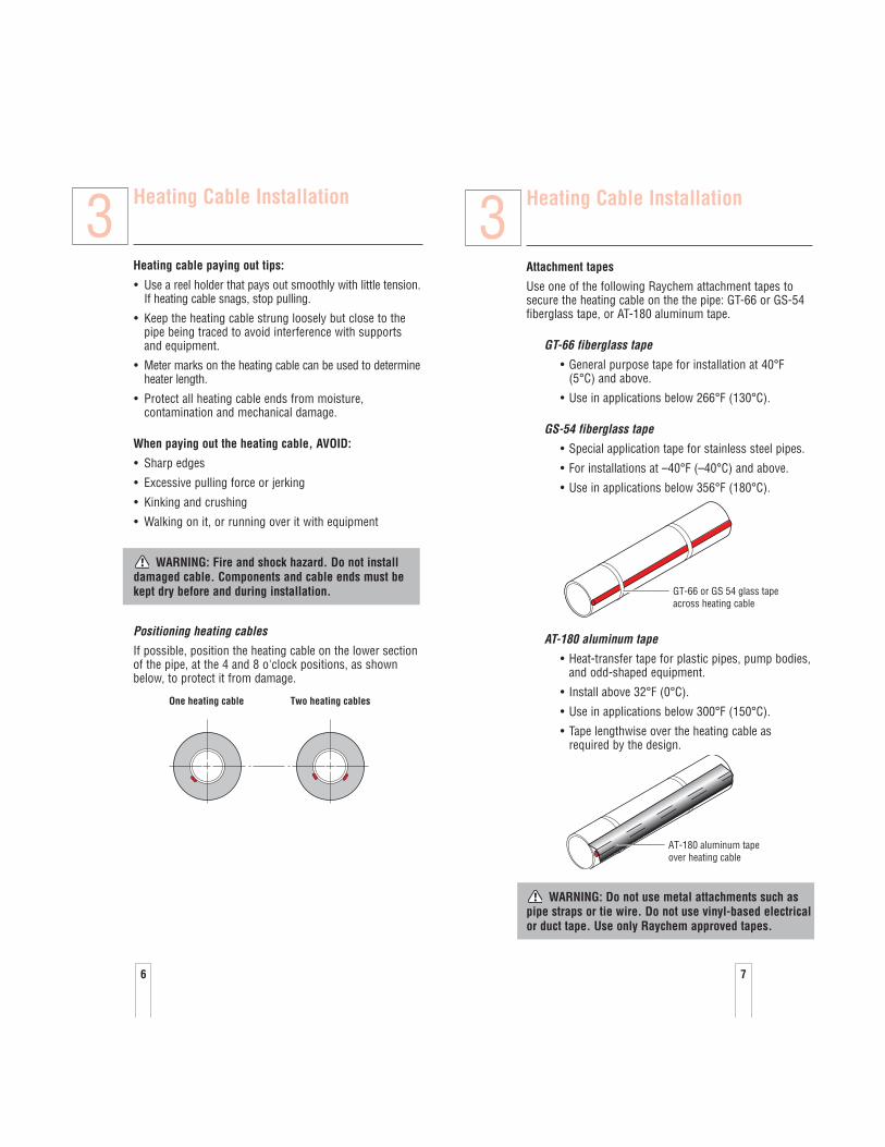
Attachment tapes
Use one of the following Raychem attachment tapes tosecure the heating cable on the the pipe: GT-66 or GS-54fiberglass tape, or AT-180 aluminum tape.
GT-66 fiberglass tape
• General purpose tape for installation at 40°F(5°C) and above.
• Use in applications below 266°F (130°C).
GS-54 fiberglass tape
• Special application tape for stainless steel pipes.
• For installations at –40°F (–40°C) and above.
• Use in applications below 356°F (180°C).
AT-180 aluminum tape
• Heat-transfer tape for plastic pipes, pump bodies,and odd-shaped equipment.
• Install above 32°F (0°C).
• Use in applications below 300°F (150°C).
• Tape lengthwise over the heating cable asrequired by the design.
WARNING: Do not use metal attachments such aspipe straps or tie wire. Do not use vinyl-based electricalor duct tape. Use only Raychem approved tapes.
AT-180 aluminum tapeover heating cable
GT-66 or GS 54 glass tapeacross heating cable
3Heating Cable Installation
Heating cable paying out tips:
• Use a reel holder that pays out smoothly with little tension.If heating cable snags, stop pulling.
• Keep the heating cable strung loosely but close to thepipe being traced to avoid interference with supportsand equipment.
• Meter marks on the heating cable can be used to determineheater length.
• Protect all heating cable ends from moisture,contamination and mechanical damage.
When paying out the heating cable, AVOID:
• Sharp edges
• Excessive pulling force or jerking
• Kinking and crushing
• Walking on it, or running over it with equipment
WARNING: Fire and shock hazard. Do not installdamaged cable. Components and cable ends must bekept dry before and during installation.
Positioning heating cables
If possible, position the heating cable on the lower sectionof the pipe, at the 4 and 8 o'clock positions, as shownbelow, to protect it from damage.
Two heating cablesOne heating cable
3
98
Heating Cable Installation
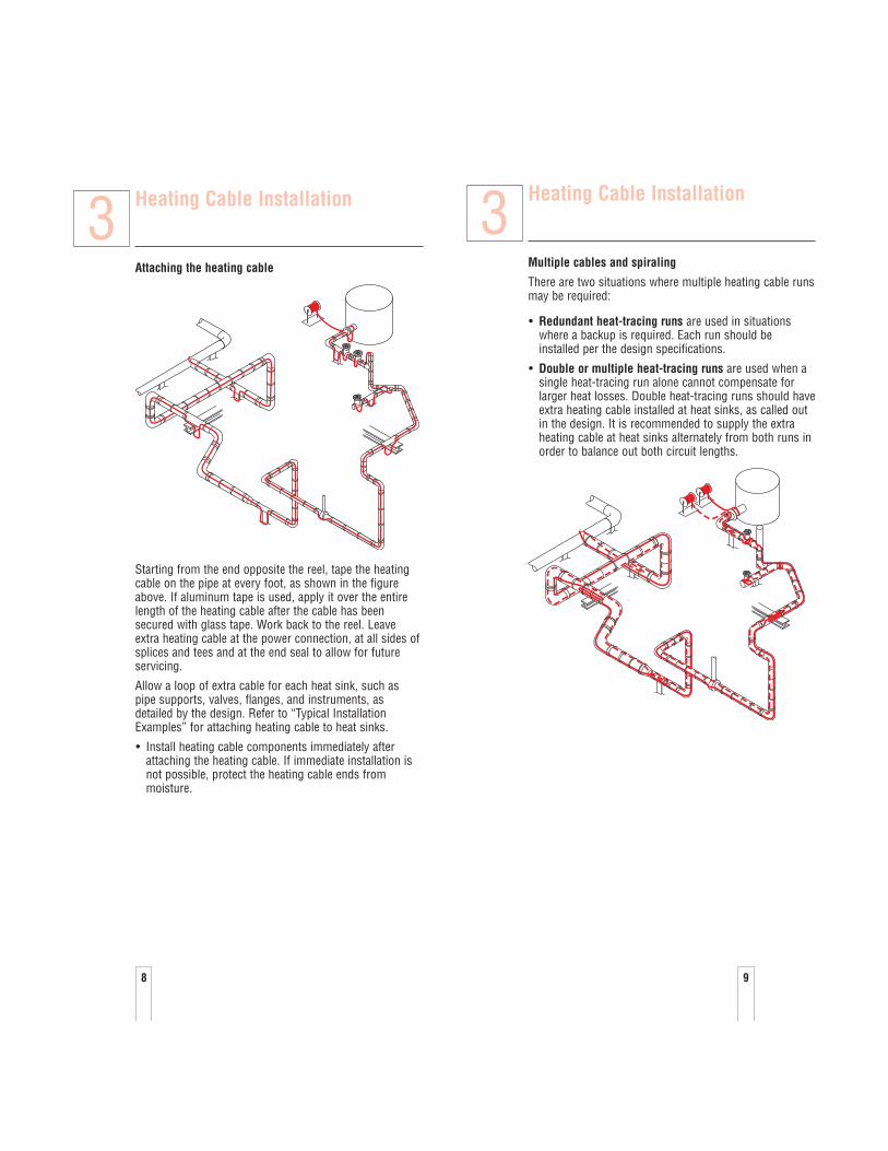
Attaching the heating cable
Starting from the end opposite the reel, tape the heatingcable on the pipe at every foot, as shown in the figureabove. If aluminum tape is used, apply it over the entirelength of the heating cable after the cable has beensecured with glass tape. Work back to the reel. Leaveextra heating cable at the power connection, at all sides ofsplices and tees and at the end seal to allow for futureservicing.
Allow a loop of extra cable for each heat sink, such aspipe supports, valves, flanges, and instruments, asdetailed by the design. Refer to “Typical InstallationExamples” for attaching heating cable to heat sinks.
• Install heating cable components immediately afterattaching the heating cable. If immediate installation isnot possible, protect the heating cable ends from moisture.
3Heating Cable Installation
Multiple cables and spiraling
There are two situations where multiple heating cable runsmay be required:
• Redundant heat-tracing runs are used in situationswhere a backup is required. Each run should beinstalled per the design specifications.
• Double or multiple heat-tracing runs are used when asingle heat-tracing run alone cannot compensate forlarger heat losses. Double heat-tracing runs should haveextra heating cable installed at heat sinks, as called outin the design. It is recommended to supply the extraheating cable at heat sinks alternately from both runs inorder to balance out both circuit lengths.
3

1110
Heating Cable Installation
Spiral tracing
When the design calls for spiralling, begin by suspendinga loop at every 10-foot pipe section. To determine the looplength, obtain a spiral factor from the design and multiply by10. For example if the spiral factor of 1.3 is called for, leave a13-foot loop of heating cable at every 10-foot section ofpipe. Attach the loop to the pipe at each interval using theappropriate Raychem attachment tape.
Bending the cable
When positioning the heating cable on the pipe, do notbend tighter than 1/2" for Self-Regulating cables and 3/4" for Power-Limiting cables.
Power-Limiting minimum bend radius
3/4"
Self-Regulating minimum bend radius
1/2"
10 feetGlass tape(typical)
Apply glasstape beforespiralingheating cableon pipe
Pull heating cable loop length
Wrap loopsin oppositedirections
Tape after spiralingheating cable on pipe
Heatingcable
3 Heating Cable Installation
The heating cable does not bend easily in the flat plane. Donot force such a bend, as the heating cable may be damaged.
Crossing the cable
Self-Regulating cables, BTV, QTVR, XTV, allow for multipleoverlapping of the heating cable.
Power-Limiting cable, VPL, allows for a single overlap ofthe heating cable per zone.
For VPL heating cable only:
Cutting the cable
Cut the heating cable to length after it is attached to thepipe.
Heating cable can be cut to length without affecting theheat output per foot.
3
1312
Heating Cable Installation
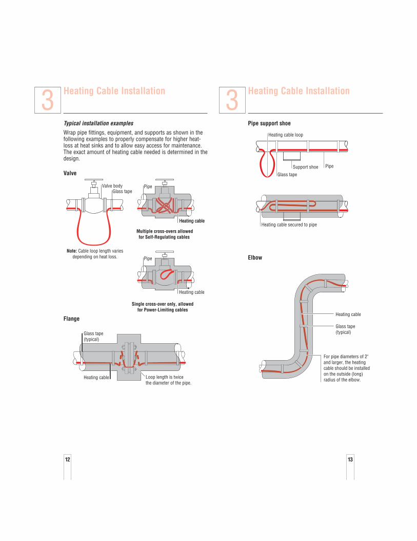
Typical installation examples
Wrap pipe fittings, equipment, and supports as shown in thefollowing examples to properly compensate for higher heat-loss at heat sinks and to allow easy access for maintenance.The exact amount of heating cable needed is determined in thedesign.
Valve
Flange
Glass tape(typical)
Heating cable Loop length is twice the diameter of the pipe.
Valve body
Multiple cross-overs allowedfor Self-Regulating cables
Single cross-over only, allowedfor Power-Limiting cables
Note: Cable loop length variesdepending on heat loss.
Glass tapePipe
Heating cable
Pipe
Heating cable
Heating cable
3 Heating Cable Installation
Pipe support shoe
Elbow
Heating cable
Glass tape(typical)
For pipe diameters of 2"and larger, the heatingcable should be installedon the outside (long)radius of the elbow.
Heating cable secured to pipe
Glass tape
Heating cable loop
Support shoe Pipe
3

Heating Cable Installation
Pipe hanger
Heating cable
Heating cable
Glass tape Do not clamp heating cable with support
Pipe hanger
Pipe hangerNo additional heating cable is required for pipe hangers unless
called for in the design specification, then use loop length specified.
3
15
Heating Cable Installation
Pressure gauge
Split case centrifugal pump
Glass tape
Pump discharge
Pump body
Heating cable
Pumpsuction
Use AT-180tape
Motor
To power connection
Heating cable
Glass tape
Pipe
3
14
Heating Cable Components
4.1 General Component InformationRaychem components must be used with Raychem Self-Regulating and Power-Limiting heating cables. A completecircuit requires a power connection and an end seal.Splices and tees are used as needed.
Use the Industrial Product Selection and Design Guide orTraceCalc Pro to select appropriate components.
Installation instructions are included with the componentkit. Steps for preparing the heating cable and connecting tocomponents must be followed.
Raychem Self-Regulating and Power-Limiting heatingcables are parallel circuit design. Do not twist the conduc-tors together as this will result in a short circuit.
Component Installation Tips• Connection kits should be mounted on top of the pipe
when practical. Electrical conduit leading to power con-nection kits should have low-point drains to keep con-densation from accumulating in the conduit. All heatingcable connections must be mounted above grade level.
• Special adapters are available for mounting on smallpipes. Be sure to use these adapters if installing cableson pipes of 1 inch O.D. or less.
• Be sure to leave a service loop at all components for futuremaintenance, except when temperature-sensitive fluids areinvolved or when the pipe is smaller than 1 inch.
• Locate junction boxes for easy access but not wherethey may be exposed to mechanical abuse.
• Heating cables must be installed over, not under, pipestraps used to secure components.
• For VPL, cut cable 12" (30 cm) from last active node(indentation) to be sure an inactive zone is used to enter thecomponent. Refer to component installation instructions.
• All power connections, splices, tees, and end seals in aDivision 1 location must use the HAK-C-100 connectionkit and an HAK-JB3-100 or a Division 1 NationallyRecognized Testing Lab (NRTL) approved junction box.
WARNING: The black heating-cable core and fibersare electrically conductive and can short. They must beproperly insulated and kept dry.
Damaged bus wires can overheat or short. Do not breakbus wire strands when stripping the heating cable
4 Heating Cable Components
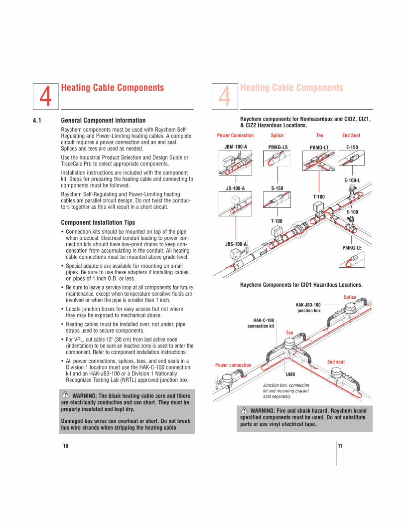
Raychem components for Nonhazardous and CID2, CIZ1,& CIZ2 Hazardous Locations.
Raychem Components for CID1 Hazardous Locations.
WARNING: Fire and shock hazard. Raychem brandspecified components must be used. Do not substituteparts or use vinyl electrical tape.
HAK-C-100connection kit
HAK-JB3-100junction box
UMB
Junction box, connection kit and mounting bracket sold separately
Splice
End seal
Tee
Power connection
E-150PKMG-LT
S-150JS-100-A
JBM-100-A
T-100
T-100
JBS-100-A
E-100
E-100-L
Power Connection Splice Tee End Seal
PMKG-LS
PMKG-LE
4
16 17
Control and Monitoring
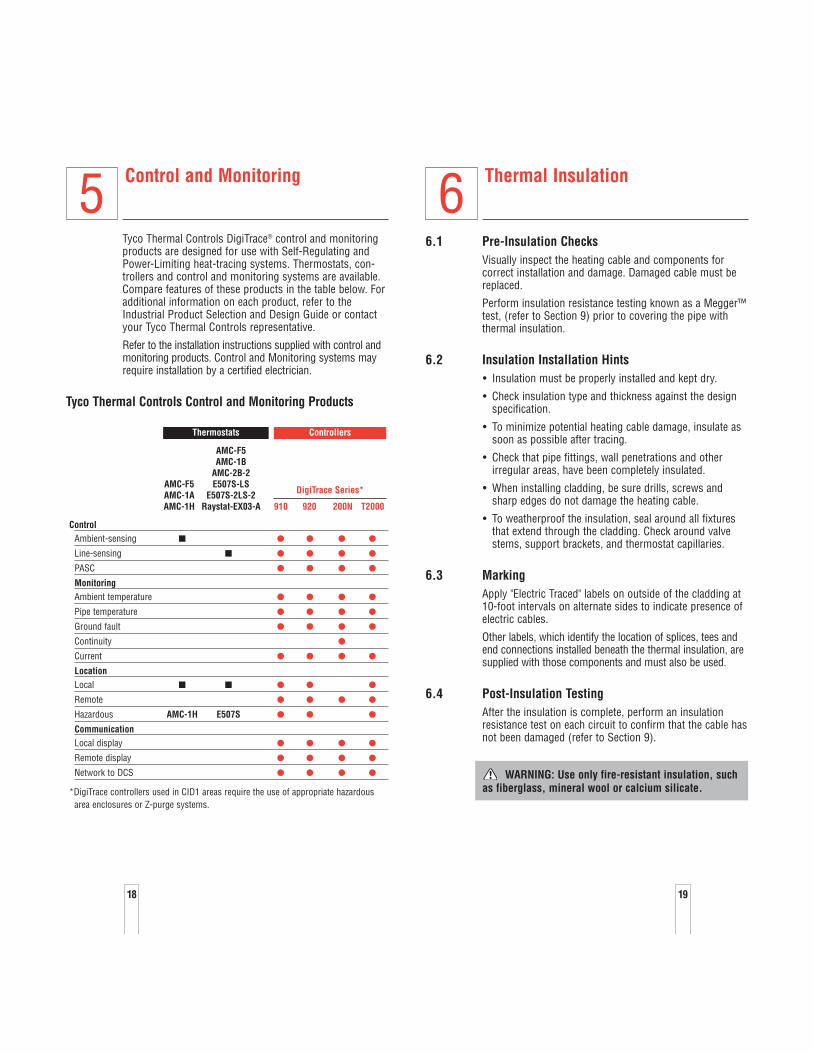
Tyco Thermal Controls DigiTrace® control and monitoringproducts are designed for use with Self-Regulating andPower-Limiting heat-tracing systems. Thermostats, con-trollers and control and monitoring systems are available.Compare features of these products in the table below. Foradditional information on each product, refer to theIndustrial Product Selection and Design Guide or contactyour Tyco Thermal Controls representative.
Refer to the installation instructions supplied with control andmonitoring products. Control and Monitoring systems mayrequire installation by a certified electrician.
Tyco Thermal Controls Control and Monitoring Products
5 Thermal Insulation
6.1 Pre-Insulation ChecksVisually inspect the heating cable and components forcorrect installation and damage. Damaged cable must bereplaced.
Perform insulation resistance testing known as a Megger™test, (refer to Section 9) prior to covering the pipe withthermal insulation.
6.2 Insulation Installation Hints• Insulation must be properly installed and kept dry.
• Check insulation type and thickness against the designspecification.
• To minimize potential heating cable damage, insulate assoon as possible after tracing.
• Check that pipe fittings, wall penetrations and otherirregular areas, have been completely insulated.
• When installing cladding, be sure drills, screws andsharp edges do not damage the heating cable.
• To weatherproof the insulation, seal around all fixturesthat extend through the cladding. Check around valvestems, support brackets, and thermostat capillaries.
6.3 MarkingApply "Electric Traced" labels on outside of the cladding at 10-foot intervals on alternate sides to indicate presence ofelectric cables.
Other labels, which identify the location of splices, tees andend connections installed beneath the thermal insulation, aresupplied with those components and must also be used.
6.4 Post-Insulation TestingAfter the insulation is complete, perform an insulationresistance test on each circuit to confirm that the cable hasnot been damaged (refer to Section 9).
WARNING: Use only fire-resistant insulation, suchas fiberglass, mineral wool or calcium silicate.
6
18 19
ControlAmbient-sensing
Line-sensing
PASC
MonitoringAmbient temperature
Pipe temperature
Ground fault
Continuity
Current
LocationLocal
Remote
Hazardous AMC-1H E507S
CommunicationLocal display
Remote display
Network to DCS
*DigiTrace controllers used in CID1 areas require the use of appropriate hazardous area enclosures or Z-purge systems.
DigiTrace Series*
910 920 200N T2000
AMC-F5AMC-1B
AMC-2B-2E507S-LS
E507S-2LS-2Raystat-EX03-A
AMC-F5AMC-1AAMC-1H
ControllersThermostats
Power Supply andElectrical Protection
7.1 Voltage RatingVerify that the source voltage corresponds to the heating-cable rating printed on the cable jacket and specified by thedesign.
7.2 Electrical LoadingOvercurrent devices are selected according to the heating-cable type, source voltage, and circuit length to allow start-up at the designed ambient temperatures. The designspecifies the size and type of overcurrent device.
7.3 Ground-Fault ProtectionIf the heating cable is improperly installed, or physicallydamaged to the point that water contacts the bus wires,sustained arcing or fire could result. If arcing does occur, thefault current may be too low to trip conventional circuitbreakers.
Tyco Thermal Controls, the U.S. National Electrical Code,and the Canadian Electrical Code require both ground-faultprotection of equipment and a grounded metallic covering onall heating cables. All Raychem products meet the metalliccovering requirement. Following are some of the ground faultbreakers that satisfy this equipment protection requirement:Square D Type GFPD EHB-EPD (277 Vac); Cutler Hammer(Westinghouse) Type QBGFEP.
WARNING: To minimize the danger of fire fromsustained electrical arcing if the heating cable is dam-aged or improperly installed, and to comply with TycoThermal Controls requirements, agency certifications,and national electrical codes, ground-fault equipmentprotection must be used on each heating-cable branchcircuit. Arcing may not be stopped by conventionalcircuit breakers.
WARNING: Disconnect all power before makingconnections to the heating cable.
7
20
Commissioning and PreventativeMaintenance
Tyco Thermal Controls requires a series of tests be per-formed on the heat-tracing system upon commissioning.These tests are also recommended at regular intervals forpreventive maintenance. Results must be recorded andmaintained for the life of the system, utilizing the“Installation and Inspection Record” (refer to Section 11).
8.1 TestsA brief description of each test is found below. Detailedtest procedures are found in Section 9.
Visual inspection
Visually inspect the pipe, insulation, and connections to theheating cable for physical damage. Check that no moistureis present, electrical connections are tight and grounded,insulation is dry and sealed, and control and monitoringsystems are operational and properly set. Damagedheating cable must be replaced.
Insulation Resistance
Insulation Resistance (IR) testing is used to verify theintegrity of the heating-cable inner and outer jackets. IRtesting is analogous to pressure testing a pipe and detectsif a hole exists in the jacket. IR testing can also be used toisolate the damage to a single run of heating cable. Faultlocation can be used to further locate damage.
Power check
The heating-cable power per foot (meter) is calculated bydividing the total wattage by the total length of a circuit.The current, voltage, operation temperature and lengthmust be known. Circuit length can be determined from “asbuilt” drawings, meter marks on cable or the capacitancetest.
Power (w/ft or m) = Volts (Vac) x Current (Amps)
Length (ft or m)
The watts per foot (meter) can be compared to the heaing-cable output indicated on the product data sheet at thetemperature of operation. This gives a good indication ofheating-cable performance.
Ground-fault test
Test all ground-fault breakers per manufacturer's instructions.
8
21
Commissioning and PreventativeMaintenance
8.2 Preventative MaintenanceRecommended maintenance for Tyco Thermal Controlsheat-tracing systems consists of performing thecommissioning tests on a regular basis. Procedures for these tests are described in Section 9. Systems shouldbe checked before each winter.
If the heat-tracing system fails any of the tests, refer toSection 10 for trouble shooting assistance. Make the nec-essary repairs and replace any damaged cable immediately.
De-energize all circuits that may be affected by maintenance.
Protect the heating cable from mechanical or thermaldamage during maintenance work.
The recommended cable installation methods allow forextra cable at all pipe fixtures (such as valves, pumps, andpressure gauges) that are likely to incur maintenance work.
Maintenance records
The “Installation and Inspection Record,” (refer to Section11), should be filled out during all maintenance and repairwork, and kept for future reference.
Repairs
Use only Raychem cable, and components when replacingany damaged heating cable. Replace the thermal insulation tooriginal condition or replace with new insulation, if damaged.
Retest the system after repairs.
WARNING: Damage to cables or components cancause sustained electrical arcing or fire. Do not attemptto repair damaged heating cable. Do not energize cablesthat have been damaged by fire. Replace damaged cableat once by removing the entire damaged section andsplicing in a new length using the appropriate Raychemsplice kits. Do not reuse grommets. Use new grommetswhenever the heating cable has been pulled out of thecomponents.
8
22
Test Procedures
9.1 Visual Inspection• Check inside heating cable components for proper
installation, overheating, corrosion, moisture, and looseconnections.
• Check the electrical connections to ensure that groundand bus wires are insulated over their full length.
• Check for damaged or wet thermal insulation; damaged,missing or cracked lagging and weather-proofing.
• Check that end seals, splices, and tees are properlylabeled on insulation cladding.
• Check Control and Monitoring system for moisture, corro-sion, set point, switch operation and capillary damage.
9.2 Insulation Resistance (Megger™) Test
Frequency
Insulation resistance testing is recommended at five stagesduring the installation process and as part of regularlyscheduled maintenance.
• Before installing the cable
• Before installing components
• Before installing the thermal insulation
• After installing the thermal insulation
• Prior to initial start-up (commissioning)
• As part of the regular system inspection
• After any maintenance or repair work
Procedure
Insulation resistance testing (using a megohmmeter)should be conducted at three voltages; 500, 1000, and2500 Vdc. Significant problems may not be detected iftesting is done only at 500 and 1000 volts.
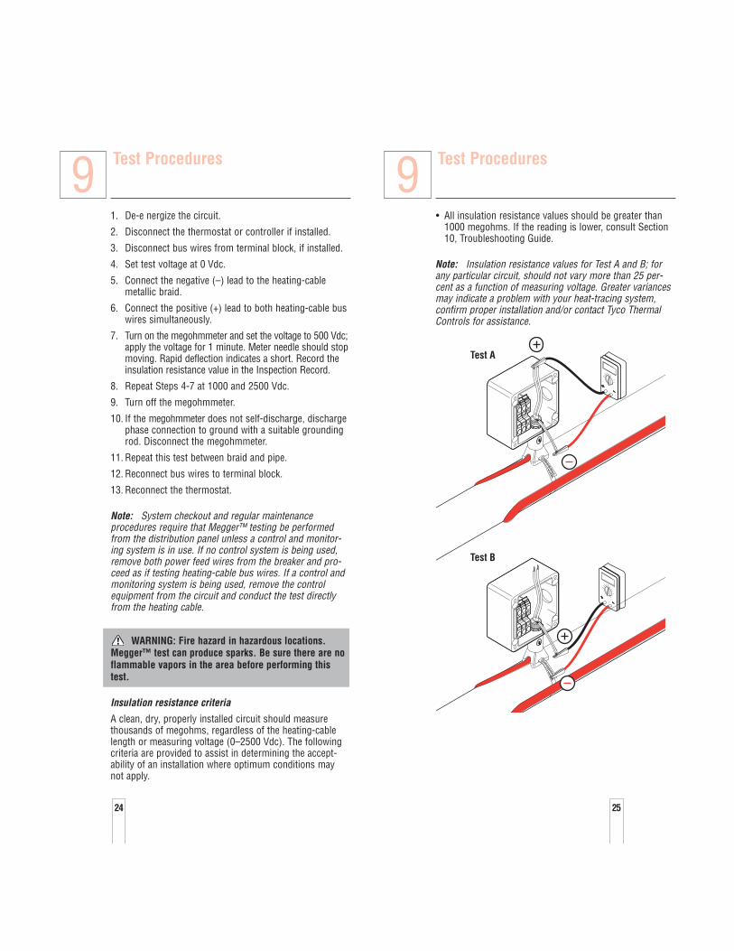
First measure the resistance between the heating cable buswires and the braid (Test A) then measure the insulationresistance between the braid and the metal pipe (Test B).Do not allow test leads to touch junction box, which cancause inaccurate readings.
9
23
Test Procedures
• All insulation resistance values should be greater than1000 megohms. If the reading is lower, consult Section10, Troubleshooting Guide.
Note: Insulation resistance values for Test A and B; forany particular circuit, should not vary more than 25 per-cent as a function of measuring voltage. Greater variancesmay indicate a problem with your heat-tracing system,confirm proper installation and/or contact Tyco ThermalControls for assistance.
Test B
Test A
9
25
Test Procedures
1. De-e nergize the circuit.
2. Disconnect the thermostat or controller if installed.
3. Disconnect bus wires from terminal block, if installed.
4. Set test voltage at 0 Vdc.
5. Connect the negative (–) lead to the heating-cablemetallic braid.
6. Connect the positive (+) lead to both heating-cable buswires simultaneously.
7. Turn on the megohmmeter and set the voltage to 500 Vdc;apply the voltage for 1 minute. Meter needle should stopmoving. Rapid deflection indicates a short. Record theinsulation resistance value in the Inspection Record.
8. Repeat Steps 4-7 at 1000 and 2500 Vdc.
9. Turn off the megohmmeter.
10. If the megohmmeter does not self-discharge, dischargephase connection to ground with a suitable groundingrod. Disconnect the megohmmeter.
11. Repeat this test between braid and pipe.
12. Reconnect bus wires to terminal block.
13. Reconnect the thermostat.
Note: System checkout and regular maintenanceprocedures require that Megger™ testing be performedfrom the distribution panel unless a control and monitor-ing system is in use. If no control system is being used,remove both power feed wires from the breaker and pro-ceed as if testing heating-cable bus wires. If a control andmonitoring system is being used, remove the controlequipment from the circuit and conduct the test directlyfrom the heating cable.
WARNING: Fire hazard in hazardous locations.Megger™ test can produce sparks. Be sure there are noflammable vapors in the area before performing thistest.
Insulation resistance criteria
A clean, dry, properly installed circuit should measurethousands of megohms, regardless of the heating-cablelength or measuring voltage (0–2500 Vdc). The followingcriteria are provided to assist in determining the accept-ability of an installation where optimum conditions maynot apply.
9
24
Test Procedures
9.3 Power CheckThe power output of Self-Regulating and Power-Limitingcable is temperature-sensitive and requires the followingspecial procedure to determine its value:
1. Power the heating cable and allow it to stabilize for 10 minutes, then measure current and voltage at thejunction box. If a thermostat or controller is used, referto details below.
2. Check the pipe temperature under the thermal insula-tion at several locations.
3. Calculate the power (watts/ft) of the heating cable bymultiplying the current by the input voltage and divid-ing by the actual circuit length.
Power (w/ft or m) = Volts (Vac) x Current (Amps)
Length (ft or m)
Ambient-sensing controlled systems
If the actual ambient temperature is higher than the desiredthermostat setting, turn the thermostat setting up highenough to turn on the system, or (with some models)manually set the selector switch to the ON position.
• Turn on the main circuit breaker.
• Turn on the branch circuit breakers.
• After a minimum of ten minutes, measure the voltage,amperage, ambient temperature, and pipe temperaturefor each circuit and record the values in the “Installationand Inspection Record” (refer to Section 11). This infor-mation is needed for future maintenance and trou-bleshooting.
• When the system is completely checked out, reset thethermostat to the proper temperature.
Line-sensing controlled systems
Set the thermostat to the desired control temperature, orto a setting high enough to turn the circuit on if the pipetemperature is above the control temperature.
• Turn on the main circuit breaker.
• Turn on the branch circuit breakers.
• Allow the system to reach the control point. This maytake up to four hours for most circuits. Large, liquid-filled pipes may take longer.
9
26
Test Procedures
• Measure the voltage, amperage, and pipe temperaturefor each circuit and record the values in the “Installationand Inspection Record” (refer to Section 11). This infor-mation is needed for future maintenance and trou-bleshooting.
• When the system is completely checked out, reset thethermostat to the proper temperature.
Control and monitoring systems
Refer to the installation instructions supplied with theproduct for commissioning tests and records.
9.4 Fault Location Tests
Fault location
There are three methods used for finding a fault within asection of heating cable: the ratio method, 1/R method andthe capacitance method. The capacitance method can alsobe used to determine total heating-cable length.
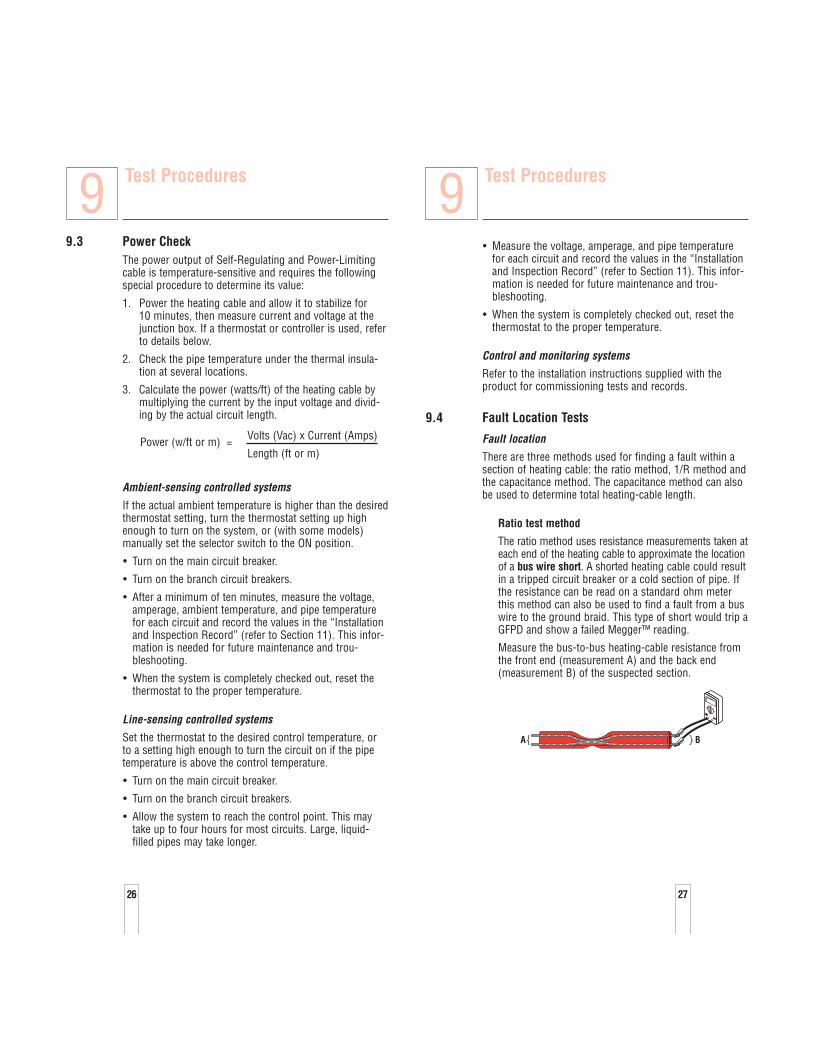
Ratio test method
The ratio method uses resistance measurements taken ateach end of the heating cable to approximate the locationof a bus wire short. A shorted heating cable could resultin a tripped circuit breaker or a cold section of pipe. Ifthe resistance can be read on a standard ohm meterthis method can also be used to find a fault from a buswire to the ground braid. This type of short would trip aGFPD and show a failed Megger™ reading.
Measure the bus-to-bus heating-cable resistance fromthe front end (measurement A) and the back end(measurement B) of the suspected section.
A B
9
27
Test Procedures
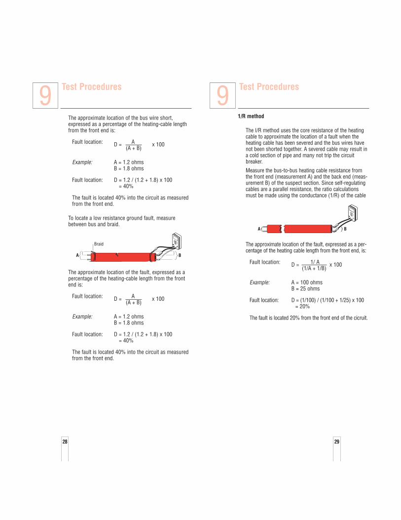
1/R method
The I/R method uses the core resistance of the heatingcable to approximate the location of a fault when theheating cable has been severed and the bus wires havenot been shorted together. A severed cable may result ina cold section of pipe and many not trip the circuitbreaker.
Measure the bus-to-bus heating cable resistance fromthe front end (measurement A) and the back end (meas-urement B) of the suspect section. Since self-regulatingcables are a parallel resistance, the ratio calculationsmust be made using the conductance (1/R) of the cable
The approximate location of the fault, expressed as a per-centage of the heating cable length from the front end, is:
Fault location: D = 1/ A x 100(1/A + 1/B)
Example: A = 100 ohmsB = 25 ohms
Fault location: D = (1/100) / (1/100 + 1/25) x 100= 20%
The fault is located 20% from the front end of the cicruit.
A B
9
29
Test Procedures
The approximate location of the bus wire short,expressed as a percentage of the heating-cable lengthfrom the front end is:
Fault location: D = A x 100(A + B)
Example: A = 1.2 ohmsB = 1.8 ohms
Fault location: D = 1.2 / (1.2 + 1.8) x 100= 40%
The fault is located 40% into the circuit as measuredfrom the front end.
To locate a low resistance ground fault, measurebetween bus and braid.
The approximate location of the fault, expressed as apercentage of the heating-cable length from the frontend is:
Fault location: D = A x 100(A + B)
Example: A = 1.2 ohmsB = 1.8 ohms
Fault location: D = 1.2 / (1.2 + 1.8) x 100= 40%
The fault is located 40% into the circuit as measuredfrom the front end.
A B
Braid
9
28
Test Procedures
Heating-cable capacitance factors
Cable CapacitanceCatalog No. Factor
3BTV1-CR 7.5
3BTV2-CT
3BTV1-CR
3BTV2-CT
5BTV1-CR 7.5
5BTV2-CT
5BTV1-CR
5BTV2-CT
8BTV1-CR 5.5
8TV2-CT
8BTV1-CR
8BTV2-CT
10BTV1-CR 5.5
10BTV2-CT
10BTV1-CR
10BTV2-CT
10QTVR1-CT 4.7
10QTVR2-CT
15QTVR2-CT
Cable CapacitanceCatalog No. Factor
15QTVR1-CT 3.3
20QTVR1-CT
20QTVR2-CT
5XTV1-CT-T3 10.8
5XTV2-CT-T3 11.1
10XTV1-CT-T3 10.3
10XTV2-CT-T3 10.7
15XTV1-CT-T3 9.7
15XTV2-CT-T3 9.9
20XTV1-CT-T2 9.3
20XTV2-CT-T2 10.1
5VPL1-CT 9.4
10VPL1-CT
15VPL1-CT
20VPL1-CT
5VPL2-CT
10VPL2-CT
15VPL2-CT
20VPL2-CT
9
31
Test Procedures
Capacitance test method
This method uses capacitance measurement (nF) toapproximate the location of a fault where the heatingcable has been severed. It also gives an estimate oftotal heating-cable length in a non-severed circuit. Thisreading must be taken at the power connection and willonly work when the heating cable has passed IR testing.This information is used to calculate the heating-cableoutput per linear foot or to determine if the maximumlength has been exceeded.
Record the capacitance reading from one end of theheating cable. The capacitance reading should bemeasured between both bus wires twisted together(positive lead) and the braid (negative lead).
Multiply the measured capacitance with the heating-cable's capacitance factor as listed in the followingtable.
Example:20XTV2-CTRecorded capacitance = 16.2 nFCapacitance factor = 10.1 ft/nFFault location = 16.2 x 10.1 nF
= 164 ft (50 m) from reading location
As an alternative, capacitance values from both thefront and back end can be used. The ratio of onecapacitance value taken from one end (A) divided bythe sum of both A and B (A + B) and then multiplied by100 yields the distance from the first end, expressed asa percentage of the heating circuit length.
9
30
3332
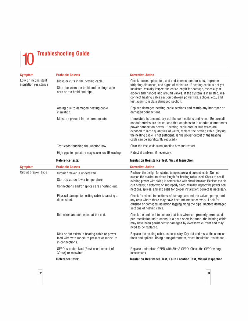
Troubleshooting Guide
Symptom Probable Causes Corrective Action
Low or inconsistentinsulation resistance
Reference tests: Insulation Resistance Test, Visual Inspection
Symptom Probable Causes Corrective Action
Circuit breaker trips
Reference tests: Insulation Resistance Test, Fault Location Test, Visual Inspection
Recheck the design for startup temperature and current loads. Do notexceed the maximum circuit length for heating cable used. Check to see ifexisting power wire sizing is compatible with circuit breaker. Replace the cir-cuit breaker, if defective or improperly sized. Visually inspect the power con-nections, splices, and end seals for proper installation; correct as necessary.
Check for visual indications of damage around the valves, pump, andany area where there may have been maintenance work. Look forcrushed or damaged insulation lagging along the pipe. Replace damagedsections of heating cable.
Check the end seal to ensure that bus wires are properly terminatedper installation instructions. If a dead short is found, the heating cablemay have been permanently damaged by excessive current and mayneed to be replaced.
Replace the heating cable, as necessary. Dry out and reseal the connec-tions and splices. Using a megohmmeter, retest insulation resistance.
Replace undersized GFPD with 30mA GFPD. Check the GFPD wiringinstructions.
Circuit breaker is undersized.
Start-up at too low a temperature.
Connections and/or splices are shorting out.
Physical damage to heating cable is causing adirect short.
Bus wires are connected at the end.
Nick or cut exists in heating cable or powerfeed wire with moisture present or moisturein connections.
GFPD is undersized (5mA used instead of30mA) or miswired.
Check power, splice, tee, and end connections for cuts, improperstripping distances, and signs of moisture. If heating cable is not yetinsulated, visually inspect the entire length for damage, especially atelbows and flanges and around valves. If the system is insulated, dis-connect heating cable section between power kits, splices, etc., andtest again to isolate damaged section.
Replace damaged heating-cable sections and restrip any improper ordamaged connections.
If moisture is present, dry out the connections and retest. Be sure allconduit entries are sealed, and that condensate in conduit cannot enterpower connection boxes. If heating-cable core or bus wires areexposed to large quantities of water, replace the heating cable. (Dryingthe heating cable is not sufficient, as the power output of the heatingcable can be significantly reduced.)
Clear the test leads from junction box and restart.
Retest at ambient, if necessary.
Nicks or cuts in the heating cable.
Short between the braid and heating-cable core or the braid and pipe.
Arcing due to damaged heating-cableinsulation.
Moisture present in the components.
Test leads touching the junction box.
High pipe temperature may cause low IR reading.
10

35
Troubleshooting Guide
Symptom Probable Causes Corrective Action
Low pipe temperature
Reference tests: Power Check, Visual Inspection
Symptom Probable Causes Corrective Action
Low or no power output
Reference tests: Power Check, Fault Location, Visual Inspection
Replace damaged heating cable. Check the pipe temperature. Checkthe power output of heating cable.
The heating cable has been exposed to exces-sive temperature, moisture or chemicals.
Check the pipe temperature. Verify heater selection. Check the poweroutput of the heating cable per the design vs. actual. Reduce pipe tem-perature if possible or contact your Tyco Thermal Controlsrepresentative to confirm design.
Pipe is at an elevated temperature.
Rewire the thermostat in the normally closed position.Control thermostat is wired in normally openposition.
Check for loose wiring connections and rewire if necessary.Improper component connection causing ahigh-resistance connection.
Check the routing and length of heating cable (use “as built” drawingsto reference actual pipe layout). Connect all splices or tees. Locate and replace any damaged heatingcables. Then recheck the power output.
The circuit is shorter than the design shows,due to splices or tees not being connected,or the heating cable having been severed.
Repair the electrical supply lines and equipment.Low or no input voltage applied.
Reinstall the thermocouple on the pipe.Thermocouple is not in contact with pipe.
Contact your Tyco Thermal Controls representative to confirm thedesign and modify as recommended.
Improper thermal design used.
Improper voltage applied.
Reset the thermostat.Thermostat was set incorrectly.
Splice in additional heating cable but do not exceed maximum circuitlength.
Insufficient heating cable was used onvalves, supports, and other heat sinks.
Remove wet insulation and replace with dry insulation, and secure itwith proper weatherproofing.
Insulation is wet, or missing.
10
34
36
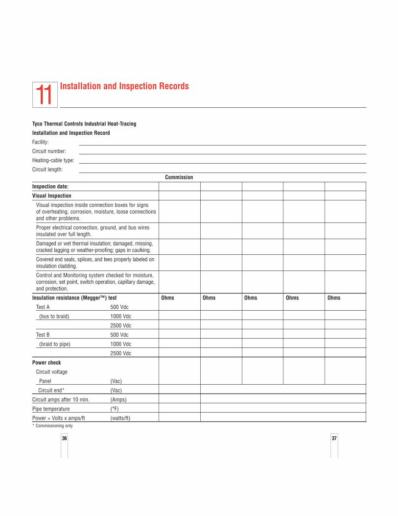
Installation and Inspection Records
Tyco Thermal Controls Industrial Heat-Tracing
Installation and Inspection Record
Facility:
Circuit number:
Heating-cable type:
Circuit length:Commission
Inspection date:
Visual Inspection
Visual inspection inside connection boxes for signsof overheating, corrosion, moisture, loose connectionsand other problems.
Proper electrical connection, ground, and bus wires insulated over full length.
Damaged or wet thermal insulation; damaged, missing,cracked lagging or weather-proofing; gaps in caulking.
Covered end seals, splices, and tees properly labeled oninsulation cladding.
Control and Monitoring system checked for moisture,corrosion, set point, switch operation, capillary damage,and protection.
Insulation resistance (Megger™) test Ohms Ohms Ohms Ohms Ohms
Test A 500 Vdc
(bus to braid) 1000 Vdc
2500 Vdc
Test B 500 Vdc
(braid to pipe) 1000 Vdc
2500 Vdc
Power check
Circuit voltage
Panel (Vac)
Circuit end* (Vac)
Circuit amps after 10 min. (Amps)
Pipe temperature (°F)
Power = Volts x amps/ft (watts/ft)* Commissioning only
11
37
3938
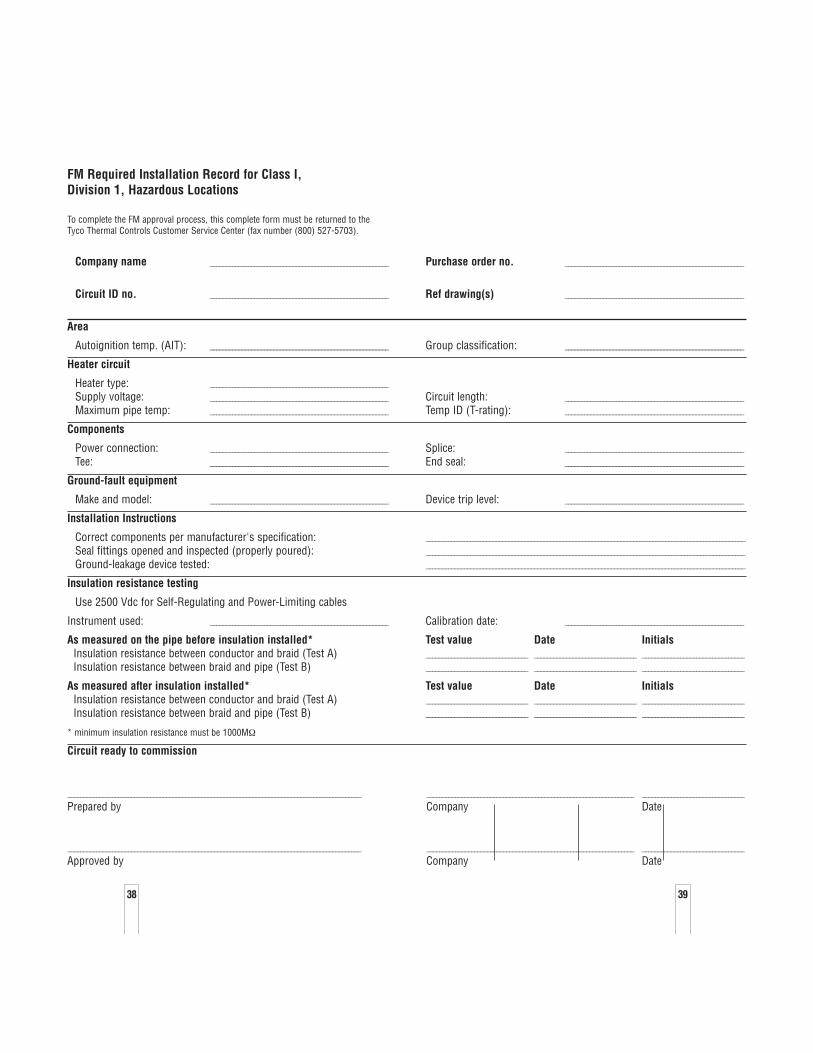
FM Required Installation Record for Class I, Division 1, Hazardous Locations
To complete the FM approval process, this complete form must be returned to theTyco Thermal Controls Customer Service Center (fax number (800) 527-5703).
Company name ________________________________________________________ Purchase order no. ________________________________________________________
Circuit ID no. ________________________________________________________ Ref drawing(s) ________________________________________________________
Area
Autoignition temp. (AIT): ________________________________________________________ Group classification: ________________________________________________________
Heater circuit
Heater type: ________________________________________________________
Supply voltage: ________________________________________________________ Circuit length: ________________________________________________________
Maximum pipe temp: ________________________________________________________ Temp ID (T-rating): ________________________________________________________
Components
Power connection: ________________________________________________________ Splice: ________________________________________________________
Tee: ________________________________________________________ End seal: ________________________________________________________
Ground-fault equipment
Make and model: ________________________________________________________ Device trip level: ________________________________________________________
Installation Instructions
Correct components per manufacturer's specification: ____________________________________________________________________________________________________
Seal fittings opened and inspected (properly poured): ____________________________________________________________________________________________________
Ground-leakage device tested: ____________________________________________________________________________________________________
Insulation resistance testing
Use 2500 Vdc for Self-Regulating and Power-Limiting cables
Instrument used: ________________________________________________________ Calibration date: ________________________________________________________
As measured on the pipe before insulation installed* Test value Date InitialsInsulation resistance between conductor and braid (Test A) ________________________________ ________________________________ ________________________________
Insulation resistance between braid and pipe (Test B) ________________________________ ________________________________ ________________________________
As measured after insulation installed* Test value Date InitialsInsulation resistance between conductor and braid (Test A) ________________________________ ________________________________ ________________________________
Insulation resistance between braid and pipe (Test B) ________________________________ ________________________________ ________________________________
* minimum insulation resistance must be 1000MΩ
Circuit ready to commission
____________________________________________________________________________________________ _________________________________________________________________ ________________________________
Prepared by Company Date
____________________________________________________________________________________________ _________________________________________________________________ ________________________________
Approved by Company Date
© 2
002,
200
3 Ty
co T
herm
al C
ontro
ls L
LC
Prin
ted
in U
SA
H57
274
04
/03
Worldwide HeadquartersTyco Thermal Controls300 Constitution DriveMenlo Park, CA 94025-1164USATel (800) 545-6258Fax (800) [email protected]
CanadaTyco Thermal Controls250 West St.Trenton, OntarioCanada K8V 5S2Tel (800) 545-6258Fax (800) 527-5703
Important: All information, including illustrations, is believed to be reliable. Users, however, should independently evaluate the suitability of each product fortheir particular application. Tyco Thermal Controls makes no warranties as to theaccuracy or completeness of the information, and disclaims any liability regardingits use. Tyco Thermal Controls' only obligations are those in the Tyco ThermalControls Standard Terms and Conditions of Sale for this product, and in no casewill Tyco Thermal Controls or its distributors be liable for any incidental, indirect,or consequential damages arising from the sale, resale, use, or misuse of theproduct. Specifications are subject to change without notice. In addition, TycoThermal Controls reserves the right to make changes—without notification toBuyer—to processing or materials that do not affect compliance with anyapplicable specification.
Tyco, DigiTrace, Raychem and TraceCalc Pro are trademarks of Tyco Thermal Controls LLC or its affiliates.Megger is a trademark of Megger Limited
Related Documents


![Untitled Document [docs-europe.electrocomponents.com]docs-europe.electrocomponents.com/webdocs/0920/0900766b809201d… · Schneider Electric Brands ZELIO-CONTROL Measurement Relays](https://static.cupdf.com/doc/110x72/5abeae277f8b9a5d718d478e/untitled-document-docs-docs-schneider-electric-brands-zelio-control-measurement.jpg)