International Journal of Science and Research (IJSR) ISSN (Online): 2319-7064 Index Copernicus Value (2013): 6.14 | Impact Factor (2013): 4.438 Volume 4 Issue 6, June 2015 www.ijsr.net Licensed Under Creative Commons Attribution CC BY Improved Methodology for Harmonics Reduction using Shunt Active Power Filter Based on p-q Theory Priyanka Zamade 1 , Minal Tomar 2 1 PG research scholar, Malwa Institute of Technology, Indore, India 2 Professor, Assistant Professor, Malwa Institute of Technology, Indore, India Abstract: This paper discuss about the problem of harmonics occurring in various power electronic equipments. It proposes a simple method for enhancement of power quality using concept of Shunt Active Power Filter (SAPF). In this paper SAPF is modeled using p-q theory with PI control method so that Total Harmonic Distortion (THD) should be in compliance with IEEE 519 standard. The compensation characteristics of each topology with the respective control scheme are proved by using MATLAB/SIMULINK. Keywords: Harmonics Compensation, SAPF, p-q theory, THD, PI controller 1. Introduction Power quality determines the fitness of electrical power to consumer devices. Synchronization of the voltage frequency and phase allows electrical systems to function in their intended manner without significant loss of performance or life. The term is used to describe electric power that drives an electrical load and the load's ability to function properly. Without the proper power, an electrical device (or load) may malfunction, fail prematurely or not operate at all. There are many ways in which electric power can be of poor quality and many more causes of such poor quality power. Current harmonics produced by non-linear loads, such as switching power supplies and motor speed controllers, are prevalent in today’s power systems. These harmonics interfere with sensitive electronic equipment and cause unnecessary losses in electrical equipment. Harmonics voltages and currents in an electric power system are a result of non-linear electric loads. Harmonic frequencies in the power grid are a frequent cause of power quality problems. Harmonics in power systems result in increased heating in the equipment and conductors, misfiring in variable speed drives, and torque pulsations in motors. Reduction of harmonics is considered desirable. A harmonic of a wave is a component frequency of the signal that is an integer multiple of the fundamental frequency, i.e. if the fundamental frequency is f, the harmonics have frequencies 2f, 3f, 4f . . . etc. The harmonics have the property that they are all periodic at the fundamental frequency; therefore the sum of harmonics is also periodic at that frequency. Harmonic frequencies are equally spaced by the width of the fundamental frequency and can be found by repeatedly adding that frequency. Figure 1: Difference between Linear and Non-Linear Loads The terms “linear” and “non-linear” define the relationship of current to the voltage waveform. A linear relationship exists between the voltage and current, which is typical of an across-the-line load. A non-linear load has a discontinuous current relationship that does not correspond to the applied voltage waveform. 2. Various Methodologies For Harmonic Mitigation The presence of harmonics in the power system cause greater power loss in distribution, interference problem in communication system and, sometimes results in operation failure of electronic equipment which are more and more sensitive. In order to reduce this problem various types of filters are used using different methods which are as follows: A. Passive Filters Passive implementations of linear filters are based on combinations of resistors (R), inductors (L) and capacitors (C). These types are collectively known as passive filters, because they do not depend upon an external power supply and/or they do not contain active components such as transistors. Passive filters are used to mitigate power quality problems in six pulse ac-dc converter. Apart from mitigating the current harmonics, passive filters also provide reactive power compensation, thereby further improving the system performance. Passive filters have been used as a solution to solve harmonic current problems, but because of the several disadvantage of passive filter like it can mitigate only few harmonics, gives rise to resonance problem, bulky in size and costly they are being used to a certain limit. B. Active Filters To overcome drawbacks of passive filters active filters are introduced. They inject harmonic voltage or current with appropriate magnitudes and phase angle into the system and cancel harmonics of non-linear loads. Active filters have the advantage of being able to compensate for harmonic without fundamental frequency reactive power concerns. This means that the rating of the active power can be less than a Paper ID: SUB152686 161

Welcome message from author
This document is posted to help you gain knowledge. Please leave a comment to let me know what you think about it! Share it to your friends and learn new things together.
Transcript

International Journal of Science and Research (IJSR) ISSN (Online): 2319-7064
Index Copernicus Value (2013): 6.14 | Impact Factor (2013): 4.438
Volume 4 Issue 6, June 2015
www.ijsr.net Licensed Under Creative Commons Attribution CC BY
Improved Methodology for Harmonics Reduction
using Shunt Active Power Filter Based on p-q
Theory
Priyanka Zamade1, Minal Tomar
2
1PG research scholar, Malwa Institute of Technology, Indore, India
2Professor, Assistant Professor, Malwa Institute of Technology, Indore, India
Abstract: This paper discuss about the problem of harmonics occurring in various power electronic equipments. It proposes a simple
method for enhancement of power quality using concept of Shunt Active Power Filter (SAPF). In this paper SAPF is modeled using p-q
theory with PI control method so that Total Harmonic Distortion (THD) should be in compliance with IEEE 519 standard. The
compensation characteristics of each topology with the respective control scheme are proved by using MATLAB/SIMULINK.
Keywords: Harmonics Compensation, SAPF, p-q theory, THD, PI controller
1. Introduction
Power quality determines the fitness of electrical power to
consumer devices. Synchronization of the voltage frequency
and phase allows electrical systems to function in their
intended manner without significant loss of performance or
life. The term is used to describe electric power that drives
an electrical load and the load's ability to function properly.
Without the proper power, an electrical device (or load) may
malfunction, fail prematurely or not operate at all. There are
many ways in which electric power can be of poor quality
and many more causes of such poor quality power. Current
harmonics produced by non-linear loads, such as switching
power supplies and motor speed controllers, are prevalent in
today’s power systems. These harmonics interfere with
sensitive electronic equipment and cause unnecessary losses
in electrical equipment. Harmonics voltages and currents in
an electric power system are a result of non-linear electric
loads. Harmonic frequencies in the power grid are a frequent
cause of power quality problems. Harmonics in power
systems result in increased heating in the equipment and
conductors, misfiring in variable speed drives, and torque
pulsations in motors. Reduction of harmonics is considered
desirable. A harmonic of a wave is a component frequency
of the signal that is an integer multiple of the fundamental
frequency, i.e. if the fundamental frequency is f, the
harmonics have frequencies 2f, 3f, 4f . . . etc. The harmonics
have the property that they are all periodic at the
fundamental frequency; therefore the sum of harmonics is
also periodic at that frequency. Harmonic frequencies are
equally spaced by the width of the fundamental frequency
and can be found by repeatedly adding that frequency.
Figure 1: Difference between Linear and Non-Linear Loads
The terms “linear” and “non-linear” define the relationship
of current to the voltage waveform. A linear relationship
exists between the voltage and current, which is typical of an
across-the-line load. A non-linear load has a discontinuous
current relationship that does not correspond to the applied
voltage waveform.
2. Various Methodologies For Harmonic
Mitigation
The presence of harmonics in the power system cause greater
power loss in distribution, interference problem in
communication system and, sometimes results in operation
failure of electronic equipment which are more and more
sensitive. In order to reduce this problem various types of
filters are used using different methods which are as follows:
A. Passive Filters Passive implementations of linear filters are based on
combinations of resistors (R), inductors (L) and capacitors
(C). These types are collectively known as passive filters,
because they do not depend upon an external power supply
and/or they do not contain active components such as
transistors. Passive filters are used to mitigate power quality
problems in six pulse ac-dc converter. Apart from mitigating
the current harmonics, passive filters also provide reactive
power compensation, thereby further improving the system
performance. Passive filters have been used as a solution to
solve harmonic current problems, but because of the several
disadvantage of passive filter like it can mitigate only few
harmonics, gives rise to resonance problem, bulky in size
and costly they are being used to a certain limit.
B. Active Filters
To overcome drawbacks of passive filters active filters are
introduced. They inject harmonic voltage or current with
appropriate magnitudes and phase angle into the system and
cancel harmonics of non-linear loads. Active filters have the
advantage of being able to compensate for harmonic without
fundamental frequency reactive power concerns. This means
that the rating of the active power can be less than a
Paper ID: SUB152686 161

International Journal of Science and Research (IJSR) ISSN (Online): 2319-7064
Index Copernicus Value (2013): 6.14 | Impact Factor (2013): 4.438
Volume 4 Issue 6, June 2015
www.ijsr.net Licensed Under Creative Commons Attribution CC BY
comparable passive filter for the same non-linear load and
the active filter will not introduce system resonances that can
move a harmonic problem from one frequency to another.
Active filter can be classified based on the connection
scheme as:
Shunt active filter
Series active filter
Hybrid active filter.
In this paper harmonic mitigation is done by using shunt
active power filter.
Figure 2: Active Power Filter
3. Shunt Active Power Filter (SAPF)
Shunt active power filter compensate current harmonics by
injecting equal but opposite harmonic compensating current.
In this case SAPF operates as a current source injecting the
harmonic components generated by the load but phase
shifted by 180º. This principle is applicable to any type of
load considered a harmonic source. Moreover, with an
appropriate control scheme, the active power filter can also
compensate the load power factor. The shunt active filter has
the capability of damping harmonic propagation between an
already-existing passive filter and the supply impedance. The
current compensation characteristic of SAPF is as shown.
Figure 3: Compensation Characteristics of SAPF
The compensation effectiveness of an active power filter
depends on its ability to flow with a minimum error and time
delay the reference signal calculated to compensate the
distorted load, current finally, the DC voltage control unit
must keep the total DC voltage constant and equals to a
given reference value. The DC voltage control is achieved by
adjusting the small amount of real power absorbed by the
inverter from the PCC. This small amount of real power is
adjusted by changing the amplitude of the fundamental
component of the reference current. The block diagram of a
shunt active power filter control scheme is shown and
consists of sensing the load currents and the point of
common coupling (PCC) voltages, reference current
generator, DC voltage control, injected current control and
the inverter. The Shunt Active Power Filter analyzed in this
paper is designed for 3-phase 4-wire systems and is capable
of compensating current harmonics, current unbalance and
power factor in 3-phase 4-wire electric systems.
3.1 Concept of P-Q Theory
The research work studied showed that a three phase four
wire system i.e. system having three phase with neutral
connection has large discrepancies when calculation of
neutral current takes place. This problem is identified and
can be solved using the concept of shunt active power filter.
It has further been seen that the neutral current concept offers
a large value when active shunt power filter has not been
deployed so validation for this also has to be done. Moreover
since the PI controller based system requires a hysteresis
control mechanism hence a hysteresis loop must also be
incorporated in the design to allow for more robust control
system.
An active rectifier based shunt compensator plays a vital role
in present-day static power compensation. This includes the
conventional compensation features like power factor
improvements, harmonic compensation and neutral current
elimination in a three-phase four- wire system. The
instantaneous power compensation theories have been
evolved essentially to execute the compensation or
correction in time domain.
Figure 4: Control Scheme of SAPF
The first instantaneous reactive power compensation theory,
popularly known as p-q theory was developed in Japan for a
three-phase three-wire system. The p-q theory was further
extended for a three-phase four wire system by defining zero
sequence power. The Instantaneous Reactive power theory
(IRP) p-q theory developed by Akagi, Kanazawa and Nabae
in 1983 uses time domain in order to define a set of
instantaneous powers. These Instantaneous powers are
defined in terms of instantaneous voltages and currents,
Paper ID: SUB152686 162

International Journal of Science and Research (IJSR) ISSN (Online): 2319-7064
Index Copernicus Value (2013): 6.14 | Impact Factor (2013): 4.438
Volume 4 Issue 6, June 2015
www.ijsr.net Licensed Under Creative Commons Attribution CC BY
which are first, transformed from phase R, S and T to α, β, 0
coordinates by using the Clarke Transformation. This
transformation produces a stationary reference frame, where
coordinates α and β are orthogonal and the co-ordinate 0
corresponds to the zero sequence component. However, this
zero sequence coordinate differs from the zero sequence
components in the symmetrical component transformation.
3.2 Compensation with p-q Theory
This concept gives an effective method to compensate for the
instantaneous components of reactive power for three-phase
systems without energy storage. Instantaneous real and
imaginary powers have first been defined in the time domain.
The three phase voltages are sensed at the PCC and denoted
as ea, eb and ec. The resultant load side line currents are
sensed and denoted as iaL, ibL and icL. The Clarke
transformation for three phase voltages and line currents,
therefore are given as follows:
… (1)
… (2)
According to the p-q theory the set of instantaneous powers
in a three-phase system consists of the instantaneous zero
sequence power p0 defined as,
… (3)
Instantaneous real power p and the instantaneous imaginary
power q defined as,
..(4)
..(5)
These powers can also be written in a matrix form as,
..(6)
These quantities written in equation (3), (4) and (5) can be
elaborated as follows:
..(7)
..(8)
Where,
p0 - Mean value of the instantaneous zero-sequence power –
corresponds to the energy per time unity which is transferred
from the power supply to the load through the zero-sequence
components of voltage and current.
-Alternated value of the instantaneous zero-sequence
power – it means the energy per time unity that is exchanged
between the power supply and the load through the zero-
sequence components. The zero-sequence power only exists
in three-phase systems with neutral wire.
p - Mean value of the instantaneous real power – corresponds
to the energy per time unity which is transferred from the
power supply to the load.
- Alternated value of the instantaneous real power – It is
the energy per time unity that is exchanged between the
power supply and the load.
q - Instantaneous imaginary power – corresponds to the
power that is exchanged between the phases of the load. This
component does not imply any transference or exchange of
energy between the power supply and the load, but is
responsible for the existence of undesirable currents, which
circulate between the system phases.
This theory, unlike other theories does not only consider
each phase of the three phase system separately but also
defines them in terms of other phases. Moreover, this gives
us flexibility of using the theory for three-wire systems.
3.3 Instantaneous p-q theory for three-wire systems
Since, three-wire power systems do not contain zero
sequence current components, the zero sequence components
and in IRP p-q theory can be considered as zero. As a result,
the three-wire system can be represented in terms of reduced
vector Clarke coordinates. The reduced Clarke coordinates
are nothing but the representation of IRP p-q theory for
three-wire systems by neglecting the zero sequence
components. The reduced vectors for three phase Clarke
voltages and currents are determined as,
..(9)
The active and reactive power is written as:
..(10)
3.4 PI Controller
In this paper the proportional-integral (PI) controller is used
in SAPF. The control scheme comprises of PI controller,
limiter, and three phase sine wave generator for reference
current generation and generation of switching signals. The
peak value of reference currents is studied by regulating the
DC link voltage. The definite capacitor voltage will be
compared with a set reference value. The error signal is then
fed through a PI controller, which gives to zero steady error
in tracking the reference current signal. The schematic
representation of the control circuit is as shown:
Figure 5: Block representation of PI controller
The output of the PI controller is presumed as peak value of
the supply current (Imax), which is composed of two
components: (a) fundamental active power component of
Paper ID: SUB152686 163

International Journal of Science and Research (IJSR) ISSN (Online): 2319-7064
Index Copernicus Value (2013): 6.14 | Impact Factor (2013): 4.438
Volume 4 Issue 6, June 2015
www.ijsr.net Licensed Under Creative Commons Attribution CC BY
load current, and (b) loss component of APF; to preserve the
average capacitor voltage to a constant value. Peak value of
the current (Imax) so found, will be multiplied by the unit
sine vectors in phase with the individual source voltages to
obtain the reference compensating currents. These expected
reference currents (Isa*, Isb*, Isc*) and detected actual
currents (Isa, Isb, Isc) are equated at a hysteresis band, which
delivers the error signal for the modulation technique. This
error signal chooses the operation of the converter switches.
In this current control circuit configuration the source/supply
currents Isabc are made to follow the sinusoidal reference
current Iabc, within a fixed hysteretic band. The width of
hysteresis window regulates the source current pattern, its
harmonic spectrum and the switching frequency of the
devices. The DC link capacitor voltage is always preserved
constant during the operation of the converter. In this
scheme, each phase of the converter is measured
independently. To increase the current of a particular phase,
the lower switch of the converter related with that particular
phase is turned on while to decrease the current the upper
switch of the corresponding converter phase is turned on.
4. Simulation Results
The simulation of the project was carried out in Matlab 8.1
and the project uses the simpower system library of
SIMULINK, the total harmonic distortion and fft analysis
was performed using power gui tool provided in sim power
systems, the results are as shown:
Figure 6: Result of THDi for the SIMULINK model
Figure 7: Graph of source current and THD without apf
Figure 8: Graph of neutral current and THD without apf
Figure 9: Graph of source current and THD in presence of
apf
Figure 10: Graph of neutral current and THD in presence of
apf
Figure 11: Graph showing PI controller operation
Paper ID: SUB152686 164
International Journal of Science and Research (IJSR) ISSN (Online): 2319-7064
Index Copernicus Value (2013): 6.14 | Impact Factor (2013): 4.438
Volume 4 Issue 6, June 2015
www.ijsr.net Licensed Under Creative Commons Attribution CC BY
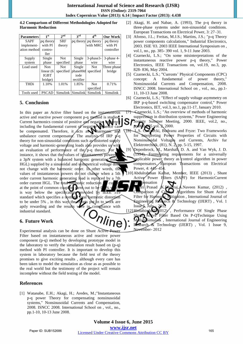
4.2 Comparison of Different Methodologies Adopted for
Harmonic Reduction
Parameters 1st 2nd 3rd 4th Our Work
SAPF
implement-
ation method
pq theory
with PI
contro-
ller
SRF
theory
pq theory pq theory
with MRC
pq theory
with PI
controller
Supply
system
Single
phase
Not
specified
Single
phase
3-phase3-
wire
3-phase 4-
wire
Load used Non
linear (6
IGBT
bridge)
Not
specified
Single
phase00d
iode
rectifier
Not
specified
Three phase
bridge
THDi 1.10% 1.01% 1.85% Not
specified
0.71%
Tools used PSCAD Simulink Simulink Simulink Simulink
5. Conclusion
In this paper an Active filter based on the instantaneous
active and reactive power component p-q method is studied.
Current harmonics consist of positive and negative sequence
including the fundamental current of negative sequence can
be compensated. Therefore, it acts as a harmonic and
unbalance current compensator. The analysis of IRP p-q
theory for non-sinusoidal conditions such as distorted supply
voltage and harmonic-generating loads also provides us with
an evaluation of performance of the p-q theory. For an
instance, it shows that the values of instantaneous powers in
a 3pN system with a balanced harmonic generating load (
HGL) supplied by a sinusoidal and symmetrical voltage does
not change with the harmonic order. In other words, the
values of instantaneous powers do not change when a 5th
order current harmonic generating load is replaced by a 7th
order current HGL. The total harmonic reduction for current
at the point of common coupling turns out to be 0.7% which
is way below the specification provided by IEEE 519
standard which specifies a nominal total harmonic distortion
to be under 5% , in this way the efforts put in to work are
aptly rewarding and the results were in compliance with
industrial standard.
6. Future Work
Experimental analysis can be done on Shunt Active Power
Filter based on instantaneous active and reactive power
component (p-q) method by developing prototype model in
the laboratory to verify the simulation result based on (p-q)
method with PI controller. It is important to develop this
system in laboratory because the field test of the theory
promises to give exciting results , although every care has
been taken to model the simulation as close as as possible to
the real world but the testimony of the project will remain
incomplete without the field testing of the model.
References [1] Watanabe, E.H.; Akagi, H.; Aredes, M.;"Instantaneous
p-q power Theory for compensating nonsinusoidal
systems," Nonsinusoidal Currents and Compensation,
2008. ISNCC 2008. International School on , vol., no.,
pp.1-10, 10-13 June 2008.
[2] Akagi, H. and Nabae, A. (1993), The p-q theory in
three-phase systems under non-sinusoidal conditions.
European Transactions on Electrical Power, 3: 27–31.
[3] Afonso, J.L.; Freitas, M.J.S.; Martins, J.S.; "p-q Theory
power components calculations," Industrial Electronics,
2003. ISIE '03. 2003 IEEE International Symposium on ,
vol.1, no., pp. 385- 390 vol. 1, 9-11 June 2003.
[4] Czarnecki, L.S.; "On some misinterpretations of the
instantaneous reactive power p-q theory," Power
Electronics, IEEE Transactions on, vol.19, no.3, pp.
828- 836, May 2004.
[5] Czarnecki, L.S.; "Currents’ Physical Components (CPC)
concept: A fundamental of power theory,"
Nonsinusoidal Currents and Compensation, 2008.
ISNCC 2008. International School on , vol., no., pp.1-
11, 10-13 June 2008.
[6] Czarnecki, L.S.; "Effect of supply voltage asymmetry on
IRP p-q-based switching compensator control," Power
Electronics, IET, vol.3, no.1, pp.11-17, January 2010.
[7] Czarnecki, L.S.; "An overview of methods of harmonic
suppression in distribution systems," Power Engineering
Society Summer Meeting, 2000. IEEE, vol.2, no.,
pp.800-805 vol. 2, 2000.
[8] L.S. Czarnecki, Budeanu and Fryze: Two Frameworks
for Interpreting Power Properties of Circuits with
Nonsinusoidal Voltages and Currents, Archiv fur
Elektrotechnik, (81), N. 2, pp. 5-15, 1997.
[9] Depenbrock, M., Marshall, D. A. and Van Wyk, J. D.
(1994), Formulating requirements for a universally
applicable power theory as control algorithm in power
compensators. European Transactions on Electrical
Power, 4: 445–454.
[10] Abdulrahman Kalbat, Member, IEEE (2013) , Shunt
Active Power Filters (SAPF) for HarmonicCurrent
Compensation
[11] A.Giri Prasad ,K.Dheeraj,A.Naveen Kumar, (2012) ,
Comparison of Control Algorithms for Shunt Active
Filter for Harmonic Mitigation , International Journal of
Engineering Research & Technology (IJERT) , Vol. 1
Issue 5, July – 2012
[12] Himabindu.T,(2012) , Performance Of Single Phase
Shunt Active Filter Based On P-QTechnique Using
Matlab/Simulink , International Journal of Engineering
Research & Technology (IJERT) , Vol. 1 Issue 9,
November- 2012
Paper ID: SUB152686 165
Related Documents