HAL Id: hal-00998857 https://hal.archives-ouvertes.fr/hal-00998857 Submitted on 2 Jun 2014 HAL is a multi-disciplinary open access archive for the deposit and dissemination of sci- entific research documents, whether they are pub- lished or not. The documents may come from teaching and research institutions in France or abroad, or from public or private research centers. L’archive ouverte pluridisciplinaire HAL, est destinée au dépôt et à la diffusion de documents scientifiques de niveau recherche, publiés ou non, émanant des établissements d’enseignement et de recherche français ou étrangers, des laboratoires publics ou privés. Implementation of Thermoelectric Generators in Airliners for Powering,Battery-free Wireless Sensor Networks Jean-Marie Dilhac, Romain Monthéard, Marise Bafleur, Vincent Boitier, Nicolas Nolhier, Paul Durand-Estèbe, Patrick Tounsi To cite this version: Jean-Marie Dilhac, Romain Monthéard, Marise Bafleur, Vincent Boitier, Nicolas Nolhier, et al.. Im- plementation of Thermoelectric Generators in Airliners for Powering,Battery-free Wireless Sensor Networks. Journal of Electronic Materials, Institute of Electrical and Electronics Engineers, 2014, 43 (6), pp.2444-2451. hal-00998857

Welcome message from author
This document is posted to help you gain knowledge. Please leave a comment to let me know what you think about it! Share it to your friends and learn new things together.
Transcript
HAL Id: hal-00998857https://hal.archives-ouvertes.fr/hal-00998857
Submitted on 2 Jun 2014
HAL is a multi-disciplinary open accessarchive for the deposit and dissemination of sci-entific research documents, whether they are pub-lished or not. The documents may come fromteaching and research institutions in France orabroad, or from public or private research centers.
L’archive ouverte pluridisciplinaire HAL, estdestinée au dépôt et à la diffusion de documentsscientifiques de niveau recherche, publiés ou non,émanant des établissements d’enseignement et derecherche français ou étrangers, des laboratoirespublics ou privés.
Implementation of Thermoelectric Generators inAirliners for Powering,Battery-free Wireless Sensor
NetworksJean-Marie Dilhac, Romain Monthéard, Marise Bafleur, Vincent Boitier,
Nicolas Nolhier, Paul Durand-Estèbe, Patrick Tounsi
To cite this version:Jean-Marie Dilhac, Romain Monthéard, Marise Bafleur, Vincent Boitier, Nicolas Nolhier, et al.. Im-plementation of Thermoelectric Generators in Airliners for Powering,Battery-free Wireless SensorNetworks. Journal of Electronic Materials, Institute of Electrical and Electronics Engineers, 2014, 43(6), pp.2444-2451. �hal-00998857�
1
Implementation of Thermoelectric Generators in Airliners for Powering Battery-free Wireless Sensor Networks
Jean-Marie Dilhac1,2, Romain Monthéard1,2, Marise Bafleur1,3, Vincent Boitier1,4, Paul Durand-Estèbe1,2, Patrick
Tounsi1,2
1 CNRS, LAAS, 7 avenue du colonel Roche, F-31400 Toulouse, France
2 Univ de Toulouse, INSA, LAAS, F-31400 Toulouse, France
3 Univ de Toulouse, LAAS, F-31400 Toulouse, France
4 Univ de Toulouse, UPS, LAAS, F-31400 Toulouse, France
Corresponding author: Jean-Marie Dilhac
tel +33 5 61 33 63 74 - FAX +33 5 61 33 62 08
Abstract
In recent years, wireless sensor networks (WSN) have been considered for various aeronautical applications to
perform sensing, data processing and wireless transmission of information, without the need of adding extra
wiring.
However, each node of these networks needs to be self-powered. Considering the critical drawbacks associated
with the use of electrochemical energy sources such as narrow operating temperature range and limited lifetime,
environmental energy capture allows an alternative solution for long term, deploy and forget, WSN. In this
context, thermoelectricity is a method of choice considering the implementation context.
In this paper we present hands-on experience related to on-going implementations of thermoelectric generators
(TEG) in airliners. In a first part, we will explain the reasons justifying the choice of ambient energy capture to
power WSN in an aircraft. Then we will derive the general requirements applying to the functional use of TEG.
Finally, in the last section, we will illustrate the above issues through practical implementations.
Keywords:
thermoelectric generator; airliner; wireless sensor network; battery-free; energy harvesting
2
1. Introduction
Today, wireless sensor networks (WSN) are considered for various aeronautical applications - ranging from
flight tests to structural health monitoring - to perform sensing, data processing and wireless transmission of
information, without the need of adding extra wiring to an already large burden.
However, as a consequence of their wireless nature, the nodes of these networks need to be self-powered. For
this purpose, primary batteries performing electrochemical storage of electricity offer a high energy density at
low cost (at least one order of magnitude cheaper than equivalent ultracapacitors), not to mention additional
benefits such as low self-discharge or potential long lifetime. However, there are critical drawbacks associated
with the use of batteries and prohibiting them in most cases for the applications considered in his paper. The first
practical and economical penalty when using primary batteries is the need, when empty, to replace them,
remembering that they are likely to be deployed in large numbers in remote areas. Another problem is linked to
safety, and can be seen as the price of the high energy density: modern primary or secondary batteries can suffer
from thermal runaway, ignite and explode when submitted to short-circuit, extreme temperatures, or
inappropriate charge or discharge, not to forget poor design. Consequently transport authorities or postal services
have issued air-shipping restrictions. Therefore, in the following, we will restrict ourselves to battery-free
devices.
Fortunately, batteries can be avoided through the use of environmental energy capture allowing a solution for
long term, deploy and forget, WSN. In this context, thermoelectricity is the method of choice in view – among
others – of the maturity (and still evolving) technology of thermoelectric generators (TEG), of the large
commercial offer, and the absence of moving parts meaning that maintenance and risk of breakdown are
minimum.
In a first part of this paper, we will detail the reasons justifying the choice of ambient energy capture together
with the need of battery-free energy storage to power WSN in an airliner, and will derive the general
requirements applying to the functional use of TEG. Then we will describe the more specific constraints
applying in the three main zones of an airliner:
. pressurized and temperature controlled zone,
. non-pressurized and non-temperature controlled zone,
. very harsh environment as found around engine or brake.
3
Finally, in the last section, we will illustrate the above issues through practical implementations in the above
three zones (getting output powers ranging from milliwatts to watts).
2. Sensor networks and energy harvesting in aircrafts
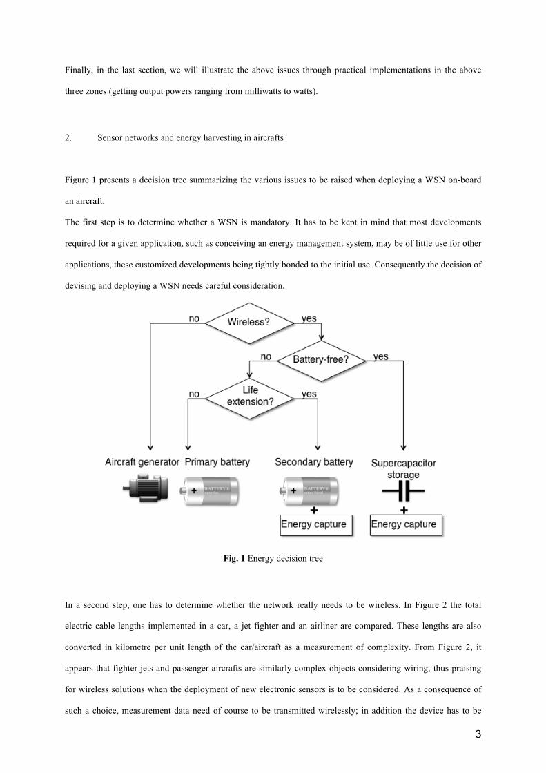
Figure 1 presents a decision tree summarizing the various issues to be raised when deploying a WSN on-board
an aircraft.
The first step is to determine whether a WSN is mandatory. It has to be kept in mind that most developments
required for a given application, such as conceiving an energy management system, may be of little use for other
applications, these customized developments being tightly bonded to the initial use. Consequently the decision of
devising and deploying a WSN needs careful consideration.
Fig. 1 Energy decision tree
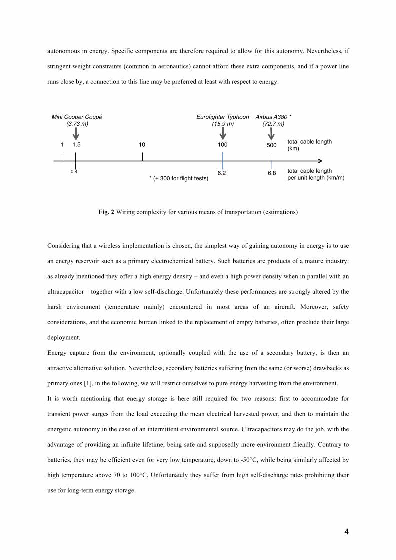
In a second step, one has to determine whether the network really needs to be wireless. In Figure 2 the total
electric cable lengths implemented in a car, a jet fighter and an airliner are compared. These lengths are also
converted in kilometre per unit length of the car/aircraft as a measurement of complexity. From Figure 2, it
appears that fighter jets and passenger aircrafts are similarly complex objects considering wiring, thus praising
for wireless solutions when the deployment of new electronic sensors is to be considered. As a consequence of
such a choice, measurement data need of course to be transmitted wirelessly; in addition the device has to be
4
autonomous in energy. Specific components are therefore required to allow for this autonomy. Nevertheless, if
stringent weight constraints (common in aeronautics) cannot afford these extra components, and if a power line
runs close by, a connection to this line may be preferred at least with respect to energy.
total cable length !(km)!
total cable length !per unit length (km/m)!
1! 10! 100!
Eurofighter Typhoon!(15.9 m)!
6.2!
Mini Cooper Coupé!(3.73 m)!
0.4!
1.5!
6.8!* (+ 300 for flight tests)!
Airbus A380 *!(72.7 m)!
500!
Fig. 2 Wiring complexity for various means of transportation (estimations)
Considering that a wireless implementation is chosen, the simplest way of gaining autonomy in energy is to use
an energy reservoir such as a primary electrochemical battery. Such batteries are products of a mature industry:
as already mentioned they offer a high energy density – and even a high power density when in parallel with an
ultracapacitor – together with a low self-discharge. Unfortunately these performances are strongly altered by the
harsh environment (temperature mainly) encountered in most areas of an aircraft. Moreover, safety
considerations, and the economic burden linked to the replacement of empty batteries, often preclude their large
deployment.
Energy capture from the environment, optionally coupled with the use of a secondary battery, is then an
attractive alternative solution. Nevertheless, secondary batteries suffering from the same (or worse) drawbacks as
primary ones [1], in the following, we will restrict ourselves to pure energy harvesting from the environment.
It is worth mentioning that energy storage is here still required for two reasons: first to accommodate for
transient power surges from the load exceeding the mean electrical harvested power, and then to maintain the
energetic autonomy in the case of an intermittent environmental source. Ultracapacitors may do the job, with the
advantage of providing an infinite lifetime, being safe and supposedly more environment friendly. Contrary to
batteries, they may be efficient even for very low temperature, down to -50°C, while being similarly affected by
high temperature above 70 to 100°C. Unfortunately they suffer from high self-discharge rates prohibiting their
use for long-term energy storage.
5
Considering ambient energy capture, very different primary energy sources may be harvested within an aircraft,
among others:
• solar and indoor light,
• transient and permanent thermal gradients,
• mechanical movements, mechanical vibrations, acoustic noise,
• electromagnetic fields.
Each category requires specific energy transducers. Generally speaking, such characteristics as the absence of
moving parts, isotropy, bandwidth, yield, and robustness to harsh environments are key parameters of choice,
when an alternative is possible. Moreover, considering that airliners lifetime spans over tens of years,
obsolescence of harvesters is also a concern, at least for applications such as Structural Health Monitoring,
where a permanent implementation is planned. For obvious reasons, obsolescence is not an issue for flight tests,
and so is robustness: if a test does not go as perfectly as planned, it can be repeated until the required data are
extracted from the airplane.
In that context, thermoelectricity is a key technology, and in the following we will restrict ourselves to the
conversion of thermal gradients into electricity. We will not develop the theory or technology of
thermoelectricity, but concentrate on some practical considerations linked to the implementation of such
systems.
3. Thermo generation and airliners
Structural health monitoring (SHM) of aircrafts consists in permanently monitoring key parameters so as to
estimate ageing effects. This is a major challenge in order to replace scheduled maintenance by predictive
maintenance, therefore reducing costs. This may also reduce exploitation costs by reducing mechanical safety
margins and consequently aircraft weight and fuel consumption1. Commercial wired sensor networks are already
being proposed for this purpose, at least for early detection of cracks within the metal structure of aircrafts such
as those being operated for many more years than originally planned2 (i.e. a common situation for military
planes). The implementations discussed below are aiming at deploying wireless sensors within this context.
In an aircraft, thermal gradients – most of them being permanent during a flight – may originate from hot sources
such as engines, auxiliary power unit (APU), bleed system, electrical or hydraulic actuators, electrical and
1 See for instance the International Workshop on Structural Health Monitoring Proceedings series, which encompass aeronautics, maritime, and civil engineering, and much more. 2 See asis system developed by Ultra Electronics (http://www.ultra-controls.com/).
6
electronics systems. They may also originate between thermally regulated and pressurized area (passenger cabin)
and outside air. Transient thermal gradient may also be created when flight level varies due to the outside air
temperature dependence vs. altitude. However, apart from the available thermal flux, the environment in which
the TEG is to be installed is also by itself a key parameter: the modules need to qualify vs. the classical and very
stringent aeronautical requirements3. Moreover, for specific locations, additional and unusual requirements also
apply: effects of sonic load in the engine area and of the reduced pressure outside pressurized areas (passenger
cabin, cargo hold).
Roughly, it makes sense to encompass the specific constraints applying in the three main zones of an airliner:
. pressurized and temperature controlled zone,
. non-pressurized and non-temperature controlled zone,
. very harsh environment.
To the knowledge of the authors, in most situations where thermo generation has been considered, the heat flux
is first transferred into the TEG by solid conduction, the TEG being in contact with a hot or cold body, and then
exits the TEG to cooler or hotter air by convection through a radiator. One may consider as an illustration a TEG
affixed to the cold inner passenger cabin wall, and exchanging with the inside hotter cabin air (thermally
regulated) [2]. There, requirements and implementation of TEG are not fundamentally different from what can
be encountered in more classical applications.
In the following, we illustrate two other schemes: exchanges with outside air or with a hot source.
3.1 Exchanging with outside air
Outside pressurized volumes, it is worth to mention that convection is there affected by conflicting parameters.
First altitude reduces atmospheric pressure and hence convection efficiency4. Then aircraft speed possibly
induces an air flux in some areas, stimulating convection. Moreover, considering heat transfer by free convection
between a surface and a fluid, vibrations also foster this transfer. These may be acoustic vibrations in the air, or
mechanical vibrations of the surface. Both mainly take place in the engine vicinity and have the same effect that
is creating a relative oscillating velocity between fluid and surface.
3 DO-160, Environmental Conditions and Test Procedures for Airborne Equipment, a standard for environmental test of avionics hardware. 4 At an airliner usual flight levels, the outside atmospheric pressure is reduced to roughly 20% of sea level pressure, while the pressurized cabin pressure is around 75% (depending upon aircraft model).
7
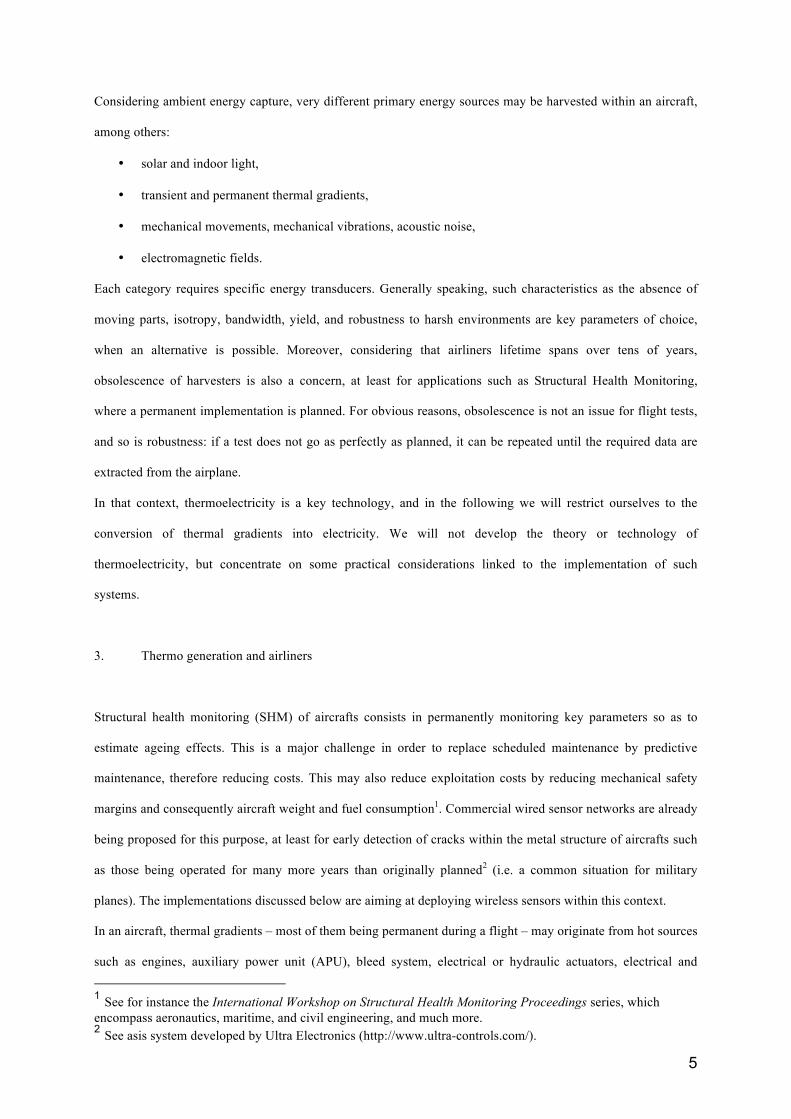
Transient thermal gradients take place when cruise level is changing, mainly during take-off / climb, and descent
/ landing phases. They are due to the strong temperature dependence of air vs. altitude (6.5°C/km according to
International Standard Atmosphere). They can be amplified by using Phase Change Materials (PCM) acting
alternatively as the hot (climb) or cold (descent) body [3,4,5], transforming temporal temperature variations into
(transient) spatial differences (Figure 3.a). Unfortunately they are not active during cruise when all mechanical
parts are more or less in thermal equilibrium, but they offer the possibility of transient thermal energy
scavenging in areas where no hot source exists. In Figure 3.b the thermal gradient obtained with such an
arrangement is given for a short-haul flight simulated in a climatic chamber equipped with a pulsed air generator.
The PCM is here water whose freezing and liquefaction phases are clearly visible. It is worth mentioning that the
use of a PCM, apart from increasing the thermal gradient by itself, consequently fosters TEG yield. Te
mpe
ratu
re (°
C)!
air!water!
Time (min)!
outside air flow!
aircraft mechanical structure!
TEG!
PCM!
(a)! (b)!
Fig. 3 Schematic of TEG implementation (a) and temperatures recorded during flight simulation in a climatic
chamber (b). For 10 g of water, the harvested electrical energy was 34 J (from [3])
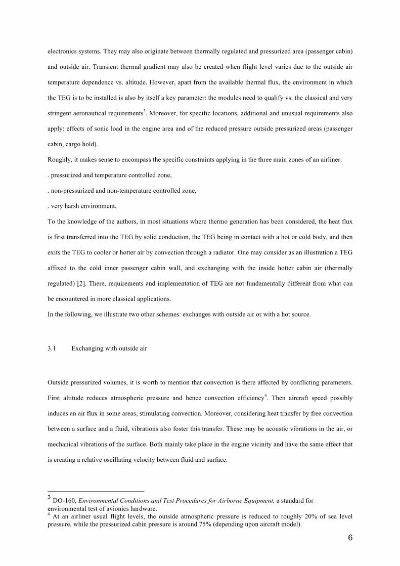
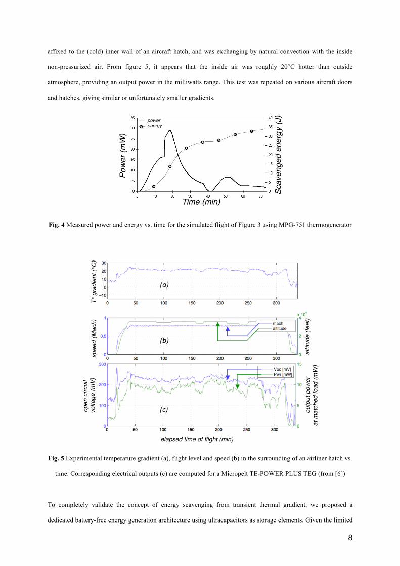
On Figure 4, we have plotted the measured power and energy obtained in the above conditions using MPG-751
TEG (Micropelt, Freiburg, Germany) mounted in a test module including the PCM. The first power peak
corresponds to the first voltage alternation related to the negative thermal gradient generated during take-off and
the second one to the voltage alternation related to the positive gradient generated during landing. The first
power peak is as high as 30 mW and the total scavenged energy is close to 35 joules, that is roughly enough to
supply a WSN node during such a short flight.
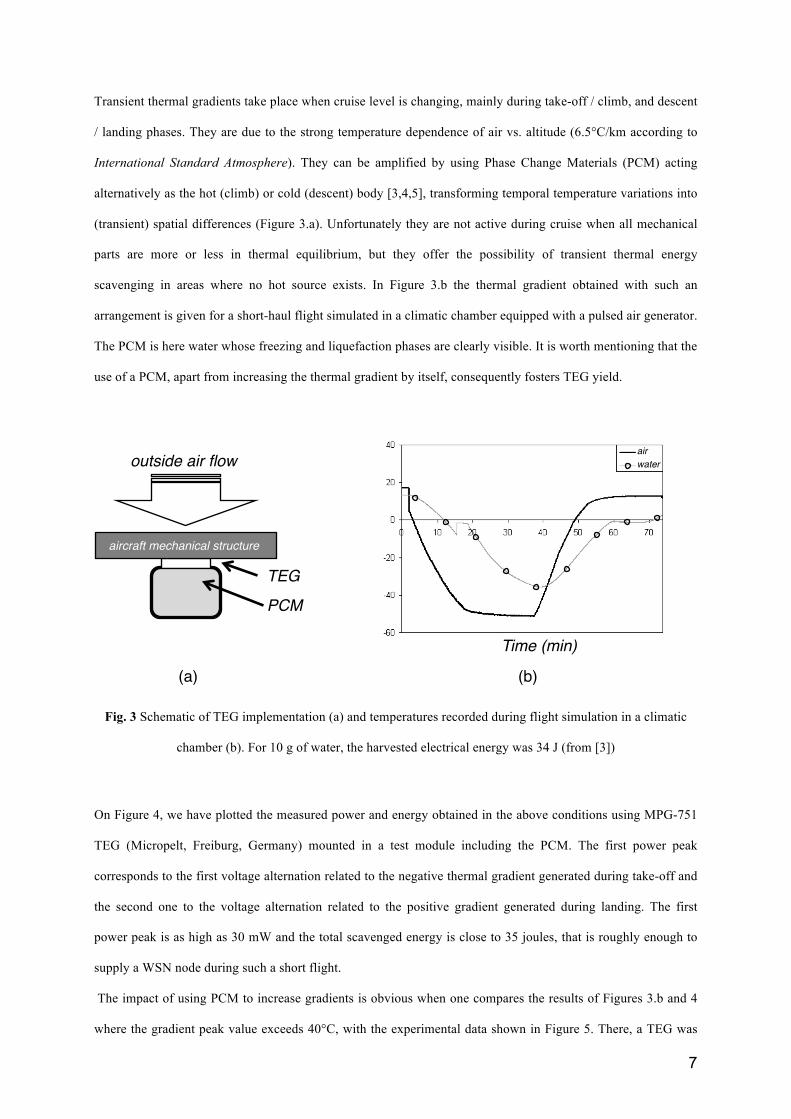
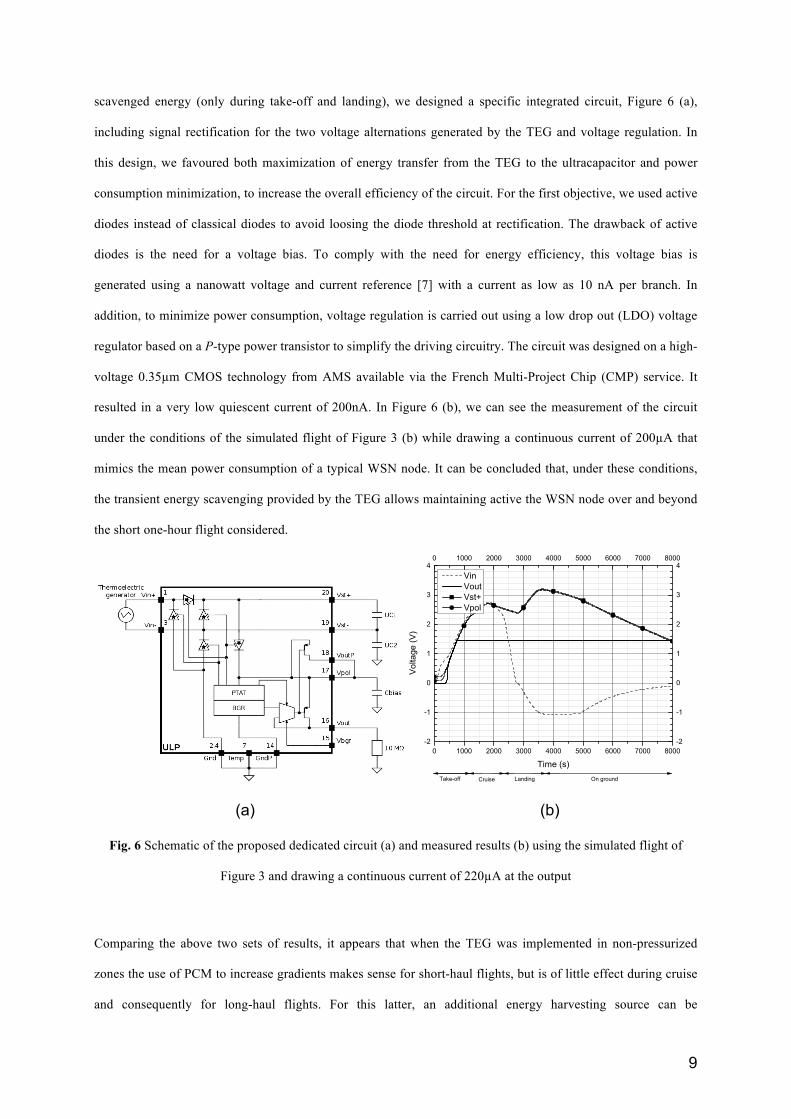
The impact of using PCM to increase gradients is obvious when one compares the results of Figures 3.b and 4
where the gradient peak value exceeds 40°C, with the experimental data shown in Figure 5. There, a TEG was
8
affixed to the (cold) inner wall of an aircraft hatch, and was exchanging by natural convection with the inside
non-pressurized air. From figure 5, it appears that the inside air was roughly 20°C hotter than outside
atmosphere, providing an output power in the milliwatts range. This test was repeated on various aircraft doors
and hatches, giving similar or unfortunately smaller gradients.
Pow
er (m
W)!
Scav
enge
d en
ergy
(J)!
Time (min)!
power!energy!
Fig. 4 Measured power and energy vs. time for the simulated flight of Figure 3 using MPG-751 thermogenerator
T° g
radi
ent (
°C)!
spee
d (M
ach)!
altit
ude
(feet
)!
open
circ
uit!
vol
tage
(mV)
!
elapsed time of flight (min) !
outp
ut p
ower
!at
mat
ched
load
(mW
) !
(a)$
(b)$
(c)$
Fig. 5 Experimental temperature gradient (a), flight level and speed (b) in the surrounding of an airliner hatch vs.
time. Corresponding electrical outputs (c) are computed for a Micropelt TE-POWER PLUS TEG (from [6])
To completely validate the concept of energy scavenging from transient thermal gradient, we proposed a
dedicated battery-free energy generation architecture using ultracapacitors as storage elements. Given the limited
9
scavenged energy (only during take-off and landing), we designed a specific integrated circuit, Figure 6 (a),
including signal rectification for the two voltage alternations generated by the TEG and voltage regulation. In
this design, we favoured both maximization of energy transfer from the TEG to the ultracapacitor and power
consumption minimization, to increase the overall efficiency of the circuit. For the first objective, we used active
diodes instead of classical diodes to avoid loosing the diode threshold at rectification. The drawback of active
diodes is the need for a voltage bias. To comply with the need for energy efficiency, this voltage bias is
generated using a nanowatt voltage and current reference [7] with a current as low as 10 nA per branch. In
addition, to minimize power consumption, voltage regulation is carried out using a low drop out (LDO) voltage
regulator based on a P-type power transistor to simplify the driving circuitry. The circuit was designed on a high-
voltage 0.35µm CMOS technology from AMS available via the French Multi-Project Chip (CMP) service. It
resulted in a very low quiescent current of 200nA. In Figure 6 (b), we can see the measurement of the circuit
under the conditions of the simulated flight of Figure 3 (b) while drawing a continuous current of 200µA that
mimics the mean power consumption of a typical WSN node. It can be concluded that, under these conditions,
the transient energy scavenging provided by the TEG allows maintaining active the WSN node over and beyond
the short one-hour flight considered.
(a) (b)
Fig. 6 Schematic of the proposed dedicated circuit (a) and measured results (b) using the simulated flight of
Figure 3 and drawing a continuous current of 220µA at the output
Comparing the above two sets of results, it appears that when the TEG was implemented in non-pressurized
zones the use of PCM to increase gradients makes sense for short-haul flights, but is of little effect during cruise
and consequently for long-haul flights. For this latter, an additional energy harvesting source can be
10
contemplated [8]. Moreover, during cruise at constant altitude, unfortunately only modest gradients
spontaneously develop when TEG is far from a hot source.
3.2 Exchanging with a permanent hot source: implementation in the aft pylon fairing
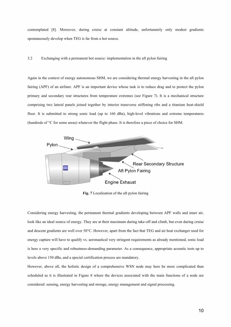
Again in the context of energy autonomous SHM, we are considering thermal energy harvesting in the aft pylon
fairing (APF) of an airliner. APF is an important device whose task is to reduce drag and to protect the pylon
primary and secondary rear structures from temperature extremes (see Figure 7). It is a mechanical structure
comprising two lateral panels joined together by interior transverse stiffening ribs and a titanium heat-shield
floor. It is submitted to strong sonic load (up to 160 dBa), high-level vibrations and extreme temperatures
(hundreds of °C for some areas) whatever the flight phase. It is therefore a piece of choice for SHM.
Fig. 7 Localisation of the aft pylon fairing
Considering energy harvesting, the permanent thermal gradients developing between APF walls and inner air,
look like an ideal source of energy. They are at their maximum during take-off and climb, but even during cruise
and descent gradients are well over 50°C. However, apart from the fact that TEG and air heat exchanger used for
energy capture will have to qualify vs. aeronautical very stringent requirements as already mentioned, sonic load
is here a very specific and robustness-demanding parameter. As a consequence, appropriate acoustic tests up to
levels above 150 dBa, and a special certification process are mandatory.
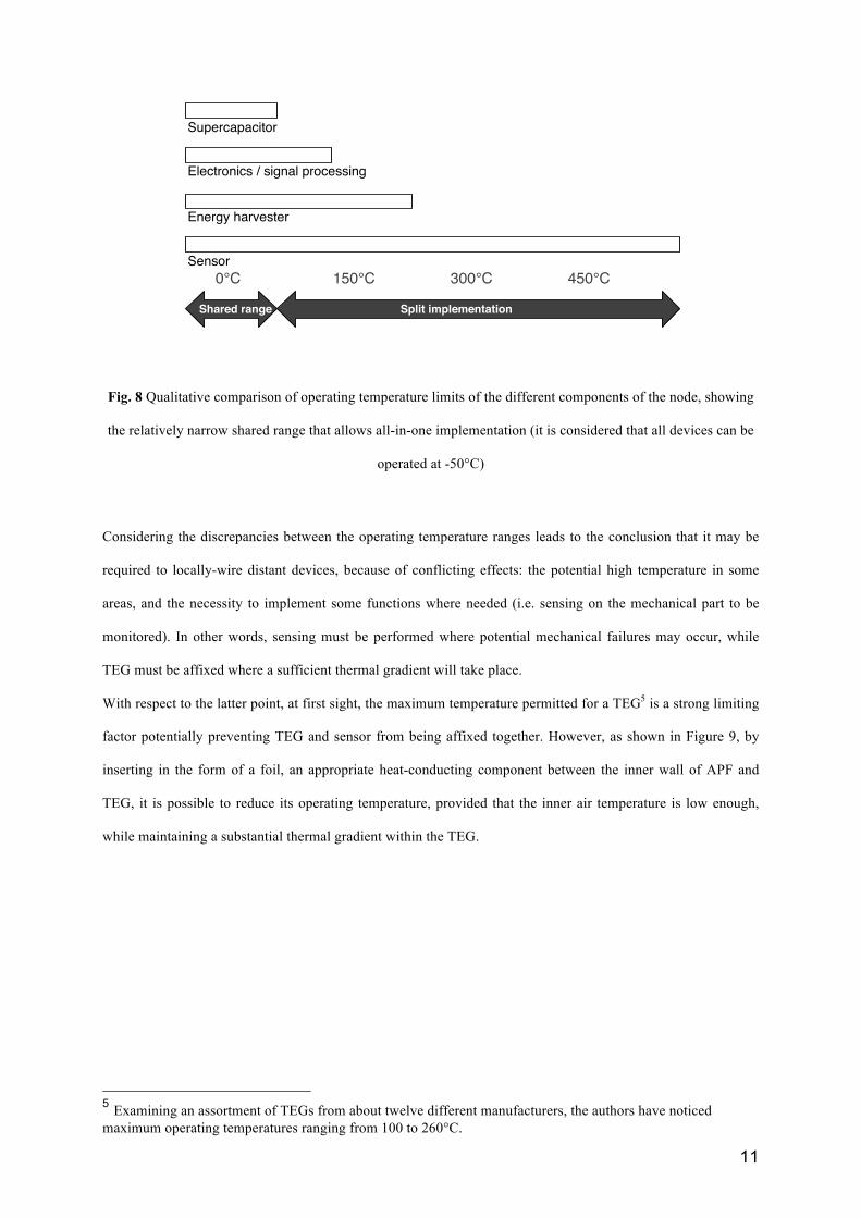
However, above all, the holistic design of a comprehensive WSN node may here be more complicated than
scheduled as it is illustrated in Figure 8 where the devices associated with the main functions of a node are
considered: sensing, energy harvesting and storage, energy management and signal processing.
11
0°C! 150°C! 300°C! 450°C!
Supercapacitor !
Electronics / signal processing!
Energy harvester!
Sensor!
Shared range! Split implementation!
Fig. 8 Qualitative comparison of operating temperature limits of the different components of the node, showing
the relatively narrow shared range that allows all-in-one implementation (it is considered that all devices can be
operated at -50°C)
Considering the discrepancies between the operating temperature ranges leads to the conclusion that it may be
required to locally-wire distant devices, because of conflicting effects: the potential high temperature in some
areas, and the necessity to implement some functions where needed (i.e. sensing on the mechanical part to be
monitored). In other words, sensing must be performed where potential mechanical failures may occur, while
TEG must be affixed where a sufficient thermal gradient will take place.
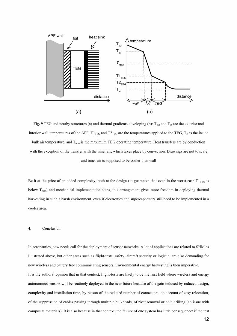
With respect to the latter point, at first sight, the maximum temperature permitted for a TEG5 is a strong limiting
factor potentially preventing TEG and sensor from being affixed together. However, as shown in Figure 9, by
inserting in the form of a foil, an appropriate heat-conducting component between the inner wall of APF and
TEG, it is possible to reduce its operating temperature, provided that the inner air temperature is low enough,
while maintaining a substantial thermal gradient within the TEG.
5 Examining an assortment of TEGs from about twelve different manufacturers, the authors have noticed maximum operating temperatures ranging from 100 to 260°C.
12
Fig. 9 TEG and nearby structures (a) and thermal gradients developing (b): Tout and Tin are the exterior and
interior wall temperatures of the APF, T1TEG and T2TEG are the temperatures applied to the TEG, T∞ is the inside
bulk air temperature, and Tmax is the maximum TEG operating temperature. Heat transfers are by conduction
with the exception of the transfer with the inner air, which takes place by convection. Drawings are not to scale
and inner air is supposed to be cooler than wall
Be it at the price of an added complexity, both at the design (to guarantee that even in the worst case T1TEG is
below Tmax) and mechanical implementation steps, this arrangement gives more freedom in deploying thermal
harvesting in such a harsh environment, even if electronics and supercapacitors still need to be implemented in a
cooler area.
4. Conclusion
In aeronautics, new needs call for the deployment of sensor networks. A lot of applications are related to SHM as
illustrated above, but other areas such as flight-tests, safety, aircraft security or logistic, are also demanding for
new wireless and battery free communicating sensors. Environmental energy harvesting is then imperative.
It is the authors’ opinion that in that context, flight-tests are likely to be the first field where wireless and energy
autonomous sensors will be routinely deployed in the near future because of the gain induced by reduced design,
complexity and installation time, by reason of the reduced number of connectors, on account of easy relocation,
of the suppression of cables passing through multiple bulkheads, of rivet removal or hole drilling (an issue with
composite materials). It is also because in that context, the failure of one system has little consequence: if the test
distance
temperature
T∞
T1TEG T2TEG
Tout
Tin
Tmax
wall TEG
distance
APF wall foil
TEG
heat sink
foil
(a) (b)
13
does not go as perfectly planned, it can be repeated at no risk until the required data are extracted from the
airplane. There, various energy harvesting methods may compete, including photovoltaic [9].
For permanent fitment (such as for SHM) the issue of reliability and robustness of energy harvester is central, as
energy processing is critical for such an application. TEG is here the major competitor, benefiting from a large
and for-years established commercial offer, combined with favourable intrinsic characteristics. However, in the
context of aeronautics, particular attention shall be paid anyhow, to avoid excessive maintenance burden induced
by such smart monitoring. The integrity, reliability and availability will be major inputs to cover such
optimization in parallel with certification duty.
5. Acknowledgements
The authors’ work on energy harvesting in aircrafts has been partially supported by Fondation de Recherche
pour l’Aéronautique et l’Espace (FNRAE), by Midi-Pyrénées Regional Council, by Conseil pour la Recherche
Aéronautique Civile (CORAC), by Direction Générale de l’Armement (DGA) and by Airbus.
Bibliography
[1] Y. Sasaki, Electrochemistry, 76(1), (2008).
[2] K. Bartholome, M. Jaegle, D. Ebling, J. Koenig, A. Jacquout, H. Boettner, Tech Mess 77 (2010).
[3] N. Bailly, J-M. Dilhac, C. Escriba, C. Vanhecke, N. Mauran, M. Bafleur, PowerMEMS 2008, Tokyo
(Japan), (2008).
[4] D. Samson, M. Kluge, T. Becker, U. Schmid, Sensor Actuat A-Physic, 172 (2011).
[5] M. E. Kiziroglou1, S. W. Wright, T. T. Toh, T. Becker, P. D. Mitcheson, E. M. Yeatman, PowerMEMS
2012, Atlanta (USA), (2012).
[6] R. Montheard, C. Escriba, J.Y. Fourniols, M. Lastapis, J. Prunet, M. Bafleur, J.M. Dilhac, International
Workshop on Structural Health Monitoring (IWSHM 2011), Stanford (USA), (2011).
[7] C. Vanhecke, European Patent EP2434364 A1, March 28, 2012.
[8] C. Vanhecke, L. Assouère, M. Bafleur, C. Rossi, J.M. Dilhac, in 8ème Journées d’étude Faible Tension
Faible Consommation (FTFC 2009), Neuchâtel (Switzerland) (2009).
[9] D. Meekhun, V. Boitier, J-M. Dilhac, ICREPQ'12, Santiago de Compostela (Spain) (2012).
Related Documents