PORR Projects World of PORR 162/2013 Roland Schorn Short description The new pump storage power plant (PSKW) Reißeck II represents an expansion of the already existing group of power plants, Malta and Reißeck/Kreuzeck in Carinthia. The new plant will link the hydraulic systems of this power plant group and better exploit the available resources. The existing annual storage reservoir Großer Mühldorfer See will be used as the upper reservoir, and the existing reservoirs Gößkar and Galgenbichl as lower reservoirs. All of the plants will be built underground with the greatest possible consideration for nature and ecological balance. No additional reservoirs or stream collecting works are required. The entire construction area runs a length of approx. 7 km in the Mühldorfer Graben area; headings are located between 600 and 2,400 m above sea-level. The length of the new headrace is approx. 5 km on the whole and consists in detail of a 3.3 km long headrace gallery as well as 0.8 km pressure shaft with a 42° gradient which flows into the new hydropower cavern over the 0.6 km lower horizontal section and the upstream distribution pipeline. There the two machinery units will be installed underground with an output of 215 MW each. The headrace is connected to the existing gallery system for the Malta power plant group through the downstream distribution pipeline and a 0.3 km underwater gallery. The power plant will have a power output in turbine and pumping operation of 430 MW. Commissioning is planned for 2014. In the following report we will describe the full project and discuss the particular technical and logistical challenges of this high-altitude mountain construction site. Illustration 1: Schematic overview of the pump storage power plant Reißeck II Image: PORR Technical data for pump storage power plant Reißeck II (chart 1) Turbine type reversible Francis pump turbine, vertically installed Median gross head 595 m Number of machinery units 2 Max. turbine output 2 x 215 MW Max. pumping power 2 x 215 MW Max. metered flow per turbine unit 40 m³/s Contract The consortium PSKW Reißeck II, consisting of the companies G. Hinteregger & Söhne, Östu-Stettin, Porr Bau GmbH and Swietelsky Tunnelbau, were awarded the contract in spring 2010 by the Verbund Hydro Power to carry out the primary works. The contract at hand encompasses all of the primary works for the new power plant. Total construction time is projected at 4.5 years. A half year for the ground opening, two years for excavation and structural work, and two additional years for the complete expansion. At the time of contract conclusion in May 2010 the contract volume was approx. 100 m euros. Geology The project area of PSKW Reißeck II lies in the area of the overthrust of the Glockner nappe (upper schist shell) over the Storz nappe and the upper Central Gneiss Core (crystalline basement). The Glockner nappe system is a macro-tectonic unit of the Pennine nappes of the Tauern window. Pump storage hydro power plant (PSKW) Reißeck II A challenge in high-altitude mountains Page 1

Welcome message from author
This document is posted to help you gain knowledge. Please leave a comment to let me know what you think about it! Share it to your friends and learn new things together.
Transcript
PORR ProjectsWorld of PORR 162/2013
Roland Schorn
Short descriptionThe new pump storage power plant (PSKW) Reißeck IIrepresents an expansion of the already existing group ofpower plants, Malta and Reißeck/Kreuzeck in Carinthia. Thenew plant will link the hydraulic systems of this power plantgroup and better exploit the available resources. The existingannual storage reservoir Großer Mühldorfer See will be usedas the upper reservoir, and the existing reservoirs Gößkarand Galgenbichl as lower reservoirs.
All of the plants will be built underground with the greatestpossible consideration for nature and ecological balance. Noadditional reservoirs or stream collecting works are required.The entire construction area runs a length of approx. 7 km inthe Mühldorfer Graben area; headings are located between600 and 2,400 m above sea-level. The length of the newheadrace is approx. 5 km on the whole and consists in detailof a 3.3 km long headrace gallery as well as 0.8 km pressureshaft with a 42° gradient which flows into the new hydropowercavern over the 0.6 km lower horizontal section and theupstream distribution pipeline.
There the two machinery units will be installed undergroundwith an output of 215 MW each. The headrace is connectedto the existing gallery system for the Malta power plant groupthrough the downstream distribution pipeline and a 0.3 kmunderwater gallery. The power plant will have a power outputin turbine and pumping operation of 430 MW. Commissioningis planned for 2014.
In the following report we will describe the full project anddiscuss the particular technical and logistical challenges ofthis high-altitude mountain construction site.
Illustration 1: Schematic overview of the pump storage power plant ReißeckIIImage: PORR
Technical data for pump storage power plant Reißeck II(chart 1)
Turbine type reversible Francis pump turbine,vertically installed
Median gross head 595 m
Number of machineryunits
2
Max. turbine output 2 x 215 MW
Max. pumping power 2 x 215 MW
Max. metered flow perturbine unit
40 m³/s
ContractThe consortium PSKW Reißeck II, consisting of thecompanies G. Hinteregger & Söhne, Östu-Stettin, Porr BauGmbH and Swietelsky Tunnelbau, were awarded the contractin spring 2010 by the Verbund Hydro Power to carry out theprimary works. The contract at hand encompasses all of theprimary works for the new power plant. Total constructiontime is projected at 4.5 years. A half year for the groundopening, two years for excavation and structural work, andtwo additional years for the complete expansion. At the time ofcontract conclusion in May 2010 the contract volume wasapprox. 100 m euros.
GeologyThe project area of PSKW Reißeck II lies in the area of theoverthrust of the Glockner nappe (upper schist shell) over theStorz nappe and the upper Central Gneiss Core (crystallinebasement). The Glockner nappe system is a macro-tectonicunit of the Pennine nappes of the Tauern window.
Pump storage hydro power plant (PSKW) ReißeckIIA challenge in high-altitude mountains
Page 1
PORR ProjectsWorld of PORR 162/2013
The project lies for the most part in the area of the CentralGneiss Core. Mostly granite and augen gneisses areencountered, while band gneisses played a subordinate rolein excavation. In the course of the tunnel drive operationshigh-strength rock was observed but also high quartz andmica content, and thus very high abrasiveness of the rock.
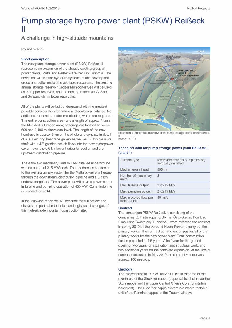
Site installation area, organisationThe construction site in Mühldorfer Graben stretches over 7km and an elevation difference of 1,800 m. The main siteinstallation is located in Mühldorfer Graben at 1,500 m oversea-level (Illustration 2). In addition to the construction officefor the client and contractor, the living cabins for approx. 300men, a central workshop, a concrete mixing plant, a storagearea for materials handling and a site canteen are alsolocated there.
A somewhat smaller site installation was set up atSchoberboden at 2,200 m over sea level for the high-pressure side of the headrace. There is an additional repairshop in this area.
Illustration 2: Main site installation in Mühldorfer Graben, Schoberbodenaccess roadImage: PORR
Site accessibility, access roadsThe 12 km long Burgstall access road runs from the valley tothe site installation in Mühldorfer Graben. The existing roadhad already exceeded its useful life and was rebuilt over theentire length while maintaining traffic operations. TheSchoberboden access road with a length of 6 km isconnected to the Burgstallstraße at Mühldorfer Graben andruns to the Schoberboden construction area at an elevation of2,200 m. This road was realigned and built anew.
In the following we describe the individual construction
areas, in particular the penstock from the intake structure atGroßer Mühldorfer See via the cavern up to the connection tothe existing gallery system of the Malta power plant.
Illustration 3: Overview of longitudinal section through the high and lowerpressure headraceImage: PORR
High-pressure side of the headraceIntake structureThe new intake and outlet structure is located at the westernflank of the existing Großer Mühldorfer See reservoir. Anextra road into the reservoir will be built to construct thestructure. The road construction, excavation and shoring workfor the structure together with the remaining tunnel drive tothe already excavated headrace gallery will be done when thereservoir is empty in the summer of 2013.
Pressure galleryThe pressure gallery runs from the intake structure in theexisting Großer Mühldorfer See to the Schoberboden surgechamber lower tank. The main part of the approx. 3.3 km longheadrace gallery was excavated with an open hard stonetunnel boring machine (TBM) with a cutter diameter of 7 m.The TBM was built up underground over days in an assemblychamber built especially for that purpose with connectingstart-tubes. The excavated material was transported initiallyby rail over the gallery system up to the rotational tipperbridge at the surface. The excavated material was collectedthere, transported by truck to the Schoberboden storage areaand filled in there.
The headrace gallery is lined with a 40 cm thick inner lining ofin situ concrete connecting to a 2.05 m wide tubbing segmentin the invert area.
Page 2
PORR ProjectsWorld of PORR 162/2013
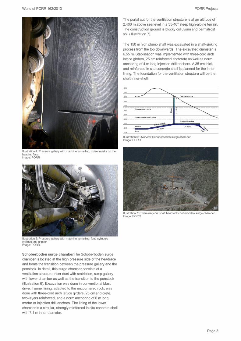
Illustration 4: Pressure gallery with machine tunnelling, chisel marks on theheading faceImage: PORR
Illustration 5: Pressure gallery with machine tunnelling, feed cylinders(yellow) and gripperImage: PORR
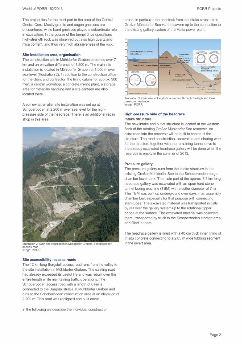
Schoberboden surge chamberThe Schoberboden surgechamber is located at the high pressure side of the headraceand forms the transition between the pressure gallery and thepenstock. In detail, this surge chamber consists of aventilation structure, riser duct with restriction, ramp gallerywith lower chamber as well as the transition to the penstock(Illustration 6). Excavation was done in conventional blastdrive. Tunnel lining, adapted to the encountered rock, wasdone with three-cord arch lattice girders, 25 cm shotcrete,two-layers reinforced, and a norm anchoring of 6 m longmortar or injection drill anchors. The lining of the lowerchamber is a circular, strongly reinforced in situ concrete shellwith 7.1 m inner diameter.
The portal cut for the ventilation structure is at an altitude of2,400 m above sea level in a 35-40° steep high-alpine terrain.The construction ground is blocky colluvium and permafrostsoil (Illustration 7).
The 150 m high plumb shaft was excavated in a shaft-sinkingprocess from the top downwards. The excavated diameter is6.55 m. Stabilisation was implemented with three-cord archlattice girders, 25 cm reinforced shotcrete as well as normanchoring of 4 m long injection drill anchors. A 35 cm thickand reinforced in situ concrete shell is planned for the innerlining. The foundation for the ventilation structure will be theshaft inner-shell.
Illustration 6: Overview Schoberboden surge chamberImage: PORR
Illustration 7: Preliminary cut shaft head of Schoberboden surge chamberImage: PORR
Page 3
PORR ProjectsWorld of PORR 162/2013
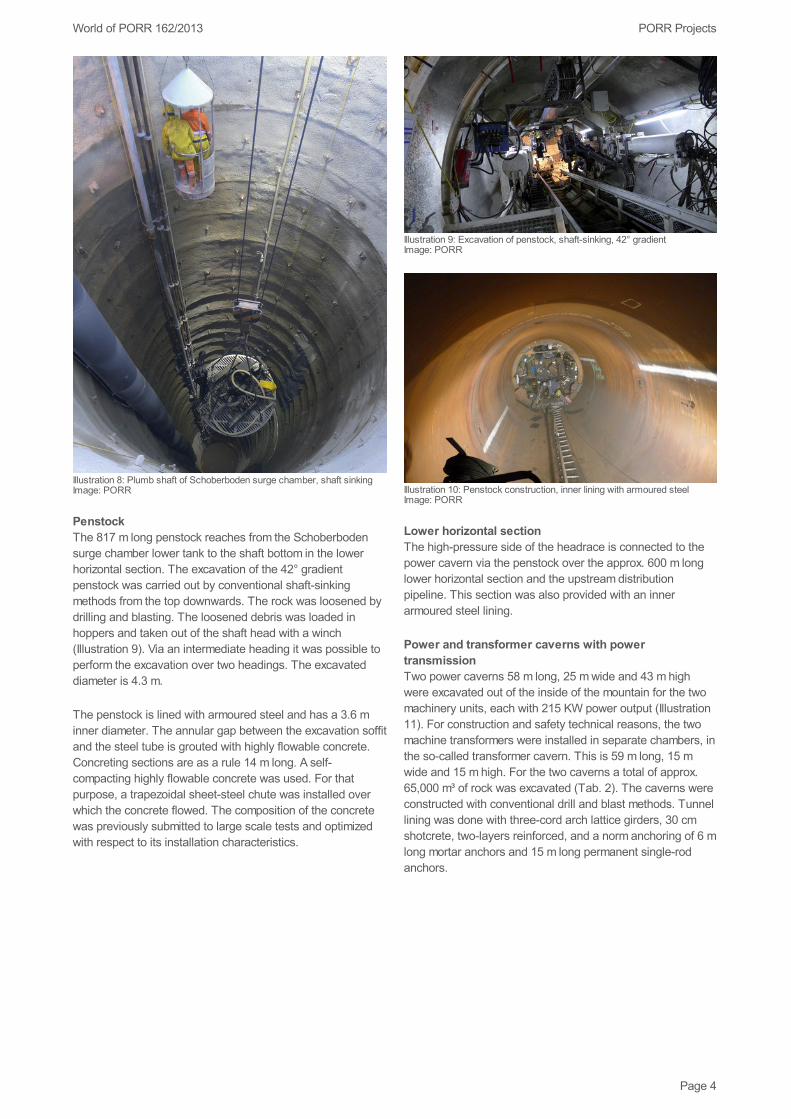
Illustration 8: Plumb shaft of Schoberboden surge chamber, shaft sinkingImage: PORR
PenstockThe 817 m long penstock reaches from the Schoberbodensurge chamber lower tank to the shaft bottom in the lowerhorizontal section. The excavation of the 42° gradientpenstock was carried out by conventional shaft-sinkingmethods from the top downwards. The rock was loosened bydrilling and blasting. The loosened debris was loaded inhoppers and taken out of the shaft head with a winch(Illustration 9). Via an intermediate heading it was possible toperform the excavation over two headings. The excavateddiameter is 4.3 m.
The penstock is lined with armoured steel and has a 3.6 minner diameter. The annular gap between the excavation soffitand the steel tube is grouted with highly flowable concrete.Concreting sections are as a rule 14 m long. A self-compacting highly flowable concrete was used. For thatpurpose, a trapezoidal sheet-steel chute was installed overwhich the concrete flowed. The composition of the concretewas previously submitted to large scale tests and optimizedwith respect to its installation characteristics.
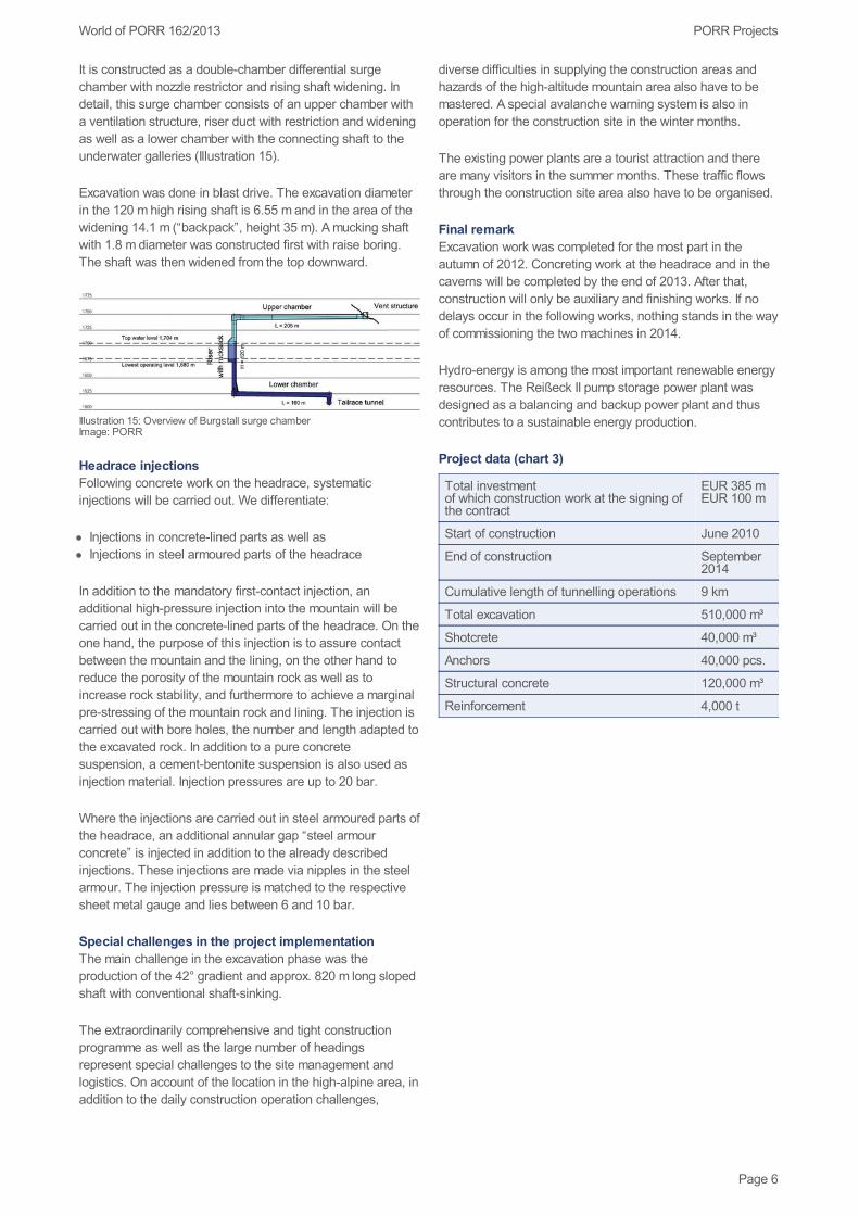
Illustration 9: Excavation of penstock, shaft-sinking, 42° gradientImage: PORR
Illustration 10: Penstock construction, inner lining with armoured steelImage: PORR
Lower horizontal sectionThe high-pressure side of the headrace is connected to thepower cavern via the penstock over the approx. 600 m longlower horizontal section and the upstream distributionpipeline. This section was also provided with an innerarmoured steel lining.
Power and transformer caverns with powertransmissionTwo power caverns 58 m long, 25 m wide and 43 m highwere excavated out of the inside of the mountain for the twomachinery units, each with 215 KW power output (Illustration11). For construction and safety technical reasons, the twomachine transformers were installed in separate chambers, inthe so-called transformer cavern. This is 59 m long, 15 mwide and 15 m high. For the two caverns a total of approx.65,000 m³ of rock was excavated (Tab. 2). The caverns wereconstructed with conventional drill and blast methods. Tunnellining was done with three-cord arch lattice girders, 30 cmshotcrete, two-layers reinforced, and a norm anchoring of 6 mlong mortar anchors and 15 m long permanent single-rodanchors.
Page 4

PORR ProjectsWorld of PORR 162/2013
Illustration 11: Cut through the power and transformer cavernsImage: PORR
Illustration 13: Interior work, power cavernImage: PORR
Comparison of the two cavern excavations (chart 2)
Power cavern
Rock excavation (solid) 51,000 m³
Length 58 m
Width 25 m
Max. height 43 m
Transformer cavern
Rock excavation (solid) 14,000 m³
Length 59 m
Width 15 m
Max. height 15 m
Power is transmitted from the transformer cavern to the relay
station in three steps. At the beginning, the energytransmission runs 820 m underground over the Burgstallaccess gallery and the energy transmission gallery. From theportal of the energy transmission gallery up to the existingmachinery chamber of the Hattelberg penstock, the energytransmission is run along the Burgstall access road into an830 m long accessible cableway. Then comes a 1,750 m longcable duct parallel to the existing Hattelberg pressure pipelinedown into the valley, to the existing outdoor switchgear bay ofthe 220 kV Malta main stage relay station (Illustration 14).The special challenges in constructing the cableway are thesteep terrain, supplying the site via the aerial railway as wellas the short construction time.
Illustration 14: Power transmission along the existing pressure pipeline,supply via the aerial railwayImage: PORR
Headrace, low-pressure sideUnderwater galleriesThe underground gallery with a length of 230 m links into theexisting Hattelberg gallery of the Malta power plant at a rightangle. Excavation was done by blasting. As with the headracegallery, the interior was provided with an in situ concrete shellwith inner diameter of 6.2 m, which connects in the invert areato a tubbing segment.
The connection to the existing Hattelberg gallery will be madeonly following completion of the underwater area in thesummer of 2013. For that purpose, the existing steelarmouring in the connection area will be cut open and linkedto the underway gallery.
Burgstall surge chamberThe Burgstall surge chamber islocated on the low pressure side in front of the connection ofthe underwater gallery to the existing Hattelberg gallery.
Page 5
PORR ProjectsWorld of PORR 162/2013
It is constructed as a double-chamber differential surgechamber with nozzle restrictor and rising shaft widening. Indetail, this surge chamber consists of an upper chamber witha ventilation structure, riser duct with restriction and wideningas well as a lower chamber with the connecting shaft to theunderwater galleries (Illustration 15).
Excavation was done in blast drive. The excavation diameterin the 120 m high rising shaft is 6.55 m and in the area of thewidening 14.1 m (“backpack”, height 35 m). A mucking shaftwith 1.8 m diameter was constructed first with raise boring.The shaft was then widened from the top downward.
Illustration 15: Overview of Burgstall surge chamberImage: PORR
Headrace injectionsFollowing concrete work on the headrace, systematicinjections will be carried out. We differentiate:
Injections in concrete-lined parts as well asInjections in steel armoured parts of the headrace
In addition to the mandatory first-contact injection, anadditional high-pressure injection into the mountain will becarried out in the concrete-lined parts of the headrace. On theone hand, the purpose of this injection is to assure contactbetween the mountain and the lining, on the other hand toreduce the porosity of the mountain rock as well as toincrease rock stability, and furthermore to achieve a marginalpre-stressing of the mountain rock and lining. The injection iscarried out with bore holes, the number and length adapted tothe excavated rock. In addition to a pure concretesuspension, a cement-bentonite suspension is also used asinjection material. Injection pressures are up to 20 bar.
Where the injections are carried out in steel armoured parts ofthe headrace, an additional annular gap “steel armourconcrete” is injected in addition to the already describedinjections. These injections are made via nipples in the steelarmour. The injection pressure is matched to the respectivesheet metal gauge and lies between 6 and 10 bar.
Special challenges in the project implementationThe main challenge in the excavation phase was theproduction of the 42° gradient and approx. 820 m long slopedshaft with conventional shaft-sinking.
The extraordinarily comprehensive and tight constructionprogramme as well as the large number of headingsrepresent special challenges to the site management andlogistics. On account of the location in the high-alpine area, inaddition to the daily construction operation challenges,
diverse difficulties in supplying the construction areas andhazards of the high-altitude mountain area also have to bemastered. A special avalanche warning system is also inoperation for the construction site in the winter months.
The existing power plants are a tourist attraction and thereare many visitors in the summer months. These traffic flowsthrough the construction site area also have to be organised.
Final remarkExcavation work was completed for the most part in theautumn of 2012. Concreting work at the headrace and in thecaverns will be completed by the end of 2013. After that,construction will only be auxiliary and finishing works. If nodelays occur in the following works, nothing stands in the wayof commissioning the two machines in 2014.
Hydro-energy is among the most important renewable energyresources. The Reißeck II pump storage power plant wasdesigned as a balancing and backup power plant and thuscontributes to a sustainable energy production.
Project data (chart 3)
Total investmentof which construction work at the signing ofthe contract
EUR 385 mEUR 100 m
Start of construction June 2010
End of construction September2014
Cumulative length of tunnelling operations 9 km
Total excavation 510,000 m³
Shotcrete 40,000 m³
Anchors 40,000 pcs.
Structural concrete 120,000 m³
Reinforcement 4,000 t
Page 6
Related Documents