RC23267 (W0407-013) July 7, 2004 Electrical Engineering IBM Research Report Digital Watermarking and Steganography via Overlays of Halftone Images Chai Wah Wu, Gerhard Thompson IBM Research Division Thomas J. Watson Research Center P.O. Box 218 Yorktown Heights, NY 10598 Mikel Stanich IBM Printing Systems Division 6300 Diagonal Highway Boulder, CO 80301 Research Division Almaden - Austin - Beijing - Haifa - India - T. J. Watson - Tokyo - Zurich LIMITED DISTRIBUTION NOTICE: This report has been submitted for publication outside of IBM and will probably be copyrighted if accepted for publication. It has been issued as a Research Report for early dissemination of its contents. In view of the transfer of copyright to the outside publisher, its distribution outside of IBM prior to publication should be limited to peer communications and specific requests. After outside publication, requests should be filled only by reprints or legally obtained copies of the article (e.g. , payment of royalties). Copies may be requested from IBM T. J. Watson Research Center , P. O. Box 218, Yorktown Heights, NY 10598 USA (email: [email protected]). Some reports are available on the internet at http://domino.watson.ibm.com/library/CyberDig.nsf/home .

Welcome message from author
This document is posted to help you gain knowledge. Please leave a comment to let me know what you think about it! Share it to your friends and learn new things together.
Transcript

RC23267 (W0407-013) July 7, 2004Electrical Engineering
IBM Research Report
Digital Watermarking and Steganography via Overlays ofHalftone Images
Chai Wah Wu, Gerhard ThompsonIBM Research Division
Thomas J. Watson Research CenterP.O. Box 218
Yorktown Heights, NY 10598
Mikel StanichIBM Printing Systems Division
6300 Diagonal HighwayBoulder, CO 80301
Research DivisionAlmaden - Austin - Beijing - Haifa - India - T. J. Watson - Tokyo - Zurich
LIMITED DISTRIBUTION NOTICE: This report has been submitted for publication outside of IBM and will probably be copyrighted if accepted for publication. It has been issued as a ResearchReport for early dissemination of its contents. In view of the transfer of copyright to the outside publisher, its distribution outside of IBM prior to publication should be limited to peer communications and specificrequests. After outside publication, requests should be filled only by reprints or legally obtained copies of the article (e.g. , payment of royalties). Copies may be requested from IBM T. J. Watson Research Center , P.O. Box 218, Yorktown Heights, NY 10598 USA (email: [email protected]). Some reports are available on the internet at http://domino.watson.ibm.com/library/CyberDig.nsf/home .

Digital watermarking and steganography via overlays ofhalftone images
Chai Wah Wua, Gerhard Thompsona and Mikel Stanichb
aIBM T. J. Watson Research Center, P. O. Box 218, Yorktown Heights, NY 10598, USA;bIBM Printing Systems Division, 6300 Diagonal Highway, Boulder, CO 80301, USA
ABSTRACT
Recently, several watermarking schemes have been proposed that embed a watermark into two halftone imagessuch that the watermark can be extracted by overlaying these halftone images. The watermark images in theseschemes are binary images and the pixels in the two halftone images are correlated or not depending on whetherthe corresponding pixel in the watermark is on or off. In these schemes, the watermark is binary and does notcontain detailed features. Furthermore, the extracted watermark contains residual patterns from the two imageswhich reduces the fidelity of the extracted watermark image. This paper proposes a watermarking algorithmthat addresses these problems. In addition, the proposed scheme admits more general watermark extractionfunctions and allows embedding of multiple watermark images.
Keywords: Data hiding, digital halftoning, error diffusion, steganography, watermarking
1. INTRODUCTION
Recently, several watermarking schemes have been proposed in the literature where a watermark is embeddedinto two halftone images such that the watermark can be extracted by simply overlaying these halftone images.In [1, 2] the halftone images are created using dither masks, whereas in [3–5] the halftoning is done via errordiffusion. The watermark images in these schemes are binary images and the binary pixels in the two halftoneimages are correlated or not depending on whether the corresponding pixel in the watermark is black or white.There are several restrictions to these schemes. First of all, the watermark is binary and not grayscale or full-color.Second, because the watermark is embedded via correlation, the average intensity of a region of pixels is neededto identify whether the watermark pixel is black or white. Therefore, the watermark images in these schemes arelimited to logos or simple graphics and do not contain detailed features. Third, the extracted watermark imagecontains residual patterns and features from the two halftone images that reduce the fidelity of the extractedwatermark image. This also limits the fine details in the watermark image. Fourth, the embedding is doneby generating binary halftone images rather than grayscale or multibit images, further reducing the fidelity ofthe extracted watermark. This paper proposes a novel watermarking algorithm to address these problems. Inparticular, the proposed watermarking scheme can embed grayscale images having similar levels of details as thetwo halftone (or multitone) images and there is no residual image in the extracted watermark, i.e. high fidelitywatermark extraction can be obtained. In [1–5], the watermark is extracted using OR or Exclusive-OR of pairsof black and white pixels. In the proposed scheme, more general operations on pairs (or more generally n-tuples)of pixels can be used in the watermark extraction algorithm. We also consider the general case where multiplewatermarks are embedded into multiple images.
2. PIXELWISE TRANSFORMATION
We consider an image to be a matrix of pixels, i.e. an image G consists of pixels G(i, j) where G(i, j), the (i, j)-thpixel of G, is a vector in a color space. For grayscale pixels, the color space is one-dimensional whereas for RGBpixels, the color space is 3-dimensional. A set of n images G1, G2, . . .Gn of the same size can be considered as amatrix of n-tuples of pixels. This is denoted as G1×G2× . . .×Gn, i.e. the (i, j)-th element of G1×G2× . . .×Gn
is the n-tuple (G1(i, j), . . . , Gn(i, j)). Equivalently, a set of n images can be considered as a single image wherethe color space is the Cartesian product of n color spaces of the images G1, . . . , Gn.
Send correspondence to C. W. Wu (E-mail: [email protected]).
1
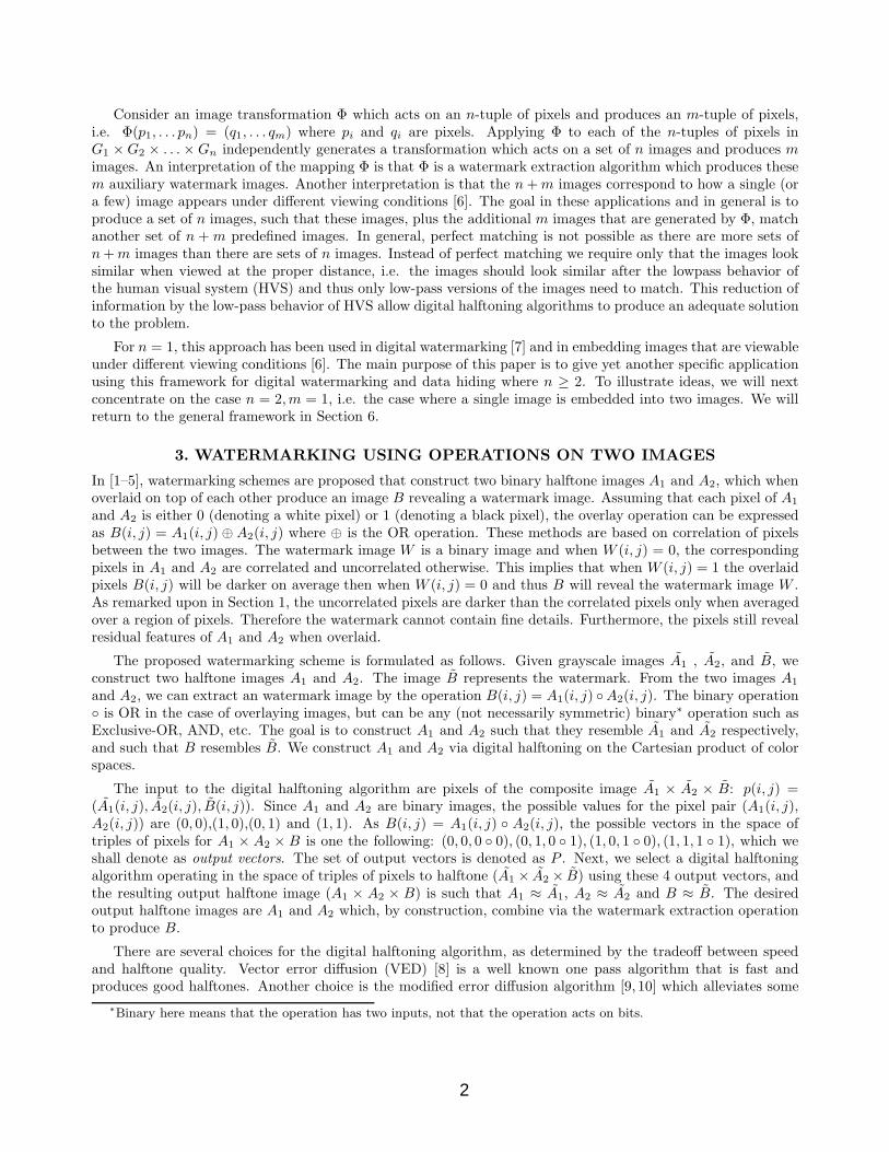
Consider an image transformation Φ which acts on an n-tuple of pixels and produces an m-tuple of pixels,i.e. Φ(p1, . . . pn) = (q1, . . . qm) where pi and qi are pixels. Applying Φ to each of the n-tuples of pixels inG1 ×G2 × . . .×Gn independently generates a transformation which acts on a set of n images and produces mimages. An interpretation of the mapping Φ is that Φ is a watermark extraction algorithm which produces thesem auxiliary watermark images. Another interpretation is that the n + m images correspond to how a single (ora few) image appears under different viewing conditions [6]. The goal in these applications and in general is toproduce a set of n images, such that these images, plus the additional m images that are generated by Φ, matchanother set of n + m predefined images. In general, perfect matching is not possible as there are more sets ofn + m images than there are sets of n images. Instead of perfect matching we require only that the images looksimilar when viewed at the proper distance, i.e. the images should look similar after the lowpass behavior ofthe human visual system (HVS) and thus only low-pass versions of the images need to match. This reduction ofinformation by the low-pass behavior of HVS allow digital halftoning algorithms to produce an adequate solutionto the problem.
For n = 1, this approach has been used in digital watermarking [7] and in embedding images that are viewableunder different viewing conditions [6]. The main purpose of this paper is to give yet another specific applicationusing this framework for digital watermarking and data hiding where n ≥ 2. To illustrate ideas, we will nextconcentrate on the case n = 2, m = 1, i.e. the case where a single image is embedded into two images. We willreturn to the general framework in Section 6.
3. WATERMARKING USING OPERATIONS ON TWO IMAGES
In [1–5], watermarking schemes are proposed that construct two binary halftone images A1 and A2, which whenoverlaid on top of each other produce an image B revealing a watermark image. Assuming that each pixel of A1
and A2 is either 0 (denoting a white pixel) or 1 (denoting a black pixel), the overlay operation can be expressedas B(i, j) = A1(i, j) ⊕ A2(i, j) where ⊕ is the OR operation. These methods are based on correlation of pixelsbetween the two images. The watermark image W is a binary image and when W (i, j) = 0, the correspondingpixels in A1 and A2 are correlated and uncorrelated otherwise. This implies that when W (i, j) = 1 the overlaidpixels B(i, j) will be darker on average then when W (i, j) = 0 and thus B will reveal the watermark image W .As remarked upon in Section 1, the uncorrelated pixels are darker than the correlated pixels only when averagedover a region of pixels. Therefore the watermark cannot contain fine details. Furthermore, the pixels still revealresidual features of A1 and A2 when overlaid.
The proposed watermarking scheme is formulated as follows. Given grayscale images A1 , A2, and B, weconstruct two halftone images A1 and A2. The image B represents the watermark. From the two images A1
and A2, we can extract an watermark image by the operation B(i, j) = A1(i, j) ◦A2(i, j). The binary operation◦ is OR in the case of overlaying images, but can be any (not necessarily symmetric) binary∗ operation such asExclusive-OR, AND, etc. The goal is to construct A1 and A2 such that they resemble A1 and A2 respectively,and such that B resembles B. We construct A1 and A2 via digital halftoning on the Cartesian product of colorspaces.
The input to the digital halftoning algorithm are pixels of the composite image A1 × A2 × B: p(i, j) =(A1(i, j), A2(i, j), B(i, j)). Since A1 and A2 are binary images, the possible values for the pixel pair (A1(i, j),A2(i, j)) are (0, 0),(1, 0),(0, 1) and (1, 1). As B(i, j) = A1(i, j) ◦ A2(i, j), the possible vectors in the space oftriples of pixels for A1 × A2 × B is one the following: (0, 0, 0 ◦ 0), (0, 1, 0 ◦ 1), (1, 0, 1 ◦ 0), (1, 1, 1 ◦ 1), which weshall denote as output vectors. The set of output vectors is denoted as P . Next, we select a digital halftoningalgorithm operating in the space of triples of pixels to halftone (A1 × A2 × B) using these 4 output vectors, andthe resulting output halftone image (A1 × A2 × B) is such that A1 ≈ A1, A2 ≈ A2 and B ≈ B. The desiredoutput halftone images are A1 and A2 which, by construction, combine via the watermark extraction operationto produce B.
There are several choices for the digital halftoning algorithm, as determined by the tradeoff between speedand halftone quality. Vector error diffusion (VED) [8] is a well known one pass algorithm that is fast andproduces good halftones. Another choice is the modified error diffusion algorithm [9, 10] which alleviates some
∗Binary here means that the operation has two inputs, not that the operation acts on bits.
2

problems due to large errors in VED. These one-pass methods analyze and process each n-tuple of pixels oncein a specific order. This ordering of pixels to be processed, and the causality of the error diffusion filter causeanisotropic artifacts in the halftone image. As we will see in Section 7, in some applications there could beconstraints relating pixels in the image which are far apart and for these applications one-pass methods such aserror diffusion are not appropriate. Therefore we will mainly use the iterative isotropic halftoning algorithm usedin [7] to halftone the images. The pseudo code for this halftoning algorithm applied to our problem is shown inAlgorithm 1. The inputs are three images (A1, A2, B) and the outputs are 2 halftone images A1 and A2. Theconstants vi determine how strongly the error in each image is minimized. The linear operator L is the linearspace-invariant model of the HVS. Several choices of such filters can be found in [11, 12]. If the images A1, A2
and B are to be viewed at different distances, then L can be different from each of these images.
Because of the linearity, space-invariance and the relatively small support of the impulse response of L, thecomputation of the variable Error in Algorithm 1 can be sped up by updating the change in Error due tochanging a single pixel of Outimage. This is because changing a single pixel of Outimage only changes a smallnumber (on the order of the size of the support of the impulse response of L) of entries of L(Outimagek − Ak)and L(Outimage3 − B). This technique has been used in dither mask construction when the output is binary[13], but is equally useful here.
The output image Outimage can be initialized as an image with random pixels from the set of output vectorsor a uniform image of a single output vector. To reduce the number of iterations, Outimage can also be initializedby running VED or Modified Error Diffusion and using its output as the initial Outimage.
Algorithm 1 Embed watermark in 2 imagesrepeat
for each i do /* loop through each row */for each j do /* loop through each column */
for each output vector o = (o1, o2, o3) ∈ P do /* loop through all possible output vectors */Outimagek(i, j)← ok, k = 1, 2, 3Error(o) ← v1‖L(Outimage1 − A1)‖ + v2‖L(Outimage2 − A2)‖ + v3‖L(Outimage3 − B)‖
end forfind output vector omin ∈ P that minimizes Error, i.e., omin ← argmino∈P Error(o)Outimage(i, j)← omin
end forend for
until Outimage has not changed between two iterations or the maximum number of iterations is reached
4. GAMUT MAPPING
It was shown that for the error in an error diffusion algorithm to be bounded for arbitrarily large images, anecessary and sufficient condition is that the pixels of the input image (A1× A2×B) should be within the convexhull of the output vectors [9, 10]. The necessity of this condition is also valid for general halftoning algorithms.We can view the lowpass behavior of the HVS as an averaging behavior and the original image is approximatedby an convex sum of output pixels. In order to satisfy this convex hull condition, scaling or gamut mapping ofthe images is needed. In this section we describe how this can be done. Let S be the set of 3-tuples of pixelsin (A1 × A2 × B) i.e. S = {(A1(i, j), A2(i, j), B(i, j))}i,j . Furthermore, let S1, S2 and S3 be the sets of pixelsof images A1, A2 and B respectively, i.e. S1 = {A1(i, j)}i,j , S2 = {A2(i, j)}i,j , and S3 = {B(i, j)}i,j. Forsimplicity, we consider only gamut mappings M that map a pixel p into a pixel M(p) having the following form:for p = (p1, p2, p3) ∈ S, M(p) = (s1p1 + d1, s2p2 + d2, s3p3 + d3) where si are real numbers denoting scalingfactors and di are offset vectors in the color space. Let H be the (closed) convex hull of the output vectors. Hcan be expressed by a set of linear inequalities: H = {x : Ax ≤ b}. A commonly used algorithm for finding theconvex hull of a set of points is the Qhull algorithm [14]. The optimization problem used to find the (optimal)
3
gamut mapping is formulated as follows:
maxsi,di
min(
s1
α1,s2
α2,s3
α3
)under the constraint that M(S) ∈ H (1)
The set of parameters {si, di} which solves the above optimization problem will be used as the gamut mappingM , i.e the pixels of (A1 × A2 × B) are scaled by M before they are halftoned by the halftoning algorithm.
The coefficients αi determine the “penalty” of scaling each image. The smaller αi is, the more the correspond-ing image will be scaled. For instance, in the watermark application, we want the two images A1, A2 to retainmost of the fidelity of the original images A1, A2, whereas the watermark image, which in many applications isassumed to be a less complex image, can accept more distortion due to scaling. In this case, we set α3 to besmaller than α1 and α2.
It is clear that the constraint in Eq. (1) is linear, i.e the inequality constraint M(S) ∈ H is linear in thevariables si, di. This is true since M(S) ∈ H for each pixel p = (p1, p2, p3) ∈ S can be written as
∑3i=1 Λi(sipi +
di) ≤ b where A = [Λ1
...Λ2
...Λ3] and A, b are the matrices defining the convex hull H = {x : Ax ≤ b}.If the number of pixels is large, the constraint M(S) ∈ H can be time consuming to compute. One way to
speed up the computation is to not use all the pixels to compute the gamut, i.e. replacing S with a subset S′′ ⊆ S.This results in a larger feasible region as the set of parameters (si, di) satisfying the constraint M(S′′) ∈ H (i.e.,the set {(si, di) : M(S′′) ∈ H}) is larger than the set of parameters satisfying M(S) ∈ H . This means that theconvex hull condition may not be strictly satisfied. However, if S′′ is a representative sample of S, then the gamutmapping obtained using S′′ is close to the gamut mapping obtained using S. In other words, the convex hullcondition violation is mild and does not cause adverse effects to the halftone images. In experiments, choosingS′′ to be 5 percent of the pixels in S using a sparse grid, gave a gamut mapping very close to the optimal one.
Another way to speed up the computation is using the following simplification which produces a smallerfeasible region for the optimization problem in Eq. (1) that is easier to compute than M(S) ∈ H . However,since the feasible region is smaller, the gamut mapping is also less optimal. Let Vi be the set of extreme pointsof the convex hull of Si. This means that the convex hull of Vi is equal to the convex hull of Si. We then replacethe constraint M(S) ∈ H with M(S′) ∈ H , where S′ = {(p1, p2, p3) : pi ∈ Vi}. It is clear that the convexhull of S′ is larger than the convex hull of S, i.e. the feasible region {(si, di) : M(S′) ∈ H} is smaller than{(si, di) : M(S) ∈ H}.
The gamut mapping is computed using the pixel values of the specific images A1, A2 and B. This gamutmapping in general is not appropriate for another set of images. By replacing S1, S2, S3 with the extreme points,which by abuse of notation we will denote as V1, V2 and V3 respectively, of the possible gamut (i.e. the possiblerange of pixel values) of the images A1, A2 and B respectively, a gamut mapping obtained using the resultingM(S′) ∈ H can be used for any possible image A1, A2 and B respectively. For instance, suppose that the pixelin the image A2 can take on values between 0 and 1. Then by replacing S2 with the set {0, 1}, which is the setof extreme points of the interval [0, 1], and solving the optimization problem using the constraints M(S′) ∈ Hwhere S′ = {(A1(i, j), v, B(i, j)) : v ∈ {0, 1}} we obtain a gamut mapping that can be used with images A1 andB and any image A2 whose pixels lie in the interval [0, 1]. If we replace all three Si’s with {0, 1}, and assume theOR operation for extracting the watermark, i.e. the output vectors are (0, 0, 0), (0, 1, 1), (1, 0, 1), (1, 1, 1), thenwe obtain the following gamut mapping: s1 = s2 = s3 = 0.25, d1 = d2 = 0.5, d3 = 0.75 which can be used for allgrayscale images A1, A2 and B. Thus by restricting the feasible region in this way we obtain suboptimal gamutmappings that cause more distortion to the original images, but are applicable to a larger set of images.
As was shown in [6, 7], the error calculation in the digital halftoning algorithm can be weighted accordingto the fidelity one wishes to achieve for each image. For instance, if a low fidelity watermark is adequate, theerror calculation can be skewed to include more emphasis in reducing the error in the two main images. This isreflected in the parameters vi in Algorithm 1.
For general images, the condition that the input pixel lie in the convex hull of the output vectors can beviolated mildly without much loss in image quality. This allows the gamut mapping to distort the image less.
4
5. EXAMPLES
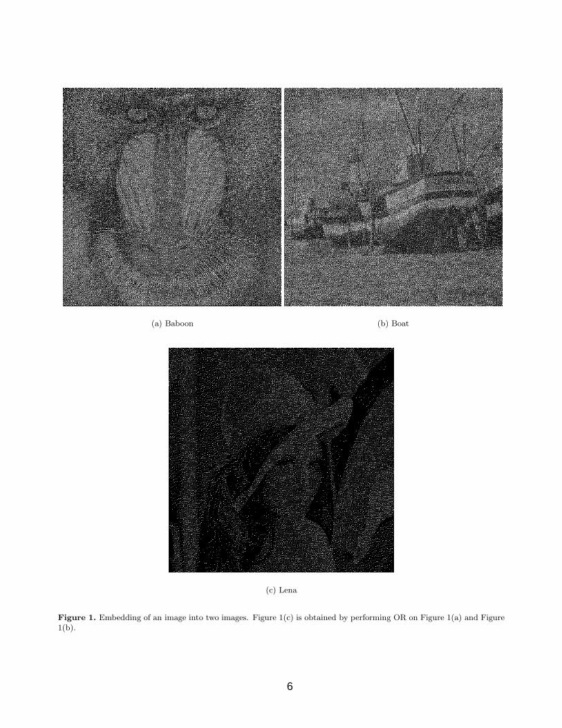
Figure 1 shows an embedding of the Lena image into the two images Baboon and Boat. The gamut mapping isobtained using α1 = 1, α2 = 1, and α3 = 0.5. Figure 1(a) and 1(b) shows the Baboon halftone image and theBoat halftone image respectively, and Figure 1(c) is the extracted watermark image obtained by performing theOR operation on the pixels of Fig. 1(a) and 1(b).
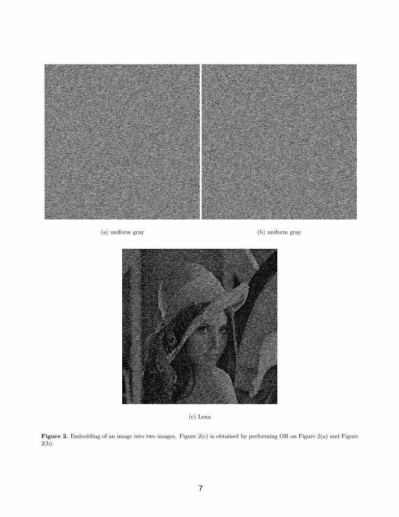
Figure 2 is the same as Figure 1, except that the Lena image is embedded into two images of uniform gray.The gamut mapping is obtained using α1 = α2 = α3 = 1.
In Figure 3 the Lena image is embedded into two Baboon images where the extraction is done using theExclusive-OR operation, instead of the OR operation in the previous examples. This is an interesting examplebecause the two Baboon images (Fig. 3(a),3(b)) appear to be the same, but the halftone dots are arrangeddifferently. When pixelwise Exclusive-OR is applied to these two images, the watermark image (Lena) emerges(Fig. 3(c)). The gamut mapping is obtained using α1 = α2 = α3 = 1.
The extracted watermark images in these examples have relatively high fidelity. This is in contrast with theschemes in [1–5], where a residual of the two halftone images is evident in the extracted watermark image.
6. GENERAL FRAMEWORK
We next discuss the general framework for using this approach in image watermarking and data hiding ap-plications. An image A is represented as a matrix of pixels. The (k, l)-th pixel of A is denoted as A(k, l).Each pixel is a vector in some color space T (which can vary from image to image), i.e. A(k, l) ∈ T . Givenn images A1, . . . An, the watermark extraction algorithm Φ = (φ1, . . . , φm) constructs m images as follows:Φ(A1, . . . , An) = (B1, . . . , Bm) where Bj = φj(A1, . . . , An), i.e. Bj are images created from the sets of imagesA1, . . . An. The operation φj operates pixelwise on the images A1, . . . An, i.e. Bj(k, l) = φj(A1(k, l), . . . An(k, l)).
Given a set of n + m images A1, . . . , An, B1, . . . , Bm, the goal is to create n images (A1, . . . , An) resemblingA1, . . . An such that the m images B1, . . . , Bm extracted from (A1, . . . , An) via Φ resemble B1, . . . Bm.
This will be done using a digital halftoning algorithm. A digital halftoning algorithm can be describedgenerally as follows: given an image I, it creates a halftone image I such that each pixel of I is a member of arestricted set of output pixels P and furthermore I resembles I under some metric d, i.e. d(I, I) is small.
Next we need to specify the set of output pixels for our specific problem in order to use digital halftoningalgorithms. Suppose that the pixels of Ai are chosen from the set Oi. Let R ⊆ O1 × . . . × On = {(p1, . . . , pn) :pi ∈ Oi∀i} be the set of all possible output vectors for the combined image A1 × . . . × An. The subset Rcan be a strictly smaller subset of O1 × . . . × On to express additional relationships between pixels in differentimages. From R we create the set of extended output vectors P = {(p, φ1(p), . . . , φm(p)) : p ∈ R} and halftone(A1 × . . .× An × B1× . . .× Bm) using P as the set of output vectors. The pseudocode of an iterative halftoningalgorithm for solving this problem is shown in Algorithm 2. In the algorithm, A1, . . . , An, B1, . . . Bm are theinput images, P is the set of output vectors and the coefficients vA
k and vBk determine how strongly the error in
each image is minimized.
To satisfy the convex hull condition, the pixels of A1× . . .× An× B1× . . .× Bm are first scaled by the gamutmapping M . The mapping M is found by solving
maxsi,di
minj
sj
αj
under the constraint that (s1p1 + d1, . . . , sn+mpn+m + dn+m) ∈ H for all pixels p = (p1, . . . pn+m) of (A1 × . . .×An × B1 × . . .× Bm), where H is the convex hull of the output vectors in P . The gamut mapping is then givenby:
M : (p1, . . . , pn+m)→ (s1p1 + d1, . . . , sn+mpn+m + dn+m)
Other forms of the objective function can be used in the optimization, e.g.:
maxsi,di
Πjsj
5
(a) Baboon (b) Boat
(c) Lena
Figure 1. Embedding of an image into two images. Figure 1(c) is obtained by performing OR on Figure 1(a) and Figure1(b).
6
(a) uniform gray (b) uniform gray
(c) Lena
Figure 2. Embedding of an image into two images. Figure 2(c) is obtained by performing OR on Figure 2(a) and Figure2(b).
7

(a) Baboon (b) Baboon
(c) Lena
Figure 3. Embedding of an image into two images where extraction of watermark is via Exclusive-OR. Figure 3(c) isobtained by performing Exclusive-OR on Figure 3(a) and Figure 3(b).
8

Algorithm 2 Embed m watermark images in n imagesrepeat
for each i do /* loop through each row */for each j do /* loop through each column */
for each output vector o = (o1, . . . , on+m) ∈ P do /* loop through all possible output vectors */Outimagek(i, j)← ok, k = 1, . . . , n + mError(o) ←∑n
k=1 vAk ‖L(Outimagek − Ak)‖+
∑mk=1 vB
k ‖L(Outimagen+k − Bk)‖end forfind output vector omin ∈ P that minimizes Error, i.e., omin ← argmino∈P Error(o)Outimage(i, j)← omin
end forend for
until Outimage has not changed between two iterations or the maximum number of iterations is reached(A1, . . . , An, B1, . . . , Bm)← OutimageOutput A1, . . . An
The watermarking application in Section 3 is a case where the output are binary halftone images, n = 2 andm = 1 and φ1 is a binary operation.
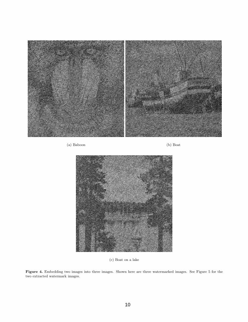
An example of an application where m > 1 is different combinations of the images producing differentwatermarks. For example, given 3 images A1, A2 and A3, combining A1 and A2 produces one watermark B1,and combining A1 and A3 produces another watermark B2. This is shown in Figure 4, where the gamut mappingis obtained using α1 = α2 = α3 = 1, α4 = α5 = 1
2 . Figure 4(a), 4(b) and 4(c) show the halftone images ofBaboon, Boat, and Boat-on-a-lake. The Peppers image in Figure 5(a) is obtained by overlaying Figure 4(a) andFigure 4(b) and the Lena image in Figure 5(b) is obtained by overlaying Figure 4(a) and Figure 4(c).
By choosing another Φ, halftone images can be produced where the extraction of the watermarks is done byusing all three images, for example, by pixelwise Exclusive-OR of all 3 images.
7. MULTIBIT IMAGES, COLOR IMAGES AND OTHER EXTENSIONS
The algorithms presented can easily be adapted to multibit output. Multibit here refers to each pixel havingmultiple levels of gray, instead of bilevel where the image pixels are black or white. In this case, the graylevelsof the two images are simply added (with clamping) to produce the graylevel of the overlaid image. When eachcomponent of the output vector is from a q-bit quantizer (e.g. the black and white case is when q = 1), thenumber of output vectors is large when q is large. In this case the innermost loop in Algorithm 1 to search forthe output vector that minimizes Error can take too many computations. Since omin is the output vector thatgives the minimal value of the error among all choices of the output vectors at location (i, j), the computation ofomin = argmino∈P Error(o) is a discrete optimization problem. For large q this can be relaxed to a continuousoptimization problem and solved using nonlinear programming and the result quantized by a q-bit quantizer.
In another application, as was done in [5], the two images can be taken to be rotated versions of the sameimage. In [5], the second image A2 is the first image A1 rotated 180 degrees. The idea is that the first imagecontains all the information needed to extract the watermark. Note that for this application, there is an acausalrelationship between the pixels of the two images and thus error diffusion is not appropriate as the halftoningalgorithm in this setting. For this application, Algorithm 1 needs to be modified as follows. For an R-pixels byC-pixels image, when computing Error(o), in addition to replacing Outimagek(i, j) with ok, we need to replaceOutimage1(R− i+1, C− j +1) with o2, Outimage2(R− i+1, C− j +1) with o1, Outimage3(R− i+1, C− j+1)with o2 ◦o1. Note that the (R− i1, C−j+1)-th pixel is the (i, j)-th pixel rotated 180 degrees. Then when omin =(omin
1 , omin2 , omin
3 ) is found, we set Outimage(i, j)← omin, Outimage(R−i+1, C−j+1)← (omin2 , omin
1 , omin2 ◦omin
1 ).Assuming that the binary operation ◦ is symmetric, the watermark image A3 must be such that it is invariantunder 180 degree rotation. The gamut mapping is chosen using α1 = α2 with the additional constraints thatd1 = d2, s1 = s2.
9
(a) Baboon (b) Boat
(c) Boat on a lake
Figure 4. Embedding two images into three images. Shown here are three watermarked images. See Figure 5 for thetwo extracted watermark images.
10
(a) Peppers (b) Lena
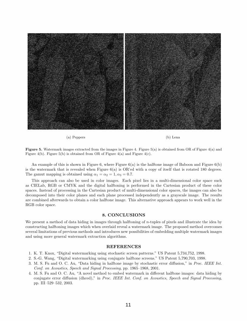
Figure 5. Watermark images extracted from the images in Figure 4. Figure 5(a) is obtained from OR of Figure 4(a) andFigure 4(b). Figure 5(b) is obtained from OR of Figure 4(a) and Figure 4(c).
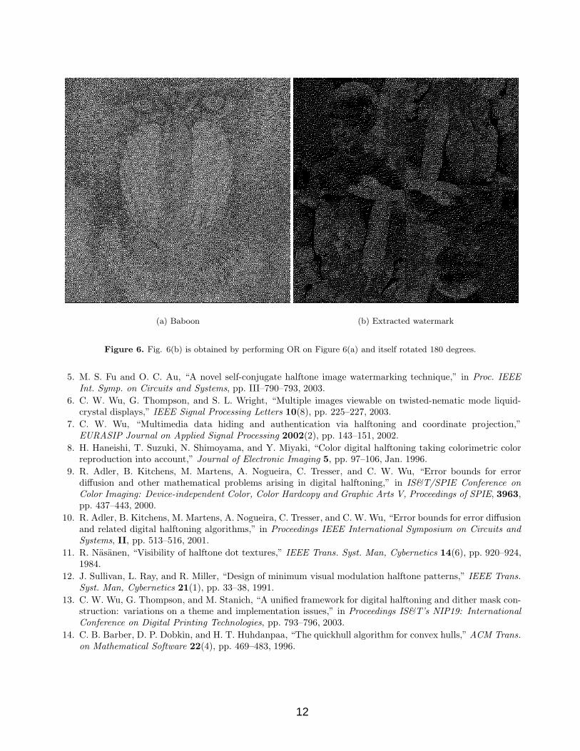
An example of this is shown in Figure 6, where Figure 6(a) is the halftone image of Baboon and Figure 6(b)is the watermark that is revealed when Figure 6(a) is OR’ed with a copy of itself that is rotated 180 degrees.The gamut mapping is obtained using α1 = α2 = 1, α3 = 0.7.
This approach can also be used in color images. Each pixel lies in a multi-dimensional color space suchas CIELab, RGB or CMYK and the digital halftoning is performed in the Cartesian product of these colorspaces. Instead of processing in the Cartesian product of multi-dimensional color spaces, the images can also bedecomposed into their color planes and each plane processed independently as a grayscale image. The resultsare combined afterwards to obtain a color halftone image. This alternative approach appears to work well in theRGB color space.
8. CONCLUSIONS
We present a method of data hiding in images through halftoning of n-tuples of pixels and illustrate the idea byconstructing halftoning images which when overlaid reveal a watermark image. The proposed method overcomesseveral limitations of previous methods and introduces new possibilities of embedding multiple watermark imagesand using more general watermark extraction algorithms.
REFERENCES1. K. T. Knox, “Digital watermarking using stochastic screen patterns.” US Patent 5,734,752, 1998.2. S.-G. Wang, “Digital watermarking using conjugate halftone screens.” US Patent 5,790,703, 1998.3. M. S. Fu and O. C. Au, “Data hiding in halftone image by stochastic error diffusion,” in Proc. IEEE Int.
Conf. on Acoustics, Speech and Signal Processing, pp. 1965–1968, 2001.4. M. S. Fu and O. C. Au, “A novel method to embed watermark in different halftone images: data hiding by
conjugate error diffusion (dhced),” in Proc. IEEE Int. Conf. on Acoustics, Speech and Signal Processing,pp. III–529–532, 2003.
11
(a) Baboon (b) Extracted watermark
Figure 6. Fig. 6(b) is obtained by performing OR on Figure 6(a) and itself rotated 180 degrees.
5. M. S. Fu and O. C. Au, “A novel self-conjugate halftone image watermarking technique,” in Proc. IEEEInt. Symp. on Circuits and Systems, pp. III–790–793, 2003.
6. C. W. Wu, G. Thompson, and S. L. Wright, “Multiple images viewable on twisted-nematic mode liquid-crystal displays,” IEEE Signal Processing Letters 10(8), pp. 225–227, 2003.
7. C. W. Wu, “Multimedia data hiding and authentication via halftoning and coordinate projection,”EURASIP Journal on Applied Signal Processing 2002(2), pp. 143–151, 2002.
8. H. Haneishi, T. Suzuki, N. Shimoyama, and Y. Miyaki, “Color digital halftoning taking colorimetric colorreproduction into account,” Journal of Electronic Imaging 5, pp. 97–106, Jan. 1996.
9. R. Adler, B. Kitchens, M. Martens, A. Nogueira, C. Tresser, and C. W. Wu, “Error bounds for errordiffusion and other mathematical problems arising in digital halftoning,” in IS&T/SPIE Conference onColor Imaging: Device-independent Color, Color Hardcopy and Graphic Arts V, Proceedings of SPIE, 3963,pp. 437–443, 2000.
10. R. Adler, B. Kitchens, M. Martens, A. Nogueira, C. Tresser, and C. W. Wu, “Error bounds for error diffusionand related digital halftoning algorithms,” in Proceedings IEEE International Symposium on Circuits andSystems, II, pp. 513–516, 2001.
11. R. Nasanen, “Visibility of halftone dot textures,” IEEE Trans. Syst. Man, Cybernetics 14(6), pp. 920–924,1984.
12. J. Sullivan, L. Ray, and R. Miller, “Design of minimum visual modulation halftone patterns,” IEEE Trans.Syst. Man, Cybernetics 21(1), pp. 33–38, 1991.
13. C. W. Wu, G. Thompson, and M. Stanich, “A unified framework for digital halftoning and dither mask con-struction: variations on a theme and implementation issues,” in Proceedings IS&T’s NIP19: InternationalConference on Digital Printing Technologies, pp. 793–796, 2003.
14. C. B. Barber, D. P. Dobkin, and H. T. Huhdanpaa, “The quickhull algorithm for convex hulls,” ACM Trans.on Mathematical Software 22(4), pp. 469–483, 1996.
12
Related Documents