Page 1 of 37 IBM Cloud for VMware Solutions vRealize Automation 7.2 Solution Architecture Date: 25 th January 2017 Version: 1.0

Welcome message from author
This document is posted to help you gain knowledge. Please leave a comment to let me know what you think about it! Share it to your friends and learn new things together.
Transcript
Page 1 of 37
IBM Cloud for VMware Solutions vRealize Automation 7.2
Solution Architecture
Date: 25th January 2017
Version: 1.0
Page 2 of 37 Copyright IBM and VMware
Table of Contents
Architecture Overview ..................................................................................................................... 5
1.1 Pre-requisites...................................................................................................................... 5
System Context ............................................................................................................................... 6
1.2 Systems .............................................................................................................................. 7
Logical Operational Model ............................................................................................................... 7
1.3 Logical Operational Model Structure .................................................................................. 8
1.4 Common Services .............................................................................................................. 9
1.4.1 Identity and Access Services ..................................................................................... 9
1.4.2 Domain Name Services ........................................................................................... 10
1.4.3 NTP Services ........................................................................................................... 11
1.4.4 Certificate Authority Services ................................................................................... 11
1.5 Cloud Management Services ........................................................................................... 11
1.5.1 Service Catalog ........................................................................................................ 12
1.5.2 Self-Service Portal ................................................................................................... 12
1.5.3 Infrastructure and Process Orchestration ................................................................ 12
1.5.4 Software Orchestration ............................................................................................ 12
Physical Operational Model ........................................................................................................... 13
1.6 Physical Layer .................................................................................................................. 13
1.7 Cloud Management Services ........................................................................................... 15
1.7.1 Cloud Management Physical Design ....................................................................... 17
1.7.2 vRealize Automation Supporting Infrastructure ....................................................... 22
1.7.3 vRealize Automation Cloud Tenant Design ............................................................. 22
1.7.4 vRealize Automation vSphere Integration Design ................................................... 26
1.7.5 Infrastructure Source Endpoints .............................................................................. 29
1.7.6 Virtualization Compute Resources .......................................................................... 29
1.7.7 Process Orchestration ............................................................................................. 30
1.7.8 Software Orchestration ............................................................................................ 33
1.7.9 Infrastructure Orchestration ..................................................................................... 35
Appendix A – Software Bill of Materials ........................................................................................ 36
Appendix B – Management Virtual Machine Summary ................................................................. 36
Page 3 of 37
Table of Figures
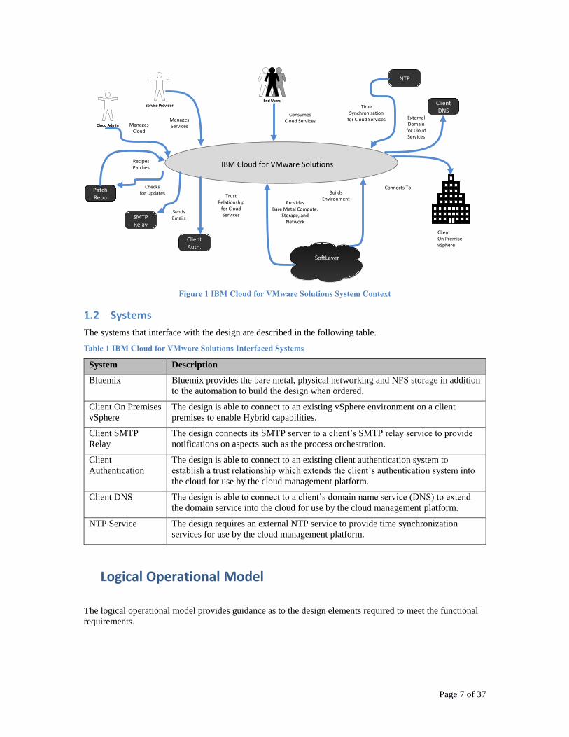
Figure 1 IBM Cloud for VMware Solutions System Context........................................................................ 7
Figure 2 Logical Structure View ........................................................................................................................... 8
Figure 3 Component Interaction Diagram ....................................................................................................... 9
Figure 4 Physical Operational Model - Virtual Servers, Networking and Clusters ........................ 13
Figure 5 Virtual Application Network Components and Design ........................................................... 14
Figure 6 vRA Virtual Network Design ............................................................................................................. 15
Figure 7 vRealize Automation Conceptual Design ..................................................................................... 16
Figure 8 vRealize Automation Design Overview......................................................................................... 18
Figure 10 Tenant Design for Single Region ................................................................................................... 23
Figure 12 vRealize Automation Integration with vSphere Endpoint – Central Cloud .................. 28
Figure 14 Template Synchronization .............................................................................................................. 30
Figure 15 Software Orchestration Logical Design ...................................................................................... 34
List of Tables
Table 1 IBM Cloud for VMware Solutions Interfaced Systems 7
Table 3 Cloud Management Services Components 17
Table 4 Load Balancer Application Profile 20
Table 5 Load Balancer Service Monitoring Configuration 20
Table 6 Load Balancer Pool Specifications 21
Table 7 Virtual Server Characteristics 21
Table 8 Base Windows Server Blueprint 25
Table 9 Base Windows Blueprint Sizing 25
Table 10 Base Linux Server Blueprint 25
Table 11 Base Linux Blueprint Sizing 26
Table 12 vRealize Integration with vSphere 26
Table 13 vRealize Orchestrator Default Configuration Ports 31
Table 14 vRealize Orchestrator Default External Communication Ports 31
Table 15 Software Orchestration Components Sizing 35
Table 16 Software Bill of Materials 36
Table 17 List of Management Cluster Virtual Machines and Sizes 36
Page 4 of 37 Copyright IBM and VMware
Summary of Changes This section records the history of significant changes to this document.
Version Date Author Description of Change
1.0 2017-01-30 IBM Cloud Initial release of vRealize Automation 7.2
Page 5 of 37
Architecture Overview
IBM Cloud for VMware Solutions provides standardized, automated deployments of a VMware
infrastructure on Bluemix. The base deployment can be extended with tooling such as VMware automation
and orchestration technology. vRealize Automation (VRA)and vRealize Optimization (VRO) provide the
primary interface to the users to consume cloud services in addition to the orchestration engines to process
the service requests. The self-service portal is used as the primary interface to view the available cloud
services (the service catalog) as well as to obtain a view of existing cloud resources that are deployed. The
service catalog is the list of available services that are managed by the service provider. The service
provider is able to determine which services are available to specific users or groups. The process
orchestration engine controls the steps required to perform a service. This includes actions such as,
obtaining an approval or connecting to an operational service system as part of the process. The process
orchestration engine calls the infrastructure orchestration engine to orchestrate the build of the virtual
resources for a service. The software orchestration engine builds the software that runs on the virtual
resources.
1.1 Pre-requisites
The design requires the following pre-requisites:
Client is required to acquire all necessary software licenses and/or keys for all products used in
this design prior to commencement of implementation
Client is required to provide Bluemix account
Client is responsible for Bluemix related charges as a result of this design’s implementation
Client is responsible for connectivity from this design to any on premises environment or systems
Client is responsible for connectivity into this design for access by administrators and end users
Client is responsible to acquire and provide domain name
Client to provide connection details and necessary credentials for any systems external to this
design that are to be integrated
Client is responsible for licensing of any software products provisioned with the design
Download all appliances
vRealize Automation 7.2 Appliance (ova file). The file can be download from
http://downloads.service.Bluemix.com/https://my.vmware.com/group/vmware/info/slug/i
nfrastructure_operations_management/vmware_vrealize_automation/7_2
vRA hostnames and static IP addresses all need to be registered in DNS.
2 vRA Core Appliance
2 Web + Model Manager (Win2k12 R2)
2 Manager Service + DEM Orchestrator (Win2k12 R2)
2 DEM Worker (Win2k12 R2)
2 Proxy Agent (Win2k12 R2)
1 MSSQL (Win2k12 R2)
Active Directory
• Configured and accessible for the environment.
• Allow vRA service account ability to create organization units.
Create dedicated service account/group
vRA service account (see account requirement details below)
Need local admin rights to all IaaS machine
Log on as a batch job right
Log on as a service right
Access to create DB with "sysadmin" role privileges in case it doesn’t
exist at the time of the installation.
Page 6 of 37 Copyright IBM and VMware
vRO service account (see account requirement details below)
Full access to compute resources (vCenter admin role)
vCenter servers for endpoint setup
Access to MSSQL database
Create separate MSSQL (2012) instance for vRA. It is highly recommended this
is setup in a dedicated server for vRA.
Need dedicated service account with "sysadmin" role provided
TCP/IP protocol enabled for MS SQL Server
Microsoft Distributed Transaction Coordinator Service (MS DTC) enabled on
all SQL nodes in the system
Firewall ports
No Firewall between all vRA components/Database/vCenter. If firewall exists,
open all necessary ports. Link to ports requirement can be found here.
Access to inbound/outbound email
Need dedicated email account for vRA system and approval notifications
vcacadmin@<domain>.com (uid/password if needed)
NTP server hostname or IP address
Provide vSphere templates (Windows 2012 R2 / Linux 7.x)
Create vRA Groups in AD (see account requirement details below)
Generate CA certificate for all vRA components (select an option from below)
Individual CA certs
Single cert with subject alternative names (SANs)
Wildcard domain cert
Configure the Load Balancer for use with vRealize Automation in an HA Configuration.
VMware guidance for Load Balancer configuration can be found here.
System Context The following are the external actors and systems that interface with the design.
Page 7 of 37
SoftLayer
IBM Cloud for VMware Solutions
ClientOn PremisevSphere
Connects To
ManagesCloud
ConsumesCloud Services
ProvidesBare Metal Compute,
Storage, andNetwork
SendsEmails
TrustRelationship
for CloudServices
ExternalDomain
for CloudServices
TimeSynchronisation
for Cloud Services
BuildsEnvironment
ManagesServices
NTP
ClientDNS
ClientAuth.
SMTPRelay
PatchRepo
Checksfor Updates
RecipesPatches
End UsersEnd UsersService ProviderService Provider
Cloud AdminCloud Admin
Figure 1 IBM Cloud for VMware Solutions System Context
1.2 Systems
The systems that interface with the design are described in the following table.
Table 1 IBM Cloud for VMware Solutions Interfaced Systems
System Description
Bluemix Bluemix provides the bare metal, physical networking and NFS storage in addition
to the automation to build the design when ordered.
Client On Premises
vSphere
The design is able to connect to an existing vSphere environment on a client
premises to enable Hybrid capabilities.
Client SMTP
Relay
The design connects its SMTP server to a client’s SMTP relay service to provide
notifications on aspects such as the process orchestration.
Client
Authentication
The design is able to connect to an existing client authentication system to
establish a trust relationship which extends the client’s authentication system into
the cloud for use by the cloud management platform.
Client DNS The design is able to connect to a client’s domain name service (DNS) to extend
the domain service into the cloud for use by the cloud management platform.
NTP Service The design requires an external NTP service to provide time synchronization
services for use by the cloud management platform.
Logical Operational Model
The logical operational model provides guidance as to the design elements required to meet the functional
requirements.
Page 8 of 37 Copyright IBM and VMware
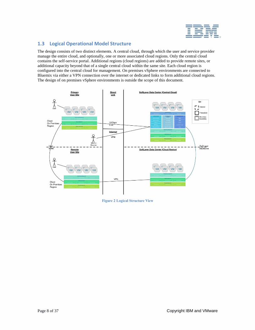
1.3 Logical Operational Model Structure
The design consists of two distinct elements. A central cloud, through which the user and service provider
manage the entire cloud, and optionally, one or more associated cloud regions. Only the central cloud
contains the self-service portal. Additional regions (cloud regions) are added to provide remote sites, or
additional capacity beyond that of a single central cloud within the same site. Each cloud region is
configured into the central cloud for management. On premises vSphere environments are connected to
Bluemix via either a VPN connection over the internet or dedicated links to form additional cloud regions.
The design of on premises vSphere environments is outside the scope of this document.
Figure 2 Logical Structure View
Page 9 of 37
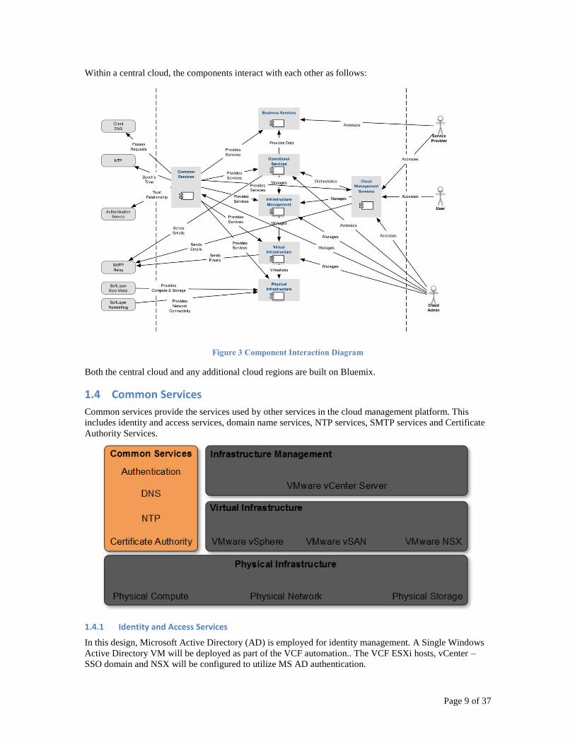
Within a central cloud, the components interact with each other as follows:
Figure 3 Component Interaction Diagram
Both the central cloud and any additional cloud regions are built on Bluemix.
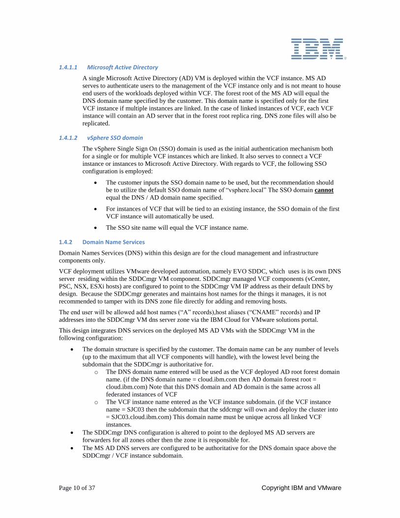
1.4 Common Services
Common services provide the services used by other services in the cloud management platform. This
includes identity and access services, domain name services, NTP services, SMTP services and Certificate
Authority Services.
1.4.1 Identity and Access Services
In this design, Microsoft Active Directory (AD) is employed for identity management. A Single Windows
Active Directory VM will be deployed as part of the VCF automation.. The VCF ESXi hosts, vCenter –
SSO domain and NSX will be configured to utilize MS AD authentication.
Page 10 of 37 Copyright IBM and VMware
1.4.1.1 Microsoft Active Directory
A single Microsoft Active Directory (AD) VM is deployed within the VCF instance. MS AD
serves to authenticate users to the management of the VCF instance only and is not meant to house
end users of the workloads deployed within VCF. The forest root of the MS AD will equal the
DNS domain name specified by the customer. This domain name is specified only for the first
VCF instance if multiple instances are linked. In the case of linked instances of VCF, each VCF
instance will contain an AD server that in the forest root replica ring. DNS zone files will also be
replicated.
1.4.1.2 vSphere SSO domain
The vSphere Single Sign On (SSO) domain is used as the initial authentication mechanism both
for a single or for multiple VCF instances which are linked. It also serves to connect a VCF
instance or instances to Microsoft Active Directory. With regards to VCF, the following SSO
configuration is employed:
The customer inputs the SSO domain name to be used, but the recommendation should
be to utilize the default SSO domain name of “vsphere.local” The SSO domain cannot
equal the DNS / AD domain name specified.
For instances of VCF that will be tied to an existing instance, the SSO domain of the first
VCF instance will automatically be used.
The SSO site name will equal the VCF instance name.
1.4.2 Domain Name Services
Domain Names Services (DNS) within this design are for the cloud management and infrastructure
components only.
VCF deployment utilizes VMware developed automation, namely EVO SDDC, which uses is its own DNS
server residing within the SDDCmgr VM component. SDDCmgr managed VCF components (vCenter,
PSC, NSX, ESXi hosts) are configured to point to the SDDCmgr VM IP address as their default DNS by
design. Because the SDDCmgr generates and maintains host names for the things it manages, it is not
recommended to tamper with its DNS zone file directly for adding and removing hosts.
The end user will be allowed add host names (“A” records),host aliases (“CNAME” records) and IP
addresses into the SDDCmgr VM dns server zone via the IBM Cloud for VMware solutions portal.
This design integrates DNS services on the deployed MS AD VMs with the SDDCmgr VM in the
following configuration:
The domain structure is specified by the customer. The domain name can be any number of levels
(up to the maximum that all VCF components will handle), with the lowest level being the
subdomain that the SDDCmgr is authoritative for.
o The DNS domain name entered will be used as the VCF deployed AD root forest domain
name. (if the DNS domain name = cloud.ibm.com then AD domain forest root =
cloud.ibm.com) Note that this DNS domain and AD domain is the same across all
federated instances of VCF
o The VCF instance name entered as the VCF instance subdomain. (if the VCF instance
name = SJC03 then the subdomain that the sddcmgr will own and deploy the cluster into
= SJC03.cloud.ibm.com) This domain name must be unique across all linked VCF
instances.
The SDDCmgr DNS configuration is altered to point to the deployed MS AD servers are
forwarders for all zones other then the zone it is responsible for.
The MS AD DNS servers are configured to be authoritative for the DNS domain space above the
SDDCmgr / VCF instance subdomain.
Page 11 of 37
The MS AD DNS servers are configured to point to the SDDCmgr IP address for the subdomain
delegation of the zone the SDDCmgr is authoritative for.
ANY Secondary cloud regions that are to be integrated to the first or target deployed cloud region
must utilize the same DNS name structure above the SDDCmgr subdomain.
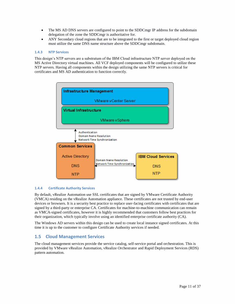
1.4.3 NTP Services
This design’s NTP servers are a substratum of the IBM Cloud infrastructure NTP server deployed on the
MS Active Directory virtual machines. All VCF deployed components will be configured to utilize these
NTP servers. Having all components within the design utilizing the same NTP servers is critical for
certificates and MS AD authentication to function correctly.
1.4.4 Certificate Authority Services
By default, vRealize Automation use SSL certificates that are signed by VMware Certificate Authority
(VMCA) residing on the vRealize Automation appliance. These certificates are not trusted by end-user
devices or browsers. It is a security best practice to replace user-facing certificates with certificates that are
signed by a third-party or enterprise CA. Certificates for machine-to-machine communication can remain
as VMCA-signed certificates, however it is highly recommended that customers follow best practices for
their organization, which typically involve using an identified enterprise certificate authority (CA).
The Windows AD servers within this design can be used to create local instance signed certificates. At this
time it is up to the customer to configure Certificate Authority services if needed.
1.5 Cloud Management Services
The cloud management services provide the service catalog, self-service portal and orchestration. This is
provided by VMware vRealize Automation, vRealize Orchestrator and Rapid Deployment Services (RDS)
pattern automation.
Page 12 of 37 Copyright IBM and VMware
1.5.1 Service Catalog
The service catalog is published through the self service catalog and allows users to request the provided
services which can include provisioning new virtual machines from templates, provisioning new
environments consisting of one or more virtual machines with software products as blueprints (also known
as patterns), or managing existing deployed resources. Advanced services are also available through the
service catalog by calling the orchestration component for process orchestration.
The service provider role is able to customize the services available to users as well as publish additional
services.
1.5.2 Self-Service Portal
The self service portal provides a single point of access for users to the IBM Cloud for VMware Solutions
solution. Authentication to the portal is performed against the Active Directory service.
1.5.3 Infrastructure and Process Orchestration
Orchestration is provided by vRealize Orchestrator. It allows for tasks and remediation actions to be
automated including integration with third party IT operations software.
vRealize Orchestrator consists of:
Workflow designer which incorporates an easy-to-use drag and drop interface to assemble
workflows. The designer runs on Windows, Linux and Mac OS desktops.
Scripting designer which allows for new building blocks to be created or imported for the vRealize
Orchestrator platform.
Orchestration engine which runs the workflows and associated scripts.
The default implementation includes a built-in workflow library with common tasks. Workflows are able to
be versioned and packaged to assist with change management.
1.5.4 Software Orchestration
Software Orchestration is provided by a Rapid Deployment Services (RDS) solution with IBM Open
Patterns. RDS implements a distributed file repository and the configuration management tools to deliver
IBM Open Patterns on deployed workloads. IBM Open Patterns describe the pre-defined architecture of
an application. For each component of the application (i.e. database, web server, etc.), the pattern defines:
Pre-installation on an operating system Pre-integration across components Pre-configured & tuned Pre-configured Monitoring Pre-configured Security Lifecycle Management
Page 13 of 37
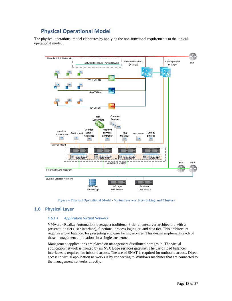
Physical Operational Model The physical operational model elaborates by applying the non-functional requirements to the logical
operational model.
Chef &BinariesChef &
BinariesNSX
ManagerNSX
Manager
Common ServicesCommon Services
NSX Controllers
NSX Controllers
vCenter Server
Appliance
vCenter Server
Appliance
Platform Services
Controller
Platform Services
Controller
Internal-Mgmt
Bluemix Private Network
BCR
Bluemix Public Network
Web VXLAN
App VXLAN
DB VXLAN
SoftLayer File Storage
SoftLayerNTP Service
SoftLayerDNS Service
Bluemix Services Network
Converged Cluster
ESG-Mgmt-NS (X Large)
SSD SSDSSDSSDVSAN
networkExchange Transit Nework
SQL ServervRealize IaaSvRealize
Automation
FCR
MBR
ESG-Workload-NS (X Large)
Figure 4 Physical Operational Model - Virtual Servers, Networking and Clusters
1.6 Physical Layer
1.6.1.1 Application Virtual Network
VMware vRealize Automation leverage a traditional 3-tier client/server architecture with a
presentation tier (user interface), functional process logic tier, and data tier. This architecture
requires a load balancer for presenting end-user facing services. This design implements each of
these management applications in a single trust zone.
Management applications are placed on management distributed port group. The virtual
application network is fronted by an NSX Edge services gateway. The use of load balancer
interfaces is required for inbound access. The use of SNAT is required for outbound access. Direct
access to virtual application networks is by connecting to Windows machines that are connected to
the management networks directly.
Page 14 of 37 Copyright IBM and VMware
IBM Bluemix private portable addressing is required for all management applications. This
approach to network virtualization service design improves security and mobility of the
management applications, and reduces the integration effort with existing customer networks.
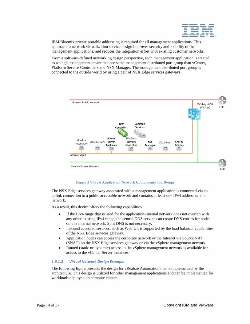
From a software-defined networking design perspective, each management application is treated
as a single management tenant that use same management distributed port group than vCenter,
Platform Service Controllers and NSX Manager. The management distributed port group is
connected to the outside world by using a pair of NSX Edge services gateways.
Chef &BinariesChef &
BinariesNSX
ManagerNSX
Manager
Common ServicesCommon Services
NSX Controllers
NSX Controllers
vCenter Server
Appliance
vCenter Server
Appliance
Platform Services
Controller
Platform Services
Controller
Internal-Mgmt
Bluemix Private NetworkBCR
Bluemix Public NetworkESG-Mgmt-NS
(X Large)
SQL ServervRealize IaaSvRealize
Automation
FCR
Figure 5 Virtual Application Network Components and Design
The NSX Edge services gateway associated with a management application is connected via an
uplink connection to a public accessible network and contains at least one IPv4 address on this
network.
As a result, this device offers the following capabilities.
If the IPv4 range that is used for the application-internal network does not overlap with
any other existing IPv4 range, the central DNS service can create DNS entries for nodes
on this internal network. Split DNS is not necessary.
Inbound access to services, such as Web UI, is supported by the load balancer capabilities
of the NSX Edge services gateway.
Application nodes can access the corporate network or the Internet via Source NAT
(SNAT) on the NSX Edge services gateway or via the vSphere management network.
Routed (static or dynamic) access to the vSphere management network is available for
access to the vCenter Server instances.
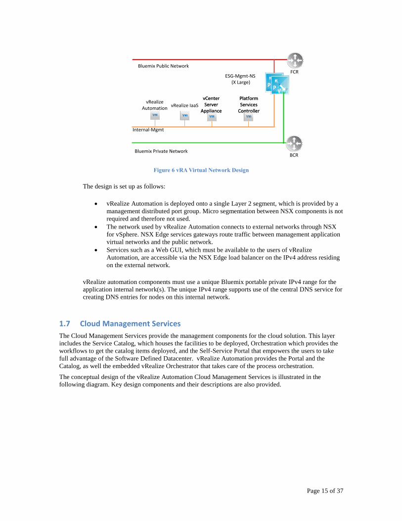
1.6.1.2 Virtual Network Design Example
The following figure presents the design for vRealize Automation that is implemented by the
architecture. This design is utilized for other management applications and can be implemented for
workloads deployed on compute cluster.
Page 15 of 37
vCenter Server
Appliance
vCenter Server
Appliance
Platform Services
Controller
Platform Services
Controller
Internal-Mgmt
Bluemix Private NetworkBCR
Bluemix Public Network
ESG-Mgmt-NS (X Large)
vRealize IaaSvRealize
Automation
FCR
Figure 6 vRA Virtual Network Design
The design is set up as follows:
vRealize Automation is deployed onto a single Layer 2 segment, which is provided by a
management distributed port group. Micro segmentation between NSX components is not
required and therefore not used.
The network used by vRealize Automation connects to external networks through NSX
for vSphere. NSX Edge services gateways route traffic between management application
virtual networks and the public network.
Services such as a Web GUI, which must be available to the users of vRealize
Automation, are accessible via the NSX Edge load balancer on the IPv4 address residing
on the external network.
vRealize automation components must use a unique Bluemix portable private IPv4 range for the
application internal network(s). The unique IPv4 range supports use of the central DNS service for
creating DNS entries for nodes on this internal network.
1.7 Cloud Management Services
The Cloud Management Services provide the management components for the cloud solution. This layer
includes the Service Catalog, which houses the facilities to be deployed, Orchestration which provides the
workflows to get the catalog items deployed, and the Self-Service Portal that empowers the users to take
full advantage of the Software Defined Datacenter. vRealize Automation provides the Portal and the
Catalog, as well the embedded vRealize Orchestrator that takes care of the process orchestration.
The conceptual design of the vRealize Automation Cloud Management Services is illustrated in the
following diagram. Key design components and their descriptions are also provided.
Page 16 of 37 Copyright IBM and VMware
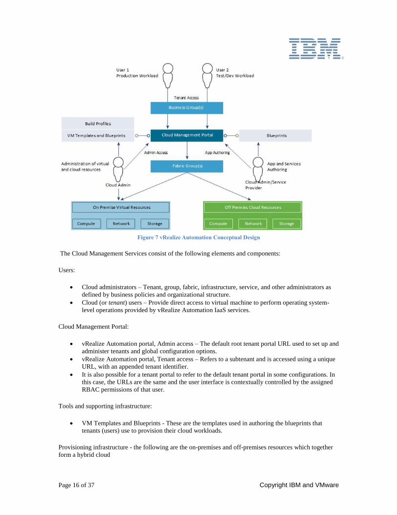
Figure 7 vRealize Automation Conceptual Design
The Cloud Management Services consist of the following elements and components:
Users:
Cloud administrators – Tenant, group, fabric, infrastructure, service, and other administrators as
defined by business policies and organizational structure.
Cloud (or tenant) users – Provide direct access to virtual machine to perform operating system-
level operations provided by vRealize Automation IaaS services.
Cloud Management Portal:
vRealize Automation portal, Admin access – The default root tenant portal URL used to set up and
administer tenants and global configuration options.
vRealize Automation portal, Tenant access – Refers to a subtenant and is accessed using a unique
URL, with an appended tenant identifier.
It is also possible for a tenant portal to refer to the default tenant portal in some configurations. In
this case, the URLs are the same and the user interface is contextually controlled by the assigned
RBAC permissions of that user.
Tools and supporting infrastructure:
VM Templates and Blueprints - These are the templates used in authoring the blueprints that
tenants (users) use to provision their cloud workloads.
Provisioning infrastructure - the following are the on-premises and off-premises resources which together
form a hybrid cloud
Page 17 of 37
Virtual – Supported hypervisors and associated management tools.
Cloud – Supported cloud providers and associated API interfaces.
In the above diagram illustrating the conceptual design of the Cloud Management Platform, these
resources are located in the Internal Virtual Resources and the External Cloud Resources
components.
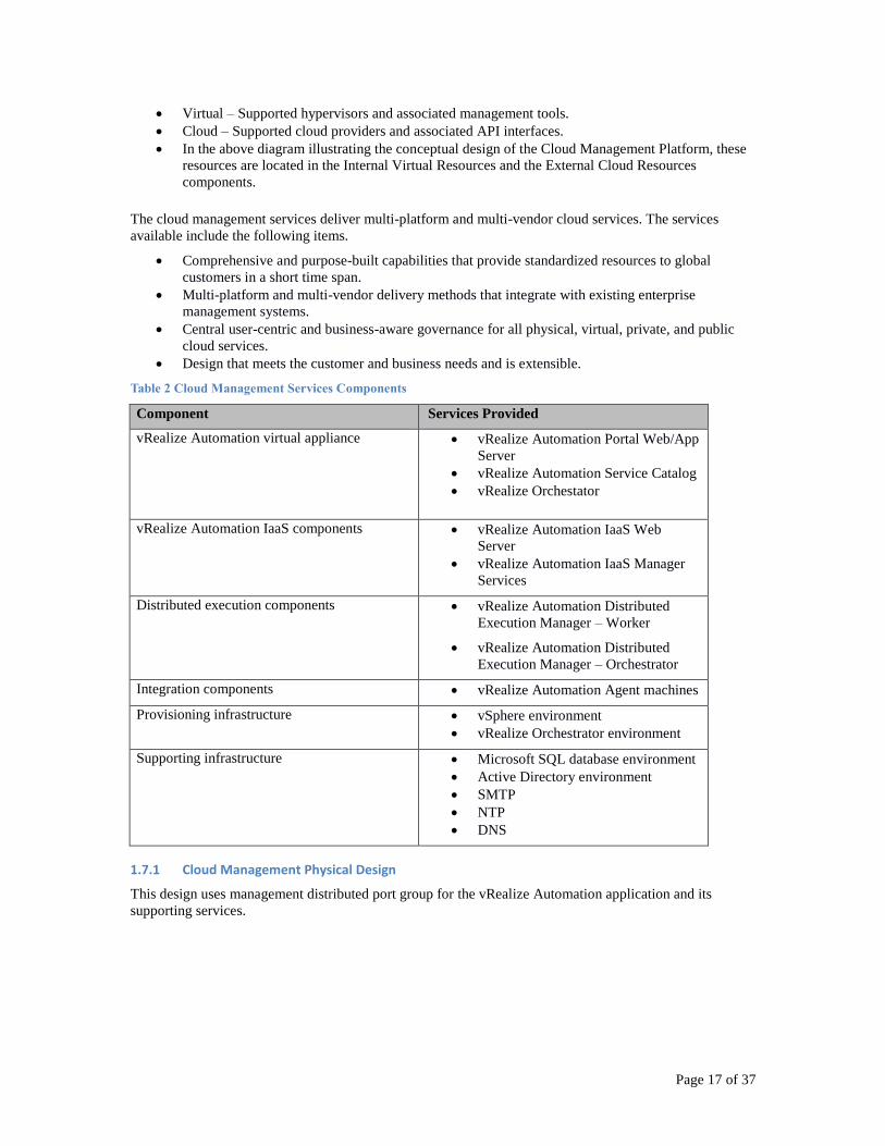
The cloud management services deliver multi-platform and multi-vendor cloud services. The services
available include the following items.
Comprehensive and purpose-built capabilities that provide standardized resources to global
customers in a short time span.
Multi-platform and multi-vendor delivery methods that integrate with existing enterprise
management systems.
Central user-centric and business-aware governance for all physical, virtual, private, and public
cloud services.
Design that meets the customer and business needs and is extensible.
Table 2 Cloud Management Services Components
Component Services Provided
vRealize Automation virtual appliance vRealize Automation Portal Web/App
Server
vRealize Automation Service Catalog
vRealize Orchestator
vRealize Automation IaaS components vRealize Automation IaaS Web
Server
vRealize Automation IaaS Manager
Services
Distributed execution components vRealize Automation Distributed
Execution Manager – Worker
vRealize Automation Distributed
Execution Manager – Orchestrator
Integration components vRealize Automation Agent machines
Provisioning infrastructure vSphere environment
vRealize Orchestrator environment
Supporting infrastructure Microsoft SQL database environment
Active Directory environment
SMTP
NTP
DNS
1.7.1 Cloud Management Physical Design
This design uses management distributed port group for the vRealize Automation application and its
supporting services.
Page 18 of 37 Copyright IBM and VMware
IWS 1
OS
MSSQL
OS
IMS
OS
IMS
OS
DEM 1
OS
DEM 2
OS
SVR 1
OS
IWS 2
OS
IAS 1
OS
IAS 2
OS
Active
SVR 1
OS
Active Standalone Active PassiveActive ActiveActive Active Active Active
vRA
ESXi Resource Cluster(s) vCenter Server NSX Manager
Active Directory DNS SMTP
Access Network
Admin Network
vRAEnd User
CloudAdmin
Abbreviations
vRA vRealize AutomationDEM Distributed Execution ManagerDNS Domain Name SystemSVR vRA ApplianceIWS IaaS Web ServerIMS IaaS Manager ServiceIAS IaaS vSphere Proxy Agent
MgmtCentral-Edge Load Balancer
MgmtCentral-Edge Load Balancer
Cluster
Management NetworkvRA
End User
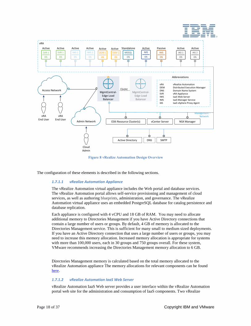
Figure 8 vRealize Automation Design Overview
The configuration of these elements is described in the following sections.
1.7.1.1 vRealize Automation Appliance
The vRealize Automation virtual appliance includes the Web portal and database services.
The vRealize Automation portal allows self-service provisioning and management of cloud
services, as well as authoring blueprints, administration, and governance. The vRealize
Automation virtual appliance uses an embedded PostgreSQL database for catalog persistence and
database replication.
Each appliance is configured with 4 vCPU and 18 GB of RAM. You may need to allocate
additional memory to Directories Management if you have Active Directory connections that
contain a large number of users or groups. By default, 4 GB of memory is allocated to the
Directories Management service. This is sufficient for many small to medium sized deployments.
If you have an Active Directory connection that uses a large number of users or groups, you may
need to increase this memory allocation. Increased memory allocation is appropriate for systems
with more than 100,000 users, each in 30 groups and 750 groups overall. For these system,
VMware recommends increasing the Directories Management memory allocation to 6 GB.
Directories Management memory is calculated based on the total memory allocated to the
vRealize Automation appliance The memory allocations for relevant components can be found
here.
1.7.1.2 vRealize Automation IaaS Web Server
vRealize Automation IaaS Web server provides a user interface within the vRealize Automation
portal web site for the administration and consumption of IaaS components. Two vRealize
Page 19 of 37
Automation IaaS web servers are installed on virtual machines. Each virtual machine runs
Microsoft Windows Server 2012 R2 and it performs Model Manager (Web) and IaaS Web
functions. Each virtual machine is sized to 4 vCPU, 4 GB of RAM and 60 GB HDD.
1.7.1.3 vRealize Automation IaaS Manager Service and DEM Orchestrator Server
The vRealize Automation IaaS Manager Service and Distributed Execution Management (DEM)
server are at the core of the vRealize Automation IaaS platform. The vRealize Automation IaaS
Manager Service and DEM server supports several functions.
Manages the integration of vRealize Automation IaaS with external systems and
databases.
Provides business logic to the DEMs.
Manages business logic and execution policies.
Maintains all workflows and their supporting constructs.
A Distributed Execution Manager (DEM) runs the business logic of custom models, interacting
with the database and with external databases and systems as required. DEMs also manage cloud
and physical machines. The DEM Orchestrator monitors the status of the DEM workers. DEM
worker manages the scheduled workflows by creating new workflow instances at the scheduled
time and allows only one instance of a particular scheduled workflow to run at a given time. It also
preprocesses workflows before execution. Preprocessing includes checking preconditions for
workflows and creating the workflow's execution history.
The vRealize Automation IaaS Manager Service and DEM server are separate servers, but are
installed on the same virtual machine.
Two virtual machines are deployed to run both IaaS Manager Service and DEM Orchestrator. The
two servers share the same active/passive application model. Only one manager service can be
active at a time.
Each virtual machine runs Microsoft Windows Server 2012 R2. Each virtual machine is sized to 4
vCPU, 8 GB of RAM and 60 GB HDD.
1.7.1.4 vRealize Automation IaaS DEM Worker Server
vRealize Automation IaaS DEM workers are responsible for the provisioning and deprovisioning
tasks initiated by the vRealize Automation portal. DEM workers communicate with vRealize
Automation endpoints. In this instance, the endpoint is vCenter Server.
Each DEM Worker can process up to 30 concurrent workflows. Beyond this limit, workflows are
queued for execution. The current design implements 2 DEM workers for a total of 60 concurrent
workflows.
DEM Workers are installed on two virtual machines running Microsoft Windows Server 2012 R2.
Each virtual machine is sized to 2 vCPU, 4 GB of RAM and 60 GB HDD.
1.7.1.5 vRealize Automation IaaS Proxy Agent
The vRealize Automation IaaS Proxy Agent is a Windows program that caches and forwards
information gathering from vCenter Server back to vRealize Automation. The IaaS Proxy Agent
server provides the following functions.
vRealize Automation IaaS Proxy Agent can interact with different types of hypervisors
such as vSphere, Hyper-V and Xen. For this design, only the vSphere agent is used.
vRealize Automation does not virtualize resources by itself, but works with vCenter
Server to provision and manage the virtual machines. It uses vSphere agents to send
commands to and collect data from vCenter Server.
Two vRealize Automation vSphere Proxy Agent virtual machines per vCenter are deployed in the
current architecture. The virtual machines are deployed on a dedicated virtual network to decouple
them from the main vRealize Automation infrastructure allowing.
Page 20 of 37 Copyright IBM and VMware
Each virtual machine runs Microsoft Windows Server 2012 R2. Each virtual machine is sized to 2
vCPU, 4 GB of RAM and 60 GB HDD.
1.7.1.6 Load Balancer
Session persistence of a load balancer allows the same server to serve all requests after a session is
established with that server. The session persistence is enabled on the load balancer to direct
subsequent requests from each unique session to the same vRealize Automation server in the load
balancer pool.
The load balancer also handles failover for the vRealize Automation Server (Manager Service).
Only one Manager Service is active at any one time. Manual failover of Manager Service is
necessary. Session persistence is not enabled because it is not a required component for the
Manager Service.
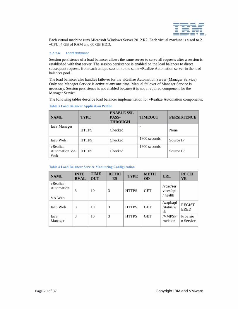
The following tables describe load balancer implementation for vRealize Automation components:
Table 3 Load Balancer Application Profile
NAME TYPE
ENABLE SSL
PASS-
THROUGH
TIMEOUT PERSISTENCE
IaaS Manager HTTPS Checked
- None
IaaS Web HTTPS Checked 1800 seconds Source IP
vRealize
Automation VA
Web
HTTPS Checked
1800 seconds
Source IP
Table 4 Load Balancer Service Monitoring Configuration
NAME INTE
RVAL
TIME
OUT
RETRI
ES TYPE
METH
OD URL
RECEI
VE
vRealize
Automation
VA Web
3 10 3 HTTPS GET
/vcac/ser
vices/api
/ health
IaaS Web 3 10 3 HTTPS GET
/wapi/api
/status/w
eb
REGIST
ERED
IaaS
Manager
3 10 3 HTTPS GET /VMPSP
rovision
Provisio
n Service
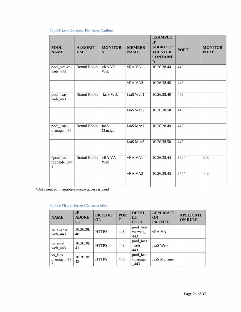
Page 21 of 37
Table 5 Load Balancer Pool Specifications
POOL
NAME
ALGORIT
HM
MONITOR
S
MEMBER
NAME
EXAMPLE
IP
ADDRESS /
VCENTER
CONTAINE
R
PORT MONITOR
PORT
pool_vra-va-
web_443
Round Robin vRA VA
Web
vRA VA1 10.26.38.44 443
vRA VA2 10.26.38.45 443
pool_iaas-
web_443
Round Robin IaaS Web IaaS Web1 10.26.38.49 443
IaaS Web2 10.26.38.50 443
pool_iaas-
manager_44
3
Round Robin IaaS
Manager
IaaS Man1 10.26.38.49 443
IaaS Man2 10.26.38.50 443
*pool_vra-
rconsole_844
4
Round Robin vRA VA
Web
vRA VA1 10.26.38.44 8444 443
vRA VA2 10.26.38.45 8444 443
*Only needed if remote-console access is used
Table 6 Virtual Server Characteristics
NAME
IP
ADDRE
SS
PROTOC
OL
POR
T
DEFAU
LT
POOL
APPLICATI
ON
PROFILE
APPLICATI
ON RULE
vs_vra-va-
web_443
10.26.38.
40 HTTPS 443
pool_vra-
va-web_
443
vRA VA
vs_iaas-
web_443
10.26.38.
41 HTTPS 443
pool_iaas
-web_
443
IaaS Web
vs_iaas-
manager_44
3
10.26.38.
42 HTTPS 443
pool_iaas
-manager
_443
IaaS Manager
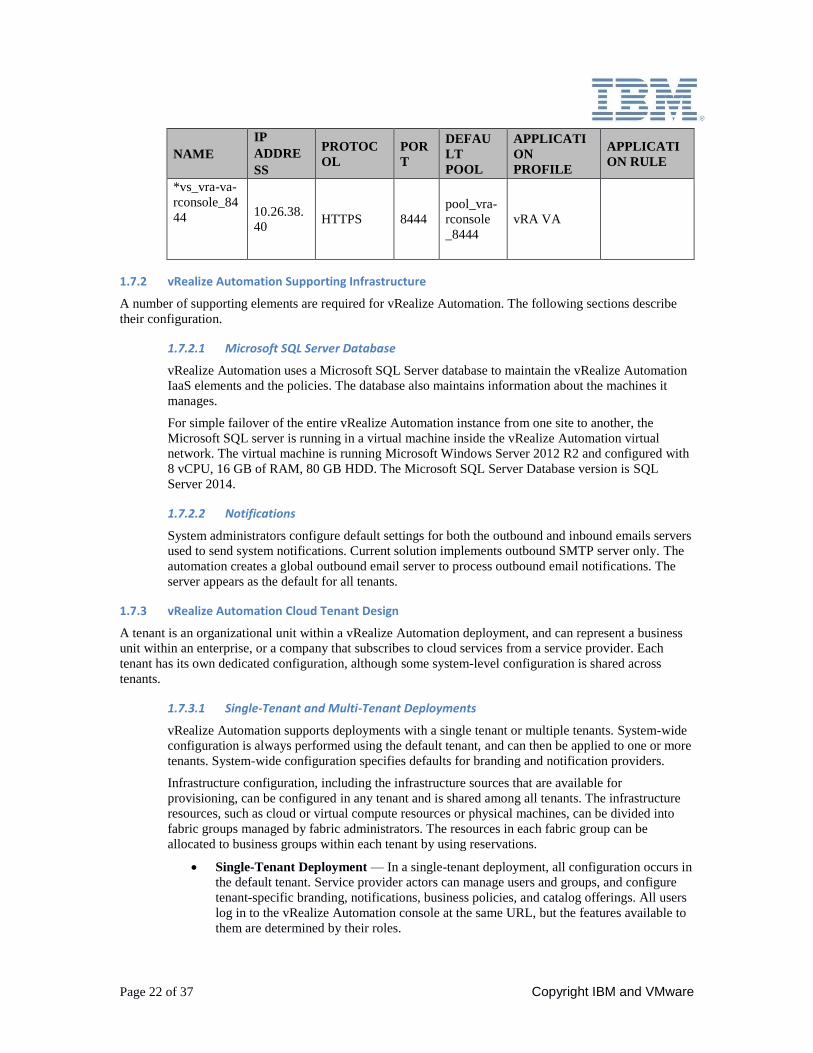
Page 22 of 37 Copyright IBM and VMware
NAME
IP
ADDRE
SS
PROTOC
OL
POR
T
DEFAU
LT
POOL
APPLICATI
ON
PROFILE
APPLICATI
ON RULE
*vs_vra-va-
rconsole_84
44
10.26.38.
40 HTTPS 8444
pool_vra-
rconsole
_8444
vRA VA
1.7.2 vRealize Automation Supporting Infrastructure
A number of supporting elements are required for vRealize Automation. The following sections describe
their configuration.
1.7.2.1 Microsoft SQL Server Database
vRealize Automation uses a Microsoft SQL Server database to maintain the vRealize Automation
IaaS elements and the policies. The database also maintains information about the machines it
manages.
For simple failover of the entire vRealize Automation instance from one site to another, the
Microsoft SQL server is running in a virtual machine inside the vRealize Automation virtual
network. The virtual machine is running Microsoft Windows Server 2012 R2 and configured with
8 vCPU, 16 GB of RAM, 80 GB HDD. The Microsoft SQL Server Database version is SQL
Server 2014.
1.7.2.2 Notifications
System administrators configure default settings for both the outbound and inbound emails servers
used to send system notifications. Current solution implements outbound SMTP server only. The
automation creates a global outbound email server to process outbound email notifications. The
server appears as the default for all tenants.
1.7.3 vRealize Automation Cloud Tenant Design
A tenant is an organizational unit within a vRealize Automation deployment, and can represent a business
unit within an enterprise, or a company that subscribes to cloud services from a service provider. Each
tenant has its own dedicated configuration, although some system-level configuration is shared across
tenants.
1.7.3.1 Single-Tenant and Multi-Tenant Deployments
vRealize Automation supports deployments with a single tenant or multiple tenants. System-wide
configuration is always performed using the default tenant, and can then be applied to one or more
tenants. System-wide configuration specifies defaults for branding and notification providers.
Infrastructure configuration, including the infrastructure sources that are available for
provisioning, can be configured in any tenant and is shared among all tenants. The infrastructure
resources, such as cloud or virtual compute resources or physical machines, can be divided into
fabric groups managed by fabric administrators. The resources in each fabric group can be
allocated to business groups within each tenant by using reservations.
Single-Tenant Deployment — In a single-tenant deployment, all configuration occurs in
the default tenant. Service provider actors can manage users and groups, and configure
tenant-specific branding, notifications, business policies, and catalog offerings. All users
log in to the vRealize Automation console at the same URL, but the features available to
them are determined by their roles.
Page 23 of 37
Multi-Tenant Deployment — In a multi-tenant deployment, the system administrator
creates new tenants for each organization that uses the same vRealize Automation
instance. Tenant users log in to the vRealize Automation console at a URL specific to
their tenant. Tenant-level configuration is segregated from other tenants and from the
default tenant, although users with system-wide roles can view and manage configuration
across multiple tenants.
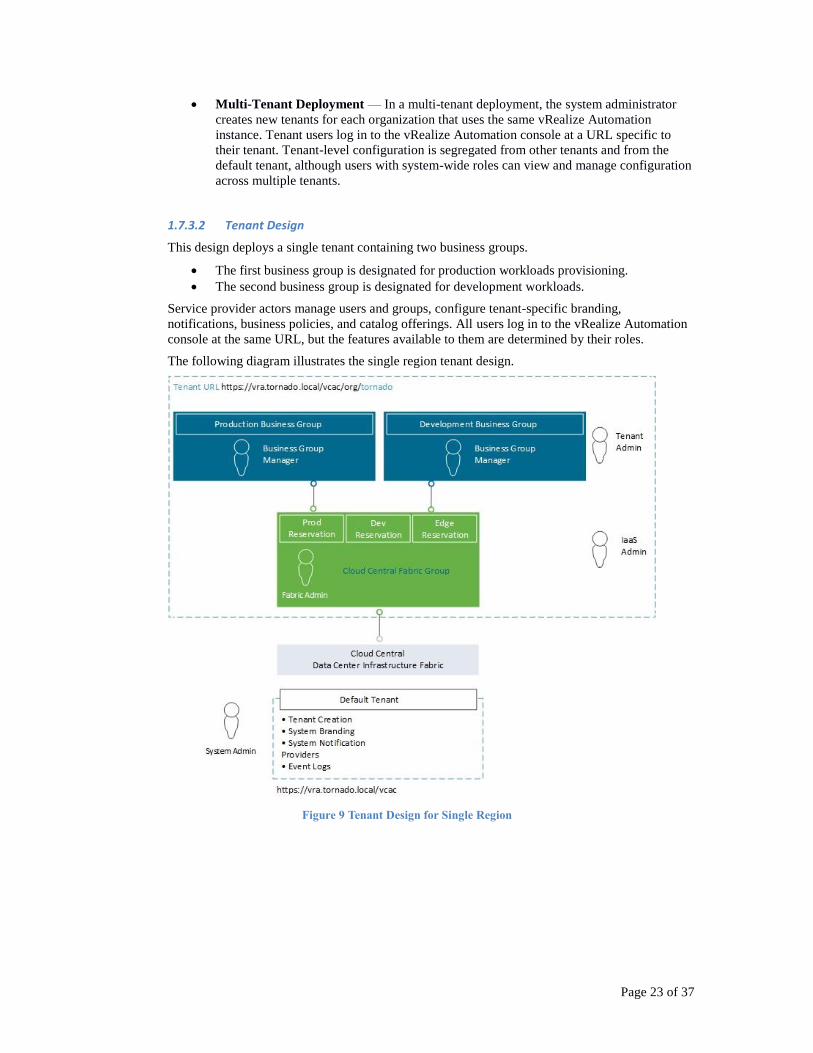
1.7.3.2 Tenant Design
This design deploys a single tenant containing two business groups.
The first business group is designated for production workloads provisioning.
The second business group is designated for development workloads.
Service provider actors manage users and groups, configure tenant-specific branding,
notifications, business policies, and catalog offerings. All users log in to the vRealize Automation
console at the same URL, but the features available to them are determined by their roles.
The following diagram illustrates the single region tenant design.
Figure 9 Tenant Design for Single Region
Page 24 of 37 Copyright IBM and VMware
The tenant has two business groups. One fabric group for the region. Each business group can
consume resources in the region. Access to the default tenant is allowed only by the system
administrator and for the purposes of managing tenants and modifying system-wide
configurations.
This solution configures vRealize Automation based on a single region.
1.7.3.3 Service Design
The service catalog provides a common interface for consumers of IT services to use to request
and manage the services and resources they need.
A service provider actor or service architect can specify information about the service catalog,
such as the service hours, support team, and change window.
The solution implements a service catalog provides the following services:
Central Cloud. Service catalog that is dedicated to the central cloud.
The solution is preinstalled with several catalog items.
1.7.3.4 Catalog Items
Users can browse the service catalog for catalog items they are entitled to request. Several generic
users will be automatically created and entitled to all items in the catalog. The users can be
disabled at a later stage or their permissions modified as appropriate.
For some catalog items, a request results in the provisioning of an item that the user can manage.
For example, the user can request a virtual machine with Windows 2012 preinstalled, and then
manage that virtual machine after it has been provisioned.
The service provider actor defines new catalog items and publish them to the service catalog. The
service provider actor can then manage the presentation of catalog items to the consumer and
entitle new items to consumers. To make the catalog item available to users, a service provider
actor must entitle the item to the users and groups who should have access to it.
A catalog item is defined in a blueprint, which provides a complete specification of the resource to
be provisioned and the process to initiate when the item is requested. It also defines the options
available to a requester of the item, such as virtual machine specifications or lease duration, or any
additional information that the requester is prompted to provide when submitting the request. The
blueprint also specifies custom properties that are applied to the requested resource.
1.7.3.5 Machine Blueprints
A machine blueprint is the complete specification for a virtual machine. A machine blueprint
determines the machine's attributes, how it is provisioned, and its policy and management settings.
Machine blueprints are published as catalog items in the service catalog.
Machine blueprints can be specific to a business group or shared among groups within a tenant. In
this design the preloaded machine blueprints are shared among business groups. Service provider
actors create shared blueprints that can be entitled to users in any business group within the tenant.
Business group managers create group blueprints that can only be entitled to users within a
specific business group. A business group manager cannot modify or delete shared blueprints.
Service provider actors cannot view or modify group blueprints unless they also have the business
group manager role for the appropriate group.
If a service provider actor sets a shared blueprint's properties so that it can be copied, the business
group manager can also copy the shared blueprint for use as a starting point to create a new group
blueprint.
Page 25 of 37
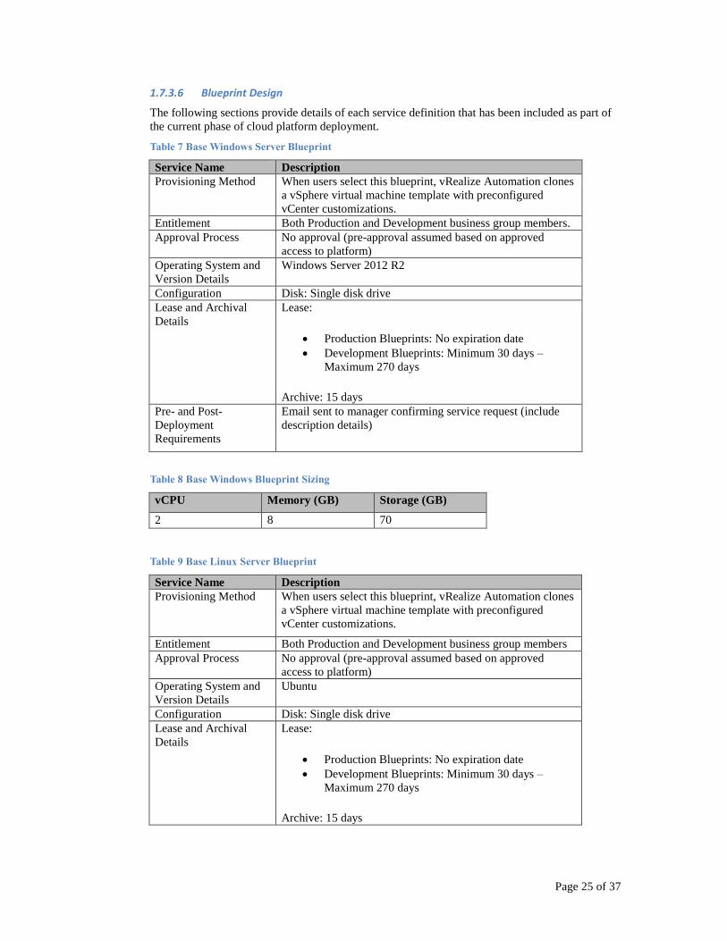
1.7.3.6 Blueprint Design
The following sections provide details of each service definition that has been included as part of
the current phase of cloud platform deployment.
Table 7 Base Windows Server Blueprint
Service Name Description
Provisioning Method When users select this blueprint, vRealize Automation clones
a vSphere virtual machine template with preconfigured
vCenter customizations.
Entitlement Both Production and Development business group members.
Approval Process No approval (pre-approval assumed based on approved
access to platform)
Operating System and
Version Details
Windows Server 2012 R2
Configuration Disk: Single disk drive
Lease and Archival
Details
Lease:
Production Blueprints: No expiration date
Development Blueprints: Minimum 30 days –
Maximum 270 days
Archive: 15 days
Pre- and Post-
Deployment
Requirements
Email sent to manager confirming service request (include
description details)
Table 8 Base Windows Blueprint Sizing
vCPU Memory (GB) Storage (GB)
2 8 70
Table 9 Base Linux Server Blueprint
Service Name Description
Provisioning Method When users select this blueprint, vRealize Automation clones
a vSphere virtual machine template with preconfigured
vCenter customizations.
Entitlement Both Production and Development business group members
Approval Process No approval (pre-approval assumed based on approved
access to platform)
Operating System and
Version Details
Ubuntu
Configuration Disk: Single disk drive
Lease and Archival
Details
Lease:
Production Blueprints: No expiration date
Development Blueprints: Minimum 30 days –
Maximum 270 days
Archive: 15 days
Page 26 of 37 Copyright IBM and VMware
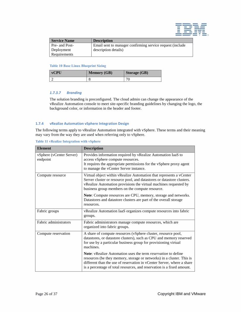
Service Name Description
Pre- and Post-
Deployment
Requirements
Email sent to manager confirming service request (include
description details)
Table 10 Base Linux Blueprint Sizing
vCPU Memory (GB) Storage (GB)
2 8 70
1.7.3.7 Branding
The solution branding is preconfigured. The cloud admin can change the appearance of the
vRealize Automation console to meet site-specific branding guidelines by changing the logo, the
background color, or information in the header and footer.
1.7.4 vRealize Automation vSphere Integration Design
The following terms apply to vRealize Automation integrated with vSphere. These terms and their meaning
may vary from the way they are used when referring only to vSphere.
Table 11 vRealize Integration with vSphere
Element Description
vSphere (vCenter Server)
endpoint
Provides information required by vRealize Automation IaaS to
access vSphere compute resources.
It requires the appropriate permissions for the vSphere proxy agent
to manage the vCenter Server instance.
Compute resource Virtual object within vRealize Automation that represents a vCenter
Server cluster or resource pool, and datastores or datastore clusters.
vRealize Automation provisions the virtual machines requested by
business group members on the compute resource.
Note: Compute resources are CPU, memory, storage and networks.
Datastores and datastore clusters are part of the overall storage
resources.
Fabric groups vRealize Automation IaaS organizes compute resources into fabric
groups.
Fabric administrators Fabric administrators manage compute resources, which are
organized into fabric groups.
Compute reservation A share of compute resources (vSphere cluster, resource pool,
datastores, or datastore clusters), such as CPU and memory reserved
for use by a particular business group for provisioning virtual
machines.
Note: vRealize Automation uses the term reservation to define
resources (be they memory, storage or networks) in a cluster. This is
different than the use of reservation in vCenter Server, where a share
is a percentage of total resources, and reservation is a fixed amount.
Page 27 of 37
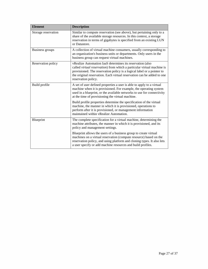
Element Description
Storage reservation Similar to compute reservation (see above), but pertaining only to a
share of the available storage resources. In this context, a storage
reservation in terms of gigabytes is specified from an existing LUN
or Datastore.
Business groups A collection of virtual machine consumers, usually corresponding to
an organization's business units or departments. Only users in the
business group can request virtual machines.
Reservation policy vRealize Automation IaaS determines its reservation (also
called virtual reservation) from which a particular virtual machine is
provisioned. The reservation policy is a logical label or a pointer to
the original reservation. Each virtual reservation can be added to one
reservation policy.
Build profile A set of user defined properties a user is able to apply to a virtual
machine when it is provisioned. For example, the operating system
used in a blueprint, or the available networks to use for connectivity
at the time of provisioning the virtual machine.
Build profile properties determine the specification of the virtual
machine, the manner in which it is provisioned, operations to
perform after it is provisioned, or management information
maintained within vRealize Automation.
Blueprint The complete specification for a virtual machine, determining the
machine attributes, the manner in which it is provisioned, and its
policy and management settings.
Blueprint allows the users of a business group to create virtual
machines on a virtual reservation (compute resource) based on the
reservation policy, and using platform and cloning types. It also lets
a user specify or add machine resources and build profiles.
Page 28 of 37 Copyright IBM and VMware
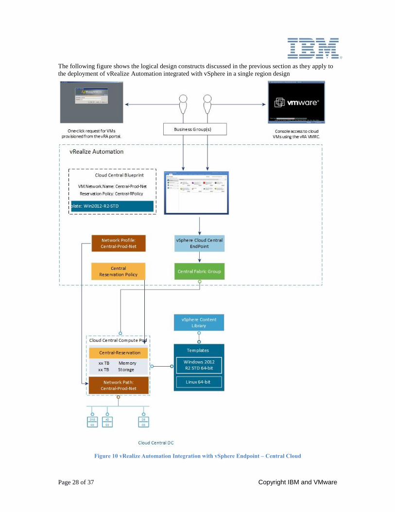
The following figure shows the logical design constructs discussed in the previous section as they apply to
the deployment of vRealize Automation integrated with vSphere in a single region design
Figure 10 vRealize Automation Integration with vSphere Endpoint – Central Cloud
Page 29 of 37
1.7.5 Infrastructure Source Endpoints
An infrastructure source endpoint is a connection to the infrastructure that provides a set (or multiple sets)
of resources, which can then be made available by IaaS administrators for consumption by users. vRealize
Automation IaaS regularly collects information about known endpoint resources and the virtual resources
provisioned therein. Endpoint resources are referred to as compute resources (or as compute pods— the
terms are often used interchangeably).
Infrastructure data is collected through proxy agents that manage and communicate with the endpoint
resources. This information about the compute resources on each infrastructure endpoint and the machines
provisioned on each computer resource is collected at regular intervals.
During solution deployment, the proxy agents and define their associated endpoints are configured
automatically.
1.7.6 Virtualization Compute Resources
A virtualization compute resource is a vRealize Automation object that represents an ESXi host or a cluster
of ESXi hosts (vSphere cluster). When a group member requests a virtual machine, the virtual machine is
provisioned on these compute resources. vRealize Automation regularly collects information about known
compute resources and the virtual machines provisioned on them through the proxy agents. Each region has
one compute cluster. The compute cluster is selected automatically during deployment.
1.7.6.1 Fabric Groups
A fabric group is a logical container of several compute resources, and can be managed by fabric
administrators. A fabric group for each region is created and it includes all the compute resources
and edge resources in that region.
1.7.6.2 Business Groups
A Business group is a collection of machine consumers (users), often corresponding to a line of
business, department, or other organizational unit. To request machines, a vRealize Automation
user must belong to at least one Business group. Each group has access to a set of local blueprints
used to request machines.
Business groups have the following characteristics.
A group must have at least one business group manager, who maintains blueprints for the
group and approves machine requests.
Groups can contain support users, who can request and manage machines on behalf of
other group members.
A vRealize Automation user can be a member of more than one Business group, and can
have different roles in each group.
Two business groups are created, one for production users and one for the development users.
1.7.6.3 Reservations
A reservation is a share of one compute resource's available memory, CPU and storage reserved
for use by a particular fabric group. Each reservation is for one fabric group only but the
relationship is many-to-many. A fabric group might have multiple reservations on one compute
resource or reservations on multiple compute resources or both. The solution implements only one
fabric group per region.
Each resource cluster has two reservations, one for production and one for development, allowing
both production and development workloads to be provisioned. An edge reservation in each region
is created and allows NSX to deploy edge services gateways on demand and place them on the
edge cluster.
Page 30 of 37 Copyright IBM and VMware
1.7.6.4 Reservation Policies
Each virtual reservation is added to one reservation policy. The reservation from which a
particular virtual machine is provisioned is determined by vRealize Automation based on the
reservation policy specified in the blueprint (if any), the priorities and current usage of the fabric
group's reservations, and other custom properties.
Two reservation policies are configured in each region, one for production and the other for
development. One edge reservation in each region is created for placement of the edge service
gateway.
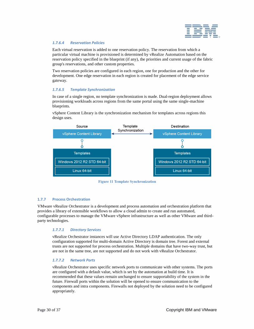
1.7.6.5 Template Synchronization
In case of a single region, no template synchronization is made. Dual-region deployment allows
provisioning workloads across regions from the same portal using the same single-machine
blueprints.
vSphere Content Library is the synchronization mechanism for templates across regions this
design uses.
Figure 11 Template Synchronization
1.7.7 Process Orchestration
VMware vRealize Orchestrator is a development and process automation and orchestration platform that
provides a library of extensible workflows to allow a cloud admin to create and run automated,
configurable processes to manage the VMware vSphere infrastructure as well as other VMware and third-
party technologies.
1.7.7.1 Directory Services
vRealize Orchestrator instances will use Active Directory LDAP authentication. The only
configuration supported for multi-domain Active Directory is domain tree. Forest and external
trusts are not supported for process orchestration. Multiple domains that have two-way trust, but
are not in the same tree, are not supported and do not work with vRealize Orchestrator.
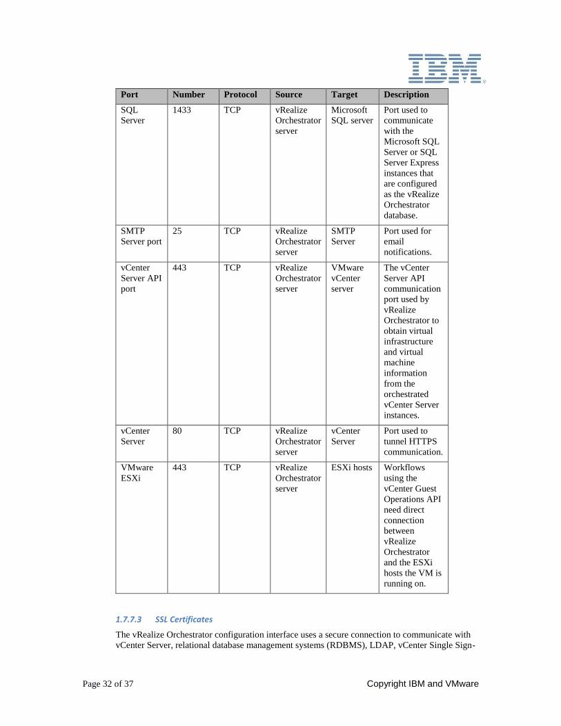
1.7.7.2 Network Ports
vRealize Orchestrator uses specific network ports to communicate with other systems. The ports
are configured with a default value, which is set by the automation at build time. It is
recommended that these values remain unchanged to ensure supportability of the system in the
future. Firewall ports within the solution will be opened to ensure communication to the
components and intra components. Firewalls not deployed by the solution need to be configured
appropriately.
Page 31 of 37
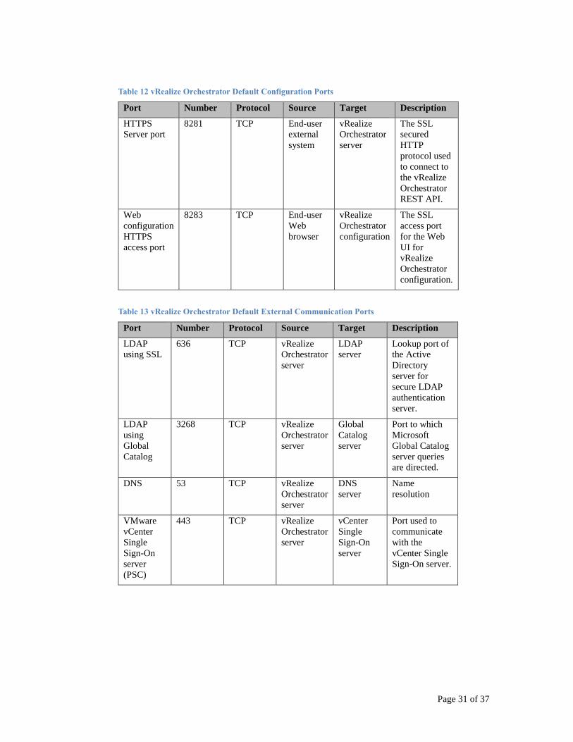
Table 12 vRealize Orchestrator Default Configuration Ports
Port Number Protocol Source Target Description
HTTPS
Server port
8281 TCP End-user
external
system
vRealize
Orchestrator
server
The SSL
secured
HTTP
protocol used
to connect to
the vRealize
Orchestrator
REST API.
Web
configuration
HTTPS
access port
8283 TCP End-user
Web
browser
vRealize
Orchestrator
configuration
The SSL
access port
for the Web
UI for
vRealize
Orchestrator
configuration.
Table 13 vRealize Orchestrator Default External Communication Ports
Port Number Protocol Source Target Description
LDAP
using SSL
636 TCP vRealize
Orchestrator
server
LDAP
server
Lookup port of
the Active
Directory
server for
secure LDAP
authentication
server.
LDAP
using
Global
Catalog
3268 TCP vRealize
Orchestrator
server
Global
Catalog
server
Port to which
Microsoft
Global Catalog
server queries
are directed.
DNS 53 TCP vRealize
Orchestrator
server
DNS
server
Name
resolution
VMware
vCenter
Single
Sign-On
server
(PSC)
443 TCP vRealize
Orchestrator
server
vCenter
Single
Sign-On
server
Port used to
communicate
with the
vCenter Single
Sign-On server.
Page 32 of 37 Copyright IBM and VMware
Port Number Protocol Source Target Description
SQL
Server
1433 TCP vRealize
Orchestrator
server
Microsoft
SQL server
Port used to
communicate
with the
Microsoft SQL
Server or SQL
Server Express
instances that
are configured
as the vRealize
Orchestrator
database.
SMTP
Server port
25 TCP vRealize
Orchestrator
server
SMTP
Server
Port used for
notifications.
vCenter
Server API
port
443 TCP vRealize
Orchestrator
server
VMware
vCenter
server
The vCenter
Server API
communication
port used by
vRealize
Orchestrator to
obtain virtual
infrastructure
and virtual
machine
information
from the
orchestrated
vCenter Server
instances.
vCenter
Server
80 TCP vRealize
Orchestrator
server
vCenter
Server
Port used to
tunnel HTTPS
communication.
VMware
ESXi
443 TCP vRealize
Orchestrator
server
ESXi hosts Workflows
using the
vCenter Guest
Operations API
need direct
connection
between
vRealize
Orchestrator
and the ESXi
hosts the VM is
running on.
1.7.7.3 SSL Certificates
The vRealize Orchestrator configuration interface uses a secure connection to communicate with
vCenter Server, relational database management systems (RDBMS), LDAP, vCenter Single Sign-
Page 33 of 37
On, and other servers. The required SSL certificates are generated by the certification authority
deployed within the solution.
1.7.7.4 vRealize Orchestrator Plug-Ins
Plug-ins allow vRealize Orchestrator to access and control external technologies and applications.
Exposing an external technology in a vRealize Orchestrator plug-in allows incorporating objects
and functions in workflows that access the objects and functions of the external technology. The
external technologies that can be accessed using plug-ins include virtualization management tools,
email systems, databases, directory services, and remote control interfaces. vRealize Orchestrator
provides a set of standard plug-ins.
The following plug-ins are configured in this design:
vRealize Orchestrator NSX plug-in
vRealize Orchestrator vRealize Automation plug-in
vRealize Orchestrator vCenter Server plug-in
1.7.7.4.1 Multi-node plugin
vRealize Orchestrator comes as a single-site topology product. The multi-node plug-in creates a
primary-secondary relation between vRealize Orchestrator servers that extends the package
management and workflow execution features. This is only enabled when deploying a multi-
region topology. The plug-in contains a set of standard workflows for hierarchical orchestration,
management of vRealize Orchestrator instances, and the scale-out of vRealize Orchestrator
activities.
1.7.7.4.2 vRealize Orchestrator Client
The vRealize Orchestrator client is a desktop application that lets users import packages, create,
run, and schedule workflows, and manage user permissions.
vRealize Orchestrator Client can be installed standalone on a desktop system. Download the
vRealize Orchestrator Client installation files from the vRealize Orchestrator appliance
page: https://vRO_hostname:8281. Alternatively, vRealize Orchestrator Client can be run
using Java WebStart directly from the homepage of the vRealize Orchestrator appliance console.
1.7.7.4.3 vRealize Orchestrator Scalability
A single vRealize Orchestrator instance allows up to 300 concurrent workflow instances in the
running state. Workflow instances that are in the waiting or waiting-event states do not count
toward that number. You can design long running workflows in a way that preserves resources by
using the wait elements of the workflow palette. A single vRealize Orchestrator instance supports
up to 35,000 managed virtual machines in its inventory.
This architecture depicts a clustered vRealize Orchestrator environment. In a clustered
environment, workflows cannot be changed while other vRealize Orchestrator instances are
running. Stop all other vRealize Orchestrator instances before connecting the vRealize
Orchestrator client and changing or developing a new workflow. Failure to do so will result in
inconsistencies within the environment.
This architecture scales out a vRealize Orchestrator environment by having multiple independent
vRealize Orchestrator instances (each with their own database instance). This allows for the
increase in the number of managed inventory objects.
This solution implements an active-active cluster with two nodes.
1.7.8 Software Orchestration
This solution provides a centralized repository for software binaries and software orchestration templates
that are implemented on deployed resources. Main software orchestration engines installed are Chef Server
and Salt Stack. Each region hosts its own dedicated repository server and software orchestration stack.
Page 34 of 37 Copyright IBM and VMware
Software binaries are replicated between regions using rsync tool. Software orchestration components use
internal specific replication mechanisms.
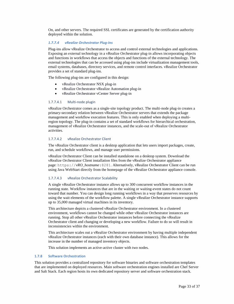
The following diagram shows a high level view of the software orchestration components.
Figure 12 Software Orchestration Logical Design
A single region design implements a central orchestration and a region orchestration.
1.7.8.1 Central Software Orchestration
Central software orchestration has no direct interaction with the resources, but provides a central
management point for maintaining the latest binaries and templates by the cloud administrator.
It is responsible for,
Maintaining the latest versions of software binaries
Maintaining the latest versions of software orchestration templates
Keeping the regions up to date with the latest software versions and templates
Inputs and Outputs
A central component pushes software binaries to the region component.
A Central component is accessed by the cloud administrator to update software and templates.
Design Rationale
In a hybrid cloud there may be many regions each with their own software and template
requirements. Plus, to avoid delays during deployment, the software binaries need to be as close to
the resource cluster as possible. This drives the need for a distributed repository of software
binaries. Maintaining these separately and keeping software versions on each up to date with the
latest versions can add considerable support cost. A central repository can regular or on change
update each of these regions without the need to update each one individually.
Implementation Approach
The central software orchestration components are co-located with the other central services to
minimize network access configuration for administrator access.
Other Functions
The central repository is also used as the backup location for the NSX Managers in the central
cloud.
Page 35 of 37
1.7.8.2 Region Software Orchestration
Responsibilities
The region component provides the software orchestration engine that implements software to
deployed resources using defined software orchestration templates. The implementation includes
mounting the software installation media (software binaries), then installing and configuring the
software. The implementation may also involve other actions to configure the deployed resource
to the software orchestration template requirements such as setting password rules.
It is responsible for,
being a repository for software binaries
being a repository for software orchestration templates
providing software orchestration engine to implement software on deployed resources
Inputs and Outputs
A region pushes software and configurations to deployed resources.
A region is called from a cloud region to deploy the software.
Design Rationale
A cloud needs to be able to implement software on deployed resources. This requires software
binaries and software orchestration templates (patterns). The region is to provide these functions.
It is separate to the cloud region in order to allow for different flavors without impacting the cloud
region design.
Implementation Approach
The region should be co-located with the other region services to minimize network traffic and
response times when deploying software to resources.
Other Functions
The region repository is also used as the backup location for the NSX Managers in the cloud
region.
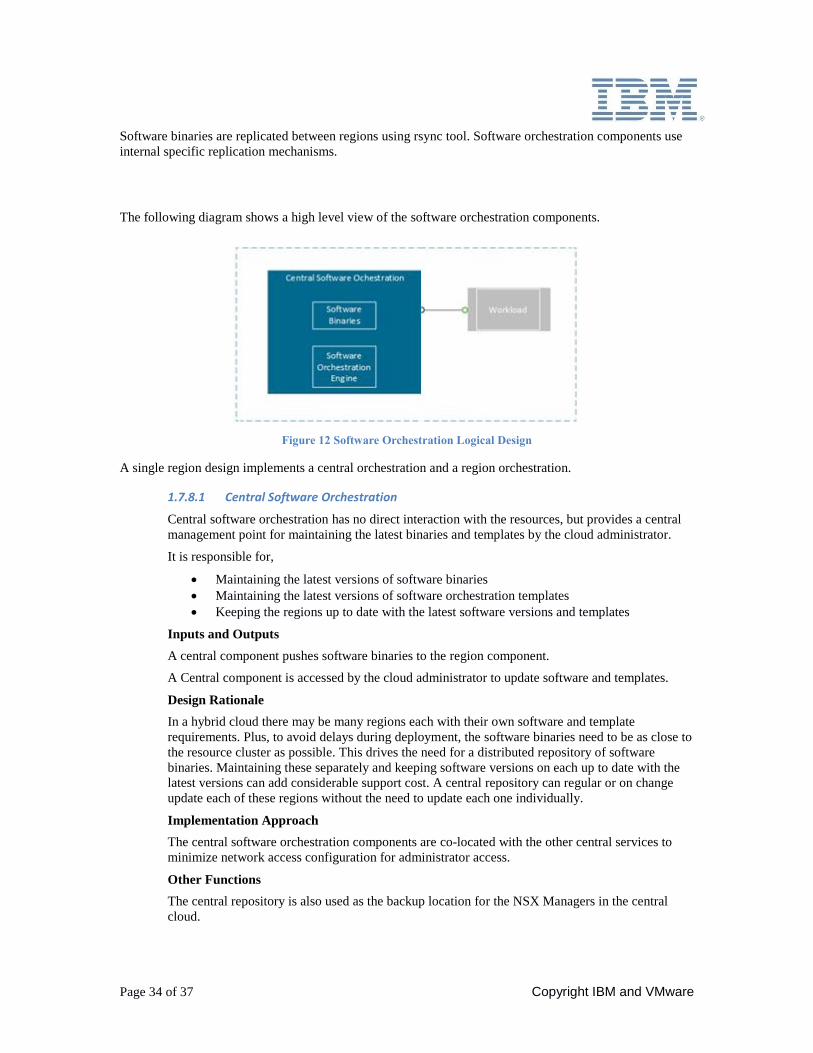
1.7.8.3 Software Orchestration Components Sizing
The following table presents sizing for central and region
Table 14 Software Orchestration Components Sizing
Server Role vCPU RAM (GB) Disk (GB)
Central repository and
Chef server
2 8 300
1.7.9 Infrastructure Orchestration
Infrastructure orchestration is handled by vRealize Orchestration and vRealize Automation which is
covered in the prior sections.
Page 36 of 37 Copyright IBM and VMware
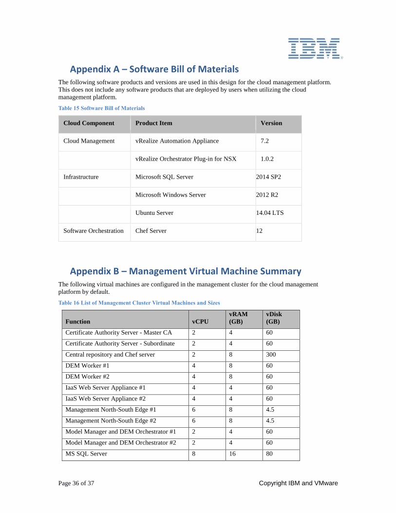
Appendix A – Software Bill of Materials The following software products and versions are used in this design for the cloud management platform.
This does not include any software products that are deployed by users when utilizing the cloud
management platform.
Table 15 Software Bill of Materials
Cloud Component Product Item Version
Cloud Management vRealize Automation Appliance 7.2
vRealize Orchestrator Plug-in for NSX 1.0.2
Infrastructure Microsoft SQL Server 2014 SP2
Microsoft Windows Server 2012 R2
Ubuntu Server 14.04 LTS
Software Orchestration Chef Server 12
Appendix B – Management Virtual Machine Summary The following virtual machines are configured in the management cluster for the cloud management
platform by default.
Table 16 List of Management Cluster Virtual Machines and Sizes
Function vCPU
vRAM
(GB)
vDisk
(GB)
Certificate Authority Server - Master CA 2 4 60
Certificate Authority Server - Subordinate 2 4 60
Central repository and Chef server 2 8 300
DEM Worker #1 4 8 60
DEM Worker #2 4 8 60
IaaS Web Server Appliance #1 4 4 60
IaaS Web Server Appliance #2 4 4 60
Management North-South Edge #1 6 8 4.5
Management North-South Edge #2 6 8 4.5
Model Manager and DEM Orchestrator #1 2 4 60
Model Manager and DEM Orchestrator #2 2 4 60
MS SQL Server 8 16 80
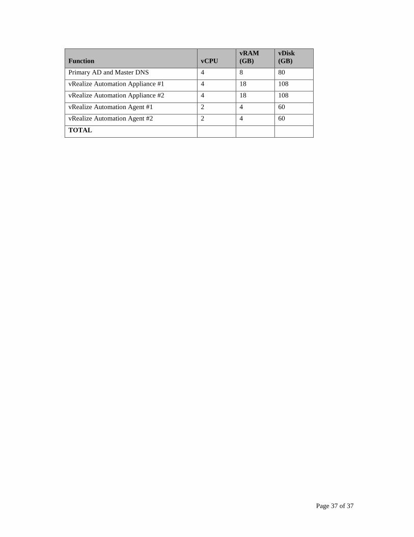
Page 37 of 37
Function vCPU
vRAM
(GB)
vDisk
(GB)
Primary AD and Master DNS 4 8 80
vRealize Automation Appliance #1 4 18 108
vRealize Automation Appliance #2 4 18 108
vRealize Automation Agent #1 2 4 60
vRealize Automation Agent #2 2 4 60
TOTAL
Related Documents