PSS 21H-3A6 B3 FOXBORO I/A Series ® HARDWARE Product Specifications DCS Fieldbus Modules for ABB/Taylor MOD300 Direct I/O Automation Systems DCS Fieldbus Modules and Motherboards FCP270 Control Processor Modules Mounted on Baseplate DIGITAL ANALOG DIGITAL ANALOG DIGITAL ANALOG DIGITAL ANALOG The I/A Series ® Field Control Processor 270 (FCP270) modules mounted on a baseplate and the distributed control system (DCS) Fieldbus Modules replace the MOD300 Direct I/O modules and connect existing field devices to the I/A Series system via a 2 Mbps HDLC Fieldbus and high-speed Ethernet network FEATURES Migration from proprietary DCS to a state-of-the-art open I/A Series system Advanced I/A Series ® control with a single point of configuration More direct control performance than any gateway device could offer Cost savings over total system replacement by preserving the existing process interface and wiring and minimizing process downtime Single vendor service and supply.

Welcome message from author
This document is posted to help you gain knowledge. Please leave a comment to let me know what you think about it! Share it to your friends and learn new things together.
Transcript
PSS 21H-3A6 B3
I/A Series® HARDWAREProduct Specifications
DCS Fieldbus Modules for ABB/Taylor MOD300 Direct I/O Automation
Systems
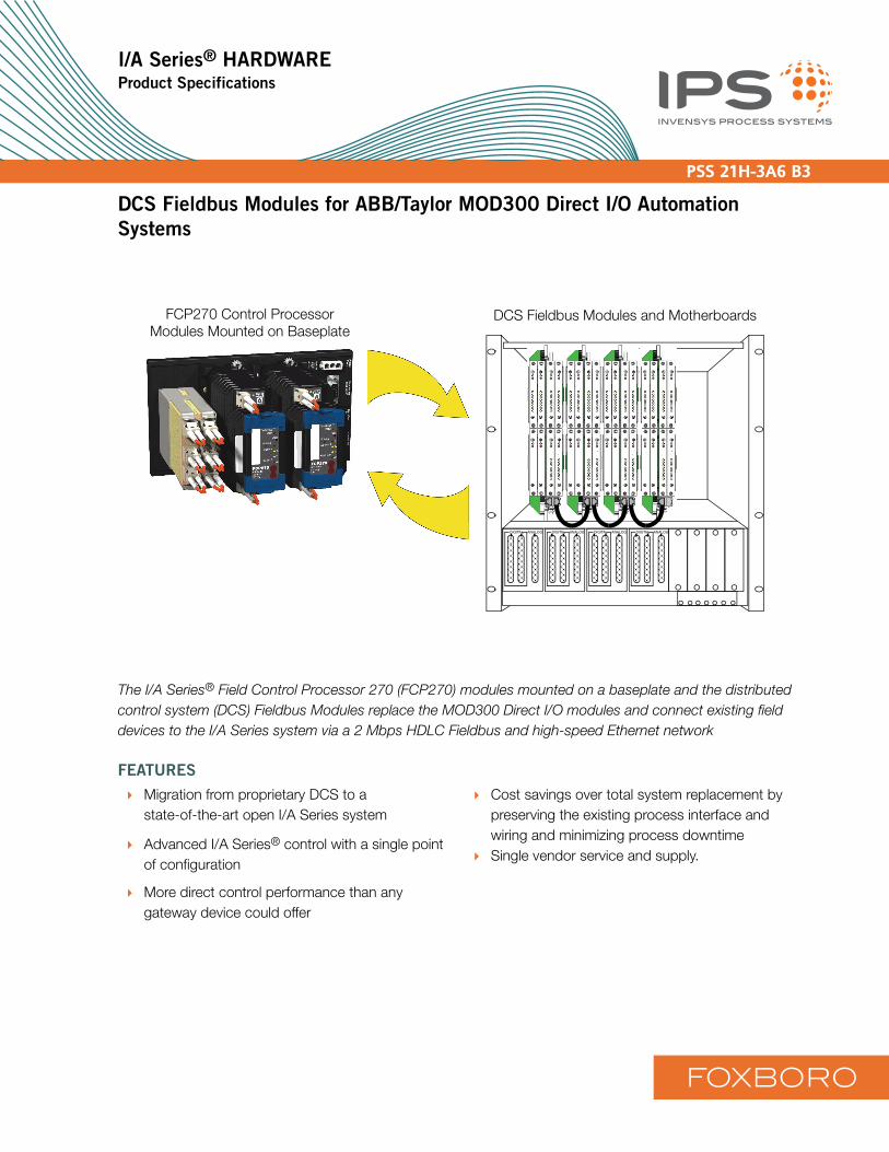
DCS Fieldbus Modules and MotherboardsFCP270 Control ProcessorModules Mounted on Baseplate
DIGITAL ANALOG DIGITAL ANALOG DIGITAL ANALOG DIGITAL ANALOG
The I/A Series® Field Control Processor 270 (FCP270) modules mounted on a baseplate and the distributed control system (DCS) Fieldbus Modules replace the MOD300 Direct I/O modules and connect existing field devices to the I/A Series system via a 2 Mbps HDLC Fieldbus and high-speed Ethernet network
FEATURES
Migration from proprietary DCS to astate-of-the-art open I/A Series system
Advanced I/A Series® control with a single point of configuration
More direct control performance than any gateway device could offer
Cost savings over total system replacement by preserving the existing process interface and wiring and minimizing process downtimeSingle vendor service and supply.
FOXBORO
PSS 21H-3A6 B3Page 2
OVERVIEW
The I/A Series DCS Fieldbus Modules (FBMs) are for migration of ABB/Taylor MOD300 Direct I/O automation systems manufactured by ABB Automation products division. The FBMs plug directly into an existing electronic nest to replace process input and output modules. Migration products include the 6002N Model A and Model B Controller card files and the 6202N Controller card files.
The I/A Series DCS FBM family provides a migration path from MOD300 Direct I/O process I/O components to I/A Series display and supervisory functions.No additional communication devices are required. No multi-vendor communication software licensing is required.
The I/A Series DCS FBM family replaces the MOD300 Direct I/O modules. Once integrated, the process is controlled entirely by the advanced I/A Series algorithm set.
The I/A Series DCS FBM product includes connectors to enable integration of original process signals to I/A Series systems while keeping the field interface and wiring. It provides access to all process signals connected to the MOD300 Direct I/O system by providing the connection between the Field Termination Assemblies (FTAs) and the I/A Series system. All process signals become fully integrated into the I/A Series system. Process data is used for operator display, history, alarming and control.
Operator functions and engineering configuration are accomplished by the I/A Series system at any I/A Series operator workstation. Because all process values become part of the I/A Series system, all configuration data is maintained by the system as native I/A Series configurations.
This migration path provides plant operations with all the power and flexibility of the I/A Series system. All process values can be used plant wide for control,
display, history, alarming and information management from a single vendor source.
FUNDAMENTAL PRINCIPLE
Invensys believes that it is only acceptable to interface with competing manufacturers’ operating systems in two ways:
Through high level public gatewaysAt the lowest level directly to field devices without communicating with proprietary buses or components.
The Invensys migration product offerings adhere to this principle.
PRODUCT DESCRIPTIONS
The I/A Series migration strategy replaces the MOD300 Direct I/O process control system with a 2 Mbps Fieldbus connection to an I/A Series Field Control Processor 270 (FCP270), provides a motherboard-and-DCS Fieldbus modules replacement of the MOD300 controller and I/O, but leaves the original process interface wiring, termination assemblies and cabinets in place.
To replace the MOD300 controller and I/O modules, the MOD300 migration consists of new I/A Series DCS FBMs, FCP270 and baseplate. The baseplate supports either a single FCP270 module or a pair of fault-tolerant FCP270 modules. The FCP270 provides the control algorithms and interface between the FBMs and the 100 Mbps/1 Gbps Ethernet control network. This allows migration to I/A Series control, display and application products while retaining the original process termination and field I/O wiring. All original process I/O capability of the MOD300 module functions is replaced by FBMs and direct I/A Series control processor scanning and control. For more information on the FCP270, refer toPSS 21H-1B9 B3.
PSS 21H-3A6 B3Page 3
Using the I/A Series Z-Module Control Processor 270 (ZCP270) instead of the FCP270 requires a new I/A Series Z-module mounting structure that mounts in a 19 inch rack, Fieldbus Communications Module (FCM100E/FCM100Et), and baseplate. A single or redundant pair of FCM100E or FCM100Et modules mounts on the baseplate. The FCM100E/FCM100Et provides the interface between the FBMs, via a 2Mbps HDLC Fieldbus, and the ZCP270 controller, via a 100Mbps Ethernet Fieldbus.For more information on the ZCP270, refer to PSS 21H-1B10 B3. For more information on the FCM100E, refer to PSS 21H-2Y11 B4.For more information on the FCM100Et, refer to PSS 21H-2Y10 B4.
New I/A Series DCS FBMs plug into a motherboard which plugs directly into existing MOD300 racks in place of MOD300 Direct I/O modules.
The Fieldbus connects the DCS FBM subsystem to the FCP270 or ZCP270. I/O from the subsystem is connected to the control strategy using standard I/A Series I/O type blocks. The DCS FBMs pass process measurement and output signals and digital I/O signals to and from the control processor.
All process signals are fully integrated into the I/A Series system, allowing direct I/A Series system monitoring and control of the process.
The migration of the following MOD300 components to the I/A Series system can be accomplished using either an FCP270 or a ZCP270/FCM100 combination mounted on a baseplate:
6000 Series Direct I/O Non-Redundant Controller
6000 Series Direct I/O Redundant Controller
6200 Series Direct I/O Non-Redundant Controller
6200 Series Direct I/O Redundant Controller
MOD300 Subsystems
An FCP270 or FCM100E/FCM100Et baseplate is installed in the MOD300 enclosure or another location with single or redundant modules. The baseplate has a built-in Fieldbus termination assembly. The I/O module power supplies and MOD300 rack nests are retained in the cabinet.
The MOD300 racks, used to house I/O modules, are reused to house the I/A Series DCS FBMs. All termination assemblies remain intact with their termination cables and field wiring.
MOD300 Controllers and I/O modules are removed from the MOD300 rack and replaced by a corresponding motherboard containing I/A Series DCS FBMs that mate to the original power/signal connector and termination cable connector. These DCS FBMs provide original I/O functionality of the process inputs and outputs.
Migration with FCP270 and DCS FBMs
The Field Control Processor 270 (FCP270) is a distributed, field-mounted controller module that supports up to 32 DCS FBMs. The FCP270 connects to the control network via optionally redundant 100 Mbps Ethernet fiber optic cables and Ethernet fiber switches. The FCP270 is an optionally fault-tolerant controller that communicates with connected DCS FBMs to perform data acquisition and control using I/A Series control algorithms.
The FCP270 mounts in a 2-position baseplate that supports a single module or a fault-tolerant module pair. The baseplate accepts only FCP270 modules. The FCP270 connects to redundant 2 Mbps HDLC I/O Fieldbus for communications to the DCS FBMs and provides galvanic isolation between the 100 Mbps Ethernet Fieldbus and the 2 Mbps local Fieldbus.
PSS 21H-3A6 B3Page 4
The Fieldbus Expansion Module 100 (FEM100) allows the FCP270 to access up to four nests through up to four Expanded Fieldbuses. Each Expanded Fieldbus typically supports the same number of FBMs as a single Fieldbus. For more details and specifications on the FEM100, refer to PSS 21H-2Y14 B4.
Fault-tolerant FCP270 modules connect to a pair of fiber optic splitter/combiners that connect to Ethernet switches in a redundant control network. The splitter/combiner pair mounts in an assembly that fastens to the baseplate.
To support redundancy, a pair of FCP270s must be used for each grouping of 32 DCS FBMs. In non-redundant configurations, only a single FCP270 is required for each grouping.
The maximum total cable length for the 2 Mbps Fieldbus is 60 m (198 ft) within a grouping.
Migration with FCM100E/FCM100Et and DCS
FBMs
The FCM100E or FCM100Et is a fiber optic communications interface which allows the DCS FBMs to communicate with the ZCP270 via the optionally redundant 100 Mbps Ethernet fiber optic Fieldbus. The FCM100E/FCM100Et converts 100 Mbps Ethernet signals used by the ZCP270 to 2 Mbps signals used by the DCS FBMs, and vice versa. The FCM100E/FCM100Et also provides galvanic isolation between the 100 Mbps Ethernet Fieldbus and the 2 Mbps local Fieldbus.
The FCM100E/Ets are used in pairs for redundancy. An module (or pair of modules) can support up to 32 DCS FBMs. The ZCP270 supports up to 32 FCM100E/Et redundant pairs connected to the 100 Mbps Ethernet Fieldbus via optionally redundant Ethernet switches and fiber optic cabling. The ZCP270 supports up to 120 DCS FBMs connected to FCM100E/Ets.
The FCM100E/Et allows the DCS FBMs to communicate with the ZCP270 over extended distances using the 100Mbps Ethernet fiber optic Fieldbus. The FCM100E/Et provides expanded networking and greater Fieldbus cabling distances in a fiber optic network. This configuration is ideally suited for sites in which groups of DCS FBMs are to be spread apart over greater distances. Up to 32 groupings of baseplate-mounted FCM100E/Ets and DCS FBMs can be linked to each optionally redundant Ethernet switch, for a maximum of 120 DCS FBMs per ZCP270 (depending on selected scan periods).
To support redundancy, a pair of FCM100E/Ets must be used for each DCS FBM grouping. In non-redundant configurations, only a single FCM100Et is required for each grouping. Signal transmission distances up to 2 kilometers (1.24 miles) are possible between the FCM100Ets and Ethernet fiber switches, providing for wide distribution of the DCS FBM equipment groupings. The maximum total cable length for the 2 Mbps Fieldbus is 60 m (198 ft) within a grouping.
I/O Modules
The DCS FBMs provide advanced 200 Series FBM technology on an MOD300 module form factor. Each DCS FBM motherboard plugs into the slot used by the replaced MOD300 module and provides connectors to the I/O signals and the FCP270 or FCM100E communication bus.
PSS 21H-3A6 B3Page 5
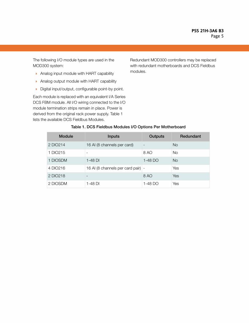
The following I/O module types are used in the MOD300 system:
Analog input module with HART capability
Analog output module with HART capability
Digital input/output, configurable point-by point.
Each module is replaced with an equivalent I/A Series DCS FBM module. All I/O wiring connected to the I/O module termination strips remain in place. Power is derived from the original rack power supply. Table 1 lists the available DCS Fieldbus Modules.
Redundant MOD300 controllers may be replaced with redundant motherboards and DCS Fieldbus modules.
Table 1. DCS Fieldbus Modules I/O Options Per Motherboard
Module Inputs Outputs Redundant
2 DIO214 16 AI (8 channels per card) - No
1 DIO215 - 8 AO No
1 DIOSDM 1-48 DI 1-48 DO No
4 DIO216 16 AI (8 channels per card pair) - Yes
2 DIO218 - 8 AO Yes
2 DIOSDM 1-48 DI 1-48 DO Yes
PSS 21H-3A6 B3Page 6
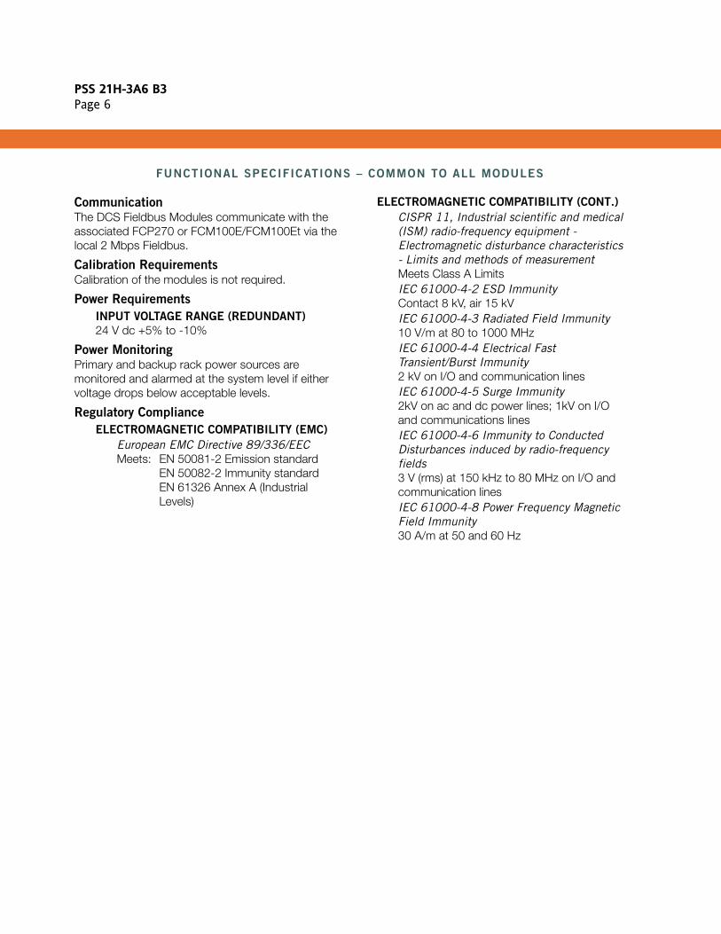
FUNCTIONAL SPECIFICATIONS – COMMON TO ALL MODULES
CommunicationThe DCS Fieldbus Modules communicate with the associated FCP270 or FCM100E/FCM100Et via the local 2 Mbps Fieldbus.
Calibration RequirementsCalibration of the modules is not required.
Power Requirements
INPUT VOLTAGE RANGE (REDUNDANT)
24 V dc +5% to -10%
Power MonitoringPrimary and backup rack power sources are monitored and alarmed at the system level if either voltage drops below acceptable levels.
Regulatory Compliance
ELECTROMAGNETIC COMPATIBILITY (EMC)
European EMC Directive 89/336/EECMeets: EN 50081-2 Emission standard
EN 50082-2 Immunity standard EN 61326 Annex A (IndustrialLevels)
ELECTROMAGNETIC COMPATIBILITY (CONT.)
CISPR 11, Industrial scientific and medical (ISM) radio-frequency equipment - Electromagnetic disturbance characteristics - Limits and methods of measurementMeets Class A LimitsIEC 61000-4-2 ESD ImmunityContact 8 kV, air 15 kVIEC 61000-4-3 Radiated Field Immunity10 V/m at 80 to 1000 MHzIEC 61000-4-4 Electrical Fast Transient/Burst Immunity2 kV on I/O and communication linesIEC 61000-4-5 Surge Immunity2kV on ac and dc power lines; 1kV on I/O and communications linesIEC 61000-4-6 Immunity to Conducted Disturbances induced by radio-frequency fields3 V (rms) at 150 kHz to 80 MHz on I/O and communication linesIEC 61000-4-8 Power Frequency Magnetic Field Immunity30 A/m at 50 and 60 Hz
PSS 21H-3A6 B3Page 7
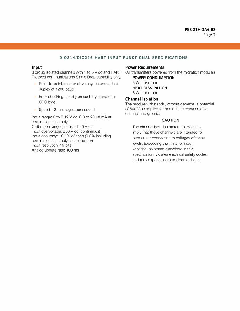
DIO214/DIO216 HART INPUT FUNCTIONAL SPECIFICATIONS
Input8 group isolated channels with 1 to 5 V dc and HART Protocol communications Single Drop capability only.
Point-to-point, master slave asynchronous, half duplex at 1200 baud
Error checking – parity on each byte and one CRC byte
Speed – 2 messages per second
Input range: 0 to 5.12 V dc (0.0 to 20.48 mA at termination assembly) Calibration range (span): 1 to 5 V dcInput overvoltage: ±30 V dc (continuous)Input accuracy: ±0.1% of span (0.2% including termination assembly sense resistor)Input resolution: 15 bitsAnalog update rate: 100 ms
Power Requirements(All transmitters powered from the migration module.)
POWER CONSUMPTION
3 W maximumHEAT DISSIPATION
3 W maximum
Channel IsolationThe module withstands, without damage, a potential of 600 V ac applied for one minute between any channel and ground.
CAUTION
The channel isolation statement does not imply that these channels are intended for permanent connection to voltages of these levels. Exceeding the limits for input voltages, as stated elsewhere in this specification, violates electrical safety codes and may expose users to electric shock.
PSS 21H-3A6 B3Page 8
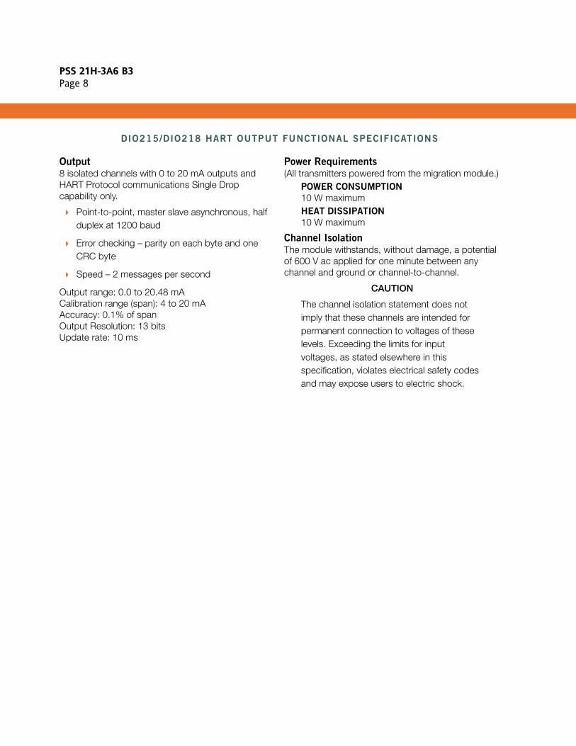
DIO215/DIO218 HART OUTPUT FUNCTIONAL SPECIFICATIONS
Output8 isolated channels with 0 to 20 mA outputs and HART Protocol communications Single Drop capability only.
Point-to-point, master slave asynchronous, half duplex at 1200 baud
Error checking – parity on each byte and one CRC byte
Speed – 2 messages per second
Output range: 0.0 to 20.48 mACalibration range (span): 4 to 20 mAAccuracy: 0.1% of spanOutput Resolution: 13 bitsUpdate rate: 10 ms
Power Requirements(All transmitters powered from the migration module.)
POWER CONSUMPTION
10 W maximumHEAT DISSIPATION
10 W maximum
Channel IsolationThe module withstands, without damage, a potential of 600 V ac applied for one minute between any channel and ground or channel-to-channel.
CAUTION
The channel isolation statement does not imply that these channels are intended for permanent connection to voltages of these levels. Exceeding the limits for input voltages, as stated elsewhere in this specification, violates electrical safety codes and may expose users to electric shock.
PSS 21H-3A6 B3Page 9
DIOSDM DISCRETE INPUT/OUTPUT FUNCTIONAL SPECIFICATIONS
Input/Output48 group isolated channels, configurable on a per channel basis as discrete input, discrete output, or pulse output.
DISCRETE INPUT (CONTACT TYPE)
Input specification depends upon the OPTO-22 devices installed in the termination assemblies.DISCRETE OUTPUT
Output specification depends upon the OPTO-22 devices installed in the termination assemblies.
Module Scan Time10 ms
Power Requirements
POWER CONSUMPTION
5 W maximumHEAT DISSIPATION
5 W maximum
Channel IsolationThe channels of the I/O card are galvanically isolated from earth (ground). The module withstands, without damage, a potential of 600 V ac applied for one minute between all channels and ground. Each channel is isolated from other channels by the attached OPTO-22 devices installed in the termination assembly.
CAUTION
The channel isolation statement does not imply that these channels are intended for permanent connection to voltages of these levels. Exceeding the limits for input voltages, as stated elsewhere in this specification, violates electrical safety codes and may expose users to electric shock.

PSS 21H-3A6 B3Page 10

PSS 21H-3A6 B3Page 11

PSS 21H-3A6 B3Page 12
IPS Corporate Headquarters5601 Granite Parkway Suite 1000Plano, TX 75024United States of Americawww.ips.invensys.comI
Foxboro Global Client SupportInside U.S.: 1-866-746-6477Outside U.S.: 1-508-549-2424 or contact your local Foxboro representative.Facsimile: 1-508-549-4999
Invensys, Foxboro and II/A Series are trademarks of Invensys plc, its subsidiaries, and affiliates.All other brand names may be trademarks of their respective owners.
Copyright 2008-2009 Invensys Systems, Inc.All rights reserved
MB 21A Printed in U.S.A. 0409
Related Documents