Huawei iLab Ultimate Experience. VR Technology White Paper Cloud VR–oriented Bearer Network White Paper Issue 01 Date 2017-11-02 Released by Huawei iLab

Welcome message from author
This document is posted to help you gain knowledge. Please leave a comment to let me know what you think about it! Share it to your friends and learn new things together.
Transcript
Huawei iLab Ultimate Experience. VR Technology White Paper
Cloud VR–oriented Bearer Network White Paper
Issue 01
Date 2017-11-02
Released by Huawei iLab
Cloud VR–oriented Bearer Network White Paper
Issue 01 (2017-11-02) Huawei Proprietary and Confidential
Copyright © Huawei Technologies Co., Ltd.
i
Preface
Cloud VR introduces the cloud computing technology to VR services. With fast and stable
bearer networks, cloud-based video and audio outputs are coded, compressed, and transmitted
to user terminals, implementing cloud-based VR service content storage and rendering.
Currently, good user experience relies mostly on high-performance devices for local
rendering. Cloud VR allows users to enjoy various VR services without purchasing expensive
high-end PCs, promoting the popularization of VR services.
In 2016, we released "VR-oriented Bearer Network White Paper" focusing on Cloud VR
video services. However, as VR technologies and applications further develop, Cloud VR is
making new achievements such as panoramic 8K and 3D VR. Real-time VR cloud rendering
also accelerates the all-cloud development of various VR applications. Cloud VR will become
the best choice of VR and an inevitable trend.
By focusing on VR experience improvement, combined with the latest technological
development and trends, this white paper analyzes bearer network requirements at different
Cloud VR stages. The white paper also provides Cloud VR bearer network solutions and
suggests network evolution directions to meet service development requirements of both the
current and future Cloud VR.

Cloud VR–oriented Bearer Network White Paper
Issue 01 (2017-11-02) Huawei Proprietary and Confidential
Copyright © Huawei Technologies Co., Ltd.
ii
Contents
Preface ................................................................................................................................................. i
1 Cloud VR: the Best Choice and an Inevitable Trend ............................................................. 1
1.1 VR Service Overview ................................................................................................................................................... 1
1.2 Fast Evolution from VR to Cloud VR .......................................................................................................................... 2
1.3 Typical Applications of Cloud VR ................................................................................................................................ 4
2 Key Technologies of Cloud VR .................................................................................................. 7
2.1 Full-View and FOV ...................................................................................................................................................... 7
2.2 Experience of Image Quality and Interaction ............................................................................................................... 7
2.3 Projection and Coding Technologies ............................................................................................................................ 9
2.4 Transmission Technology Roadmap ........................................................................................................................... 12
2.5 Rendering Technology ................................................................................................................................................ 14
3 Network Requirements at Different Cloud VR Stages ....................................................... 17
3.1 Four Stages of Cloud VR ............................................................................................................................................ 17
3.2 Network Requirements of Cloud VR .......................................................................................................................... 18
4 Cloud VR-oriented Bearer Network ........................................................................................ 21
4.1 Early and Entry-level VR on the 4K Network ............................................................................................................ 21
4.1.1 VR Bearer Network Architecture ............................................................................................................................. 21
4.1.2 Home Network Design ............................................................................................................................................ 22
4.1.3 Access Network Design ........................................................................................................................................... 26
4.1.4 Metro Network Design ............................................................................................................................................ 32
4.1.5 VR Bearer Experience Guarantee ............................................................................................................................ 35
4.1.6 VR Broadcasting Bearer Optimization .................................................................................................................... 36
4.2 Network Evolution for Advanced VR and Ultimate VR ............................................................................................. 37
4.2.1 Bearer Technology Evolution for Higher and Broader Bandwidth .......................................................................... 38
4.2.2 Bearer Technology Evolution for Lower Delay ....................................................................................................... 40
4.2.3 Smart and Flexible Cloud+Network Network ......................................................................................................... 41
4.2.4 Technology Evolution for VR Service Experience Guarantee ................................................................................. 42
Cloud VR–oriented Bearer Network White Paper
Issue 01 (2017-11-02) Huawei Proprietary and Confidential
Copyright © Huawei Technologies Co., Ltd.
1
1 Cloud VR: the Best Choice and an Inevitable Trend
1.1 VR Service Overview
Virtual reality (VR) is honored as the next-generation Internet and next-generation computing
platform. VR is a computer-generated virtual environment (VE). The environment may be a
replication of the real world or an imaginary world. People can interact in real time in this
virtual environment with 3D spatial information.
VR services have changed the man-machine interaction mode, shifting the operation interface
from two-dimensional to three-dimensional. According to academic research results, VR
services can be classified into weak-interaction VR and strong-interaction VR based on the
angle of interactive experience between users and the VE.
Weak-Interaction VR:
Weak-interaction VR implies that users do not trigger actual interaction (such as touching)
with entities in the VE and can choose the viewing point and location. In this case, user
experience is passive, and contents are pre-determined. VR video services, such as VR videos
and VR live broadcast, are typical weak-interaction VR services, which have the following
features:
1. Passive experience: Contents are pre-determined. Users experience contents in the VE
passively.
2. Limited freedom: Although users can choose the view point in the VE, only nearby
scenes can be viewed. Compared with location tracking and positioning, the degree of
freedom is limited.
3. Limited interaction: Users do not have actual interaction or have limited interaction with
entities in the VE (for example, when users turn heads to change the viewing angle).
Strong-Interaction VR:
As the interaction technology develops, the interaction mode and effects of VR will gradually
evolve to natural interaction. Technologies such as hand gesture recognition, eye movement
tracking, touch feedback, and brain-computer interface will transform weak-interaction VR to
strong-interaction VR, greatly improving user interaction and immersion.
Strong-interaction VR implies that users can interact with the VE through interactive devices
and respond in real time through objects in the VE, allowing users to feel changes in the VE.
Cloud VR–oriented Bearer Network White Paper
Issue 01 (2017-11-02) Huawei Proprietary and Confidential
Copyright © Huawei Technologies Co., Ltd.
2
In strong-interaction VR, image generation in the virtual space depends on the user input,
different from pre-planned contents in weak-interaction VR. VR games, VR home fitness, and
VR social media are all strong-interaction VR services, which have the following experience
features:
1. Strong interaction: Users can use interactive devices to interact with the VE, themselves,
and other users.
2. Real time: Entities in the VE respond to interaction in real time, allowing users to feel
changes of the VE.
3. Immersion: Users can feel like immersing in another world through interactive devices.
4. Multi-terminal and network-based: Group users share the same VE through networks,
achieving group VE interaction experience.
Currently, VR products on the market mainly include mobile phone–based, PC-based, and all-
in-one VR. Among those, mobile phone–based VR and all-in-one VR are generally used for
weak-interaction VR services, such as VR videos, due to limited rendering and computing
capabilities. PC-based VR, however, can benefit from the powerful rendering and computing
capabilities of high-end PCs and hosts and are therefore used in strong-interaction VR
services such as VR games and VR fitness, providing good user experience with poise.
1.2 Fast Evolution from VR to Cloud VR
Key features of Cloud VR are cloud-based contents and rendering. The powerful cloud
capabilities can improve VR user experience and reduce the terminal cost, promoting the
evolution of VR to Cloud VR and fast popularization of VR services.
Evolution from Weak-Interaction VR to Cloud VR:
VR video services and other weak-interaction VR services require users to download VR
videos before watching. Users, however, prefer online VR videos. In recent years, global
mainstream OTT video platforms have been providing a large number of VR videos online
and the number is growing rapidly. In addition, VR live broadcast is also gaining popularity as
a new business model, such as VR live concerts and live sports events.
Fast Evolution from Strong-Interaction VR to Cloud VR Promoted by Cloud Rendering:
Most strong-interaction VR games are local applications. Despite the mode of gaming
whether this be single-player or multi-player local gaming or online gaming, local rendering
is used in all cases, requiring strong computing and rendering capabilities of terminals to
provide good game experience. Mobile phone–based VR and all-in-one VR have limited
rendering and computing capabilities and therefore can only support simple games. Only
high-end PCs or hosts can render excellent visual effects and provide good interactive VR
experience.
However, high-end PCs or hosts are expensive, hampering the popularization of VR services
among the mass public. In this case, the gradually mature real-time cloud rendering
technology can put complicated rendering and computing processing on the cloud and deliver
the outputs to users through high-speed low-latency networks, greatly lowering requirements
on terminal performance, reducing VR terminal costs, and improving VR popularization.
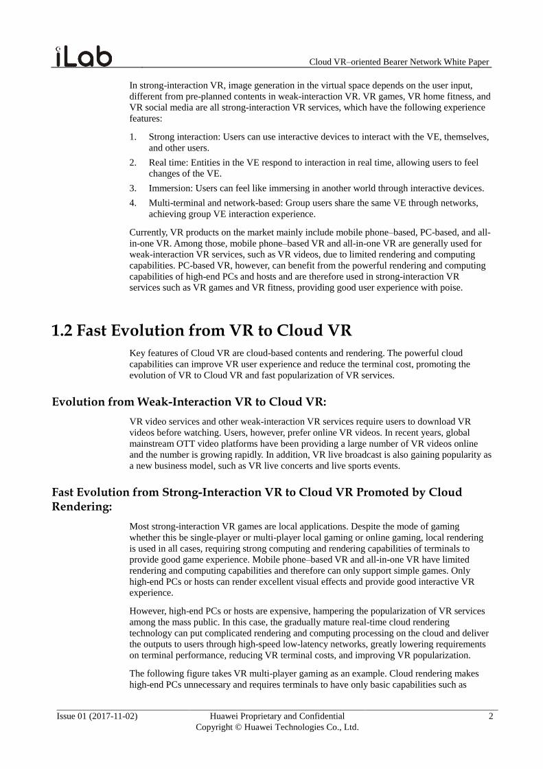
The following figure takes VR multi-player gaming as an example. Cloud rendering makes
high-end PCs unnecessary and requires terminals to have only basic capabilities such as
Cloud VR–oriented Bearer Network White Paper
Issue 01 (2017-11-02) Huawei Proprietary and Confidential
Copyright © Huawei Technologies Co., Ltd.
3
network connection, video and audio decoding, and image display. A common all-in-one VR,
phone-based VR, or STB+common VR headset can provide good user experience and greatly
lower the user consumption threshold.
Figure 1-1 Cloud rendering greatly reduces terminal cost
Strong-interaction
VR
Local rendering
Cloud rendering
Input
Mo-cap systems
Switch
Local processing
Mo-cap systems
Local game and mo-cap
serversLocal
rendering PCs
Game, mo-cap, and rendering
servers
Bearer network
Bearer network
Output
Output
Host VR
Terminal cost per user > RMB 10,000
Terminal cost per user < RMB 3,000
Switch
Input Cloud rendering
In September 15, 2017, the Cloud VR platform of Dalian Tiantu Cable TV Network was put
into operation, implementing cloud rendering. Dalian Tiantu Cable TV Network takes
advantage of the powerful computing capability of the cloud platform and provides users with
various VR services through fast and stable broadcast and television networks. Users can
access and enjoy the services through STBs. VR applications are all rendered on cloud servers
and streamed to VR headsets of users. The Cloud VR platform will accelerate the
transformation from local VR to Cloud VR, making VR services more acceptable to
households.
For strong-interaction VR, cloud rendering marks the emergence of Cloud VR. Although
strong-interaction services of Cloud VR have high bandwidth and latency requirements on the
network, the current network can meet these requirements. Certainly there are still many
technologies to develop and a long way to go to achieve the ultimate experience. The third
chapter will explain the development and evolution stages of Cloud VR in terms of
experience improvement.
Four Driving Forces of Cloud VR Development:
Four main advantages and driving forces of Cloud VR development are described as follows:
1. Reducing VR costs for users
Huawei iLab's researches and recommendations by Oculus Rift, HTC Vive, Valve, and
Steam VR show that the minimum configuration requirements for guaranteed basic VR
experience include: GPUs equivalent to GeForce GTX 970/AMD 290 or better, CPUs
equivalent to Intel i5-4590 or better, and RAM of at least 8 GB. The total cost of a PC-
Cloud VR–oriented Bearer Network White Paper
Issue 01 (2017-11-02) Huawei Proprietary and Confidential
Copyright © Huawei Technologies Co., Ltd.
4
based VR headset and a matching high-end PC exceeds RMB 10,000, which is a large
amount for a working-class family.
Whereas Cloud VR requires terminal devices to have only basic functions such as video
decoding, end rendering, image display, and receiving and uploading of control and
interaction signals. For example, VR STB decoding can be used with end-terminal
rendering processing. Together with a PC-based VR headset, the total cost of terminals
reaches around RMB 3,000.
2. Protecting VR content copyrights
Most of the VR contents are viewed off-line, making them difficult to manage. Content
copyrights of VR content providers cannot be protected. However, with Cloud VR,
content management becomes easy, and copyrights can be protected. The precise
management and provisioning can be implemented on the cloud.
3. Improving user experience
Cloud VR can improve logical computing and image processing capabilities. The
distributed computing capabilities of many-core servers, GPU clusters, and the cloud are
brought into full play. The latest GPU rendering and AI analysis technologies are used to
make up for the inadequacy of VR terminals and improve user experience.
4. Accelerating VR commercial popularization
Currently, the high per-user cost, lack of contents, difficulty of popularization result in
poor ecosystem. After VR moves to the cloud, user costs are greatly reduced,
popularizing VR in more households and enriching people's VR experience. As a result,
the development of high-quality VR contents and VR commercial scenarios will ripen.
1.3 Typical Applications of Cloud VR
According to the prediction in the 2016 VR/AR industry report of Goldman Sachs, three out
of nine major VR application domains that will be popularized by 2025 are VR games, VR
videos, and VR live broadcast. This section will introduce a few typical Cloud VR
applications.
Cloud VR Games:
Cloud VR gaming is the most typical strong-interaction application. It introduces the cloud
computing technology to VR game platforms. The cloud server performs complex computing
and image rendering of a game, and compresses it into video and audio streams for
transmission over high-speed broadband networks to players' headsets. By transferring the
computing and rendering capabilities that VR games require to cloud servers, players no
longer need to purchase high-end PCs for good gaming experience.
Cloud VR–oriented Bearer Network White Paper
Issue 01 (2017-11-02) Huawei Proprietary and Confidential
Copyright © Huawei Technologies Co., Ltd.
5
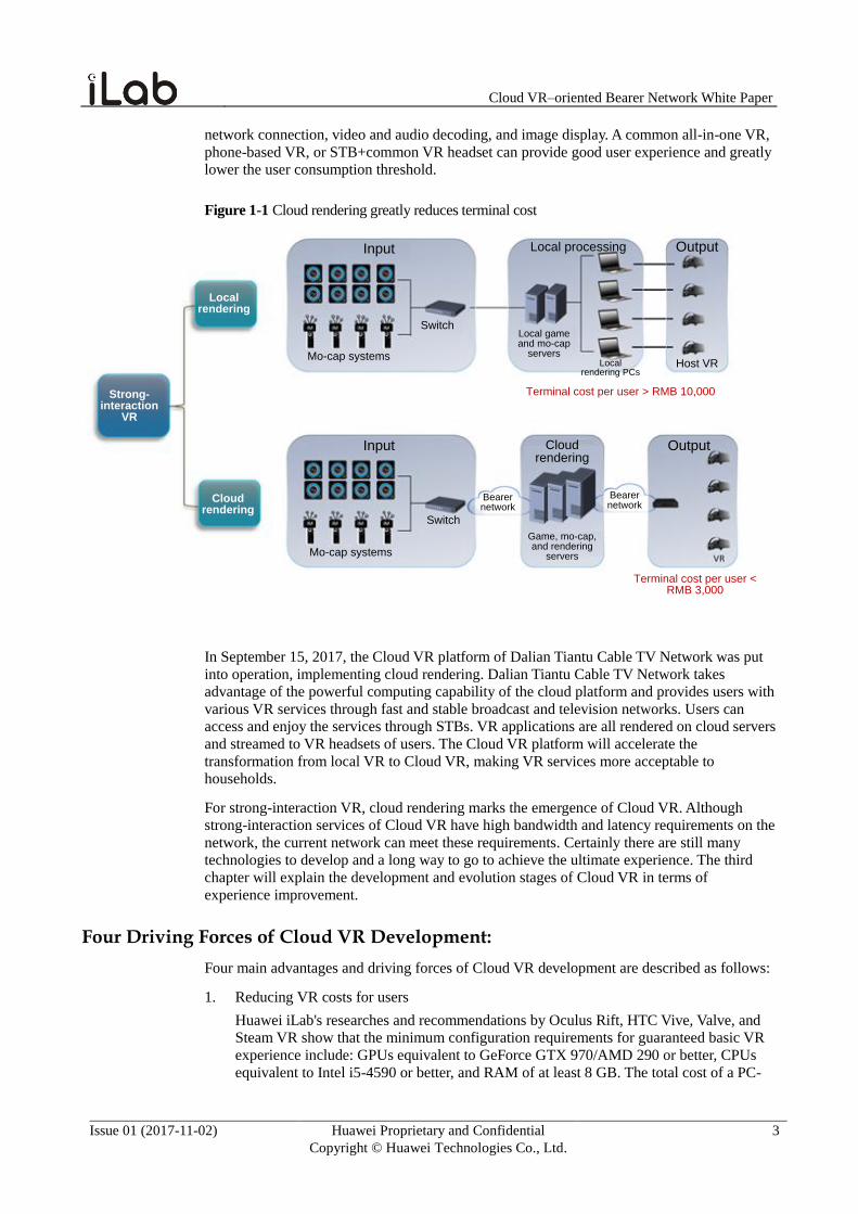
Figure 1-2 Service architecture diagram of Cloud VR games
Central cloudEdge cloud
Game server
Logic computing
· User-side gaming logic computing
· Rendering server
Edge cloud
Player A
Player B
Player C
Player information synchronization to the central cloud
Player information synchronization to the edge cloud
Image and audio information transmission to player headsets
Player motion and action information transmission to the edge cloud
· User-side gaming logic computing
· Rendering server
The preceding diagram shows the service architecture of Cloud VR games, which is
constructed with both the central and edge clouds. Part of the functions of the rendering and
game engines are deployed on the edge cloud, implementing user-side gaming logic
computing and image rendering. The edge cloud is closer to users, meaning lower latency and
satisfactory real-time interaction experience. Game servers, however, are deployed on the
central cloud, implementing other functions of the game engine and user status
synchronization.
Cloud VR Videos:
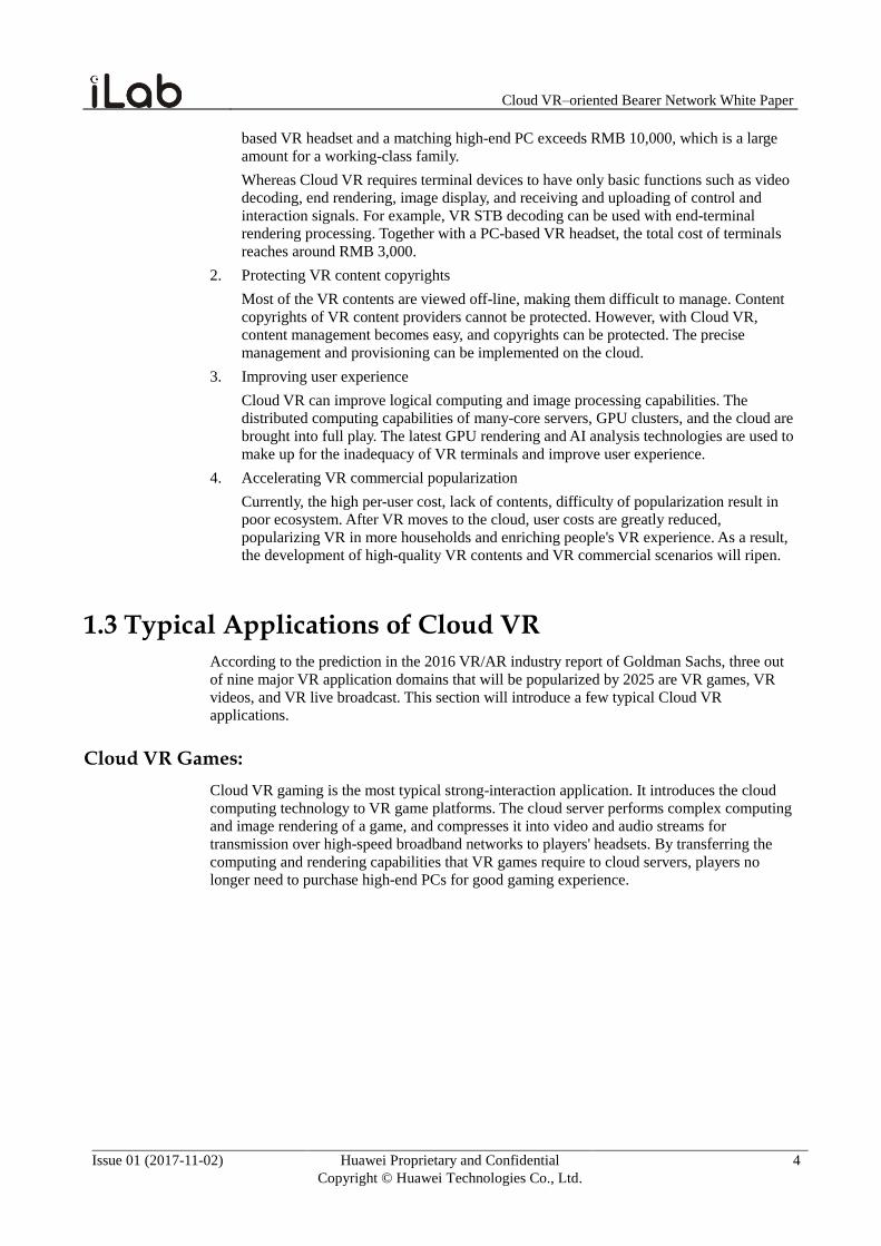
Cloud VR videos refer to VR video on demand (VoD). The key is cloud-based video contents,
which are streamed from the cloud to local terminals over networks.
Figure 1-3 Cloud VR video playing diagram
Network
Cloud VR videos provide a brand-new form of watching experience and are also the first type
of VR application that most users get to know. Currently, Cloud VR videos are supported on
most mainstream OTT video platforms around the world. For example, YouTube, Youku, and
iQIYI all have a dedicated VR video section that focuses on content ecosystem construction.
Cloud VR–oriented Bearer Network White Paper
Issue 01 (2017-11-02) Huawei Proprietary and Confidential
Copyright © Huawei Technologies Co., Ltd.
6
VR Live Broadcast:
VR live broadcast is the result of the convergence of traditional video broadcast and VR
technologies, and is implemented by panoramic shooting, real-time splicing, code streaming,
and CDN distribution. Compared with traditional live broadcast, VR live broadcast is
panoramic, 3D, and interactive. It brings people unprecedented immersion experience. VR
live broadcast, as a new form of live event/concert broadcast, has gradually penetrated our
life. For example, the VR live broadcast of the concert of Faye Wong, a famous female singer
in China, had over 20 million audiences. Industry leading operators, such as British Telecom,
SKT, and AT&T, have started commercial VR live broadcast of the English Premier League.
In addition, VR live broadcast technologies are also used in the 2017 Chinese Spring Festival
Gala, Sing! China, and other events. Through VR live broadcast, audiences can get close to
their idols across thousands of miles and feel the atmosphere like they are present at the
venue.
Beside the few typical Cloud VR applications above, there are also VR fitness, VR social
networking, and others. Cloud VR applications have penetrated people's life and will
definitely promote the prosperity of the VR industry.
Cloud VR–oriented Bearer Network White Paper
Issue 01 (2017-11-02) Huawei Proprietary and Confidential
Copyright © Huawei Technologies Co., Ltd.
7
2 Key Technologies of Cloud VR
2.1 Full-View and FOV
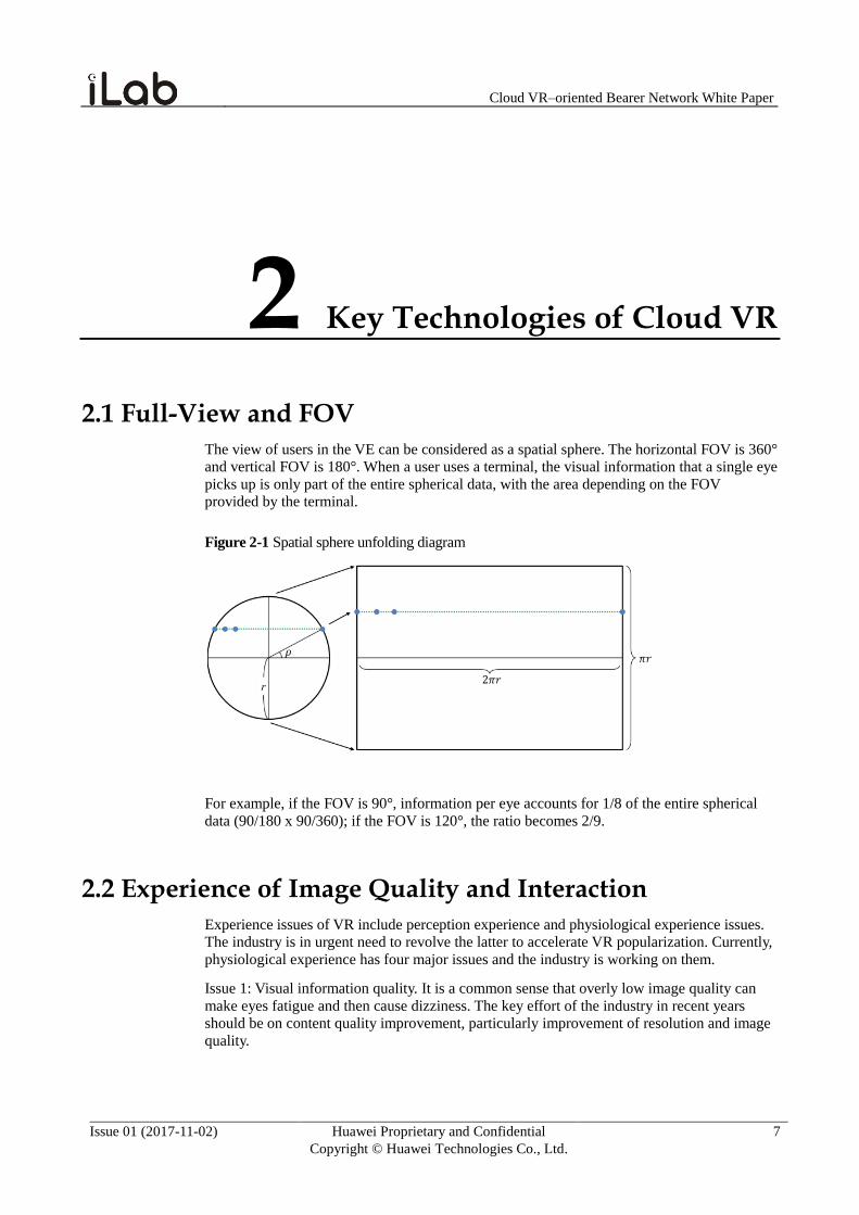
The view of users in the VE can be considered as a spatial sphere. The horizontal FOV is 360°
and vertical FOV is 180°. When a user uses a terminal, the visual information that a single eye
picks up is only part of the entire spherical data, with the area depending on the FOV
provided by the terminal.
Figure 2-1 Spatial sphere unfolding diagram
For example, if the FOV is 90°, information per eye accounts for 1/8 of the entire spherical
data (90/180 x 90/360); if the FOV is 120°, the ratio becomes 2/9.
2.2 Experience of Image Quality and Interaction
Experience issues of VR include perception experience and physiological experience issues.
The industry is in urgent need to revolve the latter to accelerate VR popularization. Currently,
physiological experience has four major issues and the industry is working on them.
Issue 1: Visual information quality. It is a common sense that overly low image quality can
make eyes fatigue and then cause dizziness. The key effort of the industry in recent years
should be on content quality improvement, particularly improvement of resolution and image
quality.
Cloud VR–oriented Bearer Network White Paper
Issue 01 (2017-11-02) Huawei Proprietary and Confidential
Copyright © Huawei Technologies Co., Ltd.
8
Issue 2: motion-to-photons latency (MTP). A widely accepted opinion in the industry says that
the MTP latency cannot exceed 20 ms, otherwise it will cause dizziness. The currently leading
VR terminal vendors, such as Oculus and HTC Vive, have managed to shorten the MTP
latency to 20 ms through end-to-end software and hardware performance improvement,
starting from sensor tracing elements, display technology and GPU.
Issue 3: motion-sensing conflict. If the motion feedback output is missing, physical motion of
the user does not match the virtual information captured by the eyes and therefore dizziness
occurs. To resolve the issue, VR terminals need to provide multi-sensory experience,
including visual, audio, touching, and motion feedback, fully exploring the value of VR new
media.
Issue 4: vergence-accommodation conflict. The conflict is also known as focusing conflict. It
exists in display terminals that utilize the dual-eye parallax principle. Because no depth data is
provided by the light emitted from the screen, the focus of the eyes is on the screen. As a
result, the focus adjustment of the eyes mismatches the visual depth, causing dizziness. To
resolve the issue, a new technology is needed to record and restore the intensity and angle of
the light emitted from a spot in the 3D space by using the record of the light field and the
projection technology. This technology will mature further in future development.
This section describes three issues that have major breakthroughs in the industry in recent
years: visual information quality, MTP latency, and motion-sensing conflict.
Image Quality Experience:
Due to the difference between the full view and FOV in VR, the traditional description of
OTT video resolution corresponds to that of the full-view resolution of VR 360 videos. What
determines the image quality experience of VR 360 videos is the single-eye resolution (FOV
resolution), which can be converted into pixels per degree (PPD), the number of pixels visible
per one degree in the FOV area. The higher the PPD value, the higher the pixel density in the
FOV, and the better the image quality experience. The PPD value for a normal-sighted user is
about 60. If the PPD is higher than 60, most people will not be able to identify individual
pixels.
An online 4K VR video on YouTube, for example, has the resolution value of 960 x 960 in a
90° FOV per eye, which corresponds to only 10 PPD. The single-eye resolution is way lower
than the 60 PPD required by normal-sighted retinas. The actual image quality experience is
much poorer than watching SD videos on traditional TVs, which have a resolution value of 22
PPD.
The immersive VR terminals have the FOV higher than that of traditional TVs; therefore, to
achieve the same level of image quality experience, the same PPD value requires VR
terminals to have much higher single-eye resolution and full-view resolution. The full-view
4K resolution is far behind the desired video quality and therefore improving the resolution
value to 8K or higher is essential. A 90° FOV, for example, has a single-eye resolution value
of 1920 x 1920 (PPD = 22) when the full-view resolution reaches 8K. When the full-view
resolution upgrades to 12K, the single-eye resolution will become 2880 x 2880 with the PPD
value increasing to only 32. In the rest of the white paper, an evolution roadmap of VR
experience will be demonstrated.
Interactive Experience
For MTP latency, a mainstream opinion in the industry believes that the latency over 20 ms
will cause dizziness. It means that when the viewing angle is changed by turning heads or
other ways, the overall latency across the terminal, network, and cloud should ensure that the
change of the motion and the change of the image in the FOV are consistent. The refresh
Cloud VR–oriented Bearer Network White Paper
Issue 01 (2017-11-02) Huawei Proprietary and Confidential
Copyright © Huawei Technologies Co., Ltd.
9
latency of the FOV image cannot exceed 20 ms, and missing of all or part of image
information in the FOV is not allowed. Similarly, for motion-sensing conflict, the
convergence capability of visual, audio, feeling, and motion feedback also requires the display
latency caused by motion to be less than 20 ms to avoid dizziness.
2.3 Projection and Coding Technologies
The projection and coding technologies determine the media information volume contained in
the VR image media files, and in which form they are produced and organized. These
technologies are essential, to quantize the network requirements of meeting certain user
experience.
Projection Technology:
To convert the spatial sphere information viewed by users in VR images into 2D media
formats, a new projection technology that has not been used in traditional videos is needed.
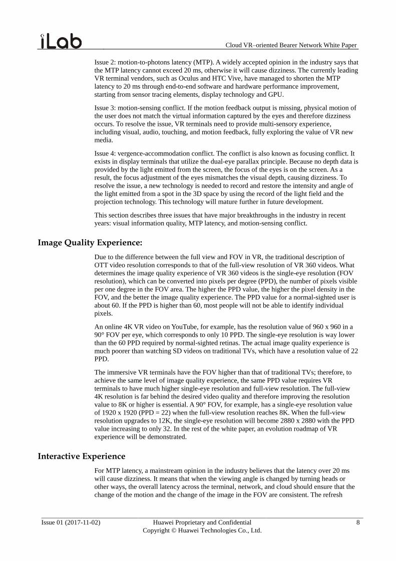
Currently, equirectangular projection (ERP) is the mainstream VR image format, but images
are subject to distortion and the compression efficiency reaches a bottleneck. The projection
method uses the classical meridian and parallel map concept and unfolds the sphere into a
planar rectangular. The meridians and parallels of the ERP intersect at 90° with the largest
area distortion and without angle distortion. The angles remain unchanged mainly due to the
area distortion. After the sphere is unfolded, the equator area has low distortion and the polar
areas have the highest distortion. Polar areas are increased to keep the angles unchanged and
therefore redundant ineffective pixels are introduced, causing low compression efficiency of
video coding. YouTube, Samsung Gear, Youku, and iQIYI are all using this projection format
to produce VR media files.
Figure 2-2 ERP diagram
Cloud VR–oriented Bearer Network White Paper
Issue 01 (2017-11-02) Huawei Proprietary and Confidential
Copyright © Huawei Technologies Co., Ltd.
10
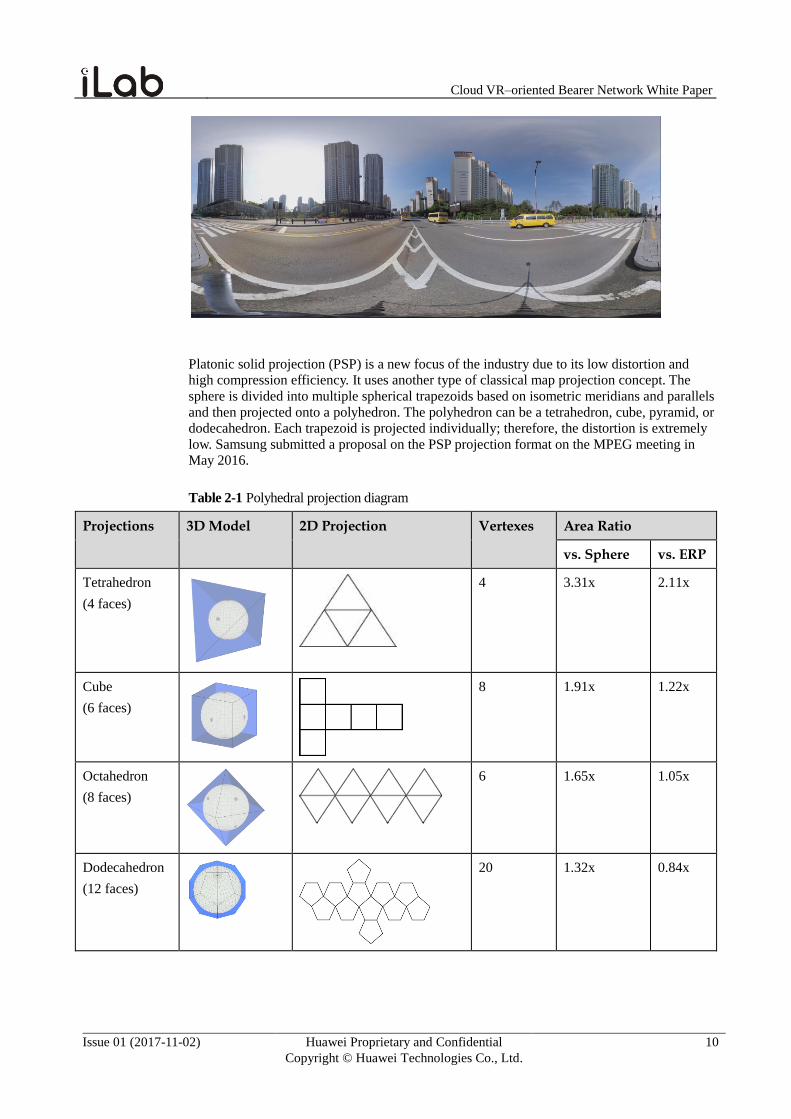
Platonic solid projection (PSP) is a new focus of the industry due to its low distortion and
high compression efficiency. It uses another type of classical map projection concept. The
sphere is divided into multiple spherical trapezoids based on isometric meridians and parallels
and then projected onto a polyhedron. The polyhedron can be a tetrahedron, cube, pyramid, or
dodecahedron. Each trapezoid is projected individually; therefore, the distortion is extremely
low. Samsung submitted a proposal on the PSP projection format on the MPEG meeting in
May 2016.
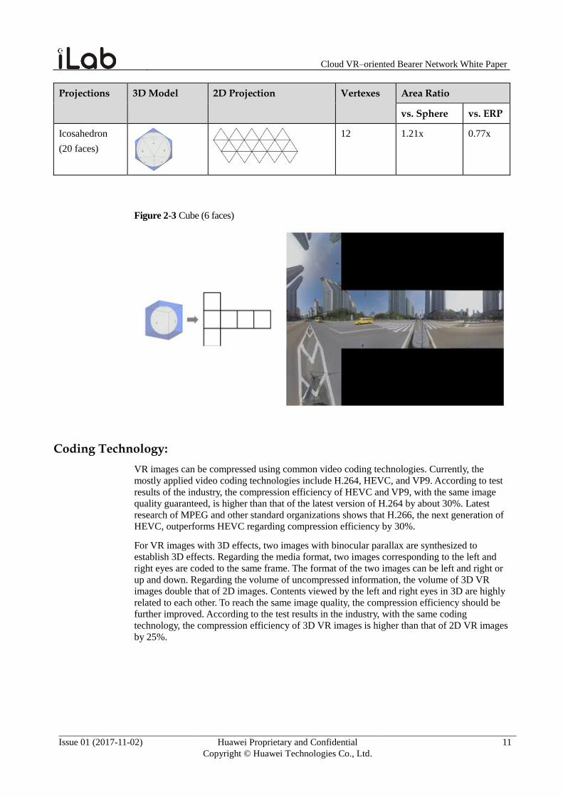
Table 2-1 Polyhedral projection diagram
Projections 3D Model 2D Projection Vertexes Area Ratio
vs. Sphere vs. ERP
Tetrahedron
(4 faces)
4 3.31x 2.11x
Cube
(6 faces)
8 1.91x 1.22x
Octahedron
(8 faces)
6 1.65x 1.05x
Dodecahedron
(12 faces)
20 1.32x 0.84x
Cloud VR–oriented Bearer Network White Paper
Issue 01 (2017-11-02) Huawei Proprietary and Confidential
Copyright © Huawei Technologies Co., Ltd.
11
Projections 3D Model 2D Projection Vertexes Area Ratio
vs. Sphere vs. ERP
Icosahedron
(20 faces)
12 1.21x 0.77x
Figure 2-3 Cube (6 faces)
Coding Technology:
VR images can be compressed using common video coding technologies. Currently, the
mostly applied video coding technologies include H.264, HEVC, and VP9. According to test
results of the industry, the compression efficiency of HEVC and VP9, with the same image
quality guaranteed, is higher than that of the latest version of H.264 by about 30%. Latest
research of MPEG and other standard organizations shows that H.266, the next generation of
HEVC, outperforms HEVC regarding compression efficiency by 30%.
For VR images with 3D effects, two images with binocular parallax are synthesized to
establish 3D effects. Regarding the media format, two images corresponding to the left and
right eyes are coded to the same frame. The format of the two images can be left and right or
up and down. Regarding the volume of uncompressed information, the volume of 3D VR
images double that of 2D images. Contents viewed by the left and right eyes in 3D are highly
related to each other. To reach the same image quality, the compression efficiency should be
further improved. According to the test results in the industry, with the same coding
technology, the compression efficiency of 3D VR images is higher than that of 2D VR images
by 25%.
Cloud VR–oriented Bearer Network White Paper
Issue 01 (2017-11-02) Huawei Proprietary and Confidential
Copyright © Huawei Technologies Co., Ltd.
12
2.4 Transmission Technology Roadmap
Online transmission of VR images uses two main technological schemes: full-view
transmission and FOV transmission. Strong-interaction VR involves only the FOV (non-full-
view) transmission scheme, whereas weak-interaction VR involves both transmission
schemes.
Full-View Transmission Scheme:
The full-view transmission scheme transmits 360° images to terminals. When users turn their
heads, the image switching processing is done locally. With the same single-eye resolution,
VR images have much larger bit rates than common 2D videos, normally by 5 to 10 folds, due
to their frame rate, bit depth, and 360° features. For example, the ultimate panoramic VR
video with single-eye 8K resolution requires the bandwidth to reach 5G, posing a great
challenge on the network and a huge burden on the cost.
In the full-view transmission scheme, a frame of data received by the terminal contains the
information of the full view of the spatial sphere. Interaction signals generated when users
change their viewing angles are processed on local terminals, which decode corresponding
FOV information from the local loaded frames and restore the data in the player. Users can
then view the visual information from a normal viewing angle. Therefore, the 20 ms latency
requirement of the interaction experience depends on terminals and does not involve network
latency and cloud latency. The scheme has a high bandwidth requirement but a low latency
requirement, and is a "bandwidth to latency" transmission scheme. The transmission scheme
can use the existing mainstream video transmission technologies, such as MPEG.DASH,
HLS, and HPD. A function that restores and projects FOV information from full-view frames
is added to terminal players.
FOV Transmission Scheme:
Regarding the full-view transmission scheme, users can view only part of the entire spatial
sphere with the rest of the area merely taking up network bandwidth, greatly wasting network
resources. To resolve this issue, the industry proposes the FOV transmission scheme which
transmits differentiated VR images based on the FOV.
The FOV transmission scheme focuses on the high-quality image transmission of the current
FOV area. Specific technologies that implement FOV transmission are not standardized yet.
The following two methods are dedicated to weak-interaction VR.
Pyramid-shaped projection transmission scheme (Facebook)
Cloud VR–oriented Bearer Network White Paper
Issue 01 (2017-11-02) Huawei Proprietary and Confidential
Copyright © Huawei Technologies Co., Ltd.
13
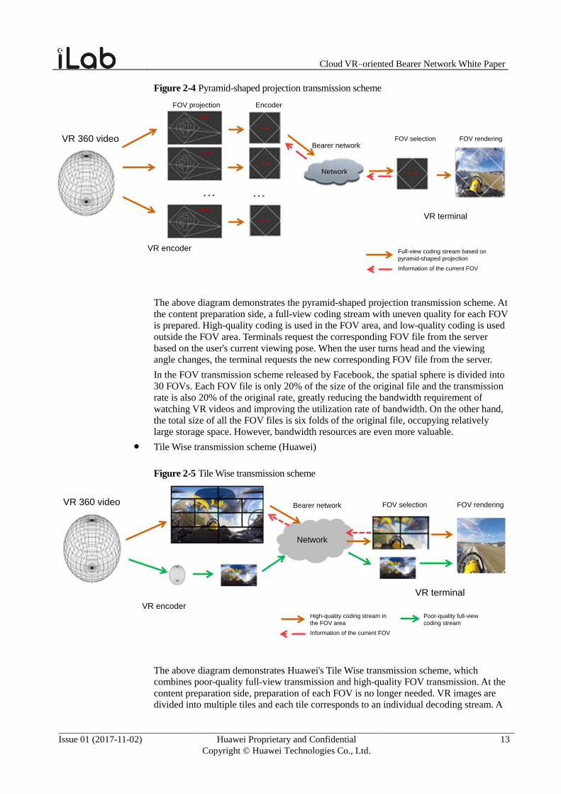
Figure 2-4 Pyramid-shaped projection transmission scheme
FOV projection Encoder
VR encoder
VR 360 videoBearer network
Network
FOV selection FOV rendering
VR terminal
Full-view coding stream based on
pyramid-shaped projection
Information of the current FOV
The above diagram demonstrates the pyramid-shaped projection transmission scheme. At
the content preparation side, a full-view coding stream with uneven quality for each FOV
is prepared. High-quality coding is used in the FOV area, and low-quality coding is used
outside the FOV area. Terminals request the corresponding FOV file from the server
based on the user's current viewing pose. When the user turns head and the viewing
angle changes, the terminal requests the new corresponding FOV file from the server.
In the FOV transmission scheme released by Facebook, the spatial sphere is divided into
30 FOVs. Each FOV file is only 20% of the size of the original file and the transmission
rate is also 20% of the original rate, greatly reducing the bandwidth requirement of
watching VR videos and improving the utilization rate of bandwidth. On the other hand,
the total size of all the FOV files is six folds of the original file, occupying relatively
large storage space. However, bandwidth resources are even more valuable.
Tile Wise transmission scheme (Huawei)
Figure 2-5 Tile Wise transmission scheme
VR encoder
VR 360 video Bearer network
Network
FOV selection FOV rendering
VR terminal
High-quality coding stream in
the FOV area
Information of the current FOV
Poor-quality full-view
coding stream
The above diagram demonstrates Huawei's Tile Wise transmission scheme, which
combines poor-quality full-view transmission and high-quality FOV transmission. At the
content preparation side, preparation of each FOV is no longer needed. VR images are divided into multiple tiles and each tile corresponds to an individual decoding stream. A
Cloud VR–oriented Bearer Network White Paper
Issue 01 (2017-11-02) Huawei Proprietary and Confidential
Copyright © Huawei Technologies Co., Ltd.
14
poor-quality full-view VR coding stream is also prepared. Terminals obtain the poor-
quality full-view coding stream and a high-quality coding stream (of a tile) by selection.
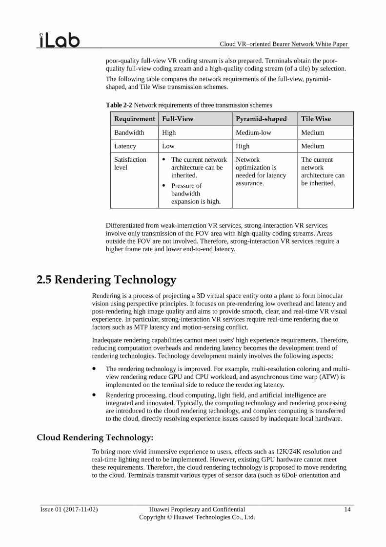
The following table compares the network requirements of the full-view, pyramid-
shaped, and Tile Wise transmission schemes.
Table 2-2 Network requirements of three transmission schemes
Requirement Full-View Pyramid-shaped Tile Wise
Bandwidth High Medium-low Medium
Latency Low High Medium
Satisfaction
level
The current network
architecture can be
inherited.
Pressure of
bandwidth
expansion is high.
Network
optimization is
needed for latency
assurance.
The current
network
architecture can
be inherited.
Differentiated from weak-interaction VR services, strong-interaction VR services
involve only transmission of the FOV area with high-quality coding streams. Areas
outside the FOV are not involved. Therefore, strong-interaction VR services require a
higher frame rate and lower end-to-end latency.
2.5 Rendering Technology
Rendering is a process of projecting a 3D virtual space entity onto a plane to form binocular
vision using perspective principles. It focuses on pre-rendering low overhead and latency and
post-rendering high image quality and aims to provide smooth, clear, and real-time VR visual
experience. In particular, strong-interaction VR services require real-time rendering due to
factors such as MTP latency and motion-sensing conflict.
Inadequate rendering capabilities cannot meet users' high experience requirements. Therefore,
reducing computation overheads and rendering latency becomes the development trend of
rendering technologies. Technology development mainly involves the following aspects:
The rendering technology is improved. For example, multi-resolution coloring and multi-
view rendering reduce GPU and CPU workload, and asynchronous time warp (ATW) is
implemented on the terminal side to reduce the rendering latency.
Rendering processing, cloud computing, light field, and artificial intelligence are
integrated and innovated. Typically, the computing technology and rendering processing
are introduced to the cloud rendering technology, and complex computing is transferred
to the cloud, directly resolving experience issues caused by inadequate local hardware.
Cloud Rendering Technology:
To bring more vivid immersive experience to users, effects such as 12K/24K resolution and
real-time lighting need to be implemented. However, existing GPU hardware cannot meet
these requirements. Therefore, the cloud rendering technology is proposed to move rendering
to the cloud. Terminals transmit various types of sensor data (such as 6DoF orientation and
Cloud VR–oriented Bearer Network White Paper
Issue 01 (2017-11-02) Huawei Proprietary and Confidential
Copyright © Huawei Technologies Co., Ltd.
15
position information) and interaction control information in real time, and the cloud
computing cluster completes image rendering and sends the result to the terminals.
The cloud rendering technology deploys most computing on the cloud, so that consumers can
obtain high-quality 3D rendering effects on lightweight VR terminals. Terminals are no longer
restricted by high hardware performance requirements, and consumers can obtain hierarchical
immersive experience (high, medium, or low) based on fees. Meanwhile, real-time rendering
needs to be ensured by end-to-end low latency.
ATW Rendering Technology:
In VR rendering, content complexity varies. Therefore, rendering of complex contents
possibly cannot be completed within the refreshing period of one frame. As a result, no new
content is generated after screen refreshing, and users will perceive that as a freeze. To resolve
this issue, the ATW rendering technology is proposed in the industry.
This technology determines the head pose in the frame by means of pose prediction, computes
the pose difference based on the pose upon generation of the previous frame image, changes
the position of the previous frame image based on the pose difference, and generates an
intermediate image in a new frame, resolving the freezing issue caused by the lack of the
current frame.
The ATW rendering technology can ensure the smooth visual experience of users in most
cases. Theoretically, ATW can continuously generate new images based on one frame of
image. However, errors between the generated images and the actual rendered images will
accumulate due to the continuous distortion. As a result, the image quality will deteriorate.
Multi-resolution Coloring Technology:
Due to VR distortion, the four edges of an image are compressed during rendering and can
never be displayed after re-sampling of a large number of pixels rendered from application
contents. In fact, the rendering overheads of these pixels can be reduced. GPU vendors in the
industry propose the multi-resolution coloring technology to reduce the rendering overheads.
In this technology, an image is divided into grids. The central area retains the original
resolution, and the resolution of the four edges and corners are compressed by 1/2 and 1/4
(can be changed as required). During rendering of the application contents, the image is
drawn by the GPU at once.
Multi-view Rendering Technology:
Compared with common application rendering, VR rendering of each frame needs to
simultaneously render the images for both the left and right eyes. In each frame, one rendering
task is submitted separately for the images on the left and right eyes. Therefore, CPU/GPU
resources occupied by VR rendering are twice as many as those occupied by common
application rendering. To resolve this issue, the multi-view rendering technology is proposed
in the industry so that the images for the left and right eyes are simultaneously rendered after
only one task is submitted.
Most information of the images for the left and right eyes is the same and the images only
slightly differ in parallax. Therefore, in the multi-view rendering technology, the CPU needs
to submit only one rendering task and parallax information to the GPU, and then the GPU can
render the images for the left and right eyes, greatly reducing CPU resource occupancy and
improving the frame rate.
Cloud VR–oriented Bearer Network White Paper
Issue 01 (2017-11-02) Huawei Proprietary and Confidential
Copyright © Huawei Technologies Co., Ltd.
16
Light Field Rendering Technology:
The existing VR imaging method is basically the 2D imaging method with binocular parallax.
The focus points and convergence point of the eyes are not at the same position for a long
time. The former is located on the screen plane, and the latter is located on the virtual plane
generated by the binocular parallax. As a result, vergence-accommodation conflict occurs,
causing dizziness and other physiological discomfort and loss of immersion.
Restoring the contents that can be seen by eyes in the real world may bring the perfect
immersion. By changing the focal length, eyes collect the light reflected on surfaces of objects
at different distances, in different positions, and in different directions. The complete set of
them all is the light field. A vendor in the industry has developed a light field camera that
collects light field information. The light field rendering technology restores the collected
light field information to meet higher immersion experience requirements of users. Currently,
collection, storage, and transmission of light field information face many basic issues such as
enormous data volumes, and the light field rendering technology is still in an early stage.
However, it may become a key rendering technology in the future as users have higher
requirements on VR experience.
Cloud VR–oriented Bearer Network White Paper
Issue 01 (2017-11-02) Huawei Proprietary and Confidential
Copyright © Huawei Technologies Co., Ltd.
17
3 Network Requirements at Different Cloud VR Stages
3.1 Four Stages of Cloud VR
The development of Cloud VR is revolving around experience: improvement in profile and
interactive and immersive experience. The compatibility between transmission technologies
and network technologies determines the level of immersive experience that can be delivered
by Cloud VR. We believe that Cloud VR experience may evolve through the following stages:
early stage, entry-level experience stage, advanced experience stage, and ultimate experience
stage. In the following text, we have some predictions on the terminal, content, experience,
network, and commercial application for each stage.
Early stage
The early stage of Cloud VR is called pre-VR, which barely reaches the entry level in terms
of experience. We believe that this stage should be marked by the fairly high-level hardware
and software that are generally available in 2016. A typical terminal is HTC VIVE with a 2K
resolution, and the typical content provider is YouTube, which provides 4K VR video, almost
equivalent to 240p PPD on a traditional TV screen in profile.
For weak-interaction VR services, the full-view transmission scheme is used at this stage.
Strong-interaction VR services need higher frame rates than weak-interaction VR services to
ensure good user experience. In addition, strong-interaction VR services use only the FOV
transmission mode, and require the terminals to support ATW rendering technology to obtain
smooth experience.
Entry-level experience stage
Cloud VR at the entry-level stage is called entry-level VR. The generally available hardware
and software will be improved to a higher level. The terminal screen resolution is improved to
4K and the full-view resolution to 8K. As a result, the profile that users receive approaches
the 480p-equivalent PPD effect on traditional TV screens.
For weak-interaction VR services, full view remains the preferred transmission scheme to
ensure good watching and interaction experience for customers. However, with the emergence
of full-view 8K 3D video and bandwidth beyond 100M, the FOV scheme will be increasingly
used. In the case of strong-interaction VR services, the resolution is further improved, and so
is the demand for bandwidth.
Cloud VR–oriented Bearer Network White Paper
Issue 01 (2017-11-02) Huawei Proprietary and Confidential
Copyright © Huawei Technologies Co., Ltd.
18
Advanced experience stage
Cloud VR at the advanced experience stage is called Advanced VR. At this stage, the screen
resolution, chip performance, and ergonomics of terminals and the quality of content are
significantly improved. The profile received by users is approaching 720p PPD on a
traditional TV screen. At this phase, Cloud VR has significantly higher requirements on
bandwidth and latency to ensure good experience of services.
For weak-interaction VR services, the full-view transmission scheme will pose higher
requirements on network bandwidth. Therefore, the FOV scheme becomes mainstream to
lower the requirements on bandwidth. In the case of strong-interaction VR services, lower
network latency is required to improve the interaction experience of users.
Ultimate experience stage
Cloud VR at the ultimate experience stage is called Ultimate VR. At this stage, the
development of terminals and the content can provide users with the best experience. The
resolution and frame rate are significantly improved, and per-eye image reaches retina level,
approaching to 4K-equivalent PPD on a traditional TV screen. In addition, technologies, such
as H.266 hardware video encoding standard and light field rendering, will be widely used.
For weak-interaction VR services, the requirements of full view transmission on network
bandwidth are too high. Therefore, FOV transmission will be widely used. In the case of
strong-interaction VR services, the resolution is further improved, and so is the demand for
bandwidth.
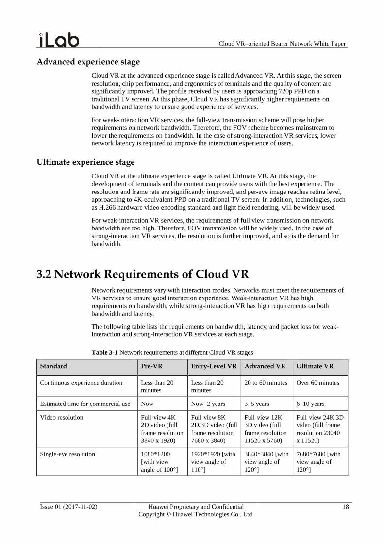
3.2 Network Requirements of Cloud VR
Network requirements vary with interaction modes. Networks must meet the requirements of
VR services to ensure good interaction experience. Weak-interaction VR has high
requirements on bandwidth, while strong-interaction VR has high requirements on both
bandwidth and latency.
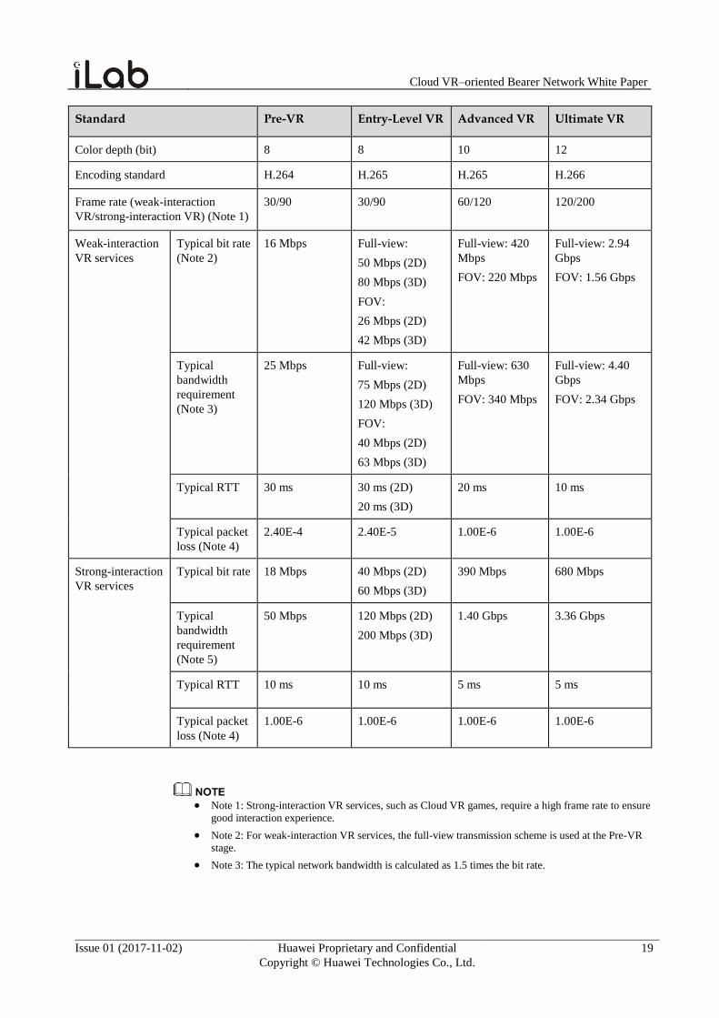
The following table lists the requirements on bandwidth, latency, and packet loss for weak-
interaction and strong-interaction VR services at each stage.
Table 3-1 Network requirements at different Cloud VR stages
Standard Pre-VR Entry-Level VR Advanced VR Ultimate VR
Continuous experience duration Less than 20
minutes
Less than 20
minutes
20 to 60 minutes Over 60 minutes
Estimated time for commercial use Now Now–2 years 3–5 years 6–10 years
Video resolution Full-view 4K
2D video (full
frame resolution
3840 x 1920)
Full-view 8K
2D/3D video (full
frame resolution
7680 x 3840)
Full-view 12K
3D video (full
frame resolution
11520 x 5760)
Full-view 24K 3D
video (full frame
resolution 23040
x 11520)
Single-eye resolution 1080*1200
[with view
angle of 100°]
1920*1920 [with
view angle of
110°]
3840*3840 [with
view angle of
120°]
7680*7680 [with
view angle of
120°]
Cloud VR–oriented Bearer Network White Paper
Issue 01 (2017-11-02) Huawei Proprietary and Confidential
Copyright © Huawei Technologies Co., Ltd.
19
Standard Pre-VR Entry-Level VR Advanced VR Ultimate VR
Color depth (bit) 8 8 10 12
Encoding standard H.264 H.265 H.265 H.266
Frame rate (weak-interaction
VR/strong-interaction VR) (Note 1)
30/90 30/90 60/120 120/200
Weak-interaction
VR services
Typical bit rate
(Note 2)
16 Mbps Full-view:
50 Mbps (2D)
80 Mbps (3D)
FOV:
26 Mbps (2D)
42 Mbps (3D)
Full-view: 420
Mbps
FOV: 220 Mbps
Full-view: 2.94
Gbps
FOV: 1.56 Gbps
Typical
bandwidth
requirement
(Note 3)
25 Mbps Full-view:
75 Mbps (2D)
120 Mbps (3D)
FOV:
40 Mbps (2D)
63 Mbps (3D)
Full-view: 630
Mbps
FOV: 340 Mbps
Full-view: 4.40
Gbps
FOV: 2.34 Gbps
Typical RTT 30 ms 30 ms (2D)
20 ms (3D)
20 ms 10 ms
Typical packet
loss (Note 4)
2.40E-4 2.40E-5 1.00E-6 1.00E-6
Strong-interaction
VR services
Typical bit rate 18 Mbps 40 Mbps (2D)
60 Mbps (3D)
390 Mbps 680 Mbps
Typical
bandwidth
requirement
(Note 5)
50 Mbps 120 Mbps (2D)
200 Mbps (3D)
1.40 Gbps 3.36 Gbps
Typical RTT 10 ms 10 ms 5 ms 5 ms
Typical packet
loss (Note 4)
1.00E-6 1.00E-6 1.00E-6 1.00E-6
Note 1: Strong-interaction VR services, such as Cloud VR games, require a high frame rate to ensure
good interaction experience.
Note 2: For weak-interaction VR services, the full-view transmission scheme is used at the Pre-VR
stage.
Note 3: The typical network bandwidth is calculated as 1.5 times the bit rate.
Cloud VR–oriented Bearer Network White Paper
Issue 01 (2017-11-02) Huawei Proprietary and Confidential
Copyright © Huawei Technologies Co., Ltd.
20
Note 4: For weak-interaction services, packet loss is calculated based on the latency to be achieved,
bandwidth, and TCP throughput. In the case of ultimate VR, TCP no longer meets the transmission
requirements, and a better or new transmission protocol must be used. Strong-interaction services
have low tolerance for packet loss.
Note 5: The typical bandwidth for strong-interaction VR services must meet the maximum
transmission speed of I frames and P frames. In addition, strong-interaction VR services also have
high requirements on latency and frame rate, which also means requirements on bandwidth.
Cloud VR–oriented Bearer Network White Paper
Issue 01 (2017-11-02) Huawei Proprietary and Confidential
Copyright © Huawei Technologies Co., Ltd.
21
4 Cloud VR-oriented Bearer Network
4.1 Early and Entry-level VR on the 4K Network
Pre-VR (full-view 4K) has similar requirements on the bearer network as 4K, with the
bandwidth requirement of 20 Mbps to 50 Mbps. Pre-VR can be quickly provisioned on a 4K-
ready bearer network. Entry-level VR (full-view 8K) has similar requirements on the bearer
network as 8K, with the bandwidth requirement of 50 Mbps to 200 Mbps. On a 4K-ready
bearer network, entry-level VR can be provisioned with simple network upgrade using the
existing technologies and products. This chapter describes the suggestions on deploying the
bearer network for pre-VR and how to upgrade the network to support quick provisioning of
entry-level VR.
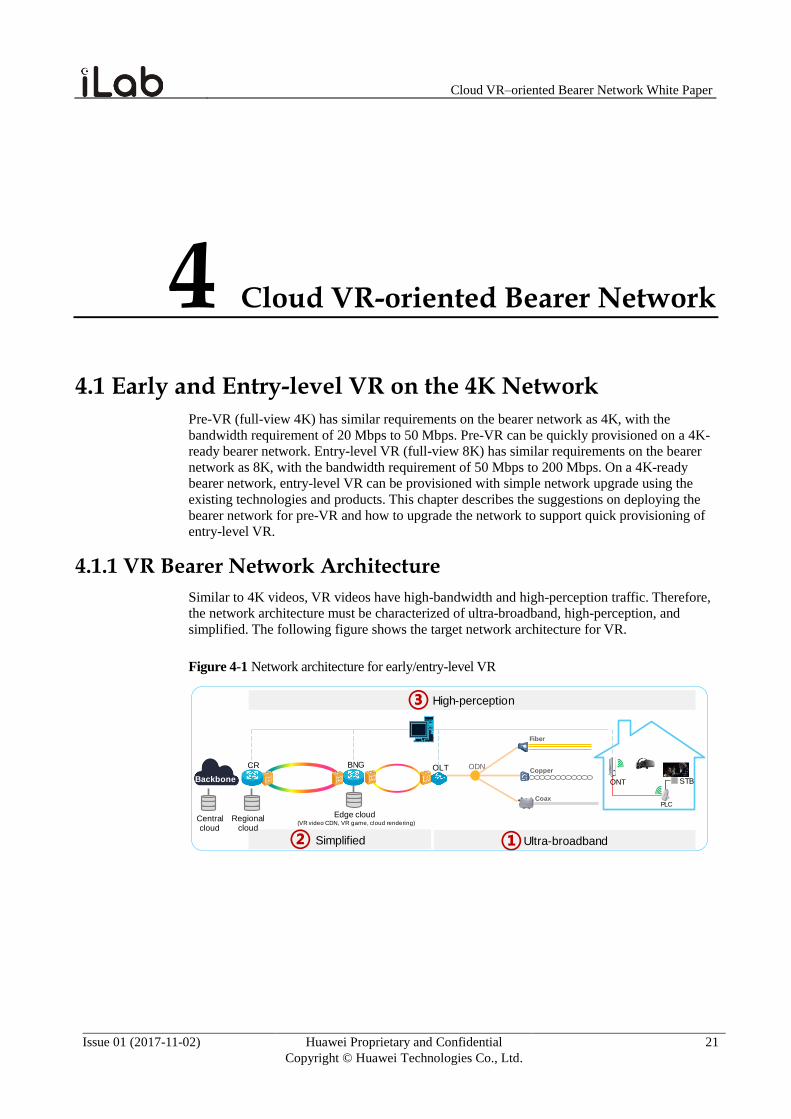
4.1.1 VR Bearer Network Architecture
Similar to 4K videos, VR videos have high-bandwidth and high-perception traffic. Therefore,
the network architecture must be characterized of ultra-broadband, high-perception, and
simplified. The following figure shows the target network architecture for VR.
Figure 4-1 Network architecture for early/entry-level VR
PLC
BNGCR OLT
Backbone
ODNCopper
Coax
Fiber
Ultra-broadbandSimplified
High-perception
② ①
③
STB
Central cloud
Regional cloud
Edge cloud (VR video CDN, VR game, cloud rendering)
ONT
Cloud VR–oriented Bearer Network White Paper
Issue 01 (2017-11-02) Huawei Proprietary and Confidential
Copyright © Huawei Technologies Co., Ltd.
22
Ultra-broadband Access
The current home broadband package of 100 Mbps bandwidth has been popularized. Such
access bandwidth can basically meet the 20 Mbps to 50 Mbps bandwidth requirement for pre-
VR (full-view 4K). VR HMDs cannot be viewed by multiple people on the same screen as TV
viewing. If multiple people at the home are watching a VR video at the same time, the
bandwidth requirement increases exponentially. If different people in a household use
different VR HMDs to view VR videos, the bandwidth package must be upgraded to be
greater than 200 Mbps. The bandwidth requirement for entry-level VR (full-view 8K) is 50
Mbps to 200 Mbps. Accordingly, the bandwidth must be greater than 200 Mbps for video
viewing of a single person. If multiple users view entry-level VR at the same time, the
bandwidth must be greater than 500 Mbps.
Simplified Network
The multi-level aggregation and high-convergence network architecture built up for
traditional services (such as voice, web, and OTT video services) is in face of great challenges
along with the exponential increase of video services. To reduce the probability of video
congestion and the bearer costs, the streamlined IP network layer becomes an inevitable trend.
High-Perception Network
VR is a type of high-perception experience service and is sensitive to packet loss and delay.
Network performance issues that may cause intermittent erratic display or frame freezing are
hard to locate using traditional methods such as viewing alarm information. A new O&M
methodology or system is in need to rapidly optimize networks and avoid user complaints and
churn.
4.1.2 Home Network Design
As VR HMDs are worn on users' heads, the Wi-Fi connection mode is generally used to
ensure VR mobility. This requires seamless Wi-Fi coverage in the areas where VR is used.
Currently, most of the Wi-Fi devices used by home users are purchased and networked by
themselves. Diverse Wi-Fi device specifications are prone to poor Wi-Fi performance and
user experience. In addition, there is no efficient method of locating and resolving Wi-Fi
performance issues. As a result, user complaints cannot be addressed in time.
Key Challenges in VR Service Bearer on Home Wi-Fi Networks
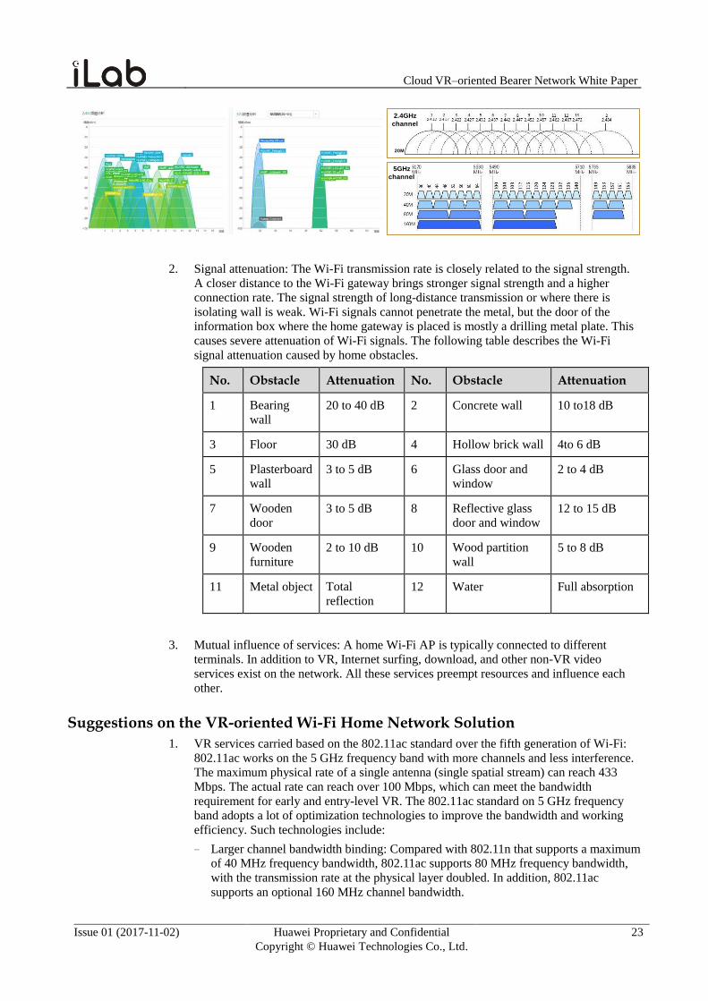
1. Signal interference: The transmission medium of Wi-Fi is shared air interfaces. Wi-Fi
defines backoff performed on the CSMA/CA at the MAC layer. When multiple APs use
the same frequency band, the performance is greatly deteriorated. When the 2.4 GHz
frequency band uses the 20 MHz frequency bandwidth, there are only 3 non-overlapping
channels and it is difficult to find a channel that does not interfere with others. When the
40 MHz frequency bandwidth is used, there is only one non-overlapping channel.
Therefore, 2.4 GHz cannot use the 40 MHz frequency bandwidth. Although there are
many 5 GHz channels, channel conflicts between neighboring APs still exist due to
inappropriate configuration.
Cloud VR–oriented Bearer Network White Paper
Issue 01 (2017-11-02) Huawei Proprietary and Confidential
Copyright © Huawei Technologies Co., Ltd.
23
5GHz
channel
2.4GHz
channel
20M
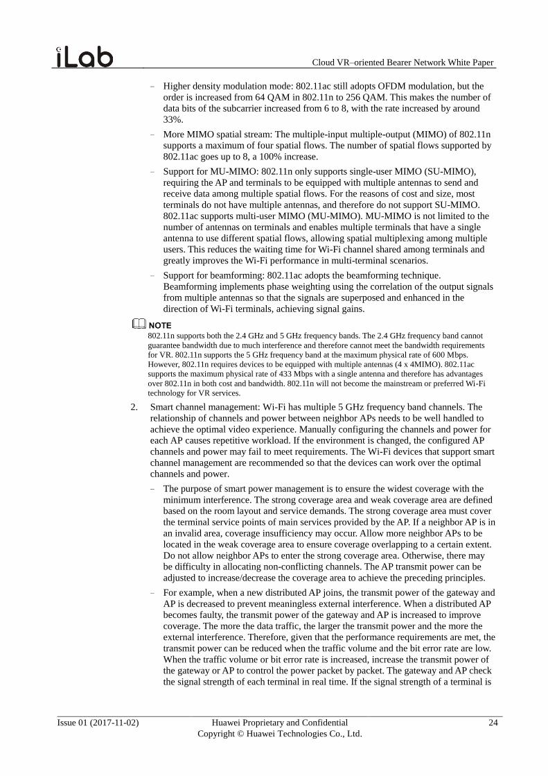
2. Signal attenuation: The Wi-Fi transmission rate is closely related to the signal strength.
A closer distance to the Wi-Fi gateway brings stronger signal strength and a higher
connection rate. The signal strength of long-distance transmission or where there is
isolating wall is weak. Wi-Fi signals cannot penetrate the metal, but the door of the
information box where the home gateway is placed is mostly a drilling metal plate. This
causes severe attenuation of Wi-Fi signals. The following table describes the Wi-Fi
signal attenuation caused by home obstacles.
No. Obstacle Attenuation No. Obstacle Attenuation
1 Bearing
wall
20 to 40 dB 2 Concrete wall 10 to18 dB
3 Floor 30 dB 4 Hollow brick wall 4to 6 dB
5 Plasterboard
wall
3 to 5 dB 6 Glass door and
window
2 to 4 dB
7 Wooden
door
3 to 5 dB 8 Reflective glass
door and window
12 to 15 dB
9 Wooden
furniture
2 to 10 dB 10 Wood partition
wall
5 to 8 dB
11 Metal object Total
reflection
12 Water Full absorption
3. Mutual influence of services: A home Wi-Fi AP is typically connected to different
terminals. In addition to VR, Internet surfing, download, and other non-VR video
services exist on the network. All these services preempt resources and influence each
other.
Suggestions on the VR-oriented Wi-Fi Home Network Solution
1. VR services carried based on the 802.11ac standard over the fifth generation of Wi-Fi:
802.11ac works on the 5 GHz frequency band with more channels and less interference.
The maximum physical rate of a single antenna (single spatial stream) can reach 433
Mbps. The actual rate can reach over 100 Mbps, which can meet the bandwidth
requirement for early and entry-level VR. The 802.11ac standard on 5 GHz frequency
band adopts a lot of optimization technologies to improve the bandwidth and working
efficiency. Such technologies include:
− Larger channel bandwidth binding: Compared with 802.11n that supports a maximum
of 40 MHz frequency bandwidth, 802.11ac supports 80 MHz frequency bandwidth,
with the transmission rate at the physical layer doubled. In addition, 802.11ac
supports an optional 160 MHz channel bandwidth.
Cloud VR–oriented Bearer Network White Paper
Issue 01 (2017-11-02) Huawei Proprietary and Confidential
Copyright © Huawei Technologies Co., Ltd.
24
− Higher density modulation mode: 802.11ac still adopts OFDM modulation, but the
order is increased from 64 QAM in 802.11n to 256 QAM. This makes the number of
data bits of the subcarrier increased from 6 to 8, with the rate increased by around
33%.
− More MIMO spatial stream: The multiple-input multiple-output (MIMO) of 802.11n
supports a maximum of four spatial flows. The number of spatial flows supported by
802.11ac goes up to 8, a 100% increase.
− Support for MU-MIMO: 802.11n only supports single-user MIMO (SU-MIMO),
requiring the AP and terminals to be equipped with multiple antennas to send and
receive data among multiple spatial flows. For the reasons of cost and size, most
terminals do not have multiple antennas, and therefore do not support SU-MIMO.
802.11ac supports multi-user MIMO (MU-MIMO). MU-MIMO is not limited to the
number of antennas on terminals and enables multiple terminals that have a single
antenna to use different spatial flows, allowing spatial multiplexing among multiple
users. This reduces the waiting time for Wi-Fi channel shared among terminals and
greatly improves the Wi-Fi performance in multi-terminal scenarios.
− Support for beamforming: 802.11ac adopts the beamforming technique.
Beamforming implements phase weighting using the correlation of the output signals
from multiple antennas so that the signals are superposed and enhanced in the
direction of Wi-Fi terminals, achieving signal gains.
802.11n supports both the 2.4 GHz and 5 GHz frequency bands. The 2.4 GHz frequency band cannot
guarantee bandwidth due to much interference and therefore cannot meet the bandwidth requirements
for VR. 802.11n supports the 5 GHz frequency band at the maximum physical rate of 600 Mbps.
However, 802.11n requires devices to be equipped with multiple antennas (4 x 4MIMO). 802.11ac
supports the maximum physical rate of 433 Mbps with a single antenna and therefore has advantages
over 802.11n in both cost and bandwidth. 802.11n will not become the mainstream or preferred Wi-Fi
technology for VR services.
2. Smart channel management: Wi-Fi has multiple 5 GHz frequency band channels. The
relationship of channels and power between neighbor APs needs to be well handled to
achieve the optimal video experience. Manually configuring the channels and power for
each AP causes repetitive workload. If the environment is changed, the configured AP
channels and power may fail to meet requirements. The Wi-Fi devices that support smart
channel management are recommended so that the devices can work over the optimal
channels and power.
− The purpose of smart power management is to ensure the widest coverage with the
minimum interference. The strong coverage area and weak coverage area are defined
based on the room layout and service demands. The strong coverage area must cover
the terminal service points of main services provided by the AP. If a neighbor AP is in
an invalid area, coverage insufficiency may occur. Allow more neighbor APs to be
located in the weak coverage area to ensure coverage overlapping to a certain extent.
Do not allow neighbor APs to enter the strong coverage area. Otherwise, there may
be difficulty in allocating non-conflicting channels. The AP transmit power can be
adjusted to increase/decrease the coverage area to achieve the preceding principles.
− For example, when a new distributed AP joins, the transmit power of the gateway and
AP is decreased to prevent meaningless external interference. When a distributed AP
becomes faulty, the transmit power of the gateway and AP is increased to improve
coverage. The more the data traffic, the larger the transmit power and the more the
external interference. Therefore, given that the performance requirements are met, the
transmit power can be reduced when the traffic volume and the bit error rate are low.
When the traffic volume or bit error rate is increased, increase the transmit power of
the gateway or AP to control the power packet by packet. The gateway and AP check
the signal strength of each terminal in real time. If the signal strength of a terminal is
Cloud VR–oriented Bearer Network White Paper
Issue 01 (2017-11-02) Huawei Proprietary and Confidential
Copyright © Huawei Technologies Co., Ltd.
25
greater than the target value (close distance to the AP), data packets are sent to the
terminal to automatically reduce the actual transmit power. If the signal strength of a
terminal is lower than the target value (long distance from the AP), the transmit
power is increased during packet sending.
3. VR-preferred Wi-Fi scheduling: The distributed coordination function (DCF) specified
in IEEE 802.11 is based on the CSMA/CA principle, allowing all terminals to obtain
channels with equal opportunities. IEEE 802.11e adds the QoS feature for the 802.11
protocol-based WLAN system and defines the Wi-Fi multimedia (WMM) standard.
− WMM defines VO (Voice), VI (Video), BE (Best effort), and BK (Background)
priority queues to ensure that high-priority packets are sent and use wireless channels
in priority.
− WMM defines the enhanced distributed channel access (EDCA) mechanism so that
high-priority packets are sent in priority and have higher bandwidth. EDCA
parameters include: (1) Arbitration Inter Frame Spacing Number (AIFSN). In the
802.11 protocol, DIFS is a fixed value. WMM allows configuration of different DIFS
values for different ACs. The larger the DIFS value, the longer the waiting time for
the user. A shorter waiting time brings more opportunities to obtain channels. (2)
Exponent form of minimum contention window (ECWmin) and exponent form of
maximum contention window (ECWmax) determine the average backoff time. The
larger the ECWmin and ECWmax values, the longer the average backoff time. (3)
Transmission opportunity (TXOP). This parameter indicates the maximum time for
occupying a channel after a successful competition. A larger TXOP value indicates
the longer duration for a user to occupy a channel.
− The air interfaces of VR video services can be used in priority by configuring a
higher priority, smaller AIFSN, ECWmin, and ECWmax, and a larger TXOP on the
video headend. For carrier-operated video services, enter a correct priority into the IP
header during headend video packet encapsulation to ensure that packets can be
mapped to the VO or VI queue. For non-carrier-operated OTT services, use ACL
rules to remark packet priorities to ensure that VR services can be mapped to the VO
and VI queue.
4. Distributed Wi-Fi coverage: The distributed Wi-Fi network solution is recommended for
home networks to resolve signal attenuation and achieve seamless Wi-Fi coverage. The
deployment and design principles for the distributed Wi-Fi coverage of home networks
are as follows:
− Gateway deployment location: Determine the ONT deployment location based on the
line position of broadband access. If fibers are extended to the living room, placing
the smart ONT in the living room is recommended. If fibers extend to the information
box instead of the living room, the ONT can be placed only in the information box.
Network cables can be used to extend fibers to the upstream gateway of LAN in the
living room.
− Whether to use distributed APs: Determine whether to use distributed APs and the
specific number of APs according to the house size and the number of rooms. Using
the Ethernet link as the backhaul link between the distributed AP and gateway is
preferred. The priority goes to the G.hn power line and then 5 GHz relay. Do not use
2.4 GHz Wi-Fi as a relay.

Cloud VR–oriented Bearer Network White Paper
Issue 01 (2017-11-02) Huawei Proprietary and Confidential
Copyright © Huawei Technologies Co., Ltd.
26
As for the current power line transmission standards Homeplug AV2 and G.hn, MIMO allows the
physical transmission rate to reach over 1 Gbps, which can meet the bandwidth requirements for
early and entry-level VR. Because power line signals are prone to interference by other electric
equipment, instability situations, such as signal fluctuation, may occur during peak hours.
Selecting G.hn-based power AP with better interference immunity is recommended. G.hn uses the
FFT-OFDM modulation (OFDM based on the fast Fourier transformation) and QC-LDPC FEC-
based PHY to ensure excellent interference immunity. The efficient 4096QAM modulation mode
is used to ensure high-speed network traffic.
− Deployment position of distributed APs: Determine the position of distributed APs
based on the room structure, indoor obstacles, and electric equipment interference.
Place the distributed AP in the middle of the coverage area with a wide view. A higher
position ensures better coverage. Take the blocking on Wi-Fi signals by the bearing
wall, floor, and reflective glass into consideration. Place the distributed AP far away
from microwave ovens, wireless mouse devices, and cordless telephones. The
common service points are the focus for coverage. Determine in advance whether the
signal strength is enough for common surfing service points, such as the sofa in the
living room, study, writing desk, and bed in the main bedroom. If the signal strength
is not powerful enough, adjust the gateway or AP position or add a distributed AP.
Summary of VR Service Requirements on Home Wi-Fi Networks
1. Use the 802.11ac standard over the fifth generation of Wi-Fi to carry VR services.
2. Choose non-overlapping channels and ensure no obstruction between VR devices and
APs to guarantee the Wi-Fi performance.
3. Optimize the VR service priority and the WMM parameters of Wi-Fi to guarantee VR
services.
4. Use the distributed Wi-Fi solution to improve seamless signal coverage of the home
network.
4.1.3 Access Network Design
The access network is the closest to terminals and functions to aggregate terminals. There are
three main access technologies: FTTH access, FTTB/C access, and coaxial access.
Suggestions on FTTH Planning
The mainstream FTTH modes are GPON and EPON. The following describes the suggestions
on bandwidth requirements for VR services at various stages.
Planning of Split Ratio and OLT Uplink Bandwidth
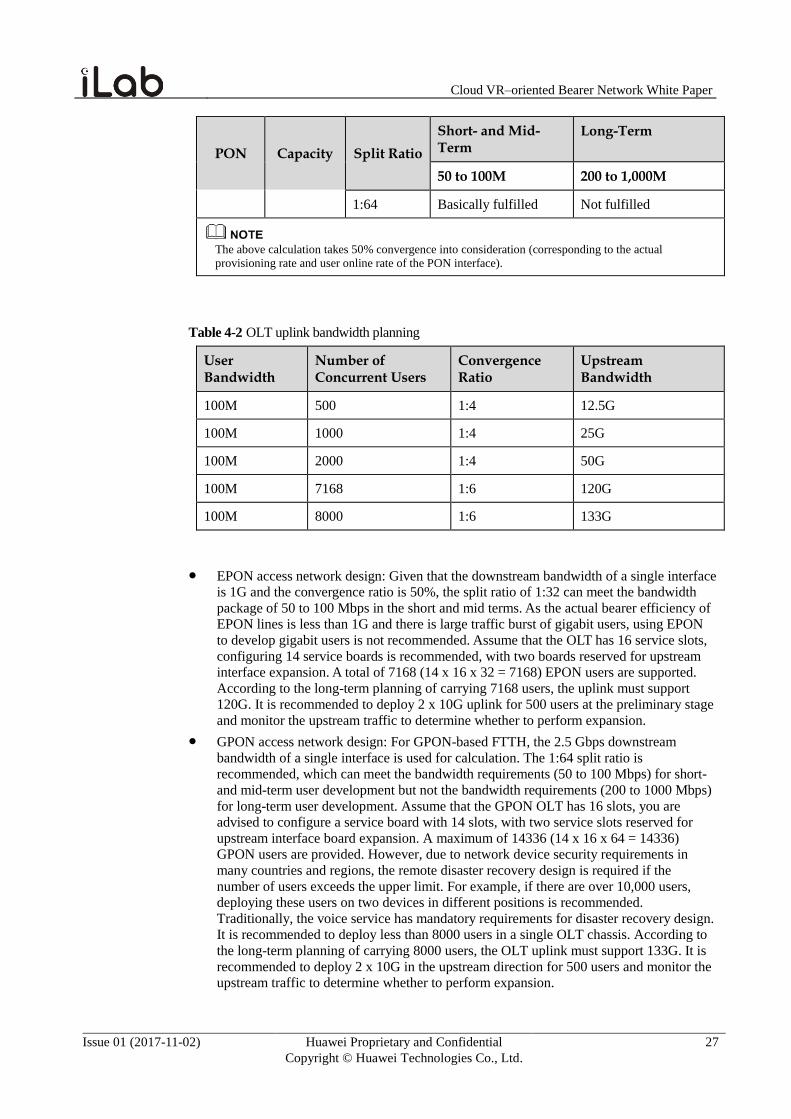
Table 4-1 Suggestions on the split ratio of FTTH
PON Capacity Split Ratio
Short- and Mid-Term
Long-Term
50 to 100M 200 to 1,000M
EPON 1G 1:32 Basically fulfilled Not fulfilled
1:64 Not fulfilled Not fulfilled
GPON 2.5G 1:32 Fulfilled Not fulfilled
Cloud VR–oriented Bearer Network White Paper
Issue 01 (2017-11-02) Huawei Proprietary and Confidential
Copyright © Huawei Technologies Co., Ltd.
27
PON Capacity Split Ratio
Short- and Mid-Term
Long-Term
50 to 100M 200 to 1,000M
1:64 Basically fulfilled Not fulfilled
The above calculation takes 50% convergence into consideration (corresponding to the actual
provisioning rate and user online rate of the PON interface).
Table 4-2 OLT uplink bandwidth planning
User Bandwidth
Number of Concurrent Users
Convergence Ratio
Upstream Bandwidth
100M 500 1:4 12.5G
100M 1000 1:4 25G
100M 2000 1:4 50G
100M 7168 1:6 120G
100M 8000 1:6 133G
EPON access network design: Given that the downstream bandwidth of a single interface
is 1G and the convergence ratio is 50%, the split ratio of 1:32 can meet the bandwidth
package of 50 to 100 Mbps in the short and mid terms. As the actual bearer efficiency of
EPON lines is less than 1G and there is large traffic burst of gigabit users, using EPON
to develop gigabit users is not recommended. Assume that the OLT has 16 service slots,
configuring 14 service boards is recommended, with two boards reserved for upstream
interface expansion. A total of 7168 (14 x 16 x 32 = 7168) EPON users are supported.
According to the long-term planning of carrying 7168 users, the uplink must support
120G. It is recommended to deploy 2 x 10G uplink for 500 users at the preliminary stage
and monitor the upstream traffic to determine whether to perform expansion.
GPON access network design: For GPON-based FTTH, the 2.5 Gbps downstream
bandwidth of a single interface is used for calculation. The 1:64 split ratio is
recommended, which can meet the bandwidth requirements (50 to 100 Mbps) for short-
and mid-term user development but not the bandwidth requirements (200 to 1000 Mbps)
for long-term user development. Assume that the GPON OLT has 16 slots, you are
advised to configure a service board with 14 slots, with two service slots reserved for
upstream interface board expansion. A maximum of 14336 (14 x 16 x 64 = 14336)
GPON users are provided. However, due to network device security requirements in
many countries and regions, the remote disaster recovery design is required if the
number of users exceeds the upper limit. For example, if there are over 10,000 users,
deploying these users on two devices in different positions is recommended.
Traditionally, the voice service has mandatory requirements for disaster recovery design.
It is recommended to deploy less than 8000 users in a single OLT chassis. According to
the long-term planning of carrying 8000 users, the OLT uplink must support 133G. It is
recommended to deploy 2 x 10G in the upstream direction for 500 users and monitor the upstream traffic to determine whether to perform expansion.
Cloud VR–oriented Bearer Network White Paper
Issue 01 (2017-11-02) Huawei Proprietary and Confidential
Copyright © Huawei Technologies Co., Ltd.
28
Suggestions on OLT architecture: For FTTH evolution, selecting the device architecture
is as important as planning the bandwidth, capacity, and split ratio. In the traditional
centralized OLT architecture, data is forwarded through the switching chip. In the big
video era, the switching chip has become the bottleneck of the system performance. OLT
evolution towards the distributed architecture is recommended.
− On the distributed OLT, each service board has its own forwarding engine that can
independently complete routing table lookup and packet forwarding, which greatly
improves the system switching capacity and performance and supports non-blocking
forwarding of 160G bandwidth packets on 10G PON boards.
− The distributed boards with large cache are used to anticipate the high-burst traffic
brought by video services and gigabit users.
− To cope with the popularization of VR services and ever-increasing user package
acceleration, EPON and GPON need to evolve to 10G. During the evolution, keep the
ODN unchanged and do not deploy the 1:128 split ratio. This is because the 1:128
split ratio has high requirements for ODN quality and requires huge engineering
workload in ODN split acceleration. Once a rogue ONT exists on the PON line, the
1:128 split ratio has great impact on the user scale. In view of compatibility, you are
advised to evolve EPON to 10G EPON and evolve GPON to 10G GPON.
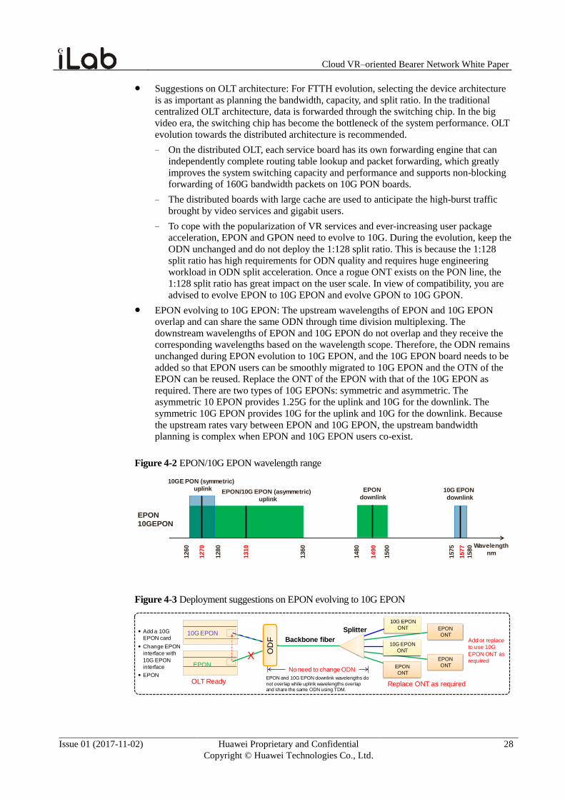
EPON evolving to 10G EPON: The upstream wavelengths of EPON and 10G EPON
overlap and can share the same ODN through time division multiplexing. The
downstream wavelengths of EPON and 10G EPON do not overlap and they receive the
corresponding wavelengths based on the wavelength scope. Therefore, the ODN remains
unchanged during EPON evolution to 10G EPON, and the 10G EPON board needs to be
added so that EPON users can be smoothly migrated to 10G EPON and the OTN of the
EPON can be reused. Replace the ONT of the EPON with that of the 10G EPON as
required. There are two types of 10G EPONs: symmetric and asymmetric. The
asymmetric 10 EPON provides 1.25G for the uplink and 10G for the downlink. The
symmetric 10G EPON provides 10G for the uplink and 10G for the downlink. Because
the upstream rates vary between EPON and 10G EPON, the upstream bandwidth
planning is complex when EPON and 10G EPON users co-exist.
Figure 4-2 EPON/10G EPON wavelength range
1260
1360
1480
1500
1575
1580
EPON/10G EPON (asymmetric)
uplink
EPON
downlink10G EPON
downlink
10GE PON (symmetric)
uplink
Wavelength
nm
EPON10GEPON
1270
1280
1310
1490
1577
Figure 4-3 Deployment suggestions on EPON evolving to 10G EPON
10G EPON
EPON
Backbone fiber
Splitter
OD
F
X
No need to change ODN
10G EPON
ONT
EPON
ONT
EPON
ONT
EPON
ONT
10G EPON
ONT
Add or replace
to use 10G
EPON ONT as
required
Add a 10G
EPON card
Change EPON
interface with
10G EPON
interface
EPON
OLT Ready Replace ONT as requiredEPON and 10G EPON downlink wavelengths do
not overlap while uplink wavelengths overlap and share the same ODN using TDM.
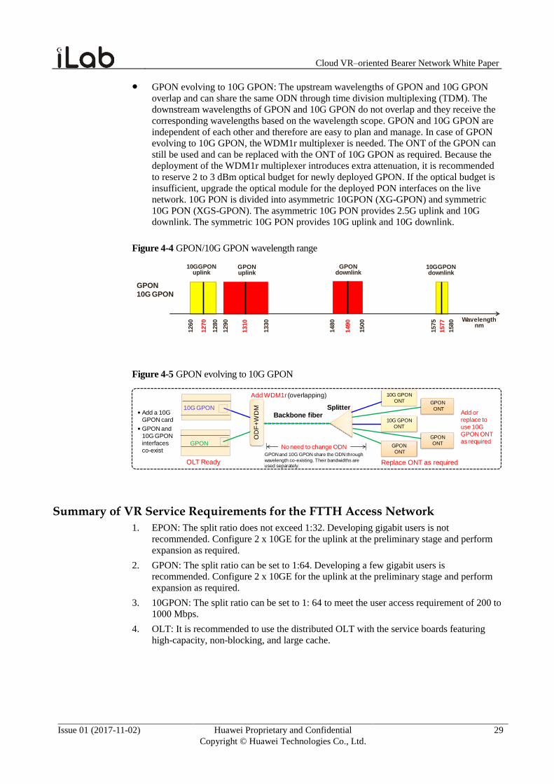
Cloud VR–oriented Bearer Network White Paper
Issue 01 (2017-11-02) Huawei Proprietary and Confidential
Copyright © Huawei Technologies Co., Ltd.
29
GPON evolving to 10G GPON: The upstream wavelengths of GPON and 10G GPON
overlap and can share the same ODN through time division multiplexing (TDM). The
downstream wavelengths of GPON and 10G GPON do not overlap and they receive the
corresponding wavelengths based on the wavelength scope. GPON and 10G GPON are
independent of each other and therefore are easy to plan and manage. In case of GPON
evolving to 10G GPON, the WDM1r multiplexer is needed. The ONT of the GPON can
still be used and can be replaced with the ONT of 10G GPON as required. Because the
deployment of the WDM1r multiplexer introduces extra attenuation, it is recommended
to reserve 2 to 3 dBm optical budget for newly deployed GPON. If the optical budget is
insufficient, upgrade the optical module for the deployed PON interfaces on the live
network. 10G PON is divided into asymmetric 10GPON (XG-GPON) and symmetric
10G PON (XGS-GPON). The asymmetric 10G PON provides 2.5G uplink and 10G
downlink. The symmetric 10G PON provides 10G uplink and 10G downlink.
Figure 4-4 GPON/10G GPON wavelength range
GPON10G GPON
1260
1280
1290
1330
1480
1500
1575
1580
10GGPONuplink
GPONuplink
GPONdownlink
10GGPONdownlink
Wavelengthnm
1270
1310
1577
1490
Figure 4-5 GPON evolving to 10G GPON
10G GPON
GPON
Add WDM1r (overlapping)
Backbone fiberSplitter
OD
F+
WD
M
10G GPON
ONT
GPON
ONT
GPON
ONT
GPON
ONT
10G GPON
ONT
Add a 10G GPON card
GPON and 10G GPON interfaces co-exist
No need to change ODNGPON and 10G GPON share the ODN through
wavelength co-existing. Their bandwidths are used separately.
Add or replace to use 10G GPON ONT as required
OLT Ready Replace ONT as required
Summary of VR Service Requirements for the FTTH Access Network
1. EPON: The split ratio does not exceed 1:32. Developing gigabit users is not
recommended. Configure 2 x 10GE for the uplink at the preliminary stage and perform
expansion as required.
2. GPON: The split ratio can be set to 1:64. Developing a few gigabit users is
recommended. Configure 2 x 10GE for the uplink at the preliminary stage and perform
expansion as required.
3. 10GPON: The split ratio can be set to 1: 64 to meet the user access requirement of 200 to
1000 Mbps.
4. OLT: It is recommended to use the distributed OLT with the service boards featuring
high-capacity, non-blocking, and large cache.
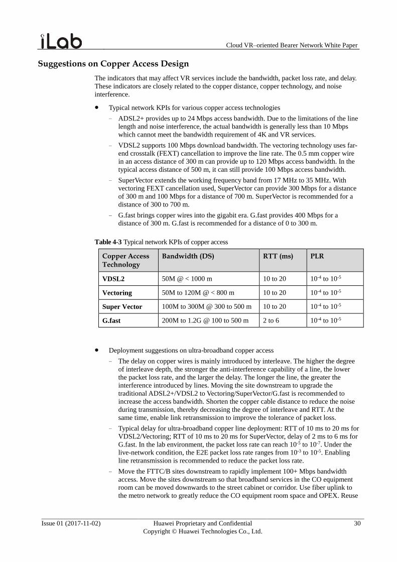
Cloud VR–oriented Bearer Network White Paper
Issue 01 (2017-11-02) Huawei Proprietary and Confidential
Copyright © Huawei Technologies Co., Ltd.
30
Suggestions on Copper Access Design
The indicators that may affect VR services include the bandwidth, packet loss rate, and delay.
These indicators are closely related to the copper distance, copper technology, and noise
interference.
Typical network KPIs for various copper access technologies
− ADSL2+ provides up to 24 Mbps access bandwidth. Due to the limitations of the line
length and noise interference, the actual bandwidth is generally less than 10 Mbps
which cannot meet the bandwidth requirement of 4K and VR services.
− VDSL2 supports 100 Mbps download bandwidth. The vectoring technology uses far-
end crosstalk (FEXT) cancellation to improve the line rate. The 0.5 mm copper wire
in an access distance of 300 m can provide up to 120 Mbps access bandwidth. In the
typical access distance of 500 m, it can still provide 100 Mbps access bandwidth.
− SuperVector extends the working frequency band from 17 MHz to 35 MHz. With
vectoring FEXT cancellation used, SuperVector can provide 300 Mbps for a distance
of 300 m and 100 Mbps for a distance of 700 m. SuperVector is recommended for a
distance of 300 to 700 m.
− G.fast brings copper wires into the gigabit era. G.fast provides 400 Mbps for a
distance of 300 m. G.fast is recommended for a distance of 0 to 300 m.
Table 4-3 Typical network KPIs of copper access
Copper Access Technology
Bandwidth (DS) RTT (ms) PLR
VDSL2 50M @ < 1000 m 10 to 20 10-4 to 10-5
Vectoring 50M to 120M @ < 800 m 10 to 20 10-4 to 10-5
Super Vector 100M to 300M @ 300 to 500 m 10 to 20 10-4 to 10-5
G.fast 200M to 1.2G @ 100 to 500 m 2 to 6 10-4 to 10-5
Deployment suggestions on ultra-broadband copper access
− The delay on copper wires is mainly introduced by interleave. The higher the degree
of interleave depth, the stronger the anti-interference capability of a line, the lower
the packet loss rate, and the larger the delay. The longer the line, the greater the
interference introduced by lines. Moving the site downstream to upgrade the
traditional ADSL2+/VDSL2 to Vectoring/SuperVector/G.fast is recommended to
increase the access bandwidth. Shorten the copper cable distance to reduce the noise
during transmission, thereby decreasing the degree of interleave and RTT. At the
same time, enable link retransmission to improve the tolerance of packet loss.
− Typical delay for ultra-broadband copper line deployment: RTT of 10 ms to 20 ms for
VDSL2/Vectoring; RTT of 10 ms to 20 ms for SuperVector, delay of 2 ms to 6 ms for
G.fast. In the lab environment, the packet loss rate can reach 10-5 to 10-7. Under the
live-network condition, the E2E packet loss rate ranges from 10-3 to 10-5. Enabling
line retransmission is recommended to reduce the packet loss rate.
− Move the FTTC/B sites downstream to rapidly implement 100+ Mbps bandwidth
access. Move the sites downstream so that broadband services in the CO equipment
room can be moved downwards to the street cabinet or corridor. Use fiber uplink to
the metro network to greatly reduce the CO equipment room space and OPEX. Reuse
Cloud VR–oriented Bearer Network White Paper
Issue 01 (2017-11-02) Huawei Proprietary and Confidential
Copyright © Huawei Technologies Co., Ltd.
31
copper access resources and shorten the copper distance. Use Vectoring and G.fast
technologies to provide high-speed data access.
− Because the copper wire performance is affected by factors such as distance and
crosstalk, install the line diagnosis system on the copper network. Perform line
performance evaluation before service provisioning to determine the rate of service
provisioning and then package to be used.
Summary of VR Service Requirements for the Copper Access Network
1. Install the copper line diagnosis system. Perform line performance evaluation before
service provisioning to determine the rate of service provisioning and then package to be
used.
2. Use the Vectoring, SuperVector, and G.fast technologies, with the copper wire distance
meeting at least 50 Mbps bandwidth.
3. Enable line retransmission and reduce the interleave depth to reduce the delay to 8 ms to
12 ms.
4. When the copper bandwidth is insufficient, move FTTC/FTTB sites downstream.
Suggestions on Coaxial Access Design
In traditional broadcast mode, regardless of whether users are viewing a video, all the
programs are broadcast to the user, using a lot of spectrum resources. This mode is vital when
SD or a few HD channels are used. However, the broadcast mode makes the existing
spectrum resources insufficient when it comes to high-bit-rate videos like 4K and VR. As IP-
based video services gradually take a dominant position, the traditional TV service in
broadcast mode is in face of huge challenges, and IP-based new services like air shift are not
supported. Therefore, building a high-bandwidth converged IP network has become an
inevitable trend. The reference for coaxial access design in this climate is as follows:
Distributed D-CCAP design based on DOCSIS 3.0: DOCSIS3.0 provides up to 32
channels and 1.6 Gbps downstream bandwidth. Give the 50 Mbps bandwidth for each
program and the 50% deployment rate, connecting each distributed D-CCAP to up to 66
users is recommended. So far, most of the cable carriers use DOCSIS 3.0 to implement
the Internet service. The TV programs are still transmitted in broadcast mode. As a large
number of DOCSIS 3.0 spectrum resources are still reserved for broadcast videos,
provisioning many 4K/VR videos on the DOCSIS 3.0 network is not recommended. This
move can be considered only when a few programs are available.
Distributed D-CCAP design based on DOCSIS 3.1: DOCSIS 3.1 currently provides a
downstream bandwidth of 4 Gbps. After future spectrum resources are released, an
upstream bandwidth of 10 Gbps can be supported, which is suitable for IPTV and 4K
videos. Give the 50 Mbps bandwidth for each program and the 50% deployment rate,
each D-CCAP can be connected to 164 to 410 users. This is also suitable for the number
of users currently connected to remote optical modes.
The application of G.fast to coaxial cables is under discussion. Therefore, all spectrum
resources will be used for bandwidth expansion in the future, regardless of copper wires or
coaxial cables. The traditional broadcast videos will be phased out and replaced with IP-based
multicast and VOD services.
Summary of VR Service Requirements for the Coaxial Access Network
1. Do not deploy a large number of 4K or VR services on the DOCSIS3.0 network.
2. Implement distributed D-CCAP design based on DOCSIS 3.1. Allow each D-CCAP to
be connected to 164 to 410 4K or VR users.
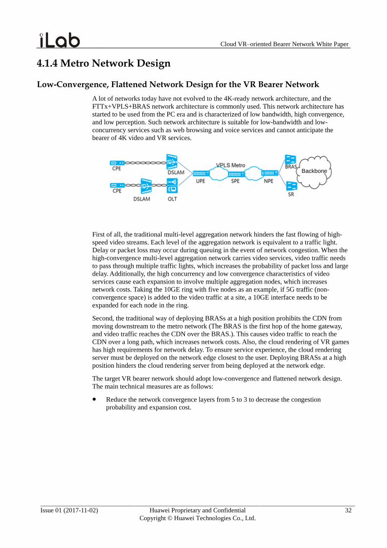
Cloud VR–oriented Bearer Network White Paper
Issue 01 (2017-11-02) Huawei Proprietary and Confidential
Copyright © Huawei Technologies Co., Ltd.
32
4.1.4 Metro Network Design
Low-Convergence, Flattened Network Design for the VR Bearer Network
A lot of networks today have not evolved to the 4K-ready network architecture, and the
FTTx+VPLS+BRAS network architecture is commonly used. This network architecture has
started to be used from the PC era and is characterized of low bandwidth, high convergence,
and low perception. Such network architecture is suitable for low-bandwidth and low-
concurrency services such as web browsing and voice services and cannot anticipate the
bearer of 4K video and VR services.
Backbone
First of all, the traditional multi-level aggregation network hinders the fast flowing of high-
speed video streams. Each level of the aggregation network is equivalent to a traffic light.
Delay or packet loss may occur during queuing in the event of network congestion. When the
high-convergence multi-level aggregation network carries video services, video traffic needs
to pass through multiple traffic lights, which increases the probability of packet loss and large
delay. Additionally, the high concurrency and low convergence characteristics of video
services cause each expansion to involve multiple aggregation nodes, which increases
network costs. Taking the 10GE ring with five nodes as an example, if 5G traffic (non-
convergence space) is added to the video traffic at a site, a 10GE interface needs to be
expanded for each node in the ring.
Second, the traditional way of deploying BRASs at a high position prohibits the CDN from
moving downstream to the metro network (The BRAS is the first hop of the home gateway,
and video traffic reaches the CDN over the BRAS.). This causes video traffic to reach the
CDN over a long path, which increases network costs. Also, the cloud rendering of VR games
has high requirements for network delay. To ensure service experience, the cloud rendering
server must be deployed on the network edge closest to the user. Deploying BRASs at a high
position hinders the cloud rendering server from being deployed at the network edge.
The target VR bearer network should adopt low-convergence and flattened network design.
The main technical measures are as follows:
Reduce the network convergence layers from 5 to 3 to decrease the congestion
probability and expansion cost.
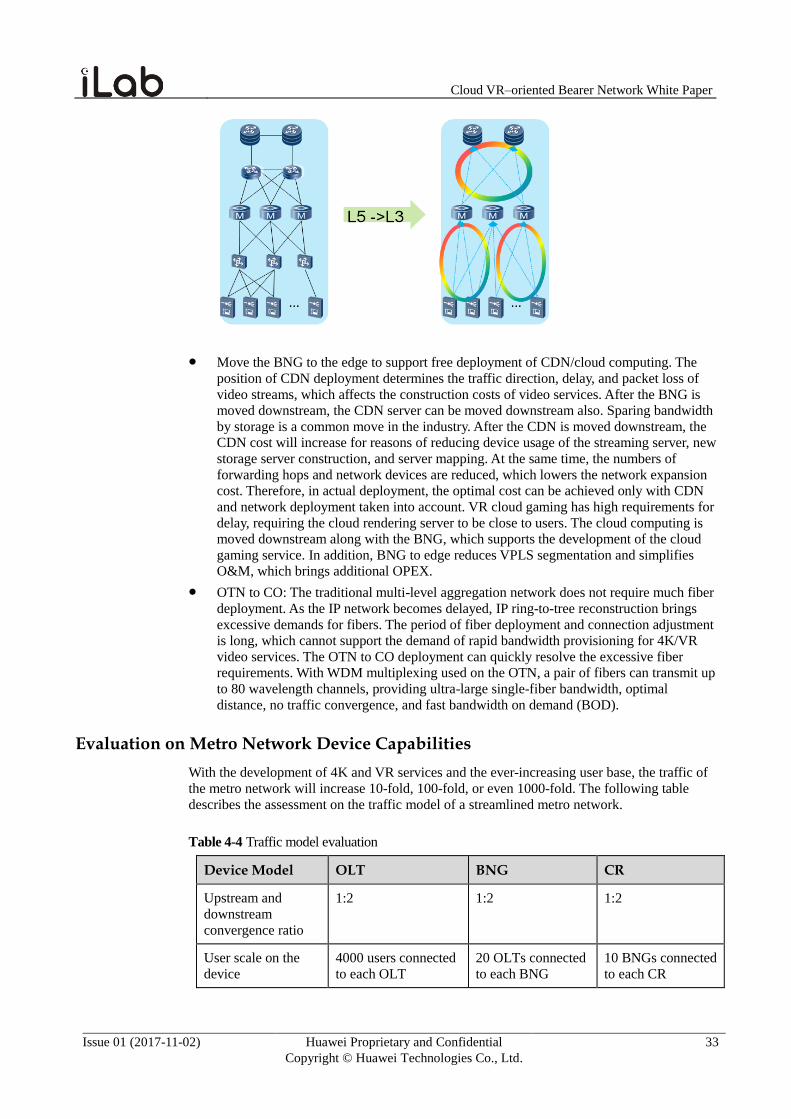
Cloud VR–oriented Bearer Network White Paper
Issue 01 (2017-11-02) Huawei Proprietary and Confidential
Copyright © Huawei Technologies Co., Ltd.
33
Move the BNG to the edge to support free deployment of CDN/cloud computing. The
position of CDN deployment determines the traffic direction, delay, and packet loss of
video streams, which affects the construction costs of video services. After the BNG is
moved downstream, the CDN server can be moved downstream also. Sparing bandwidth
by storage is a common move in the industry. After the CDN is moved downstream, the
CDN cost will increase for reasons of reducing device usage of the streaming server, new
storage server construction, and server mapping. At the same time, the numbers of
forwarding hops and network devices are reduced, which lowers the network expansion
cost. Therefore, in actual deployment, the optimal cost can be achieved only with CDN
and network deployment taken into account. VR cloud gaming has high requirements for
delay, requiring the cloud rendering server to be close to users. The cloud computing is
moved downstream along with the BNG, which supports the development of the cloud
gaming service. In addition, BNG to edge reduces VPLS segmentation and simplifies
O&M, which brings additional OPEX.
OTN to CO: The traditional multi-level aggregation network does not require much fiber
deployment. As the IP network becomes delayed, IP ring-to-tree reconstruction brings
excessive demands for fibers. The period of fiber deployment and connection adjustment
is long, which cannot support the demand of rapid bandwidth provisioning for 4K/VR
video services. The OTN to CO deployment can quickly resolve the excessive fiber
requirements. With WDM multiplexing used on the OTN, a pair of fibers can transmit up
to 80 wavelength channels, providing ultra-large single-fiber bandwidth, optimal
distance, no traffic convergence, and fast bandwidth on demand (BOD).
Evaluation on Metro Network Device Capabilities
With the development of 4K and VR services and the ever-increasing user base, the traffic of
the metro network will increase 10-fold, 100-fold, or even 1000-fold. The following table
describes the assessment on the traffic model of a streamlined metro network.
Table 4-4 Traffic model evaluation
Device Model OLT BNG CR
Upstream and
downstream
convergence ratio
1:2 1:2 1:2
User scale on the
device
4000 users connected
to each OLT
20 OLTs connected
to each BNG
10 BNGs connected
to each CR
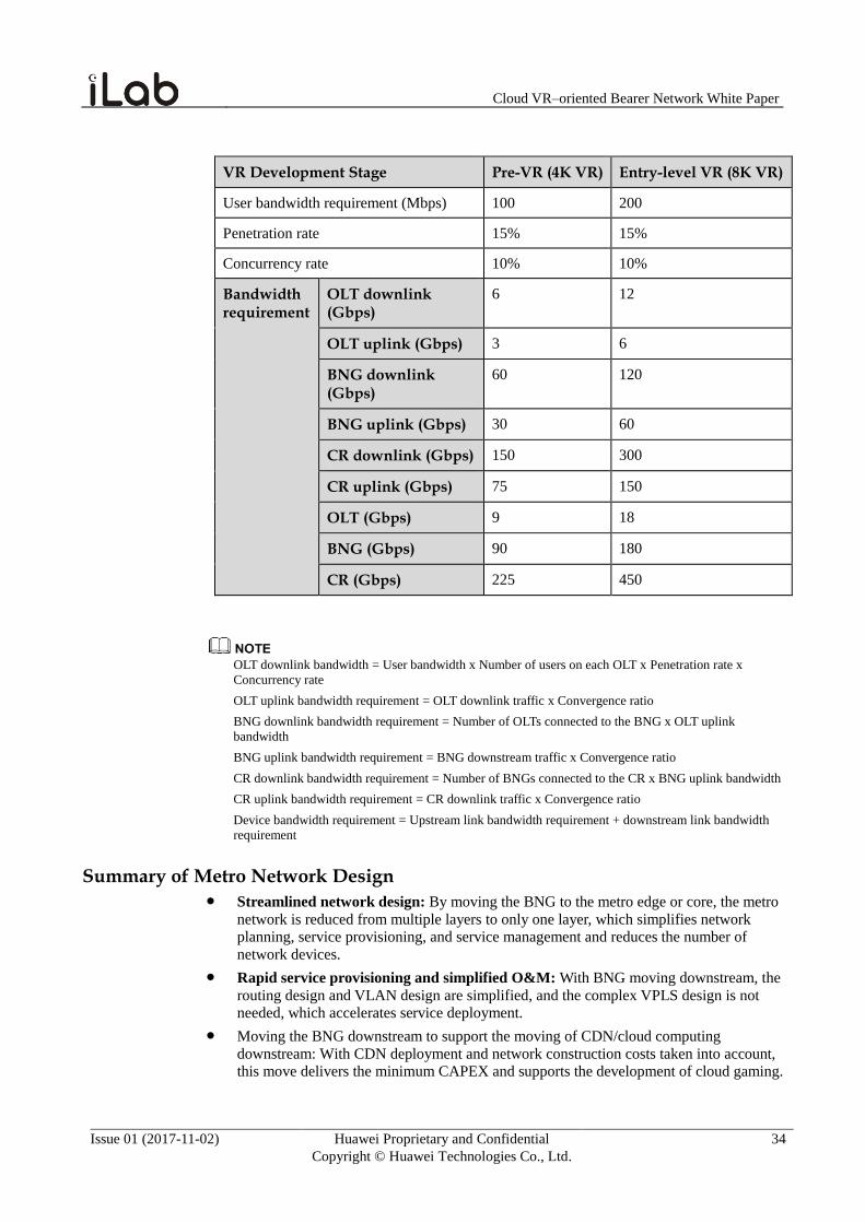
Cloud VR–oriented Bearer Network White Paper
Issue 01 (2017-11-02) Huawei Proprietary and Confidential
Copyright © Huawei Technologies Co., Ltd.
34
VR Development Stage Pre-VR (4K VR) Entry-level VR (8K VR)
User bandwidth requirement (Mbps) 100 200
Penetration rate 15% 15%
Concurrency rate 10% 10%
Bandwidth requirement
OLT downlink (Gbps)
6 12
OLT uplink (Gbps) 3 6
BNG downlink (Gbps)
60 120
BNG uplink (Gbps) 30 60
CR downlink (Gbps) 150 300
CR uplink (Gbps) 75 150
OLT (Gbps) 9 18
BNG (Gbps) 90 180
CR (Gbps) 225 450
OLT downlink bandwidth = User bandwidth x Number of users on each OLT x Penetration rate x
Concurrency rate
OLT uplink bandwidth requirement = OLT downlink traffic x Convergence ratio
BNG downlink bandwidth requirement = Number of OLTs connected to the BNG x OLT uplink
bandwidth
BNG uplink bandwidth requirement = BNG downstream traffic x Convergence ratio
CR downlink bandwidth requirement = Number of BNGs connected to the CR x BNG uplink bandwidth
CR uplink bandwidth requirement = CR downlink traffic x Convergence ratio
Device bandwidth requirement = Upstream link bandwidth requirement + downstream link bandwidth
requirement
Summary of Metro Network Design Streamlined network design: By moving the BNG to the metro edge or core, the metro
network is reduced from multiple layers to only one layer, which simplifies network
planning, service provisioning, and service management and reduces the number of
network devices.
Rapid service provisioning and simplified O&M: With BNG moving downstream, the
routing design and VLAN design are simplified, and the complex VPLS design is not
needed, which accelerates service deployment.
Moving the BNG downstream to support the moving of CDN/cloud computing
downstream: With CDN deployment and network construction costs taken into account,
this move delivers the minimum CAPEX and supports the development of cloud gaming.
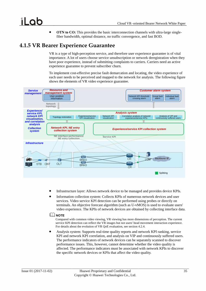
Cloud VR–oriented Bearer Network White Paper
Issue 01 (2017-11-02) Huawei Proprietary and Confidential
Copyright © Huawei Technologies Co., Ltd.
35
OTN to CO: This provides the basic interconnection channels with ultra-large single-
fiber bandwidth, optimal distance, no traffic convergence, and fast BOD.
4.1.5 VR Bearer Experience Guarantee
VR is a type of high-perception service, and therefore user experience guarantee is of vital
importance. A lot of users choose service unsubscription or network deregistration when they
have poor experience, instead of submitting complaints to carriers. Carriers need an active
experience guarantee to prevent subscriber churn.
To implement cost-effective precise fault demarcation and locating, the video experience of
each user needs to be perceived and mapped to the network for analysis. The following figure
shows the elements of VR video experience guarantee.
Resource and management system
User position information
Customer alarm system
Network KPI threshold-crossing alarm
Group fault alarm
Individual fault alarm
Service management
Network topology
Experience/service KPI, network KPI visualization,
and correlation analysis
Collection system
Infrastructure
Analysis system
Topology restorationExperience/service KPI visualization
Network KPI visualization
Correlation analysis of network/experience/service KPIs
Analysis of VIP and continuously suffered users
Network KPI, NE entry collection system
Experience/service KPI collection system
NE interface performance/NE entry collection
Backbone IP
Splitting
Service KPI
Infrastructure layer: Allows network device to be managed and provides device KPIs.
Information collection system: Collects KPIs of numerous network devices and user
services. Video service KPI detection can be performed using probes or directly on
terminals. An objective forecast algorithm (such as U-vMOS) is used to evaluate users'
video experience. The KPIs of network devices are obtained by collecting interface data.
Compared with common video viewing, VR viewing has more dimensions of perception. The current
service KPI detection can reflect the VR images but not users' head movement interaction experience.
For details about the evolution of VR QoE evaluation, see section 4.2.4.
Analysis system: Supports real-time quality reports and network KPI ranking, service
KPI and network KPI correlation, and analysis on VIP and continuously suffered users.
The performance indicators of network devices can be separately scanned to discover
performance issues. This, however, cannot determine whether the video quality is
affected. The performance indicators must be associated with network KPIs to discover
the specific network devices or KPIs that affect the video quality.
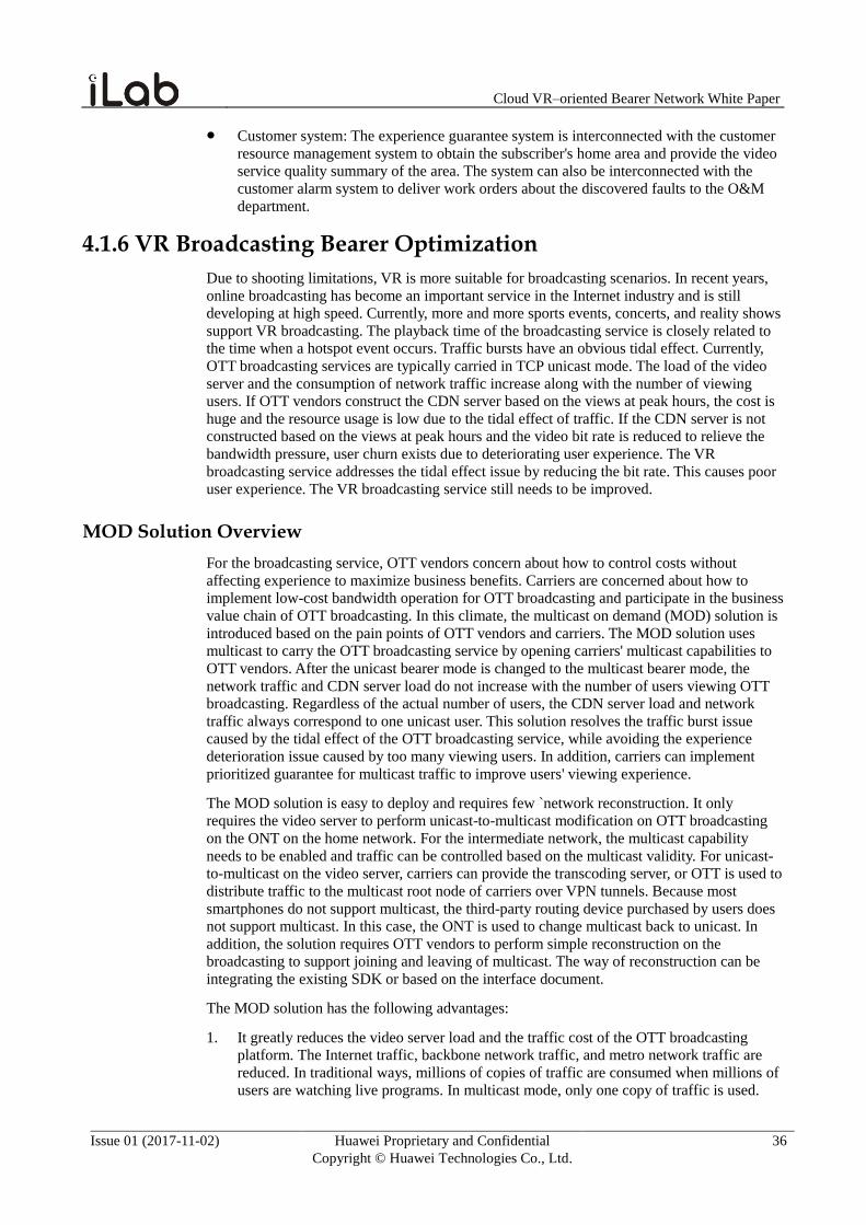
Cloud VR–oriented Bearer Network White Paper
Issue 01 (2017-11-02) Huawei Proprietary and Confidential
Copyright © Huawei Technologies Co., Ltd.
36
Customer system: The experience guarantee system is interconnected with the customer
resource management system to obtain the subscriber's home area and provide the video
service quality summary of the area. The system can also be interconnected with the
customer alarm system to deliver work orders about the discovered faults to the O&M
department.
4.1.6 VR Broadcasting Bearer Optimization
Due to shooting limitations, VR is more suitable for broadcasting scenarios. In recent years,
online broadcasting has become an important service in the Internet industry and is still
developing at high speed. Currently, more and more sports events, concerts, and reality shows
support VR broadcasting. The playback time of the broadcasting service is closely related to
the time when a hotspot event occurs. Traffic bursts have an obvious tidal effect. Currently,
OTT broadcasting services are typically carried in TCP unicast mode. The load of the video
server and the consumption of network traffic increase along with the number of viewing
users. If OTT vendors construct the CDN server based on the views at peak hours, the cost is
huge and the resource usage is low due to the tidal effect of traffic. If the CDN server is not
constructed based on the views at peak hours and the video bit rate is reduced to relieve the
bandwidth pressure, user churn exists due to deteriorating user experience. The VR
broadcasting service addresses the tidal effect issue by reducing the bit rate. This causes poor
user experience. The VR broadcasting service still needs to be improved.
MOD Solution Overview
For the broadcasting service, OTT vendors concern about how to control costs without
affecting experience to maximize business benefits. Carriers are concerned about how to
implement low-cost bandwidth operation for OTT broadcasting and participate in the business
value chain of OTT broadcasting. In this climate, the multicast on demand (MOD) solution is
introduced based on the pain points of OTT vendors and carriers. The MOD solution uses
multicast to carry the OTT broadcasting service by opening carriers' multicast capabilities to
OTT vendors. After the unicast bearer mode is changed to the multicast bearer mode, the
network traffic and CDN server load do not increase with the number of users viewing OTT
broadcasting. Regardless of the actual number of users, the CDN server load and network
traffic always correspond to one unicast user. This solution resolves the traffic burst issue
caused by the tidal effect of the OTT broadcasting service, while avoiding the experience
deterioration issue caused by too many viewing users. In addition, carriers can implement
prioritized guarantee for multicast traffic to improve users' viewing experience.
The MOD solution is easy to deploy and requires few `network reconstruction. It only
requires the video server to perform unicast-to-multicast modification on OTT broadcasting
on the ONT on the home network. For the intermediate network, the multicast capability
needs to be enabled and traffic can be controlled based on the multicast validity. For unicast-
to-multicast on the video server, carriers can provide the transcoding server, or OTT is used to
distribute traffic to the multicast root node of carriers over VPN tunnels. Because most
smartphones do not support multicast, the third-party routing device purchased by users does
not support multicast. In this case, the ONT is used to change multicast back to unicast. In
addition, the solution requires OTT vendors to perform simple reconstruction on the
broadcasting to support joining and leaving of multicast. The way of reconstruction can be
integrating the existing SDK or based on the interface document.
The MOD solution has the following advantages:
1. It greatly reduces the video server load and the traffic cost of the OTT broadcasting
platform. The Internet traffic, backbone network traffic, and metro network traffic are
reduced. In traditional ways, millions of copies of traffic are consumed when millions of
users are watching live programs. In multicast mode, only one copy of traffic is used.
Cloud VR–oriented Bearer Network White Paper
Issue 01 (2017-11-02) Huawei Proprietary and Confidential
Copyright © Huawei Technologies Co., Ltd.
37
2. Carriers' inter-network settlement costs are saved, making the carrier network healthier.
This solution avoids the tidal effect and prevents traffic bursts during peak hours. In
unicast mode, network imbalance often occurs due to CDN, and the investment in
maintaining the carrier network is huge. The MOD solution reduces backbone and metro
network traffic, making the network more smooth and healthy.
3. This solution adds new profitability methods for carriers. Currently, most of the revenues
of the broadcasting field are obtained by CDN vendors. The MOD solution provides the
cost-effective broadcasting optimization, which reduces the CDN costs for broadcasting
enterprises while obtaining gains for carriers.
4. The MOD solution combines the advantages of IPTV broadcasting and OTT
broadcasting. It can be used for OTT broadcasting to reduce the CDN and bandwidth
costs and improve user experience. It can also be used for IPTV broadcasting so that
terminals (such as smartphones and tablets) that do not support multicast can view
broadcasting.
Figure 4-6 MOD solution
OTT platform
U2M
Unicast
Multicast
M2U
BRAS CR
OLT
ONT
Home 1
Home 2
Home 3PE BTV video
source
MOD : Multicast On Demand
U2M : Unicast to Multicast
M2U : Multicast to Unicast
Multicast replication pointIPTV platform
Multicast video source
4.2 Network Evolution for Advanced VR and Ultimate VR
With the improvement of the screen resolution and chip performance of VR HMDs as well as
the VR content quality, VR videos are gradually evolving towards the advanced level (full-
view 12K) and ultimate level (full-view 24K). At the advanced VR stage, the improving VR
image experience brings higher requirements for network bandwidth (200 Mbps to 1 Gbps),
requiring more than 1 Gbps access bandwidth. The ultimate VR brings the single-eye image
to the retina level. For the full-view transmission that has high bandwidth requirements (2
Gbps to 5 Gbps), the FOV transmission solution is required to reduce the bandwidth
requirements. In the full-view transmission solution, the 20 ms delay of VR interaction
experience does not involve network delay and cloud + device delay. In the FOV solution, the
network delay is included in the 20 ms delay of VR interaction experience. Therefore, the
FOV transmission solution has high requirements for delay. Therefore, the future network
must evolve towards higher bandwidth and lower delay in response to the advanced VR and
ultimate VR.
The traditional bearer network construction seldom takes into account service experience
requirements. Generally, network planning or expansion is performed upon threshold-crossing
of bandwidth usage. VR has high requirements for bandwidth and is delay sensitive. To meet
the requirements for VR, the bearer network construction and evolution must follow the
following principles:
Service experience can be guaranteed based on each service interaction, such as the head movement switching angle.
Cloud VR–oriented Bearer Network White Paper
Issue 01 (2017-11-02) Huawei Proprietary and Confidential
Copyright © Huawei Technologies Co., Ltd.
38
Network capabilities are based on the delay requirement for each interaction. For
example, angle switching in the VR immersive experience requires the delay within 10
milliseconds.
The network bandwidth of the bearer network must be planned based on service delay
requirements. For example, the bearer network must meet the high-traffic transmission
of VR within 10 milliseconds.
4.2.1 Bearer Technology Evolution for Higher and Broader Bandwidth
High-bandwidth Wi-Fi Technology
To meet the Gbps bandwidth requirements for future VR services, the home Wi-Fi network
must support 802.11ax, the next-generation Wi-Fi standard. The 802.11ax standard achieves
up to 10 Gbps air interface rate and has more powerful anti-interference capability to
guarantee performance indicators, such as the packet loss rate, delay, and bandwidth stability.
More powerful anti-interference: 802.11ax introduces the orthogonal frequency division
multiple access (OFDMA) technology that is used in 4G LTE cell base stations, allowing
users to use only a subset in subcarrier within a specified period, thereby improving the
bandwidth utilization of the same channel. With a new spatial multiplexing technology
used, the 802.11ax standard can efficiently identify air interface conflicts and perform
backoff. The 802.11ax standard combines a lot of methods such as dynamic idle channel
evaluation and dynamic power control to improve the identification of interference
signals and noise reduction performance.
Higher transmission rate: 802.11ax introduces 1024 QAM. Compared with 802.11ac that
provides up to 256 QAM, 802.11ax improves the maximum physical rate of each 80M
frequency bandwidth spatial stream from 433 Mbps to 600.4 Mbps. The theoretical
maximum physical rate (160M frequency bandwidth, 8 spatial streams) is increased from
6.9 Gbps to around 9.6 Gbps, an increase of approximately 40%.
Longer transmission range: 802.11ax provides four times of subcarriers, 1/4 of subcarrier
interval, and four times of symbol time compared with 802.11ac. This is beneficial to
channel evaluation and balance. Especially in anti-multipath fading, and outdoor
scenarios, 802.11ax provides better robustness and performance and thereby covers a
larger range.
More powerful concurrency: 802.11ac defines only downstream MU-MIMO, and a
single node independently transmits data in the upstream direction. 802.11ax supports
upstream MU-MIMO. With the upstream/downstream MU-MIMO and OFDMA
technologies, 802.11ax supports concurrent transmission for multiple users using multi-
spatial-flow and multi-subcarrier, increasing the air interface efficiency, reducing
application delay and user backoff against conflicts. This provides a better transmission
efficiency for multi-user scenarios.
Currently, IEEE 802.11 is speculating the 60 GHz-based next-generation Wi-Fi standard
802.11ay. The 802.11ay standard uses technologies such as channel bonding and MU-MIMO
to provide 20 to 40 Gbps bandwidth, aiming to achieve uncompressed video frame data
transmission. The 802.11ay technology can be used for wireless VR HMDs. It uses wireless
transmission technologies to perform seamless video transmission to address user experience
issues caused by the connections between the HMD and host.
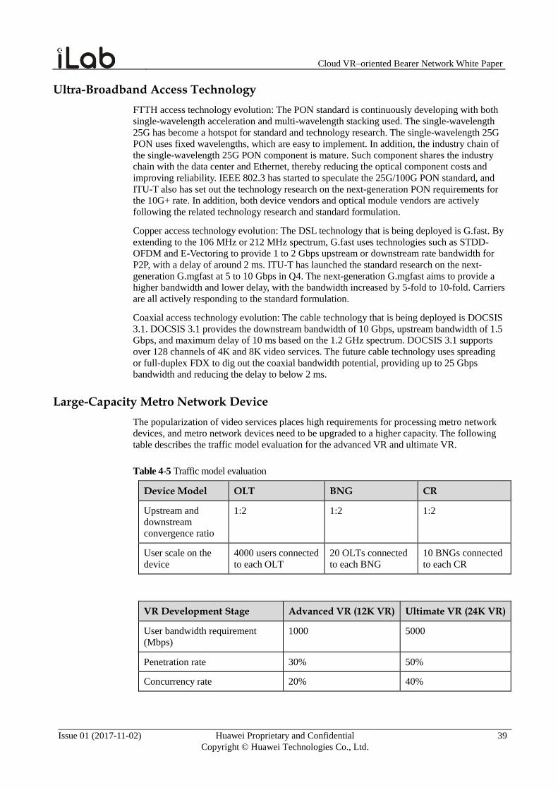
Cloud VR–oriented Bearer Network White Paper
Issue 01 (2017-11-02) Huawei Proprietary and Confidential
Copyright © Huawei Technologies Co., Ltd.
39
Ultra-Broadband Access Technology
FTTH access technology evolution: The PON standard is continuously developing with both
single-wavelength acceleration and multi-wavelength stacking used. The single-wavelength
25G has become a hotspot for standard and technology research. The single-wavelength 25G
PON uses fixed wavelengths, which are easy to implement. In addition, the industry chain of
the single-wavelength 25G PON component is mature. Such component shares the industry
chain with the data center and Ethernet, thereby reducing the optical component costs and
improving reliability. IEEE 802.3 has started to speculate the 25G/100G PON standard, and
ITU-T also has set out the technology research on the next-generation PON requirements for
the 10G+ rate. In addition, both device vendors and optical module vendors are actively
following the related technology research and standard formulation.
Copper access technology evolution: The DSL technology that is being deployed is G.fast. By
extending to the 106 MHz or 212 MHz spectrum, G.fast uses technologies such as STDD-
OFDM and E-Vectoring to provide 1 to 2 Gbps upstream or downstream rate bandwidth for
P2P, with a delay of around 2 ms. ITU-T has launched the standard research on the next-
generation G.mgfast at 5 to 10 Gbps in Q4. The next-generation G.mgfast aims to provide a
higher bandwidth and lower delay, with the bandwidth increased by 5-fold to 10-fold. Carriers
are all actively responding to the standard formulation.
Coaxial access technology evolution: The cable technology that is being deployed is DOCSIS
3.1. DOCSIS 3.1 provides the downstream bandwidth of 10 Gbps, upstream bandwidth of 1.5
Gbps, and maximum delay of 10 ms based on the 1.2 GHz spectrum. DOCSIS 3.1 supports
over 128 channels of 4K and 8K video services. The future cable technology uses spreading
or full-duplex FDX to dig out the coaxial bandwidth potential, providing up to 25 Gbps
bandwidth and reducing the delay to below 2 ms.
Large-Capacity Metro Network Device
The popularization of video services places high requirements for processing metro network
devices, and metro network devices need to be upgraded to a higher capacity. The following
table describes the traffic model evaluation for the advanced VR and ultimate VR.
Table 4-5 Traffic model evaluation
Device Model OLT BNG CR
Upstream and
downstream
convergence ratio
1:2 1:2 1:2
User scale on the
device
4000 users connected
to each OLT
20 OLTs connected
to each BNG
10 BNGs connected
to each CR
VR Development Stage Advanced VR (12K VR) Ultimate VR (24K VR)
User bandwidth requirement
(Mbps)
1000 5000
Penetration rate 30% 50%
Concurrency rate 20% 40%
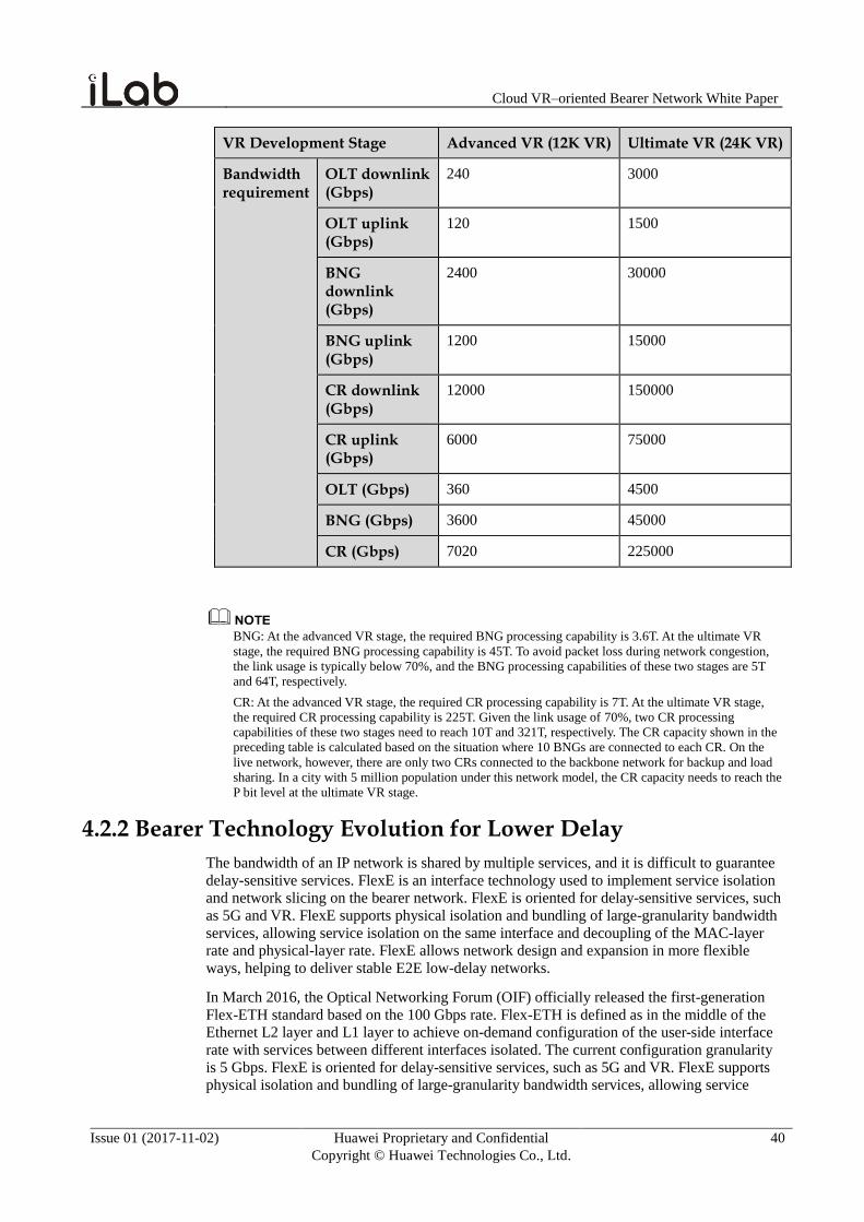
Cloud VR–oriented Bearer Network White Paper
Issue 01 (2017-11-02) Huawei Proprietary and Confidential
Copyright © Huawei Technologies Co., Ltd.
40
VR Development Stage Advanced VR (12K VR) Ultimate VR (24K VR)
Bandwidth requirement
OLT downlink (Gbps)
240 3000
OLT uplink (Gbps)
120 1500
BNG downlink (Gbps)
2400 30000
BNG uplink (Gbps)
1200 15000
CR downlink (Gbps)
12000 150000
CR uplink (Gbps)
6000 75000
OLT (Gbps) 360 4500
BNG (Gbps) 3600 45000
CR (Gbps) 7020 225000
BNG: At the advanced VR stage, the required BNG processing capability is 3.6T. At the ultimate VR
stage, the required BNG processing capability is 45T. To avoid packet loss during network congestion,
the link usage is typically below 70%, and the BNG processing capabilities of these two stages are 5T
and 64T, respectively.
CR: At the advanced VR stage, the required CR processing capability is 7T. At the ultimate VR stage,
the required CR processing capability is 225T. Given the link usage of 70%, two CR processing
capabilities of these two stages need to reach 10T and 321T, respectively. The CR capacity shown in the
preceding table is calculated based on the situation where 10 BNGs are connected to each CR. On the
live network, however, there are only two CRs connected to the backbone network for backup and load
sharing. In a city with 5 million population under this network model, the CR capacity needs to reach the
P bit level at the ultimate VR stage.
4.2.2 Bearer Technology Evolution for Lower Delay
The bandwidth of an IP network is shared by multiple services, and it is difficult to guarantee
delay-sensitive services. FlexE is an interface technology used to implement service isolation
and network slicing on the bearer network. FlexE is oriented for delay-sensitive services, such
as 5G and VR. FlexE supports physical isolation and bundling of large-granularity bandwidth
services, allowing service isolation on the same interface and decoupling of the MAC-layer
rate and physical-layer rate. FlexE allows network design and expansion in more flexible
ways, helping to deliver stable E2E low-delay networks.
In March 2016, the Optical Networking Forum (OIF) officially released the first-generation
Flex-ETH standard based on the 100 Gbps rate. Flex-ETH is defined as in the middle of the
Ethernet L2 layer and L1 layer to achieve on-demand configuration of the user-side interface
rate with services between different interfaces isolated. The current configuration granularity
is 5 Gbps. FlexE is oriented for delay-sensitive services, such as 5G and VR. FlexE supports physical isolation and bundling of large-granularity bandwidth services, allowing service
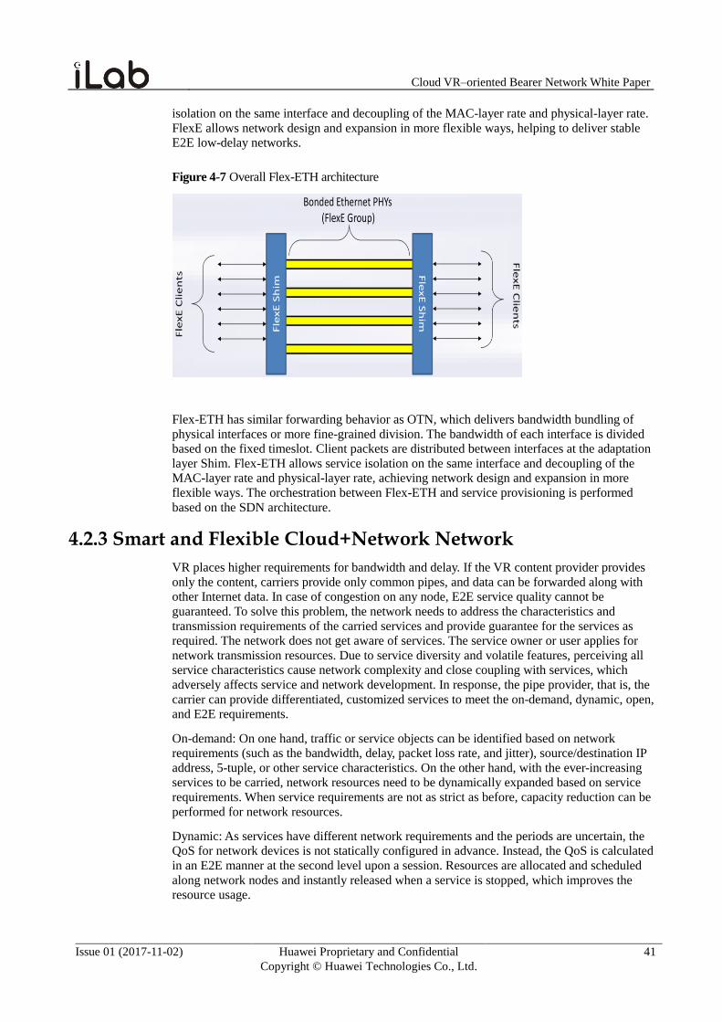
Cloud VR–oriented Bearer Network White Paper
Issue 01 (2017-11-02) Huawei Proprietary and Confidential
Copyright © Huawei Technologies Co., Ltd.
41
isolation on the same interface and decoupling of the MAC-layer rate and physical-layer rate.
FlexE allows network design and expansion in more flexible ways, helping to deliver stable
E2E low-delay networks.
Figure 4-7 Overall Flex-ETH architecture
Flex-ETH has similar forwarding behavior as OTN, which delivers bandwidth bundling of
physical interfaces or more fine-grained division. The bandwidth of each interface is divided
based on the fixed timeslot. Client packets are distributed between interfaces at the adaptation
layer Shim. Flex-ETH allows service isolation on the same interface and decoupling of the
MAC-layer rate and physical-layer rate, achieving network design and expansion in more
flexible ways. The orchestration between Flex-ETH and service provisioning is performed
based on the SDN architecture.
4.2.3 Smart and Flexible Cloud+Network Network
VR places higher requirements for bandwidth and delay. If the VR content provider provides
only the content, carriers provide only common pipes, and data can be forwarded along with
other Internet data. In case of congestion on any node, E2E service quality cannot be
guaranteed. To solve this problem, the network needs to address the characteristics and
transmission requirements of the carried services and provide guarantee for the services as
required. The network does not get aware of services. The service owner or user applies for
network transmission resources. Due to service diversity and volatile features, perceiving all
service characteristics cause network complexity and close coupling with services, which
adversely affects service and network development. In response, the pipe provider, that is, the
carrier can provide differentiated, customized services to meet the on-demand, dynamic, open,
and E2E requirements.
On-demand: On one hand, traffic or service objects can be identified based on network
requirements (such as the bandwidth, delay, packet loss rate, and jitter), source/destination IP
address, 5-tuple, or other service characteristics. On the other hand, with the ever-increasing
services to be carried, network resources need to be dynamically expanded based on service
requirements. When service requirements are not as strict as before, capacity reduction can be
performed for network resources.
Dynamic: As services have different network requirements and the periods are uncertain, the
QoS for network devices is not statically configured in advance. Instead, the QoS is calculated
in an E2E manner at the second level upon a session. Resources are allocated and scheduled
along network nodes and instantly released when a service is stopped, which improves the
resource usage.
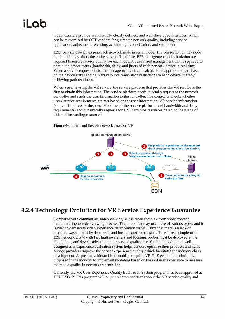
Cloud VR–oriented Bearer Network White Paper
Issue 01 (2017-11-02) Huawei Proprietary and Confidential
Copyright © Huawei Technologies Co., Ltd.
42
Open: Carriers provide user-friendly, clearly defined, and well-developed interfaces, which
can be customized by OTT vendors for guarantee network quality, including service
application, adjustment, releasing, accounting, reconciliation, and settlement.
E2E: Service data flows pass each network node in serial mode. The congestion on any node
on the path may affect the entire service. Therefore, E2E management and calculation are
required to ensure service quality for each node. A centralized management unit is required to
obtain the device status (bandwidth, delay, and jitter) of each network device in real time.
When a service request exists, the management unit can calculate the appropriate path based
on the device status and delivers resource reservation restrictions to each device, thereby
achieving path readiness.
When a user is using the VR service, the service platform that provides the VR service is the
first to obtain this information. The service platform needs to send a request to the network
controller and sends the user information to the controller. The controller checks whether
users' service requirements are met based on the user information, VR service information
(source IP address of the user, IP address of the service platform, and bandwidth and delay
requirements) and dynamically requests for E2E hard pipe resources based on the usage of
link and forwarding resources.
Figure 4-8 Smart and flexible network based on VR
CDN
Video
platform
Resource management server
1
2
3 3 3
4Terminal requests a program to the platform
The platform requests network resources about program connections from carriers
Calculate paths and deliver resource reservation instructions
Reserve resources for transit devices
4.2.4 Technology Evolution for VR Service Experience Guarantee
Compared with common 4K video viewing, VR is more complex from video content
manufacturing to video viewing process. The faults that may occur are of various types, and it
is hard to demarcate video experience deterioration issues. Currently, there is a lack of
effective ways to rapidly demarcate and locate experience issues. Therefore, to implement
E2E network O&M with fast fault awareness and locating, probes must be deployed at the
cloud, pipe, and device sides to monitor service quality in real time. In addition, a well-
designed user experience evaluation system helps vendors optimize their products and helps
service providers improve the service experience quality, which facilitates the industry chain
development. At present, a hierarchical, multi-perception VR QoE evaluation solution is
proposed in the industry to implement modeling based on the real user experience to measure
the media quality in network transmission.
Currently, the VR User Experience Quality Evaluation System program has been approved at
ITU-T SG12. This program will output recommendations about the VR service quality and

Cloud VR–oriented Bearer Network White Paper
Issue 01 (2017-11-02) Huawei Proprietary and Confidential
Copyright © Huawei Technologies Co., Ltd.
43
provides suggestions on QoE factors, QoE/QoS requirements, testing methodology, and
objective quality evaluation model. This program plans to be developed in five phases.
1. Identify the VR service and pipe technology.
2. Identify the key quality factors that may affect VR QoE.
3. Define the method of measuring the quality of VR QoE.
4. Work out the objective and subjective evaluation methodology of VR quality.
5. Output suggestions on guaranteeing good VR QoE quality requirements.
Related Documents