1 Technical white paper HP Virtual Connect FlexFabric Cookbook – With HP Virtual Connect Flex-10/10D (Version 3.70 through 4.01 Firmware Enhancements) Purpose 4 Documentation feedback 4 Introduction to Virtual Connect Flex-10 and FlexFabric 5 New Features: 5 The Virtual Connect Cookbook Series: 8 Virtual Connect Ethernet Modules 9 Connecting VC Flex-10/10D or VC FlexFabric to the CORE 21 Choosing VC Flex-10/10D or VC FlexFabric 22 Choosing an Adapter for VC Flex-10/10D or VC FlexFabric 23 Determining Network Traffic Patterns and Virtual Connect network design (Active/Standby vs. Active/Active) 23 VMware ESXi 5.0/5.1 26 Single Domain/Enclosure Scenarios 28 Overview 28 Requirements 28 Scenario 1 – Simple vNet with Active/Standby Uplinks – Ethernet and FCoE – Windows 2008 R2 30 Overview 30 Requirements 30 Installation and configuration 32 Review 40 Results – Windows 2008 R2 Networking Examples 40 Results – Windows 2008 R2 SAN Connectivity 45 Summary 46 Scenario 2 –Shared Uplink Sets with Active/Active uplinks and 802.3ad (LACP) - Ethernet and FCoE – Windows 2008 R2 47 Overview 47 Requirements 47 Installation and configuration 49 Review 58 Results – Windows 2008 R2 Networking Examples 59 Results – Windows 2008 R2 SAN Connectivity 63 Summary 64

HP VC Cookbook
Dec 31, 2015
HP VC Cookbook
Welcome message from author
This document is posted to help you gain knowledge. Please leave a comment to let me know what you think about it! Share it to your friends and learn new things together.
Transcript
1
Technical white paper
HP Virtual Connect FlexFabric Cookbook – With HP Virtual Connect Flex-10/10D
(Version 3.70 through 4.01 Firmware Enhancements)
Purpose 4
Documentation feedback 4
Introduction to Virtual Connect Flex-10 and FlexFabric 5
New Features: 5
The Virtual Connect Cookbook Series: 8
Virtual Connect Ethernet Modules 9
Connecting VC Flex-10/10D or VC FlexFabric to the CORE 21
Choosing VC Flex-10/10D or VC FlexFabric 22
Choosing an Adapter for VC Flex-10/10D or VC FlexFabric 23
Determining Network Traffic Patterns and Virtual Connect network design (Active/Standby vs. Active/Active) 23
VMware ESXi 5.0/5.1 26
Single Domain/Enclosure Scenarios 28
Overview 28
Requirements 28
Scenario 1 – Simple vNet with Active/Standby Uplinks – Ethernet and FCoE – Windows 2008 R2 30
Overview 30
Requirements 30
Installation and configuration 32
Review 40
Results – Windows 2008 R2 Networking Examples 40
Results – Windows 2008 R2 SAN Connectivity 45
Summary 46
Scenario 2 –Shared Uplink Sets with Active/Active uplinks and 802.3ad (LACP) - Ethernet and FCoE – Windows 2008 R2 47
Overview 47
Requirements 47
Installation and configuration 49
Review 58
Results – Windows 2008 R2 Networking Examples 59
Results – Windows 2008 R2 SAN Connectivity 63
Summary 64
Scenario 3 – Shared Uplink Set with Active/Active Uplinks and 802.3ad (LACP) - Ethernet and FCoE Boot from SAN – Windows 2008 R2 65
Overview 65
Requirements 65
Installation and configuration 67
Review 77
Results – Windows 2008 R2 Networking Examples 77
Results – Windows 2008 R2 SAN Connectivity 82
Summary 83
Scenario 4 – Shared Uplink Set with Active/Active Uplinks and 802.3ad (LACP) – Ethernet, FCoE SAN - Windows 2008 R2 Hyper-V 84
Overview 84
Requirements 84
Installation and configuration 86
Review 97
Results – Windows 2008 R2 Networking Examples 98
Results – Windows 2008 R2 SAN Connectivity 108
Summary 109
Scenario 5 – Shared Uplink Set with Active/Standby Uplinks and 802.3ad (LACP) - Ethernet and FCoE SAN - vSphere 110
Overview 110
Requirements 110
Installation and configuration 112
Review 123
Results – vSphere Networking Examples 125
Results – vSphere SAN Connectivity 130
Summary 131
Scenario 6 – Shared Uplink Set with Active/Active Uplinks, 802.3ad (LACP) - Ethernet and FCoE SAN – vSphere 132
Overview 132
Requirements 132
Installation and configuration 134
Review 144
Results – vSphere Networking Examples 146
Results – vSphere SAN Connectivity 151
Summary 152
3
Scenario 7 – Tunneled VLANs and Shared Uplink Set with Active/Active Uplinks and 802.3ad (LACP) - Ethernet and FCoE SAN - vSphere 153
Overview 153
Requirements 153
Installation and configuration 155
Review 167
Results – vSphere Networking Examples 168
Results – vSphere SAN Connectivity 173
Summary 174
Scenario 8 – Network Access Groups in a Shared Uplink Set - Ethernet and FCoE SAN – Windows 2008R2 175
Overview 175
Requirements 175
Installation and configuration 178
Review 187
Results – Windows 2008 R2 Networking Examples 187
Summary 192
Scenario 9 – Shared Uplink Set with Active/Active Uplinks, 802.3ad (LACP) – Flex-10 and VC-Fibre Channel SAN – vSphere 193
Overview 193
Requirements 193
Installation and configuration 195
Review 205
Results – vSphere Networking Examples 207
Results – vSphere SAN Connectivity 212
Summary 213
Appendix A1 – Scenario-based CISCO IOS Command Line Reference 214
Appendix A2 – Scenario-based CISCO NX-OS Command Line Reference 219
Appendix B1 – Scenario-based ProCurve Command Line Reference 224
Appendix B2 – Scenario-based Comware Command Line Reference 228
Appendix C – Acronyms and abbreviations 234
Appendix D – Useful VC CLI Command sets 235
VC Domain Configuration 235
FlexFabric Scripting Additions 238
Release 3.30 Scripting Additions 238
Appendix E – Configuring QoS 240

Purpose 4
Purpose The purpose of this Virtual Connect Cookbook is to provide users of Virtual Connect with a better understanding of the concepts and steps required when integrating HP BladeSystem and Virtual Connect Flex-10 or FlexFabric components into an existing network.
The scenarios in this Cookbook vary from simplistic to more complex while covering a range of typical building blocks to use when designing Virtual Connect Flex-10 or FlexFabric solutions. Although these scenarios are shown individually, some scenarios could be combined to create a more complex and versatile Virtual Connect environment, such as the combined use of Shares Uplink Sets (SUS) and vNet Tunnels. Or Active/Active networks for North/South traffic flows, such as iSCSI or VDI, while also having the primary network traffic configured in a separate Shared Uplink Set with Active/Standby uplinks.
Existing users of Virtual Connect will quickly realize that as of VC firmware release 3.30 that the selection between “Mapped” and “Tunneled” modes are no longer of concern. The capabilities provided in those modes are now available in the default installation of VC firmware 3.30 and beyond. These capabilities and changes will be discussed in further detail later in this paper.
In addition to the features added in release 3.30, 4.01 is a major release containing several new features, including QoS and Min/Max downlink speed settings among others. This Cookbook will highlight and discuss some of these added features.
The scenarios as written are meant to be self-contained configurations and do not build on earlier scenarios, with this you may find some repetition or duplication of configuration across scenarios.
This paper is not meant to be a complete or detailed guide to Virtual Connect Flex-10 or FlexFabric, but is intended to provide the reader with some valid examples of how Virtual Connect Flex-10 or FlexFabric could be deployed within their environments. Many additional configurations or scenarios could also be implemented. Please refer to the following section for additional reference material on Virtual Connect, Flex-10 and FlexFabric.
Documentation feedback HP welcomes your feedback. To make comments and suggestions about product documentation, send a message to [email protected]. Include the document title and manufacturing part number. All submissions become the property of HP.
Introduction to Virtual Connect Flex-10 and FlexFabric 5
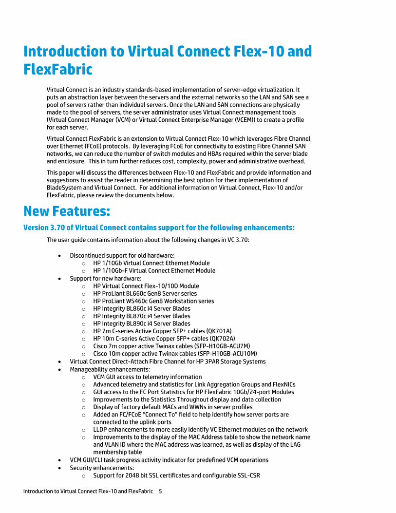
Introduction to Virtual Connect Flex-10 and FlexFabric
Virtual Connect is an industry standards-based implementation of server-edge virtualization. It puts an abstraction layer between the servers and the external networks so the LAN and SAN see a pool of servers rather than individual servers. Once the LAN and SAN connections are physically made to the pool of servers, the server administrator uses Virtual Connect management tools (Virtual Connect Manager (VCM) or Virtual Connect Enterprise Manager (VCEM)) to create a profile for each server.
Virtual Connect FlexFabric is an extension to Virtual Connect Flex-10 which leverages Fibre Channel over Ethernet (FCoE) protocols. By leveraging FCoE for connectivity to existing Fibre Channel SAN networks, we can reduce the number of switch modules and HBAs required within the server blade and enclosure. This in turn further reduces cost, complexity, power and administrative overhead.
This paper will discuss the differences between Flex-10 and FlexFabric and provide information and suggestions to assist the reader in determining the best option for their implementation of BladeSystem and Virtual Connect. For additional information on Virtual Connect, Flex-10 and/or FlexFabric, please review the documents below.
New Features: Version 3.70 of Virtual Connect contains support for the following enhancements:
The user guide contains information about the following changes in VC 3.70:
Discontinued support for old hardware: o HP 1/10Gb Virtual Connect Ethernet Module o HP 1/10Gb-F Virtual Connect Ethernet Module
Support for new hardware: o HP Virtual Connect Flex-10/10D Module o HP ProLiant BL660c Gen8 Server series o HP ProLiant WS460c Gen8 Workstation series o HP Integrity BL860c i4 Server Blades o HP Integrity BL870c i4 Server Blades o HP Integrity BL890c i4 Server Blades o HP 7m C-series Active Copper SFP+ cables (QK701A) o HP 10m C-series Active Copper SFP+ cables (QK702A) o Cisco 7m copper active Twinax cables (SFP-H10GB-ACU7M) o Cisco 10m copper active Twinax cables (SFP-H10GB-ACU10M)
Virtual Connect Direct-Attach Fibre Channel for HP 3PAR Storage Systems Manageability enhancements:
o VCM GUI access to telemetry information o Advanced telemetry and statistics for Link Aggregation Groups and FlexNICs o GUI access to the FC Port Statistics for HP FlexFabric 10Gb/24-port Modules o Improvements to the Statistics Throughout display and data collection o Display of factory default MACs and WWNs in server profiles o Added an FC/FCoE “Connect To” field to help identify how server ports are
connected to the uplink ports o LLDP enhancements to more easily identify VC Ethernet modules on the network o Improvements to the display of the MAC Address table to show the network name
and VLAN ID where the MAC address was learned, as well as display of the LAG membership table
VCM GUI/CLI task progress activity indicator for predefined VCM operations Security enhancements:
o Support for 2048 bit SSL certificates and configurable SSL-CSR
Introduction to Virtual Connect Flex-10 and FlexFabric 6
o Activity logging improvements for TACACS+ accounting o Option to disable local account access when LDAP, RADIUS, or TACACS+
authentication is enabled o Increased the default VCM local user account minimum required password length o SNMP access security to prevent access from unauthorized management stations
SmartLink failover improvements IGMP “NoFlood” option when IGMP snooping is enabled Browser support:
o Internet Explorer 8 and 9 o Firefox 10 and 11
Firmware upgrade rollback from a previous firmware upgrade without domain deletion Please refer to the VC 3.70 User Guide for additional VCEM feature enhancements
Please refer to the VC 3.70 Release notes and User Guides for further information
3.70 Release Notes http://bizsupport2.austin.hp.com/bc/docs/support/SupportManual/c03478436/c03478436.pdf
3.70 CLI User Guide http://bizsupport2.austin.hp.com/bc/docs/support/SupportManual/c03478433/c03478433.pdf
3.70 User Guide http://h20628.www2.hp.com/km-ext/kmcsdirect/emr_na-c03478464-3.pdf
Virtual Connect Firmware 4.01 includes the following new features:
Version 4.01 of Virtual Connect contains support for the following enhancements:
Manageability enhancements: Extended support for FCoE protocol on Flex-10/10D and FlexFabric modules, which
includes FIP snooping support but is limited to dual-hop configurations. FlexFabric module dual-hop FCoE support is restricted to uplink ports X1-X4 IMPORTANT: For more information about the installation and limitations for Virtual Connect dual-hop FCoE support, see the HP Virtual Connect Dual-Hop FCoE Cookbook, which can be found on the Installing tab of the HP BladeSystem Technical Resources website (http://www.hp.com/go/bladesystem/documentation)
Prioritization of critical application traffic with QoS Minimum and maximum bandwidth optimization for efficient allocation of bandwidth
in virtualized environments with Flex-10 and FlexFabric adapters. Flex-10 and FlexFabric adapter firmware and drivers must be updated to SPP version 2013.02.00, or the latest hotfix thereafter, to take advantage of this enhancement Note: This feature excludes support for the following adapters:
o HP NC551i Dual Port FlexFabric 10Gb Converged Network Adapter o HP NC551m Dual Port FlexFabric 10Gb Converged Network Adapter o HP NC550m 10Gb 2-port PCIe x8 Flex-10 Ethernet Adapter
VC SNMP MIB enhancements for improved troubleshooting and failure analysis Virtual Connect SNMP Domain MIB (vc-domain-mib.mib) traps now contain detailed information
with the root cause of each event. Update SNMP management stations with the HP MIB Kit version 9.30 prior to installing Virtual Connect version 4.01 to take advantage of this enhancement. Download the update from the HP website (http://h18006.www1.hp.com/products/servers/management/hpsim/mibkit.html).
Enhanced support for LLDP MIB, Bridge MIB, Interface MIB, and Link aggregation MIB The domain status alerts screen includes cause and root cause for each alert Customization of VC user roles and privileges The VCM GUI now allows searching for Network Access Groups, modules, interconnect
bays, and device bay items from the left navigation tree Configurable long or short LACP timer VCM CLI TAB key auto-completion The Network, SUS, and hardware pages now display the remote system name instead
Introduction to Virtual Connect Flex-10 and FlexFabric 7
of the MAC address. Security enhancements:
o IGMP Snooping enhancements with multicast group host membership filtering o Ability to set session timeout for idle VCM CLI or VCM GUI management sessions o Protection of VC Ethernet modules from buffer exhaustion due to flooding of
Pause packets from servers VCEM compatibility:
If you are running VCEM 6.3.1 or later to manage a VC 4.01 domain, the 4.01 domain can be in a VCDG in 3.30 firmware mode or later. To enable new features in VC 4.01, you must upgrade to VCEM 7.2 or later. VCEM 7.2 does not support VC versions prior to 3.30
Configurable role operations must be delegated to one of the following roles if they are to be performed while the domain is in Maintenance Mode: Network, Storage or Domain. Administrators logging into VCM with a Server role account while the domain is in Maintenance mode will be denied access to perform delegated operations such as exporting support files, updating firmware, configuring port monitoring or saving or restoring domain configuration
In VC 4.01, the telemetry port throughput is Enabled by default. You must do the following to add a fresh VC 4.01 installation to your existing VCDG: 3.30-3.70 VCDG with statistics throughput disabled—Clear the Enable
Throughput Statistics checkbox on the Ethernet Settings (Advanced Settings) screen, or run the following VCM CLI command:
set statistics-throughput Enabled=false 3.30-3.70 VCDG with statistics throughput enabled—Add the domain as is. No
change is required In VC 4.01, the VLAN Capacity is set to Expanded by default. You must do the following
to add a fresh VC 4.01 installation to your existing VCDG: 3.30-3.70 with Legacy VLAN VCDG—You cannot add the domain. Select a different
VCDG 3.30-3.70 with Enhanced VLAN VCDG—Add the domain as is. No change is
required
Please refer to the VC 4.01 Release notes for further information
4.01 Release Notes http://bizsupport2.austin.hp.com/bc/docs/support/SupportManual/c03801912/c03801912.pdf
4.01 CLI User Guide http://bizsupport2.austin.hp.com/bc/docs/support/SupportManual/c03790895/c03790895.pdf
4.01 User Guide http://bizsupport2.austin.hp.com/bc/docs/support/SupportManual/c03791917/c03791917.pdf
Additional Virtual Connect Reference Material
Links to HP Virtual Connect technology site, provides a great deal of reference information on HP Virtual Connect Flex-10 and FlexFabric. http://h18000.www1.hp.com/products/blades/virtualconnect/
Overview of HP Virtual Connect Technologies http://h20000.www2.hp.com/bc/docs/support/SupportManual/c00814156/c00814156.pdf
HP Virtual Connect Traffic Flow http://h20000.www2.hp.com/bc/docs/support/SupportManual/c03154250/c03154250.pdf
HP Virtual Connect for c-Class BladeSystem Setup and Installation Guide http://bizsupport1.austin.hp.com/bc/docs/support/SupportManual/c01732252/c01732252.pdf
Efficiently managing Virtual Connect environments http://h20000.www2.hp.com/bc/docs/support/SupportManual/c03028646/c03028646.pdf
HP Virtual Connect Direct-Attach Fibre Channel for HP 3PAR (FlatSAN) Solution brief http://h20195.www2.hp.com/V2/GetPDF.aspx/4AA4-1557ENW.pdf
Introduction to Virtual Connect Flex-10 and FlexFabric 8
HP BladeSystem Network Reference Architecture - FlexFabric and VMware vSphere 5 http://h20000.www2.hp.com/bc/docs/support/SupportManual/c03278211/c03278211.pdf
Virtual Connect User, Setup and CLI Guides http://h20000.www2.hp.com/bizsupport/TechSupport/DocumentIndex.jsp?contentType=SupportManual&lang=en&cc=us&docIndexId=64180&taskId=101&prodTypeId=3709945&prodSeriesId=3794423
HP Virtual Connect FlexFabric Solutions Recipe http://vibsdepot.hp.com/hpq/recipes/
Virtual Connect Multi-Enclosure Stacking Reference Guide http://h20000.www2.hp.com/bc/docs/support/SupportManual/c02102153/c02102153.pdf
Virtual Connect for the CISCO Administrator http://h20000.www2.hp.com/bc/docs/support/SupportManual/c01386629/c01386629.pdf (www.hp.com/go/blades)
The Virtual Connect Cookbook Series: Virtual Connect 1Gb Ethernet Cookbook
Virtual Connect can be used to support both Ethernet and Fibre Channel connections. The Virtual Connect 1Gb Ethernet Cookbook is provided with basic Virtual Connect configurations in a 1Gb environment. Earlier releases of the Virtual Connect Ethernet Cookbook cover both 1Gb and 10Gb solutions; however, the most recent release of the Virtual Connect 1Gb Cookbook cover only 1Gb Ethernet Solutions up to Virtual Connect firmware release 3.6x.
http://h20000.www2.hp.com/bc/docs/support/SupportManual/c01990371/c01990371.pdf
(www.hp.com/go/blades)
Virtual Connect Dual-Hop FCoE Cookbook
Virtual Connect 4.01 now provides the ability to pass FCoE (Dual Hop) to an external FCoE capable network switch. This guide is focused on both the Virtual Connect and Network switch configurations needed to support this connectivity.
For Dual Hop FCoE connectivity, please refer to the Dual-Hop FCoE with HP Virtual Connect modules Cookbook
http://bizsupport1.austin.hp.com/bc/docs/support/SupportManual/c03808925/c03808925.pdf
(www.hp.com/go/blades)
Virtual Connect Fibre Channel Cookbook
Virtual Connect can be used to support both Ethernet and Fibre Channel connections; however, this guide is focused completely on the Ethernet configuration.
For Fibre Channel connectivity, please refer to the Virtual Connect Fibre Channel Cookbook http://bizsupport1.austin.hp.com/bc/docs/support/SupportManual/c01702940/c01702940.pdf
(www.hp.com/go/blades)
Virtual Connect iSCSI Cookbook
Virtual Connect can be used to support iSCSI accelerated connections, including iSCSI boot, however, this guide is focused completely on the Ethernet and iSCSI configuration.
For iSCSI connectivity, please refer to the Virtual Connect iSCSI Cookbook http://h20000.www2.hp.com/bc/docs/support/SupportManual/c02533991/c02533991.pdf
(www.hp.com/go/blades)
Introduction to Virtual Connect Flex-10 and FlexFabric 9
Virtual Connect Ethernet Modules Virtual Connect Flex-10 Module Uplink Port Mappings
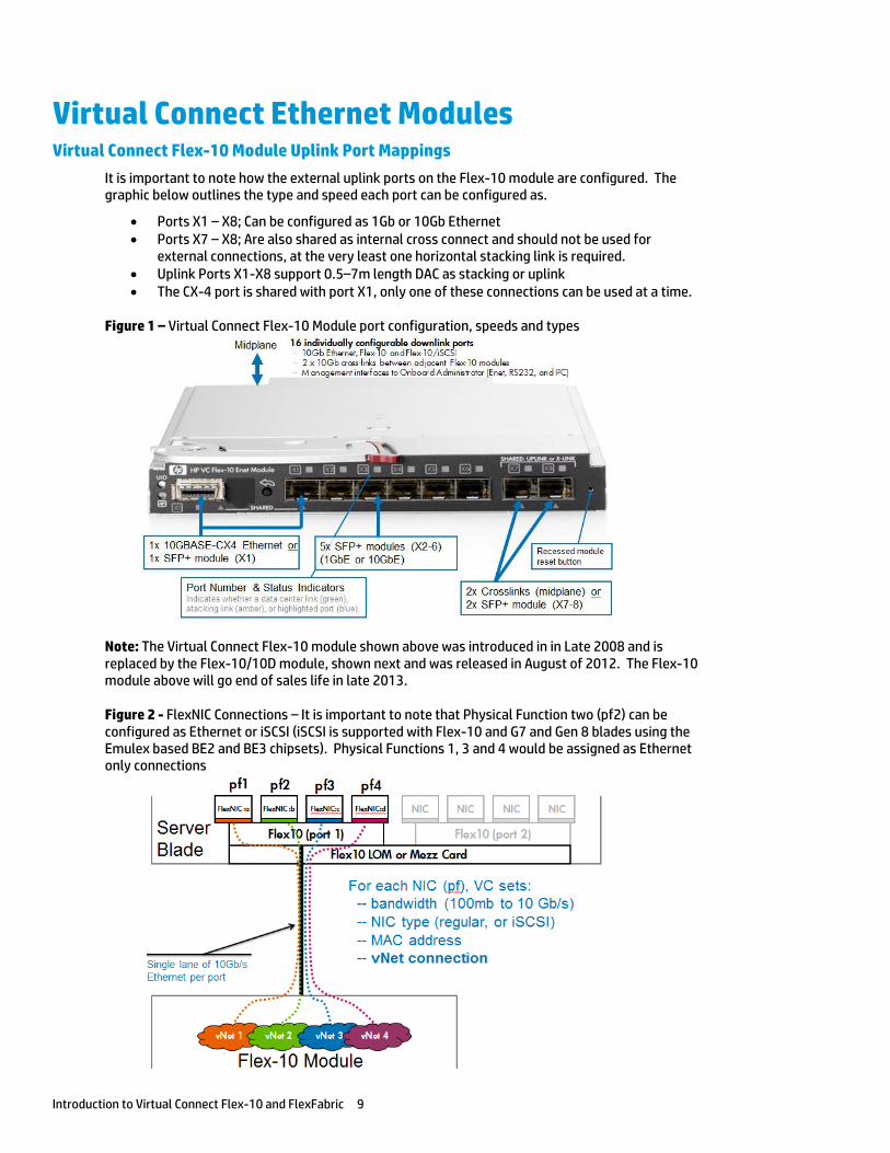
It is important to note how the external uplink ports on the Flex-10 module are configured. The graphic below outlines the type and speed each port can be configured as.
Ports X1 – X8; Can be configured as 1Gb or 10Gb Ethernet Ports X7 – X8; Are also shared as internal cross connect and should not be used for
external connections, at the very least one horizontal stacking link is required. Uplink Ports X1-X8 support 0.5–7m length DAC as stacking or uplink The CX-4 port is shared with port X1, only one of these connections can be used at a time.
Figure 1 – Virtual Connect Flex-10 Module port configuration, speeds and types
Note: The Virtual Connect Flex-10 module shown above was introduced in in Late 2008 and is replaced by the Flex-10/10D module, shown next and was released in August of 2012. The Flex-10 module above will go end of sales life in late 2013.
Figure 2 - FlexNIC Connections – It is important to note that Physical Function two (pf2) can be configured as Ethernet or iSCSI (iSCSI is supported with Flex-10 and G7 and Gen 8 blades using the Emulex based BE2 and BE3 chipsets). Physical Functions 1, 3 and 4 would be assigned as Ethernet only connections
Introduction to Virtual Connect Flex-10 and FlexFabric 10
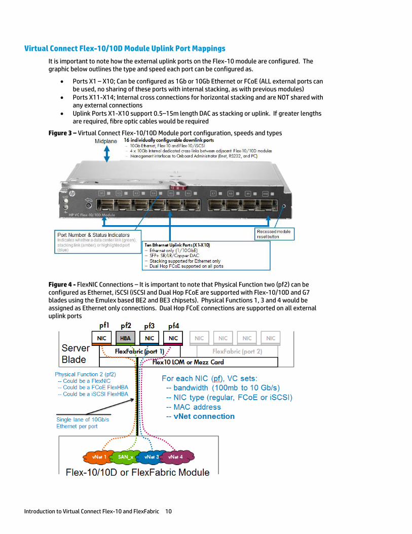
Virtual Connect Flex-10/10D Module Uplink Port Mappings
It is important to note how the external uplink ports on the Flex-10 module are configured. The graphic below outlines the type and speed each port can be configured as.
Ports X1 – X10; Can be configured as 1Gb or 10Gb Ethernet or FCoE (ALL external ports can be used, no sharing of these ports with internal stacking, as with previous modules)
Ports X11-X14; Internal cross connections for horizontal stacking and are NOT shared with any external connections
Uplink Ports X1-X10 support 0.5–15m length DAC as stacking or uplink. If greater lengths are required, fibre optic cables would be required
Figure 3 – Virtual Connect Flex-10/10D Module port configuration, speeds and types
Figure 4 - FlexNIC Connections – It is important to note that Physical Function two (pf2) can be configured as Ethernet, iSCSI (iSCSI and Dual Hop FCoE are supported with Flex-10/10D and G7 blades using the Emulex based BE2 and BE3 chipsets). Physical Functions 1, 3 and 4 would be assigned as Ethernet only connections. Dual Hop FCoE connections are supported on all external uplink ports
Introduction to Virtual Connect Flex-10 and FlexFabric 11
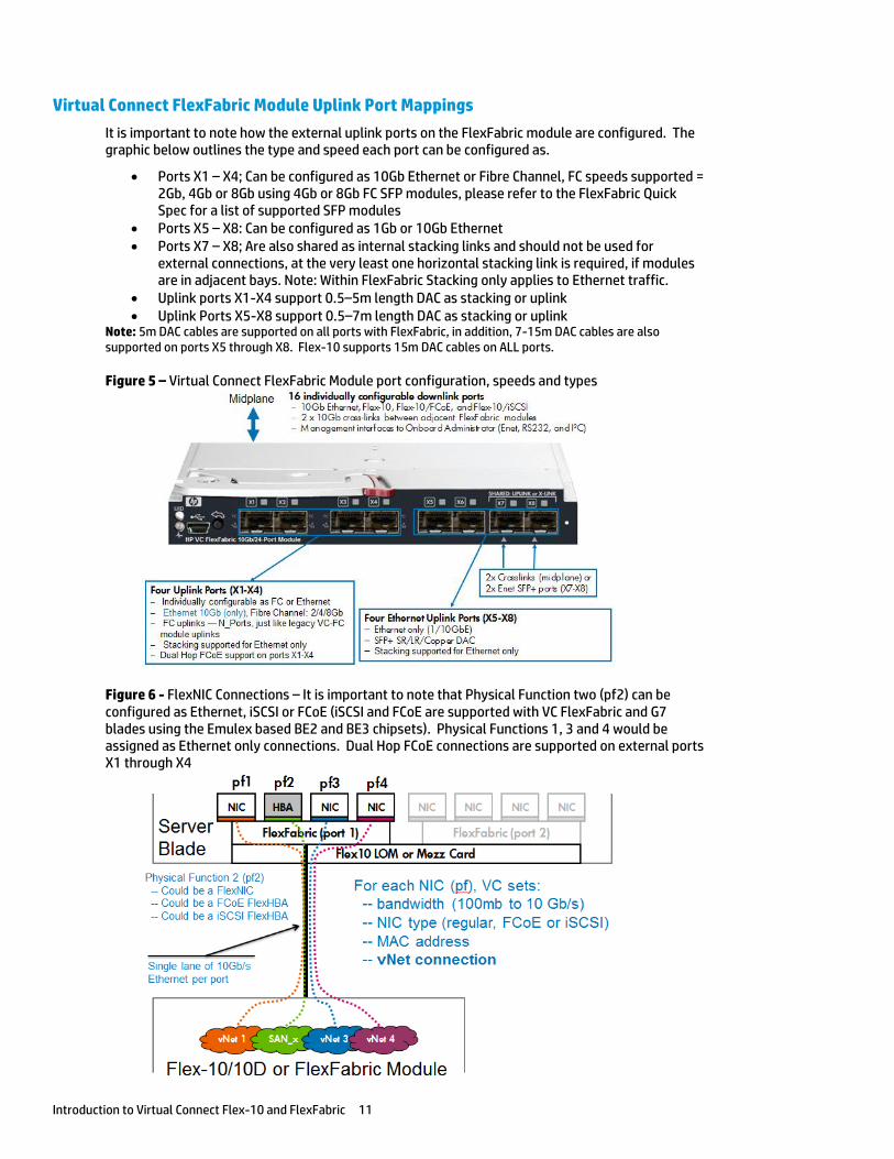
Virtual Connect FlexFabric Module Uplink Port Mappings
It is important to note how the external uplink ports on the FlexFabric module are configured. The graphic below outlines the type and speed each port can be configured as.
Ports X1 – X4; Can be configured as 10Gb Ethernet or Fibre Channel, FC speeds supported = 2Gb, 4Gb or 8Gb using 4Gb or 8Gb FC SFP modules, please refer to the FlexFabric Quick Spec for a list of supported SFP modules
Ports X5 – X8: Can be configured as 1Gb or 10Gb Ethernet Ports X7 – X8; Are also shared as internal stacking links and should not be used for
external connections, at the very least one horizontal stacking link is required, if modules are in adjacent bays. Note: Within FlexFabric Stacking only applies to Ethernet traffic.
Uplink ports X1-X4 support 0.5–5m length DAC as stacking or uplink Uplink Ports X5-X8 support 0.5–7m length DAC as stacking or uplink
Note: 5m DAC cables are supported on all ports with FlexFabric, in addition, 7-15m DAC cables are also supported on ports X5 through X8. Flex-10 supports 15m DAC cables on ALL ports.
Figure 5 – Virtual Connect FlexFabric Module port configuration, speeds and types
Figure 6 - FlexNIC Connections – It is important to note that Physical Function two (pf2) can be configured as Ethernet, iSCSI or FCoE (iSCSI and FCoE are supported with VC FlexFabric and G7 blades using the Emulex based BE2 and BE3 chipsets). Physical Functions 1, 3 and 4 would be assigned as Ethernet only connections. Dual Hop FCoE connections are supported on external ports X1 through X4
Introduction to Virtual Connect Flex-10 and FlexFabric 12
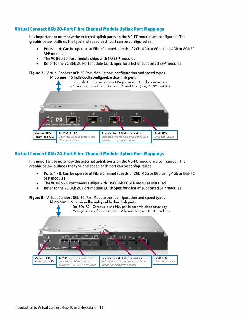
Virtual Connect 8Gb 20-Port Fibre Channel Module Uplink Port Mappings
It is important to note how the external uplink ports on the VC-FC module are configured. The graphic below outlines the type and speed each port can be configured as.
Ports 1 - 4; Can be operate at Fibre Channel speeds of 2Gb, 4Gb or 8Gb using 4Gb or 8Gb FC SFP modules,
The VC 8Gb 2o Port module ships with NO SFP modules Refer to the VC 8Gb 20 Port module Quick Spec for a list of supported SFP modules
Figure 7 - Virtual Connect 8Gb 20 Port Module port configuration and speed types
Virtual Connect 8Gb 24-Port Fibre Channel Module Uplink Port Mappings
It is important to note how the external uplink ports on the VC-FC module are configured. The graphic below outlines the type and speed each port can be configured as.
Ports 1 - 8; Can be operate at Fibre Channel speeds of 2Gb, 4Gb or 8Gb using 4Gb or 8Gb FC SFP modules
The VC 8Gb 24 Port module ships with TWO 8Gb FC SFP modules installed Refer to the VC 8Gb 20 Port module Quick Spec for a list of supported SFP modules
Figure 8 - Virtual Connect 8Gb 20 Port Module port configuration and speed types
Introduction to Virtual Connect Flex-10 and FlexFabric 13
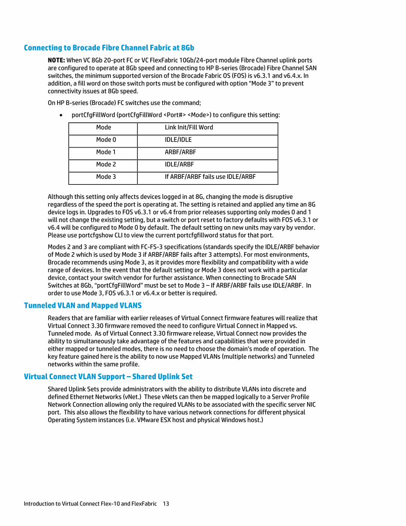
Connecting to Brocade Fibre Channel Fabric at 8Gb
NOTE: When VC 8Gb 20-port FC or VC FlexFabric 10Gb/24-port module Fibre Channel uplink ports are configured to operate at 8Gb speed and connecting to HP B-series (Brocade) Fibre Channel SAN switches, the minimum supported version of the Brocade Fabric OS (FOS) is v6.3.1 and v6.4.x. In addition, a fill word on those switch ports must be configured with option “Mode 3” to prevent connectivity issues at 8Gb speed.
On HP B-series (Brocade) FC switches use the command;
portCfgFillWord (portCfgFillWord <Port#> <Mode>) to configure this setting:
Although this setting only affects devices logged in at 8G, changing the mode is disruptive regardless of the speed the port is operating at. The setting is retained and applied any time an 8G device logs in. Upgrades to FOS v6.3.1 or v6.4 from prior releases supporting only modes 0 and 1 will not change the existing setting, but a switch or port reset to factory defaults with FOS v6.3.1 or v6.4 will be configured to Mode 0 by default. The default setting on new units may vary by vendor. Please use portcfgshow CLI to view the current portcfgfillword status for that port.
Modes 2 and 3 are compliant with FC-FS-3 specifications (standards specify the IDLE/ARBF behavior of Mode 2 which is used by Mode 3 if ARBF/ARBF fails after 3 attempts). For most environments, Brocade recommends using Mode 3, as it provides more flexibility and compatibility with a wide range of devices. In the event that the default setting or Mode 3 does not work with a particular device, contact your switch vendor for further assistance. When connecting to Brocade SAN Switches at 8Gb, “portCfgFillWord” must be set to Mode 3 – If ARBF/ARBF fails use IDLE/ARBF. In order to use Mode 3, FOS v6.3.1 or v6.4.x or better is required.
Tunneled VLAN and Mapped VLANS
Readers that are familiar with earlier releases of Virtual Connect firmware features will realize that Virtual Connect 3.30 firmware removed the need to configure Virtual Connect in Mapped vs. Tunneled mode. As of Virtual Connect 3.30 firmware release, Virtual Connect now provides the ability to simultaneously take advantage of the features and capabilities that were provided in either mapped or tunneled modes, there is no need to choose the domain’s mode of operation. The key feature gained here is the ability to now use Mapped VLANs (multiple networks) and Tunneled networks within the same profile.
Virtual Connect VLAN Support – Shared Uplink Set
Shared Uplink Sets provide administrators with the ability to distribute VLANs into discrete and defined Ethernet Networks (vNet.) These vNets can then be mapped logically to a Server Profile Network Connection allowing only the required VLANs to be associated with the specific server NIC port. This also allows the flexibility to have various network connections for different physical Operating System instances (i.e. VMware ESX host and physical Windows host.)
Mode Link Init/Fill Word
Mode 0 IDLE/IDLE
Mode 1 ARBF/ARBF
Mode 2 IDLE/ARBF
Mode 3 If ARBF/ARBF fails use IDLE/ARBF
Introduction to Virtual Connect Flex-10 and FlexFabric 14
Legacy VLAN Capacity
Legacy VLAN capacity mode allows up to 320 VLANs per Ethernet module, 128 VLANs per Shared Uplink Set and, up to 28 VLANs are allowed per FlexNIC port. Care must be taken not to exceed the limit per physical server port.
The following Shared Uplink Set rules apply to legacy capacity mode:
320 VLANs per Virtual Connect Ethernet Module 128 VLANs per Shared Uplink Set (single uplink port) 28 unique server mapped VLANs per server profile network connection
The above configuration rules apply only to a Shared Uplink set. If support for a larger numbers of VLANs is required, a VLAN Tunnel can be configured to support a large number of VLANs. Please see the Virtual Connect Release Notes for future details.
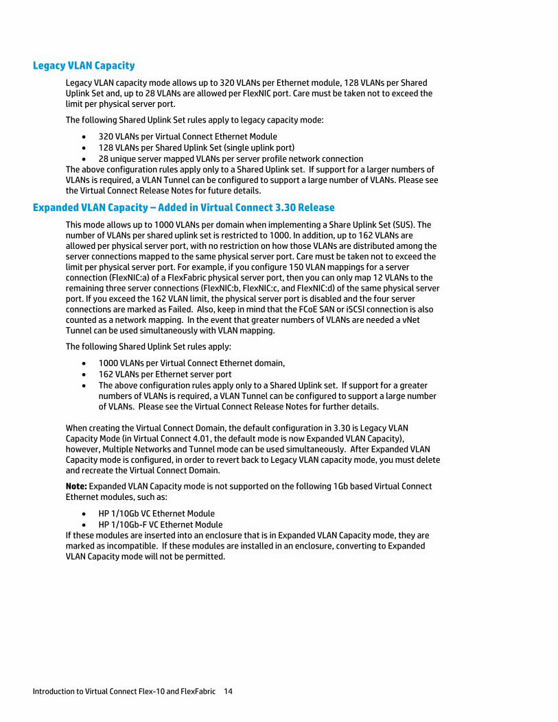
Expanded VLAN Capacity – Added in Virtual Connect 3.30 Release
This mode allows up to 1000 VLANs per domain when implementing a Share Uplink Set (SUS). The number of VLANs per shared uplink set is restricted to 1000. In addition, up to 162 VLANs are allowed per physical server port, with no restriction on how those VLANs are distributed among the server connections mapped to the same physical server port. Care must be taken not to exceed the limit per physical server port. For example, if you configure 150 VLAN mappings for a server connection (FlexNIC:a) of a FlexFabric physical server port, then you can only map 12 VLANs to the remaining three server connections (FlexNIC:b, FlexNIC:c, and FlexNIC:d) of the same physical server port. If you exceed the 162 VLAN limit, the physical server port is disabled and the four server connections are marked as Failed. Also, keep in mind that the FCoE SAN or iSCSI connection is also counted as a network mapping. In the event that greater numbers of VLANs are needed a vNet Tunnel can be used simultaneously with VLAN mapping.
The following Shared Uplink Set rules apply:
1000 VLANs per Virtual Connect Ethernet domain, 162 VLANs per Ethernet server port The above configuration rules apply only to a Shared Uplink set. If support for a greater
numbers of VLANs is required, a VLAN Tunnel can be configured to support a large number of VLANs. Please see the Virtual Connect Release Notes for further details.
When creating the Virtual Connect Domain, the default configuration in 3.30 is Legacy VLAN Capacity Mode (in Virtual Connect 4.01, the default mode is now Expanded VLAN Capacity), however, Multiple Networks and Tunnel mode can be used simultaneously. After Expanded VLAN Capacity mode is configured, in order to revert back to Legacy VLAN capacity mode, you must delete and recreate the Virtual Connect Domain.
Note: Expanded VLAN Capacity mode is not supported on the following 1Gb based Virtual Connect Ethernet modules, such as:
HP 1/10Gb VC Ethernet Module HP 1/10Gb-F VC Ethernet Module
If these modules are inserted into an enclosure that is in Expanded VLAN Capacity mode, they are marked as incompatible. If these modules are installed in an enclosure, converting to Expanded VLAN Capacity mode will not be permitted.
Introduction to Virtual Connect Flex-10 and FlexFabric 15
Figure 9 - Configuring Expanded VLAN Capacity support
Bulk VLAN Creation
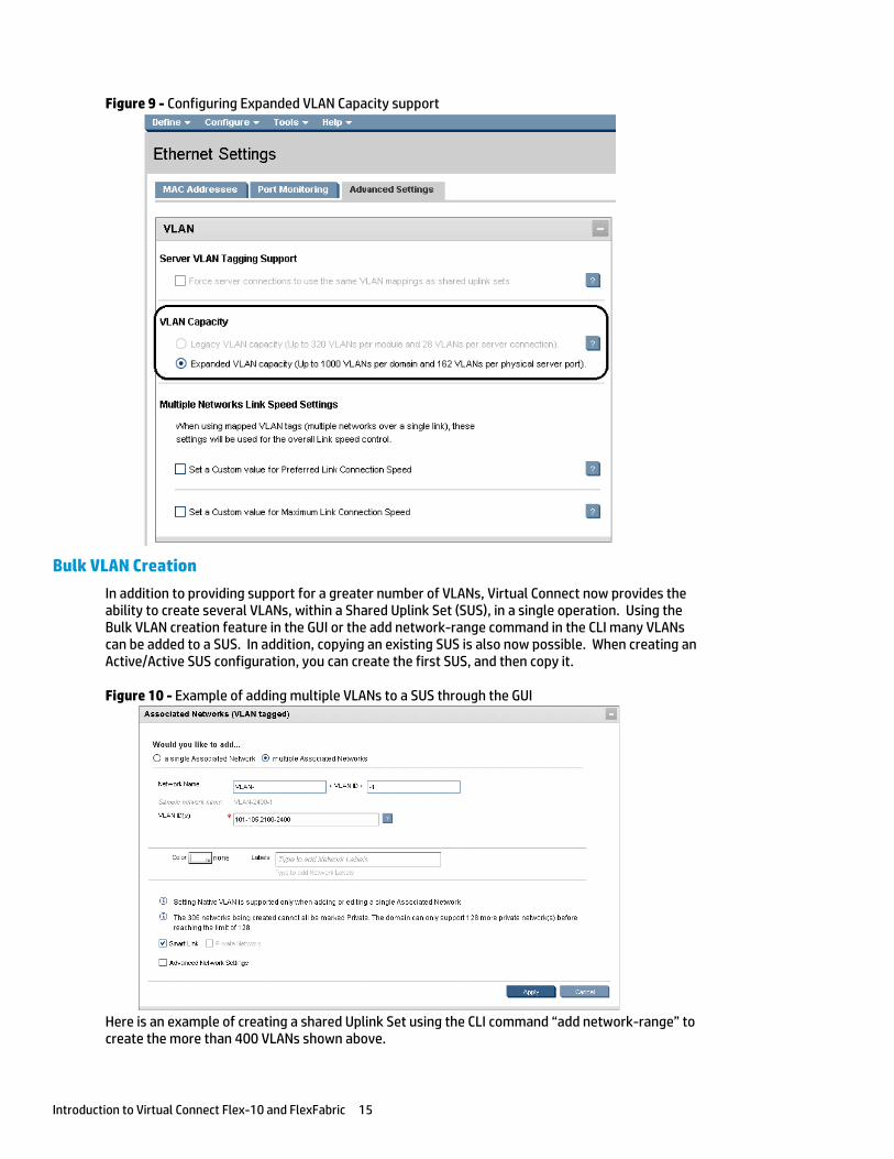
In addition to providing support for a greater number of VLANs, Virtual Connect now provides the ability to create several VLANs, within a Shared Uplink Set (SUS), in a single operation. Using the Bulk VLAN creation feature in the GUI or the add network-range command in the CLI many VLANs can be added to a SUS. In addition, copying an existing SUS is also now possible. When creating an Active/Active SUS configuration, you can create the first SUS, and then copy it.
Figure 10 - Example of adding multiple VLANs to a SUS through the GUI
Here is an example of creating a shared Uplink Set using the CLI command “add network-range” to create the more than 400 VLANs shown above.
Introduction to Virtual Connect Flex-10 and FlexFabric 16
add uplinkset VLAN-Trunk-1 add uplinkport enc0:1:X5 Uplinkset=VLAN-Trunk-1 speed=auto add uplinkport enc0:1:X6 Uplinkset=VLAN-Trunk-1 speed=auto add network-range -quiet UplinkSet=VLAN-Trunk-1 NamePrefix=VLAN- NameSuffix=-1 VLANIds=101-105,2100-2400 State=enabled PrefSpeedType=auto SmartLink=enabled
Note: Earlier release of Virtual Connect firmware supported only 320 VLANs, in addition, to create each VLAN with SmartLink enabled required two lines of script. In the example above, over 300 VLANs are created in a single statement.
Copying a Shared Uplink Sets
Virtual Connect provides the ability to copy a Shared Uplink Set. This can be very handy when defining an Active/Active Shared Uplink Set design. You simply create the first SUS, and then copy it.
For example, after creating Shared Uplink Set VLAN-Trunk-1 you can copy it to VLAN-Trunk-2. You will then need to add uplinks to the new SUS and ensure all networks have SmartLink enabled. This can be accomplished as follows;
copy uplinkset VLAN-Trunk-1 VLAN-Trunk-2 fromVlanStr=1 toVlanStr=2 replace=last add uplinkport enc0:2:X5 Uplinkset=VLAN-Trunk-2 speed=auto add uplinkport enc0:2:X6 Uplinkset=VLAN-Trunk-2 speed=auto set network-range -quiet UplinkSet=VLAN-Trunk-1 VLANIds=101-105,2100-2400 SmartLink=enabled
vNets, Tunnels and Shared Uplink Sets
There are two types of vNets. The first is a simple vNet that will pass only untagged frames. The second is a vNet tunnel which will pass tagged frames for one or many VLANs.
vNet
The vNet is a simple network connection between one or many server NICs to one or many uplink ports.
A vNet could be used to connect a single VLAN, without tagging, to one or many server NICs. If this network is configured as a VLAN, by configuring the upstream switch port as an access or untagged port, by extension, any server connected to this vNet would reside in that VLAN, but would not need to be configured to interpret the VLAN tags.
Benefits of a vNet
A vNet can be utilized in one of two ways, a simple vNet, used to pass untagged frames and a tunneled vNet. A tunneled vNet can be used to pass many VLANs without modifying the VLAN tags, functioning as a transparent VLAN Pass-Thru module.
vNet Tunnel
A tunneled vNet will pass VLAN tagged frames, without the need to interpret or forward those frames based on the VLAN tag. Within a tunneled vNet the VLAN tag is completely ignored by Virtual Connect and the frame is forwarded to the appropriate connection (server NIC[s] or uplinks) depending on frame direction flow. In this case, the end server would need to be configured to interpret the VLAN tags. This could be a server with a local operating system, in which the network stack would need to be configured to understand which VLAN the server was in, or a virtualization host with a vSwitch supporting multiple VLANs.
The tunneled vNet can support up to 4096 VLANs.
Benefits of a vNet Tunnel
A vNet Tunnel can present one or many VLANs to a server NIC. When additional VLANs are added to the upstream switch port, they are made available to server with no changes required within Virtual Connect. All presented VLANs are pass through the tunnel, unchanged.
Introduction to Virtual Connect Flex-10 and FlexFabric 17
Shared Uplink Set (SUS)
The SUS provides the ability to support VLAN tagging and forward frames based on the VLAN tags of those frames. The SUS connects one or many server NICs to one or many uplink ports. A SUS would be configured for the specific VLANs it will support. If support for additional VLANs is required, those VLANs need to be configured within the SUS. When connecting a server NIC to a network within a SUS, there are two choices provided. The key difference between these two options is the state in which the frame is passed to the server NIC. When configuring a server NIC for network connection;
1. Selecting a single network – which would be mapped to a specific VLAN. If a single network is selected, the frames will be presented to the server NIC WITHOUT a VLAN tag. In this case the host operating system does not need to understand which VLAN it resides in. When the server transmits frames back to Virtual Connect, those frames will not be tagged, however; Virtual Connect will add the VLAN tag and forward the frame onto the correct VLAN.
2. Selecting multiple networks – which would provide connectivity to several VLANs. The Map VLAN Tags feature provides the ability to use a Shared Uplink Set to present multiple networks to a single NIC. If you select Multiple Networks when assigning a Network to a server NIC, you will have the ability to configure multiple Networks (VLANS) on that server NIC. At this point Virtual Connect tags ALL the packets presented to the NIC — unless the Native check box is selected for one of the networks, in which case packets from this network (VLAN) will be untagged, and any untagged packets leaving the server will be placed on this Network (VLAN).
With Mapped VLAN Tags, you can create a Shared Uplink Set that contains ALL the VLANs you want to present to your servers, then present only ONE network (the one associated with the VLAN we want the server NIC in) to the Windows, LINUX or the ESX Console NIC, then select Multiple Networks for the NIC connected to the ESX vSwitch and select ALL the networks that we want presented to the ESX host vSwitch. The vSwitch will then break out the VLANs into port groups and present them to the guests. Using Mapped VLAN Tags minimizes the number of uplinks required.
Benefits of a SUS
A Shared Uplink Set can be configure to support both tagged and un-tagged network traffic to a server NIC, which simplifies the overall configuration and minimizes the number of uplink cables required to support the network connections.
MAC Cache Failover
When a Virtual Connect Ethernet uplink that was previously in standby mode becomes active, it can take several minutes for external Ethernet switches to recognize that the c-Class server blades can now be reached on this newly-active connection. Enabling Fast MAC Cache Failover causes Virtual Connect to transmit Ethernet packets on newly-active links, which enables the external Ethernet switches to identify the new connection more quickly (and update their MAC caches appropriately). This transmission sequence repeats a few times at the MAC refresh interval (5 seconds recommended) and completes in about 1 minute.
When implementing Virtual Connect in an Active/Standby configuration, where some of the links connected to a Virtual connect Network (whether a SUS or vNet) are in standby, MAC Cache Fail-over would be employed to notify the switch as a link transitions from Standby to Active within Virtual Connect.
Note: Be sure to set switches to allow MAC addresses to move from one port to another without waiting for an expiration period or causing a lock out.
Introduction to Virtual Connect Flex-10 and FlexFabric 18
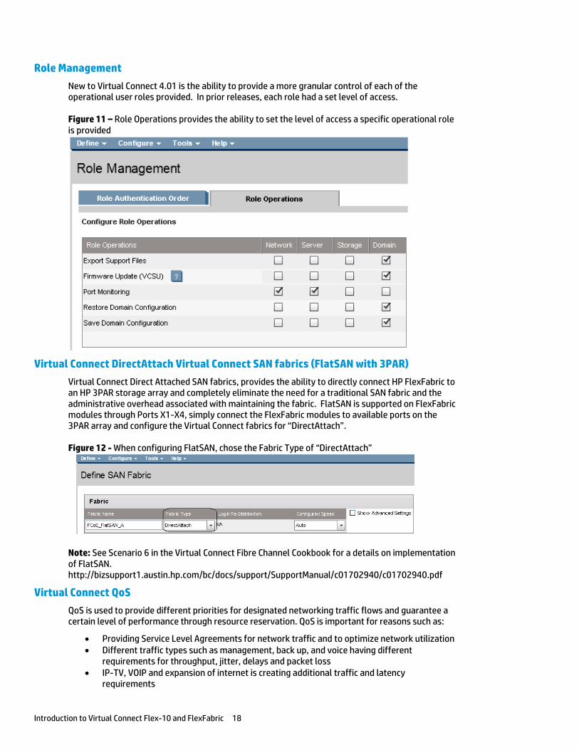
Role Management
New to Virtual Connect 4.01 is the ability to provide a more granular control of each of the operational user roles provided. In prior releases, each role had a set level of access.
Figure 11 – Role Operations provides the ability to set the level of access a specific operational role is provided
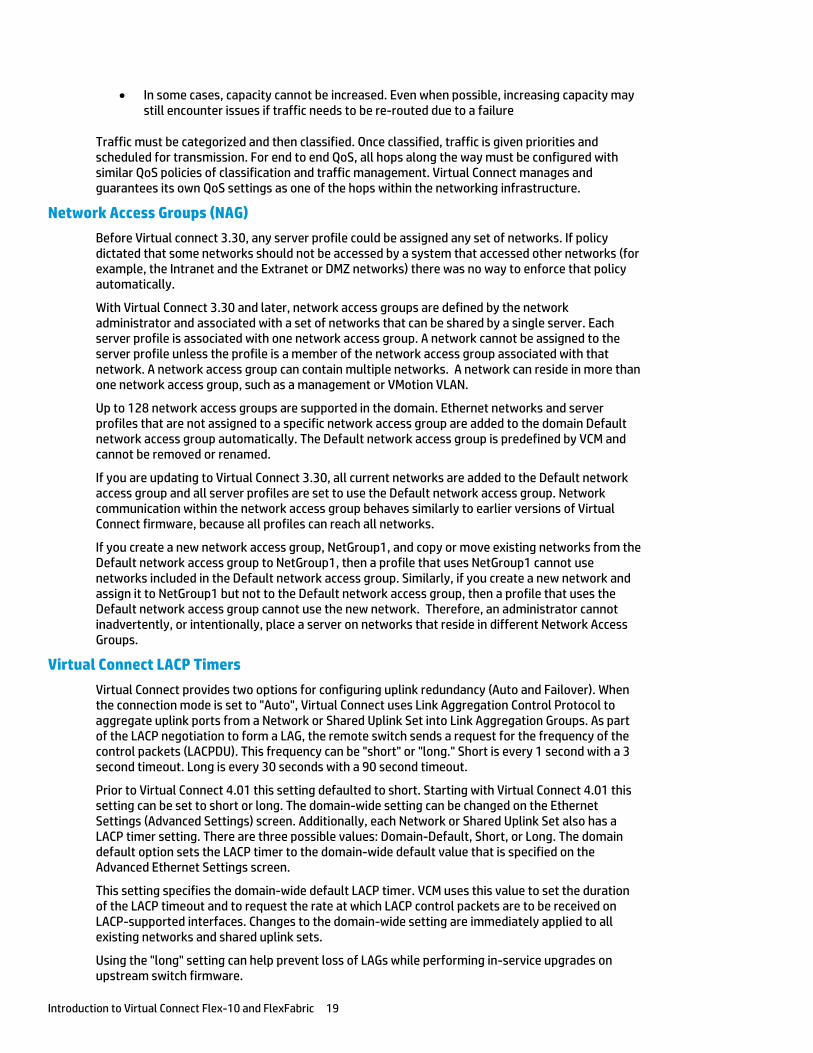
Virtual Connect DirectAttach Virtual Connect SAN fabrics (FlatSAN with 3PAR)
Virtual Connect Direct Attached SAN fabrics, provides the ability to directly connect HP FlexFabric to an HP 3PAR storage array and completely eliminate the need for a traditional SAN fabric and the administrative overhead associated with maintaining the fabric. FlatSAN is supported on FlexFabric modules through Ports X1-X4, simply connect the FlexFabric modules to available ports on the 3PAR array and configure the Virtual Connect fabrics for “DirectAttach”.
Figure 12 - When configuring FlatSAN, chose the Fabric Type of “DirectAttach”
Note: See Scenario 6 in the Virtual Connect Fibre Channel Cookbook for a details on implementation of FlatSAN. http://bizsupport1.austin.hp.com/bc/docs/support/SupportManual/c01702940/c01702940.pdf
Virtual Connect QoS
QoS is used to provide different priorities for designated networking traffic flows and guarantee a certain level of performance through resource reservation. QoS is important for reasons such as:
Providing Service Level Agreements for network traffic and to optimize network utilization Different traffic types such as management, back up, and voice having different
requirements for throughput, jitter, delays and packet loss IP-TV, VOIP and expansion of internet is creating additional traffic and latency
requirements
Introduction to Virtual Connect Flex-10 and FlexFabric 19
In some cases, capacity cannot be increased. Even when possible, increasing capacity may still encounter issues if traffic needs to be re-routed due to a failure
Traffic must be categorized and then classified. Once classified, traffic is given priorities and scheduled for transmission. For end to end QoS, all hops along the way must be configured with similar QoS policies of classification and traffic management. Virtual Connect manages and guarantees its own QoS settings as one of the hops within the networking infrastructure.
Network Access Groups (NAG)
Before Virtual connect 3.30, any server profile could be assigned any set of networks. If policy dictated that some networks should not be accessed by a system that accessed other networks (for example, the Intranet and the Extranet or DMZ networks) there was no way to enforce that policy automatically.
With Virtual Connect 3.30 and later, network access groups are defined by the network administrator and associated with a set of networks that can be shared by a single server. Each server profile is associated with one network access group. A network cannot be assigned to the server profile unless the profile is a member of the network access group associated with that network. A network access group can contain multiple networks. A network can reside in more than one network access group, such as a management or VMotion VLAN.
Up to 128 network access groups are supported in the domain. Ethernet networks and server profiles that are not assigned to a specific network access group are added to the domain Default network access group automatically. The Default network access group is predefined by VCM and cannot be removed or renamed.
If you are updating to Virtual Connect 3.30, all current networks are added to the Default network access group and all server profiles are set to use the Default network access group. Network communication within the network access group behaves similarly to earlier versions of Virtual Connect firmware, because all profiles can reach all networks.
If you create a new network access group, NetGroup1, and copy or move existing networks from the Default network access group to NetGroup1, then a profile that uses NetGroup1 cannot use networks included in the Default network access group. Similarly, if you create a new network and assign it to NetGroup1 but not to the Default network access group, then a profile that uses the Default network access group cannot use the new network. Therefore, an administrator cannot inadvertently, or intentionally, place a server on networks that reside in different Network Access Groups.
Virtual Connect LACP Timers
Virtual Connect provides two options for configuring uplink redundancy (Auto and Failover). When the connection mode is set to "Auto", Virtual Connect uses Link Aggregation Control Protocol to aggregate uplink ports from a Network or Shared Uplink Set into Link Aggregation Groups. As part of the LACP negotiation to form a LAG, the remote switch sends a request for the frequency of the control packets (LACPDU). This frequency can be "short" or "long." Short is every 1 second with a 3 second timeout. Long is every 30 seconds with a 90 second timeout.
Prior to Virtual Connect 4.01 this setting defaulted to short. Starting with Virtual Connect 4.01 this setting can be set to short or long. The domain-wide setting can be changed on the Ethernet Settings (Advanced Settings) screen. Additionally, each Network or Shared Uplink Set also has a LACP timer setting. There are three possible values: Domain-Default, Short, or Long. The domain default option sets the LACP timer to the domain-wide default value that is specified on the Advanced Ethernet Settings screen.
This setting specifies the domain-wide default LACP timer. VCM uses this value to set the duration of the LACP timeout and to request the rate at which LACP control packets are to be received on LACP-supported interfaces. Changes to the domain-wide setting are immediately applied to all existing networks and shared uplink sets.
Using the "long" setting can help prevent loss of LAGs while performing in-service upgrades on upstream switch firmware.
Introduction to Virtual Connect Flex-10 and FlexFabric 20
Multiple Networks Link Speed Settings (Min/Max Bandwidth Control)
A new feature to Virtual Connect 4.01 provides the ability to configure a minimum and maximum preferred NIC link speed for server downlinks. This setting can be configured as a global default for NICs configured with multiple networks, but can also be fine-tuned at the individual NIC level. The default global Preferred Speed is set to 10Gb. The new “Maximum Link Connection Speed” setting can be configured to enable a NIC to transmit at a speed greater that it’s configured speed. The default Maximum speed is set to 10Gb. If these settings are remain as default, each NIC, although configured for a set speed (minimum guaranteed speed), will be able to transmit at a rate as high as 10Gb. This feature is also known as “Min/Max”.
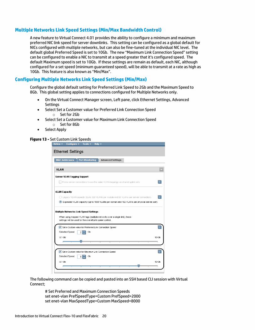
Configuring Multiple Networks Link Speed Settings (Min/Max)
Configure the global default setting for Preferred Link Speed to 2Gb and the Maximum Speed to 8Gb. This global setting applies to connections configured for Multiple Networks only.
On the Virtual Connect Manager screen, Left pane, click Ethernet Settings, Advanced Settings
Select Set a Customer value for Preferred Link Connection Speed o Set for 2Gb
Select Set a Customer value for Maximum Link Connection Speed o Set for 8Gb
Select Apply
Figure 13 - Set Custom Link Speeds
The following command can be copied and pasted into an SSH based CLI session with Virtual Connect;
# Set Preferred and Maximum Connection Speeds set enet-vlan PrefSpeedType=Custom PrefSpeed=2000 set enet-vlan MaxSpeedType=Custom MaxSpeed=8000
Introduction to Virtual Connect Flex-10 and FlexFabric 21
Configuring Throughput Statistics
Telemetry support for network devices caters to seamless operations and interoperability by providing visibility into what is happening on the network at any given time. It offers extensive and useful detection capabilities which can be coupled with upstream systems for analysis and trending of observed activity.
The Throughput Statistics configuration determines how often the Throughput Statistics are collected and the supported time frame for sample collection before overwriting existing samples. When the time frame for sample collection is reached, the oldest sample is removed to allocate room for the new sample. Configuration changes can be made without having to enable Throughput Statistics. Applying configuration changes when Throughput statistics is enabled clears all existing samples.
Some conditions can clear existing Throughput Statistics:
Disabling the collection of Throughput Statistics clears all existing samples.
Changing the sampling rate clears all existing samples.
Power cycling a Virtual connect Ethernet module clears all Throughput Statistics samples for that module.
Collected samples are available for analysis on the Throughput Statistics screen (on page 226 of the Virtual Connect 4.01 User Guide), accessible by selecting Throughput Statistics from the Tools pull-down menu.
The following table describes the available actions for changing Throughput Statistics settings.
Task Action
Enable/disable Select (enable) or clear (disable) the Enable Throughput Statistics checkbox
Change sampling rate
Select a sampling rate from the Configuration list. Supported sampling rates include:
Sample rate of 1 minute, collecting up to 5 hours of samples. Sample rate of 2 minutes, collecting up to 10 hours of samples. Sample rate of 3 minutes, collecting up to 15 hours of samples. Sample rate of 4 minutes, collecting up to 20 hours of samples. Sample rate of 5 minutes, collecting up to 25 hours of samples. Sample rate of 1 hour, collecting up to 12.5 days of samples.
Connecting VC Flex-10/10D or VC FlexFabric to the CORE
The baseline Virtual Connect technology adds a virtualization layer between the edge of the server and the edge of the existing LAN and SAN. As a result, the external networks connect to a shared resource pool of MAC addresses and WWNs rather than to MACs/WWNs of individual servers.
LAN-Safe
From the external networking view, Virtual Connect FlexFabric, Flex-10, or Ethernet uplinks appear to be multiple NICs on a large server. Virtual Connect ports at the enclosure edge look like server connections. This is analogous to a VMware environment that provides multiple MAC addresses to the network through a single NIC port on a server.
Virtual Connect works seamlessly with your external network:
Does not participate in Spanning Tree Protocol (STP) on the network uplinks to the data center. This avoids potential STP configuration errors that can negatively affect switches in the network and the servers connected to those switches
Introduction to Virtual Connect Flex-10 and FlexFabric 22
Uses an internal loop prevention algorithm to automatically detect and prevent loops inside a Virtual Connect domain. Virtual Connect ensures that there is only one active uplink for any single network at one time
Allows aggregation of uplinks to data center networks (using LACP and fail-over)
Supports VLAN tagging on egress or pass-thru of VLAN tags in tunneled mode
Supports Link Layer Discovery Protocol (LLDP) and Jumbo Frames
Virtual Connect was designed to connect to the network as an endpoint device, as such, it is capable of connecting to any network switch, at any layer, including directly to the core switch, providing the ability to flatten the network as required.
Choosing VC Flex-10/10D or VC FlexFabric When choosing between Flex-10/10D and FlexFabric, the first question to ask is whether a direct connection to a Fibre Channel SAN fabric will be required, today or in the future. The key difference between Flex-10 and FlexFabric is that FlexFabric modules leverage the built in Converged Network Adapter (CNA) provided in the G7 and Gen 8 BladeSystem servers to provide FCoE (Fibre Channel) connectivity. FCoE connectivity is provided through the integrated Converged Network Adapter (CNA) and the FlexFabric modules, the FlexFabric modules connect directly to the existing Fibre Channel switch fabrics, no additional components would be required, such as a traditional HBA.
With the release of Virtual connect firmware 4.01, the Flex-10/10D and FlexFabric modules can also be utilized to provide dual hop FCoE connectivity to a switch that supports FCoE connections, in which case the FCoE traffic would traverse the Ethernet uplinks and connect to the SAN through the ToR or Core switch.
Virtual Connect 3.70 provided a new capability when connecting to HP’s 3PAR storage arrays using Fibre Channel, allowing the 3PAR array to be directly connected to the FlexFabric modules. This feature is call “FlatSAN” and provides the ability to completely eliminate the need for a fibre channel SAN fabric, further reducing the cost of implementation and management of a blade server environment.
If direct connection to a Fibre Channel SAN fabric is not required, then all the capabilities of the CNA in the G7 and Gen 8 Blade and Virtual Connect can be obtained through the use of the Flex-10/10D modules, the only feature not available would be direct connection to a fibre channel SAN fabric. Fibre Channel connectivity could be later added through the use of traditional Virtual Connect Fibre Channel modules, and FC HBAs. iSCSI support is provided through either FlexFabric or Flex-10 modules.
If Fibre Channel is not used, then the second Physical Function (pf) on each port would be used for Ethernet. If Flex-10 modules are used with Virtual connect Fibre Channel modules, ensure an HBA is installed in the appropriate MEZZ slot in the blade and simply configure a “FC HBA” within the server profile and map it to the appropriate FC SAN Fabrics. In this case, FCoE SAN Fabrics and FCoE CNAs would not be utilized. An example of this configuration is provided in Scenario 9.
The Scenarios provided in this document could be implemented on either; Flex-10, Flex-10/10D (with VC-FC Modules for FC connections) or FlexFabric modules, with the exception of the dual hop FCoE, which would not be supported on Flex-10 modules.
FlexFabric also provides the ability to support “Direct Attached” SAN fabrics to an HP 3PAR SAN, which provides the ability to eliminate the SAN fabric.
Note: Dual hop FCoE connectivity is provided through Flex-10/10D and FlexFabric modules only. The original Flex-10 module does not support dual hop FCoE.
Introduction to Virtual Connect Flex-10 and FlexFabric 23
Choosing an Adapter for VC Flex-10/10D or VC FlexFabric
The following adapters are supported with Virtual Connect Flex-10, Flex-10/10D and FlexFabric;
Gen 8 Blades – FlexFabric FCoE/iSCSI support
HP FlexFabric 10Gb 2-port 554FLB Adapter HP FlexFabric 10Gb 2-port 554M Adapter
Gen 8 Blades – Flex-10 Ethernet only HP Flex-10 10Gb 2-port 530FLB Adapter HP Flex-10 10Gb 2-port 530M Adapter HP Flex-10 10Gb 2-port 552M Adapter
Gen 7 and older Blades – FlexFabric FCoE/iSCSI support HP NC553i 10Gb FlexFabric adapter HP NC553m 10Gb 2-port FlexFabric Adapter
Gen 7 and older Blades – Flex-10 Ethernet Only HP NC552m 10Gb Dual Port Flex-10 Ethernet Adapter HP NC532m 10Gb Dual Port Flex-10 Ethernet Adapter HP NC542m 10Gb Dual Port Flex-10 Ethernet Adapter HP NC550m 10Gb Dual Port Flex-10 Ethernet Adapter
The Min/Max bandwidth optimization feature released in Virtual Connect 4.01 excludes support for the following adapters:
HP NC551i Dual Port FlexFabric 10Gb Converged Network Adapter HP NC551m Dual Port FlexFabric 10Gb Converged Network Adapter HP NC550m 10Gb 2-port PCIe x8 Flex-10 Ethernet Adapter
The following adapters are NOT supported with Flex-10, Flex-10/10D or FlexFabric:
HP Ethernet 10Gb 2-port 560FLB FIO Adapter HP Ethernet 10Gb 2-port 560M Adapter
Note: All 1Gb Blade LAN adapters will function with any of the Virtual Connect 10Gb Ethernet modules, however, will operate at 1Gb.
Determining Network Traffic Patterns and Virtual Connect network design (Active/Standby vs. Active/Active)
When choosing which Virtual Connect network design to use (Active/Active (A/A) vs. Active/Standby (A/S) uplinks), consider the type of network traffic this enclosure will need to support. For example, will there be much server to server traffic needed within the enclosure, or is the traffic flow mainly in/out bound of the enclosure.
Network traffic patterns, North/South (N/S) vs. East/West (E/W), should be considered when designing a Virtual Connect solution as network connectivity can be implemented in a way to maximize the connected bandwidth and/or minimize the need for server to server traffic to leave the enclosure when communicating on the same VLAN with other servers within the same enclosure.
Introduction to Virtual Connect Flex-10 and FlexFabric 24
For example; if the solution being implemented will have a high level of in/out or North/South traffic flow, an A/A network design would likely be the better solution as it would enable all connected uplinks. However, if a greater level of network traffic is between systems within the same enclosure/VLAN, such as a multi-tiered application, then a better design may be A/S, as this would minimize or eliminate any server to server communications from leaving the enclosure.
Determining whether network connectivity is A/A vs. A/S is not a domain configuration issue or concern. Networks are independent of one another and both A/A and A/S networks could be implemented in the same Virtual Connect domains. As an example, an iSCSI connection could be configured as A/A to support a high rate of N/S traffic between targets and initiators. Whereas the LAN connectivity for the users and applications could be more E/W where an A/S network design could be implemented.
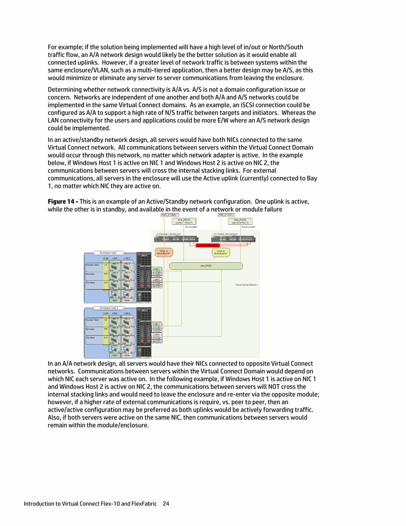
In an active/standby network design, all servers would have both NICs connected to the same Virtual Connect network. All communications between servers within the Virtual Connect Domain would occur through this network, no matter which network adapter is active. In the example below, if Windows Host 1 is active on NIC 1 and Windows Host 2 is active on NIC 2, the communications between servers will cross the internal stacking links. For external communications, all servers in the enclosure will use the Active uplink (currently) connected to Bay 1, no matter which NIC they are active on.
Figure 14 - This is an example of an Active/Standby network configuration. One uplink is active, while the other is in standby, and available in the event of a network or module failure
In an A/A network design, all servers would have their NICs connected to opposite Virtual Connect networks. Communications between servers within the Virtual Connect Domain would depend on which NIC each server was active on. In the following example, if Windows Host 1 is active on NIC 1 and Windows Host 2 is active on NIC 2, the communications between servers will NOT cross the internal stacking links and would need to leave the enclosure and re-enter via the opposite module; however, if a higher rate of external communications is require, vs. peer to peer, then an active/active configuration may be preferred as both uplinks would be actively forwarding traffic. Also, if both servers were active on the same NIC, then communications between servers would remain within the module/enclosure.
Introduction to Virtual Connect Flex-10 and FlexFabric 25
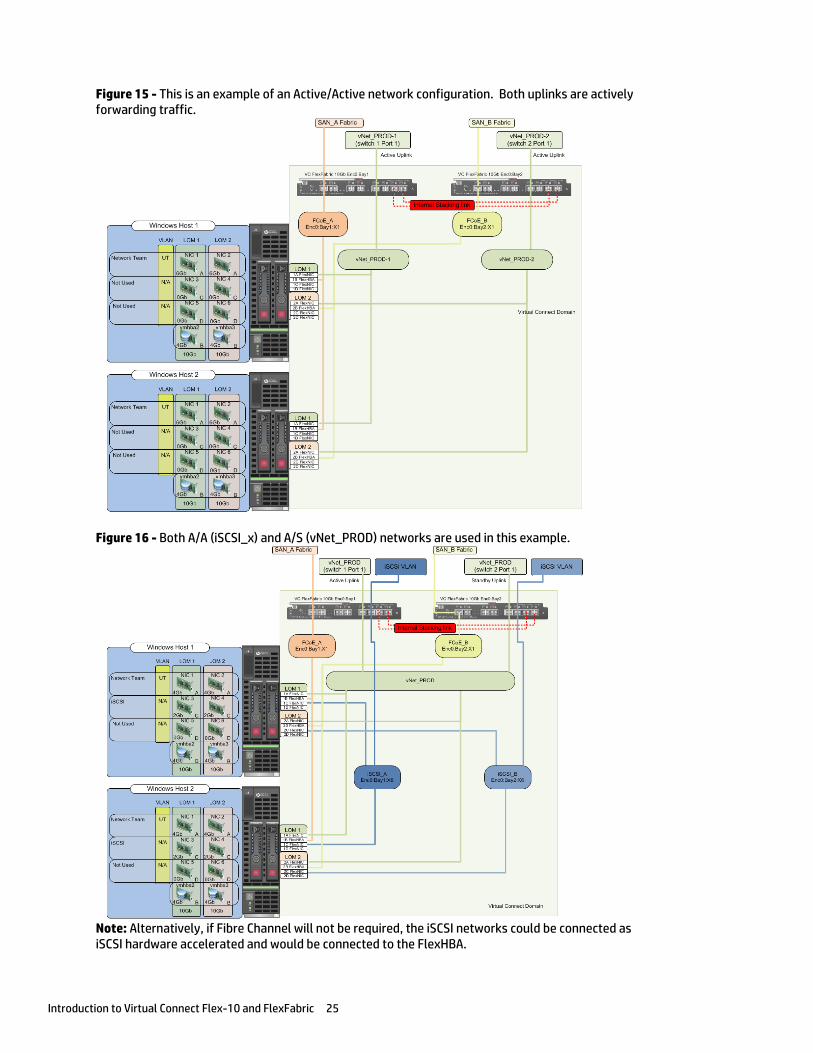
Figure 15 - This is an example of an Active/Active network configuration. Both uplinks are actively forwarding traffic.
Figure 16 - Both A/A (iSCSI_x) and A/S (vNet_PROD) networks are used in this example.
Note: Alternatively, if Fibre Channel will not be required, the iSCSI networks could be connected as iSCSI hardware accelerated and would be connected to the FlexHBA.
Introduction to Virtual Connect Flex-10 and FlexFabric 26
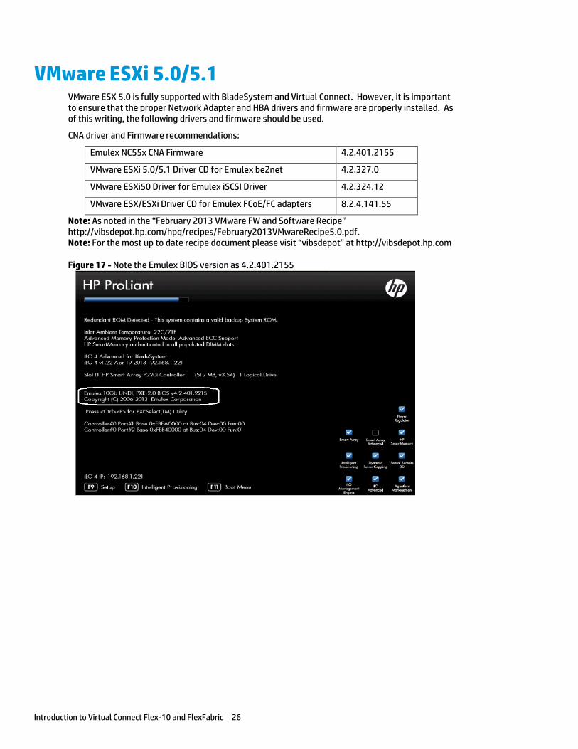
VMware ESXi 5.0/5.1 VMware ESX 5.0 is fully supported with BladeSystem and Virtual Connect. However, it is important to ensure that the proper Network Adapter and HBA drivers and firmware are properly installed. As of this writing, the following drivers and firmware should be used.
CNA driver and Firmware recommendations:
Emulex NC55x CNA Firmware 4.2.401.2155
VMware ESXi 5.0/5.1 Driver CD for Emulex be2net 4.2.327.0
VMware ESXi50 Driver for Emulex iSCSI Driver 4.2.324.12
VMware ESX/ESXi Driver CD for Emulex FCoE/FC adapters 8.2.4.141.55
Note: As noted in the “February 2013 VMware FW and Software Recipe” http://vibsdepot.hp.com/hpq/recipes/February2013VMwareRecipe5.0.pdf. Note: For the most up to date recipe document please visit “vibsdepot” at http://vibsdepot.hp.com
Figure 17 - Note the Emulex BIOS version as 4.2.401.2155
Introduction to Virtual Connect Flex-10 and FlexFabric 27
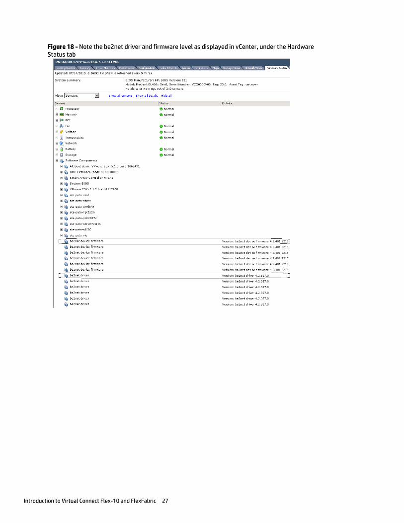
Figure 18 - Note the be2net driver and firmware level as displayed in vCenter, under the Hardware Status tab
Single Domain/Enclosure Scenarios 28
Single Domain/Enclosure Scenarios
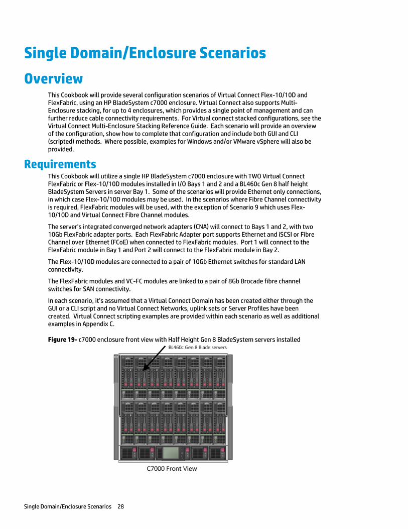
Overview This Cookbook will provide several configuration scenarios of Virtual Connect Flex-10/10D and FlexFabric, using an HP BladeSystem c7000 enclosure. Virtual Connect also supports Multi-Enclosure stacking, for up to 4 enclosures, which provides a single point of management and can further reduce cable connectivity requirements. For Virtual connect stacked configurations, see the Virtual Connect Multi-Enclosure Stacking Reference Guide. Each scenario will provide an overview of the configuration, show how to complete that configuration and include both GUI and CLI (scripted) methods. Where possible, examples for Windows and/or VMware vSphere will also be provided.
Requirements This Cookbook will utilize a single HP BladeSystem c7000 enclosure with TWO Virtual Connect FlexFabric or Flex-10/10D modules installed in I/O Bays 1 and 2 and a BL460c Gen 8 half height BladeSystem Servers in server Bay 1. Some of the scenarios will provide Ethernet only connections, in which case Flex-10/10D modules may be used. In the scenarios where Fibre Channel connectivity is required, FlexFabric modules will be used, with the exception of Scenario 9 which uses Flex-10/10D and Virtual Connect Fibre Channel modules.
The server’s integrated converged network adapters (CNA) will connect to Bays 1 and 2, with two 10Gb FlexFabric adapter ports. Each FlexFabric Adapter port supports Ethernet and iSCSI or Fibre Channel over Ethernet (FCoE) when connected to FlexFabric modules. Port 1 will connect to the FlexFabric module in Bay 1 and Port 2 will connect to the FlexFabric module in Bay 2.
The Flex-10/10D modules are connected to a pair of 10Gb Ethernet switches for standard LAN connectivity.
The FlexFabric modules and VC-FC modules are linked to a pair of 8Gb Brocade fibre channel switches for SAN connectivity.
In each scenario, it’s assumed that a Virtual Connect Domain has been created either through the GUI or a CLI script and no Virtual Connect Networks, uplink sets or Server Profiles have been created. Virtual Connect scripting examples are provided within each scenario as well as additional examples in Appendix C.
Figure 19- c7000 enclosure front view with Half Height Gen 8 BladeSystem servers installed
Single Domain/Enclosure Scenarios 29
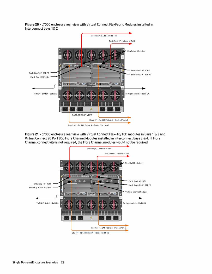
Figure 20 - c7000 enclosure rear view with Virtual Connect FlexFabric Modules installed in Interconnect bays 1& 2
Figure 21 - c7000 enclosure rear view with Virtual Connect Flex-10/10D modules in Bays 1 & 2 and Virtual Connect 20 Port 8Gb Fibre Channel Modules installed in Interconnect bays 3 & 4. If Fibre Channel connectivity is not required, the Fibre Channel modules would not be required
Scenario 1 – Simple vNet with Active/Standby Uplinks – Ethernet and FCoE – Windows 2008 R2 30
Scenario 1 – Simple vNet with Active/Standby Uplinks – Ethernet and FCoE – Windows 2008 R2
Overview This simple configuration uses the Virtual Connect vNet along with FCoE for SAN connectivity. When VLAN mapping is not required, the vNet is the simplest way to connect Virtual Connect to a network and server. In this scenario, the upstream network switch connects a network to a single port on each FlexFabric module. In addition, Fibre Channel uplinks will also be connected to the FlexFabric modules to connect to the existing Fibre Channel infrastructure.
No special upstream switch configuration is required as the switch is in the factory default configuration, typically configured as an Access or untagged port on either the default VLAN or a specific VLAN. In this scenario, Virtual Connect does not receive VLAN tags.
When configuring Virtual Connect, we can provide several ways to implement network fail-over or redundancy. One option would be to connect TWO uplinks to a single vNet; those two uplinks would connect from different Virtual Connect modules within the enclosure and could then connect to the same or two different upstream switches, depending on your redundancy needs. An alternative would be to configure TWO separate vNets, each with a single or multiple uplinks configured. Each option has its advantages and disadvantages. For example; an Active/Standby configuration places the redundancy at the VC level, where Active/Active places it at the OS NIC teaming or bonding level. We will review the first option in this scenario.
In addition, several vNets can be configured to support the required networks to the servers within the BladeSystem enclosure. These networks could be used to separate the various network traffic types, such as iSCSI, backup and VMotion from production network traffic.
This scenario will also leverage the Fibre Channel over Ethernet (FCoE) capabilities of the FlexFabric modules. Each Fibre channel fabric will have one uplink connected to each of the FlexFabric modules.
Requirements This scenario will support both Ethernet and fibre channel connectivity. In order to implement this scenario, an HP BladeSystem c7000 enclosure with one or more server blades and TWO Virtual Connect FlexFabric modules, installed in I/O Bays 1& 2 are required. In addition, we will require ONE or TWO external Network switches. As Virtual Connect does not appear to the network as a switch and is transparent to the network, any standard managed switch will work with Virtual Connect. The Fibre Channel uplinks will connect to the existing FC SAN fabrics. The SAN switch ports will need to be configured to support NPIV logins. One uplink from each FlexFabric module will be connected the existing SAN fabrics.

Scenario 1 – Simple vNet with Active/Standby Uplinks – Ethernet and FCoE – Windows 2008 R2 31
Figure 22 - Physical View; Shows one Ethernet uplink from Ports X5 on Module 1 and 2 to Port 1 on each network switch. The SAN fabrics are also connected redundantly, with TWO uplinks per fabric, from ports X1 and X2 on module 1 to Fabric A and ports X1 and X2 to Fabric B.
Figure 23 - Logical View; Shows a single Ethernet uplink from Port X5 on Module 1 on the first network switch and a single uplink from Port X5 on Module 2 to the second network switch. Both Ethernet uplinks are connected to the same vNet, vNet-PROD. In addition, SAN Fabric FCoE_A connects to the existing SAN Fabric A through port X1 on Module 1 (Bay 1) and FCoE_B connects to the existing SAN Fabric B through port X1 on Module 2 (Bay 2)
Scenario 1 – Simple vNet with Active/Standby Uplinks – Ethernet and FCoE – Windows 2008 R2 32
Installation and configuration Switch configuration
As the Virtual Connect module acts as an edge switch, Virtual Connect can connect to the network at either the distribution level or directly to the core switch.
The appendices provide a summary of the cli commands required to configure various switches for connection to Virtual Connect. The configuration information provided in the appendices for this scenario assumes the following information:
The switch ports are configured as ACCESS or untagged ports, either presenting the Default VLAN or a specific VLAN and will be forwarding untagged frames
As an alternative, if the switch ports were configured as TRUNK ports and forwarding multiple VLANS, Virtual Connect would forward those tagged frames to the host NICs configured for this network, however; the Virtual Connect network would need to be configured for VLAN Tunneling. The connected host would then need to be configured to interpret those VLAN tags.
The network switch port should be configured for Spanning Tree Edge as Virtual Connect appears to the switch as an access device and not another switch. By configuring the port as Spanning Tree Edge, it allows the switch to place the port into a forwarding state much quicker than otherwise, this allows a newly connected port to come online and begin forwarding much quicker.
The SAN switch ports connecting to the FlexFabric module must be configured to accept NPIV logins.
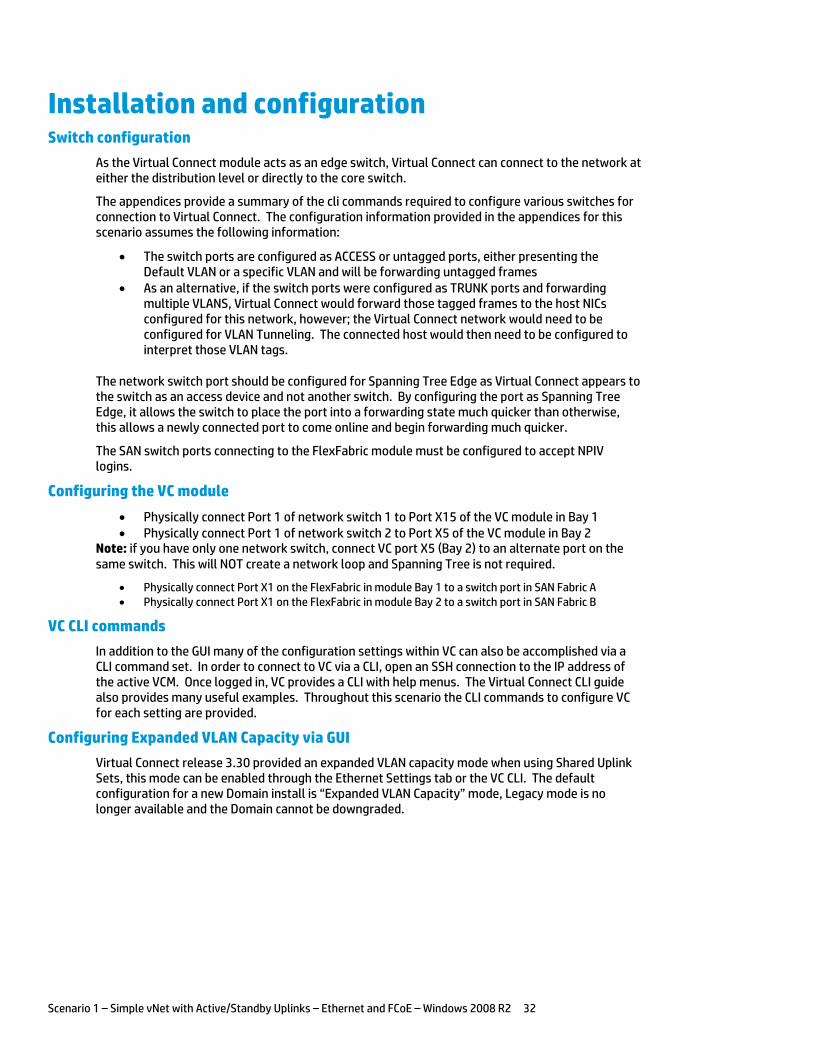
Configuring the VC module
Physically connect Port 1 of network switch 1 to Port X15 of the VC module in Bay 1 Physically connect Port 1 of network switch 2 to Port X5 of the VC module in Bay 2
Note: if you have only one network switch, connect VC port X5 (Bay 2) to an alternate port on the same switch. This will NOT create a network loop and Spanning Tree is not required.
Physically connect Port X1 on the FlexFabric in module Bay 1 to a switch port in SAN Fabric A Physically connect Port X1 on the FlexFabric in module Bay 2 to a switch port in SAN Fabric B
VC CLI commands
In addition to the GUI many of the configuration settings within VC can also be accomplished via a CLI command set. In order to connect to VC via a CLI, open an SSH connection to the IP address of the active VCM. Once logged in, VC provides a CLI with help menus. The Virtual Connect CLI guide also provides many useful examples. Throughout this scenario the CLI commands to configure VC for each setting are provided.
Configuring Expanded VLAN Capacity via GUI
Virtual Connect release 3.30 provided an expanded VLAN capacity mode when using Shared Uplink Sets, this mode can be enabled through the Ethernet Settings tab or the VC CLI. The default configuration for a new Domain install is “Expanded VLAN Capacity” mode, Legacy mode is no longer available and the Domain cannot be downgraded.
Scenario 1 – Simple vNet with Active/Standby Uplinks – Ethernet and FCoE – Windows 2008 R2 33
To verify the VLAN Capacity mode
On the Virtual Connect Manager screen, Left pane, click Ethernet Settings, Advanced Settings
Select Expanded VLAN capacity Verify Expanded VLAN Capacity is configured and Legacy VLAN Capacity is greyed out.
Note: Legacy VLAN mode will only be presented if 1Gb Virtual Connect Modules are present, in which case the domain would be limited to Firmware version 3.6x.
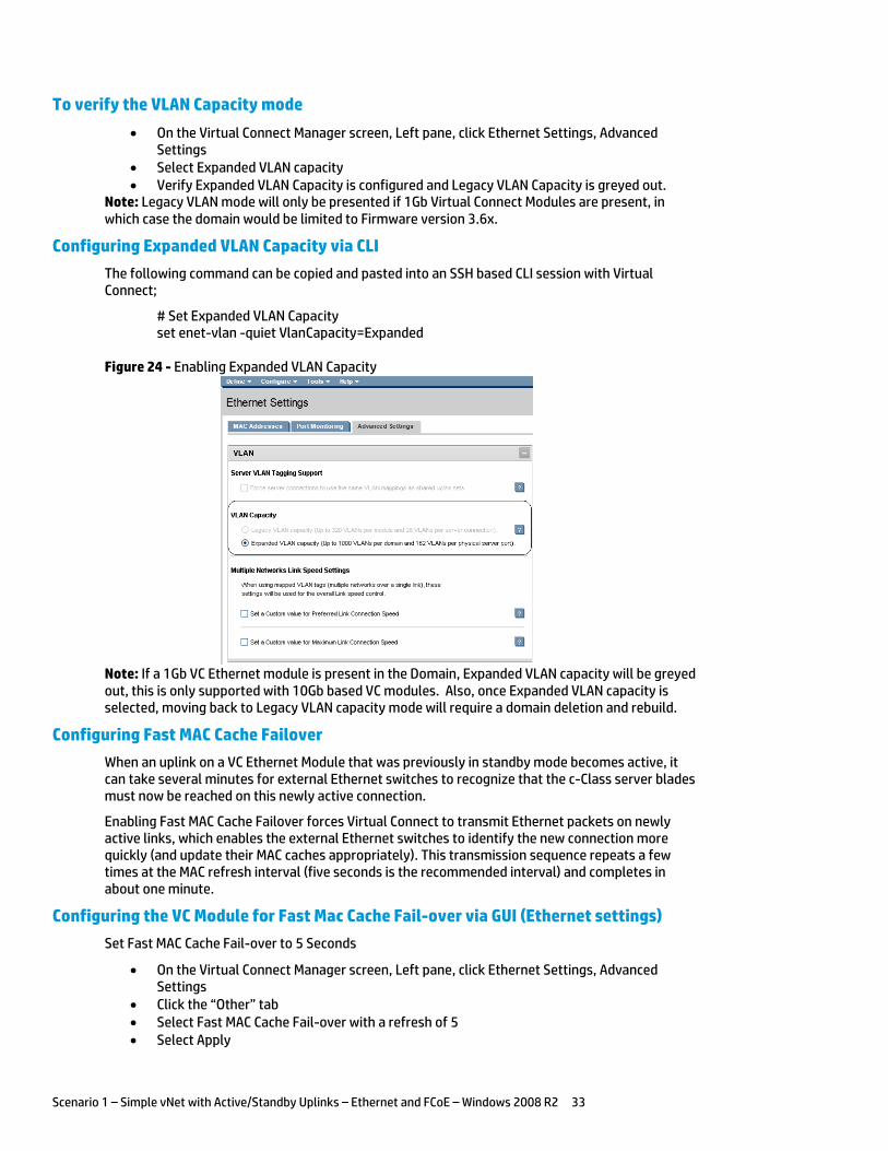
Configuring Expanded VLAN Capacity via CLI
The following command can be copied and pasted into an SSH based CLI session with Virtual Connect;
# Set Expanded VLAN Capacity set enet-vlan -quiet VlanCapacity=Expanded
Figure 24 - Enabling Expanded VLAN Capacity
Note: If a 1Gb VC Ethernet module is present in the Domain, Expanded VLAN capacity will be greyed out, this is only supported with 10Gb based VC modules. Also, once Expanded VLAN capacity is selected, moving back to Legacy VLAN capacity mode will require a domain deletion and rebuild.
Configuring Fast MAC Cache Failover
When an uplink on a VC Ethernet Module that was previously in standby mode becomes active, it can take several minutes for external Ethernet switches to recognize that the c-Class server blades must now be reached on this newly active connection.
Enabling Fast MAC Cache Failover forces Virtual Connect to transmit Ethernet packets on newly active links, which enables the external Ethernet switches to identify the new connection more quickly (and update their MAC caches appropriately). This transmission sequence repeats a few times at the MAC refresh interval (five seconds is the recommended interval) and completes in about one minute.
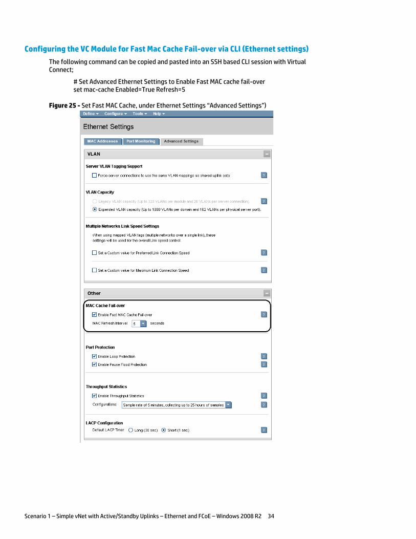
Configuring the VC Module for Fast Mac Cache Fail-over via GUI (Ethernet settings)
Set Fast MAC Cache Fail-over to 5 Seconds
On the Virtual Connect Manager screen, Left pane, click Ethernet Settings, Advanced Settings
Click the “Other” tab Select Fast MAC Cache Fail-over with a refresh of 5 Select Apply
Scenario 1 – Simple vNet with Active/Standby Uplinks – Ethernet and FCoE – Windows 2008 R2 34
Configuring the VC Module for Fast Mac Cache Fail-over via CLI (Ethernet settings)
The following command can be copied and pasted into an SSH based CLI session with Virtual Connect;
# Set Advanced Ethernet Settings to Enable Fast MAC cache fail-over set mac-cache Enabled=True Refresh=5
Figure 25 - Set Fast MAC Cache, under Ethernet Settings “Advanced Settings”)
Scenario 1 – Simple vNet with Active/Standby Uplinks – Ethernet and FCoE – Windows 2008 R2 35
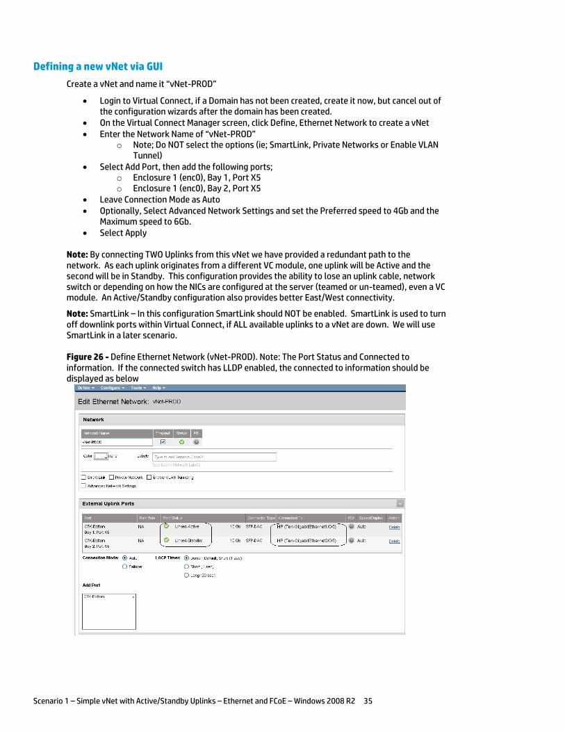
Defining a new vNet via GUI
Create a vNet and name it “vNet-PROD”
Login to Virtual Connect, if a Domain has not been created, create it now, but cancel out of the configuration wizards after the domain has been created.
On the Virtual Connect Manager screen, click Define, Ethernet Network to create a vNet Enter the Network Name of “vNet-PROD”
o Note; Do NOT select the options (ie; SmartLink, Private Networks or Enable VLAN Tunnel)
Select Add Port, then add the following ports; o Enclosure 1 (enc0), Bay 1, Port X5 o Enclosure 1 (enc0), Bay 2, Port X5
Leave Connection Mode as Auto Optionally, Select Advanced Network Settings and set the Preferred speed to 4Gb and the
Maximum speed to 6Gb. Select Apply
Note: By connecting TWO Uplinks from this vNet we have provided a redundant path to the network. As each uplink originates from a different VC module, one uplink will be Active and the second will be in Standby. This configuration provides the ability to lose an uplink cable, network switch or depending on how the NICs are configured at the server (teamed or un-teamed), even a VC module. An Active/Standby configuration also provides better East/West connectivity.
Note: SmartLink – In this configuration SmartLink should NOT be enabled. SmartLink is used to turn off downlink ports within Virtual Connect, if ALL available uplinks to a vNet are down. We will use SmartLink in a later scenario.
Figure 26 - Define Ethernet Network (vNet-PROD). Note: The Port Status and Connected to information. If the connected switch has LLDP enabled, the connected to information should be displayed as below
Scenario 1 – Simple vNet with Active/Standby Uplinks – Ethernet and FCoE – Windows 2008 R2 36
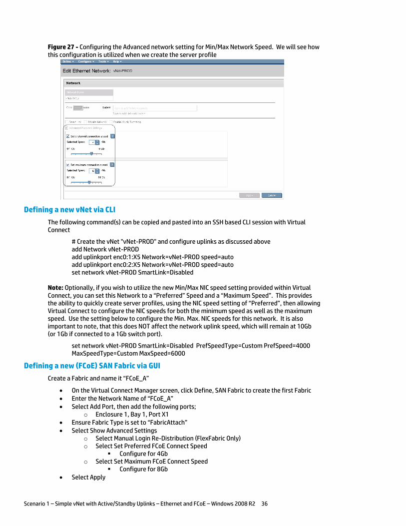
Figure 27 - Configuring the Advanced network setting for Min/Max Network Speed. We will see how this configuration is utilized when we create the server profile
Defining a new vNet via CLI
The following command(s) can be copied and pasted into an SSH based CLI session with Virtual Connect
# Create the vNet "vNet-PROD" and configure uplinks as discussed above add Network vNet-PROD add uplinkport enc0:1:X5 Network=vNet-PROD speed=auto add uplinkport enc0:2:X5 Network=vNet-PROD speed=auto set network vNet-PROD SmartLink=Disabled
Note: Optionally, if you wish to utilize the new Min/Max NIC speed setting provided within Virtual Connect, you can set this Network to a “Preferred” Speed and a “Maximum Speed”. This provides the ability to quickly create server profiles, using the NIC speed setting of “Preferred”, then allowing Virtual Connect to configure the NIC speeds for both the minimum speed as well as the maximum speed. Use the setting below to configure the Min. Max. NIC speeds for this network. It is also important to note, that this does NOT affect the network uplink speed, which will remain at 10Gb (or 1Gb if connected to a 1Gb switch port).
set network vNet-PROD SmartLink=Disabled PrefSpeedType=Custom PrefSpeed=4000 MaxSpeedType=Custom MaxSpeed=6000
Defining a new (FCoE) SAN Fabric via GUI
Create a Fabric and name it “FCoE_A”
On the Virtual Connect Manager screen, click Define, SAN Fabric to create the first Fabric Enter the Network Name of “FCoE_A” Select Add Port, then add the following ports;
o Enclosure 1, Bay 1, Port X1 Ensure Fabric Type is set to “FabricAttach” Select Show Advanced Settings
o Select Manual Login Re-Distribution (FlexFabric Only) o Select Set Preferred FCoE Connect Speed
Configure for 4Gb o Select Set Maximum FCoE Connect Speed
Configure for 8Gb Select Apply
Scenario 1 – Simple vNet with Active/Standby Uplinks – Ethernet and FCoE – Windows 2008 R2 37
Create a second Fabric and name it “FCoE_B”
On the Virtual Connect Manager screen, click Define, SAN Fabric to create the second Fabric Enter the Network Name of “FCoE_B” Select Add Port, then add the following ports;
o Enclosure 1, Bay 2, Port X1 Ensure Fabric Type is set to “FabricAttach” Select Show Advanced Settings
o Select Manual Login Re-Distribution (FlexFabric Only) o Select Set Preferred FCoE Connect Speed
Configure for 4Gb o Select Set Maximum FCoE Connect Speed
Configure for 8Gb Select Apply
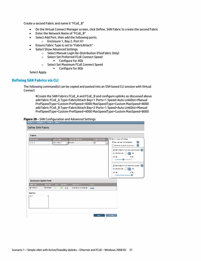
Defining SAN Fabrics via CLI
The following command(s) can be copied and pasted into an SSH based CLI session with Virtual Connect
#Create the SAN Fabrics FCoE_A and FCoE_B and configure uplinks as discussed above add fabric FCoE_A Type=FabricAttach Bay=1 Ports=1 Speed=Auto LinkDist=Manual PrefSpeedType=Custom PrefSpeed=4000 MaxSpeedType=Custom MaxSpeed=8000 add fabric FCoE_B Type=FabricAttach Bay=2 Ports=1 Speed=Auto LinkDist=Manual PrefSpeedType=Custom PrefSpeed=4000 MaxSpeedType=Custom MaxSpeed=8000
Figure 28 - SAN Configuration and Advanced Settings
Scenario 1 – Simple vNet with Active/Standby Uplinks – Ethernet and FCoE – Windows 2008 R2 38
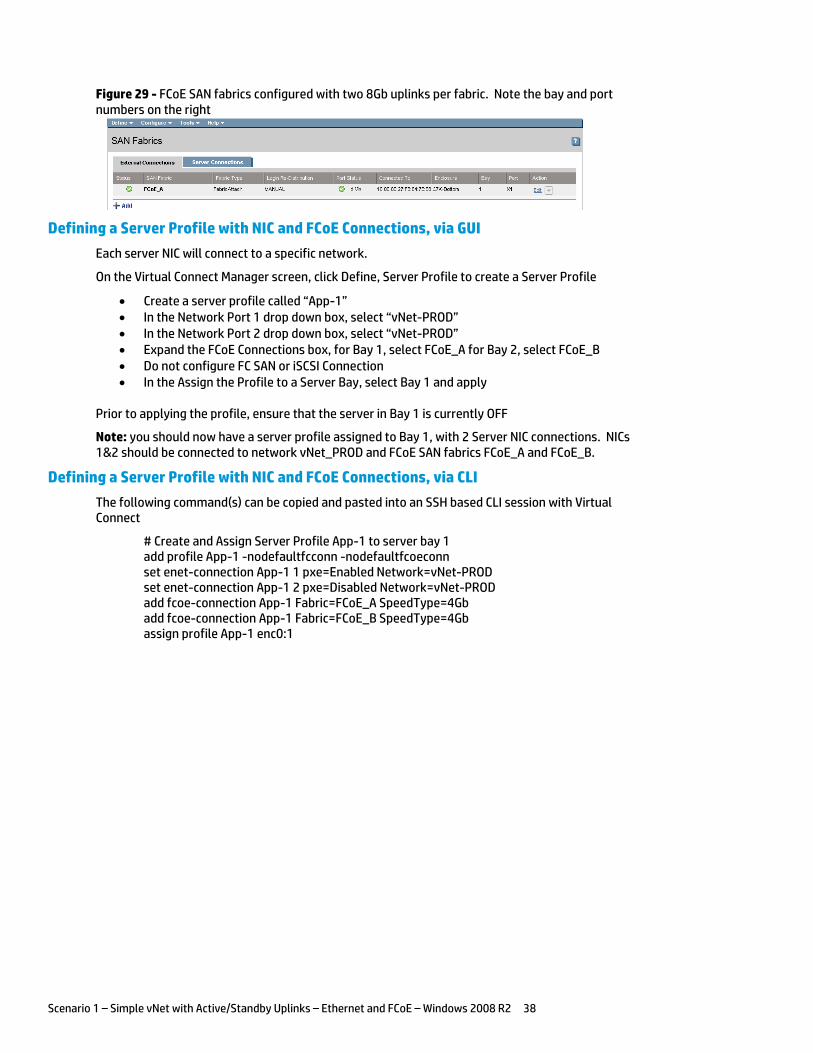
Figure 29 - FCoE SAN fabrics configured with two 8Gb uplinks per fabric. Note the bay and port numbers on the right
Defining a Server Profile with NIC and FCoE Connections, via GUI
Each server NIC will connect to a specific network.
On the Virtual Connect Manager screen, click Define, Server Profile to create a Server Profile
Create a server profile called “App-1” In the Network Port 1 drop down box, select “vNet-PROD” In the Network Port 2 drop down box, select “vNet-PROD” Expand the FCoE Connections box, for Bay 1, select FCoE_A for Bay 2, select FCoE_B Do not configure FC SAN or iSCSI Connection In the Assign the Profile to a Server Bay, select Bay 1 and apply
Prior to applying the profile, ensure that the server in Bay 1 is currently OFF
Note: you should now have a server profile assigned to Bay 1, with 2 Server NIC connections. NICs 1&2 should be connected to network vNet_PROD and FCoE SAN fabrics FCoE_A and FCoE_B.
Defining a Server Profile with NIC and FCoE Connections, via CLI
The following command(s) can be copied and pasted into an SSH based CLI session with Virtual Connect
# Create and Assign Server Profile App-1 to server bay 1 add profile App-1 -nodefaultfcconn -nodefaultfcoeconn set enet-connection App-1 1 pxe=Enabled Network=vNet-PROD set enet-connection App-1 2 pxe=Disabled Network=vNet-PROD add fcoe-connection App-1 Fabric=FCoE_A SpeedType=4Gb add fcoe-connection App-1 Fabric=FCoE_B SpeedType=4Gb assign profile App-1 enc0:1
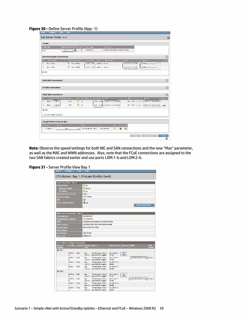
Scenario 1 – Simple vNet with Active/Standby Uplinks – Ethernet and FCoE – Windows 2008 R2 39
Figure 30 - Define Server Profile (App- 1)
Note: Observe the speed settings for both NIC and SAN connections and the new “Max” parameter, as well as the MAC and WWN addresses. Also, note that the FCoE connections are assigned to the two SAN fabrics created earlier and use ports LOM:1-b and LOM:2-b.
Figure 31 - Server Profile View Bay 1
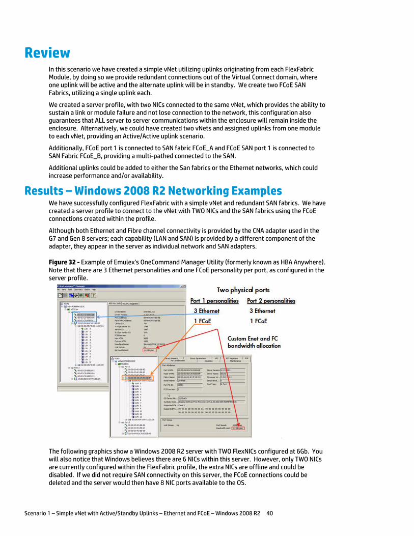
Scenario 1 – Simple vNet with Active/Standby Uplinks – Ethernet and FCoE – Windows 2008 R2 40
Review In this scenario we have created a simple vNet utilizing uplinks originating from each FlexFabric Module, by doing so we provide redundant connections out of the Virtual Connect domain, where one uplink will be active and the alternate uplink will be in standby. We create two FCoE SAN Fabrics, utilizing a single uplink each.
We created a server profile, with two NICs connected to the same vNet, which provides the ability to sustain a link or module failure and not lose connection to the network, this configuration also guarantees that ALL server to server communications within the enclosure will remain inside the enclosure. Alternatively, we could have created two vNets and assigned uplinks from one module to each vNet, providing an Active/Active uplink scenario.
Additionally, FCoE port 1 is connected to SAN fabric FCoE_A and FCoE SAN port 1 is connected to SAN Fabric FCoE_B, providing a multi-pathed connected to the SAN.
Additional uplinks could be added to either the San fabrics or the Ethernet networks, which could increase performance and/or availability.
Results – Windows 2008 R2 Networking Examples We have successfully configured FlexFabric with a simple vNet and redundant SAN fabrics. We have created a server profile to connect to the vNet with TWO NICs and the SAN fabrics using the FCoE connections created within the profile.
Although both Ethernet and Fibre channel connectivity is provided by the CNA adapter used in the G7 and Gen 8 servers; each capability (LAN and SAN) is provided by a different component of the adapter, they appear in the server as individual network and SAN adapters.
Figure 32 - Example of Emulex's OneCommand Manager Utility (formerly known as HBA Anywhere). Note that there are 3 Ethernet personalities and one FCoE personality per port, as configured in the server profile.
The following graphics show a Windows 2008 R2 server with TWO FlexNICs configured at 6Gb. You will also notice that Windows believes there are 6 NICs within this server. However, only TWO NICs are currently configured within the FlexFabric profile, the extra NICs are offline and could be disabled. If we did not require SAN connectivity on this server, the FCoE connections could be deleted and the server would then have 8 NIC ports available to the OS.
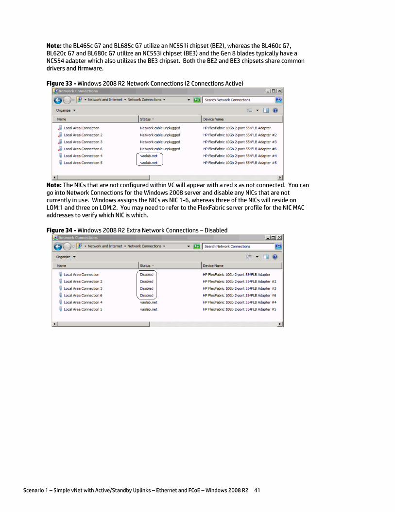
Scenario 1 – Simple vNet with Active/Standby Uplinks – Ethernet and FCoE – Windows 2008 R2 41
Note: the BL465c G7 and BL685c G7 utilize an NC551i chipset (BE2), whereas the BL460c G7, BL620c G7 and BL680c G7 utilize an NC553i chipset (BE3) and the Gen 8 blades typically have a NC554 adapter which also utilizes the BE3 chipset. Both the BE2 and BE3 chipsets share common drivers and firmware.
Figure 33 - Windows 2008 R2 Network Connections (2 Connections Active)
Note: The NICs that are not configured within VC will appear with a red x as not connected. You can go into Network Connections for the Windows 2008 server and disable any NICs that are not currently in use. Windows assigns the NICs as NIC 1-6, whereas three of the NICs will reside on LOM:1 and three on LOM:2. You may need to refer to the FlexFabric server profile for the NIC MAC addresses to verify which NIC is which.
Figure 34 - Windows 2008 R2 Extra Network Connections – Disabled
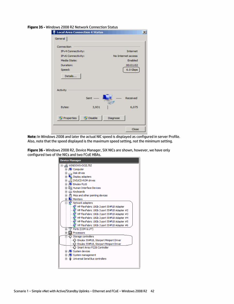
Scenario 1 – Simple vNet with Active/Standby Uplinks – Ethernet and FCoE – Windows 2008 R2 42
Figure 35 - Windows 2008 R2 Network Connection Status
Note: In Windows 2008 and later the actual NIC speed is displayed as configured in server Profile. Also, note that the speed displayed is the maximum speed setting, not the minimum setting.
Figure 36 - Windows 2008 R2, Device Manager, SIX NICs are shown, however, we have only configured two of the NICs and two FCoE HBAs.
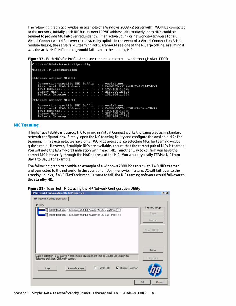
Scenario 1 – Simple vNet with Active/Standby Uplinks – Ethernet and FCoE – Windows 2008 R2 43
The following graphics provides an example of a Windows 2008 R2 server with TWO NICs connected to the network, initially each NIC has its own TCP/IP address, alternatively, both NICs could be teamed to provide NIC fail-over redundancy. If an active uplink or network switch were to fail, Virtual Connect would fail-over to the standby uplink. In the event of a Virtual Connect FlexFabric module failure, the server’s NIC teaming software would see one of the NICs go offline, assuming it was the active NIC, NIC teaming would fail-over to the standby NIC.
Figure 37 - Both NICs for Profile App-1are connected to the network through vNet-PROD
NIC Teaming
If higher availability is desired, NIC teaming in Virtual Connect works the same way as in standard network configurations. Simply, open the NIC teaming Utility and configure the available NICs for teaming. In this example, we have only TWO NICs available, so selecting NICs for teaming will be quite simple. However, if multiple NICs are available, ensure that the correct pair of NICs is teamed. You will note the BAY#-Port# indication within each NIC. Another way to confirm you have the correct NIC is to verify through the MAC address of the NIC. You would typically TEAM a NIC from Bay 1 to Bay 2 for example.
The following graphics provide an example of a Windows 2008 R2 server with TWO NICs teamed and connected to the network. In the event of an Uplink or switch failure, VC will fail-over to the standby uplinks, if a VC FlexFabric module were to fail, the NIC teaming software would fail-over to the standby NIC.
Figure 38 - Team both NICs, using the HP Network Configuration Utility
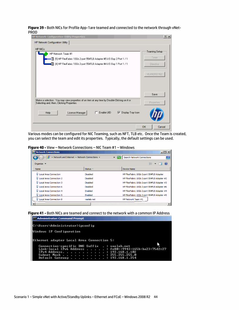
Scenario 1 – Simple vNet with Active/Standby Uplinks – Ethernet and FCoE – Windows 2008 R2 44
Figure 39 - Both NICs for Profile App-1are teamed and connected to the network through vNet-PROD
Various modes can be configured for NIC Teaming, such as NFT, TLB etc. Once the Team is created, you can select the team and edit its properties. Typically, the default settings can be used.
Figure 40 - View – Network Connections – NIC Team #1 – Windows
Figure 41 - Both NICs are teamed and connect to the network with a common IP Address
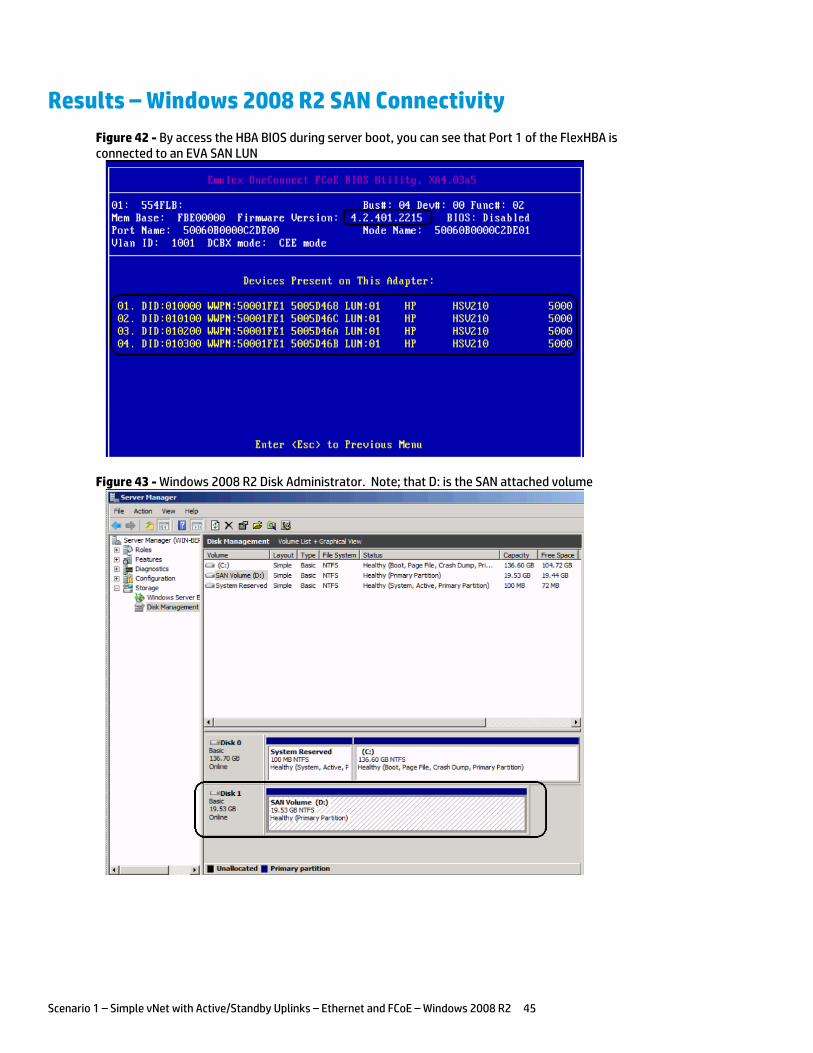
Scenario 1 – Simple vNet with Active/Standby Uplinks – Ethernet and FCoE – Windows 2008 R2 45
Results – Windows 2008 R2 SAN Connectivity
Figure 42 - By access the HBA BIOS during server boot, you can see that Port 1 of the FlexHBA is connected to an EVA SAN LUN
Figure 43 - Windows 2008 R2 Disk Administrator. Note; that D: is the SAN attached volume
Scenario 1 – Simple vNet with Active/Standby Uplinks – Ethernet and FCoE – Windows 2008 R2 46
Summary We presented a Virtual Connect Network scenario by creating a simple vNet, we configured the new Min/Max Network speed setting for the vNet. A dual path SAN fabric for storage connectivity was also configured.
When VC profile App-1 is applied to the server in bay1 and the server is powered up, it has one NIC connected through each FlexFabric module connected to “vNet-PROD”, which connects to the network infrastructure through the 10Gb uplinks. These NICs could now be configured as individual NICs with their own IP address or as a pair of TEAMED NICs. Either NIC could be active. As a result, this server could access the network through either NIC or either uplink cable, depending on which is active at the time. Each NIC is configured for a guaranteed minimum bandwidth of 4Gb, with a maximum of 6Gb of network bandwidth and each FCoE port is configured for 4Gb of SAN bandwidth with the ability to burst to a maximum of 8Gb.
Additional NICs could be added within FlexFabric, by simply powering the server off and adding up to a total of 6 NICs, the NIC speed can then be adjusted accordingly to suit the needs of each NIC. If additional or less SAN bandwidth is required, the speed of the SAN connection can also be adjusted.
As additional servers are added to the enclosure, simply create additional profiles, or copy existing profiles, configure the NICs for LAN and SAN fabrics as required and apply them to the appropriate server bays and power the server on.
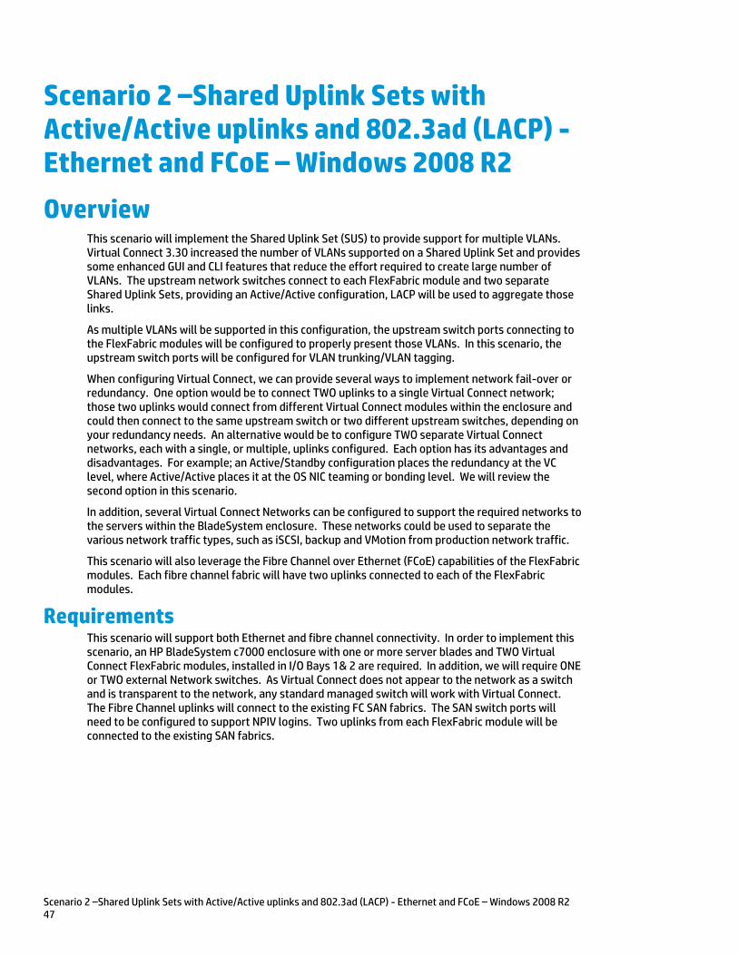
Scenario 2 –Shared Uplink Sets with Active/Active uplinks and 802.3ad (LACP) - Ethernet and FCoE – Windows 2008 R2 47
Scenario 2 –Shared Uplink Sets with Active/Active uplinks and 802.3ad (LACP) - Ethernet and FCoE – Windows 2008 R2
Overview This scenario will implement the Shared Uplink Set (SUS) to provide support for multiple VLANs. Virtual Connect 3.30 increased the number of VLANs supported on a Shared Uplink Set and provides some enhanced GUI and CLI features that reduce the effort required to create large number of VLANs. The upstream network switches connect to each FlexFabric module and two separate Shared Uplink Sets, providing an Active/Active configuration, LACP will be used to aggregate those links.
As multiple VLANs will be supported in this configuration, the upstream switch ports connecting to the FlexFabric modules will be configured to properly present those VLANs. In this scenario, the upstream switch ports will be configured for VLAN trunking/VLAN tagging.
When configuring Virtual Connect, we can provide several ways to implement network fail-over or redundancy. One option would be to connect TWO uplinks to a single Virtual Connect network; those two uplinks would connect from different Virtual Connect modules within the enclosure and could then connect to the same upstream switch or two different upstream switches, depending on your redundancy needs. An alternative would be to configure TWO separate Virtual Connect networks, each with a single, or multiple, uplinks configured. Each option has its advantages and disadvantages. For example; an Active/Standby configuration places the redundancy at the VC level, where Active/Active places it at the OS NIC teaming or bonding level. We will review the second option in this scenario.
In addition, several Virtual Connect Networks can be configured to support the required networks to the servers within the BladeSystem enclosure. These networks could be used to separate the various network traffic types, such as iSCSI, backup and VMotion from production network traffic.
This scenario will also leverage the Fibre Channel over Ethernet (FCoE) capabilities of the FlexFabric modules. Each fibre channel fabric will have two uplinks connected to each of the FlexFabric modules.
Requirements This scenario will support both Ethernet and fibre channel connectivity. In order to implement this scenario, an HP BladeSystem c7000 enclosure with one or more server blades and TWO Virtual Connect FlexFabric modules, installed in I/O Bays 1& 2 are required. In addition, we will require ONE or TWO external Network switches. As Virtual Connect does not appear to the network as a switch and is transparent to the network, any standard managed switch will work with Virtual Connect. The Fibre Channel uplinks will connect to the existing FC SAN fabrics. The SAN switch ports will need to be configured to support NPIV logins. Two uplinks from each FlexFabric module will be connected to the existing SAN fabrics.
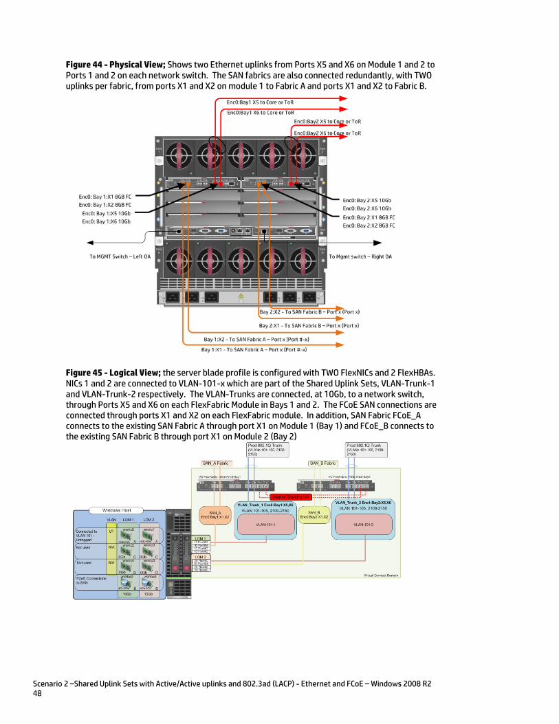
Scenario 2 –Shared Uplink Sets with Active/Active uplinks and 802.3ad (LACP) - Ethernet and FCoE – Windows 2008 R2 48
Figure 44 - Physical View; Shows two Ethernet uplinks from Ports X5 and X6 on Module 1 and 2 to Ports 1 and 2 on each network switch. The SAN fabrics are also connected redundantly, with TWO uplinks per fabric, from ports X1 and X2 on module 1 to Fabric A and ports X1 and X2 to Fabric B.
Figure 45 - Logical View; the server blade profile is configured with TWO FlexNICs and 2 FlexHBAs. NICs 1 and 2 are connected to VLAN-101-x which are part of the Shared Uplink Sets, VLAN-Trunk-1 and VLAN-Trunk-2 respectively. The VLAN-Trunks are connected, at 10Gb, to a network switch, through Ports X5 and X6 on each FlexFabric Module in Bays 1 and 2. The FCoE SAN connections are connected through ports X1 and X2 on each FlexFabric module. In addition, SAN Fabric FCoE_A connects to the existing SAN Fabric A through port X1 on Module 1 (Bay 1) and FCoE_B connects to the existing SAN Fabric B through port X1 on Module 2 (Bay 2)

Scenario 2 –Shared Uplink Sets with Active/Active uplinks and 802.3ad (LACP) - Ethernet and FCoE – Windows 2008 R2 49
Installation and configuration Switch configuration
As the Virtual Connect module acts as an edge switch, Virtual Connect can connect to the network at either the distribution level or directly to the core switch.
The appendices provide a summary of the cli commands required to configure various switches for connection to Virtual Connection. The configuration information provided in the appendices for this scenario assumes the following information:
The switch ports are configured as VLAN TRUNK ports (tagging) to support several VLANs. All frames will be forwarded to Virtual Connect with VLAN tags. Optionally, one VLAN could be configured as (Default) untagged, if so, then a corresponding vNet within the Shared Uplink Set would be configured and set as “Default”
Note: when adding additional uplinks to the SUS, if the additional uplinks are connecting from the same FlexFabric module to the same switch, in order to ensure all the uplinks are active, the switch ports will need to be configured for LACP within the same Link Aggregation Group.
The network switch port should be configured for Spanning Tree Edge as Virtual Connect appears to the switch as an access device and not another switch. By configuring the port as Spanning Tree Edge, it allows the switch to place the port into a forwarding state much quicker than otherwise, this allows a newly connected port to come online and begin forwarding much quicker.
The SAN switch ports connecting to the FlexFabric module must be configured to accept NPIV logins.
Configuring the VC module
Physically connect Port 1 of network switch 1 to Port X5 of the VC module in Bay 1 Physically connect Port 2 of network switch 1 to Port X6 of the VC module in Bay 1 Physically connect Port 1 of network switch 2 to Port X5 of the VC module in Bay 2 Physically connect Port 2 of network switch 2 to Port X6 of the VC module in Bay 2
Note: if you have only one network switch, connect VC ports X5 and X6 (Bay 2) to an alternate ports on the same switch. This will NOT create a network loop and Spanning Tree is not required.
Physically connect Ports X1/X2 on the FlexFabric in module Bay 1 to switch ports in SAN Fabric A Physically connect Ports X1/X2 on the FlexFabric in module Bay 2 to switch ports in SAN Fabric B
VC CLI commands
Many of the configuration settings within VC can also be accomplished via a CLI command set. In order to connect to VC via a CLI, open an SSH connection to the IP address of the active VCM. Once logged in, VC provides a CLI with help menus. Through this scenario the CLI commands to configure VC for each setting will also be provided.
Configuring Expanded VLAN Capacity via GUI
Virtual Connect release 3.30 provided an expanded VLAN capacity mode when using Shared Uplink Sets, this mode can be enabled through the Ethernet Settings tab or the VC CLI. The default configuration for a new Domain install is “Expanded VLAN Capacity” mode, Legacy mode is no longer available and the Domain cannot be downgraded.
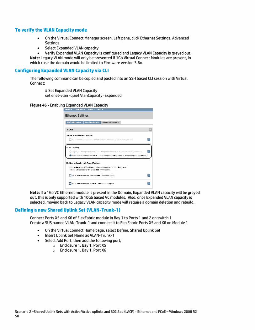
Scenario 2 –Shared Uplink Sets with Active/Active uplinks and 802.3ad (LACP) - Ethernet and FCoE – Windows 2008 R2 50
To verify the VLAN Capacity mode
On the Virtual Connect Manager screen, Left pane, click Ethernet Settings, Advanced Settings
Select Expanded VLAN capacity Verify Expanded VLAN Capacity is configured and Legacy VLAN Capacity is greyed out.
Note: Legacy VLAN mode will only be presented if 1Gb Virtual Connect Modules are present, in which case the domain would be limited to Firmware version 3.6x.
Configuring Expanded VLAN Capacity via CLI
The following command can be copied and pasted into an SSH based CLI session with Virtual Connect;
# Set Expanded VLAN Capacity set enet-vlan -quiet VlanCapacity=Expanded
Figure 46 - Enabling Expanded VLAN Capacity
Note: If a 1Gb VC Ethernet module is present in the Domain, Expanded VLAN capacity will be greyed out, this is only supported with 10Gb based VC modules. Also, once Expanded VLAN capacity is selected, moving back to Legacy VLAN capacity mode will require a domain deletion and rebuild.
Defining a new Shared Uplink Set (VLAN-Trunk-1)
Connect Ports X5 and X6 of FlexFabric module in Bay 1 to Ports 1 and 2 on switch 1 Create a SUS named VLAN-Trunk-1 and connect it to FlexFabric Ports X5 and X6 on Module 1
On the Virtual Connect Home page, select Define, Shared Uplink Set Insert Uplink Set Name as VLAN-Trunk-1 Select Add Port, then add the following port;
o Enclosure 1, Bay 1, Port X5 o Enclosure 1, Bay 1, Port X6
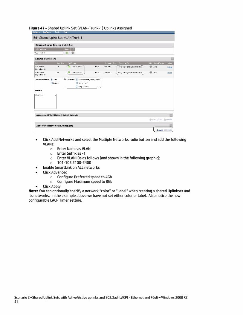
Scenario 2 –Shared Uplink Sets with Active/Active uplinks and 802.3ad (LACP) - Ethernet and FCoE – Windows 2008 R2 51
Figure 47 - Shared Uplink Set (VLAN-Trunk-1) Uplinks Assigned
Click Add Networks and select the Multiple Networks radio button and add the following VLANs;
o Enter Name as VLAN- o Enter Suffix as -1 o Enter VLAN IDs as follows (and shown in the following graphic); o 101-105,2100-2400
Enable SmartLink on ALL networks Click Advanced
o Configure Preferred speed to 4Gb o Configure Maximum speed to 8Gb
Click Apply Note: You can optionally specify a network “color” or “Label” when creating a shared Uplinkset and its networks. In the example above we have not set either color or label. Also notice the new configurable LACP Timer setting.
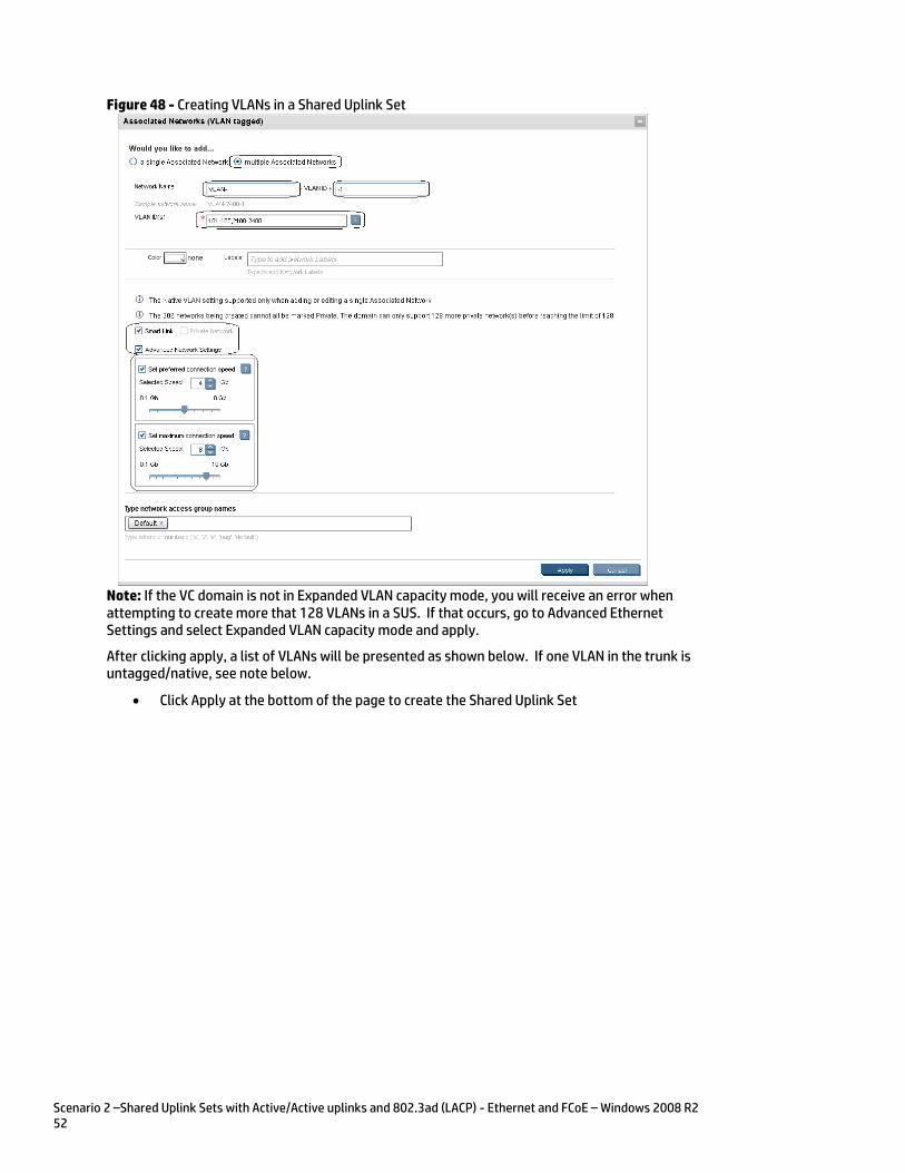
Scenario 2 –Shared Uplink Sets with Active/Active uplinks and 802.3ad (LACP) - Ethernet and FCoE – Windows 2008 R2 52
Figure 48 - Creating VLANs in a Shared Uplink Set
Note: If the VC domain is not in Expanded VLAN capacity mode, you will receive an error when attempting to create more that 128 VLANs in a SUS. If that occurs, go to Advanced Ethernet Settings and select Expanded VLAN capacity mode and apply.
After clicking apply, a list of VLANs will be presented as shown below. If one VLAN in the trunk is untagged/native, see note below.
Click Apply at the bottom of the page to create the Shared Uplink Set
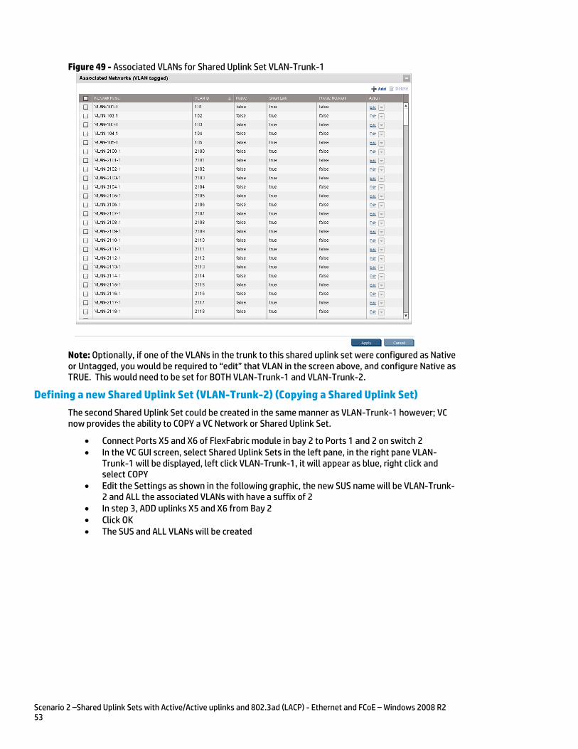
Scenario 2 –Shared Uplink Sets with Active/Active uplinks and 802.3ad (LACP) - Ethernet and FCoE – Windows 2008 R2 53
Figure 49 - Associated VLANs for Shared Uplink Set VLAN-Trunk-1
Note: Optionally, if one of the VLANs in the trunk to this shared uplink set were configured as Native or Untagged, you would be required to “edit” that VLAN in the screen above, and configure Native as TRUE. This would need to be set for BOTH VLAN-Trunk-1 and VLAN-Trunk-2.
Defining a new Shared Uplink Set (VLAN-Trunk-2) (Copying a Shared Uplink Set)
The second Shared Uplink Set could be created in the same manner as VLAN-Trunk-1 however; VC now provides the ability to COPY a VC Network or Shared Uplink Set.
Connect Ports X5 and X6 of FlexFabric module in bay 2 to Ports 1 and 2 on switch 2 In the VC GUI screen, select Shared Uplink Sets in the left pane, in the right pane VLAN-
Trunk-1 will be displayed, left click VLAN-Trunk-1, it will appear as blue, right click and select COPY
Edit the Settings as shown in the following graphic, the new SUS name will be VLAN-Trunk-2 and ALL the associated VLANs with have a suffix of 2
In step 3, ADD uplinks X5 and X6 from Bay 2 Click OK The SUS and ALL VLANs will be created

Scenario 2 –Shared Uplink Sets with Active/Active uplinks and 802.3ad (LACP) - Ethernet and FCoE – Windows 2008 R2 54
Figure 50 - Copying a SUS and ALL VLANs
Defining a new Shared Uplink Set via CLI
The following script can be used to create the first Shared Uplink Set (VLAN-Trunk-1) The following command(s) can be copied and pasted into an SSH based CLI session with Virtual Connect
# Create Shared Uplink Set VLAN-Trunk-1 and configure uplinks add uplinkset VLAN-Trunk-1 add uplinkport enc0:1:X5 Uplinkset=VLAN-Trunk-1 speed=auto add uplinkport enc0:1:X6 Uplinkset=VLAN-Trunk-1 speed=auto # Create Networks VLAN-101-1 through VLAN-105-1 and 2100-2400 for Shared Uplink Set VLAN-Trunk-1 add network-range -quiet UplinkSet=VLAN-Trunk-1 NamePrefix=VLAN- NameSuffix=-1 VLANIds=101-105,2100-2400 State=enabled PrefSpeedType=Custom PrefSpeed=4000 MaxSpeedType=Custom MaxSpeed=8000 SmartLink=enabled
Note: Refer to Appendix D; “Scripting the Native VLAN” for scripting examples.
The following script can be used to create the Second Shared Uplink Set (VLAN-Trunk-2)
# Create Shared Uplink Set VLAN-Trunk-2 and configure uplinks add uplinkset VLAN-Trunk-2 add uplinkport enc0:2:X5 Uplinkset=VLAN-Trunk-2 speed=auto add uplinkport enc0:2:X6 Uplinkset=VLAN-Trunk-2 speed=auto
# Create Networks VLAN101-2 through VLAN105-2 and VLAN-2100-2 through VLAN-2400-2 for Shared Uplink Set VLAN-Trunk-2 add network-range -quiet UplinkSet=VLAN-Trunk-2 NamePrefix=VLAN- NameSuffix=-2 VLANIds=101-105,2100-2400 State=enabled PrefSpeedType=Custom PrefSpeed=4000 MaxSpeedType=Custom MaxSpeed=8000 SmartLink=enabled

Scenario 2 –Shared Uplink Sets with Active/Active uplinks and 802.3ad (LACP) - Ethernet and FCoE – Windows 2008 R2 55
Note: In this scenario we have created two independent Share Uplink Sets (SUS), each originating from the opposite FlexFabric Modules, by doing so we provide the ability to create separate and redundant connections out of the Virtual Connect domain. When we create the server profiles, you will see how the NICs will connect to VLANs accessed through the opposite VC module, which provides the ability to create an Active / Active uplink scenario. Alternatively, we could have created a single SUS and assigned both sets of these uplink ports to the same SUS, however, this would have provided an Active/Standby uplink scenario, as shown in Scenario 5.
Note: As we did not configure the Min/Max network speed setting for any of these networks, you will notice in each profile that ALL configured NICs will have a configured speed of 10Gb. If you wish to limit the speed of specific networks, you could edit each network and configure a maximum speed.
Defining a new (FCoE) SAN Fabric via GUI
Create a Fabric and name it “FCoE_A”
On the Virtual Connect Manager screen, click Define, SAN Fabric to create the first Fabric Enter the Network Name of “FCoE_A” Select Add Port, then add the following ports;
o Enclosure 1, Bay 1, Port X1 o Enclosure 1, Bay 1, Port X2
Ensure Fabric Type is set to “FabricAttach” Select Show Advanced Settings
o Select Automatic Login Re-Distribution (FlexFabric Only) o Select Set Preferred FCoE Connect Speed
Configure for 4Gb o Select Set Maximum FCoE Connect Speed
Configure for 8Gb Select Apply
Create a second Fabric and name it “FCoE_B”
On the Virtual Connect Manager screen, click Define, SAN Fabric to create the second Fabric Enter the Network Name of “FCoE_B” Select Add Port, then add the following ports;
o Enclosure 1, Bay 2, Port X1 o Enclosure 1, Bay 2, Port X2
Ensure Fabric Type is set to “FabricAttach” Select Show Advanced Settings
o Select Automatic Login Re-Distribution (FlexFabric Only) o Select Set Preferred FCoE Connect Speed
Configure for 4Gb o Select Set Maximum FCoE Connect Speed
Configure for 8Gb Select Apply
Defining SAN Fabrics via CLI
The following command(s) can be copied and pasted into an SSH based CLI session with Virtual Connect
#Create the SAN Fabrics FCoE_A and FCoE_B and configure uplinks as discussed above add fabric FCoE_A Type=FabricAttach Bay=1 Ports=1,2 Speed=Auto LinkDist=Auto PrefSpeedType=Custom PrefSpeed=4000 MaxSpeedType=Custom MaxSpeed=8000 add fabric FCoE_B Type=FabricAttach Bay=2 Ports=1,2 Speed=Auto LinkDist=Auto PrefSpeedType=Custom PrefSpeed=4000 MaxSpeedType=Custom MaxSpeed=8000
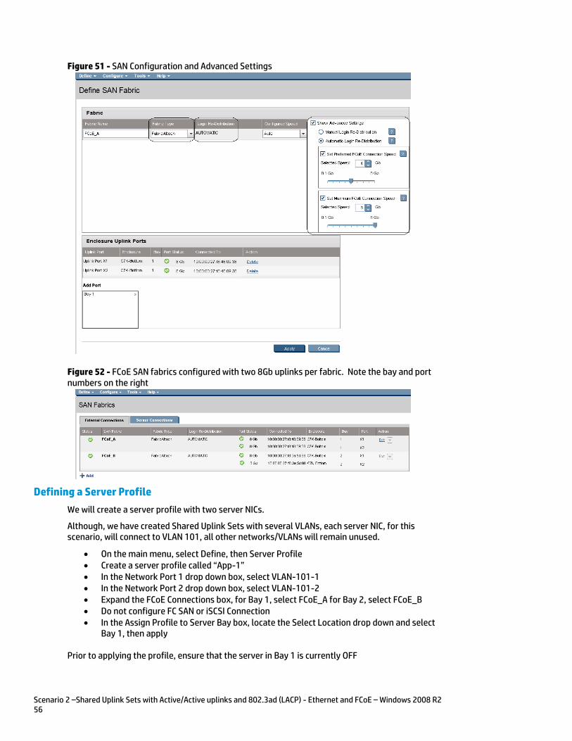
Scenario 2 –Shared Uplink Sets with Active/Active uplinks and 802.3ad (LACP) - Ethernet and FCoE – Windows 2008 R2 56
Figure 51 - SAN Configuration and Advanced Settings
Figure 52 - FCoE SAN fabrics configured with two 8Gb uplinks per fabric. Note the bay and port numbers on the right
Defining a Server Profile
We will create a server profile with two server NICs.
Although, we have created Shared Uplink Sets with several VLANs, each server NIC, for this scenario, will connect to VLAN 101, all other networks/VLANs will remain unused.
On the main menu, select Define, then Server Profile Create a server profile called “App-1” In the Network Port 1 drop down box, select VLAN-101-1 In the Network Port 2 drop down box, select VLAN-101-2 Expand the FCoE Connections box, for Bay 1, select FCoE_A for Bay 2, select FCoE_B Do not configure FC SAN or iSCSI Connection In the Assign Profile to Server Bay box, locate the Select Location drop down and select
Bay 1, then apply
Prior to applying the profile, ensure that the server in Bay 1 is currently OFF
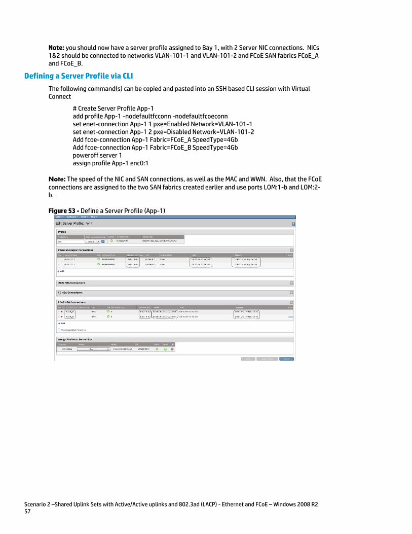
Scenario 2 –Shared Uplink Sets with Active/Active uplinks and 802.3ad (LACP) - Ethernet and FCoE – Windows 2008 R2 57
Note: you should now have a server profile assigned to Bay 1, with 2 Server NIC connections. NICs 1&2 should be connected to networks VLAN-101-1 and VLAN-101-2 and FCoE SAN fabrics FCoE_A and FCoE_B.
Defining a Server Profile via CLI
The following command(s) can be copied and pasted into an SSH based CLI session with Virtual Connect
# Create Server Profile App-1 add profile App-1 -nodefaultfcconn -nodefaultfcoeconn set enet-connection App-1 1 pxe=Enabled Network=VLAN-101-1 set enet-connection App-1 2 pxe=Disabled Network=VLAN-101-2 Add fcoe-connection App-1 Fabric=FCoE_A SpeedType=4Gb Add fcoe-connection App-1 Fabric=FCoE_B SpeedType=4Gb poweroff server 1 assign profile App-1 enc0:1
Note: The speed of the NIC and SAN connections, as well as the MAC and WWN. Also, that the FCoE connections are assigned to the two SAN fabrics created earlier and use ports LOM:1-b and LOM:2-b.
Figure 53 - Define a Server Profile (App-1)
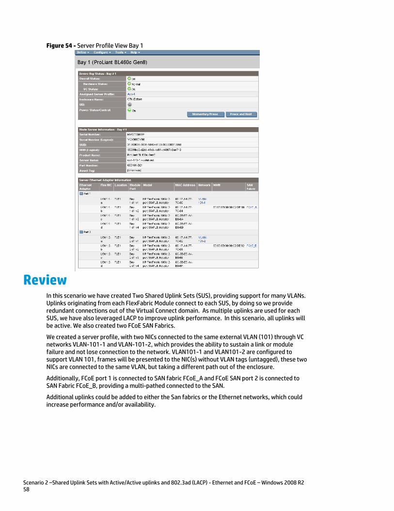
Scenario 2 –Shared Uplink Sets with Active/Active uplinks and 802.3ad (LACP) - Ethernet and FCoE – Windows 2008 R2 58
Figure 54 - Server Profile View Bay 1
Review In this scenario we have created Two Shared Uplink Sets (SUS), providing support for many VLANs. Uplinks originating from each FlexFabric Module connect to each SUS, by doing so we provide redundant connections out of the Virtual Connect domain. As multiple uplinks are used for each SUS, we have also leveraged LACP to improve uplink performance. In this scenario, all uplinks will be active. We also created two FCoE SAN Fabrics.
We created a server profile, with two NICs connected to the same external VLAN (101) through VC networks VLAN-101-1 and VLAN-101-2, which provides the ability to sustain a link or module failure and not lose connection to the network. VLAN101-1 and VLAN101-2 are configured to support VLAN 101, frames will be presented to the NIC(s) without VLAN tags (untagged), these two NICs are connected to the same VLAN, but taking a different path out of the enclosure.
Additionally, FCoE port 1 is connected to SAN fabric FCoE_A and FCoE SAN port 2 is connected to SAN Fabric FCoE_B, providing a multi-pathed connected to the SAN.
Additional uplinks could be added to either the San fabrics or the Ethernet networks, which could increase performance and/or availability.
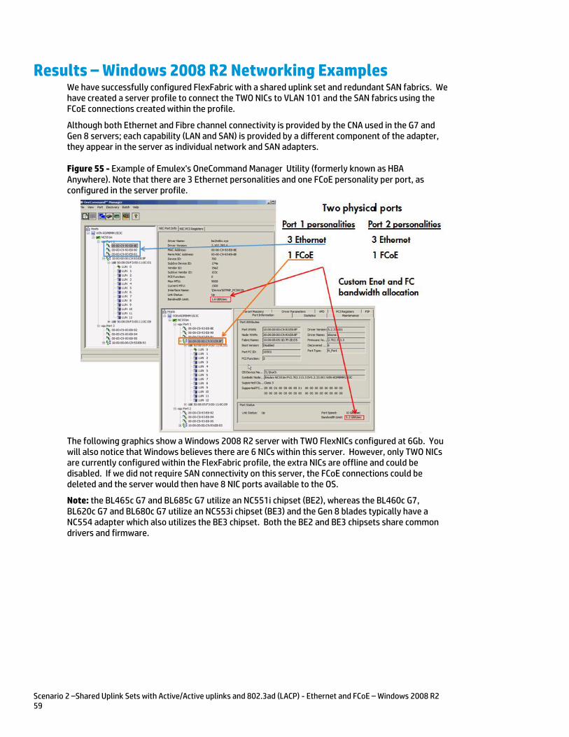
Scenario 2 –Shared Uplink Sets with Active/Active uplinks and 802.3ad (LACP) - Ethernet and FCoE – Windows 2008 R2 59
Results – Windows 2008 R2 Networking Examples We have successfully configured FlexFabric with a shared uplink set and redundant SAN fabrics. We have created a server profile to connect the TWO NICs to VLAN 101 and the SAN fabrics using the FCoE connections created within the profile.
Although both Ethernet and Fibre channel connectivity is provided by the CNA used in the G7 and Gen 8 servers; each capability (LAN and SAN) is provided by a different component of the adapter, they appear in the server as individual network and SAN adapters.
Figure 55 - Example of Emulex's OneCommand Manager Utility (formerly known as HBA Anywhere). Note that there are 3 Ethernet personalities and one FCoE personality per port, as configured in the server profile.
The following graphics show a Windows 2008 R2 server with TWO FlexNICs configured at 6Gb. You will also notice that Windows believes there are 6 NICs within this server. However, only TWO NICs are currently configured within the FlexFabric profile, the extra NICs are offline and could be disabled. If we did not require SAN connectivity on this server, the FCoE connections could be deleted and the server would then have 8 NIC ports available to the OS.
Note: the BL465c G7 and BL685c G7 utilize an NC551i chipset (BE2), whereas the BL460c G7, BL620c G7 and BL680c G7 utilize an NC553i chipset (BE3) and the Gen 8 blades typically have a NC554 adapter which also utilizes the BE3 chipset. Both the BE2 and BE3 chipsets share common drivers and firmware.
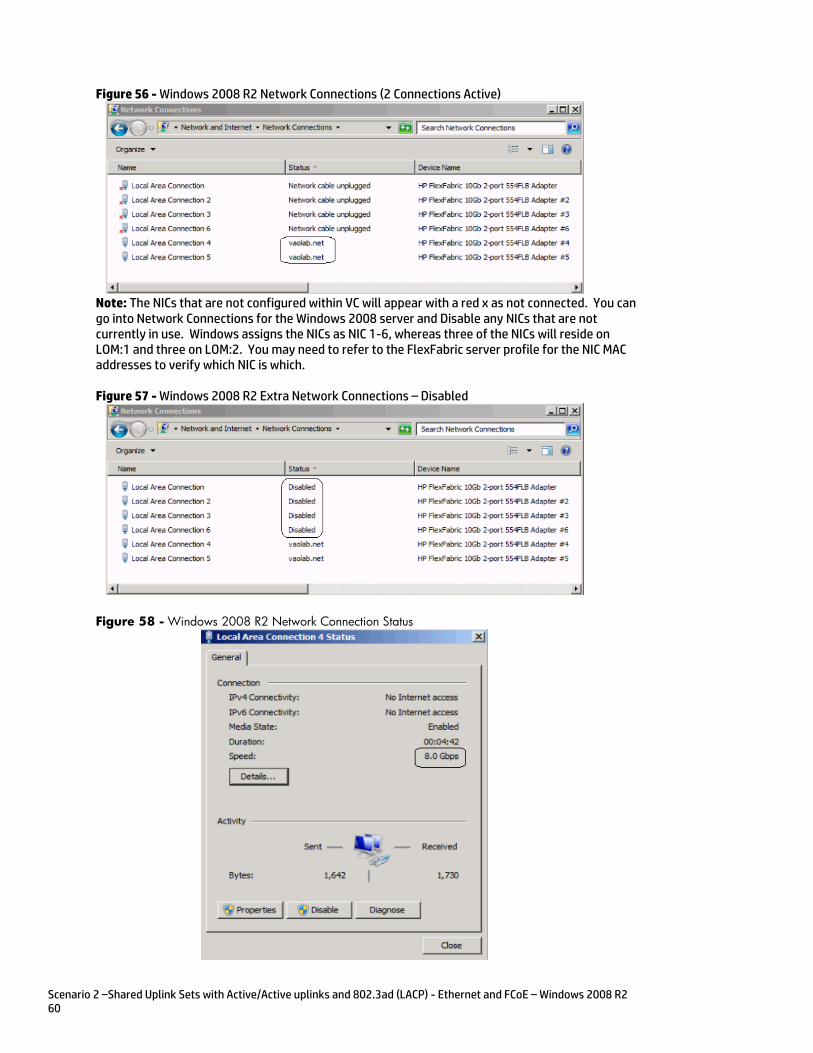
Scenario 2 –Shared Uplink Sets with Active/Active uplinks and 802.3ad (LACP) - Ethernet and FCoE – Windows 2008 R2 60
Figure 56 - Windows 2008 R2 Network Connections (2 Connections Active)
Note: The NICs that are not configured within VC will appear with a red x as not connected. You can go into Network Connections for the Windows 2008 server and Disable any NICs that are not currently in use. Windows assigns the NICs as NIC 1-6, whereas three of the NICs will reside on LOM:1 and three on LOM:2. You may need to refer to the FlexFabric server profile for the NIC MAC addresses to verify which NIC is which.
Figure 57 - Windows 2008 R2 Extra Network Connections – Disabled
Figure 58 - Windows 2008 R2 Network Connection Status
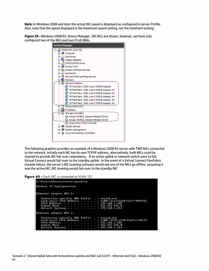
Scenario 2 –Shared Uplink Sets with Active/Active uplinks and 802.3ad (LACP) - Ethernet and FCoE – Windows 2008 R2 61
Note: In Windows 2008 and later the actual NIC speed is displayed as configured in server Profile. Also, note that the speed displayed is the maximum speed setting, not the minimum setting.
Figure 59 - Windows 2008 R2, Device Manager, SIX NICs are shown, however, we have only configured two of the NICs and two FCoE HBAs.
The following graphics provides an example of a Windows 2008 R2 server with TWO NICs connected to the network, initially each NIC has its own TCP/IP address, alternatively, both NICs could be teamed to provide NIC fail-over redundancy. If an active uplink or network switch were to fail, Virtual Connect would fail-over to the standby uplink. In the event of a Virtual Connect FlexFabric module failure, the server’s NIC teaming software would see one of the NICs go offline, assuming it was the active NIC, NIC teaming would fail-over to the standby NIC.
Figure 60 – Each NIC is connected to VLAN 101
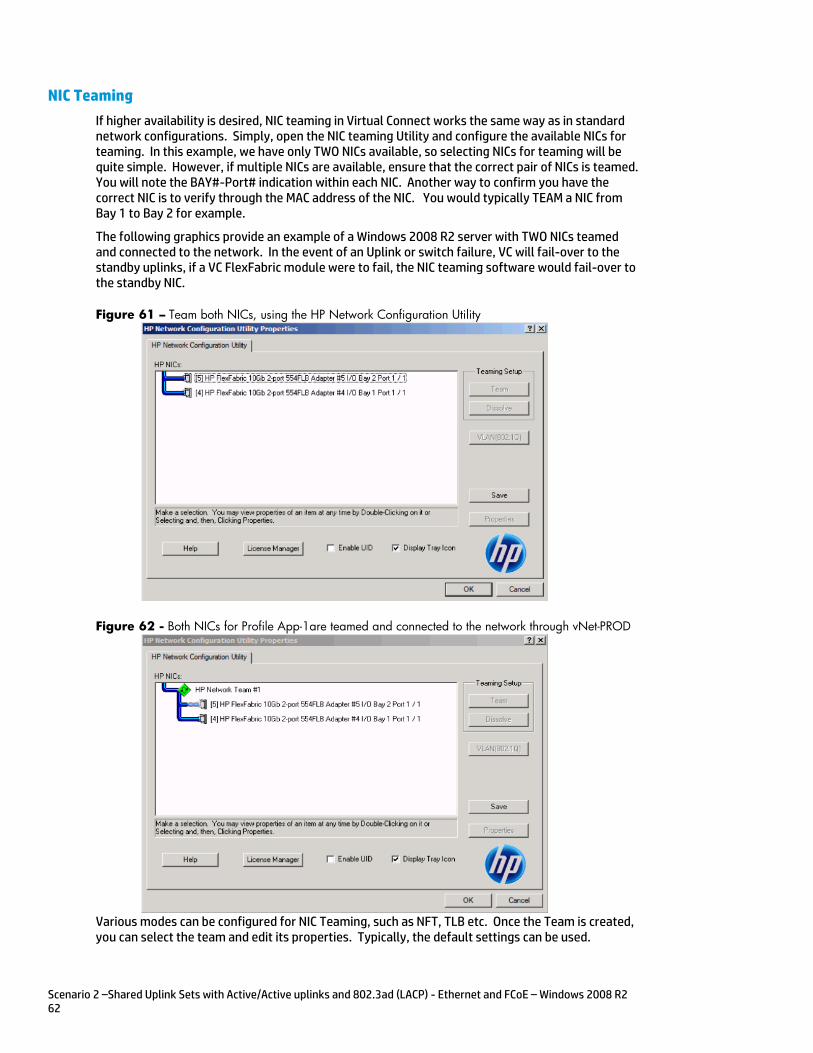
Scenario 2 –Shared Uplink Sets with Active/Active uplinks and 802.3ad (LACP) - Ethernet and FCoE – Windows 2008 R2 62
NIC Teaming
If higher availability is desired, NIC teaming in Virtual Connect works the same way as in standard network configurations. Simply, open the NIC teaming Utility and configure the available NICs for teaming. In this example, we have only TWO NICs available, so selecting NICs for teaming will be quite simple. However, if multiple NICs are available, ensure that the correct pair of NICs is teamed. You will note the BAY#-Port# indication within each NIC. Another way to confirm you have the correct NIC is to verify through the MAC address of the NIC. You would typically TEAM a NIC from Bay 1 to Bay 2 for example.
The following graphics provide an example of a Windows 2008 R2 server with TWO NICs teamed and connected to the network. In the event of an Uplink or switch failure, VC will fail-over to the standby uplinks, if a VC FlexFabric module were to fail, the NIC teaming software would fail-over to the standby NIC.
Figure 61 – Team both NICs, using the HP Network Configuration Utility
Figure 62 - Both NICs for Profile App-1are teamed and connected to the network through vNet-PROD
Various modes can be configured for NIC Teaming, such as NFT, TLB etc. Once the Team is created, you can select the team and edit its properties. Typically, the default settings can be used.
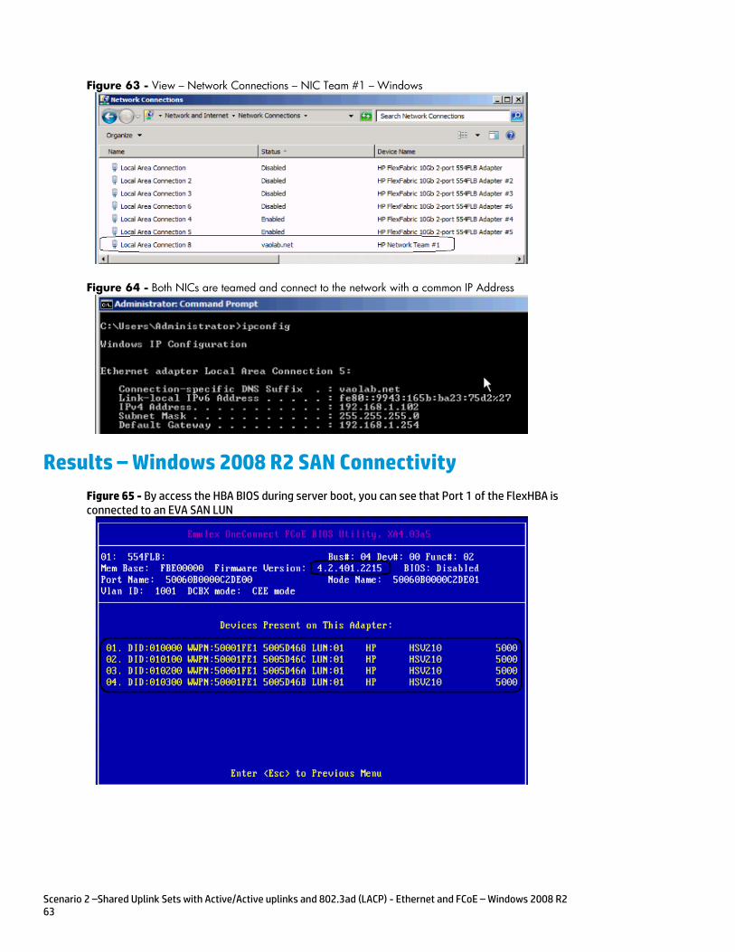
Scenario 2 –Shared Uplink Sets with Active/Active uplinks and 802.3ad (LACP) - Ethernet and FCoE – Windows 2008 R2 63
Figure 63 - View – Network Connections – NIC Team #1 – Windows
Figure 64 - Both NICs are teamed and connect to the network with a common IP Address
Results – Windows 2008 R2 SAN Connectivity
Figure 65 - By access the HBA BIOS during server boot, you can see that Port 1 of the FlexHBA is connected to an EVA SAN LUN
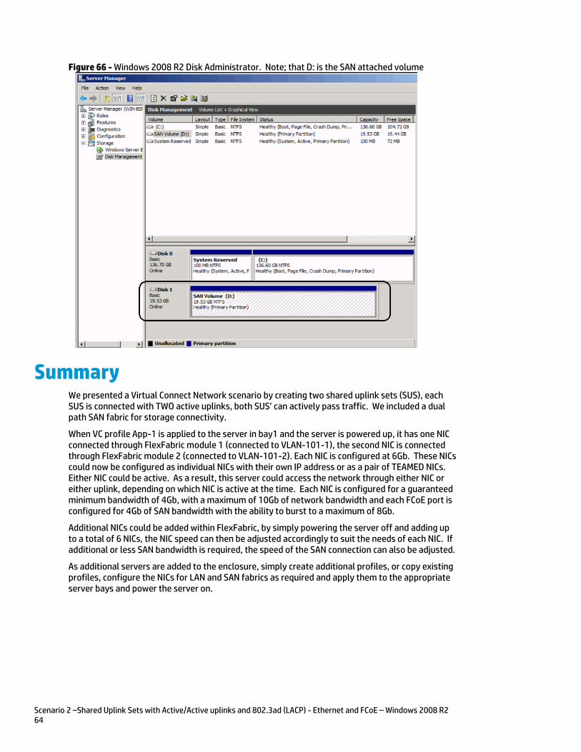
Scenario 2 –Shared Uplink Sets with Active/Active uplinks and 802.3ad (LACP) - Ethernet and FCoE – Windows 2008 R2 64
Figure 66 - Windows 2008 R2 Disk Administrator. Note; that D: is the SAN attached volume
Summary We presented a Virtual Connect Network scenario by creating two shared uplink sets (SUS), each SUS is connected with TWO active uplinks, both SUS’ can actively pass traffic. We included a dual path SAN fabric for storage connectivity.
When VC profile App-1 is applied to the server in bay1 and the server is powered up, it has one NIC connected through FlexFabric module 1 (connected to VLAN-101-1), the second NIC is connected through FlexFabric module 2 (connected to VLAN-101-2). Each NIC is configured at 6Gb. These NICs could now be configured as individual NICs with their own IP address or as a pair of TEAMED NICs. Either NIC could be active. As a result, this server could access the network through either NIC or either uplink, depending on which NIC is active at the time. Each NIC is configured for a guaranteed minimum bandwidth of 4Gb, with a maximum of 10Gb of network bandwidth and each FCoE port is configured for 4Gb of SAN bandwidth with the ability to burst to a maximum of 8Gb.
Additional NICs could be added within FlexFabric, by simply powering the server off and adding up to a total of 6 NICs, the NIC speed can then be adjusted accordingly to suit the needs of each NIC. If additional or less SAN bandwidth is required, the speed of the SAN connection can also be adjusted.
As additional servers are added to the enclosure, simply create additional profiles, or copy existing profiles, configure the NICs for LAN and SAN fabrics as required and apply them to the appropriate server bays and power the server on.
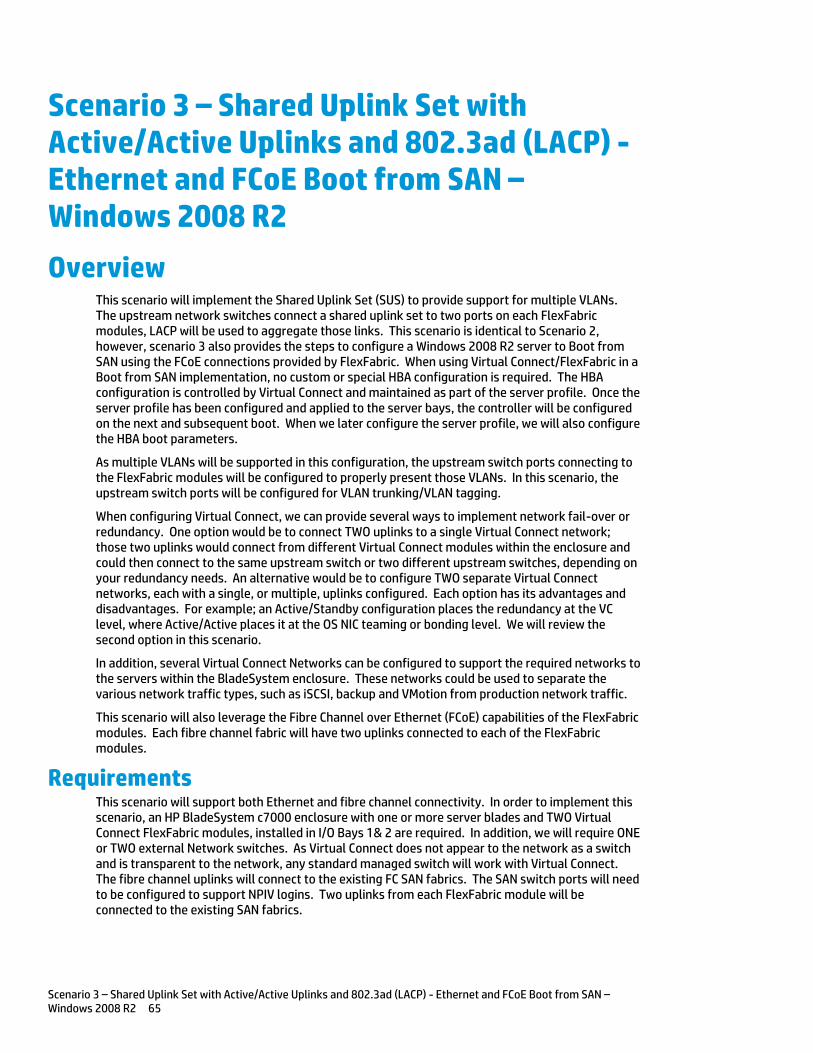
Scenario 3 – Shared Uplink Set with Active/Active Uplinks and 802.3ad (LACP) - Ethernet and FCoE Boot from SAN – Windows 2008 R2 65
Scenario 3 – Shared Uplink Set with Active/Active Uplinks and 802.3ad (LACP) - Ethernet and FCoE Boot from SAN – Windows 2008 R2
Overview This scenario will implement the Shared Uplink Set (SUS) to provide support for multiple VLANs. The upstream network switches connect a shared uplink set to two ports on each FlexFabric modules, LACP will be used to aggregate those links. This scenario is identical to Scenario 2, however, scenario 3 also provides the steps to configure a Windows 2008 R2 server to Boot from SAN using the FCoE connections provided by FlexFabric. When using Virtual Connect/FlexFabric in a Boot from SAN implementation, no custom or special HBA configuration is required. The HBA configuration is controlled by Virtual Connect and maintained as part of the server profile. Once the server profile has been configured and applied to the server bays, the controller will be configured on the next and subsequent boot. When we later configure the server profile, we will also configure the HBA boot parameters.
As multiple VLANs will be supported in this configuration, the upstream switch ports connecting to the FlexFabric modules will be configured to properly present those VLANs. In this scenario, the upstream switch ports will be configured for VLAN trunking/VLAN tagging.
When configuring Virtual Connect, we can provide several ways to implement network fail-over or redundancy. One option would be to connect TWO uplinks to a single Virtual Connect network; those two uplinks would connect from different Virtual Connect modules within the enclosure and could then connect to the same upstream switch or two different upstream switches, depending on your redundancy needs. An alternative would be to configure TWO separate Virtual Connect networks, each with a single, or multiple, uplinks configured. Each option has its advantages and disadvantages. For example; an Active/Standby configuration places the redundancy at the VC level, where Active/Active places it at the OS NIC teaming or bonding level. We will review the second option in this scenario.
In addition, several Virtual Connect Networks can be configured to support the required networks to the servers within the BladeSystem enclosure. These networks could be used to separate the various network traffic types, such as iSCSI, backup and VMotion from production network traffic.
This scenario will also leverage the Fibre Channel over Ethernet (FCoE) capabilities of the FlexFabric modules. Each fibre channel fabric will have two uplinks connected to each of the FlexFabric modules.
Requirements This scenario will support both Ethernet and fibre channel connectivity. In order to implement this scenario, an HP BladeSystem c7000 enclosure with one or more server blades and TWO Virtual Connect FlexFabric modules, installed in I/O Bays 1& 2 are required. In addition, we will require ONE or TWO external Network switches. As Virtual Connect does not appear to the network as a switch and is transparent to the network, any standard managed switch will work with Virtual Connect. The fibre channel uplinks will connect to the existing FC SAN fabrics. The SAN switch ports will need to be configured to support NPIV logins. Two uplinks from each FlexFabric module will be connected to the existing SAN fabrics.
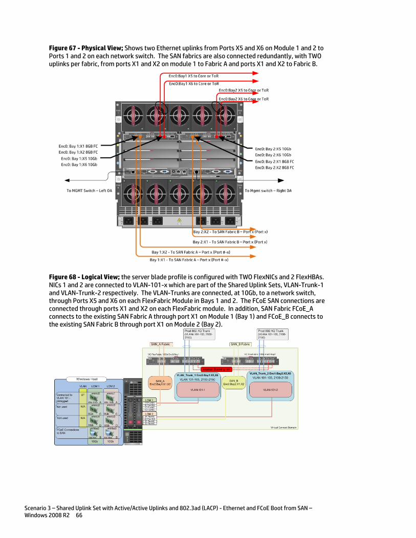
Scenario 3 – Shared Uplink Set with Active/Active Uplinks and 802.3ad (LACP) - Ethernet and FCoE Boot from SAN – Windows 2008 R2 66
Figure 67 - Physical View; Shows two Ethernet uplinks from Ports X5 and X6 on Module 1 and 2 to Ports 1 and 2 on each network switch. The SAN fabrics are also connected redundantly, with TWO uplinks per fabric, from ports X1 and X2 on module 1 to Fabric A and ports X1 and X2 to Fabric B.
Figure 68 - Logical View; the server blade profile is configured with TWO FlexNICs and 2 FlexHBAs. NICs 1 and 2 are connected to VLAN-101-x which are part of the Shared Uplink Sets, VLAN-Trunk-1 and VLAN-Trunk-2 respectively. The VLAN-Trunks are connected, at 10Gb, to a network switch, through Ports X5 and X6 on each FlexFabric Module in Bays 1 and 2. The FCoE SAN connections are connected through ports X1 and X2 on each FlexFabric module. In addition, SAN Fabric FCoE_A connects to the existing SAN Fabric A through port X1 on Module 1 (Bay 1) and FCoE_B connects to the existing SAN Fabric B through port X1 on Module 2 (Bay 2).
Scenario 3 – Shared Uplink Set with Active/Active Uplinks and 802.3ad (LACP) - Ethernet and FCoE Boot from SAN – Windows 2008 R2 67
Installation and configuration Switch configuration
As the Virtual Connect module acts as an edge switch, Virtual Connect can connect to the network at either the distribution level or directly to the core switch.
The appendices provide a summary of the cli commands required to configure various switches for connection to Virtual Connect. The configuration information provided in the appendices for this scenario assumes the following information:
The switch ports are configured as VLAN TRUNK ports (tagging) to support several VLANs. All frames will be forwarded to Virtual Connect with VLAN tags. Optionally, one VLAN could be configured as (Default) untagged, if so, then a corresponding vNet within the Shared Uplink Set would be configured and set as “Default”
Note: when adding additional uplinks to the SUS, if the additional uplinks are connecting from the same FlexFabric module to the same switch, in order to ensure all the uplinks are active, the switch ports will need to be configured for LACP within the same Link Aggregation Group.
The network switch port should be configured for Spanning Tree Edge as Virtual Connect appears to the switch as an access device and not another switch. By configuring the port as Spanning Tree Edge, it allows the switch to place the port into a forwarding state much quicker than otherwise, this allows a newly connected port to come online and begin forwarding much quicker.
The SAN switch ports connecting to the FlexFabric module must be configured to accept NPIV logins.
Configuring the VC module
Physically connect Port 1 of network switch 1 to Port X5 of the VC module in Bay 1 Physically connect Port 2 of network switch 1 to Port X6 of the VC module in Bay 1 Physically connect Port 1 of network switch 2 to Port X5 of the VC module in Bay 2 Physically connect Port 2 of network switch 2 to Port X6 of the VC module in Bay 2
Note: if you have only one network switch, connect VC ports X5 and X6 (Bay 2) to an alternate port on the same switch. This will NOT create a network loop and Spanning Tree is not required.
Physically connect Ports X1/X2 on the FlexFabric in module Bay 1 to switch ports in SAN Fabric A Physically connect Ports X1/X2 on the FlexFabric in module Bay 2 to switch ports in SAN Fabric B
VC CLI commands
Many of the configuration settings within VC can also be accomplished via a CLI command set. In order to connect to VC via a CLI, open an SSH connection to the IP address of the active VCM. Once logged in, VC provides a CLI with help menus. Through this scenario the CLI commands to configure VC for each setting will also be provided.
Configuring Expanded VLAN Capacity via GUI
Virtual Connect release 3.30 provided an expanded VLAN capacity mode when using Shared Uplink Sets, this mode can be enabled through the Ethernet Settings tab or the VC CLI. The default configuration for a new Domain install is “Expanded VLAN Capacity” mode, Legacy mode is no longer available and the Domain cannot be downgraded.
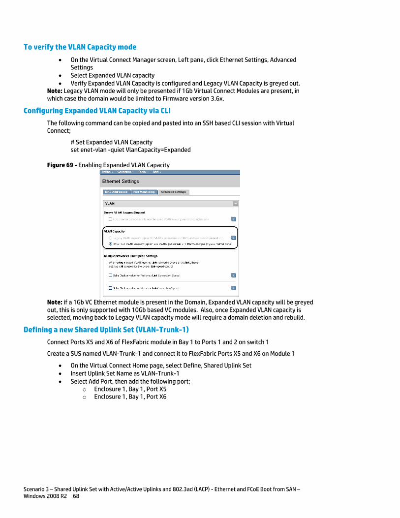
Scenario 3 – Shared Uplink Set with Active/Active Uplinks and 802.3ad (LACP) - Ethernet and FCoE Boot from SAN – Windows 2008 R2 68
To verify the VLAN Capacity mode
On the Virtual Connect Manager screen, Left pane, click Ethernet Settings, Advanced Settings
Select Expanded VLAN capacity Verify Expanded VLAN Capacity is configured and Legacy VLAN Capacity is greyed out.
Note: Legacy VLAN mode will only be presented if 1Gb Virtual Connect Modules are present, in which case the domain would be limited to Firmware version 3.6x.
Configuring Expanded VLAN Capacity via CLI
The following command can be copied and pasted into an SSH based CLI session with Virtual Connect;
# Set Expanded VLAN Capacity set enet-vlan -quiet VlanCapacity=Expanded
Figure 69 - Enabling Expanded VLAN Capacity
Note: if a 1Gb VC Ethernet module is present in the Domain, Expanded VLAN capacity will be greyed out, this is only supported with 10Gb based VC modules. Also, once Expanded VLAN capacity is selected, moving back to Legacy VLAN capacity mode will require a domain deletion and rebuild.
Defining a new Shared Uplink Set (VLAN-Trunk-1)
Connect Ports X5 and X6 of FlexFabric module in Bay 1 to Ports 1 and 2 on switch 1
Create a SUS named VLAN-Trunk-1 and connect it to FlexFabric Ports X5 and X6 on Module 1
On the Virtual Connect Home page, select Define, Shared Uplink Set Insert Uplink Set Name as VLAN-Trunk-1 Select Add Port, then add the following port;
o Enclosure 1, Bay 1, Port X5 o Enclosure 1, Bay 1, Port X6
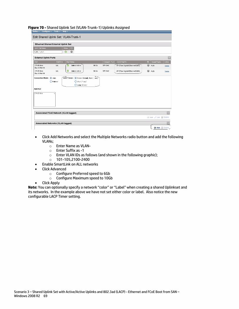
Scenario 3 – Shared Uplink Set with Active/Active Uplinks and 802.3ad (LACP) - Ethernet and FCoE Boot from SAN – Windows 2008 R2 69
Figure 70 - Shared Uplink Set (VLAN-Trunk-1) Uplinks Assigned
Click Add Networks and select the Multiple Networks radio button and add the following VLANs;
o Enter Name as VLAN- o Enter Suffix as -1 o Enter VLAN IDs as follows (and shown in the following graphic); o 101-105,2100-2400
Enable SmartLink on ALL networks Click Advanced
o Configure Preferred speed to 6Gb o Configure Maximum speed to 10Gb
Click Apply Note: You can optionally specify a network “color” or “Label” when creating a shared Uplinkset and its networks. In the example above we have not set either color or label. Also notice the new configurable LACP Timer setting.
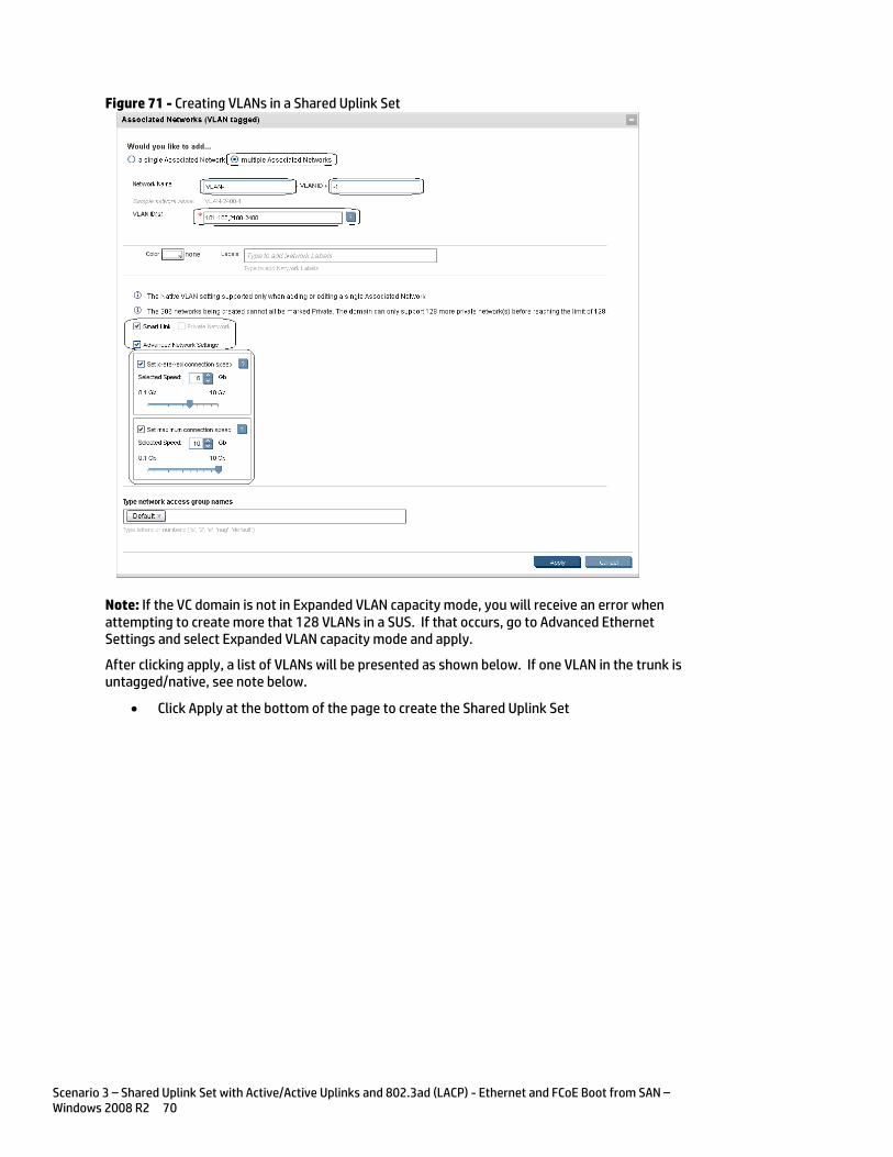
Scenario 3 – Shared Uplink Set with Active/Active Uplinks and 802.3ad (LACP) - Ethernet and FCoE Boot from SAN – Windows 2008 R2 70
Figure 71 - Creating VLANs in a Shared Uplink Set
Note: If the VC domain is not in Expanded VLAN capacity mode, you will receive an error when attempting to create more that 128 VLANs in a SUS. If that occurs, go to Advanced Ethernet Settings and select Expanded VLAN capacity mode and apply.
After clicking apply, a list of VLANs will be presented as shown below. If one VLAN in the trunk is untagged/native, see note below.
Click Apply at the bottom of the page to create the Shared Uplink Set
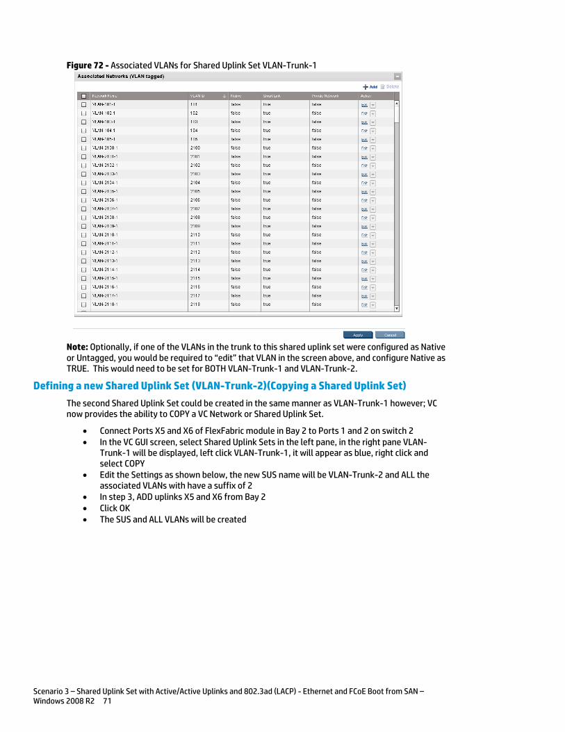
Scenario 3 – Shared Uplink Set with Active/Active Uplinks and 802.3ad (LACP) - Ethernet and FCoE Boot from SAN – Windows 2008 R2 71
Figure 72 - Associated VLANs for Shared Uplink Set VLAN-Trunk-1
Note: Optionally, if one of the VLANs in the trunk to this shared uplink set were configured as Native or Untagged, you would be required to “edit” that VLAN in the screen above, and configure Native as TRUE. This would need to be set for BOTH VLAN-Trunk-1 and VLAN-Trunk-2.
Defining a new Shared Uplink Set (VLAN-Trunk-2)(Copying a Shared Uplink Set)
The second Shared Uplink Set could be created in the same manner as VLAN-Trunk-1 however; VC now provides the ability to COPY a VC Network or Shared Uplink Set.
Connect Ports X5 and X6 of FlexFabric module in Bay 2 to Ports 1 and 2 on switch 2 In the VC GUI screen, select Shared Uplink Sets in the left pane, in the right pane VLAN-
Trunk-1 will be displayed, left click VLAN-Trunk-1, it will appear as blue, right click and select COPY
Edit the Settings as shown below, the new SUS name will be VLAN-Trunk-2 and ALL the associated VLANs with have a suffix of 2
In step 3, ADD uplinks X5 and X6 from Bay 2 Click OK The SUS and ALL VLANs will be created
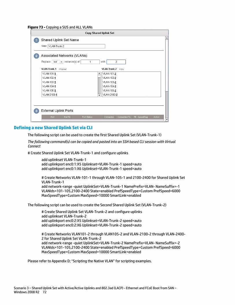
Scenario 3 – Shared Uplink Set with Active/Active Uplinks and 802.3ad (LACP) - Ethernet and FCoE Boot from SAN – Windows 2008 R2 72
Figure 73 - Copying a SUS and ALL VLANs
Defining a new Shared Uplink Set via CLI
The following script can be used to create the first Shared Uplink Set (VLAN-Trunk-1)
The following command(s) can be copied and pasted into an SSH based CLI session with Virtual Connect
# Create Shared Uplink Set VLAN-Trunk-1 and configure uplinks
add uplinkset VLAN-Trunk-1 add uplinkport enc0:1:X5 Uplinkset=VLAN-Trunk-1 speed=auto add uplinkport enc0:1:X6 Uplinkset=VLAN-Trunk-1 speed=auto # Create Networks VLAN-101-1 through VLAN-105-1 and 2100-2400 for Shared Uplink Set VLAN-Trunk-1 add network-range -quiet UplinkSet=VLAN-Trunk-1 NamePrefix=VLAN- NameSuffix=-1 VLANIds=101-105,2100-2400 State=enabled PrefSpeedType=Custom PrefSpeed=6000 MaxSpeedType=Custom MaxSpeed=10000 SmartLink=enabled
The following script can be used to create the Second Shared Uplink Set (VLAN-Trunk-2)
# Create Shared Uplink Set VLAN-Trunk-2 and configure uplinks add uplinkset VLAN-Trunk-2 add uplinkport enc0:2:X5 Uplinkset=VLAN-Trunk-2 speed=auto add uplinkport enc0:2:X6 Uplinkset=VLAN-Trunk-2 speed=auto # Create Networks VLAN101-2 through VLAN105-2 and VLAN-2100-2 through VLAN-2400-2 for Shared Uplink Set VLAN-Trunk-2 add network-range -quiet UplinkSet=VLAN-Trunk-2 NamePrefix=VLAN- NameSuffix=-2 VLANIds=101-105,2100-2400 State=enabled PrefSpeedType=Custom PrefSpeed=6000 MaxSpeedType=Custom MaxSpeed=10000 SmartLink=enabled
Please refer to Appendix D; “Scripting the Native VLAN” for scripting examples.
Scenario 3 – Shared Uplink Set with Active/Active Uplinks and 802.3ad (LACP) - Ethernet and FCoE Boot from SAN – Windows 2008 R2 73
Note: In this scenario we have created two independent Share Uplink Sets (SUS), each originating from the opposite FlexFabric Modules, by doing so we provide the ability to create separate and redundant connections out of the Virtual Connect domain. When we create the server profiles, you will see how the NICs will connect to VLANs accessed through the opposite VC module, which provides the ability to create an Active / Active uplink scenario. Alternatively, we could have created a single SUS and assigned both sets of these uplink ports to the same SUS, however, this would have provided an Active/Standby uplink scenario, as shown in Scenario 5.
Defining a new (FCoE) SAN Fabric via GUI
Create a Fabric and name it “FCoE_A”
On the Virtual Connect Manager screen, click Define, SAN Fabric to create the first Fabric Enter the Network Name of “FCoE_A” Select Add Port, then add the following ports;
o Enclosure 1, Bay 1, Port X1 o Enclosure 1, Bay 1, Port X2
Ensure Fabric Type is set to “FabricAttach” Select Show Advanced Settings
o Select Automatic Login Re-Distribution (FlexFabric Only) o Select Set Preferred FCoE Connect Speed
Configure for 4Gb o Select Set Maximum FCoE Connect Speed
Configure for 8Gb Select Apply
Create a second Fabric and name it “FCoE_B”
On the Virtual Connect Manager screen, click Define, SAN Fabric to create the second Fabric Enter the Network Name of “FCoE_B” Select Add Port, then add the following ports;
o Enclosure 1, Bay 2, Port X1 o Enclosure 1, Bay 2, Port X2
Ensure Fabric Type is set to “FabricAttach” Select Show Advanced Settings
o Select Automatic Login Re-Distribution (FlexFabric Only) o Select Set Preferred FCoE Connect Speed
Configure for 4Gb o Select Set Maximum FCoE Connect Speed
Configure for 8Gb Select Apply
Defining SAN Fabrics via CLI
The following command(s) can be copied and pasted into an SSH based CLI session with Virtual Connect
#Create the SAN Fabrics FCoE_A and FCoE_B and configure uplinks as discussed above add fabric FCoE_A Type=FabricAttach Bay=1 Ports=1,2 Speed=Auto LinkDist=Auto PrefSpeedType=Custom PrefSpeed=4000 MaxSpeedType=Custom MaxSpeed=8000 add fabric FCoE_B Type=FabricAttach Bay=2 Ports=1,2 Speed=Auto LinkDist=Auto PrefSpeedType=Custom PrefSpeed=4000 MaxSpeedType=Custom MaxSpeed=8000
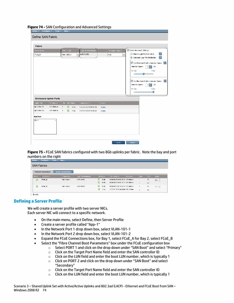
Scenario 3 – Shared Uplink Set with Active/Active Uplinks and 802.3ad (LACP) - Ethernet and FCoE Boot from SAN – Windows 2008 R2 74
Figure 74 - SAN Configuration and Advanced Settings
Figure 75 - FCoE SAN fabrics configured with two 8Gb uplinks per fabric. Note the bay and port numbers on the right
Defining a Server Profile
We will create a server profile with two server NICs. Each server NIC will connect to a specific network.
On the main menu, select Define, then Server Profile Create a server profile called “App-1” In the Network Port 1 drop down box, select VLAN-101-1 In the Network Port 2 drop down box, select VLAN-101-2 Expand the FCoE Connections box, for Bay 1, select FCoE_A for Bay 2, select FCoE_B Select the “Fibre Channel Boot Parameters” box under the FCoE configuration box
o Select PORT 1 and click on the drop down under “SAN Boot” and select “Primary” o Click on the Target Port Name field and enter the SAN controller ID o Click on the LUN field and enter the boot LUN number, which is typically 1 o Click on PORT 2 and click on the drop down under “SAN Boot” and select
“Secondary” o Click on the Target Port Name field and enter the SAN controller ID o Click on the LUN field and enter the boot LUN number, which is typically 1
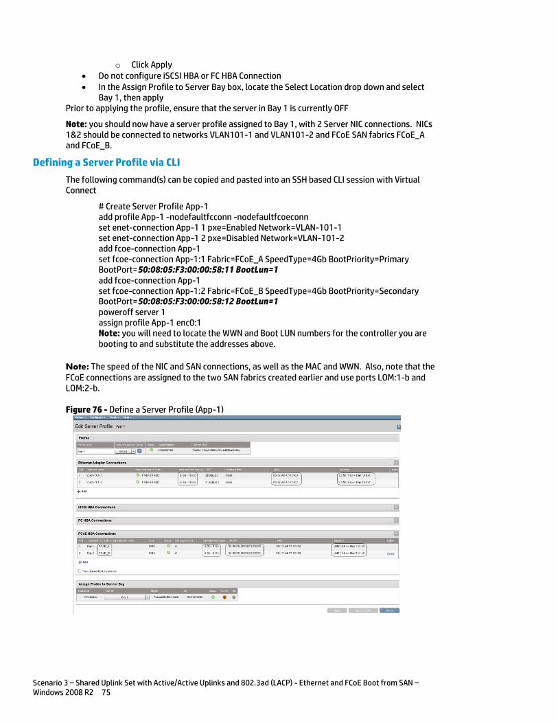
Scenario 3 – Shared Uplink Set with Active/Active Uplinks and 802.3ad (LACP) - Ethernet and FCoE Boot from SAN – Windows 2008 R2 75
o Click Apply Do not configure iSCSI HBA or FC HBA Connection In the Assign Profile to Server Bay box, locate the Select Location drop down and select
Bay 1, then apply Prior to applying the profile, ensure that the server in Bay 1 is currently OFF
Note: you should now have a server profile assigned to Bay 1, with 2 Server NIC connections. NICs 1&2 should be connected to networks VLAN101-1 and VLAN101-2 and FCoE SAN fabrics FCoE_A and FCoE_B.
Defining a Server Profile via CLI
The following command(s) can be copied and pasted into an SSH based CLI session with Virtual Connect
# Create Server Profile App-1 add profile App-1 -nodefaultfcconn -nodefaultfcoeconn set enet-connection App-1 1 pxe=Enabled Network=VLAN-101-1 set enet-connection App-1 2 pxe=Disabled Network=VLAN-101-2 add fcoe-connection App-1 set fcoe-connection App-1:1 Fabric=FCoE_A SpeedType=4Gb BootPriority=Primary BootPort=50:08:05:F3:00:00:58:11 BootLun=1 add fcoe-connection App-1 set fcoe-connection App-1:2 Fabric=FCoE_B SpeedType=4Gb BootPriority=Secondary BootPort=50:08:05:F3:00:00:58:12 BootLun=1 poweroff server 1 assign profile App-1 enc0:1 Note: you will need to locate the WWN and Boot LUN numbers for the controller you are booting to and substitute the addresses above.
Note: The speed of the NIC and SAN connections, as well as the MAC and WWN. Also, note that the FCoE connections are assigned to the two SAN fabrics created earlier and use ports LOM:1-b and LOM:2-b.
Figure 76 - Define a Server Profile (App-1)
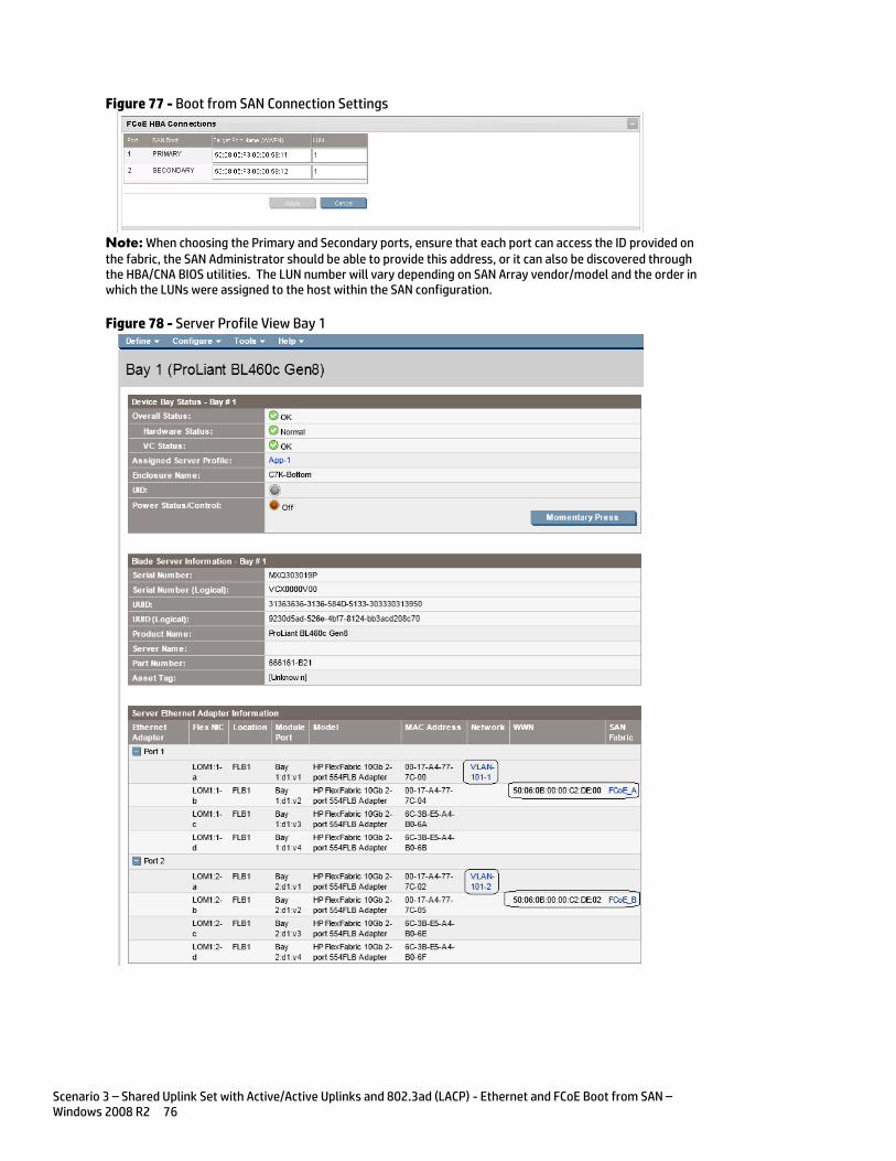
Scenario 3 – Shared Uplink Set with Active/Active Uplinks and 802.3ad (LACP) - Ethernet and FCoE Boot from SAN – Windows 2008 R2 76
Figure 77 - Boot from SAN Connection Settings
Note: When choosing the Primary and Secondary ports, ensure that each port can access the ID provided on the fabric, the SAN Administrator should be able to provide this address, or it can also be discovered through the HBA/CNA BIOS utilities. The LUN number will vary depending on SAN Array vendor/model and the order in which the LUNs were assigned to the host within the SAN configuration.
Figure 78 - Server Profile View Bay 1
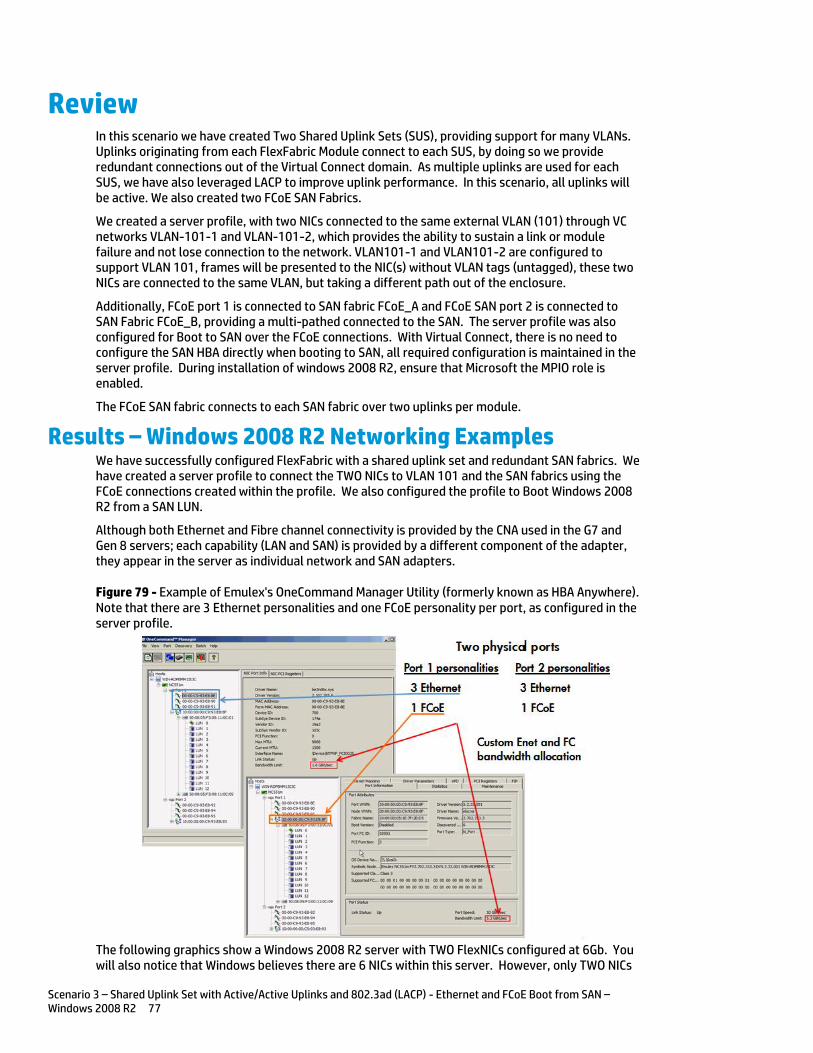
Scenario 3 – Shared Uplink Set with Active/Active Uplinks and 802.3ad (LACP) - Ethernet and FCoE Boot from SAN – Windows 2008 R2 77
Review In this scenario we have created Two Shared Uplink Sets (SUS), providing support for many VLANs. Uplinks originating from each FlexFabric Module connect to each SUS, by doing so we provide redundant connections out of the Virtual Connect domain. As multiple uplinks are used for each SUS, we have also leveraged LACP to improve uplink performance. In this scenario, all uplinks will be active. We also created two FCoE SAN Fabrics.
We created a server profile, with two NICs connected to the same external VLAN (101) through VC networks VLAN-101-1 and VLAN-101-2, which provides the ability to sustain a link or module failure and not lose connection to the network. VLAN101-1 and VLAN101-2 are configured to support VLAN 101, frames will be presented to the NIC(s) without VLAN tags (untagged), these two NICs are connected to the same VLAN, but taking a different path out of the enclosure.
Additionally, FCoE port 1 is connected to SAN fabric FCoE_A and FCoE SAN port 2 is connected to SAN Fabric FCoE_B, providing a multi-pathed connected to the SAN. The server profile was also configured for Boot to SAN over the FCoE connections. With Virtual Connect, there is no need to configure the SAN HBA directly when booting to SAN, all required configuration is maintained in the server profile. During installation of windows 2008 R2, ensure that Microsoft the MPIO role is enabled.
The FCoE SAN fabric connects to each SAN fabric over two uplinks per module.
Results – Windows 2008 R2 Networking Examples We have successfully configured FlexFabric with a shared uplink set and redundant SAN fabrics. We have created a server profile to connect the TWO NICs to VLAN 101 and the SAN fabrics using the FCoE connections created within the profile. We also configured the profile to Boot Windows 2008 R2 from a SAN LUN.
Although both Ethernet and Fibre channel connectivity is provided by the CNA used in the G7 and Gen 8 servers; each capability (LAN and SAN) is provided by a different component of the adapter, they appear in the server as individual network and SAN adapters.
Figure 79 - Example of Emulex's OneCommand Manager Utility (formerly known as HBA Anywhere). Note that there are 3 Ethernet personalities and one FCoE personality per port, as configured in the server profile.
The following graphics show a Windows 2008 R2 server with TWO FlexNICs configured at 6Gb. You will also notice that Windows believes there are 6 NICs within this server. However, only TWO NICs
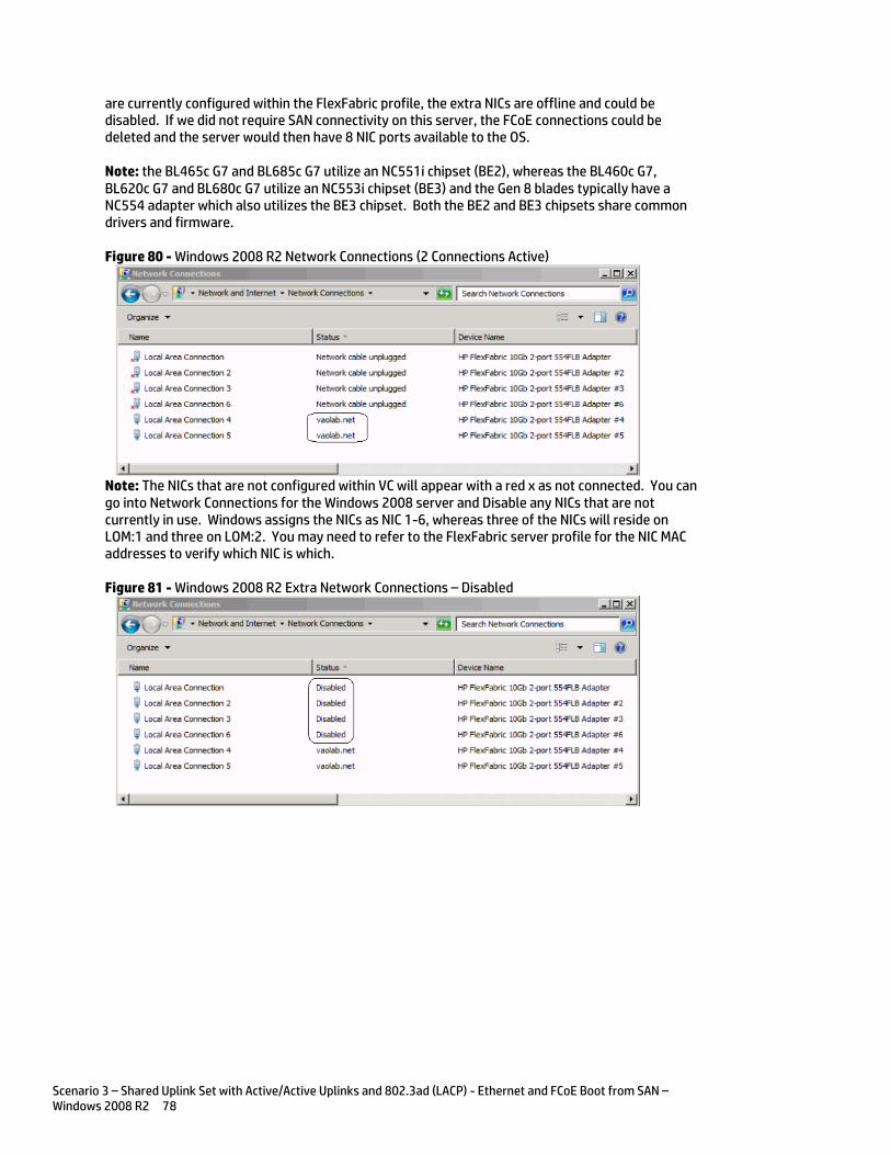
Scenario 3 – Shared Uplink Set with Active/Active Uplinks and 802.3ad (LACP) - Ethernet and FCoE Boot from SAN – Windows 2008 R2 78
are currently configured within the FlexFabric profile, the extra NICs are offline and could be disabled. If we did not require SAN connectivity on this server, the FCoE connections could be deleted and the server would then have 8 NIC ports available to the OS.
Note: the BL465c G7 and BL685c G7 utilize an NC551i chipset (BE2), whereas the BL460c G7, BL620c G7 and BL680c G7 utilize an NC553i chipset (BE3) and the Gen 8 blades typically have a NC554 adapter which also utilizes the BE3 chipset. Both the BE2 and BE3 chipsets share common drivers and firmware.
Figure 80 - Windows 2008 R2 Network Connections (2 Connections Active)
Note: The NICs that are not configured within VC will appear with a red x as not connected. You can go into Network Connections for the Windows 2008 server and Disable any NICs that are not currently in use. Windows assigns the NICs as NIC 1-6, whereas three of the NICs will reside on LOM:1 and three on LOM:2. You may need to refer to the FlexFabric server profile for the NIC MAC addresses to verify which NIC is which.
Figure 81 - Windows 2008 R2 Extra Network Connections – Disabled
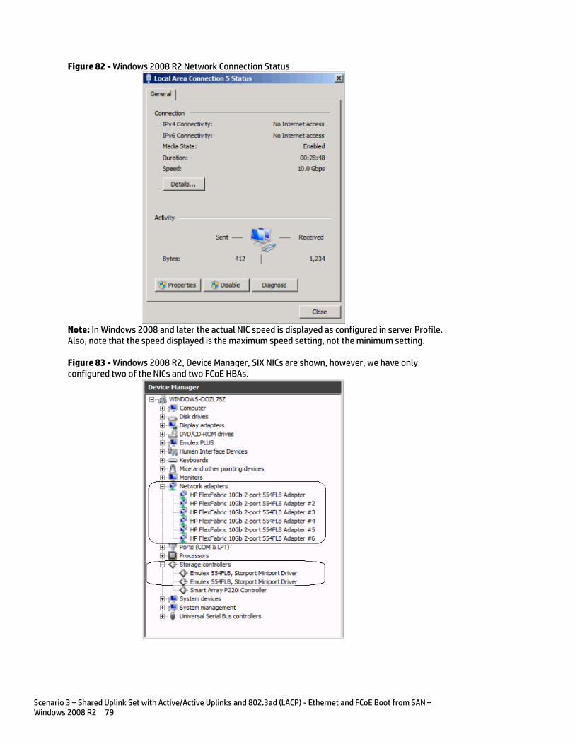
Scenario 3 – Shared Uplink Set with Active/Active Uplinks and 802.3ad (LACP) - Ethernet and FCoE Boot from SAN – Windows 2008 R2 79
Figure 82 - Windows 2008 R2 Network Connection Status
Note: In Windows 2008 and later the actual NIC speed is displayed as configured in server Profile. Also, note that the speed displayed is the maximum speed setting, not the minimum setting.
Figure 83 - Windows 2008 R2, Device Manager, SIX NICs are shown, however, we have only configured two of the NICs and two FCoE HBAs.

Scenario 3 – Shared Uplink Set with Active/Active Uplinks and 802.3ad (LACP) - Ethernet and FCoE Boot from SAN – Windows 2008 R2 80
The following graphics provides an example of a Windows 2008 R2 server with TWO NICs connected to the network, initially each NIC has its own TCP/IP address, alternatively, both NICs could be teamed to provide NIC fail-over redundancy. If an active uplink or network switch were to fail, Virtual Connect would fail-over to the standby uplink. In the event of a Virtual Connect FlexFabric module failure, the server’s NIC teaming software would see one of the NICs go offline, assuming it was the active NIC, NIC teaming would fail-over to the standby NIC.
Figure 84 - Each NIC is connected to VLAN 101
NIC Teaming
If higher availability is desired, NIC teaming in Virtual Connect works the same way as in standard network configurations. Simply, open the NIC teaming Utility and configure the available NICs for teaming. In this example, we have only TWO NICs available, so selecting NICs for teaming will be quite simple. However, if multiple NICs are available, ensure that the correct pair of NICs is teamed. You will note the BAY#-Port# indication within each NIC. Another way to confirm you have the correct NIC is to verify through the MAC address of the NIC. You would typically TEAM a NIC from Bay 1 to Bay 2 for example.
The following graphics provide an example of a Windows 2008 R2 server with TWO NICs teamed and connected to the network. In the event of an Uplink or switch failure, the SUS will lose connection to the network; SmartLink will alert the NIC teaming software to this event, by turning the server NIC port off, causing the NIC teaming software to fail-over to the alternate NIC.
Figure 85 – Team both NICs, using the HP Network Configuration Utility

Scenario 3 – Shared Uplink Set with Active/Active Uplinks and 802.3ad (LACP) - Ethernet and FCoE Boot from SAN – Windows 2008 R2 81
Figure 86 - Both NICs for Profile App-1are teamed and connected to the network through VLAN-Trunk-x, either path could be active
Various modes can be configured for NIC Teaming, such as NFT, TLB etc. Once the Team is created, you can select the team and edit its properties. Typically, the default settings can be used.
Figure 87 - View – Network Connections – NIC Team #1 – Windows
Figure 88 - Both NICs are teamed and connect to the network with a common IP Address
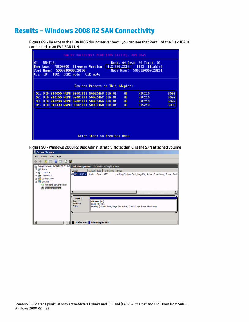
Scenario 3 – Shared Uplink Set with Active/Active Uplinks and 802.3ad (LACP) - Ethernet and FCoE Boot from SAN – Windows 2008 R2 82
Results – Windows 2008 R2 SAN Connectivity
Figure 89 - By access the HBA BIOS during server boot, you can see that Port 1 of the FlexHBA is connected to an EVA SAN LUN
Figure 90 - Windows 2008 R2 Disk Administrator. Note; that C: is the SAN attached volume
Scenario 3 – Shared Uplink Set with Active/Active Uplinks and 802.3ad (LACP) - Ethernet and FCoE Boot from SAN – Windows 2008 R2 83
Summary We presented a Virtual Connect Network scenario by creating two shared uplink sets (SUS), each SUS is connected with TWO active uplinks, both SUS’ can actively pass traffic. We included a dual path FCoE SAN fabric for storage connectivity and boot to SAN.
When VC profile App-1 is applied to the server in bay1 and the server is powered up, it has one NIC connected through FlexFabric module 1 (connected to VLAN-101-1), the second NIC is connected through FlexFabric module 2 (connected to VLAN-101-2). Each NIC is configured at 6Gb. These NICs could now be configured as individual NICs with their own IP address or as a pair of TEAMED NICs. Either NIC could be active. As a result, this server could access the network through either NIC or either uplink, depending on which NIC is active at the time. Each NIC is configured for a guaranteed minimum bandwidth of 8Gb, with a maximum of 10Gb of network bandwidth and each FCoE port is configured for 4Gb of SAN bandwidth with the ability to burst to a maximum of 8Gb.
We also configured the server profile to Boot to SAN, this configuration is part of the profile, if the profile is moved to a different server bay, the Boot to SAN information will follow with the profile. The profile can also be copied and assigned additional server bays, each new profile will retain the Boot to SAN configuration, however, will also acquire new WWN addresses.
Additional NICs could be added within FlexFabric, by simply powering the server off and adding up to a total of 6 NICs, the NIC speed can then be adjusted accordingly to suit the needs of each NIC. If additional or less SAN bandwidth is required, the speed of the SAN connection can also be adjusted.
As additional servers are added to the enclosure, simply create additional profiles, or copy existing profiles, configure the NICs for LAN and SAN fabrics as required and apply them to the appropriate server bays and power the server on.
Scenario 4 – Shared Uplink Set with Active/Active Uplinks and 802.3ad (LACP) – Ethernet, FCoE SAN - Windows 2008 R2 Hyper-V 84
Scenario 4 – Shared Uplink Set with Active/Active Uplinks and 802.3ad (LACP) – Ethernet, FCoE SAN - Windows 2008 R2 Hyper-V
Overview This scenario will implement the Shared Uplink Set (SUS) to provide support for multiple VLANs. The upstream network switches connect a shared uplink set to two ports on each FlexFabric modules, LACP will be used to aggregate those links.
As multiple VLANs will be supported in this configuration, the upstream switch ports connecting to the FlexFabric modules will be configured to properly present those VLANs. In this scenario, the upstream switch ports will be configured for VLAN trunking/VLAN tagging.
When configuring Virtual Connect, we can provide several ways to implement network fail-over or redundancy. One option would be to connect TWO uplinks to a single Virtual Connect network; those two uplinks would connect from different Virtual Connect modules within the enclosure and could then connect to the same upstream switch or two different upstream switches, depending on your redundancy needs. An alternative would be to configure TWO separate Virtual Connect networks, each with a single, or multiple, uplinks configured. Each option has its advantages and disadvantages. For example; an Active/Standby configuration places the redundancy at the VC level, where Active/Active places it at the OS NIC teaming or bonding level. We will review the second option in this scenario.
In addition, several Virtual Connect Networks can be configured to support the required networks to the servers within the BladeSystem enclosure. These networks could be used to separate the various network traffic types, such as iSCSI, backup and VMotion from production network traffic.
This scenario will also leverage the Fibre Channel over Ethernet (FCoE) capabilities of the FlexFabric modules. Each fibre channel fabric will have two uplinks connected to each of the FlexFabric modules.
Requirements This scenario will support both Ethernet and fibre channel connectivity. In order to implement this scenario, an HP BladeSystem c7000 enclosure with one or more server blades and TWO Virtual Connect FlexFabric modules, installed in I/O Bays 1& 2 are required. In addition, we will require ONE or TWO external Network switches. As Virtual Connect does not appear to the network as a switch and is transparent to the network, any standard managed switch will work with Virtual Connect. The fibre channel uplinks will connect to the existing FC SAN fabrics. The SAN switch ports will need to be configured to support NPIV logins. Two uplinks from each FlexFabric module will be connected to the existing SAN fabrics.
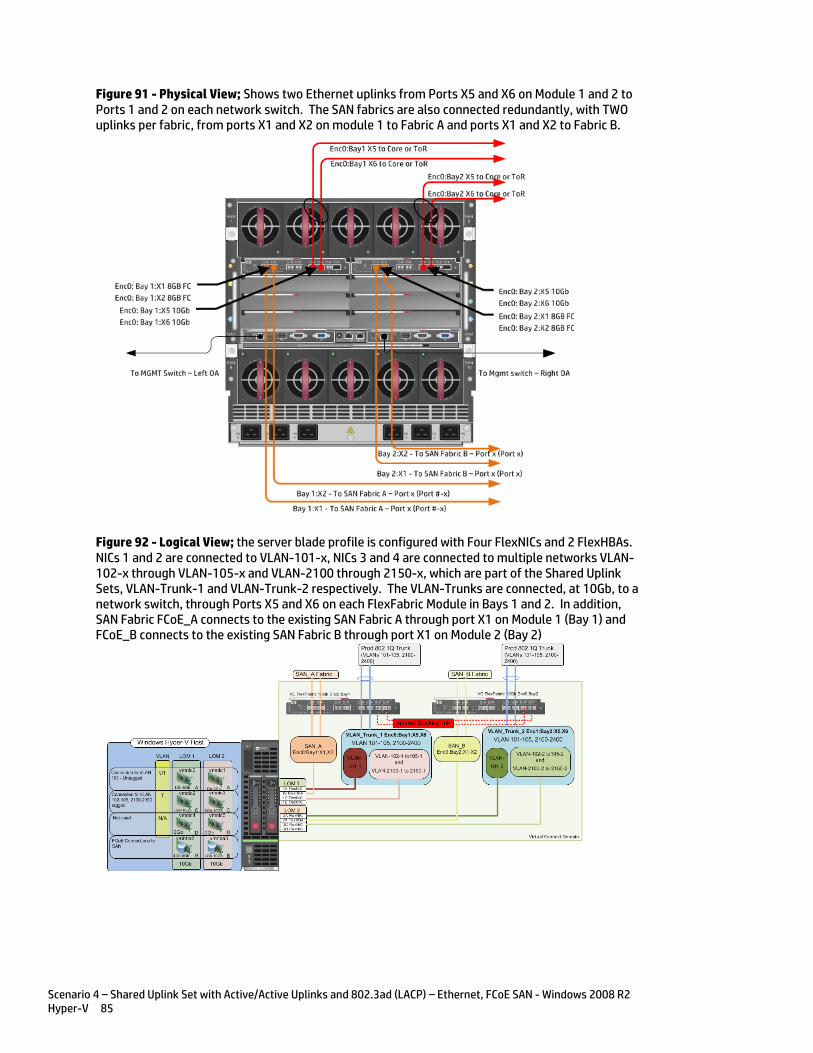
Scenario 4 – Shared Uplink Set with Active/Active Uplinks and 802.3ad (LACP) – Ethernet, FCoE SAN - Windows 2008 R2 Hyper-V 85
Figure 91 - Physical View; Shows two Ethernet uplinks from Ports X5 and X6 on Module 1 and 2 to Ports 1 and 2 on each network switch. The SAN fabrics are also connected redundantly, with TWO uplinks per fabric, from ports X1 and X2 on module 1 to Fabric A and ports X1 and X2 to Fabric B.
Figure 92 - Logical View; the server blade profile is configured with Four FlexNICs and 2 FlexHBAs. NICs 1 and 2 are connected to VLAN-101-x, NICs 3 and 4 are connected to multiple networks VLAN-102-x through VLAN-105-x and VLAN-2100 through 2150-x, which are part of the Shared Uplink Sets, VLAN-Trunk-1 and VLAN-Trunk-2 respectively. The VLAN-Trunks are connected, at 10Gb, to a network switch, through Ports X5 and X6 on each FlexFabric Module in Bays 1 and 2. In addition, SAN Fabric FCoE_A connects to the existing SAN Fabric A through port X1 on Module 1 (Bay 1) and FCoE_B connects to the existing SAN Fabric B through port X1 on Module 2 (Bay 2)
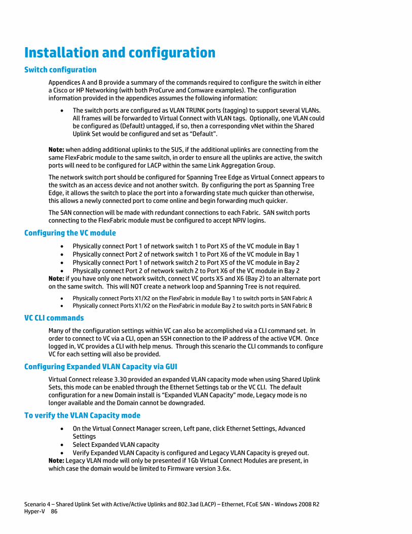
Scenario 4 – Shared Uplink Set with Active/Active Uplinks and 802.3ad (LACP) – Ethernet, FCoE SAN - Windows 2008 R2 Hyper-V 86
Installation and configuration Switch configuration
Appendices A and B provide a summary of the commands required to configure the switch in either a Cisco or HP Networking (with both ProCurve and Comware examples). The configuration information provided in the appendices assumes the following information:
The switch ports are configured as VLAN TRUNK ports (tagging) to support several VLANs. All frames will be forwarded to Virtual Connect with VLAN tags. Optionally, one VLAN could be configured as (Default) untagged, if so, then a corresponding vNet within the Shared Uplink Set would be configured and set as “Default”.
Note: when adding additional uplinks to the SUS, if the additional uplinks are connecting from the same FlexFabric module to the same switch, in order to ensure all the uplinks are active, the switch ports will need to be configured for LACP within the same Link Aggregation Group.
The network switch port should be configured for Spanning Tree Edge as Virtual Connect appears to the switch as an access device and not another switch. By configuring the port as Spanning Tree Edge, it allows the switch to place the port into a forwarding state much quicker than otherwise, this allows a newly connected port to come online and begin forwarding much quicker.
The SAN connection will be made with redundant connections to each Fabric. SAN switch ports connecting to the FlexFabric module must be configured to accept NPIV logins.
Configuring the VC module
Physically connect Port 1 of network switch 1 to Port X5 of the VC module in Bay 1 Physically connect Port 2 of network switch 1 to Port X6 of the VC module in Bay 1 Physically connect Port 1 of network switch 2 to Port X5 of the VC module in Bay 2 Physically connect Port 2 of network switch 2 to Port X6 of the VC module in Bay 2
Note: if you have only one network switch, connect VC ports X5 and X6 (Bay 2) to an alternate port on the same switch. This will NOT create a network loop and Spanning Tree is not required.
Physically connect Ports X1/X2 on the FlexFabric in module Bay 1 to switch ports in SAN Fabric A Physically connect Ports X1/X2 on the FlexFabric in module Bay 2 to switch ports in SAN Fabric B
VC CLI commands
Many of the configuration settings within VC can also be accomplished via a CLI command set. In order to connect to VC via a CLI, open an SSH connection to the IP address of the active VCM. Once logged in, VC provides a CLI with help menus. Through this scenario the CLI commands to configure VC for each setting will also be provided.
Configuring Expanded VLAN Capacity via GUI
Virtual Connect release 3.30 provided an expanded VLAN capacity mode when using Shared Uplink Sets, this mode can be enabled through the Ethernet Settings tab or the VC CLI. The default configuration for a new Domain install is “Expanded VLAN Capacity” mode, Legacy mode is no longer available and the Domain cannot be downgraded.
To verify the VLAN Capacity mode
On the Virtual Connect Manager screen, Left pane, click Ethernet Settings, Advanced Settings
Select Expanded VLAN capacity Verify Expanded VLAN Capacity is configured and Legacy VLAN Capacity is greyed out.
Note: Legacy VLAN mode will only be presented if 1Gb Virtual Connect Modules are present, in which case the domain would be limited to Firmware version 3.6x.
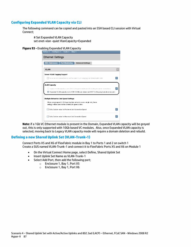
Scenario 4 – Shared Uplink Set with Active/Active Uplinks and 802.3ad (LACP) – Ethernet, FCoE SAN - Windows 2008 R2 Hyper-V 87
Configuring Expanded VLAN Capacity via CLI
The following command can be copied and pasted into an SSH based CLI session with Virtual Connect;
# Set Expanded VLAN Capacity set enet-vlan -quiet VlanCapacity=Expanded
Figure 93 - Enabling Expanded VLAN Capacity
Note: if a 1Gb VC Ethernet module is present in the Domain, Expanded VLAN capacity will be greyed out, this is only supported with 10Gb based VC modules. Also, once Expanded VLAN capacity is selected, moving back to Legacy VLAN capacity mode will require a domain deletion and rebuild.
Defining a new Shared Uplink Set (VLAN-Trunk-1)
Connect Ports X5 and X6 of FlexFabric module in Bay 1 to Ports 1 and 2 on switch 1 Create a SUS named VLAN-Trunk-1 and connect it to FlexFabric Ports X5 and X6 on Module 1
On the Virtual Connect Home page, select Define, Shared Uplink Set Insert Uplink Set Name as VLAN-Trunk-1 Select Add Port, then add the following port;
o Enclosure 1, Bay 1, Port X5 o Enclosure 1, Bay 1, Port X6
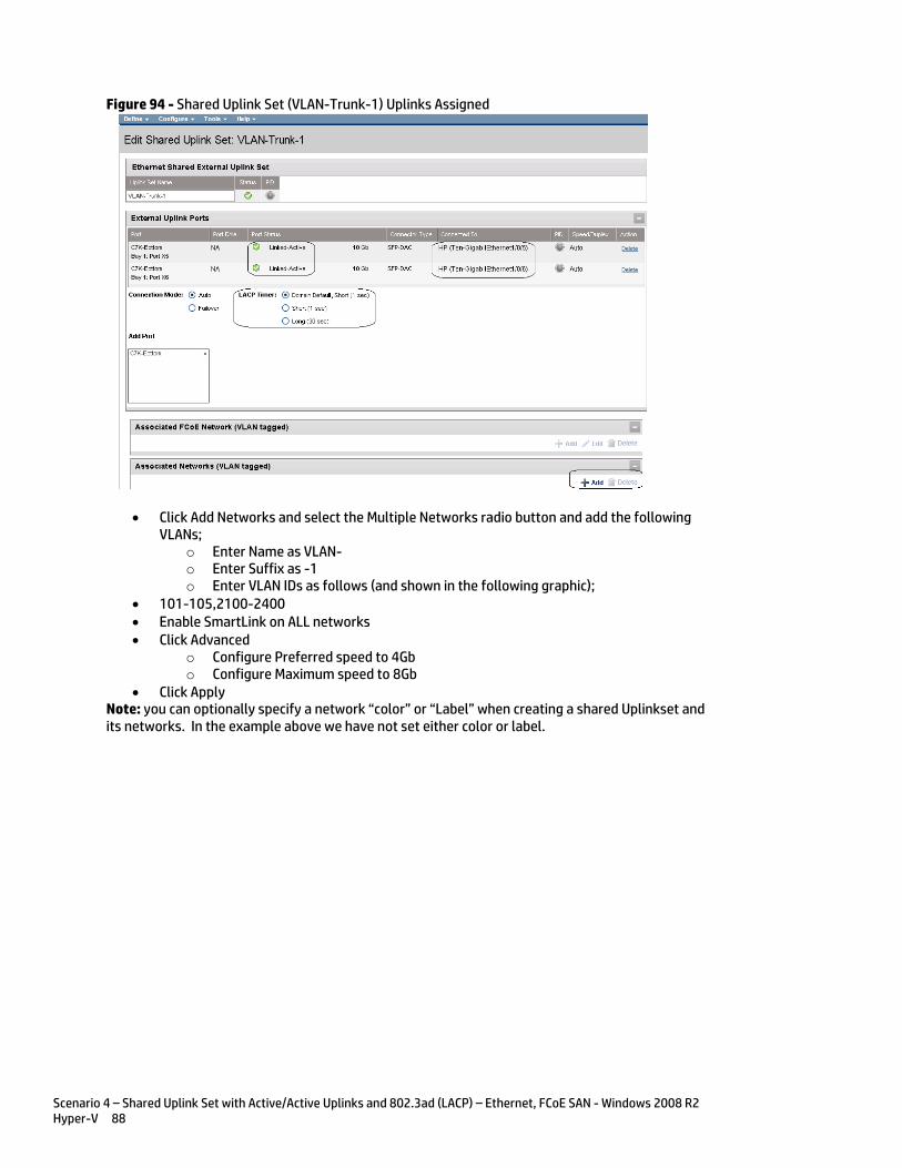
Scenario 4 – Shared Uplink Set with Active/Active Uplinks and 802.3ad (LACP) – Ethernet, FCoE SAN - Windows 2008 R2 Hyper-V 88
Figure 94 - Shared Uplink Set (VLAN-Trunk-1) Uplinks Assigned
Click Add Networks and select the Multiple Networks radio button and add the following VLANs;
o Enter Name as VLAN- o Enter Suffix as -1 o Enter VLAN IDs as follows (and shown in the following graphic);
101-105,2100-2400 Enable SmartLink on ALL networks Click Advanced
o Configure Preferred speed to 4Gb o Configure Maximum speed to 8Gb
Click Apply Note: you can optionally specify a network “color” or “Label” when creating a shared Uplinkset and its networks. In the example above we have not set either color or label.

Scenario 4 – Shared Uplink Set with Active/Active Uplinks and 802.3ad (LACP) – Ethernet, FCoE SAN - Windows 2008 R2 Hyper-V 89
Figure 95 - Creating VLANs in a Shared Uplink Set
Note: If the VC domain is not in Expanded VLAN capacity mode, you will receive an error when attempting to create more that 128 VLANs in a SUS. If that occurs, go to Advanced Ethernet Settings and select Expanded VLAN capacity mode and apply.
After clicking apply, a list of VLANs will be presented as shown below. If one VLAN in the trunk is untagged/native, see note below.
Click Apply at the bottom of the page to create the Shared Uplink Set
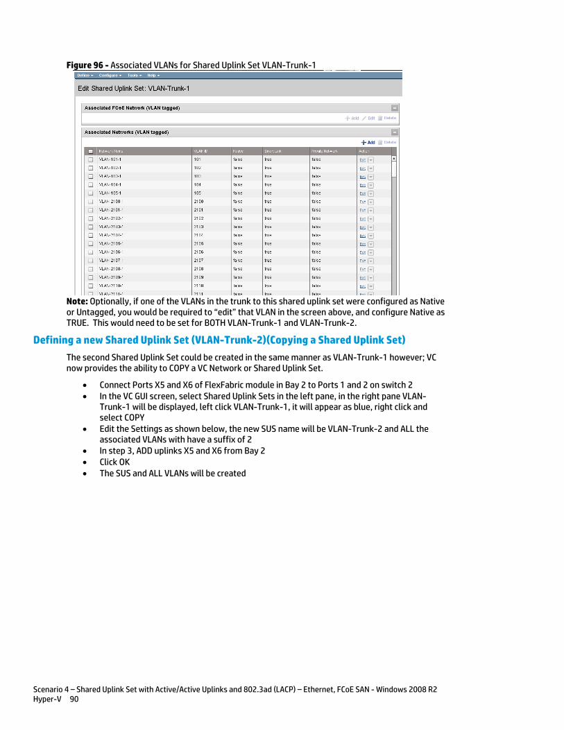
Scenario 4 – Shared Uplink Set with Active/Active Uplinks and 802.3ad (LACP) – Ethernet, FCoE SAN - Windows 2008 R2 Hyper-V 90
Figure 96 - Associated VLANs for Shared Uplink Set VLAN-Trunk-1
Note: Optionally, if one of the VLANs in the trunk to this shared uplink set were configured as Native or Untagged, you would be required to “edit” that VLAN in the screen above, and configure Native as TRUE. This would need to be set for BOTH VLAN-Trunk-1 and VLAN-Trunk-2.
Defining a new Shared Uplink Set (VLAN-Trunk-2)(Copying a Shared Uplink Set)
The second Shared Uplink Set could be created in the same manner as VLAN-Trunk-1 however; VC now provides the ability to COPY a VC Network or Shared Uplink Set.
Connect Ports X5 and X6 of FlexFabric module in Bay 2 to Ports 1 and 2 on switch 2 In the VC GUI screen, select Shared Uplink Sets in the left pane, in the right pane VLAN-
Trunk-1 will be displayed, left click VLAN-Trunk-1, it will appear as blue, right click and select COPY
Edit the Settings as shown below, the new SUS name will be VLAN-Trunk-2 and ALL the associated VLANs with have a suffix of 2
In step 3, ADD uplinks X5 and X6 from Bay 2 Click OK The SUS and ALL VLANs will be created
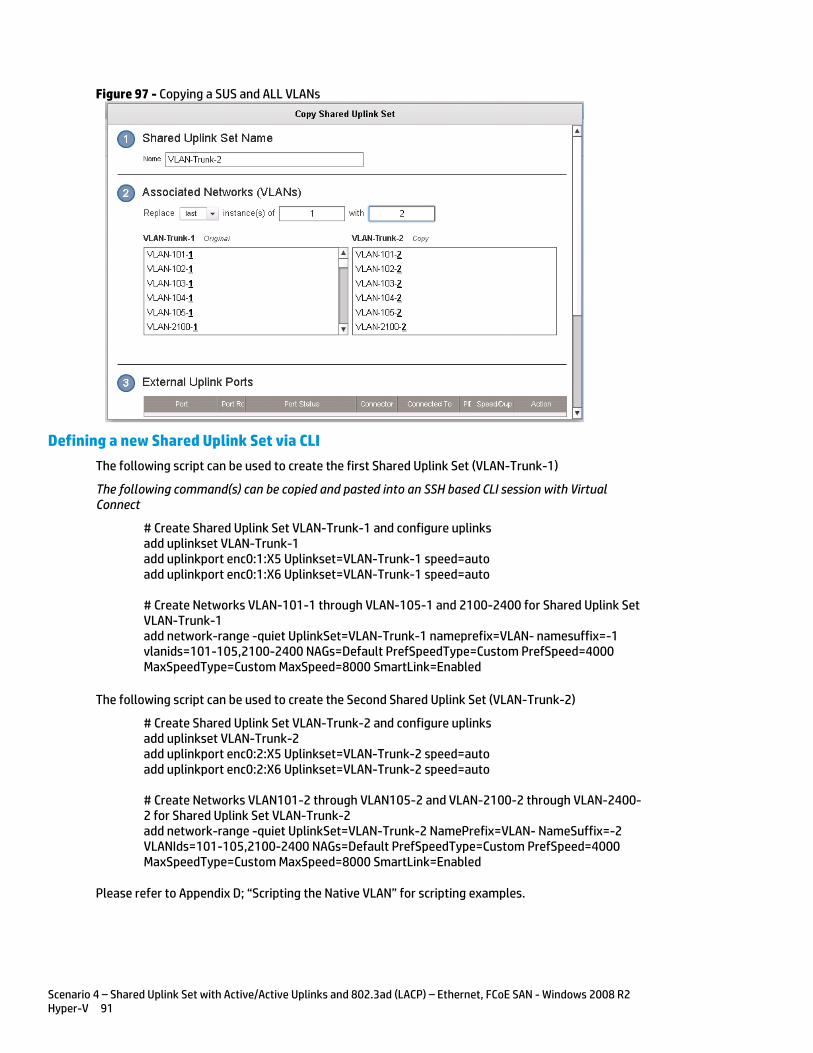
Scenario 4 – Shared Uplink Set with Active/Active Uplinks and 802.3ad (LACP) – Ethernet, FCoE SAN - Windows 2008 R2 Hyper-V 91
Figure 97 - Copying a SUS and ALL VLANs
Defining a new Shared Uplink Set via CLI
The following script can be used to create the first Shared Uplink Set (VLAN-Trunk-1)
The following command(s) can be copied and pasted into an SSH based CLI session with Virtual Connect
# Create Shared Uplink Set VLAN-Trunk-1 and configure uplinks add uplinkset VLAN-Trunk-1 add uplinkport enc0:1:X5 Uplinkset=VLAN-Trunk-1 speed=auto add uplinkport enc0:1:X6 Uplinkset=VLAN-Trunk-1 speed=auto # Create Networks VLAN-101-1 through VLAN-105-1 and 2100-2400 for Shared Uplink Set VLAN-Trunk-1 add network-range -quiet UplinkSet=VLAN-Trunk-1 nameprefix=VLAN- namesuffix=-1 vlanids=101-105,2100-2400 NAGs=Default PrefSpeedType=Custom PrefSpeed=4000 MaxSpeedType=Custom MaxSpeed=8000 SmartLink=Enabled
The following script can be used to create the Second Shared Uplink Set (VLAN-Trunk-2)
# Create Shared Uplink Set VLAN-Trunk-2 and configure uplinks add uplinkset VLAN-Trunk-2 add uplinkport enc0:2:X5 Uplinkset=VLAN-Trunk-2 speed=auto add uplinkport enc0:2:X6 Uplinkset=VLAN-Trunk-2 speed=auto # Create Networks VLAN101-2 through VLAN105-2 and VLAN-2100-2 through VLAN-2400-2 for Shared Uplink Set VLAN-Trunk-2 add network-range -quiet UplinkSet=VLAN-Trunk-2 NamePrefix=VLAN- NameSuffix=-2 VLANIds=101-105,2100-2400 NAGs=Default PrefSpeedType=Custom PrefSpeed=4000 MaxSpeedType=Custom MaxSpeed=8000 SmartLink=Enabled
Please refer to Appendix D; “Scripting the Native VLAN” for scripting examples.

Scenario 4 – Shared Uplink Set with Active/Active Uplinks and 802.3ad (LACP) – Ethernet, FCoE SAN - Windows 2008 R2 Hyper-V 92
Note: In this scenario we have created two independent Share Uplink Sets (SUS), each originating from the opposite FlexFabric Modules, by doing so we provide the ability to create separate and redundant connections out of the Virtual Connect domain. When we create the server profiles, you will see how the NICs will connect to VLANs accessed through the opposite VC module, which provides the ability to create an Active / Active uplink scenario. Alternatively, we could have created a single SUS and assigned both sets of these uplink ports to the same SUS, however, this would have provided an Active/Standby uplink scenario, as shown in Scenario 5.
Defining a new (FCoE) SAN Fabric via GUI
Create a Fabric and name it “FCoE_A”
On the Virtual Connect Manager screen, click Define, SAN Fabric to create the first Fabric Enter the Network Name of “FCoE_A” Select Add Port, then add the following ports;
o Enclosure 1, Bay 1, Port X1 o Enclosure 1, Bay 1, Port X2
Ensure Fabric Type is set to “FabricAttach” Select Show Advanced Settings
o Select Automatic Login Re-Distribution (FlexFabric Only) o Select Set Preferred FCoE Connect Speed
Configure for 4Gb o Select Set Maximum FCoE Connect Speed
Configure for 8Gb Select Apply
Create a second Fabric and name it “FCoE_B”
On the Virtual Connect Manager screen, click Define, SAN Fabric to create the second Fabric Enter the Network Name of “FCoE_B” Select Add Port, then add the following ports;
o Enclosure 1, Bay 2, Port X1 o Enclosure 1, Bay 2, Port X2
Ensure Fabric Type is set to “FabricAttach” Select Show Advanced Settings
o Select Automatic Login Re-Distribution (FlexFabric Only) o Select Set Preferred FCoE Connect Speed
Configure for 4Gb o Select Set Maximum FCoE Connect Speed
Configure for 8Gb Select Apply
Defining SAN Fabrics via CLI
The following command(s) can be copied and pasted into an SSH based CLI session with Virtual Connect
#Create the SAN Fabrics FCoE_A and FCoE_B and configure uplinks as discussed above add fabric FCoE_A Type=FabricAttach Bay=1 Ports=1,2 Speed=Auto LinkDist=Auto PrefSpeedType=Custom PrefSpeed=4000 MaxSpeedType=Custom MaxSpeed=8000 add fabric FCoE_B Type=FabricAttach Bay=2 Ports=1,2 Speed=Auto LinkDist=Auto PrefSpeedType=Custom PrefSpeed=4000 MaxSpeedType=Custom MaxSpeed=8000
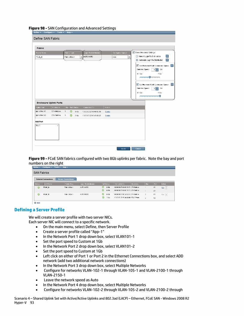
Scenario 4 – Shared Uplink Set with Active/Active Uplinks and 802.3ad (LACP) – Ethernet, FCoE SAN - Windows 2008 R2 Hyper-V 93
Figure 98 - SAN Configuration and Advanced Settings
Figure 99 - FCoE SAN fabrics configured with two 8Gb uplinks per fabric. Note the bay and port numbers on the right
Defining a Server Profile
We will create a server profile with two server NICs. Each server NIC will connect to a specific network.
On the main menu, select Define, then Server Profile Create a server profile called “App-1” In the Network Port 1 drop down box, select VLAN101-1 Set the port speed to Custom at 1Gb In the Network Port 2 drop down box, select VLAN101-2 Set the port speed to Custom at 1Gb Left click on either of Port 1 or Port 2 in the Ethernet Connections box, and select ADD
network (add two additional network connections) In the Network Port 3 drop down box, select Multiple Networks Configure for networks VLAN-102-1 through VLAN-105-1 and VLAN-2100-1 through
VLAN-2150-1 Leave the network speed as Auto In the Network Port 4 drop down box, select Multiple Networks Configure for networks VLAN-102-2 through VLAN-105-2 and VLAN-2100-2 through

Scenario 4 – Shared Uplink Set with Active/Active Uplinks and 802.3ad (LACP) – Ethernet, FCoE SAN - Windows 2008 R2 Hyper-V 94
VLAN-2150-2 Leave the network speed as Auto Expand the FCoE Connections box, for Bay 1, select FCoE_A for Bay 2, select FCoE_B Do not configure FC SAN or iSCSI Connection In the Assign Profile to Server Bay box, locate the Select Location drop down and select
Bay 1, then apply Prior to applying the profile, ensure that the server in Bay 1 is currently OFF
Note: You should now have a server profile assigned to Bay 1, with 4 Server NIC connections. NICs 1&2 should be connected to networks VLAN-101-x, NICs 3&4 should be connected to networks VLAN102-x through VLAN105-x and VLAN-2100-x through VLAN-2150-x. FCoE SAN fabrics are connected to, Port 1 - FCoE_A and Port 2 - FCoE_B.
Defining a Server Profile via CLI
The following command(s) can be copied and pasted into an SSH based CLI session with Virtual Connect
# Create Server Profile App-1 add profile App-1 -nodefaultfcconn -nodefaultfcoeconn set enet-connection App-1 1 pxe=Enabled Network=VLAN-101-1 SpeedType=Custom Speed=1000 set enet-connection App-1 2 pxe=Disabled Network=VLAN-101-2 SpeedType=Custom Speed=1000 add enet-connection App-1 pxe=Disabled add server-port-map-range App-1:3 UplinkSet=VLAN-Trunk-1 VLanIds=102-105,2100-2150 add enet-connection App-1 pxe=Disabled add server-port-map-range App-1:4 UplinkSet=VLAN-Trunk-1 VLanIds=102-105,2100-2150 set enet-connection App-1 3 SpeedType=Preferred set enet-connection App-1 4 SpeedType=Preferred add fcoe-connection App-1 Fabric=FCoE_A SpeedType=4Gb add fcoe-connection App-1 Fabric=FCoE_B SpeedType=4Gb poweroff server 1 assign profile App-1 enc0:1
Note: The “add server-port-map-range” command is new to VC firmware release 3.30 and can be used to map many VLANs to a server NIC, in a single command. Prior releases would have required one command to create the NIC and one additional command per VLAN mapping added. This command will make profile scripting much easier, less complicated and quicker. Note: The speed of the NIC and SAN connections, as well as the MAC and WWN. Also, note that the FCoE connections are assigned to the two SAN fabrics created earlier and use ports LOM:1-b and LOM:2-b.
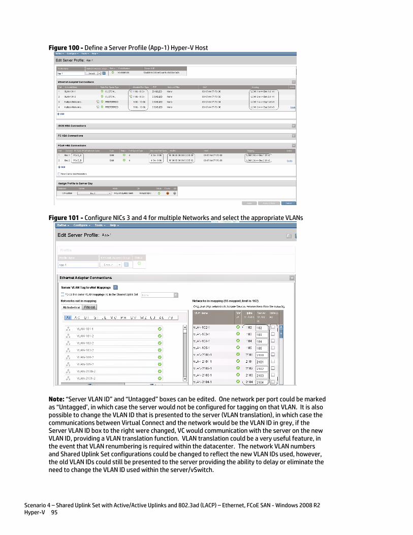
Scenario 4 – Shared Uplink Set with Active/Active Uplinks and 802.3ad (LACP) – Ethernet, FCoE SAN - Windows 2008 R2 Hyper-V 95
Figure 100 - Define a Server Profile (App-1) Hyper-V Host
Figure 101 - Configure NICs 3 and 4 for multiple Networks and select the appropriate VLANs
Note: “Server VLAN ID” and “Untagged” boxes can be edited. One network per port could be marked as “Untagged’, in which case the server would not be configured for tagging on that VLAN. It is also possible to change the VLAN ID that is presented to the server (VLAN translation), in which case the communications between Virtual Connect and the network would be the VLAN ID in grey, if the Server VLAN ID box to the right were changed, VC would communication with the server on the new VLAN ID, providing a VLAN translation function. VLAN translation could be a very useful feature, in the event that VLAN renumbering is required within the datacenter. The network VLAN numbers and Shared Uplink Set configurations could be changed to reflect the new VLAN IDs used, however, the old VLAN IDs could still be presented to the server providing the ability to delay or eliminate the need to change the VLAN ID used within the server/vSwitch.
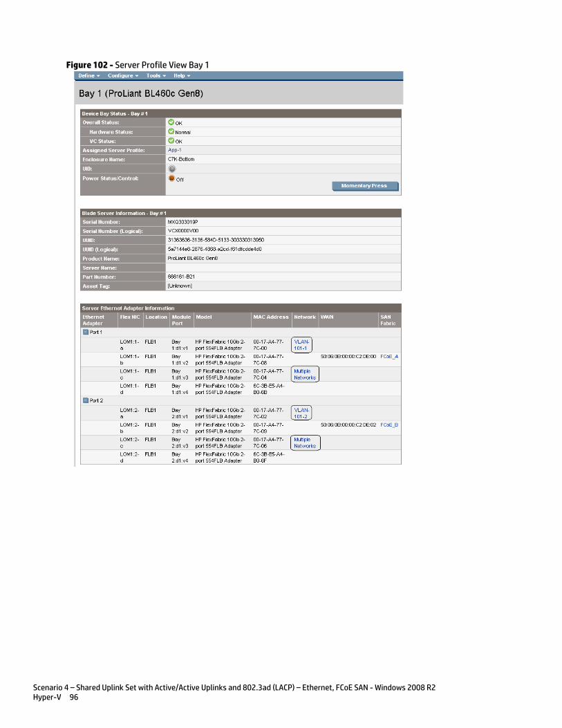
Scenario 4 – Shared Uplink Set with Active/Active Uplinks and 802.3ad (LACP) – Ethernet, FCoE SAN - Windows 2008 R2 Hyper-V 96
Figure 102 - Server Profile View Bay 1
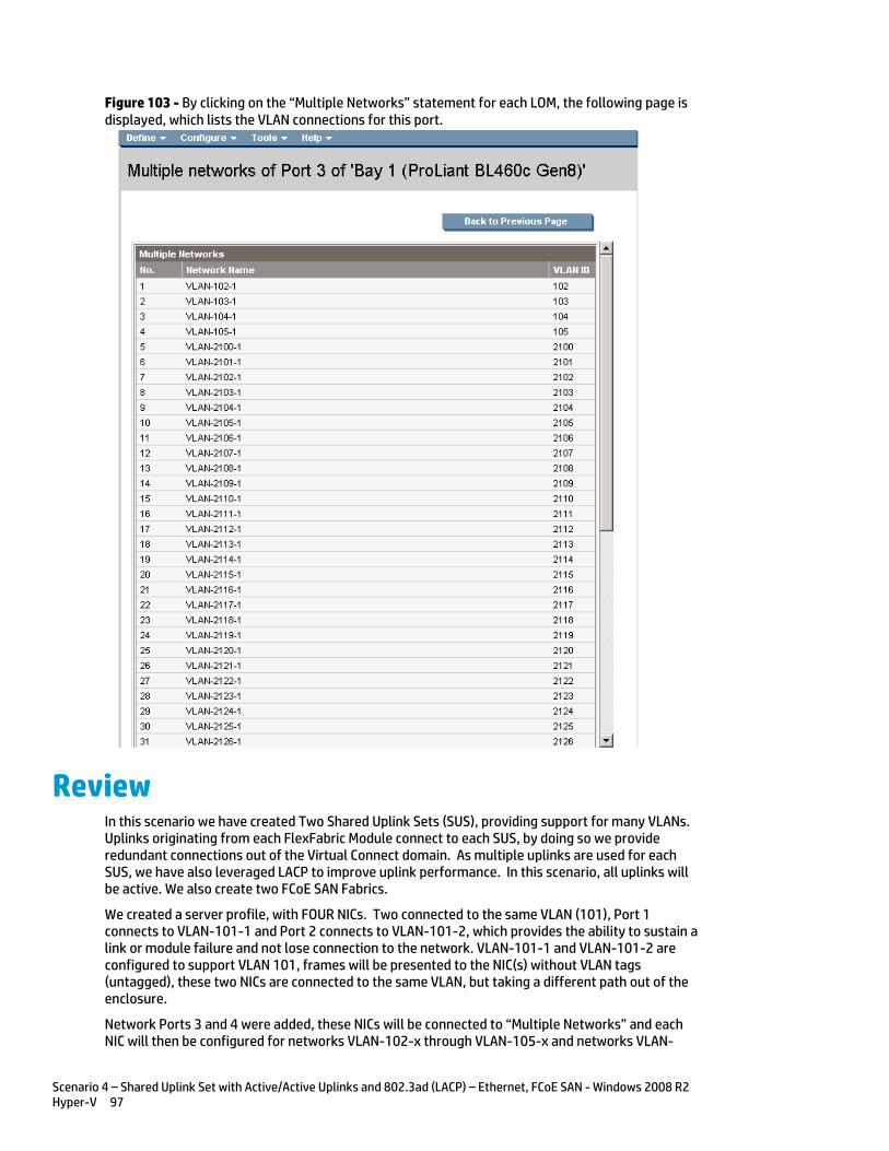
Scenario 4 – Shared Uplink Set with Active/Active Uplinks and 802.3ad (LACP) – Ethernet, FCoE SAN - Windows 2008 R2 Hyper-V 97
Figure 103 - By clicking on the “Multiple Networks” statement for each LOM, the following page is displayed, which lists the VLAN connections for this port.
Review In this scenario we have created Two Shared Uplink Sets (SUS), providing support for many VLANs. Uplinks originating from each FlexFabric Module connect to each SUS, by doing so we provide redundant connections out of the Virtual Connect domain. As multiple uplinks are used for each SUS, we have also leveraged LACP to improve uplink performance. In this scenario, all uplinks will be active. We also create two FCoE SAN Fabrics.
We created a server profile, with FOUR NICs. Two connected to the same VLAN (101), Port 1 connects to VLAN-101-1 and Port 2 connects to VLAN-101-2, which provides the ability to sustain a link or module failure and not lose connection to the network. VLAN-101-1 and VLAN-101-2 are configured to support VLAN 101, frames will be presented to the NIC(s) without VLAN tags (untagged), these two NICs are connected to the same VLAN, but taking a different path out of the enclosure.
Network Ports 3 and 4 were added, these NICs will be connected to “Multiple Networks” and each NIC will then be configured for networks VLAN-102-x through VLAN-105-x and networks VLAN-
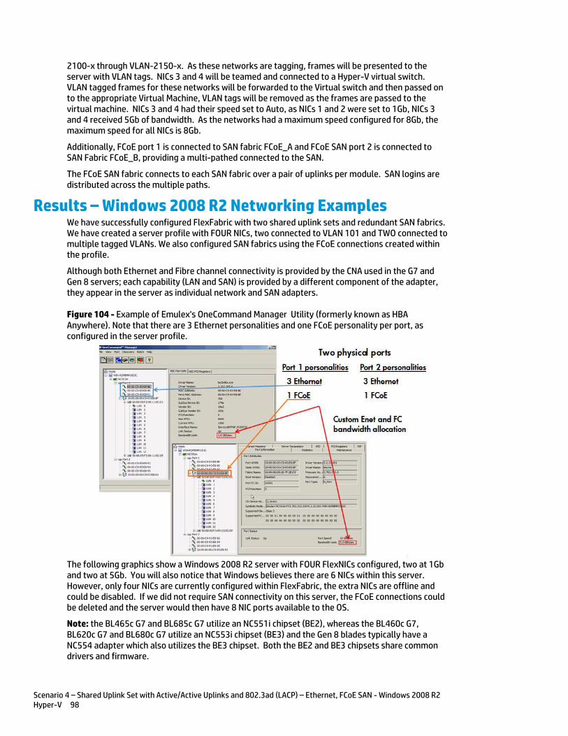
Scenario 4 – Shared Uplink Set with Active/Active Uplinks and 802.3ad (LACP) – Ethernet, FCoE SAN - Windows 2008 R2 Hyper-V 98
2100-x through VLAN-2150-x. As these networks are tagging, frames will be presented to the server with VLAN tags. NICs 3 and 4 will be teamed and connected to a Hyper-V virtual switch. VLAN tagged frames for these networks will be forwarded to the Virtual switch and then passed on to the appropriate Virtual Machine, VLAN tags will be removed as the frames are passed to the virtual machine. NICs 3 and 4 had their speed set to Auto, as NICs 1 and 2 were set to 1Gb, NICs 3 and 4 received 5Gb of bandwidth. As the networks had a maximum speed configured for 8Gb, the maximum speed for all NICs is 8Gb.
Additionally, FCoE port 1 is connected to SAN fabric FCoE_A and FCoE SAN port 2 is connected to SAN Fabric FCoE_B, providing a multi-pathed connected to the SAN.
The FCoE SAN fabric connects to each SAN fabric over a pair of uplinks per module. SAN logins are distributed across the multiple paths.
Results – Windows 2008 R2 Networking Examples We have successfully configured FlexFabric with two shared uplink sets and redundant SAN fabrics. We have created a server profile with FOUR NICs, two connected to VLAN 101 and TWO connected to multiple tagged VLANs. We also configured SAN fabrics using the FCoE connections created within the profile.
Although both Ethernet and Fibre channel connectivity is provided by the CNA used in the G7 and Gen 8 servers; each capability (LAN and SAN) is provided by a different component of the adapter, they appear in the server as individual network and SAN adapters.
Figure 104 - Example of Emulex's OneCommand Manager Utility (formerly known as HBA Anywhere). Note that there are 3 Ethernet personalities and one FCoE personality per port, as configured in the server profile.
The following graphics show a Windows 2008 R2 server with FOUR FlexNICs configured, two at 1Gb and two at 5Gb. You will also notice that Windows believes there are 6 NICs within this server. However, only four NICs are currently configured within FlexFabric, the extra NICs are offline and could be disabled. If we did not require SAN connectivity on this server, the FCoE connections could be deleted and the server would then have 8 NIC ports available to the OS.
Note: the BL465c G7 and BL685c G7 utilize an NC551i chipset (BE2), whereas the BL460c G7, BL620c G7 and BL680c G7 utilize an NC553i chipset (BE3) and the Gen 8 blades typically have a NC554 adapter which also utilizes the BE3 chipset. Both the BE2 and BE3 chipsets share common drivers and firmware.

Scenario 4 – Shared Uplink Set with Active/Active Uplinks and 802.3ad (LACP) – Ethernet, FCoE SAN - Windows 2008 R2 Hyper-V 99
Figure 105 - Windows 2008 R2 Network Connections (4 Connections Active)
Note: The NICs that are not configured within VC will appear with a red x as not connected. You can go into Network Connections for the Windows 2008 R2 server and disable any NICs that are not currently in use. Windows assigns the NICs as NIC 1-6, whereas three of the NICs will reside on LOM:1 (a,c &d)and three on LOM:2 (a,c &d). You may need to refer to the FlexFabric server profile for the NIC MAC addresses to verify which NIC is which.
Figure 106 - Windows 2008 R2 Network Connections (2 Connections Disabled)
Figure 107 - Windows 2008 R2 Network Connection Status
Note: In windows 2003 the NIC speeds may not be shown accurately when speeds are configured in 100MB increments above 1Gb. ie: if a NIC is configured for 2.5Gb it will be displayed in Windows 2003 as a 2Gb NIC. Windows 2008 does not have this limitation. In addition, as Virtual Connect 4.01 now provides the Min/Max network speed setting, even though we set the NIC to 1 and 5Gb, and set the maximum to 8Gb, the NIC displays the speed of 8Gb.
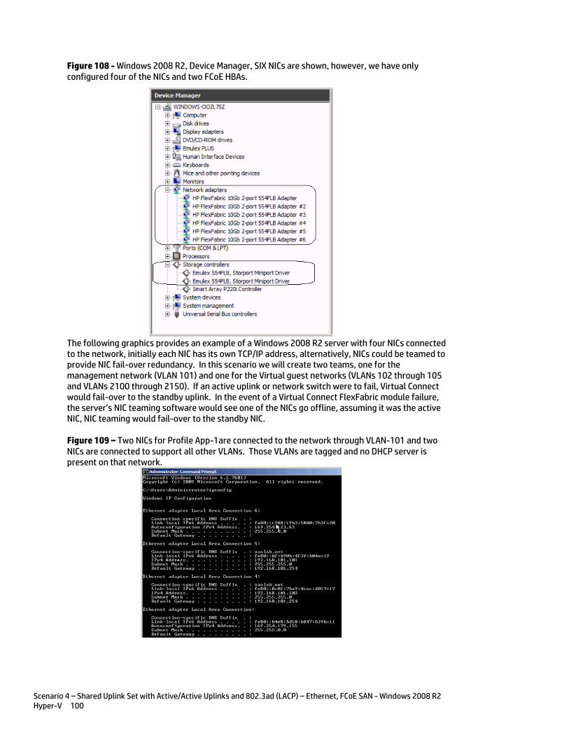
Scenario 4 – Shared Uplink Set with Active/Active Uplinks and 802.3ad (LACP) – Ethernet, FCoE SAN - Windows 2008 R2 Hyper-V 100
Figure 108 - Windows 2008 R2, Device Manager, SIX NICs are shown, however, we have only configured four of the NICs and two FCoE HBAs.
The following graphics provides an example of a Windows 2008 R2 server with four NICs connected to the network, initially each NIC has its own TCP/IP address, alternatively, NICs could be teamed to provide NIC fail-over redundancy. In this scenario we will create two teams, one for the management network (VLAN 101) and one for the Virtual guest networks (VLANs 102 through 105 and VLANs 2100 through 2150). If an active uplink or network switch were to fail, Virtual Connect would fail-over to the standby uplink. In the event of a Virtual Connect FlexFabric module failure, the server’s NIC teaming software would see one of the NICs go offline, assuming it was the active NIC, NIC teaming would fail-over to the standby NIC.
Figure 109 – Two NICs for Profile App-1are connected to the network through VLAN-101 and two NICs are connected to support all other VLANs. Those VLANs are tagged and no DHCP server is present on that network.
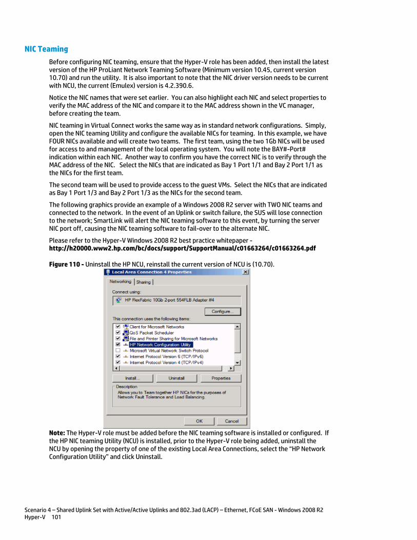
Scenario 4 – Shared Uplink Set with Active/Active Uplinks and 802.3ad (LACP) – Ethernet, FCoE SAN - Windows 2008 R2 Hyper-V 101
NIC Teaming
Before configuring NIC teaming, ensure that the Hyper-V role has been added, then install the latest version of the HP ProLiant Network Teaming Software (Minimum version 10.45, current version 10.70) and run the utility. It is also important to note that the NIC driver version needs to be current with NCU, the current (Emulex) version is 4.2.390.6.
Notice the NIC names that were set earlier. You can also highlight each NIC and select properties to verify the MAC address of the NIC and compare it to the MAC address shown in the VC manager, before creating the team.
NIC teaming in Virtual Connect works the same way as in standard network configurations. Simply, open the NIC teaming Utility and configure the available NICs for teaming. In this example, we have FOUR NICs available and will create two teams. The first team, using the two 1Gb NICs will be used for access to and management of the local operating system. You will note the BAY#-Port# indication within each NIC. Another way to confirm you have the correct NIC is to verify through the MAC address of the NIC. Select the NICs that are indicated as Bay 1 Port 1/1 and Bay 2 Port 1/1 as the NICs for the first team.
The second team will be used to provide access to the guest VMs. Select the NICs that are indicated as Bay 1 Port 1/3 and Bay 2 Port 1/3 as the NICs for the second team.
The following graphics provide an example of a Windows 2008 R2 server with TWO NIC teams and connected to the network. In the event of an Uplink or switch failure, the SUS will lose connection to the network; SmartLink will alert the NIC teaming software to this event, by turning the server NIC port off, causing the NIC teaming software to fail-over to the alternate NIC.
Please refer to the Hyper-V Windows 2008 R2 best practice whitepaper - http://h20000.www2.hp.com/bc/docs/support/SupportManual/c01663264/c01663264.pdf
Figure 110 - Uninstall the HP NCU, reinstall the current version of NCU is (10.70).
Note: The Hyper-V role must be added before the NIC teaming software is installed or configured. If the HP NIC teaming Utility (NCU) is installed, prior to the Hyper-V role being added, uninstall the NCU by opening the property of one of the existing Local Area Connections, select the “HP Network Configuration Utility” and click Uninstall.
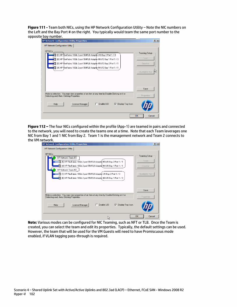
Scenario 4 – Shared Uplink Set with Active/Active Uplinks and 802.3ad (LACP) – Ethernet, FCoE SAN - Windows 2008 R2 Hyper-V 102
Figure 111 - Team both NICs, using the HP Network Configuration Utility – Note the NIC numbers on the Left and the Bay Port # on the right. You typically would team the same port number to the opposite bay number.
Figure 112 – The four NICs configured within the profile (App-1) are teamed in pairs and connected to the network, you will need to create the teams one at a time. Note that each Team leverages one NIC from Bay 1 and 1 NIC from Bay 2. Team 1 is the management network and Team 2 connects to the VM network.
Note: Various modes can be configured for NIC Teaming, such as NFT or TLB. Once the Team is created, you can select the team and edit its properties. Typically, the default settings can be used. However, the team that will be used for the VM Guests will need to have Promiscuous mode enabled, if VLAN tagging pass-through is required.
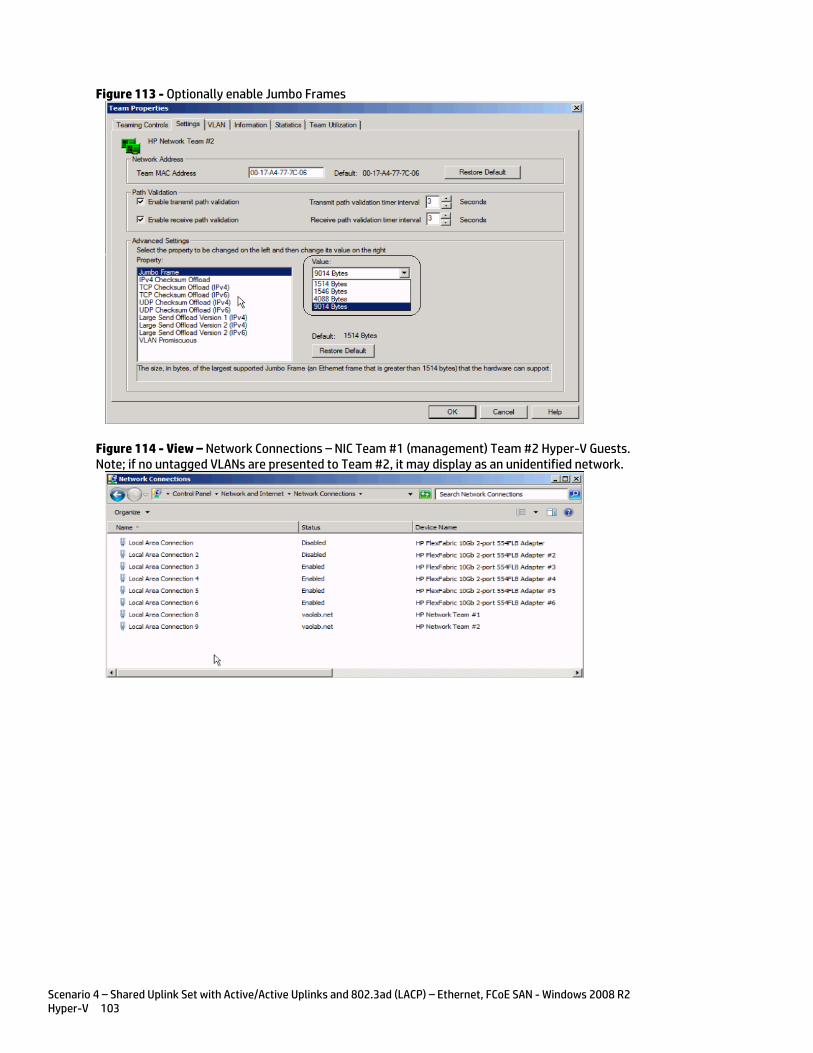
Scenario 4 – Shared Uplink Set with Active/Active Uplinks and 802.3ad (LACP) – Ethernet, FCoE SAN - Windows 2008 R2 Hyper-V 103
Figure 113 - Optionally enable Jumbo Frames
Figure 114 - View – Network Connections – NIC Team #1 (management) Team #2 Hyper-V Guests. Note; if no untagged VLANs are presented to Team #2, it may display as an unidentified network.
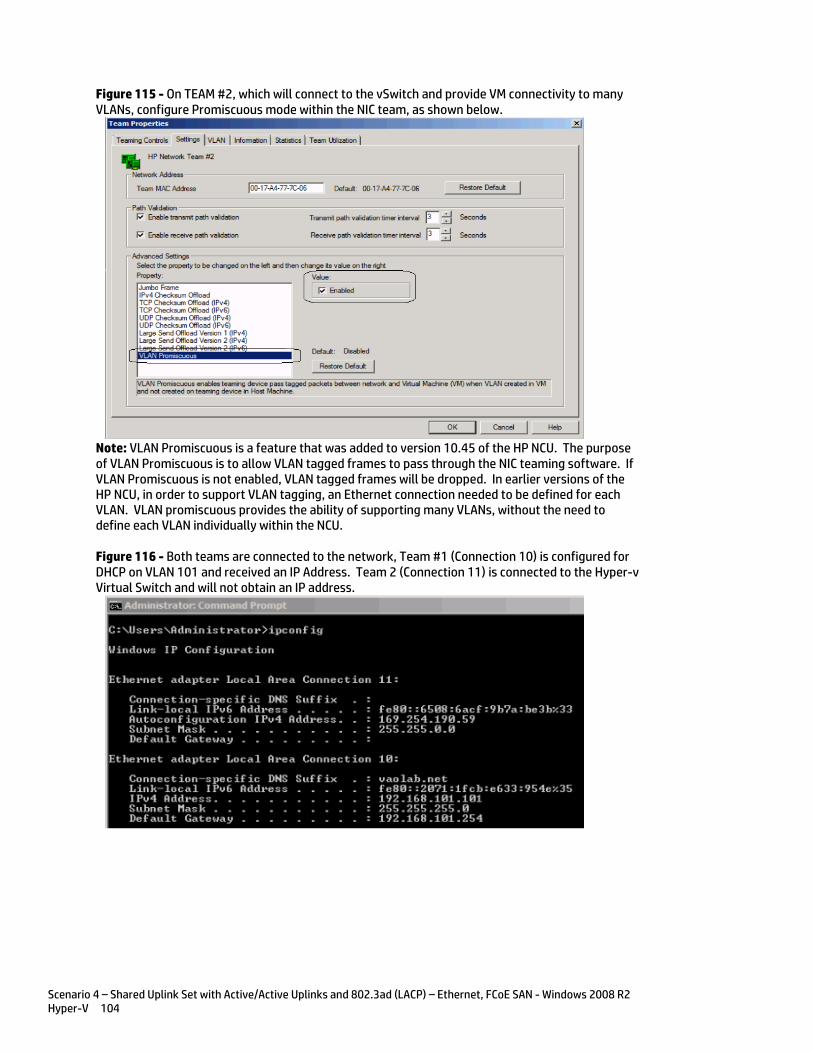
Scenario 4 – Shared Uplink Set with Active/Active Uplinks and 802.3ad (LACP) – Ethernet, FCoE SAN - Windows 2008 R2 Hyper-V 104
Figure 115 - On TEAM #2, which will connect to the vSwitch and provide VM connectivity to many VLANs, configure Promiscuous mode within the NIC team, as shown below.
Note: VLAN Promiscuous is a feature that was added to version 10.45 of the HP NCU. The purpose of VLAN Promiscuous is to allow VLAN tagged frames to pass through the NIC teaming software. If VLAN Promiscuous is not enabled, VLAN tagged frames will be dropped. In earlier versions of the HP NCU, in order to support VLAN tagging, an Ethernet connection needed to be defined for each VLAN. VLAN promiscuous provides the ability of supporting many VLANs, without the need to define each VLAN individually within the NCU.
Figure 116 - Both teams are connected to the network, Team #1 (Connection 10) is configured for DHCP on VLAN 101 and received an IP Address. Team 2 (Connection 11) is connected to the Hyper-v Virtual Switch and will not obtain an IP address.
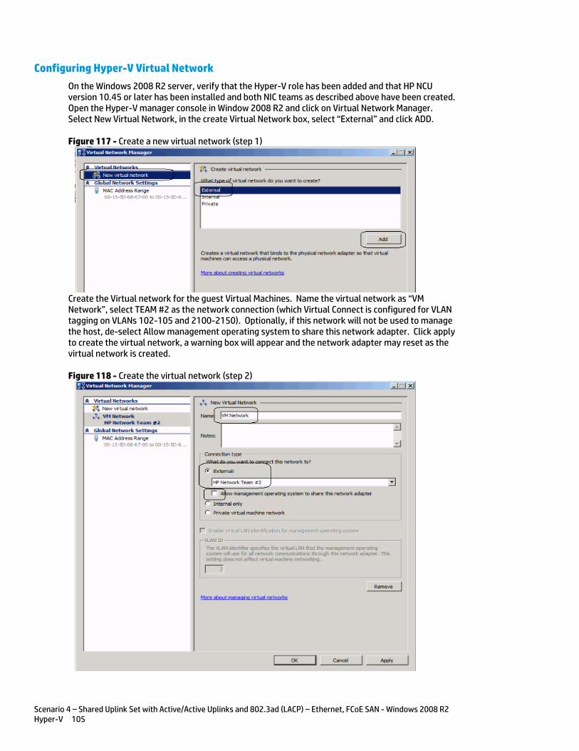
Scenario 4 – Shared Uplink Set with Active/Active Uplinks and 802.3ad (LACP) – Ethernet, FCoE SAN - Windows 2008 R2 Hyper-V 105
Configuring Hyper-V Virtual Network
On the Windows 2008 R2 server, verify that the Hyper-V role has been added and that HP NCU version 10.45 or later has been installed and both NIC teams as described above have been created. Open the Hyper-V manager console in Window 2008 R2 and click on Virtual Network Manager. Select New Virtual Network, in the create Virtual Network box, select “External” and click ADD.
Figure 117 - Create a new virtual network (step 1)
Create the Virtual network for the guest Virtual Machines. Name the virtual network as “VM Network”, select TEAM #2 as the network connection (which Virtual Connect is configured for VLAN tagging on VLANs 102-105 and 2100-2150). Optionally, if this network will not be used to manage the host, de-select Allow management operating system to share this network adapter. Click apply to create the virtual network, a warning box will appear and the network adapter may reset as the virtual network is created.
Figure 118 - Create the virtual network (step 2)
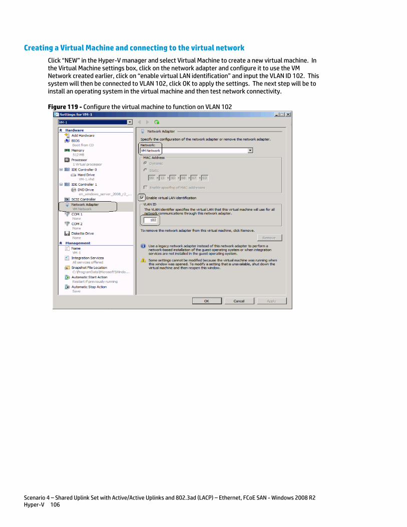
Scenario 4 – Shared Uplink Set with Active/Active Uplinks and 802.3ad (LACP) – Ethernet, FCoE SAN - Windows 2008 R2 Hyper-V 106
Creating a Virtual Machine and connecting to the virtual network
Click “NEW” in the Hyper-V manager and select Virtual Machine to create a new virtual machine. In the Virtual Machine settings box, click on the network adapter and configure it to use the VM Network created earlier, click on “enable virtual LAN identification” and input the VLAN ID 102. This system will then be connected to VLAN 102, click OK to apply the settings. The next step will be to install an operating system in the virtual machine and then test network connectivity.
Figure 119 - Configure the virtual machine to function on VLAN 102
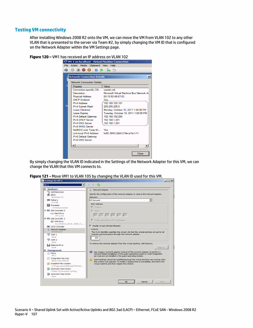
Scenario 4 – Shared Uplink Set with Active/Active Uplinks and 802.3ad (LACP) – Ethernet, FCoE SAN - Windows 2008 R2 Hyper-V 107
Testing VM connectivity
After installing Windows 2008 R2 onto the VM, we can move the VM from VLAN 102 to any other VLAN that is presented to the server via Team #2, by simply changing the VM ID that is configured on the Network Adapter within the VM Settings page.
Figure 120 – VM1 has received an IP address on VLAN 102
By simply changing the VLAN ID indicated in the Settings of the Network Adapter for this VM, we can change the VLAN that this VM connects to.
Figure 121 - Move VM1 to VLAN 105 by changing the VLAN ID used for this VM.
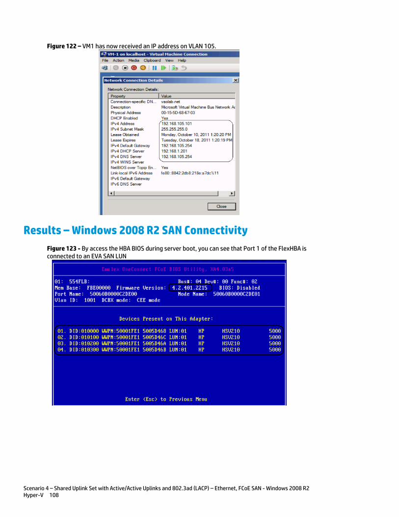
Scenario 4 – Shared Uplink Set with Active/Active Uplinks and 802.3ad (LACP) – Ethernet, FCoE SAN - Windows 2008 R2 Hyper-V 108
Figure 122 – VM1 has now received an IP address on VLAN 105.
Results – Windows 2008 R2 SAN Connectivity
Figure 123 - By access the HBA BIOS during server boot, you can see that Port 1 of the FlexHBA is connected to an EVA SAN LUN

Scenario 4 – Shared Uplink Set with Active/Active Uplinks and 802.3ad (LACP) – Ethernet, FCoE SAN - Windows 2008 R2 Hyper-V 109
Figure 124 - Windows 2008 R2 Disk Administrator. Note; that D: is the SAN attached volume
Summary We presented a Virtual Connect Network and SAN scenario by creating two shared uplink sets (SUS), each SUS is connected with TWO active uplinks; both SUS’ can actively pass traffic. We included a dual path SAN fabric for storage connectivity.
When VC profile App-1 is applied to the server in bay1 and the server is powered up, it has one NIC connected through the FlexFabric module 1 in Bay 1(connected to VLAN-101-1), the second NIC is connected through the FlexFabric module in Bay 2 (connected to VLAN-101-2). Each NIC is configured at 1Gb. These NICs are teamed (Team #1) and will be used to manage the Hyper-v host. Either NIC or path could be active. The second pair of NICs is also teamed (Team #2) and the team is configured in promiscuous mode to support multiple tagged VLANs (102-105 and 2100-2150). Each of these NICs is configured for 5Gb. Either NIC could be active. As a result, this server could access the network through either NIC or either uplink, depending on which NIC is active at the time. This host is also configured for FCoE based SAN access and connects to a SAN LUN to store the Guest VMs. Each FCoE port is configured for 4Gb of SAN bandwidth.
Additional NICs could be added within FlexFabric, by simply powering the server off and adding up to a total of 6 NICs, the NIC speed can then be adjusted accordingly to suit the needs of each NIC. If additional or less SAN bandwidth is required, the speed of the SAN connection can also be adjusted. If the FCoE SAN connections are not required, these could be deleted, in which two additional NIC ports would then be made available to the host.
We then added the Hyper-V role to the server and created a VM guest. The guest was configured for VLAN 102, and then was later moved to VLAN 105, by simply changing the VLAN id as configured in the VM settings tab. Additional VLANs can be configured within the Shared Uplink Set and presented to the NIC team supporting the guests; those VLANs would then be made available to Hyper-V manager and any VM guests.
As additional servers are added to the enclosure, simply create additional profiles, or copy existing profiles, configure the NICs for LAN and SAN fabrics as required and apply them to the appropriate server bays and power the server on.
Scenario 5 – Shared Uplink Set with Active/Standby Uplinks and 802.3ad (LACP) - Ethernet and FCoE SAN - vSphere 110
Scenario 5 – Shared Uplink Set with Active/Standby Uplinks and 802.3ad (LACP) - Ethernet and FCoE SAN - vSphere
Overview This scenario will implement the Shared Uplink Set (SUS) to provide support for multiple VLANs. The upstream network switches connect a shared uplink set to two ports on each FlexFabric modules, LACP will be used to aggregate those links.
As multiple VLANs will be supported in this configuration, the upstream switch ports connecting to the FlexFabric modules will be configured to properly present those VLANs. In this scenario, the upstream switch ports will be configured for VLAN trunking/VLAN tagging.
When configuring Virtual Connect, we can provide several ways to implement network fail-over or redundancy. One option would be to connect multiple uplinks to a single Virtual Connect network; those uplinks would connect from different Virtual Connect modules within the enclosure and could then connect to the same upstream switch or two different upstream switches, depending on your redundancy needs. An alternative would be to configure TWO separate Virtual Connect networks, each with a single, or multiple, uplinks configured. Each option has its advantages and disadvantages. For example; an Active/Standby configuration places the redundancy at the VC level, where Active/Active places it at the OS NIC teaming or bonding level. We will review the first option in this scenario.
In addition, several Virtual Connect Networks can be configured to support the required networks to the servers within the BladeSystem enclosure. These networks could be used to separate the various network traffic types, such as iSCSI, backup and VMotion from production network traffic.
This scenario will also leverage the Fibre Channel over Ethernet (FCoE) capabilities of the FlexFabric modules. Each fibre channel fabric will have two uplinks connected to each of the FlexFabric modules.
Requirements This scenario will support both Ethernet and fibre channel connectivity. In order to implement this scenario, an HP BladeSystem c7000 enclosure with one or more server blades and TWO Virtual Connect FlexFabric modules, installed in I/O Bays 1& 2 are required. In addition, we will require ONE or TWO external Network switches. As Virtual Connect does not appear to the network as a switch and is transparent to the network, any standard managed switch will work with Virtual Connect. The Fibre Channel uplinks will connect to the existing FC SAN fabrics. The SAN switch ports will need to be configured to support NPIV logins. Two uplinks from each FlexFabric module will be connected to the existing SAN fabrics.
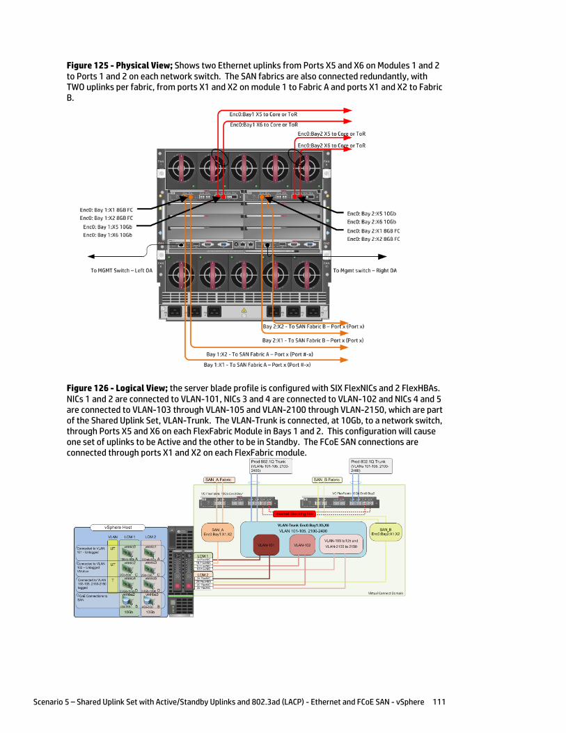
Scenario 5 – Shared Uplink Set with Active/Standby Uplinks and 802.3ad (LACP) - Ethernet and FCoE SAN - vSphere 111
Figure 125 - Physical View; Shows two Ethernet uplinks from Ports X5 and X6 on Modules 1 and 2 to Ports 1 and 2 on each network switch. The SAN fabrics are also connected redundantly, with TWO uplinks per fabric, from ports X1 and X2 on module 1 to Fabric A and ports X1 and X2 to Fabric B.
Figure 126 - Logical View; the server blade profile is configured with SIX FlexNICs and 2 FlexHBAs. NICs 1 and 2 are connected to VLAN-101, NICs 3 and 4 are connected to VLAN-102 and NICs 4 and 5 are connected to VLAN-103 through VLAN-105 and VLAN-2100 through VLAN-2150, which are part of the Shared Uplink Set, VLAN-Trunk. The VLAN-Trunk is connected, at 10Gb, to a network switch, through Ports X5 and X6 on each FlexFabric Module in Bays 1 and 2. This configuration will cause one set of uplinks to be Active and the other to be in Standby. The FCoE SAN connections are connected through ports X1 and X2 on each FlexFabric module.
Scenario 5 – Shared Uplink Set with Active/Standby Uplinks and 802.3ad (LACP) - Ethernet and FCoE SAN - vSphere 112
Installation and configuration Switch configuration
As the Virtual Connect module acts as an edge switch, Virtual Connect can connect to the network at either the distribution level or directly to the core switch.
The appendices provide a summary of the cli commands required to configure various switches for connection to Virtual Connect. The configuration information provided in the appendices for this scenario assumes the following information:
The switch ports are configured as VLAN TRUNK ports (tagging) to support several VLANs. All frames will be forwarded to Virtual Connect with VLAN tags. Optionally, one VLAN could be configured as (Default) untagged, if so, then a corresponding vNet within the Shared Uplink Set would be configured and set as “Default”.
Note: When adding additional uplinks to the SUS, if the additional uplinks are connecting from the same FlexFabric module to the same switch, in order to ensure all the uplinks are active, the switch ports will need to be configured for LACP within the same Link Aggregation Group.
The network switch port should be configured for Spanning Tree Edge as Virtual Connect appears to the switch as an access device and not another switch. By configuring the port as Spanning Tree Edge, it allows the switch to place the port into a forwarding state much quicker than otherwise, this allows a newly connected port to come online and begin forwarding much quicker.
The SAN connection will be made with redundant connections to each Fabric. SAN switch ports connecting to the FlexFabric module must be configured to accept NPIV logins.
Configuring the VC module
Physically connect Port 1 of network switch 1 to Port X5 of the VC module in Bay 1 Physically connect Port 2 of network switch 1 to Port X6 of the VC module in Bay 1 Physically connect Port 1 of network switch 2 to Port X5 of the VC module in Bay 2 Physically connect Port 2 of network switch 2 to Port X6 of the VC module in Bay 2
Note: if you have only one network switch, connect VC ports X5 and X6 (Bay 2) to an alternate port on the same switch. This will NOT create a network loop and Spanning Tree is not required.
Physically connect Ports X1/X2 on the FlexFabric in module Bay 1 to switch ports in SAN Fabric A Physically connect Ports X1/X2 on the FlexFabric in module Bay 2 to switch ports in SAN Fabric B
VC CLI commands
Many of the configuration settings within VC can also be accomplished via a CLI command set. In order to connect to VC via a CLI, open an SSH connection to the IP address of the active VCM. Once logged in, VC provides a CLI with help menus. Through this scenario the CLI commands to configure VC for each setting will also be provided.
Configuring Expanded VLAN Capacity via GUI
Virtual Connect release 3.30 provided an expanded VLAN capacity mode when using Shared Uplink Sets, this mode can be enabled through the Ethernet Settings tab or the VC CLI. The default configuration for a new Domain install is “Expanded VLAN Capacity” mode, Legacy mode is no longer available and the Domain cannot be downgraded.
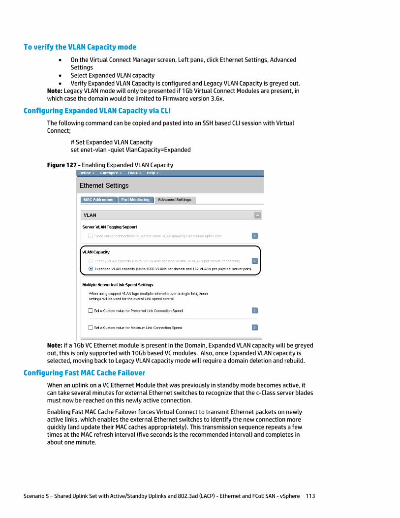
Scenario 5 – Shared Uplink Set with Active/Standby Uplinks and 802.3ad (LACP) - Ethernet and FCoE SAN - vSphere 113
To verify the VLAN Capacity mode
On the Virtual Connect Manager screen, Left pane, click Ethernet Settings, Advanced Settings
Select Expanded VLAN capacity Verify Expanded VLAN Capacity is configured and Legacy VLAN Capacity is greyed out.
Note: Legacy VLAN mode will only be presented if 1Gb Virtual Connect Modules are present, in which case the domain would be limited to Firmware version 3.6x.
Configuring Expanded VLAN Capacity via CLI
The following command can be copied and pasted into an SSH based CLI session with Virtual Connect;
# Set Expanded VLAN Capacity set enet-vlan -quiet VlanCapacity=Expanded
Figure 127 - Enabling Expanded VLAN Capacity
Note: if a 1Gb VC Ethernet module is present in the Domain, Expanded VLAN capacity will be greyed out, this is only supported with 10Gb based VC modules. Also, once Expanded VLAN capacity is selected, moving back to Legacy VLAN capacity mode will require a domain deletion and rebuild.
Configuring Fast MAC Cache Failover
When an uplink on a VC Ethernet Module that was previously in standby mode becomes active, it can take several minutes for external Ethernet switches to recognize that the c-Class server blades must now be reached on this newly active connection.
Enabling Fast MAC Cache Failover forces Virtual Connect to transmit Ethernet packets on newly active links, which enables the external Ethernet switches to identify the new connection more quickly (and update their MAC caches appropriately). This transmission sequence repeats a few times at the MAC refresh interval (five seconds is the recommended interval) and completes in about one minute.
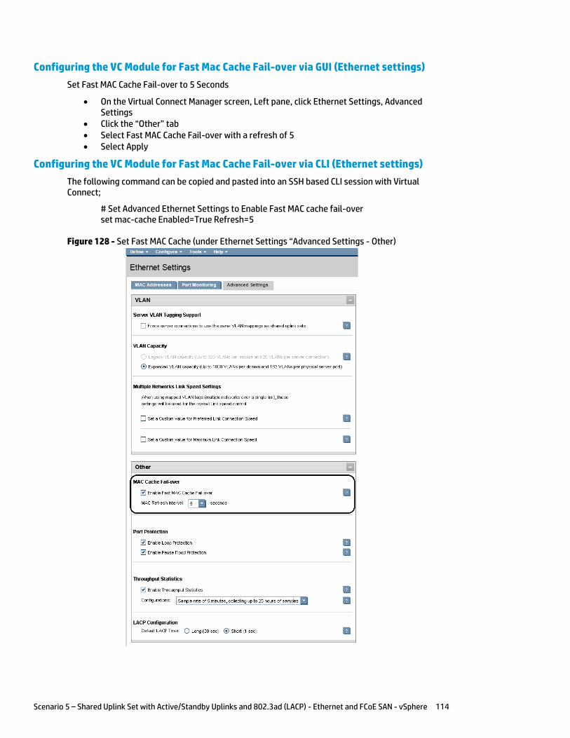
Scenario 5 – Shared Uplink Set with Active/Standby Uplinks and 802.3ad (LACP) - Ethernet and FCoE SAN - vSphere 114
Configuring the VC Module for Fast Mac Cache Fail-over via GUI (Ethernet settings)
Set Fast MAC Cache Fail-over to 5 Seconds
On the Virtual Connect Manager screen, Left pane, click Ethernet Settings, Advanced Settings
Click the “Other” tab Select Fast MAC Cache Fail-over with a refresh of 5 Select Apply
Configuring the VC Module for Fast Mac Cache Fail-over via CLI (Ethernet settings)
The following command can be copied and pasted into an SSH based CLI session with Virtual Connect;
# Set Advanced Ethernet Settings to Enable Fast MAC cache fail-over set mac-cache Enabled=True Refresh=5
Figure 128 - Set Fast MAC Cache (under Ethernet Settings “Advanced Settings - Other)
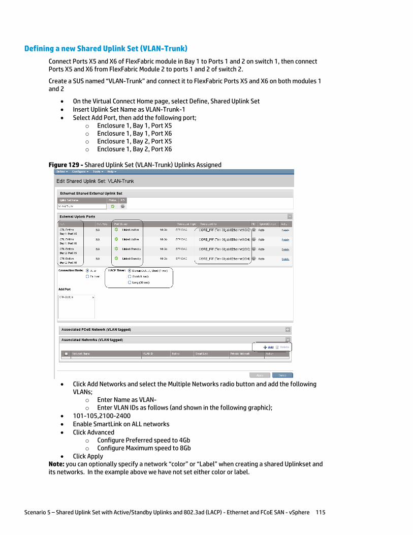
Scenario 5 – Shared Uplink Set with Active/Standby Uplinks and 802.3ad (LACP) - Ethernet and FCoE SAN - vSphere 115
Defining a new Shared Uplink Set (VLAN-Trunk)
Connect Ports X5 and X6 of FlexFabric module in Bay 1 to Ports 1 and 2 on switch 1, then connect Ports X5 and X6 from FlexFabric Module 2 to ports 1 and 2 of switch 2.
Create a SUS named “VLAN-Trunk” and connect it to FlexFabric Ports X5 and X6 on both modules 1 and 2
On the Virtual Connect Home page, select Define, Shared Uplink Set Insert Uplink Set Name as VLAN-Trunk-1 Select Add Port, then add the following port;
o Enclosure 1, Bay 1, Port X5 o Enclosure 1, Bay 1, Port X6 o Enclosure 1, Bay 2, Port X5 o Enclosure 1, Bay 2, Port X6
Figure 129 - Shared Uplink Set (VLAN-Trunk) Uplinks Assigned
Click Add Networks and select the Multiple Networks radio button and add the following
VLANs; o Enter Name as VLAN- o Enter VLAN IDs as follows (and shown in the following graphic);
101-105,2100-2400 Enable SmartLink on ALL networks Click Advanced
o Configure Preferred speed to 4Gb o Configure Maximum speed to 8Gb
Click Apply Note: you can optionally specify a network “color” or “Label” when creating a shared Uplinkset and its networks. In the example above we have not set either color or label.
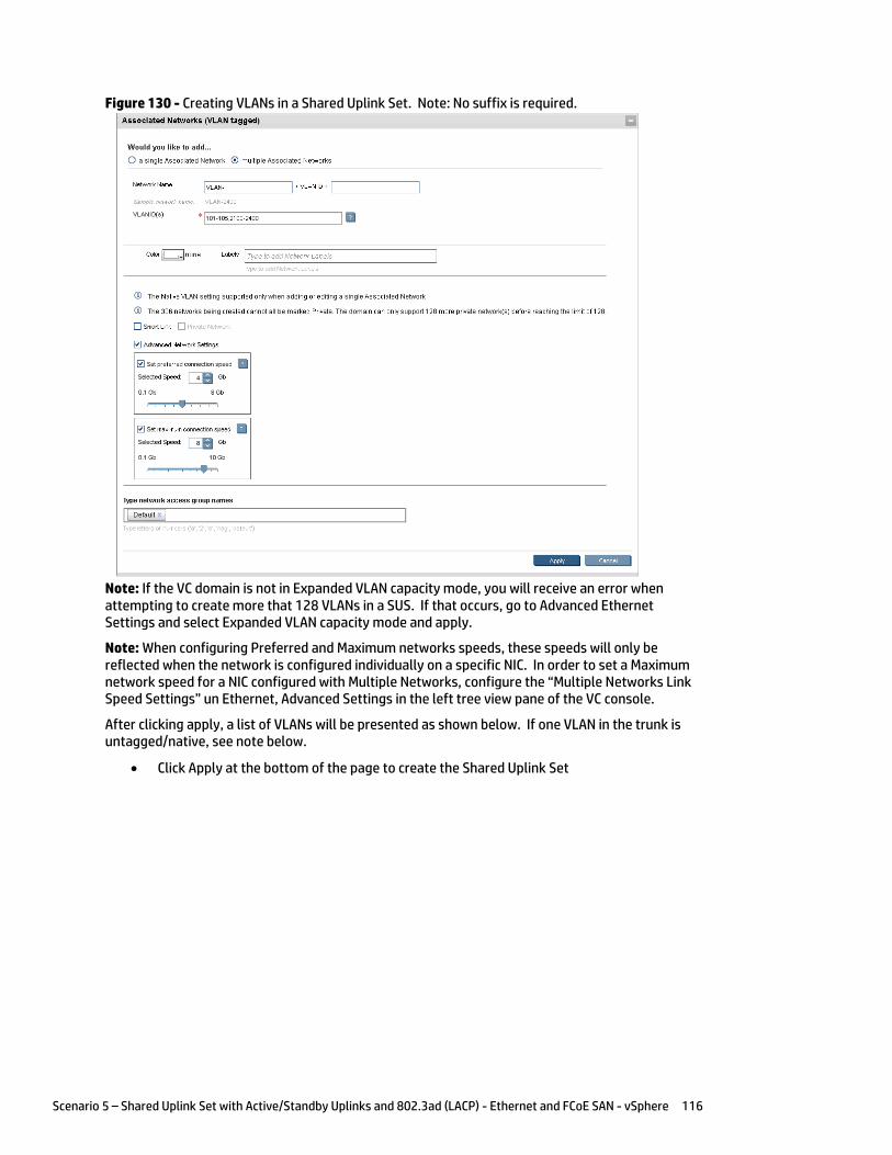
Scenario 5 – Shared Uplink Set with Active/Standby Uplinks and 802.3ad (LACP) - Ethernet and FCoE SAN - vSphere 116
Figure 130 - Creating VLANs in a Shared Uplink Set. Note: No suffix is required.
Note: If the VC domain is not in Expanded VLAN capacity mode, you will receive an error when attempting to create more that 128 VLANs in a SUS. If that occurs, go to Advanced Ethernet Settings and select Expanded VLAN capacity mode and apply.
Note: When configuring Preferred and Maximum networks speeds, these speeds will only be reflected when the network is configured individually on a specific NIC. In order to set a Maximum network speed for a NIC configured with Multiple Networks, configure the “Multiple Networks Link Speed Settings” un Ethernet, Advanced Settings in the left tree view pane of the VC console.
After clicking apply, a list of VLANs will be presented as shown below. If one VLAN in the trunk is untagged/native, see note below.
Click Apply at the bottom of the page to create the Shared Uplink Set
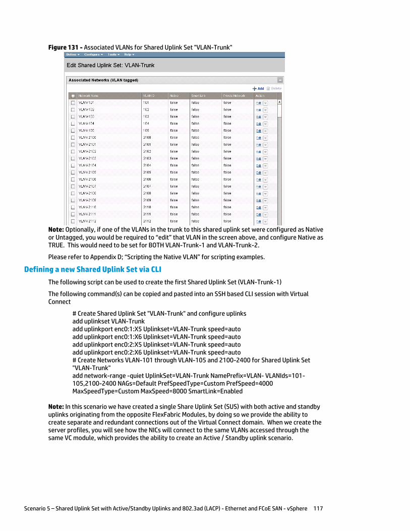
Scenario 5 – Shared Uplink Set with Active/Standby Uplinks and 802.3ad (LACP) - Ethernet and FCoE SAN - vSphere 117
Figure 131 - Associated VLANs for Shared Uplink Set "VLAN-Trunk"
Note: Optionally, if one of the VLANs in the trunk to this shared uplink set were configured as Native or Untagged, you would be required to “edit” that VLAN in the screen above, and configure Native as TRUE. This would need to be set for BOTH VLAN-Trunk-1 and VLAN-Trunk-2.
Please refer to Appendix D; “Scripting the Native VLAN” for scripting examples.
Defining a new Shared Uplink Set via CLI
The following script can be used to create the first Shared Uplink Set (VLAN-Trunk-1)
The following command(s) can be copied and pasted into an SSH based CLI session with Virtual Connect
# Create Shared Uplink Set "VLAN-Trunk" and configure uplinks add uplinkset VLAN-Trunk add uplinkport enc0:1:X5 Uplinkset=VLAN-Trunk speed=auto add uplinkport enc0:1:X6 Uplinkset=VLAN-Trunk speed=auto add uplinkport enc0:2:X5 Uplinkset=VLAN-Trunk speed=auto add uplinkport enc0:2:X6 Uplinkset=VLAN-Trunk speed=auto # Create Networks VLAN-101 through VLAN-105 and 2100-2400 for Shared Uplink Set "VLAN-Trunk" add network-range -quiet UplinkSet=VLAN-Trunk NamePrefix=VLAN- VLANIds=101-105,2100-2400 NAGs=Default PrefSpeedType=Custom PrefSpeed=4000 MaxSpeedType=Custom MaxSpeed=8000 SmartLink=Enabled
Note: In this scenario we have created a single Share Uplink Set (SUS) with both active and standby uplinks originating from the opposite FlexFabric Modules, by doing so we provide the ability to create separate and redundant connections out of the Virtual Connect domain. When we create the server profiles, you will see how the NICs will connect to the same VLANs accessed through the same VC module, which provides the ability to create an Active / Standby uplink scenario.
Scenario 5 – Shared Uplink Set with Active/Standby Uplinks and 802.3ad (LACP) - Ethernet and FCoE SAN - vSphere 118
Defining a new (FCoE) SAN Fabric via GUI
Create a Fabric and name it “FCoE_A”
On the Virtual Connect Manager screen, click Define, SAN Fabric to create the first Fabric Enter the Network Name of “FCoE_A” Select Add Port, then add the following ports;
o Enclosure 1, Bay 1, Port X1 o Enclosure 1, Bay 1, Port X2
Ensure Fabric Type is set to “FabricAttach” Select Show Advanced Settings
o Select Automatic Login Re-Distribution (FlexFabric Only) o Select Set Preferred FCoE Connect Speed
Configure for 4Gb o Select Set Maximum FCoE Connect Speed
Configure for 8Gb Select Apply
Create a second Fabric and name it “FCoE_B”
On the Virtual Connect Manager screen, click Define, SAN Fabric to create the second Fabric Enter the Network Name of “FCoE_B” Select Add Port, then add the following ports;
o Enclosure 1, Bay 2, Port X1 o Enclosure 1, Bay 2, Port X2
Ensure Fabric Type is set to “FabricAttach” Select Show Advanced Settings
o Select Automatic Login Re-Distribution (FlexFabric Only) o Select Set Preferred FCoE Connect Speed
Configure for 4Gb o Select Set Maximum FCoE Connect Speed
Configure for 8Gb Select Apply
Defining SAN Fabrics via CLI
The following command(s) can be copied and pasted into an SSH based CLI session with Virtual Connect
#Create the SAN Fabrics FCoE_A and FCoE_B and configure uplinks as discussed above add fabric FCoE_A Type=FabricAttach Bay=1 Ports=1,2 Speed=Auto LinkDist=Auto PrefSpeedType=Custom PrefSpeed=4000 MaxSpeedType=Custom MaxSpeed=8000 add fabric FCoE_B Type=FabricAttach Bay=2 Ports=1,2 Speed=Auto LinkDist=Auto PrefSpeedType=Custom PrefSpeed=4000 MaxSpeedType=Custom MaxSpeed=8000
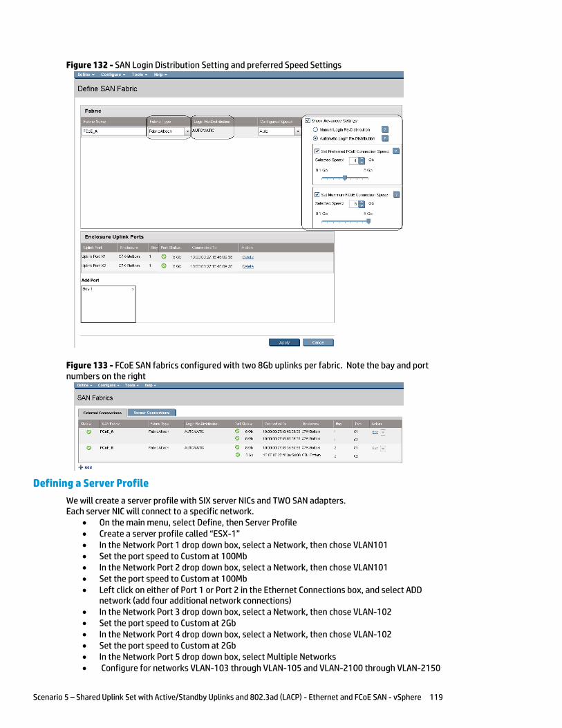
Scenario 5 – Shared Uplink Set with Active/Standby Uplinks and 802.3ad (LACP) - Ethernet and FCoE SAN - vSphere 119
Figure 132 - SAN Login Distribution Setting and preferred Speed Settings
Figure 133 - FCoE SAN fabrics configured with two 8Gb uplinks per fabric. Note the bay and port numbers on the right
Defining a Server Profile
We will create a server profile with SIX server NICs and TWO SAN adapters. Each server NIC will connect to a specific network.
On the main menu, select Define, then Server Profile Create a server profile called “ESX-1” In the Network Port 1 drop down box, select a Network, then chose VLAN101 Set the port speed to Custom at 100Mb In the Network Port 2 drop down box, select a Network, then chose VLAN101 Set the port speed to Custom at 100Mb Left click on either of Port 1 or Port 2 in the Ethernet Connections box, and select ADD
network (add four additional network connections) In the Network Port 3 drop down box, select a Network, then chose VLAN-102 Set the port speed to Custom at 2Gb In the Network Port 4 drop down box, select a Network, then chose VLAN-102 Set the port speed to Custom at 2Gb In the Network Port 5 drop down box, select Multiple Networks Configure for networks VLAN-103 through VLAN-105 and VLAN-2100 through VLAN-2150
Scenario 5 – Shared Uplink Set with Active/Standby Uplinks and 802.3ad (LACP) - Ethernet and FCoE SAN - vSphere 120
Leave the network speed as Auto In the Network Port 6 drop down box, select Multiple Networks Configure for networks VLAN-103 through VLAN-105 and VLAN-2100 through VLAN-2150 Leave the network speed as Auto Expand the FCoE Connections box, for Bay 1, select FCoE_A for Bay 2, select FCoE_B Do not configure FC SAN or iSCSI Connection In the Assign Profile to Server Bay box, locate the Select Location drop down and select
Bay 1, then apply Prior to applying the profile, ensure that the server in Bay 1 is currently OFF
Note: you should now have a server profile assigned to Bay 2, with 4 Server NIC connections. NICs 1&2 should be connected to networks VLAN-101 (MGMT), NICs 3&4 should be connected VLAN-102 (VMotion) to networks VLAN103 through VLAN105 and VLAN-2100 through VLAN-2150. FCoE SAN fabrics are connected to, Port 1 - FCoE_A and Port 2 - FCoE_B.
Defining a Server Profile via CLI
The following command(s) can be copied and pasted into an SSH based CLI session with Virtual Connect
# Create Server Profile ESX-1 add profile ESX-1 -nodefaultfcconn -nodefaultfcoeconn set enet-connection ESX-1 1 pxe=Enabled Network=VLAN-101 SpeedType=Custom Speed=100 set enet-connection ESX-1 2 pxe=Disabled Network=VLAN-101 SpeedType=Custom Speed=100 add enet-connection ESX-1 pxe=Disabled Network=VLAN-102 SpeedType=Custom Speed=2000 add enet-connection ESX-1 pxe=Disabled Network=VLAN-102 SpeedType=Custom Speed=2000 add enet-connection ESX-1 pxe=Disabled add server-port-map-range ESX-1:5 UplinkSet=VLAN-Trunk VLanIds=103-105,2100-2150 add enet-connection ESX-1 pxe=Disabled add server-port-map-range ESX-1:6 UplinkSet=VLAN-Trunk VLanIds=103-105,2100-2150 add fcoe-connection ESX-1 Fabric=FCoE_A SpeedType=4Gb add fcoe-connection ESX-1 Fabric=FCoE_B SpeedType=4Gb poweroff server 2 assign profile ESX-1 enc0:2
Note: The “add server-port-map-range” command is new to VC firmware release 3.30 and can be used to map many VLANs to a server NIC, in a single command. Prior releases would have required one command to create the NIC and one additional command per VLAN mapping added. This command will make profile scripting much easier, less complicated and quicker.
Note: The speed of the NIC and SAN connections, as well as the MAC and WWN. Also, note that the FCoE connections are assigned to the two SAN fabrics created earlier and use ports LOM:1-b and LOM:2-b.
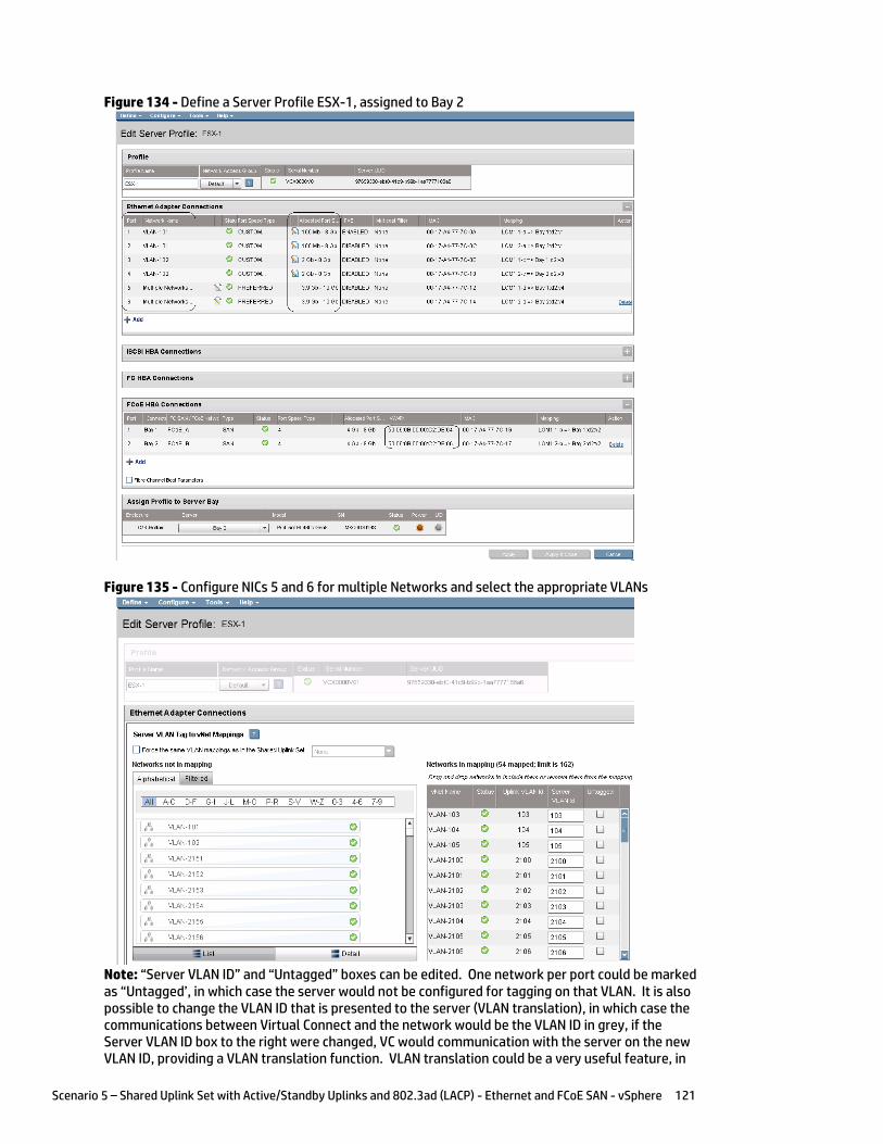
Scenario 5 – Shared Uplink Set with Active/Standby Uplinks and 802.3ad (LACP) - Ethernet and FCoE SAN - vSphere 121
Figure 134 - Define a Server Profile ESX-1, assigned to Bay 2
Figure 135 - Configure NICs 5 and 6 for multiple Networks and select the appropriate VLANs
Note: “Server VLAN ID” and “Untagged” boxes can be edited. One network per port could be marked as “Untagged’, in which case the server would not be configured for tagging on that VLAN. It is also possible to change the VLAN ID that is presented to the server (VLAN translation), in which case the communications between Virtual Connect and the network would be the VLAN ID in grey, if the Server VLAN ID box to the right were changed, VC would communication with the server on the new VLAN ID, providing a VLAN translation function. VLAN translation could be a very useful feature, in
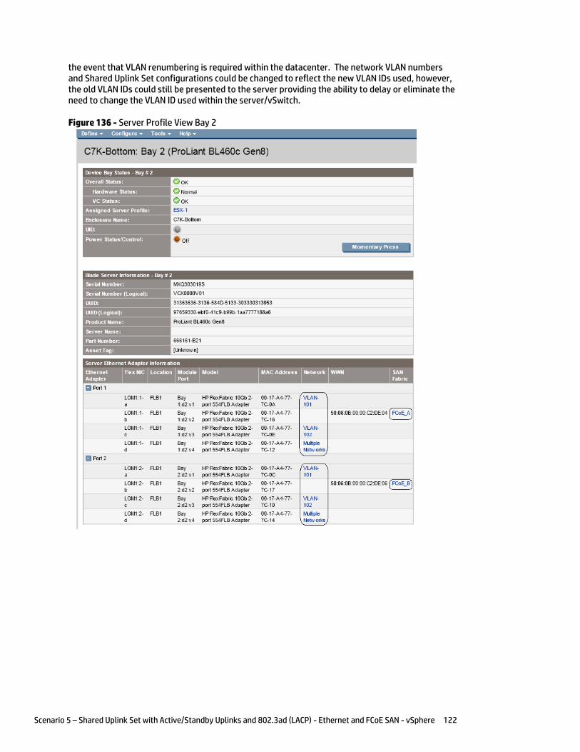
Scenario 5 – Shared Uplink Set with Active/Standby Uplinks and 802.3ad (LACP) - Ethernet and FCoE SAN - vSphere 122
the event that VLAN renumbering is required within the datacenter. The network VLAN numbers and Shared Uplink Set configurations could be changed to reflect the new VLAN IDs used, however, the old VLAN IDs could still be presented to the server providing the ability to delay or eliminate the need to change the VLAN ID used within the server/vSwitch.
Figure 136 - Server Profile View Bay 2
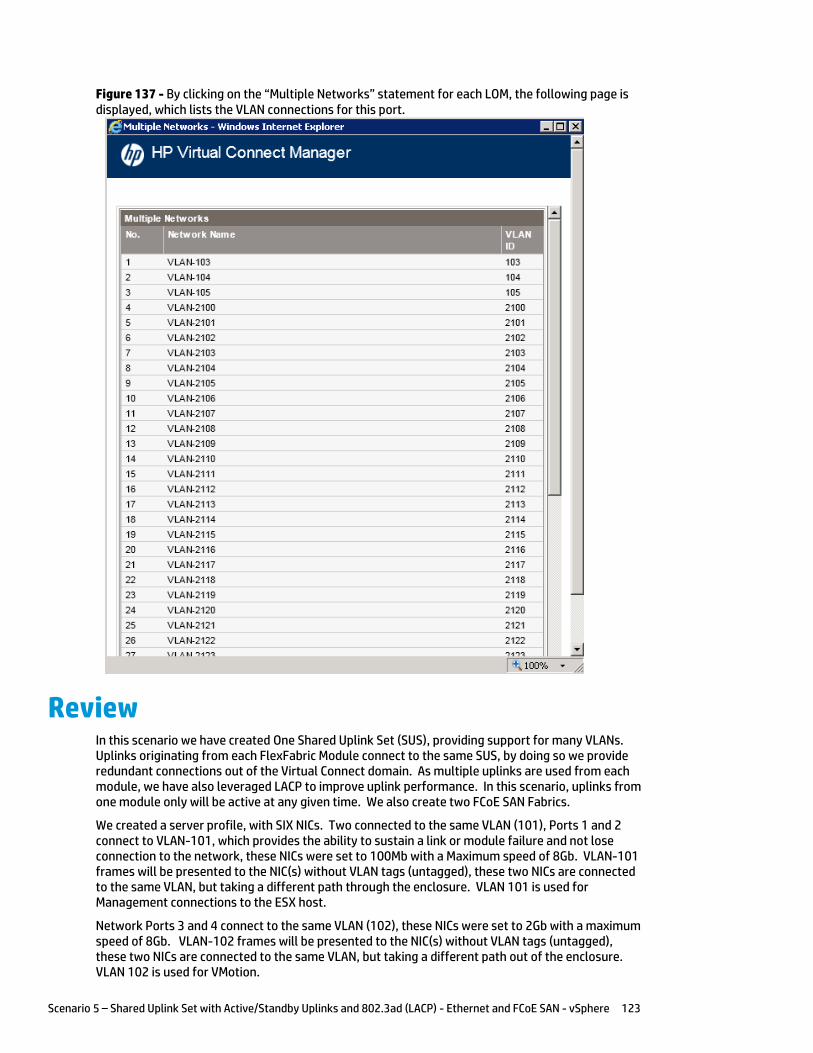
Scenario 5 – Shared Uplink Set with Active/Standby Uplinks and 802.3ad (LACP) - Ethernet and FCoE SAN - vSphere 123
Figure 137 - By clicking on the “Multiple Networks” statement for each LOM, the following page is displayed, which lists the VLAN connections for this port.
Review In this scenario we have created One Shared Uplink Set (SUS), providing support for many VLANs. Uplinks originating from each FlexFabric Module connect to the same SUS, by doing so we provide redundant connections out of the Virtual Connect domain. As multiple uplinks are used from each module, we have also leveraged LACP to improve uplink performance. In this scenario, uplinks from one module only will be active at any given time. We also create two FCoE SAN Fabrics.
We created a server profile, with SIX NICs. Two connected to the same VLAN (101), Ports 1 and 2 connect to VLAN-101, which provides the ability to sustain a link or module failure and not lose connection to the network, these NICs were set to 100Mb with a Maximum speed of 8Gb. VLAN-101 frames will be presented to the NIC(s) without VLAN tags (untagged), these two NICs are connected to the same VLAN, but taking a different path through the enclosure. VLAN 101 is used for Management connections to the ESX host.
Network Ports 3 and 4 connect to the same VLAN (102), these NICs were set to 2Gb with a maximum speed of 8Gb. VLAN-102 frames will be presented to the NIC(s) without VLAN tags (untagged), these two NICs are connected to the same VLAN, but taking a different path out of the enclosure. VLAN 102 is used for VMotion.
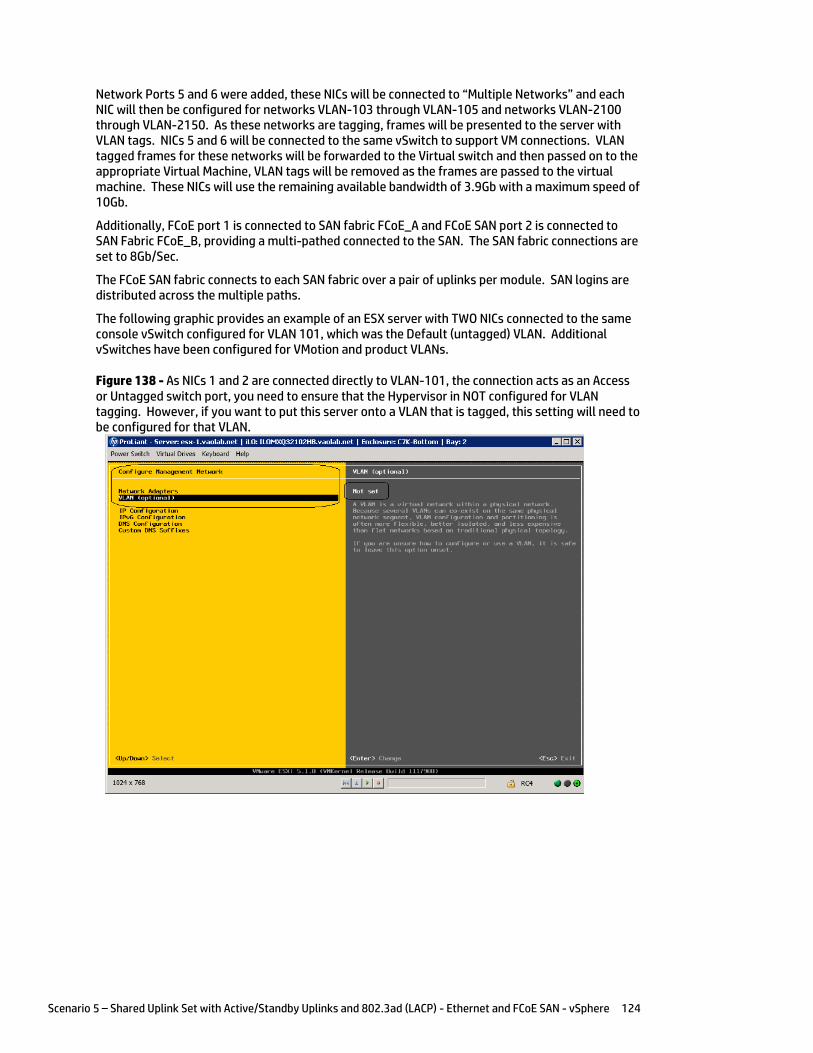
Scenario 5 – Shared Uplink Set with Active/Standby Uplinks and 802.3ad (LACP) - Ethernet and FCoE SAN - vSphere 124
Network Ports 5 and 6 were added, these NICs will be connected to “Multiple Networks” and each NIC will then be configured for networks VLAN-103 through VLAN-105 and networks VLAN-2100 through VLAN-2150. As these networks are tagging, frames will be presented to the server with VLAN tags. NICs 5 and 6 will be connected to the same vSwitch to support VM connections. VLAN tagged frames for these networks will be forwarded to the Virtual switch and then passed on to the appropriate Virtual Machine, VLAN tags will be removed as the frames are passed to the virtual machine. These NICs will use the remaining available bandwidth of 3.9Gb with a maximum speed of 10Gb.
Additionally, FCoE port 1 is connected to SAN fabric FCoE_A and FCoE SAN port 2 is connected to SAN Fabric FCoE_B, providing a multi-pathed connected to the SAN. The SAN fabric connections are set to 8Gb/Sec.
The FCoE SAN fabric connects to each SAN fabric over a pair of uplinks per module. SAN logins are distributed across the multiple paths.
The following graphic provides an example of an ESX server with TWO NICs connected to the same console vSwitch configured for VLAN 101, which was the Default (untagged) VLAN. Additional vSwitches have been configured for VMotion and product VLANs.
Figure 138 - As NICs 1 and 2 are connected directly to VLAN-101, the connection acts as an Access or Untagged switch port, you need to ensure that the Hypervisor in NOT configured for VLAN tagging. However, if you want to put this server onto a VLAN that is tagged, this setting will need to be configured for that VLAN.
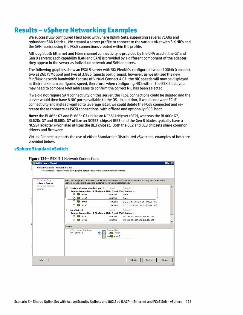
Scenario 5 – Shared Uplink Set with Active/Standby Uplinks and 802.3ad (LACP) - Ethernet and FCoE SAN - vSphere 125
Results – vSphere Networking Examples We successfully configured FlexFabric with Share Uplink Sets, supporting several VLANs and redundant SAN fabrics. We created a server profile to connect to the various vNet with SIX NICs and the SAN fabrics using the FCoE connections created within the profile.
Although both Ethernet and Fibre channel connectivity is provided by the CNA used in the G7 and Gen 8 servers; each capability (LAN and SAN) is provided by a different component of the adapter, they appear in the server as individual network and SAN adapters.
The following graphics show an ESXi 5 server with SIX FlexNICs configured, two at 100Mb (console), two at 2Gb (VMotion) and two at 3.9Gb (Guests port groups), however, as we utilized the new Min/Max network bandwidth feature of Virtual Connect 4.01, the NIC speeds will now be displayed at their maximum configured speed, therefore; when configuring NICs within the ESXi host, you may need to compare MAX addresses to confirm the correct NIC has been selected.
If we did not require SAN connectivity on this server, the FCoE connections could be deleted and the server would then have 8 NIC ports available to the OS. In addition, if we did not want FCoE connectivity and instead wanted to leverage iSCSI, we could delete the FCoE connected and re-create those connects as iSCSI connections, with offload and optionally iSCSI boot.
Note: the BL465c G7 and BL685c G7 utilize an NC551i chipset (BE2), whereas the BL460c G7, BL620c G7 and BL680c G7 utilize an NC553i chipset (BE3) and the Gen 8 blades typically have a NC554 adapter which also utilizes the BE3 chipset. Both the BE2 and BE3 chipsets share common drivers and firmware.
Virtual Connect supports the use of either Standard or Distributed vSwitches, examples of both are provided below.
vSphere Standard vSwitch
Figure 139 – ESXi 5.1 Network Connections

Scenario 5 – Shared Uplink Set with Active/Standby Uplinks and 802.3ad (LACP) - Ethernet and FCoE SAN - vSphere 126
Figure 140 – ESXi 5.1 networking - three vSwitches configured. (Note the NIC speeds)
Note: As VLAN 101 is set as untagged at the upstream switch port, the management network port group should be defined as untagged. This will allow the server to be deployed, without having the set a VLAN ID for the management network.
Figure 141 - You may want to specify a specific NIC for VMotion traffic. This will ensure that all VMotion traffic between servers within the enclosure will remain on the same VC module, reducing the likelihood of multiple hops between servers. Edit the VMotion Configuration.
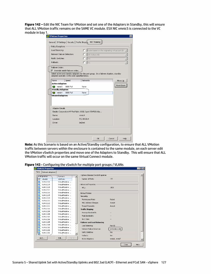
Scenario 5 – Shared Uplink Set with Active/Standby Uplinks and 802.3ad (LACP) - Ethernet and FCoE SAN - vSphere 127
Figure 142 – Edit the NIC Team for VMotion and set one of the Adapters in Standby, this will ensure that ALL VMotion traffic remains on the SAME VC module. ESX NIC vmnic5 is connected to the VC module in bay 1.
Note: As this Scenario is based on an Active/Standby configuration, to ensure that ALL VMotion traffic between servers within the enclosure is contained to the same module, on each server edit the VMotion vSwitch properties and move one of the Adapters to Standby. This will ensure that ALL VMotion traffic will occur on the same Virtual Connect module.
Figure 143 - Configuring the vSwitch for multiple port groups / VLANs

Scenario 5 – Shared Uplink Set with Active/Standby Uplinks and 802.3ad (LACP) - Ethernet and FCoE SAN - vSphere 128
Figure 144 - VM1 configured for VLAN 104
Figure 145 - VM1 on VLAN 104
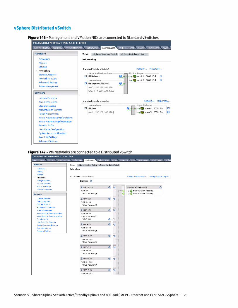
Scenario 5 – Shared Uplink Set with Active/Standby Uplinks and 802.3ad (LACP) - Ethernet and FCoE SAN - vSphere 129
vSphere Distributed vSwitch
Figure 146 - Management and VMotion NICs are connected to Standard vSwitches
Figure 147 - VM Networks are connected to a Distributed vSwitch
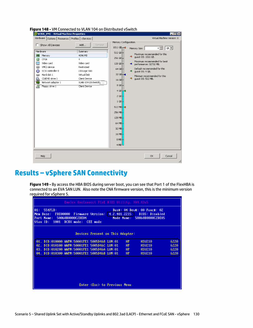
Scenario 5 – Shared Uplink Set with Active/Standby Uplinks and 802.3ad (LACP) - Ethernet and FCoE SAN - vSphere 130
Figure 148 - VM Connected to VLAN 104 on Distributed vSwitch
Results – vSphere SAN Connectivity
Figure 149 - By access the HBA BIOS during server boot, you can see that Port 1 of the FlexHBA is connected to an EVA SAN LUN. Also note the CNA firmware version, this is the minimum version required for vSphere 5.
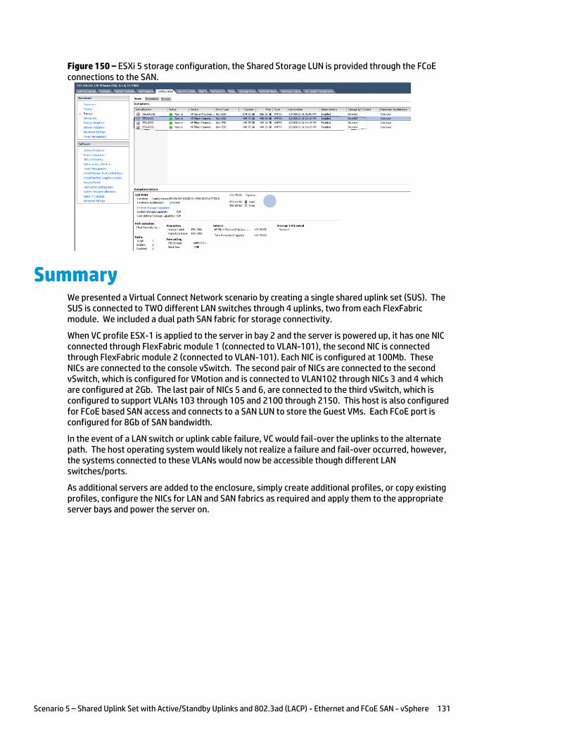
Scenario 5 – Shared Uplink Set with Active/Standby Uplinks and 802.3ad (LACP) - Ethernet and FCoE SAN - vSphere 131
Figure 150 – ESXi 5 storage configuration, the Shared Storage LUN is provided through the FCoE connections to the SAN.
Summary We presented a Virtual Connect Network scenario by creating a single shared uplink set (SUS). The SUS is connected to TWO different LAN switches through 4 uplinks, two from each FlexFabric module. We included a dual path SAN fabric for storage connectivity.
When VC profile ESX-1 is applied to the server in bay 2 and the server is powered up, it has one NIC connected through FlexFabric module 1 (connected to VLAN-101), the second NIC is connected through FlexFabric module 2 (connected to VLAN-101). Each NIC is configured at 100Mb. These NICs are connected to the console vSwitch. The second pair of NICs are connected to the second vSwitch, which is configured for VMotion and is connected to VLAN102 through NICs 3 and 4 which are configured at 2Gb. The last pair of NICs 5 and 6, are connected to the third vSwitch, which is configured to support VLANs 103 through 105 and 2100 through 2150. This host is also configured for FCoE based SAN access and connects to a SAN LUN to store the Guest VMs. Each FCoE port is configured for 8Gb of SAN bandwidth.
In the event of a LAN switch or uplink cable failure, VC would fail-over the uplinks to the alternate path. The host operating system would likely not realize a failure and fail-over occurred, however, the systems connected to these VLANs would now be accessible though different LAN switches/ports.
As additional servers are added to the enclosure, simply create additional profiles, or copy existing profiles, configure the NICs for LAN and SAN fabrics as required and apply them to the appropriate server bays and power the server on.

Scenario 6 – Shared Uplink Set with Active/Active Uplinks, 802.3ad (LACP) - Ethernet and FCoE SAN – vSphere 132
Scenario 6 – Shared Uplink Set with Active/Active Uplinks, 802.3ad (LACP) - Ethernet and FCoE SAN – vSphere
Overview This scenario will implement the Shared Uplink Set (SUS) to provide support for multiple VLANs. The upstream network switches connect a shared uplink set to two ports on each FlexFabric modules, LACP will be used to aggregate those links.
As multiple VLANs will be supported in this configuration, the upstream switch ports connecting to the FlexFabric modules will be configured to properly present those VLANs. In this scenario, the upstream switch ports will be configured for VLAN trunking/VLAN tagging.
When configuring Virtual Connect, we can provide several ways to implement network fail-over or redundancy. One option would be to connect TWO uplinks to a single Virtual Connect network; those two uplinks would connect from different Virtual Connect modules within the enclosure and could then connect to the same upstream switch or two different upstream switches, depending on your redundancy needs. An alternative would be to configure TWO separate Virtual Connect networks, each with a single, or multiple, uplinks configured. Each option has its advantages and disadvantages. For example; an Active/Standby configuration places the redundancy at the VC level, where Active/Active places it at the OS NIC teaming or bonding level. We will review the second option in this scenario.
In addition, several Virtual Connect Networks can be configured to support the required networks to the servers within the BladeSystem enclosure. These networks could be used to separate the various network traffic types, such as iSCSI, backup and VMotion from production network traffic.
This scenario will also leverage the Fibre Channel over Ethernet (FCoE) capabilities of the FlexFabric modules. Each fibre channel fabric will have two uplinks connected to each of the FlexFabric modules.
Requirements This scenario will support both Ethernet and fibre channel connectivity. In order to implement this scenario, an HP BladeSystem c7000 enclosure with one or more server blades and TWO Virtual Connect FlexFabric modules, installed in I/O Bays 1& 2 are required. In addition, we will require ONE or TWO external Network switches. As Virtual Connect does not appear to the network as a switch and is transparent to the network, any standard managed switch will work with Virtual Connect. The Fibre Channel uplinks will connect to the existing FC SAN fabrics. The SAN switch ports will need to be configured to support NPIV logins. Two uplinks from each FlexFabric module will be connected to the existing SAN fabrics.
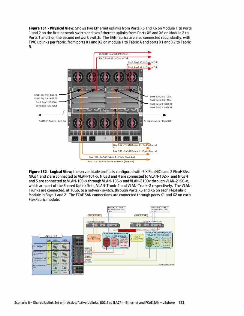
Scenario 6 – Shared Uplink Set with Active/Active Uplinks, 802.3ad (LACP) - Ethernet and FCoE SAN – vSphere 133
Figure 151 - Physical View; Shows two Ethernet uplinks from Ports X5 and X6 on Module 1 to Ports 1 and 2 on the first network switch and two Ethernet uplinks from Ports X5 and X6 on Module 2 to Ports 1 and 2 on the second network switch. The SAN fabrics are also connected redundantly, with TWO uplinks per fabric, from ports X1 and X2 on module 1 to Fabric A and ports X1 and X2 to Fabric B.
Figure 152 - Logical View; the server blade profile is configured with SIX FlexNICs and 2 FlexHBAs. NICs 1 and 2 are connected to VLAN-101-x, NICs 3 and 4 are connected to VLAN-102-x and NICs 4 and 5 are connected to VLAN-103-x through VLAN-105-x and VLAN-2100x through VLAN-2150-x, which are part of the Shared Uplink Sets, VLAN-Trunk-1 and VLAN-Trunk-2 respectively. The VLAN-Trunks are connected, at 10Gb, to a network switch, through Ports X5 and X6 on each FlexFabric Module in Bays 1 and 2. The FCoE SAN connections are connected through ports X1 and X2 on each FlexFabric module.
Scenario 6 – Shared Uplink Set with Active/Active Uplinks, 802.3ad (LACP) - Ethernet and FCoE SAN – vSphere 134
Installation and configuration Switch configuration
As the Virtual Connect module acts as an edge switch, Virtual Connect can connect to the network at either the distribution level or directly to the core switch.
The appendices provide a summary of the cli commands required to configure various switches for connection to Virtual Connect. The configuration information provided in the appendices for this scenario assumes the following information:
The switch ports are configured as VLAN TRUNK ports (tagging) to support several VLANs. All frames will be forwarded to Virtual Connect with VLAN tags. Optionally, one VLAN could be configured as (Default) untagged, if so, then a corresponding vNet within the Shared Uplink Set would be configured and set as “Default”.
Note: when adding additional uplinks to the SUS, if the additional uplinks are connecting from the same FlexFabric module to the same switch, in order to ensure all the uplinks are active, the switch ports will need to be configured for LACP within the same Link Aggregation Group.
The network switch port should be configured for Spanning Tree Edge as Virtual Connect appears to the switch as an access device and not another switch. By configuring the port as Spanning Tree Edge, it allows the switch to place the port into a forwarding state much quicker than otherwise, this allows a newly connected port to come online and begin forwarding much quicker.
The SAN connection will be made with redundant connections to each Fabric. SAN switch ports connecting to the FlexFabric module must be configured to accept NPIV logins.
Configuring the VC module
Physically connect Port 1 of network switch 1 to Port X5 of the VC module in Bay 1 Physically connect Port 2 of network switch 1 to Port X6 of the VC module in Bay 1 Physically connect Port 1 of network switch 2 to Port X5 of the VC module in Bay 2 Physically connect Port 2 of network switch 2 to Port X6 of the VC module in Bay 2
Note: if you have only one network switch, connect VC ports X5 and X6 (Bay 2) to an alternate port on the same switch. This will NOT create a network loop and Spanning Tree is not required.
Physically connect Ports X1/X2 on the FlexFabric in module Bay 1 to switch ports in SAN Fabric A Physically connect Ports X1/X2 on the FlexFabric in module Bay 2 to switch ports in SAN Fabric B
VC CLI commands
Many of the configuration settings within VC can also be accomplished via a CLI command set. In order to connect to VC via a CLI, open an SSH connection to the IP address of the active VCM. Once logged in, VC provides a CLI with help menus. Through this scenario the CLI commands to configure VC for each setting will also be provided.
Configuring Expanded VLAN Capacity via GUI
Virtual Connect release 3.30 provided an expanded VLAN capacity mode when using Shared Uplink Sets, this mode can be enabled through the Ethernet Settings tab or the VC CLI. The default configuration for a new Domain install is “Expanded VLAN Capacity” mode, Legacy mode is no longer available and the Domain cannot be downgraded.
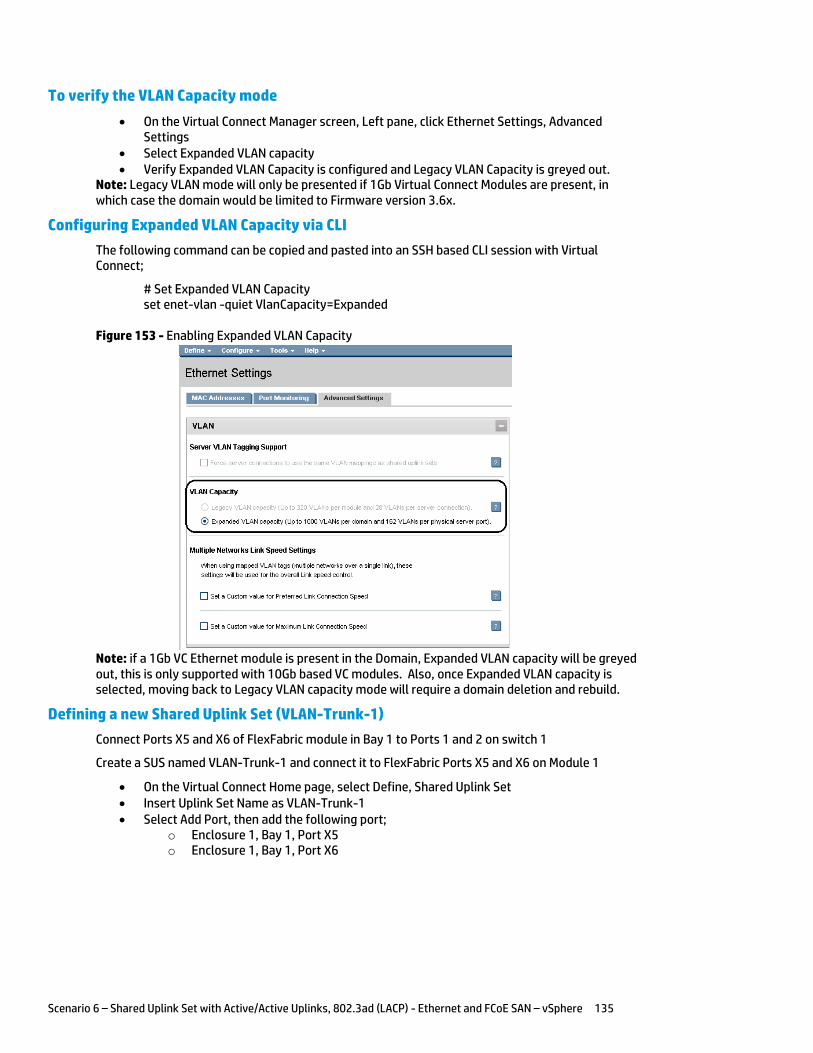
Scenario 6 – Shared Uplink Set with Active/Active Uplinks, 802.3ad (LACP) - Ethernet and FCoE SAN – vSphere 135
To verify the VLAN Capacity mode
On the Virtual Connect Manager screen, Left pane, click Ethernet Settings, Advanced Settings
Select Expanded VLAN capacity Verify Expanded VLAN Capacity is configured and Legacy VLAN Capacity is greyed out.
Note: Legacy VLAN mode will only be presented if 1Gb Virtual Connect Modules are present, in which case the domain would be limited to Firmware version 3.6x.
Configuring Expanded VLAN Capacity via CLI
The following command can be copied and pasted into an SSH based CLI session with Virtual Connect;
# Set Expanded VLAN Capacity set enet-vlan -quiet VlanCapacity=Expanded
Figure 153 - Enabling Expanded VLAN Capacity
Note: if a 1Gb VC Ethernet module is present in the Domain, Expanded VLAN capacity will be greyed out, this is only supported with 10Gb based VC modules. Also, once Expanded VLAN capacity is selected, moving back to Legacy VLAN capacity mode will require a domain deletion and rebuild.
Defining a new Shared Uplink Set (VLAN-Trunk-1)
Connect Ports X5 and X6 of FlexFabric module in Bay 1 to Ports 1 and 2 on switch 1
Create a SUS named VLAN-Trunk-1 and connect it to FlexFabric Ports X5 and X6 on Module 1
On the Virtual Connect Home page, select Define, Shared Uplink Set Insert Uplink Set Name as VLAN-Trunk-1 Select Add Port, then add the following port;
o Enclosure 1, Bay 1, Port X5 o Enclosure 1, Bay 1, Port X6
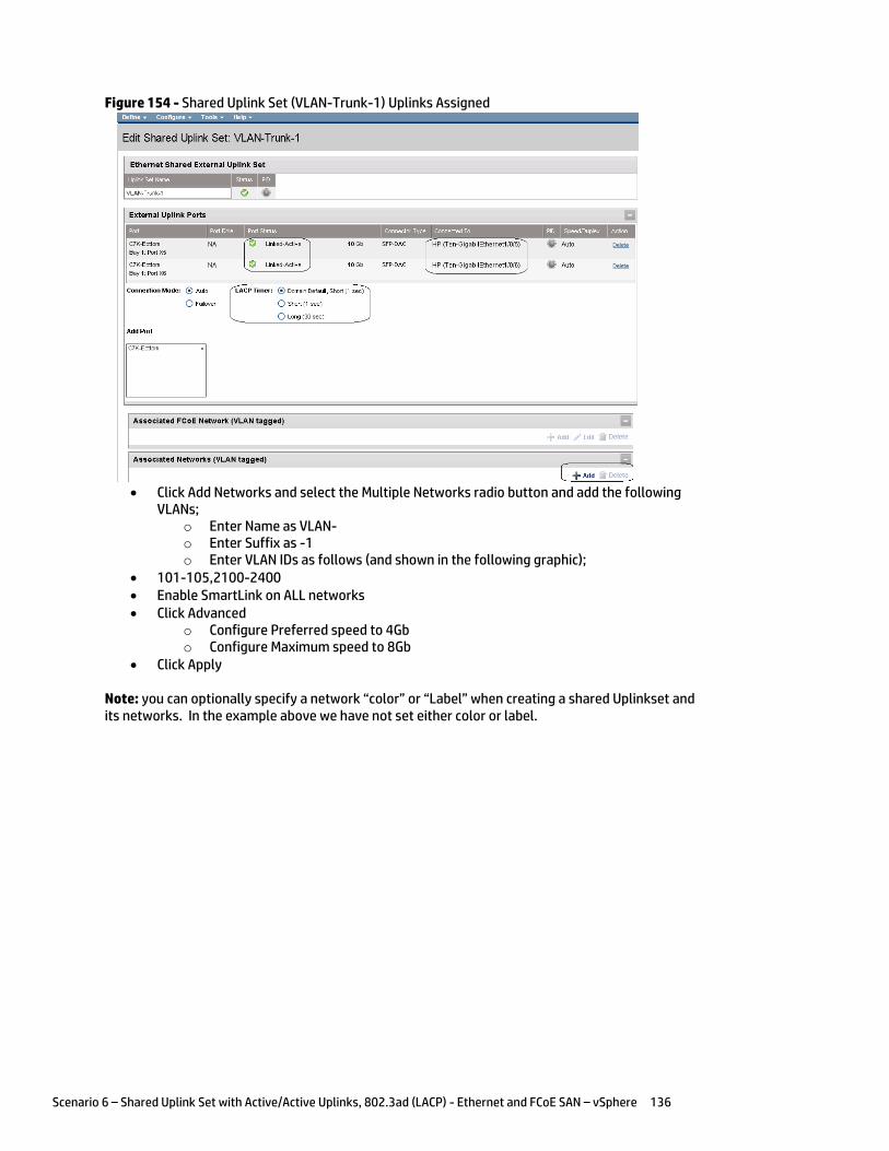
Scenario 6 – Shared Uplink Set with Active/Active Uplinks, 802.3ad (LACP) - Ethernet and FCoE SAN – vSphere 136
Figure 154 - Shared Uplink Set (VLAN-Trunk-1) Uplinks Assigned
Click Add Networks and select the Multiple Networks radio button and add the following
VLANs; o Enter Name as VLAN- o Enter Suffix as -1 o Enter VLAN IDs as follows (and shown in the following graphic);
101-105,2100-2400 Enable SmartLink on ALL networks Click Advanced
o Configure Preferred speed to 4Gb o Configure Maximum speed to 8Gb
Click Apply
Note: you can optionally specify a network “color” or “Label” when creating a shared Uplinkset and its networks. In the example above we have not set either color or label.

Scenario 6 – Shared Uplink Set with Active/Active Uplinks, 802.3ad (LACP) - Ethernet and FCoE SAN – vSphere 137
Figure 155 - Creating VLANs in a Shared Uplink Set
Note: When configuring Preferred and Maximum networks speeds, these speeds will only be reflected when the network is configured individually on a specific NIC. In order to set a Maximum network speed for a NIC configured with Multiple Networks, configure the “Multiple Networks Link Speed Settings” un Ethernet, Advanced Settings in the left tree view pane of the VC console.
After clicking apply, a list of VLANs will be presented as shown below. If one VLAN in the trunk is untagged/native, see note below.
Click Apply at the bottom of the page to create the Shared Uplink Set
Figure 156 - Associated VLANs for Shared Uplink Set VLAN-Trunk-1
Note: Optionally, if one of the VLANs in the trunk to this shared uplink set were configured as Native
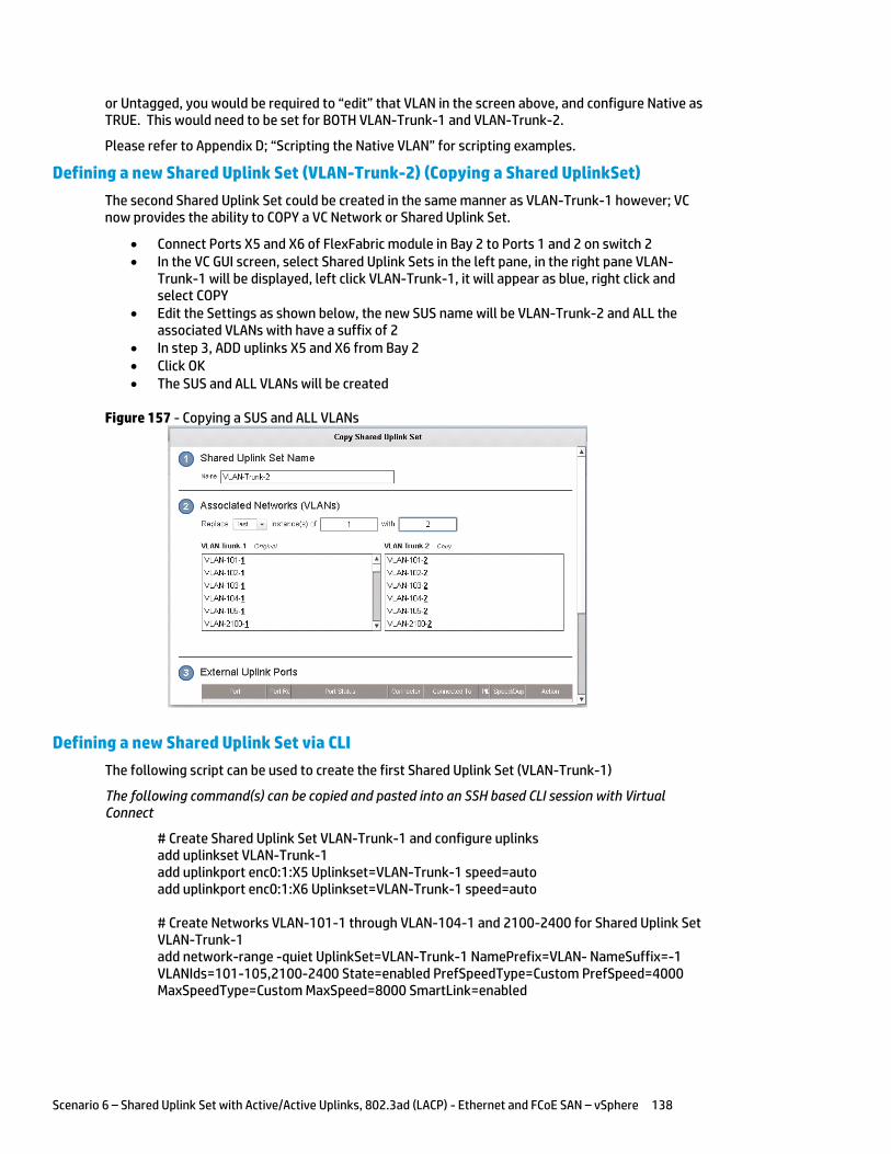
Scenario 6 – Shared Uplink Set with Active/Active Uplinks, 802.3ad (LACP) - Ethernet and FCoE SAN – vSphere 138
or Untagged, you would be required to “edit” that VLAN in the screen above, and configure Native as TRUE. This would need to be set for BOTH VLAN-Trunk-1 and VLAN-Trunk-2.
Please refer to Appendix D; “Scripting the Native VLAN” for scripting examples.
Defining a new Shared Uplink Set (VLAN-Trunk-2) (Copying a Shared UplinkSet)
The second Shared Uplink Set could be created in the same manner as VLAN-Trunk-1 however; VC now provides the ability to COPY a VC Network or Shared Uplink Set.
Connect Ports X5 and X6 of FlexFabric module in Bay 2 to Ports 1 and 2 on switch 2 In the VC GUI screen, select Shared Uplink Sets in the left pane, in the right pane VLAN-
Trunk-1 will be displayed, left click VLAN-Trunk-1, it will appear as blue, right click and select COPY
Edit the Settings as shown below, the new SUS name will be VLAN-Trunk-2 and ALL the associated VLANs with have a suffix of 2
In step 3, ADD uplinks X5 and X6 from Bay 2 Click OK The SUS and ALL VLANs will be created
Figure 157 - Copying a SUS and ALL VLANs
Defining a new Shared Uplink Set via CLI
The following script can be used to create the first Shared Uplink Set (VLAN-Trunk-1)
The following command(s) can be copied and pasted into an SSH based CLI session with Virtual Connect
# Create Shared Uplink Set VLAN-Trunk-1 and configure uplinks add uplinkset VLAN-Trunk-1 add uplinkport enc0:1:X5 Uplinkset=VLAN-Trunk-1 speed=auto add uplinkport enc0:1:X6 Uplinkset=VLAN-Trunk-1 speed=auto # Create Networks VLAN-101-1 through VLAN-104-1 and 2100-2400 for Shared Uplink Set VLAN-Trunk-1 add network-range -quiet UplinkSet=VLAN-Trunk-1 NamePrefix=VLAN- NameSuffix=-1 VLANIds=101-105,2100-2400 State=enabled PrefSpeedType=Custom PrefSpeed=4000 MaxSpeedType=Custom MaxSpeed=8000 SmartLink=enabled
Scenario 6 – Shared Uplink Set with Active/Active Uplinks, 802.3ad (LACP) - Ethernet and FCoE SAN – vSphere 139
The following script can be used to create the Second Shared Uplink Set (VLAN-Trunk-2)
# Create Shared Uplink Set VLAN-Trunk-2 and configure uplinks add uplinkset VLAN-Trunk-2 add uplinkport enc0:2:X5 Uplinkset=VLAN-Trunk-2 speed=auto add uplinkport enc0:2:X6 Uplinkset=VLAN-Trunk-2 speed=auto # Create Networks VLAN101-2 through VLAN105-2 and VLAN-2100-2 through VLAN-2400-2 for Shared Uplink Set VLAN-Trunk-2 add network-range -quiet UplinkSet=VLAN-Trunk-2 NamePrefix=VLAN- NameSuffix=-2 VLANIds=101-105,2100-2400 State=enabled PrefSpeedType=Custom PrefSpeed=4000 MaxSpeedType=Custom MaxSpeed=8000 SmartLink=enabled
Note: In this scenario we have created two independent Share Uplink Sets (SUS), each originating from the opposite FlexFabric Modules, by doing so we provide the ability to create separate and redundant connections out of the Virtual Connect domain. When we create the server profiles, you will see how the NICs will connect to VLANs accessed through the opposite VC module, which provides the ability to create an Active / Active uplink scenario. Alternatively, we could have created a single SUS and assigned both sets of these uplink ports to the same SUS, however, this would have provided an Active/Standby uplink scenario, as shown in Scenario 5.
Defining a new (FCoE) SAN Fabric via GUI
Create a Fabric and name it “FCoE_A”
On the Virtual Connect Manager screen, click Define, SAN Fabric to create the first Fabric Enter the Network Name of “FCoE_A” Select Add Port, then add the following ports;
o Enclosure 1, Bay 1, Port X1 o Enclosure 1, Bay 1, Port X2
Ensure Fabric Type is set to “FabricAttach” Select Show Advanced Settings
o Select Automatic Login Re-Distribution (FlexFabric Only) o Select Set Preferred FCoE Connect Speed
Configure for 4Gb o Select Set Maximum FCoE Connect Speed
Configure for 8Gb Select Apply
Create a second Fabric and name it “FCoE_B”
On the Virtual Connect Manager screen, click Define, SAN Fabric to create the second Fabric Enter the Network Name of “FCoE_B” Select Add Port, then add the following ports;
o Enclosure 1, Bay 2, Port X1 o Enclosure 1, Bay 2, Port X2
Ensure Fabric Type is set to “FabricAttach” Select Show Advanced Settings
o Select Automatic Login Re-Distribution (FlexFabric Only) o Select Set Preferred FCoE Connect Speed
Configure for 4Gb o Select Set Maximum FCoE Connect Speed
Configure for 8Gb Select Apply

Scenario 6 – Shared Uplink Set with Active/Active Uplinks, 802.3ad (LACP) - Ethernet and FCoE SAN – vSphere 140
Defining SAN Fabrics via CLI
The following command(s) can be copied and pasted into an SSH based CLI session with Virtual Connect
#Create the SAN Fabrics FCoE_A and FCoE_B and configure uplinks as discussed above add fabric FCoE_A Type=FabricAttach Bay=1 Ports=1,2 Speed=Auto LinkDist=Auto PrefSpeedType=Custom PrefSpeed=4000 MaxSpeedType=Custom MaxSpeed=8000 add fabric FCoE_B Type=FabricAttach Bay=2 Ports=1,2 Speed=Auto LinkDist=Auto PrefSpeedType=Custom PrefSpeed=4000 MaxSpeedType=Custom MaxSpeed=8000
Figure 158 - SAN Configuration and Advanced Settings
Figure 159 - FCoE SAN fabrics configured with two 8Gb uplinks per fabric. Note the bay and port numbers on the right
Defining a Server Profile
We will create a server profile with SIX server NICs and TWO SAN adapters.
Each server NIC will connect to a specific network.
On the main menu, select Define, then Server Profile Create a server profile called “ESX-1” In the Network Port 1 drop down box, select a Network, then chose VLAN101-1
Scenario 6 – Shared Uplink Set with Active/Active Uplinks, 802.3ad (LACP) - Ethernet and FCoE SAN – vSphere 141
Set the port speed to Custom at 100Mb In the Network Port 2 drop down box, select a Network, then chose VLAN101-2 Set the port speed to Custom at 100Mb Left click on either of Port 1 or Port 2 in the Ethernet Connections box, and select ADD
network (add four additional network connections) In the Network Port 3 drop down box, select a Network, then chose VLAN-102-1 Set the port speed to Custom at 2Gb In the Network Port 4 drop down box, select a Network, then chose VLAN-102-2 Set the port speed to Custom at 2Gb In the Network Port 5 drop down box, select Multiple Networks Configure for networks VLAN-103-1 through VLAN-105-1 and VLAN-2100-1 through
VLAN-2150-1 Leave the network speed as Auto In the Network Port 6 drop down box, select Multiple Networks Configure for networks VLAN-103-2 through VLAN-105-2 and VLAN-2100-2 through
VLAN-2150-2 Leave the network speed as Auto Expand the FCoE Connections box, for Bay 1, select FCoE_A for Bay 2, select FCoE_B Do not configure FC SAN or iSCSI Connection In the Assign Profile to Server Bay box, locate the Select Location drop down and select
Bay 2, then apply
Prior to applying the profile, ensure that the server in Bay 2 is currently OFF
Note: You should now have a server profile assigned to Bay 2, with 4 Server NIC connections. NICs 1&2 should be connected to networks VLAN-101-x (MGMT), NICs 3&4 should be connected VLAN-102-x (VMotion) to networks VLAN103-x through VLAN105-x and VLAN-2100-x through VLAN-2150-x. FCoE SAN fabrics are connected to, Port 1 - FCoE_A and Port 2 - FCoE_B.
Defining a Server Profile via CLI
The following command(s) can be copied and pasted into an SSH based CLI session with Virtual Connect
# Create Server Profile ESX-1 add profile ESX-1 -nodefaultfcconn -nodefaultfcoeconn set enet-connection ESX-1 1 pxe=Enabled Network=VLAN-101-1 SpeedType=Custom Speed=100 set enet-connection ESX-1 2 pxe=Disabled Network=VLAN-101-2 SpeedType=Custom Speed=100 add enet-connection ESX-1 pxe=Disabled Network=VLAN-102-1 SpeedType=Custom Speed=2000 add enet-connection ESX-1 pxe=Disabled Network=VLAN-102-2 SpeedType=Custom Speed=2000 add enet-connection ESX-1 pxe=Disabled add server-port-map-range ESX-1:5 UplinkSet=VLAN-Trunk-1 VLanIds=103-105,2100-2150 add enet-connection ESX-1 pxe=Disabled add server-port-map-range ESX-1:6 UplinkSet=VLAN-Trunk-2 VLanIds=103-105,2100-2150 add fcoe-connection ESX-1 Fabric=FCoE_A SpeedType=4Gb add fcoe-connection ESX-1 Fabric=FCoE_B SpeedType=4Gb poweroff server 2 assign profile ESX-1 enc0:2
Note: the “add server-port-map-range” command is new to VC firmware release 3.30 and can be used to map many VLANs to a server NIC, in a single command. Prior releases would have required one command to create the NIC and one additional command per VLAN mapping added. This command will make profile scripting much easier, less complicated and quicker.
Note: The speed of the NIC and SAN connections, as well as the MAC and WWN. Also, note that the FCoE connections are assigned to the two SAN fabrics created earlier and use ports LOM:1-b and LOM:2-b.
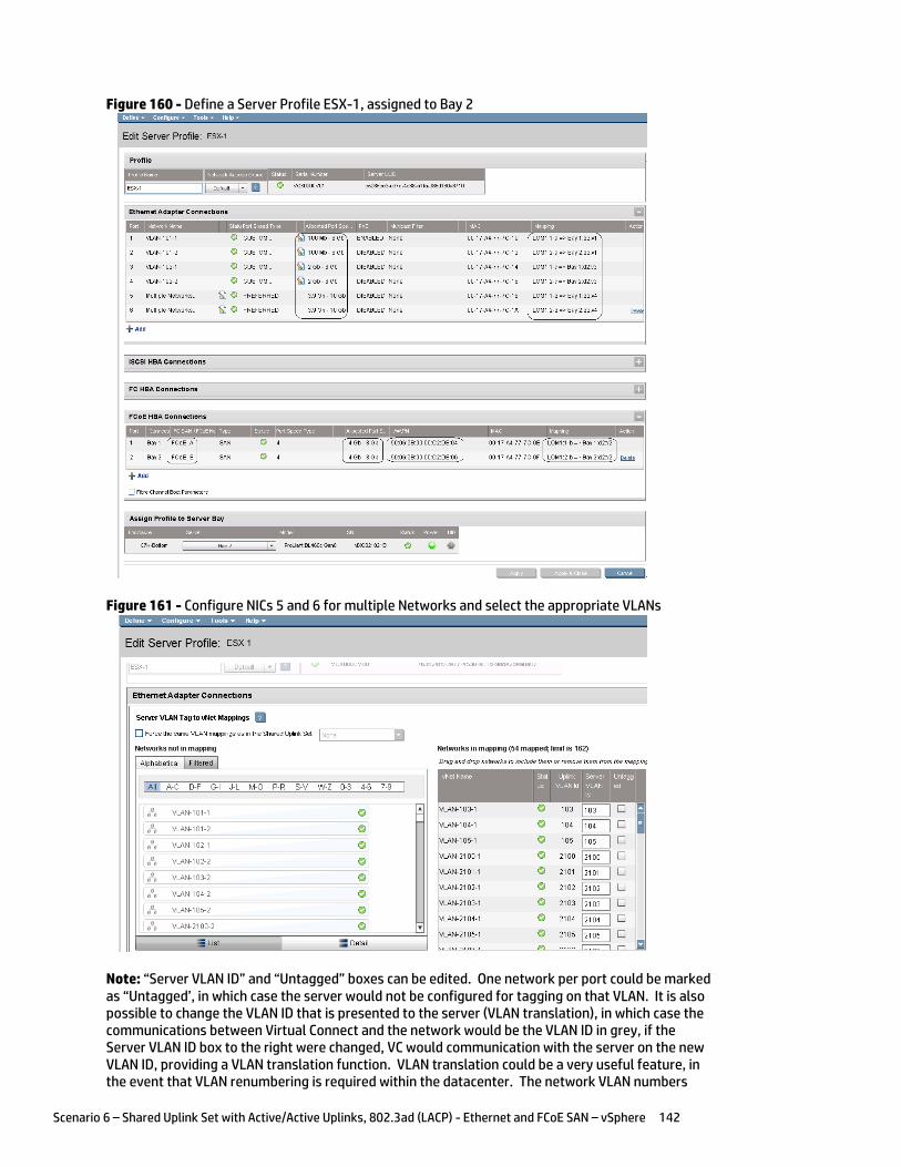
Scenario 6 – Shared Uplink Set with Active/Active Uplinks, 802.3ad (LACP) - Ethernet and FCoE SAN – vSphere 142
Figure 160 - Define a Server Profile ESX-1, assigned to Bay 2
Figure 161 - Configure NICs 5 and 6 for multiple Networks and select the appropriate VLANs
Note: “Server VLAN ID” and “Untagged” boxes can be edited. One network per port could be marked as “Untagged’, in which case the server would not be configured for tagging on that VLAN. It is also possible to change the VLAN ID that is presented to the server (VLAN translation), in which case the communications between Virtual Connect and the network would be the VLAN ID in grey, if the Server VLAN ID box to the right were changed, VC would communication with the server on the new VLAN ID, providing a VLAN translation function. VLAN translation could be a very useful feature, in the event that VLAN renumbering is required within the datacenter. The network VLAN numbers
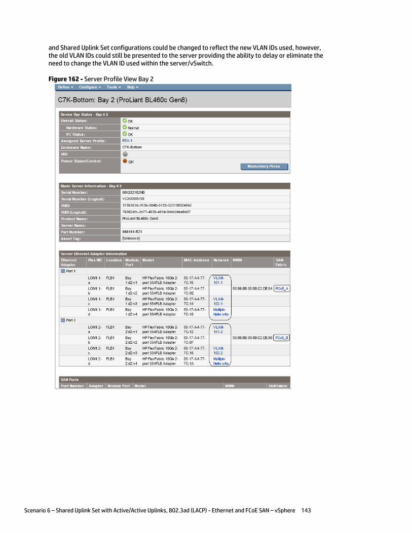
Scenario 6 – Shared Uplink Set with Active/Active Uplinks, 802.3ad (LACP) - Ethernet and FCoE SAN – vSphere 143
and Shared Uplink Set configurations could be changed to reflect the new VLAN IDs used, however, the old VLAN IDs could still be presented to the server providing the ability to delay or eliminate the need to change the VLAN ID used within the server/vSwitch.
Figure 162 - Server Profile View Bay 2
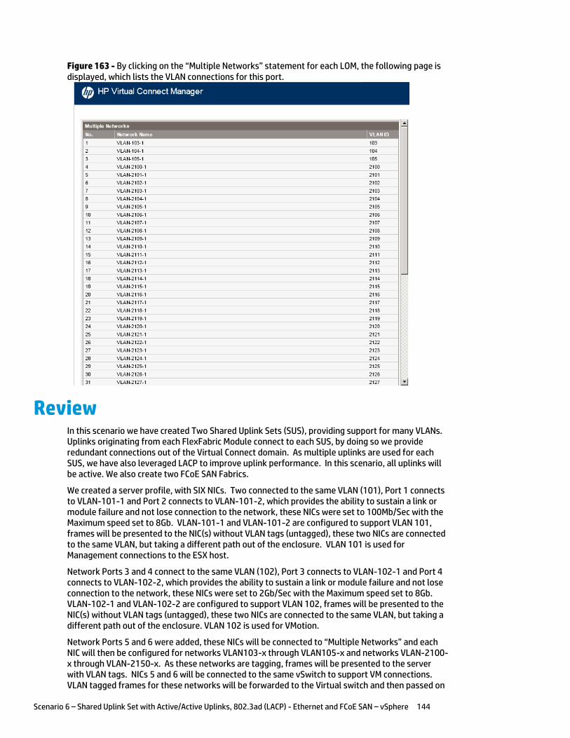
Scenario 6 – Shared Uplink Set with Active/Active Uplinks, 802.3ad (LACP) - Ethernet and FCoE SAN – vSphere 144
Figure 163 - By clicking on the “Multiple Networks” statement for each LOM, the following page is displayed, which lists the VLAN connections for this port.
Review In this scenario we have created Two Shared Uplink Sets (SUS), providing support for many VLANs. Uplinks originating from each FlexFabric Module connect to each SUS, by doing so we provide redundant connections out of the Virtual Connect domain. As multiple uplinks are used for each SUS, we have also leveraged LACP to improve uplink performance. In this scenario, all uplinks will be active. We also create two FCoE SAN Fabrics.
We created a server profile, with SIX NICs. Two connected to the same VLAN (101), Port 1 connects to VLAN-101-1 and Port 2 connects to VLAN-101-2, which provides the ability to sustain a link or module failure and not lose connection to the network, these NICs were set to 100Mb/Sec with the Maximum speed set to 8Gb. VLAN-101-1 and VLAN-101-2 are configured to support VLAN 101, frames will be presented to the NIC(s) without VLAN tags (untagged), these two NICs are connected to the same VLAN, but taking a different path out of the enclosure. VLAN 101 is used for Management connections to the ESX host.
Network Ports 3 and 4 connect to the same VLAN (102), Port 3 connects to VLAN-102-1 and Port 4 connects to VLAN-102-2, which provides the ability to sustain a link or module failure and not lose connection to the network, these NICs were set to 2Gb/Sec with the Maximum speed set to 8Gb. VLAN-102-1 and VLAN-102-2 are configured to support VLAN 102, frames will be presented to the NIC(s) without VLAN tags (untagged), these two NICs are connected to the same VLAN, but taking a different path out of the enclosure. VLAN 102 is used for VMotion.
Network Ports 5 and 6 were added, these NICs will be connected to “Multiple Networks” and each NIC will then be configured for networks VLAN103-x through VLAN105-x and networks VLAN-2100-x through VLAN-2150-x. As these networks are tagging, frames will be presented to the server with VLAN tags. NICs 5 and 6 will be connected to the same vSwitch to support VM connections. VLAN tagged frames for these networks will be forwarded to the Virtual switch and then passed on
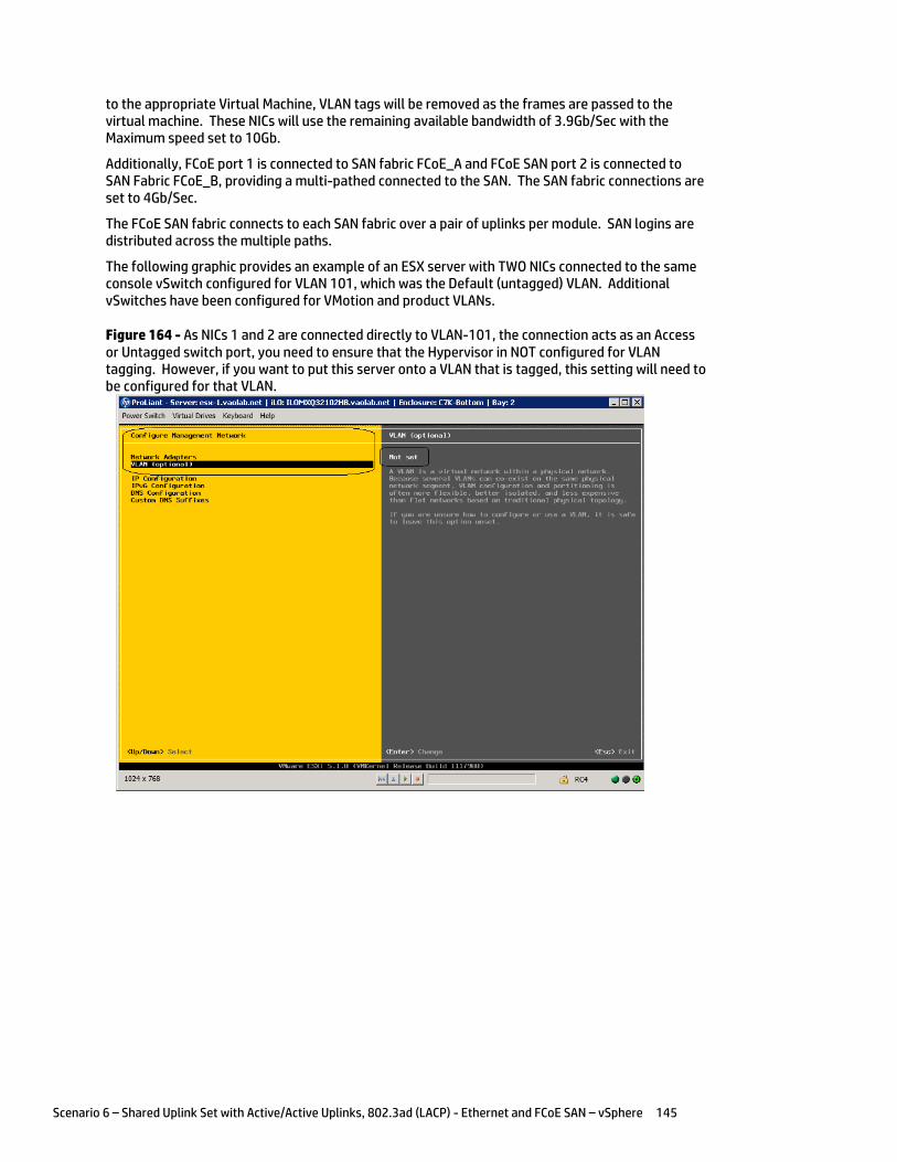
Scenario 6 – Shared Uplink Set with Active/Active Uplinks, 802.3ad (LACP) - Ethernet and FCoE SAN – vSphere 145
to the appropriate Virtual Machine, VLAN tags will be removed as the frames are passed to the virtual machine. These NICs will use the remaining available bandwidth of 3.9Gb/Sec with the Maximum speed set to 10Gb.
Additionally, FCoE port 1 is connected to SAN fabric FCoE_A and FCoE SAN port 2 is connected to SAN Fabric FCoE_B, providing a multi-pathed connected to the SAN. The SAN fabric connections are set to 4Gb/Sec.
The FCoE SAN fabric connects to each SAN fabric over a pair of uplinks per module. SAN logins are distributed across the multiple paths.
The following graphic provides an example of an ESX server with TWO NICs connected to the same console vSwitch configured for VLAN 101, which was the Default (untagged) VLAN. Additional vSwitches have been configured for VMotion and product VLANs.
Figure 164 - As NICs 1 and 2 are connected directly to VLAN-101, the connection acts as an Access or Untagged switch port, you need to ensure that the Hypervisor in NOT configured for VLAN tagging. However, if you want to put this server onto a VLAN that is tagged, this setting will need to be configured for that VLAN.
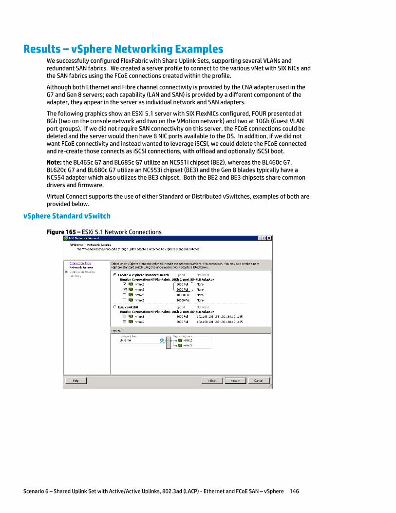
Scenario 6 – Shared Uplink Set with Active/Active Uplinks, 802.3ad (LACP) - Ethernet and FCoE SAN – vSphere 146
Results – vSphere Networking Examples We successfully configured FlexFabric with Share Uplink Sets, supporting several VLANs and redundant SAN fabrics. We created a server profile to connect to the various vNet with SIX NICs and the SAN fabrics using the FCoE connections created within the profile.
Although both Ethernet and Fibre channel connectivity is provided by the CNA adapter used in the G7 and Gen 8 servers; each capability (LAN and SAN) is provided by a different component of the adapter, they appear in the server as individual network and SAN adapters.
The following graphics show an ESXi 5.1 server with SIX FlexNICs configured, FOUR presented at 8Gb (two on the console network and two on the VMotion network) and two at 10Gb (Guest VLAN port groups). If we did not require SAN connectivity on this server, the FCoE connections could be deleted and the server would then have 8 NIC ports available to the OS. In addition, if we did not want FCoE connectivity and instead wanted to leverage iSCSI, we could delete the FCoE connected and re-create those connects as iSCSI connections, with offload and optionally iSCSI boot.
Note: the BL465c G7 and BL685c G7 utilize an NC551i chipset (BE2), whereas the BL460c G7, BL620c G7 and BL680c G7 utilize an NC553i chipset (BE3) and the Gen 8 blades typically have a NC554 adapter which also utilizes the BE3 chipset. Both the BE2 and BE3 chipsets share common drivers and firmware.
Virtual Connect supports the use of either Standard or Distributed vSwitches, examples of both are provided below.
vSphere Standard vSwitch
Figure 165 – ESXi 5.1 Network Connections
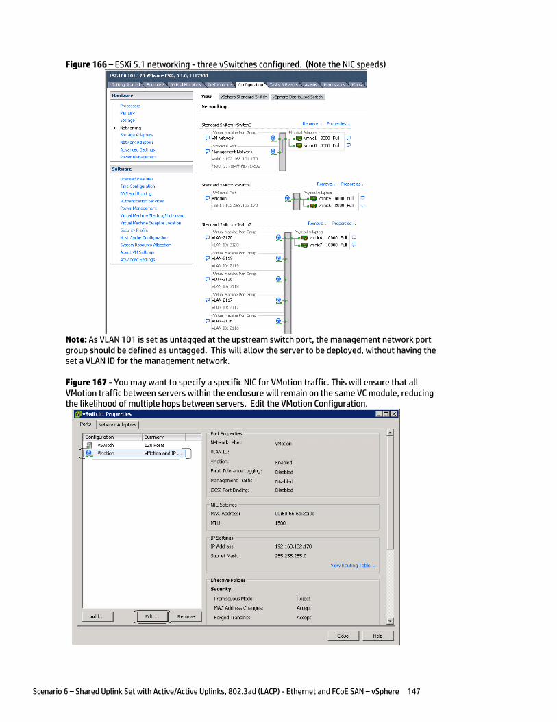
Scenario 6 – Shared Uplink Set with Active/Active Uplinks, 802.3ad (LACP) - Ethernet and FCoE SAN – vSphere 147
Figure 166 – ESXi 5.1 networking - three vSwitches configured. (Note the NIC speeds)
Note: As VLAN 101 is set as untagged at the upstream switch port, the management network port group should be defined as untagged. This will allow the server to be deployed, without having the set a VLAN ID for the management network.
Figure 167 - You may want to specify a specific NIC for VMotion traffic. This will ensure that all VMotion traffic between servers within the enclosure will remain on the same VC module, reducing the likelihood of multiple hops between servers. Edit the VMotion Configuration.
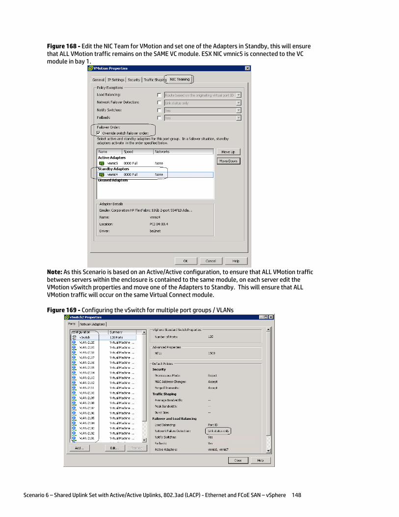
Scenario 6 – Shared Uplink Set with Active/Active Uplinks, 802.3ad (LACP) - Ethernet and FCoE SAN – vSphere 148
Figure 168 - Edit the NIC Team for VMotion and set one of the Adapters in Standby, this will ensure that ALL VMotion traffic remains on the SAME VC module. ESX NIC vmnic5 is connected to the VC module in bay 1.
Note: As this Scenario is based on an Active/Active configuration, to ensure that ALL VMotion traffic between servers within the enclosure is contained to the same module, on each server edit the VMotion vSwitch properties and move one of the Adapters to Standby. This will ensure that ALL VMotion traffic will occur on the same Virtual Connect module.
Figure 169 - Configuring the vSwitch for multiple port groups / VLANs
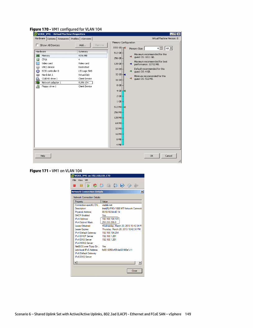
Scenario 6 – Shared Uplink Set with Active/Active Uplinks, 802.3ad (LACP) - Ethernet and FCoE SAN – vSphere 149
Figure 170 - VM1 configured for VLAN 104
Figure 171 - VM1 on VLAN 104

Scenario 6 – Shared Uplink Set with Active/Active Uplinks, 802.3ad (LACP) - Ethernet and FCoE SAN – vSphere 150
vSphere Distributed vSwitch
Figure 172 - Management and VMotion NICs are connected to Standard vSwitches
Figure 173 - VM Networks are connected to a Distributed vSwitch

Scenario 6 – Shared Uplink Set with Active/Active Uplinks, 802.3ad (LACP) - Ethernet and FCoE SAN – vSphere 151
Figure 174 - VM Connected to VLAN 104 on Distributed vSwitch
Results – vSphere SAN Connectivity
Figure 175 - By access the HBA BIOS during server boot, you can see that Port 1 of the FlexHBA is connected to an EVA SAN LUN. Also note the CNA firmware version, this is the minimum version required for vSphere 5.
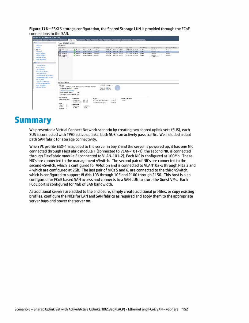
Scenario 6 – Shared Uplink Set with Active/Active Uplinks, 802.3ad (LACP) - Ethernet and FCoE SAN – vSphere 152
Figure 176 – ESXi 5 storage configuration, the Shared Storage LUN is provided through the FCoE connections to the SAN.
Summary We presented a Virtual Connect Network scenario by creating two shared uplink sets (SUS), each SUS is connected with TWO active uplinks; both SUS’ can actively pass traffic. We included a dual path SAN fabric for storage connectivity.
When VC profile ESX-1 is applied to the server in bay 2 and the server is powered up, it has one NIC connected through FlexFabric module 1 (connected to VLAN-101-1), the second NIC is connected through FlexFabric module 2 (connected to VLAN-101-2). Each NIC is configured at 100Mb. These NICs are connected to the management vSwitch. The second pair of NICs are connected to the second vSwitch, which is configured for VMotion and is connected to VLAN102-x through NICs 3 and 4 which are configured at 2Gb. The last pair of NICs 5 and 6, are connected to the third vSwitch, which is configured to support VLANs 103 through 105 and 2100 through 2150. This host is also configured for FCoE based SAN access and connects to a SAN LUN to store the Guest VMs. Each FCoE port is configured for 4Gb of SAN bandwidth.
As additional servers are added to the enclosure, simply create additional profiles, or copy existing profiles, configure the NICs for LAN and SAN fabrics as required and apply them to the appropriate server bays and power the server on.
Scenario 7 – Tunneled VLANs and Shared Uplink Set with Active/Active Uplinks and 802.3ad (LACP) - Ethernet and FCoE SAN - vSphere 153
Scenario 7 – Tunneled VLANs and Shared Uplink Set with Active/Active Uplinks and 802.3ad (LACP) - Ethernet and FCoE SAN - vSphere
Overview This scenario will implement the VLAN-Tunnel to provide support for multiple VLANs. The upstream network switches connect VLAN-Tunnels to two ports on each FlexFabric modules, LACP will be used to aggregate those links. A Shared Uplink Set will also be used to provide connectivity for the Management and VMotion networks only.
As multiple VLANs will be supported in this configuration, the upstream switch ports connecting to the FlexFabric modules will be configured to properly present those VLANs. In this scenario, the upstream switch ports will be configured for VLAN trunking/VLAN tagging.
When configuring Virtual Connect, we can provide several ways to implement network fail-over or redundancy. One option would be to connect TWO uplinks to a single Virtual Connect network; those two uplinks would connect from different Virtual Connect modules within the enclosure and could then connect to the same upstream switch or two different upstream switches, depending on your redundancy needs. An alternative would be to configure TWO separate Virtual Connect networks, each with a single, or multiple, uplinks configured. Each option has its advantages and disadvantages. For example; an Active/Standby configuration places the redundancy at the VC level, where Active/Active places it at the OS NIC teaming or bonding level. We will review the second option in this scenario.
In addition, several Virtual Connect Networks can be configured to support the required networks to the servers within the BladeSystem enclosure. These networks could be used to separate the various network traffic types, such as iSCSI, backup and VMotion from production network traffic.
This scenario will also leverage the Fibre Channel over Ethernet (FCoE) capabilities of the FlexFabric modules. Each fibre channel fabric will have two uplinks connected to each of the FlexFabric modules.
Requirements This scenario will support both Ethernet and fibre channel connectivity. In order to implement this scenario, an HP BladeSystem c7000 enclosure with one or more server blades and TWO Virtual Connect FlexFabric modules, installed in I/O Bays 1& 2 are required. In addition, we will require ONE or TWO external Network switches. As Virtual Connect does not appear to the network as a switch and is transparent to the network, any standard managed switch will work with Virtual Connect. The Fibre Channel uplinks will connect to the existing FC SAN fabrics. The SAN switch ports will need to be configured to support NPIV logins. Two uplinks from each FlexFabric module will be connected to the existing SAN fabrics.
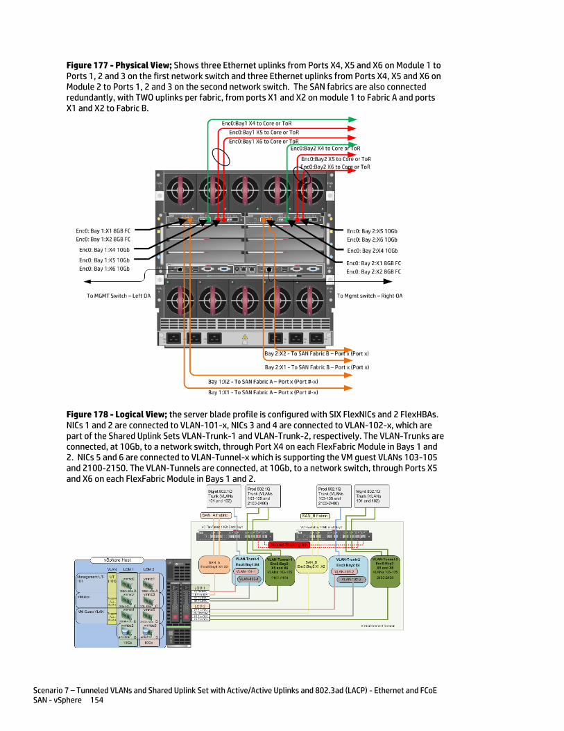
Scenario 7 – Tunneled VLANs and Shared Uplink Set with Active/Active Uplinks and 802.3ad (LACP) - Ethernet and FCoE SAN - vSphere 154
Figure 177 - Physical View; Shows three Ethernet uplinks from Ports X4, X5 and X6 on Module 1 to Ports 1, 2 and 3 on the first network switch and three Ethernet uplinks from Ports X4, X5 and X6 on Module 2 to Ports 1, 2 and 3 on the second network switch. The SAN fabrics are also connected redundantly, with TWO uplinks per fabric, from ports X1 and X2 on module 1 to Fabric A and ports X1 and X2 to Fabric B.
Figure 178 - Logical View; the server blade profile is configured with SIX FlexNICs and 2 FlexHBAs. NICs 1 and 2 are connected to VLAN-101-x, NICs 3 and 4 are connected to VLAN-102-x, which are part of the Shared Uplink Sets VLAN-Trunk-1 and VLAN-Trunk-2, respectively. The VLAN-Trunks are connected, at 10Gb, to a network switch, through Port X4 on each FlexFabric Module in Bays 1 and 2. NICs 5 and 6 are connected to VLAN-Tunnel-x which is supporting the VM guest VLANs 103-105 and 2100-2150. The VLAN-Tunnels are connected, at 10Gb, to a network switch, through Ports X5 and X6 on each FlexFabric Module in Bays 1 and 2.

Scenario 7 – Tunneled VLANs and Shared Uplink Set with Active/Active Uplinks and 802.3ad (LACP) - Ethernet and FCoE SAN - vSphere 155
Installation and configuration Switch configuration
As the Virtual Connect module acts as an edge switch, Virtual Connect can connect to the network at either the distribution level or directly to the core switch.
The appendices provide a summary of the cli commands required to configure various switches for connection to Virtual Connect. The configuration information provided in the appendices for this scenario assumes the following information:
The switch ports are configured as VLAN TRUNK ports (tagging) to support several VLANs. All frames will be forwarded to Virtual Connect with VLAN tags. Optionally, one VLAN could be configured as (Default) untagged, if so, then a corresponding vNet within the Shared Uplink Set would be configured and set as “Default”.
Note: when adding additional uplinks to the SUS, if the additional uplinks are connecting from the same FlexFabric module to the same switch, in order to ensure all the uplinks are active, the switch ports will need to be configured for LACP within the same Link Aggregation Group.
The network switch port should be configured for Spanning Tree Edge as Virtual Connect appears to the switch as an access device and not another switch. By configuring the port as Spanning Tree Edge, it allows the switch to place the port into a forwarding state much quicker than otherwise, this allows a newly connected port to come online and begin forwarding much quicker.
The SAN connection will be made with redundant connections to each Fabric. SAN switch ports connecting to the FlexFabric module must be configured to accept NPIV logins.
Configuring the VC module
Physically connect Port 1 of network switch 1 to Port X4 of the VC module in Bay 1 Physically connect Port 2 of network switch 1 to Port X5 of the VC module in Bay 1 Physically connect Port 3 of network switch 1 to Port X6 of the VC module in Bay 1 Physically connect Port 1 of network switch 2 to Port X4 of the VC module in Bay 2 Physically connect Port 2 of network switch 2 to Port X5 of the VC module in Bay 2 Physically connect Port 3 of network switch 1 to Port X6 of the VC module in Bay 2
Note: If you have only one network switch, connect VC ports X4, X5 & X6 (Bay 2) to an alternate port on the same switch. This will NOT create a network loop and Spanning Tree is not required.
Physically connect Ports X1/X2 on the FlexFabric in module Bay 1 to switch ports in SAN Fabric A Physically connect Ports X1/X2 on the FlexFabric in module Bay 2 to switch ports in SAN Fabric B
VC CLI commands
Many of the configuration settings within VC can also be accomplished via a CLI command set. In order to connect to VC via a CLI, open an SSH connection to the IP address of the active VCM. Once logged in, VC provides a CLI with help menus. Through this scenario the CLI commands to configure VC for each setting will also be provided.
Configuring Expanded VLAN Capacity via GUI
Virtual Connect release 3.30 provided an expanded VLAN capacity mode when using Shared Uplink Sets, this mode can be enabled through the Ethernet Settings tab or the VC CLI. The default configuration for a new Domain install is “Expanded VLAN Capacity” mode, Legacy mode is no longer available and the Domain cannot be downgraded.
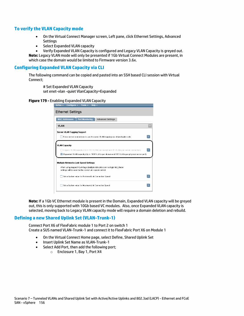
Scenario 7 – Tunneled VLANs and Shared Uplink Set with Active/Active Uplinks and 802.3ad (LACP) - Ethernet and FCoE SAN - vSphere 156
To verify the VLAN Capacity mode
On the Virtual Connect Manager screen, Left pane, click Ethernet Settings, Advanced Settings
Select Expanded VLAN capacity Verify Expanded VLAN Capacity is configured and Legacy VLAN Capacity is greyed out.
Note: Legacy VLAN mode will only be presented if 1Gb Virtual Connect Modules are present, in which case the domain would be limited to Firmware version 3.6x.
Configuring Expanded VLAN Capacity via CLI
The following command can be copied and pasted into an SSH based CLI session with Virtual Connect;
# Set Expanded VLAN Capacity set enet-vlan -quiet VlanCapacity=Expanded
Figure 179 - Enabling Expanded VLAN Capacity
Note: If a 1Gb VC Ethernet module is present in the Domain, Expanded VLAN capacity will be greyed out, this is only supported with 10Gb based VC modules. Also, once Expanded VLAN capacity is selected, moving back to Legacy VLAN capacity mode will require a domain deletion and rebuild.
Defining a new Shared Uplink Set (VLAN-Trunk-1)
Connect Port X6 of FlexFabric module 1 to Port 2 on switch 1 Create a SUS named VLAN-Trunk-1 and connect it to FlexFabric Port X6 on Module 1
On the Virtual Connect Home page, select Define, Shared Uplink Set Insert Uplink Set Name as VLAN-Trunk-1 Select Add Port, then add the following port;
o Enclosure 1, Bay 1, Port X4
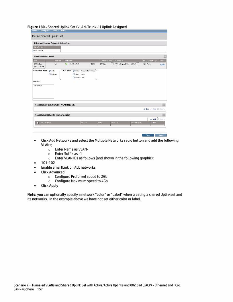
Scenario 7 – Tunneled VLANs and Shared Uplink Set with Active/Active Uplinks and 802.3ad (LACP) - Ethernet and FCoE SAN - vSphere 157
Figure 180 - Shared Uplink Set (VLAN-Trunk-1) Uplink Assigned
Click Add Networks and select the Multiple Networks radio button and add the following
VLANs; o Enter Name as VLAN- o Enter Suffix as -1 o Enter VLAN IDs as follows (and shown in the following graphic);
101-102 Enable SmartLink on ALL networks Click Advanced
o Configure Preferred speed to 2Gb o Configure Maximum speed to 4Gb
Click Apply
Note: you can optionally specify a network “color” or “Label” when creating a shared Uplinkset and its networks. In the example above we have not set either color or label.
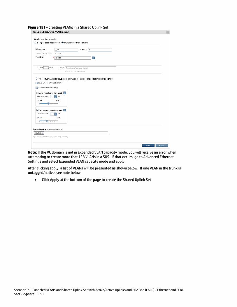
Scenario 7 – Tunneled VLANs and Shared Uplink Set with Active/Active Uplinks and 802.3ad (LACP) - Ethernet and FCoE SAN - vSphere 158
Figure 181 - Creating VLANs in a Shared Uplink Set
Note: If the VC domain is not in Expanded VLAN capacity mode, you will receive an error when attempting to create more that 128 VLANs in a SUS. If that occurs, go to Advanced Ethernet Settings and select Expanded VLAN capacity mode and apply.
After clicking apply, a list of VLANs will be presented as shown below. If one VLAN in the trunk is untagged/native, see note below.
Click Apply at the bottom of the page to create the Shared Uplink Set
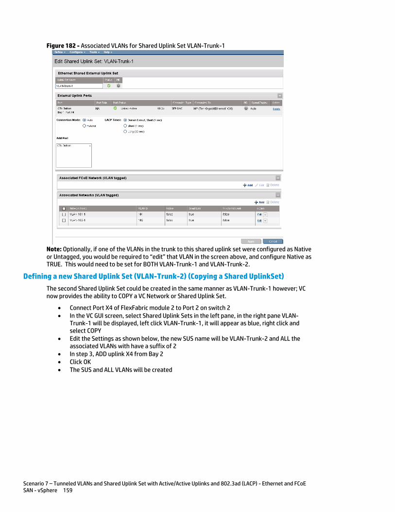
Scenario 7 – Tunneled VLANs and Shared Uplink Set with Active/Active Uplinks and 802.3ad (LACP) - Ethernet and FCoE SAN - vSphere 159
Figure 182 - Associated VLANs for Shared Uplink Set VLAN-Trunk-1
Note: Optionally, if one of the VLANs in the trunk to this shared uplink set were configured as Native or Untagged, you would be required to “edit” that VLAN in the screen above, and configure Native as TRUE. This would need to be set for BOTH VLAN-Trunk-1 and VLAN-Trunk-2.
Defining a new Shared Uplink Set (VLAN-Trunk-2) (Copying a Shared UplinkSet)
The second Shared Uplink Set could be created in the same manner as VLAN-Trunk-1 however; VC now provides the ability to COPY a VC Network or Shared Uplink Set.
Connect Port X4 of FlexFabric module 2 to Port 2 on switch 2 In the VC GUI screen, select Shared Uplink Sets in the left pane, in the right pane VLAN-
Trunk-1 will be displayed, left click VLAN-Trunk-1, it will appear as blue, right click and select COPY
Edit the Settings as shown below, the new SUS name will be VLAN-Trunk-2 and ALL the associated VLANs with have a suffix of 2
In step 3, ADD uplink X4 from Bay 2 Click OK The SUS and ALL VLANs will be created

Scenario 7 – Tunneled VLANs and Shared Uplink Set with Active/Active Uplinks and 802.3ad (LACP) - Ethernet and FCoE SAN - vSphere 160
Figure 183 - Copying a SUS and ALL VLANs
Defining a new Shared Uplink Set via CLI
The following script can be used to create the first Shared Uplink Set (VLAN-Trunk-1)
The following command(s) can be copied and pasted into an SSH based CLI session with Virtual Connect
# Create Shared Uplink Set VLAN-Trunk-1 and configure uplinks add uplinkset VLAN-Trunk-1 add uplinkport enc0:1:X4 Uplinkset=VLAN-Trunk-1 speed=auto # Create Networks VLAN-101-1 through VLAN-102-1 for Shared Uplink Set VLAN-Trunk-1 add network-range -quiet UplinkSet=VLAN-Trunk-1 NamePrefix=VLAN- NameSuffix=-1 VLANIds=101-102 State=enabled PrefSpeedType=Custom PrefSpeed=2000 MaxSpeedType=Custom MaxSpeed=4000 SmartLink=enabled
The following script can be used to create the Second Shared Uplink Set (VLAN-Trunk-2)
# Create Shared Uplink Set VLAN-Trunk-2 and configure uplinks add uplinkset VLAN-Trunk-2 add uplinkport enc0:2:X4 Uplinkset=VLAN-Trunk-2 speed=auto # Create Networks VLAN101-2 through VLAN102-2 for Shared Uplink Set VLAN-Trunk-2 add network-range -quiet UplinkSet=VLAN-Trunk-2 NamePrefix=VLAN- NameSuffix=-2 VLANIds=101-102 State=enabled PrefSpeedType=Custom PrefSpeed=2000 MaxSpeedType=Custom MaxSpeed=4000 SmartLink=enabled
Defining a new vNet Tunnel (Tunnel-1)
Connect Port X5 and X6 of FlexFabric module 1 to Port 3 and 4 on switch 1 Create an Ethernet Network named Tunnel-1 and connect it to FlexFabric Ports X5 and X6 on Module 1
On the Virtual Connect Home page, select Define a Network Insert Network Name as Tunnel-1 Select Add Port, then add the following port;
o Enclosure 1, Bay 1, Ports X5 and X6 o Enable SmartLink o Enable VLAN Tunneling
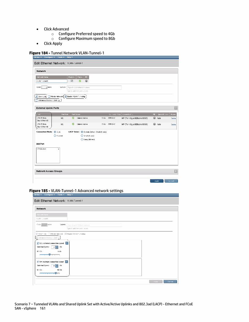
Scenario 7 – Tunneled VLANs and Shared Uplink Set with Active/Active Uplinks and 802.3ad (LACP) - Ethernet and FCoE SAN - vSphere 161
Click Advanced o Configure Preferred speed to 4Gb o Configure Maximum speed to 8Gb
Click Apply
Figure 184 - Tunnel Network VLAN-Tunnel-1
Figure 185 - VLAN-Tunnel-1 Advanced network settings
Scenario 7 – Tunneled VLANs and Shared Uplink Set with Active/Active Uplinks and 802.3ad (LACP) - Ethernet and FCoE SAN - vSphere 162
Defining a new vNet Tunnel (Tunnel-2)
Connect Port X5 and X6 of FlexFabric module 2 to Ports 3 and 4 on switch 2 Create an Ethernet Network named Tunnel-2 and connect it to FlexFabric Ports X5 and X6 on Module 2
On the Virtual Connect Home page, select Define a Network Insert Network Name as Tunnel-2 Select Add Port, then add the following port;
o Enclosure 1, Bay 2, Ports X5 and X6 o Enable SmartLink o Enable VLAN Tunneling
Click Advanced o Configure Preferred speed to 4Gb o Configure Maximum speed to 8Gb
Click Apply
Note: The vNet Tunnel provides the ability to pass an unlimited number of VLANs to the server NIC., Typically, that NIC would be connected to Hypervisor vSwitch. By using a Tunnel, we can exceed any VLAN limits that VC may have, example; VC 3.30 will support up to 1000 VLAN in a Shared Uplink Set, the Tunnel allows us to exceed that limit. In addition, the Tunnel allows the Network administrator to add and remove VLANs at will, without the need to configure those VLANs within Virtual Connect, they will however, need to be configured in the Hypervisor.
Defining a new Network Tunnel via CLI
The following script can be used to create the vNet Tunnel (Tunnel-1)
The following command(s) can be copied and pasted into an SSH based CLI session with Virtual Connect
# Create vNet Tunnel "Tunnel-1" and configure uplinks add network VLAN-Tunnel-1 VLanTunnel=Enabled LacpTimer=Domain-Default PrefSpeedType=Custom PrefSpeed=4000 MaxSpeedType=Custom MaxSpeed=8000 add uplinkport enc0:1:X5 Network=VLAN-Tunnel-1 Speed=Auto add uplinkport enc0:1:X6 Network=VLAN-Tunnel-1 Speed=Auto set network VLAN-Tunnel-1 SmartLink=Enabled # Create vNet Tunnel "Tunnel-2" and configure uplinks add network VLAN-Tunnel-2 VLanTunnel=Enabled LacpTimer=Domain-Default PrefSpeedType=Custom PrefSpeed=4000 MaxSpeedType=Custom MaxSpeed=8000 add uplinkport enc0:2:X5 Network=VLAN-Tunnel-2 Speed=Auto add uplinkport enc0:2:X6 Network=VLAN-Tunnel-2 Speed=Auto set network VLAN-Tunnel-2 SmartLink=Enabled
Note: In this scenario we have created two independent Share Uplink Sets (SUS), each originating from the opposite FlexFabric Modules, by doing so we provide the ability to create separate and redundant connections out of the Virtual Connect domain. When we create the server profiles, you will see how the NICs will connect to VLANs accessed through the opposite VC module, which provides the ability to create an Active / Active uplink scenario. Alternatively, we could have created a single SUS and assigned both sets of these uplink ports to the same SUS, however, this would have provided an Active/Standby uplink scenario, as shown in Scenario 5.
In addition to the Shared Uplink Set, we also created a pair of vNet (Network) Tunnels. The Tunnel can be used to pass many VLANs (up to 4094 VLANs) without the need to define each VLAN, as in the Shared Uplink Set.

Scenario 7 – Tunneled VLANs and Shared Uplink Set with Active/Active Uplinks and 802.3ad (LACP) - Ethernet and FCoE SAN - vSphere 163
Defining a new (FCoE) SAN Fabric via GUI
Create a Fabric and name it “FCoE_A”
On the Virtual Connect Manager screen, click Define, SAN Fabric to create the first Fabric Enter the Network Name of “FCoE_A” Select Add Port, then add the following ports;
o Enclosure 1, Bay 1, Port X1 o Enclosure 1, Bay 1, Port X2
Ensure Fabric Type is set to “FabricAttach” Select Show Advanced Settings
o Select Automatic Login Re-Distribution (FlexFabric Only) o Select Set Preferred FCoE Connect Speed
Configure for 4Gb o Select Set Maximum FCoE Connect Speed
Configure for 8Gb Select Apply
Create a second Fabric and name it “FCoE_B”
On the Virtual Connect Manager screen, click Define, SAN Fabric to create the second Fabric Enter the Network Name of “FCoE_B” Select Add Port, then add the following ports;
o Enclosure 1, Bay 2, Port X1 o Enclosure 1, Bay 2, Port X2
Ensure Fabric Type is set to “FabricAttach” Select Show Advanced Settings
o Select Automatic Login Re-Distribution (FlexFabric Only) o Select Set Preferred FCoE Connect Speed
Configure for 4Gb o Select Set Maximum FCoE Connect Speed
Configure for 8Gb Select Apply
Defining SAN Fabrics via CLI
The following command(s) can be copied and pasted into an SSH based CLI session with Virtual Connect
#Create the SAN Fabrics FCoE_A and FCoE_B and configure uplinks as discussed above add fabric FCoE_A Type=FabricAttach Bay=1 Ports=1,2 Speed=Auto LinkDist=Auto PrefSpeedType=Custom PrefSpeed=4000 MaxSpeedType=Custom MaxSpeed=8000 add fabric FCoE_B Type=FabricAttach Bay=2 Ports=1,2 Speed=Auto LinkDist=Auto PrefSpeedType=Custom PrefSpeed=4000 MaxSpeedType=Custom MaxSpeed=8000

Scenario 7 – Tunneled VLANs and Shared Uplink Set with Active/Active Uplinks and 802.3ad (LACP) - Ethernet and FCoE SAN - vSphere 164
Figure 186 - SAN Configuration and Advanced Settings
Figure 187 - FCoE SAN fabrics configured with two 8Gb uplinks per fabric. Note the bay and port numbers on the right
Scenario 7 – Tunneled VLANs and Shared Uplink Set with Active/Active Uplinks and 802.3ad (LACP) - Ethernet and FCoE SAN - vSphere 165
Defining a Server Profile
We will create a server profile with SIX server NICs and TWO SAN adapters. Each server NIC will connect to a specific network.
On the main menu, select Define, then Server Profile Create a server profile called “ESX-1” In the Network Port 1 drop down box, select a Network, then chose VLAN101-1 Set the port speed to Custom at 100Mb In the Network Port 2 drop down box, select a Network, then chose VLAN101-2 Set the port speed to Custom at 100Mb Left click on either of Port 1 or Port 2 in the Ethernet Connections box, and select ADD
network (add four additional network connections) In the Network Port 3 drop down box, select a Network, then chose VLAN-102-1 Leave the network speed as Preferred In the Network Port 4 drop down box, select a Network, then chose VLAN-102-2 Leave the network speed as Preferred In the Network Port 5 drop down box, select a Network and chose VLAN-Tunnel-1 Leave the network speed as Preferred In the Network Port 6 drop down box, select a Network and chose VLAN-Tunnel-2 Leave the network speed as Preferred Expand the FCoE Connections box, for Bay 1, select FCoE_A for Bay 2, select FCoE_B Leave the SAN Port speed as Preferred Do not configure FC SAN or iSCSI Connection In the Assign Profile to Server Bay box, locate the Select Location drop down and select
Bay 2, then apply Prior to applying the profile, ensure that the server in Bay 2 is currently OFF
Note: You should now have a server profile assigned to Bay 2, with 6 Server NIC connections. NICs 1&2 should be connected to VLAN VLAN-101-x (MGMT), NICs 3&4 should be connected and VLAN-102x (VMotion) and NICs 5 and 6 are connected to VLAN-Tunnel-x (VM Guest Networks). FCoE SAN fabrics are connected to, Port 1 - FCoE_A and Port 2 - FCoE_B.
Defining a Server Profile via CLI
The following command(s) can be copied and pasted into an SSH based CLI session with Virtual Connect
# Create Server Profile ESX-1 add profile ESX-1 -nodefaultfcconn -nodefaultfcoeconn set enet-connection ESX-1 1 pxe=Enabled Network=VLAN-101-1 SpeedType=Custom Speed=100 set enet-connection ESX-1 2 pxe=Disabled Network=VLAN-101-2 SpeedType=Custom Speed=100 add enet-connection ESX-1 pxe=Disabled Network=VLAN-102-1 add enet-connection ESX-1 pxe=Disabled Network=VLAN-102-2 add enet-connection ESX-1 pxe=Disabled Network=VLAN-Tunnel-1 SpeedType=Auto add enet-connection ESX-1 pxe=Disabled Network=VLAN-Tunnel-2 SpeedType=Auto add fcoe-connection ESX-1 Fabric=FCoE_A SpeedType=Preferred add fcoe-connection ESX-1 Fabric=FCoE_B SpeedType=Preferred Poweroff server 2 assign profile ESX-1 enc0:2
Note: The speed of the NIC and SAN connections, as well as the MAC and WWN. Also, note that the FCoE connections are assigned to the two SAN fabrics created earlier and use ports LOM:1-b and LOM:2-b.
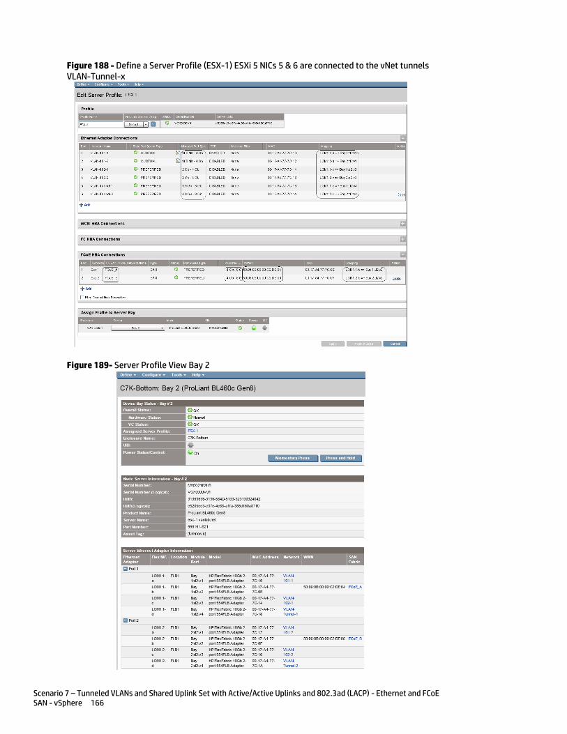
Scenario 7 – Tunneled VLANs and Shared Uplink Set with Active/Active Uplinks and 802.3ad (LACP) - Ethernet and FCoE SAN - vSphere 166
Figure 188 - Define a Server Profile (ESX-1) ESXi 5 NICs 5 & 6 are connected to the vNet tunnels VLAN-Tunnel-x
Figure 189- Server Profile View Bay 2
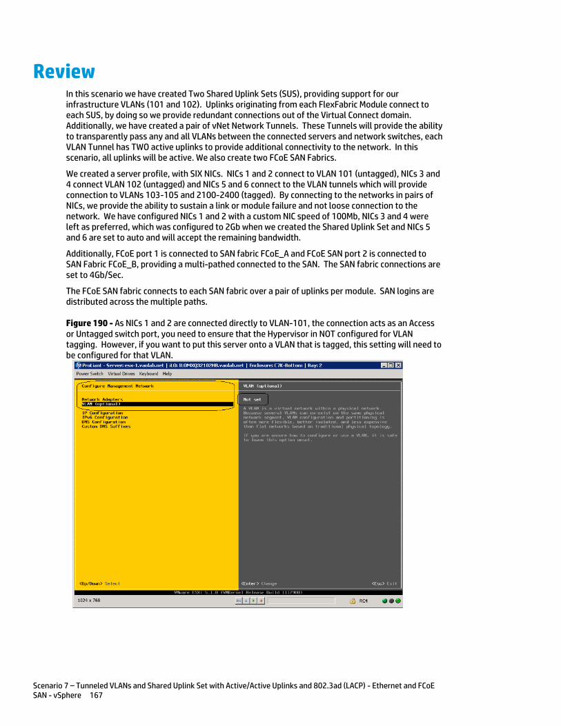
Scenario 7 – Tunneled VLANs and Shared Uplink Set with Active/Active Uplinks and 802.3ad (LACP) - Ethernet and FCoE SAN - vSphere 167
Review In this scenario we have created Two Shared Uplink Sets (SUS), providing support for our infrastructure VLANs (101 and 102). Uplinks originating from each FlexFabric Module connect to each SUS, by doing so we provide redundant connections out of the Virtual Connect domain. Additionally, we have created a pair of vNet Network Tunnels. These Tunnels will provide the ability to transparently pass any and all VLANs between the connected servers and network switches, each VLAN Tunnel has TWO active uplinks to provide additional connectivity to the network. In this scenario, all uplinks will be active. We also create two FCoE SAN Fabrics.
We created a server profile, with SIX NICs. NICs 1 and 2 connect to VLAN 101 (untagged), NICs 3 and 4 connect VLAN 102 (untagged) and NICs 5 and 6 connect to the VLAN tunnels which will provide connection to VLANs 103-105 and 2100-2400 (tagged). By connecting to the networks in pairs of NICs, we provide the ability to sustain a link or module failure and not loose connection to the network. We have configured NICs 1 and 2 with a custom NIC speed of 100Mb, NICs 3 and 4 were left as preferred, which was configured to 2Gb when we created the Shared Uplink Set and NICs 5 and 6 are set to auto and will accept the remaining bandwidth.
Additionally, FCoE port 1 is connected to SAN fabric FCoE_A and FCoE SAN port 2 is connected to SAN Fabric FCoE_B, providing a multi-pathed connected to the SAN. The SAN fabric connections are set to 4Gb/Sec.
The FCoE SAN fabric connects to each SAN fabric over a pair of uplinks per module. SAN logins are distributed across the multiple paths.
Figure 190 - As NICs 1 and 2 are connected directly to VLAN-101, the connection acts as an Access or Untagged switch port, you need to ensure that the Hypervisor in NOT configured for VLAN tagging. However, if you want to put this server onto a VLAN that is tagged, this setting will need to be configured for that VLAN.
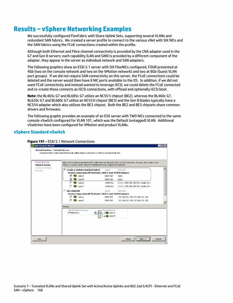
Scenario 7 – Tunneled VLANs and Shared Uplink Set with Active/Active Uplinks and 802.3ad (LACP) - Ethernet and FCoE SAN - vSphere 168
Results – vSphere Networking Examples We successfully configured FlexFabric with Share Uplink Sets, supporting several VLANs and redundant SAN fabrics. We created a server profile to connect to the various vNet with SIX NICs and the SAN fabrics using the FCoE connections created within the profile.
Although both Ethernet and Fibre channel connectivity is provided by the CNA adapter used in the G7 and Gen 8 servers; each capability (LAN and SAN) is provided by a different component of the adapter, they appear in the server as individual network and SAN adapters.
The following graphics show an ESXi 5.1 server with SIX FlexNICs configured, FOUR presented at 4Gb (two on the console network and two on the VMotion network) and two at 8Gb (Guest VLAN port groups). If we did not require SAN connectivity on this server, the FCoE connections could be deleted and the server would then have 8 NIC ports available to the OS. In addition, if we did not want FCoE connectivity and instead wanted to leverage iSCSI, we could delete the FCoE connected and re-create those connects as iSCSI connections, with offload and optionally iSCSI boot.
Note: the BL465c G7 and BL685c G7 utilize an NC551i chipset (BE2), whereas the BL460c G7, BL620c G7 and BL680c G7 utilize an NC553i chipset (BE3) and the Gen 8 blades typically have a NC554 adapter which also utilizes the BE3 chipset. Both the BE2 and BE3 chipsets share common drivers and firmware.
The following graphic provides an example of an ESX server with TWO NICs connected to the same console vSwitch configured for VLAN 101, which was the Default (untagged) VLAN. Additional vSwitches have been configured for VMotion and product VLANs.
vSphere Standard vSwitch
Figure 191 - ESXi 5.1 Network Connections

Scenario 7 – Tunneled VLANs and Shared Uplink Set with Active/Active Uplinks and 802.3ad (LACP) - Ethernet and FCoE SAN - vSphere 169
Figure 192 – ESXi 5 Networking - three vSwitches configured. (Note the NIC speeds)
Note: As VLAN 101 is set as untagged at the upstream switch port, the management network port group should be defined as untagged. This will allow the server to be deployed, without having the set a VLAN ID for the management network.
Figure 193 - You may want to specify a specific NIC for VMotion traffic. This will ensure that all VMotion traffic between servers within the enclosure will remain on the same VC module, reducing the likelihood of multiple hops between servers. Edit the VMotion Configuration.
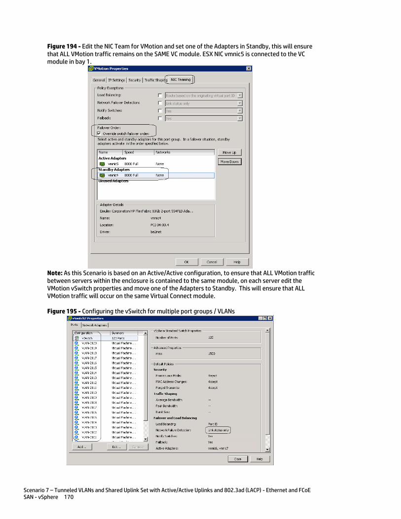
Scenario 7 – Tunneled VLANs and Shared Uplink Set with Active/Active Uplinks and 802.3ad (LACP) - Ethernet and FCoE SAN - vSphere 170
Figure 194 - Edit the NIC Team for VMotion and set one of the Adapters in Standby, this will ensure that ALL VMotion traffic remains on the SAME VC module. ESX NIC vmnic5 is connected to the VC module in bay 1.
Note: As this Scenario is based on an Active/Active configuration, to ensure that ALL VMotion traffic between servers within the enclosure is contained to the same module, on each server edit the VMotion vSwitch properties and move one of the Adapters to Standby. This will ensure that ALL VMotion traffic will occur on the same Virtual Connect module.
Figure 195 - Configuring the vSwitch for multiple port groups / VLANs
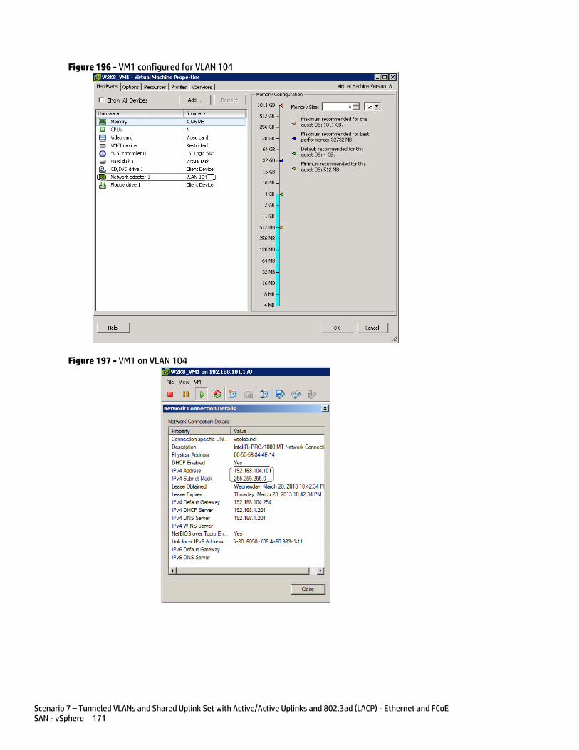
Scenario 7 – Tunneled VLANs and Shared Uplink Set with Active/Active Uplinks and 802.3ad (LACP) - Ethernet and FCoE SAN - vSphere 171
Figure 196 - VM1 configured for VLAN 104
Figure 197 - VM1 on VLAN 104
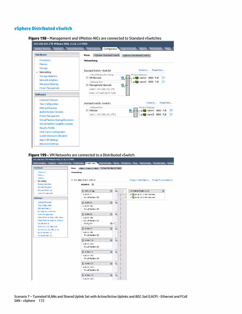
Scenario 7 – Tunneled VLANs and Shared Uplink Set with Active/Active Uplinks and 802.3ad (LACP) - Ethernet and FCoE SAN - vSphere 172
vSphere Distributed vSwitch
Figure 198 - Management and VMotion NICs are connected to Standard vSwitches
Figure 199 - VM Networks are connected to a Distributed vSwitch

Scenario 7 – Tunneled VLANs and Shared Uplink Set with Active/Active Uplinks and 802.3ad (LACP) - Ethernet and FCoE SAN - vSphere 173
Figure 200 - VM Connected to VLAN 104 on Distributed vSwitch
Results – vSphere SAN Connectivity
Figure 201 - By access the HBA BIOS during server boot, you can see that Port 1 of the FlexHBA is connected to an EVA SAN LUN. Also note the CNA firmware version, this is the minimum version required for vSphere 5.
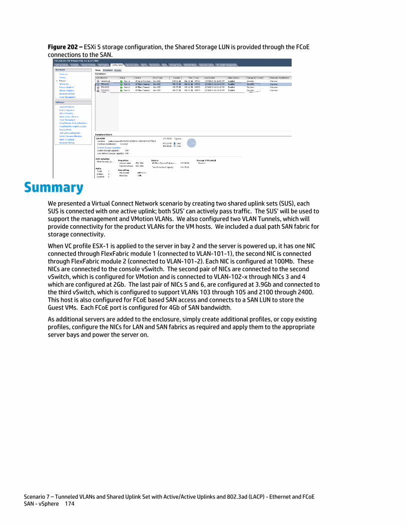
Scenario 7 – Tunneled VLANs and Shared Uplink Set with Active/Active Uplinks and 802.3ad (LACP) - Ethernet and FCoE SAN - vSphere 174
Figure 202 – ESXi 5 storage configuration, the Shared Storage LUN is provided through the FCoE connections to the SAN.
Summary We presented a Virtual Connect Network scenario by creating two shared uplink sets (SUS), each SUS is connected with one active uplink; both SUS’ can actively pass traffic. The SUS’ will be used to support the management and VMotion VLANs. We also configured two VLAN Tunnels, which will provide connectivity for the product VLANs for the VM hosts. We included a dual path SAN fabric for storage connectivity.
When VC profile ESX-1 is applied to the server in bay 2 and the server is powered up, it has one NIC connected through FlexFabric module 1 (connected to VLAN-101-1), the second NIC is connected through FlexFabric module 2 (connected to VLAN-101-2). Each NIC is configured at 100Mb. These NICs are connected to the console vSwitch. The second pair of NICs are connected to the second vSwitch, which is configured for VMotion and is connected to VLAN-102-x through NICs 3 and 4 which are configured at 2Gb. The last pair of NICs 5 and 6, are configured at 3.9Gb and connected to the third vSwitch, which is configured to support VLANs 103 through 105 and 2100 through 2400. This host is also configured for FCoE based SAN access and connects to a SAN LUN to store the Guest VMs. Each FCoE port is configured for 4Gb of SAN bandwidth.
As additional servers are added to the enclosure, simply create additional profiles, or copy existing profiles, configure the NICs for LAN and SAN fabrics as required and apply them to the appropriate server bays and power the server on.
Scenario 8 – Network Access Groups in a Shared Uplink Set - Ethernet and FCoE SAN – Windows 2008R2 175
Scenario 8 – Network Access Groups in a Shared Uplink Set - Ethernet and FCoE SAN – Windows 2008R2
Overview This scenario will implement the Shared Uplink Set (SUS) to provide support for multiple VLANs and will also leverage Network Access Groups to provide access control to specific VLANs.
The Network Access Group (NAG) is a feature enhancement with VC firmware release 3.30 and provides the ability to group VLANs based on application or security boundaries. We will create a Shared Uplink Set, and then identify VLANs that will associate with different applications and then create Network Access Groups to contain those VLANs. We can then create server profiles and assign server profiles to specific Network Access Groups, which will restrict their ability to connect to networks which are outside the Network Access Group they belong to.
As multiple VLANs will be supported in this configuration, the upstream switch ports connecting to the FlexFabric modules will be configured to properly present those VLANs. The upstream switch ports will be configured for VLAN trunking/VLAN tagging. LACP will also be used to connect two uplinks per module.
This scenario will focus on Ethernet connectivity only; however, FCoE connectivity is still support when using Network Access Groups.
Requirements In order to implement this scenario, an HP BladeSystem c7000 enclosure with one or more server blades and TWO Virtual Connect FlexFabric (or Flex-10) modules, installed in I/O Bays 1& 2 are required. In addition, we will require ONE or TWO external Network switches. As Virtual Connect does not appear to the network as a switch and is transparent to the network, any standard managed switch will work with Virtual Connect.
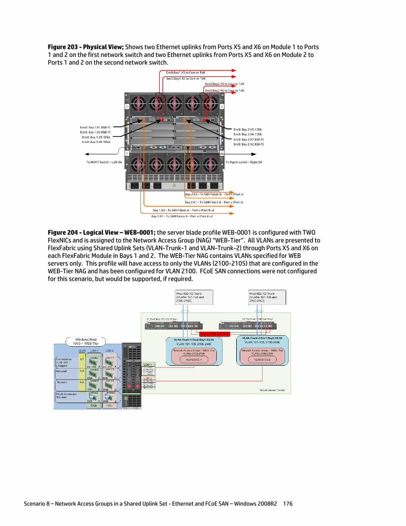
Scenario 8 – Network Access Groups in a Shared Uplink Set - Ethernet and FCoE SAN – Windows 2008R2 176
Figure 203 - Physical View; Shows two Ethernet uplinks from Ports X5 and X6 on Module 1 to Ports 1 and 2 on the first network switch and two Ethernet uplinks from Ports X5 and X6 on Module 2 to Ports 1 and 2 on the second network switch.
Figure 204 - Logical View – WEB-0001; the server blade profile WEB-0001 is configured with TWO FlexNICs and is assigned to the Network Access Group (NAG) “WEB-Tier”. All VLANs are presented to FlexFabric using Shared Uplink Sets (VLAN-Trunk-1 and VLAN-Trunk-2) through Ports X5 and X6 on each FlexFabric Module in Bays 1 and 2. The WEB-Tier NAG contains VLANs specified for WEB servers only. This profile will have access to only the VLANs (2100-2105) that are configured in the WEB-Tier NAG and has been configured for VLAN 2100. FCoE SAN connections were not configured for this scenario, but would be supported, if required.
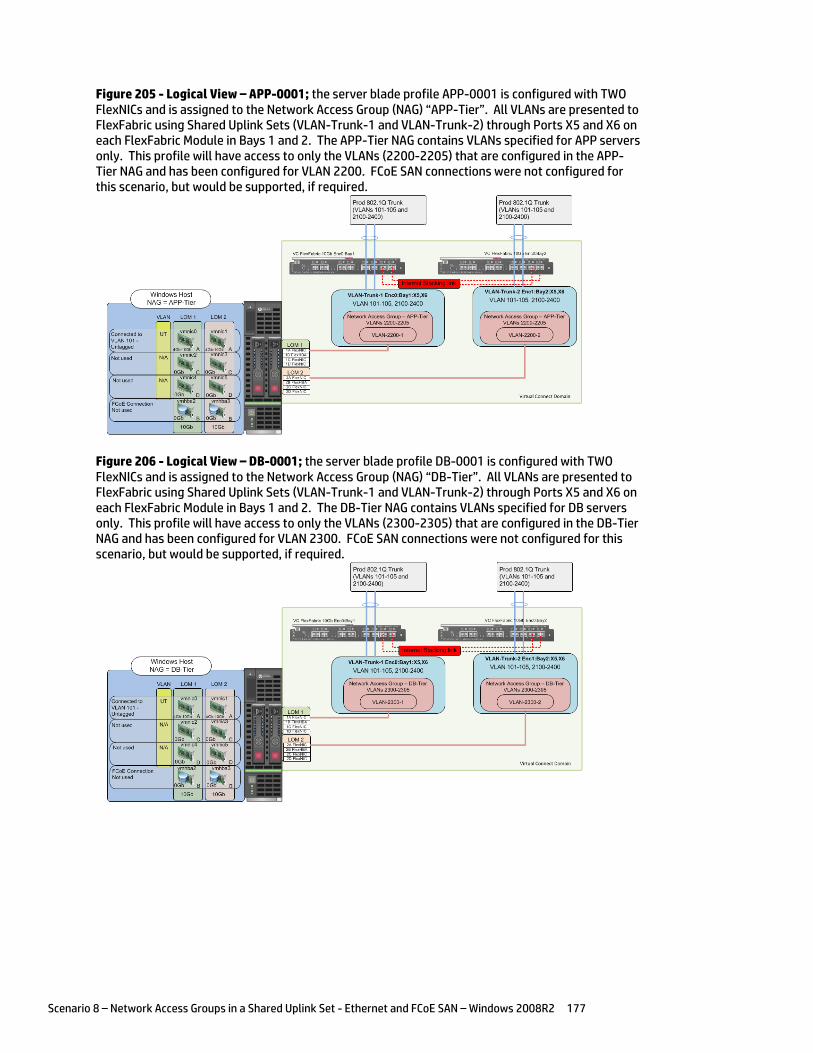
Scenario 8 – Network Access Groups in a Shared Uplink Set - Ethernet and FCoE SAN – Windows 2008R2 177
Figure 205 - Logical View – APP-0001; the server blade profile APP-0001 is configured with TWO FlexNICs and is assigned to the Network Access Group (NAG) “APP-Tier”. All VLANs are presented to FlexFabric using Shared Uplink Sets (VLAN-Trunk-1 and VLAN-Trunk-2) through Ports X5 and X6 on each FlexFabric Module in Bays 1 and 2. The APP-Tier NAG contains VLANs specified for APP servers only. This profile will have access to only the VLANs (2200-2205) that are configured in the APP-Tier NAG and has been configured for VLAN 2200. FCoE SAN connections were not configured for this scenario, but would be supported, if required.
Figure 206 - Logical View – DB-0001; the server blade profile DB-0001 is configured with TWO FlexNICs and is assigned to the Network Access Group (NAG) “DB-Tier”. All VLANs are presented to FlexFabric using Shared Uplink Sets (VLAN-Trunk-1 and VLAN-Trunk-2) through Ports X5 and X6 on each FlexFabric Module in Bays 1 and 2. The DB-Tier NAG contains VLANs specified for DB servers only. This profile will have access to only the VLANs (2300-2305) that are configured in the DB-Tier NAG and has been configured for VLAN 2300. FCoE SAN connections were not configured for this scenario, but would be supported, if required.
Scenario 8 – Network Access Groups in a Shared Uplink Set - Ethernet and FCoE SAN – Windows 2008R2 178
Installation and configuration Switch configuration
As the Virtual Connect module acts as an edge switch, Virtual Connect can connect to the network at either the distribution level or directly to the core switch.
The appendices provide a summary of the cli commands required to configure various switches for connection to Virtual Connect. The configuration information provided in the appendices for this scenario assumes the following information:
The switch ports are configured as VLAN TRUNK ports (tagging) to support several VLANs. All frames will be forwarded to Virtual Connect with VLAN tags. Optionally, one VLAN could be configured as (Default) untagged, if so, then a corresponding vNet within the Shared Uplink Set would be configured and set as “Default”.
Note: when adding additional uplinks to the SUS, if the additional uplinks are connecting from the same FlexFabric module to the same switch, in order to ensure all the uplinks are active, the switch ports will need to be configured for LACP within the same Link Aggregation Group.
The network switch port should be configured for Spanning Tree Edge as Virtual Connect appears to the switch as an access device and not another switch. By configuring the port as Spanning Tree Edge, it allows the switch to place the port into a forwarding state much quicker than otherwise, this allows a newly connected port to come online and begin forwarding much quicker.
Configuring the VC module
Physically connect Port 1 of network switch 1 to Port X5 of the VC module in Bay 1 Physically connect Port 2 of network switch 1 to Port X6 of the VC module in Bay 1 Physically connect Port 1 of network switch 2 to Port X5 of the VC module in Bay 2 Physically connect Port 2 of network switch 2 to Port X6 of the VC module in Bay 2
Note: if you have only one network switch, connect VC ports X5 & X6 (Bay 2) to an alternate port on the same switch. This will NOT create a network loop and Spanning Tree is not required.
VC CLI commands
Many of the configuration settings within VC can also be accomplished via a CLI command set. In order to connect to VC via a CLI, open an SSH connection to the IP address of the active VCM. Once logged in, VC provides a CLI with help menus. Through this scenario the CLI commands to configure VC for each setting will also be provided.
Configuring Expanded VLAN Capacity via GUI
Virtual Connect release 3.30 provided an expanded VLAN capacity mode when using Shared Uplink Sets, this mode can be enabled through the Ethernet Settings tab or the VC CLI. The default configuration for a new Domain install is “Expanded VLAN Capacity” mode, Legacy mode is no longer available and the Domain cannot be downgraded.
To verify the VLAN Capacity mode
On the Virtual Connect Manager screen, Left pane, click Ethernet Settings, Advanced Settings
Select Expanded VLAN capacity Verify Expanded VLAN Capacity is configured and Legacy VLAN Capacity is greyed out.
Note: Legacy VLAN mode will only be presented if 1Gb Virtual Connect Modules are present, in which case the domain would be limited to Firmware version 3.6x.
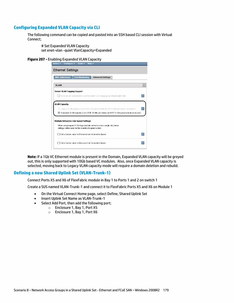
Scenario 8 – Network Access Groups in a Shared Uplink Set - Ethernet and FCoE SAN – Windows 2008R2 179
Configuring Expanded VLAN Capacity via CLI
The following command can be copied and pasted into an SSH based CLI session with Virtual Connect;
# Set Expanded VLAN Capacity set enet-vlan -quiet VlanCapacity=Expanded
Figure 207 - Enabling Expanded VLAN Capacity
Note: If a 1Gb VC Ethernet module is present in the Domain, Expanded VLAN capacity will be greyed out, this is only supported with 10Gb based VC modules. Also, once Expanded VLAN capacity is selected, moving back to Legacy VLAN capacity mode will require a domain deletion and rebuild.
Defining a new Shared Uplink Set (VLAN-Trunk-1)
Connect Ports X5 and X6 of FlexFabric module in Bay 1 to Ports 1 and 2 on switch 1
Create a SUS named VLAN-Trunk-1 and connect it to FlexFabric Ports X5 and X6 on Module 1
On the Virtual Connect Home page, select Define, Shared Uplink Set Insert Uplink Set Name as VLAN-Trunk-1 Select Add Port, then add the following port;
o Enclosure 1, Bay 1, Port X5 o Enclosure 1, Bay 1, Port X6

Scenario 8 – Network Access Groups in a Shared Uplink Set - Ethernet and FCoE SAN – Windows 2008R2 180
Figure 208 - Shared Uplink Set (VLAN-Trunk-1) Uplinks Assigned
Click Add Networks and select the Multiple Networks radio button and add the following
VLANs; o Enter Name as VLAN- o Enter Suffix as -1 o Enter VLAN IDs as follows (and shown in the following graphic);
101-105,2100-2400 Enable SmartLink on ALL networks Click Advanced
o Configure Preferred speed to 4Gb o Configure Maximum speed to 8Gb
Click Apply
Note: You can optionally specify a network “color” or “Label” when creating a shared Uplinkset and its networks. In the example above we have not set either color or label.
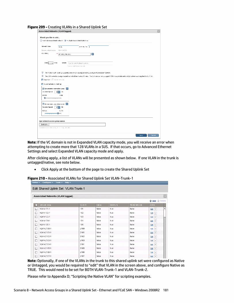
Scenario 8 – Network Access Groups in a Shared Uplink Set - Ethernet and FCoE SAN – Windows 2008R2 181
Figure 209 - Creating VLANs in a Shared Uplink Set
Note: If the VC domain is not in Expanded VLAN capacity mode, you will receive an error when attempting to create more that 128 VLANs in a SUS. If that occurs, go to Advanced Ethernet Settings and select Expanded VLAN capacity mode and apply.
After clicking apply, a list of VLANs will be presented as shown below. If one VLAN in the trunk is untagged/native, see note below.
Click Apply at the bottom of the page to create the Shared Uplink Set
Figure 210 - Associated VLANs for Shared Uplink Set VLAN-Trunk-1
Note: Optionally, if one of the VLANs in the trunk to this shared uplink set were configured as Native or Untagged, you would be required to “edit” that VLAN in the screen above, and configure Native as TRUE. This would need to be set for BOTH VLAN-Trunk-1 and VLAN-Trunk-2.
Please refer to Appendix D; “Scripting the Native VLAN” for scripting examples.
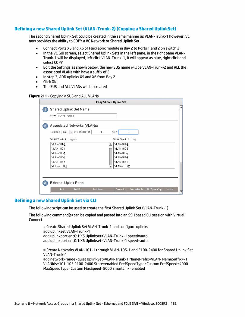
Scenario 8 – Network Access Groups in a Shared Uplink Set - Ethernet and FCoE SAN – Windows 2008R2 182
Defining a new Shared Uplink Set (VLAN-Trunk-2) (Copying a Shared UplinkSet)
The second Shared Uplink Set could be created in the same manner as VLAN-Trunk-1 however; VC now provides the ability to COPY a VC Network or Shared Uplink Set.
Connect Ports X5 and X6 of FlexFabric module in Bay 2 to Ports 1 and 2 on switch 2 In the VC GUI screen, select Shared Uplink Sets in the left pane, in the right pane VLAN-
Trunk-1 will be displayed, left click VLAN-Trunk-1, it will appear as blue, right click and select COPY
Edit the Settings as shown below, the new SUS name will be VLAN-Trunk-2 and ALL the associated VLANs with have a suffix of 2
In step 3, ADD uplinks X5 and X6 from Bay 2 Click OK The SUS and ALL VLANs will be created
Figure 211 - Copying a SUS and ALL VLANs
Defining a new Shared Uplink Set via CLI
The following script can be used to create the first Shared Uplink Set (VLAN-Trunk-1)
The following command(s) can be copied and pasted into an SSH based CLI session with Virtual Connect
# Create Shared Uplink Set VLAN-Trunk-1 and configure uplinks add uplinkset VLAN-Trunk-1 add uplinkport enc0:1:X5 Uplinkset=VLAN-Trunk-1 speed=auto add uplinkport enc0:1:X6 Uplinkset=VLAN-Trunk-1 speed=auto # Create Networks VLAN-101-1 through VLAN-105-1 and 2100-2400 for Shared Uplink Set VLAN-Trunk-1 add network-range -quiet UplinkSet=VLAN-Trunk-1 NamePrefix=VLAN- NameSuffix=-1 VLANIds=101-105,2100-2400 State=enabled PrefSpeedType=Custom PrefSpeed=4000 MaxSpeedType=Custom MaxSpeed=8000 SmartLink=enabled
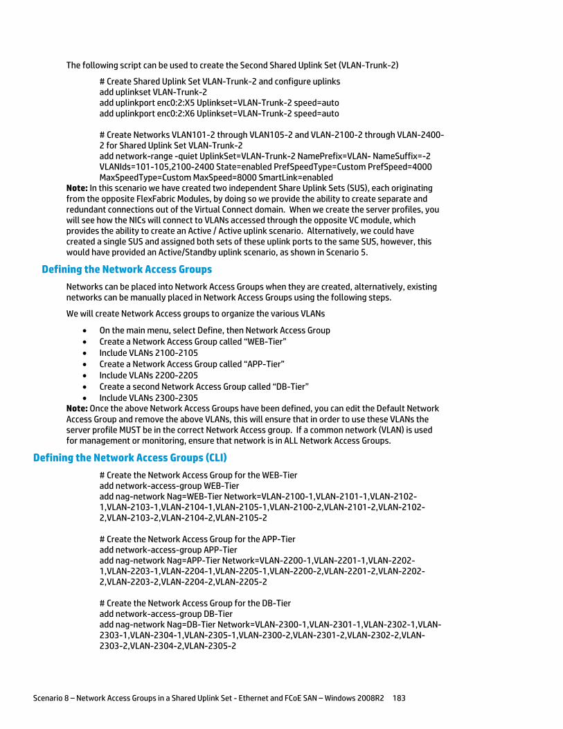
Scenario 8 – Network Access Groups in a Shared Uplink Set - Ethernet and FCoE SAN – Windows 2008R2 183
The following script can be used to create the Second Shared Uplink Set (VLAN-Trunk-2)
# Create Shared Uplink Set VLAN-Trunk-2 and configure uplinks add uplinkset VLAN-Trunk-2 add uplinkport enc0:2:X5 Uplinkset=VLAN-Trunk-2 speed=auto add uplinkport enc0:2:X6 Uplinkset=VLAN-Trunk-2 speed=auto # Create Networks VLAN101-2 through VLAN105-2 and VLAN-2100-2 through VLAN-2400-2 for Shared Uplink Set VLAN-Trunk-2 add network-range -quiet UplinkSet=VLAN-Trunk-2 NamePrefix=VLAN- NameSuffix=-2 VLANIds=101-105,2100-2400 State=enabled PrefSpeedType=Custom PrefSpeed=4000 MaxSpeedType=Custom MaxSpeed=8000 SmartLink=enabled
Note: In this scenario we have created two independent Share Uplink Sets (SUS), each originating from the opposite FlexFabric Modules, by doing so we provide the ability to create separate and redundant connections out of the Virtual Connect domain. When we create the server profiles, you will see how the NICs will connect to VLANs accessed through the opposite VC module, which provides the ability to create an Active / Active uplink scenario. Alternatively, we could have created a single SUS and assigned both sets of these uplink ports to the same SUS, however, this would have provided an Active/Standby uplink scenario, as shown in Scenario 5.
Defining the Network Access Groups
Networks can be placed into Network Access Groups when they are created, alternatively, existing networks can be manually placed in Network Access Groups using the following steps.
We will create Network Access groups to organize the various VLANs
On the main menu, select Define, then Network Access Group Create a Network Access Group called “WEB-Tier” Include VLANs 2100-2105 Create a Network Access Group called “APP-Tier” Include VLANs 2200-2205 Create a second Network Access Group called “DB-Tier” Include VLANs 2300-2305
Note: Once the above Network Access Groups have been defined, you can edit the Default Network Access Group and remove the above VLANs, this will ensure that in order to use these VLANs the server profile MUST be in the correct Network Access group. If a common network (VLAN) is used for management or monitoring, ensure that network is in ALL Network Access Groups.
Defining the Network Access Groups (CLI)
# Create the Network Access Group for the WEB-Tier add network-access-group WEB-Tier add nag-network Nag=WEB-Tier Network=VLAN-2100-1,VLAN-2101-1,VLAN-2102-1,VLAN-2103-1,VLAN-2104-1,VLAN-2105-1,VLAN-2100-2,VLAN-2101-2,VLAN-2102-2,VLAN-2103-2,VLAN-2104-2,VLAN-2105-2 # Create the Network Access Group for the APP-Tier add network-access-group APP-Tier add nag-network Nag=APP-Tier Network=VLAN-2200-1,VLAN-2201-1,VLAN-2202-1,VLAN-2203-1,VLAN-2204-1,VLAN-2205-1,VLAN-2200-2,VLAN-2201-2,VLAN-2202-2,VLAN-2203-2,VLAN-2204-2,VLAN-2205-2 # Create the Network Access Group for the DB-Tier add network-access-group DB-Tier add nag-network Nag=DB-Tier Network=VLAN-2300-1,VLAN-2301-1,VLAN-2302-1,VLAN-2303-1,VLAN-2304-1,VLAN-2305-1,VLAN-2300-2,VLAN-2301-2,VLAN-2302-2,VLAN-2303-2,VLAN-2304-2,VLAN-2305-2
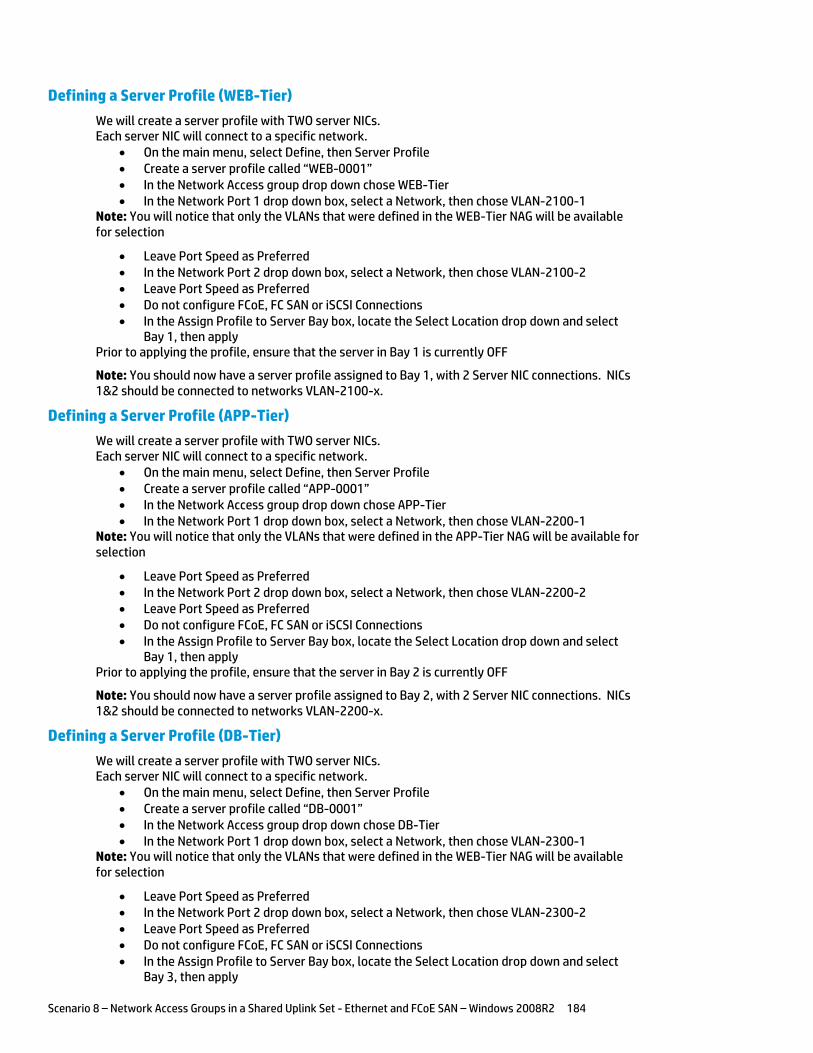
Scenario 8 – Network Access Groups in a Shared Uplink Set - Ethernet and FCoE SAN – Windows 2008R2 184
Defining a Server Profile (WEB-Tier)
We will create a server profile with TWO server NICs. Each server NIC will connect to a specific network.
On the main menu, select Define, then Server Profile Create a server profile called “WEB-0001” In the Network Access group drop down chose WEB-Tier In the Network Port 1 drop down box, select a Network, then chose VLAN-2100-1
Note: You will notice that only the VLANs that were defined in the WEB-Tier NAG will be available for selection
Leave Port Speed as Preferred In the Network Port 2 drop down box, select a Network, then chose VLAN-2100-2 Leave Port Speed as Preferred Do not configure FCoE, FC SAN or iSCSI Connections In the Assign Profile to Server Bay box, locate the Select Location drop down and select
Bay 1, then apply Prior to applying the profile, ensure that the server in Bay 1 is currently OFF
Note: You should now have a server profile assigned to Bay 1, with 2 Server NIC connections. NICs 1&2 should be connected to networks VLAN-2100-x.
Defining a Server Profile (APP-Tier)
We will create a server profile with TWO server NICs. Each server NIC will connect to a specific network.
On the main menu, select Define, then Server Profile Create a server profile called “APP-0001” In the Network Access group drop down chose APP-Tier In the Network Port 1 drop down box, select a Network, then chose VLAN-2200-1
Note: You will notice that only the VLANs that were defined in the APP-Tier NAG will be available for selection
Leave Port Speed as Preferred In the Network Port 2 drop down box, select a Network, then chose VLAN-2200-2 Leave Port Speed as Preferred Do not configure FCoE, FC SAN or iSCSI Connections In the Assign Profile to Server Bay box, locate the Select Location drop down and select
Bay 1, then apply Prior to applying the profile, ensure that the server in Bay 2 is currently OFF
Note: You should now have a server profile assigned to Bay 2, with 2 Server NIC connections. NICs 1&2 should be connected to networks VLAN-2200-x.
Defining a Server Profile (DB-Tier)
We will create a server profile with TWO server NICs. Each server NIC will connect to a specific network.
On the main menu, select Define, then Server Profile Create a server profile called “DB-0001” In the Network Access group drop down chose DB-Tier In the Network Port 1 drop down box, select a Network, then chose VLAN-2300-1
Note: You will notice that only the VLANs that were defined in the WEB-Tier NAG will be available for selection
Leave Port Speed as Preferred In the Network Port 2 drop down box, select a Network, then chose VLAN-2300-2 Leave Port Speed as Preferred Do not configure FCoE, FC SAN or iSCSI Connections In the Assign Profile to Server Bay box, locate the Select Location drop down and select
Bay 3, then apply
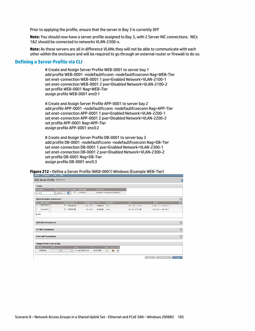
Scenario 8 – Network Access Groups in a Shared Uplink Set - Ethernet and FCoE SAN – Windows 2008R2 185
Prior to applying the profile, ensure that the server in Bay 3 is currently OFF
Note: You should now have a server profile assigned to Bay 3, with 2 Server NIC connections. NICs 1&2 should be connected to networks VLAN-2300-x.
Note: As these servers are all in difference VLANs they will not be able to communicate with each other within the enclosure and will be required to go through an external router or firewall to do so.
Defining a Server Profile via CLI
# Create and Assign Server Profile WEB-0001 to server bay 1 add profile WEB-0001 -nodefaultfcconn -nodefaultfcoeconn Nag=WEB-Tier set enet-connection WEB-0001 1 pxe=Enabled Network=VLAN-2100-1 set enet-connection WEB-0001 2 pxe=Disabled Network=VLAN-2100-2 set profile WEB-0001 Nag=WEB-Tier assign profile WEB-0001 enc0:1 # Create and Assign Server Profile APP-0001 to server bay 2 add profile APP-0001 -nodefaultfcconn -nodefaultfcoeconn Nag=APP-Tier set enet-connection APP-0001 1 pxe=Enabled Network=VLAN-2200-1 set enet-connection APP-0001 2 pxe=Disabled Network=VLAN-2200-2 set profile APP-0001 Nag=APP-Tier assign profile APP-0001 enc0:2 # Create and Assign Server Profile DB-0001 to server bay 3 add profile DB-0001 -nodefaultfcconn -nodefaultfcoeconn Nag=DB-Tier set enet-connection DB-0001 1 pxe=Enabled Network=VLAN-2300-1 set enet-connection DB-0001 2 pxe=Disabled Network=VLAN-2300-2 set profile DB-0001 Nag=DB-Tier assign profile DB-0001 enc0:3
Figure 212 - Define a Server Profile (WEB-0001) Windows (Example WEB-Tier)
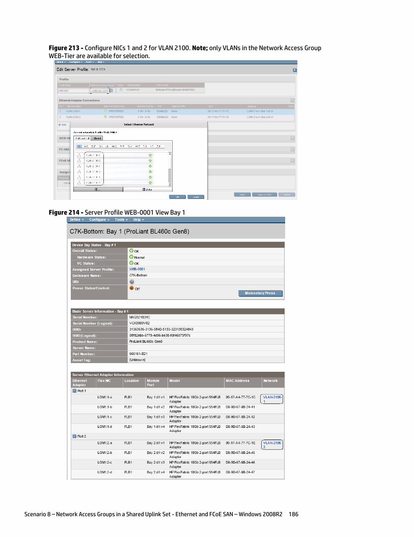
Scenario 8 – Network Access Groups in a Shared Uplink Set - Ethernet and FCoE SAN – Windows 2008R2 186
Figure 213 - Configure NICs 1 and 2 for VLAN 2100. Note; only VLANs in the Network Access Group WEB-Tier are available for selection.
Figure 214 - Server Profile WEB-0001 View Bay 1
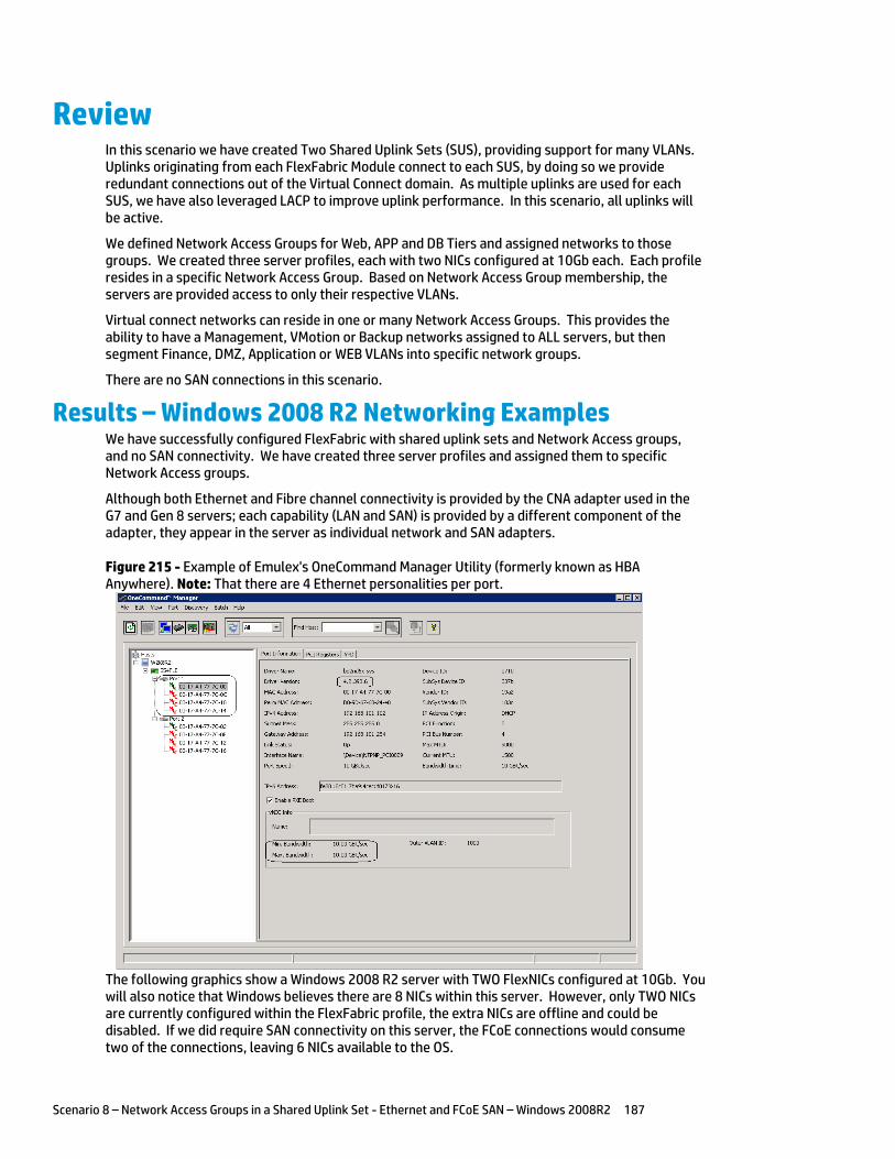
Scenario 8 – Network Access Groups in a Shared Uplink Set - Ethernet and FCoE SAN – Windows 2008R2 187
Review In this scenario we have created Two Shared Uplink Sets (SUS), providing support for many VLANs. Uplinks originating from each FlexFabric Module connect to each SUS, by doing so we provide redundant connections out of the Virtual Connect domain. As multiple uplinks are used for each SUS, we have also leveraged LACP to improve uplink performance. In this scenario, all uplinks will be active.
We defined Network Access Groups for Web, APP and DB Tiers and assigned networks to those groups. We created three server profiles, each with two NICs configured at 10Gb each. Each profile resides in a specific Network Access Group. Based on Network Access Group membership, the servers are provided access to only their respective VLANs.
Virtual connect networks can reside in one or many Network Access Groups. This provides the ability to have a Management, VMotion or Backup networks assigned to ALL servers, but then segment Finance, DMZ, Application or WEB VLANs into specific network groups.
There are no SAN connections in this scenario.
Results – Windows 2008 R2 Networking Examples We have successfully configured FlexFabric with shared uplink sets and Network Access groups, and no SAN connectivity. We have created three server profiles and assigned them to specific Network Access groups.
Although both Ethernet and Fibre channel connectivity is provided by the CNA adapter used in the G7 and Gen 8 servers; each capability (LAN and SAN) is provided by a different component of the adapter, they appear in the server as individual network and SAN adapters.
Figure 215 - Example of Emulex's OneCommand Manager Utility (formerly known as HBA Anywhere). Note: That there are 4 Ethernet personalities per port.
The following graphics show a Windows 2008 R2 server with TWO FlexNICs configured at 10Gb. You will also notice that Windows believes there are 8 NICs within this server. However, only TWO NICs are currently configured within the FlexFabric profile, the extra NICs are offline and could be disabled. If we did require SAN connectivity on this server, the FCoE connections would consume two of the connections, leaving 6 NICs available to the OS.
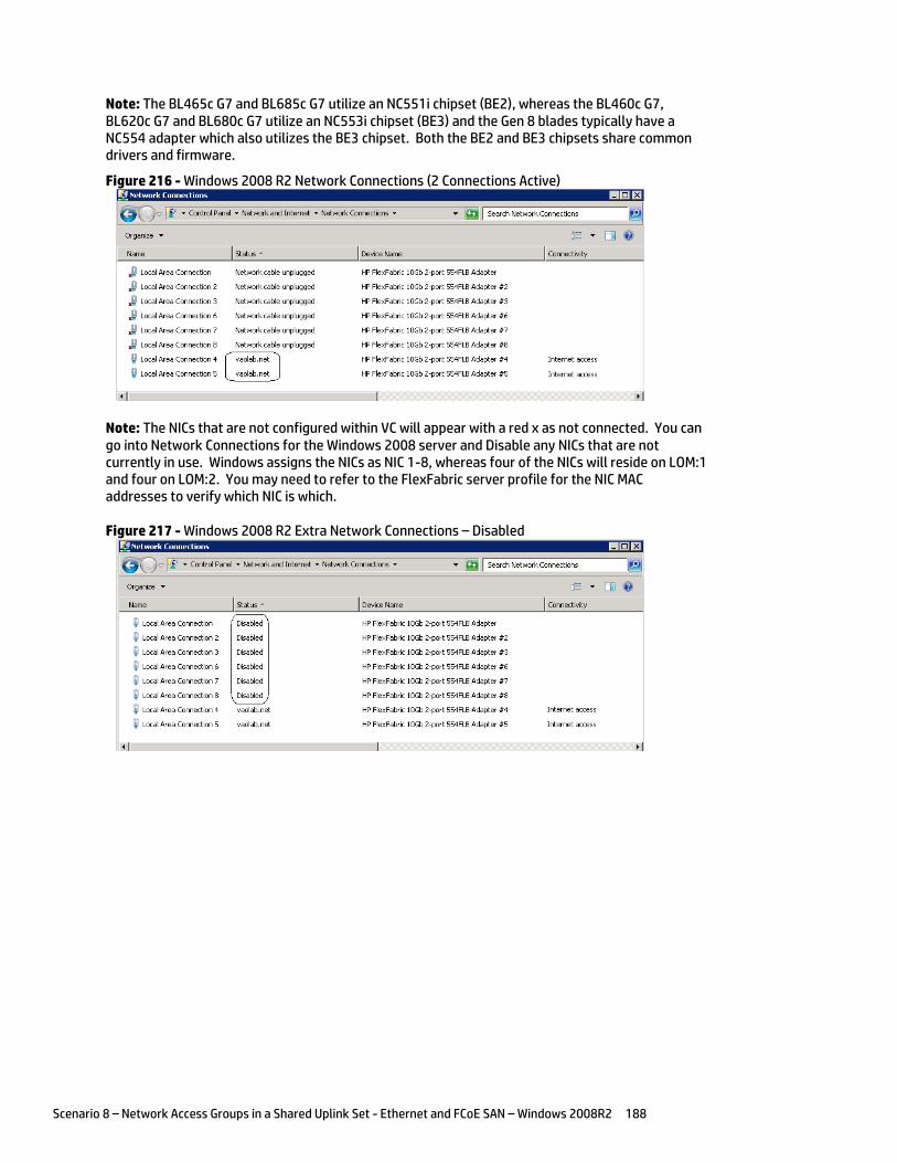
Scenario 8 – Network Access Groups in a Shared Uplink Set - Ethernet and FCoE SAN – Windows 2008R2 188
Note: The BL465c G7 and BL685c G7 utilize an NC551i chipset (BE2), whereas the BL460c G7, BL620c G7 and BL680c G7 utilize an NC553i chipset (BE3) and the Gen 8 blades typically have a NC554 adapter which also utilizes the BE3 chipset. Both the BE2 and BE3 chipsets share common drivers and firmware.
Figure 216 - Windows 2008 R2 Network Connections (2 Connections Active)
Note: The NICs that are not configured within VC will appear with a red x as not connected. You can go into Network Connections for the Windows 2008 server and Disable any NICs that are not currently in use. Windows assigns the NICs as NIC 1-8, whereas four of the NICs will reside on LOM:1 and four on LOM:2. You may need to refer to the FlexFabric server profile for the NIC MAC addresses to verify which NIC is which.
Figure 217 - Windows 2008 R2 Extra Network Connections – Disabled
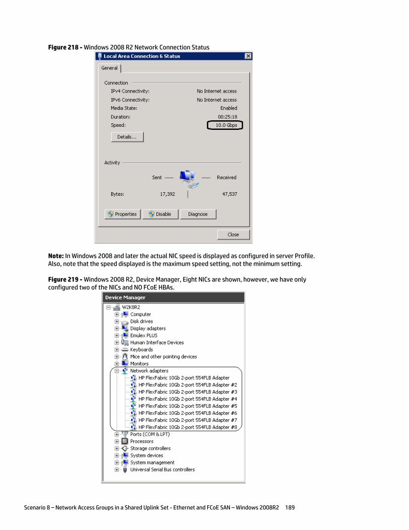
Scenario 8 – Network Access Groups in a Shared Uplink Set - Ethernet and FCoE SAN – Windows 2008R2 189
Figure 218 - Windows 2008 R2 Network Connection Status
Note: In Windows 2008 and later the actual NIC speed is displayed as configured in server Profile. Also, note that the speed displayed is the maximum speed setting, not the minimum setting.
Figure 219 - Windows 2008 R2, Device Manager, Eight NICs are shown, however, we have only configured two of the NICs and NO FCoE HBAs.
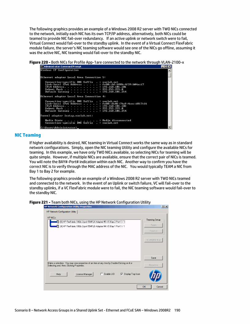
Scenario 8 – Network Access Groups in a Shared Uplink Set - Ethernet and FCoE SAN – Windows 2008R2 190
The following graphics provides an example of a Windows 2008 R2 server with TWO NICs connected to the network, initially each NIC has its own TCP/IP address, alternatively, both NICs could be teamed to provide NIC fail-over redundancy. If an active uplink or network switch were to fail, Virtual Connect would fail-over to the standby uplink. In the event of a Virtual Connect FlexFabric module failure, the server’s NIC teaming software would see one of the NICs go offline, assuming it was the active NIC, NIC teaming would fail-over to the standby NIC.
Figure 220 - Both NICs for Profile App-1are connected to the network through VLAN-2100-x
NIC Teaming
If higher availability is desired, NIC teaming in Virtual Connect works the same way as in standard network configurations. Simply, open the NIC teaming Utility and configure the available NICs for teaming. In this example, we have only TWO NICs available, so selecting NICs for teaming will be quite simple. However, if multiple NICs are available, ensure that the correct pair of NICs is teamed. You will note the BAY#-Port# indication within each NIC. Another way to confirm you have the correct NIC is to verify through the MAC address of the NIC. You would typically TEAM a NIC from Bay 1 to Bay 2 for example.
The following graphics provide an example of a Windows 2008 R2 server with TWO NICs teamed and connected to the network. In the event of an Uplink or switch failure, VC will fail-over to the standby uplinks, if a VC FlexFabric module were to fail, the NIC teaming software would fail-over to the standby NIC.
Figure 221 - Team both NICs, using the HP Network Configuration Utility
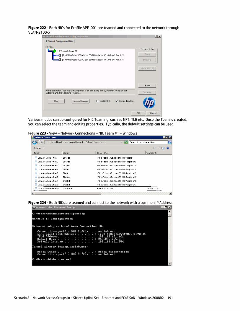
Scenario 8 – Network Access Groups in a Shared Uplink Set - Ethernet and FCoE SAN – Windows 2008R2 191
Figure 222 - Both NICs for Profile APP-001 are teamed and connected to the network through VLAN-2100-x
Various modes can be configured for NIC Teaming, such as NFT, TLB etc. Once the Team is created, you can select the team and edit its properties. Typically, the default settings can be used.
Figure 223 - View – Network Connections – NIC Team #1 – Windows
Figure 224 - Both NICs are teamed and connect to the network with a common IP Address
Scenario 8 – Network Access Groups in a Shared Uplink Set - Ethernet and FCoE SAN – Windows 2008R2 192
Summary We presented a Virtual Connect Network scenario by creating two shared uplink sets (SUS), each SUS is connected with TWO active uplinks, both SUS’ can actively pass traffic.
When VC profile WEB-0001 is applied to the server in bay1 and the server is powered up, it has one NIC connected through FlexFabric module 1 (connected to VLAN-2100-1), the second NIC is connected through FlexFabric module 2 (connected to VLAN-2100-2). VLAN access is controlled by Profile membership of a specific Network Access group, profile WEB-0001 is a member of the WEB-Tier Network Access Group and can be connected to any VLAN in that group, but only VLANs in that group.
These NICs could now be configured as individual NICs with their own IP address or as a pair of TEAMED NICs. Either NIC could be active. As a result, this server could access the network through either NIC or either uplink, depending on which NIC is active at the time. Each NIC is configured for 10Gb of network bandwidth.
Additional NICs could be added within FlexFabric, by simply powering the server off and adding up to a total of 8 NICs, (or SIX NICs and TWO FCoE connections) speed can then be adjusted accordingly to suit the needs of each NIC. However, any additional NICs would still need to adhere to the Network Access Group policy.
Network Access Groups for the APP and DB tiers were also created and have profiles configured and assigned to Bays 2 and 3.
As additional servers are added to the enclosure, simply create additional profiles, or copy existing profiles, configure the NICs for LAN and SAN fabrics as required and apply them to the appropriate server bays and power the server on.
Scenario 9 – Shared Uplink Set with Active/Active Uplinks, 802.3ad (LACP) – Flex-10 and VC-Fibre Channel SAN – vSphere 193
Scenario 9 – Shared Uplink Set with Active/Active Uplinks, 802.3ad (LACP) – Flex-10 and VC-Fibre Channel SAN – vSphere
Overview This scenario will implement the Shared Uplink Set (SUS) to provide support for multiple VLANs. The upstream network switches connect a shared uplink set to two ports on each FlexFabric modules, LACP will be used to aggregate those links.
As multiple VLANs will be supported in this configuration, the upstream switch ports connecting to the FlexFabric modules will be configured to properly present those VLANs. In this scenario, the upstream switch ports will be configured for VLAN trunking/VLAN tagging.
When configuring Virtual Connect, we can provide several ways to implement network fail-over or redundancy. One option would be to connect TWO uplinks to a single Virtual Connect network; those two uplinks would connect from different Virtual Connect modules within the enclosure and could then connect to the same upstream switch or two different upstream switches, depending on your redundancy needs. An alternative would be to configure TWO separate Virtual Connect networks, each with a single, or multiple, uplinks configured. Each option has its advantages and disadvantages. For example; an Active/Standby configuration places the redundancy at the VC level, where Active/Active places it at the OS NIC teaming or bonding level. We will review the second option in this scenario.
In addition, several Virtual Connect Networks can be configured to support the required networks to the servers within the BladeSystem enclosure. These networks could be used to separate the various network traffic types, such as iSCSI, backup and VMotion from production network traffic.
This scenario will also leverage the Fibre Channel over Ethernet (FCoE) capabilities of the FlexFabric modules. Each fibre channel fabric will have two uplinks connected to each of the FlexFabric modules.
Requirements This scenario will support both Ethernet and fibre channel connectivity. In order to implement this scenario, an HP BladeSystem c7000 enclosure with one or more server blades and TWO Virtual Connect Flex-10 or Flex-10/10D modules, installed in I/O Bays 1& 2 and two Virtual Connect Fibre Channel (VC-FC) Modules in Bays 3 and 4. In addition, we will require ONE or TWO external Network switches. As Virtual Connect does not appear to the network as a switch and is transparent to the network, any standard managed switch will work with Virtual Connect. The Fibre Channel uplinks will connect to the existing FC SAN fabrics. The SAN switch ports will need to be configured to support NPIV logins. Two uplinks from each VC-FC module will be connected to the existing SAN fabrics.
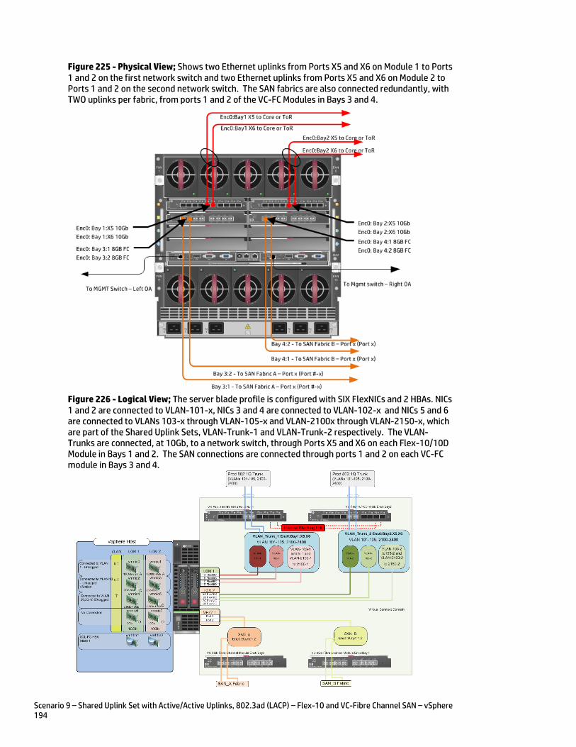
Scenario 9 – Shared Uplink Set with Active/Active Uplinks, 802.3ad (LACP) – Flex-10 and VC-Fibre Channel SAN – vSphere 194
Figure 225 - Physical View; Shows two Ethernet uplinks from Ports X5 and X6 on Module 1 to Ports 1 and 2 on the first network switch and two Ethernet uplinks from Ports X5 and X6 on Module 2 to Ports 1 and 2 on the second network switch. The SAN fabrics are also connected redundantly, with TWO uplinks per fabric, from ports 1 and 2 of the VC-FC Modules in Bays 3 and 4.
Figure 226 - Logical View; The server blade profile is configured with SIX FlexNICs and 2 HBAs. NICs 1 and 2 are connected to VLAN-101-x, NICs 3 and 4 are connected to VLAN-102-x and NICs 5 and 6 are connected to VLANs 103-x through VLAN-105-x and VLAN-2100x through VLAN-2150-x, which are part of the Shared Uplink Sets, VLAN-Trunk-1 and VLAN-Trunk-2 respectively. The VLAN-Trunks are connected, at 10Gb, to a network switch, through Ports X5 and X6 on each Flex-10/10D Module in Bays 1 and 2. The SAN connections are connected through ports 1 and 2 on each VC-FC module in Bays 3 and 4.
Scenario 9 – Shared Uplink Set with Active/Active Uplinks, 802.3ad (LACP) – Flex-10 and VC-Fibre Channel SAN – vSphere 195
Installation and configuration Switch configuration
As the Virtual Connect module acts as an edge switch, Virtual Connect can connect to the network at either the distribution level or directly to the core switch.
The appendices provide a summary of the cli commands required to configure various switches for connection to Virtual Connect. The configuration information provided in the appendices for this scenario assumes the following information:
The switch ports are configured as VLAN TRUNK ports (tagging) to support several VLANs. All frames will be forwarded to Virtual Connect with VLAN tags. Optionally, one VLAN could be configured as (Default) untagged, if so, then a corresponding vNet within the Shared Uplink Set would be configured and set as “Default”.
Note: when adding additional uplinks to the SUS, if the additional uplinks are connecting from the same Flex-10 module to the same switch, in order to ensure all the uplinks are active, the switch ports will need to be configured for LACP within the same Link Aggregation Group.
The network switch port should be configured for Spanning Tree Edge as Virtual Connect appears to the switch as an access device and not another switch. By configuring the port as Spanning Tree Edge, it allows the switch to place the port into a forwarding state much quicker than otherwise, this allows a newly connected port to come online and begin forwarding much quicker.
The SAN connection will be made with redundant connections to each Fabric. SAN switch ports connecting to the VC-FC module must be configured to accept NPIV logins.
Configuring the VC module
Physically connect Port 1 of network switch 1 to Port X5 of the VC module in Bay 1 Physically connect Port 2 of network switch 1 to Port X6 of the VC module in Bay 1 Physically connect Port 1 of network switch 2 to Port X5 of the VC module in Bay 2 Physically connect Port 2 of network switch 2 to Port X6 of the VC module in Bay 2
Note: If you have only one network switch, connect VC ports X5 & X6 (Bay 2) to an alternate port on the same switch. This will NOT create a network loop and Spanning Tree is not required.
Physically connect Ports 1&2 on the VC-FC in module Bay 3 to switch ports in SAN Fabric A Physically connect Ports 1&2 on the VC-FC in module Bay 4 to switch ports in SAN Fabric B
VC CLI commands
Many of the configuration settings within VC can also be accomplished via a CLI command set. In order to connect to VC via a CLI, open an SSH connection to the IP address of the active VCM. Once logged in, VC provides a CLI with help menus. Through this scenario the CLI commands to configure VC for each setting will also be provided.
Configuring Expanded VLAN Capacity via GUI
Virtual Connect release 3.30 provided an expanded VLAN capacity mode when using Shared Uplink Sets, this mode can be enabled through the Ethernet Settings tab or the VC CLI. The default configuration for a new Domain install is “Expanded VLAN Capacity” mode, Legacy mode is no longer available and the Domain cannot be downgraded.
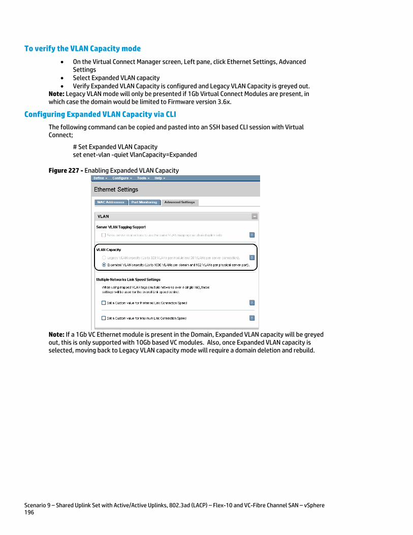
Scenario 9 – Shared Uplink Set with Active/Active Uplinks, 802.3ad (LACP) – Flex-10 and VC-Fibre Channel SAN – vSphere 196
To verify the VLAN Capacity mode
On the Virtual Connect Manager screen, Left pane, click Ethernet Settings, Advanced Settings
Select Expanded VLAN capacity Verify Expanded VLAN Capacity is configured and Legacy VLAN Capacity is greyed out.
Note: Legacy VLAN mode will only be presented if 1Gb Virtual Connect Modules are present, in which case the domain would be limited to Firmware version 3.6x.
Configuring Expanded VLAN Capacity via CLI
The following command can be copied and pasted into an SSH based CLI session with Virtual Connect;
# Set Expanded VLAN Capacity set enet-vlan -quiet VlanCapacity=Expanded
Figure 227 - Enabling Expanded VLAN Capacity
Note: If a 1Gb VC Ethernet module is present in the Domain, Expanded VLAN capacity will be greyed out, this is only supported with 10Gb based VC modules. Also, once Expanded VLAN capacity is selected, moving back to Legacy VLAN capacity mode will require a domain deletion and rebuild.
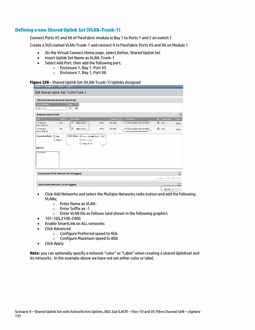
Scenario 9 – Shared Uplink Set with Active/Active Uplinks, 802.3ad (LACP) – Flex-10 and VC-Fibre Channel SAN – vSphere 197
Defining a new Shared Uplink Set (VLAN-Trunk-1)
Connect Ports X5 and X6 of FlexFabric module in Bay 1 to Ports 1 and 2 on switch 1
Create a SUS named VLAN-Trunk-1 and connect it to FlexFabric Ports X5 and X6 on Module 1
On the Virtual Connect Home page, select Define, Shared Uplink Set Insert Uplink Set Name as VLAN-Trunk-1 Select Add Port, then add the following port;
o Enclosure 1, Bay 1, Port X5 o Enclosure 1, Bay 1, Port X6
Figure 228 - Shared Uplink Set (VLAN-Trunk-1) Uplinks Assigned
Click Add Networks and select the Multiple Networks radio button and add the following
VLANs; o Enter Name as VLAN- o Enter Suffix as -1 o Enter VLAN IDs as follows (and shown in the following graphic);
101-105,2100-2400 Enable SmartLink on ALL networks Click Advanced
o Configure Preferred speed to 4Gb o Configure Maximum speed to 8Gb
Click Apply
Note: you can optionally specify a network “color” or “Label” when creating a shared Uplinkset and its networks. In the example above we have not set either color or label.
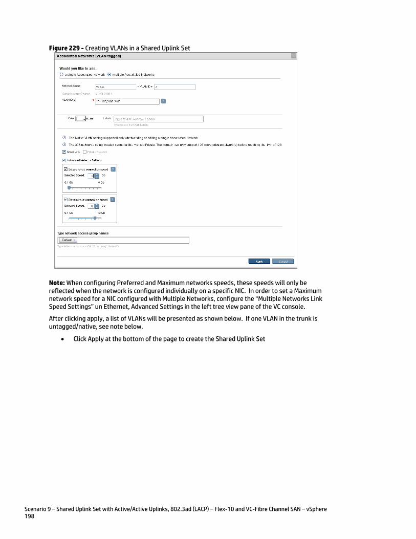
Scenario 9 – Shared Uplink Set with Active/Active Uplinks, 802.3ad (LACP) – Flex-10 and VC-Fibre Channel SAN – vSphere 198
Figure 229 - Creating VLANs in a Shared Uplink Set
Note: When configuring Preferred and Maximum networks speeds, these speeds will only be reflected when the network is configured individually on a specific NIC. In order to set a Maximum network speed for a NIC configured with Multiple Networks, configure the “Multiple Networks Link Speed Settings” un Ethernet, Advanced Settings in the left tree view pane of the VC console.
After clicking apply, a list of VLANs will be presented as shown below. If one VLAN in the trunk is untagged/native, see note below.
Click Apply at the bottom of the page to create the Shared Uplink Set
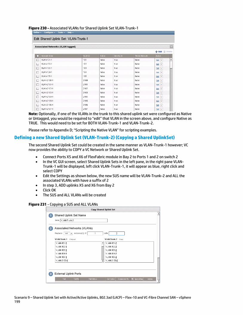
Scenario 9 – Shared Uplink Set with Active/Active Uplinks, 802.3ad (LACP) – Flex-10 and VC-Fibre Channel SAN – vSphere 199
Figure 230 - Associated VLANs for Shared Uplink Set VLAN-Trunk-1
Note: Optionally, if one of the VLANs in the trunk to this shared uplink set were configured as Native or Untagged, you would be required to “edit” that VLAN in the screen above, and configure Native as TRUE. This would need to be set for BOTH VLAN-Trunk-1 and VLAN-Trunk-2.
Please refer to Appendix D; “Scripting the Native VLAN” for scripting examples.
Defining a new Shared Uplink Set (VLAN-Trunk-2) (Copying a Shared UplinkSet)
The second Shared Uplink Set could be created in the same manner as VLAN-Trunk-1 however; VC now provides the ability to COPY a VC Network or Shared Uplink Set.
Connect Ports X5 and X6 of FlexFabric module in Bay 2 to Ports 1 and 2 on switch 2 In the VC GUI screen, select Shared Uplink Sets in the left pane, in the right pane VLAN-
Trunk-1 will be displayed, left click VLAN-Trunk-1, it will appear as blue, right click and select COPY
Edit the Settings as shown below, the new SUS name will be VLAN-Trunk-2 and ALL the associated VLANs with have a suffix of 2
In step 3, ADD uplinks X5 and X6 from Bay 2 Click OK The SUS and ALL VLANs will be created
Figure 231 - Copying a SUS and ALL VLANs
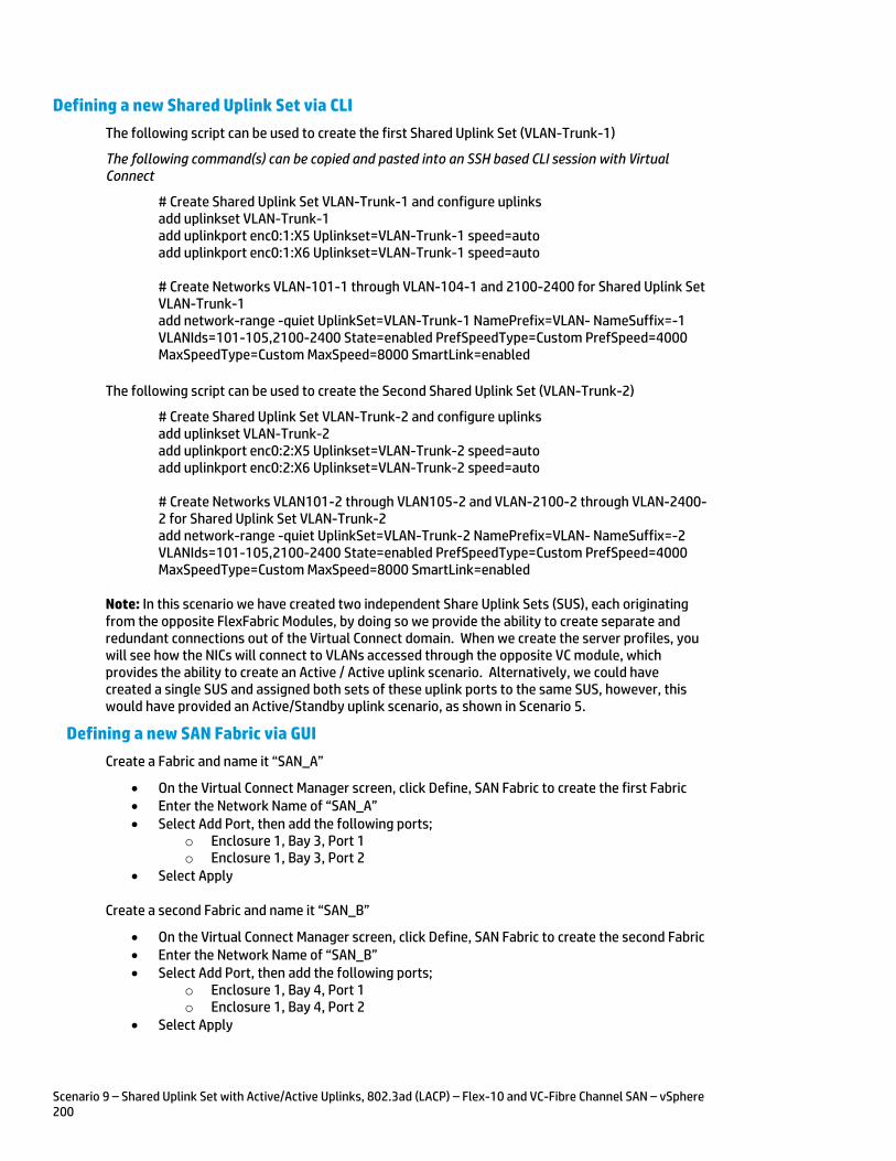
Scenario 9 – Shared Uplink Set with Active/Active Uplinks, 802.3ad (LACP) – Flex-10 and VC-Fibre Channel SAN – vSphere 200
Defining a new Shared Uplink Set via CLI
The following script can be used to create the first Shared Uplink Set (VLAN-Trunk-1)
The following command(s) can be copied and pasted into an SSH based CLI session with Virtual Connect
# Create Shared Uplink Set VLAN-Trunk-1 and configure uplinks add uplinkset VLAN-Trunk-1 add uplinkport enc0:1:X5 Uplinkset=VLAN-Trunk-1 speed=auto add uplinkport enc0:1:X6 Uplinkset=VLAN-Trunk-1 speed=auto # Create Networks VLAN-101-1 through VLAN-104-1 and 2100-2400 for Shared Uplink Set VLAN-Trunk-1 add network-range -quiet UplinkSet=VLAN-Trunk-1 NamePrefix=VLAN- NameSuffix=-1 VLANIds=101-105,2100-2400 State=enabled PrefSpeedType=Custom PrefSpeed=4000 MaxSpeedType=Custom MaxSpeed=8000 SmartLink=enabled
The following script can be used to create the Second Shared Uplink Set (VLAN-Trunk-2)
# Create Shared Uplink Set VLAN-Trunk-2 and configure uplinks add uplinkset VLAN-Trunk-2 add uplinkport enc0:2:X5 Uplinkset=VLAN-Trunk-2 speed=auto add uplinkport enc0:2:X6 Uplinkset=VLAN-Trunk-2 speed=auto # Create Networks VLAN101-2 through VLAN105-2 and VLAN-2100-2 through VLAN-2400-2 for Shared Uplink Set VLAN-Trunk-2 add network-range -quiet UplinkSet=VLAN-Trunk-2 NamePrefix=VLAN- NameSuffix=-2 VLANIds=101-105,2100-2400 State=enabled PrefSpeedType=Custom PrefSpeed=4000 MaxSpeedType=Custom MaxSpeed=8000 SmartLink=enabled
Note: In this scenario we have created two independent Share Uplink Sets (SUS), each originating from the opposite FlexFabric Modules, by doing so we provide the ability to create separate and redundant connections out of the Virtual Connect domain. When we create the server profiles, you will see how the NICs will connect to VLANs accessed through the opposite VC module, which provides the ability to create an Active / Active uplink scenario. Alternatively, we could have created a single SUS and assigned both sets of these uplink ports to the same SUS, however, this would have provided an Active/Standby uplink scenario, as shown in Scenario 5.
Defining a new SAN Fabric via GUI
Create a Fabric and name it “SAN_A”
On the Virtual Connect Manager screen, click Define, SAN Fabric to create the first Fabric Enter the Network Name of “SAN_A” Select Add Port, then add the following ports;
o Enclosure 1, Bay 3, Port 1 o Enclosure 1, Bay 3, Port 2
Select Apply
Create a second Fabric and name it “SAN_B”
On the Virtual Connect Manager screen, click Define, SAN Fabric to create the second Fabric Enter the Network Name of “SAN_B” Select Add Port, then add the following ports;
o Enclosure 1, Bay 4, Port 1 o Enclosure 1, Bay 4, Port 2
Select Apply
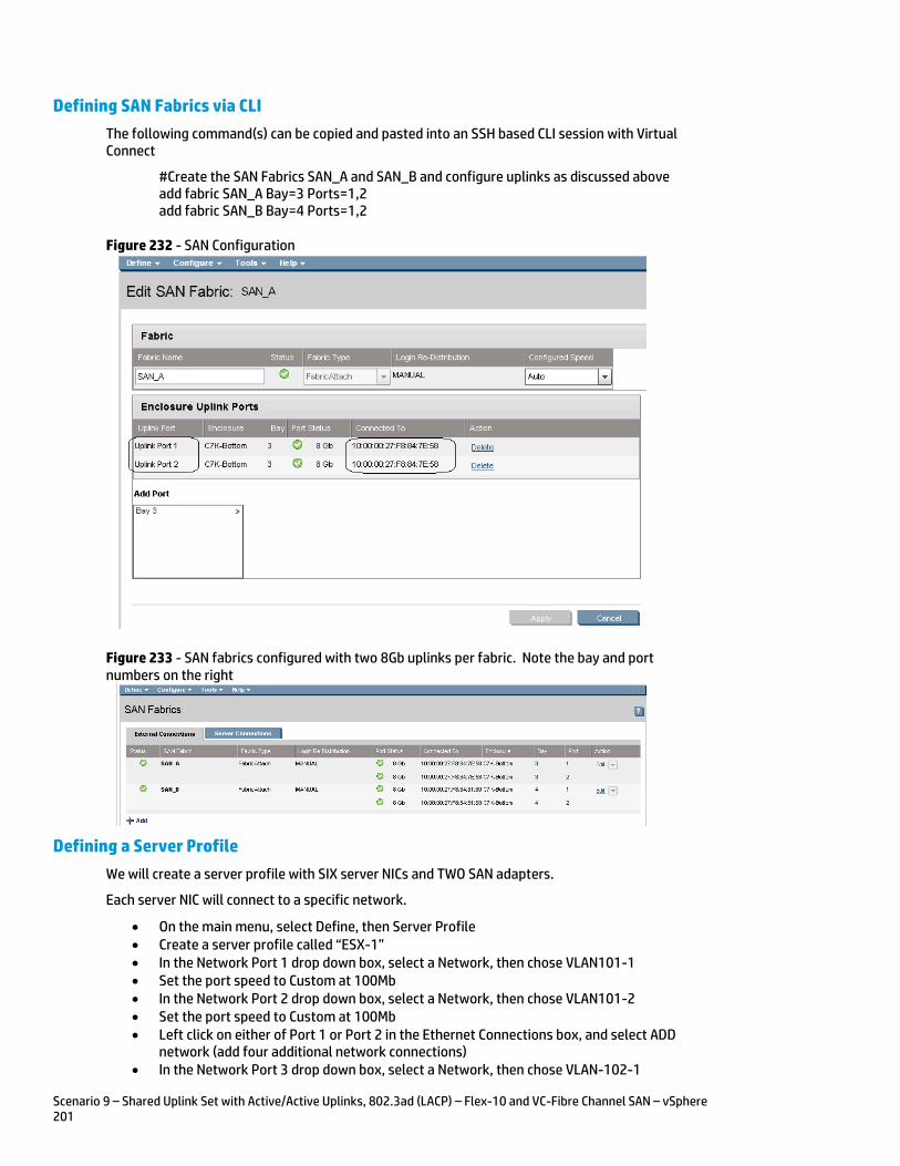
Scenario 9 – Shared Uplink Set with Active/Active Uplinks, 802.3ad (LACP) – Flex-10 and VC-Fibre Channel SAN – vSphere 201
Defining SAN Fabrics via CLI
The following command(s) can be copied and pasted into an SSH based CLI session with Virtual Connect
#Create the SAN Fabrics SAN_A and SAN_B and configure uplinks as discussed above add fabric SAN_A Bay=3 Ports=1,2 add fabric SAN_B Bay=4 Ports=1,2
Figure 232 - SAN Configuration
Figure 233 - SAN fabrics configured with two 8Gb uplinks per fabric. Note the bay and port numbers on the right
Defining a Server Profile
We will create a server profile with SIX server NICs and TWO SAN adapters.
Each server NIC will connect to a specific network.
On the main menu, select Define, then Server Profile Create a server profile called “ESX-1” In the Network Port 1 drop down box, select a Network, then chose VLAN101-1 Set the port speed to Custom at 100Mb In the Network Port 2 drop down box, select a Network, then chose VLAN101-2 Set the port speed to Custom at 100Mb Left click on either of Port 1 or Port 2 in the Ethernet Connections box, and select ADD
network (add four additional network connections) In the Network Port 3 drop down box, select a Network, then chose VLAN-102-1
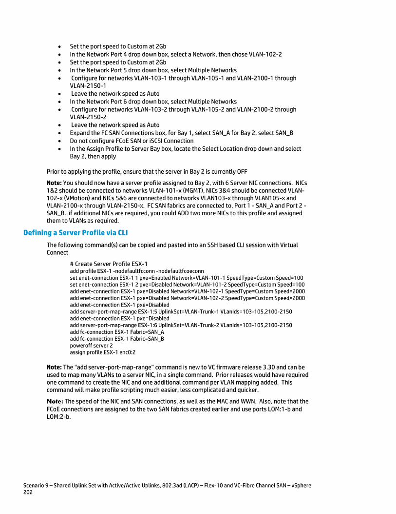
Scenario 9 – Shared Uplink Set with Active/Active Uplinks, 802.3ad (LACP) – Flex-10 and VC-Fibre Channel SAN – vSphere 202
Set the port speed to Custom at 2Gb In the Network Port 4 drop down box, select a Network, then chose VLAN-102-2 Set the port speed to Custom at 2Gb In the Network Port 5 drop down box, select Multiple Networks Configure for networks VLAN-103-1 through VLAN-105-1 and VLAN-2100-1 through
VLAN-2150-1 Leave the network speed as Auto In the Network Port 6 drop down box, select Multiple Networks Configure for networks VLAN-103-2 through VLAN-105-2 and VLAN-2100-2 through
VLAN-2150-2 Leave the network speed as Auto Expand the FC SAN Connections box, for Bay 1, select SAN_A for Bay 2, select SAN_B Do not configure FCoE SAN or iSCSI Connection In the Assign Profile to Server Bay box, locate the Select Location drop down and select
Bay 2, then apply
Prior to applying the profile, ensure that the server in Bay 2 is currently OFF
Note: You should now have a server profile assigned to Bay 2, with 6 Server NIC connections. NICs 1&2 should be connected to networks VLAN-101-x (MGMT), NICs 3&4 should be connected VLAN-102-x (VMotion) and NICs 5&6 are connected to networks VLAN103-x through VLAN105-x and VLAN-2100-x through VLAN-2150-x. FC SAN fabrics are connected to, Port 1 - SAN_A and Port 2 - SAN_B. if additional NICs are required, you could ADD two more NICs to this profile and assigned them to VLANs as required.
Defining a Server Profile via CLI
The following command(s) can be copied and pasted into an SSH based CLI session with Virtual Connect
# Create Server Profile ESX-1 add profile ESX-1 -nodefaultfcconn -nodefaultfcoeconn set enet-connection ESX-1 1 pxe=Enabled Network=VLAN-101-1 SpeedType=Custom Speed=100 set enet-connection ESX-1 2 pxe=Disabled Network=VLAN-101-2 SpeedType=Custom Speed=100 add enet-connection ESX-1 pxe=Disabled Network=VLAN-102-1 SpeedType=Custom Speed=2000 add enet-connection ESX-1 pxe=Disabled Network=VLAN-102-2 SpeedType=Custom Speed=2000 add enet-connection ESX-1 pxe=Disabled add server-port-map-range ESX-1:5 UplinkSet=VLAN-Trunk-1 VLanIds=103-105,2100-2150 add enet-connection ESX-1 pxe=Disabled add server-port-map-range ESX-1:6 UplinkSet=VLAN-Trunk-2 VLanIds=103-105,2100-2150 add fc-connection ESX-1 Fabric=SAN_A add fc-connection ESX-1 Fabric=SAN_B poweroff server 2 assign profile ESX-1 enc0:2
Note: The “add server-port-map-range” command is new to VC firmware release 3.30 and can be used to map many VLANs to a server NIC, in a single command. Prior releases would have required one command to create the NIC and one additional command per VLAN mapping added. This command will make profile scripting much easier, less complicated and quicker.
Note: The speed of the NIC and SAN connections, as well as the MAC and WWN. Also, note that the FCoE connections are assigned to the two SAN fabrics created earlier and use ports LOM:1-b and LOM:2-b.
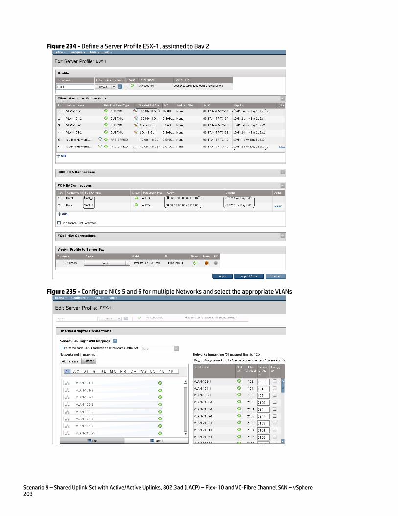
Scenario 9 – Shared Uplink Set with Active/Active Uplinks, 802.3ad (LACP) – Flex-10 and VC-Fibre Channel SAN – vSphere 203
Figure 234 - Define a Server Profile ESX-1, assigned to Bay 2
Figure 235 - Configure NICs 5 and 6 for multiple Networks and select the appropriate VLANs
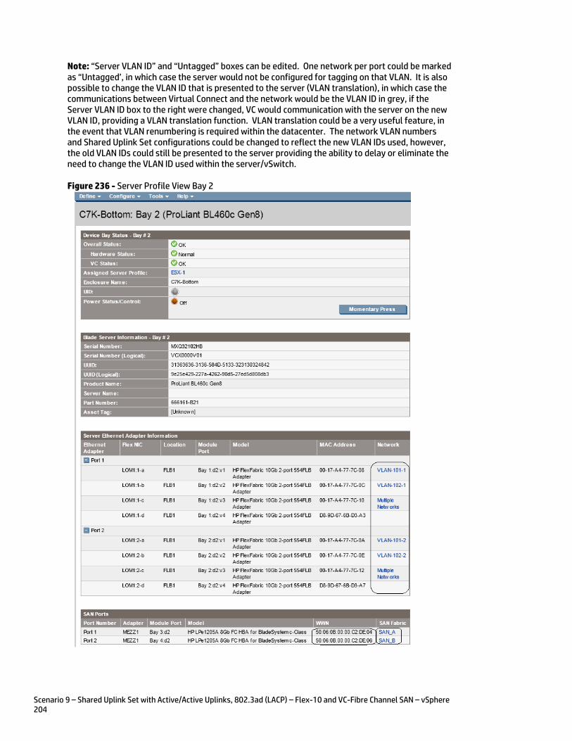
Scenario 9 – Shared Uplink Set with Active/Active Uplinks, 802.3ad (LACP) – Flex-10 and VC-Fibre Channel SAN – vSphere 204
Note: “Server VLAN ID” and “Untagged” boxes can be edited. One network per port could be marked as “Untagged’, in which case the server would not be configured for tagging on that VLAN. It is also possible to change the VLAN ID that is presented to the server (VLAN translation), in which case the communications between Virtual Connect and the network would be the VLAN ID in grey, if the Server VLAN ID box to the right were changed, VC would communication with the server on the new VLAN ID, providing a VLAN translation function. VLAN translation could be a very useful feature, in the event that VLAN renumbering is required within the datacenter. The network VLAN numbers and Shared Uplink Set configurations could be changed to reflect the new VLAN IDs used, however, the old VLAN IDs could still be presented to the server providing the ability to delay or eliminate the need to change the VLAN ID used within the server/vSwitch.
Figure 236 - Server Profile View Bay 2

Scenario 9 – Shared Uplink Set with Active/Active Uplinks, 802.3ad (LACP) – Flex-10 and VC-Fibre Channel SAN – vSphere 205
Figure 237 - By clicking on the “Multiple Networks” statement for each LOM, the following page is displayed, which lists the VLAN connections for this port.
Review In this scenario we have created Two Shared Uplink Sets (SUS), providing support for many VLANs. Uplinks originating from each FlexFabric Module connect to each SUS, by doing so we provide redundant connections out of the Virtual Connect domain. As multiple uplinks are used for each SUS, we have also leveraged LACP to improve uplink performance. In this scenario, all uplinks will be active. We also create two FCoE SAN Fabrics.
We created a server profile, with SIX NICs. Two connected to the same VLAN (101), Port 1 connects to VLAN-101-1 and Port 2 connects to VLAN-101-2, which provides the ability to sustain a link or module failure and not lose connection to the network, these NICs were set to 100Mb/Sec with the Maximum speed set to 8Gb. VLAN-101-1 and VLAN-101-2 are configured to support VLAN 101, frames will be presented to the NIC(s) without VLAN tags (untagged), these two NICs are connected to the same VLAN, but taking a different path out of the enclosure. VLAN 101 is used for Management connections to the ESX host.
Network Ports 3 and 4 connect to the same VLAN (102), Port 3 connects to VLAN-102-1 and Port 4 connects to VLAN-102-2, which provides the ability to sustain a link or module failure and not lose connection to the network, these NICs were set to 2Gb/Sec with the Maximum speed set to 8Gb. VLAN-102-1 and VLAN-102-2 are configured to support VLAN 102, frames will be presented to the NIC(s) without VLAN tags (untagged), these two NICs are connected to the same VLAN, but taking a different path out of the enclosure. VLAN 102 is used for VMotion.
Network Ports 5 and 6 were added, these NICs will be connected to “Multiple Networks” and each NIC will then be configured for networks VLAN103-x through VLAN105-x and networks VLAN-2100-x through VLAN-2150-x. As these networks are tagging, frames will be presented to the server with VLAN tags. NICs 5 and 6 will be connected to the same vSwitch to support VM connections.
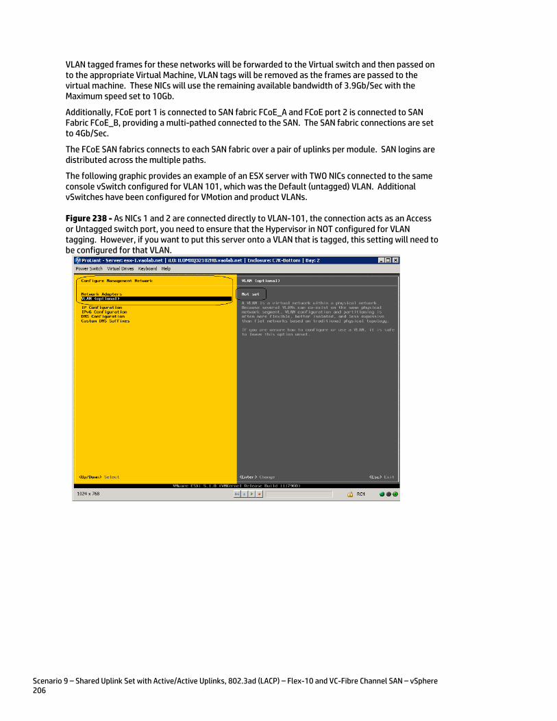
Scenario 9 – Shared Uplink Set with Active/Active Uplinks, 802.3ad (LACP) – Flex-10 and VC-Fibre Channel SAN – vSphere 206
VLAN tagged frames for these networks will be forwarded to the Virtual switch and then passed on to the appropriate Virtual Machine, VLAN tags will be removed as the frames are passed to the virtual machine. These NICs will use the remaining available bandwidth of 3.9Gb/Sec with the Maximum speed set to 10Gb.
Additionally, FCoE port 1 is connected to SAN fabric FCoE_A and FCoE port 2 is connected to SAN Fabric FCoE_B, providing a multi-pathed connected to the SAN. The SAN fabric connections are set to 4Gb/Sec.
The FCoE SAN fabrics connects to each SAN fabric over a pair of uplinks per module. SAN logins are distributed across the multiple paths.
The following graphic provides an example of an ESX server with TWO NICs connected to the same console vSwitch configured for VLAN 101, which was the Default (untagged) VLAN. Additional vSwitches have been configured for VMotion and product VLANs.
Figure 238 - As NICs 1 and 2 are connected directly to VLAN-101, the connection acts as an Access or Untagged switch port, you need to ensure that the Hypervisor in NOT configured for VLAN tagging. However, if you want to put this server onto a VLAN that is tagged, this setting will need to be configured for that VLAN.
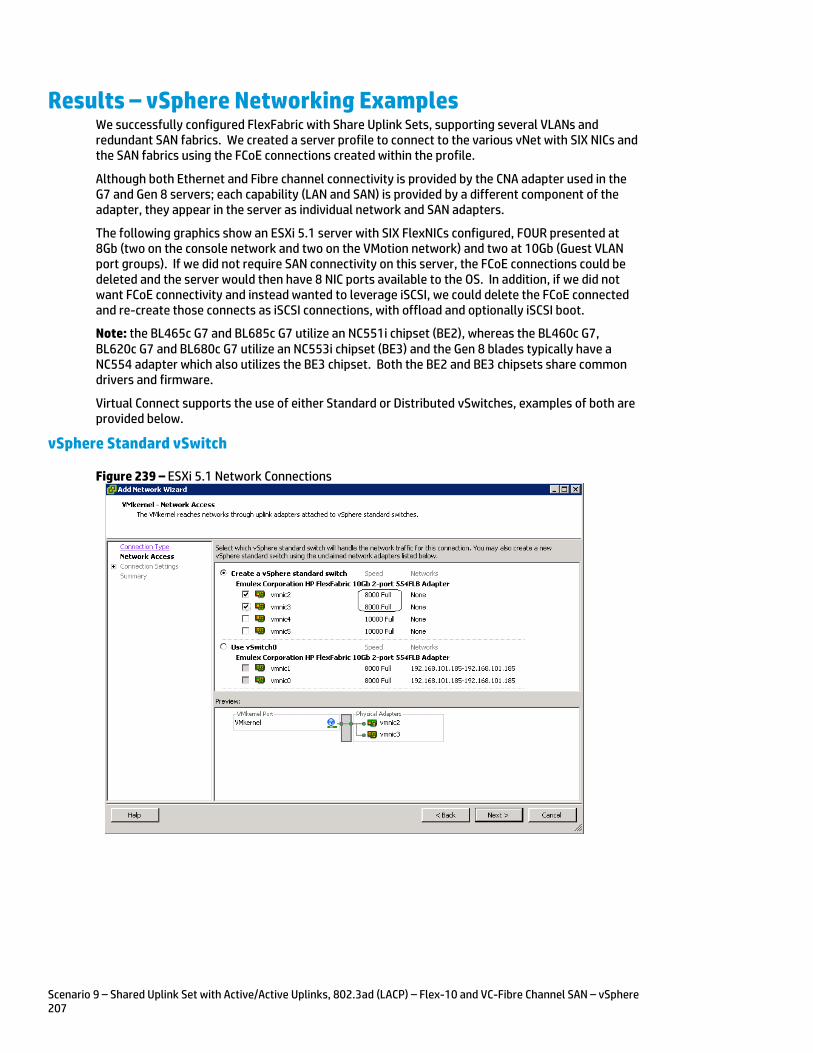
Scenario 9 – Shared Uplink Set with Active/Active Uplinks, 802.3ad (LACP) – Flex-10 and VC-Fibre Channel SAN – vSphere 207
Results – vSphere Networking Examples We successfully configured FlexFabric with Share Uplink Sets, supporting several VLANs and redundant SAN fabrics. We created a server profile to connect to the various vNet with SIX NICs and the SAN fabrics using the FCoE connections created within the profile.
Although both Ethernet and Fibre channel connectivity is provided by the CNA adapter used in the G7 and Gen 8 servers; each capability (LAN and SAN) is provided by a different component of the adapter, they appear in the server as individual network and SAN adapters.
The following graphics show an ESXi 5.1 server with SIX FlexNICs configured, FOUR presented at 8Gb (two on the console network and two on the VMotion network) and two at 10Gb (Guest VLAN port groups). If we did not require SAN connectivity on this server, the FCoE connections could be deleted and the server would then have 8 NIC ports available to the OS. In addition, if we did not want FCoE connectivity and instead wanted to leverage iSCSI, we could delete the FCoE connected and re-create those connects as iSCSI connections, with offload and optionally iSCSI boot.
Note: the BL465c G7 and BL685c G7 utilize an NC551i chipset (BE2), whereas the BL460c G7, BL620c G7 and BL680c G7 utilize an NC553i chipset (BE3) and the Gen 8 blades typically have a NC554 adapter which also utilizes the BE3 chipset. Both the BE2 and BE3 chipsets share common drivers and firmware.
Virtual Connect supports the use of either Standard or Distributed vSwitches, examples of both are provided below.
vSphere Standard vSwitch
Figure 239 – ESXi 5.1 Network Connections
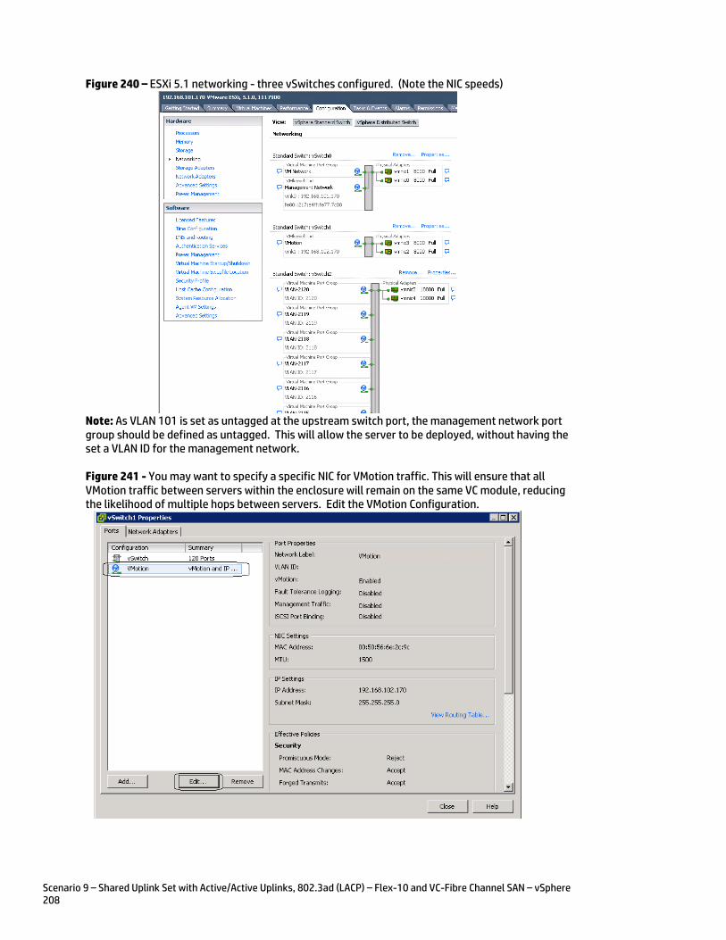
Scenario 9 – Shared Uplink Set with Active/Active Uplinks, 802.3ad (LACP) – Flex-10 and VC-Fibre Channel SAN – vSphere 208
Figure 240 – ESXi 5.1 networking - three vSwitches configured. (Note the NIC speeds)
Note: As VLAN 101 is set as untagged at the upstream switch port, the management network port group should be defined as untagged. This will allow the server to be deployed, without having the set a VLAN ID for the management network.
Figure 241 - You may want to specify a specific NIC for VMotion traffic. This will ensure that all VMotion traffic between servers within the enclosure will remain on the same VC module, reducing the likelihood of multiple hops between servers. Edit the VMotion Configuration.
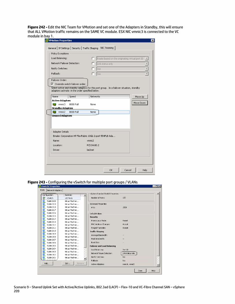
Scenario 9 – Shared Uplink Set with Active/Active Uplinks, 802.3ad (LACP) – Flex-10 and VC-Fibre Channel SAN – vSphere 209
Figure 242 - Edit the NIC Team for VMotion and set one of the Adapters in Standby, this will ensure that ALL VMotion traffic remains on the SAME VC module. ESX NIC vmnic3 is connected to the VC module in bay 1.
Figure 243 - Configuring the vSwitch for multiple port groups / VLANs
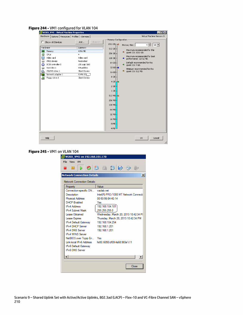
Scenario 9 – Shared Uplink Set with Active/Active Uplinks, 802.3ad (LACP) – Flex-10 and VC-Fibre Channel SAN – vSphere 210
Figure 244 - VM1 configured for VLAN 104
Figure 245 - VM1 on VLAN 104
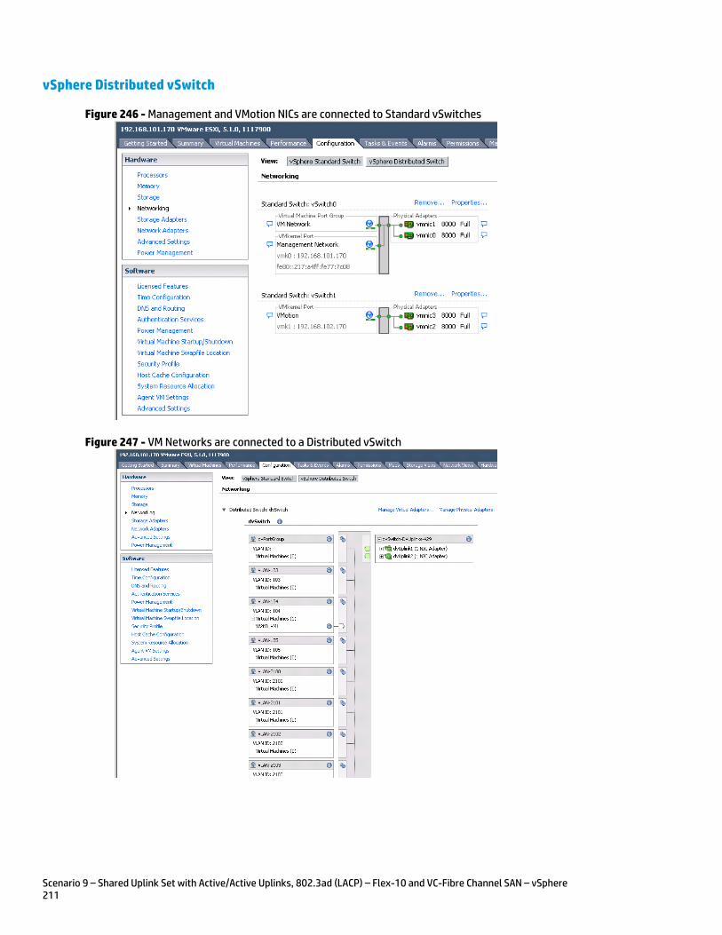
Scenario 9 – Shared Uplink Set with Active/Active Uplinks, 802.3ad (LACP) – Flex-10 and VC-Fibre Channel SAN – vSphere 211
vSphere Distributed vSwitch
Figure 246 - Management and VMotion NICs are connected to Standard vSwitches
Figure 247 - VM Networks are connected to a Distributed vSwitch
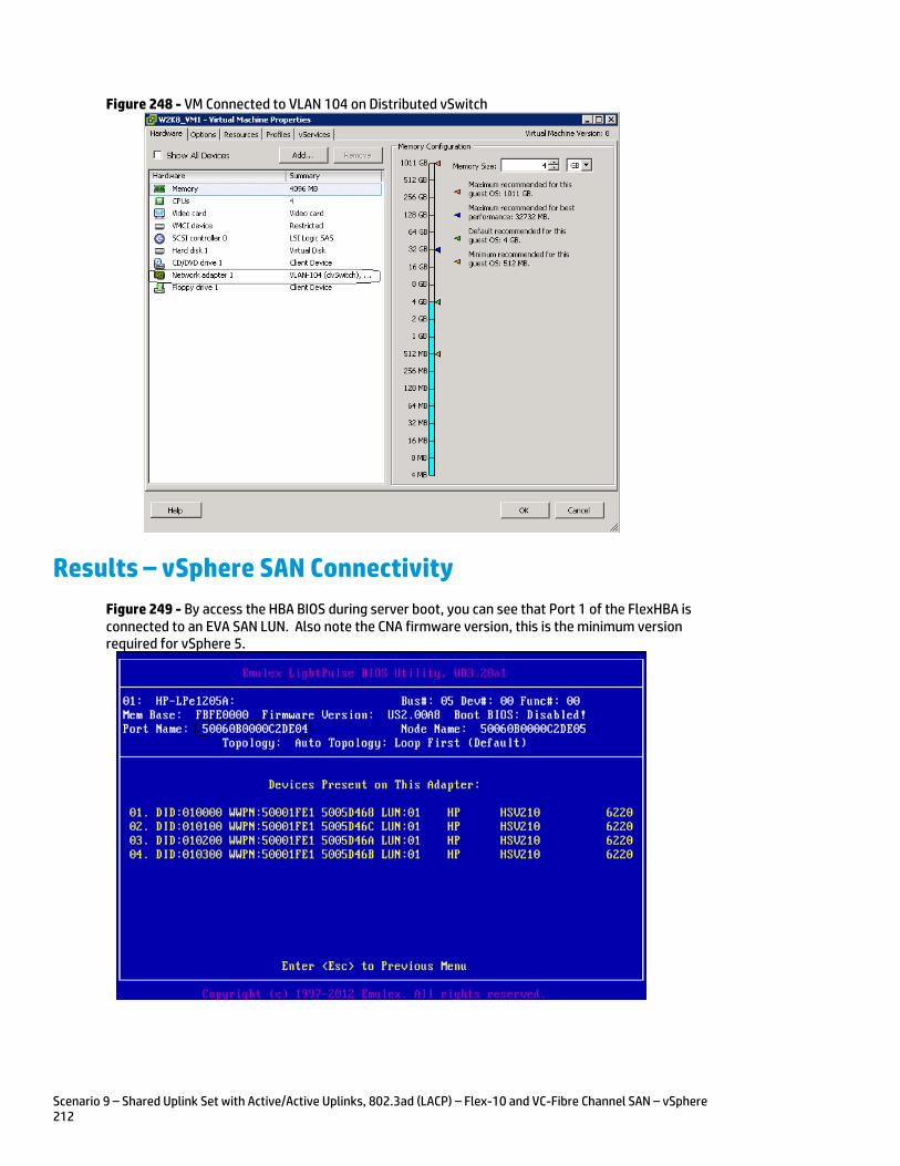
Scenario 9 – Shared Uplink Set with Active/Active Uplinks, 802.3ad (LACP) – Flex-10 and VC-Fibre Channel SAN – vSphere 212
Figure 248 - VM Connected to VLAN 104 on Distributed vSwitch
Results – vSphere SAN Connectivity
Figure 249 - By access the HBA BIOS during server boot, you can see that Port 1 of the FlexHBA is connected to an EVA SAN LUN. Also note the CNA firmware version, this is the minimum version required for vSphere 5.
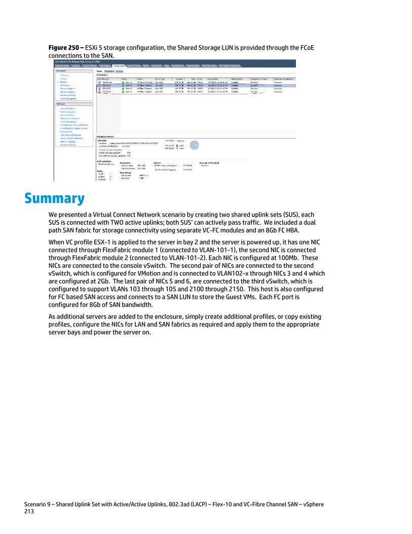
Scenario 9 – Shared Uplink Set with Active/Active Uplinks, 802.3ad (LACP) – Flex-10 and VC-Fibre Channel SAN – vSphere 213
Figure 250 – ESXi 5 storage configuration, the Shared Storage LUN is provided through the FCoE connections to the SAN.
Summary We presented a Virtual Connect Network scenario by creating two shared uplink sets (SUS), each SUS is connected with TWO active uplinks; both SUS’ can actively pass traffic. We included a dual path SAN fabric for storage connectivity using separate VC-FC modules and an 8Gb FC HBA.
When VC profile ESX-1 is applied to the server in bay 2 and the server is powered up, it has one NIC connected through FlexFabric module 1 (connected to VLAN-101-1), the second NIC is connected through FlexFabric module 2 (connected to VLAN-101-2). Each NIC is configured at 100Mb. These NICs are connected to the console vSwitch. The second pair of NICs are connected to the second vSwitch, which is configured for VMotion and is connected to VLAN102-x through NICs 3 and 4 which are configured at 2Gb. The last pair of NICs 5 and 6, are connected to the third vSwitch, which is configured to support VLANs 103 through 105 and 2100 through 2150. This host is also configured for FC based SAN access and connects to a SAN LUN to store the Guest VMs. Each FC port is configured for 8Gb of SAN bandwidth.
As additional servers are added to the enclosure, simply create additional profiles, or copy existing profiles, configure the NICs for LAN and SAN fabrics as required and apply them to the appropriate server bays and power the server on.
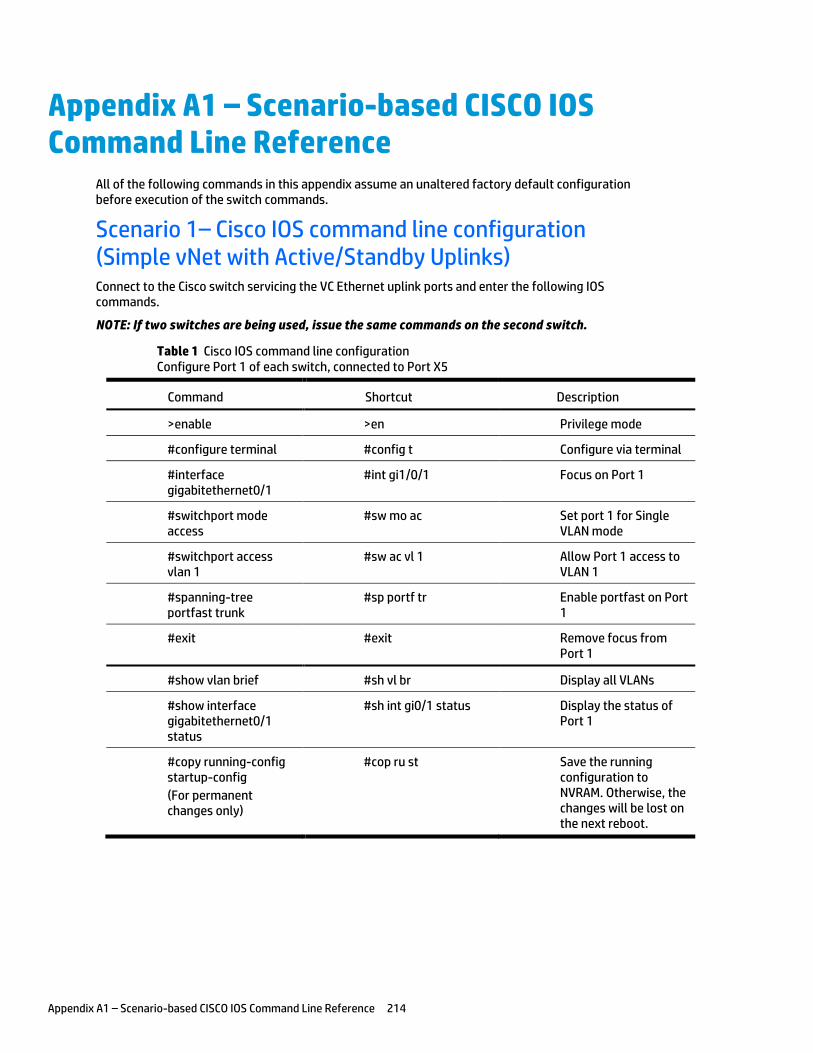
Appendix A1 – Scenario-based CISCO IOS Command Line Reference 214
Appendix A1 – Scenario-based CISCO IOS Command Line Reference
All of the following commands in this appendix assume an unaltered factory default configuration before execution of the switch commands.
Scenario 1– Cisco IOS command line configuration (Simple vNet with Active/Standby Uplinks) Connect to the Cisco switch servicing the VC Ethernet uplink ports and enter the following IOS commands.
NOTE: If two switches are being used, issue the same commands on the second switch.
Table 1 Cisco IOS command line configuration Configure Port 1 of each switch, connected to Port X5
Command Shortcut Description
>enable >en Privilege mode
#configure terminal #config t Configure via terminal
#interface gigabitethernet0/1
#int gi1/0/1 Focus on Port 1
#switchport mode access
#sw mo ac Set port 1 for Single VLAN mode
#switchport access vlan 1
#sw ac vl 1 Allow Port 1 access to VLAN 1
#spanning-tree portfast trunk
#sp portf tr Enable portfast on Port 1
#exit #exit Remove focus from Port 1
#show vlan brief #sh vl br Display all VLANs
#show interface gigabitethernet0/1 status
#sh int gi0/1 status Display the status of Port 1
#copy running-config startup-config
(For permanent changes only)
#cop ru st Save the running configuration to NVRAM. Otherwise, the changes will be lost on the next reboot.
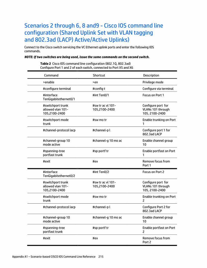
Appendix A1 – Scenario-based CISCO IOS Command Line Reference 215
Scenarios 2 through 6, 8 and9 - Cisco IOS command line configuration (Shared Uplink Set with VLAN tagging and 802.3ad (LACP) Active/Active Uplinks) Connect to the Cisco switch servicing the VC Ethernet uplink ports and enter the following IOS commands.
NOTE: If two switches are being used, issue the same commands on the second switch.
Table 2 Cisco IOS command line configuration (802.1Q, 802.3ad) Configure Port 1 and 2 of each switch, connected to Port X5 and X6
Command Shortcut Description
>enable >en Privilege mode
#configure terminal #config t Configure via terminal
#interface TenGigabitethernet0/1
#int Ten0/1 Focus on Port 1
#switchport trunk allowed vlan 101-105,2100-2400
#sw tr ac vl 101-105,2100-2400
Configure port for VLANs 101 through 105, 2100-2400
#switchport mode trunk
#sw mo tr Enable trunking on Port 1
#channel-protocol lacp #channel-p l Configure port 1 for 802.3ad LACP
#channel-group 10 mode active
#channel-g 10 mo ac Enable channel group 10
#spanning-tree portfast trunk
#sp portf tr Enable portfast on Port 1
#exit #ex Remove focus from Port 1
#interface TenGigabitethernet0/2
#int Ten0/2 Focus on Port 2
#switchport trunk allowed vlan 101-105,2100-2400
#sw tr ac vl 101-105,2100-2400
Configure port for VLANs 101 through 105, 2100-2400
#switchport mode trunk
#sw mo tr Enable trunking on Port 2
#channel-protocol lacp #channel-p l Configure Port 2 for 802.3ad LACP
#channel-group 10 mode active
#channel-g 10 mo ac Enable channel group 10
#spanning-tree portfast trunk
#sp portf tr Enable portfast on Port 2
#exit #ex Remove focus from Port 2
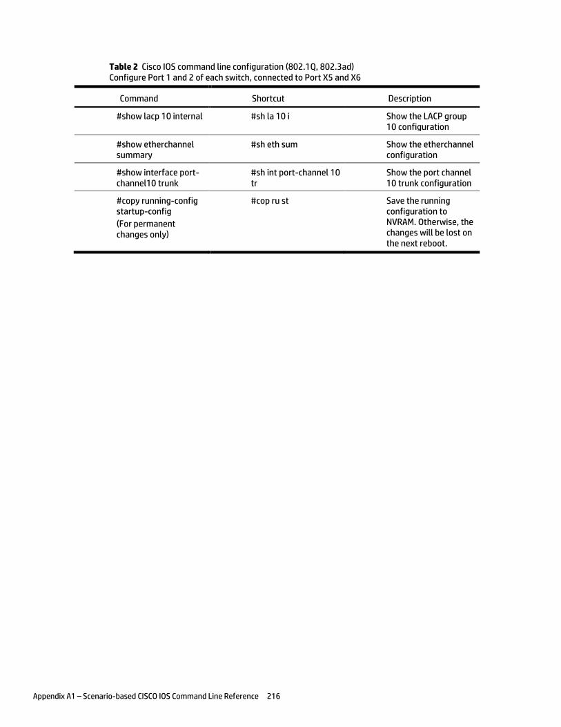
Appendix A1 – Scenario-based CISCO IOS Command Line Reference 216
Table 2 Cisco IOS command line configuration (802.1Q, 802.3ad) Configure Port 1 and 2 of each switch, connected to Port X5 and X6
Command Shortcut Description
#show lacp 10 internal #sh la 10 i Show the LACP group 10 configuration
#show etherchannel summary
#sh eth sum Show the etherchannel configuration
#show interface port-channel10 trunk
#sh int port-channel 10 tr
Show the port channel 10 trunk configuration
#copy running-config startup-config
(For permanent changes only)
#cop ru st Save the running configuration to NVRAM. Otherwise, the changes will be lost on the next reboot.
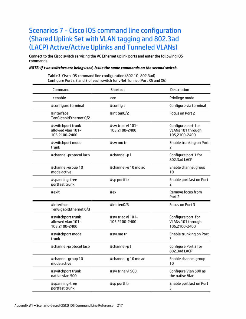
Appendix A1 – Scenario-based CISCO IOS Command Line Reference 217
Scenarios 7 - Cisco IOS command line configuration (Shared Uplink Set with VLAN tagging and 802.3ad (LACP) Active/Active Uplinks and Tunneled VLANs) Connect to the Cisco switch servicing the VC Ethernet uplink ports and enter the following IOS commands.
NOTE: If two switches are being used, issue the same commands on the second switch.
Table 3 Cisco IOS command line configuration (802.1Q, 802.3ad) Configure Port s 2 and 3 of each switch for vNet Tunnel (Port X5 and X6)
Command Shortcut Description
>enable >en Privilege mode
#configure terminal #config t Configure via terminal
#interface TenGigabitEthernet 0/2
#int ten0/2 Focus on Port 2
#switchport trunk allowed vlan 101-105,2100-2400
#sw tr ac vl 101-105,2100-2400
Configure port for VLANs 101 through 105,2100-2400
#switchport mode trunk
#sw mo tr Enable trunking on Port 2
#channel-protocol lacp #channel-p l Configure port 1 for 802.3ad LACP
#channel-group 10 mode active
#channel-g 10 mo ac Enable channel group 10
#spanning-tree portfast trunk
#sp portf tr Enable portfast on Port 2
#exit #ex Remove focus from Port 2
#interface TenGigabitEthernet 0/3
#int ten0/3 Focus on Port 3
#switchport trunk allowed vlan 101-105,2100-2400
#sw tr ac vl 101-105,2100-2400
Configure port for VLANs 101 through 105,2100-2400
#switchport mode trunk
#sw mo tr Enable trunking on Port 3
#channel-protocol lacp #channel-p l Configure Port 3 for 802.3ad LACP
#channel-group 10 mode active
#channel-g 10 mo ac Enable channel group 10
#switchport trunk native vlan 500
#sw tr na vl 500 Configure Vlan 500 as the native Vlan
#spanning-tree portfast trunk
#sp portf tr Enable portfast on Port 3
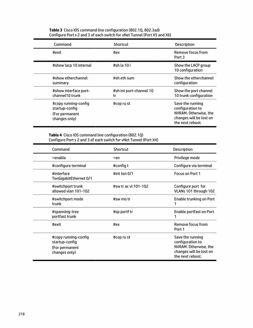
218
Table 3 Cisco IOS command line configuration (802.1Q, 802.3ad) Configure Port s 2 and 3 of each switch for vNet Tunnel (Port X5 and X6)
Command Shortcut Description
#exit #ex Remove focus from Port 3
#show lacp 10 internal #sh la 10 i Show the LACP group 10 configuration
#show etherchannel summary
#sh eth sum Show the etherchannel configuration
#show interface port-channel10 trunk
#sh int port-channel 10 tr
Show the port channel 10 trunk configuration
#copy running-config startup-config
(For permanent changes only)
#cop ru st Save the running configuration to NVRAM. Otherwise, the changes will be lost on the next reboot.
Table 4 Cisco IOS command line configuration (802.1Q) Configure Port s 2 and 3 of each switch for vNet Tunnel (Port X4)
Command Shortcut Description
>enable >en Privilege mode
#configure terminal #config t Configure via terminal
#interface TenGigabitEthernet 0/1
#int ten 0/1 Focus on Port 1
#switchport trunk allowed vlan 101-102
#sw tr ac vl 101-102 Configure port for VLANs 101 through 102
#switchport mode trunk
#sw mo tr Enable trunking on Port 1
#spanning-tree portfast trunk
#sp portf tr Enable portfast on Port 1
#exit #ex Remove focus from Port 1
#copy running-config startup-config
(For permanent changes only)
#cop ru st Save the running configuration to NVRAM. Otherwise, the changes will be lost on the next reboot.
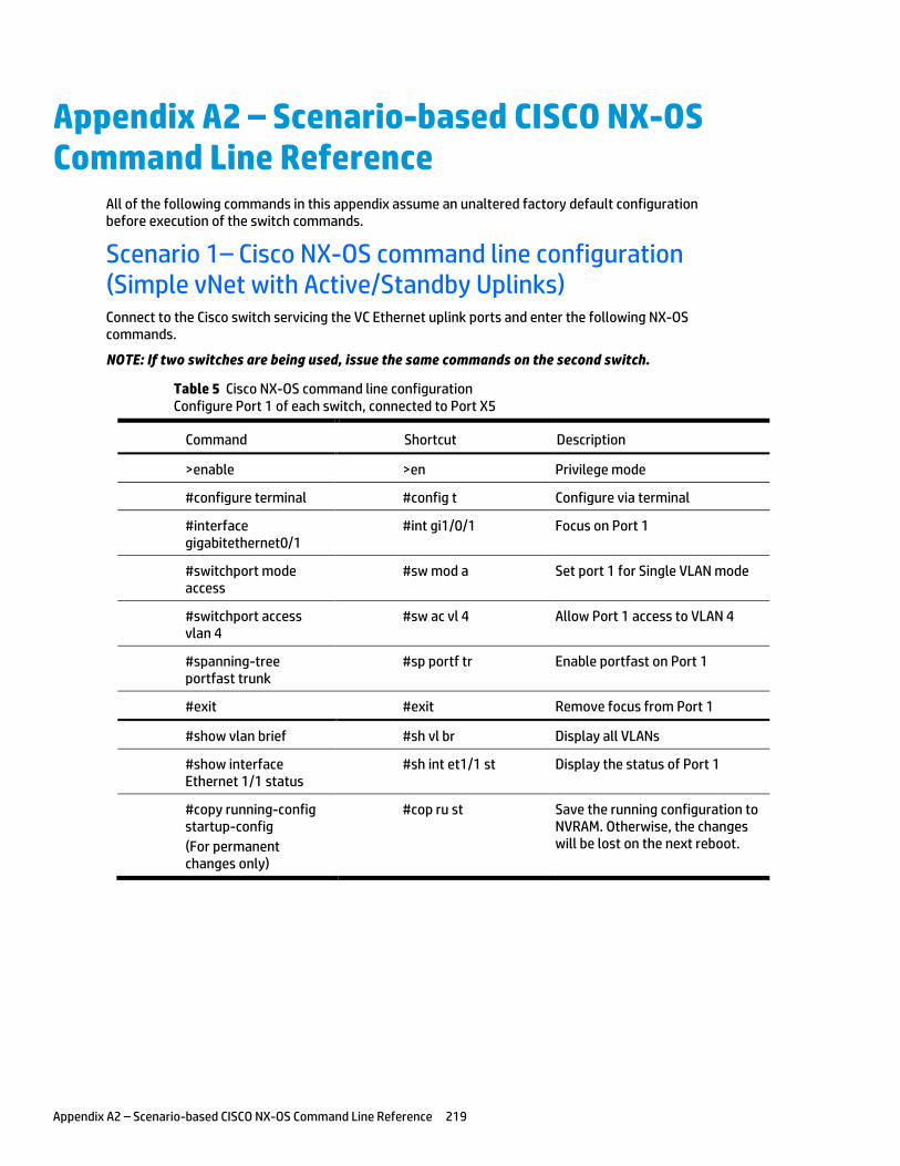
Appendix A2 – Scenario-based CISCO NX-OS Command Line Reference 219
Appendix A2 – Scenario-based CISCO NX-OS Command Line Reference
All of the following commands in this appendix assume an unaltered factory default configuration before execution of the switch commands.
Scenario 1– Cisco NX-OS command line configuration (Simple vNet with Active/Standby Uplinks) Connect to the Cisco switch servicing the VC Ethernet uplink ports and enter the following NX-OS commands.
NOTE: If two switches are being used, issue the same commands on the second switch.
Table 5 Cisco NX-OS command line configuration Configure Port 1 of each switch, connected to Port X5
Command Shortcut Description
>enable >en Privilege mode
#configure terminal #config t Configure via terminal
#interface gigabitethernet0/1
#int gi1/0/1 Focus on Port 1
#switchport mode access
#sw mod a Set port 1 for Single VLAN mode
#switchport access vlan 4
#sw ac vl 4 Allow Port 1 access to VLAN 4
#spanning-tree portfast trunk
#sp portf tr Enable portfast on Port 1
#exit #exit Remove focus from Port 1
#show vlan brief #sh vl br Display all VLANs
#show interface Ethernet 1/1 status
#sh int et1/1 st Display the status of Port 1
#copy running-config startup-config
(For permanent changes only)
#cop ru st Save the running configuration to NVRAM. Otherwise, the changes will be lost on the next reboot.
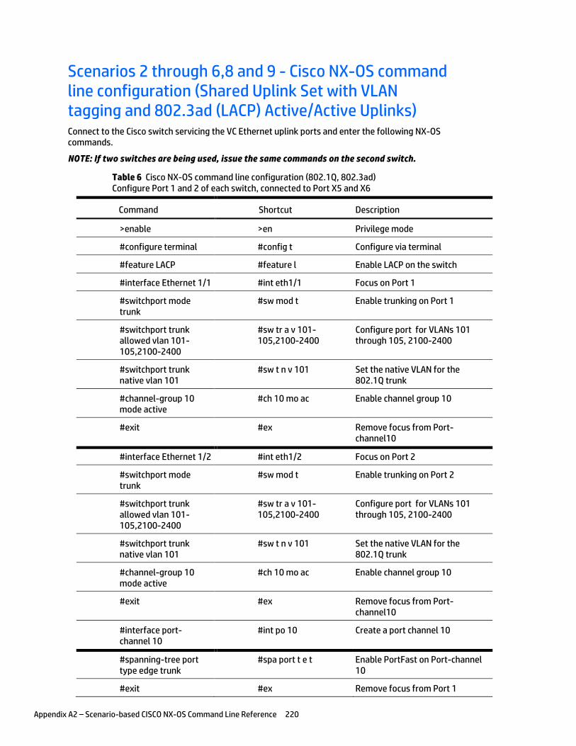
Appendix A2 – Scenario-based CISCO NX-OS Command Line Reference 220
Scenarios 2 through 6,8 and 9 - Cisco NX-OS command line configuration (Shared Uplink Set with VLAN tagging and 802.3ad (LACP) Active/Active Uplinks) Connect to the Cisco switch servicing the VC Ethernet uplink ports and enter the following NX-OS commands.
NOTE: If two switches are being used, issue the same commands on the second switch.
Table 6 Cisco NX-OS command line configuration (802.1Q, 802.3ad) Configure Port 1 and 2 of each switch, connected to Port X5 and X6
Command Shortcut Description
>enable >en Privilege mode
#configure terminal #config t Configure via terminal
#feature LACP #feature l Enable LACP on the switch
#interface Ethernet 1/1 #int eth1/1 Focus on Port 1
#switchport mode trunk
#sw mod t Enable trunking on Port 1
#switchport trunk allowed vlan 101-105,2100-2400
#sw tr a v 101-105,2100-2400
Configure port for VLANs 101 through 105, 2100-2400
#switchport trunk native vlan 101
#sw t n v 101 Set the native VLAN for the 802.1Q trunk
#channel-group 10 mode active
#ch 10 mo ac Enable channel group 10
#exit #ex Remove focus from Port-channel10
#interface Ethernet 1/2 #int eth1/2 Focus on Port 2
#switchport mode trunk
#sw mod t Enable trunking on Port 2
#switchport trunk allowed vlan 101-105,2100-2400
#sw tr a v 101-105,2100-2400
Configure port for VLANs 101 through 105, 2100-2400
#switchport trunk native vlan 101
#sw t n v 101 Set the native VLAN for the 802.1Q trunk
#channel-group 10 mode active
#ch 10 mo ac Enable channel group 10
#exit #ex Remove focus from Port-channel10
#interface port-channel 10
#int po 10 Create a port channel 10
#spanning-tree port type edge trunk
#spa port t e t Enable PortFast on Port-channel 10
#exit #ex Remove focus from Port 1
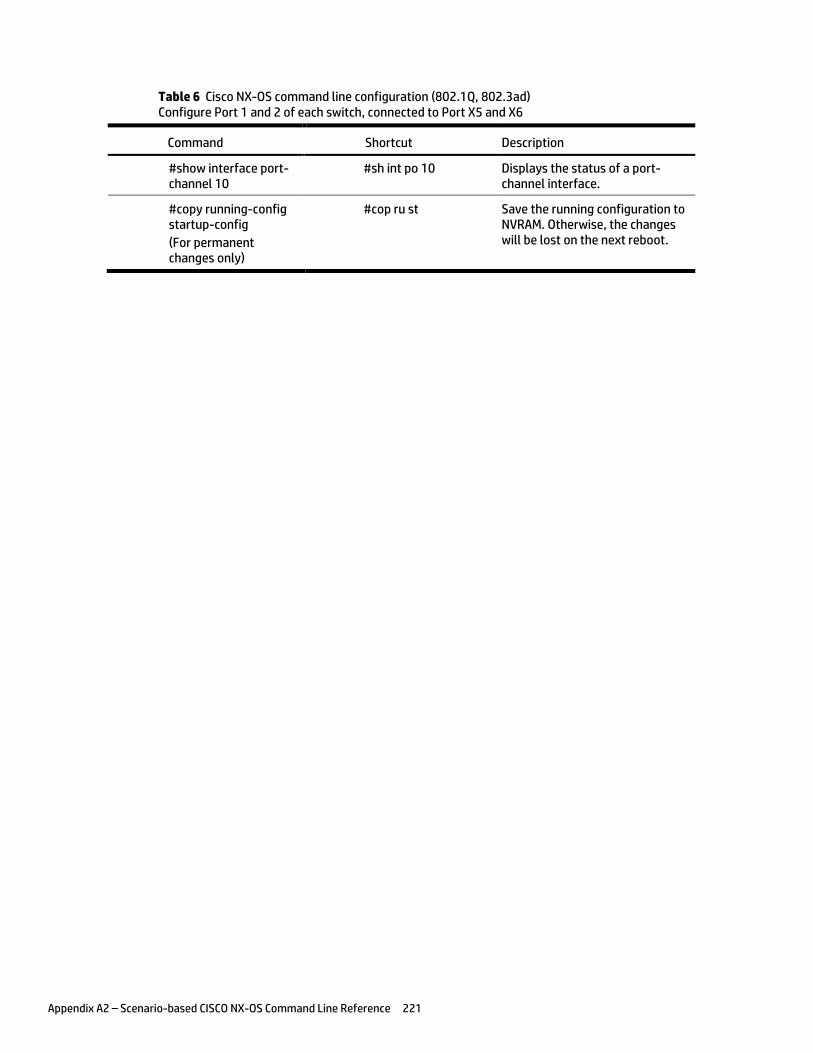
Appendix A2 – Scenario-based CISCO NX-OS Command Line Reference 221
Table 6 Cisco NX-OS command line configuration (802.1Q, 802.3ad) Configure Port 1 and 2 of each switch, connected to Port X5 and X6
Command Shortcut Description
#show interface port-channel 10
#sh int po 10 Displays the status of a port-channel interface.
#copy running-config startup-config
(For permanent changes only)
#cop ru st Save the running configuration to NVRAM. Otherwise, the changes will be lost on the next reboot.
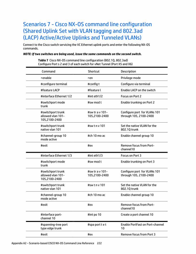
Appendix A2 – Scenario-based CISCO NX-OS Command Line Reference 222
Scenarios 7 - Cisco NX-OS command line configuration (Shared Uplink Set with VLAN tagging and 802.3ad (LACP) Active/Active Uplinks and Tunneled VLANs) Connect to the Cisco switch servicing the VC Ethernet uplink ports and enter the following NX-OS commands.
NOTE: If two switches are being used, issue the same commands on the second switch.
Table 7 Cisco NX-OS command line configuration (802.1Q, 802.3ad) Configure Port s 2 and 3 of each switch for vNet Tunnel (Port X5 and X6)
Command Shortcut Description
>enable >en Privilege mode
#configure terminal #config t Configure via terminal
#feature LACP #feature l Enable LACP on the switch
#interface Ethernet 1/2 #int eth1/2 Focus on Port 2
#switchport mode trunk
#sw mod t Enable trunking on Port 2
#switchport trunk allowed vlan 101-105,2100-2400
#sw tr a v 101-105,2100-2400
Configure port for VLANs 101 through 105, 2100-2400
#switchport trunk native vlan 101
#sw t n v 101 Set the native VLAN for the 802.1Q trunk
#channel-group 10 mode active
#ch 10 mo ac Enable channel group 10
#exit #ex Remove focus from Port-channel10
#interface Ethernet 1/3 #int eth1/3 Focus on Port 3
#switchport mode trunk
#sw mod t Enable trunking on Port 3
#switchport trunk allowed vlan 101-105,2100-2400
#sw tr a v 101-105,2100-2400
Configure port for VLANs 101 through 105, 2100-2400
#switchport trunk native vlan 101
#sw t n v 101 Set the native VLAN for the 802.1Q trunk
#channel-group 10 mode active
#ch 10 mo ac Enable channel group 10
#exit #ex Remove focus from Port-channel10
#interface port-channel 10
#int po 10 Create a port channel 10
#spanning-tree port type edge trunk
#spa port t e t Enable PortFast on Port-channel 10
#exit #ex Remove focus from Port 3
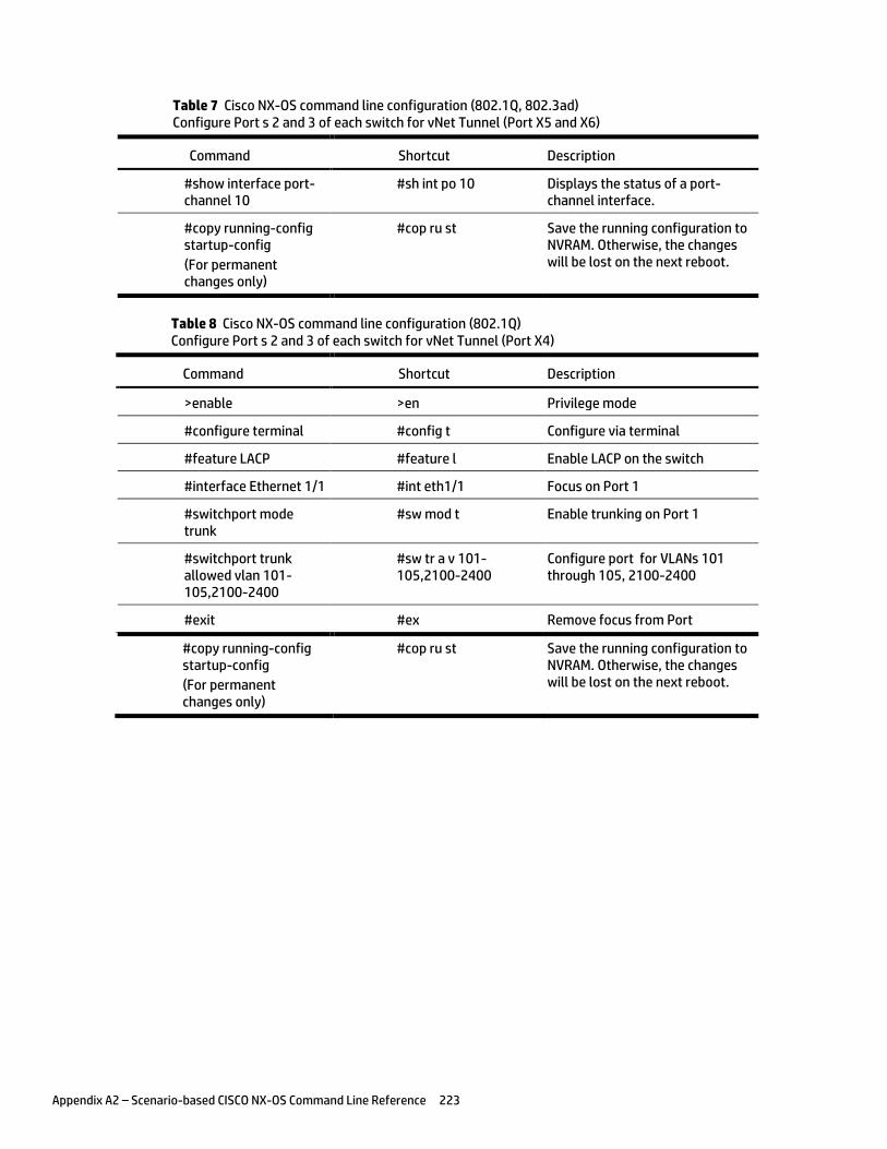
Appendix A2 – Scenario-based CISCO NX-OS Command Line Reference 223
Table 7 Cisco NX-OS command line configuration (802.1Q, 802.3ad) Configure Port s 2 and 3 of each switch for vNet Tunnel (Port X5 and X6)
Command Shortcut Description
#show interface port-channel 10
#sh int po 10 Displays the status of a port-channel interface.
#copy running-config startup-config
(For permanent changes only)
#cop ru st Save the running configuration to NVRAM. Otherwise, the changes will be lost on the next reboot.
Table 8 Cisco NX-OS command line configuration (802.1Q) Configure Port s 2 and 3 of each switch for vNet Tunnel (Port X4)
Command Shortcut Description
>enable >en Privilege mode
#configure terminal #config t Configure via terminal
#feature LACP #feature l Enable LACP on the switch
#interface Ethernet 1/1 #int eth1/1 Focus on Port 1
#switchport mode trunk
#sw mod t Enable trunking on Port 1
#switchport trunk allowed vlan 101-105,2100-2400
#sw tr a v 101-105,2100-2400
Configure port for VLANs 101 through 105, 2100-2400
#exit #ex Remove focus from Port
#copy running-config startup-config
(For permanent changes only)
#cop ru st Save the running configuration to NVRAM. Otherwise, the changes will be lost on the next reboot.
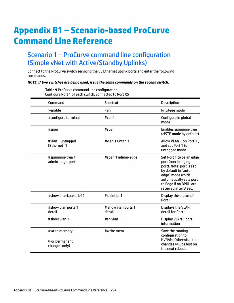
Appendix B1 – Scenario-based ProCurve Command Line Reference 224
Appendix B1 – Scenario-based ProCurve Command Line Reference
Scenario 1 – ProCurve command line configuration (Simple vNet with Active/Standby Uplinks) Connect to the ProCurve switch servicing the VC Ethernet uplink ports and enter the following commands.
NOTE: If two switches are being used, issue the same commands on the second switch.
Table 9 ProCurve command line configuration Configure Port 1 of each switch, connected to Port X5
Command Shortcut Description
>enable >en Privilege mode
#configure terminal #conf Configure in global mode
#span #span Enables spanning-tree (MSTP mode by default)
#vlan 1 untagged [Ethernet] 1
#vlan 1 untag 1 Allow VLAN 1 on Port 1 , and set Port 1 to untagged mode
#spanning-tree 1 admin-edge-port
#span 1 admin-edge Set Port 1 to be an edge port (non-bridging port). Note: port is set by default in “auto-edge” mode which automatically sets port to Edge if no BPDU are received after 3 sec.
#show interface brief 1 #sh int br 1 Display the status of Port 1
#show vlan ports 1 detail
# show vlan ports 1 detail
Displays the VLAN detail for Port 1
#show vlan 1 #sh vlan 1 Display VLAN 1 port information
#write memory
(For permanent changes only)
#write mem Save the running configuration to NVRAM. Otherwise, the changes will be lost on the next reboot.

Appendix B1 – Scenario-based ProCurve Command Line Reference 225
Scenarios 2 through 6, 8 and 9 - ProCurve command line configuration (Shared Uplink Set with VLAN tagging and 802.3ad (LACP) Active/Active Uplinks) Connect to the ProCurve switch servicing the VC Ethernet uplink ports and enter the following commands.
NOTE: If two switches are being used, issue the same commands on the second switch.
Table 10 ProCurve command line configuration (802.1Q, 802.3ad) Configure Port 1 and 2 of each switch, connected to Port X5 and X6
Command Shortcut Description
>enable >en Privilege mode
#configure terminal #conf Configure in global mode
#span #span Enables spanning-tree (MSTP mode by default)
#trunk 1-2 trk1 lacp #trunk 1-2 trk1 lacp Configure LACP port-trunk 1 to include Ports 1 & 2
#vlan 101 tagged trk1 #vlan 101 tag trk1 Allow VLAN 101 on Ports 1 and 2. Trk1 (tagged)
#vlan 102 tagged trk1 #vlan 102 tag trk1 Allow VLAN 102 on Ports 1 and 2. Trk1 (tagged)
#vlan 103 tagged trk1 #vlan 103 tag trk1 Allow VLAN 103 on Ports 1 and 2. Trk1 (tagged)
#vlan 104 tagged trk1 #vlan 104 tag trk1 Allow VLAN 104 on Ports 1 and 2. Trk1 (tagged)
….. … Configure all other VLANs
#vlan 2400 tagged trk1 #vlan 2400 tag trk1 Allow VLAN 2400 on Ports 1 and 2. Trk1 (tagged)
#spanning-tree ethernet trk1 admin-edge-port
#span e trk1 admin-edge
Set trk1 as an edge port (non bridging port). Note: default is “auto-edge” mode which automatically sets port to Edge if no BPDU are received after 3 sec.
#show vlan 101 #sh vlan 101 Display VLAN 101
#show vlan 102 #sh vlan 102 Display VLAN 102
#show vlan 103 #sh vlan 103 Display VLAN 103
#show vlan 104 #sh vlan 104 Display VLAN 104
#show vlan ports trk1 detail
# show vlan ports trk1 detail
Displays the VLAN detail for Trunk 1
#show interface brief1-2
#sh int br1-2 Show Port 1-2 status
#write memory #wr mem Save Running Config
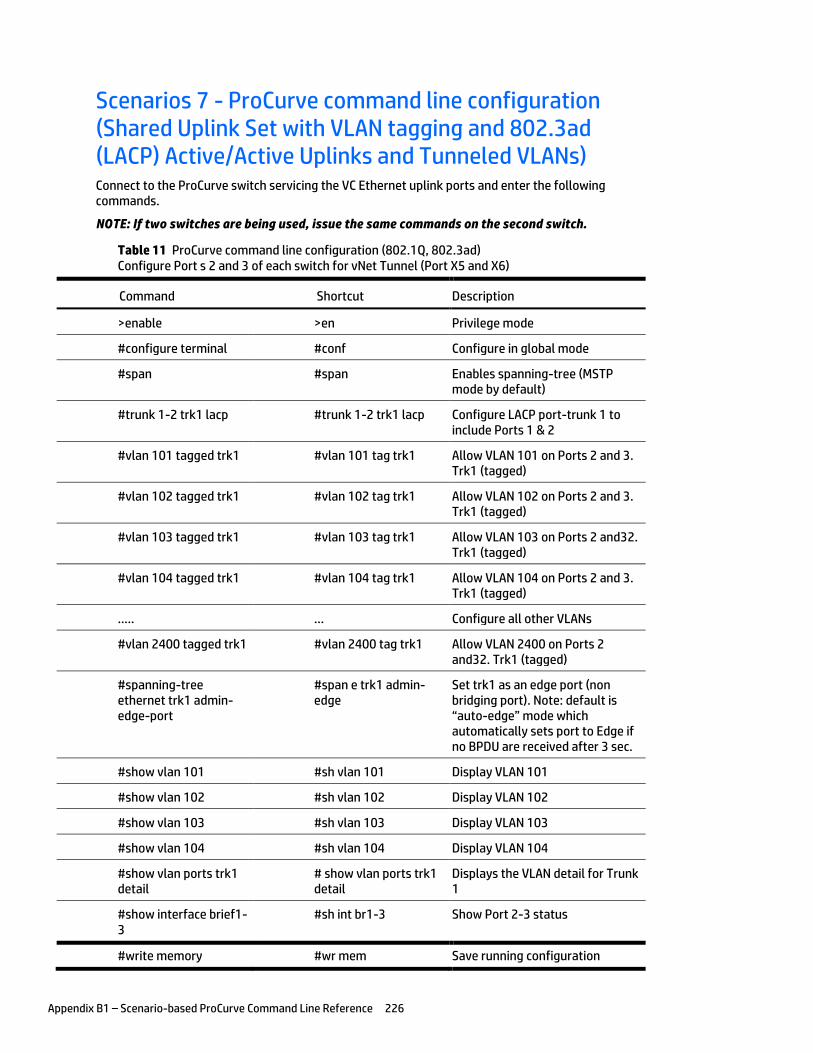
Appendix B1 – Scenario-based ProCurve Command Line Reference 226
Scenarios 7 - ProCurve command line configuration (Shared Uplink Set with VLAN tagging and 802.3ad (LACP) Active/Active Uplinks and Tunneled VLANs) Connect to the ProCurve switch servicing the VC Ethernet uplink ports and enter the following commands.
NOTE: If two switches are being used, issue the same commands on the second switch.
Table 11 ProCurve command line configuration (802.1Q, 802.3ad) Configure Port s 2 and 3 of each switch for vNet Tunnel (Port X5 and X6)
Command Shortcut Description
>enable >en Privilege mode
#configure terminal #conf Configure in global mode
#span #span Enables spanning-tree (MSTP mode by default)
#trunk 1-2 trk1 lacp #trunk 1-2 trk1 lacp Configure LACP port-trunk 1 to include Ports 1 & 2
#vlan 101 tagged trk1 #vlan 101 tag trk1 Allow VLAN 101 on Ports 2 and 3. Trk1 (tagged)
#vlan 102 tagged trk1 #vlan 102 tag trk1 Allow VLAN 102 on Ports 2 and 3. Trk1 (tagged)
#vlan 103 tagged trk1 #vlan 103 tag trk1 Allow VLAN 103 on Ports 2 and32. Trk1 (tagged)
#vlan 104 tagged trk1 #vlan 104 tag trk1 Allow VLAN 104 on Ports 2 and 3. Trk1 (tagged)
….. … Configure all other VLANs
#vlan 2400 tagged trk1 #vlan 2400 tag trk1 Allow VLAN 2400 on Ports 2 and32. Trk1 (tagged)
#spanning-tree ethernet trk1 admin-edge-port
#span e trk1 admin-edge
Set trk1 as an edge port (non bridging port). Note: default is “auto-edge” mode which automatically sets port to Edge if no BPDU are received after 3 sec.
#show vlan 101 #sh vlan 101 Display VLAN 101
#show vlan 102 #sh vlan 102 Display VLAN 102
#show vlan 103 #sh vlan 103 Display VLAN 103
#show vlan 104 #sh vlan 104 Display VLAN 104
#show vlan ports trk1 detail
# show vlan ports trk1 detail
Displays the VLAN detail for Trunk 1
#show interface brief1-3
#sh int br1-3 Show Port 2-3 status
#write memory #wr mem Save running configuration
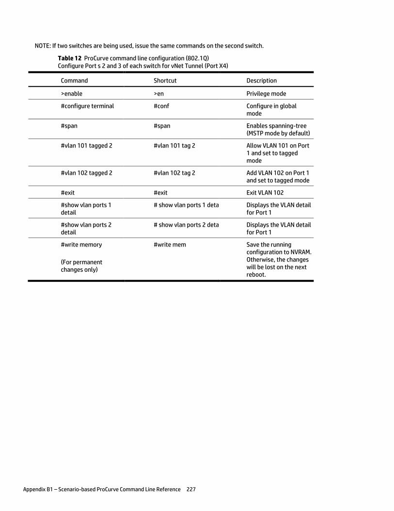
Appendix B1 – Scenario-based ProCurve Command Line Reference 227
NOTE: If two switches are being used, issue the same commands on the second switch.
Table 12 ProCurve command line configuration (802.1Q) Configure Port s 2 and 3 of each switch for vNet Tunnel (Port X4)
Command Shortcut Description
>enable >en Privilege mode
#configure terminal #conf Configure in global mode
#span #span Enables spanning-tree (MSTP mode by default)
#vlan 101 tagged 2 #vlan 101 tag 2 Allow VLAN 101 on Port 1 and set to tagged mode
#vlan 102 tagged 2 #vlan 102 tag 2 Add VLAN 102 on Port 1 and set to tagged mode
#exit #exit Exit VLAN 102
#show vlan ports 1 detail
# show vlan ports 1 detail Displays the VLAN detail for Port 1
#show vlan ports 2 detail
# show vlan ports 2 detail Displays the VLAN detail for Port 1
#write memory
(For permanent changes only)
#write mem Save the running configuration to NVRAM. Otherwise, the changes will be lost on the next reboot.
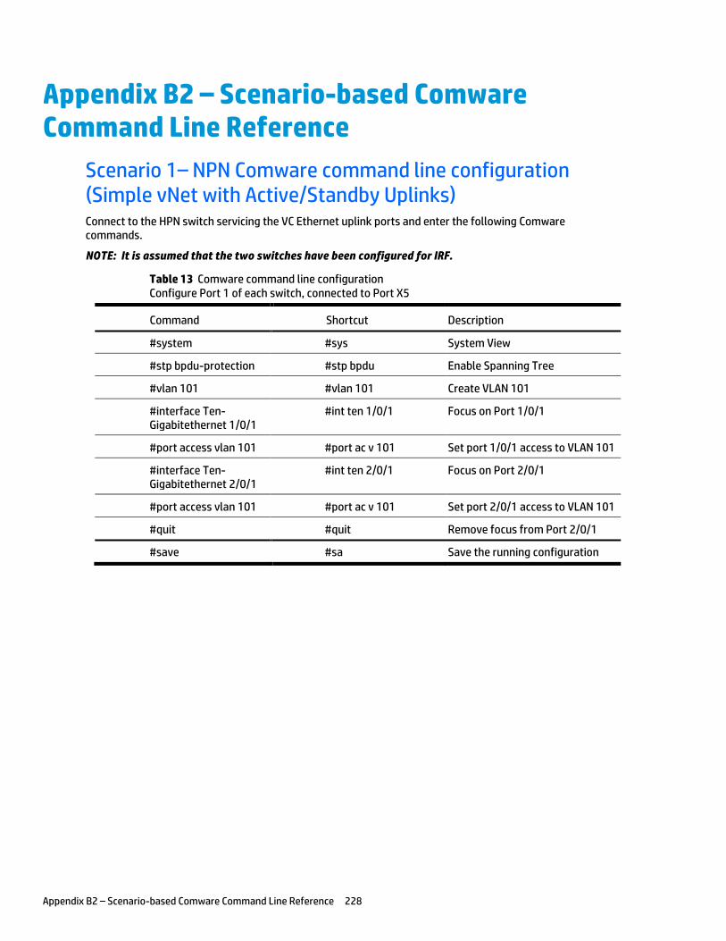
Appendix B2 – Scenario-based Comware Command Line Reference 228
Appendix B2 – Scenario-based Comware Command Line Reference
Scenario 1– NPN Comware command line configuration (Simple vNet with Active/Standby Uplinks) Connect to the HPN switch servicing the VC Ethernet uplink ports and enter the following Comware commands.
NOTE: It is assumed that the two switches have been configured for IRF.
Table 13 Comware command line configuration Configure Port 1 of each switch, connected to Port X5
Command Shortcut Description
#system #sys System View
#stp bpdu-protection #stp bpdu Enable Spanning Tree
#vlan 101 #vlan 101 Create VLAN 101
#interface Ten-Gigabitethernet 1/0/1
#int ten 1/0/1 Focus on Port 1/0/1
#port access vlan 101 #port ac v 101 Set port 1/0/1 access to VLAN 101
#interface Ten-Gigabitethernet 2/0/1
#int ten 2/0/1 Focus on Port 2/0/1
#port access vlan 101 #port ac v 101 Set port 2/0/1 access to VLAN 101
#quit #quit Remove focus from Port 2/0/1
#save #sa Save the running configuration
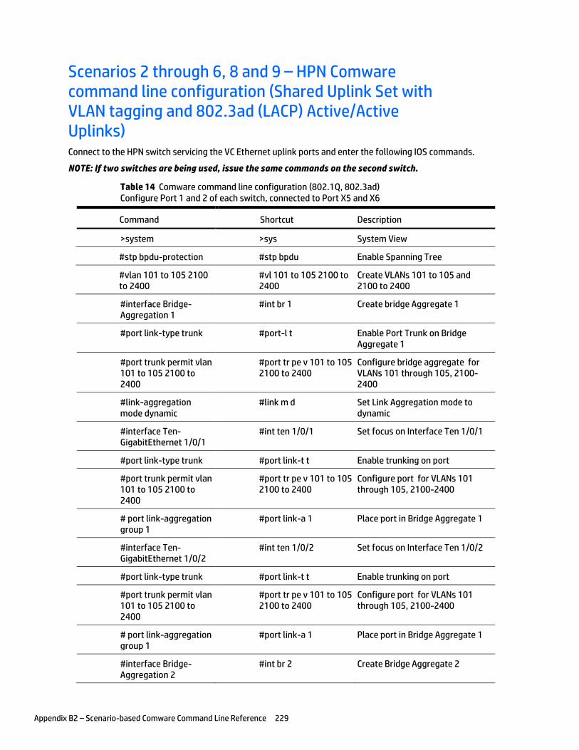
Appendix B2 – Scenario-based Comware Command Line Reference 229
Scenarios 2 through 6, 8 and 9 – HPN Comware command line configuration (Shared Uplink Set with VLAN tagging and 802.3ad (LACP) Active/Active Uplinks) Connect to the HPN switch servicing the VC Ethernet uplink ports and enter the following IOS commands.
NOTE: If two switches are being used, issue the same commands on the second switch.
Table 14 Comware command line configuration (802.1Q, 802.3ad) Configure Port 1 and 2 of each switch, connected to Port X5 and X6
Command Shortcut Description
>system >sys System View
#stp bpdu-protection #stp bpdu Enable Spanning Tree
#vlan 101 to 105 2100 to 2400
#vl 101 to 105 2100 to 2400
Create VLANs 101 to 105 and 2100 to 2400
#interface Bridge-Aggregation 1
#int br 1 Create bridge Aggregate 1
#port link-type trunk #port-l t Enable Port Trunk on Bridge Aggregate 1
#port trunk permit vlan 101 to 105 2100 to 2400
#port tr pe v 101 to 105 2100 to 2400
Configure bridge aggregate for VLANs 101 through 105, 2100-2400
#link-aggregation mode dynamic
#link m d Set Link Aggregation mode to dynamic
#interface Ten-GigabitEthernet 1/0/1
#int ten 1/0/1 Set focus on Interface Ten 1/0/1
#port link-type trunk #port link-t t Enable trunking on port
#port trunk permit vlan 101 to 105 2100 to 2400
#port tr pe v 101 to 105 2100 to 2400
Configure port for VLANs 101 through 105, 2100-2400
# port link-aggregation group 1
#port link-a 1 Place port in Bridge Aggregate 1
#interface Ten-GigabitEthernet 1/0/2
#int ten 1/0/2 Set focus on Interface Ten 1/0/2
#port link-type trunk #port link-t t Enable trunking on port
#port trunk permit vlan 101 to 105 2100 to 2400
#port tr pe v 101 to 105 2100 to 2400
Configure port for VLANs 101 through 105, 2100-2400
# port link-aggregation group 1
#port link-a 1 Place port in Bridge Aggregate 1
#interface Bridge-Aggregation 2
#int br 2 Create Bridge Aggregate 2
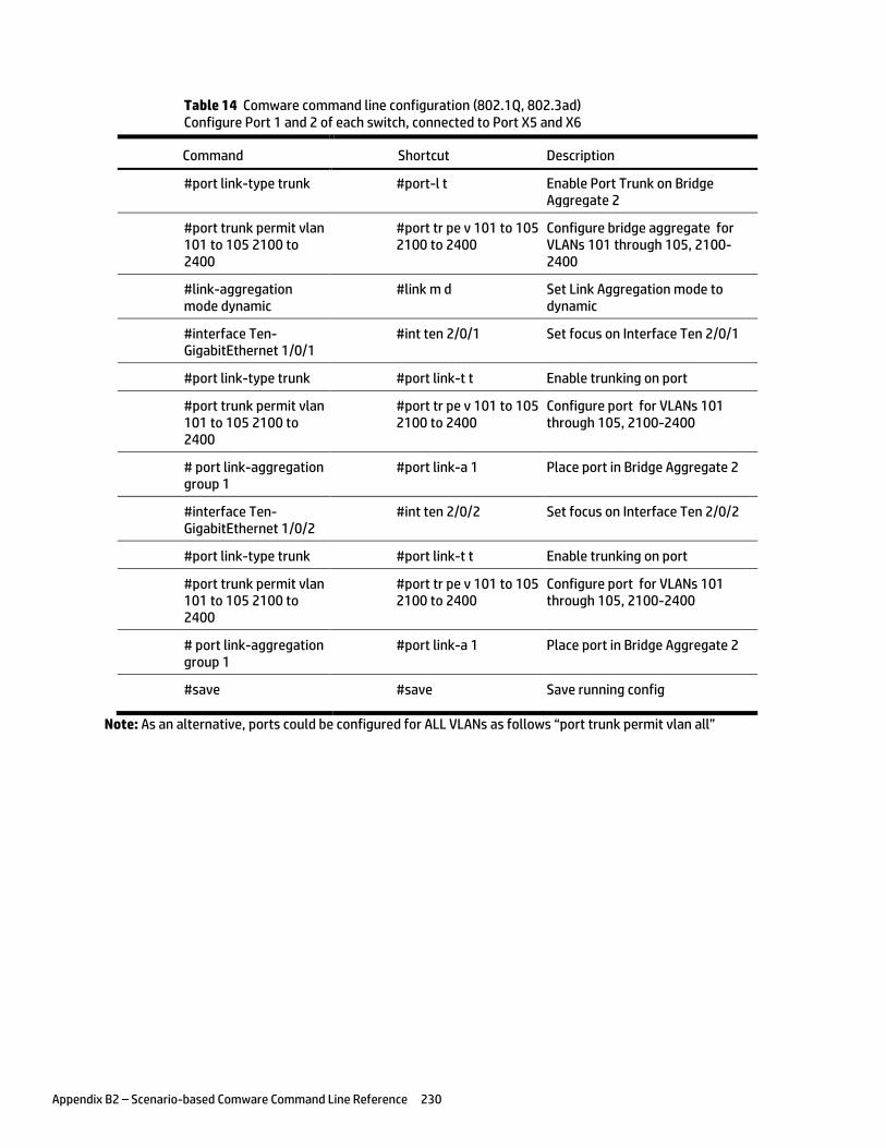
Appendix B2 – Scenario-based Comware Command Line Reference 230
Table 14 Comware command line configuration (802.1Q, 802.3ad) Configure Port 1 and 2 of each switch, connected to Port X5 and X6
Command Shortcut Description
#port link-type trunk #port-l t Enable Port Trunk on Bridge Aggregate 2
#port trunk permit vlan 101 to 105 2100 to 2400
#port tr pe v 101 to 105 2100 to 2400
Configure bridge aggregate for VLANs 101 through 105, 2100-2400
#link-aggregation mode dynamic
#link m d Set Link Aggregation mode to dynamic
#interface Ten-GigabitEthernet 1/0/1
#int ten 2/0/1 Set focus on Interface Ten 2/0/1
#port link-type trunk #port link-t t Enable trunking on port
#port trunk permit vlan 101 to 105 2100 to 2400
#port tr pe v 101 to 105 2100 to 2400
Configure port for VLANs 101 through 105, 2100-2400
# port link-aggregation group 1
#port link-a 1 Place port in Bridge Aggregate 2
#interface Ten-GigabitEthernet 1/0/2
#int ten 2/0/2 Set focus on Interface Ten 2/0/2
#port link-type trunk #port link-t t Enable trunking on port
#port trunk permit vlan 101 to 105 2100 to 2400
#port tr pe v 101 to 105 2100 to 2400
Configure port for VLANs 101 through 105, 2100-2400
# port link-aggregation group 1
#port link-a 1 Place port in Bridge Aggregate 2
#save #save Save running config
Note: As an alternative, ports could be configured for ALL VLANs as follows “port trunk permit vlan all”

Appendix B2 – Scenario-based Comware Command Line Reference 231
Scenarios 7 - Comware command line configuration (Shared Uplink Set with VLAN tagging and 802.3ad (LACP) Active/Active Uplinks and Tunneled VLANs) Connect to the HPN switch servicing the VC Ethernet uplink ports and enter the following IOS commands.
NOTE: If two switches are being used, issue the same commands on the second switch.
Table 15 Comware command line configuration (802.1Q, 802.3ad) Configure Port 1 of each switch for Shared Uplink Set (Port X4)
Command Shortcut Description
>system >sys System View
#stp bpdu-protection #stp bpdu Enable Spanning Tree
#vlan 101 to 105 #vl 101 to 105 Create VLANs 101 to 105
#interface Ten-GigabitEthernet 1/0/1
#int ten 1/0/1 Set focus on Interface Ten 1/0/1
#port link-type trunk #port link-t t Enable trunking on port
#port trunk permit vlan 101 to 102
#port tr pe v 101 to 102 Configure port for VLANs 101 to 102
#interface Ten-GigabitEthernet 1/0/2
#int ten 2/0/1 Set focus on Interface Ten 2/0/1
#port link-type trunk #port link-t t Enable trunking on port
#port trunk permit vlan 101 to 102
#port tr pe v 101 to 102 Configure port for VLANs 101 to 102
#save #save Save running config
Note: As an alternative, ports could be configured for ALL VLANs as follows “port trunk permit vlan all”
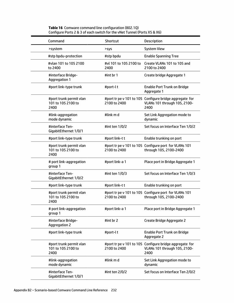
Appendix B2 – Scenario-based Comware Command Line Reference 232
Table 16 Comware command line configuration (802.1Q) Configure Ports 2 & 3 of each switch for the vNet Tunnel (Ports X5 & X6)
Command Shortcut Description
>system >sys System View
#stp bpdu-protection #stp bpdu Enable Spanning Tree
#vlan 101 to 105 2100 to 2400
#vl 101 to 105 2100 to 2400
Create VLANs 101 to 105 and 2100 to 2400
#interface Bridge-Aggregation 1
#int br 1 Create bridge Aggregate 1
#port link-type trunk #port-l t Enable Port Trunk on Bridge Aggregate 1
#port trunk permit vlan 101 to 105 2100 to 2400
#port tr pe v 101 to 105 2100 to 2400
Configure bridge aggregate for VLANs 101 through 105, 2100-2400
#link-aggregation mode dynamic
#link m d Set Link Aggregation mode to dynamic
#interface Ten-GigabitEthernet 1/0/1
#int ten 1/0/2 Set focus on Interface Ten 1/0/2
#port link-type trunk #port link-t t Enable trunking on port
#port trunk permit vlan 101 to 105 2100 to 2400
#port tr pe v 101 to 105 2100 to 2400
Configure port for VLANs 101 through 105, 2100-2400
# port link-aggregation group 1
#port link-a 1 Place port in Bridge Aggregate 1
#interface Ten-GigabitEthernet 1/0/2
#int ten 1/0/3 Set focus on Interface Ten 1/0/3
#port link-type trunk #port link-t t Enable trunking on port
#port trunk permit vlan 101 to 105 2100 to 2400
#port tr pe v 101 to 105 2100 to 2400
Configure port for VLANs 101 through 105, 2100-2400
# port link-aggregation group 1
#port link-a 1 Place port in Bridge Aggregate 1
#interface Bridge-Aggregation 2
#int br 2 Create Bridge Aggregate 2
#port link-type trunk #port-l t Enable Port Trunk on Bridge Aggregate 2
#port trunk permit vlan 101 to 105 2100 to 2400
#port tr pe v 101 to 105 2100 to 2400
Configure bridge aggregate for VLANs 101 through 105, 2100-2400
#link-aggregation mode dynamic
#link m d Set Link Aggregation mode to dynamic
#interface Ten-GigabitEthernet 1/0/1
#int ten 2/0/2 Set focus on Interface Ten 2/0/2
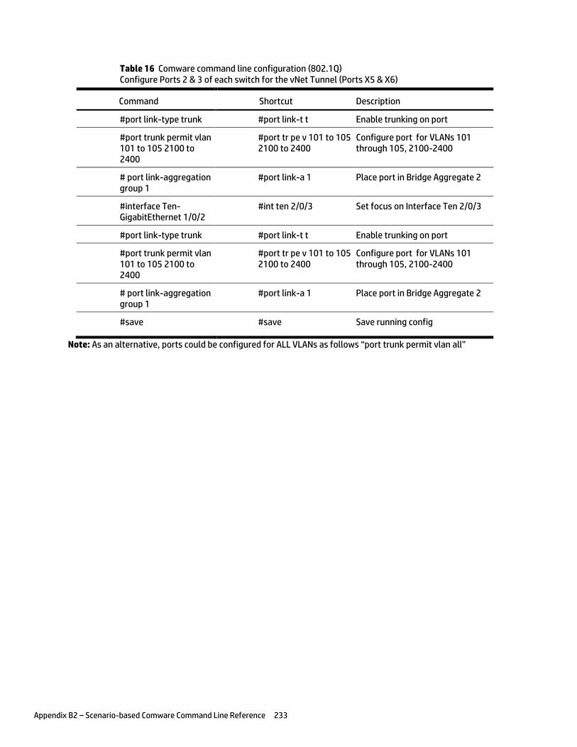
Appendix B2 – Scenario-based Comware Command Line Reference 233
Table 16 Comware command line configuration (802.1Q) Configure Ports 2 & 3 of each switch for the vNet Tunnel (Ports X5 & X6)
Command Shortcut Description
#port link-type trunk #port link-t t Enable trunking on port
#port trunk permit vlan 101 to 105 2100 to 2400
#port tr pe v 101 to 105 2100 to 2400
Configure port for VLANs 101 through 105, 2100-2400
# port link-aggregation group 1
#port link-a 1 Place port in Bridge Aggregate 2
#interface Ten-GigabitEthernet 1/0/2
#int ten 2/0/3 Set focus on Interface Ten 2/0/3
#port link-type trunk #port link-t t Enable trunking on port
#port trunk permit vlan 101 to 105 2100 to 2400
#port tr pe v 101 to 105 2100 to 2400
Configure port for VLANs 101 through 105, 2100-2400
# port link-aggregation group 1
#port link-a 1 Place port in Bridge Aggregate 2
#save #save Save running config
Note: As an alternative, ports could be configured for ALL VLANs as follows “port trunk permit vlan all”
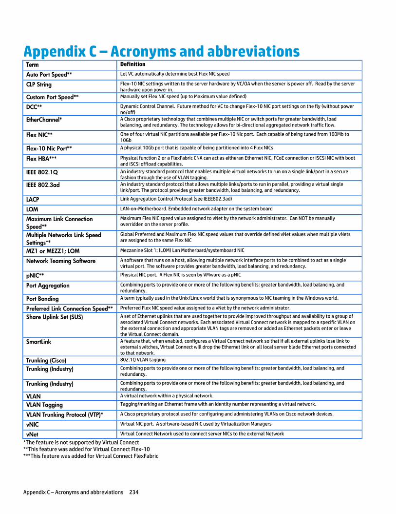
Appendix C – Acronyms and abbreviations 234
Appendix C – Acronyms and abbreviations Term Definition
Auto Port Speed** Let VC automatically determine best Flex NIC speed
CLP String Flex-10 NIC settings written to the server hardware by VC/OA when the server is power off. Read by the server hardware upon power in.
Custom Port Speed** Manually set Flex NIC speed (up to Maximum value defined)
DCC** Dynamic Control Channel. Future method for VC to change Flex-10 NIC port settings on the fly (without power no/off)
EtherChannel* A Cisco proprietary technology that combines multiple NIC or switch ports for greater bandwidth, load balancing, and redundancy. The technology allows for bi-directional aggregated network traffic flow.
Flex NIC** One of four virtual NIC partitions available per Flex-10 Nic port. Each capable of being tuned from 100Mb to 10Gb
Flex-10 Nic Port** A physical 10Gb port that is capable of being partitioned into 4 Flex NICs
Flex HBA*** Physical function 2 or a FlexFabric CNA can act as eitheran Ethernet NIC, FCoE connection or iSCSI NIC with boot and iSCSI offload capabilities.
IEEE 802.1Q An industry standard protocol that enables multiple virtual networks to run on a single link/port in a secure fashion through the use of VLAN tagging.
IEEE 802.3ad An industry standard protocol that allows multiple links/ports to run in parallel, providing a virtual single link/port. The protocol provides greater bandwidth, load balancing, and redundancy.
LACP Link Aggregation Control Protocol (see IEEE802.3ad)
LOM LAN-on-Motherboard. Embedded network adapter on the system board
Maximum Link Connection
Speed**
Maximum Flex NIC speed value assigned to vNet by the network administrator. Can NOT be manually overridden on the server profile.
Multiple Networks Link Speed
Settings**
Global Preferred and Maximum Flex NIC speed values that override defined vNet values when multiple vNets are assigned to the same Flex NIC
MZ1 or MEZZ1; LOM Mezzanine Slot 1; (LOM) Lan Motherbard/systemboard NIC
Network Teaming Software A software that runs on a host, allowing multiple network interface ports to be combined to act as a single virtual port. The software provides greater bandwidth, load balancing, and redundancy.
pNIC** Physical NIC port. A Flex NIC is seen by VMware as a pNIC
Port Aggregation Combining ports to provide one or more of the following benefits: greater bandwidth, load balancing, and redundancy.
Port Bonding A term typically used in the Unix/Linux world that is synonymous to NIC teaming in the Windows world.
Preferred Link Connection Speed** Preferred Flex NIC speed value assigned to a vNet by the network administrator.
Share Uplink Set (SUS) A set of Ethernet uplinks that are used together to provide improved throughput and availability to a group of associated Virtual Connect networks. Each associated Virtual Connect network is mapped to a specific VLAN on the external connection and appropriate VLAN tags are removed or added as Ethernet packets enter or leave the Virtual Connect domain.
SmartLink A feature that, when enabled, configures a Virtual Connect network so that if all external uplinks lose link to external switches, Virtual Connect will drop the Ethernet link on all local server blade Ethernet ports connected to that network.
Trunking (Cisco) 802.1Q VLAN tagging
Trunking (Industry) Combining ports to provide one or more of the following benefits: greater bandwidth, load balancing, and redundancy.
Trunking (Industry) Combining ports to provide one or more of the following benefits: greater bandwidth, load balancing, and redundancy.
VLAN A virtual network within a physical network.
VLAN Tagging Tagging/marking an Ethernet frame with an identity number representing a virtual network.
VLAN Trunking Protocol (VTP)* A Cisco proprietary protocol used for configuring and administering VLANs on Cisco network devices.
vNIC Virtual NIC port. A software-based NIC used by Virtualization Managers
vNet Virtual Connect Network used to connect server NICs to the external Network
*The feature is not supported by Virtual Connect **This feature was added for Virtual Connect Flex-10 ***This feature was added for Virtual Connect FlexFabric
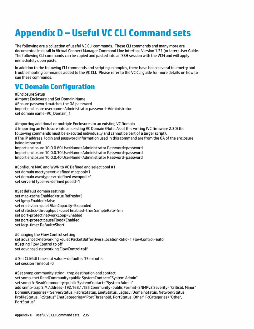
Appendix D – Useful VC CLI Command sets 235
Appendix D – Useful VC CLI Command sets The following are a collection of useful VC CLI commands. These CLI commands and many more are documented in detail in Virtual Connect Manager Command Line Interface Version 1.31 (or later) User Guide. The following CLI commands can be copied and pasted into an SSH session with the VCM and will apply immediately upon paste.
In addition to the following CLI commands and scripting examples, there have been several telemetry and troubleshooting commands added to the VC CLI. Please refer to the VC CLI guide for more details on how to sue these commands.
VC Domain Configuration #Enclosure Setup #Import Enclosure and Set Domain Name #Ensure password matches the OA password import enclosure username=Administrator password=Administrator set domain name=VC_Domain_1 #Importing additional or multiple Enclosures to an existing VC Domain # Importing an Enclosure into an existing VC Domain (Note: As of this writing (VC firmware 2.30) the following commands must be executed individually and cannot be part of a larger script). #The IP address, login and password information used in this command are from the OA of the enclosure being imported. Import enclosure 10.0.0.60 UserName=Administrator Password=password Import enclosure 10.0.0.30 UserName=Administrator Password=password Import enclosure 10.0.0.40 UserName=Administrator Password=password #Configure MAC and WWN to VC Defined and select pool #1 set domain mactype=vc-defined macpool=1 set domain wwntype=vc-defined wwnpool=1 set serverid type=vc-defined poolid=1 #Set default domain settings set mac-cache Enabled=true Refresh=5 set igmp Enabled=false set enet-vlan -quiet VlanCapacity=Expanded set statistics-throughput -quiet Enabled=true SampleRate=5m set port-protect networkLoop=Enabled set port-protect pauseFlood=Enabled set lacp-timer Default=Short #Changing the Flow Control setting set advanced-networking -quiet PacketBufferOverallocationRatio=1 FlowControl=auto #Setting Flow Control to off set advanced-networking FlowControl=off # Set CLI/GUI time-out value – default is 15 minutes set session Timeout=0 #Set snmp community string, trap destination and contact set snmp enet ReadCommunity=public SystemContact="System Admin" set snmp fc ReadCommunity=public SystemContact="System Admin" add snmp-trap SIM Address=192.168.1.185 Community=public Format=SNMPv2 Severity="Critical, Minor" DomainCategories="ServerStatus, FabricStatus, EnetStatus, Legacy, DomainStatus, NetworkStatus, ProfileStatus, FcStatus" EnetCategories="PortThreshold, PortStatus, Other" FcCategories="Other, PortStatus"
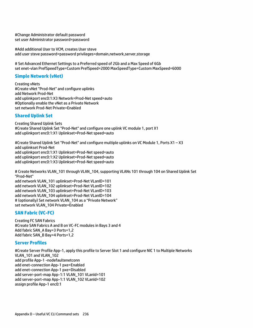
Appendix D – Useful VC CLI Command sets 236
#Change Administrator default password set user Administrator password=password #Add additional User to VCM, creates User steve add user steve password=password privileges=domain,network,server,storage # Set Advanced Ethernet Settings to a Preferred speed of 2Gb and a Max Speed of 6Gb set enet-vlan PrefSpeedType=Custom PrefSpeed=2000 MaxSpeedType=Custom MaxSpeed=6000
Simple Network (vNet)
Creating vNets #Create vNet "Prod-Net" and configure uplinks add Network Prod-Net add uplinkport enc0:1:X3 Network=Prod-Net speed=auto #Optionally enable the vNet as a Private Network set network Prod-Net Private=Enabled
Shared Uplink Set
Creating Shared Uplink Sets #Create Shared Uplink Set "Prod-Net" and configure one uplink VC module 1, port X1 add uplinkport enc0:1:X1 Uplinkset=Prod-Net speed=auto #Create Shared Uplink Set "Prod-Net" and configure multiple uplinks on VC Module 1, Ports X1 – X3 add uplinkset Prod-Net add uplinkport enc0:1:X1 Uplinkset=Prod-Net speed=auto add uplinkport enc0:1:X2 Uplinkset=Prod-Net speed=auto add uplinkport enc0:1:X3 Uplinkset=Prod-Net speed=auto # Create Networks VLAN_101 through VLAN_104, supporting VLANs 101 through 104 on Shared Uplink Set "Prod-Net" add network VLAN_101 uplinkset=Prod-Net VLanID=101 add network VLAN_102 uplinkset=Prod-Net VLanID=102 add network VLAN_103 uplinkset=Prod-Net VLanID=103 add network VLAN_104 uplinkset=Prod-Net VLanID=104 # (optionally) Set network VLAN_104 as a “Private Network” set network VLAN_104 Private=Enabled
SAN Fabric (VC-FC)
Creating FC SAN Fabrics #Create SAN Fabrics A and B on VC-FC modules in Bays 3 and 4 Add fabric SAN_A Bay=3 Ports=1,2 Add fabric SAN_B Bay=4 Ports=1,2
Server Profiles
#Create Server Profile App-1, apply this profile to Server Slot 1 and configure NIC 1 to Multiple Networks VLAN_101 and VLAN_102 add profile App-1 -nodefaultenetconn add enet-connection App-1 pxe=Enabled add enet-connection App-1 pxe=Disabled add server-port-map App-1:1 VLAN_101 VLanId=101 add server-port-map App-1:1 VLAN_102 VLanId=102 assign profile App-1 enc0:1
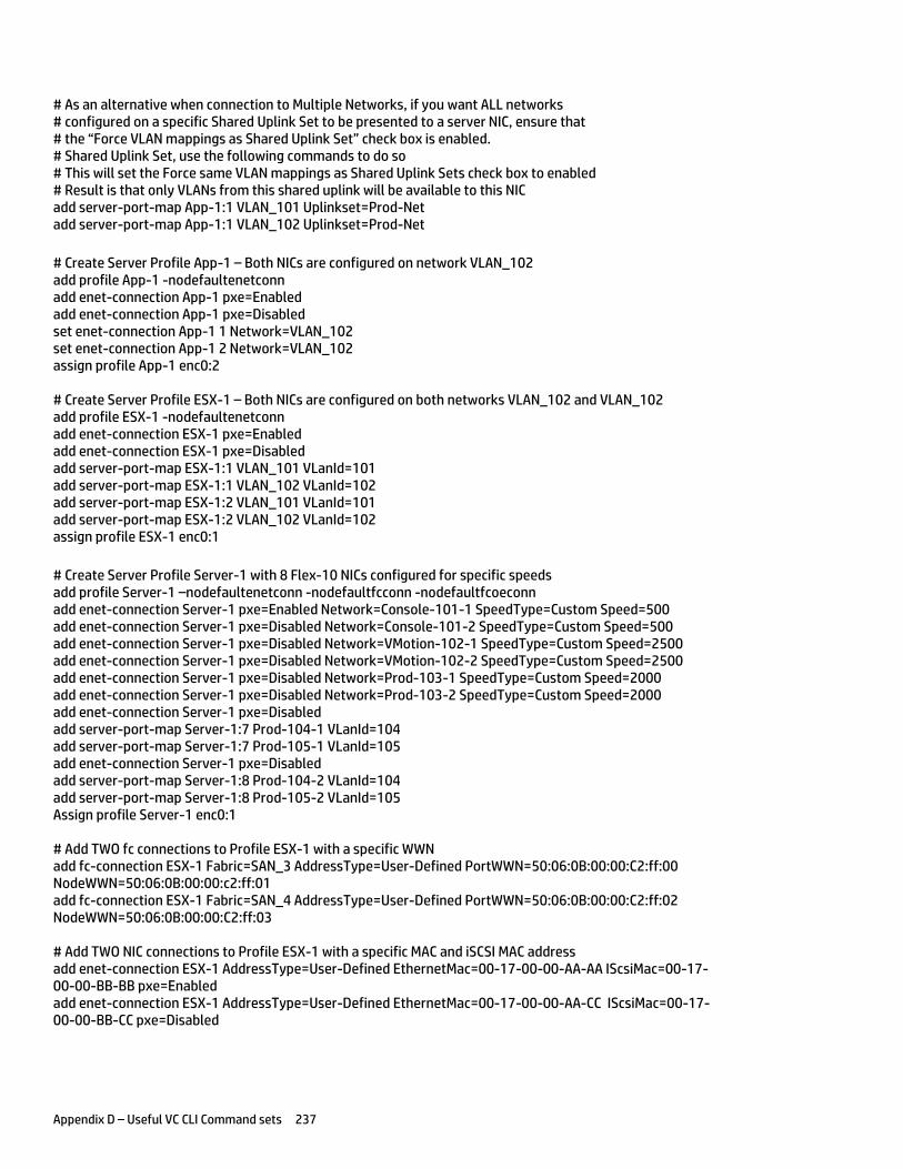
Appendix D – Useful VC CLI Command sets 237
# As an alternative when connection to Multiple Networks, if you want ALL networks # configured on a specific Shared Uplink Set to be presented to a server NIC, ensure that # the “Force VLAN mappings as Shared Uplink Set” check box is enabled. # Shared Uplink Set, use the following commands to do so # This will set the Force same VLAN mappings as Shared Uplink Sets check box to enabled # Result is that only VLANs from this shared uplink will be available to this NIC add server-port-map App-1:1 VLAN_101 Uplinkset=Prod-Net add server-port-map App-1:1 VLAN_102 Uplinkset=Prod-Net
# Create Server Profile App-1 – Both NICs are configured on network VLAN_102 add profile App-1 -nodefaultenetconn add enet-connection App-1 pxe=Enabled add enet-connection App-1 pxe=Disabled set enet-connection App-1 1 Network=VLAN_102 set enet-connection App-1 2 Network=VLAN_102 assign profile App-1 enc0:2 # Create Server Profile ESX-1 – Both NICs are configured on both networks VLAN_102 and VLAN_102 add profile ESX-1 -nodefaultenetconn add enet-connection ESX-1 pxe=Enabled add enet-connection ESX-1 pxe=Disabled add server-port-map ESX-1:1 VLAN_101 VLanId=101 add server-port-map ESX-1:1 VLAN_102 VLanId=102 add server-port-map ESX-1:2 VLAN_101 VLanId=101 add server-port-map ESX-1:2 VLAN_102 VLanId=102 assign profile ESX-1 enc0:1
# Create Server Profile Server-1 with 8 Flex-10 NICs configured for specific speeds add profile Server-1 –nodefaultenetconn -nodefaultfcconn -nodefaultfcoeconn add enet-connection Server-1 pxe=Enabled Network=Console-101-1 SpeedType=Custom Speed=500 add enet-connection Server-1 pxe=Disabled Network=Console-101-2 SpeedType=Custom Speed=500 add enet-connection Server-1 pxe=Disabled Network=VMotion-102-1 SpeedType=Custom Speed=2500 add enet-connection Server-1 pxe=Disabled Network=VMotion-102-2 SpeedType=Custom Speed=2500 add enet-connection Server-1 pxe=Disabled Network=Prod-103-1 SpeedType=Custom Speed=2000 add enet-connection Server-1 pxe=Disabled Network=Prod-103-2 SpeedType=Custom Speed=2000 add enet-connection Server-1 pxe=Disabled add server-port-map Server-1:7 Prod-104-1 VLanId=104 add server-port-map Server-1:7 Prod-105-1 VLanId=105 add enet-connection Server-1 pxe=Disabled add server-port-map Server-1:8 Prod-104-2 VLanId=104 add server-port-map Server-1:8 Prod-105-2 VLanId=105 Assign profile Server-1 enc0:1
# Add TWO fc connections to Profile ESX-1 with a specific WWN add fc-connection ESX-1 Fabric=SAN_3 AddressType=User-Defined PortWWN=50:06:0B:00:00:C2:ff:00 NodeWWN=50:06:0B:00:00:c2:ff:01 add fc-connection ESX-1 Fabric=SAN_4 AddressType=User-Defined PortWWN=50:06:0B:00:00:C2:ff:02 NodeWWN=50:06:0B:00:00:C2:ff:03 # Add TWO NIC connections to Profile ESX-1 with a specific MAC and iSCSI MAC address add enet-connection ESX-1 AddressType=User-Defined EthernetMac=00-17-00-00-AA-AA IScsiMac=00-17-00-00-BB-BB pxe=Enabled add enet-connection ESX-1 AddressType=User-Defined EthernetMac=00-17-00-00-AA-CC IScsiMac=00-17-00-00-BB-CC pxe=Disabled
Appendix D – Useful VC CLI Command sets 238
FlexFabric Scripting Additions #Create the FCoE SAN Fabrics FCoE_A and FCoE_B and configure uplinks as discussed above Add fabric FCoE_A Bay=1 Ports=1,2 LinkDist=Auto Add fabric FCoE_B Bay=2 Ports=1,2 LinkDist=Auto
Release 3.30 Scripting Additions Scripting a Shared Uplink Set
When creating a Shared Uplink Set, you can now bulk create the VLAN entries for the Shared Uplink Set through the use of the “add Network-range” command.
# Create Shared Uplink Set VLAN-Trunk-1 and configure uplinks add uplinkset VLAN-Trunk-1 add uplinkport enc0:1:X5 Uplinkset=VLAN-Trunk-1 speed=auto add uplinkport enc0:1:X6 Uplinkset=VLAN-Trunk-1 speed=auto # Create Networks VLAN-1-1 through VLAN-3-1, VLAN-101-1 through VLAN-105-1, VLAN-201-1 through VLAN-205-1, VLAN-301-1 through VLAN-305-1 for Shared Uplink Set VLAN-Trunk-1 add network-range -quiet UplinkSet=VLAN-Trunk-1 NamePrefix=VLAN- NameSuffix=-1 VLANIds=101-105,201-205,301-305 State=enabled PrefSpeedType=auto SmartLink=enabled
Scripting a Shared Uplink Set – with a Native VLAN and SmartLink
When creating a Shared Uplink Set, you can now bulk create the VLAN entries for the Shared Uplink Set through the use of the “add Network-range” command.
# Create Shared Uplink Set VLAN-Trunk-1 and configure uplinks add uplinkset VLAN-Trunk-1 add uplinkport enc0:1:X5 Uplinkset=VLAN-Trunk-1 speed=auto add uplinkport enc0:1:X6 Uplinkset=VLAN-Trunk-1 speed=auto # Create Network VLAN-1-1 for Shared Uplink Set VLAN-Trunk-1, enable SmartLink and NativeVLAN add network VLAN-1-1 uplinkset=VLAN-Trunk-1 VLanID=1 NativeVLAN=Enabled Set Network VLAN-1-1 SmartLink=Enabled # Create Networks VLAN-2-1 through VLAN-3-1, VLAN-101-1 through VLAN-105-1, VLAN-2100 through 2400 for Shared Uplink Set VLAN-Trunk-1 add network-range -quiet UplinkSet=VLAN-Trunk-1 NamePrefix=VLAN- NameSuffix=-1 VLANIds=2,3,101-105,2100-2400 State=enabled PrefSpeedType=auto SmartLink=enabled
Copying a Shared Uplink Sets – with a Native VLAN and SmartLink
Virtual Connect provides the ability to copy a Shared Uplink Set. This can be very handy when defining an Active/Active Shared Uplink Set design. You simply create the first SUS, then copy it.
For example, after creating Shared Uplink Set VLAN-Trunk-1 you can copy it to VLAN-Trunk-2. You will then need to add uplinks to the new SUS and ensure all networks have SmartLink enabled. This can be accomplished as follows;
copy uplinkset VLAN-Trunk-1 VLAN-Trunk-2 fromVlanStr=1 toVlanStr=2 replace=last add uplinkport enc0:2:X5 Uplinkset=VLAN-Trunk-2 speed=auto add uplinkport enc0:2:X6 Uplinkset=VLAN-Trunk-2 speed=auto set network-range -quiet UplinkSet=VLAN-Trunk-1 VLANIds=1,2,3,101-105,2100-2400 SmartLink=enabled
Appendix D – Useful VC CLI Command sets 239
Scripting a Server Profile
When creating a server profile, mapping multiple VLANs to a server NIC is further simplified through the use of the “add server-port-map-range” command
# Create Server Profile ESX-1 add profile ESX-1 -nodefaultfcconn -nodefaultfcoeconn set enet-connection ESX-1 1 pxe=Enabled Network=VLAN-101-1 SpeedType=Custom Speed=100 set enet-connection ESX-1 2 pxe=Disabled Network=VLAN-101-2 SpeedType=Custom Speed=100 add enet-connection ESX-1 pxe=Disabled Network=VLAN-102-1 SpeedType=Custom Speed=2000 add enet-connection ESX-1 pxe=Disabled Network=VLAN-102-2 SpeedType=Custom Speed=2000 add enet-connection ESX-1 pxe=Disabled add server-port-map-range ESX-1:5 UplinkSet=VLAN-Trunk-1 VLanIds=103-105,2100-2150 add enet-connection ESX-1 pxe=Disabled add server-port-map-range ESX-1:6 UplinkSet=VLAN-Trunk-2 VLanIds=103-105,2100-2150 add fcoe-connection ESX-1 Fabric=FCoE_A SpeedType=4Gb add fcoe-connection ESX-1 Fabric=FCoE_B SpeedType=4Gb assign profile ESX-1 enc0:1
Copying a Server Profile
Virtual Connect CLI provides the ability to COPY a profile. The example below will copy an existing profile (ESX-1), then apply it to a vacant server bay (bay 2-4), and optionally power it on.
copy profile ESX-1 ESX-2 assign profile ESX-2 enc0:2 Poweron server enc0:2 copy profile ESX-1 ESX-3 assign profile ESX-2 enc0:3 Poweron server enc0:3 copy profile ESX-1 ESX-4 assign profile ESX-2 enc0:4 Poweron server enc0:4
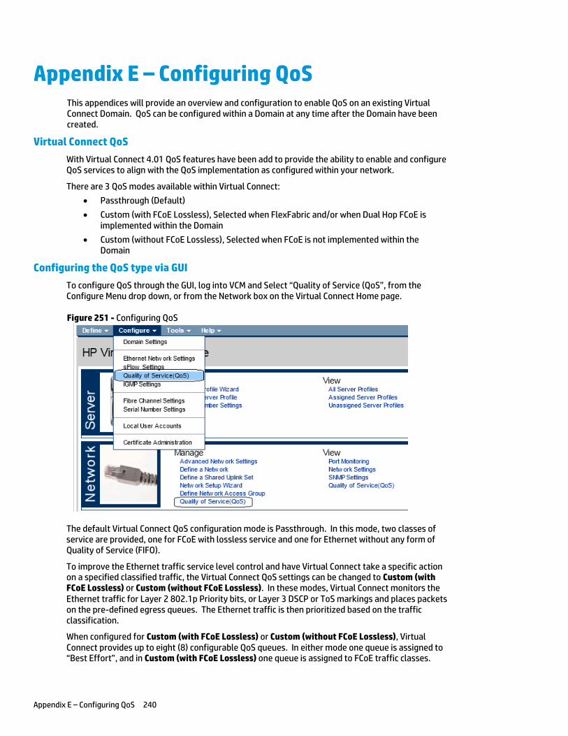
Appendix E – Configuring QoS 240
Appendix E – Configuring QoS This appendices will provide an overview and configuration to enable QoS on an existing Virtual Connect Domain. QoS can be configured within a Domain at any time after the Domain have been created.
Virtual Connect QoS
With Virtual Connect 4.01 QoS features have been add to provide the ability to enable and configure QoS services to align with the QoS implementation as configured within your network.
There are 3 QoS modes available within Virtual Connect:
Passthrough (Default)
Custom (with FCoE Lossless), Selected when FlexFabric and/or when Dual Hop FCoE is implemented within the Domain
Custom (without FCoE Lossless), Selected when FCoE is not implemented within the Domain
Configuring the QoS type via GUI
To configure QoS through the GUI, log into VCM and Select “Quality of Service (QoS”, from the Configure Menu drop down, or from the Network box on the Virtual Connect Home page.
Figure 251 - Configuring QoS
The default Virtual Connect QoS configuration mode is Passthrough. In this mode, two classes of service are provided, one for FCoE with lossless service and one for Ethernet without any form of Quality of Service (FIFO).
To improve the Ethernet traffic service level control and have Virtual Connect take a specific action on a specified classified traffic, the Virtual Connect QoS settings can be changed to Custom (with FCoE Lossless) or Custom (without FCoE Lossless). In these modes, Virtual Connect monitors the Ethernet traffic for Layer 2 802.1p Priority bits, or Layer 3 DSCP or ToS markings and places packets on the pre-defined egress queues. The Ethernet traffic is then prioritized based on the traffic classification.
When configured for Custom (with FCoE Lossless) or Custom (without FCoE Lossless), Virtual Connect provides up to eight (8) configurable QoS queues. In either mode one queue is assigned to “Best Effort”, and in Custom (with FCoE Lossless) one queue is assigned to FCoE traffic classes.
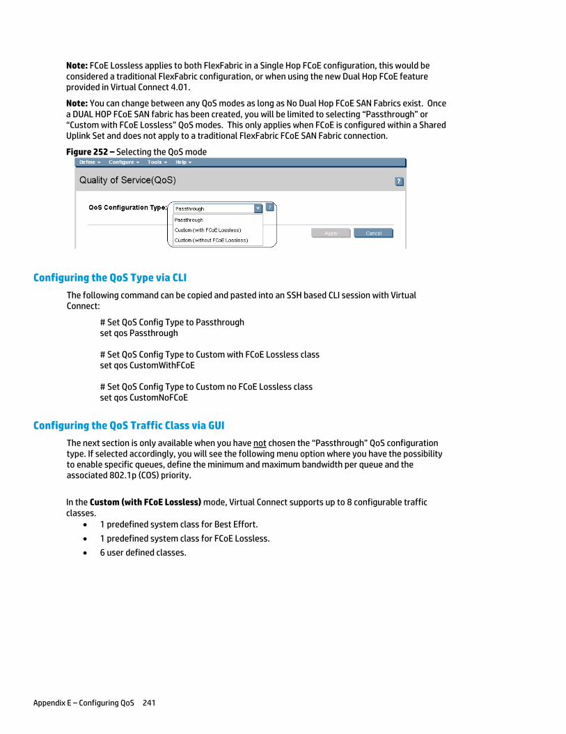
Appendix E – Configuring QoS 241
Note: FCoE Lossless applies to both FlexFabric in a Single Hop FCoE configuration, this would be considered a traditional FlexFabric configuration, or when using the new Dual Hop FCoE feature provided in Virtual Connect 4.01.
Note: You can change between any QoS modes as long as No Dual Hop FCoE SAN Fabrics exist. Once a DUAL HOP FCoE SAN fabric has been created, you will be limited to selecting “Passthrough” or “Custom with FCoE Lossless” QoS modes. This only applies when FCoE is configured within a Shared Uplink Set and does not apply to a traditional FlexFabric FCoE SAN Fabric connection.
Figure 252 – Selecting the QoS mode
Configuring the QoS Type via CLI
The following command can be copied and pasted into an SSH based CLI session with Virtual Connect:
# Set QoS Config Type to Passthrough set qos Passthrough # Set QoS Config Type to Custom with FCoE Lossless class set qos CustomWithFCoE # Set QoS Config Type to Custom no FCoE Lossless class set qos CustomNoFCoE
Configuring the QoS Traffic Class via GUI
The next section is only available when you have not chosen the “Passthrough” QoS configuration type. If selected accordingly, you will see the following menu option where you have the possibility to enable specific queues, define the minimum and maximum bandwidth per queue and the associated 802.1p (COS) priority.
In the Custom (with FCoE Lossless) mode, Virtual Connect supports up to 8 configurable traffic classes.
1 predefined system class for Best Effort.
1 predefined system class for FCoE Lossless.
6 user defined classes.
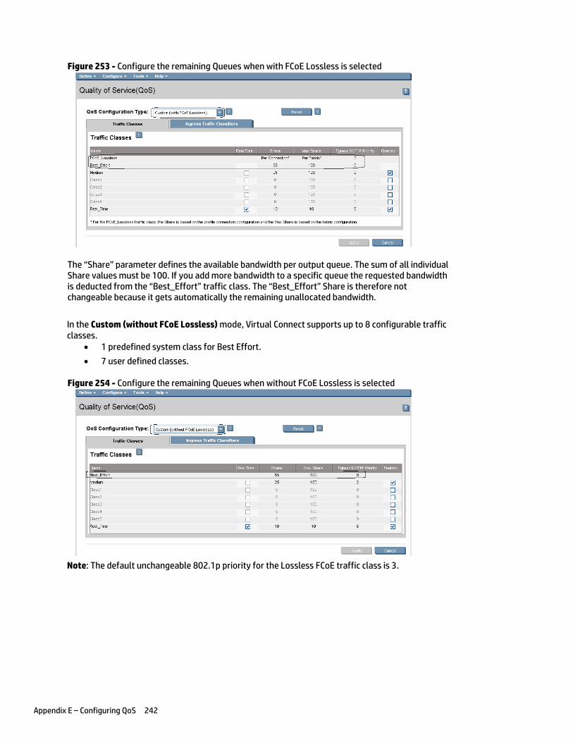
Appendix E – Configuring QoS 242
Figure 253 - Configure the remaining Queues when with FCoE Lossless is selected
The “Share” parameter defines the available bandwidth per output queue. The sum of all individual Share values must be 100. If you add more bandwidth to a specific queue the requested bandwidth is deducted from the “Best_Effort” traffic class. The “Best_Effort” Share is therefore not changeable because it gets automatically the remaining unallocated bandwidth.
In the Custom (without FCoE Lossless) mode, Virtual Connect supports up to 8 configurable traffic classes.
1 predefined system class for Best Effort.
7 user defined classes.
Figure 254 - Configure the remaining Queues when without FCoE Lossless is selected
Note: The default unchangeable 802.1p priority for the Lossless FCoE traffic class is 3.
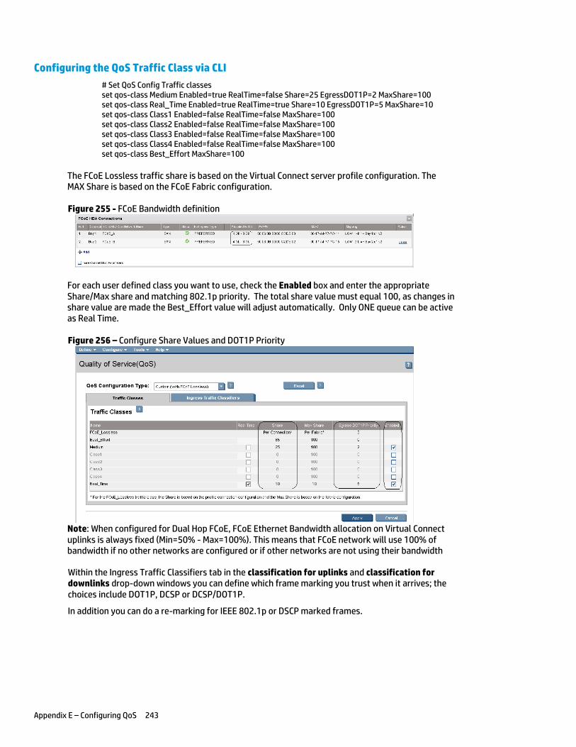
Appendix E – Configuring QoS 243
Configuring the QoS Traffic Class via CLI
# Set QoS Config Traffic classes set qos-class Medium Enabled=true RealTime=false Share=25 EgressDOT1P=2 MaxShare=100 set qos-class Real_Time Enabled=true RealTime=true Share=10 EgressDOT1P=5 MaxShare=10 set qos-class Class1 Enabled=false RealTime=false MaxShare=100 set qos-class Class2 Enabled=false RealTime=false MaxShare=100 set qos-class Class3 Enabled=false RealTime=false MaxShare=100 set qos-class Class4 Enabled=false RealTime=false MaxShare=100 set qos-class Best_Effort MaxShare=100
The FCoE Lossless traffic share is based on the Virtual Connect server profile configuration. The MAX Share is based on the FCoE Fabric configuration.
Figure 255 - FCoE Bandwidth definition
For each user defined class you want to use, check the Enabled box and enter the appropriate Share/Max share and matching 802.1p priority. The total share value must equal 100, as changes in share value are made the Best_Effort value will adjust automatically. Only ONE queue can be active as Real Time.
Figure 256 – Configure Share Values and DOT1P Priority
Note: When configured for Dual Hop FCoE, FCoE Ethernet Bandwidth allocation on Virtual Connect uplinks is always fixed (Min=50% - Max=100%). This means that FCoE network will use 100% of bandwidth if no other networks are configured or if other networks are not using their bandwidth
Within the Ingress Traffic Classifiers tab in the classification for uplinks and classification for downlinks drop-down windows you can define which frame marking you trust when it arrives; the choices include DOT1P, DCSP or DCSP/DOT1P.
In addition you can do a re-marking for IEEE 802.1p or DSCP marked frames.
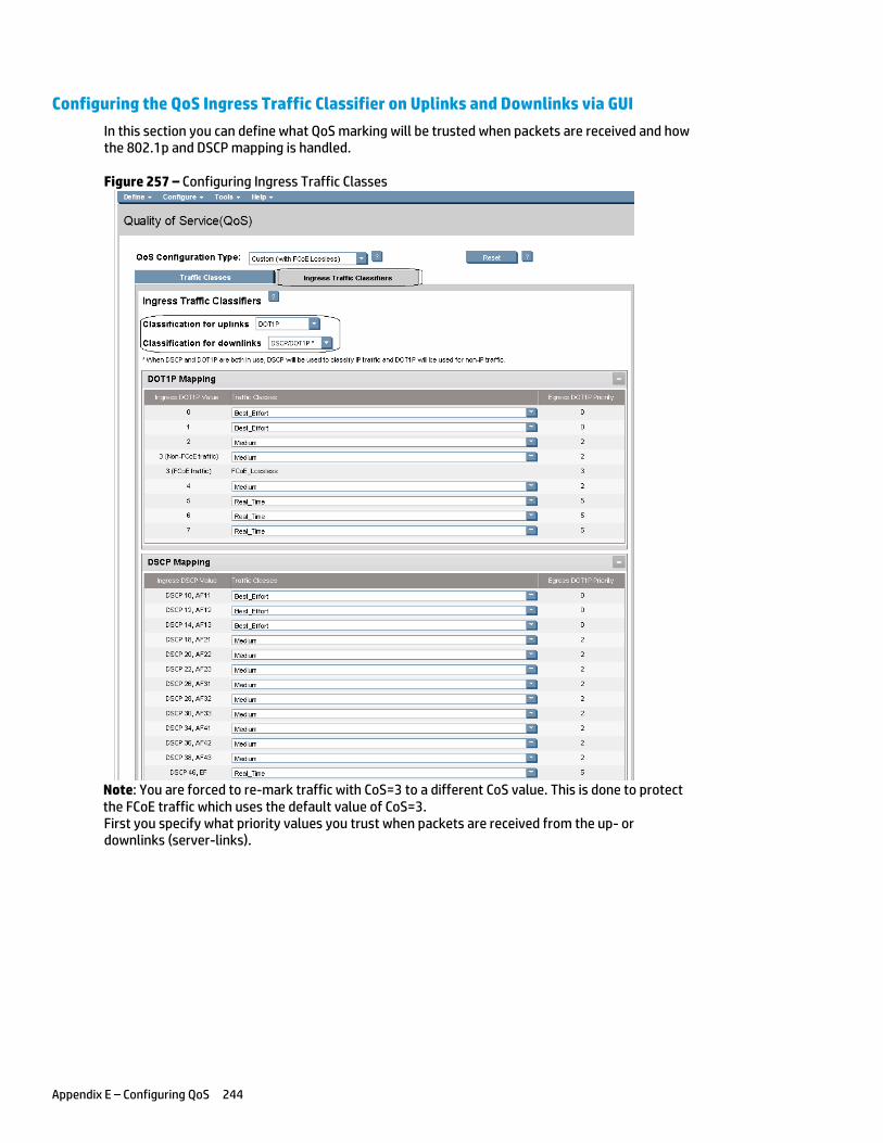
Appendix E – Configuring QoS 244
Configuring the QoS Ingress Traffic Classifier on Uplinks and Downlinks via GUI
In this section you can define what QoS marking will be trusted when packets are received and how the 802.1p and DSCP mapping is handled.
Figure 257 – Configuring Ingress Traffic Classes
Note: You are forced to re-mark traffic with CoS=3 to a different CoS value. This is done to protect the FCoE traffic which uses the default value of CoS=3. First you specify what priority values you trust when packets are received from the up- or downlinks (server-links).
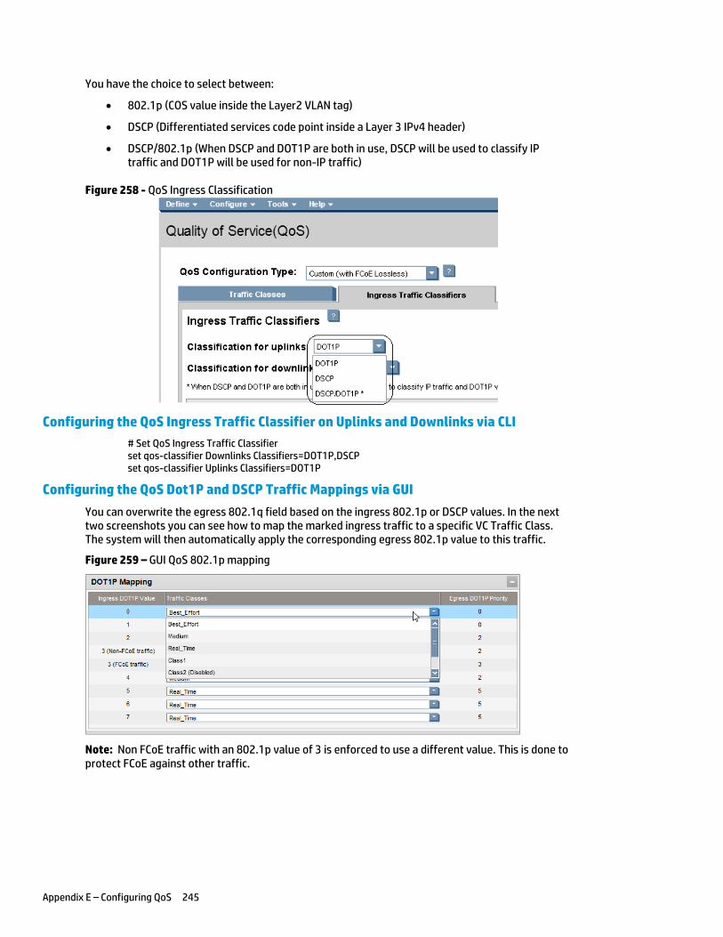
Appendix E – Configuring QoS 245
You have the choice to select between:
802.1p (COS value inside the Layer2 VLAN tag)
DSCP (Differentiated services code point inside a Layer 3 IPv4 header)
DSCP/802.1p (When DSCP and DOT1P are both in use, DSCP will be used to classify IP traffic and DOT1P will be used for non-IP traffic)
Figure 258 - QoS Ingress Classification
Configuring the QoS Ingress Traffic Classifier on Uplinks and Downlinks via CLI
# Set QoS Ingress Traffic Classifier set qos-classifier Downlinks Classifiers=DOT1P,DSCP set qos-classifier Uplinks Classifiers=DOT1P
Configuring the QoS Dot1P and DSCP Traffic Mappings via GUI
You can overwrite the egress 802.1q field based on the ingress 802.1p or DSCP values. In the next two screenshots you can see how to map the marked ingress traffic to a specific VC Traffic Class. The system will then automatically apply the corresponding egress 802.1p value to this traffic.
Figure 259 – GUI QoS 802.1p mapping
Note: Non FCoE traffic with an 802.1p value of 3 is enforced to use a different value. This is done to protect FCoE against other traffic.
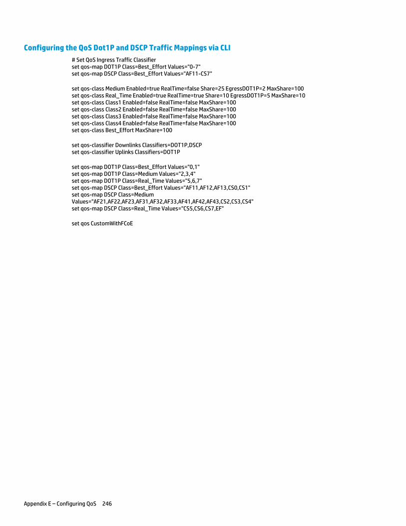
Appendix E – Configuring QoS 246
Configuring the QoS Dot1P and DSCP Traffic Mappings via CLI
# Set QoS Ingress Traffic Classifier set qos-map DOT1P Class=Best_Effort Values="0-7" set qos-map DSCP Class=Best_Effort Values="AF11-CS7"
set qos-class Medium Enabled=true RealTime=false Share=25 EgressDOT1P=2 MaxShare=100 set qos-class Real_Time Enabled=true RealTime=true Share=10 EgressDOT1P=5 MaxShare=10 set qos-class Class1 Enabled=false RealTime=false MaxShare=100 set qos-class Class2 Enabled=false RealTime=false MaxShare=100 set qos-class Class3 Enabled=false RealTime=false MaxShare=100 set qos-class Class4 Enabled=false RealTime=false MaxShare=100 set qos-class Best_Effort MaxShare=100
set qos-classifier Downlinks Classifiers=DOT1P,DSCP set qos-classifier Uplinks Classifiers=DOT1P
set qos-map DOT1P Class=Best_Effort Values="0,1" set qos-map DOT1P Class=Medium Values="2,3,4" set qos-map DOT1P Class=Real_Time Values="5,6,7" set qos-map DSCP Class=Best_Effort Values="AF11,AF12,AF13,CS0,CS1" set qos-map DSCP Class=Medium Values="AF21,AF22,AF23,AF31,AF32,AF33,AF41,AF42,AF43,CS2,CS3,CS4" set qos-map DSCP Class=Real_Time Values="CS5,CS6,CS7,EF"
set qos CustomWithFCoE

Appendix E – Configuring QoS 247
For more information
To read more about Virtual Connect, go to: hp.com/go/virtualconnect
Get connected hp.com/go/getconnected
© Copyright 2013 Hewlett-Packard Development Company, L.P. The information contained herein is subject to change without notice. The only warranties for HP products and services are set forth in the express warranty statements accompanying such products and services. Nothing herein should be construed as constituting an additional warranty. HP shall not be liable for technical or editorial errors or omissions contained herein.
Part number c02616817, Third Edition August 2013
Related Documents