HP-UX version 11.00.01 Stratus Technologies R1004H-06 HP-UX Operating System: Fault Tolerant System Administration

Welcome message from author
This document is posted to help you gain knowledge. Please leave a comment to let me know what you think about it! Share it to your friends and learn new things together.
Transcript
HP-UX version 11.00.01Stratus Technologies
R1004H-06
HP-UX Operating System:Fault Tolerant System Administration

Notice
The information contained in this document is subject to change without notice.
UNLESS EXPRESSLY SET FORTH IN A WRITTEN AGREEMENT SIGNED BY AN AUTHORIZED REPRESENTATIVE OF STRATUS TECHNOLOGIES, STRATUS MAKES NO WARRANTY OR REPRESENTATION OF ANY KIND WITH RESPECT TO THE INFORMATION CONTAINED HEREIN, INCLUDING WARRANTY OF MERCHANTABILITY AND FITNESS FOR A PURPOSE. Stratus Technologies assumes no responsibility or obligation of any kind for any errors contained herein or in connection with the furnishing, performance, or use of this document.
Software described in Stratus documents (a) is the property of Stratus Technologies Bermuda, Ltd. or the third party, (b) is furnished only under license, and (c) may be copied or used only as expressly permitted under the terms of the license.
Stratus documentation describes all supported features of the user interfaces and the application programming interfaces (API) developed by Stratus. Any undocumented features of these interfaces are intended solely for use by Stratus personnel and are subject to change without warning.
This document is protected by copyright. All rights are reserved. No part of this document may be copied, reproduced, or translated, either mechanically or electronically, without the prior written consent of Stratus Technologies.
Stratus, the Stratus logo, ftServer, Continuum, Continuous Processing, StrataLINK, StrataNET, DNCP, SINAP, and FTX are registered trademarks of Stratus Technologies Bermuda, Ltd.
The Stratus Technologies logo, the ftServer logo, Stratus 24 x 7 with design, The World’s Most Reliable Servers, The World’s Most Reliable Server Technologies, ftGateway, ftMemory, ftMessaging, ftStorage, Selectable Availability, XA/R, SQL/2000, The Availability Company, RSN, and MultiStack are trademarks of Stratus Technologies Bermuda, Ltd.
Hewlett-Packard, HP, and HP-UX are registered trademarks of Hewlett-Packard Company.UNIX is a registered trademark of X/Open Company, Ltd., in the U.S.A. and other countries.Eurologic and Vayager are registered trademarks of Eurolocig Systems.StorageWorks is a registered trademark of Compaq Computer Corporation.All other trademarks are the property of their respective owners.
Manual Name: HP-UX Operating System: Fault Tolerant System Administration
Part Number: R1004HRevision Number: 06 Operating System: HP-UX version 11.00.01Publication Date: May 2003
Stratus Technologies, Inc.111 Powdermill RoadMaynard, Massachusetts 01754-3409
© 2003 Stratus Technologies Bermuda, Ltd. All rights reserved.
Contents
PrefaceRevision Information xiAudience xiNotation Conventions xiProduct Documentation xiv
Online Documentation xivNotes Files xvMan Pages xv
Related Documentation xvOrdering Documentation xviCommenting on This Guide xvii
Customer Assistance Center (CAC) xvii
1. Getting Started 1-1Using This Manual 1-1Continuous Availability Administration 1-4
Continuum Series 400 Systems 1-4Continuum Series 600 and 1200 Systems 1-5Console Controller 1-6
Fault Tolerant Design 1-7Fault Tolerant Hardware 1-7Continuous Availability Software 1-8Duplexed Components 1-8Solo Components 1-9
2. Setting Up the System 2-1Installing a System 2-2Configuring a System 2-2
Standard Configuration Tasks 2-2Continuum Configuration Tasks 2-3
Maintaining a System 2-5Tracking and Fixing System Problems 2-6
HP-UX version 11.00.01 Contents iii
Contents
3. Starting and Stopping the System 3-1Overview of the Boot Process 3-1Configuring the Boot Environment 3-4
Enabling and Disabling Autoboot 3-5Modifying CONF Variables 3-8
Sample CONF Files 3-9Modifying the CONF File 3-10
Booting Process Commands 3-11CPU PROM Commands 3-12Primary Bootloader Commands 3-13Secondary Bootloader Commands 3-17
Booting the System 3-18Issuing Console Commands 3-20Manually Booting Your System 3-23
Shutting Down the System 3-24Using SAM 3-25Using Shell Commands 3-25
Changing to Single-User State 3-26Broadcasting a Message to Users 3-26Rebooting the System 3-27Halting the System 3-27Activating a New Kernel 3-29Designating Shutdown Authorization 3-29
Dealing with Power Failures 3-30Configuring the Power Failure Grace Period 3-31Configuring the UPS Port 3-32
Managing Flash Cards 3-32Flash Card Utility Commands 3-34Creating a New Flash Card 3-35Duplicating a Flash Card 3-36
4. Mirroring Data 4-1Mirroring Data 4-1
Glossary of Terms 4-1Sample Mirror Configuration 4-3Recommended Volume Structure 4-3Guidelines for Managing Mirrors 4-4
Mirroring Root and Primary Swap 4-5Adding a Mirror to Root Data After Installation 4-5
Setting Up I/O Channel Separation 4-8
iv Fault Tolerant System Administration (R1002H) HP-UX version 11.00.01
Contents
5. Administering Fault Tolerant Hardware 5-1Fault Tolerant Hardware Administration 5-1Using Hardware Utilities 5-2Determining Hardware Paths 5-3Physical Hardware Configuration 5-3
Continuum Series 400 Hardware Paths 5-6Continuum Series 600 and 1200 Hardware Paths 5-8CPU, Memory, and Console Controller Paths 5-10I/O Subsystem Paths 5-11
Logical Hardware Configuration 5-13Logical Communications I/O Configuration 5-15Logical Cabinet Configuration 5-16Logical LAN Manager Configuration 5-19Logical SCSI Manager Configuration 5-20
Defining a Logical SCSI Bus 5-23Mapping Logical Addresses to Physical Devices 5-26Mapping Logical Addresses to Device Files 5-30
Logical CPU/Memory Configuration 5-31Determining Component Status 5-32
Software State 5-32Hardware Status 5-34Displaying State and Status Information 5-35
Managing Hardware Devices 5-35Checking Status Lights 5-36Error Detection and Handling 5-37Disabling a Hardware Device 5-37Enabling a Hardware Device 5-38Correcting the Error State 5-38
Managing MTBF Statistics 5-39MTBF Calculation and Affects 5-39Displaying MTBF Information 5-40Clearing the MTBF 5-40Changing the MTBF Threshold 5-41Configuring the Minimum Number of Samples 5-41Configuring the Soft Error Weight 5-42
Error Notification 5-42Remote Service Network 5-43Status Lights 5-43Console and syslog Messages 5-44Status Messages 5-44
Monitoring and Troubleshooting 5-44Analyzing System Status 5-44Modifying System Resources 5-45Fault Codes 5-46
HP-UX version 11.00.01 Contents v
Contents
6. Remote Service Network 6-1How the RSN Software Works 6-2Using the RSN Software 6-4
Configuring the RSN 6-4Starting the RSN Software 6-5Checking Your RSN Setup 6-6Stopping the RSN Software 6-7Sending Mail to the HUB 6-8Listing RSN Configuration Information 6-9Validating Incoming Calls 6-9Testing the RSN Connection 6-9Listing RSN Requests 6-9Cancelling an RSN Request 6-10Displaying the Current RSN-Port Device Name 6-10
RSN Command Summary 6-11RSN Files and Directories 6-12
Output and Status Files 6-12Communication Queues 6-13Other RSN-Related Files 6-15
Appendix A. Stratus Value-Added Features A-1New and Customized Software A-1
Console Interface A-2Flash Cards A-2Power Failure Recovery Software A-2Mean-Time-Between-Failures Administration A-3Duplexed and Logically Paired Components A-3Remote Service Network (RSN) A-3Configuring Root Disk Mirroring at Installation A-4
New and Customized Commands A-4
Appendix B. Updating PROM Code B-1Updating PROM Code B-1Updating CPU/Memory PROM Code B-4Updating Console Controller PROM Code B-7
Updating config and path Partitions B-7Updating diag, online, and offline Partitions B-7
Updating U501–U503 SCSI Adapter Card PROM Code B-9Updating K460 I/O Controller Card PROM Code B-12Updating K600 Communications I/O Processor PROM Code B-13Updating I/O Adapter Card PROM Code B-14Downloading I/O Card Firmware B-14
Index Index-1
vi Fault Tolerant System Administration (R1002H) HP-UX version 11.00.01
Figures
Figure 3-1. Boot Process 3-2Figure 3-2. Flash Card Contents 3-33Figure 3-3. Sample Listing of LIF Volume Contents 3-33Figure 4-1. Example of Data Mirroring 4-3Figure 5-1. Hardware Address Levels 5-4Figure 5-2. Console Controller Hardware Path 5-4Figure 5-3. Continuum Series 400 Physical Hardware Paths 5-7Figure 5-4. Continuum Series 1200 Physical Hardware Paths 5-9Figure 5-5. Logical Communications I/O Configuration 5-15Figure 5-6. Logical Cabinet Configuration 5-17Figure 5-7. Logical LAN Configuration 5-19Figure 5-8. Logical SCSI Manager Configuration 5-21Figure 5-9. Logical SCSI Bus Definition 5-24Figure 5-10. Continuum Series 400 SCSI Device Paths 5-26Figure 5-11. Continuum Series 400-CO (with StorageWorks
Disk Enclosure) SCSI Device Paths 5-27Figure 5-12. Continuum Series 400-CO (with Eurologic
Disk Enclosure) SCSI Device Paths 5-28Figure 5-13. Continuum Series 600 and 1200 SCSI Device Paths 5-29Figure 5-14. Logical CPU/Memory Configuration 5-31Figure 5-15. Software State Transitions 5-33Figure 6-1. RSN Software Components 6-3
HP-UX version 11.00.01 Figures vii

Tables
Table 1-1. Where to Find Information 1-2Table 3-1. LIF Files 3-8Table 3-2. CPU PROM Commands 3-12Table 3-3. Primary Bootloader Commands 3-13Table 3-4. Options to the boot Command 3-14Table 3-5. Boot Environment Variables 3-15Table 3-6. Secondary Bootloader Commands 3-17Table 3-7. Booting Options 3-18Table 3-8. Booting Sources 3-19Table 3-9. Console Commands 3-21Table 3-10. Sample /etc/shutdown File Entries 3-30Table 3-11. Flash Card Utilities 3-34Table 5-1. Hardware Categories 5-5Table 5-2. Logical Hardware Addressing 5-14Table 5-3. Logical SCSI Bus Hardware Path Definition 5-25Table 5-4. D700 SCSI Peripheral Enclosure 5-28Table 5-5. Sample Device Files and Hardware Paths 5-30Table 5-6. Software States 5-32Table 5-7. Hardware Status 5-34Table 5-8. Fault Codes 5-46Table 6-1. RSN Commands 6-11Table 6-2. Files in the /etc/stratus/rsn Directory 6-12Table 6-3. Contents of /var/stratus/rsn/queues 6-13Table 6-4. RSN-Related Files in Other Locations 6-15Table A-1. New and Modified Commands A-4Table B-1. PROM Code File Naming Conventions B-2
HP-UX version 11.00.01 Tables ix

Preface <Preface>Preface
The HP-UX Operating System: Fault Tolerant System Administration (R1004H) guide describes the system administration of the fault tolerant software installed on Continuum systems.
Revision InformationThis manual has been revised to reflect support for Continuum systems using suitcases with the PA-8600 CPU modules, additional PCI card and storage device models, company and platform1 name changes, and miscellaneous corrections to existing text.
AudienceThis document is intended for system administrators who install and configure the HP-UX™ operating system.
Notation ConventionsThis document uses the following conventions and symbols:
■ Helvetica represents all window titles, fields, menu names, and menu items in swinstall windows and System Administration Manager (SAM) windows. For example,
Select Mark Install from the Actions menu.
■ The following font conventions apply both to general text and to text in displays:
1 Some Continuum systems were previously called Distributed Network Control Platform (DNCP) systems. References to DNCP still appear in some documentation and code.
HP-UX version 11.00.01 Preface xi
Notation Conventions
– Monospace represents text that would appear on your screen (such as commands and system responses, functions, code fragments, file names, directories, prompt signs, messages). For example,
Broadcast Message from ...
– Monospace bold represents user input in screen displays. For example,
ls -a
– Monospace italic represents variables in commands for which the user must supply an actual value. For example,
cp filename1 filename2
It also represents variables in prompts and error messages for which the system supplies actual values. For example,
cannot create temp filename filename
■ Italic emphasizes words in text. For example,
…does not support…
It is also used for book titles. For example,
HP-UX Operating System: Fault Tolerant System Administration (R1004H)
■ Bold introduces or defines new terms. For example,
An object manager is an OSNM process that …
■ The notation <Ctrl> – <char> indicates a control–character sequence. To type a control character, hold down the control key (usually labeled <Ctrl>) while you type the character specified by <char>. For example, <Ctrl> – <c> means hold down the <Ctrl> key while pressing the <c> key; the letter c does not appear on the screen.
■ Angle brackets (< >) enclose input that does not appear on the screen when you type it, such as passwords. For example,
<password>
■ Brackets ([ ]) enclose optional command arguments. For example,
cflow [–r] [–ix] [–i_] [–d num] files
■ The vertical bar (|) separates mutually exclusive arguments from which you choose one. For example,
command [arg1 | arg2]
■ Ellipses (…) indicate that you can enter more than one of an argument on a single command line. For example,
cb [–s] [–j] [–l length] [–V] [file …]
xii Fault Tolerant System Administration (R1002H) HP-UX version 11.00.01
Notation Conventions
■ A right-arrow (>) on a sample screen indicates the cursor position. For example,
>install - Installs Package
■ A name followed by a section number in parentheses refers to a man page for a command, file, or type of software. The section classifications are as follows:
– 1 – User Commands
– 1M – Administrative Commands
– 2 – System Calls
– 3 – Library Functions
– 4 – File Formats
– 5 – Miscellaneous
– 7 – Device Special Files
– 8 – System Maintenance Commands
For example, init(1M) refers to the man page for the init command used by system administrators.
■ Document citations include the document name followed by the document part number in parentheses. For example, HP-UX Operating System: Fault Tolerant System Administration (R1004H) is the standard reference for this document.
■ Note, Caution, Warning, and Danger notices call attention to essential information.
NOTE
Notes call attention to essential information, such as tips or advice on using a program, device, or system.
CAUTION
Cautions alert you to conditions that could damage a program, device, system, or data.
WARNING
Warning notices alert the reader to conditions that are potentially hazardous to people. These hazards can cause personal injury if the warnings are ignored.
HP-UX version 11.00.01 Preface xiii
Product Documentation
DANGER
Danger notices alert the reader to conditions that are potentially lethal or extremely hazardous to people.
Product DocumentationThe HP-UX operating system is shipped with the following documentation:
■ HP-UX Operating System: Peripherals Configuration (R1001H)—provides information about configuring peripherals on a Continuum system
■ HP-UX Operating System: Installation and Update (R1002H)—provides information about installing or upgrading the HP-UX operating system on a Continuum system
■ HP-UX Operating System: Read Me Before Installing (R1003H)—provides updated preparation and reference information, and describes updated features and limitations
■ HP-UX Operating System: Fault Tolerant System Administration (R1004H)—provides information about administering a Continuum system running the HP-UX operating system
■ HP-UX Operating System: LAN Configuration Guide (R1011H)—provides information about configuring a LAN network on a Continuum system running the HP-UX operating system
■ HP-UX Operating System: Site Call System User’s Guide (R1021H)—provides information about using the Site Call System utility
■ Managing Systems and Workgroups (B2355-90157)—provides general information about administering a system running the HP-UX operating system (this is a companion manual to the HP-UX Operating System: Fault Tolerant System Administration (R1004H))
Additional platform-specific documentation is shipped with complete systems (see “Related Documentation”).
Online DocumentationWhen you install the HP-UX operating system software, the following online documentation is installed:
■ notes files
xiv Fault Tolerant System Administration (R1002H) HP-UX version 11.00.01
Product Documentation
■ manual (man) pages
Notes FilesThe /usr/share/doc/RelNotes.fts file contains the final information about this product.
The /usr/share/doc/known_problems.fts file documents the known problems and problem-avoidance strategies.
The /usr/share/doc/fixed_list.fts file lists the bugs that were fixed in this release.
Man PagesThe operating system comes with a complete set of online man pages. To display a man page on your screen, enter
man name
name is the name of the man page you want displayed. The man command includes various options, such as retrieving man pages from a specific section (for example, separate term man pages exist in Sections 4 and 5), displaying a version list for a particular command (for example, the mount command has a separate man page for each file type), and executing keyword searches of the one-line summaries. See the man(1) man page for more information.
Related DocumentationIn addition to the operating system manuals, the following documentation contains information related to administering a Continuum system running the HP-UX operating system:
■ The sam(1M) man page provides information about using the System Administration Manager (SAM).
■ The Continuum Series 400-CO: Site Planning Guide (R454), the Continuum 400 Series: Site Planning Guide (R411), or the Continuum 600 and 1200 Series: Site Planning Guide (R391) provides a system overview, site requirements (for example, electrical and environmental requirements), cabling and connection information, equipment specification sheets, and site layout models that can assist in your site preparation for the respective system.
■ The HP-UX Operating System: Continuum Series 400 Hardware Installation Guide (R002H) or the HP-UX Operating System: Continuum Series 400-CO Hardware Installation Guide (R021H) describes how to install a complete Continuum Series 400 or 400-CO system from unpacking the system components to booting the machine.
HP-UX version 11.00.01 Preface xv
Product Documentation
■ The HP-UX Operating System: Continuum Series 400-CO Operation and Maintenance Guide (R025H), the HP-UX Operating System: Continuum Series 400 Operation and Maintenance Guide (R001H), or the HP-UX Operating System: Continuum Series 600 and 1200 Operation and Maintenance Guide (R024H) provides detailed descriptions and diagrams, along with instructions about installing and maintaining the system components for the respective system.
■ The DNCP Series 400-CO CD-ROM Drive: Installation and Operation (R720) or the Continuum Series 600 and 1200: D758 CD-ROM Drive Guide (R447) describes how to install, operate, and maintain CD-ROM drives for the respective system.
■ The Continuum Series 400-CO: Tape Drive Operation Guide (R719), the Continuum Series 400 and 400-CO: Tape Drive Operation Guide (R716), or the Continuum 600 and 1200 Series: Tape-Drive Operation Guide (R442) describes how to operate and maintain tape drives for the respective system.
■ The Continuum 600 and 1200 Series: PMC-Card Installation Guide (R443) describes how to install PMC cards into Continuum Series 600 and 1200 systems.
■ Each PCI card installation guide describes how to install that PCI card into a Continuum system.
■ For information about manuals available from Hewlett-Packard™, see the Hewlett-Packard documentation web site at http://www.docs.hp.com.
Ordering DocumentationHP-UX operating system documentation is provided on CD-ROM (except for the Managing Systems and Workgroups (B2355-90157) which is provided as a separate printed manual). You can order a documentation CD-ROM or other printed documentation in either of the following ways:
■ Call the CAC (see “Customer Assistance Center (CAC)”).
■ If your system is connected to the Remote Service Network (RSN), add a call using the Site Call System (SCS). See the scsac(1) man page for more information.
When ordering a documentation CD-ROM please specify the product and platform documentation you desire, as there are several documentation CD-ROMs available. When ordering a printed manual, please provide the title, the part number, and a purchase order number from your organization. If you have questions about the ordering process, contact the CAC.
xvi Fault Tolerant System Administration (R1002H) HP-UX version 11.00.01
Customer Assistance Center (CAC)
Commenting on This GuideStratus welcomes any corrections or suggestions for improving this guide. Contact the CAC to provide input about this guide.
Customer Assistance Center (CAC)The Stratus Customer Assistance Center (CAC), is available 24 hours a day, 7 days a week. To contact the CAC, do one of the following:
■ Within North America, call 800-828-8513.
■ For local contact information in other regions of the world, see the CAC web site at http://www.stratus.com/support/cac and select the link for the appropriate region.
HP-UX version 11.00.01 Preface xvii

HP-UX version 11.00.01
1
Getting Started 1-This chapter provides you with information about using this manual and describes continuous-availability administration and fault-tolerant design.
Using This ManualThe HP-UX operating system delivered with Continuum systems has been enhanced for use with fault tolerant hardware. This manual provides information about the customized commands and procedures you need for administering a Continuum system running the enhanced HP-UX operating system.
NOTE
Most administrative commands and utilities reside in standard locations. In this manual, only the command name, not the full path name, is provided if that command resides in a standard location. The standard locations are /sbin, /usr/sbin, /bin, /usr/bin, and /etc. Full path names are provided when the command is located in a nonstandard directory. You can determine file locations through the find and which commands. See the find(1) and which(1) man pages for more information.
1-1
Using This Manual
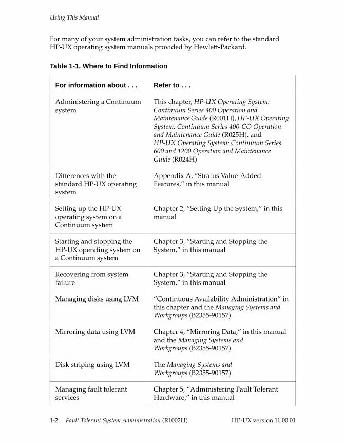
For many of your system administration tasks, you can refer to the standard HP-UX operating system manuals provided by Hewlett-Packard.
Table 1-1. Where to Find Information
For information about . . . Refer to . . .
Administering a Continuum system
This chapter, HP-UX Operating System: Continuum Series 400 Operation and Maintenance Guide (R001H), HP-UX Operating System: Continuum Series 400-CO Operation and Maintenance Guide (R025H), and HP-UX Operating System: Continuum Series 600 and 1200 Operation and Maintenance Guide (R024H)
Differences with the standard HP-UX operating system
Appendix A, “Stratus Value-Added Features,” in this manual
Setting up the HP-UX operating system on a Continuum system
Chapter 2, “Setting Up the System,” in this manual
Starting and stopping the HP-UX operating system on a Continuum system
Chapter 3, “Starting and Stopping the System,” in this manual
Recovering from system failure
Chapter 3, “Starting and Stopping the System,” in this manual
Managing disks using LVM “Continuous Availability Administration” in this chapter and the Managing Systems and Workgroups (B2355-90157)
Mirroring data using LVM Chapter 4, “Mirroring Data,” in this manual and the Managing Systems and Workgroups (B2355-90157)
Disk striping using LVM The Managing Systems and Workgroups (B2355-90157)
Managing fault tolerant services
Chapter 5, “Administering Fault Tolerant Hardware,” in this manual
1-2 Fault Tolerant System Administration (R1002H) HP-UX version 11.00.01
Using This Manual
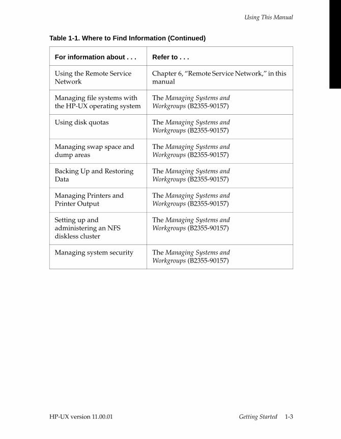
Using the Remote Service Network
Chapter 6, “Remote Service Network,” in this manual
Managing file systems with the HP-UX operating system
The Managing Systems and Workgroups (B2355-90157)
Using disk quotas The Managing Systems and Workgroups (B2355-90157)
Managing swap space and dump areas
The Managing Systems and Workgroups (B2355-90157)
Backing Up and Restoring Data
The Managing Systems and Workgroups (B2355-90157)
Managing Printers and Printer Output
The Managing Systems and Workgroups (B2355-90157)
Setting up and administering an NFS diskless cluster
The Managing Systems and Workgroups (B2355-90157)
Managing system security The Managing Systems and Workgroups (B2355-90157)
Table 1-1. Where to Find Information (Continued)
For information about . . . Refer to . . .
HP-UX version 11.00.01 Getting Started 1-3
Continuous Availability Administration
Continuous Availability AdministrationThis section describes a Continuum system’s unique continuous-availability architecture and provides an overview of the special tasks system administrators must perform to support and monitor this architecture.
Continuum Series 400 Systems Stratus offers two models of Continuum Series 400 systems: a standard (AC-powered) model housed in a compact system base that is designed for general environments, and a central-office (DC-powered) model housed in a cabinet that is designed for central office environments. Continuum Series 400 and 400-CO systems include the following features:
■ A pair of suitcases that integrate processors, memory, console support, power, and cooling in a single customer-replaceable unit (CRU).
■ Two card-cages (sometimes called bays) built into the system base or cabinet that are electrically isolated from each other. Each card-cage contains eight slots for peripheral component interconnect (PCI) I/O cards.
■ A storage enclosure built into the system base or cabinet that houses disks; standard models support one storage enclosure and central-office models support two storage enclosures.
■ Two power supplies and, if the system is connected to an uninterruptible power supply (UPS), flexible powerfail recovery options.
■ Multiple, variable-speed fans that automatically adjust to environmental conditions.
■ Optional disk expansion cabinets (standard models only).
See the HP-UX Operating System: Continuum Series 400 Operation and Maintenance Guide (R001H), or the HP-UX Operating System: Continuum Series 400-CO Operation and Maintenance Guide (R025H) for a complete description of the Continuum Series 400 architecture and components.
1-4 Fault Tolerant System Administration (R1002H) HP-UX version 11.00.01
Continuous Availability Administration
Continuum Series 600 and 1200 Systems Stratus offers two large models of Continuum systems. A Continuum Series 600 system can hold up to two CPU boards and four main I/O controller boards; a Continuum Series 1200 system can hold up to two CPU boards and eight main I/O controller boards. Continuum Series 600 and 1200 systems include the following features:
■ A pair of CPU/memory boards that integrate processors, cache, and memory on a single board.
■ A pair of console controller boards that provide console and machine management support.
■ One or more of the following main I/O controller boards:
– An I/O controller board (K460) that provides SCSI and Ethernet support (at least one K460 board is required)
– An I/O processor board (K470) that provides support for up to three PCI mezzanine cards (PMC)
– An I/O processor board (K600) that supports Stratus’s proprietary I/O processor-to-I/O adapter (IOA) model for selected communications IOA cards
■ A power system that provides redundant power supplies, built-in batteries, and flexible powerfail ride-through and recovery options.
■ A multiple fan system that can vary fan speed to adjust for environmental conditions.
■ A cabinet data collector (CDC) that automatically collects information about cabinet power and air flow and multiple, variable-speed fans that automatically adjust to environmental conditions.
■ Expansion cabinets to house storage or communications devices. Each system includes at least one expansion cabinet to house the boot (and other) disks.
See the HP-UX Operating System: Continuum Series 600 and 1200 Operation and Maintenance Guide (R024H) for a complete description of the Continuum architecture and components.
HP-UX version 11.00.01 Getting Started 1-5
Continuous Availability Administration
Console Controller Continuum systems do not include a control panel or buttons to execute machine management commands. All such actions are controlled through the system console, which is connected to the console controller. The console controller serves the following purposes:
■ The console controller implements a console command interface that allows you to initiate certain actions, such as a shutdown or main bus reset. See “Issuing Console Commands” in Chapter 3, “Starting and Stopping the System,” for instructions on how to issue console commands.
■ The console controller supports three serial ports: a system console port, an RSN port, and an auxiliary port for a UPS connection, console printer, or other purpose. The ports are located on the back of the system base or cabinet in a Continuum system. See the “Configuring Serial Ports for Terminals and Modems” chapter in the HP-UX Operating System: Peripherals Configuration (R1001H) for instructions on how to set these ports.
■ The console controller contains the hardware clock. The date command sets both the system and hardware clocks. See the date(1) man page for instructions on how to set the system (and hardware) clock.
■ The console controller includes programmable PROM partitions that contain code for the following: board-level diagnostics, board operations (online), and board operations (standby). The diagnostics and board operations code (both online and standby) are burned onto the board at the factory. To update this code, you can burn a new firmware file into these partitions. See “Updating Console Controller PROM Code” in Appendix B, “Updating PROM Code,” for instructions on how to burn these PROM partitions.
■ The console controller contains a programmable PROM data partition that stores console port configuration information (bits per character, baud rate, stop bits, and parity) and certain system response settings. You can reset the defaults by entering the appropriate information and reburning the partition. See the “Configuring Serial Ports for Terminals and Modems” chapter in the HP-UX Operating System: Peripherals Configuration (R1001H) for this procedure.
■ The console controller contains a programmable PROM data partition that stores information on where the system should look for a bootable device when it attempts to boot automatically. (However, the shutdown -r and reboot commands do not use the console controller; they take information stored in the kernel to find the bootable device.) See “Manually Booting Your System” in Chapter 3, “Starting and Stopping the System,” for this procedure.
1-6 Fault Tolerant System Administration (R1002H) HP-UX version 11.00.01
Fault Tolerant Design
Fault Tolerant DesignContinuum systems are fault tolerant; that is, they continue operating even if major components fail. Continuum systems provide both hardware and software features that maximize system availability.
Fault Tolerant HardwareThe fault tolerant hardware features include the following:
■ Continuum systems employ a parallel pair and spare architecture for most hardware components that lets two physical components operate either as a true lock-step pair (identical and precisely parallel simultaneous actions) or as an online/standby pair. In either case, the pair operates as a single unit, which provides fault tolerance if one of the components should fail.
■ Continuum systems consist of modularized hardware components designed for easy servicing and replacing. Many hardware components (such as suitcases or CPU/memory boards, I/O controller cards, disk and tape devices, and power supplies) are CRUs and can be replaced on site by system administrators with minimal training or tools. Most other hardware are field-replaceable units (FRUs) and can be replaced on site by trained Stratus personnel.
■ Some components are hot pluggable; that is, the system administrator can replace them without interrupting system services. You can dynamically upgrade some components.
■ Most components have self-checking diagnostics that identify and alert the system to any problems. When a diagnostic program detects a fault, it sends a message to the fault tolerant services (FTS) software subsystem. The FTS constantly monitors and evaluates hardware and software problems and initiates corrective actions.
■ Most components include a set of status lights that immediately alerts an administrator about the status of the component.
■ Continuum Series 400 systems boot from a 20-MB PCMCIA flash card; Continuum 600 and 1200 systems boot from disk.
■ Continuum Series 600 and 1200 systems have internal batteries, and all Continuum systems include a port that you can configure and connect to a UPS. All Continuum systems provide logic for “ride-through” power failure protection, in which batteries power the system without interruption during short outages, and full shutdown power failure protection and recovery when longer outages require a machine shutdown.
HP-UX version 11.00.01 Getting Started 1-7
Fault Tolerant Design
■ Continuum systems contain multiple fans and environmental monitoring features. Power and air flow information is collected automatically and corrective actions are initiated as necessary.
Continuous Availability Software The fault tolerant software features include the following:
■ Stratus provides a layer of software fault tolerant services with the standard HP-UX operating system. These services constantly monitor for and respond to hardware problems. The fault tolerant services are below the application level, so applications do not need to be customized to support them.
■ The fault tolerant services software automatically maintains mean-time-between-failures (MTBF) statistics for many system components. Administrators can access this information at any time and can reconfigure the MTBF parameters that affect how the fault tolerant services respond to component problems.
■ The Remote Service Network (RSN) allows Stratus to monitor and service your system at any time. The RSN automatically transmits status information about your system to the Customer Assistance Center (CAC) where trained personnel can analyze and correct problems remotely. (CAC services require a service contract.)
■ The console command interface provides a set of console commands that let you quickly control key machine actions.
■ The fault tolerant services software provides special utilities that help you monitor and manage the fault tolerant hardware resources. These utilities include addhardware, ftsmaint, and several flash card and RSN utilities.
■ The logical volume manager (LVM) utilities let you create logical volumes, mirror disks, backup data, and perform other services to maximize data-storage flexibility and integrity. The LVM utilities are part of the standard HP-UX operating system.
Duplexed ComponentsMost physical components in a Continuum system can be configured redundantly to maintain fault tolerance. The redundancy method might be full duplexing (lock-step operation), logical pairing (online/standby), or some method of pooling. All systems contain the following fault tolerant features:
■ boards/cards—Most boards or cards in the system can be paired in some way. Pairing methods include full duplexing (for example, CPU/memory and K600 boards), logical pairing (for example, console controller and K460 boards), or
1-8 Fault Tolerant System Administration (R1002H) HP-UX version 11.00.01
Fault Tolerant Design
dual initiation of board resources (for example, SCSI ports on I/O controllers) or software configuration of board resources (for example, using RNI to configure dual Ethernet ports).
■ buses—In Continuum Series 400 systems, the suitcases and PCI bridge cards are cross-wired on the main bus to provide fault tolerance. In Continuum Series 600 and 1200 systems, both the main chassis and I/O chassis buses are paired. The combination of error detection, retry logic, and bus switching ensures that all bus transactions are fault tolerant.
■ disks—The LVM utilities let you create mirrored disks and logical data volumes, which you can configure in various ways to protect data.
■ power supplies—All Continuum systems support powerfail logic to ‘ride through’ short power outages or gracefully shut down during longer power outages.
– Continuum Series 400 systems include a power supply in each suitcase and two system-base power supplies, with a connection for an external UPS. When attached to a UPS, systems can continue operation through brief (duration dependent on the UPS capability) power disturbances.
– Continuum Series 600 and 1200 systems include redundant power controllers, multiple power supplies that operate in an N+1 model (that is, all but one power supply are active at any given time while the last unit is on standby should any active unit develop a problem), and redundant batteries that provide at least four minutes of continuous power to the system after the external power stops.
■ fans—Continuum Series 400-CO and Continuum Series 600 and 1200 systems include multiple multispeed fans in each cabinet to control temperature. Continuum Series 400 systems include multiple fans embedded in system components (suitcases and system-base power supplies). All Continuum systems support environmental-monitoring logic that identifies fan faults and adjusts fans speed as necessary to maintain proper cooling.
Solo ComponentsSolo components do not have backup partners. If a solo component fails, services supported by that component are no longer available and operation could be interrupted. The components that operate in a solo fashion are as follows:
■ I/O adapter cards—I/O adapter cards function as solo components unless they are dual-initiated or software-configured as a pair.
■ PCI bridge cards—In Continuum Series 400 systems, each PCI bridge card supports a separate card-cage. PCI bridge cards cannot be duplexed; if a PCI bridge card fails, support is lost for all I/O adapter cards in that card-cage.
HP-UX version 11.00.01 Getting Started 1-9
Fault Tolerant Design
■ tape and CD-ROM drives—Tape and CD-ROM drives are not paired, so tape and CD-ROM operations that fail must be repeated.
■ simplex disk volumes—You can configure a disk as a simplex volume if you do not need to protect your data and you want to maximize storage capacity. However, this practice is not recommended.
1-10 Fault Tolerant System Administration (R1002H) HP-UX version 11.00.01
HP-UX version 11.00.01
2
Setting Up the System 2-A system administrator’s job is to provide and support computer services for a group of users. Specifically, the administrator does the following:
■ sets up the system by installing, creating, or configuring hardware components, operating system and layered software, communications and storage devices, file systems, user accounts and services, print services, network services, and access controls
■ allocates resources among users
■ optimizes software resources
■ protects software resources
■ performs routine maintenance chores
■ replaces defective hardware and corrects software as problems arise
The rest of this chapter describes tasks associated with these responsibilities.
2-1
Installing a System
Installing a System Continuum systems are installed by Stratus representatives who can guide you in setting up your system. Nevertheless, all administrators should expect to allocate time to site planning and installation.
1. Prepare your site prior to system delivery. See the Continuum 400 Series: Site Planning Guide (R411), the Continuum Series 400-CO: Site Planning Guide (R454), or the Continuum 600 and 1200 Series: Site Planning Guide (R391) for a system overview, site requirements (for example, electrical and environmental requirements), cabling and connection information, equipment specification sheets, and site layout models that can assist in your site preparation.
2. Install peripheral components (for example, terminals, modems, tape drives, and printers) and other additional hardware. See the installation manual that came with the peripheral and the HP-UX Operating System: Peripherals Configuration (R1001H). For more information, see the HP-UX Operating System: Continuum Series 400 Operation and Maintenance Guide (R001H), the HP-UX Operating System: Continuum Series 400-CO Operation and Maintenance Guide (R025H), or the HP-UX Operating System: Continuum Series 600 and 1200 Operation and Maintenance Guide (R024H).
3. Install optional layered software. See the documentation that comes with the layered software for instructions on how to install software packages.
Configuring a System There are numerous tasks you might have to perform to configure a system properly for your environment. In most ways, administering a Continuum system does not differ from administering other systems running the HP-UX operating system. However, there are some special considerations when administering a Continuum system.
Standard Configuration TasksCommon configuration or management tasks when administering any system using the HP-UX operating system include the following:
■ setting system parameters (for example, setting the system clock and the system hostname)
■ controlling system access (for example, adding users and groups, setting file permissions, and setting up a trusted system)
2-2 Fault Tolerant System Administration (R1002H) HP-UX version 11.00.01
Configuring a System
■ configuring disks (for example, creating LVM volumes)
■ creating swap and dump space
■ creating file systems
■ configuring mail and print services
■ setting up NFS services
■ setting up network services
■ backing up and restoring data
■ setting up a workgroup
See the Managing Systems and Workgroups (B2355-90157) for detailed information about administering a system running the HP-UX operating system. (Hewlett-Packard offers additional manuals that describe how to set up and manage networking and other services. For more information, see the Hewlett-Packard documentation web site at http://www.docs.hp.com.)
Continuum Configuration Tasks In addition to the standard configuration and management tasks, consider the following issues when administering a Continuum system:
■ Configure, if necessary, the system console port. The console will not work properly unless the appropriate port is correctly configured. See Chapter 3, “Configuring Serial Ports for Terminals and Modems,” in HP-UX Operating System: Peripherals Configuration (R1001H) for the procedure to configure the console controller ports.
■ Configure, if necessary, the Remote Service Network (RSN). If it was not configured properly during installation (and you have a service contract), see Chapter 6, “Remote Service Network.”
■ Configure, if necessary, the autoboot value. At power-up (and some other reboot scenarios), the system reads the path partition of the console controller to locate the boot device and determine whether to autoboot. If the path partition is not set or specifies a nonbootable device, you must do a manual boot. The path partition is burned as part of the installation process, but if this burn fails or if you need to specify a different boot device after installation, you must manually burn the path partition. For information about burning the path partition, see “Manually Booting Your System” in Chapter 3, “Starting and Stopping the System.”
HP-UX version 11.00.01 Setting Up the System 2-3
Configuring a System
■ Modify, as necessary, boot parameters. The system installs with a default set of boot parameters in the /stand/conf file. If conditions warrant, you can modify those parameters, for example, to specify a new root device. See Chapter 3, “Starting and Stopping the System,” and the conf(4) man page for more information.
■ Configure, if necessary, logical LAN interfaces. Logical LAN interfaces are created automatically when the cards are installed, but it might be necessary to change the configuration or add services, such as logically pairing cards through RNI. You can dynamically change logical LAN interfaces (which remain in effect until the next boot) through the lconf command, and you can permanently change them by modifying the /stand/conf file. See the HP-UX Operating System: LAN Configuration Guide (R1011H) for more information.
■ Configure, if necessary, logical SCSI buses. The system installs with a default set of logical SCSI buses defined in the /stand/conf file. If you add a disk expansion cabinet or move I/O controller cards, you might need to modify the logical SCSI definitions. See Chapter 5, “Administering Fault Tolerant Hardware,” and the conf(4) man page for more information.
■ Modify, as desired, mean-time-between-failure (MTBF) settings. The system reacts to hardware faults in part based on MTBF settings. If conditions warrant, you can change the default MTBF settings. See “Managing MTBF Statistics” in Chapter 5, “Administering Fault Tolerant Hardware.”
■ A Continuum system can be a cluster server, but not a cluster client. All diskless cluster information and procedures defined for HP 9000 system servers apply to Continuum systems.
■ All information about disk management tasks provided for HP 9000 systems applies to the HP-UX operating system delivered with your Continuum system. Disk mirroring is a standard feature on Continuum systems. For Stratus’ recommendations for disk mirroring, see Chapter 4, “Mirroring Data.”
■ All information about managing swap space and dump areas, file systems, disk quotas, system access and security, and print and mail services on HP 9000 systems applies to the HP-UX operating system delivered with your Continuum system.
2-4 Fault Tolerant System Administration (R1002H) HP-UX version 11.00.01
Maintaining a System
Maintaining a System An active system requires regular monitoring and periodic maintenance to ensure proper security, adequate capability, and optimal performance. The following are guidelines for maintaining a healthy system:
■ Set up a regular schedule for backing up (copying) the data on your system. Decide how often you must back up various data objects (full file systems, partial file systems, data partitions, and so on) to ensure that lost data can always be retrieved.
■ Make sure your software is up to date. When new releases of current software become available, install them if warranted. Installing some software could affect availability, so consider the administrative policy for your site to determine when, or if, to upgrade software.
■ Control network and user access to system resources. Controls can include maintaining proper user and group membership, creating a trusted system, managing access to files (for example, by using access control lists), and restricting network access through network control files (for example, nethosts, hosts, hosts.equiv, services, exports, protocols, inetd.conf, and netgroup) and other tools.
■ Monitor system use and performance. The HP-UX operating system provides several monitoring tools, such as sar, iostat, nfsstat, netstat, and vmstat. To closely monitor system use, install and enable the auditing subsystem, which can record all events that you designate.
■ Maintain system activities logs and review them periodically. Record any information that could prove useful later, including the following:
– dates and descriptions of maintenance procedures
– printouts of diagnostic and error messages
– dates and descriptions of user comments and suggestions
– dates and descriptions of hardware changes
■ Inform users of scheduled or unscheduled system maintenance prior to attempting the maintenance procedure(s). Tools to inform users include electronic mail, the message of the day file (/etc/motd), and the wall command.
HP-UX version 11.00.01 Setting Up the System 2-5
Maintaining a System
Tracking and Fixing System ProblemsAn important function of a system administrator is to identify and fix problems that occur in the hardware, software, or network while the system is in normal use. Continuum systems are designed specifically for continuous availability, so you should experience fewer system problems than with other systems running the HP-UX operating system. Nevertheless, there are a variety of potential problems in any system, such as the following:
■ Users cannot log in.
■ Users cannot access applications or data.
■ File systems cannot be mounted.
■ Disks or file systems become full.
■ Data is lost.
■ File systems become corrupted.
■ Users cannot access network services.
■ Users cannot access printers.
■ System performance decreases.
■ System becomes unresponsive.
By regularly monitoring system performance and use, maintaining good administrative records, and following the guidelines in this chapter, you can limit the scope and severity of problems.
2-6 Fault Tolerant System Administration (R1002H) HP-UX version 11.00.01
HP-UX version 11.00.01
3
Starting and Stopping the System 3-This chapter provides an overview of the boot process and describes the following tasks:
■ configuring the boot environment
■ booting the system
■ shutting down the system
■ dealing with power failures
■ managing flash cards
Overview of the Boot ProcessBringing the system from power up to a point where users can log in is the process of booting. The boot process flows in sequence through the following three components:
■ CPU PROM
■ primary bootloader (lynx)
■ secondary bootloader (isl)
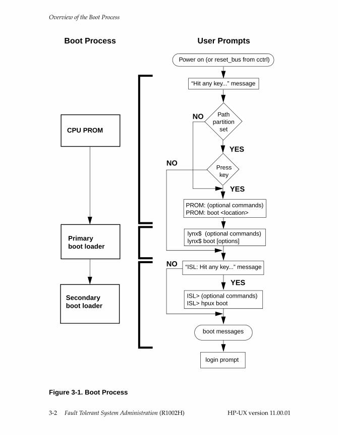
Figure 3-1 illustrates the booting stages, control sequence, and user prompts.
3-1
Overview of the Boot Process
Figure 3-1. Boot Process
“ISL: Hit any key...” message
Boot Process User Prompts
Power on (or reset_bus from cctrl)
“Hit any key...” message
Pathpartition
set
Presskey
PROM: (optional commands)PROM: boot <location>
lynx$ (optional commands)lynx$ boot [options]
ISL> (optional commands)ISL> hpux boot
boot messages
login prompt
NO
NO
NO
YES
YES
YES
CPU PROM
Primaryboot loader
Secondaryboot loader
3-2 Fault Tolerant System Administration (R1002H) HP-UX version 11.00.01
Overview of the Boot Process
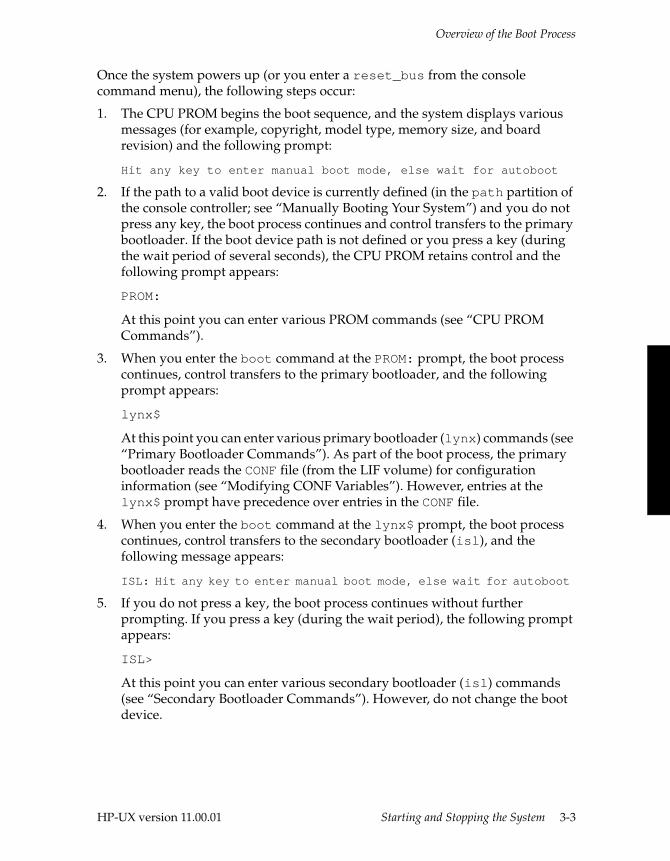
Once the system powers up (or you enter a reset_bus from the console command menu), the following steps occur:
1. The CPU PROM begins the boot sequence, and the system displays various messages (for example, copyright, model type, memory size, and board revision) and the following prompt:
Hit any key to enter manual boot mode, else wait for autoboot
2. If the path to a valid boot device is currently defined (in the path partition of the console controller; see “Manually Booting Your System”) and you do not press any key, the boot process continues and control transfers to the primary bootloader. If the boot device path is not defined or you press a key (during the wait period of several seconds), the CPU PROM retains control and the following prompt appears:
PROM:
At this point you can enter various PROM commands (see “CPU PROM Commands”).
3. When you enter the boot command at the PROM: prompt, the boot process continues, control transfers to the primary bootloader, and the following prompt appears:
lynx$
At this point you can enter various primary bootloader (lynx) commands (see “Primary Bootloader Commands”). As part of the boot process, the primary bootloader reads the CONF file (from the LIF volume) for configuration information (see “Modifying CONF Variables”). However, entries at the lynx$ prompt have precedence over entries in the CONF file.
4. When you enter the boot command at the lynx$ prompt, the boot process continues, control transfers to the secondary bootloader (isl), and the following message appears:
ISL: Hit any key to enter manual boot mode, else wait for autoboot
5. If you do not press a key, the boot process continues without further prompting. If you press a key (during the wait period), the following prompt appears:
ISL>
At this point you can enter various secondary bootloader (isl) commands (see “Secondary Bootloader Commands”). However, do not change the boot device.
HP-UX version 11.00.01 Starting and Stopping the System 3-3
Configuring the Boot Environment
NOTE
A PA-7100-based system does not display the ISL message and bypasses the ISL> prompt unless islprompt=1 is set at the lynx$ prompt (see Table 3-5).
6. When you enter the hpux boot command, the boot process continues without further prompting, and various messages are displayed until the login prompt appears, at which point the boot process is complete.
NOTE
Before you power up the computer, turn on the console, terminals, and any other peripherals and peripheral buses that are attached to the computer. If you do not turn on the peripherals first, the system will not be able to configure the bus or peripherals. When the peripherals are on and have completed their self-check tests, turn on the computer.
Configuring the Boot EnvironmentYou can modify the boot environment and system parameters through the following mechanisms:
■ The autoboot mechanism requires that a valid boot device be defined in the path partition of the console controller; otherwise, you must do a manual boot. You can change the defined boot device(s) by reburning the path partition. See “Enabling and Disabling Autoboot.”
■ The primary bootloader reads configuration information and loads the secondary bootloader from files (CONF and BOOT) in the LIF volume. You can modify the contents of the CONF file to fit your environment. See “Modifying CONF Variables.”
■ During the manual boot process, you can list or modify configuration parameters at each stage of the boot process: CPU PROM, primary bootloader, and secondary bootloader. See “Booting Process Commands.”
3-4 Fault Tolerant System Administration (R1002H) HP-UX version 11.00.01
Configuring the Boot Environment
Enabling and Disabling AutobootWhen your system boots, the CPU PROM code queries the path partition on the online console controller for a boot path. The boot path specifies the location of a boot device (a flash card for Continuum Series 400 systems or a boot disk for Continuum Series 600 and 1200 systems). The path partition can hold up to four paths, and the system searches the paths in order until it finds the first bootable device. If the path partition is empty or lists nonbootable devices only, the system will not autoboot, and you must do a manual boot (the system displays the PROM: prompt and waits for input).
■ On Continuum Series 600 and 1200 systems, the path partition is burned as part of a full (cold) installation. After you define the boot device in the installation procedure (see the HP-UX Operating System: Installation and Update (R1002H)), the system burns the path partition to match the specified boot device.
■ On Continuum Series 400 systems, your system is preconfigured to autoboot from the flash card in card-cage 2; that is, it first looks for a bootable flash card in card-cage 2. If a bootable flash card is in card-cage 2, it boots from that flash card. If not, it then automatically checks card-cage 3 for a bootable flash card. (However, like Continuum Series 600 and 1200 systems, the path partition is burned as part of a cold installation, so you can specify an alternate order during the installation procedure.)
To change the boot path or disable autoboot, do the following:
1. Log in as root.
2. Determine which console controller is on standby. To do this, enter
ftsmaint ls 1/0ftsmaint ls 1/1
The Status field shows Online for the online board and Online Standby for the standby board (if both boards are functioning properly).
NOTE
You must specify the standby console controller for any PROM-burning commands. You will get an error if you specify the online console controller. Do not attempt to update a console controller if it is not in the Online Standby state (for example, if it is in a broken state).
HP-UX version 11.00.01 Starting and Stopping the System 3-5
Configuring the Boot Environment
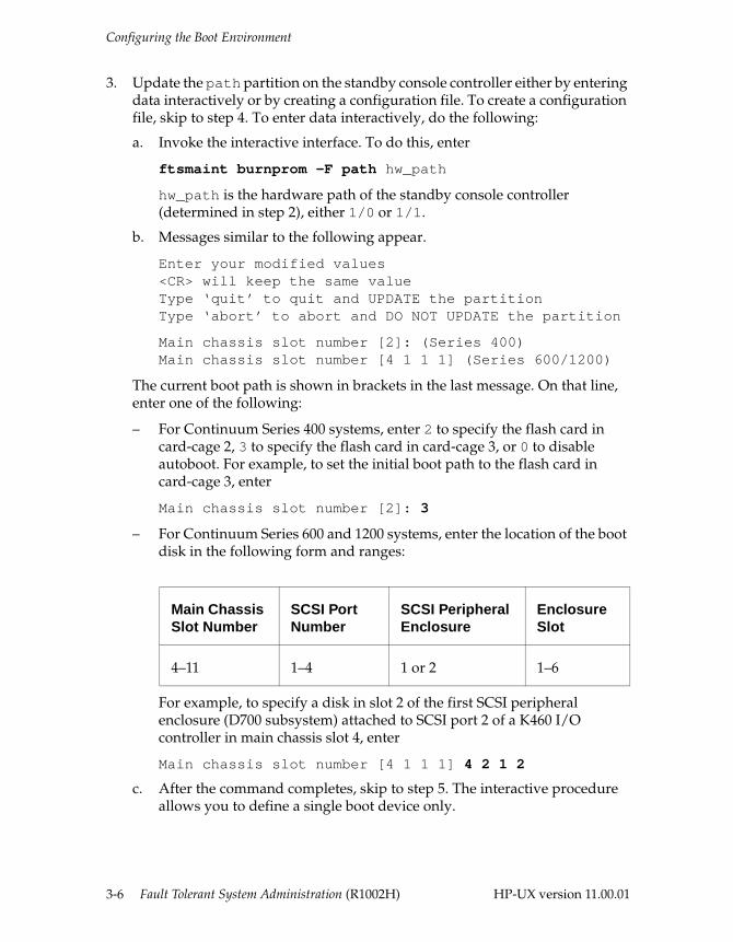
3. Update the path partition on the standby console controller either by entering data interactively or by creating a configuration file. To create a configuration file, skip to step 4. To enter data interactively, do the following:
a. Invoke the interactive interface. To do this, enter
ftsmaint burnprom -F path hw_path
hw_path is the hardware path of the standby console controller (determined in step 2), either 1/0 or 1/1.
b. Messages similar to the following appear.
Enter your modified values<CR> will keep the same valueType ‘quit’ to quit and UPDATE the partitionType ‘abort’ to abort and DO NOT UPDATE the partition
Main chassis slot number [2]: (Series 400)Main chassis slot number [4 1 1 1] (Series 600/1200)
The current boot path is shown in brackets in the last message. On that line, enter one of the following:
– For Continuum Series 400 systems, enter 2 to specify the flash card in card-cage 2, 3 to specify the flash card in card-cage 3, or 0 to disable autoboot. For example, to set the initial boot path to the flash card in card-cage 3, enter
Main chassis slot number [2]: 3
– For Continuum Series 600 and 1200 systems, enter the location of the boot disk in the following form and ranges:
For example, to specify a disk in slot 2 of the first SCSI peripheral enclosure (D700 subsystem) attached to SCSI port 2 of a K460 I/O controller in main chassis slot 4, enter
Main chassis slot number [4 1 1 1] 4 2 1 2
c. After the command completes, skip to step 5. The interactive procedure allows you to define a single boot device only.
Main Chassis Slot Number
SCSI Port Number
SCSI PeripheralEnclosure
Enclosure Slot
4–11 1–4 1 or 2 1–6
3-6 Fault Tolerant System Administration (R1002H) HP-UX version 11.00.01
Configuring the Boot Environment
4. If you want to define additional (up to four) boot devices, create and load a configuration file as follows:
a. Edit the /stand/bootpath file and enter appropriate entries for the boot device(s). Each line presents one boot device, and you can enter up to four lines. The system searches for a boot device in the order entered in the file. The following are sample entries:
(Series 400)2 0 0 0 3 0 0 0
(Series 600/1200) 4 1 1 1 4 2 1 1
The format of entries for Continuum Series 600 and 1200 boot disks is the same as described in step 3. See the /stand/bootpath file for more information.
b. Update the path partition with the information from the /stand/bootpath file. To do this, enter
ftsmaint burnprom -F path -B hw_path
hw_path is the hardware path of the standby console controller (determined in step 2), either 1/0 or 1/1.
5. Switch control to the newly updated console controller board and put the online board in standby mode. To do this, enter
ftsmaint switch hw_path
hw_path is the hardware path of the standby console controller (determined in step 2), either 1/0 or 1/1.
6. Verify the status of the newly updated console controller. To do this, enter
ftsmaint ls hw_path
hw_path is the hardware path of the newly updated console controller. Do not proceed until the Status field is Online.
7. Update the path partition on the second console controller by repeating step 3 or step 4. (Note: the standby and online hardware paths are now reversed.)
HP-UX version 11.00.01 Starting and Stopping the System 3-7
Configuring the Boot Environment
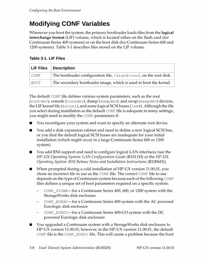
Modifying CONF Variables Whenever you boot the system, the primary bootloader loads files from the logical interchange format (LIF) volume, which is located either on the flash card (for Continuum Series 400 systems) or on the boot disk (for Continuum Series 600 and 1200 systems). Table 3-1 describes files stored on the LIF volume.
The default CONF file defines various system parameters, such as the root (rootdev), console (consdev), dump (dumpdev), and swap (swapdev) devices, the LIF kernel file (kernel), and some logical SCSI buses (lsm#). Although the file you select during installation as the default CONF file is adequate in many settings, you might need to modify the CONF parameters if:
■ You reconfigure your system and want to specify an alternate root device.
■ You add a disk expansion cabinet and need to define a new logical SCSI bus, or you find the default logical SCSI buses are inadequate for your initial installation (which might occur in a large Continuum Series 600 or 1200 system).
■ You add RNI support and need to configure logical LAN interfaces (see the HP-UX Operating System: LAN Configuration Guide (R1011H) or the HP-UX Operating System: RNI Release Notes and Installation Instructions (R1006H)).
■ When prompted during a cold installation of HP-UX version 11.00.01, you chose an incorrect file to use as the CONF file. The correct CONF file to use depends on the type of Continuum system because each of the following CONF files defines a unique set of boot parameters required on a specific system:
– CONF_STGWK—for a Continuum Series 400, 600, or 1200 system with the StorageWorks disk enclosure
– CONF_EURAC—for a Continuum Series 400 system with the AC powered Eurologic disk enclosure
– CONF_EURDC—for a Continuum Series 400-CO system with the DC powered Eurologic disk enclosure
■ You upgraded a Continuum system with a StorageWorks disk enclosure to HP-UX version 11.00.01; however, in the HP-UX version 11.00.01, the default CONF file is the CONF_EURDC file. This will create a problem because the boot
Table 3-1. LIF Files
LIF Files Description
CONF The bootloader configuration file, /stand/conf, on the root disk.
BOOT The secondary bootloader image, which is used to boot the kernel.
3-8 Fault Tolerant System Administration (R1002H) HP-UX version 11.00.01
Configuring the Boot Environment
parameters specified in the default CONF file are automatically loaded when lynx starts up.
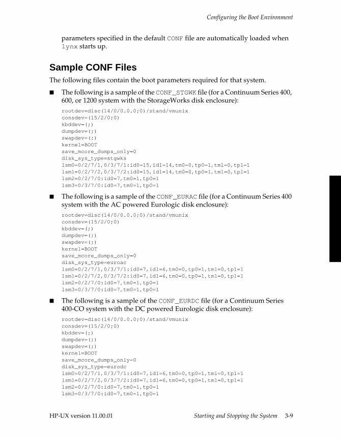
Sample CONF FilesThe following files contain the boot parameters required for that system.
■ The following is a sample of the CONF_STGWK file (for a Continuum Series 400, 600, or 1200 system with the StorageWorks disk enclosure): rootdev=disc(14/0/0.0.0;0)/stand/vmunixconsdev=(15/2/0;0)kbddev=(;)dumpdev=(;)swapdev=(;)kernel=BOOTsave_mcore_dumps_only=0disk_sys_type=stgwkslsm0=0/2/7/1,0/3/7/1:id0=15,id1=14,tm0=0,tp0=1,tm1=0,tp1=1lsm1=0/2/7/2,0/3/7/2:id0=15,id1=14,tm0=0,tp0=1,tm1=0,tp1=1lsm2=0/2/7/0:id0=7,tm0=1,tp0=1lsm3=0/3/7/0:id0=7,tm0=1,tp0=1
■ The following is a sample of the CONF_EURAC file (for a Continuum Series 400 system with the AC powered Eurologic disk enclosure):rootdev=disc(14/0/0.0.0;0)/stand/vmunixconsdev=(15/2/0;0)kbddev=(;)dumpdev=(;)swapdev=(;)kernel=BOOTsave_mcore_dumps_only=0disk_sys_type=euroaclsm0=0/2/7/1,0/3/7/1:id0=7,id1=6,tm0=0,tp0=1,tm1=0,tp1=1lsm1=0/2/7/2,0/3/7/2:id0=7,id1=6,tm0=0,tp0=1,tm1=0,tp1=1lsm2=0/2/7/0:id0=7,tm0=1,tp0=1lsm3=0/3/7/0:id0=7,tm0=1,tp0=1
■ The following is a sample of the CONF_EURDC file (for a Continuum Series 400-CO system with the DC powered Eurologic disk enclosure):rootdev=disc(14/0/0.0.0;0)/stand/vmunixconsdev=(15/2/0;0)kbddev=(;)dumpdev=(;)swapdev=(;)kernel=BOOTsave_mcore_dumps_only=0disk_sys_type=eurodclsm0=0/2/7/1,0/3/7/1:id0=7,id1=6,tm0=0,tp0=1,tm1=0,tp1=1lsm1=0/2/7/2,0/3/7/2:id0=7,id1=6,tm0=0,tp0=1,tm1=0,tp1=1lsm2=0/2/7/0:id0=7,tm0=1,tp0=1lsm3=0/3/7/0:id0=7,tm0=1,tp0=1
HP-UX version 11.00.01 Starting and Stopping the System 3-9
Configuring the Boot Environment
Modifying the CONF FileThe system does not automatically update the CONF file during system boot or shutdown. To make a change, you must update this file manually.
NOTE
See the conf(4) man page for a description of the system parameters you can set, the lynx(1M) man page for a description of the format used to define the root device in the rootdev entry, and “Defining a Logical SCSI Bus” in Chapter 5, “Administering Fault Tolerant Hardware,” for information about defining logical SCSI buses.
Use the following procedure to modify the CONF file:
1. Log in as root.2. Copy the current CONF file to /stand/conf (to ensure that they are the same
before you make modifications) as follows:
a. If you have a Continuum Series 400 system, enter
flifcp flashcard:CONF /stand/conf
flashcard is the booting flash card device file name, either /dev/rflash/c2a0d0 or /dev/rflash/c2a0d0.
b. If you have a Continuum Series 600 or 1200 system, enter
lifcp boot_device:CONF /stand/conf
boot_device is the raw root disk device file name, for example, /dev/rdsk/c4a1d0.
3. Edit the /stand/conf file as necessary. See the conf(4) man page for more information.
4. Remove the current CONF file as follows:
a. If you have a Continuum Series 400 system, enter
flifrm flashcard:CONF
b. If you have a Continuum Series 600 or 1200 system, enter
lifrm boot_device:CONF
3-10 Fault Tolerant System Administration (R1002H) HP-UX version 11.00.01
Configuring the Boot Environment
5. Copy the updated /stand/conf file to the CONF file as follows:
a. If you have a Continuum Series 400 system, enter
flifcp /stand/conf flashcard:CONF
b. If you have a Continuum Series 600 or 1200 system, enter
lifcp -K4 -r /stand/conf boot_device:CONF
6. Reboot the system to activate the new settings. To do this, enter
shutdown -r
See “Flash Card Utility Commands” later in this chapter for a complete list of commands that you can use to check or manipulate LIF files.
Booting Process CommandsThe CPU PROM, primary bootloader, and secondary bootloader support a separate set of commands at each stage of the boot process. For example, the following commands at the primary bootloader prompt (lynx$) assign a new value to the rootdev parameter and instruct the bootloader to bring up the system in single-user mode (run-level s) overriding the default run level:
lynx$ rootdev=(14/0/1.0.0;0)/stand/vmunixlynx$ go -is
The following sections describe the commands available at each stage of the boot process.
NOTE
No commands entered at any of the boot prompts are written to the CONF file. The modified settings apply to the current session only.
HP-UX version 11.00.01 Starting and Stopping the System 3-11
Configuring the Boot Environment
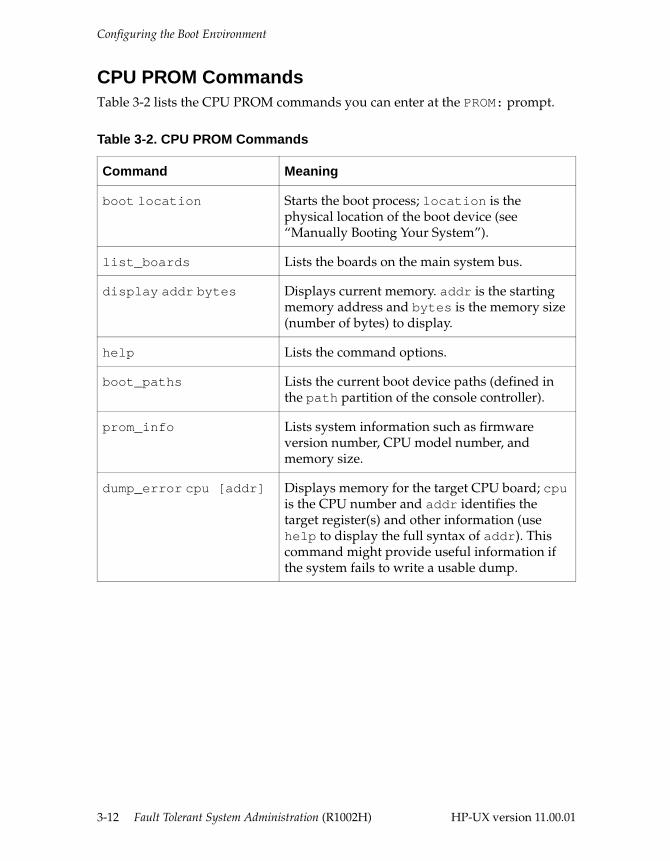
CPU PROM CommandsTable 3-2 lists the CPU PROM commands you can enter at the PROM: prompt.
Table 3-2. CPU PROM Commands
Command Meaning
boot location Starts the boot process; location is the physical location of the boot device (see “Manually Booting Your System”).
list_boards Lists the boards on the main system bus.
display addr bytes Displays current memory. addr is the starting memory address and bytes is the memory size (number of bytes) to display.
help Lists the command options.
boot_paths Lists the current boot device paths (defined in the path partition of the console controller).
prom_info Lists system information such as firmware version number, CPU model number, and memory size.
dump_error cpu [addr] Displays memory for the target CPU board; cpu is the CPU number and addr identifies the target register(s) and other information (use help to display the full syntax of addr). This command might provide useful information if the system fails to write a usable dump.
3-12 Fault Tolerant System Administration (R1002H) HP-UX version 11.00.01
Configuring the Boot Environment
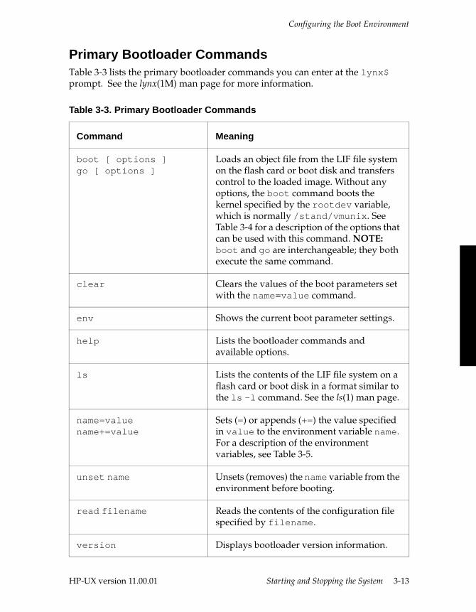
Primary Bootloader CommandsTable 3-3 lists the primary bootloader commands you can enter at the lynx$ prompt. See the lynx(1M) man page for more information.
Table 3-3. Primary Bootloader Commands
Command Meaning
boot [ options ]go [ options ]
Loads an object file from the LIF file system on the flash card or boot disk and transfers control to the loaded image. Without any options, the boot command boots the kernel specified by the rootdev variable, which is normally /stand/vmunix. See Table 3-4 for a description of the options that can be used with this command. NOTE: boot and go are interchangeable; they both execute the same command.
clear Clears the values of the boot parameters set with the name=value command.
env Shows the current boot parameter settings.
help Lists the bootloader commands and available options.
ls Lists the contents of the LIF file system on a flash card or boot disk in a format similar to the ls -l command. See the ls(1) man page.
name=value name+=value
Sets (=) or appends (+=) the value specified in value to the environment variable name. For a description of the environment variables, see Table 3-5.
unset name Unsets (removes) the name variable from the environment before booting.
read filename Reads the contents of the configuration file specified by filename.
version Displays bootloader version information.
HP-UX version 11.00.01 Starting and Stopping the System 3-13

Configuring the Boot Environment
The boot command has several options. The command syntax is as follows:
boot [-F] [-lq] [-P number] [-M number] [-lm] [-s file][-a[C|R|S|D] devicefile] [-f number] [-i string]
Table 3-4 lists the boot command options.
Table 3-4. Options to the boot Command
Command Meaning
-F Use with the SwitchOver/UX software. Ignore any locks on the boot disk. This option should be used only when it is known that the processor holding the lock is no longer running. (If this option is not specified and a disk is locked by another processor, the kernel will not boot from it in order to avoid the corruption that would result if the other processor were still using the disk.)
-lq Boot the system with the disk quorum check turned off.
-P number Boot the system with the CPU limit of number. Use this option if you want to limit the number of CPUs in your environment.
-M number Boot the system with the system memory size (in kilobytes) of number.
-lm Boot the system in LVM maintenance mode, configure only the root volume, and then initiate single-user mode.
-s file Boot the system with the kernel file. file is the LIF file name of a kernel on the flash card or boot disk.
3-14 Fault Tolerant System Administration (R1002H) HP-UX version 11.00.01
Configuring the Boot Environment
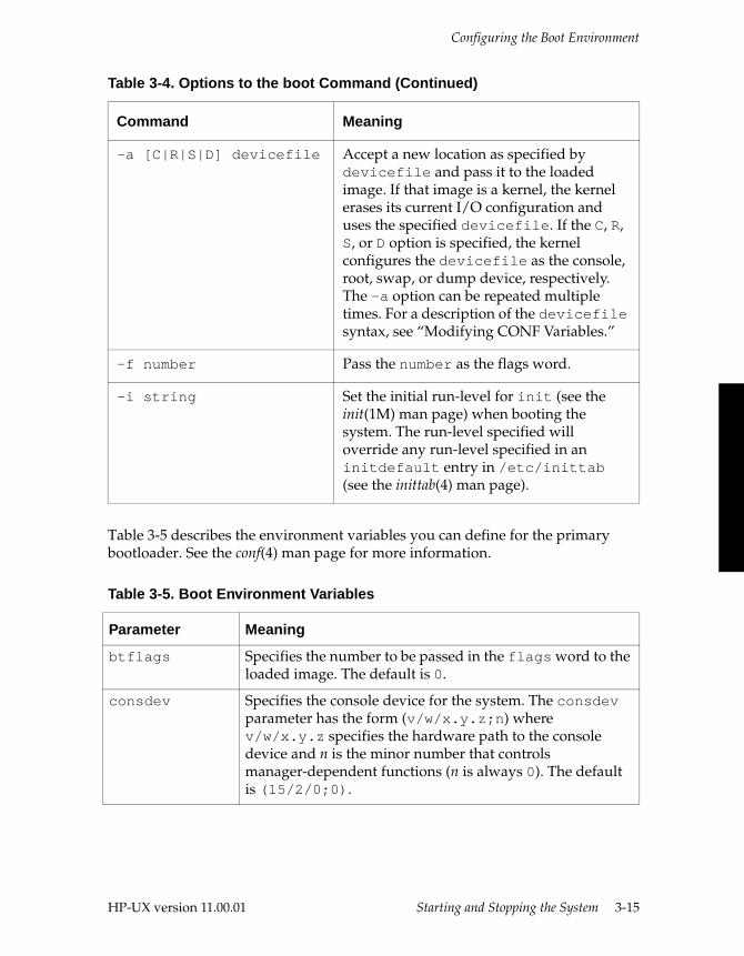
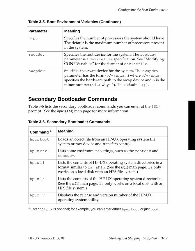
Table 3-5 describes the environment variables you can define for the primary bootloader. See the conf(4) man page for more information.
-a [C|R|S|D] devicefile Accept a new location as specified by devicefile and pass it to the loaded image. If that image is a kernel, the kernel erases its current I/O configuration and uses the specified devicefile. If the C, R, S, or D option is specified, the kernel configures the devicefile as the console, root, swap, or dump device, respectively. The -a option can be repeated multiple times. For a description of the devicefile syntax, see “Modifying CONF Variables.”
-f number Pass the number as the flags word.
-i string Set the initial run-level for init (see the init(1M) man page) when booting the system. The run-level specified will override any run-level specified in an initdefault entry in /etc/inittab (see the inittab(4) man page).
Table 3-5. Boot Environment Variables
Parameter Meaning
btflags Specifies the number to be passed in the flags word to the loaded image. The default is 0.
consdev Specifies the console device for the system. The consdev parameter has the form (v/w/x.y.z;n) where v/w/x.y.z specifies the hardware path to the console device and n is the minor number that controls manager-dependent functions (n is always 0). The default is (15/2/0;0).
Table 3-4. Options to the boot Command (Continued)
Command Meaning
HP-UX version 11.00.01 Starting and Stopping the System 3-15
Configuring the Boot Environment
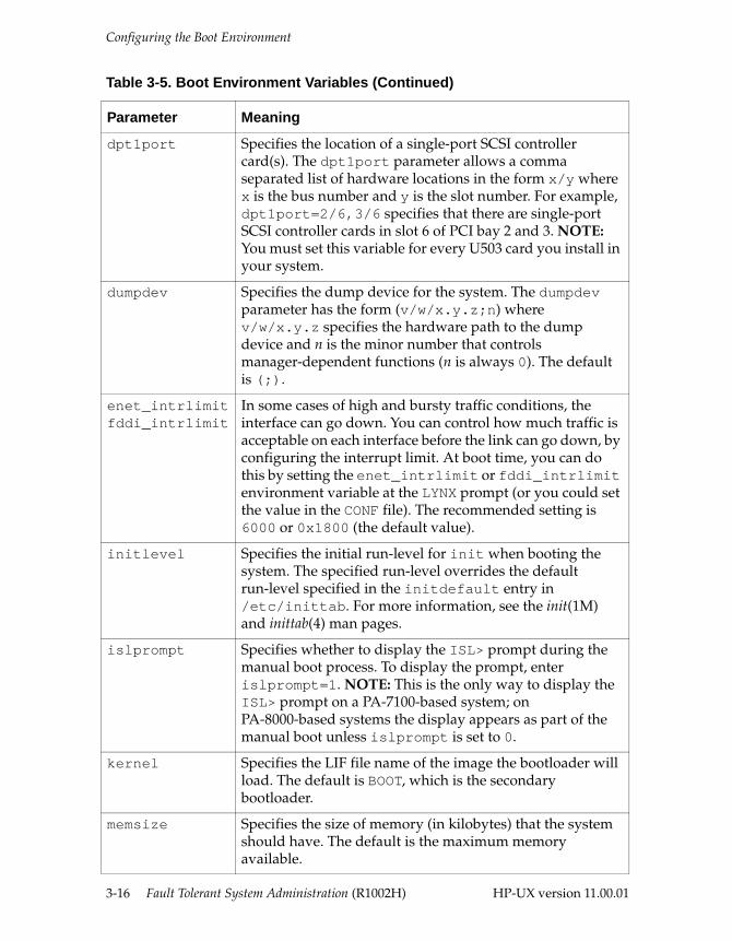
dpt1port Specifies the location of a single-port SCSI controller card(s). The dpt1port parameter allows a comma separated list of hardware locations in the form x/y where x is the bus number and y is the slot number. For example, dpt1port=2/6,3/6 specifies that there are single-port SCSI controller cards in slot 6 of PCI bay 2 and 3. NOTE: You must set this variable for every U503 card you install in your system.
dumpdev Specifies the dump device for the system. The dumpdev parameter has the form (v/w/x.y.z;n) where v/w/x.y.z specifies the hardware path to the dump device and n is the minor number that controls manager-dependent functions (n is always 0). The default is (;).
enet_intrlimitfddi_intrlimit
In some cases of high and bursty traffic conditions, the interface can go down. You can control how much traffic is acceptable on each interface before the link can go down, by configuring the interrupt limit. At boot time, you can do this by setting the enet_intrlimit or fddi_intrlimit environment variable at the LYNX prompt (or you could set the value in the CONF file). The recommended setting is 6000 or 0x1800 (the default value).
initlevel Specifies the initial run-level for init when booting the system. The specified run-level overrides the default run-level specified in the initdefault entry in /etc/inittab. For more information, see the init(1M) and inittab(4) man pages.
islprompt Specifies whether to display the ISL> prompt during the manual boot process. To display the prompt, enter islprompt=1. NOTE: This is the only way to display the ISL> prompt on a PA-7100-based system; on PA-8000-based systems the display appears as part of the manual boot unless islprompt is set to 0.
kernel Specifies the LIF file name of the image the bootloader will load. The default is BOOT, which is the secondary bootloader.
memsize Specifies the size of memory (in kilobytes) that the system should have. The default is the maximum memory available.
Table 3-5. Boot Environment Variables (Continued)
Parameter Meaning
3-16 Fault Tolerant System Administration (R1002H) HP-UX version 11.00.01
Configuring the Boot Environment
Secondary Bootloader Commands Table 3-6 lists the secondary bootloader commands you can enter at the ISL> prompt. See the hpux(1M) man page for more information.
ncpu Specifies the number of processors the system should have. The default is the maximum number of processors present in the system.
rootdev Specifies the root device for the system. The rootdev parameter is a devicefile specification. See “Modifying CONF Variables” for the format of devicefile.
swapdev Specifies the swap device for the system. The swapdev parameter has the form (v/w/x.y.z;n) where v/w/x.y.z specifies the hardware path to the swap device and n is the minor number (n is always 0). The default is (;).
Table 3-6. Secondary Bootloader Commands
Command 1
1 Entering hpux is optional; for example, you can enter either hpux boot or just boot.
Meaning
hpux boot Loads an object file from an HP-UX operating system file system or raw device and transfers control.
hpux env Lists some environment settings, such as the rootdev and consdev.
hpux ll Lists the contents of HP-UX operating system directories in a format similar to ls -aFln. (See the ls(1) man page. ls only works on a local disk with an HFS file system.)
hpux ls Lists the contents of the HP-UX operating system directories. (See the ls(1) man page. ls only works on a local disk with an HFS file system.)
hpux -v Displays the release and version number of the HP-UX operating system utility.
Table 3-5. Boot Environment Variables (Continued)
Parameter Meaning
HP-UX version 11.00.01 Starting and Stopping the System 3-17
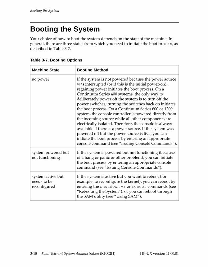
Booting the System
Booting the System Your choice of how to boot the system depends on the state of the machine. In general, there are three states from which you need to initiate the boot process, as described in Table 3-7.
Table 3-7. Booting Options
Machine State Booting Method
no power If the system is not powered because the power source was interrupted (or if this is the initial power-on), regaining power initiates the boot process. On a Continuum Series 400 systems, the only way to deliberately power off the system is to turn off the power switches; turning the switches back on initiates the boot process. On a Continuum Series 600 or 1200 system, the console controller is powered directly from the incoming source while all other components are electrically isolated. Therefore, the console is always available if there is a power source. If the system was powered off but the power source is live, you can initiate the boot process by entering an appropriate console command (see “Issuing Console Commands”).
system powered but not functioning
If the system is powered but not functioning (because of a hang or panic or other problem), you can initiate the boot process by entering an appropriate console command (see “Issuing Console Commands”).
system active but needs to be reconfigured
If the system is active but you want to reboot (for example, to reconfigure the kernel), you can reboot by entering the shutdown -r or reboot commands (see “Rebooting the System”), or you can reboot through the SAM utility (see “Using SAM”).
3-18 Fault Tolerant System Administration (R1002H) HP-UX version 11.00.01
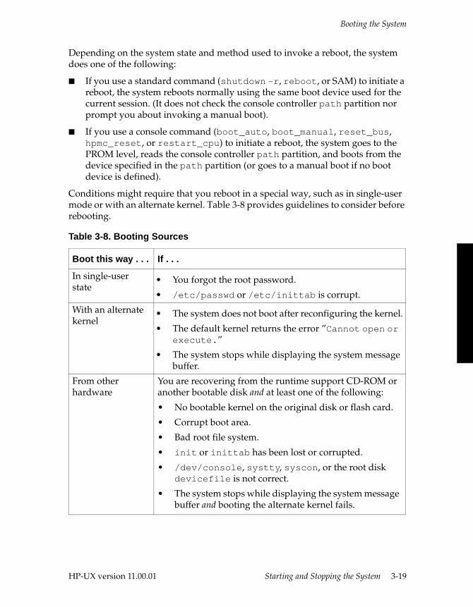
Booting the System
Depending on the system state and method used to invoke a reboot, the system does one of the following:
■ If you use a standard command (shutdown -r, reboot, or SAM) to initiate a reboot, the system reboots normally using the same boot device used for the current session. (It does not check the console controller path partition nor prompt you about invoking a manual boot).
■ If you use a console command (boot_auto, boot_manual, reset_bus, hpmc_reset, or restart_cpu) to initiate a reboot, the system goes to the PROM level, reads the console controller path partition, and boots from the device specified in the path partition (or goes to a manual boot if no boot device is defined).
Conditions might require that you reboot in a special way, such as in single-user mode or with an alternate kernel. Table 3-8 provides guidelines to consider before rebooting.
Table 3-8. Booting Sources
Boot this way . . . If . . .
In single-user state
• You forgot the root password.
• /etc/passwd or /etc/inittab is corrupt.
With an alternate kernel
• The system does not boot after reconfiguring the kernel.
• The default kernel returns the error ”Cannot open or execute.”
• The system stops while displaying the system message buffer.
From other hardware
You are recovering from the runtime support CD-ROM or another bootable disk and at least one of the following:
• No bootable kernel on the original disk or flash card.
• Corrupt boot area.
• Bad root file system.
• init or inittab has been lost or corrupted.
• /dev/console, systty, syscon, or the root disk devicefile is not correct.
• The system stops while displaying the system message buffer and booting the alternate kernel fails.
HP-UX version 11.00.01 Starting and Stopping the System 3-19
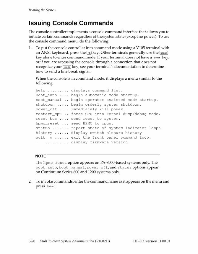
Booting the System
Issuing Console CommandsThe console controller implements a console command interface that allows you to initiate certain commands regardless of the system state (except no power). To use the console command menu, do the following:
1. To put the console controller into command mode using a V105 terminal with an ANSI keyboard, press the <F5> key. Other terminals generally use the <Break> key alone to enter command mode. If your terminal does not have a <Break> key, or if you are accessing the console through a connection that does not recognize your <Break> key, see your terminal’s documentation to determine how to send a line break signal.
When the console is in command mode, it displays a menu similar to the following:
help ......... displays command list.boot_auto .... begin automatic mode startup.boot_manual .. begin operator assisted mode startup.shutdown ..... begin orderly system shutdown.power_off .... immediately kill power.restart_cpu .. force CPU into kernel dump/debug mode.reset_bus .... send reset to system.hpmc_reset ... send HPMC to cpus.status ....... report state of system indicator lamps.history ...... display switch closure history.quit, q ...... exit the front panel command loop.. .......... display firmware version.
NOTE
The hpmc_reset option appears on PA-8000-based systems only. The boot_auto, boot_manual, power_off, and status options appear on Continuum Series 600 and 1200 systems only.
2. To invoke commands, enter the command name as it appears on the menu and press <Return>.
3-20 Fault Tolerant System Administration (R1002H) HP-UX version 11.00.01
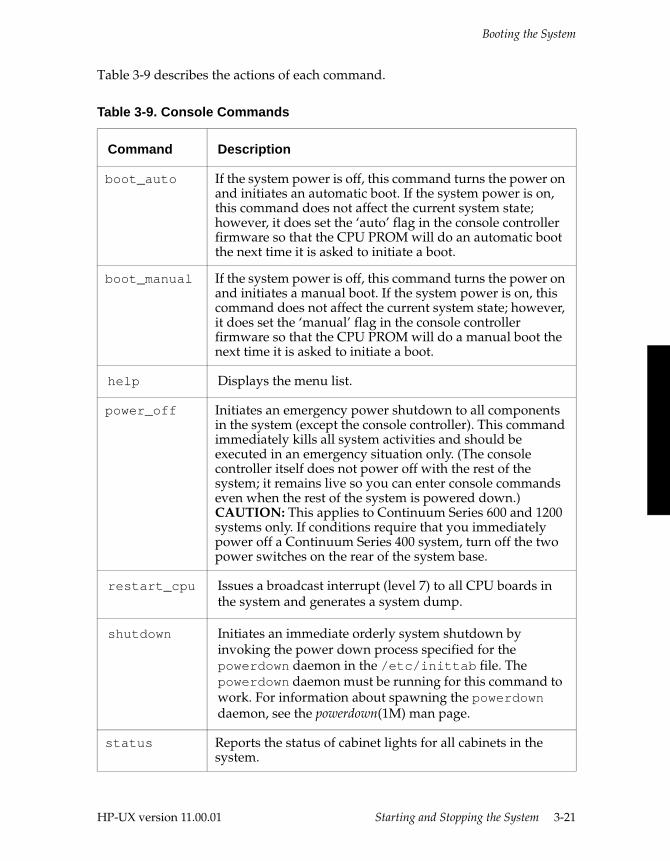
Booting the System
Table 3-9 describes the actions of each command.
Table 3-9. Console Commands
Command Description
boot_auto If the system power is off, this command turns the power on and initiates an automatic boot. If the system power is on, this command does not affect the current system state; however, it does set the ‘auto’ flag in the console controller firmware so that the CPU PROM will do an automatic boot the next time it is asked to initiate a boot.
boot_manual If the system power is off, this command turns the power on and initiates a manual boot. If the system power is on, this command does not affect the current system state; however, it does set the ‘manual’ flag in the console controller firmware so that the CPU PROM will do a manual boot the next time it is asked to initiate a boot.
help Displays the menu list.
power_off Initiates an emergency power shutdown to all components in the system (except the console controller). This command immediately kills all system activities and should be executed in an emergency situation only. (The console controller itself does not power off with the rest of the system; it remains live so you can enter console commands even when the rest of the system is powered down.) CAUTION: This applies to Continuum Series 600 and 1200 systems only. If conditions require that you immediately power off a Continuum Series 400 system, turn off the two power switches on the rear of the system base.
restart_cpu Issues a broadcast interrupt (level 7) to all CPU boards in the system and generates a system dump.
shutdown Initiates an immediate orderly system shutdown by invoking the power down process specified for the powerdown daemon in the /etc/inittab file. The powerdown daemon must be running for this command to work. For information about spawning the powerdown daemon, see the powerdown(1M) man page.
status Reports the status of cabinet lights for all cabinets in the system.
HP-UX version 11.00.01 Starting and Stopping the System 3-21
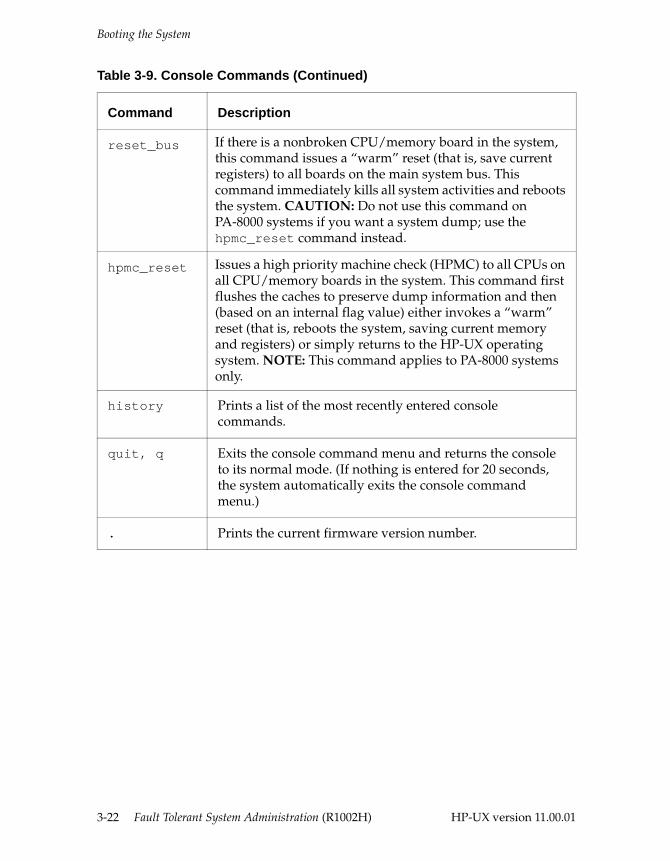
Booting the System
reset_bus If there is a nonbroken CPU/memory board in the system, this command issues a “warm” reset (that is, save current registers) to all boards on the main system bus. This command immediately kills all system activities and reboots the system. CAUTION: Do not use this command on PA-8000 systems if you want a system dump; use the hpmc_reset command instead.
hpmc_reset Issues a high priority machine check (HPMC) to all CPUs on all CPU/memory boards in the system. This command first flushes the caches to preserve dump information and then (based on an internal flag value) either invokes a “warm” reset (that is, reboots the system, saving current memory and registers) or simply returns to the HP-UX operating system. NOTE: This command applies to PA-8000 systems only.
history Prints a list of the most recently entered console commands.
quit, q Exits the console command menu and returns the console to its normal mode. (If nothing is entered for 20 seconds, the system automatically exits the console command menu.)
. Prints the current firmware version number.
Table 3-9. Console Commands (Continued)
Command Description
3-22 Fault Tolerant System Administration (R1002H) HP-UX version 11.00.01
Booting the System
Manually Booting Your SystemNormally, booting occurs automatically at the appropriate times, for example, when the system powers up. However, certain events could require you to initiate a manual boot, for example, if the system cannot find the boot device or a system problem makes the boot device unusable. Use the following procedure for the manual boot process:
1. If the PROM: prompt is displayed on the system console, proceed to step 2. If you wish to force a manual boot, invoke the appropriate command:
– If you are on a running system, either invoke SAM (see “Shutting Down the System”) or enter
shutdown -h
When the system halts, invoke the console command menu (press the <F5> key on a V105 console or usually the <Break> key on other console terminals) and enter the reset_bus command. See “Issuing Console Commands” for more information.
– If the system is in the automatic boot process, press any key when you see the following prompt:
Hit any key to enter manual boot mode, else wait for autoboot
2. The system displays a PROM: prompt. At this prompt, invoke the primary bootloader. To do this, enter
PROM: boot location
location is the boot device location.
– On a Continuum Series 400 system, enter a flash card location from which to boot. For example, to boot from the flash card in card-cage 2, enter
PROM: boot 2
– On a Continuum Series 600 or 1200 system, enter the root disk location from which to boot. For example, to specify a disk in slot 1 of the first SCSI peripheral enclosure (D700 subsystem) attached to SCSI port 1 of a K460 I/O controller in main chassis slot 4, enter
PROM: boot 4 1 1 1
For a list of PROM commands, enter help at the PROM: prompt. For more information, see “CPU PROM Commands.”
HP-UX version 11.00.01 Starting and Stopping the System 3-23
Shutting Down the System
3. Once the system finds the boot device, it loads the primary bootloader and displays the lynx$ prompt. To invoke the secondary bootloader (see “Primary Bootloader Commands” for options), enter
lynx$ boot
4. The following message appears:
ISL: Hit any key to enter manual boot mode, else wait for autoboot
If you do not press a key, the boot process continues without further prompting. If you press a key (during the wait period), the secondary bootloader prompt (ISL>) appears.
5. To complete the manual boot process (see “Secondary Bootloader Commands” for options), enter
ISL> hpux boot
From this point, the boot process continues without interruption. The system displays various messages as the boot progresses until the system is brought up to the appropriate run-level.
Shutting Down the SystemYou must be root or a designated user with super-user capabilities to shut down the system. Typically, you shut down the system before:
■ putting it in single-user state so you can update the system, reconfigure the kernel, check the file systems, or back up the system
■ activating a new kernel
NOTE
You do not need to shut down a Continuum system to add or replace most hardware components. See the HP-UX Operating System: Peripherals Configuration (R1001H), the HP-UX Operating System: Continuum Series 400 Operation and Maintenance Guide (R001H), the HP-UX Operating System: Continuum Series 400-CO Operation and Maintenance Guide (R025H), or the HP-UX Operating System: Continuum Series 600 and 1200 Operation and Maintenance Guide (R024H) for more information.
3-24 Fault Tolerant System Administration (R1002H) HP-UX version 11.00.01
Shutting Down the System
Using SAMTo shut down the system using SAM, do the following:
1. Log in as root.
2. Invoke SAM. To do this, enter
sam
3. Select the Routine Tasks icon or menu option.
4. Select the System Shutdown icon or menu option.
5. Select the type of shutdown you want:
– Halt the system
– Reboot (restart) the system
– Go to single-user state
6. In the Time Before Shutdown control box, enter the number of minutes before shutdown will begin and select OK.
7. SAM displays a window telling you how many users are logged in and what it is going to do, and prompts you to confirm. If you want to continue, select Yes.
SAM waits for the specified grace period and then performs the shutdown method you chose.
Using Shell CommandsThis section contains procedures using shell commands for the following tasks:
■ changing to single-user state
■ broadcasting a message to users
■ rebooting the system
■ halting the system
■ turning the system off and on
■ activating a new kernel
■ designating shutdown authority
HP-UX version 11.00.01 Starting and Stopping the System 3-25
Shutting Down the System
Changing to Single-User StateTo change to a single-user state, do the following:
1. Change to the / (root) directory. To do this, enter
cd /
2. Shut down the system. To do this, enter
shutdown
The system prompts you to send a message informing users how much time they have to end their sessions and when to log off.
3. At the prompt for sending a message, enter y.
4. Enter a message.
5. When you finish entering the message, press <Return> and then <Ctrl>-<D>.
The system shuts down to a single-user state after the default 60-second grace period.
CAUTION
Do not run shutdown from a remote system. You will be logged out and control will be returned to the system console. For more information, see the shutdown(1M) man page.
Broadcasting a Message to UsersYou can use the wall command to send a message to all users that are logged on before you shut it down. For more information, see the wall(1M) man page.
3-26 Fault Tolerant System Administration (R1002H) HP-UX version 11.00.01
Shutting Down the System
Rebooting the SystemWhen you finish performing necessary system administration tasks, you can boot the system without turning off any equipment.
■ If the system is in single-user state (run-level s), enter
reboot
The system returns a series of messages similar to the following:
Shutdown at 16:47 (in 0 minutes)
*** FINAL System shutdown message from root@hendrix ***
System going down IMMEDIATELY
System shutdown time has arrivedJul 20 16:48:03 automount[457]: exitingJul 20 16:48:03.17 [FTS,c0] (0/0) ftsarg = 401!Jul 20 16:48:09.43 [FTS,c0] (0/0) ftsarg = 401!
sync’ing disks (0 buffers to flush):0 buffers not flushed0 buffers still dirty
Stratus Continuum Series 400, Version 46.0Built: Mon Aug 11 10:30:58 EDT 1998
(c) Copyright 1995-1998 Stratus Computer, Inc.All Rights Reserved
Model Type: g835Total Memory Size: 512 MbBoard Revision: 58CPU Configuration: CPU in slot 0Boot Status: RebootingBooting with device 3 0 0 0 .
■ If the system is in a multiuser state, enter
shutdown -r
Halting the System■ To halt the system from a multiuser state, enter
shutdown -h
The system changes to run-level 0 and then executes reboot -h.
HP-UX version 11.00.01 Starting and Stopping the System 3-27
Shutting Down the System
■ To halt the system from single-user state, enter
reboot -h
The following example shows what happens when you halt the system from a multiuser state:
# shutdown -h
SHUTDOWN PROGRAM 01/27/98 14:43:52 PDTWaiting a grace period of 60 seconds for users to log out.Do not turn off the power or press reset during this time.
Broadcast message from root (console) Tue Jan 27 14:44:52 ...SYSTEM BEING BROUGHT DOWN NOW ! ! !Do you want to continue? (You must respond with ‘y’ or ‘n’.):
If you answer yes, the following appears:
Transition to run-level 0 is complete.Executing “/sbin/reboot -h “.
... (individual shutdown messages omitted)
Shutdown at 16:47 (in 0 minutes)
*** FINAL System shutdown message from root@hendrix ***
System going down IMMEDIATELY
System shutdown time has arrivedJul 20 16:48:03 automount[457]: exitingJul 20 16:48:03.17 [FTS,c0] (0/0) ftsarg = 401!Jul 20 16:48:09.43 [FTS,c0] (0/0) ftsarg = 401!
sync’ing disks (0 buffers to flush):0 buffers not flushed0 buffers still dirty
Closing open logical volumes...
System has haltedOK to turn off power or reset systemUNLESS “WAIT for UPS to turn off power” message was printed above
NOTE
To recover from this state, you must invoke the console command menu and enter an appropriate command (for example, reset_bus). See “Issuing Console Commands” for more information.
3-28 Fault Tolerant System Administration (R1002H) HP-UX version 11.00.01
Shutting Down the System
Activating a New KernelFrom the multiuser state, shut down the system to activate a new kernel. To do this, enter
shutdown -r
The -r option causes the system to enter single-user state and reboot immediately.
CAUTION
Do not execute shutdown -r from single-user run-level. If you are in single-user state, you must reboot using the reboot command. For more information, see the reboot(1M) man page.
Designating Shutdown AuthorizationBy default, only the super-user can use the shutdown command. You can give other users permission to use shutdown by listing their user names in the /etc/shutdown.allow file. If the /etc/shutdown.allow file is empty, only the super-user can shut down the system.
NOTE
If the /etc/shutdown.allow file is not empty and the super-user login (usually root) is not listed in the file, the super-user will not be able to shut down the system.
The /etc/shutdown.allow file contains lines that indicate which systems can be shut down by which users. The syntax for each line is as follows:
system_name user_name
If + appears in the user_name position, any user can shut down this system. If + appears in the system_name position, any system can be shut down by the named user or users.
HP-UX version 11.00.01 Starting and Stopping the System 3-29
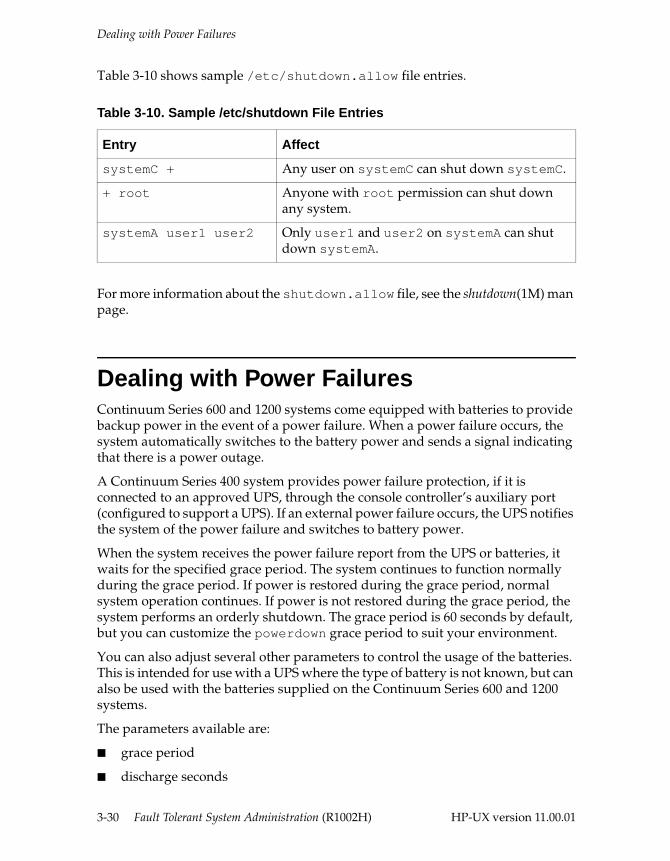
Dealing with Power Failures
Table 3-10 shows sample /etc/shutdown.allow file entries.
For more information about the shutdown.allow file, see the shutdown(1M) man page.
Dealing with Power FailuresContinuum Series 600 and 1200 systems come equipped with batteries to provide backup power in the event of a power failure. When a power failure occurs, the system automatically switches to the battery power and sends a signal indicating that there is a power outage.
A Continuum Series 400 system provides power failure protection, if it is connected to an approved UPS, through the console controller’s auxiliary port (configured to support a UPS). If an external power failure occurs, the UPS notifies the system of the power failure and switches to battery power.
When the system receives the power failure report from the UPS or batteries, it waits for the specified grace period. The system continues to function normally during the grace period. If power is restored during the grace period, normal system operation continues. If power is not restored during the grace period, the system performs an orderly shutdown. The grace period is 60 seconds by default, but you can customize the powerdown grace period to suit your environment.
You can also adjust several other parameters to control the usage of the batteries. This is intended for use with a UPS where the type of battery is not known, but can also be used with the batteries supplied on the Continuum Series 600 and 1200 systems.
The parameters available are:
■ grace period
■ discharge seconds
Table 3-10. Sample /etc/shutdown File Entries
Entry Affect
systemC + Any user on systemC can shut down systemC.
+ root Anyone with root permission can shut down any system.
systemA user1 user2 Only user1 and user2 on systemA can shut down systemA.
3-30 Fault Tolerant System Administration (R1002H) HP-UX version 11.00.01
Dealing with Power Failures
■ maximum ridethrough seconds
■ battery factor
■ shutdown time
Information on the grace period is provided below. The other parameters are set by including them on the command line defined in the inittab file, as shown in the grace period example. See the powerdown(1M) man page for details on the parameters.
CAUTION
A Continuum Series 400 system immediately halts when power fails if it is not connected to a UPS; it does not have time to perform any shutdown procedures.
If you do not have a UPS on a Continuum Series 400 system to give your system time to shut down gracefully in the event of a power failure, your recovery procedure is very limited. You must simply reboot the system and verify that your file systems were not corrupted. Contact the CAC for further assistance.
Configuring the Power Failure Grace PeriodThe power failure grace period is the number of seconds that the system waits after a power failure occurs before it begins an orderly shutdown of the system. If power is restored within the time specified by the grace period, the system does not shut down. The default grace period is 60 seconds.
When the system boots, it starts a powerdown daemon that waits for a power failure or a system shutdown command and then performs an orderly system shutdown. You specify how long you want the grace period to be by customizing the command that starts the powerdown daemon in the /etc/inittab file. If the grace period ends and the power has not returned, the powerdown daemon invokes the command shutdown -h -y 0. For more information, see the powerdown(1M) and shutdown(1M) man pages.
To configure the power failure grace period, do the following:
1. Edit the entry in the /etc/inittab file and specify the value you want for the grace option (-g). If the entry does not exist, create it. The -g option specifies the length of the grace period in seconds. The following sample entry starts the powerdown daemon with a grace period of 2 minutes:
pdwn::respawn:/sbin/powerdown -g 120 #powerdown daemon
2. Invoke the new (latest) /etc/inittab settings. To do this, enter
# init q
HP-UX version 11.00.01 Starting and Stopping the System 3-31
Managing Flash Cards
3. Terminate the existing powerdown daemon. To do this, determine the powerdown daemon process ID and kill that process, as illustrated in the following example:
# ps -ef | grep powerdown root 699 1 0 Apr 10 ? 0:00 /sbin/powerdownannh 6339 6228 1 16:56:40 pts/ 0:00 grep powerdown# kill -9 699
Within seconds, the init process spawns a new powerdown daemon with your changes.
4. Verify that the new process ID was spawned, as illustrated in the following example:
# ps -ef | grep powerdownroot 6346 1 0 17:01:13 ? 0:00 /sbin/powerdownroot 6358 6341 0 17:06:25 pts/2 0:00 grep powerdown
For more information, see the powerdown(1M), kill(1M), init(1M), and inittab(4) man pages.
Configuring the UPS PortYou can configure the console controller auxiliary port to support a UPS. See Chapter 3, “Configuring Serial Ports for Terminals and Modems,” in the HP-UX Operating System: Peripherals Configuration (R1001H) for more information.
Managing Flash CardsA Continuum Series 400 system uses a device called a flash card to perform the primary boot functions. The flash card contains the primary bootloader, a configuration file, and the secondary bootloader. The HP-UX operating system kernel is stored on the root disk and booted from there.
NOTE
Properly maintaining your flash cards is critical for achieving continuous availability. Make sure that you understand and follow all the instructions described in this section.
3-32 Fault Tolerant System Administration (R1002H) HP-UX version 11.00.01
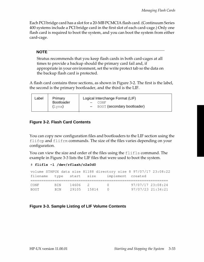
Managing Flash Cards
Each PCI bridge card has a slot for a 20-MB PCMCIA flash card. (Continuum Series 400 systems include a PCI bridge card in the first slot of each card-cage.) Only one flash card is required to boot the system, and you can boot the system from either card-cage.
NOTE
Stratus recommends that you keep flash cards in both card-cages at all times to provide a backup should the primary card fail and, if appropriate in your environment, set the write protect tab so the data on the backup flash card is protected.
A flash card contains three sections, as shown in Figure 3-2. The first is the label, the second is the primary bootloader, and the third is the LIF.
Figure 3-2. Flash Card Contents
You can copy new configuration files and bootloaders to the LIF section using the flifcp and flifrm commands. The size of the files varies depending on your configuration.
You can view the size and order of the files using the flifls command. The example in Figure 3-3 lists the LIF files that were used to boot the system.
Figure 3-3. Sample Listing of LIF Volume Contents
Logical Interchange Format (LIF)– CONF– BOOT (secondary bootloader)
Primary Bootloader(lynx)
Label
# flifls -l /dev/rflash/c2a0d0
volume STHPUX data size 81188 directory size 8 97/07/17 23:08:22filename type start size implement created===============================================================CONF BIN 14606 2 0 97/07/17 23:08:24BOOT BIN 29105 15814 0 97/07/23 21:34:21
HP-UX version 11.00.01 Starting and Stopping the System 3-33

Managing Flash Cards
The LIF section on a flash card has a total space of 81188 blocks of 256K bytes, which is a little less than 20 MB. The following information is provided for each file:
filename The name of the file.
type The type of all these files is BIN, or binary.
start Indicates the block number at which the file starts.
size The number of blocks used by the file.
implement Not used and can be ignored.
created Indicates the date and time the file was written to the flash card.
Flash Card Utility CommandsSeveral flash card utility commands can help you maintain your flash cards. All flash card utility commands begin with the prefix flash or flif.
NOTE
The standard HP-UX operating system commands lifcp, lifinit, lifls, lifrename, and lifrm manipulate LIF files on disk only; they do not work for a flash card. You must use the commands in Table 3-11 to manipulate LIF files on a flash card.
Table 3-11 describes the flash card utilities. For more information, see the procedures later in this chapter and the corresponding man pages.
Table 3-11. Flash Card Utilities
Flash Card Utility Description
flashboot Copies data from a file on disk to the bootloader area on the flash card. Use this command to copy the bootloader to the flash card. The installation image is stored at /stand/flash/lynx.obj.
flashcp Copies data from one flash card to another.
flashdd Copies data from flash images on disk to a flash card. Use this command to initialize a new flash card with the installation flash card image.
flifcmp Compares a file on the flash card to a file on disk.
flifcompact Eliminates fragmented storage space on the flash card.
3-34 Fault Tolerant System Administration (R1002H) HP-UX version 11.00.01
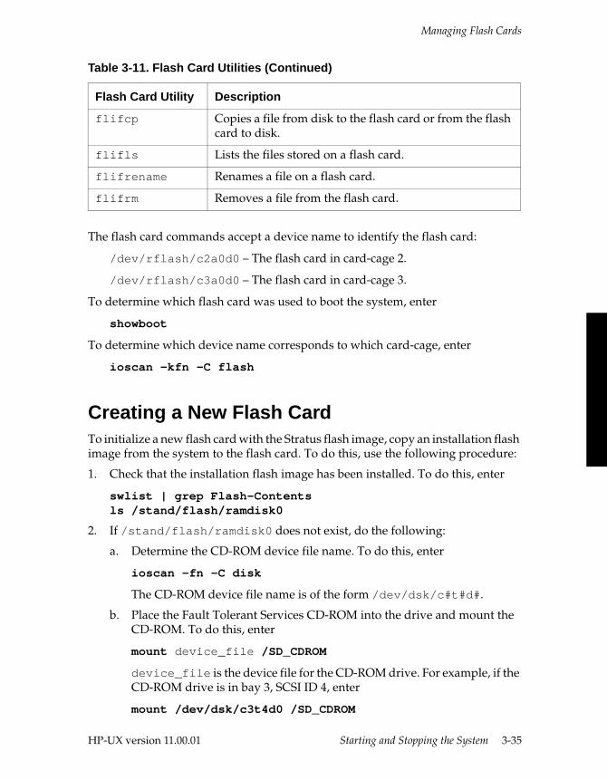
Managing Flash Cards
The flash card commands accept a device name to identify the flash card:
/dev/rflash/c2a0d0 – The flash card in card-cage 2.
/dev/rflash/c3a0d0 – The flash card in card-cage 3.
To determine which flash card was used to boot the system, enter
showboot
To determine which device name corresponds to which card-cage, enter
ioscan -kfn -C flash
Creating a New Flash CardTo initialize a new flash card with the Stratus flash image, copy an installation flash image from the system to the flash card. To do this, use the following procedure:
1. Check that the installation flash image has been installed. To do this, enter
swlist | grep Flash-Contentsls /stand/flash/ramdisk0
2. If /stand/flash/ramdisk0 does not exist, do the following:
a. Determine the CD-ROM device file name. To do this, enter
ioscan -fn -C disk
The CD-ROM device file name is of the form /dev/dsk/c#t#d#.
b. Place the Fault Tolerant Services CD-ROM into the drive and mount the CD-ROM. To do this, enter
mount device_file /SD_CDROM
device_file is the device file for the CD-ROM drive. For example, if the CD-ROM drive is in bay 3, SCSI ID 4, enter
mount /dev/dsk/c3t4d0 /SD_CDROM
flifcp Copies a file from disk to the flash card or from the flash card to disk.
flifls Lists the files stored on a flash card.
flifrename Renames a file on a flash card.
flifrm Removes a file from the flash card.
Table 3-11. Flash Card Utilities (Continued)
Flash Card Utility Description
HP-UX version 11.00.01 Starting and Stopping the System 3-35
Managing Flash Cards
c. Install the Flash-Contents fileset. To do this, enter
swinstall -s /SD_CDROM Flash-Contents
3. Copy the flash image to a new flash card. To do this, enter
flashdd dev_name /stand/flash/ramdisk0
dev_name is the device name of the flash card to be written, which is either /dev/rflash/c2a0d0 (card-cage 2) or /dev/rflash/c3a0d0 (card-cage 3). For more information, see the swinstall(1M) and flashdd(1) man pages.
Duplicating a Flash CardTo duplicate a flash card, enter
flashcp from_devname to_devname
from_devname is the device name of the flash card you want to duplicate and to_devname is the device name of the new flash card. Use /dev/rflash/c2a0d0 for the flash card in card-cage 2; use /dev/rflash/c3a0d0 for the flash card in card-cage 3.
For more information, see the flashcp(1) man page.
3-36 Fault Tolerant System Administration (R1002H) HP-UX version 11.00.01
HP-UX version 11.00.01
4
Mirroring Data 4-This chapter provides information about mirroring data, mirroring root and swap disks, and setting up I/O channel separation.
NOTE
The MirrorDisk/HP-UX operating system software is included on Continuum Series systems running the HP-UX operating system; you do not need to purchase it separately.
Mirroring DataThis chapter describes the recommended configuration for mirroring data on Continuum Series systems. For more information about setting up disk mirroring, see the Managing Systems and Workgroups (B2355-90157).
Glossary of TermsBefore you can mirror the data on your disks, you need to set up volume groups, physical volume groups, and logical volumes. The following terms are defined in the Managing Systems and Workgroups (B2355-90157) and are used in this chapter.
■ A mirror is an identical copy of a set of data that you can access if your primary data becomes unavailable.
■ A volume group is a pool of storage space, usually made up of multiple physical storage devices.
4-1
Mirroring Data
■ A physical volume group is a set of physical volumes, or disks, within a volume group.
■ A logical volume is a unit of usable disk space divided into sequential logical extents. Logical volumes can be used for swap, dump, raw data, or file systems.
■ A logical extent is a portion of a logical volume mapped to a physical extent.
■ A physical extent is an addressable unit on a physical volume.
■ Contiguous means that the physical extents of each mirror are placed immediately adjacent to one another on the disk and cannot span several disks. Root volumes must be contiguous.
■ Noncontiguous means that physical extents of each mirror can be allocated to one or more physical volumes and can be separated by other data.
■ Strict allocation means that physical extents are allocated to different physical volumes, or disks. Strict allocation is the default for mirroring.
■ PVG-strict allocation means that physical extents of each mirror are allocated to different physical volume groups, and not just different physical volumes. In addition to increasing availability, this allows LVM more flexibility in reading data, resulting in better performance. If you configure physical volume groups so that disks using the same interface card or SCSI bus are grouped together, this allocation policy is also called I/O channel separation. For more information, see the “Setting Up I/O Channel Separation” section later in this chapter.
■ Nonstrict allocation means that physical extents can be allocated to any available disk space in the volume group. With this allocation policy, mirrored physical extents can be allocated to the same disk. If the disk or SCSI bus fails, both primary and mirrored data can become unavailable or lost.
■ Dual-initiation is a term used when a logical SCSI bus is driven by two physical SCSI controllers, usually in different PCI card-cages, working together to support a single set of disks. If one of the controllers fails, the other controller can still access the disks.
■ Single-initiation is the term used when the logical SCSI bus is driven by a single SCSI controller.
4-2 Fault Tolerant System Administration (R1002H) HP-UX version 11.00.01
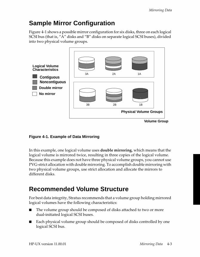
Mirroring Data
Sample Mirror ConfigurationFigure 4-1 shows a possible mirror configuration for six disks, three on each logical SCSI bus (that is, “A” disks and “B” disks on separate logical SCSI buses), divided into two physical volume groups.
Figure 4-1. Example of Data Mirroring
In this example, one logical volume uses double mirroring, which means that the logical volume is mirrored twice, resulting in three copies of the logical volume. Because this example does not have three physical volume groups, you cannot use PVG-strict allocation with double mirroring. To accomplish double mirroring with two physical volume groups, use strict allocation and allocate the mirrors to different disks.
Recommended Volume StructureFor best data integrity, Stratus recommends that a volume group holding mirrored logical volumes have the following characteristics:
■ The volume group should be composed of disks attached to two or more dual-initiated logical SCSI buses.
■ Each physical volume group should be composed of disks controlled by one logical SCSI bus.
Volume Group
Physical Volume Groups
Double mirror
ContiguousNoncontiguous
No mirror
Logical VolumeCharacteristics
3B
3A
2B
2A
1B
1A
HP-UX version 11.00.01 Mirroring Data 4-3
Mirroring Data
■ Mirrored logical volumes should use PVG-strict allocation to allocate physical extents.
■ If you use single-initiated SCSI buses, make sure that you mirror disks controlled by a single-initiated SCSI bus with disks controlled by a SCSI bus attached to a controller port of a PCI card in the other card-cage.
This strategy will ensure that a logical volume can still be accessed in the event of disk failure or SCSI bus failure.
Guidelines for Managing MirrorsThere are many ways you can set up data mirroring on your system. The Managing Systems and Workgroups (B2355-90157) describes the guidelines to consider before setting up or changing mirrored disk configuration.
The following options are presented when you use SAM to configure your mirrors:
■ Bad block relocation—If LVM is unable to store data on a particular block, it stores the data at the end of the disk.
Always use with Continuum Series systems when hardware sparing is not available for disks.
■ Contiguous allocation—Indicates that data is distributed in physical volumes with no gaps.
Use for root logical volumes, /stand files, and swap space.
■ Number of mirrored copies (0, 1, or 2)—Creates the specified number of mirrors.
Use 0 for data that rarely changes and is backed up or can be regenerated. Use 2 when you need to back up the data without interrupting the mirror. Use 1 for all other cases.
■ Mirror policy (separate physical volume groups, separate disks, or same disk)—Specifies location of mirrors.
Use separate physical volume groups (also called I/O channel separation) whenever possible. Physical volume groups should be set up such that physical volumes are on different SCSI buses. Use separate disks when you have only two physical volume groups and need two mirrored copies.
■ Scheduling (parallel, sequential, dynamic)—Specifies how mirror is to be updated.
For higher performance, use parallel to update all copies at the same time. For higher data integrity, use sequential to update the primary copy first. For a high-integrity mixture (with better performance than sequential), use
4-4 Fault Tolerant System Administration (R1002H) HP-UX version 11.00.01
Mirroring Root and Primary Swap
dynamic to choose parallel when the physical write operation is synchronous or sequential when the physical write operation is asynchronous.
■ Mirror Write Cache—Keeps a log of writes that are not yet mirrored, and uses the log at recovery. Performance is slower during regular use to update the log, but recovery time is faster.
Use when fast recovery of the data is essential. Turn off for mirrored swap space that is also used as a dump. If this feature is on and the disk fails, the dump will be erased.
■ Mirror Consistency—Makes all mirrors consistent at recovery. Recovery time is slower. Performance is optimal during regular use.
Use for user data, or data that can be unavailable during a longer recovery.
Mirroring Root and Primary Swap Root and swap logical volumes are defined during installation. You are prompted to configure root disk mirroring during installation. If choose not to mirror the root disk during installation, you can use the standard Logical Volume Manager (LVM) commands to do so after installation is complete. The procedure is described below.
When you mirror the root disk during installation, all logical volumes on the system root disk, including primary swap, are mirrored on the physical volume that you select as the mirror disk.
NOTE
Stratus recommends that you mirror the root logical volumes on two disks that are dedicated to root data and that are on different SCSI buses.
Adding a Mirror to Root Data After InstallationAfter installation you can add a third mirror. To mirror a third disk, do the following:
1. Create a bootable physical volume. To do this, enter
pvcreate -B /dev/rdsk/address
2. Add the physical volume to your existing root volume group. To do this, enter
vgextend /dev/vg00 /dev/dsk/address
3. Place boot utilities in the boot area. To do this, enter
mkboot /dev/rdsk/address
HP-UX version 11.00.01 Mirroring Data 4-5
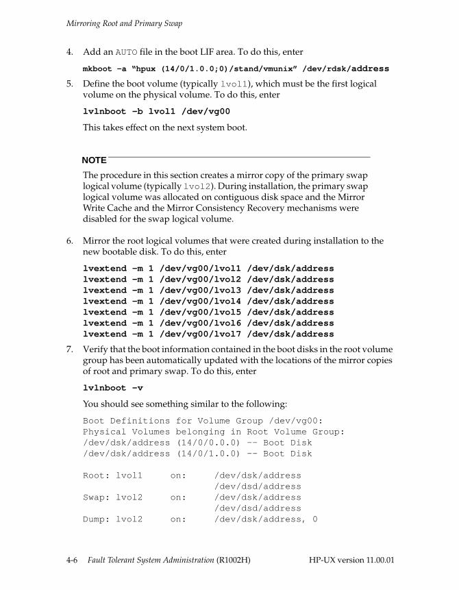
Mirroring Root and Primary Swap
4. Add an AUTO file in the boot LIF area. To do this, enter
mkboot -a “hpux (14/0/1.0.0;0)/stand/vmunix” /dev/rdsk/address
5. Define the boot volume (typically lvol1), which must be the first logical volume on the physical volume. To do this, enter
lvlnboot -b lvol1 /dev/vg00
This takes effect on the next system boot.
NOTE
The procedure in this section creates a mirror copy of the primary swap logical volume (typically lvol2). During installation, the primary swap logical volume was allocated on contiguous disk space and the Mirror Write Cache and the Mirror Consistency Recovery mechanisms were disabled for the swap logical volume.
6. Mirror the root logical volumes that were created during installation to the new bootable disk. To do this, enter
lvextend -m 1 /dev/vg00/lvol1 /dev/dsk/addresslvextend -m 1 /dev/vg00/lvol2 /dev/dsk/addresslvextend -m 1 /dev/vg00/lvol3 /dev/dsk/addresslvextend -m 1 /dev/vg00/lvol4 /dev/dsk/addresslvextend -m 1 /dev/vg00/lvol5 /dev/dsk/addresslvextend -m 1 /dev/vg00/lvol6 /dev/dsk/addresslvextend -m 1 /dev/vg00/lvol7 /dev/dsk/address
7. Verify that the boot information contained in the boot disks in the root volume group has been automatically updated with the locations of the mirror copies of root and primary swap. To do this, enter
lvlnboot -v
You should see something similar to the following:
Boot Definitions for Volume Group /dev/vg00:Physical Volumes belonging in Root Volume Group:/dev/dsk/address (14/0/0.0.0) -- Boot Disk/dev/dsk/address (14/0/1.0.0) -- Boot Disk
Root: lvol1 on: /dev/dsk/address /dev/dsd/addressSwap: lvol2 on: /dev/dsk/address /dev/dsd/addressDump: lvol2 on: /dev/dsk/address, 0
4-6 Fault Tolerant System Administration (R1002H) HP-UX version 11.00.01
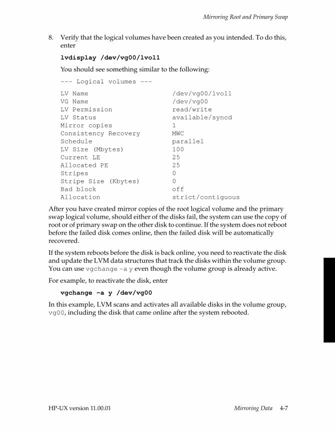
Mirroring Root and Primary Swap
8. Verify that the logical volumes have been created as you intended. To do this, enter
lvdisplay /dev/vg00/lvol1
You should see something similar to the following:
--- Logical volumes ---
LV Name /dev/vg00/lvol1VG Name /dev/vg00LV Permission read/write LV Status available/syncd Mirror copies 1 Consistency Recovery MWC Schedule parallel LV Size (Mbytes) 100 Current LE 25 Allocated PE 25 Stripes 0 Stripe Size (Kbytes) 0 Bad block off Allocation strict/contiguous
After you have created mirror copies of the root logical volume and the primary swap logical volume, should either of the disks fail, the system can use the copy of root or of primary swap on the other disk to continue. If the system does not reboot before the failed disk comes online, then the failed disk will be automatically recovered.
If the system reboots before the disk is back online, you need to reactivate the disk and update the LVM data structures that track the disks within the volume group. You can use vgchange -a y even though the volume group is already active.
For example, to reactivate the disk, enter
vgchange -a y /dev/vg00
In this example, LVM scans and activates all available disks in the volume group, vg00, including the disk that came online after the system rebooted.
HP-UX version 11.00.01 Mirroring Data 4-7
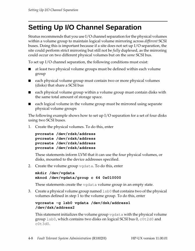
Setting Up I/O Channel Separation
Setting Up I/O Channel SeparationStratus recommends that you use I/O channel separation for the physical volumes within a volume group to maintain logical volume mirroring across different SCSI buses. Doing this is important because if a site does not set up I/O separation, the site could perform strict mirroring but still not be fully duplexed, as the mirroring could occur on two different physical volumes but on the same SCSI bus.
To set up I/O channel separation, the following conditions must exist:
■ at least two physical volume groups must be defined within each volume group
■ each physical volume group must contain two or more physical volumes (disks) that share a SCSI bus
■ each physical volume group within a volume group must contain disks with the same total amount of storage space.
■ each logical volume in the volume group must be mirrored using separate physical volume groups
The following example shows how to set up I/O separation for a set of four disks using two SCSI buses.
1. Create the physical volumes. To do this, enter
pvcreate /dev/rdsk/addresspvcreate /dev/rdsk/addresspvcreate /dev/rdsk/addresspvcreate /dev/rdsk/address
These statements inform LVM that it can use the four physical volumes, or disks, mounted to the device addresses specified.
2. Create the volume group vgdata. To do this, enter
mkdir /dev/vgdatamknod /dev/vgdata/group c 64 0x010000
These statements create the vgdata volume group in an empty state.
3. Create a physical volume group named lsb0 that contains two of the physical volumes defined in step 1 to the volume group. To do this, enter
vgcreate -g lsb0 vgdata /dev/dsk/address1 /dev/dsk/address2
This statement initializes the volume group vgdata with the physical volume group lsb0, which contains two disks on logical SCSI bus 0, c0t2d0 and c0t3d0.
4-8 Fault Tolerant System Administration (R1002H) HP-UX version 11.00.01
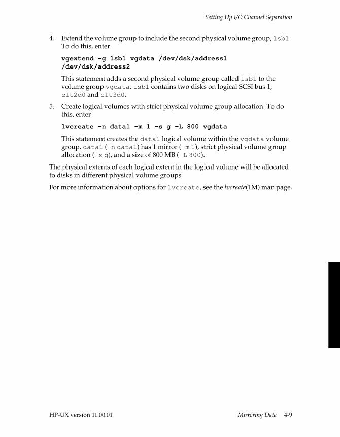
Setting Up I/O Channel Separation
4. Extend the volume group to include the second physical volume group, lsb1. To do this, enter
vgextend -g lsb1 vgdata /dev/dsk/address1 /dev/dsk/address2
This statement adds a second physical volume group called lsb1 to the volume group vgdata. lsb1 contains two disks on logical SCSI bus 1, c1t2d0 and c1t3d0.
5. Create logical volumes with strict physical volume group allocation. To do this, enter
lvcreate -n data1 -m 1 -s g -L 800 vgdata
This statement creates the data1 logical volume within the vgdata volume group. data1 (-n data1) has 1 mirror (-m 1), strict physical volume group allocation (-s g), and a size of 800 MB (-L 800).
The physical extents of each logical extent in the logical volume will be allocated to disks in different physical volume groups.
For more information about options for lvcreate, see the lvcreate(1M) man page.
HP-UX version 11.00.01 Mirroring Data 4-9

HP-UX version 11.00.01
5
Administering Fault Tolerant Hardware 5-This chapter describes the duties related to fault-tolerant hardware administration. It provides information about physical and logical hardware configurations, how to determine component status, and how to manage hardware devices and MTBF statistics. In addition, it provides information about error notification and troubleshooting.
Fault Tolerant Hardware AdministrationContinuum systems are designed for maximum serviceability. You can replace many devices on site without special tools and without bringing down your system. Devices are classified into two categories:
■ Customer-replaceable unit (CRU)—system devices that you can install or replace on site. Most devices in a Continuum system, such as suitcases or CPU/memory boards, I/O controller or adapter cards, power supplies, disk drives, tape drives, and CD-ROM drives are CRUs.
■ Field-replaceable unit (FRU)—system devices that only trained Stratus personnel can install or replace on site.
When the system boots, it checks each hardware path to determine whether a CRU or FRU device is present and to record the model number of each device it finds. The system automatically registers each device with its hardware path and initiates on-going device maintenance. Maintenance includes the following:
■ attempt recovery, if the device suffers transient failures
■ respond to maintenance commands
■ make the device’s resources available to the system
5-1
Using Hardware Utilities
■ log changes in the device’s status
■ display the device’s state on demand
During normal operation, the system periodically checks each hardware path. If a device is not operating, is missing, or is the wrong model number for that hardware path’s definition, the system logs messages in the system log file and, if configured, sends a message to the console.
Using Hardware UtilitiesReplacing or deleting some devices requires only that you insert or remove the units from the system. Other tasks require that you enter certain commands. The primary hardware utilities are addhardware and ftsmaint.
Use the addhardware command when you add new hardware to a running machine. See the HP-UX Operating System: Peripherals Configuration (R1001H) and the addhardware(1M) man page for information about adding and configuring hardware.
You can use the ftsmaint command for many tasks, including the following:
■ listing and determining hardware paths
■ displaying hardware status information
■ enabling and disabling hardware devices
■ attempting to bring a faulty device back into service
■ displaying and managing MTBF statistics
■ updating PROM code
This chapter describes various uses of the ftsmaint command. See Appendix B, “Updating PROM Code,” for procedures to update PROM code and the ftsmaint(1M) man page for information about all options and services.
5-2 Fault Tolerant System Administration (R1002H) HP-UX version 11.00.01
Determining Hardware Paths
Determining Hardware PathsYou can identify each piece of hardware configured on a system by its hardware path. For many system administration tasks, you must determine the physical location of a device when given its hardware path, or supply a hardware path in a command line. The hardware path is usually indicated by the hw_path argument in the command syntax.
A hardware path specifies the addresses of the hardware devices leading to a device. It consists of a numerical string of hardware addresses, notated sequentially from the bus address to the device address.
You can use the ftsmaint ls command to display the hardware paths of all hardware devices in your system. You can also use the standard ioscan command to display hardware paths. See the HP-UX Operating System: Peripherals Configuration (R1001H) and the ioscan(1M) man page for more information about this command.
Physical Hardware ConfigurationThis section explains how hardware paths are used to describe the physical hardware devices on Continuum systems.
– For a description of the components of a Continuum Series 400 system, see the HP-UX Operating System: Continuum Series 400 Operation and Maintenance Guide (R001H) or the HP-UX Operating System: Continuum Series 400-CO Operation and Maintenance Guide (R025H).
– For a description of the components of a Continuum Series 600 or 1200 system, see the HP-UX Operating System: Continuum Series 600 and 1200 Operation and Maintenance Guide (R024H).
HP-UX version 11.00.01 Administering Fault Tolerant Hardware 5-3
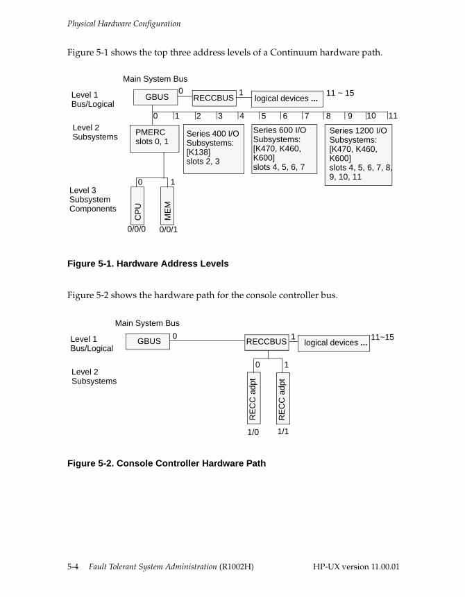
Physical Hardware Configuration
Figure 5-1 shows the top three address levels of a Continuum hardware path.
Figure 5-1. Hardware Address Levels
Figure 5-2 shows the hardware path for the console controller bus.
Figure 5-2. Console Controller Hardware Path
Level 1Bus/Logical
Level 2 Subsystems
Main System Bus
Level 3 Subsystem Components
PMERCslots 0, 1
GBUS
Series 400 I/O Subsystems:[K138] slots 2, 3
Series 600 I/O Subsystems:[K470, K460,K600] slots 4, 5, 6, 7
Series 1200 I/O Subsystems:[K470, K460, K600] slots 4, 5, 6, 7, 8, 9, 10, 11
CP
U
ME
M
0 1 2 3 4 5 6 7 8 9 10
0 1
RECCBUS logical devices ...0 1 11 ~ 15
11
0/0/0 0/0/1
Level 1Bus/Logical
Level 2Subsystems
Main System Bus
GBUS
RE
CC
adp
t
0 1
RECCBUS logical devices ...0 1 11~15
1/0 1/1
RE
CC
adp
t
5-4 Fault Tolerant System Administration (R1002H) HP-UX version 11.00.01
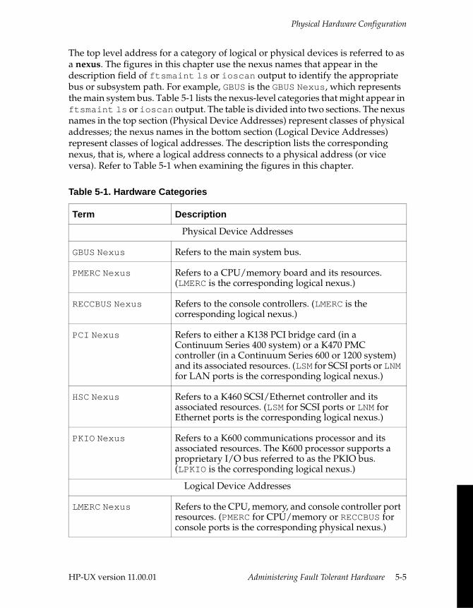
Physical Hardware Configuration
The top level address for a category of logical or physical devices is referred to as a nexus. The figures in this chapter use the nexus names that appear in the description field of ftsmaint ls or ioscan output to identify the appropriate bus or subsystem path. For example, GBUS is the GBUS Nexus, which represents the main system bus. Table 5-1 lists the nexus-level categories that might appear in ftsmaint ls or ioscan output. The table is divided into two sections. The nexus names in the top section (Physical Device Addresses) represent classes of physical addresses; the nexus names in the bottom section (Logical Device Addresses) represent classes of logical addresses. The description lists the corresponding nexus, that is, where a logical address connects to a physical address (or vice versa). Refer to Table 5-1 when examining the figures in this chapter.
Table 5-1. Hardware Categories
Term Description
Physical Device Addresses
GBUS Nexus Refers to the main system bus.
PMERC Nexus Refers to a CPU/memory board and its resources. (LMERC is the corresponding logical nexus.)
RECCBUS Nexus Refers to the console controllers. (LMERC is the corresponding logical nexus.)
PCI Nexus Refers to either a K138 PCI bridge card (in a Continuum Series 400 system) or a K470 PMC controller (in a Continuum Series 600 or 1200 system) and its associated resources. (LSM for SCSI ports or LNM for LAN ports is the corresponding logical nexus.)
HSC Nexus Refers to a K460 SCSI/Ethernet controller and its associated resources. (LSM for SCSI ports or LNM for Ethernet ports is the corresponding logical nexus.)
PKIO Nexus Refers to a K600 communications processor and its associated resources. The K600 processor supports a proprietary I/O bus referred to as the PKIO bus. (LPKIO is the corresponding logical nexus.)
Logical Device Addresses
LMERC Nexus Refers to the CPU, memory, and console controller port resources. (PMERC for CPU/memory or RECCBUS for console ports is the corresponding physical nexus.)
HP-UX version 11.00.01 Administering Fault Tolerant Hardware 5-5
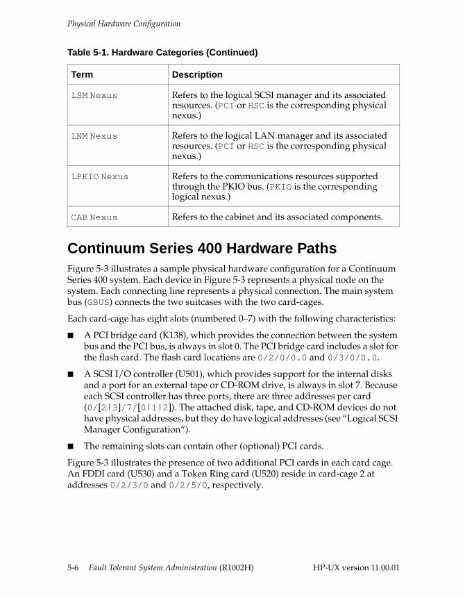
Physical Hardware Configuration
Continuum Series 400 Hardware PathsFigure 5-3 illustrates a sample physical hardware configuration for a Continuum Series 400 system. Each device in Figure 5-3 represents a physical node on the system. Each connecting line represents a physical connection. The main system bus (GBUS) connects the two suitcases with the two card-cages.
Each card-cage has eight slots (numbered 0–7) with the following characteristics:
■ A PCI bridge card (K138), which provides the connection between the system bus and the PCI bus, is always in slot 0. The PCI bridge card includes a slot for the flash card. The flash card locations are 0/2/0/0.0 and 0/3/0/0.0.
■ A SCSI I/O controller (U501), which provides support for the internal disks and a port for an external tape or CD-ROM drive, is always in slot 7. Because each SCSI controller has three ports, there are three addresses per card (0/[2|3]/7/[0|1|2]). The attached disk, tape, and CD-ROM devices do not have physical addresses, but they do have logical addresses (see “Logical SCSI Manager Configuration”).
■ The remaining slots can contain other (optional) PCI cards.
Figure 5-3 illustrates the presence of two additional PCI cards in each card cage. An FDDI card (U530) and a Token Ring card (U520) reside in card-cage 2 at addresses 0/2/3/0 and 0/2/5/0, respectively.
LSM Nexus Refers to the logical SCSI manager and its associated resources. (PCI or HSC is the corresponding physical nexus.)
LNM Nexus Refers to the logical LAN manager and its associated resources. (PCI or HSC is the corresponding physical nexus.)
LPKIO Nexus Refers to the communications resources supported through the PKIO bus. (PKIO is the corresponding logical nexus.)
CAB Nexus Refers to the cabinet and its associated components.
Table 5-1. Hardware Categories (Continued)
Term Description
5-6 Fault Tolerant System Administration (R1002H) HP-UX version 11.00.01
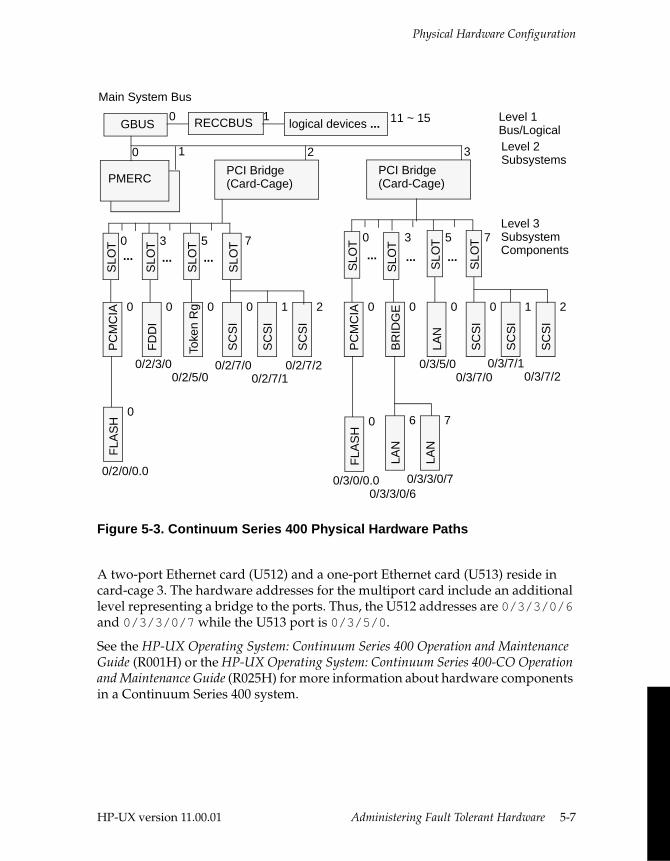
Physical Hardware Configuration
Figure 5-3. Continuum Series 400 Physical Hardware Paths
A two-port Ethernet card (U512) and a one-port Ethernet card (U513) reside in card-cage 3. The hardware addresses for the multiport card include an additional level representing a bridge to the ports. Thus, the U512 addresses are 0/3/3/0/6 and 0/3/3/0/7 while the U513 port is 0/3/5/0.
See the HP-UX Operating System: Continuum Series 400 Operation and Maintenance Guide (R001H) or the HP-UX Operating System: Continuum Series 400-CO Operation and Maintenance Guide (R025H) for more information about hardware components in a Continuum Series 400 system.
53 70
SLO
TTo
ken
Rg 0
SLO
TF
DD
I
0
SLO
TS
CS
I
0
SC
SI
1S
CS
I2
SLO
TP
CM
CIA 0
FLA
SH
0
SLO
TLA
N
0
BR
IDG
E 0
SLO
TS
CS
I
0
SC
SI
1
SC
SI
2
SLO
TP
CM
CIA 0
FLA
SH
0
LAN
6LA
N7
Level 1Bus/LogicalLevel 2 Subsystems
Main System Bus
Level 3 Subsystem Components
PMERC
GBUS
0 1 2 3
RECCBUS logical devices ...0 1 11 ~ 15
PCI Bridge(Card-Cage)
PCI Bridge(Card-Cage)
0/3/0/0.00/3/3/0/6
0/3/3/0/7
0/3/5/00/3/7/0
0/2/7/00/2/7/1
0/2/3/00/2/5/0
0/2/0/0.0
0/2/7/2 0/3/7/10/3/7/2
53 70
... ... ... ... ... ...
SLO
T
HP-UX version 11.00.01 Administering Fault Tolerant Hardware 5-7
Physical Hardware Configuration
Continuum Series 600 and 1200 Hardware PathsThe main system bus supports all the slots in the main chassis, with the CPU/memory boards in slots 0 and 1 and the I/O controller boards in slots 4 through 11 for Continuum Series 1200 systems or slots 4 through 7 for Continuum Series 600 systems. (The main chassis was originally designed to support up to four PA-7100-based CPU/memory boards, but PA-8x00-based boards require more space; thus, slots 2 and 3 no longer appear.) The main system bus (GBUS) is fault tolerant, as it consists of two lock-stepped, self-checking buses that perform as a single virtual bus. As a result, adjacent slots (0/1 for CPU/memory boards and 4/5, 6/7, 8/9, and 10/11 for I/O controller boards) are paired and provide fault tolerance for the pair of boards in those slots. The supported I/O controllers are as follows:
■ A K460 SCSI/Ethernet controller (sometimes referred to as an HSC controller) includes four SCSI ports and one Ethernet port, and it provides support for all disks on the system. The SCSI ports for a pair of K460 boards in adjacent slots are dual-initiated, but the Ethernet ports are independent. (You can provide failover protection for the Ethernet ports through the optional Redundant Network Interface [RNI] software.) K460 controllers operate as an online/standby pair. If one (or more) of the SCSI ports on the online board fails, the standby board becomes the online board, and all services on the broken board (including the Ethernet port) go out of service. (If just the Ethernet port on the online board fails, the board does not fail over.) You can have multiple pairs of K460 boards, but every system must have at least one.
■ A K600 communications processor controls the I/O adapter cards (referred to as K-cards) that run off a proprietary I/O bus (referred to as the PKIO bus). A pair of K600 processors operate as a fully duplexed pair (that is, they run in lock-step). A K600 processor can support up to 32 K-cards (four of which must be terminators). You can have one or more pairs of K600 boards in the system, but none are required.
■ A K470 PMC controller includes three slots for PMC cards. K470 controllers do not function as a pair. Each K470 controller provides support for the attached PMC cards. (You can provide failover protection for the LAN ports on a PMC card through RNI.) You can have one or more K470 cards in your system, but none are required.
Figure 5-4 illustrates a sample physical hardware configuration for a Continuum Series 1200 system. Each device in Figure 5-4 represents a physical node on the system. Each connecting line represents a physical connection.
5-8 Fault Tolerant System Administration (R1002H) HP-UX version 11.00.01
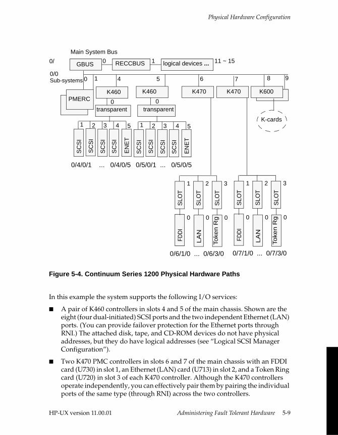
Physical Hardware Configuration
Figure 5-4. Continuum Series 1200 Physical Hardware Paths
In this example the system supports the following I/O services:
■ A pair of K460 controllers in slots 4 and 5 of the main chassis. Shown are the eight (four dual-initiated) SCSI ports and the two independent Ethernet (LAN) ports. (You can provide failover protection for the Ethernet ports through RNI.) The attached disk, tape, and CD-ROM devices do not have physical addresses, but they do have logical addresses (see “Logical SCSI Manager Configuration”).
■ Two K470 PMC controllers in slots 6 and 7 of the main chassis with an FDDI card (U730) in slot 1, an Ethernet (LAN) card (U713) in slot 2, and a Token Ring card (U720) in slot 3 of each K470 controller. Although the K470 controllers operate independently, you can effectively pair them by pairing the individual ports of the same type (through RNI) across the two controllers.
K600
0/
0/0 Sub-systems
Main System Bus
PMERC
GBUS
0 1 5 7
RECCBUS logical devices ...0 1 11 ~ 15
K460 K460 K470 K470 K600
8 4 6
transparent transparent0 0
EN
ET
5
SC
SI
4
SC
SI
1
SC
SI
2
SC
SI
3
Toke
n R
g 0
FDD
I
0
LA
N
0S
LOT
3S
LOT
1
SLO
T
2
K-cards
Toke
n R
g 0
FDD
I
0
LA
N
0
SLO
T
3
SLO
T
1
SLO
T
2
9
EN
ET
5
SC
SI
4
SC
SI
1
SC
SI
2
SC
SI
3
0/4/0/1 ... 0/4/0/5 0/5/0/1 ... 0/5/0/5
0/6/1/0 ... 0/6/3/0 0/7/1/0 ... 0/7/3/0
HP-UX version 11.00.01 Administering Fault Tolerant Hardware 5-9
Physical Hardware Configuration
■ A pair of K600 processors in slots 8 and 9 of the main chassis that support I/O adapter cards (K-cards). The I/O adapter cards are housed in one or two IOA chassis. The last two slots in each chassis [14/15 and 30/31] are for the terminator cards; the remaining slots can contain any supported I/O adapter card. I/O adapter cards do not have physical addresses, but they do have logical addresses (see “Logical Communications I/O Configuration”).
See the HP-UX Operating System: Read Me Before Installing (R1003H) for a list of supported cards and peripherals.
NOTE
You can use RNI to provide failover protection between any ports of the same type (for example, a K460 Ethernet port with a U713 Ethernet port). However, by pairing ports on boards in adjacent main chassis slots, you provide both port and bus fault tolerance.
CPU, Memory, and Console Controller PathsThe CPU and memory constitute one physical nexus (PMERC) while the console controllers constitute a separate physical nexus (RECCBUS), but the resources for both (such as processors or tty devices) are treated as part of the same logical nexus (see “Logical CPU/Memory Configuration”). In a Continuum Series 400 system, the CPU, memory, and console controllers are housed in a single suitcase; in a Continuum Series 600 or 1200 system, CPU and memory reside on a single board while the console controller is a separate board. In either case, the physical addressing scheme is as follows:
■ The first-level address identifies either the main system bus nexus (GBUS) or the console controller bus nexus (RECCBUS). For the CPU/memory, the address is 0. For the console controller, the address is 1.
■ The second-level address identifies either the CPU/memory nexus (PMERC) or the console controller (RECC). In either case, the values for duplexed boards are 0 and 1.
■ The third-level address identifies the PMERC resource as either CPU (0) or memory (1). (Console controllers do not have a third-level physical address.)
5-10 Fault Tolerant System Administration (R1002H) HP-UX version 11.00.01
Physical Hardware Configuration
The following sample ftsmaint ls output shows physical CPU, memory, and console controller hardware paths:Modelx H/W Path Description State Serial# PRev Status FCode Fct
===========================================================================
- CLAIM - - Online - 0- 0 GBUS Nexus CLAIM - - Online - 0g32100 0/0 PMERC Nexus CLAIM 10426 9.0 Online - 1- 0/0/0 CPU Adapter CLAIM - - Online - 0m70700 0/0/1 MEM Adapter CLAIM - - Online - 0g32100 0/1 PMERC Nexus CLAIM 10426 9.0 Online - 1- 0/1/0 CPU Adapter CLAIM - - Online - 0m70700 0/1/1 MEM Adapter CLAIM - - Online - 0
...
- 1 RECCBUS Nexus CLAIM - - Online - 0e59300 1/0 RECC Adapter CLAIM 12379 17.0 Online - 0e59300 1/1 RECC Adapter CLAIM 12386 17.0 Online - 0
NOTE
The sample ftsmaint ls output in this and the following sections shows the selected devices only. Actual ftsmaint ls output lists all devices.
I/O Subsystem PathsThe I/O subsystem addressing convention is as follows:
■ The first-level address, 0, identifies the main system bus nexus (GBUS).
■ The second-level address identifies the I/O subsystem nexus (PCI, HSC, or PKIO). Possible addresses for a Continuum Series 400 system are 2 and 3 (which correspond to the two card-cages). Possible addresses for a Continuum Series 600 or 1200 system are 4–7 and 4–11, respectively (which correspond to the main chassis slots for I/O controllers).
■ The third-level address identifies the following:
– On a Continuum Series 400 system, a third level is the SLOT interface, which identifies the PCI slot number (0–7).
– On a Continuum 600 or 1200 system, the third level is either a constant (0 for paths through a K460 controller) or is not present (for paths through a K600 processor).
HP-UX version 11.00.01 Administering Fault Tolerant Hardware 5-11
Physical Hardware Configuration
NOTE
There are no physical addresses beyond the second level for components supported through a K600 processor. You can locate and specify I/O adapters through their logical address (see “Logical Communications I/O Configuration”).
■ The fourth-level address identifies the following:
– On a Continuum Series 400 system, the fourth level is either an adapter (such as a SCSI port off a U501 card or a LAN port off a U513 card) or a bridge (such as a PCI-PCI bridge for a two-port U512 card).
– On a Continuum Series 600 or 1200 system, the fourth level is either a K460 controller port (SCSI or Ethernet) or a SCSI peripheral enclosure supported by that K460 controller.
■ The fifth-level address identifies the following:
– On a Continuum Series 400 system, the fifth level is a device-specific service (for example a LAN port on a two-port U512 card).
– On a Continuum Series 600 or 1200 system, the fifth level is a SCSI peripheral enclosure power supply (Subsystem Monitor).
The following sample composite ftsmaint ls output (from both Continuum Series 400 and Continuum Series 1200 systems) shows physical hardware paths for I/O devices: Modelx H/W Path Description State Serial# PRev Status FCode Fct
===========================================================================
(Continuum Series 400)
k13800 0/2 PCI Nexus CLAIM 10347 - Online - 5- 0/2/3 SLOT Interface CLAIM - - Online - 0- 0/2/3/0 PCI-PCI Bridge CLAIM - - Online - 0u51200 0/2/3/0/6 LAN Adapter CLAIM - 1 Online - 0u51200 0/2/3/0/7 LAN Adapter CLAIM - 1 Online - 0
...
- 0/2/7 SLOT Interface CLAIM - - Online - 0u50100 0/2/7/0 SCSI Adapter CLAIM - 0ST1 Online - 0u50100 0/2/7/1 SCSI Adapter CLAIM - 0ST1 Online - 0u50100 0/2/7/2 SCSI Adapter CLAIM - 0ST1 Online - 0
5-12 Fault Tolerant System Administration (R1002H) HP-UX version 11.00.01
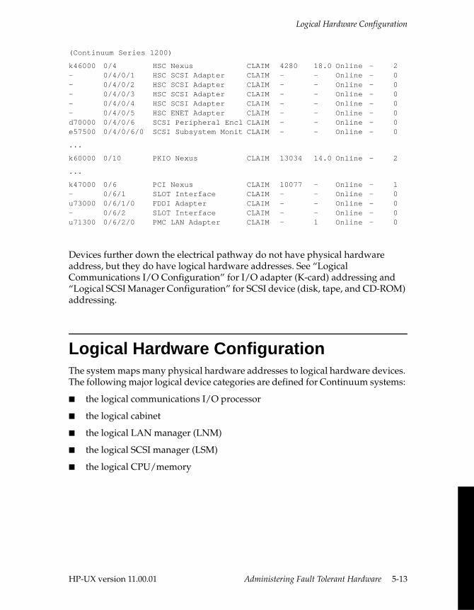
Logical Hardware Configuration
(Continuum Series 1200)
k46000 0/4 HSC Nexus CLAIM 4280 18.0 Online - 2- 0/4/0/1 HSC SCSI Adapter CLAIM - - Online - 0- 0/4/0/2 HSC SCSI Adapter CLAIM - - Online - 0- 0/4/0/3 HSC SCSI Adapter CLAIM - - Online - 0- 0/4/0/4 HSC SCSI Adapter CLAIM - - Online - 0- 0/4/0/5 HSC ENET Adapter CLAIM - - Online - 0d70000 0/4/0/6 SCSI Peripheral Encl CLAIM - - Online - 0e57500 0/4/0/6/0 SCSI Subsystem Monit CLAIM - - Online - 0
...
k60000 0/10 PKIO Nexus CLAIM 13034 14.0 Online - 2
...
k47000 0/6 PCI Nexus CLAIM 10077 - Online - 1- 0/6/1 SLOT Interface CLAIM - - Online - 0u73000 0/6/1/0 FDDI Adapter CLAIM - - Online - 0- 0/6/2 SLOT Interface CLAIM - - Online - 0u71300 0/6/2/0 PMC LAN Adapter CLAIM - 1 Online - 0
Devices further down the electrical pathway do not have physical hardware address, but they do have logical hardware addresses. See “Logical Communications I/O Configuration” for I/O adapter (K-card) addressing and “Logical SCSI Manager Configuration” for SCSI device (disk, tape, and CD-ROM) addressing.
Logical Hardware ConfigurationThe system maps many physical hardware addresses to logical hardware devices. The following major logical device categories are defined for Continuum systems:
■ the logical communications I/O processor
■ the logical cabinet
■ the logical LAN manager (LNM)
■ the logical SCSI manager (LSM)
■ the logical CPU/memory
HP-UX version 11.00.01 Administering Fault Tolerant Hardware 5-13
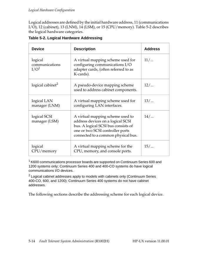
Logical Hardware Configuration
Logical addresses are defined by the initial hardware address, 11 (communications I/O), 12 (cabinet), 13 (LNM), 14 (LSM), or 15 (CPU/memory). Table 5-2 describes the logical hardware categories.
The following sections describe the addressing scheme for each logical device.
Table 5-2. Logical Hardware Addressing
Device Description Address
logical communications I/O1
1 K600 communications processor boards are supported on Continuum Series 600 and 1200 systems only; Continuum Series 400 and 400-CO systems do have logical communications I/O devices.
A virtual mapping scheme used for configuring communications I/O adapter cards, (often referred to as K-cards).
11/...
logical cabinet2
2 Logical cabinet addresses apply to models with cabinets only (Continuum Series 400-CO, 600, and 1200); Continuum Series 400 systems do not have cabinet addresses.
A pseudo-device mapping scheme used to address cabinet components.
12/...
logical LAN manager (LNM)
A virtual mapping scheme used for configuring LAN interfaces.
13/...
logical SCSI manager (LSM)
A virtual mapping scheme used to address devices on a logical SCSI bus. A logical SCSI bus consists of one or two SCSI controller ports connected to a common physical bus.
14/...
logical CPU/memory
A virtual mapping scheme for the CPU, memory, and console ports.
15/...
5-14 Fault Tolerant System Administration (R1002H) HP-UX version 11.00.01
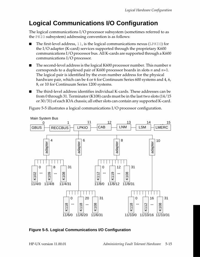
Logical Hardware Configuration
Logical Communications I/O Configuration The logical communications I/O processor subsystem (sometimes referred to as the PKIO subsystem) addressing convention is as follows:
■ The first-level address, 11, is the logical communications nexus (LPKIO) for the I/O adapter (K-card) services supported through the proprietary K600 communications I/O processor bus. All K-cards are supported through a K600 communications I/O processor.
■ The second-level address is the logical K600 processor number. This number n corresponds to a duplexed pair of K600 processor boards in slots n and n+1. The logical pair is identified by the even number address for the physical hardware pair, which can be 4 or 6 for Continuum Series 600 systems and 4, 6, 8, or 10 for Continuum Series 1200 systems.
■ The third-level address identifies individual K-cards. These addresses can be from 0 through 31. Terminator (K108) cards must be in the last two slots (14/15 or 30/31) of each IOA chassis; all other slots can contain any supported K-card.
Figure 5-5 illustrates a logical communications I/O processor configuration.
Figure 5-5. Logical Communications I/O Configuration
Main System Bus
adap
ter
K10
9
8
K10
2
0
K10
8
31
11/4/0 11/4/8 11/4/31
adap
ter 6
adap
ter 4
adap
ter 8 10
... ...
K11
8
20
K11
8
0
K10
8
31
11/6/0 11/6/20 11/6/31
... ...
K11
9
12
K11
2
0
K10
8
31
11/8/0 11/8/12 11/8/31
... ...
K11
2
16
K11
8
0
K10
8
31
11/10/0 11/10/16 11/10/31
... ...
GBUS
11 12 13 1415
RECCBUS0 1
LPKIO CAB LNM LSM LMERC15
HP-UX version 11.00.01 Administering Fault Tolerant Hardware 5-15

Logical Hardware Configuration
The following sample ftsmaint ls output shows the hardware paths for K-cards in a single IOA chassis supported by a K600 processor pair in logical slot 10 (physical slots 10/11).
Modelx H/W Path Description State Serial# PRev Status FCode Fct
===========================================================================
- 11 LPKIO Nexus CLAIM - - Online - 0- 11/10 LPKIO Adapter CLAIM - - Online - 0k11800 11/10/7 k118 adapter CLAIM - - Online - 0k10200 11/10/9 k102 adapter CLAIM - - Online - 0k10200 11/10/10 k102 adapter CLAIM - - Online - 0k11200 11/10/11 k112 adapter CLAIM - - Online - 0k11200 11/10/12 k112 adapter CLAIM - - Online - 0k11200 11/10/13 k112 adapter CLAIM - - Online - 0k10810 11/10/14 PK Terminator CLAIM - - Online - 0k10810 11/10/15 PK Terminator CLAIM - - Online - 0
Logical Cabinet Configuration Cabinet components—such as CDC or ACU units, fans, and power supplies—do not have true physical addresses. However, they are treated as pseudo devices and given logical addresses for reporting purposes. The logical cabinet addressing convention is as follows:
■ The first-level address, 12, is the logical cabinet nexus (CAB).
■ The second-level address identifies the specific cabinet number. For a Continuum Series 400-CO system, this is always 0. (Continuum Series 400 systems do not have cabinet addresses.) For a Continuum Series 600 or 1200 system, the main cabinet is 0, and expansion cabinets 1, 2, and so on.
■ The third-level address identifies individual cabinet components. (The number sequence is arbitrary.)
5-16 Fault Tolerant System Administration (R1002H) HP-UX version 11.00.01
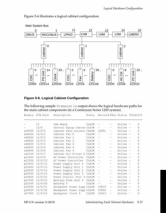
Logical Hardware Configuration
Figure 5-6 illustrates a logical cabinet configuration.
Figure 5-6. Logical Cabinet Configuration
The following sample ftsmaint ls output shows the logical hardware paths for the main cabinet components (in a Continuum Series 1200 system).Modelx H/W Path Description State Serial# PRev Status FCode Fct
===========================================================================
- 12 CAB Nexus CLAIM - - Online - 0- 12/0 Central Equip Cabine CLAIM - - Online - 0e59000 12/0/0 Cabinet Data Collect CLAIM 12891 - Online - 0e68400 12/0/1 Cabinet Fan 0 CLAIM - - Online - 0e68400 12/0/2 Cabinet Fan 1 CLAIM - - Online - 0e68400 12/0/3 Cabinet Fan 2 CLAIM - - Online - 0e68400 12/0/4 Cabinet Fan 3 CLAIM - - Online - 0e68400 12/0/5 Cabinet Fan 4 CLAIM - - Online - 0e68400 12/0/6 Cabinet Fan 5 CLAIM - - Online - 0ax6100 12/0/7 Cabinet Air Filter 0 CLAIM - - Online - 0p21400 12/0/8 AC Power Controller CLAIM - - Online - 0p21400 12/0/10 AC Power Controller CLAIM - - Online - 0p20600 12/0/12 Power Supply Unit 0 CLAIM - - Online - 0p20600 12/0/13 Power Supply Unit 1 CLAIM - - Online - 0p20600 12/0/14 Power Supply Unit 2 CLAIM - - Online - 0p20600 12/0/15 Power Supply Unit 3 CLAIM - - Online - 0p20400 12/0/22 Power Control Unit 0 CLAIM - - Online - 0p21000 12/0/23 Battery Fuse Unit 0 CLAIM - - Online - 0p22300 12/0/26 Battery 0 CLAIM - - Online - 0p20000 12/0/31 Backpanel Power Supp CLAIM 10819 - Online - 0p20000 12/0/32 Backpanel Power Supp CLAIM 10850 - Online - 0e57900 12/0/33 Backpanel Clock 0 CLAIM 10623 - Online - 0
PS
Uni
t 14
CD
C
0
Clo
ck
33...
12/0/0 12/0/14 12/0/33
... ...
cabi
net
cabi
net 1
cabi
net 0 2
Fan
6C
DC
0
Bat
tery
28...
12/1/0 12/1/6 12/1/26
... ...
AC
Ctlr
8
CD
C
0
PC
Uni
t 22...
12/2/0 12/2/8 12/2/22
... ...
GBUS
11 12 14
RECCBUS0 1
LPKIO CAB LSM LMERC1513
LNM
Main System Bus
HP-UX version 11.00.01 Administering Fault Tolerant Hardware 5-17
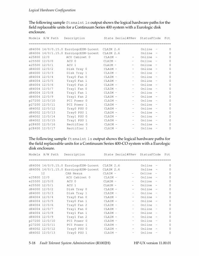
Logical Hardware Configuration
The following sample ftsmaint ls output shows the logical hardware paths for the field replaceable units for a Continuum Series 400 system with a Eurologic disk enclosure.Modelx H/W Path Description State Serial#PRev StatusFCode Fct
===========================================================================
d84006 14/0/0.15.0 EuroLogcESM-Lucent CLAIM 2.6 Online - 0d84006 14/0/1.15.0 EuroLogcESM-Lucent CLAIM 2.6 Online - 0e25800 12/0 ACU Cabinet 0 CLAIM - - Online - 0e25500 12/0/0 ACU 0 CLAIM - - Online - 0e25500 12/0/1 ACU 1 CLAIM - - Online - 0d84000 12/0/2 Disk Tray 0 CLAIM - - Online - 0d84000 12/0/3 Disk Tray 1 CLAIM - - Online - 0d84004 12/0/4 Tray0 Fan 0 CLAIM - - Online - 0d84004 12/0/5 Tray0 Fan 1 CLAIM - - Online - 0d84004 12/0/6 Tray0 Fan 2 CLAIM - - Online - 0d84004 12/0/7 Tray1 Fan 0 CLAIM - - Online - 0d84004 12/0/8 Tray1 Fan 1 CLAIM - - Online - 0d84004 12/0/9 Tray1 Fan 2 CLAIM - - Online - 0p27200 12/0/10 PCI Power 0 CLAIM - - Online - 0p27200 12/0/11 PCI Power 1 CLAIM - - Online - 0d84002 12/0/12 Tray0 PSU 0 CLAIM - - Online - 0d84002 12/0/13 Tray0 PSU 1 CLAIM - - Online - 0d84002 12/0/14 Tray1 PSU 0 CLAIM - - Online - 0d84002 12/0/15 Tray1 PSU 1 CLAIM - - Online - 0p28400 12/0/16 Rectifier 0 CLAIM - - Online - 0p28400 12/0/17 Rectifier 1 CLAIM - - Online - 0
The following sample ftsmaint ls output shows the logical hardware paths for the field replaceable units for a Continuum Series 400-CO system with a Eurologic disk enclosure.Modelx H/W Path Description State Serial#PRev StatusFCode Fct
===========================================================================
d84006 14/0/0.15.0 EuroLogcESM-Lucent CLAIM 2.6 Online - 0d84006 14/0/1.15.0 EuroLogcESM-Lucent CLAIM 2.6 Online - 0- 12 CAB Nexus CLAIM - - Online - 0e25800 12/0 ACU Cabinet 0 CLAIM - - Online - 0e25500 12/0/0 ACU 0 CLAIM - - Online - 0e25500 12/0/1 ACU 1 CLAIM - - Online - 0d84000 12/0/2 Disk Tray 0 CLAIM - - Online - 0d84000 12/0/3 Disk Tray 1 CLAIM - - Online - 0d84004 12/0/4 Tray0 Fan 0 CLAIM - - Online - 0d84004 12/0/5 Tray0 Fan 1 CLAIM - - Online - 0d84004 12/0/6 Tray0 Fan 2 CLAIM - - Online - 0d84004 12/0/7 Tray1 Fan 0 CLAIM - - Online - 0d84004 12/0/8 Tray1 Fan 1 CLAIM - - Online - 0d84004 12/0/9 Tray1 Fan 2 CLAIM - - Online - 0p27200 12/0/10 PCI Power 0 CLAIM - - Online - 0p27200 12/0/11 PCI Power 1 CLAIM - - Online - 0d84002 12/0/12 Tray0 PSU 0 CLAIM - - Online - 0d84002 12/0/13 Tray0 PSU 1 CLAIM - - Online - 0
5-18 Fault Tolerant System Administration (R1002H) HP-UX version 11.00.01
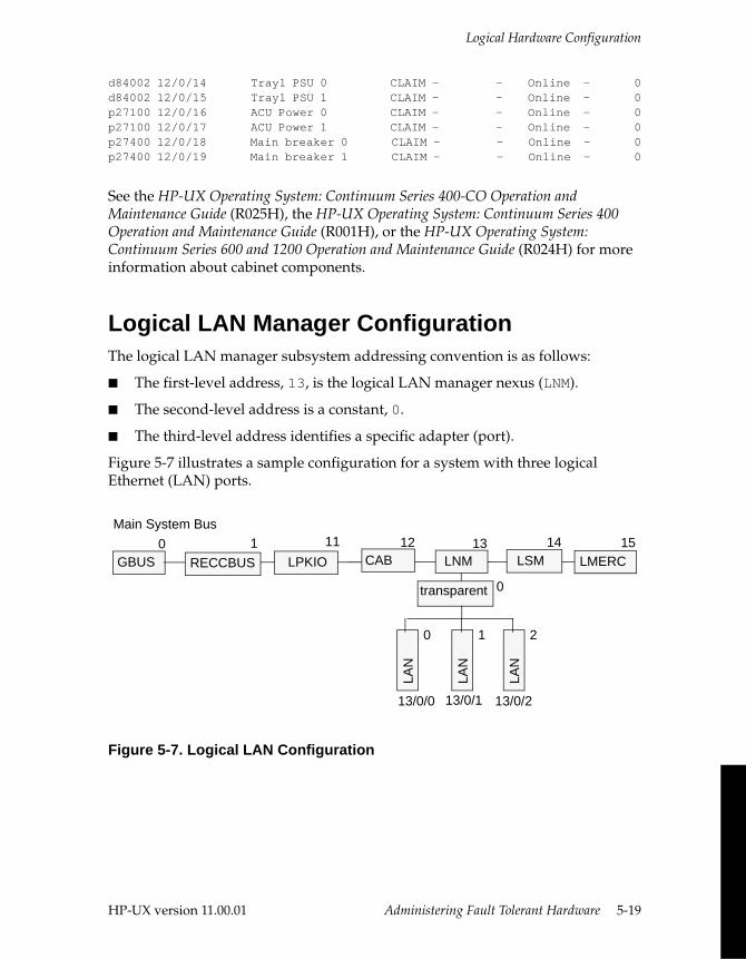
Logical Hardware Configuration
d84002 12/0/14 Tray1 PSU 0 CLAIM - - Online - 0d84002 12/0/15 Tray1 PSU 1 CLAIM - - Online - 0p27100 12/0/16 ACU Power 0 CLAIM - - Online - 0p27100 12/0/17 ACU Power 1 CLAIM - - Online - 0p27400 12/0/18 Main breaker 0 CLAIM - - Online - 0p27400 12/0/19 Main breaker 1 CLAIM - - Online - 0
See the HP-UX Operating System: Continuum Series 400-CO Operation and Maintenance Guide (R025H), the HP-UX Operating System: Continuum Series 400 Operation and Maintenance Guide (R001H), or the HP-UX Operating System: Continuum Series 600 and 1200 Operation and Maintenance Guide (R024H) for more information about cabinet components.
Logical LAN Manager ConfigurationThe logical LAN manager subsystem addressing convention is as follows:
■ The first-level address, 13, is the logical LAN manager nexus (LNM).
■ The second-level address is a constant, 0.
■ The third-level address identifies a specific adapter (port).
Figure 5-7 illustrates a sample configuration for a system with three logical Ethernet (LAN) ports.
Figure 5-7. Logical LAN Configuration
Main System Bus
transparent 0
LAN
0
LAN
1
LAN
2
13/0/0 13/0/1 13/0/2
GBUS
11 12 14
RECCBUS0 1
LPKIO CAB LSM LMERC1513
LNM
HP-UX version 11.00.01 Administering Fault Tolerant Hardware 5-19
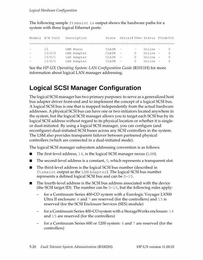
Logical Hardware Configuration
The following sample ftsmaint ls output shows the hardware paths for a system with three logical Ethernet ports:
Modelx H/W Path Description State Serial# PRev Status FCode Fct
===========================================================================
- 13 LNM Nexus CLAIM - - Online - 0- 13/0/0 LAN Adapter CLAIM - 0 Online - 0- 13/0/1 LAN Adapter CLAIM - 0 Online - 0- 13/0/2 LAN Adapter CLAIM - 0 Online - 0
See the HP-UX Operating System: LAN Configuration Guide (R1011H) for more information about logical LAN manager addressing.
Logical SCSI Manager ConfigurationThe logical SCSI manager has two primary purposes: to serve as a generalized host bus adapter driver front-end and to implement the concept of a logical SCSI bus. A logical SCSI bus is one that is mapped independently from the actual hardware addresses. A physical SCSI bus can have one or two initiators located anywhere in the system, but the logical SCSI manager allows you to target each SCSI bus by its logical SCSI address without regard to its physical location or whether it is single- or dual-initiated. By using a logical SCSI manager, you can configure (and reconfigure) dual-initiated SCSI buses across any SCSI controllers in the system. The LSM also provides transparent failover between partnered physical controllers (which are connected in a dual-initiated mode).
The logical SCSI manager subsystem addressing convention is as follows:
■ The first-level address, 14, is the logical SCSI manager nexus (LSM).
■ The second-level address is a constant, 0, which represents a transparent slot.
■ The third-level address is the logical SCSI bus number (described in ftsmaint output as the LSM Adapter). The logical SCSI bus number represents a defined logical SCSI bus and can be 0–15.
■ The fourth-level address is the SCSI bus address associated with the device (the SCSI target ID). The number can be 0–15, but the following rules apply:
– for a Continuum Series 400-CO system with a Eurologic Voyager LX500 Ultra II enclosure: 6 and 7 are reserved (for the controllers) and 15 is reserved (for the SCSI Enclosure Services (SES) module)
– for a Continuum Series 400-CO system with a StorageWorks enclosure: 14 and 15 are reserved (for the controllers)
– for a Continuum Series 600 or 1200 system: 6 and 7 are reserved (for the controllers)
5-20 Fault Tolerant System Administration (R1002H) HP-UX version 11.00.01
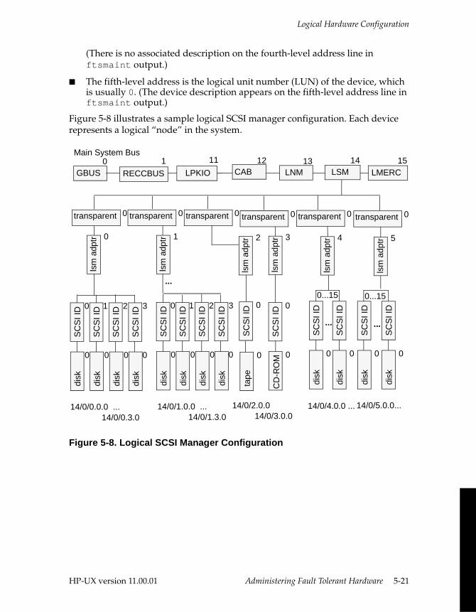
Logical Hardware Configuration
(There is no associated description on the fourth-level address line in ftsmaint output.)
■ The fifth-level address is the logical unit number (LUN) of the device, which is usually 0. (The device description appears on the fifth-level address line in ftsmaint output.)
Figure 5-8 illustrates a sample logical SCSI manager configuration. Each device represents a logical “node” in the system.
Figure 5-8. Logical SCSI Manager Configuration
SC
SI I
D
SC
SI I
D
disk
0di
sk0
0...15
transparent 0
lsm
adp
tr 0
14/0/0.0.0 ...
transparent 0
14/0/1.0.0 ...
transparent 0
SC
SI I
D 1
SC
SI I
D 2
SC
SI I
D 3
transparent 0
disk
0
disk
0
disk
0
tape
0
SC
SI I
D 0
disk
0
lsm
adp
tr 2
SC
SI I
D
SC
SI I
D
SC
SI I
D 0di
sk
0
disk
0
CD
-RO
M 0
lsm
adp
tr 1
lsm
adp
tr 3
...
14/0/0.3.0 14/0/1.3.014/0/2.0.0 14/0/4.0.0 ... 14/0/5.0.0...
14/0/3.0.0
Main System Bus
GBUS
11 12 14
RECCBUS0 1
LPKIO CAB LSM LMERC1513
LNM
transparent 0 transparent 0
lsm
adp
tr 4
...
lsm
adp
tr 5
SC
SI I
D 1
SC
SI I
D 2
SC
SI I
D 3
disk
0
disk
0
disk
0
SC
SI I
D 0
disk
0
SC
SI I
D 00...15
...
HP-UX version 11.00.01 Administering Fault Tolerant Hardware 5-21
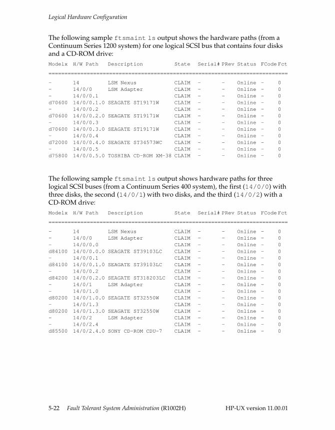
Logical Hardware Configuration
The following sample ftsmaint ls output shows the hardware paths (from a Continuum Series 1200 system) for one logical SCSI bus that contains four disks and a CD-ROM drive: Modelx H/W Path Description State Serial# PRev Status FCode Fct
===========================================================================
- 14 LSM Nexus CLAIM - - Online - 0- 14/0/0 LSM Adapter CLAIM - - Online - 0- 14/0/0.1 CLAIM - - Online - 0d70600 14/0/0.1.0 SEAGATE ST19171W CLAIM - - Online - 0- 14/0/0.2 CLAIM - - Online - 0d70600 14/0/0.2.0 SEAGATE ST19171W CLAIM - - Online - 0- 14/0/0.3 CLAIM - - Online - 0d70600 14/0/0.3.0 SEAGATE ST19171W CLAIM - - Online - 0- 14/0/0.4 CLAIM - - Online - 0d72000 14/0/0.4.0 SEAGATE ST34573WC CLAIM - - Online - 0- 14/0/0.5 CLAIM - - Online - 0d75800 14/0/0.5.0 TOSHIBA CD-ROM XM-38 CLAIM - - Online - 0
The following sample ftsmaint ls output shows hardware paths for three logical SCSI buses (from a Continuum Series 400 system), the first (14/0/0) with three disks, the second (14/0/1) with two disks, and the third (14/0/2) with a CD-ROM drive: Modelx H/W Path Description State Serial# PRev Status FCode Fct
===========================================================================
- 14 LSM Nexus CLAIM - - Online - 0- 14/0/0 LSM Adapter CLAIM - - Online - 0- 14/0/0.0 CLAIM - - Online - 0d84100 14/0/0.0.0 SEAGATE ST39103LC CLAIM - - Online - 0- 14/0/0.1 CLAIM - - Online - 0d84100 14/0/0.1.0 SEAGATE ST39103LC CLAIM - - Online - 0- 14/0/0.2 CLAIM - - Online - 0d84200 14/0/0.2.0 SEAGATE ST318203LC CLAIM - - Online - 0- 14/0/1 LSM Adapter CLAIM - - Online - 0- 14/0/1.0 CLAIM - - Online - 0d80200 14/0/1.0.0 SEAGATE ST32550W CLAIM - - Online - 0- 14/0/1.3 CLAIM - - Online - 0d80200 14/0/1.3.0 SEAGATE ST32550W CLAIM - - Online - 0- 14/0/2 LSM Adapter CLAIM - - Online - 0- 14/0/2.4 CLAIM - - Online - 0d85500 14/0/2.4.0 SONY CD-ROM CDU-7 CLAIM - - Online - 0
5-22 Fault Tolerant System Administration (R1002H) HP-UX version 11.00.01
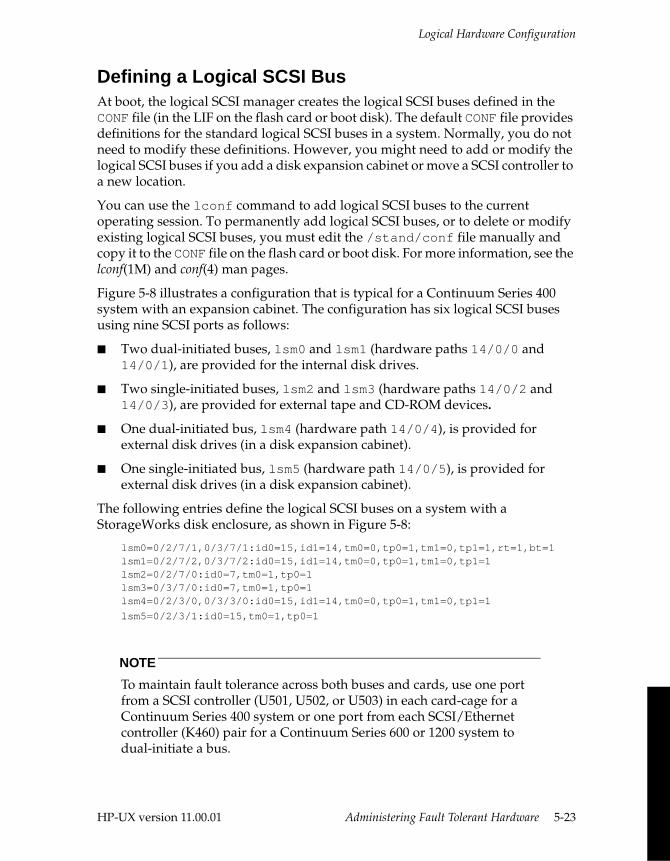
Logical Hardware Configuration
Defining a Logical SCSI BusAt boot, the logical SCSI manager creates the logical SCSI buses defined in the CONF file (in the LIF on the flash card or boot disk). The default CONF file provides definitions for the standard logical SCSI buses in a system. Normally, you do not need to modify these definitions. However, you might need to add or modify the logical SCSI buses if you add a disk expansion cabinet or move a SCSI controller to a new location.
You can use the lconf command to add logical SCSI buses to the current operating session. To permanently add logical SCSI buses, or to delete or modify existing logical SCSI buses, you must edit the /stand/conf file manually and copy it to the CONF file on the flash card or boot disk. For more information, see the lconf(1M) and conf(4) man pages.
Figure 5-8 illustrates a configuration that is typical for a Continuum Series 400 system with an expansion cabinet. The configuration has six logical SCSI buses using nine SCSI ports as follows:
■ Two dual-initiated buses, lsm0 and lsm1 (hardware paths 14/0/0 and 14/0/1), are provided for the internal disk drives.
■ Two single-initiated buses, lsm2 and lsm3 (hardware paths 14/0/2 and 14/0/3), are provided for external tape and CD-ROM devices.
■ One dual-initiated bus, lsm4 (hardware path 14/0/4), is provided for external disk drives (in a disk expansion cabinet).
■ One single-initiated bus, lsm5 (hardware path 14/0/5), is provided for external disk drives (in a disk expansion cabinet).
The following entries define the logical SCSI buses on a system with a StorageWorks disk enclosure, as shown in Figure 5-8:
lsm0=0/2/7/1,0/3/7/1:id0=15,id1=14,tm0=0,tp0=1,tm1=0,tp1=1,rt=1,bt=1lsm1=0/2/7/2,0/3/7/2:id0=15,id1=14,tm0=0,tp0=1,tm1=0,tp1=1lsm2=0/2/7/0:id0=7,tm0=1,tp0=1 lsm3=0/3/7/0:id0=7,tm0=1,tp0=1lsm4=0/2/3/0,0/3/3/0:id0=15,id1=14,tm0=0,tp0=1,tm1=0,tp1=1
lsm5=0/2/3/1:id0=15,tm0=1,tp0=1
NOTE
To maintain fault tolerance across both buses and cards, use one port from a SCSI controller (U501, U502, or U503) in each card-cage for a Continuum Series 400 system or one port from each SCSI/Ethernet controller (K460) pair for a Continuum Series 600 or 1200 system to dual-initiate a bus.
HP-UX version 11.00.01 Administering Fault Tolerant Hardware 5-23
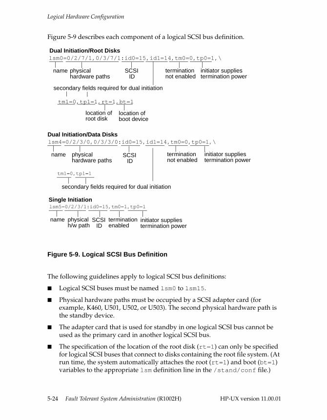
Logical Hardware Configuration
Figure 5-9 describes each component of a logical SCSI bus definition.
Figure 5-9. Logical SCSI Bus Definition
The following guidelines apply to logical SCSI bus definitions:
■ Logical SCSI buses must be named lsm0 to lsm15.
■ Physical hardware paths must be occupied by a SCSI adapter card (for example, K460, U501, U502, or U503). The second physical hardware path is the standby device.
■ The adapter card that is used for standby in one logical SCSI bus cannot be used as the primary card in another logical SCSI bus.
■ The specification of the location of the root disk (rt=1) can only be specified for logical SCSI buses that connect to disks containing the root file system. (At run time, the system automatically attaches the root (rt=1) and boot (bt=1) variables to the appropriate lsm definition line in the /stand/conf file.)
lsm0=0/2/7/1,0/3/7/1:id0=15,id1=14,tm0=0,tp0=1,\
tm1=0,tp1=1,rt=1,bt=1
name physicalhardware paths
SCSIID
terminationnot enabled
initiator suppliestermination power
lsm5=0/2/3/1:id0=15,tm0=1,tp0=1
name physicalh/w path
terminationenabled
initiator suppliestermination power
Dual Initiation/Root Disks
Single Initiation
SCSIID
lsm4=0/2/3/0,0/3/3/0:id0=15,id1=14,tm0=0,tp0=1,\
tm1=0,tp1=1
name physicalhardware paths
SCSIID
terminationnot enabled
initiator suppliestermination power
secondary fields required for dual initiation
Dual Initiation/Data Disks
location ofroot disk
location ofboot device
secondary fields required for dual initiation
5-24 Fault Tolerant System Administration (R1002H) HP-UX version 11.00.01
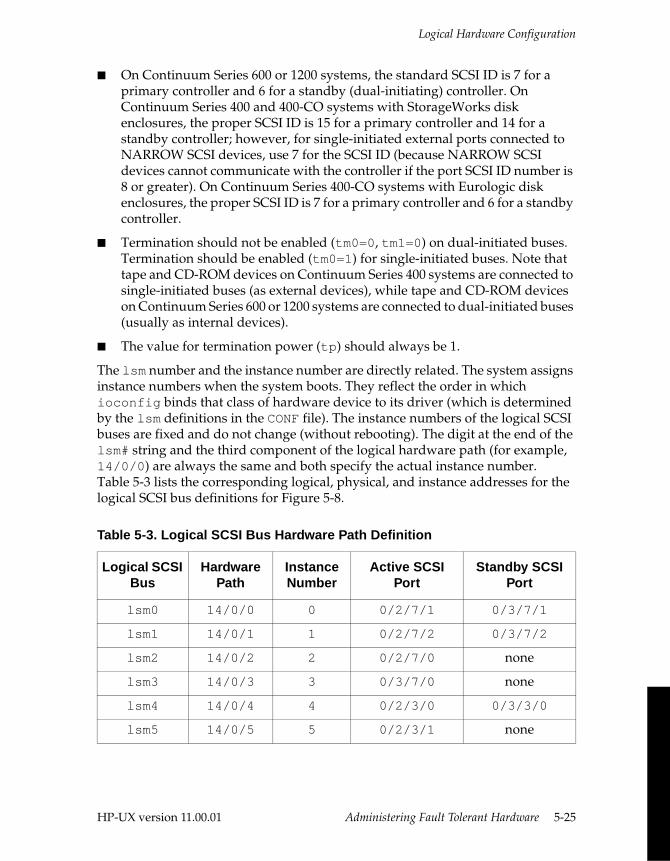
Logical Hardware Configuration
■ On Continuum Series 600 or 1200 systems, the standard SCSI ID is 7 for a primary controller and 6 for a standby (dual-initiating) controller. On Continuum Series 400 and 400-CO systems with StorageWorks disk enclosures, the proper SCSI ID is 15 for a primary controller and 14 for a standby controller; however, for single-initiated external ports connected to NARROW SCSI devices, use 7 for the SCSI ID (because NARROW SCSI devices cannot communicate with the controller if the port SCSI ID number is 8 or greater). On Continuum Series 400-CO systems with Eurologic disk enclosures, the proper SCSI ID is 7 for a primary controller and 6 for a standby controller.
■ Termination should not be enabled (tm0=0, tm1=0) on dual-initiated buses. Termination should be enabled (tm0=1) for single-initiated buses. Note that tape and CD-ROM devices on Continuum Series 400 systems are connected to single-initiated buses (as external devices), while tape and CD-ROM devices on Continuum Series 600 or 1200 systems are connected to dual-initiated buses (usually as internal devices).
■ The value for termination power (tp) should always be 1.
The lsm number and the instance number are directly related. The system assigns instance numbers when the system boots. They reflect the order in which ioconfig binds that class of hardware device to its driver (which is determined by the lsm definitions in the CONF file). The instance numbers of the logical SCSI buses are fixed and do not change (without rebooting). The digit at the end of the lsm# string and the third component of the logical hardware path (for example, 14/0/0) are always the same and both specify the actual instance number. Table 5-3 lists the corresponding logical, physical, and instance addresses for the logical SCSI bus definitions for Figure 5-8.
Table 5-3. Logical SCSI Bus Hardware Path Definition
Logical SCSI Bus
Hardware Path
Instance Number
Active SCSI Port
Standby SCSI Port
lsm0 14/0/0 0 0/2/7/1 0/3/7/1
lsm1 14/0/1 1 0/2/7/2 0/3/7/2
lsm2 14/0/2 2 0/2/7/0 none
lsm3 14/0/3 3 0/3/7/0 none
lsm4 14/0/4 4 0/2/3/0 0/3/3/0
lsm5 14/0/5 5 0/2/3/1 none
HP-UX version 11.00.01 Administering Fault Tolerant Hardware 5-25
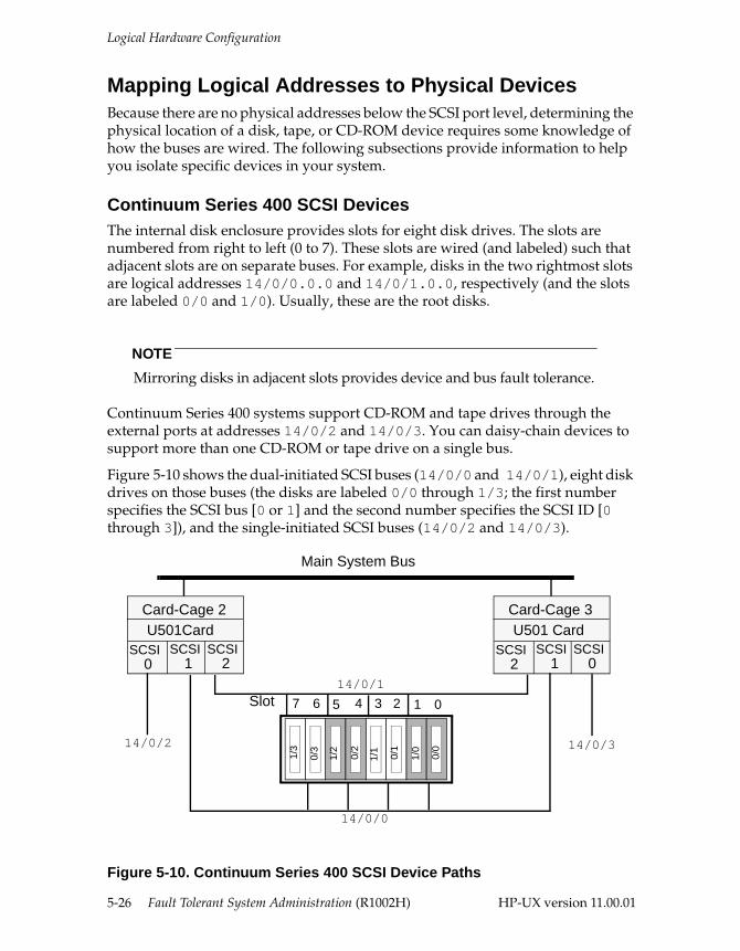
Logical Hardware Configuration
Mapping Logical Addresses to Physical Devices Because there are no physical addresses below the SCSI port level, determining the physical location of a disk, tape, or CD-ROM device requires some knowledge of how the buses are wired. The following subsections provide information to help you isolate specific devices in your system.
Continuum Series 400 SCSI DevicesThe internal disk enclosure provides slots for eight disk drives. The slots are numbered from right to left (0 to 7). These slots are wired (and labeled) such that adjacent slots are on separate buses. For example, disks in the two rightmost slots are logical addresses 14/0/0.0.0 and 14/0/1.0.0, respectively (and the slots are labeled 0/0 and 1/0). Usually, these are the root disks.
NOTE
Mirroring disks in adjacent slots provides device and bus fault tolerance.
Continuum Series 400 systems support CD-ROM and tape drives through the external ports at addresses 14/0/2 and 14/0/3. You can daisy-chain devices to support more than one CD-ROM or tape drive on a single bus.
Figure 5-10 shows the dual-initiated SCSI buses (14/0/0 and 14/0/1), eight disk drives on those buses (the disks are labeled 0/0 through 1/3; the first number specifies the SCSI bus [0 or 1] and the second number specifies the SCSI ID [0 through 3]), and the single-initiated SCSI buses (14/0/2 and 14/0/3).
Figure 5-10. Continuum Series 400 SCSI Device Paths
Main System Bus
Card-Cage 2
14/0/0
14/0/1
U501Card SCSI
0SCSI
1SCSI
2
Card-Cage 3U501 Card
SCSI2
SCSI1
SCSI0
14/0/2 14/0/3
1/3
1/2
0/2
1/1
0/1
1/0
0/0
0/3
Slot 7 6 5 4 3 2 1 0
5-26 Fault Tolerant System Administration (R1002H) HP-UX version 11.00.01
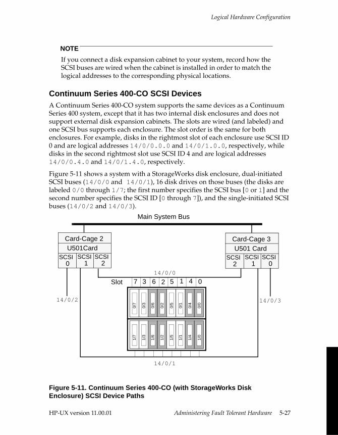
Logical Hardware Configuration
NOTE
If you connect a disk expansion cabinet to your system, record how the SCSI buses are wired when the cabinet is installed in order to match the logical addresses to the corresponding physical locations.
Continuum Series 400-CO SCSI DevicesA Continuum Series 400-CO system supports the same devices as a Continuum Series 400 system, except that it has two internal disk enclosures and does not support external disk expansion cabinets. The slots are wired (and labeled) and one SCSI bus supports each enclosure. The slot order is the same for both enclosures. For example, disks in the rightmost slot of each enclosure use SCSI ID 0 and are logical addresses 14/0/0.0.0 and 14/0/1.0.0, respectively, while disks in the second rightmost slot use SCSI ID 4 and are logical addresses 14/0/0.4.0 and 14/0/1.4.0, respectively.
Figure 5-11 shows a system with a StorageWorks disk enclosure, dual-initiated SCSI buses (14/0/0 and 14/0/1), 16 disk drives on those buses (the disks are labeled 0/0 through 1/7; the first number specifies the SCSI bus [0 or 1] and the second number specifies the SCSI ID [0 through 7]), and the single-initiated SCSI buses (14/0/2 and 14/0/3).
Figure 5-11. Continuum Series 400-CO (with StorageWorks Disk Enclosure) SCSI Device Paths
Main System Bus
Card-Cage 2
14/0/0
U501Card SCSI
0SCSI
1SCSI
2
Card-Cage 3U501 Card
SCSI2
SCSI1
SCSI0
14/0/2 14/0/3
Slot 7 3 6 2 5 1 4 0
0/7
0/3
0/6
0/2
0/5
0/1
0/4
0/0
1/7
1/3
1/6
1/2
1/5
1/1
1/4
1/0
14/0/1
HP-UX version 11.00.01 Administering Fault Tolerant Hardware 5-27
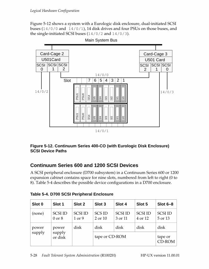
Logical Hardware Configuration
Figure 5-12 shows a system with a Eurologic disk enclosure, dual-initiated SCSI buses (14/0/0 and 14/0/1), 14 disk drives and four PSUs on those buses, and the single-initiated SCSI buses (14/0/2 and 14/0/3).
Figure 5-12. Continuum Series 400-CO (with Eurologic Disk Enclosure) SCSI Device Paths
Continuum Series 600 and 1200 SCSI Devices A SCSI peripheral enclosure (D700 subsystem) in a Continuum Series 600 or 1200 expansion cabinet contains space for nine slots, numbered from left to right (0 to 8). Table 5-4 describes the possible device configurations in a D700 enclosure.
Table 5-4. D700 SCSI Peripheral Enclosure
Slot 0 Slot 1 Slot 2 Slot 3 Slot 4 Slot 5 Slot 6–8
(none) SCSI ID 0 or 8
SCSI ID 1 or 9
SCS ID2 or 10
SCSI ID3 or 11
SCSI ID4 or 12
SCSI ID5 or 13
power supply
power supply or disk
disk disk disk disk disk
tape or CD-ROM tape or CD-ROM
Main System Bus
Card-Cage 2
14/0/0
U501Card SCSI
0SCSI
1SCSI
2
Card-Cage 3U501 Card
SCSI2
SCSI1
SCSI0
14/0/2 14/0/3
Slot 7 6 5 4 3 2 1P
SU
0
0/14
0/5
0/4
0/3
0/2
0/1
0/0
14/0/1
PS
U1
PS
U0
0/14
0/5
0/4
0/3
0/2
0/1
0/0
PS
U1
5-28 Fault Tolerant System Administration (R1002H) HP-UX version 11.00.01
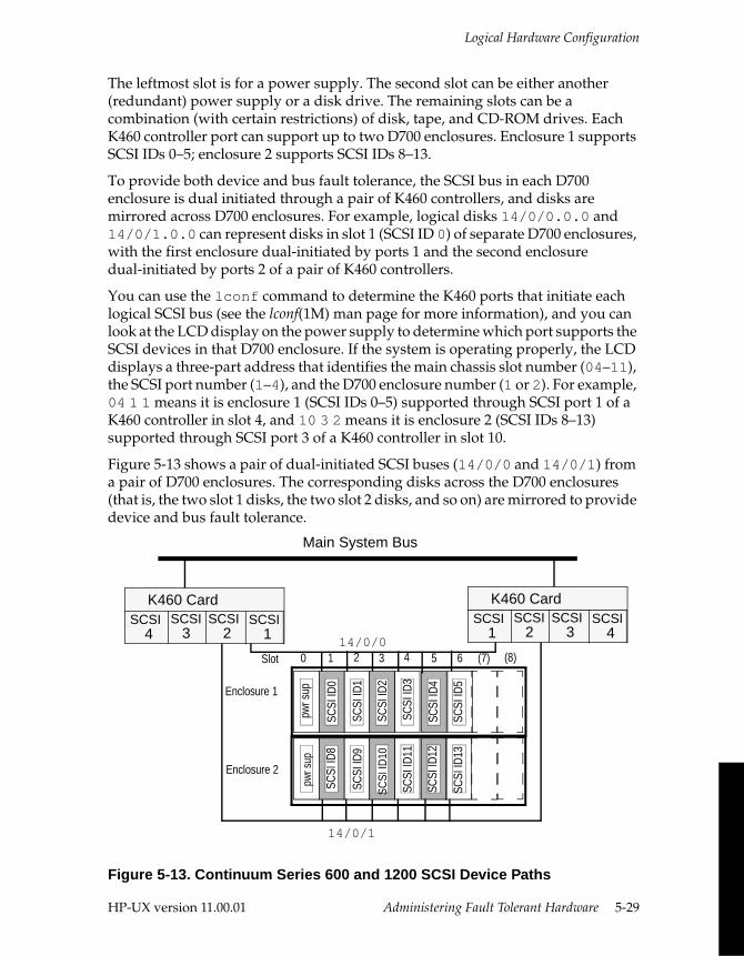
Logical Hardware Configuration
The leftmost slot is for a power supply. The second slot can be either another (redundant) power supply or a disk drive. The remaining slots can be a combination (with certain restrictions) of disk, tape, and CD-ROM drives. Each K460 controller port can support up to two D700 enclosures. Enclosure 1 supports SCSI IDs 0–5; enclosure 2 supports SCSI IDs 8–13.
To provide both device and bus fault tolerance, the SCSI bus in each D700 enclosure is dual initiated through a pair of K460 controllers, and disks are mirrored across D700 enclosures. For example, logical disks 14/0/0.0.0 and 14/0/1.0.0 can represent disks in slot 1 (SCSI ID 0) of separate D700 enclosures, with the first enclosure dual-initiated by ports 1 and the second enclosure dual-initiated by ports 2 of a pair of K460 controllers.
You can use the lconf command to determine the K460 ports that initiate each logical SCSI bus (see the lconf(1M) man page for more information), and you can look at the LCD display on the power supply to determine which port supports the SCSI devices in that D700 enclosure. If the system is operating properly, the LCD displays a three-part address that identifies the main chassis slot number (04–11), the SCSI port number (1–4), and the D700 enclosure number (1 or 2). For example, 04 1 1 means it is enclosure 1 (SCSI IDs 0–5) supported through SCSI port 1 of a K460 controller in slot 4, and 10 3 2 means it is enclosure 2 (SCSI IDs 8–13) supported through SCSI port 3 of a K460 controller in slot 10.
Figure 5-13 shows a pair of dual-initiated SCSI buses (14/0/0 and 14/0/1) from a pair of D700 enclosures. The corresponding disks across the D700 enclosures (that is, the two slot 1 disks, the two slot 2 disks, and so on) are mirrored to provide device and bus fault tolerance.
Figure 5-13. Continuum Series 600 and 1200 SCSI Device Paths
SCSI
ID12
SCSI
ID13
SCSI
ID4
SCSI
ID5
14/0/1
Main System Bus
14/0/0
K460 Card SCSI
4SCSI
3SCSI
2
pwr s
uppw
r sup
SCSI
ID8
SCSI
ID9
SCSI
ID11
SCSI
ID0
SCSI
ID1
SCSI
ID2
SCSI
ID3
SCSI1
K460 Card SCSI
1SCSI
2SCSI
3SCSI
4
Enclosure 1
Enclosure 2
Slot 0 1 2 3 4 5 6 (7) (8)
SCSI
ID10
HP-UX version 11.00.01 Administering Fault Tolerant Hardware 5-29
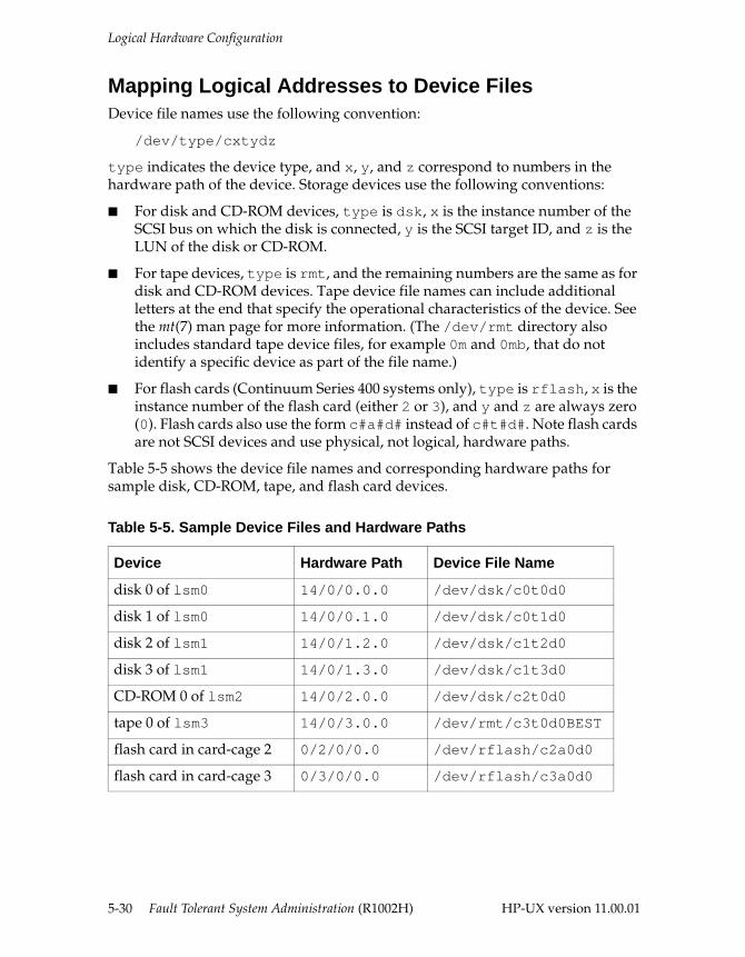
Logical Hardware Configuration
Mapping Logical Addresses to Device FilesDevice file names use the following convention:
/dev/type/cxtydz
type indicates the device type, and x, y, and z correspond to numbers in the hardware path of the device. Storage devices use the following conventions:
■ For disk and CD-ROM devices, type is dsk, x is the instance number of the SCSI bus on which the disk is connected, y is the SCSI target ID, and z is the LUN of the disk or CD-ROM.
■ For tape devices, type is rmt, and the remaining numbers are the same as for disk and CD-ROM devices. Tape device file names can include additional letters at the end that specify the operational characteristics of the device. See the mt(7) man page for more information. (The /dev/rmt directory also includes standard tape device files, for example 0m and 0mb, that do not identify a specific device as part of the file name.)
■ For flash cards (Continuum Series 400 systems only), type is rflash, x is the instance number of the flash card (either 2 or 3), and y and z are always zero (0). Flash cards also use the form c#a#d# instead of c#t#d#. Note flash cards are not SCSI devices and use physical, not logical, hardware paths.
Table 5-5 shows the device file names and corresponding hardware paths for sample disk, CD-ROM, tape, and flash card devices.
Table 5-5. Sample Device Files and Hardware Paths
Device Hardware Path Device File Name
disk 0 of lsm0 14/0/0.0.0 /dev/dsk/c0t0d0
disk 1 of lsm0 14/0/0.1.0 /dev/dsk/c0t1d0
disk 2 of lsm1 14/0/1.2.0 /dev/dsk/c1t2d0
disk 3 of lsm1 14/0/1.3.0 /dev/dsk/c1t3d0
CD-ROM 0 of lsm2 14/0/2.0.0 /dev/dsk/c2t0d0
tape 0 of lsm3 14/0/3.0.0 /dev/rmt/c3t0d0BEST
flash card in card-cage 2 0/2/0/0.0 /dev/rflash/c2a0d0
flash card in card-cage 3 0/3/0/0.0 /dev/rflash/c3a0d0
5-30 Fault Tolerant System Administration (R1002H) HP-UX version 11.00.01
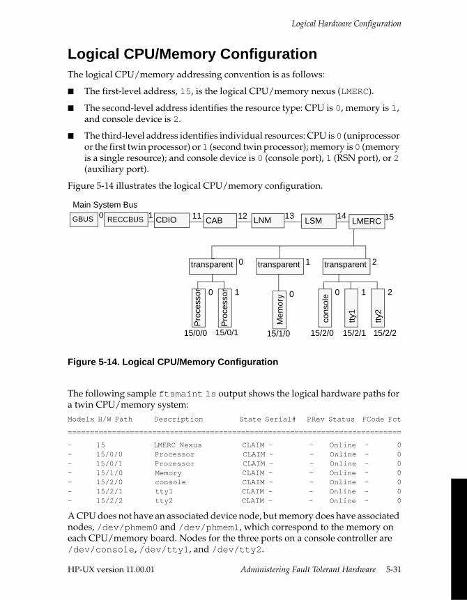
Logical Hardware Configuration
Logical CPU/Memory ConfigurationThe logical CPU/memory addressing convention is as follows:
■ The first-level address, 15, is the logical CPU/memory nexus (LMERC).
■ The second-level address identifies the resource type: CPU is 0, memory is 1, and console device is 2.
■ The third-level address identifies individual resources: CPU is 0 (uniprocessor or the first twin processor) or 1 (second twin processor); memory is 0 (memory is a single resource); and console device is 0 (console port), 1 (RSN port), or 2 (auxiliary port).
Figure 5-14 illustrates the logical CPU/memory configuration.
Figure 5-14. Logical CPU/Memory Configuration
The following sample ftsmaint ls output shows the logical hardware paths for a twin CPU/memory system: Modelx H/W Path Description State Serial# PRev Status FCode Fct
===========================================================================
- 15 LMERC Nexus CLAIM - - Online - 0- 15/0/0 Processor CLAIM - - Online - 0- 15/0/1 Processor CLAIM - - Online - 0- 15/1/0 Memory CLAIM - - Online - 0- 15/2/0 console CLAIM - - Online - 0- 15/2/1 tty1 CLAIM - - Online - 0- 15/2/2 tty2 CLAIM - - Online - 0
A CPU does not have an associated device node, but memory does have associated nodes, /dev/phmem0 and /dev/phmem1, which correspond to the memory on each CPU/memory board. Nodes for the three ports on a console controller are /dev/console, /dev/tty1, and /dev/tty2.
Main System Bus
GBUS 11 12 13 14 15RECCBUS0 1 CDIO CAB LNM LSM LMERC
transparent 0
Pro
cess
or 0
Pro
cess
or 1
15/0/0 15/0/1
transparent 1
Mem
ory 0
15/1/0
transparent 2
cons
ole 0
tty1
1
tty2
2
15/2/0 15/2/1 15/2/2
HP-UX version 11.00.01 Administering Fault Tolerant Hardware 5-31
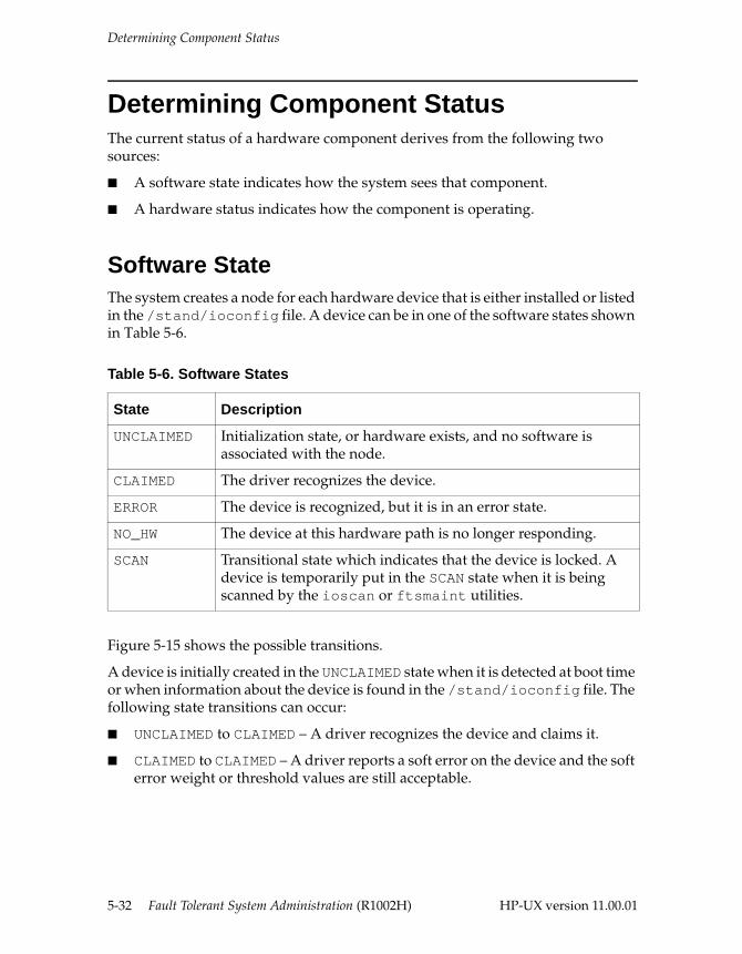
Determining Component Status
Determining Component StatusThe current status of a hardware component derives from the following two sources:
■ A software state indicates how the system sees that component.
■ A hardware status indicates how the component is operating.
Software State The system creates a node for each hardware device that is either installed or listed in the /stand/ioconfig file. A device can be in one of the software states shown in Table 5-6.
Figure 5-15 shows the possible transitions.
A device is initially created in the UNCLAIMED state when it is detected at boot time or when information about the device is found in the /stand/ioconfig file. The following state transitions can occur:
■ UNCLAIMED to CLAIMED – A driver recognizes the device and claims it.
■ CLAIMED to CLAIMED – A driver reports a soft error on the device and the soft error weight or threshold values are still acceptable.
Table 5-6. Software States
State Description
UNCLAIMED Initialization state, or hardware exists, and no software is associated with the node.
CLAIMED The driver recognizes the device.
ERROR The device is recognized, but it is in an error state.
NO_HW The device at this hardware path is no longer responding.
SCAN Transitional state which indicates that the device is locked. A device is temporarily put in the SCAN state when it is being scanned by the ioscan or ftsmaint utilities.
5-32 Fault Tolerant System Administration (R1002H) HP-UX version 11.00.01
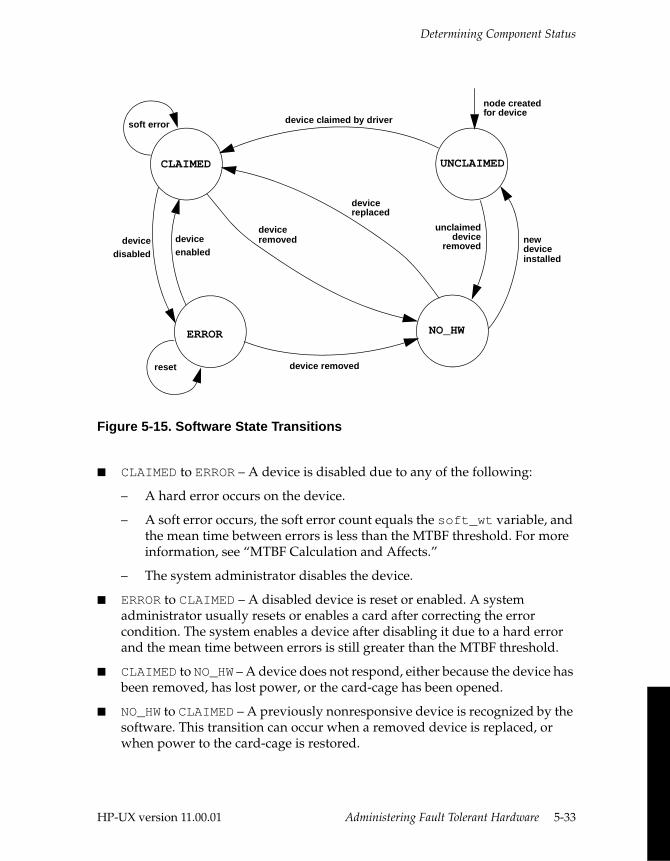
Determining Component Status
Figure 5-15. Software State Transitions
■ CLAIMED to ERROR – A device is disabled due to any of the following:
– A hard error occurs on the device.
– A soft error occurs, the soft error count equals the soft_wt variable, and the mean time between errors is less than the MTBF threshold. For more information, see “MTBF Calculation and Affects.”
– The system administrator disables the device.
■ ERROR to CLAIMED – A disabled device is reset or enabled. A system administrator usually resets or enables a card after correcting the error condition. The system enables a device after disabling it due to a hard error and the mean time between errors is still greater than the MTBF threshold.
■ CLAIMED to NO_HW – A device does not respond, either because the device has been removed, has lost power, or the card-cage has been opened.
■ NO_HW to CLAIMED – A previously nonresponsive device is recognized by the software. This transition can occur when a removed device is replaced, or when power to the card-cage is restored.
soft error
CLAIMED
ERROR
UNCLAIMED
NO_HW
device claimed by driver
device removed
new unclaimed
deviceremoved
installed
deviceremoved
device replaced
reset
node createdfor device
deviceenabled
devicedisabled device
HP-UX version 11.00.01 Administering Fault Tolerant Hardware 5-33
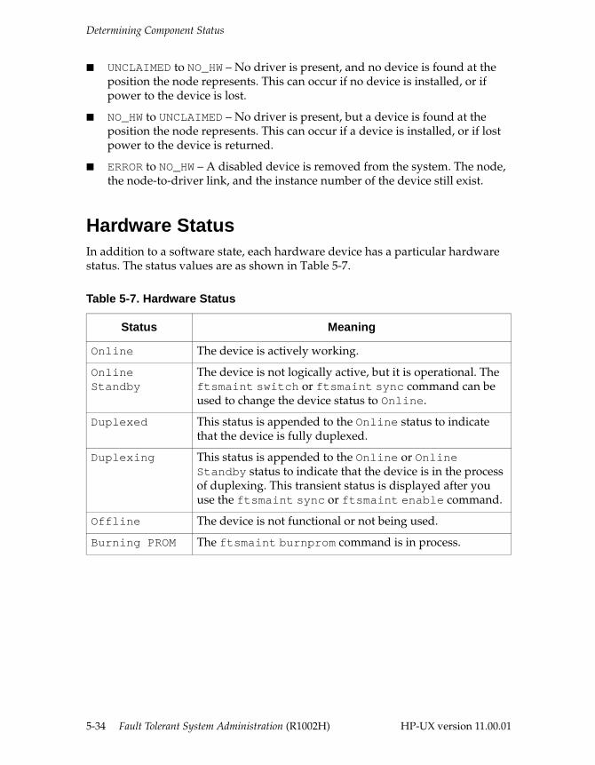
Determining Component Status
■ UNCLAIMED to NO_HW – No driver is present, and no device is found at the position the node represents. This can occur if no device is installed, or if power to the device is lost.
■ NO_HW to UNCLAIMED – No driver is present, but a device is found at the position the node represents. This can occur if a device is installed, or if lost power to the device is returned.
■ ERROR to NO_HW – A disabled device is removed from the system. The node, the node-to-driver link, and the instance number of the device still exist.
Hardware Status In addition to a software state, each hardware device has a particular hardware status. The status values are as shown in Table 5-7.
Table 5-7. Hardware Status
Status Meaning
Online The device is actively working.
Online Standby
The device is not logically active, but it is operational. The ftsmaint switch or ftsmaint sync command can be used to change the device status to Online.
Duplexed This status is appended to the Online status to indicate that the device is fully duplexed.
Duplexing This status is appended to the Online or Online Standby status to indicate that the device is in the process of duplexing. This transient status is displayed after you use the ftsmaint sync or ftsmaint enable command.
Offline The device is not functional or not being used.
Burning PROM The ftsmaint burnprom command is in process.
5-34 Fault Tolerant System Administration (R1002H) HP-UX version 11.00.01
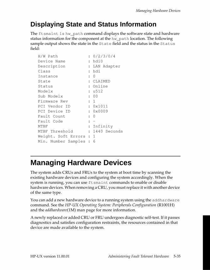
Managing Hardware Devices
Displaying State and Status InformationThe ftsmaint ls hw_path command displays the software state and hardware status information for the component at the hw_path location. The following sample output shows the state in the State field and the status in the Status field:
H/W Path : 0/2/3/0/4Device Name : hdi0Description : LAN AdapterClass : hdiInstance : 0State : CLAIMEDStatus : OnlineModelx : u512Sub Modelx : 00Firmware Rev : 1PCI Vendor ID : 0x1011PCI Device ID : 0x0009Fault Count : 0Fault Code : - MTBF : InfinityMTBF Threshold : 1440 SecondsWeight. Soft Errors : 1Min. Number Samples : 6
Managing Hardware DevicesThe system adds CRUs and FRUs to the system at boot time by scanning the existing hardware devices and configuring the system accordingly. When the system is running, you can use ftsmaint commands to enable or disable hardware devices. When removing a CRU, you must replace it with another device of the same type.
You can add a new hardware device to a running system using the addhardware command. See the HP-UX Operating System: Peripherals Configuration (R1001H) and the addhardware(1M) man page for more information.
A newly replaced or added CRU or FRU undergoes diagnostic self-test. If it passes diagnostics and satisfies configuration restraints, the resources contained in that device are made available to the system.
HP-UX version 11.00.01 Administering Fault Tolerant Hardware 5-35
Managing Hardware Devices
See the HP-UX Operating System: Continuum Series 400 Operation and Maintenance Guide (R001H), the HP-UX Operating System: Continuum Series 400-CO Operation and Maintenance Guide (R025H), or the HP-UX Operating System: Continuum Series 600 and 1200 Operation and Maintenance Guide (R024H) for step-by-step instructions for replacing specific CRUs.
Checking Status LightsMost system components contain one or more lights that identify the operating status of that component (see “Status Lights” later in this chapter). You can test whether the status lights for the following components are operating properly:
■ Continuum Series 400-CO systems: suitcases, PCI slots, and cabinets and ACU units. (This feature is not supported on Continuum Series 400 systems.)
■ Continuum Series 600 and 1200 systems: cabinets and CPU/memory boards
To verify that the status lights for a particular component are operating properly, do the following:
1. Determine the hardware path for the component. For example, to see the hardware paths for all components, enter
ftsmaint ls
Hardware paths are in the H/W Path column.
2. Set the component into blink mode. To do this, enter
ftsmaint blinkstart hw_path
hw_path is the hardware path determined in step 1. This causes the component’s status lights to begin blinking, which verifies that the status lights are operational. For example, the following commands on a Continuum Series 400 system blink the status lights in suitcase 0, slot 0 in card-cage 3, and all occupied slots in card-cage 3, respectively.
ftsmaint blinkstart 0/0 ftsmaint blinkstart 0/3/0 ftsmaint blinkstart 0/3
3. Reset the status lights into normal mode. To do this, enter
ftsmaint blinkstop hw_path
4. Repeat steps 2 and 3, as necessary, for all components in question.
5-36 Fault Tolerant System Administration (R1002H) HP-UX version 11.00.01
Managing Hardware Devices
Error Detection and Handling Hardware errors are detected by the hardware itself and then evaluated by the maintenance and diagnostics software. After a hardware error, the affected device is directed to test itself. If it fails the test, the error is called hard and the device is taken out of service. If it passes the test, the error is called soft.
The system takes the device out of service and places the device in the ERROR state under the following circumstances:
■ The error is a hard error.
■ The error is a soft error, the soft error count equals the soft_wt variable, and the mean time between errors is less than the MTBF threshold set for the device.
If the error is a hard error, and the mean time between failures is greater than the predefined MTBF threshold, the system attempts to enable the device and return it to the CLAIMED state.
For more information about soft error weights, MTBF thresholds, and how MTBF is calculated, see “Managing MTBF Statistics.”
Disabling a Hardware DeviceThe system administrator can manually take a device out of service and place it in the ERROR state. To do this, enter
ftsmaint disable hw_path
hw_path is the hardware path of the device you want to disable.
CAUTION
Disabling a device might cause unexpected problems. Contact the CAC before disabling a device.
HP-UX version 11.00.01 Administering Fault Tolerant Hardware 5-37
Managing Hardware Devices
The system denies a disable request if any resource in the device is critical to the system (for example, a simplex CPU/memory board) and returns an error message when a critical resource is involved. Otherwise, the red status light on that device appears, and you can then safely remove it from the system.
NOTE
On a Continuum Series 400 system, ftsmaint disable disables the PCI bus (not just the card) in that card-cage and leaves it broken to avoid causing the other bay to break when the first one is opened.
Enabling a Hardware DeviceThe system administrator can manually attempt to bring the device back into service and change the state from ERROR to CLAIMED. To do this, enter
ftsmaint enable hw_path
hw_path is the hardware path of the device you want to enable.
Correcting the Error StateIf a device is in the ERROR state, try to reset the device before enabling it as follows:
1. Perform a hardware reset. To do this, enter
ftsmaint reset hw_path
hw_path is the hardware path of the device.
2. Enable the device. To do this, enter
ftsmaint enable hw_path
hw_path is the hardware path of the device.
If the device does not change to CLAIMED, call the CAC for further assistance. For more information about contacting the CAC, see the Preface of this manual.
5-38 Fault Tolerant System Administration (R1002H) HP-UX version 11.00.01
Managing MTBF Statistics
Managing MTBF StatisticsThe system maintains statistics on the mean time between failures (MTBF) for each hardware device in the system. The following sections describe how the MTBF is calculated; how to display, clear, and set the MTBF threshold; and how to configure the minimum number of samples, as well as two other important variables, numsamp, and the soft error weightage, soft_wt.
For more information about the hard and soft errors that trigger the system to evaluate the MTBF, see “Error Detection and Handling.”
MTBF Calculation and AffectsFor each error that occurs, the system performs certain calculations.
If the error is a hard error, the system records the time of the error and increments the total error count. Then the system takes the device out of service and places it in the ERROR state. Finally, the system calculates the MTBF1 and compares it with the threshold. One of the following occurs:
■ If the MTBF is less than the threshold, the system leaves the device in the ERROR state.
■ If the MTBF is greater than the threshold, the system attempts to enable the device and return it to the CLAIMED state.
If the error is a soft error, the system increments the soft error count and compares the soft error count to the soft_wt variable. One of the following occurs:
■ If the soft error count is less than the soft_wt variable, the system takes no further action and continues to monitor the device for errors.
■ If the soft error count equals the soft_wt variable, the system records the time of the error, increments the total error count, and clears the soft error count. Then the system calculates the MTBF and compares it with the threshold. One of the following occurs:
– If the MTBF is less than the threshold, the system takes the device out of service and places it in the ERROR state.
– If the MTBF is greater than the threshold, the system takes no further action and continues to monitor the device for errors.
1 The system does not calculate MTBF until the total error count equals the numsamp variable, and then it uses the recorded times of the last numsamp errors to calculate MTBF. If MTBF has not yet been calculated, the system considers the MTBF value unreliable and acts as if MTBF is greater than the threshold.
HP-UX version 11.00.01 Administering Fault Tolerant Hardware 5-39
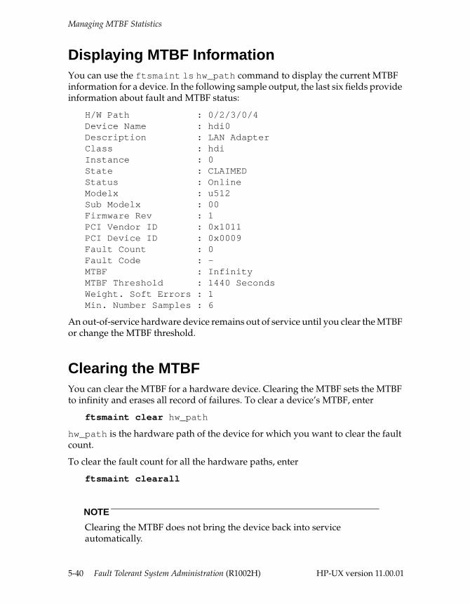
Managing MTBF Statistics
Displaying MTBF InformationYou can use the ftsmaint ls hw_path command to display the current MTBF information for a device. In the following sample output, the last six fields provide information about fault and MTBF status:
H/W Path : 0/2/3/0/4Device Name : hdi0Description : LAN AdapterClass : hdiInstance : 0State : CLAIMEDStatus : OnlineModelx : u512Sub Modelx : 00Firmware Rev : 1PCI Vendor ID : 0x1011PCI Device ID : 0x0009Fault Count : 0Fault Code : - MTBF : InfinityMTBF Threshold : 1440 SecondsWeight. Soft Errors : 1Min. Number Samples : 6
An out-of-service hardware device remains out of service until you clear the MTBF or change the MTBF threshold.
Clearing the MTBFYou can clear the MTBF for a hardware device. Clearing the MTBF sets the MTBF to infinity and erases all record of failures. To clear a device’s MTBF, enter
ftsmaint clear hw_path
hw_path is the hardware path of the device for which you want to clear the fault count.
To clear the fault count for all the hardware paths, enter
ftsmaint clearall
NOTE
Clearing the MTBF does not bring the device back into service automatically.
5-40 Fault Tolerant System Administration (R1002H) HP-UX version 11.00.01
Managing MTBF Statistics
If the device that you cleared is in the ERROR state, you must correct the state using the ftsmaint reset and enable commands. (See “Correcting the Error State” for more information.)
Changing the MTBF Threshold The MTBF threshold is expressed in seconds. If a device’s MTBF falls beneath this threshold, the system takes the device out of service and changes the device state to ERROR. If you change the MTBF threshold for a device, the device is not affected until another failure occurs. For example:
■ If you increase the threshold for a device that is currently in ERROR, you must enable the device so that it can return to service. The system will not change the state of the device automatically.
■ If the device’s actual MTBF is less than the new threshold (meaning that failures occur more often than the threshold allows) and the device in the CLAIMED state, the system will not recalculate MTBF and take the device out of service until another failure occurs.
You can change the MTBF threshold for a device. To do so, enter
ftsmaint threshold numsecs hw_path
numsecs is the threshold value in seconds and hw_path is the hardware path of the device.
Configuring the Minimum Number of SamplesYou can set a minimum number of faults required to calculate the MTBF for a hardware device. (The default minimum fault limit is 6.) For example, if you set the minimum fault limit to 3, the system requires that at least three failures have occurred since the last time the statistics were cleared before it can calculate MTBF for the device. When the system has stored the times of three or more failures for the device, it uses the times between each failure to calculate MTBF. To set the minimum fault number, enter
ftsmaint numsamp min_samples hw_path
min_samples is a number from 0 to 6 indicating the minimum number of faults and hw_path is the hardware path of the device.
■ If you set min_samples to 0, the system does not calculate MTBF, but considers the device to have exceeded the MTBF threshold at the first failure.
■ If you set min_samples to a value greater than 6, the system sets it to 6.
HP-UX version 11.00.01 Administering Fault Tolerant Hardware 5-41
Error Notification
To clear all the error information recorded for a device, enter
ftsmaint clear hw_path
hw_path is the hardware path of the device.
NOTE
The default numsamp value for suitcases is either 0 (for PA 7100-based suitcases) or 6 (for PA 8000-based suitcases).
Configuring the Soft Error WeightYou can set the number of soft errors that are required before the time of a soft error is used to recalculate MTBF. When the number of soft errors equals the soft_wt value, the system records the time of the last soft error and recalculates MTBF. To set the soft errors number, enter
ftsmaint soft_wt soft_error_weight hw_path
soft_error_weight is the number of soft errors that will cause the system to calculate MTBF, and hw_path is the hardware path of the device.
For more information about hard and soft errors, see “Error Detection and Handling” earlier in this chapter. For more information about how MTBF is calculated, see “MTBF Calculation and Affects.”
Error Notification When a Continuum system operates normally, with all major devices duplexed, you might not notice when one device of a duplexed pair fails. For this reason, the following indicators are provided to alert you to a device failure:
■ Remote Service Network (notification from the CAC)
■ status lights on the device
■ console and syslog messages
■ indications in status displays
5-42 Fault Tolerant System Administration (R1002H) HP-UX version 11.00.01
Error Notification
Remote Service Network The Remote Service Network (RSN) software running on your system collects hardware faults and significant events. The RSN allows trained Customer Assistance Center (CAC) personnel to analyze and correct problems remotely. For information about configuring the RSN, see Chapter 6, “Remote Service Network.”
Status Lights Status lights are provided for almost all devices. Each device contains one, two, or three status lights that identify its current operational state. The number of status lights depends on the type of device. Status lights are red (or amber), yellow, and green. Each combination of lights (on, off, or blinking) represents a specific state for that device. To determine possible status conditions for a particular device, see the HP-UX Operating System: Continuum Series 400 Operation and Maintenance Guide (R001H), the HP-UX Operating System: Continuum Series 400-CO Operation and Maintenance Guide (R025H), or the HP-UX Operating System: Continuum Series 600 and 1200 Operation and Maintenance Guide (R024H).
For most devices, a green light indicates that the device is operating properly, a yellow light indicates that the device is operating properly but is simplexed, and a red (or amber) light indicates that the device (or at least one of the services on that device, such as a faulted port on an I/O controller) is out of service or being tested. Testing occurs at the following times:
■ while the system is starting up (all devices are tested at this time)
■ when a device experiences an error
■ when a device is inserted into a slot
If the testing logic on a device detects a serious error, the unit is removed from service for further testing by the system. If the problem was transient, the system restores the device to service. Otherwise, the device remains out of service and the red status light stays on.
NOTE
The green light on a disk drive flashes when I/O activity occurs on that drive. This green light does not reflect any other status, and it does not imply the disk is mirrored. On systems with a Eurologic disk enclosure, the red light comes on when the system marks a disk as having failed; however, this does not cause the cabinet light to come on.
HP-UX version 11.00.01 Administering Fault Tolerant Hardware 5-43
Monitoring and Troubleshooting
Console and syslog Messages Each time a significant event occurs, the syslog message logging facility enters an error message into the system log, /var/adm/syslog/syslog.log. Depending upon the severity of the error and the phase of system operation, the same message might also be configured to display on the console. For more information, see the syslog(3C) and syslogd(1M) man pages.
Status MessagesSeveral commands provide status information about devices or services, for example, the FCode field from ftsmaint ls output. For a complete list of status commands, see “Monitoring and Troubleshooting.”
Monitoring and Troubleshooting If you encounter any problems, you can take several steps to analyze and recover from the problems.
Analyzing System StatusThe system provides various information sources to aid you in assessing system status and analyzing problems. Sources of information include the following:
■ status lights on the cabinet, boards and cards, fans, power supplies, and other devices in the system (see the HP-UX Operating System: Continuum Series 400 Operation and Maintenance Guide (R001H), the HP-UX Operating System: Continuum Series 400-CO Operation and Maintenance Guide (R025H), or the HP-UX Operating System: Continuum Series 600 and 1200 Operation and Maintenance Guide (R024H))
■ messages written to the console
■ messages written to the system log using the syslog message logging facility. For more information, see the syslog(3C) and syslogd(1M) man pages.
■ status information from the following system commands. For more information, see the appropriate man page.
– ioscan and ftsmaint commands for hardware information
– sar for system performance information
5-44 Fault Tolerant System Administration (R1002H) HP-UX version 11.00.01
Monitoring and Troubleshooting
– sysdef for kernel parameter information
– lp and lpstat for print services information
– ps for process information
– pwck and grpck for password inconsistencies information
– who and whodo for current user information
– netstat, uustat, lanscan, ping, and ifconfig for network services information
– ypcat, ypmatch, ypwhich, and yppoll for Network Information Service (NIS) information
– df and du for disk and volume information
Modifying System Resources After you analyze the system status, you can use various tools to manipulate your system. For more information, see the appropriate man page.
■ Use the console command menu to reboot or execute other commands on a nonfunctioning system.
■ Use shutdown and reboot to shut down and reboot the system.
■ Use ftsmaint to manage hardware devices.
■ Use enable, cancel, disable, lpadmin, lpmove, lpsched, and lpshut to manage printer services.
■ Use kill to terminate processes.
■ Use fsck and fsdb to administer and repair file systems.
■ Use ypinit, ypxfr, yppush, ypset, and yppasswd to administer the Network Information Service (NIS).
HP-UX version 11.00.01 Administering Fault Tolerant Hardware 5-45
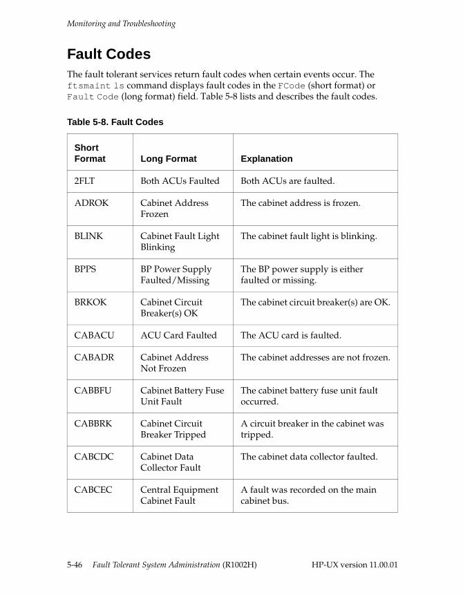
Monitoring and Troubleshooting
Fault Codes The fault tolerant services return fault codes when certain events occur. The ftsmaint ls command displays fault codes in the FCode (short format) or Fault Code (long format) field. Table 5-8 lists and describes the fault codes.
Table 5-8. Fault Codes
Short Format Long Format Explanation
2FLT Both ACUs Faulted Both ACUs are faulted.
ADROK Cabinet Address Frozen
The cabinet address is frozen.
BLINK Cabinet Fault Light Blinking
The cabinet fault light is blinking.
BPPS BP Power Supply Faulted/Missing
The BP power supply is either faulted or missing.
BRKOK Cabinet Circuit Breaker(s) OK
The cabinet circuit breaker(s) are OK.
CABACU ACU Card Faulted The ACU card is faulted.
CABADR Cabinet Address Not Frozen
The cabinet addresses are not frozen.
CABBFU Cabinet Battery Fuse Unit Fault
The cabinet battery fuse unit fault occurred.
CABBRK Cabinet Circuit Breaker Tripped
A circuit breaker in the cabinet was tripped.
CABCDC Cabinet Data Collector Fault
The cabinet data collector faulted.
CABCEC Central Equipment Cabinet Fault
A fault was recorded on the main cabinet bus.
5-46 Fault Tolerant System Administration (R1002H) HP-UX version 11.00.01
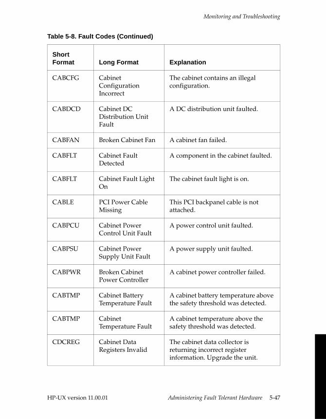
Monitoring and Troubleshooting
CABCFG Cabinet Configuration Incorrect
The cabinet contains an illegal configuration.
CABDCD Cabinet DC Distribution Unit Fault
A DC distribution unit faulted.
CABFAN Broken Cabinet Fan A cabinet fan failed.
CABFLT Cabinet Fault Detected
A component in the cabinet faulted.
CABFLT Cabinet Fault Light On
The cabinet fault light is on.
CABLE PCI Power Cable Missing
This PCI backpanel cable is not attached.
CABPCU Cabinet Power Control Unit Fault
A power control unit faulted.
CABPSU Cabinet Power Supply Unit Fault
A power supply unit faulted.
CABPWR Broken Cabinet Power Controller
A cabinet power controller failed.
CABTMP Cabinet Battery Temperature Fault
A cabinet battery temperature above the safety threshold was detected.
CABTMP Cabinet Temperature Fault
A cabinet temperature above the safety threshold was detected.
CDCREG Cabinet Data Registers Invalid
The cabinet data collector is returning incorrect register information. Upgrade the unit.
Table 5-8. Fault Codes (Continued)
Short Format Long Format Explanation
HP-UX version 11.00.01 Administering Fault Tolerant Hardware 5-47
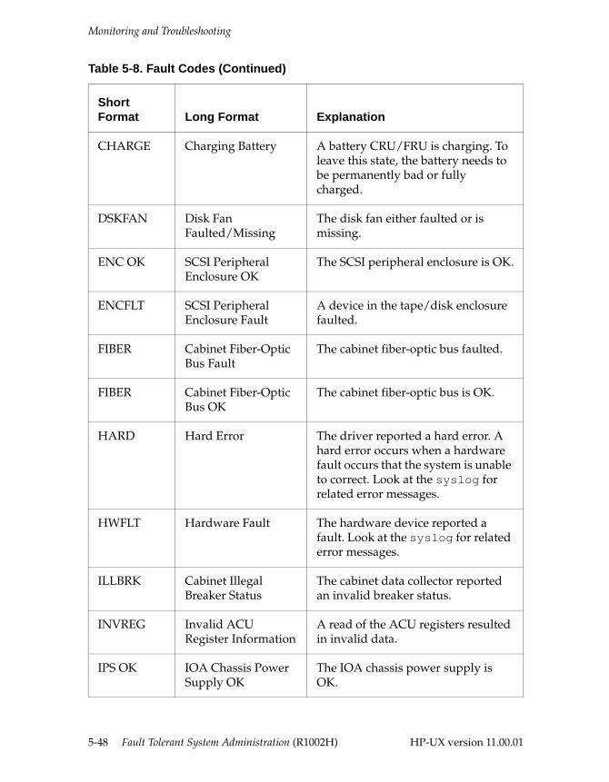
Monitoring and Troubleshooting
CHARGE Charging Battery A battery CRU/FRU is charging. To leave this state, the battery needs to be permanently bad or fully charged.
DSKFAN Disk Fan Faulted/Missing
The disk fan either faulted or is missing.
ENC OK SCSI Peripheral Enclosure OK
The SCSI peripheral enclosure is OK.
ENCFLT SCSI Peripheral Enclosure Fault
A device in the tape/disk enclosure faulted.
FIBER Cabinet Fiber-Optic Bus Fault
The cabinet fiber-optic bus faulted.
FIBER Cabinet Fiber-Optic Bus OK
The cabinet fiber-optic bus is OK.
HARD Hard Error The driver reported a hard error. A hard error occurs when a hardware fault occurs that the system is unable to correct. Look at the syslog for related error messages.
HWFLT Hardware Fault The hardware device reported a fault. Look at the syslog for related error messages.
ILLBRK Cabinet Illegal Breaker Status
The cabinet data collector reported an invalid breaker status.
INVREG Invalid ACU Register Information
A read of the ACU registers resulted in invalid data.
IPS OK IOA Chassis Power Supply OK
The IOA chassis power supply is OK.
Table 5-8. Fault Codes (Continued)
Short Format Long Format Explanation
5-48 Fault Tolerant System Administration (R1002H) HP-UX version 11.00.01
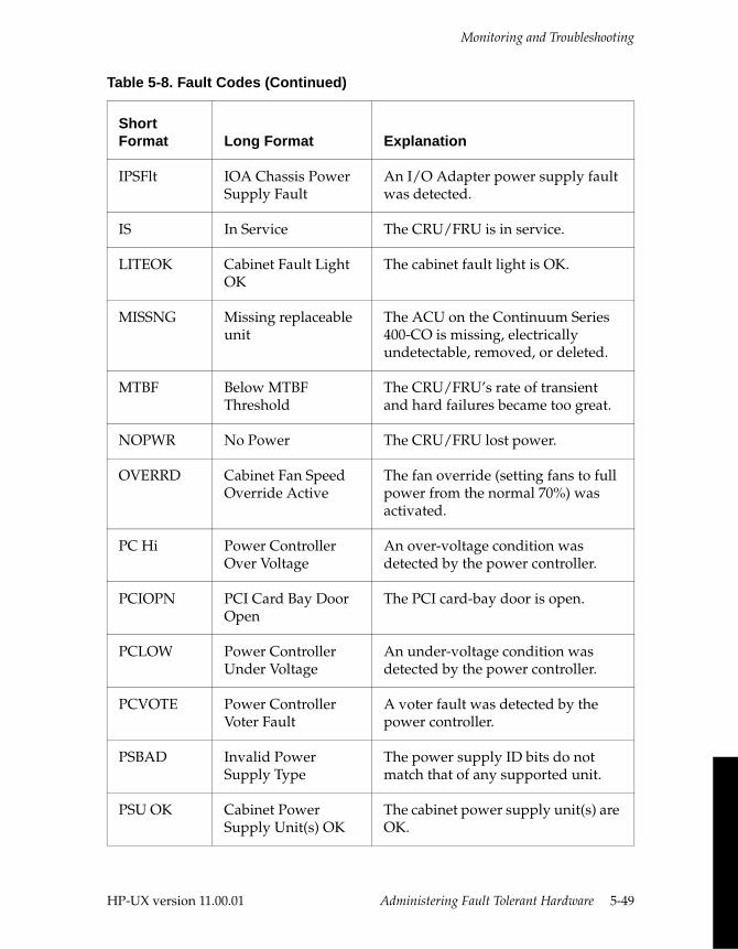
Monitoring and Troubleshooting
IPSFlt IOA Chassis Power Supply Fault
An I/O Adapter power supply fault was detected.
IS In Service The CRU/FRU is in service.
LITEOK Cabinet Fault Light OK
The cabinet fault light is OK.
MISSNG Missing replaceable unit
The ACU on the Continuum Series 400-CO is missing, electrically undetectable, removed, or deleted.
MTBF Below MTBF Threshold
The CRU/FRU’s rate of transient and hard failures became too great.
NOPWR No Power The CRU/FRU lost power.
OVERRD Cabinet Fan Speed Override Active
The fan override (setting fans to full power from the normal 70%) was activated.
PC Hi Power Controller Over Voltage
An over-voltage condition was detected by the power controller.
PCIOPN PCI Card Bay Door Open
The PCI card-bay door is open.
PCLOW Power Controller Under Voltage
An under-voltage condition was detected by the power controller.
PCVOTE Power Controller Voter Fault
A voter fault was detected by the power controller.
PSBAD Invalid Power Supply Type
The power supply ID bits do not match that of any supported unit.
PSU OK Cabinet Power Supply Unit(s) OK
The cabinet power supply unit(s) are OK.
Table 5-8. Fault Codes (Continued)
Short Format Long Format Explanation
HP-UX version 11.00.01 Administering Fault Tolerant Hardware 5-49
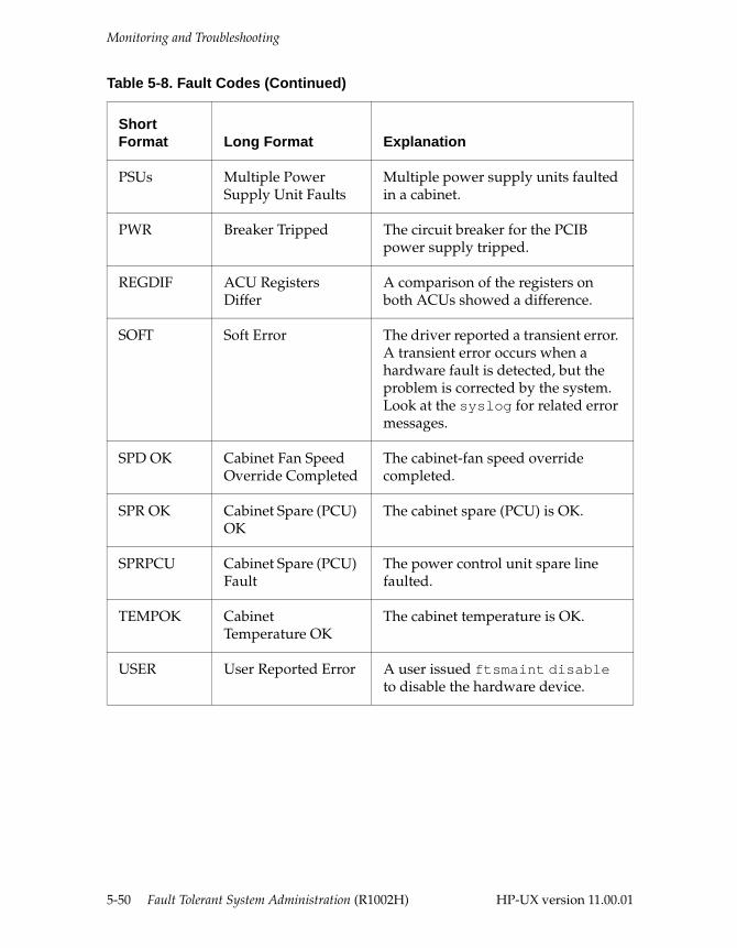
Monitoring and Troubleshooting
PSUs Multiple Power Supply Unit Faults
Multiple power supply units faulted in a cabinet.
PWR Breaker Tripped The circuit breaker for the PCIB power supply tripped.
REGDIF ACU Registers Differ
A comparison of the registers on both ACUs showed a difference.
SOFT Soft Error The driver reported a transient error. A transient error occurs when a hardware fault is detected, but the problem is corrected by the system. Look at the syslog for related error messages.
SPD OK Cabinet Fan Speed Override Completed
The cabinet-fan speed override completed.
SPR OK Cabinet Spare (PCU) OK
The cabinet spare (PCU) is OK.
SPRPCU Cabinet Spare (PCU) Fault
The power control unit spare line faulted.
TEMPOK Cabinet Temperature OK
The cabinet temperature is OK.
USER User Reported Error A user issued ftsmaint disable to disable the hardware device.
Table 5-8. Fault Codes (Continued)
Short Format Long Format Explanation
5-50 Fault Tolerant System Administration (R1002H) HP-UX version 11.00.01
HP-UX version 11.00.01
6
Remote Service Network 6-The Remote Service Network (RSN) is a highly secure worldwide network that Stratus uses to monitor its customer’s fault tolerant systems. Your system contains RSN software that regularly polls your system for the status of the hardware. If the RSN software detects a fault or system event, it automatically sends a message to a Stratus HUB system. The HUB system is usually located at the Customer Assistance Center (CAC) nearest to your site. The RSN enables Stratus to provide you with remote monitoring and diagnostics for your system 24 hours a day, seven days a week.
Your RSN software and hardware provide the following features:
■ hardware device status monitoring—The RSN software tracks current state, state history, and state change information for hardware devices on your system. The hardware devices monitored by the RSN software include buses, boards and cards, disks, tapes, fans, and power supplies. For more information about how you can access hardware status information, see the “Hardware Status” in Chapter 5, “Administering Fault Tolerant Hardware.”
■ event logging—The RSN software logs the following types of events in various log files in the /var/stratus/rsn/queues directory:
– hardware device events
– RSN device reconfiguration events
– RSN data transfer events
■ event reporting to your supporting CAC (dial-out)—The RSN software automatically reports significant hardware events (referred to as calls) by dialing out to the CAC. You can also manually dial out to the CAC to add new calls, update existing calls, and send mail using the mntreq command. For information about how to use the mntreq command, see the “Sending Mail to the HUB” section later in this chapter. See the HP-UX Operating System: Site Call System
6-1
How the RSN Software Works
User’s Guide (R1021H) for information on the Site Call System, the recommended RSN interface.
■ remote access to your system by CAC personnel (dial-in)—The Stratus system provides two special logins that the CAC can use to dial in to your system to diagnose problems and perform data transfer functions. The logins, sracs and sracsx, are subject to validation by the system administrator at your site. You use the validate_hub command to validate an incoming call. For information about how to receive and validate calls made to your system, see the “Validating Incoming Calls” section later in this chapter.
How the RSN Software WorksFigure 6-1 shows the major RSN software components on your system and how they interact with each other. The numbered callouts in Figure 6-1 are described as follows:
1. rsnd polls the system regularly for the status of its hardware components.
2. If a fault or system event is detected, rsntrans automatically sends a call to the HUB.
3. Calls are sent to the HUB over a dial-up telephone line.
4. You can use the mntreq command to send electronic mail messages, add calls, and update existing calls to the HUB.
5. Calls and electronic mail messages are saved in files which are placed on the RSN queue before being transferred to the HUB.
6. When a call is received at your supporting CAC, CAC will contact you regarding the problem. The support personnel can dial into your system using the cac login if further diagnosis is required.
7. Dial-in connections, which are received through the RSN port on your system’s console controller, are monitored by rsngetty.
8. The RSN software is configured and administered primarily through the rsnadmin program.
9. The rsndb file contains RSN configuration database information.
6-2 Fault Tolerant System Administration (R1002H) HP-UX version 11.00.01
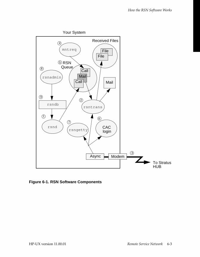
How the RSN Software Works
Figure 6-1. RSN Software Components
Async Modem
rsndrsngetty login
rsntransrsndb
rsnadmin
mntreq
CallMail
Call
FileFile
RSN
Received Files
Queue
To Stratus
Your System
1
2
3
4
5
67
8
9
CAC
HUB
HP-UX version 11.00.01 Remote Service Network 6-3
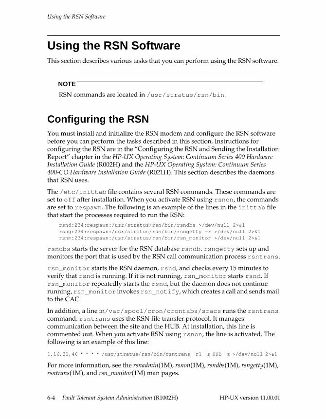
Using the RSN Software
Using the RSN SoftwareThis section describes various tasks that you can perform using the RSN software.
NOTE
RSN commands are located in /usr/stratus/rsn/bin.
Configuring the RSNYou must install and initialize the RSN modem and configure the RSN software before you can perform the tasks described in this section. Instructions for configuring the RSN are in the “Configuring the RSN and Sending the Installation Report” chapter in the HP-UX Operating System: Continuum Series 400 Hardware Installation Guide (R002H) and the HP-UX Operating System: Continuum Series 400-CO Hardware Installation Guide (R021H). This section describes the daemons that RSN uses.
The /etc/inittab file contains several RSN commands. These commands are set to off after installation. When you activate RSN using rsnon, the commands are set to respawn. The following is an example of the lines in the inittab file that start the processes required to run the RSN:
rsnd:234:respawn:/usr/stratus/rsn/bin/rsndbs >/dev/null 2>&1rsng:234:respawn:/usr/stratus/rsn/bin/rsngetty -r >/dev/null 2>&1rsnm:234:respawn:/usr/stratus/rsn/bin/rsn_monitor >/dev/null 2>&1
rsndbs starts the server for the RSN database rsndb. rsngetty sets up and monitors the port that is used by the RSN call communication process rsntrans.
rsn_monitor starts the RSN daemon, rsnd, and checks every 15 minutes to verify that rsnd is running. If it is not running, rsn_monitor starts rsnd. If rsn_monitor repeatedly starts the rsnd, but the daemon does not continue running, rsn_monitor invokes rsn_notify, which creates a call and sends mail to the CAC.
In addition, a line in/var/spool/cron/crontabs/sracs runs the rsntrans command. rsntrans uses the RSN file transfer protocol. It manages communication between the site and the HUB. At installation, this line is commented out. When you activate RSN using rsnon, the line is activated. The following is an example of this line:
1,16,31,46 * * * * /usr/stratus/rsn/bin/rsntrans -r1 -s HUB -z >/dev/null 2>&1
For more information, see the rsnadmin(1M), rsnon(1M), rsndbs(1M), rsngetty(1M), rsntrans(1M), and rsn_monitor(1M) man pages.
6-4 Fault Tolerant System Administration (R1002H) HP-UX version 11.00.01
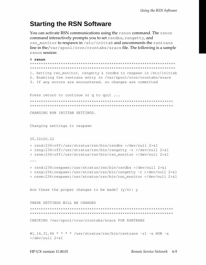
Using the RSN Software
Starting the RSN SoftwareYou can activate RSN communications using the rsnon command. The rsnon command interactively prompts you to set rsndbs, rsngetty, and rsn_monitor to respawn in /etc/inittab and uncomments the rsntrans line in the/var/spool/cron/crontabs/sracs file. The following is a sample rsnon session:
# rsnon************************************************************************************************************************************1. Setting rsn_monitor, rsngetty & rsndbs to respawn in /etc/inittab2. Enabling the rsntrans entry in /var/spool/cron/crontabs/sracs3. If any errors are encountered, no changes are committed
Press return to continue or q to quit ...
**********************************************************************************************************************************
CHANGING RSN INITTAB SETTINGS.
Changing settings to respawn
20,22c20,22
< rsnd:234:off:/usr/stratus/rsn/bin/rsndbs >/dev/null 2>&1< rsng:234:off:/usr/stratus/rsn/bin/rsngetty -r >/dev/null 2>&1< rsnm:234:off:/usr/stratus/rsn/bin/rsn_monitor >/dev/null 2>&1
---
> rsnd:234:respawn:/usr/stratus/rsn/bin/rsndbs >/dev/null 2>&1> rsng:234:respawn:/usr/stratus/rsn/bin/rsngetty -r >/dev/null 2>&1> rsnm:234:respawn:/usr/stratus/rsn/bin/rsn_monitor >/dev/null 2>&1
Are these the proper changes to be made? (y/n): y
THESE SETTINGS WILL BE CHANGED
**********************************************************************************************************************************
CHECKING /var/spool/cron/crontabs/sracs FOR RSNTRANS
#1,16,31,46 * * * * /usr/stratus/rsn/bin/rsntrans -r1 -s HUB -z >/dev/null 2>&1
HP-UX version 11.00.01 Remote Service Network 6-5
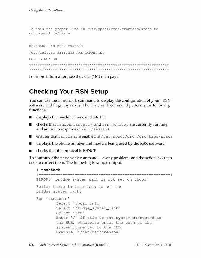
Using the RSN Software
Is this the proper line in /var/spool/cron/crontabs/sracs to uncomment? (y/n): y
RSNTRANS HAS BEEN ENABLED
/etc/inittab SETTINGS ARE COMMITTED
RSN IS NOW ON
**********************************************************************************************************************************
For more information, see the rsnon(1M) man page.
Checking Your RSN SetupYou can use the rsncheck command to display the configuration of your RSN software and flags any errors. The rsncheck command performs the following functions:
■ displays the machine name and site ID
■ checks that rsndbs, rsngetty, and rsn_monitor are currently running and are set to respawn in /etc/inittab
■ ensures that rsntrans is enabled in /var/spool/cron/crontabs/sracs
■ displays the phone number and modem being used by the RSN software
■ checks that the protocol is RSNCP
The output of the rsncheck command lists any problems and the actions you can take to correct them. The following is sample output:
# rsncheck+=======================================================+ERROR3: bridge system path is not set on chopin
Follow these instructions to set thebridge_system_path:
Run ’rsnadmin’Select ’local_info’Select ’bridge_system_path’Select ’set’.Enter ’/’ if this is the system connected tothe HUB, otherwise enter the path of thesystem connected to the HUBExample: ’/net/machinename’
6-6 Fault Tolerant System Administration (R1002H) HP-UX version 11.00.01
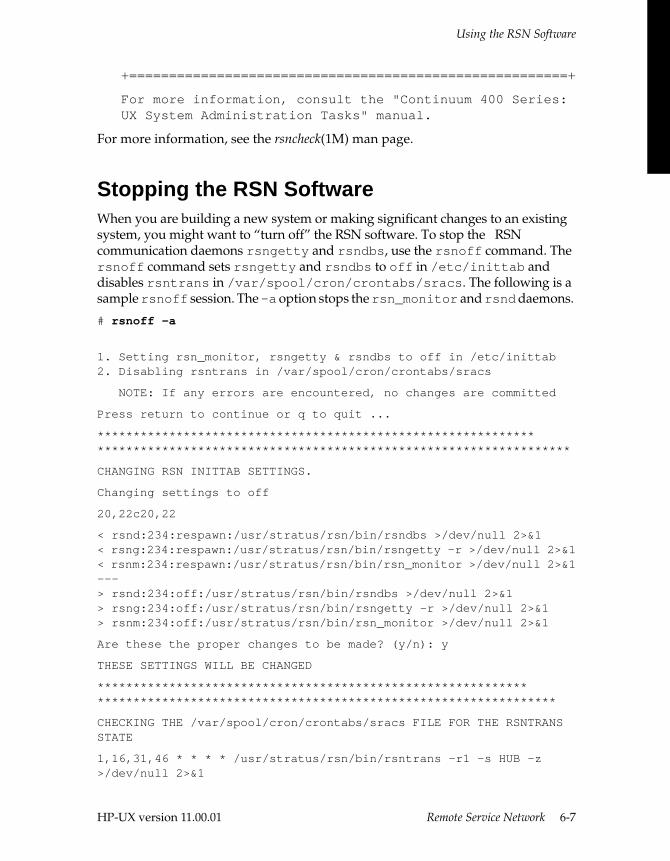
Using the RSN Software
+=======================================================+
For more information, consult the "Continuum 400 Series: UX System Administration Tasks" manual.
For more information, see the rsncheck(1M) man page.
Stopping the RSN SoftwareWhen you are building a new system or making significant changes to an existing system, you might want to “turn off” the RSN software. To stop the RSN communication daemons rsngetty and rsndbs, use the rsnoff command. The rsnoff command sets rsngetty and rsndbs to off in /etc/inittab and disables rsntrans in /var/spool/cron/crontabs/sracs. The following is a sample rsnoff session. The -a option stops the rsn_monitor and rsnd daemons.
# rsnoff -a
1. Setting rsn_monitor, rsngetty & rsndbs to off in /etc/inittab2. Disabling rsntrans in /var/spool/cron/crontabs/sracs
NOTE: If any errors are encountered, no changes are committed
Press return to continue or q to quit ...
*******************************************************************************************************************************
CHANGING RSN INITTAB SETTINGS.
Changing settings to off
20,22c20,22
< rsnd:234:respawn:/usr/stratus/rsn/bin/rsndbs >/dev/null 2>&1< rsng:234:respawn:/usr/stratus/rsn/bin/rsngetty -r >/dev/null 2>&1< rsnm:234:respawn:/usr/stratus/rsn/bin/rsn_monitor >/dev/null 2>&1---> rsnd:234:off:/usr/stratus/rsn/bin/rsndbs >/dev/null 2>&1> rsng:234:off:/usr/stratus/rsn/bin/rsngetty -r >/dev/null 2>&1> rsnm:234:off:/usr/stratus/rsn/bin/rsn_monitor >/dev/null 2>&1
Are these the proper changes to be made? (y/n): y
THESE SETTINGS WILL BE CHANGED
****************************************************************************************************************************
CHECKING THE /var/spool/cron/crontabs/sracs FILE FOR THE RSNTRANS STATE
1,16,31,46 * * * * /usr/stratus/rsn/bin/rsntrans -r1 -s HUB -z >/dev/null 2>&1
HP-UX version 11.00.01 Remote Service Network 6-7
Using the RSN Software
Is this the proper line in /var/spool/cron/crontabs/sracs to comment? (y/n): y
RSNTRANS HAS BEEN DISABLED
RSN IS OFF*************************************************************************************************************************
For more information, see the rsnoff(1M) man page.
Sending Mail to the HUBThe mntreq command is an interactive utility that lets you communicate with the supporting Stratus HUB. mntreq provides three subcommands, addcall, updatecall, and mail. For information about using the addcall and updatecall subcommands, see the mntreq(1M) man page.
NOTE
To use the mntreq command, the directory /var/stratus/rsn/queues/mntreq.d must exist. If it does not, an error message will appear when you try to use mntreq. To correct this error, log in as root and create this directory (using mkdir).
When you specify the mail subcommand, mntreq creates a message in the form of a file and transfers the message to the supporting HUB. When you use mntreq with the mail subcommand, it prompts you for:
■ your phone number
■ the person at the HUB who should receive the mail
■ the subject of the mail
■ the content of your message
After you have answered these prompts, the system redisplays the information you provided and prompts you to enter the text of your message. End your message with a period (.) on a line by itself.
The system finally prompts you to send, edit, or quit the message. A copy of the mail message is saved in the /var/stratus/rsn/queues/mntreq.d directory. For more information, see the mntreq(1M) man page.
6-8 Fault Tolerant System Administration (R1002H) HP-UX version 11.00.01
Using the RSN Software
Listing RSN Configuration InformationTo list the configuration information contained in the RSN database, use the list_rsn_cfg command. This is a quicker way to list information than running the rsnadmin command and, unlike rsnadmin, does not require special permissions. To invoke this command, enter
list_rsn_cfg | more
In this example, the output was piped to the more command because the output is often lengthy. For more information, see the list_rsn_cfg(1M) man page.
Validating Incoming CallsTo verify that an incoming telephone call to your site originates from the HUB, you can request that the caller supply the code for your site. You use the validate_hub command to determine the unique three-digit code for your site on a particular date.
The following shows sample output of the validate_hub command:
# validate_hub
Site_id is smith_coValidation code on 97-11-19 is 642
For more information, see the validate_hub(1M) man page.
Testing the RSN ConnectionTo test the connection with the HUB, use the rsntry script. This command connects to the HUB, swaps the line twice, and displays its success or failure on the screen.
For more information, see the rsntry(1M) man page.
Listing RSN RequestsThe list_rsn_req command lists all jobs that are in the queue to be sent to the HUB. Jobs that fail to be queued for any reason are stored in /var/stratus/rsn/queues/hub_pickup. If the job you want to see is not listed, use list_rsn_req -f to view failed jobs.
You can display all jobs, the HUB connection status, all jobs that were sent to the queue today, or only the jobs that were submitted by a specified userid.
HP-UX version 11.00.01 Remote Service Network 6-9
Using the RSN Software
The following example displays RSN requests for every user and all types of requests:
# list_rsn_req -a
Job Queued User Action Priority Tries Stat Size---- ------------- -------- ------ ------- ----- ---- ----1FBD 07-07.10:42:19 glenn mail STANDARD 1/5 C --4614 07-08.10:50:34 bob mail STANDARD 0/5 D --
For more information, see the list_rsn_req(1M) man page.
Cancelling an RSN RequestTo cancel a queued RSN request, use the cancel_rsn_req command. You can cancel a specific job or all pending jobs. Non-super-users can cancel their own jobs; the super-user can cancel other user’s jobs as well.
The following example cancels a specific job. You can get the job number using list_rsn_req, as shown in the previous section.
cancel_rsn_req 4614
The following example cancels all pending jobs:
cancel_rsn_req -a
For more information, see the cancel_rsn_req(1M) man page.
Displaying the Current RSN-Port Device NameUsing the rsnport command, you can display the current device name of the RSN port. The man page is provided with the operating system. Two options of the command, -i and -r, are used internally by other Stratus commands. The third option, -d, displays the device name of the port used for the RSN. For example, if you make card changes and reset /etc/ioconfig, the instance number of the RSN port will also change. In this case, you need to follow these steps to reconfigure the RSN port:
1. Using a text editor (such as vi), remove entries for the old device nodes from the /etc/uucp/Devices file.
2. Using the rm command, remove the old /dev/cuaNp0, /dev/culNp0, and /dev/ttydNp0 device nodes, where N is the instance number of the RSN port before any card changes were made.
3. Invoke the command /usr/stratus/rsn/bin/rsnport -i to create new device nodes and add new entries to the /etc/uucp/Devices file.
4. Update the port_name in the port_info menu by using rsnadmin.
For more information, see the rsnport(1M) man page.
6-10 Fault Tolerant System Administration (R1002H) HP-UX version 11.00.01
RSN Command Summary
RSN Command SummaryTable 6-1 lists all the commands you can use to manage RSN. All of these commands are in the /usr/stratus/rsn/bin directory. See the corresponding man pages for additional information.
Table 6-1. RSN Commands
Command Function
cancel_rsn_req Cancels an RSN request.
list_rsn_cfg Lists RSN configuration information.
list_rsn_req Selectively lists all RSN jobs queued to be sent to the HUB.
mntreq Sends mail to the HUB, adds calls, and updates existing calls to the HUB.
rsn_monitor Starts the RSN daemon and ensures that the daemon is always running. rsn_monitor is started from the /etc/inittab file.
rsn_setup Checks that the directories /etc/stratus/rsn, /var/stratus/rsn/queues/outgoing_mail and /var/stratus/rsn/queues/hub_pickup exist and the permissions for root are read, write, and executable.
rsnadmin Provides a user interface to access and modify all RSN configuration information. This command requires root permission. (The rsnadmin command is described in the HP-UX Operating System: Continuum Series 400 Hardware Installation Guide (R002H) and HP-UX Operating System: Continuum Series 400-CO Hardware Installation Guide (R021H).)
rsncheck Validates the RSN setup and displays any errors.
rsnoff Deactivates RSN communication by editing RSN inittab and crontabs entries. Optionally deactivates monitoring.
rsnon Activates RSN communication and monitoring by editing RSN inittab and crontabs entries.
rsnport Displays RSN port device nodes.
rsntry Establishes an RSN connection with the HUB for testing purposes. (This command requires root permission.)
validate_hub Verifies that incoming verbal telephone calls originate from the HUB.
HP-UX version 11.00.01 Remote Service Network 6-11
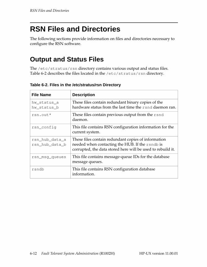
RSN Files and Directories
RSN Files and Directories The following sections provide information on files and directories necessary to configure the RSN software.
Output and Status FilesThe /etc/stratus/rsn directory contains various output and status files. Table 6-2 describes the files located in the /etc/stratus/rsn directory.
Table 6-2. Files in the /etc/stratus/rsn Directory
File Name Description
hw_status_ahw_status_b
These files contain redundant binary copies of the hardware status from the last time the rsnd daemon ran.
rsn.out* These files contain previous output from the rsnd daemon.
rsn_config This file contains RSN configuration information for the current system.
rsn_hub_data_arsn_hub_data_b
These files contain redundant copies of information needed when contacting the HUB. If the rsndb is corrupted, the data stored here will be used to rebuild it.
rsn_msg_queues This file contains message-queue IDs for the database message queues.
rsndb This file contains RSN configuration database information.
6-12 Fault Tolerant System Administration (R1002H) HP-UX version 11.00.01
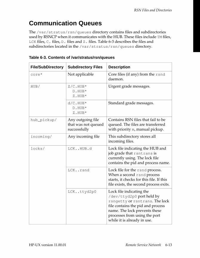
RSN Files and Directories
Communication QueuesThe /var/stratus/rsn/queues directory contains files and subdirectories used by RSNCP when it communicates with the HUB. These files include TM files, LCK files, C. files, D. files and Z. files. Table 6-3 describes the files and subdirectories located in the /var/stratus/rsn/queues directory.
Table 6-3. Contents of /var/stratus/rsn/queues
File/SubDirectory Subdirectory Files Description
core* Not applicable Core files (if any) from the rsnd daemon.
HUB/ Z/C.HUB*D.HUB*Z.HUB*
Urgent grade messages.
d/C.HUB*D.HUB*Z.HUB*
Standard grade messages.
hub_pickup/ Any outgoing file that was not queued successfully
Contains RSN files that fail to be queued. The files are transferred with priority m, manual pickup.
incoming/ Any incoming file This subdirectory stores all incoming files.
locks/ LCK..HUB.d Lock file indicating the HUB and job grade that rsntrans is currently using. The lock file contains the pid and process name.
LCK..rsnd Lock file for the rsnd process. When a second rsnd process starts, it checks for this file. If this file exists, the second process exits.
LCK..ttyd2p0 Lock file indicating the /dev/ttyd2p0 port held by rsngetty or rsntrans. The lock file contains the pid and process name. The lock prevents these processes from using the port while it is already in use.
HP-UX version 11.00.01 Remote Service Network 6-13
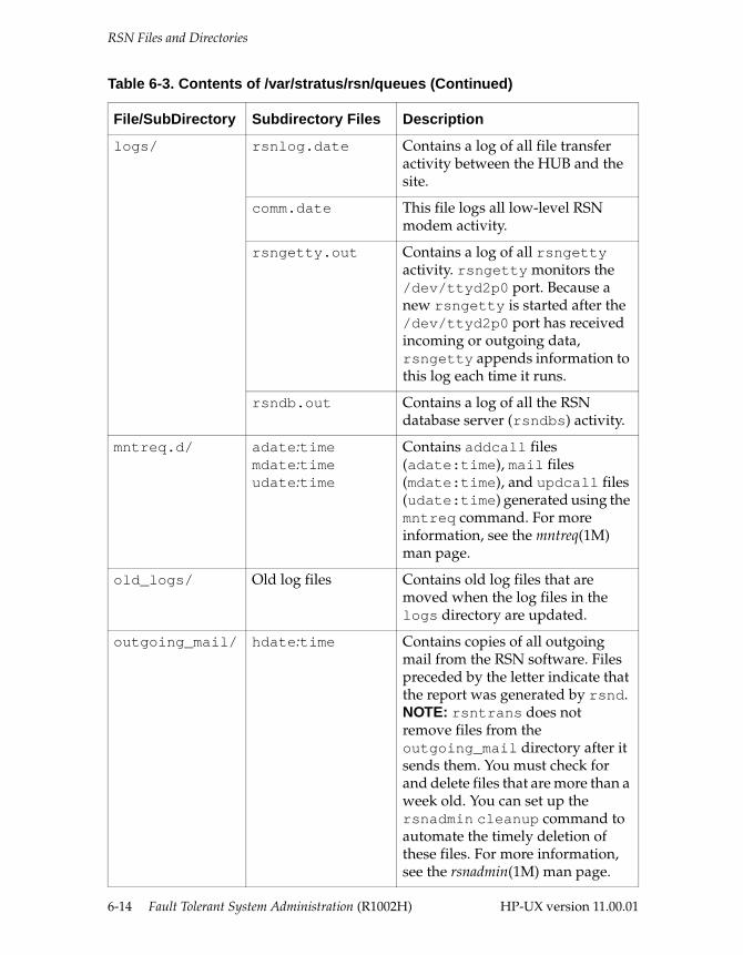
RSN Files and Directories
logs/ rsnlog.date Contains a log of all file transfer activity between the HUB and the site.
comm.date This file logs all low-level RSN modem activity.
rsngetty.out Contains a log of all rsngetty activity. rsngetty monitors the /dev/ttyd2p0 port. Because a new rsngetty is started after the /dev/ttyd2p0 port has received incoming or outgoing data, rsngetty appends information to this log each time it runs.
rsndb.out Contains a log of all the RSN database server (rsndbs) activity.
mntreq.d/ adate:timemdate:timeudate:time
Contains addcall files (adate:time), mail files (mdate:time), and updcall files (udate:time) generated using the mntreq command. For more information, see the mntreq(1M) man page.
old_logs/ Old log files Contains old log files that are moved when the log files in the logs directory are updated.
outgoing_mail/ hdate:time Contains copies of all outgoing mail from the RSN software. Files preceded by the letter indicate that the report was generated by rsnd.NOTE: rsntrans does not remove files from the outgoing_mail directory after it sends them. You must check for and delete files that are more than a week old. You can set up the rsnadmin cleanup command to automate the timely deletion of these files. For more information, see the rsnadmin(1M) man page.
Table 6-3. Contents of /var/stratus/rsn/queues (Continued)
File/SubDirectory Subdirectory Files Description
6-14 Fault Tolerant System Administration (R1002H) HP-UX version 11.00.01
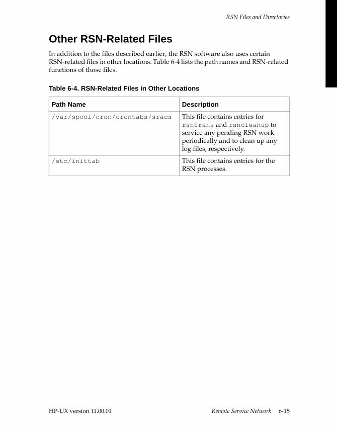
RSN Files and Directories
Other RSN-Related FilesIn addition to the files described earlier, the RSN software also uses certain RSN-related files in other locations. Table 6-4 lists the path names and RSN-related functions of those files.
Table 6-4. RSN-Related Files in Other Locations
Path Name Description
/var/spool/cron/crontabs/sracs This file contains entries for rsntrans and rsncleanup to service any pending RSN work periodically and to clean up any log files, respectively.
/etc/inittab This file contains entries for the RSN processes.
HP-UX version 11.00.01 Remote Service Network 6-15

HP-UX version 11.00.01
A
Stratus Value-Added Features A-This appendix discusses the following Stratus value-added features:
■ new and customized software
■ new and customized commands
New and Customized SoftwareThis appendix describes the commands and features of the HP-UX operating system that are either unique to Stratus or modified from the base release to support Continuum Series systems.
NOTE
The HP-UX version 11.00.01 operating system runs as a 32-bit Stratus-only operating system. In general, the HP-UX version 11.00.01 operating system is designed to be fully compatible with HP-UX version 10.x. You do not have to port most software to run it on the HP-UX version 11.00.01 operating system. The great majority of software will run acceptably on 11.00.01 without source changes or recompilation. All HP-UX operating system software will operate on Continuum Series systems. Modifications made to the HP-UX operating system to support Continuum Series systems do not affect applications that run on the HP-UX operating system.
This section describes the changes and additions made to the standard HP-UX operating system to support Continuum Series systems.
A-1
Stratus Value-Added Features
Console InterfaceContinuum Series systems provide a system console interface through which you can execute machine management commands. A set of console commands allows you to quickly control important machine actions.
To access the console command interface, you must connect a terminal to the console controller. For more information about setting up a console terminal, see the “Configuring Serial Ports for Terminals and Modems” chapter in the HP-UX Operating System: Peripherals Configuration (R1001H). For more information about console commands, see “Solo Components” in Chapter 1, “Getting Started,” in this manual.
Flash Cards Continuum Series 400 system’s primary boot is from a 20-MB PCMCIA flash card rather than from disk. The root file system and the HP-UX operating system and kernel do reside on disk, however. The flash card uses the Logical Interchange Format (LIF) to store the following:
■ primary bootloader (LYNX)
■ secondary bootloader (boot)
■ bootloader configuration file (conf)
For a complete description of flash cards, how they work, and how you update them, see Chapter 3, “Starting and Stopping the System.”
NOTE
The lifcp, lifinit, lifls, lifrename, and lifrm commands will not work on the LIF files stored on a flash card. You must use the Stratus commands to manipulate files on a flash card.
Power Failure Recovery Software The system supports software logic to provide power failure protection. You can connect an external uninterruptible power supply (UPS) to your Continuum Series 400 system to take advantage of this capability. Continuum Series 600 and 1200 systems all ship with internal batteries to support this capability. You can configure power failure software logic with the powerdown command. See the powerdown(1M) man page.
A-2 Fault Tolerant System Administration (R1002H) HP-UX version 11.00.01
Stratus Value-Added Features
For information about configuring the power failure configuration on your system, see “Dealing with Power Failures” in Chapter 3, “Starting and Stopping the System.”
Mean-Time-Between-Failures AdministrationContinuum Series systems automatically maintain MTBF statistics for many system components. You can access the information at any time and can reconfigure MTBF parameters, which affects how the fault tolerant services (FTS) software subsystem responds to component problems.
For information about configuring MTBF thresholds and managing fault tolerance, see “Managing MTBF Statistics” in Chapter 5, “Administering Fault Tolerant Hardware.”
Duplexed and Logically Paired Components Continuum Series systems use a parallel “pair and spare” architecture for some hardware components. This allows two physical components to operate in lock step (that is, identical actions at the same time) and appear as a single unit. Failure of a single component in a duplexed pair does not affect system availability or performance.
Certain components do not use true lock-step duplexing (for example, the console controller). Such components can be logically paired so that one is online while the other is in standby mode. If the online component fails, the standby one goes online immediately and assumes primary functions. You can also explicitly “switch” the online and standby components.
For more information about managing your fault tolerant system, see Chapter 5, “Administering Fault Tolerant Hardware.”
Remote Service Network (RSN) The Remote Service Network (RSN) software provides an interface for access and communication between you and the Customer Assistance Center (CAC).
You must set up and maintain the RSN on your system before you can use it. For a description of how RSN works and how you can use it, see Chapter 6, “Remote Service Network.”
HP-UX version 11.00.01 Stratus Value-Added Features A-3
New and Customized Commands
Configuring Root Disk Mirroring at InstallationThe standard HP-UX operating system provides disk mirroring as a separate optional product. The Stratus implementation of the HP-UX operating system provides the complete disk mirroring package with all systems.
You can configure root disk mirroring during the installation procedure by executing the ‘mirror-on’ program. For information about mirroring the root disk after installation, as well as Stratus’s recommendations for disk mirroring, see Chapter 4, “Mirroring Data.”
For information about mirroring the root disk during installation, see the HP-UX Operating System: Installation and Update (R1002H).
For general information about disk mirroring on an HP-UX operating system, see the Managing Systems and Workgroups (B2355-90157).
New and Customized CommandsTable A-1 lists the new (to 11.00.01) commands and the standard HP-UX operating system commands that have been modified by Stratus. All of these commands are described in the man pages installed with your system.
Table A-1. New and Modified Commands
Man Page Name and Section Description
addhardware(1) Lets you add new hardware to a running system by installing it, powering it on, and running this command. This command finds the new hardware, associates it with its device driver, and updates the ioconfig file and flash card so that the configuration will be maintained for all system reboots.
addmodelx(1M) A tool to update entries in the modelx.conf file.
articdload(1) Added to Fault Tolerant OS core.
asyndload(1M) Downloads firmware to asynchronous interface card.
boot(1M) Updated to explain the Stratus boot process. This is the secondary boot command.
cancel_rsn_req(1M) Cancels any RSN requests that are in the queue to be sent to the CAC.
A-4 Fault Tolerant System Administration (R1002H) HP-UX version 11.00.01
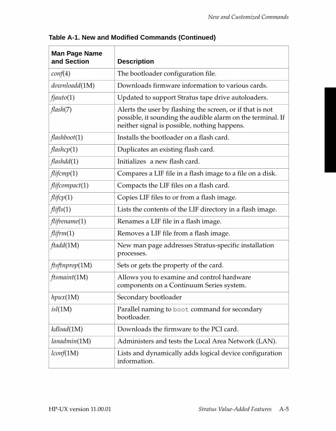
New and Customized Commands
conf(4) The bootloader configuration file.
downloadd(1M) Downloads firmware information to various cards.
fjauto(1) Updated to support Stratus tape drive autoloaders.
flash(7) Alerts the user by flashing the screen, or if that is not possible, it sounding the audible alarm on the terminal. If neither signal is possible, nothing happens.
flashboot(1) Installs the bootloader on a flash card.
flashcp(1) Duplicates an existing flash card.
flashdd(1) Initializes a new flash card.
flifcmp(1) Compares a LIF file in a flash image to a file on a disk.
flifcompact(1) Compacts the LIF files on a flash card.
flifcp(1) Copies LIF files to or from a flash image.
flifls(1) Lists the contents of the LIF directory in a flash image.
flifrename(1) Renames a LIF file in a flash image.
flifrm(1) Removes a LIF file from a flash image.
ftadd(1M) New man page addresses Stratus-specific installation processes.
ftsftnprop(1M) Sets or gets the property of the card.
ftsmaint(1M) Allows you to examine and control hardware components on a Continuum Series system.
hpux(1M) Secondary bootloader
isl(1M) Parallel naming to boot command for secondary bootloader.
kdload(1M) Downloads the firmware to the PCI card.
lanadmin(1M) Administers and tests the Local Area Network (LAN).
lconf(1M) Lists and dynamically adds logical device configuration information.
Table A-1. New and Modified Commands (Continued)
Man Page Name and Section Description
HP-UX version 11.00.01 Stratus Value-Added Features A-5
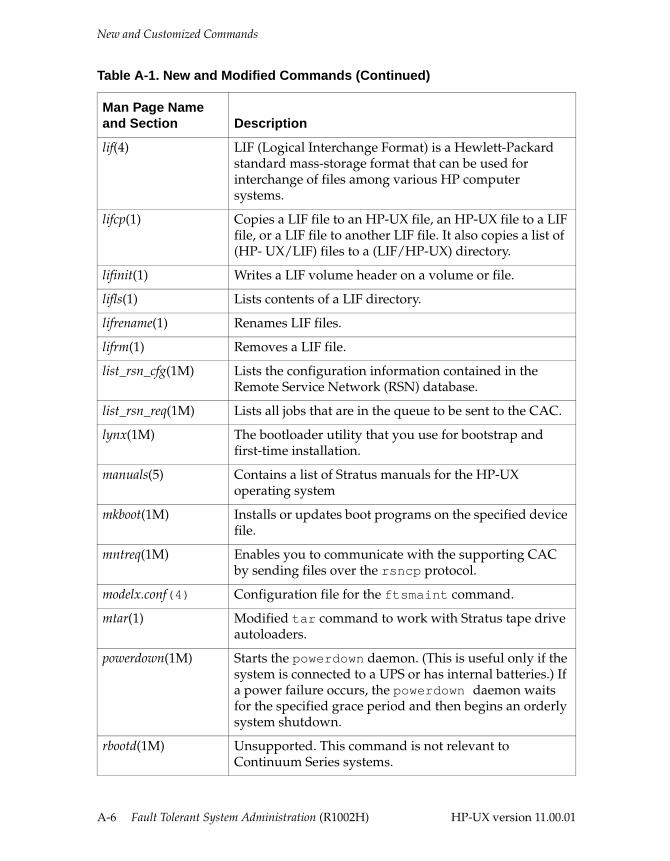
New and Customized Commands
lif(4) LIF (Logical Interchange Format) is a Hewlett-Packard standard mass-storage format that can be used for interchange of files among various HP computer systems.
lifcp(1) Copies a LIF file to an HP-UX file, an HP-UX file to a LIF file, or a LIF file to another LIF file. It also copies a list of (HP- UX/LIF) files to a (LIF/HP-UX) directory.
lifinit(1) Writes a LIF volume header on a volume or file.
lifls(1) Lists contents of a LIF directory.
lifrename(1) Renames LIF files.
lifrm(1) Removes a LIF file.
list_rsn_cfg(1M) Lists the configuration information contained in the Remote Service Network (RSN) database.
list_rsn_req(1M) Lists all jobs that are in the queue to be sent to the CAC.
lynx(1M) The bootloader utility that you use for bootstrap and first-time installation.
manuals(5) Contains a list of Stratus manuals for the HP-UX operating system
mkboot(1M) Installs or updates boot programs on the specified device file.
mntreq(1M) Enables you to communicate with the supporting CAC by sending files over the rsncp protocol.
modelx.conf(4) Configuration file for the ftsmaint command.
mtar(1) Modified tar command to work with Stratus tape drive autoloaders.
powerdown(1M) Starts the powerdown daemon. (This is useful only if the system is connected to a UPS or has internal batteries.) If a power failure occurs, the powerdown daemon waits for the specified grace period and then begins an orderly system shutdown.
rbootd(1M) Unsupported. This command is not relevant to Continuum Series systems.
Table A-1. New and Modified Commands (Continued)
Man Page Name and Section Description
A-6 Fault Tolerant System Administration (R1002H) HP-UX version 11.00.01
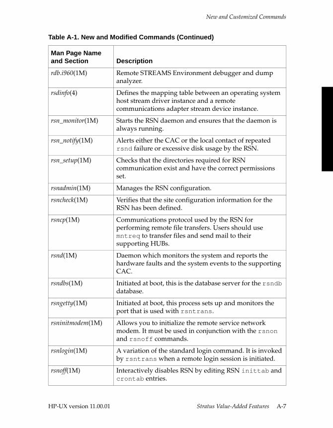
New and Customized Commands
rdb.i960(1M) Remote STREAMS Environment debugger and dump analyzer.
rsdinfo(4) Defines the mapping table between an operating system host stream driver instance and a remote communications adapter stream device instance.
rsn_monitor(1M) Starts the RSN daemon and ensures that the daemon is always running.
rsn_notify(1M) Alerts either the CAC or the local contact of repeated rsnd failure or excessive disk usage by the RSN.
rsn_setup(1M) Checks that the directories required for RSN communication exist and have the correct permissions set.
rsnadmin(1M) Manages the RSN configuration.
rsncheck(1M) Verifies that the site configuration information for the RSN has been defined.
rsncp(1M) Communications protocol used by the RSN for performing remote file transfers. Users should use mntreq to transfer files and send mail to their supporting HUBs.
rsnd(1M) Daemon which monitors the system and reports the hardware faults and the system events to the supporting CAC.
rsndbs(1M) Initiated at boot, this is the database server for the rsndb database.
rsngetty(1M) Initiated at boot, this process sets up and monitors the port that is used with rsntrans.
rsninitmodem(1M) Allows you to initialize the remote service network modem. It must be used in conjunction with the rsnon and rsnoff commands.
rsnlogin(1M) A variation of the standard login command. It is invoked by rsntrans when a remote login session is initiated.
rsnoff(1M) Interactively disables RSN by editing RSN inittab and crontab entries.
Table A-1. New and Modified Commands (Continued)
Man Page Name and Section Description
HP-UX version 11.00.01 Stratus Value-Added Features A-7
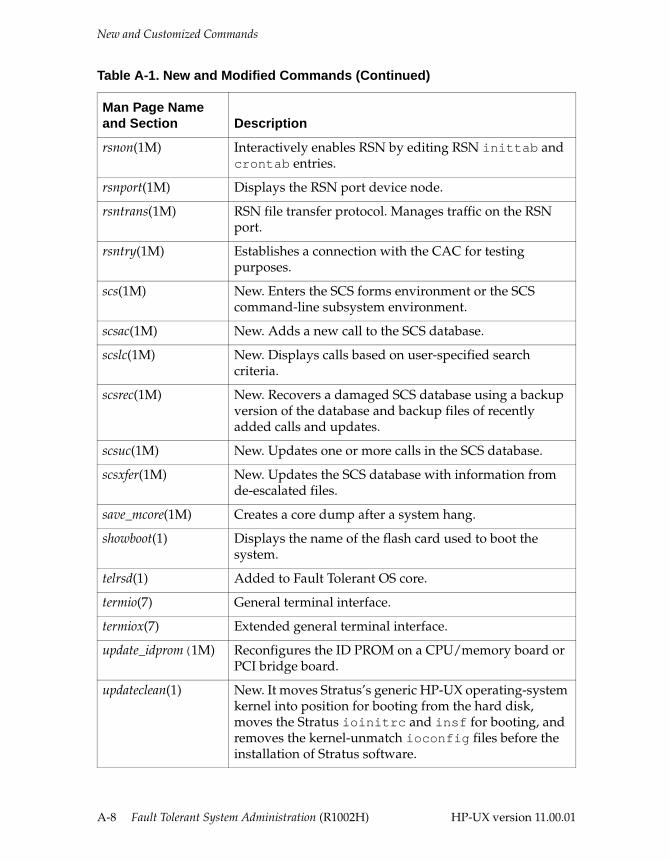
New and Customized Commands
rsnon(1M) Interactively enables RSN by editing RSN inittab and crontab entries.
rsnport(1M) Displays the RSN port device node.
rsntrans(1M) RSN file transfer protocol. Manages traffic on the RSN port.
rsntry(1M) Establishes a connection with the CAC for testing purposes.
scs(1M) New. Enters the SCS forms environment or the SCS command-line subsystem environment.
scsac(1M) New. Adds a new call to the SCS database.
scslc(1M) New. Displays calls based on user-specified search criteria.
scsrec(1M) New. Recovers a damaged SCS database using a backup version of the database and backup files of recently added calls and updates.
scsuc(1M) New. Updates one or more calls in the SCS database.
scsxfer(1M) New. Updates the SCS database with information from de-escalated files.
save_mcore(1M) Creates a core dump after a system hang.
showboot(1) Displays the name of the flash card used to boot the system.
telrsd(1) Added to Fault Tolerant OS core.
termio(7) General terminal interface.
termiox(7) Extended general terminal interface.
update_idprom(1M) Reconfigures the ID PROM on a CPU/memory board or PCI bridge board.
updateclean(1) New. It moves Stratus’s generic HP-UX operating-system kernel into position for booting from the hard disk, moves the Stratus ioinitrc and insf for booting, and removes the kernel-unmatch ioconfig files before the installation of Stratus software.
Table A-1. New and Modified Commands (Continued)
Man Page Name and Section Description
A-8 Fault Tolerant System Administration (R1002H) HP-UX version 11.00.01
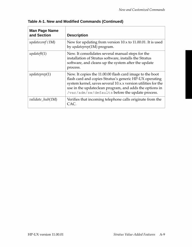
New and Customized Commands
updateconf(1M) New for updating from version 10.x to 11.00.01. It is used by updateprep(1M) program.
updateft(1) New. It consolidates several manual steps for the installation of Stratus software, installs the Stratus software, and cleans up the system after the update process.
updateprep(1) New. It copies the 11.00.00 flash card image to the boot flash card and copies Stratus’s generic HP-UX operating system kernel, saves several 10.x.x version utilities for the use in the updateclean program, and adds the options in /var/adm/sw/defaults before the update process.
validate_hub(1M) Verifies that incoming telephone calls originate from the CAC.
Table A-1. New and Modified Commands (Continued)
Man Page Name and Section Description
HP-UX version 11.00.01 Stratus Value-Added Features A-9

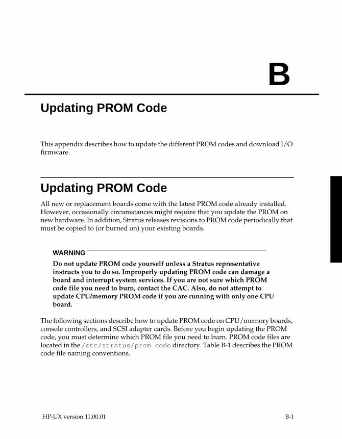
HP-UX version 11.00.01
B
Updating PROM Code B-This appendix describes how to update the different PROM codes and download I/O firmware.
Updating PROM CodeAll new or replacement boards come with the latest PROM code already installed. However, occasionally circumstances might require that you update the PROM on new hardware. In addition, Stratus releases revisions to PROM code periodically that must be copied to (or burned on) your existing boards.
WARNING
Do not update PROM code yourself unless a Stratus representative instructs you to do so. Improperly updating PROM code can damage a board and interrupt system services. If you are not sure which PROM code file you need to burn, contact the CAC. Also, do not attempt to update CPU/memory PROM code if you are running with only one CPU board.
The following sections describe how to update PROM code on CPU/memory boards, console controllers, and SCSI adapter cards. Before you begin updating the PROM code, you must determine which PROM file you need to burn. PROM code files are located in the /etc/stratus/prom_code directory. Table B-1 describes the PROM code file naming conventions.
B-1

Updating PROM Code
Table B-1. PROM Code File Naming Conventions
PROM Code File Type Naming Convention
CPU/memory GNMMSccVV.V.xxx (for PA-7100 and PA-8000)GNMNSccVV.V.xxx (for PA-8500 and PA-8600)
GNMM or GNMN is the modelx number, G8XX for PA-7100 and G2XX for PA-8000 (400 only), G3XX for PA-8000 (600/1200 only), G2X2 for PA-8500 and PA-8600
S is the submodel compatibility number (0–9)
cc is the source code identifier: fw is firmware
VV is the major revision number (0–99)
V is the minor revision number (0–9)
xxx is the file type (raw or bin)
For example:G2XX0fw10.0.bin (for PA-8000 CPU boards)
console controller EMMMMSccVV.Vrom.xxx
EMMMM is the board identification number
S is the submodel compatibility number (0–9)
cc is the source code identifier: on (online), of (offline), or dg (diagnostic)
VV is the major revision number (0–99)
V is the minor revision number (0–9)
rom specifies read-only memory
xxx is the file type (raw or bin)
For example:
On Continuum Series 400 systems:E5940on19.0bin (online)E5940of19.0bin (offline)E5940dg19.0bin (diagnostic)
B-2 Fault Tolerant System Administration (R1002H) HP-UX version 11.00.01
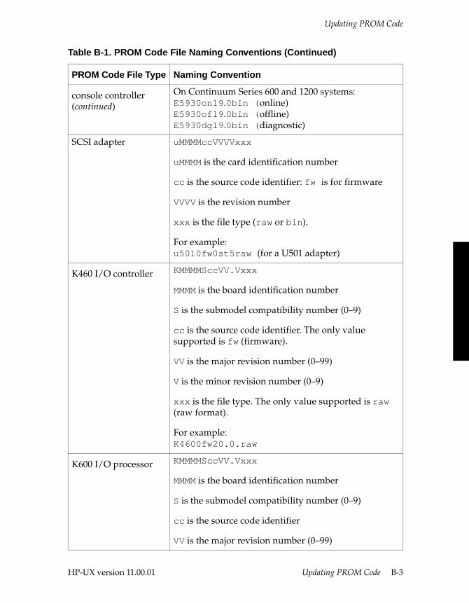
Updating PROM Code
console controller(continued)
On Continuum Series 600 and 1200 systems:E5930on19.0bin (online)E5930of19.0bin (offline)E5930dg19.0bin (diagnostic)
SCSI adapter uMMMMccVVVVxxx
uMMMM is the card identification number
cc is the source code identifier: fw is for firmware
VVVV is the revision number
xxx is the file type (raw or bin).
For example:u5010fw0st5raw (for a U501 adapter)
K460 I/O controller KMMMMSccVV.Vxxx
MMMM is the board identification number
S is the submodel compatibility number (0–9)
cc is the source code identifier. The only value supported is fw (firmware).
VV is the major revision number (0–99)
V is the minor revision number (0–9)
xxx is the file type. The only value supported is raw (raw format).
For example: K4600fw20.0.raw
K600 I/O processor KMMMMSccVV.Vxxx
MMMM is the board identification number
S is the submodel compatibility number (0–9)
cc is the source code identifier
VV is the major revision number (0–99)
Table B-1. PROM Code File Naming Conventions (Continued)
PROM Code File Type Naming Convention
HP-UX version 11.00.01 Updating PROM Code B-3
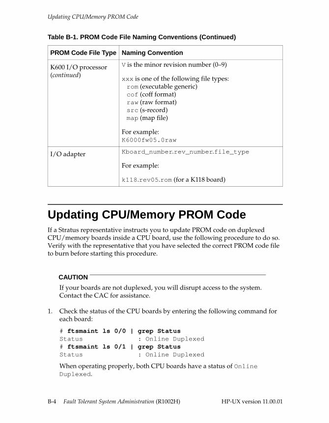
Updating CPU/Memory PROM Code
Updating CPU/Memory PROM CodeIf a Stratus representative instructs you to update PROM code on duplexed CPU/memory boards inside a CPU board, use the following procedure to do so. Verify with the representative that you have selected the correct PROM code file to burn before starting this procedure.
CAUTION
If your boards are not duplexed, you will disrupt access to the system. Contact the CAC for assistance.
1. Check the status of the CPU boards by entering the following command for each board:
# ftsmaint ls 0/0 | grep StatusStatus : Online Duplexed# ftsmaint ls 0/1 | grep StatusStatus : Online Duplexed
When operating properly, both CPU boards have a status of Online Duplexed.
K600 I/O processor(continued)
V is the minor revision number (0–9)
xxx is one of the following file types:rom (executable generic)cof (coff format)raw (raw format)src (s-record)map (map file)
For example:K6000fw05.0raw
I/O adapter Kboard_number.rev_number.file_type
For example:
k118.rev05.rom (for a K118 board)
Table B-1. PROM Code File Naming Conventions (Continued)
PROM Code File Type Naming Convention
B-4 Fault Tolerant System Administration (R1002H) HP-UX version 11.00.01
Updating CPU/Memory PROM Code
2. Select a CPU board to update and change the status of the selected CPU board to Offline Standby by entering
ftsmaint nosync hw_path
hw_path is the hardware path of the CPU board. For example, to take CPU board 0/1 offline, you would enter the command
ftsmaint nosync 0/1
3. Update the CPU/memory PROM code in the CPU board now on standby by entering
ftsmaint burnprom -f prom_code hw_path
prom_code is the path name of the PROM code file, and hw_path is the path to the CPU. For example, to use the G8XX0fw045.0.bin file to update the CPU/memory PROM code in CPU board 0/1, you would enter the command
ftsmaint burnprom -f G8XX0fw045.0.bin 0/1
For more information about PROM-code file naming conventions, see Table B-1.
NOTE
The ftsmaint command assumes the prom_code file is in the /etc/stratus/prom_code directory. Therefore, you need to include the full path name only if the file is in a different directory.
4. When the prompt returns, switch the status of both CPU boards (that is, activate the standby CPU board and put the active CPU board on standby) by entering
ftsmaint switch hw_path
hw_path is the path of the CPU board to be brought online. For example, to bring CPU board 0/1 online (and CPU board 0/0 offline), you would enter the command
ftsmaint switch 0/1
This step can take up to five minutes to complete; however, the prompt will return immediately.
5. Periodically check the status of the CPU board being taken offline by entering
ftsmaint ls hw_path | grep Status
HP-UX version 11.00.01 Updating PROM Code B-5
Updating CPU/Memory PROM Code
hw_path is the hardware path of the CPU board for which you are checking the status. For example, to check the status of CPU board 0/0. you would enter the command
ftsmaint ls 0/0 | grep Status
6. When the Status changes from Online Standby Duplexing to Offline Standby, update the CPU/memory PROM code of the board in the CPU board now on standby by entering
ftsmaint burnprom -f prom_code hw_path
prom_code is the PROM code file in the CPU board, hw_path. For example, to update CPU/memory PROM code in CPU board 0/0, you would enter the command
ftsmaint burnprom -f G8XX0fw45.0.bin 0/0
7. Duplex the CPU boards by entering
ftsmaint sync hw_path
hw_path is the hardware path of the CPU board you just updated. For example, to duplex CPU board 0/0, you would enter the command
ftsmaint sync 0/0
NOTE
This step can take up to 15 minutes to complete; however, the prompt returns immediately.
8. Periodically check the status of the CPU board being duplexed (see step 5).
The update is complete when both CPU boards have a status of Online Duplexed and both show a single green light.
9. To display the current (updated) CPU/memory PROM code version for each CPU board, enter
ftsmaint ls 0/0 ftsmaint ls 0/1
B-6 Fault Tolerant System Administration (R1002H) HP-UX version 11.00.01
Updating Console Controller PROM Code
Updating Console Controller PROM CodeIf a Stratus representative instructs you to update PROM code for the configuration, path, diagnostic, online, and offline partitions of a console controller card, use the procedures in the following sections to do so. Verify with the representative that you have selected the correct PROM code file to burn before starting this procedure.
Updating config and path PartitionsTo modify the configuration of the console, RSN, or auxiliary (secondary console/UPS) ports, update the config partition. See the “Configuring Serial Ports for Terminals and Modems” chapter in the HP-UX Operating System: Peripherals Configuration (R1001H) for the procedure to update the config partition.
To configure boot path information, update the console controller path partition. See “Manually Booting Your System” in Chapter 3, “Starting and Stopping the System,” for the procedure to update the path partition.
Updating diag, online, and offline PartitionsThe following procedure updates the diag, online, and offline partitions.
Before you begin, determine which PROM file you need to burn. PROM code files are located in the /etc/stratus/prom_code directory. There will be one file for each PROM partition on the console controller.
1. Determine which console controller is on Online Standby by entering
# ftsmaint ls 1/0 | grep StatusStatus : Online # ftsmaint ls 1/1 | grep StatusStatus : Online Standby
2. Update the PROM code on the standby console controller for the online partition by entering
ftsmaint burnprom -F online -f prom_code hw_path
partition is the partition to be burned, prom_code is the path name of the PROM code file, and hw_path is the path name of the standby console controller. For example, to burn the online partition, you would enter the command
HP-UX version 11.00.01 Updating PROM Code B-7
Updating Console Controller PROM Code
ftsmaint burnprom -F online -f E5940on17.0bin 1/1 (for Series 400 systems)
ftsmaint burnprom -F online -f E5930of17.0bin 1/1 (for Series 600/1200 systems)
For more information about PROM-code file naming conventions, see Table B-1.
NOTE
The ftsmaint command assumes the prom_code file is in the /etc/stratus/prom_code directory. Therefore, you need to include the full path name only if the file is in a different directory.
3. Update the PROM code on the standby console controller for the each of the other partitions by entering
ftsmaint burnprom -F partition -f prom_code hw_path
partition is the partition to be burned, prom_code is the path name of the PROM code file, and hw_path is the path name of the standby console controller. For example, to burn the offline partition, you would enter the command
ftsmaint burnprom -F offline -f E5940of17.0bin 1/1 (for Series 400 systems)
ftsmaint burnprom -F offline -f E5930of17.0bin 1/1 (for Series 600/1200 systems)
Repeat this command for each partition. Each command takes a few minutes. When the prompt returns, proceed to the next partition.
4. When the prompt returns after burning the last partition, switch the status of both controller boards by entering
ftsmaint switch hw_path
hw_path is the hardware path of the standby console controller, which you just updated. For example, to switch the console controller in console controller board 1/1 to online and the console controller in console controller board 1/0 to standby, you would enter the command
ftsmaint switch 1/1
5. Check that the status of the newly updated console controller is Online and that the other console controller is Online Standby by entering
ftsmaint ls 1/1ftsmaint ls 1/0
B-8 Fault Tolerant System Administration (R1002H) HP-UX version 11.00.01
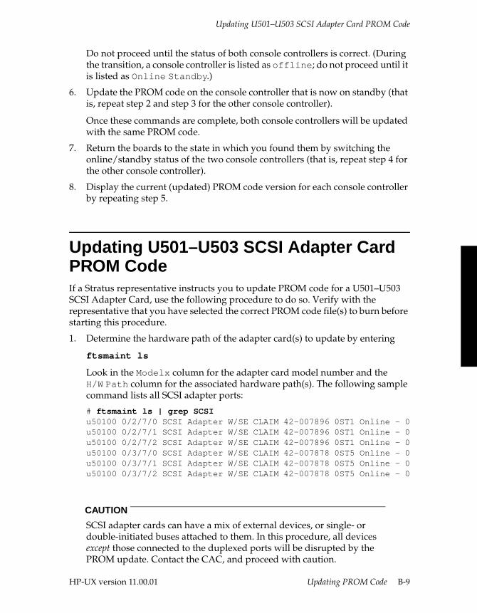
Updating U501–U503 SCSI Adapter Card PROM Code
Do not proceed until the status of both console controllers is correct. (During the transition, a console controller is listed as offline; do not proceed until it is listed as Online Standby.)
6. Update the PROM code on the console controller that is now on standby (that is, repeat step 2 and step 3 for the other console controller).
Once these commands are complete, both console controllers will be updated with the same PROM code.
7. Return the boards to the state in which you found them by switching the online/standby status of the two console controllers (that is, repeat step 4 for the other console controller).
8. Display the current (updated) PROM code version for each console controller by repeating step 5.
Updating U501–U503 SCSI Adapter Card PROM Code If a Stratus representative instructs you to update PROM code for a U501–U503 SCSI Adapter Card, use the following procedure to do so. Verify with the representative that you have selected the correct PROM code file(s) to burn before starting this procedure.
1. Determine the hardware path of the adapter card(s) to update by entering
ftsmaint ls
Look in the Modelx column for the adapter card model number and the H/W Path column for the associated hardware path(s). The following sample command lists all SCSI adapter ports:
# ftsmaint ls | grep SCSI u50100 0/2/7/0 SCSI Adapter W/SE CLAIM 42-007896 0ST1 Online - 0u50100 0/2/7/1 SCSI Adapter W/SE CLAIM 42-007896 0ST1 Online - 0u50100 0/2/7/2 SCSI Adapter W/SE CLAIM 42-007896 0ST1 Online - 0u50100 0/3/7/0 SCSI Adapter W/SE CLAIM 42-007878 0ST5 Online - 0u50100 0/3/7/1 SCSI Adapter W/SE CLAIM 42-007878 0ST5 Online - 0u50100 0/3/7/2 SCSI Adapter W/SE CLAIM 42-007878 0ST5 Online - 0
CAUTION
SCSI adapter cards can have a mix of external devices, or single- or double-initiated buses attached to them. In this procedure, all devices except those connected to the duplexed ports will be disrupted by the PROM update. Contact the CAC, and proceed with caution.
HP-UX version 11.00.01 Updating PROM Code B-9
Updating U501–U503 SCSI Adapter Card PROM Code
2. Notify users of any external devices or single-initiated logical SCSI buses attached to both SCSI adapter cards that service will be disrupted. Disconnect the cables from both ports.
3. Determine which (if any) of the cards you plan to update contain resources (ports) on standby duplexed status by entering
ftsmaint ls hw_path | grep -e Status -e Partner
hw_path is the hardware path determined in step 1. For example, to identify the status for the resources at 0/2/7/1, you would enter the command
ftsmaint ls 0/2/7/1 | grep -e Status -e Partner
4. Repeat step 3 for each resource in question.
5. Stop the standby resource from duplexing with its partner by entering
ftsmaint nosync hw_path
hw_path is the hardware path of the standby resource. For example, to stop 0/3/7/1 from duplexing with 0/2/7/1, you would enter the command
ftsmaint nosync 0/3/7/1
Invoking ftsmaint nosync on a single resource also stops duplexing and (if necessary) puts on standby status other resources (ports) on that card. Therefore, it is not necessary to repeat this command for the other resources.
CAUTION
The next step stops all communication with devices connected externally to the standby SCSI adapter card.
6. Update the PROM code on the standby card using the hardware address of one of the ports on the card by entering
ftsmaint burnprom -f prom_code hw_path
prom_code is the path name of the PROM code file, and hw_path is the path to the standby card. For example, to update the PROM code in a U501 card in slot 7, card-cage 3, you would enter the command
ftsmaint burnprom -f u5010fw0st5raw 0/3/7/1)
For more information about PROM-code file naming conventions, see Table B-1.
NOTE
The ftsmaint command assumes the prom_code file is in the /etc/stratus/prom_code directory. Therefore, you need to include the full path name only if the file is in a different directory.
B-10 Fault Tolerant System Administration (R1002H) HP-UX version 11.00.01
Updating U501–U503 SCSI Adapter Card PROM Code
7. Restart duplexing between the standby resource and its partner by entering
ftsmaint sync hw_path
hw_path is the hardware path of the standby resource. For example, to restart duplexing for 0/3/7/1, you would enter the command
ftsmaint sync 0/3/7/1
NOTE
Invoking ftsmaint sync on a single resource also restarts (as appropriate) duplexing for other resources (ports) on that card. Therefore, it is not necessary to repeat this command for the other resources.
8. Reverse the standby status of the two cards and stop duplexing.
ftsmaint nosync hw_path
hw_path is the hardware path of the duplexed port. For example, if 0/2/7/1 is one of the duplexed ports of the active card, you would enter the command
ftsmaint nosync 0/2/7/1
CAUTION
The next step stops all communication with devices connected externally to the standby SCSI adapter card.
9. Update the PROM code on the card that is now standby by entering
ftsmaint burnprom -f prom_code hw_path
prom_code is the path name of the PROM code file, and hw_path is the path to the standby card. For example, to update the PROM code in a U501 card in slot 7, card-cage 2, you would enter the command
ftsmaint burnprom -f u5010fw0st5raw 0/2/7/1
10. When the prompt returns, restart duplexing between the standby resource and its partner (and other resources on that card).
ftsmaint sync hw_path
hw_path is the hardware path of the standby resource. For example, to restart duplexing for 0/2/7/1, you would enter the command
ftsmaint sync 0/2/7/1
HP-UX version 11.00.01 Updating PROM Code B-11

Updating K460 I/O Controller Card PROM Code
11. Check the status of the newly updated card and verify the current (updated) PROM code version by entering the following command for both the resource and its partner
ftsmaint ls hw_path
When the status becomes Online Standby Duplexed, the card has resumed duplex mode.
Updating K460 I/O Controller Card PROM Code If a Stratus representative instructs you to update PROM code for a K460 I/O controller card, use the following procedure to do so. Verify with the representative that you have selected the correct PROM code file to burn before starting this procedure.
CAUTION
To burn a K460 I/O controller PROM, the boards must be logically paired. If your boards are not duplexed, you will disrupt access to the system. Contact the CAC for assistance.
1. Locate the new PROM code file in the /etc/stratus/prom_code directory, determine which is the correct file, and record the name of that file.
For more information about PROM-code file naming conventions, see Table B-1.
2. Choose one of the boards and update the board PROM by entering
ftsmaint nosync 0/4ftsmaint burnprom -F fw -f prom_code 0/slotftsmaint sync 0/4
prom_code must be the full path name of the PROM code file to be downloaded, and slot is the location of the board to be burned.
B-12 Fault Tolerant System Administration (R1002H) HP-UX version 11.00.01
Updating K600 Communications I/O Processor PROM Code
Updating K600 Communications I/O Processor PROM Code If a Stratus representative instructs you to update PROM code for a K600 communications I/O processor, use the following procedure to do so. Verify with the representative that you have selected the correct PROM code file to burn before starting this procedure.
CAUTION
To burn a K460 I/O Controller PROM, the boards must be logically paired. If your boards are not duplexed, you will disrupt access to the system. Contact the CAC for assistance.
1. Locate the new PROM code file in the /etc/prom_code directory, determine which is the correct file, and record the name of that file.
For more information about PROM-code file naming conventions, see Table B-1.
2. Choose one of the boards and update the board PROM by entering
ftsmaint nosync 0/6ftsmaint burnprom -f prom_code 0/slotftsmaint sync 0/6
prom_code must be the full path name of the PROM code file to be downloaded, and slot is the location of the board to be burned.
HP-UX version 11.00.01 Updating PROM Code B-13
Updating I/O Adapter Card PROM Code
Updating I/O Adapter Card PROM CodeIf a Stratus representative instructs you to update PROM code for a K102, K109, K112, or K118 I/O adapter card, use the following procedure to do so. Verify with the representative that you have selected the correct PROM code file to burn before starting this procedure.
CAUTION
To burn a K102, K109, K112, or K118 I/O adapter card, the card must be logically paired. If your card is not duplexed, you will disrupt access to the system. Contact the CAC for assistance.
1. Locate the new PROM code file in the /etc/prom_code directory, determine which is the correct file, and record the name of that file.
For more information about PROM-code file naming conventions, see Table B-1.
2. Choose one of the boards and update the PROM by entering
ftsmaint burnprom -f prom_code hw_path
prom_code must be the full path name of the PROM code file to be downloaded, and the hw_path is the actual location of the board to be burned.
Downloading I/O Card Firmware When the operating system boots or an I/O card is added, Continuum systems can automatically download firmware into the card(s) as necessary. Stratus supplies default firmware files, which are normally located in the /etc directory. If you do not want to use the default firmware, you can designate your own custom downloadable firmware file in the /etc/personality.conf file. This file contains special configuration information about I/O cards (such as the relationship between these devices and their device files). Although it is not necessary to identify a firmware file in personality.conf, if you do specify one, Continuum systems use the file you designate instead of the default.
CAUTION
Do not designate an alternate firmware file unless you are certain that file is appropriate for that card. Inappropriate firmware files can disable the card and, possibly, the system.
See the downloadd(1M) man page and the HP-UX Operating System: Peripherals Configuration (R1001H) for additional information.
B-14 Fault Tolerant System Administration (R1002H) HP-UX version 11.00.01
IndexIndex-
Aactivating a new kernel, 3-29addhardware command, 5-2, A-4addmodelx command, A-4addressing
logical hardware paths, 5-13physical hardware paths, 5-3
administrative tasksfinding information about, 1-2standard command paths, 1-1
alternate kernel, booting, 3-15architecture
fault tolerant hardware, 1-7fault tolerant software, 1-8
articdload command, A-4asyndload command, A-4autoboot, 3-4autoboot, enabling and disabling, 3-5
Bbackups
cross-reference, 1-3bad block relocation, 4-4bay
see card-cageboot command, A-4boot methods, 3-18boot parameters
specifying, 3-8boot path, modifying, 3-5booting
alternate kernel, 3-15boot command options, 3-14determining boot device, 3-19disk quorum check, 3-14from the console control menu, 3-22maintenance mode, 3-14manual boot procedure, 3-23methods, 3-18
modifying the boot path, 3-5options, 3-14rebooting online system, 3-27setting initial run-level, 3-15show current settings, 3-13single-user mode, 3-11
bootloader, 3-4boot parameters, 3-8command summary, 3-13
btflags boot parameter, 3-15bus fault tolerance, 5-29
Ccabinet addressing, 5-16cabinet data collector (CDC), 1-5CAC, contacting, xviicalling the CAC, 6-1cancel_rsn_req command, 6-10, 6-11, A-4card-cage, 1-4, 5-6channel separation, 4-8clusters, diskless, 2-4communications adapter cards
burning PROM code, B-14communications processor (K600), 5-8components
determining hardware status, 5-34determining software state, 5-32installing, 2-2testing status lights, 5-36
computer, turning on, 3-4conf command, A-5CONF file, 5-23CONF file
description of, 3-8conf file
syntax for logical SCSI buses, 5-24configuring
guidelines and tasks, 2-2
HP-UX version 11.00.01 Index 1
Index
confinfo filedownloading firmware to I/O
adapters, B-14consdev boot parameter, 3-15console commands, issuing, 3-21console controller, 1-6
burning PROM code on, B-7features of, 1-6offline partition, B-8online partition, B-8path partition, 3-6
console messages, 5-44contiguous allocation, 4-4contiguous extents, 4-2continuous availability
architecture, 1-4software, 1-8
control panel, 1-6conventions, notation, xiCPU/memory boards, 5-8CRU, 1-7, 5-1Customer Assistance Center
see CACCustomer Service login, 6-2customer-replaceable unit (CRU), 1-4customer-replaceable units, 1-7, 5-1
Ddata
backing up, 2-5data integrity, 4-3data, backing up and restoring, 1-3device fault tolerance, 5-29device names
disk, 5-30dial out, 6-1dial-in access, 6-2disabling a device, 5-38disk
device names, 5-30failure when mirrored, 4-7managing using LVM, 2-4quotas, 2-4simplexed volumes, 1-10striping using LVM, 2-4
diskless clusters, 2-4display, bootloader version, 3-13
DNCP Series 400physical components, 1-4, 1-5
documentation, viewing, xvidocumentation revision information, xidocumentation sources, xiv, 1-2double mirroring, 4-3downloadd command, A-5dpt1port boot parameter, 3-16dual-initiation, 4-2dumpdev boot parameter, 3-16duplexed components, 1-8duplexed device failure, notification, 5-42dynamic scheduling, disk mirroring, 4-4
Eenabling a device, 5-38/etc/inittab, 3-15, 6-4, 6-15/etc/shutdown.allow, 3-29/etc/stratus/rsn, 6-12Ethernet card
one-port (U513), 5-7two-port (U512), 5-7
event logging, 6-1extent, logical and physical, 4-2
Ffailure of duplexed device, 5-42fans, 1-4, 1-5fault codes, 5-46fault tolerance
bus, 5-29device, 5-29
fault toleranthardware features, 1-7meaning of, 1-7software features, 1-8
fault tolerant services (FTS), 1-7FDDI card (U530), 5-6field-replaceable units, 1-7, 5-1file systems, managing, 2-4firmware
downloading for I/O adapters, B-14fjauto command, A-5
2 Fault Tolerant System Administration (R1002H) HP-UX version 11.00.01
Index
flash cardscontents, 3-32creating, 3-35description, 3-32device names and symbolic links, 3-35duplicating, 3-36
flash command, A-5flashboot command, 3-34, A-5flashcp command, 3-34, A-5flashdd command, 3-34, A-5flifcmp command, A-5flifcompact command, A-5flifcp command
description, 3-35, A-5flifls command, 3-35, A-5flifrename command, A-5flifrm command, 3-35, A-5FRU, 1-7, 5-1ftadd command, A-5ftsftnprop command, A-5ftsmaint command
burning PROM codeconsole controller, B-7CPU/memory board, B-4online, offline, diag partitions, B-7path partition, 3-6SCSI adapter card, B-9
changing MTBF fault limit, 5-41description of, A-5determining hardware paths with, 5-3disabling hardware, 5-38displaying MTBF statistics, 5-40enabling hardware, 5-38
GGBUS, main system bus, 5-8grace period, power failure, 3-31guidelines for maintaining system, 2-5
Hhard errors, 5-37hardware architecture, 1-7hardware component status, 5-32hardware components
see componentshardware configuration, 5-6
hardware pathsCPU/memory board
logical, 5-31physical, 5-11
definition of, 5-3logical addresses, 5-13logical cabinet addresses, 5-16physical addresses, 5-3
hardware status, 5-34help console command, 3-21history console command, 3-22hot pluggable components, 1-7hpmc_cpu console command, 3-22hpux command, A-5HUB system, 6-1hwmaint command
burning PROM code, B-13
II/O adapter cards
burning PROM code, B-14downloading firmware, B-14
I/O channel separation, 4-2, 4-8I/O controller board (K460), 1-5I/O controller boards, 5-8I/O processor board (K600), 1-5I/O subsystem addresses
adapter or bridge, 5-12controller port (SCSI or Ethernet), 5-12device-specific service, 5-12I/O subsystem nexus (PCI, HSC, or
PKIO), 5-11main system bus nexus (GBUS), 5-11SCSI peripheral enclosure, 5-12SCSI peripheral enclosure power
supply, 5-12SLOT interface, 5-11
incoming RSN file, 6-13initlevel boot parameter, 3-16installing
hardware, 2-2software, 2-2
instance number, 5-25integrity, best data, 4-3internal disks, 1-4ioscan command, 5-3isl command, A-5islprompt, 3-16
HP-UX version 11.00.01 Index 3
Index
KK600 boards, burning PROM code, B-13kdload command, A-5kernel
booting alternate, 3-15kernel boot parameter, 3-16
Llanadmin command, A-5lconf command, 5-23, 5-29lconf command, 5-23, A-5lif command, A-6LIF commands, using, 3-34lifcp command, A-6lifcp command, A-2lifinit command, A-6lifinit command, A-2lifls command, A-6lifls command, A-2lifrename command, A-6lifrename command, A-2lifrm command, A-6lifrm command, A-2list_rsn_cfg command, 6-9, 6-11, A-6list_rsn_req command, 6-9, 6-11, A-6lock-step, 1-7logging events, 6-1logical addresses, 5-14
mapping to device files, 5-30for disk and CD-ROM devices, 5-30for flash cards, 5-30for tape devices, 5-30
mapping to physical devices, 5-26logical cabinet addresses, 5-16logical cabinet-component addresses
individual cabinet components, 5-16logical cabinet nexus (CAB), 5-16specific cabinet number, 5-16
logical communications I/O processor addresses, 5-15
individual K-cards, 5-15logical communications nexus
(LPKIO), 5-15logical K600 processor number, 5-15
logical CPU/memory addressesindividual resources, 5-31logical CPU/memory nexus
(LMERC), 5-31resource type, 5-31
logical devices, 5-5logical extent, 4-2logical hardware addressing, 5-13logical hardware categories
logical cabinet, 5-14logical communications I/O, 5-14logical CPU/memory, 5-14logical LAN manager (LNM), 5-14logical SCSI manager (LSM), 5-14
Logical Interchange Format (LIF) volume, 3-8logical LAN manager addresses, 5-19
logical LAN manager nexus (LNM), 5-19specific adapter (port), 5-19
logical SCSI busdefining, 5-23rules for defining, 5-24sample configuration, 5-21
logical SCSI buses, 5-23logical SCSI manager, 5-20, 5-23logical SCSI manager addresses, 5-20
logical SCSI bus number, 5-20logical SCSI manager nexus (LSM), 5-20logical unit number (LUN), 5-21SCSI target ID, 5-20
logical volume manager (LVM), 1-8logical volumes
description of, 4-2maintenance mode boot, 3-14
logssystem, 2-6
lsm number, 5-25lvdisplay command, 4-7lvlnboot command, 4-6LVM, 2-4lynx bootloader, A-6
Mmain system bus (GBUS), 5-8maintenance
guidelines, 2-5maintenance mode, LVM, 3-14manual boot, 3-4manual boot procedure, 3-23manuals command, A-6mean time between failures
see MTBFmemsize boot parameter, 3-16message-of-the-day
see motd file
4 Fault Tolerant System Administration (R1002H) HP-UX version 11.00.01
Index
Mirror Consistency, 4-5Mirror Write Cache, 4-5MirrorDisk/HP-UX, 4-1mirroring
definition, 4-1disk failure, 4-7double, 4-3number of copies, 4-4primary swap, 4-5recommendation, 4-3root disk, 4-5SAM options, 4-4scheduling options, 4-4
mkboot command, A-6mkboot command, 4-5mknod command, 4-8mntreq command, 6-2, 6-8, 6-11, A-6modelx.conf file, A-6motd file, 2-5mtar command, A-6MTBF, 1-8
changing threshold for, 5-41clearing, 5-40displaying statistics for, 5-39
Nncpu boot parameter, 3-17nexus, 5-5nexus-level categories
CAB Nexus, 5-6GBUS Nexus, 5-5HSC Nexus, 5-5LMERC Nexus, 5-5LNM Nexus, 5-6LPKIO Nexus, 5-6LSM Nexus, 5-6PCI Nexus, 5-5PKIO Nexus, 5-5PMERC Nexus, 5-5RECCBUS Nexus, 5-5
NFS diskless clusters, 2-4noncontiguous extents, 4-2nonstrict allocation, 4-2notation conventions, xinumsamp, setting using ftsmaint, 5-41
Ooffline partition, B-8online partition, B-8outgoing RSN files
hub_pickup directory, 6-13mail, 6-14
Ppair and spare architecture, 1-7parallel scheduling, disk mirroring, 4-4path names, administrative commands, 1-1path partition, 3-6PCI bay
see card-cagePCI bridge card (K138), 5-6PCI mezzanine cards (PMC), 1-5PCMCIA, 3-33peripheral component interconnect (PCI), 1-4permissions
shutdown, 3-29physical addresses
console controller (RECC), 5-10console controller bus nexus
(RECCBUS), 5-10CPU/memory nexus (PMERC), 5-10main system bus nexus (GBUS), 5-10PMERC resource, CPU or memory, 5-10
physical devices, 5-5physical extent, 4-2physical hardware configuration
Ethernet (LAN) card (U713), 5-9FDDI card (U730), 5-9K460 controllers, 5-9K470 PMC controllers, 5-9K600 processors, 5-10Token Ring card (U720), 5-9
physical nexus (PMERC)CPU, 5-10memory, 5-10
physical nexus (RECCBUS), console controllers, 5-10
physical volume, 4-2physical volume group, 4-2PKIO subsystem, 5-15PMC controller (K470), 5-8
HP-UX version 11.00.01 Index 5
Index
power failuresconfiguring UPS port, 3-32grace period, 3-31managing, 3-30
power on, order of powering hardware, 3-4powerdown daemon, A-6primary bootloader, 3-4primary swap, mirroring, 4-5PROM code
updating console controller partitions, B-7updating CPU/memory board, B-4updating path partition, 3-5updating SCSI adapter card, B-9
PROM code burningI/O adapter cards, B-14K600 boards, B-13
pseudo devices, 5-16pvcreate command, 4-5PVG-strict allocation, 4-2
Qqueuing RSN jobs, failure, 6-9quit console command, 3-22
Rrbootd command, A-6rdb.i960 command, A-7ReCC
see console controllerremote access (dial-in), 6-2Remote Service Network (RSN), 1-8
activating using rsnon, 6-5cancelling requests, 6-10checking setup of, 6-6checking your setup, 6-6command summary, 6-11configuration information, 6-12database information, 6-12deactivating using rsnoff, 6-7files and directories, 6-12initializing the modem for, 6-4listing configuration information, 6-9listing queued jobs, 6-9log files for, 6-14major components of, 6-2overview of, 6-1queuing messages for, 6-2sending mail using, 6-8
testing the connection to, 6-9verifying incoming calls, 6-9
reporting events, 6-1reset_bus console command, 3-22resetting devices in ERROR state, 5-38restart_cpu console command, 3-21restoring data, 1-3revision, documentation changes in this, xiRNI, providing failover protection, 5-10root disk mirroring, 4-5rootdev boot parameter, 3-11, 3-17rsdinfo command, A-7RSN
see Remote Service Network (RSN)rsn_monitor command, 6-4, 6-11, A-7rsn_notify command, 6-4, A-7rsn_setup command, 6-11, A-7rsnadmin command, 6-2, 6-11, A-7rsncheck command, 6-6, 6-11, A-7rsncleanup command, 6-15RSNCP protocol, 6-6, 6-13, A-7rsnd daemon, 6-2, A-7rsndb file, 6-2rsndbs command, 6-4, A-7rsngetty command, 6-2, 6-4, A-7rsninitmodem command, A-7rsnlogin command, A-7rsnoff command, 6-7, 6-11, A-7rsnon command, 6-4, 6-5, 6-11, A-8rsnport, 6-11rsnport command, A-8rsntrans command, 6-2, 6-4, A-8rsntry command, 6-9, 6-11, A-8run-level
single-user mode, 3-11
SSAM
disk mirroring options, 4-4save_mcore command, A-8scheduling, disk mirroring, 4-4scs command, A-8scsac command, A-8SCSI adapter card, updating PROM, B-9SCSI devices, 5-26, 5-27SCSI I/O controller (U501), 5-6SCSI/Ethernet controller (K460), 5-8scslc command, A-8
6 Fault Tolerant System Administration (R1002H) HP-UX version 11.00.01
Index
scsrec command, A-8scsuc command, A-8scsxfer command, A-8secondary bootloader, 3-4self-checking diagnostics, 1-7separation, I/O channel, 4-8sequential scheduling, disk mirroring, 4-4shell commands, 3-25showboot command, A-8shutdown command, 3-21shutdown policy, 2-6shutdown, authorization, 3-29shutting down the system, 3-21, 3-24single-initiation, 4-2single-user mode, booting in, 3-11soft errors, 5-37software
installing, 2-2software states, 5-32solo components, 1-9/stand/conf, 3-8, 5-24/stand/ioconfig, 5-32state transitions, 5-32status information, displaying, 5-34status lights
testing, 5-36status messages, 5-44storage enclosure, 1-4strict allocation, 4-2striping, disk, 2-4Subsystem Monitor, 5-12suitcase, 1-4swap space, managing, 2-4swapdev boot parameter, 3-17SwitchOver/UX, 3-14syslog command, 5-44system log, 2-6system messages, 5-44
Ttasks, finding information about, 1-2telrsd command, A-8terminals, turning on, 3-4termio command, A-8termiox command, A-8testing status lights, 5-36Token Ring card (U520), 5-6troubleshooting, overview of, 5-44
twin processor, 5-31
Uuninterruptible power supply (UPS), 1-4update_idprom command, A-8updateclean command, A-8updateconf command, A-9updateft command, A-9updateprep command, A-9UPS
configuring UPS port, 3-32
Vvalidate_hub command, 6-9, 6-11, A-9/var/adm/syslog/syslog.log, 5-44/var/stratus/rsn/queues, 6-1, 6-13version, documentation changes for this, xivgchange command, 4-7vgextend command, 4-5volume group, 4-1
HP-UX version 11.00.01 Index 7

Related Documents