Combined Service Manual HP LaserJet 4 / 4M (C2001A / C2021A) HP LaserJet 4 Plus / 4M Plus (C2037A / C2039A) HP LaserJet 5 / 5M /5N (C3916A/C3917A/ C3952A)

Welcome message from author
This document is posted to help you gain knowledge. Please leave a comment to let me know what you think about it! Share it to your friends and learn new things together.
Transcript
Combined ServiceManual
HP LaserJet 4 / 4M(C2001A / C2021A)
HP LaserJet 4 Plus /4M Plus(C2037A / C2039A)
HP LaserJet 5 / 5M/5N(C3916A/C3917A/C3952A)

© CopyrightHewlett-PackardCompany 1996
All Rights Reserved.Reproduction, adaptation,or translation withoutprior written permissionis prohibited, except asallowed under thecopyright laws.
Publication numberC3916-90984
First edition, March 1996
Printed in USA
WarrantyThe informationcontained in thisdocument is subject tochange without notice.
Hewlett-Packard makesno warranty of any kindwith regard to thismaterial, including, butnot limited to, theimplied warranties ormerchantability andfitness for a particularpurpose.
Hewlett-Packard shallnot be liable for errorscontained herein or forincidental orconsequential damagedin connection with thefurnishing, performance,or use of this material.
WARNINGElectrical ShockHazardTo avoid electrical shock,use only supplied powercords and connect only toproperly grounded(3-hole) wall outlets.
Hewlett-Packard Company11311 Chinden BoulevardBoise, Idaho 83714
Conventions
This manual uses the following conventions:
Unless specifically stated otherwise, information applies to allseven printer models (LaserJet 4/4 Plus/4 M/4 M Plus/5/5 M/5 N).Most procedures are combined for all printers, except where theydiffer substantially.
Color is used to emphasize items which are important to thematerial under discussion.
The names of major printer parts and assemblies are Capitalized.
Bold is used for emphasis, particularly in situations where italictype would be confusing.
Italic type is used to indicate related documents or emphasis.
COMPUTER type indicates text as seen on a computer monitor.
DISPLAY type indicates text as seen on the printer’s 16 characterLCD display panel (LaserJet 4Plus/4MPlus only).
[KEYFACE] indicates keys on a computer keyboard or on theprinter’s control panel. Examples include [Enter], [On Line] andGo.
N o t e Notes contain important information set off fromthe text.
C A U T I O N Caution messages alert you to the possibility ofdamage to equipment or loss of data.
W A R N I N G ! Warning messages alert you to the possibility ofpersonal injury.
i

ii
Contents
1 Product InformationProduct Family Information . . . . . . . . . . . . . . . 1-2
Identification . . . . . . . . . . . . . . . . . . . . . . . 1-3Specifications . . . . . . . . . . . . . . . . . . . . . . . . 1-5
HP LaserJet 4 and 4 Plus . . . . . . . . . . . . . . . . 1-5Related Documentation . . . . . . . . . . . . . . . . . . 1-7Safety Information . . . . . . . . . . . . . . . . . . . . . . 1-8
Product and Laser Safety . . . . . . . . . . . . . . . . 1-8FCC RFI Statement . . . . . . . . . . . . . . . . . . . 1-9Laser Statement (Sweden/Finland) . . . . . . . . . . 1-10Toner Safety . . . . . . . . . . . . . . . . . . . . . 1-11Ozone Statement . . . . . . . . . . . . . . . . . . . . 1-11
Doing Business with HP . . . . . . . . . . . . . . . . . . 1-12Technical Assistance . . . . . . . . . . . . . . . . . 1-12HP ASAP 1-800-333-1917 (U.S.) . . . . . . . . . . . . 1-12HP FIRST . . . . . . . . . . . . . . . . . . . . . . . . 1-12HP FIRST, U.S. . . . . . . . . . . . . . . . . . . . . . 1-12HP FIRST, Europe . . . . . . . . . . . . . . . . . . . 1-12HP AUDIO-TIPS . . . . . . . . . . . . . . . . . . . . 1-13HP CompuServe Forum . . . . . . . . . . . . . . . . 1-13Customer Information Centers . . . . . . . . . . . . . 1-13Customer Support Center (Assist Line) . . . . . . . . 1-13Printer Drivers . . . . . . . . . . . . . . . . . . . . . 1-13European Customer Support Center . . . . . . . . . 1-14Other Areas . . . . . . . . . . . . . . . . . . . . . . . 1-14
2 Site Planning and RequirementsSite Requirements . . . . . . . . . . . . . . . . . . . . . . 2-1
Printer Space Requirements . . . . . . . . . . . . . . . 2-2Print Media Specifications . . . . . . . . . . . . . . . . 2-3
Adhesive Labels . . . . . . . . . . . . . . . . . . . . . 2-5Label Construction . . . . . . . . . . . . . . . . . . . . 2-5Overhead Transparencies . . . . . . . . . . . . . . . . 2-6Envelopes . . . . . . . . . . . . . . . . . . . . . . . . . 2-6Envelope Construction . . . . . . . . . . . . . . . . . . 2-7
3 ConfigurationIntroduction . . . . . . . . . . . . . . . . . . . . . . . . . 3-1Using The Control Panel . . . . . . . . . . . . . . . . . . 3-2
Contents-1
Control Panel Keys . . . . . . . . . . . . . . . . . . . 3-2Reset Menu . . . . . . . . . . . . . . . . . . . . . . . 3-5Control Panel Menus . . . . . . . . . . . . . . . . . . . 3-6
Printer Features . . . . . . . . . . . . . . . . . . . . . . 3-13Page Protection (HP LaserJet 4 only) . . . . . . . . . 3-13Resource Saving (HP LaserJet 4 Plus and 5 only) . . 3-14I/O Buffering (HP LaserJet 4 Plus and 5 only) . . . . 3-15EconoMode (HP LaserJet 4 Plus and 5 only) . . . . . 3-16Resolution Enhancement (REt) . . . . . . . . . . . . 3-16Memory Enhancement technology (MEt)
(HP LaserJet 4 Plus and 5 only) . . . . . . . . . . 3-17Density . . . . . . . . . . . . . . . . . . . . . . . . 3-17
Network Security . . . . . . . . . . . . . . . . . . . . . 3-18Remote Control Panel (DOS) . . . . . . . . . . . . . 3-18HP LaserJet Utility (Macintosh) . . . . . . . . . . . 3-18HP JetAdmin Utility (Novell Networks) . . . . . . . 3-19
Service Mode . . . . . . . . . . . . . . . . . . . . . . . 3-20Setting the Page Count . . . . . . . . . . . . . . . . 3-21Setting the Cold Reset Default . . . . . . . . . . . 3-22
Cold Reset . . . . . . . . . . . . . . . . . . . . . . . . 3-23Understanding the PCL Self Test Printout . . . . . . 3-24Changing the Control Panel Display Language . . . . 3-28Test Print Button . . . . . . . . . . . . . . . . . . . . 3-29System Configuration . . . . . . . . . . . . . . . . . 3-31
MS-DOS System Configuration . . . . . . . . . . . . 3-31Parallel DOS Commands . . . . . . . . . . . . . . . 3-31Serial MS-DOS Commands . . . . . . . . . . . . . . 3-32
Printer I/O Configuration . . . . . . . . . . . . . . . . . 3-33Parallel Menu . . . . . . . . . . . . . . . . . . . . . 3-33Advanced Functions . . . . . . . . . . . . . . . . . 3-33Serial Configuration . . . . . . . . . . . . . . . . . . 3-33Serial Protocol . . . . . . . . . . . . . . . . . . . . . 3-33BAUD Rate . . . . . . . . . . . . . . . . . . . . . . . 3-33Pacing (Handshaking) . . . . . . . . . . . . . . . 3-34
Serial Cable Pin-outs . . . . . . . . . . . . . . . . . . . 3-35DB-9 RS-232 Serial Connection — HP LaserJet 4 . . 3-35DB-25 RS-232 Serial Connection — HP LaserJet 4
Plus/5 . . . . . . . . . . . . . . . . . . . . . . . . . 3-36DB-25 Serial Connection — HP LaserJet 4 . . . . . 3-37DB-25 RS-232 Serial Connection — HP LaserJet 4
Plus/5 . . . . . . . . . . . . . . . . . . . . . . . . . 3-38RS-422A Serial Connection (Not available on the
HP LaserJet 4 Plus or 5 printers) . . . . . . . . . 3-39RS-422A Serial Configuration (LaserJet 4 only) . . . 3-39
Modular I/O Configuration . . . . . . . . . . . . . . . . 3-40
Contents-2
Printer Drivers . . . . . . . . . . . . . . . . . . . . . . . 3-41Install Printer Drivers and Utilities . . . . . . . . . 3-41How to Obtain Printer Drivers . . . . . . . . . . . . . 3-41
DOS Utilities . . . . . . . . . . . . . . . . . . . . . . . . 3-42Packing the Printer . . . . . . . . . . . . . . . . . . . 3-43
Repackaging Instructions . . . . . . . . . . . . . . 3-43Packing Checklist . . . . . . . . . . . . . . . . . . . . 3-43
Installing The Optional Lower Cassette . . . . . . . . 3-44Loading Paper into the Optional Lower Cassette . . 3-45
Envelope Feeder Installation . . . . . . . . . . . . . . . 3-49LaserJet 4 and 4 Plus . . . . . . . . . . . . . . . . . . 3-50LaserJet 5 . . . . . . . . . . . . . . . . . . . . . . . . 3-50
SIMM Installation . . . . . . . . . . . . . . . . . . . . . 3-51Protecting the SIMM Board . . . . . . . . . . . . . . 3-51Memory Requirements . . . . . . . . . . . . . . . . . 3-53Accessing the SIMM Slots . . . . . . . . . . . . . . . 3-55Installing the SIMM Boards . . . . . . . . . . . . . . 3-55
Testing a SIMM Board . . . . . . . . . . . . . . . . . . 3-57Memory SIMM . . . . . . . . . . . . . . . . . . . . . 3-57Running a Self Test Printout . . . . . . . . . . . . . . 3-57Personality SIMM
(PostScript) . . . . . . . . . . . . . . . . . . . . . . 3-58Troubleshooting a SIMM Board . . . . . . . . . . . . . . 3-59
Service / Error Messages . . . . . . . . . . . . . . . . 3-59
4 Preventive Maintenance Introduction . . . . . . . . . . . . . . . . . . . . . . . . . 4-1Life Expectancy of Consumables . . . . . . . . . . . . . . 4-2Service Checkpoints . . . . . . . . . . . . . . . . . . . . . 4-3
Cleaning Your Printer . . . . . . . . . . . . . . . . . . 4-4Toner Cartridge . . . . . . . . . . . . . . . . . . . . . . 4-5
Saving Toner with EconoMode (HP LaserJet 4Plus and 5 Only) . . . . . . . . . . . . . . . . . . . . 4-6
Storing the Toner Cartridge . . . . . . . . . . . . . . . 4-6Installing the Toner Cartridge . . . . . . . . . . . . . 4-7Non-HP Toner Cartridges . . . . . . . . . . . . . . . . 4-9Clearing the TONER LOW Message . . . . . . . . . 4-10
Periodic Maintenance Procedures . . . . . . . . . . . . 4-11Removing the MP Tray (Tray 1) Pickup Roller and
Separation Pad . . . . . . . . . . . . . . . . . . . 4-11Removing the PC (Tray 2) Pickup Roller . . . . . . 4-13Removing the Lower Cassette (LC) or (Tray 3)
Pickup Roller . . . . . . . . . . . . . . . . . . . . 4-14Removing and Replacing the Transfer Roller . . . . 4-15
Contents-3
Removing the Transfer Roller . . . . . . . . . . . . 4-16Replacing the Transfer Roller . . . . . . . . . . . . 4-16
5 Functional OverviewIntroduction . . . . . . . . . . . . . . . . . . . . . . . . . 5-1
DC Controller System . . . . . . . . . . . . . . . . . . 5-2DC Controller Loads . . . . . . . . . . . . . . . . . . . 5-3Serial Data Communication . . . . . . . . . . . . . . . 5-4Solenoids . . . . . . . . . . . . . . . . . . . . . . . . . 5-5Photosensors . . . . . . . . . . . . . . . . . . . . . . . 5-6Microswitches . . . . . . . . . . . . . . . . . . . . . . 5-8PC (Tray 2) and LC (Tray 3) Tray Size Sensing
System . . . . . . . . . . . . . . . . . . . . . . . . . 5-9Motors . . . . . . . . . . . . . . . . . . . . . . . . . 5-10Paper Jam Detection . . . . . . . . . . . . . . . . . 5-11
Formatter System . . . . . . . . . . . . . . . . . . . . 5-12I/O Control . . . . . . . . . . . . . . . . . . . . . . . 5-12Memory Management . . . . . . . . . . . . . . . . . 5-14Data Processing . . . . . . . . . . . . . . . . . . . . 5-14PJL Overview . . . . . . . . . . . . . . . . . . . . . 5-15
Image Formation System . . . . . . . . . . . . . . . . . 5-16Photosensitive Drum . . . . . . . . . . . . . . . . . 5-17Drum Sensitivity . . . . . . . . . . . . . . . . . . . 5-17Cleaning Stage . . . . . . . . . . . . . . . . . . . . 5-18Conditioning Stage . . . . . . . . . . . . . . . . . . 5-19Writing Stage . . . . . . . . . . . . . . . . . . . . . 5-20Developing Stage . . . . . . . . . . . . . . . . . . . 5-22Transferring Stage . . . . . . . . . . . . . . . . . . 5-24Fusing Stage . . . . . . . . . . . . . . . . . . . . . 5-25
Paper Feed System . . . . . . . . . . . . . . . . . . . 5-26Printing from the MP Tray (Tray 1) . . . . . . . . . 5-29Printing from the PC Tray (Tray 2) . . . . . . . . . 5-30
Power System . . . . . . . . . . . . . . . . . . . . . . . 5-31Basic Sequence of Operation . . . . . . . . . . . . . . 5-33
Standard Printer Operation . . . . . . . . . . . . . 5-33Timing Diagrams . . . . . . . . . . . . . . . . . . . 5-34Warmup Period . . . . . . . . . . . . . . . . . . . . 5-37Standby Period . . . . . . . . . . . . . . . . . . . . 5-37PowerSave . . . . . . . . . . . . . . . . . . . . . . . 5-37Initial Rotation Period . . . . . . . . . . . . . . . . 5-38Print Period . . . . . . . . . . . . . . . . . . . . . . 5-40
Last Rotation Period . . . . . . . . . . . . . . . . . . . 5-42
Contents-4
6 Removal and ReplacementRequired Tools . . . . . . . . . . . . . . . . . . . . . . . . 6-2Hardware Review . . . . . . . . . . . . . . . . . . . . . . 6-2Removing the Covers . . . . . . . . . . . . . . . . . . . . 6-4
Right Side Cover Removal . . . . . . . . . . . . . . . . 6-4Top Cover Removal . . . . . . . . . . . . . . . . . . . 6-5Left Side Cover Removal . . . . . . . . . . . . . . . . . 6-7Rear Door Removal . . . . . . . . . . . . . . . . . . . . 6-8Font Door Cover Removal (LJ 5 Right Front
Cover Removal) . . . . . . . . . . . . . . . . . . . 6-10Multi-Purpose (MP) Tray (Tray 1) Door Removal . . . 6-12Multi-Purpose (MP) Tray (Tray 1) Removal . . . . . . 6-13
Assemblies Removal . . . . . . . . . . . . . . . . . . . . 6-15Power Supply Removal . . . . . . . . . . . . . . . . . 6-15Paper Feed Assembly Removal . . . . . . . . . . . . . 6-18High Voltage Power Supply (HVPS) Removal . . . . . 6-21Fuser Assembly Removal . . . . . . . . . . . . . . . . 6-22Control Panel and Overlay Removal . . . . . . . . . . 6-23Removing the SIMMs Door . . . . . . . . . . . . . . 6-25Formatter Cage Removal . . . . . . . . . . . . . . . . 6-27Formatter PCA Removal . . . . . . . . . . . . . . . . 6-29DC Controller Removal . . . . . . . . . . . . . . . . . 6-33DC Controller Installation . . . . . . . . . . . . . . . 6-35Main Motor Assembly Removal . . . . . . . . . . . . 6-37Gear Assembly Removal . . . . . . . . . . . . . . . . 6-38Fan Removal . . . . . . . . . . . . . . . . . . . . . . 6-39Output Assembly Removal . . . . . . . . . . . . . . . 6-41Paper Exit Sensor (PS3) Removal . . . . . . . . . . . 6-42Scanner Assembly Removal . . . . . . . . . . . . . . 6-43
Lower Cassette Assemblies . . . . . . . . . . . . . . . . 6-44Lower Cassette Sensor PCA Removal . . . . . . . . . 6-44Lower Cassette Pickup Motor Removal . . . . . . . . 6-45Replacing Fuser Assembly Parts . . . . . . . . . . 6-47Fuser Assembly Configuration . . . . . . . . . . . . 6-48Removing the Fuser Roller Heat Lamp . . . . . . . . 6-49Fuser Assembly Thermoswitch Removal . . . . . . . 6-55Thermistor Removal . . . . . . . . . . . . . . . . . . 6-56Paper Control PCA Removal . . . . . . . . . . . . . . 6-59Sensor PCA Removal . . . . . . . . . . . . . . . . . . 6-60PS1 and PS2 Sensor Assembly Removal . . . . . . . 6-61
High Voltage Contact Plate (HVCP) and Paper GuideRemoval . . . . . . . . . . . . . . . . . . . . . . . . 6-62Accessing the High Voltage Contact Plate and
Feed Guide Assembly . . . . . . . . . . . . . . . . 6-62
Contents-5
Removing the High Voltage Contact Assembly andFeed Guide Assembly . . . . . . . . . . . . . . . . 6-67
Replacing the High Voltage ContactAssembly/Feed Guide Assembly . . . . . . . . . . 6-68
Interconnect PCA Removal . . . . . . . . . . . . . . . 6-69
7 TroubleshootingLaserJet 5 Error Map . . . . . . . . . . . . . . . . . . . . 7-APre-Troubleshooting Procedures . . . . . . . . . . . . . 7-1
Preliminary Operating Checks . . . . . . . . . . . . . 7-1Printer Message Troubleshooting . . . . . . . . . . . 7-2
Printer Message Summary Table . . . . . . . . . . . 7-2Clearable Warnings . . . . . . . . . . . . . . . . . 7-10
Printer Message Troubleshooting Procedures . . . . . . 7-12Blank Display . . . . . . . . . . . . . . . . . . . . . 7-12MP/PC/LC (Tray 1/2/3) LOAD Message . . . . . . 7-13Cassette Size Switches (SW603, SW604, SW605)
Functional Check . . . . . . . . . . . . . . . . . . 7-15Paper Size Sensing Lower Cassette . . . . . . . . . 7-16PC Empty Sensor (PS2) Functional Check . . . . . . 7-17PS4 Check (MP Tray Empty Sensor) . . . . . . . . . 7-17 12 Printer Open Message . . . . . . . . . . . . . . . 7-18SW601 Functional Check . . . . . . . . . . . . . . . 7-1913 PAPER JAM Message . . . . . . . . . . . . . . . 7-20PS1 (Input/Registration Sensor) Check . . . . . . . . 7-22PS3 (Exit Sensor) Check . . . . . . . . . . . . . . . . 7-23Pickup Motor Functional Test (M2) . . . . . . . . . . 7-23Lower Cassette Functional Check . . . . . . . . . . 7-2414 NO EP CART Message . . . . . . . . . . . . . . . 7-2516 Toner Low Message . . . . . . . . . . . . . . . . 7-2541.X ERROR Message . . . . . . . . . . . . . . . . 7-2750 SERVICE Error - Fuser Malfunction . . . . . . . 7-2951 ERROR Message . . . . . . . . . . . . . . . . . . 7-3152 ERROR Scanner Malfunction . . . . . . . . . . . 7-32Laser/Scanner Assembly Functional Checks . . . . . 7-3257 (or 57.1) SERVICE Message (Main Motor
Failure) . . . . . . . . . . . . . . . . . . . . . . . 7-33Main Motor Functional Checks . . . . . . . . . . . . 7-3358 (or 57.2) SERVICE (Fan Failure) . . . . . . . . . 7-34
Image Defect Summary . . . . . . . . . . . . . . . . . 7-35PS5 Check (MP Tray Paper End Sensor)
Functional Test . . . . . . . . . . . . . . . . . . . 7-44Image Formation Troubleshooting . . . . . . . . . . . . 7-49
Half Self-Test Functional Check . . . . . . . . . . . 7-49
Contents-6
Drum Rotation Functional Check . . . . . . . . . . . 7-50High Voltage Power Supply Assembly . . . . . . . . 7-51
Interface Troubleshooting . . . . . . . . . . . . . . . . . 7-52Communications Check . . . . . . . . . . . . . . . . 7-52Test Message . . . . . . . . . . . . . . . . . . . . . . 7-52AUTOEXEC.BAT Standard Configurations . . . . . 7-53Parallel DOS Commands . . . . . . . . . . . . . . . 7-53Serial MS-DOS Commands . . . . . . . . . . . . . . 7-53Communications Checks . . . . . . . . . . . . . . . . 7-54
MIO Troubleshooting . . . . . . . . . . . . . . . . . . . 7-56Troubleshooting Hints . . . . . . . . . . . . . . . . . 7-56Explanation of Self Test Printout . . . . . . . . . . . 7-57
Troubleshooting Aids . . . . . . . . . . . . . . . . . . . 7-59Component Locations . . . . . . . . . . . . . . . . . . 7-59Repetitive Defect Template . . . . . . . . . . . . . . 7-67Voltage Test Points . . . . . . . . . . . . . . . . . . 7-69Measuring the DC Voltage Levels . . . . . . . . . . . 7-69
8 Parts and DiagramsHow To Use the Parts Lists . . . . . . . . . . . . . . . . . 8-1
Parts Lists and Illustrations . . . . . . . . . . . . . . . 8-2Accessory Parts . . . . . . . . . . . . . . . . . . . . . . 8-33
SIMM Memory . . . . . . . . . . . . . . . . . . . . . 8-38Miscellaneous Parts and Accessories . . . . . . . . . 8-39
Parts List . . . . . . . . . . . . . . . . . . . . . . . . . . 8-40
A Duplexer Functional Overview . . . . . . . . . . . . . . . . . . A-2Duplex Printing . . . . . . . . . . . . . . . . . . . . . A-3Switchback Assembly . . . . . . . . . . . . . . . . . . A-3Holding Tray . . . . . . . . . . . . . . . . . . . . . . A-3Electrical Overview . . . . . . . . . . . . . . . . . . . A-5
Installing the Optional Duplexer . . . . . . . . . . . . . A-6Removal and Replacement . . . . . . . . . . . . . . . . A-8
Required Tools . . . . . . . . . . . . . . . . . . . . . A-8Removing the Covers . . . . . . . . . . . . . . . . . . A-9Removing the Switchback Covers . . . . . . . . . . . A-9Removing the Side Cover on Power Side . . . . . . . A-10Removing the Side Cover on Gear Side . . . . . . . . A-11Removing the Back Cover . . . . . . . . . . . . . . . A-13Removing the Front Cover . . . . . . . . . . . . . . . A-13Removing Internal Duplexer Components . . . . . . . A-14Removing the Fan/Motor/Solenoid/Sensor . . . . . . . A-14Removing the Switchback Paper Guide . . . . . . . . A-15
Contents-7
Removing the Paper Guide Assembly . . . . . . . . . A-16Removing the Paper Roller . . . . . . . . . . . . . . A-17Removing the Control PCA . . . . . . . . . . . . . . A-20Removing the Power PCA . . . . . . . . . . . . . . . A-22Removing the Holding Tray Center Paper Guide . . . A-23Removing the Holding Tray Belt . . . . . . . . . . . A-24Removing the Holding Tray Paper Sensor . . . . . . A-26Removing the Switchback Assembly . . . . . . . . . A-27
Parts and Diagrams for the Duplexer . . . . . . . . . . A-28
B LaserJet 5/5M/5N PrinterProduct Information . . . . . . . . . . . . . . . . . . . . . B-2
Product Family Information . . . . . . . . . . . . . . . B-3Identification . . . . . . . . . . . . . . . . . . . . . . . . B-5Specifications . . . . . . . . . . . . . . . . . . . . . . . . B-6
HP LaserJet 5 / 5M / 5N . . . . . . . . . . . . . . . . . B-6Related Documentation . . . . . . . . . . . . . . . . . . B-8
Laser Statement (Sweden/Finland) . . . . . . . . . . B-9Control Panel Layout . . . . . . . . . . . . . . . . . . . B-10
Control Panel Keys . . . . . . . . . . . . . . . . . . . B-10Control Panel Menus . . . . . . . . . . . . . . . . . . B-13To change a control panel setting: . . . . . . . . . . . B-13Printing Menu . . . . . . . . . . . . . . . . . . . . . B-15PCL Fonts Menu . . . . . . . . . . . . . . . . . . . . B-17PostScript Menu . . . . . . . . . . . . . . . . . . . . B-18Job Menu . . . . . . . . . . . . . . . . . . . . . . . . B-18Configuration Menu . . . . . . . . . . . . . . . . . . B-19Memory Configuration Menu . . . . . . . . . . . . . B-21Parallel Menu . . . . . . . . . . . . . . . . . . . . . B-22Serial Menu . . . . . . . . . . . . . . . . . . . . . . . B-22Resets Menu . . . . . . . . . . . . . . . . . . . . . . B-23Test Menu . . . . . . . . . . . . . . . . . . . . . . . B-24
Service Mode . . . . . . . . . . . . . . . . . . . . . . . B-25Setting the Page Count . . . . . . . . . . . . . . . . B-26Setting the Cold Reset Default . . . . . . . . . . . . B-27Skip Demo . . . . . . . . . . . . . . . . . . . . . . . B-28Big Data . . . . . . . . . . . . . . . . . . . . . . . . B-28Diagnostics . . . . . . . . . . . . . . . . . . . . . . . B-28
Programming a Flash SIMM . . . . . . . . . . . . . . . B-29Changing the Control Panel Display Language . . . B-30
NVRAM Init . . . . . . . . . . . . . . . . . . . . . . . . B-31Understanding the PCL Self Test Printout . . . . . . . B-32Infrared Communication . . . . . . . . . . . . . . . . . B-34
System Requirements . . . . . . . . . . . . . . . . . B-35
Contents-8

To Print Using the Infrared Port . . . . . . . . . . . . B-36Troubleshooting IR Printing Problems . . . . . . . . B-38Infrared Port Not Responding . . . . . . . . . . . . . B-41
Contents-9

Contents-10
1
Product Information
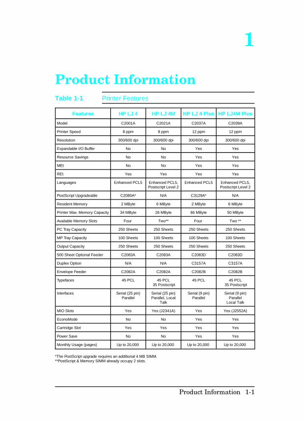
Features HP LJ 4 HP LJ 4M HP LJ 4 Plus HP LJ4M Plus
Model C2001A C2021A C2037A C2039A
Printer Speed 8 ppm 8 ppm 12 ppm 12 ppm
Resolution 300/600 dpi 300/600 dpi 300/600 dpi 300/600 dpi
Expandable I/O Buffer No No Yes Yes
Resource Savings No No Yes Yes
MEt No No Yes Yes
REt Yes Yes Yes Yes
Languages Enhanced PCL5 Enhanced PCL5,Postscript Level 2
Enhanced PCL5 Enhanced PCL5,Postscript Level 2
PostScript Upgradeable C2080A* N/A C3129A* N/A
Resident Memory 2 MByte 6 MByte 2 MByte 6 MByte
Printer Max. Memory Capacity 34 MByte 26 MByte 66 MByte 50 MByte
Available Memory Slots Four Two** Four Two **
PC Tray Capacity 250 Sheets 250 Sheets 250 Sheets 250 Sheets
MP Tray Capacity 100 Sheets 100 Sheets 100 Sheets 100 Sheets
Output Capacity 250 Sheets 250 Sheets 250 Sheets 250 Sheets
500 Sheet Optional Feeder C2083A C2083A C2083D C2083D
Duplex Option N/A N/A C3157A C3157A
Envelope Feeder C2082A C2082A C2082B C2082B
Typefaces 45 PCL 45 PCL 35 Postscript
45 PCL 45 PCL 35 Postscript
Interfaces Serial (25 pin)Parallel
Serial (25 pin)Parallel, Local
Talk
Serial (9 pin)Parallel
Serial (9 pin)Parallel
Local Talk
MIO Slots Yes Yes (J2341A) Yes Yes (J2552A)
EconoMode No No Yes Yes
Cartridge Slot Yes Yes Yes Yes
Power Save No No Yes Yes
Monthly Usage (pages) Up to 20,000 Up to 20,000 Up to 20,000 Up to 20,000
*The PostScript upgrade requires an additional 4 MB SIMM. **PostScript & Memory SIMM already occupy 2 slots.
Table 1-1 Printer Features
Product Information 1-1
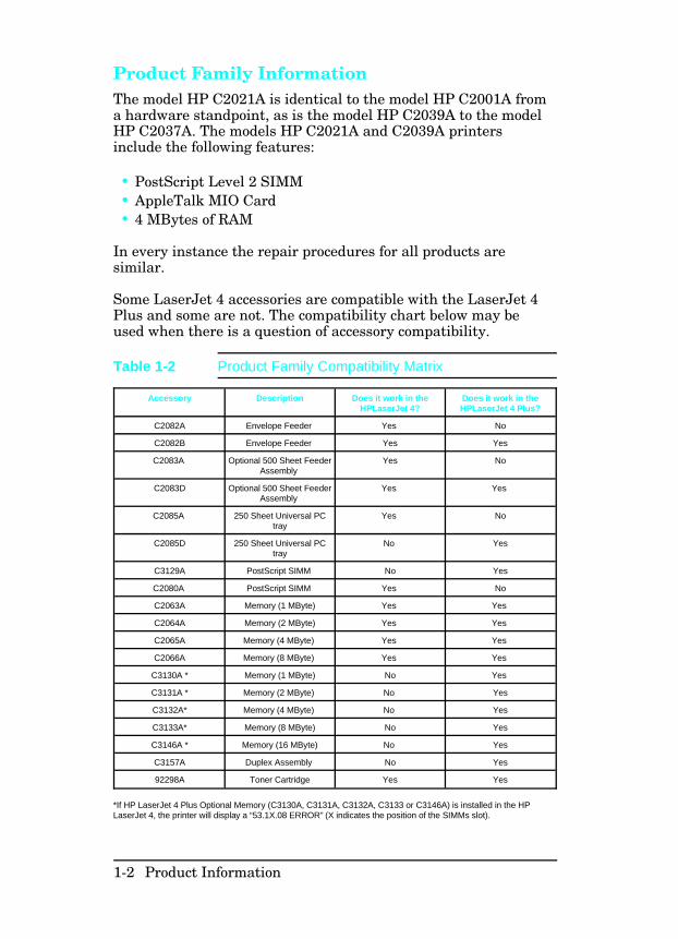
Product Family InformationThe model HP C2021A is identical to the model HP C2001A froma hardware standpoint, as is the model HP C2039A to the modelHP C2037A. The models HP C2021A and C2039A printersinclude the following features:
• PostScript Level 2 SIMM• AppleTalk MIO Card• 4 MBytes of RAM
In every instance the repair procedures for all products aresimilar.
Some LaserJet 4 accessories are compatible with the LaserJet 4Plus and some are not. The compatibility chart below may beused when there is a question of accessory compatibility.
Accessory Description Does it work in theHPLaserJet 4?
Does it work in theHPLaserJet 4 Plus?
C2082A Envelope Feeder Yes No
C2082B Envelope Feeder Yes Yes
C2083A Optional 500 Sheet FeederAssembly
Yes No
C2083D Optional 500 Sheet FeederAssembly
Yes Yes
C2085A 250 Sheet Universal PCtray
Yes No
C2085D 250 Sheet Universal PCtray
No Yes
C3129A PostScript SIMM No Yes
C2080A PostScript SIMM Yes No
C2063A Memory (1 MByte) Yes Yes
C2064A Memory (2 MByte) Yes Yes
C2065A Memory (4 MByte) Yes Yes
C2066A Memory (8 MByte) Yes Yes
C3130A * Memory (1 MByte) No Yes
C3131A * Memory (2 MByte) No Yes
C3132A* Memory (4 MByte) No Yes
C3133A* Memory (8 MByte) No Yes
C3146A * Memory (16 MByte) No Yes
C3157A Duplex Assembly No Yes
92298A Toner Cartridge Yes Yes
*If HP LaserJet 4 Plus Optional Memory (C3130A, C3131A, C3132A, C3133 or C3146A) is installed in the HPLaserJet 4, the printer will display a “53.1X.08 ERROR” (X indicates the position of the SIMMs slot).
Table 1-2 Product Family Compatibility Matrix
1-2 Product Information
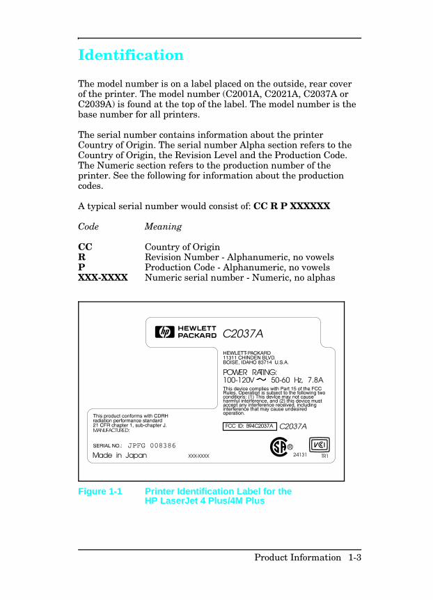
Identification
The model number is on a label placed on the outside, rear coverof the printer. The model number (C2001A, C2021A, C2037A orC2039A) is found at the top of the label. The model number is thebase number for all printers.
The serial number contains information about the printerCountry of Origin. The serial number Alpha section refers to theCountry of Origin, the Revision Level and the Production Code.The Numeric section refers to the production number of theprinter. See the following for information about the productioncodes.
A typical serial number would consist of: CC R P XXXXXX
Code Meaning
CC Country of OriginR Revision Number - Alphanumeric, no vowelsP Production Code - Alphanumeric, no vowelsXXX-XXXX Numeric serial number - Numeric, no alphas
TR1
FCC ID: B94C2037A
24131
POWER RATING:100-120V 50-60 Hz, 7.8A
MANUFACTURED:
C2037A
Made in Japan
C2037A
XXX-XXXX
Figure 1-1 Printer Identification Label for theHP LaserJet 4 Plus/4M Plus
Product Information 1-3
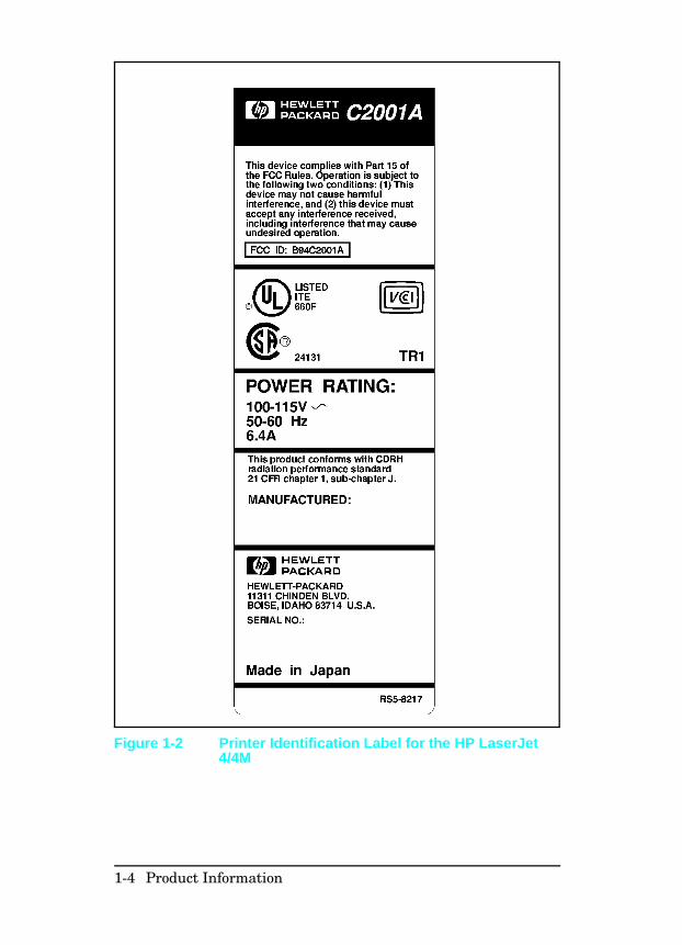
Figure 1-2 Printer Identification Label for the HP LaserJet4/4M
1-4 Product Information
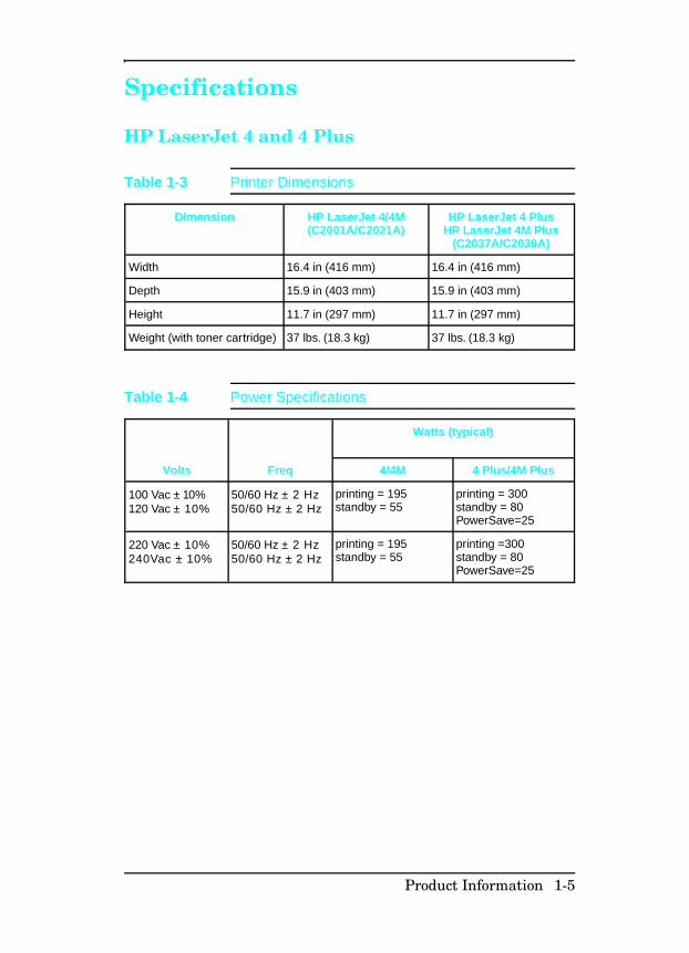
Specifications
HP LaserJet 4 and 4 Plus
Dimension HP LaserJet 4/4M(C2001A/C2021A)
HP LaserJet 4 PlusHP LaserJet 4M Plus
(C2037A/C2039A)
Width 16.4 in (416 mm) 16.4 in (416 mm)
Depth 15.9 in (403 mm) 15.9 in (403 mm)
Height 11.7 in (297 mm) 11.7 in (297 mm)
Weight (with toner cartridge) 37 lbs. (18.3 kg) 37 lbs. (18.3 kg)
Table 1-3 Printer Dimensions
Watts (typical)
Volts Freq 4/4M 4 Plus/4M Plus
100 Vac ± 10%120 Vac ± 10%
50/60 Hz ± 2 Hz50/60 Hz ± 2 Hz
printing = 195standby = 55
printing = 300standby = 80PowerSave=25
220 Vac ± 10%240Vac ± 10%
50/60 Hz ± 2 Hz50/60 Hz ± 2 Hz
printing = 195standby = 55
printing =300standby = 80PowerSave=25
Table 1-4 Power Specifications
Product Information 1-5
Status 100/115 V4/4M 4 Plus/4M
Plus
220/240 V4/4M 4 Plus/4M
Plus
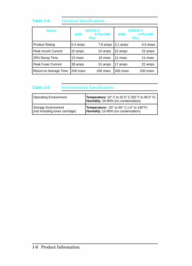
Product Rating 6.4 amps 7.8 amps 3.1 amps 4.0 amps
Peak Inrush Current 22 amps 22 amps 22 amps 22 amps
25% Decay Time 13 msec 18 msec 11 msec 11 msec
Peak Fuser Current 38 amps 51 amps 17 amps 22 amps
Return-to Average Time 200 msec 200 msec 200 msec 200 msec
Table 1-6 Electrical Specifications
Operating Environment Temperature: 10° C to 32.5° C (50° F to 90.5° F)Humidity: 20-80% (no condensation)
Storage Environment(not including toner cartridge)
Temperature: -20° to 60° C (-4° to 140°F)Humidity: 15-90% (no condensation)
Table 1-5 Environmental Specifications
1-6 Product Information
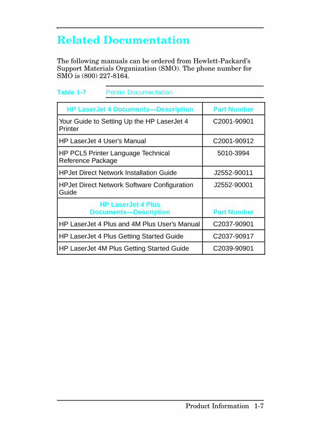
Related Documentation
The following manuals can be ordered from Hewlett-Packard’sSupport Materials Organization (SMO). The phone number forSMO is (800) 227-8164.
HP LaserJet 4 Documents—Description Part Number
Your Guide to Setting Up the HP LaserJet 4Printer
C2001-90901
HP LaserJet 4 User’s Manual C2001-90912
HP PCL5 Printer Language TechnicalReference Package
5010-3994
HPJet Direct Network Installation Guide J2552-90011
HPJet Direct Network Software ConfigurationGuide
J2552-90001
HP LaserJet 4 PlusDocuments—Description Part Number
HP LaserJet 4 Plus and 4M Plus User’s Manual C2037-90901
HP LaserJet 4 Plus Getting Started Guide C2037-90917
HP LaserJet 4M Plus Getting Started Guide C2039-90901
Table 1-7 Printer Documentation
Product Information 1-7
Safety Information
Product and Laser Safety HP printers are UL 1950 listed, CSA 22.2 950 certified, andmanufactured in accordance with DIN IEC 950. The printers arecertified as “Class 1” laser products under the U.S. Department ofHealth and Human Services (DHHS) Radiation PerformanceStandard, according to the Radiation Control for Health andSafety Act of 1968. The printers do not produce hazardous laserradiation.
Since radiation emitted inside the printer is completely confinedwithin protective housings and external covers, the laser beamcannot escape during any phase of normal user operation.
The Center for Devices and Radiological Health (CDRH) of theU.S. Food and Drug Administration implemented regulations forlaser products on August 2, 1976. These regulations apply tolaser products manufactured from August 1, 1976. Compliance ismandatory for products marketed in the United States.
N o t e In accordance with West German standardVDE0836 (VDE-Bestimmung fur die ElektrischeSicherheit von Lasergeraten und Anlagen), twoservicemen are required to service each unit.
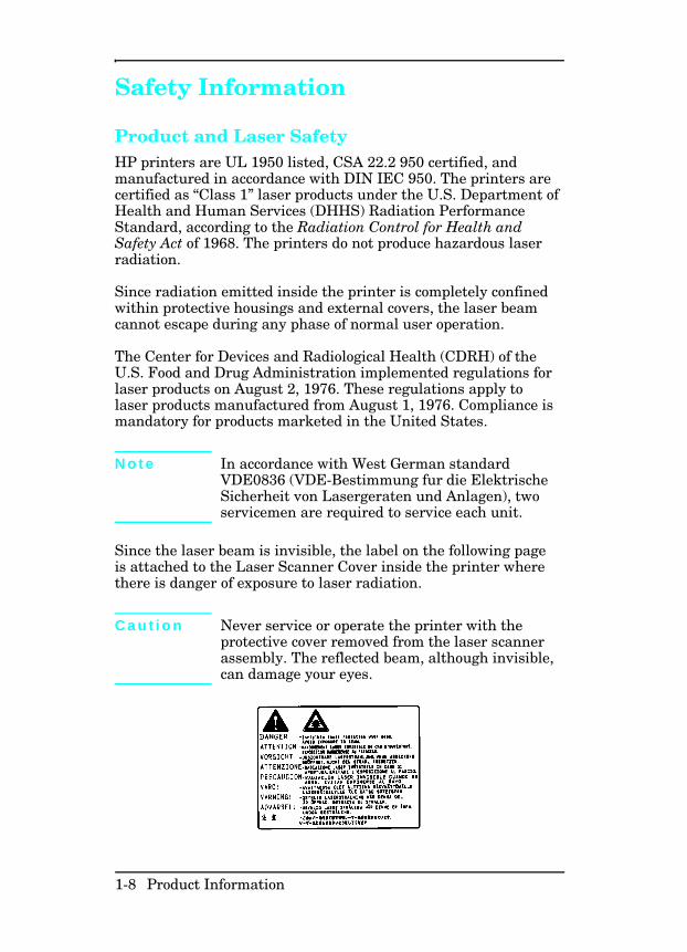
Since the laser beam is invisible, the label on the following pageis attached to the Laser Scanner Cover inside the printer wherethere is danger of exposure to laser radiation.
C a u t i o n Never service or operate the printer with theprotective cover removed from the laser scannerassembly. The reflected beam, although invisible,can damage your eyes.
1-8 Product Information
FCC RFI Statement This equipment has been tested and found to comply with thelimits for a Class B digital device, pursuant to Part 15 of the FCCRules. These limits are designed to provide reasonable protectionagainst harmful interference when the equipment is operated in acommercial environment. This equipment generates, uses, andcan radiate radio frequency energy and, if not installed and usedin accordance with the instruction manual, may cause harmfulinterference to radio communications. However, there is noguarantee that interference will not occur in a particularinstallation. If this equipment does cause harmful interference toradio or television reception, which can be determined by turningthe equipment off and on, the user is encouraged to try to correctthe interference by one or more of the following measures:
• Reorient or relocate the receiving attenna.• Increase the separation between the equipment and the
receiver.• Connect the equipment into an outlet on a circuit different
from that to which the receiver is connected.• Consult the dealer or an experienced radio/TV technician for
help.
Any changes or modifications not expressly approved byHewlett-Packard could void the user’s authority to operate thisequipment.
N o t e Use of a shielded interface cable is required tocomply with the Class B limits of Part 15 of theFCC rules.
This product also meets the FCC Class A emission standards.
Product Information 1-9

Laser Statement (Sweden/Finland) LASERTURVALLISUUS
LUOKAN 1 LASERLAITEKLASS 1 LASER APPARAT
HP LaserJet(s) 4/4M, 4 Plus/4M Plus laserkirjoitin on käyttäjänkannalta turvallinen luokan 1 laserlaite. Normaalissa käytössäkirjoittimen suojakotelointi estää lasersäteen pääsyn laitteenulkopuolelle.
Kirjoittimen on hyväksynyt Suomessa laserturvallisuuden osaltaSähkötarkastuskeskus. Laitteen turvallisuusluokka onmääritetty valtioneuvoston päätöksen N:o 472/1985 ja standardinEN 60825 (1991) mukaisesti.
VAROITUS ! Laitteen käyttäminen muulla kuin käyttöohjeessamainitulla tavalla saattaa altistaa käyttäjän turvallisuusluokan1 ylittävälle näkymättömälle lasersäteilylle.
VARNING ! Om apparaten används på annat sätt än ibruksanvisning specificerats, kan användaren utsättas förosynlig laserstrålning, som överskrider gränsen för laserklass 1.
HUOLTO HP LaserJet (s) 4/4M, 4 Plus/4M Plus-kirjoittimensisällä ei ole käyttäjän huollettavissa olevia kohteita. Laitteensaa avata ja huoltaa ainoastaan sen huoltamiseen koulutettuhenkilö. Tällaiseksi huoltotoimenpiteeksi ei katsotaväriainekasetin vaihtamista, paperiradan puhdistusta tai muitakäyttäjän käsikirjassa lueteltuja, käyttäjän tehtäväksitarkoitettuja ylläpitotoimia, jotka voidaan suorittaa ilmanerikoistyökaluja.
VARO !Mikäli kirjoittimen suojakotelo avataan, olet alttiinanäkymättömälle lasersäteilylle laitteen ollessa toiminnassa. Äläkatso säteeseen.
VARNING !Om laserprinterns skyddshölje öppnas då apparatenär i funktion, utsättas användaren för osynlig laserstrålning.Betrakta ej strålen.
Tiedot laitteessa käytettävän laserdiodin säteilyominaisuuksista:
Aallonpituus 770-795 nmTeho 5 mWLuokan 3B laser
1-10 Product Information
Toner Safety
N o t e Toner may stain clothing. Skin and clothing arebest cleaned by removing as much toner aspossible with a dry tissue, then washing with coldwater. Hot water causes toner to melt andpermanently fuse into clothing.
A Material Safety Data Sheet (MSDS) for the toner cartridgeused in the HP printers, is available through Hewlett-Packard byeither mail or fax.
Mail. To obtain a MSDS for the 92298A LaserJet Toner ImagingSystem through the mail, call the Customer Information Center(CIC) at 1-800-752-0900 between 6 A.M. and 5 P.M. PacificStandard Time. Fax. To obtain a MSDS for the 92298A LaserJet Toner ImagingSystem by fax, call the HP FIRST number at (800) 333-1917 (U.S.and Canada) and enter document number 1512.
N o t e To get documents from HP FIRST by fax, youmust use a Group 3 (touchtone) fax machine.
Ozone Statement These printers do not use high voltage corona wires in theelectro-photographic process, and therefore generate nomeasurable ozone gas (O3). They use a charging roller in thetoner cartridge and a charging transfer roller in the printer.
Product Information 1-11

Doing Business with HP
Technical Assistance
HP ASAP 1-800-333-1917 (U.S.)HP ASAP (Automated Support Access Program) provides freetechnical support information 24 hours a day, 7 days a week. TheASAP system includes HP FIRST and HP AUDIO-TIPS, bothexplained below. The ASAP service requires a touch-tone phone.
HP FIRSTHP FIRST (Fax Information Retrieval Support Technology) is aphone-in fax service providing technical information for HPLaserJet users as well as service personnel. Receiving a faxrequires a group 3 facsimile machine or fax card. Service-relatedinformation includes:
• Service notes (HP Authorized Dealers) (password = 737842).• Application notes.• Product Data Sheets.• Material Safety Data Sheets (MSDS).• Typeface and accessory information.• Printer support software information.• Toner information.• Driver request form and Software Matrix.
HP FIRST, U.S.Call the HP ASAP system (1-800-333-1917) and follow the voiceprompts to enter HP FIRST.
HP FIRST, EuropeCall HP FIRST at one of the following numbers:
U.K., 0-800-96-02-71 Netherlands, 06-02-22-420Belgium (Dutch), 0800-1-1906 Germany, 0130-8100-61Switzerland (German), 155-1527 Austria, 0660-8128For English service outside the above countries, (31) 20-681-5792
1-12 Product Information
HP AUDIO-TIPSHP AUDIO-TIPS, available within HP ASAP, is an interactivevoice response system providing pre-recorded answers to thequestions most frequently asked by HP LaserJet printer users.Helpful “System Maps” to the HP AUDIO-TIPS recordings areavailable by fax through HP FIRST.
HP CompuServe ForumCompuServe members can download a variety of supportmaterials including product data sheets, software applicationnotes, and printer drivers for many popular softwareapplications. Members may also post and reply to questions in aninteractive format. To access the HP Forum, type GO HPPER atany prompt. For more information, or to join CompuServe, call1-800-524-3388.
Customer Information CentersFor further technical assistance, service-authorized HP anddealer service personnel can contact the nearest Hewlett-PackardCustomer Information Center, 1-800-752-0900 in North America.
Customer Support Center (Assist Line)The HP Customer Support Center, (208-323-2551) is available toanswer technical questions regarding setup, configuration,installation and operation of HP printers in the PC andMacintosh environments. The CSC Assist Line is availableweekdays from 7 am to 6 pm Mountain Time (Wednesdays until4 pm).
Questions relating to operating systems such as MS-DOS andUNIX, your network configuration, or network operating systemcannot be answered by the Center and should be referred to yourauthorized reseller.
Printer DriversTo order additional drivers for your software applications, call theHP Driver Distribution Center at 1-970-339-7009.
Product Information 1-13

European Customer Support Center The HP European Customer Support Center, located inAmsterdam, Holland, is open from 8:30 am to 6:00 pm centralEuropean time (Wednesdays until 4:00 pm). Multilingualcustomer support representatives can answer technical questionssimilar to the U.S. CSC, described on the previous page. Thisservice is available at no charge for a period equivalent to theoriginal HP hardware warranty period.
Each time you call the HP European Customer Support Center,you will be required to provide the printer’s serial number andoriginal date of purchase.
To receive a fax listing the supported languages on a country’sphone number, call HP FIRST (refer to “HP FIRST,” earlier inthis section). You can also call the nearest HP Sales and Serviceoffice to obtain the telephone number for the Center. The Centerfeatures automated call-routing technology, so you will receivefaster service if calling from a touchtone phone or tone dialer.
Other AreasOutside of North America and Europe, contact your local HPsales office for assistance in obtaining technical support.
1-14 Product Information
2
Site Planning andRequirements
Site Requirements
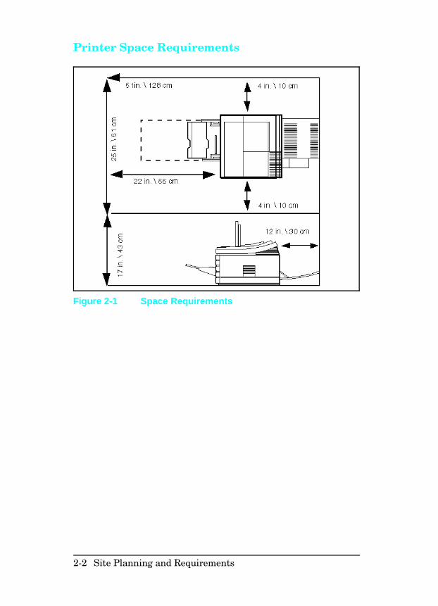
The environmental specifications, listed in the Specificationssection of Chapter 1, must be maintained to ensure the properoperation of this printer. Consider the following points beforeinstalling the printer:
• Install the printer in a well-ventilated area.• Install the printer on a sturdy, level surface.• Install the printer where the temperature and humidity do not
change abruptly. Do not position the printer near watersources, humidifiers, air conditioners, refrigerators, or othermajor appliances.
• Do not expose the printer to direct sunlight, dust, open flames,or ammonia fumes. If the printer is placed near a window,make sure the window has a curtain or blind to block directsunlight.
• Install the printer away from walls. There must be enoughspace around the printer for proper access and operation (seeFigure 2-1).
Site Planning and Requirements 2-1
Printer Space Requirements
Figure 2-1 Space Requirements
2-2 Site Planning and Requirements
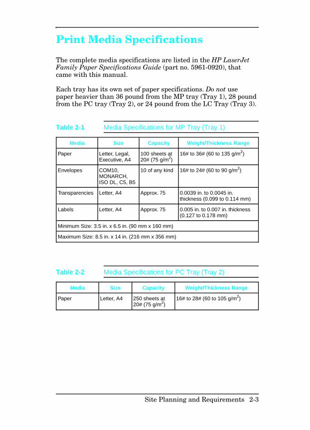
Print Media Specifications
The complete media specifications are listed in the HP LaserJetFamily Paper Specifications Guide (part no. 5961-0920), thatcame with this manual.
Each tray has its own set of paper specifications. Do not usepaper heavier than 36 pound from the MP tray (Tray 1), 28 poundfrom the PC tray (Tray 2), or 24 pound from the LC Tray (Tray 3).
Media Size Capacity Weight/Thickness Range
Paper Letter, Legal,Executive, A4
100 sheets at20# (75 g/m2)
16# to 36# (60 to 135 g/m2)
Envelopes COM10,MONARCH,ISO DL, C5, B5
10 of any kind 16# to 24# (60 to 90 g/m2)
Transparencies Letter, A4 Approx. 75 0.0039 in. to 0.0045 in.thickness (0.099 to 0.114 mm)
Labels Letter, A4 Approx. 75 0.005 in. to 0.007 in. thickness(0.127 to 0.178 mm)
Minimum Size: 3.5 in. x 6.5 in. (90 mm x 160 mm)
Maximum Size: 8.5 in. x 14 in. (216 mm x 356 mm)
Table 2-1 Media Specifications for MP Tray (Tray 1)
Media Size Capacity Weight/Thickness Range
Paper Letter, A4 250 sheets at20# (75 g/m2)
16# to 28# (60 to 105 g/m2)
Table 2-2 Media Specifications for PC Tray (Tray 2)
Site Planning and Requirements 2-3
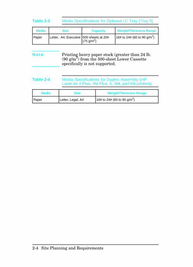
N o t e Printing heavy paper stock (greater than 24 lb.(90 g/m2) from the 500-sheet Lower Cassettespecifically is not supported.
Media Size Capacity Weight/Thickness Range
Paper Letter, A4, Executive 500 sheets at 20#(75 g/m2)
16# to 24# (60 to 90 g/m2)
Table 2-3 Media Specifications for Optional LC Tray (Tray 3)
Media Size Weight/Thickness Range
Paper Letter, Legal, A4 16# to 24# (60 to 90 g/m2)
Table 2-4 Media Specifications for Duplex Assembly (HPLaserJet 4 Plus, 4M Plus, 5, 5M, and 5N printers)
2-4 Site Planning and Requirements
Adhesive Labels
N o t e Printing labels using the Duplex Assembly , the500-sheet Lower Cassette (Tray 3) or the PC tray(Tray 2) specifically is not supported. Always usethe MP tray (Tray 1) to print labels.
Label ConstructionWhen selecting labels, consider the quality of each component:
• Adhesives: The adhesive material should be stable at the392° F (200° C) temperatures encountered in the printer’sfusing process. None of the adhesive should be exposedbetween the labels.
• Label arrangement: If possible, use labels with no exposedareas between labels. If labels with exposed areas are used,they should be arranged on the carrier sheet (the backing) sothat they cover the entire page with the exposed areas of thecarrier sheet running lengthwise down the sheet. Using labelstock with spaces between labels often results in labels peelingoff during the printing cycle, causing serious jammingproblems.
• Label curl: Labels must lie flat with no more than0.5in(13mm) of curl in any direction.
• Poorly manufactured labels: Do not use labels withwrinkles, bubbles, or other indications of delamination.
Site Planning and Requirements 2-5
Overhead Transparencies
N o t e Printing overhead transparencies using theDuplex Assembly, the 500-sheet Lower Cassette(Tray 3) or PC tray (Tray 2) specifically is notsupported.
Overhead transparencies used in HP LaserJet printers must beable to withstand the 392° F (200° C) temperature encountered inthe printer’s fusing process. See the HP LaserJet Family PaperSpecifications Guide for more information.
C a u t i o n Use only overhead transparencies recommendedfor use in laser printers.
Envelopes Many kinds of envelopes can be printed with your printer. Someenvelope styles perform better than others because theirconstruction is better suited to feeding through a laser printer.
Hewlett-Packard Company neither warrants nor recommends theuse of a particular brand of envelope. Envelope properties aresubject to change by envelope manufacturers, andHewlett-Packard Company has no control over such changes.
2-6 Site Planning and Requirements
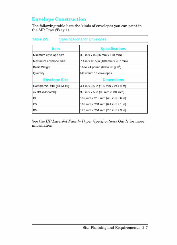
Envelope ConstructionThe following table lists the kinds of envelopes you can print inthe MP Tray (Tray 1).
See the HP LaserJet Family Paper Specifications Guide for moreinformation.
Item Specifications
Minimum envelope size 3.5 in x 7 in (86 mm x 178 mm)
Maximum envelope size 7.4 in x 10.5 in (188 mm x 267 mm)
Basis Weight 16 to 24 pound (60 to 90 g/m2)
Quantity Maximum 10 envelopes
Envelope Size Dimensions
Commercial #10 (COM 10) 4.1 in x 9.5 in (105 mm x 241 mm)
#7 3/4 (Monarch) 3.8 in x 7.5 in (98 mm x 191 mm)
DL 109 mm x 218 mm (4.3 in x 8.6 in)
C5 163 mm x 231 mm (6.4 in x 9.1 in)
B5 178 mm x 251 mm (7.0 in x 9.9 in)
Table 2-5 Specifications for Envelopes
Site Planning and Requirements 2-7

2-8 Site Planning and Requirements
3
Configuration
Introduction
The Configuration of the printer consists of setting hard and softuser defaults, and setting up the host computer to communicatewith the printer (System Configuration). For installationinstructions refer to Installation in the Getting Started Manualthat is shipped with the printer.
Hard defaults are the I/O Menu and Configuration Menusettings. These are set when the printer is installed and remainas configured. The soft defaults (Printing menu and PCL menu)change with the print job requirements. System Configurationincludes installing printer drivers, MODE commands andupdating the AUTOEXEC.BAT file.
The instructions in this chapter explain how to access the printerfeatures through the control panel, and how to set up the printerin different configurations. This chapter explains how to checkthe configuration settings, and how to verify that a configurationis correctly selected.
Setup and configuration information for accessories is availablein this chapter. This information is intended to augment and notreplace the information provided with the accessories themselves.If possible, use the information provided with the accessorieswhen installing the accessory products.
Use the information that comes with the printer drivers wheninstalling the printer. Many features of the printer are notavailable without the correct printer driver for the softwareapplication.
Configuration 3-1
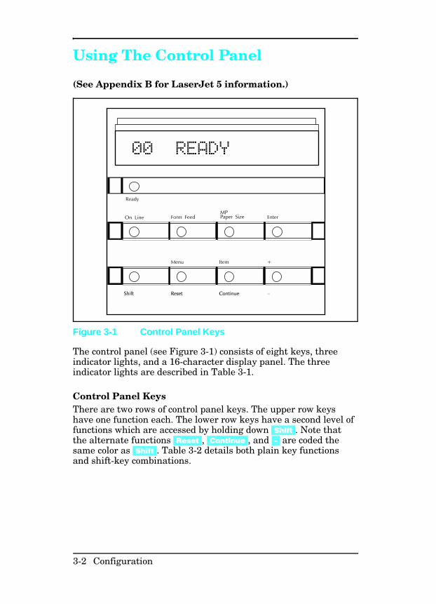
Using The Control Panel
(See Appendix B for LaserJet 5 information.)
The control panel (see Figure 3-1) consists of eight keys, threeindicator lights, and a 16-character display panel. The threeindicator lights are described in Table 3-1.
Control Panel Keys There are two rows of control panel keys. The upper row keyshave one function each. The lower row keys have a second level offunctions which are accessed by holding down [Shift]. Note thatthe alternate functions [Reset], [Continue], and [-] are coded thesame color as [Shift]. Table 3-2 details both plain key functionsand shift-key combinations.
Figure 3-1 Control Panel Keys
3-2 Configuration
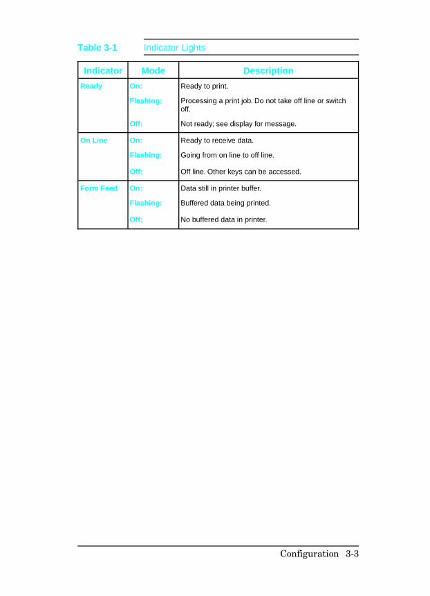
Indicator Mode Description
Ready On: Ready to print.
Flashing: Processing a print job. Do not take off line or switchoff.
Off: Not ready; see display for message.
On Line On: Ready to receive data.
Flashing: Going from on line to off line.
Off: Off line. Other keys can be accessed.
Form Feed On: Data still in printer buffer.
Flashing: Buffered data being printed.
Off: No buffered data in printer.
Table 3-1 Indicator Lights
Configuration 3-3
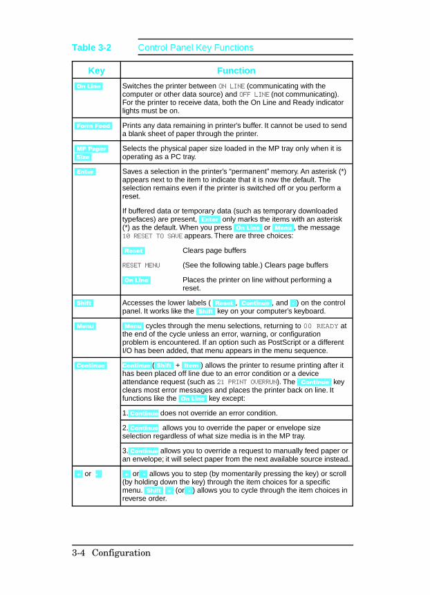
Key Function
[On Line] Switches the printer between ON LINE (communicating with thecomputer or other data source) and OFF LINE (not communicating).For the printer to receive data, both the On Line and Ready indicatorlights must be on.
[Form Feed] Prints any data remaining in printer’s buffer. It cannot be used to senda blank sheet of paper through the printer.
[MP Paper Size]
Selects the physical paper size loaded in the MP tray only when it isoperating as a PC tray.
[Enter] Saves a selection in the printer’s “permanent” memory. An asterisk (*)appears next to the item to indicate that it is now the default. Theselection remains even if the printer is switched off or you perform areset.
If buffered data or temporary data (such as temporary downloadedtypefaces) are present, [Enter] only marks the items with an asterisk(*) as the default. When you press [On Line] or [Menu], the message10 RESET TO SAVE appears. There are three choices:
[Reset] Clears page buffers
RESET MENU (See the following table.) Clears page buffers
[On Line] Places the printer on line without performing areset.
[Shift] Accesses the lower labels ( [Reset], [Continue], and [-]) on the controlpanel. It works like the [Shift] key on your computer’s keyboard.
[Menu] [Menu] cycles through the menu selections, returning to 00 READY atthe end of the cycle unless an error, warning, or configurationproblem is encountered. If an option such as PostScript or a differentI/O has been added, that menu appears in the menu sequence.
[Continue] Continue ([Shift] + [Item]) allows the printer to resume printing after ithas been placed off line due to an error condition or a deviceattendance request (such as 21 PRINT OVERRUN). The [Continue] keyclears most error messages and places the printer back on line. Itfunctions like the [On Line] key except:
1. Continue does not override an error condition.
2. Continue allows you to override the paper or envelope sizeselection regardless of what size media is in the MP tray.
3. Continue allows you to override a request to manually feed paper oran envelope; it will select paper from the next available source instead.
[+] or -] [+] or [-] allows you to step (by momentarily pressing the key) or scroll(by holding down the key) through the item choices for a specificmenu. [Shift] [+] (or [-]) allows you to cycle through the item choices inreverse order.
Table 3-2 Control Panel Key Functions
3-4 Configuration
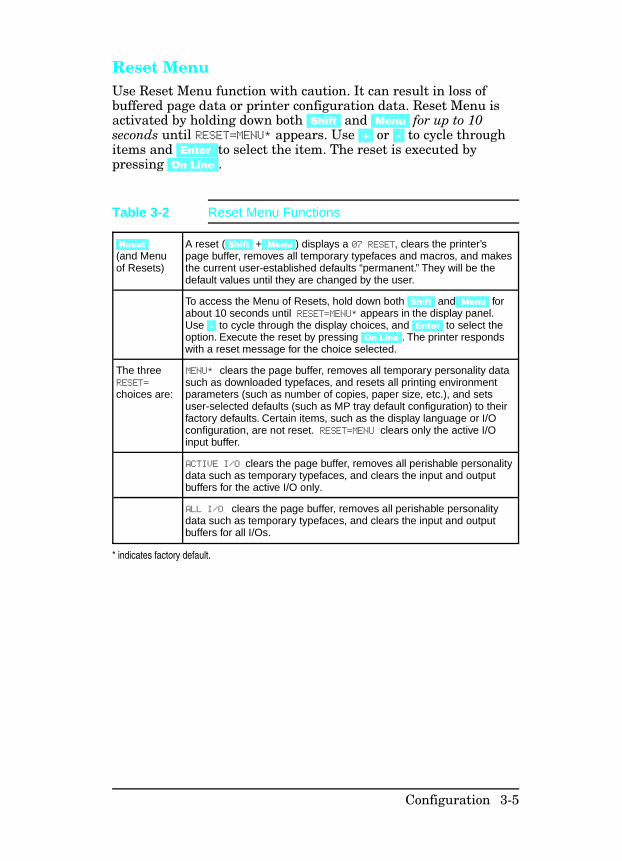
Reset Menu Use Reset Menu function with caution. It can result in loss ofbuffered page data or printer configuration data. Reset Menu isactivated by holding down both [Shift] and [Menu] for up to 10seconds until RESET=MENU* appears. Use [+] or [-] to cycle throughitems and [Enter] to select the item. The reset is executed bypressing [On Line].
[Reset](and Menuof Resets)
A reset ([Shift] + [Menu]) displays a 07 RESET, clears the printer’spage buffer, removes all temporary typefaces and macros, and makesthe current user-established defaults “permanent.” They will be thedefault values until they are changed by the user.
To access the Menu of Resets, hold down both [Shift] and [Menu] forabout 10 seconds until RESET=MENU* appears in the display panel.Use [-] to cycle through the display choices, and [Enter] to select theoption. Execute the reset by pressing [On Line]. The printer respondswith a reset message for the choice selected.
The threeRESET=
choices are:
MENU* clears the page buffer, removes all temporary personality datasuch as downloaded typefaces, and resets all printing environmentparameters (such as number of copies, paper size, etc.), and setsuser-selected defaults (such as MP tray default configuration) to theirfactory defaults. Certain items, such as the display language or I/Oconfiguration, are not reset. RESET=MENU clears only the active I/Oinput buffer.
ACTIVE I/O clears the page buffer, removes all perishable personalitydata such as temporary typefaces, and clears the input and outputbuffers for the active I/O only.
ALL I/O clears the page buffer, removes all perishable personalitydata such as temporary typefaces, and clears the input and outputbuffers for all I/Os.
* indicates factory default.
Table 3-2 Reset Menu Functions
Configuration 3-5
Control Panel MenusFigure 3-2 shows the menus and menu items available with thebasic printer configuration. Not all menu items are discussed inthis section. Only those items of specific interest from a servicestandpoint, or items new to the printers are discussed in thissection. If options such as PostScript or a different I/O areinstalled, new menu items automatically are added at theappropriate location. For example, a PostScript Menu appearsfollowing the PCL Menu.
3-6 Configuration
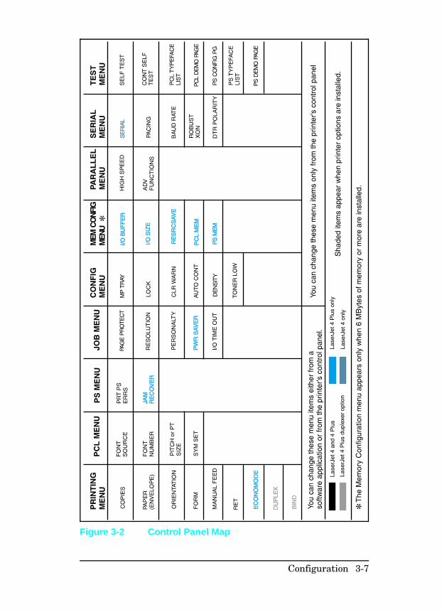
Figure 3-2 Control Panel Map
Configuration 3-7
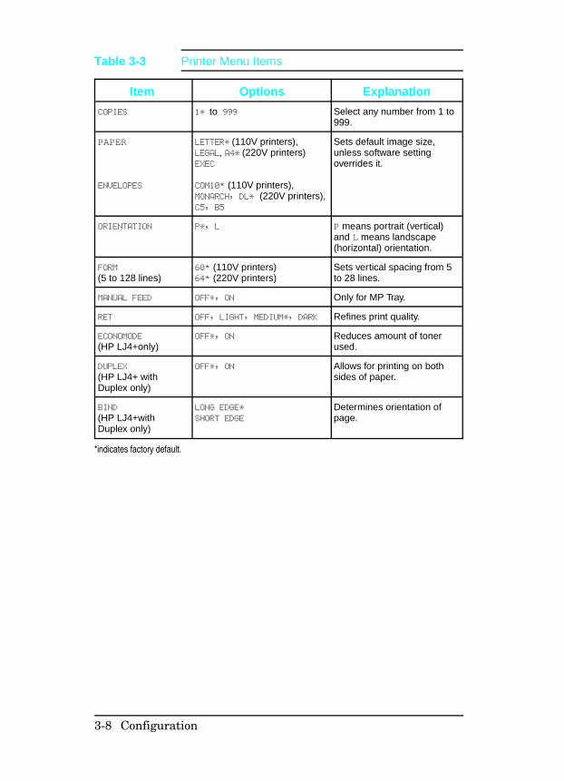
Item Options Explanation
COPIES 1* to 999 Select any number from 1 to999.
PAPER
ENVELOPES
LETTER* (110V printers),LEGAL, A4* (220V printers)EXEC
COM10* (110V printers),MONARCH, DL* (220V printers),C5, B5
Sets default image size,unless software settingoverrides it.
ORIENTATION P*, L P means portrait (vertical)and L means landscape(horizontal) orientation.
FORM
(5 to 128 lines)60* (110V printers)64* (220V printers)
Sets vertical spacing from 5to 28 lines.
MANUAL FEED OFF*, ON Only for MP Tray.
RET OFF, LIGHT, MEDIUM*, DARK Refines print quality.
ECONOMODE
(HP LJ4+only)OFF*, ON Reduces amount of toner
used.
DUPLEX
(HP LJ4+ withDuplex only)
OFF*, ON Allows for printing on bothsides of paper.
BIND
(HP LJ4+withDuplex only)
LONG EDGE*
SHORT EDGE
Determines orientation ofpage.
*indicates factory default.
Table 3-3 Printer Menu Items
3-8 Configuration
Item Options Explanation
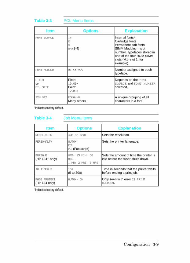
FONT SOURCE I*
C
S
Mn (1-4)
Internal fonts*Cartridge fontsPermanent soft fontsSIMM Module: n=slotnumber. Typefaces stored inone of the four ROM SIMMslots (M1=slot 1, forexample).
FONT NUMBER 0* to 999 Number assigned to eachtypeface.
PITCH
or
PT. SIZE
Pitch:10.00*
Point:12.00*
Depends on the FONTSOURCE and FONT NUMBERselected.
SYM SET ROMAN-8
Many othersA unique grouping of allcharacters in a font.
*indicates factory default.
Table 3-3 PCL Menu Items
Item Options Explanation
RESOLUTION 300 or 600* Sets the resolution.
PERSONALTY AUTO*
PCL
PS (Postscript)
Sets the printer language.
PWRSAVE
(HP LJ4+ only)OFF, 15 MIN, 30
MIN,
1 HR, 2 HRS, 3 HRS
Sets the amount of time the printer isidle before the fuser shuts down.
IO TIMEOUT 15*
(5 to 300)Time in seconds that the printer waitsbefore ending a print job.
PAGE PROTECT
(HP LJ4 only)AUTO*, ON Only seen with error 21 PRINT
OVERRUN.
*indicates factory default.
Table 3-4 Job Menu Items
Configuration 3-9
Item Options Explanation
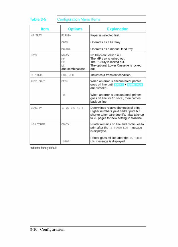
MP TRAY FIRST*
CASS
MANUAL
Paper is selected first.
Operates as a PC tray.
Operates as a manual feed tray.
LOCK NONE*
MP
PC
LC
and combinations
No trays are locked out.The MP tray is locked out.The PC tray is locked out.The optional Lower Cassette is lockedout.
CLR WARN ON*, JOB Indicates a transient condition.
AUTO CONT OFF*
ON
When an error is encountered, printergoes off line until [SHIFT] + [CONTINUE]are pressed.
When an error is encountered, printergoes off line for 10 secs., then comesback on line.
DENSITY 1, 2, 3*, 4, 5 Determines relative darkness of print.Higher numbers yield darker print butshorter toner cartridge life. May take upto 20 pages for new setting to stabilize.
LOW TONER CONT*
STOP
Printer remains on line and continues toprint after the 16 TONER LOW messageis displayed.
Printer goes off line after the 16 TONERLOW message is displayed.
*indicates factory default.
Table 3-5 Configuration Menu Items
3-10 Configuration
Item Options Explanation
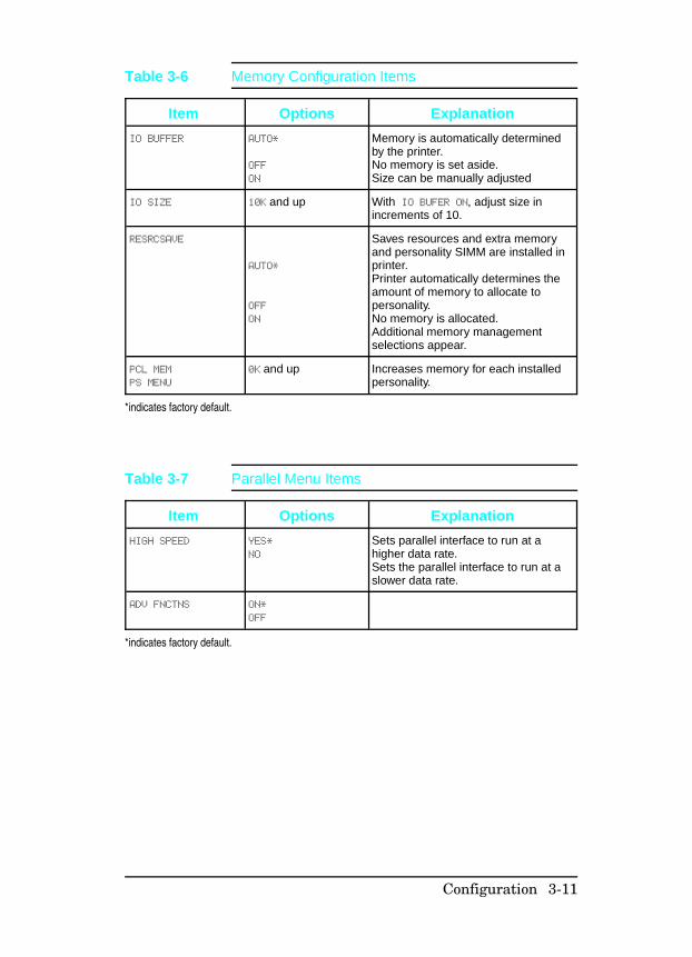
IO BUFFER AUTO*
OFF
ON
Memory is automatically determinedby the printer.No memory is set aside.Size can be manually adjusted
IO SIZE 10K and up With IO BUFER ON, adjust size inincrements of 10.
RESRCSAVE
AUTO*
OFF
ON
Saves resources and extra memoryand personality SIMM are installed inprinter.Printer automatically determines theamount of memory to allocate topersonality.No memory is allocated.Additional memory managementselections appear.
PCL MEM
PS MENU
0K and up Increases memory for each installedpersonality.
*indicates factory default.
Table 3-6 Memory Configuration Items
Item Options Explanation
HIGH SPEED YES*
NO
Sets parallel interface to run at ahigher data rate.Sets the parallel interface to run at aslower data rate.
ADV FNCTNS ON*
OFF
*indicates factory default.
Table 3-7 Parallel Menu Items
Configuration 3-11
Item Options Explanation
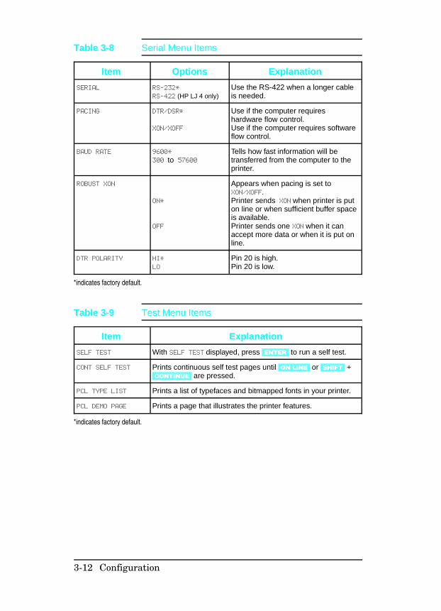
SERIAL RS-232*
RS-422 (HP LJ 4 only)Use the RS-422 when a longer cableis needed.
PACING DTR/DSR*
XON/XOFF
Use if the computer requireshardware flow control.Use if the computer requires softwareflow control.
BAUD RATE 9600*
300 to 57600Tells how fast information will betransferred from the computer to theprinter.
ROBUST XON
ON*
OFF
Appears when pacing is set toXON/XOFF. Printer sends XON when printer is puton line or when sufficient buffer spaceis available.Printer sends one XON when it canaccept more data or when it is put online.
DTR POLARITY HI*
LO
Pin 20 is high.Pin 20 is low.
*indicates factory default.
Table 3-8 Serial Menu Items
Item Explanation
SELF TEST With SELF TEST displayed, press [ENTER] to run a self test.
CONT SELF TEST Prints continuous self test pages until [ON LINE] or [SHIFT] +[CONTINUE] are pressed.
PCL TYPE LIST Prints a list of typefaces and bitmapped fonts in your printer.
PCL DEMO PAGE Prints a page that illustrates the printer features.
*indicates factory default.
Table 3-9 Test Menu Items
3-12 Configuration
Printer Features
Some of the important features of the HP LaserJet 4, 4 Plus, andLaserJet 5 printers are described below.
Page Protection (HP LaserJet 4 only)
N o t e The default is PAGE PROTECT=OFF*. Unless youfrequently get 21 PRINT OVERRUN messages, youmay not need to set a value for page protection.
Page protection reserves additional memory for the page imageprocess, allowing the printer to create an entire page image inmemory before paper starts through the printer. The memoryrequired for page protection is dependent upon the resolutionselected: a 600-dpi page can take 4 times as much memory as a300-dpi page. If you use page protection, set it for the size youexpect to use most often. Be sure you have sufficient installedmemory for the option you select. Complex graphics andPostScript applications also require more memory than isincluded in the standard printer configuration.
N o t e Unlike earlier HP LaserJet printers, pageprotection and resolution can be set regardless ofmemory installed in the printer. Be aware thatsetting page protection ON will decrease theamount of memory available for other memorydependent features.
Configuration 3-13

Resource Saving (HP LaserJet 4 Plus and 5 only)Resource Saving gives the printer the ability to save certainentities such as permanent soft fonts, macros, symbol sets anduser-defined graphics patterns when the printer changespersonalities, resolutions or page protect modes. For example, if auser switches the LaserJet 4 printer from PCL mode toPostScript mode, all PCL soft fonts macros are lost. The HPLaserJet 4 Plus/4M Plus printer would not clear these entitiesfrom memory. When the user switches back to PCL fromPostScript all of the PCL entities would still be resident in theHP LaserJet 4 Plus/4M Plus printer. Resource Saving can only beaccessed when the printer has the PostScript language installedand a minimum memory configuration of 7 MB. If the printer hasa duplexer option, the minimum amount of memory necessary toaccess Resource Saving is 13 MB.
The Resource Saving configuration is located in the MemoryConfiguration Menu. Resource Saving can be set for three modes,AUTO (default), ON, and OFF. Auto configuration sets theResource Saving for PCL and Postscript to a minimum value (400KBytes) for each personality. Setting Resource Saving to ONallows the user to determine how much printer memory will beused for Resource Saving for the PCL personality and thePostscript personality. The memory can be allocated in 100KBytes increments. For example, if the user sets the ResourceSaving memory size to 200 KBytes, a total of 400 KBytes ofmemory will be assigned to Resource Saving. 200 KBytes ofmemory will be used for Postscript Resource Saving and 200KBytes of memory will be used for PCL Resource Saving.Turning Resource Saving OFF disables the Resource Savingfunction and no memory is allocated to Resource Saving.
3-14 Configuration
I/O Buffering (HP LaserJet 4 Plus and 5 only)I/O buffering allows the user to allocate printer memory to holdthe job while it prints, freeing up the host system sooner, like aprint spooler. The standard printer has approximately 10 KBytesof memory allocated to I/O buffering and an additional 100KBytes of memory is assigned to I/O buffering for each 1 MByteof memory added to the printer.
If the printer has a minimum of 6 MBytes of memory installed(12 MBytes of memory for a printer with a duplex option), the I/Obuffer size can also be adjusted from the control panel. Threesettings exist for the I/O buffer; AUTO (default), ON, and OFF.AUTO sets the printer’s I/O buffer to a minimum value that isdetermined by the total amount of memory that is resident in theprinter. Setting I/O buffering to ON allows the user to set the I/Obuffer size from the front panel. Setting the I/O buffering to OFFdisables I/O buffering .
N o t e When you change the I/O buffer setting alldownloaded resources are deleted.
Configuration 3-15
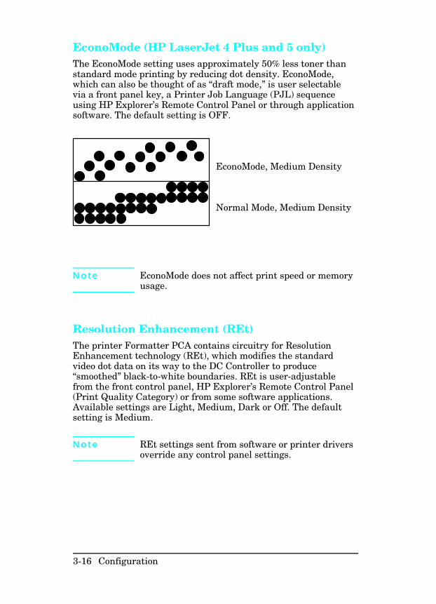
EconoMode (HP LaserJet 4 Plus and 5 only)The EconoMode setting uses approximately 50% less toner thanstandard mode printing by reducing dot density. EconoMode,which can also be thought of as “draft mode,” is user selectablevia a front panel key, a Printer Job Language (PJL) sequenceusing HP Explorer’s Remote Control Panel or through applicationsoftware. The default setting is OFF.
EconoMode, Medium Density
Normal Mode, Medium Density
N o t e EconoMode does not affect print speed or memoryusage.
Resolution Enhancement (REt)The printer Formatter PCA contains circuitry for ResolutionEnhancement technology (REt), which modifies the standardvideo dot data on its way to the DC Controller to produce“smoothed” black-to-white boundaries. REt is user-adjustablefrom the front control panel, HP Explorer’s Remote Control Panel(Print Quality Category) or from some software applications.Available settings are Light, Medium, Dark or Off. The defaultsetting is Medium.
N o t e REt settings sent from software or printer driversoverride any control panel settings.
3-16 Configuration
Memory Enhancement technology (MEt)(HP LaserJet 4 Plus and 5 only)HP Memory Enhancement technology (MEt) effectively doublesthe printer’s standard memory through a variety of font and datacompression methods. MEt also automatically compresses fontsfor desktop publishing applications.
When printing graphics, MEt analyzes each page as it is beingprinted and automatically applies a variety of methods to printthe complete page at the correct resolution. Two of thesemethods, Image Adapt and Page Protect, are user-selectablethrough HP Explorer’s Remote Control Panel (Printer MemoryCategory).
N o t e MEt is only available in PCL mode; it is notfunctional when printing in PostScript mode.
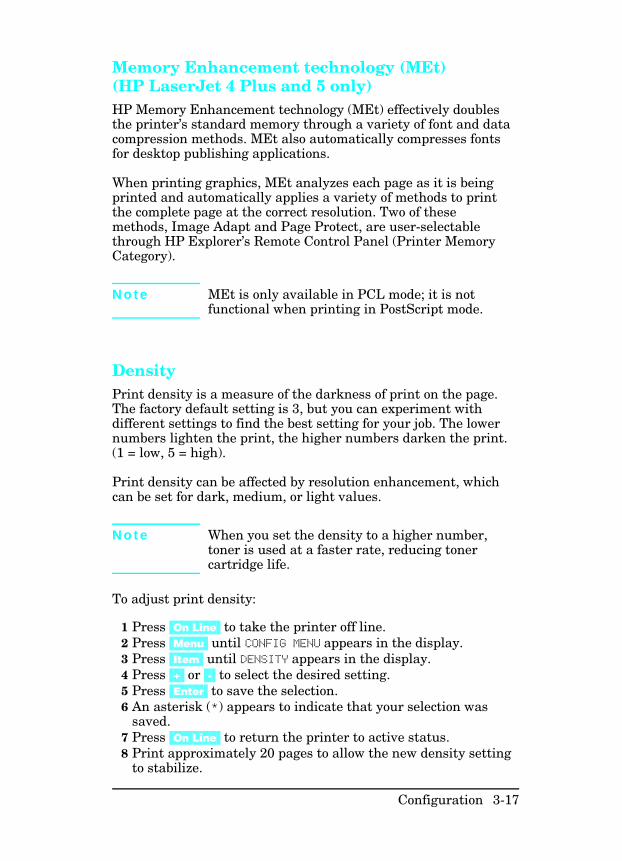
Density Print density is a measure of the darkness of print on the page.The factory default setting is 3, but you can experiment withdifferent settings to find the best setting for your job. The lowernumbers lighten the print, the higher numbers darken the print.(1 = low, 5 = high).
Print density can be affected by resolution enhancement, whichcan be set for dark, medium, or light values.
N o t e When you set the density to a higher number,toner is used at a faster rate, reducing tonercartridge life.
To adjust print density:
1 Press [On Line] to take the printer off line.2 Press [Menu] until CONFIG MENU appears in the display.3 Press [Item] until DENSITY appears in the display.4 Press [+] or [-] to select the desired setting.5 Press [Enter] to save the selection. 6 An asterisk (*) appears to indicate that your selection was
saved.7 Press [On Line] to return the printer to active status.8 Print approximately 20 pages to allow the new density setting
to stabilize.
Configuration 3-17
Network Security
The HP LaserJet 4 Plus and 5 printers allow the SystemAdministrator to lock out other user’s ability to change mostprinter control panel settings. This is done by setting a passwordand turning LOCK on. The message MENU LOCKED will appear whena user tries to change the printer control panel settings.
N o t e If you forget your password, you can perform a“Cold Reset” by holding down the [On Line] key (Goon LJ 5) while turning the printer on.
There are four ways to implement printer security:
1 HP Explorer software’s Remote Control Panel for DOS users,if you are directly connected to the printer through its parallelport.
2 HP LaserJet Utility for Macintosh users.3 JetAdmin for Novell networks.4 PJL escape sequence sent from any ASCII editor.
Remote Control Panel (DOS)1 Select OPTIONS from the Remote Control Panel screen.2 Select SECURITY from the OPTIONS menu.3 Select Use Password from the Printer Passwords box.4 Type in the password and confirm it in the New Password
box. Numeric password values can be set from 0 to 65535. (Ifyou already have a password, go the the next step; you will beprompted for your password.)
5 To lock the printer’s control panel, select ON in the ControlPanel Lock box.
HP LaserJet Utility (Macintosh)1 Select the HP LaserJet Utility icon in the HP LaserJet
folder on your hard drive.2 If necessary, double click on the Select Printer button to
select the the appropriate printer.3 Under the Extras menu, select Control Panel Lock. 4 In the Control Panel Lock: HP LaserJet 4M Plus or 5M
screen, click on the On (Locked) box, then click the OKbutton. You will be prompted to enter a password if thepassword has been set. If a password has not been set, go tothe next step.
3-18 Configuration
5 Under the Extras menu, select Set Printer Password. Onthe Printer Security screen, enter the new password (numericvalues can be set from 0 to 65535), and click on the OK button.
HP JetAdmin Utility (Novell Networks)1 Run JETADMIN.2 Select the printer you want to configure. It is listed under its
“JetDirect Interface Name” which appears on the self testpage/configuration plot.
3 Select Configuration.... The Printer I/O Configurationscreen appears.
4 Select Advance.... The Advance Settings screen appears.5 Select Lock Printer Control Panel.... 6 Click on Select... (the Advanced: Printer Security screen
appears), then click on the ON button.7 Click the OK button.
ASCII PJL Escape Sequence
Password: send this sequence to the printer from any ASCIIeditor:
EC %-12345X@PJL JOB
@PJL DEFAULT PASSWORD=[numeric password (0 to 65535)] @PJL EOJE
C %-12345X
CPLOCK: to turn on or off, assuming that a password has NOTbeen set, send the following ASCII sequence to the printer:
EC %-12345X@PJL JOB
@PJL DEFAULT CPLOCK=ON [OFF]@PJL EOJE
C %-12345X
If a password HAS been set, send the following ASCII sequenceto the printer to turn CPLOCK on or off.:
EC %-12345X@PJL JOB PASSWORD=(numeric password)
@PJL DEFAULT CPLOCK=ON(OFF)@PJL EOJE
C %-12345X
Configuration 3-19
Service Mode
(Refer to Appendix B for LaserJet 5 information.)
The Service Mode should be used only by authorized servicepersonnel. The following can be executed while in the ServiceMode:
• Print a Service Mode Self Test.• Verify the Page Count, (the page count also is displayed on the
standard self test).• Set the Page Count.• Set the Cold Reset Default (This sets the factory default paper
size. Use when replacing non-U.S. Formatters).• Set the Diagnostic Functions ON or OFF (for software
developers use only).• Demo Page=On/Off. Removes the Demo Page option from the
self test menu.• BIG Data=On/Off (HP LaserJet 4 Plus only). Setting BIG
Data to ON increases the size of the printer’s status ReadbackBuffer.
The following procedure is used to initiate the Service Mode.
1 Hold down the [ON LINE], [FORM FEED], and [ENTER] keys whilepowering ON the printer, until the ON LINE and FORMFEED Indicators are both illuminated and the DisplayWindow is blank. (If the Display Window reads 05 SELFTEST at this point, the keys were released too soon. Repeatthis step until successful.)
2 Press the [FORM FEED] key, then the [ENTER] key. Themessage SERVICE MODE is displayed briefly, then the printerautomatically begins a 05 SELF TEST.
After several seconds, the [ON LINE] and [FORM FEED] lights turnOFF. (The printer may display 02 WARMING UP if it has notwarmed up completely.)
After the printer has warmed up and passed the self test,SERVICE MODE is displayed.
To exit the Service Mode press the [ON LINE] key.
3-20 Configuration
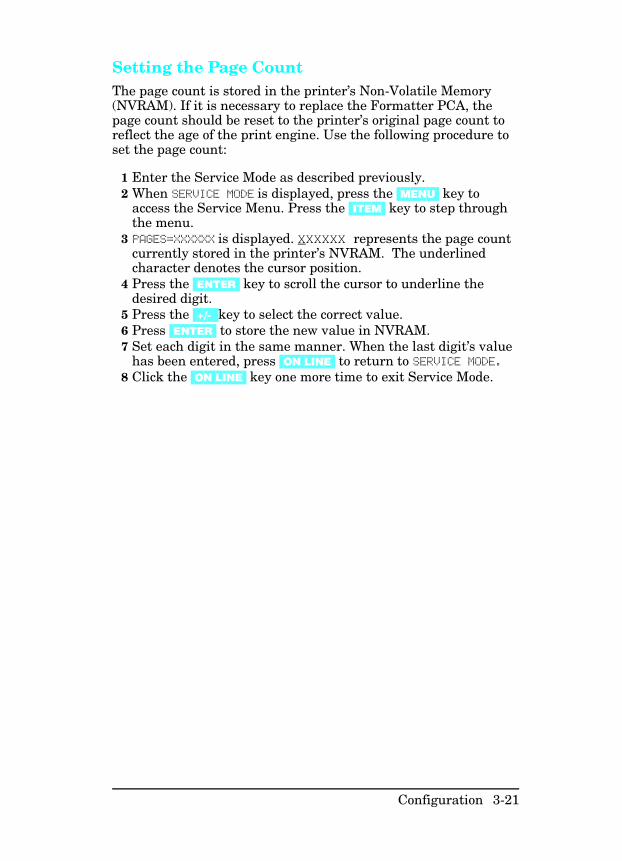
Setting the Page Count The page count is stored in the printer’s Non-Volatile Memory(NVRAM). If it is necessary to replace the Formatter PCA, thepage count should be reset to the printer’s original page count toreflect the age of the print engine. Use the following procedure toset the page count:
1 Enter the Service Mode as described previously. 2 When SERVICE MODE is displayed, press the [MENU] key to
access the Service Menu. Press the [ITEM] key to step throughthe menu.
3 PAGES=XXXXXX is displayed. XXXXXX represents the page countcurrently stored in the printer’s NVRAM. The underlinedcharacter denotes the cursor position.
4 Press the [ENTER] key to scroll the cursor to underline thedesired digit.
5 Press the [+/-] key to select the correct value. 6 Press [ENTER] to store the new value in NVRAM.7 Set each digit in the same manner. When the last digit’s value
has been entered, press [ON LINE] to return to SERVICE MODE.8 Click the [ON LINE] key one more time to exit Service Mode.
Configuration 3-21
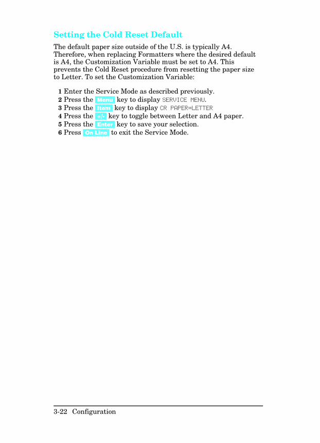
Setting the Cold Reset Default The default paper size outside of the U.S. is typically A4.Therefore, when replacing Formatters where the desired defaultis A4, the Customization Variable must be set to A4. Thisprevents the Cold Reset procedure from resetting the paper sizeto Letter. To set the Customization Variable:
1 Enter the Service Mode as described previously.2 Press the [Menu] key to display SERVICE MENU.3 Press the [Item] key to display CR PAPER=LETTER4 Press the [+/-] key to toggle between Letter and A4 paper. 5 Press the [Enter] key to save your selection.6 Press [On Line] to exit the Service Mode.
3-22 Configuration
Cold Reset
The Cold Reset feature of the printers allows the printer to bereturned instantly to the factory default configuration settings.This feature is valuable because the the Dynamic I/O and PJLfeatures of the printer enable any user connected to any I/O toaccess and change the default configuration as applicationsrequire. When setting up the printer in a new location, or whentroubleshooting printer problems, always perform the Cold Resetbefore entering the selected user defaults. A Cold Reset can notreset the page count, cold reset tray size, or displaylanguage settings. If the Control Panel is locked, a Cold Resetwill disable the lock and return the printer to the factory defaults.Inform the system administrator of all Cold Resets.
A Cold Reset is performed as follows:
1 Turn OFF the printer.2 Hold the [On-Line] (or Go for the LJ5) key down while powering
ON the printer.3 The message COLD RESET is displayed. The COLD RESET does
not take effect until the 00 READY message is displayed.4 When the 00 READY message is displayed, the default settings
have been returned to the factory defaults and the printer isready to accept new settings.
Configuration 3-23
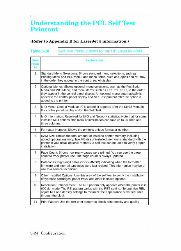
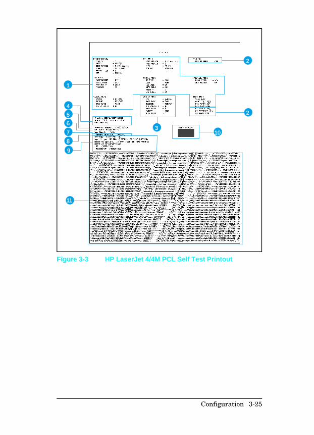
Understanding the PCL Self TestPrintout
(Refer to Appendix B for LaserJet 5 information.)
ItemFigure
3-3
Explanation
1 Standard Menu Selections: Shows standard menu selections, such asPrinting Menu and PCL Menu, and menu items, such as Copies and MP tray,in the order they appear in the control panel display.
2 Optional Menus: Shows optional menu selections, such as the PostScriptMenu and MIO Menu, and menu items, such as PRT PS ERRS, in the orderthey appear in the control panel display. An optional menu automatically isadded to the control panel display and Self Test printout after the option isadded to the printer.
3 MIO Menu: Once a Modular I/0 is added, it appears after the Serial Menu inthe control panel display and in the Self Test.
4 MIO Information: Reserved for MIO and Network statistics. Note that for someinstalled MIO options, this block of information can take up to 20 lines andthree columns.
5 Formatter Number: Shows the printer’s unique formatter number.
6 RAM Size: Shows the total amount of installed printer memory, includingadded optional memory. Two MBytes of installed memory is standard with theprinter. If you install optional memory, a self test can be used to verify properinstallation.
7 Page Count: Shows how many pages were printed. You can use the pagecount to track printer use. The page count is always updated.
8 Datecodes: Eight-digit dates (YYYYMMDD) indicating when the formatterfirmware and internal typefaces were last revised. This information may be ofuse to a service technician.
9 Other Installed Options: Use this area of the self test to verify the installationof typeface cartridges, paper trays, and other installed options.
10 Resolution Enhancement: The REt pattern only appears when the printer is in600 dpi mode. The REt pattern varies with the RET setting. To optimize REt,adjust REt and density settings to minimize the appearance of vertical linesthrough the block.
11 Print Pattern: Use the text print pattern to check print density and quality.
Table 3-10 Self Test Printout Items for the HP LaserJet 4/4M
3-24 Configuration
2
1
2
3
4
5
6
7
8
9
11
10
Figure 3-3 HP LaserJet 4/4M PCL Self Test Printout
Configuration 3-25
ItemFigure
3-4
Explanation
1 Standard menu selections: Lists selections in the order in which theyappear in the control panel display.
2 Optional menus: Shows optional menu selections, such as thePostScript Menu, and menu items, in the order in which they appear in thecontrol panel display. Optional menus automatically appear in the controlpanel display when options are added to the printer.
3 MIO Menu: When an optional Modular I/O is added, the MIO Menuappears following the Serial Menu in the self test and control panel display.
4 MIO information: Reserved for MIO and network statistics. For someinstalled MIO options, this block of information can be as long as 20 linesand three columns.
5 Formatter Number: Shows the printer’s unique formatter number.
6 RAM size: Shows total installed printer memory
7 PCL Memory Information: Shows the total amount of installed memory.Also indicates the amount of available memory for PCL applications.
8 Page Count: Shows number of pages the printer has printed.
9 Firmware Datecode: Eight-digit date (YYYYMMDD) and version numberof formatter firmware.
10 Control Panel options status: Shows status of control panel Lock andPassword functions.
11 Other installed options: Lists optional typeface cartridges, paper trays,personalities, and other installed options.
12 Resolution Enhancement: When resolution is set to 600-dpi, the REtblock appears here. The REt block illustrates current resolutionenhancement. To optimize REt, adjust REt and density settings tominimize the appearance of vertical lines through the block.
13 I/O Buffering and Resource Saving: Information about the currentconfiguration appears here. If the printer does not have enough memoryinstalled to enable I/O Buffering or Resource Saving, the amount ofadditional memory needed appears here.
14 Print Pattern: Illustrates print density and quality.
Table 3-11 Self Test Printout Items - HP LaserJet 4 Plus/4MPlus
3-26 Configuration
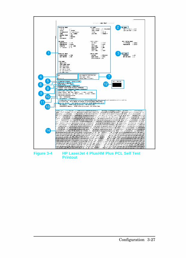
Figure 3-4 HP LaserJet 4 Plus/4M Plus PCL Self TestPrintout
Configuration 3-27
Changing the Control Panel DisplayLanguage
The default control panel display language is set for English.Supported languages are: English, French, German, Italian,Spanish, Finnish, Danish, Dutch, Swedish, Norwegian, andPortuguese. Follow these instructions to change the displaylanguage.
1 Switch OFF the printer.2 Press and hold [Enter] (or Select on the LJ 5) while switching
the printer ON until CONFIG LANGUAGE appears in the display.3 After the power-on self test, LANGUAGE=ENGLISH appears. Press
[+] until the desired language appears in the display.4 Press [Enter] to save your choice. An asterisk (*)appears next
to the language to indicate it is now the default.5 Press [On Line]. The On Line indicator is lit, and display
messages are now in the language you selected.
N o t e If the display language is changed, replace orinstall the Control Panel Overlay to match theselected language. See the index to Chapter 6 forinstructions on changing or installing the ControlPanel Overlay.
N o t e Failure to explicitly select a language afterpowering on the printer while holding down theENTER or SELECT key will cause the printer toprompt for a specific language every time it ispowered on.
3-28 Configuration
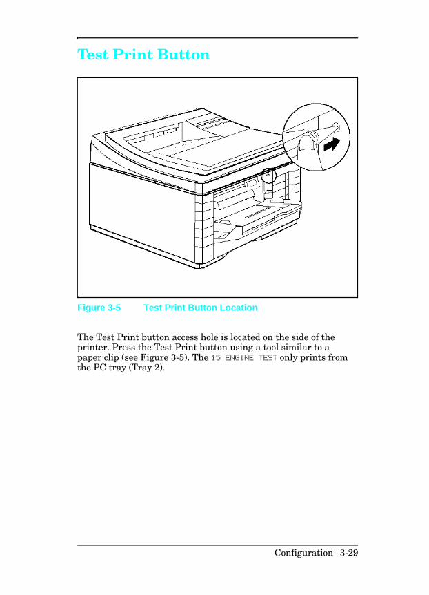
Test Print Button
The Test Print button access hole is located on the side of theprinter. Press the Test Print button using a tool similar to apaper clip (see Figure 3-5). The 15 ENGINE TEST only prints fromthe PC tray (Tray 2).
Figure 3-5 Test Print Button Location
Configuration 3-29
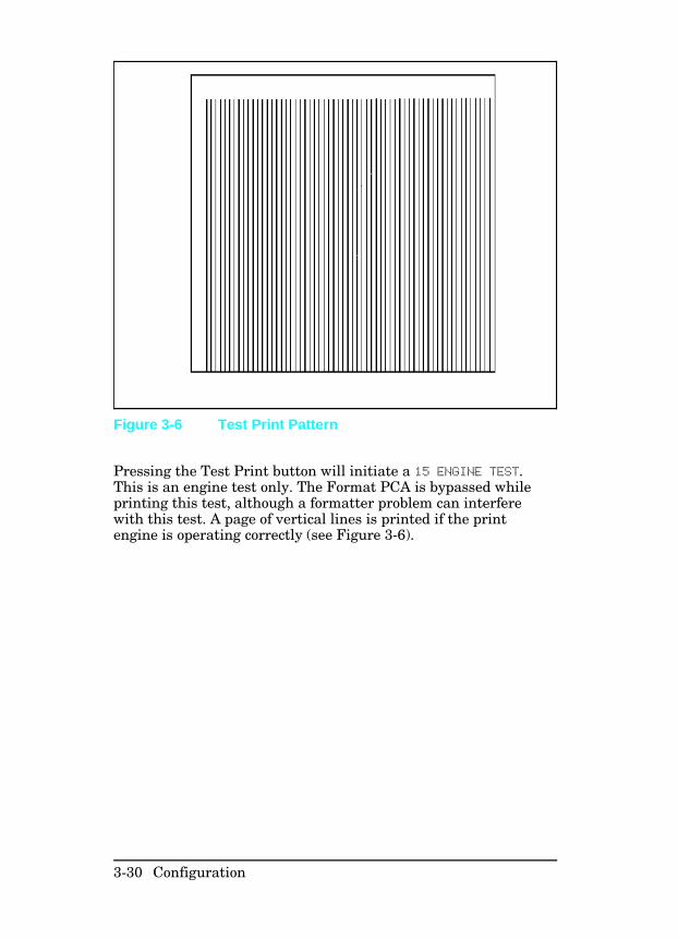
Pressing the Test Print button will initiate a 15 ENGINE TEST.This is an engine test only. The Format PCA is bypassed whileprinting this test, although a formatter problem can interferewith this test. A page of vertical lines is printed if the printengine is operating correctly (see Figure 3-6).
Figure 3-6 Test Print Pattern
3-30 Configuration
System Configuration
MS-DOS System ConfigurationTo communicate properly with the printer, the MS-DOSenvironment requires the addition or modification of MODEcommands in the AUTOEXEC.BAT file. Add or modify theMODE command(s), depending on the interface configuration, asfollows:
Parallel DOS CommandsMost IBM PC and AT compatible computers default to a parallelprinter port. To ensure that information is sent to your parallelprinter port, type the following MS-DOS command at yourMS-DOS prompt or include it in your AUTOEXEC.BAT file:
MODE LPT1:,,P
For MS-DOS version 4.0 and above, enter:
MODE LPT1:,,B
N o t e This example assumes that you are using parallelprinter port LPT1. If you are using LPT2 orLPT3, replace LPT1 in the example with theprinter port that you are using.
Since the MODE command is an external MS-DOS command (aprogram named MODE.COM is run when the MODE command isinvoked), the program file must be contained in the root directory,or in a directory specified in a preceding PATH command in theAUTOEXEC.BAT file.
N o t e After changing the AUTOEXEC.BAT file, rebootthe computer to initiate the changes.
Configuration 3-31
Serial MS-DOS CommandsMost IBM compatible computers default to a parallel printer port.To ensure that information is sent to your serial printer port, typethe following MS-DOS commands at your MS-DOS prompt, orinclude them in your AUTOEXEC.BAT file.
MODE COM1:9600,N,8,1,P
MODE LPT1:=COM1
For MS-DOS version 4.0 or above, enter:
MODE COM1:9600,N,8,1,B
MODE LPT1:=COM1
N o t e These examples assume that you are using serialprinter COM1. If you are using COM2 or COM3,replace COM1 with the the printer port that youare using.
Since the MODE command is an external MS-DOS command (aprogram named MODE.COM is run when the MODE command isinvoked), the program file must be contained in the root directory,or in a directory specified in a preceding PATH command in theAUTOEXEC.BAT file.
N o t e After changing the AUTOEXEC.BAT file, rebootthe computer to initiate the changes.
3-32 Configuration
Printer I/O Configuration
Parallel MenuThe default setting for the High Speed Parallel I/O is YES. If it isset to NO, the interface runs at a slower speed that is compatiblewith older computers. When the default is set to YES, the parallelinterface runs at a higher rate supported by newer computers.
Advanced Functions The Advanced Functions feature of the printer enablesbi-directional communications between the printer and the host.The default setting is ON. This default setting (ON) must beactive in order to use LaserJet Explorer, the Windows PrintingSystem, and other software applications and drivers.
Serial Configuration Use RS-232C serial configuration when the printer is located 11to 50 feet from the computer. If you need to locate the printerbetween 51 and 2000 feet from the computer, use an RS-422Aserial configuration (not available on the LaserJet 4 Plus or 5).
Since the default-printer I/O setting on the printer is parallel,remember to change the settings on the printer control panel forserial printing.
Serial ProtocolWhen printing with a serial configuration, the same protocolmust be set on both the printer and the computer. Protocol onthe printer is set by changing the control panel. Protocol on thecomputer is set by using DOS commands. The default protocolsettings are described below.
BAUD RateThe BAUD-rate setting tells the printer how fast information istransferred to and from the computer. The default BAUD ratesetting is:
BAUD RATE=9600*.
Configuration 3-33
Pacing (Handshaking) Pacing (or “handshaking”) is a type of communication betweenthe printer and the computer. This is an important item in theprinter because it allows the printer to tell the computer when tosend information. If the printer is unable to receive information,for example, when the print buffer is full or when the printer isout of paper, a signal is sent to the computer to stop sendinginformation. When the printer is able to resume receivinginformation, it sends another signal to the computer to send moredata.
Pacing is set through the control panel’s Serial Menu. Two typesof handshaking are supported by your printer:
• Select DTR/DSR through the Serial Menu’s PACING item if thecomputer requires hardware flow control (most personalcomputers do). Through the Serial Menu’s DTR POLARITY item,the DTR polarity can be set to High or Low. The default is DTRPOLARITY=HI
• Select XON/XOFF through the Serial Menu’s PACING item if thecomputer requires software flow control (for example, if youare using a UNIX workstation). Note that status readbackmessages are not paced when XON/XOFF is selected. Throughthe Serial Menu’s ROBUST XON item, Robust Xon can be set toON (the default) or OFF. Note that the ROBUST XON item onlyappears under the Serial Menu if XON/XOFF was selected.
3-34 Configuration
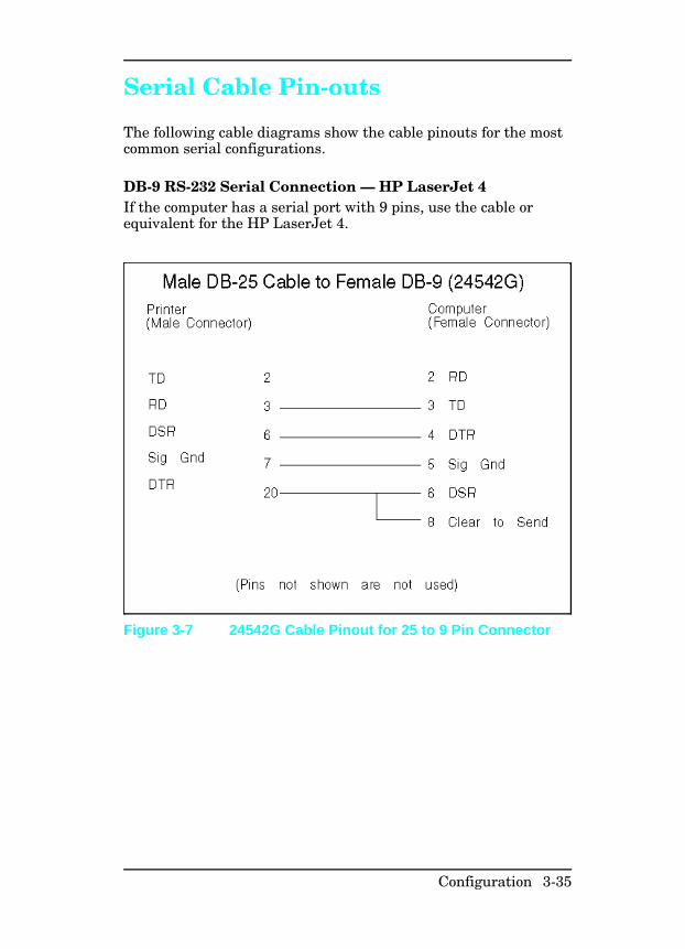
Serial Cable Pin-outs
The following cable diagrams show the cable pinouts for the mostcommon serial configurations.
DB-9 RS-232 Serial Connection — HP LaserJet 4 If the computer has a serial port with 9 pins, use the cable orequivalent for the HP LaserJet 4.
Figure 3-7 24542G Cable Pinout for 25 to 9 Pin Connector
Configuration 3-35
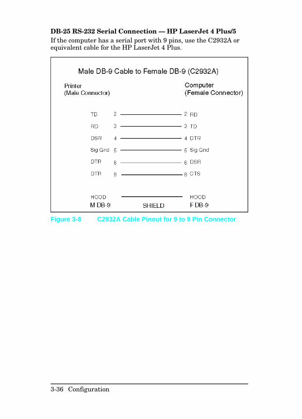
DB-25 RS-232 Serial Connection — HP LaserJet 4 Plus/5If the computer has a serial port with 9 pins, use the C2932A orequivalent cable for the HP LaserJet 4 Plus.
Figure 3-8 C2932A Cable Pinout for 9 to 9 Pin Connector
3-36 Configuration
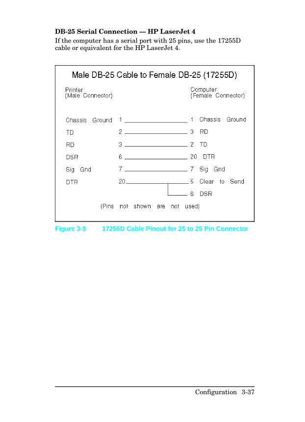
DB-25 Serial Connection — HP LaserJet 4 If the computer has a serial port with 25 pins, use the 17255Dcable or equivalent for the HP LaserJet 4.
Figure 3-9 17255D Cable Pinout for 25 to 25 Pin Connector
Configuration 3-37
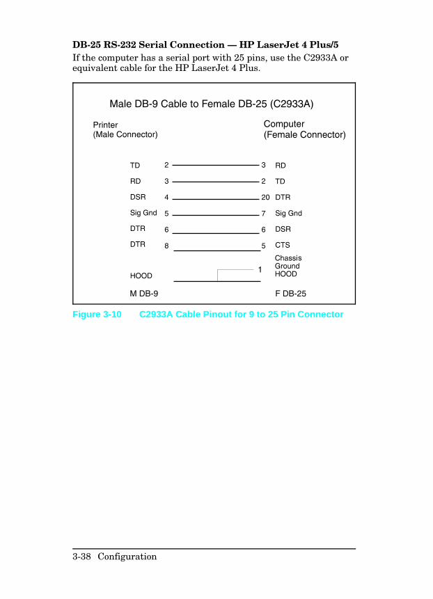
DB-25 RS-232 Serial Connection — HP LaserJet 4 Plus/5If the computer has a serial port with 25 pins, use the C2933A orequivalent cable for the HP LaserJet 4 Plus.
Figure 3-10 C2933A Cable Pinout for 9 to 25 Pin Connector
3-38 Configuration
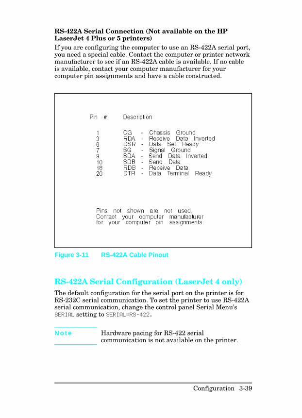
RS-422A Serial Connection (Not available on the HPLaserJet 4 Plus or 5 printers)If you are configuring the computer to use an RS-422A serial port,you need a special cable. Contact the computer or printer networkmanufacturer to see if an RS-422A cable is available. If no cableis available, contact your computer manufacturer for yourcomputer pin assignments and have a cable constructed.
RS-422A Serial Configuration (LaserJet 4 only)The default configuration for the serial port on the printer is forRS-232C serial communication. To set the printer to use RS-422Aserial communication, change the control panel Serial Menu’sSERIAL setting to SERIAL=RS-422.
N o t e Hardware pacing for RS-422 serialcommunication is not available on the printer.
Figure 3-11 RS-422A Cable Pinout
Configuration 3-39
Modular I/O Configuration
The printers are equipped with a modular I/O slot. A modular I/Ointerface card can be plugged into that slot to increase thenumber of interfaces available.
A modular I/O card can provide increased printer performancewhen printing from a network. In addition, a modular I/O cardprovides the ability to place the printer anywhere on the network.This eliminates the need to attach the printer directly to a serveror a workstation, and enables you to place your HP LaserJetprinter closer to your network users.
N o t e When you install a MIO card, you may need toperform a Cold Reset to reinitialize the printer’scontrol panel.
The HP JetDirect Card allows these printers to operate inmultiple operating system networks.
To determine the appropriate MIO solution for a specific hostsystem/application environment, refer to the latest edition of the“HP Peripherals Connectivity Solutions Guide.”
3-40 Configuration
Printer Drivers
Install Printer Drivers and Utilities Printer drivers are specialized programs designed to allowspecific software applications to function with the HP LaserJetprinters. Printer utilities include such things as the HP Explorerprogram modules, which enhance the usability of the printer andprovide convenient access to printer features outside of specificsoftware applications.
How to Obtain Printer DriversFirst, check the software’s printer selection feature to see if theprinter is listed among the available printers. If it is not, run thesoftware’s SETUP or INSTALL program to install a “printerdriver” or “printer file” for the printer.
Here are some ways to obtain printer drivers and SoftwareApplication Notes for HP LaserJet printers:
• Check the Printing Software package to see if it includes adriver for your software.
• Order an updated driver from the software vendor.• Call Hewlett-Packard at 970-339-7009.• Obtain a driver request form by fax through HP FIRST
(call 1-800-333-1917) U.S. only.• Download a driver through CompuServe’s HP Forum. To sign
up for CompuServe, call 1-800-524-3388.
N o t e While waiting for a specific HP LaserJet printerdriver, you can substitute a similar printer driver(such as a driver for the HP LaserJet III, IIIP, or4 printer). These substitute drivers will allow youto use the printer, but they do not support all ofthe printer’s features.
Configuration 3-41
DOS Utilities
Use the DOS Utilities to install printer drivers for MS-DOSapplications. Printer driver software for some common softwareapplications are included the DOS Utilities. See the DoingBusiness With HP section of Chapter 1 for information onsoftware drivers not included with the LaserJet DOS Utilities.
A DOS Utilities disk is shipped with every printer. If the DOSUtilities is not installed on the host computer, look for the DOSUtilities software disks in the documentation package that camewith the printer and install the software.
3-42 Configuration
Packing the Printer
Repackaging Instructions The printer warranty is for one-year and must be returned to anAuthorized HP service center for service. If the original packagingmaterial is no longer available, replacement packing andshipping material is available from HP’s Support MaterialOrganization (SMO) for a charge. To order replacement packingand shipping material, call:
1-800-227-8164 (U.S.)
416-678-9430 (Canada)
To order the shipping box and packing inserts for the printers,ask for part number C2001-00906.
In other countries, return the printer to the selling dealer or theHP-authorized service center for your service area.
Packing Checklist
• Remove and retain any accessories that were installed in theprinter. This includes:• Toner Cartridge• Optional Lower Cassette• Envelope Feeder• Accessory Cartridge• Duplex Assembly (LaserJet 4 Plus/5)• Optional Memory, Personality SIMMs, or Flash
• Include print samples that indicate the problem.• If the problem is associated with media, include 50-100 sheets
of the media causing the problem.
Configuration 3-43
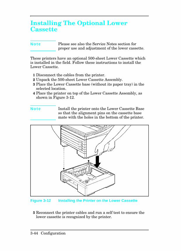
Installing The Optional LowerCassette
N o t e Please see also the Service Notes section forproper use and adjustment of the lower cassette.
These printers have an optional 500-sheet Lower Cassette whichis installed in the field. Follow these instructions to install theLower Cassette.
1 Disconnect the cables from the printer.2 Unpack the 500-sheet Lower Cassette Assembly.3 Place the Lower Cassette base (without its paper tray) in the
selected location.4 Place the printer on top of the Lower Cassette Assembly, as
shown in Figure 3-12.
N o t e Install the printer onto the Lower Cassette Baseso that the alignment pins on the cassette basemate with the holes in the bottom of the printer.
5 Reconnect the printer cables and run a self test to ensure thelower cassette is recognized by the printer.
Figure 3-12 Installing the Printer on the Lower Cassette
3-44 Configuration
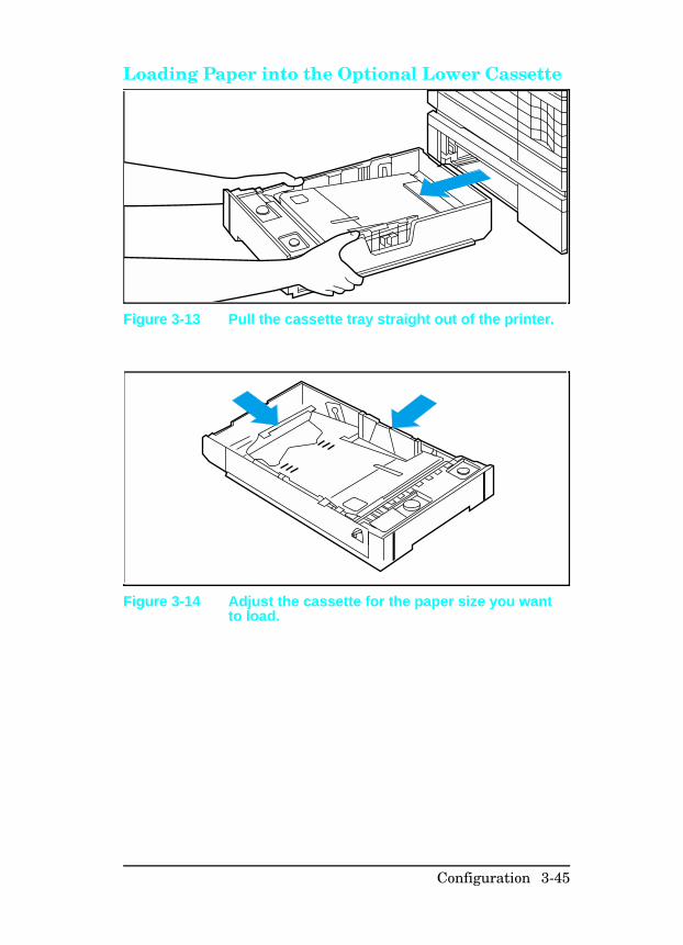
Loading Paper into the Optional Lower Cassette
Figure 3-13 Pull the cassette tray straight out of the printer.
Figure 3-14 Adjust the cassette for the paper size you wantto load.
Configuration 3-45
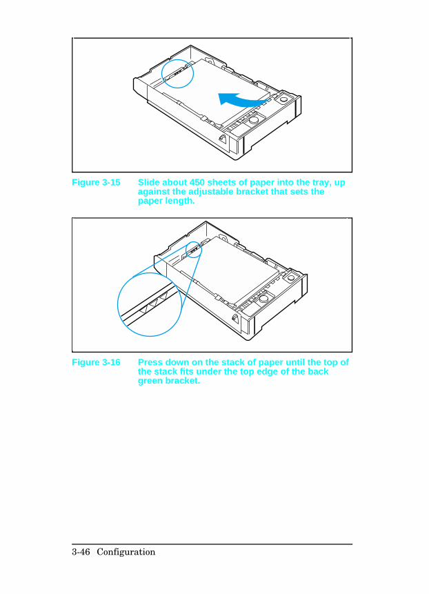
Figure 3-15 Slide about 450 sheets of paper into the tray, upagainst the adjustable bracket that sets thepaper length.
Figure 3-16 Press down on the stack of paper until the top ofthe stack fits under the top edge of the backgreen bracket.
3-46 Configuration
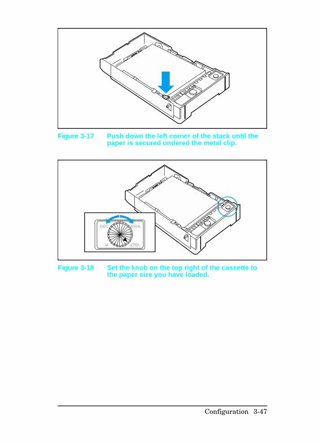
Figure 3-17 Push down the left corner of the stack until thepaper is secured undered the metal clip.
LETTER
EXEC
A4
LEGAL
Figure 3-18 Set the knob on the top right of the cassette tothe paper size you have loaded.
Configuration 3-47
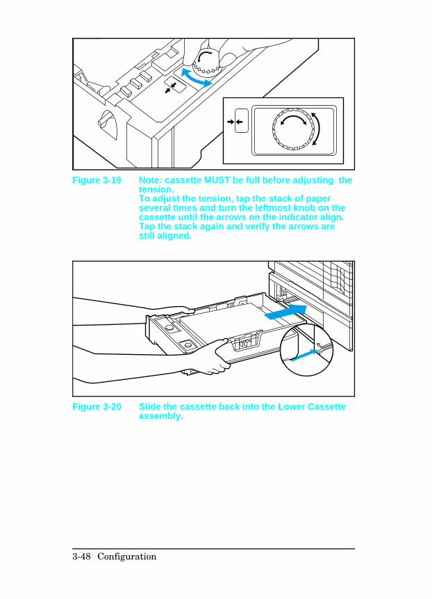
Figure 3-19 Note: cassette MUST be full before adjusting thetension. To adjust the tension, tap the stack of paperseveral times and turn the leftmost knob on thecassette until the arrows on the indicator align.Tap the stack again and verify the arrows arestill aligned.
Figure 3-20 Slide the cassette back into the Lower Cassetteassembly.
3-48 Configuration
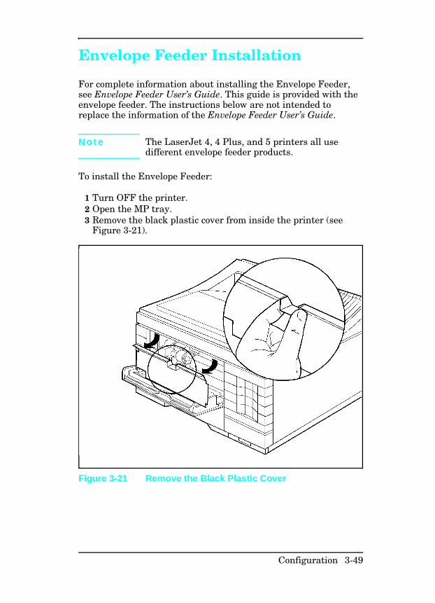
Envelope Feeder Installation
For complete information about installing the Envelope Feeder,see Envelope Feeder User’s Guide. This guide is provided with theenvelope feeder. The instructions below are not intended toreplace the information of the Envelope Feeder User’s Guide.
N o t e The LaserJet 4, 4 Plus, and 5 printers all usedifferent envelope feeder products.
To install the Envelope Feeder:
1 Turn OFF the printer.2 Open the MP tray.3 Remove the black plastic cover from inside the printer (see
Figure 3-21).
Figure 3-21 Remove the Black Plastic Cover
Configuration 3-49
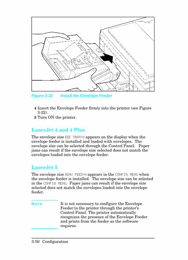
4 Insert the Envelope Feeder firmly into the printer (see Figure3-22).
5 Turn ON the printer.
LaserJet 4 and 4 PlusThe envelope size (EE TRAY=) appears on the display when theenvelope feeder is installed and loaded with envelopes. Theenvelope size can be selected through the Control Panel. Paperjams can result if the envelope size selected does not match theenvelopes loaded into the envelope feeder.
LaserJet 5The envelope size (ENV FEED=) appears in the CONFIG MENU whenthe envelope feeder is installed. The envelope size can be selectedin the CONFIG MENU. Paper jams can result if the envelope sizeselected does not match the envelopes loaded into the envelopefeeder.
N o t e It is not necessary to configure the EnvelopeFeeder to the printer through the printer’sControl Panel. The printer automaticallyrecognizes the presence of the Envelope Feederand prints from the feeder as the softwarerequires.
Figure 3-22 Install the Envelope Feeder
3-50 Configuration

SIMM Installation
SIMM installation is covered in detail in the the printer’s User’sManual and in the kit that accompanies the SIMM. Theinstructions shown here are not intended to replace these sources.
Follow these instructions to install memory, language, and flashSIMM boards. Install all types of SIMM boards in the samemanner.
Protecting the SIMM Board SIMM boards can be damaged easily by small amounts of staticelectricity. To prevent damage from static electricity:
• Touch the surface of the antistatic package before removingthe board from its package. When handling the board,frequently touch bare metal on the printer or the antistaticbag, or wear an antistatic wrist strap.
• Avoid moving about the work area to prevent generating staticelectricity.
• Handle the board carefully at all times. Avoid flexing it ortouching its components.
Configuration 3-51
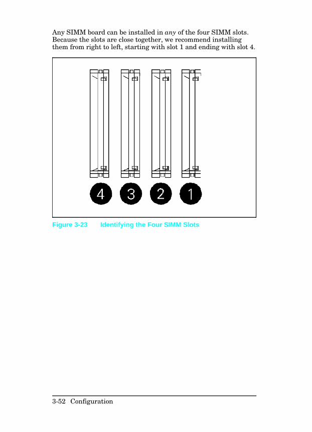
Any SIMM board can be installed in any of the four SIMM slots.Because the slots are close together, we recommend installingthem from right to left, starting with slot 1 and ending with slot 4.
Figure 3-23 Identifying the Four SIMM Slots
3-52 Configuration
Memory RequirementsA page’s complexity (rules, graphics, or dense text) may exceedthe printer’s ability to create the image rapidly enough to keeppace with the printing process. If a page is too complex, only partof the page prints, and some print data loss is likely. In suchcases, a 21 PRINT OVERRUN message (signifying possible loss ofprint data) or a Clearable Warning message appears in thedisplay.
PCL Only PostScript Only
Resolution 300 dpi 600 dpi 300 dpi 600 dpi
Letter/A4 Pages1
Page Protect OFF2 (1.6)2 2 (1.4) 2 (1) 6 (2.3)
Legal Pages1
Page Protect OFF2 (1.6) 2 (1.4) 3 (1.7) 6 (1.3)3
Letter/A4 Pages1
Page Protect ON2 (0.8) 6 (1.9) 2 (1) 6 (2.3)
Legal Pages1
Page Protect ON 3 (1.6) 6 (1) 3 (1.7) 6 (1.3)
1 More memory may be required if using downloaded soft fonts, forms, or complextext with a large number of downloaded typefaces.
2 Numbers in parentheses indicate the approximate amount of memory available tothe user for data files, downloaded typefaces, and other non-system uses.
3 For PostScript language applications only, a “mini-legal” page will print with thisamount of memory.
Table 3-12 Minimum Memory Recommendations LaserJet 4 Only
Configuration 3-53
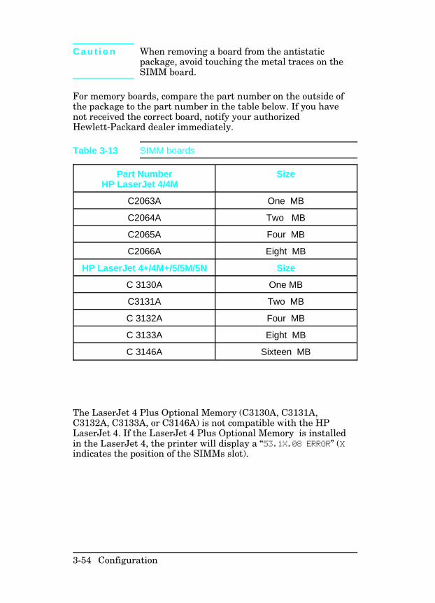
C a u t i o n When removing a board from the antistaticpackage, avoid touching the metal traces on theSIMM board.
For memory boards, compare the part number on the outside ofthe package to the part number in the table below. If you havenot received the correct board, notify your authorizedHewlett-Packard dealer immediately.
The LaserJet 4 Plus Optional Memory (C3130A, C3131A,C3132A, C3133A, or C3146A) is not compatible with the HPLaserJet 4. If the LaserJet 4 Plus Optional Memory is installedin the LaserJet 4, the printer will display a “53.1X.08 ERROR” (Xindicates the position of the SIMMs slot).
Part NumberHP LaserJet 4/4M
Size
C2063A One MB
C2064A Two MB
C2065A Four MB
C2066A Eight MB
HP LaserJet 4+/4M+/5/5M/5N Size
C 3130A One MB
C3131A Two MB
C 3132A Four MB
C 3133A Eight MB
C 3146A Sixteen MB
Table 3-13 SIMM boards
3-54 Configuration
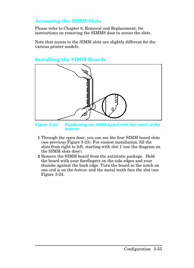
Accessing the SIMM SlotsPlease refer to Chapter 6, Removal and Replacement, forinstructions on removing the SIMMS door to access the slots.
Note that access to the SIMM slots are slightly different for thevarious printer models.
Installing the SIMM Boards
1 Through the open door, you can see the four SIMM board slots(see previous Figure 3-23). For easiest installation, fill theslots from right to left, starting with slot 1 (see the diagram onthe SIMM slots door).
2 Remove the SIMM board from the antistatic package. Holdthe board with your forefingers on the side edges and yourthumbs against the back edge. Turn the board so the notch onone end is on the bottom and the metal teeth face the slot (seeFigure 3-24.
Figure 3-24 Positioning the SIMM board with the notch at thebottom.
Configuration 3-55
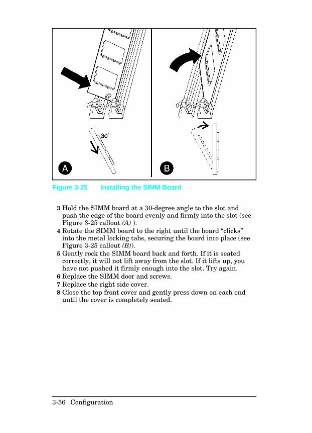
3 Hold the SIMM board at a 30-degree angle to the slot andpush the edge of the board evenly and firmly into the slot (seeFigure 3-25 callout (A) ).
4 Rotate the SIMM board to the right until the board “clicks”into the metal locking tabs, securing the board into place (seeFigure 3-25 callout (B)).
5 Gently rock the SIMM board back and forth. If it is seatedcorrectly, it will not lift away from the slot. If it lifts up, youhave not pushed it firmly enough into the slot. Try again.
6 Replace the SIMM door and screws. 7 Replace the right side cover. 8 Close the top front cover and gently press down on each end
until the cover is completely seated.
Figure 3-25 Installing the SIMM Board
3-56 Configuration
Testing a SIMM Board
Use the procedures below to print a self-test page to verify SIMMboard installation. Procedures are given for both memory andPostScript SIMMs.
Memory SIMM
N o t e For the LaserJet 5/5M/5N, the On Line key hasbeen replaced by the Go key. The Enter key hasbeen replaced by the Select key.
Running a Self Test Printout1 Plug in the power cord and turn ON the printer. 2 After a few seconds, 00 READY should appear in the control
panel display. If an error message appears, refer to“Troubleshooting a SIMM Board” later in this chapter.
3 Press [On Line] to take the printer off line.4 Press [Menu] until TEST MENU appears in the control panel
display.5 Press [Item] until SELF TEST appears in the control panel
display. 6 Press [Enter] to print a self test. 7 Press [On Line] after the self test printed.
Locate “RAM SIZE” on the self-test printout. This is the amountof printer memory now installed in the printer.
Configuration 3-57
Personality SIMM(PostScript)A personality (printer language) SIMM installation can beverified as outlined below (a PostScript SIMM is used in thisexample).
N o t e For the LaserJet 5/5M/5N, the On Line key hasbeen replaced by the Go key. The Enter key hasbeen replaced by the Select key.
1 Plug in the power cord and turn ON the printer.2 After a few seconds, the on line indicator should light and 00READY should appear in the control panel display. If an errormessage appears, refer to “Troubleshooting a SIMM Board”following.
3 Press [On Line to take the printer off line.4 Press [Menu] until JOB MENU appears in the control panel
display.5 Press [Item] until PERSONALITY=AUTO*, the default, appears in
the control panel display.6 Press [+] until PERSONALITY=PS appears in the display. This
indicates that your printer recognizes that PostScript isinstalled. If PERSONALITY=PS does not appear, check theSIMM installation.
7 Press [On Line] to return the printer on line.
3-58 Configuration
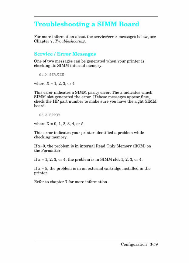
Troubleshooting a SIMM Board
For more information about the service/error messages below, seeChapter 7, Troubleshooting.
Service / Error MessagesOne of two messages can be generated when your printer ischecking its SIMM internal memory.
61.X SERVICE
where X = 1, 2, 3, or 4
This error indicates a SIMM parity error. The x indicates whichSIMM slot generated the error. If these messages appear first,check the HP part number to make sure you have the right SIMMboard.
62.X ERROR
where X = 0, 1, 2, 3, 4, or 5
This error indicates your printer identified a problem whilechecking memory.
If x=0, the problem is in internal Read Only Memory (ROM) onthe Formatter.
If x = 1, 2, 3, or 4, the problem is in SIMM slot 1, 2, 3, or 4.
If x = 5, the problem is in an external cartridge installed in theprinter.
Refer to chapter 7 for more information.
Configuration 3-59

3-60 Configuration
4
Preventive Maintenance
Introduction
The printer requires minimum routine maintenance. Use thischapter for information on:
• Service Checkpoints. These are the items that must becleaned and checked when the Toner Cartridge is replaced, orbefore performing periodic maintenance.
• Toner Cartridge information, such as:• Storing and installing the Toner Cartridge• Refilled Toner Cartridges• 16 TONER LOW message
• Required periodic maintenance on:• Transfer roller• Separation pads• Paper pickup rollers
Preventive Maintenance 4-1
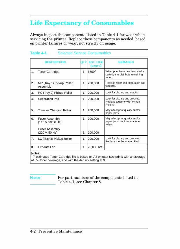
Life Expectancy of Consumables
Always inspect the components listed in Table 4-1 for wear whenservicing the printer. Replace these components as needed, basedon printer failures or wear, not strictly on usage.
DESCRIPTION QTY EST. LIFE(pages)
REMARKS
1. Toner Cartridge 1 68001 When print becomes faint, shakecartridge to distribute remainingtoner.
2. MP (Tray 1) Pickup RollerAssembly
1 200,000 Replace roller and separation padtogether.
3. PC (Tray 2) Pickup Roller 1 200,000 Look for glazing and cracks.
4. Separation Pad 1 200,000 Look for glazing and grooves.Replace together with PickupRollers.
5. Transfer Charging Roller 1 200,000 May affect print quality and/orpaper jams.
6. Fuser Assembly(115 V, 50/60 Hz) Fuser Assembly(220 V, 50 Hz)
1
1
200,000
200,000
May affect print quality and/orpaper jams. Look for marks onrollers.
7. LC (Tray 3) Pickup Roller 1 200,000 Look for glazing and grooves.Replace the Separation Pad.
8. Exhaust Fan 1 25,000 hrs.
Notes:The estimated Toner Cartridge life is based on A4 or letter size prints with an averageof 5% toner coverage, and with the density setting at 3.
N o t e For part numbers of the components listed inTable 4-1, see Chapter 8.
Table 4-1 Selected Service Consumables
4-2 Preventive Maintenance
Service Checkpoints
This is a fold-out page 3 panels wide.
Figure 4-1 Maintenance Checkpoints
Preventive Maintenance 4-3

Cleaning Your PrinterWhen it is time to replace the toner cartridge, perform thecleaning procedures outlined in Figure 4-1.
4-4 Preventive Maintenance
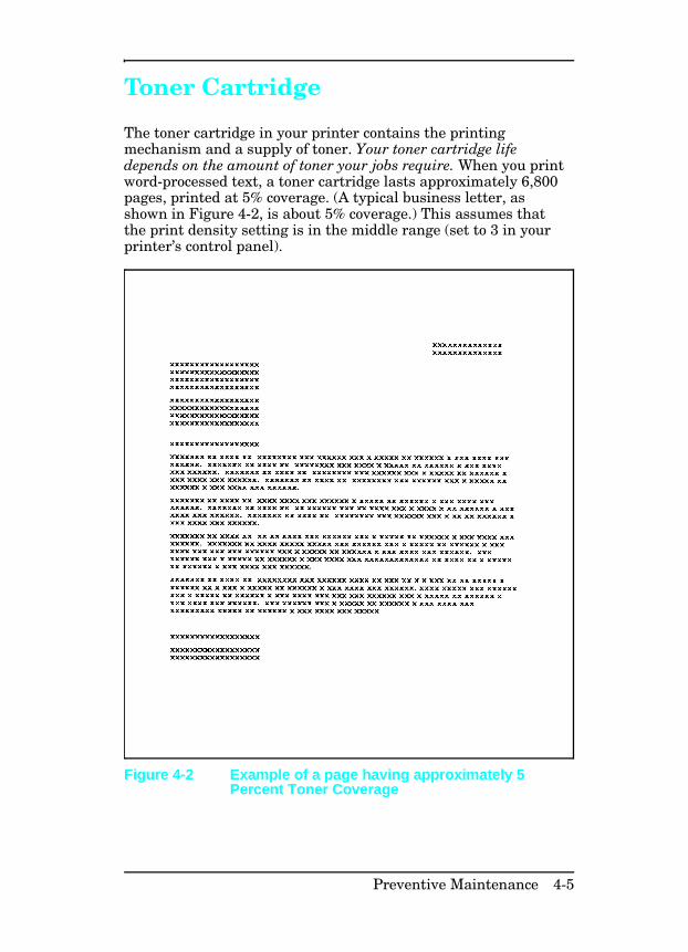
Toner Cartridge
The toner cartridge in your printer contains the printingmechanism and a supply of toner. Your toner cartridge lifedepends on the amount of toner your jobs require. When you printword-processed text, a toner cartridge lasts approximately 6,800pages, printed at 5% coverage. (A typical business letter, asshown in Figure 4-2, is about 5% coverage.) This assumes thatthe print density setting is in the middle range (set to 3 in yourprinter’s control panel).
Figure 4-2 Example of a page having approximately 5Percent Toner Coverage
Preventive Maintenance 4-5

Saving Toner with EconoMode (HP LaserJet 4Plus and 5 Only)Toner cartridge life can be extended dramatically by using theEconoMode printing feature of the printer. EconoMode can beturned on or off via the printer control panel, through HP’sRemote Control Panel or through a software application with theappropriate printer driver.
N o t e EconoMode is recommended in portraitorientation only.
Some software applications may refer to this as“draft mode”.
Software settings always override control panelselections.
Storing the Toner Cartridge Do not remove the toner cartridge from its packaging until youare ready to use it. The shelf life of an unopened cartridgepackage is approximately 2 1⁄2 years of storage including usage;the maximum shelf life of an opened cartridge package isapproximately six months including usage.
Use the toner cartridge before the expiration date which isprinted on its shipping box.
Always store cartridges:
• As specified on the shipping box, or horizontally (flat) ifremoved from the box.
• In a normal office environment (for example, a location withregulated temperature and humidity).
• Away from direct sunlight or other strong light.
4-6 Preventive Maintenance
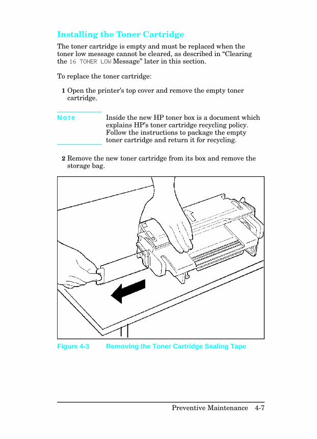
Installing the Toner Cartridge The toner cartridge is empty and must be replaced when thetoner low message cannot be cleared, as described in “Clearingthe 16 TONER LOW Message” later in this section.
To replace the toner cartridge:
1 Open the printer’s top cover and remove the empty tonercartridge.
N o t e Inside the new HP toner box is a document whichexplains HP’s toner cartridge recycling policy.Follow the instructions to package the emptytoner cartridge and return it for recycling.
2 Remove the new toner cartridge from its box and remove thestorage bag.
Figure 4-3 Removing the Toner Cartridge Sealing Tape
Preventive Maintenance 4-7
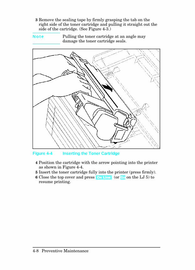
3 Remove the sealing tape by firmly grasping the tab on theright side of the toner cartridge and pulling it straight out theside of the cartridge. (See Figure 4-3.)
N o t e Pulling the toner cartridge at an angle maydamage the toner cartridge seals.
4 Position the cartridge with the arrow pointing into the printeras shown in Figure 4-4.
5 Insert the toner cartridge fully into the printer (press firmly).6 Close the top cover and press [On Line] (or Go on the LJ 5) to
resume printing.
Figure 4-4 Inserting the Toner Cartridge
4-8 Preventive Maintenance
Non-HP Toner Cartridges While Hewlett-Packard does not prohibit the use of Non-HPtoner cartridges during the warranty period or while under amaintenance contract, we do not recommend their use. Thereasons for this are:
• Hewlett-Packard has no control or process to ensure that aNon-HP toner cartridge functions at the high level ofreliability of an HP LaserJet toner cartridge.Hewlett-Packard also cannot predict what the long termreliability effect on the printer is from using different tonerformulations found in Non-HP cartridges.
• Hewlett-Packard has no control over the actual print qualityof a Non-HP toner cartridge. The print quality of HP LaserJetcartridges influences the customer’s perception of the printer.The high print quality of HP LaserJet printers is one of theprimary reasons for the success of the product and we arekeenly interested in maintaining that image.
• Repairs resulting from the use of Non-HP toner cartridges arenot covered under the HP warranty.
Preventive Maintenance 4-9
Clearing the TONER LOW Message If the 16 TONER LOW message appears in the control panel display,the toner level in the toner cartridge is getting low. The printbecomes lighter and white streaks may appear. (This messagemeans that it is time to replace the toner cartridge).
If the control panel Config Menu Toner Low item is set to TONERLOW=ON (or CONT on the LJ4+ and LJ5 printers), the printercontinues to print with the 16 TONER LOW message in the controlpanel display. TONER LOW=ON is the default setting.
A Configuration Menu setting TONER LOW=OFF (or STOP on theLJ4+ and LJ 5 printers) is available that causes the printer to gooff-line and to stop printing when low toner is detected. If TONERLOW=OFF (or STOP) is selected from the Configuration Menu, youmust press [Continue] (or Go on the LJ 5) to resume printing. Usethe TONER LOW=OFF (STOP) setting when sharing the printer withother users, or when using MICR cartridges.
You can improve the print quality temporarily by redistributingthe toner as follows:
1 Remove the toner cartridge.2 Rotate the toner cartridge about its horizontal axis (i.e., not
end over end) to redistribute toner. 3 Reinsert the toner cartridge and press [On Line] (or Go on the
LJ5).
The 16 TONER LOW message still may appear, but the printquality should improve. If the print remains light, replace thetoner cartridge immediately. Install the new cartridge asdescribed in the instructions included with the cartridge.
4-10 Preventive Maintenance
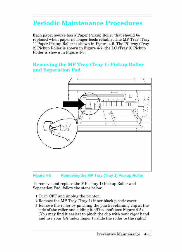
Periodic Maintenance Procedures
Each paper source has a Paper Pickup Roller that should bereplaced when paper no longer feeds reliably. The MP Tray (Tray1) Paper Pickup Roller is shown in Figure 4-5. The PC tray (Tray2) Pickup Roller is shown in Figure 4-7, the LC (Tray 3) PickupRoller is shown in Figure 4-8.
Removing the MP Tray (Tray 1) Pickup Rollerand Separation Pad
To remove and replace the MP (Tray 1) Pickup Roller andSeparation Pad, follow the steps below.
1 Turn OFF and unplug the printer.2 Remove the MP Tray (Tray 1) inner black plastic cover.3 Remove the roller by pinching the plastic retaining clip at the
side of the roller and sliding it off its shaft (see Figure 4-5).(You may find it easiest to pinch the clip with your right handand use your left index finger to slide the roller to the right.)
Figure 4-5 Removing the MP Tray (Tray 1) Pickup Roller
Preventive Maintenance 4-11
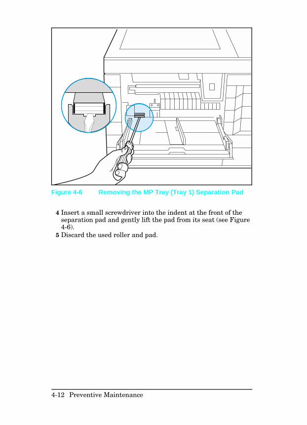
4 Insert a small screwdriver into the indent at the front of theseparation pad and gently lift the pad from its seat (see Figure4-6).
5 Discard the used roller and pad.
Figure 4-6 Removing the MP Tray (Tray 1) Separation Pad
4-12 Preventive Maintenance
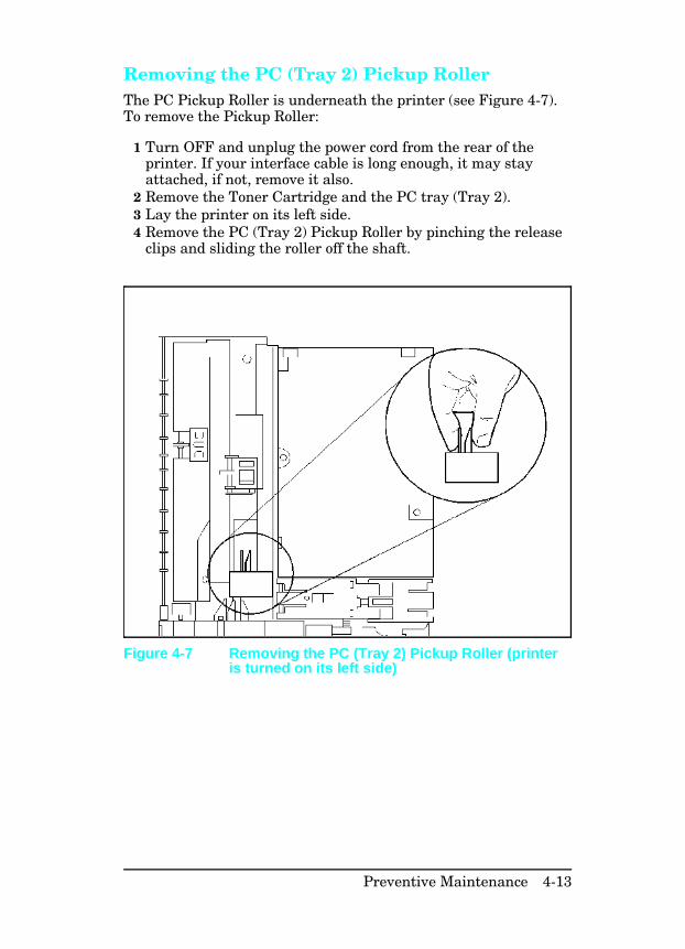
Removing the PC (Tray 2) Pickup Roller The PC Pickup Roller is underneath the printer (see Figure 4-7).To remove the Pickup Roller:
1 Turn OFF and unplug the power cord from the rear of theprinter. If your interface cable is long enough, it may stayattached, if not, remove it also.
2 Remove the Toner Cartridge and the PC tray (Tray 2).3 Lay the printer on its left side.4 Remove the PC (Tray 2) Pickup Roller by pinching the release
clips and sliding the roller off the shaft.
Figure 4-7 Removing the PC (Tray 2) Pickup Roller (printeris turned on its left side)
Preventive Maintenance 4-13
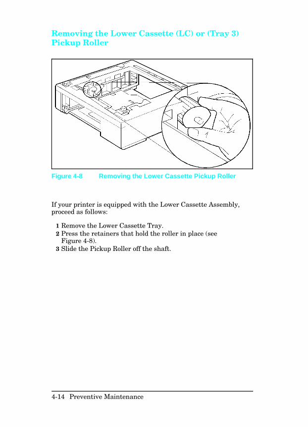
Removing the Lower Cassette (LC) or (Tray 3)Pickup Roller
If your printer is equipped with the Lower Cassette Assembly,proceed as follows:
1 Remove the Lower Cassette Tray. 2 Press the retainers that hold the roller in place (see
Figure 4-8).3 Slide the Pickup Roller off the shaft.
Figure 4-8 Removing the Lower Cassette Pickup Roller
4-14 Preventive Maintenance
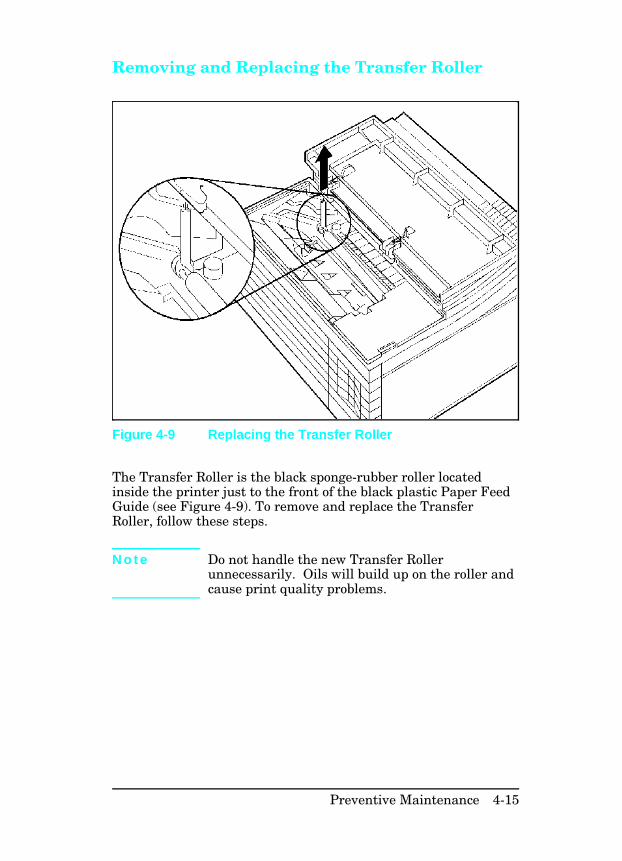
Removing and Replacing the Transfer Roller
The Transfer Roller is the black sponge-rubber roller locatedinside the printer just to the front of the black plastic Paper FeedGuide (see Figure 4-9). To remove and replace the TransferRoller, follow these steps.
N o t e Do not handle the new Transfer Rollerunnecessarily. Oils will build up on the roller andcause print quality problems.
Figure 4-9 Replacing the Transfer Roller
Preventive Maintenance 4-15
Removing the Transfer Roller 1 Turn OFF and unplug the printer.2 Open the printer’s top cover.3 Remove the Toner Cartridge.4 Use the hook inside the top cover to remove the Transfer
Roller as follows. Hook the left side of the chrome rod besidethe sponge roller, and lift the roller out.
5 Discard the used roller.
Replacing the Transfer Roller 1 Slide the right end of the new roller (the end without the
gear), onto the right slot. Press the rod into the slot.2 Lower the gear end of the roller into place. 3 Install the toner cartridge.4 Replace the hook tool.5 Close the top cover.6 Plug in the power cord and switch the printer ON.
4-16 Preventive Maintenance
5
Functional Overview
Introduction
This section of the manual presents a functional overview of theprinters. It provides the Service Representative with anunderstanding of the printing process. Refer to the block diagramof Figure 5-1 to see the relationship of the parts as a whole.
This chapter discusses the following printer functions:
• DC Controller System• Formatter System• Image Formation System• Paper Feed System• Power System• Basic Sequence of Operation
Functional Overview 5-1
DC Controller SystemThe DC Controller PCA is responsible for coordinating allactivities involved in the printing process. The DC Controllerenables the drive circuitry for the laser beam, and coordinatesprint data from the Formatter PCA with paper size, laser beammotion, the high voltage system, fuser temperature, and motors.The DC Controller also shares machine status information withthe Formatter PCA so that proper diagnostic messages aredisplayed on the control panel.
The DC Controller communicates with the Paper Control PCA,the High Voltage PCA, the Envelope Feeder, Lower CassetteAssembly and Duplex Assembly by way of two serial data lines(SLI and SLO). One line (SLO) is used for sending commands, theother (SLI) is used for receiving status information from theselected devices. The amount of toner in the Toner Cartridge alsois monitored indirectly with information on the serial data line.
In summary, the following systems and functions are controlledand/or monitored by the DC Controller:
• Paper Motion• Laser and Scanner Drive• Timing• Machine Status• Paper Size and Availability• High Voltage System• Fusing Temperature• Main Motor Drive• DC Power Supply• Toner Level
5-2 Functional Overview
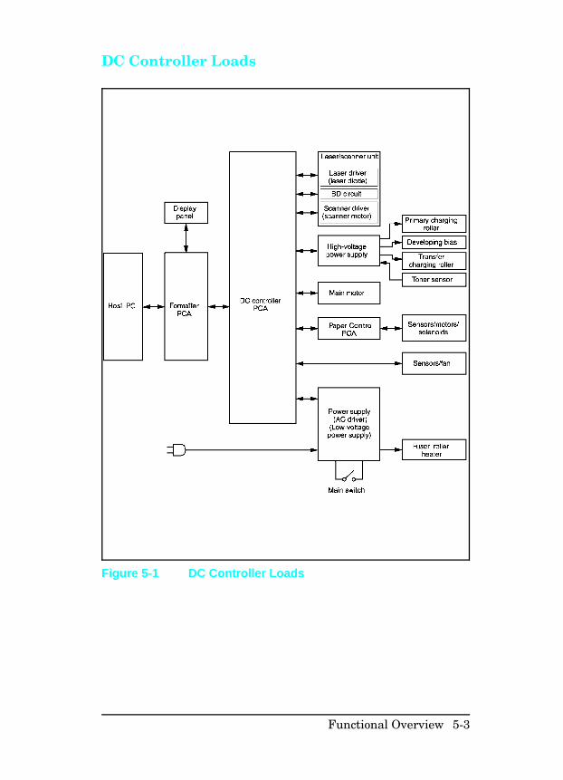
DC Controller Loads
Figure 5-1 DC Controller Loads
Functional Overview 5-3
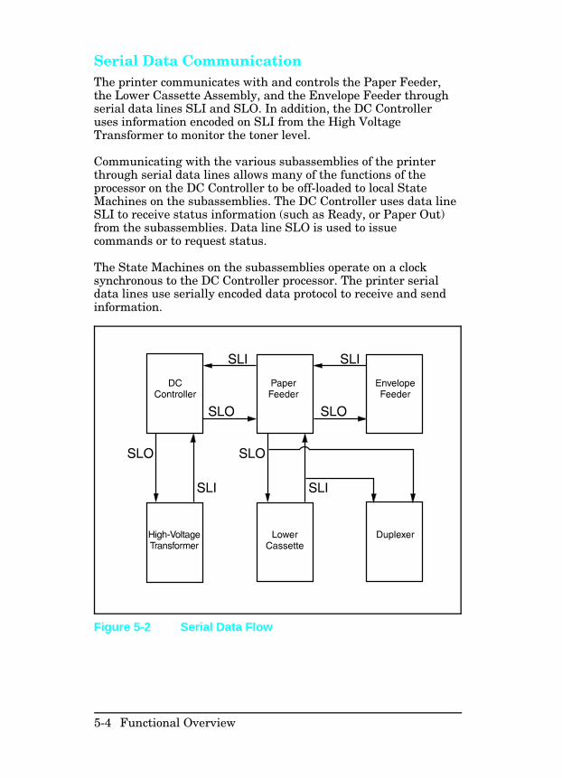
Serial Data Communication The printer communicates with and controls the Paper Feeder,the Lower Cassette Assembly, and the Envelope Feeder throughserial data lines SLI and SLO. In addition, the DC Controlleruses information encoded on SLI from the High VoltageTransformer to monitor the toner level.
Communicating with the various subassemblies of the printerthrough serial data lines allows many of the functions of theprocessor on the DC Controller to be off-loaded to local StateMachines on the subassemblies. The DC Controller uses data lineSLI to receive status information (such as Ready, or Paper Out)from the subassemblies. Data line SLO is used to issuecommands or to request status.
The State Machines on the subassemblies operate on a clocksynchronous to the DC Controller processor. The printer serialdata lines use serially encoded data protocol to receive and sendinformation.
Figure 5-2 Serial Data Flow
5-4 Functional Overview
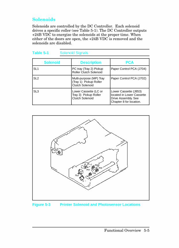
Solenoids Solenoids are controlled by the DC Controller. Each solenoiddrives a specific roller (see Table 5-1). The DC Controller outputs+24B VDC to energize the solenoids at the proper time. Wheneither of the doors are open, the +24B VDC is removed and thesolenoids are disabled.
Solenoid Description PCA
SL1 PC tray (Tray 2) PickupRoller Clutch Solenoid
Paper Control PCA (J704)
SL2 Multi-purpose (MP) Tray(Tray 1) Pickup RollerClutch Solenoid
Paper Control PCA (J702)
SL3 Lower Cassette (LC or Tray 3) Pickup RollerClutch Solenoid
Lower Cassette (J853)located in Lower CassetteDrive Assembly. SeeChapter 8 for location.
Table 5-1 Solenoid Signals
Figure 5-3 Printer Solenoid and Photosensor Locations
Functional Overview 5-5
Photosensors Photosensors, monitored by the DC Controller, are responsible fordetecting the presence of paper, paper motion, and timing. (SeeTable 5-2.) Photosensor PS2 senses paper in the PC tray;photosensor PS4 senses paper in the MP tray. The message PCLOAD or MP LOAD is displayed when either the PC tray or the MPtray is selected as the primary tray and is out of paper. PS6 andPS7 (respectively) sense the presence of paper in the LowerCassette and the Envelope Feeder. Paper must be loaded into theprimary paper tray before printing can resume. The message PCEMPTY or MP EMPTY is displayed when either the PC tray or theMP tray is out of paper and is not selected as the primary papertray. LC EMPTY or EE EMPTY is displayed when the Lower Cassetteor the Envelope Feeder is empty. The EMPTY message is only areminder that the paper tray is empty; it is not necessary to loadpaper to continue printing from another tray.
The Paper Control PCA, Lower Cassette Assembly, and theEnvelope Feeder communicate with the DC Controller throughserial data lines. The condition of the printer enginephotosensors PS2, PS4, PS5, the optional Lower Cassette PS6,and the optional Envelope Feeder PS7 is encoded into a digitallogic stream and read by the DC Controller on line SLI.
PS1 detects paper at the Input Feed Roller and is used in jamdetection and registration. PS3 detects the presence of paper inthe Fuser Assembly, and is used in jam detection. PS5 terminateslaser operation when it detects the end of the sheet. This allowsthe printer to print images on odd-sized media fed from the MPtray without contaminating the Transfer Roller.
N o t e The LaserJet 5 printer uses different traydesignators and associated messages as follows.
LJ 4 / 4 Plus LJ 5
MP Tray Tray 1
PC Tray Tray 2
LC Tray Tray 3
MP/PC/LC LOAD TRAY x LOAD (x=1,2, or 3)
MP/PC/LC EMPTY TRAY x EMPTY (x=1,2, or 3)
5-6 Functional Overview
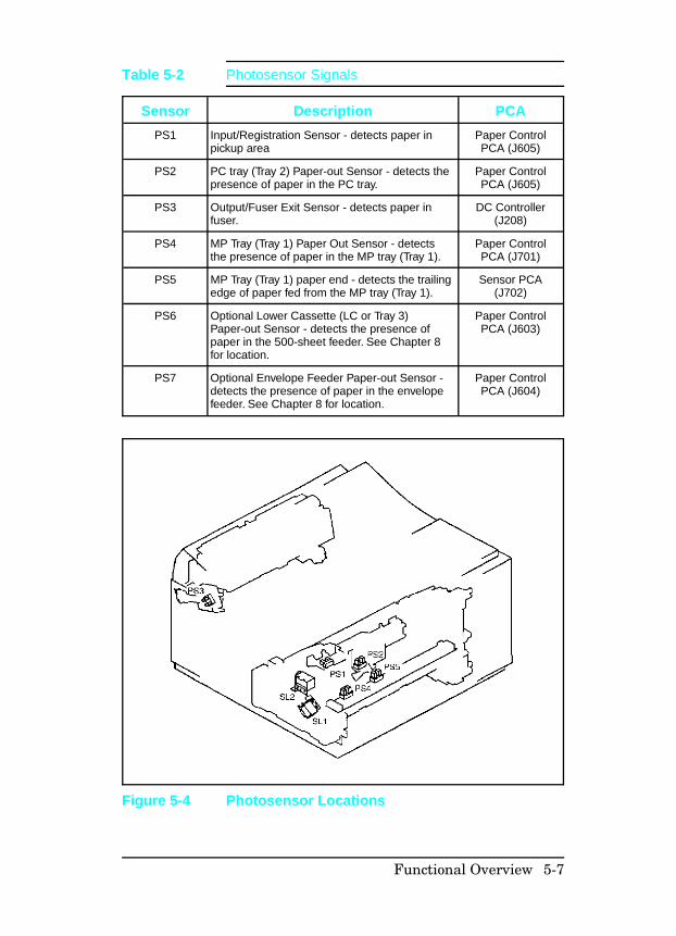
Sensor Description PCA
PS1 Input/Registration Sensor - detects paper inpickup area
Paper ControlPCA (J605)
PS2 PC tray (Tray 2) Paper-out Sensor - detects thepresence of paper in the PC tray.
Paper ControlPCA (J605)
PS3 Output/Fuser Exit Sensor - detects paper infuser.
DC Controller(J208)
PS4 MP Tray (Tray 1) Paper Out Sensor - detectsthe presence of paper in the MP tray (Tray 1).
Paper ControlPCA (J701)
PS5 MP Tray (Tray 1) paper end - detects the trailingedge of paper fed from the MP tray (Tray 1).
Sensor PCA(J702)
PS6 Optional Lower Cassette (LC or Tray 3)Paper-out Sensor - detects the presence ofpaper in the 500-sheet feeder. See Chapter 8for location.
Paper ControlPCA (J603)
PS7 Optional Envelope Feeder Paper-out Sensor -detects the presence of paper in the envelopefeeder. See Chapter 8 for location.
Paper ControlPCA (J604)
Table 5-2 Photosensor Signals
Figure 5-4 Photosensor Locations
Functional Overview 5-7
Microswitches All microswitch conditions are monitored by the DC Controllerover serial data lines SLI and SLO. The State Machines on theindividual control PCAs, (for example the Paper Control PCA)convert the switch condition to a digital logic level, and encodethat information on the data stream for the DC Controller to use.
SW601 (Door Open Sensing switch) monitors the top cover. If thetop cover is open, the printing process stops and the 12PRINTER OPEN message is displayed. SW601 disables the +24V(B) voltage, so the printer goes through the warm-up cycle afterthe cover is closed.
SW602 (Test Print switch) is labeled and located under the MPtray (Tray 1) door on the right edge of the door opening. The PrintEngine Test isolates the entire printer from the Formatter PCA.Press the Test Print switch once to start the Print Engine Test.The Print Engine Test is a good method for finding whether printproblems are associated with the DC Controller or the FormatterPCA.
Paper tray size microswitches are activated by protrusions oneach PC tray (Tray 2). The tray size is determined by thecombination of engaged microswitches (see Table 5-3 and 5-4).
SW 603, 604, 605 (Cassette Size Switches) are for the PC tray(Tray 2), and SW 851, 852, 853 are for the 500-sheet LowerCassette (Tray 3). These microswitches work together to indicateto the DC Controller which size cassette is installed, or indicatethat the cassette is incorrectly installed. The combinations foreach cassette size are listed in Table 5-4.
5-8 Functional Overview
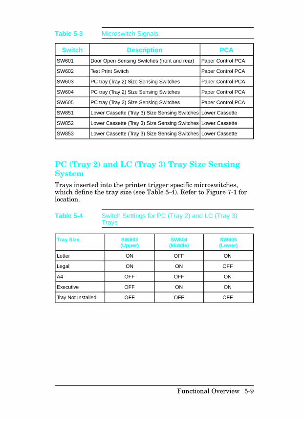
PC (Tray 2) and LC (Tray 3) Tray Size SensingSystemTrays inserted into the printer trigger specific microswitches,which define the tray size (see Table 5-4). Refer to Figure 7-1 forlocation.
Switch Description PCA
SW601 Door Open Sensing Switches (front and rear) Paper Control PCA
SW602 Test Print Switch Paper Control PCA
SW603 PC tray (Tray 2) Size Sensing Switches Paper Control PCA
SW604 PC tray (Tray 2) Size Sensing Switches Paper Control PCA
SW605 PC tray (Tray 2) Size Sensing Switches Paper Control PCA
SW851 Lower Cassette (Tray 3) Size Sensing Switches Lower Cassette
SW852 Lower Cassette (Tray 3) Size Sensing Switches Lower Cassette
SW853 Lower Cassette (Tray 3) Size Sensing Switches Lower Cassette
Table 5-3 Microswitch Signals
Tray Size SW603(Upper)
SW604(Middle)
SW605(Lower)
Letter ON OFF ON
Legal ON ON OFF
A4 OFF OFF ON
Executive OFF ON ON
Tray Not Installed OFF OFF OFF
Table 5-4 Switch Settings for PC (Tray 2) and LC (Tray 3)Trays
Functional Overview 5-9

Motors The DC Controller controls the Exhaust Fan, the Main Motor,and the Laser/Scanner Motor. The remaining motors andsolenoids are controlled by State Machines on the motor’sassembly. The condition of these motors and solenoids ismonitored by the DC Controller through serial data lines.
The Main Motor (M1) rotates after any printer door is opened andclosed, during the Warm-up period, the Initial Rotation period,the Print period, or the Last Rotation Period. The Scanner Motor(M5) is controlled and monitored by the DC Controller PCA. M5operates during the Initial Rotation period, the Print period, andthe Last Rotation period.
The Paper Feed Assembly Drive Motor (M2) runs during thePrint Period. This motor provides the drive to pick paper from thePC tray, and deliver it to the Input/Registration Sensor (PS1).The LC Assembly Motor (M3) provides the drive to pick paperfrom the optional 500-sheet Lower Cassette, and deliver it to theInput/Registration Sensor (PS1). M3 is mounted on the 500-sheetLower Cassette. The Envelope Feeder Drive Motor (M4) providesthe drive to pick envelopes from the envelope feeder and deliverthem to the Input/Registration Sensor (PS1). M4 is mounted onthe optional Envelope Feeder.
The Exhaust Fan Motor (FM1) is controlled and monitored by theDC Controller PCA. The Exhaust Fan Motor operates atlow-speed during the Warm-up period, Standby period, andduring PowerSave. It operates at high-speed during the InitialRotation period, the Print period, and the Last Rotation period.
The Paper Feed Assembly Motor (M2) is controlled by the PaperControl PCA. The Paper Feed Assembly Motor drives the pickuprollers through SL1 and SL2. These rollers pick media fromeither the PC tray (Tray 2) or the MP tray (Tray 1), and deliverthe media to the Paper Registration Sensor (PS1).
5-10 Functional Overview
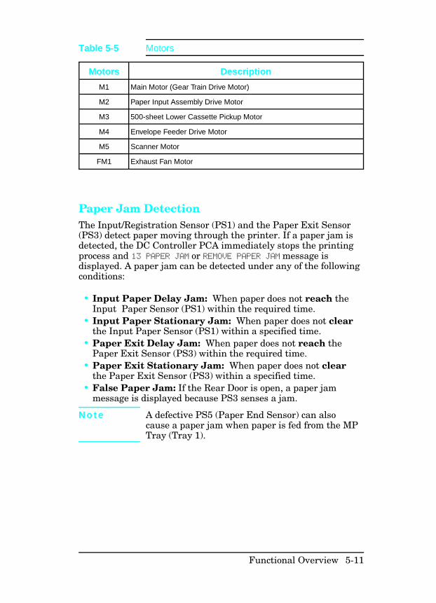
Paper Jam Detection The Input/Registration Sensor (PS1) and the Paper Exit Sensor(PS3) detect paper moving through the printer. If a paper jam isdetected, the DC Controller PCA immediately stops the printingprocess and 13 PAPER JAM or REMOVE PAPER JAM message isdisplayed. A paper jam can be detected under any of the followingconditions:
• Input Paper Delay Jam: When paper does not reach theInput Paper Sensor (PS1) within the required time.
• Input Paper Stationary Jam: When paper does not clearthe Input Paper Sensor (PS1) within a specified time.
• Paper Exit Delay Jam: When paper does not reach thePaper Exit Sensor (PS3) within the required time.
• Paper Exit Stationary Jam: When paper does not clearthe Paper Exit Sensor (PS3) within a specified time.
• False Paper Jam: If the Rear Door is open, a paper jammessage is displayed because PS3 senses a jam.
N o t e A defective PS5 (Paper End Sensor) can alsocause a paper jam when paper is fed from the MPTray (Tray 1).
Motors Description
M1 Main Motor (Gear Train Drive Motor)
M2 Paper Input Assembly Drive Motor
M3 500-sheet Lower Cassette Pickup Motor
M4 Envelope Feeder Drive Motor
M5 Scanner Motor
FM1 Exhaust Fan Motor
Table 5-5 Motors
Functional Overview 5-11
Formatter System
The formatter is responsible for the following:
• Receiving and processing ASCII data from printer interfaces.• Monitoring front panel input and relaying printer status
information (through the front panel and bi-directional I/O).• Developing/coordinating data placement and timing with the
print engine.• Storing font information.• Communicating with the host computer.
The Formatter PCA can be divided into three functional areas:
• I/O Control• Memory/Memory Management• Data Processing
Formatter Feature LaserJet 4 LaserJet 4+ LaserJet 5
Processor 20 MHz 80960KA 25 MHz 80960KB 33 MHz 80960JF
REt Yes Yes Yes
MEt No Yes Yes
Economode No Yes Yes
Configurable I/O Buffer Size No Yes Yes
Personality ResourceSaving
No Yes Yes
PowerSave Mode No Yes Yes
Font Cartridge Slot Yes Yes No
MIO Interface Level 5.0 5.1 6.0
Serial Ports RS-232/422 RS-232 RS-232 & SIR
Parallel Port Bitronics IEEE-1284 Bitronics IEEE-1284 Bitronics
Maximum RAM (PCL/PS) 34/22 MB 66/50 MB 66/52 MB
SIMM Support RAM/ROM RAM/ROM RAM/ROM/Flash
PCL Level 5 5E 6
On-Board Fonts 35 Intellifont/10 TT Line Printer
35 Intellifont/10 TTLine Printer
45 TT & Dark CourierLine Printer
Default Symbol Set Roman-8 Roman-8 PC-8
Paper Size Support Letter/Legal/A4/Exec Letter/Legal/A4/Exec Letter/Legal/A4/Exec/A5
MP (Tray 1) Modes First, Manual, Cassette First, Manual, Cassette First, Cassette
Grayscale Hardware Assist No No Yes
ROPS 3 Hardware Assist No No Yes
Intuitive Control Panel No No Yes
I/O ControlThe formatter I/O control is responsible for maintainingcommunications with the host system(s). The printer has threeinterfaces; serial, parallel (bitronic), and Modular I/O (MIO). Theformatter maintains connections with hosts connected to theseI/O’s including accepting data handshaking, and returning status.
5-12 Functional Overview
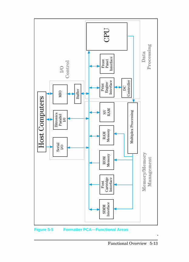
Figure 5-5 Formatter PCA—Functional Areas
Functional Overview 5-13
Memory ManagementThe printer uses several different types of memory. This memorycan be divided into two different categories, Read Only Memory(ROM) and Random Access Memory (RAM). ROM memoryconsists of the memory located on the Formatter PCA and anyfont cartridges that may be installed in the printer. RAM memoryconsists of RAM memory resident on the Formatter PCA, SIMMmemory installed in the printer, and the Non-Volatile Memory(NVRAM) located on the Formatter PCA.
In general, the ROM is responsible for storing the instructions forthe operation of the processor and font information. The RAMmemory is used to store temporary information that will be usedby the printer for a particular print job or a series of print jobs.This could consist of soft fonts, macros or graphics patterns. RAMmemory is also used by the printer to store data that is beingprocessed into the raster image that will control the laser andcreate the printed page.
The NVRAM is used to store printer configuration informationthat can be input from the printer front panel. This informationstored in NVRAM will remain resident in the printer even if thepower to the printer is turned off.
Data ProcessingThe formatter CPU is responsible for the overall control of allfunctions related to the formatter. One of the CPU’s mainfunctions is to maintain communication with the print engine.This is done by the print engine interface and the DC ControllerPCA. The DC Controller PCA monitors all print engine functionssuch as fuser temperature and paper jam status. The print enginestatus is communicated by the DC Controller to the formatterCPU by the print engine interface. The CPU also controls theprocess that converts ASCII data received from the host into theraster data. This raster data is sent to the laser scanner assemblyvia the DC Controller.
Finally the CPU comunicates printer status to the user throughthe control panel via the front panel interface. The front panelinterface also transmits front panel inputs to the CPU.
5-14 Functional Overview
PJL Overview Printer Job Language (PJL) is an integral part of configuration,in addition to the standard Printer Command Language. Withstandard I/O cabling, PJL allows the printer to perform functionssuch as:
• Allowing the printer to talk to the host computer through aBi-directional parallel connection. The printer can tell the hostsuch things as the control panel settings, and allow the controlpanel settings to be set from the host.
• Dynamic I/O switching allows the printer to be configuredwith a host on each I/O. The printer can receive data from anyI/O simultaneously.
• Context-sensitive switching allows the printer to recognizeautomatically the personalities (PostScript or PCL) of eachhost and configure itself to serve that personality.
• PJL can act as a spooler to print only sections of a print job asdefined from the software.
• PJL allows any print job to be protected from the effects of theprevious print job. If a print job is sent to the printer inlandscape mode, the subsequent print jobs print in landscapeonly if they are formatted for landscape printing.
Functional Overview 5-15
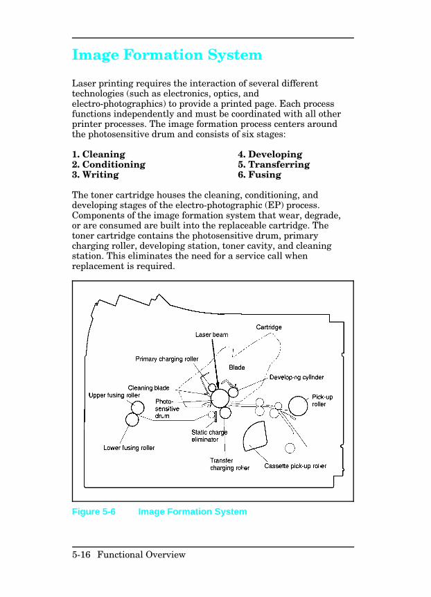
Image Formation System
Laser printing requires the interaction of several differenttechnologies (such as electronics, optics, andelectro-photographics) to provide a printed page. Each processfunctions independently and must be coordinated with all otherprinter processes. The image formation process centers aroundthe photosensitive drum and consists of six stages:
1. Cleaning 4. Developing2. Conditioning 5. Transferring3. Writing 6. Fusing
The toner cartridge houses the cleaning, conditioning, anddeveloping stages of the electro-photographic (EP) process.Components of the image formation system that wear, degrade,or are consumed are built into the replaceable cartridge. Thetoner cartridge contains the photosensitive drum, primarycharging roller, developing station, toner cavity, and cleaningstation. This eliminates the need for a service call whenreplacement is required.
Figure 5-6 Image Formation System
5-16 Functional Overview
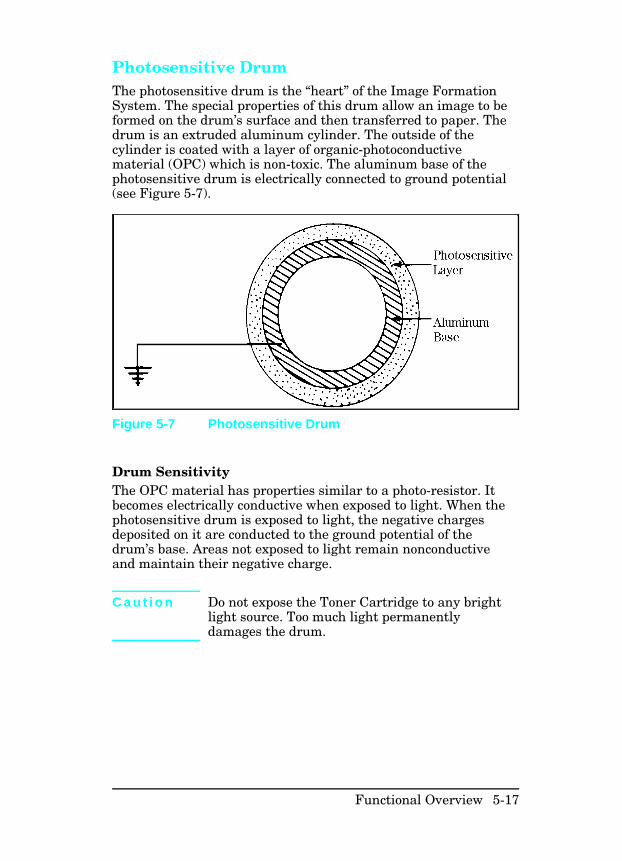
Photosensitive Drum The photosensitive drum is the “heart” of the Image FormationSystem. The special properties of this drum allow an image to beformed on the drum’s surface and then transferred to paper. Thedrum is an extruded aluminum cylinder. The outside of thecylinder is coated with a layer of organic-photoconductivematerial (OPC) which is non-toxic. The aluminum base of thephotosensitive drum is electrically connected to ground potential(see Figure 5-7).
Drum Sensitivity The OPC material has properties similar to a photo-resistor. Itbecomes electrically conductive when exposed to light. When thephotosensitive drum is exposed to light, the negative chargesdeposited on it are conducted to the ground potential of thedrum’s base. Areas not exposed to light remain nonconductiveand maintain their negative charge.
C a u t i o n Do not expose the Toner Cartridge to any brightlight source. Too much light permanentlydamages the drum.
Figure 5-7 Photosensitive Drum
Functional Overview 5-17
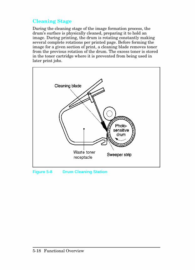
Cleaning Stage During the cleaning stage of the image formation process, thedrum’s surface is physically cleaned, preparing it to hold animage. During printing, the drum is rotating constantly makingseveral complete rotations per printed page. Before forming theimage for a given section of print, a cleaning blade removes tonerfrom the previous rotation of the drum. The excess toner is storedin the toner cartridge where it is prevented from being used inlater print jobs.
Figure 5-8 Drum Cleaning Station
5-18 Functional Overview
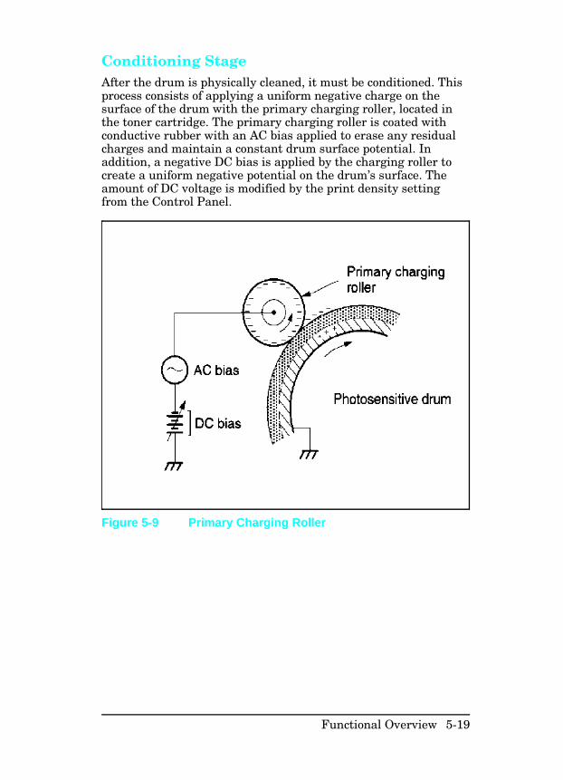
Conditioning Stage After the drum is physically cleaned, it must be conditioned. Thisprocess consists of applying a uniform negative charge on thesurface of the drum with the primary charging roller, located inthe toner cartridge. The primary charging roller is coated withconductive rubber with an AC bias applied to erase any residualcharges and maintain a constant drum surface potential. Inaddition, a negative DC bias is applied by the charging roller tocreate a uniform negative potential on the drum’s surface. Theamount of DC voltage is modified by the print density settingfrom the Control Panel.
Figure 5-9 Primary Charging Roller
Functional Overview 5-19
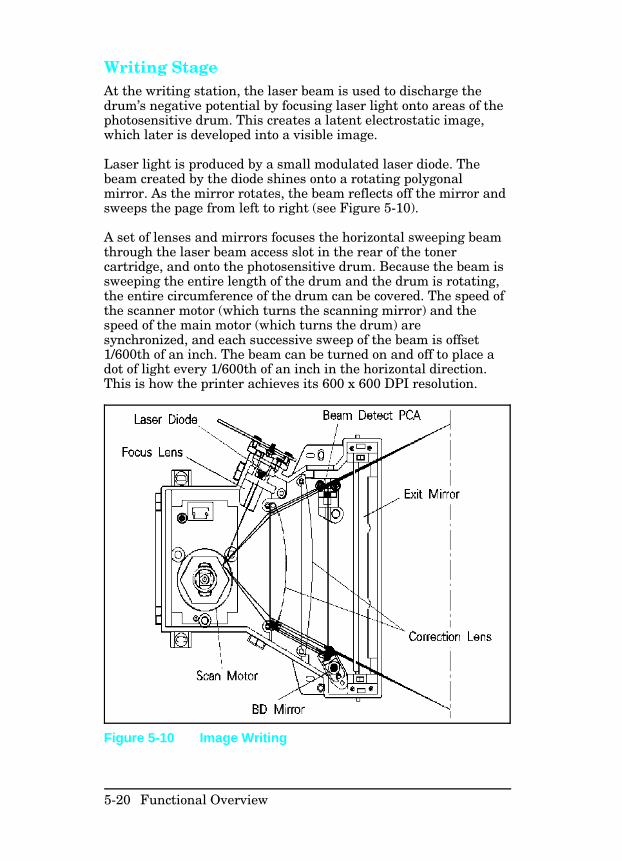
Writing Stage At the writing station, the laser beam is used to discharge thedrum’s negative potential by focusing laser light onto areas of thephotosensitive drum. This creates a latent electrostatic image,which later is developed into a visible image.
Laser light is produced by a small modulated laser diode. Thebeam created by the diode shines onto a rotating polygonalmirror. As the mirror rotates, the beam reflects off the mirror andsweeps the page from left to right (see Figure 5-10).
A set of lenses and mirrors focuses the horizontal sweeping beamthrough the laser beam access slot in the rear of the tonercartridge, and onto the photosensitive drum. Because the beam issweeping the entire length of the drum and the drum is rotating,the entire circumference of the drum can be covered. The speed ofthe scanner motor (which turns the scanning mirror) and thespeed of the main motor (which turns the drum) aresynchronized, and each successive sweep of the beam is offset1/600th of an inch. The beam can be turned on and off to place adot of light every 1/600th of an inch in the horizontal direction.This is how the printer achieves its 600 x 600 DPI resolution.
Figure 5-10 Image Writing
5-20 Functional Overview
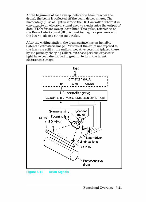
At the beginning of each sweep (before the beam reaches thedrum), the beam is reflected off the beam detect mirror. Themomentary pulse of light is sent to the DC Controller, where it isconverted to an electrical signal used to synchronize the output ofdata (VDO) for one sweep (scan line). This pulse, referred to asthe Beam Detect signal (BD), is used to diagnose problems withthe laser diode or scanner motor also.
After the writing station, the drum surface has an invisible(latent) electrostatic image. Portions of the drum not exposed tothe laser are still at the uniform negative potential (placed thereby the primary charging roller), but those portions exposed tolight have been discharged to ground, to form the latentelectrostatic image.
Figure 5-11 Drum Signals
Functional Overview 5-21
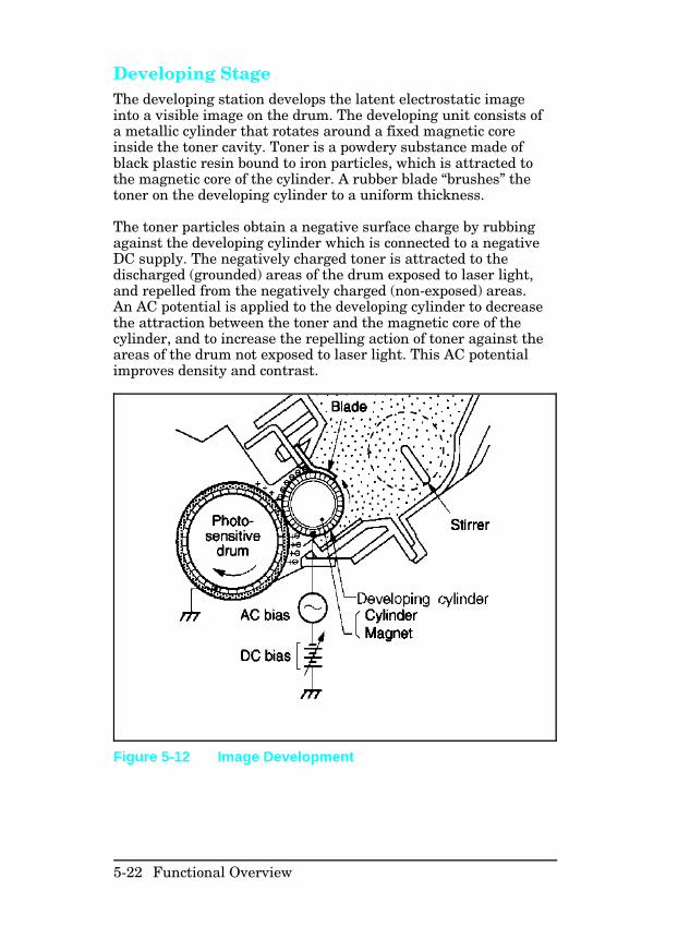
Developing Stage The developing station develops the latent electrostatic imageinto a visible image on the drum. The developing unit consists ofa metallic cylinder that rotates around a fixed magnetic coreinside the toner cavity. Toner is a powdery substance made ofblack plastic resin bound to iron particles, which is attracted tothe magnetic core of the cylinder. A rubber blade “brushes” thetoner on the developing cylinder to a uniform thickness.
The toner particles obtain a negative surface charge by rubbingagainst the developing cylinder which is connected to a negativeDC supply. The negatively charged toner is attracted to thedischarged (grounded) areas of the drum exposed to laser light,and repelled from the negatively charged (non-exposed) areas.An AC potential is applied to the developing cylinder to decreasethe attraction between the toner and the magnetic core of thecylinder, and to increase the repelling action of toner against theareas of the drum not exposed to laser light. This AC potentialimproves density and contrast.
Figure 5-12 Image Development
5-22 Functional Overview
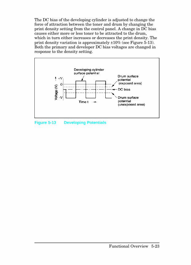
The DC bias of the developing cylinder is adjusted to change theforce of attraction between the toner and drum by changing theprint density setting from the control panel. A change in DC biascauses either more or less toner to be attracted to the drum,which in turn either increases or decreases the print density. Theprint density variation is approximately ±10% (see Figure 5-13).Both the primary and developer DC bias voltages are changed inresponse to the density setting.
Figure 5-13 Developing Potentials
Functional Overview 5-23
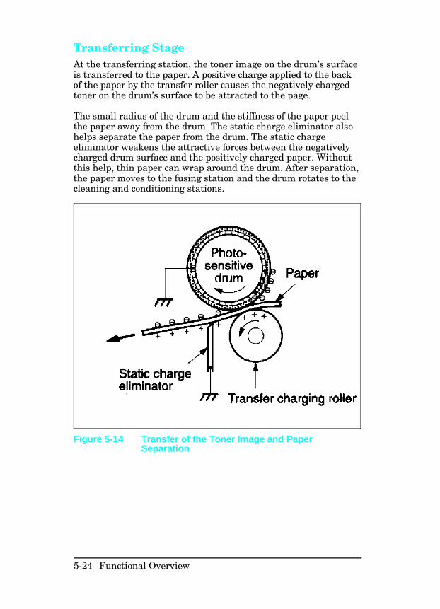
Transferring Stage At the transferring station, the toner image on the drum’s surfaceis transferred to the paper. A positive charge applied to the backof the paper by the transfer roller causes the negatively chargedtoner on the drum’s surface to be attracted to the page.
The small radius of the drum and the stiffness of the paper peelthe paper away from the drum. The static charge eliminator alsohelps separate the paper from the drum. The static chargeeliminator weakens the attractive forces between the negativelycharged drum surface and the positively charged paper. Withoutthis help, thin paper can wrap around the drum. After separation,the paper moves to the fusing station and the drum rotates to thecleaning and conditioning stations.
Figure 5-14 Transfer of the Toner Image and PaperSeparation
5-24 Functional Overview
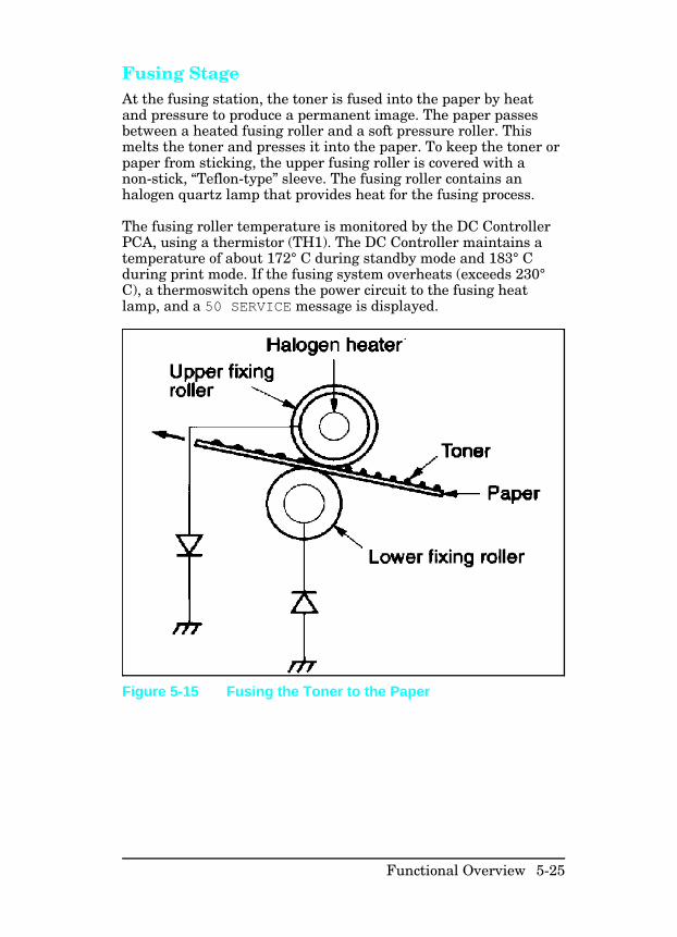
Fusing Stage At the fusing station, the toner is fused into the paper by heatand pressure to produce a permanent image. The paper passesbetween a heated fusing roller and a soft pressure roller. Thismelts the toner and presses it into the paper. To keep the toner orpaper from sticking, the upper fusing roller is covered with anon-stick, “Teflon-type” sleeve. The fusing roller contains anhalogen quartz lamp that provides heat for the fusing process.
The fusing roller temperature is monitored by the DC ControllerPCA, using a thermistor (TH1). The DC Controller maintains atemperature of about 172° C during standby mode and 183° Cduring print mode. If the fusing system overheats (exceeds 230°C), a thermoswitch opens the power circuit to the fusing heatlamp, and a 50 SERVICE message is displayed.
Figure 5-15 Fusing the Toner to the Paper
Functional Overview 5-25
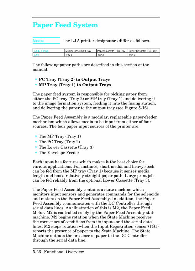
Paper Feed System
N o t e The LJ 5 printer designators differ as follows.
LJ 4 / 4 Plus Multipurpose (MP) Tray Paper Cassette (PC) Tray Lower Cassette (LC) Tray
LJ 5 Tray 1 Tray 2 Tray 3
The following paper paths are described in this section of themanual:
• PC Tray (Tray 2) to Output Trays• MP Tray (Tray 1) to Output Trays
The paper feed system is responsible for picking paper fromeither the PC tray (Tray 2) or MP tray (Tray 1) and delivering itto the image formation system, feeding it into the fusing station,and delivering the paper to the output tray (see Figure 5-16).
The Paper Feed Assembly is a modular, replaceable paper-feedermechanism which allows media to be input from either of foursources. The four paper input sources of the printer are:
• The MP Tray (Tray 1)• The PC Tray (Tray 2)• The Lower Cassette (Tray 3)• The Envelope Feeder
Each input has features which makes it the best choice forvarious applications. For instance, short media and heavy stockcan be fed from the MP tray (Tray 1) because it senses medialength and has a relatively straight paper path. Large print jobscan be fed reliably from the optional Lower Cassette (Tray 3).
The Paper Feed Assembly contains a state machine whichmonitors input sensors and generates commands for the solenoidsand motors on the Paper Feed Assembly. In addition, the PaperFeed Assembly communicates with the DC Controller throughserial data lines. An illustration of this is M2, the Paper FeedMotor. M2 is controlled solely by the Paper Feed Assembly statemachine. M2 begins rotation when the State Machine receivesthe correct set of conditions from its inputs and the serial datalines. M2 stops rotation when the Input Registration sensor (PS1)reports the presence of paper to the State Machine. The StateMachine outputs the presence of paper to the DC Controllerthrough the serial data line.
5-26 Functional Overview
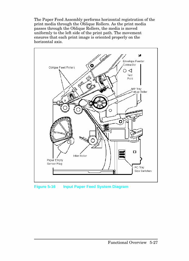
The Paper Feed Assembly performs horizontal registration of theprint media through the Oblique Rollers. As the print mediapasses through the Oblique Rollers, the media is moveduniformly to the left side of the print path. The movementensures that each print image is oriented properly on thehorizontal axis.
Figure 5-16 Input Paper Feed System Diagram
Functional Overview 5-27
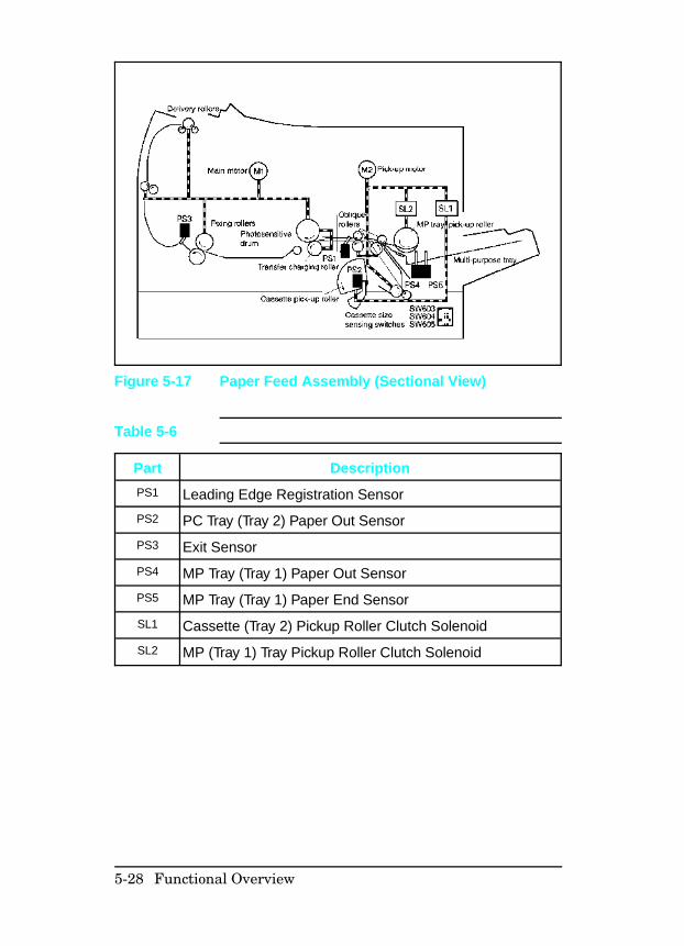
Figure 5-17 Paper Feed Assembly (Sectional View)
Part Description
PS1 Leading Edge Registration Sensor
PS2 PC Tray (Tray 2) Paper Out Sensor
PS3 Exit Sensor
PS4 MP Tray (Tray 1) Paper Out Sensor
PS5 MP Tray (Tray 1) Paper End Sensor
SL1 Cassette (Tray 2) Pickup Roller Clutch Solenoid
SL2 MP (Tray 1) Tray Pickup Roller Clutch Solenoid
Table 5-6
5-28 Functional Overview
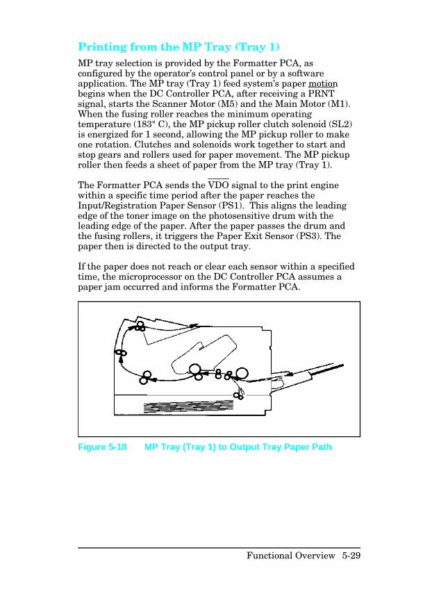
Printing from the MP Tray (Tray 1) MP tray selection is provided by the Formatter PCA, asconfigured by the operator’s control panel or by a softwareapplication. The MP tray (Tray 1) feed system’s paper motionbegins when the DC Controller PCA, after receiving a PRNTsignal, starts the Scanner Motor (M5) and the Main Motor (M1).When the fusing roller reaches the minimum operatingtemperature (183° C), the MP pickup roller clutch solenoid (SL2)is energized for 1 second, allowing the MP pickup roller to makeone rotation. Clutches and solenoids work together to start andstop gears and rollers used for paper movement. The MP pickuproller then feeds a sheet of paper from the MP tray (Tray 1).
The Formatter PCA sends the VDO signal to the print enginewithin a specific time period after the paper reaches theInput/Registration Paper Sensor (PS1). This aligns the leadingedge of the toner image on the photosensitive drum with theleading edge of the paper. After the paper passes the drum andthe fusing rollers, it triggers the Paper Exit Sensor (PS3). Thepaper then is directed to the output tray.
If the paper does not reach or clear each sensor within a specifiedtime, the microprocessor on the DC Controller PCA assumes apaper jam occurred and informs the Formatter PCA.
Figure 5-18 MP Tray (Tray 1) to Output Tray Paper Path
Functional Overview 5-29
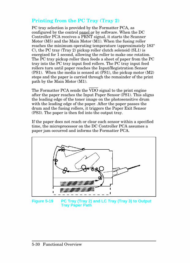
Printing from the PC Tray (Tray 2) PC tray selection is provided by the Formatter PCA, asconfigured by the control panel or by software. When the DCController PCA receives a PRNT signal, it starts the ScannerMotor (M5) and the Main Motor (M1). When the fusing rollerreaches the minimum operating temperature (approximately 183°C), the PC tray (Tray 2) pickup roller clutch solenoid (SL1) isenergized for 1 second, allowing the roller to make one rotation.The PC tray pickup roller then feeds a sheet of paper from the PCtray into the PC tray input feed rollers. The PC tray input feedrollers turn until paper reaches the Input/Registration Sensor(PS1). When the media is sensed at (PS1), the pickup motor (M2)stops and the paper is carried through the remainder of the printpath by the Main Motor (M1).
The Formatter PCA sends the VDO signal to the print engineafter the paper reaches the Input Paper Sensor (PS1). This alignsthe leading edge of the toner image on the photosensitive drumwith the leading edge of the paper. After the paper passes thedrum and the fusing rollers, it triggers the Paper Exit Sensor(PS3). The paper is then fed into the output tray.
If the paper does not reach or clear each sensor within a specifiedtime, the microprocessor on the DC Controller PCA assumes apaper jam occurred and informs the Formatter PCA.
Figure 5-19 PC Tray (Tray 2) and LC Tray (Tray 3) to OutputTray Paper Path
5-30 Functional Overview
Power System
When the main power switch is turned ON, the AC Power Supplyprovides AC voltage to the DC Power Supply and the fuserassembly heat lamp. The paper path doors must be closed toactivate the AC power supply door switches before voltage isprovided to the heat lamp.
The DC Power Supply generates +5V DC, and +24V DC for useby the Formatter PCA and the DC Controller PCA. The DCController PCA distributes voltages to the remaining electricalassemblies. Over-current protection for the DC Power Supply isprovided by a current monitoring circuit (crowbar circuit). Toreset the crowbar circuit, the printer’s power must be turned OFFfor at least ten minutes. The power system block diagram isillustrated in Figure 5-20.
Note that both AC and DC power supplies are contained withinthe Power Supply Assembly. The high voltage power supply is adiscrete assembly located on the underside of the printer.
Functional Overview 5-31
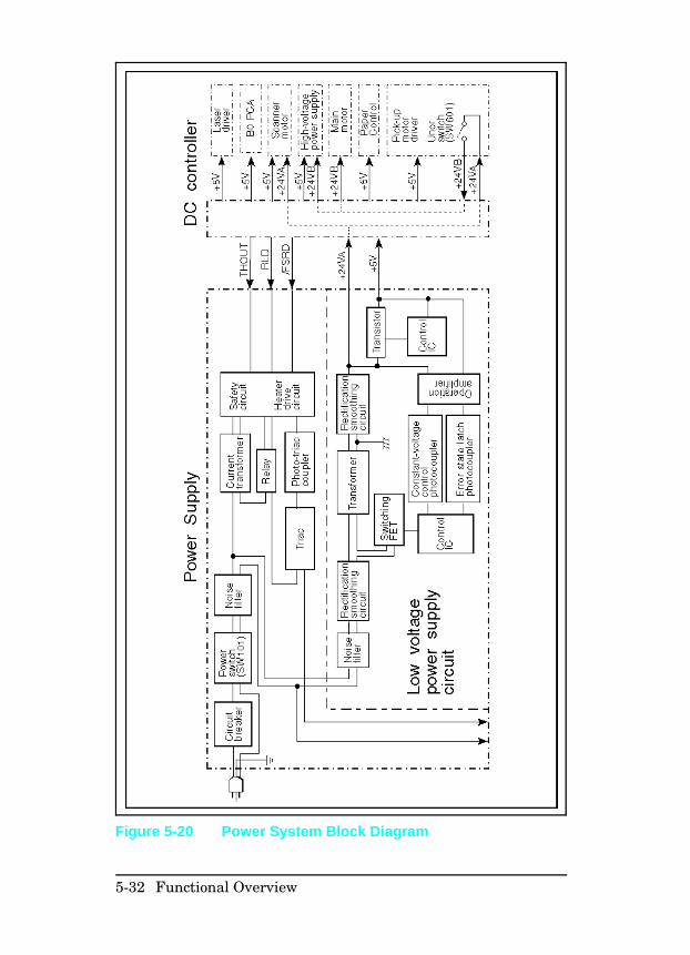
Figure 5-20 Power System Block Diagram
5-32 Functional Overview
Basic Sequence of Operation
The Formatter PCA and the DC Controller PCA shareinformation during printer operation. Connector J7 on theformatter and connector J207 on the DC controller form a linkwhich operates as a serial data bus. This allows printer status,command information, and dot-image data to be passed betweenboth controllers.
Standard Printer Operation The following events take place during normal printer operation:
1 After the printer’s power is turned ON, the printer enters theWarmup period.
2 After the printer completes the Warmup period and is readyfor operation, the DC controller sends a READY signal (RDY)to the formatter.
3 After the RDY signal is true and print data is ready to betransmitted, the formatter sends a PRINT signal (PRNT) tothe DC controller.
4 After the DC controller receives the PRNT signal, the InitialRotation period begins.
5 At the end of the Initial Rotation period, the DC controllersends a TOP OF PRINT signal (TOP) synchronized with aBEAM DETECT signal (BD) to the formatter. This initiatesthe Print period.
Functional Overview 5-33
6 Each time the formatter receives a synchronized BD signalfrom the DC controller, the formatter sends a VIDEO datastream (VDO) to the DC controller.
7 After the DC controller receives the VDO data, the DCcontroller translates it into a VIDEO OUT signal (VDOUT)that switches the laser diode ON and OFF.
8 The laser beam, created by the laser diode, reflects off thescanner mirror onto the photosensitive drum to form a latentelectrostatic image, writing a single line of print (dot) data.
9 After the last VDO line of dot data is sent from the formatter,the DC controller checks for another PRNT signal from theformatter.
10 If another PRNT signal is detected, the Print period continueswith another page.
11 If the DC controller fails to receive a PRNT signal before theend of the page passes over the Input/Registration Sensor(PS1), the DC controller initiates the Last Rotation period.
If the printer fails to perform correctly, the DC controller sendsan appropriate status to the formatter PCA, and an error isdisplayed on the printer’s control panel.
Timing Diagrams The following timing diagram describes the operation of theprinters. The “MP Tray Timing Diagram” was developed byrunning two consecutive prints on A4 paper.
5-34 Functional Overview
This a 2 panel pull-out.
Figure 5-21 MP Tray Timing Diagram—HP LaserJet 4/4M
Functional Overview 5-35
This a 2 panel pull-out.
Figure 5-22 MP (Tray 1) Timing Diagram—HP LaserJet 4Plus/4M Plus/5/5M/5N
5-36 Functional Overview
Warmup Period The Warmup period begins when the printer’s power is turnedON, and ends when the fusing roller temperature reaches 172° C.When the printer is switched ON, the exhaust fan (FM1) beginslow-speed rotation and the fusing roller maintains 172° C. TheDC controller then switches the main motor (M1) ON, and appliesAC high voltage to the primary charging roller to remove anyresidual charge from the photosensitive drum. Negative highvoltage is applied to the transfer roller to clean toner build-upfrom the roller. When the fusing roller reaches 172° C, the mainmotor, and AC high voltage, are turned OFF.
After the power is switched on, the Main Motor (M1) and thepickup motor (M2) turn for approximately 4 seconds to clear thepaper path. The motors stop rotation when the fuser reaches 172° C.
After the printer warms up, the message 00 READY is displayed,the printer goes “on-line,” and the control panel keys becomeoperational.
Standby Period When the Warmup period is completed, the message 00 READY isdisplayed. At this point the printer is in the Standby period. Thisindicates that the printer is ready for printing. The fusing rollerremains at a constant temperature of 172° C, and the exhaust fancontinues operating at low-speed rotation.
PowerSaveWhen the printer enters PowerSave mode, fuser current is shutdown, allowing the fuser to cool to room temperature withoutposting a 50 SERVICE error. The exhaust fan continues to operateat low speed.
Functional Overview 5-37
Initial Rotation Period When the DC controller receives a PRINT signal (PRNT) from theformatter, the DC controller allows the fusing roller to beginwarming up to approximately 183° C, and starts the main motor(M1), the pickup motor (M2), and scanner motor (M5). Next, thelaser diode turns ON and generates a sweep beam used to adjustthe laser power (APCIN). After the DC controller receives aBEAM DETECT signal (BD) initiated by the sweep beam, thelaser power stabilizes and the sweep beam turns OFF.
The DC controller then turns ON the main motor, switches theexhaust fan to high-speed rotation, applies AC high voltage andnegative DC high voltage to the primary charging roller, andapplies negative high voltage to the transfer roller to help removeexcess toner.
The developing bias (a negative AC/DC voltage) is applied to thedeveloping roller 1.16 seconds after the main motor is turned ON,then positive high voltage is applied to the transfer roller 2.0seconds after the main motor is turned ON.
When the fusing roller temperature reaches 183°, the MP (Tray 1) pickup roller clutch solenoid (SL2) energizes and paper isfed from the tray. If paper feeds from the PC tray (Tray 2),roughly 10 seconds after Initial Rotation begins, the PC tray(Tray 2) pickup roller clutch solenoid (SL1) energizes.
5-38 Functional Overview
If a failure occurs during this period, the following errors may bedisplayed:
50 SERVICE This error occurs when the fusing roller fails toreach the correct temperature in the requiredtime (see “50 SERVICE”) in Chapter 7).
51 ERROR This error occurs when the BD signal is notreceived by the DC controller, (see “51 ERRORBEAM DETECT)” in Chapter 7).
52 ERROR This error occurs when the scanner motor fails(see “52 ERROR,” Chapter 7).
Functional Overview 5-39
Print Period When the leading edge of the paper activates theinput/registration sensor (PS1), the DC controller forces the laserdiode ON until a BD signal is received. Next, the DC controllerreceives a VIDEO data stream (VDO) from the formatter. TheDC controller translates the VDO data into a VIDEO OUT signal(VDOUT), which modulates the laser diode ON and OFF, creatingintermittent bursts of laser light which reflect off the scannermirror and onto the photosensitive drum to form a latentelectrostatic image. VDO data is sent from the formatter for eachscan line of print data on a page, and a BD signal must precedeeach VDOUT line data received by the DC controller.
When the paper exit sensor (PS3) is activated by the leading edgeof the first page, the DC controller allows the Fusing Roller towarmup to 183° C. After the last VDO data is sent for the lastline of print data on the first page, the formatter sends a PRNTsignal for the second page.
About 1.87 seconds after the first VDO signal is sent from theformatter, the High Voltage PCA applies positive high voltage tothe transfer roller.
When the DC controller identifies the last line of print data onthe first page, the laser diode is forced ON and generates a sweepbeam used to adjust the laser power. After the DC controllerreceives a BEAM DETECT signal (BD) initiated by the sweepbeam, the laser power stabilizes and the sweep beam turns OFF.The DC controller then searches for a PRNT signal to begin thesecond page.
When the DC controller receives the next PRNT signal from theformatter, the DC controller anticipates receiving a BD signaland energizes the pickup roller clutch solenoid (PC tray-SL1, MPtray-SL2, or lower cassette SL3) about 1.0 second before itreceives the BD signal, and the second page feeds from the papertray. Until the DC controller receives the expected BD signal, anominal positive voltage is applied to the transfer roller toprevent toner build-up while the transfer Roller is in directcontact with the drum.
5-40 Functional Overview
The formatter then sends VDO data to the DC controller. The DCcontroller translates the VDO signal into a VIDEO OUT signal(VDOUT), which modulates the laser diode ON and OFF, creatingintermittent bursts of laser light that are reflected off the scannermirror and onto the photosensitive drum to form a latentelectrostatic image. Upon receipt of a BD signal from the DCcontroller, VDO data is sent from the formatter for each scan lineof print data on a page.
Before the next sheet of paper arrives, the voltage on the transferroller switches from the nominal standby voltage to a positivehigh voltage, to prepare to transfer the toner image from thedrum to the paper. The process repeats for each successive pageas necessary.
If a failure occurs during this period, the following errors may bedisplayed:
41 ERROR This error occurs when a sheet of paper is fed toosoon or when an unstable BD or TOP signal isreceived (see “41.x ERROR” message in Chapter 7).
50 SERVICE This error occurs when the fusing roller fails torise to the correct temperature in the requiredtime (see “50 SERVICE”) in Chapter 7).
51 ERROR This error occurs when the BD signal is notreceived by the DC controller (see “51 ERROR” inChapter 7).
52 ERROR This error occurs when the scanner motor fails(see “52 ERROR” in Chapter 7).
Functional Overview 5-41
Last Rotation Period After printing is complete, the Last Rotation period begins,during which residual static charges are eliminated from thephotosensitive drum to prepare for the next printed page.
About 1.7 seconds after the Last Rotation period begins, anominal standby voltage is applied to the transfer roller to stopthe toner attraction. Then, 4.0 seconds after the Last Rotationperiod begins, the negative DC high voltage on the primarycharging roller is turned OFF, leaving the AC voltage toneutralize the drum’s surface. Finally 5.98 seconds afterbeginning the Last Rotation period, the transfer roller voltagereturns to a negative high voltage, and any toner on the surfaceof the transfer roller is attracted to the photosensitive drum.
At the end of the Last Rotation period, the fusing roller returns to172° C, the main motor turns OFF, the scanner motor turns OFF,the AC high voltage to the primary charging roller turns OFF, thetransfer roller voltage returns to 0 volts, and the printer returnsto the Standby period. About 30 seconds after the printer returnsto the Standby period, the exhaust fan switches to low-speedrotation.
When another PRNT signal is sent from the formatter, printeroperation resumes.
5-42 Functional Overview
6
Removal and ReplacementThis chapter describes the complete disassembly of the printerfrom the beginning. In every instance, tasks that must beperformed before beginning the procedure are listed first.Remove the assemblies in the order listed to prevent damageduring re-assembly.
Removal and replacement of user-replaceable maintenance itemsis shown in Chapter 4, “Preventive Maintenance.” These itemsinclude:
• All Pickup Rollers and Separation Pad• Transfer Roller Replacement• Installing the Toner Cartridge
Servicing the printer involves replacing printed circuit andelectro-mechanical assemblies. Do not repair component failureswithin these assemblies. In all instances, replace the failedassembly.
The assembly procedure is the reverse of the removal procedure,except where specific instructions are provided.
C a u t i o n Power-off the printer and disconnect the powercord from the power outlet and the printer beforeservicing the printer.
Some sheet metal edges, particularly around theformatter cage, are sharp. Be careful whenworking in these areas to avoid being cut.
N o t e The printer contains parts that are sensitive toElectrostatic-Static Discharge (ESD). Alwaysobserve proper ESD procedures when servicingthe printer. This symbol: appears in thischapter when the parts being serviced areespecially susceptible to ESD damage.
Removal and Replacement 6-1
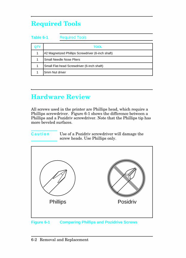
Required Tools
Hardware Review
All screws used in the printer are Phillips head, which require aPhillips screwdriver. Figure 6-1 shows the difference between aPhillips and a Pozidriv screwdriver. Note that the Phillips tip hasmore beveled surfaces.
C a u t i o n Use of a Pozidriv screwdriver will damage thescrew heads. Use Phillips only.
QTY TOOL
1 #2 Magnetized Phillips Screwdriver (6-inch shaft)
1 Small Needle Nose Pliers
1 Small Flat-head Screwdriver (6-inch shaft)
1 5mm Nut driver
Table 6-1 Required Tools
PosidrivPhillips
Figure 6-1 Comparing Phillips and Pozidrive Screws
6-2 Removal and Replacement
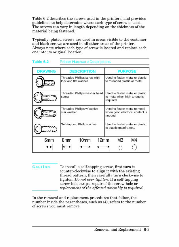
Table 6-2 describes the screws used in the printers, and providesguidelines to help determine where each type of screw is used.The screws can vary in length depending on the thickness of thematerial being fastened.
Typically, plated screws are used in areas visible to the customer,and black screws are used in all other areas of the printer.Always note where each type of screw is located and replace eachone into its original location.
C a u t i o n To install a self-tapping screw, first turn itcounter-clockwise to align it with the existingthread pattern, then carefully turn clockwise totighten. Do not over-tighten. If a self-tappingscrew-hole strips, repair of the screw-hole orreplacement of the affected assembly is required.
In the removal and replacement procedures that follow, thenumber inside the parentheses, such as (4), refers to the numberof screws you must remove.
DRAWING DESCRIPTION PURPOSE
Threaded Phillips screw withlock and flat washer
Used to fasten metal or plasticto threaded plastic or metal.
Threaded Phillips washer headscrew
Used to fasten metal or plasticto metal when high torque isrequired.
Threaded Phillips w/captivestar washer
Used to fasten metal to metalwhen good electrical contact isneeded.
Self-tapping Phillips screw Used to fasten metal or plasticto plastic mainframes.
Table 6-2 Printer Hardware Descriptions
Removal and Replacement 6-3
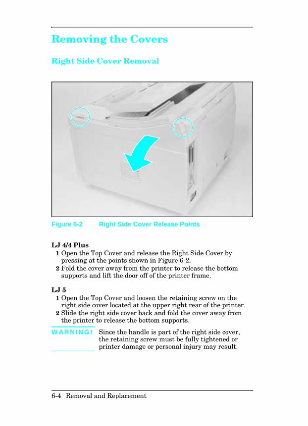
Removing the Covers
Right Side Cover Removal
LJ 4/4 Plus1 Open the Top Cover and release the Right Side Cover by
pressing at the points shown in Figure 6-2.2 Fold the cover away from the printer to release the bottom
supports and lift the door off of the printer frame.
LJ 51 Open the Top Cover and loosen the retaining screw on the
right side cover located at the upper right rear of the printer.2 Slide the right side cover back and fold the cover away from
the printer to release the bottom supports.
W A R N I N G ! Since the handle is part of the right side cover,the retaining screw must be fully tightened orprinter damage or personal injury may result.
Figure 6-2 Right Side Cover Release Points
6-4 Removal and Replacement
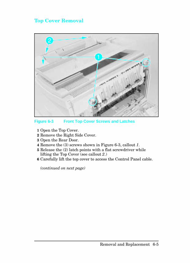
Top Cover Removal
1 Open the Top Cover.2 Remove the Right Side Cover.3 Open the Rear Door.4 Remove the (3) screws shown in Figure 6-3, callout 1.5 Release the (2) latch points with a flat screwdriver while
lifting the Top Cover (see callout 2.)6 Carefully lift the top cover to access the Control Panel cable.
(continued on next page)
Figure 6-3 Front Top Cover Screws and Latches
Removal and Replacement 6-5
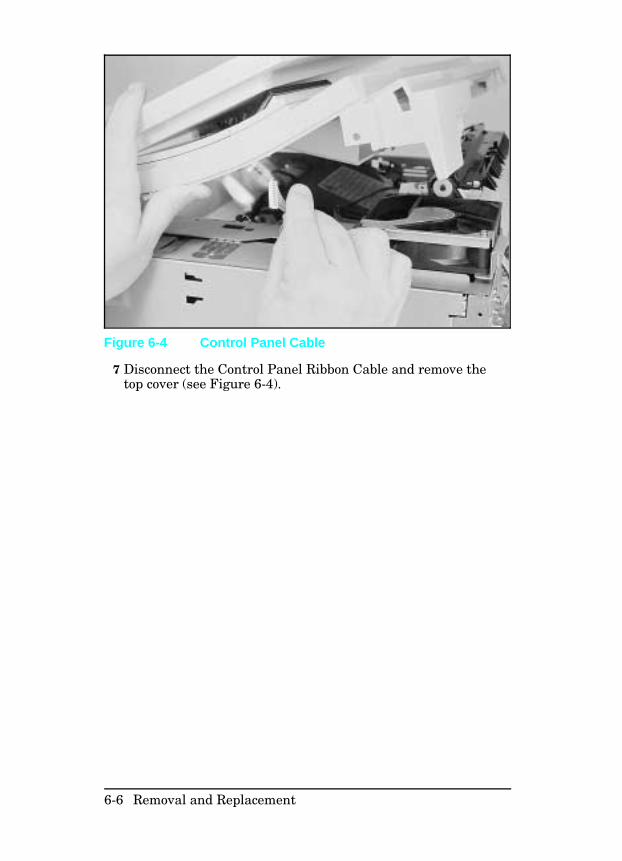
7 Disconnect the Control Panel Ribbon Cable and remove thetop cover (see Figure 6-4).
Figure 6-4 Control Panel Cable
6-6 Removal and Replacement
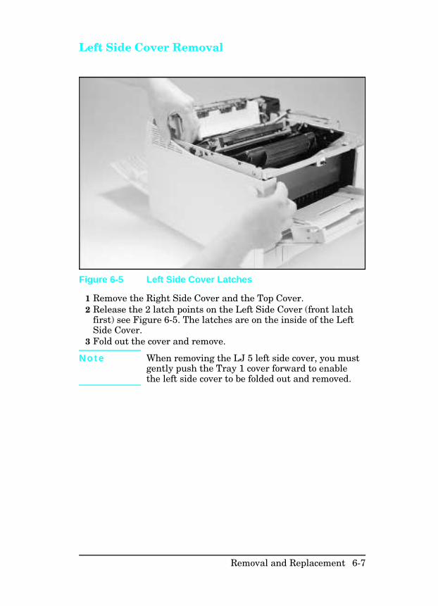
Left Side Cover Removal
1 Remove the Right Side Cover and the Top Cover.2 Release the 2 latch points on the Left Side Cover (front latch
first) see Figure 6-5. The latches are on the inside of the LeftSide Cover.
3 Fold out the cover and remove.
N o t e When removing the LJ 5 left side cover, you mustgently push the Tray 1 cover forward to enablethe left side cover to be folded out and removed.
Figure 6-5 Left Side Cover Latches
Removal and Replacement 6-7
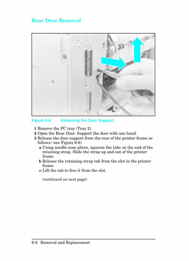
Rear Door Removal
1 Remove the PC tray (Tray 2).2 Open the Rear Door. Support the door with one hand.3 Release the door support from the rear of the printer frame as
follows: (see Figure 6-6)a Using needle-nose pliers, squeeze the tabs on the end of the
retaining strap. Slide the strap up and out of the printerframe.
b Release the retaining strap tab from the slot in the printerframe.
c Lift the tab to free it from the slot.
(continued on next page)
Figure 6-6 Releasing the Door Support
6-8 Removal and Replacement
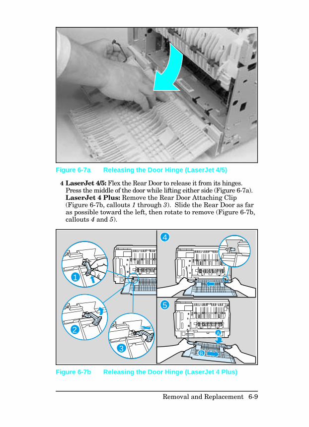
4 LaserJet 4/5: Flex the Rear Door to release it from its hinges.Press the middle of the door while lifting either side (Figure 6-7a).LaserJet 4 Plus: Remove the Rear Door Attaching Clip(Figure 6-7b, callouts 1 through 3). Slide the Rear Door as faras possible toward the left, then rotate to remove (Figure 6-7b,callouts 4 and 5).
Figure 6-7a Releasing the Door Hinge (LaserJet 4/5)
1
2
3
A
B
5
4
Figure 6-7b Releasing the Door Hinge (LaserJet 4 Plus)
Removal and Replacement 6-9
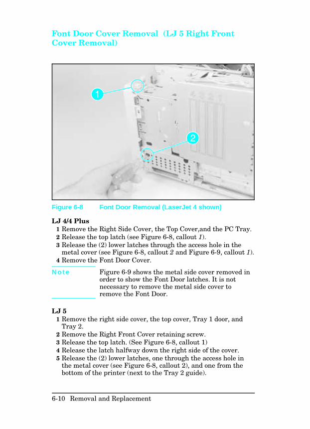
Font Door Cover Removal (LJ 5 Right FrontCover Removal)
LJ 4/4 Plus1 Remove the Right Side Cover, the Top Cover,and the PC Tray.2 Release the top latch (see Figure 6-8, callout 1).3 Release the (2) lower latches through the access hole in the
metal cover (see Figure 6-8, callout 2 and Figure 6-9, callout 1).4 Remove the Font Door Cover.
N o t e Figure 6-9 shows the metal side cover removed inorder to show the Font Door latches. It is notnecessary to remove the metal side cover toremove the Font Door.
LJ 51 Remove the right side cover, the top cover, Tray 1 door, and
Tray 2.2 Remove the Right Front Cover retaining screw.3 Release the top latch. (See Figure 6-8, callout 1)4 Release the latch halfway down the right side of the cover.5 Release the (2) lower latches, one through the access hole in
the metal cover (see Figure 6-8, callout 2), and one from thebottom of the printer (next to the Tray 2 guide).
Figure 6-8 Font Door Removal (LaserJet 4 shown)
6-10 Removal and Replacement
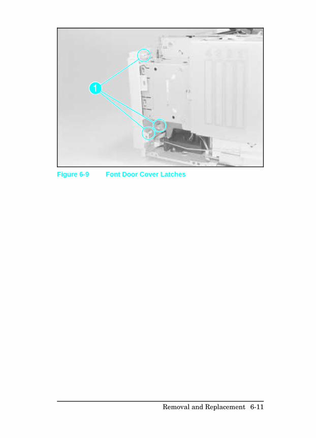
Figure 6-9 Font Door Cover Latches
Removal and Replacement 6-11
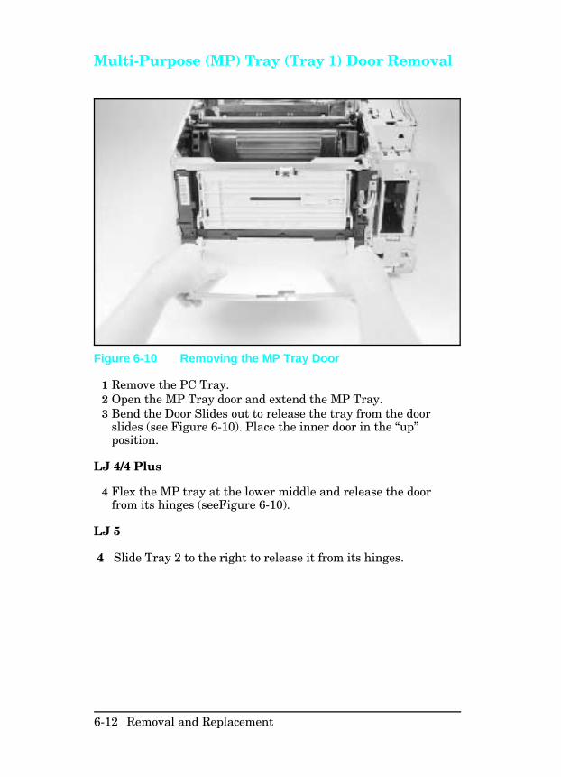
Multi-Purpose (MP) Tray (Tray 1) Door Removal
1 Remove the PC Tray.2 Open the MP Tray door and extend the MP Tray.3 Bend the Door Slides out to release the tray from the door
slides (see Figure 6-10). Place the inner door in the “up”position.
LJ 4/4 Plus
4 Flex the MP tray at the lower middle and release the doorfrom its hinges (seeFigure 6-10).
LJ 5
4 Slide Tray 2 to the right to release it from its hinges.
Figure 6-10 Removing the MP Tray Door
6-12 Removal and Replacement
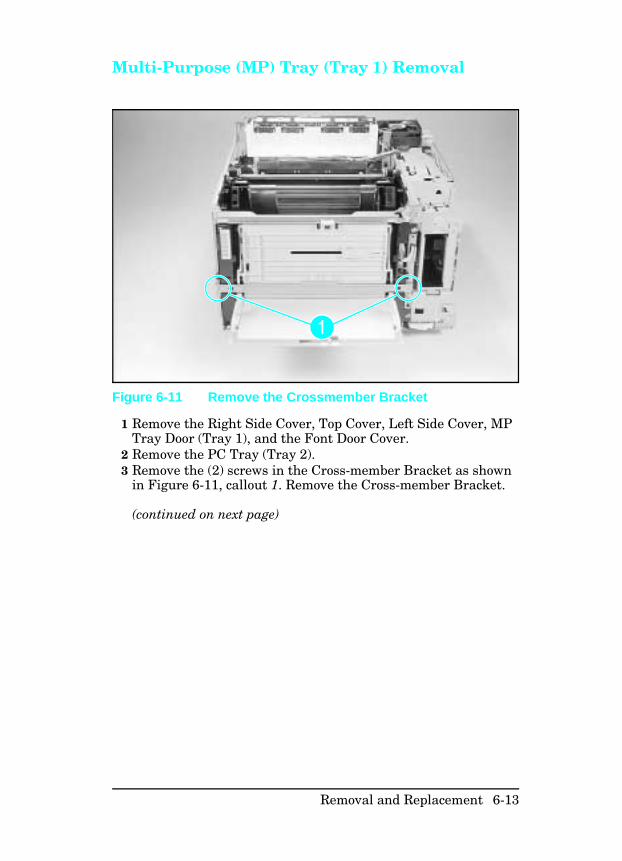
Multi-Purpose (MP) Tray (Tray 1) Removal
1 Remove the Right Side Cover, Top Cover, Left Side Cover, MPTray Door (Tray 1), and the Font Door Cover.
2 Remove the PC Tray (Tray 2).3 Remove the (2) screws in the Cross-member Bracket as shown
in Figure 6-11, callout 1. Remove the Cross-member Bracket.
(continued on next page)
Figure 6-11 Remove the Crossmember Bracket
Removal and Replacement 6-13
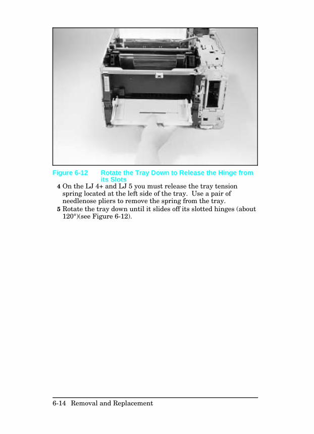
4 On the LJ 4+ and LJ 5 you must release the tray tensionspring located at the left side of the tray. Use a pair ofneedlenose pliers to remove the spring from the tray.
5 Rotate the tray down until it slides off its slotted hinges (about120°)(see Figure 6-12).
Figure 6-12 Rotate the Tray Down to Release the Hinge fromits Slots
6-14 Removal and Replacement
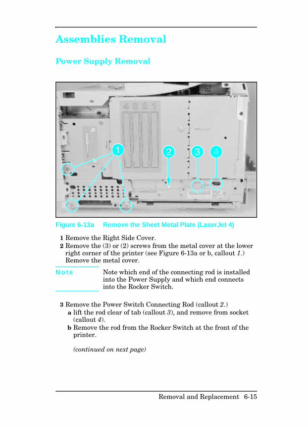
Assemblies Removal
Power Supply Removal
1 Remove the Right Side Cover.2 Remove the (3) or (2) screws from the metal cover at the lower
right corner of the printer (see Figure 6-13a or b, callout 1.)Remove the metal cover.
N o t e Note which end of the connecting rod is installedinto the Power Supply and which end connectsinto the Rocker Switch.
3 Remove the Power Switch Connecting Rod (callout 2.) a lift the rod clear of tab (callout 3), and remove from socket
(callout 4).b Remove the rod from the Rocker Switch at the front of the
printer.
(continued on next page)
Figure 6-13a Remove the Sheet Metal Plate (LaserJet 4)
Removal and Replacement 6-15
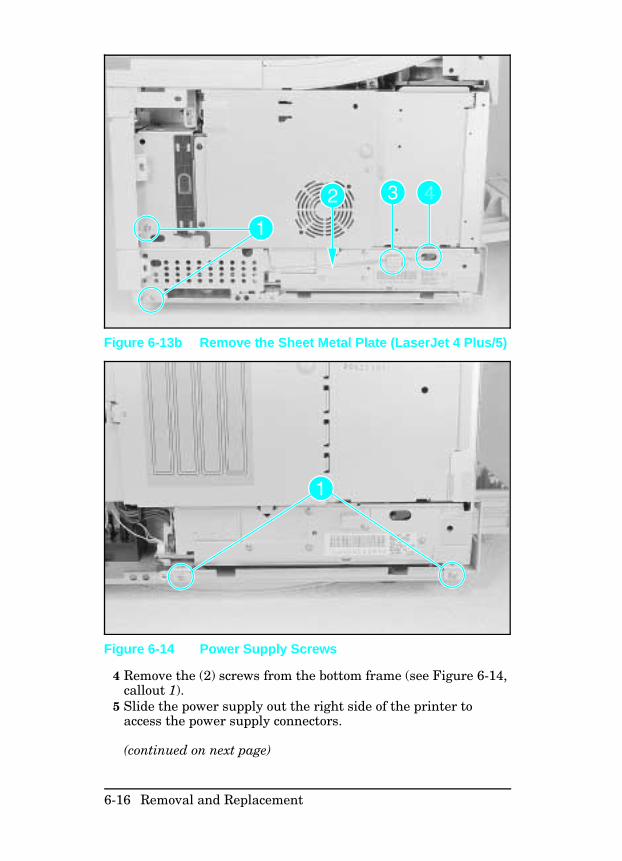
4 Remove the (2) screws from the bottom frame (see Figure 6-14,callout 1).
5 Slide the power supply out the right side of the printer toaccess the power supply connectors.
(continued on next page)
Figure 6-13b Remove the Sheet Metal Plate (LaserJet 4 Plus/5)
Figure 6-14 Power Supply Screws
6-16 Removal and Replacement
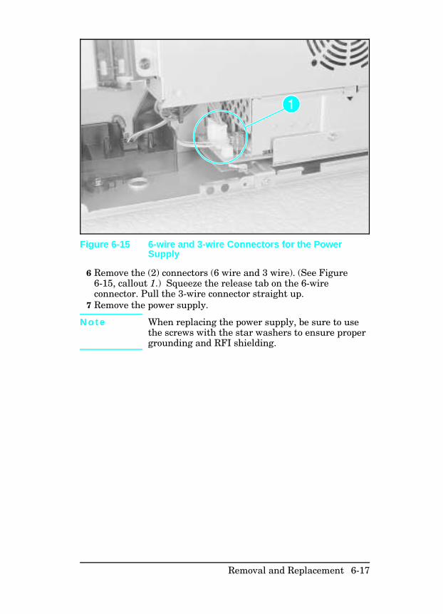
6 Remove the (2) connectors (6 wire and 3 wire). (See Figure6-15, callout 1.) Squeeze the release tab on the 6-wireconnector. Pull the 3-wire connector straight up.
7 Remove the power supply.
N o t e When replacing the power supply, be sure to usethe screws with the star washers to ensure propergrounding and RFI shielding.
Figure 6-15 6-wire and 3-wire Connectors for the PowerSupply
Removal and Replacement 6-17
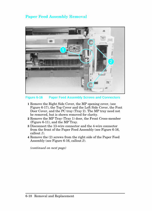
Paper Feed Assembly Removal
1 Remove the Right Side Cover, the MP opening cover, (seeFigure 6-17), the Top Cover and the Left Side Cover, the FontDoor Cover, and the PC tray (Tray 2). The MP tray need notbe removed, but is shown removed for clarity.
2 Remove the MP Tray (Tray 1) door, the Front Cross-member(Figure 6-11), and the MP Tray.
3 Disconnect the 13-wire connector and the 4-wire connectorfrom the front of the Paper Feed Assembly (see Figure 6-16,callout 1).
4 Remove the (2) screws from the right side of the Paper FeedAssembly (see Figure 6-16, callout 2).
(continued on next page)
Figure 6-16 Paper Feed Assembly Screws and Connectors
6-18 Removal and Replacement
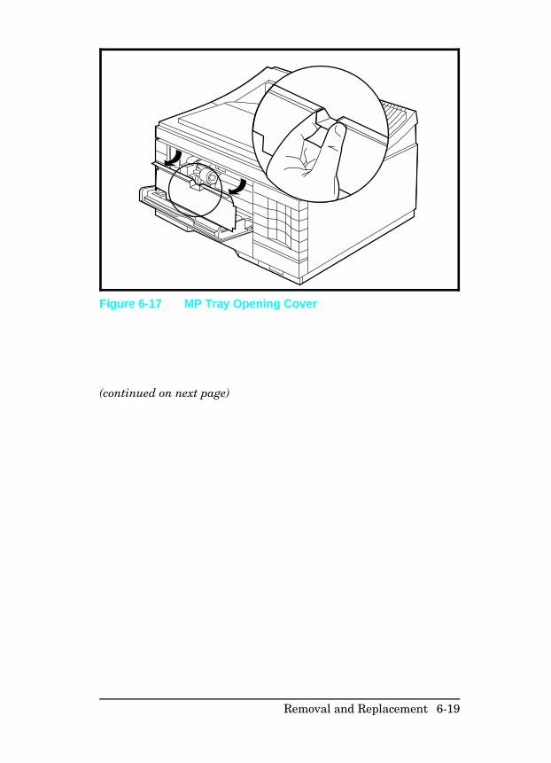
(continued on next page)
Figure 6-17 MP Tray Opening Cover
Removal and Replacement 6-19
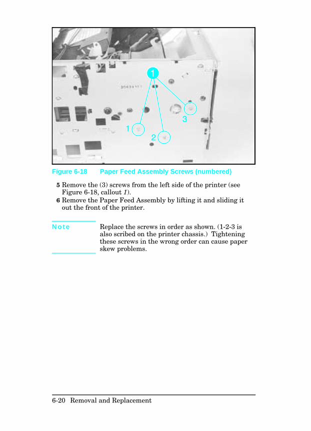
5 Remove the (3) screws from the left side of the printer (seeFigure 6-18, callout 1).
6 Remove the Paper Feed Assembly by lifting it and sliding itout the front of the printer.
N o t e Replace the screws in order as shown. (1-2-3 isalso scribed on the printer chassis.) Tighteningthese screws in the wrong order can cause paperskew problems.
Figure 6-18 Paper Feed Assembly Screws (numbered)
6-20 Removal and Replacement
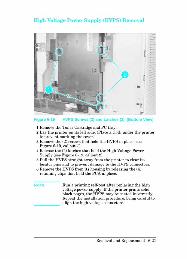
High Voltage Power Supply (HVPS) Removal
1 Remove the Toner Cartridge and PC tray.2 Lay the printer on its left side. (Place a cloth under the printer
to prevent marking the cover.)3 Remove the (2) screws that hold the HVPS in place (see
Figure 6-19, callout 1).4 Release the (2) latches that hold the High Voltage Power
Supply (see Figure 6-19, callout 2).5 Pull the HVPS straight away from the printer to clear its
locator pins and to prevent damage to the HVPS connectors.6 Remove the HVPS from its housing by releasing the (4)
retaining clips that hold the PCA in place.
N o t e Run a printing self-test after replacing the highvoltage power supply. If the printer prints solidblack pages, the HVPS may be seated incorrectly.Repeat the installation procedure, being careful toalign the high voltage connectors.
Figure 6-19 HVPS Screws (2) and Latches (2) (Bottom View)
Removal and Replacement 6-21
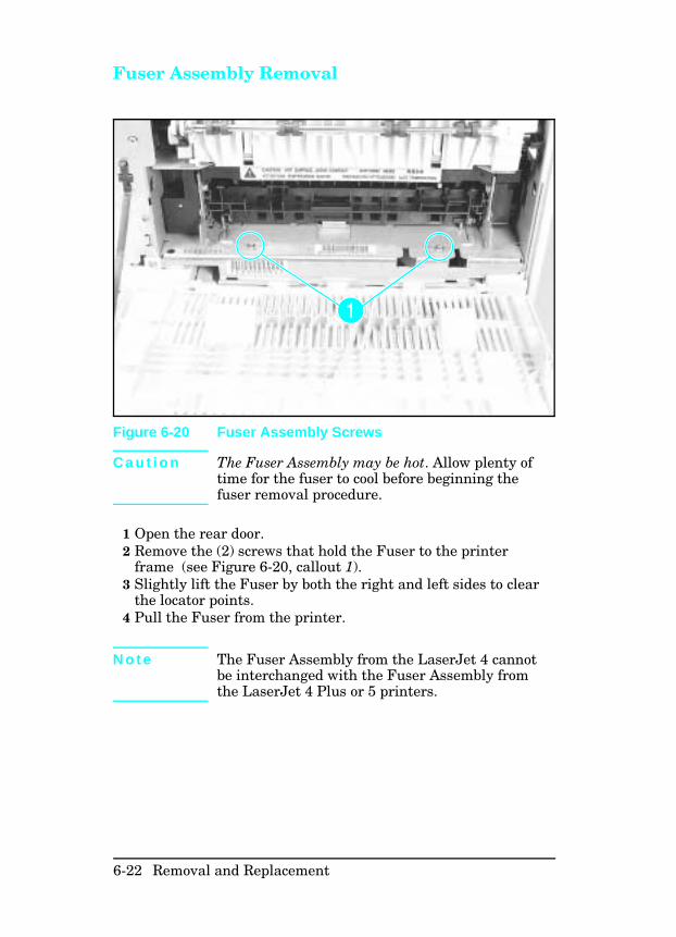
Fuser Assembly Removal
C a u t i o n The Fuser Assembly may be hot. Allow plenty oftime for the fuser to cool before beginning thefuser removal procedure.
1 Open the rear door.2 Remove the (2) screws that hold the Fuser to the printer
frame (see Figure 6-20, callout 1).3 Slightly lift the Fuser by both the right and left sides to clear
the locator points. 4 Pull the Fuser from the printer.
N o t e The Fuser Assembly from the LaserJet 4 cannotbe interchanged with the Fuser Assembly fromthe LaserJet 4 Plus or 5 printers.
Figure 6-20 Fuser Assembly Screws
6-22 Removal and Replacement
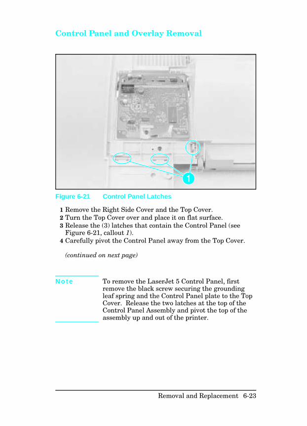
Control Panel and Overlay Removal
1 Remove the Right Side Cover and the Top Cover.2 Turn the Top Cover over and place it on flat surface.3 Release the (3) latches that contain the Control Panel (see
Figure 6-21, callout 1).4 Carefully pivot the Control Panel away from the Top Cover.
(continued on next page)
N o t e To remove the LaserJet 5 Control Panel, firstremove the black screw securing the groundingleaf spring and the Control Panel plate to the TopCover. Release the two latches at the top of theControl Panel Assembly and pivot the top of theassembly up and out of the printer.
Figure 6-21 Control Panel Latches
Removal and Replacement 6-23
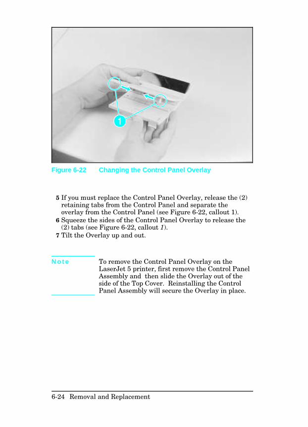
5 If you must replace the Control Panel Overlay, release the (2)retaining tabs from the Control Panel and separate theoverlay from the Control Panel (see Figure 6-22, callout 1).
6 Squeeze the sides of the Control Panel Overlay to release the(2) tabs (see Figure 6-22, callout 1).
7 Tilt the Overlay up and out.
N o t e To remove the Control Panel Overlay on theLaserJet 5 printer, first remove the Control PanelAssembly and then slide the Overlay out of theside of the Top Cover. Reinstalling the ControlPanel Assembly will secure the Overlay in place.
Figure 6-22 Changing the Control Panel Overlay
6-24 Removal and Replacement
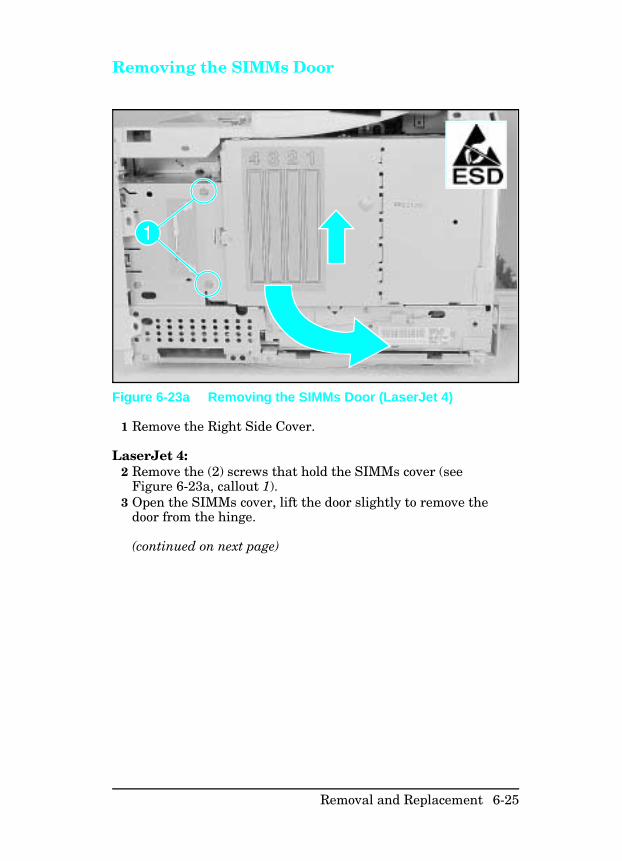
Removing the SIMMs Door
1 Remove the Right Side Cover.
LaserJet 4:2 Remove the (2) screws that hold the SIMMs cover (see
Figure 6-23a, callout 1).3 Open the SIMMs cover, lift the door slightly to remove the
door from the hinge.
(continued on next page)
Figure 6-23a Removing the SIMMs Door (LaserJet 4)
Removal and Replacement 6-25
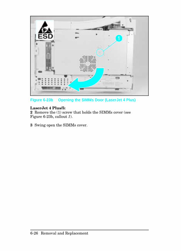
LaserJet 4 Plus/5:2 Remove the (1) screw that holds the SIMMs cover (seeFigure 6-23b, callout 1).
3 Swing open the SIMMs cover.
Figure 6-23b Opening the SIMMs Door (LaserJet 4 Plus)
6-26 Removal and Replacement
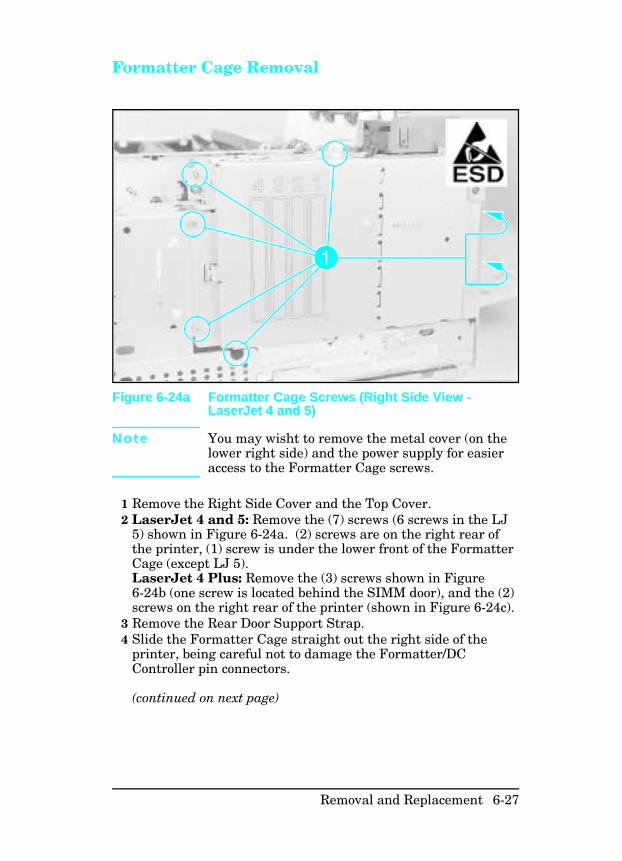
Formatter Cage Removal
N o t e You may wisht to remove the metal cover (on thelower right side) and the power supply for easieraccess to the Formatter Cage screws.
1 Remove the Right Side Cover and the Top Cover.2 LaserJet 4 and 5: Remove the (7) screws (6 screws in the LJ
5) shown in Figure 6-24a. (2) screws are on the right rear ofthe printer, (1) screw is under the lower front of the FormatterCage (except LJ 5). LaserJet 4 Plus: Remove the (3) screws shown in Figure6-24b (one screw is located behind the SIMM door), and the (2)screws on the right rear of the printer (shown in Figure 6-24c).
3 Remove the Rear Door Support Strap.4 Slide the Formatter Cage straight out the right side of the
printer, being careful not to damage the Formatter/DCController pin connectors.
(continued on next page)
Figure 6-24a Formatter Cage Screws (Right Side View -LaserJet 4 and 5)
Removal and Replacement 6-27
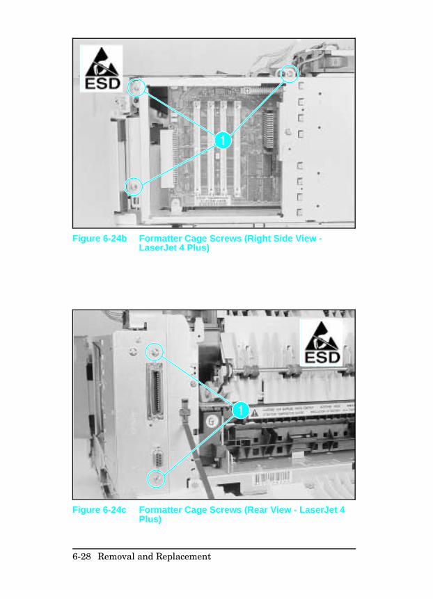
Figure 6-24b Formatter Cage Screws (Right Side View -LaserJet 4 Plus)
Figure 6-24c Formatter Cage Screws (Rear View - LaserJet 4Plus)
6-28 Removal and Replacement
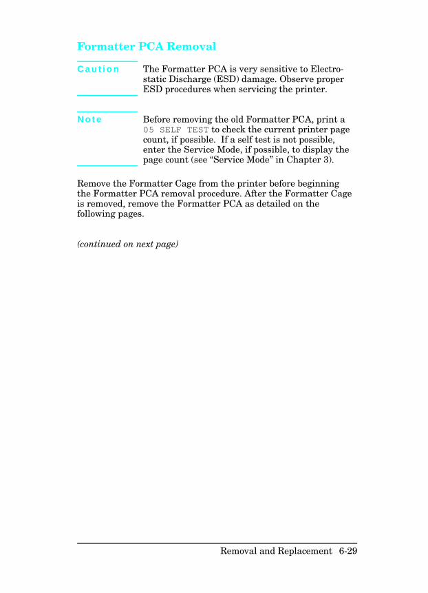
Formatter PCA Removal
C a u t i o n The Formatter PCA is very sensitive to Electro-static Discharge (ESD) damage. Observe properESD procedures when servicing the printer.
N o t e Before removing the old Formatter PCA, print a05 SELF TEST to check the current printer pagecount, if possible. If a self test is not possible,enter the Service Mode, if possible, to display thepage count (see “Service Mode” in Chapter 3).
Remove the Formatter Cage from the printer before beginningthe Formatter PCA removal procedure. After the Formatter Cageis removed, remove the Formatter PCA as detailed on thefollowing pages.
(continued on next page)
Removal and Replacement 6-29
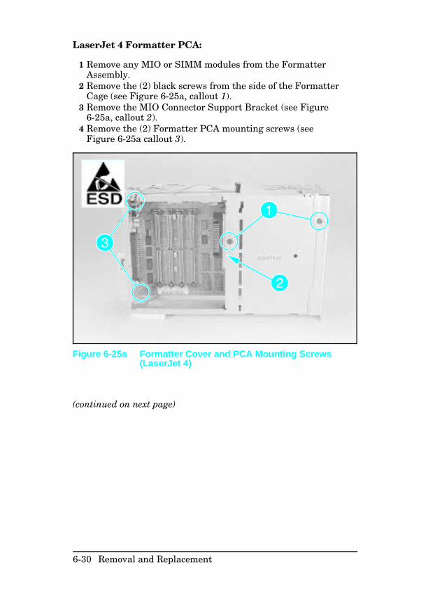
LaserJet 4 Formatter PCA:
1 Remove any MIO or SIMM modules from the FormatterAssembly.
2 Remove the (2) black screws from the side of the FormatterCage (see Figure 6-25a, callout 1).
3 Remove the MIO Connector Support Bracket (see Figure6-25a, callout 2).
4 Remove the (2) Formatter PCA mounting screws (seeFigure 6-25a callout 3).
(continued on next page)
Figure 6-25a Formatter Cover and PCA Mounting Screws(LaserJet 4)
6-30 Removal and Replacement
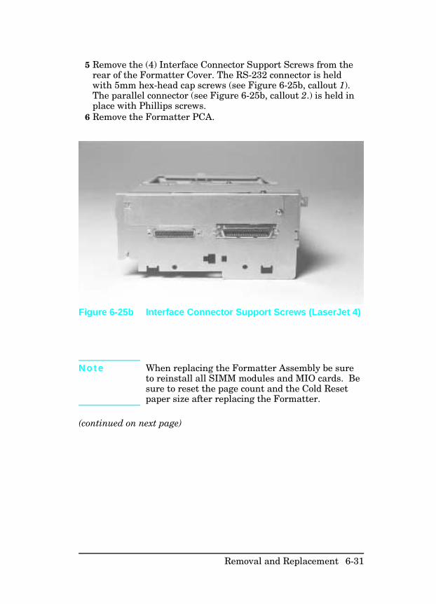
5 Remove the (4) Interface Connector Support Screws from therear of the Formatter Cover. The RS-232 connector is heldwith 5mm hex-head cap screws (see Figure 6-25b, callout 1).The parallel connector (see Figure 6-25b, callout 2.) is held inplace with Phillips screws.
6 Remove the Formatter PCA.
N o t e When replacing the Formatter Assembly be sureto reinstall all SIMM modules and MIO cards. Besure to reset the page count and the Cold Resetpaper size after replacing the Formatter.
(continued on next page)
Figure 6-25b Interface Connector Support Screws (LaserJet 4)
Removal and Replacement 6-31
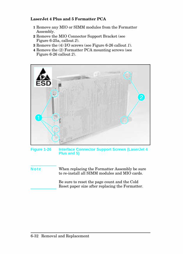
LaserJet 4 Plus and 5 Formatter PCA
1 Remove any MIO or SIMM modules from the FormatterAssembly.
2 Remove the MIO Connector Support Bracket (seeFigure 6-25a, callout 2).
3 Remove the (4) I/O screws (see Figure 6-26 callout 1).4 Remove the (2) Formatter PCA mounting screws (see
Figure 6-26 callout 2).
N o t e When replacing the Formatter Assembly be sureto re-install all SIMM modules and MIO cards.
Be sure to reset the page count and the ColdReset paper size after replacing the Formatter.
Figure 1-26 Interface Connector Support Screws (LaserJet 4Plus and 5)
6-32 Removal and Replacement
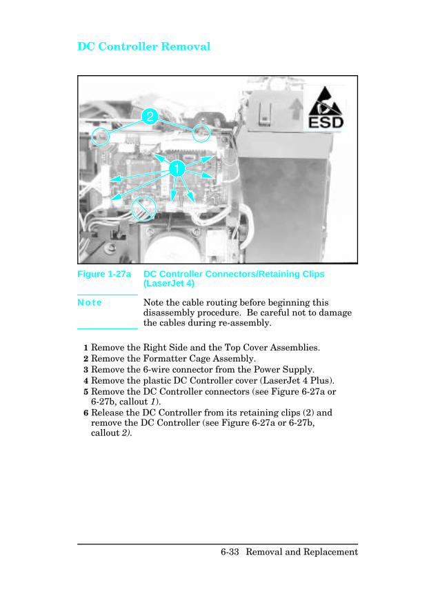
DC Controller Removal
N o t e Note the cable routing before beginning thisdisassembly procedure. Be careful not to damagethe cables during re-assembly.
1 Remove the Right Side and the Top Cover Assemblies.2 Remove the Formatter Cage Assembly.3 Remove the 6-wire connector from the Power Supply.4 Remove the plastic DC Controller cover (LaserJet 4 Plus).5 Remove the DC Controller connectors (see Figure 6-27a or
6-27b, callout 1). 6 Release the DC Controller from its retaining clips (2) and
remove the DC Controller (see Figure 6-27a or 6-27b,callout 2).
Figure 1-27a DC Controller Connectors/Retaining Clips(LaserJet 4)
6-33 Removal and Replacement
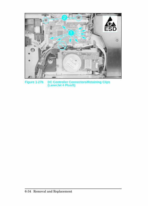
Figure 1-27b DC Controller Connectors/Retaining Clips(LaserJet 4 Plus/5)
6-34 Removal and Replacement
DC Controller Installation
C a u t i o n When reinstalling the DC Controller PCA it isextremely important that all cables be properlyrouted. If cables are not routed properly, it isdifficult to reinstall the Formatter Cage and cabledamage may result.
When replacing the DC Controller, be sure to set the leading edgeadjustment as shown in the following procedure.
N o t e The Leading Edge Adjustment is set at thefactory and is not required as a maintenanceprocedure. The Leading Edge Adjustment shouldbe done only when the DC Controller is replaced.
The following procedure is performed with the FormatterAssembly removed.
To set the Leading Edge Registration:
1 Install the new DC Controller in the reverse order of theremoval.
2 Run a test print to check the leading edge adjustment (asshown in Figure 6-28.
3 Use VR202 (LaserJet 4) or VR201 (LaserJet 4 Plus and 5) (seeFigure 6-29) to adjust the leading edge registration to thedimension shown in Figure 6-28 (a=2mm).
4 Make several test prints (15 ENGINE TEST as shown inFigures 3-5 and 3-6) and check the adjustment. Repeat theabove steps until the adjustment is correct.
6-35 Removal and Replacement
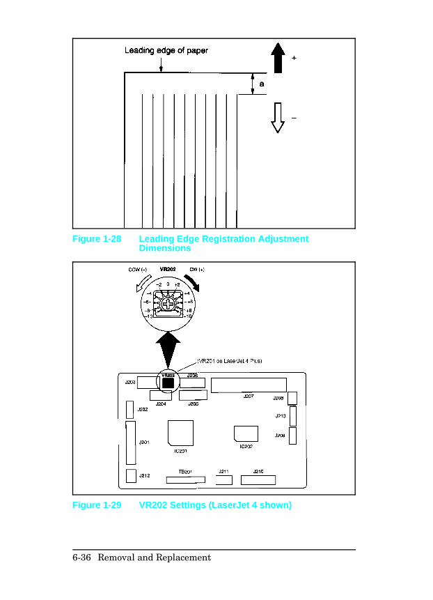
Figure 1-28 Leading Edge Registration AdjustmentDimensions
Figure 1-29 VR202 Settings (LaserJet 4 shown)
6-36 Removal and Replacement
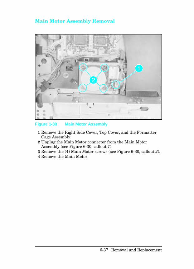
Main Motor Assembly Removal
1 Remove the Right Side Cover, Top Cover, and the FormatterCage Assembly.
2 Unplug the Main Motor connector from the Main MotorAssembly (see Figure 6-30, callout 1).
3 Remove the (4) Main Motor screws (see Figure 6-30, callout 2).4 Remove the Main Motor.
Figure 1-30 Main Motor Assembly
6-37 Removal and Replacement
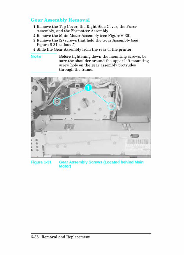
Gear Assembly Removal 1 Remove the Top Cover, the Right Side Cover, the Fuser
Assembly, and the Formatter Assembly. 2 Remove the Main Motor Assembly (see Figure 6-30).3 Remove the (2) screws that hold the Gear Assembly (see
Figure 6-31 callout 1).4 Slide the Gear Assembly from the rear of the printer.
N o t e Before tightening down the mounting screws, besure the shoulder around the upper left mountingscrew hole on the gear assembly protrudesthrough the frame.
Figure 1-31 Gear Assembly Screws (Located behind MainMotor)
6-38 Removal and Replacement
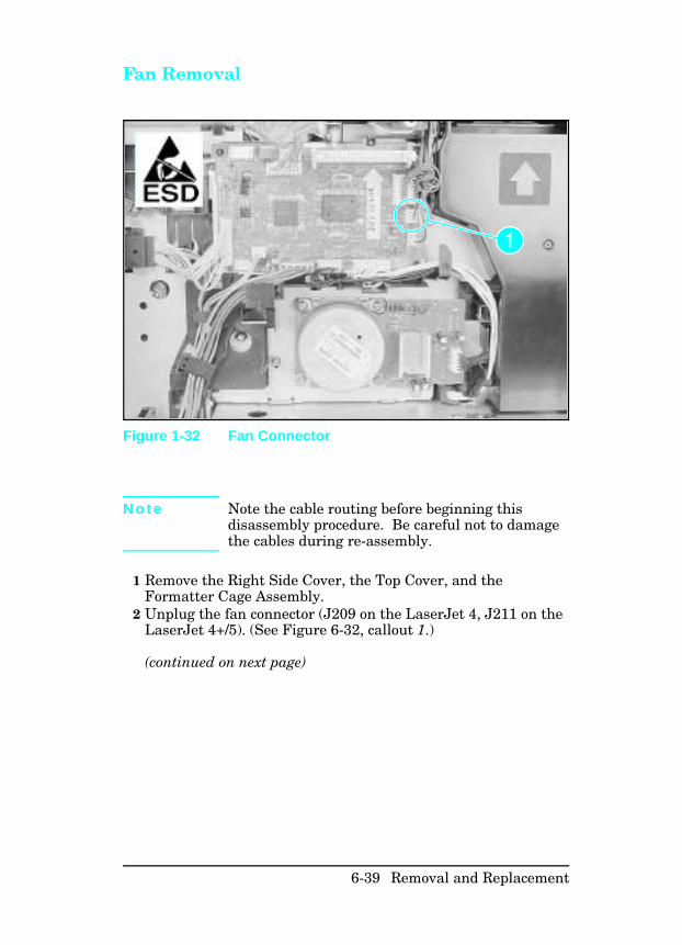
Fan Removal
N o t e Note the cable routing before beginning thisdisassembly procedure. Be careful not to damagethe cables during re-assembly.
1 Remove the Right Side Cover, the Top Cover, and theFormatter Cage Assembly.
2 Unplug the fan connector (J209 on the LaserJet 4, J211 on theLaserJet 4+/5). (See Figure 6-32, callout 1.)
(continued on next page)
Figure 1-32 Fan Connector
6-39 Removal and Replacement
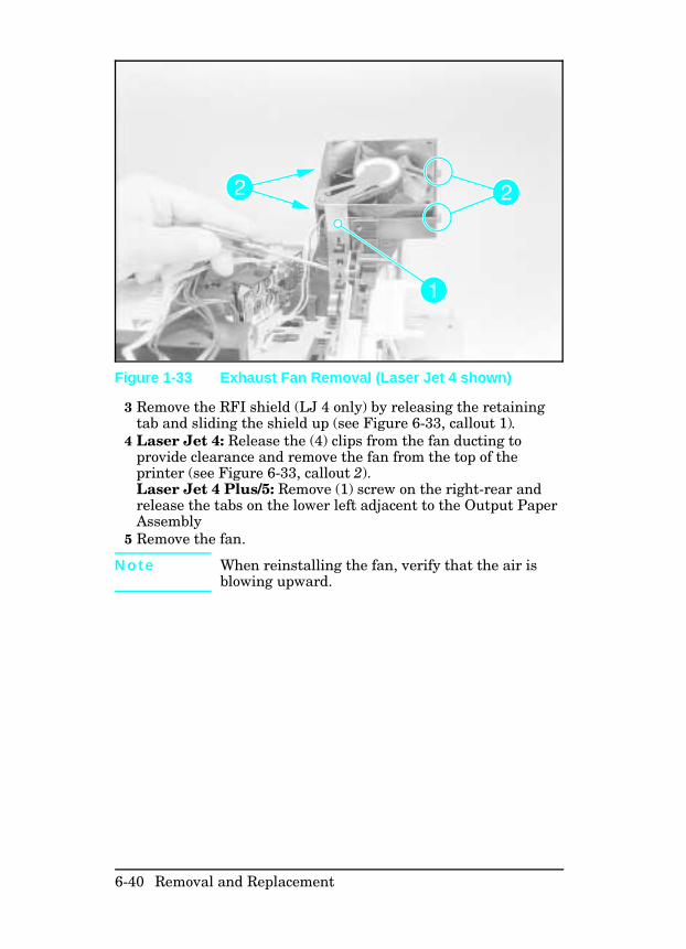
3 Remove the RFI shield (LJ 4 only) by releasing the retainingtab and sliding the shield up (see Figure 6-33, callout 1).
4 Laser Jet 4: Release the (4) clips from the fan ducting toprovide clearance and remove the fan from the top of theprinter (see Figure 6-33, callout 2).Laser Jet 4 Plus/5: Remove (1) screw on the right-rear andrelease the tabs on the lower left adjacent to the Output PaperAssembly
5 Remove the fan.
N o t e When reinstalling the fan, verify that the air isblowing upward.
Figure 1-33 Exhaust Fan Removal (Laser Jet 4 shown)
6-40 Removal and Replacement
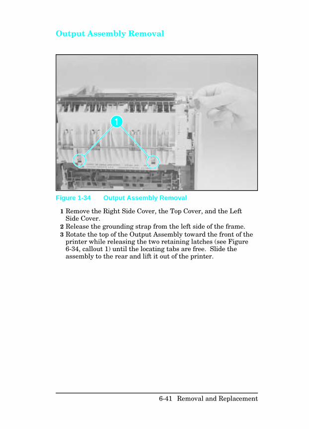
Output Assembly Removal
1 Remove the Right Side Cover, the Top Cover, and the LeftSide Cover.
2 Release the grounding strap from the left side of the frame.3 Rotate the top of the Output Assembly toward the front of the
printer while releasing the two retaining latches (see Figure6-34, callout 1) until the locating tabs are free. Slide theassembly to the rear and lift it out of the printer.
Figure 1-34 Output Assembly Removal
6-41 Removal and Replacement
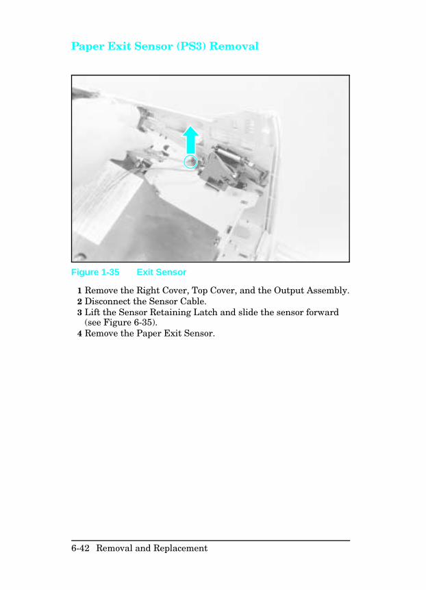
Paper Exit Sensor (PS3) Removal
1 Remove the Right Cover, Top Cover, and the Output Assembly.2 Disconnect the Sensor Cable.3 Lift the Sensor Retaining Latch and slide the sensor forward
(see Figure 6-35).4 Remove the Paper Exit Sensor.
Figure 1-35 Exit Sensor
6-42 Removal and Replacement
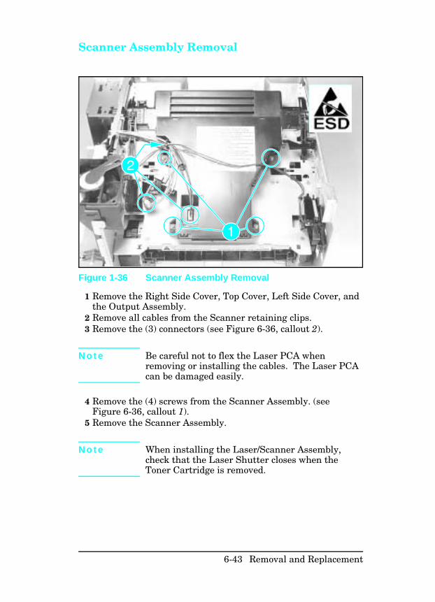
Scanner Assembly Removal
1 Remove the Right Side Cover, Top Cover, Left Side Cover, andthe Output Assembly.
2 Remove all cables from the Scanner retaining clips.3 Remove the (3) connectors (see Figure 6-36, callout 2).
N o t e Be careful not to flex the Laser PCA whenremoving or installing the cables. The Laser PCAcan be damaged easily.
4 Remove the (4) screws from the Scanner Assembly. (seeFigure 6-36, callout 1).
5 Remove the Scanner Assembly.
N o t e When installing the Laser/Scanner Assembly,check that the Laser Shutter closes when theToner Cartridge is removed.
Figure 1-36 Scanner Assembly Removal
6-43 Removal and Replacement
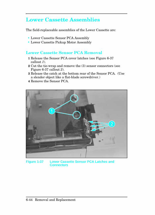
Lower Cassette Assemblies
The field-replaceable assemblies of the Lower Cassette are:
• Lower Cassette Sensor PCA Assembly• Lower Cassette Pickup Motor Assembly
Lower Cassette Sensor PCA Removal1 Release the Sensor PCA cover latches (see Figure 6-37
callout 1).2 Cut the tie-wrap and remove the (3) sensor connectors (see
Figure 6-37 callout 2).3 Release the catch at the bottom rear of the Sensor PCA. (Use
a slender object like a flat-blade screwdriver.)4 Remove the Sensor PCA.
Figure 1-37 Lower Cassette Sensor PCA Latches andConnectors
6-44 Removal and Replacement
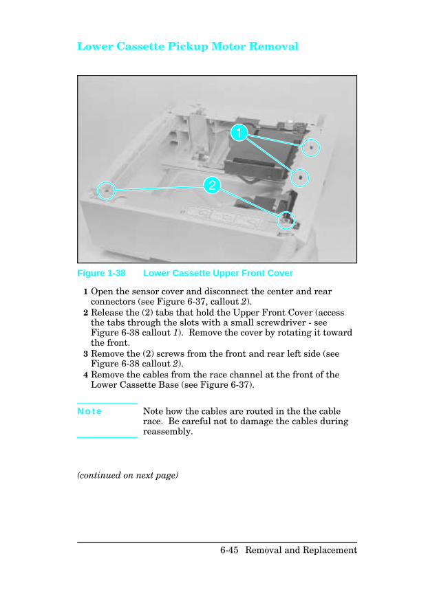
Lower Cassette Pickup Motor Removal
1 Open the sensor cover and disconnect the center and rearconnectors (see Figure 6-37, callout 2).
2 Release the (2) tabs that hold the Upper Front Cover (accessthe tabs through the slots with a small screwdriver - seeFigure 6-38 callout 1). Remove the cover by rotating it towardthe front.
3 Remove the (2) screws from the front and rear left side (seeFigure 6-38 callout 2).
4 Remove the cables from the race channel at the front of theLower Cassette Base (see Figure 6-37).
N o t e Note how the cables are routed in the the cablerace. Be careful not to damage the cables duringreassembly.
(continued on next page)
Figure 1-38 Lower Cassette Upper Front Cover
6-45 Removal and Replacement
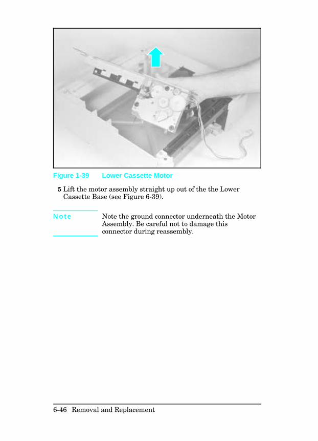
5 Lift the motor assembly straight up out of the the LowerCassette Base (see Figure 6-39).
N o t e Note the ground connector underneath the MotorAssembly. Be careful not to damage thisconnector during reassembly.
Figure 1-39 Lower Cassette Motor
6-46 Removal and Replacement

Replacing Fuser Assembly Parts The following procedures describe the removal and replacementof major Fuser Assembly Components (Fusing Roller, Thermistor,Thermoswitch, and Heater Lamp). When performing theseprocedures, note the order in which the parts were removed andtheir orientation.
C a u t i o n Handle the Heater Bulb by the ceramic ends. Donot touch the Heater Bulb, or allow it to becomecontaminated. If contamination occurs, clean thebulb thoroughly with isopropyl alcohol.
6-47 Removal and Replacement
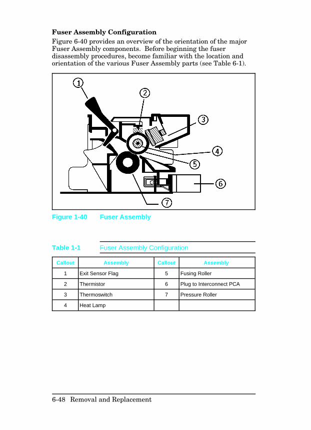
Fuser Assembly Configuration Figure 6-40 provides an overview of the orientation of the majorFuser Assembly components. Before beginning the fuserdisassembly procedures, become familiar with the location andorientation of the various Fuser Assembly parts (see Table 6-1).
Figure 1-40 Fuser Assembly
Callout Assembly Callout Assembly
1 Exit Sensor Flag 5 Fusing Roller
2 Thermistor 6 Plug to Interconnect PCA
3 Thermoswitch 7 Pressure Roller
4 Heat Lamp
Table 1-1 Fuser Assembly Configuration
6-48 Removal and Replacement
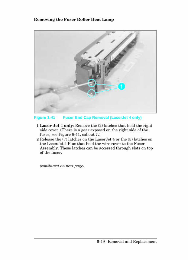
Removing the Fuser Roller Heat Lamp
1 Laser Jet 4 only: Remove the (2) latches that hold the rightside cover. (There is a gear exposed on the right side of thefuser, see Figure 6-41, callout 1.)
2 Release the (7) latches on the LaserJet 4 or the (5) latches onthe LaserJet 4 Plus that hold the wire cover to the FuserAssembly. These latches can be accessed through slots on topof the fuser.
(continued on next page)
Figure 1-41 Fuser End Cap Removal (LaserJet 4 only)
6-49 Removal and Replacement
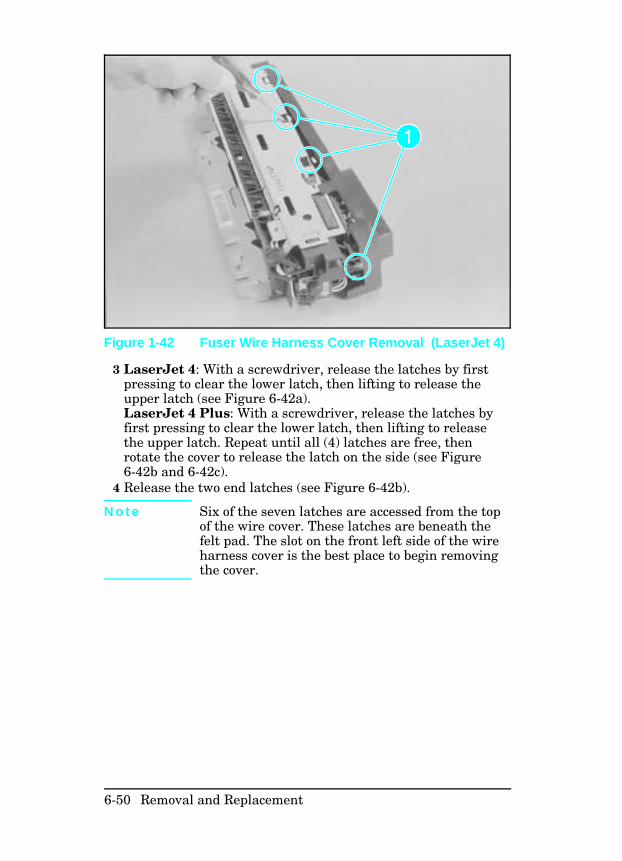
3 LaserJet 4: With a screwdriver, release the latches by firstpressing to clear the lower latch, then lifting to release theupper latch (see Figure 6-42a).LaserJet 4 Plus: With a screwdriver, release the latches byfirst pressing to clear the lower latch, then lifting to releasethe upper latch. Repeat until all (4) latches are free, thenrotate the cover to release the latch on the side (see Figure6-42b and 6-42c).
4 Release the two end latches (see Figure 6-42b).
N o t e Six of the seven latches are accessed from the topof the wire cover. These latches are beneath thefelt pad. The slot on the front left side of the wireharness cover is the best place to begin removingthe cover.
Figure 1-42 Fuser Wire Harness Cover Removal (LaserJet 4)
6-50 Removal and Replacement
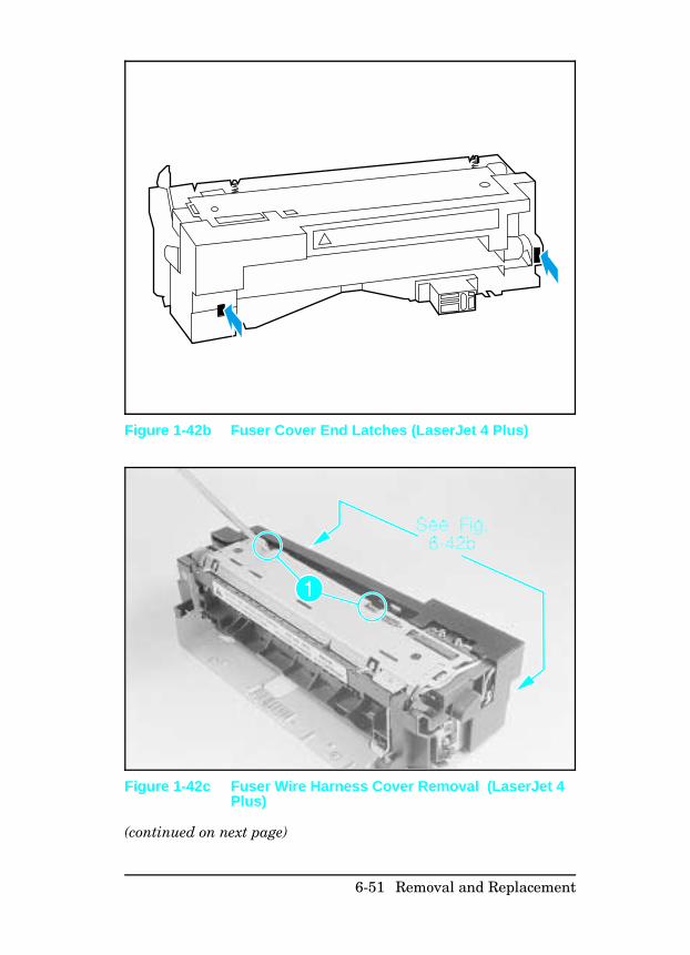
(continued on next page)
Figure 1-42b Fuser Cover End Latches (LaserJet 4 Plus)
Figure 1-42c Fuser Wire Harness Cover Removal (LaserJet 4Plus)
6-51 Removal and Replacement
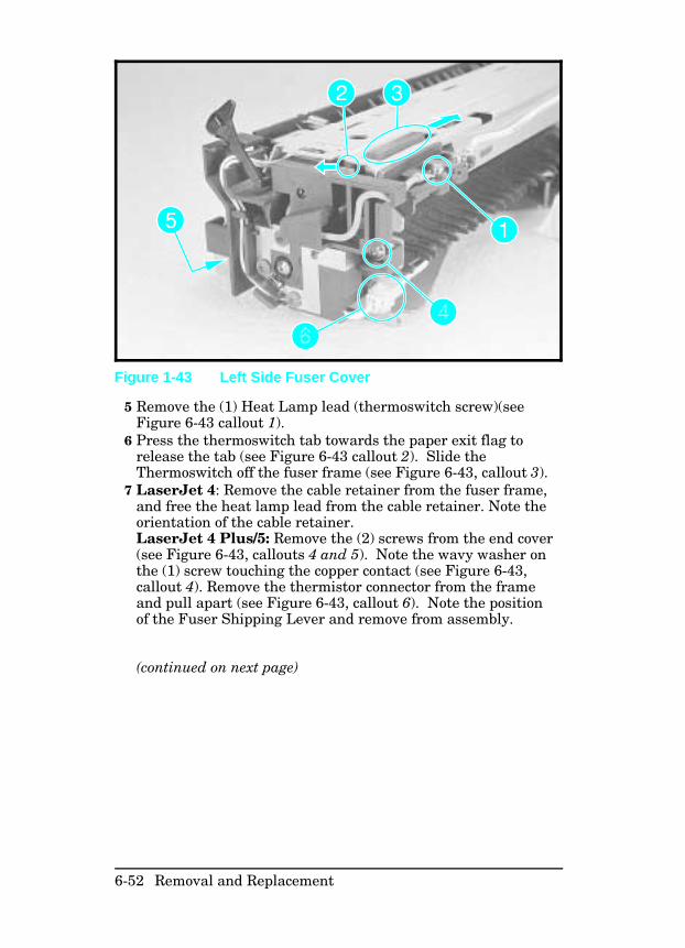
5 Remove the (1) Heat Lamp lead (thermoswitch screw)(seeFigure 6-43 callout 1).
6 Press the thermoswitch tab towards the paper exit flag torelease the tab (see Figure 6-43 callout 2). Slide theThermoswitch off the fuser frame (see Figure 6-43, callout 3).
7 LaserJet 4: Remove the cable retainer from the fuser frame,and free the heat lamp lead from the cable retainer. Note theorientation of the cable retainer.LaserJet 4 Plus/5: Remove the (2) screws from the end cover(see Figure 6-43, callouts 4 and 5). Note the wavy washer onthe (1) screw touching the copper contact (see Figure 6-43,callout 4). Remove the thermistor connector from the frameand pull apart (see Figure 6-43, callout 6). Note the positionof the Fuser Shipping Lever and remove from assembly.
(continued on next page)
Figure 1-43 Left Side Fuser Cover
6-52 Removal and Replacement
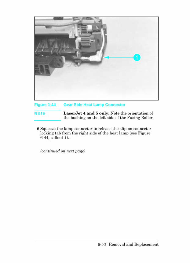
N o t e LaserJet 4 and 5 only: Note the orientation ofthe bushing on the left side of the Fusing Roller.
8 Squeeze the lamp connector to release the slip-on connectorlocking tab from the right side of the heat lamp (see Figure6-44, callout 1).
(continued on next page)
Figure 1-44 Gear Side Heat Lamp Connector
6-53 Removal and Replacement
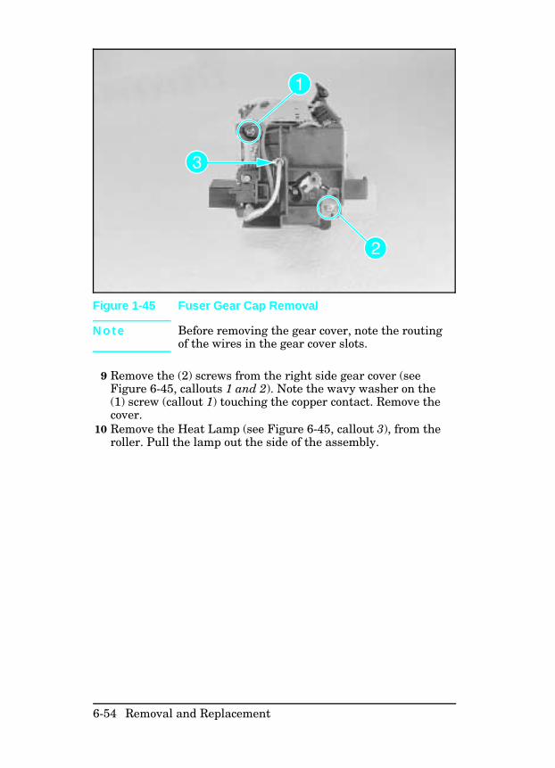
N o t e Before removing the gear cover, note the routingof the wires in the gear cover slots.
9 Remove the (2) screws from the right side gear cover (seeFigure 6-45, callouts 1 and 2). Note the wavy washer on the(1) screw (callout 1) touching the copper contact. Remove thecover.
10 Remove the Heat Lamp (see Figure 6-45, callout 3), from theroller. Pull the lamp out the side of the assembly.
Figure 1-45 Fuser Gear Cap Removal
6-54 Removal and Replacement
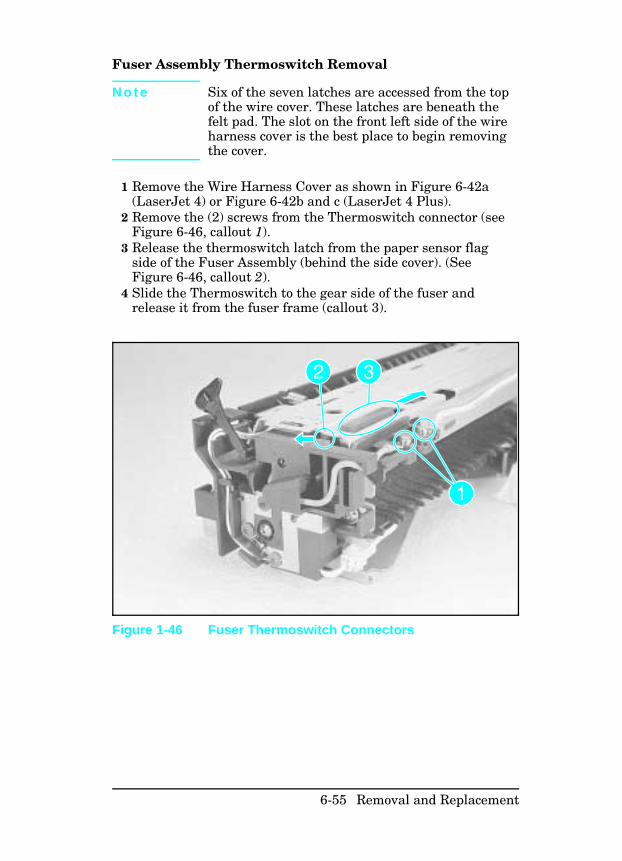
Fuser Assembly Thermoswitch Removal
N o t e Six of the seven latches are accessed from the topof the wire cover. These latches are beneath thefelt pad. The slot on the front left side of the wireharness cover is the best place to begin removingthe cover.
1 Remove the Wire Harness Cover as shown in Figure 6-42a(LaserJet 4) or Figure 6-42b and c (LaserJet 4 Plus).
2 Remove the (2) screws from the Thermoswitch connector (seeFigure 6-46, callout 1).
3 Release the thermoswitch latch from the paper sensor flagside of the Fuser Assembly (behind the side cover). (SeeFigure 6-46, callout 2).
4 Slide the Thermoswitch to the gear side of the fuser andrelease it from the fuser frame (callout 3).
Figure 1-46 Fuser Thermoswitch Connectors
6-55 Removal and Replacement
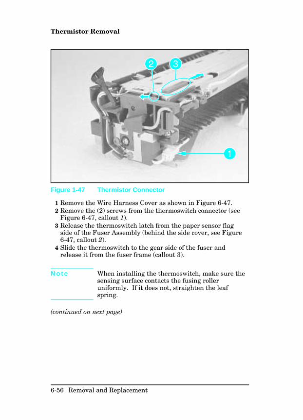
Thermistor Removal
1 Remove the Wire Harness Cover as shown in Figure 6-47.2 Remove the (2) screws from the thermoswitch connector (see
Figure 6-47, callout 1).3 Release the thermoswitch latch from the paper sensor flag
side of the Fuser Assembly (behind the side cover, see Figure6-47, callout 2).
4 Slide the thermoswitch to the gear side of the fuser andrelease it from the fuser frame (callout 3).
N o t e When installing the thermoswitch, make sure thesensing surface contacts the fusing rolleruniformly. If it does not, straighten the leafspring.
(continued on next page)
Figure 1-47 Thermistor Connector
6-56 Removal and Replacement
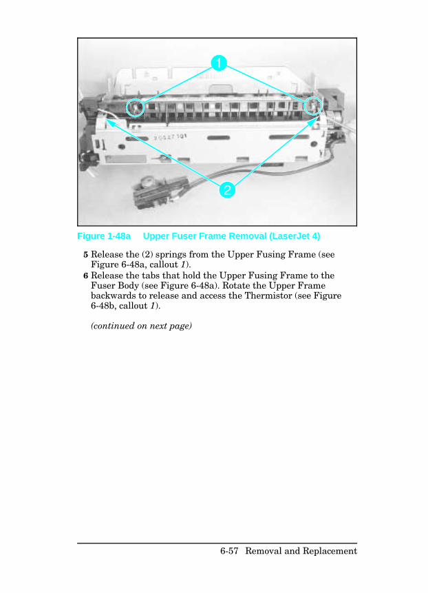
5 Release the (2) springs from the Upper Fusing Frame (seeFigure 6-48a, callout 1).
6 Release the tabs that hold the Upper Fusing Frame to theFuser Body (see Figure 6-48a). Rotate the Upper Framebackwards to release and access the Thermistor (see Figure6-48b, callout 1).
(continued on next page)
Figure 1-48a Upper Fuser Frame Removal (LaserJet 4)
6-57 Removal and Replacement
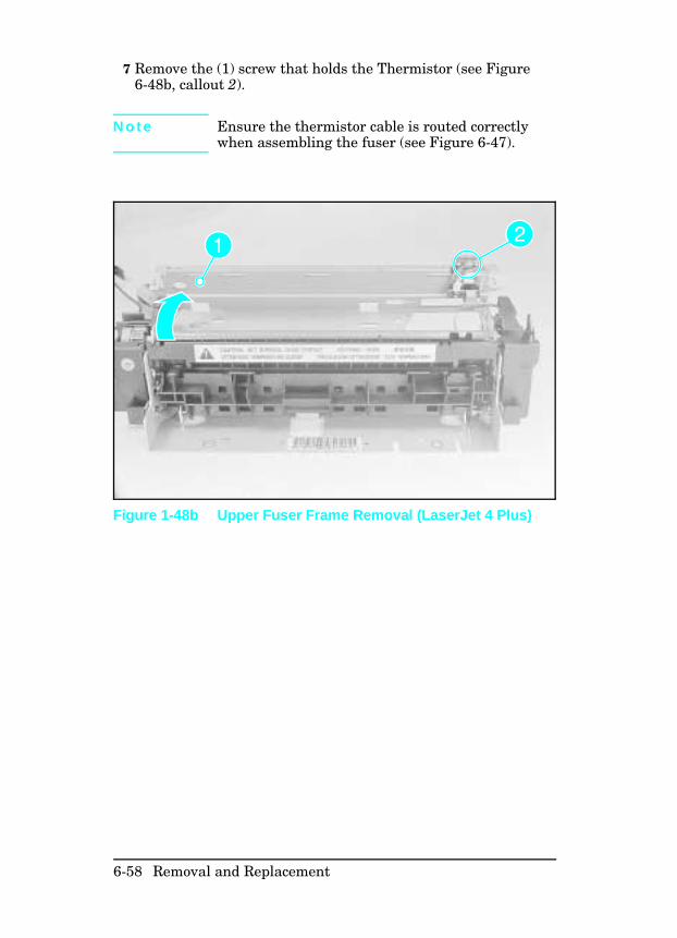
7 Remove the (1) screw that holds the Thermistor (see Figure6-48b, callout 2).
N o t e Ensure the thermistor cable is routed correctlywhen assembling the fuser (see Figure 6-47).
Figure 1-48b Upper Fuser Frame Removal (LaserJet 4 Plus)
6-58 Removal and Replacement
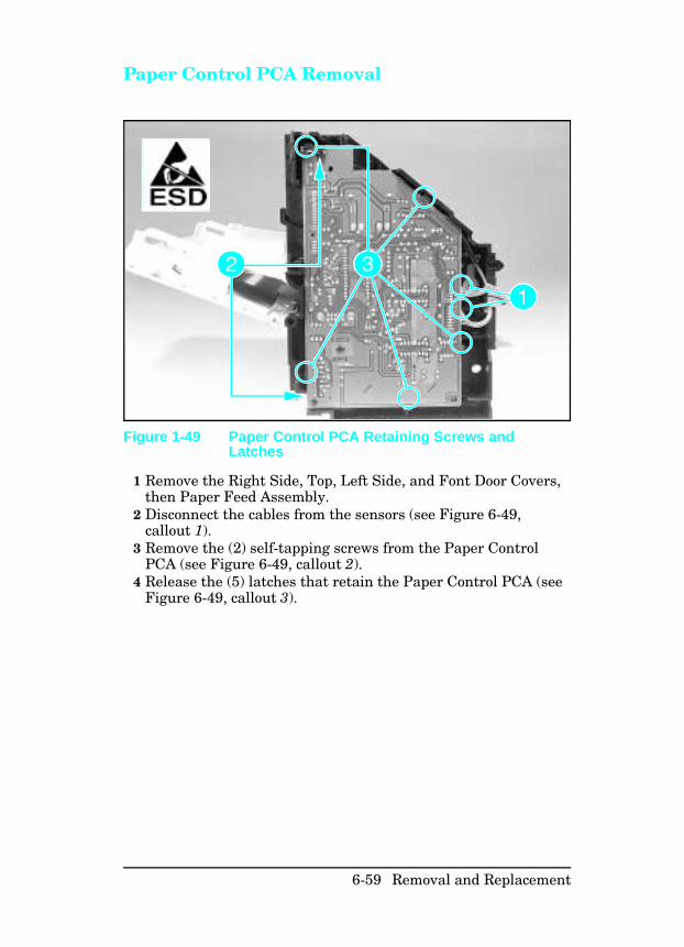
Paper Control PCA Removal
1 Remove the Right Side, Top, Left Side, and Font Door Covers,then Paper Feed Assembly.
2 Disconnect the cables from the sensors (see Figure 6-49,callout 1).
3 Remove the (2) self-tapping screws from the Paper ControlPCA (see Figure 6-49, callout 2).
4 Release the (5) latches that retain the Paper Control PCA (seeFigure 6-49, callout 3).
Figure 1-49 Paper Control PCA Retaining Screws andLatches
6-59 Removal and Replacement
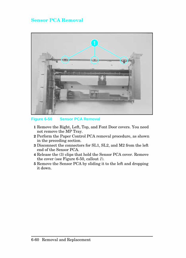
Sensor PCA Removal
1 Remove the Right, Left, Top, and Font Door covers. You neednot remove the MP Tray.
2 Perform the Paper Control PCA removal procedure, as shownin the preceding section.
3 Disconnect the connectors for SL1, SL2, and M2 from the leftend of the Sensor PCA.
4 Release the (3) clips that hold the Sensor PCA cover. Removethe cover (see Figure 6-50, callout 1).
5 Remove the Sensor PCA by sliding it to the left and droppingit down.
Figure 6-50 Sensor PCA Removal
6-60 Removal and Replacement
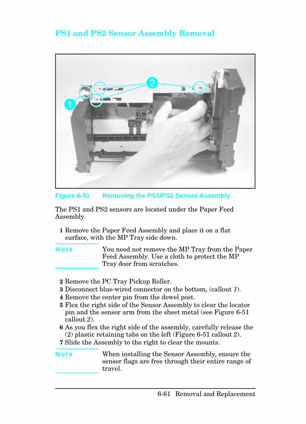
PS1 and PS2 Sensor Assembly Removal
The PS1 and PS2 sensors are located under the Paper FeedAssembly.
1 Remove the Paper Feed Assembly and place it on a flatsurface, with the MP Tray side down.
N o t e You need not remove the MP Tray from the PaperFeed Assembly. Use a cloth to protect the MPTray door from scratches.
2 Remove the PC Tray Pickup Roller.3 Disconnect blue-wired connector on the bottom, (callout 1).4 Remove the center pin from the dowel post.5 Flex the right side of the Sensor Assembly to clear the locator
pin and the sensor arm from the sheet metal (see Figure 6-51callout 2).
6 As you flex the right side of the assembly, carefully release the(2) plastic retaining tabs on the left (Figure 6-51 callout 2).
7 Slide the Assembly to the right to clear the mounts.
N o t e When installing the Sensor Assembly, ensure thesensor flags are free through their entire range oftravel.
Figure 6-51 Removing the PS1/PS2 Sensor Assembly
6-61 Removal and Replacement
High Voltage Contact Plate (HVCP)and Paper Guide Removal
This procedure involves removing many subassemblies anddifficult disassembly processes. Because this procedure iscomplex, it is separated into three sections:
• Accessing the HVCP and Feed Guide Assembly.• Removing the HVCP and Feed Guide Assembly.• Replacing the HVCP and Feed Guide Assembly.
Allow plenty of time to perform this procedure, and be careful notto damage any parts during reassembly.
Accessing the High Voltage Contact Plate andFeed Guide Assembly Accessing the High Voltage Contact Plate and Feed GuideAssembly requires prior removal of the following:
• Top Cover• Right Side Cover• Left Side Cover• Paper Feed Assembly• Toner Cartridge• Fuser Assembly• Transfer Roller
(continued on next page)
6-62 Removal and Replacement
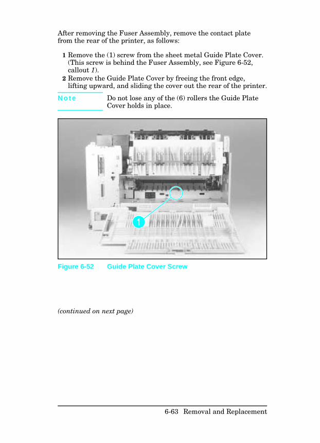
After removing the Fuser Assembly, remove the contact platefrom the rear of the printer, as follows:
1 Remove the (1) screw from the sheet metal Guide Plate Cover.(This screw is behind the Fuser Assembly, see Figure 6-52,callout 1).
2 Remove the Guide Plate Cover by freeing the front edge,lifting upward, and sliding the cover out the rear of the printer.
N o t e Do not lose any of the (6) rollers the Guide PlateCover holds in place.
(continued on next page)
Figure 6-52 Guide Plate Cover Screw
6-63 Removal and Replacement
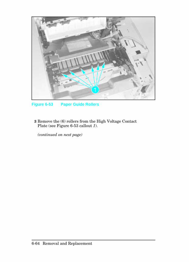
3 Remove the (6) rollers from the High Voltage ContactPlate (see Figure 6-53 callout 1).
(continued on next page)
Figure 6-53 Paper Guide Rollers
6-64 Removal and Replacement
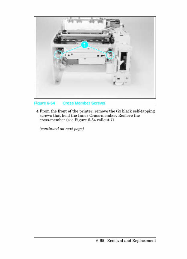
4 From the front of the printer, remove the (2) black self-tappingscrews that hold the Inner Cross-member. Remove thecross-member (see Figure 6-54 callout 1).
(continued on next page)
Figure 6-54 Cross Member Screws
6-65 Removal and Replacement
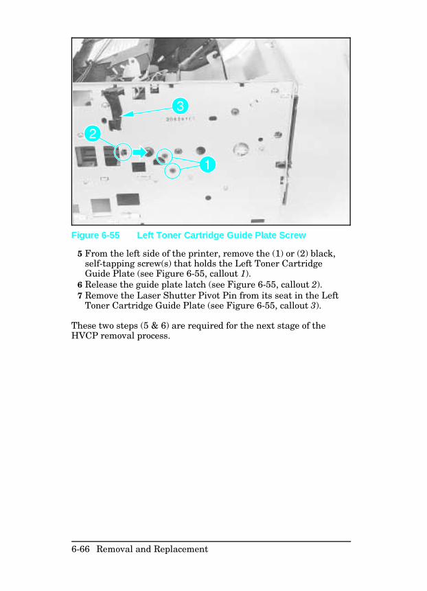
5 From the left side of the printer, remove the (1) or (2) black,self-tapping screw(s) that holds the Left Toner CartridgeGuide Plate (see Figure 6-55, callout 1).
6 Release the guide plate latch (see Figure 6-55, callout 2).7 Remove the Laser Shutter Pivot Pin from its seat in the Left
Toner Cartridge Guide Plate (see Figure 6-55, callout 3).
These two steps (5 & 6) are required for the next stage of theHVCP removal process.
Figure 6-55 Left Toner Cartridge Guide Plate Screw
6-66 Removal and Replacement
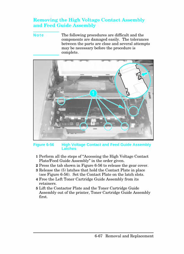
Removing the High Voltage Contact Assemblyand Feed Guide Assembly
N o t e The following procedures are difficult and thecomponents are damaged easily. The tolerancesbetween the parts are close and several attemptsmay be necessary before the procedure iscomplete.
1 Perform all the steps of “Accessing the High Voltage ContactPlate/Feed Guide Assembly” in the order given.
2 Press the tab shown in Figure 6-56 to release the gear cover.3 Release the (5) latches that hold the Contact Plate in place
(see Figure 6-56). Set the Contact Plate on the latch slots.4 Free the Left Toner Cartridge Guide Assembly from its
retainers.5 Lift the Contactor Plate and the Toner Cartridge Guide
Assembly out of the printer, Toner Cartridge Guide Assemblyfirst.
Figure 6-56 High Voltage Contact and Feed Guide AssemblyLatches
6-67 Removal and Replacement
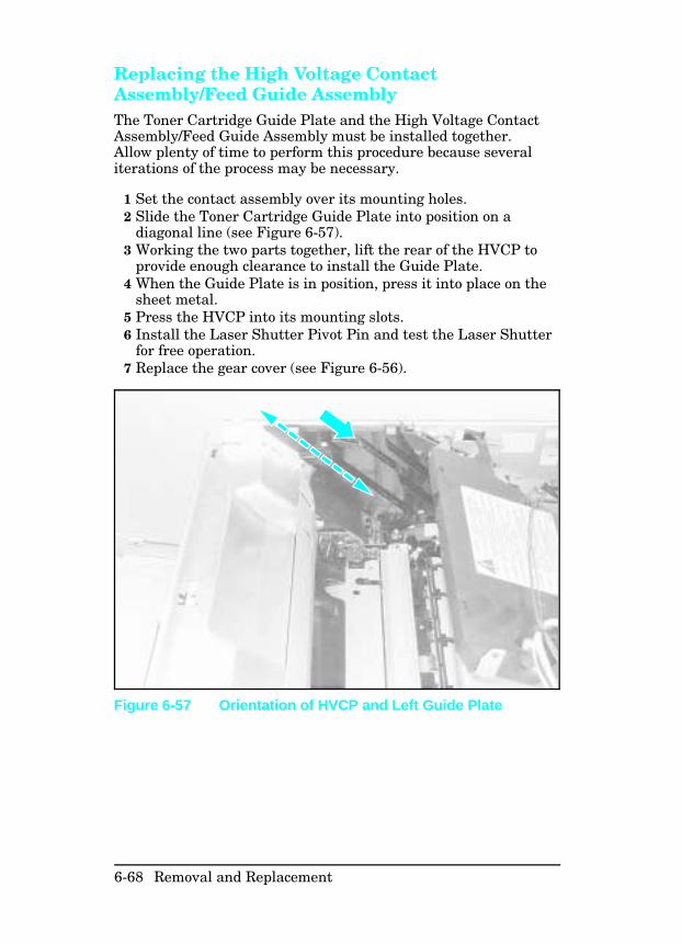
Replacing the High Voltage ContactAssembly/Feed Guide Assembly The Toner Cartridge Guide Plate and the High Voltage ContactAssembly/Feed Guide Assembly must be installed together.Allow plenty of time to perform this procedure because severaliterations of the process may be necessary.
1 Set the contact assembly over its mounting holes.2 Slide the Toner Cartridge Guide Plate into position on a
diagonal line (see Figure 6-57).3 Working the two parts together, lift the rear of the HVCP to
provide enough clearance to install the Guide Plate.4 When the Guide Plate is in position, press it into place on the
sheet metal.5 Press the HVCP into its mounting slots.6 Install the Laser Shutter Pivot Pin and test the Laser Shutter
for free operation.7 Replace the gear cover (see Figure 6-56).
Figure 6-57 Orientation of HVCP and Left Guide Plate
6-68 Removal and Replacement
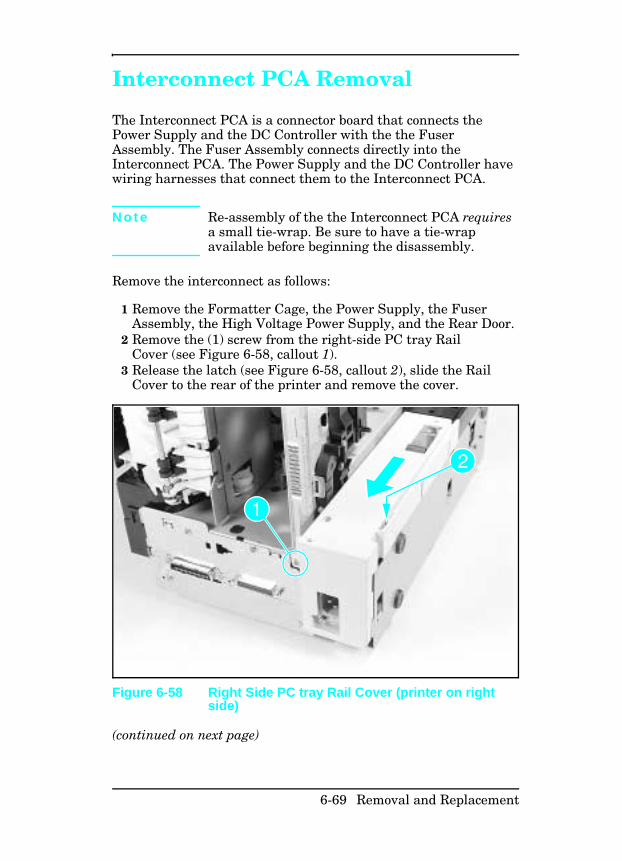
Interconnect PCA Removal
The Interconnect PCA is a connector board that connects thePower Supply and the DC Controller with the the FuserAssembly. The Fuser Assembly connects directly into theInterconnect PCA. The Power Supply and the DC Controller havewiring harnesses that connect them to the Interconnect PCA.
N o t e Re-assembly of the the Interconnect PCA requiresa small tie-wrap. Be sure to have a tie-wrapavailable before beginning the disassembly.
Remove the interconnect as follows:
1 Remove the Formatter Cage, the Power Supply, the FuserAssembly, the High Voltage Power Supply, and the Rear Door.
2 Remove the (1) screw from the right-side PC tray RailCover (see Figure 6-58, callout 1).
3 Release the latch (see Figure 6-58, callout 2), slide the RailCover to the rear of the printer and remove the cover.
(continued on next page)
Figure 6-58 Right Side PC tray Rail Cover (printer on rightside)
6-69 Removal and Replacement
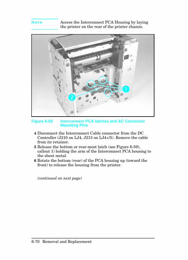
N o t e Access the Interconnect PCA Housing by layingthe printer on the rear of the printer chassis.
4 Disconnect the Interconnect Cable connector from the DCController (J210 on LJ4, J213 on LJ4+/5). Remove the cablefrom its retainer.
5 Release the bottom or rear-most latch (see Figure 6-59),callout 1) holding the arm of the Interconnect PCA housing tothe sheet metal.
6 Rotate the bottom (rear) of the PCA housing up (toward thefront) to release the housing from the printer.
(continued on next page)
Figure 6-59 Interconnect PCA latches and AC ConnectorMounting Pins
6-70 Removal and Replacement
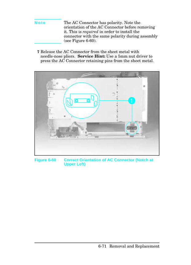
N o t e The AC Connector has polarity. Note theorientation of the AC Connector before removingit. This is required in order to install theconnector with the same polarity during assembly(see Figure 6-60).
7 Release the AC Connector from the sheet metal withneedle-nose pliers. Service Hint: Use a 5mm nut driver topress the AC Connector retaining pins from the sheet metal.
Figure 6-60 Correct Orientation of AC Connector (Notch atUpper Left)
6-71 Removal and Replacement

6-72 Removal and Replacement
7
LaserJet 5 Error MapThe LaserJet 5/5M/5N printer has error messages that aresimilar to the LaserJet 4/4M/4+/4M+. Use the following table tolook up the LJ5 error and take the recommended action. If therecommendation is to see another error, for example See 00POWERSAVE, look up the recommendation for that error in thePrinter Message Troubleshooting section (Tables 7-1 and 7-2).
N o t e The LaserJet 5 printer’s Go key replaces both theOnline and Continue keys previously used toresolve some of the temporary errors in theLaserJet 4 and 4 Plus printers.
N o t e For any LaserJet 5 error message preceded with anumber from 20 through 81, look up theequivalently-numbered message in Table 7-1 andproceed as directed.
Message on LJ 5/5M/5N Recommendations
CLEARING MEMORY See 07 RESET
CLOSE PRINTER COVER See 12 PRINTER OPEN
CONTINUOUS TEST, PRESS JOB CANCEL
KEY
See 04 SELF TEST
DATA RECEIVED The received data is waiting for a formfeed. (Takes the place of the Form Feedindicator on the LJ4.)
ENGINE TEST See 15 ENGINE TEST
FACTORY DEFAULTS BEING RESTORED See 09 MENU RESET
INCOMPATIBLE ENVELOPE FEEDER
INSTALLED
Indicates that an envelope feeder hasbeen installed that is not compatible withthe LJ5. Press GO to clear the error. Thefeeder will not appear in any controlpanel or PJL messages.
LaserJet 5 Error Map 7-A
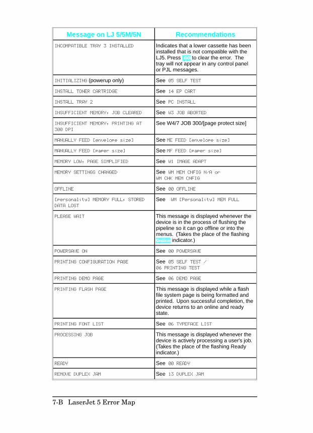
Message on LJ 5/5M/5N Recommendations
INCOMPATIBLE TRAY 3 INSTALLED Indicates that a lower cassette has beeninstalled that is not compatible with theLJ5. Press GO to clear the error. Thetray will not appear in any control panelor PJL messages.
INITIALIZING (powerup only) See 05 SELF TEST
INSTALL TONER CARTRIDGE See 14 EP CART
INSTALL TRAY 2 See PC INSTALL
INSUFFICIENT MEMORY, JOB CLEARED See W3 JOB ABORTED
INSUFFICIENT MEMORY, PRINTING AT
300 DPI
See W4/7 JOB 300/[page protect size]
MANUALLY FEED [envelope size] See ME FEED [envelope size]
MANUALLY FEED [paper size] See MF FEED [paper size]
MEMORY LOW, PAGE SIMPLIFIED See W1 IMAGE ADAPT
MEMORY SETTINGS CHANGED See WM MEM CNFIG N/A orWM CHK MEM CNFIG
OFFLINE See 00 OFFLINE
[personality] MEMORY FULL, STORED
DATA LOST
See WM [Personality] MEM FULL
PLEASE WAIT This message is displayed whenever thedevice is in the process of flushing thepipeline so it can go offline or into themenus. (Takes the place of the flashingOnline indicator.)
POWERSAVE ON See 00 POWERSAVE
PRINTING CONFIGURATION PAGE See 05 SELF TEST /06 PRINTING TEST
PRINTING DEMO PAGE See 06 DEMO PAGE
PRINTING FLASH PAGE This message is displayed while a flashfile system page is being formatted andprinted. Upon successful completion, thedevice returns to an online and readystate.
PRINTING FONT LIST See 06 TYPEFACE LIST
PROCESSING JOB This message is displayed whenever thedevice is actively processing a user’s job.(Takes the place of the flashing Readyindicator.)
READY See 00 READY
REMOVE DUPLEX JAM See 13 DUPLEX JAM
7-B LaserJet 5 Error Map
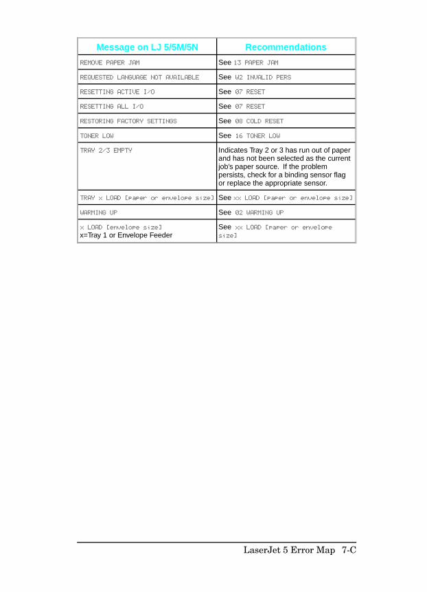
Message on LJ 5/5M/5N Recommendations
REMOVE PAPER JAM See 13 PAPER JAM
REQUESTED LANGUAGE NOT AVAILABLE See W2 INVALID PERS
RESETTING ACTIVE I/O See 07 RESET
RESETTING ALL I/O See 07 RESET
RESTORING FACTORY SETTINGS See 08 COLD RESET
TONER LOW See 16 TONER LOW
TRAY 2/3 EMPTY Indicates Tray 2 or 3 has run out of paperand has not been selected as the currentjob’s paper source. If the problempersists, check for a binding sensor flagor replace the appropriate sensor.
TRAY x LOAD [paper or envelope size] See xx LOAD [paper or envelope size]
WARMING UP See 02 WARMING UP
x LOAD [envelope size]
x=Tray 1 or Envelope FeederSee xx LOAD [paper or envelopesize]
LaserJet 5 Error Map 7-C

7-D LaserJet 5 Error Map
7
Troubleshooting
Pre-Troubleshooting Procedures
Preliminary Operating Checks Prior to troubleshooting a specific printer problem, you shouldensure that:
• The printer is being maintained on a regular basis asdescribed in Chapter 4.
• The customer is using acceptable media as specified in theUser’s Manual.
• The printer is installed on a solid, level surface.• The line voltage does not vary more than 10% from the
nominal rated value as specified on the Power Rating Label.• The operating environment for the printer and paper is within
the temperature and humidity specifications listed in Chapter1 of this manual.
• The printer is never exposed to ammonia fumes such as thoseproduced by diazo copiers, or office cleaning materials.
• The printer is not exposed to direct sunlight.• Non-HP components (such as refilled toner cartridges, font
cartridges, and memory boards) are removed from the printer.
Troubleshooting 7-1
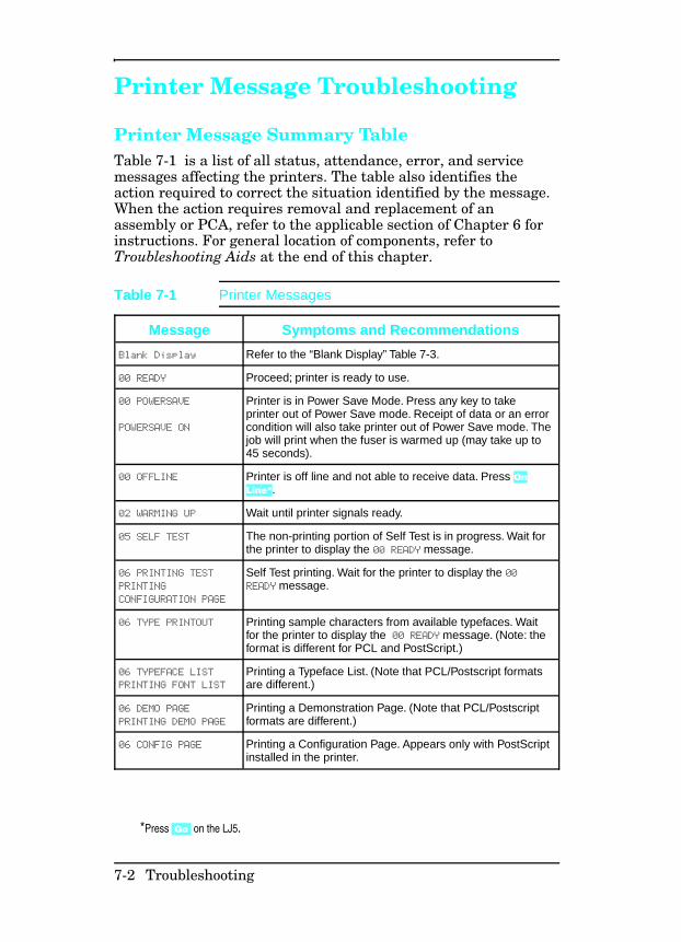
Printer Message Troubleshooting
Printer Message Summary Table Table 7-1 is a list of all status, attendance, error, and servicemessages affecting the printers. The table also identifies theaction required to correct the situation identified by the message.When the action requires removal and replacement of anassembly or PCA, refer to the applicable section of Chapter 6 forinstructions. For general location of components, refer toTroubleshooting Aids at the end of this chapter.
Message Symptoms and Recommendations
Blank Display Refer to the “Blank Display” Table 7-3.
00 READY Proceed; printer is ready to use.
00 POWERSAVE
POWERSAVE ON
Printer is in Power Save Mode. Press any key to takeprinter out of Power Save mode. Receipt of data or an errorcondition will also take printer out of Power Save mode. Thejob will print when the fuser is warmed up (may take up to45 seconds).
00 OFFLINE Printer is off line and not able to receive data. Press OnLine*.
02 WARMING UP Wait until printer signals ready.
05 SELF TEST The non-printing portion of Self Test is in progress. Wait forthe printer to display the 00 READY message.
06 PRINTING TEST
PRINTING
CONFIGURATION PAGE
Self Test printing. Wait for the printer to display the 00READY message.
06 TYPE PRINTOUT Printing sample characters from available typefaces. Waitfor the printer to display the 00 READY message. (Note: theformat is different for PCL and PostScript.)
06 TYPEFACE LIST
PRINTING FONT LIST
Printing a Typeface List. (Note that PCL/Postscript formatsare different.)
06 DEMO PAGE
PRINTING DEMO PAGE
Printing a Demonstration Page. (Note that PCL/Postscriptformats are different.)
06 CONFIG PAGE Printing a Configuration Page. Appears only with PostScriptinstalled in the printer.
*Press Go on the LJ5.
Table 7-1 Printer Messages
7-2 Troubleshooting
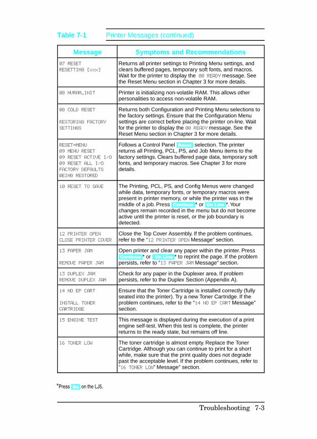
Message Symptoms and Recommendations
07 RESET
RESETTING [xxx]
Returns all printer settings to Printing Menu settings, andclears buffered pages, temporary soft fonts, and macros.Wait for the printer to display the 00 READY message. Seethe Reset Menu section in Chapter 3 for more details.
08 NVRAM_INIT Printer is initializing non-volatile RAM. This allows otherpersonalities to access non-volatile RAM.
08 COLD RESET
RESTORING FACTORY
SETTINGS
Returns both Configuration and Printing Menu selections tothe factory settings. Ensure that the Configuration Menusettings are correct before placing the printer on-line. Waitfor the printer to display the 00 READY message. See theReset Menu section in Chapter 3 for more details.
RESET=MENU
09 MENU RESET
09 RESET ACTIVE I/O
09 RESET ALL I/O
FACTORY DEFAULTS
BEING RESTORED
Follows a Control Panel [Reset] selection. The printerreturns all Printing, PCL, PS, and Job Menu items to thefactory settings. Clears buffered page data, temporary softfonts, and temporary macros. See Chapter 3 for moredetails.
10 RESET TO SAVE The Printing, PCL, PS, and Config Menus were changedwhile data, temporary fonts, or temporary macros werepresent in printer memory, or while the printer was in themiddle of a job. Press [Continue]* or [On Line]*. Yourchanges remain recorded in the menu but do not becomeactive until the printer is reset, or the job boundary isdetected.
12 PRINTER OPEN
CLOSE PRINTER COVER
Close the Top Cover Assembly. If the problem continues,refer to the “12 PRINTER OPEN Message” section.
13 PAPER JAM
REMOVE PAPER JAM
Open printer and clear any paper within the printer. Press[Continue]* or [On Line]* to reprint the page. If the problempersists, refer to “13 PAPER JAM Message” section.
13 DUPLEX JAM
REMOVE DUPLEX JAM
Check for any paper in the Duplexer area. If problempersists, refer to the Duplex Section (Appendix A).
14 NO EP CART
INSTALL TONER
CARTRIDGE
Ensure that the Toner Cartridge is installed correctly (fullyseated into the printer). Try a new Toner Cartridge. If theproblem continues, refer to the “14 NO EP CART Message”section.
15 ENGINE TEST This message is displayed during the execution of a printengine self-test. When this test is complete, the printerreturns to the ready state, but remains off line.
16 TONER LOW The toner cartridge is almost empty. Replace the TonerCartridge. Although you can continue to print for a shortwhile, make sure that the print quality does not degradepast the acceptable level. If the problem continues, refer to“16 TONER LOW” Message" section.
Table 7-1 Printer Messages (continued)
*Press Go on the LJ5.
Troubleshooting 7-3
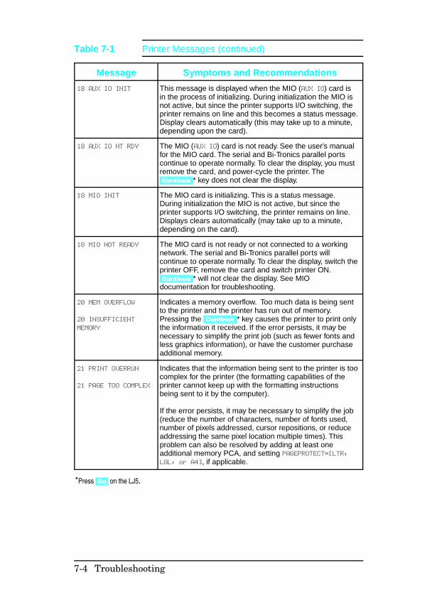
Message Symptoms and Recommendations
18 AUX IO INIT This message is displayed when the MIO (AUX IO) card isin the process of initializing. During initialization the MIO isnot active, but since the printer supports I/O switching, theprinter remains on line and this becomes a status message.Display clears automatically (this may take up to a minute,depending upon the card).
18 AUX IO NT RDY The MIO (AUX IO) card is not ready. See the user’s manualfor the MIO card. The serial and Bi-Tronics parallel portscontinue to operate normally. To clear the display, you mustremove the card, and power-cycle the printer. The[Continue]* key does not clear the display.
18 MIO INIT The MIO card is initializing. This is a status message.During initialization the MIO is not active, but since theprinter supports I/O switching, the printer remains on line.Displays clears automatically (may take up to a minute,depending on the card).
18 MIO NOT READY The MIO card is not ready or not connected to a workingnetwork. The serial and Bi-Tronics parallel ports willcontinue to operate normally. To clear the display, switch theprinter OFF, remove the card and switch printer ON.[Continue]* will not clear the display. See MIOdocumentation for troubleshooting.
20 MEM OVERFLOW
20 INSUFFICIENT
MEMORY
Indicates a memory overflow. Too much data is being sentto the printer and the printer has run out of memory.Pressing the [Continue]* key causes the printer to print onlythe information it received. If the error persists, it may benecessary to simplify the print job (such as fewer fonts andless graphics information), or have the customer purchaseadditional memory.
21 PRINT OVERRUN
21 PAGE TOO COMPLEX
Indicates that the information being sent to the printer is toocomplex for the printer (the formatting capabilities of theprinter cannot keep up with the formatting instructionsbeing sent to it by the computer).
If the error persists, it may be necessary to simplify the job(reduce the number of characters, number of fonts used,number of pixels addressed, cursor repositions, or reduceaddressing the same pixel location multiple times). Thisproblem can also be resolved by adding at least oneadditional memory PCA, and setting PAGEPROTECT=[LTR,LGL, or A4], if applicable.
*Press Go on the LJ5.
Table 7-1 Printer Messages (continued)
7-4 Troubleshooting
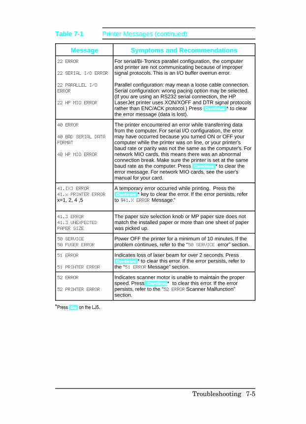
Message Symptoms and Recommendations
22 ERROR
22 SERIAL I/O ERROR
22 PARALLEL I/O
ERROR
22 HP MIO ERROR
For serial/Bi-Tronics parallel configuration, the computerand printer are not communicating because of impropersignal protocols. This is an I/O buffer overrun error.
Parallel configuration: may mean a loose cable connection.Serial configuration: wrong pacing option may be selected.(If you are using an RS232 serial connection, the HPLaserJet printer uses XON/XOFF and DTR signal protocolsrather than ENC/ACK protocol.) Press [Continue]* to clearthe error message (data is lost).
40 ERROR
40 BAD SERIAL DATA
FORMAT
40 HP MIO ERROR
The printer encountered an error while transferring datafrom the computer. For serial I/O configuration, the errormay have occurred because you turned ON or OFF yourcomputer while the printer was on line, or your printer’sbaud rate or parity was not the same as the computer’s. Fornetwork MIO cards, this means there was an abnormalconnection break. Make sure the printer is set at the samebaud rate as the computer. Press [Continue]* to clear theerror message. For network MIO cards, see the user’smanual for your card.
41.[X] ERROR 41.x PRINTER ERROR
x=1, 2, 4 ,5
A temporary error occurred while printing. Press the[Continue]* key to clear the error. If the error persists, referto “41.X ERROR Message.”
41.3 ERROR
41.3 UNEXPECTED
PAPER SIZE
The paper size selection knob or MP paper size does notmatch the installed paper or more than one sheet of paperwas picked up.
50 SERVICE
50 FUSER ERROR
Power OFF the printer for a minimum of 10 minutes. If theproblem continues, refer to the “50 SERVICE error” section.
51 ERROR
51 PRINTER ERROR
Indicates loss of laser beam for over 2 seconds. Press[Continue]* to clear this error. If the error persists, refer tothe “51 ERROR Message” section.
52 ERROR
52 PRINTER ERROR
Indicates scanner motor is unable to maintain the properspeed. Press [Continue* to clear this error. If the errorpersists, refer to the “52 ERROR Scanner Malfunction”section.
*Press Go on the LJ5.
Table 7-1 Printer Messages (continued)
Troubleshooting 7-5
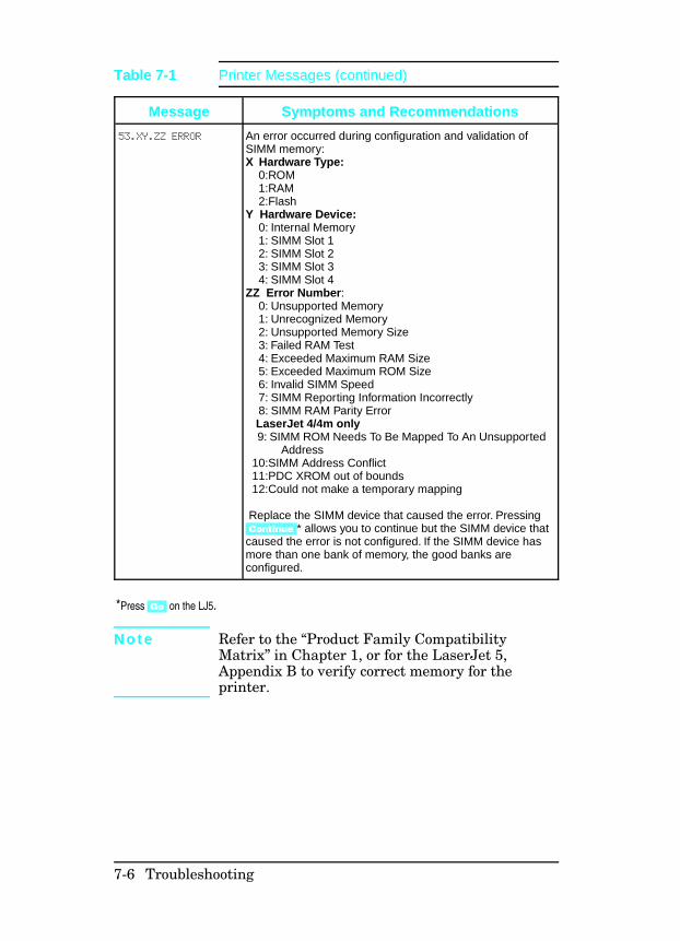
N o t e Refer to the “Product Family CompatibilityMatrix” in Chapter 1, or for the LaserJet 5,Appendix B to verify correct memory for theprinter.
Message Symptoms and Recommendations
53.XY.ZZ ERROR An error occurred during configuration and validation ofSIMM memory:X Hardware Type: 0:ROM 1:RAM 2:FlashY Hardware Device: 0: Internal Memory 1: SIMM Slot 1 2: SIMM Slot 2 3: SIMM Slot 3 4: SIMM Slot 4ZZ Error Number: 0: Unsupported Memory 1: Unrecognized Memory 2: Unsupported Memory Size 3: Failed RAM Test 4: Exceeded Maximum RAM Size 5: Exceeded Maximum ROM Size 6: Invalid SIMM Speed 7: SIMM Reporting Information Incorrectly 8: SIMM RAM Parity Error LaserJet 4/4m only 9: SIMM ROM Needs To Be Mapped To An Unsupported Address 10:SIMM Address Conflict 11:PDC XROM out of bounds 12:Could not make a temporary mapping
Replace the SIMM device that caused the error. Pressing[Continue]* allows you to continue but the SIMM device thatcaused the error is not configured. If the SIMM device hasmore than one bank of memory, the good banks areconfigured.
*Press Go on the LJ5.
Table 7-1 Printer Messages (continued)
7-6 Troubleshooting
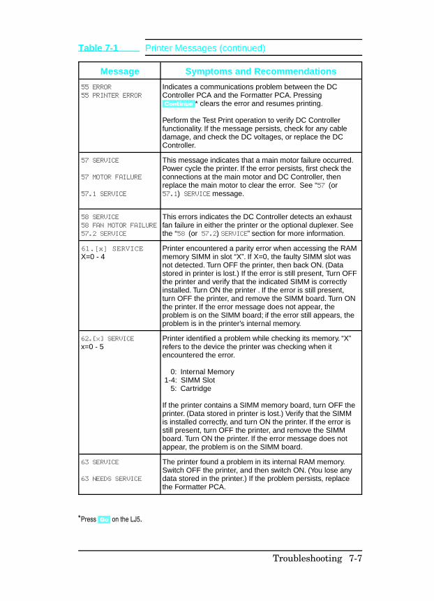
Message Symptoms and Recommendations
55 ERROR
55 PRINTER ERROR
Indicates a communications problem between the DCController PCA and the Formatter PCA. Pressing[Continue]* clears the error and resumes printing.
Perform the Test Print operation to verify DC Controllerfunctionality. If the message persists, check for any cabledamage, and check the DC voltages, or replace the DCController.
57 SERVICE
57 MOTOR FAILURE
57.1 SERVICE
This message indicates that a main motor failure occurred.Power cycle the printer. If the error persists, first check theconnections at the main motor and DC Controller, thenreplace the main motor to clear the error. See “57 (or57.1) SERVICE message.
58 SERVICE
58 FAN MOTOR FAILURE
57.2 SERVICE
This errors indicates the DC Controller detects an exhaustfan failure in either the printer or the optional duplexer. Seethe “58 (or 57.2) SERVICE” section for more information.
61.[x] SERVICEX=0 - 4
Printer encountered a parity error when accessing the RAMmemory SIMM in slot “X”. If X=0, the faulty SIMM slot wasnot detected. Turn OFF the printer, then back ON. (Datastored in printer is lost.) If the error is still present, Turn OFFthe printer and verify that the indicated SIMM is correctlyinstalled. Turn ON the printer . If the error is still present,turn OFF the printer, and remove the SIMM board. Turn ONthe printer. If the error message does not appear, theproblem is on the SIMM board; if the error still appears, theproblem is in the printer’s internal memory.
62.[x] SERVICE
x=0 - 5Printer identified a problem while checking its memory. “X”refers to the device the printer was checking when itencountered the error.
0: Internal Memory 1-4: SIMM Slot 5: Cartridge
If the printer contains a SIMM memory board, turn OFF theprinter. (Data stored in printer is lost.) Verify that the SIMMis installed correctly, and turn ON the printer. If the error isstill present, turn OFF the printer, and remove the SIMMboard. Turn ON the printer. If the error message does notappear, the problem is on the SIMM board.
63 SERVICE
63 NEEDS SERVICE
The printer found a problem in its internal RAM memory.Switch OFF the printer, and then switch ON. (You lose anydata stored in the printer.) If the problem persists, replacethe Formatter PCA.
Table 7-1 Printer Messages (continued)
*Press Go on the LJ5.
Troubleshooting 7-7
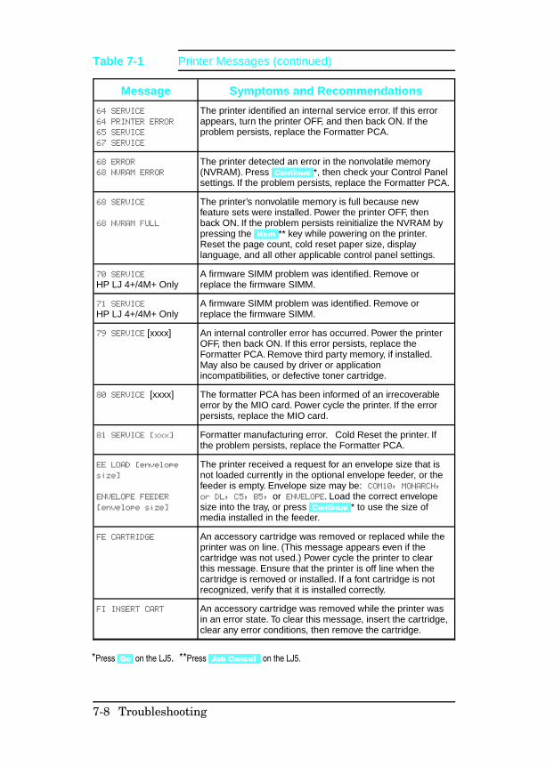
Message Symptoms and Recommendations
64 SERVICE
64 PRINTER ERROR
65 SERVICE
67 SERVICE
The printer identified an internal service error. If this errorappears, turn the printer OFF, and then back ON. If theproblem persists, replace the Formatter PCA.
68 ERROR
68 NVRAM ERROR
The printer detected an error in the nonvolatile memory(NVRAM). Press [Continue]*, then check your Control Panelsettings. If the problem persists, replace the Formatter PCA.
68 SERVICE
68 NVRAM FULL
The printer’s nonvolatile memory is full because newfeature sets were installed. Power the printer OFF, thenback ON. If the problem persists reinitialize the NVRAM bypressing the [Item]** key while powering on the printer.Reset the page count, cold reset paper size, displaylanguage, and all other applicable control panel settings.
70 SERVICE
HP LJ 4+/4M+ OnlyA firmware SIMM problem was identified. Remove orreplace the firmware SIMM.
71 SERVICE
HP LJ 4+/4M+ OnlyA firmware SIMM problem was identified. Remove orreplace the firmware SIMM.
79 SERVICE [xxxx] An internal controller error has occurred. Power the printerOFF, then back ON. If this error persists, replace theFormatter PCA. Remove third party memory, if installed.May also be caused by driver or applicationincompatibilities, or defective toner cartridge.
80 SERVICE [xxxx] The formatter PCA has been informed of an irrecoverableerror by the MIO card. Power cycle the printer. If the errorpersists, replace the MIO card.
81 SERVICE [xxx] Formatter manufacturing error. Cold Reset the printer. Ifthe problem persists, replace the Formatter PCA.
EE LOAD [envelope
size]
ENVELOPE FEEDER
[envelope size]
The printer received a request for an envelope size that isnot loaded currently in the optional envelope feeder, or thefeeder is empty. Envelope size may be: COM10, MONARCH,or DL, C5, B5, or ENVELOPE. Load the correct envelopesize into the tray, or press [Continue]* to use the size ofmedia installed in the feeder.
FE CARTRIDGE An accessory cartridge was removed or replaced while theprinter was on line. (This message appears even if thecartridge was not used.) Power cycle the printer to clearthis message. Ensure that the printer is off line when thecartridge is removed or installed. If a font cartridge is notrecognized, verify that it is installed correctly.
FI INSERT CART An accessory cartridge was removed while the printer wasin an error state. To clear this message, insert the cartridge,clear any error conditions, then remove the cartridge.
Table 7-1 Printer Messages (continued)
*Press Go on the LJ5. **Press Job Cancel on the LJ5.
7-8 Troubleshooting
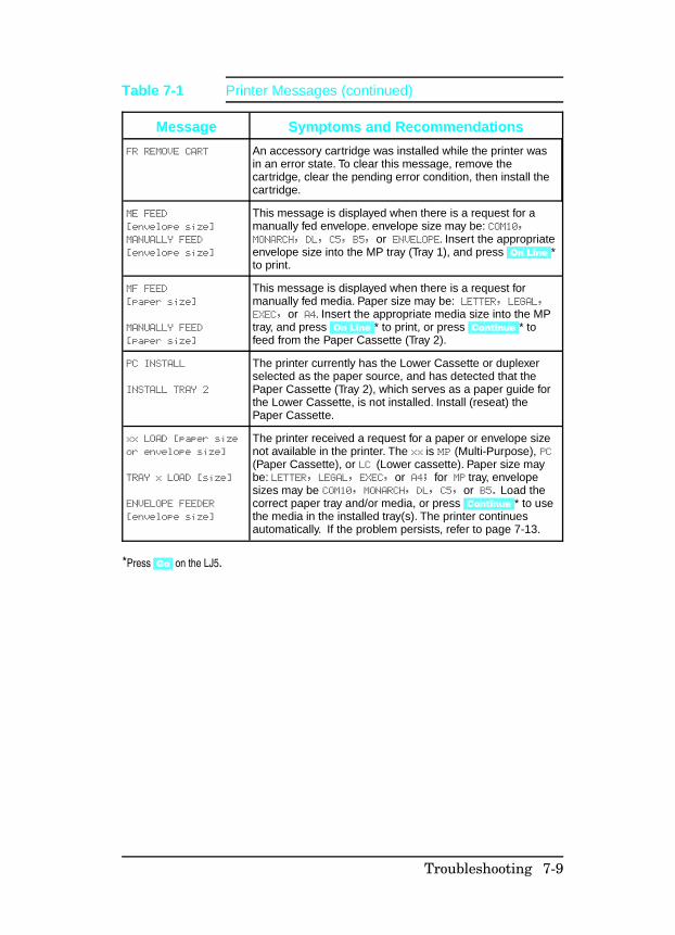
Message Symptoms and Recommendations
FR REMOVE CART An accessory cartridge was installed while the printer wasin an error state. To clear this message, remove thecartridge, clear the pending error condition, then install thecartridge.
ME FEED
[envelope size]
MANUALLY FEED
[envelope size]
This message is displayed when there is a request for amanually fed envelope. envelope size may be: COM10,MONARCH, DL, C5, B5, or ENVELOPE. Insert the appropriateenvelope size into the MP tray (Tray 1), and press [On Line]*to print.
MF FEED
[paper size]
MANUALLY FEED
[paper size]
This message is displayed when there is a request formanually fed media. Paper size may be: LETTER, LEGAL,EXEC, or A4. Insert the appropriate media size into the MPtray, and press [On Line]* to print, or press [Continue]* tofeed from the Paper Cassette (Tray 2).
PC INSTALL
INSTALL TRAY 2
The printer currently has the Lower Cassette or duplexerselected as the paper source, and has detected that thePaper Cassette (Tray 2), which serves as a paper guide forthe Lower Cassette, is not installed. Install (reseat) thePaper Cassette.
xx LOAD [paper size
or envelope size]
TRAY x LOAD [size]
ENVELOPE FEEDER
[envelope size]
The printer received a request for a paper or envelope sizenot available in the printer. The xx is MP (Multi-Purpose), PC(Paper Cassette), or LC (Lower cassette). Paper size maybe: LETTER, LEGAL, EXEC, or A4; for MP tray, envelopesizes may be COM10, MONARCH, DL, C5, or B5. Load thecorrect paper tray and/or media, or press [Continue]* to usethe media in the installed tray(s). The printer continuesautomatically. If the problem persists, refer to page 7-13.
*Press Go on the LJ5.
Table 7-1 Printer Messages (continued)
Troubleshooting 7-9

Clearable Warnings A clearable warning indicates a transient condition in theprinter. The printer continues on line while the message isdisplayed in place of 00 READY. A clearable warning appears eachtime the printer alters resolution or page protection (this causesreconfiguration of memory), or aborts a job due to an invalid oruninstalled personality, or insufficient memory. Clear themessage by pressing [Shift] + [Continue] (or Go for the LaserJet 5).
7-10 Troubleshooting
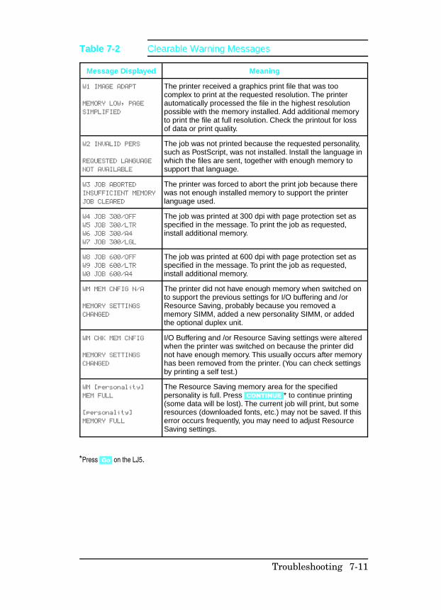
Message Displayed Meaning
W1 IMAGE ADAPT
MEMORY LOW, PAGE
SIMPLIFIED
The printer received a graphics print file that was toocomplex to print at the requested resolution. The printerautomatically processed the file in the highest resolutionpossible with the memory installed. Add additional memoryto print the file at full resolution. Check the printout for lossof data or print quality.
W2 INVALID PERS
REQUESTED LANGUAGE
NOT AVAILABLE
The job was not printed because the requested personality,such as PostScript, was not installed. Install the language inwhich the files are sent, together with enough memory tosupport that language.
W3 JOB ABORTED
INSUFFICIENT MEMORY
JOB CLEARED
The printer was forced to abort the print job because therewas not enough installed memory to support the printerlanguage used.
W4 JOB 300/OFF
W5 JOB 300/LTR
W6 JOB 300/A4
W7 JOB 300/LGL
The job was printed at 300 dpi with page protection set asspecified in the message. To print the job as requested,install additional memory.
W8 JOB 600/OFF
W9 JOB 600/LTR
W0 JOB 600/A4
The job was printed at 600 dpi with page protection set asspecified in the message. To print the job as requested,install additional memory.
WM MEM CNFIG N/A
MEMORY SETTINGS
CHANGED
The printer did not have enough memory when switched onto support the previous settings for I/O buffering and /orResource Saving, probably because you removed amemory SIMM, added a new personality SIMM, or addedthe optional duplex unit.
WM CHK MEM CNFIG
MEMORY SETTINGS
CHANGED
I/O Buffering and /or Resource Saving settings were alteredwhen the printer was switched on because the printer didnot have enough memory. This usually occurs after memoryhas been removed from the printer. (You can check settingsby printing a self test.)
WM [personality]
MEM FULL
[personality]
MEMORY FULL
The Resource Saving memory area for the specifiedpersonality is full. Press [CONTINUE]* to continue printing(some data will be lost). The current job will print, but someresources (downloaded fonts, etc.) may not be saved. If thiserror occurs frequently, you may need to adjust ResourceSaving settings.
*Press Go on the LJ5.
Table 7-2 Clearable Warning Messages
Troubleshooting 7-11
Printer Message TroubleshootingProcedures
When the following procedures require removing and replacingan assembly or PCA, refer to the applicable section in Chapter 6for instructions.
Blank Display
Checks Action
Is the power on? 1.
2.
Check the ON/OFF switch and verify the power isplugged in.
Press a Control Panel key to verify problem stillexists.
Is the fan working? 1.
2.
If the fan is working, check the cabling to theControl Panel. If the cabling is good, replace theFormatter first, then the Control Panel.
If the fan is NOT working, measure the DCvoltage levels (refer to Table 7-39). If the voltagelevels are good from the power supply to the DCController and the fan is not working, replace theDC Controller. If the voltage levels are not presentat TB1, replace the DC Power Supply.
Table 7-3 Blank Display
7-12 Troubleshooting
MP/PC/LC (Tray 1/2/3) LOAD Message The conditions that result in MP/PC/LC LOAD or (TRAY 1/2/3)messages are:
• The absence of any input tray.• The absence of media in either tray.• The tray size switches may be defective and not recognize
the presence of the paper tray. The tray is sensed as thetray-identifier tabs contact one or more of the three trayidentifier microswitches.
• The Universal Tray paper size dial setting does not matchthe installed paper.
The MP/PC/LC LOAD message is also generated when the user orsoftware requests a paper size other than that installed.
The Paper Sensing Arms are located in the paper input areas ofthe printer. During normal operation, the Paper Sensing Armflags rest on the media installed in the paper tray. The SensingArm flags are attached to shafts. The opposite end of the shaft isa photointerrupter that rotates through the sensors on the PaperControl PCA. These sensors are:
• PS4 Paper out-MP tray.• PS2 Paper out-PC tray.• PS6 Paper out-Lower Cassette.• PS7 Paper out-Envelope Feeder.
The presence of paper in the paper tray is sensed by the papersensor arm. When paper is in the cassette, the sensor arm restson top of the paper in the tray. At this point, the sensors are notblocked. When the tray is empty, the arm swings through itstravel. The photointerrupter attached to the paper sensor armshaft rotates and blocks the sensor diode.
Troubleshooting 7-13
Checks Action
Is media present in the tray(s). Install media.
Are the proper trays fully inserted in theprinter?
Reseat the cassettes. Make sure eachcassette is fully seated into the printer.Ensure that the Universal Paper trayselector knob setting matches theinstalled paper.
Does the Control Panel’s or application’sPaper size setting match the tray beingused?
Correct the setting to match tray.
Is the expected tray size beingrecognized by the printer?
Ensure that the image is sized correctly(formatted) for the paper size selected.Proceed to the following cassette sizeswitches functional check. Checkswitches 603/4/5 if feeding from the PCtray (Tray 1). Check switches 851/2/3 iffeeding from the Lower Cassette. seeFigures 7-14 and 7-15 for locations.)
Are any of the tray identifier tabs brokenon either PC (Tray 1) or LC (Tray 2)paper tray?
Inspect the tray for damage. If damaged,replace the tray.
Table 7-4 “MP/PC/LC (Tray 1/2/3) LOAD” Message Checks
7-14 Troubleshooting
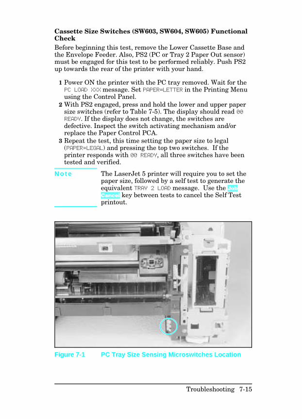
Cassette Size Switches (SW603, SW604, SW605) FunctionalCheck Before beginning this test, remove the Lower Cassette Base andthe Envelope Feeder. Also, PS2 (PC or Tray 2 Paper Out sensor)must be engaged for this test to be performed reliably. Push PS2up towards the rear of the printer with your hand.
1 Power ON the printer with the PC tray removed. Wait for thePC LOAD XXX message. Set PAPER=LETTER in the Printing Menuusing the Control Panel.
2 With PS2 engaged, press and hold the lower and upper papersize switches (refer to Table 7-5). The display should read 00READY. If the display does not change, the switches aredefective. Inspect the switch activating mechanism and/orreplace the Paper Control PCA.
3 Repeat the test, this time setting the paper size to legal(PAPER=LEGAL) and pressing the top two switches. If theprinter responds with 00 READY, all three switches have beentested and verified.
N o t e The LaserJet 5 printer will require you to set thepaper size, followed by a self test to generate theequivalent TRAY 2 LOAD message. Use the JobCancel key between tests to cancel the Self Testprintout.
Figure 7-1 PC Tray Size Sensing Microswitches Location
Troubleshooting 7-15
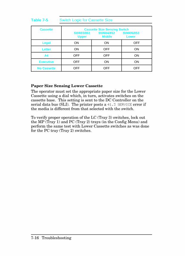
Paper Size Sensing Lower Cassette The operator must set the appropriate paper size for the LowerCassette using a dial which, in turn, activates switches on thecassette base. This setting is sent to the DC Controller on theserial data bus (SLI). The printer posts a 41.3 SERVICE error ifthe media is different from that selected with the switch.
To verify proper operation of the LC (Tray 3) switches, lock outthe MP (Tray 1) and PC (Tray 2) trays (in the Config Menu) andperform the same test with Lower Cassette switches as was donefor the PC tray (Tray 2) switches.
Cassette Cassette Size Sensing SwitchSW603/851 SW604/852 SW605/853
Upper Middle Lower
Legal ON ON OFF
Letter ON OFF ON
A4 OFF OFF ON
Executive OFF ON ON
No Cassette OFF OFF OFF
Table 7-5 Switch Logic for Cassette Size
7-16 Troubleshooting
PC Empty Sensor (PS2) Functional Check 1 Power on the printer with the PC tray (Tray 2) empty.2 After the 05 SELF TEST and the 02 WARMING UP cycles, the PCLOAD LETTER (or A4) or TRAY 2 EMPTY message appears.
3 Add paper to the PC tray and re-install the tray.4 The display should read 02 WARMING UP, then 00 READY. Ifthe PC LOAD or TRAY 2 EMPTY message persists, replace PS2.
PS4 Check (MP Tray Empty Sensor)
1 With the printer powered ON and 00 READY displayed, select
the Config Menu from the Control Panel.2 Configure the MP Tray (Tray 1) as a cassette (MP TRAY=CASSor TRAY 1=CASSETTE).
3 Lock out the remaining paper trays (LOCK= PC LC or LOCKTRAY= 2 3).
4 Remove any paper from the MP Tray (Tray 1). The printershould display an MP LOAD [paper size] message. For theLaserJet 5 printer, run a Self Test to generate the TRAY 1LOAD message.
5 Insert paper into the MP Tray (Tray 1). If the MP LOAD (TRAY1 LOAD) message persists (or if the load message neveroccurred), PS4 or the sensor flag is defective.
Troubleshooting 7-17
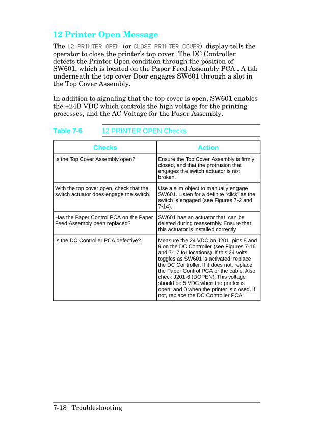
12 Printer Open Message The 12 PRINTER OPEN (or CLOSE PRINTER COVER) display tells theoperator to close the printer’s top cover. The DC Controllerdetects the Printer Open condition through the position ofSW601, which is located on the Paper Feed Assembly PCA . A tabunderneath the top cover Door engages SW601 through a slot inthe Top Cover Assembly.
In addition to signaling that the top cover is open, SW601 enablesthe +24B VDC which controls the high voltage for the printingprocesses, and the AC Voltage for the Fuser Assembly.
Checks Action
Is the Top Cover Assembly open? Ensure the Top Cover Assembly is firmlyclosed, and that the protrusion thatengages the switch actuator is notbroken.
With the top cover open, check that theswitch actuator does engage the switch.
Use a slim object to manually engageSW601. Listen for a definite “click” as theswitch is engaged (see Figures 7-2 and7-14).
Has the Paper Control PCA on the PaperFeed Assembly been replaced?
SW601 has an actuator that can bedeleted during reassembly. Ensure thatthis actuator is installed correctly.
Is the DC Controller PCA defective? Measure the 24 VDC on J201, pins 8 and9 on the DC Controller (see Figures 7-16and 7-17 for locations). If this 24 voltstoggles as SW601 is activated, replacethe DC Controller. If it does not, replacethe Paper Control PCA or the cable. Alsocheck J201-6 (DOPEN). This voltageshould be 5 VDC when the printer isopen, and 0 when the printer is closed. Ifnot, replace the DC Controller PCA.
Table 7-6 12 PRINTER OPEN Checks
7-18 Troubleshooting
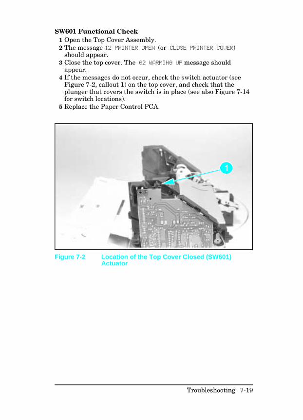
SW601 Functional Check 1 Open the Top Cover Assembly.2 The message 12 PRINTER OPEN (or CLOSE PRINTER COVER)
should appear.3 Close the top cover. The 02 WARMING UP message should
appear.4 If the messages do not occur, check the switch actuator (see
Figure 7-2, callout 1) on the top cover, and check that theplunger that covers the switch is in place (see also Figure 7-14for switch locations).
5 Replace the Paper Control PCA.
Figure 7-2 Location of the Top Cover Closed (SW601)Actuator
Troubleshooting 7-19
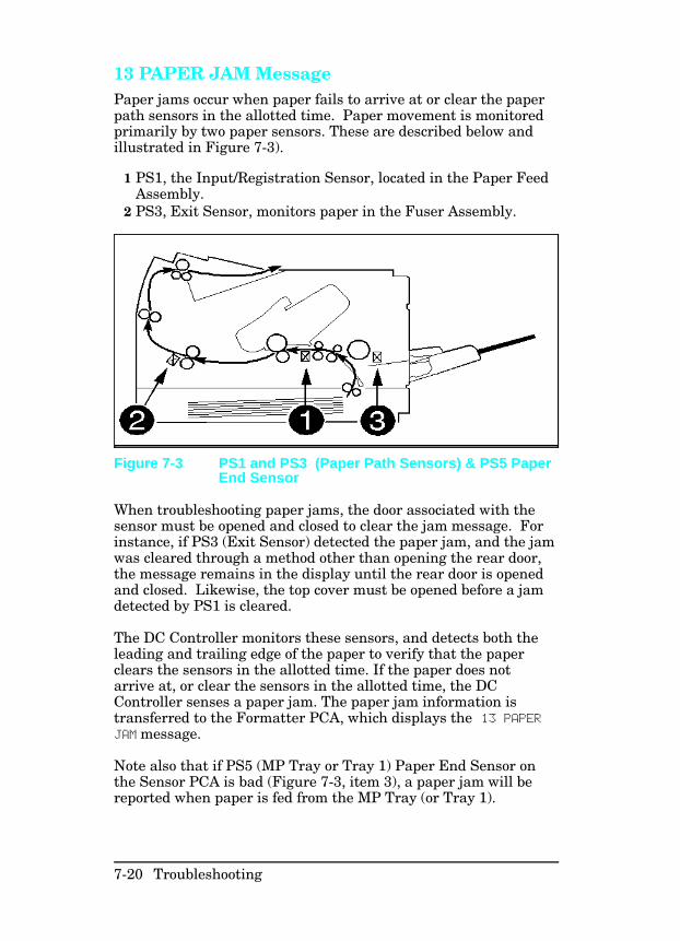
13 PAPER JAM Message Paper jams occur when paper fails to arrive at or clear the paperpath sensors in the allotted time. Paper movement is monitoredprimarily by two paper sensors. These are described below andillustrated in Figure 7-3).
1 PS1, the Input/Registration Sensor, located in the Paper FeedAssembly.
2 PS3, Exit Sensor, monitors paper in the Fuser Assembly.
When troubleshooting paper jams, the door associated with thesensor must be opened and closed to clear the jam message. Forinstance, if PS3 (Exit Sensor) detected the paper jam, and the jamwas cleared through a method other than opening the rear door,the message remains in the display until the rear door is openedand closed. Likewise, the top cover must be opened before a jamdetected by PS1 is cleared.
The DC Controller monitors these sensors, and detects both theleading and trailing edge of the paper to verify that the paperclears the sensors in the allotted time. If the paper does notarrive at, or clear the sensors in the allotted time, the DCController senses a paper jam. The paper jam information istransferred to the Formatter PCA, which displays the 13 PAPERJAM message.
Note also that if PS5 (MP Tray or Tray 1) Paper End Sensor onthe Sensor PCA is bad (Figure 7-3, item 3), a paper jam will bereported when paper is fed from the MP Tray (or Tray 1).
Figure 7-3 PS1 and PS3 (Paper Path Sensors) & PS5 PaperEnd Sensor
7-20 Troubleshooting
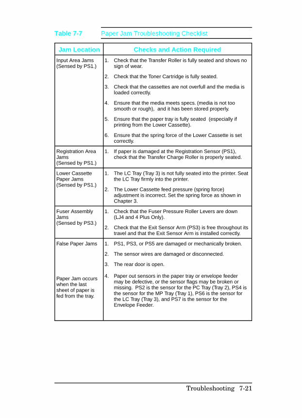
Jam Location Checks and Action Required
Input Area Jams(Sensed by PS1.)
1. Check that the Transfer Roller is fully seated and shows nosign of wear.
2. Check that the Toner Cartridge is fully seated.
3. Check that the cassettes are not overfull and the media isloaded correctly.
4. Ensure that the media meets specs. (media is not toosmooth or rough), and it has been stored properly.
5. Ensure that the paper tray is fully seated (especially ifprinting from the Lower Cassette).
6. Ensure that the spring force of the Lower Cassette is setcorrectly.
Registration AreaJams(Sensed by PS1.)
1. If paper is damaged at the Registration Sensor (PS1),check that the Transfer Charge Roller is properly seated.
Lower CassettePaper Jams(Sensed by PS1.)
1. The LC Tray (Tray 3) is not fully seated into the printer. Seatthe LC Tray firmly into the printer.
2. The Lower Cassette feed pressure (spring force)adjustment is incorrect. Set the spring force as shown inChapter 3.
Fuser AssemblyJams(Sensed by PS3.)
1. Check that the Fuser Pressure Roller Levers are down(LJ4 and 4 Plus Only).
2. Check that the Exit Sensor Arm (PS3) is free throughout itstravel and that the Exit Sensor Arm is installed correctly.
False Paper Jams
Paper Jam occurswhen the lastsheet of paper isfed from the tray.
1. PS1, PS3, or PS5 are damaged or mechanically broken.
2. The sensor wires are damaged or disconnected.
3.
4.
The rear door is open.
Paper out sensors in the paper tray or envelope feedermay be defective, or the sensor flags may be broken ormissing. PS2 is the sensor for the PC Tray (Tray 2), PS4 isthe sensor for the MP Tray (Tray 1), PS6 is the sensor forthe LC Tray (Tray 3), and PS7 is the sensor for theEnvelope Feeder.
Table 7-7 Paper Jam Troubleshooting Checklist
Troubleshooting 7-21
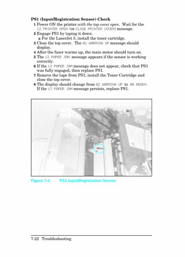
PS1 (Input/Registration Sensor) Check1 Power ON the printer with the top cover open. Wait for the12 PRINTER OPEN (or CLOSE PRINTER COVER) message.
2 Engage PS1 by taping it down.a For the LaserJet 5, install the toner cartridge.
3 Close the top cover. The 02 WARMING UP message shoulddisplay.
4 After the fuser warms up, the main motor should turn on.5 The 13 PAPER JAM message appears if the sensor is working
correctly. 6 If the 13 PAPER JAM message does not appear, check that PS1
was fully engaged, then replace PS1.7 Remove the tape from PS1, install the Toner Cartridge and
close the top cover.8 The display should change from 02 WARMING UP to 00 READY.
If the 13 PAPER JAM message persists, replace PS1.
Figure 7-4 PS1 Input/Registration Sensor
7-22 Troubleshooting
PS3 (Exit Sensor) Check1 Open the rear door (cover) of the printer.2 The display should read 13 PAPER JAM (or REMOVE PAPER JAM)
immediately after the door is opened.3 Close the rear cover. The display should change from02 WARMING UP to 00 READY. a If the 00 READY message does not appear, check that the
rear door is not damaged, and the the door closes andlatches properly.
b If the PAPER JAM message does not appear, replace PS3.
Pickup Motor Functional Test (M2) There is not a good method with which to access the test pointsaround the Pickup Motor (M2) circuit. Therefore, whentroubleshooting Pickup Motor failures, perform the following inthe order listed (see Figures 7-11 and 7-12 for componentlocation).
1 Reseat J601 and J602 on the Paper Control PCA. 2 Reseat J201 on the DC Controller. Reseat J703 on the Sensor
PCA.3 Verify that the Paper Control PCA and the Sensor PCA are
firmly seated into one another.4 Replace the Pickup Motor.5 Replace the Paper Control PCA.6 Replace the Sensor PCA.
Troubleshooting 7-23
Lower Cassette Functional Check When troubleshooting a Lower Cassette failure, always prove thefailure by removing the Lower Cassette from the printer. Next,test the printer’s ability to move and print media satisfactorilywithout the Lower Cassette installed.
The Lower Cassette is a field-serviceable item. The procedures forremoving and replacing the Lower Cassette components are inChapter 6. Replacement parts for the Lower Cassette Assemblyare listed in Chapter 8.
After the failure has been associated with the Lower CassetteAssembly, perform the following in the order given. Test therepair after each replacement.
1 Reseat all connectors in Lower Cassette.2 Replace the Lower Cassette Pickup Motor.3 Replace the Paper Control PCA.4 Replace the DC Controller.
7-24 Troubleshooting
14 NO EP CART Message The printer detects the presence of the Toner Cartridge and thelevel of toner present in the cartridge through the condition of theANTIN signal. The ANTIN signal becomes part of the serial datastream used to communicate with the DC Controller (see Figure7-5 for cartridge components). Troubleshoot the 14 NO EP CART(or INSTALL TONER CARTRIDGE) message as follows:
1 Reseat the Toner Cartridge. Try a new or known good TonerCartridge.
2 Check the High Voltage Contacts for damage. If the contactsare dirty or damaged, clean the contacts after the repair.
3 Replace the High Voltage Power Supply. 4 Check and reseat the HVPS cable.5 Replace the DC Controller.
16 Toner Low Message The TONER LOW message results as the level of toner in thecartridge cavity falls past the minimum level. The level is sensedby a mechanism similar to an antenna, which detects the ACDeveloper Bias Voltage applied to the developer mixture. If the TONER LOW message cannot be cleared by shaking or replacing theToner Cartridge, perform the steps listed for troubleshooting the14 NO EP CART message.
Troubleshooting 7-25
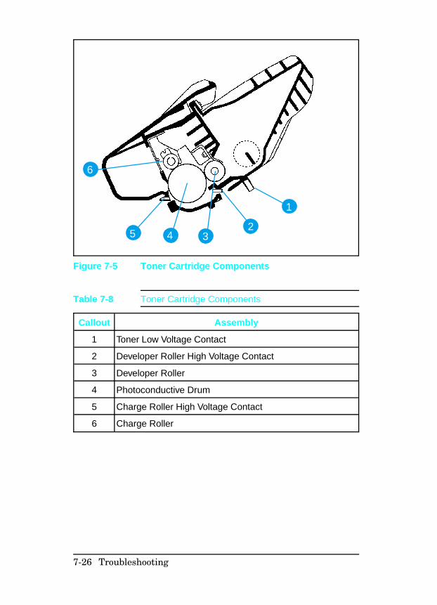
1
245
6
3
Figure 7-5 Toner Cartridge Components
Callout Assembly
1 Toner Low Voltage Contact
2 Developer Roller High Voltage Contact
3 Developer Roller
4 Photoconductive Drum
5 Charge Roller High Voltage Contact
6 Charge Roller
Table 7-8 Toner Cartridge Components
7-26 Troubleshooting
41.X ERROR Message A 41.X ERROR (misprint) indicates that a temporary malfunctionhas occurred with the print engine (NOT a Formatter error).Occasional occurrences of this message can be expected. However,persistent 41 ERROR messages indicate a problem requiringattention.
The 41.X ERROR is usually accompanied by a blank, or partiallyprinted page. Pressing the [Continue] (or Go) key re-prints thepage, and continues the print job.
A 41 ERROR occurs due to the following conditions:
• Incorrect Universal Tray Switch setting. Set the UniversalTray and the Lower Cassette Tray paper size as shown inChapter 3.
• Wrong size paper in tray. Check that the Universal Tray,and/or the Lower Cassette settings match the installed paper.
• An unstable or temporary loss of the Beam Detect pulse. Thisproblem normally is accompanied by a partially printed page,often with thin horizontal black lines, deformed characters, orsolid black areas. Loss of the Beam Detect pulse for more than2 seconds results in a 51 ERROR condition.
• Paper reaching the Input Paper Sensor (PS1) before it isexpected. This is accompanied by a blank page. This normallyis due to paper feed problems.
Proceed as directed in the following table.
Troubleshooting 7-27
Error Message Recommended Action
41.1 ERROR
Noisy Vertical Sync (VS)Reseat all connectors on the DC Controller, the LaserDrive PCA, the Scanner Connector and the Beam DetectConnector.
41.2 ERROR
Beam Detect (BD)weak or unstable.
Reseat all connectors on the DC Controller. Also check theLaser Scanning Assembly connections.
41.3 ERROR
Paper Multifeed1. Incorrect size selection on the cassette.
2. One of the cassettes is overfull. Remove the extrapaper from the overfull cassette.
3. Check the paper for edge damage. Improperly cutedges can lock together causing multi-feeds.
4.
5.
Check that the pickup rollers and separation pad arenot worn. Replace the rollers and pad as a set ifnecessary. Ensure that the corners of the paper aretucked in the tray’s retainers.
Check the paper tension adjustment on the optionalLower Cassette, if attached. Refer to procedure inChapter 3.
41.4 ERROR
Vertical Sync Late (VS)Signal
Reseat the DC Controller and Formatter PCA Connections.
41.5 ERROR
Undetermined CauseReseat the DC Controller and Formatter PCA connections.
See Figures 7-11 through 7-17 for connector locations.
Table 7-9 41.X ERROR Checks
7-28 Troubleshooting
50 SERVICE Error - Fuser Malfunction
W a r n i n g The Fuser Assembly is HOT. Allow the assemblytime to cool before servicing.
The purpose of the fusing system is to maintain a constanttemperature on the fuser roller. A high intensity fusing lamp,located inside the fuser roller, provides the high temperaturerequired for the fusing process. While the printer is in standbymode, a temperature of approximately 172° C is maintained onthe fuser roller. While the printer is in printing mode, atemperature of around 183° C is maintained.
The main components of the Fuser Assembly are the fusing lampand its associated fusing and pressure rollers, a thermistor,thermoprotector, and the AC controller/safety circuitry in the ACPower Supply. The fusing lamp is a specially designed 460 watt(220V), or 500 watt (115V) halogen lamp that operates at linevoltage. The thermistor is a resistor whose value changes withtemperature. At room temperature the resistance value of thethermistor should be between 180k ohms and 280k ohms.Thethermoprotector is a switch designed for over-temperatureprotection, and opens when the temperature reaches 230° C. Thethermoprotector will not reset when the fuser cools. It may benecessary to replace the thermoprotector or fuser assembly if thethermoprotector opens.
The following conditions result in a fusing error:
1 Unable to maintain a temperature above approximately 180° C.
2 A temperature above 230° C.3 A condition wherein a temperature of 165° C is NOT reached
within 90 seconds after power-up.
N o t e If a 50 SERVICE error message is displayed, turnthe printer OFF for at least 10 minutes. Failureto wait the full 10 minutes before turning theprinter ON results in a continuation of the errormessage and the shutting off of the fuser lampcurrent during this time, though the source of theerror may have already been resolved.
Troubleshooting 7-29
N o t e The 50 SERVICE error message can be clearedimmediately by shorting the C202 leads on theHP LaserJet 4/4M (or the C205 leads on the HPLaserJet 4 Plus/4M Plus/5/5M/5N) on the DCController. Remove the Formatter PCA to accessthe DC Controller as shown in Chapter 6.
Checks Action
Is the Fuser Assembly correctlyseated?
Reseat the Fuser Assembly. Allowadequate time for the error message toclear (10 minutes) and turn the printerON.
Is the Fuser Bulb/ Thermoswitch open?
1.
2.
The fuser bulb and thermoswitch arewired in series. To check if one or theother is defective, perform the following:
Remove the Fuser Assembly from theprinter.
Use an ohmmeter and measure thecontinuity between pins (see Figure7-6, callout 1). It should read about 2ohms (about 4 ohms for the 220 voltfuser). If an open condition is detected,either the fusing bulb or thethermoswitch is defective. Replace thedefective component (refer to Chapter6) or replace the complete FuserAssembly.
Is the Thermistor defective? 1.
2.
Remove the Fuser Assembly and let itcool to room temperature.
Use an ohmmeter and measure theresistance between pins (see Figure7-6, callout 2) It should read about 220K ohms +/- 40 K ohms at ambientroom temperature. If the thermistor iseither open or shorted, replace thethermistor (refer to Chapter 6) or thecomplete Fuser Assembly.
Does the error persist? 1.
2.
Verify all cabling is correct.
Replace the following components inthe order given: Power Supply Assembly DC Controller PCA
See Figure 7-11 for Fuser Assembly location and Chapter 6 forremoval and replacement, as necessary.
Table 7-10 50 SERVICE Fuser Malfunction Checks
7-30 Troubleshooting
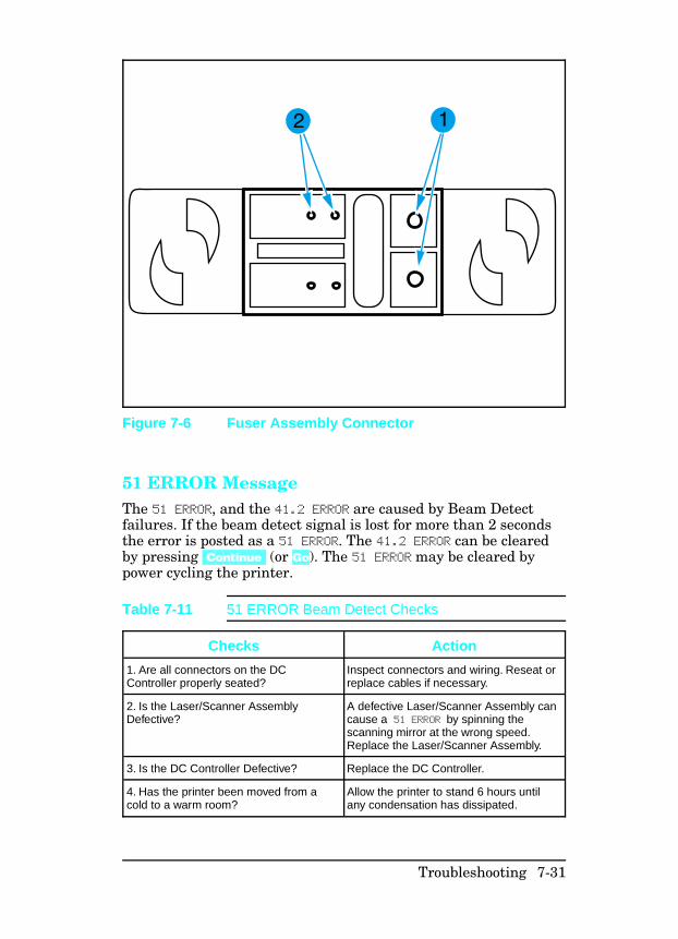
51 ERROR Message The 51 ERROR, and the 41.2 ERROR are caused by Beam Detectfailures. If the beam detect signal is lost for more than 2 secondsthe error is posted as a 51 ERROR. The 41.2 ERROR can be clearedby pressing [Continue] (or Go). The 51 ERROR may be cleared bypower cycling the printer.
Figure 7-6 Fuser Assembly Connector
Checks Action
1. Are all connectors on the DCController properly seated?
Inspect connectors and wiring. Reseat orreplace cables if necessary.
2. Is the Laser/Scanner AssemblyDefective?
A defective Laser/Scanner Assembly cancause a 51 ERROR by spinning thescanning mirror at the wrong speed.Replace the Laser/Scanner Assembly.
3. Is the DC Controller Defective? Replace the DC Controller.
4. Has the printer been moved from acold to a warm room?
Allow the printer to stand 6 hours untilany condensation has dissipated.
Table 7-11 51 ERROR Beam Detect Checks
Troubleshooting 7-31
52 ERROR Scanner Malfunction The scanner motor is a flat, brushless, DC motor. Motor operationis completely controlled by the DC Controller.
The scanner motor is enabled when the printer is powered-up(during the printer’s power-on self test), or whenever the PRINTcommand is received by the Formatter PCA. The scanner motormakes a distinctive sound when starting. The sound can bedescribed as a “variable pitch whirring” sound. Listen for thesound of the scanner motor when troubleshooting the 52 ERROR.
Laser/Scanner Assembly Functional Checks Initiate a Self Test. As the test begins, listen for the sound of thescanner motor. If the motor cannot be heard, perform thefollowing in the order given:
1 Check the Laser/Scanner and the Power Supply cables.Replace if necessary.
2 Replace the Laser/Scanner Assembly. 3 Replace the DC Controller.
7-32 Troubleshooting
57 (or 57.1) SERVICE Message (Main MotorFailure) The 57 SERVICE indicates that the DC Controller PCA detected ageneral motor failure. The Main Motor drives all movingcomponents in the printing process. The Main Motor is a 4-phase,DC servo motor controlled by the DC Controller PCA.
The formatter detects a Main Motor failure when:
• The Main Motor does not come up to speed within one secondof receiving drive voltage.
• The Main Motor deviates from the correct speed for one secondafter reaching the correct speed.
Main Motor Functional Checks
• Inspect the gear train for debris that would block the freeoperation of the gears.
• Check the gears in the Toner Cartridge for wear and binding.• Reseat J211 (or J214 on the HP LaserJet 4 Plus/4M Plus) on
the DC Controller PCA, and the main connector on the MainMotor Assembly. Refer to Figures 7-16 and 7-17 for the DCController PCA connector locations.
• If the problem persists, check that the +24B Voltage is presenton the DC Controller. If the voltage is not present, replace theDC Controller. If the voltage is present, and the motor doesnot rotate, replace the Main Motor Assembly (see Figure 7-11for location).
Troubleshooting 7-33
58 (or 57.2) SERVICE (Fan Failure) The 58 SERVICE indicates that the DC Controller detected afailure in the Exhaust Fan (FM1) in the printer or the optionalduplexer. When troubleshooting this problem, perform thefollowing steps in the order given.
1 Check that the fan is mounted correctly in its shroud.2 Check that the fan blades are not blocked.3 Check that the Cooling Fan connector is firmly seated on the
DC Controller (see Figure 7-16 or Figure 7-17 for location).If the above checks are satisfactory, replace the fan.
N o t e Verify the direction of air flow. Air should blowout of the printer.
7-34 Troubleshooting
Image Defect Summary
The quality of the printer’s output is subject to the judgment ofthe user. This section of the manual helps you define printquality defects, and understand what factors affect print quality.
The print samples shown in the following figures illustrate someprint quality defects. Keep copies of print quality defectsencountered in the field with an explanation of their causes forfuture reference.
The image defects listed below are covered in the following tables.(For major assembly, connector, and switch locations, see Figures7-11 through 7-18 later in this chapter.)
• Black Pages. • Any Faint Print Condition• Faulty Registration• Vertical White Streaks. • Right-hand Image Missing. • Small Print Voids• Random Horizontal Black Lines• Repetitive Defects. • Smeared Print/Improper Fusing.• Distorted Print.• Black Pages with Horizontal White Strips.• Image Skew.• Improperly Sized Image.• Vertical Dark Streaks.• Large Print Voids.• Background Scatter.• White or Blank Pages.
Troubleshooting 7-35
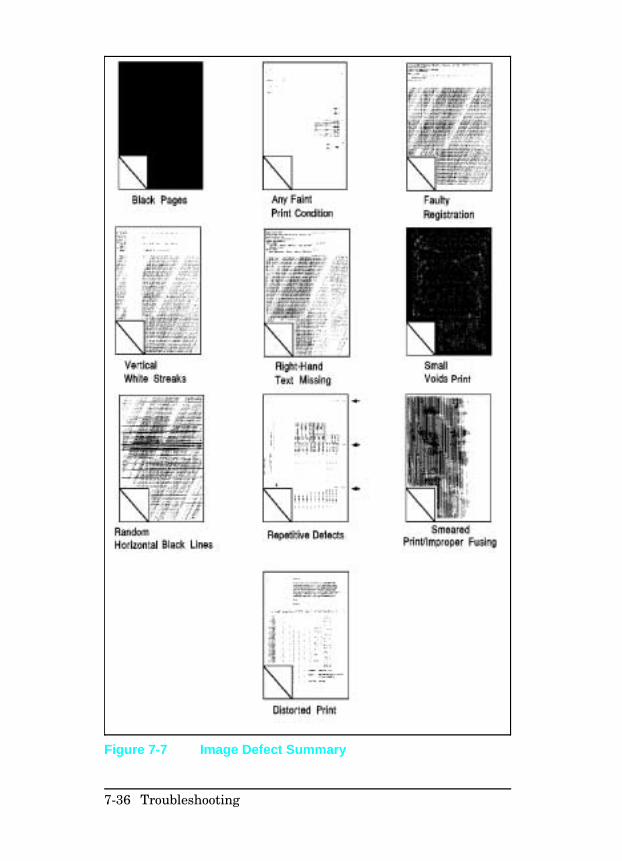
Figure 7-7 Image Defect Summary
7-36 Troubleshooting
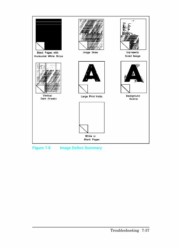
Figure 7-8 Image Defect Summary
Troubleshooting 7-37
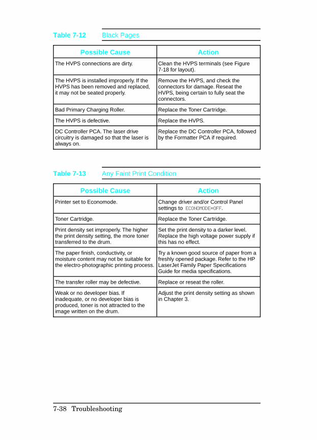
Possible Cause Action
The HVPS connections are dirty. Clean the HVPS terminals (see Figure7-18 for layout).
The HVPS is installed improperly. If theHVPS has been removed and replaced,it may not be seated properly.
Remove the HVPS, and check theconnectors for damage. Reseat theHVPS, being certain to fully seat theconnectors.
Bad Primary Charging Roller. Replace the Toner Cartridge.
The HVPS is defective. Replace the HVPS.
DC Controller PCA. The laser drivecircuitry is damaged so that the laser isalways on.
Replace the DC Controller PCA, followedby the Formatter PCA if required.
Table 7-12 Black Pages
Possible Cause Action
Printer set to Economode. Change driver and/or Control Panelsettings to ECONOMODE=OFF.
Toner Cartridge. Replace the Toner Cartridge.
Print density set improperly. The higherthe print density setting, the more tonertransferred to the drum.
Set the print density to a darker level.Replace the high voltage power supply ifthis has no effect.
The paper finish, conductivity, ormoisture content may not be suitable forthe electro-photographic printing process.
Try a known good source of paper from afreshly opened package. Refer to the HPLaserJet Family Paper SpecificationsGuide for media specifications.
The transfer roller may be defective. Replace or reseat the roller.
Weak or no developer bias. Ifinadequate, or no developer bias isproduced, toner is not attracted to theimage written on the drum.
Adjust the print density setting as shownin Chapter 3.
Table 7-13 Any Faint Print Condition
7-38 Troubleshooting
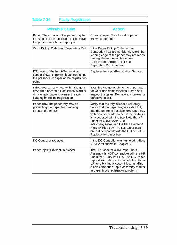
Possible Cause Action
Paper. The surface of the paper may betoo smooth for the pickup roller to movethe paper through the paper path.
Change paper. Try a brand of paperknown to be good.
Worn Pickup Roller and Separation Pad. If the Paper Pickup Roller, or theSeparation Pad are sufficiently worn, theleading edge of the paper may not reachthe registration assembly in time.Replace the Pickup Roller andSeparation Pad together.
PS1 faulty. If the Input/Registrationsensor (PS1) is broken, it can not sensethe presence of paper at the registrationpoint.
Replace the Input/Registration Sensor.
Drive Gears. If any gear within the geardrive train becomes excessively worn ordirty, erratic paper movement results,causing image misregistration.
Examine the gears along the paper pathfor wear and contamination. Clean andinspect the gears. Replace any broken ordefective gears.
Paper Tray. The paper tray may bepreventing the paper from movingthrough the printer.
Verify that the tray is loaded correctly.Verify that the paper tray is seated fullyinto the printer. If possible, exchange traywith another printer to see if the problemis associated with the tray. Note the HPLaserJet 4/4M tray is NOTinterchangeable with the HP LaserJet 4Plus/4M Plus tray. The LJ5 paper traysare not compatible with the LJ4 or LJ4+.Replace the paper tray.
DC Controller replaced. If the DC Controller was replaced, adjustVR202 as shown in Chapter 6.
Paper Input Assembly replaced. The HP LaserJet 4/4M Paper InputAssembly is NOT compatible with the HPLaserJet 4 Plus/4M Plus. The LJ5 PaperInput Assembly is not compatible with theLJ4 or LJ4+ Input Assemblies. Installinga non-compatible Input Assembly resultsin paper input registration problems.
Table 7-14 Faulty Registration
Troubleshooting 7-39
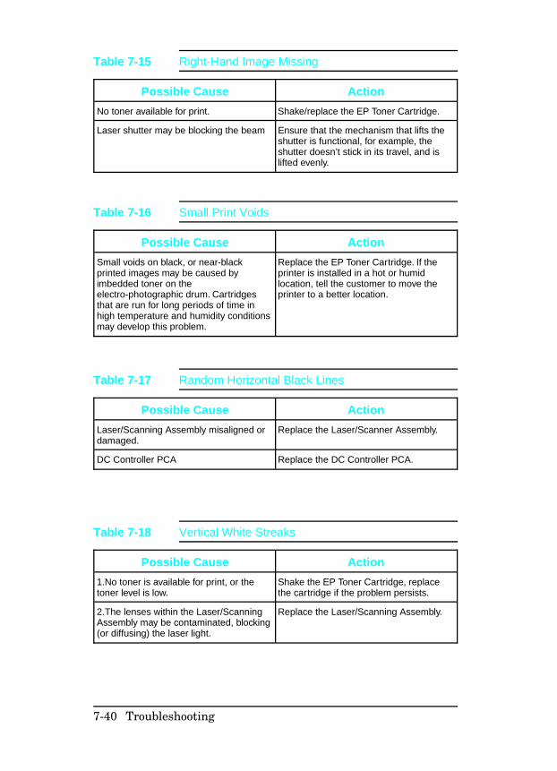
Possible Cause Action
No toner available for print. Shake/replace the EP Toner Cartridge.
Laser shutter may be blocking the beam Ensure that the mechanism that lifts theshutter is functional, for example, theshutter doesn’t stick in its travel, and islifted evenly.
Table 7-15 Right-Hand Image Missing
Possible Cause Action
Small voids on black, or near-blackprinted images may be caused byimbedded toner on theelectro-photographic drum. Cartridgesthat are run for long periods of time inhigh temperature and humidity conditionsmay develop this problem.
Replace the EP Toner Cartridge. If theprinter is installed in a hot or humidlocation, tell the customer to move theprinter to a better location.
Table 7-16 Small Print Voids
Possible Cause Action
Laser/Scanning Assembly misaligned ordamaged.
Replace the Laser/Scanner Assembly.
DC Controller PCA Replace the DC Controller PCA.
Table 7-17 Random Horizontal Black Lines
Possible Cause Action
1.No toner is available for print, or thetoner level is low.
Shake the EP Toner Cartridge, replacethe cartridge if the problem persists.
2.The lenses within the Laser/ScanningAssembly may be contaminated, blocking(or diffusing) the laser light.
Replace the Laser/Scanning Assembly.
Table 7-18 Vertical White Streaks
7-40 Troubleshooting
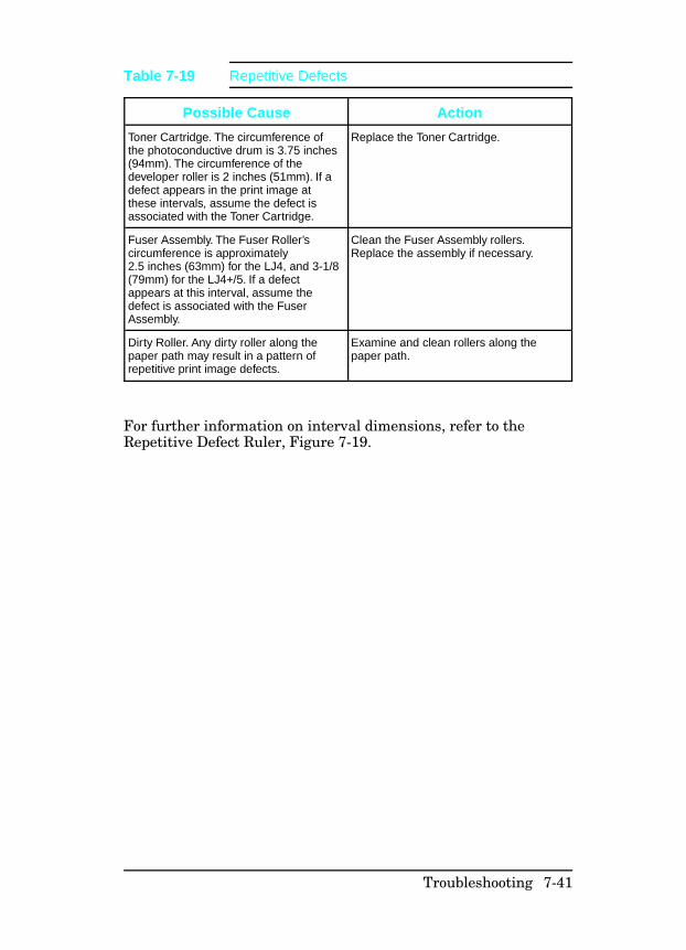
For further information on interval dimensions, refer to theRepetitive Defect Ruler, Figure 7-19.
Possible Cause Action
Toner Cartridge. The circumference ofthe photoconductive drum is 3.75 inches(94mm). The circumference of thedeveloper roller is 2 inches (51mm). If adefect appears in the print image atthese intervals, assume the defect isassociated with the Toner Cartridge.
Replace the Toner Cartridge.
Fuser Assembly. The Fuser Roller’scircumference is approximately2.5 inches (63mm) for the LJ4, and 3-1/8(79mm) for the LJ4+/5. If a defectappears at this interval, assume thedefect is associated with the FuserAssembly.
Clean the Fuser Assembly rollers.Replace the assembly if necessary.
Dirty Roller. Any dirty roller along thepaper path may result in a pattern ofrepetitive print image defects.
Examine and clean rollers along thepaper path.
Table 7-19 Repetitive Defects
Troubleshooting 7-41
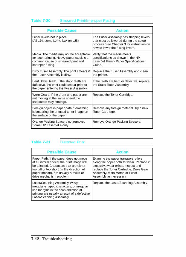
Possible Cause Action
Fuser levers not in place.(All LJ4, some LJ4+, N/A on LJ5)
The Fuser Assembly has shipping leversthat must be lowered during the setupprocess. See Chapter 3 for instruction onhow to lower the fusing levers.
Media. The media may not be acceptablefor laser printing. Heavy paper stock is acommon cause of smeared print andimproper fusing.
Verify that the media meetsspecifications as shown in the HPLaserJet Family Paper SpecificationsGuide.
Dirty Fuser Assembly. The print smears ifthe Fuser Assembly is dirty.
Replace the Fuser Assembly and cleanthe printer.
Bent Static Teeth. If the static teeth aredefective, the print could smear prior tothe paper entering the Fuser Assembly.
If the teeth are bent or defective, replacethe Static Teeth Assembly.
Worn Gears. If the drum and paper arenot moving at the same speed thecharacters may smudge.
Replace the Toner Cartridge.
Foreign object in paper path. Somethingis smearing the unfused toner image onthe surface of the paper.
Remove any foreign material. Try a newToner Cartridge.
Orange Packing Spacers not removed.Some HP LaserJet 4 only.
Remove Orange Packing Spacers.
Table 7-20 Smeared Print/Improper Fusing
Possible Cause Action
Paper Path. If the paper does not moveat a uniform speed, the print image willbe affected. Characters that are eithertoo tall or too short (in the direction ofpaper motion), are usually a result ofdrive mechanism problem.
Examine the paper transport rollersalong the paper path for wear. Replace ifexcessive wear exists. Inspect andreplace the Toner Cartridge, Drive GearAssembly, Main Motor, or FuserAssembly as necessary.
Laser/Scanning Assembly. Wavy,irregular-shaped characters, or irregularline margins in the scan direction ofprinting are usually a result of a defectiveLaser/Scanning Assembly.
Replace the Laser/Scanning Assembly.
Table 7-21 Distorted Print
7-42 Troubleshooting
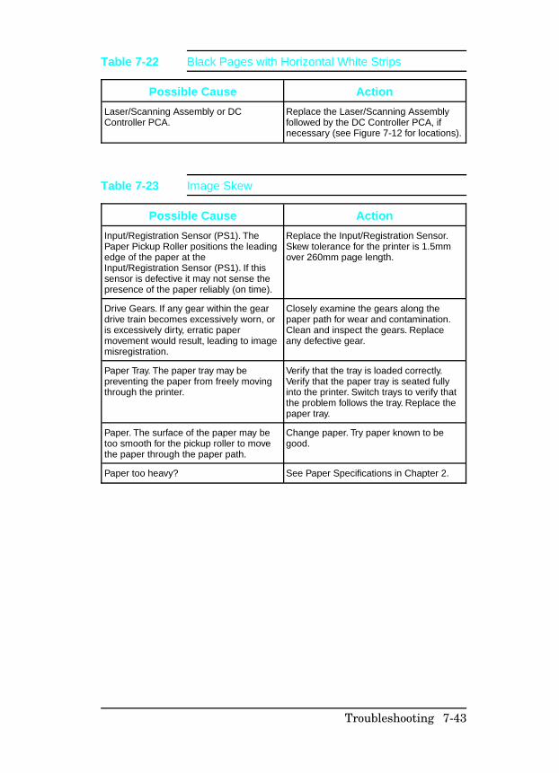
Possible Cause Action
Laser/Scanning Assembly or DCController PCA.
Replace the Laser/Scanning Assemblyfollowed by the DC Controller PCA, ifnecessary (see Figure 7-12 for locations).
Table 7-22 Black Pages with Horizontal White Strips
Possible Cause Action
Input/Registration Sensor (PS1). ThePaper Pickup Roller positions the leadingedge of the paper at theInput/Registration Sensor (PS1). If thissensor is defective it may not sense thepresence of the paper reliably (on time).
Replace the Input/Registration Sensor.Skew tolerance for the printer is 1.5mmover 260mm page length.
Drive Gears. If any gear within the geardrive train becomes excessively worn, oris excessively dirty, erratic papermovement would result, leading to imagemisregistration.
Closely examine the gears along thepaper path for wear and contamination.Clean and inspect the gears. Replaceany defective gear.
Paper Tray. The paper tray may bepreventing the paper from freely movingthrough the printer.
Verify that the tray is loaded correctly.Verify that the paper tray is seated fullyinto the printer. Switch trays to verify thatthe problem follows the tray. Replace thepaper tray.
Paper. The surface of the paper may betoo smooth for the pickup roller to movethe paper through the paper path.
Change paper. Try paper known to begood.
Paper too heavy? See Paper Specifications in Chapter 2.
Table 7-23 Image Skew
Troubleshooting 7-43
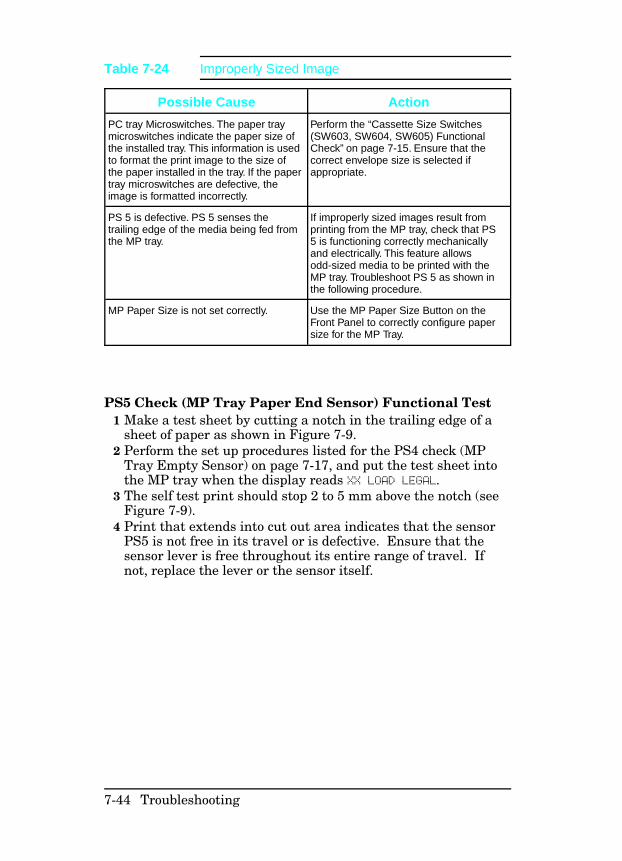
PS5 Check (MP Tray Paper End Sensor) Functional Test 1 Make a test sheet by cutting a notch in the trailing edge of a
sheet of paper as shown in Figure 7-9. 2 Perform the set up procedures listed for the PS4 check (MP
Tray Empty Sensor) on page 7-17, and put the test sheet intothe MP tray when the display reads XX LOAD LEGAL.
3 The self test print should stop 2 to 5 mm above the notch (seeFigure 7-9).
4 Print that extends into cut out area indicates that the sensorPS5 is not free in its travel or is defective. Ensure that thesensor lever is free throughout its entire range of travel. Ifnot, replace the lever or the sensor itself.
Possible Cause Action
PC tray Microswitches. The paper traymicroswitches indicate the paper size ofthe installed tray. This information is usedto format the print image to the size ofthe paper installed in the tray. If the papertray microswitches are defective, theimage is formatted incorrectly.
Perform the “Cassette Size Switches(SW603, SW604, SW605) FunctionalCheck” on page 7-15. Ensure that thecorrect envelope size is selected ifappropriate.
PS 5 is defective. PS 5 senses thetrailing edge of the media being fed fromthe MP tray.
If improperly sized images result fromprinting from the MP tray, check that PS5 is functioning correctly mechanicallyand electrically. This feature allowsodd-sized media to be printed with theMP tray. Troubleshoot PS 5 as shown inthe following procedure.
MP Paper Size is not set correctly. Use the MP Paper Size Button on theFront Panel to correctly configure papersize for the MP Tray.
Table 7-24 Improperly Sized Image
7-44 Troubleshooting
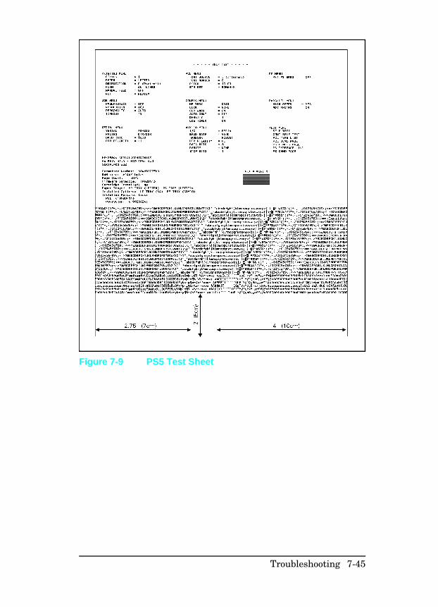
Figure 7-9 PS5 Test Sheet
Troubleshooting 7-45
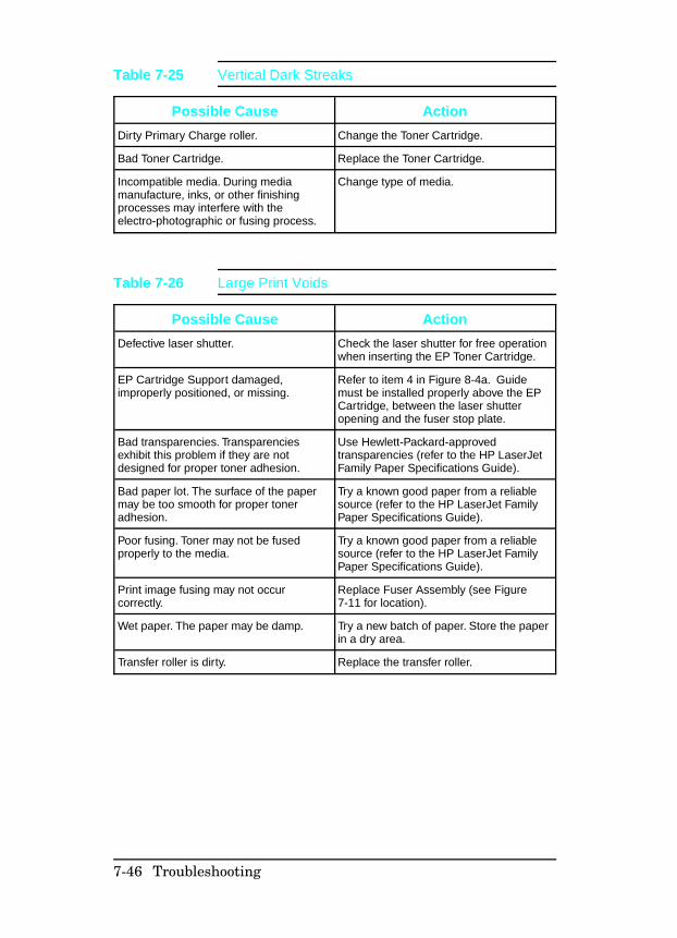
Possible Cause Action
Dirty Primary Charge roller. Change the Toner Cartridge.
Bad Toner Cartridge. Replace the Toner Cartridge.
Incompatible media. During mediamanufacture, inks, or other finishingprocesses may interfere with theelectro-photographic or fusing process.
Change type of media.
Table 7-25 Vertical Dark Streaks
Possible Cause Action
Defective laser shutter. Check the laser shutter for free operationwhen inserting the EP Toner Cartridge.
EP Cartridge Support damaged,improperly positioned, or missing.
Refer to item 4 in Figure 8-4a. Guidemust be installed properly above the EPCartridge, between the laser shutteropening and the fuser stop plate.
Bad transparencies. Transparenciesexhibit this problem if they are notdesigned for proper toner adhesion.
Use Hewlett-Packard-approvedtransparencies (refer to the HP LaserJetFamily Paper Specifications Guide).
Bad paper lot. The surface of the papermay be too smooth for proper toneradhesion.
Try a known good paper from a reliablesource (refer to the HP LaserJet FamilyPaper Specifications Guide).
Poor fusing. Toner may not be fusedproperly to the media.
Try a known good paper from a reliablesource (refer to the HP LaserJet FamilyPaper Specifications Guide).
Print image fusing may not occurcorrectly.
Replace Fuser Assembly (see Figure7-11 for location).
Wet paper. The paper may be damp. Try a new batch of paper. Store the paperin a dry area.
Transfer roller is dirty. Replace the transfer roller.
Table 7-26 Large Print Voids
7-46 Troubleshooting
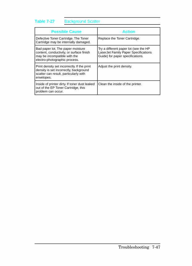
Possible Cause Action
Defective Toner Cartridge. The TonerCartridge may be internally damaged.
Replace the Toner Cartridge.
Bad paper lot. The paper moisturecontent, conductivity, or surface finishmay be incompatible with theelectro-photographic process.
Try a different paper lot (see the HPLaserJet Family Paper SpecificationsGuide) for paper specifications.
Print density set incorrectly. If the printdensity is set incorrectly, backgroundscatter can result, particularly withenvelopes.
Adjust the print density.
Inside of printer dirty. If toner dust leakedout of the EP Toner Cartridge, thisproblem can occur.
Clean the inside of the printer.
Table 7-27 Background Scatter
Troubleshooting 7-47
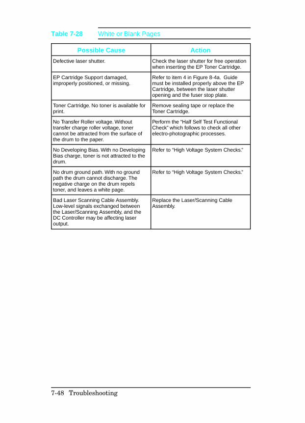
Possible Cause Action
Defective laser shutter. Check the laser shutter for free operationwhen inserting the EP Toner Cartridge.
EP Cartridge Support damaged,improperly positioned, or missing.
Refer to item 4 in Figure 8-4a. Guidemust be installed properly above the EPCartridge, between the laser shutteropening and the fuser stop plate.
Toner Cartridge. No toner is available forprint.
Remove sealing tape or replace theToner Cartridge.
No Transfer Roller voltage. Withouttransfer charge roller voltage, tonercannot be attracted from the surface ofthe drum to the paper.
Perform the “Half Self Test FunctionalCheck” which follows to check all otherelectro-photographic processes.
No Developing Bias. With no DevelopingBias charge, toner is not attracted to thedrum.
Refer to “High Voltage System Checks.”
No drum ground path. With no groundpath the drum cannot discharge. Thenegative charge on the drum repelstoner, and leaves a white page.
Refer to “High Voltage System Checks.”
Bad Laser Scanning Cable Assembly.Low-level signals exchanged betweenthe Laser/Scanning Assembly, and theDC Controller may be affecting laseroutput.
Replace the Laser/Scanning CableAssembly.
Table 7-28 White or Blank Pages
7-48 Troubleshooting
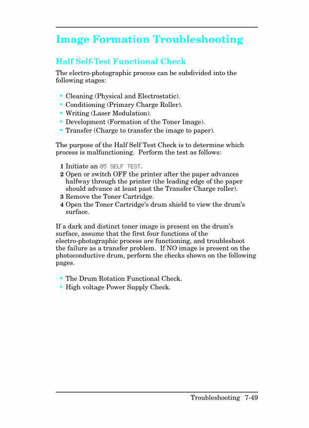
Image Formation Troubleshooting
Half Self-Test Functional Check The electro-photographic process can be subdivided into thefollowing stages:
• Cleaning (Physical and Electrostatic).• Conditioning (Primary Charge Roller).• Writing (Laser Modulation).• Development (Formation of the Toner Image).• Transfer (Charge to transfer the image to paper).
The purpose of the Half Self Test Check is to determine whichprocess is malfunctioning. Perform the test as follows:
1 Initiate an 05 SELF TEST. 2 Open or switch OFF the printer after the paper advances
halfway through the printer (the leading edge of the papershould advance at least past the Transfer Charge roller).
3 Remove the Toner Cartridge.4 Open the Toner Cartridge’s drum shield to view the drum’s
surface.
If a dark and distinct toner image is present on the drum’ssurface, assume that the first four functions of theelectro-photographic process are functioning, and troubleshootthe failure as a transfer problem. If NO image is present on thephotoconductive drum, perform the checks shown on the followingpages.
• The Drum Rotation Functional Check.• High voltage Power Supply Check.
Troubleshooting 7-49
Drum Rotation Functional Check The photoconductive drum, located in the Toner Cartridge, mustrotate for the print process to work. The photoconductive drumreceives its drive from the Main Motor gear train. To verifywhether the drum is rotating:
1 Open the printer’s Top Cover Assembly. 2 Remove the Toner Cartridge. Open the Toner Cartridge’s
drum shield (cover) to view the photoconductive drum.3 Mark the gear with a felt-tipped marker. Note the position of
the mark.4 Install the EP Toner Cartridge, and close the Top Cover. The
1-second startup sequence should rotate the drum enough tomove the mark. Open the printer, and inspect the drum.Verify that the mark moved.
If the mark did not move, inspect the gear train to ensure that itis meshing with the Toner Cartridge gears. If the drive gearsappear functional, and the drum does not move, replace the TonerCartridge.
N o t e This test is especially important if refilled TonerCartridges were used.
7-50 Troubleshooting
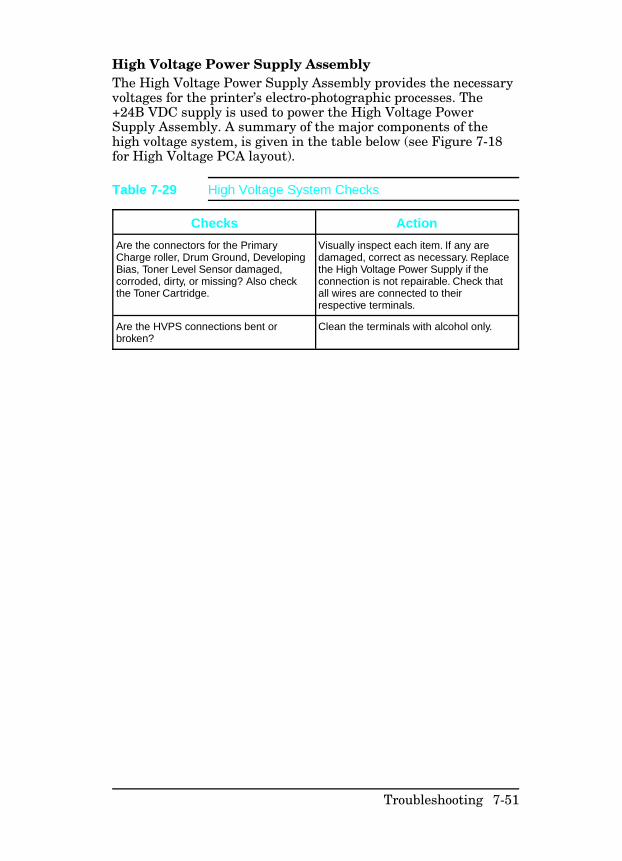
High Voltage Power Supply Assembly The High Voltage Power Supply Assembly provides the necessaryvoltages for the printer’s electro-photographic processes. The+24B VDC supply is used to power the High Voltage PowerSupply Assembly. A summary of the major components of thehigh voltage system, is given in the table below (see Figure 7-18for High Voltage PCA layout).
Checks Action
Are the connectors for the PrimaryCharge roller, Drum Ground, DevelopingBias, Toner Level Sensor damaged,corroded, dirty, or missing? Also checkthe Toner Cartridge.
Visually inspect each item. If any aredamaged, correct as necessary. Replacethe High Voltage Power Supply if theconnection is not repairable. Check thatall wires are connected to theirrespective terminals.
Are the HVPS connections bent orbroken?
Clean the terminals with alcohol only.
Table 7-29 High Voltage System Checks
Troubleshooting 7-51
Interface Troubleshooting
This section provides an overview of the printer interfacerequirements. Refer to Chapter 3 for detailed information aboutthe printer interfaces and configuration.
Communications Check
N o t e Communication problems are normally thecustomer’s responsibility. Time spent attemptingto resolve these problems may not be covered bythe product’s Hewlett-Packard warranty.
The Customer Service Center (CSC) is availableto the customer to help them through theseproblems. The CSC telephone number is:(208) 323-2551.
If the printer is not connected to an MS-DOS-based host, proceedto the Communications Checks table in this section.
Test Message After the printer is installed, verify communications between theprinter and the IBM-compatible computer. Enter the following atthe DOS prompt:
C:\DIR>LPT1 [Enter]
The printer should print a directory listing of the C:\ directory. Ifthe Communications Check fails, proceed as follows.
7-52 Troubleshooting
AUTOEXEC.BAT Standard Configurations
Parallel DOS Commands If the previous check did not produce the desired result, ensurethat the AUTOEXEC.BAT file contains the following statementsfor parallel interface communications:
MODE LPT1:,,P
For MS-DOS version 4.0 and above, enter:
MODE LPT1:,,B
N o t e This example assumes that you are using parallelprinter port LPT1. If you are using LPT2 orLPT3, replace LPT1 in the example with theappropriate printer port.
If the problem persists, proceed to Table 7-30 “CommunicationsChecks.”
Serial MS-DOS Commands Most IBM compatible computers default to a parallel printer port.To ensure that information is sent to your serial printer port, typethe following MS-DOS commands at your MS-DOS prompt, orinclude them in your AUTOEXEC.BAT file.
MODE COM1:9600,N,8,1,P
MODE LPT1:=COM1
For MS-DOS version 4.0, or above, enter:
MODE COM1:9600,N,8,1,B
MODE LPT1:=COM1
N o t e These examples assume that you are using serialprinter port COM1. If you are using COM2 orCOM3, replace COM1 with the appropriateprinter port.
If the problem persists, proceed with the following checks inTable 7-30.
Troubleshooting 7-53
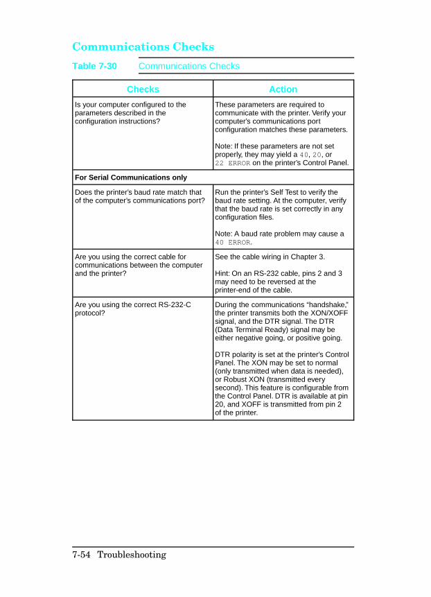
Communications Checks
Checks Action
Is your computer configured to theparameters described in theconfiguration instructions?
These parameters are required tocommunicate with the printer. Verify yourcomputer’s communications portconfiguration matches these parameters.
Note: If these parameters are not setproperly, they may yield a 40, 20, or22 ERROR on the printer’s Control Panel.
For Serial Communications only
Does the printer’s baud rate match thatof the computer’s communications port?
Run the printer’s Self Test to verify thebaud rate setting. At the computer, verifythat the baud rate is set correctly in anyconfiguration files.
Note: A baud rate problem may cause a40 ERROR.
Are you using the correct cable forcommunications between the computerand the printer?
See the cable wiring in Chapter 3.
Hint: On an RS-232 cable, pins 2 and 3may need to be reversed at theprinter-end of the cable.
Are you using the correct RS-232-Cprotocol?
During the communications “handshake,”the printer transmits both the XON/XOFFsignal, and the DTR signal. The DTR(Data Terminal Ready) signal may beeither negative going, or positive going.
DTR polarity is set at the printer’s ControlPanel. The XON may be set to normal(only transmitted when data is needed),or Robust XON (transmitted everysecond). This feature is configurable fromthe Control Panel. DTR is available at pin20, and XOFF is transmitted from pin 2of the printer.
Table 7-30 Communications Checks
7-54 Troubleshooting
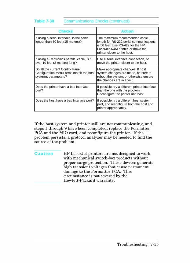
If the host system and printer still are not communicating, andsteps 1 through 9 have been completed, replace the FormatterPCA and the MIO card, and reconfigure the printer. If theproblem persists, a protocol analyzer may be needed to find thesource of the problem.
C a u t i o n HP LaserJet printers are not designed to workwith mechanical switch-box products withoutproper surge protection. These devices generatehigh transient voltages that cause permanentdamage to the Formatter PCA. Thiscircumstance is not covered by theHewlett-Packard warranty.
Checks Action
If using a serial interface, is the cablelonger than 50 feet (15 meters)?
The maximum recommended cablelength for RS-232 serial communicationsis 50 feet. Use RS-422 for the HPLaserJet 4/4M printer, or move theprinter closer to the host.
If using a Centronics parallel cable, is itover 10 feet (3 meters) long?
Use a serial interface connection, ormove the printer closer to the host.
Do all the current Control PanelConfiguration Menu items match the hostsystem’s parameters?
Make appropriate changes. If hostsystem changes are made, be sure toreboot the system, or otherwise ensurethe changes are in effect.
Does the printer have a bad interfaceport?
If possible, try a different printer interfacethan the one with the problem.Reconfigure the printer and host.
Does the host have a bad interface port? If possible, try a different host systemport, and reconfigure both the host andprinter appropriately.
Table 7-30 Communications Checks (continued)
Troubleshooting 7-55

MIO Troubleshooting
The Self Test Printout and explanation shown on the followingpages contain valuable information regarding the current statusof the MIO. Before attempting to troubleshoot a network problemor notifying your network consultant of a problem, always obtaina Self Test Printout.
Troubleshooting HintsThe JetDirect Card Status Block (see Figure 7-10, status block 2)indicates the functionality of the JetDirect Card. An I/O NOTREADY STATUS indicates a problem. A 2-digit error code followsthe message. Use the HP JetDirect Network InterfaceConfiguration Guide (P/N J2552-90001) for detailed explanationsof errors and suggested corrective action.
NETWORK STATISTICS, status block 3, indicates networkactivity. Bad packets, framing errors, unsendable packet andcollisions should be minimal. If unusually high numbers of thesestatistics occur, please advise the network administrator.
The various Network Operating Systems supported by theseprinters are indicated in status blocks 4, 5, 6, and 7. When thestatus is READY, the printer has successfully connected to thehost network server and is awaiting data. Other messagesindicate the printer is either still trying to successfully connect tothe network or a configuration problem has been encountered.Refer to the HP JetDirect Network Interface Configuration Guide(P/N J2552-90001) for detailed explanations of these messages.
7-56 Troubleshooting
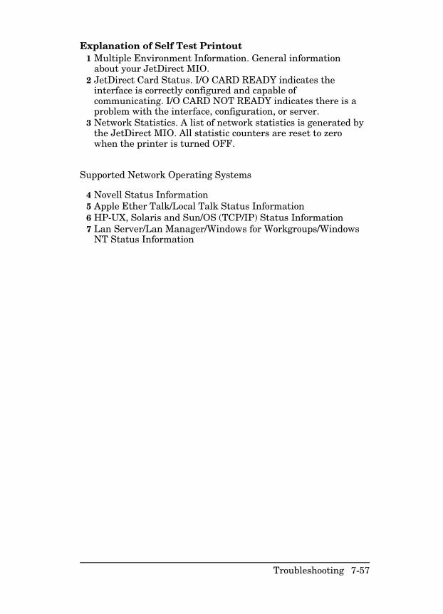
Explanation of Self Test Printout1 Multiple Environment Information. General information
about your JetDirect MIO.2 JetDirect Card Status. I/O CARD READY indicates the
interface is correctly configured and capable ofcommunicating. I/O CARD NOT READY indicates there is aproblem with the interface, configuration, or server.
3 Network Statistics. A list of network statistics is generated bythe JetDirect MIO. All statistic counters are reset to zerowhen the printer is turned OFF.
Supported Network Operating Systems
4 Novell Status Information5 Apple Ether Talk/Local Talk Status Information6 HP-UX, Solaris and Sun/OS (TCP/IP) Status Information7 Lan Server/Lan Manager/Windows for Workgroups/Windows
NT Status Information
Troubleshooting 7-57
Figure 7-10 MIO Staus Information on the Self Test Printout
7-58 Troubleshooting
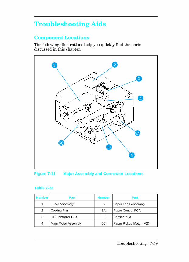
Troubleshooting Aids
Component LocationsThe following illustrations help you quickly find the partsdiscussed in this chapter.
1 2
3
4
5
5B
5A
5C
Figure 7-11 Major Assembly and Connector Locations
Number Part Number Part
1 Fuser Assembly 5 Paper Feed Assembly
2 Cooling Fan 5A Paper Control PCA
3 DC Controller PCA 5B Sensor PCA
4 Main Motor Assembly 5C Paper Pickup Motor (M2)
Table 7-31
Troubleshooting 7-59
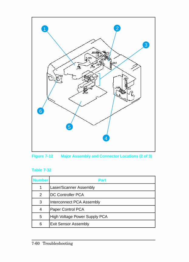
1 2
3
4
5
6
Figure 7-12 Major Assembly and Connector Locations (2 of 3)
Number Part
1 Laser/Scanner Assembly
2 DC Controller PCA
3 Interconnect PCA Assembly
4 Paper Control PCA
5 High Voltage Power Supply PCA
6 Exit Sensor Assembly
Table 7-32
7-60 Troubleshooting
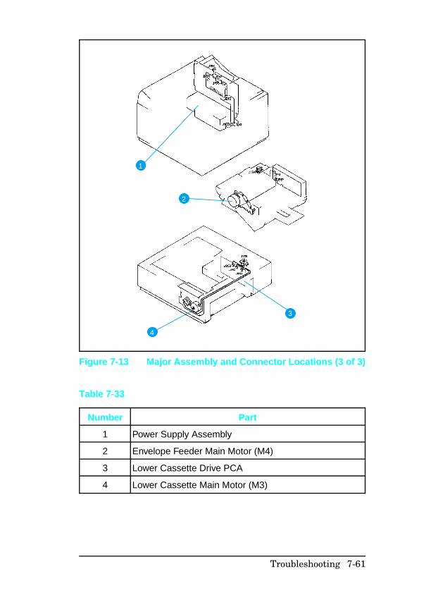
1
2
3
4
Figure 7-13 Major Assembly and Connector Locations (3 of 3)
Number Part
1 Power Supply Assembly
2 Envelope Feeder Main Motor (M4)
3 Lower Cassette Drive PCA
4 Lower Cassette Main Motor (M3)
Table 7-33
Troubleshooting 7-61
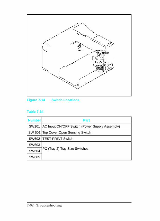
Figure 7-14 Switch Locations
Number Part
SW101 AC Input ON/OFF Switch (Power Supply Assembly)
SW 601 Top Cover Open Sensing Switch
SW602 TEST PRINT Switch
SW603PC (Tray 2) Tray Size Switches
SW604
SW605
Table 7-34
7-62 Troubleshooting
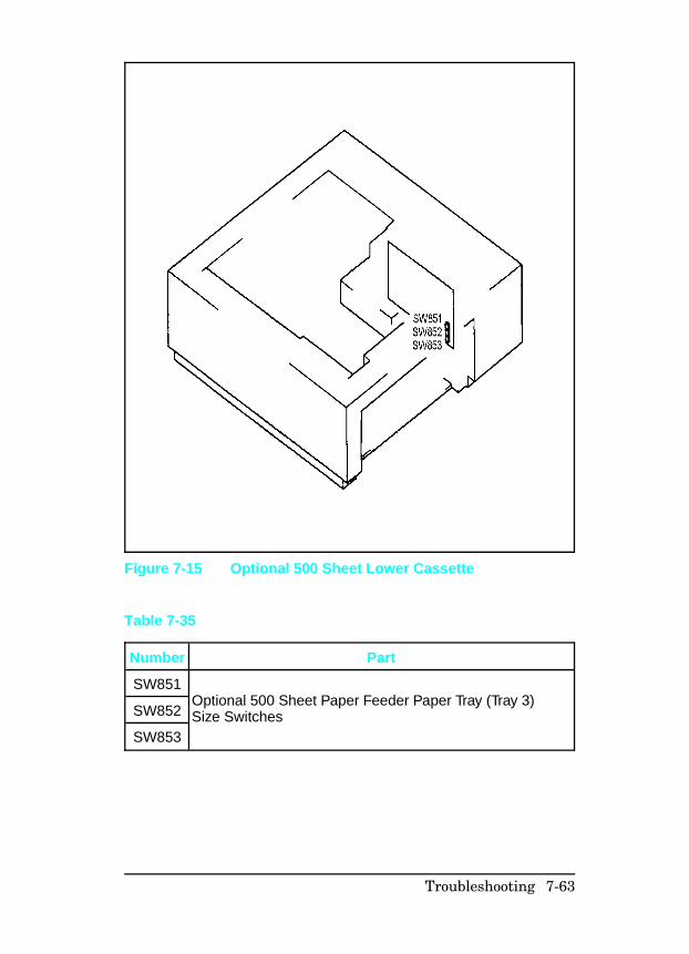
Figure 7-15 Optional 500 Sheet Lower Cassette
Number Part
SW851Optional 500 Sheet Paper Feeder Paper Tray (Tray 3)Size SwitchesSW852
SW853
Table 7-35
Troubleshooting 7-63
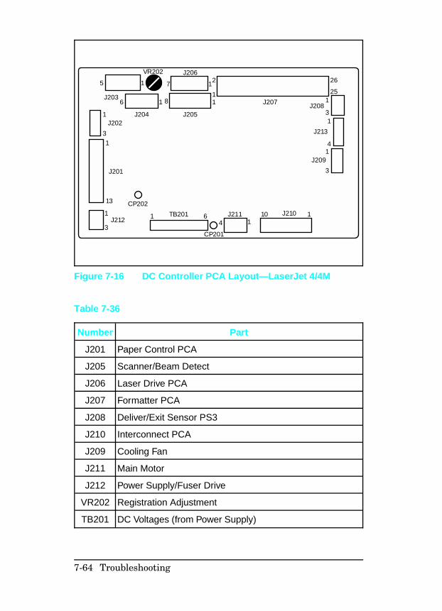
5
VR202 J206
J203
J204 J205
6 1 181
171 2
1
31
J202
J201
13
1
3J212
CP202
1 6TB201
CP201
J2114 1
10 1J210
3
1J209
4
13
125
26
J213
J208J207
Figure 7-16 DC Controller PCA Layout—LaserJet 4/4M
Number Part
J201 Paper Control PCA
J205 Scanner/Beam Detect
J206 Laser Drive PCA
J207 Formatter PCA
J208 Deliver/Exit Sensor PS3
J210 Interconnect PCA
J209 Cooling Fan
J211 Main Motor
J212 Power Supply/Fuser Drive
VR202 Registration Adjustment
TB201 DC Voltages (from Power Supply)
Table 7-36
7-64 Troubleshooting
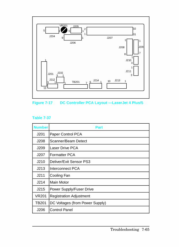
5
J204
1 5 1
19
2
1
J206
J205VR201
1
13
3 1 1 7
J201
J212
3 1J215
TB201 6 1J214 10 1J213
3
1J211
3J210
18
1 1
7
J209J208
J20731
32
Figure 7-17 DC Controller PCA Layout —LaserJet 4 Plus/5
Number Part
J201 Paper Control PCA
J208 Scanner/Beam Detect
J209 Laser Drive PCA
J207 Formatter PCA
J210 Deliver/Exit Sensor PS3
J213 Interconnect PCA
J211 Cooling Fan
J214 Main Motor
J215 Power Supply/Fuser Drive
VR201 Registration Adjustment
TB201 DC Voltages (from Power Supply)
J206 Control Panel
Table 7-37
Troubleshooting 7-65
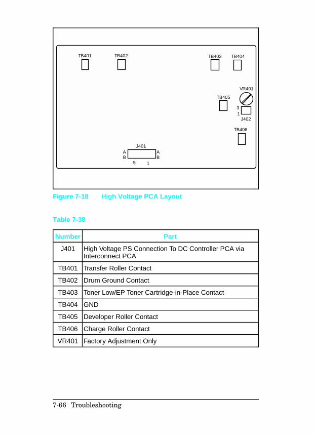
TB403 TB404
TB405
TB406
VR401
J402
31
J401
5 1
AB
AB
TB402TB401
Figure 7-18 High Voltage PCA Layout
Number Part
J401 High Voltage PS Connection To DC Controller PCA viaInterconnect PCA
TB401 Transfer Roller Contact
TB402 Drum Ground Contact
TB403 Toner Low/EP Toner Cartridge-in-Place Contact
TB404 GND
TB405 Developer Roller Contact
TB406 Charge Roller Contact
VR401 Factory Adjustment Only
Table 7-38
7-66 Troubleshooting
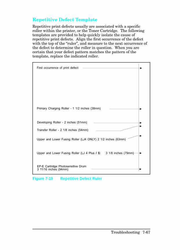
Repetitive Defect Template Repetitive print defects usually are associated with a specificroller within the printer, or the Toner Cartridge. The followingtemplates are provided to help quickly isolate the cause ofrepetitive print defects. Align the first occurrence of the defectwith the top of the “ruler”, and measure to the next occurrence ofthe defect to determine the roller in question. When you arecertain that your defect pattern matches the pattern of thetemplate, replace the indicated roller.
/ 5)
Figure 7-19 Repetitive Defect Ruler
Troubleshooting 7-67
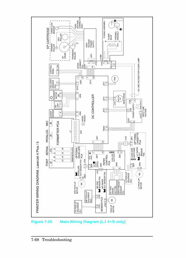
Figure 7-20 Main Wiring Diagram (LJ 4+/5 only)
7-68 Troubleshooting
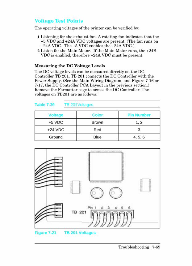
Voltage Test Points The operating voltages of the printer can be verified by:
1 Listening for the exhaust fan. A rotating fan indicates that the+5 VDC and +24A VDC voltages are present. (The fan runs on+24A VDC. The +5 VDC enables the +24A VDC.)
2 Listen for the Main Motor. If the Main Motor runs, the +24BVDC is enabled, therefore +24A VDC must be present.
Measuring the DC Voltage Levels The DC voltage levels can be measured directly on the DCController TB 201. TB 201 connects the DC Controller with thePower Supply. (See the Main Wiring Diagram, and Figure 7-16 or7-17, the DC Controller PCA Layout in the previous section.)Remove the Formatter cage to access the DC Controller. Thevoltages on TB201 are as follows:
Voltage Color Pin Number
+5 VDC Brown 1, 2
+24 VDC Red 3
Ground Blue 4, 5, 6
Table 7-39 TB 201Voltages
Figure 7-21 TB 201 Voltages
Troubleshooting 7-69

7-70 Troubleshooting
8
Parts and Diagrams
How To Use the Parts Lists
The figures in this chapter illustrate the major subassembliesand component parts of the HP LaserJet 4/4M, LaserJet 4 Plus/4M Plus, and LaserJet 5/5M/5N printers. When ordering anelectrical part, pay special attention that the part chosen has thecorrect voltage rating for the machine under repair.
Part numbers with no indicator in the Notes column are stockedand can be ordered through Hewlett-Packard’s Support MaterialsOrganization (SMO). Parts marked with an S in the Notes columnare special order parts which can be ordered through SMO butmay have an eight-week lead time.
An alphanumeric index referencing all part numbers is includedat the end of this chapter (see Parts List, page 8-40).
N o t e Not all parts are orderable. The parts listed arethe only orderable parts. Parts that have noreference designator or part number are notfield-replaceable and cannot be ordered throughSMO.
Figures referred to in the tables are placed before the tablethroughout the chapter.
Accessory Parts are listed on 8-33. This list includes such itemsas the MIO and SIMM cards.
Parts and Diagrams 8-1
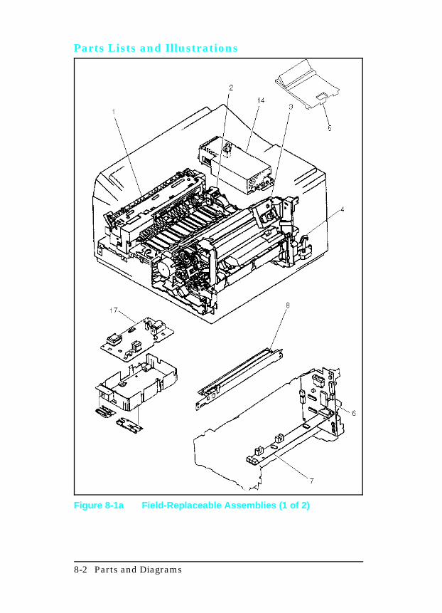
Parts Lists and Illustrations
Figure 8-1a Field-Replaceable Assemblies (1 of 2)
8-2 Parts and Diagrams
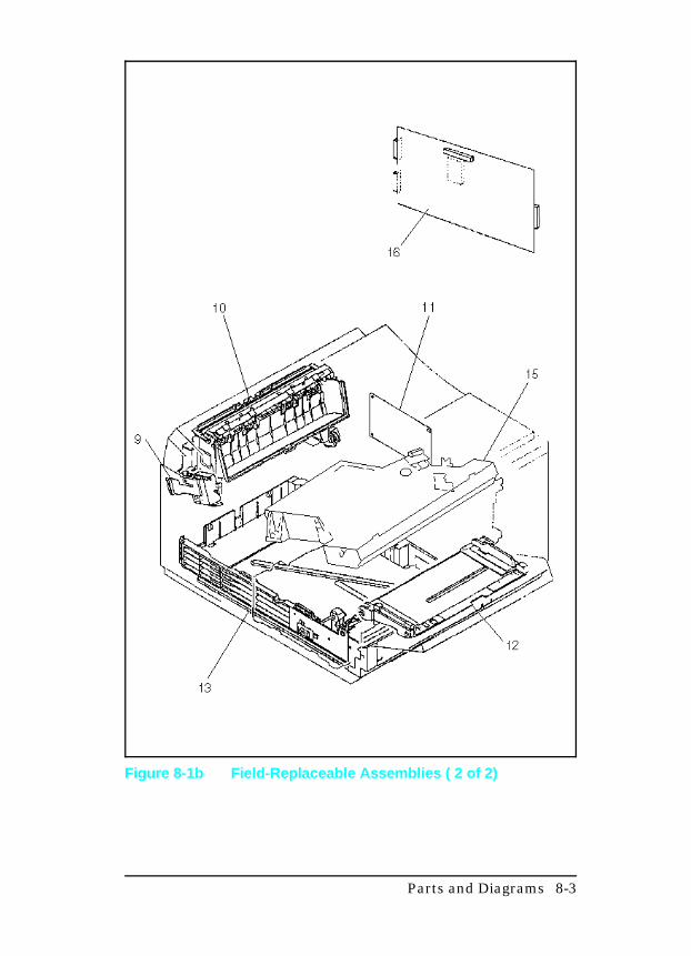
Figure 8-1b Field-Replaceable Assemblies ( 2 of 2)
Parts and Diagrams 8-3
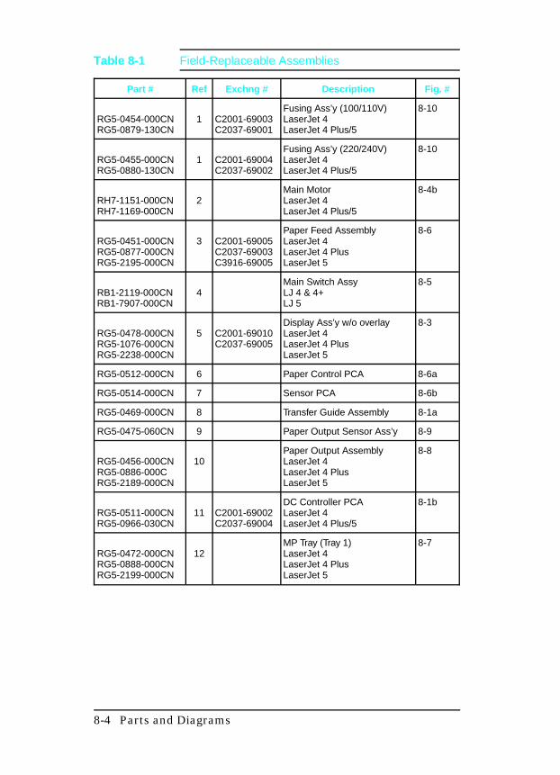
Part # Ref Exchng # Description Fig. #
RG5-0454-000CNRG5-0879-130CN
1 C2001-69003C2037-69001
Fusing Ass’y (100/110V)LaserJet 4 LaserJet 4 Plus/5
8-10
RG5-0455-000CNRG5-0880-130CN
1 C2001-69004C2037-69002
Fusing Ass’y (220/240V)LaserJet 4LaserJet 4 Plus/5
8-10
RH7-1151-000CNRH7-1169-000CN
2Main MotorLaserJet 4LaserJet 4 Plus/5
8-4b
RG5-0451-000CNRG5-0877-000CNRG5-2195-000CN
3 C2001-69005C2037-69003C3916-69005
Paper Feed AssemblyLaserJet 4LaserJet 4 PlusLaserJet 5
8-6
RB1-2119-000CNRB1-7907-000CN
4Main Switch AssyLJ 4 & 4+LJ 5
8-5
RG5-0478-000CNRG5-1076-000CNRG5-2238-000CN
5 C2001-69010C2037-69005
Display Ass’y w/o overlayLaserJet 4LaserJet 4 PlusLaserJet 5
8-3
RG5-0512-000CN 6 Paper Control PCA 8-6a
RG5-0514-000CN 7 Sensor PCA 8-6b
RG5-0469-000CN 8 Transfer Guide Assembly 8-1a
RG5-0475-060CN 9 Paper Output Sensor Ass’y 8-9
RG5-0456-000CNRG5-0886-000CRG5-2189-000CN
10Paper Output AssemblyLaserJet 4 LaserJet 4 PlusLaserJet 5
8-8
RG5-0511-000CNRG5-0966-030CN
11 C2001-69002C2037-69004
DC Controller PCALaserJet 4LaserJet 4 Plus/5
8-1b
RG5-0472-000CNRG5-0888-000CNRG5-2199-000CN
12MP Tray (Tray 1)LaserJet 4LaserJet 4 PlusLaserJet 5
8-7
Table 8-1 Field-Replaceable Assemblies
8-4 Parts and Diagrams
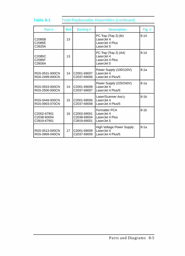
Part # Ref Exchng # Description Fig. #
C2085BC2085EC3925A
13PC Tray (Tray 2) (ltr)LaserJet 4LaserJet 4 PlusLaserJet 5
8-14
C2085CC2085FC3926A
13PC Tray (Tray 2) (A4)LaserJet 4LaserJet 4 PlusLaserJet 5
8-14
RG5-0531-000CNRG6-2499-000CN
14 C2001-69007C2037-69006
Power Supply (100/120V)LaserJet 4LaserJet 4 Plus/5
8-1a
RG5-0553-000CNRG5-2500-000CN
14 C2001-69008C2037-69007
Power Supply (220/240V)LaserJet 4LaserJet 4 Plus/5
8-1a
RG5-0449-000CNRG5-0903-070CN
15 C2001-69006C2037-69008
Laser/Scanner Ass’yLaserJet 4LaserJet 4 Plus/5
8-1b
C2002-67901C2038-60004C3919-67901
16 C2002-69001C2038-69004C3919-69001
Formatter PCALaserJet 4LaserJet 4 PlusLaserJet 5
8-1b
RG5-0513-000CNRG5-0969-040CN
17 C2001-69009C2037-69009
High Voltage Power SupplyLaserJet 4LaserJet 4 Plus/5
8-1a
Table 8-1 Field-Replaceable Assemblies (continued)
Parts and Diagrams 8-5
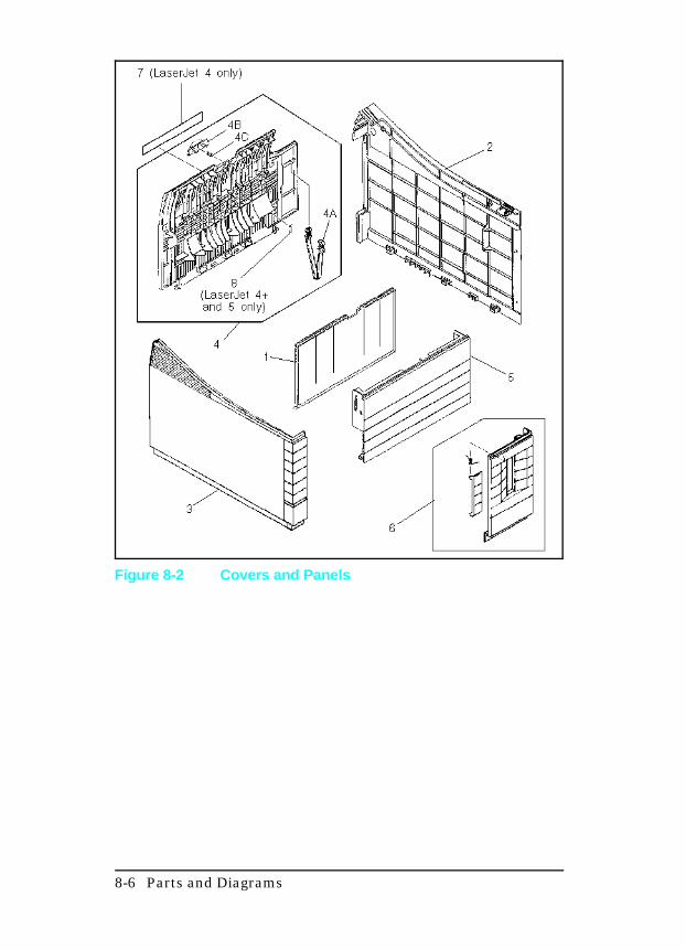
Figure 8-2 Covers and Panels
8-6 Parts and Diagrams
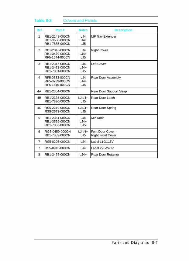
Ref Part # Notes Description
1 RB1-2143-000CNRB1-3558-000CNRB1-7885-000CN
LJ4LJ4+LJ5
MP Tray Extender
2 RB1-2346-000CNRB1-3470-000CNRF5-1644-000CN
LJ4LJ4+LJ5
Right Cover
3 RB1-2347-000CNRB1-3471-000CNRB1-7881-000CN
LJ4LJ4+LJ5
Left Cover
4 RF5-0533-000CNRF5-0733-000CNRF5-1645-000CN
LJ4LJ4+LJ5
Rear Door Assembly
4A RB1-2354-000CN Rear Door Support Strap
4B RB1-2335-000CNRB1-7890-000CN
LJ4/4+LJ5
Rear Door Latch
4C RS5-2219-000CNRS5-2571-000CN
LJ4/4+LJ5
Rear Door Spring
5 RB1-2351-000CNRB1-3559-000CNRB1-7886-000CN
LJ4LJ4+LJ5
MP Door
6 RG5-0459-000CNRB1-7889-000CN
LJ4/4+LJ5
Font Door CoverRight Front Cover
7 RS5-8205-000CN LJ4 Label 110/115V
7 RS5-8916-000CN LJ4 Label 220/240V
8 RB1-3475-000CN LJ4+ Rear Door Retainer
Table 8-2 Covers and Panels
Parts and Diagrams 8-7
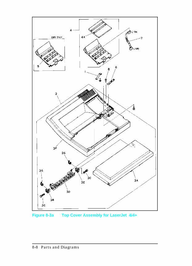
Figure 8-3a Top Cover Assembly for LaserJet 4/4+
8-8 Parts and Diagrams
Ref Part # Notes Description
1 RB1-2330-000CN S Spring, Leaf
3 RG5-0458-000CNRG5-0872-000CN
LJ4LJ4+
Upper Cover Assembly
3A RB1-2322-000CNRB1-3474-000CN
LJ4LJ4+
Top Cover Door
3B RB1-2323-000CN Hinge, Bracket
3C RB1-2324-000CN 2 ea. Hinge, Pin
3D RB1-2329-000CNRB1-3473-000CN
LJ4LJ4+
Hinge, Arm
3E RB1-2364-000CN Hinge, Bracket
3F RF5-0360-000CNRF5-0732-000CN
LJ4LJ4+
Cover, Upper
3G RB1-2314-000CN 2 ea. Stop, Hinge
4 RG5-0533-000CNC2001-69010RG5-1077-000CNC2037-69005
LJ4Exchange
LJ4+Exchange
Display Ass’y (English)
4A RB1-2359-000CNRB1-3476-000CN
LJ4LJ4+
Overlay (English)
Exchange PartNumbers
Overlays
4A C2001-40001C2001-40002C2001-40003C2001-40004C2001-40005C2001-40006C2001-40007C2001-40008C2001-40009C2001-40010C2001-40011C2001-40012C2001-40013C2037-40014
LJ4 EnglishFrenchGermanItalianSpanishNorwegianSwedishDanishFinnishDutchPolishTurkishPortugeseEuropean English
Table 8-3a Top Cover Assembly
Parts and Diagrams 8-9
Ref Part # Notes Description
4A C2037-40001C2037-40002C2037-40003C2037-40004C2037-40005C2037-40006C2037-40007C2037-40008C2037-40009C2037-40010C2037-40011C2037-40012C2037-40013C2037-40014
LJ4+ EnglishFrenchGermanItalianSpanishNorwegianSwedishDanishFinnishDutchPolishTurkishPortugeseEuropean English
5 RG5-0478-000CNRG5-1076-000CN
LJ4LJ4+
Display Ass’y (W/O overlay)
6 RB1-2260-000CN Brush, cleaning
7 RG5-0519-000CNRG5-0982-000CN
LJ4LJ4+
Cable, Display Panel
8 XA9-0591-000CN Screw with Washer (M3 x 8)
8-10 Parts and Diagrams
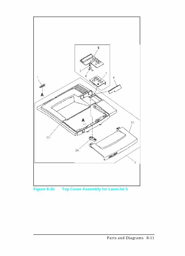
Figure 8-3b Top Cover Assembly for LaserJet 5
Parts and Diagrams 8-11
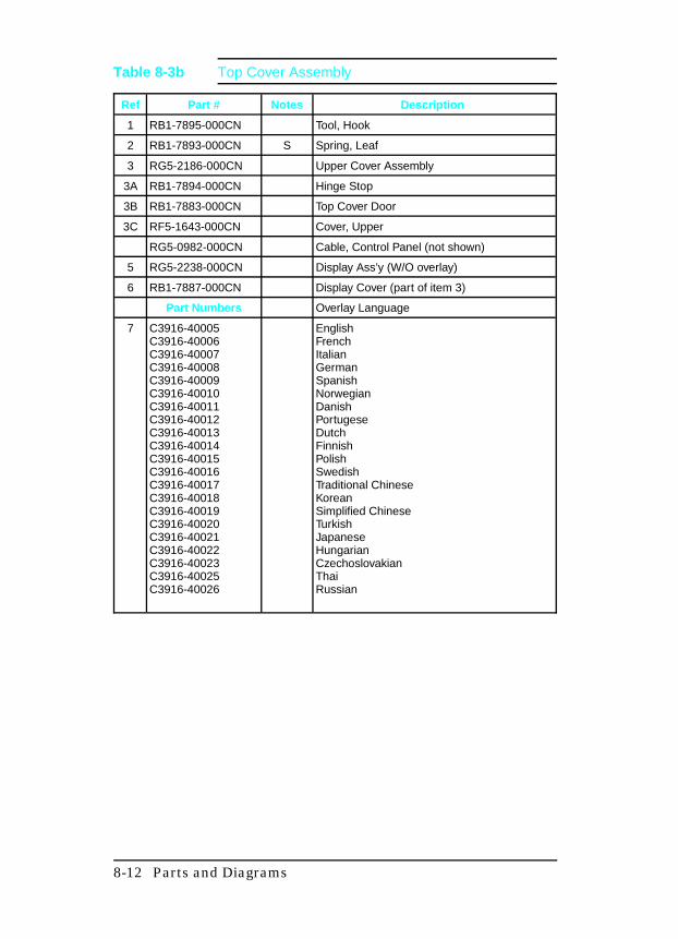
Ref Part # Notes Description
1 RB1-7895-000CN Tool, Hook
2 RB1-7893-000CN S Spring, Leaf
3 RG5-2186-000CN Upper Cover Assembly
3A RB1-7894-000CN Hinge Stop
3B RB1-7883-000CN Top Cover Door
3C RF5-1643-000CN Cover, Upper
RG5-0982-000CN Cable, Control Panel (not shown)
5 RG5-2238-000CN Display Ass’y (W/O overlay)
6 RB1-7887-000CN Display Cover (part of item 3)
Part Numbers Overlay Language
7 C3916-40005C3916-40006C3916-40007C3916-40008C3916-40009C3916-40010C3916-40011C3916-40012C3916-40013C3916-40014C3916-40015C3916-40016C3916-40017C3916-40018C3916-40019C3916-40020C3916-40021C3916-40022C3916-40023C3916-40025C3916-40026
EnglishFrenchItalianGermanSpanishNorwegianDanishPortugeseDutchFinnishPolishSwedishTraditional ChineseKoreanSimplified ChineseTurkishJapaneseHungarianCzechoslovakianThaiRussian
Table 8-3b Top Cover Assembly
8-12 Parts and Diagrams

Figure 8-4a Internal Components (1 of 4)
Ref Part # Notes Description
1 RB1-2080-000CN Shutter, laser
2 RB1-2100-000CNRB1-5730-000CN
LJ4/4+LJ5
Guide, Cartridge
3 RB1-2101-020CN Guide, Cartridge
4 RB1-2105-030CN Support, Cartridge
5 RB1-2106-000CN S Plate, grounding
6 RB1-2107-000CNRB1-7913-000CN
LJ4/4+LJ5
Guide, Cassette, Left
Table 8-4a Internal Components (Section 2)
Parts and Diagrams 8-13
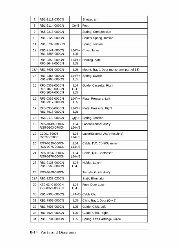
7 RB1-2111-030CN Shutter, arm
8 RB1-2114-000CN Qty 5 Foot
9 RS5-2218-000CN Spring, Compression
10 RB1-2122-000CN Shutter Spring, Torsion
11 RB1-5732 -000CN Spring, Torsion
12 RB1-2141-000CNRB1-7888-000CN
LJ4/4+LJ5
Cover, Inner
13 RB1-2353-000CNRF5-1648-000CN
LJ4/4+LJ5
Holding Plate
13A RB1-7901-000CN LJ5 Mount, Tray 1 Door (not shown-part of 13)
14 RB1-2358-000CNRB1-2966-000CN
LJ4/4+LJ5
Spring, Switch
15 RF5-0363-000CN RF5-1079-000CNRF5-1657-000CN
LJ4LJ4+LJ5
Guide, Cassette, Right
16 RF5-0365-000CNRB1-7917-000CN
LJ4/4+LJ5
Plate, Pressure, Left
17 RF5-0366-000CNRB1-7918-000CN
LJ4/4+LJ5
Plate, Pressure, Right
18 RS5-2170-000CN Qty 2 Spring, Tension
19 RG5-0449-000CNRG5-0903-070CN
LJ4LJ4+/5
Laser/Scanner Ass’y
19 C2001-69006C2037-69008
LJ4LJ4+/5
Laser/Scanner Ass’y (exchng)
20 RG5-0520-000CNRG5-0975-000CN
LJ4LJ4+/5
Cable, D.C. Cont/Scanner
21 RG5-0556-000CNRG5-0976-000CN
LJ4LJ4+/5
Cable, D.C. Cont/laser
27 RB1-2125-000CNRB1-3560-000CN
LJ4LJ4+
Holder, Latch
28 RG5-0469-020CN Transfer Guide Ass’y
28A RB1-2237-020CN Static Eliminator
29 XZ9-0340-000CNXZ9-0379-000CN
LJ4LJ4+
Front Door Latch
30 RB1-7908-000CN LJ 4+/5 Cable Clip
31 RB1-7902-000CN LJ5 Click, Tray 1 Door (Qty 2)
32 RB1-7903-000CN LJ5 Guide, Click, Left
33 RB1-7923-000CN LJ5 Guide, Click, Right
34 RB1-5731-000CN LJ5 Spring, Left Cartridge Guide
8-14 Parts and Diagrams
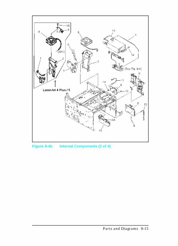
Figure 8-4b Internal Components (2 of 4)
Parts and Diagrams 8-15
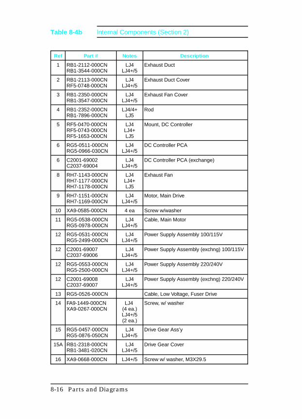
Ref Part # Notes Description
1 RB1-2112-000CNRB1-3544-000CN
LJ4LJ4+/5
Exhaust Duct
2 RB1-2113-000CNRF5-0748-000CN
LJ4LJ4+/5
Exhaust Duct Cover
3 RB1-2350-000CNRB1-3547-000CN
LJ4LJ4+/5
Exhaust Fan Cover
4 RB1-2352-000CNRB1-7896-000CN
LJ4/4+LJ5
Rod
5 RF5-0470-000CNRF5-0743-000CNRF5-1653-000CN
LJ4LJ4+LJ5
Mount, DC Controller
6 RG5-0511-000CNRG5-0966-030CN
LJ4LJ4+/5
DC Controller PCA
6 C2001-69002C2037-69004
LJ4LJ4+/5
DC Controller PCA (exchange)
8 RH7-1143-000CNRH7-1177-000CNRH7-1178-000CN
LJ4LJ4+LJ5
Exhaust Fan
9 RH7-1151-000CNRH7-1169-000CN
LJ4LJ4+/5
Motor, Main Drive
10 XA9-0585-000CN 4 ea Screw w/washer
11 RG5-0538-000CNRG5-0978-000CN
LJ4LJ4+/5
Cable, Main Motor
12 RG5-0531-000CNRG5-2499-000CN
LJ4LJ4+/5
Power Supply Assembly 100/115V
12 C2001-69007C2037-69006
LJ4LJ4+/5
Power Supply Assembly (exchng) 100/115V
12 RG5-0553-000CNRG5-2500-000CN
LJ4LJ4+/5
Power Supply Assembly 220/240V
12 C2001-69008C2037-69007
LJ4LJ4+/5
Power Supply Assembly (exchng) 220/240V
13 RG5-0526-000CN Cable, Low Voltage, Fuser Drive
14 FA9-1449-000CNXA9-0267-000CN
LJ4 (4 ea.)LJ4+/5(2 ea.)
Screw, w/ washer
15 RG5-0457-000CNRG5-0876-050CN
LJ4LJ4+/5
Drive Gear Ass’y
15A RB1-2318-000CNRB1-3481-020CN
LJ4LJ4+/5
Drive Gear Cover
16 XA9-0668-000CN LJ4+/5 Screw w/ washer, M3X29.5
Table 8-4b lnternal Components (Section 2)
8-16 Parts and Diagrams
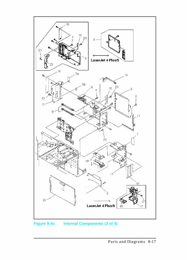
Figure 8-4c Internal Components (3 of 4)
Parts and Diagrams 8-17
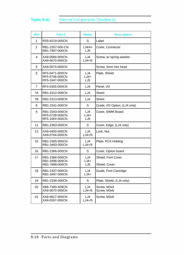
Ref Part # Notes Description
1 RS5-8219-000CN S Label
2 RB1-2357-000-CNRB1-7897-000CN
LJ4/4+LJ5
Cover, Connector
4 XA9-0584-000CNXA9-0670-000CN
LJ4LJ4+/5
Screw, w/ spring washer
5 XA9-0574-000CN Screw, 5mm hex head
6 RF5-0471-000CNRF5-0746-000CNRF5-1647-000CN
LJ4LJ4+LJ5
Plate, Shield
7 RF5-0355-000CN LJ4 Panel, I/O
7A RB1-2312-000CN LJ4 Sheet
7B RB1-2313-000CN LJ4 Sheet
8 RB1-2341-000CN S Guide, I/O Option, (LJ4 only)
9 RB1-2343-000CNRF5-0739-000CNRF5-1654-000CN
LJ4LJ4+LJ5
Cover, SIMM Board
11 RB1-2363-000CN S Cover, Edge, (LJ4 only)
13 XA9-0400-000CNXA9-0704-000CN
LJ4LJ4+/5
Lock, Nut
15 RB1-2365-000CNRB1-3493-000CN
LJ4LJ4+/5
Plate, PCA Holding
16 RB1-2366-000CN S Cover, Option board
17 RB1-2366-000CNRB1-3496-000CNRB1-7898-000CN
LJ4LJ4+LJ5
Shield, Font Cover
Shield, Cover
18 RB1-2337-000CNRB1-3497-000CN
LJ4LJ4+
Guide, Font Cartridge
19 RB1-2338-000CN S Plate, Shield, (LJ4 only)
20 XB6-7300-409CNXA9-0670-000CN
LJ4LJ4+/5
Screw, M3x4Screw, M3x6
21 XA9-0617-000CNXA9-0267-000CN
LJ4LJ4+/5
Screw, M3x6
Table 8-4c Internal Components (Section 3)
8-18 Parts and Diagrams
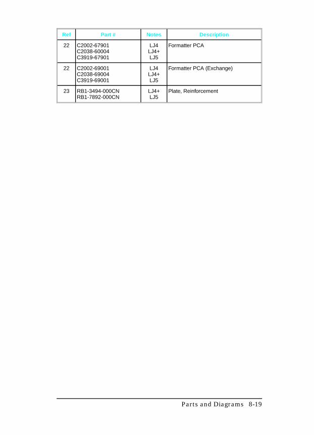
Ref Part # Notes Description
22 C2002-67901C2038-60004C3919-67901
LJ4LJ4+LJ5
Formatter PCA
22 C2002-69001C2038-69004C3919-69001
LJ4LJ4+LJ5
Formatter PCA (Exchange)
23 RB1-3494-000CNRB1-7892-000CN
LJ4+LJ5
Plate, Reinforcement
Parts and Diagrams 8-19
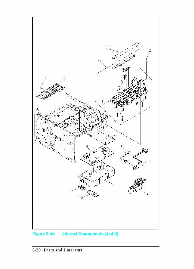
Figure 8-4d Internal Components (4 of 4)
8-20 Parts and Diagrams
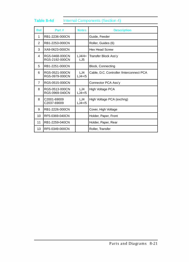
Ref Part # Notes Description
1 RB1-2236-000CN Guide, Feeder
2 RB1-2253-000CN Roller, Guides (6)
3 XA9-0623-000CN Hex Head Screw
4 RG5-0468-000CNRG5-2192-000CN
LJ4/4+LJ5
Transfer Block Ass’y
5 RB1-2251-000CN Block, Connecting
6 RG5-0521-000CNRG5-0979-000CN
LJ4LJ4+/5
Cable, D.C. Controller /Interconnect PCA
7 RG5-0515-000CN Connector PCA Ass’y
8 RG5-0513-000CNRG5-0969-040CN
LJ4LJ4+/5
High Voltage PCA
8 C2001-69009C2037-69009
LJ4LJ4+/5
High Voltage PCA (exchng)
9 RB1-2226-000CN Cover, High Voltage
10 RF5-0369-040CN Holder, Paper, Front
11 RB1-2259-040CN Holder, Paper, Rear
13 RF5-0349-000CN Roller, Transfer
Table 8-4d Internal Components (Section 4)
Parts and Diagrams 8-21
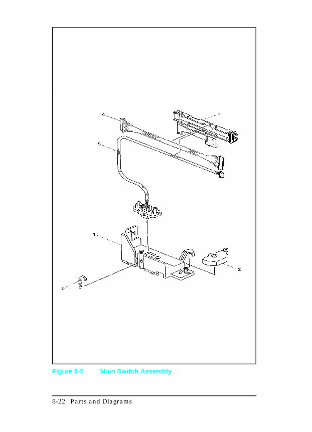
Figure 8-5 Main Switch Assembly
8-22 Parts and Diagrams
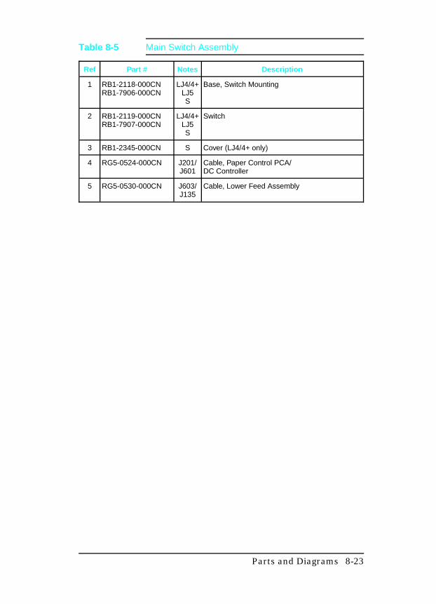
Ref Part # Notes Description
1 RB1-2118-000CNRB1-7906-000CN
LJ4/4+LJ5S
Base, Switch Mounting
2 RB1-2119-000CNRB1-7907-000CN
LJ4/4+LJ5S
Switch
3 RB1-2345-000CN S Cover (LJ4/4+ only)
4 RG5-0524-000CN J201/J601
Cable, Paper Control PCA/DC Controller
5 RG5-0530-000CN J603/J135
Cable, Lower Feed Assembly
Table 8-5 Main Switch Assembly
Parts and Diagrams 8-23

Figure 8-6a Paper Feed Assembly (1 of 2)
8-24 Parts and Diagrams
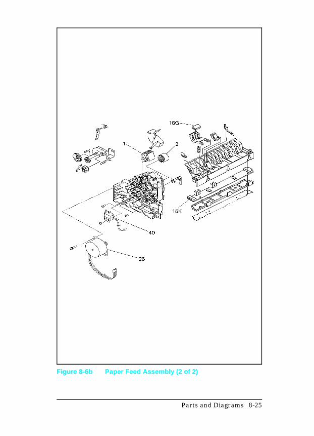
Figure 8-6b Paper Feed Assembly (2 of 2)
Parts and Diagrams 8-25
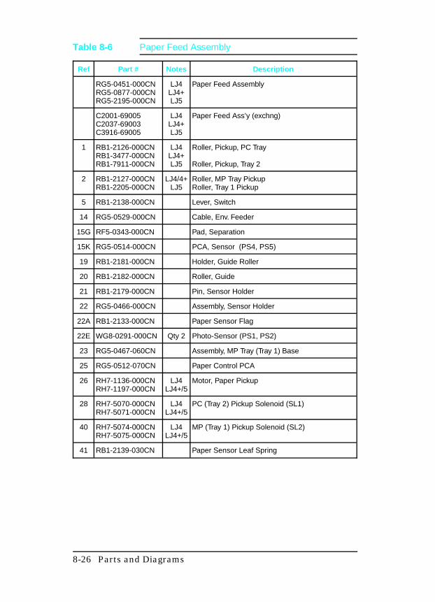
Ref Part # Notes Description
RG5-0451-000CNRG5-0877-000CNRG5-2195-000CN
LJ4LJ4+LJ5
Paper Feed Assembly
C2001-69005C2037-69003C3916-69005
LJ4LJ4+LJ5
Paper Feed Ass’y (exchng)
1 RB1-2126-000CNRB1-3477-000CNRB1-7911-000CN
LJ4LJ4+LJ5
Roller, Pickup, PC Tray
Roller, Pickup, Tray 2
2 RB1-2127-000CNRB1-2205-000CN
LJ4/4+LJ5
Roller, MP Tray PickupRoller, Tray 1 Pickup
5 RB1-2138-000CN Lever, Switch
14 RG5-0529-000CN Cable, Env. Feeder
15G RF5-0343-000CN Pad, Separation
15K RG5-0514-000CN PCA, Sensor (PS4, PS5)
19 RB1-2181-000CN Holder, Guide Roller
20 RB1-2182-000CN Roller, Guide
21 RB1-2179-000CN Pin, Sensor Holder
22 RG5-0466-000CN Assembly, Sensor Holder
22A RB1-2133-000CN Paper Sensor Flag
22E WG8-0291-000CN Qty 2 Photo-Sensor (PS1, PS2)
23 RG5-0467-060CN Assembly, MP Tray (Tray 1) Base
25 RG5-0512-070CN Paper Control PCA
26 RH7-1136-000CNRH7-1197-000CN
LJ4LJ4+/5
Motor, Paper Pickup
28 RH7-5070-000CNRH7-5071-000CN
LJ4LJ4+/5
PC (Tray 2) Pickup Solenoid (SL1)
40 RH7-5074-000CNRH7-5075-000CN
LJ4LJ4+/5
MP (Tray 1) Pickup Solenoid (SL2)
41 RB1-2139-030CN Paper Sensor Leaf Spring
Table 8-6 Paper Feed Assembly
8-26 Parts and Diagrams
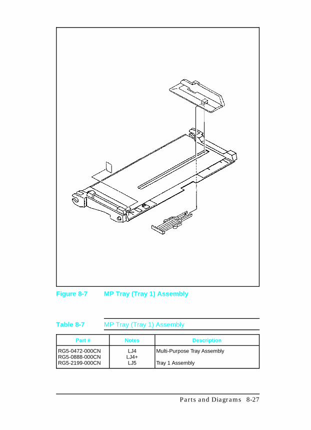
Figure 8-7 MP Tray (Tray 1) Assembly
Part # Notes Description
RG5-0472-000CNRG5-0888-000CNRG5-2199-000CN
LJ4LJ4+LJ5
Multi-Purpose Tray Assembly
Tray 1 Assembly
Table 8-7 MP Tray (Tray 1) Assembly
Parts and Diagrams 8-27
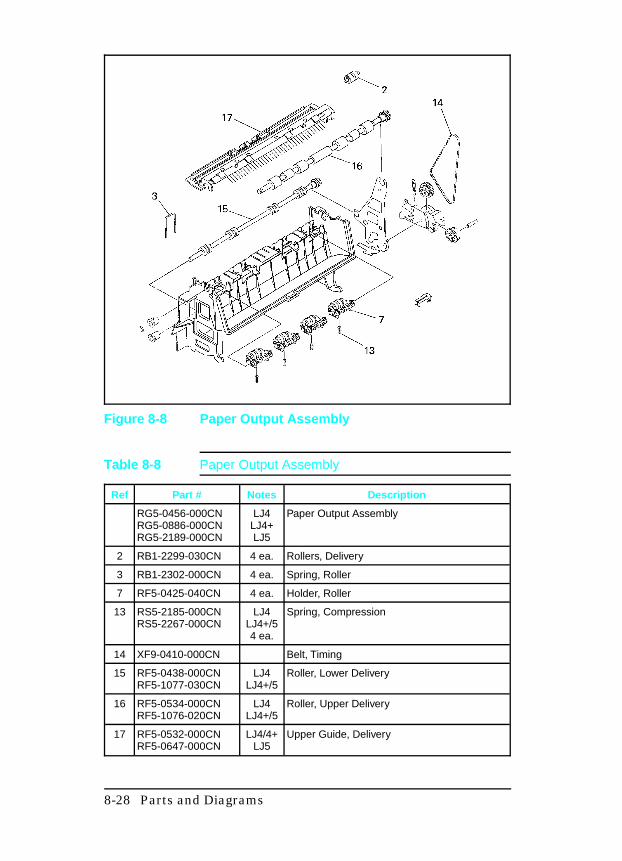
Figure 8-8 Paper Output Assembly
Ref Part # Notes Description
RG5-0456-000CNRG5-0886-000CNRG5-2189-000CN
LJ4LJ4+LJ5
Paper Output Assembly
2 RB1-2299-030CN 4 ea. Rollers, Delivery
3 RB1-2302-000CN 4 ea. Spring, Roller
7 RF5-0425-040CN 4 ea. Holder, Roller
13 RS5-2185-000CNRS5-2267-000CN
LJ4LJ4+/54 ea.
Spring, Compression
14 XF9-0410-000CN Belt, Timing
15 RF5-0438-000CNRF5-1077-030CN
LJ4LJ4+/5
Roller, Lower Delivery
16 RF5-0534-000CNRF5-1076-020CN
LJ4LJ4+/5
Roller, Upper Delivery
17 RF5-0532-000CNRF5-0647-000CN
LJ4/4+LJ5
Upper Guide, Delivery
Table 8-8 Paper Output Assembly
8-28 Parts and Diagrams
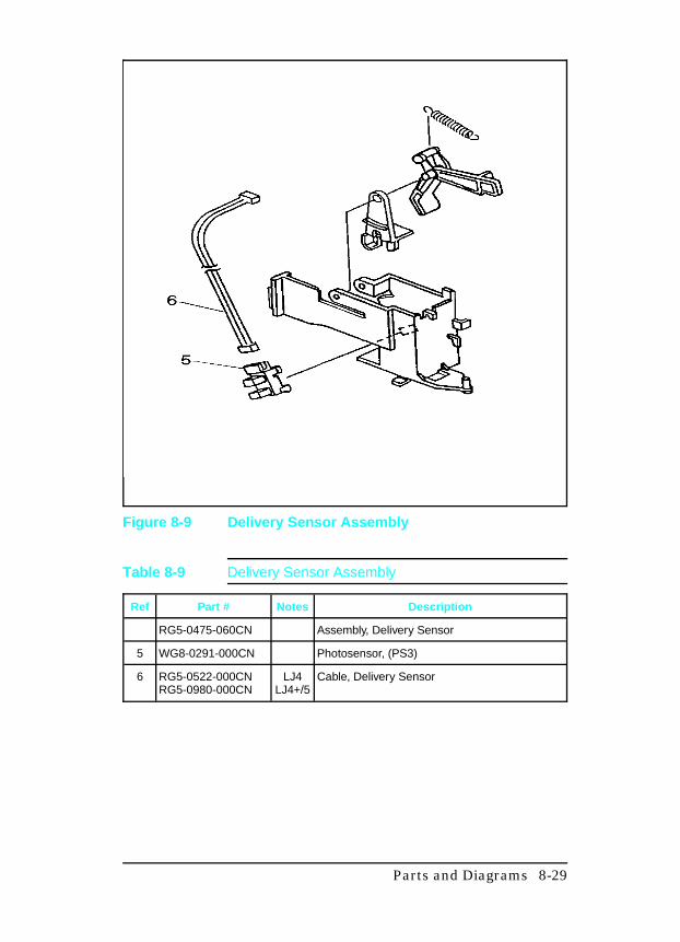
Figure 8-9 Delivery Sensor Assembly
Ref Part # Notes Description
RG5-0475-060CN Assembly, Delivery Sensor
5 WG8-0291-000CN Photosensor, (PS3)
6 RG5-0522-000CNRG5-0980-000CN
LJ4LJ4+/5
Cable, Delivery Sensor
Table 8-9 Delivery Sensor Assembly
Parts and Diagrams 8-29
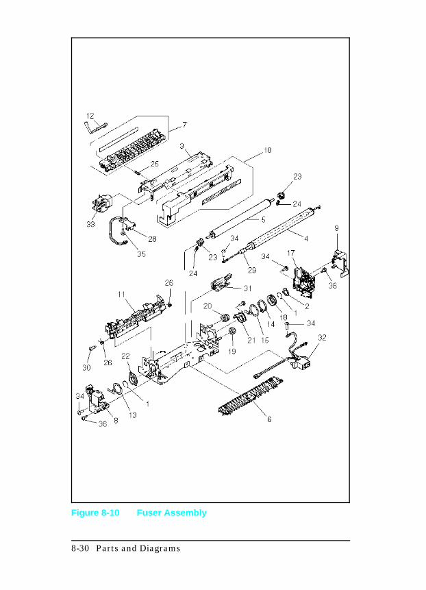
Figure 8-10 Fuser Assembly
8-30 Parts and Diagrams
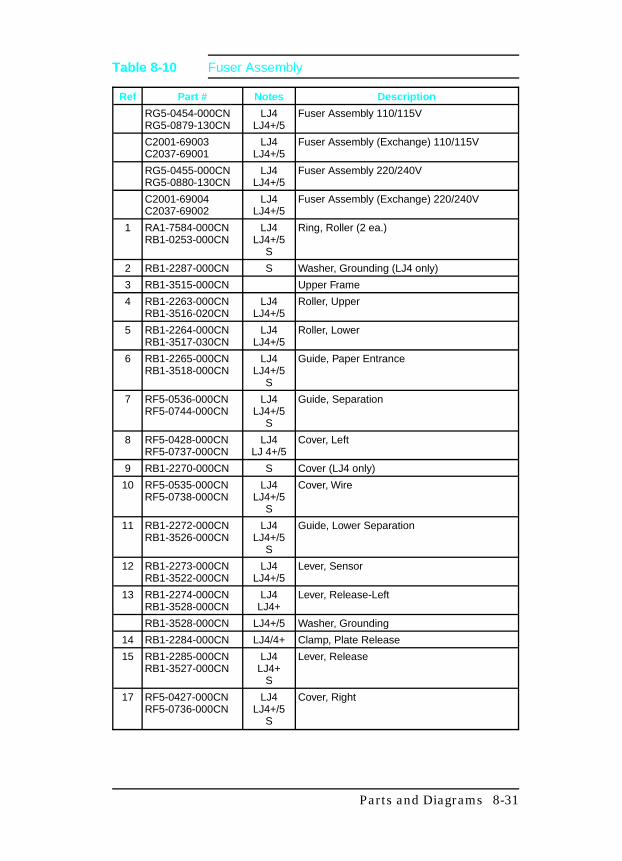
Ref Part # Notes Description
RG5-0454-000CNRG5-0879-130CN
LJ4LJ4+/5
Fuser Assembly 110/115V
C2001-69003C2037-69001
LJ4LJ4+/5
Fuser Assembly (Exchange) 110/115V
RG5-0455-000CNRG5-0880-130CN
LJ4LJ4+/5
Fuser Assembly 220/240V
C2001-69004C2037-69002
LJ4LJ4+/5
Fuser Assembly (Exchange) 220/240V
1 RA1-7584-000CNRB1-0253-000CN
LJ4LJ4+/5
S
Ring, Roller (2 ea.)
2 RB1-2287-000CN S Washer, Grounding (LJ4 only)
3 RB1-3515-000CN Upper Frame
4 RB1-2263-000CNRB1-3516-020CN
LJ4LJ4+/5
Roller, Upper
5 RB1-2264-000CNRB1-3517-030CN
LJ4LJ4+/5
Roller, Lower
6 RB1-2265-000CNRB1-3518-000CN
LJ4LJ4+/5
S
Guide, Paper Entrance
7 RF5-0536-000CNRF5-0744-000CN
LJ4LJ4+/5
S
Guide, Separation
8 RF5-0428-000CNRF5-0737-000CN
LJ4LJ 4+/5
Cover, Left
9 RB1-2270-000CN S Cover (LJ4 only)
10 RF5-0535-000CNRF5-0738-000CN
LJ4LJ4+/5
S
Cover, Wire
11 RB1-2272-000CNRB1-3526-000CN
LJ4LJ4+/5
S
Guide, Lower Separation
12 RB1-2273-000CNRB1-3522-000CN
LJ4LJ4+/5
Lever, Sensor
13 RB1-2274-000CNRB1-3528-000CN
LJ4LJ4+
Lever, Release-Left
RB1-3528-000CN LJ4+/5 Washer, Grounding
14 RB1-2284-000CN LJ4/4+ Clamp, Plate Release
15 RB1-2285-000CNRB1-3527-000CN
LJ4LJ4+
S
Lever, Release
17 RF5-0427-000CNRF5-0736-000CN
LJ4LJ4+/5
S
Cover, Right
Table 8-10 Fuser Assembly
Parts and Diagrams 8-31
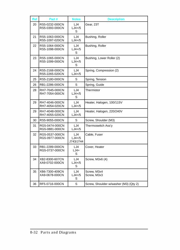
Ref Part # Notes Description
20 RS5-0232-000CNRS5-0393-000CN
LJ4LJ4+/5
S
Gear, 23T
21 RS5-1063-000CNRS5-1097-020CN
LJ4LJ4+/5
Bushing, Roller
22 RS5-1064-000CNRS5-1098-000CN
LJ4LJ4+/5
S
Bushing, Roller
23 RS5-1065-000CNRS5-1099-000CN
LJ4LJ4+/5
S
Bushing, Lower Roller (2)
24 RS5-2168-000CNRS5-2265-020CN
LJ4LJ4+/5
Spring, Compression (2)
25 RS5-2180-000CN S Spring, Tension
26 RB1-2286-000CN S Spring, Guide
28 RH7-7045-000CNRH7-7054-000CN
LJ4LJ4+/5
S
Thermistor
29 RH7-4046-000CNRH7-4054-020CN
LJ4LJ4+/5
Heater, Halogen, 100/115V
29 RH7-4048-000CNRH7-4055-020CN
LJ4LJ4+/5
Heater, Halogen, 220/240V
30 RS5-9055-000CN S Screw, Shoulder (M3)
31 RG5-0474-000CNRG5-0881-000CN
LJ4LJ4+/5
Thermoswitch Ass’y
32 RG5-0537-000CNRG5-0977-000CN
LJ4LJ4+/5
J743/J744
Cable, Fuser
33 RB1-2289-000CNRG5-0737-000CN
LJ4LJ4+
S
Cover, Heater
34 XB2-8300-607CNXA9-0702-000CN
LJ4LJ4+/5
S
Screw, M3x6 (4)
35 XB6-7300-409CNXA9-0678-000CN
LJ4LJ4+/5
S
Screw, M3x4Screw, M3x3
36 RF5-0716-000CN S Screw, Shoulder w/washer (M3) (Qty 2)
8-32 Parts and Diagrams
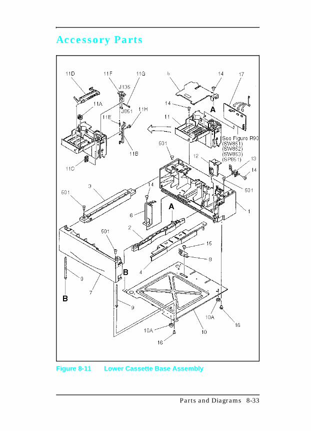
Accessory Parts
Figure 8-11 Lower Cassette Base Assembly
Parts and Diagrams 8-33
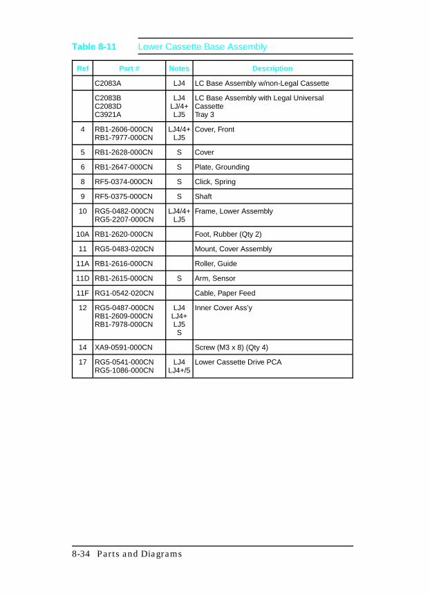
Ref Part # Notes Description
C2083A LJ4 LC Base Assembly w/non-Legal Cassette
C2083BC2083DC3921A
LJ4LJ/4+LJ5
LC Base Assembly with Legal UniversalCassetteTray 3
4 RB1-2606-000CNRB1-7977-000CN
LJ4/4+LJ5
Cover, Front
5 RB1-2628-000CN S Cover
6 RB1-2647-000CN S Plate, Grounding
8 RF5-0374-000CN S Click, Spring
9 RF5-0375-000CN S Shaft
10 RG5-0482-000CNRG5-2207-000CN
LJ4/4+LJ5
Frame, Lower Assembly
10A RB1-2620-000CN Foot, Rubber (Qty 2)
11 RG5-0483-020CN Mount, Cover Assembly
11A RB1-2616-000CN Roller, Guide
11D RB1-2615-000CN S Arm, Sensor
11F RG1-0542-020CN Cable, Paper Feed
12 RG5-0487-000CNRB1-2609-000CNRB1-7978-000CN
LJ4LJ4+LJ5S
Inner Cover Ass’y
14 XA9-0591-000CN Screw (M3 x 8) (Qty 4)
17 RG5-0541-000CNRG5-1086-000CN
LJ4LJ4+/5
Lower Cassette Drive PCA
Table 8-11 Lower Cassette Base Assembly
8-34 Parts and Diagrams
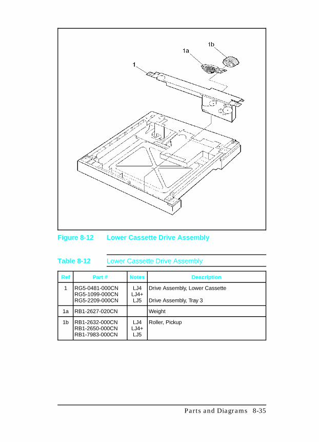
Figure 8-12 Lower Cassette Drive Assembly
Ref Part # Notes Description
1 RG5-0481-000CNRG5-1099-000CNRG5-2209-000CN
LJ4LJ4+LJ5
Drive Assembly, Lower Cassette
Drive Assembly, Tray 3
1a RB1-2627-020CN Weight
1b RB1-2632-000CNRB1-2650-000CNRB1-7983-000CN
LJ4LJ4+LJ5
Roller, Pickup
Table 8-12 Lower Cassette Drive Assembly
Parts and Diagrams 8-35
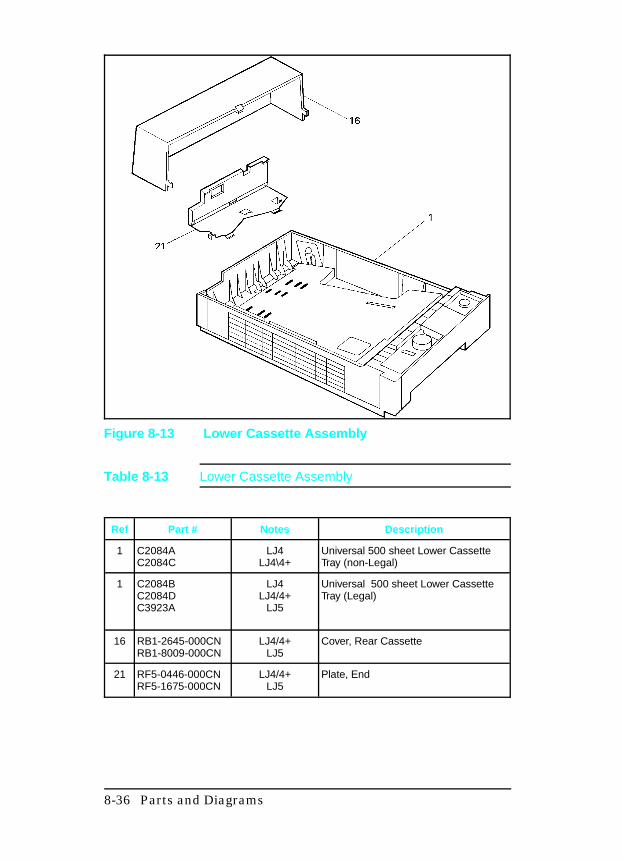
Figure 8-13 Lower Cassette Assembly
Ref Part # Notes Description
1 C2084AC2084C
LJ4LJ4\4+
Universal 500 sheet Lower CassetteTray (non-Legal)
1 C2084BC2084DC3923A
LJ4LJ4/4+
LJ5
Universal 500 sheet Lower CassetteTray (Legal)
16 RB1-2645-000CNRB1-8009-000CN
LJ4/4+LJ5
Cover, Rear Cassette
21 RF5-0446-000CNRF5-1675-000CN
LJ4/4+LJ5
Plate, End
Table 8-13 Lower Cassette Assembly
8-36 Parts and Diagrams
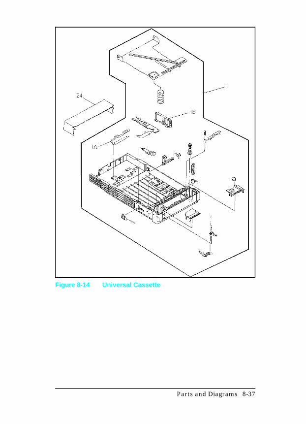
Figure 8-14 Universal Cassette
Parts and Diagrams 8-37
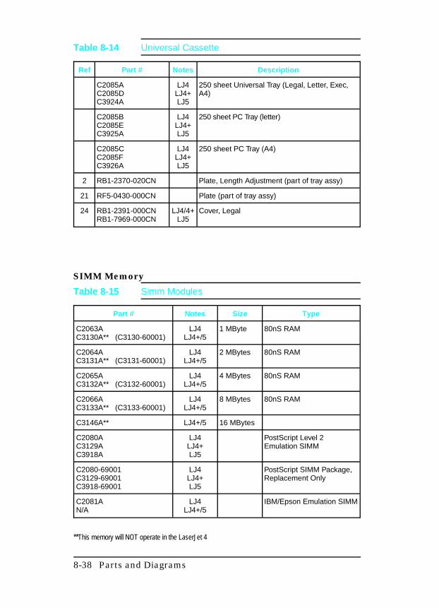
SIMM Memory
Ref Part # Notes Description
C2085AC2085DC3924A
LJ4LJ4+LJ5
250 sheet Universal Tray (Legal, Letter, Exec,A4)
C2085BC2085EC3925A
LJ4LJ4+LJ5
250 sheet PC Tray (letter)
C2085CC2085FC3926A
LJ4LJ4+LJ5
250 sheet PC Tray (A4)
2 RB1-2370-020CN Plate, Length Adjustment (part of tray assy)
21 RF5-0430-000CN Plate (part of tray assy)
24 RB1-2391-000CNRB1-7969-000CN
LJ4/4+LJ5
Cover, Legal
Table 8-14 Universal Cassette
Part # Notes Size Type
C2063AC3130A** (C3130-60001)
LJ4LJ4+/5
1 MByte 80nS RAM
C2064AC3131A** (C3131-60001)
LJ4LJ4+/5
2 MBytes 80nS RAM
C2065AC3132A** (C3132-60001)
LJ4LJ4+/5
4 MBytes 80nS RAM
C2066AC3133A** (C3133-60001)
LJ4LJ4+/5
8 MBytes 80nS RAM
C3146A** LJ4+/5 16 MBytes
C2080AC3129AC3918A
LJ4LJ4+LJ5
PostScript Level 2Emulation SIMM
C2080-69001C3129-69001C3918-69001
LJ4LJ4+LJ5
PostScript SIMM Package,Replacement Only
C2081AN/A
LJ4LJ4+/5
IBM/Epson Emulation SIMM
**This memory will NOT operate in the LaserJet 4
Table 8-15 Simm Modules
8-38 Parts and Diagrams
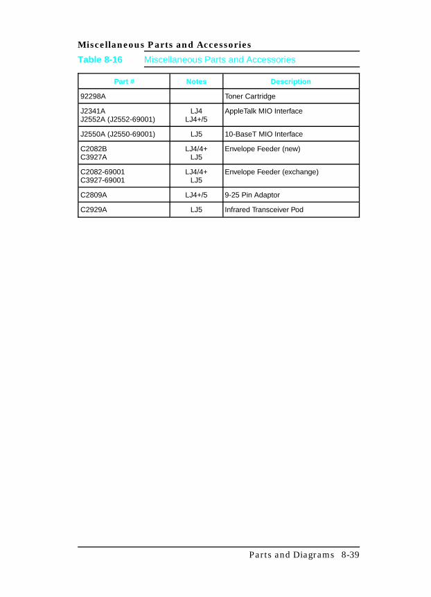
Miscellaneous Parts and Accessories
Part # Notes Description
92298A Toner Cartridge
J2341AJ2552A (J2552-69001)
LJ4LJ4+/5
AppleTalk MIO Interface
J2550A (J2550-69001) LJ5 10-BaseT MIO Interface
C2082BC3927A
LJ4/4+LJ5
Envelope Feeder (new)
C2082-69001C3927-69001
LJ4/4+LJ5
Envelope Feeder (exchange)
C2809A LJ4+/5 9-25 Pin Adaptor
C2929A LJ5 Infrared Transceiver Pod
Table 8-16 Miscellaneous Parts and Accessories
Parts and Diagrams 8-39
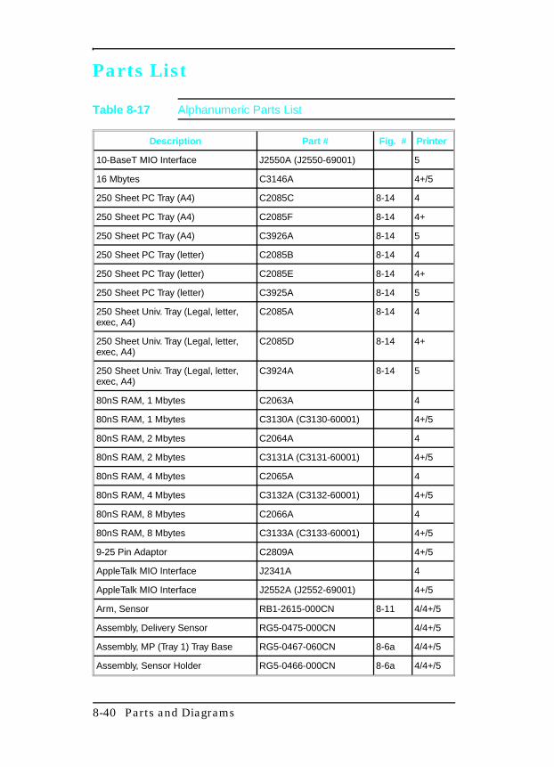
Parts List
Description Part # Fig. # Printer
10-BaseT MIO Interface J2550A (J2550-69001) 5
16 Mbytes C3146A 4+/5
250 Sheet PC Tray (A4) C2085C 8-14 4
250 Sheet PC Tray (A4) C2085F 8-14 4+
250 Sheet PC Tray (A4) C3926A 8-14 5
250 Sheet PC Tray (letter) C2085B 8-14 4
250 Sheet PC Tray (letter) C2085E 8-14 4+
250 Sheet PC Tray (letter) C3925A 8-14 5
250 Sheet Univ. Tray (Legal, letter,exec, A4)
C2085A 8-14 4
250 Sheet Univ. Tray (Legal, letter,exec, A4)
C2085D 8-14 4+
250 Sheet Univ. Tray (Legal, letter,exec, A4)
C3924A 8-14 5
80nS RAM, 1 Mbytes C2063A 4
80nS RAM, 1 Mbytes C3130A (C3130-60001) 4+/5
80nS RAM, 2 Mbytes C2064A 4
80nS RAM, 2 Mbytes C3131A (C3131-60001) 4+/5
80nS RAM, 4 Mbytes C2065A 4
80nS RAM, 4 Mbytes C3132A (C3132-60001) 4+/5
80nS RAM, 8 Mbytes C2066A 4
80nS RAM, 8 Mbytes C3133A (C3133-60001) 4+/5
9-25 Pin Adaptor C2809A 4+/5
AppleTalk MIO Interface J2341A 4
AppleTalk MIO Interface J2552A (J2552-69001) 4+/5
Arm, Sensor RB1-2615-000CN 8-11 4/4+/5
Assembly, Delivery Sensor RG5-0475-000CN 4/4+/5
Assembly, MP (Tray 1) Tray Base RG5-0467-060CN 8-6a 4/4+/5
Assembly, Sensor Holder RG5-0466-000CN 8-6a 4/4+/5
Table 8-17 Alphanumeric Parts List
8-40 Parts and Diagrams
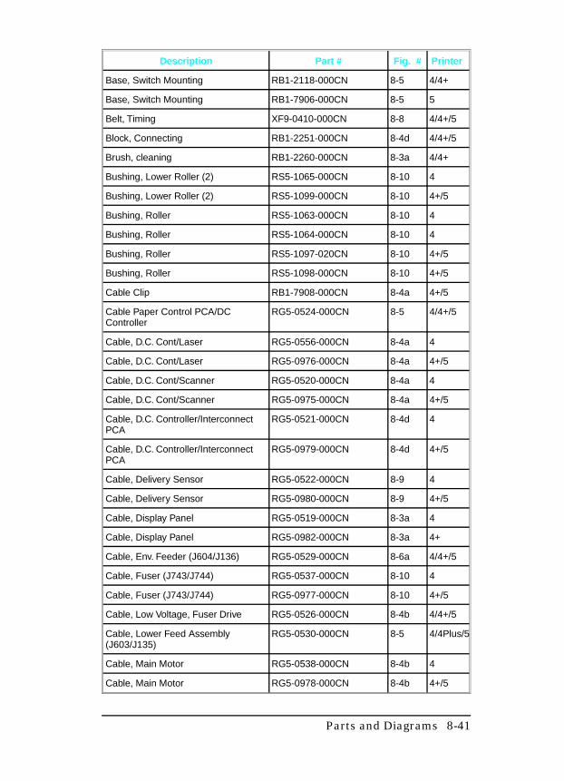
Description Part # Fig. # Printer
Base, Switch Mounting RB1-2118-000CN 8-5 4/4+
Base, Switch Mounting RB1-7906-000CN 8-5 5
Belt, Timing XF9-0410-000CN 8-8 4/4+/5
Block, Connecting RB1-2251-000CN 8-4d 4/4+/5
Brush, cleaning RB1-2260-000CN 8-3a 4/4+
Bushing, Lower Roller (2) RS5-1065-000CN 8-10 4
Bushing, Lower Roller (2) RS5-1099-000CN 8-10 4+/5
Bushing, Roller RS5-1063-000CN 8-10 4
Bushing, Roller RS5-1064-000CN 8-10 4
Bushing, Roller RS5-1097-020CN 8-10 4+/5
Bushing, Roller RS5-1098-000CN 8-10 4+/5
Cable Clip RB1-7908-000CN 8-4a 4+/5
Cable Paper Control PCA/DCController
RG5-0524-000CN 8-5 4/4+/5
Cable, D.C. Cont/Laser RG5-0556-000CN 8-4a 4
Cable, D.C. Cont/Laser RG5-0976-000CN 8-4a 4+/5
Cable, D.C. Cont/Scanner RG5-0520-000CN 8-4a 4
Cable, D.C. Cont/Scanner RG5-0975-000CN 8-4a 4+/5
Cable, D.C. Controller/InterconnectPCA
RG5-0521-000CN 8-4d 4
Cable, D.C. Controller/InterconnectPCA
RG5-0979-000CN 8-4d 4+/5
Cable, Delivery Sensor RG5-0522-000CN 8-9 4
Cable, Delivery Sensor RG5-0980-000CN 8-9 4+/5
Cable, Display Panel RG5-0519-000CN 8-3a 4
Cable, Display Panel RG5-0982-000CN 8-3a 4+
Cable, Env. Feeder (J604/J136) RG5-0529-000CN 8-6a 4/4+/5
Cable, Fuser (J743/J744) RG5-0537-000CN 8-10 4
Cable, Fuser (J743/J744) RG5-0977-000CN 8-10 4+/5
Cable, Low Voltage, Fuser Drive RG5-0526-000CN 8-4b 4/4+/5
Cable, Lower Feed Assembly(J603/J135)
RG5-0530-000CN 8-5 4/4Plus/5
Cable, Main Motor RG5-0538-000CN 8-4b 4
Cable, Main Motor RG5-0978-000CN 8-4b 4+/5
Parts and Diagrams 8-41
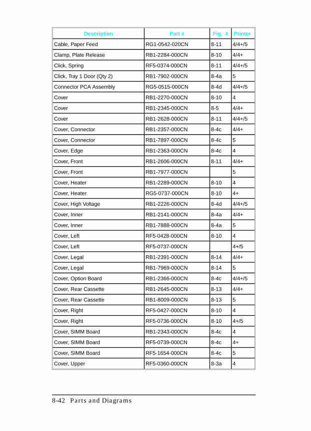
Description Part # Fig. # Printer
Cable, Paper Feed RG1-0542-020CN 8-11 4/4+/5
Clamp, Plate Release RB1-2284-000CN 8-10 4/4+
Click, Spring RF5-0374-000CN 8-11 4/4+/5
Click, Tray 1 Door (Qty 2) RB1-7902-000CN 8-4a 5
Connector PCA Assembly RG5-0515-000CN 8-4d 4/4+/5
Cover RB1-2270-000CN 8-10 4
Cover RB1-2345-000CN 8-5 4/4+
Cover RB1-2628-000CN 8-11 4/4+/5
Cover, Connector RB1-2357-000CN 8-4c 4/4+
Cover, Connector RB1-7897-000CN 8-4c 5
Cover, Edge RB1-2363-000CN 8-4c 4
Cover, Front RB1-2606-000CN 8-11 4/4+
Cover, Front RB1-7977-000CN 5
Cover, Heater RB1-2289-000CN 8-10 4
Cover, Heater RG5-0737-000CN 8-10 4+
Cover, High Voltage RB1-2226-000CN 8-4d 4/4+/5
Cover, Inner RB1-2141-000CN 8-4a 4/4+
Cover, Inner RB1-7888-000CN 8-4a 5
Cover, Left RF5-0428-000CN 8-10 4
Cover, Left RF5-0737-000CN 4+/5
Cover, Legal RB1-2391-000CN 8-14 4/4+
Cover, Legal RB1-7969-000CN 8-14 5
Cover, Option Board RB1-2366-000CN 8-4c 4/4+/5
Cover, Rear Cassette RB1-2645-000CN 8-13 4/4+
Cover, Rear Cassette RB1-8009-000CN 8-13 5
Cover, Right RF5-0427-000CN 8-10 4
Cover, Right RF5-0736-000CN 8-10 4+/5
Cover, SIMM Board RB1-2343-000CN 8-4c 4
Cover, SIMM Board RF5-0739-000CN 8-4c 4+
Cover, SIMM Board RF5-1654-000CN 8-4c 5
Cover, Upper RF5-0360-000CN 8-3a 4
8-42 Parts and Diagrams
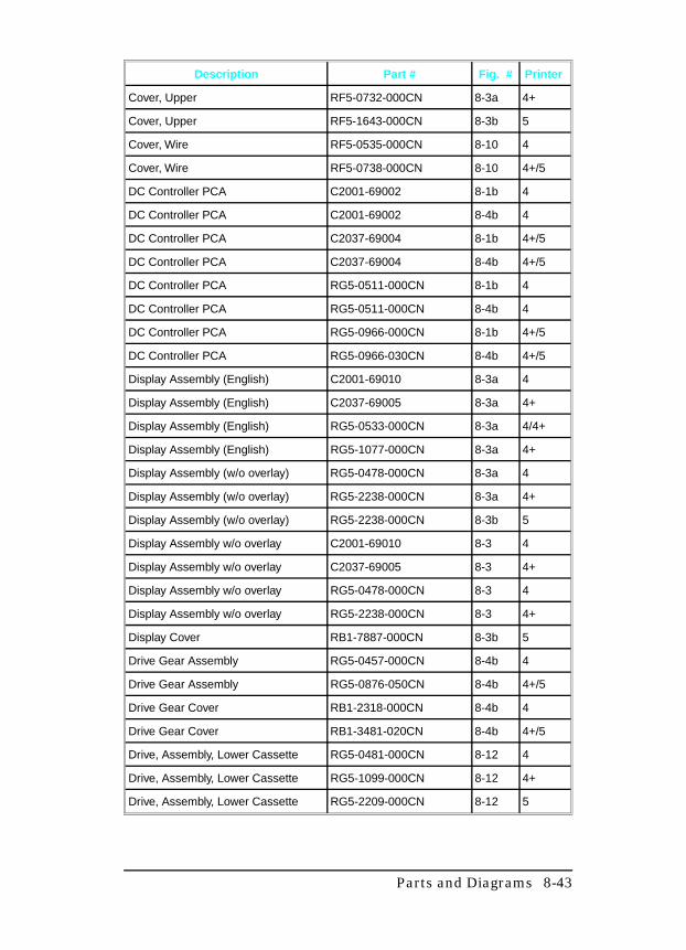
Description Part # Fig. # Printer
Cover, Upper RF5-0732-000CN 8-3a 4+
Cover, Upper RF5-1643-000CN 8-3b 5
Cover, Wire RF5-0535-000CN 8-10 4
Cover, Wire RF5-0738-000CN 8-10 4+/5
DC Controller PCA C2001-69002 8-1b 4
DC Controller PCA C2001-69002 8-4b 4
DC Controller PCA C2037-69004 8-1b 4+/5
DC Controller PCA C2037-69004 8-4b 4+/5
DC Controller PCA RG5-0511-000CN 8-1b 4
DC Controller PCA RG5-0511-000CN 8-4b 4
DC Controller PCA RG5-0966-000CN 8-1b 4+/5
DC Controller PCA RG5-0966-030CN 8-4b 4+/5
Display Assembly (English) C2001-69010 8-3a 4
Display Assembly (English) C2037-69005 8-3a 4+
Display Assembly (English) RG5-0533-000CN 8-3a 4/4+
Display Assembly (English) RG5-1077-000CN 8-3a 4+
Display Assembly (w/o overlay) RG5-0478-000CN 8-3a 4
Display Assembly (w/o overlay) RG5-2238-000CN 8-3a 4+
Display Assembly (w/o overlay) RG5-2238-000CN 8-3b 5
Display Assembly w/o overlay C2001-69010 8-3 4
Display Assembly w/o overlay C2037-69005 8-3 4+
Display Assembly w/o overlay RG5-0478-000CN 8-3 4
Display Assembly w/o overlay RG5-2238-000CN 8-3 4+
Display Cover RB1-7887-000CN 8-3b 5
Drive Gear Assembly RG5-0457-000CN 8-4b 4
Drive Gear Assembly RG5-0876-050CN 8-4b 4+/5
Drive Gear Cover RB1-2318-000CN 8-4b 4
Drive Gear Cover RB1-3481-020CN 8-4b 4+/5
Drive, Assembly, Lower Cassette RG5-0481-000CN 8-12 4
Drive, Assembly, Lower Cassette RG5-1099-000CN 8-12 4+
Drive, Assembly, Lower Cassette RG5-2209-000CN 8-12 5
Parts and Diagrams 8-43
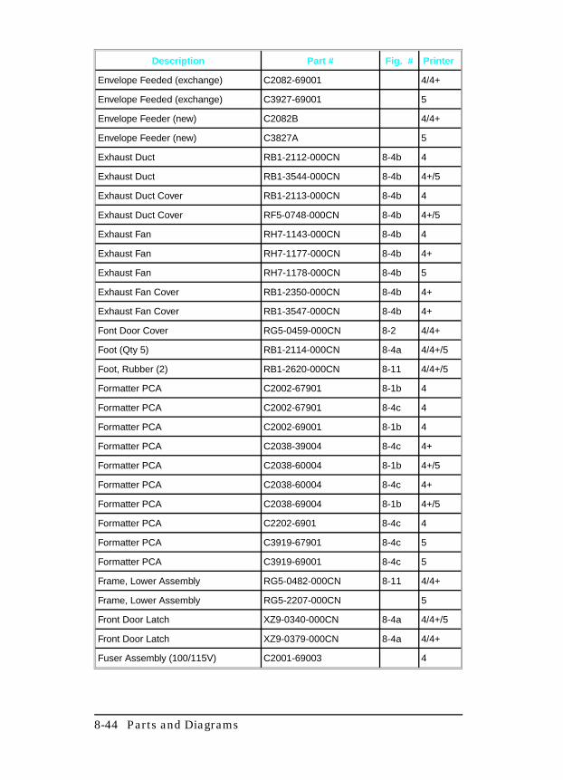
Description Part # Fig. # Printer
Envelope Feeded (exchange) C2082-69001 4/4+
Envelope Feeded (exchange) C3927-69001 5
Envelope Feeder (new) C2082B 4/4+
Envelope Feeder (new) C3827A 5
Exhaust Duct RB1-2112-000CN 8-4b 4
Exhaust Duct RB1-3544-000CN 8-4b 4+/5
Exhaust Duct Cover RB1-2113-000CN 8-4b 4
Exhaust Duct Cover RF5-0748-000CN 8-4b 4+/5
Exhaust Fan RH7-1143-000CN 8-4b 4
Exhaust Fan RH7-1177-000CN 8-4b 4+
Exhaust Fan RH7-1178-000CN 8-4b 5
Exhaust Fan Cover RB1-2350-000CN 8-4b 4+
Exhaust Fan Cover RB1-3547-000CN 8-4b 4+
Font Door Cover RG5-0459-000CN 8-2 4/4+
Foot (Qty 5) RB1-2114-000CN 8-4a 4/4+/5
Foot, Rubber (2) RB1-2620-000CN 8-11 4/4+/5
Formatter PCA C2002-67901 8-1b 4
Formatter PCA C2002-67901 8-4c 4
Formatter PCA C2002-69001 8-1b 4
Formatter PCA C2038-39004 8-4c 4+
Formatter PCA C2038-60004 8-1b 4+/5
Formatter PCA C2038-60004 8-4c 4+
Formatter PCA C2038-69004 8-1b 4+/5
Formatter PCA C2202-6901 8-4c 4
Formatter PCA C3919-67901 8-4c 5
Formatter PCA C3919-69001 8-4c 5
Frame, Lower Assembly RG5-0482-000CN 8-11 4/4+
Frame, Lower Assembly RG5-2207-000CN 5
Front Door Latch XZ9-0340-000CN 8-4a 4/4+/5
Front Door Latch XZ9-0379-000CN 8-4a 4/4+
Fuser Assembly (100/115V) C2001-69003 4
8-44 Parts and Diagrams
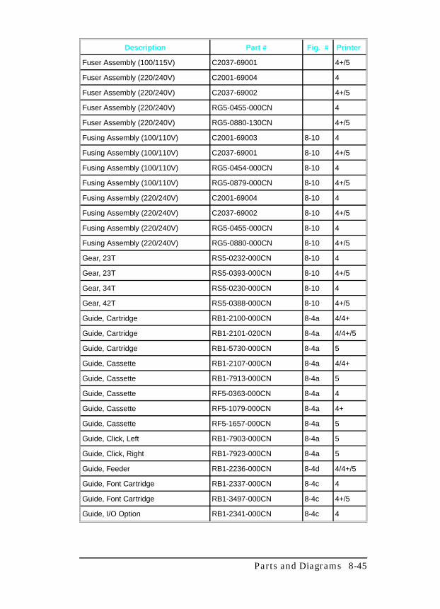
Description Part # Fig. # Printer
Fuser Assembly (100/115V) C2037-69001 4+/5
Fuser Assembly (220/240V) C2001-69004 4
Fuser Assembly (220/240V) C2037-69002 4+/5
Fuser Assembly (220/240V) RG5-0455-000CN 4
Fuser Assembly (220/240V) RG5-0880-130CN 4+/5
Fusing Assembly (100/110V) C2001-69003 8-10 4
Fusing Assembly (100/110V) C2037-69001 8-10 4+/5
Fusing Assembly (100/110V) RG5-0454-000CN 8-10 4
Fusing Assembly (100/110V) RG5-0879-000CN 8-10 4+/5
Fusing Assembly (220/240V) C2001-69004 8-10 4
Fusing Assembly (220/240V) C2037-69002 8-10 4+/5
Fusing Assembly (220/240V) RG5-0455-000CN 8-10 4
Fusing Assembly (220/240V) RG5-0880-000CN 8-10 4+/5
Gear, 23T RS5-0232-000CN 8-10 4
Gear, 23T RS5-0393-000CN 8-10 4+/5
Gear, 34T RS5-0230-000CN 8-10 4
Gear, 42T RS5-0388-000CN 8-10 4+/5
Guide, Cartridge RB1-2100-000CN 8-4a 4/4+
Guide, Cartridge RB1-2101-020CN 8-4a 4/4+/5
Guide, Cartridge RB1-5730-000CN 8-4a 5
Guide, Cassette RB1-2107-000CN 8-4a 4/4+
Guide, Cassette RB1-7913-000CN 8-4a 5
Guide, Cassette RF5-0363-000CN 8-4a 4
Guide, Cassette RF5-1079-000CN 8-4a 4+
Guide, Cassette RF5-1657-000CN 8-4a 5
Guide, Click, Left RB1-7903-000CN 8-4a 5
Guide, Click, Right RB1-7923-000CN 8-4a 5
Guide, Feeder RB1-2236-000CN 8-4d 4/4+/5
Guide, Font Cartridge RB1-2337-000CN 8-4c 4
Guide, Font Cartridge RB1-3497-000CN 8-4c 4+/5
Guide, I/O Option RB1-2341-000CN 8-4c 4
Parts and Diagrams 8-45
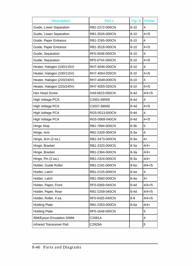
Description Part # Fig. # Printer
Guide, Lower Separation RB1-2272-000CN 8-10 4
Guide, Lower Separation RB1-3526-000CN 8-10 4+/5
Guide, Paper Entrance RB1-2265-000CN 8-10 4
Guide, Paper Entrance RB1-3518-000CN 8-10 4+/5
Guide, Separation RF5-0536-000CN 8-10 4
Guide, Separation RF5-0744-000CN 8-10 4+/5
Heater, Halogen (100/115V) RH7-4046-000CN 8-10 4
Heater, Halogen (100/115V) RH7-4054-020CN 8-10 4+/5
Heater, Halogen (220/240V) RH7-4048-000CN 8-10 4
Heater, Halogen (220/240V) RH7-4055-020CN 8-10 4+/5
Hex Head Screw XA9-0623-000CN 8-4d 4/4+/5
High Voltage PCA C2001-69009 8-4d 4
High Voltage PCA C2037-69009 8-4d 4+/5
High Voltage PCA RG5-0513-000CN 8-4d 4
High Voltage PCA RG5-0969-040CN 8-4d 4+/5
Hinge Stop RB1-7894-000CN 8-3b 5
Hinge, Arm RB1-2329-000CN 8-3a 4
Hinge, Arm (2 ea.) RB1-3473-000CN 8-3a 4+
Hinge, Bracket RB1-2323-000CN 8-3a 4/4+
Hinge, Bracket RB1-2364-000CN 8-3a 4/4+
Hinge, Pin (2 ea.) RB1-2324-000CN 8-3a 4/4+
Holder, Guide Roller RB1-2181-000CN 8-6a 4/4+/5
Holder, Latch RB1-2125-000CN 8-4a 4
Holder, Latch RB1-3560-000CN 8-4a 4+
Holder, Paper, Front RF5-0369-040CN 8-4d 4/4+/5
Holder, Paper, Rear RB1-2259-040CN 8-4d 4/4+/5
Holder, Roller, 4 ea. RF5-0425-040CN 8-8 4/4+/5
Holding Plate RB1-2353-000CN 8-4a 4/4+
Holding Plate RF5-1648-000CN 5
IBM/Epson Emulation SIMM C2081A 4
Infrared Transceiver Pod C2929A 5
8-46 Parts and Diagrams
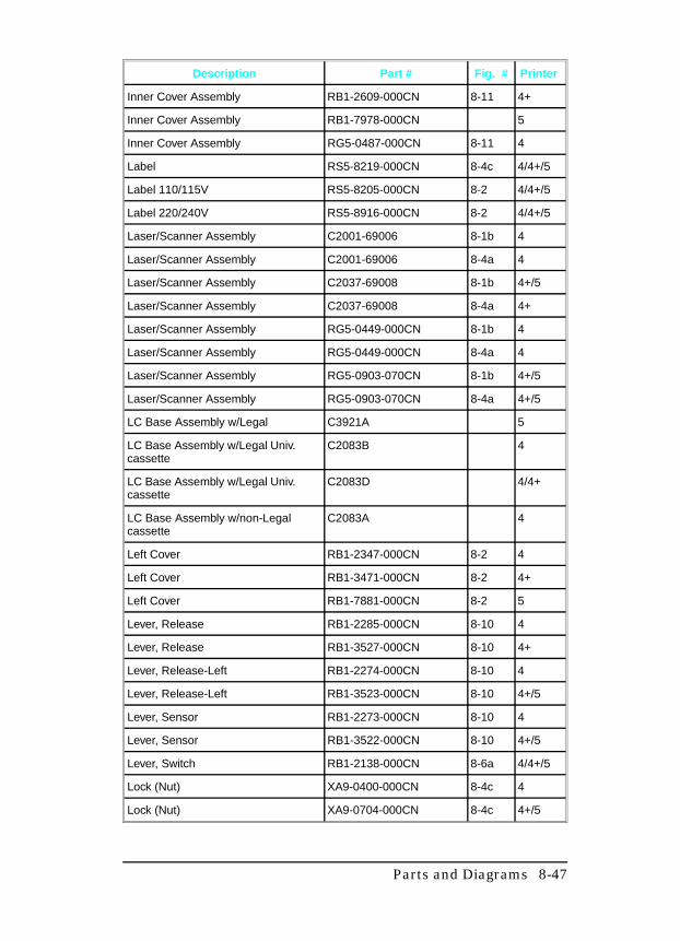
Description Part # Fig. # Printer
Inner Cover Assembly RB1-2609-000CN 8-11 4+
Inner Cover Assembly RB1-7978-000CN 5
Inner Cover Assembly RG5-0487-000CN 8-11 4
Label RS5-8219-000CN 8-4c 4/4+/5
Label 110/115V RS5-8205-000CN 8-2 4/4+/5
Label 220/240V RS5-8916-000CN 8-2 4/4+/5
Laser/Scanner Assembly C2001-69006 8-1b 4
Laser/Scanner Assembly C2001-69006 8-4a 4
Laser/Scanner Assembly C2037-69008 8-1b 4+/5
Laser/Scanner Assembly C2037-69008 8-4a 4+
Laser/Scanner Assembly RG5-0449-000CN 8-1b 4
Laser/Scanner Assembly RG5-0449-000CN 8-4a 4
Laser/Scanner Assembly RG5-0903-070CN 8-1b 4+/5
Laser/Scanner Assembly RG5-0903-070CN 8-4a 4+/5
LC Base Assembly w/Legal C3921A 5
LC Base Assembly w/Legal Univ.cassette
C2083B 4
LC Base Assembly w/Legal Univ.cassette
C2083D 4/4+
LC Base Assembly w/non-Legalcassette
C2083A 4
Left Cover RB1-2347-000CN 8-2 4
Left Cover RB1-3471-000CN 8-2 4+
Left Cover RB1-7881-000CN 8-2 5
Lever, Release RB1-2285-000CN 8-10 4
Lever, Release RB1-3527-000CN 8-10 4+
Lever, Release-Left RB1-2274-000CN 8-10 4
Lever, Release-Left RB1-3523-000CN 8-10 4+/5
Lever, Sensor RB1-2273-000CN 8-10 4
Lever, Sensor RB1-3522-000CN 8-10 4+/5
Lever, Switch RB1-2138-000CN 8-6a 4/4+/5
Lock (Nut) XA9-0400-000CN 8-4c 4
Lock (Nut) XA9-0704-000CN 8-4c 4+/5
Parts and Diagrams 8-47
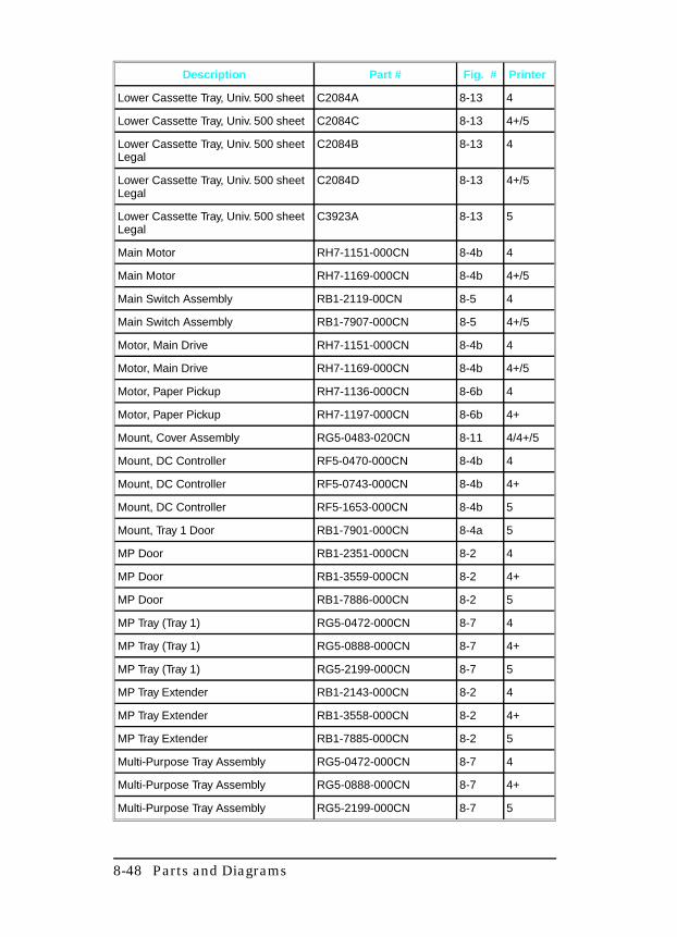
Description Part # Fig. # Printer
Lower Cassette Tray, Univ. 500 sheet C2084A 8-13 4
Lower Cassette Tray, Univ. 500 sheet C2084C 8-13 4+/5
Lower Cassette Tray, Univ. 500 sheetLegal
C2084B 8-13 4
Lower Cassette Tray, Univ. 500 sheetLegal
C2084D 8-13 4+/5
Lower Cassette Tray, Univ. 500 sheetLegal
C3923A 8-13 5
Main Motor RH7-1151-000CN 8-4b 4
Main Motor RH7-1169-000CN 8-4b 4+/5
Main Switch Assembly RB1-2119-00CN 8-5 4
Main Switch Assembly RB1-7907-000CN 8-5 4+/5
Motor, Main Drive RH7-1151-000CN 8-4b 4
Motor, Main Drive RH7-1169-000CN 8-4b 4+/5
Motor, Paper Pickup RH7-1136-000CN 8-6b 4
Motor, Paper Pickup RH7-1197-000CN 8-6b 4+
Mount, Cover Assembly RG5-0483-020CN 8-11 4/4+/5
Mount, DC Controller RF5-0470-000CN 8-4b 4
Mount, DC Controller RF5-0743-000CN 8-4b 4+
Mount, DC Controller RF5-1653-000CN 8-4b 5
Mount, Tray 1 Door RB1-7901-000CN 8-4a 5
MP Door RB1-2351-000CN 8-2 4
MP Door RB1-3559-000CN 8-2 4+
MP Door RB1-7886-000CN 8-2 5
MP Tray (Tray 1) RG5-0472-000CN 8-7 4
MP Tray (Tray 1) RG5-0888-000CN 8-7 4+
MP Tray (Tray 1) RG5-2199-000CN 8-7 5
MP Tray Extender RB1-2143-000CN 8-2 4
MP Tray Extender RB1-3558-000CN 8-2 4+
MP Tray Extender RB1-7885-000CN 8-2 5
Multi-Purpose Tray Assembly RG5-0472-000CN 8-7 4
Multi-Purpose Tray Assembly RG5-0888-000CN 8-7 4+
Multi-Purpose Tray Assembly RG5-2199-000CN 8-7 5
8-48 Parts and Diagrams
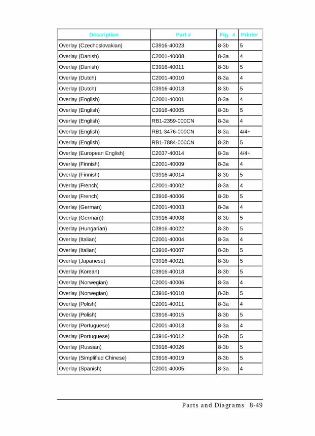
Description Part # Fig. # Printer
Overlay (Czechoslovakian) C3916-40023 8-3b 5
Overlay (Danish) C2001-40008 8-3a 4
Overlay (Danish) C3916-40011 8-3b 5
Overlay (Dutch) C2001-40010 8-3a 4
Overlay (Dutch) C3916-40013 8-3b 5
Overlay (English) C2001-40001 8-3a 4
Overlay (English) C3916-40005 8-3b 5
Overlay (English) RB1-2359-000CN 8-3a 4
Overlay (English) RB1-3476-000CN 8-3a 4/4+
Overlay (English) RB1-7884-000CN 8-3b 5
Overlay (European English) C2037-40014 8-3a 4/4+
Overlay (Finnish) C2001-40009 8-3a 4
Overlay (Finnish) C3916-40014 8-3b 5
Overlay (French) C2001-40002 8-3a 4
Overlay (French) C3916-40006 8-3b 5
Overlay (German) C2001-40003 8-3a 4
Overlay (German)) C3916-40008 8-3b 5
Overlay (Hungarian) C3916-40022 8-3b 5
Overlay (Italian) C2001-40004 8-3a 4
Overlay (Italian) C3916-40007 8-3b 5
Overlay (Japanese) C3916-40021 8-3b 5
Overlay (Korean) C3916-40018 8-3b 5
Overlay (Norwegian) C2001-40006 8-3a 4
Overlay (Norwegian) C3916-40010 8-3b 5
Overlay (Polish) C2001-40011 8-3a 4
Overlay (Polish) C3916-40015 8-3b 5
Overlay (Portuguese) C2001-40013 8-3a 4
Overlay (Portuguese) C3916-40012 8-3b 5
Overlay (Russian) C3916-40026 8-3b 5
Overlay (Simplified Chinese) C3916-40019 8-3b 5
Overlay (Spanish) C2001-40005 8-3a 4
Parts and Diagrams 8-49
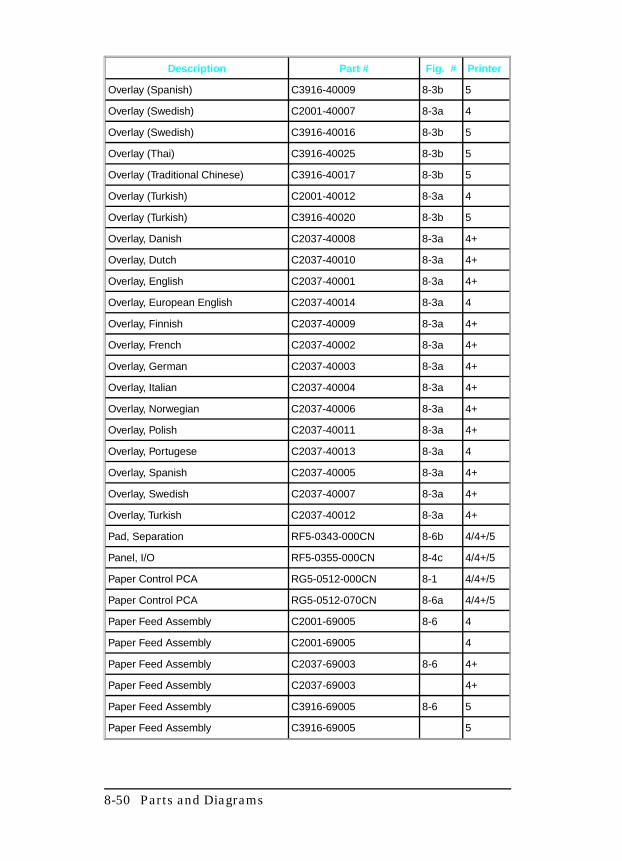
Description Part # Fig. # Printer
Overlay (Spanish) C3916-40009 8-3b 5
Overlay (Swedish) C2001-40007 8-3a 4
Overlay (Swedish) C3916-40016 8-3b 5
Overlay (Thai) C3916-40025 8-3b 5
Overlay (Traditional Chinese) C3916-40017 8-3b 5
Overlay (Turkish) C2001-40012 8-3a 4
Overlay (Turkish) C3916-40020 8-3b 5
Overlay, Danish C2037-40008 8-3a 4+
Overlay, Dutch C2037-40010 8-3a 4+
Overlay, English C2037-40001 8-3a 4+
Overlay, European English C2037-40014 8-3a 4
Overlay, Finnish C2037-40009 8-3a 4+
Overlay, French C2037-40002 8-3a 4+
Overlay, German C2037-40003 8-3a 4+
Overlay, Italian C2037-40004 8-3a 4+
Overlay, Norwegian C2037-40006 8-3a 4+
Overlay, Polish C2037-40011 8-3a 4+
Overlay, Portugese C2037-40013 8-3a 4
Overlay, Spanish C2037-40005 8-3a 4+
Overlay, Swedish C2037-40007 8-3a 4+
Overlay, Turkish C2037-40012 8-3a 4+
Pad, Separation RF5-0343-000CN 8-6b 4/4+/5
Panel, I/O RF5-0355-000CN 8-4c 4/4+/5
Paper Control PCA RG5-0512-000CN 8-1 4/4+/5
Paper Control PCA RG5-0512-070CN 8-6a 4/4+/5
Paper Feed Assembly C2001-69005 8-6 4
Paper Feed Assembly C2001-69005 4
Paper Feed Assembly C2037-69003 8-6 4+
Paper Feed Assembly C2037-69003 4+
Paper Feed Assembly C3916-69005 8-6 5
Paper Feed Assembly C3916-69005 5
8-50 Parts and Diagrams
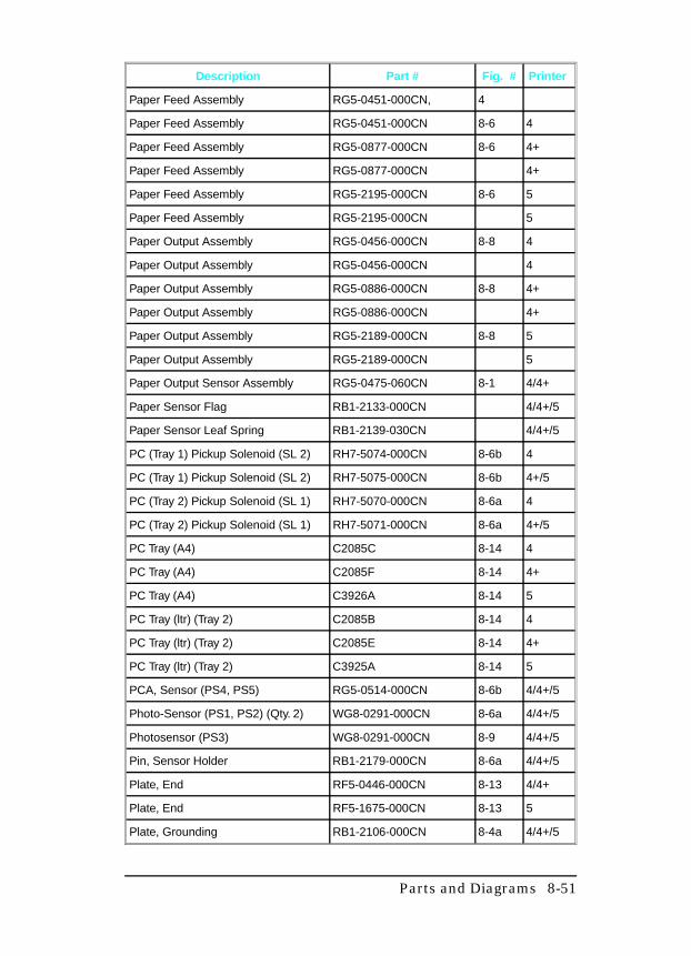
Description Part # Fig. # Printer
Paper Feed Assembly RG5-0451-000CN, 4
Paper Feed Assembly RG5-0451-000CN 8-6 4
Paper Feed Assembly RG5-0877-000CN 8-6 4+
Paper Feed Assembly RG5-0877-000CN 4+
Paper Feed Assembly RG5-2195-000CN 8-6 5
Paper Feed Assembly RG5-2195-000CN 5
Paper Output Assembly RG5-0456-000CN 8-8 4
Paper Output Assembly RG5-0456-000CN 4
Paper Output Assembly RG5-0886-000CN 8-8 4+
Paper Output Assembly RG5-0886-000CN 4+
Paper Output Assembly RG5-2189-000CN 8-8 5
Paper Output Assembly RG5-2189-000CN 5
Paper Output Sensor Assembly RG5-0475-060CN 8-1 4/4+
Paper Sensor Flag RB1-2133-000CN 4/4+/5
Paper Sensor Leaf Spring RB1-2139-030CN 4/4+/5
PC (Tray 1) Pickup Solenoid (SL 2) RH7-5074-000CN 8-6b 4
PC (Tray 1) Pickup Solenoid (SL 2) RH7-5075-000CN 8-6b 4+/5
PC (Tray 2) Pickup Solenoid (SL 1) RH7-5070-000CN 8-6a 4
PC (Tray 2) Pickup Solenoid (SL 1) RH7-5071-000CN 8-6a 4+/5
PC Tray (A4) C2085C 8-14 4
PC Tray (A4) C2085F 8-14 4+
PC Tray (A4) C3926A 8-14 5
PC Tray (ltr) (Tray 2) C2085B 8-14 4
PC Tray (ltr) (Tray 2) C2085E 8-14 4+
PC Tray (ltr) (Tray 2) C3925A 8-14 5
PCA, Sensor (PS4, PS5) RG5-0514-000CN 8-6b 4/4+/5
Photo-Sensor (PS1, PS2) (Qty. 2) WG8-0291-000CN 8-6a 4/4+/5
Photosensor (PS3) WG8-0291-000CN 8-9 4/4+/5
Pin, Sensor Holder RB1-2179-000CN 8-6a 4/4+/5
Plate, End RF5-0446-000CN 8-13 4/4+
Plate, End RF5-1675-000CN 8-13 5
Plate, Grounding RB1-2106-000CN 8-4a 4/4+/5
Parts and Diagrams 8-51
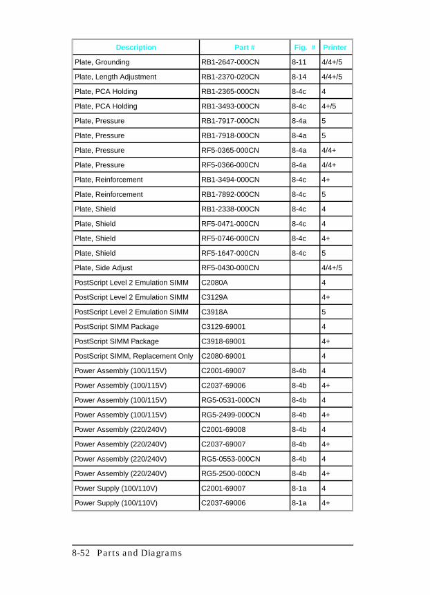
Description Part # Fig. # Printer
Plate, Grounding RB1-2647-000CN 8-11 4/4+/5
Plate, Length Adjustment RB1-2370-020CN 8-14 4/4+/5
Plate, PCA Holding RB1-2365-000CN 8-4c 4
Plate, PCA Holding RB1-3493-000CN 8-4c 4+/5
Plate, Pressure RB1-7917-000CN 8-4a 5
Plate, Pressure RB1-7918-000CN 8-4a 5
Plate, Pressure RF5-0365-000CN 8-4a 4/4+
Plate, Pressure RF5-0366-000CN 8-4a 4/4+
Plate, Reinforcement RB1-3494-000CN 8-4c 4+
Plate, Reinforcement RB1-7892-000CN 8-4c 5
Plate, Shield RB1-2338-000CN 8-4c 4
Plate, Shield RF5-0471-000CN 8-4c 4
Plate, Shield RF5-0746-000CN 8-4c 4+
Plate, Shield RF5-1647-000CN 8-4c 5
Plate, Side Adjust RF5-0430-000CN 4/4+/5
PostScript Level 2 Emulation SIMM C2080A 4
PostScript Level 2 Emulation SIMM C3129A 4+
PostScript Level 2 Emulation SIMM C3918A 5
PostScript SIMM Package C3129-69001 4
PostScript SIMM Package C3918-69001 4+
PostScript SIMM, Replacement Only C2080-69001 4
Power Assembly (100/115V) C2001-69007 8-4b 4
Power Assembly (100/115V) C2037-69006 8-4b 4+
Power Assembly (100/115V) RG5-0531-000CN 8-4b 4
Power Assembly (100/115V) RG5-2499-000CN 8-4b 4+
Power Assembly (220/240V) C2001-69008 8-4b 4
Power Assembly (220/240V) C2037-69007 8-4b 4+
Power Assembly (220/240V) RG5-0553-000CN 8-4b 4
Power Assembly (220/240V) RG5-2500-000CN 8-4b 4+
Power Supply (100/110V) C2001-69007 8-1a 4
Power Supply (100/110V) C2037-69006 8-1a 4+
8-52 Parts and Diagrams
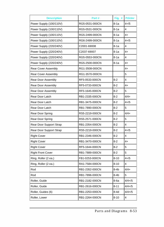
Description Part # Fig. # Printer
Power Supply (100/110V) RG5-0531-000CN 8-1a 4+/5
Power Supply (100/110V) RG5-0531-000CN 8-1a 4
Power Supply (100/110V) RG5-2499-000CN 8-1a 4+
Power Supply (100/110V) RG6-2499-000CN 8-1a 4+/5
Power Supply (220/240V) C2001-69008 8-1a 4
Power Supply (220/240V) C2037-69007 8-1a 4+
Power Supply (220/240V) RG5-0553-000CN 8-1a 4
Power Supply (220/240V) RG5-2500-000CN 8-1a 4+
Rear Cover Assembly RG1-3508-000CN 4+
Rear Cover Assembly RG1-3570-000CN 5
Rear Door Assembly RF5-0533-000CN 8-2 4
Rear Door Assembly RF5-0733-000CN 8-2 4+
Rear Door Assembly RF5-1645-000CN 8-2 5
Rear Door Latch RB1-2335-000CN 8-2 4/4+
Rear Door Latch RB1-3475-000CN 8-2 4+/5
Rear Door Latch RB1-7890-000CN 8-2 5
Rear Door Spring RS5-2219-000CN 8-2 4/4+
Rear Door Spring RS5-2571-000CN 8-2 5
Rear Door Support Strap RB1-2354-000CN 8-2 4
Rear Door Support Strap RS5-2219-000CN 8-2 4+/5
Right Cover RB1-2346-000CN 8-2 4
Right Cover RB1-3470-000CN 8-2 4+
Right Cover RF5-1644-000CN 8-2 5
Right Front Cover RB1-7889-000CN 8-2 5
Ring, Roller (2 ea.) FB1-0253-000CN 8-10 4+/5
Ring, Roller (2 ea.) RA1-7584-000CN 8-10 4
Rod RB1-2352-000CN 8-4b 4/4+
Rod RB1-7896-000CN 8-4b 5
Roller, Guide RB1-2182-000CN 8-6a 4/4+/5
Roller, Guide RB1-2616-000CN 8-11 4/4+/5
Roller, Guides (6) RB1-2253-000CN 8-4d 4/4+/5
Roller, Lower RB1-2264-000CN 8-10 4
Parts and Diagrams 8-53
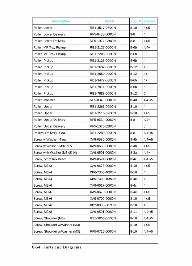
Description Part # Fig. # Printer
Roller, Lower RB1-3517-030CN 8-10 4+/5
Roller, Lower Delivery RF5-0438-000CN 8-8 4
Roller, Lower Delivery RF5-1077-030CN 8-8 4+/5
Roller, MP Tray Pickup RB1-2127-000CN 8-6b 4/4+
Roller, MP Tray Pickup RB1-2205-000CN 8-6b 5
Roller, Pickup RB1-2126-000CN 8-6b 4
Roller, Pickup RB1-2632-000CN 8-12 4
Roller, Pickup RB1-2650-000CN 8-12 4+
Roller, Pickup RB1-3477-000CN 8-6b 4+
Roller, Pickup RB1-7911-000CN 8-6b 5
Roller, Pickup RB1-7983-000CN 8-12 5
Roller, Transfer RF5-0349-000CN 8-4d 4/4+/5
Roller, Upper RB1-2263-000CN 8-10 4
Roller, Upper RB1-3516-020CN 8-10 4+/5
Roller, Upper Delivery RF5-0534-000CN 8-8 4/4+
Roller, Upper Delivery RF5-1076-020CN 5
Rollers, Delivery, 4 ea. RB1-2299-030CN 8-8 4/4+/5
Screw w/Washer, 4 ea. XA9-0585-000CN 8-4b 4/4+/5
Screw w/Washer, M3x29.5 XA9-0668-000CN 8-4b 4+/5
Screw with Washer (M3x8) (4) XA9-0591-000CN 8-3a 4/4+
Screw, 5mm hex head XA9-0574-000CN 8-4c 4/4+/5
Screw, M3x3 XA9-0678-000CN 8-10 4+/5
Screw, M3x4 XB6-7300-409CN 8-10 4
Screw, M3x4 XB6-7300-409CN 8-4c 4
Screw, M3x6 XA9-0617-000CN 8-4c 4
Screw, M3x6 XA9-0670-000CN 8-4c 4+/5
Screw, M3x6 XA9-0702-000CN 8-10 4+/5
Screw, M3x6 XB2-8300-607CN 8-10 4
Screw, M3x8 XA9-0591-000CN 8-11 4/4+/5
Screw, Shoulder (M3) RS5-9055-000CN 8-10 4/4+/5
Screw, Shoulder w/Washer (M3) 8-10 4+/5
Screw, Shoulder w/Washer (M3) RF5-0716-000CN 8-10 4/4+/5
8-54 Parts and Diagrams
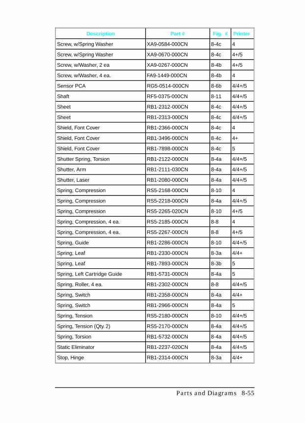
Description Part # Fig. # Printer
Screw, w/Spring Washer XA9-0584-000CN 8-4c 4
Screw, w/Spring Washer XA9-0670-000CN 8-4c 4+/5
Screw, w/Washer, 2 ea XA9-0267-000CN 8-4b 4+/5
Screw, w/Washer, 4 ea. FA9-1449-000CN 8-4b 4
Sensor PCA RG5-0514-000CN 8-6b 4/4+/5
Shaft RF5-0375-000CN 8-11 4/4+/5
Sheet RB1-2312-000CN 8-4c 4/4+/5
Sheet RB1-2313-000CN 8-4c 4/4+/5
Shield, Font Cover RB1-2366-000CN 8-4c 4
Shield, Font Cover RB1-3496-000CN 8-4c 4+
Shield, Font Cover RB1-7898-000CN 8-4c 5
Shutter Spring, Torsion RB1-2122-000CN 8-4a 4/4+/5
Shutter, Arm RB1-2111-030CN 8-4a 4/4+/5
Shutter, Laser RB1-2080-000CN 8-4a 4/4+/5
Spring, Compression RS5-2168-000CN 8-10 4
Spring, Compression RS5-2218-000CN 8-4a 4/4+/5
Spring, Compression RS5-2265-020CN 8-10 4+/5
Spring, Compression, 4 ea. RS5-2185-000CN 8-8 4
Spring, Compression, 4 ea. RS5-2267-000CN 8-8 4+/5
Spring, Guide RB1-2286-000CN 8-10 4/4+/5
Spring, Leaf RB1-2330-000CN 8-3a 4/4+
Spring, Leaf RB1-7893-000CN 8-3b 5
Spring, Left Cartridge Guide RB1-5731-000CN 8-4a 5
Spring, Roller, 4 ea. RB1-2302-000CN 8-8 4/4+/5
Spring, Switch RB1-2358-000CN 8-4a 4/4+
Spring, Switch RB1-2966-000CN 8-4a 5
Spring, Tension RS5-2180-000CN 8-10 4/4+/5
Spring, Tension (Qty. 2) RS5-2170-000CN 8-4a 4/4+/5
Spring, Torsion RB1-5732-000CN 8-4a 4/4+/5
Static Eliminator RB1-2237-020CN 8-4a 4/4+/5
Stop, Hinge RB1-2314-000CN 8-3a 4/4+
Parts and Diagrams 8-55
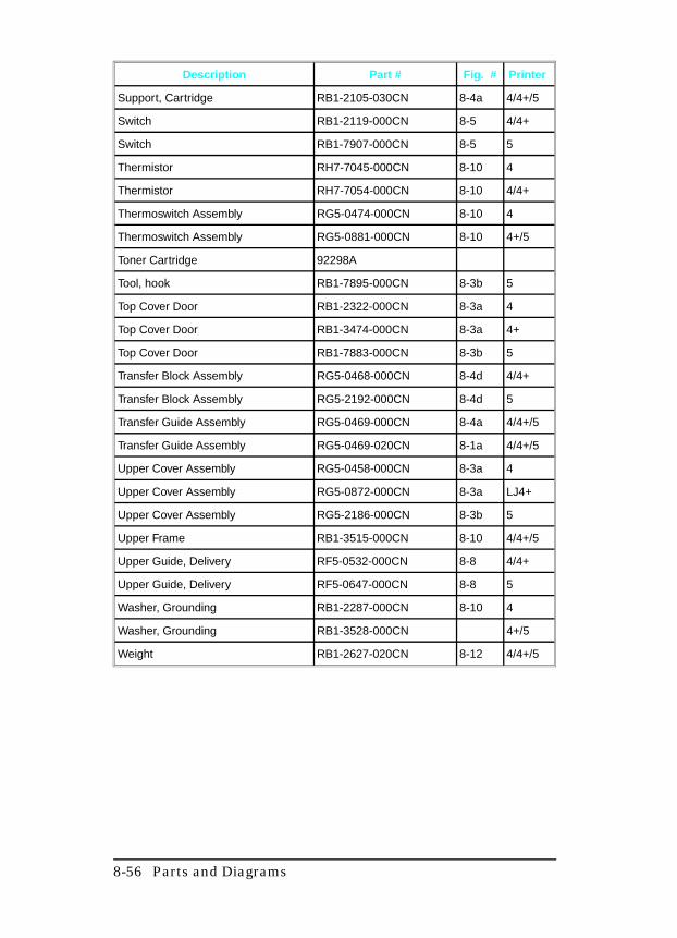
Description Part # Fig. # Printer
Support, Cartridge RB1-2105-030CN 8-4a 4/4+/5
Switch RB1-2119-000CN 8-5 4/4+
Switch RB1-7907-000CN 8-5 5
Thermistor RH7-7045-000CN 8-10 4
Thermistor RH7-7054-000CN 8-10 4/4+
Thermoswitch Assembly RG5-0474-000CN 8-10 4
Thermoswitch Assembly RG5-0881-000CN 8-10 4+/5
Toner Cartridge 92298A
Tool, hook RB1-7895-000CN 8-3b 5
Top Cover Door RB1-2322-000CN 8-3a 4
Top Cover Door RB1-3474-000CN 8-3a 4+
Top Cover Door RB1-7883-000CN 8-3b 5
Transfer Block Assembly RG5-0468-000CN 8-4d 4/4+
Transfer Block Assembly RG5-2192-000CN 8-4d 5
Transfer Guide Assembly RG5-0469-000CN 8-4a 4/4+/5
Transfer Guide Assembly RG5-0469-020CN 8-1a 4/4+/5
Upper Cover Assembly RG5-0458-000CN 8-3a 4
Upper Cover Assembly RG5-0872-000CN 8-3a LJ4+
Upper Cover Assembly RG5-2186-000CN 8-3b 5
Upper Frame RB1-3515-000CN 8-10 4/4+/5
Upper Guide, Delivery RF5-0532-000CN 8-8 4/4+
Upper Guide, Delivery RF5-0647-000CN 8-8 5
Washer, Grounding RB1-2287-000CN 8-10 4
Washer, Grounding RB1-3528-000CN 4+/5
Weight RB1-2627-020CN 8-12 4/4+/5
8-56 Parts and Diagrams
A
Duplexer This Appendix contains a functional overview of the OptionalDuplexer, as well as step-by-step Installation and Removal &Replacement instructions.
The Optional Duplexer, when used with the LaserJet 4 Plus/5printer, allows printing on both sides of the paper. It may be usedwith the optional 500-sheet Lower Cassette or with the printeralone.
N o t e The Duplexer works only with the LaserJet 4Plus or LaserJet 5 printer. It is not supported onthe LaserJet 4.
Duplexer A -1
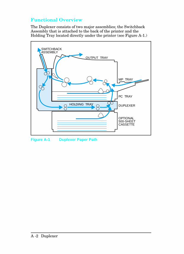
Functional OverviewThe Duplexer consists of two major assemblies; the SwitchbackAssembly that is attached to the back of the printer and theHolding Tray located directly under the printer (see Figure A-1.)
SWITCHBACKASSEMBLY
OUTPUT TRAY
MP TRAY
PC TRAY
DUPLEXER
OPTIONAL500-SHEETCASSETTE
HOLDING TRAY
Figure A-1 Duplexer Paper Path
A -2 Duplexer
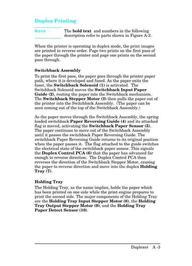
Duplex Printing
N o t e The bold text and numbers in the followingdescription refer to parts shown in Figure A-2.
When the printer is operating in duplex mode, the print imagesare printed in reverse order. Page two prints on the first pass ofthe paper through the printer and page one prints on the secondpass through.
Switchback AssemblyTo print the first pass, the paper goes through the printer paperpath, where it is developed and fused. As the paper exits thefuser, the Switchback Solenoid (1) is activated. TheSwitchback Solenoid moves the Switchback Input PaperGuide (2), routing the paper into the Switchback mechanism.The Switchback Stepper Motor (3) then pulls the paper out ofthe printer into the Switchback Assembly. (The paper can beseen coming out of the top of the Switchback Assembly.)
As the paper moves through the Switchback Assembly, the springloaded switchback Paper Reversing Guide (4) and its attachedflag is moved, activating the Switchback Paper Sensor (5).The paper continues to move out of the Switchback Assemblyuntil it passes the switchback Paper Reversing Guide. Theswitchback Paper Reversing Guide returns to its original positionwhen the paper passes it. The flag attached to the guide switchesthe electrical state of the switchback paper sensor. This signalsthe Duplex Control PCA (6) that the paper has advanced farenough to reverse direction. The Duplex Control PCA thenreverses the direction of the Switchback Stepper Motor, causingthe paper to reverse direction and move into the duplex HoldingTray (7).
Holding TrayThe Holding Tray, as the name implies, holds the paper whichhas been printed on one side while the print engine prepares toprint the second side. The major components of the Holding Trayare the Holding Tray Input Stepper Motor (8), the HoldingTray Output Stepper Motor (9), and the Holding TrayPaper Detect Sensor (10).
Duplexer A -3
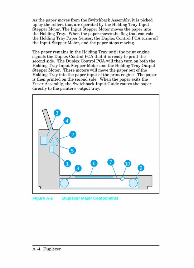
As the paper moves from the Switchback Assembly, it is pickedup by the rollers that are operated by the Holding Tray InputStepper Motor. The Input Stepper Motor moves the paper intothe Holding Tray. When the paper moves the flag that controlsthe Holding Tray Paper Sensor, the Duplex Control PCA turns offthe Input Stepper Motor, and the paper stops moving.
The paper remains in the Holding Tray until the print enginesignals the Duplex Control PCA that it is ready to print thesecond side. The Duplex Control PCA will then turn on both theHolding Tray Input Stepper Motor and the Holding Tray OutputStepper Motor. These motors will move the paper out of theHolding Tray into the paper input of the print engine. The paperis then printed on the second side. When the paper exits theFuser Assembly, the Switchback Input Guide routes the paperdirectly to the printer’s output tray.
3
4
2
5
18 9
7 106
Figure A-2 Duplexer Major Components
A -4 Duplexer
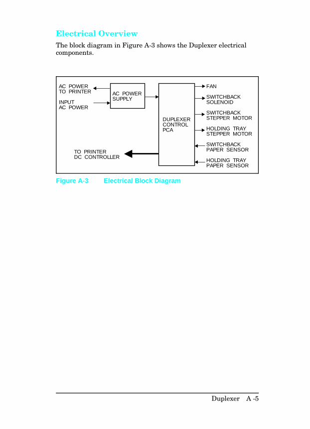
Electrical OverviewThe block diagram in Figure A-3 shows the Duplexer electricalcomponents.
AC POWERSUPPLY
DUPLEXERCONTROLPCA
AC POWERTO PRINTER
INPUTAC POWER
TO PRINTERDC CONTROLLER
FAN
SWITCHBACKSOLENOID
SWITCHBACKSTEPPER MOTOR
HOLDING TRAYSTEPPER MOTOR
SWITCHBACKPAPER SENSOR
HOLDING TRAYPAPER SENSOR
Figure A-3 Electrical Block Diagram
Duplexer A -5
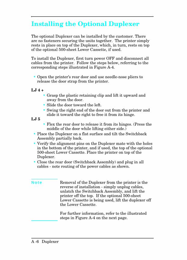
Installing the Optional Duplexer
The optional Duplexer can be installed by the customer. Thereare no fasteners securing the units together. The printer simplyrests in place on top of the Duplexer, which, in turn, rests on topof the optional 500-sheet Lower Cassette, if used.
To install the Duplexer, first turn power OFF and disconnect allcables from the printer. Follow the steps below, referring to thecorresponding steps illustrated in Figure A-4.
• Open the printer’s rear door and use needle-nose pliers torelease the door strap from the printer.
LJ 4 +• Grasp the plastic retaining clip and lift it upward and
away from the door.• Slide the door toward the left.• Swing the right end of the door out from the printer and
slide it toward the right to free it from its hinge.LJ 5
• Flex the rear door to release it from its hinges. (Press themiddle of the door while lifting either side.)
• Place the Duplexer on a flat surface and tilt the SwitchbackAssembly partially back.
• Verify the alignment pins on the Duplexer mate with the holesin the bottom of the printer, and if used, the top of the optional500-sheet Lower Cassette. Place the printer on top of theDuplexer.
• Close the rear door (Switchback Assembly) and plug in allcables - note routing of the power cables as shown.
N o t e Removal of the Duplexer from the printer is thereverse of installation - simply unplug cables,unlatch the Switchback Assembly, and lift theprinter off the top. If the optional 500-sheetLower Cassette is being used, lift the duplexer offthe Lower Cassette.
For further information, refer to the illustratedsteps in Figure A-4 on the next page.
A -6 Duplexer
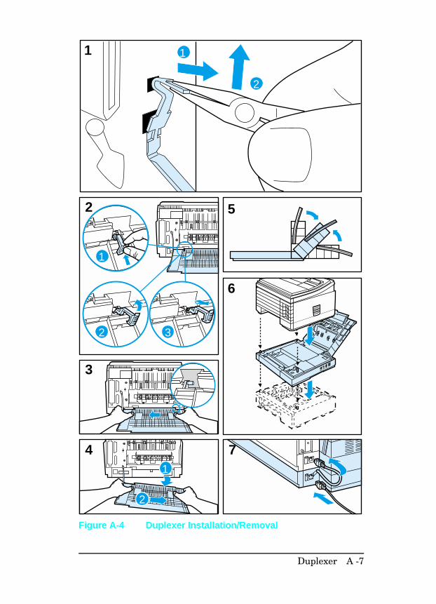
7
6
52
4
3
1
2 3
1
2
1 1
2
Figure A-4 Duplexer Installation/Removal
Duplexer A -7
Removal and Replacement
This section describes the complete disassembly of the Duplexer.Tasks that must be performed before beginning the procedure arelisted first. Remove the assemblies in the order listed to preventdamage.
The assembly procedure is the reverse of the removal procedure,except where specific instructions are provided.
In the removal and replacement procedures that follow, thenumber inside the parentheses, such as (4), refers to the numberof screws to remove.
W a r n i n g Power OFF the printer and disconnect the powercord from the outlet and the printer beforeservicing the Duplexer.
Some sheet metal edges are sharp. Be carefulwhen working in these areas to avoid being cut.
C a u t i o n The Duplexer contains parts that are sensitive toElectro-Static Discharge (ESD). Always observeproper ESD procedures when servicing theDuplexer.
This symbol appears when the parts beingserviced are especially susceptible to ESDdamage.
Required Tools#2 Magnetized Phillips ScrewdriverSmall Flat-head Screwdriver (6-inch shaft)Needle-nose Pliers
C a u t i o n Do not use a Pozidriv screwdriver. Damage to thescrew heads will result.
A -8 Duplexer
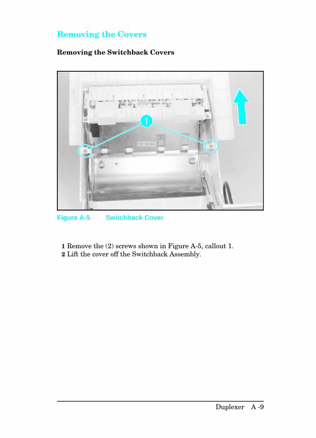
Removing the Covers
Removing the Switchback Covers
1 Remove the (2) screws shown in Figure A-5, callout 1. 2 Lift the cover off the Switchback Assembly.
Figure A-5 Switchback Cover
Duplexer A -9
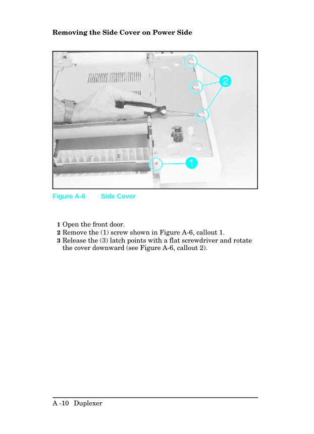
Removing the Side Cover on Power Side
1 Open the front door.2 Remove the (1) screw shown in Figure A-6, callout 1.3 Release the (3) latch points with a flat screwdriver and rotate
the cover downward (see Figure A-6, callout 2).
Figure A-6 Side Cover
A -10 Duplexer
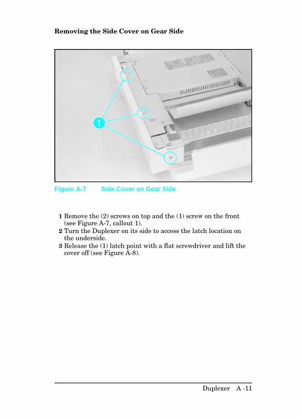
Removing the Side Cover on Gear Side
1 Remove the (2) screws on top and the (1) screw on the front(see Figure A-7, callout 1).
2 Turn the Duplexer on its side to access the latch location onthe underside.
3 Release the (1) latch point with a flat screwdriver and lift thecover off (see Figure A-8).
Figure A-7 Side Cover on Gear Side
Duplexer A -11
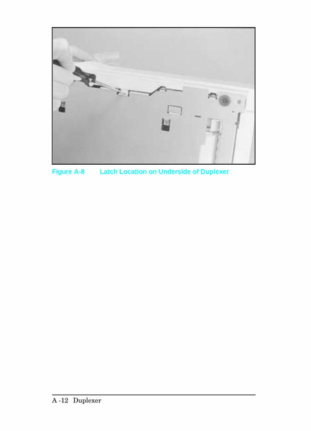
Figure A-8 Latch Location on Underside of Duplexer
A -12 Duplexer
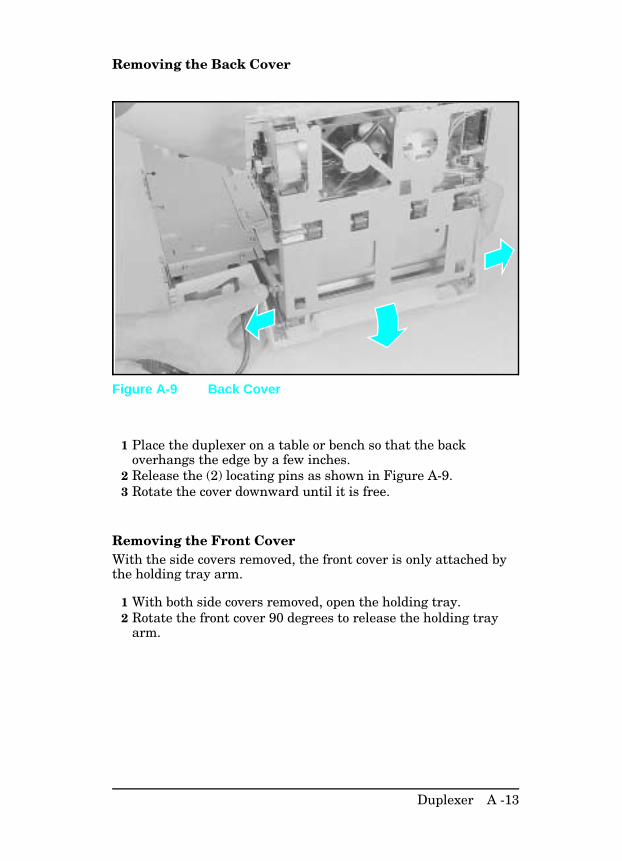
Removing the Back Cover
1 Place the duplexer on a table or bench so that the backoverhangs the edge by a few inches.
2 Release the (2) locating pins as shown in Figure A-9.3 Rotate the cover downward until it is free.
Removing the Front CoverWith the side covers removed, the front cover is only attached bythe holding tray arm.
1 With both side covers removed, open the holding tray.2 Rotate the front cover 90 degrees to release the holding tray
arm.
Figure A-9 Back Cover
Duplexer A -13
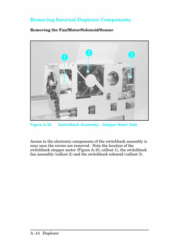
Removing Internal Duplexer Components
Removing the Fan/Motor/Solenoid/Sensor
Access to the electronic components of the switchback assembly iseasy once the covers are removed. Note the location of theswitchback stepper motor (Figure A-10, callout 1), the switchbackfan assembly (callout 2) and the switchback solenoid (callout 3).
Figure A-10 Switchback Assembly - Stepper Motor Side
A -14 Duplexer
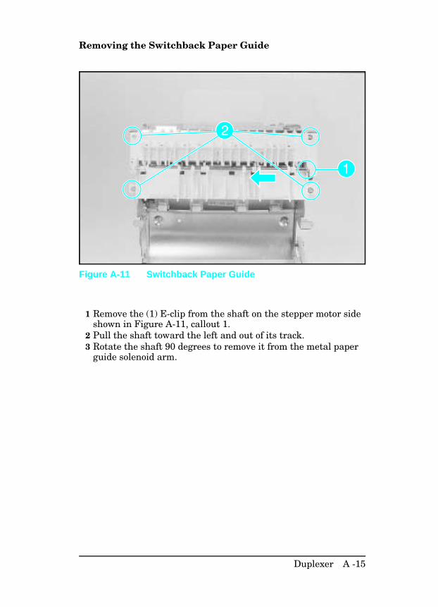
Removing the Switchback Paper Guide
1 Remove the (1) E-clip from the shaft on the stepper motor sideshown in Figure A-11, callout 1.
2 Pull the shaft toward the left and out of its track.3 Rotate the shaft 90 degrees to remove it from the metal paper
guide solenoid arm.
Figure A-11 Switchback Paper Guide
Duplexer A -15
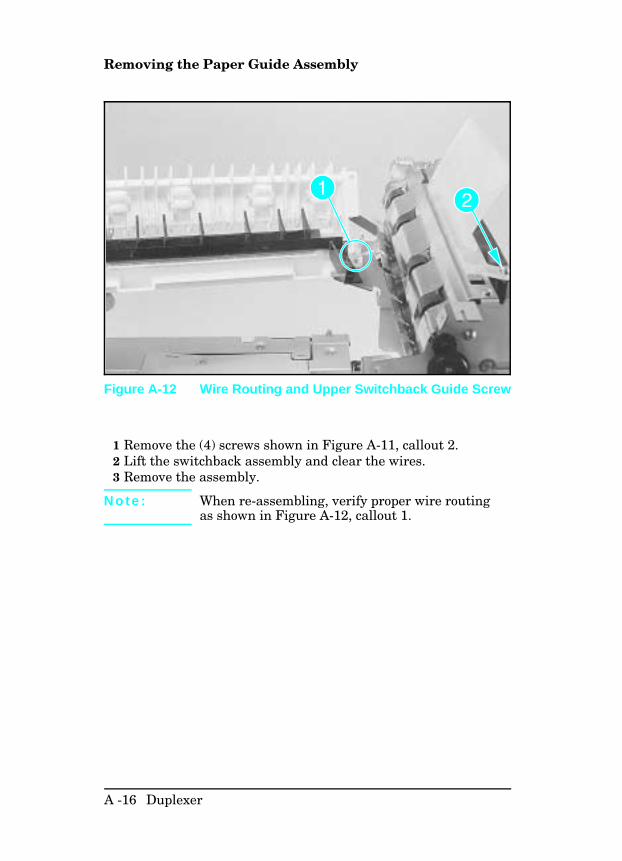
Removing the Paper Guide Assembly
1 Remove the (4) screws shown in Figure A-11, callout 2.2 Lift the switchback assembly and clear the wires.3 Remove the assembly.
N o t e : When re-assembling, verify proper wire routingas shown in Figure A-12, callout 1.
Figure A-12 Wire Routing and Upper Switchback Guide Screw
A -16 Duplexer
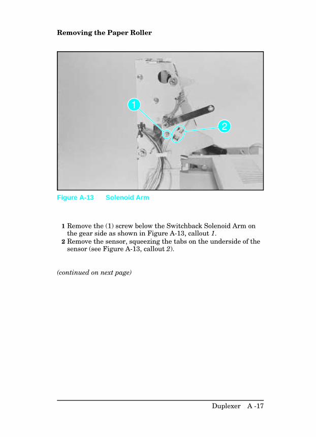
Removing the Paper Roller
1 Remove the (1) screw below the Switchback Solenoid Arm onthe gear side as shown in Figure A-13, callout 1.
2 Remove the sensor, squeezing the tabs on the underside of thesensor (see Figure A-13, callout 2).
(continued on next page)
Figure A-13 Solenoid Arm
Duplexer A -17
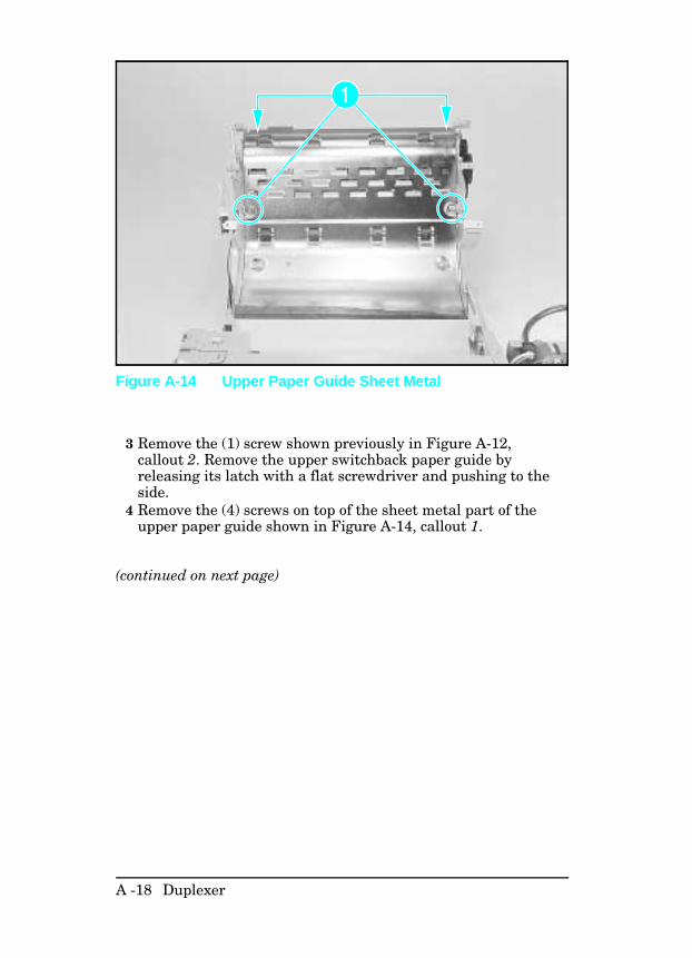
3 Remove the (1) screw shown previously in Figure A-12,callout 2. Remove the upper switchback paper guide byreleasing its latch with a flat screwdriver and pushing to theside.
4 Remove the (4) screws on top of the sheet metal part of theupper paper guide shown in Figure A-14, callout 1.
(continued on next page)
Figure A-14 Upper Paper Guide Sheet Metal
A -18 Duplexer
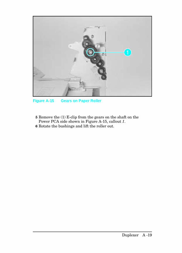
5 Remove the (1) E-clip from the gears on the shaft on thePower PCA side shown in Figure A-15, callout 1.
6 Rotate the bushings and lift the roller out.
Figure A-15 Gears on Paper Roller
Duplexer A -19
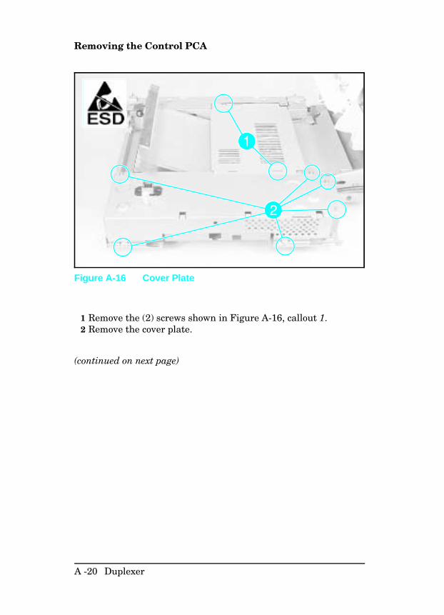
Removing the Control PCA
1 Remove the (2) screws shown in Figure A-16, callout 1.2 Remove the cover plate.
(continued on next page)
Figure A-16 Cover Plate
A -20 Duplexer
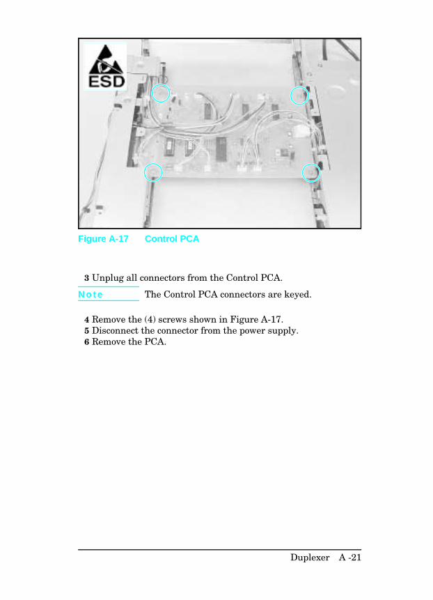
3 Unplug all connectors from the Control PCA.
N o t e The Control PCA connectors are keyed.
4 Remove the (4) screws shown in Figure A-17.5 Disconnect the connector from the power supply.6 Remove the PCA.
Figure A-17 Control PCA
Duplexer A -21
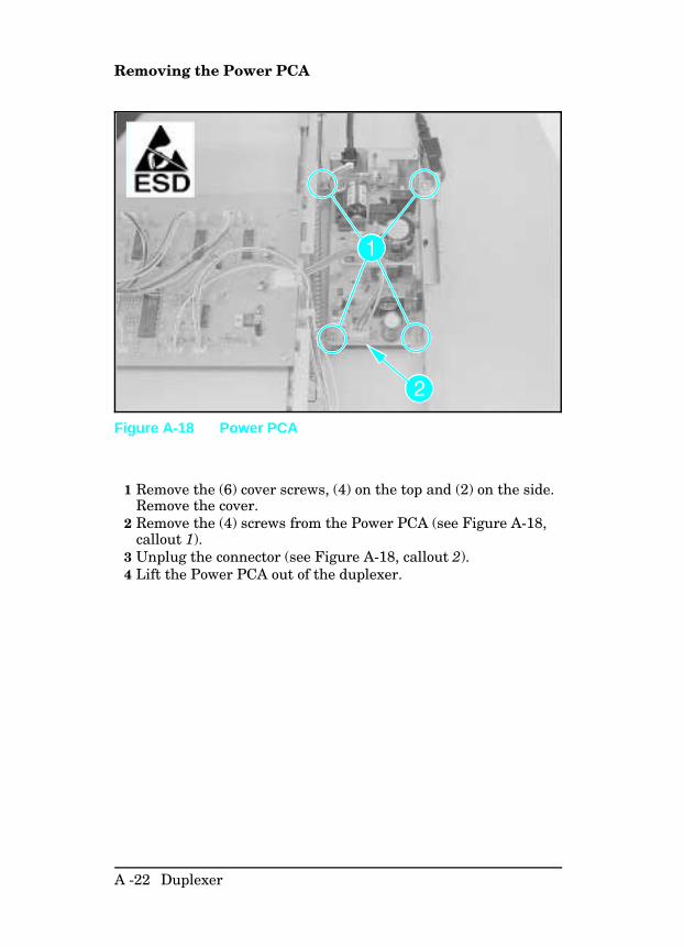
Removing the Power PCA
1 Remove the (6) cover screws, (4) on the top and (2) on the side.Remove the cover.
2 Remove the (4) screws from the Power PCA (see Figure A-18,callout 1).
3 Unplug the connector (see Figure A-18, callout 2).4 Lift the Power PCA out of the duplexer.
Figure A-18 Power PCA
A -22 Duplexer
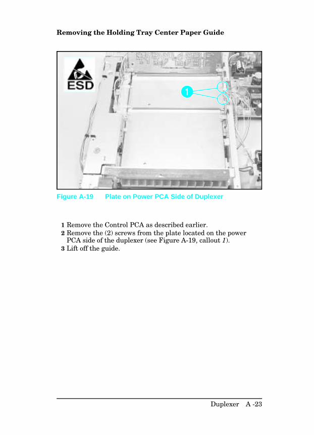
Removing the Holding Tray Center Paper Guide
1 Remove the Control PCA as described earlier.2 Remove the (2) screws from the plate located on the power
PCA side of the duplexer (see Figure A-19, callout 1).3 Lift off the guide.
Figure A-19 Plate on Power PCA Side of Duplexer
Duplexer A -23
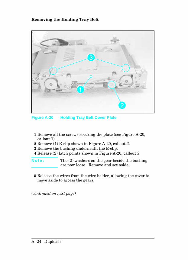
Removing the Holding Tray Belt
1 Remove all the screws securing the plate (see Figure A-20,callout 1).
2 Remove (1) E-clip shown in Figure A-20, callout 2. 3 Remove the bushing underneath the E-clip.4 Release (2) latch points shown in Figure A-20, callout 3.
N o t e : The (2) washers on the gear beside the bushingare now loose. Remove and set aside.
5 Release the wires from the wire holder, allowing the cover tomove aside to access the gears.
(continued on next page)
Figure A-20 Holding Tray Belt Cover Plate
A -24 Duplexer
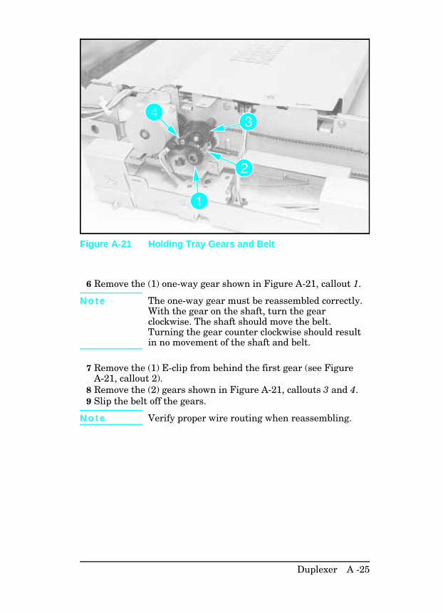
6 Remove the (1) one-way gear shown in Figure A-21, callout 1.
N o t e The one-way gear must be reassembled correctly.With the gear on the shaft, turn the gearclockwise. The shaft should move the belt.Turning the gear counter clockwise should resultin no movement of the shaft and belt.
7 Remove the (1) E-clip from behind the first gear (see FigureA-21, callout 2).
8 Remove the (2) gears shown in Figure A-21, callouts 3 and 4.9 Slip the belt off the gears.
N o t e Verify proper wire routing when reassembling.
Figure A-21 Holding Tray Gears and Belt
Duplexer A -25
Removing the Holding Tray Paper Sensor
1 Release the output holding tray.2 Remove the (2) screws from the stepper motor mount and
remove mount. (This provides access to the paper sensorlatches.)
3 Squeeze the (2) latch points of the paper sensor to release (seeFigure A-22).
4 Disconnect the connector and remove the paper sensor.
Figure A-22 Holding Tray Paper Sensor
A -26 Duplexer
Removing the Switchback Assembly
1 Pull out the pin located on the Power PCA side (see FigureA-23, callout 1).
2 Release the (1) E-clip on the upper pin near the retaining arm(see Figure A-23, callout 2).
3 Pull the retaining arm off the pin.4 Rotate the switchback assembly and remove.5 Unplug the connectors.
Figure A-23 Switchback Assembly Hinge Pins
Duplexer A -27
Parts and Diagrams for the Duplexer
The figures in this section illustrate the major subassemblies andcomponent parts of the HP LaserJet 4+/5 Duplexer.
N o t eNot all duplexer parts are orderable. The parts listed are the onlyorderable parts. Parts that have no reference designator or partnumber are not field-replaceable and cannot be ordered throughHP.
A -28 Duplexer
Figure A-24 Duplex External Covers
Duplexer A -29
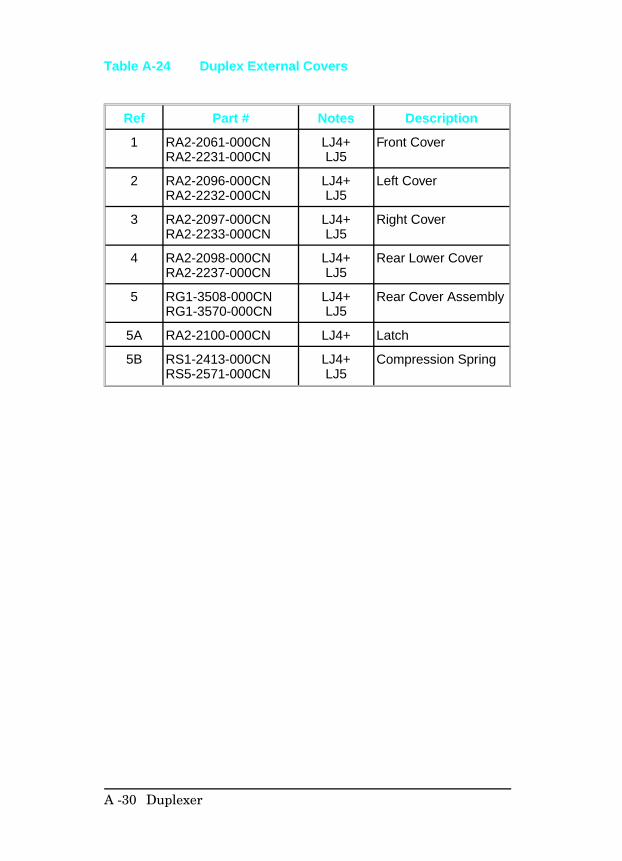
Ref Part # Notes Description
1 RA2-2061-000CNRA2-2231-000CN
LJ4+LJ5
Front Cover
2 RA2-2096-000CNRA2-2232-000CN
LJ4+LJ5
Left Cover
3 RA2-2097-000CNRA2-2233-000CN
LJ4+LJ5
Right Cover
4 RA2-2098-000CNRA2-2237-000CN
LJ4+LJ5
Rear Lower Cover
5 RG1-3508-000CNRG1-3570-000CN
LJ4+LJ5
Rear Cover Assembly
5A RA2-2100-000CN LJ4+ Latch
5B RS1-2413-000CNRS5-2571-000CN
LJ4+LJ5
Compression Spring
Table A-24 Duplex External Covers
A -30 Duplexer
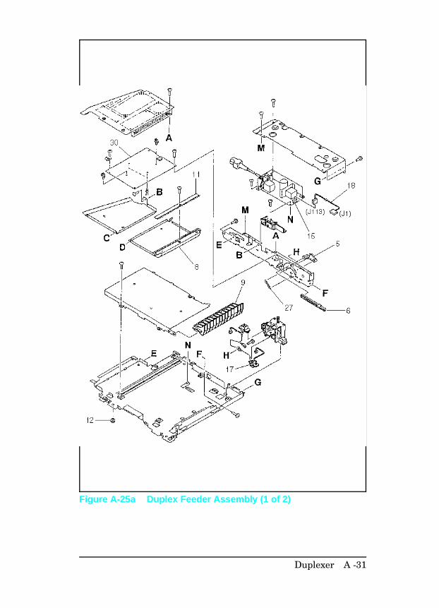
Figure A-25a Duplex Feeder Assembly (1 of 2)
Duplexer A -31
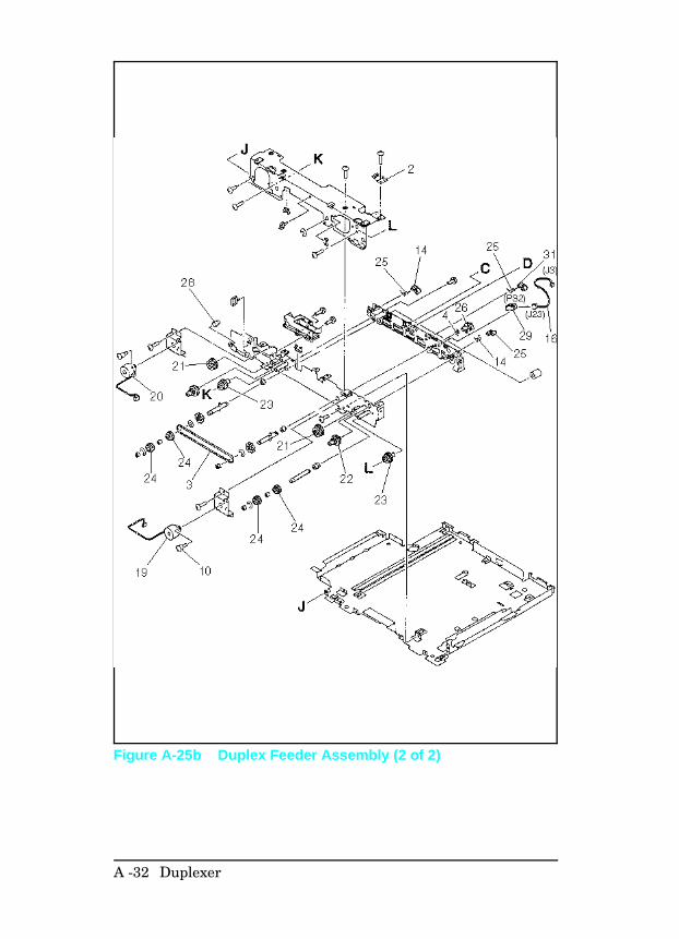
Figure A-25b Duplex Feeder Assembly (2 of 2)
A -32 Duplexer
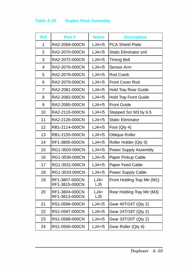
Ref Part # Notes Description
1 RA2-2069-000CN LJ4+/5 PCA Shield Plate
2 RA2-2070-000CN LJ4+/5 Static Eliminator sml
3 RA2-2072-000CN LJ4+/5 Timing Belt
4 RA2-2076-000CN LJ4+/5 Sensor Arm
5 RA2-2078-000CN LJ4+/5 Rod Crank
6 RA2-2079-000CN LJ4+/5 Front Cover Rod
7 RA2-2081-000CN LJ4+/5 Hold Tray Rear Guide
8 RA2-2082-000CN LJ4+/5 Hold Tray Front Guide
9 RA2-2085-000CN LJ4+/5 Front Guide
10 RA2-2115-000CN LJ4+/5 Stepped Scr M3 by 6.5
11 RA2-2126-000CN LJ4+/5 Static Eliminator
12 RB1-2114-000CN LJ4+/5 Foot (Qty 4)
13 RB1-2155-000CN LJ4+/5 Oblique Roller
14 RF1-3805-000CN LJ4+/5 Roller Holder (Qty 3)
15 RG1-3503-000CN LJ4+/5 Power Supply Assembly
16 RG1-3530-000CN LJ4+/5 Paper Pickup Cable
17 RG1-3531-000CN LJ4+/5 Paper Feed Cable
18 RG1-3533-000CN LJ4+/5 Power Supply Cable
19 RF1-3807-000CNRF1-3815-000CN
LJ4+LJ5
Front Holding Tray Mtr (M1)
20 RF1-3804-000CNRF1-3813-000CN
LJ4+LJ5
Rear Holding Tray Mtr (M3)
21 RS1-0586-000CN LJ4+/5 Gear 40T/24T (Qty 2)
22 RS1-0587-000CN LJ4+/5 Gear 24T/18T (Qty 2)
23 RS1-0588-000CN LJ4+/5 Gear 33T/20T (Qty 2)
24 RS1-0595-000CN LJ4+/5 Gear Roller (Qty 4)
Table A-25 Duplex Feed Assembly
Duplexer A -33
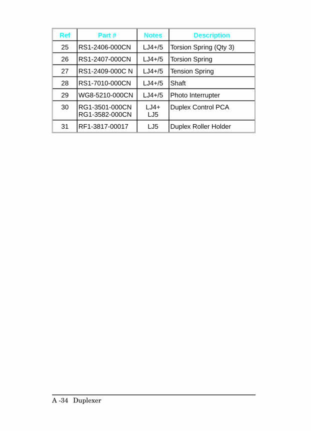
Ref Part # Notes Description
25 RS1-2406-000CN LJ4+/5 Torsion Spring (Qty 3)
26 RS1-2407-000CN LJ4+/5 Torsion Spring
27 RS1-2409-000C N LJ4+/5 Tension Spring
28 RS1-7010-000CN LJ4+/5 Shaft
29 WG8-5210-000CN LJ4+/5 Photo Interrupter
30 RG1-3501-000CNRG1-3582-000CN
LJ4+LJ5
Duplex Control PCA
31 RF1-3817-00017 LJ5 Duplex Roller Holder
A -34 Duplexer
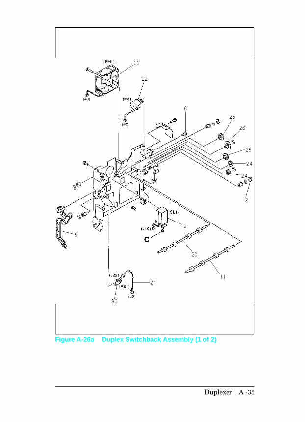
Figure A-26a Duplex Switchback Assembly (1 of 2)
Duplexer A -35
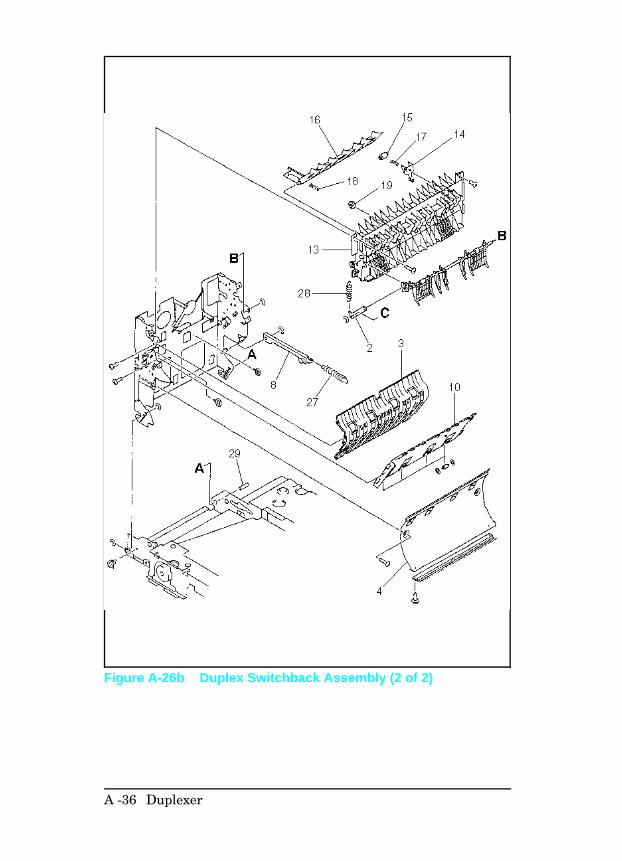
Figure A-26b Duplex Switchback Assembly (2 of 2)
A -36 Duplexer
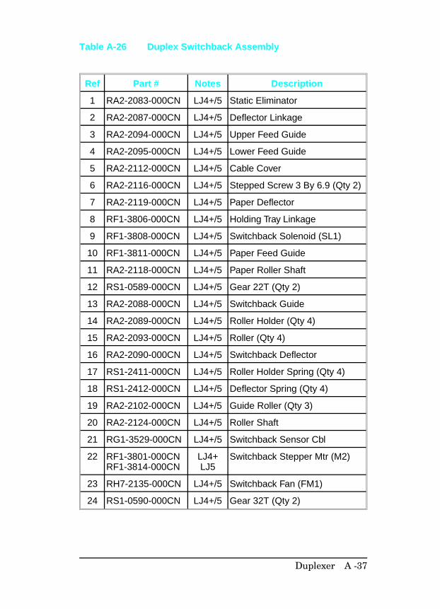
Ref Part # Notes Description
1 RA2-2083-000CN LJ4+/5 Static Eliminator
2 RA2-2087-000CN LJ4+/5 Deflector Linkage
3 RA2-2094-000CN LJ4+/5 Upper Feed Guide
4 RA2-2095-000CN LJ4+/5 Lower Feed Guide
5 RA2-2112-000CN LJ4+/5 Cable Cover
6 RA2-2116-000CN LJ4+/5 Stepped Screw 3 By 6.9 (Qty 2)
7 RA2-2119-000CN LJ4+/5 Paper Deflector
8 RF1-3806-000CN LJ4+/5 Holding Tray Linkage
9 RF1-3808-000CN LJ4+/5 Switchback Solenoid (SL1)
10 RF1-3811-000CN LJ4+/5 Paper Feed Guide
11 RA2-2118-000CN LJ4+/5 Paper Roller Shaft
12 RS1-0589-000CN LJ4+/5 Gear 22T (Qty 2)
13 RA2-2088-000CN LJ4+/5 Switchback Guide
14 RA2-2089-000CN LJ4+/5 Roller Holder (Qty 4)
15 RA2-2093-000CN LJ4+/5 Roller (Qty 4)
16 RA2-2090-000CN LJ4+/5 Switchback Deflector
17 RS1-2411-000CN LJ4+/5 Roller Holder Spring (Qty 4)
18 RS1-2412-000CN LJ4+/5 Deflector Spring (Qty 4)
19 RA2-2102-000CN LJ4+/5 Guide Roller (Qty 3)
20 RA2-2124-000CN LJ4+/5 Roller Shaft
21 RG1-3529-000CN LJ4+/5 Switchback Sensor Cbl
22 RF1-3801-000CNRF1-3814-000CN
LJ4+LJ5
Switchback Stepper Mtr (M2)
23 RH7-2135-000CN LJ4+/5 Switchback Fan (FM1)
24 RS1-0590-000CN LJ4+/5 Gear 32T (Qty 2)
Table A-26 Duplex Switchback Assembly
Duplexer A -37
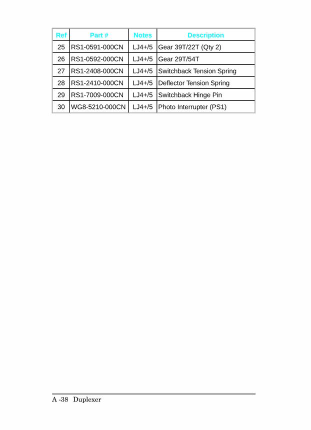
Ref Part # Notes Description
25 RS1-0591-000CN LJ4+/5 Gear 39T/22T (Qty 2)
26 RS1-0592-000CN LJ4+/5 Gear 29T/54T
27 RS1-2408-000CN LJ4+/5 Switchback Tension Spring
28 RS1-2410-000CN LJ4+/5 Deflector Tension Spring
29 RS1-7009-000CN LJ4+/5 Switchback Hinge Pin
30 WG8-5210-000CN LJ4+/5 Photo Interrupter (PS1)
A -38 Duplexer
B
LaserJet 5/5M/5N PrinterThe Combined Service Manual contains information to be usedwith the LaserJet4/4+/4M/4M+/5/5M/5N. In specialcircumstances, the information in Chapters 1 and 3 will notpertain specifically to the LaserJet 5/5M/5N printer (such as thecontrol panel information). This Appendix contains theinformation that is specific for the LaserJet 5/5M/5N printers.
The Product Information shows feature comparisons of theLaserJet 5/5M/5N with the LaserJet 4+/4M+ and a productcompatibility matrix. Also included in this Appendix arespecifications for the LaserJet 5/5M/5N, Related Documentation,Safety Information, Control Panel information, Service Modeinstructions, PCL Self Test Printout information, and Infraredtroubleshooting information.
Please note that if the information you are looking for is notfound in this Appendix, please see Chapters 1 through 8,Appendix A, or the Service Notes section.
LaserJet 5/5M/5N Printer B-1
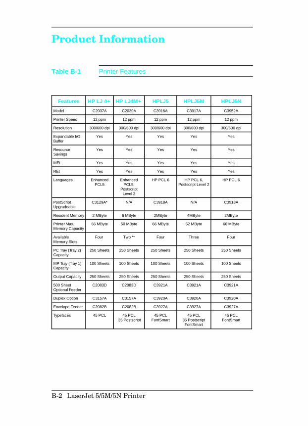
Product Information
Features HP LJ 4+ HP LJ4M+ HPLJ5 HPLJ5M HPLJ5N
Model C2037A C2039A C3916A C3917A C3952A
Printer Speed 12 ppm 12 ppm 12 ppm 12 ppm 12 ppm
Resolution 300/600 dpi 300/600 dpi 300/600 dpi 300/600 dpi 300/600 dpi
Expandable I/OBuffer
Yes Yes Yes Yes Yes
ResourceSavings
Yes Yes Yes Yes Yes
MEt Yes Yes Yes Yes Yes
REt Yes Yes Yes Yes Yes
Languages EnhancedPCL5
EnhancedPCL5,
PostscriptLevel 2
HP PCL 6 HP PCL 6,Postscript Level 2
HP PCL 6
PostScriptUpgradeable
C3129A* N/A C3918A N/A C3918A
Resident Memory 2 MByte 6 MByte 2MByte 4MByte 2MByte
Printer Max.Memory Capacity
66 MByte 50 MByte 66 MByte 52 MByte 66 MByte
AvailableMemory Slots
Four Two ** Four Three Four
PC Tray (Tray 2)Capacity
250 Sheets 250 Sheets 250 Sheets 250 Sheets 250 Sheets
MP Tray (Tray 1)Capacity
100 Sheets 100 Sheets 100 Sheets 100 Sheets 100 Sheets
Output Capacity 250 Sheets 250 Sheets 250 Sheets 250 Sheets 250 Sheets
500 SheetOptional Feeder
C2083D C2083D C3921A C3921A C3921A
Duplex Option C3157A C3157A C3920A C3920A C3920A
Envelope Feeder C2082B C2082B C3927A C3927A C3927A
Typefaces 45 PCL 45 PCL 35 Postscript
45 PCLFontSmart
45 PCL35 PostscriptFontSmart
45 PCLFontSmart
Table B-1 Printer Features
B-2 LaserJet 5/5M/5N Printer
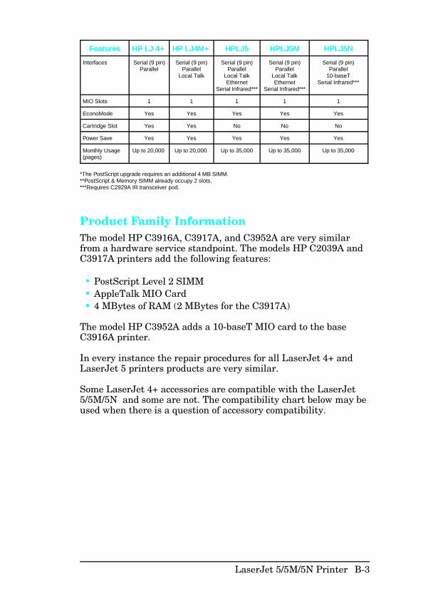
Product Family InformationThe model HP C3916A, C3917A, and C3952A are very similarfrom a hardware service standpoint. The models HP C2039A andC3917A printers add the following features:
• PostScript Level 2 SIMM• AppleTalk MIO Card• 4 MBytes of RAM (2 MBytes for the C3917A)
The model HP C3952A adds a 10-baseT MIO card to the baseC3916A printer.
In every instance the repair procedures for all LaserJet 4+ andLaserJet 5 printers products are very similar.
Some LaserJet 4+ accessories are compatible with the LaserJet5/5M/5N and some are not. The compatibility chart below may beused when there is a question of accessory compatibility.
Features HP LJ 4+ HP LJ4M+ HPLJ5 HPLJ5M HPLJ5N
Interfaces Serial (9 pin)Parallel
Serial (9 pin)Parallel
Local Talk
Serial (9 pin)Parallel
Local TalkEthernet
Serial Infrared***
Serial (9 pin)Parallel
Local TalkEthernet
Serial Infrared***
Serial (9 pin)Parallel
10-baseTSerial Infrared***
MIO Slots 1 1 1 1 1
EconoMode Yes Yes Yes Yes Yes
Cartridge Slot Yes Yes No No No
Power Save Yes Yes Yes Yes Yes
Monthly Usage(pages)
Up to 20,000 Up to 20,000 Up to 35,000 Up to 35,000 Up to 35,000
*The PostScript upgrade requires an additional 4 MB SIMM. **PostScript & Memory SIMM already occupy 2 slots.***Requires C2929A IR transceiver pod.
LaserJet 5/5M/5N Printer B-3
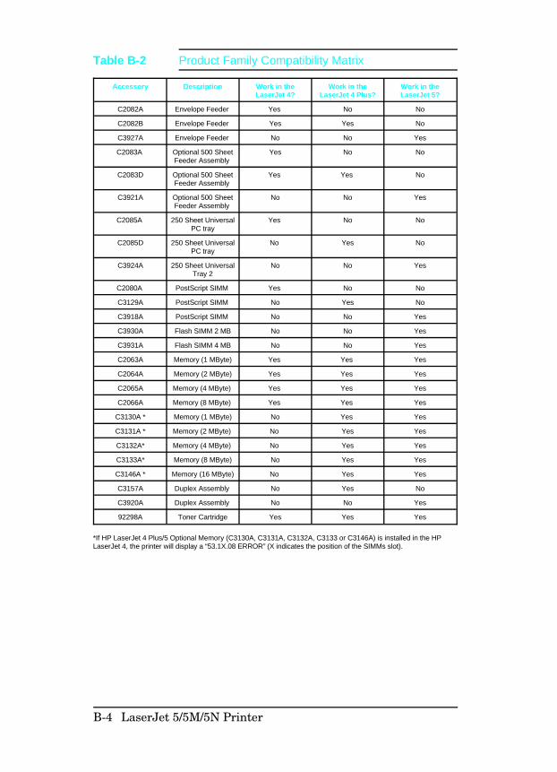
Accessory Description Work in theLaserJet 4?
Work in theLaserJet 4 Plus?
Work in theLaserJet 5?
C2082A Envelope Feeder Yes No No
C2082B Envelope Feeder Yes Yes No
C3927A Envelope Feeder No No Yes
C2083A Optional 500 SheetFeeder Assembly
Yes No No
C2083D Optional 500 SheetFeeder Assembly
Yes Yes No
C3921A Optional 500 SheetFeeder Assembly
No No Yes
C2085A 250 Sheet UniversalPC tray
Yes No No
C2085D 250 Sheet UniversalPC tray
No Yes No
C3924A 250 Sheet UniversalTray 2
No No Yes
C2080A PostScript SIMM Yes No No
C3129A PostScript SIMM No Yes No
C3918A PostScript SIMM No No Yes
C3930A Flash SIMM 2 MB No No Yes
C3931A Flash SIMM 4 MB No No Yes
C2063A Memory (1 MByte) Yes Yes Yes
C2064A Memory (2 MByte) Yes Yes Yes
C2065A Memory (4 MByte) Yes Yes Yes
C2066A Memory (8 MByte) Yes Yes Yes
C3130A * Memory (1 MByte) No Yes Yes
C3131A * Memory (2 MByte) No Yes Yes
C3132A* Memory (4 MByte) No Yes Yes
C3133A* Memory (8 MByte) No Yes Yes
C3146A * Memory (16 MByte) No Yes Yes
C3157A Duplex Assembly No Yes No
C3920A Duplex Assembly No No Yes
92298A Toner Cartridge Yes Yes Yes
*If HP LaserJet 4 Plus/5 Optional Memory (C3130A, C3131A, C3132A, C3133 or C3146A) is installed in the HPLaserJet 4, the printer will display a “53.1X.08 ERROR” (X indicates the position of the SIMMs slot).
Table B-2 Product Family Compatibility Matrix
B-4 LaserJet 5/5M/5N Printer
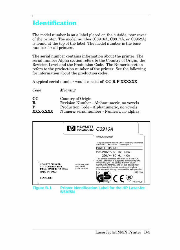
Identification
The model number is on a label placed on the outside, rear coverof the printer. The model number (C3916A, C3917A, or C3952A)is found at the top of the label. The model number is the basenumber for all printers.
The serial number contains information about the printer. Theserial number Alpha section refers to the Country of Origin, theRevision Level and the Production Code. The Numeric sectionrefers to the production number of the printer. See the followingfor information about the production codes.
A typical serial number would consist of: CC R P XXXXXX
Code Meaning
CC Country of OriginR Revision Number - Alphanumeric, no vowelsP Production Code - Alphanumeric, no vowelsXXX-XXXX Numeric serial number - Numeric, no alphas
Figure B-1 Printer Identification Label for the HP LaserJet5/5M/5N
LaserJet 5/5M/5N Printer B-5
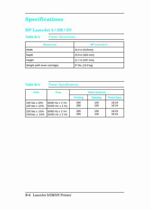
Specifications
HP LaserJet 5 / 5M / 5N
Dimension HP LaserJet 5
Width 16.4 in (415mm)
Depth 15.9 in (403 mm)
Height 11.7 in (297 mm)
Weight (with toner cartridge) 37 lbs. (16.8 kg)
Table B-3 Printer Dimensions
Volts Freq Watts (typical)
Printing Standby PowerSave
100 Vac ± 10%120 Vac ± 10%
50/60 Hz ± 2 Hz50/60 Hz ± 2 Hz
290290
100100
18-2418-24
220 Vac ± 10%240Vac ± 10%
50/60 Hz ± 2 Hz50/60 Hz ± 2 Hz
290290
100100
18-2418-24
Table B-4 Power Specifications
B-6 LaserJet 5/5M/5N Printer
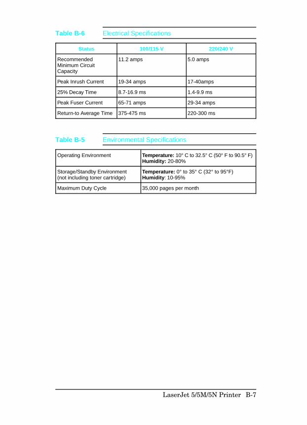
Status 100/115 V 220/240 V
RecommendedMinimum CircuitCapacity
11.2 amps 5.0 amps
Peak Inrush Current 19-34 amps 17-40amps
25% Decay Time 8.7-16.9 ms 1.4-9.9 ms
Peak Fuser Current 65-71 amps 29-34 amps
Return-to Average Time 375-475 ms 220-300 ms
Table B-6 Electrical Specifications
Operating Environment Temperature: 10° C to 32.5° C (50° F to 90.5° F)Humidity: 20-80%
Storage/Standby Environment(not including toner cartridge)
Temperature: 0° to 35° C (32° to 95°F)Humidity: 10-95%
Maximum Duty Cycle 35,000 pages per month
Table B-5 Environmental Specifications
LaserJet 5/5M/5N Printer B-7
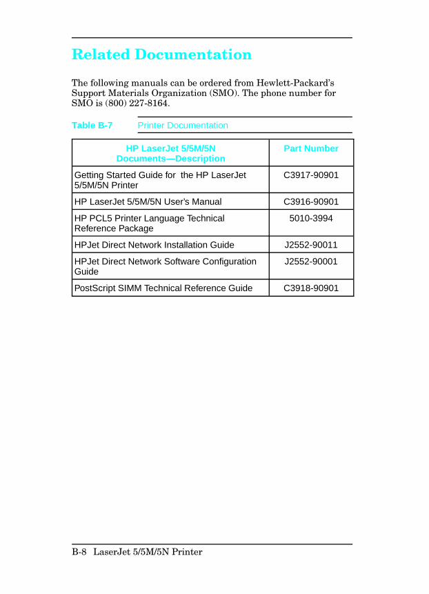
Related Documentation
The following manuals can be ordered from Hewlett-Packard’sSupport Materials Organization (SMO). The phone number forSMO is (800) 227-8164.
HP LaserJet 5/5M/5NDocuments—Description
Part Number
Getting Started Guide for the HP LaserJet5/5M/5N Printer
C3917-90901
HP LaserJet 5/5M/5N User’s Manual C3916-90901
HP PCL5 Printer Language TechnicalReference Package
5010-3994
HPJet Direct Network Installation Guide J2552-90011
HPJet Direct Network Software ConfigurationGuide
J2552-90001
PostScript SIMM Technical Reference Guide C3918-90901
Table B-7 Printer Documentation
B-8 LaserJet 5/5M/5N Printer
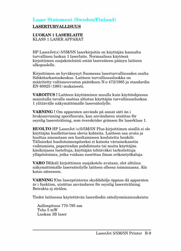
Laser Statement (Sweden/Finland) LASERTURVALLISUUS
LUOKAN 1 LASERLAITEKLASS 1 LASER APPARAT
HP LaserJet(s) 5/5M/5N laserkirjoitin on käyttäjän kannaltaturvallinen luokan 1 laserlaite. Normaalissa käytössäkirjoittimen suojakotelointi estää lasersäteen pääsyn laitteenulkopuolelle.
Kirjoittimen on hyväksynyt Suomessa laserturvallisuuden osaltaSähkötarkastuskeskus. Laitteen turvallisuusluokka onmääritetty valtioneuvoston päätöksen N:o 472/1985 ja standardinEN 60825 (1991) mukaisesti.
VAROITUS ! Laitteen käyttäminen muulla kuin käyttöohjeessamainitulla tavalla saattaa altistaa käyttäjän turvallisuusluokan1 ylittävälle näkymättömälle lasersäteilylle.
VARNING ! Om apparaten används på annat sätt än ibruksanvisning specificerats, kan användaren utsättas förosynlig laserstrålning, som överskrider gränsen för laserklass 1.
HUOLTO HP LaserJet (s)5/5M/5N Plus-kirjoittimen sisällä ei olekäyttäjän huollettavissa olevia kohteita. Laitteen saa avata jahuoltaa ainoastaan sen huoltamiseen koulutettu henkilö.Tällaiseksi huoltotoimenpiteeksi ei katsota väriainekasetinvaihtamista, paperiradan puhdistusta tai muita käyttäjänkäsikirjassa lueteltuja, käyttäjän tehtäväksi tarkoitettujaylläpitotoimia, jotka voidaan suorittaa ilman erikoistyökaluja.
VARO !Mikäli kirjoittimen suojakotelo avataan, olet alttiinanäkymättömälle lasersäteilylle laitteen ollessa toiminnassa. Äläkatso säteeseen.
VARNING !Om laserprinterns skyddshölje öppnas då apparatenär i funktion, utsättas användaren för osynlig laserstrålning.Betrakta ej strålen.
Tiedot laitteessa käytettävän laserdiodin säteilyominaisuuksista:
Aallonpituus 770-795 nmTeho 5 mWLuokan 3B laser
LaserJet 5/5M/5N Printer B-9
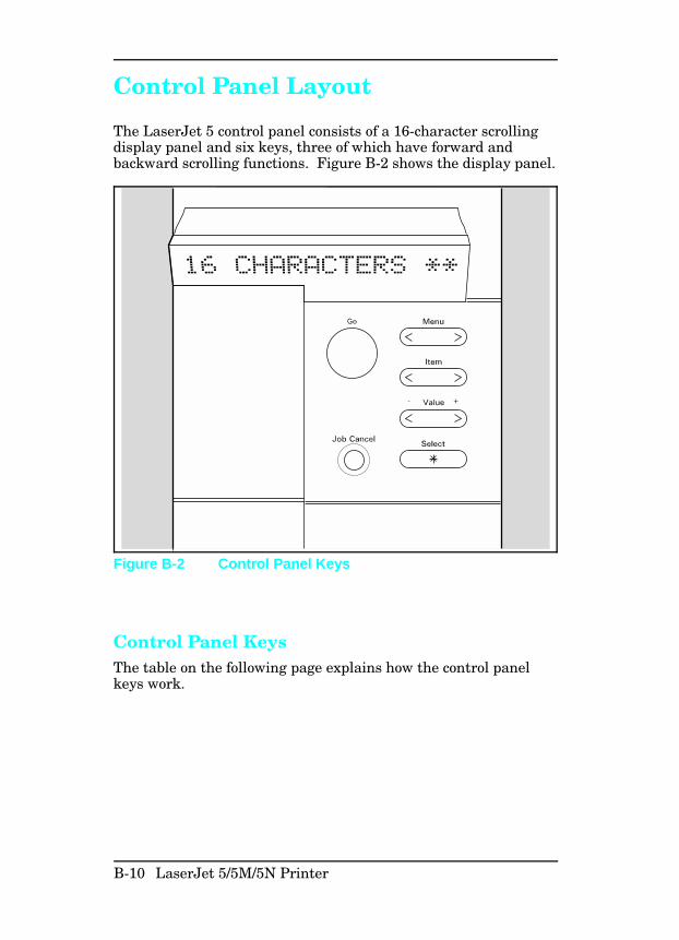
Control Panel Layout
The LaserJet 5 control panel consists of a 16-character scrollingdisplay panel and six keys, three of which have forward andbackward scrolling functions. Figure B-2 shows the display panel.
Control Panel KeysThe table on the following page explains how the control panelkeys work.
Figure B-2 Control Panel Keys
B-10 LaserJet 5/5M/5N Printer
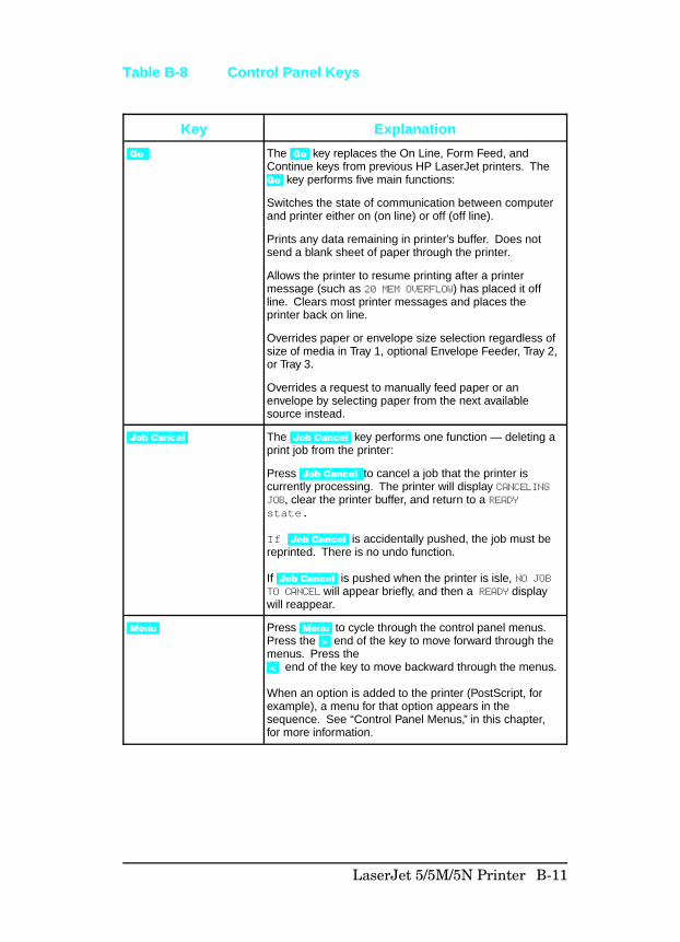
Key Explanation
Go The Go key replaces the On Line, Form Feed, andContinue keys from previous HP LaserJet printers. The Go key performs five main functions:
Switches the state of communication between computerand printer either on (on line) or off (off line).
Prints any data remaining in printer’s buffer. Does notsend a blank sheet of paper through the printer.
Allows the printer to resume printing after a printermessage (such as 20 MEM OVERFLOW) has placed it offline. Clears most printer messages and places theprinter back on line.
Overrides paper or envelope size selection regardless ofsize of media in Tray 1, optional Envelope Feeder, Tray 2,or Tray 3.
Overrides a request to manually feed paper or anenvelope by selecting paper from the next availablesource instead.
Job Cancel The Job Cancel key performs one function — deleting aprint job from the printer:
Press Job Cancel to cancel a job that the printer iscurrently processing. The printer will display CANCELINGJOB, clear the printer buffer, and return to a READYstate.
If Job Cancel is accidentally pushed, the job must bereprinted. There is no undo function.
If Job Cancel is pushed when the printer is isle, NO JOBTO CANCEL will appear briefly, and then a READY displaywill reappear.
Menu Press Menu to cycle through the control panel menus.Press the > end of the key to move forward through themenus. Press the < end of the key to move backward through the menus.
When an option is added to the printer (PostScript, forexample), a menu for that option appears in thesequence. See “Control Panel Menus,” in this chapter,for more information.
Table B-8 Control Panel Keys
LaserJet 5/5M/5N Printer B-11
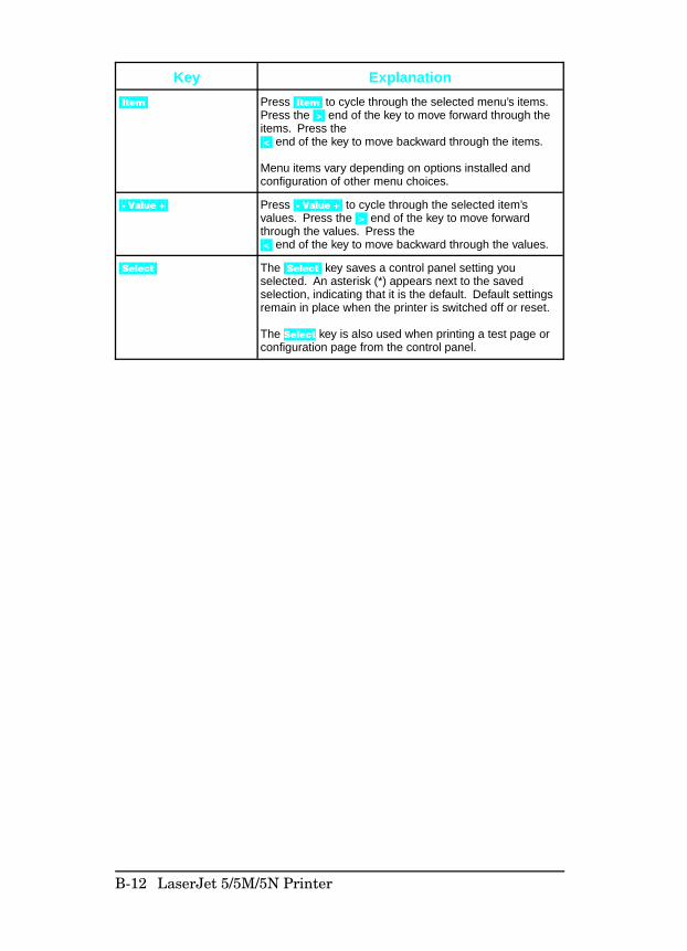
Key Explanation
Item Press Item to cycle through the selected menu’s items.Press the > end of the key to move forward through theitems. Press the < end of the key to move backward through the items.
Menu items vary depending on options installed andconfiguration of other menu choices.
- Value + Press - Value + to cycle through the selected item’svalues. Press the > end of the key to move forwardthrough the values. Press the < end of the key to move backward through the values.
Select The Select key saves a control panel setting youselected. An asterisk (*) appears next to the savedselection, indicating that it is the default. Default settingsremain in place when the printer is switched off or reset.
The Select key is also used when printing a test page orconfiguration page from the control panel.
B-12 LaserJet 5/5M/5N Printer
Control Panel MenusFigure B-3 shows the menus and menu items available with thebasic printer configuration. Not all menu items are discussed inthis section. Only those items of specific interest from a servicestandpoint, or items new to the printers are discussed in thissection. If options such as PostScript or a different I/O areinstalled, the new menu items automatically are added at theappropriate location. For example, a PostScript Menu appearsfollowing the PCL Menu.
To change a control panel setting:1 Press Menu repeatedly until the menu you want appears.2 Press Item repeatedly until the item you want appears.3 Press -Value+ until the setting you want appears.4 Press Select to save your selection.
N o t e An asterisk appears next to your selection in thedisplay, indicating that it is now the default.
5 Press Go to exit the menu.
Reference Explanation
1 Printing Menu: Lists the current printing and PowerSave settings.
2 PCL Fonts Menu: Lists current font settings.
3 Postscript Menu: List current postscript settings.
4 Job Menu: Lists current settings for print resolution, personality, and I/Otimeout.
5 Config Menu: List current internal configuration settings of the printer.
6 Mem. Config. Menu: Lists I/O buffer and resource saving buffer settings.
7 Parallel Menu: Lists current settings of the parallel port.
8 Serial Menu: Lists current settings of the serial port.
9 HP MIO Menu: Lists current settings of the MIO card.
10 Reset Menu: Lists reset options available.
11 Test Menu: Lists internal tests available.
Table B-9 Control Panel Menu for the HP LaserJet 5(Refer to Figure B-3)
LaserJet 5/5M/5N Printer B-13
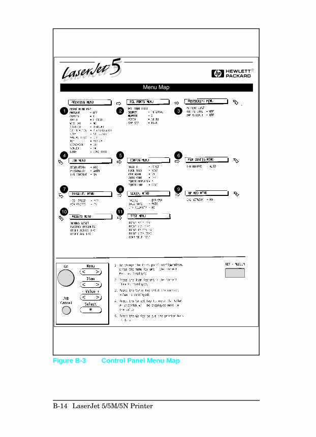
Figure B-3 Control Panel Menu Map
B-14 LaserJet 5/5M/5N Printer
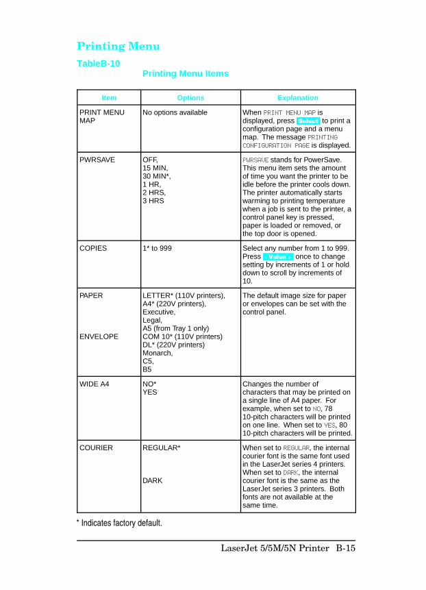
Printing Menu
Item Options Explanation
PRINT MENUMAP
No options available When PRINT MENU MAP isdisplayed, press Select to print aconfiguration page and a menumap. The message PRINTINGCONFIGURATION PAGE is displayed.
PWRSAVE OFF, 15 MIN,30 MIN*,1 HR,2 HRS,3 HRS
PWRSAVE stands for PowerSave.This menu item sets the amountof time you want the printer to beidle before the printer cools down.The printer automatically startswarming to printing temperaturewhen a job is sent to the printer, acontrol panel key is pressed,paper is loaded or removed, orthe top door is opened.
COPIES 1* to 999 Select any number from 1 to 999.Press - Value + once to changesetting by increments of 1 or holddown to scroll by increments of10.
PAPER
ENVELOPE
LETTER* (110V printers),A4* (220V printers),Executive,Legal,A5 (from Tray 1 only)COM 10* (110V printers)DL* (220V printers)Monarch,C5,B5
The default image size for paperor envelopes can be set with thecontrol panel.
WIDE A4 NO*YES
Changes the number ofcharacters that may be printed ona single line of A4 paper. Forexample, when set to NO, 7810-pitch characters will be printedon one line. When set to YES, 8010-pitch characters will be printed.
COURIER REGULAR*
DARK
When set to REGULAR, the internalcourier font is the same font usedin the LaserJet series 4 printers.When set to DARK, the internalcourier font is the same as theLaserJet series 3 printers. Bothfonts are not available at thesame time.
TableB-10Printing Menu Items
* Indicates factory default.
LaserJet 5/5M/5N Printer B-15
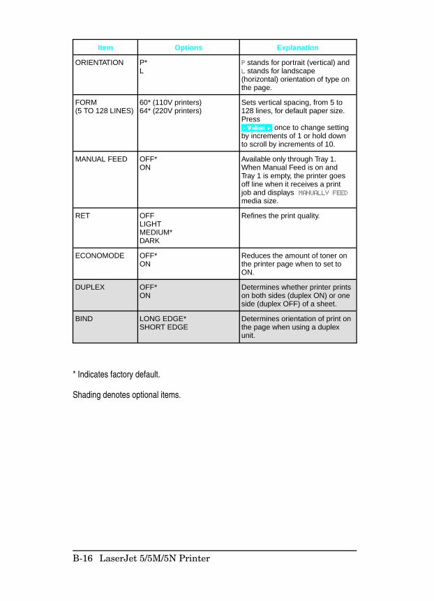
Item Options Explanation
ORIENTATION P*L
P stands for portrait (vertical) andL stands for landscape(horizontal) orientation of type onthe page.
FORM(5 TO 128 LINES)
60* (110V printers)64* (220V printers)
Sets vertical spacing, from 5 to128 lines, for default paper size.Press - Value + once to change settingby increments of 1 or hold downto scroll by increments of 10.
MANUAL FEED OFF*ON
Available only through Tray 1.When Manual Feed is on andTray 1 is empty, the printer goesoff line when it receives a printjob and displays MANUALLY FEEDmedia size.
RET OFFLIGHTMEDIUM*DARK
Refines the print quality.
ECONOMODE OFF*ON
Reduces the amount of toner onthe printer page when to set toON.
DUPLEX OFF*ON
Determines whether printer printson both sides (duplex ON) or oneside (duplex OFF) of a sheet.
BIND LONG EDGE*SHORT EDGE
Determines orientation of print onthe page when using a duplexunit.
* Indicates factory default.
Shading denotes optional items.
B-16 LaserJet 5/5M/5N Printer
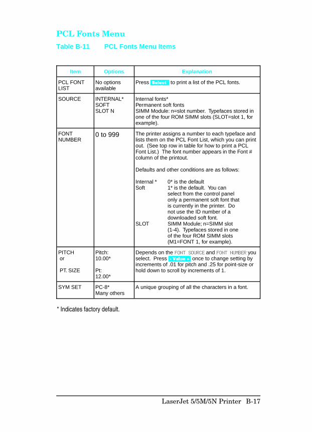
PCL Fonts Menu
Item Options Explanation
PCL FONTLIST
No optionsavailable
Press Select to print a list of the PCL fonts.
SOURCE INTERNAL*SOFTSLOT N
Internal fonts*Permanent soft fontsSIMM Module: n=slot number. Typefaces stored inone of the four ROM SIMM slots (SLOT=slot 1, forexample).
FONTNUMBER
0 to 999 The printer assigns a number to each typeface andlists them on the PCL Font List, which you can printout. (See top row in table for how to print a PCLFont List.) The font number appears in the Font #column of the printout.
Defaults and other conditions are as follows:
Internal * 0* is the defaultSoft 1* is the default. You can
select from the control panelonly a permanent soft font thatis currently in the printer. Do not use the ID number of a downloaded soft font.
SLOT SIMM Module; n=SIMM slot (1-4). Typefaces stored in oneof the four ROM SIMM slots(M1=FONT 1, for example).
PITCH or
PT. SIZE
Pitch:10.00*
Pt:12.00*
Depends on the FONT SOURCE and FONT NUMBER youselect. Press - Value + once to change setting byincrements of .01 for pitch and .25 for point-size orhold down to scroll by increments of 1.
SYM SET PC-8*Many others
A unique grouping of all the characters in a font.
* Indicates factory default.
Table B-11 PCL Fonts Menu Items
LaserJet 5/5M/5N Printer B-17
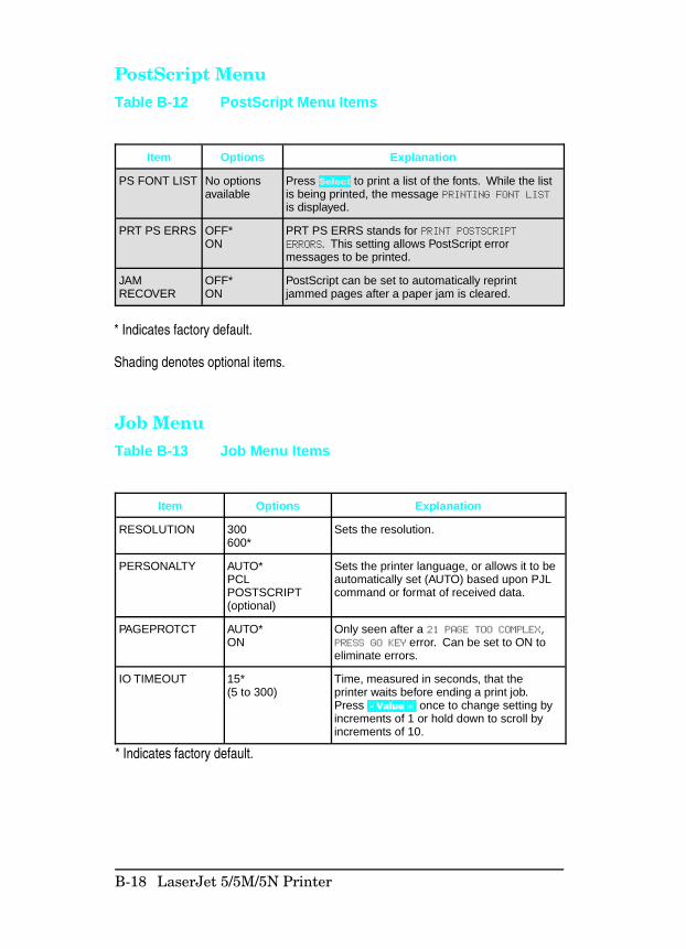
PostScript Menu
Job Menu
Item Options Explanation
PS FONT LIST No optionsavailable
Press Select to print a list of the fonts. While the listis being printed, the message PRINTING FONT LISTis displayed.
PRT PS ERRS OFF*ON
PRT PS ERRS stands for PRINT POSTSCRIPTERRORS. This setting allows PostScript errormessages to be printed.
JAMRECOVER
OFF*ON
PostScript can be set to automatically reprintjammed pages after a paper jam is cleared.
Table B-12 PostScript Menu Items
Item Options Explanation
RESOLUTION 300600*
Sets the resolution.
PERSONALTY AUTO*PCLPOSTSCRIPT(optional)
Sets the printer language, or allows it to beautomatically set (AUTO) based upon PJLcommand or format of received data.
PAGEPROTCT AUTO*ON
Only seen after a 21 PAGE TOO COMPLEX,PRESS GO KEY error. Can be set to ON toeliminate errors.
IO TIMEOUT 15*(5 to 300)
Time, measured in seconds, that theprinter waits before ending a print job.Press - Value + once to change setting byincrements of 1 or hold down to scroll byincrements of 10.
Table B-13 Job Menu Items
* Indicates factory default.
* Indicates factory default.
Shading denotes optional items.
B-18 LaserJet 5/5M/5N Printer
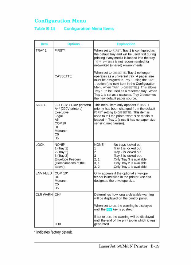
Configuration Menu
Item Options Explanation
TRAY 1 FIRST*
CASSETTE
When set to FIRST, Tray 1 is configured asthe default tray and will be used first duringprinting if any media is loaded into the tray.TRAY 1=FIRST is not recommended fornetworked (shared) environments.
When set to CASSETTE, Tray 1 no longeroperates as a universal tray. A paper sizemust be assigned to Tray 1 using the SIZE1 option (the next item in the ConfigurationMenu when TRAY 1=CASSETTE.) This allowsTray 1 to be used as a reserved tray. WhenTray 1 is set as a cassette, Tray 2 becomesthe new default paper source.
SIZE 1 LETTER* (110V printers)A4* (220V printers)ExecutiveLegalA5COM10DLMonarchC5B5
This menu item only appears if TRAY 1priority has been changed from the defaultFIRST setting to CASSETTE. This item isused to tell the printer what size media isloaded in Tray 1 (since it has no paper sizesensing mechanism).
LOCK NONE*1 (Tray 1)2 (Tray 2)3 (Tray 3)Envelope Feeders(Combinations of theabove)
NONE No trays locked out1 Tray 1 is locked out.2 Tray 2 is locked out.3 Tray 3 is locked out.2, 1 Only Tray 3 is available3, 1 Only Tray 2 is available.3, 2 Only Tray 1 is available.
ENV FEED COM 10*DLMonarchC5B5
Only appears if the optional envelopefeeder is installed in the printer. Used todesignate the envelope size.
CLR WARN ON*
JOB
Determines how long a clearable warningwill be displayed on the control panel.
When set to ON, the warning is displayeduntil the Go key is pushed.
If set to JOB, the warning will be displayeduntil the end of the print job in which it wasgenerated.
Table B-14 Configuration Menu Items
* Indicates factory default.
LaserJet 5/5M/5N Printer B-19
Item Options Explanation
AUTOCONT
OFF*
ON
Determines how the printer reacts to dataerrors and printer errors. When autocontinue is set to OFF, the printer displaysan error message and goes off line untilyou press Go .
When auto continue is set to ON, the printerdisplays a message and goes off line forabout 10 seconds, then comes back on line.
If your printer is part of a network or remotespooling system, set auto continue to ON.
TONERDENSITY
123*45
Determines the relative darkness of print onthe paper; 1 being the lightest and 5 beingthe darkest.
LOWTONER
CONT*
STOP
If TONER LOW is set to CONT, the printer willremain on line and continue to print whilethe message is displayed.
If TONER LOW is set to STOP, the printer willgo off line and wait for further action.
* Indicates factory default.
B-20 LaserJet 5/5M/5N Printer
Memory Configuration Menu
Item Options Explanation
I/O BUFFER AUTO*
OFF
ON
Memory set aside for I/O buffering isautomatically determined by the printer.
No memory is set aside for I/O buffers.
Size can be manually adjusted.
I/O SIZE 10K and up When IO BUFFER is set to ON, this item appears inthe menu. Press - Value + to add or reduce I/Obuffer memory in increments of 0 KBytes up to100 KBytes, then in 100 KByte increments.
RESRCSAVE
AUTO*
OFF
ON
Appears when a certain amount of memory and apersonality SIMM are installed in the printer.Enables or disables Resource Saving.
Printer automatically determines the amount ofmemory to allocate to each installed personality.
No memory is allocated.
Additional memory management item selectionsappear.
PCL MEMPS MEM
0K and up Increases memory for each installed personality.
Table B-15 Memory Configuration Menu Items
* Indicates factory default.
LaserJet 5/5M/5N Printer B-21
Parallel Menu
Serial Menu
Item Options Explanation
HIGH SPEED
YES*
NO
The speed at which data is transmitted to the printer.If the default value (YES) results in I/O errors or nocommunications, set this value to NO.
Sets the parallel interface to run at a higher data rate
Sets the parallel interface to run at a slower speed.
ADV FNCTNS ON*OFF
ADV FNCTNS=ON enables bi-directional parallelcommunication, which allows your printer to sendstatus readback messages to your computer. Settingadvance functions to ON may slow personalityswitching.
Table B-16 Parallel Menu Items
Item Options Explanation
PACING DTR/DSR*,
XON/XOFF
If the computer requires hardware flowcontrol.
If the computer requires software flowcontrol.
BAUD RATE 9600*300 to 57600
Tells the printer how fast information willbe transferred from the computer to theprinter.
ROBUST XON ON*
OFF
Appears only when PACING is set toXON/XOFF. If it is set to ON, the printersends an XON every one second untildata is received when the printer is online and when sufficient buffer space hasbecome available.
If it is set to OFF, the printer sends oneXON when it can accept more data orwhen it is on line.
DTR POLARITY HI*LO
Determines whether pin 8 goes high orlow to indicate the printer is ready toreceive data.
Table B-17 Serial Menu Items
* Indicates factory default.
* Indicates factory default.
B-22 LaserJet 5/5M/5N Printer
Resets Menu
N o t e The control panel resets will clear all memory inthe printer, while the Job Cancel feature onlyclears the current job.
MenuSelection
Printer Response Explanation
MEMORYRESET
CLEARING MEMORY Press Select to perform a MEMORY RESET. Thiswill clear the printer buffer and return allprinting environment parameters to thosevalues set in the Control Panel menus.
FACTORYDEFAULT
FACTORY
DEFAULTS BEING
RESTORED
Press Select to perform FACTORY DEFAULT. Thisrestores most of the printer’s factory defaultsettings and performs a memeory reset.
Items in the Config, Memory Configuration,Parallel, and Serial Menus are not reset.
Table B-18 Resets Menu Items
LaserJet 5/5M/5N Printer B-23
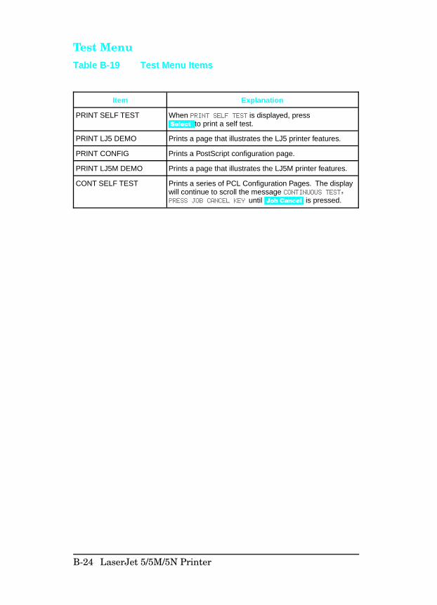
Test Menu
Item Explanation
PRINT SELF TEST When PRINT SELF TEST is displayed, press Select to print a self test.
PRINT LJ5 DEMO Prints a page that illustrates the LJ5 printer features.
PRINT CONFIG Prints a PostScript configuration page.
PRINT LJ5M DEMO Prints a page that illustrates the LJ5M printer features.
CONT SELF TEST Prints a series of PCL Configuration Pages. The displaywill continue to scroll the message CONTINUOUS TEST,PRESS JOB CANCEL KEY until Job Cancel is pressed.
Table B-19 Test Menu Items
B-24 LaserJet 5/5M/5N Printer
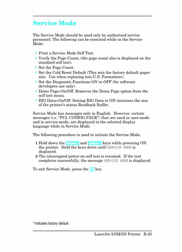
Service Mode
The Service Mode should be used only by authorized servicepersonnel. The following can be executed while in the ServiceMode:
• Print a Service Mode Self Test.• Verify the Page Count, (the page count also is displayed on the
standard self test).• Set the Page Count.• Set the Cold Reset Default (This sets the factory default paper
size. Use when replacing non-U.S. Formatters).• Set the Diagnostic Functions ON or OFF (for software
developers use only).• Demo Page=On/Off. Removes the Demo Page option from the
self test menu.• BIG Data=On/Off. Setting BIG Data to ON increases the size
of the printer’s status Readback Buffer.
Service Mode has messages only in English. However, certainmessages (i.e. “PCL CONFIG PAGE”) that are used in user-modeand in service-mode, are displayed in the selected displaylanguage while in Service Mode.
The following procedure is used to initiate the Service Mode.
1 Hold down the [Menu+] and [Value+] keys while powering ONthe printer. Hold the keys down until SERVICE MODE isdisplayed.
2 The interrupted power-on self test is resumed. If the testcompletes successfully, the message SERVICE MODE is displayed.
To exit Service Mode, press the Go key.
* Indicates factory default.
LaserJet 5/5M/5N Printer B-25
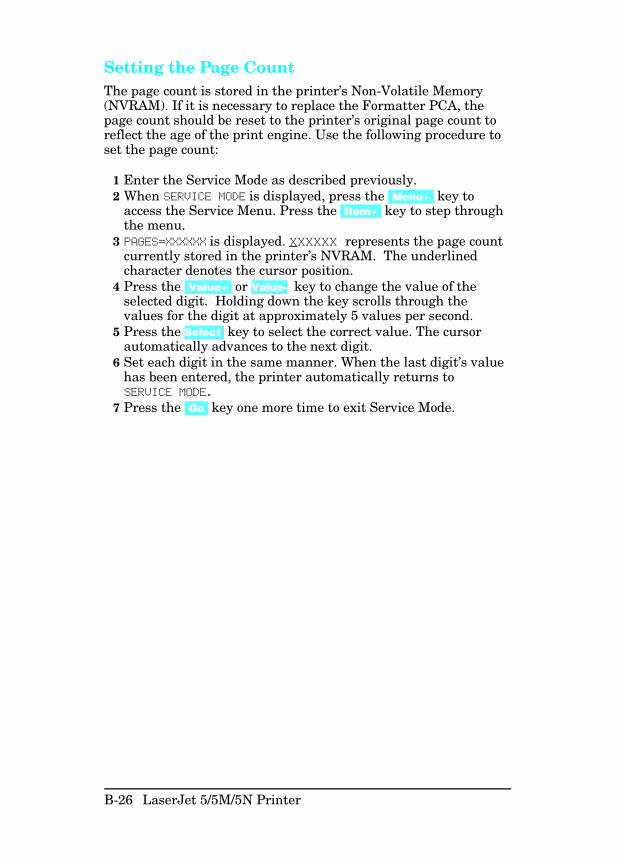
Setting the Page CountThe page count is stored in the printer’s Non-Volatile Memory(NVRAM). If it is necessary to replace the Formatter PCA, thepage count should be reset to the printer’s original page count toreflect the age of the print engine. Use the following procedure toset the page count:
1 Enter the Service Mode as described previously. 2 When SERVICE MODE is displayed, press the [Menu+] key to
access the Service Menu. Press the [Item+] key to step throughthe menu.
3 PAGES=XXXXXX is displayed. XXXXXX represents the page countcurrently stored in the printer’s NVRAM. The underlinedcharacter denotes the cursor position.
4 Press the [Value+] or Value- key to change the value of theselected digit. Holding down the key scrolls through thevalues for the digit at approximately 5 values per second.
5 Press the Select key to select the correct value. The cursorautomatically advances to the next digit.
6 Set each digit in the same manner. When the last digit’s valuehas been entered, the printer automatically returns toSERVICE MODE.
7 Press the [Go] key one more time to exit Service Mode.
B-26 LaserJet 5/5M/5N Printer
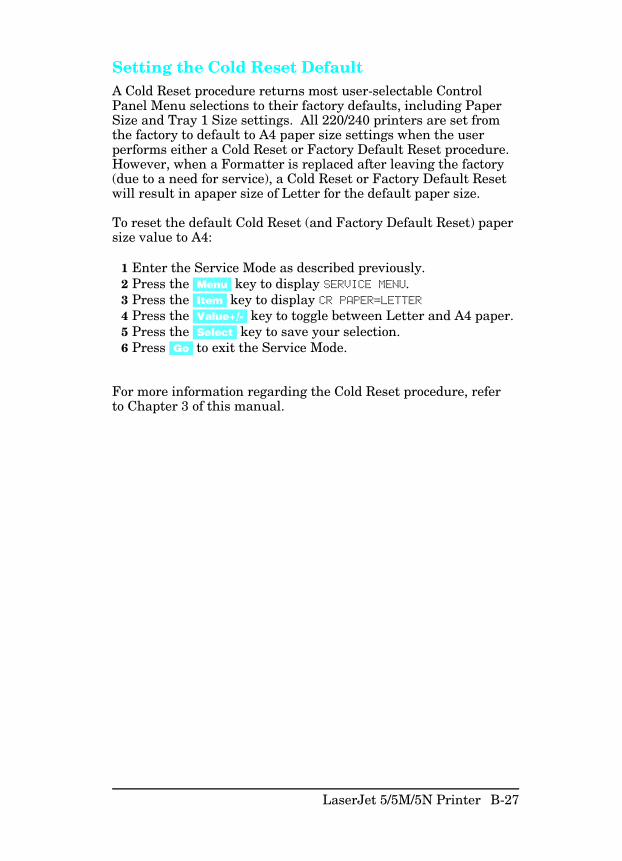
Setting the Cold Reset DefaultA Cold Reset procedure returns most user-selectable ControlPanel Menu selections to their factory defaults, including PaperSize and Tray 1 Size settings. All 220/240 printers are set fromthe factory to default to A4 paper size settings when the userperforms either a Cold Reset or Factory Default Reset procedure.However, when a Formatter is replaced after leaving the factory(due to a need for service), a Cold Reset or Factory Default Resetwill result in apaper size of Letter for the default paper size.
To reset the default Cold Reset (and Factory Default Reset) papersize value to A4:
1 Enter the Service Mode as described previously.2 Press the [Menu] key to display SERVICE MENU.3 Press the [Item] key to display CR PAPER=LETTER4 Press the [Value+/-] key to toggle between Letter and A4 paper. 5 Press the [Select] key to save your selection.6 Press [Go] to exit the Service Mode.
For more information regarding the Cold Reset procedure, referto Chapter 3 of this manual.
LaserJet 5/5M/5N Printer B-27

Skip DemoIf set to TRUE, will disable any test and demo pages containingthe HP logo. This setting should only be used by OEMs notwishing to give user-access to these pages.
Big DataThis item will allow a user to increase the amount of statusreadback buffer if the item is set to ON. The default for this itemis OFF. The printer must be power-cycled after changing thisvalue in order for the new buffer size to take effect.
DiagnosticsAllows a diagnostic mode for firmware developers. Should alwaysbe set to OFF (default value).
B-28 LaserJet 5/5M/5N Printer
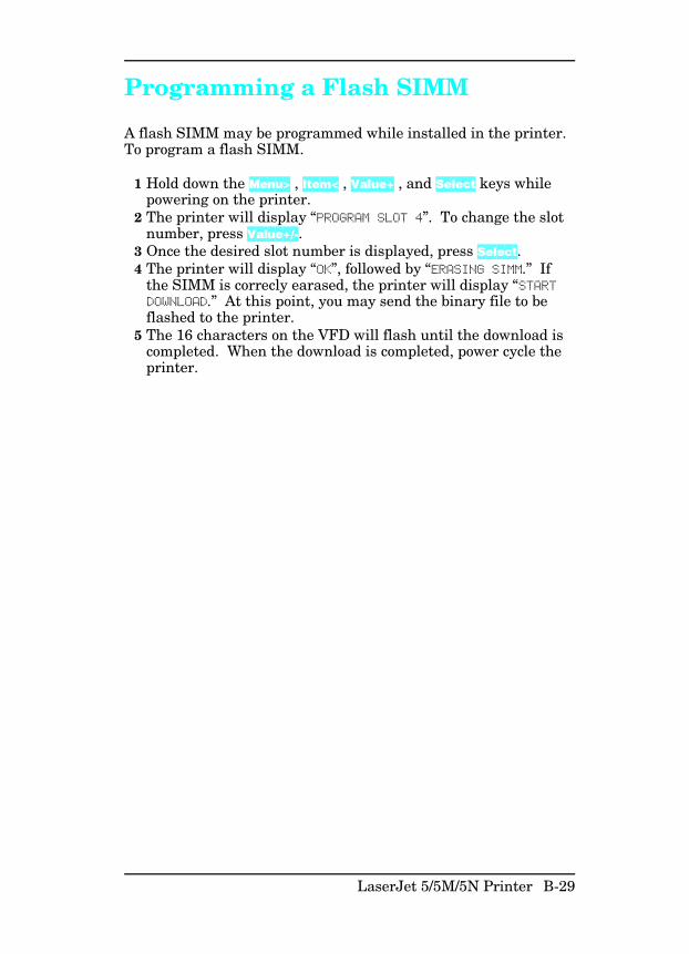
Programming a Flash SIMM
A flash SIMM may be programmed while installed in the printer.To program a flash SIMM.
1 Hold down the Menu> , Item< , Value+ , and Select keys whilepowering on the printer.
2 The printer will display “PROGRAM SLOT 4”. To change the slotnumber, press Value+/-.
3 Once the desired slot number is displayed, press Select.4 The printer will display “OK”, followed by “ERASING SIMM.” If
the SIMM is correcly earased, the printer will display “STARTDOWNLOAD.” At this point, you may send the binary file to beflashed to the printer.
5 The 16 characters on the VFD will flash until the download iscompleted. When the download is completed, power cycle theprinter.
LaserJet 5/5M/5N Printer B-29
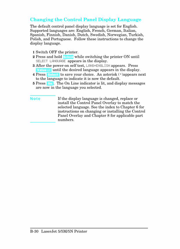
Changing the Control Panel Display LanguageThe default control panel display language is set for English.Supported languages are: English, French, German, Italian,Spanish, Finnish, Danish, Dutch, Swedish, Norwegian, Turkish,Polish, and Portuguese. Follow these instructions to change thedisplay language.
1 Switch OFF the printer.2 Press and hold Select while switching the printer ON untilSELECT LANGUAGE appears in the display.
3 After the power-on self test, LANG=ENGLISH appears. Press[Value+/-] until the desired language appears in the display.
4 Press [Select] to save your choice. An asterisk (*)appears nextto the language to indicate it is now the default.
5 Press [Go]. The On Line indicator is lit, and display messagesare now in the language you selected.
N o t e If the display language is changed, replace orinstall the Control Panel Overlay to match theselected language. See the index to Chapter 6 forinstructions on changing or installing the ControlPanel Overlay and Chapter 8 for applicable partnumbers.
B-30 LaserJet 5/5M/5N Printer
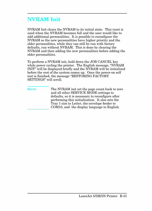
NVRAM Init
NVRAM Init clears the NVRAM to its initial state. This reset isused when the NVRAM becomes full and the user would like toadd additional personalities. It is possible to reconfigure theNVRAM so the new personalities have higher priority and theolder personalities, while they can still be run with factorydefaults, run without NVRAM. This is done by clearing theNVRAM and then adding the new personalities before adding theolder personalities.
To perform a NVRAM init, hold down the JOB CANCEL keywhile power cycling the printer. The English message, “NVRAMINIT” will be displayed briefly and the NVRAM will be initializedbefore the rest of the system comes up. Once the power-on selftest is finished, the message “RESTORING FACTORYSETTINGS” will scroll.
N o t e The NVRAM init set the page count back to zeroand all other SERVICE MODE settings todefaults, so it is necessary to reconfigure afterperforming this initialization. It also sets theTray 1 size to Letter, the envelope feeder toCOM10, and the display language to English.
LaserJet 5/5M/5N Printer B-31
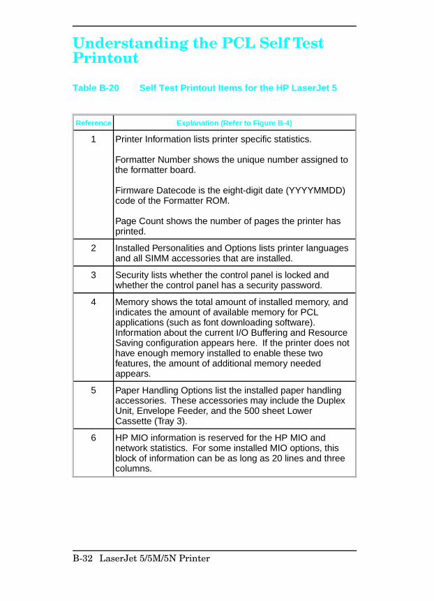
Understanding the PCL Self TestPrintout
Reference Explanation (Refer to Figure B-4)
1 Printer Information lists printer specific statistics.
Formatter Number shows the unique number assigned tothe formatter board.
Firmware Datecode is the eight-digit date (YYYYMMDD)code of the Formatter ROM.
Page Count shows the number of pages the printer hasprinted.
2 Installed Personalities and Options lists printer languagesand all SIMM accessories that are installed.
3 Security lists whether the control panel is locked andwhether the control panel has a security password.
4 Memory shows the total amount of installed memory, andindicates the amount of available memory for PCLapplications (such as font downloading software).Information about the current I/O Buffering and ResourceSaving configuration appears here. If the printer does nothave enough memory installed to enable these twofeatures, the amount of additional memory neededappears.
5 Paper Handling Options list the installed paper handlingaccessories. These accessories may include the DuplexUnit, Envelope Feeder, and the 500 sheet LowerCassette (Tray 3).
6 HP MIO information is reserved for the HP MIO andnetwork statistics. For some installed MIO options, thisblock of information can be as long as 20 lines and threecolumns.
Table B-20 Self Test Printout Items for the HP LaserJet 5
B-32 LaserJet 5/5M/5N Printer
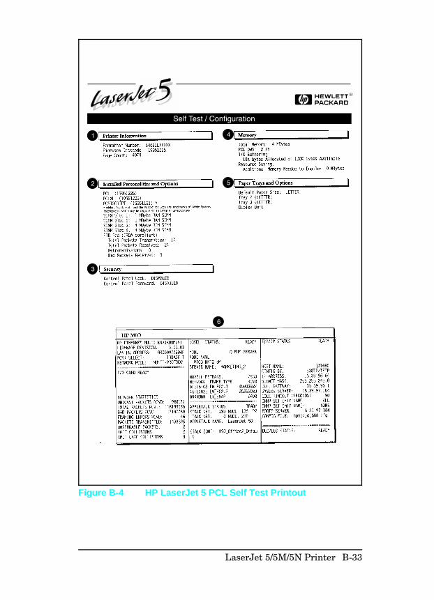
Figure B-4 HP LaserJet 5 PCL Self Test Printout
LaserJet 5/5M/5N Printer B-33
Infrared Communication
The HP LaserJet 5, 5M, and 5N printers are equipped with anInfrared Datalink Association (IrDA) compliant port. The IrDAspecification allows “wireless” transmission of print data betweena wide variety of hosts (primary) and peripheral (secondary)devices. A primary device — such as a PC or laptop computer —is capable of reading and writing data to another primary deviceor writing to a secondary device, such as a printer. Secondarydevices are read-only; they cannot initiate their owncommunication, and can only respond to a host command whenproperly addressed.
The IrDA protocol uses a transceiver chip in both devices to sendand receive data packets. The packets are checked for validity,and a response is sent by the secondary device indicating whetherthe packets were complete or in error.
The IrDA protocol is contained in three layers:
• The physical electronics are the hardware elements in eachdevice for sending and receiving the data.
• The Link Access Protocol (LAP) layer controls the physicallayer, packetizes/unpacketizes data, and sets transmissionrates.
• The Link Management Protocol (LMP) layer routes data toand from the host operating system (DOS/Windows).
The data flow is shown in Figure B-5.
The LAP and LMP layers can reside in either firmware, software,or a combination of both. There are different LAP and LMPprotocols for primary and secondary devices.
The HP LaserJet 5 printer has the complete secondary protocol,and any host trying to communicate via the infrared (IR) portmust have the complete primary protocol installed. The primaryprotocol software is the responsibility of the host supplier. It isnot provided by Hewlett-Packard with the printer.
IrDA host (or primary device) communications can be obtainedeither via an internal IR port or an external IR accessory. Severalmanufacturers offer complete accessory upgrades for both hostand peripheral devices.
B-34 LaserJet 5/5M/5N Printer
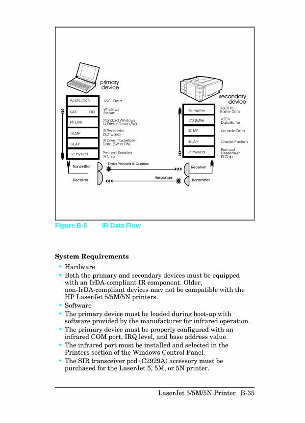
System Requirements
• Hardware• Both the primary and secondary devices must be equipped
with an IrDA-compliant IR component. Older,non-IrDA-compliant devices may not be compatible with theHP LaserJet 5/5M/5N printers.
• Software• The primary device must be loaded during boot-up with
software provided by the manufacturer for infrared operation.• The primary device must be properly configured with an
infrared COM port, IRQ level, and base address value.• The infrared port must be installed and selected in the
Printers section of the Windows Control Panel.• The SIR transceiver pod (C2929A) accessory must be
purchased for the LaserJet 5, 5M, or 5N printer.
Protocol SerializerIR Chip
Application
GDI DDI
Ptr DVR
IRLMP
IRLAP
IR Physical
Transmitter
Receiver
Receiver
Transmitter
IR Physical
IRLAP
IRLMP
I/O Buffer
Formatter
Data Packets & Queries
Responses
secondarysecondarydevicedevice
primarydevice
ASCII Data
WindowsSystem
Standard WindowsLJ Printer Driver (SW)
IR Redirector(Software)
IR Driver Packetizes Data (SW or FW)
ASCII to Raster Data
ASCII Data Buffer
Unpacks Data
Checks Packets
ProtocolDeserializerIR Chip
Figure B-5 IR Data Flow
LaserJet 5/5M/5N Printer B-35
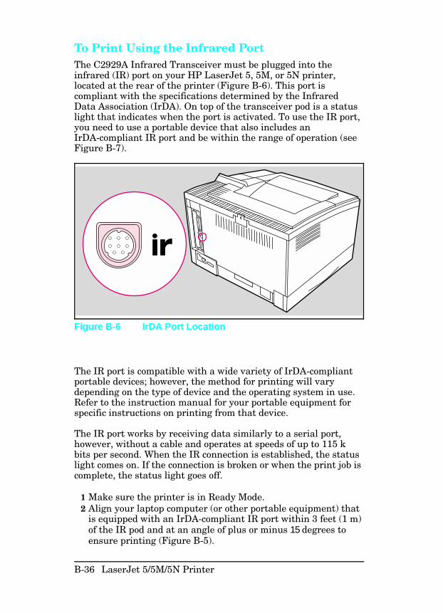
To Print Using the Infrared PortThe C2929A Infrared Transceiver must be plugged into theinfrared (IR) port on your HP LaserJet 5, 5M, or 5N printer,located at the rear of the printer (Figure B-6). This port iscompliant with the specifications determined by the InfraredData Association (IrDA). On top of the transceiver pod is a statuslight that indicates when the port is activated. To use the IR port,you need to use a portable device that also includes anIrDA-compliant IR port and be within the range of operation (seeFigure B-7).
The IR port is compatible with a wide variety of IrDA-compliantportable devices; however, the method for printing will varydepending on the type of device and the operating system in use.Refer to the instruction manual for your portable equipment forspecific instructions on printing from that device.
The IR port works by receiving data similarly to a serial port,however, without a cable and operates at speeds of up to 115 kbits per second. When the IR connection is established, the statuslight comes on. If the connection is broken or when the print job iscomplete, the status light goes off.
1 Make sure the printer is in Ready Mode.2 Align your laptop computer (or other portable equipment) that
is equipped with an IrDA-compliant IR port within 3 feet (1 m)of the IR pod and at an angle of plus or minus 15 degrees toensure printing (Figure B-5).
Figure B-6 IrDA Port Location
B-36 LaserJet 5/5M/5N Printer
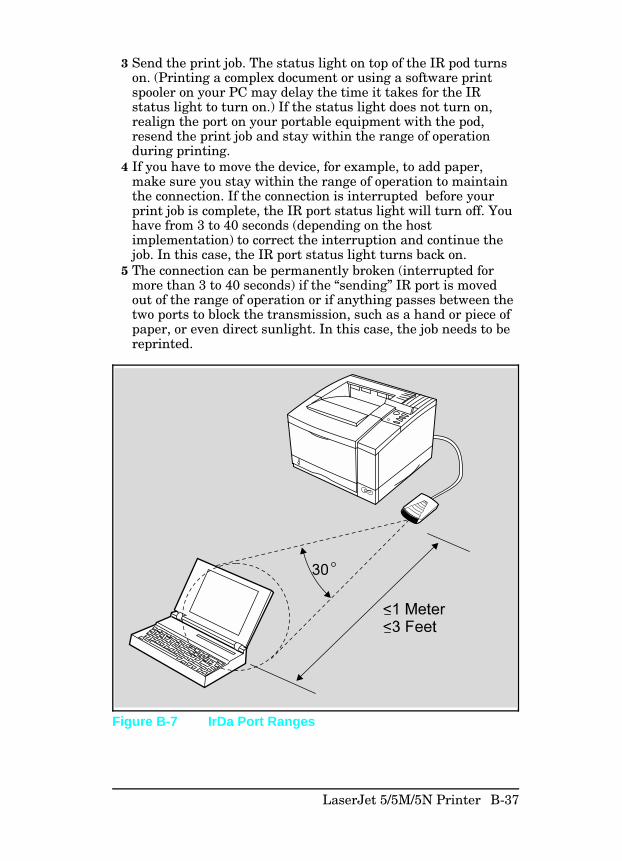
3 Send the print job. The status light on top of the IR pod turnson. (Printing a complex document or using a software printspooler on your PC may delay the time it takes for the IRstatus light to turn on.) If the status light does not turn on,realign the port on your portable equipment with the pod,resend the print job and stay within the range of operationduring printing.
4 If you have to move the device, for example, to add paper,make sure you stay within the range of operation to maintainthe connection. If the connection is interrupted before yourprint job is complete, the IR port status light will turn off. Youhave from 3 to 40 seconds (depending on the hostimplementation) to correct the interruption and continue thejob. In this case, the IR port status light turns back on.
5 The connection can be permanently broken (interrupted formore than 3 to 40 seconds) if the “sending” IR port is movedout of the range of operation or if anything passes between thetwo ports to block the transmission, such as a hand or piece ofpaper, or even direct sunlight. In this case, the job needs to bereprinted.
Figure B-7 IrDa Port Ranges
LaserJet 5/5M/5N Printer B-37
If you still have problems printing, make sure you are using anIrDA-compliant device and proper software and have selected theproper port for printing.
N o t e The IrDA standard for infrared communicationsrepresents an emerging technology. Oldernon-IrDA-compliant portable devices may not becompatible with your HP LaserJet 5/5M/5Nprinter. If you continue to have problems printingusing the IR port, contact the manufacturer ordealer where you purchased your portable deviceto verify compatibility with the IrDA standard,and follow the troubleshooting procedureimmediately following.
Troubleshooting IR Printing ProblemsIR printing problems may be caused by any of the several systemcomponents or by lack of proper configuration. The followingchecklist will help determine the source of the problem.
1 Verify the user is operating the printer and PC as described inthe User’s Manual: less than one meter between devices, andnot more than plus or minus 15 degrees from direct center.
2 Verify the host PC or laptop and the printer areIrDA-compliant and have the necessary hardware componentsfor IR communication.
3 Verify the IR software has been loaded on the primary device.(This is system software and should be available from the PCmanufacturer.)
4 Verify the host PC or laptop is properly configured. Check theport assignment, the IRQ level, and the base address value.Check both the DOS AUTOEXEC.BAT and CONFIG.SYSfiles, and the Windows system configuration.
B-38 LaserJet 5/5M/5N Printer

If all these elements are properly installed and configured, usethe IR test tool to test the IrDA protocol transmission and deviceoperation. This tool for troubleshooting IR communicationproblems, shown in Figure 10, has been developed by GenoaTechnology, Inc., in cooperation with Hewlett-Packard. The partnumber is 5062-4661 and can be ordered through HP Parts DirectOrdering.
The IR test tool can be used with any IrDA-compliant primary orsecondary device, regardless of manufacturer.
To test the peripheral device:
1 Put the HP LaserJet 5 in Ready Mode.2 Press the “Peripheral Test” button on the test tool. The LEDs
on the test tool will sequence.If the “PASS” LED lights, the test was successful, indicating thatcommunication with the printer’s IR port is functioning normally.
LBTest Connect Pass
PeripheralTest
ComputerTest
Test Modes
PCL PrinterPostScript PrinterEnergy DetectTest Frame sw
itche
s
IR Diodes
Figure B-8 Infrared Test Tool
LaserJet 5/5M/5N Printer B-39
On HP Laser-Jet printers, a self-test page will be initiated by thetest.
If the “TEST” LED goes out and the “PASS” LED fails to light,the printer’s IR port is not functioning correctly; check theoperator’s instructions included with the IR test tool.
To test the host computer:
1 Place the test tool on a table in front of the PC’s IR port.2 Press the “computer Test button. The test tool will sequence
the LEDs.
If the “PASS” LED light, the test was successful, indicating thatcommunication with the printer’s IR port is functioning normally.
If the “TEST” LED goes out and the “PASS” LED fails to light,the host’s IR port is not functioning correctly.
B-40 LaserJet 5/5M/5N Printer
Infrared Port Not Responding
Situation Solution
The connection cannot beestablished or the transmissionseems to be taking longer thanusual.
Make sure the device you areusing is IrDA-compliant; look foran IrDA symbol on the device orrefer to the manual for the devicefor IrDA specifications.
Make sure that the operatingsystem on your computerincludes an IR driver and yourapplication uses a HP LaserJet5/5M/5N compatible printerdriver.
Make sure you have positionedthe device within the range ofoperation and that no objects,such as a finger, paper, books,or bright light, are interfering withthe connection. Also make surethe two IR ports are clean (freefrom dirt and grease.)
Bright light of any kind (sunlight,incandescent light, fluorescentlight, or light from an infraredremote control, such as thoseused for TVs and VCRs) shiningdirectly into one of the IR portsmay cause interference.
Position the device closer to theprinter’s IR pod.
Table B-21 Solutions for Infrared Not Responding
LaserJet 5/5M/5N Printer B-41
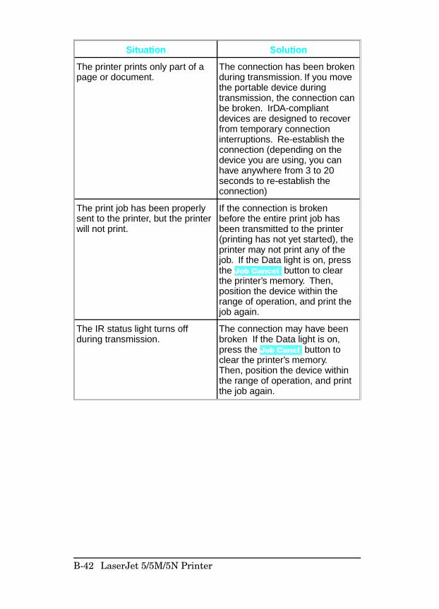
Situation Solution
The printer prints only part of apage or document.
The connection has been brokenduring transmission. If you movethe portable device duringtransmission, the connection canbe broken. IrDA-compliantdevices are designed to recoverfrom temporary connectioninterruptions. Re-establish theconnection (depending on thedevice you are using, you canhave anywhere from 3 to 20seconds to re-establish theconnection)
The print job has been properlysent to the printer, but the printerwill not print.
If the connection is brokenbefore the entire print job hasbeen transmitted to the printer(printing has not yet started), theprinter may not print any of thejob. If the Data light is on, pressthe Job Cancel button to clearthe printer’s memory. Then,position the device within therange of operation, and print thejob again.
The IR status light turns offduring transmission.
The connection may have beenbroken If the Data light is on,press the Job Canel button toclear the printer’s memory.Then, position the device withinthe range of operation, and printthe job again.
B-42 LaserJet 5/5M/5N Printer
Index
!
12 PRINTER OPEN 7-18 13 PAPER JAM 7-2014 NO EP CART 7-25 16 TONER LOW 4-10, 7-25 21 PRINT OVERRUN 3-53 41.1 ERROR 7-28 41.2 ERROR 7-28, 7-31 41.3 ERROR 7-28 41.4 ERROR 7-28 41.5 ERROR 7-28 50 service error 7-29 51 ERROR Message 7-31 52 ERROR 7-32 57 SERVICE 7-33 58 SERVICE fan failure 7-34
A
Accessory Parts 8-33 adjustment
leading edge registration 1-35 advanced functions 3-33 ASAP (Automated Support Access
Program) 1-12 ASCII PJL Escape Sequence 3-19 assemblies removal 6-15 Assist Line (HP CSC) 1-13 assistance, technical 1-12 AUDIO TIPS, HP 1-13 autoexec.bat 3-31, 7-53
B
background scatter 7-35, 7-47 basic sequence of operation 5-33 baud rate 3-33 beam detect signal weak (41.2) 7-27 big data B-28 black pages 7-35
with horizontal stripes 7-35 blank display 7-12 button, test print 3-29
C
cable pinouts 3-35 CDRH laser safety 1-8 changing the display language 3-28
checkMP tray empty sensor 7-17 sw601 7-19
checkpoints, service 4-3 CIC (Customer Information Centers)
1-13 cleaning brush uses 4-16 cleaning station, drum 5-18 clearable warnings 7-10 CLEARING MEMORY 7-A CLOSE PRINTER COVER 7-A cold reset 3-23, B-27 communications checks 7-52, 7-54 component locations 7-59 CompuServe Forum, HP 1-13 conditioning station, drum 5-19 configuration
AUTOEXEC.BAT 7-53 communications check 7-52 system 3-31 test message 7-52
configuration menu B-19 contact plate, high voltage 6-62 contactor removal 6-62 CONTINUOUS TEST 7-A control panel 3-2, 3-6, B-10
flashing indicators 3-2 overlay 3-28removal 6-23 security 3-18
control panel keys B-11 covers removal 6-4 Customer Support Center
Europe (ECSC) 1-14 U.S. (CSC) 1-13
customization variable 3-22
D
data flow, serial 5-4 DATA RECEIVED 7-A datecode 3-26 DB-25 3-37
cable pinouts 3-37 DB-9 3-35
cable pinouts 3-35 DC Controller 5-2
installation 6-35 loads 5-3 removal 6-33 system 5-1
DC power supply 5-2
Index-1
defect Ruler 7-67 defect template 7-67 developing station, drum 5-22 DHHS laser safety 1-8 Diagnostics B-28 diagrams, timing 5-34disassembly, fuser 6-47 display language, changing 3-28, B-30 distorted print 7-35, 7-42 documentation, related 1-7, B-8 DOS commands
serial 7-53 DOS Utilities 3-42 Drum
cleaning station 5-18 conditioning station 5-19 developing station 5-22 photosensitive 5-17Rotation Check 7-50 sensitivity 5-17 transferring station 5-24 writing station 5-20
dtr polarity 3-34 dtr/dsr 3-34 Duplex
components A-14 covers A-9 electrical block diagram A-5 installation A-6 overview A-2 printing A-3 removal and replacement A-8
E
EconoMode 3-16, 4-6 ENGINE TEST 7-A envelope feeder 5-4
installation 3-49 envelopes 2-6 error
infrared B-41 Error Map for LJ 5 7-A - 7-D Error messages
MP/PC/LC LOAD 7-13 troubleshooting 7-2
ESD 6-1 European Customer Support Center
(ECSC) 1-14 European formatter installation 3-22 exhaust fan motor 5-10 Explorer 3-33
F
FACTORY DEFAULTS 7-A faint print 7-35 faint print 7-38
fanchecks 7-34 failure 7-34 motor signals 5-10 removal 6-39
faulty registration 7-39 fax information service (HP FIRST)
1-12 feed guide assembly 6-62
replacing 6-68 Finland laser safety 1-10, B-9 firmware date code 3-26 flash SIMM B-29 flashing indicators 3-2 FM1 7-34
exhaust fan motor 5-10 font door cover 6-10 formatter
PCA removal 6-29 pca, functional overview 5-12 system 5-12
formatter cage removal 6-27 formatter system 5-1 functional check
half self-test 7-49 laser/scanner assembly 7-32 lower cassette 7-24 main motor 7-33 PS2 7-17
functional overview, formatter 5-12 functional test, pickup motor (m2)
7-23 fuser assembly
configuration 6-48 life expectancy 4-2 parts location 6-48 PM 4-3 removal 6-22 thermoswitch removal 6-55
fuser bulb replacement 1-47 fuser disassembly 6-47 fuser malfunction 7-29 fusing
process 5-25 station 5-25 temperature 5-2
fusing roller heat lamp removal 6-49
G
gear assembly removal 6-38
H
half self-test functional check 7-49 handshaking 3-34 hardware 6-2
descriptions 6-3 heat lamp 6-49
Index-2
high voltagecontact assembly 6-68 contact plate 6-62 contactor removal 6-62 contactor/paper guide removal 6-62
High Voltage Power Supplyassembly 7-51 checks 7-51 removal 6-21 troubleshooting 7-51
high voltage system 5-2 HP ASAP (Automated Support Access
Program) 1-12 HP AUDIO TIPS 1-13 HP FIRST (Fax Information Retrieval
Support Technology) 1-12
I
I/Obuffering 3-15 information 3-26
imagedefect summary 7-35 formation system 5-1, 5-16 formation troubleshooting 7-49 skew 7-35
image skew 7-43 improperly sized image 7-35, 7-44 INCOMPATIBLE ENVELOPE
FEEDER 7-A INCOMPATIBLE TRAY 3 7-B indicators 3-2 information, related 1-7, B-8 infrared
operation B-37 printing B-36 software B-34 status light B-36 test tool B-39 troubleshooting B-38, B-41 using to print B-36
infrared communication B-34 Infrared, test tool B-38 initial rotation period 5-38 INITIALIZING 7-B input area paper jams 7-20 input feed roller, PM 4-3 Input/Registration Sensor Check 7-22 INSTALL TONE CARTRIDGE 7-B INSTALL TRAY 2 7-B installation
DC controller 6-35 installing
printer drivers 3-41 SIMM 3-51 the control panel overlay 3-28 the envelope feeder 3-49 the optional lower cassette 3-44
the toner cartridge 4-7 the transfer roller 4-16
INSUFFICIENT MEMORY 7-B insufficient memory messages 7-10 interconnect PCA removal 6-69 interface troubleshooting 7-52 interfaces
DOS commands, parallel 3-31 parallel DOS commands 3-31
IrDA, print using B-36
J
J09, fan connector 7-34 J131 7-33 J211, main motor connector 7-33 J601 7-23 J602 7-23 J701 7-23 J702
location 5-5 paper control PCA 5-5
J704location 5-5 paper control PCA 5-5
jam, detection, paper 5-11 job menu B-18
L
label, laser safety 1-8 labels
adhesive 2-5 arrangement 2-5 construction 2-5 curl 2-5 guidelines 2-5
language, changing the display 3-28 large print voids 7-35, 7-46 laser and scanner drive 5-2 laser safety
CDRH 1-8 DHHS 1-8 Finland 1-10, B-9 label 1-8
laser/scanner assembly functionalchecks 7-32
LaserJet Explorer 3-33 last rotation period 5-42 LC LOAD message 7-13 leading edge registration adjustment
6-35 left side cover removal 6-7 life expectancy
fuser assembly 4-2 rollers 4-2 separation pad 4-2 toner cartridge 4-2
LJ 5 Printer B-1 - B-42
Index-3
lower cassetteassemblies removal 6-44 assembly 5-4 drive motor (M3) 5-10 functional check 7-24 installing 3-44 paper loading 3-45 pickup motor 7-24 pickup motor removal 6-45 sensor board removal 6-44tray switches 5-9
LPT1 3-31
M
M1, main motor 5-10 M2 functional test 7-23 M2, paper feed motor 5-10 m3
lower cassette drive motor 5-10 lower cassette pickup motor 7-24
M4, envelope feeder drive motor 5-10M5, scanner motor 5-11 machine status 5-2 Macintosh 3-18 main motor
(M1) 5-10 assembly removal 6-37drive 5-2 drive system 5-10 failure 7-33 functional checks 7-33 functional tests 7-33 signals 5-10
maintenance 4-1 procedures 4-11
malfunction, fuser 7-29 MANUALLY FEED 7-B measuring d.c. voltages 7-69 media specifications 2-3 memory 3-53
size 3-26 memory configuration menu B-21 Memory Enhancement technology
(MEt) 3-17 MEMORY FULL 7-BMEMORY LOW 7-B MEMORY SETTINGS CHANGED
7-B memory-induced messages 7-10 message, TONER LOW 4-10 microswitch
(SW603) 7-15 (SW604) 7-15 (SW605) 7-15 signals 5-8
MIO 3-26, 3-40, 7-56 menus 3-26
MODE command 3-31
MODE statement 7-53 model number 1-3, B-5motor locations 7-61 MP Door Removal 6-12 MP pick-up roller clutch solenoid
(SL2) 5-5 MP rollers, PM 4-3 MP tray
empty sensor check 7-17 paper end sensor functional test 7-44 paper path 5-29 paper pickup rollers removal 4-11 removal 6-13 separation pad removal 4-11
MP/PC/LC LOAD Message 7-13 MS-DOS
System configuration 3-31 version 4 and above 7-53 version 4 and below 7-53
MSDS, phone number 1-11 multifeed (41.3) 7-28
N
networks, security 3-18 noisy vertical sync signal (41.1) 7-28 non-HP toner cartridge 4-9 Novell Networks, HP JetAdmin
Utility 3-19 number
model 1-3, B-5 Serial 1-3, B-5
NVRAM Init B-31
O
OFFLINE 7-B operation
basic sequence of 5-33 standard printer 5-33
options, installed status 3-26 ordering
documentation 1-7, B-8 packaging material 3-43
output area paper jams 7-20 output assembly removal 6-41 overhead transparencies 2-6 ozone, safety 1-11
P
pacing 3-34 packaging material part no. 3-43 packaging the printer 3-43 page count 3-24, 3-26
setting the 3-21 page protect 3-13 paper control pca removal 6-59 paper exit sensor removal 6-42
Index-4
paper feedassembly removal 6-18
paper feed guide removal 6-62 paper feed system 5-1, 5-26 paper jam 7-20
detection 5-11 PS1 7-20 troubleshooting 7-20
paper motion 5-2 paper path
MP tray 5-29 PC tray 5-30
paper pickup motor 5-10 paper pickup rollers 4-11 paper sensors 7-20 paper size sensing, lower cassette 7-16 paper specifications 2-3 paper tray switch settings 5-9 paper, loading optional lower cassette
3-45 parallel
communication 3-31 DOS commands 7-53
parallel menu 3-33, B-22 parts list 8-40 PC LOAD Message 7-13 PC pick-up roller clutch solenoid
(SL1) 5-5 PC rollers, PM 4-3 PC tray
paper path 5-30 pickup roller removal 4-13
PC tray size switches (SW603,SW604, SW605) functional check7-15
PCL fonts menu B-17 PCL memory requirements 3-26 period
initial rotation 5-38 last rotation 5-42 print 5-40 standby 5-37 warm-up 5-37
periodic maintenance procedures 4-11 phone numbers
CIC (Customer Information Centers)1-13 CSC (Customer Support Center) 1-13 MSDS 1-11 printer drivers 3-41 technical assistance 1-12
photosensitive drum 5-17 photosensors
signals 5-5 - 5-6 tray and door 5-5 - 5-6
pickup motor (m2) functional test 7-23 pickup motor, lower cassette 7-24 pickup rollers 6-1 PLEASE WAIT 7-B
portinfrared B-35
PostScript 3-58 postscript menu B-18 power supply removal 6-15 power system 5-1, 5-31 POWERSAVE ON 7-B pre-troubleshooting procedures 7-1 preliminary operating checks 7-1 print darkness 3-17 print density 7-38
adjusting 3-17 adjustment 4-5 dial 3-17
print media specifications 2-3 print period 5-40 printer
security 3-18 serial number 1-3, B-5 specifications 1-5, B-6
printer drivers 1-13, 3-41 obtaining 3-41
Printer Job Language (PJL) overview5-15
printer message troubleshooting 7-2 printer open failure 7-18 PRINTING CONFIG PAGE 7-B PRINTING DEMO PAGE 7-B printing envelopes 2-6 PRINTING FLASH PAGE 7-B PRINTING FONT LIST 7-B printing menu 3-24, B-15 printout, test print 3-29 process, fusing 5-25 PROCESSING JOB 7-B product compatibility 1-2, B-2 - B-3 programming flash SIMM B-29 protecting the SIMM board 3-51 protocol
infrared B-34 PS 5, MP tray trailing edge sensor
7-44 PS1
and PS2 sensor assembly removal6-61 input/registration sensor 5-7 paper jam 7-20
PS2functional check 7-17 paper jam 7-20
PC tray paper-out sensor 5-6 PS3
(exit sensor) check 7-23 paper exit sensor 5-7
PS3 removal 6-42 PS4
check 7-17
Index-5
PS5check 7-44 MP tray trailing edge sensor 5-7
PS6, lower cassette paper-out sensor5-7
PS7, envelope feeder paper-out sensor5-7
R
RAM size 3-24 Random Horizontal Black Lines 7-40 READY 7-B rear door removal 6-8 recycling program
Toner Cartridge 4-7 registration
adjustment 6-35 leading edge adjustment 6-35
related documentation 1-7, B-8 removal
font door cover 6-10 formatter pca 6-29 gear assembly 6-38 left side cover 6-7 MP tray separation 4-11 PC tray pickup roller 4-13 top cover 6-5 transfer roller 4-16
REMOVE DUPLEX JAM 7-B REMOVE PAPER JAM 7-C removing
and replacing the transfer roller 4-15 lower cassette roller 4-14 MP tray separation pad 4-11 MP tray, paper pickup rollers 4-11 PC tray pickup roller 4-13 the SIMMs cover 6-25 transfer roller 4-16
removing the covers 6-4 repackaging instructions 3-43 repetitive defect template 7-67 repetitive defects 7-35, 7-41 replacing
fuser parts 6-47 MP tray separation pad 4-11 paper pickup rollers 4-11 the feed guide assembly 6-68 the high voltage contact assembly
6-68 the transfer roller 4-16
REQUESTED LANGUAGE NOTAVAIL 7-C
requirementsfor infrared B-35
requirements, site 2-1 Reset Menu 3-5 reset, cold 3-23 resets menu B-23
RESETTING ACTIVE I/O 7-C RESETTING ALL I/O 7-C Resolution Enhancement (REt) 3-16 Resolution Enhancement technology
status 3-26 Resource Saving 3-14
status 3-26 RESTORING FACTORY SETTINGS
7-C returning the printer 3-43 RFI statement 1-9 right hand text missing 7-35, 7-40 right side cover removal 6-4 robust xon 3-34 rollers
life expectancy 4-2 MP tray 4-11 paper pickup 4-11
rs-422A 3-39 rs232C 3-33
S
safetyFinland laser 1-10, B-9 label, Laser 1-8 laser, CDRH 1-8 laser, DHHS 1-8 ozone 1-11toner 1-11
scanner assembly removal 6-43 scanner malfunction 7-32 scanner motor 5-10
signals 5-10 security, networks 3-18 self test description 3-24, B-32 sensitivity, drum 5-17 sensor pca removal 6-60 separation pad 6-1
life expectancy 4-2 MP tray 4-11
sequence of operation, basic 5-33 serial
cable pinouts 3-35 communication 3-31 configuration 3-33 DOS commands 7-53
serial datacommunication 5-4 flow 5-4 input (SLI) 5-2 output (SLO) 5-2, 5-4
repackaging instructions 3-43 repetitive defect template 7-67 repetitive defects 7-35, 7-41 replacing
fuser parts 6-47 serial menu B-22 serial number 1-3, B-5
Index-6
service checkpoints 4-1, 4-3 Service Mode 3-20, B-25 service/error messages 3-59 setting the cold reset B-27 setting the page count 3-21, B-26 setting up the envelope feeder 3-50 settings, tray switch 5-9 sheet feeder installation 3-44 signals
fan motor 5-10 main motor 5-10 Microswitch 5-8 Photosensor 5-6 scanner motor 5-10 solenoid 5-5
site requirements 2-1 Skip demo B-28 SL1, PC pick-up roller clutch solenoid
5-5 SL2, MP pick-up roller clutch solenoid
5-5 SL3 lower cassette pickup roller
clutch solenoid 5-5 SLI (serial data in) 5-4 SLO (serial data out) 5-4 smeared print/improper fusing 7-35,
7-42 software B-35
shipped with printer B-34 solenoids 5-5
signals 5-5 space requirements 2-2 specifications
IrDA B-34 labels 2-3, 2-5 paper 2-3 print media 2-3
standard printer operation 5-33 standby period 5-37 state machines 5-4 statement, RFI 1-9 station
drum cleaning 5-18 drum conditioning 5-19 drum developing 5-22 drum transferring 5-24 drum writing 5-20 fusing 5-25
Status message troubleshooting 7-2 status, self test 3-26 sw601 7-19 sw601, top cover open sensor switch
5-8 sw602, test print switch 5-8 SW603 7-15
PC size switch 5-8 SW604 7-15
PC size switch 5-8 SW605 7-15
PC size switch 5-8
sw851, lower cassette size switch 5-8 sw852, lower cassette size switch 5-8 sw853, lower cassette size switch 5-8 switch locations 7-62 switch settings, paper tray 5-9 system
communication 3-31 configuration 3-31 paper feed 5-26
T
TB201 (voltage test points) 7-69 technical assistance 1-12test menu B-24 test message for communications
check 7-52 test print button 3-29 test print printout 3-29 test tool
infrared B-39 thermistor removal 6-56 thermoswitch removal 6-55 timing 5-2 timing diagrams 5-34 toner
cleaning 1-11 distribution 4-10 level 5-2 safety 1-11
toner cartridge 4-1, 4-5, 4-10 components 7-26 life 4-5 life expectancy 4-2 recycling 4-7 refilled 4-9 shelf life 4-6 storage 4-6
TONER LOW 4-10, 7-C message 7-25
TONER LOW=OFF 4-10 TONER LOW=ON 4-10 tools, required 6-2 top cover removal 6-5 trailing edge sensor
PS5 7-44 transfer roller
PM 4-3 removal and replacement 4-15 - 4-16 replacement 4-16
transferring station, drum 5-24 TRAY 1/2/3 LOAD message 7-13 Tray 2 tray size switches 7-15 TRAY 2/3 EMPTY 7-C TRAY X LOAD 7-C tray, switch settings 5-9 troubleshooting
aids 7-59 Attendance messages 7-2
Index-7
Error messages 7-2 general information 7-1 infrared B-38 Message Summary Table 7-2 messages 7-2 preliminary 7-1 Printer messages 7-2 quick checks 7-1 Status messages 7-2
Troubleshooting, IR port B-38
U
unpacking the printer 3-43 user maintenance 4-2
V
variable, customization 3-22 version number 3-26 vertical dark streaks 7-35, 7-46 vertical sync late (41.4) 7-28 vertical white streaks 7-35, 7-40 voltage checks 7-69 voltage test points 7-69
W
W0 JOB 600/A4 7-11 W1 IMAGE ADAPT 7-11 W2 INVALID PERS 7-11W3 JOB ABORTED 7-11 W4 JOB 300/OFF 7-11 W5 JOB 300/LTR 7-11 W6 JOB 300/A4 7-11 W7 JOB 300/LGL 7-11 W8 JOB 600/OFF 7-11 W9 JOB 600/LTR 7-11 warm-up period 5-37 WARMING UP 7-C white or blank pages 7-48white streaks, vertical 7-40 wireless printing
See see infrared writing station, drum 5-20
X
X LOAD 7-C xon/xoff 3-34
Index-8
SN-1 Service Notes
SN-2 Service Notes
SN-3 Service Notes
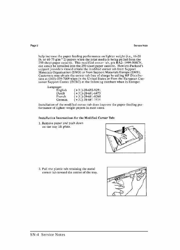
SN-4 Service Notes
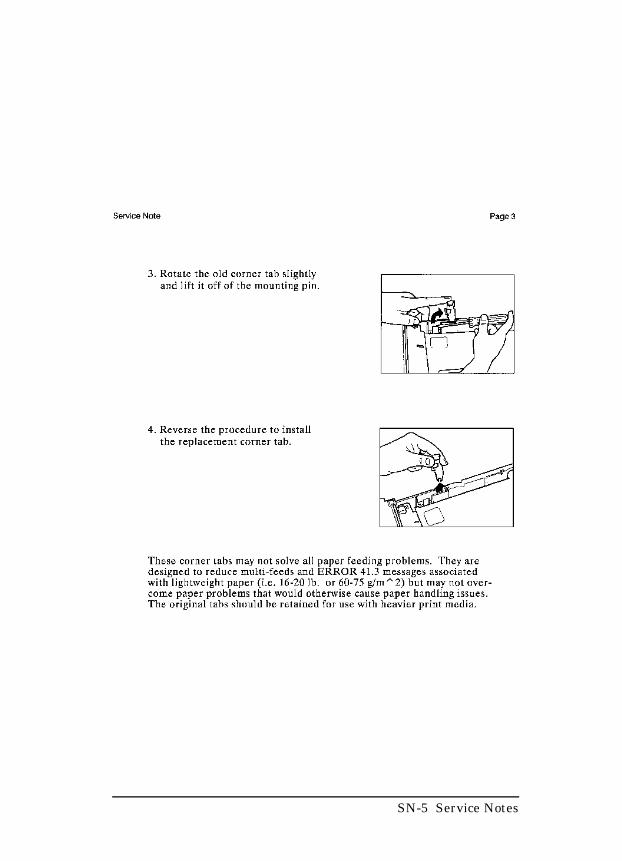
SN-5 Service Notes

SN-6 Service Notes
SN-7 Service Notes

SN-8 Service Notes

Copyright© 1996Hewlett-Packard CompanyPrinted in USA 3/96
Manual Part No.C3916-90984
*C3916-90984**C3916-90984*
C3916-90984
Related Documents