Welcome message from author
This document is posted to help you gain knowledge. Please leave a comment to let me know what you think about it! Share it to your friends and learn new things together.
Transcript

High-Security Mechanical Locks:An Encyclopedic Reference

This page intentionally left blank
High-Security Mechanical Locks:An Encyclopedic Reference
Graham W. Pulford
AMSTERDAM • BOSTON • HEIDELBERG • LONDON
NEW YORK • OXFORD • PARIS • SAN DIEGO
SAN FRANCISCO • SINGAPORE • SYDNEY • TOKYO
Butterworth-Heinemann is an imprint of Elsevier
Elsevier Academic Press30 Corporate Drive, Suite 400, Burlington, MA 01803, USA525 B Street, Suite 1900, San Diego, California 92101-4495, USA84 Theobald’s Road, London WC1X 8RR, UK
This book is printed on acid-free paper.
Copyright c© 2007, Elsevier Inc. All rights reserved.
No part of this publication may be reproduced or transmitted in any form or by any means,electronic or mechanical, including photocopy, recording, or any information storage and retrievalsystem, without permission in writing from the publisher.
Permissions may be sought directly from Elsevier’s Science & Technology Rights Department inOxford, UK: phone: (+44) 1865 843830, fax: (+44) 1865 853333, E-mail: [email protected] may also complete your request on-line via the Elsevier homepage (http://elsevier.com), byselecting “Customer Support” and then “Obtaining Permissions.”
Library of Congress Cataloging-in-Publication Data
Pulford Graham W.High-security mechanical locks : an encyclopedic reference/Graham W. Pulford.
p. cm.Includes bibliographical references and index.ISBN-13: 978-0-7506-8437-8 (alk. paper)ISBN-10: 0-7506-8437-2 (alk. paper)1. Locks and keys–Encyclopedias.
TS520.P854 2007683′.32–dc22
2007004202
British Library Cataloguing-in-Publication Data
A catalogue record for this book is available from the British Library
ISBN 13: 978-0-7506-8437-8ISBN 10: 0-7506-8437-2
For all information on all Elsevier Academic Press publicationsvisit our Web site at www.books.elsevier.com
Printed in the United States of America
07 08 09 10 11 12 10 9 8 7 6 5 4 3 2 1

To Jill, Arthur, Lehene, HweeYing and Chloe

This page intentionally left blank
Contents
Acknowledgments xi
Preface xiii
1 Introduction 1
1.1 Prologue . . . . . . . . . . . . . . . . . . . . . . . . . . . . . . . . . . . . . . . . . . . 1
1.2 Security Versus Obscurity . . . . . . . . . . . . . . . . . . . . . . . . . . . . . . . 5
1.3 Innovation in the Lock Industry . . . . . . . . . . . . . . . . . . . . . . . . . . 8
1.4 Administrative Matters . . . . . . . . . . . . . . . . . . . . . . . . . . . . . . . . 22
2 Pin-Tumbler Locks 31
2.1 Introduction . . . . . . . . . . . . . . . . . . . . . . . . . . . . . . . . . . . . . . . . 31
2.2 Inline . . . . . . . . . . . . . . . . . . . . . . . . . . . . . . . . . . . . . . . . . . . . . 64
2.3 Inline with Passive Profile Pins . . . . . . . . . . . . . . . . . . . . . . . . . . . 79
2.4 Inline Horizontal Keyway . . . . . . . . . . . . . . . . . . . . . . . . . . . . . . . 86
2.5 Twin Inline . . . . . . . . . . . . . . . . . . . . . . . . . . . . . . . . . . . . . . . . . 91
2.6 Inline with Active Profile Pins . . . . . . . . . . . . . . . . . . . . . . . . . . . 99
2.7 Cruciform . . . . . . . . . . . . . . . . . . . . . . . . . . . . . . . . . . . . . . . . . . 111
2.8 Multiple Inline . . . . . . . . . . . . . . . . . . . . . . . . . . . . . . . . . . . . . . . 115
2.9 Tubular . . . . . . . . . . . . . . . . . . . . . . . . . . . . . . . . . . . . . . . . . . . . 138
viii CONTENTS
2.10 Concentric Pin . . . . . . . . . . . . . . . . . . . . . . . . . . . . . . . . . . . . . . . 153
2.11 Rotating Pin . . . . . . . . . . . . . . . . . . . . . . . . . . . . . . . . . . . . . . . . 160
2.12 Pin Matrix . . . . . . . . . . . . . . . . . . . . . . . . . . . . . . . . . . . . . . . . . 163
2.13 Key-Changeable . . . . . . . . . . . . . . . . . . . . . . . . . . . . . . . . . . . . . . 168
3 Wafer Locks 173
3.1 Introduction . . . . . . . . . . . . . . . . . . . . . . . . . . . . . . . . . . . . . . . . 173
3.2 Conventional . . . . . . . . . . . . . . . . . . . . . . . . . . . . . . . . . . . . . . . . 186
3.3 Contoured . . . . . . . . . . . . . . . . . . . . . . . . . . . . . . . . . . . . . . . . . . 190
3.4 Three-sided . . . . . . . . . . . . . . . . . . . . . . . . . . . . . . . . . . . . . . . . . 194
3.5 Inline Push Type . . . . . . . . . . . . . . . . . . . . . . . . . . . . . . . . . . . . . 196
3.6 Bell Locks . . . . . . . . . . . . . . . . . . . . . . . . . . . . . . . . . . . . . . . . . . 199
3.7 Axial . . . . . . . . . . . . . . . . . . . . . . . . . . . . . . . . . . . . . . . . . . . . . 205
3.8 Key-Changeable . . . . . . . . . . . . . . . . . . . . . . . . . . . . . . . . . . . . . . 217
4 Side-Bar Locks 223
4.1 Introduction . . . . . . . . . . . . . . . . . . . . . . . . . . . . . . . . . . . . . . . . 223
4.2 Disc Side-bar . . . . . . . . . . . . . . . . . . . . . . . . . . . . . . . . . . . . . . . . 234
4.3 Lever Side-bar . . . . . . . . . . . . . . . . . . . . . . . . . . . . . . . . . . . . . . . 252
4.4 Driverless-Pin Side-bar . . . . . . . . . . . . . . . . . . . . . . . . . . . . . . . . . 264
4.5 Wafer Side-bar . . . . . . . . . . . . . . . . . . . . . . . . . . . . . . . . . . . . . . . 279
4.6 Dual-action Side-bar . . . . . . . . . . . . . . . . . . . . . . . . . . . . . . . . . . 287
5 Lever Locks 313
5.1 Introduction . . . . . . . . . . . . . . . . . . . . . . . . . . . . . . . . . . . . . . . . 313
5.2 Conventional . . . . . . . . . . . . . . . . . . . . . . . . . . . . . . . . . . . . . . . . 349
5.3 Double-Throw . . . . . . . . . . . . . . . . . . . . . . . . . . . . . . . . . . . . . . . 375
CONTENTS ix
5.4 Axial . . . . . . . . . . . . . . . . . . . . . . . . . . . . . . . . . . . . . . . . . . . . . 379
5.5 Radial . . . . . . . . . . . . . . . . . . . . . . . . . . . . . . . . . . . . . . . . . . . . . 387
5.6 Cylindrical . . . . . . . . . . . . . . . . . . . . . . . . . . . . . . . . . . . . . . . . . 394
5.7 Geared . . . . . . . . . . . . . . . . . . . . . . . . . . . . . . . . . . . . . . . . . . . . 409
5.8 Trap-Door . . . . . . . . . . . . . . . . . . . . . . . . . . . . . . . . . . . . . . . . . . 414
5.9 Twin . . . . . . . . . . . . . . . . . . . . . . . . . . . . . . . . . . . . . . . . . . . . . . 416
5.10 Variable . . . . . . . . . . . . . . . . . . . . . . . . . . . . . . . . . . . . . . . . . . . 420
5.11 Dual-Control . . . . . . . . . . . . . . . . . . . . . . . . . . . . . . . . . . . . . . . . 430
6 Magnetic Locks 435
6.1 Introduction . . . . . . . . . . . . . . . . . . . . . . . . . . . . . . . . . . . . . . . . 435
6.2 Miwa Magnetic . . . . . . . . . . . . . . . . . . . . . . . . . . . . . . . . . . . . . . 448
6.3 Anker . . . . . . . . . . . . . . . . . . . . . . . . . . . . . . . . . . . . . . . . . . . . . 450
6.4 MagLok . . . . . . . . . . . . . . . . . . . . . . . . . . . . . . . . . . . . . . . . . . . 454
6.5 Miracle Magnetic . . . . . . . . . . . . . . . . . . . . . . . . . . . . . . . . . . . . . 457
6.6 EVVA MCS . . . . . . . . . . . . . . . . . . . . . . . . . . . . . . . . . . . . . . . . . 459
6.7 Schlage CorKey . . . . . . . . . . . . . . . . . . . . . . . . . . . . . . . . . . . . . . 463
7 Car Locks 469
7.1 Introduction . . . . . . . . . . . . . . . . . . . . . . . . . . . . . . . . . . . . . . . . 469
7.2 Double-Sided . . . . . . . . . . . . . . . . . . . . . . . . . . . . . . . . . . . . . . . . 476
7.3 Holden Commodore . . . . . . . . . . . . . . . . . . . . . . . . . . . . . . . . . . . 478
7.4 Ford Tibbe . . . . . . . . . . . . . . . . . . . . . . . . . . . . . . . . . . . . . . . . . 479
7.5 Ford Chubb . . . . . . . . . . . . . . . . . . . . . . . . . . . . . . . . . . . . . . . . . 482
7.6 General Motors . . . . . . . . . . . . . . . . . . . . . . . . . . . . . . . . . . . . . . 484
7.7 Mercedes Two-Track . . . . . . . . . . . . . . . . . . . . . . . . . . . . . . . . . . 487
x CONTENTS
7.8 BMW Two-Track . . . . . . . . . . . . . . . . . . . . . . . . . . . . . . . . . . . . . 489
7.9 Mercedes Four-Track . . . . . . . . . . . . . . . . . . . . . . . . . . . . . . . . . . 491
7.10 Mitsubishi . . . . . . . . . . . . . . . . . . . . . . . . . . . . . . . . . . . . . . . . . . 493
7.11 Porsche . . . . . . . . . . . . . . . . . . . . . . . . . . . . . . . . . . . . . . . . . . . . 495
7.12 Alpha Romeo . . . . . . . . . . . . . . . . . . . . . . . . . . . . . . . . . . . . . . . 497
7.13 Volvo . . . . . . . . . . . . . . . . . . . . . . . . . . . . . . . . . . . . . . . . . . . . . 499
7.14 Citroen Simplex . . . . . . . . . . . . . . . . . . . . . . . . . . . . . . . . . . . . . . 501
8 Conclusion 505
Bibliography 511
Figure and Table Credits 521
Appendices 525
Appendix A1: Permutations and Combinations . . . . . . . . . . . . . . . . . . . 525
Appendix A2: Lock Permutations and Fractals . . . . . . . . . . . . . . . . . . . . 530
Appendix B: Translations of Lock Vocabulary . . . . . . . . . . . . . . . . . . . . 535
Appendix C: Terminology and Abbreviations . . . . . . . . . . . . . . . . . . . . . 546
Appendix D: Lock Patents . . . . . . . . . . . . . . . . . . . . . . . . . . . . . . . . . . 548
Appendix E: Brief History of the Bramah Lock . . . . . . . . . . . . . . . . . . . 558
Appendix F: Key Code Computations . . . . . . . . . . . . . . . . . . . . . . . . . . 561
Appendix G: Security Gradings for Cylinder Locks . . . . . . . . . . . . . . . . . 573
Index 575
Acknowledgments
Following the release in 1994 of the “Catalogue of High Security Locks v1.00” [101],the author has received correspondence from many people who have offered theirviews and feedback on material that has helped to improve the content, coverage,and accuracy of the information in this book. Many of these people, being contrib-utors to the alt.locksmithing newsgroup and other online forums, are known to theauthor only by their electronic mail addresses. For the sake of discreetness I cannotidentify these people here, but my thanks go out to them nonetheless. Their helpfulremarks were a regular reminder to me to continue working on this project.
In Australia, I had the good fortune to meet Norm Axford of Acorn Locksmiths andthe Master Locksmiths Association (Australia), whose willingness to support thisbook was a great source of encouragement to me. I am particularly grateful to IanMcColl of Stockade Locksmiths, who greatly contributed to the completeness andcoverage of the book and also assisted with the early stages of proofreading. I wouldalso like to thank Rodney Loschiavo who generously shared with me his knowledgeacquired during many years in the trade. I am grateful for the endorsement of MarkWilson from the Sydney Institute of Technical and Further Education, who grantedme access to the Ultimo workshop. Geoff Birkett of Olympic Keiler Security gavegenerously of his time to help ensure the accuracy of the material presented onseveral high-security locks. Meilin Yum’s willing assistance in typing part of themanuscript is gratefully acknowledged.
In addition, I am fortunate to have had international collaborators. In this connec-tion I would like to express my gratitude to Nathan Schlossman, Oliver Diederich-sen, Tetsuya Ozawa, Han Fey, Paul Prescott, Tony Beck, and Alex Carter. I owea special debt of gratitude to my friend and colleague, Jean-Marie Machefert, formany stimulating discussions and for imbuing me with some of his knowledge ofthe subtleties of the art, particularly in respect of French high-security locks. Inthe United Kingdom Michael Fincher, Richard Hopkins, and Jon Millington all pro-vided valuable assistance with the proofreading of the manuscript. I am indebtedto Michael Fincher for allowing me to photograph some of his lock collection; hisin-depth knowledge, especially of German locks, spared me the embarrassment ofcommitting some major historical errors. It would be remiss of me not to extendmy sincere thanks to the editorial and production team at Elsevier for transformingthe manuscript into a book.
xii ACKNOWLEDGMENTS
A number of organizations are also deserving of mention for their assistance eitherwith the supply of samples or in the provision of product information or services.In this context, the following businesses and companies are acknowledged: WestPhiladelphia Locksmith Co. (Philadelphia, U.S.A.), Lockmart (Toronto, Canada),Serrurerie Rapid-Securit (Paris, France), Quincaillerie d’Alembert (Paris, France),CISA S.p.A. (Faenza, Italy), Centro Sicurezza Minerva (Rome, Italy), DiesenhofenerSchlusseldienst Gabriel (Munich, Germany), Munchener Schlusseldienst Willi Killian(Munich, Germany), Cire Electronics (Sydney, Australia), Rivers Locking Systems(Sydney, Australia), Eastwood Lock & Key service (Sydney, Australia), ABA LocksManufacturer Co. (Taipei, Taiwan), Tover Security Systems (Banyoles, Spain),Helason SicherheitsTechnik GmbH (Vienna, Austria), ANTO Translation Services(Turin, Italy), Can-Am Door Hardware Inc. (Quebec, Canada), Bramah SecurityEquipment (London, U.K.), Supra (UK) Ltd. (Worcestershire, U.K.), K. J. RossSecurity Locks Pty. Ltd. (Melbourne, Australia), SEA Schliess-Systeme AG(Zollikofen, Switzerland), and Australian Lock Company (Unanderra, Australia).
A final note of thanks is due to the keepers of the alt.locksmithing newsgrouparchives at ftp.indra.com, who kindly made a place on their system for the documentthat formed the basis for this book.
Preface
I have been interested in things mechanical and electrical since the age of two when,my father tells me, I unscrewed the back of the washing machine, having seen himdo it. I also liked puzzles and used to infuriate my mother who, being of a moreliterary inclination, had considerably more trouble with them than I did. I hadpreviously heard of things like lockpicking, skeleton keys, and Houdini, and hadseen schoolmates open cheap padlocks with screwdrivers. But I had never stoppedto think carefully about what made a lock tick. Like many other people I knew,I took locks for granted. My mindset regarding locks in those times can be summedup in this way, “if there is a lock on it, then it can only be opened by the personwith the proper key.”
My real interest in locks, which grew into a fascination, started when my familymoved. As people tend to do, I thought we should have the locks changed. So inorder to save money I unscrewed the front door lock, removed the rim cylinder, andtook it to the local locksmith. I remember being totally amazed when, about fiveminutes after I’d handed it to him, he returned it to me recombinated with a newkey. I realized there must be a trick to this and decided to find out some more aboutit. Over the course of the next few years, I learned about how pin-tumbler locksworked and how to pick them using homemade tools. Some of my friends who hadcontact with people in the locksmithing profession helped me along the way.
A pivotal point in my growing interest in high-security locks occurred while I wastraveling in Europe. The locks I saw in France, Germany, Austria, and other coun-tries were so different from those I was used to in my home country of Australia.I realized then that there was a whole world of ingenious locks out there to learnabout, each with its own particular features. There were also many similarities inthe operating principles.
Since that time, I have collected locks from Europe, Asia, and the United States, aswell as from Australia. It was on the basis of these travels and experiences that in1994 I compiled a document called the “Catalogue of High Security Locks v1.00.”The present book contains the information in that previous work as well as manyadditional high-security lock descriptions. The obvious deficiency of that document—its lack of pictures—has been corrected in this book. This information is offered to
xiv PREFACE
readers in the hope that they can share in some of the excitement that I have hadin discovering the amazing world of high-security locks.
Finally, a word of caution seems in order. This book will help you to understandthe operating principles of a large number of high-security lock designs. It providesa rough estimate of the manipulation resistance provided by each lock. However, nodetailed information on lock-defeating methods has been given. Thus, after read-ing this material, you may know if a given lock is susceptible to manipulation byimpressioning or picking, but you will not be given instructions on how to do it.Nor is prescriptive information such as where to drill a lock or how to construct adecoder for a particular lock provided herein. Needless to say, the first step in pick-ing or bypassing a lock is to have a detailed understanding of its design and howit works. The reader should be aware that specific tools and decoders are availablenot just for simple pin-tumbler locks, but for most mechanical high-security locksthat enable them to be opened nondestructively without the key. However, suchequipment is, for obvious reasons, not generally available to the public.
Chapter 1
Introduction
The construction of locks, is a subject on which many ingenious mechanicshave employed their thought, and the art hath received many, and greatimprovements from their labours. Joseph Bramah, c. 1784
1.1 Prologue
The king did not wish to be disturbed. He had withdrawn to his atelier and boltedthe door. The entire morning had been wasted on bothersome matters of statein which his wife showed considerably more interest than he did. Once inside hisworkshop he could concentrate on his favorite pastime: locks. For the last few days,he had been busy fashioning some intricate sash warding for an ornate lock he hopedto fit to his chambers. He was still engrossed in his work when there came a knockat the door. “Sire, the commoner Gamin requests an audience with you. He saysthat he is in possession of an item that you wished to see.” The king put downthe file with which he had been shaping the warding for the lock, his hands dirtyfrom the work. “Bring him to me,” he said. Some minutes later Gamin was broughtto the now open door of the workshop. The king greeted him warmly, eager to seethe article the man carried with him. Gamin beckoned the king over to a benchthat seemed to be a little bit freer than the others. Pushing aside some tools andother clutter, he placed the article on the bench. He took a nearby screwdriver andproceeded to pry off the front of the case, revealing the interior mechanism. “It is adouble-acting lever lock, sire. Come, see how it works!” The king had not seen thistype of lever lock before, though he had heard about it. He picked up the lock inhis sooty hands to examine it more closely. “Hand me the key!” he said.
The king was of course Louis XVI of France, his home the sumptuous palace ofVersailles to the west of Paris. The particular episode described here is fictional,
2 CHAPTER 1 INTRODUCTION
although given Louis’ penchant for locksmithing and neglect of his state duties, itcould quite easily have happened. Louis XVI did in fact associate with Gamin, alocksmith who taught Louis much of what he knew about the trade. There is nodoubt that he was fascinated by locks and spent many hours in pursuit of his hobby.Perhaps if he had spent more of his energies responding to the cries of the Frenchpeople for social reform he would not have come to such a sticky end.
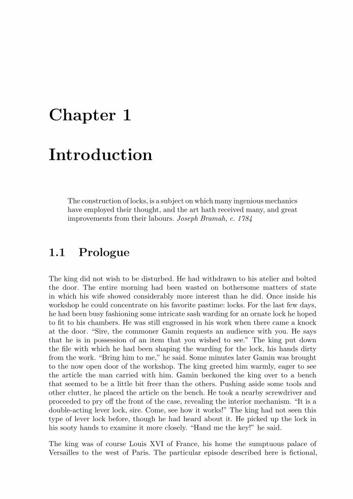
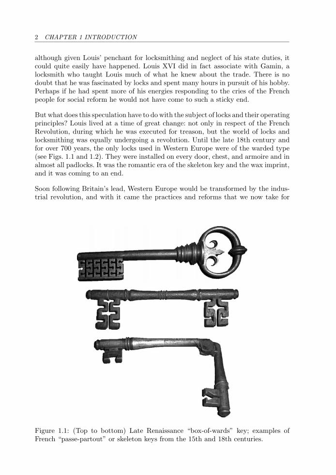
But what does this speculation have to do with the subject of locks and their operatingprinciples? Louis lived at a time of great change: not only in respect of the FrenchRevolution, during which he was executed for treason, but the world of locks andlocksmithing was equally undergoing a revolution. Until the late 18th century andfor over 700 years, the only locks used in Western Europe were of the warded type(see Figs. 1.1 and 1.2). They were installed on every door, chest, and armoire and inalmost all padlocks. It was the romantic era of the skeleton key and the wax imprint,and it was coming to an end.
Soon following Britain’s lead, Western Europe would be transformed by the indus-trial revolution, and with it came the practices and reforms that we now take for
Figure 1.1: (Top to bottom) Late Renaissance “box-of-wards” key; examples ofFrench “passe-partout” or skeleton keys from the 15th and 18th centuries.
1.1 PROLOGUE 3
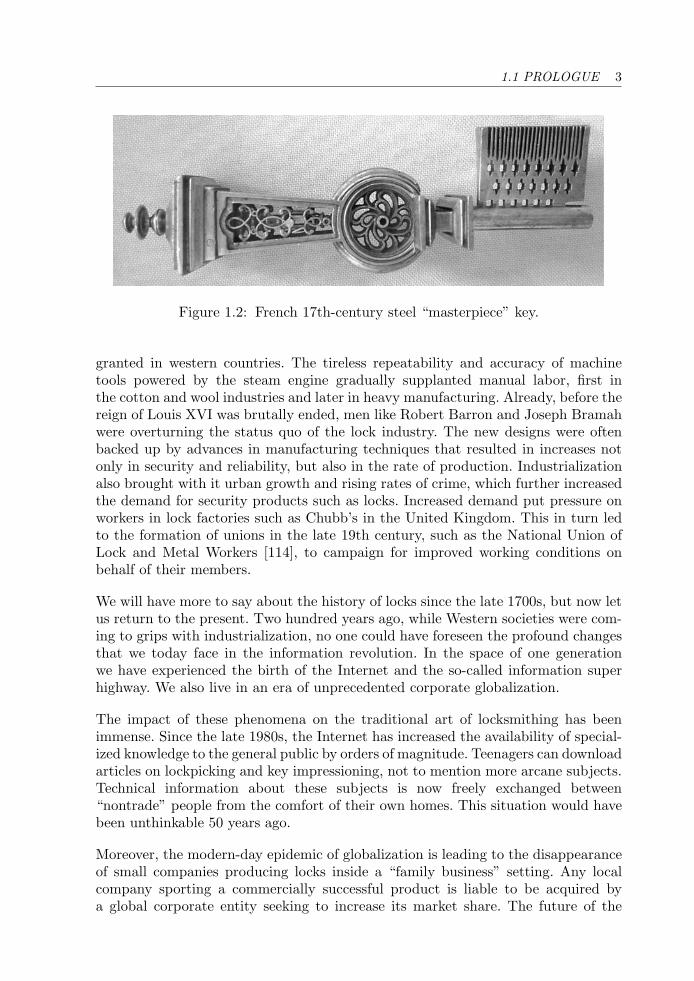
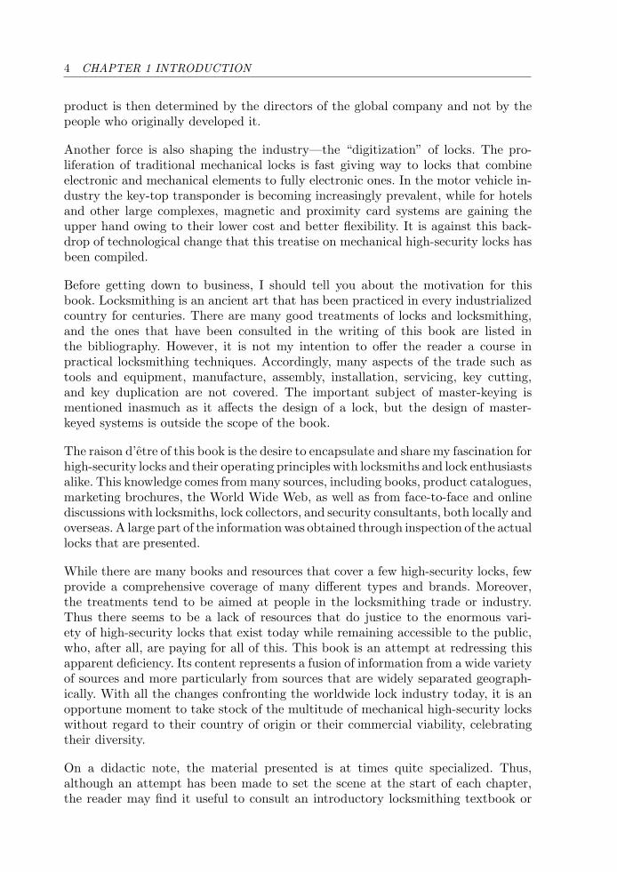
Figure 1.2: French 17th-century steel “masterpiece” key.
granted in western countries. The tireless repeatability and accuracy of machinetools powered by the steam engine gradually supplanted manual labor, first inthe cotton and wool industries and later in heavy manufacturing. Already, before thereign of Louis XVI was brutally ended, men like Robert Barron and Joseph Bramahwere overturning the status quo of the lock industry. The new designs were oftenbacked up by advances in manufacturing techniques that resulted in increases notonly in security and reliability, but also in the rate of production. Industrializationalso brought with it urban growth and rising rates of crime, which further increasedthe demand for security products such as locks. Increased demand put pressure onworkers in lock factories such as Chubb’s in the United Kingdom. This in turn ledto the formation of unions in the late 19th century, such as the National Union ofLock and Metal Workers [114], to campaign for improved working conditions onbehalf of their members.
We will have more to say about the history of locks since the late 1700s, but now letus return to the present. Two hundred years ago, while Western societies were com-ing to grips with industrialization, no one could have foreseen the profound changesthat we today face in the information revolution. In the space of one generationwe have experienced the birth of the Internet and the so-called information superhighway. We also live in an era of unprecedented corporate globalization.
The impact of these phenomena on the traditional art of locksmithing has beenimmense. Since the late 1980s, the Internet has increased the availability of special-ized knowledge to the general public by orders of magnitude. Teenagers can downloadarticles on lockpicking and key impressioning, not to mention more arcane subjects.Technical information about these subjects is now freely exchanged between“nontrade” people from the comfort of their own homes. This situation would havebeen unthinkable 50 years ago.
Moreover, the modern-day epidemic of globalization is leading to the disappearanceof small companies producing locks inside a “family business” setting. Any localcompany sporting a commercially successful product is liable to be acquired bya global corporate entity seeking to increase its market share. The future of the
4 CHAPTER 1 INTRODUCTION
product is then determined by the directors of the global company and not by thepeople who originally developed it.
Another force is also shaping the industry—the “digitization” of locks. The pro-liferation of traditional mechanical locks is fast giving way to locks that combineelectronic and mechanical elements to fully electronic ones. In the motor vehicle in-dustry the key-top transponder is becoming increasingly prevalent, while for hotelsand other large complexes, magnetic and proximity card systems are gaining theupper hand owing to their lower cost and better flexibility. It is against this back-drop of technological change that this treatise on mechanical high-security locks hasbeen compiled.
Before getting down to business, I should tell you about the motivation for thisbook. Locksmithing is an ancient art that has been practiced in every industrializedcountry for centuries. There are many good treatments of locks and locksmithing,and the ones that have been consulted in the writing of this book are listed inthe bibliography. However, it is not my intention to offer the reader a course inpractical locksmithing techniques. Accordingly, many aspects of the trade such astools and equipment, manufacture, assembly, installation, servicing, key cutting,and key duplication are not covered. The important subject of master-keying ismentioned inasmuch as it affects the design of a lock, but the design of master-keyed systems is outside the scope of the book.
The raison d’etre of this book is the desire to encapsulate and share my fascination forhigh-security locks and their operating principles with locksmiths and lock enthusiastsalike. This knowledge comes from many sources, including books, product catalogues,marketing brochures, the World Wide Web, as well as from face-to-face and onlinediscussions with locksmiths, lock collectors, and security consultants, both locally andoverseas. A large part of the information was obtained through inspection of the actuallocks that are presented.
While there are many books and resources that cover a few high-security locks, fewprovide a comprehensive coverage of many different types and brands. Moreover,the treatments tend to be aimed at people in the locksmithing trade or industry.Thus there seems to be a lack of resources that do justice to the enormous vari-ety of high-security locks that exist today while remaining accessible to the public,who, after all, are paying for all of this. This book is an attempt at redressing thisapparent deficiency. Its content represents a fusion of information from a wide varietyof sources and more particularly from sources that are widely separated geograph-ically. With all the changes confronting the worldwide lock industry today, it is anopportune moment to take stock of the multitude of mechanical high-security lockswithout regard to their country of origin or their commercial viability, celebratingtheir diversity.
On a didactic note, the material presented is at times quite specialized. Thus,although an attempt has been made to set the scene at the start of each chapter,the reader may find it useful to consult an introductory locksmithing textbook or
1.2 SECURITY VERSUS OBSCURITY 5
online resource (e.g., [47]) beforehand in order to become acquainted with the ideasand vocabulary used in this treatise. A good degree of familiarity with basic lock-operating principles is assumed in some of the descriptions.
The level of presentation is suited to an apprentice locksmith or intermediate hobby-ist wishing to gain a more complete understanding of high-security lock principles,including the similarities in the designs as well as what sets them apart. Peoplewith an engineering, electronics, software, or information technology backgroundshould have little trouble digesting the material. Even more experienced readers,both professionals and enthusiasts, may discover some types of locks of which theywere previously unaware, due to the inclusion of locks from many different countriesaround the world.
1.2 Security Versus Obscurity
In a book on a potentially sensitive subject like high-security locks, a discussion ofthe topic of security versus obscurity is warranted. I have deliberately modified theusual term of security through obscurity to imply that security does not arise simplythrough secrecy, as will be argued in this section.
While attitudes toward the dissemination of information from the locksmithing pro-fession have fluctuated, there has never been a consensus on what represents anacceptable level of disclosure. The problem has always been to balance the legiti-mate right of the public to know about the product it is purchasing with the risk ofthe information being used for nefarious purposes.
The existence of the Internet has had a tremendous impact on the availability ofdetailed information on locks and manipulation techniques. With little skill or ded-ication, patents and other documentation can be located via Web search engines.This is not to say that the information was not available before (patents in theirmodern form, i.e., with a specification, have existed in the United Kingdom sincethe early 1700s), but it is now much cheaper and easier to find and redistribute.Despite copyright, it is not uncommon for entire books to be made available, albeitillegally, online in electronic format.
Because almost everybody buys and uses locks, the situation is somewhat lessclear-cut than the protection of sensitive information in national defense, wheresecrecy is paramount. In this arena it is clearly unwise to divulge to a third partydetailed information about, for instance, signaling codes or actual weaknesses indefense systems. Sensitive information is shared only on a “need to know” basis inorder to minimize the occurrence of security breaches.
At the start of the industrial revolution, as noted by Ian McNeil in his biographyof Joseph Bramah [82], the interchange of technical information about locks was
6 CHAPTER 1 INTRODUCTION
very much restricted. Besides the cost of printing, the need for secrecy was nodoubt justified by the locksmith’s legitimate concern for the public’s protectionfrom criminals on the one hand and his fear of divulging trade secrets on the other.Nonetheless, the thieves and pick-locks of the time did not seem to suffer greatlyfrom this lack of information disclosure. It seems fair to say that the main casualtieswere the public, which was starved of affordable products offering adequate secu-rity, and the lock industry itself, which initially suffered from slow progress due toduplication of work and an inability to derive benefit through the sharing of ideas.
By the mid-1800s, the situation had changed considerably. John Chubb [22] saw fitto publish at a meeting of the Institution of Civil Engineers in April 1850 the detailsof a warded lock from a London banking house to emphasize its weaknesses:
. . . and to prove its utter insecurity, a drawing has been made of a lockand key, with picklocks.
Chubb went on to disclose in great detail the working principles of Bramah’s lockand the Chubb detector lever lock, both of which are covered later in this book.A detailed drawing of a tool for prying open iron safe doors, called a “Jack in thebox,” was exhibited. Chubb added in an appendix a detailed sketch of a quadruple24-lever lock for strong rooms, designed only four years earlier. A picture of this lockis featured in Chapter 5. The appendix of Chubb’s paper also contains a completelist of U.K. lock patents from 1774 to 1849 (the year prior to the meeting). Thissignaled a clear departure from the tradition of secrecy in locksmithing.
Further argument in favor of disclosure is provided by A. C. Hobbs, the legendarylockpicker of the Day & Newell Company who picked Chubb’s detector lock at theGreat Exhibition of 1851. He wrote in 1854 [51]:
Many well-meaning persons suppose that the discussion respecting themeans for baffling the supposed safety of locks offers a premium fordishonesty, by shewing others how to be dishonest. This is a fallacy.
Hobbs followed this remark with the observation that:
the spread of the knowledge [of the vulnerability of locks] is necessary togive fair play to those who might suffer by ignorance. It cannot be tooearnestly urged, that an acquaintance with real facts will, in the end, bebetter for all parties.
It is clear that both Chubb and Hobbs intended this disclosure of frank and accurateinformation to allow people to make an educated choice on what security deviceswere worthy of their consideration and which devices should be avoided. It is alsotrue that in publicizing the weaknesses of competing products, both of them wereeager for the public to adopt their own respective brands of locks and safes.
1.2 SECURITY VERSUS OBSCURITY 7
The same is no less true of the American locksmith Linus Yale Junior. Only twoyears after Hobbs’s book appeared in print, Yale published a 40-page book whoseostentatious subtitle included a sales pitch and product endorsement:
A Dissertation on Locks and Lockpicking, and the Principles of Burglar Proofing:showing the Advantages Attending the Use of the Magic Infallible Bank Lock, theInfallible Safe Lock and the Patent Door Lock, Invented by Linus Yale, Jr., andhis Patent Chilled Iron Burglar-Proof Bank Doors, Vaults, and Safes, which areAdopted by the U.S. Treasury Department for All the New Mints, Custom-Houses,and Sub-Treasuries in the United States.
In his book, Yale Junior, a highly skilful lockpicker in his own right, made thefollowing statement about a recently discovered soft-key impressioning techniquethat he had successfully applied to Hobbs’s locks [135]:
It was not at first intended to give the modus operandi of the newmethods of lockpicking, lest a knowledge of the fatal facility with whicha lock can be picked by any one of average ability, might tempt todepredation—but the constantly recurring remarks made to us that weare the only ones who know these processes, have decided us to publishour methods in self-defence; for we do not doubt that now the possibil-ity of so doing is demonstrated, the method will soon be rediscoveredby those who wish to do so for nefarious purposes: whilst those mostinterested in knowing whether that in which they place their reliance issecure, are still ignorant of the fact.
If Yale hesitated to make his method immediately known, George Price, a note-worthy English locksmith and author of a monumental work, entitled Treatise onFire and Thief-Proof Depositories and Locks & Keys, was more forthright. Price’sbook [99], also published in 1856, pointed out that the technique, known at the timeas mapping the lock, was merely an adaptation of the age-old method of smokinga key blank. Price had liberal views on the dissemination of knowledge about theweaknesses of locks, quoting, as we do, a translation from French of the 18th-centuryscientist Reaumur.1
But is there not a danger that at the same time we shall be giving lessonsto theives? It is not very likely that they will seek instruction from us,or that they have any need of it; they are greater masters in the art ofopening doors than we. So let us learn the art of opening [locked] doors,so that we may acquire [the art] of securing them in such a way as toleave little or nothing to fear.
1Rene Antoine Ferchault de Reaumur was responsible from 1709 to 1757 for the compilation ofa 27-volume dossier on Arts and Trades commissioned by the French Royal Academy of Sciences,which was published after his death by Henri Louis Duhamel du Monceau [28]. A large part ofvolume 6 of this work, published in 1776 and entitled l’Art du Serrurier, is devoted to locksmithing.
8 CHAPTER 1 INTRODUCTION
It is true in areas other than locksmithing that commercial success does notnecessarily reflect technical superiority or ingenuity. In locksmithing, this is evi-denced by the proliferation of cheaper products on the market that only serve toprovide their owners with a false sense of security. Still it seems reasonable to assumethat no harm can come from informing the customer of the pros and cons of the var-ious products available. This idea is seen in almost all areas of consumer goods andservices (e.g., Choice, Which, and Que Choisir magazines). The cost saving in buy-ing a cheaper lock should be balanced by the increased risk of it being compromisedby a thief or burglar.
The author’s own view on the matter is that sufficient information should be publiclyavailable to allow an informed choice to be made, but this information should bedisclosed in a responsible manner that, as far as possible, respects the businessinterests of the manufacturer. Thus, to use a colloquialism, it is not really justifiableto “go the whole hog” and release very detailed accounts of how to pick, impression,drill, and bypass high-security locks, simply for the purpose of educating the public.This line of thought applies even more strongly where locks are used to protect theassets of many people (e.g., in bank safes and vaults). It stands to reason that thedetailed plans and specifications for such equipment should be closely controlled,while the presence and nature of security features and the level of protection theyprovide should be made known.
Wherever possible, objective and factual information should be provided as thiscontributes to the state of the art without making life easy for unscrupulous indi-viduals. On the other hand, if a serious flaw is found that comprises the securitylevel provided by an existing product, then this information should be brought tothe attention first of the manufacturer and subsequently the public. In this way,the manufacturer is given the opportunity to rectify the problem, with the eventualbenefit being passed on to the consumer. It is important to realize that no productis perfect, and improvement is only possible through recognition of shortcomingscombined with an iterative process of development and testing.
1.3 Innovation in the Lock Industry
Numerous factors contribute to the need for innovation in the design of high-securitylocks. Since the market for locks is huge, consisting of residential, commercial,industrial, and government sectors, there has always been a great deal of competitionin the development of commercially successful technologies. This variety of end-usersleads to a large spectrum of customer requirements in terms of function, price, size,convenience, finish, durability, safety, and security that reflect the different envi-ronments and uses to which the lock will be put. These requirements continue toevolve with time and have led to demand for more affordable systems providingbetter levels of security. In particular, as organizations grow in size, there is a needto supply larger, more complex suites or master-keyed systems, with tighter controlover the supply and reproduction of keys and key blanks.
1.3 INNOVATION IN THE LOCK INDUSTRY 9
The need for continued development of high-security locks is also driven from withinthe industry itself. Many manufacturers patent or register their lock and key designs,and this provides a time window for the production and marketing of the product.Once this time window has elapsed, competitors can move in and copy the design.A further motivating factor is exposing weaknesses in existing designs. This may bedue to ongoing testing by the manufacturers, locksmiths, independent labs, or evenfrom people outside the profession. Progress in the design of new and improved lockswould indeed be slow were it not for the feedback of information on the deficienciesof the product. As we mentioned before, for hundreds of years people used wardedlocks that could be defeated in a matter of minutes by a skilled thief without leavingany trace.
As it is in science, the exchange of accurate, up-to-date information leads to rapidprogress. In the commercial arena, however, it is often not the core ideas thatneed to be protected, but rather their method of implementation. Thus, while thebasic principles may well be explained in a patent specification or working model,a commercial edge can be maintained by safeguarding the actual processes used tomanufacture the product reliably and economically. It is often more important tomaintain the continuity of development of a product than to worry about competi-tors stealing the idea from a patent or other publication: “strike while the iron ishot,” so to speak.
All of these factors provide a constant impetus for innovation in the lock industry.As new designs are introduced to satisfy evolving requirements, the state of theart advances incrementally. A further aspect of innovation is the capturing of theexpected or achievable performance of existing systems in industry standards, whichmust be regularly updated. In the next few sections we review some of these ideasin more detail.
Patents and Registered Designs
Patents, or utility patents as they are known in the United States, are widely usedin the lock industry for new designs because they provide up to 20 years of protec-tion against unauthorized production and importation of copycat products, oftenof inferior quality. A patent typically reviews the state of the art, identifies one ormore problems to be addressed, and then specifies the design (at least at a the-oretical level) of a novel apparatus or method to solve the problem that involvesan “inventive step” and is capable of industrial application. Since the design pro-cess is iterative, patents often relate to improvements in established designs or inthe processes required to manufacture the product. There are tens of thousands oflock-related patents whose title includes the word “improvements.”
The patenting process starts with the preparation of a provisional specification thatis assessed for patentability and originality. This is followed by the submission ofa complete design specification that is reviewed in the light of the existing bodyof patented and public-domain information. A properly researched patent should
10 CHAPTER 1 INTRODUCTION
contain references to previous relevant patents or other public-domain sources. Eachpatent also contains a list of claims that precisely characterizes the design. Duringthis time a provisional patent may be granted pending the award of a full patent.Worldwide patents require the submission of the specification to the patentingauthorities in each country where patent protection is being sought.
As is often the case with legal work, the patenting process can be very slow, resultingin delays of several years between the submission of the provisional specification andthe granting of the full patent. In this book, when we refer to the date of a patent, wetake the filing date, which more accurately reflects when the work was actually done,rather than the issue date, which may be several years later. (In this text, patents aregenerally referred to by their reference number preceded by a country code.)
A brief but fascinating account of patents, as they apply to locks in the English-speaking world, is contained in an article by Millington [87] from which we citea few facts. The first English patent for a locking device was issued to GeorgeBlack in 1774. Patents have been used in the United States since 1790, althoughthey were not numbered until 1836. One of the earliest U.S. patents relating tolocks and keys is number 7,917 for a swivel-nibbed key invented by J. Hanley in1851. During the researching of this book, one of the most recent patents for alock was European patent EP 1,518,979, published in 2005, which describes theelectromechanical control of a cylinder lock developed by the French company Deny-Fontaine. We mention numerous other lock patents in subsequent chapters of thisbook. Not all of these locks went on to achieve commercial success; indeed, a largepercentage of patents never get past the prototype stage.
The registration of a design or trademark is also a popular method of protectingcertain aspects of high-security locking systems.2 This approach is typically used toprevent third parties from making after-market key blanks. Before the original reg-istration has expired, the keyway broaching of a given high-security lock is modifiedand registered as a new design. Old systems are then progressively upgraded to usethe new design.
Registration covers aspects of the system that would not normally be covered by apatent: for instance, the shape or other visual aspects of a particular key or keyway.The registration process is simpler, cheaper, and generally quicker than the patent-ing process (e.g., months rather than years) and covers the appearance and externalqualities of the product rather than its internal design and functionality. Registra-tion provides up to 25 years of protection against breach of industrial copyright.According to the Designs Registry of the United Kingdom Patent Office [94], theindustrial design copyright was first enacted in 1787 in connection with the textilesindustry.
Most manufacturers of high-security locks offer patented locking systems with reg-istered key and plug broachings. This formula brings peace of mind to the end-user
2In the United States designs are covered by “design patents.”
1.3 INNOVATION IN THE LOCK INDUSTRY 11
as well as to the lock companies, since they can ensure that no one will be ableto make and supply unauthorized copies of their keys. When the original patentexpires, it is often the case that the company that holds the patent will make suffi-cient modifications to the design so that a new patent can be taken out and, withit, a new lease of protection can be acquired.
Customer Requirements
There are reasons other than expiry of patent and registration that motivate thedesign of new high-security locks. Most innovations in high-security locks can betraced to customer requirements. We already mentioned the need for protectionagainst unauthorized duplication of keys, which can be addressed through designregistration and control of the distribution network from the manufacturer to thelocksmith. Since the 1980s, locks have been produced that have a movable elementin the key, which renders copying impractical. Another example is customer conve-nience, which has led to smaller-sized and reversible (symmetric) keys. The problemof key breakage, a great inconvenience to the customer, has led to a number of designrefinements in terms of strength of materials, key section, and key-bitting patterns.
One of the principal motivating factors is the exhausting of key codes, which can hap-pen when a lock has been in production for a long time or with the increasing scale ofmaster-keyed (MK) systems3 for large building complexes. Particularly with inlinepin-tumbler locks, it is true that the more the system is master-keyed, the less secureindividual locks tend to be. Thus there is a move toward lock designs that supportvery large numbers of master-keying options and retain as much system integrityas possible even when master-keyed. The traditional solution for large MK systemshas been to use sectional or multiplex keyways together with more pin-tumblers.Multiplex systems allow expansion of a MK system using a hierarchy of differentkey profiles or broachings. Another approach is based on passive profile pins. Bothof these concepts are described in Chapter 2. A more recent and much more securesolution is furnished by the class of dual-action side-bar locks, covered in Chapter 4.
The requirement of easy reconfigurability—that is, the ability to change or recom-binate the lock with a minimum of effort—has led to the design of a number ofkey-changeable locks, some of which are covered herein. A common situation arisesfollowing the construction of a building when the key is to be handed over to theowner: a method called construction keying is applied to ensure that the key is dif-ferent from that used to access the site during the construction phase. For some timethe idea of an interchangeable-core (IC) lock has been popular for large centralizedinstallations. A control key is all that is needed to remove the core of the lock sothat it can be replaced, for example, following the loss of a key (see Chapter 2).Requirements from the hotel sector have resulted in a number of interesting designsthat focus on easily rekeyed locks with low-cost keys (e.g., Vingcard).
3Further abbreviations are listed in Appendix C.
12 CHAPTER 1 INTRODUCTION
Naturally, a prime factor in the design of high-security locks is the requirement ofbetter security against surreptitious and forced entry. These factors have greatlyinfluenced the design of locks over the centuries and more particularly the lockspresented in this book. Modern high-security locks often contain hardened, drill-resistant inserts and saw-proof collars to protect the cylinder. Manufacturers of lockcylinders must also guard against attacks by prying and wrenching. Although cus-tomers tend to be more aware of the consequences of forced entry, the nondestructivemethods of lock opening have been no less of a driving force in the design of moresecure locks. We encounter some of these further on.
Industry Standards
Real high-security locks are designed to industry standards that ensure quality,reliability, and fitness for purpose. Each country has its own industry standards.Different standards are applied to products with different end-user requirements. Inparticular, there are separate standards for cylinder and door locks, mechanical safelocks (keyed and keyless), and electronic safe locks, although some of these may becovered by the same standard. For instance, the European standard EN 1300 (2004)defines a high-security lock as:
an independent assembly normally fitted to doors of secure storage units,into which codes can be entered for comparison with memorized codes(processing unit); a correct match of an opening code allows movementof a blocking feature.
A mechanical high-security lock (as opposed to an electronic one) is secured bymeans of mechanical elements only.
In Australia the standard for cylinder locks is AS 4145. In the United Kingdomthe applicable standard is BS 3621. U.K. Product certification is carried out by theLoss Prevention Certification Board (LPCB) and Building Research Establishment(BRE) Certification. In France, the CNPP (Centre National de Prevention et deProtection) oversees the A2P rating system. For cylinder locks the A2P rating isone, two, or three stars depending on the level of security afforded by the product.Each star corresponds to an increment of five minutes in resistance time to variousburlargy methods. In Germany the appropriate standard for profile-cylinder locks isDIN 18252 (classes P1–P3), with class P3 offering the highest level of security (e.g.,resistance to drilling and forced extraction). Certification testing is carried out bythe organization VdS Schadenverhug. VdS stands for Vertrauen durch Sicherheit,which translates as “confidence through safety and security,” and Schadenverhugmeans “loss prevention.”
The standards set by a country’s industry standards bureau are not, in general, thesame as those set out by its insurance and accreditation agencies. A case in pointis the U.K. Loss Prevention Certification Board, whose security requirements for
1.3 INNOVATION IN THE LOCK INDUSTRY 13
lock cylinders are set out in LPS 1242 [72]. This standard sets out requirementsand testing procedures that allow locks to be sorted into eight categories, whereasthe national standard specifies only five grades. Additional categories include designpatenting, key registration, key cutting, and whether the lock can form part of a MKsystem. The testing procedures specify the types of tools and conduct of tests forthe grading operation. Tools are sorted into six categories as specified in LPS 1175[73], which deals with standards and tests for security enclosures. LPCB’s standardsfor safes and strong rooms are set out in LPS 1183 [74]. A summary of the LPS1242 security gradings is contained in Appendix G.
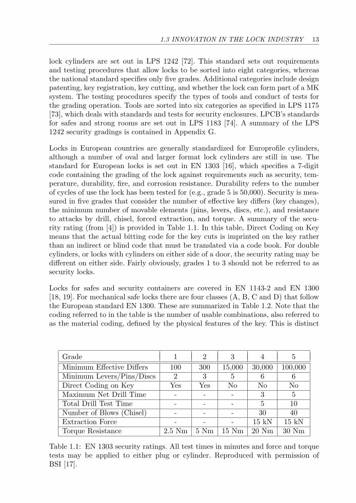
Locks in European countries are generally standardized for Europrofile cylinders,although a number of oval and larger format lock cylinders are still in use. Thestandard for European locks is set out in EN 1303 [16], which specifies a 7-digitcode containing the grading of the lock against requirements such as security, tem-perature, durability, fire, and corrosion resistance. Durability refers to the numberof cycles of use the lock has been tested for (e.g., grade 5 is 50,000). Security is mea-sured in five grades that consider the number of effective key differs (key changes),the minimum number of movable elements (pins, levers, discs, etc.), and resistanceto attacks by drill, chisel, forced extraction, and torque. A summary of the secu-rity rating (from [4]) is provided in Table 1.1. In this table, Direct Coding on Keymeans that the actual bitting code for the key cuts is imprinted on the key ratherthan an indirect or blind code that must be translated via a code book. For doublecylinders, or locks with cylinders on either side of a door, the security rating may bedifferent on either side. Fairly obviously, grades 1 to 3 should not be referred to assecurity locks.
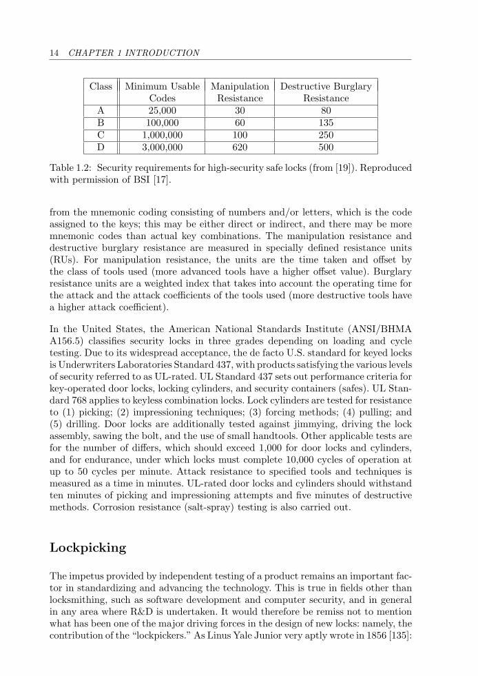
Locks for safes and security containers are covered in EN 1143-2 and EN 1300[18, 19]. For mechanical safe locks there are four classes (A, B, C and D) that followthe European standard EN 1300. These are summarized in Table 1.2. Note that thecoding referred to in the table is the number of usable combinations, also referred toas the material coding, defined by the physical features of the key. This is distinct
Grade 1 2 3 4 5Minimum Effective Differs 100 300 15,000 30,000 100,000Minimum Levers/Pins/Discs 2 3 5 6 6Direct Coding on Key Yes Yes No No NoMaximum Net Drill Time - - - 3 5Total Drill Test Time - - - 5 10Number of Blows (Chisel) - - - 30 40Extraction Force - - - 15 kN 15 kNTorque Resistance 2.5 Nm 5 Nm 15 Nm 20 Nm 30 Nm
Table 1.1: EN 1303 security ratings. All test times in minutes and force and torquetests may be applied to either plug or cylinder. Reproduced with permission ofBSI [17].
14 CHAPTER 1 INTRODUCTION
Class Minimum Usable Manipulation Destructive BurglaryCodes Resistance Resistance
A 25,000 30 80B 100,000 60 135C 1,000,000 100 250D 3,000,000 620 500
Table 1.2: Security requirements for high-security safe locks (from [19]). Reproducedwith permission of BSI [17].
from the mnemonic coding consisting of numbers and/or letters, which is the codeassigned to the keys; this may be either direct or indirect, and there may be moremnemonic codes than actual key combinations. The manipulation resistance anddestructive burglary resistance are measured in specially defined resistance units(RUs). For manipulation resistance, the units are the time taken and offset bythe class of tools used (more advanced tools have a higher offset value). Burglaryresistance units are a weighted index that takes into account the operating time forthe attack and the attack coefficients of the tools used (more destructive tools havea higher attack coefficient).
In the United States, the American National Standards Institute (ANSI/BHMAA156.5) classifies security locks in three grades depending on loading and cycletesting. Due to its widespread acceptance, the de facto U.S. standard for keyed locksis Underwriters Laboratories Standard 437, with products satisfying the various levelsof security referred to as UL-rated. UL Standard 437 sets out performance criteria forkey-operated door locks, locking cylinders, and security containers (safes). UL Stan-dard 768 applies to keyless combination locks. Lock cylinders are tested for resistanceto (1) picking; (2) impressioning techniques; (3) forcing methods; (4) pulling; and(5) drilling. Door locks are additionally tested against jimmying, driving the lockassembly, sawing the bolt, and the use of small handtools. Other applicable tests arefor the number of differs, which should exceed 1,000 for door locks and cylinders,and for endurance, under which locks must complete 10,000 cycles of operation atup to 50 cycles per minute. Attack resistance to specified tools and techniques ismeasured as a time in minutes. UL-rated door locks and cylinders should withstandten minutes of picking and impressioning attempts and five minutes of destructivemethods. Corrosion resistance (salt-spray) testing is also carried out.
Lockpicking
The impetus provided by independent testing of a product remains an important fac-tor in standardizing and advancing the technology. This is true in fields other thanlocksmithing, such as software development and computer security, and in generalin any area where R&D is undertaken. It would therefore be remiss not to mentionwhat has been one of the major driving forces in the design of new locks: namely, thecontribution of the “lockpickers.” As Linus Yale Junior very aptly wrote in 1856 [135]:
1.3 INNOVATION IN THE LOCK INDUSTRY 15
The art of Locksmithing has become almost a science; and a review ofthe ingenuity and labor displayed in endeavoring to fill this great wantof the community, would show to the inquiring mind the most ingenioussystem of attack and defence ever witnessed; difficulties and obstacles,instead of daunting, have only stimulated new effort.
Literally dozens of patents claim to have invented the “pick-proof” lock, butaccording to F. S. Holmes [56], one of the most famous lock makers of the worldonce said:
No lock having a key hole has ever been made or invented which isabsolutely proof against picking, nor is it probable that one will ever beor can be made.
Despite these claims and counterclaims, efforts on the part of the lockpickers con-tinue apace, as well as the development and testing of more destructive techniquesbrought to bear on the opening of locks. When a method by which a lock canbe opened or bypassed without its correct key is brought to the attention of alock manufacturer, it often results in modifications to the product to counter theattack.
Methods that have been applied to open or bypass mechanical locks include(together with references, where appropriate):
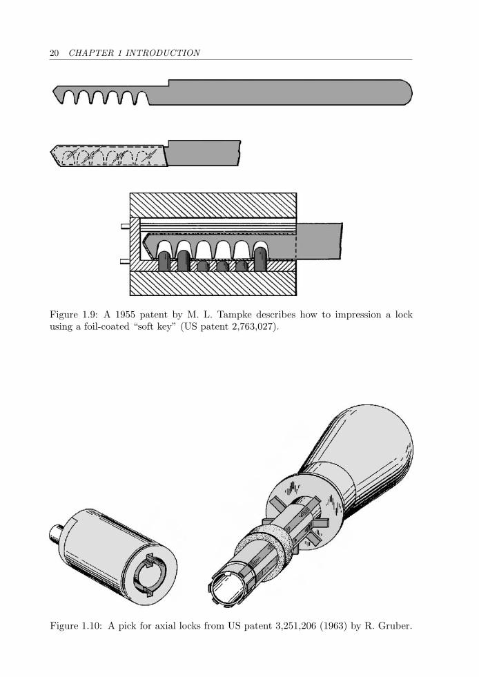
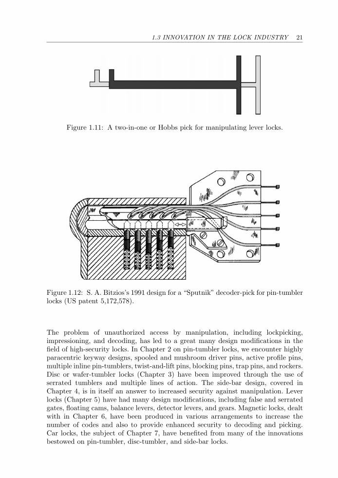
1. Picking the lock manually with flat, tubular, or Hobbs picks (see Figs. 1.10and 1.11) [10, 65].
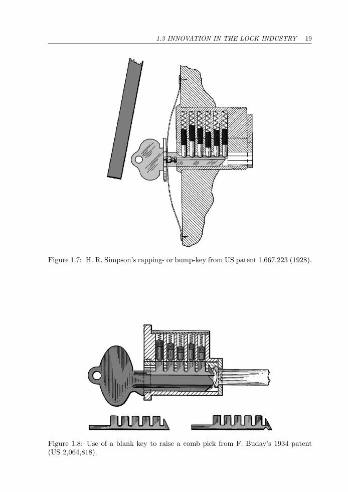
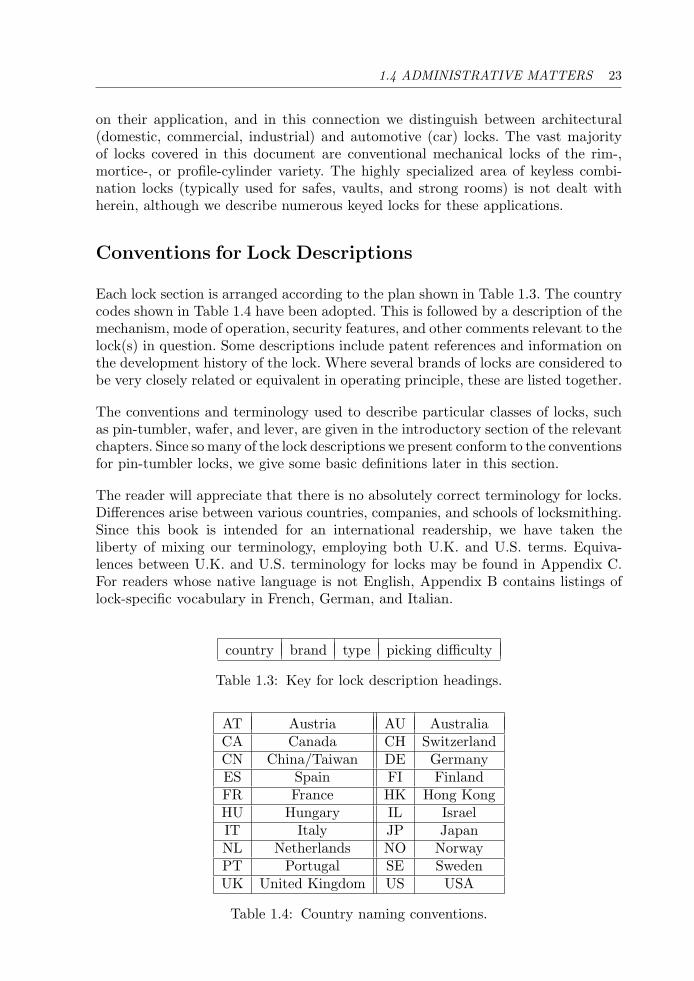
2. Manipulating the pins using specially designed tools such as wire lifters,“Sputniks” (Fig. 1.12), and comb picks (Fig. 1.8).
3. Impressioning the lock using blanks, foil, wood, or other “soft keys” in orderto make a working key (Fig. 1.9) [129].
4. Decoding the combination of the lock optically, acoustically, electrically,magnetically, electromagnetically, or by mechanical measurement of the pins(or other elements) and hence cutting or assembling a correct key [120].
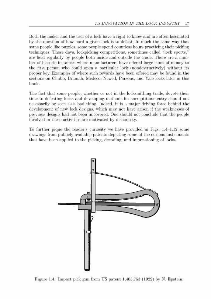
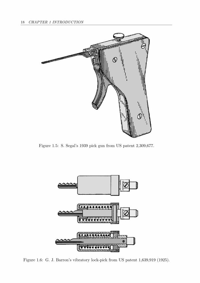
5. Impact-based methods such as pick guns (Figs. 1.4 and 1.5), vibrator picks(Fig. 1.6), bump-keys (Fig. 1.7), and rapping [130].
6. Partially destructive methods such as grinding and shimming the front ofthe plug, or bypass methods requiring drilling small holes or other minordamage.
7. Somewhat destructive or forced entry methods, including drilling the pins,side-bar or bolt stump, forced extraction of the cylinder, forced rotation ofthe plug, breaking of the coupling on profile cylinders, punching, and drivingof the lock cylinder.
16 CHAPTER 1 INTRODUCTION
8. Totally destructive methods: chisels, pry-bars, sledge hammer, power tools(carbide-tipped drills, angle grinders, saws, and cutting wheels), oxy-acetylenetorch, thermic lance (also known as a “burning bar”), hydraulic and scaffoldingjacks, and explosives.
The list has deliberately been arranged in order of decreasing subtlety and shouldconvince the reader of the lengths to which some people are prepared to go to defeata lock, especially when there may be money behind it. Nitroglycerin, a liquid-formhigh explosive invented in 1864 by Alfred Nobel, was used to blow the rear casingoff safe locks. Gunpowder was also a popular choice [100]. These tactics becameless effective with the invention of “powder-proof” lever locks in the mid-1800s (seeFig. 1.3) and safe relocking devices in the early 1920s [104]. Contrary to popularbelief, hand-guns are not very effective for opening locks and padlocks.
Most of these techniques are discussed in textbooks on locksmithing [95, 105, 106] andin Tobias’s two books [121, 122]. Many of the less destructive techniques are used bylocksmiths in perfectly legitimate circumstances (e.g., lock-outs). All of these tech-niques are known and employed by security and specialized personnel in state and fed-eral government agencies. Less fortunately, but inevitably, they are also available tocriminals, who tend to prefer the more rapid and often more destructive methods.
If we have implied that this information on “opening techniques” is due to dishonestpeople, then a correction is in order. Many of the techniques have been developedeither by locksmiths, lock designers, or in laboratories where the security level oflocks is tested (such as Underwriters Labs in the United States).
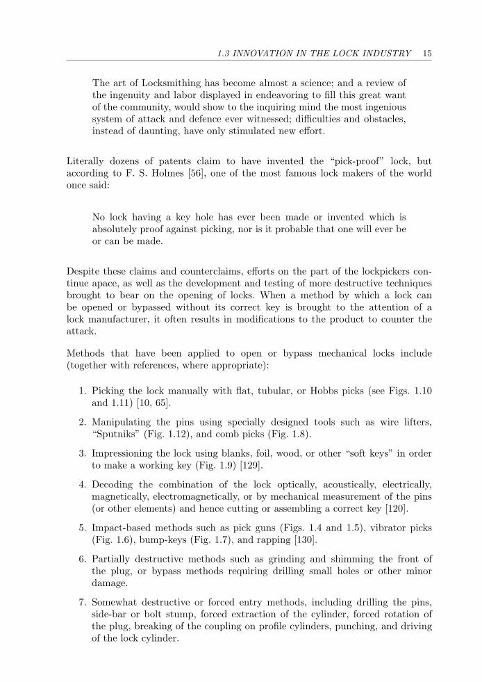
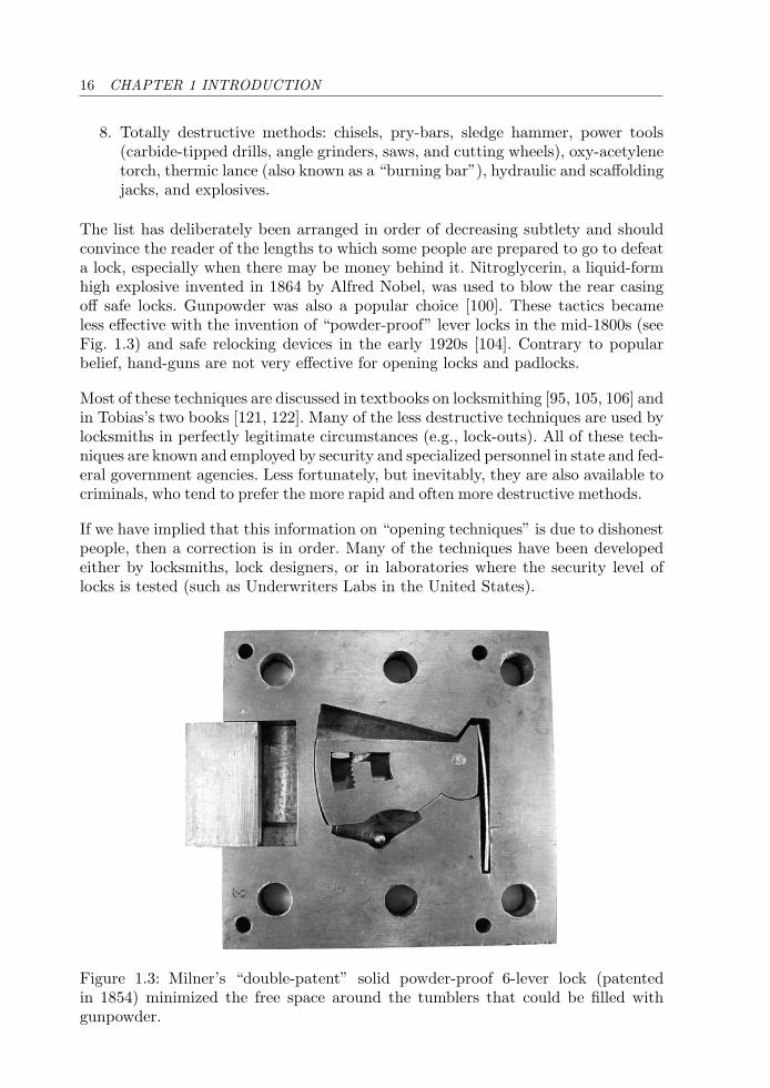
Figure 1.3: Milner’s “double-patent” solid powder-proof 6-lever lock (patentedin 1854) minimized the free space around the tumblers that could be filled withgunpowder.
1.3 INNOVATION IN THE LOCK INDUSTRY 17
Both the maker and the user of a lock have a right to know and are often fascinatedby the question of how hard a given lock is to defeat. In much the same way thatsome people like puzzles, some people spend countless hours practicing their pickingtechniques. These days, lockpicking competitions, sometimes called “lock sports,”are held regularly by people both inside and outside the trade. There are a num-ber of historic instances where manufacturers have offered large sums of money tothe first person who could open a particular lock (nondestructively) without itsproper key. Examples of where such rewards have been offered may be found in thesections on Chubb, Bramah, Medeco, Newell, Parsons, and Yale locks later in thisbook.
The fact that some people, whether or not in the locksmithing trade, devote theirtime to defeating locks and developing methods for surreptitious entry should notnecessarily be seen as a bad thing. Indeed, it is a major driving force behind thedevelopment of new lock designs, which may not have arisen if the weaknesses ofprevious designs had not been uncovered. One should not conclude that the peopleinvolved in these activities are motivated by dishonesty.
To further pique the reader’s curiosity we have provided in Figs. 1.4–1.12 somedrawings from publicly available patents depicting some of the curious instrumentsthat have been applied to the picking, decoding, and impressioning of locks.
Figure 1.4: Impact pick gun from US patent 1,403,753 (1922) by N. Epstein.
18 CHAPTER 1 INTRODUCTION
Figure 1.5: S. Segal’s 1939 pick gun from US patent 2,309,677.
Figure 1.6: G. J. Barron’s vibratory lock-pick from US patent 1,639,919 (1925).
1.3 INNOVATION IN THE LOCK INDUSTRY 19
Figure 1.7: H. R. Simpson’s rapping- or bump-key from US patent 1,667,223 (1928).
Figure 1.8: Use of a blank key to raise a comb pick from F. Buday’s 1934 patent(US 2,064,818).
20 CHAPTER 1 INTRODUCTION
Figure 1.9: A 1955 patent by M. L. Tampke describes how to impression a lockusing a foil-coated “soft key” (US patent 2,763,027).
Figure 1.10: A pick for axial locks from US patent 3,251,206 (1963) by R. Gruber.
1.3 INNOVATION IN THE LOCK INDUSTRY 21
Figure 1.11: A two-in-one or Hobbs pick for manipulating lever locks.
Figure 1.12: S. A. Bitzios’s 1991 design for a “Sputnik” decoder-pick for pin-tumblerlocks (US patent 5,172,578).
The problem of unauthorized access by manipulation, including lockpicking,impressioning, and decoding, has led to a great many design modifications in thefield of high-security locks. In Chapter 2 on pin-tumbler locks, we encounter highlyparacentric keyway designs, spooled and mushroom driver pins, active profile pins,multiple inline pin-tumblers, twist-and-lift pins, blocking pins, trap pins, and rockers.Disc or wafer-tumbler locks (Chapter 3) have been improved through the use ofserrated tumblers and multiple lines of action. The side-bar design, covered inChapter 4, is in itself an answer to increased security against manipulation. Leverlocks (Chapter 5) have had many design modifications, including false and serratedgates, floating cams, balance levers, detector levers, and gears. Magnetic locks, dealtwith in Chapter 6, have been produced in various arrangements to increase thenumber of codes and also to provide enhanced security to decoding and picking.Car locks, the subject of Chapter 7, have benefited from many of the innovationsbestowed on pin-tumbler, disc-tumbler, and side-bar locks.

22 CHAPTER 1 INTRODUCTION
1.4 Administrative Matters
A number of administrative issues need to be dealt with before we launch into themain fare. The first of these is a discussion of the scope of the material covered inthe book. This is followed by a brief description of the conventions and terminologyused in the following chapters. The reader will also find a section explaining thedifference between the theoretical number of key combinations and the practical orusable number. There is also a discussion on the grading of manipulation resistanceas it has been interpreted in this book. Finally, the organization of the sections ispresented.
Scope
Current locks can loosely be classed as electronic or mechanical, although quite a fewuse both principles. It would be ambitious to attempt to cover both electronic andmechanical locks in a single book, and the skills required to describe and understandboth types are quite different. This book is restricted to mechanical locks, andin particular to key-operated mechanical locks. All the same, we will occasionallymention whether a given design has electronic enhancements, as these now seem tobe gaining popularity at the high end of the market.
Electronic locks include electromagnetic and fully electronic locks. Electromagneticlocks employ such devices as magnetic card readers that are read by the lock orresonant circuits (coils) that “talk to” a receiver in the lock by RF electromag-netic induction. Another type relies on an array of Hall effect sensors to read amagnetic signature in the key. Electronic locks use radio frequency transponders,opto-electronic or mechanical switches (that can be either on or off), or numerickeypads to detect whether the correct code is being presented. An important class ofelectronic systems is that of smart cards [126], where the code is held digitally in asilicon chip carried in the card key. Other fully electronic methods include biometrictechniques like retinal and fingerprint scanning and voice recognition [35, 61, 62].Electromechanical principles are also used in electric strike plates, solenoid-operatedbolts, and electromagnetic induction door fasteners. For safety reasons, many ofthese designs must also be teamed with a mechanical lock or override in the eventof an electricity failure.
Mechanical locks, which all have moving parts, can loosely be divided into threeclasses: (i) conventional; (ii) keyless combination; and (iii) magnetic. The classof conventional mechanical locks includes pin- and wafer-tumbler, side-bar, andlever locks. Examples of keyless combination locks are wheel pack and push-button“digital” locks. Some locks are situated in between conventional and combinationtypes (e.g., the Vingcard lock, which uses a matrix of “binary” pins). Magneticmechanical locks use the attraction or repulsion between pairs of permanent mag-nets to actuate their tumblers. A further subdivision of mechanical locks is based
1.4 ADMINISTRATIVE MATTERS 23
on their application, and in this connection we distinguish between architectural(domestic, commercial, industrial) and automotive (car) locks. The vast majorityof locks covered in this document are conventional mechanical locks of the rim-,mortice-, or profile-cylinder variety. The highly specialized area of keyless combi-nation locks (typically used for safes, vaults, and strong rooms) is not dealt withherein, although we describe numerous keyed locks for these applications.
Conventions for Lock Descriptions
Each lock section is arranged according to the plan shown in Table 1.3. The countrycodes shown in Table 1.4 have been adopted. This is followed by a description of themechanism, mode of operation, security features, and other comments relevant to thelock(s) in question. Some descriptions include patent references and information onthe development history of the lock. Where several brands of locks are considered tobe very closely related or equivalent in operating principle, these are listed together.
The conventions and terminology used to describe particular classes of locks, suchas pin-tumbler, wafer, and lever, are given in the introductory section of the relevantchapters. Since so many of the lock descriptions we present conform to the conventionsfor pin-tumbler locks, we give some basic definitions later in this section.
The reader will appreciate that there is no absolutely correct terminology for locks.Differences arise between various countries, companies, and schools of locksmithing.Since this book is intended for an international readership, we have taken theliberty of mixing our terminology, employing both U.K. and U.S. terms. Equiva-lences between U.K. and U.S. terminology for locks may be found in Appendix C.For readers whose native language is not English, Appendix B contains listings oflock-specific vocabulary in French, German, and Italian.
country brand type picking difficulty
Table 1.3: Key for lock description headings.
AT Austria AU AustraliaCA Canada CH SwitzerlandCN China/Taiwan DE GermanyES Spain FI FinlandFR France HK Hong KongHU Hungary IL IsraelIT Italy JP JapanNL Netherlands NO NorwayPT Portugal SE SwedenUK United Kingdom US USA
Table 1.4: Country naming conventions.
24 CHAPTER 1 INTRODUCTION
In many cases the distinction in terminology is unimportant since there is no possibleambiguity. Thus we may equally well say “plug” for “core” or “barrel” for “cylinder.”Other examples of words that have been used interchangeably include bitting, cut;section, profile, broaching; and change, code, differ, permutation, combination. Whenspeaking of key or keying permutations, we have used the word “code” to mean theactual key bittings corresponding to the permutation. The reader should be awarethat these are equivalent for so-called direct codes but not for indirect or blindcodes.
In some cases, particularly for the more complex locks, the usual terminology doesnot provide enough differentiation, and ambiguities arise. In these cases, we haveused both U.S. and U.K. terms to mean different things. For example, in the Citroen(Simplex) lock, which has several levels of “housing,” we refer to the innermost partas the core, and then in order of increasing diameter, plug, barrel, and cylinder body.The table of equivalences in Appendix C should help readers to equate the morecommonly used terms with those familiar to them.
We have attempted to keep to a consistent set of terminology for all locks in a givencategory. Thus for Bell-type locks we use the term “bar-wafer;” for Bramah andAva-type locks we use “slider;” for Abloy type locks we use “disc.” In some sectionswe have had to adopt other words like “rocker” since none of the conventional onesseemed to fit the purpose.
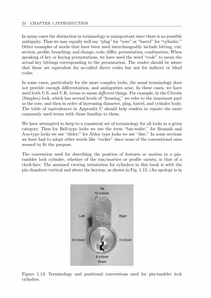
The convention used for describing the position of features or motion in a pin-tumbler lock cylinder, whether of the rim/mortice or profile variety, is that of aclock-face. The assumed viewing orientation for cylinders in this book is with thepin chambers vertical and above the keyway, as shown in Fig. 1.13. (An apology is in
Up
RightLeft
3 o'clock
12 o'clock
9 o'clock
6 o'clock
Down
Figure 1.13: Terminology and positional conventions used for pin-tumbler lockcylinders.
1.4 ADMINISTRATIVE MATTERS 25
order for European readers, who are more accustomed to viewing the cylinder withthe keyway at the top.) In this orientation, the bottom of the keyway is at 6 o’clock,the right side of the cylinder at 3 o’clock, and the left side at 9 o’clock. The 12 o’clockdirection is referred to as up and the 6 o’clock as down. Directions toward or awayfrom the central axis of rotation of the plug are called radially inward and outward,respectively. Directions along the axis are called longitudinal or axial. Along thelongitudinal axis, the direction toward the front of the lock is called forward, andthe direction toward the rear is called aft. Directions perpendicular to a given axis(usually the major or longest one) are called transverse. The term “lateral” is usedto describe longitudinal warding in a plug or milling on a key blade.
For locks with a single row of pins, pin position or “space” numbering starts fromthe front of the cylinder or the shoulder of the key. (Note that some manufacturersnumber pins in the opposite way: from the tip of the key back toward the shoulder.)For other locks the description is tailored to the particular geometry in question.Pin-tumbler sizes (depths) for bottom or key pins are generally numbered from0 upward, corresponding to the required depth of cut. Thus a size 0 pin requires theminimum cut to the key blank. Note again that some manufacturers use the conven-tion that size 1 is the minimum depth and size 0 is actually size 10 (i.e., greater thansize 9).
For certain locks we have provided a theoretical analysis of the number of keyingcombinations supported by the system. Several points should be noted in connec-tion with this. First, this information is of a theoretical nature and provided onlyfor illustrative purposes. In practice, the lock manufacturer and/or locksmith whocombinates the lock determines which key codes are supported and which are not.The net result is that the practical or usable number of combinations is always lessthan the theoretical number, usually significantly so. The estimates that we provideby combinatorial analysis are based purely on simple factors like the number of pinsizes (or depths of cut) and the number of pin positions. This type of analysis iscommon in the literature on locks (e.g., see [20]).
In some cases we also account for the maximum adjacent cut specification (MACS).In a few cases we have also provided estimates that account for bitting rules suchas the exclusion of repeated cuts of the same size. Such estimates must in generalbe worked out with the aid of a computer program (see Appendix F). We make thepoint that even though the estimates for usable combinations may not coincide withthe actual figures obtained in real keying systems due to the use of different bittingrules, the inclusion of MACS and other constraints makes the figures considerablymore realistic.
For dual-action side-bar locks and other locks where two independent locking mech-anisms coexist, the theoretical number of combinations is taken as the product ofthe combinations provided by each mechanism (see Appendix A). In all cases, thenumber of combinations assumes that the same keyway profile is in use. Thus we donot consider that different key sections, warding, or multiplex master-keying provideadditional key combinations (see Chapter 2), since these necessitate a change to thephysical design of the lock.
26 CHAPTER 1 INTRODUCTION
Grading of Manipulation Resistance
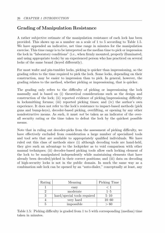
A rather subjective estimate of the manipulation resistance of each lock has beenprovided. This shows up as a number on a scale of 1 to 5 according to Table 1.5.We have appended an indicative, net time range in minutes for the manipulationexercise. This time range is to be interpreted as the median time to pick or impressionthe lock in “laboratory conditions” (i.e., when firmly mounted, properly illuminated,and using appropriate tools) by an experienced person who has practiced on severallocks of the same brand (keyed differently).
For most wafer and pin-tumbler locks, picking is quicker than impressioning, so thegrading refers to the time required to pick the lock. Some locks, depending on theirconstruction, may be easier to impression than to pick. In general, however, thegrading relates to the method, whether picking or impressioning, that is quicker.
The grading only refers to the difficulty of picking or impressioning the lockmanually and is based on (i) theoretical considerations such as the design andconstruction of the lock; (ii) reported evidence of picking/impressioning difficultyin locksmithing forums; (iii) reported picking times; and (iv) the author’s ownexperience. It does not refer to the lock’s resistance to impact-based methods (pickguns and bump-keys), decoder-based picking, overlifting, or opening by any othernondestructive means. As such, it must not be taken as an indicator of the over-all security rating or the time taken to defeat the lock by the quickest possiblemeans.
Note that in ruling out decoder-picks from the assessment of picking difficulty, wehave effectively excluded from consideration a large number of specialized toolsand tool sets that are available to appropriately qualified individuals. We haveruled out this class of methods since (i) although decoding tools are hand-held,they give such an advantage to the lockpicker as to void comparison with othermanual techniques; (ii) decoder-based picking tools allow each locking element ofthe lock to be manipulated independently while maintaining elements that havealready been decoded/picked in their correct positions; and (iii) data on decodingof high-security locks is not in the public domain. In much the same way as acombination safe lock can be opened by an “auto-dialer,” conceptually at least, any
Rating Meaning Picking Time1 easy < 12 moderate 1–53 hard/special tools required 5–104 very hard 10–605 impossible > 60
Table 1.5: Picking difficulty is graded from 1 to 5 with corresponding (median) timetaken in minutes.
1.4 ADMINISTRATIVE MATTERS 27
mechanical lock can be defeated by exhaustively trying every possible combination.In this respect, decoding a lock, especially through exhaustive search for the correctkey, is fundamentally different from manual picking—a point we discuss further inChapter 2.
The assessment of manipulation difficulty is highly error-prone. The actual degreeof difficulty depends in practice on variables such as (pinning) combination, wear,lubrication, and even on the location of the lock (whether on a bench or in the field).A lock from a master-keyed system will generally be easier to pick than one that isnot, in as much as it has been designed to be operated by more than a single key.More importantly the difficulty depends on the tools being used and the skills ofthe lockpicker. It is well known that even among locks with the same combinationof pins, picking difficulty may vary enormously due to tiny differences within therange of manufacturing tolerances. This is particularly true for locks in the highergrades (3 and above). The same comments apply to impressioning. It is therefore tobe expected that there is a high degree of statistical variation in the time taken toopen a given lock in a given situation. For example, the author was provided withsome actual figures for Ingersoll 10-lever padlocks by someone skilled in the art. Thepicking time on 11 trials for different padlocks varied from 5 to 900 minutes with amedian of 30 minutes. In two further trials, the padlock was unable to be opened(in a single session).
We have reserved the category “impossible” for locks that would take an expert inlockpicking and impressioning a “long time” (e.g., several hours, or even days, to openor for which there have been no reported openings). Locks in this category includethe Fichet-Bauche 787, the EVVA MCS, and a number of German safe locks. Wealso class dual-control safe deposit locks (with separate renter and guard keyways4)as unpickable since they require the action of two keys.
Security is a relative term. The reader will appreciate the need for different standardsfor door locks compared with locks designed for safes and vaults. Although locks forthe latter category are usually defined as high-security locks, we employ rather looserterminology here. For commercial and residential purposes, any lock with a ratingof 3 or above could be classed as a high-security lock in terms of the time requiredto manipulate the mechanism. It should be remembered that once a lock requiresmore than a few minutes to open by manipulation, it is an effective deterrent toa would-be thief, who will either go elsewhere or look for a quicker way in (e.g., awindow or the roof).
Destructive methods (drilling, extraction, forcing, bypassing, etc.) are not consideredin this assessment, although many of the high-security locks featured in this bookcan include hardened inserts and/or a cylinder-guard to counter attacks of this sort.Further information on ratings for attack resistance of locks may be found in thesection on industry standards.
4For safe deposit locks, the term guardian key is used in the United Kingdom whereas guardkey is used in the United States.

28 CHAPTER 1 INTRODUCTION
Chapter Organization
The rest of the book has been organized under six main chapters, with a concludingsection in Chapter 8:
Chapter 2: Pin-Tumbler Locks
Chapter 3: Wafer Locks
Chapter 4: Lever Locks
Chapter 5: Side-bar Locks
Chapter 6: Magnetic Locks
Chapter 7: Car Locks
Each chapter contains an introductory section giving a historical perspective and adescription of the basic mode of operation for the locks presented. In order to balancethe presentation, in some cases, I have chosen to defer an account of the history ofa lock or lock-making company to the section pertaining to the lock in question.
Following this the reader will find a classification table that sorts the locks intocategories according to their operating principle. The remainder of each chapterpresents the different locks in more detail. Patent diagrams and references are usedoccasionally to illustrate concepts both in the introductory and descriptive sections,especially for locks with historical significance.5 The patents that are referenced inthe text are listed in Appendix D. At various points the reader may wish to consultthe index to help with cross-referencing.
Some of the locks cited in the text are described without illustrations. The readermay find it helpful in these cases to employ a Web search engine to obtain furtherinformation. As Web sites constantly shift and change, only a few of the major onesare actually provided as references. Although it is easy to compile, I decided to omita detailed listing of Web sites, including those of lock manufacturers, because inthe current climate of company mergers and acquisitions it would rapidly becomeobsolete.
The chapter on pin-tumbler locks is longer than the other chapters for two rea-sons. First, there is a large number of different types of pin-tumbler locks to cover.Second, the class of pin-tumbler locks has been used to illustrate concepts such askey codes, master-keying, and key-bitting constraints. These concepts recur in laterchapters.
5Patent diagrams used in this book were obtained from the European Patent Office esp@cenetWeb site at http://ep.espacenet.com.
1.4 ADMINISTRATIVE MATTERS 29
Appendices are also provided that cover the following topics:
Appendix A1: Permutations and Combinations
Appendix A2: Lock Permutations and Fractals
Appendix B: Translations of Lock Vocabulary
Appendix C: Terminology and Abbreviations
Appendix D: Lock Patents
Appendix E: Brief History of the Bramah Lock
Appendix F: Computer Code for Key Computations
Appendix G: Security Gradings for Cylinder Locks
The discussion in Appendix A2 on lock permutations points out a connection witha new type of fractal image.

This page intentionally left blank
Chapter 2
Pin-Tumbler Locks
It would seem that there is a limit to the number of distinctive wayswhich are purely mechanical of providing security and differing in locksand that the limit has been reached, or nearly so. F. J. Butter, c. 1958
2.1 Introduction
The pin-tumbler lock is loosely based on a locking principle employed in ancient Egyptas early as 2000 B.C. [91] where a wooden key with pegs or prongs was required toretract a bolt fastening a door. Although not widely recognized, the modern pin-tumbler principle was enunciated as early as 1805 in a British patent (UK 2,851) byA. O. Stansbury, an American who emigrated to England [99]. Stansbury’s ideainvolved a pronged, axial, or bit key that operated a pair of circular plates, one fixedand one rotating. Inserting the key brought the ends of the pins to the interfacebetween the two plates, allowing the front plate to turn. The pins were all of the samelength, however, with variation achieved through the use of wards or different posi-tioning of the holes for the pins [31]. Another invention relating to pin-tumbler locksof the axial variety was proposed in 1839 by W. M. Williams in England, although itwas not commercialized [22]. The conventional inline pin-tumbler cylinder lock, whichwe recognize today, has its origins in the mid-to-late 18th century with inventions bythe North American locksmith Linus Yale Senior and his son Linus Yale Junior.
Professionally, the Yales were not a father-and-son team. By the time he was inhis mid-30s, Yale Junior was at pains to distance himself from his father in regardto a pin-tumbler lock that Yale Senior had invented some years earlier and sub-sequently sold to a lock producer called Bacon on the grounds this lock had beenrepeatedly picked [135]. Yale Senior produced a number of security locks for banksincluding a “Quadruplex” lock, patented in 1844 (US 3,630) with four rows of radial
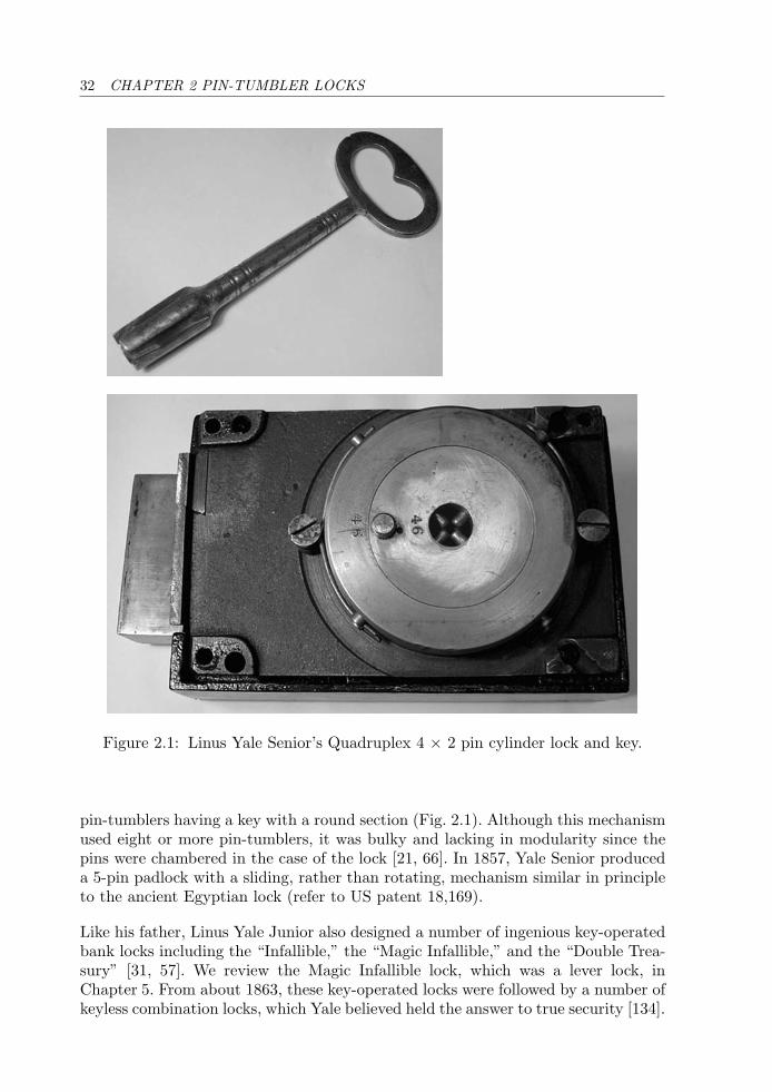
32 CHAPTER 2 PIN-TUMBLER LOCKS
Figure 2.1: Linus Yale Senior’s Quadruplex 4 × 2 pin cylinder lock and key.
pin-tumblers having a key with a round section (Fig. 2.1). Although this mechanismused eight or more pin-tumblers, it was bulky and lacking in modularity since thepins were chambered in the case of the lock [21, 66]. In 1857, Yale Senior produceda 5-pin padlock with a sliding, rather than rotating, mechanism similar in principleto the ancient Egyptian lock (refer to US patent 18,169).
Like his father, Linus Yale Junior also designed a number of ingenious key-operatedbank locks including the “Infallible,” the “Magic Infallible,” and the “Double Trea-sury” [31, 57]. We review the Magic Infallible lock, which was a lever lock, inChapter 5. From about 1863, these key-operated locks were followed by a number ofkeyless combination locks, which Yale believed held the answer to true security [134].
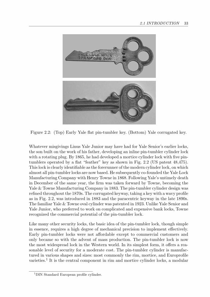
2.1 INTRODUCTION 33
Figure 2.2: (Top) Early Yale flat pin-tumbler key. (Bottom) Yale corrugated key.
Whatever misgivings Linus Yale Junior may have had for Yale Senior’s earlier locks,the son built on the work of his father, developing an inline pin-tumbler cylinder lockwith a rotating plug. By 1865, he had developed a mortice cylinder lock with five pin-tumblers operated by a flat “feather” key as shown in Fig. 2.2 (US patent 48,475).This lock is clearly identifiable as the forerunner of the modern cylinder lock, on whichalmost all pin-tumbler locks are now based. He subsequently co-founded the Yale LockManufacturing Company with Henry Towne in 1868. Following Yale’s untimely deathin December of the same year, the firm was taken forward by Towne, becoming theYale & Towne Manufacturing Company in 1883. The pin-tumbler cylinder design wasrefined throughout the 1870s. The corrugated keyway, taking a key with a wavy profileas in Fig. 2.2, was introduced in 1883 and the paracentric keyway in the late 1890s.The familiar Yale & Towne oval cylinder was patented in 1923. Unlike Yale Senior andYale Junior, who preferred to work on complicated and expensive bank locks, Townerecognized the commercial potential of the pin-tumbler lock.
Like many other security locks, the basic idea of the pin-tumbler lock, though simplein essence, requires a high degree of mechanical precision to implement effectively.Early pin-tumbler locks were not affordable except to commercial customers andonly became so with the advent of mass production. The pin-tumbler lock is nowthe most widespread lock in the Western world. In its simplest form, it offers a rea-sonable level of security for a moderate cost. The pin-tumbler cylinder is manufac-tured in various shapes and sizes: most commonly the rim, mortice, and Europrofilevarieties.1 It is the central component in rim and mortice cylinder locks, a modular
1DIN Standard European profile cylinder.
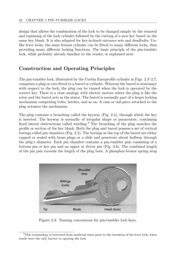
34 CHAPTER 2 PIN-TUMBLER LOCKS
design that allows the combination of the lock to be changed simply by the removaland repinning of the lock cylinder followed by the cutting of a new key based on thesame key blank. It is also adapted for key-in-knob entrance sets and deadbolts. Un-like lever locks, the same format cylinder can be fitted to many different locks, thusproviding many different locking functions. The basic principle of the pin-tumblerlock, while probably already familiar to the reader, is explained next.
Construction and Operating Principles
The pin-tumbler lock, illustrated by the Corbin Europrofile cylinder in Figs. 2.3–2.7,comprises a plug or core fitted to a barrel or cylinder. Whereas the barrel is stationarywith respect to the lock, the plug can be turned when the lock is operated by thecorrect key. There is a close analogy with electric motors where the plug is like therotor and the barrel acts as the stator. The barrel is normally part of a larger lockingmechanism comprising bolts, latches, and so on. A cam or tail-piece attached to theplug actuates the mechanism.
The plug contains a broaching called the keyway (Fig. 2.4), through which the keyis inserted. The keyway is normally of irregular shape or paracentric, containingfixed lateral obstructions called warding.2 The broaching of the plug matches theprofile or section of the key blank. Both the plug and barrel possess a set of verticalborings called pin chambers (Fig. 2.5). The borings in the top of the barrel are eithercapped or sealed with brass plugs or a slide and penetrate about halfway throughthe plug’s diameter. Each pin chamber contains a pin-tumbler pair consisting of abottom pin or key pin and an upper or driver pin (Fig. 2.6). The combined lengthof the pin pair exceeds the length of the plug bore. A phosphor-bronze spring atop
Shoulderstop
Bittings(cuts)
BladeTip Head (bow)
Figure 2.3: Naming conventions for pin-tumbler lock keys.
2This terminology is borrowed from medieval times prior to the invention of the lever lock, whenwards were the only barrier to opening the lock.
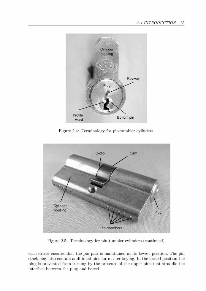
2.1 INTRODUCTION 35
Cylinderhousing
Keyway
Bottom pinProfile
ward
Plug
Figure 2.4: Terminology for pin-tumbler cylinders.
C-clip Cam
Cylinderhousing
Pin chambers
Plug
Figure 2.5: Terminology for pin-tumbler cylinders (continued).
each driver ensures that the pin pair is maintained at its lowest position. The pinstack may also contain additional pins for master-keying. In the locked position theplug is prevented from turning by the presence of the upper pins that straddle theinterface between the plug and barrel.
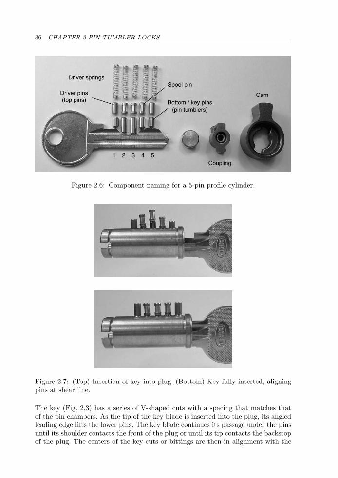
36 CHAPTER 2 PIN-TUMBLER LOCKS
Driver springs
Driver pins(top pins)
1 2 3 4 5Coupling
Bottom / key pins(pin tumblers)
Spool pin
Cam
Figure 2.6: Component naming for a 5-pin profile cylinder.
Figure 2.7: (Top) Insertion of key into plug. (Bottom) Key fully inserted, aligningpins at shear line.
The key (Fig. 2.3) has a series of V-shaped cuts with a spacing that matches thatof the pin chambers. As the tip of the key blade is inserted into the plug, its angledleading edge lifts the lower pins. The key blade continues its passage under the pinsuntil its shoulder contacts the front of the plug or until its tip contacts the backstopof the plug. The centers of the key cuts or bittings are then in alignment with the
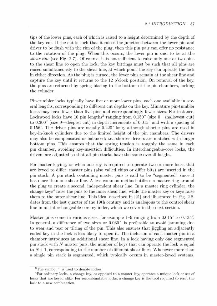
2.1 INTRODUCTION 37
tips of the lower pins, each of which is raised to a height determined by the depth ofthe key cut. If the cut is such that it raises the junction between the lower pin anddriver to be flush with the rim of the plug, then this pin pair can offer no resistanceto the rotation of the plug. When this occurs, the lower pin is said to be at theshear line (see Fig. 2.7). Of course, it is not sufficient to raise only one or two pinsto the shear line to open the lock; the key bittings must be such that all pins areraised simultaneously to the shear line, at which point the key can operate the lockin either direction. As the plug is turned, the lower pins remain at the shear line andcapture the key until it returns to the 12 o’clock position. On removal of the key,the pins are returned by spring biasing to the bottom of the pin chambers, lockingthe cylinder.
Pin-tumbler locks typically have five or more lower pins, each one available in sev-eral lengths, corresponding to different cut depths on the key. Miniature pin-tumblerlocks may have fewer than five pins and correspondingly fewer sizes. For instance,Lockwood locks have 10 pin lengths3 ranging from 0.150˝ (size 0—shallowest cut)to 0.300˝ (size 9—deepest cut) in depth increments of 0.015˝ and with a spacing of0.156 . The driver pins are usually 0.220˝ long, although shorter pins are used inkey-in-knob cylinders due to the limited height of the pin chambers. The driversmay also be compensated or balanced: i.e., shorter drivers are matched with longerbottom pins. This ensures that the spring tension is roughly the same in eachpin chamber, avoiding key-insertion difficulties. In interchangeable-core locks, thedrivers are adjusted so that all pin stacks have the same overall height.
For master-keying, or when one key is required to operate two or more locks thatare keyed to differ, master pins (also called chips or differ bits) are inserted in thepin stack. A pin stack containing master pins is said to be “segmented” since ithas more than one shear line. A less common method utilizes a master ring aroundthe plug to create a second, independent shear line. In a master ring cylinder, thechange keys4 raise the pins to the inner shear line, while the master key or keys raisethem to the outer shear line. This idea, described in [21] and illustrated in Fig. 2.8,dates from the last quarter of the 19th century and is analogous to the control shearline in an interchangeable-core cylinder, which we cover in the next section.
Master pins come in various sizes, for example 1–9 ranging from 0.015˝ to 0.135 .In general, a difference of two sizes or 0.030˝ is preferable to avoid jamming dueto wear and tear or tilting of the pin. This also ensures that jiggling an adjacentlycoded key in the lock is less likely to open it. The inclusion of each master pin in achamber introduces an additional shear line. In a lock having only one segmentedpin stack with N master pins, the number of keys that can operate the lock is equalto N +1, corresponding to the number of different shear lines. Whenever more thana single pin stack is segmented, which typically occurs in master-keyed systems,
3The symbol ˝ is used to denote inches.4For ordinary locks, a change key, as opposed to a master key, operates a unique lock or set of
locks that are keyed alike. For recombinatable locks, a change key is the tool required to reset thelock to a new combination.
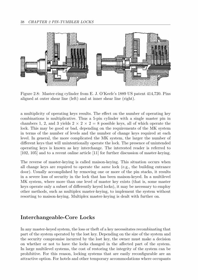
38 CHAPTER 2 PIN-TUMBLER LOCKS
Figure 2.8: Master-ring cylinder from E. J. O’Keefe’s 1889 US patent 414,720. Pinsaligned at outer shear line (left) and at inner shear line (right).
a multiplicity of operating keys results. The effect on the number of operating keycombinations is multiplicative. Thus a 5-pin cylinder with a single master pin inchambers 1, 2, and 3 yields 2 × 2 × 2 = 8 possible keys, all of which operate thelock. This may be good or bad, depending on the requirements of the MK systemin terms of the number of levels and the number of change keys required at eachlevel. In general, the more complicated the MK system, the larger the number ofdifferent keys that will unintentionally operate the lock. The presence of unintendedoperating keys is known as key interchange. The interested reader is referred to[102, 105] and to a recent online article [11] for further discussion of master-keying.
The reverse of master-keying is called maison-keying. This situation occurs whenall change keys are required to operate the same lock (e.g., the building entrancedoor). Usually accomplished by removing one or more of the pin stacks, it resultsin a severe loss of security in the lock that has been maison-keyed. In a multilevelMK system, where more than one level of master key exists (that is, some masterkeys operate only a subset of differently keyed locks), it may be necessary to employother methods, such as multiplex master-keying, to implement the system withoutresorting to maison-keying. Multiplex master-keying is dealt with further on.
Interchangeable-Core Locks
In any master-keyed system, the loss or theft of a key necessitates recombinating thatpart of the system operated by the lost key. Depending on the size of the system andthe security compromise incurred by the lost key, the owner must make a decisionon whether or not to have the locks changed in the affected part of the system.In large multilevel systems, the cost of restoring the integrity of the system can beprohibitive. For this reason, locking systems that are easily reconfigurable are anattractive option. For hotels and other temporary accommodations where occupants
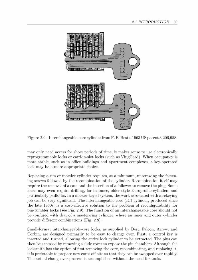
2.1 INTRODUCTION 39
Figure 2.9: Interchangeable-core cylinder from F. E. Best’s 1963 US patent 3,206,958.
may only need access for short periods of time, it makes sense to use electronicallyreprogrammable locks or card-in-slot locks (such as VingCard). When occupancy ismore stable, such as in office buildings and apartment complexes, a key-operatedlock may be a more appropriate choice.
Replacing a rim or mortice cylinder requires, at a minimum, unscrewing the fasten-ing screws followed by the recombination of the cylinder. Recombination itself mayrequire the removal of a cam and the insertion of a follower to remove the plug. Somelocks may even require drilling, for instance, older style Europrofile cylinders andparticularly padlocks. In a master-keyed system, the work associated with a rekeyingjob can be very significant. The interchangeable-core (IC) cylinder, produced sincethe late 1930s, is a cost-effective solution to the problem of reconfigurability forpin-tumbler locks (see Fig. 2.9). The function of an interchangeable core should notbe confused with that of a master-ring cylinder, where an inner and outer cylinderprovide different combinations (Fig. 2.8).
Small-format interchangeable-core locks, as supplied by Best, Falcon, Arrow, andCorbin, are designed primarily to be easy to change over. First, a control key isinserted and turned, allowing the entire lock cylinder to be extracted. The pins canthen be accessed by removing a slide cover to expose the pin chambers. Although thelocksmith has the option of first removing the core, recombinating, and replacing it,it is preferable to prepare new cores off-site so that they can be swapped over rapidly.The actual changeover process is accomplished without the need for tools.
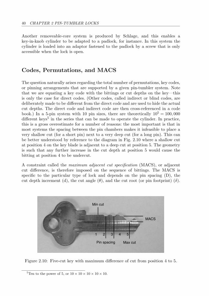
40 CHAPTER 2 PIN-TUMBLER LOCKS
Another removeable-core system is produced by Schlage, and this enables akey-in-knob cylinder to be adapted to a padlock, for instance. In this system thecylinder is loaded into an adaptor fastened to the padlock by a screw that is onlyaccessible when the lock is open.
Codes, Permutations, and MACS
The question naturally arises regarding the total number of permutations, key codes,or pinning arrangements that are supported by a given pin-tumbler system. Notethat we are equating a key code with the bittings or cut depths on the key—thisis only the case for direct codes. (Other codes, called indirect or blind codes, aredeliberately made to be different from the direct code and are used to hide the actualcut depths. The direct code and indirect code are then cross-referenced in a codebook.) In a 5-pin system with 10 pin sizes, there are theoretically 105 = 100, 000different keys5 in the series that can be made to operate the cylinder. In practice,this is a gross overestimate for a number of reasons: the most important is that inmost systems the spacing between the pin chambers makes it infeasible to place avery shallow cut (for a short pin) next to a very deep cut (for a long pin). This canbe better understood by reference to the diagram in Fig. 2.10 where a shallow cutat position 4 on the key blade is adjacent to a deep cut at position 5. The geometryis such that any further increase in the cut depth at position 5 would cause thebitting at position 4 to be undercut.
A constraint called the maximum adjacent cut specification (MACS), or adjacentcut difference, is therefore imposed on the sequence of bittings. The MACS isspecific to the particular type of lock and depends on the pin spacing (D), thecut depth increment (d), the cut angle (θ), and the cut root (or pin footprint) (δ).
Min cut
Pin spacing Max cut
1 2 3 4 5
MACS
Figure 2.10: Five-cut key with maximum difference of cut from position 4 to 5.
5Ten to the power of 5, or 10 × 10 × 10 × 10 × 10.
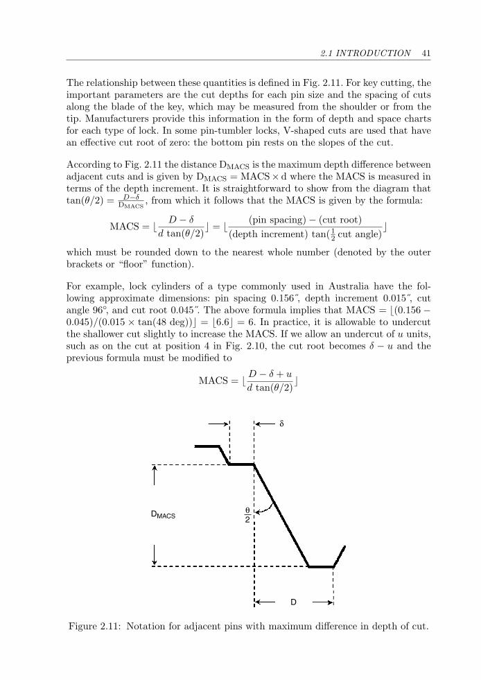
2.1 INTRODUCTION 41
The relationship between these quantities is defined in Fig. 2.11. For key cutting, theimportant parameters are the cut depths for each pin size and the spacing of cutsalong the blade of the key, which may be measured from the shoulder or from thetip. Manufacturers provide this information in the form of depth and space chartsfor each type of lock. In some pin-tumbler locks, V-shaped cuts are used that havean effective cut root of zero: the bottom pin rests on the slopes of the cut.
According to Fig. 2.11 the distance DMACS is the maximum depth difference betweenadjacent cuts and is given by DMACS = MACS× d where the MACS is measured interms of the depth increment. It is straightforward to show from the diagram thattan(θ/2) = D−δ
DMACS, from which it follows that the MACS is given by the formula:
MACS = � D − δ
d tan(θ/2)� = � (pin spacing) − (cut root)
(depth increment) tan(12 cut angle)
�
which must be rounded down to the nearest whole number (denoted by the outerbrackets or “floor” function).
For example, lock cylinders of a type commonly used in Australia have the fol-lowing approximate dimensions: pin spacing 0.156 , depth increment 0.015 , cutangle 96◦, and cut root 0.045 . The above formula implies that MACS = �(0.156 −0.045)/(0.015 × tan(48 deg))� = �6.6� = 6. In practice, it is allowable to undercutthe shallower cut slightly to increase the MACS. If we allow an undercut of u units,such as on the cut at position 4 in Fig. 2.10, the cut root becomes δ − u and theprevious formula must be modified to
MACS = � D − δ + u
d tan(θ/2)�
δ
DMACS
D
θ2
Figure 2.11: Notation for adjacent pins with maximum difference in depth of cut.
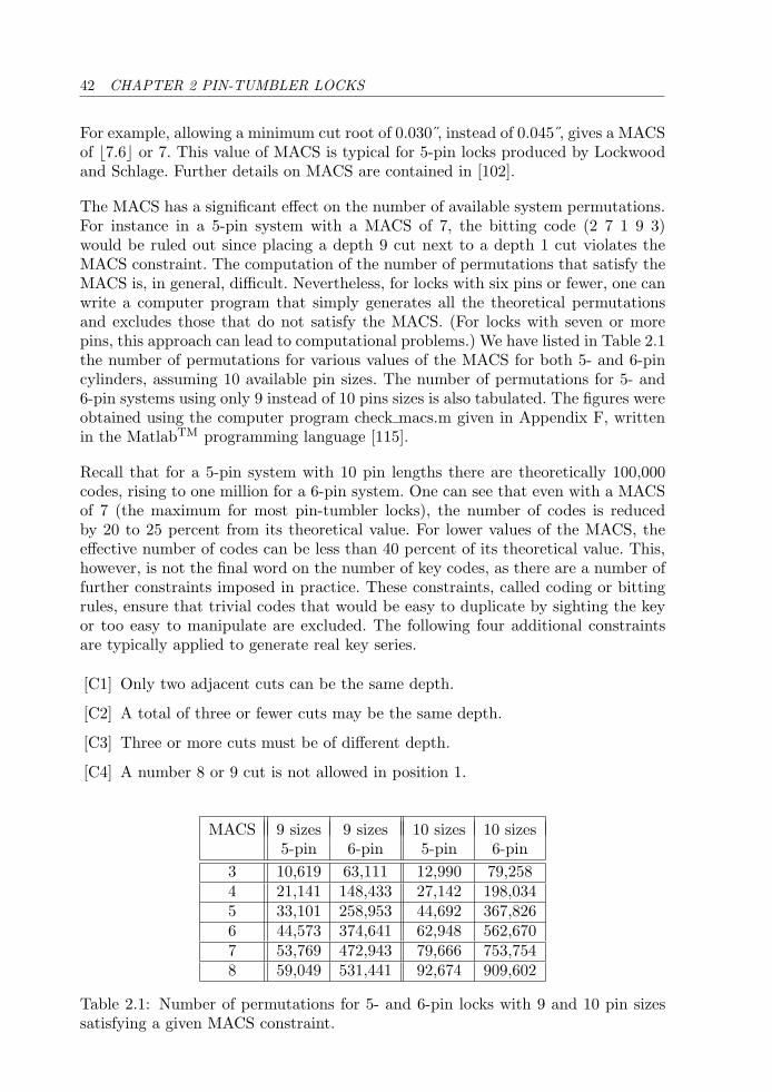
42 CHAPTER 2 PIN-TUMBLER LOCKS
For example, allowing a minimum cut root of 0.030 , instead of 0.045 , gives a MACSof �7.6� or 7. This value of MACS is typical for 5-pin locks produced by Lockwoodand Schlage. Further details on MACS are contained in [102].
The MACS has a significant effect on the number of available system permutations.For instance in a 5-pin system with a MACS of 7, the bitting code (2 7 1 9 3)would be ruled out since placing a depth 9 cut next to a depth 1 cut violates theMACS constraint. The computation of the number of permutations that satisfy theMACS is, in general, difficult. Nevertheless, for locks with six pins or fewer, one canwrite a computer program that simply generates all the theoretical permutationsand excludes those that do not satisfy the MACS. (For locks with seven or morepins, this approach can lead to computational problems.) We have listed in Table 2.1the number of permutations for various values of the MACS for both 5- and 6-pincylinders, assuming 10 available pin sizes. The number of permutations for 5- and6-pin systems using only 9 instead of 10 pins sizes is also tabulated. The figures wereobtained using the computer program check macs.m given in Appendix F, writtenin the MatlabTM programming language [115].
Recall that for a 5-pin system with 10 pin lengths there are theoretically 100,000codes, rising to one million for a 6-pin system. One can see that even with a MACSof 7 (the maximum for most pin-tumbler locks), the number of codes is reducedby 20 to 25 percent from its theoretical value. For lower values of the MACS, theeffective number of codes can be less than 40 percent of its theoretical value. This,however, is not the final word on the number of key codes, as there are a number offurther constraints imposed in practice. These constraints, called coding or bittingrules, ensure that trivial codes that would be easy to duplicate by sighting the keyor too easy to manipulate are excluded. The following four additional constraintsare typically applied to generate real key series.
[C1] Only two adjacent cuts can be the same depth.
[C2] A total of three or fewer cuts may be the same depth.
[C3] Three or more cuts must be of different depth.
[C4] A number 8 or 9 cut is not allowed in position 1.
MACS 9 sizes 9 sizes 10 sizes 10 sizes5-pin 6-pin 5-pin 6-pin
3 10,619 63,111 12,990 79,2584 21,141 148,433 27,142 198,0345 33,101 258,953 44,692 367,8266 44,573 374,641 62,948 562,6707 53,769 472,943 79,666 753,7548 59,049 531,441 92,674 909,602
Table 2.1: Number of permutations for 5- and 6-pin locks with 9 and 10 pin sizessatisfying a given MACS constraint.

2.1 INTRODUCTION 43
The first three constraints (C1–C3) ensure that pinning sequences such as (5 5 55 5), (3 3 3 4 5), and (3 2 3 2 3) are not permitted. Constraint C4 is neededto minimize key breakage due to a maximum-depth or near maximum-depth cutin the position nearest to the key shoulder. When we account for the MACS andconditions (C1–C4), the number of different codes is reduced further, though notmassively (refer to Table 2.2). These results were obtained with the help of theprogram perms macs.m in Appendix F.
The above figures are for the set of bitting rules C1–C4 as given. If we change thebitting rules, then a different key series is generated with a different number of codes.For instance, in order to obtain a larger series, some manufacturers relax the firstconstraint, allowing up to three adjacent cuts to be of the same depth. Many othersets of bitting rules can be applied, each generating its own key series. The programsin Appendix F may be used as a starting point for creating code series accordingto different bitting rules. For instance, another bitting rule called a “pull-out” ruleis sometimes enforced. This stipulates that the sequence of cut depths must notincrease monotonically along the blade, for example, as with (5 5 6 7 9). For codeslike this, the key could potentially be pulled out in the unlocked position if the lockand key were sufficiently worn.
The security advantages of a 6-pin over a 5-pin cylinder can be readily appreciatedfrom Table 2.2. The multiplication in the effective number of differs due to the singleextra pin is better than 8 for practical values of the MACS (greater than or equalto 5). If constraint number C4 is ignored, about 20 percent more differs are availablethan those indicated in the table, although many of these weaken the key bladenear the shoulder, leaving it prone to breakage. We have deferred the presentationof results for 7-pin locks until a later section.
In a single key series for a master-keyed system, an even smaller number of codes isachievable since, in order to avoid key interchange (two different keys unintentionallyoperating the same lock), a minimum difference of two cut depths is usually requiredbetween codes. Instead some systems require a difference of one depth increment inat least two positions. The minimum difference between successive codes is referredto as the progression step. In more secure systems, key codes may be required to
MACS 9 sizes 9 sizes 10 sizes 10 sizes5-pin 6-pin 5-pin 6-pin
3 8,799 51,401 10,010 60,0724 17,967 124,457 21,364 153,8965 28,381 219,519 35,341 287,8176 38,287 318,571 49,703 440,2257 46,046 401,240 62,514 586,5848 50,176 447,552 71,928 700,528
Table 2.2: Number of codes for 5- and 6-pin locks with 9 and 10 pin sizes, takingboth MACS and additional constraints into account.
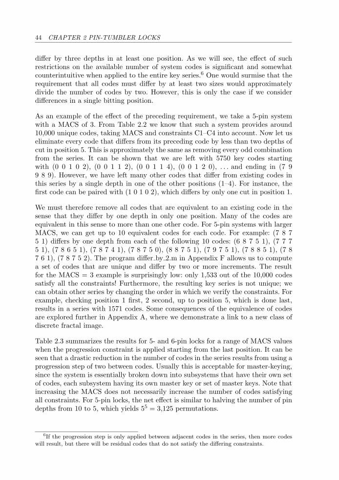
44 CHAPTER 2 PIN-TUMBLER LOCKS
differ by three depths in at least one position. As we will see, the effect of suchrestrictions on the available number of system codes is significant and somewhatcounterintuitive when applied to the entire key series.6 One would surmise that therequirement that all codes must differ by at least two sizes would approximatelydivide the number of codes by two. However, this is only the case if we considerdifferences in a single bitting position.
As an example of the effect of the preceding requirement, we take a 5-pin systemwith a MACS of 3. From Table 2.2 we know that such a system provides around10,000 unique codes, taking MACS and constraints C1–C4 into account. Now let useliminate every code that differs from its preceding code by less than two depths ofcut in position 5. This is approximately the same as removing every odd combinationfrom the series. It can be shown that we are left with 5750 key codes startingwith (0 0 1 0 2), (0 0 1 1 2), (0 0 1 1 4), (0 0 1 2 0), . . . and ending in (7 99 8 9). However, we have left many other codes that differ from existing codes inthis series by a single depth in one of the other positions (1–4). For instance, thefirst code can be paired with (1 0 1 0 2), which differs by only one cut in position 1.
We must therefore remove all codes that are equivalent to an existing code in thesense that they differ by one depth in only one position. Many of the codes areequivalent in this sense to more than one other code. For 5-pin systems with largerMACS, we can get up to 10 equivalent codes for each code. For example: (7 8 75 1) differs by one depth from each of the following 10 codes: (6 8 7 5 1), (7 7 75 1), (7 8 6 5 1), (7 8 7 4 1), (7 8 7 5 0), (8 8 7 5 1), (7 9 7 5 1), (7 8 8 5 1), (7 87 6 1), (7 8 7 5 2). The program differ by 2.m in Appendix F allows us to computea set of codes that are unique and differ by two or more increments. The resultfor the MACS = 3 example is surprisingly low: only 1,533 out of the 10,000 codessatisfy all the constraints! Furthermore, the resulting key series is not unique; wecan obtain other series by changing the order in which we verify the constraints. Forexample, checking position 1 first, 2 second, up to position 5, which is done last,results in a series with 1571 codes. Some consequences of the equivalence of codesare explored further in Appendix A, where we demonstrate a link to a new class ofdiscrete fractal image.
Table 2.3 summarizes the results for 5- and 6-pin locks for a range of MACS valueswhen the progression constraint is applied starting from the last position. It can beseen that a drastic reduction in the number of codes in the series results from using aprogression step of two between codes. Usually this is acceptable for master-keying,since the system is essentially broken down into subsystems that have their own setof codes, each subsystem having its own master key or set of master keys. Note thatincreasing the MACS does not necessarily increase the number of codes satisfyingall constraints. For 5-pin locks, the net effect is similar to halving the number of pindepths from 10 to 5, which yields 55 = 3,125 permutations.
6If the progression step is only applied between adjacent codes in the series, then more codeswill result, but there will be residual codes that do not satisfy the differing constraints.
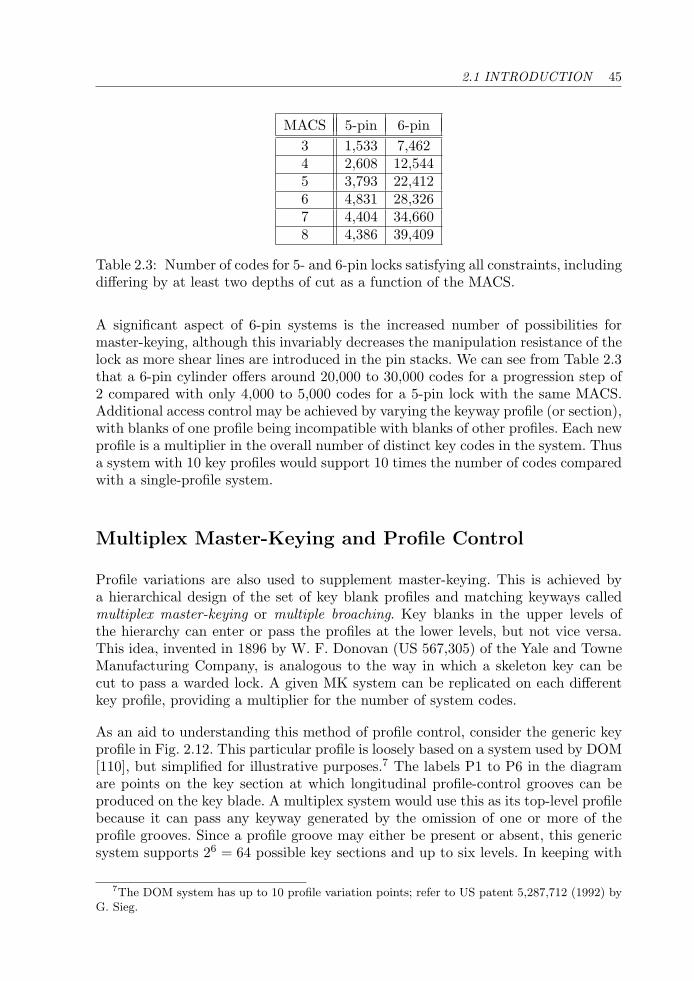
2.1 INTRODUCTION 45
MACS 5-pin 6-pin3 1,533 7,4624 2,608 12,5445 3,793 22,4126 4,831 28,3267 4,404 34,6608 4,386 39,409
Table 2.3: Number of codes for 5- and 6-pin locks satisfying all constraints, includingdiffering by at least two depths of cut as a function of the MACS.
A significant aspect of 6-pin systems is the increased number of possibilities formaster-keying, although this invariably decreases the manipulation resistance of thelock as more shear lines are introduced in the pin stacks. We can see from Table 2.3that a 6-pin cylinder offers around 20,000 to 30,000 codes for a progression step of2 compared with only 4,000 to 5,000 codes for a 5-pin lock with the same MACS.Additional access control may be achieved by varying the keyway profile (or section),with blanks of one profile being incompatible with blanks of other profiles. Each newprofile is a multiplier in the overall number of distinct key codes in the system. Thusa system with 10 key profiles would support 10 times the number of codes comparedwith a single-profile system.
Multiplex Master-Keying and Profile Control
Profile variations are also used to supplement master-keying. This is achieved bya hierarchical design of the set of key blank profiles and matching keyways calledmultiplex master-keying or multiple broaching. Key blanks in the upper levels ofthe hierarchy can enter or pass the profiles at the lower levels, but not vice versa.This idea, invented in 1896 by W. F. Donovan (US 567,305) of the Yale and TowneManufacturing Company, is analogous to the way in which a skeleton key can becut to pass a warded lock. A given MK system can be replicated on each differentkey profile, providing a multiplier for the number of system codes.
As an aid to understanding this method of profile control, consider the generic keyprofile in Fig. 2.12. This particular profile is loosely based on a system used by DOM[110], but simplified for illustrative purposes.7 The labels P1 to P6 in the diagramare points on the key section at which longitudinal profile-control grooves can beproduced on the key blade. A multiplex system would use this as its top-level profilebecause it can pass any keyway generated by the omission of one or more of theprofile grooves. Since a profile groove may either be present or absent, this genericsystem supports 26 = 64 possible key sections and up to six levels. In keeping with
7The DOM system has up to 10 profile variation points; refer to US patent 5,287,712 (1992) byG. Sieg.
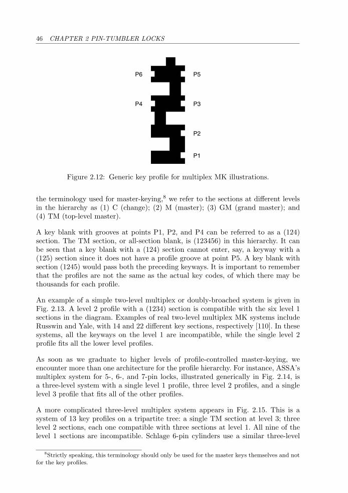
46 CHAPTER 2 PIN-TUMBLER LOCKS
P6
P4
P5
P3
P2
P1
Figure 2.12: Generic key profile for multiplex MK illustrations.
the terminology used for master-keying,8 we refer to the sections at different levelsin the hierarchy as (1) C (change); (2) M (master); (3) GM (grand master); and(4) TM (top-level master).
A key blank with grooves at points P1, P2, and P4 can be referred to as a (124)section. The TM section, or all-section blank, is (123456) in this hierarchy. It canbe seen that a key blank with a (124) section cannot enter, say, a keyway with a(125) section since it does not have a profile groove at point P5. A key blank withsection (1245) would pass both the preceding keyways. It is important to rememberthat the profiles are not the same as the actual key codes, of which there may bethousands for each profile.
An example of a simple two-level multiplex or doubly-broached system is given inFig. 2.13. A level 2 profile with a (1234) section is compatible with the six level 1sections in the diagram. Examples of real two-level multiplex MK systems includeRusswin and Yale, with 14 and 22 different key sections, respectively [110]. In thesesystems, all the keyways on the level 1 are incompatible, while the single level 2profile fits all the lower level profiles.
As soon as we graduate to higher levels of profile-controlled master-keying, weencounter more than one architecture for the profile hierarchy. For instance, ASSA’smultiplex system for 5-, 6-, and 7-pin locks, illustrated generically in Fig. 2.14, isa three-level system with a single level 1 profile, three level 2 profiles, and a singlelevel 3 profile that fits all of the other profiles.
A more complicated three-level multiplex system appears in Fig. 2.15. This is asystem of 13 key profiles on a tripartite tree: a single TM section at level 3; threelevel 2 sections, each one compatible with three sections at level 1. All nine of thelevel 1 sections are incompatible. Schlage 6-pin cylinders use a similar three-level
8Strictly speaking, this terminology should only be used for the master keys themselves and notfor the key profiles.
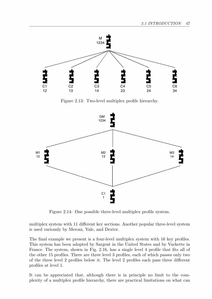
2.1 INTRODUCTION 47
M1234
C112
C213
C314
C423
C524
C634
Figure 2.13: Two-level multiplex profile hierarchy.
M112
M213
GM1234
M314
C11
Figure 2.14: One possible three-level multiplex profile system.
multiplex system with 11 different key sections. Another popular three-level systemis used variously by Meroni, Yale, and Dexter.
The final example we present is a four-level multiplex system with 16 key profiles.This system has been adopted by Sargent in the United States and by Vachette inFrance. The system, shown in Fig. 2.16, has a single level 4 profile that fits all ofthe other 15 profiles. There are three level 3 profiles, each of which passes only twoof the three level 2 profiles below it. The level 2 profiles each pass three differentprofiles at level 1.
It can be appreciated that, although there is in principle no limit to the com-plexity of a multiplex profile hierarchy, there are practical limitations on what can
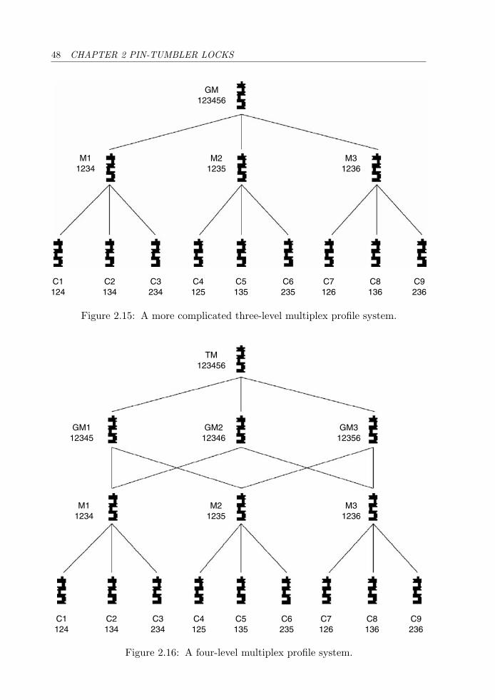
48 CHAPTER 2 PIN-TUMBLER LOCKS
GM123456
M21235
M31236
M11234
C1124
C2134
C3234
C4125
C5135
C6235
C7126
C8136
C9236
Figure 2.15: A more complicated three-level multiplex profile system.
C1124
C2134
C3234
M21235
M31236
GM312356
GM212346
GM112345
TM123456
M11234
C4125
C5135
C6235
C7126
C8136
C9236
Figure 2.16: A four-level multiplex profile system.
2.1 INTRODUCTION 49
be achieved through variation of the keyway broaching. The larger the number ofprofiles, the less tolerance there is to wear and tear through frequent use. More-over, the design has an inherent security flaw in that it is frequently possible toconvert a low-level profile so that it fits all the other profiles simply by grindingdown the sides of the key. This can obviously lead to key interchange or unintendedoperability. In the days of warded locks, a similar situation existed that led to theappearance of skeleton keys that were created by filing off the inessential parts of thekey bit.
In an effort to avoid the shortcomings of key control through profile variationsand also to reduce production costs, numerous manufacturers have moved towardlocks with profile-control pins. We will see many examples of such locks later inthis chapter. The fact still remains that whenever the profile-control mechanism ispassive, the key blank can be doctored so that it will pass all levels in the system.A better method is the use of active profile control as evidenced by locks such asABUS, ISEO, Vachette, MLA, Winkhaus, and Schlage.
Increasing the Level of Security
In this section we consider a number of aspects that influence the security of apin-tumbler lock. These include the design of the keyway, which is important toprevent the insertion of picking and bypass tools. We also discuss physical securityaspects such as drill resistance. Security can be interpreted in terms of the number ofcombinations or differs, which is greater when more pins are included. The subjectof key control, via the restriction of key blanks and requiring authorization for keycopying, is also discussed.
A major step toward the modern pin-tumbler lock was the development of thecorrugated keyway by Linus Yale Junior in 1883 [134]. Prior to this invention, itwas possible to insert a crude, flat blade into the keyway of the lock in order to pickit. This was followed in the late 1890s by Yale’s so-called paracentric keyway, whichis still used in Yale cylinder locks. The paracentric keyway was first suggested in an1891 patent (US 457,753) by W. H. Taylor, a long-time employee and the principalinventor at the Yale and Towne Manufacturing Company [50]. This lock includedbeveled pins with locating lugs to ensure vertical lift by the (very wavy) key blade.Despite its improvements, such a lock could not be economically manufactured atthe time.
Since then many other refinements have been made, to the point where today thereexist tens of thousands of different keyway sections from hundreds of different manu-facturers, each with its own distinct key blank. The Silca range of catalogues[110, 111] is a good reference on this subject. Only a relatively small number ofthese profiles contain severe enough warding to hamper significantly the manipula-tion of the pin-tumblers using modern tools, and some of these locks are covered inthis chapter.
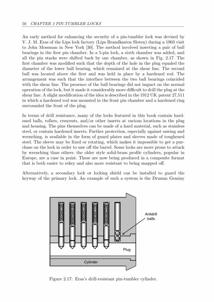
50 CHAPTER 2 PIN-TUMBLER LOCKS
An early method for enhancing the security of a pin-tumbler lock was devised byV. J. M. Eras of the Lips lock factory (Lips Brandkasten Sloten) during a 1903 visitto John Mossman in New York [30]. The method involved inserting a pair of ballbearings in the first pin chamber. In a 5-pin lock, a sixth chamber was added, andall the pin stacks were shifted back by one chamber, as shown in Fig. 2.17. Thefirst chamber was modified such that the depth of the hole in the plug equaled thediameter of the lower ball bearing, which remained at the shear line. The secondball was located above the first and was held in place by a hardened rod. Thearrangement was such that the interface between the two ball bearings coincidedwith the shear line. The presence of the ball bearings did not impact on the normaloperation of the lock, but it made it considerably more difficult to drill the plug at theshear line. A slight modification of the idea is described in the 1912 UK patent 27,511in which a hardened rod was mounted in the front pin chamber and a hardened ringsurrounded the front of the plug.
In terms of drill resistance, many of the locks featured in this book contain hard-ened balls, rollers, crescents, and/or other inserts at various locations in the plugand housing. The pins themselves can be made of a hard material, such as stainlesssteel, or contain hardened inserts. Further protection, especially against sawing andwrenching, is available in the form of guard plates and sleeves made of toughenedsteel. The sleeve may be fixed or rotating, which makes it impossible to get a pur-chase on the lock in order to saw off the barrel. Some locks are more prone to attackby wrenching than others: the older style solid-brass profile cylinders, popular inEurope, are a case in point. These are now being produced in a composite formatthat is both easier to rekey and also more resistant to being snapped off.
Alternatively, a secondary lock or locking shield can be installed to guard thekeyway of the primary lock. An example of such a system is the Drumm Geminy
Antidrillballs
Cylinder
Plug
Figure 2.17: Eras’s drill-resistant pin-tumbler cylinder.
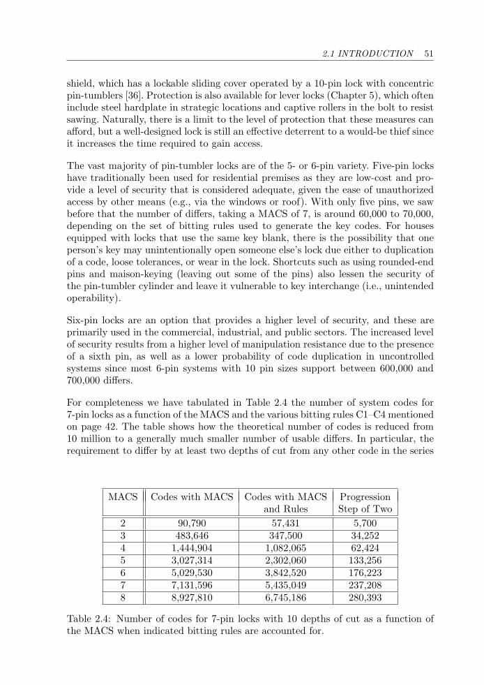
2.1 INTRODUCTION 51
shield, which has a lockable sliding cover operated by a 10-pin lock with concentricpin-tumblers [36]. Protection is also available for lever locks (Chapter 5), which ofteninclude steel hardplate in strategic locations and captive rollers in the bolt to resistsawing. Naturally, there is a limit to the level of protection that these measures canafford, but a well-designed lock is still an effective deterrent to a would-be thief sinceit increases the time required to gain access.
The vast majority of pin-tumbler locks are of the 5- or 6-pin variety. Five-pin lockshave traditionally been used for residential premises as they are low-cost and pro-vide a level of security that is considered adequate, given the ease of unauthorizedaccess by other means (e.g., via the windows or roof). With only five pins, we sawbefore that the number of differs, taking a MACS of 7, is around 60,000 to 70,000,depending on the set of bitting rules used to generate the key codes. For housesequipped with locks that use the same key blank, there is the possibility that oneperson’s key may unintentionally open someone else’s lock due either to duplicationof a code, loose tolerances, or wear in the lock. Shortcuts such as using rounded-endpins and maison-keying (leaving out some of the pins) also lessen the security ofthe pin-tumbler cylinder and leave it vulnerable to key interchange (i.e., unintendedoperability).
Six-pin locks are an option that provides a higher level of security, and these areprimarily used in the commercial, industrial, and public sectors. The increased levelof security results from a higher level of manipulation resistance due to the presenceof a sixth pin, as well as a lower probability of code duplication in uncontrolledsystems since most 6-pin systems with 10 pin sizes support between 600,000 and700,000 differs.
For completeness we have tabulated in Table 2.4 the number of system codes for7-pin locks as a function of the MACS and the various bitting rules C1–C4 mentionedon page 42. The table shows how the theoretical number of codes is reduced from10 million to a generally much smaller number of usable differs. In particular, therequirement to differ by at least two depths of cut from any other code in the series
MACS Codes with MACS Codes with MACS Progressionand Rules Step of Two
2 90,790 57,431 5,7003 483,646 347,500 34,2524 1,444,904 1,082,065 62,4245 3,027,314 2,302,060 133,2566 5,029,530 3,842,520 176,2237 7,131,596 5,435,049 237,2088 8,927,810 6,745,186 280,393
Table 2.4: Number of codes for 7-pin locks with 10 depths of cut as a function ofthe MACS when indicated bitting rules are accounted for.
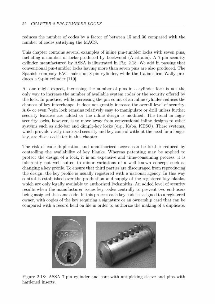
52 CHAPTER 2 PIN-TUMBLER LOCKS
reduces the number of codes by a factor of between 15 and 30 compared with thenumber of codes satisfying the MACS.
This chapter contains several examples of inline pin-tumbler locks with seven pins,including a number of locks produced by Lockwood (Australia). A 7-pin securitycylinder manufactured by ASSA is illustrated in Fig. 2.18. We add in passing thatconventional pin-tumbler locks having more than seven pins are also produced. TheSpanish company FAC makes an 8-pin cylinder, while the Italian firm Wally pro-duces a 9-pin cylinder [110].
As one might expect, increasing the number of pins in a cylinder lock is not theonly way to increase the number of available system codes or the security offered bythe lock. In practice, while increasing the pin count of an inline cylinder reduces thechances of key interchange, it does not greatly increase the overall level of security.A 6- or even 7-pin lock remains relatively easy to manipulate or drill unless furthersecurity features are added or the inline design is modified. The trend in high-security locks, however, is to move away from conventional inline designs to othersystems such as side-bar and dimple-key locks (e.g., Kaba, KESO). These systems,which provide vastly increased security and key control without the need for a longerkey, are discussed later in this chapter.
The risk of code duplication and unauthorized access can be further reduced bycontrolling the availability of key blanks. Whereas patenting may be applied toprotect the design of a lock, it is an expensive and time-consuming process: it isinherently not well suited to minor variations of a well known concept such aschanging a key profile. To ensure that third parties are discouraged from reproducingthe design, the key profile is usually registered with a national agency. In this waycontrol is established over the production and supply of the registered key blanks,which are only legally available to authorized locksmiths. An added level of securityresults when the manufacturer issues key codes centrally to prevent two end-usersbeing assigned the same code. In this process each key code is assigned to a registeredowner, with copies of the key requiring a signature or an ownership card that can becompared with a record held on file in order to authorize the making of a duplicate.
Figure 2.18: ASSA 7-pin cylinder and core with antipicking sleeve and pins withhardened inserts.
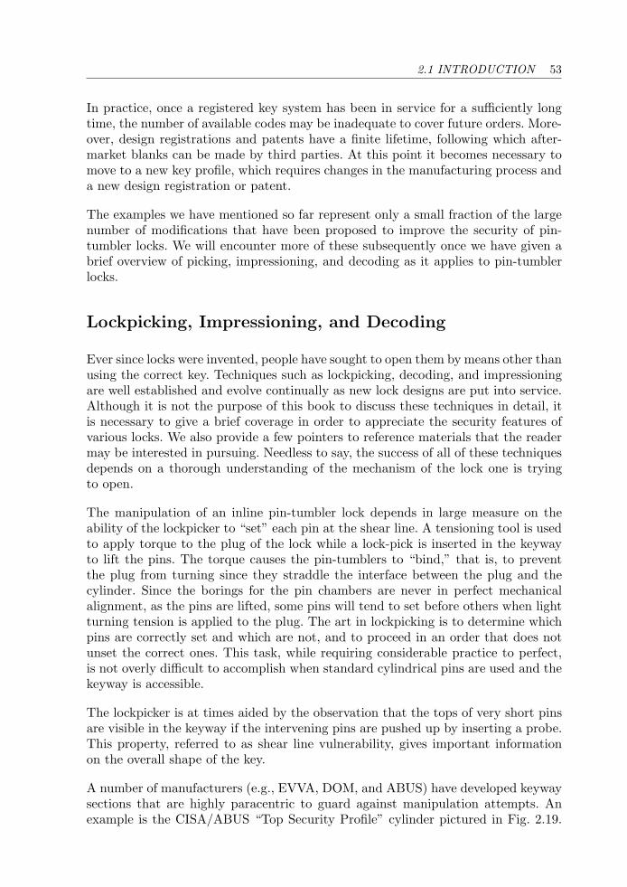
2.1 INTRODUCTION 53
In practice, once a registered key system has been in service for a sufficiently longtime, the number of available codes may be inadequate to cover future orders. More-over, design registrations and patents have a finite lifetime, following which after-market blanks can be made by third parties. At this point it becomes necessary tomove to a new key profile, which requires changes in the manufacturing process anda new design registration or patent.
The examples we have mentioned so far represent only a small fraction of the largenumber of modifications that have been proposed to improve the security of pin-tumbler locks. We will encounter more of these subsequently once we have given abrief overview of picking, impressioning, and decoding as it applies to pin-tumblerlocks.
Lockpicking, Impressioning, and Decoding
Ever since locks were invented, people have sought to open them by means other thanusing the correct key. Techniques such as lockpicking, decoding, and impressioningare well established and evolve continually as new lock designs are put into service.Although it is not the purpose of this book to discuss these techniques in detail, itis necessary to give a brief coverage in order to appreciate the security features ofvarious locks. We also provide a few pointers to reference materials that the readermay be interested in pursuing. Needless to say, the success of all of these techniquesdepends on a thorough understanding of the mechanism of the lock one is tryingto open.
The manipulation of an inline pin-tumbler lock depends in large measure on theability of the lockpicker to “set” each pin at the shear line. A tensioning tool is usedto apply torque to the plug of the lock while a lock-pick is inserted in the keywayto lift the pins. The torque causes the pin-tumblers to “bind,” that is, to preventthe plug from turning since they straddle the interface between the plug and thecylinder. Since the borings for the pin chambers are never in perfect mechanicalalignment, as the pins are lifted, some pins will tend to set before others when lightturning tension is applied to the plug. The art in lockpicking is to determine whichpins are correctly set and which are not, and to proceed in an order that does notunset the correct ones. This task, while requiring considerable practice to perfect,is not overly difficult to accomplish when standard cylindrical pins are used and thekeyway is accessible.
The lockpicker is at times aided by the observation that the tops of very short pinsare visible in the keyway if the intervening pins are pushed up by inserting a probe.This property, referred to as shear line vulnerability, gives important informationon the overall shape of the key.
A number of manufacturers (e.g., EVVA, DOM, and ABUS) have developed keywaysections that are highly paracentric to guard against manipulation attempts. Anexample is the CISA/ABUS “Top Security Profile” cylinder pictured in Fig. 2.19.
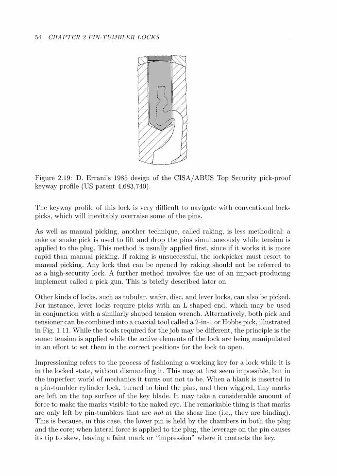
54 CHAPTER 2 PIN-TUMBLER LOCKS
Figure 2.19: D. Errani’s 1985 design of the CISA/ABUS Top Security pick-proofkeyway profile (US patent 4,683,740).
The keyway profile of this lock is very difficult to navigate with conventional lock-picks, which will inevitably overraise some of the pins.
As well as manual picking, another technique, called raking, is less methodical: arake or snake pick is used to lift and drop the pins simultaneously while tension isapplied to the plug. This method is usually applied first, since if it works it is morerapid than manual picking. If raking is unsuccessful, the lockpicker must resort tomanual picking. Any lock that can be opened by raking should not be referred toas a high-security lock. A further method involves the use of an impact-producingimplement called a pick gun. This is briefly described later on.
Other kinds of locks, such as tubular, wafer, disc, and lever locks, can also be picked.For instance, lever locks require picks with an L-shaped end, which may be usedin conjunction with a similarly shaped tension wrench. Alternatively, both pick andtensioner can be combined into a coaxial tool called a 2-in-1 or Hobbs pick, illustratedin Fig. 1.11. While the tools required for the job may be different, the principle is thesame: tension is applied while the active elements of the lock are being manipulatedin an effort to set them in the correct positions for the lock to open.
Impressioning refers to the process of fashioning a working key for a lock while it isin the locked state, without dismantling it. This may at first seem impossible, but inthe imperfect world of mechanics it turns out not to be. When a blank is inserted ina pin-tumbler cylinder lock, turned to bind the pins, and then wiggled, tiny marksare left on the top surface of the key blade. It may take a considerable amount offorce to make the marks visible to the naked eye. The remarkable thing is that marksare only left by pin-tumblers that are not at the shear line (i.e., they are binding).This is because, in this case, the lower pin is held by the chambers in both the plugand the core; when lateral force is applied to the plug, the leverage on the pin causesits tip to skew, leaving a faint mark or “impression” where it contacts the key.
2.1 INTRODUCTION 55
The trick in impressioning a key is to remove only a small amount of the blank,by filing or cutting, from the pin positions where impressions have been left. Ifa key-cutting tool is available, the mark may be deepened to the next depth ofcut. The process of wiggling the key blank and incrementally filing the key in therequired locations is continued until no further impressions are left by any of thepins, at which point the lock should open. During this process the order of filing maychange; thus some pins may not make a noticeable mark until other pin positionshave been filed.
Like picking, the impressioning process requires skill and considerable time to learn.With practice, basic pin-tumbler locks can be impressioned in a matter of 10 minutes.Other impressioning techniques involve turning the key to bind the pins and theneither tapping it or pulling it to take an impression. Impressioning can also be appliedto other types of locks including wafer and lever locks.
The primary requirement for impressioning, apart from a set of files and a grip tool,is a blank that fits the lock’s keyway. Makers of high-security locks exercise controlover the distribution of registered blank keys by supplying only through authorizedagents and locksmiths who duplicate keys on proof of ownership. Many security keysare restricted in this sense, and this is a first step in preventing unauthorized keysfrom being made by impressioning. The reader is referred to [122, 129] for more detailon the art of impressioning locks.
Decoding, as the name suggests, is the process of determining the code of the keyfrom measurements taken on the lock. The measurements may be taken by anyphysical means, including mechanical, acoustic, optical, electrical, electromagnetic,or even X-ray. Some locks, for instance, wafer locks and low-security lever locks, canbe decoded by inspection of the locking elements visible in the keyway. As far asmechanical decoding is concerned, any tool may be used that allows the shear lineof each pin to be detected and the corresponding height of the pin to be measured.Examples include shims, thin wires, and calibrated pin-lifting devices. In pin-tumblerlocks with a constant driver length, the compression of the spring is proportionalto the length of the lower pin. Thus it is possible to estimate the pin length bymeasuring the force on each pin stack. For this reason many high-security pin-tumbler locks use compensated drivers to ensure that the pin stacks have roughlythe same overall length.
The decoding idea can be applied after a lock is opened by picking, or it can be usedto assemble or cut a working key. A key made by assembling a key from componentsof preset lengths is referred to as a “make-up key” or “pin-and-cam tool,” and thisis a popular method for opening lever locks. Once a pin-tumbler lock is pickedopen, a gauge consisting of a thin pivoting arm can be inserted into the keyway;the distances from the bottom of the keyway to the tip of each lower pin are thensimply related to the angle of the pivot arm.
Decoding and picking can be combined into a single process whereby the individuallocking elements are maintained at the heights determined via the decoding process.
56 CHAPTER 2 PIN-TUMBLER LOCKS
The net result is that the tool both measures the active elements in the lock andopens it. An implementation of this idea for conventional pin-tumbler locks is theso-called Sputnik decoder-pick pictured in Fig. 1.12. Another example of a com-bined decoder and pick is furnished by the tubular lock-pick in Fig. 1.10. In thisinstrument, the cut depths may be read off a calibrated scale on each of the slidersonce the lock is picked.
Using a combined decoder-pick is fundamentally different from manual picking. Asexplained above, manual picking relies on imperfections in the lock to bind pins atthe shear line under light turning force: if picking proceeds out of sequence, pinsthat were previously set return to their locked positions. This contrasts with decoderpicking in which the instrument effectively decouples the functions of the lockingelements by allowing them to be manipulated independently. Once the correct heightis determined for one pin, it can be maintained at that height and left alone whiledecoding proceeds on the other pins. The technique is amazingly powerful, and thereare few locks in this book that are immune from this type of approach, given anappropriately fashioned tool (refer to [122] for examples, particularly those producedby Falle Safe Securities).
Spool and Mushroom Pins
A simple way to enhance a cylinder’s manipulation resistance, and one that has beenemployed for many years, is to replace some of the straight driver pins with spoolor mushroom-shaped pins, as in Fig. 2.20. These are a standard feature in manyhigh-security locks such as Yale and DOM, and can be incorporated at minimalextra cost as they do not entail a change in the overall design of the lock. The effectof a spooled driver is to bind in the pin chamber if not properly set (see Fig. 2.21).This thwarts a picking attempt since it is then not possible to raise the spooleddriver to the shear line without relaxing tension on the plug—which allows pinsthat were set to drop back down to their rest positions.
Although picking a lock with spooled drivers is still feasible, it requires much morefinesse with the instruments. One reported technique is to raise all pins to the topof the keyway and set them from above the shear line by gradually relaxing thetensioner. This technique works on the assumption that the lower pins are not of
Figure 2.20: Mushroom drivers increase a lock’s resistance to picking.
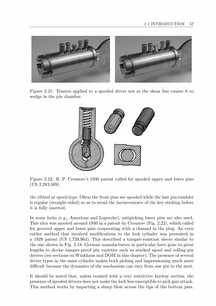
2.1 INTRODUCTION 57
Figure 2.21: Tension applied to a spooled driver not at the shear line causes it towedge in the pin chamber.
Figure 2.22: R. P. Crousore’s 1940 patent called for spooled upper and lower pins(US 2,283,489).
the ribbed or spool-type. Often the front pins are spooled while the last pin-tumbleris regular (straight-sided) so as to avoid the inconvenience of the key sticking beforeit is fully inserted.
In some locks (e.g., American and Laperche), antipicking lower pins are also used.This idea was mooted around 1940 in a patent by Crousore (Fig. 2.22), which calledfor grooved upper and lower pins cooperating with a channel in the plug. An evenearlier method that involved modifications to the lock cylinder was presented ina 1928 patent (US 1,739,964). This described a tamper-resistant sleeve similar tothe one shown in Fig. 2.18. German manufacturers in particular have gone to greatlengths to devise tamper-proof pin varieties such as stacked spool and rolling-pindrivers (see sections on Winkhaus and DOM in this chapter). The presence of severaldriver types in the same cylinder makes both picking and impressioning much moredifficult because the dynamics of the mechanism can vary from one pin to the next.
It should be noted that, unless teamed with a very restrictive keyway section, thepresence of spooled drivers does not make the lock less susceptible to pick gun attack.This method works by imparting a sharp blow across the tips of the bottom pins.
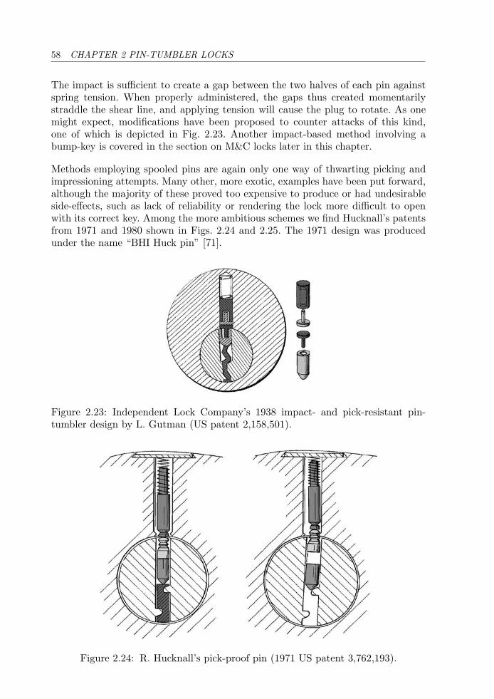
58 CHAPTER 2 PIN-TUMBLER LOCKS
The impact is sufficient to create a gap between the two halves of each pin againstspring tension. When properly administered, the gaps thus created momentarilystraddle the shear line, and applying tension will cause the plug to rotate. As onemight expect, modifications have been proposed to counter attacks of this kind,one of which is depicted in Fig. 2.23. Another impact-based method involving abump-key is covered in the section on M&C locks later in this chapter.
Methods employing spooled pins are again only one way of thwarting picking andimpressioning attempts. Many other, more exotic, examples have been put forward,although the majority of these proved too expensive to produce or had undesirableside-effects, such as lack of reliability or rendering the lock more difficult to openwith its correct key. Among the more ambitious schemes we find Hucknall’s patentsfrom 1971 and 1980 shown in Figs. 2.24 and 2.25. The 1971 design was producedunder the name “BHI Huck pin” [71].
Figure 2.23: Independent Lock Company’s 1938 impact- and pick-resistant pin-tumbler design by L. Gutman (US patent 2,158,501).
Figure 2.24: R. Hucknall’s pick-proof pin (1971 US patent 3,762,193).

2.1 INTRODUCTION 59
Figure 2.25: Cross-section of Hucknall’s 1980 impression-resistant pin-tumbler lock(US patent 4,377,940).
Profile Pins, Pin Design, and Geometry
We have so far considered the influence of keyway design and the inclusion of hard-ened inserts and variously shaped pins and drivers. Further levels of security requiremore substantial modifications to the basic pin-tumbler cylinder design. We havegrouped these modifications into three broad classes: pin design, profile pins, andpin-tumbler geometry. The additional category of pin chamber design, which hasbeen suggested in some old patents, for example, US patents 1,860,712 (1930) and2,043,205 (1932), is rarely used in practice for reasons of cost and complexity andhas therefore been omitted.9
Pin design encompasses, as well as conventional spooled drivers, modifications tothe function of a pin-tumbler pair. In this category we include both rotating andinterlocking pins, as found in locks like Medeco and Emhart (note that Medeco is aside-bar lock, dealt with in Chapter 4).
Profile pins differ from conventional pin-tumbler pairs in respect of not having aspring-biased driver moving in a pin chamber, although some types are paired witha ball bearing. Profile pins are generally operated by cuts or dimples on the side(s)of the key that are supplementary to the main bittings for the pin-tumblers. Thecut for a given profile pin is either present or absent on the key blade. An exampleof profile pin design is furnished by Kerr’s 1966 patent (US 3,418,833) which wasfor wafer locks but applies equally well to pin-tumbler locks (see Fig. 2.26).
Two basic types of profile pins are discernible: passive and active. Passive profilepins are not related to the locking function of the cylinder, but instead provide alevel of key control above that afforded by the keyway broaching itself. Profile pins
9An exception is the ASSA V-10 side-bar lock covered in Chapter 4.
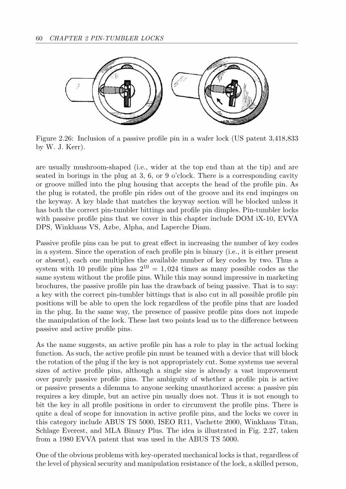
60 CHAPTER 2 PIN-TUMBLER LOCKS
Figure 2.26: Inclusion of a passive profile pin in a wafer lock (US patent 3,418,833by W. J. Kerr).
are usually mushroom-shaped (i.e., wider at the top end than at the tip) and areseated in borings in the plug at 3, 6, or 9 o’clock. There is a corresponding cavityor groove milled into the plug housing that accepts the head of the profile pin. Asthe plug is rotated, the profile pin rides out of the groove and its end impinges onthe keyway. A key blade that matches the keyway section will be blocked unless ithas both the correct pin-tumbler bittings and profile pin dimples. Pin-tumbler lockswith passive profile pins that we cover in this chapter include DOM iX-10, EVVADPS, Winkhaus VS, Azbe, Alpha, and Laperche Diam.
Passive profile pins can be put to great effect in increasing the number of key codesin a system. Since the operation of each profile pin is binary (i.e., it is either presentor absent), each one multiplies the available number of key codes by two. Thus asystem with 10 profile pins has 210 = 1, 024 times as many possible codes as thesame system without the profile pins. While this may sound impressive in marketingbrochures, the passive profile pin has the drawback of being passive. That is to say:a key with the correct pin-tumbler bittings that is also cut in all possible profile pinpositions will be able to open the lock regardless of the profile pins that are loadedin the plug. In the same way, the presence of passive profile pins does not impedethe manipulation of the lock. These last two points lead us to the difference betweenpassive and active profile pins.
As the name suggests, an active profile pin has a role to play in the actual lockingfunction. As such, the active profile pin must be teamed with a device that will blockthe rotation of the plug if the key is not appropriately cut. Some systems use severalsizes of active profile pins, although a single size is already a vast improvementover purely passive profile pins. The ambiguity of whether a profile pin is activeor passive presents a dilemma to anyone seeking unauthorized access: a passive pinrequires a key dimple, but an active pin usually does not. Thus it is not enough tobit the key in all profile positions in order to circumvent the profile pins. There isquite a deal of scope for innovation in active profile pins, and the locks we cover inthis category include ABUS TS 5000, ISEO R11, Vachette 2000, Winkhaus Titan,Schlage Everest, and MLA Binary Plus. The idea is illustrated in Fig. 2.27, takenfrom a 1980 EVVA patent that was used in the ABUS TS 5000.
One of the obvious problems with key-operated mechanical locks is that, regardless ofthe level of physical security and manipulation resistance of the lock, a skilled person,
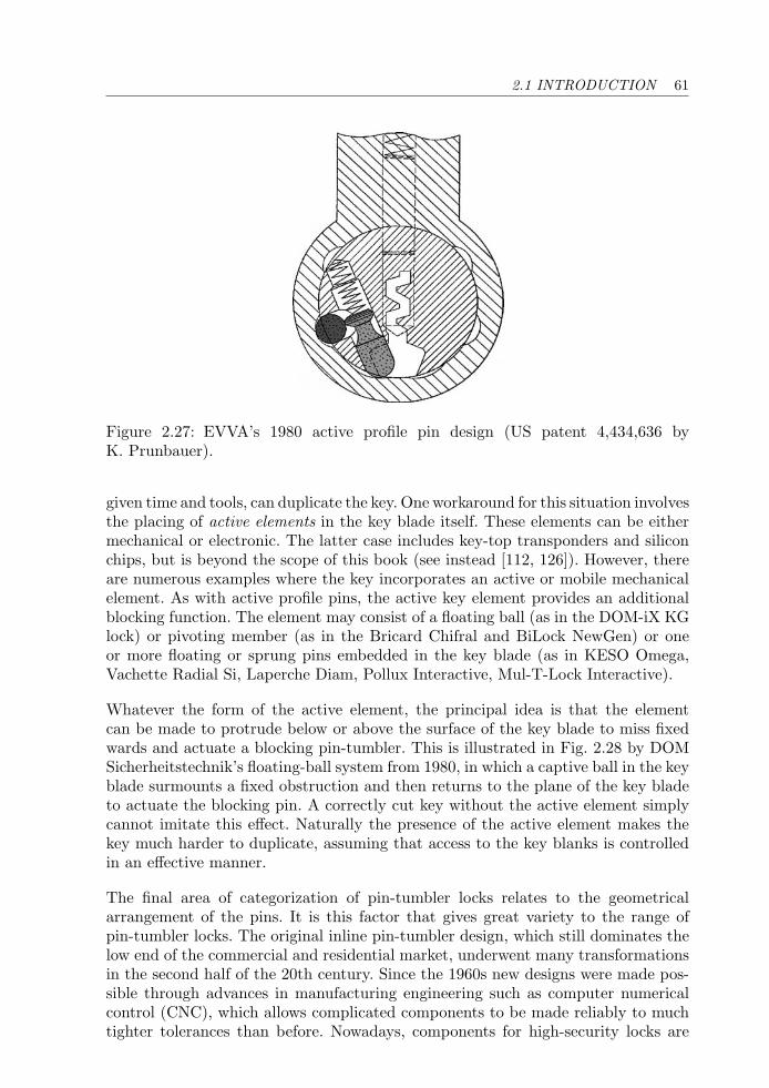
2.1 INTRODUCTION 61
Figure 2.27: EVVA’s 1980 active profile pin design (US patent 4,434,636 byK. Prunbauer).
given time and tools, can duplicate the key. One workaround for this situation involvesthe placing of active elements in the key blade itself. These elements can be eithermechanical or electronic. The latter case includes key-top transponders and siliconchips, but is beyond the scope of this book (see instead [112, 126]). However, thereare numerous examples where the key incorporates an active or mobile mechanicalelement. As with active profile pins, the active key element provides an additionalblocking function. The element may consist of a floating ball (as in the DOM-iX KGlock) or pivoting member (as in the Bricard Chifral and BiLock NewGen) or oneor more floating or sprung pins embedded in the key blade (as in KESO Omega,Vachette Radial Si, Laperche Diam, Pollux Interactive, Mul-T-Lock Interactive).
Whatever the form of the active element, the principal idea is that the elementcan be made to protrude below or above the surface of the key blade to miss fixedwards and actuate a blocking pin-tumbler. This is illustrated in Fig. 2.28 by DOMSicherheitstechnik’s floating-ball system from 1980, in which a captive ball in the keyblade surmounts a fixed obstruction and then returns to the plane of the key bladeto actuate the blocking pin. A correctly cut key without the active element simplycannot imitate this effect. Naturally the presence of the active element makes thekey much harder to duplicate, assuming that access to the key blanks is controlledin an effective manner.
The final area of categorization of pin-tumbler locks relates to the geometricalarrangement of the pins. It is this factor that gives great variety to the range ofpin-tumbler locks. The original inline pin-tumbler design, which still dominates thelow end of the commercial and residential market, underwent many transformationsin the second half of the 20th century. Since the 1960s new designs were made pos-sible through advances in manufacturing engineering such as computer numericalcontrol (CNC), which allows complicated components to be made reliably to muchtighter tolerances than before. Nowadays, components for high-security locks are
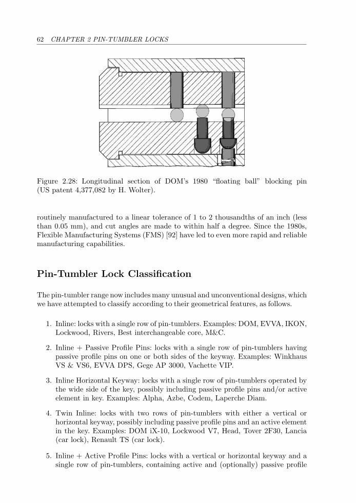
62 CHAPTER 2 PIN-TUMBLER LOCKS
Figure 2.28: Longitudinal section of DOM’s 1980 “floating ball” blocking pin(US patent 4,377,082 by H. Wolter).
routinely manufactured to a linear tolerance of 1 to 2 thousandths of an inch (lessthan 0.05 mm), and cut angles are made to within half a degree. Since the 1980s,Flexible Manufacturing Systems (FMS) [92] have led to even more rapid and reliablemanufacturing capabilities.
Pin-Tumbler Lock Classification
The pin-tumbler range now includes many unusual and unconventional designs, whichwe have attempted to classify according to their geometrical features, as follows.
1. Inline: locks with a single row of pin-tumblers. Examples: DOM, EVVA, IKON,Lockwood, Rivers, Best interchangeable core, M&C.
2. Inline + Passive Profile Pins: locks with a single row of pin-tumblers havingpassive profile pins on one or both sides of the keyway. Examples: WinkhausVS & VS6, EVVA DPS, Gege AP 3000, Vachette VIP.
3. Inline Horizontal Keyway: locks with a single row of pin-tumblers operated bythe wide side of the key, possibly including passive profile pins and/or activeelement in key. Examples: Alpha, Azbe, Codem, Laperche Diam.
4. Twin Inline: locks with two rows of pin-tumblers with either a vertical orhorizontal keyway, possibly including passive profile pins and an active elementin the key. Examples: DOM iX-10, Lockwood V7, Head, Tover 2F30, Lancia(car lock), Renault TS (car lock).
5. Inline + Active Profile Pins: locks with a vertical or horizontal keyway and asingle row of pin-tumblers, containing active and (optionally) passive profile
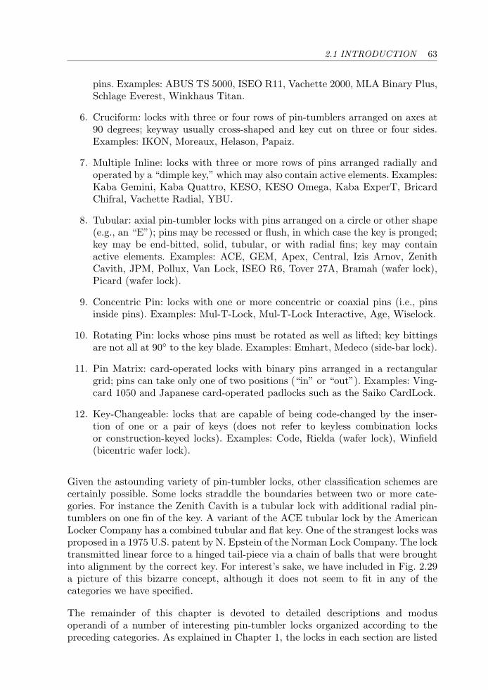
2.1 INTRODUCTION 63
pins. Examples: ABUS TS 5000, ISEO R11, Vachette 2000, MLA Binary Plus,Schlage Everest, Winkhaus Titan.
6. Cruciform: locks with three or four rows of pin-tumblers arranged on axes at90 degrees; keyway usually cross-shaped and key cut on three or four sides.Examples: IKON, Moreaux, Helason, Papaiz.
7. Multiple Inline: locks with three or more rows of pins arranged radially andoperated by a “dimple key,” which may also contain active elements. Examples:Kaba Gemini, Kaba Quattro, KESO, KESO Omega, Kaba ExperT, BricardChifral, Vachette Radial, YBU.
8. Tubular: axial pin-tumbler locks with pins arranged on a circle or other shape(e.g., an “E”); pins may be recessed or flush, in which case the key is pronged;key may be end-bitted, solid, tubular, or with radial fins; key may containactive elements. Examples: ACE, GEM, Apex, Central, Izis Arnov, ZenithCavith, JPM, Pollux, Van Lock, ISEO R6, Tover 27A, Bramah (wafer lock),Picard (wafer lock).
9. Concentric Pin: locks with one or more concentric or coaxial pins (i.e., pinsinside pins). Examples: Mul-T-Lock, Mul-T-Lock Interactive, Age, Wiselock.
10. Rotating Pin: locks whose pins must be rotated as well as lifted; key bittingsare not all at 90◦ to the key blade. Examples: Emhart, Medeco (side-bar lock).
11. Pin Matrix: card-operated locks with binary pins arranged in a rectangulargrid; pins can take only one of two positions (“in” or “out”). Examples: Ving-card 1050 and Japanese card-operated padlocks such as the Saiko CardLock.
12. Key-Changeable: locks that are capable of being code-changed by the inser-tion of one or a pair of keys (does not refer to keyless combination locksor construction-keyed locks). Examples: Code, Rielda (wafer lock), Winfield(bicentric wafer lock).
Given the astounding variety of pin-tumbler locks, other classification schemes arecertainly possible. Some locks straddle the boundaries between two or more cate-gories. For instance the Zenith Cavith is a tubular lock with additional radial pin-tumblers on one fin of the key. A variant of the ACE tubular lock by the AmericanLocker Company has a combined tubular and flat key. One of the strangest locks wasproposed in a 1975 U.S. patent by N. Epstein of the Norman Lock Company. The locktransmitted linear force to a hinged tail-piece via a chain of balls that were broughtinto alignment by the correct key. For interest’s sake, we have included in Fig. 2.29a picture of this bizarre concept, although it does not seem to fit in any of thecategories we have specified.
The remainder of this chapter is devoted to detailed descriptions and modusoperandi of a number of interesting pin-tumbler locks organized according to thepreceding categories. As explained in Chapter 1, the locks in each section are listed
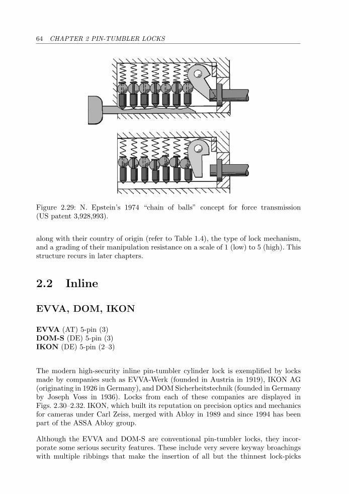
64 CHAPTER 2 PIN-TUMBLER LOCKS
Figure 2.29: N. Epstein’s 1974 “chain of balls” concept for force transmission(US patent 3,928,993).
along with their country of origin (refer to Table 1.4), the type of lock mechanism,and a grading of their manipulation resistance on a scale of 1 (low) to 5 (high). Thisstructure recurs in later chapters.
2.2 Inline
EVVA, DOM, IKON
EVVA (AT) 5-pin (3)DOM-S (DE) 5-pin (3)IKON (DE) 5-pin (2–3)
The modern high-security inline pin-tumbler cylinder lock is exemplified by locksmade by companies such as EVVA-Werk (founded in Austria in 1919), IKON AG(originating in 1926 in Germany), and DOM Sicherheitstechnik (founded in Germanyby Joseph Voss in 1936). Locks from each of these companies are displayed inFigs. 2.30–2.32. IKON, which built its reputation on precision optics and mechanicsfor cameras under Carl Zeiss, merged with Abloy in 1989 and since 1994 has beenpart of the ASSA Abloy group.
Although the EVVA and DOM-S are conventional pin-tumbler locks, they incor-porate some serious security features. These include very severe keyway broachingswith multiple ribbings that make the insertion of all but the thinnest lock-picks
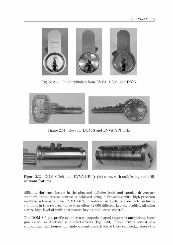
2.2 INLINE 65
Figure 2.30: Inline cylinders from EVVA, DOM, and IKON.
Figure 2.31: Keys for DOM-S and EVVA GPI locks.
Figure 2.32: DOM-S (left) and EVVA GPI (right) cores, with antipicking and drill-resistant features.
difficult. Hardened inserts in the plug and cylinder body and spooled drivers arestandard issue. Access control is achieved using a broaching with high-precisionmultiple side-wards. The EVVA GPI, introduced in 1976, is a de facto industrystandard in this respect: the system offers 32,000 different keyway profiles, allowinga very high level of multiplex master-keying and access control.
The DOM-S 5-pin profile cylinder uses torpedo-shaped (tapered) antipicking lowerpins as well as stacked-disc spooled drivers (Fig. 2.33). These drivers consist of asupport pin that houses four independent discs. Each of these can wedge across the
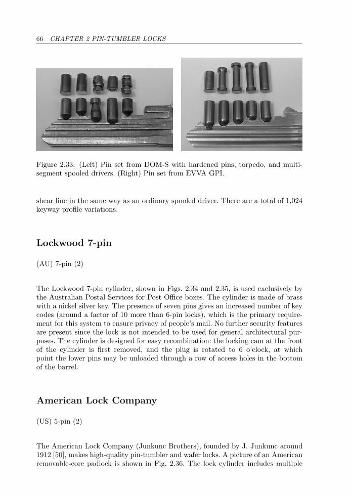
66 CHAPTER 2 PIN-TUMBLER LOCKS
Figure 2.33: (Left) Pin set from DOM-S with hardened pins, torpedo, and multi-segment spooled drivers. (Right) Pin set from EVVA GPI.
shear line in the same way as an ordinary spooled driver. There are a total of 1,024keyway profile variations.
Lockwood 7-pin
(AU) 7-pin (2)
The Lockwood 7-pin cylinder, shown in Figs. 2.34 and 2.35, is used exclusively bythe Australian Postal Services for Post Office boxes. The cylinder is made of brasswith a nickel silver key. The presence of seven pins gives an increased number of keycodes (around a factor of 10 more than 6-pin locks), which is the primary require-ment for this system to ensure privacy of people’s mail. No further security featuresare present since the lock is not intended to be used for general architectural pur-poses. The cylinder is designed for easy recombination: the locking cam at the frontof the cylinder is first removed, and the plug is rotated to 6 o’clock, at whichpoint the lower pins may be unloaded through a row of access holes in the bottomof the barrel.
American Lock Company
(US) 5-pin (2)
The American Lock Company (Junkunc Brothers), founded by J. Junkunc around1912 [50], makes high-quality pin-tumbler and wafer locks. A picture of an Americanremovable-core padlock is shown in Fig. 2.36. The lock cylinder includes multiple
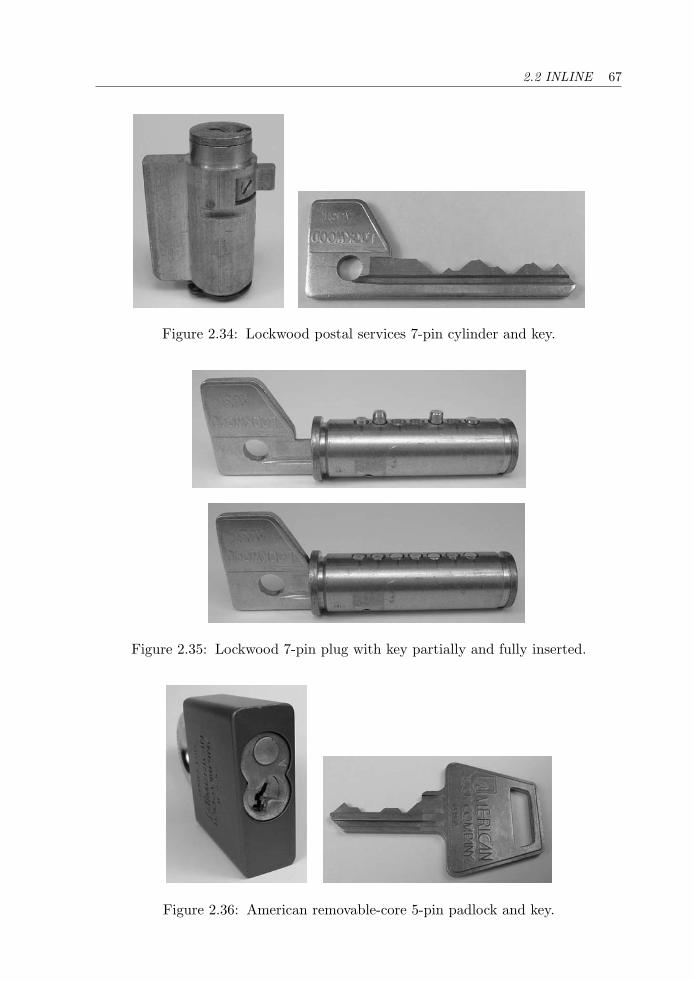
2.2 INLINE 67
Figure 2.34: Lockwood postal services 7-pin cylinder and key.
Figure 2.35: Lockwood 7-pin plug with key partially and fully inserted.
Figure 2.36: American removable-core 5-pin padlock and key.
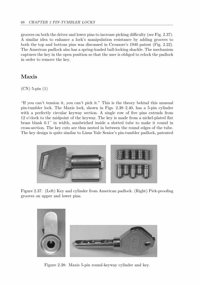
68 CHAPTER 2 PIN-TUMBLER LOCKS
grooves on both the driver and lower pins to increase picking difficulty (see Fig. 2.37).A similar idea to enhance a lock’s manipulation resistance by adding grooves toboth the top and bottom pins was discussed in Crousore’s 1940 patent (Fig. 2.22).The American padlock also has a spring-loaded ball-locking shackle. The mechanismcaptures the key in the open position so that the user is obliged to relock the padlockin order to remove the key.
Maxis
(CN) 5-pin (1)
“If you can’t tension it, you can’t pick it.” This is the theory behind this unusualpin-tumbler lock. The Maxis lock, shown in Figs. 2.38–2.40, has a 5-pin cylinderwith a perfectly circular keyway section. A single row of five pins extends from12 o’clock to the midpoint of the keyway. The key is made from a nickel-plated flatbrass blank 0.1˝ in width, sandwiched inside a slotted tube to make it round incross-section. The key cuts are thus nested in between the round edges of the tube.The key design is quite similar to Linus Yale Senior’s pin-tumbler padlock, patented
Figure 2.37: (Left) Key and cylinder from American padlock. (Right) Pick-proofinggrooves on upper and lower pins.
Figure 2.38: Maxis 5-pin round-keyway cylinder and key.
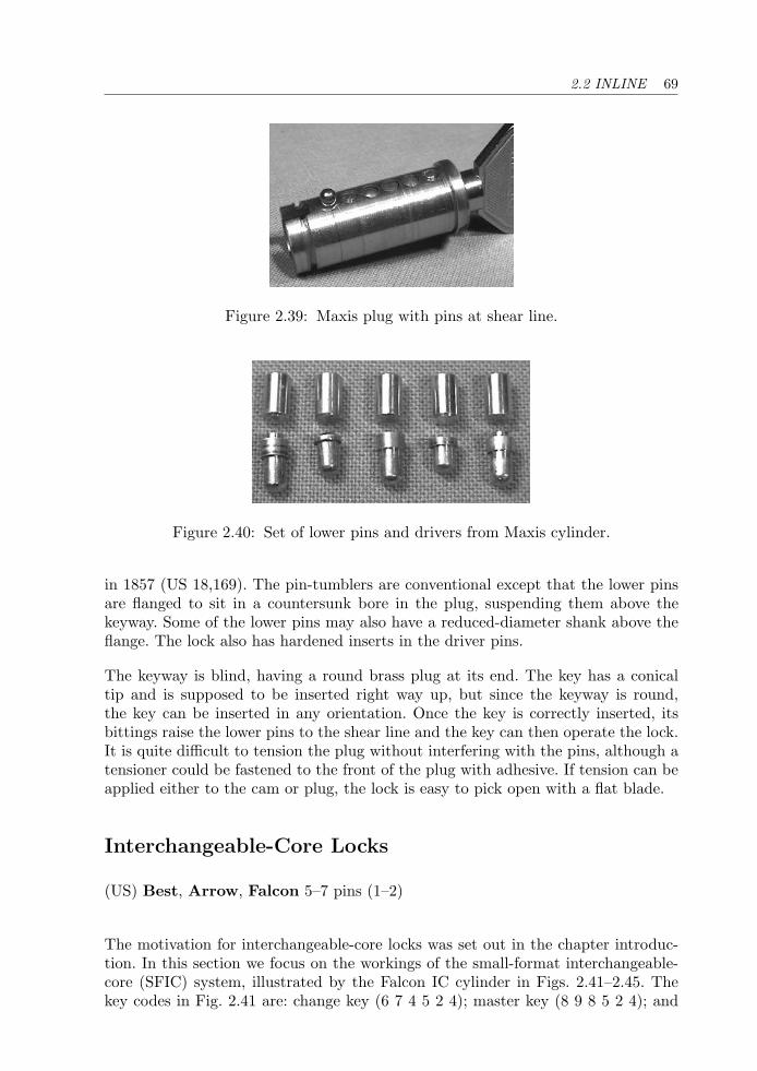
2.2 INLINE 69
Figure 2.39: Maxis plug with pins at shear line.
Figure 2.40: Set of lower pins and drivers from Maxis cylinder.
in 1857 (US 18,169). The pin-tumblers are conventional except that the lower pinsare flanged to sit in a countersunk bore in the plug, suspending them above thekeyway. Some of the lower pins may also have a reduced-diameter shank above theflange. The lock also has hardened inserts in the driver pins.
The keyway is blind, having a round brass plug at its end. The key has a conicaltip and is supposed to be inserted right way up, but since the keyway is round,the key can be inserted in any orientation. Once the key is correctly inserted, itsbittings raise the lower pins to the shear line and the key can then operate the lock.It is quite difficult to tension the plug without interfering with the pins, although atensioner could be fastened to the front of the plug with adhesive. If tension can beapplied either to the cam or plug, the lock is easy to pick open with a flat blade.
Interchangeable-Core Locks
(US) Best, Arrow, Falcon 5–7 pins (1–2)
The motivation for interchangeable-core locks was set out in the chapter introduc-tion. In this section we focus on the workings of the small-format interchangeable-core (SFIC) system, illustrated by the Falcon IC cylinder in Figs. 2.41–2.45. Thekey codes in Fig. 2.41 are: change key (6 7 4 5 2 4); master key (8 9 8 5 2 4); and
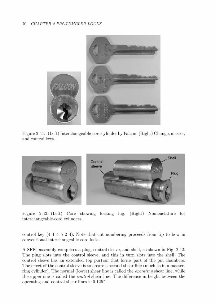
70 CHAPTER 2 PIN-TUMBLER LOCKS
Figure 2.41: (Left) Interchangeable-core cylinder by Falcon. (Right) Change, master,and control keys.
Controlsleeve
Shell
Plug
Figure 2.42: (Left) Core showing locking lug. (Right) Nomenclature forinterchangeable-core cylinders.
control key (4 1 4 5 2 4). Note that cut numbering proceeds from tip to bow inconventional interchangeable-core locks.
A SFIC assembly comprises a plug, control sleeve, and shell, as shown in Fig. 2.42.The plug slots into the control sleeve, and this in turn slots into the shell. Thecontrol sleeve has an extended top portion that forms part of the pin chambers.The effect of the control sleeve is to create a second shear line (much as in a master-ring cylinder). The normal (lower) shear line is called the operating shear line, whilethe upper one is called the control shear line. The difference in height between theoperating and control shear lines is 0.125 .
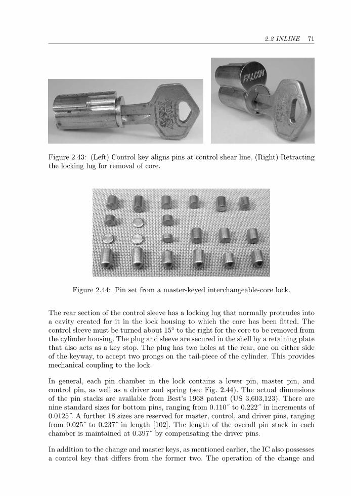
2.2 INLINE 71
Figure 2.43: (Left) Control key aligns pins at control shear line. (Right) Retractingthe locking lug for removal of core.
Figure 2.44: Pin set from a master-keyed interchangeable-core lock.
The rear section of the control sleeve has a locking lug that normally protrudes intoa cavity created for it in the lock housing to which the core has been fitted. Thecontrol sleeve must be turned about 15◦ to the right for the core to be removed fromthe cylinder housing. The plug and sleeve are secured in the shell by a retaining platethat also acts as a key stop. The plug has two holes at the rear, one on either sideof the keyway, to accept two prongs on the tail-piece of the cylinder. This providesmechanical coupling to the lock.
In general, each pin chamber in the lock contains a lower pin, master pin, andcontrol pin, as well as a driver and spring (see Fig. 2.44). The actual dimensionsof the pin stacks are available from Best’s 1968 patent (US 3,603,123). There arenine standard sizes for bottom pins, ranging from 0.110˝ to 0.222˝ in increments of0.0125 . A further 18 sizes are reserved for master, control, and driver pins, rangingfrom 0.025˝ to 0.237˝ in length [102]. The length of the overall pin stack in eachchamber is maintained at 0.397˝ by compensating the driver pins.
In addition to the change and master keys, as mentioned earlier, the IC also possessesa control key that differs from the former two. The operation of the change and
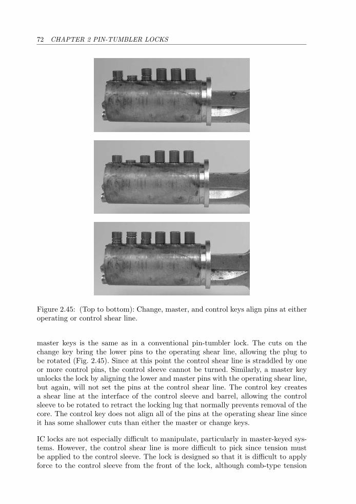
72 CHAPTER 2 PIN-TUMBLER LOCKS
Figure 2.45: (Top to bottom): Change, master, and control keys align pins at eitheroperating or control shear line.
master keys is the same as in a conventional pin-tumbler lock. The cuts on thechange key bring the lower pins to the operating shear line, allowing the plug tobe rotated (Fig. 2.45). Since at this point the control shear line is straddled by oneor more control pins, the control sleeve cannot be turned. Similarly, a master keyunlocks the lock by aligning the lower and master pins with the operating shear line,but again, will not set the pins at the control shear line. The control key createsa shear line at the interface of the control sleeve and barrel, allowing the controlsleeve to be rotated to retract the locking lug that normally prevents removal of thecore. The control key does not align all of the pins at the operating shear line sinceit has some shallower cuts than either the master or change keys.
IC locks are not especially difficult to manipulate, particularly in master-keyed sys-tems. However, the control shear line is more difficult to pick since tension mustbe applied to the control sleeve. The lock is designed so that it is difficult to applyforce to the control sleeve from the front of the lock, although comb-type tension
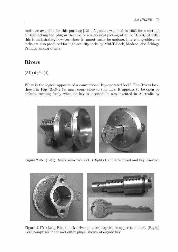
2.2 INLINE 73
tools are available for this purpose [121]. A patent was filed in 1963 for a methodof deadlocking the plug in the case of a successful picking attempt (US 3,181,320);this is undesirable, however, since it cannot easily be undone. Interchangeable-corelocks are also produced for high-security locks by Mul-T-Lock, Medeco, and SchlagePrimus, among others.
Rivers
(AU) 6-pin (4)
What is the logical opposite of a conventional key-operated lock? The Rivers lock,shown in Figs. 2.46–2.49, must come close to this idea. It appears to be open bydefault, turning freely when no key is inserted! It was invented in Australia by
Figure 2.46: (Left) Rivers key-drive lock. (Right) Handle removed and key inserted.
Figure 2.47: (Left) Rivers lock driver pins are captive in upper chambers. (Right)Core comprises inner and outer plugs, shown alongside key.
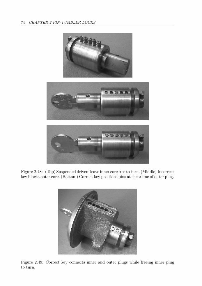
74 CHAPTER 2 PIN-TUMBLER LOCKS
Figure 2.48: (Top) Suspended drivers leave inner core free to turn. (Middle) Incorrectkey blocks outer core. (Bottom) Correct key positions pins at shear line of outer plug.
Figure 2.49: Correct key connects inner and outer plugs while freeing inner plugto turn.
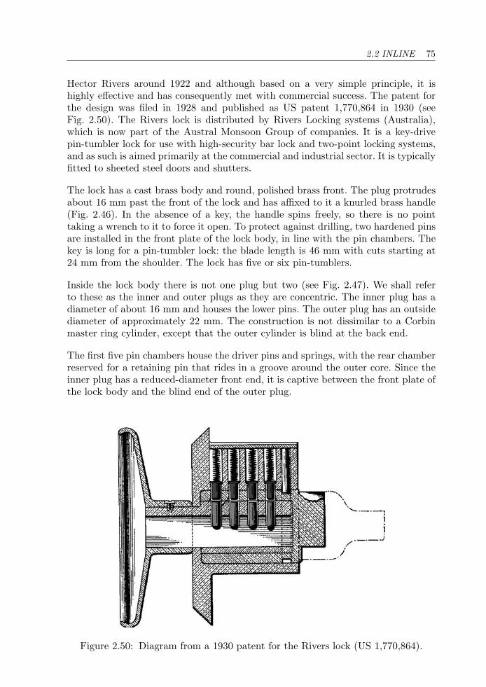
2.2 INLINE 75
Hector Rivers around 1922 and although based on a very simple principle, it ishighly effective and has consequently met with commercial success. The patent forthe design was filed in 1928 and published as US patent 1,770,864 in 1930 (seeFig. 2.50). The Rivers lock is distributed by Rivers Locking systems (Australia),which is now part of the Austral Monsoon Group of companies. It is a key-drivepin-tumbler lock for use with high-security bar lock and two-point locking systems,and as such is aimed primarily at the commercial and industrial sector. It is typicallyfitted to sheeted steel doors and shutters.
The lock has a cast brass body and round, polished brass front. The plug protrudesabout 16 mm past the front of the lock and has affixed to it a knurled brass handle(Fig. 2.46). In the absence of a key, the handle spins freely, so there is no pointtaking a wrench to it to force it open. To protect against drilling, two hardened pinsare installed in the front plate of the lock body, in line with the pin chambers. Thekey is long for a pin-tumbler lock: the blade length is 46 mm with cuts starting at24 mm from the shoulder. The lock has five or six pin-tumblers.
Inside the lock body there is not one plug but two (see Fig. 2.47). We shall referto these as the inner and outer plugs as they are concentric. The inner plug has adiameter of about 16 mm and houses the lower pins. The outer plug has an outsidediameter of approximately 22 mm. The construction is not dissimilar to a Corbinmaster ring cylinder, except that the outer cylinder is blind at the back end.
The first five pin chambers house the driver pins and springs, with the rear chamberreserved for a retaining pin that rides in a groove around the outer core. Since theinner plug has a reduced-diameter front end, it is captive between the front plate ofthe lock body and the blind end of the outer plug.
Figure 2.50: Diagram from a 1930 patent for the Rivers lock (US 1,770,864).
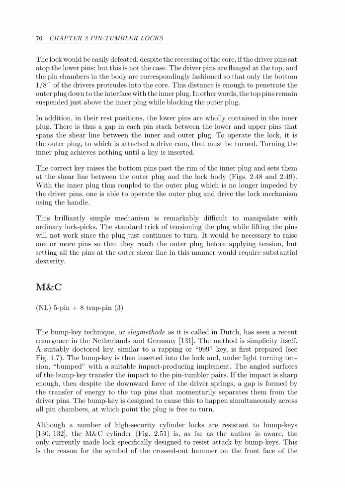
76 CHAPTER 2 PIN-TUMBLER LOCKS
The lock would be easily defeated, despite the recessing of the core, if the driver pins satatop the lower pins; but this is not the case. The driver pins are flanged at the top, andthe pin chambers in the body are correspondingly fashioned so that only the bottom1/8˝ of the drivers protrudes into the core. This distance is enough to penetrate theouter plugdown to the interfacewith the inner plug. In otherwords, the toppins remainsuspended just above the inner plug while blocking the outer plug.
In addition, in their rest positions, the lower pins are wholly contained in the innerplug. There is thus a gap in each pin stack between the lower and upper pins thatspans the shear line between the inner and outer plug. To operate the lock, it isthe outer plug, to which is attached a drive cam, that must be turned. Turning theinner plug achieves nothing until a key is inserted.
The correct key raises the bottom pins past the rim of the inner plug and sets themat the shear line between the outer plug and the lock body (Figs. 2.48 and 2.49).With the inner plug thus coupled to the outer plug which is no longer impeded bythe driver pins, one is able to operate the outer plug and drive the lock mechanismusing the handle.
This brilliantly simple mechanism is remarkably difficult to manipulate withordinary lock-picks. The standard trick of tensioning the plug while lifting the pinswill not work since the plug just continues to turn. It would be necessary to raiseone or more pins so that they reach the outer plug before applying tension, butsetting all the pins at the outer shear line in this manner would require substantialdexterity.
M&C
(NL) 5-pin + 8 trap-pin (3)
The bump-key technique, or slagmethode as it is called in Dutch, has seen a recentresurgence in the Netherlands and Germany [131]. The method is simplicity itself.A suitably doctored key, similar to a rapping or “999” key, is first prepared (seeFig. 1.7). The bump-key is then inserted into the lock and, under light turning ten-sion, “bumped” with a suitable impact-producing implement. The angled surfacesof the bump-key transfer the impact to the pin-tumbler pairs. If the impact is sharpenough, then despite the downward force of the driver springs, a gap is formed bythe transfer of energy to the top pins that momentarily separates them from thedriver pins. The bump-key is designed to cause this to happen simultaneously acrossall pin chambers, at which point the plug is free to turn.
Although a number of high-security cylinder locks are resistant to bump-keys[130, 132], the M&C cylinder (Fig. 2.51) is, as far as the author is aware, theonly currently made lock specifically designed to resist attack by bump-keys. Thisis the reason for the symbol of the crossed-out hammer on the front face of the
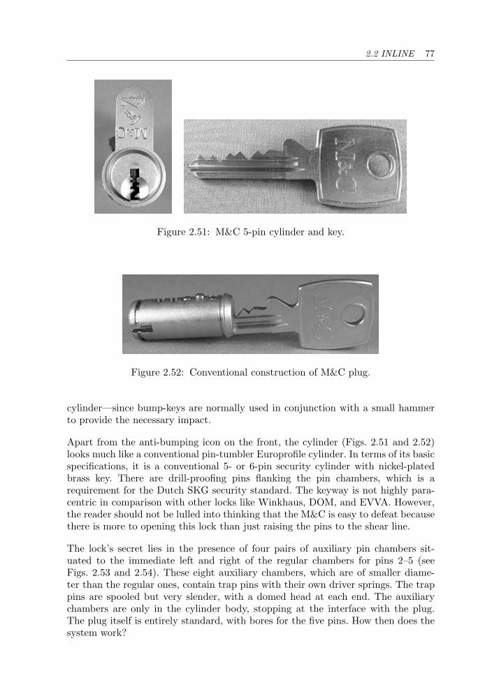
2.2 INLINE 77
Figure 2.51: M&C 5-pin cylinder and key.
Figure 2.52: Conventional construction of M&C plug.
cylinder—since bump-keys are normally used in conjunction with a small hammerto provide the necessary impact.
Apart from the anti-bumping icon on the front, the cylinder (Figs. 2.51 and 2.52)looks much like a conventional pin-tumbler Europrofile cylinder. In terms of its basicspecifications, it is a conventional 5- or 6-pin security cylinder with nickel-platedbrass key. There are drill-proofing pins flanking the pin chambers, which is arequirement for the Dutch SKG security standard. The keyway is not highly para-centric in comparison with other locks like Winkhaus, DOM, and EVVA. However,the reader should not be lulled into thinking that the M&C is easy to defeat becausethere is more to opening this lock than just raising the pins to the shear line.
The lock’s secret lies in the presence of four pairs of auxiliary pin chambers sit-uated to the immediate left and right of the regular chambers for pins 2–5 (seeFigs. 2.53 and 2.54). These eight auxiliary chambers, which are of smaller diame-ter than the regular ones, contain trap pins with their own driver springs. The trappins are spooled but very slender, with a domed head at each end. The auxiliarychambers are only in the cylinder body, stopping at the interface with the plug.The plug itself is entirely standard, with bores for the five pins. How then does thesystem work?
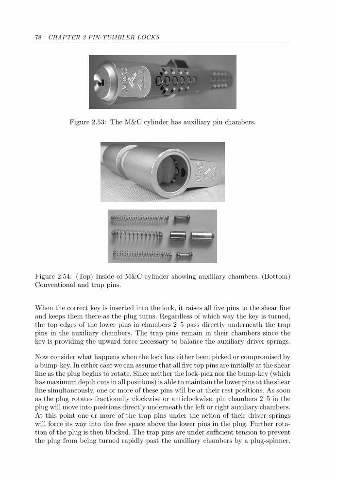
78 CHAPTER 2 PIN-TUMBLER LOCKS
Figure 2.53: The M&C cylinder has auxiliary pin chambers.
Figure 2.54: (Top) Inside of M&C cylinder showing auxiliary chambers. (Bottom)Conventional and trap pins.
When the correct key is inserted into the lock, it raises all five pins to the shear lineand keeps them there as the plug turns. Regardless of which way the key is turned,the top edges of the lower pins in chambers 2–5 pass directly underneath the trappins in the auxiliary chambers. The trap pins remain in their chambers since thekey is providing the upward force necessary to balance the auxiliary driver springs.
Now consider what happens when the lock has either been picked or compromised bya bump-key. In either case we can assume that all five top pins are initially at the shearline as the plug begins to rotate. Since neither the lock-pick nor the bump-key (whichhas maximum depth cuts in all positions) is able to maintain the lower pins at the shearline simultaneously, one or more of these pins will be at their rest positions. As soonas the plug rotates fractionally clockwise or anticlockwise, pin chambers 2–5 in theplug will move into positions directly underneath the left or right auxiliary chambers.At this point one or more of the trap pins under the action of their driver springswill force its way into the free space above the lower pins in the plug. Further rota-tion of the plug is then blocked. The trap pins are under sufficient tension to preventthe plug from being turned rapidly past the auxiliary chambers by a plug-spinner.
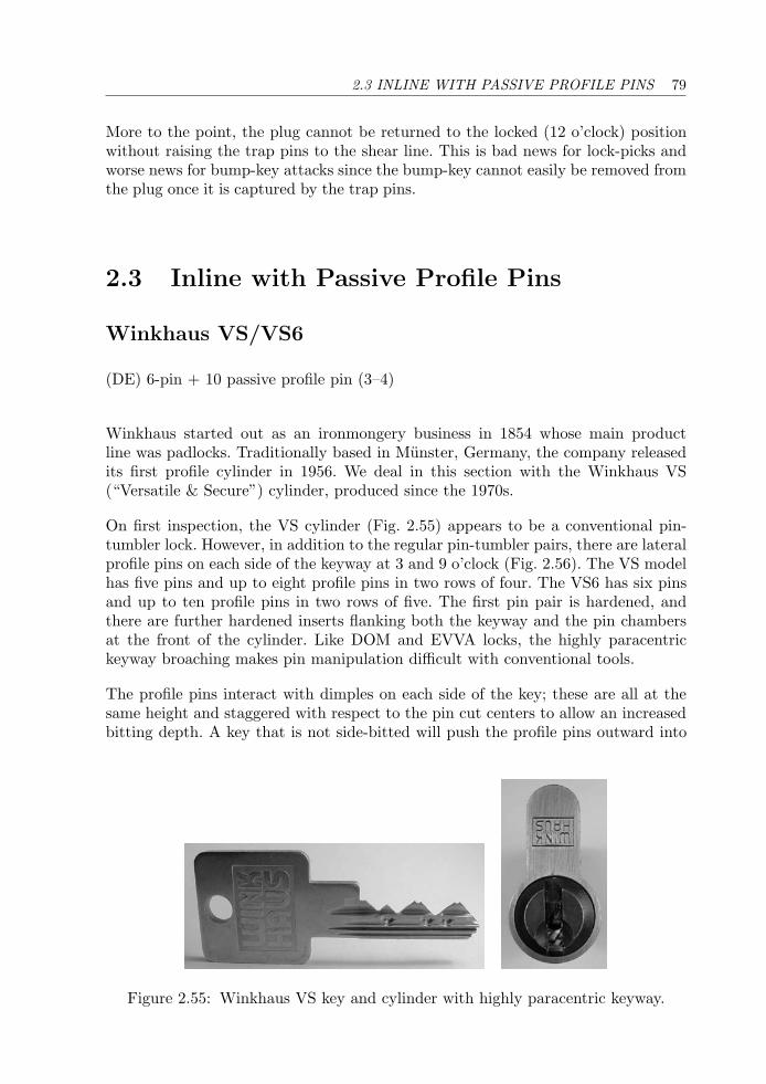
2.3 INLINE WITH PASSIVE PROFILE PINS 79
More to the point, the plug cannot be returned to the locked (12 o’clock) positionwithout raising the trap pins to the shear line. This is bad news for lock-picks andworse news for bump-key attacks since the bump-key cannot easily be removed fromthe plug once it is captured by the trap pins.
2.3 Inline with Passive Profile Pins
Winkhaus VS/VS6
(DE) 6-pin + 10 passive profile pin (3–4)
Winkhaus started out as an ironmongery business in 1854 whose main productline was padlocks. Traditionally based in Munster, Germany, the company releasedits first profile cylinder in 1956. We deal in this section with the Winkhaus VS(“Versatile & Secure”) cylinder, produced since the 1970s.
On first inspection, the VS cylinder (Fig. 2.55) appears to be a conventional pin-tumbler lock. However, in addition to the regular pin-tumbler pairs, there are lateralprofile pins on each side of the keyway at 3 and 9 o’clock (Fig. 2.56). The VS modelhas five pins and up to eight profile pins in two rows of four. The VS6 has six pinsand up to ten profile pins in two rows of five. The first pin pair is hardened, andthere are further hardened inserts flanking both the keyway and the pin chambersat the front of the cylinder. Like DOM and EVVA locks, the highly paracentrickeyway broaching makes pin manipulation difficult with conventional tools.
The profile pins interact with dimples on each side of the key; these are all at thesame height and staggered with respect to the pin cut centers to allow an increasedbitting depth. A key that is not side-bitted will push the profile pins outward into
Figure 2.55: Winkhaus VS key and cylinder with highly paracentric keyway.
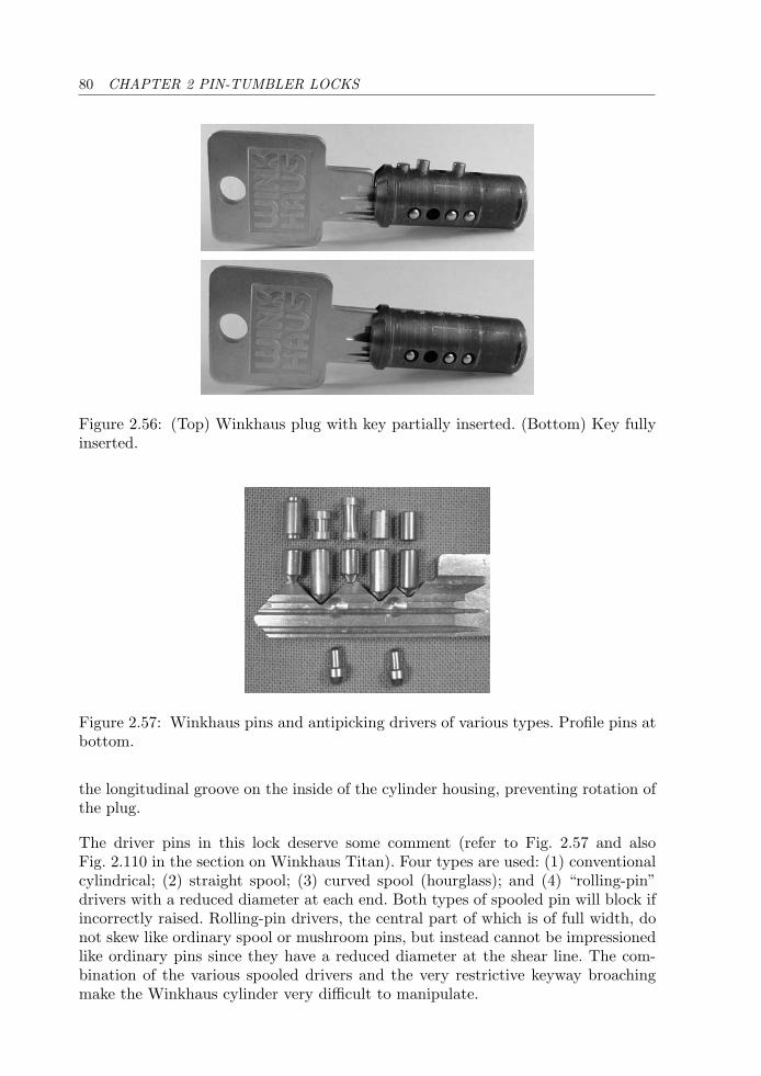
80 CHAPTER 2 PIN-TUMBLER LOCKS
Figure 2.56: (Top) Winkhaus plug with key partially inserted. (Bottom) Key fullyinserted.
Figure 2.57: Winkhaus pins and antipicking drivers of various types. Profile pins atbottom.
the longitudinal groove on the inside of the cylinder housing, preventing rotation ofthe plug.
The driver pins in this lock deserve some comment (refer to Fig. 2.57 and alsoFig. 2.110 in the section on Winkhaus Titan). Four types are used: (1) conventionalcylindrical; (2) straight spool; (3) curved spool (hourglass); and (4) “rolling-pin”drivers with a reduced diameter at each end. Both types of spooled pin will block ifincorrectly raised. Rolling-pin drivers, the central part of which is of full width, donot skew like ordinary spool or mushroom pins, but instead cannot be impressionedlike ordinary pins since they have a reduced diameter at the shear line. The com-bination of the various spooled drivers and the very restrictive keyway broachingmake the Winkhaus cylinder very difficult to manipulate.
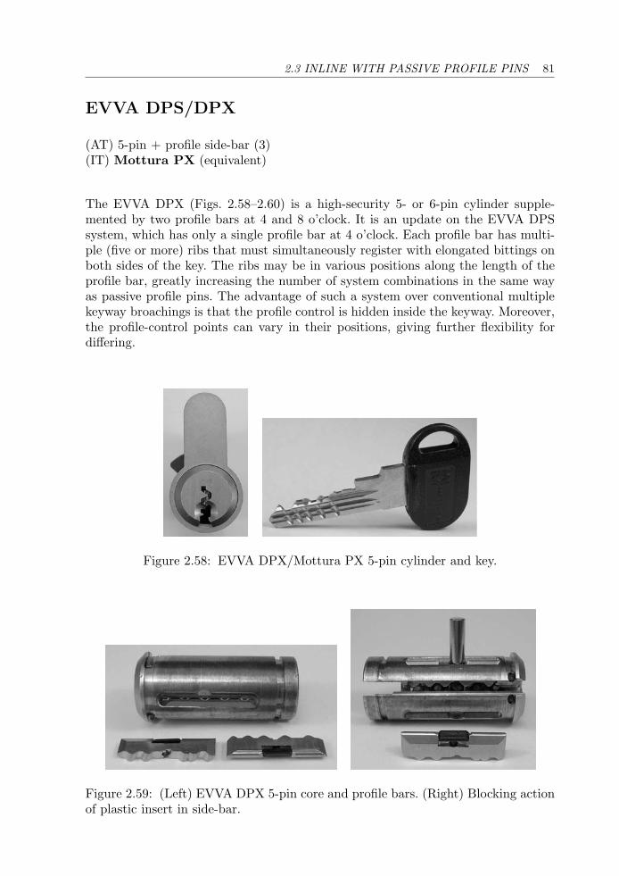
2.3 INLINE WITH PASSIVE PROFILE PINS 81
EVVA DPS/DPX
(AT) 5-pin + profile side-bar (3)(IT) Mottura PX (equivalent)
The EVVA DPX (Figs. 2.58–2.60) is a high-security 5- or 6-pin cylinder supple-mented by two profile bars at 4 and 8 o’clock. It is an update on the EVVA DPSsystem, which has only a single profile bar at 4 o’clock. Each profile bar has multi-ple (five or more) ribs that must simultaneously register with elongated bittings onboth sides of the key. The ribs may be in various positions along the length of theprofile bar, greatly increasing the number of system combinations in the same wayas passive profile pins. The advantage of such a system over conventional multiplekeyway broachings is that the profile control is hidden inside the keyway. Moreover,the profile-control points can vary in their positions, giving further flexibility fordiffering.
Figure 2.58: EVVA DPX/Mottura PX 5-pin cylinder and key.
Figure 2.59: (Left) EVVA DPX 5-pin core and profile bars. (Right) Blocking actionof plastic insert in side-bar.
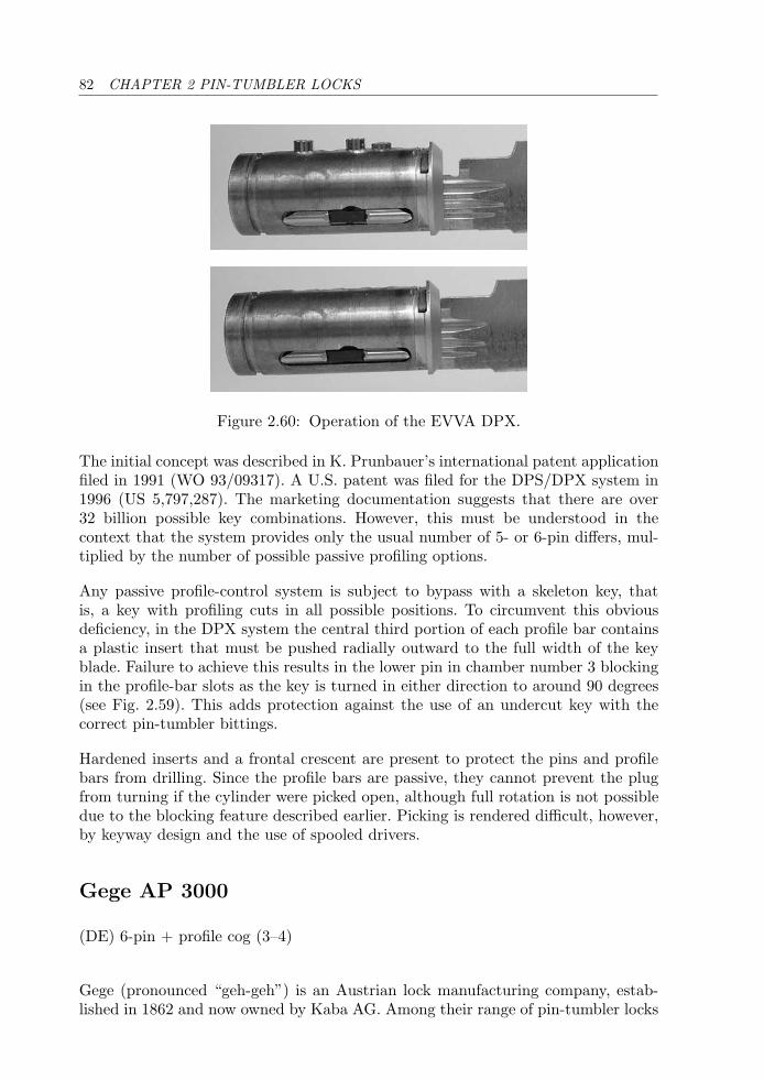
82 CHAPTER 2 PIN-TUMBLER LOCKS
Figure 2.60: Operation of the EVVA DPX.
The initial concept was described in K. Prunbauer’s international patent applicationfiled in 1991 (WO 93/09317). A U.S. patent was filed for the DPS/DPX system in1996 (US 5,797,287). The marketing documentation suggests that there are over32 billion possible key combinations. However, this must be understood in thecontext that the system provides only the usual number of 5- or 6-pin differs, mul-tiplied by the number of possible passive profiling options.
Any passive profile-control system is subject to bypass with a skeleton key, thatis, a key with profiling cuts in all possible positions. To circumvent this obviousdeficiency, in the DPX system the central third portion of each profile bar containsa plastic insert that must be pushed radially outward to the full width of the keyblade. Failure to achieve this results in the lower pin in chamber number 3 blockingin the profile-bar slots as the key is turned in either direction to around 90 degrees(see Fig. 2.59). This adds protection against the use of an undercut key with thecorrect pin-tumbler bittings.
Hardened inserts and a frontal crescent are present to protect the pins and profilebars from drilling. Since the profile bars are passive, they cannot prevent the plugfrom turning if the cylinder were picked open, although full rotation is not possibledue to the blocking feature described earlier. Picking is rendered difficult, however,by keyway design and the use of spooled drivers.
Gege AP 3000
(DE) 6-pin + profile cog (3–4)
Gege (pronounced “geh-geh”) is an Austrian lock manufacturing company, estab-lished in 1862 and now owned by Kaba AG. Among their range of pin-tumbler locks
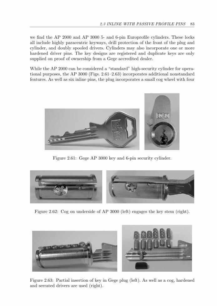
2.3 INLINE WITH PASSIVE PROFILE PINS 83
we find the AP 2000 and AP 3000 5- and 6-pin Europrofile cylinders. These locksall include highly paracentric keyways, drill protection of the front of the plug andcylinder, and doubly spooled drivers. Cylinders may also incorporate one or morehardened driver pins. The key designs are registered and duplicate keys are onlysupplied on proof of ownership from a Gege accredited dealer.
While the AP 2000 can be considered a “standard” high-security cylinder for opera-tional purposes, the AP 3000 (Figs. 2.61–2.63) incorporates additional nonstandardfeatures. As well as six inline pins, the plug incorporates a small cog wheel with four
Figure 2.61: Gege AP 3000 key and 6-pin security cylinder.
Figure 2.62: Cog on underside of AP 3000 (left) engages the key stem (right).
Figure 2.63: Partial insertion of key in Gege plug (left). As well as a cog, hardenedand serrated drivers are used (right).
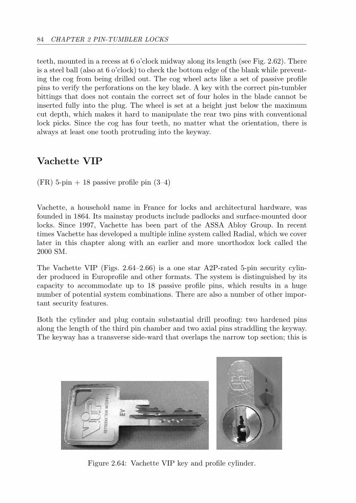
84 CHAPTER 2 PIN-TUMBLER LOCKS
teeth, mounted in a recess at 6 o’clock midway along its length (see Fig. 2.62). Thereis a steel ball (also at 6 o’clock) to check the bottom edge of the blank while prevent-ing the cog from being drilled out. The cog wheel acts like a set of passive profilepins to verify the perforations on the key blade. A key with the correct pin-tumblerbittings that does not contain the correct set of four holes in the blade cannot beinserted fully into the plug. The wheel is set at a height just below the maximumcut depth, which makes it hard to manipulate the rear two pins with conventionallock picks. Since the cog has four teeth, no matter what the orientation, there isalways at least one tooth protruding into the keyway.
Vachette VIP
(FR) 5-pin + 18 passive profile pin (3–4)
Vachette, a household name in France for locks and architectural hardware, wasfounded in 1864. Its mainstay products include padlocks and surface-mounted doorlocks. Since 1997, Vachette has been part of the ASSA Abloy Group. In recenttimes Vachette has developed a multiple inline system called Radial, which we coverlater in this chapter along with an earlier and more unorthodox lock called the2000 SM.
The Vachette VIP (Figs. 2.64–2.66) is a one star A2P-rated 5-pin security cylin-der produced in Europrofile and other formats. The system is distinguished by itscapacity to accommodate up to 18 passive profile pins, which results in a hugenumber of potential system combinations. There are also a number of other impor-tant security features.
Both the cylinder and plug contain substantial drill proofing: two hardened pinsalong the length of the third pin chamber and two axial pins straddling the keyway.The keyway has a transverse side-ward that overlaps the narrow top section; this is
Figure 2.64: Vachette VIP key and profile cylinder.
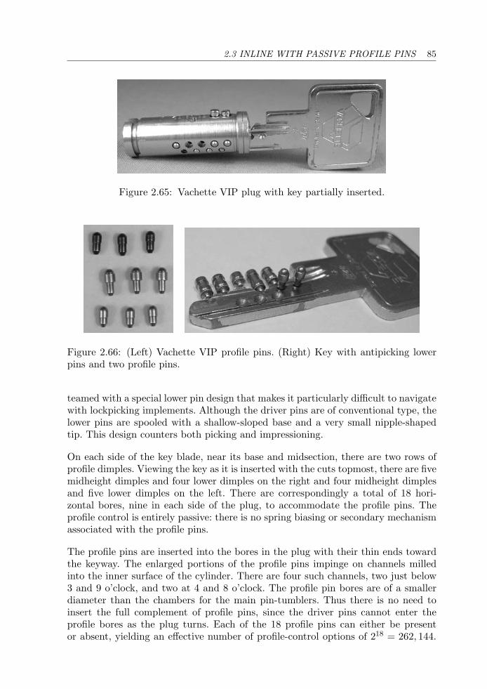
2.3 INLINE WITH PASSIVE PROFILE PINS 85
Figure 2.65: Vachette VIP plug with key partially inserted.
Figure 2.66: (Left) Vachette VIP profile pins. (Right) Key with antipicking lowerpins and two profile pins.
teamed with a special lower pin design that makes it particularly difficult to navigatewith lockpicking implements. Although the driver pins are of conventional type, thelower pins are spooled with a shallow-sloped base and a very small nipple-shapedtip. This design counters both picking and impressioning.
On each side of the key blade, near its base and midsection, there are two rows ofprofile dimples. Viewing the key as it is inserted with the cuts topmost, there are fivemidheight dimples and four lower dimples on the right and four midheight dimplesand five lower dimples on the left. There are correspondingly a total of 18 hori-zontal bores, nine in each side of the plug, to accommodate the profile pins. Theprofile control is entirely passive: there is no spring biasing or secondary mechanismassociated with the profile pins.
The profile pins are inserted into the bores in the plug with their thin ends towardthe keyway. The enlarged portions of the profile pins impinge on channels milledinto the inner surface of the cylinder. There are four such channels, two just below3 and 9 o’clock, and two at 4 and 8 o’clock. The profile pin bores are of a smallerdiameter than the chambers for the main pin-tumblers. Thus there is no need toinsert the full complement of profile pins, since the driver pins cannot enter theprofile bores as the plug turns. Each of the 18 profile pins can either be presentor absent, yielding an effective number of profile-control options of 218 = 262, 144.
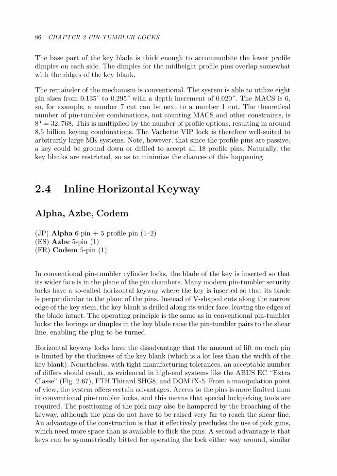
86 CHAPTER 2 PIN-TUMBLER LOCKS
The base part of the key blade is thick enough to accommodate the lower profiledimples on each side. The dimples for the midheight profile pins overlap somewhatwith the ridges of the key blank.
The remainder of the mechanism is conventional. The system is able to utilize eightpin sizes from 0.135˝ to 0.295˝ with a depth increment of 0.020˝. The MACS is 6,so, for example, a number 7 cut can be next to a number 1 cut. The theoreticalnumber of pin-tumbler combinations, not counting MACS and other constraints, is85 = 32, 768. This is multiplied by the number of profile options, resulting in around8.5 billion keying combinations. The Vachette VIP lock is therefore well-suited toarbitrarily large MK systems. Note, however, that since the profile pins are passive,a key could be ground down or drilled to accept all 18 profile pins. Naturally, thekey blanks are restricted, so as to minimize the chances of this happening.
2.4 Inline Horizontal Keyway
Alpha, Azbe, Codem
(JP) Alpha 6-pin + 5 profile pin (1–2)(ES) Azbe 5-pin (1)(FR) Codem 5-pin (1)
In conventional pin-tumbler cylinder locks, the blade of the key is inserted so thatits wider face is in the plane of the pin chambers. Many modern pin-tumbler securitylocks have a so-called horizontal keyway where the key is inserted so that its bladeis perpendicular to the plane of the pins. Instead of V-shaped cuts along the narrowedge of the key stem, the key blank is drilled along its wider face, leaving the edges ofthe blade intact. The operating principle is the same as in conventional pin-tumblerlocks: the borings or dimples in the key blade raise the pin-tumbler pairs to the shearline, enabling the plug to be turned.
Horizontal keyway locks have the disadvantage that the amount of lift on each pinis limited by the thickness of the key blank (which is a lot less than the width of thekey blank). Nonetheless, with tight manufacturing tolerances, an acceptable numberof differs should result, as evidenced in high-end systems like the ABUS EC “ExtraClasse” (Fig. 2.67), FTH Thirard SHG8, and DOM iX-5. From a manipulation pointof view, the system offers certain advantages. Access to the pins is more limited thanin conventional pin-tumbler locks, and this means that special lockpicking tools arerequired. The positioning of the pick may also be hampered by the broaching of thekeyway, although the pins do not have to be raised very far to reach the shear line.An advantage of the construction is that it effectively precludes the use of pick guns,which need more space than is available to flick the pins. A second advantage is thatkeys can be symmetrically bitted for operating the lock either way around, similar
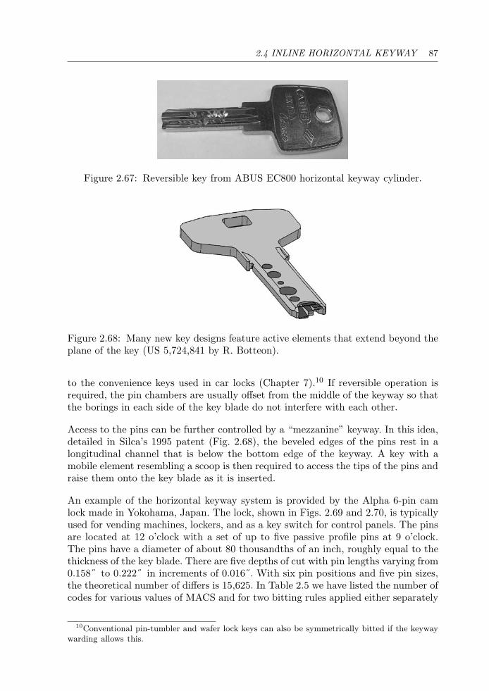
2.4 INLINE HORIZONTAL KEYWAY 87
Figure 2.67: Reversible key from ABUS EC800 horizontal keyway cylinder.
Figure 2.68: Many new key designs feature active elements that extend beyond theplane of the key (US 5,724,841 by R. Botteon).
to the convenience keys used in car locks (Chapter 7).10 If reversible operation isrequired, the pin chambers are usually offset from the middle of the keyway so thatthe borings in each side of the key blade do not interfere with each other.
Access to the pins can be further controlled by a “mezzanine” keyway. In this idea,detailed in Silca’s 1995 patent (Fig. 2.68), the beveled edges of the pins rest in alongitudinal channel that is below the bottom edge of the keyway. A key with amobile element resembling a scoop is then required to access the tips of the pins andraise them onto the key blade as it is inserted.
An example of the horizontal keyway system is provided by the Alpha 6-pin camlock made in Yokohama, Japan. The lock, shown in Figs. 2.69 and 2.70, is typicallyused for vending machines, lockers, and as a key switch for control panels. The pinsare located at 12 o’clock with a set of up to five passive profile pins at 9 o’clock.The pins have a diameter of about 80 thousandths of an inch, roughly equal to thethickness of the key blade. There are five depths of cut with pin lengths varying from0.158˝ to 0.222˝ in increments of 0.016˝. With six pin positions and five pin sizes,the theoretical number of differs is 15,625. In Table 2.5 we have listed the number ofcodes for various values of MACS and for two bitting rules applied either separately
10Conventional pin-tumbler and wafer lock keys can also be symmetrically bitted if the keywaywarding allows this.
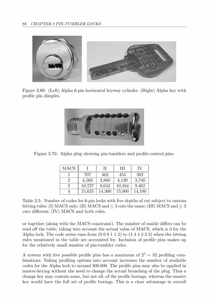
88 CHAPTER 2 PIN-TUMBLER LOCKS
Figure 2.69: (Left) Alpha 6-pin horizontal keyway cylinder. (Right) Alpha key withprofile pin dimples.
Figure 2.70: Alpha plug showing pin-tumblers and profile-control pins.
MACS I II III IV1 707 462 454 3822 4,569 3,880 4,130 3,7403 10,727 9,642 10,164 9,4624 15,625 14,300 15,000 14,100
Table 2.5: Number of codes for 6-pin locks with five depths of cut subject to variousbitting rules: (I) MACS only; (II) MACS and ≤ 3 cuts the same; (III) MACS and ≥ 3cuts different; (IV) MACS and both rules.
or together (along with the MACS constraint). The number of usable differs can beread off the table, taking into account the actual value of MACS, which is 3 for theAlpha lock. The code series runs from (0 0 0 1 1 2) to (4 4 4 3 3 2) when the bittingrules mentioned in the table are accounted for. Inclusion of profile pins makes upfor the relatively small number of pin-tumbler codes.
A system with five possible profile pins has a maximum of 25 = 32 profiling com-binations. Taking profiling options into account increases the number of availablecodes for the Alpha lock to around 300,000. The profile pins may also be applied inmaster-keying without the need to change the actual broaching of the plug. Thus achange key may contain some, but not all, of the profile borings, whereas the masterkey would have the full set of profile borings. This is a clear advantage in overall
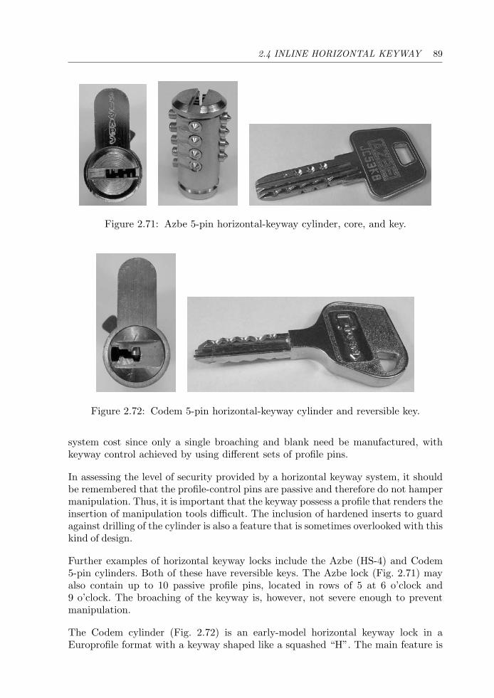
2.4 INLINE HORIZONTAL KEYWAY 89
Figure 2.71: Azbe 5-pin horizontal-keyway cylinder, core, and key.
Figure 2.72: Codem 5-pin horizontal-keyway cylinder and reversible key.
system cost since only a single broaching and blank need be manufactured, withkeyway control achieved by using different sets of profile pins.
In assessing the level of security provided by a horizontal keyway system, it shouldbe remembered that the profile-control pins are passive and therefore do not hampermanipulation. Thus, it is important that the keyway possess a profile that renders theinsertion of manipulation tools difficult. The inclusion of hardened inserts to guardagainst drilling of the cylinder is also a feature that is sometimes overlooked with thiskind of design.
Further examples of horizontal keyway locks include the Azbe (HS-4) and Codem5-pin cylinders. Both of these have reversible keys. The Azbe lock (Fig. 2.71) mayalso contain up to 10 passive profile pins, located in rows of 5 at 6 o’clock and9 o’clock. The broaching of the keyway is, however, not severe enough to preventmanipulation.
The Codem cylinder (Fig. 2.72) is an early-model horizontal keyway lock in aEuroprofile format with a keyway shaped like a squashed “H”. The main feature is
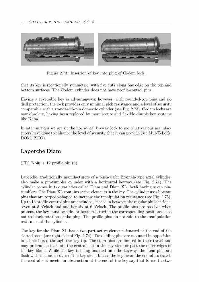
90 CHAPTER 2 PIN-TUMBLER LOCKS
Figure 2.73: Insertion of key into plug of Codem lock.
that its key is rotationally symmetric, with five cuts along one edge on the top andbottom surfaces. The Codem cylinder does not have profile-control pins.
Having a reversible key is advantageous; however, with rounded-top pins and nodrill protection, the lock provides only minimal pick resistance and a level of securitycomparable with a standard 5-pin domestic cylinder (see Fig. 2.73). Codem locks arenow obsolete, having been replaced by more secure and flexible dimple key systemslike Kaba.
In later sections we revisit the horizontal keyway lock to see what various manufac-turers have done to enhance the level of security that it can provide (see Mul-T-Lock,DOM, ISEO).
Laperche Diam
(FR) 7-pin + 12 profile pin (3)
Laperche, traditionally manufacturers of a push-wafer Bramah-type axial cylinder,also make a pin-tumbler cylinder with a horizontal keyway (see Fig. 2.74). Thecylinder comes in two varieties called Diam and Diam XL, both having seven pin-tumblers. The Diam XL contains active elements in the key. The cylinder uses bottompins that are torpedo-shaped to increase the manipulation resistance (see Fig. 2.75).Up to 13 profile-control pins are included, spaced in between the regular pin locations:seven at 3 o’clock and another six at 6 o’clock. The profile pins are passive: whenpresent, the key must be side- or bottom-bitted in the corresponding positions so asnot to block rotation of the plug. The profile pins do not add to the manipulationresistance of the cylinder.
The key for the Diam XL has a two-part active element situated at the end of theslotted stem (see right side of Fig. 2.74). Two sliding pins are mounted in oppositionin a hole bored through the key tip. The stem pins are limited in their travel andmay protrude either into the central slot in the key stem or past the outer edges ofthe key blade. While the key is being inserted into the keyway, the stem pins areflush with the outer edges of the key stem, but as the key nears the end of its travel,the central slot meets an obstruction at the end of the keyway that forces the two
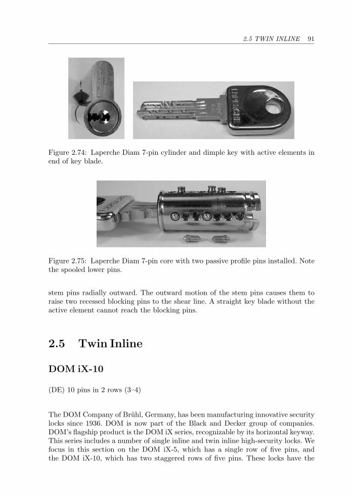
2.5 TWIN INLINE 91
Figure 2.74: Laperche Diam 7-pin cylinder and dimple key with active elements inend of key blade.
Figure 2.75: Laperche Diam 7-pin core with two passive profile pins installed. Notethe spooled lower pins.
stem pins radially outward. The outward motion of the stem pins causes them toraise two recessed blocking pins to the shear line. A straight key blade without theactive element cannot reach the blocking pins.
2.5 Twin Inline
DOM iX-10
(DE) 10 pins in 2 rows (3–4)
The DOM Company of Bruhl, Germany, has been manufacturing innovative securitylocks since 1936. DOM is now part of the Black and Decker group of companies.DOM’s flagship product is the DOM iX series, recognizable by its horizontal keyway.This series includes a number of single inline and twin inline high-security locks. Wefocus in this section on the DOM iX-5, which has a single row of five pins, andthe DOM iX-10, which has two staggered rows of five pins. These locks have the
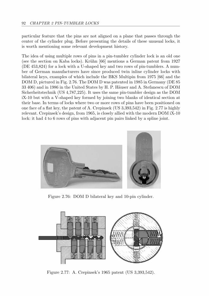
92 CHAPTER 2 PIN-TUMBLER LOCKS
particular feature that the pins are not aligned on a plane that passes through thecenter of the cylinder plug. Before presenting the details of these unusual locks, itis worth mentioning some relevant development history.
The idea of using multiple rows of pins in a pin-tumbler cylinder lock is an old one(see the section on Kaba locks). Kruhn [66] mentions a German patent from 1927(DE 453,824) for a lock with a U-shaped key and two rows of pin-tumblers. A num-ber of German manufacturers have since produced twin inline cylinder locks withbilateral keys, examples of which include the BKS Multipin from 1975 [66] and theDOM D, pictured in Fig. 2.76. The DOM D was patented in 1985 in Germany (DE 8533 406) and in 1986 in the United States by H. P. Hauser and A. Stefanescu of DOMSicherheitstechnik (US 4,787,225). It uses the same pin-tumbler design as the DOMiX-10 but with a V-shaped key formed by joining two blanks of identical section attheir base. In terms of locks where two or more rows of pins have been positioned onone face of a flat key, the patent of A. Crepinsek (US 3,393,542) in Fig. 2.77 is highlyrelevant. Crepinsek’s design, from 1965, is closely allied with the modern DOM iX-10lock: it had 4 to 6 rows of pins with adjacent pin pairs linked by a spline joint.
Figure 2.76: DOM D bilateral key and 10-pin cylinder.
Figure 2.77: A. Crepinsek’s 1965 patent (US 3,393,542).
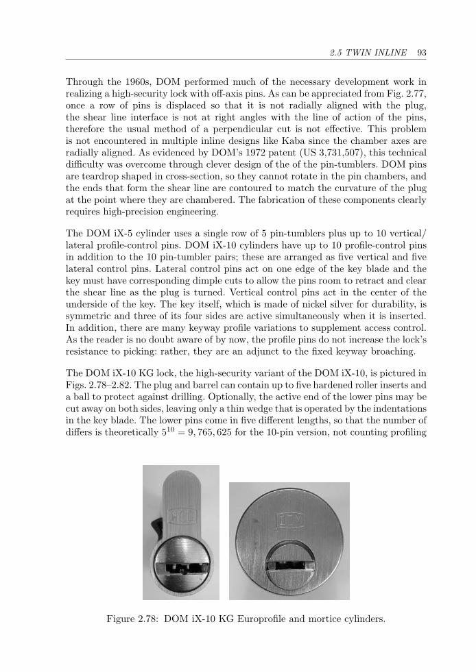
2.5 TWIN INLINE 93
Through the 1960s, DOM performed much of the necessary development work inrealizing a high-security lock with off-axis pins. As can be appreciated from Fig. 2.77,once a row of pins is displaced so that it is not radially aligned with the plug,the shear line interface is not at right angles with the line of action of the pins,therefore the usual method of a perpendicular cut is not effective. This problemis not encountered in multiple inline designs like Kaba since the chamber axes areradially aligned. As evidenced by DOM’s 1972 patent (US 3,731,507), this technicaldifficulty was overcome through clever design of the of the pin-tumblers. DOM pinsare teardrop shaped in cross-section, so they cannot rotate in the pin chambers, andthe ends that form the shear line are contoured to match the curvature of the plugat the point where they are chambered. The fabrication of these components clearlyrequires high-precision engineering.
The DOM iX-5 cylinder uses a single row of 5 pin-tumblers plus up to 10 vertical/lateral profile-control pins. DOM iX-10 cylinders have up to 10 profile-control pinsin addition to the 10 pin-tumbler pairs; these are arranged as five vertical and fivelateral control pins. Lateral control pins act on one edge of the key blade and thekey must have corresponding dimple cuts to allow the pins room to retract and clearthe shear line as the plug is turned. Vertical control pins act in the center of theunderside of the key. The key itself, which is made of nickel silver for durability, issymmetric and three of its four sides are active simultaneously when it is inserted.In addition, there are many keyway profile variations to supplement access control.As the reader is no doubt aware of by now, the profile pins do not increase the lock’sresistance to picking: rather, they are an adjunct to the fixed keyway broaching.
The DOM iX-10 KG lock, the high-security variant of the DOM iX-10, is pictured inFigs. 2.78–2.82. The plug and barrel can contain up to five hardened roller inserts anda ball to protect against drilling. Optionally, the active end of the lower pins may becut away on both sides, leaving only a thin wedge that is operated by the indentationsin the key blade. The lower pins come in five different lengths, so that the number ofdiffers is theoretically 510 = 9, 765, 625 for the 10-pin version, not counting profiling
Figure 2.78: DOM iX-10 KG Europrofile and mortice cylinders.
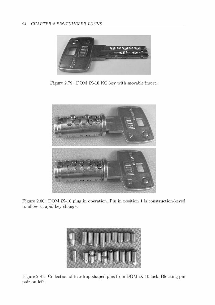
94 CHAPTER 2 PIN-TUMBLER LOCKS
Figure 2.79: DOM iX-10 KG key with movable insert.
Figure 2.80: DOM iX-10 plug in operation. Pin in position 1 is construction-keyedto allow a rapid key change.
Figure 2.81: Collection of teardrop-shaped pins from DOM iX-10 lock. Blocking pinpair on left.
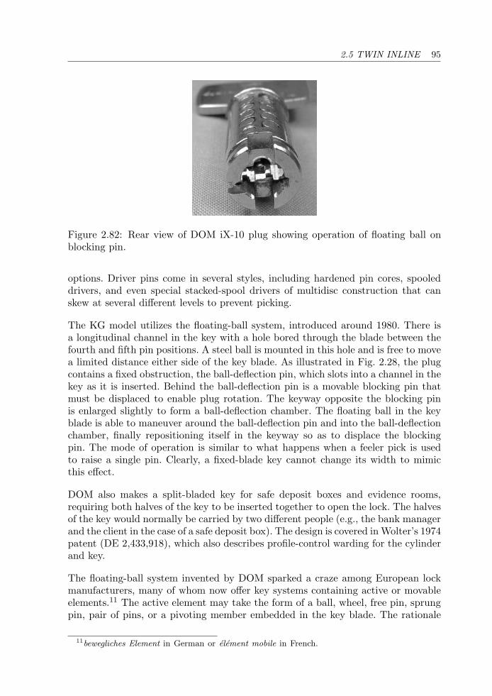
2.5 TWIN INLINE 95
Figure 2.82: Rear view of DOM iX-10 plug showing operation of floating ball onblocking pin.
options. Driver pins come in several styles, including hardened pin cores, spooleddrivers, and even special stacked-spool drivers of multidisc construction that canskew at several different levels to prevent picking.
The KG model utilizes the floating-ball system, introduced around 1980. There isa longitudinal channel in the key with a hole bored through the blade between thefourth and fifth pin positions. A steel ball is mounted in this hole and is free to movea limited distance either side of the key blade. As illustrated in Fig. 2.28, the plugcontains a fixed obstruction, the ball-deflection pin, which slots into a channel in thekey as it is inserted. Behind the ball-deflection pin is a movable blocking pin thatmust be displaced to enable plug rotation. The keyway opposite the blocking pinis enlarged slightly to form a ball-deflection chamber. The floating ball in the keyblade is able to maneuver around the ball-deflection pin and into the ball-deflectionchamber, finally repositioning itself in the keyway so as to displace the blockingpin. The mode of operation is similar to what happens when a feeler pick is usedto raise a single pin. Clearly, a fixed-blade key cannot change its width to mimicthis effect.
DOM also makes a split-bladed key for safe deposit boxes and evidence rooms,requiring both halves of the key to be inserted together to open the lock. The halvesof the key would normally be carried by two different people (e.g., the bank managerand the client in the case of a safe deposit box). The design is covered in Wolter’s 1974patent (DE 2,433,918), which also describes profile-control warding for the cylinderand key.
The floating-ball system invented by DOM sparked a craze among European lockmanufacturers, many of whom now offer key systems containing active or movableelements.11 The active element may take the form of a ball, wheel, free pin, sprungpin, pair of pins, or a pivoting member embedded in the key blade. The rationale
11bewegliches Element in German or element mobile in French.
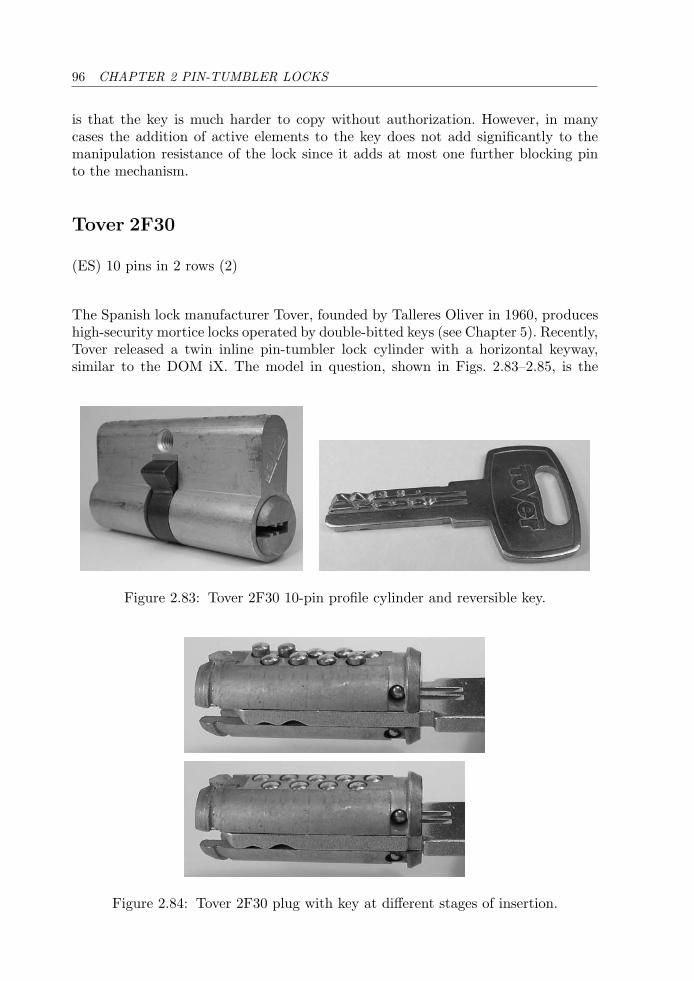
96 CHAPTER 2 PIN-TUMBLER LOCKS
is that the key is much harder to copy without authorization. However, in manycases the addition of active elements to the key does not add significantly to themanipulation resistance of the lock since it adds at most one further blocking pinto the mechanism.
Tover 2F30
(ES) 10 pins in 2 rows (2)
The Spanish lock manufacturer Tover, founded by Talleres Oliver in 1960, produceshigh-security mortice locks operated by double-bitted keys (see Chapter 5). Recently,Tover released a twin inline pin-tumbler lock cylinder with a horizontal keyway,similar to the DOM iX. The model in question, shown in Figs. 2.83–2.85, is the
Figure 2.83: Tover 2F30 10-pin profile cylinder and reversible key.
Figure 2.84: Tover 2F30 plug with key at different stages of insertion.
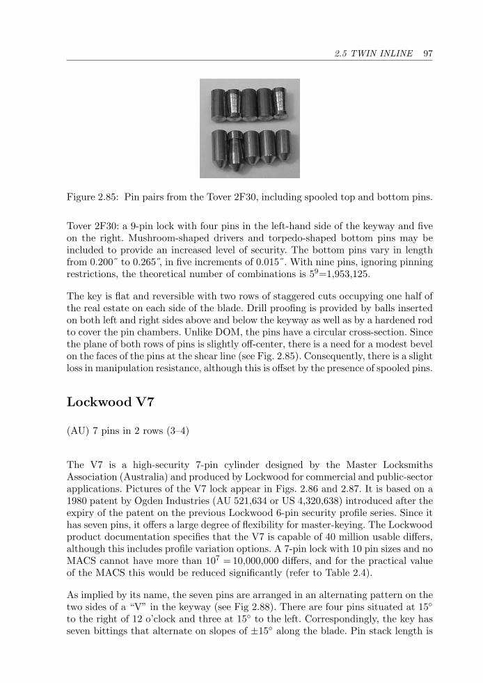
2.5 TWIN INLINE 97
Figure 2.85: Pin pairs from the Tover 2F30, including spooled top and bottom pins.
Tover 2F30: a 9-pin lock with four pins in the left-hand side of the keyway and fiveon the right. Mushroom-shaped drivers and torpedo-shaped bottom pins may beincluded to provide an increased level of security. The bottom pins vary in lengthfrom 0.200˝ to 0.265 , in five increments of 0.015˝. With nine pins, ignoring pinningrestrictions, the theoretical number of combinations is 59=1,953,125.
The key is flat and reversible with two rows of staggered cuts occupying one half ofthe real estate on each side of the blade. Drill proofing is provided by balls insertedon both left and right sides above and below the keyway as well as by a hardened rodto cover the pin chambers. Unlike DOM, the pins have a circular cross-section. Sincethe plane of both rows of pins is slightly off-center, there is a need for a modest bevelon the faces of the pins at the shear line (see Fig. 2.85). Consequently, there is a slightloss in manipulation resistance, although this is offset by the presence of spooled pins.
Lockwood V7
(AU) 7 pins in 2 rows (3–4)
The V7 is a high-security 7-pin cylinder designed by the Master LocksmithsAssociation (Australia) and produced by Lockwood for commercial and public-sectorapplications. Pictures of the V7 lock appear in Figs. 2.86 and 2.87. It is based on a1980 patent by Ogden Industries (AU 521,634 or US 4,320,638) introduced after theexpiry of the patent on the previous Lockwood 6-pin security profile series. Since ithas seven pins, it offers a large degree of flexibility for master-keying. The Lockwoodproduct documentation specifies that the V7 is capable of 40 million usable differs,although this includes profile variation options. A 7-pin lock with 10 pin sizes and noMACS cannot have more than 107 = 10,000,000 differs, and for the practical valueof the MACS this would be reduced significantly (refer to Table 2.4).
As implied by its name, the seven pins are arranged in an alternating pattern on thetwo sides of a “V” in the keyway (see Fig 2.88). There are four pins situated at 15◦to the right of 12 o’clock and three at 15◦ to the left. Correspondingly, the key hasseven bittings that alternate on slopes of ±15◦ along the blade. Pin stack length is
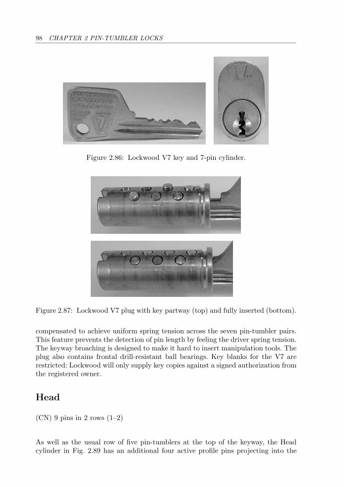
98 CHAPTER 2 PIN-TUMBLER LOCKS
Figure 2.86: Lockwood V7 key and 7-pin cylinder.
Figure 2.87: Lockwood V7 plug with key partway (top) and fully inserted (bottom).
compensated to achieve uniform spring tension across the seven pin-tumbler pairs.This feature prevents the detection of pin length by feeling the driver spring tension.The keyway broaching is designed to make it hard to insert manipulation tools. Theplug also contains frontal drill-resistant ball bearings. Key blanks for the V7 arerestricted: Lockwood will only supply key copies against a signed authorization fromthe registered owner.
Head
(CN) 9 pins in 2 rows (1–2)
As well as the usual row of five pin-tumblers at the top of the keyway, the Headcylinder in Fig. 2.89 has an additional four active profile pins projecting into the
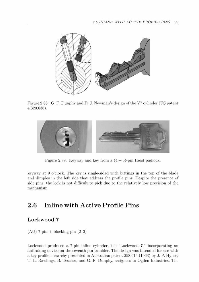
2.6 INLINE WITH ACTIVE PROFILE PINS 99
Figure 2.88: G. F. Dunphy and D. J. Newman’s design of the V7 cylinder (US patent4,320,638).
Figure 2.89: Keyway and key from a (4 + 5)-pin Head padlock.
keyway at 9 o’clock. The key is single-sided with bittings in the top of the bladeand dimples in the left side that address the profile pins. Despite the presence ofside pins, the lock is not difficult to pick due to the relatively low precision of themechanism.
2.6 Inline with Active Profile Pins
Lockwood 7
(AU) 7-pin + blocking pin (2–3)
Lockwood produced a 7-pin inline cylinder, the “Lockwood 7,” incorporating anantiraking device on the seventh pin-tumbler. The design was intended for use witha key profile hierarchy presented in Australian patent 258,614 (1963) by J. P. Hynes,T. L. Rawlings, B. Tescher, and G. F. Dunphy, assignees to Ogden Industries. The
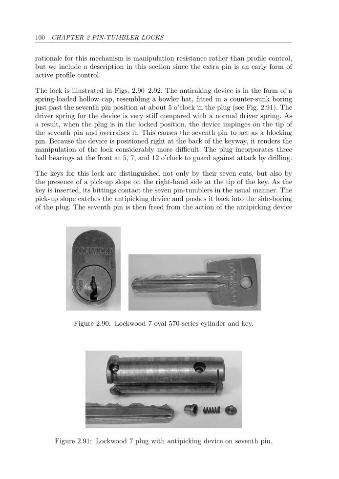
100 CHAPTER 2 PIN-TUMBLER LOCKS
rationale for this mechanism is manipulation resistance rather than profile control,but we include a description in this section since the extra pin is an early form ofactive profile control.
The lock is illustrated in Figs. 2.90–2.92. The antiraking device is in the form of aspring-loaded hollow cap, resembling a bowler hat, fitted in a counter-sunk boringjust past the seventh pin position at about 5 o’clock in the plug (see Fig. 2.91). Thedriver spring for the device is very stiff compared with a normal driver spring. Asa result, when the plug is in the locked position, the device impinges on the tip ofthe seventh pin and overraises it. This causes the seventh pin to act as a blockingpin. Because the device is positioned right at the back of the keyway, it renders themanipulation of the lock considerably more difficult. The plug incorporates threeball bearings at the front at 5, 7, and 12 o’clock to guard against attack by drilling.
The keys for this lock are distinguished not only by their seven cuts, but also bythe presence of a pick-up slope on the right-hand side at the tip of the key. As thekey is inserted, its bittings contact the seven pin-tumblers in the usual manner. Thepick-up slope catches the antipicking device and pushes it back into the side-boringof the plug. The seventh pin is then freed from the action of the antipicking device
Figure 2.90: Lockwood 7 oval 570-series cylinder and key.
Figure 2.91: Lockwood 7 plug with antipicking device on seventh pin.
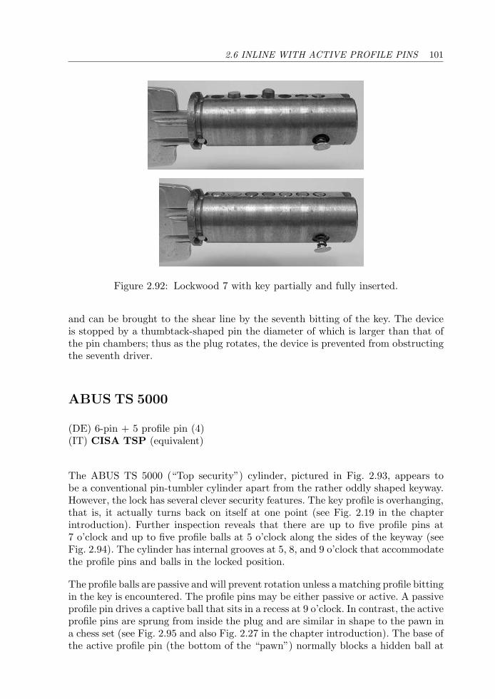
2.6 INLINE WITH ACTIVE PROFILE PINS 101
Figure 2.92: Lockwood 7 with key partially and fully inserted.
and can be brought to the shear line by the seventh bitting of the key. The deviceis stopped by a thumbtack-shaped pin the diameter of which is larger than that ofthe pin chambers; thus as the plug rotates, the device is prevented from obstructingthe seventh driver.
ABUS TS 5000
(DE) 6-pin + 5 profile pin (4)(IT) CISA TSP (equivalent)
The ABUS TS 5000 (“Top security”) cylinder, pictured in Fig. 2.93, appears tobe a conventional pin-tumbler cylinder apart from the rather oddly shaped keyway.However, the lock has several clever security features. The key profile is overhanging,that is, it actually turns back on itself at one point (see Fig. 2.19 in the chapterintroduction). Further inspection reveals that there are up to five profile pins at7 o’clock and up to five profile balls at 5 o’clock along the sides of the keyway (seeFig. 2.94). The cylinder has internal grooves at 5, 8, and 9 o’clock that accommodatethe profile pins and balls in the locked position.
The profile balls are passive and will prevent rotation unless a matching profile bittingin the key is encountered. The profile pins may be either passive or active. A passiveprofile pin drives a captive ball that sits in a recess at 9 o’clock. In contrast, the activeprofile pins are sprung from inside the plug and are similar in shape to the pawn ina chess set (see Fig. 2.95 and also Fig. 2.27 in the chapter introduction). The base ofthe active profile pin (the bottom of the “pawn”) normally blocks a hidden ball at
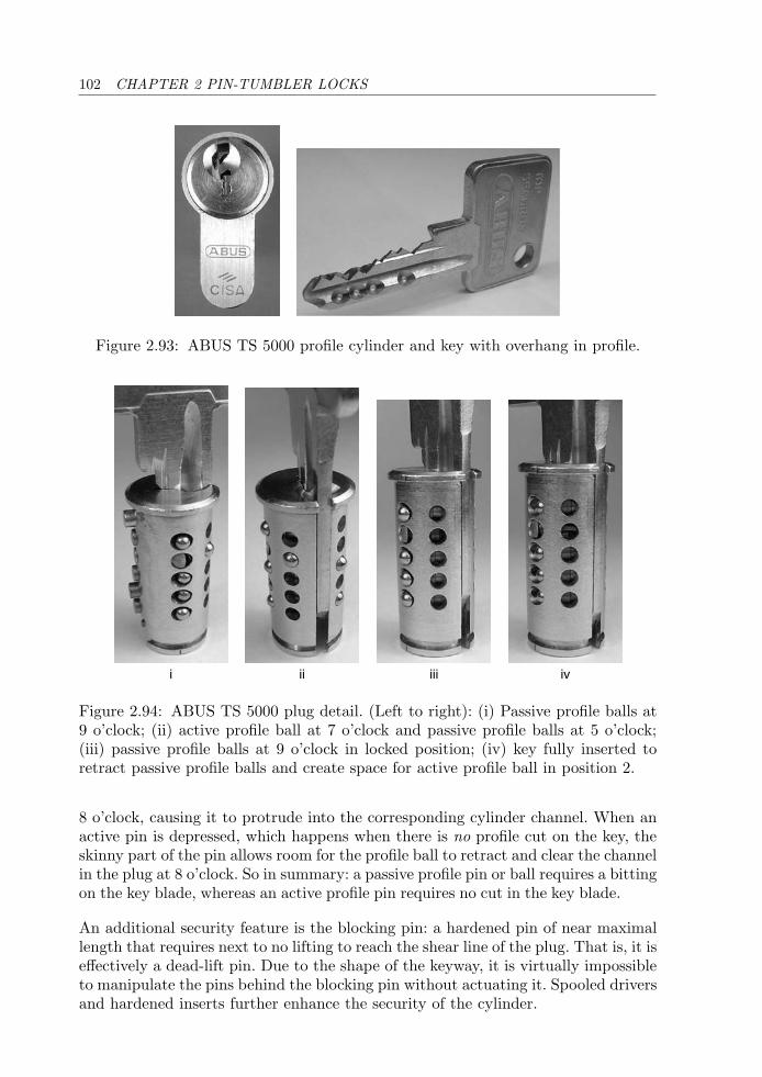
102 CHAPTER 2 PIN-TUMBLER LOCKS
Figure 2.93: ABUS TS 5000 profile cylinder and key with overhang in profile.
i ii iii iv
Figure 2.94: ABUS TS 5000 plug detail. (Left to right): (i) Passive profile balls at9 o’clock; (ii) active profile ball at 7 o’clock and passive profile balls at 5 o’clock;(iii) passive profile balls at 9 o’clock in locked position; (iv) key fully inserted toretract passive profile balls and create space for active profile ball in position 2.
8 o’clock, causing it to protrude into the corresponding cylinder channel. When anactive pin is depressed, which happens when there is no profile cut on the key, theskinny part of the pin allows room for the profile ball to retract and clear the channelin the plug at 8 o’clock. So in summary: a passive profile pin or ball requires a bittingon the key blade, whereas an active profile pin requires no cut in the key blade.
An additional security feature is the blocking pin: a hardened pin of near maximallength that requires next to no lifting to reach the shear line of the plug. That is, it iseffectively a dead-lift pin. Due to the shape of the keyway, it is virtually impossibleto manipulate the pins behind the blocking pin without actuating it. Spooled driversand hardened inserts further enhance the security of the cylinder.
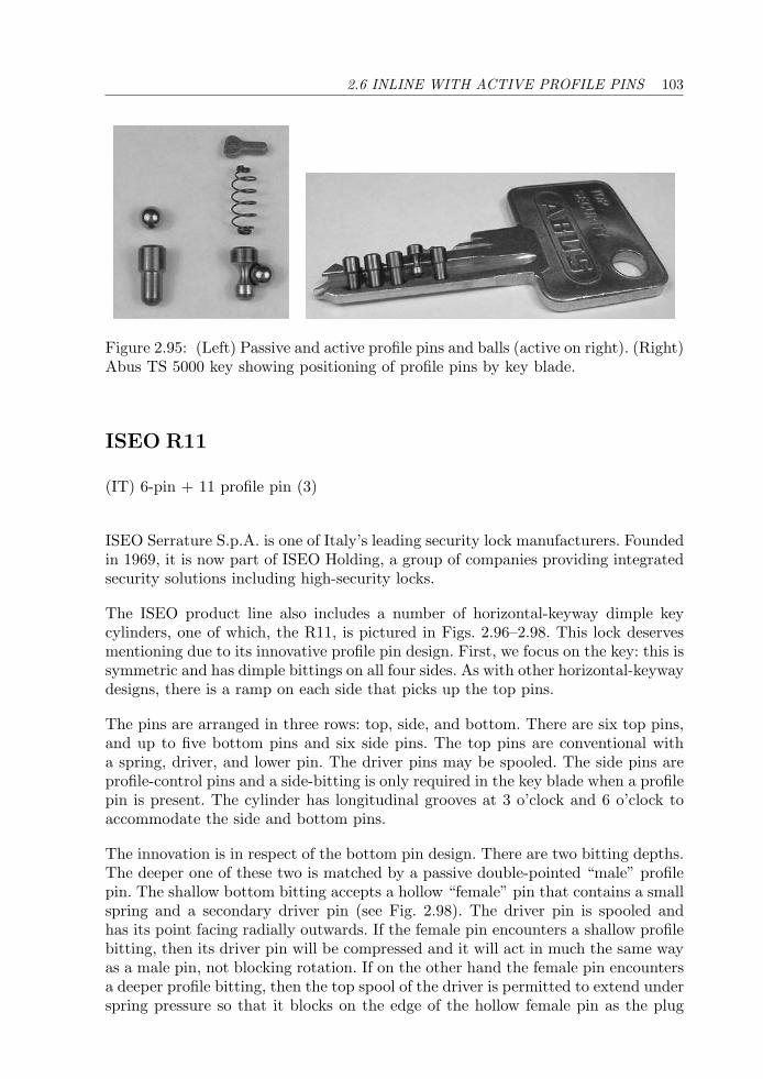
2.6 INLINE WITH ACTIVE PROFILE PINS 103
Figure 2.95: (Left) Passive and active profile pins and balls (active on right). (Right)Abus TS 5000 key showing positioning of profile pins by key blade.
ISEO R11
(IT) 6-pin + 11 profile pin (3)
ISEO Serrature S.p.A. is one of Italy’s leading security lock manufacturers. Foundedin 1969, it is now part of ISEO Holding, a group of companies providing integratedsecurity solutions including high-security locks.
The ISEO product line also includes a number of horizontal-keyway dimple keycylinders, one of which, the R11, is pictured in Figs. 2.96–2.98. This lock deservesmentioning due to its innovative profile pin design. First, we focus on the key: this issymmetric and has dimple bittings on all four sides. As with other horizontal-keywaydesigns, there is a ramp on each side that picks up the top pins.
The pins are arranged in three rows: top, side, and bottom. There are six top pins,and up to five bottom pins and six side pins. The top pins are conventional witha spring, driver, and lower pin. The driver pins may be spooled. The side pins areprofile-control pins and a side-bitting is only required in the key blade when a profilepin is present. The cylinder has longitudinal grooves at 3 o’clock and 6 o’clock toaccommodate the side and bottom pins.
The innovation is in respect of the bottom pin design. There are two bitting depths.The deeper one of these two is matched by a passive double-pointed “male” profilepin. The shallow bottom bitting accepts a hollow “female” pin that contains a smallspring and a secondary driver pin (see Fig. 2.98). The driver pin is spooled andhas its point facing radially outwards. If the female pin encounters a shallow profilebitting, then its driver pin will be compressed and it will act in much the same wayas a male pin, not blocking rotation. If on the other hand the female pin encountersa deeper profile bitting, then the top spool of the driver is permitted to extend underspring pressure so that it blocks on the edge of the hollow female pin as the plug
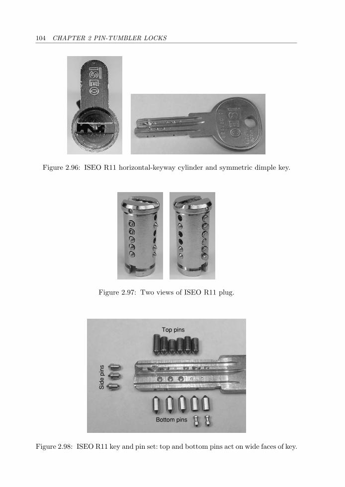
104 CHAPTER 2 PIN-TUMBLER LOCKS
Figure 2.96: ISEO R11 horizontal-keyway cylinder and symmetric dimple key.
Figure 2.97: Two views of ISEO R11 plug.
Sid
e pi
ns
Bottom pins
Top pins
Figure 2.98: ISEO R11 key and pin set: top and bottom pins act on wide faces of key.
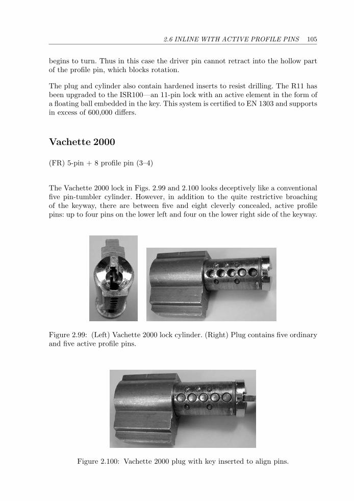
2.6 INLINE WITH ACTIVE PROFILE PINS 105
begins to turn. Thus in this case the driver pin cannot retract into the hollow partof the profile pin, which blocks rotation.
The plug and cylinder also contain hardened inserts to resist drilling. The R11 hasbeen upgraded to the ISR100—an 11-pin lock with an active element in the form ofa floating ball embedded in the key. This system is certified to EN 1303 and supportsin excess of 600,000 differs.
Vachette 2000
(FR) 5-pin + 8 profile pin (3–4)
The Vachette 2000 lock in Figs. 2.99 and 2.100 looks deceptively like a conventionalfive pin-tumbler cylinder. However, in addition to the quite restrictive broachingof the keyway, there are between five and eight cleverly concealed, active profilepins: up to four pins on the lower left and four on the lower right side of the keyway.
Figure 2.99: (Left) Vachette 2000 lock cylinder. (Right) Plug contains five ordinaryand five active profile pins.
Figure 2.100: Vachette 2000 plug with key inserted to align pins.
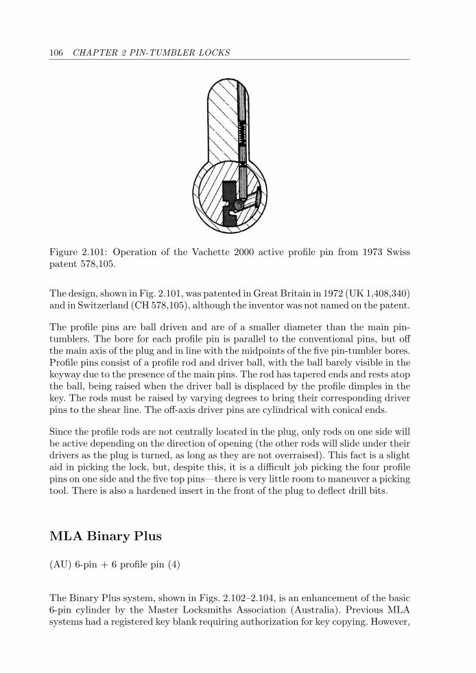
106 CHAPTER 2 PIN-TUMBLER LOCKS
Figure 2.101: Operation of the Vachette 2000 active profile pin from 1973 Swisspatent 578,105.
The design, shown in Fig. 2.101, was patented in Great Britain in 1972 (UK 1,408,340)and in Switzerland (CH 578,105), although the inventor was not named on the patent.
The profile pins are ball driven and are of a smaller diameter than the main pin-tumblers. The bore for each profile pin is parallel to the conventional pins, but offthe main axis of the plug and in line with the midpoints of the five pin-tumbler bores.Profile pins consist of a profile rod and driver ball, with the ball barely visible in thekeyway due to the presence of the main pins. The rod has tapered ends and rests atopthe ball, being raised when the driver ball is displaced by the profile dimples in thekey. The rods must be raised by varying degrees to bring their corresponding driverpins to the shear line. The off-axis driver pins are cylindrical with conical ends.
Since the profile rods are not centrally located in the plug, only rods on one side willbe active depending on the direction of opening (the other rods will slide under theirdrivers as the plug is turned, as long as they are not overraised). This fact is a slightaid in picking the lock, but, despite this, it is a difficult job picking the four profilepins on one side and the five top pins—there is very little room to maneuver a pickingtool. There is also a hardened insert in the front of the plug to deflect drill bits.
MLA Binary Plus
(AU) 6-pin + 6 profile pin (4)
The Binary Plus system, shown in Figs. 2.102–2.104, is an enhancement of the basic6-pin cylinder by the Master Locksmiths Association (Australia). Previous MLAsystems had a registered key blank requiring authorization for key copying. However,
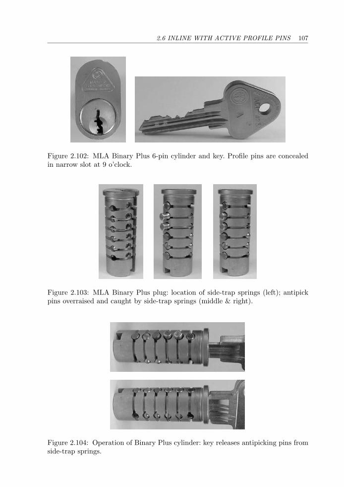
2.6 INLINE WITH ACTIVE PROFILE PINS 107
Figure 2.102: MLA Binary Plus 6-pin cylinder and key. Profile pins are concealedin narrow slot at 9 o’clock.
Figure 2.103: MLA Binary Plus plug: location of side-trap springs (left); antipickpins overraised and caught by side-trap springs (middle & right).
Figure 2.104: Operation of Binary Plus cylinder: key releases antipicking pins fromside-trap springs.
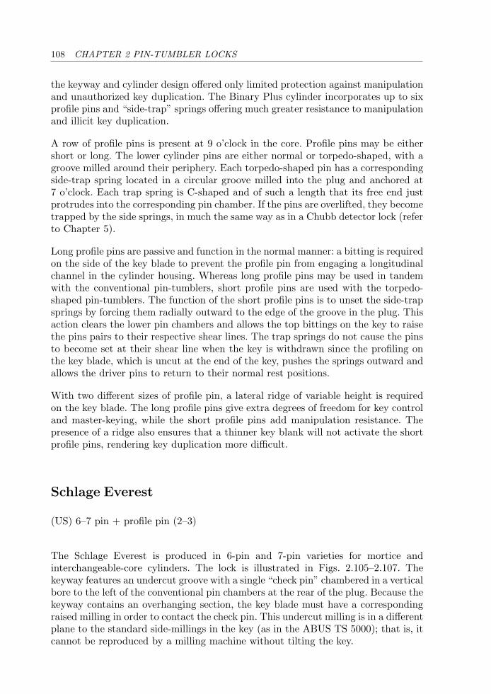
108 CHAPTER 2 PIN-TUMBLER LOCKS
the keyway and cylinder design offered only limited protection against manipulationand unauthorized key duplication. The Binary Plus cylinder incorporates up to sixprofile pins and “side-trap” springs offering much greater resistance to manipulationand illicit key duplication.
A row of profile pins is present at 9 o’clock in the core. Profile pins may be eithershort or long. The lower cylinder pins are either normal or torpedo-shaped, with agroove milled around their periphery. Each torpedo-shaped pin has a correspondingside-trap spring located in a circular groove milled into the plug and anchored at7 o’clock. Each trap spring is C-shaped and of such a length that its free end justprotrudes into the corresponding pin chamber. If the pins are overlifted, they becometrapped by the side springs, in much the same way as in a Chubb detector lock (referto Chapter 5).
Long profile pins are passive and function in the normal manner: a bitting is requiredon the side of the key blade to prevent the profile pin from engaging a longitudinalchannel in the cylinder housing. Whereas long profile pins may be used in tandemwith the conventional pin-tumblers, short profile pins are used with the torpedo-shaped pin-tumblers. The function of the short profile pins is to unset the side-trapsprings by forcing them radially outward to the edge of the groove in the plug. Thisaction clears the lower pin chambers and allows the top bittings on the key to raisethe pins pairs to their respective shear lines. The trap springs do not cause the pinsto become set at their shear line when the key is withdrawn since the profiling onthe key blade, which is uncut at the end of the key, pushes the springs outward andallows the driver pins to return to their normal rest positions.
With two different sizes of profile pin, a lateral ridge of variable height is requiredon the key blade. The long profile pins give extra degrees of freedom for key controland master-keying, while the short profile pins add manipulation resistance. Thepresence of a ridge also ensures that a thinner key blank will not activate the shortprofile pins, rendering key duplication more difficult.
Schlage Everest
(US) 6–7 pin + profile pin (2–3)
The Schlage Everest is produced in 6-pin and 7-pin varieties for mortice andinterchangeable-core cylinders. The lock is illustrated in Figs. 2.105–2.107. Thekeyway features an undercut groove with a single “check pin” chambered in a verticalbore to the left of the conventional pin chambers at the rear of the plug. Because thekeyway contains an overhanging section, the key blade must have a correspondingraised milling in order to contact the check pin. This undercut milling is in a differentplane to the standard side-millings in the key (as in the ABUS TS 5000); that is, itcannot be reproduced by a milling machine without tilting the key.
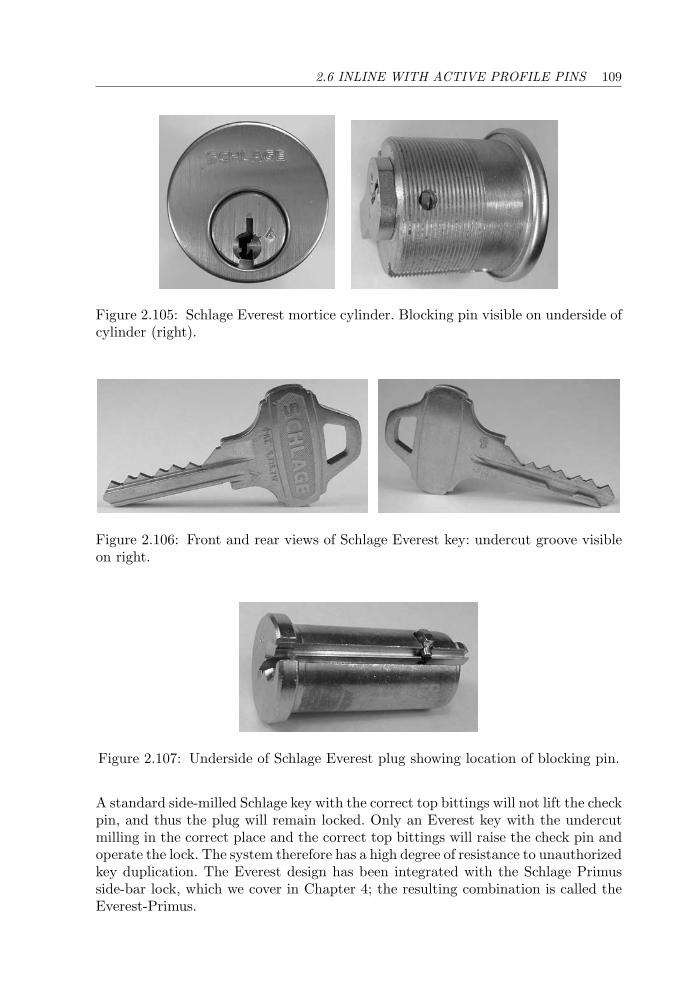
2.6 INLINE WITH ACTIVE PROFILE PINS 109
Figure 2.105: Schlage Everest mortice cylinder. Blocking pin visible on underside ofcylinder (right).
Figure 2.106: Front and rear views of Schlage Everest key: undercut groove visibleon right.
Figure 2.107: Underside of Schlage Everest plug showing location of blocking pin.
A standard side-milled Schlage key with the correct top bittings will not lift the checkpin, and thus the plug will remain locked. Only an Everest key with the undercutmilling in the correct place and the correct top bittings will raise the check pin andoperate the lock. The system therefore has a high degree of resistance to unauthorizedkey duplication. The Everest design has been integrated with the Schlage Primusside-bar lock, which we cover in Chapter 4; the resulting combination is called theEverest-Primus.
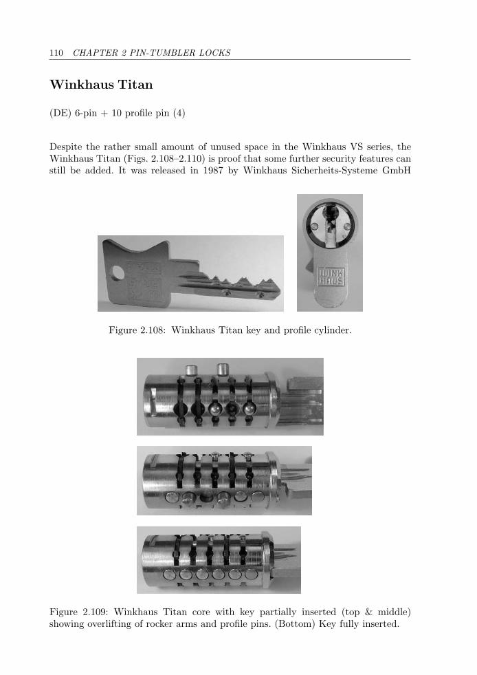
110 CHAPTER 2 PIN-TUMBLER LOCKS
Winkhaus Titan
(DE) 6-pin + 10 profile pin (4)
Despite the rather small amount of unused space in the Winkhaus VS series, theWinkhaus Titan (Figs. 2.108–2.110) is proof that some further security features canstill be added. It was released in 1987 by Winkhaus Sicherheits-Systeme GmbH
Figure 2.108: Winkhaus Titan key and profile cylinder.
Figure 2.109: Winkhaus Titan core with key partially inserted (top & middle)showing overlifting of rocker arms and profile pins. (Bottom) Key fully inserted.
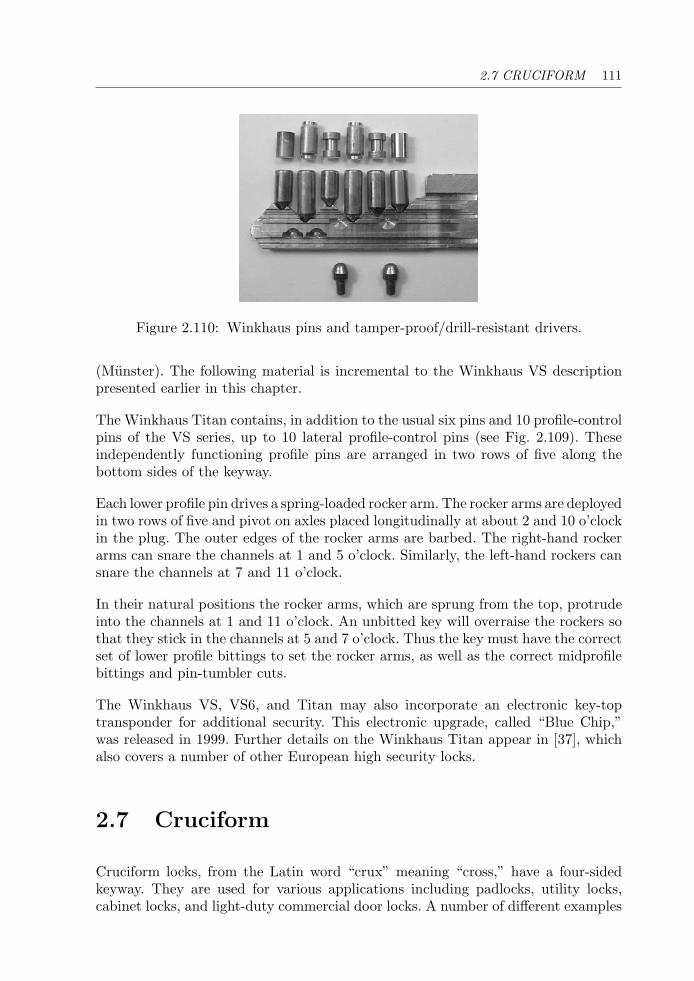
2.7 CRUCIFORM 111
Figure 2.110: Winkhaus pins and tamper-proof/drill-resistant drivers.
(Munster). The following material is incremental to the Winkhaus VS descriptionpresented earlier in this chapter.
The Winkhaus Titan contains, in addition to the usual six pins and 10 profile-controlpins of the VS series, up to 10 lateral profile-control pins (see Fig. 2.109). Theseindependently functioning profile pins are arranged in two rows of five along thebottom sides of the keyway.
Each lower profile pin drives a spring-loaded rocker arm. The rocker arms are deployedin two rows of five and pivot on axles placed longitudinally at about 2 and 10 o’clockin the plug. The outer edges of the rocker arms are barbed. The right-hand rockerarms can snare the channels at 1 and 5 o’clock. Similarly, the left-hand rockers cansnare the channels at 7 and 11 o’clock.
In their natural positions the rocker arms, which are sprung from the top, protrudeinto the channels at 1 and 11 o’clock. An unbitted key will overraise the rockers sothat they stick in the channels at 5 and 7 o’clock. Thus the key must have the correctset of lower profile bittings to set the rocker arms, as well as the correct midprofilebittings and pin-tumbler cuts.
The Winkhaus VS, VS6, and Titan may also incorporate an electronic key-toptransponder for additional security. This electronic upgrade, called “Blue Chip,”was released in 1999. Further details on the Winkhaus Titan appear in [37], whichalso covers a number of other European high security locks.
2.7 Cruciform
Cruciform locks, from the Latin word “crux” meaning “cross,” have a four-sidedkeyway. They are used for various applications including padlocks, utility locks,cabinet locks, and light-duty commercial door locks. A number of different examples
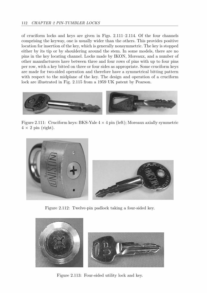
112 CHAPTER 2 PIN-TUMBLER LOCKS
of cruciform locks and keys are given in Figs. 2.111–2.114. Of the four channelscomprising the keyway, one is usually wider than the others. This provides positivelocation for insertion of the key, which is generally nonsymmetric. The key is stoppedeither by its tip or by shouldering around the stem. In some models, there are nopins in the key locating channel. Locks made by IKON, Moreaux, and a number ofother manufacturers have between three and four rows of pins with up to four pinsper row, with a key bitted on three or four sides as appropriate. Some cruciform keysare made for two-sided operation and therefore have a symmetrical bitting patternwith respect to the midplane of the key. The design and operation of a cruciformlock are illustrated in Fig. 2.115 from a 1959 UK patent by Pearson.
Figure 2.111: Cruciform keys: BKS-Yale 4 × 4 pin (left); Moreaux axially symmetric4 × 2 pin (right).
Figure 2.112: Twelve-pin padlock taking a four-sided key.
Figure 2.113: Four-sided utility lock and key.
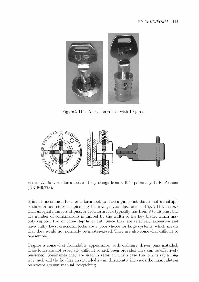
2.7 CRUCIFORM 113
Figure 2.114: A cruciform lock with 10 pins.
Figure 2.115: Cruciform lock and key design from a 1959 patent by T. F. Pearson(UK 940,778).
It is not uncommon for a cruciform lock to have a pin count that is not a multipleof three or four since the pins may be arranged, as illustrated in Fig. 2.114, in rowswith unequal numbers of pins. A cruciform lock typically has from 8 to 18 pins, butthe number of combinations is limited by the width of the key blade, which mayonly support two or three depths of cut. Since they are relatively expensive andhave bulky keys, cruciform locks are a poor choice for large systems, which meansthat they would not normally be master-keyed. They are also somewhat difficult toreassemble.
Despite a somewhat formidable appearance, with ordinary driver pins installed,these locks are not especially difficult to pick open provided they can be effectivelytensioned. Sometimes they are used in safes, in which case the lock is set a longway back and the key has an extended stem; this greatly increases the manipulationresistance against manual lockpicking.
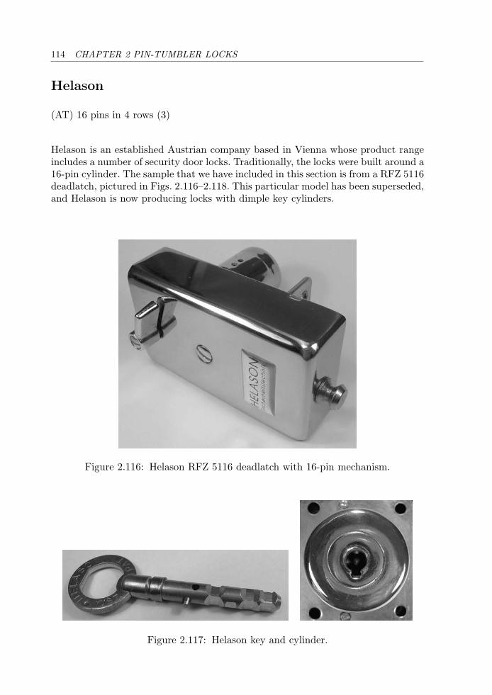
114 CHAPTER 2 PIN-TUMBLER LOCKS
Helason
(AT) 16 pins in 4 rows (3)
Helason is an established Austrian company based in Vienna whose product rangeincludes a number of security door locks. Traditionally, the locks were built around a16-pin cylinder. The sample that we have included in this section is from a RFZ 5116deadlatch, pictured in Figs. 2.116–2.118. This particular model has been superseded,and Helason is now producing locks with dimple key cylinders.
Figure 2.116: Helason RFZ 5116 deadlatch with 16-pin mechanism.
Figure 2.117: Helason key and cylinder.
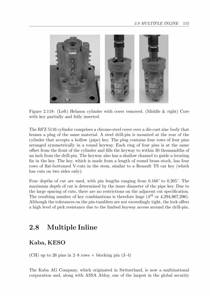
2.8 MULTIPLE INLINE 115
Figure 2.118: (Left) Helason cylinder with cover removed. (Middle & right) Corewith key partially and fully inserted.
The RFZ 5116 cylinder comprises a chrome-steel cover over a die-cast zinc body thathouses a plug of the same material. A steel drill-pin is mounted at the rear of thecylinder that accepts a hollow (pipe) key. The plug contains four rows of four pinsarranged symmetrically in a round keyway. Each ring of four pins is at the sameoffset from the front of the cylinder and fills the keyway to within 30 thousandths ofan inch from the drill-pin. The keyway also has a shallow channel to guide a locatingfin in the key. The key, which is made from a length of round brass stock, has fourrows of flat-bottomed V-cuts in the stem, similar to a Renault TS car key (whichhas cuts on two sides only).
Four depths of cut are used, with pin lengths ranging from 0.160˝ to 0.205 . Themaximum depth of cut is determined by the inner diameter of the pipe key. Due tothe large spacing of cuts, there are no restrictions on the adjacent cut specification.The resulting number of key combinations is therefore huge (416 or 4,294,967,296).Although the tolerances on the pin-tumblers are not exceedingly tight, the lock offersa high level of pick resistance due to the limited keyway access around the drill-pin.
2.8 Multiple Inline
Kaba, KESO
(CH) up to 26 pins in 2–8 rows + blocking pin (3–4)
The Kaba AG Company, which originated in Switzerland, is now a multinationalcorporation and, along with ASSA Abloy, one of the largest in the global security
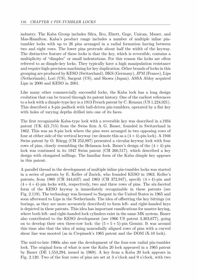
116 CHAPTER 2 PIN-TUMBLER LOCKS
industry. The Kaba Group includes Silca, Ilco, Elzett, Gege, Unican, Mauer, andMas-Hamilton. Kaba’s product range includes a number of multiple inline pin-tumbler locks with up to 26 pins arranged in a radial formation having betweentwo and eight rows. The lower pins protrude about half the width of the keyway.The distinctive feature of these locks is that the key, which is reversible, contains amultiplicity of “dimples” or small indentations. For this reason the locks are oftenreferred to as dimple-key locks. They typically have a high manipulation resistanceand require high-precision machining for key duplication. Other brands of locks in thisgrouping are produced by KESO (Switzerland), BKS (Germany), JPM (France), Lips(Netherlands), Lori (US), Sargent (US), and Showa (Japan). ASSA Abloy acquiredLips in 2000 and KESO in 2001.
Like many other commercially successful locks, the Kaba lock has a long designevolution that can be traced through its patent history. One of the earliest referencesto a lock with a dimple-type key is a 1913 French patent by C. Renaux (US 1,224,021).This described a 3-pin padlock with ball-driven pin-tumblers, operated by a flat keywith holes of varying depths drilled into one of its faces.
The first recognizable Kaba-type lock with a reversible key was described in a 1934patent (UK 421,715) from the Swiss firm A. G. Bauer, founded in Switzerland in1862. This was an 8-pin lock where the pins were arranged in two opposing rows offour at either side of the vertical keyway (we denote this as a (4 + 4)-pin lock). A 1946Swiss patent by O. Ruegg (CH 252,097) presented a circular-keyway lock with fourrows of pins, closely resembling the Helasaon lock. Bauer’s design of the (4 + 4)-pinlock was continued in its 1947 Swiss patent (CH 260,517), which described a keydesign with elongated millings. The familiar form of the Kaba dimple key appearsin this patent.
A parallel thread in the development of multiple inline pin-tumbler locks was startedin a series of patents by E. Keller of Zurich, who founded KESO in 1963. Keller’spatents, from 1960 (CH 344,637) and 1963 (CH 372,947), specify (4 + 4)-pin and(4 + 4 + 4)-pin locks with, respectively, two and three rows of pins. The six-facetedform of the KESO keyway is immediately recognizable in these patents (seeFig. 2.119). The technology was licensed to Sargent in the United States in 1965 andsoon afterward to Lips in the Netherlands. The idea of offsetting the key bittings (orborings, as they are more accurately described) to form left- and right-handed keysis depicted in these patents. This idea has important ramifications for master-keying,where both left- and right-handed lock cylinders exist in the same MK system. Baueralso contributed to the KESO development (see 1966 US patent 3,303,677), goingon to develop their own three-row lock: the (5 + 5 + 5)-pin Gemini. It was aroundthis time also that the idea of using nonradially aligned rows of pins with a curvedshear line was mooted (as in Crepinsek’s 1965 patent and the DOM iX-10 lock).
The mid-to-late 1960s also saw the development of the four-row radial pin-tumblerlock. The original form of what is now the Kaba 20 lock appeared in a 1965 patentby Bauer (DE 1,553,294, issued in 1969). A key from a Kaba 20 lock appears inFig. 2.120. Two of the four rows of pins are set at 3 o’clock and 9 o’clock, with two
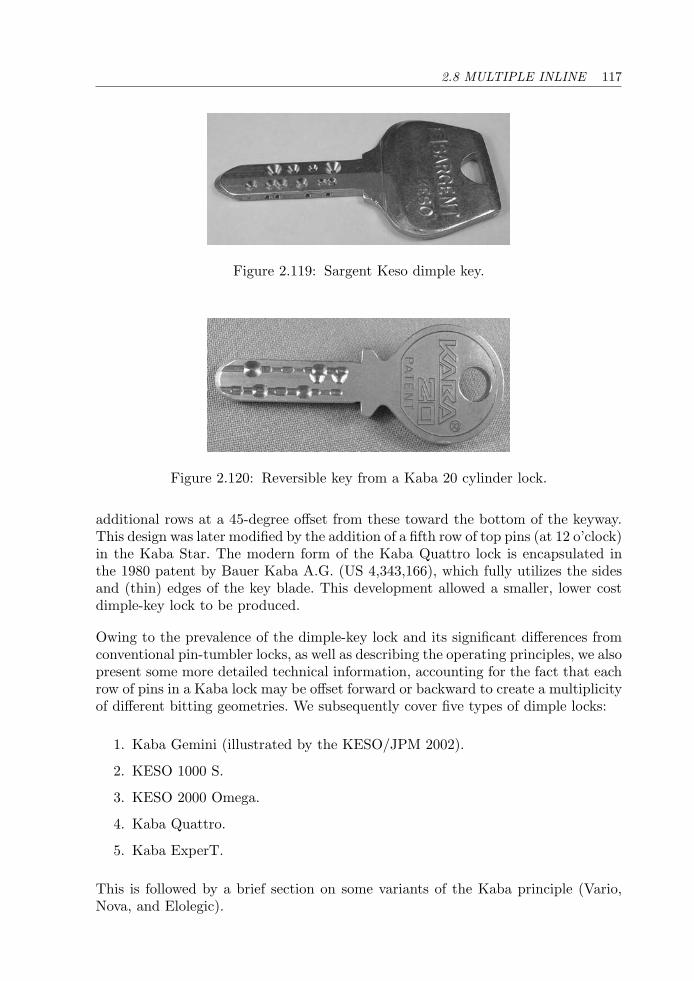
2.8 MULTIPLE INLINE 117
Figure 2.119: Sargent Keso dimple key.
Figure 2.120: Reversible key from a Kaba 20 cylinder lock.
additional rows at a 45-degree offset from these toward the bottom of the keyway.This design was later modified by the addition of a fifth row of top pins (at 12 o’clock)in the Kaba Star. The modern form of the Kaba Quattro lock is encapsulated inthe 1980 patent by Bauer Kaba A.G. (US 4,343,166), which fully utilizes the sidesand (thin) edges of the key blade. This development allowed a smaller, lower costdimple-key lock to be produced.
Owing to the prevalence of the dimple-key lock and its significant differences fromconventional pin-tumbler locks, as well as describing the operating principles, we alsopresent some more detailed technical information, accounting for the fact that eachrow of pins in a Kaba lock may be offset forward or backward to create a multiplicityof different bitting geometries. We subsequently cover five types of dimple locks:
1. Kaba Gemini (illustrated by the KESO/JPM 2002).
2. KESO 1000 S.
3. KESO 2000 Omega.
4. Kaba Quattro.
5. Kaba ExperT.
This is followed by a brief section on some variants of the Kaba principle (Vario,Nova, and Elolegic).
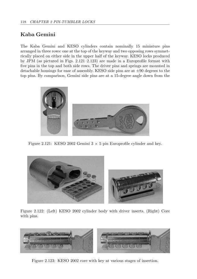
118 CHAPTER 2 PIN-TUMBLER LOCKS
Kaba Gemini
The Kaba Gemini and KESO cylinders contain nominally 15 miniature pinsarranged in three rows: one at the top of the keyway and two opposing rows symmet-rically placed on either side in the upper half of the keyway. KESO locks producedby JPM (as pictured in Figs. 2.121–2.123) are made in a Europrofile format withfive pins in the top and both side rows. The driver pins and springs are mounted indetachable housings for ease of assembly. KESO side pins are at ±90 degrees to thetop pins. By comparison, Gemini side pins are at a 15-degree angle down from the
Figure 2.121: KESO 2002 Gemini 3 × 5 pin Europrofile cylinder and key.
Figure 2.122: (Left) KESO 2002 cylinder body with driver inserts. (Right) Corewith pins.
Figure 2.123: KESO 2002 core with key at various stages of insertion.
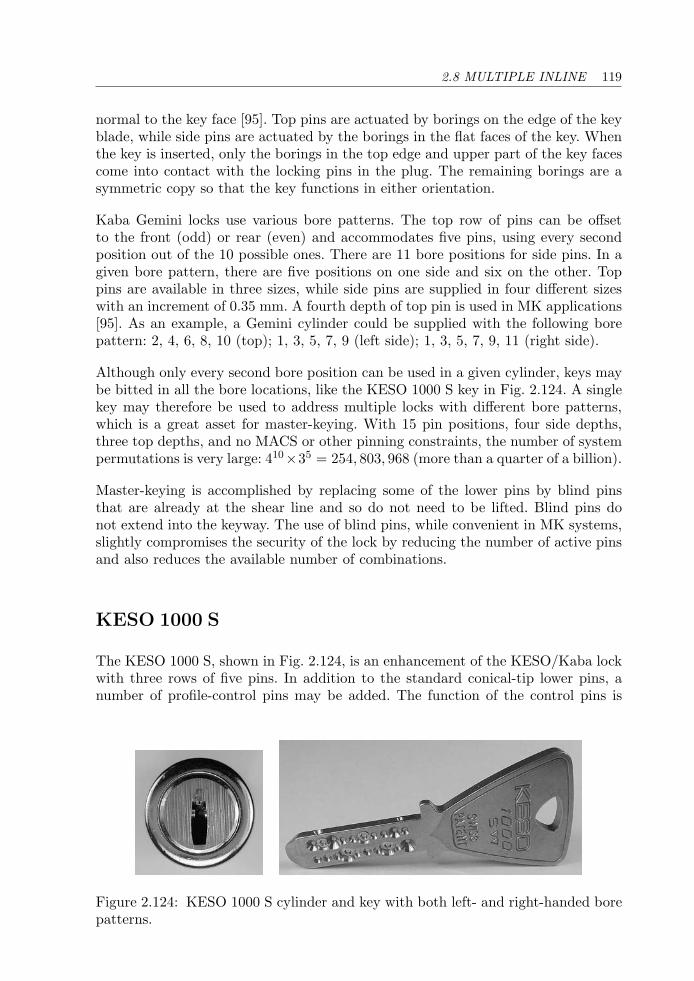
2.8 MULTIPLE INLINE 119
normal to the key face [95]. Top pins are actuated by borings on the edge of the keyblade, while side pins are actuated by the borings in the flat faces of the key. Whenthe key is inserted, only the borings in the top edge and upper part of the key facescome into contact with the locking pins in the plug. The remaining borings are asymmetric copy so that the key functions in either orientation.
Kaba Gemini locks use various bore patterns. The top row of pins can be offsetto the front (odd) or rear (even) and accommodates five pins, using every secondposition out of the 10 possible ones. There are 11 bore positions for side pins. In agiven bore pattern, there are five positions on one side and six on the other. Toppins are available in three sizes, while side pins are supplied in four different sizeswith an increment of 0.35 mm. A fourth depth of top pin is used in MK applications[95]. As an example, a Gemini cylinder could be supplied with the following borepattern: 2, 4, 6, 8, 10 (top); 1, 3, 5, 7, 9 (left side); 1, 3, 5, 7, 9, 11 (right side).
Although only every second bore position can be used in a given cylinder, keys maybe bitted in all the bore locations, like the KESO 1000 S key in Fig. 2.124. A singlekey may therefore be used to address multiple locks with different bore patterns,which is a great asset for master-keying. With 15 pin positions, four side depths,three top depths, and no MACS or other pinning constraints, the number of systempermutations is very large: 410×35 = 254, 803, 968 (more than a quarter of a billion).
Master-keying is accomplished by replacing some of the lower pins by blind pinsthat are already at the shear line and so do not need to be lifted. Blind pins donot extend into the keyway. The use of blind pins, while convenient in MK systems,slightly compromises the security of the lock by reducing the number of active pinsand also reduces the available number of combinations.
KESO 1000 S
The KESO 1000 S, shown in Fig. 2.124, is an enhancement of the KESO/Kaba lockwith three rows of five pins. In addition to the standard conical-tip lower pins, anumber of profile-control pins may be added. The function of the control pins is
Figure 2.124: KESO 1000 S cylinder and key with both left- and right-handed borepatterns.
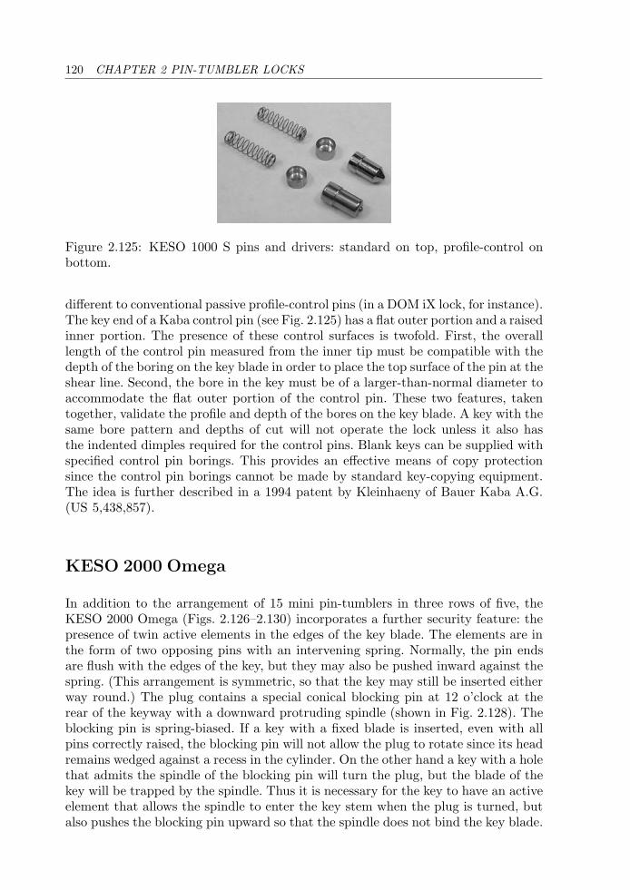
120 CHAPTER 2 PIN-TUMBLER LOCKS
Figure 2.125: KESO 1000 S pins and drivers: standard on top, profile-control onbottom.
different to conventional passive profile-control pins (in a DOM iX lock, for instance).The key end of a Kaba control pin (see Fig. 2.125) has a flat outer portion and a raisedinner portion. The presence of these control surfaces is twofold. First, the overalllength of the control pin measured from the inner tip must be compatible with thedepth of the boring on the key blade in order to place the top surface of the pin at theshear line. Second, the bore in the key must be of a larger-than-normal diameter toaccommodate the flat outer portion of the control pin. These two features, takentogether, validate the profile and depth of the bores on the key blade. A key with thesame bore pattern and depths of cut will not operate the lock unless it also hasthe indented dimples required for the control pins. Blank keys can be supplied withspecified control pin borings. This provides an effective means of copy protectionsince the control pin borings cannot be made by standard key-copying equipment.The idea is further described in a 1994 patent by Kleinhaeny of Bauer Kaba A.G.(US 5,438,857).
KESO 2000 Omega
In addition to the arrangement of 15 mini pin-tumblers in three rows of five, theKESO 2000 Omega (Figs. 2.126–2.130) incorporates a further security feature: thepresence of twin active elements in the edges of the key blade. The elements are inthe form of two opposing pins with an intervening spring. Normally, the pin endsare flush with the edges of the key, but they may also be pushed inward against thespring. (This arrangement is symmetric, so that the key may still be inserted eitherway round.) The plug contains a special conical blocking pin at 12 o’clock at therear of the keyway with a downward protruding spindle (shown in Fig. 2.128). Theblocking pin is spring-biased. If a key with a fixed blade is inserted, even with allpins correctly raised, the blocking pin will not allow the plug to rotate since its headremains wedged against a recess in the cylinder. On the other hand a key with a holethat admits the spindle of the blocking pin will turn the plug, but the blade of thekey will be trapped by the spindle. Thus it is necessary for the key to have an activeelement that allows the spindle to enter the key stem when the plug is turned, butalso pushes the blocking pin upward so that the spindle does not bind the key blade.
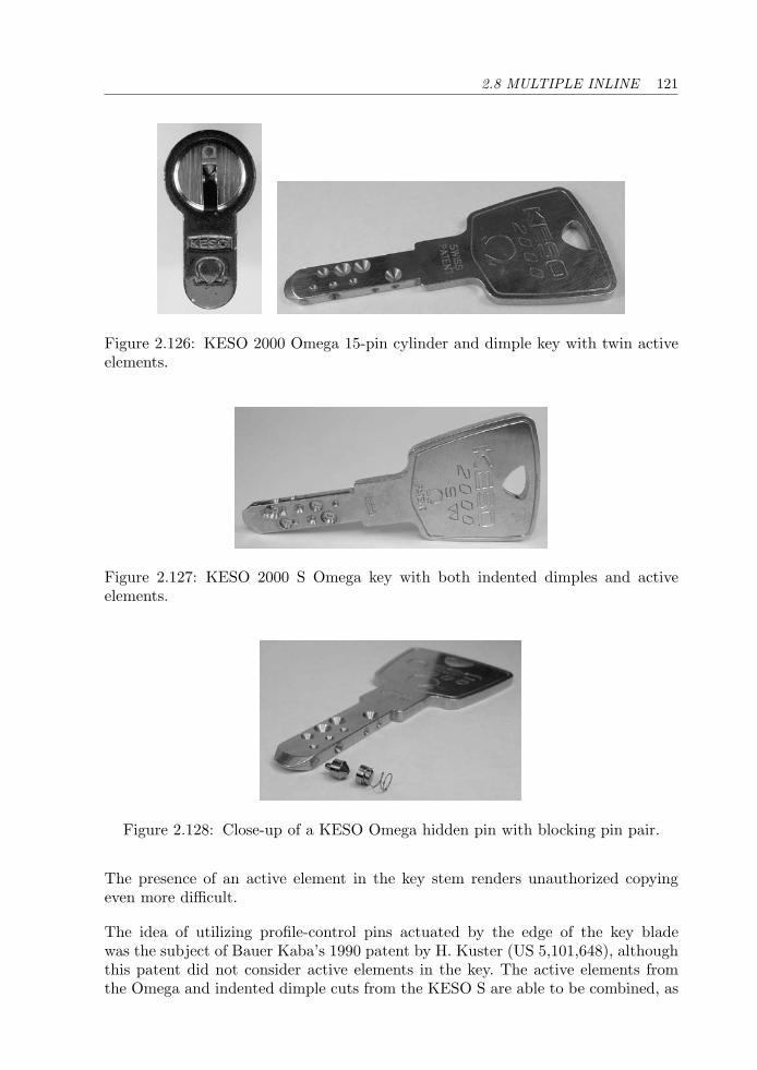
2.8 MULTIPLE INLINE 121
Figure 2.126: KESO 2000 Omega 15-pin cylinder and dimple key with twin activeelements.
Figure 2.127: KESO 2000 S Omega key with both indented dimples and activeelements.
Figure 2.128: Close-up of a KESO Omega hidden pin with blocking pin pair.
The presence of an active element in the key stem renders unauthorized copyingeven more difficult.
The idea of utilizing profile-control pins actuated by the edge of the key bladewas the subject of Bauer Kaba’s 1990 patent by H. Kuster (US 5,101,648), althoughthis patent did not consider active elements in the key. The active elements fromthe Omega and indented dimple cuts from the KESO S are able to be combined, as
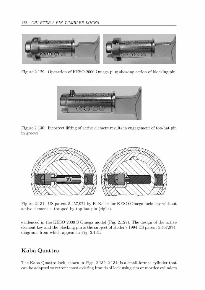
122 CHAPTER 2 PIN-TUMBLER LOCKS
Figure 2.129: Operation of KESO 2000 Omega plug showing action of blocking pin.
Figure 2.130: Incorrect lifting of active element results in engagement of top-hat pinin groove.
Figure 2.131: US patent 5,457,974 by E. Keller for KESO Omega lock: key withoutactive element is trapped by top-hat pin (right).
evidenced in the KESO 2000 S Omega model (Fig. 2.127). The design of the activeelement key and the blocking pin is the subject of Keller’s 1994 US patent 5,457,974,diagrams from which appear in Fig. 2.131.
Kaba Quattro
The Kaba Quattro lock, shown in Figs. 2.132–2.134, is a small-format cylinder thatcan be adapted to retrofit most existing brands of lock using rim or mortice cylinders

2.8 MULTIPLE INLINE 123
Figure 2.132: Kaba Quattro 22-pin cylinder and key.
Figure 2.133: (Left) Kaba Quattro plug and core with outer sleeve removed. (Right)Core with pins loaded.
Figure 2.134: Kaba Quattro tumbler pins (left) and counter-pins (right).
as well as knob-sets. A large range of adaptors and tail-pieces are made for thispurpose. The Quattro is characterized by its four rows of pin-tumblers, arranged inan “X” around the top part of a rectangular keyway with shallow side wards. Thelock cylinder comprises, in order of decreasing diameter: an outer sleeve, a brasscore, and a plug. The core is fixed, while the plug is rotatable. The function of thesleeve is to retain the driver pins and springs and to allow easy removal of the coreassembly for servicing.
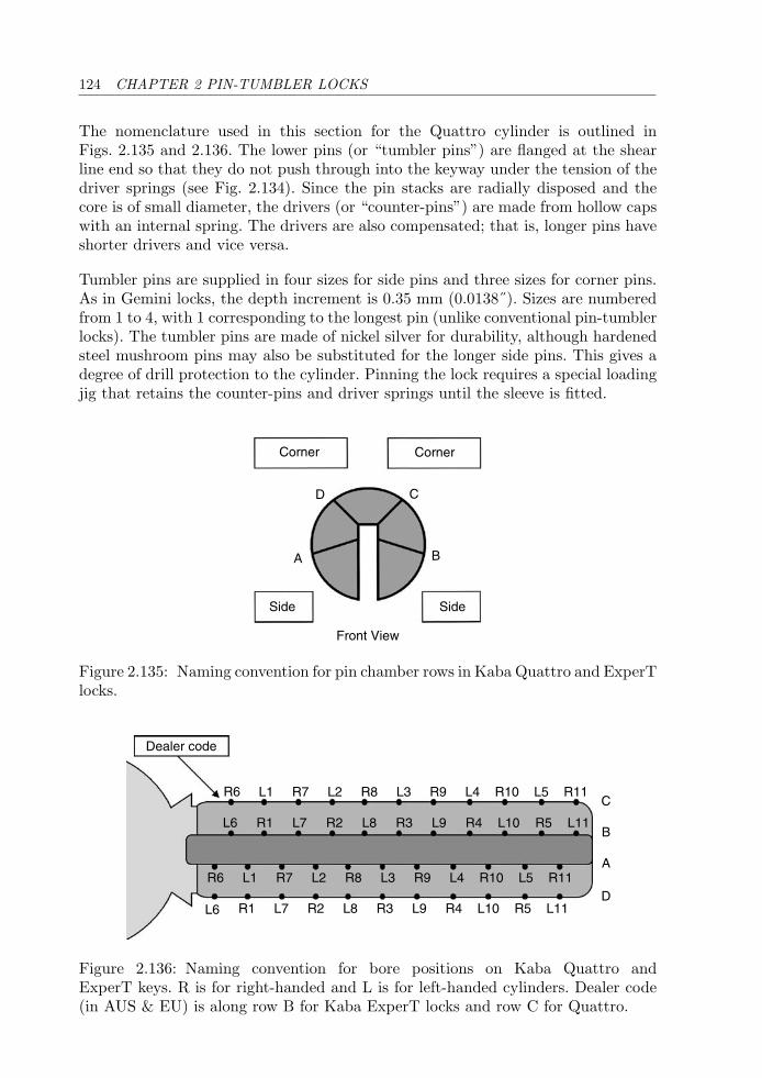
124 CHAPTER 2 PIN-TUMBLER LOCKS
The nomenclature used in this section for the Quattro cylinder is outlined inFigs. 2.135 and 2.136. The lower pins (or “tumbler pins”) are flanged at the shearline end so that they do not push through into the keyway under the tension of thedriver springs (see Fig. 2.134). Since the pin stacks are radially disposed and thecore is of small diameter, the drivers (or “counter-pins”) are made from hollow capswith an internal spring. The drivers are also compensated; that is, longer pins haveshorter drivers and vice versa.
Tumbler pins are supplied in four sizes for side pins and three sizes for corner pins.As in Gemini locks, the depth increment is 0.35 mm (0.0138˝). Sizes are numberedfrom 1 to 4, with 1 corresponding to the longest pin (unlike conventional pin-tumblerlocks). The tumbler pins are made of nickel silver for durability, although hardenedsteel mushroom pins may also be substituted for the longer side pins. This gives adegree of drill protection to the cylinder. Pinning the lock requires a special loadingjig that retains the counter-pins and driver springs until the sleeve is fitted.
Corner Corner
Side
A B
CD
Side
Front View
Figure 2.135: Naming convention for pin chamber rows in Kaba Quattro and ExperTlocks.
L6
R6
L6
R6
Dealer code
L1 R7 L2 R8 L3 R9 L4 R10 L5 R11
R1 L7 R2 L8 R3 L9 R4 L10 R5 L11
L1 R7 L2 R8 L3 R9 L4 R10 L5 R11
R1 L7 R2 L8 R3 L9 R4 L10 R5 L11
C
B
A
D
Figure 2.136: Naming convention for bore positions on Kaba Quattro andExperT keys. R is for right-handed and L is for left-handed cylinders. Dealer code(in AUS & EU) is along row B for Kaba ExperT locks and row C for Quattro.
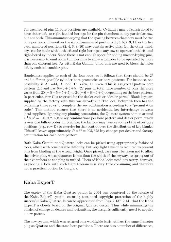
2.8 MULTIPLE INLINE 125
For each row of pins 11 bore positions are available. Cylinders may be constructed tohave either left- or right-handed borings for the pin chambers in any particular row,but not both. This amounts to saying that the spacing between chambers must be twobore positions. Thus either the six odd-numbered positions (1, 3, 5, 7, 9, 11) or the fiveeven-numbered positions (2, 4, 6, 8, 10) may contain active pins. On the other hand,keys can be made with both left and right borings in any row to operate both left- andright-bored cylinders. Since there is not enough space for adding master-keying pins,it is necessary to omit some tumbler pins to allow a cylinder to be operated by morethan one different key. As with Kaba Gemini, blind pins are used to block the holesleft by omitted tumbler pins.
Handedness applies to each of the four rows, so it follows that there should be 24
or 16 different possible cylinder bore geometries or bore patterns. For instance, onepossibility is A—odd, B—odd, C—even, D—even. This is assigned Quattro borepattern QR and has 6 + 6 + 5 + 5 = 22 pins in total. The number of pins thereforevaries from 20 (= 5 + 5 + 5 + 5) to 24 (= 6 + 6 + 6 + 6), depending on the bore pattern.In particular, row C is reserved for the dealer code or “dealer perm.” Blank keys aresupplied by the factory with this row already cut. The local locksmith then has theremaining three rows to complete the key combination according to a “permutationcode.” This method ensures that there is no accidental key interchange betweenlocal suppliers. Ignoring any pinning constraints, the Quattro system admits around411×35 = 1, 019, 215, 872 key combinations per bore pattern and dealer perm, whichis over one billion codes. In practice, the factory may reserve some of the other borepositions (e.g., row D) to exercise further control over the distribution of key blanks.This still leaves approximately 46×35 = 995, 328 key changes per dealer and factorypermutation for each bore pattern.
Both Kaba Gemini and Quattro locks can be picked using appropriately fashionedtools, albeit with considerable difficulty, but very light tension is required to preventpins from binding at the wrong height. Once picked, care must be taken not to allowthe driver pins, whose diameter is less than the width of the keyway, to spring out oftheir chambers as the plug is turned. Users of Kaba locks need not worry, however,as picking a lock with such tight tolerances is very time consuming and thereforenot a practical option for burglars.
Kaba ExperT
The expiry of the Kaba Quattro patent in 2004 was countered by the release ofthe Kaba ExperT system, ensuring continued copyright protection of the highlysuccessful Kaba Quattro. It can be appreciated from Figs. 2.137–2.141 that the KabaExperT is closely based on the original Quattro design. Thus while minimizing theburden of change on dealers and locksmiths, the design is sufficiently novel to acquirea new patent.
The new system, which was released on a worldwide basis, utilizes the same diameterplug as Quattro and the same bore positions. There are also a number of differences,
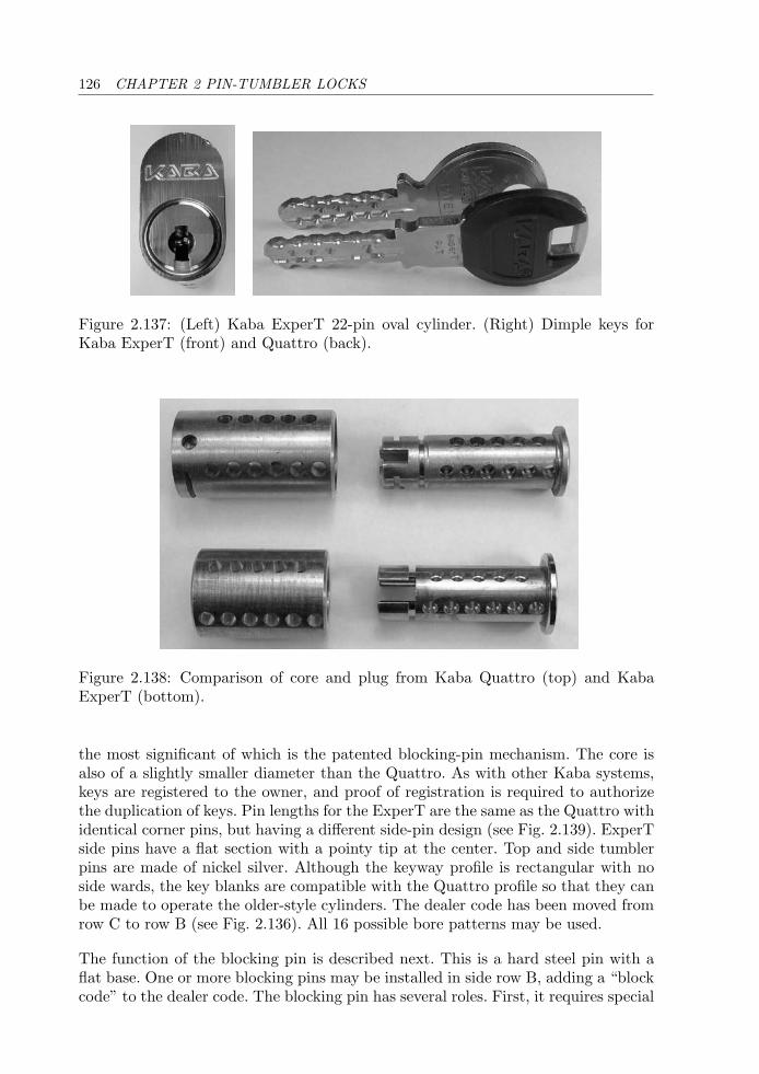
126 CHAPTER 2 PIN-TUMBLER LOCKS
Figure 2.137: (Left) Kaba ExperT 22-pin oval cylinder. (Right) Dimple keys forKaba ExperT (front) and Quattro (back).
Figure 2.138: Comparison of core and plug from Kaba Quattro (top) and KabaExperT (bottom).
the most significant of which is the patented blocking-pin mechanism. The core isalso of a slightly smaller diameter than the Quattro. As with other Kaba systems,keys are registered to the owner, and proof of registration is required to authorizethe duplication of keys. Pin lengths for the ExperT are the same as the Quattro withidentical corner pins, but having a different side-pin design (see Fig. 2.139). ExperTside pins have a flat section with a pointy tip at the center. Top and side tumblerpins are made of nickel silver. Although the keyway profile is rectangular with noside wards, the key blanks are compatible with the Quattro profile so that they canbe made to operate the older-style cylinders. The dealer code has been moved fromrow C to row B (see Fig. 2.136). All 16 possible bore patterns may be used.
The function of the blocking pin is described next. This is a hard steel pin with aflat base. One or more blocking pins may be installed in side row B, adding a “blockcode” to the dealer code. The blocking pin has several roles. First, it requires special
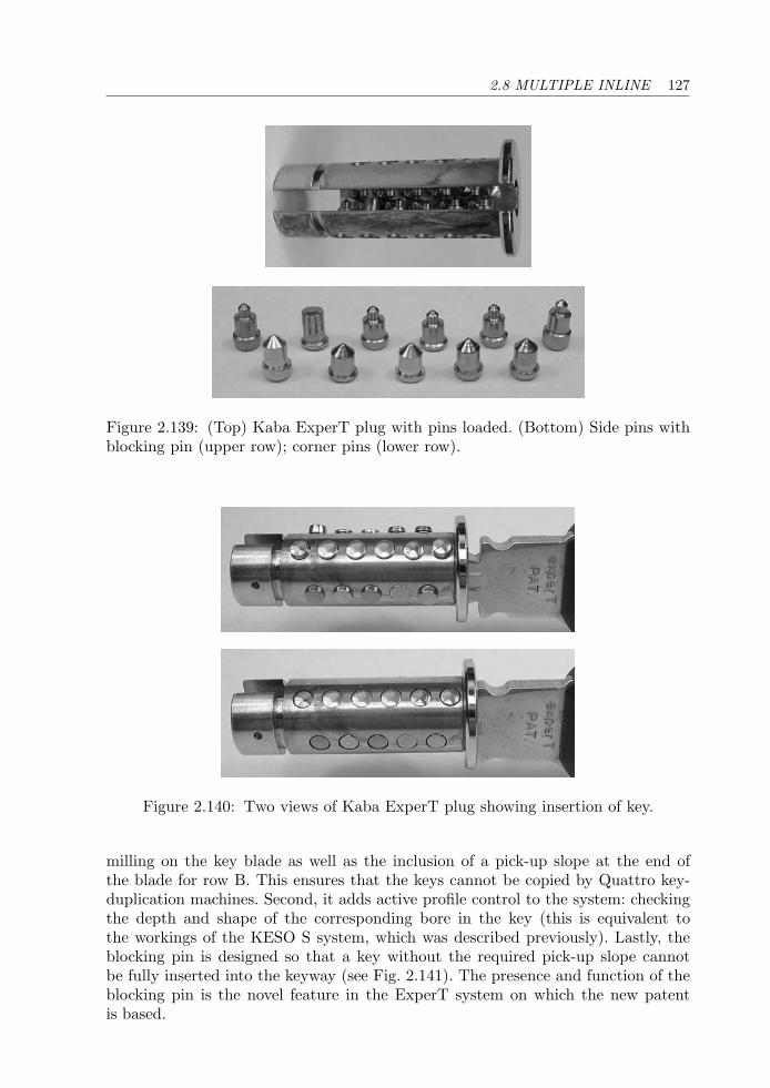
2.8 MULTIPLE INLINE 127
Figure 2.139: (Top) Kaba ExperT plug with pins loaded. (Bottom) Side pins withblocking pin (upper row); corner pins (lower row).
Figure 2.140: Two views of Kaba ExperT plug showing insertion of key.
milling on the key blade as well as the inclusion of a pick-up slope at the end ofthe blade for row B. This ensures that the keys cannot be copied by Quattro key-duplication machines. Second, it adds active profile control to the system: checkingthe depth and shape of the corresponding bore in the key (this is equivalent tothe workings of the KESO S system, which was described previously). Lastly, theblocking pin is designed so that a key without the required pick-up slope cannotbe fully inserted into the keyway (see Fig. 2.141). The presence and function of theblocking pin is the novel feature in the ExperT system on which the new patentis based.
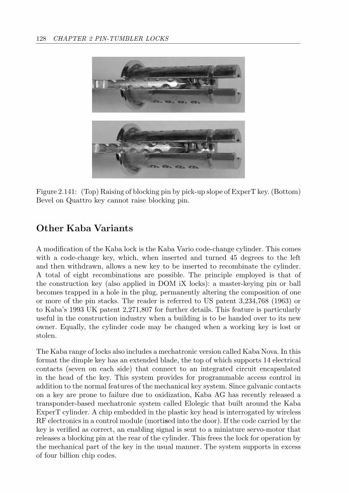
128 CHAPTER 2 PIN-TUMBLER LOCKS
Figure 2.141: (Top) Raising of blocking pin by pick-up slope of ExperT key. (Bottom)Bevel on Quattro key cannot raise blocking pin.
Other Kaba Variants
A modification of the Kaba lock is the Kaba Vario code-change cylinder. This comeswith a code-change key, which, when inserted and turned 45 degrees to the leftand then withdrawn, allows a new key to be inserted to recombinate the cylinder.A total of eight recombinations are possible. The principle employed is that ofthe construction key (also applied in DOM iX locks): a master-keying pin or ballbecomes trapped in a hole in the plug, permanently altering the composition of oneor more of the pin stacks. The reader is referred to US patent 3,234,768 (1963) orto Kaba’s 1993 UK patent 2,271,807 for further details. This feature is particularlyuseful in the construction industry when a building is to be handed over to its newowner. Equally, the cylinder code may be changed when a working key is lost orstolen.
The Kaba range of locks also includes a mechatronic version called Kaba Nova. In thisformat the dimple key has an extended blade, the top of which supports 14 electricalcontacts (seven on each side) that connect to an integrated circuit encapsulatedin the head of the key. This system provides for programmable access control inaddition to the normal features of the mechanical key system. Since galvanic contactson a key are prone to failure due to oxidization, Kaba AG has recently released atransponder-based mechatronic system called Elolegic that built around the KabaExperT cylinder. A chip embedded in the plastic key head is interrogated by wirelessRF electronics in a control module (mortised into the door). If the code carried by thekey is verified as correct, an enabling signal is sent to a miniature servo-motor thatreleases a blocking pin at the rear of the cylinder. This frees the lock for operation bythe mechanical part of the key in the usual manner. The system supports in excessof four billion chip codes.
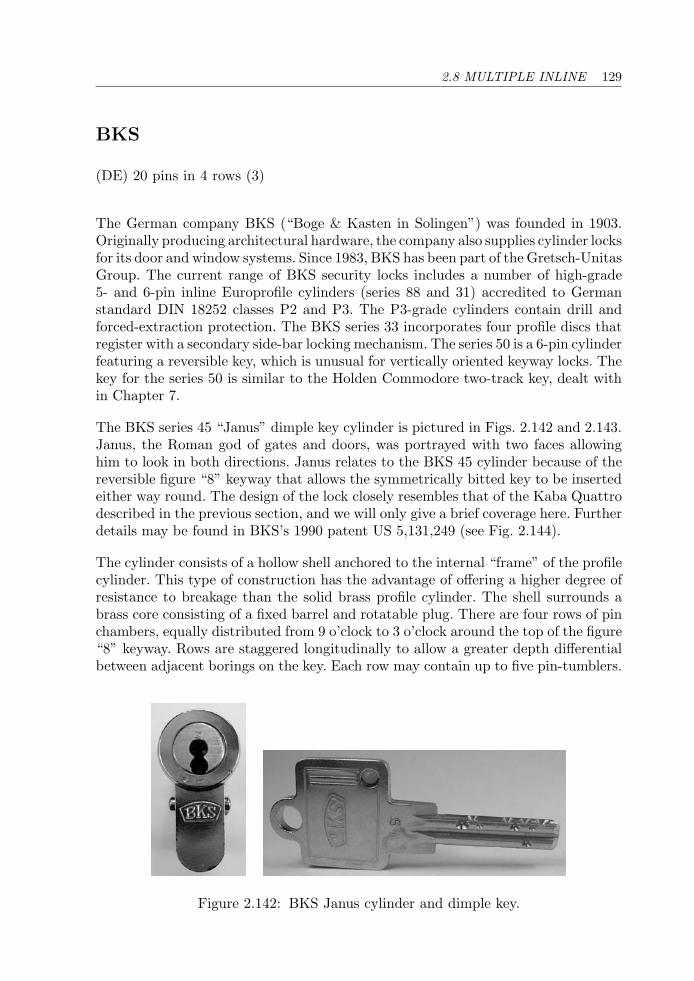
2.8 MULTIPLE INLINE 129
BKS
(DE) 20 pins in 4 rows (3)
The German company BKS (“Boge & Kasten in Solingen”) was founded in 1903.Originally producing architectural hardware, the company also supplies cylinder locksfor its door and window systems. Since 1983, BKS has been part of the Gretsch-UnitasGroup. The current range of BKS security locks includes a number of high-grade5- and 6-pin inline Europrofile cylinders (series 88 and 31) accredited to Germanstandard DIN 18252 classes P2 and P3. The P3-grade cylinders contain drill andforced-extraction protection. The BKS series 33 incorporates four profile discs thatregister with a secondary side-bar locking mechanism. The series 50 is a 6-pin cylinderfeaturing a reversible key, which is unusual for vertically oriented keyway locks. Thekey for the series 50 is similar to the Holden Commodore two-track key, dealt within Chapter 7.
The BKS series 45 “Janus” dimple key cylinder is pictured in Figs. 2.142 and 2.143.Janus, the Roman god of gates and doors, was portrayed with two faces allowinghim to look in both directions. Janus relates to the BKS 45 cylinder because of thereversible figure “8” keyway that allows the symmetrically bitted key to be insertedeither way round. The design of the lock closely resembles that of the Kaba Quattrodescribed in the previous section, and we will only give a brief coverage here. Furtherdetails may be found in BKS’s 1990 patent US 5,131,249 (see Fig. 2.144).
The cylinder consists of a hollow shell anchored to the internal “frame” of the profilecylinder. This type of construction has the advantage of offering a higher degree ofresistance to breakage than the solid brass profile cylinder. The shell surrounds abrass core consisting of a fixed barrel and rotatable plug. There are four rows of pinchambers, equally distributed from 9 o’clock to 3 o’clock around the top of the figure“8” keyway. Rows are staggered longitudinally to allow a greater depth differentialbetween adjacent borings on the key. Each row may contain up to five pin-tumblers.
Figure 2.142: BKS Janus cylinder and dimple key.
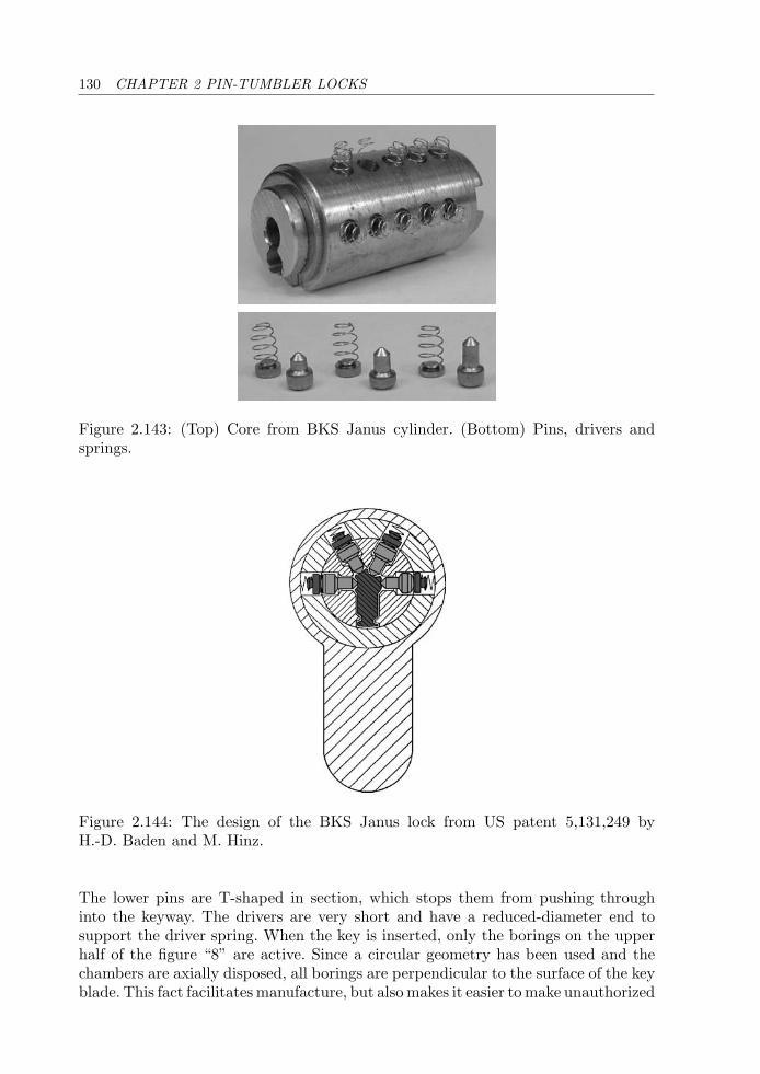
130 CHAPTER 2 PIN-TUMBLER LOCKS
Figure 2.143: (Top) Core from BKS Janus cylinder. (Bottom) Pins, drivers andsprings.
Figure 2.144: The design of the BKS Janus lock from US patent 5,131,249 byH.-D. Baden and M. Hinz.
The lower pins are T-shaped in section, which stops them from pushing throughinto the keyway. The drivers are very short and have a reduced-diameter end tosupport the driver spring. When the key is inserted, only the borings on the upperhalf of the figure “8” are active. Since a circular geometry has been used and thechambers are axially disposed, all borings are perpendicular to the surface of the keyblade. This fact facilitates manufacture, but also makes it easier to make unauthorized
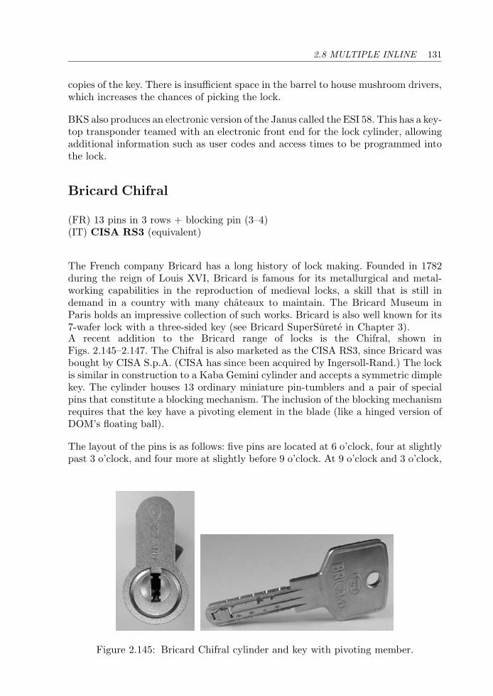
2.8 MULTIPLE INLINE 131
copies of the key. There is insufficient space in the barrel to house mushroom drivers,which increases the chances of picking the lock.
BKS also produces an electronic version of the Janus called the ESI 58. This has a key-top transponder teamed with an electronic front end for the lock cylinder, allowingadditional information such as user codes and access times to be programmed intothe lock.
Bricard Chifral
(FR) 13 pins in 3 rows + blocking pin (3–4)(IT) CISA RS3 (equivalent)
The French company Bricard has a long history of lock making. Founded in 1782during the reign of Louis XVI, Bricard is famous for its metallurgical and metal-working capabilities in the reproduction of medieval locks, a skill that is still indemand in a country with many chateaux to maintain. The Bricard Museum inParis holds an impressive collection of such works. Bricard is also well known for its7-wafer lock with a three-sided key (see Bricard SuperSurete in Chapter 3).A recent addition to the Bricard range of locks is the Chifral, shown inFigs. 2.145–2.147. The Chifral is also marketed as the CISA RS3, since Bricard wasbought by CISA S.p.A. (CISA has since been acquired by Ingersoll-Rand.) The lockis similar in construction to a Kaba Gemini cylinder and accepts a symmetric dimplekey. The cylinder houses 13 ordinary miniature pin-tumblers and a pair of specialpins that constitute a blocking mechanism. The inclusion of the blocking mechanismrequires that the key have a pivoting element in the blade (like a hinged version ofDOM’s floating ball).
The layout of the pins is as follows: five pins are located at 6 o’clock, four at slightlypast 3 o’clock, and four more at slightly before 9 o’clock. At 9 o’clock and 3 o’clock,
Figure 2.145: Bricard Chifral cylinder and key with pivoting member.
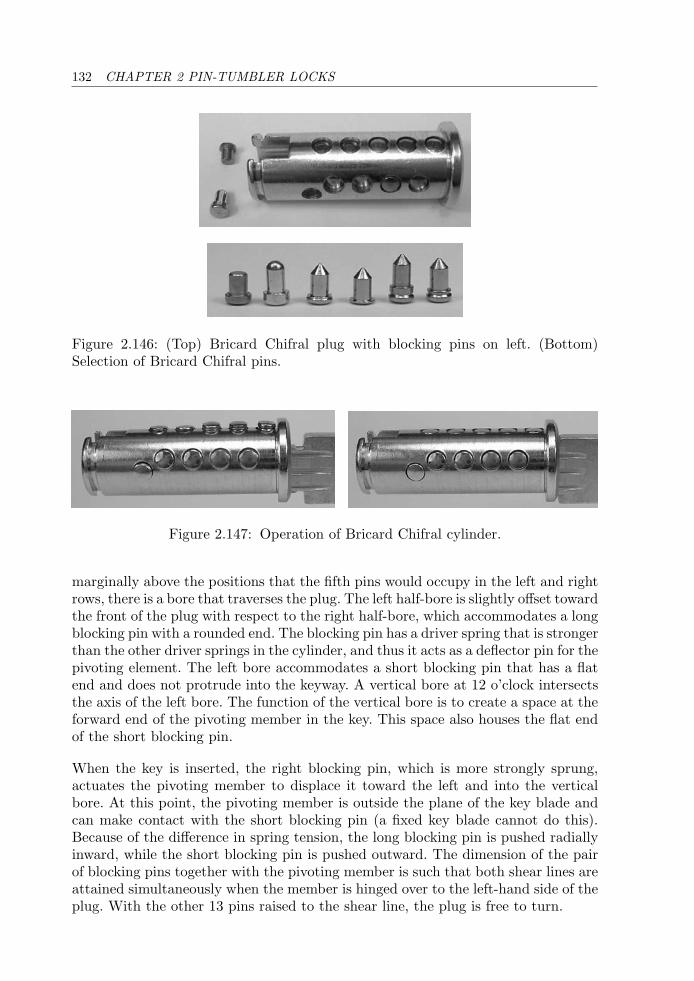
132 CHAPTER 2 PIN-TUMBLER LOCKS
Figure 2.146: (Top) Bricard Chifral plug with blocking pins on left. (Bottom)Selection of Bricard Chifral pins.
Figure 2.147: Operation of Bricard Chifral cylinder.
marginally above the positions that the fifth pins would occupy in the left and rightrows, there is a bore that traverses the plug. The left half-bore is slightly offset towardthe front of the plug with respect to the right half-bore, which accommodates a longblocking pin with a rounded end. The blocking pin has a driver spring that is strongerthan the other driver springs in the cylinder, and thus it acts as a deflector pin for thepivoting element. The left bore accommodates a short blocking pin that has a flatend and does not protrude into the keyway. A vertical bore at 12 o’clock intersectsthe axis of the left bore. The function of the vertical bore is to create a space at theforward end of the pivoting member in the key. This space also houses the flat endof the short blocking pin.
When the key is inserted, the right blocking pin, which is more strongly sprung,actuates the pivoting member to displace it toward the left and into the verticalbore. At this point, the pivoting member is outside the plane of the key blade andcan make contact with the short blocking pin (a fixed key blade cannot do this).Because of the difference in spring tension, the long blocking pin is pushed radiallyinward, while the short blocking pin is pushed outward. The dimension of the pairof blocking pins together with the pivoting member is such that both shear lines areattained simultaneously when the member is hinged over to the left-hand side of theplug. With the other 13 pins raised to the shear line, the plug is free to turn.
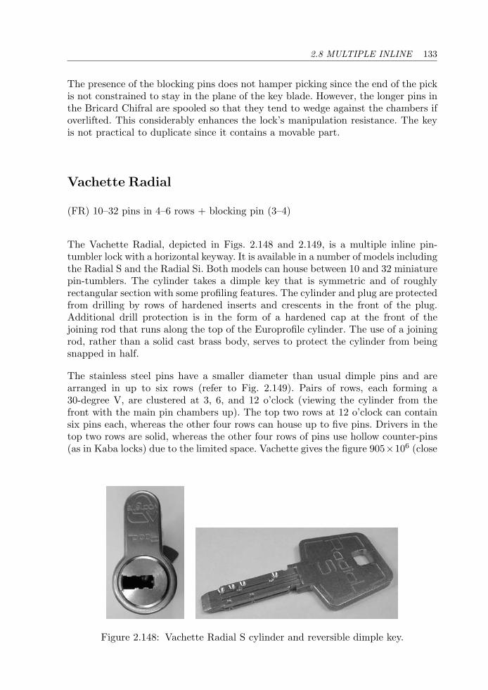
2.8 MULTIPLE INLINE 133
The presence of the blocking pins does not hamper picking since the end of the pickis not constrained to stay in the plane of the key blade. However, the longer pins inthe Bricard Chifral are spooled so that they tend to wedge against the chambers ifoverlifted. This considerably enhances the lock’s manipulation resistance. The keyis not practical to duplicate since it contains a movable part.
Vachette Radial
(FR) 10–32 pins in 4–6 rows + blocking pin (3–4)
The Vachette Radial, depicted in Figs. 2.148 and 2.149, is a multiple inline pin-tumbler lock with a horizontal keyway. It is available in a number of models includingthe Radial S and the Radial Si. Both models can house between 10 and 32 miniaturepin-tumblers. The cylinder takes a dimple key that is symmetric and of roughlyrectangular section with some profiling features. The cylinder and plug are protectedfrom drilling by rows of hardened inserts and crescents in the front of the plug.Additional drill protection is in the form of a hardened cap at the front of thejoining rod that runs along the top of the Europrofile cylinder. The use of a joiningrod, rather than a solid cast brass body, serves to protect the cylinder from beingsnapped in half.
The stainless steel pins have a smaller diameter than usual dimple pins and arearranged in up to six rows (refer to Fig. 2.149). Pairs of rows, each forming a30-degree V, are clustered at 3, 6, and 12 o’clock (viewing the cylinder from thefront with the main pin chambers up). The top two rows at 12 o’clock can containsix pins each, whereas the other four rows can house up to five pins. Drivers in thetop two rows are solid, whereas the other four rows of pins use hollow counter-pins(as in Kaba locks) due to the limited space. Vachette gives the figure 905×106 (close
Figure 2.148: Vachette Radial S cylinder and reversible dimple key.
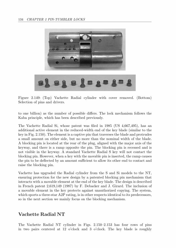
134 CHAPTER 2 PIN-TUMBLER LOCKS
Figure 2.149: (Top) Vachette Radial cylinder with cover removed. (Bottom)Selection of pins and drivers.
to one billion) as the number of possible differs. The lock mechanism follows theKaba principle, which has been described previously.
The Vachette Radial Si, whose patent was filed in 1985 (US 4,667,495), has anadditional active element in the reduced-width end of the key blade (similar to thekey in Fig. 2.150). The element is a captive pin that traverses the blade and protrudesa small amount on either side, but no more than the nominal width of the blade.A blocking pin is located at the rear of the plug, aligned with the major axis of thekeyway, and there is a ramp opposite the pin. The blocking pin is recessed and isnot visible in the keyway. A standard Vachette Radial S key will not contact theblocking pin. However, when a key with the movable pin is inserted, the ramp causesthe pin to be deflected by an amount sufficient to allow its other end to contact andraise the blocking pin.
Vachette has upgraded the Radial cylinder from the S and Si models to the NT,ensuring protection for the new design by a patented blocking pin mechanism thatinteracts with a movable element at the end of the key blade. The design is describedin French patent 2,619,149 (1987) by F. Debacker and J. Girard. The inclusion ofa movable element in the key protects against unauthorized copying. The system,which sports a three-star A2P rating, is in other respects identical to its predecessors,so in the next section we mainly focus on the blocking mechanism.
Vachette Radial NT
The Vachette Radial NT cylinder in Figs. 2.150–2.153 has four rows of pinsin two pairs centered at 12 o’clock and 3 o’clock. The key blade is roughly
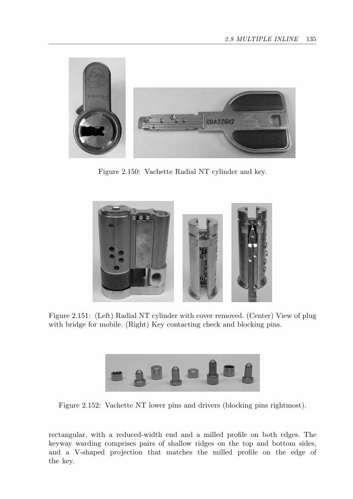
2.8 MULTIPLE INLINE 135
Figure 2.150: Vachette Radial NT cylinder and key.
Figure 2.151: (Left) Radial NT cylinder with cover removed. (Center) View of plugwith bridge for mobile. (Right) Key contacting check and blocking pins.
Figure 2.152: Vachette NT lower pins and drivers (blocking pins rightmost).
rectangular, with a reduced-width end and a milled profile on both edges. Thekeyway warding comprises pairs of shallow ridges on the top and bottom sides,and a V-shaped projection that matches the milled profile on the edge ofthe key.
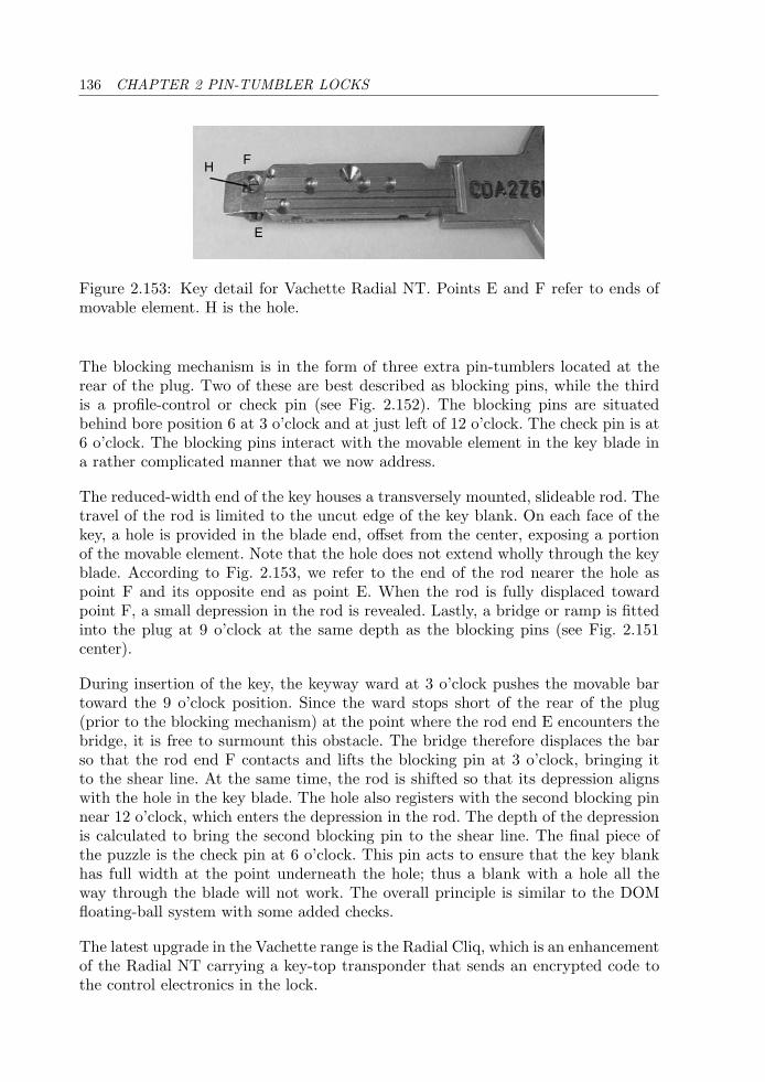
136 CHAPTER 2 PIN-TUMBLER LOCKS
H F
E
Figure 2.153: Key detail for Vachette Radial NT. Points E and F refer to ends ofmovable element. H is the hole.
The blocking mechanism is in the form of three extra pin-tumblers located at therear of the plug. Two of these are best described as blocking pins, while the thirdis a profile-control or check pin (see Fig. 2.152). The blocking pins are situatedbehind bore position 6 at 3 o’clock and at just left of 12 o’clock. The check pin is at6 o’clock. The blocking pins interact with the movable element in the key blade ina rather complicated manner that we now address.
The reduced-width end of the key houses a transversely mounted, slideable rod. Thetravel of the rod is limited to the uncut edge of the key blank. On each face of thekey, a hole is provided in the blade end, offset from the center, exposing a portionof the movable element. Note that the hole does not extend wholly through the keyblade. According to Fig. 2.153, we refer to the end of the rod nearer the hole aspoint F and its opposite end as point E. When the rod is fully displaced towardpoint F, a small depression in the rod is revealed. Lastly, a bridge or ramp is fittedinto the plug at 9 o’clock at the same depth as the blocking pins (see Fig. 2.151center).
During insertion of the key, the keyway ward at 3 o’clock pushes the movable bartoward the 9 o’clock position. Since the ward stops short of the rear of the plug(prior to the blocking mechanism) at the point where the rod end E encounters thebridge, it is free to surmount this obstacle. The bridge therefore displaces the barso that the rod end F contacts and lifts the blocking pin at 3 o’clock, bringing itto the shear line. At the same time, the rod is shifted so that its depression alignswith the hole in the key blade. The hole also registers with the second blocking pinnear 12 o’clock, which enters the depression in the rod. The depth of the depressionis calculated to bring the second blocking pin to the shear line. The final piece ofthe puzzle is the check pin at 6 o’clock. This pin acts to ensure that the key blankhas full width at the point underneath the hole; thus a blank with a hole all theway through the blade will not work. The overall principle is similar to the DOMfloating-ball system with some added checks.
The latest upgrade in the Vachette range is the Radial Cliq, which is an enhancementof the Radial NT carrying a key-top transponder that sends an encrypted code tothe control electronics in the lock.
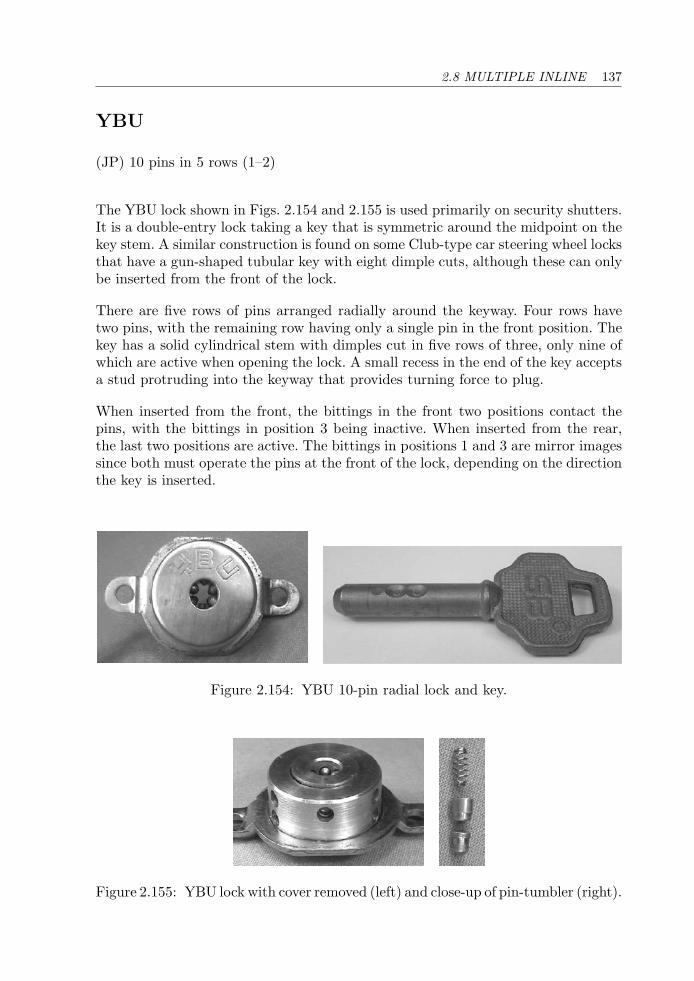
2.8 MULTIPLE INLINE 137
YBU
(JP) 10 pins in 5 rows (1–2)
The YBU lock shown in Figs. 2.154 and 2.155 is used primarily on security shutters.It is a double-entry lock taking a key that is symmetric around the midpoint on thekey stem. A similar construction is found on some Club-type car steering wheel locksthat have a gun-shaped tubular key with eight dimple cuts, although these can onlybe inserted from the front of the lock.
There are five rows of pins arranged radially around the keyway. Four rows havetwo pins, with the remaining row having only a single pin in the front position. Thekey has a solid cylindrical stem with dimples cut in five rows of three, only nine ofwhich are active when opening the lock. A small recess in the end of the key acceptsa stud protruding into the keyway that provides turning force to plug.
When inserted from the front, the bittings in the front two positions contact thepins, with the bittings in position 3 being inactive. When inserted from the rear,the last two positions are active. The bittings in positions 1 and 3 are mirror imagessince both must operate the pins at the front of the lock, depending on the directionthe key is inserted.
Figure 2.154: YBU 10-pin radial lock and key.
Figure 2.155: YBU lock with cover removed (left) and close-up of pin-tumbler (right).
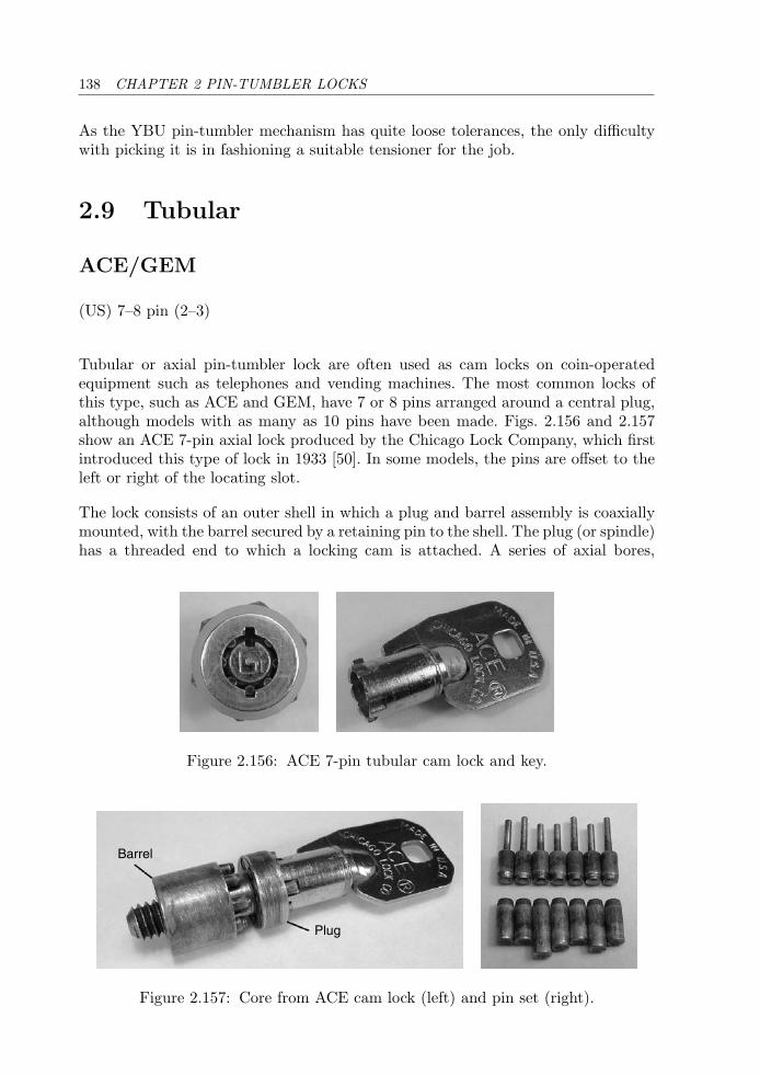
138 CHAPTER 2 PIN-TUMBLER LOCKS
As the YBU pin-tumbler mechanism has quite loose tolerances, the only difficultywith picking it is in fashioning a suitable tensioner for the job.
2.9 Tubular
ACE/GEM
(US) 7–8 pin (2–3)
Tubular or axial pin-tumbler lock are often used as cam locks on coin-operatedequipment such as telephones and vending machines. The most common locks ofthis type, such as ACE and GEM, have 7 or 8 pins arranged around a central plug,although models with as many as 10 pins have been made. Figs. 2.156 and 2.157show an ACE 7-pin axial lock produced by the Chicago Lock Company, which firstintroduced this type of lock in 1933 [50]. In some models, the pins are offset to theleft or right of the locating slot.
The lock consists of an outer shell in which a plug and barrel assembly is coaxiallymounted, with the barrel secured by a retaining pin to the shell. The plug (or spindle)has a threaded end to which a locking cam is attached. A series of axial bores,
Figure 2.156: ACE 7-pin tubular cam lock and key.
Barrel
Plug
Figure 2.157: Core from ACE cam lock (left) and pin set (right).
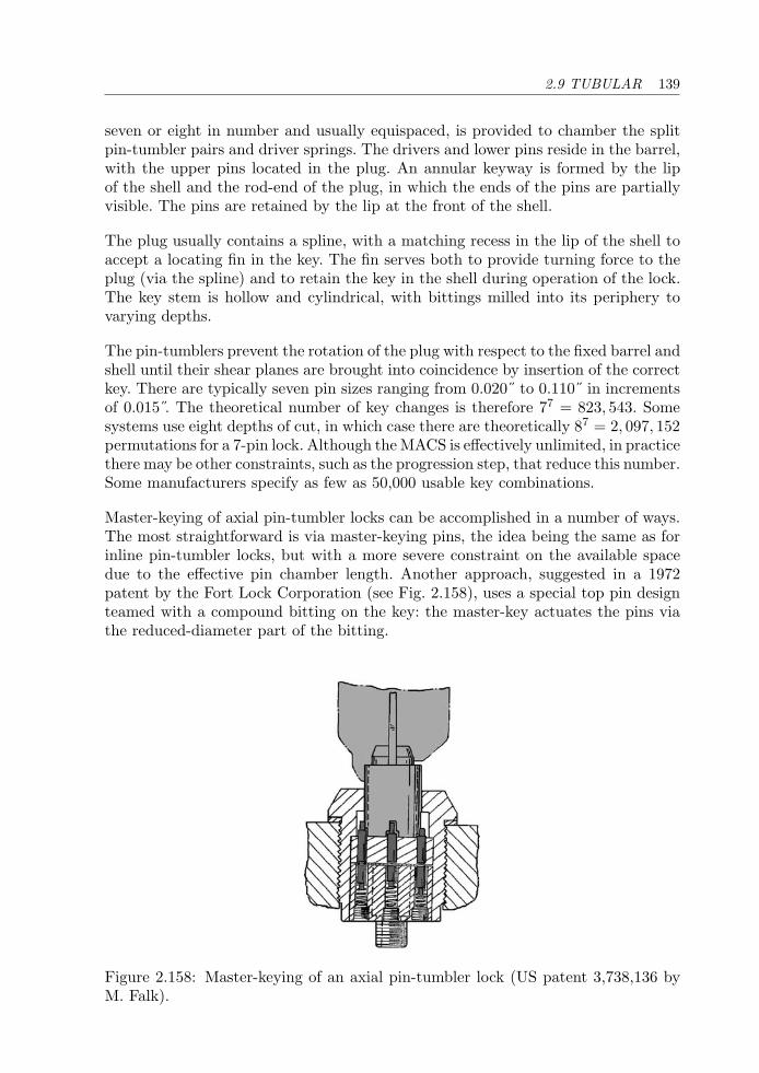
2.9 TUBULAR 139
seven or eight in number and usually equispaced, is provided to chamber the splitpin-tumbler pairs and driver springs. The drivers and lower pins reside in the barrel,with the upper pins located in the plug. An annular keyway is formed by the lipof the shell and the rod-end of the plug, in which the ends of the pins are partiallyvisible. The pins are retained by the lip at the front of the shell.
The plug usually contains a spline, with a matching recess in the lip of the shell toaccept a locating fin in the key. The fin serves both to provide turning force to theplug (via the spline) and to retain the key in the shell during operation of the lock.The key stem is hollow and cylindrical, with bittings milled into its periphery tovarying depths.
The pin-tumblers prevent the rotation of the plug with respect to the fixed barrel andshell until their shear planes are brought into coincidence by insertion of the correctkey. There are typically seven pin sizes ranging from 0.020˝ to 0.110˝ in incrementsof 0.015 . The theoretical number of key changes is therefore 77 = 823, 543. Somesystems use eight depths of cut, in which case there are theoretically 87 = 2, 097, 152permutations for a 7-pin lock. Although the MACS is effectively unlimited, in practicethere may be other constraints, such as the progression step, that reduce this number.Some manufacturers specify as few as 50,000 usable key combinations.
Master-keying of axial pin-tumbler locks can be accomplished in a number of ways.The most straightforward is via master-keying pins, the idea being the same as forinline pin-tumbler locks, but with a more severe constraint on the available spacedue to the effective pin chamber length. Another approach, suggested in a 1972patent by the Fort Lock Corporation (see Fig. 2.158), uses a special top pin designteamed with a compound bitting on the key: the master-key actuates the pins viathe reduced-diameter part of the bitting.
Figure 2.158: Master-keying of an axial pin-tumbler lock (US patent 3,738,136 byM. Falk).
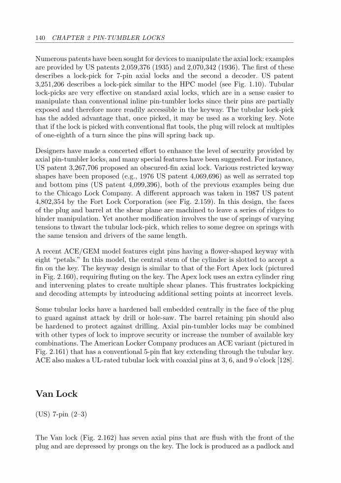
140 CHAPTER 2 PIN-TUMBLER LOCKS
Numerous patents have been sought for devices to manipulate the axial lock: examplesare provided by US patents 2,059,376 (1935) and 2,070,342 (1936). The first of thesedescribes a lock-pick for 7-pin axial locks and the second a decoder. US patent3,251,206 describes a lock-pick similar to the HPC model (see Fig. 1.10). Tubularlock-picks are very effective on standard axial locks, which are in a sense easier tomanipulate than conventional inline pin-tumbler locks since their pins are partiallyexposed and therefore more readily accessible in the keyway. The tubular lock-pickhas the added advantage that, once picked, it may be used as a working key. Notethat if the lock is picked with conventional flat tools, the plug will relock at multiplesof one-eighth of a turn since the pins will spring back up.
Designers have made a concerted effort to enhance the level of security provided byaxial pin-tumbler locks, and many special features have been suggested. For instance,US patent 3,267,706 proposed an obscured-fin axial lock. Various restricted keywayshapes have been proposed (e.g., 1976 US patent 4,069,696) as well as serrated topand bottom pins (US patent 4,099,396), both of the previous examples being dueto the Chicago Lock Company. A different approach was taken in 1987 US patent4,802,354 by the Fort Lock Corporation (see Fig. 2.159). In this design, the facesof the plug and barrel at the shear plane are machined to leave a series of ridges tohinder manipulation. Yet another modification involves the use of springs of varyingtensions to thwart the tubular lock-pick, which relies to some degree on springs withthe same tension and drivers of the same length.
A recent ACE/GEM model features eight pins having a flower-shaped keyway witheight “petals.” In this model, the central stem of the cylinder is slotted to accept afin on the key. The keyway design is similar to that of the Fort Apex lock (picturedin Fig. 2.160), requiring fluting on the key. The Apex lock uses an extra cylinder ringand intervening plates to create multiple shear planes. This frustrates lockpickingand decoding attempts by introducing additional setting points at incorrect levels.
Some tubular locks have a hardened ball embedded centrally in the face of the plugto guard against attack by drill or hole-saw. The barrel retaining pin should alsobe hardened to protect against drilling. Axial pin-tumbler locks may be combinedwith other types of lock to improve security or increase the number of available keycombinations. The American Locker Company produces an ACE variant (pictured inFig. 2.161) that has a conventional 5-pin flat key extending through the tubular key.ACE also makes a UL-rated tubular lock with coaxial pins at 3, 6, and 9 o’clock [128].
Van Lock
(US) 7-pin (2–3)
The Van lock (Fig. 2.162) has seven axial pins that are flush with the front of theplug and are depressed by prongs on the key. The lock is produced as a padlock and
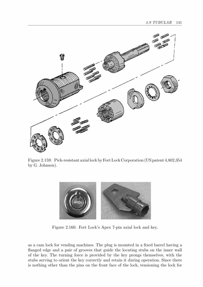
2.9 TUBULAR 141
Figure 2.159: Pick-resistant axial lock byFort LockCorporation (USpatent 4,802,354by G. Johnson).
Figure 2.160: Fort Lock’s Apex 7-pin axial lock and key.
as a cam lock for vending machines. The plug is mounted in a fixed barrel having aflanged edge and a pair of grooves that guide the locating stubs on the inner wallof the key. The turning force is provided by the key prongs themselves, with thestubs serving to orient the key correctly and retain it during operation. Since thereis nothing other than the pins on the front face of the lock, tensioning the lock for
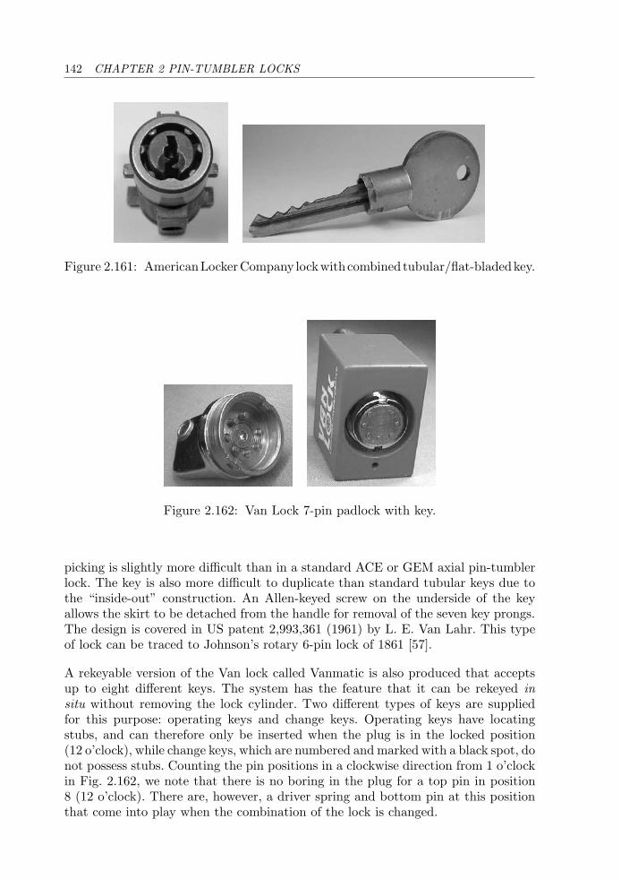
142 CHAPTER 2 PIN-TUMBLER LOCKS
Figure 2.161: AmericanLockerCompany lockwithcombined tubular/flat-bladedkey.
Figure 2.162: Van Lock 7-pin padlock with key.
picking is slightly more difficult than in a standard ACE or GEM axial pin-tumblerlock. The key is also more difficult to duplicate than standard tubular keys due tothe “inside-out” construction. An Allen-keyed screw on the underside of the keyallows the skirt to be detached from the handle for removal of the seven key prongs.The design is covered in US patent 2,993,361 (1961) by L. E. Van Lahr. This typeof lock can be traced to Johnson’s rotary 6-pin lock of 1861 [57].
A rekeyable version of the Van lock called Vanmatic is also produced that acceptsup to eight different keys. The system has the feature that it can be rekeyed insitu without removing the lock cylinder. Two different types of keys are suppliedfor this purpose: operating keys and change keys. Operating keys have locatingstubs, and can therefore only be inserted when the plug is in the locked position(12 o’clock), while change keys, which are numbered and marked with a black spot, donot possess stubs. Counting the pin positions in a clockwise direction from 1 o’clockin Fig. 2.162, we note that there is no boring in the plug for a top pin in position8 (12 o’clock). There are, however, a driver spring and bottom pin at this positionthat come into play when the combination of the lock is changed.
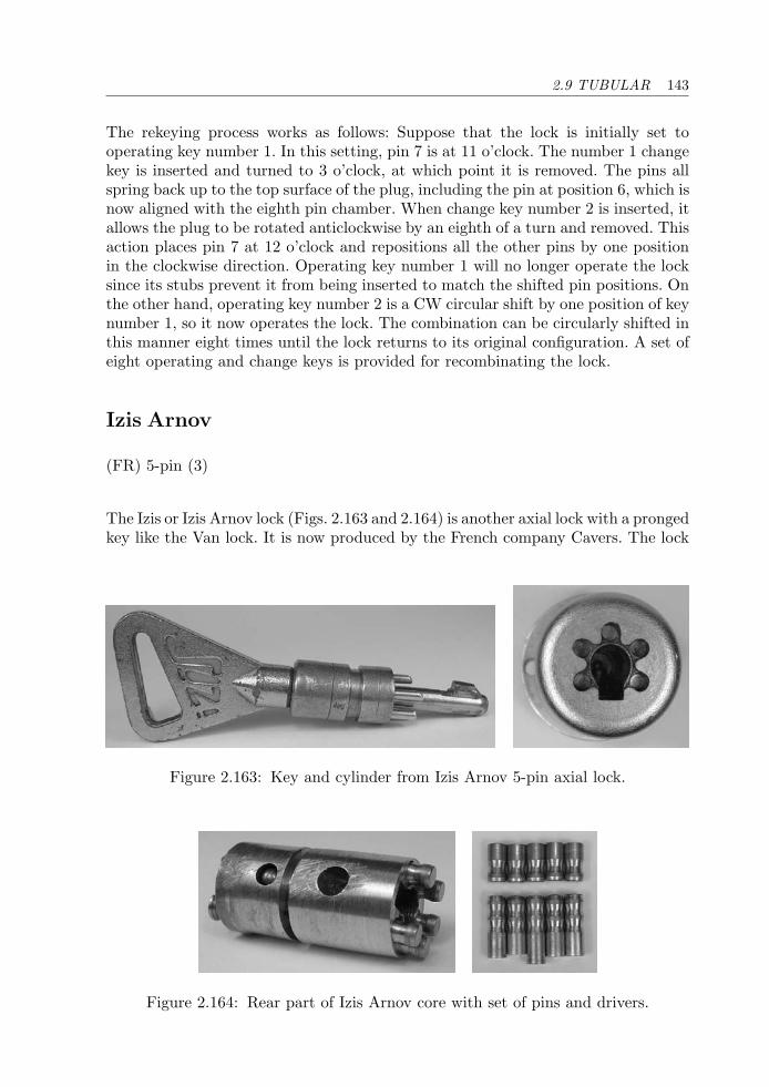
2.9 TUBULAR 143
The rekeying process works as follows: Suppose that the lock is initially set tooperating key number 1. In this setting, pin 7 is at 11 o’clock. The number 1 changekey is inserted and turned to 3 o’clock, at which point it is removed. The pins allspring back up to the top surface of the plug, including the pin at position 6, which isnow aligned with the eighth pin chamber. When change key number 2 is inserted, itallows the plug to be rotated anticlockwise by an eighth of a turn and removed. Thisaction places pin 7 at 12 o’clock and repositions all the other pins by one positionin the clockwise direction. Operating key number 1 will no longer operate the locksince its stubs prevent it from being inserted to match the shifted pin positions. Onthe other hand, operating key number 2 is a CW circular shift by one position of keynumber 1, so it now operates the lock. The combination can be circularly shifted inthis manner eight times until the lock returns to its original configuration. A set ofeight operating and change keys is provided for recombinating the lock.
Izis Arnov
(FR) 5-pin (3)
The Izis or Izis Arnov lock (Figs. 2.163 and 2.164) is another axial lock with a prongedkey like the Van lock. It is now produced by the French company Cavers. The lock
Figure 2.163: Key and cylinder from Izis Arnov 5-pin axial lock.
Figure 2.164: Rear part of Izis Arnov core with set of pins and drivers.
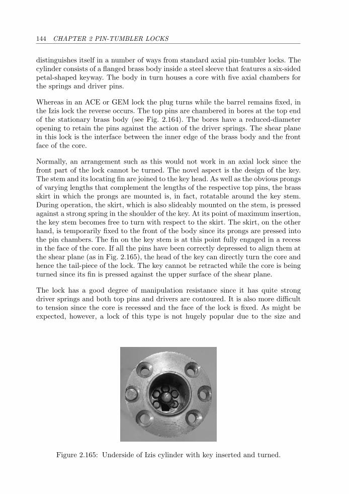
144 CHAPTER 2 PIN-TUMBLER LOCKS
distinguishes itself in a number of ways from standard axial pin-tumbler locks. Thecylinder consists of a flanged brass body inside a steel sleeve that features a six-sidedpetal-shaped keyway. The body in turn houses a core with five axial chambers forthe springs and driver pins.
Whereas in an ACE or GEM lock the plug turns while the barrel remains fixed, inthe Izis lock the reverse occurs. The top pins are chambered in bores at the top endof the stationary brass body (see Fig. 2.164). The bores have a reduced-diameteropening to retain the pins against the action of the driver springs. The shear planein this lock is the interface between the inner edge of the brass body and the frontface of the core.
Normally, an arrangement such as this would not work in an axial lock since thefront part of the lock cannot be turned. The novel aspect is the design of the key.The stem and its locating fin are joined to the key head. As well as the obvious prongsof varying lengths that complement the lengths of the respective top pins, the brassskirt in which the prongs are mounted is, in fact, rotatable around the key stem.During operation, the skirt, which is also slideably mounted on the stem, is pressedagainst a strong spring in the shoulder of the key. At its point of maximum insertion,the key stem becomes free to turn with respect to the skirt. The skirt, on the otherhand, is temporarily fixed to the front of the body since its prongs are pressed intothe pin chambers. The fin on the key stem is at this point fully engaged in a recessin the face of the core. If all the pins have been correctly depressed to align them atthe shear plane (as in Fig. 2.165), the head of the key can directly turn the core andhence the tail-piece of the lock. The key cannot be retracted while the core is beingturned since its fin is pressed against the upper surface of the shear plane.
The lock has a good degree of manipulation resistance since it has quite strongdriver springs and both top pins and drivers are contoured. It is also more difficultto tension since the core is recessed and the face of the lock is fixed. As might beexpected, however, a lock of this type is not hugely popular due to the size and
Figure 2.165: Underside of Izis cylinder with key inserted and turned.
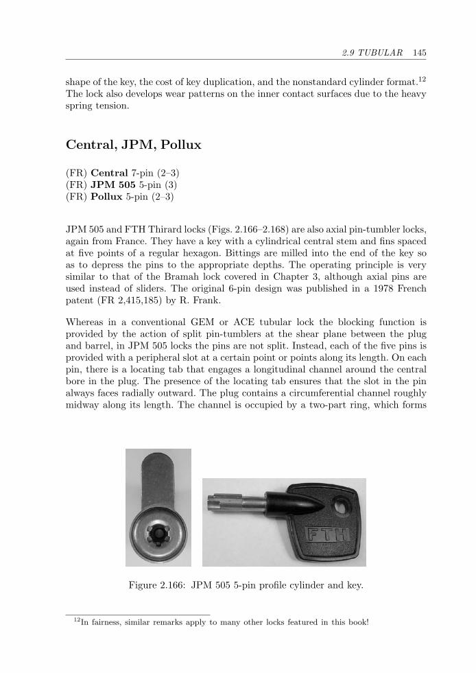
2.9 TUBULAR 145
shape of the key, the cost of key duplication, and the nonstandard cylinder format.12
The lock also develops wear patterns on the inner contact surfaces due to the heavyspring tension.
Central, JPM, Pollux
(FR) Central 7-pin (2–3)(FR) JPM 505 5-pin (3)(FR) Pollux 5-pin (2–3)
JPM 505 and FTH Thirard locks (Figs. 2.166–2.168) are also axial pin-tumbler locks,again from France. They have a key with a cylindrical central stem and fins spacedat five points of a regular hexagon. Bittings are milled into the end of the key soas to depress the pins to the appropriate depths. The operating principle is verysimilar to that of the Bramah lock covered in Chapter 3, although axial pins areused instead of sliders. The original 6-pin design was published in a 1978 Frenchpatent (FR 2,415,185) by R. Frank.
Whereas in a conventional GEM or ACE tubular lock the blocking function isprovided by the action of split pin-tumblers at the shear plane between the plugand barrel, in JPM 505 locks the pins are not split. Instead, each of the five pins isprovided with a peripheral slot at a certain point or points along its length. On eachpin, there is a locating tab that engages a longitudinal channel around the centralbore in the plug. The presence of the locating tab ensures that the slot in the pinalways faces radially outward. The plug contains a circumferential channel roughlymidway along its length. The channel is occupied by a two-part ring, which forms
Figure 2.166: JPM 505 5-pin profile cylinder and key.
12In fairness, similar remarks apply to many other locks featured in this book!
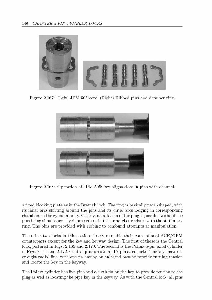
146 CHAPTER 2 PIN-TUMBLER LOCKS
Figure 2.167: (Left) JPM 505 core. (Right) Ribbed pins and detainer ring.
Figure 2.168: Operation of JPM 505: key aligns slots in pins with channel.
a fixed blocking plate as in the Bramah lock. The ring is basically petal-shaped, withits inner arcs skirting around the pins and its outer arcs lodging in correspondingchambers in the cylinder body. Clearly, no rotation of the plug is possible without thepins being simultaneously depressed so that their notches register with the stationaryring. The pins are provided with ribbing to confound attempts at manipulation.
The other two locks in this section closely resemble their conventional ACE/GEMcounterparts except for the key and keyway design. The first of these is the Centrallock, pictured in Figs. 2.169 and 2.170. The second is the Pollux 5-pin axial cylinderin Figs. 2.171 and 2.172. Central produces 5- and 7-pin axial locks. The keys have sixor eight radial fins, with one fin having an enlarged base to provide turning tensionand locate the key in the keyway.
The Pollux cylinder has five pins and a sixth fin on the key to provide tension to theplug as well as locating the pipe key in the keyway. As with the Central lock, all pins
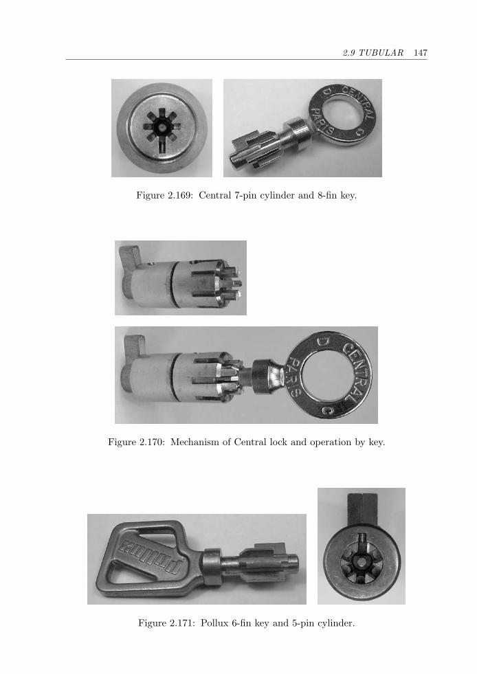
2.9 TUBULAR 147
Figure 2.169: Central 7-pin cylinder and 8-fin key.
Figure 2.170: Mechanism of Central lock and operation by key.
Figure 2.171: Pollux 6-fin key and 5-pin cylinder.
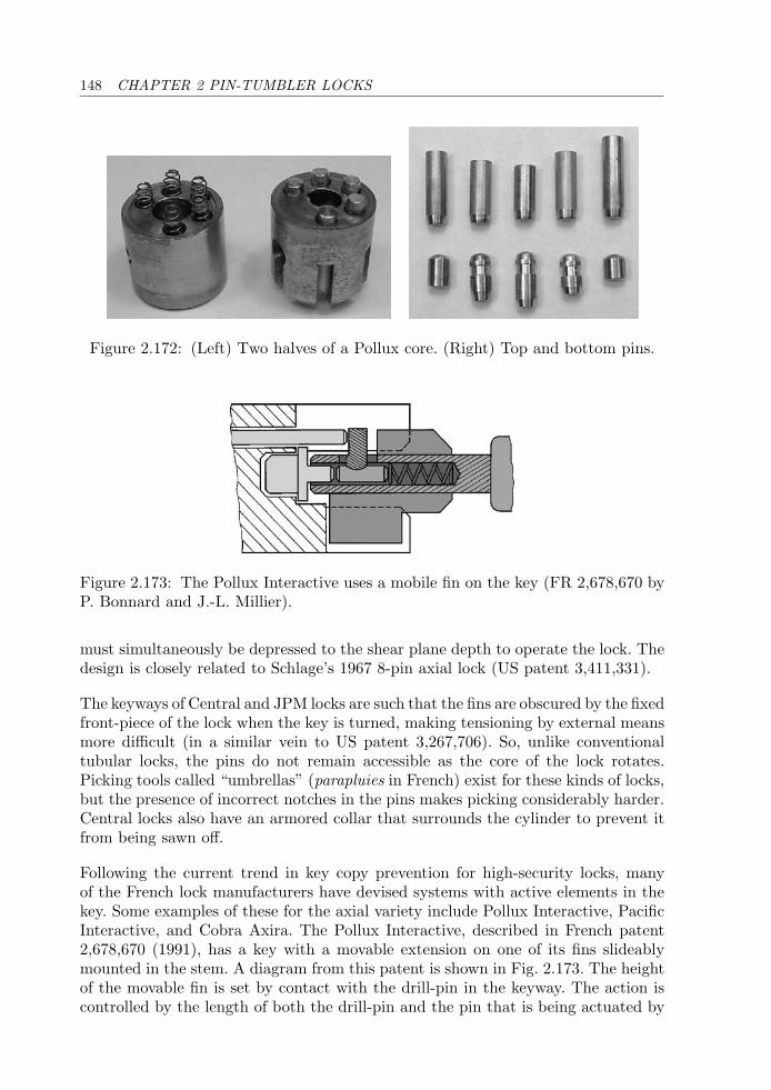
148 CHAPTER 2 PIN-TUMBLER LOCKS
Figure 2.172: (Left) Two halves of a Pollux core. (Right) Top and bottom pins.
Figure 2.173: The Pollux Interactive uses a mobile fin on the key (FR 2,678,670 byP. Bonnard and J.-L. Millier).
must simultaneously be depressed to the shear plane depth to operate the lock. Thedesign is closely related to Schlage’s 1967 8-pin axial lock (US patent 3,411,331).
The keyways of Central and JPM locks are such that the fins are obscured by the fixedfront-piece of the lock when the key is turned, making tensioning by external meansmore difficult (in a similar vein to US patent 3,267,706). So, unlike conventionaltubular locks, the pins do not remain accessible as the core of the lock rotates.Picking tools called “umbrellas” (parapluies in French) exist for these kinds of locks,but the presence of incorrect notches in the pins makes picking considerably harder.Central locks also have an armored collar that surrounds the cylinder to prevent itfrom being sawn off.
Following the current trend in key copy prevention for high-security locks, manyof the French lock manufacturers have devised systems with active elements in thekey. Some examples of these for the axial variety include Pollux Interactive, PacificInteractive, and Cobra Axira. The Pollux Interactive, described in French patent2,678,670 (1991), has a key with a movable extension on one of its fins slideablymounted in the stem. A diagram from this patent is shown in Fig. 2.173. The heightof the movable fin is set by contact with the drill-pin in the keyway. The action iscontrolled by the length of both the drill-pin and the pin that is being actuated by
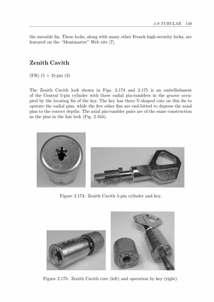
2.9 TUBULAR 149
the movable fin. These locks, along with many other French high-security locks, arefeatured on the “Montmartre” Web site [7].
Zenith Cavith
(FR) (5 + 3)-pin (3)
The Zenith Cavith lock shown in Figs. 2.174 and 2.175 is an embellishmentof the Central 5-pin cylinder with three radial pin-tumblers in the groove occu-pied by the locating fin of the key. The key has three V-shaped cuts on this fin tooperate the radial pins, while the five other fins are end-bitted to depress the axialpins to the correct depths. The axial pin-tumbler pairs are of the same constructionas the pins in the Izis lock (Fig. 2.164).
Figure 2.174: Zenith Cavith 5-pin cylinder and key.
Figure 2.175: Zenith Cavith core (left) and operation by key (right).
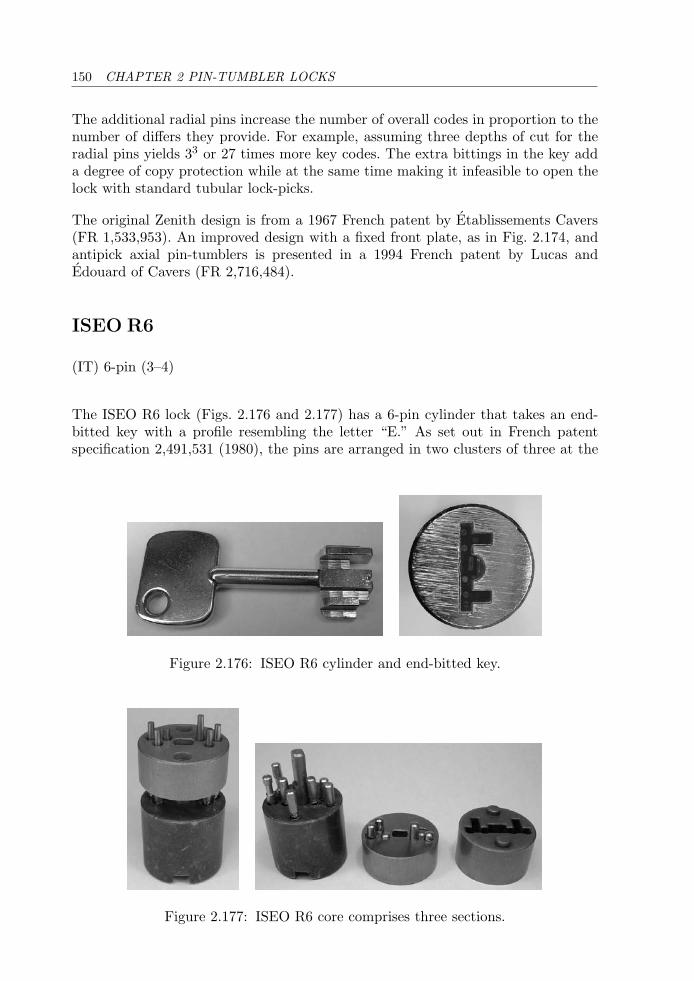
150 CHAPTER 2 PIN-TUMBLER LOCKS
The additional radial pins increase the number of overall codes in proportion to thenumber of differs they provide. For example, assuming three depths of cut for theradial pins yields 33 or 27 times more key codes. The extra bittings in the key adda degree of copy protection while at the same time making it infeasible to open thelock with standard tubular lock-picks.
The original Zenith design is from a 1967 French patent by Etablissements Cavers(FR 1,533,953). An improved design with a fixed front plate, as in Fig. 2.174, andantipick axial pin-tumblers is presented in a 1994 French patent by Lucas andEdouard of Cavers (FR 2,716,484).
ISEO R6
(IT) 6-pin (3–4)
The ISEO R6 lock (Figs. 2.176 and 2.177) has a 6-pin cylinder that takes an end-bitted key with a profile resembling the letter “E.” As set out in French patentspecification 2,491,531 (1980), the pins are arranged in two clusters of three at the
Figure 2.176: ISEO R6 cylinder and end-bitted key.
Figure 2.177: ISEO R6 core comprises three sections.
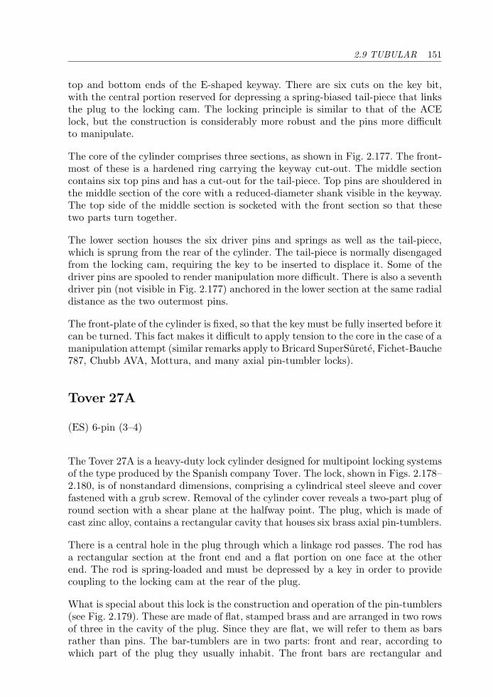
2.9 TUBULAR 151
top and bottom ends of the E-shaped keyway. There are six cuts on the key bit,with the central portion reserved for depressing a spring-biased tail-piece that linksthe plug to the locking cam. The locking principle is similar to that of the ACElock, but the construction is considerably more robust and the pins more difficultto manipulate.
The core of the cylinder comprises three sections, as shown in Fig. 2.177. The front-most of these is a hardened ring carrying the keyway cut-out. The middle sectioncontains six top pins and has a cut-out for the tail-piece. Top pins are shouldered inthe middle section of the core with a reduced-diameter shank visible in the keyway.The top side of the middle section is socketed with the front section so that thesetwo parts turn together.
The lower section houses the six driver pins and springs as well as the tail-piece,which is sprung from the rear of the cylinder. The tail-piece is normally disengagedfrom the locking cam, requiring the key to be inserted to displace it. Some of thedriver pins are spooled to render manipulation more difficult. There is also a seventhdriver pin (not visible in Fig. 2.177) anchored in the lower section at the same radialdistance as the two outermost pins.
The front-plate of the cylinder is fixed, so that the key must be fully inserted before itcan be turned. This fact makes it difficult to apply tension to the core in the case of amanipulation attempt (similar remarks apply to Bricard SuperSurete, Fichet-Bauche787, Chubb AVA, Mottura, and many axial pin-tumbler locks).
Tover 27A
(ES) 6-pin (3–4)
The Tover 27A is a heavy-duty lock cylinder designed for multipoint locking systemsof the type produced by the Spanish company Tover. The lock, shown in Figs. 2.178–2.180, is of nonstandard dimensions, comprising a cylindrical steel sleeve and coverfastened with a grub screw. Removal of the cylinder cover reveals a two-part plug ofround section with a shear plane at the halfway point. The plug, which is made ofcast zinc alloy, contains a rectangular cavity that houses six brass axial pin-tumblers.
There is a central hole in the plug through which a linkage rod passes. The rod hasa rectangular section at the front end and a flat portion on one face at the otherend. The rod is spring-loaded and must be depressed by a key in order to providecoupling to the locking cam at the rear of the plug.
What is special about this lock is the construction and operation of the pin-tumblers(see Fig. 2.179). These are made of flat, stamped brass and are arranged in two rowsof three in the cavity of the plug. Since they are flat, we will refer to them as barsrather than pins. The bar-tumblers are in two parts: front and rear, according towhich part of the plug they usually inhabit. The front bars are rectangular and

152 CHAPTER 2 PIN-TUMBLER LOCKS
Figure 2.178: Tover 27A large-format profile cylinder and key.
Figure 2.179: Two halves of Tover 27A core.
Figure 2.180: (Left) Key pushes bar-tumblers to correct depths. (Right) Not all keybittings are active.
have different lengths. The rear bars or drivers are mounted on thin stems and arespring-biased toward the front of the plug. There are two sorts of driver shapes,differing in their end profiles at the shear plane. The first of these is shaped like aninverted L. The second resembles the letter “t” and has an antipicking function.
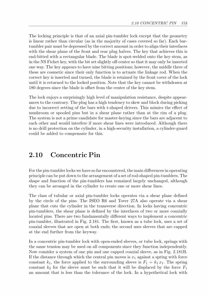
2.10 CONCENTRIC PIN 153
The locking principle is that of an axial pin-tumbler lock except that the geometryis linear rather than circular (as in the majority of cases covered so far). Each bar-tumbler pair must be depressed by the correct amount in order to align their interfaceswith the shear plane of the front and rear plug halves. The key that achieves this isend-bitted with a rectangular blade. The blade is spot-welded onto the key stem, asin the NS Fichet key, with the bit set slightly off-center so that it may only be insertedone way. The key appears to have nine bitting positions; however, the middle three ofthese are cosmetic since their only function is to actuate the linkage rod. When thecorrect key is inserted and turned, the blade is retained by the front cover of the lockuntil it is returned to the locked position. Note that the key cannot be withdrawn at180 degrees since the blade is offset from the center of the key stem.
The lock enjoys a surprisingly high level of manipulation resistance, despite appear-ances to the contrary. The plug has a high tendency to skew and block during pickingdue to incorrect setting of the bars with t-shaped drivers. This mimics the effect ofmushroom or spooled pins but in a shear plane rather than at the rim of a plug.The system is not a prime candidate for master-keying since the bars are adjacent toeach other and would interfere if more shear lines were introduced. Although thereis no drill protection on the cylinder, in a high-security installation, a cylinder-guardcould be added to compensate for this.
2.10 Concentric Pin
For the pin-tumbler locks we have so far encountered, the main differences in operatingprinciple can be put down to the arrangement of a set of rod-shaped pin-tumblers. Theshape and function of the pin-tumblers has remained largely unchanged, althoughthey can be arranged in the cylinder to create one or more shear lines.
The class of tubular or axial pin-tumbler locks operates via a shear plane definedby the circle of the pins. The ISEO R6 and Tover 27A also operate via a shearplane that cuts the cylinder in the transverse direction. In locks having concentricpin-tumblers, the shear plane is defined by the interfaces of two or more coaxiallylocated pins. There are two fundamentally different ways to implement a concentricpin-tumbler, illustrated in Fig. 2.181. The first, known as a tube lock, uses a set ofcoaxial sleeves that are open at both ends; the second uses sleeves that are cappedat the end further from the keyway.
In a concentric pin-tumbler lock with open-ended sleeves, or tube lock, springs withthe same tension may be used on all components since they function independently.Now consider a system of one pin and one capped coaxial sleeve, as in Fig. 2.181B.If the distance through which the central pin moves is x1 against a spring with forceconstant k1, the force applied to the surrounding sleeve is F1 = k1 x1. The springconstant k2 for the sleeve must be such that it will be displaced by the force F1
an amount that is less than the tolerance of the lock. In a hypothetical lock with
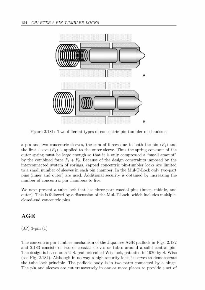
154 CHAPTER 2 PIN-TUMBLER LOCKS
A
B
Figure 2.181: Two different types of concentric pin-tumbler mechanisms.
a pin and two concentric sleeves, the sum of forces due to both the pin (F1) andthe first sleeve (F2) is applied to the outer sleeve. Thus the spring constant of theouter spring must be large enough so that it is only compressed a “small amount”by the combined force F1 + F2. Because of the design constraints imposed by theinterconnected system of springs, capped concentric pin-tumbler locks are limitedto a small number of sleeves in each pin chamber. In the Mul-T-Lock only two-partpins (inner and outer) are used. Additional security is obtained by increasing thenumber of concentric pin chambers to five.
We next present a tube lock that has three-part coaxial pins (inner, middle, andouter). This is followed by a discussion of the Mul-T-Lock, which includes multiple,closed-end concentric pins.
AGE
(JP) 3-pin (1)
The concentric pin-tumbler mechanism of the Japanese AGE padlock in Figs. 2.182and 2.183 consists of two of coaxial sleeves or tubes around a solid central pin.The design is based on a U.S. padlock called Wiselock, patented in 1920 by S. Wise(see Fig. 2.184). Although in no way a high-security lock, it serves to demonstratethe tube lock principle. The padlock body is in two parts connected by a hinge.The pin and sleeves are cut transversely in one or more places to provide a set of
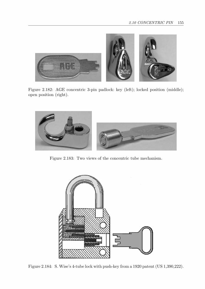
2.10 CONCENTRIC PIN 155
Figure 2.182: AGE concentric 3-pin padlock: key (left); locked position (middle);open position (right).
Figure 2.183: Two views of the concentric tube mechanism.
Figure 2.184: S. Wise’s 4-tube lock with push-key from a 1920 patent (US 1,390,222).
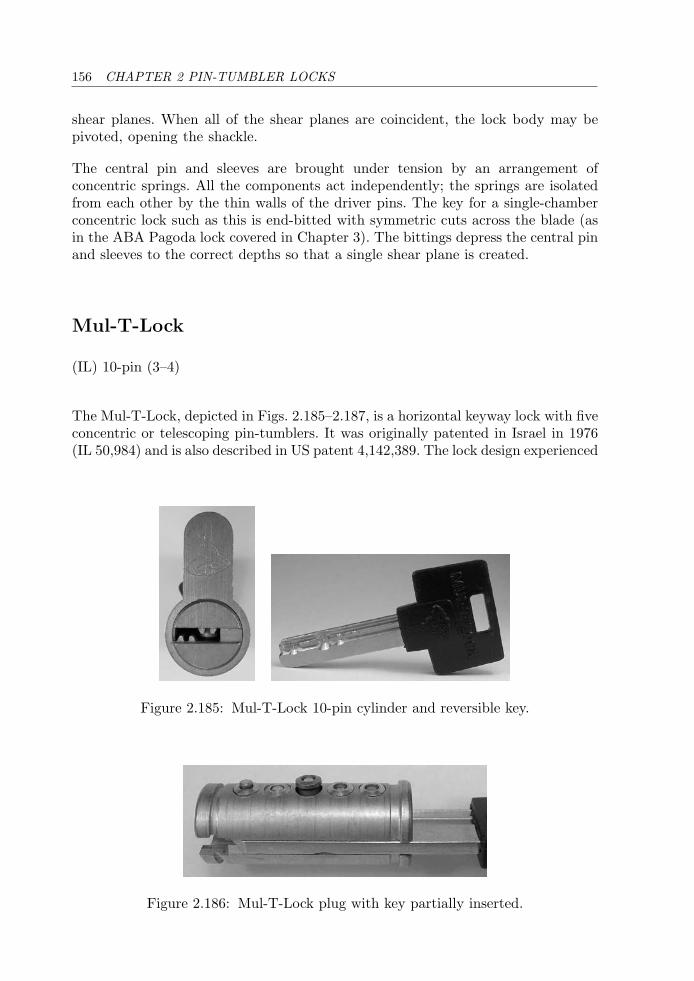
156 CHAPTER 2 PIN-TUMBLER LOCKS
shear planes. When all of the shear planes are coincident, the lock body may bepivoted, opening the shackle.
The central pin and sleeves are brought under tension by an arrangement ofconcentric springs. All the components act independently; the springs are isolatedfrom each other by the thin walls of the driver pins. The key for a single-chamberconcentric lock such as this is end-bitted with symmetric cuts across the blade (asin the ABA Pagoda lock covered in Chapter 3). The bittings depress the central pinand sleeves to the correct depths so that a single shear plane is created.
Mul-T-Lock
(IL) 10-pin (3–4)
The Mul-T-Lock, depicted in Figs. 2.185–2.187, is a horizontal keyway lock with fiveconcentric or telescoping pin-tumblers. It was originally patented in Israel in 1976(IL 50,984) and is also described in US patent 4,142,389. The lock design experienced
Figure 2.185: Mul-T-Lock 10-pin cylinder and reversible key.
Figure 2.186: Mul-T-Lock plug with key partially inserted.
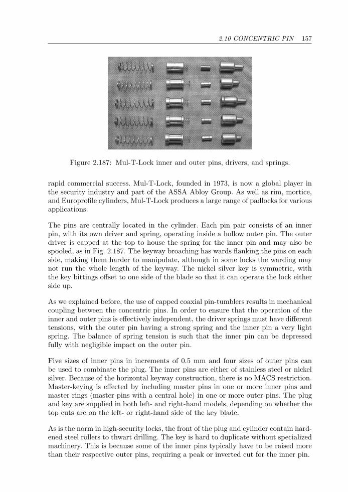
2.10 CONCENTRIC PIN 157
Figure 2.187: Mul-T-Lock inner and outer pins, drivers, and springs.
rapid commercial success. Mul-T-Lock, founded in 1973, is now a global player inthe security industry and part of the ASSA Abloy Group. As well as rim, mortice,and Europrofile cylinders, Mul-T-Lock produces a large range of padlocks for variousapplications.
The pins are centrally located in the cylinder. Each pin pair consists of an innerpin, with its own driver and spring, operating inside a hollow outer pin. The outerdriver is capped at the top to house the spring for the inner pin and may also bespooled, as in Fig. 2.187. The keyway broaching has wards flanking the pins on eachside, making them harder to manipulate, although in some locks the warding maynot run the whole length of the keyway. The nickel silver key is symmetric, withthe key bittings offset to one side of the blade so that it can operate the lock eitherside up.
As we explained before, the use of capped coaxial pin-tumblers results in mechanicalcoupling between the concentric pins. In order to ensure that the operation of theinner and outer pins is effectively independent, the driver springs must have differenttensions, with the outer pin having a strong spring and the inner pin a very lightspring. The balance of spring tension is such that the inner pin can be depressedfully with negligible impact on the outer pin.
Five sizes of inner pins in increments of 0.5 mm and four sizes of outer pins canbe used to combinate the plug. The inner pins are either of stainless steel or nickelsilver. Because of the horizontal keyway construction, there is no MACS restriction.Master-keying is effected by including master pins in one or more inner pins andmaster rings (master pins with a central hole) in one or more outer pins. The plugand key are supplied in both left- and right-hand models, depending on whether thetop cuts are on the left- or right-hand side of the key blade.
As is the norm in high-security locks, the front of the plug and cylinder contain hard-ened steel rollers to thwart drilling. The key is hard to duplicate without specializedmachinery. This is because some of the inner pins typically have to be raised morethan their respective outer pins, requiring a peak or inverted cut for the inner pin.
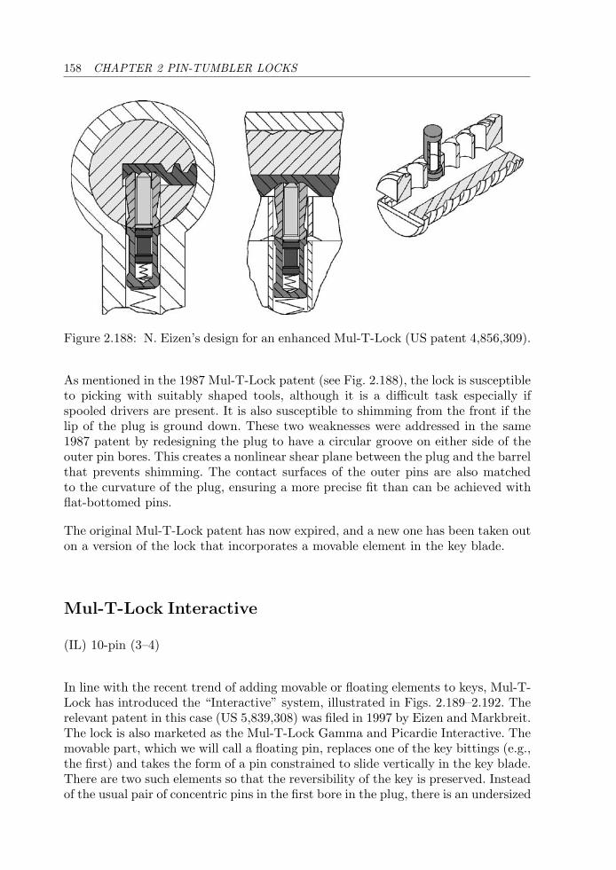
158 CHAPTER 2 PIN-TUMBLER LOCKS
Figure 2.188: N. Eizen’s design for an enhanced Mul-T-Lock (US patent 4,856,309).
As mentioned in the 1987 Mul-T-Lock patent (see Fig. 2.188), the lock is susceptibleto picking with suitably shaped tools, although it is a difficult task especially ifspooled drivers are present. It is also susceptible to shimming from the front if thelip of the plug is ground down. These two weaknesses were addressed in the same1987 patent by redesigning the plug to have a circular groove on either side of theouter pin bores. This creates a nonlinear shear plane between the plug and the barrelthat prevents shimming. The contact surfaces of the outer pins are also matchedto the curvature of the plug, ensuring a more precise fit than can be achieved withflat-bottomed pins.
The original Mul-T-Lock patent has now expired, and a new one has been taken outon a version of the lock that incorporates a movable element in the key blade.
Mul-T-Lock Interactive
(IL) 10-pin (3–4)
In line with the recent trend of adding movable or floating elements to keys, Mul-T-Lock has introduced the “Interactive” system, illustrated in Figs. 2.189–2.192. Therelevant patent in this case (US 5,839,308) was filed in 1997 by Eizen and Markbreit.The lock is also marketed as the Mul-T-Lock Gamma and Picardie Interactive. Themovable part, which we will call a floating pin, replaces one of the key bittings (e.g.,the first) and takes the form of a pin constrained to slide vertically in the key blade.There are two such elements so that the reversibility of the key is preserved. Insteadof the usual pair of concentric pins in the first bore in the plug, there is an undersized
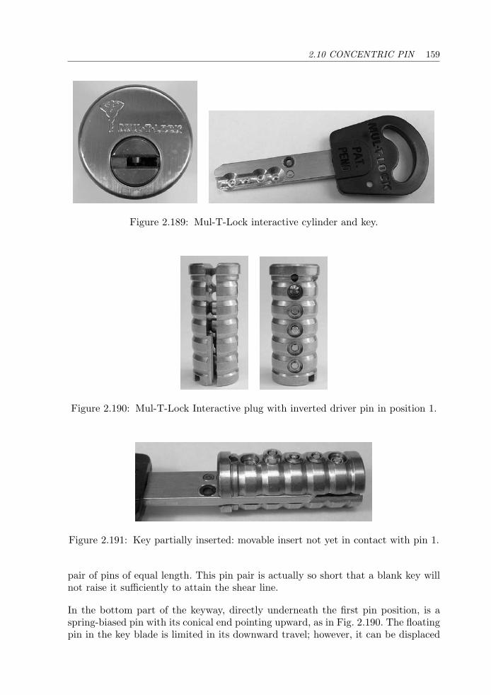
2.10 CONCENTRIC PIN 159
Figure 2.189: Mul-T-Lock interactive cylinder and key.
Figure 2.190: Mul-T-Lock Interactive plug with inverted driver pin in position 1.
Figure 2.191: Key partially inserted: movable insert not yet in contact with pin 1.
pair of pins of equal length. This pin pair is actually so short that a blank key willnot raise it sufficiently to attain the shear line.
In the bottom part of the keyway, directly underneath the first pin position, is aspring-biased pin with its conical end pointing upward, as in Fig. 2.190. The floatingpin in the key blade is limited in its downward travel; however, it can be displaced
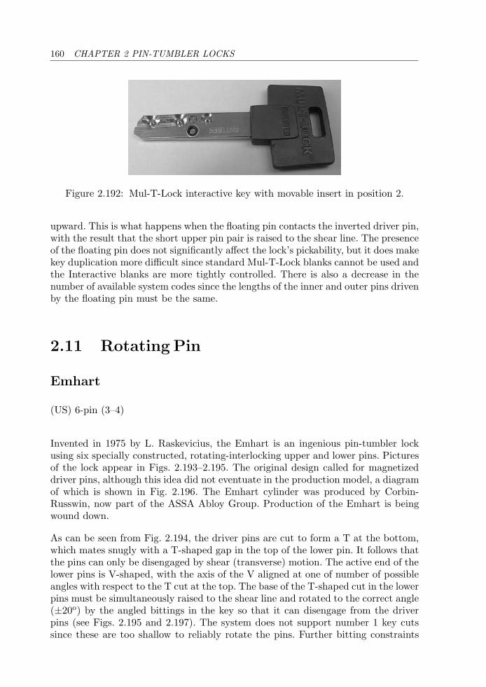
160 CHAPTER 2 PIN-TUMBLER LOCKS
Figure 2.192: Mul-T-Lock interactive key with movable insert in position 2.
upward. This is what happens when the floating pin contacts the inverted driver pin,with the result that the short upper pin pair is raised to the shear line. The presenceof the floating pin does not significantly affect the lock’s pickability, but it does makekey duplication more difficult since standard Mul-T-Lock blanks cannot be used andthe Interactive blanks are more tightly controlled. There is also a decrease in thenumber of available system codes since the lengths of the inner and outer pins drivenby the floating pin must be the same.
2.11 Rotating Pin
Emhart
(US) 6-pin (3–4)
Invented in 1975 by L. Raskevicius, the Emhart is an ingenious pin-tumbler lockusing six specially constructed, rotating-interlocking upper and lower pins. Picturesof the lock appear in Figs. 2.193–2.195. The original design called for magnetizeddriver pins, although this idea did not eventuate in the production model, a diagramof which is shown in Fig. 2.196. The Emhart cylinder was produced by Corbin-Russwin, now part of the ASSA Abloy Group. Production of the Emhart is beingwound down.
As can be seen from Fig. 2.194, the driver pins are cut to form a T at the bottom,which mates snugly with a T-shaped gap in the top of the lower pin. It follows thatthe pins can only be disengaged by shear (transverse) motion. The active end of thelower pins is V-shaped, with the axis of the V aligned at one of number of possibleangles with respect to the T cut at the top. The base of the T-shaped cut in the lowerpins must be simultaneously raised to the shear line and rotated to the correct angle(±20o) by the angled bittings in the key so that it can disengage from the driverpins (see Figs. 2.195 and 2.197). The system does not support number 1 key cutssince these are too shallow to reliably rotate the pins. Further bitting constraints
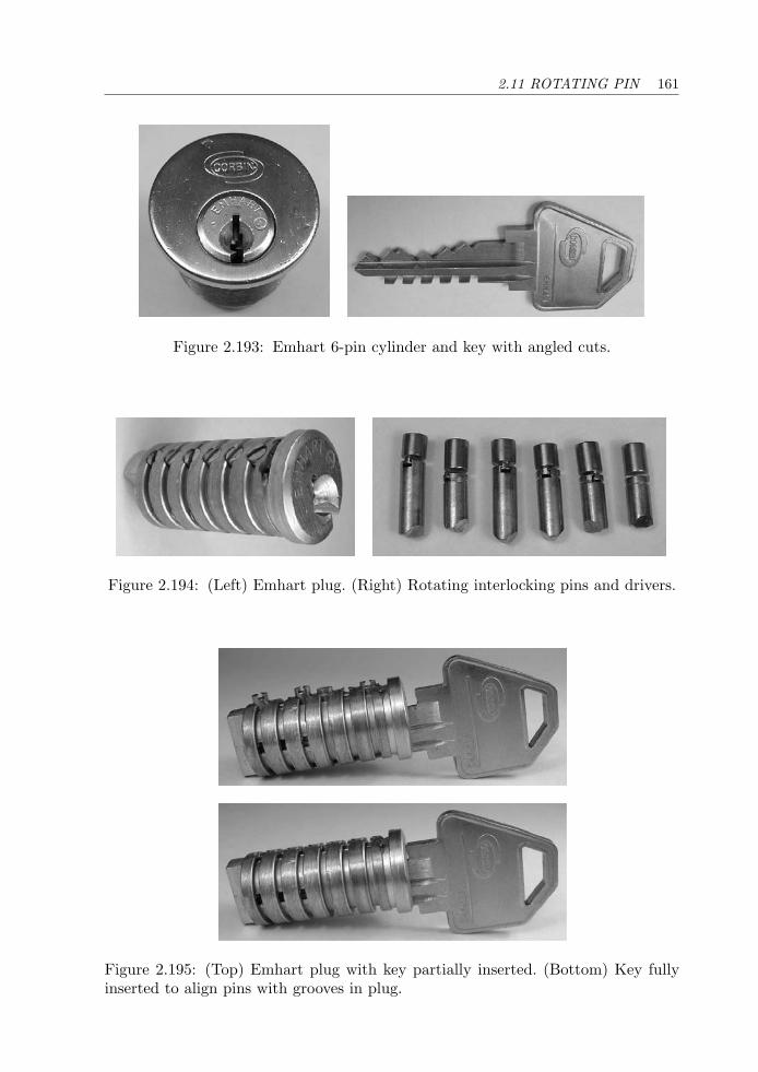
2.11 ROTATING PIN 161
Figure 2.193: Emhart 6-pin cylinder and key with angled cuts.
Figure 2.194: (Left) Emhart plug. (Right) Rotating interlocking pins and drivers.
Figure 2.195: (Top) Emhart plug with key partially inserted. (Bottom) Key fullyinserted to align pins with grooves in plug.
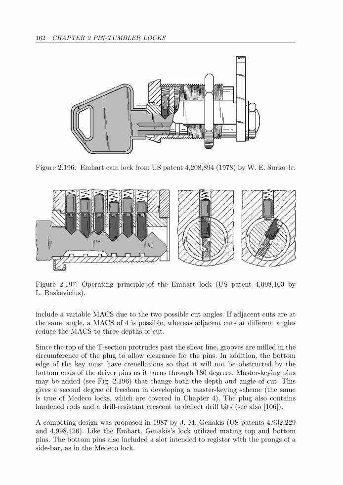
162 CHAPTER 2 PIN-TUMBLER LOCKS
Figure 2.196: Emhart cam lock from US patent 4,208,894 (1978) by W. E. Surko Jr.
Figure 2.197: Operating principle of the Emhart lock (US patent 4,098,103 byL. Raskevicius).
include a variable MACS due to the two possible cut angles. If adjacent cuts are atthe same angle, a MACS of 4 is possible, whereas adjacent cuts at different anglesreduce the MACS to three depths of cut.
Since the top of the T-section protrudes past the shear line, grooves are milled in thecircumference of the plug to allow clearance for the pins. In addition, the bottomedge of the key must have crenellations so that it will not be obstructed by thebottom ends of the driver pins as it turns through 180 degrees. Master-keying pinsmay be added (see Fig. 2.196) that change both the depth and angle of cut. Thisgives a second degree of freedom in developing a master-keying scheme (the sameis true of Medeco locks, which are covered in Chapter 4). The plug also containshardened rods and a drill-resistant crescent to deflect drill bits (see also [106]).
A competing design was proposed in 1987 by J. M. Genakis (US patents 4,932,229and 4,998,426). Like the Emhart, Genakis’s lock utilized mating top and bottompins. The bottom pins also included a slot intended to register with the prongs of aside-bar, as in the Medeco lock.
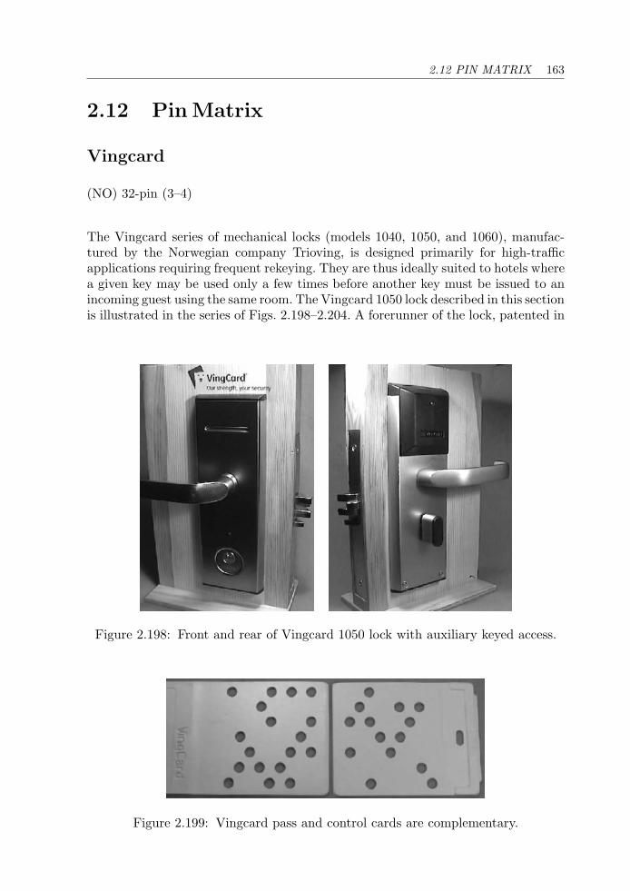
2.12 PIN MATRIX 163
2.12 Pin Matrix
Vingcard
(NO) 32-pin (3–4)
The Vingcard series of mechanical locks (models 1040, 1050, and 1060), manufac-tured by the Norwegian company Trioving, is designed primarily for high-trafficapplications requiring frequent rekeying. They are thus ideally suited to hotels wherea given key may be used only a few times before another key must be issued to anincoming guest using the same room. The Vingcard 1050 lock described in this sectionis illustrated in the series of Figs. 2.198–2.204. A forerunner of the lock, patented in
Figure 2.198: Front and rear of Vingcard 1050 lock with auxiliary keyed access.
Figure 2.199: Vingcard pass and control cards are complementary.
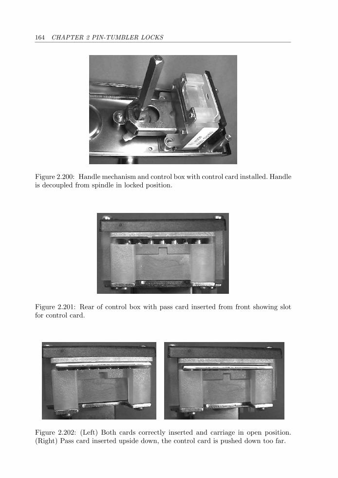
164 CHAPTER 2 PIN-TUMBLER LOCKS
Figure 2.200: Handle mechanism and control box with control card installed. Handleis decoupled from spindle in locked position.
Figure 2.201: Rear of control box with pass card inserted from front showing slotfor control card.
Figure 2.202: (Left) Both cards correctly inserted and carriage in open position.(Right) Pass card inserted upside down, the control card is pushed down too far.
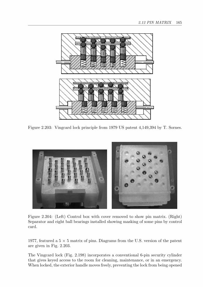
2.12 PIN MATRIX 165
Figure 2.203: Vingcard lock principle from 1979 US patent 4,149,394 by T. Sornes.
Figure 2.204: (Left) Control box with cover removed to show pin matrix. (Right)Separator and eight ball bearings installed showing masking of some pins by controlcard.
1977, featured a 5 × 5 matrix of pins. Diagrams from the U.S. version of the patentare given in Fig. 2.203.
The Vingcard lock (Fig. 2.198) incorporates a conventional 6-pin security cylinderthat gives keyed access to the room for cleaning, maintenance, or in an emergency.When locked, the exterior handle moves freely, preventing the lock from being opened
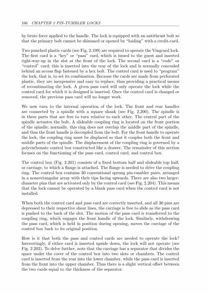
166 CHAPTER 2 PIN-TUMBLER LOCKS
by brute force applied to the handle. The lock is equipped with an antithrust bolt sothat the primary bolt cannot be shimmed or opened by “loiding” with a credit-card.
Two punched plastic cards (see Fig. 2.199) are required to operate the Vingcard lock.The first card is a “key” or “pass” card, which is issued to the guest and insertedright-way-up in the slot at the front of the lock. The second card is a “code” or“control” card; this is inserted into the rear of the lock and is normally concealedbehind an access flap fastened by a hex bolt. The control card is used to “program”the lock, that is, to set its combination. Because the cards are made from perforatedplastic, they are inexpensive and easy to replace, thus providing a practical meansof recombinating the lock. A given pass card will only operate the lock while thecontrol card for which it is designed is inserted. Once the control card is changed orremoved, the previous pass card will no longer work.
We now turn to the internal operation of the lock. The front and rear handlesare connected by a spindle with a square shank (see Fig. 2.200). The spindle isin three parts that are free to turn relative to each other. The central part of thespindle actuates the bolt. A slideable coupling ring is located on the front portionof the spindle; normally, this ring does not overlap the middle part of the spindle,and thus the front handle is decoupled from the bolt. For the front handle to operatethe lock, the coupling ring must be displaced so that it couples both the front andmiddle parts of the spindle. The displacement of the coupling ring is governed by apolycarbonate control box constructed like a drawer. The remainder of this sectionfocuses on the functioning of the pass card, control card, and control box.
The control box (Fig. 2.201) consists of a fixed bottom half and slideable top half,or carriage, to which a flange is attached. The flange is needed to drive the couplingring. The control box contains 30 conventional sprung pin-tumbler pairs, arrangedin a nonrectangular array with their tips facing upwards. There are also two larger-diameter pins that are activated only by the control card (see Fig. 2.204). This meansthat the lock cannot be operated by a blank pass card when the control card is notinstalled.
When both the control card and pass card are correctly inserted, and all 30 pins aredepressed to their respective shear lines, the carriage is free to slide as the pass cardis pushed to the back of the slot. The motion of the pass card is transferred to thecoupling ring, which engages the front handle of the lock. Similarly, withdrawingthe pass card, which is held in position during opening, moves the carriage of thecontrol box back to its original position.
How is it that both the pass and control cards are needed to operate the lock?Interestingly, if either card is inserted upside down, the lock will not operate (seeFig. 2.202). To delve further, note that the carriage has a separator that divides thespace under the cover of the control box into two slots or chambers. The controlcard is inserted from the rear into the lower chamber, while the pass card is insertedfrom the front into the upper chamber. Thus there is a slight vertical offset betweenthe two cards equal to the thickness of the separator.
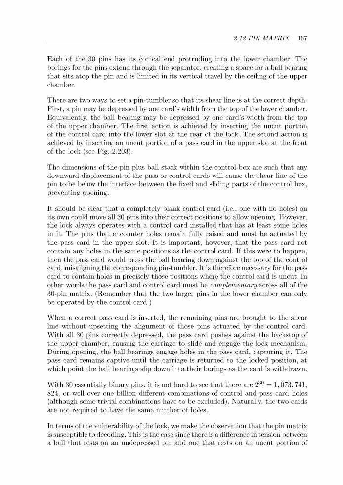
2.12 PIN MATRIX 167
Each of the 30 pins has its conical end protruding into the lower chamber. Theborings for the pins extend through the separator, creating a space for a ball bearingthat sits atop the pin and is limited in its vertical travel by the ceiling of the upperchamber.
There are two ways to set a pin-tumbler so that its shear line is at the correct depth.First, a pin may be depressed by one card’s width from the top of the lower chamber.Equivalently, the ball bearing may be depressed by one card’s width from the topof the upper chamber. The first action is achieved by inserting the uncut portionof the control card into the lower slot at the rear of the lock. The second action isachieved by inserting an uncut portion of a pass card in the upper slot at the frontof the lock (see Fig. 2.203).
The dimensions of the pin plus ball stack within the control box are such that anydownward displacement of the pass or control cards will cause the shear line of thepin to be below the interface between the fixed and sliding parts of the control box,preventing opening.
It should be clear that a completely blank control card (i.e., one with no holes) onits own could move all 30 pins into their correct positions to allow opening. However,the lock always operates with a control card installed that has at least some holesin it. The pins that encounter holes remain fully raised and must be actuated bythe pass card in the upper slot. It is important, however, that the pass card notcontain any holes in the same positions as the control card. If this were to happen,then the pass card would press the ball bearing down against the top of the controlcard, misaligning the corresponding pin-tumbler. It is therefore necessary for the passcard to contain holes in precisely those positions where the control card is uncut. Inother words the pass card and control card must be complementary across all of the30-pin matrix. (Remember that the two larger pins in the lower chamber can onlybe operated by the control card.)
When a correct pass card is inserted, the remaining pins are brought to the shearline without upsetting the alignment of those pins actuated by the control card.With all 30 pins correctly depressed, the pass card pushes against the backstop ofthe upper chamber, causing the carriage to slide and engage the lock mechanism.During opening, the ball bearings engage holes in the pass card, capturing it. Thepass card remains captive until the carriage is returned to the locked position, atwhich point the ball bearings slip down into their borings as the card is withdrawn.
With 30 essentially binary pins, it is not hard to see that there are 230 = 1, 073, 741,824, or well over one billion different combinations of control and pass card holes(although some trivial combinations have to be excluded). Naturally, the two cardsare not required to have the same number of holes.
In terms of the vulnerability of the lock, we make the observation that the pin matrixis susceptible to decoding. This is the case since there is a difference in tension betweena ball that rests on an undepressed pin and one that rests on an uncut portion of
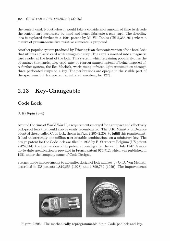
168 CHAPTER 2 PIN-TUMBLER LOCKS
the control card. Nonetheless it would take a considerable amount of time to decodethe control card accurately by hand and hence fabricate a pass card. The decodingidea is explored further in a 1994 patent by M. W. Tobias (US 5,355,701) where amatrix of pressure-sensitive resistive elements is proposed.
Another popular system produced by Trioving is an electronic version of the hotel lockthat utilizes a plastic card with a magnetic strip. The card is inserted into a magneticcard reader at the front of the lock. This system, which is gaining popularity, has theadvantage that cards, once used, may be reprogrammed instead of being disposed of.A further system, the Ilco Marlock, works using infrared light transmission throughthree perforated strips on a key. The perforations are opaque in the visible part ofthe spectrum but transparent at infrared wavelengths [127].
2.13 Key-Changeable
Code Lock
(UK) 6-pin (3–4)
Around the time of World War II, a requirement emerged for a compact and effectivelypick-proof lock that could also be easily recombinated. The U.K. Ministry of Defenceadopted the so-called Code lock, shown in Figs. 2.205–2.208, to fulfill this requirement.It had theoretically one million user-settable combinations on a miniature key. Thedesign patent for the Code lock was filed in 1938 by B. Sterner in Belgium (US patent2,424,514), the final version of the patent appearing after the war in July 1947. A moreup-to-date specification is provided in French patent 974,712, which was published in1951 under the company name of Code Designs.
Sterner made improvements to an earlier design of lock and key by O. D. Von Mehren,described in US patents 1,819,853 (1928) and 1,899,739 (1929). The improvements
Figure 2.205: The mechanically reprogrammable 6-pin Code padlock and key.
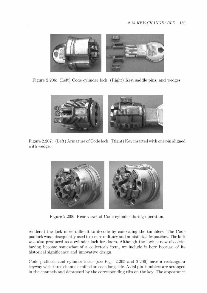
2.13 KEY-CHANGEABLE 169
Figure 2.206: (Left) Code cylinder lock. (Right) Key, saddle pins, and wedges.
Figure 2.207: (Left) Armature of Code lock. (Right) Key inserted with one pin alignedwith wedge.
Figure 2.208: Rear views of Code cylinder during operation.
rendered the lock more difficult to decode by concealing the tumblers. The Codepadlock was subsequently used to secure military and ministerial despatches. The lockwas also produced as a cylinder lock for doors. Although the lock is now obsolete,having become somewhat of a collector’s item, we include it here because of itshistorical significance and innovative design.
Code padlocks and cylinder locks (see Figs. 2.205 and 2.206) have a rectangularkeyway with three channels milled on each long side. Axial pin-tumblers are arrangedin the channels and depressed by the corresponding ribs on the key. The appearance
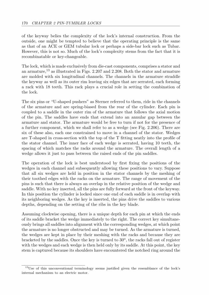
170 CHAPTER 2 PIN-TUMBLER LOCKS
of the keyway belies the complexity of the lock’s internal construction. From theoutside, one might be tempted to believe that the operating principle is the sameas that of an ACE or GEM tubular lock or perhaps a side-bar lock such as Tubar.However, this is not so. Much of the lock’s complexity stems from the fact that it isrecombinatable or key-changeable.
The lock, which is made exclusively from die-cast components, comprises a stator andan armature,13 as illustrated in Figs. 2.207 and 2.208. Both the stator and armatureare molded with six longitudinal channels. The channels in the armature straddlethe keyway as well as its outer rim leaving six edges that are serrated, each forminga rack with 18 teeth. This rack plays a crucial role in setting the combination ofthe lock.
The six pins or “U-shaped pushers” as Sterner referred to them, ride in the channelsof the armature and are spring-biased from the rear of the cylinder. Each pin iscoupled to a saddle in the outer rim of the armature that follows the axial motionof the pin. The saddles have ends that extend into an annular gap between thearmature and stator. The armature would be free to turn if not for the presence ofa further component, which we shall refer to as a wedge (see Fig. 2.206). There aresix of these also, each one constrained to move in a channel of the stator. Wedgesare T-shaped in cross-section with the top of the T fitting neatly into the profile ofthe stator channel. The inner face of each wedge is serrated, having 10 teeth, thespacing of which matches the racks around the armature. The overall length of awedge allows it just to pass between the raised ends of the pin saddles.
The operation of the lock is best understood by first fixing the positions of thewedges in each channel and subsequently allowing these positions to vary. Supposethat all six wedges are held in position in the stator channels by the meshing oftheir toothed edges with the racks on the armature. The range of movement of thepins is such that there is always an overlap in the relative position of the wedge andsaddle. With no key inserted, all the pins are fully forward at the front of the keyway.In this position the cylinder is locked since one end of each saddle is in overlap withits neighboring wedges. As the key is inserted, the pins drive the saddles to variousdepths, depending on the setting of the ribs in the key blade.
Assuming clockwise opening, there is a unique depth for each pin at which the endsof its saddle bracket the wedge immediately to the right. The correct key simultane-ously brings all saddles into alignment with the corresponding wedges, at which pointthe armature is no longer obstructed and may be turned. As the armature is turned,the wedges are kept in place by their meshing with the racks and because they arebracketed by the saddles. Once the key is turned to 30o, the racks fall out of registerwith the wedges and each wedge is then held only by its saddle. At this point, the keystem is captured because its shoulders have encountered the notched ring around the
13Use of this unconventional terminology seems justified given the resemblance of the lock’sinternal mechanism to an electric motor.
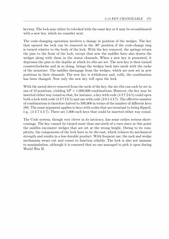
2.13 KEY-CHANGEABLE 171
keyway. The lock may either be relocked with the same key or it may be recombinatedwith a new key, which we consider next.
The code-changing operation involves a change in position of the wedges. The keythat opened the lock can be removed in the 30o position if the code-change ringis turned relative to the body of the lock. With the key removed, the springs returnthe pins to the front of the lock, except that now the saddles have also drawn thewedges along with them in the stator channels. When a new key is presented, itdepresses the pins to the depths at which its ribs are set. The new key is then turnedcounterclockwise and in so doing, brings the wedges back into mesh with the racksof the armature. The saddles disengage from the wedges, which are now set in newpositions in their channels. The new key is withdrawn and, voila, the combinationhas been changed. Now only the new key will open the lock.
With the metal sleeve removed from the neck of the key, the six ribs can each be set inone of 10 positions, yielding 106 = 1,000,000 combinations. However, the key may beinserted either way round so that, for instance, a key with code (4 3 7 2 6 5) could openboth a lock with code (4 3 7 2 6 5) and one with code (2 6 5 4 3 7). The effective numberof combinations is therefore halved to 500,000 in terms of the number of different keys[88]. The same argument applies to keys with codes that are invariant to being flipped,e.g., (4 3 7 4 3 7). There are 1,000 such keys that could be inserted either way round.
The Code system, though very clever in its intricacy, has some rather serious short-comings. The key cannot be turned more than one-sixth of a turn since at this pointthe saddles encounter wedges that are set at the wrong height. Owing to its com-plexity, the components of the lock have to be die-cast, which reduces its mechanicalstrength and results in a less durable product. With frequent use, the rack and wedgemechanism wears out and ceases to function reliably. The lock is also not immuneto manipulation, although it is rumored that no one managed to pick it open duringWorld War II.

This page intentionally left blank
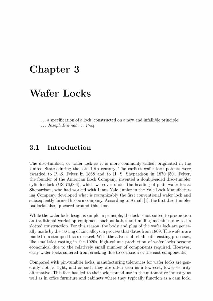
Chapter 3
Wafer Locks
. . . a specification of a lock, constructed on a new and infallible principle,
. . . Joseph Bramah, c. 1784
3.1 Introduction
The disc-tumbler, or wafer lock as it is more commonly called, originated in theUnited States during the late 19th century. The earliest wafer lock patents wereawarded to P. S. Felter in 1868 and to H. S. Shepardson in 1870 [50]. Felter,the founder of the American Lock Company, invented a double-sided disc-tumblercylinder lock (US 76,066), which we cover under the heading of plate-wafer locks.Shepardson, who had worked with Linus Yale Junior in the Yale Lock Manufactur-ing Company, developed what is recognizably the first conventional wafer lock andsubsequently formed his own company. According to Arnall [1], the first disc-tumblerpadlocks also appeared around this time.
While the wafer lock design is simple in principle, the lock is not suited to productionon traditional workshop equipment such as lathes and milling machines due to itsslotted construction. For this reason, the body and plug of the wafer lock are gener-ally made by die casting of zinc alloys, a process that dates from 1869. The wafers aremade from stamped brass or steel. With the advent of reliable die-casting processes,like small-slot casting in the 1920s, high-volume production of wafer locks becameeconomical due to the relatively small number of components required. However,early wafer locks suffered from cracking due to corrosion of the cast components.
Compared with pin-tumbler locks, manufacturing tolerances for wafer locks are gen-erally not as tight, and as such they are often seen as a low-cost, lower-securityalternative. This fact has led to their widespread use in the automotive industry aswell as in office furniture and cabinets where they typically function as a cam lock.
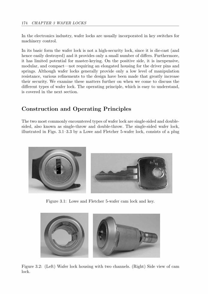
174 CHAPTER 3 WAFER LOCKS
In the electronics industry, wafer locks are usually incorporated in key switches formachinery control.
In its basic form the wafer lock is not a high-security lock, since it is die-cast (andhence easily destroyed) and it provides only a small number of differs. Furthermore,it has limited potential for master-keying. On the positive side, it is inexpensive,modular, and compact—not requiring an elongated housing for the driver pins andsprings. Although wafer locks generally provide only a low level of manipulationresistance, various refinements to the design have been made that greatly increasetheir security. We examine these matters further on when we come to discuss thedifferent types of wafer lock. The operating principle, which is easy to understand,is covered in the next section.
Construction and Operating Principles
The two most commonly encountered types of wafer lock are single-sided and double-sided, also known as single-throw and double-throw. The single-sided wafer lock,illustrated in Figs. 3.1–3.3 by a Lowe and Fletcher 5-wafer lock, consists of a plug
Figure 3.1: Lowe and Fletcher 5-wafer cam lock and key.
Figure 3.2: (Left) Wafer lock housing with two channels. (Right) Side view of camlock.
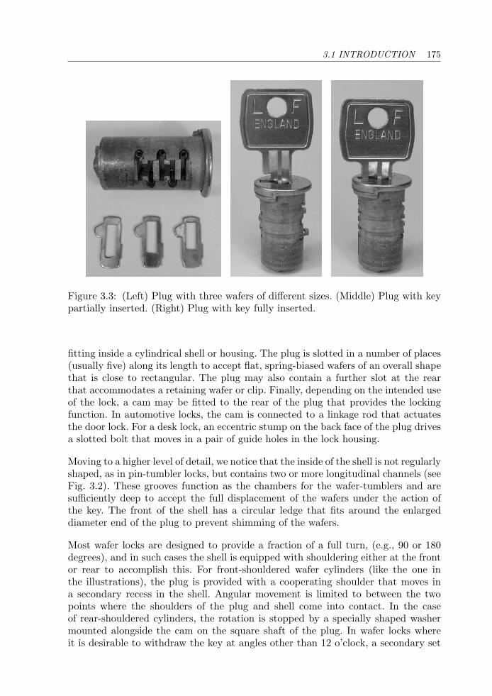
3.1 INTRODUCTION 175
Figure 3.3: (Left) Plug with three wafers of different sizes. (Middle) Plug with keypartially inserted. (Right) Plug with key fully inserted.
fitting inside a cylindrical shell or housing. The plug is slotted in a number of places(usually five) along its length to accept flat, spring-biased wafers of an overall shapethat is close to rectangular. The plug may also contain a further slot at the rearthat accommodates a retaining wafer or clip. Finally, depending on the intended useof the lock, a cam may be fitted to the rear of the plug that provides the lockingfunction. In automotive locks, the cam is connected to a linkage rod that actuatesthe door lock. For a desk lock, an eccentric stump on the back face of the plug drivesa slotted bolt that moves in a pair of guide holes in the lock housing.
Moving to a higher level of detail, we notice that the inside of the shell is not regularlyshaped, as in pin-tumbler locks, but contains two or more longitudinal channels (seeFig. 3.2). These grooves function as the chambers for the wafer-tumblers and aresufficiently deep to accept the full displacement of the wafers under the action ofthe key. The front of the shell has a circular ledge that fits around the enlargeddiameter end of the plug to prevent shimming of the wafers.
Most wafer locks are designed to provide a fraction of a full turn, (e.g., 90 or 180degrees), and in such cases the shell is equipped with shouldering either at the frontor rear to accomplish this. For front-shouldered wafer cylinders (like the one inthe illustrations), the plug is provided with a cooperating shoulder that moves ina secondary recess in the shell. Angular movement is limited to between the twopoints where the shoulders of the plug and shell come into contact. In the caseof rear-shouldered cylinders, the rotation is stopped by a specially shaped washermounted alongside the cam on the square shaft of the plug. In wafer locks whereit is desirable to withdraw the key at angles other than 12 o’clock, a secondary set
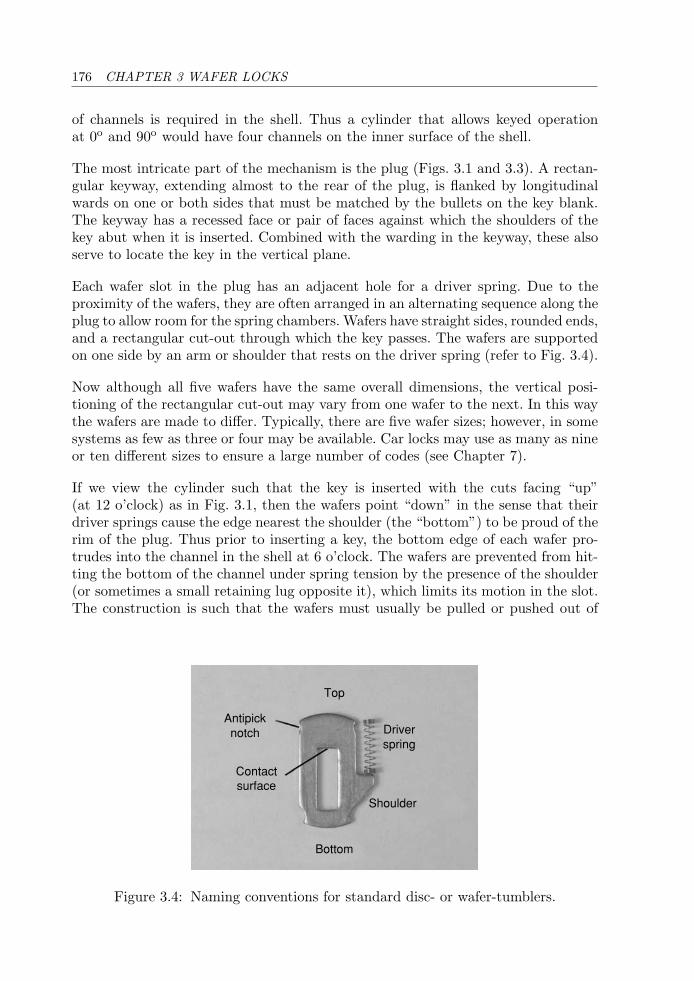
176 CHAPTER 3 WAFER LOCKS
of channels is required in the shell. Thus a cylinder that allows keyed operationat 0o and 90o would have four channels on the inner surface of the shell.
The most intricate part of the mechanism is the plug (Figs. 3.1 and 3.3). A rectan-gular keyway, extending almost to the rear of the plug, is flanked by longitudinalwards on one or both sides that must be matched by the bullets on the key blank.The keyway has a recessed face or pair of faces against which the shoulders of thekey abut when it is inserted. Combined with the warding in the keyway, these alsoserve to locate the key in the vertical plane.
Each wafer slot in the plug has an adjacent hole for a driver spring. Due to theproximity of the wafers, they are often arranged in an alternating sequence along theplug to allow room for the spring chambers. Wafers have straight sides, rounded ends,and a rectangular cut-out through which the key passes. The wafers are supportedon one side by an arm or shoulder that rests on the driver spring (refer to Fig. 3.4).
Now although all five wafers have the same overall dimensions, the vertical posi-tioning of the rectangular cut-out may vary from one wafer to the next. In this waythe wafers are made to differ. Typically, there are five wafer sizes; however, in somesystems as few as three or four may be available. Car locks may use as many as nineor ten different sizes to ensure a large number of codes (see Chapter 7).
If we view the cylinder such that the key is inserted with the cuts facing “up”(at 12 o’clock) as in Fig. 3.1, then the wafers point “down” in the sense that theirdriver springs cause the edge nearest the shoulder (the “bottom”) to be proud of therim of the plug. Thus prior to inserting a key, the bottom edge of each wafer pro-trudes into the channel in the shell at 6 o’clock. The wafers are prevented from hit-ting the bottom of the channel under spring tension by the presence of the shoulder(or sometimes a small retaining lug opposite it), which limits its motion in the slot.The construction is such that the wafers must usually be pulled or pushed out of
Top
Bottom
Antipicknotch
Contactsurface
Driverspring
Shoulder
Figure 3.4: Naming conventions for standard disc- or wafer-tumblers.
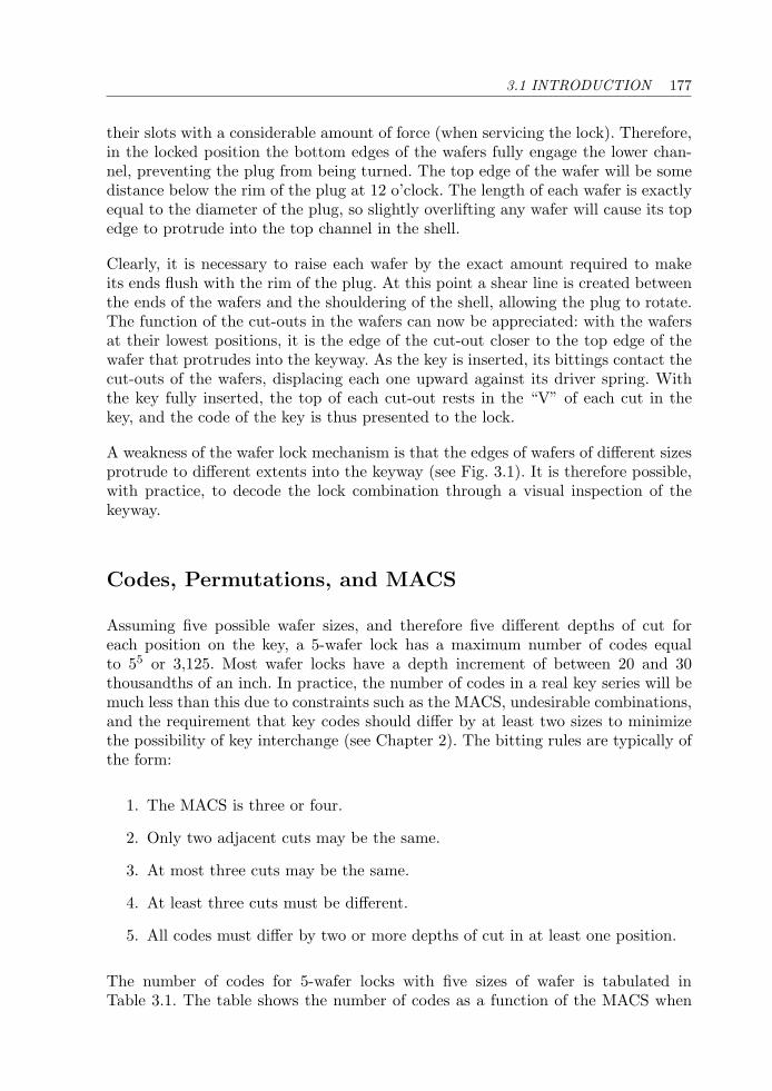
3.1 INTRODUCTION 177
their slots with a considerable amount of force (when servicing the lock). Therefore,in the locked position the bottom edges of the wafers fully engage the lower chan-nel, preventing the plug from being turned. The top edge of the wafer will be somedistance below the rim of the plug at 12 o’clock. The length of each wafer is exactlyequal to the diameter of the plug, so slightly overlifting any wafer will cause its topedge to protrude into the top channel in the shell.
Clearly, it is necessary to raise each wafer by the exact amount required to makeits ends flush with the rim of the plug. At this point a shear line is created betweenthe ends of the wafers and the shouldering of the shell, allowing the plug to rotate.The function of the cut-outs in the wafers can now be appreciated: with the wafersat their lowest positions, it is the edge of the cut-out closer to the top edge of thewafer that protrudes into the keyway. As the key is inserted, its bittings contact thecut-outs of the wafers, displacing each one upward against its driver spring. Withthe key fully inserted, the top of each cut-out rests in the “V” of each cut in thekey, and the code of the key is thus presented to the lock.
A weakness of the wafer lock mechanism is that the edges of wafers of different sizesprotrude to different extents into the keyway (see Fig. 3.1). It is therefore possible,with practice, to decode the lock combination through a visual inspection of thekeyway.
Codes, Permutations, and MACS
Assuming five possible wafer sizes, and therefore five different depths of cut foreach position on the key, a 5-wafer lock has a maximum number of codes equalto 55 or 3,125. Most wafer locks have a depth increment of between 20 and 30thousandths of an inch. In practice, the number of codes in a real key series will bemuch less than this due to constraints such as the MACS, undesirable combinations,and the requirement that key codes should differ by at least two sizes to minimizethe possibility of key interchange (see Chapter 2). The bitting rules are typically ofthe form:
1. The MACS is three or four.
2. Only two adjacent cuts may be the same.
3. At most three cuts may be the same.
4. At least three cuts must be different.
5. All codes must differ by two or more depths of cut in at least one position.
The number of codes for 5-wafer locks with five sizes of wafer is tabulated inTable 3.1. The table shows the number of codes as a function of the MACS when
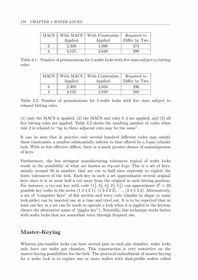
178 CHAPTER 3 WAFER LOCKS
MACS With MACS With Constraints Required toApplied Applied Differ by Two
3 2,309 1,890 2744 3,125 2,640 399
Table 3.1: Number of permutations for 5-wafer locks with five sizes subject to bittingrules.
MACS With MACS With Constraints Required toApplied Applied Differ by Two
3 2,309 2,034 2964 3,125 2,820 589
Table 3.2: Number of permutations for 5-wafer locks with five sizes subject torelaxed bitting rules.
(1) only the MACS is applied; (2) the MACS and rules 2–4 are applied; and (3) allfive bitting rules are applied. Table 3.2 shows the resulting number of codes whenrule 2 is relaxed to “up to three adjacent cuts may be the same”.
It can be seen that in practice only several hundred different codes may satisfythese constraints, a number substantially inferior to that offered by a 5-pin cylinderlock. With so few effective differs, there is a much greater chance of nonuniquenessof keys.
Furthermore, the less stringent manufacturing tolerances typical of wafer locksresult in the possibility of what are known as try-out keys. This is a set of keys,usually around 50 in number, that are cut to half sizes expressly to exploit thelower tolerances of the lock. Each key in such a set approximates several originalkeys since it is at most half a cut away from the original in each bitting position.For instance, a try-out key with code (11
2 312 41
2 212 11
2) can approximate 25 = 32possible key codes in the series (1 3 4 2 1), (1 3 4 2 2), . . ., (2 4 5 3 2). Alternatively,a set of “computer keys” of flat section and wavy cuts (similar in shape to somelock-picks) can be inserted one at a time and tried out. It is to be expected that atleast one key in a set can be made to operate a lock when it is jiggled in the keyway(hence the alternative name of “jiggler key”). Naturally, this technique works betterwith wafer locks that are somewhat worn through frequent use.
Master-Keying
Whereas pin-tumbler locks can have several pins in each pin chamber, wafer locksonly have one wafer per chamber. This construction is very restrictive on themaster-keying possibilities for the lock. The practical embodiment of master-keyingfor a wafer lock is to replace one or more wafers with dual-profile wafers called
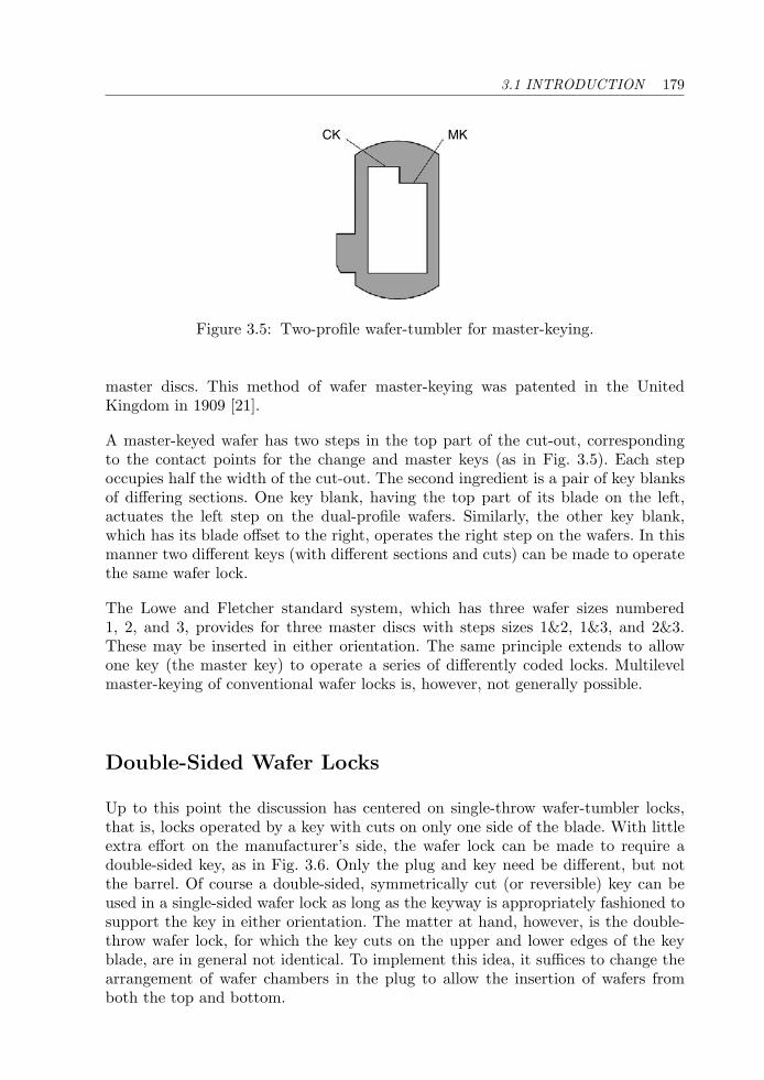
3.1 INTRODUCTION 179
CK MK
Figure 3.5: Two-profile wafer-tumbler for master-keying.
master discs. This method of wafer master-keying was patented in the UnitedKingdom in 1909 [21].
A master-keyed wafer has two steps in the top part of the cut-out, correspondingto the contact points for the change and master keys (as in Fig. 3.5). Each stepoccupies half the width of the cut-out. The second ingredient is a pair of key blanksof differing sections. One key blank, having the top part of its blade on the left,actuates the left step on the dual-profile wafers. Similarly, the other key blank,which has its blade offset to the right, operates the right step on the wafers. In thismanner two different keys (with different sections and cuts) can be made to operatethe same wafer lock.
The Lowe and Fletcher standard system, which has three wafer sizes numbered1, 2, and 3, provides for three master discs with steps sizes 1&2, 1&3, and 2&3.These may be inserted in either orientation. The same principle extends to allowone key (the master key) to operate a series of differently coded locks. Multilevelmaster-keying of conventional wafer locks is, however, not generally possible.
Double-Sided Wafer Locks
Up to this point the discussion has centered on single-throw wafer-tumbler locks,that is, locks operated by a key with cuts on only one side of the blade. With littleextra effort on the manufacturer’s side, the wafer lock can be made to require adouble-sided key, as in Fig. 3.6. Only the plug and key need be different, but notthe barrel. Of course a double-sided, symmetrically cut (or reversible) key can beused in a single-sided wafer lock as long as the keyway is appropriately fashioned tosupport the key in either orientation. The matter at hand, however, is the double-throw wafer lock, for which the key cuts on the upper and lower edges of the keyblade, are in general not identical. To implement this idea, it suffices to change thearrangement of wafer chambers in the plug to allow the insertion of wafers fromboth the top and bottom.
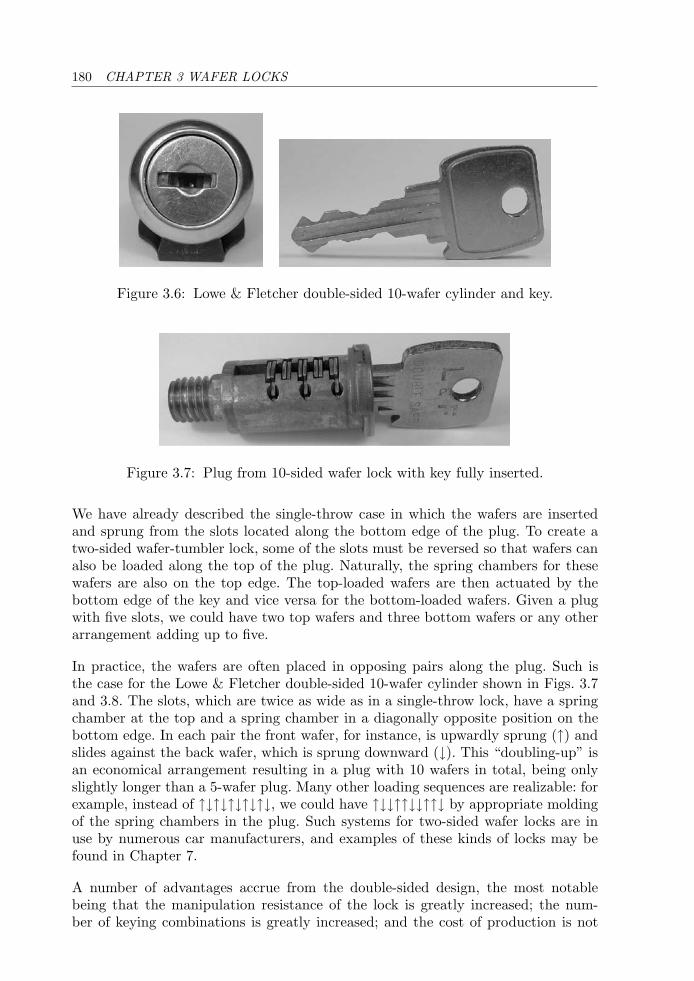
180 CHAPTER 3 WAFER LOCKS
Figure 3.6: Lowe & Fletcher double-sided 10-wafer cylinder and key.
Figure 3.7: Plug from 10-sided wafer lock with key fully inserted.
We have already described the single-throw case in which the wafers are insertedand sprung from the slots located along the bottom edge of the plug. To create atwo-sided wafer-tumbler lock, some of the slots must be reversed so that wafers canalso be loaded along the top of the plug. Naturally, the spring chambers for thesewafers are also on the top edge. The top-loaded wafers are then actuated by thebottom edge of the key and vice versa for the bottom-loaded wafers. Given a plugwith five slots, we could have two top wafers and three bottom wafers or any otherarrangement adding up to five.
In practice, the wafers are often placed in opposing pairs along the plug. Such isthe case for the Lowe & Fletcher double-sided 10-wafer cylinder shown in Figs. 3.7and 3.8. The slots, which are twice as wide as in a single-throw lock, have a springchamber at the top and a spring chamber in a diagonally opposite position on thebottom edge. In each pair the front wafer, for instance, is upwardly sprung (↑) andslides against the back wafer, which is sprung downward (↓). This “doubling-up” isan economical arrangement resulting in a plug with 10 wafers in total, being onlyslightly longer than a 5-wafer plug. Many other loading sequences are realizable: forexample, instead of ↑↓↑↓↑↓↑↓↑↓, we could have ↑↓↓↑↑↓↓↑↑↓ by appropriate moldingof the spring chambers in the plug. Such systems for two-sided wafer locks are inuse by numerous car manufacturers, and examples of these kinds of locks may befound in Chapter 7.
A number of advantages accrue from the double-sided design, the most notablebeing that the manipulation resistance of the lock is greatly increased; the num-ber of keying combinations is greatly increased; and the cost of production is not
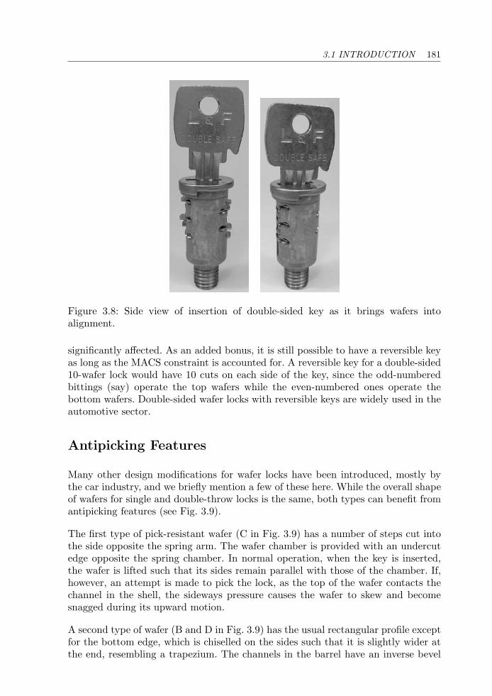
3.1 INTRODUCTION 181
Figure 3.8: Side view of insertion of double-sided key as it brings wafers intoalignment.
significantly affected. As an added bonus, it is still possible to have a reversible keyas long as the MACS constraint is accounted for. A reversible key for a double-sided10-wafer lock would have 10 cuts on each side of the key, since the odd-numberedbittings (say) operate the top wafers while the even-numbered ones operate thebottom wafers. Double-sided wafer locks with reversible keys are widely used in theautomotive sector.
Antipicking Features
Many other design modifications for wafer locks have been introduced, mostly bythe car industry, and we briefly mention a few of these here. While the overall shapeof wafers for single and double-throw locks is the same, both types can benefit fromantipicking features (see Fig. 3.9).
The first type of pick-resistant wafer (C in Fig. 3.9) has a number of steps cut intothe side opposite the spring arm. The wafer chamber is provided with an undercutedge opposite the spring chamber. In normal operation, when the key is inserted,the wafer is lifted such that its sides remain parallel with those of the chamber. If,however, an attempt is made to pick the lock, as the top of the wafer contacts thechannel in the shell, the sideways pressure causes the wafer to skew and becomesnagged during its upward motion.
A second type of wafer (B and D in Fig. 3.9) has the usual rectangular profile exceptfor the bottom edge, which is chiselled on the sides such that it is slightly wider atthe end, resembling a trapezium. The channels in the barrel have an inverse bevel
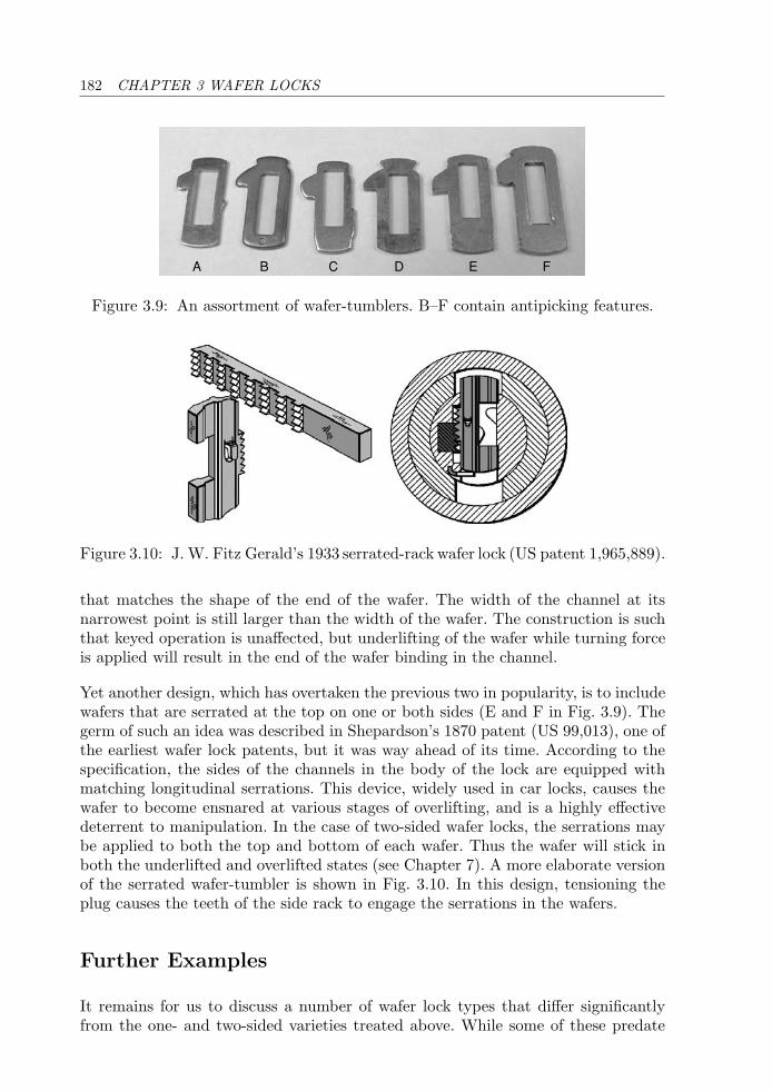
182 CHAPTER 3 WAFER LOCKS
A B C D E F
Figure 3.9: An assortment of wafer-tumblers. B–F contain antipicking features.
Figure 3.10: J. W. Fitz Gerald’s 1933 serrated-rack wafer lock (US patent 1,965,889).
that matches the shape of the end of the wafer. The width of the channel at itsnarrowest point is still larger than the width of the wafer. The construction is suchthat keyed operation is unaffected, but underlifting of the wafer while turning forceis applied will result in the end of the wafer binding in the channel.
Yet another design, which has overtaken the previous two in popularity, is to includewafers that are serrated at the top on one or both sides (E and F in Fig. 3.9). Thegerm of such an idea was described in Shepardson’s 1870 patent (US 99,013), one ofthe earliest wafer lock patents, but it was way ahead of its time. According to thespecification, the sides of the channels in the body of the lock are equipped withmatching longitudinal serrations. This device, widely used in car locks, causes thewafer to become ensnared at various stages of overlifting, and is a highly effectivedeterrent to manipulation. In the case of two-sided wafer locks, the serrations maybe applied to both the top and bottom of each wafer. Thus the wafer will stick inboth the underlifted and overlifted states (see Chapter 7). A more elaborate versionof the serrated wafer-tumbler is shown in Fig. 3.10. In this design, tensioning theplug causes the teeth of the side rack to engage the serrations in the wafers.
Further Examples
It remains for us to discuss a number of wafer lock types that differ significantlyfrom the one- and two-sided varieties treated above. While some of these predate
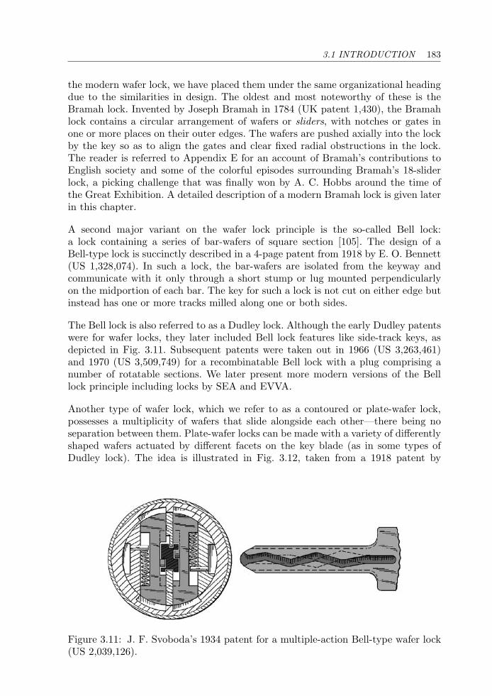
3.1 INTRODUCTION 183
the modern wafer lock, we have placed them under the same organizational headingdue to the similarities in design. The oldest and most noteworthy of these is theBramah lock. Invented by Joseph Bramah in 1784 (UK patent 1,430), the Bramahlock contains a circular arrangement of wafers or sliders, with notches or gates inone or more places on their outer edges. The wafers are pushed axially into the lockby the key so as to align the gates and clear fixed radial obstructions in the lock.The reader is referred to Appendix E for an account of Bramah’s contributions toEnglish society and some of the colorful episodes surrounding Bramah’s 18-sliderlock, a picking challenge that was finally won by A. C. Hobbs around the time ofthe Great Exhibition. A detailed description of a modern Bramah lock is given laterin this chapter.
A second major variant on the wafer lock principle is the so-called Bell lock:a lock containing a series of bar-wafers of square section [105]. The design of aBell-type lock is succinctly described in a 4-page patent from 1918 by E. O. Bennett(US 1,328,074). In such a lock, the bar-wafers are isolated from the keyway andcommunicate with it only through a short stump or lug mounted perpendicularlyon the midportion of each bar. The key for such a lock is not cut on either edge butinstead has one or more tracks milled along one or both sides.
The Bell lock is also referred to as a Dudley lock. Although the early Dudley patentswere for wafer locks, they later included Bell lock features like side-track keys, asdepicted in Fig. 3.11. Subsequent patents were taken out in 1966 (US 3,263,461)and 1970 (US 3,509,749) for a recombinatable Bell lock with a plug comprising anumber of rotatable sections. We later present more modern versions of the Belllock principle including locks by SEA and EVVA.
Another type of wafer lock, which we refer to as a contoured or plate-wafer lock,possesses a multiplicity of wafers that slide alongside each other—there being noseparation between them. Plate-wafer locks can be made with a variety of differentlyshaped wafers actuated by different facets on the key blade (as in some types ofDudley lock). The idea is illustrated in Fig. 3.12, taken from a 1918 patent by
Figure 3.11: J. F. Svoboda’s 1934 patent for a multiple-action Bell-type wafer lock(US 2,039,126).
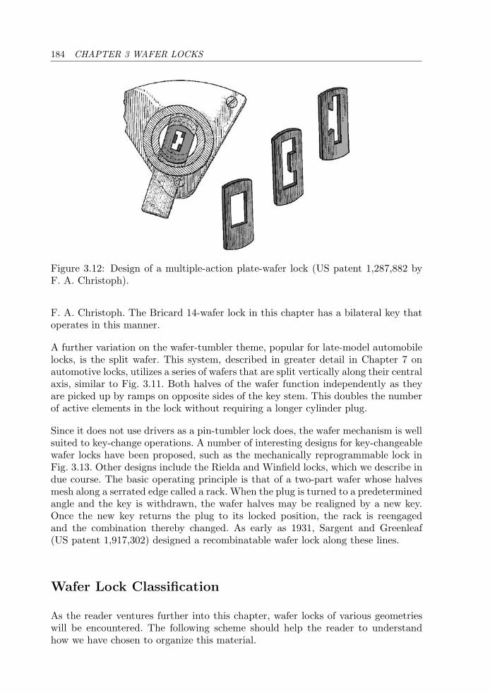
184 CHAPTER 3 WAFER LOCKS
Figure 3.12: Design of a multiple-action plate-wafer lock (US patent 1,287,882 byF. A. Christoph).
F. A. Christoph. The Bricard 14-wafer lock in this chapter has a bilateral key thatoperates in this manner.
A further variation on the wafer-tumbler theme, popular for late-model automobilelocks, is the split wafer. This system, described in greater detail in Chapter 7 onautomotive locks, utilizes a series of wafers that are split vertically along their centralaxis, similar to Fig. 3.11. Both halves of the wafer function independently as theyare picked up by ramps on opposite sides of the key stem. This doubles the numberof active elements in the lock without requiring a longer cylinder plug.
Since it does not use drivers as a pin-tumbler lock does, the wafer mechanism is wellsuited to key-change operations. A number of interesting designs for key-changeablewafer locks have been proposed, such as the mechanically reprogrammable lock inFig. 3.13. Other designs include the Rielda and Winfield locks, which we describe indue course. The basic operating principle is that of a two-part wafer whose halvesmesh along a serrated edge called a rack. When the plug is turned to a predeterminedangle and the key is withdrawn, the wafer halves may be realigned by a new key.Once the new key returns the plug to its locked position, the rack is reengagedand the combination thereby changed. As early as 1931, Sargent and Greenleaf(US patent 1,917,302) designed a recombinatable wafer lock along these lines.
Wafer Lock Classification
As the reader ventures further into this chapter, wafer locks of various geometrieswill be encountered. The following scheme should help the reader to understandhow we have chosen to organize this material.
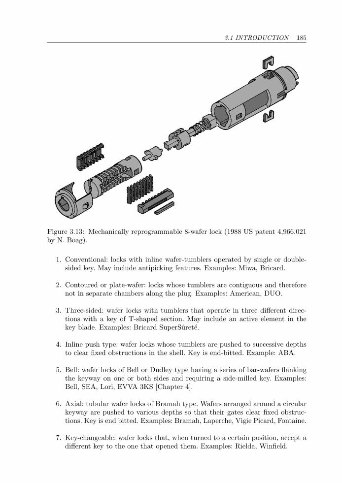
3.1 INTRODUCTION 185
Figure 3.13: Mechanically reprogrammable 8-wafer lock (1988 US patent 4,966,021by N. Boag).
1. Conventional: locks with inline wafer-tumblers operated by single or double-sided key. May include antipicking features. Examples: Miwa, Bricard.
2. Contoured or plate-wafer: locks whose tumblers are contiguous and thereforenot in separate chambers along the plug. Examples: American, DUO.
3. Three-sided: wafer locks with tumblers that operate in three different direc-tions with a key of T-shaped section. May include an active element in thekey blade. Examples: Bricard SuperSurete.
4. Inline push type: wafer locks whose tumblers are pushed to successive depthsto clear fixed obstructions in the shell. Key is end-bitted. Example: ABA.
5. Bell: wafer locks of Bell or Dudley type having a series of bar-wafers flankingthe keyway on one or both sides and requiring a side-milled key. Examples:Bell, SEA, Lori, EVVA 3KS [Chapter 4].
6. Axial: tubular wafer locks of Bramah type. Wafers arranged around a circularkeyway are pushed to various depths so that their gates clear fixed obstruc-tions. Key is end bitted. Examples: Bramah, Laperche, Vigie Picard, Fontaine.
7. Key-changeable: wafer locks that, when turned to a certain position, accept adifferent key to the one that opened them. Examples: Rielda, Winfield.
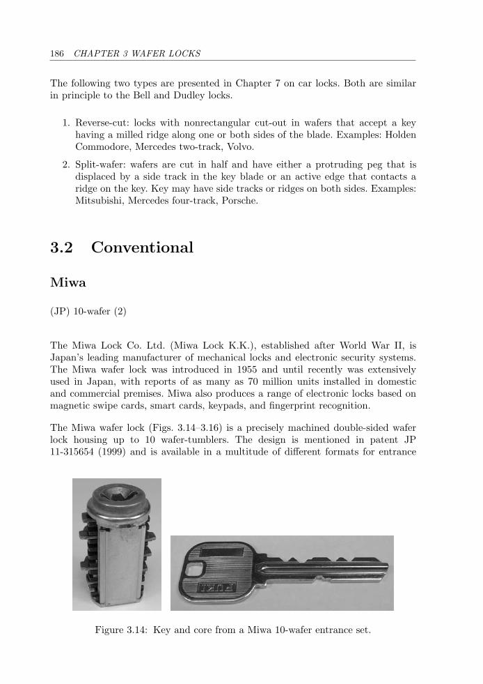
186 CHAPTER 3 WAFER LOCKS
The following two types are presented in Chapter 7 on car locks. Both are similarin principle to the Bell and Dudley locks.
1. Reverse-cut: locks with nonrectangular cut-out in wafers that accept a keyhaving a milled ridge along one or both sides of the blade. Examples: HoldenCommodore, Mercedes two-track, Volvo.
2. Split-wafer: wafers are cut in half and have either a protruding peg that isdisplaced by a side track in the key blade or an active edge that contacts aridge on the key. Key may have side tracks or ridges on both sides. Examples:Mitsubishi, Mercedes four-track, Porsche.
3.2 Conventional
Miwa
(JP) 10-wafer (2)
The Miwa Lock Co. Ltd. (Miwa Lock K.K.), established after World War II, isJapan’s leading manufacturer of mechanical locks and electronic security systems.The Miwa wafer lock was introduced in 1955 and until recently was extensivelyused in Japan, with reports of as many as 70 million units installed in domesticand commercial premises. Miwa also produces a range of electronic locks based onmagnetic swipe cards, smart cards, keypads, and fingerprint recognition.
The Miwa wafer lock (Figs. 3.14–3.16) is a precisely machined double-sided waferlock housing up to 10 wafer-tumblers. The design is mentioned in patent JP11-315654 (1999) and is available in a multitude of different formats for entrance
Figure 3.14: Key and core from a Miwa 10-wafer entrance set.
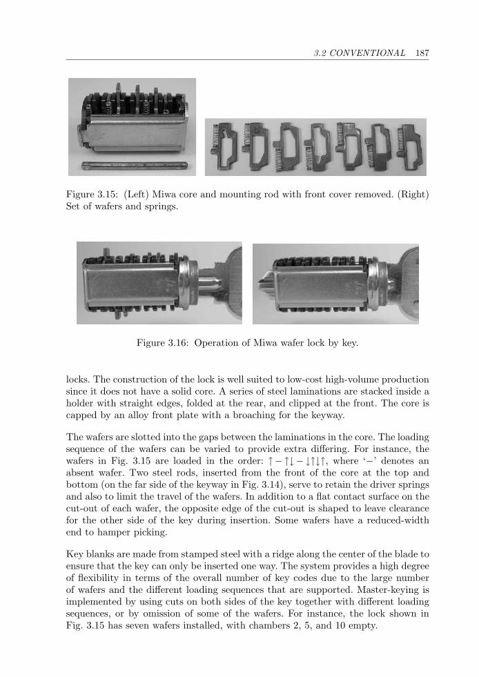
3.2 CONVENTIONAL 187
Figure 3.15: (Left) Miwa core and mounting rod with front cover removed. (Right)Set of wafers and springs.
Figure 3.16: Operation of Miwa wafer lock by key.
locks. The construction of the lock is well suited to low-cost high-volume productionsince it does not have a solid core. A series of steel laminations are stacked inside aholder with straight edges, folded at the rear, and clipped at the front. The core iscapped by an alloy front plate with a broaching for the keyway.
The wafers are slotted into the gaps between the laminations in the core. The loadingsequence of the wafers can be varied to provide extra differing. For instance, thewafers in Fig. 3.15 are loaded in the order: ↑−↑↓−↓↑↓↑, where ‘−’ denotes anabsent wafer. Two steel rods, inserted from the front of the core at the top andbottom (on the far side of the keyway in Fig. 3.14), serve to retain the driver springsand also to limit the travel of the wafers. In addition to a flat contact surface on thecut-out of each wafer, the opposite edge of the cut-out is shaped to leave clearancefor the other side of the key during insertion. Some wafers have a reduced-widthend to hamper picking.
Key blanks are made from stamped steel with a ridge along the center of the blade toensure that the key can only be inserted one way. The system provides a high degreeof flexibility in terms of the overall number of key codes due to the large numberof wafers and the different loading sequences that are supported. Master-keying isimplemented by using cuts on both sides of the key together with different loadingsequences, or by omission of some of the wafers. For instance, the lock shown inFig. 3.15 has seven wafers installed, with chambers 2, 5, and 10 empty.
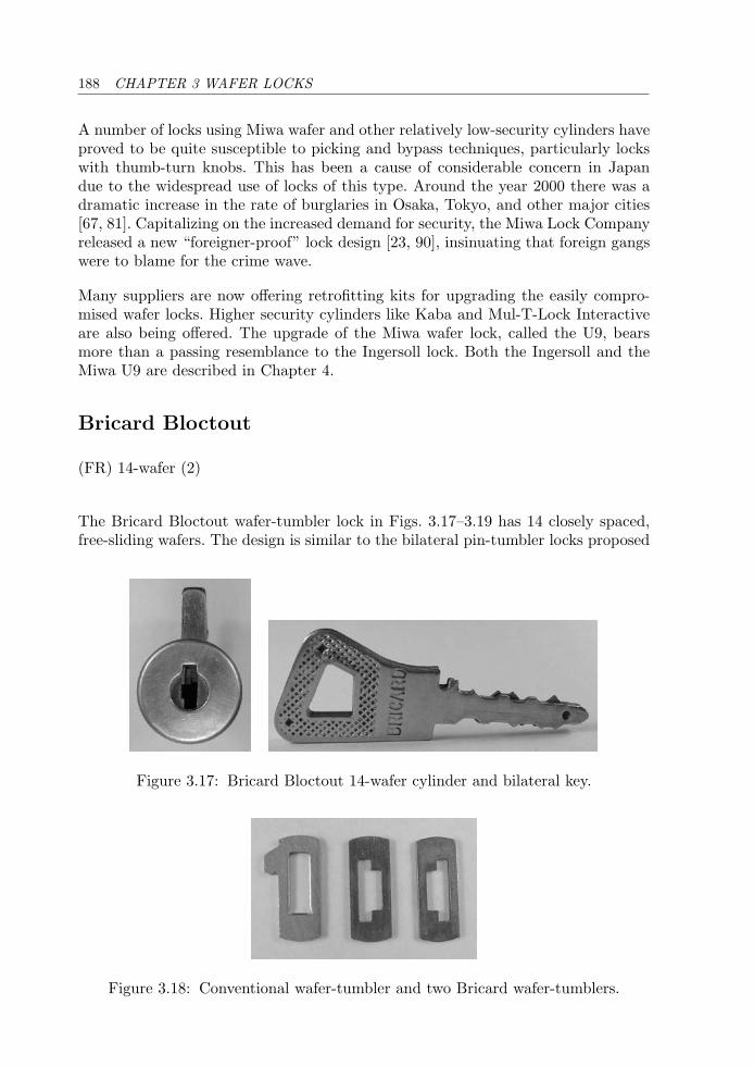
188 CHAPTER 3 WAFER LOCKS
A number of locks using Miwa wafer and other relatively low-security cylinders haveproved to be quite susceptible to picking and bypass techniques, particularly lockswith thumb-turn knobs. This has been a cause of considerable concern in Japandue to the widespread use of locks of this type. Around the year 2000 there was adramatic increase in the rate of burglaries in Osaka, Tokyo, and other major cities[67, 81]. Capitalizing on the increased demand for security, the Miwa Lock Companyreleased a new “foreigner-proof” lock design [23, 90], insinuating that foreign gangswere to blame for the crime wave.
Many suppliers are now offering retrofitting kits for upgrading the easily compro-mised wafer locks. Higher security cylinders like Kaba and Mul-T-Lock Interactiveare also being offered. The upgrade of the Miwa wafer lock, called the U9, bearsmore than a passing resemblance to the Ingersoll lock. Both the Ingersoll and theMiwa U9 are described in Chapter 4.
Bricard Bloctout
(FR) 14-wafer (2)
The Bricard Bloctout wafer-tumbler lock in Figs. 3.17–3.19 has 14 closely spaced,free-sliding wafers. The design is similar to the bilateral pin-tumbler locks proposed
Figure 3.17: Bricard Bloctout 14-wafer cylinder and bilateral key.
Figure 3.18: Conventional wafer-tumbler and two Bricard wafer-tumblers.
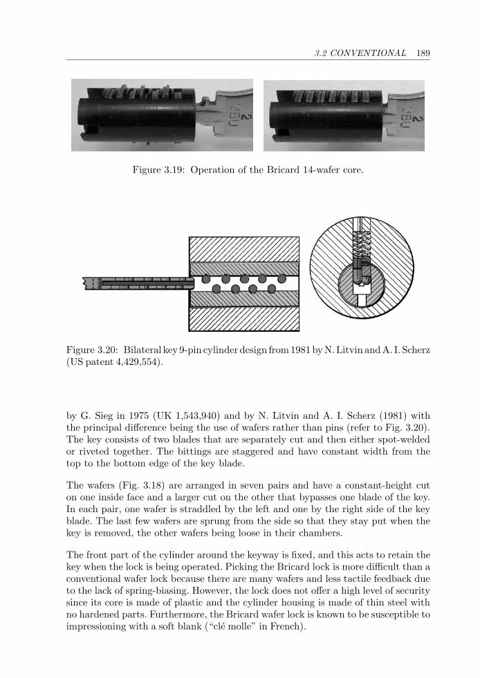
3.2 CONVENTIONAL 189
Figure 3.19: Operation of the Bricard 14-wafer core.
Figure 3.20: Bilateral key 9-pin cylinder design from1981byN.Litvin andA. I. Scherz(US patent 4,429,554).
by G. Sieg in 1975 (UK 1,543,940) and by N. Litvin and A. I. Scherz (1981) withthe principal difference being the use of wafers rather than pins (refer to Fig. 3.20).The key consists of two blades that are separately cut and then either spot-weldedor riveted together. The bittings are staggered and have constant width from thetop to the bottom edge of the key blade.
The wafers (Fig. 3.18) are arranged in seven pairs and have a constant-height cuton one inside face and a larger cut on the other that bypasses one blade of the key.In each pair, one wafer is straddled by the left and one by the right side of the keyblade. The last few wafers are sprung from the side so that they stay put when thekey is removed, the other wafers being loose in their chambers.
The front part of the cylinder around the keyway is fixed, and this acts to retain thekey when the lock is being operated. Picking the Bricard lock is more difficult than aconventional wafer lock because there are many wafers and less tactile feedback dueto the lack of spring-biasing. However, the lock does not offer a high level of securitysince its core is made of plastic and the cylinder housing is made of thin steel withno hardened parts. Furthermore, the Bricard wafer lock is known to be susceptible toimpressioning with a soft blank (“cle molle” in French).
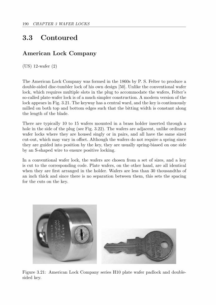
190 CHAPTER 3 WAFER LOCKS
3.3 Contoured
American Lock Company
(US) 12-wafer (2)
The American Lock Company was formed in the 1860s by P. S. Felter to produce adouble-sided disc-tumbler lock of his own design [50]. Unlike the conventional waferlock, which requires multiple slots in the plug to accommodate the wafers, Felter’sso-called plate-wafer lock is of a much simpler construction. A modern version of thelock appears in Fig. 3.21. The keyway has a central ward, and the key is continuouslymilled on both top and bottom edges such that the bitting width is constant alongthe length of the blade.
There are typically 10 to 15 wafers mounted in a brass holder inserted through ahole in the side of the plug (see Fig. 3.22). The wafers are adjacent, unlike ordinarywafer locks where they are housed singly or in pairs, and all have the same sizedcut-out, which may vary in offset. Although the wafers do not require a spring sincethey are guided into position by the key, they are usually spring-biased on one sideby an S-shaped wire to ensure positive locking.
In a conventional wafer lock, the wafers are chosen from a set of sizes, and a keyis cut to the corresponding code. Plate wafers, on the other hand, are all identicalwhen they are first arranged in the holder. Wafers are less than 30 thousandths ofan inch thick and since there is no separation between them, this sets the spacingfor the cuts on the key.
Figure 3.21: American Lock Company series H10 plate wafer padlock and double-sided key.
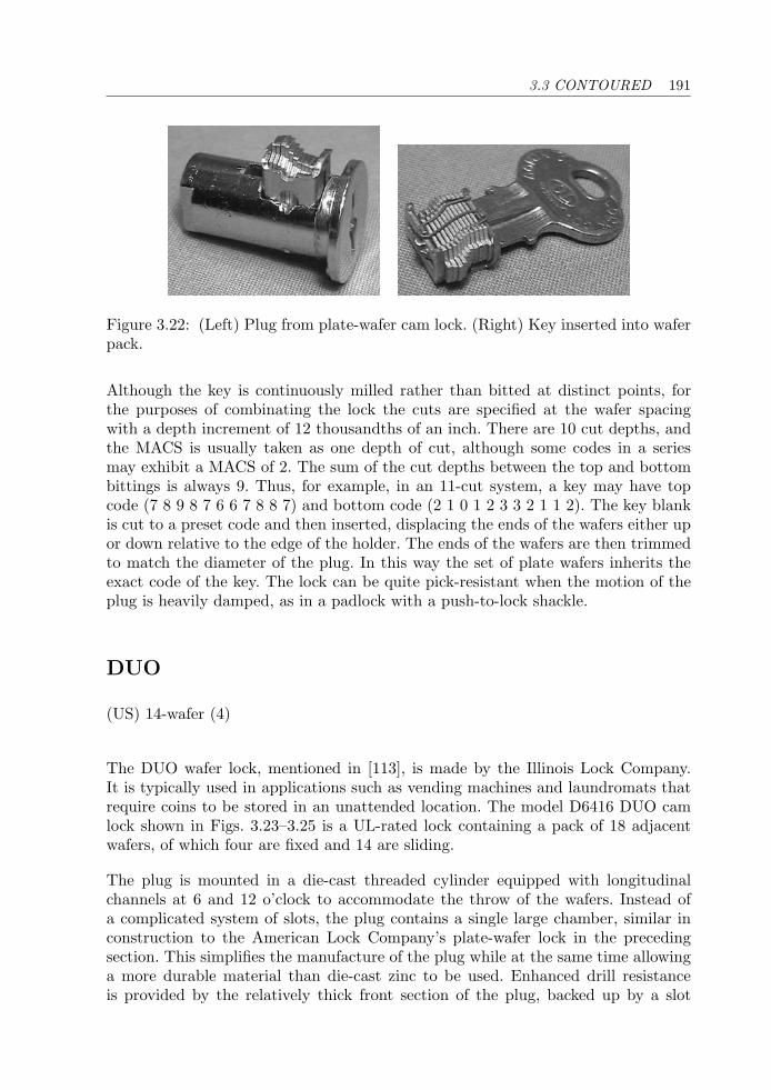
3.3 CONTOURED 191
Figure 3.22: (Left) Plug from plate-wafer cam lock. (Right) Key inserted into waferpack.
Although the key is continuously milled rather than bitted at distinct points, forthe purposes of combinating the lock the cuts are specified at the wafer spacingwith a depth increment of 12 thousandths of an inch. There are 10 cut depths, andthe MACS is usually taken as one depth of cut, although some codes in a seriesmay exhibit a MACS of 2. The sum of the cut depths between the top and bottombittings is always 9. Thus, for example, in an 11-cut system, a key may have topcode (7 8 9 8 7 6 6 7 8 8 7) and bottom code (2 1 0 1 2 3 3 2 1 1 2). The key blankis cut to a preset code and then inserted, displacing the ends of the wafers either upor down relative to the edge of the holder. The ends of the wafers are then trimmedto match the diameter of the plug. In this way the set of plate wafers inherits theexact code of the key. The lock can be quite pick-resistant when the motion of theplug is heavily damped, as in a padlock with a push-to-lock shackle.
DUO
(US) 14-wafer (4)
The DUO wafer lock, mentioned in [113], is made by the Illinois Lock Company.It is typically used in applications such as vending machines and laundromats thatrequire coins to be stored in an unattended location. The model D6416 DUO camlock shown in Figs. 3.23–3.25 is a UL-rated lock containing a pack of 18 adjacentwafers, of which four are fixed and 14 are sliding.
The plug is mounted in a die-cast threaded cylinder equipped with longitudinalchannels at 6 and 12 o’clock to accommodate the throw of the wafers. Instead ofa complicated system of slots, the plug contains a single large chamber, similar inconstruction to the American Lock Company’s plate-wafer lock in the precedingsection. This simplifies the manufacture of the plug while at the same time allowinga more durable material than die-cast zinc to be used. Enhanced drill resistanceis provided by the relatively thick front section of the plug, backed up by a slot
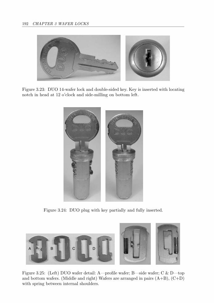
192 CHAPTER 3 WAFER LOCKS
Figure 3.23: DUO 14-wafer lock and double-sided key. Key is inserted with locatingnotch in head at 12 o’clock and side-milling on bottom left.
Figure 3.24: DUO plug with key partially and fully inserted.
A B C D
Figure 3.25: (Left) DUO wafer detail: A—profile wafer; B—side wafer; C & D—topand bottom wafers. (Middle and right) Wafers are arranged in pairs (A+B), (C+D)with spring between internal shoulders.
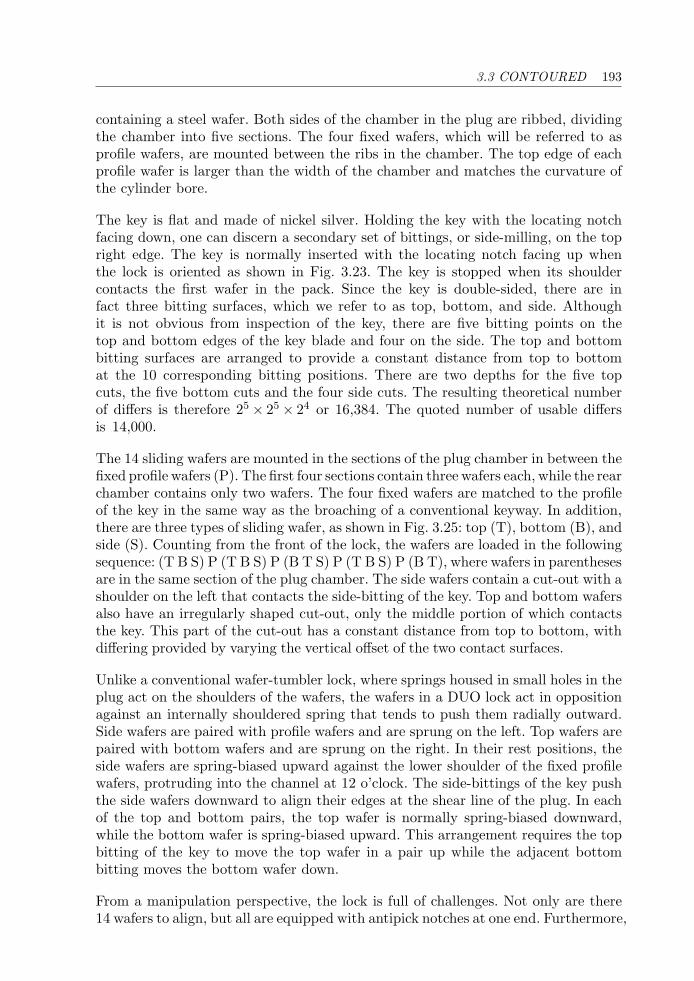
3.3 CONTOURED 193
containing a steel wafer. Both sides of the chamber in the plug are ribbed, dividingthe chamber into five sections. The four fixed wafers, which will be referred to asprofile wafers, are mounted between the ribs in the chamber. The top edge of eachprofile wafer is larger than the width of the chamber and matches the curvature ofthe cylinder bore.
The key is flat and made of nickel silver. Holding the key with the locating notchfacing down, one can discern a secondary set of bittings, or side-milling, on the topright edge. The key is normally inserted with the locating notch facing up whenthe lock is oriented as shown in Fig. 3.23. The key is stopped when its shouldercontacts the first wafer in the pack. Since the key is double-sided, there are infact three bitting surfaces, which we refer to as top, bottom, and side. Althoughit is not obvious from inspection of the key, there are five bitting points on thetop and bottom edges of the key blade and four on the side. The top and bottombitting surfaces are arranged to provide a constant distance from top to bottomat the 10 corresponding bitting positions. There are two depths for the five topcuts, the five bottom cuts and the four side cuts. The resulting theoretical numberof differs is therefore 25 × 25 × 24 or 16,384. The quoted number of usable differsis 14,000.
The 14 sliding wafers are mounted in the sections of the plug chamber in between thefixed profile wafers (P). The first four sections contain three wafers each, while the rearchamber contains only two wafers. The four fixed wafers are matched to the profileof the key in the same way as the broaching of a conventional keyway. In addition,there are three types of sliding wafer, as shown in Fig. 3.25: top (T), bottom (B), andside (S). Counting from the front of the lock, the wafers are loaded in the followingsequence: (T B S) P (T B S) P (B T S) P (T B S) P (B T), where wafers in parenthesesare in the same section of the plug chamber. The side wafers contain a cut-out with ashoulder on the left that contacts the side-bitting of the key. Top and bottom wafersalso have an irregularly shaped cut-out, only the middle portion of which contactsthe key. This part of the cut-out has a constant distance from top to bottom, withdiffering provided by varying the vertical offset of the two contact surfaces.
Unlike a conventional wafer-tumbler lock, where springs housed in small holes in theplug act on the shoulders of the wafers, the wafers in a DUO lock act in oppositionagainst an internally shouldered spring that tends to push them radially outward.Side wafers are paired with profile wafers and are sprung on the left. Top wafers arepaired with bottom wafers and are sprung on the right. In their rest positions, theside wafers are spring-biased upward against the lower shoulder of the fixed profilewafers, protruding into the channel at 12 o’clock. The side-bittings of the key pushthe side wafers downward to align their edges at the shear line of the plug. In eachof the top and bottom pairs, the top wafer is normally spring-biased downward,while the bottom wafer is spring-biased upward. This arrangement requires the topbitting of the key to move the top wafer in a pair up while the adjacent bottombitting moves the bottom wafer down.
From a manipulation perspective, the lock is full of challenges. Not only are there14 wafers to align, but all are equipped with antipick notches at one end. Furthermore,
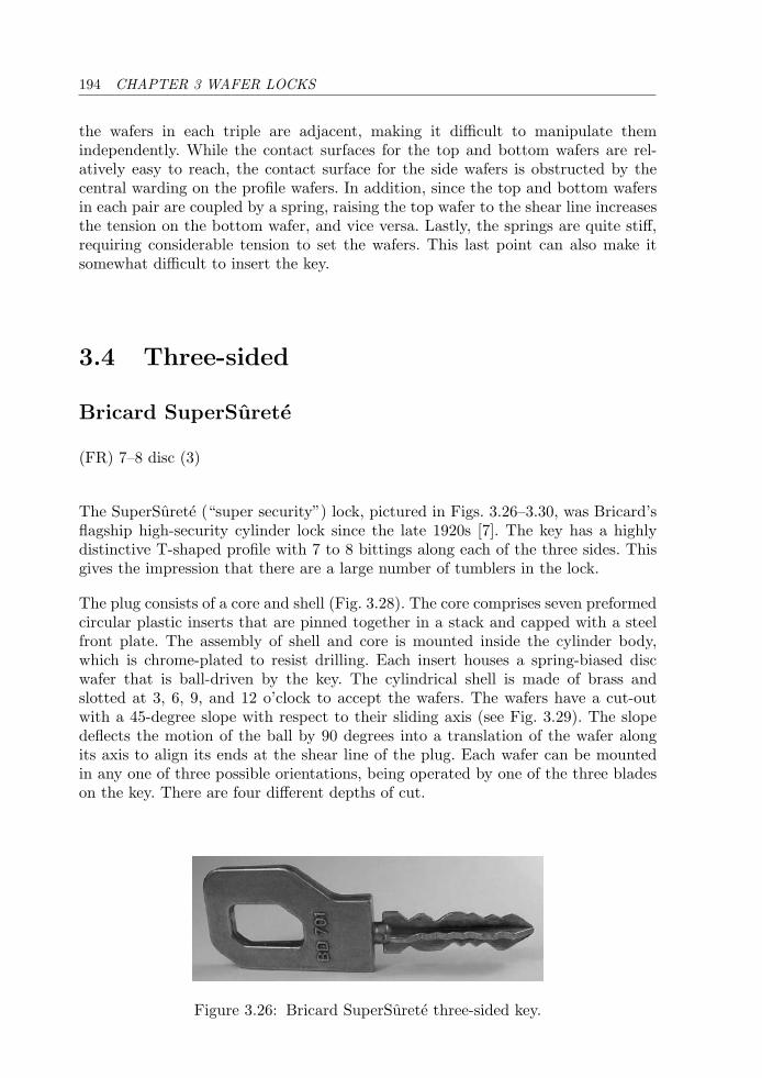
194 CHAPTER 3 WAFER LOCKS
the wafers in each triple are adjacent, making it difficult to manipulate themindependently. While the contact surfaces for the top and bottom wafers are rel-atively easy to reach, the contact surface for the side wafers is obstructed by thecentral warding on the profile wafers. In addition, since the top and bottom wafersin each pair are coupled by a spring, raising the top wafer to the shear line increasesthe tension on the bottom wafer, and vice versa. Lastly, the springs are quite stiff,requiring considerable tension to set the wafers. This last point can also make itsomewhat difficult to insert the key.
3.4 Three-sided
Bricard SuperSurete
(FR) 7–8 disc (3)
The SuperSurete (“super security”) lock, pictured in Figs. 3.26–3.30, was Bricard’sflagship high-security cylinder lock since the late 1920s [7]. The key has a highlydistinctive T-shaped profile with 7 to 8 bittings along each of the three sides. Thisgives the impression that there are a large number of tumblers in the lock.
The plug consists of a core and shell (Fig. 3.28). The core comprises seven preformedcircular plastic inserts that are pinned together in a stack and capped with a steelfront plate. The assembly of shell and core is mounted inside the cylinder body,which is chrome-plated to resist drilling. Each insert houses a spring-biased discwafer that is ball-driven by the key. The cylindrical shell is made of brass andslotted at 3, 6, 9, and 12 o’clock to accept the wafers. The wafers have a cut-outwith a 45-degree slope with respect to their sliding axis (see Fig. 3.29). The slopedeflects the motion of the ball by 90 degrees into a translation of the wafer alongits axis to align its ends at the shear line of the plug. Each wafer can be mountedin any one of three possible orientations, being operated by one of the three bladeson the key. There are four different depths of cut.
Figure 3.26: Bricard SuperSurete three-sided key.
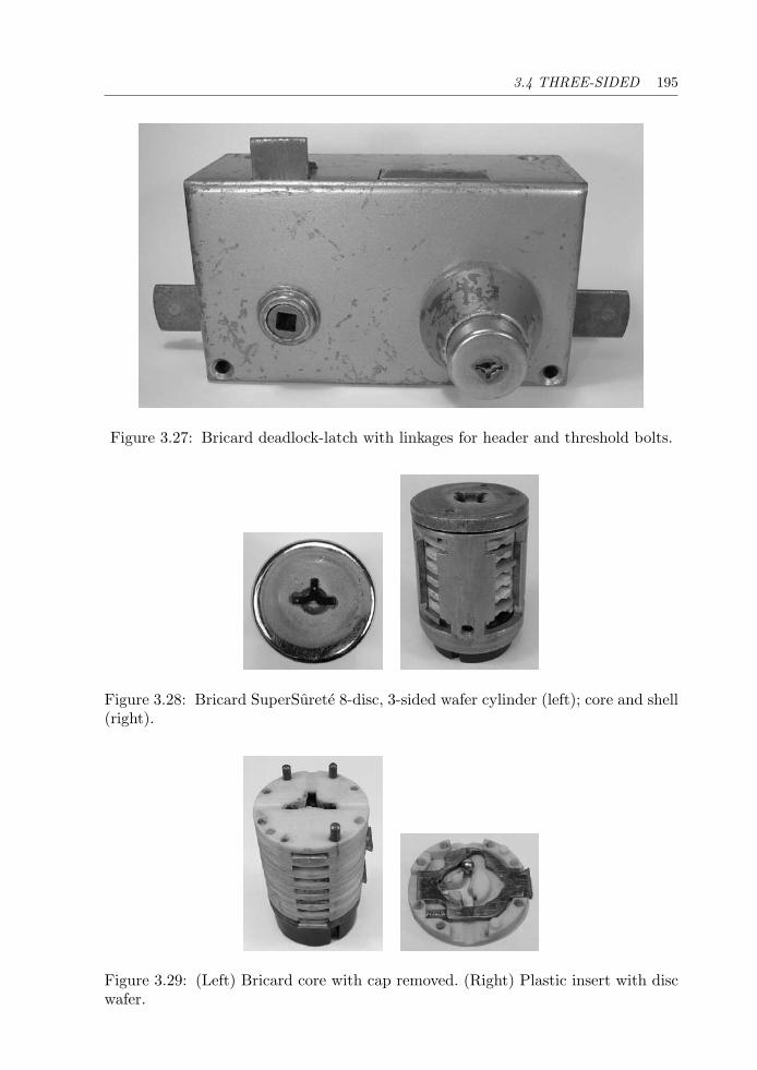
3.4 THREE-SIDED 195
Figure 3.27: Bricard deadlock-latch with linkages for header and threshold bolts.
Figure 3.28: Bricard SuperSurete 8-disc, 3-sided wafer cylinder (left); core and shell(right).
Figure 3.29: (Left) Bricard core with cap removed. (Right) Plastic insert with discwafer.
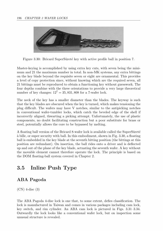
196 CHAPTER 3 WAFER LOCKS
Figure 3.30: Bricard SuperSurete key with active profile ball in position 7.
Master-keying is accomplished by using extra key cuts, with seven being the mini-mum and 21 the maximum number in total. In non-MK systems, any extra bittingson the key blade beyond the requisite seven or eight are ornamental. This providesa level of copy protection since, without knowing which are the required seven, all21 bittings must be reproduced to obtain a functioning key without guesswork. Thefour depths combine with the three orientations to provide a very large theoreticalnumber of key changes: 127 = 35, 831, 808 for a 7-wafer lock.
The neck of the key has a smaller diameter than the blades. The keyway is suchthat the key blades are obscured when the key is turned, which makes tensioning theplug difficult. The wafers may have V notches, similar to the antipicking notchesin conventional wafer-tumbler locks, which catch the beveled edge of the shell ifincorrectly aligned, thwarting a picking attempt. Unfortunately, the use of plasticcomponents, no doubt facilitating construction but a poor substitute for brass orsteel, potentially allows the core to be bypassed by melting.
A floating ball version of the Bricard 8-wafer lock is available called the SuperSuretea bille, or super security with ball. In this embodiment, shown in Fig. 3.30, a floatingball is embedded in the key blade at the seventh bitting position (the bittings at thisposition are redundant). On insertion, the ball rides onto a driver and is deflectedup and out of the plane of the key blade, actuating the seventh wafer. A key withoutthe movable element cannot therefore operate the lock. The principle is based onthe DOM floating-ball system covered in Chapter 2.
3.5 Inline Push Type
ABA Pagoda
(CN) 4-disc (3)
The ABA Pagoda 4-disc lock is one that, to some extent, defies classification. Thelock is manufactured in Taiwan and comes in various packages including cam lock,key switch, and rim cylinder. An ABA cam lock is pictured in Figs. 3.31–3.34.Outwardly the lock looks like a conventional wafer lock, but on inspection someunusual structure is revealed.
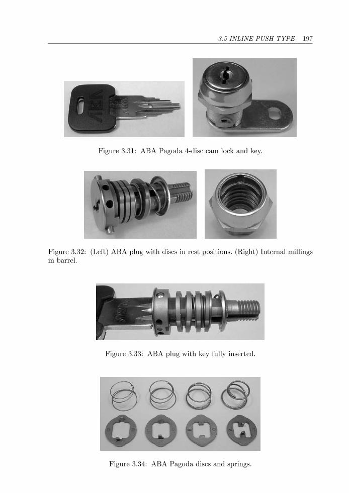
3.5 INLINE PUSH TYPE 197
Figure 3.31: ABA Pagoda 4-disc cam lock and key.
Figure 3.32: (Left) ABA plug with discs in rest positions. (Right) Internal millingsin barrel.
Figure 3.33: ABA plug with key fully inserted.
Figure 3.34: ABA Pagoda discs and springs.
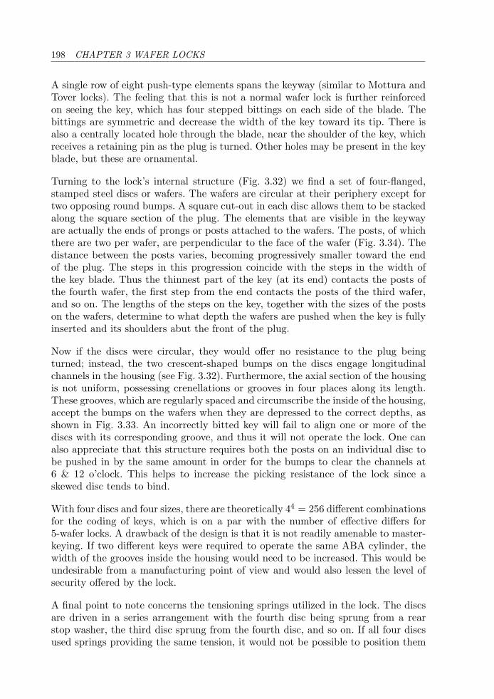
198 CHAPTER 3 WAFER LOCKS
A single row of eight push-type elements spans the keyway (similar to Mottura andTover locks). The feeling that this is not a normal wafer lock is further reinforcedon seeing the key, which has four stepped bittings on each side of the blade. Thebittings are symmetric and decrease the width of the key toward its tip. There isalso a centrally located hole through the blade, near the shoulder of the key, whichreceives a retaining pin as the plug is turned. Other holes may be present in the keyblade, but these are ornamental.
Turning to the lock’s internal structure (Fig. 3.32) we find a set of four-flanged,stamped steel discs or wafers. The wafers are circular at their periphery except fortwo opposing round bumps. A square cut-out in each disc allows them to be stackedalong the square section of the plug. The elements that are visible in the keywayare actually the ends of prongs or posts attached to the wafers. The posts, of whichthere are two per wafer, are perpendicular to the face of the wafer (Fig. 3.34). Thedistance between the posts varies, becoming progressively smaller toward the endof the plug. The steps in this progression coincide with the steps in the width ofthe key blade. Thus the thinnest part of the key (at its end) contacts the posts ofthe fourth wafer, the first step from the end contacts the posts of the third wafer,and so on. The lengths of the steps on the key, together with the sizes of the postson the wafers, determine to what depth the wafers are pushed when the key is fullyinserted and its shoulders abut the front of the plug.
Now if the discs were circular, they would offer no resistance to the plug beingturned; instead, the two crescent-shaped bumps on the discs engage longitudinalchannels in the housing (see Fig. 3.32). Furthermore, the axial section of the housingis not uniform, possessing crenellations or grooves in four places along its length.These grooves, which are regularly spaced and circumscribe the inside of the housing,accept the bumps on the wafers when they are depressed to the correct depths, asshown in Fig. 3.33. An incorrectly bitted key will fail to align one or more of thediscs with its corresponding groove, and thus it will not operate the lock. One canalso appreciate that this structure requires both the posts on an individual disc tobe pushed in by the same amount in order for the bumps to clear the channels at6 & 12 o’clock. This helps to increase the picking resistance of the lock since askewed disc tends to bind.
With four discs and four sizes, there are theoretically 44 = 256 different combinationsfor the coding of keys, which is on a par with the number of effective differs for5-wafer locks. A drawback of the design is that it is not readily amenable to master-keying. If two different keys were required to operate the same ABA cylinder, thewidth of the grooves inside the housing would need to be increased. This would beundesirable from a manufacturing point of view and would also lessen the level ofsecurity offered by the lock.
A final point to note concerns the tensioning springs utilized in the lock. The discsare driven in a series arrangement with the fourth disc being sprung from a rearstop washer, the third disc sprung from the fourth disc, and so on. If all four discsused springs providing the same tension, it would not be possible to position them
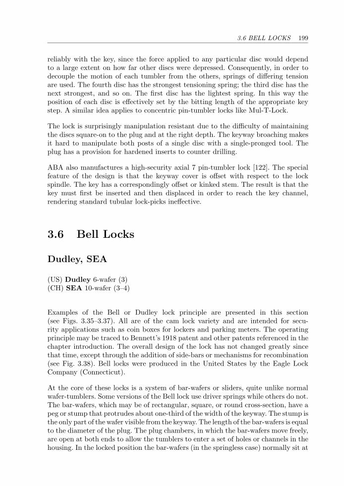
3.6 BELL LOCKS 199
reliably with the key, since the force applied to any particular disc would dependto a large extent on how far other discs were depressed. Consequently, in order todecouple the motion of each tumbler from the others, springs of differing tensionare used. The fourth disc has the strongest tensioning spring; the third disc has thenext strongest, and so on. The first disc has the lightest spring. In this way theposition of each disc is effectively set by the bitting length of the appropriate keystep. A similar idea applies to concentric pin-tumbler locks like Mul-T-Lock.
The lock is surprisingly manipulation resistant due to the difficulty of maintainingthe discs square-on to the plug and at the right depth. The keyway broaching makesit hard to manipulate both posts of a single disc with a single-pronged tool. Theplug has a provision for hardened inserts to counter drilling.
ABA also manufactures a high-security axial 7 pin-tumbler lock [122]. The specialfeature of the design is that the keyway cover is offset with respect to the lockspindle. The key has a correspondingly offset or kinked stem. The result is that thekey must first be inserted and then displaced in order to reach the key channel,rendering standard tubular lock-picks ineffective.
3.6 Bell Locks
Dudley, SEA
(US) Dudley 6-wafer (3)(CH) SEA 10-wafer (3–4)
Examples of the Bell or Dudley lock principle are presented in this section(see Figs. 3.35–3.37). All are of the cam lock variety and are intended for secu-rity applications such as coin boxes for lockers and parking meters. The operatingprinciple may be traced to Bennett’s 1918 patent and other patents referenced in thechapter introduction. The overall design of the lock has not changed greatly sincethat time, except through the addition of side-bars or mechanisms for recombination(see Fig. 3.38). Bell locks were produced in the United States by the Eagle LockCompany (Connecticut).
At the core of these locks is a system of bar-wafers or sliders, quite unlike normalwafer-tumblers. Some versions of the Bell lock use driver springs while others do not.The bar-wafers, which may be of rectangular, square, or round cross-section, have apeg or stump that protrudes about one-third of the width of the keyway. The stump isthe only part of the wafer visible from the keyway. The length of the bar-wafers is equalto the diameter of the plug. The plug chambers, in which the bar-wafers move freely,are open at both ends to allow the tumblers to enter a set of holes or channels in thehousing. In the locked position the bar-wafers (in the springless case) normally sit at
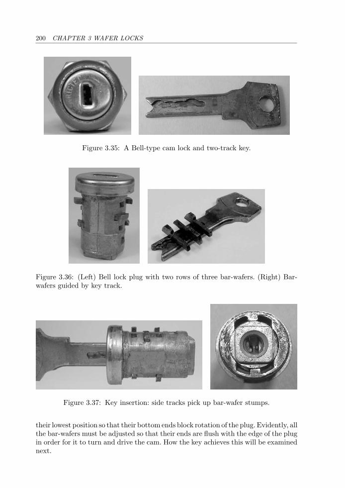
200 CHAPTER 3 WAFER LOCKS
Figure 3.35: A Bell-type cam lock and two-track key.
Figure 3.36: (Left) Bell lock plug with two rows of three bar-wafers. (Right) Bar-wafers guided by key track.
Figure 3.37: Key insertion: side tracks pick up bar-wafer stumps.
their lowest position so that their bottom ends block rotation of the plug. Evidently, allthe bar-wafers must be adjusted so that their ends are flush with the edge of the plugin order for it to turn and drive the cam. How the key achieves this will be examinednext.
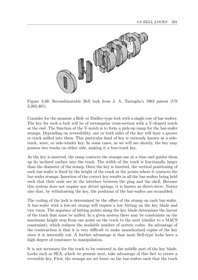
3.6 BELL LOCKS 201
Figure 3.38: Recombinatable Bell lock from J. A. Tartaglia’s 1963 patent (US3,263,461).
Consider for the moment a Bell- or Dudley-type lock with a single row of bar-wafers.The key for such a lock will be of rectangular cross-section with a V-shaped notchat the end. The function of the V-notch is to form a pick-up ramp for the bar-waferstumps. Depending on reversibility, one or both sides of the key will have a grooveor track milled into them. This particular kind of key is variously known as a side-track, wave, or side-winder key. In some cases, as we will see shortly, the key maypossess two tracks on either side, making it a four-track key.
As the key is inserted, the ramp contacts the stumps one at a time and guides themup its inclined surface into the track. The width of the track is fractionally largerthan the diameter of the stump. Once the key is inserted, the vertical positioning ofeach bar-wafer is fixed by the height of the track at the points where it contacts thebar-wafer stumps. Insertion of the correct key results in all the bar-wafers being heldsuch that their ends are at the interface between the plug and the shell. Becausethis system does not require any driver springs, it is known as direct-drive. Noticealso that, by withdrawing the key, the positions of the bar-wafers are scrambled.
The coding of the lock is determined by the offset of the stump on each bar-wafer.A bar-wafer with a low-set stump will require a low bitting on the key blade andvice versa. The sequence of bitting points along the key blade determines the layoutof the track that must be milled. In a given system there may be constraints on themaximum height step from one point on the track to the next (similar to a MACSconstraint), which reduces the available number of system codes. An advantage ofthe construction is that it is very difficult to make unauthorized copies of the keysince it is internally cut. A further advantage is that most Bell-type locks have ahigh degree of resistance to manipulation.
It is not necessary for the track to be centered in the middle part of the key blade.Locks such as SEA, which we present next, take advantage of this fact to create areversible key. First, the stumps are set lower on the bar-wafers such that the track
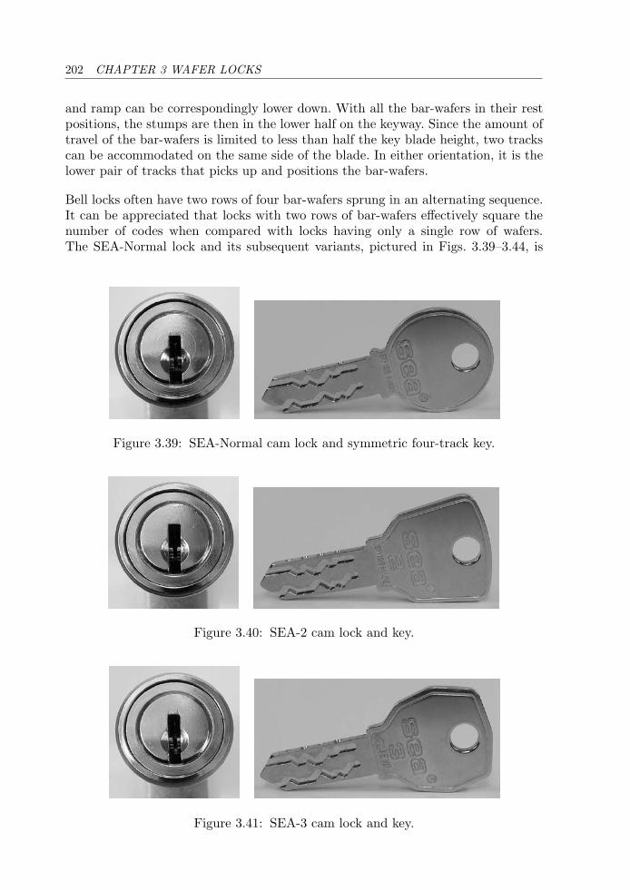
202 CHAPTER 3 WAFER LOCKS
and ramp can be correspondingly lower down. With all the bar-wafers in their restpositions, the stumps are then in the lower half on the keyway. Since the amount oftravel of the bar-wafers is limited to less than half the key blade height, two trackscan be accommodated on the same side of the blade. In either orientation, it is thelower pair of tracks that picks up and positions the bar-wafers.
Bell locks often have two rows of four bar-wafers sprung in an alternating sequence.It can be appreciated that locks with two rows of bar-wafers effectively square thenumber of codes when compared with locks having only a single row of wafers.The SEA-Normal lock and its subsequent variants, pictured in Figs. 3.39–3.44, is
Figure 3.39: SEA-Normal cam lock and symmetric four-track key.
Figure 3.40: SEA-2 cam lock and key.
Figure 3.41: SEA-3 cam lock and key.
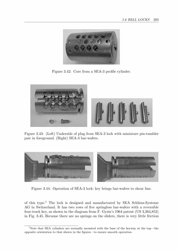
3.6 BELL LOCKS 203
Figure 3.42: Core from a SEA-3 profile cylinder.
Figure 3.43: (Left) Underside of plug from SEA-3 lock with miniature pin-tumblerpair in foreground. (Right) SEA-3 bar-wafers.
Figure 3.44: Operation of SEA-3 lock: key brings bar-wafers to shear line.
of this type.1 The lock is designed and manufactured by SEA Schliess-SystemeAG in Switzerland. It has two rows of five springless bar-wafers with a reversiblefour-track key, as shown in the diagram from F. Gysin’s 1964 patent (US 3,264,852)in Fig. 3.45. Because there are no springs on the sliders, there is very little friction
1Note that SEA cylinders are normally mounted with the base of the keyway at the top—theopposite orientation to that shown in the figures—to ensure smooth operation.
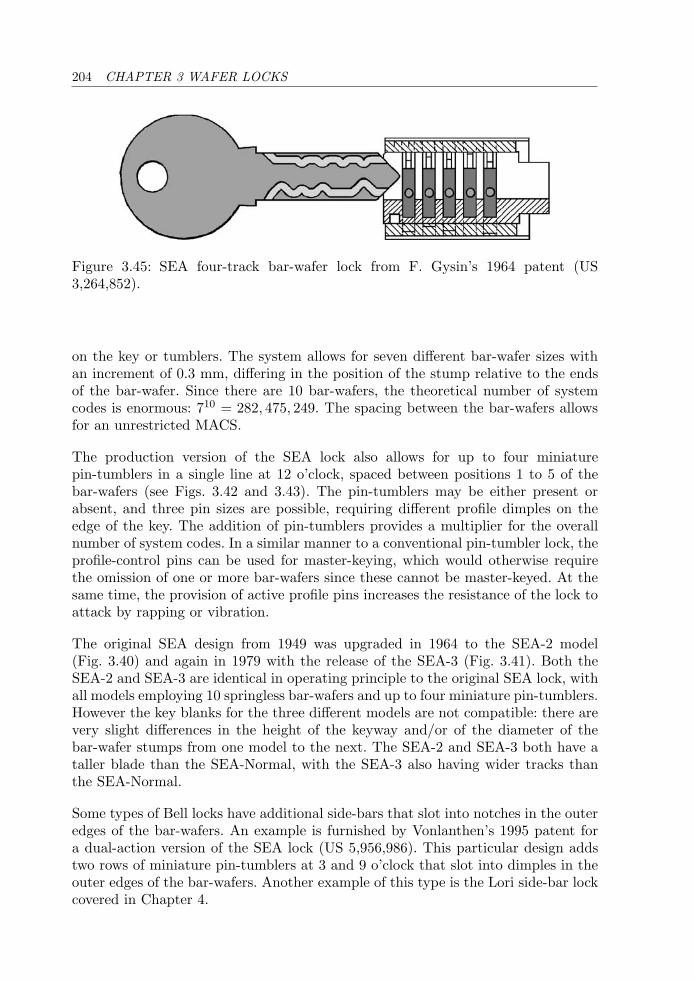
204 CHAPTER 3 WAFER LOCKS
Figure 3.45: SEA four-track bar-wafer lock from F. Gysin’s 1964 patent (US3,264,852).
on the key or tumblers. The system allows for seven different bar-wafer sizes withan increment of 0.3 mm, differing in the position of the stump relative to the endsof the bar-wafer. Since there are 10 bar-wafers, the theoretical number of systemcodes is enormous: 710 = 282, 475, 249. The spacing between the bar-wafers allowsfor an unrestricted MACS.
The production version of the SEA lock also allows for up to four miniaturepin-tumblers in a single line at 12 o’clock, spaced between positions 1 to 5 of thebar-wafers (see Figs. 3.42 and 3.43). The pin-tumblers may be either present orabsent, and three pin sizes are possible, requiring different profile dimples on theedge of the key. The addition of pin-tumblers provides a multiplier for the overallnumber of system codes. In a similar manner to a conventional pin-tumbler lock, theprofile-control pins can be used for master-keying, which would otherwise requirethe omission of one or more bar-wafers since these cannot be master-keyed. At thesame time, the provision of active profile pins increases the resistance of the lock toattack by rapping or vibration.
The original SEA design from 1949 was upgraded in 1964 to the SEA-2 model(Fig. 3.40) and again in 1979 with the release of the SEA-3 (Fig. 3.41). Both theSEA-2 and SEA-3 are identical in operating principle to the original SEA lock, withall models employing 10 springless bar-wafers and up to four miniature pin-tumblers.However the key blanks for the three different models are not compatible: there arevery slight differences in the height of the keyway and/or of the diameter of thebar-wafer stumps from one model to the next. The SEA-2 and SEA-3 both have ataller blade than the SEA-Normal, with the SEA-3 also having wider tracks thanthe SEA-Normal.
Some types of Bell locks have additional side-bars that slot into notches in the outeredges of the bar-wafers. An example is furnished by Vonlanthen’s 1995 patent fora dual-action version of the SEA lock (US 5,956,986). This particular design addstwo rows of miniature pin-tumblers at 3 and 9 o’clock that slot into dimples in theouter edges of the bar-wafers. Another example of this type is the Lori side-bar lockcovered in Chapter 4.

3.7 AXIAL 205
3.7 Axial
Bramah
(UK) 7-wafer (3–4)
Axial wafer locks accept a tubular or solid key of round section with bittings at thetip. There are a number of differences with respect to conventional wafer-tumblerlocks, the most significant of these being that the wafers are pushed axially into thelock rather than being lifted by sloped cuts on the key blade. Axial wafer locks, liketheir pin-tumbler counterparts, will relock at fractions of a turn unless the wafers aremaintained at the correct depths. We present a number of such locks in this section,starting with the English Bramah lock and then proceeding with descriptions ofFrench and German modifications to the Bramah principle.
The Bramah lock, briefly mentioned in the chapter introduction, was the first axiallock and has served as a model for many other axial push-key locks. The Bramahcompany, now established in the United States, produces locks for commercial andresidential applications such as the MD27 mortice deadlock. The Bramah lockis also used for safes, with stainless steel blank keys supplied in stem lengths upto 6 . The construction and functioning of a model C17 Bramah lock, based on adesign that has remained largely unchanged for over 200 years, is now considered.Further historical details concerning Joseph Bramah and Company may be foundin Appendix E.
The lock, shown in Figs. 3.46–3.49, consists of a cylinder housing into which is set arotatable core. The core is held in the locked position by a radially disposed systemof usually seven wafers or sliders, although variants of the lock have been madewith between four and 18 sliders. These are arranged around a central drill-pin ontowhich a strong spring and cap are mounted.
Figure 3.46: Bramah C17 7-slider mortice cylinder and key.
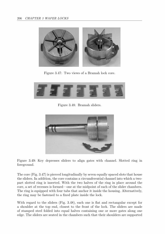
206 CHAPTER 3 WAFER LOCKS
Figure 3.47: Two views of a Bramah lock core.
Figure 3.48: Bramah sliders.
Figure 3.49: Key depresses sliders to align gates with channel. Slotted ring inforeground.
The core (Fig. 3.47) is pierced longitudinally by seven equally spaced slots that housethe sliders. In addition, the core contains a circumferential channel into which a two-part slotted ring is inserted. With the two halves of the ring in place around thecore, a set of recesses is formed—one at the midpoint of each of the slider chambers.The ring is equipped with four tabs that anchor it inside the housing. Alternatively,the ring may be fastened to a fixed plate inside the lock.
With regard to the sliders (Fig. 3.48), each one is flat and rectangular except fora shoulder at the top end, closest to the front of the lock. The sliders are madeof stamped steel folded into equal halves containing one or more gates along oneedge. The sliders are seated in the chambers such that their shoulders are supported
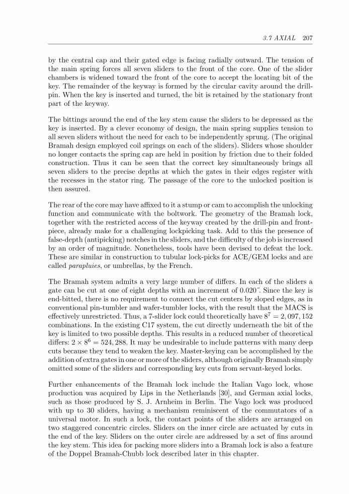
3.7 AXIAL 207
by the central cap and their gated edge is facing radially outward. The tension ofthe main spring forces all seven sliders to the front of the core. One of the sliderchambers is widened toward the front of the core to accept the locating bit of thekey. The remainder of the keyway is formed by the circular cavity around the drill-pin. When the key is inserted and turned, the bit is retained by the stationary frontpart of the keyway.
The bittings around the end of the key stem cause the sliders to be depressed as thekey is inserted. By a clever economy of design, the main spring supplies tension toall seven sliders without the need for each to be independently sprung. (The originalBramah design employed coil springs on each of the sliders). Sliders whose shoulderno longer contacts the spring cap are held in position by friction due to their foldedconstruction. Thus it can be seen that the correct key simultaneously brings allseven sliders to the precise depths at which the gates in their edges register withthe recesses in the stator ring. The passage of the core to the unlocked position isthen assured.
The rear of the core may have affixed to it a stump or cam to accomplish the unlockingfunction and communicate with the boltwork. The geometry of the Bramah lock,together with the restricted access of the keyway created by the drill-pin and front-piece, already make for a challenging lockpicking task. Add to this the presence offalse-depth (antipicking) notches in the sliders, and the difficulty of the job is increasedby an order of magnitude. Nonetheless, tools have been devised to defeat the lock.These are similar in construction to tubular lock-picks for ACE/GEM locks and arecalled parapluies, or umbrellas, by the French.
The Bramah system admits a very large number of differs. In each of the sliders agate can be cut at one of eight depths with an increment of 0.020 . Since the key isend-bitted, there is no requirement to connect the cut centers by sloped edges, as inconventional pin-tumbler and wafer-tumbler locks, with the result that the MACS iseffectively unrestricted. Thus, a 7-slider lock could theoretically have 87 = 2, 097, 152combinations. In the existing C17 system, the cut directly underneath the bit of thekey is limited to two possible depths. This results in a reduced number of theoreticaldiffers: 2 × 86 = 524, 288. It may be undesirable to include patterns with many deepcuts because they tend to weaken the key. Master-keying can be accomplished by theaddition of extra gates in one or more of the sliders, although originally Bramah simplyomitted some of the sliders and corresponding key cuts from servant-keyed locks.
Further enhancements of the Bramah lock include the Italian Vago lock, whoseproduction was acquired by Lips in the Netherlands [30], and German axial locks,such as those produced by S. J. Arnheim in Berlin. The Vago lock was producedwith up to 30 sliders, having a mechanism reminiscent of the commutators of auniversal motor. In such a lock, the contact points of the sliders are arranged ontwo staggered concentric circles. Sliders on the inner circle are actuated by cuts inthe end of the key. Sliders on the outer circle are addressed by a set of fins aroundthe key stem. This idea for packing more sliders into a Bramah lock is also a featureof the Doppel Bramah-Chubb lock described later in this chapter.
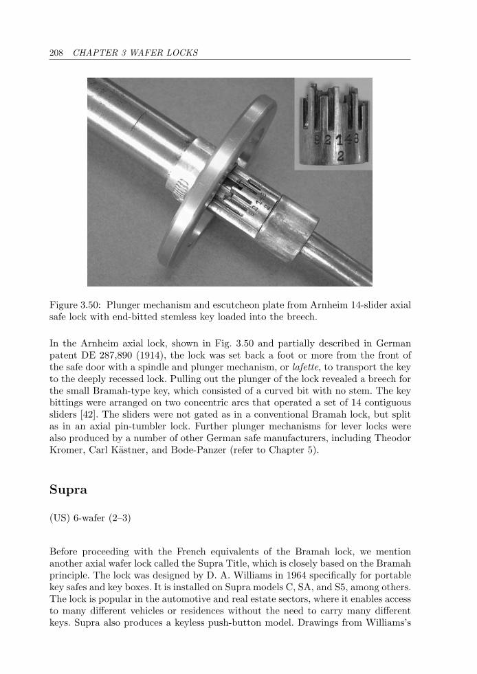
208 CHAPTER 3 WAFER LOCKS
Figure 3.50: Plunger mechanism and escutcheon plate from Arnheim 14-slider axialsafe lock with end-bitted stemless key loaded into the breech.
In the Arnheim axial lock, shown in Fig. 3.50 and partially described in Germanpatent DE 287,890 (1914), the lock was set back a foot or more from the front ofthe safe door with a spindle and plunger mechanism, or lafette, to transport the keyto the deeply recessed lock. Pulling out the plunger of the lock revealed a breech forthe small Bramah-type key, which consisted of a curved bit with no stem. The keybittings were arranged on two concentric arcs that operated a set of 14 contiguoussliders [42]. The sliders were not gated as in a conventional Bramah lock, but splitas in an axial pin-tumbler lock. Further plunger mechanisms for lever locks werealso produced by a number of other German safe manufacturers, including TheodorKromer, Carl Kastner, and Bode-Panzer (refer to Chapter 5).
Supra
(US) 6-wafer (2–3)
Before proceeding with the French equivalents of the Bramah lock, we mentionanother axial wafer lock called the Supra Title, which is closely based on the Bramahprinciple. The lock was designed by D. A. Williams in 1964 specifically for portablekey safes and key boxes. It is installed on Supra models C, SA, and S5, among others.The lock is popular in the automotive and real estate sectors, where it enables accessto many different vehicles or residences without the need to carry many differentkeys. Supra also produces a keyless push-button model. Drawings from Williams’s
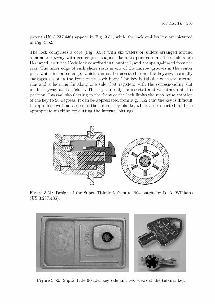
3.7 AXIAL 209
patent (US 3,237,436) appear in Fig. 3.51, while the lock and its key are picturedin Fig. 3.52.
The lock comprises a core (Fig. 3.53) with six wafers or sliders arranged arounda circular keyway with center post shaped like a six-pointed star. The sliders areU-shaped, as in the Code lock described in Chapter 2, and are spring-biased from therear. The inner edge of each slider rests in one of the narrow grooves in the centerpost while its outer edge, which cannot be accessed from the keyway, normallyenagages a slot in the front of the lock body. The key is tubular with six internalribs and a locating fin along one side that registers with the corresponding slotin the keyway at 12 o’clock. The key can only be inserted and withdrawn at thisposition. Internal shouldering in the front of the lock limits the maximum rotationof the key to 90 degrees. It can be appreciated from Fig. 3.52 that the key is difficultto reproduce without access to the correct key blanks, which are restricted, and theappropriate machine for cutting the internal bittings.
Figure 3.51: Design of the Supra Title lock from a 1964 patent by D. A. Williams(US 3,237,436).
Figure 3.52: Supra Title 6-slider key safe and two views of the tubular key.
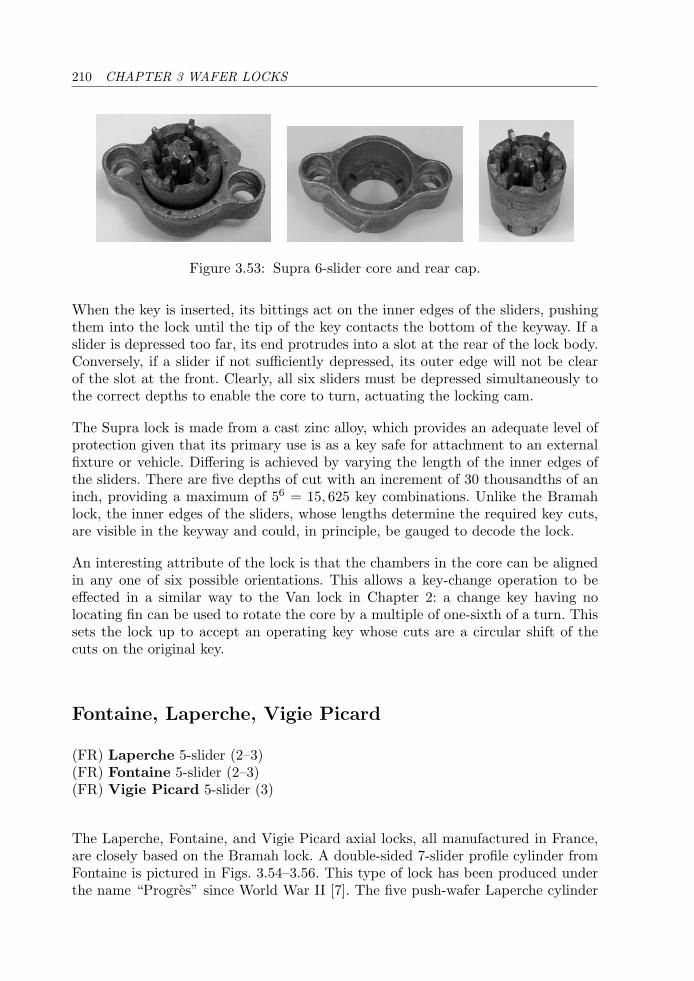
210 CHAPTER 3 WAFER LOCKS
Figure 3.53: Supra 6-slider core and rear cap.
When the key is inserted, its bittings act on the inner edges of the sliders, pushingthem into the lock until the tip of the key contacts the bottom of the keyway. If aslider is depressed too far, its end protrudes into a slot at the rear of the lock body.Conversely, if a slider if not sufficiently depressed, its outer edge will not be clearof the slot at the front. Clearly, all six sliders must be depressed simultaneously tothe correct depths to enable the core to turn, actuating the locking cam.
The Supra lock is made from a cast zinc alloy, which provides an adequate level ofprotection given that its primary use is as a key safe for attachment to an externalfixture or vehicle. Differing is achieved by varying the length of the inner edges ofthe sliders. There are five depths of cut with an increment of 30 thousandths of aninch, providing a maximum of 56 = 15, 625 key combinations. Unlike the Bramahlock, the inner edges of the sliders, whose lengths determine the required key cuts,are visible in the keyway and could, in principle, be gauged to decode the lock.
An interesting attribute of the lock is that the chambers in the core can be alignedin any one of six possible orientations. This allows a key-change operation to beeffected in a similar way to the Van lock in Chapter 2: a change key having nolocating fin can be used to rotate the core by a multiple of one-sixth of a turn. Thissets the lock up to accept an operating key whose cuts are a circular shift of thecuts on the original key.
Fontaine, Laperche, Vigie Picard
(FR) Laperche 5-slider (2–3)(FR) Fontaine 5-slider (2–3)(FR) Vigie Picard 5-slider (3)
The Laperche, Fontaine, and Vigie Picard axial locks, all manufactured in France,are closely based on the Bramah lock. A double-sided 7-slider profile cylinder fromFontaine is pictured in Figs. 3.54–3.56. This type of lock has been produced underthe name “Progres” since World War II [7]. The five push-wafer Laperche cylinder
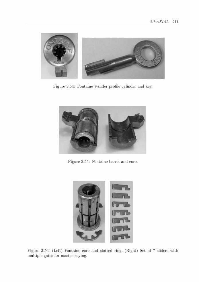
3.7 AXIAL 211
Figure 3.54: Fontaine 7-slider profile cylinder and key.
Figure 3.55: Fontaine barrel and core.
Figure 3.56: (Left) Fontaine core and slotted ring. (Right) Set of 7 sliders withmultiple gates for master-keying.
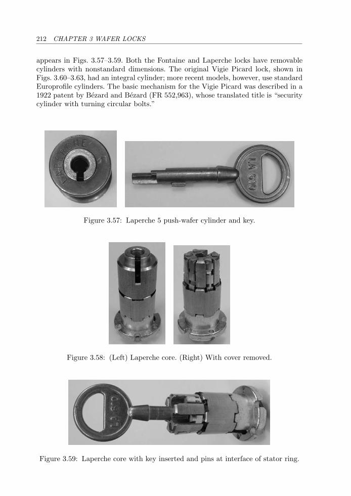
212 CHAPTER 3 WAFER LOCKS
appears in Figs. 3.57–3.59. Both the Fontaine and Laperche locks have removablecylinders with nonstandard dimensions. The original Vigie Picard lock, shown inFigs. 3.60–3.63, had an integral cylinder; more recent models, however, use standardEuroprofile cylinders. The basic mechanism for the Vigie Picard was described in a1922 patent by Bezard and Bezard (FR 552,963), whose translated title is “securitycylinder with turning circular bolts.”
Figure 3.57: Laperche 5 push-wafer cylinder and key.
Figure 3.58: (Left) Laperche core. (Right) With cover removed.
Figure 3.59: Laperche core with key inserted and pins at interface of stator ring.
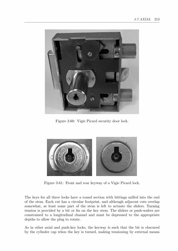
3.7 AXIAL 213
Figure 3.60: Vigie Picard security door lock.
Figure 3.61: Front and rear keyway of a Vigie Picard lock.
The keys for all three locks have a round section with bittings milled into the endof the stem. Each cut has a circular footprint, and although adjacent cuts overlapsomewhat, at least some part of the stem is left to actuate the sliders. Turningtension is provided by a bit or fin on the key stem. The sliders or push-wafers areconstrained to a longitudinal channel and must be depressed to the appropriatedepths to allow the plug to rotate.
As in other axial and push-key locks, the keyway is such that the bit is obscuredby the cylinder cap when the key is turned, making tensioning by external means
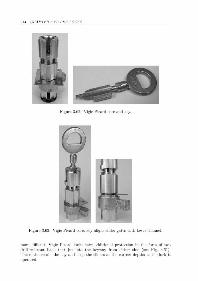
214 CHAPTER 3 WAFER LOCKS
Figure 3.62: Vigie Picard core and key.
Figure 3.63: Vigie Picard core: key aligns slider gates with lower channel.
more difficult. Vigie Picard locks have additional protection in the form of twodrill-resistant balls that jut into the keyway from either side (see Fig. 3.61).These also retain the key and keep the sliders at the correct depths as the lock isoperated.
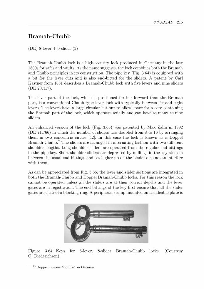
3.7 AXIAL 215
Bramah-Chubb
(DE) 8-lever + 9-slider (5)
The Bramah-Chubb lock is a high-security lock produced in Germany in the late1800s for safes and vaults. As the name suggests, the lock combines both the Bramahand Chubb principles in its construction. The pipe key (Fig. 3.64) is equipped witha bit for the lever cuts and is also end-bitted for the sliders. A patent by CarlKastner from 1881 describes a Bramah-Chubb lock with five levers and nine sliders(DE 20,417).
The lever part of the lock, which is positioned further forward than the Bramahpart, is a conventional Chubb-type lever lock with typically between six and eightlevers. The levers have a large circular cut-out to allow space for a core containingthe Bramah part of the lock, which operates axially and can have as many as ninesliders.
An enhanced version of the lock (Fig. 3.65) was patented by Max Zahn in 1892(DE 71,766) in which the number of sliders was doubled from 8 to 16 by arrangingthem in two concentric circles [42]. In this case the lock is known as a DoppelBramah-Chubb.2 The sliders are arranged in alternating fashion with two differentshoulder lengths. Long-shoulder sliders are operated from the regular end-bittingsin the pipe key. Short-shoulder sliders are depressed by millings in the key stem inbetween the usual end-bittings and set higher up on the blade so as not to interferewith them.
As can be appreciated from Fig. 3.66, the lever and slider sections are integrated inboth the Bramah-Chubb and Doppel Bramah-Chubb locks. For this reason the lockcannot be operated unless all the sliders are at their correct depths and the levergates are in registration. The end bittings of the key first ensure that all the slidergates are clear of a blocking ring. A peripheral stump mounted on a slideable plate is
Figure 3.64: Keys for 6-lever, 8-slider Bramah-Chubb locks. (CourtesyO. Diederichsen).
2“Doppel” means “double” in German.
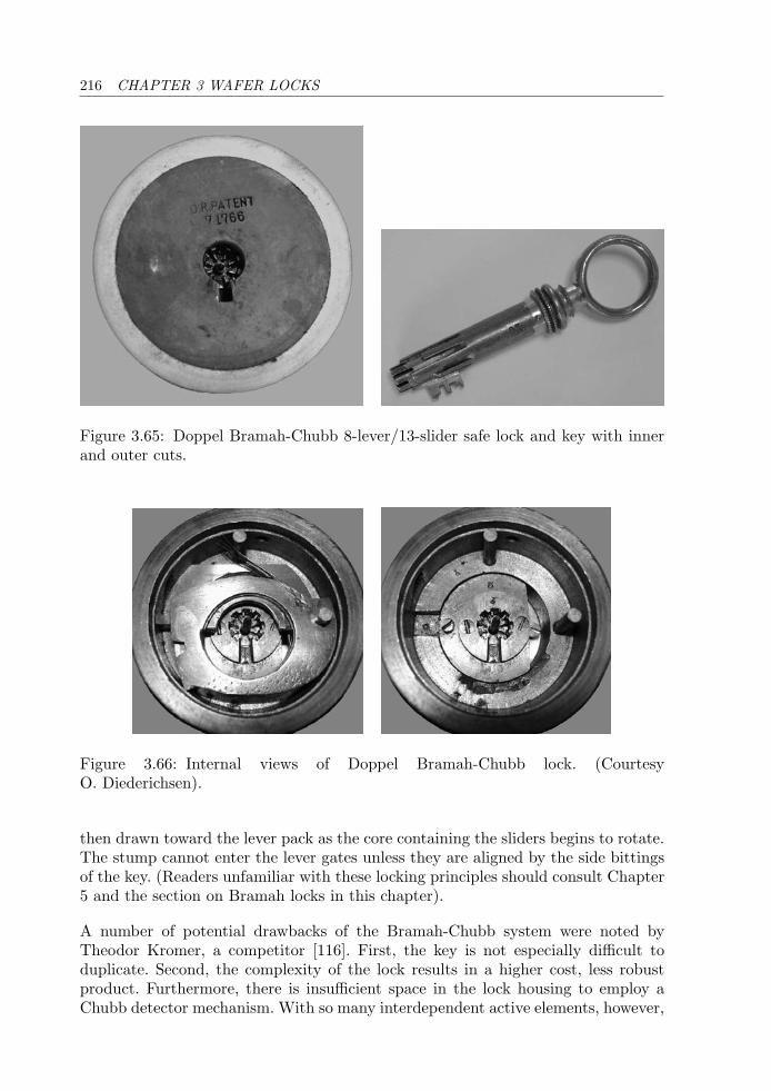
216 CHAPTER 3 WAFER LOCKS
Figure 3.65: Doppel Bramah-Chubb 8-lever/13-slider safe lock and key with innerand outer cuts.
Figure 3.66: Internal views of Doppel Bramah-Chubb lock. (CourtesyO. Diederichsen).
then drawn toward the lever pack as the core containing the sliders begins to rotate.The stump cannot enter the lever gates unless they are aligned by the side bittingsof the key. (Readers unfamiliar with these locking principles should consult Chapter5 and the section on Bramah locks in this chapter).
A number of potential drawbacks of the Bramah-Chubb system were noted byTheodor Kromer, a competitor [116]. First, the key is not especially difficult toduplicate. Second, the complexity of the lock results in a higher cost, less robustproduct. Furthermore, there is insufficient space in the lock housing to employ aChubb detector mechanism. With so many interdependent active elements, however,
3.8 KEY-CHANGEABLE 217
it is doubtful that the lock can be opened without the correct key, although it maybe possible to impression the lever part of the key once the Bramah part of the lockis decoded—clearly not a job for the faint of heart!
3.8 Key-Changeable
Rielda
(IT) 7-wafer (3–4)
The Rielda lock is one of only a handful of small-format key-changeable cylinderlocks, and provides ample proof of the flexibility of the wafer-tumbler mechanism.Fitting inside a standard Europrofile cylinder, it is not at all obvious at first glancehow it could be made to work. The user simply inserts the current “programmingkey,” turns it to 6 o’clock, and removes it. A new programming key may then beinserted, and on returning it to the locked position, voila, the combination has beenchanged!
The design was mooted in a 1986 patent (US 4,712,399) by M. Mattossovichof Rielda Serrature S.R.L. in Italy, although the production version more closelyresembles the mechanically reprogrammable wafer lock described in N. Boag’s 1988patent (US 4,966,021). The resettable lock assembly suggested in both of thesepatents is traceable to Raymond and Millett’s 1980 patent (US 4,376,382), which isalso relevant to the Winfield lock covered in the next section.
Early versions of the Rielda key and lock mechanism were quite delicate—a fac-tor that weighed against their reliability. Although the original lock utilized twoside-bars, they played no part in the locking operation, so from a manipulationperspective the cylinder was a standard seven wafer lock. Since then, Rielda hasredeveloped the product in a simpler and significantly more robust format than theoriginal cast zinc alloy construction. The lock is available in various styles with keykits comprising one gold-colored programming key and three silver-colored operat-ing keys. The programming key, which is slightly smaller than the operating keysand can be inserted and withdrawn at 6 o’clock, is used to set the cylinder to theassigned combination.
The Rielda was introduced in the United States in 2005 by Hampton ProductsInternational in a high-security format called the Lynx lock. The new design, whichuses the Rielda resettable wafers to control the shear line of a set of pin-tumblers, issummarized in a 1998 patent by A. Loreti (US 6,119,495). The Lynx lock incorporatesseven wafers and an additional two pin-tumblers to increase the number of availablediffers. Key blanks for both the Rielda and the Lynx lock are restricted. The remainder
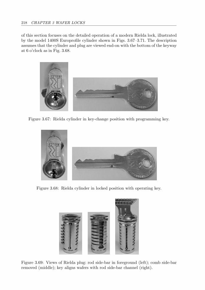
218 CHAPTER 3 WAFER LOCKS
of this section focuses on the detailed operation of a modern Rielda lock, illustratedby the model 1400S Europrofile cylinder shown in Figs. 3.67–3.71. The descriptionassumes that the cylinder and plug are viewed end-on with the bottom of the keywayat 6 o’clock as in Fig. 3.68.
Figure 3.67: Rielda cylinder in key-change position with programming key.
Figure 3.68: Rielda cylinder in locked position with operating key.
Figure 3.69: Views of Rielda plug: rod side-bar in foreground (left); comb side-barremoved (middle); key aligns wafers with rod side-bar channel (right).
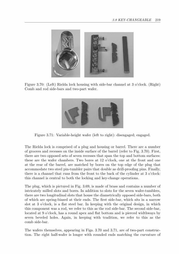
3.8 KEY-CHANGEABLE 219
Figure 3.70: (Left) Rielda lock housing with side-bar channel at 3 o’clock. (Right)Comb and rod side-bars and two-part wafer.
Figure 3.71: Variable-height wafer (left to right): disengaged; engaged.
The Rielda lock is comprised of a plug and housing or barrel. There are a numberof grooves and recesses on the inside surface of the barrel (refer to Fig. 3.70). First,there are two opposed sets of seven recesses that span the top and bottom surfaces:these are the wafer chambers. Two bores at 12 o’clock, one at the front and oneat the rear of the barrel, are matched by bores on the top edge of the plug thataccommodate two steel pin-tumbler pairs that double as drill-proofing pins. Finally,there is a channel that runs from the front to the back of the cylinder at 3 o’clock:this channel is central to both the locking and key-change operations.
The plug, which is pictured in Fig. 3.69, is made of brass and contains a number ofintricately milled slots and bores. In addition to slots for the seven wafer-tumblers,there are two longitudinal slots that house the diametrically opposed side-bars, bothof which are spring-biased at their ends. The first side-bar, which sits in a narrowslot at 3 o’clock, is a flat steel bar. In keeping with the original design, in whichthis component was a rod, we refer to this as the rod side-bar. The second side-bar,located at 9 o’clock, has a round apex and flat bottom and is pierced widthways byseven beveled holes. Again, in keeping with tradition, we refer to this as thecomb side-bar.
The wafers themselves, appearing in Figs. 3.70 and 3.71, are of two-part construc-tion. The right half-wafer is longer with rounded ends matching the curvature of
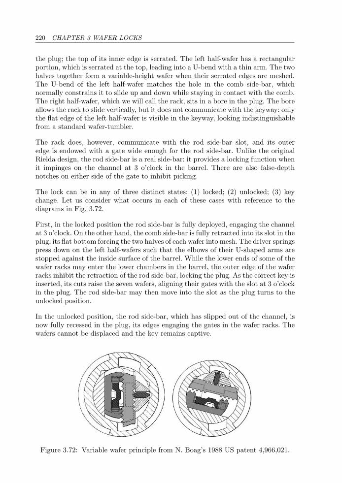
220 CHAPTER 3 WAFER LOCKS
the plug; the top of its inner edge is serrated. The left half-wafer has a rectangularportion, which is serrated at the top, leading into a U-bend with a thin arm. The twohalves together form a variable-height wafer when their serrated edges are meshed.The U-bend of the left half-wafer matches the hole in the comb side-bar, whichnormally constrains it to slide up and down while staying in contact with the comb.The right half-wafer, which we will call the rack, sits in a bore in the plug. The boreallows the rack to slide vertically, but it does not communicate with the keyway: onlythe flat edge of the left half-wafer is visible in the keyway, looking indistinguishablefrom a standard wafer-tumbler.
The rack does, however, communicate with the rod side-bar slot, and its outeredge is endowed with a gate wide enough for the rod side-bar. Unlike the originalRielda design, the rod side-bar is a real side-bar: it provides a locking function whenit impinges on the channel at 3 o’clock in the barrel. There are also false-depthnotches on either side of the gate to inhibit picking.
The lock can be in any of three distinct states: (1) locked; (2) unlocked; (3) keychange. Let us consider what occurs in each of these cases with reference to thediagrams in Fig. 3.72.
First, in the locked position the rod side-bar is fully deployed, engaging the channelat 3 o’clock. On the other hand, the comb side-bar is fully retracted into its slot in theplug, its flat bottom forcing the two halves of each wafer into mesh. The driver springspress down on the left half-wafers such that the elbows of their U-shaped arms arestopped against the inside surface of the barrel. While the lower ends of some of thewafer racks may enter the lower chambers in the barrel, the outer edge of the waferracks inhibit the retraction of the rod side-bar, locking the plug. As the correct key isinserted, its cuts raise the seven wafers, aligning their gates with the slot at 3 o’clockin the plug. The rod side-bar may then move into the slot as the plug turns to theunlocked position.
In the unlocked position, the rod side-bar, which has slipped out of the channel, isnow fully recessed in the plug, its edges engaging the gates in the wafer racks. Thewafers cannot be displaced and the key remains captive.
Figure 3.72: Variable wafer principle from N. Boag’s 1988 US patent 4,966,021.
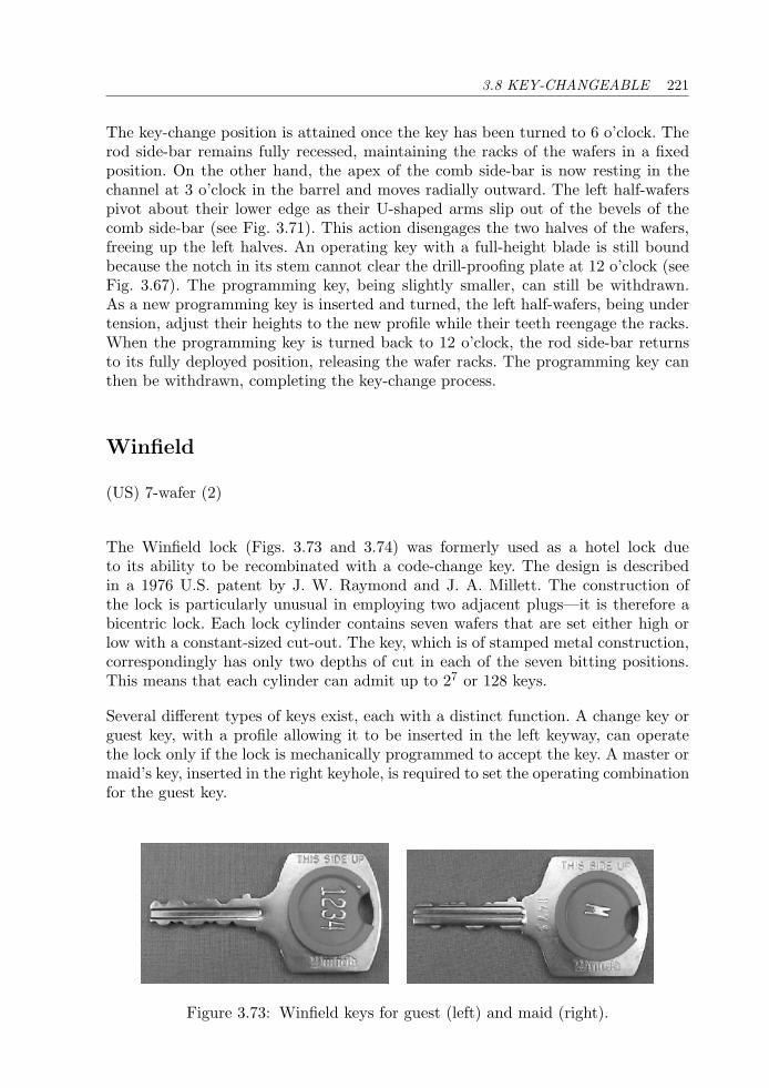
3.8 KEY-CHANGEABLE 221
The key-change position is attained once the key has been turned to 6 o’clock. Therod side-bar remains fully recessed, maintaining the racks of the wafers in a fixedposition. On the other hand, the apex of the comb side-bar is now resting in thechannel at 3 o’clock in the barrel and moves radially outward. The left half-waferspivot about their lower edge as their U-shaped arms slip out of the bevels of thecomb side-bar (see Fig. 3.71). This action disengages the two halves of the wafers,freeing up the left halves. An operating key with a full-height blade is still boundbecause the notch in its stem cannot clear the drill-proofing plate at 12 o’clock (seeFig. 3.67). The programming key, being slightly smaller, can still be withdrawn.As a new programming key is inserted and turned, the left half-wafers, being undertension, adjust their heights to the new profile while their teeth reengage the racks.When the programming key is turned back to 12 o’clock, the rod side-bar returnsto its fully deployed position, releasing the wafer racks. The programming key canthen be withdrawn, completing the key-change process.
Winfield
(US) 7-wafer (2)
The Winfield lock (Figs. 3.73 and 3.74) was formerly used as a hotel lock dueto its ability to be recombinated with a code-change key. The design is describedin a 1976 U.S. patent by J. W. Raymond and J. A. Millett. The construction ofthe lock is particularly unusual in employing two adjacent plugs—it is therefore abicentric lock. Each lock cylinder contains seven wafers that are set either high orlow with a constant-sized cut-out. The key, which is of stamped metal construction,correspondingly has only two depths of cut in each of the seven bitting positions.This means that each cylinder can admit up to 27 or 128 keys.
Several different types of keys exist, each with a distinct function. A change key orguest key, with a profile allowing it to be inserted in the left keyway, can operatethe lock only if the lock is mechanically programmed to accept the key. A master ormaid’s key, inserted in the right keyhole, is required to set the operating combinationfor the guest key.
Figure 3.73: Winfield keys for guest (left) and maid (right).
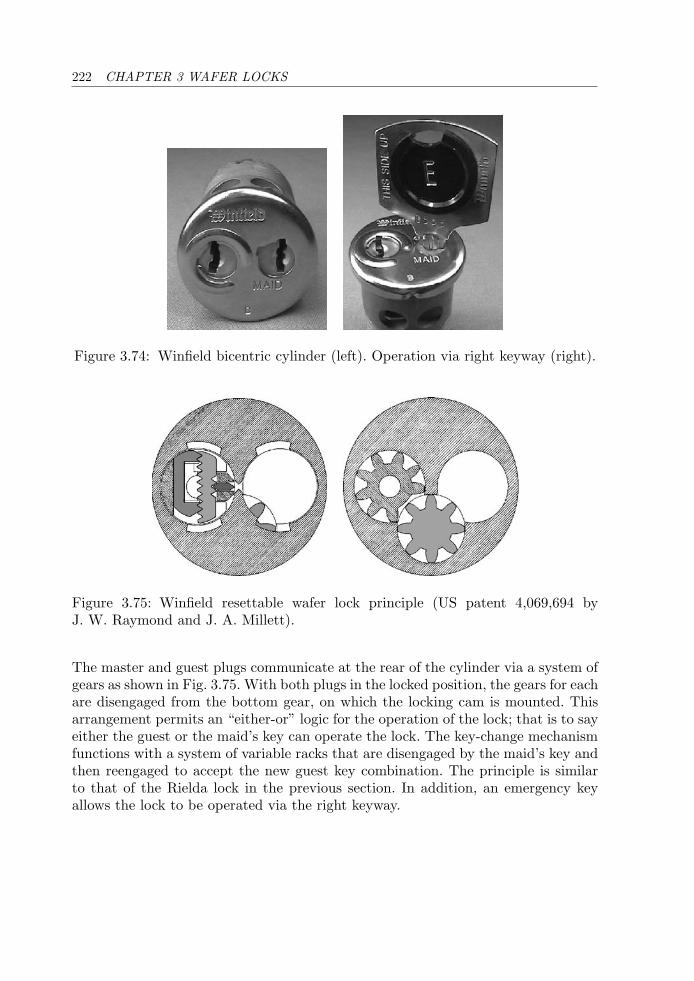
222 CHAPTER 3 WAFER LOCKS
Figure 3.74: Winfield bicentric cylinder (left). Operation via right keyway (right).
Figure 3.75: Winfield resettable wafer lock principle (US patent 4,069,694 byJ. W. Raymond and J. A. Millett).
The master and guest plugs communicate at the rear of the cylinder via a system ofgears as shown in Fig. 3.75. With both plugs in the locked position, the gears for eachare disengaged from the bottom gear, on which the locking cam is mounted. Thisarrangement permits an “either-or” logic for the operation of the lock; that is to sayeither the guest or the maid’s key can operate the lock. The key-change mechanismfunctions with a system of variable racks that are disengaged by the maid’s key andthen reengaged to accept the new guest key combination. The principle is similarto that of the Rielda lock in the previous section. In addition, an emergency keyallows the lock to be operated via the right keyway.
Chapter 4
Side-Bar Locks
There is a constant effort by lock designers to design a lock which ispick-proof. However, this constant effort [ . . . ] seems to lag the increasein skill and determination of lock pickers. C. A. Bauer 1
4.1 Introduction
As its name implies, a side-bar is a bar that lies alongside a set of active elementsor tumblers in a lock. Until such time as the tumblers are aligned by the properkey, the side-bar prevents the mechanism from being unlocked. The side-bar plays asimilar role to the shear line in a pin-tumbler lock or the bolt stump in a lever lock.By its nature, a side-bar tends to be more secure against manipulation than a pin-tumbler, wafer, or lever lock. In each of the preceding cases, the active elements haveindividual contact points with the locking interface: pins against the pin chambers,wafers against the cylinder body, and levers against the bolt stump. By contrast,in a side-bar lock this interface is once-removed from the active elements. Since thecontact between the side-bar and the lock cylinder provides the locking function, itis harder to correlate the movement of the plug with the manipulation of a particularactive element.
The concept of a side-bar lock is older than one might imagine and quite difficult totrace in English-language literature. As early as 1800 [1] padlocks like the one shownin Fig. 4.1 were in use in Scandinavia that had a rotating disc mechanism with two ormore discs. An article from the Nordisk Familjebok encyclopedia [70, 133] attributesthe invention of the Scandinavian padlock to Christopher Polhem, a Swedish scientistand inventor, born in 1661. Polhem built up an industrial plant in Stjarnsund,powered by running water, where clocks and locks were produced during the first
1Charles A. Bauer, Sargent & Greenleaf, US patent 3,181,320, filed March 14, 1963.
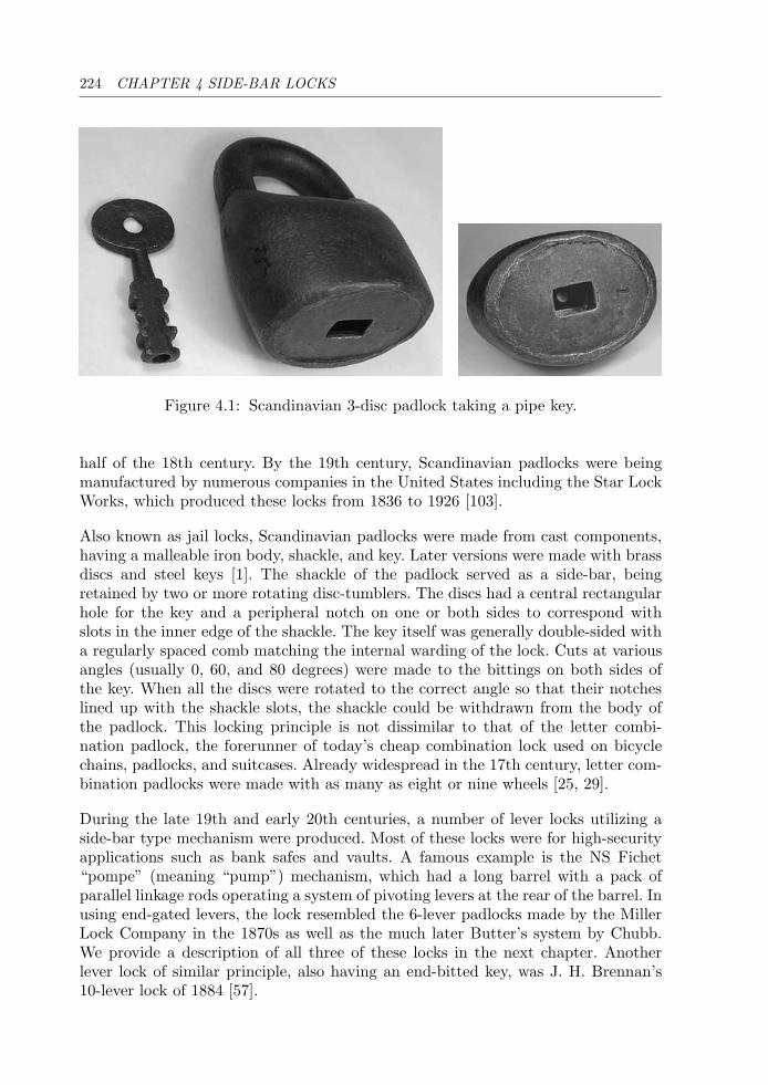
224 CHAPTER 4 SIDE-BAR LOCKS
Figure 4.1: Scandinavian 3-disc padlock taking a pipe key.
half of the 18th century. By the 19th century, Scandinavian padlocks were beingmanufactured by numerous companies in the United States including the Star LockWorks, which produced these locks from 1836 to 1926 [103].
Also known as jail locks, Scandinavian padlocks were made from cast components,having a malleable iron body, shackle, and key. Later versions were made with brassdiscs and steel keys [1]. The shackle of the padlock served as a side-bar, beingretained by two or more rotating disc-tumblers. The discs had a central rectangularhole for the key and a peripheral notch on one or both sides to correspond withslots in the inner edge of the shackle. The key itself was generally double-sided witha regularly spaced comb matching the internal warding of the lock. Cuts at variousangles (usually 0, 60, and 80 degrees) were made to the bittings on both sides ofthe key. When all the discs were rotated to the correct angle so that their notcheslined up with the shackle slots, the shackle could be withdrawn from the body ofthe padlock. This locking principle is not dissimilar to that of the letter combi-nation padlock, the forerunner of today’s cheap combination lock used on bicyclechains, padlocks, and suitcases. Already widespread in the 17th century, letter com-bination padlocks were made with as many as eight or nine wheels [25, 29].
During the late 19th and early 20th centuries, a number of lever locks utilizing aside-bar type mechanism were produced. Most of these locks were for high-securityapplications such as bank safes and vaults. A famous example is the NS Fichet“pompe” (meaning “pump”) mechanism, which had a long barrel with a pack ofparallel linkage rods operating a system of pivoting levers at the rear of the barrel. Inusing end-gated levers, the lock resembled the 6-lever padlocks made by the MillerLock Company in the 1870s as well as the much later Butter’s system by Chubb.We provide a description of all three of these locks in the next chapter. Anotherlever lock of similar principle, also having an end-bitted key, was J. H. Brennan’s10-lever lock of 1884 [57].
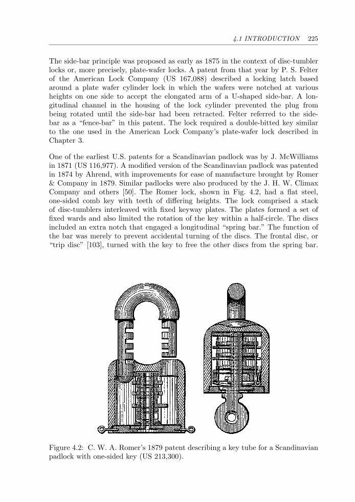
4.1 INTRODUCTION 225
The side-bar principle was proposed as early as 1875 in the context of disc-tumblerlocks or, more precisely, plate-wafer locks. A patent from that year by P. S. Felterof the American Lock Company (US 167,088) described a locking latch basedaround a plate wafer cylinder lock in which the wafers were notched at variousheights on one side to accept the elongated arm of a U-shaped side-bar. A lon-gitudinal channel in the housing of the lock cylinder prevented the plug frombeing rotated until the side-bar had been retracted. Felter referred to the side-bar as a “fence-bar” in this patent. The lock required a double-bitted key similarto the one used in the American Lock Company’s plate-wafer lock described inChapter 3.
One of the earliest U.S. patents for a Scandinavian padlock was by J. McWilliamsin 1871 (US 116,977). A modified version of the Scandinavian padlock was patentedin 1874 by Ahrend, with improvements for ease of manufacture brought by Romer& Company in 1879. Similar padlocks were also produced by the J. H. W. ClimaxCompany and others [50]. The Romer lock, shown in Fig. 4.2, had a flat steel,one-sided comb key with teeth of differing heights. The lock comprised a stackof disc-tumblers interleaved with fixed keyway plates. The plates formed a set offixed wards and also limited the rotation of the key within a half-circle. The discsincluded an extra notch that engaged a longitudinal “spring bar.” The function ofthe bar was merely to prevent accidental turning of the discs. The frontal disc, or“trip disc” [103], turned with the key to free the other discs from the spring bar.
Figure 4.2: C. W. A. Romer’s 1879 patent describing a key tube for a Scandinavianpadlock with one-sided key (US 213,300).
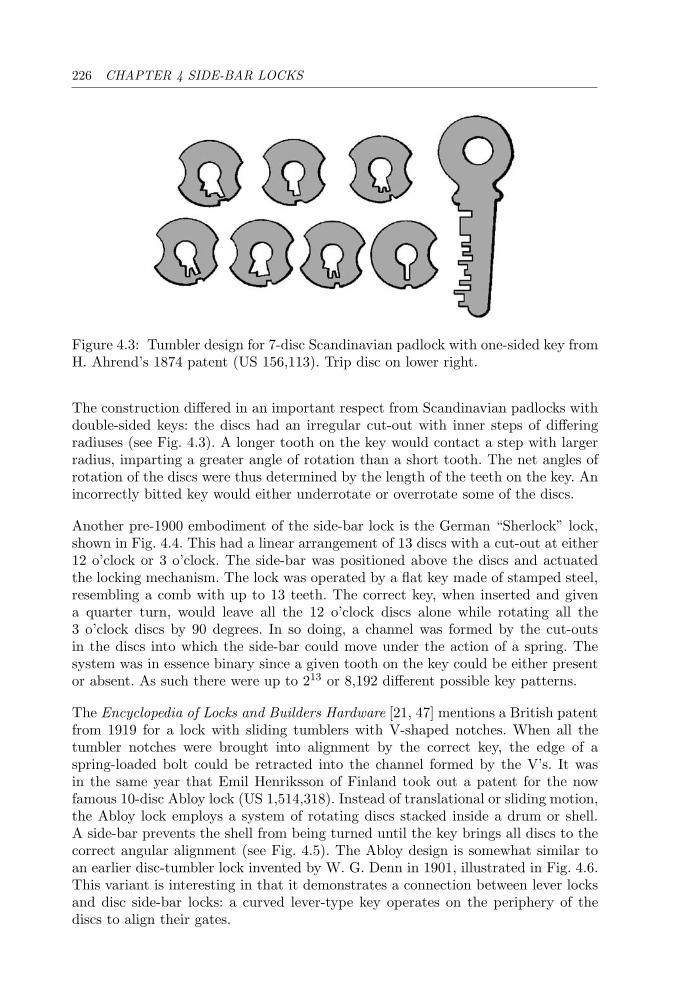
226 CHAPTER 4 SIDE-BAR LOCKS
Figure 4.3: Tumbler design for 7-disc Scandinavian padlock with one-sided key fromH. Ahrend’s 1874 patent (US 156,113). Trip disc on lower right.
The construction differed in an important respect from Scandinavian padlocks withdouble-sided keys: the discs had an irregular cut-out with inner steps of differingradiuses (see Fig. 4.3). A longer tooth on the key would contact a step with largerradius, imparting a greater angle of rotation than a short tooth. The net angles ofrotation of the discs were thus determined by the length of the teeth on the key. Anincorrectly bitted key would either underrotate or overrotate some of the discs.
Another pre-1900 embodiment of the side-bar lock is the German “Sherlock” lock,shown in Fig. 4.4. This had a linear arrangement of 13 discs with a cut-out at either12 o’clock or 3 o’clock. The side-bar was positioned above the discs and actuatedthe locking mechanism. The lock was operated by a flat key made of stamped steel,resembling a comb with up to 13 teeth. The correct key, when inserted and givena quarter turn, would leave all the 12 o’clock discs alone while rotating all the3 o’clock discs by 90 degrees. In so doing, a channel was formed by the cut-outsin the discs into which the side-bar could move under the action of a spring. Thesystem was in essence binary since a given tooth on the key could be either presentor absent. As such there were up to 213 or 8,192 different possible key patterns.
The Encyclopedia of Locks and Builders Hardware [21, 47] mentions a British patentfrom 1919 for a lock with sliding tumblers with V-shaped notches. When all thetumbler notches were brought into alignment by the correct key, the edge of aspring-loaded bolt could be retracted into the channel formed by the V’s. It wasin the same year that Emil Henriksson of Finland took out a patent for the nowfamous 10-disc Abloy lock (US 1,514,318). Instead of translational or sliding motion,the Abloy lock employs a system of rotating discs stacked inside a drum or shell.A side-bar prevents the shell from being turned until the key brings all discs to thecorrect angular alignment (see Fig. 4.5). The Abloy design is somewhat similar toan earlier disc-tumbler lock invented by W. G. Denn in 1901, illustrated in Fig. 4.6.This variant is interesting in that it demonstrates a connection between lever locksand disc side-bar locks: a curved lever-type key operates on the periphery of thediscs to align their gates.
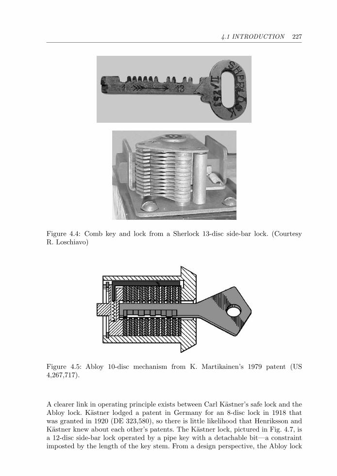
4.1 INTRODUCTION 227
Figure 4.4: Comb key and lock from a Sherlock 13-disc side-bar lock. (CourtesyR. Loschiavo)
Figure 4.5: Abloy 10-disc mechanism from K. Martikainen’s 1979 patent (US4,267,717).
A clearer link in operating principle exists between Carl Kastner’s safe lock and theAbloy lock. Kastner lodged a patent in Germany for an 8-disc lock in 1918 thatwas granted in 1920 (DE 323,580), so there is little likelihood that Henriksson andKastner knew about each other’s patents. The Kastner lock, pictured in Fig. 4.7, isa 12-disc side-bar lock operated by a pipe key with a detachable bit—a constraintimposted by the length of the key stem. From a design perspective, the Abloy lock
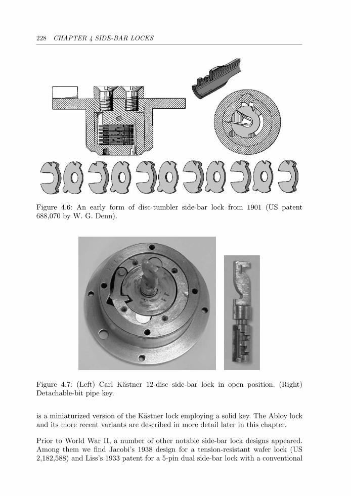
228 CHAPTER 4 SIDE-BAR LOCKS
Figure 4.6: An early form of disc-tumbler side-bar lock from 1901 (US patent688,070 by W. G. Denn).
Figure 4.7: (Left) Carl Kastner 12-disc side-bar lock in open position. (Right)Detachable-bit pipe key.
is a miniaturized version of the Kastner lock employing a solid key. The Abloy lockand its more recent variants are described in more detail later in this chapter.
Prior to World War II, a number of other notable side-bar lock designs appeared.Among them we find Jacobi’s 1938 design for a tension-resistant wafer lock (US2,182,588) and Liss’s 1933 patent for a 5-pin dual side-bar lock with a conventional
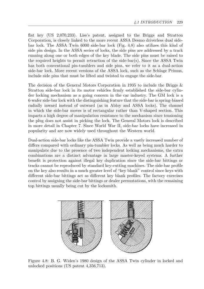
4.1 INTRODUCTION 229
flat key (US 2,070,233). Liss’s patent, assigned to the Briggs and StrattonCorporation, is closely linked to the more recent ASSA Desmo driverless dual side-bar lock. The ASSA Twin 6000 side-bar lock (Fig. 4.8) also utilizes this kind ofside pin design. In the ASSA series of locks, the side pins are addressed by a trackrunning along one or both edges of the key blade. The side pins must be raised tothe required heights to permit retraction of the side-bar(s). Since the ASSA Twinhas both conventional pin-tumblers and side pins, we refer to it as a dual-actionside-bar lock. More recent versions of the ASSA lock, such as the Schlage Primus,include side pins that must be lifted and twisted to engage the side-bar.
The decision of the General Motors Corporation in 1935 to include the Briggs &Stratton side-bar lock in its motor vehicles firmly established the side-bar cylin-der locking mechanism as a going concern in the car industry. The GM lock is a6-wafer side-bar lock with the distinguishing feature that the side-bar is spring-biasedradially inward instead of outward (as in Abloy and ASSA locks). The channelin which the side-bar moves is of rectangular rather than V-shaped section. Thisimparts a high degree of manipulation resistance to the mechanism since tensioningthe plug does not assist in picking the lock. The General Motors lock is describedin more detail in Chapter 7. Since World War II, side-bar locks have increased inpopularity and are now widely used throughout the Western world.
Dual-action side-bar locks like the ASSA Twin provide a vastly increased number ofdiffers compared with ordinary pin-tumbler locks. As well as being much harder tomanipulate due to the presence of two independent locking mechanisms, the extracombinations are a distinct advantage in large master-keyed systems. A furtherbenefit is protection against illegal key duplication since the side-bar bittings ortracks cannot be reproduced by standard key-cutting machines. The side-bar profileon the key also results in a much greater level of “key blank” control since keys withdifferent side-bar bittings act as different key blank profiles. The factory exercisescontrol by assigning the side-bar bittings or dealer permutations, with the remainingtop bittings usually being cut by the locksmith.
Figure 4.8: B. G. Widen’s 1980 design of the ASSA Twin cylinder in locked andunlocked positions (US patent 4,356,713).
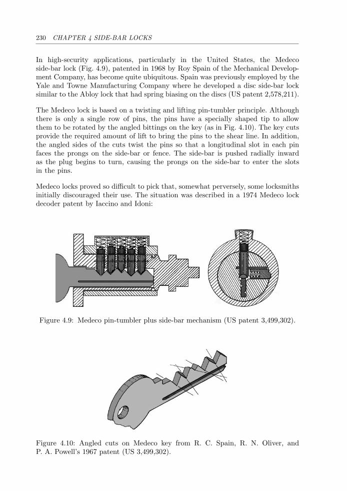
230 CHAPTER 4 SIDE-BAR LOCKS
In high-security applications, particularly in the United States, the Medecoside-bar lock (Fig. 4.9), patented in 1968 by Roy Spain of the Mechanical Develop-ment Company, has become quite ubiquitous. Spain was previously employed by theYale and Towne Manufacturing Company where he developed a disc side-bar locksimilar to the Abloy lock that had spring biasing on the discs (US patent 2,578,211).
The Medeco lock is based on a twisting and lifting pin-tumbler principle. Althoughthere is only a single row of pins, the pins have a specially shaped tip to allowthem to be rotated by the angled bittings on the key (as in Fig. 4.10). The key cutsprovide the required amount of lift to bring the pins to the shear line. In addition,the angled sides of the cuts twist the pins so that a longitudinal slot in each pinfaces the prongs on the side-bar or fence. The side-bar is pushed radially inwardas the plug begins to turn, causing the prongs on the side-bar to enter the slotsin the pins.
Medeco locks proved so difficult to pick that, somewhat perversely, some locksmithsinitially discouraged their use. The situation was described in a 1974 Medeco lockdecoder patent by Iaccino and Idoni:
Figure 4.9: Medeco pin-tumbler plus side-bar mechanism (US patent 3,499,302).
Figure 4.10: Angled cuts on Medeco key from R. C. Spain, R. N. Oliver, andP. A. Powell’s 1967 patent (US 3,499,302).
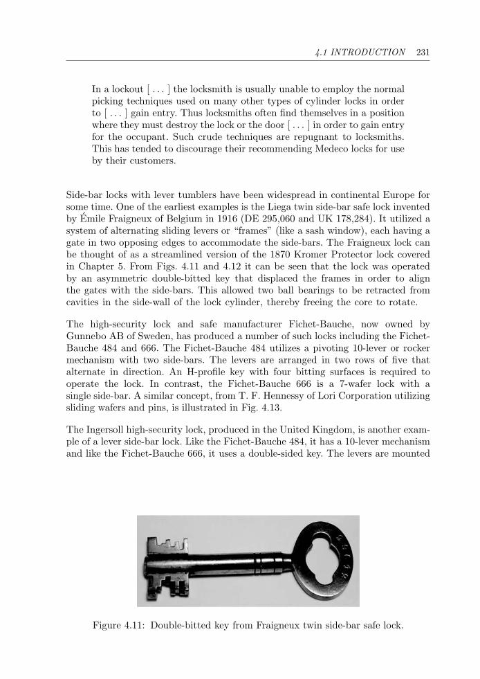
4.1 INTRODUCTION 231
In a lockout [ . . . ] the locksmith is usually unable to employ the normalpicking techniques used on many other types of cylinder locks in orderto [ . . . ] gain entry. Thus locksmiths often find themselves in a positionwhere they must destroy the lock or the door [ . . . ] in order to gain entryfor the occupant. Such crude techniques are repugnant to locksmiths.This has tended to discourage their recommending Medeco locks for useby their customers.
Side-bar locks with lever tumblers have been widespread in continental Europe forsome time. One of the earliest examples is the Liega twin side-bar safe lock inventedby Emile Fraigneux of Belgium in 1916 (DE 295,060 and UK 178,284). It utilized asystem of alternating sliding levers or “frames” (like a sash window), each having agate in two opposing edges to accommodate the side-bars. The Fraigneux lock canbe thought of as a streamlined version of the 1870 Kromer Protector lock coveredin Chapter 5. From Figs. 4.11 and 4.12 it can be seen that the lock was operatedby an asymmetric double-bitted key that displaced the frames in order to alignthe gates with the side-bars. This allowed two ball bearings to be retracted fromcavities in the side-wall of the lock cylinder, thereby freeing the core to rotate.
The high-security lock and safe manufacturer Fichet-Bauche, now owned byGunnebo AB of Sweden, has produced a number of such locks including the Fichet-Bauche 484 and 666. The Fichet-Bauche 484 utilizes a pivoting 10-lever or rockermechanism with two side-bars. The levers are arranged in two rows of five thatalternate in direction. An H-profile key with four bitting surfaces is required tooperate the lock. In contrast, the Fichet-Bauche 666 is a 7-wafer lock with asingle side-bar. A similar concept, from T. F. Hennessy of Lori Corporation utilizingsliding wafers and pins, is illustrated in Fig. 4.13.
The Ingersoll high-security lock, produced in the United Kingdom, is another exam-ple of a lever side-bar lock. Like the Fichet-Bauche 484, it has a 10-lever mechanismand like the Fichet-Bauche 666, it uses a double-sided key. The levers are mounted
Figure 4.11: Double-bitted key from Fraigneux twin side-bar safe lock.
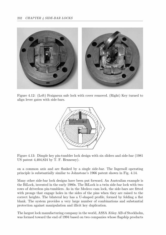
232 CHAPTER 4 SIDE-BAR LOCKS
Figure 4.12: (Left) Fraigneux safe lock with cover removed. (Right) Key turned toalign lever gates with side-bars.
Figure 4.13: Dimple key pin-tumbler lock design with six sliders and side-bar (1981US patent 4,404,824 by T. F. Hennessy).
on a common axis and are flanked by a single side-bar. The Ingersoll operatingprinciple is substantially similar to Johnstone’s 1966 patent shown in Fig. 4.14.
Many other side-bar lock designs have been put forward. An Australian example isthe BiLock, invented in the early 1980s. The BiLock is a twin side-bar lock with tworows of driverless pin-tumblers. As in the Medeco cam lock, the side-bars are fittedwith prongs that engage holes in the sides of the pins when they are raised to thecorrect heights. The bilateral key has a U-shaped profile, formed by folding a flatblank. The system provides a very large number of combinations and substantialprotection against manipulation and illicit key duplication.
The largest lock manufacturing company in the world, ASSA Abloy AB of Stockholm,was formed toward the end of 1994 based on two companies whose flagship products
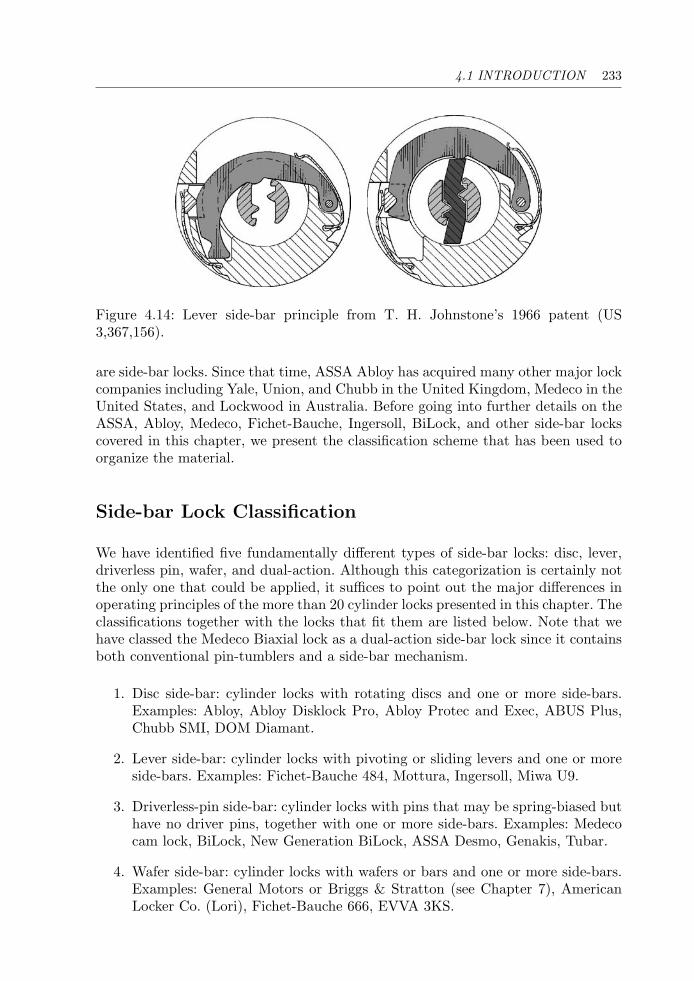
4.1 INTRODUCTION 233
Figure 4.14: Lever side-bar principle from T. H. Johnstone’s 1966 patent (US3,367,156).
are side-bar locks. Since that time, ASSA Abloy has acquired many other major lockcompanies including Yale, Union, and Chubb in the United Kingdom, Medeco in theUnited States, and Lockwood in Australia. Before going into further details on theASSA, Abloy, Medeco, Fichet-Bauche, Ingersoll, BiLock, and other side-bar lockscovered in this chapter, we present the classification scheme that has been used toorganize the material.
Side-bar Lock Classification
We have identified five fundamentally different types of side-bar locks: disc, lever,driverless pin, wafer, and dual-action. Although this categorization is certainly notthe only one that could be applied, it suffices to point out the major differences inoperating principles of the more than 20 cylinder locks presented in this chapter. Theclassifications together with the locks that fit them are listed below. Note that wehave classed the Medeco Biaxial lock as a dual-action side-bar lock since it containsboth conventional pin-tumblers and a side-bar mechanism.
1. Disc side-bar: cylinder locks with rotating discs and one or more side-bars.Examples: Abloy, Abloy Disklock Pro, Abloy Protec and Exec, ABUS Plus,Chubb SMI, DOM Diamant.
2. Lever side-bar: cylinder locks with pivoting or sliding levers and one or moreside-bars. Examples: Fichet-Bauche 484, Mottura, Ingersoll, Miwa U9.
3. Driverless-pin side-bar: cylinder locks with pins that may be spring-biased buthave no driver pins, together with one or more side-bars. Examples: Medecocam lock, BiLock, New Generation BiLock, ASSA Desmo, Genakis, Tubar.
4. Wafer side-bar: cylinder locks with wafers or bars and one or more side-bars.Examples: General Motors or Briggs & Stratton (see Chapter 7), AmericanLocker Co. (Lori), Fichet-Bauche 666, EVVA 3KS.
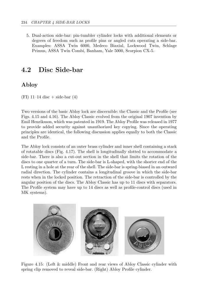
234 CHAPTER 4 SIDE-BAR LOCKS
5. Dual-action side-bar: pin-tumbler cylinder locks with additional elements ordegrees of freedom such as profile pins or angled cuts operating a side-bar.Examples: ASSA Twin 6000, Medeco Biaxial, Lockwood Twin, SchlagePrimus, ASSA Twin Combi, Banham, Yale 5000, Scorpion CX-5.
4.2 Disc Side-bar
Abloy
(FI) 11–14 disc + side-bar (4)
Two versions of the basic Abloy lock are discernible: the Classic and the Profile (seeFigs. 4.15 and 4.16). The Abloy Classic evolved from the original 1907 invention byEmil Henriksson, which was patented in 1919. The Abloy Profile was released in 1977to provide added security against unauthorized key copying. Since the operatingprinciples are identical, the following discussion applies equally to both the Classicand the Profile.
The Abloy lock consists of an outer brass cylinder and inner shell containing a stackof rotatable discs (Fig. 4.17). The shell is longitudinally slotted to accommodate aside-bar. There is also a cut-out section in the shell that limits the rotation of thediscs to one quarter of a turn. The side-bar is L-shaped, with the shorter end of theL resting in a hole at the rear of the shell. The side-bar is spring-biased in an outwardradial direction. The cylinder contains a longitudinal groove in which the side-barrests when in the locked position. The retraction of the side-bar is controlled by theangular position of the discs. The Abloy Classic has up to 11 discs with separators.The Profile system may have up to 14 discs as well as profile-control discs (used inMK systems).
Figure 4.15: (Left & middle) Front and rear views of Abloy Classic cylinder withspring clip removed to reveal side-bar. (Right) Abloy Profile cylinder.
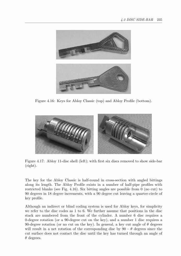
4.2 DISC SIDE-BAR 235
Figure 4.16: Keys for Abloy Classic (top) and Abloy Profile (bottom).
Figure 4.17: Abloy 11-disc shell (left); with first six discs removed to show side-bar(right).
The key for the Abloy Classic is half-round in cross-section with angled bittingsalong its length. The Abloy Profile exists in a number of half-pipe profiles withrestricted blanks (see Fig. 4.16). Six bitting angles are possible from 0 (no cut) to90 degrees in 18 degree increments, with a 90 degree cut leaving a quarter-circle ofkey profile.
Although an indirect or blind coding system is used for Abloy keys, for simplicitywe refer to the disc codes as 1 to 6. We further assume that positions in the discstack are numbered from the front of the cylinder. A number 6 disc requires a0-degree rotation (or a 90-degree cut on the key), and a number 1 disc requires a90-degree rotation (or no cut on the key). In general, a key cut angle of θ degreeswill result in a net rotation of the corresponding disc by 90 − θ degrees since thecut surface does not contact the disc until the key has turned through an angle ofθ degrees.
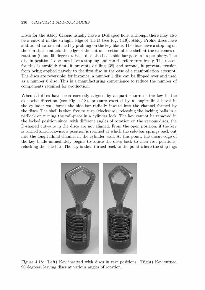
236 CHAPTER 4 SIDE-BAR LOCKS
Discs for the Abloy Classic usually have a D-shaped hole, although there may alsobe a cut-out in the straight edge of the D (see Fig. 4.19). Abloy Profile discs haveadditional wards matched by profiling on the key blade. The discs have a stop lug onthe rim that contacts the edge of the cut-out section of the shell at the extremes ofrotation (0 and 90 degrees). Each disc also has a side-bar gate in its periphery. Thedisc in position 1 does not have a stop lug and can therefore turn freely. The reasonfor this is twofold: first, it prevents drilling [38] and second, it prevents tensionfrom being applied naıvely to the first disc in the case of a manipulation attempt.The discs are reversible: for instance, a number 1 disc can be flipped over and usedas a number 6 disc. This is a manufacturing convenience to reduce the number ofcomponents required for production.
When all discs have been correctly aligned by a quarter turn of the key in theclockwise direction (see Fig. 4.18), pressure exerted by a longitudinal bevel inthe cylinder wall forces the side-bar radially inward into the channel formed bythe discs. The shell is then free to turn (clockwise), releasing the locking balls in apadlock or turning the tail-piece in a cylinder lock. The key cannot be removed inthe locked position since, with different angles of rotation on the various discs, theD-shaped cut-outs in the discs are not aligned. From the open position, if the keyis turned anticlockwise, a position is reached at which the side-bar springs back outinto the longitudinal channel in the cylinder wall. At this point, the uncut edge ofthe key blade immediately begins to rotate the discs back to their rest positions,relocking the side-bar. The key is then turned back to the point where the stop lugs
Figure 4.18: (Left) Key inserted with discs in rest positions. (Right) Key turned90 degrees, leaving discs at various angles of rotation.
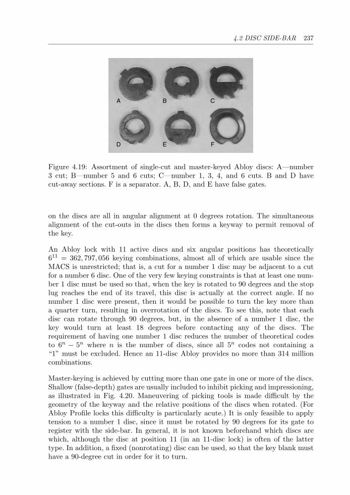
4.2 DISC SIDE-BAR 237
A B C
D E F
Figure 4.19: Assortment of single-cut and master-keyed Abloy discs: A—number3 cut; B—number 5 and 6 cuts; C—number 1, 3, 4, and 6 cuts. B and D havecut-away sections. F is a separator. A, B, D, and E have false gates.
on the discs are all in angular alignment at 0 degrees rotation. The simultaneousalignment of the cut-outs in the discs then forms a keyway to permit removal ofthe key.
An Abloy lock with 11 active discs and six angular positions has theoretically611 = 362, 797, 056 keying combinations, almost all of which are usable since theMACS is unrestricted; that is, a cut for a number 1 disc may be adjacent to a cutfor a number 6 disc. One of the very few keying constraints is that at least one num-ber 1 disc must be used so that, when the key is rotated to 90 degrees and the stoplug reaches the end of its travel, this disc is actually at the correct angle. If nonumber 1 disc were present, then it would be possible to turn the key more thana quarter turn, resulting in overrotation of the discs. To see this, note that eachdisc can rotate through 90 degrees, but, in the absence of a number 1 disc, thekey would turn at least 18 degrees before contacting any of the discs. Therequirement of having one number 1 disc reduces the number of theoretical codesto 6n − 5n where n is the number of discs, since all 5n codes not containing a“1” must be excluded. Hence an 11-disc Abloy provides no more than 314 millioncombinations.
Master-keying is achieved by cutting more than one gate in one or more of the discs.Shallow (false-depth) gates are usually included to inhibit picking and impressioning,as illustrated in Fig. 4.20. Maneuvering of picking tools is made difficult by thegeometry of the keyway and the relative positions of the discs when rotated. (ForAbloy Profile locks this difficulty is particularly acute.) It is only feasible to applytension to a number 1 disc, since it must be rotated by 90 degrees for its gate toregister with the side-bar. In general, it is not known beforehand which discs arewhich, although the disc at position 11 (in an 11-disc lock) is often of the lattertype. In addition, a fixed (nonrotating) disc can be used, so that the key blank musthave a 90-degree cut in order for it to turn.
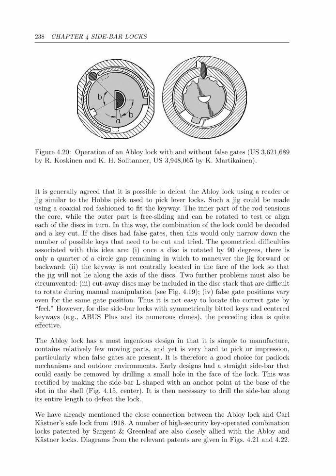
238 CHAPTER 4 SIDE-BAR LOCKS
Figure 4.20: Operation of an Abloy lock with and without false gates (US 3,621,689by R. Koskinen and K. H. Solitanner, US 3,948,065 by K. Martikainen).
It is generally agreed that it is possible to defeat the Abloy lock using a reader orjig similar to the Hobbs pick used to pick lever locks. Such a jig could be madeusing a coaxial rod fashioned to fit the keyway. The inner part of the rod tensionsthe core, while the outer part is free-sliding and can be rotated to test or aligneach of the discs in turn. In this way, the combination of the lock could be decodedand a key cut. If the discs had false gates, then this would only narrow down thenumber of possible keys that need to be cut and tried. The geometrical difficultiesassociated with this idea are: (i) once a disc is rotated by 90 degrees, there isonly a quarter of a circle gap remaining in which to maneuver the jig forward orbackward: (ii) the keyway is not centrally located in the face of the lock so thatthe jig will not lie along the axis of the discs. Two further problems must also becircumvented: (iii) cut-away discs may be included in the disc stack that are difficultto rotate during manual manipulation (see Fig. 4.19); (iv) false gate positions varyeven for the same gate position. Thus it is not easy to locate the correct gate by“feel.” However, for disc side-bar locks with symmetrically bitted keys and centeredkeyways (e.g., ABUS Plus and its numerous clones), the preceding idea is quiteeffective.
The Abloy lock has a most ingenious design in that it is simple to manufacture,contains relatively few moving parts, and yet is very hard to pick or impression,particularly when false gates are present. It is therefore a good choice for padlockmechanisms and outdoor environments. Early designs had a straight side-bar thatcould easily be removed by drilling a small hole in the face of the lock. This wasrectified by making the side-bar L-shaped with an anchor point at the base of theslot in the shell (Fig. 4.15, center). It is then necessary to drill the side-bar alongits entire length to defeat the lock.
We have already mentioned the close connection between the Abloy lock and CarlKastner’s safe lock from 1918. A number of high-security key-operated combinationlocks patented by Sargent & Greenleaf are also closely allied with the Abloy andKastner locks. Diagrams from the relevant patents are given in Figs. 4.21 and 4.22.
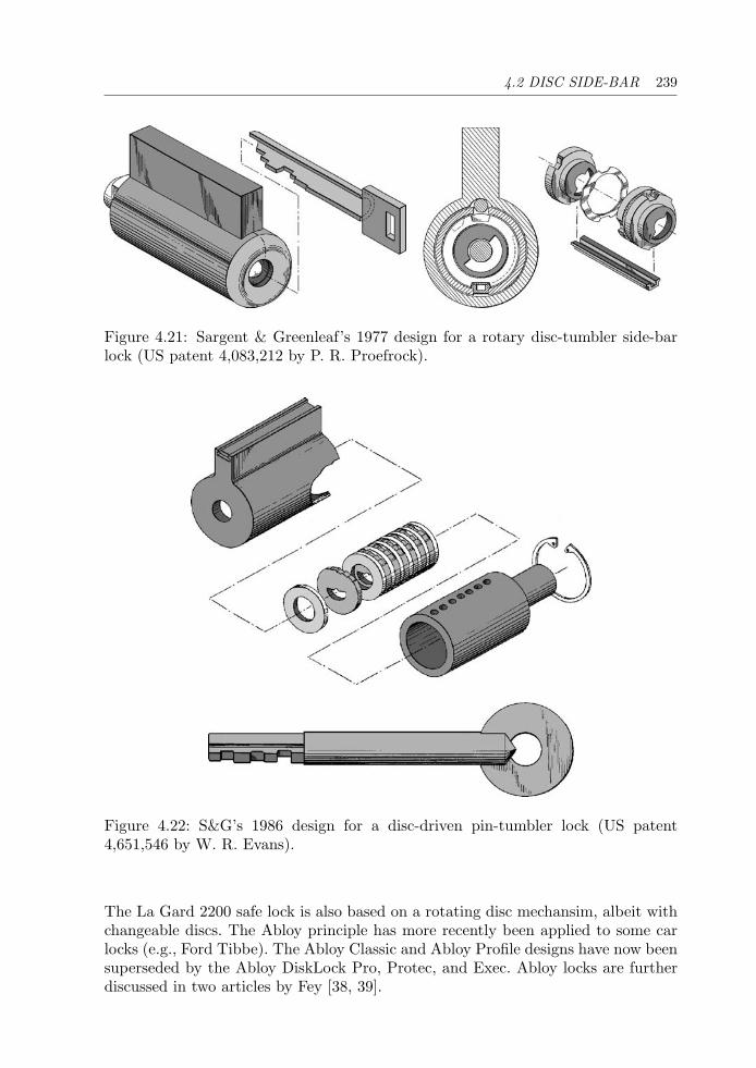
4.2 DISC SIDE-BAR 239
Figure 4.21: Sargent & Greenleaf’s 1977 design for a rotary disc-tumbler side-barlock (US patent 4,083,212 by P. R. Proefrock).
Figure 4.22: S&G’s 1986 design for a disc-driven pin-tumbler lock (US patent4,651,546 by W. R. Evans).
The La Gard 2200 safe lock is also based on a rotating disc mechansim, albeit withchangeable discs. The Abloy principle has more recently been applied to some carlocks (e.g., Ford Tibbe). The Abloy Classic and Abloy Profile designs have now beensuperseded by the Abloy DiskLock Pro, Protec, and Exec. Abloy locks are furtherdiscussed in two articles by Fey [38, 39].
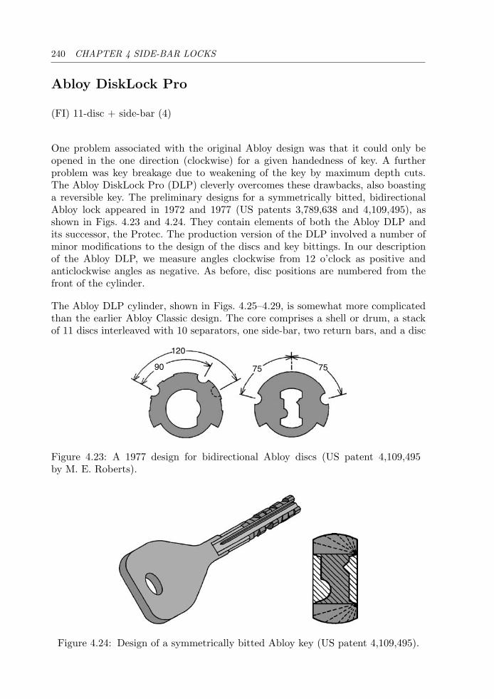
240 CHAPTER 4 SIDE-BAR LOCKS
Abloy DiskLock Pro
(FI) 11-disc + side-bar (4)
One problem associated with the original Abloy design was that it could only beopened in the one direction (clockwise) for a given handedness of key. A furtherproblem was key breakage due to weakening of the key by maximum depth cuts.The Abloy DiskLock Pro (DLP) cleverly overcomes these drawbacks, also boastinga reversible key. The preliminary designs for a symmetrically bitted, bidirectionalAbloy lock appeared in 1972 and 1977 (US patents 3,789,638 and 4,109,495), asshown in Figs. 4.23 and 4.24. They contain elements of both the Abloy DLP andits successor, the Protec. The production version of the DLP involved a number ofminor modifications to the design of the discs and key bittings. In our descriptionof the Abloy DLP, we measure angles clockwise from 12 o’clock as positive andanticlockwise angles as negative. As before, disc positions are numbered from thefront of the cylinder.
The Abloy DLP cylinder, shown in Figs. 4.25–4.29, is somewhat more complicatedthan the earlier Abloy Classic design. The core comprises a shell or drum, a stackof 11 discs interleaved with 10 separators, one side-bar, two return bars, and a disc
120
90 75 75
Figure 4.23: A 1977 design for bidirectional Abloy discs (US patent 4,109,495by M. E. Roberts).
Figure 4.24: Design of a symmetrically bitted Abloy key (US patent 4,109,495).
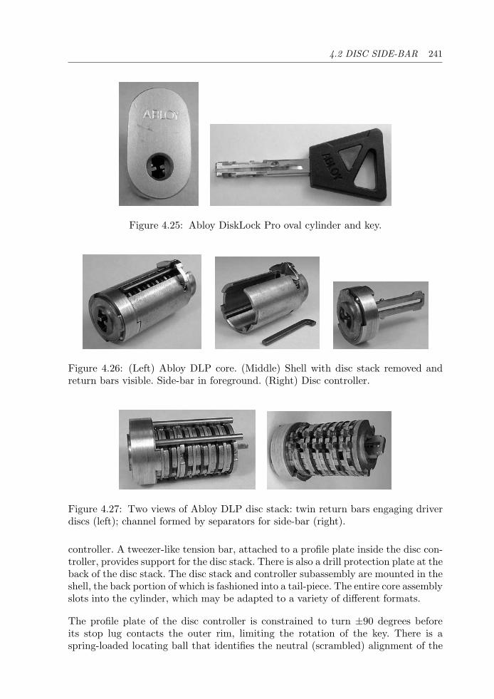
4.2 DISC SIDE-BAR 241
Figure 4.25: Abloy DiskLock Pro oval cylinder and key.
Figure 4.26: (Left) Abloy DLP core. (Middle) Shell with disc stack removed andreturn bars visible. Side-bar in foreground. (Right) Disc controller.
Figure 4.27: Two views of Abloy DLP disc stack: twin return bars engaging driverdiscs (left); channel formed by separators for side-bar (right).
controller. A tweezer-like tension bar, attached to a profile plate inside the disc con-troller, provides support for the disc stack. There is also a drill protection plate at theback of the disc stack. The disc stack and controller subassembly are mounted in theshell, the back portion of which is fashioned into a tail-piece. The entire core assemblyslots into the cylinder, which may be adapted to a variety of different formats.
The profile plate of the disc controller is constrained to turn ±90 degrees beforeits stop lug contacts the outer rim, limiting the rotation of the key. There is aspring-loaded locating ball that identifies the neutral (scrambled) alignment of the
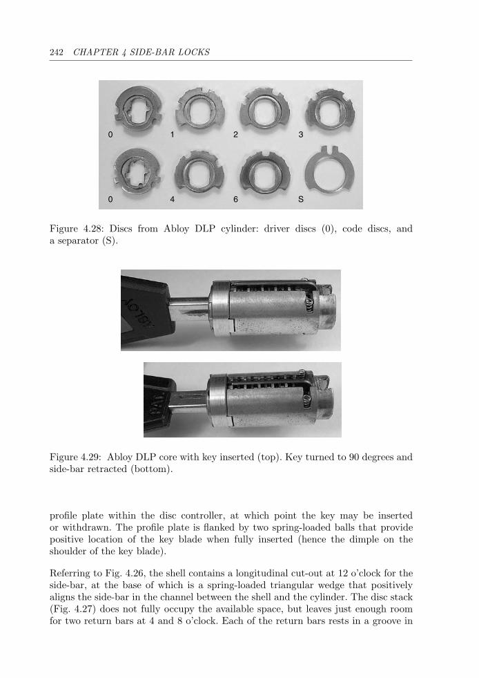
242 CHAPTER 4 SIDE-BAR LOCKS
0 1 2 3
0 4 6 S
Figure 4.28: Discs from Abloy DLP cylinder: driver discs (0), code discs, anda separator (S).
Figure 4.29: Abloy DLP core with key inserted (top). Key turned to 90 degrees andside-bar retracted (bottom).
profile plate within the disc controller, at which point the key may be insertedor withdrawn. The profile plate is flanked by two spring-loaded balls that providepositive location of the key blade when fully inserted (hence the dimple on theshoulder of the key blade).
Referring to Fig. 4.26, the shell contains a longitudinal cut-out at 12 o’clock for theside-bar, at the base of which is a spring-loaded triangular wedge that positivelyaligns the side-bar in the channel between the shell and the cylinder. The disc stack(Fig. 4.27) does not fully occupy the available space, but leaves just enough roomfor two return bars at 4 and 8 o’clock. Each of the return bars rests in a groove in
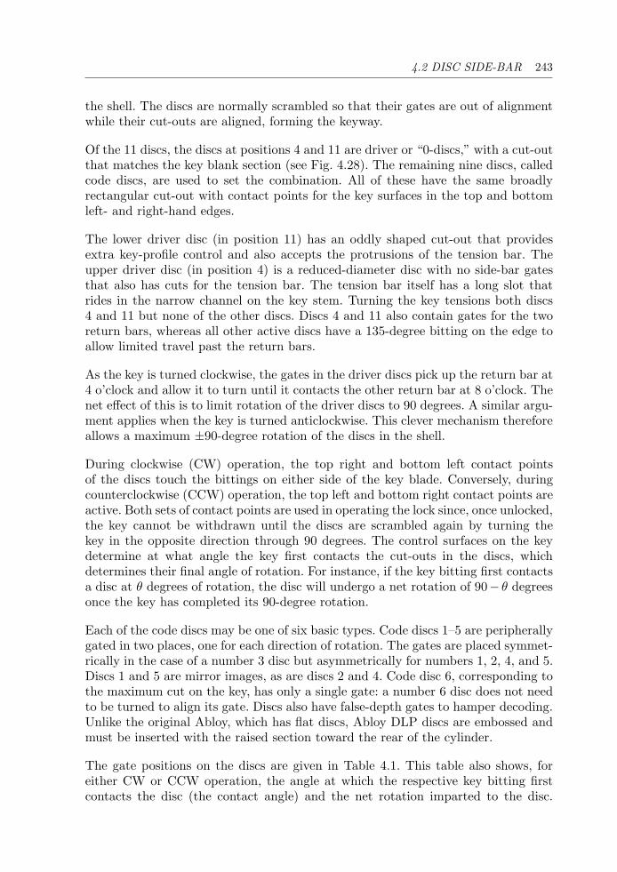
4.2 DISC SIDE-BAR 243
the shell. The discs are normally scrambled so that their gates are out of alignmentwhile their cut-outs are aligned, forming the keyway.
Of the 11 discs, the discs at positions 4 and 11 are driver or “0-discs,” with a cut-outthat matches the key blank section (see Fig. 4.28). The remaining nine discs, calledcode discs, are used to set the combination. All of these have the same broadlyrectangular cut-out with contact points for the key surfaces in the top and bottomleft- and right-hand edges.
The lower driver disc (in position 11) has an oddly shaped cut-out that providesextra key-profile control and also accepts the protrusions of the tension bar. Theupper driver disc (in position 4) is a reduced-diameter disc with no side-bar gatesthat also has cuts for the tension bar. The tension bar itself has a long slot thatrides in the narrow channel on the key stem. Turning the key tensions both discs4 and 11 but none of the other discs. Discs 4 and 11 also contain gates for the tworeturn bars, whereas all other active discs have a 135-degree bitting on the edge toallow limited travel past the return bars.
As the key is turned clockwise, the gates in the driver discs pick up the return bar at4 o’clock and allow it to turn until it contacts the other return bar at 8 o’clock. Thenet effect of this is to limit rotation of the driver discs to 90 degrees. A similar argu-ment applies when the key is turned anticlockwise. This clever mechanism thereforeallows a maximum ±90-degree rotation of the discs in the shell.
During clockwise (CW) operation, the top right and bottom left contact pointsof the discs touch the bittings on either side of the key blade. Conversely, duringcounterclockwise (CCW) operation, the top left and bottom right contact points areactive. Both sets of contact points are used in operating the lock since, once unlocked,the key cannot be withdrawn until the discs are scrambled again by turning thekey in the opposite direction through 90 degrees. The control surfaces on the keydetermine at what angle the key first contacts the cut-outs in the discs, whichdetermines their final angle of rotation. For instance, if the key bitting first contactsa disc at θ degrees of rotation, the disc will undergo a net rotation of 90− θ degreesonce the key has completed its 90-degree rotation.
Each of the code discs may be one of six basic types. Code discs 1–5 are peripherallygated in two places, one for each direction of rotation. The gates are placed symmet-rically in the case of a number 3 disc but asymmetrically for numbers 1, 2, 4, and 5.Discs 1 and 5 are mirror images, as are discs 2 and 4. Code disc 6, corresponding tothe maximum cut on the key, has only a single gate: a number 6 disc does not needto be turned to align its gate. Discs also have false-depth gates to hamper decoding.Unlike the original Abloy, which has flat discs, Abloy DLP discs are embossed andmust be inserted with the raised section toward the rear of the cylinder.
The gate positions on the discs are given in Table 4.1. This table also shows, foreither CW or CCW operation, the angle at which the respective key bitting firstcontacts the disc (the contact angle) and the net rotation imparted to the disc.
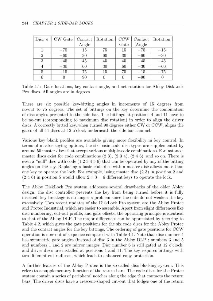
244 CHAPTER 4 SIDE-BAR LOCKS
Disc # CW Gate Contact Rotation CCW Contact RotationAngle Gate Angle
1 −75 15 75 15 −75 −152 −60 30 60 30 −60 −303 −45 45 45 45 −45 −454 −30 60 30 60 −30 −605 −15 75 15 75 −15 −756 0 90 0 0 −90 0
Table 4.1: Gate locations, key contact angle, and net rotation for Abloy DiskLockPro discs. All angles are in degrees.
There are six possible key-bitting angles in increments of 15 degrees fromno-cut to 75 degrees. The set of bittings on the key determine the combinationof disc angles presented to the side-bar. The bittings at positions 4 and 11 have tobe no-cut (corresponding to maximum disc rotation) in order to align the driverdiscs. A correctly bitted key, when turned 90 degrees either CW or CCW, aligns thegates of all 11 discs at 12 o’clock underneath the side-bar channel.
Various key blank profiles are available giving more flexibility in key control. Interms of master-keying options, the six basic code disc types are supplemented byaround 50 master discs that accept various multiple-code combinations. For instance,master discs exist for code combinations (2 3), (2 3 4), (2 4 6), and so on. There iseven a “null” disc with code (1 2 3 4 5 6) that can be operated by any of the bittingangles on the key. Replacing a basic code disc with a master disc allows more thanone key to operate the lock. For example, using master disc (2 3) in position 2 and(2 4 6) in position 5 would allow 2 × 3 = 6 different keys to operate the lock.
The Abloy DiskLock Pro system addresses several drawbacks of the older Abloydesign: the disc controller prevents the key from being turned before it is fullyinserted; key breakage is no longer a problem since the cuts do not weaken the keyexcessively. Two recent updates of the DiskLock Pro system are the Abloy Protecand Protec Industrial, which are easier to assemble. Apart from slight differences likedisc numbering, cut-out profile, and gate offsets, the operating principle is identicalto that of the Abloy DLP. The major differences can be appreciated by referring toTable 4.2, which gives the gate positions for the six code discs for the Abloy Protecand the contact angles for the key bittings. The ordering of gate positions for CCWoperation is now out of sequence compared with Table 4.1. Note that disc number 4has symmetric gate angles (instead of disc 3 in the Abloy DLP); numbers 3 and 5and numbers 1 and 2 are mirror images. Disc number 6 is still gated at 12 o’clock,and driver discs are installed at positions 4 and 11. The key requires bittings withtwo different cut radiuses, which leads to enhanced copy protection.
A further feature of the Abloy Protec is the so-called disc-blocking system. Thisrefers to a supplementary function of the return bars. The code discs for the Protecsystem contain a series of peripheral notches along the edge that contacts the returnbars. The driver discs have a crescent-shaped cut-out that lodges one of the return
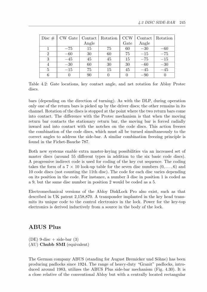
4.2 DISC SIDE-BAR 245
Disc # CW Gate Contact Rotation CCW Contact RotationAngle Gate Angle
1 −75 15 75 60 −30 −602 −60 30 60 75 −15 −753 −45 45 45 15 −75 −154 −30 60 30 30 −60 −305 −15 75 15 45 −45 −456 0 90 0 0 −90 0
Table 4.2: Gate locations, key contact angle, and net rotation for Abloy Protecdiscs.
bars (depending on the direction of turning). As with the DLP, during operationonly one of the return bars is picked up by the driver discs; the other remains in itschannel. Rotation of the discs is stopped at the point where the two return bars comeinto contact. The difference with the Protec mechanism is that when the movingreturn bar contacts the stationary return bar, the moving bar is forced radiallyinward and into contact with the notches on the code discs. This action freezesthe combination of the code discs, which must all be turned simultaneously to thecorrect angles to address the side-bar. A similar combination freezing principle isfound in the Fichet-Bauche 787.
Both new systems enable extra master-keying possibilities via an increased set ofmaster discs (around 55 different types in addition to the six basic code discs).A progressive indirect code is used for coding of the key cut sequence. The codingtakes the form of a 7 × 10 look-up table for the seven disc numbers (0, . . . , 6) and10 code discs (not counting the 11th disc). The code for each disc varies dependingon its position in the code. For instance, a number 3 disc in position 1 is coded asa 9, but the same disc number in position 2 would be coded as a 5.
Electromechanical versions of the Abloy DiskLock Pro also exist, such as thatdescribed in UK patent 2,158,870. A transponder implanted in the key head trans-mits its unique code to the control electronics in the lock. Power for the key-topelectronics is derived inductively from a source in the body of the lock.
ABUS Plus
(DE) 9-disc + side-bar (3)(AU) Chubb SMI (equivalent)
The German company ABUS (standing for August Bremicker und Sohne) has beenproducing padlocks since 1924. The range of heavy-duty “Granit” padlocks, intro-duced around 1983, utilizes the ABUS Plus side-bar mechanism (Fig. 4.30). It isa close relative of the conventional Abloy but with a centrally located rectangular
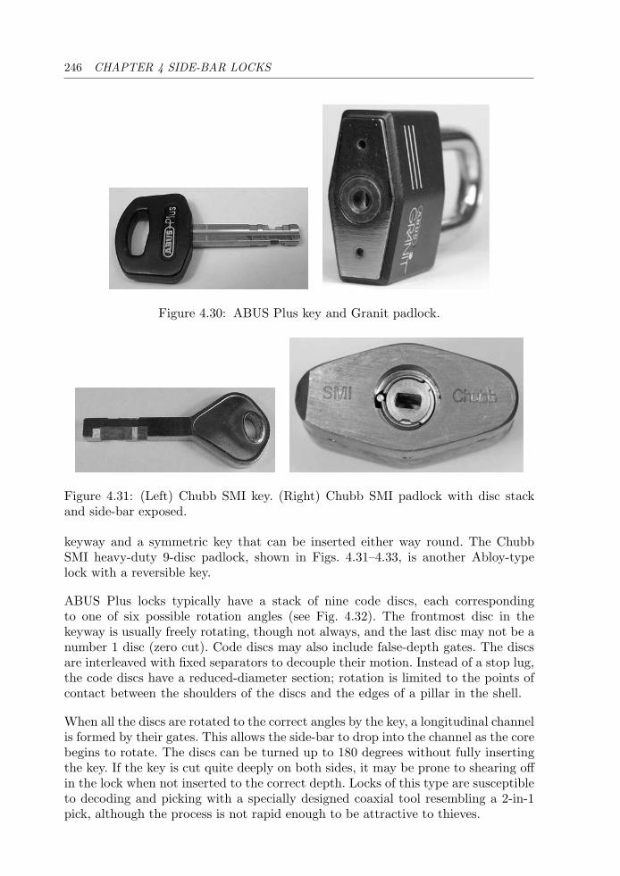
246 CHAPTER 4 SIDE-BAR LOCKS
Figure 4.30: ABUS Plus key and Granit padlock.
Figure 4.31: (Left) Chubb SMI key. (Right) Chubb SMI padlock with disc stackand side-bar exposed.
keyway and a symmetric key that can be inserted either way round. The ChubbSMI heavy-duty 9-disc padlock, shown in Figs. 4.31–4.33, is another Abloy-typelock with a reversible key.
ABUS Plus locks typically have a stack of nine code discs, each correspondingto one of six possible rotation angles (see Fig. 4.32). The frontmost disc in thekeyway is usually freely rotating, though not always, and the last disc may not be anumber 1 disc (zero cut). Code discs may also include false-depth gates. The discsare interleaved with fixed separators to decouple their motion. Instead of a stop lug,the code discs have a reduced-diameter section; rotation is limited to the points ofcontact between the shoulders of the discs and the edges of a pillar in the shell.
When all the discs are rotated to the correct angles by the key, a longitudinal channelis formed by their gates. This allows the side-bar to drop into the channel as the corebegins to rotate. The discs can be turned up to 180 degrees without fully insertingthe key. If the key is cut quite deeply on both sides, it may be prone to shearing offin the lock when not inserted to the correct depth. Locks of this type are susceptibleto decoding and picking with a specially designed coaxial tool resembling a 2-in-1pick, although the process is not rapid enough to be attractive to thieves.
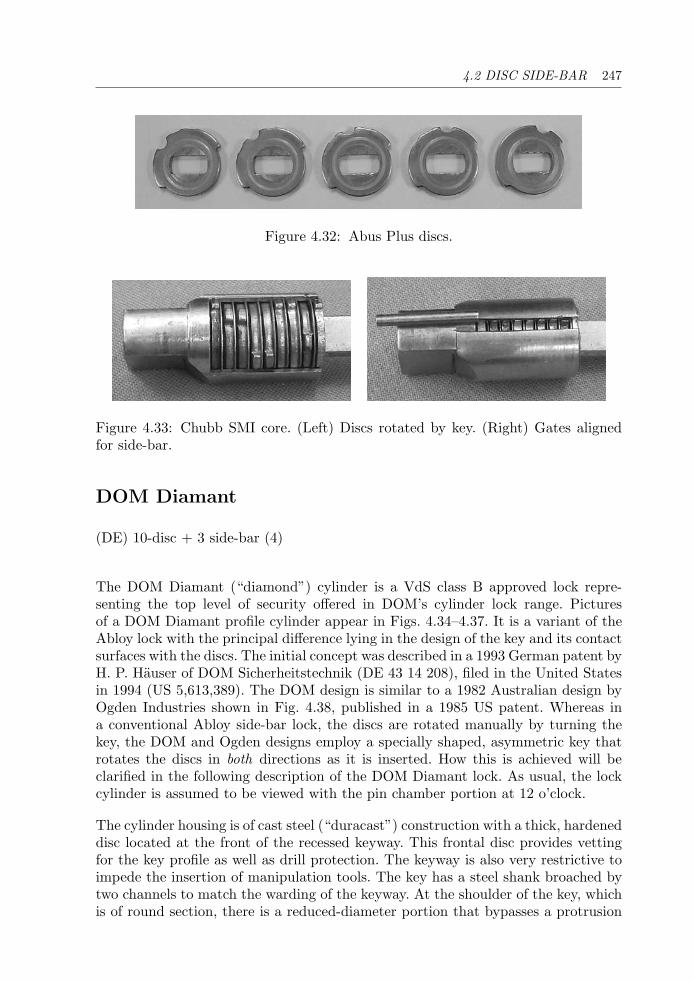
4.2 DISC SIDE-BAR 247
Figure 4.32: Abus Plus discs.
Figure 4.33: Chubb SMI core. (Left) Discs rotated by key. (Right) Gates alignedfor side-bar.
DOM Diamant
(DE) 10-disc + 3 side-bar (4)
The DOM Diamant (“diamond”) cylinder is a VdS class B approved lock repre-senting the top level of security offered in DOM’s cylinder lock range. Picturesof a DOM Diamant profile cylinder appear in Figs. 4.34–4.37. It is a variant of theAbloy lock with the principal difference lying in the design of the key and its contactsurfaces with the discs. The initial concept was described in a 1993 German patent byH. P. Hauser of DOM Sicherheitstechnik (DE 43 14 208), filed in the United Statesin 1994 (US 5,613,389). The DOM design is similar to a 1982 Australian design byOgden Industries shown in Fig. 4.38, published in a 1985 US patent. Whereas ina conventional Abloy side-bar lock, the discs are rotated manually by turning thekey, the DOM and Ogden designs employ a specially shaped, asymmetric key thatrotates the discs in both directions as it is inserted. How this is achieved will beclarified in the following description of the DOM Diamant lock. As usual, the lockcylinder is assumed to be viewed with the pin chamber portion at 12 o’clock.
The cylinder housing is of cast steel (“duracast”) construction with a thick, hardeneddisc located at the front of the recessed keyway. This frontal disc provides vettingfor the key profile as well as drill protection. The keyway is also very restrictive toimpede the insertion of manipulation tools. The key has a steel shank broached bytwo channels to match the warding of the keyway. At the shoulder of the key, whichis of round section, there is a reduced-diameter portion that bypasses a protrusion
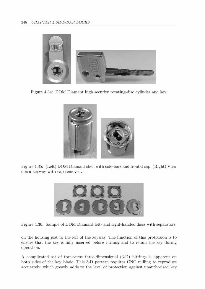
248 CHAPTER 4 SIDE-BAR LOCKS
Figure 4.34: DOM Diamant high security rotating-disc cylinder and key.
Figure 4.35: (Left) DOM Diamant shell with side-bars and frontal cap. (Right) Viewdown keyway with cap removed.
Figure 4.36: Sample of DOM Diamant left- and right-handed discs with separators.
on the housing just to the left of the keyway. The function of this protrusion is toensure that the key is fully inserted before turning and to retain the key duringoperation.
A complicated set of transverse three-dimensional (3-D) bittings is apparent onboth sides of the key blade. This 3-D pattern requires CNC milling to reproduceaccurately, which greatly adds to the level of protection against unauthorized key

4.2 DISC SIDE-BAR 249
Figure 4.37: (Left and middle) DOM Diamant shell with key partially inserted.(Right) Full insertion of key aligns gates in discs.
duplication. The key is inserted with the larger part of the head at 12 o’clock. Inthis orientation, the deeper channel in the key blade is at 9 o’clock. One can discernfour separate “quadrants” or tracks on the key surface. For later use, we refer tothe four quadrants as top left (TL), bottom left (BL), top right (TR), and bottomright (BR).
The cylinder houses a brass shell (Fig. 4.35), similar to the Abloy lock, in which anumber of stamped steel discs are mounted. The shell is blind at the rear and openat the front, capped by the hardened steel frontal disc. Two locating tabs ensurethat the frontal disc is properly seated on the shell. The shell is longitudinallyslotted at four places around its edge, the slots being at an angular spacing of90 degrees. Three longitudinal channels are milled into the cylinder bore at 6, 9, and12 o’clock. These three channels accommodate steel side-bars with pointed ends thatregister with the slots in the shell. The slot at 3 o’clock in the shell contains a nylonstop rod.
The cylinder contains 10 active discs and 11 separator discs (Fig. 4.36). The11 separator discs, which are not involved in the locking function, each contain fourtiny ball bearings to ensure smooth and independent operation of the rotating activediscs. All active discs contain a system of three peripheral notches or gates spaced90 degrees apart. Shallow, false-depth notches are also provided to thwart lockpick-ing and decoding attempts. The presence of the separator discs, one of which ismade of rubber, also provides damping on the rotation of the discs.
Two types of active discs are employed, distinguished by the shape of their centralB-shaped cut-out. Left-hand discs, acted on by the left-hand edge of the key blade,have a short central ward (the horizontal part of the B). Right-hand discs, actedon by the right-hand edge of the key blade, have a long central ward. In bothcases, there are two contact points along the straight edge of the B in each disc.In the locked position, the left-hand discs are oriented with the B facing right,
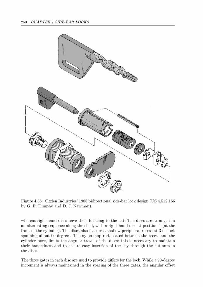
250 CHAPTER 4 SIDE-BAR LOCKS
Figure 4.38: Ogden Industries’ 1985 bidirectional side-bar lock design (US 4,512,166by G. F. Dunphy and D. J. Newman).
whereas right-hand discs have their B facing to the left. The discs are arranged inan alternating sequence along the shell, with a right-hand disc at position 1 (at thefront of the cylinder). The discs also feature a shallow peripheral recess at 3 o’clockspanning about 90 degrees. The nylon stop rod, seated between the recess and thecylinder bore, limits the angular travel of the discs: this is necessary to maintaintheir handedness and to ensure easy insertion of the key through the cut-outs inthe discs.
The three gates in each disc are used to provide differs for the lock. While a 90-degreeincrement is always maintained in the spacing of the three gates, the angular offset
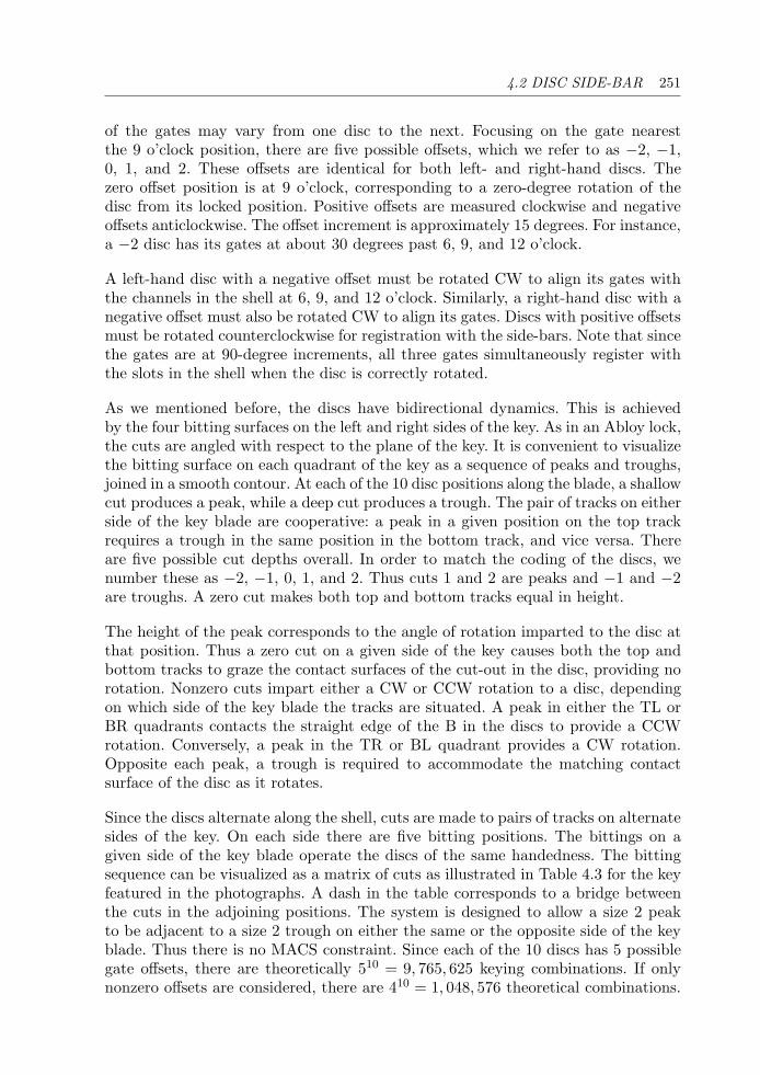
4.2 DISC SIDE-BAR 251
of the gates may vary from one disc to the next. Focusing on the gate nearestthe 9 o’clock position, there are five possible offsets, which we refer to as −2, −1,0, 1, and 2. These offsets are identical for both left- and right-hand discs. Thezero offset position is at 9 o’clock, corresponding to a zero-degree rotation of thedisc from its locked position. Positive offsets are measured clockwise and negativeoffsets anticlockwise. The offset increment is approximately 15 degrees. For instance,a −2 disc has its gates at about 30 degrees past 6, 9, and 12 o’clock.
A left-hand disc with a negative offset must be rotated CW to align its gates withthe channels in the shell at 6, 9, and 12 o’clock. Similarly, a right-hand disc with anegative offset must also be rotated CW to align its gates. Discs with positive offsetsmust be rotated counterclockwise for registration with the side-bars. Note that sincethe gates are at 90-degree increments, all three gates simultaneously register withthe slots in the shell when the disc is correctly rotated.
As we mentioned before, the discs have bidirectional dynamics. This is achievedby the four bitting surfaces on the left and right sides of the key. As in an Abloy lock,the cuts are angled with respect to the plane of the key. It is convenient to visualizethe bitting surface on each quadrant of the key as a sequence of peaks and troughs,joined in a smooth contour. At each of the 10 disc positions along the blade, a shallowcut produces a peak, while a deep cut produces a trough. The pair of tracks on eitherside of the key blade are cooperative: a peak in a given position on the top trackrequires a trough in the same position in the bottom track, and vice versa. Thereare five possible cut depths overall. In order to match the coding of the discs, wenumber these as −2, −1, 0, 1, and 2. Thus cuts 1 and 2 are peaks and −1 and −2are troughs. A zero cut makes both top and bottom tracks equal in height.
The height of the peak corresponds to the angle of rotation imparted to the disc atthat position. Thus a zero cut on a given side of the key causes both the top andbottom tracks to graze the contact surfaces of the cut-out in the disc, providing norotation. Nonzero cuts impart either a CW or CCW rotation to a disc, dependingon which side of the key blade the tracks are situated. A peak in either the TL orBR quadrants contacts the straight edge of the B in the discs to provide a CCWrotation. Conversely, a peak in the TR or BL quadrant provides a CW rotation.Opposite each peak, a trough is required to accommodate the matching contactsurface of the disc as it rotates.
Since the discs alternate along the shell, cuts are made to pairs of tracks on alternatesides of the key. On each side there are five bitting positions. The bittings on agiven side of the key blade operate the discs of the same handedness. The bittingsequence can be visualized as a matrix of cuts as illustrated in Table 4.3 for the keyfeatured in the photographs. A dash in the table corresponds to a bridge betweenthe cuts in the adjoining positions. The system is designed to allow a size 2 peakto be adjacent to a size 2 trough on either the same or the opposite side of the keyblade. Thus there is no MACS constraint. Since each of the 10 discs has 5 possiblegate offsets, there are theoretically 510 = 9, 765, 625 keying combinations. If onlynonzero offsets are considered, there are 410 = 1, 048, 576 theoretical combinations.

252 CHAPTER 4 SIDE-BAR LOCKS
Position 1 2 3 4 5 6 7 8 9 10TL - −2 - 2 - 2 - −1 - −1BL - 2 - −2 - −2 - 1 - 1TR −2 - 1 - −2 - 1 - −1 -BR 2 - −1 - 2 - −1 - 1 -
Table 4.3: Example bitting matrix for DOM Diamant key.
As the key is inserted (Fig. 4.37), the peaks on the tracks contact the cut-outs inthe discs. With the key fully inserted, the angular positions of the 10 active discsare determined by the bittings in the four quadrants of the key. If the key correctlyrotates all 10 discs, then their gate recesses register with the slots in the shell at 6,9, and 12 o’clock. As the key is turned, the three side-bars are retracted into thechannels formed by the gates. Once the shell is turned, the discs are held in positionby the three side-bars.
The picking of the DOM Diamant mechanism, though theoretically achievable, ishampered by the presence of false-depth notches and the very limited space in thekeyway. Since the frontal disc is fixed to the inner shell and not to the housing, itmay be used to tension the lock. Interestingly, the presence of three side-bars haslittle effect on the manipulation difficulty, since alignment of the discs for one side-bar implies alignment for the other two. The extra side-bars do, however, increasethe degree of drill resistance.
4.3 Lever Side-bar
Fichet-Bauche 484
(FR) 10-lever + 2 side-bar (4)
The Fichet Company was founded in 1825 in Paris by Alexandre Fichet. Fichetproduced a fire-proof safe in 1840 and by 1879 was producing safe vaults with depositboxes for banks. In 1967 Fichet merged with Bauche, another famous French lockand safe manufacturer, founded by Auguste Bauche in 1864. Fichet-Bauche wasthe leading supplier of high-security locks and safes in France up to the time of itsacquisition by Gunnebo AB in 1999.
The Fichet-Bauche 484, shown in Figs. 4.39–4.41, is a classic French high-securitylock, manufactured in a “2D monoblock” format with 26 mm cylinders. It waspatented in 1949 in France, and a lock utilizing the 484 mechanism is describedin UK patent 678,123 (1950). The principle is loosely based on much earlierdesigns described in US patents 408,147 (1889) by T. Taylor and 1,498,047 (1923)
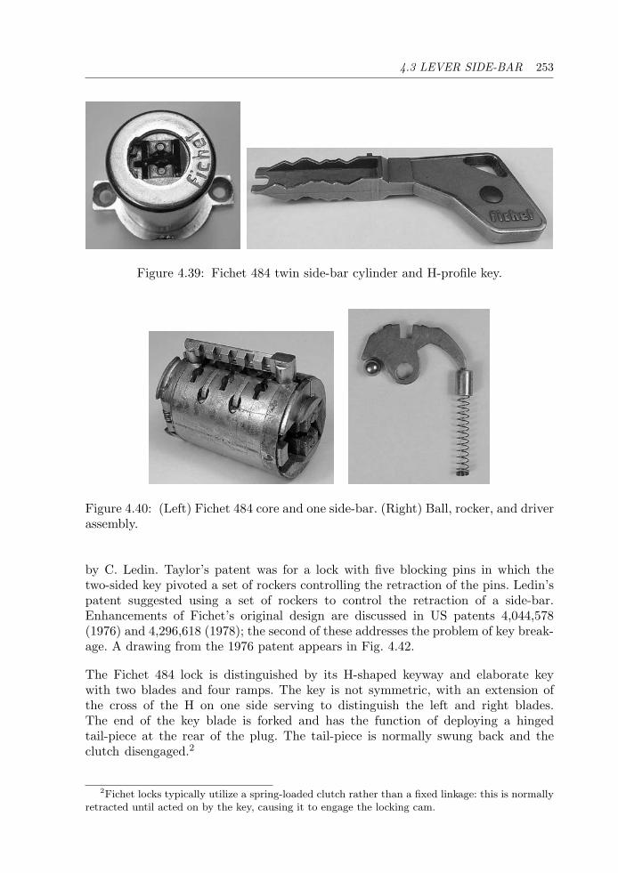
4.3 LEVER SIDE-BAR 253
Figure 4.39: Fichet 484 twin side-bar cylinder and H-profile key.
Figure 4.40: (Left) Fichet 484 core and one side-bar. (Right) Ball, rocker, and driverassembly.
by C. Ledin. Taylor’s patent was for a lock with five blocking pins in which thetwo-sided key pivoted a set of rockers controlling the retraction of the pins. Ledin’spatent suggested using a set of rockers to control the retraction of a side-bar.Enhancements of Fichet’s original design are discussed in US patents 4,044,578(1976) and 4,296,618 (1978); the second of these addresses the problem of key break-age. A drawing from the 1976 patent appears in Fig. 4.42.
The Fichet 484 lock is distinguished by its H-shaped keyway and elaborate keywith two blades and four ramps. The key is not symmetric, with an extension ofthe cross of the H on one side serving to distinguish the left and right blades.The end of the key blade is forked and has the function of deploying a hingedtail-piece at the rear of the plug. The tail-piece is normally swung back and theclutch disengaged.2
2Fichet locks typically utilize a spring-loaded clutch rather than a fixed linkage: this is normallyretracted until acted on by the key, causing it to engage the locking cam.
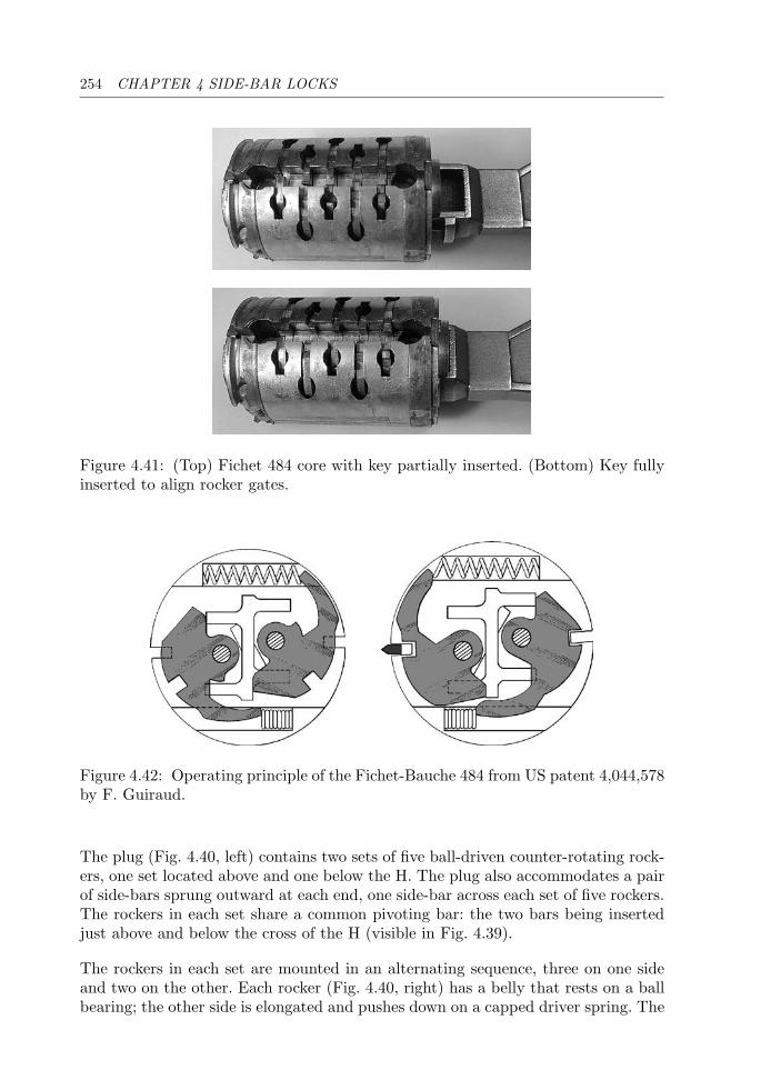
254 CHAPTER 4 SIDE-BAR LOCKS
Figure 4.41: (Top) Fichet 484 core with key partially inserted. (Bottom) Key fullyinserted to align rocker gates.
Figure 4.42: Operating principle of the Fichet-Bauche 484 from US patent 4,044,578by F. Guiraud.
The plug (Fig. 4.40, left) contains two sets of five ball-driven counter-rotating rock-ers, one set located above and one below the H. The plug also accommodates a pairof side-bars sprung outward at each end, one side-bar across each set of five rockers.The rockers in each set share a common pivoting bar: the two bars being insertedjust above and below the cross of the H (visible in Fig. 4.39).
The rockers in each set are mounted in an alternating sequence, three on one sideand two on the other. Each rocker (Fig. 4.40, right) has a belly that rests on a ballbearing; the other side is elongated and pushes down on a capped driver spring. The
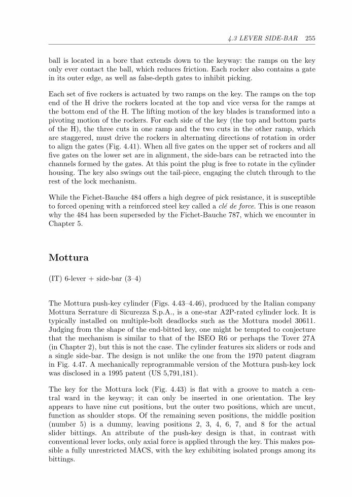
4.3 LEVER SIDE-BAR 255
ball is located in a bore that extends down to the keyway: the ramps on the keyonly ever contact the ball, which reduces friction. Each rocker also contains a gatein its outer edge, as well as false-depth gates to inhibit picking.
Each set of five rockers is actuated by two ramps on the key. The ramps on the topend of the H drive the rockers located at the top and vice versa for the ramps atthe bottom end of the H. The lifting motion of the key blades is transformed into apivoting motion of the rockers. For each side of the key (the top and bottom partsof the H), the three cuts in one ramp and the two cuts in the other ramp, whichare staggered, must drive the rockers in alternating directions of rotation in orderto align the gates (Fig. 4.41). When all five gates on the upper set of rockers and allfive gates on the lower set are in alignment, the side-bars can be retracted into thechannels formed by the gates. At this point the plug is free to rotate in the cylinderhousing. The key also swings out the tail-piece, engaging the clutch through to therest of the lock mechanism.
While the Fichet-Bauche 484 offers a high degree of pick resistance, it is susceptibleto forced opening with a reinforced steel key called a cle de force. This is one reasonwhy the 484 has been superseded by the Fichet-Bauche 787, which we encounter inChapter 5.
Mottura
(IT) 6-lever + side-bar (3–4)
The Mottura push-key cylinder (Figs. 4.43–4.46), produced by the Italian companyMottura Serrature di Sicurezza S.p.A., is a one-star A2P-rated cylinder lock. It istypically installed on multiple-bolt deadlocks such as the Mottura model 30611.Judging from the shape of the end-bitted key, one might be tempted to conjecturethat the mechanism is similar to that of the ISEO R6 or perhaps the Tover 27A(in Chapter 2), but this is not the case. The cylinder features six sliders or rods anda single side-bar. The design is not unlike the one from the 1970 patent diagramin Fig. 4.47. A mechanically reprogrammable version of the Mottura push-key lockwas disclosed in a 1995 patent (US 5,791,181).
The key for the Mottura lock (Fig. 4.43) is flat with a groove to match a cen-tral ward in the keyway; it can only be inserted in one orientation. The keyappears to have nine cut positions, but the outer two positions, which are uncut,function as shoulder stops. Of the remaining seven positions, the middle position(number 5) is a dummy, leaving positions 2, 3, 4, 6, 7, and 8 for the actualslider bittings. An attribute of the push-key design is that, in contrast withconventional lever locks, only axial force is applied through the key. This makes pos-sible a fully unrestricted MACS, with the key exhibiting isolated prongs among itsbittings.
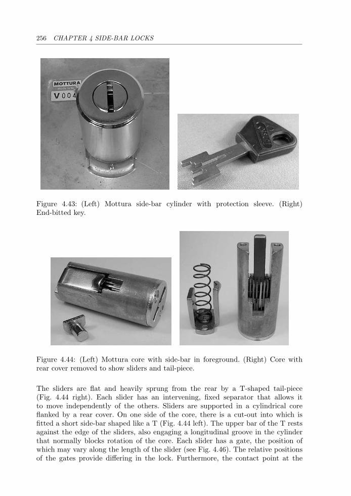
256 CHAPTER 4 SIDE-BAR LOCKS
Figure 4.43: (Left) Mottura side-bar cylinder with protection sleeve. (Right)End-bitted key.
Figure 4.44: (Left) Mottura core with side-bar in foreground. (Right) Core withrear cover removed to show sliders and tail-piece.
The sliders are flat and heavily sprung from the rear by a T-shaped tail-piece(Fig. 4.44 right). Each slider has an intervening, fixed separator that allows itto move independently of the others. Sliders are supported in a cylindrical coreflanked by a rear cover. On one side of the core, there is a cut-out into which isfitted a short side-bar shaped like a T (Fig. 4.44 left). The upper bar of the T restsagainst the edge of the sliders, also engaging a longitudinal groove in the cylinderthat normally blocks rotation of the core. Each slider has a gate, the position ofwhich may vary along the length of the slider (see Fig. 4.46). The relative positionsof the gates provide differing in the lock. Furthermore, the contact point at the
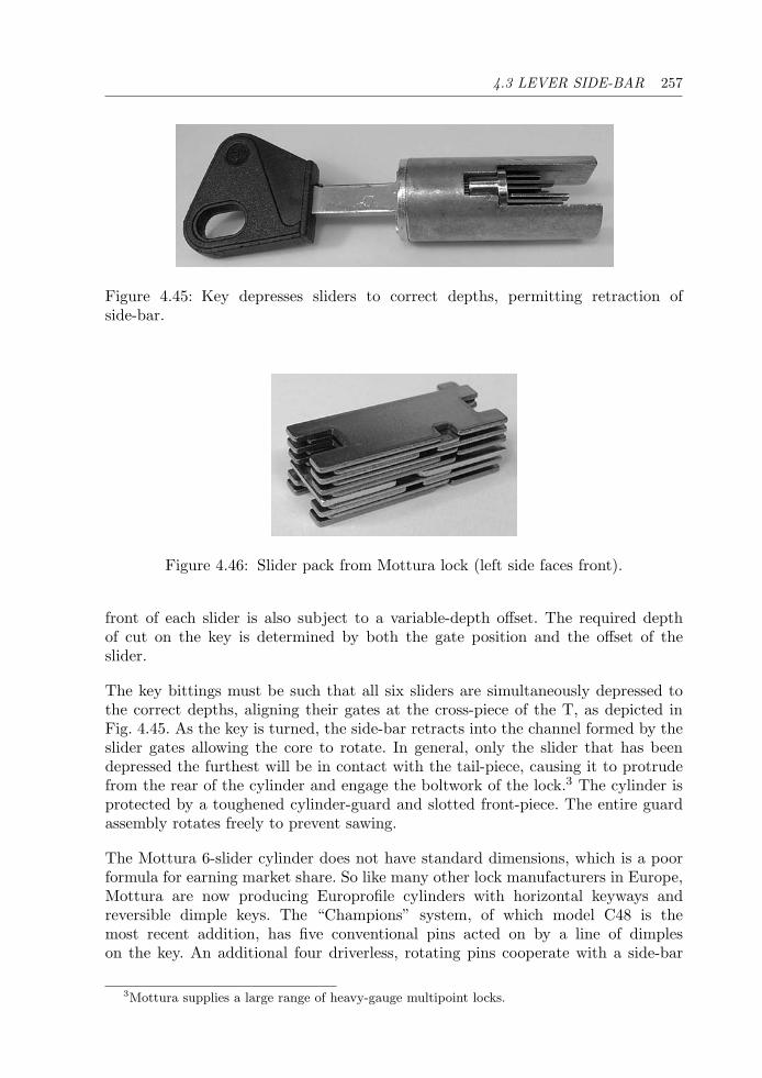
4.3 LEVER SIDE-BAR 257
Figure 4.45: Key depresses sliders to correct depths, permitting retraction ofside-bar.
Figure 4.46: Slider pack from Mottura lock (left side faces front).
front of each slider is also subject to a variable-depth offset. The required depthof cut on the key is determined by both the gate position and the offset of theslider.
The key bittings must be such that all six sliders are simultaneously depressed tothe correct depths, aligning their gates at the cross-piece of the T, as depicted inFig. 4.45. As the key is turned, the side-bar retracts into the channel formed by theslider gates allowing the core to rotate. In general, only the slider that has beendepressed the furthest will be in contact with the tail-piece, causing it to protrudefrom the rear of the cylinder and engage the boltwork of the lock.3 The cylinder isprotected by a toughened cylinder-guard and slotted front-piece. The entire guardassembly rotates freely to prevent sawing.
The Mottura 6-slider cylinder does not have standard dimensions, which is a poorformula for earning market share. So like many other lock manufacturers in Europe,Mottura are now producing Europrofile cylinders with horizontal keyways andreversible dimple keys. The “Champions” system, of which model C48 is themost recent addition, has five conventional pins acted on by a line of dimpleson the key. An additional four driverless, rotating pins cooperate with a side-bar
3Mottura supplies a large range of heavy-gauge multipoint locks.
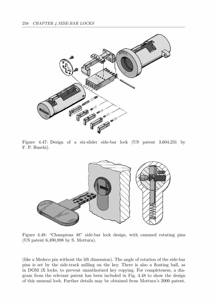
258 CHAPTER 4 SIDE-BAR LOCKS
Figure 4.47: Design of a six-slider side-bar lock (US patent 3,604,231 byF. P. Buschi).
Figure 4.48: “Champions 48” side-bar lock design, with cammed rotating pins(US patent 6,490,898 by S. Mottura).
(like a Medeco pin without the lift dimension). The angle of rotation of the side-barpins is set by the side-track milling on the key. There is also a floating ball, asin DOM iX locks, to prevent unauthorized key copying. For completeness, a dia-gram from the relevant patent has been included in Fig. 4.48 to show the designof this unusual lock. Further details may be obtained from Mottura’s 2000 patent.
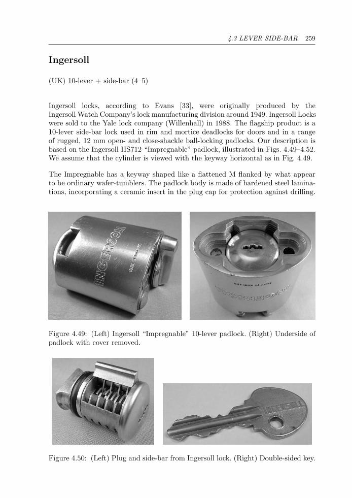
4.3 LEVER SIDE-BAR 259
Ingersoll
(UK) 10-lever + side-bar (4–5)
Ingersoll locks, according to Evans [33], were originally produced by theIngersoll Watch Company’s lock manufacturing division around 1949. Ingersoll Lockswere sold to the Yale lock company (Willenhall) in 1988. The flagship product is a10-lever side-bar lock used in rim and mortice deadlocks for doors and in a rangeof rugged, 12 mm open- and close-shackle ball-locking padlocks. Our description isbased on the Ingersoll HS712 “Impregnable” padlock, illustrated in Figs. 4.49–4.52.We assume that the cylinder is viewed with the keyway horizontal as in Fig. 4.49.
The Impregnable has a keyway shaped like a flattened M flanked by what appearto be ordinary wafer-tumblers. The padlock body is made of hardened steel lamina-tions, incorporating a ceramic insert in the plug cap for protection against drilling.
Figure 4.49: (Left) Ingersoll “Impregnable” 10-lever padlock. (Right) Underside ofpadlock with cover removed.
Figure 4.50: (Left) Plug and side-bar from Ingersoll lock. (Right) Double-sided key.
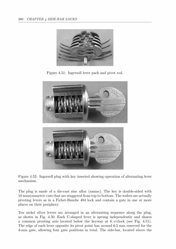
260 CHAPTER 4 SIDE-BAR LOCKS
Figure 4.51: Ingersoll lever pack and pivot rod.
Figure 4.52: Ingersoll plug with key inserted showing operation of alternating levermechanism.
The plug is made of a die-cast zinc alloy (zamac). The key is double-sided with10 nonsymmetric cuts that are staggered from top to bottom. The wafers are actuallypivoting levers as in a Fichet-Bauche 484 lock and contain a gate in one or moreplaces on their periphery.
Ten nickel silver levers are arranged in an alternating sequence along the plug,as shown in Fig. 4.50. Each C-shaped lever is sprung independently and sharesa common pivoting axis located below the keyway at 6 o’clock (see Fig. 4.51).The edge of each lever opposite its pivot point has around 6.5 mm reserved for the3-mm gate, allowing four gate positions in total. The side-bar, located above the
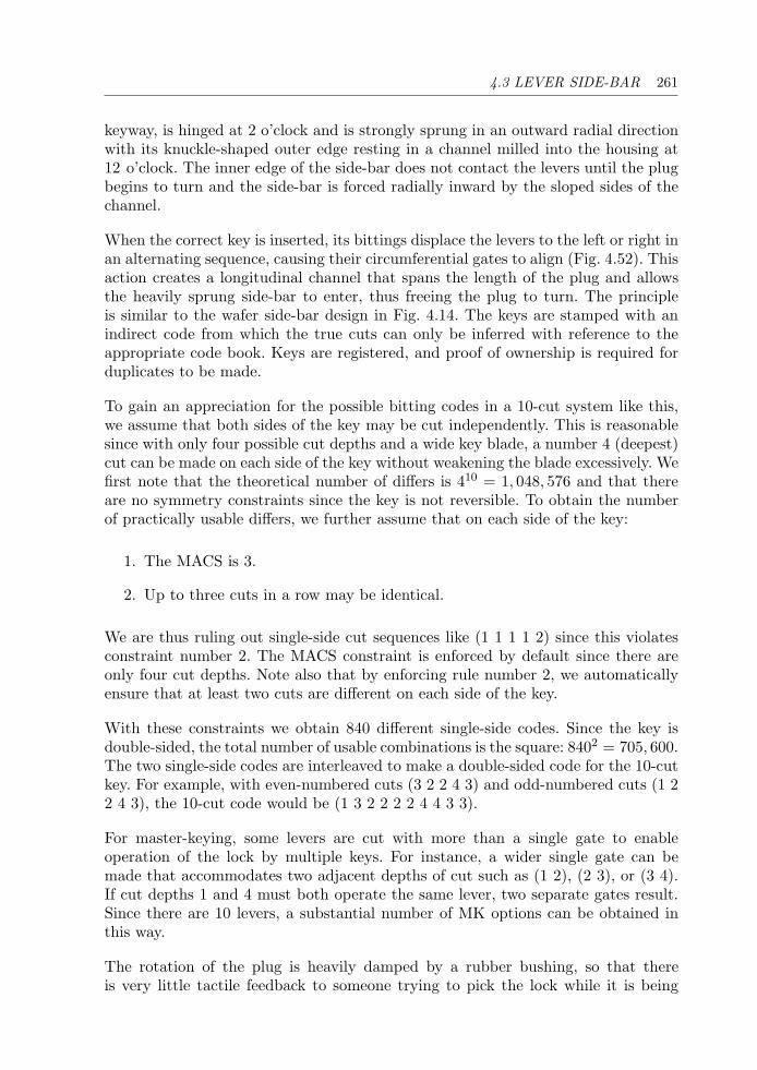
4.3 LEVER SIDE-BAR 261
keyway, is hinged at 2 o’clock and is strongly sprung in an outward radial directionwith its knuckle-shaped outer edge resting in a channel milled into the housing at12 o’clock. The inner edge of the side-bar does not contact the levers until the plugbegins to turn and the side-bar is forced radially inward by the sloped sides of thechannel.
When the correct key is inserted, its bittings displace the levers to the left or right inan alternating sequence, causing their circumferential gates to align (Fig. 4.52). Thisaction creates a longitudinal channel that spans the length of the plug and allowsthe heavily sprung side-bar to enter, thus freeing the plug to turn. The principleis similar to the wafer side-bar design in Fig. 4.14. The keys are stamped with anindirect code from which the true cuts can only be inferred with reference to theappropriate code book. Keys are registered, and proof of ownership is required forduplicates to be made.
To gain an appreciation for the possible bitting codes in a 10-cut system like this,we assume that both sides of the key may be cut independently. This is reasonablesince with only four possible cut depths and a wide key blade, a number 4 (deepest)cut can be made on each side of the key without weakening the blade excessively. Wefirst note that the theoretical number of differs is 410 = 1, 048, 576 and that thereare no symmetry constraints since the key is not reversible. To obtain the numberof practically usable differs, we further assume that on each side of the key:
1. The MACS is 3.
2. Up to three cuts in a row may be identical.
We are thus ruling out single-side cut sequences like (1 1 1 1 2) since this violatesconstraint number 2. The MACS constraint is enforced by default since there areonly four cut depths. Note also that by enforcing rule number 2, we automaticallyensure that at least two cuts are different on each side of the key.
With these constraints we obtain 840 different single-side codes. Since the key isdouble-sided, the total number of usable combinations is the square: 8402 = 705, 600.The two single-side codes are interleaved to make a double-sided code for the 10-cutkey. For example, with even-numbered cuts (3 2 2 4 3) and odd-numbered cuts (1 22 4 3), the 10-cut code would be (1 3 2 2 2 2 4 4 3 3).
For master-keying, some levers are cut with more than a single gate to enableoperation of the lock by multiple keys. For instance, a wider single gate can bemade that accommodates two adjacent depths of cut such as (1 2), (2 3), or (3 4).If cut depths 1 and 4 must both operate the same lever, two separate gates result.Since there are 10 levers, a substantial number of MK options can be obtained inthis way.
The rotation of the plug is heavily damped by a rubber bushing, so that thereis very little tactile feedback to someone trying to pick the lock while it is being
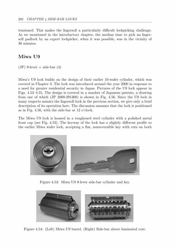
262 CHAPTER 4 SIDE-BAR LOCKS
tensioned. This makes the Ingersoll a particularly difficult lockpicking challenge.As we mentioned in the introductory chapter, the median time to pick an Inger-soll padlock by an expert lockpicker, when it was possible, was in the vicinity of30 minutes.
Miwa U9
(JP) 9-lever + side-bar (4)
Miwa’s U9 lock builds on the design of their earlier 10-wafer cylinder, which wascovered in Chapter 3. The lock was introduced around the year 2000 in response toa need for greater residential security in Japan. Pictures of the U9 lock appear inFigs. 4.53–4.55. The design is covered in a number of Japanese patents, a drawingfrom one of which (JP 2000-291300) is shown in Fig. 4.56. Since the U9 lock inmany respects mimics the Ingersoll lock in the previous section, we give only a briefdescription of its operation here. The discussion assumes that the lock is positionedas in Fig. 4.56, with the side-bar at 12 o’clock.
The Miwa U9 lock is housed in a toughened steel cylinder with a polished metalfront cap (see Fig. 4.53). The keyway of the lock has a slightly different profile tothe earlier Miwa wafer lock, accepting a flat, nonreversible key with cuts on both
Figure 4.53: Miwa U9 9-lever side-bar cylinder and key.
Figure 4.54: (Left) Miwa U9 barrel. (Right) Side-bar above laminated core.
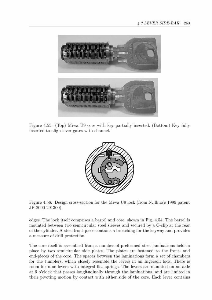
4.3 LEVER SIDE-BAR 263
Figure 4.55: (Top) Miwa U9 core with key partially inserted. (Bottom) Key fullyinserted to align lever gates with channel.
Figure 4.56: Design cross-section for the Miwa U9 lock (from N. Ikuo’s 1999 patentJP 2000-291300).
edges. The lock itself comprises a barrel and core, shown in Fig. 4.54. The barrel ismounted between two semicircular steel sleeves and secured by a C-clip at the rearof the cylinder. A steel front-piece contains a broaching for the keyway and providesa measure of drill protection.
The core itself is assembled from a number of preformed steel laminations held inplace by two semicircular side plates. The plates are fastened to the front- andend-pieces of the core. The spaces between the laminations form a set of chambersfor the tumblers, which closely resemble the levers in an Ingersoll lock. There isroom for nine levers with integral flat springs. The levers are mounted on an axleat 6 o’clock that passes longitudinally through the laminations, and are limited intheir pivoting motion by contact with either side of the core. Each lever contains
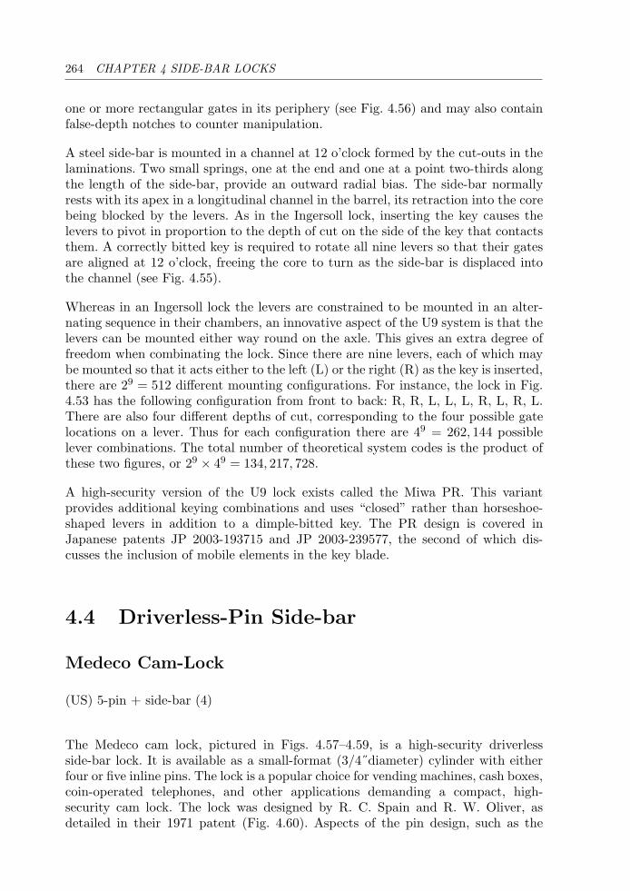
264 CHAPTER 4 SIDE-BAR LOCKS
one or more rectangular gates in its periphery (see Fig. 4.56) and may also containfalse-depth notches to counter manipulation.
A steel side-bar is mounted in a channel at 12 o’clock formed by the cut-outs in thelaminations. Two small springs, one at the end and one at a point two-thirds alongthe length of the side-bar, provide an outward radial bias. The side-bar normallyrests with its apex in a longitudinal channel in the barrel, its retraction into the corebeing blocked by the levers. As in the Ingersoll lock, inserting the key causes thelevers to pivot in proportion to the depth of cut on the side of the key that contactsthem. A correctly bitted key is required to rotate all nine levers so that their gatesare aligned at 12 o’clock, freeing the core to turn as the side-bar is displaced intothe channel (see Fig. 4.55).
Whereas in an Ingersoll lock the levers are constrained to be mounted in an alter-nating sequence in their chambers, an innovative aspect of the U9 system is that thelevers can be mounted either way round on the axle. This gives an extra degree offreedom when combinating the lock. Since there are nine levers, each of which maybe mounted so that it acts either to the left (L) or the right (R) as the key is inserted,there are 29 = 512 different mounting configurations. For instance, the lock in Fig.4.53 has the following configuration from front to back: R, R, L, L, L, R, L, R, L.There are also four different depths of cut, corresponding to the four possible gatelocations on a lever. Thus for each configuration there are 49 = 262, 144 possiblelever combinations. The total number of theoretical system codes is the product ofthese two figures, or 29 × 49 = 134, 217, 728.
A high-security version of the U9 lock exists called the Miwa PR. This variantprovides additional keying combinations and uses “closed” rather than horseshoe-shaped levers in addition to a dimple-bitted key. The PR design is covered inJapanese patents JP 2003-193715 and JP 2003-239577, the second of which dis-cusses the inclusion of mobile elements in the key blade.
4.4 Driverless-Pin Side-bar
Medeco Cam-Lock
(US) 5-pin + side-bar (4)
The Medeco cam lock, pictured in Figs. 4.57–4.59, is a high-security driverlessside-bar lock. It is available as a small-format (3/4˝diameter) cylinder with eitherfour or five inline pins. The lock is a popular choice for vending machines, cash boxes,coin-operated telephones, and other applications demanding a compact, high-security cam lock. The lock was designed by R. C. Spain and R. W. Oliver, asdetailed in their 1971 patent (Fig. 4.60). Aspects of the pin design, such as the
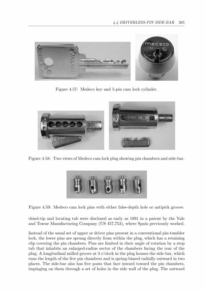
4.4 DRIVERLESS-PIN SIDE-BAR 265
Figure 4.57: Medeco key and 5-pin cam lock cylinder.
Figure 4.58: Two views of Medeco cam lock plug showing pin chambers and side-bar.
Figure 4.59: Medeco cam lock pins with either false-depth hole or antipick groove.
chisel-tip and locating tab were disclosed as early as 1891 in a patent by the Yaleand Towne Manufacturing Company (US 457,753), where Spain previously worked.
Instead of the usual set of upper or driver pins present in a conventional pin-tumblerlock, the lower pins are sprung directly from within the plug, which has a retainingclip covering the pin chambers. Pins are limited in their angle of rotation by a stoptab that inhabits an enlarged-radius sector of the chambers facing the rear of theplug. A longitudinal milled groove at 3 o’clock in the plug houses the side-bar, whichruns the length of the five pin chambers and is spring-biased radially outward in twoplaces. The side-bar also has five posts that face inward toward the pin chambers,impinging on them through a set of holes in the side wall of the plug. The outward
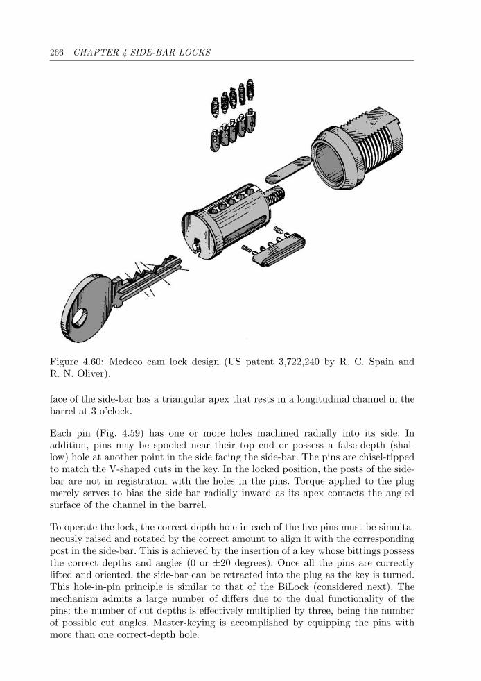
266 CHAPTER 4 SIDE-BAR LOCKS
Figure 4.60: Medeco cam lock design (US patent 3,722,240 by R. C. Spain andR. N. Oliver).
face of the side-bar has a triangular apex that rests in a longitudinal channel in thebarrel at 3 o’clock.
Each pin (Fig. 4.59) has one or more holes machined radially into its side. Inaddition, pins may be spooled near their top end or possess a false-depth (shal-low) hole at another point in the side facing the side-bar. The pins are chisel-tippedto match the V-shaped cuts in the key. In the locked position, the posts of the side-bar are not in registration with the holes in the pins. Torque applied to the plugmerely serves to bias the side-bar radially inward as its apex contacts the angledsurface of the channel in the barrel.
To operate the lock, the correct depth hole in each of the five pins must be simulta-neously raised and rotated by the correct amount to align it with the correspondingpost in the side-bar. This is achieved by the insertion of a key whose bittings possessthe correct depths and angles (0 or ±20 degrees). Once all the pins are correctlylifted and oriented, the side-bar can be retracted into the plug as the key is turned.This hole-in-pin principle is similar to that of the BiLock (considered next). Themechanism admits a large number of differs due to the dual functionality of thepins: the number of cut depths is effectively multiplied by three, being the numberof possible cut angles. Master-keying is accomplished by equipping the pins withmore than one correct-depth hole.
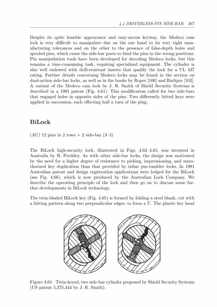
4.4 DRIVERLESS-PIN SIDE-BAR 267
Despite its quite humble appearance and easy-access keyway, the Medeco camlock is very difficult to manipulate due on the one hand to its very tight man-ufacturing tolerances and on the other to the presence of false-depth holes andspooled pins, which cause the side-bar posts to bind the pins in the wrong positions.Pin manipulation tools have been developed for decoding Medeco locks, but thisremains a time-consuming task, requiring specialized equipment. The cylinder isalso well endowed with drill-resistant inserts that qualify the lock for a UL 437rating. Further details concerning Medeco locks may be found in the section ondual-action side-bar locks, as well as in the books by Roper [106] and Rathjen [102].A variant of the Medeco cam lock by J. R. Smith of Shield Security Systems isdescribed in a 1991 patent (Fig. 4.61). This modification called for two side-barsthat engaged holes in opposite sides of the pins. Two differently bitted keys wereapplied in succession, each effecting half a turn of the plug.
BiLock
(AU) 12 pins in 2 rows + 2 side-bar (3–4)
The BiLock high-security lock, illustrated in Figs. 4.62–4.65, was invented inAustralia by B. Preddey. As with other side-bar locks, the design was motivatedby the need for a higher degree of resistance to picking, impressioning, and unau-thorized key duplication than that provided by inline pin-tumbler locks. In 1981Australian patent and design registration applications were lodged for the BiLock(see Fig. 4.66), which is now produced by the Australian Lock Company. Wedescribe the operating principle of the lock and then go on to discuss some fur-ther developments in BiLock technology.
The twin-bladed BiLock key (Fig. 4.65) is formed by folding a steel blank, cut witha bitting pattern along two perpendicular edges, to form a U. The plastic key head
Figure 4.61: Twin-keyed, two side-bar cylinder proposed by Shield Security Systems(US patent 5,375,444 by J. R. Smith).
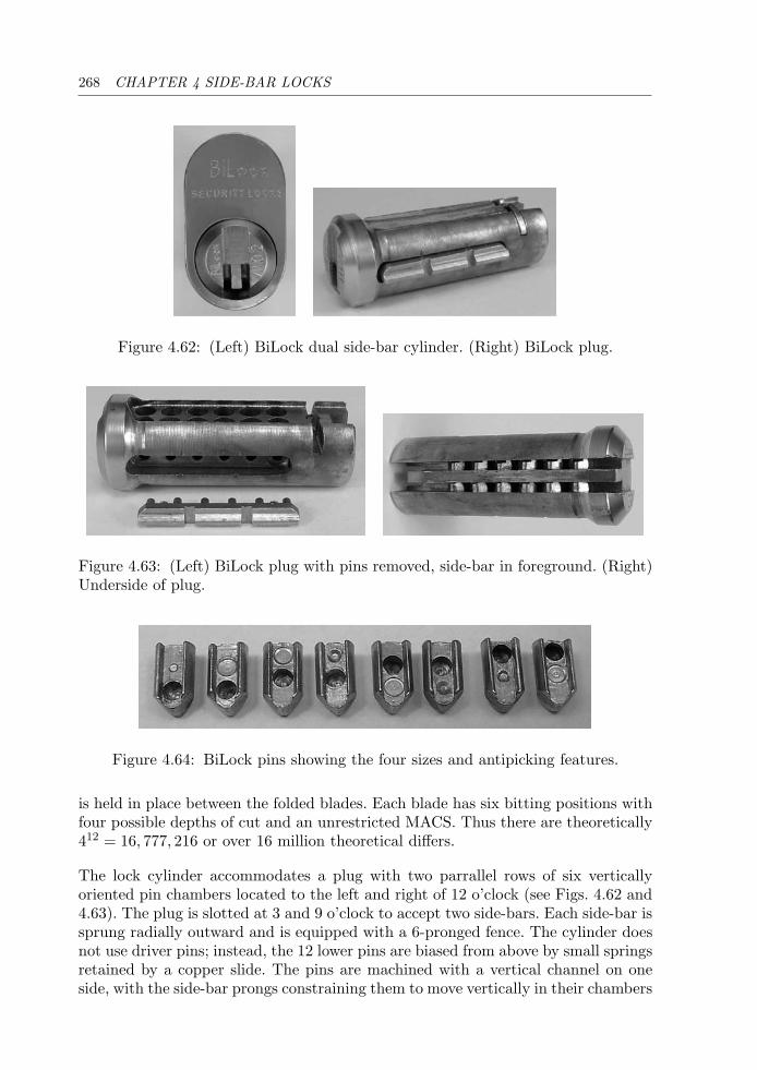
268 CHAPTER 4 SIDE-BAR LOCKS
Figure 4.62: (Left) BiLock dual side-bar cylinder. (Right) BiLock plug.
Figure 4.63: (Left) BiLock plug with pins removed, side-bar in foreground. (Right)Underside of plug.
Figure 4.64: BiLock pins showing the four sizes and antipicking features.
is held in place between the folded blades. Each blade has six bitting positions withfour possible depths of cut and an unrestricted MACS. Thus there are theoretically412 = 16, 777, 216 or over 16 million theoretical differs.
The lock cylinder accommodates a plug with two parrallel rows of six verticallyoriented pin chambers located to the left and right of 12 o’clock (see Figs. 4.62 and4.63). The plug is slotted at 3 and 9 o’clock to accept two side-bars. Each side-bar issprung radially outward and is equipped with a 6-pronged fence. The cylinder doesnot use driver pins; instead, the 12 lower pins are biased from above by small springsretained by a copper slide. The pins are machined with a vertical channel on oneside, with the side-bar prongs constraining them to move vertically in their chambers
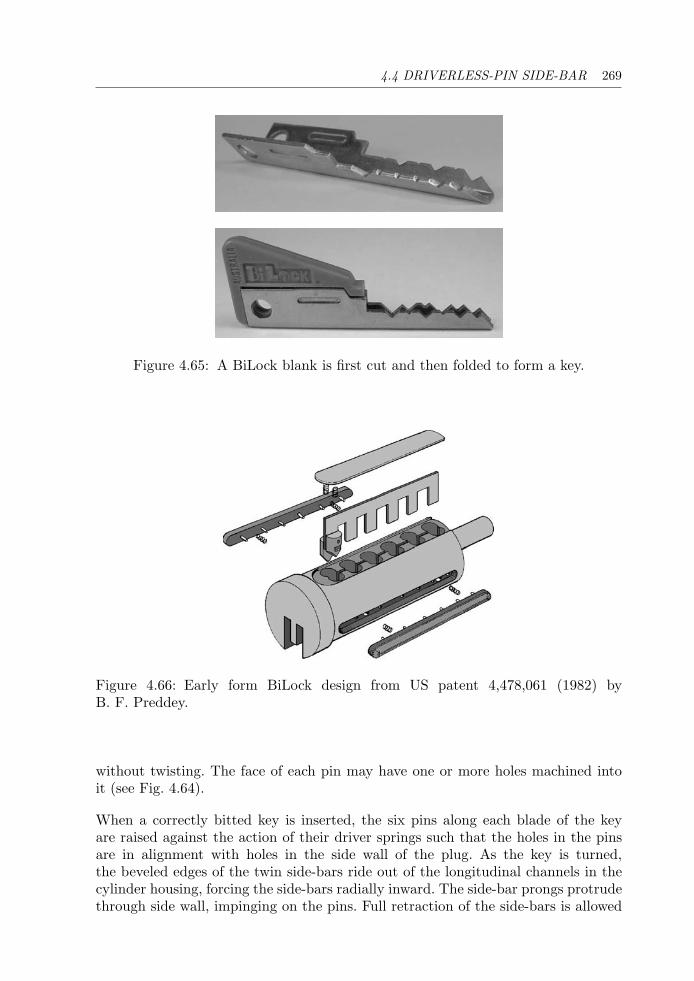
4.4 DRIVERLESS-PIN SIDE-BAR 269
Figure 4.65: A BiLock blank is first cut and then folded to form a key.
Figure 4.66: Early form BiLock design from US patent 4,478,061 (1982) byB. F. Preddey.
without twisting. The face of each pin may have one or more holes machined intoit (see Fig. 4.64).
When a correctly bitted key is inserted, the six pins along each blade of the keyare raised against the action of their driver springs such that the holes in the pinsare in alignment with holes in the side wall of the plug. As the key is turned,the beveled edges of the twin side-bars ride out of the longitudinal channels in thecylinder housing, forcing the side-bars radially inward. The side-bar prongs protrudethrough side wall, impinging on the pins. Full retraction of the side-bars is allowed
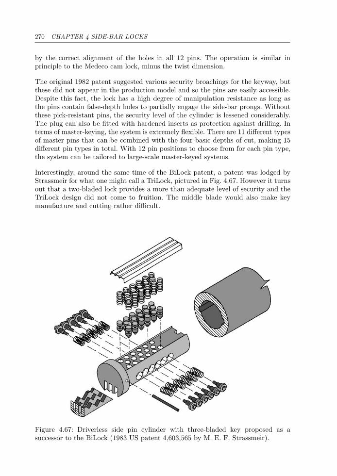
270 CHAPTER 4 SIDE-BAR LOCKS
by the correct alignment of the holes in all 12 pins. The operation is similar inprinciple to the Medeco cam lock, minus the twist dimension.
The original 1982 patent suggested various security broachings for the keyway, butthese did not appear in the production model and so the pins are easily accessible.Despite this fact, the lock has a high degree of manipulation resistance as long asthe pins contain false-depth holes to partially engage the side-bar prongs. Withoutthese pick-resistant pins, the security level of the cylinder is lessened considerably.The plug can also be fitted with hardened inserts as protection against drilling. Interms of master-keying, the system is extremely flexible. There are 11 different typesof master pins that can be combined with the four basic depths of cut, making 15different pin types in total. With 12 pin positions to choose from for each pin type,the system can be tailored to large-scale master-keyed systems.
Interestingly, around the same time of the BiLock patent, a patent was lodged byStrassmeir for what one might call a TriLock, pictured in Fig. 4.67. However it turnsout that a two-bladed lock provides a more than adequate level of security and theTriLock design did not come to fruition. The middle blade would also make keymanufacture and cutting rather difficult.
Figure 4.67: Driverless side pin cylinder with three-bladed key proposed as asuccessor to the BiLock (1983 US patent 4,603,565 by M. E. F. Strassmeir).
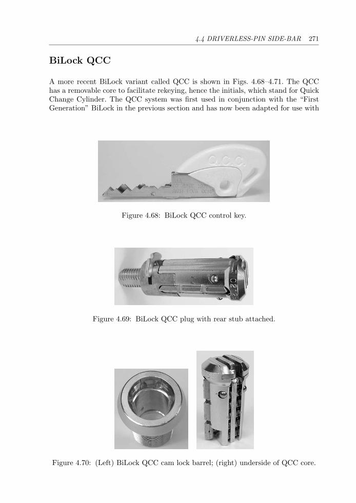
4.4 DRIVERLESS-PIN SIDE-BAR 271
BiLock QCC
A more recent BiLock variant called QCC is shown in Figs. 4.68–4.71. The QCChas a removable core to facilitate rekeying, hence the initials, which stand for QuickChange Cylinder. The QCC system was first used in conjunction with the “FirstGeneration” BiLock in the previous section and has now been adapted for use with
Figure 4.68: BiLock QCC control key.
Figure 4.69: BiLock QCC plug with rear stub attached.
Figure 4.70: (Left) BiLock QCC cam lock barrel; (right) underside of QCC core.
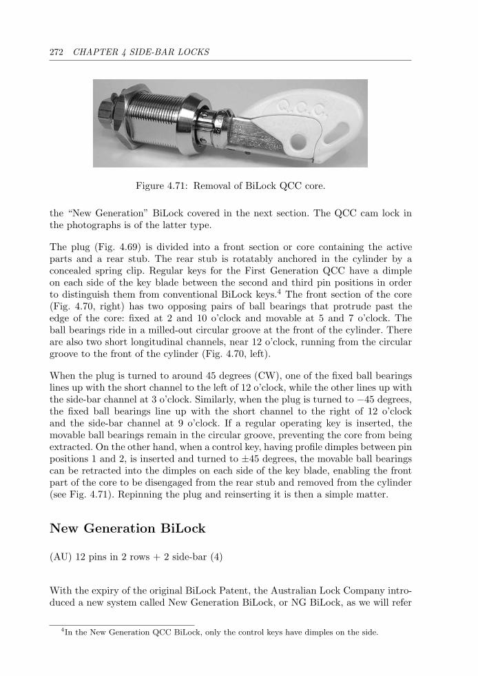
272 CHAPTER 4 SIDE-BAR LOCKS
Figure 4.71: Removal of BiLock QCC core.
the “New Generation” BiLock covered in the next section. The QCC cam lock inthe photographs is of the latter type.
The plug (Fig. 4.69) is divided into a front section or core containing the activeparts and a rear stub. The rear stub is rotatably anchored in the cylinder by aconcealed spring clip. Regular keys for the First Generation QCC have a dimpleon each side of the key blade between the second and third pin positions in orderto distinguish them from conventional BiLock keys.4 The front section of the core(Fig. 4.70, right) has two opposing pairs of ball bearings that protrude past theedge of the core: fixed at 2 and 10 o’clock and movable at 5 and 7 o’clock. Theball bearings ride in a milled-out circular groove at the front of the cylinder. Thereare also two short longitudinal channels, near 12 o’clock, running from the circulargroove to the front of the cylinder (Fig. 4.70, left).
When the plug is turned to around 45 degrees (CW), one of the fixed ball bearingslines up with the short channel to the left of 12 o’clock, while the other lines up withthe side-bar channel at 3 o’clock. Similarly, when the plug is turned to −45 degrees,the fixed ball bearings line up with the short channel to the right of 12 o’clockand the side-bar channel at 9 o’clock. If a regular operating key is inserted, themovable ball bearings remain in the circular groove, preventing the core from beingextracted. On the other hand, when a control key, having profile dimples between pinpositions 1 and 2, is inserted and turned to ±45 degrees, the movable ball bearingscan be retracted into the dimples on each side of the key blade, enabling the frontpart of the core to be disengaged from the rear stub and removed from the cylinder(see Fig. 4.71). Repinning the plug and reinserting it is then a simple matter.
New Generation BiLock
(AU) 12 pins in 2 rows + 2 side-bar (4)
With the expiry of the original BiLock Patent, the Australian Lock Company intro-duced a new system called New Generation BiLock, or NG BiLock, as we will refer
4In the New Generation QCC BiLock, only the control keys have dimples on the side.
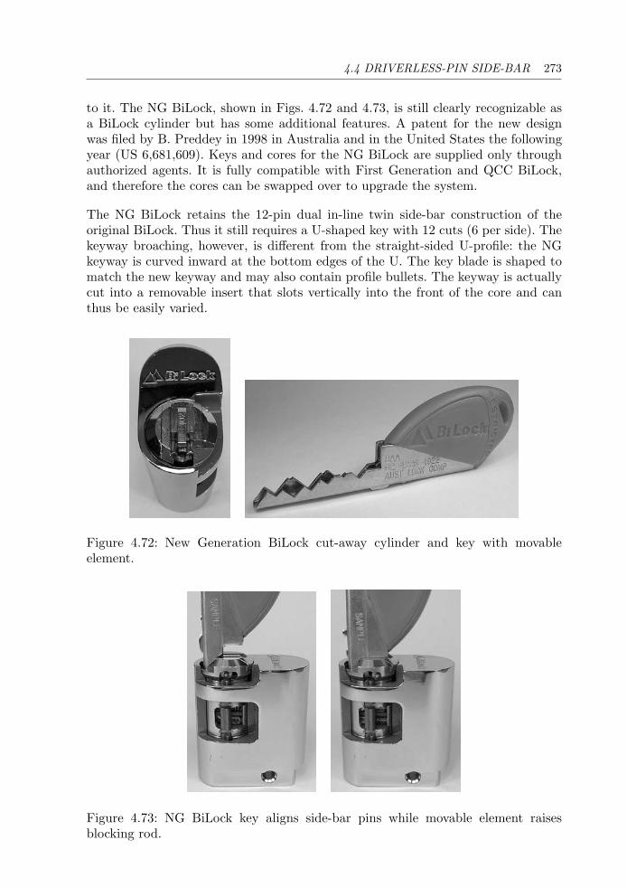
4.4 DRIVERLESS-PIN SIDE-BAR 273
to it. The NG BiLock, shown in Figs. 4.72 and 4.73, is still clearly recognizable asa BiLock cylinder but has some additional features. A patent for the new designwas filed by B. Preddey in 1998 in Australia and in the United States the followingyear (US 6,681,609). Keys and cores for the NG BiLock are supplied only throughauthorized agents. It is fully compatible with First Generation and QCC BiLock,and therefore the cores can be swapped over to upgrade the system.
The NG BiLock retains the 12-pin dual in-line twin side-bar construction of theoriginal BiLock. Thus it still requires a U-shaped key with 12 cuts (6 per side). Thekeyway broaching, however, is different from the straight-sided U-profile: the NGkeyway is curved inward at the bottom edges of the U. The key blade is shaped tomatch the new keyway and may also contain profile bullets. The keyway is actuallycut into a removable insert that slots vertically into the front of the core and canthus be easily varied.
Figure 4.72: New Generation BiLock cut-away cylinder and key with movableelement.
Figure 4.73: NG BiLock key aligns side-bar pins while movable element raisesblocking rod.
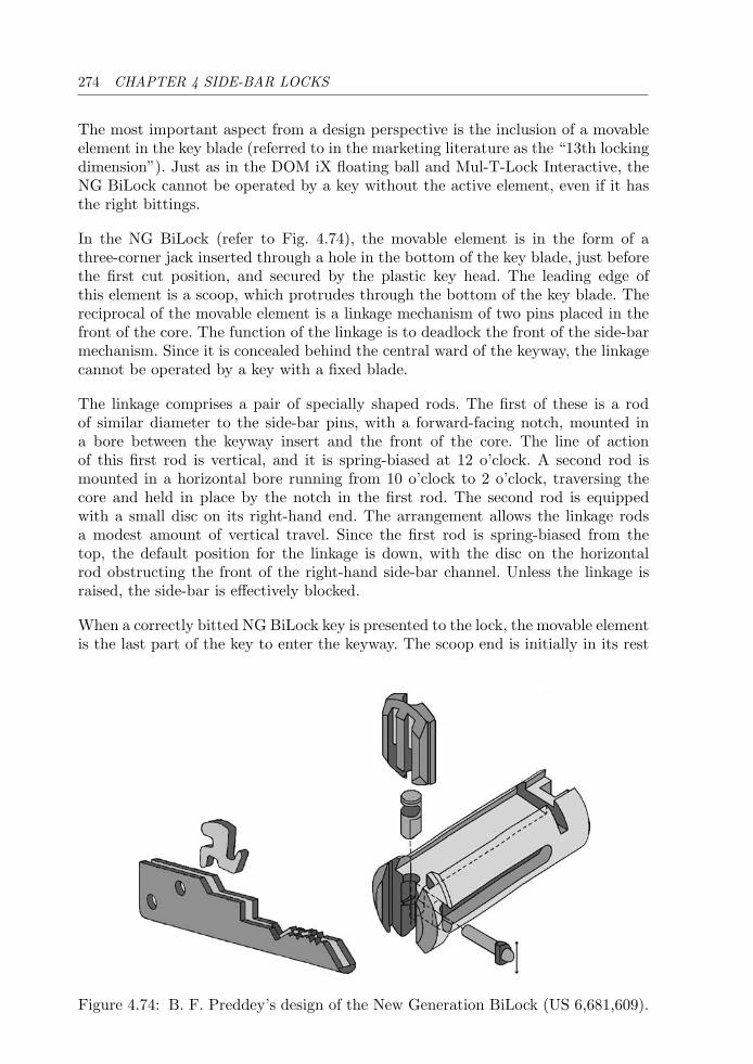
274 CHAPTER 4 SIDE-BAR LOCKS
The most important aspect from a design perspective is the inclusion of a movableelement in the key blade (referred to in the marketing literature as the “13th lockingdimension”). Just as in the DOM iX floating ball and Mul-T-Lock Interactive, theNG BiLock cannot be operated by a key without the active element, even if it hasthe right bittings.
In the NG BiLock (refer to Fig. 4.74), the movable element is in the form of athree-corner jack inserted through a hole in the bottom of the key blade, just beforethe first cut position, and secured by the plastic key head. The leading edge ofthis element is a scoop, which protrudes through the bottom of the key blade. Thereciprocal of the movable element is a linkage mechanism of two pins placed in thefront of the core. The function of the linkage is to deadlock the front of the side-barmechanism. Since it is concealed behind the central ward of the keyway, the linkagecannot be operated by a key with a fixed blade.
The linkage comprises a pair of specially shaped rods. The first of these is a rodof similar diameter to the side-bar pins, with a forward-facing notch, mounted ina bore between the keyway insert and the front of the core. The line of actionof this first rod is vertical, and it is spring-biased at 12 o’clock. A second rod ismounted in a horizontal bore running from 10 o’clock to 2 o’clock, traversing thecore and held in place by the notch in the first rod. The second rod is equippedwith a small disc on its right-hand end. The arrangement allows the linkage rodsa modest amount of vertical travel. Since the first rod is spring-biased from thetop, the default position for the linkage is down, with the disc on the horizontalrod obstructing the front of the right-hand side-bar channel. Unless the linkage israised, the side-bar is effectively blocked.
When a correctly bitted NG BiLock key is presented to the lock, the movable elementis the last part of the key to enter the keyway. The scoop end is initially in its rest
Figure 4.74: B. F. Preddey’s design of the New Generation BiLock (US 6,681,609).
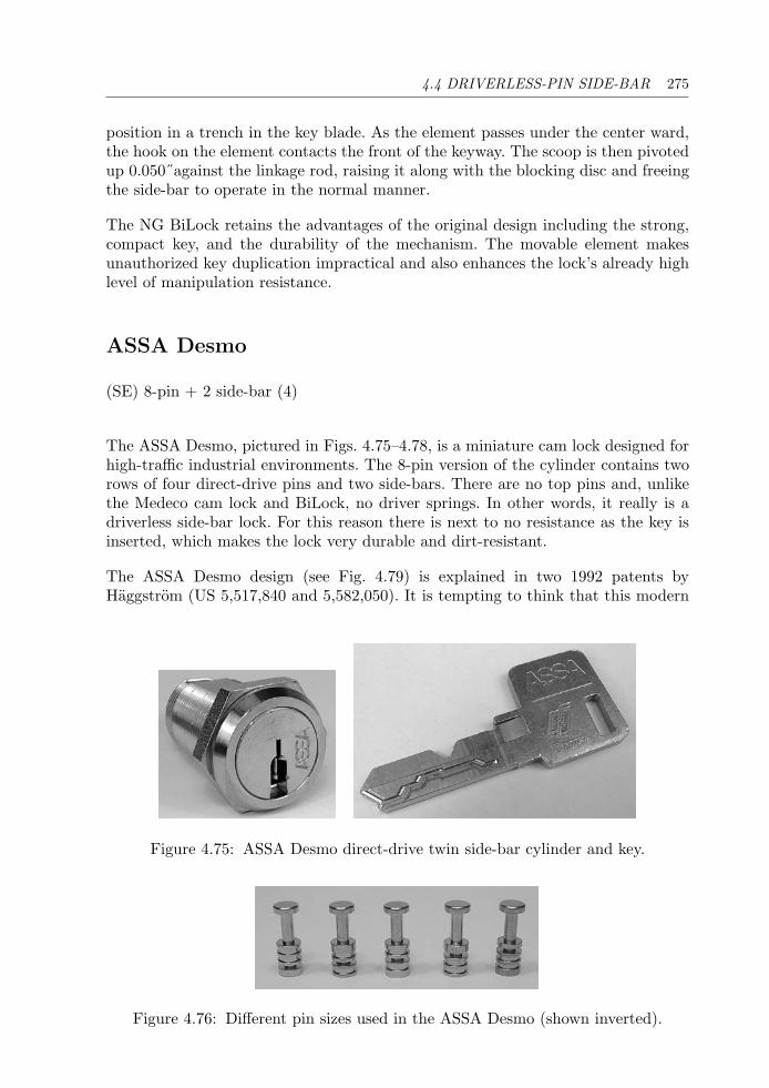
4.4 DRIVERLESS-PIN SIDE-BAR 275
position in a trench in the key blade. As the element passes under the center ward,the hook on the element contacts the front of the keyway. The scoop is then pivotedup 0.050˝against the linkage rod, raising it along with the blocking disc and freeingthe side-bar to operate in the normal manner.
The NG BiLock retains the advantages of the original design including the strong,compact key, and the durability of the mechanism. The movable element makesunauthorized key duplication impractical and also enhances the lock’s already highlevel of manipulation resistance.
ASSA Desmo
(SE) 8-pin + 2 side-bar (4)
The ASSA Desmo, pictured in Figs. 4.75–4.78, is a miniature cam lock designed forhigh-traffic industrial environments. The 8-pin version of the cylinder contains tworows of four direct-drive pins and two side-bars. There are no top pins and, unlikethe Medeco cam lock and BiLock, no driver springs. In other words, it really is adriverless side-bar lock. For this reason there is next to no resistance as the key isinserted, which makes the lock very durable and dirt-resistant.
The ASSA Desmo design (see Fig. 4.79) is explained in two 1992 patents byHaggstrom (US 5,517,840 and 5,582,050). It is tempting to think that this modern
Figure 4.75: ASSA Desmo direct-drive twin side-bar cylinder and key.
Figure 4.76: Different pin sizes used in the ASSA Desmo (shown inverted).
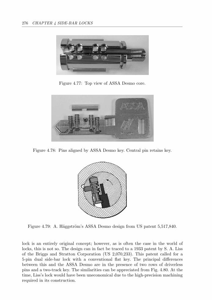
276 CHAPTER 4 SIDE-BAR LOCKS
Figure 4.77: Top view of ASSA Desmo core.
Figure 4.78: Pins aligned by ASSA Desmo key. Central pin retains key.
Figure 4.79: A. Haggstrom’s ASSA Desmo design from US patent 5,517,840.
lock is an entirely original concept; however, as is often the case in the world oflocks, this is not so. The design can in fact be traced to a 1933 patent by S. A. Lissof the Briggs and Stratton Corporation (US 2,070,233). This patent called for a5-pin dual side-bar lock with a conventional flat key. The principal differencesbetween this and the ASSA Desmo are in the presence of two rows of driverlesspins and a two-track key. The similarities can be appreciated from Fig. 4.80. At thetime, Liss’s lock would have been uneconomical due to the high-precision machiningrequired in its construction.
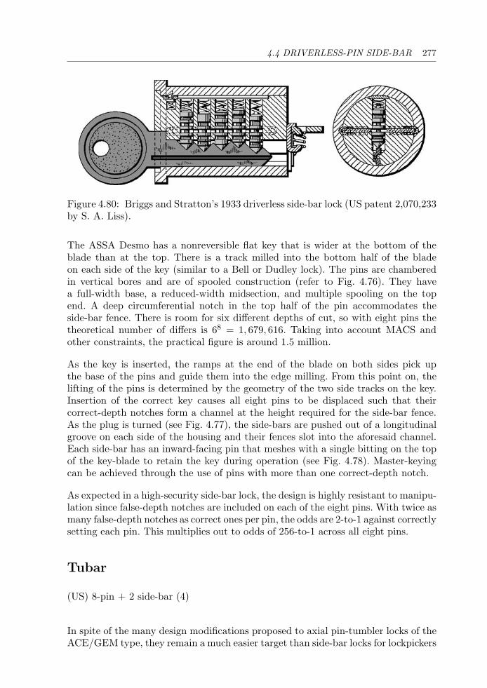
4.4 DRIVERLESS-PIN SIDE-BAR 277
Figure 4.80: Briggs and Stratton’s 1933 driverless side-bar lock (US patent 2,070,233by S. A. Liss).
The ASSA Desmo has a nonreversible flat key that is wider at the bottom of theblade than at the top. There is a track milled into the bottom half of the bladeon each side of the key (similar to a Bell or Dudley lock). The pins are chamberedin vertical bores and are of spooled construction (refer to Fig. 4.76). They havea full-width base, a reduced-width midsection, and multiple spooling on the topend. A deep circumferential notch in the top half of the pin accommodates theside-bar fence. There is room for six different depths of cut, so with eight pins thetheoretical number of differs is 68 = 1, 679, 616. Taking into account MACS andother constraints, the practical figure is around 1.5 million.
As the key is inserted, the ramps at the end of the blade on both sides pick upthe base of the pins and guide them into the edge milling. From this point on, thelifting of the pins is determined by the geometry of the two side tracks on the key.Insertion of the correct key causes all eight pins to be displaced such that theircorrect-depth notches form a channel at the height required for the side-bar fence.As the plug is turned (see Fig. 4.77), the side-bars are pushed out of a longitudinalgroove on each side of the housing and their fences slot into the aforesaid channel.Each side-bar has an inward-facing pin that meshes with a single bitting on the topof the key-blade to retain the key during operation (see Fig. 4.78). Master-keyingcan be achieved through the use of pins with more than one correct-depth notch.
As expected in a high-security side-bar lock, the design is highly resistant to manipu-lation since false-depth notches are included on each of the eight pins. With twice asmany false-depth notches as correct ones per pin, the odds are 2-to-1 against correctlysetting each pin. This multiplies out to odds of 256-to-1 across all eight pins.
Tubar
(US) 8-pin + 2 side-bar (4)
In spite of the many design modifications proposed to axial pin-tumbler locks of theACE/GEM type, they remain a much easier target than side-bar locks for lockpickers
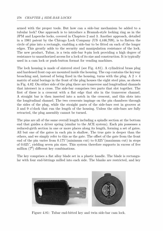
278 CHAPTER 4 SIDE-BAR LOCKS
armed with the proper tools. But how can a side-bar mechanism be added to atubular lock? One approach is to introduce a Bramah-style locking ring as in theJPM and Laperche locks, covered in Chapters 2 and 3. Another approach, detailedin a 1981 patent by the Chicago Lock Company (US 4,446,709), is to flatten thecircle of pins into a rectangle, enabling a side-bar to be fitted on each of the longeredges. This greatly adds to the security and manipulation resistance of the lock.The new product, Tubar, is a twin side-bar 8-pin lock providing a high degree ofresistance to unauthorized access for a lock of its size and construction. It is typicallyused in a cam lock or push-button format for vending machines.
The lock housing is made of sintered steel (see Fig. 4.81). A cylindrical brass plugand hardened front cap are mounted inside the housing. The cap contains the keywaybroaching and, instead of being fixed in the housing, turns with the plug. A 2 × 4matrix of axial borings in the front of the plug houses the eight steel pins, as shownin Fig. 4.82. On either side of the plug there are transverse and longitudinal channelsthat intersect in a cross. The side-bar comprises two parts that slot together. Thefirst of these is a crescent with a flat edge that sits in the transverse channel.A straight bar is then inserted into a notch in the crescent, and this slots intothe longitudinal channel. The two crescents impinge on the pin chambers throughthe sides of the plug, while the straight parts of the side-bars rest in grooves at3 and 9 o’clock that run the length of the housing. Unless the side-bars are fullyretracted, the plug assembly cannot be turned.
The pins are all of the same overall length including a spindle section at the bottomend that guides a driver spring (similar to the ACE system). Each pin possesses areduced-girth section in one or more places along its length, forming a set of gates.All but one of the gates in each pin is shallow. The true gate is deeper than theothers, and we simply refer to this as the gate. The offset of the gate from the frontend of the pin varies from 0.175˝(minimum cut) to 0.325˝(maximum cut) in stepsof 0.025 , yielding seven pin sizes. This system therefore supports in excess of fivemillion (78) different key combinations.
The key comprises a flat alloy blade set in a plastic handle. The blade is rectangu-lar with four end-bittings milled into each side. The blanks are restricted, and key
Figure 4.81: Tubar end-bitted key and twin side-bar cam lock.
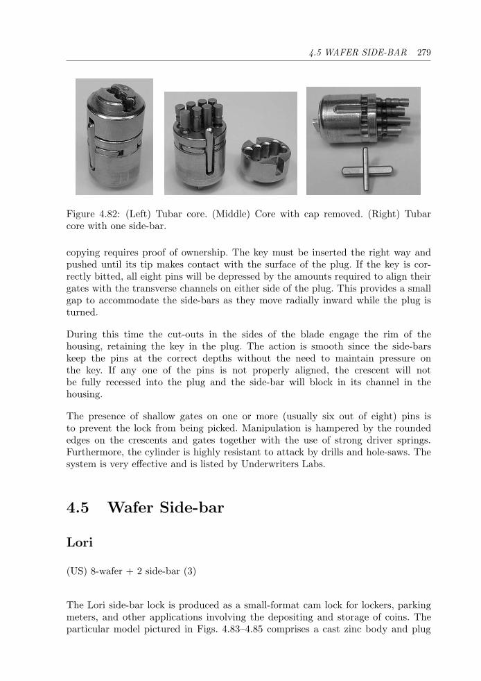
4.5 WAFER SIDE-BAR 279
Figure 4.82: (Left) Tubar core. (Middle) Core with cap removed. (Right) Tubarcore with one side-bar.
copying requires proof of ownership. The key must be inserted the right way andpushed until its tip makes contact with the surface of the plug. If the key is cor-rectly bitted, all eight pins will be depressed by the amounts required to align theirgates with the transverse channels on either side of the plug. This provides a smallgap to accommodate the side-bars as they move radially inward while the plug isturned.
During this time the cut-outs in the sides of the blade engage the rim of thehousing, retaining the key in the plug. The action is smooth since the side-barskeep the pins at the correct depths without the need to maintain pressure onthe key. If any one of the pins is not properly aligned, the crescent will notbe fully recessed into the plug and the side-bar will block in its channel in thehousing.
The presence of shallow gates on one or more (usually six out of eight) pins isto prevent the lock from being picked. Manipulation is hampered by the roundededges on the crescents and gates together with the use of strong driver springs.Furthermore, the cylinder is highly resistant to attack by drills and hole-saws. Thesystem is very effective and is listed by Underwriters Labs.
4.5 Wafer Side-bar
Lori
(US) 8-wafer + 2 side-bar (3)
The Lori side-bar lock is produced as a small-format cam lock for lockers, parkingmeters, and other applications involving the depositing and storage of coins. Theparticular model pictured in Figs. 4.83–4.85 comprises a cast zinc body and plug
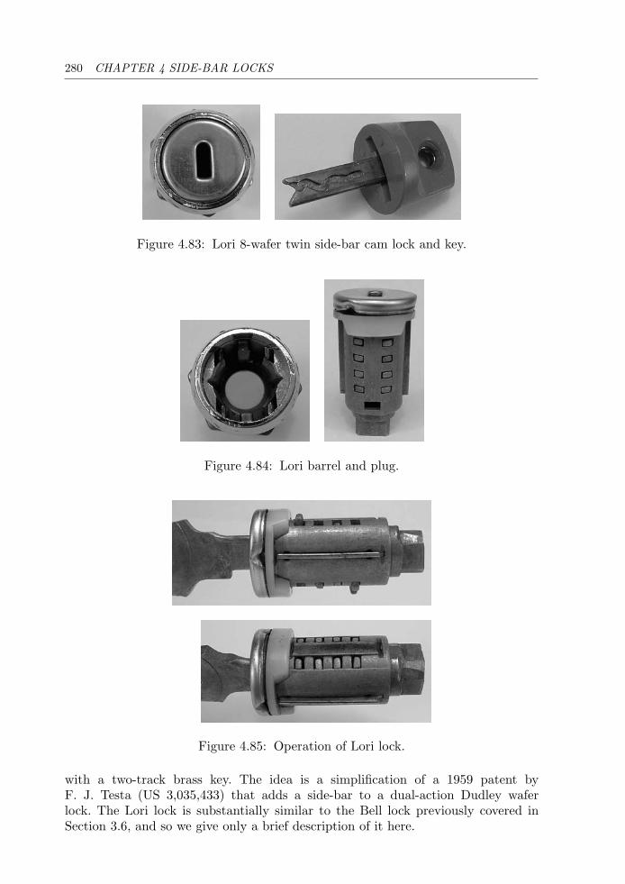
280 CHAPTER 4 SIDE-BAR LOCKS
Figure 4.83: Lori 8-wafer twin side-bar cam lock and key.
Figure 4.84: Lori barrel and plug.
Figure 4.85: Operation of Lori lock.
with a two-track brass key. The idea is a simplification of a 1959 patent byF. J. Testa (US 3,035,433) that adds a side-bar to a dual-action Dudley waferlock. The Lori lock is substantially similar to the Bell lock previously covered inSection 3.6, and so we give only a brief description of it here.
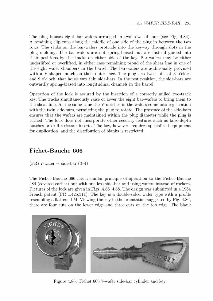
4.5 WAFER SIDE-BAR 281
The plug houses eight bar-wafers arranged in two rows of four (see Fig. 4.84).A retaining clip runs along the middle of one side of the plug in between the tworows. The stubs on the bar-wafers protrude into the keyway through slots in theplug molding. The bar-wafers are not spring-biased but are instead guided intotheir positions by the tracks on either side of the key. Bar-wafers may be eitherunderlifted or overlifted, in either case remaining proud of the shear line in one ofthe eight wafer chambers in the barrel. The bar-wafers are additionally providedwith a V-shaped notch on their outer face. The plug has two slots, at 3 o’clockand 9 o’clock, that house two thin side-bars. In the rest position, the side-bars areoutwardly spring-biased into longitudinal channels in the barrel.
Operation of the lock is assured by the insertion of a correctly milled two-trackkey. The tracks simultaneously raise or lower the eight bar-wafers to bring them tothe shear line. At the same time the V-notches in the wafers come into registrationwith the twin side-bars, permitting the plug to rotate. The presence of the side-barsensures that the wafers are maintained within the plug diameter while the plug isturned. The lock does not incorporate other security features such as false-depthnotches or drill-resistant inserts. The key, however, requires specialized equipmentfor duplication, and the distribution of blanks is restricted.
Fichet-Bauche 666
(FR) 7-wafer + side-bar (3–4)
The Fichet-Bauche 666 has a similar principle of operation to the Fichet-Bauche484 (covered earlier) but with one less side-bar and using wafers instead of rockers.Pictures of the lock are given in Figs. 4.86–4.88. The design was submitted in a 1964French patent (FR 1,425,311). The key is a double-sided wafer type with a profileresembling a flattened M. Viewing the key in the orientation suggested by Fig. 4.86,there are four cuts on the lower edge and three cuts on the top edge. The blank
Figure 4.86: Fichet 666 7-wafer side-bar cylinder and key.
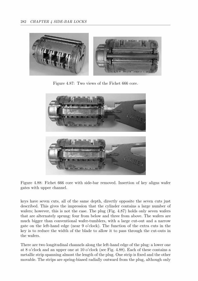
282 CHAPTER 4 SIDE-BAR LOCKS
Figure 4.87: Two views of the Fichet 666 core.
Figure 4.88: Fichet 666 core with side-bar removed. Insertion of key aligns wafergates with upper channel.
keys have seven cuts, all of the same depth, directly opposite the seven cuts justdescribed. This gives the impression that the cylinder contains a large number ofwafers; however, this is not the case. The plug (Fig. 4.87) holds only seven wafersthat are alternately sprung: four from below and three from above. The wafers aremuch bigger than conventional wafer-tumblers, with a large cut-out and a narrowgate on the left-hand edge (near 9 o’clock). The function of the extra cuts in thekey is to reduce the width of the blade to allow it to pass through the cut-outs inthe wafers.
There are two longitudinal channels along the left-hand edge of the plug: a lower oneat 8 o’clock and an upper one at 10 o’clock (see Fig. 4.88). Each of these contains ametallic strip spanning almost the length of the plug. One strip is fixed and the othermovable. The strips are spring-biased radially outward from the plug, although only
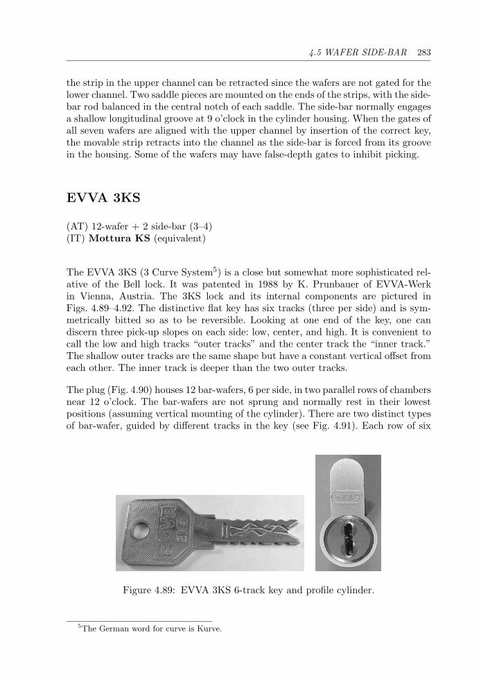
4.5 WAFER SIDE-BAR 283
the strip in the upper channel can be retracted since the wafers are not gated for thelower channel. Two saddle pieces are mounted on the ends of the strips, with the side-bar rod balanced in the central notch of each saddle. The side-bar normally engagesa shallow longitudinal groove at 9 o’clock in the cylinder housing. When the gates ofall seven wafers are aligned with the upper channel by insertion of the correct key,the movable strip retracts into the channel as the side-bar is forced from its groovein the housing. Some of the wafers may have false-depth gates to inhibit picking.
EVVA 3KS
(AT) 12-wafer + 2 side-bar (3–4)(IT) Mottura KS (equivalent)
The EVVA 3KS (3 Curve System5) is a close but somewhat more sophisticated rel-ative of the Bell lock. It was patented in 1988 by K. Prunbauer of EVVA-Werkin Vienna, Austria. The 3KS lock and its internal components are pictured inFigs. 4.89–4.92. The distinctive flat key has six tracks (three per side) and is sym-metrically bitted so as to be reversible. Looking at one end of the key, one candiscern three pick-up slopes on each side: low, center, and high. It is convenient tocall the low and high tracks “outer tracks” and the center track the “inner track.”The shallow outer tracks are the same shape but have a constant vertical offset fromeach other. The inner track is deeper than the two outer tracks.
The plug (Fig. 4.90) houses 12 bar-wafers, 6 per side, in two parallel rows of chambersnear 12 o’clock. The bar-wafers are not sprung and normally rest in their lowestpositions (assuming vertical mounting of the cylinder). There are two distinct typesof bar-wafer, guided by different tracks in the key (see Fig. 4.91). Each row of six
Figure 4.89: EVVA 3KS 6-track key and profile cylinder.
5The German word for curve is Kurve.
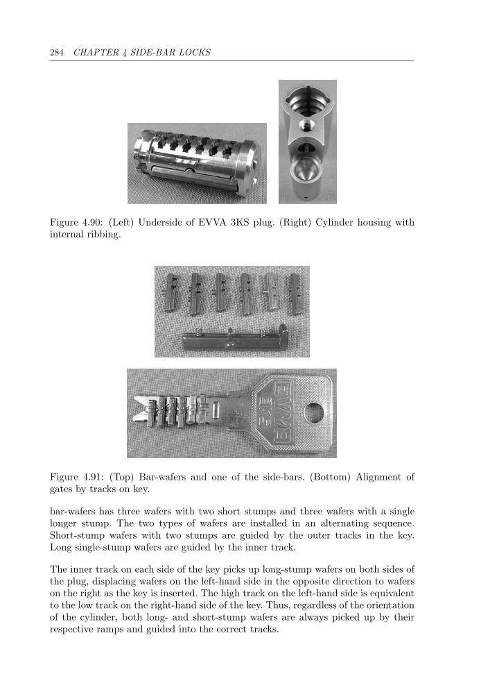
284 CHAPTER 4 SIDE-BAR LOCKS
Figure 4.90: (Left) Underside of EVVA 3KS plug. (Right) Cylinder housing withinternal ribbing.
Figure 4.91: (Top) Bar-wafers and one of the side-bars. (Bottom) Alignment ofgates by tracks on key.
bar-wafers has three wafers with two short stumps and three wafers with a singlelonger stump. The two types of wafers are installed in an alternating sequence.Short-stump wafers with two stumps are guided by the outer tracks in the key.Long single-stump wafers are guided by the inner track.
The inner track on each side of the key picks up long-stump wafers on both sides ofthe plug, displacing wafers on the left-hand side in the opposite direction to waferson the right as the key is inserted. The high track on the left-hand side is equivalentto the low track on the right-hand side of the key. Thus, regardless of the orientationof the cylinder, both long- and short-stump wafers are always picked up by theirrespective ramps and guided into the correct tracks.
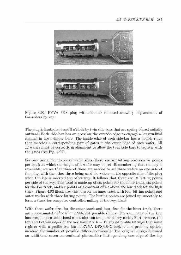
4.5 WAFER SIDE-BAR 285
Figure 4.92: EVVA 3KS plug with side-bar removed showing displacement ofbar-wafers by key.
The plug is flanked at 3 and 9 o’clock by twin side-bars that are spring-biased radiallyoutward. Each side-bar has an apex on the outside edge to engage a longitudinalchannel in the cylinder bore. The inside edge of each side-bar has a double ridgethat matches a corresponding pair of gates in the outer edge of each wafer. All12 wafers must be correctly in alignment to allow the twin side-bars to register withthe gates (see Fig. 4.92).
For any particular choice of wafer sizes, there are six bitting positions or pointsper track at which the height of a wafer may be set. Remembering that the key isreversible, we see that three of these are needed to set three wafers on one side ofthe plug, with the other three being used for wafers on the opposite side of the plugwhen the key is inserted the other way. It follows that there are 18 bitting pointsper side of the key. This total is made up of six points for the inner track, six pointsfor the low track, and six points at a constant offset above the low track for the hightrack. Figure 4.93 illustrates this idea for an inner track with four bitting points andouter tracks with three bitting points. The bitting points are joined up smoothly toform a track for computer-controlled milling of the key blank.
With three wafer sizes for the outer track and four sizes for the inner track, thereare approximately 36 × 46 = 2, 985, 984 possible differs. The symmetry of the key,however, imposes additional constraints on the possible key codes. Furthermore, thetop and bottom edges of the key have 2 × 6 = 12 angled profile bittings that mustregister with a profile bar (as in EVVA DPS/DPX locks). The profiling optionsincrease the number of possible differs enormously. The original design featuredan additional seven conventional pin-tumbler bittings along one edge of the key
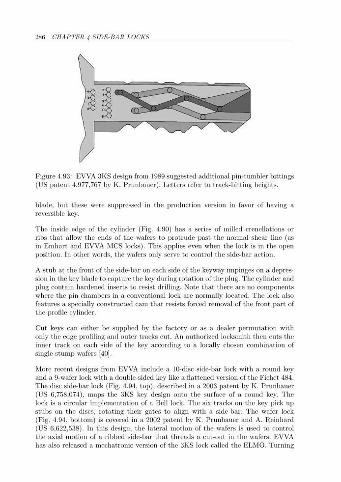
286 CHAPTER 4 SIDE-BAR LOCKS
Figure 4.93: EVVA 3KS design from 1989 suggested additional pin-tumbler bittings(US patent 4,977,767 by K. Prunbauer). Letters refer to track-bitting heights.
blade, but these were suppressed in the production version in favor of having areversible key.
The inside edge of the cylinder (Fig. 4.90) has a series of milled crenellations orribs that allow the ends of the wafers to protrude past the normal shear line (asin Emhart and EVVA MCS locks). This applies even when the lock is in the openposition. In other words, the wafers only serve to control the side-bar action.
A stub at the front of the side-bar on each side of the keyway impinges on a depres-sion in the key blade to capture the key during rotation of the plug. The cylinder andplug contain hardened inserts to resist drilling. Note that there are no componentswhere the pin chambers in a conventional lock are normally located. The lock alsofeatures a specially constructed cam that resists forced removal of the front part ofthe profile cylinder.
Cut keys can either be supplied by the factory or as a dealer permutation withonly the edge profiling and outer tracks cut. An authorized locksmith then cuts theinner track on each side of the key according to a locally chosen combination ofsingle-stump wafers [40].
More recent designs from EVVA include a 10-disc side-bar lock with a round keyand a 9-wafer lock with a double-sided key like a flattened version of the Fichet 484.The disc side-bar lock (Fig. 4.94, top), described in a 2003 patent by K. Prunbauer(US 6,758,074), maps the 3KS key design onto the surface of a round key. Thelock is a circular implementation of a Bell lock. The six tracks on the key pick upstubs on the discs, rotating their gates to align with a side-bar. The wafer lock(Fig. 4.94, bottom) is covered in a 2002 patent by K. Prunbauer and A. Reinhard(US 6,622,538). In this design, the lateral motion of the wafers is used to controlthe axial motion of a ribbed side-bar that threads a cut-out in the wafers. EVVAhas also released a mechatronic version of the 3KS lock called the ELMO. Turning
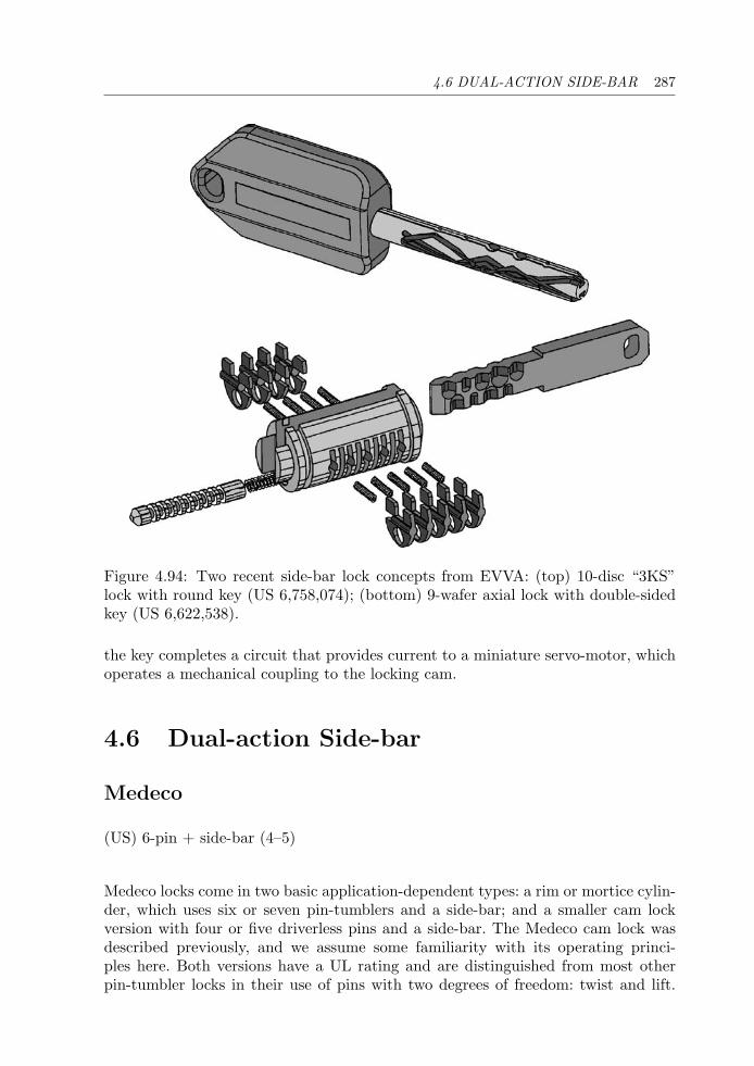
4.6 DUAL-ACTION SIDE-BAR 287
Figure 4.94: Two recent side-bar lock concepts from EVVA: (top) 10-disc “3KS”lock with round key (US 6,758,074); (bottom) 9-wafer axial lock with double-sidedkey (US 6,622,538).
the key completes a circuit that provides current to a miniature servo-motor, whichoperates a mechanical coupling to the locking cam.
4.6 Dual-action Side-bar
Medeco
(US) 6-pin + side-bar (4–5)
Medeco locks come in two basic application-dependent types: a rim or mortice cylin-der, which uses six or seven pin-tumblers and a side-bar; and a smaller cam lockversion with four or five driverless pins and a side-bar. The Medeco cam lock wasdescribed previously, and we assume some familiarity with its operating princi-ples here. Both versions have a UL rating and are distinguished from most otherpin-tumbler locks in their use of pins with two degrees of freedom: twist and lift.
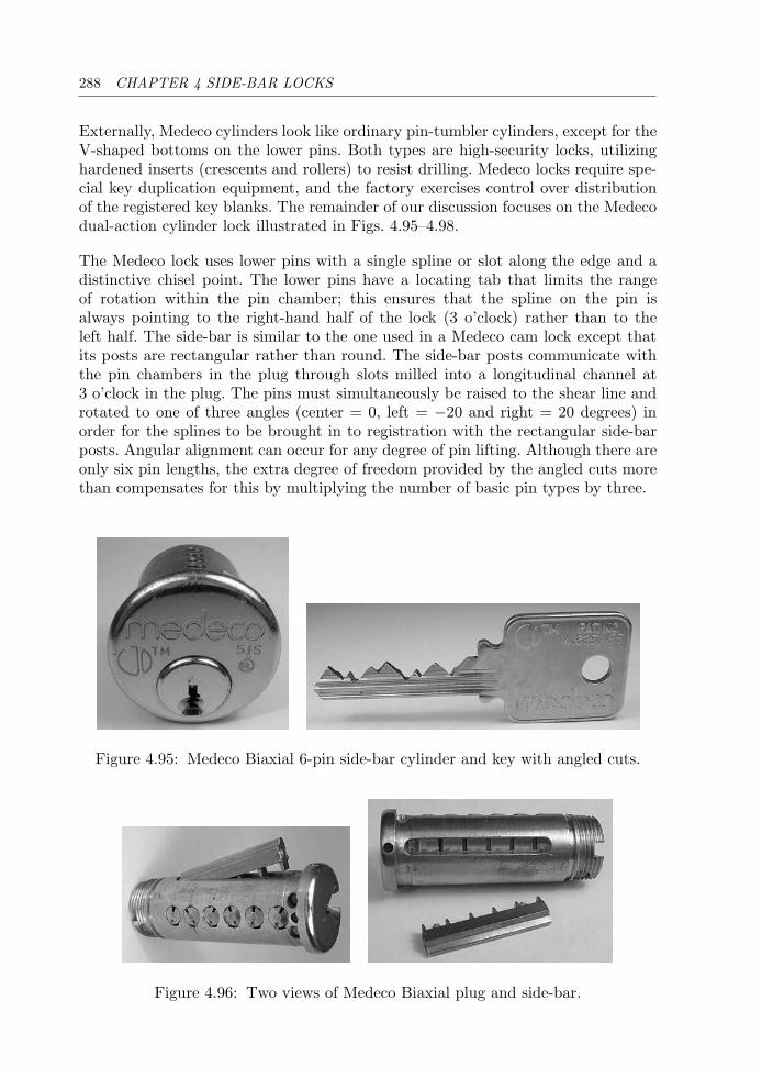
288 CHAPTER 4 SIDE-BAR LOCKS
Externally, Medeco cylinders look like ordinary pin-tumbler cylinders, except for theV-shaped bottoms on the lower pins. Both types are high-security locks, utilizinghardened inserts (crescents and rollers) to resist drilling. Medeco locks require spe-cial key duplication equipment, and the factory exercises control over distributionof the registered key blanks. The remainder of our discussion focuses on the Medecodual-action cylinder lock illustrated in Figs. 4.95–4.98.
The Medeco lock uses lower pins with a single spline or slot along the edge and adistinctive chisel point. The lower pins have a locating tab that limits the rangeof rotation within the pin chamber; this ensures that the spline on the pin isalways pointing to the right-hand half of the lock (3 o’clock) rather than to theleft half. The side-bar is similar to the one used in a Medeco cam lock except thatits posts are rectangular rather than round. The side-bar posts communicate withthe pin chambers in the plug through slots milled into a longitudinal channel at3 o’clock in the plug. The pins must simultaneously be raised to the shear line androtated to one of three angles (center = 0, left = −20 and right = 20 degrees) inorder for the splines to be brought in to registration with the rectangular side-barposts. Angular alignment can occur for any degree of pin lifting. Although there areonly six pin lengths, the extra degree of freedom provided by the angled cuts morethan compensates for this by multiplying the number of basic pin types by three.
Figure 4.95: Medeco Biaxial 6-pin side-bar cylinder and key with angled cuts.
Figure 4.96: Two views of Medeco Biaxial plug and side-bar.
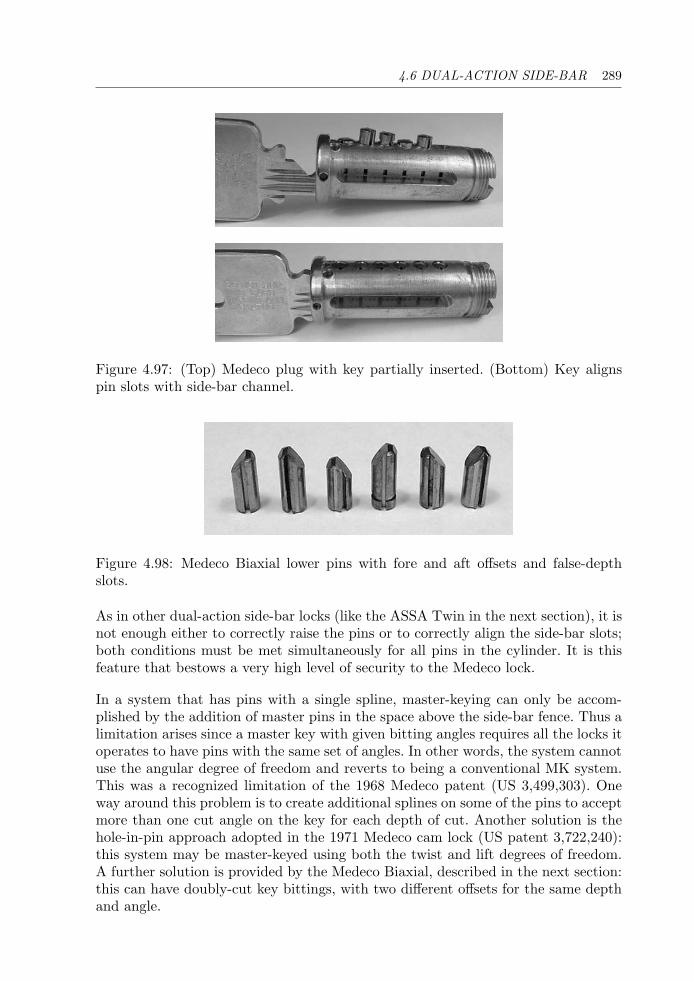
4.6 DUAL-ACTION SIDE-BAR 289
Figure 4.97: (Top) Medeco plug with key partially inserted. (Bottom) Key alignspin slots with side-bar channel.
Figure 4.98: Medeco Biaxial lower pins with fore and aft offsets and false-depthslots.
As in other dual-action side-bar locks (like the ASSA Twin in the next section), it isnot enough either to correctly raise the pins or to correctly align the side-bar slots;both conditions must be met simultaneously for all pins in the cylinder. It is thisfeature that bestows a very high level of security to the Medeco lock.
In a system that has pins with a single spline, master-keying can only be accom-plished by the addition of master pins in the space above the side-bar fence. Thus alimitation arises since a master key with given bitting angles requires all the locks itoperates to have pins with the same set of angles. In other words, the system cannotuse the angular degree of freedom and reverts to being a conventional MK system.This was a recognized limitation of the 1968 Medeco patent (US 3,499,303). Oneway around this problem is to create additional splines on some of the pins to acceptmore than one cut angle on the key for each depth of cut. Another solution is thehole-in-pin approach adopted in the 1971 Medeco cam lock (US patent 3,722,240):this system may be master-keyed using both the twist and lift degrees of freedom.A further solution is provided by the Medeco Biaxial, described in the next section:this can have doubly-cut key bittings, with two different offsets for the same depthand angle.
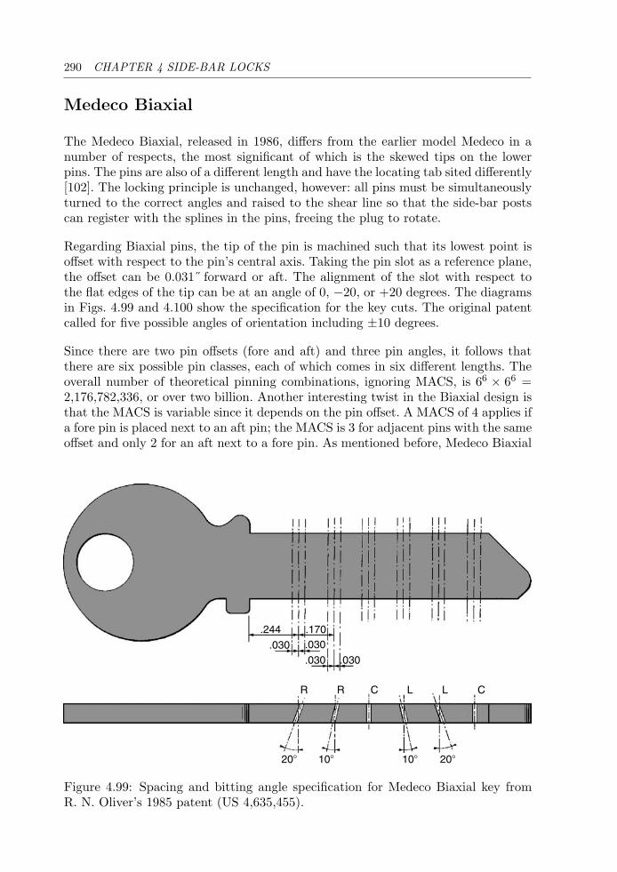
290 CHAPTER 4 SIDE-BAR LOCKS
Medeco Biaxial
The Medeco Biaxial, released in 1986, differs from the earlier model Medeco in anumber of respects, the most significant of which is the skewed tips on the lowerpins. The pins are also of a different length and have the locating tab sited differently[102]. The locking principle is unchanged, however: all pins must be simultaneouslyturned to the correct angles and raised to the shear line so that the side-bar postscan register with the splines in the pins, freeing the plug to rotate.
Regarding Biaxial pins, the tip of the pin is machined such that its lowest point isoffset with respect to the pin’s central axis. Taking the pin slot as a reference plane,the offset can be 0.031˝ forward or aft. The alignment of the slot with respect tothe flat edges of the tip can be at an angle of 0, −20, or +20 degrees. The diagramsin Figs. 4.99 and 4.100 show the specification for the key cuts. The original patentcalled for five possible angles of orientation including ±10 degrees.
Since there are two pin offsets (fore and aft) and three pin angles, it follows thatthere are six possible pin classes, each of which comes in six different lengths. Theoverall number of theoretical pinning combinations, ignoring MACS, is 66 × 66 =2,176,782,336, or over two billion. Another interesting twist in the Biaxial design isthat the MACS is variable since it depends on the pin offset. A MACS of 4 applies ifa fore pin is placed next to an aft pin; the MACS is 3 for adjacent pins with the sameoffset and only 2 for an aft next to a fore pin. As mentioned before, Medeco Biaxial
.244 .170
.030 .030
.030 .030
208
R R C CL L
208108 108
Figure 4.99: Spacing and bitting angle specification for Medeco Biaxial key fromR. N. Oliver’s 1985 patent (US 4,635,455).
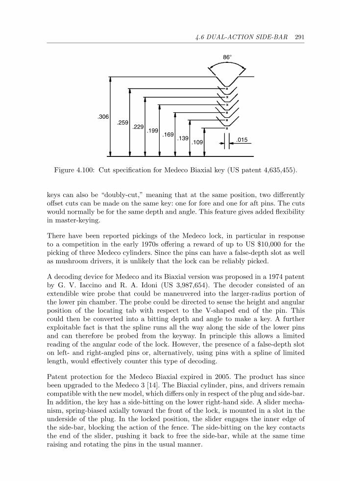
4.6 DUAL-ACTION SIDE-BAR 291
.306.259
.229.199
.169.139
.109 .015
868
Figure 4.100: Cut specification for Medeco Biaxial key (US patent 4,635,455).
keys can also be “doubly-cut,” meaning that at the same position, two differentlyoffset cuts can be made on the same key: one for fore and one for aft pins. The cutswould normally be for the same depth and angle. This feature gives added flexibilityin master-keying.
There have been reported pickings of the Medeco lock, in particular in responseto a competition in the early 1970s offering a reward of up to US $10,000 for thepicking of three Medeco cylinders. Since the pins can have a false-depth slot as wellas mushroom drivers, it is unlikely that the lock can be reliably picked.
A decoding device for Medeco and its Biaxial version was proposed in a 1974 patentby G. V. Iaccino and R. A. Idoni (US 3,987,654). The decoder consisted of anextendible wire probe that could be maneuvered into the larger-radius portion ofthe lower pin chamber. The probe could be directed to sense the height and angularposition of the locating tab with respect to the V-shaped end of the pin. Thiscould then be converted into a bitting depth and angle to make a key. A furtherexploitable fact is that the spline runs all the way along the side of the lower pinsand can therefore be probed from the keyway. In principle this allows a limitedreading of the angular code of the lock. However, the presence of a false-depth sloton left- and right-angled pins or, alternatively, using pins with a spline of limitedlength, would effectively counter this type of decoding.
Patent protection for the Medeco Biaxial expired in 2005. The product has sincebeen upgraded to the Medeco 3 [14]. The Biaxial cylinder, pins, and drivers remaincompatible with the new model, which differs only in respect of the plug and side-bar.In addition, the key has a side-bitting on the lower right-hand side. A slider mecha-nism, spring-biased axially toward the front of the lock, is mounted in a slot in theunderside of the plug. In the locked position, the slider engages the inner edge ofthe side-bar, blocking the action of the fence. The side-bitting on the key contactsthe end of the slider, pushing it back to free the side-bar, while at the same timeraising and rotating the pins in the usual manner.
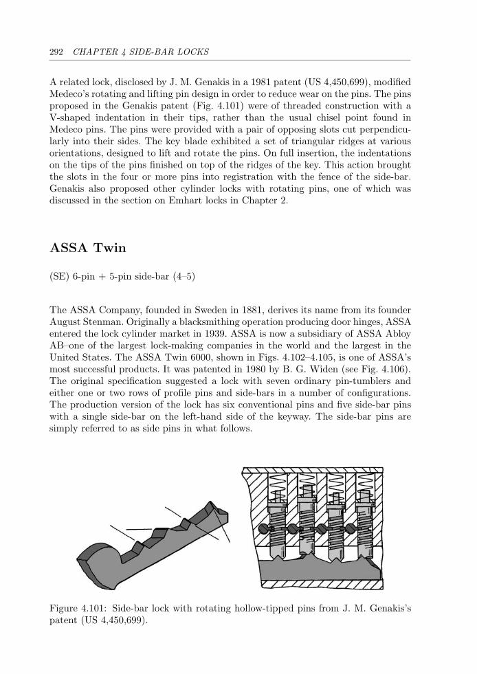
292 CHAPTER 4 SIDE-BAR LOCKS
A related lock, disclosed by J. M. Genakis in a 1981 patent (US 4,450,699), modifiedMedeco’s rotating and lifting pin design in order to reduce wear on the pins. The pinsproposed in the Genakis patent (Fig. 4.101) were of threaded construction with aV-shaped indentation in their tips, rather than the usual chisel point found inMedeco pins. The pins were provided with a pair of opposing slots cut perpendicu-larly into their sides. The key blade exhibited a set of triangular ridges at variousorientations, designed to lift and rotate the pins. On full insertion, the indentationson the tips of the pins finished on top of the ridges of the key. This action broughtthe slots in the four or more pins into registration with the fence of the side-bar.Genakis also proposed other cylinder locks with rotating pins, one of which wasdiscussed in the section on Emhart locks in Chapter 2.
ASSA Twin
(SE) 6-pin + 5-pin side-bar (4–5)
The ASSA Company, founded in Sweden in 1881, derives its name from its founderAugust Stenman. Originally a blacksmithing operation producing door hinges, ASSAentered the lock cylinder market in 1939. ASSA is now a subsidiary of ASSA AbloyAB–one of the largest lock-making companies in the world and the largest in theUnited States. The ASSA Twin 6000, shown in Figs. 4.102–4.105, is one of ASSA’smost successful products. It was patented in 1980 by B. G. Widen (see Fig. 4.106).The original specification suggested a lock with seven ordinary pin-tumblers andeither one or two rows of profile pins and side-bars in a number of configurations.The production version of the lock has six conventional pins and five side-bar pinswith a single side-bar on the left-hand side of the keyway. The side-bar pins aresimply referred to as side pins in what follows.
Figure 4.101: Side-bar lock with rotating hollow-tipped pins from J. M. Genakis’spatent (US 4,450,699).
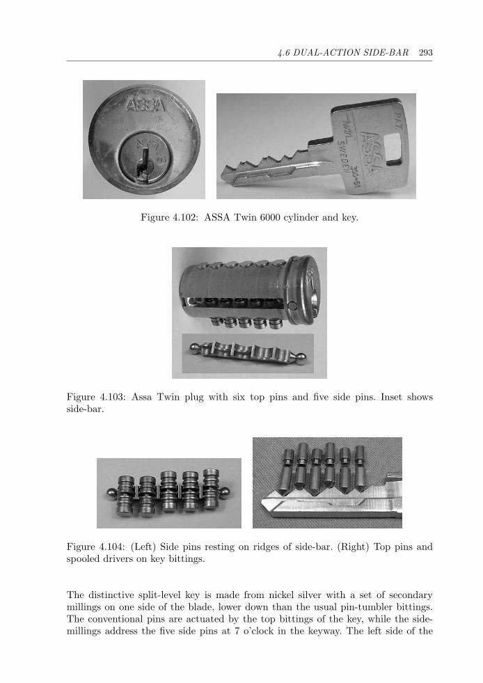
4.6 DUAL-ACTION SIDE-BAR 293
Figure 4.102: ASSA Twin 6000 cylinder and key.
Figure 4.103: Assa Twin plug with six top pins and five side pins. Inset showsside-bar.
Figure 4.104: (Left) Side pins resting on ridges of side-bar. (Right) Top pins andspooled drivers on key bittings.
The distinctive split-level key is made from nickel silver with a set of secondarymillings on one side of the blade, lower down than the usual pin-tumbler bittings.The conventional pins are actuated by the top bittings of the key, while the side-millings address the five side pins at 7 o’clock in the keyway. The left side of the
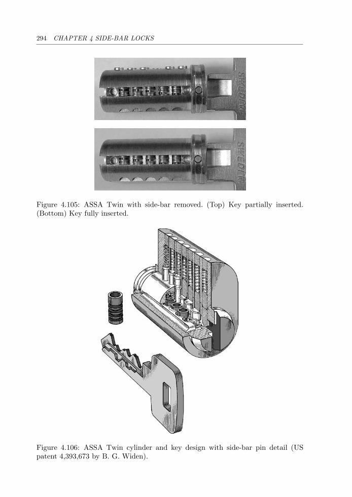
294 CHAPTER 4 SIDE-BAR LOCKS
Figure 4.105: ASSA Twin with side-bar removed. (Top) Key partially inserted.(Bottom) Key fully inserted.
Figure 4.106: ASSA Twin cylinder and key design with side-bar pin detail (USpatent 4,393,673 by B. G. Widen).
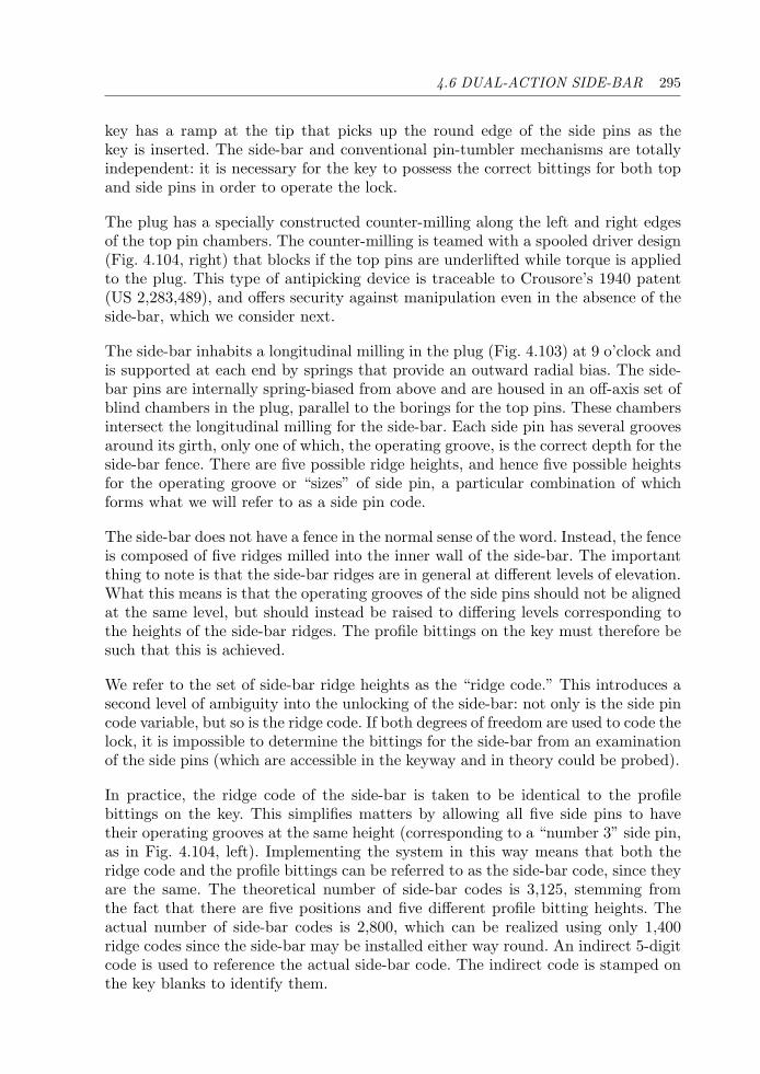
4.6 DUAL-ACTION SIDE-BAR 295
key has a ramp at the tip that picks up the round edge of the side pins as thekey is inserted. The side-bar and conventional pin-tumbler mechanisms are totallyindependent: it is necessary for the key to possess the correct bittings for both topand side pins in order to operate the lock.
The plug has a specially constructed counter-milling along the left and right edgesof the top pin chambers. The counter-milling is teamed with a spooled driver design(Fig. 4.104, right) that blocks if the top pins are underlifted while torque is appliedto the plug. This type of antipicking device is traceable to Crousore’s 1940 patent(US 2,283,489), and offers security against manipulation even in the absence of theside-bar, which we consider next.
The side-bar inhabits a longitudinal milling in the plug (Fig. 4.103) at 9 o’clock andis supported at each end by springs that provide an outward radial bias. The side-bar pins are internally spring-biased from above and are housed in an off-axis set ofblind chambers in the plug, parallel to the borings for the top pins. These chambersintersect the longitudinal milling for the side-bar. Each side pin has several groovesaround its girth, only one of which, the operating groove, is the correct depth for theside-bar fence. There are five possible ridge heights, and hence five possible heightsfor the operating groove or “sizes” of side pin, a particular combination of whichforms what we will refer to as a side pin code.
The side-bar does not have a fence in the normal sense of the word. Instead, the fenceis composed of five ridges milled into the inner wall of the side-bar. The importantthing to note is that the side-bar ridges are in general at different levels of elevation.What this means is that the operating grooves of the side pins should not be alignedat the same level, but should instead be raised to differing levels corresponding tothe heights of the side-bar ridges. The profile bittings on the key must therefore besuch that this is achieved.
We refer to the set of side-bar ridge heights as the “ridge code.” This introduces asecond level of ambiguity into the unlocking of the side-bar: not only is the side pincode variable, but so is the ridge code. If both degrees of freedom are used to code thelock, it is impossible to determine the bittings for the side-bar from an examinationof the side pins (which are accessible in the keyway and in theory could be probed).
In practice, the ridge code of the side-bar is taken to be identical to the profilebittings on the key. This simplifies matters by allowing all five side pins to havetheir operating grooves at the same height (corresponding to a “number 3” side pin,as in Fig. 4.104, left). Implementing the system in this way means that both theridge code and the profile bittings can be referred to as the side-bar code, since theyare the same. The theoretical number of side-bar codes is 3,125, stemming fromthe fact that there are five positions and five different profile bitting heights. Theactual number of side-bar codes is 2,800, which can be realized using only 1,400ridge codes since the side-bar may be installed either way round. An indirect 5-digitcode is used to reference the actual side-bar code. The indirect code is stamped onthe key blanks to identify them.
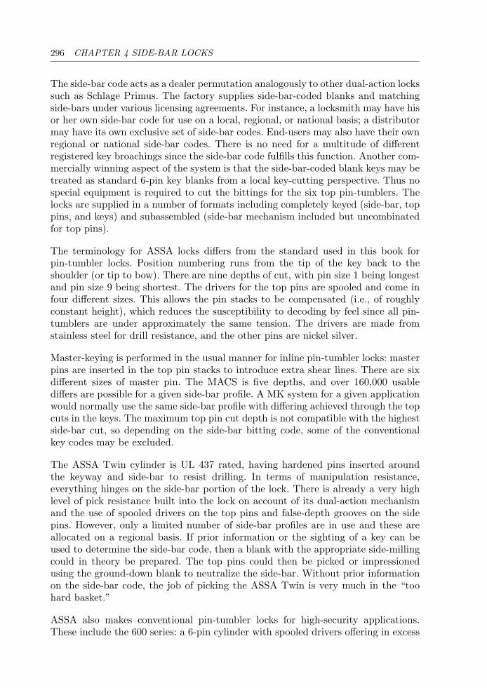
296 CHAPTER 4 SIDE-BAR LOCKS
The side-bar code acts as a dealer permutation analogously to other dual-action lockssuch as Schlage Primus. The factory supplies side-bar-coded blanks and matchingside-bars under various licensing agreements. For instance, a locksmith may have hisor her own side-bar code for use on a local, regional, or national basis; a distributormay have its own exclusive set of side-bar codes. End-users may also have their ownregional or national side-bar codes. There is no need for a multitude of differentregistered key broachings since the side-bar code fulfills this function. Another com-mercially winning aspect of the system is that the side-bar-coded blank keys may betreated as standard 6-pin key blanks from a local key-cutting perspective. Thus nospecial equipment is required to cut the bittings for the six top pin-tumblers. Thelocks are supplied in a number of formats including completely keyed (side-bar, toppins, and keys) and subassembled (side-bar mechanism included but uncombinatedfor top pins).
The terminology for ASSA locks differs from the standard used in this book forpin-tumbler locks. Position numbering runs from the tip of the key back to theshoulder (or tip to bow). There are nine depths of cut, with pin size 1 being longestand pin size 9 being shortest. The drivers for the top pins are spooled and come infour different sizes. This allows the pin stacks to be compensated (i.e., of roughlyconstant height), which reduces the susceptibility to decoding by feel since all pin-tumblers are under approximately the same tension. The drivers are made fromstainless steel for drill resistance, and the other pins are nickel silver.
Master-keying is performed in the usual manner for inline pin-tumbler locks: masterpins are inserted in the top pin stacks to introduce extra shear lines. There are sixdifferent sizes of master pin. The MACS is five depths, and over 160,000 usablediffers are possible for a given side-bar profile. A MK system for a given applicationwould normally use the same side-bar profile with differing achieved through the topcuts in the keys. The maximum top pin cut depth is not compatible with the highestside-bar cut, so depending on the side-bar bitting code, some of the conventionalkey codes may be excluded.
The ASSA Twin cylinder is UL 437 rated, having hardened pins inserted aroundthe keyway and side-bar to resist drilling. In terms of manipulation resistance,everything hinges on the side-bar portion of the lock. There is already a very highlevel of pick resistance built into the lock on account of its dual-action mechanismand the use of spooled drivers on the top pins and false-depth grooves on the sidepins. However, only a limited number of side-bar profiles are in use and these areallocated on a regional basis. If prior information or the sighting of a key can beused to determine the side-bar code, then a blank with the appropriate side-millingcould in theory be prepared. The top pins could then be picked or impressionedusing the ground-down blank to neutralize the side-bar. Without prior informationon the side-bar code, the job of picking the ASSA Twin is very much in the “toohard basket.”
ASSA also makes conventional pin-tumbler locks for high-security applications.These include the 600 series: a 6-pin cylinder with spooled drivers offering in excess
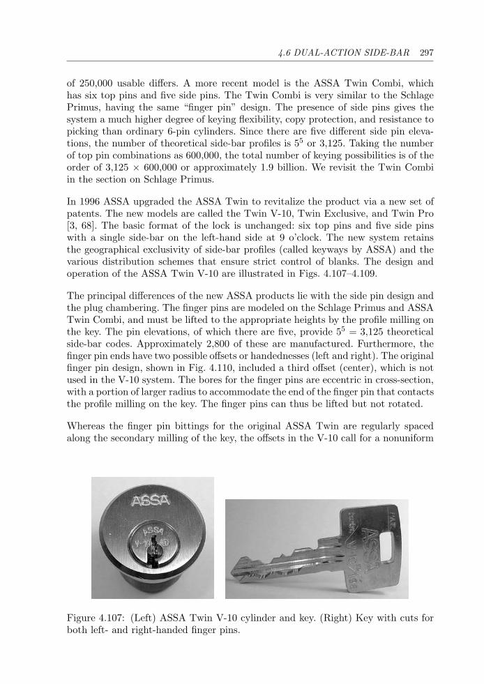
4.6 DUAL-ACTION SIDE-BAR 297
of 250,000 usable differs. A more recent model is the ASSA Twin Combi, whichhas six top pins and five side pins. The Twin Combi is very similar to the SchlagePrimus, having the same “finger pin” design. The presence of side pins gives thesystem a much higher degree of keying flexibility, copy protection, and resistance topicking than ordinary 6-pin cylinders. Since there are five different side pin eleva-tions, the number of theoretical side-bar profiles is 55 or 3,125. Taking the numberof top pin combinations as 600,000, the total number of keying possibilities is of theorder of 3,125 × 600,000 or approximately 1.9 billion. We revisit the Twin Combiin the section on Schlage Primus.
In 1996 ASSA upgraded the ASSA Twin to revitalize the product via a new set ofpatents. The new models are called the Twin V-10, Twin Exclusive, and Twin Pro[3, 68]. The basic format of the lock is unchanged: six top pins and five side pinswith a single side-bar on the left-hand side at 9 o’clock. The new system retainsthe geographical exclusivity of side-bar profiles (called keyways by ASSA) and thevarious distribution schemes that ensure strict control of blanks. The design andoperation of the ASSA Twin V-10 are illustrated in Figs. 4.107–4.109.
The principal differences of the new ASSA products lie with the side pin design andthe plug chambering. The finger pins are modeled on the Schlage Primus and ASSATwin Combi, and must be lifted to the appropriate heights by the profile milling onthe key. The pin elevations, of which there are five, provide 55 = 3,125 theoreticalside-bar codes. Approximately 2,800 of these are manufactured. Furthermore, thefinger pin ends have two possible offsets or handednesses (left and right). The originalfinger pin design, shown in Fig. 4.110, included a third offset (center), which is notused in the V-10 system. The bores for the finger pins are eccentric in cross-section,with a portion of larger radius to accommodate the end of the finger pin that contactsthe profile milling on the key. The finger pins can thus be lifted but not rotated.
Whereas the finger pin bittings for the original ASSA Twin are regularly spacedalong the secondary milling of the key, the offsets in the V-10 call for a nonuniform
Figure 4.107: (Left) ASSA Twin V-10 cylinder and key. (Right) Key with cuts forboth left- and right-handed finger pins.
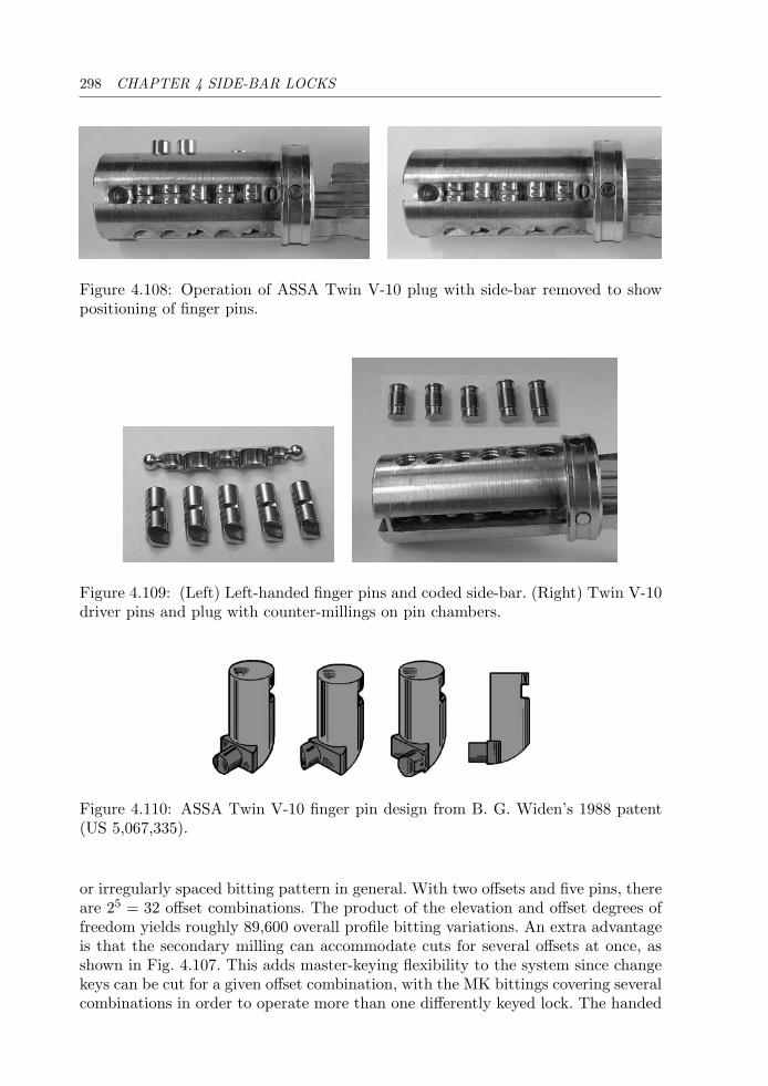
298 CHAPTER 4 SIDE-BAR LOCKS
Figure 4.108: Operation of ASSA Twin V-10 plug with side-bar removed to showpositioning of finger pins.
Figure 4.109: (Left) Left-handed finger pins and coded side-bar. (Right) Twin V-10driver pins and plug with counter-millings on pin chambers.
Figure 4.110: ASSA Twin V-10 finger pin design from B. G. Widen’s 1988 patent(US 5,067,335).
or irregularly spaced bitting pattern in general. With two offsets and five pins, thereare 25 = 32 offset combinations. The product of the elevation and offset degrees offreedom yields roughly 89,600 overall profile bitting variations. An extra advantageis that the secondary milling can accommodate cuts for several offsets at once, asshown in Fig. 4.107. This adds master-keying flexibility to the system since changekeys can be cut for a given offset combination, with the MK bittings covering severalcombinations in order to operate more than one differently keyed lock. The handed
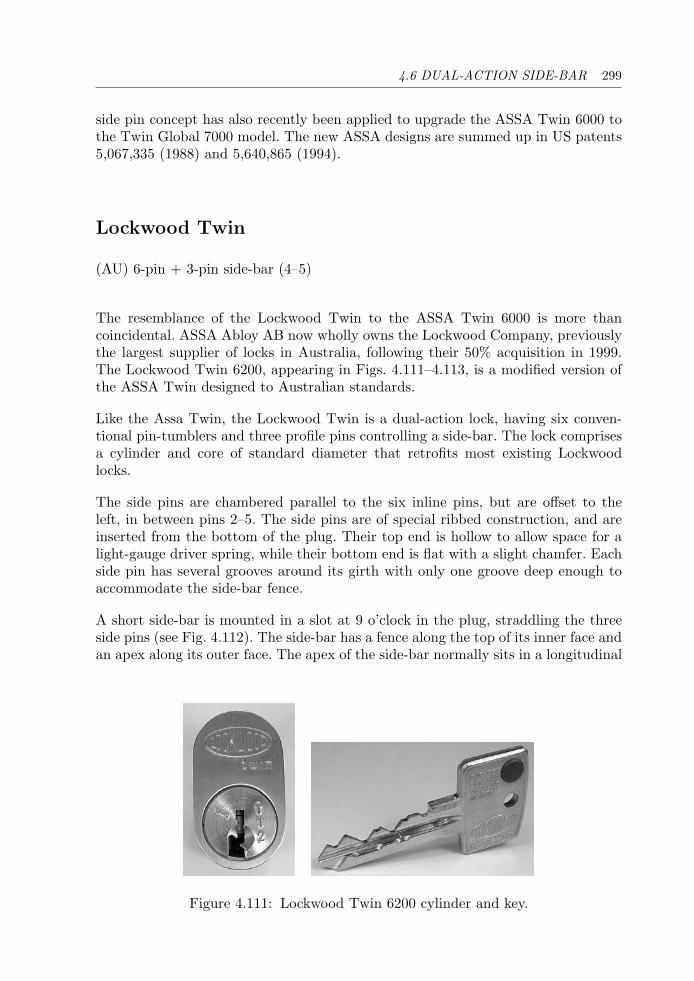
4.6 DUAL-ACTION SIDE-BAR 299
side pin concept has also recently been applied to upgrade the ASSA Twin 6000 tothe Twin Global 7000 model. The new ASSA designs are summed up in US patents5,067,335 (1988) and 5,640,865 (1994).
Lockwood Twin
(AU) 6-pin + 3-pin side-bar (4–5)
The resemblance of the Lockwood Twin to the ASSA Twin 6000 is more thancoincidental. ASSA Abloy AB now wholly owns the Lockwood Company, previouslythe largest supplier of locks in Australia, following their 50% acquisition in 1999.The Lockwood Twin 6200, appearing in Figs. 4.111–4.113, is a modified version ofthe ASSA Twin designed to Australian standards.
Like the Assa Twin, the Lockwood Twin is a dual-action lock, having six conven-tional pin-tumblers and three profile pins controlling a side-bar. The lock comprisesa cylinder and core of standard diameter that retrofits most existing Lockwoodlocks.
The side pins are chambered parallel to the six inline pins, but are offset to theleft, in between pins 2–5. The side pins are of special ribbed construction, and areinserted from the bottom of the plug. Their top end is hollow to allow space for alight-gauge driver spring, while their bottom end is flat with a slight chamfer. Eachside pin has several grooves around its girth with only one groove deep enough toaccommodate the side-bar fence.
A short side-bar is mounted in a slot at 9 o’clock in the plug, straddling the threeside pins (see Fig. 4.112). The side-bar has a fence along the top of its inner face andan apex along its outer face. The apex of the side-bar normally sits in a longitudinal
Figure 4.111: Lockwood Twin 6200 cylinder and key.
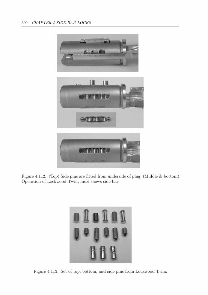
300 CHAPTER 4 SIDE-BAR LOCKS
Figure 4.112: (Top) Side pins are fitted from underside of plug. (Middle & bottom)Operation of Lockwood Twin; inset shows side-bar.
Figure 4.113: Set of top, bottom, and side pins from Lockwood Twin.
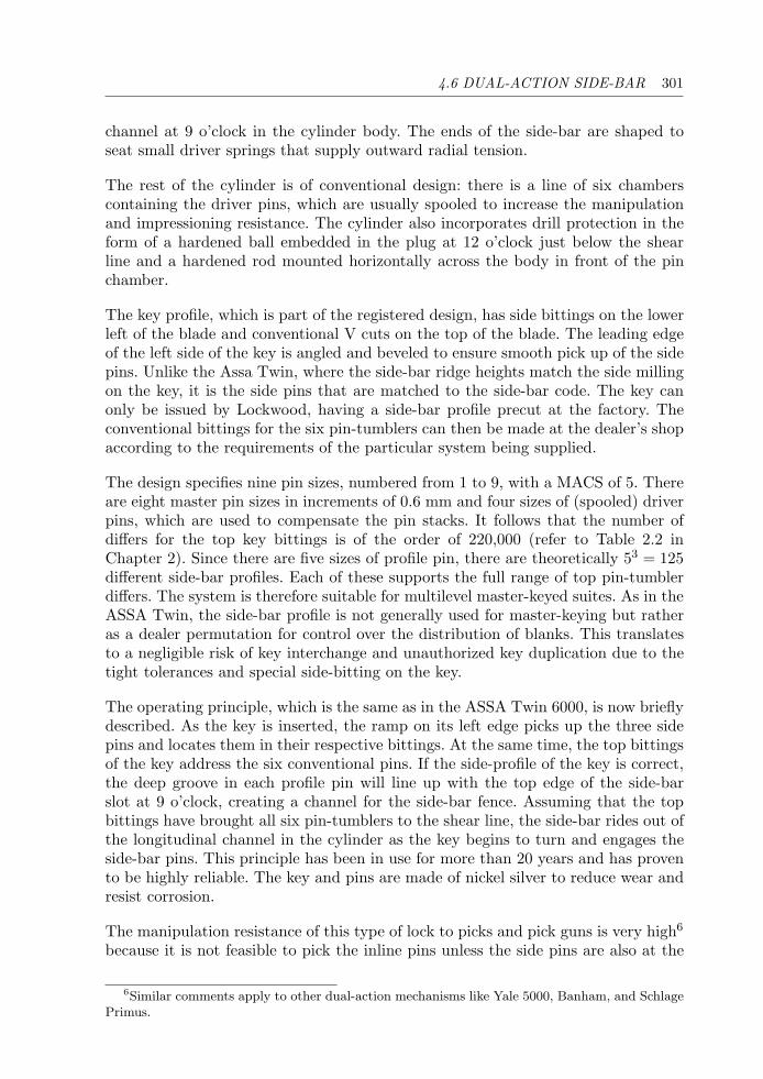
4.6 DUAL-ACTION SIDE-BAR 301
channel at 9 o’clock in the cylinder body. The ends of the side-bar are shaped toseat small driver springs that supply outward radial tension.
The rest of the cylinder is of conventional design: there is a line of six chamberscontaining the driver pins, which are usually spooled to increase the manipulationand impressioning resistance. The cylinder also incorporates drill protection in theform of a hardened ball embedded in the plug at 12 o’clock just below the shearline and a hardened rod mounted horizontally across the body in front of the pinchamber.
The key profile, which is part of the registered design, has side bittings on the lowerleft of the blade and conventional V cuts on the top of the blade. The leading edgeof the left side of the key is angled and beveled to ensure smooth pick up of the sidepins. Unlike the Assa Twin, where the side-bar ridge heights match the side millingon the key, it is the side pins that are matched to the side-bar code. The key canonly be issued by Lockwood, having a side-bar profile precut at the factory. Theconventional bittings for the six pin-tumblers can then be made at the dealer’s shopaccording to the requirements of the particular system being supplied.
The design specifies nine pin sizes, numbered from 1 to 9, with a MACS of 5. Thereare eight master pin sizes in increments of 0.6 mm and four sizes of (spooled) driverpins, which are used to compensate the pin stacks. It follows that the number ofdiffers for the top key bittings is of the order of 220,000 (refer to Table 2.2 inChapter 2). Since there are five sizes of profile pin, there are theoretically 53 = 125different side-bar profiles. Each of these supports the full range of top pin-tumblerdiffers. The system is therefore suitable for multilevel master-keyed suites. As in theASSA Twin, the side-bar profile is not generally used for master-keying but ratheras a dealer permutation for control over the distribution of blanks. This translatesto a negligible risk of key interchange and unauthorized key duplication due to thetight tolerances and special side-bitting on the key.
The operating principle, which is the same as in the ASSA Twin 6000, is now brieflydescribed. As the key is inserted, the ramp on its left edge picks up the three sidepins and locates them in their respective bittings. At the same time, the top bittingsof the key address the six conventional pins. If the side-profile of the key is correct,the deep groove in each profile pin will line up with the top edge of the side-barslot at 9 o’clock, creating a channel for the side-bar fence. Assuming that the topbittings have brought all six pin-tumblers to the shear line, the side-bar rides out ofthe longitudinal channel in the cylinder as the key begins to turn and engages theside-bar pins. This principle has been in use for more than 20 years and has provento be highly reliable. The key and pins are made of nickel silver to reduce wear andresist corrosion.
The manipulation resistance of this type of lock to picks and pick guns is very high6
because it is not feasible to pick the inline pins unless the side pins are also at the
6Similar comments apply to other dual-action mechanisms like Yale 5000, Banham, and SchlagePrimus.

302 CHAPTER 4 SIDE-BAR LOCKS
right height. The shallow grooves on the side pins provide protection against pickingand decoding the side-bar profile. Thus one could only expect to narrow down thenumber of possible side-profiles that would need to be tried, bearing in mind thatthe side-bitting requires specialized key-cutting equipment.
Banham
(UK) 6-pin + 5-disc side-bar (4–5)(US) Yale 5000 (equivalent)
In addition to conventional 6 pin-tumbler and 7-lever mortice locks, Banham in theUnited Kingdom produces a 6-pin high-security cylinder lock equivalent to the Yale5000 [69] with side-millings on the key. Yale also produces a 7-pin version of thelock. The Banham side-bar lock is pictured in Figs. 4.114 and 4.115. The cylin-der features drill-resistant pins and an optional hardened cylinder guard-ring. Thefive side-bittings on the key are on the right-hand side and are positioned halfwaybetween each of the pin-tumbler cuts.
The relevant patent reference is US 4,638,651 (1985) by W. Surko on behalf ofYale Security Inc. The mechanism bears a resemblance in its operating principle totwo 1980 patents, the first by H. Wolter of DOM-Sicherheitstechnik (US 4,377,082)and the second by Prunbauer of EVVA-Werk (US 4,434,636). Wolter’s patent dis-cusses a system of active profile rockers driven by floating balls embedded in thekey blade. Prunbauer’s patent proposed a number of active profile pin designs andblocking side-bar mechanisms actuated by secondary bittings on the edge of the key.Prunbauer’s patent also formed the basis for the ABUS TS 5000 profile pins illus-trated in Chapter 2 (Fig. 2.27).
Figure 4.114: Banham key with side-bar bittings and 6-pin high-security cylinder.
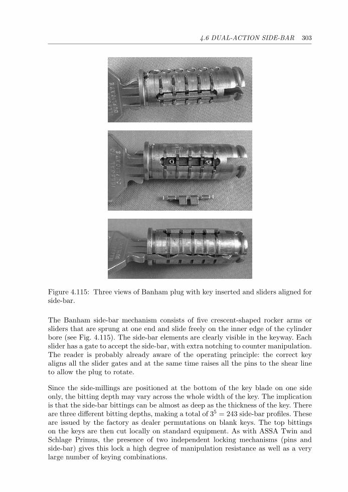
4.6 DUAL-ACTION SIDE-BAR 303
Figure 4.115: Three views of Banham plug with key inserted and sliders aligned forside-bar.
The Banham side-bar mechanism consists of five crescent-shaped rocker arms orsliders that are sprung at one end and slide freely on the inner edge of the cylinderbore (see Fig. 4.115). The side-bar elements are clearly visible in the keyway. Eachslider has a gate to accept the side-bar, with extra notching to counter manipulation.The reader is probably already aware of the operating principle: the correct keyaligns all the slider gates and at the same time raises all the pins to the shear lineto allow the plug to rotate.
Since the side-millings are positioned at the bottom of the key blade on one sideonly, the bitting depth may vary across the whole width of the key. The implicationis that the side-bar bittings can be almost as deep as the thickness of the key. Thereare three different bitting depths, making a total of 35 = 243 side-bar profiles. Theseare issued by the factory as dealer permutations on blank keys. The top bittingson the keys are then cut locally on standard equipment. As with ASSA Twin andSchlage Primus, the presence of two independent locking mechanisms (pins andside-bar) gives this lock a high degree of manipulation resistance as well as a verylarge number of keying combinations.
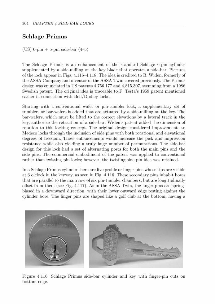
304 CHAPTER 4 SIDE-BAR LOCKS
Schlage Primus
(US) 6-pin + 5-pin side-bar (4–5)
The Schlage Primus is an enhancement of the standard Schlage 6-pin cylindersupplemented by a side-milling on the key blade that operates a side-bar. Picturesof the lock appear in Figs. 4.116–4.118. The idea is credited to B. Widen, formerly ofthe ASSA Company and inventor of the ASSA Twin covered previously. The Primusdesign was enunciated in US patents 4,756,177 and 4,815,307, stemming from a 1986Swedish patent. The original idea is traceable to F. Testa’s 1959 patent mentionedearlier in connection with Bell/Dudley locks.
Starting with a conventional wafer or pin-tumbler lock, a supplementary set oftumblers or bar-wafers is added that are actuated by a side-milling on the key. Thebar-wafers, which must be lifted to the correct elevations by a lateral track in thekey, authorize the retraction of a side-bar. Widen’s patent added the dimension ofrotation to this locking concept. The original design considered improvements toMedeco locks through the inclusion of side pins with both rotational and elevationaldegrees of freedom. These enhancements would increase the pick and impressionresistance while also yielding a truly huge number of permutations. The side-bardesign for this lock had a set of alternating posts for both the main pins and theside pins. The commercial embodiment of the patent was applied to conventionalrather than twisting pin locks; however, the twisting side pin idea was retained.
In a Schlage Primus cylinder there are five profile or finger pins whose tips are visibleat 6 o’clock in the keyway, as seen in Fig. 4.116. These secondary pins inhabit boresthat are parallel to the main row of six pin-tumbler chambers, but are longitudinallyoffset from them (see Fig. 4.117). As in the ASSA Twin, the finger pins are spring-biased in a downward direction, with their lower outward edge resting against thecylinder bore. The finger pins are shaped like a golf club at the bottom, having a
Figure 4.116: Schlage Primus side-bar cylinder and key with finger-pin cuts onbottom edge.
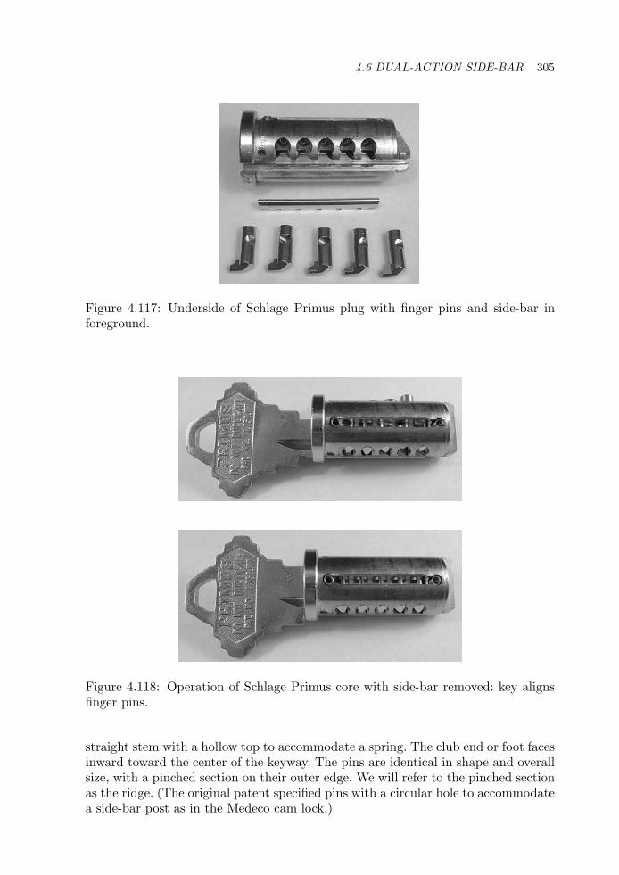
4.6 DUAL-ACTION SIDE-BAR 305
Figure 4.117: Underside of Schlage Primus plug with finger pins and side-bar inforeground.
Figure 4.118: Operation of Schlage Primus core with side-bar removed: key alignsfinger pins.
straight stem with a hollow top to accommodate a spring. The club end or foot facesinward toward the center of the keyway. The pins are identical in shape and overallsize, with a pinched section on their outer edge. We will refer to the pinched sectionas the ridge. (The original patent specified pins with a circular hole to accommodatea side-bar post as in the Medeco cam lock.)
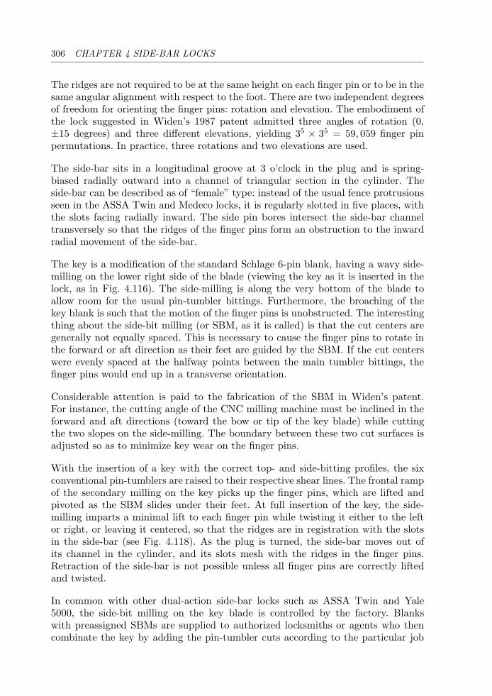
306 CHAPTER 4 SIDE-BAR LOCKS
The ridges are not required to be at the same height on each finger pin or to be in thesame angular alignment with respect to the foot. There are two independent degreesof freedom for orienting the finger pins: rotation and elevation. The embodiment ofthe lock suggested in Widen’s 1987 patent admitted three angles of rotation (0,±15 degrees) and three different elevations, yielding 35 × 35 = 59, 059 finger pinpermutations. In practice, three rotations and two elevations are used.
The side-bar sits in a longitudinal groove at 3 o’clock in the plug and is spring-biased radially outward into a channel of triangular section in the cylinder. Theside-bar can be described as of “female” type: instead of the usual fence protrusionsseen in the ASSA Twin and Medeco locks, it is regularly slotted in five places, withthe slots facing radially inward. The side pin bores intersect the side-bar channeltransversely so that the ridges of the finger pins form an obstruction to the inwardradial movement of the side-bar.
The key is a modification of the standard Schlage 6-pin blank, having a wavy side-milling on the lower right side of the blade (viewing the key as it is inserted in thelock, as in Fig. 4.116). The side-milling is along the very bottom of the blade toallow room for the usual pin-tumbler bittings. Furthermore, the broaching of thekey blank is such that the motion of the finger pins is unobstructed. The interestingthing about the side-bit milling (or SBM, as it is called) is that the cut centers aregenerally not equally spaced. This is necessary to cause the finger pins to rotate inthe forward or aft direction as their feet are guided by the SBM. If the cut centerswere evenly spaced at the halfway points between the main tumbler bittings, thefinger pins would end up in a transverse orientation.
Considerable attention is paid to the fabrication of the SBM in Widen’s patent.For instance, the cutting angle of the CNC milling machine must be inclined in theforward and aft directions (toward the bow or tip of the key blade) while cuttingthe two slopes on the side-milling. The boundary between these two cut surfaces isadjusted so as to minimize key wear on the finger pins.
With the insertion of a key with the correct top- and side-bitting profiles, the sixconventional pin-tumblers are raised to their respective shear lines. The frontal rampof the secondary milling on the key picks up the finger pins, which are lifted andpivoted as the SBM slides under their feet. At full insertion of the key, the side-milling imparts a minimal lift to each finger pin while twisting it either to the leftor right, or leaving it centered, so that the ridges are in registration with the slotsin the side-bar (see Fig. 4.118). As the plug is turned, the side-bar moves out ofits channel in the cylinder, and its slots mesh with the ridges in the finger pins.Retraction of the side-bar is not possible unless all finger pins are correctly liftedand twisted.
In common with other dual-action side-bar locks such as ASSA Twin and Yale5000, the side-bit milling on the key blade is controlled by the factory. Blankswith preassigned SBMs are supplied to authorized locksmiths or agents who thencombinate the key by adding the pin-tumbler cuts according to the particular job
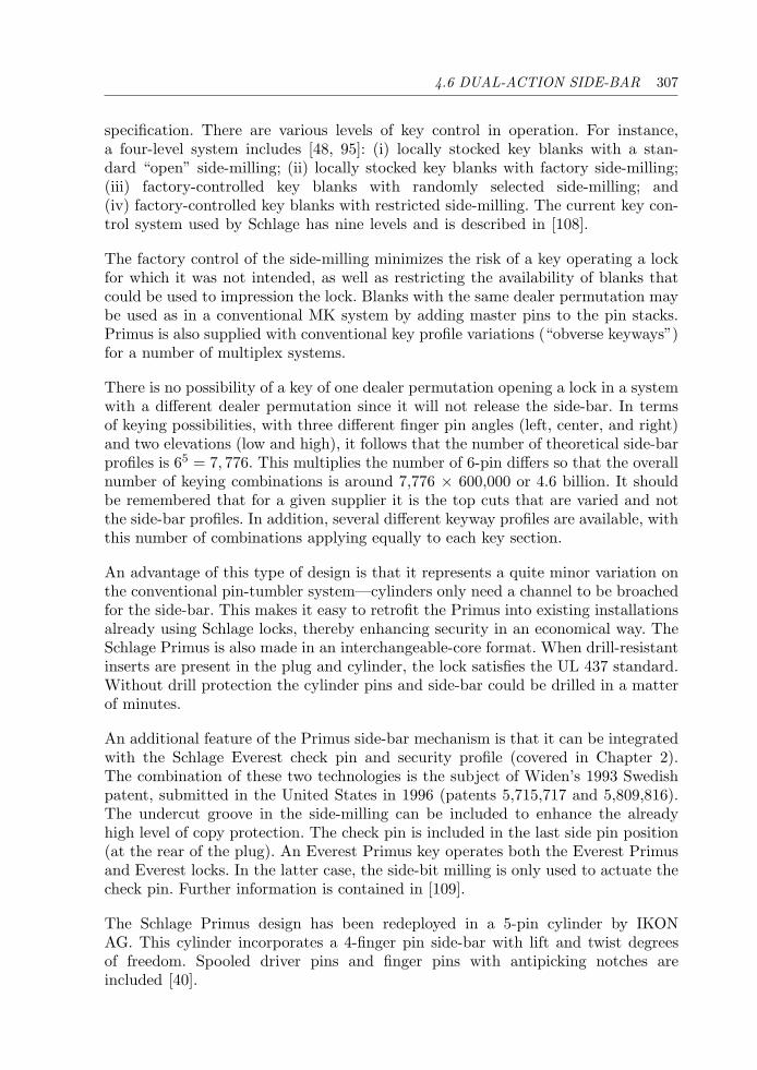
4.6 DUAL-ACTION SIDE-BAR 307
specification. There are various levels of key control in operation. For instance,a four-level system includes [48, 95]: (i) locally stocked key blanks with a stan-dard “open” side-milling; (ii) locally stocked key blanks with factory side-milling;(iii) factory-controlled key blanks with randomly selected side-milling; and(iv) factory-controlled key blanks with restricted side-milling. The current key con-trol system used by Schlage has nine levels and is described in [108].
The factory control of the side-milling minimizes the risk of a key operating a lockfor which it was not intended, as well as restricting the availability of blanks thatcould be used to impression the lock. Blanks with the same dealer permutation maybe used as in a conventional MK system by adding master pins to the pin stacks.Primus is also supplied with conventional key profile variations (“obverse keyways”)for a number of multiplex systems.
There is no possibility of a key of one dealer permutation opening a lock in a systemwith a different dealer permutation since it will not release the side-bar. In termsof keying possibilities, with three different finger pin angles (left, center, and right)and two elevations (low and high), it follows that the number of theoretical side-barprofiles is 65 = 7, 776. This multiplies the number of 6-pin differs so that the overallnumber of keying combinations is around 7,776 × 600,000 or 4.6 billion. It shouldbe remembered that for a given supplier it is the top cuts that are varied and notthe side-bar profiles. In addition, several different keyway profiles are available, withthis number of combinations applying equally to each key section.
An advantage of this type of design is that it represents a quite minor variation onthe conventional pin-tumbler system—cylinders only need a channel to be broachedfor the side-bar. This makes it easy to retrofit the Primus into existing installationsalready using Schlage locks, thereby enhancing security in an economical way. TheSchlage Primus is also made in an interchangeable-core format. When drill-resistantinserts are present in the plug and cylinder, the lock satisfies the UL 437 standard.Without drill protection the cylinder pins and side-bar could be drilled in a matterof minutes.
An additional feature of the Primus side-bar mechanism is that it can be integratedwith the Schlage Everest check pin and security profile (covered in Chapter 2).The combination of these two technologies is the subject of Widen’s 1993 Swedishpatent, submitted in the United States in 1996 (patents 5,715,717 and 5,809,816).The undercut groove in the side-milling can be included to enhance the alreadyhigh level of copy protection. The check pin is included in the last side pin position(at the rear of the plug). An Everest Primus key operates both the Everest Primusand Everest locks. In the latter case, the side-bit milling is only used to actuate thecheck pin. Further information is contained in [109].
The Schlage Primus design has been redeployed in a 5-pin cylinder by IKONAG. This cylinder incorporates a 4-finger pin side-bar with lift and twist degreesof freedom. Spooled driver pins and finger pins with antipicking notches areincluded [40].
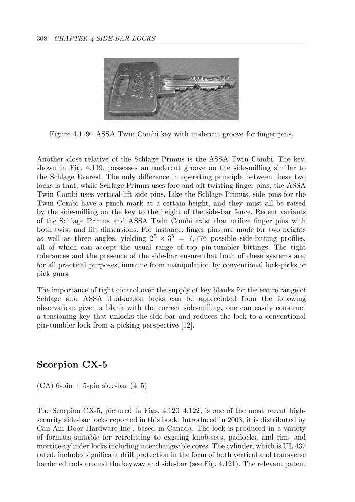
308 CHAPTER 4 SIDE-BAR LOCKS
Figure 4.119: ASSA Twin Combi key with undercut groove for finger pins.
Another close relative of the Schlage Primus is the ASSA Twin Combi. The key,shown in Fig. 4.119, possesses an undercut groove on the side-milling similar tothe Schlage Everest. The only difference in operating principle between these twolocks is that, while Schlage Primus uses fore and aft twisting finger pins, the ASSATwin Combi uses vertical-lift side pins. Like the Schlage Primus, side pins for theTwin Combi have a pinch mark at a certain height, and they must all be raisedby the side-milling on the key to the height of the side-bar fence. Recent variantsof the Schlage Primus and ASSA Twin Combi exist that utilize finger pins withboth twist and lift dimensions. For instance, finger pins are made for two heightsas well as three angles, yielding 25 × 35 = 7, 776 possible side-bitting profiles,all of which can accept the usual range of top pin-tumbler bittings. The tighttolerances and the presence of the side-bar ensure that both of these systems are,for all practical purposes, immune from manipulation by conventional lock-picks orpick guns.
The importance of tight control over the supply of key blanks for the entire range ofSchlage and ASSA dual-action locks can be appreciated from the followingobservation: given a blank with the correct side-milling, one can easily constructa tensioning key that unlocks the side-bar and reduces the lock to a conventionalpin-tumbler lock from a picking perspective [12].
Scorpion CX-5
(CA) 6-pin + 5-pin side-bar (4–5)
The Scorpion CX-5, pictured in Figs. 4.120–4.122, is one of the most recent high-security side-bar locks reported in this book. Introduced in 2003, it is distributed byCan-Am Door Hardware Inc., based in Canada. The lock is produced in a varietyof formats suitable for retrofitting to existing knob-sets, padlocks, and rim- andmortice-cylinder locks including interchangeable cores. The cylinder, which is UL 437rated, includes significant drill protection in the form of both vertical and transversehardened rods around the keyway and side-bar (see Fig. 4.121). The relevant patent
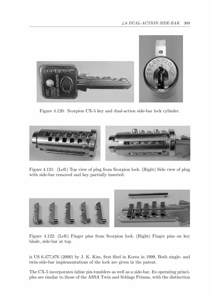
4.6 DUAL-ACTION SIDE-BAR 309
Figure 4.120: Scorpion CX-5 key and dual-action side-bar lock cylinder.
Figure 4.121: (Left) Top view of plug from Scorpion lock. (Right) Side view of plugwith side-bar removed and key partially inserted.
Figure 4.122: (Left) Finger pins from Scorpion lock. (Right) Finger pins on keyblade, side-bar at top.
is US 6,477,876 (2000) by J. K. Kim, first filed in Korea in 1999. Both single- andtwin-side-bar implementations of the lock are given in the patent.
The CX-5 incorporates inline pin-tumblers as well as a side-bar. Its operating princi-ples are similar to those of the ASSA Twin and Schlage Primus, with the distinction
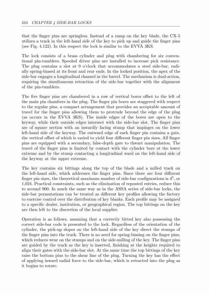
310 CHAPTER 4 SIDE-BAR LOCKS
that the finger pins are springless. Instead of a ramp on the key blade, the CX-5utilizes a track in the left-hand side of the key to pick up and guide the finger pins(see Fig. 4.122). In this respect the lock is similar to the EVVA 3KS.
The lock consists of a brass cylinder and plug with chambering for six conven-tional pin-tumblers. Spooled driver pins are installed to increase pick resistance.The plug contains a slot at 9 o’clock that accommodates a steel side-bar, radi-ally spring-biased at its front and rear ends. In the locked position, the apex of theside-bar engages a longitudinal channel in the barrel. The mechanism is dual-action,requiring the simultaneous retraction of the side-bar together with the alignmentof the pin-tumblers.
The five finger pins are chambered in a row of vertical bores offset to the left ofthe main pin chambers in the plug. The finger pin bores are staggered with respectto the regular pins, a compact arrangement that provides an acceptable amount oftravel for the finger pins allowing them to protrude beyond the edge of the plug(as occurs in the EVVA 3KS). The inside edges of the bores are open to thekeyway, while their outside edges intersect with the side-bar slot. The finger pinsare of square section with an inwardly facing stump that impinges on the lowerleft-hand side of the keyway. The outward edge of each finger pin contains a gate,the vertical offset of which is varied to yield four different finger pin sizes. All fingerpins are equipped with a secondary, false-depth gate to thwart manipulation. Thetravel of the finger pins is limited by contact with the cylinder bore at the lowerextreme and by the stump contacting a longitudinal ward on the left-hand side ofthe keyway at the upper extreme.
The key contains six bittings along the top of the blade and a milled track onthe left-hand side, which addresses the finger pins. Since there are four differentfinger pin sizes, the theoretical maximum number of side-bar configurations is 45, or1,024. Practical constraints, such as the elimination of repeated entries, reduce thisto around 900. In much the same way as in the ASSA series of side-bar locks, theside-bar permutations can be treated as different key profiles allowing the factoryto exercise control over the distribution of key blanks. Each profile may be assignedto a specific dealer, institution, or geographical region. The top bittings on the keyare then left to the discretion of the local supplier.
Operation is as follows, assuming that a correctly bitted key also possessing thecorrect side-bar code is presented to the lock. Regardless of the orientation of thecylinder, the pick-up slopes on the left-hand side of the key direct the stumps ofthe finger pins into the track. There is no need for spring-biasing on the finger pins,which reduces wear on the stumps and on the side-milling of the key. The finger pinsare guided by the track as the key is inserted, finishing at the heights required toalign their gates with the side-bar slot. At the same time the top bittings of the keyraise the bottom pins to the shear line of the plug. Turning the key has the effectof applying inward radial force to the side-bar, which is retracted into the plug asit begins to rotate.
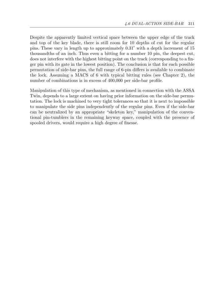
4.6 DUAL-ACTION SIDE-BAR 311
Despite the apparently limited vertical space between the upper edge of the trackand top of the key blade, there is still room for 10 depths of cut for the regularpins. These vary in length up to approximately 0.31 with a depth increment of 15thousandths of an inch. Thus even a bitting for a number 10 pin, the deepest cut,does not interfere with the highest bitting point on the track (corresponding to a fin-ger pin with its gate in the lowest position). The conclusion is that for each possiblepermutation of side-bar pins, the full range of 6-pin differs is available to combinatethe lock. Assuming a MACS of 6 with typical bitting rules (see Chapter 2), thenumber of combinations is in excess of 400,000 per side-bar profile.
Manipulation of this type of mechanism, as mentioned in connection with the ASSATwin, depends to a large extent on having prior information on the side-bar permu-tation. The lock is machined to very tight tolerances so that it is next to impossibleto manipulate the side pins independently of the regular pins. Even if the side-barcan be neutralized by an appropriate “skeleton key,” manipulation of the conven-tional pin-tumblers in the remaining keyway space, coupled with the presence ofspooled drivers, would require a high degree of finesse.

This page intentionally left blank
Chapter 5
Lever Locks
The successes of lockpickers have always been a constant impetus to animproved construction, since these served to expose the weaknesses andtechnical deficiencies of supposed security locks. V. J. M. Eras, c. 1957
5.1 Introduction
The subject of lever locks has received much attention, in large measure due to theiruse in safes and vaults. While the lever lock has been superseded by keyless electronicand combination locks in true high-security applications, it is still widely used insmaller safes. Lever locks of varying levels of quality are equally used as door locksin many countries. Due to the strength of materials employed in their construction,lever locks are fundamentally more secure and robust than pin-tumbler locks, butowing to their size, cost, and lack of modularity they have lost market share.
Since their invention in late 17th-century Europe, thousands of modifications andpatents have appeared. It is not possible to do justice to these in the space of asingle book chapter. Nonetheless, in what follows we will try to give the reader arepresentative sample covering a wide range of lever locks, most of which are stillin use today. The operation of a modern 6-lever lock, produced by Ross SecurityLocks,1 is explained pictorially in the series of Figs. 5.1–5.5. This particular type oflever lock is referred to as a single-entry rim lock, meaning that it is mounted on theback of the door rather than mortised into it, and has a keyhole in the front faceof the lock only. Double-entry or double-sided locks, which are often of the morticevariety, have keyholes in both the front and back faces and may be operated fromeither side of the door.
1The Ross 100 has been superseded by the 102 model.
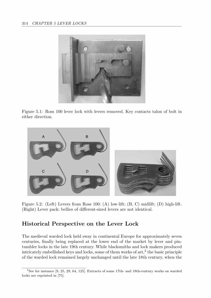
314 CHAPTER 5 LEVER LOCKS
Figure 5.1: Ross 100 lever lock with levers removed. Key contacts talon of bolt ineither direction.
A
C D
B
Figure 5.2: (Left) Levers from Ross 100: (A) low-lift; (B, C) midlift; (D) high-lift.(Right) Lever pack: bellies of different-sized levers are not identical.
Historical Perspective on the Lever Lock
The medieval warded lock held sway in continental Europe for approximately sevencenturies, finally being replaced at the lower end of the market by lever and pin-tumbler locks in the late 19th century. While blacksmiths and lock makers producedintricately embellished keys and locks, some of them works of art,2 the basic principleof the warded lock remained largely unchanged until the late 18th century, when the
2See for instance [9, 25, 29, 64, 125]. Extracts of some 17th- and 18th-century works on wardedlocks are reprinted in [75].
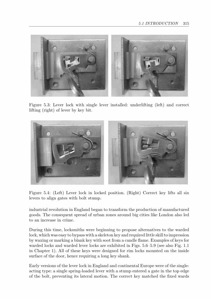
5.1 INTRODUCTION 315
Figure 5.3: Lever lock with single lever installed: underlifting (left) and correctlifting (right) of lever by key bit.
Figure 5.4: (Left) Lever lock in locked position. (Right) Correct key lifts all sixlevers to align gates with bolt stump.
industrial revolution in England began to transform the production of manufacturedgoods. The consequent spread of urban zones around big cities like London also ledto an increase in crime.
During this time, locksmiths were beginning to propose alternatives to the wardedlock, which was easy to bypass with a skeleton key and required little skill to impressionby waxing or marking a blank key with soot from a candle flame. Examples of keys forwarded locks and warded lever locks are exhibited in Figs. 5.6–5.9 (see also Fig. 1.1in Chapter 1). All of these keys were designed for rim locks mounted on the insidesurface of the door, hence requiring a long key shank.
Early versions of the lever lock in England and continental Europe were of the single-acting type: a single spring-loaded lever with a stump entered a gate in the top edgeof the bolt, preventing its lateral motion. The correct key matched the fixed wards
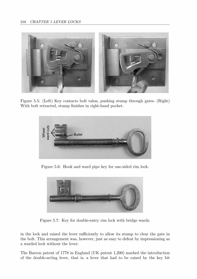
316 CHAPTER 5 LEVER LOCKS
Figure 5.5: (Left) Key contacts bolt talon, pushing stump through gates. (Right)With bolt retracted, stump finishes in right-hand pocket.
BulletWhe
elw
ard
cuts
Figure 5.6: Hook and ward pipe key for one-sided rim lock.
Figure 5.7: Key for double-entry rim lock with bridge wards.
in the lock and raised the lever sufficiently to allow its stump to clear the gate inthe bolt. This arrangement was, however, just as easy to defeat by impressioning asa warded lock without the lever.
The Barron patent of 1778 in England (UK patent 1,200) marked the introductionof the double-acting lever, that is, a lever that had to be raised by the key bit

5.1 INTRODUCTION 317
Figure 5.8: A skeleton key bypasses fixed obstructions in a warded lock. Keys shownabove would work the same locks as the keys in Figs. 5.6 and 5.7.
Levercuts
Boltstep
Sas
h w
ard
cuts
Figure 5.9: Key for 3-lever double-entry rim lock with sash wards.
adequately to clear a lower gate in the bolt, but not overraised or it would be blockedby the upper part of the gate. The embodiment shown in Fig. 5.10 contained twosuch levers acting in parallel with a 3-pocketed gate in the bolt for double-throwoperation. Barron locks with as many as four levers were produced.
Different-sized bellies on the levers required different cuts on the bit of the keyto ensure that both lever stumps could pass freely through the gates. Such a lockcould not be impressioned “in one go” since the two cuts, being of unknown depthsinitially, had to be incrementally approached lest they be filed too deeply for the keyto work. However, as expressed by John Chubb in his 1850 paper to the Institutionof Civil Engineers in London:
On account of only two tumblers being used in these locks, it is obviousthat no great changes or permutations, can be made in the combinations,so as to prevent the evil of keys passing a lock for which they were notmade.
The evolution of the English lever lock can be traced through a series of patents overthe 40 years following Robert Barron’s invention to the 6-lever “detector” lock ofJeremiah Chubb, which was patented in February 1818 (UK 4,219). Whereas earlierlever locks had gates in the bolt and stumps on the levers, the Chubb lock had the
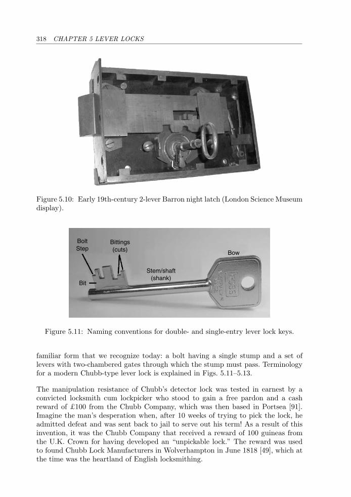
318 CHAPTER 5 LEVER LOCKS
Figure 5.10: Early 19th-century 2-lever Barron night latch (London Science Museumdisplay).
Bittings(cuts)
BoltStep
Bit
Stem/shaft(shank)
Bow
Figure 5.11: Naming conventions for double- and single-entry lever lock keys.
familiar form that we recognize today: a bolt having a single stump and a set oflevers with two-chambered gates through which the stump must pass. Terminologyfor a modern Chubb-type lever lock is explained in Figs. 5.11–5.13.
The manipulation resistance of Chubb’s detector lock was tested in earnest by aconvicted locksmith cum lockpicker who stood to gain a free pardon and a cashreward of £100 from the Chubb Company, which was then based in Portsea [91].Imagine the man’s desperation when, after 10 weeks of trying to pick the lock, headmitted defeat and was sent back to jail to serve out his term! As a result of thisinvention, it was the Chubb Company that received a reward of 100 guineas fromthe U.K. Crown for having developed an “unpickable lock.” The reward was usedto found Chubb Lock Manufacturers in Wolverhampton in June 1818 [49], which atthe time was the heartland of English locksmithing.
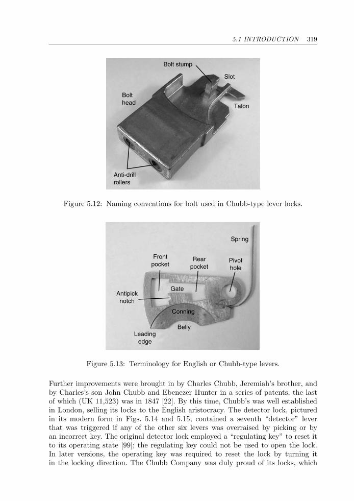
5.1 INTRODUCTION 319
Bolt stump
Slot
Talon
Bolthead
Anti-drillrollers
Figure 5.12: Naming conventions for bolt used in Chubb-type lever locks.
Spring
Pivothole
Rearpocket
Frontpocket
Antipicknotch
Leadingedge
Belly
Gate
Conning
Figure 5.13: Terminology for English or Chubb-type levers.
Further improvements were brought in by Charles Chubb, Jeremiah’s brother, andby Charles’s son John Chubb and Ebenezer Hunter in a series of patents, the lastof which (UK 11,523) was in 1847 [22]. By this time, Chubb’s was well establishedin London, selling its locks to the English aristocracy. The detector lock, picturedin its modern form in Figs. 5.14 and 5.15, contained a seventh “detector” leverthat was triggered if any of the other six levers was overraised by picking or byan incorrect key. The original detector lock employed a “regulating key” to reset itto its operating state [99]; the regulating key could not be used to open the lock.In later versions, the operating key was required to reset the lock by turning itin the locking direction. The Chubb Company was duly proud of its locks, which
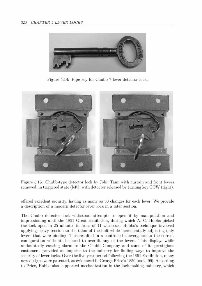
320 CHAPTER 5 LEVER LOCKS
Figure 5.14: Pipe key for Chubb 7-lever detector lock.
Figure 5.15: Chubb-type detector lock by John Tann with curtain and front leversremoved: in triggered state (left); with detector released by turning key CCW (right).
offered excellent security, having as many as 30 changes for each lever. We providea description of a modern detector lever lock in a later section.
The Chubb detector lock withstood attempts to open it by manipulation andimpressioning until the 1851 Great Exhibition, during which A. C. Hobbs pickedthe lock open in 25 minutes in front of 11 witnesses. Hobbs’s technique involvedapplying heavy tension to the talon of the bolt while incrementally adjusting onlylevers that were binding. This resulted in a controlled convergence to the correctconfiguration without the need to overlift any of the levers. This display, whileundoubtedly causing alarm to the Chubb Company and some of its prestigiouscustomers, provided an impetus to the industry for finding ways to improve thesecurity of lever locks. Over the five-year period following the 1851 Exhibition, manynew designs were patented, as evidenced in George Price’s 1856 book [99]. Accordingto Price, Hobbs also supported mechanization in the lock-making industry, which
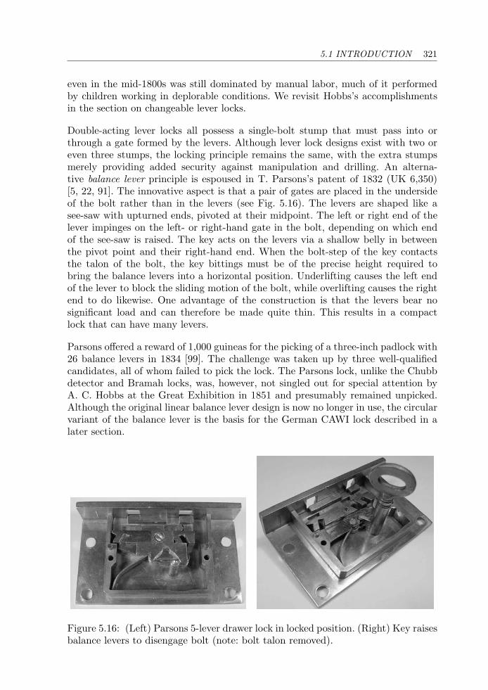
5.1 INTRODUCTION 321
even in the mid-1800s was still dominated by manual labor, much of it performedby children working in deplorable conditions. We revisit Hobbs’s accomplishmentsin the section on changeable lever locks.
Double-acting lever locks all possess a single-bolt stump that must pass into orthrough a gate formed by the levers. Although lever lock designs exist with two oreven three stumps, the locking principle remains the same, with the extra stumpsmerely providing added security against manipulation and drilling. An alterna-tive balance lever principle is espoused in T. Parsons’s patent of 1832 (UK 6,350)[5, 22, 91]. The innovative aspect is that a pair of gates are placed in the undersideof the bolt rather than in the levers (see Fig. 5.16). The levers are shaped like asee-saw with upturned ends, pivoted at their midpoint. The left or right end of thelever impinges on the left- or right-hand gate in the bolt, depending on which endof the see-saw is raised. The key acts on the levers via a shallow belly in betweenthe pivot point and their right-hand end. When the bolt-step of the key contactsthe talon of the bolt, the key bittings must be of the precise height required tobring the balance levers into a horizontal position. Underlifting causes the left endof the lever to block the sliding motion of the bolt, while overlifting causes the rightend to do likewise. One advantage of the construction is that the levers bear nosignificant load and can therefore be made quite thin. This results in a compactlock that can have many levers.
Parsons offered a reward of 1,000 guineas for the picking of a three-inch padlock with26 balance levers in 1834 [99]. The challenge was taken up by three well-qualifiedcandidates, all of whom failed to pick the lock. The Parsons lock, unlike the Chubbdetector and Bramah locks, was, however, not singled out for special attention byA. C. Hobbs at the Great Exhibition in 1851 and presumably remained unpicked.Although the original linear balance lever design is now no longer in use, the circularvariant of the balance lever is the basis for the German CAWI lock described in alater section.
Figure 5.16: (Left) Parsons 5-lever drawer lock in locked position. (Right) Key raisesbalance levers to disengage bolt (note: bolt talon removed).
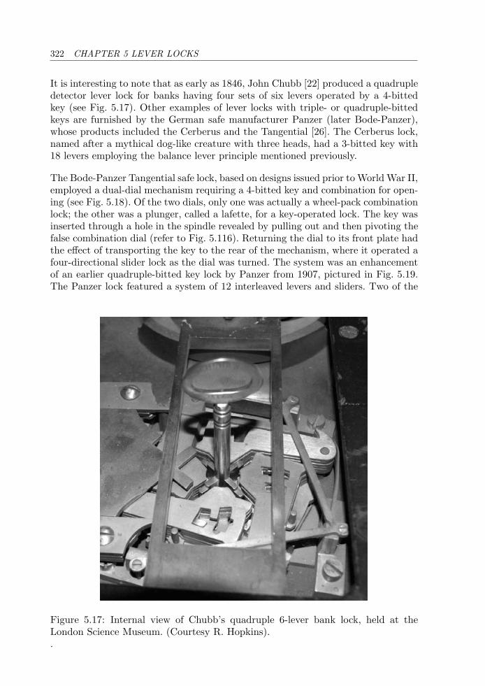
322 CHAPTER 5 LEVER LOCKS
It is interesting to note that as early as 1846, John Chubb [22] produced a quadrupledetector lever lock for banks having four sets of six levers operated by a 4-bittedkey (see Fig. 5.17). Other examples of lever locks with triple- or quadruple-bittedkeys are furnished by the German safe manufacturer Panzer (later Bode-Panzer),whose products included the Cerberus and the Tangential [26]. The Cerberus lock,named after a mythical dog-like creature with three heads, had a 3-bitted key with18 levers employing the balance lever principle mentioned previously.
The Bode-Panzer Tangential safe lock, based on designs issued prior to World War II,employed a dual-dial mechanism requiring a 4-bitted key and combination for open-ing (see Fig. 5.18). Of the two dials, only one was actually a wheel-pack combinationlock; the other was a plunger, called a lafette, for a key-operated lock. The key wasinserted through a hole in the spindle revealed by pulling out and then pivoting thefalse combination dial (refer to Fig. 5.116). Returning the dial to its front plate hadthe effect of transporting the key to the rear of the mechanism, where it operated afour-directional slider lock as the dial was turned. The system was an enhancementof an earlier quadruple-bitted key lock by Panzer from 1907, pictured in Fig. 5.19.The Panzer lock featured a system of 12 interleaved levers and sliders. Two of the
Figure 5.17: Internal view of Chubb’s quadruple 6-lever bank lock, held at theLondon Science Museum. (Courtesy R. Hopkins)..
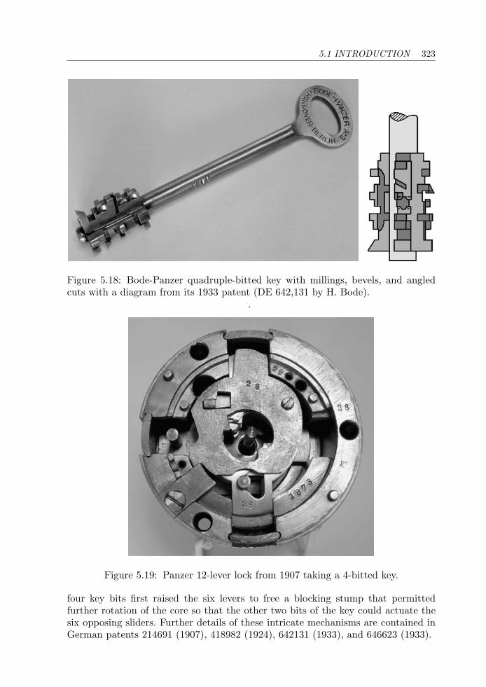
5.1 INTRODUCTION 323
Figure 5.18: Bode-Panzer quadruple-bitted key with millings, bevels, and angledcuts with a diagram from its 1933 patent (DE 642,131 by H. Bode).
.
Figure 5.19: Panzer 12-lever lock from 1907 taking a 4-bitted key.
four key bits first raised the six levers to free a blocking stump that permittedfurther rotation of the core so that the other two bits of the key could actuate thesix opposing sliders. Further details of these intricate mechanisms are contained inGerman patents 214691 (1907), 418982 (1924), 642131 (1933), and 646623 (1933).

324 CHAPTER 5 LEVER LOCKS
Double-bitted Key Lever Locks
Until the 1870s, lock makers in the United Kingdom such as Chubb, Milner, andChatwood concentrated on lever locks with single-bitted keys [96]. Meanwhile inEurope the focus had shifted to lever locks with double-bitted keys. Depending onthe mechanism employed, double-bitted keys can offer a higher level of security andare more difficult to copy than their single-bitted counterparts. The double-bittedlever lock has a number of embodiments, including the Italian and German leverdesigns with constant-width double-bitted keys.
The German lever design is typified by the Novum lock depicted in Figs. 5.20 and5.21. It was originally produced by the Theodor Kromer Company in the late 1800s(see, for example, 1909 German patent DE 214,693). A similar design principle wasespoused in the Max Zahn “Federlos” or springless lock. The obvious simplicity oflocks such as these belie their high degree of effectiveness and reliability. Inside thelock case there is little more than a bolt with integral stump and a stack of leverswith identical cut-outs.
Compared with conventional Chubb levers, the gate in a German lever lock is shiftedto the edge of the lever opposite its hinge point. The lever cut-out has two opposingcircular arcs and clearance for the keyway (refer to Fig. 5.45). A consequence of thisconstruction is that a double-bitted key is required to operate the lock. The offsetof the constant-width bittings varies along the key stem according to the positionsof the gates in the levers. Since the bittings of the key contact the upper and lowerarches in each lever, the levers do not actually need to be spring-biased. However,a spring assembly may still be used to return the levers to the locked position onwithdrawal of the key. The Mauer Variator lock presented in a later section of thischapter features this type of cut-out lever construction.
Figure 5.20: Kromer Novum double-bitted key with constant-width bittings.
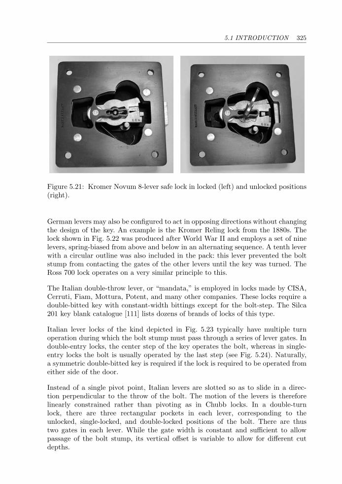
5.1 INTRODUCTION 325
Figure 5.21: Kromer Novum 8-lever safe lock in locked (left) and unlocked positions(right).
German levers may also be configured to act in opposing directions without changingthe design of the key. An example is the Kromer Reling lock from the 1880s. Thelock shown in Fig. 5.22 was produced after World War II and employs a set of ninelevers, spring-biased from above and below in an alternating sequence. A tenth leverwith a circular outline was also included in the pack: this lever prevented the boltstump from contacting the gates of the other levers until the key was turned. TheRoss 700 lock operates on a very similar principle to this.
The Italian double-throw lever, or “mandata,” is employed in locks made by CISA,Cerruti, Fiam, Mottura, Potent, and many other companies. These locks require adouble-bitted key with constant-width bittings except for the bolt-step. The Silca201 key blank catalogue [111] lists dozens of brands of locks of this type.
Italian lever locks of the kind depicted in Fig. 5.23 typically have multiple turnoperation during which the bolt stump must pass through a series of lever gates. Indouble-entry locks, the center step of the key operates the bolt, whereas in single-entry locks the bolt is usually operated by the last step (see Fig. 5.24). Naturally,a symmetric double-bitted key is required if the lock is required to be operated fromeither side of the door.
Instead of a single pivot point, Italian levers are slotted so as to slide in a direc-tion perpendicular to the throw of the bolt. The motion of the levers is thereforelinearly constrained rather than pivoting as in Chubb locks. In a double-turnlock, there are three rectangular pockets in each lever, corresponding to theunlocked, single-locked, and double-locked positions of the bolt. There are thustwo gates in each lever. While the gate width is constant and sufficient to allowpassage of the bolt stump, its vertical offset is variable to allow for different cutdepths.
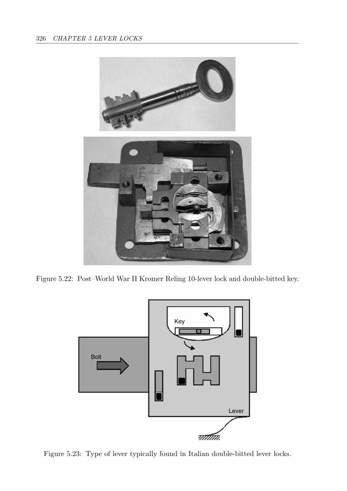
326 CHAPTER 5 LEVER LOCKS
Figure 5.22: Post–World War II Kromer Reling 10-lever lock and double-bitted key.
Key
Bolt
Lever
Figure 5.23: Type of lever typically found in Italian double-bitted lever locks.
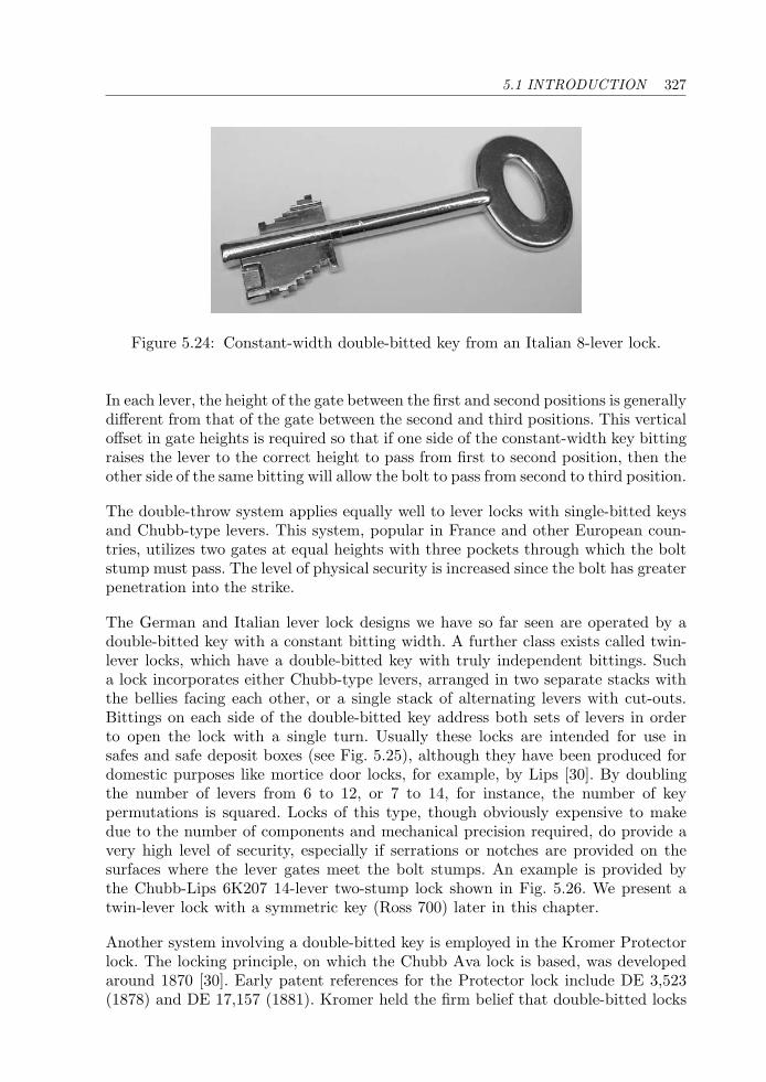
5.1 INTRODUCTION 327
Figure 5.24: Constant-width double-bitted key from an Italian 8-lever lock.
In each lever, the height of the gate between the first and second positions is generallydifferent from that of the gate between the second and third positions. This verticaloffset in gate heights is required so that if one side of the constant-width key bittingraises the lever to the correct height to pass from first to second position, then theother side of the same bitting will allow the bolt to pass from second to third position.
The double-throw system applies equally well to lever locks with single-bitted keysand Chubb-type levers. This system, popular in France and other European coun-tries, utilizes two gates at equal heights with three pockets through which the boltstump must pass. The level of physical security is increased since the bolt has greaterpenetration into the strike.
The German and Italian lever lock designs we have so far seen are operated by adouble-bitted key with a constant bitting width. A further class exists called twin-lever locks, which have a double-bitted key with truly independent bittings. Sucha lock incorporates either Chubb-type levers, arranged in two separate stacks withthe bellies facing each other, or a single stack of alternating levers with cut-outs.Bittings on each side of the double-bitted key address both sets of levers in orderto open the lock with a single turn. Usually these locks are intended for use insafes and safe deposit boxes (see Fig. 5.25), although they have been produced fordomestic purposes like mortice door locks, for example, by Lips [30]. By doublingthe number of levers from 6 to 12, or 7 to 14, for instance, the number of keypermutations is squared. Locks of this type, though obviously expensive to makedue to the number of components and mechanical precision required, do provide avery high level of security, especially if serrations or notches are provided on thesurfaces where the lever gates meet the bolt stumps. An example is provided bythe Chubb-Lips 6K207 14-lever two-stump lock shown in Fig. 5.26. We present atwin-lever lock with a symmetric key (Ross 700) later in this chapter.
Another system involving a double-bitted key is employed in the Kromer Protectorlock. The locking principle, on which the Chubb Ava lock is based, was developedaround 1870 [30]. Early patent references for the Protector lock include DE 3,523(1878) and DE 17,157 (1881). Kromer held the firm belief that double-bitted locks
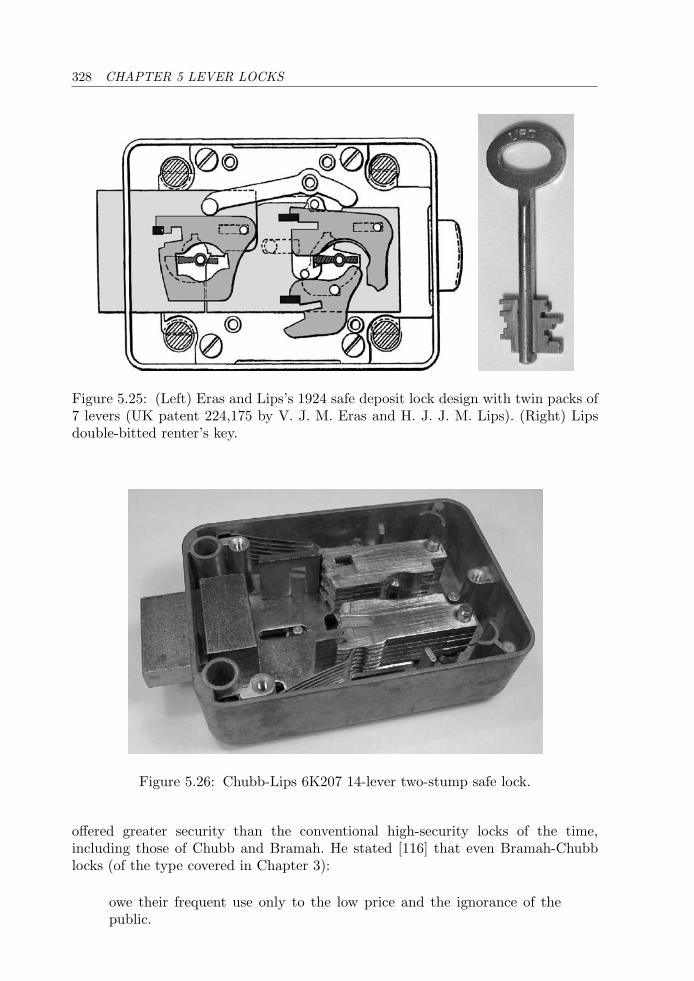
328 CHAPTER 5 LEVER LOCKS
Figure 5.25: (Left) Eras and Lips’s 1924 safe deposit lock design with twin packs of7 levers (UK patent 224,175 by V. J. M. Eras and H. J. J. M. Lips). (Right) Lipsdouble-bitted renter’s key.
Figure 5.26: Chubb-Lips 6K207 14-lever two-stump safe lock.
offered greater security than the conventional high-security locks of the time,including those of Chubb and Bramah. He stated [116] that even Bramah-Chubblocks (of the type covered in Chapter 3):
owe their frequent use only to the low price and the ignorance of thepublic.
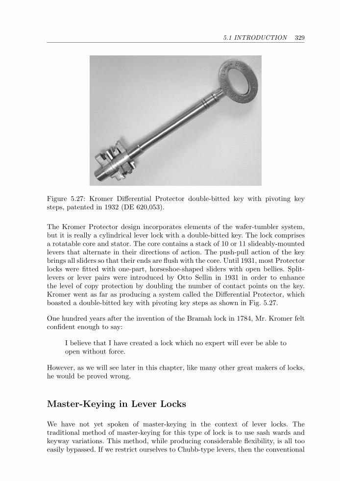
5.1 INTRODUCTION 329
Figure 5.27: Kromer Differential Protector double-bitted key with pivoting keysteps, patented in 1932 (DE 620,053).
The Kromer Protector design incorporates elements of the wafer-tumbler system,but it is really a cylindrical lever lock with a double-bitted key. The lock comprisesa rotatable core and stator. The core contains a stack of 10 or 11 slideably-mountedlevers that alternate in their directions of action. The push-pull action of the keybrings all sliders so that their ends are flush with the core. Until 1931, most Protectorlocks were fitted with one-part, horseshoe-shaped sliders with open bellies. Split-levers or lever pairs were introduced by Otto Sellin in 1931 in order to enhancethe level of copy protection by doubling the number of contact points on the key.Kromer went as far as producing a system called the Differential Protector, whichboasted a double-bitted key with pivoting key steps as shown in Fig. 5.27.
One hundred years after the invention of the Bramah lock in 1784, Mr. Kromer feltconfident enough to say:
I believe that I have created a lock which no expert will ever be able toopen without force.
However, as we will see later in this chapter, like many other great makers of locks,he would be proved wrong.
Master-Keying in Lever Locks
We have not yet spoken of master-keying in the context of lever locks. Thetraditional method of master-keying for this type of lock is to use sash wards andkeyway variations. This method, while producing considerable flexibility, is all tooeasily bypassed. If we restrict ourselves to Chubb-type levers, then the conventional
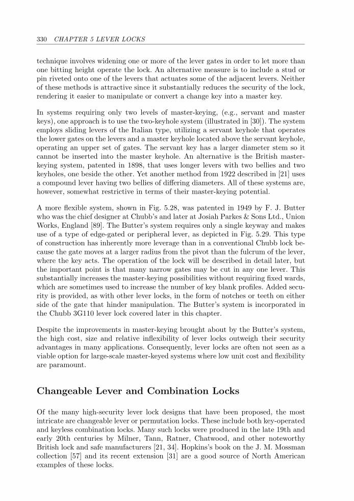
330 CHAPTER 5 LEVER LOCKS
technique involves widening one or more of the lever gates in order to let more thanone bitting height operate the lock. An alternative measure is to include a stud orpin riveted onto one of the levers that actuates some of the adjacent levers. Neitherof these methods is attractive since it substantially reduces the security of the lock,rendering it easier to manipulate or convert a change key into a master key.
In systems requiring only two levels of master-keying, (e.g., servant and masterkeys), one approach is to use the two-keyhole system (illustrated in [30]). The systememploys sliding levers of the Italian type, utilizing a servant keyhole that operatesthe lower gates on the levers and a master keyhole located above the servant keyhole,operating an upper set of gates. The servant key has a larger diameter stem so itcannot be inserted into the master keyhole. An alternative is the British master-keying system, patented in 1898, that uses longer levers with two bellies and twokeyholes, one beside the other. Yet another method from 1922 described in [21] usesa compound lever having two bellies of differing diameters. All of these systems are,however, somewhat restrictive in terms of their master-keying potential.
A more flexible system, shown in Fig. 5.28, was patented in 1949 by F. J. Butterwho was the chief designer at Chubb’s and later at Josiah Parkes & Sons Ltd., UnionWorks, England [89]. The Butter’s system requires only a single keyway and makesuse of a type of edge-gated or peripheral lever, as depicted in Fig. 5.29. This typeof construction has inherently more leverage than in a conventional Chubb lock be-cause the gate moves at a larger radius from the pivot than the fulcrum of the lever,where the key acts. The operation of the lock will be described in detail later, butthe important point is that many narrow gates may be cut in any one lever. Thissubstantially increases the master-keying possibilities without requiring fixed wards,which are sometimes used to increase the number of key blank profiles. Added secu-rity is provided, as with other lever locks, in the form of notches or teeth on eitherside of the gate that hinder manipulation. The Butter’s system is incorporated inthe Chubb 3G110 lever lock covered later in this chapter.
Despite the improvements in master-keying brought about by the Butter’s system,the high cost, size and relative inflexibility of lever locks outweigh their securityadvantages in many applications. Consequently, lever locks are often not seen as aviable option for large-scale master-keyed systems where low unit cost and flexibilityare paramount.
Changeable Lever and Combination Locks
Of the many high-security lever lock designs that have been proposed, the mostintricate are changeable lever or permutation locks. These include both key-operatedand keyless combination locks. Many such locks were produced in the late 19th andearly 20th centuries by Milner, Tann, Ratner, Chatwood, and other noteworthyBritish lock and safe manufacturers [21, 34]. Hopkins’s book on the J. M. Mossmancollection [57] and its recent extension [31] are a good source of North Americanexamples of these locks.
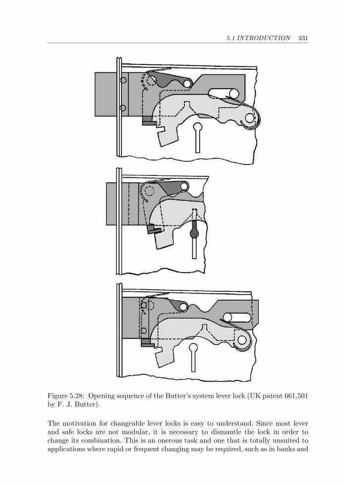
5.1 INTRODUCTION 331
Figure 5.28: Opening sequence of the Butter’s system lever lock (UK patent 661,501by F. J. Butter).
The motivation for changeable lever locks is easy to understand. Since most leverand safe locks are not modular, it is necessary to dismantle the lock in order tochange its combination. This is an onerous task and one that is totally unsuited toapplications where rapid or frequent changing may be required, such as in banks and
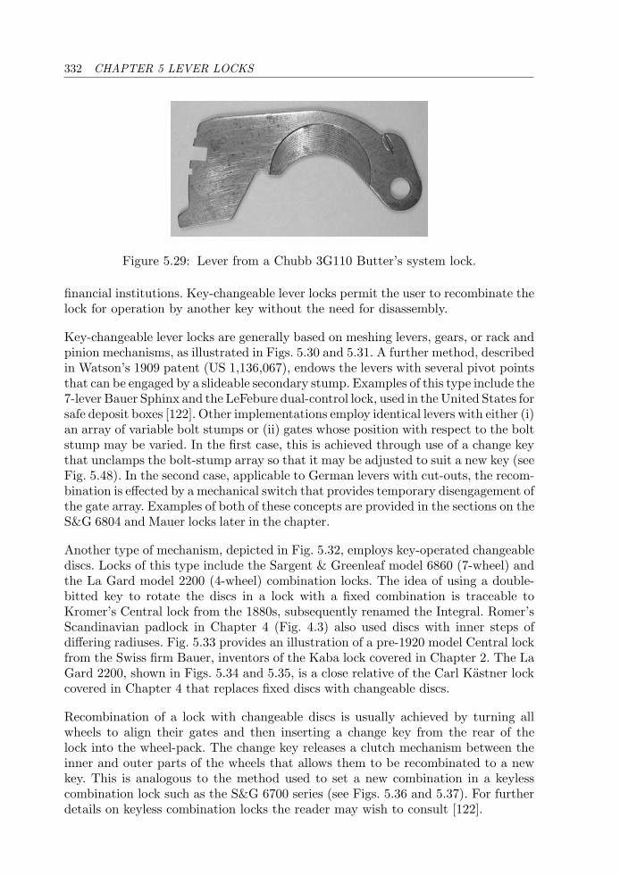
332 CHAPTER 5 LEVER LOCKS
Figure 5.29: Lever from a Chubb 3G110 Butter’s system lock.
financial institutions. Key-changeable lever locks permit the user to recombinate thelock for operation by another key without the need for disassembly.
Key-changeable lever locks are generally based on meshing levers, gears, or rack andpinion mechanisms, as illustrated in Figs. 5.30 and 5.31. A further method, describedin Watson’s 1909 patent (US 1,136,067), endows the levers with several pivot pointsthat can be engaged by a slideable secondary stump. Examples of this type include the7-lever Bauer Sphinx and the LeFebure dual-control lock, used in the United States forsafe deposit boxes [122]. Other implementations employ identical levers with either (i)an array of variable bolt stumps or (ii) gates whose position with respect to the boltstump may be varied. In the first case, this is achieved through use of a change keythat unclamps the bolt-stump array so that it may be adjusted to suit a new key (seeFig. 5.48). In the second case, applicable to German levers with cut-outs, the recom-bination is effected by a mechanical switch that provides temporary disengagement ofthe gate array. Examples of both of these concepts are provided in the sections on theS&G 6804 and Mauer locks later in the chapter.
Another type of mechanism, depicted in Fig. 5.32, employs key-operated changeablediscs. Locks of this type include the Sargent & Greenleaf model 6860 (7-wheel) andthe La Gard model 2200 (4-wheel) combination locks. The idea of using a double-bitted key to rotate the discs in a lock with a fixed combination is traceable toKromer’s Central lock from the 1880s, subsequently renamed the Integral. Romer’sScandinavian padlock in Chapter 4 (Fig. 4.3) also used discs with inner steps ofdiffering radiuses. Fig. 5.33 provides an illustration of a pre-1920 model Central lockfrom the Swiss firm Bauer, inventors of the Kaba lock covered in Chapter 2. The LaGard 2200, shown in Figs. 5.34 and 5.35, is a close relative of the Carl Kastner lockcovered in Chapter 4 that replaces fixed discs with changeable discs.
Recombination of a lock with changeable discs is usually achieved by turning allwheels to align their gates and then inserting a change key from the rear of thelock into the wheel-pack. The change key releases a clutch mechanism between theinner and outer parts of the wheels that allows them to be recombinated to a newkey. This is analogous to the method used to set a new combination in a keylesscombination lock such as the S&G 6700 series (see Figs. 5.36 and 5.37). For furtherdetails on keyless combination locks the reader may wish to consult [122].
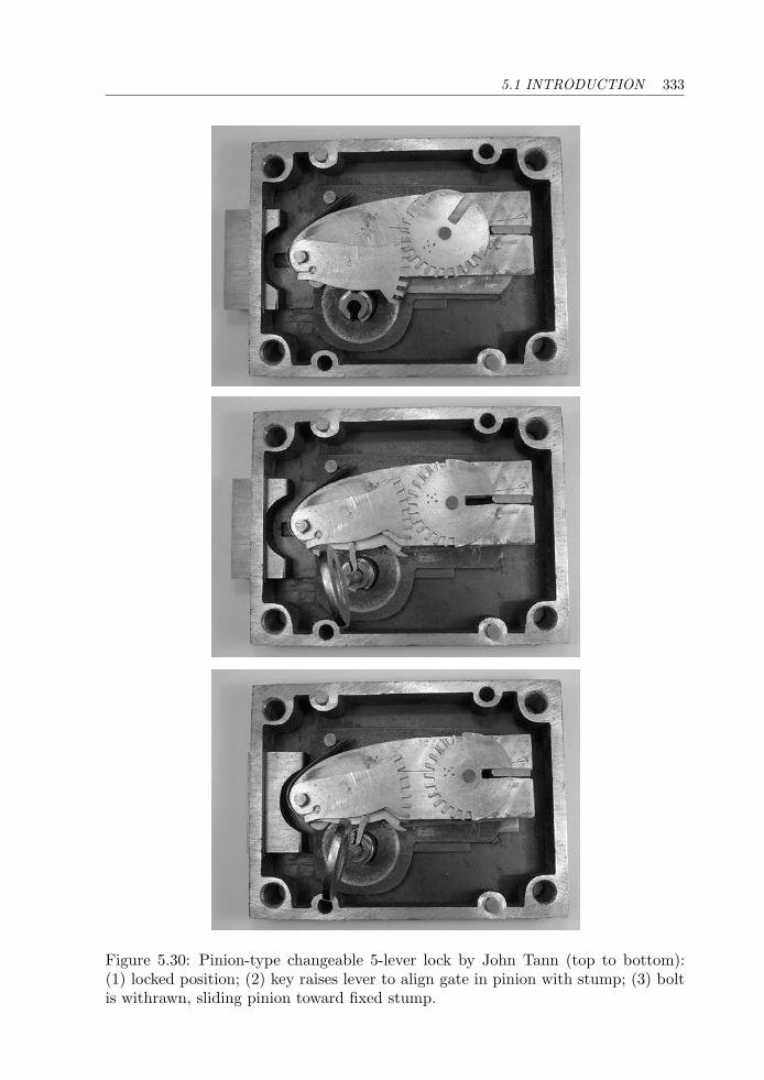
5.1 INTRODUCTION 333
Figure 5.30: Pinion-type changeable 5-lever lock by John Tann (top to bottom):(1) locked position; (2) key raises lever to align gate in pinion with stump; (3) boltis withrawn, sliding pinion toward fixed stump.
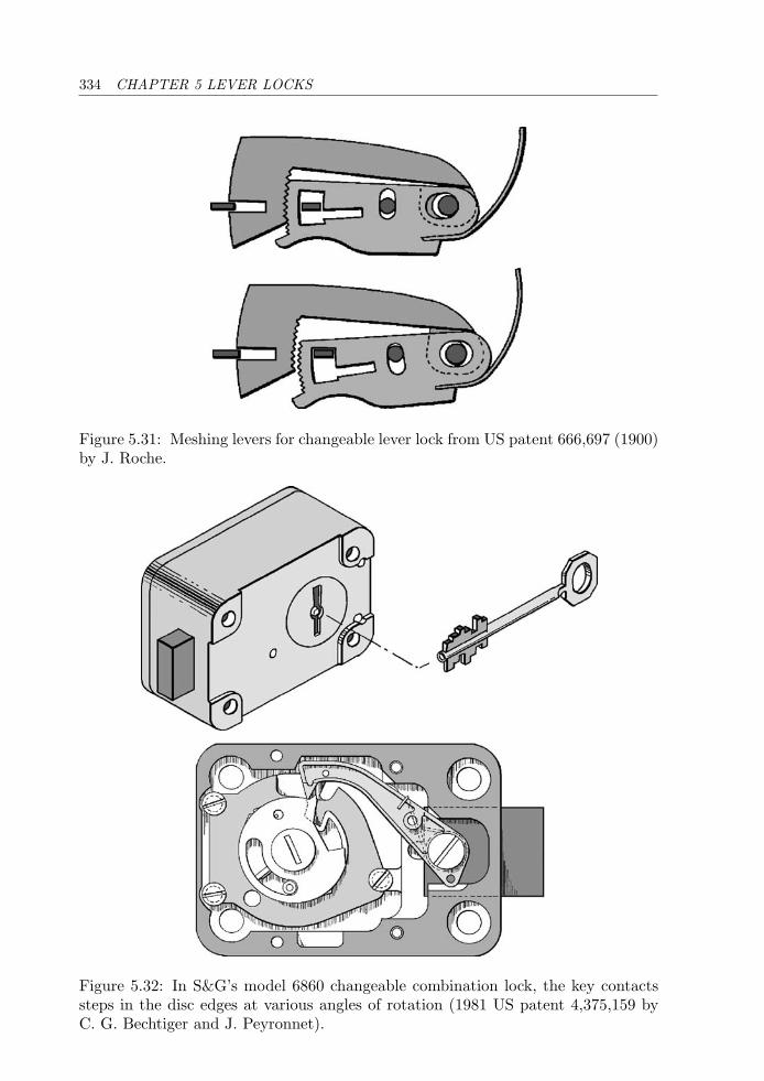
334 CHAPTER 5 LEVER LOCKS
Figure 5.31: Meshing levers for changeable lever lock from US patent 666,697 (1900)by J. Roche.
Figure 5.32: In S&G’s model 6860 changeable combination lock, the key contactssteps in the disc edges at various angles of rotation (1981 US patent 4,375,159 byC. G. Bechtiger and J. Peyronnet).
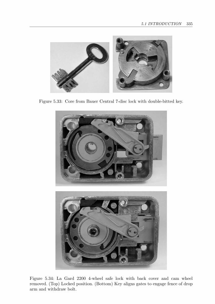
5.1 INTRODUCTION 335
Figure 5.33: Core from Bauer Central 7-disc lock with double-bitted key.
Figure 5.34: La Gard 2200 4-wheel safe lock with back cover and cam wheelremoved. (Top) Locked position. (Bottom) Key aligns gates to engage fence of droparm and withdraw bolt.
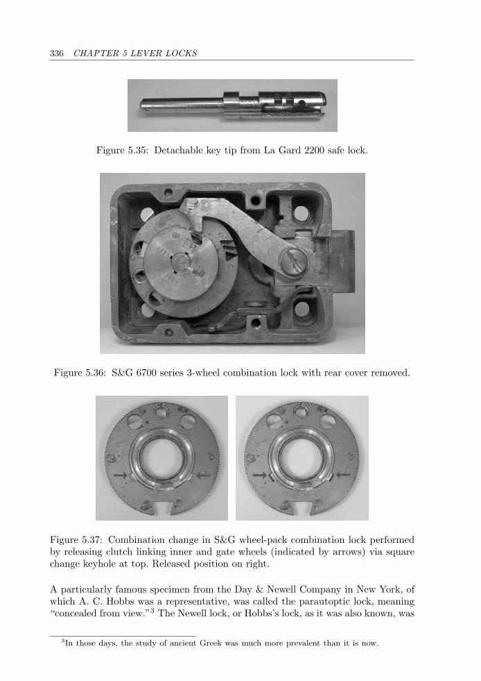
336 CHAPTER 5 LEVER LOCKS
Figure 5.35: Detachable key tip from La Gard 2200 safe lock.
Figure 5.36: S&G 6700 series 3-wheel combination lock with rear cover removed.
Figure 5.37: Combination change in S&G wheel-pack combination lock performedby releasing clutch linking inner and gate wheels (indicated by arrows) via squarechange keyhole at top. Released position on right.
A particularly famous specimen from the Day & Newell Company in New York, ofwhich A. C. Hobbs was a representative, was called the parautoptic lock, meaning“concealed from view.”3 The Newell lock, or Hobbs’s lock, as it was also known, was
3In those days, the study of ancient Greek was much more prevalent than it is now.
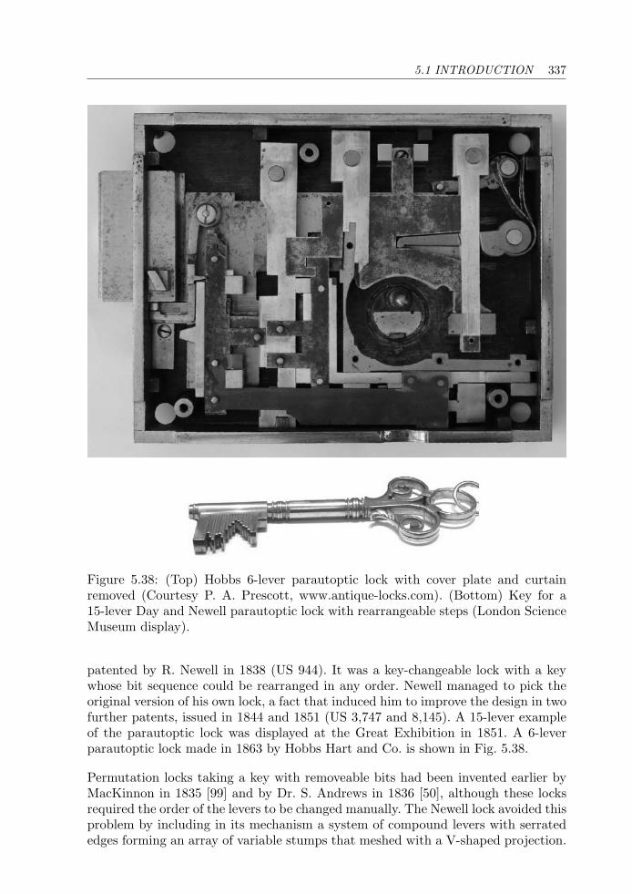
5.1 INTRODUCTION 337
Figure 5.38: (Top) Hobbs 6-lever parautoptic lock with cover plate and curtainremoved (Courtesy P. A. Prescott, www.antique-locks.com). (Bottom) Key for a15-lever Day and Newell parautoptic lock with rearrangeable steps (London ScienceMuseum display).
patented by R. Newell in 1838 (US 944). It was a key-changeable lock with a keywhose bit sequence could be rearranged in any order. Newell managed to pick theoriginal version of his own lock, a fact that induced him to improve the design in twofurther patents, issued in 1844 and 1851 (US 3,747 and 8,145). A 15-lever exampleof the parautoptic lock was displayed at the Great Exhibition in 1851. A 6-leverparautoptic lock made in 1863 by Hobbs Hart and Co. is shown in Fig. 5.38.
Permutation locks taking a key with removeable bits had been invented earlier byMacKinnon in 1835 [99] and by Dr. S. Andrews in 1836 [50], although these locksrequired the order of the levers to be changed manually. The Newell lock avoided thisproblem by including in its mechanism a system of compound levers with serratededges forming an array of variable stumps that meshed with a V-shaped projection.

338 CHAPTER 5 LEVER LOCKS
Figure 5.39: Operation of 9-lever Hobbs banker’s solid change-key lock: notches instump array, raised according to the key profile, engage V-shaped projections in case.
Once disengaged by the correct key, the stumps could be shifted and reengaged,thus recombinating the lock to any desired key. As a precaution against inspectingthe lever-tumblers, the parautoptic lock also included a shutter that blocked thekeyhole while the curtain was being turned. The automatic setting action of thebolt-stump array by the key is more easily appreciated by reference to Fig. 5.39,which shows a 9-lever Hobbs “Protector” change-key bank lock from around 1880.
Since the number of rearrangements or permutations of N objects is N factorial= N × (N − 1) × ... × 3 × 2 × 1, a 10-lever Newell lock with 10 different stepswould have 3,628,800 possible key changes. If M of the steps were identical, thenthis number would be divided by M factorial.4 The rearrangeable-bit key is still inuse today in the form of a make-up key or pin and cam tool. Once a lever lock hasbeen decoded (a topic we consider next), a working key can quickly be assembledby mounting bits of the required length onto the supporting stem.
The 1851 Newell lock was offered as a picking challenge with a reward of £200 atthe Great Exhibition. A Mr. Garbutt accepted the challenge and spent a total of30 days in an unsuccessful picking attempt [99]. Newell’s formidable lock conse-quently appeared to be unpickable. By 1856, Linus Yale Junior had developed asoft-key impressioning technique for it in the course of promoting his own brand of
4Refer to Appendix A for further details on permutations.
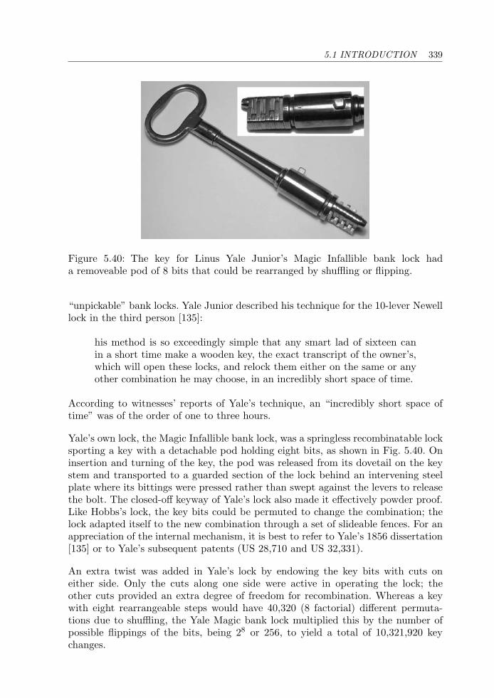
5.1 INTRODUCTION 339
Figure 5.40: The key for Linus Yale Junior’s Magic Infallible bank lock hada removeable pod of 8 bits that could be rearranged by shuffling or flipping.
“unpickable” bank locks. Yale Junior described his technique for the 10-lever Newelllock in the third person [135]:
his method is so exceedingly simple that any smart lad of sixteen canin a short time make a wooden key, the exact transcript of the owner’s,which will open these locks, and relock them either on the same or anyother combination he may choose, in an incredibly short space of time.
According to witnesses’ reports of Yale’s technique, an “incredibly short space oftime” was of the order of one to three hours.
Yale’s own lock, the Magic Infallible bank lock, was a springless recombinatable locksporting a key with a detachable pod holding eight bits, as shown in Fig. 5.40. Oninsertion and turning of the key, the pod was released from its dovetail on the keystem and transported to a guarded section of the lock behind an intervening steelplate where its bittings were pressed rather than swept against the levers to releasethe bolt. The closed-off keyway of Yale’s lock also made it effectively powder proof.Like Hobbs’s lock, the key bits could be permuted to change the combination; thelock adapted itself to the new combination through a set of slideable fences. For anappreciation of the internal mechanism, it is best to refer to Yale’s 1856 dissertation[135] or to Yale’s subsequent patents (US 28,710 and US 32,331).
An extra twist was added in Yale’s lock by endowing the key bits with cuts oneither side. Only the cuts along one side were active in operating the lock; theother cuts provided an extra degree of freedom for recombination. Whereas a keywith eight rearrangeable steps would have 40,320 (8 factorial) different permuta-tions due to shuffling, the Yale Magic bank lock multiplied this by the number ofpossible flippings of the bits, being 28 or 256, to yield a total of 10,321,920 keychanges.
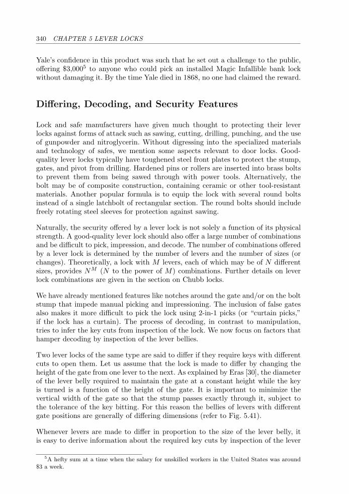
340 CHAPTER 5 LEVER LOCKS
Yale’s confidence in this product was such that he set out a challenge to the public,offering $3,0005 to anyone who could pick an installed Magic Infallible bank lockwithout damaging it. By the time Yale died in 1868, no one had claimed the reward.
Differing, Decoding, and Security Features
Lock and safe manufacturers have given much thought to protecting their leverlocks against forms of attack such as sawing, cutting, drilling, punching, and the useof gunpowder and nitroglycerin. Without digressing into the specialized materialsand technology of safes, we mention some aspects relevant to door locks. Good-quality lever locks typically have toughened steel front plates to protect the stump,gates, and pivot from drilling. Hardened pins or rollers are inserted into brass boltsto prevent them from being sawed through with power tools. Alternatively, thebolt may be of composite construction, containing ceramic or other tool-resistantmaterials. Another popular formula is to equip the lock with several round boltsinstead of a single latchbolt of rectangular section. The round bolts should includefreely rotating steel sleeves for protection against sawing.
Naturally, the security offered by a lever lock is not solely a function of its physicalstrength. A good-quality lever lock should also offer a large number of combinationsand be difficult to pick, impression, and decode. The number of combinations offeredby a lever lock is determined by the number of levers and the number of sizes (orchanges). Theoretically, a lock with M levers, each of which may be of N differentsizes, provides NM (N to the power of M) combinations. Further details on leverlock combinations are given in the section on Chubb locks.
We have already mentioned features like notches around the gate and/or on the boltstump that impede manual picking and impressioning. The inclusion of false gatesalso makes it more difficult to pick the lock using 2-in-1 picks (or “curtain picks,”if the lock has a curtain). The process of decoding, in contrast to manipulation,tries to infer the key cuts from inspection of the lock. We now focus on factors thathamper decoding by inspection of the lever bellies.
Two lever locks of the same type are said to differ if they require keys with differentcuts to open them. Let us assume that the lock is made to differ by changing theheight of the gate from one lever to the next. As explained by Eras [30], the diameterof the lever belly required to maintain the gate at a constant height while the keyis turned is a function of the height of the gate. It is important to minimize thevertical width of the gate so that the stump passes exactly through it, subject tothe tolerance of the key bitting. For this reason the bellies of levers with differentgate positions are generally of differing dimensions (refer to Fig. 5.41).
Whenever levers are made to differ in proportion to the size of the lever belly, itis easy to derive information about the required key cuts by inspection of the lever
5A hefty sum at a time when the salary for unskilled workers in the United States was around$3 a week.
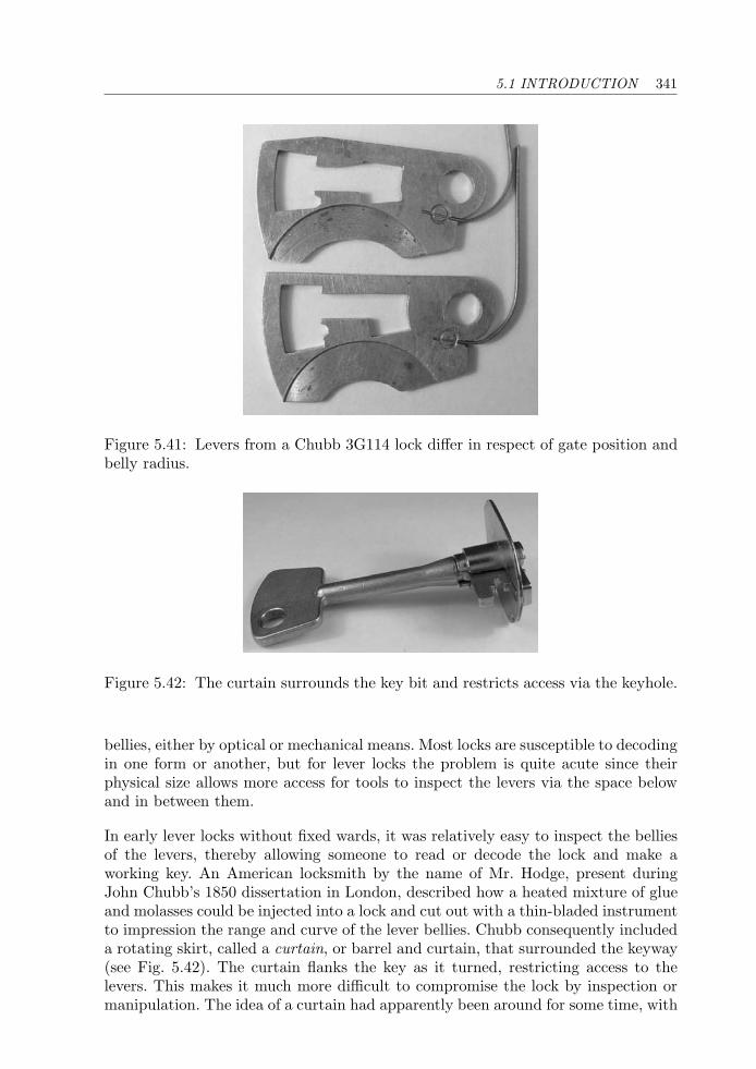
5.1 INTRODUCTION 341
Figure 5.41: Levers from a Chubb 3G114 lock differ in respect of gate position andbelly radius.
Figure 5.42: The curtain surrounds the key bit and restricts access via the keyhole.
bellies, either by optical or mechanical means. Most locks are susceptible to decodingin one form or another, but for lever locks the problem is quite acute since theirphysical size allows more access for tools to inspect the levers via the space belowand in between them.
In early lever locks without fixed wards, it was relatively easy to inspect the belliesof the levers, thereby allowing someone to read or decode the lock and make aworking key. An American locksmith by the name of Mr. Hodge, present duringJohn Chubb’s 1850 dissertation in London, described how a heated mixture of glueand molasses could be injected into a lock and cut out with a thin-bladed instrumentto impression the range and curve of the lever bellies. Chubb consequently includeda rotating skirt, called a curtain, or barrel and curtain, that surrounded the keyway(see Fig. 5.42). The curtain flanks the key as it turned, restricting access to thelevers. This makes it much more difficult to compromise the lock by inspection ormanipulation. The idea of a curtain had apparently been around for some time, with
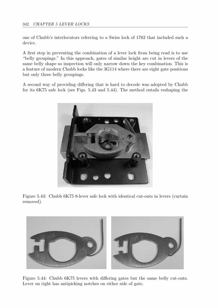
342 CHAPTER 5 LEVER LOCKS
one of Chubb’s interlocutors referring to a Swiss lock of 1762 that included such adevice.
A first step in preventing the combination of a lever lock from being read is to use“belly groupings.” In this approach, gates of similar height are cut in levers of thesame belly shape so inspection will only narrow down the key combination. This isa feature of modern Chubb locks like the 3G114 where there are eight gate positionsbut only three belly groupings.
A second way of providing differing that is hard to decode was adopted by Chubbfor its 6K75 safe lock (see Figs. 5.43 and 5.44). The method entails reshaping the
Figure 5.43: Chubb 6K75 8-lever safe lock with identical cut-outs in levers (curtainremoved).
Figure 5.44: Chubb 6K75 levers with differing gates but the same belly cut-outs.Lever on right has antipicking notches on either side of gate.
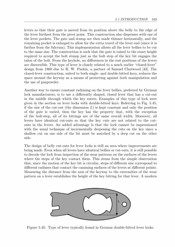
5.1 INTRODUCTION 343
levers so that their gate is moved from its position above the belly to the edge ofthe lever furthest from the pivot point. This construction also dispenses with one ofthe lever pockets. The gate and stump are then made thinner horizontally, and theremaining pocket is enlarged to allow for the extra travel of the lever end (since it isfurther from the fulcrum). This implementation allows all the lever bellies to be cutto the same size. The construction is such that the gate is raised to the exact heightrequired to accept the bolt stump just as the bolt step of the key bit engages thetalon of the bolt. From the keyhole, no differences in the rest positions of the leversare discernible. This type of lever is closely related to a much earlier “closed-lever”design from 1860 due to R. W. Parkin, a partner of Samuel Chatwood [43]. Theclosed-lever construction, suited to both single- and double-bitted keys, reduces thespace around the keyway as a means of protecting against both manipulation andthe use of gunpowder.
Another way to ensure constant radiusing on the lever bellies, preferred by Germanlock manufacturers, is to use a differently shaped, closed lever that has a cut-outin the middle through which the key enters. Examples of this type of lock weregiven in the section on lever locks with double-bitted keys. Referring to Fig. 5.45,if the size of the cut-out (the dimension L) is kept constant and only the positionof the gate is varied, then the key has the property that, with the exceptionof the bolt-step, all of its bittings are of the same overall width. Moreover, alllevers have identical cut-outs so that the key cuts are not related to the cut-outs in the levers. An added advantage is that the lock cannot be impressionedwith the usual technique of incrementally deepening the cuts on the key since ashallow cut on one side of the bit must be matched by a deep cut on the otherside.
The design of belly cut-outs for lever locks is still an area where improvements arebeing made. Even when all levers have identical bellies or cut-outs, it is still possibleto decode the lock from inspection of the wear patterns on the surfaces of the leverswhere the steps of the key contact them. This stems from the simple observationthat, since the motion of the key bit is circular, steps of different size correspond todifferent radiuses that contact the camming surfaces of the levers at different points.Measuring the distance from the axis of the keyway to the extremities of the wearpattern on a lever establishes the height of the key bitting for that lever. A modern
L
Figure 5.45: Type of lever typically found in German double-bitted lever locks.
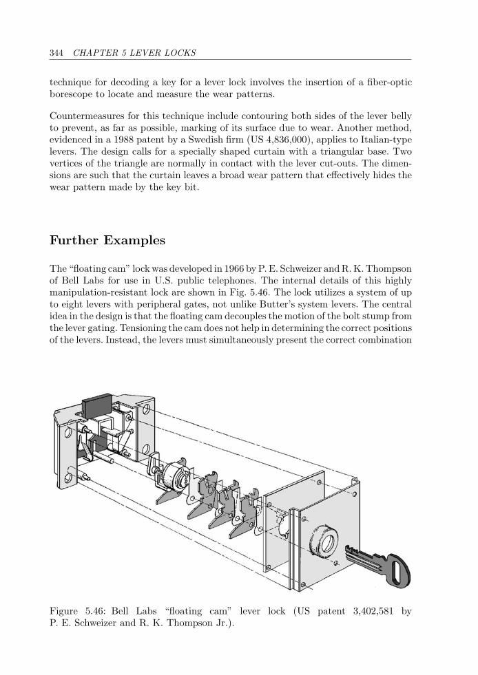
344 CHAPTER 5 LEVER LOCKS
technique for decoding a key for a lever lock involves the insertion of a fiber-opticborescope to locate and measure the wear patterns.
Countermeasures for this technique include contouring both sides of the lever bellyto prevent, as far as possible, marking of its surface due to wear. Another method,evidenced in a 1988 patent by a Swedish firm (US 4,836,000), applies to Italian-typelevers. The design calls for a specially shaped curtain with a triangular base. Twovertices of the triangle are normally in contact with the lever cut-outs. The dimen-sions are such that the curtain leaves a broad wear pattern that effectively hides thewear pattern made by the key bit.
Further Examples
The “floating cam” lock was developed in 1966 by P. E. Schweizer and R. K. Thompsonof Bell Labs for use in U.S. public telephones. The internal details of this highlymanipulation-resistant lock are shown in Fig. 5.46. The lock utilizes a system of upto eight levers with peripheral gates, not unlike Butter’s system levers. The centralidea in the design is that the floating cam decouples the motion of the bolt stump fromthe lever gating. Tensioning the cam does not help in determining the correct positionsof the levers. Instead, the levers must simultaneously present the correct combination
Figure 5.46: Bell Labs “floating cam” lever lock (US patent 3,402,581 byP. E. Schweizer and R. K. Thompson Jr.).
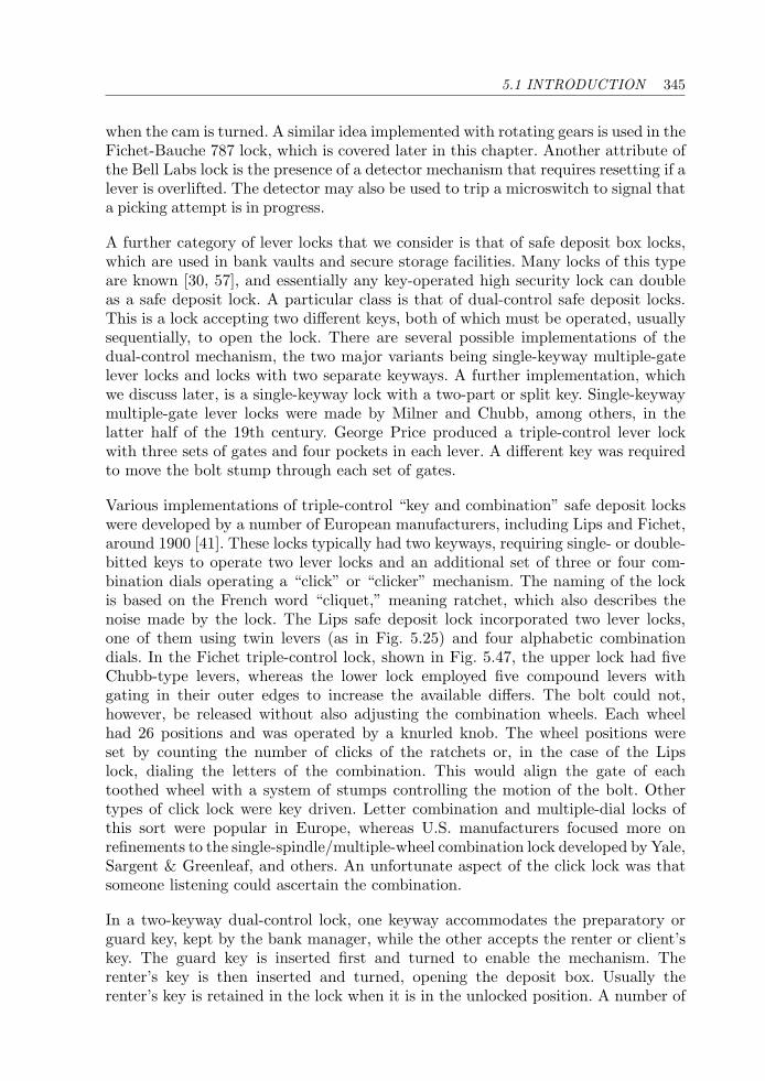
5.1 INTRODUCTION 345
when the cam is turned. A similar idea implemented with rotating gears is used in theFichet-Bauche 787 lock, which is covered later in this chapter. Another attribute ofthe Bell Labs lock is the presence of a detector mechanism that requires resetting if alever is overlifted. The detector may also be used to trip a microswitch to signal thata picking attempt is in progress.
A further category of lever locks that we consider is that of safe deposit box locks,which are used in bank vaults and secure storage facilities. Many locks of this typeare known [30, 57], and essentially any key-operated high security lock can doubleas a safe deposit lock. A particular class is that of dual-control safe deposit locks.This is a lock accepting two different keys, both of which must be operated, usuallysequentially, to open the lock. There are several possible implementations of thedual-control mechanism, the two major variants being single-keyway multiple-gatelever locks and locks with two separate keyways. A further implementation, whichwe discuss later, is a single-keyway lock with a two-part or split key. Single-keywaymultiple-gate lever locks were made by Milner and Chubb, among others, in thelatter half of the 19th century. George Price produced a triple-control lever lockwith three sets of gates and four pockets in each lever. A different key was requiredto move the bolt stump through each set of gates.
Various implementations of triple-control “key and combination” safe deposit lockswere developed by a number of European manufacturers, including Lips and Fichet,around 1900 [41]. These locks typically had two keyways, requiring single- or double-bitted keys to operate two lever locks and an additional set of three or four com-bination dials operating a “click” or “clicker” mechanism. The naming of the lockis based on the French word “cliquet,” meaning ratchet, which also describes thenoise made by the lock. The Lips safe deposit lock incorporated two lever locks,one of them using twin levers (as in Fig. 5.25) and four alphabetic combinationdials. In the Fichet triple-control lock, shown in Fig. 5.47, the upper lock had fiveChubb-type levers, whereas the lower lock employed five compound levers withgating in their outer edges to increase the available differs. The bolt could not,however, be released without also adjusting the combination wheels. Each wheelhad 26 positions and was operated by a knurled knob. The wheel positions wereset by counting the number of clicks of the ratchets or, in the case of the Lipslock, dialing the letters of the combination. This would align the gate of eachtoothed wheel with a system of stumps controlling the motion of the bolt. Othertypes of click lock were key driven. Letter combination and multiple-dial locks ofthis sort were popular in Europe, whereas U.S. manufacturers focused more onrefinements to the single-spindle/multiple-wheel combination lock developed by Yale,Sargent & Greenleaf, and others. An unfortunate aspect of the click lock was thatsomeone listening could ascertain the combination.
In a two-keyway dual-control lock, one keyway accommodates the preparatory orguard key, kept by the bank manager, while the other accepts the renter or client’skey. The guard key is inserted first and turned to enable the mechanism. Therenter’s key is then inserted and turned, opening the deposit box. Usually therenter’s key is retained in the lock when it is in the unlocked position. A number of

346 CHAPTER 5 LEVER LOCKS
Figure 5.47: Triple-control Fichet safe deposit lock with 3-knob “click” mechanism.First, the three knobs must be set at the correct positions. The guard key is theninserted in the upper keyhole and turned to allow access for the renter’s key (top),which is inserted in the lower keyhole to operate the compound 5-lever lock. Thefretting is ornamental—the original lock would have had a plain steel front plate.
distinct embodiments are possible for this type of dual-control lock. For lever locks,we can make a distinction depending on whether one or two stumps are attachedto the bolt. In the case of two stumps, there are two independent lever packs. Thegates on both sets of levers must be aligned by the correct keys to permit retrac-tion of the bolt. For single-stump dual-control locks, the levers for both keywaysare interleaved and share the same pivot point. The renter’s key is inserted into a
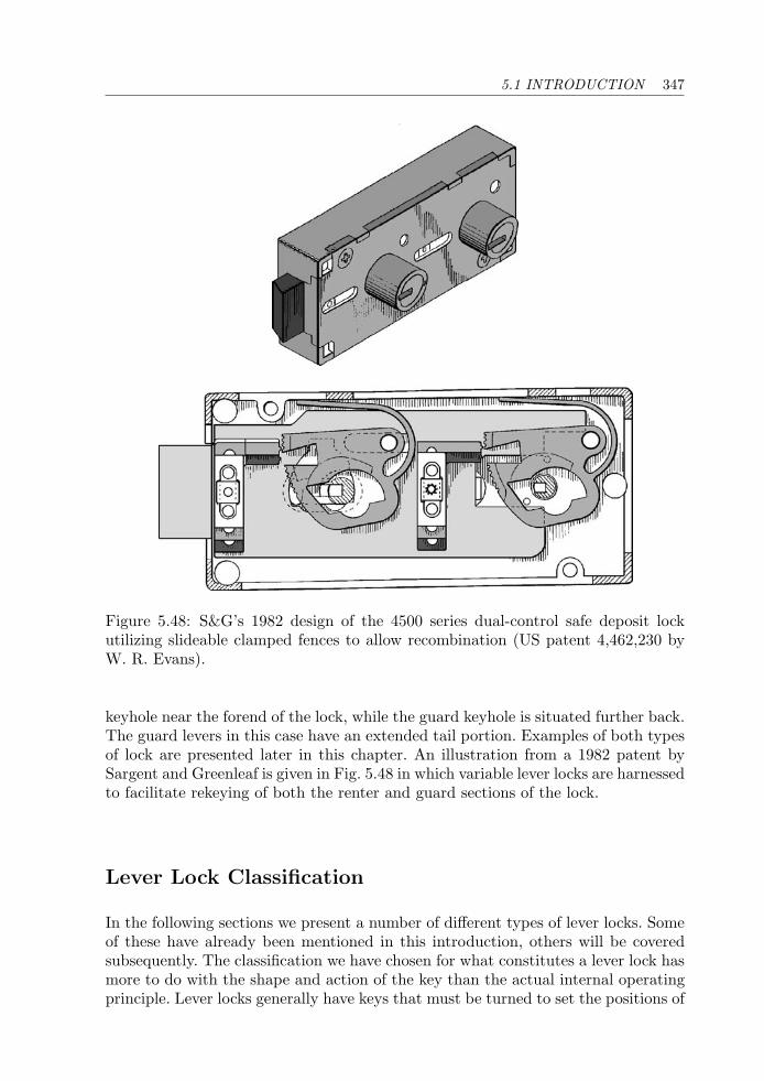
5.1 INTRODUCTION 347
Figure 5.48: S&G’s 1982 design of the 4500 series dual-control safe deposit lockutilizing slideable clamped fences to allow recombination (US patent 4,462,230 byW. R. Evans).
keyhole near the forend of the lock, while the guard keyhole is situated further back.The guard levers in this case have an extended tail portion. Examples of both typesof lock are presented later in this chapter. An illustration from a 1982 patent bySargent and Greenleaf is given in Fig. 5.48 in which variable lever locks are harnessedto facilitate rekeying of both the renter and guard sections of the lock.
Lever Lock Classification
In the following sections we present a number of different types of lever locks. Someof these have already been mentioned in this introduction, others will be coveredsubsequently. The classification we have chosen for what constitutes a lever lock hasmore to do with the shape and action of the key than the actual internal operatingprinciple. Lever locks generally have keys that must be turned to set the positions of
348 CHAPTER 5 LEVER LOCKS
the tumblers. For this reason, locks such as the Chubb Ava and Kromer Protector,despite their obvious similarities to wafer locks, are considered to be lever locks.Master-keying aspects are discussed for locks that are intended for use on normal(residential and office) doors. Master-keying is not required for lever locks designedfor use on safe and vault doors.
Locks from the following categories have been included.
1. Conventional (English) lever locks with single-bitted keys: these include theChubb 5-lever and 7-lever, Chubb 5-detainer (Butter’s system) and Chubbdetector locks. The Fichet-Bauche “sans souci” with its twin-bitted key is alsoin this category. We have also included the Ross 102 and Ross 600 lever locks,the last of which uses vertical-lift levers.
2. Italian double-throw vertical-lift lever locks with double-bitted keys having aconstant bitting width. Examples: Mottura and Nova Acytra, amongothers.
3. Axial or push-lever locks with end-bitted keys. Examples: NS Fichet, Muel,Miller.
4. Radial lever locks having circular symmetry in the arrangement of their leversand fluted keys. Examples: Fichet-Bauche Monopole, Fichet-Bauche M2B,Cotterill “climax detector.”
5. Cylindrical lever locks having either alternating sliding levers or balance leversstacked in a cylindrical core and operated by a double-bitted key. Examples:Chubb Ava, Kromer Protector, Kuhne Panzer, CAWI.
6. Geared lever locks whose levers have serrated edges that mesh with toothedwheels containing a gate. The Fichet-Bauche 787 is an example of such a lockhaving an end-bitted key.
7. Trap-door locks: turning the key operates a trap-door at the rear of the cylin-der. The key is then pushed through to the rear chamber to operate thelock mechanism. The Deny 3-lever lock with its double-bitted key is the onlyexample presented here.
8. Twin-lever locks having two sets of opposing levers operated by a double-bittedkey with independent bittings. Examples: Ross 700, Chubb-Lips 6K207.
9. Changeable lever locks with a variable bolt stump mechanism. Examples:Sargent & Greenleaf 6804, Mauer Variator.
10. Dual-control safe deposit box locks: requiring two keys and having two leverpacks with either shared or different pivots and one or two bolt stumps, respec-tively. Examples include Mosler 5700 (single-stump), S&G 4400, and Diebold175 (both double-stump).
5.2 CONVENTIONAL 349
5.2 Conventional
Chubb
(UK) 5–9 lever (3–4)
The Chubb lock is the original English lever lock, traceable to inventions by Barronand Chubb (late 18th century) that sought to make the warded lock more secure.Some of the early history of the Chubb Company was covered in the introductionto this chapter. We take up the story again here, drawing on material from Evans[34], Gunn [49], and the references therein.
In the first quarter of the 19th century, the Chubb Company was based in Wolver-hampton, England. The safe business was established in London in 1837 followingthe development of a burglar-resistant safe, but moved to Wolverhampton in theearly 1900s. The company diversified its lock and safe business to include fire pro-tection after World War II. Chubb took over Hobbs Hart and Co. in 1956, Chatwood-Milner Ltd. (Liverpool) in 1959, then Josiah Parkes and Sons (Willenhall, makers ofUnion locks) in 1965 and Lips (Netherlands) in 1973. Chubb’s Lock Security Groupunderwent a number of acquisitions through the 1980s and 1990s, being acquired byASSA Abloy in 2000, which retained the security lock division while selling the safe-making division to Gunnebo. ASSA Abloy continues to market locks from Chubb,Yale, and Union.
Chubb produces a large range of lever and cylinder locks for residential, commer-cial, and high-security applications. In terms of architectural lever locks, the threeprincipal types are: (1) the 5-lever mortice deadlock (3G114); (2) the 7-lever morticedeadlock (3G117, 3G227); and (3) the 5-detainer deadlock (3G110, 3G135). Thereare many variations on these basic types depending on the locking function, overallcase dimensions, bolt throw, and bolt type. For example, the 3G114 is also producedas a sashlock—a two-bolt format with both deadlocking and latchbolt operation. Wedescribe a 7-lever sashbolt (the 3K277) later in this section. All Chubb locks con-form to British standard BS 3621 in terms of their resistance to sawing, forcing,drilling, and picking (see [78]). The quoted number of differs is 1,000 for the 3G114and 6,000 for the 3G117.
The operating principle of a Chubb lever lock was explained pictorially in the chapterintroduction. We give a more thorough coverage here, based on the Chubb 3G114illustrated in Figs. 5.49–5.52. The lock is assumed to be viewed with the directionof bolt throw to the left and the cover plate on top. Lever positions are numberedfrom 1 to 5, starting from the front of the lock (bow to tip on the key).
The lock case (Fig. 5.51) is constructed from folded steel with studs for theattachment of the front cover plate and one stud, called a pivot, on which the
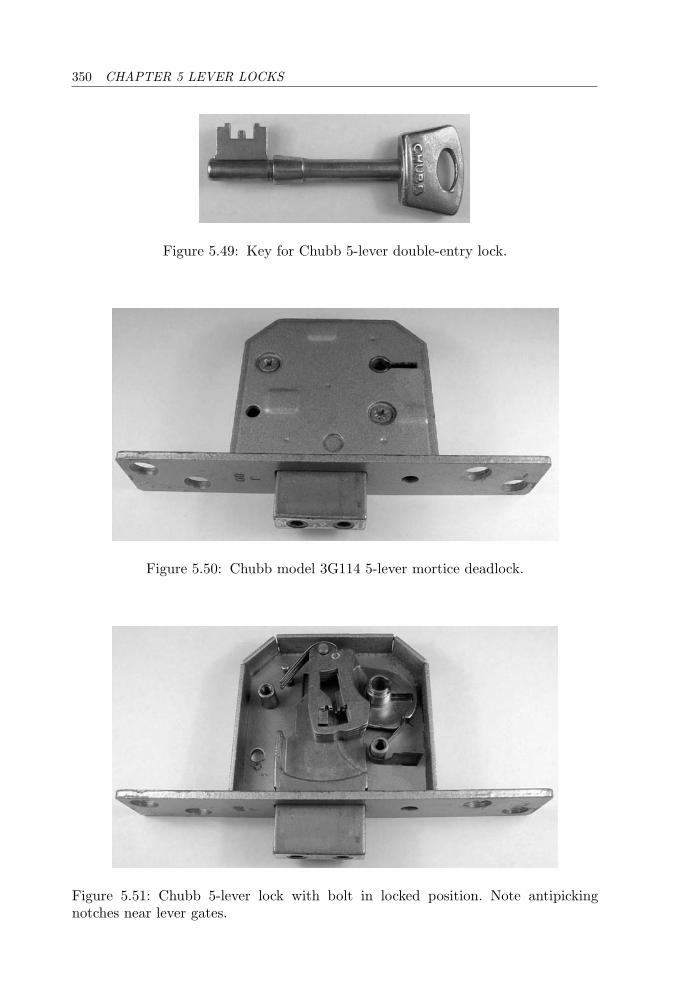
350 CHAPTER 5 LEVER LOCKS
Figure 5.49: Key for Chubb 5-lever double-entry lock.
Figure 5.50: Chubb model 3G114 5-lever mortice deadlock.
Figure 5.51: Chubb 5-lever lock with bolt in locked position. Note antipickingnotches near lever gates.
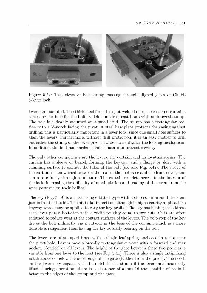
5.2 CONVENTIONAL 351
Figure 5.52: Two views of bolt stump passing through aligned gates of Chubb5-lever lock.
levers are mounted. The thick steel forend is spot-welded onto the case and containsa rectangular hole for the bolt, which is made of cast brass with an integral stump.The bolt is slideably mounted on a small stud. The stump has a rectangular sec-tion with a V-notch facing the pivot. A steel hardplate protects the casing againstdrilling; this is particularly important in a lever lock, since one small hole suffices toalign the levers. Furthermore, without drill protection, it is an easy matter to drillout either the stump or the lever pivot in order to neutralize the locking mechanism.In addition, the bolt has hardened roller inserts to prevent sawing.
The only other components are the levers, the curtain, and its locating spring. Thecurtain has a sleeve or barrel, forming the keyway, and a flange or skirt with acamming surface to contact the talon of the bolt (see also Fig. 5.42). The sleeve ofthe curtain is sandwiched between the rear of the lock case and the front cover, andcan rotate freely through a full turn. The curtain restricts access to the interior ofthe lock, increasing the difficulty of manipulation and reading of the levers from thewear patterns on their bellies.
The key (Fig. 5.49) is a classic single-bitted type with a stop collar around the stemjust in front of the bit. The bit is flat in section, although in high-security applicationskeyway wards may be applied to vary the key profile. The key has bittings to addresseach lever plus a bolt-step with a width roughly equal to two cuts. Cuts are oftenradiused to reduce wear at the contact surfaces of the levers. The bolt-step of the keydrives the bolt indirectly via a cut-out in the base of the curtain, which is a moredurable arrangement than having the key actually bearing on the bolt.
The levers are of stamped brass with a single leaf spring anchored in a slot nearthe pivot hole. Levers have a broadly rectangular cut-out with a forward and rearpocket, identical on all levers. The height of the gate between these two pockets isvariable from one lever to the next (see Fig. 5.41). There is also a single antipickingnotch above or below the outer edge of the gate (further from the pivot). The notchon the lever may engage with the notch in the stump if the levers are incorrectlylifted. During operation, there is a clearance of about 16 thousandths of an inchbetween the edges of the stump and the gates.
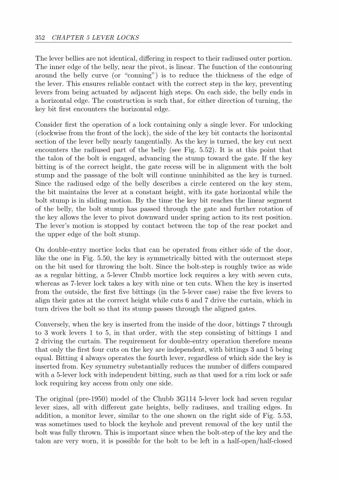
352 CHAPTER 5 LEVER LOCKS
The lever bellies are not identical, differing in respect to their radiused outer portion.The inner edge of the belly, near the pivot, is linear. The function of the contouringaround the belly curve (or “conning”) is to reduce the thickness of the edge ofthe lever. This ensures reliable contact with the correct step in the key, preventinglevers from being actuated by adjacent high steps. On each side, the belly ends ina horizontal edge. The construction is such that, for either direction of turning, thekey bit first encounters the horizontal edge.
Consider first the operation of a lock containing only a single lever. For unlocking(clockwise from the front of the lock), the side of the key bit contacts the horizontalsection of the lever belly nearly tangentially. As the key is turned, the key cut nextencounters the radiused part of the belly (see Fig. 5.52). It is at this point thatthe talon of the bolt is engaged, advancing the stump toward the gate. If the keybitting is of the correct height, the gate recess will be in alignment with the boltstump and the passage of the bolt will continue uninhibited as the key is turned.Since the radiused edge of the belly describes a circle centered on the key stem,the bit maintains the lever at a constant height, with its gate horizontal while thebolt stump is in sliding motion. By the time the key bit reaches the linear segmentof the belly, the bolt stump has passed through the gate and further rotation ofthe key allows the lever to pivot downward under spring action to its rest position.The lever’s motion is stopped by contact between the top of the rear pocket andthe upper edge of the bolt stump.
On double-entry mortice locks that can be operated from either side of the door,like the one in Fig. 5.50, the key is symmetrically bitted with the outermost stepson the bit used for throwing the bolt. Since the bolt-step is roughly twice as wideas a regular bitting, a 5-lever Chubb mortice lock requires a key with seven cuts,whereas as 7-lever lock takes a key with nine or ten cuts. When the key is insertedfrom the outside, the first five bittings (in the 5-lever case) raise the five levers toalign their gates at the correct height while cuts 6 and 7 drive the curtain, which inturn drives the bolt so that its stump passes through the aligned gates.
Conversely, when the key is inserted from the inside of the door, bittings 7 throughto 3 work levers 1 to 5, in that order, with the step consisting of bittings 1 and2 driving the curtain. The requirement for double-entry operation therefore meansthat only the first four cuts on the key are independent, with bittings 3 and 5 beingequal. Bitting 4 always operates the fourth lever, regardless of which side the key isinserted from. Key symmetry substantially reduces the number of differs comparedwith a 5-lever lock with independent bitting, such as that used for a rim lock or safelock requiring key access from only one side.
The original (pre-1950) model of the Chubb 3G114 5-lever lock had seven regularlever sizes, all with different gate heights, belly radiuses, and trailing edges. Inaddition, a monitor lever, similar to the one shown on the right side of Fig. 5.53,was sometimes used to block the keyhole and prevent removal of the key until thebolt was fully thrown. This is important since when the bolt-step of the key and thetalon are very worn, it is possible for the bolt to be left in a half-open/half-closed
5.2 CONVENTIONAL 353
Figure 5.53: Levers from a Chubb detector lock: (left) regular lever; (right) monitorlever.
state. The monitor lever gives an early indication of this fault by partially blockingthe keyhole.
The new (post–1988) 3G114 model has eight lever sizes, all of which have oneantipicking notch above or below the gate (depending on the gate position). Thinbellies are used to lessen the problem of one key cut contacting two adjacent levers.The eight gate positions give eight possible depths of cut in the key bit. A high gaterequires a deep cut in the key, a low gate requires a shallow cut. Said another way, alever with a high gate (a low-lift lever) requires less lift than a lever with a low gate(a high-lift lever). Lever size numbering starts from 1, corresponding to the highestlift and the shallowest key cut. The depth increment in the key bittings is roughly45 thousandths of an inch.
For symmetric operation, the bittings on the key must be of the form ABCDCBA,where each of A, B, C, and D is one of the eight possible cut depths. Since there areonly four independent key bittings out of the seven, the theoretical total numberof differs is 84 = 4, 096. (Note that for a 5-lever lock with one-sided operation, thiswould be 85 = 32, 768.) However, not all of these are usable: codes with repeatedentries such as (1 1 1 2 1 1 1) are too easy to duplicate; codes like (1 8 8 1 8 8 1)excessively weaken the key bit.
In a practical key series it is necessary to impose some restrictions on the bittingcodes. Typically, the following bitting rules are applied to the first four cuts (ABCD):
1. The code is excluded if three or more of the first four cuts are identical.
2. At least two of the first four cuts must be different.
3. At least one adjacent cut difference must be two or more.
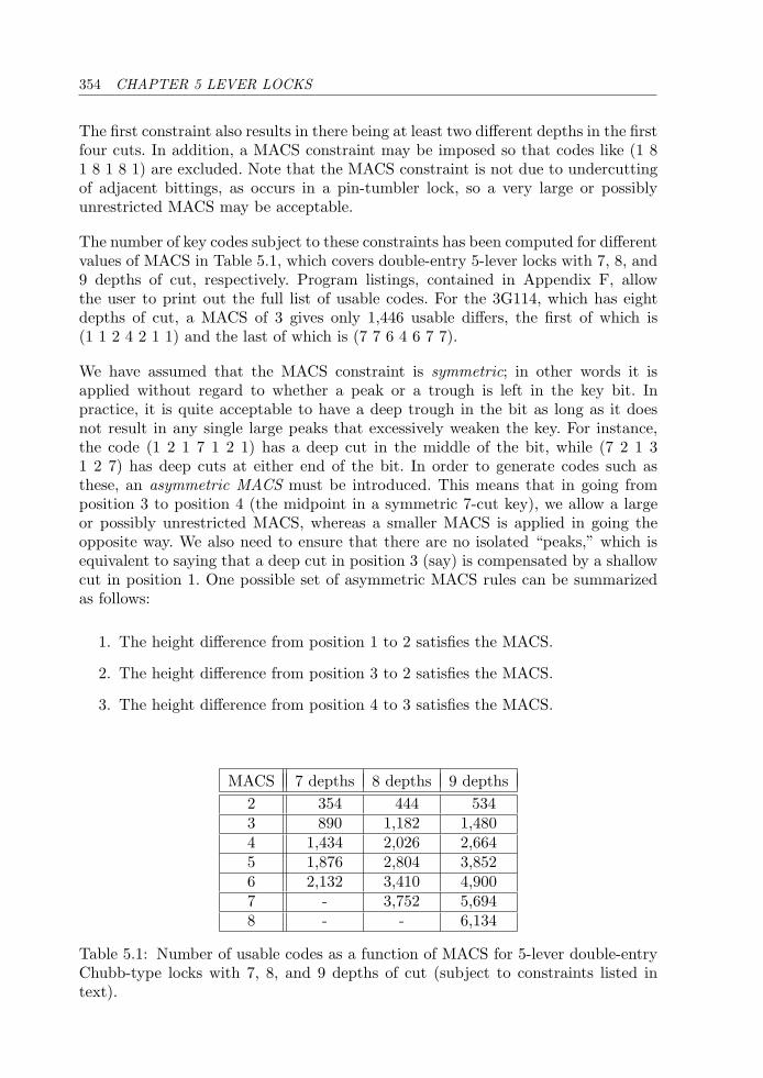
354 CHAPTER 5 LEVER LOCKS
The first constraint also results in there being at least two different depths in the firstfour cuts. In addition, a MACS constraint may be imposed so that codes like (1 81 8 1 8 1) are excluded. Note that the MACS constraint is not due to undercuttingof adjacent bittings, as occurs in a pin-tumbler lock, so a very large or possiblyunrestricted MACS may be acceptable.
The number of key codes subject to these constraints has been computed for differentvalues of MACS in Table 5.1, which covers double-entry 5-lever locks with 7, 8, and9 depths of cut, respectively. Program listings, contained in Appendix F, allowthe user to print out the full list of usable codes. For the 3G114, which has eightdepths of cut, a MACS of 3 gives only 1,446 usable differs, the first of which is(1 1 2 4 2 1 1) and the last of which is (7 7 6 4 6 7 7).
We have assumed that the MACS constraint is symmetric; in other words it isapplied without regard to whether a peak or a trough is left in the key bit. Inpractice, it is quite acceptable to have a deep trough in the bit as long as it doesnot result in any single large peaks that excessively weaken the key. For instance,the code (1 2 1 7 1 2 1) has a deep cut in the middle of the bit, while (7 2 1 31 2 7) has deep cuts at either end of the bit. In order to generate codes such asthese, an asymmetric MACS must be introduced. This means that in going fromposition 3 to position 4 (the midpoint in a symmetric 7-cut key), we allow a largeor possibly unrestricted MACS, whereas a smaller MACS is applied in going theopposite way. We also need to ensure that there are no isolated “peaks,” which isequivalent to saying that a deep cut in position 3 (say) is compensated by a shallowcut in position 1. One possible set of asymmetric MACS rules can be summarizedas follows:
1. The height difference from position 1 to 2 satisfies the MACS.
2. The height difference from position 3 to 2 satisfies the MACS.
3. The height difference from position 4 to 3 satisfies the MACS.
MACS 7 depths 8 depths 9 depths2 354 444 5343 890 1,182 1,4804 1,434 2,026 2,6645 1,876 2,804 3,8526 2,132 3,410 4,9007 - 3,752 5,6948 - - 6,134
Table 5.1: Number of usable codes as a function of MACS for 5-lever double-entryChubb-type locks with 7, 8, and 9 depths of cut (subject to constraints listed intext).
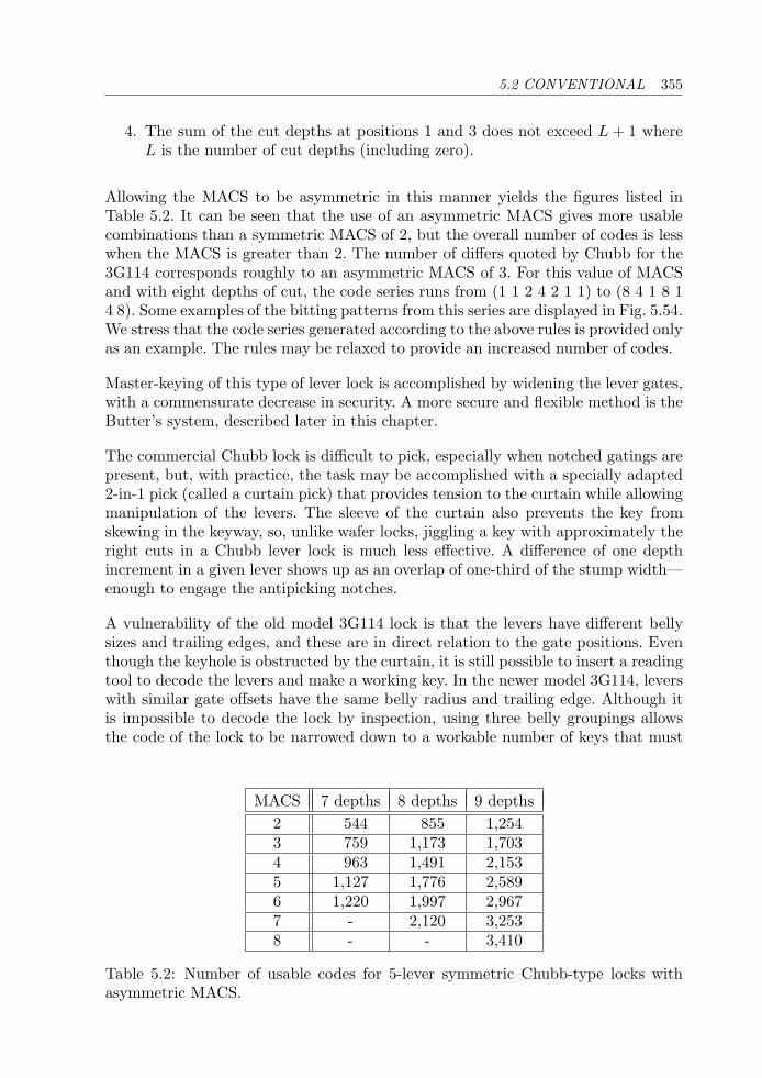
5.2 CONVENTIONAL 355
4. The sum of the cut depths at positions 1 and 3 does not exceed L + 1 whereL is the number of cut depths (including zero).
Allowing the MACS to be asymmetric in this manner yields the figures listed inTable 5.2. It can be seen that the use of an asymmetric MACS gives more usablecombinations than a symmetric MACS of 2, but the overall number of codes is lesswhen the MACS is greater than 2. The number of differs quoted by Chubb for the3G114 corresponds roughly to an asymmetric MACS of 3. For this value of MACSand with eight depths of cut, the code series runs from (1 1 2 4 2 1 1) to (8 4 1 8 14 8). Some examples of the bitting patterns from this series are displayed in Fig. 5.54.We stress that the code series generated according to the above rules is provided onlyas an example. The rules may be relaxed to provide an increased number of codes.
Master-keying of this type of lever lock is accomplished by widening the lever gates,with a commensurate decrease in security. A more secure and flexible method is theButter’s system, described later in this chapter.
The commercial Chubb lock is difficult to pick, especially when notched gatings arepresent, but, with practice, the task may be accomplished with a specially adapted2-in-1 pick (called a curtain pick) that provides tension to the curtain while allowingmanipulation of the levers. The sleeve of the curtain also prevents the key fromskewing in the keyway, so, unlike wafer locks, jiggling a key with approximately theright cuts in a Chubb lever lock is much less effective. A difference of one depthincrement in a given lever shows up as an overlap of one-third of the stump width—enough to engage the antipicking notches.
A vulnerability of the old model 3G114 lock is that the levers have different bellysizes and trailing edges, and these are in direct relation to the gate positions. Eventhough the keyhole is obstructed by the curtain, it is still possible to insert a readingtool to decode the levers and make a working key. In the newer model 3G114, leverswith similar gate offsets have the same belly radius and trailing edge. Although itis impossible to decode the lock by inspection, using three belly groupings allowsthe code of the lock to be narrowed down to a workable number of keys that must
MACS 7 depths 8 depths 9 depths2 544 855 1,2543 759 1,173 1,7034 963 1,491 2,1535 1,127 1,776 2,5896 1,220 1,997 2,9677 - 2,120 3,2538 - - 3,410
Table 5.2: Number of usable codes for 5-lever symmetric Chubb-type locks withasymmetric MACS.
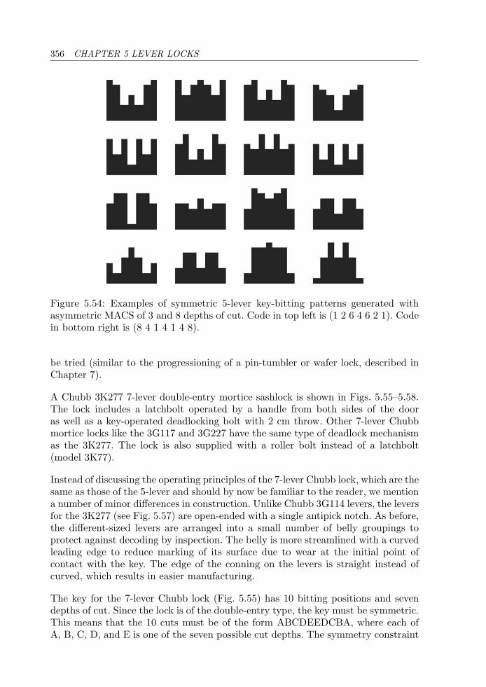
356 CHAPTER 5 LEVER LOCKS
Figure 5.54: Examples of symmetric 5-lever key-bitting patterns generated withasymmetric MACS of 3 and 8 depths of cut. Code in top left is (1 2 6 4 6 2 1). Codein bottom right is (8 4 1 4 1 4 8).
be tried (similar to the progressioning of a pin-tumbler or wafer lock, described inChapter 7).
A Chubb 3K277 7-lever double-entry mortice sashlock is shown in Figs. 5.55–5.58.The lock includes a latchbolt operated by a handle from both sides of the dooras well as a key-operated deadlocking bolt with 2 cm throw. Other 7-lever Chubbmortice locks like the 3G117 and 3G227 have the same type of deadlock mechanismas the 3K277. The lock is also supplied with a roller bolt instead of a latchbolt(model 3K77).
Instead of discussing the operating principles of the 7-lever Chubb lock, which are thesame as those of the 5-lever and should by now be familiar to the reader, we mentiona number of minor differences in construction. Unlike Chubb 3G114 levers, the leversfor the 3K277 (see Fig. 5.57) are open-ended with a single antipick notch. As before,the different-sized levers are arranged into a small number of belly groupings toprotect against decoding by inspection. The belly is more streamlined with a curvedleading edge to reduce marking of its surface due to wear at the initial point ofcontact with the key. The edge of the conning on the levers is straight instead ofcurved, which results in easier manufacturing.
The key for the 7-lever Chubb lock (Fig. 5.55) has 10 bitting positions and sevendepths of cut. Since the lock is of the double-entry type, the key must be symmetric.This means that the 10 cuts must be of the form ABCDEEDCBA, where each ofA, B, C, D, and E is one of the seven possible cut depths. The symmetry constraint

5.2 CONVENTIONAL 357
Figure 5.55: Symmetric single-bitted key for Chubb 3K277 7-lever lock.
Figure 5.56: Chubb 3K277 7-lever double-entry sashlock with front cover removed.
Figure 5.57: Number 1 (left) and number 4 (right) open-ended levers from Chubb3K277 lock.
results in only five independent cuts. When the key is inserted from the front of thelock, the first seven bittings raise the levers while the last three cuts are covered bythe rear of the curtain. For operation from the back, it is the last seven cuts thatcontact the levers. Table 5.3 gives the number of key codes subject to the bitting rules
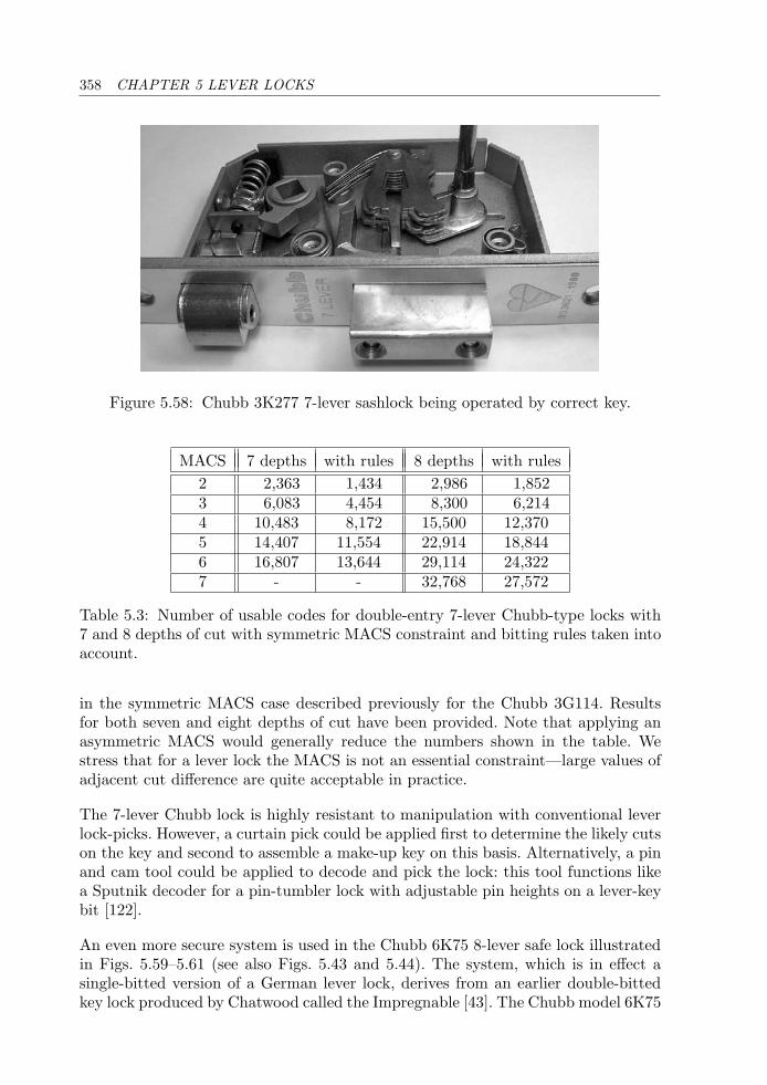
358 CHAPTER 5 LEVER LOCKS
Figure 5.58: Chubb 3K277 7-lever sashlock being operated by correct key.
MACS 7 depths with rules 8 depths with rules2 2,363 1,434 2,986 1,8523 6,083 4,454 8,300 6,2144 10,483 8,172 15,500 12,3705 14,407 11,554 22,914 18,8446 16,807 13,644 29,114 24,3227 - - 32,768 27,572
Table 5.3: Number of usable codes for double-entry 7-lever Chubb-type locks with7 and 8 depths of cut with symmetric MACS constraint and bitting rules taken intoaccount.
in the symmetric MACS case described previously for the Chubb 3G114. Resultsfor both seven and eight depths of cut have been provided. Note that applying anasymmetric MACS would generally reduce the numbers shown in the table. Westress that for a lever lock the MACS is not an essential constraint—large values ofadjacent cut difference are quite acceptable in practice.
The 7-lever Chubb lock is highly resistant to manipulation with conventional leverlock-picks. However, a curtain pick could be applied first to determine the likely cutson the key and second to assemble a make-up key on this basis. Alternatively, a pinand cam tool could be applied to decode and pick the lock: this tool functions likea Sputnik decoder for a pin-tumbler lock with adjustable pin heights on a lever-keybit [122].
An even more secure system is used in the Chubb 6K75 8-lever safe lock illustratedin Figs. 5.59–5.61 (see also Figs. 5.43 and 5.44). The system, which is in effect asingle-bitted version of a German lever lock, derives from an earlier double-bittedkey lock produced by Chatwood called the Impregnable [43]. The Chubb model 6K75
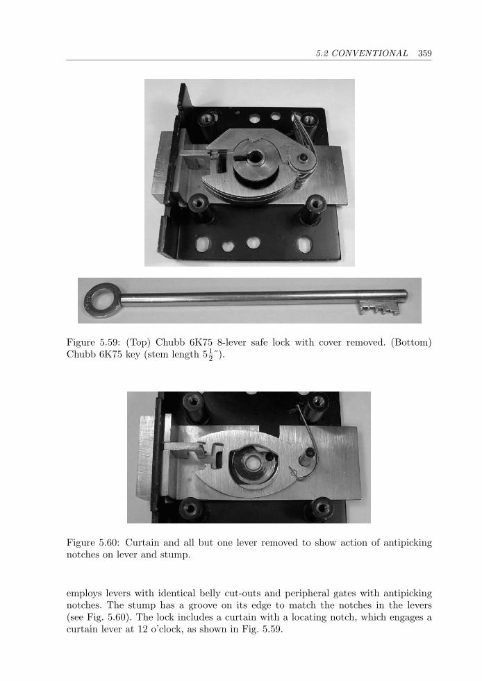
5.2 CONVENTIONAL 359
Figure 5.59: (Top) Chubb 6K75 8-lever safe lock with cover removed. (Bottom)Chubb 6K75 key (stem length 51
2˝).
Figure 5.60: Curtain and all but one lever removed to show action of antipickingnotches on lever and stump.
employs levers with identical belly cut-outs and peripheral gates with antipickingnotches. The stump has a groove on its edge to match the notches in the levers(see Fig. 5.60). The lock includes a curtain with a locating notch, which engages acurtain lever at 12 o’clock, as shown in Fig. 5.59.
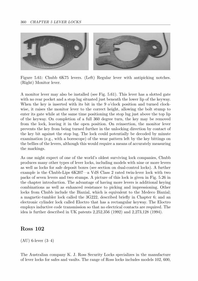
360 CHAPTER 5 LEVER LOCKS
Figure 5.61: Chubb 6K75 levers. (Left) Regular lever with antipicking notches.(Right) Monitor lever.
A monitor lever may also be installed (see Fig. 5.61). This lever has a slotted gatewith no rear pocket and a stop lug situated just beneath the lower lip of the keyway.When the key is inserted with its bit in the 9 o’clock position and turned clock-wise, it raises the monitor lever to the correct height, allowing the bolt stump toenter its gate while at the same time positioning the stop lug just above the top lipof the keyway. On completion of a full 360 degree turn, the key may be removedfrom the lock, leaving it in the open position. On reinsertion, the monitor leverprevents the key from being turned further in the unlocking direction by contact ofthe key bit against the stop lug. The lock could potentially be decoded by minuteexamination (e.g., with a borescope) of the wear pattern left by the key bittings onthe bellies of the levers, although this would require a means of accurately measuringthe markings.
As one might expect of one of the world’s oldest surviving lock companies, Chubbproduces many other types of lever locks, including models with nine or more leversas well as locks for safe deposit boxes (see section on dual-control locks). A furtherexample is the Chubb-Lips 6K207—a VdS Class 2 rated twin-lever lock with twopacks of seven levers and two stumps. A picture of this lock is given in Fig. 5.26 inthe chapter introduction. The advantage of having more levers is additional keyingcombinations as well as enhanced resistance to picking and impressioning. Otherlocks from Chubb include the Biaxial, which is equivalent to the Medeco Biaxial;a magnetic-tumbler lock called the 3G222, described briefly in Chapter 6; and anelectronic cylinder lock called Eloctro that has a rectangular keyway. The Eloctroemploys inductive code transmission so that no electrical contacts are required. Theidea is further described in UK patents 2,252,356 (1992) and 2,273,128 (1994).
Ross 102
(AU) 6-lever (3–4)
The Australian company K. J. Ross Security Locks specializes in the manufactureof lever locks for safes and vaults. The range of Ross locks includes models 102, 600,
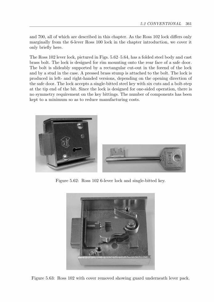
5.2 CONVENTIONAL 361
and 700, all of which are described in this chapter. As the Ross 102 lock differs onlymarginally from the 6-lever Ross 100 lock in the chapter introduction, we cover itonly briefly here.
The Ross 102 lever lock, pictured in Figs. 5.62–5.64, has a folded steel body and castbrass bolt. The lock is designed for rim mounting onto the rear face of a safe door.The bolt is slideably supported by a rectangular cut-out in the forend of the lockand by a stud in the case. A pressed brass stump is attached to the bolt. The lock isproduced in left- and right-handed versions, depending on the opening direction ofthe safe door. The lock accepts a single-bitted steel key with six cuts and a bolt-stepat the tip end of the bit. Since the lock is designed for one-sided operation, there isno symmetry requirement on the key bittings. The number of components has beenkept to a minimum so as to reduce manufacturing costs.
Figure 5.62: Ross 102 6-lever lock and single-bitted key.
Figure 5.63: Ross 102 with cover removed showing guard underneath lever pack.
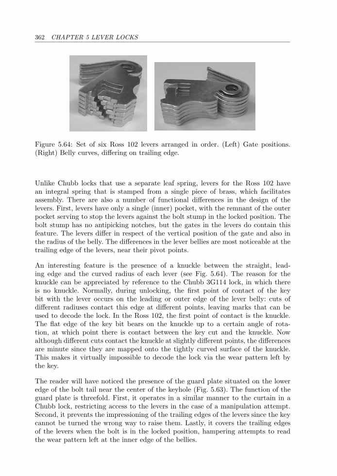
362 CHAPTER 5 LEVER LOCKS
Figure 5.64: Set of six Ross 102 levers arranged in order. (Left) Gate positions.(Right) Belly curves, differing on trailing edge.
Unlike Chubb locks that use a separate leaf spring, levers for the Ross 102 havean integral spring that is stamped from a single piece of brass, which facilitatesassembly. There are also a number of functional differences in the design of thelevers. First, levers have only a single (inner) pocket, with the remnant of the outerpocket serving to stop the levers against the bolt stump in the locked position. Thebolt stump has no antipicking notches, but the gates in the levers do contain thisfeature. The levers differ in respect of the vertical position of the gate and also inthe radius of the belly. The differences in the lever bellies are most noticeable at thetrailing edge of the levers, near their pivot points.
An interesting feature is the presence of a knuckle between the straight, lead-ing edge and the curved radius of each lever (see Fig. 5.64). The reason for theknuckle can be appreciated by reference to the Chubb 3G114 lock, in which thereis no knuckle. Normally, during unlocking, the first point of contact of the keybit with the lever occurs on the leading or outer edge of the lever belly: cuts ofdifferent radiuses contact this edge at different points, leaving marks that can beused to decode the lock. In the Ross 102, the first point of contact is the knuckle.The flat edge of the key bit bears on the knuckle up to a certain angle of rota-tion, at which point there is contact between the key cut and the knuckle. Nowalthough different cuts contact the knuckle at slightly different points, the differencesare minute since they are mapped onto the tightly curved surface of the knuckle.This makes it virtually impossible to decode the lock via the wear pattern left bythe key.
The reader will have noticed the presence of the guard plate situated on the loweredge of the bolt tail near the center of the keyhole (Fig. 5.63). The function of theguard plate is threefold. First, it operates in a similar manner to the curtain in aChubb lock, restricting access to the levers in the case of a manipulation attempt.Second, it prevents the impressioning of the trailing edges of the levers since the keycannot be turned the wrong way to raise them. Lastly, it covers the trailing edgesof the levers when the bolt is in the locked position, hampering attempts to readthe wear pattern left at the inner edge of the bellies.
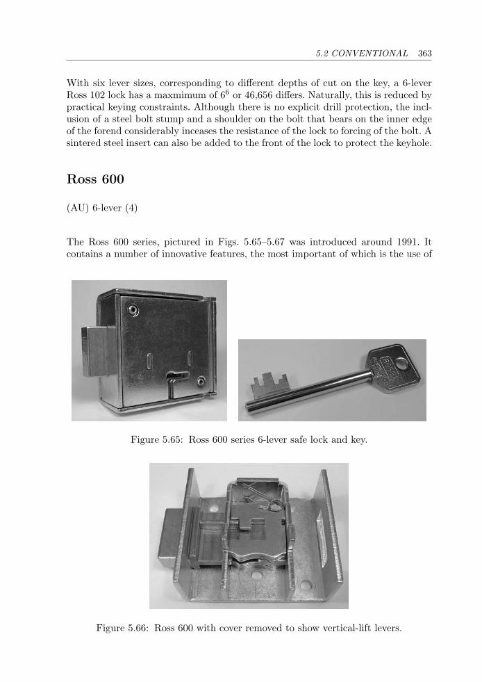
5.2 CONVENTIONAL 363
With six lever sizes, corresponding to different depths of cut on the key, a 6-leverRoss 102 lock has a maxmimum of 66 or 46,656 differs. Naturally, this is reduced bypractical keying constraints. Although there is no explicit drill protection, the incl-usion of a steel bolt stump and a shoulder on the bolt that bears on the inner edgeof the forend considerably inceases the resistance of the lock to forcing of the bolt. Asintered steel insert can also be added to the front of the lock to protect the keyhole.
Ross 600
(AU) 6-lever (4)
The Ross 600 series, pictured in Figs. 5.65–5.67 was introduced around 1991. Itcontains a number of innovative features, the most important of which is the use of
Figure 5.65: Ross 600 series 6-lever safe lock and key.
Figure 5.66: Ross 600 with cover removed to show vertical-lift levers.
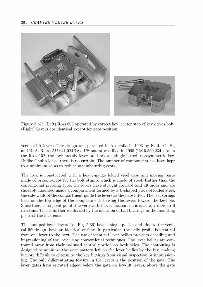
364 CHAPTER 5 LEVER LOCKS
Figure 5.67: (Left) Ross 600 operated by correct key: center step of key drives bolt.(Right) Levers are identical except for gate position.
vertical-lift levers. The design was patented in Australia in 1993 by K. J., G. H.,and B. A. Ross (AU 641,024B); a US patent was filed in 1995 (US 5,560,234). As inthe Ross 102, the lock has six levers and takes a single-bitted, nonsymmetric key.Unlike Chubb locks, there is no curtain. The number of components has been keptto a minimum so as to reduce manufacturing costs.
The lock is constructed with a heavy-gauge folded steel case and moving partsmade of brass, except for the bolt stump, which is made of steel. Rather than theconventional pivoting type, the levers have straight forward and aft sides and areslideably mounted inside a compartment formed by a U-shaped piece of folded steel;the side-walls of the compartment guide the levers as they are lifted. The leaf springsbear on the top edge of the compartment, biasing the levers toward the keyhole.Since there is no pivot point, the vertical-lift lever mechanism is naturally more drillresistant. This is further reinforced by the inclusion of ball bearings in the mountingposts of the lock case.
The stamped brass levers (see Fig. 5.66) have a single pocket and, due to the verti-cal lift design, have an identical outline. In particular, the belly profile is identicalfrom one lever to the next. The use of identical lever bellies prevents decoding andimpressioning of the lock using conventional techniques. The lever bellies are con-toured away from their radiused central portion on both sides. The contouring isdesigned to minimize the wear pattern left on the lever bellies by the key, makingit more difficult to determine the key bittings from visual inspection or impression-ing. The only differentiating feature in the levers is the position of the gate. Thelever gates have serrated edges: below the gate on low-lift levers, above the gate

5.2 CONVENTIONAL 365
on high-lift levers, and both above and below on mid-lift levers. The serrations canengage a notch in the bolt stump (not shown), greatly increasing the difficulty ofmanipulating the lock.
The six levers are disposed in two groups of three: one below the bolt and one above.Counting eight positions along the key bit, the levers are operated by the cuts atpositions 1–3 and 6–8, with positions 4 and 5 reserved for the bolt-step (a zero-depthcut). There are 10 cut depths and correspondingly 10 different gate positions. Theapproximate depth increment in the cuts is 0.75 mm. Cuts are numbered from 0 (nocut or maximum lift) to 9 (deepest cut or minimum lift). The theoretical maximumnumber of key combinations is 106 = 1, 000, 000. Typical keying constraints allowfor a MACS of 4 between adjacent lever cuts and 8 adjacent to the bolt-step.
From a lockpicking perspective there are a number of challenges. These stem fromthe serrated edges of the lever gates and the fact that tension must be applied ata position in between the two packs of three levers. A normal 2-in-1 pick cannotbe applied since this would only give access to either the first or last three levers,depending on the tensioning arrangement. A number of companies have developedtools for decoding/picking the Ross 600 lock. The quoted time for nondestructiveopening of the lock using the tool from Prescott’s site [97] is 20 to 40 minutes.
Detector Lock
(UK) 7-lever (4)
The original Chubb detector lever lock was patented by Charles and Jeremiah Chubbin 1818. The essence of the idea, which is highly effective, is to block the operationof the lock in the event of a manipulation attempt by picking or use of incorrectkeys. Whereas previous designs had required the lock to be dismantled in order toreset it for normal operation, the detector lever lock could be reset by inserting aregulating key and turning it the wrong way (i.e., counterclockwise in a lock withthe bolt on the left).
In this section we present a more contemporary version of the Chubb detectorlock produced by Tann in the 1960s. John Tann, a traditional British safe-makingcompany, was established in 1795. It became part of Rosengrens AB in 1990 and isnow owned by the Swedish Gunnebo Group of companies that also acquired Chubb’ssafe division in August 2000. The vault doors on the Tower of London that protectthe Crown Jewels were produced by Rosengrens-Tann. Two double-bitted keys arerequired to operate the locks on these doors.
The Tann detector lock shown in Figs. 5.68–5.72 has seven levers and is designedfor single-sided operation by a single-bitted key. The lock, including its case, ismade almost exclusively from brass components. The bolt has a narrow stump and
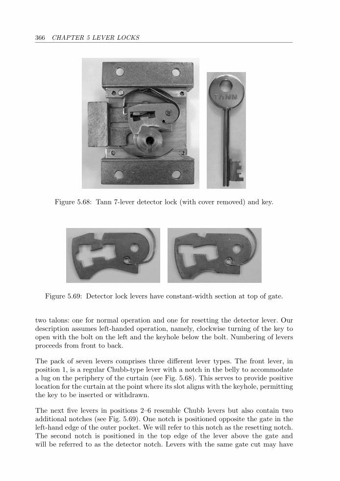
366 CHAPTER 5 LEVER LOCKS
Figure 5.68: Tann 7-lever detector lock (with cover removed) and key.
Figure 5.69: Detector lock levers have constant-width section at top of gate.
two talons: one for normal operation and one for resetting the detector lever. Ourdescription assumes left-handed operation, namely, clockwise turning of the key toopen with the bolt on the left and the keyhole below the bolt. Numbering of leversproceeds from front to back.
The pack of seven levers comprises three different lever types. The front lever, inposition 1, is a regular Chubb-type lever with a notch in the belly to accommodatea lug on the periphery of the curtain (see Fig. 5.68). This serves to provide positivelocation for the curtain at the point where its slot aligns with the keyhole, permittingthe key to be inserted or withdrawn.
The next five levers in positions 2–6 resemble Chubb levers but also contain twoadditional notches (see Fig. 5.69). One notch is positioned opposite the gate in theleft-hand edge of the outer pocket. We will refer to this notch as the resetting notch.The second notch is positioned in the top edge of the lever above the gate andwill be referred to as the detector notch. Levers with the same gate cut may have
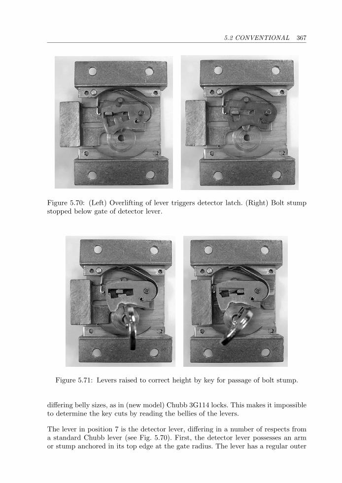
5.2 CONVENTIONAL 367
Figure 5.70: (Left) Overlifting of lever triggers detector latch. (Right) Bolt stumpstopped below gate of detector lever.
Figure 5.71: Levers raised to correct height by key for passage of bolt stump.
differing belly sizes, as in (new model) Chubb 3G114 locks. This makes it impossibleto determine the key cuts by reading the bellies of the levers.
The lever in position 7 is the detector lever, differing in a number of respects froma standard Chubb lever (see Fig. 5.70). First, the detector lever possesses an armor stump anchored in its top edge at the gate radius. The lever has a regular outer
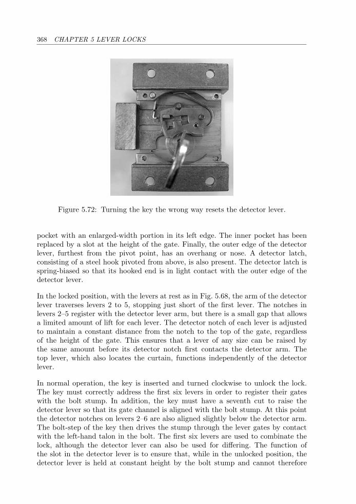
368 CHAPTER 5 LEVER LOCKS
Figure 5.72: Turning the key the wrong way resets the detector lever.
pocket with an enlarged-width portion in its left edge. The inner pocket has beenreplaced by a slot at the height of the gate. Finally, the outer edge of the detectorlever, furthest from the pivot point, has an overhang or nose. A detector latch,consisting of a steel hook pivoted from above, is also present. The detector latch isspring-biased so that its hooked end is in light contact with the outer edge of thedetector lever.
In the locked position, with the levers at rest as in Fig. 5.68, the arm of the detectorlever traverses levers 2 to 5, stopping just short of the first lever. The notches inlevers 2–5 register with the detector lever arm, but there is a small gap that allowsa limited amount of lift for each lever. The detector notch of each lever is adjustedto maintain a constant distance from the notch to the top of the gate, regardlessof the height of the gate. This ensures that a lever of any size can be raised bythe same amount before its detector notch first contacts the detector arm. Thetop lever, which also locates the curtain, functions independently of the detectorlever.
In normal operation, the key is inserted and turned clockwise to unlock the lock.The key must correctly address the first six levers in order to register their gateswith the bolt stump. In addition, the key must have a seventh cut to raise thedetector lever so that its gate channel is aligned with the bolt stump. At this pointthe detector notches on levers 2–6 are also aligned slightly below the detector arm.The bolt-step of the key then drives the stump through the lever gates by contactwith the left-hand talon in the bolt. The first six levers are used to combinate thelock, although the detector lever can also be used for differing. The function ofthe slot in the detector lever is to ensure that, while in the unlocked position, thedetector lever is held at constant height by the bolt stump and cannot therefore
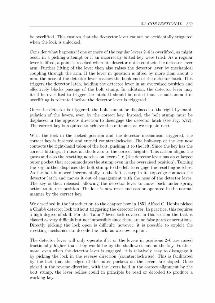
5.2 CONVENTIONAL 369
be overlifted. This ensures that the dectector lever cannot be accidentally triggeredwhen the lock is unlocked.
Consider what happens if one or more of the regular levers 2–6 is overlifted, as mightoccur in a picking attempt or if an incorrectly bitted key were tried. As a regularlever is lifted, a point is reached where its detector notch contacts the detector leverarm. Further lifting of the lever then also raises the detector lever by mechanicalcoupling through the arm. If the lever in question is lifted by more than about 5mm, the nose of the detector lever reaches the hook end of the detector latch. Thistriggers the detector latch, holding the detector lever in an overraised position andeffectively blocks passage of the bolt stump. In addition, the detector lever mayitself be overlifted to trigger the latch. It should be noted that a small amount ofoverlifting is tolerated before the detector lever is triggered.
Once the detector is triggered, the bolt cannot be displaced to the right by mani-pulation of the levers, even by the correct key. Instead, the bolt stump must bedisplaced in the opposite direction to disengage the detector latch (see Fig. 5.72).The correct key is required to achieve this outcome, as we explain next.
With the lock in the locked position and the detector mechanism triggered, thecorrect key is inserted and turned counterclockwise. The bolt-step of the key nowcontacts the right-hand talon of the bolt, pushing it to the left. Since the key has thecorrect bittings, it raises all the levers to the correct heights. This action aligns thegates and also the resetting notches on levers 1–6 (the detector lever has an enlargedouter pocket that accommodates the stump even in the overraised position). Turningthe key further displaces the bolt stump to the left to engage the resetting notches.As the bolt is moved incrementally to the left, a step in its top-edge contacts thedetector latch and moves it out of engagement with the nose of the detector lever.The key is then released, allowing the detector lever to move back under springaction to its rest position. The lock is now reset and can be operated in the normalmanner by the correct key.
We described in the introduction to the chapter how in 1851 Alfred C. Hobbs pickeda Chubb detector lock without triggering the detector lever. In practice, this requiresa high degree of skill. For the Tann 7-lever lock covered in this section the task isclassed as very difficult but not impossible since there are no false gates or serrations.Directly picking the lock open is difficult; however, it is possible to exploit theresetting mechanism to decode the lock, as we now explain.
The detector lever will only operate if it or the levers in positions 2–6 are raisedfractionally higher than they would be by the shallowest cut on the key. Further-more, even when the detector lever is engaged, it is relatively easy to disengage itby picking the lock in the reverse direction (counterclockwise). This is facilitatedby the fact that the edges of the outer pockets on the levers are sloped. Oncepicked in the reverse direction, with the levers held in the correct alignment by thebolt stump, the lever bellies could in principle be read or decoded to produce aworking key.
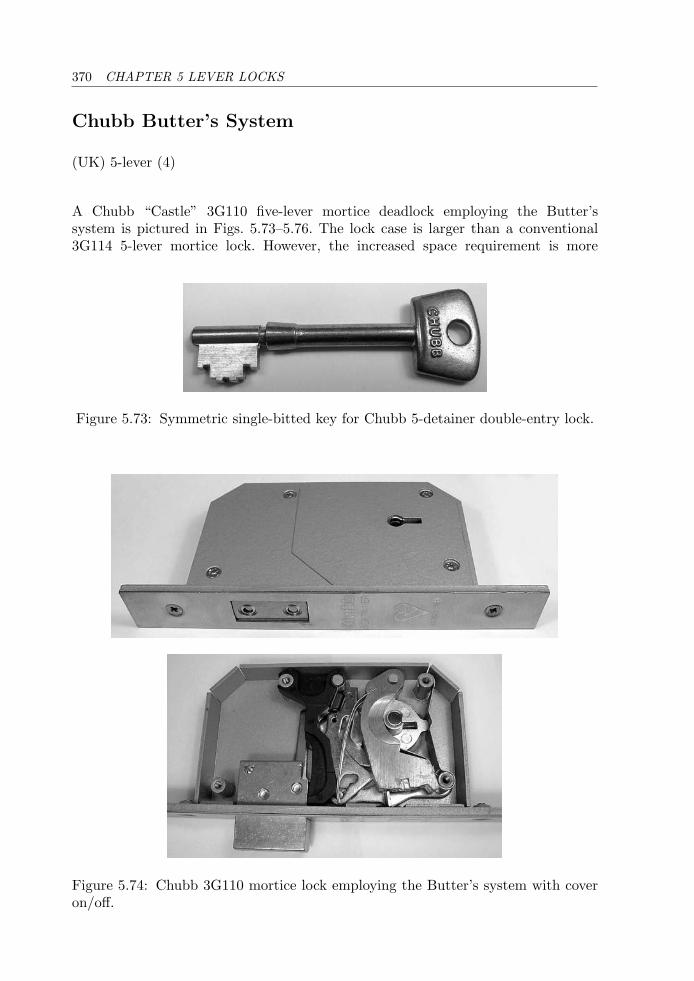
370 CHAPTER 5 LEVER LOCKS
Chubb Butter’s System
(UK) 5-lever (4)
A Chubb “Castle” 3G110 five-lever mortice deadlock employing the Butter’ssystem is pictured in Figs. 5.73–5.76. The lock case is larger than a conventional3G114 5-lever mortice lock. However, the increased space requirement is more
Figure 5.73: Symmetric single-bitted key for Chubb 5-detainer double-entry lock.
Figure 5.74: Chubb 3G110 mortice lock employing the Butter’s system with coveron/off.
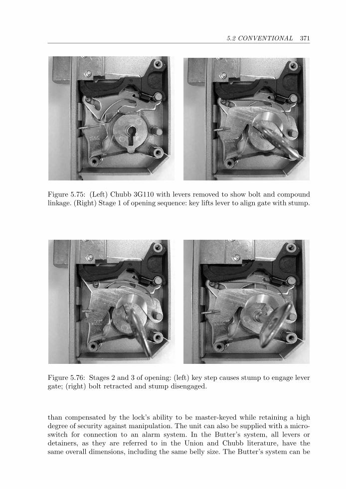
5.2 CONVENTIONAL 371
Figure 5.75: (Left) Chubb 3G110 with levers removed to show bolt and compoundlinkage. (Right) Stage 1 of opening sequence: key lifts lever to align gate with stump.
Figure 5.76: Stages 2 and 3 of opening: (left) key step causes stump to engage levergate; (right) bolt retracted and stump disengaged.
than compensated by the lock’s ability to be master-keyed while retaining a highdegree of security against manipulation. The unit can also be supplied with a micro-switch for connection to an alarm system. In the Butter’s system, all levers ordetainers, as they are referred to in the Union and Chubb literature, have thesame overall dimensions, including the same belly size. The Butter’s system can be
372 CHAPTER 5 LEVER LOCKS
implemented with either pivoting or vertical-lift levers. In the case of the 3G110,the levers are pivoting and differ from conventional Chubb levers by having a muchlarger end opposite the pivot point. The gate has no pockets, and the usual boltstump is replaced by a flange mounted on one member of a two-part linkage orcrank.
The linkage consists of two arms, one horizontal and one vertical, each of which ispivoted at one end on a stud in the casing (see Fig. 5.75). The arms meet roughlyat right angles at a sliding coupling. (In older models of the lock, the linkage iscomprised of a single right-angled elbow pivoting at its corner with a protrusion onone arm forming the stump [21].) The horizontal arm that runs parallel to the boltis shaped roughly like a standard lever and is raised at its belly by a cam on thecurtain (in line with the keyhole) when the key turns between 11 and 1 o’clock. Inthis range of rotation, the cam also engages the talon of a slider, located at the rearof the mechanism, upon which the bolt is mounted.
As the cam raises the first part of the linkage, the movement is transferred throughthe angled slot of the sliding coupling, causing the vertical part of the linkage topresent the flange to the active edge of the lever pack (see Fig. 5.76). Only the correctkey will align all five of the lever gates at the height of the flange, permitting thekey to complete its circle and withdraw the bolt. As the key turns past 1 o’clockin the clockwise direction, the linkage is returned to its rest position, the flange isdisengaged from the lever gates, and the levers return under spring tension to restagainst the curtain. The deadlocking of the bolt is achieved by a second stump onthe horizontal linkage that travels between two pockets in the bolt stump. The flangeon the vertical linkage is only presented to the levers during locking or unlockingwhen the horizontal linkage is raised.
The lock is designed for two-sided operation, taking a key with nine cut positions,as in Fig. 5.73. The bittings on the key must be of the form ABCDEDCBA, whereeach of A, B, C, D and E is one of the nine possible cut depths. Each cut depthcorresponds to one of the gate positions along the edge of each lever. The gatewidth is about 3.5 mm with a 50 percent overlap between adjacent gates. Sincethere are only five independent key bittings out of the nine cut positions, thetheoretical number of differs is 95 = 59, 049. The quoted number of usable dif-fers is 25,000, which takes into account practical keying constraints such as theelimination of repeated adjacent cuts. A higher security version of the 3G110 isalso available, called the 3G135, that has three different key blank and curtainprofiles.
Since each of the five levers can contain multiple gates, the 3G110 lock provides aconsiderable amount of flexibility for master-keying compared with a conventionalChubb 3G114 lever lock, while retaining a good measure of security. Security isfurther enhanced by endowing the lever edges with indentations or serrations.The positioning of these false gates on either side of the true gate can be usedto advantage in manipulating the lock, although this is by no means a trivialtask.
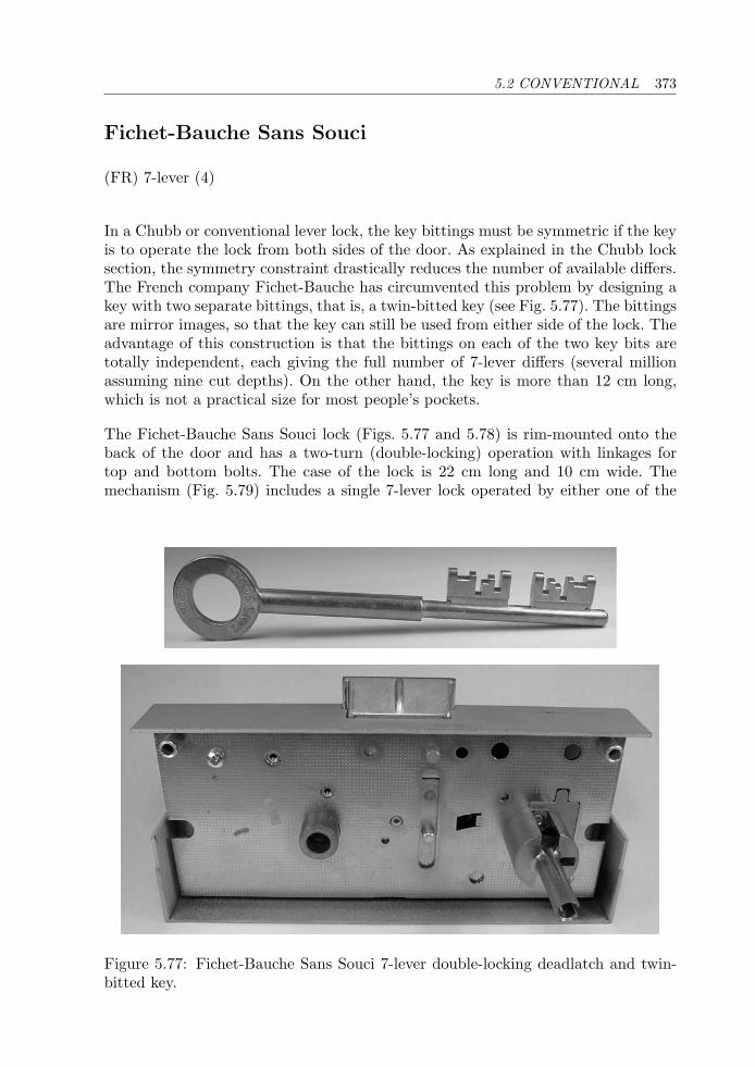
5.2 CONVENTIONAL 373
Fichet-Bauche Sans Souci
(FR) 7-lever (4)
In a Chubb or conventional lever lock, the key bittings must be symmetric if the keyis to operate the lock from both sides of the door. As explained in the Chubb locksection, the symmetry constraint drastically reduces the number of available differs.The French company Fichet-Bauche has circumvented this problem by designing akey with two separate bittings, that is, a twin-bitted key (see Fig. 5.77). The bittingsare mirror images, so that the key can still be used from either side of the lock. Theadvantage of this construction is that the bittings on each of the two key bits aretotally independent, each giving the full number of 7-lever differs (several millionassuming nine cut depths). On the other hand, the key is more than 12 cm long,which is not a practical size for most people’s pockets.
The Fichet-Bauche Sans Souci lock (Figs. 5.77 and 5.78) is rim-mounted onto theback of the door and has a two-turn (double-locking) operation with linkages fortop and bottom bolts. The case of the lock is 22 cm long and 10 cm wide. Themechanism (Fig. 5.79) includes a single 7-lever lock operated by either one of the
Figure 5.77: Fichet-Bauche Sans Souci 7-lever double-locking deadlatch and twin-bitted key.
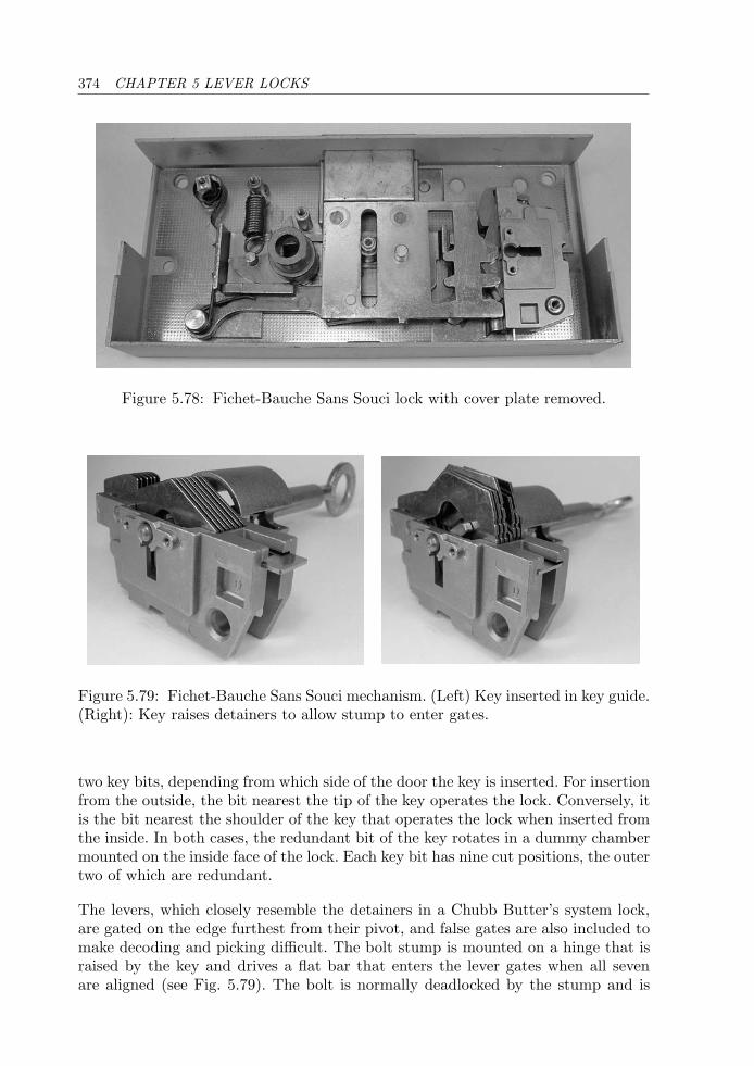
374 CHAPTER 5 LEVER LOCKS
Figure 5.78: Fichet-Bauche Sans Souci lock with cover plate removed.
Figure 5.79: Fichet-Bauche Sans Souci mechanism. (Left) Key inserted in key guide.(Right): Key raises detainers to allow stump to enter gates.
two key bits, depending from which side of the door the key is inserted. For insertionfrom the outside, the bit nearest the tip of the key operates the lock. Conversely, itis the bit nearest the shoulder of the key that operates the lock when inserted fromthe inside. In both cases, the redundant bit of the key rotates in a dummy chambermounted on the inside face of the lock. Each key bit has nine cut positions, the outertwo of which are redundant.
The levers, which closely resemble the detainers in a Chubb Butter’s system lock,are gated on the edge furthest from their pivot, and false gates are also included tomake decoding and picking difficult. The bolt stump is mounted on a hinge that israised by the key and drives a flat bar that enters the lever gates when all sevenare aligned (see Fig. 5.79). The bolt is normally deadlocked by the stump and is
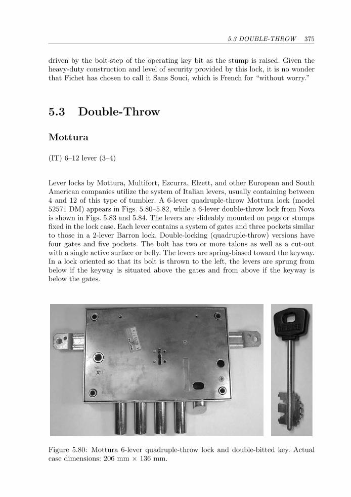
5.3 DOUBLE-THROW 375
driven by the bolt-step of the operating key bit as the stump is raised. Given theheavy-duty construction and level of security provided by this lock, it is no wonderthat Fichet has chosen to call it Sans Souci, which is French for “without worry.”
5.3 Double-Throw
Mottura
(IT) 6–12 lever (3–4)
Lever locks by Mottura, Multifort, Ezcurra, Elzett, and other European and SouthAmerican companies utilize the system of Italian levers, usually containing between4 and 12 of this type of tumbler. A 6-lever quadruple-throw Mottura lock (model52571 DM) appears in Figs. 5.80–5.82, while a 6-lever double-throw lock from Novais shown in Figs. 5.83 and 5.84. The levers are slideably mounted on pegs or stumpsfixed in the lock case. Each lever contains a system of gates and three pockets similarto those in a 2-lever Barron lock. Double-locking (quadruple-throw) versions havefour gates and five pockets. The bolt has two or more talons as well as a cut-outwith a single active surface or belly. The levers are spring-biased toward the keyway.In a lock oriented so that its bolt is thrown to the left, the levers are sprung frombelow if the keyway is situated above the gates and from above if the keyway isbelow the gates.
Figure 5.80: Mottura 6-lever quadruple-throw lock and double-bitted key. Actualcase dimensions: 206 mm × 136 mm.
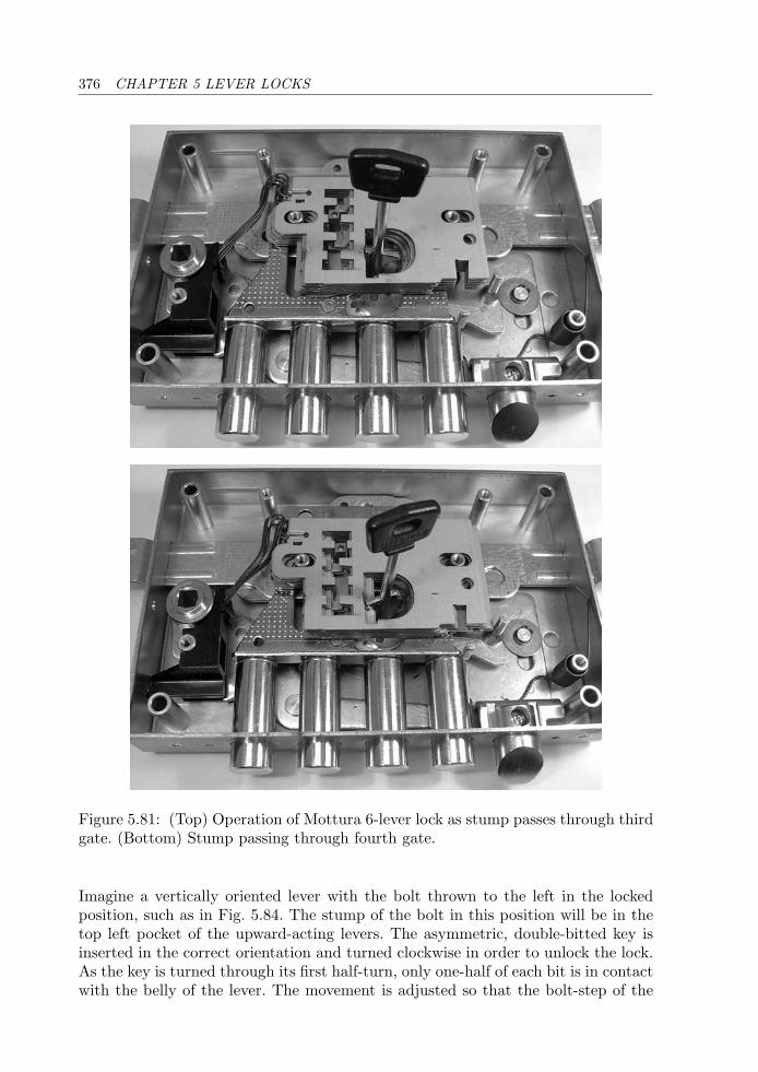
376 CHAPTER 5 LEVER LOCKS
Figure 5.81: (Top) Operation of Mottura 6-lever lock as stump passes through thirdgate. (Bottom) Stump passing through fourth gate.
Imagine a vertically oriented lever with the bolt thrown to the left in the lockedposition, such as in Fig. 5.84. The stump of the bolt in this position will be in thetop left pocket of the upward-acting levers. The asymmetric, double-bitted key isinserted in the correct orientation and turned clockwise in order to unlock the lock.As the key is turned through its first half-turn, only one-half of each bit is in contactwith the belly of the lever. The movement is adjusted so that the bolt-step of the
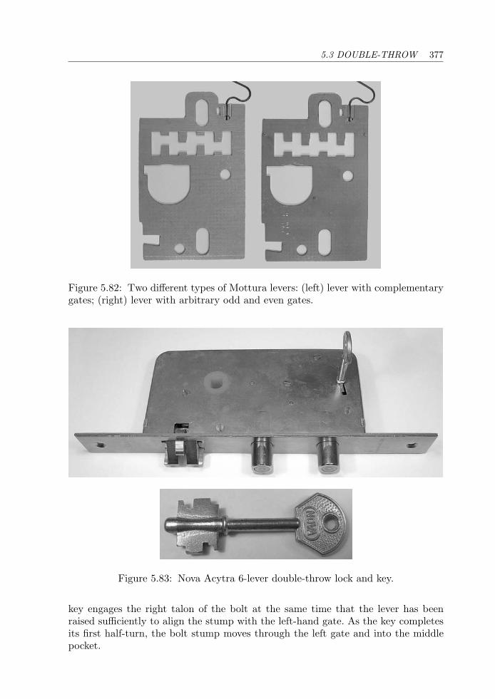
5.3 DOUBLE-THROW 377
Figure 5.82: Two different types of Mottura levers: (left) lever with complementarygates; (right) lever with arbitrary odd and even gates.
Figure 5.83: Nova Acytra 6-lever double-throw lock and key.
key engages the right talon of the bolt at the same time that the lever has beenraised sufficiently to align the stump with the left-hand gate. As the key completesits first half-turn, the bolt stump moves through the left gate and into the middlepocket.
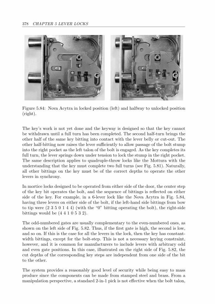
378 CHAPTER 5 LEVER LOCKS
Figure 5.84: Nova Acytra in locked position (left) and halfway to unlocked position(right).
The key’s work is not yet done and the keyway is designed so that the key cannotbe withdrawn until a full turn has been completed. The second half-turn brings theother half of the same key bitting into contact with the lever belly or cut-out. Theother half-bitting now raises the lever sufficiently to allow passage of the bolt stumpinto the right pocket as the left talon of the bolt is engaged. As the key completes itsfull turn, the lever springs down under tension to lock the stump in the right pocket.The same description applies to quadruple-throw locks like the Mottura with theunderstanding that the key must complete two full turns (see Fig. 5.81). Naturally,all other bittings on the key must be of the correct depths to operate the otherlevers in synchrony.
In mortice locks designed to be operated from either side of the door, the center stepof the key bit operates the bolt, and the sequence of bittings is reflected on eitherside of the key. For example, in a 6-lever lock like the Nova Acytra in Fig. 5.84,having three levers on either side of the bolt, if the left-hand side bittings from bowto tip were (2 3 5 0 1 4 4) (with the “0” bitting operating the bolt), the right-sidebittings would be (4 4 1 0 5 3 2).
The odd-numbered gates are usually complementary to the even-numbered ones, asshown on the left side of Fig. 5.82. Thus, if the first gate is high, the second is low,and so on. If this is the case for all the levers in the lock, then the key has constant-width bittings, except for the bolt-step. This is not a necessary keying constraint,however, and it is common for manufacturers to include levers with arbitrary oddand even gate positions. In this case, illustrated on the right side of Fig. 5.82, thecut depths of the corresponding key steps are independent from one side of the bitto the other.
The system provides a reasonably good level of security while being easy to massproduce since the components can be made from stamped steel and brass. From amanipulation perspective, a standard 2-in-1 pick is not effective when the bolt talon,
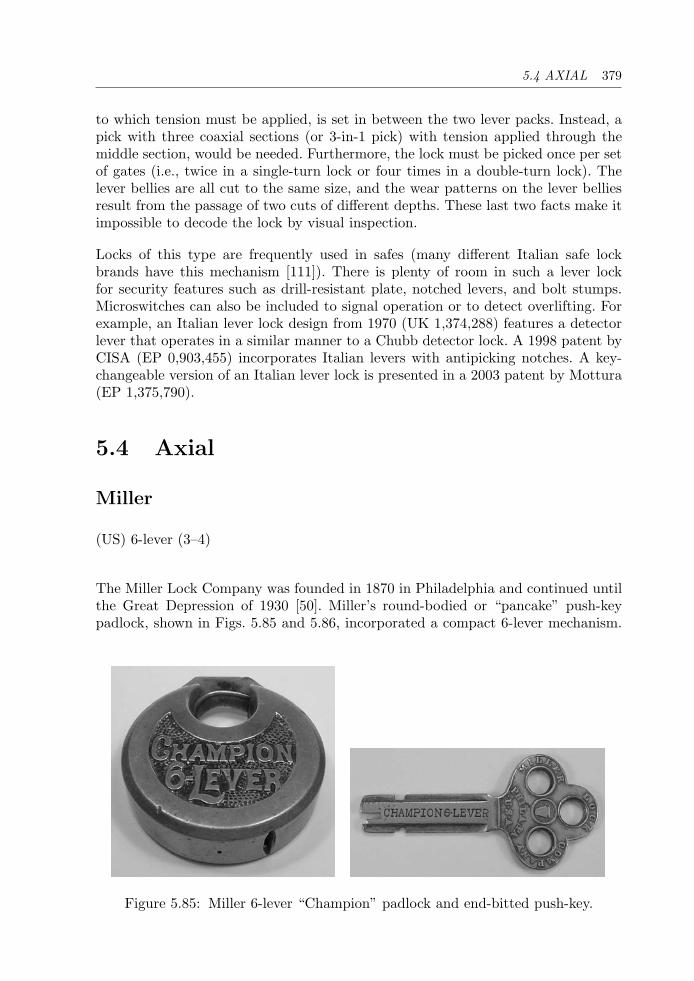
5.4 AXIAL 379
to which tension must be applied, is set in between the two lever packs. Instead, apick with three coaxial sections (or 3-in-1 pick) with tension applied through themiddle section, would be needed. Furthermore, the lock must be picked once per setof gates (i.e., twice in a single-turn lock or four times in a double-turn lock). Thelever bellies are all cut to the same size, and the wear patterns on the lever belliesresult from the passage of two cuts of different depths. These last two facts make itimpossible to decode the lock by visual inspection.
Locks of this type are frequently used in safes (many different Italian safe lockbrands have this mechanism [111]). There is plenty of room in such a lever lockfor security features such as drill-resistant plate, notched levers, and bolt stumps.Microswitches can also be included to signal operation or to detect overlifting. Forexample, an Italian lever lock design from 1970 (UK 1,374,288) features a detectorlever that operates in a similar manner to a Chubb detector lock. A 1998 patent byCISA (EP 0,903,455) incorporates Italian levers with antipicking notches. A key-changeable version of an Italian lever lock is presented in a 2003 patent by Mottura(EP 1,375,790).
5.4 Axial
Miller
(US) 6-lever (3–4)
The Miller Lock Company was founded in 1870 in Philadelphia and continued untilthe Great Depression of 1930 [50]. Miller’s round-bodied or “pancake” push-keypadlock, shown in Figs. 5.85 and 5.86, incorporated a compact 6-lever mechanism.
Figure 5.85: Miller 6-lever “Champion” padlock and end-bitted push-key.
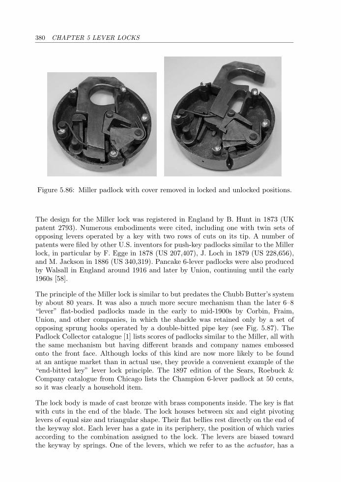
380 CHAPTER 5 LEVER LOCKS
Figure 5.86: Miller padlock with cover removed in locked and unlocked positions.
The design for the Miller lock was registered in England by B. Hunt in 1873 (UKpatent 2793). Numerous embodiments were cited, including one with twin sets ofopposing levers operated by a key with two rows of cuts on its tip. A number ofpatents were filed by other U.S. inventors for push-key padlocks similar to the Millerlock, in particular by F. Egge in 1878 (US 207,407), J. Loch in 1879 (US 228,656),and M. Jackson in 1886 (US 340,319). Pancake 6-lever padlocks were also producedby Walsall in England around 1916 and later by Union, continuing until the early1960s [58].
The principle of the Miller lock is similar to but predates the Chubb Butter’s systemby about 80 years. It was also a much more secure mechanism than the later 6–8“lever” flat-bodied padlocks made in the early to mid-1900s by Corbin, Fraim,Union, and other companies, in which the shackle was retained only by a set ofopposing sprung hooks operated by a double-bitted pipe key (see Fig. 5.87). ThePadlock Collector catalogue [1] lists scores of padlocks similar to the Miller, all withthe same mechanism but having different brands and company names embossedonto the front face. Although locks of this kind are now more likely to be foundat an antique market than in actual use, they provide a convenient example of the“end-bitted key” lever lock principle. The 1897 edition of the Sears, Roebuck &Company catalogue from Chicago lists the Champion 6-lever padlock at 50 cents,so it was clearly a household item.
The lock body is made of cast bronze with brass components inside. The key is flatwith cuts in the end of the blade. The lock houses between six and eight pivotinglevers of equal size and triangular shape. Their flat bellies rest directly on the end ofthe keyway slot. Each lever has a gate in its periphery, the position of which variesaccording to the combination assigned to the lock. The levers are biased towardthe keyway by springs. One of the levers, which we refer to as the actuator, has a
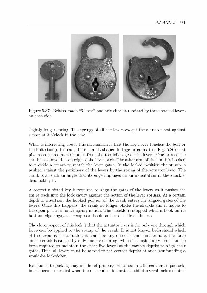
5.4 AXIAL 381
Figure 5.87: British-made “6-lever” padlock: shackle retained by three hooked leverson each side.
slightly longer spring. The springs of all the levers except the actuator rest againsta post at 3 o’clock in the case.
What is interesting about this mechanism is that the key never touches the bolt orthe bolt stump. Instead, there is an L-shaped linkage or crank (see Fig. 5.86) thatpivots on a post at a distance from the top left edge of the levers. One arm of thecrank lies above the top edge of the lever pack. The other arm of the crank is hookedto provide a stump to match the lever gates. In the locked position the stump ispushed against the periphery of the levers by the spring of the actuator lever. Thecrank is at such an angle that its edge impinges on an indentation in the shackle,deadlocking it.
A correctly bitted key is required to align the gates of the levers as it pushes theentire pack into the lock cavity against the action of the lever springs. At a certaindepth of insertion, the hooked portion of the crank enters the aligned gates of thelevers. Once this happens, the crank no longer blocks the shackle and it moves tothe open position under spring action. The shackle is stopped when a hook on itsbottom edge engages a reciprocal hook on the left side of the case.
The clever aspect of this lock is that the actuator lever is the only one through whichforce can be applied to the stump of the crank. It is not known beforehand whichof the levers is the actuator: it could be any one of them. Furthermore, the forceon the crank is caused by only one lever spring, which is considerably less than theforce required to maintain the other five levers at the correct depths to align theirgates. Thus, all levers must be moved to the correct depths at once, confounding awould-be lockpicker.
Resistance to picking may not be of primary relevance in a 50 cent brass padlock,but it becomes crucial when the mechanism is located behind several inches of steel
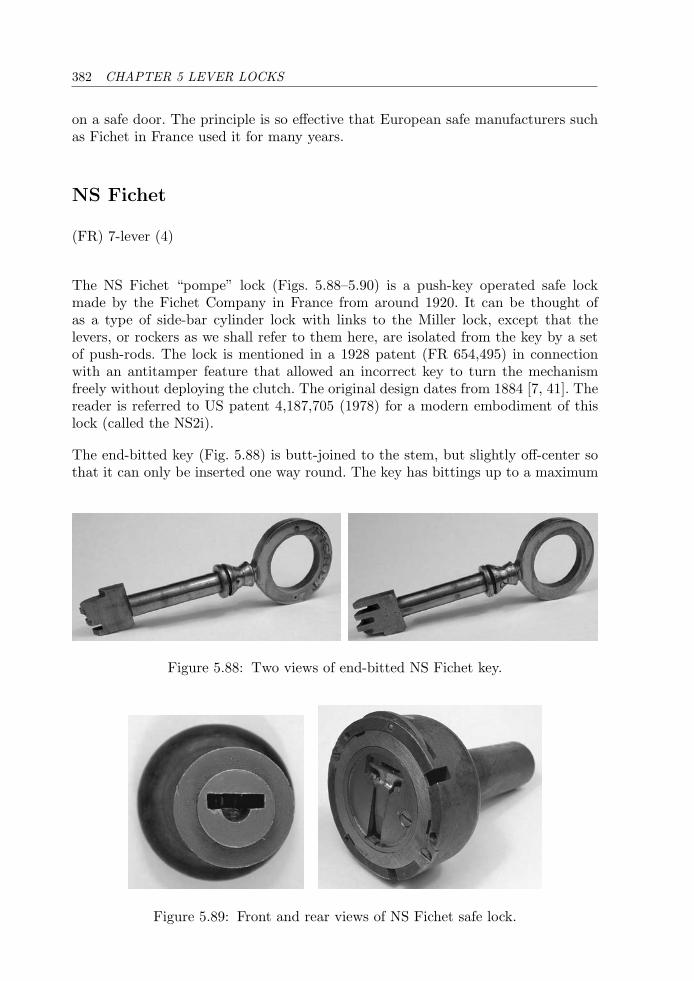
382 CHAPTER 5 LEVER LOCKS
on a safe door. The principle is so effective that European safe manufacturers suchas Fichet in France used it for many years.
NS Fichet
(FR) 7-lever (4)
The NS Fichet “pompe” lock (Figs. 5.88–5.90) is a push-key operated safe lockmade by the Fichet Company in France from around 1920. It can be thought ofas a type of side-bar cylinder lock with links to the Miller lock, except that thelevers, or rockers as we shall refer to them here, are isolated from the key by a setof push-rods. The lock is mentioned in a 1928 patent (FR 654,495) in connectionwith an antitamper feature that allowed an incorrect key to turn the mechanismfreely without deploying the clutch. The original design dates from 1884 [7, 41]. Thereader is referred to US patent 4,187,705 (1978) for a modern embodiment of thislock (called the NS2i).
The end-bitted key (Fig. 5.88) is butt-joined to the stem, but slightly off-center sothat it can only be inserted one way round. The key has bittings up to a maximum
Figure 5.88: Two views of end-bitted NS Fichet key.
Figure 5.89: Front and rear views of NS Fichet safe lock.
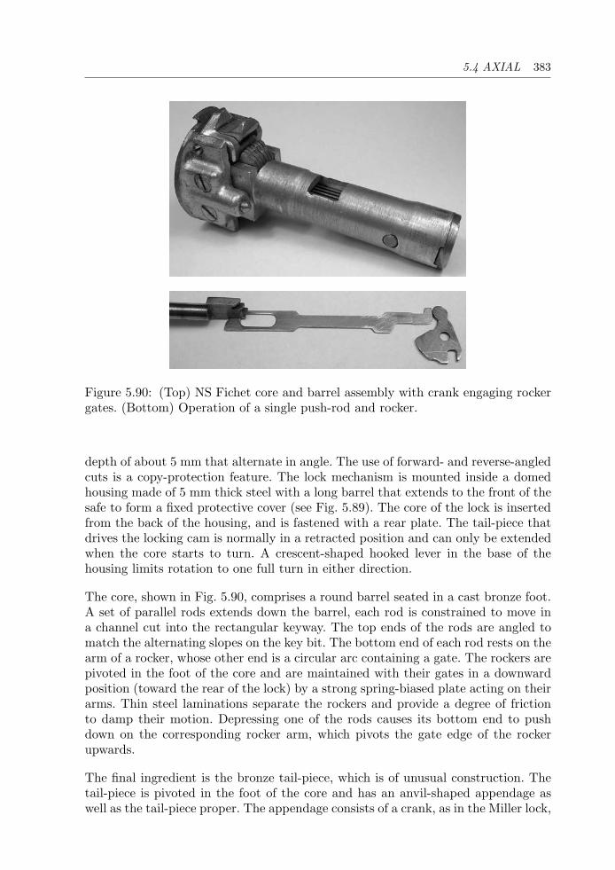
5.4 AXIAL 383
Figure 5.90: (Top) NS Fichet core and barrel assembly with crank engaging rockergates. (Bottom) Operation of a single push-rod and rocker.
depth of about 5 mm that alternate in angle. The use of forward- and reverse-angledcuts is a copy-protection feature. The lock mechanism is mounted inside a domedhousing made of 5 mm thick steel with a long barrel that extends to the front of thesafe to form a fixed protective cover (see Fig. 5.89). The core of the lock is insertedfrom the back of the housing, and is fastened with a rear plate. The tail-piece thatdrives the locking cam is normally in a retracted position and can only be extendedwhen the core starts to turn. A crescent-shaped hooked lever in the base of thehousing limits rotation to one full turn in either direction.
The core, shown in Fig. 5.90, comprises a round barrel seated in a cast bronze foot.A set of parallel rods extends down the barrel, each rod is constrained to move ina channel cut into the rectangular keyway. The top ends of the rods are angled tomatch the alternating slopes on the key bit. The bottom end of each rod rests on thearm of a rocker, whose other end is a circular arc containing a gate. The rockers arepivoted in the foot of the core and are maintained with their gates in a downwardposition (toward the rear of the lock) by a strong spring-biased plate acting on theirarms. Thin steel laminations separate the rockers and provide a degree of frictionto damp their motion. Depressing one of the rods causes its bottom end to pushdown on the corresponding rocker arm, which pivots the gate edge of the rockerupwards.
The final ingredient is the bronze tail-piece, which is of unusual construction. Thetail-piece is pivoted in the foot of the core and has an anvil-shaped appendage aswell as the tail-piece proper. The appendage consists of a crank, as in the Miller lock,
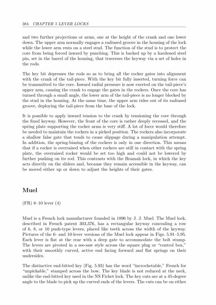
384 CHAPTER 5 LEVER LOCKS
and two further projections or arms, one at the height of the crank and one lowerdown. The upper arm normally engages a radiused groove in the housing of the lockwhile the lower arm rests on a steel stud. The function of the stud is to protect thecore from being forced inward by punching. This is backed up by a hardened steelpin, set in the barrel of the housing, that traverses the keyway via a set of holes inthe rods.
The key bit depresses the rods so as to bring all the rocker gates into alignmentwith the crank of the tail-piece. With the key bit fully inserted, turning force canbe transmitted to the core. Inward radial pressure is now exerted on the tail-piece’supper arm, causing the crank to engage the gates in the rockers. Once the core hasturned through a small angle, the lower arm of the tail-piece is no longer blocked bythe stud in the housing. At the same time, the upper arm rides out of its radiusedgroove, deploying the tail-piece from the base of the lock.
It is possible to apply inward tension to the crank by tensioning the core throughthe fixed keyway. However, the front of the core is rather deeply recessed, and thespring plate supporting the rocker arms is very stiff. A lot of force would thereforebe needed to maintain the rockers in a picked position. The rockers also incorporatea shallow false gate that tends to cause slippage during a manipulation attempt.In addition, the spring-biasing of the rockers is only in one direction. This meansthat if a rocker is overraised when other rockers are still in contact with the springplate, the overraised rocker would be set too high and could not be lowered byfurther pushing on its rod. This contrasts with the Bramah lock, in which the keyacts directly on the sliders and, because they remain accessible in the keyway, canbe moved either up or down to adjust the heights of their gates.
Muel
(FR) 6–10 lever (4)
Muel is a French lock manufacturer founded in 1896 by J. J. Muel. The Muel lock,described in French patent 303,376, has a rectangular keyway concealing a rowof 6, 8, or 10 push-type levers, placed like teeth across the width of the keyway.Pictures of the 6- and 10-lever versions of the Muel lock appear in Figs. 5.91–5.95.Each lever is flat at the rear with a deep gate to accommodate the bolt stump.The levers are pivoted in a see-saw style across the square plug or “control box,”with their smoothly curved, active end facing forward and flat springs on theirundersides.
The distinctive end-bitted key (Fig. 5.93) has the word “incrochetable,” French for“unpickable,” stamped across the bow. The key blade is not reduced at the neck,unlike the end-bitted key used in the NS Fichet lock. The key cuts are at a 45-degreeangle to the blade to pick up the curved ends of the levers. The cuts can be on either
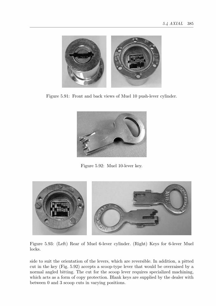
5.4 AXIAL 385
Figure 5.91: Front and back views of Muel 10 push-lever cylinder.
Figure 5.92: Muel 10-lever key.
Figure 5.93: (Left) Rear of Muel 6-lever cylinder. (Right) Keys for 6-lever Muellocks.
side to suit the orientation of the levers, which are reversible. In addition, a pittedcut in the key (Fig. 5.92) accepts a scoop-type lever that would be overraised by anormal angled bitting. The cut for the scoop lever requires specialized machining,which acts as a form of copy protection. Blank keys are supplied by the dealer withbetween 0 and 3 scoop cuts in varying positions.
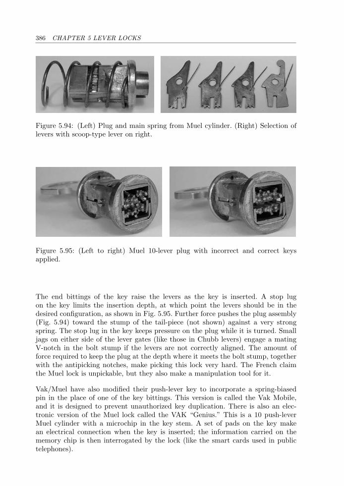
386 CHAPTER 5 LEVER LOCKS
Figure 5.94: (Left) Plug and main spring from Muel cylinder. (Right) Selection oflevers with scoop-type lever on right.
Figure 5.95: (Left to right) Muel 10-lever plug with incorrect and correct keysapplied.
The end bittings of the key raise the levers as the key is inserted. A stop lugon the key limits the insertion depth, at which point the levers should be in thedesired configuration, as shown in Fig. 5.95. Further force pushes the plug assembly(Fig. 5.94) toward the stump of the tail-piece (not shown) against a very strongspring. The stop lug in the key keeps pressure on the plug while it is turned. Smalljags on either side of the lever gates (like those in Chubb levers) engage a matingV-notch in the bolt stump if the levers are not correctly aligned. The amount offorce required to keep the plug at the depth where it meets the bolt stump, togetherwith the antipicking notches, make picking this lock very hard. The French claimthe Muel lock is unpickable, but they also make a manipulation tool for it.
Vak/Muel have also modified their push-lever key to incorporate a spring-biasedpin in the place of one of the key bittings. This version is called the Vak Mobile,and it is designed to prevent unauthorized key duplication. There is also an elec-tronic version of the Muel lock called the VAK “Genius.” This is a 10 push-leverMuel cylinder with a microchip in the key stem. A set of pads on the key makean electrical connection when the key is inserted; the information carried on thememory chip is then interrogated by the lock (like the smart cards used in publictelephones).
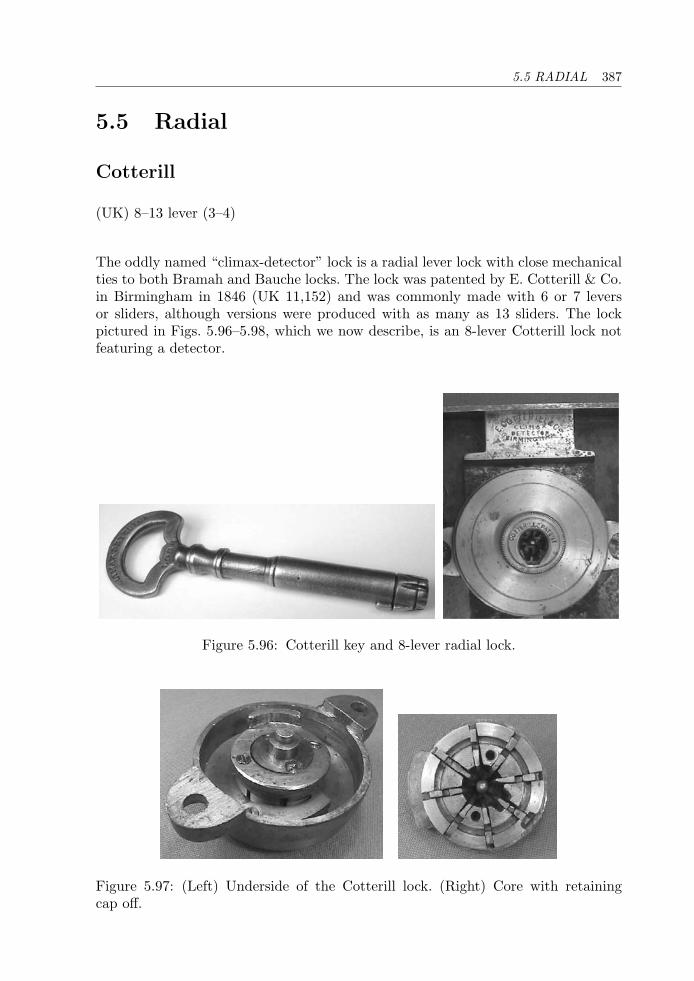
5.5 RADIAL 387
5.5 Radial
Cotterill
(UK) 8–13 lever (3–4)
The oddly named “climax-detector” lock is a radial lever lock with close mechanicalties to both Bramah and Bauche locks. The lock was patented by E. Cotterill & Co.in Birmingham in 1846 (UK 11,152) and was commonly made with 6 or 7 leversor sliders, although versions were produced with as many as 13 sliders. The lockpictured in Figs. 5.96–5.98, which we now describe, is an 8-lever Cotterill lock notfeaturing a detector.
Figure 5.96: Cotterill key and 8-lever radial lock.
Figure 5.97: (Left) Underside of the Cotterill lock. (Right) Core with retainingcap off.
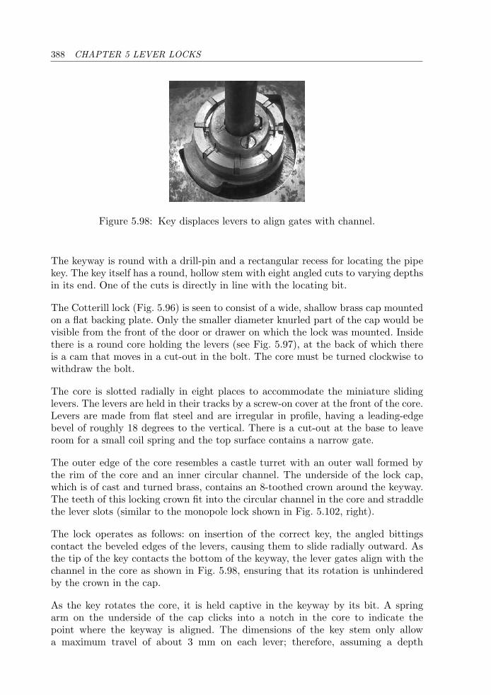
388 CHAPTER 5 LEVER LOCKS
Figure 5.98: Key displaces levers to align gates with channel.
The keyway is round with a drill-pin and a rectangular recess for locating the pipekey. The key itself has a round, hollow stem with eight angled cuts to varying depthsin its end. One of the cuts is directly in line with the locating bit.
The Cotterill lock (Fig. 5.96) is seen to consist of a wide, shallow brass cap mountedon a flat backing plate. Only the smaller diameter knurled part of the cap would bevisible from the front of the door or drawer on which the lock was mounted. Insidethere is a round core holding the levers (see Fig. 5.97), at the back of which thereis a cam that moves in a cut-out in the bolt. The core must be turned clockwise towithdraw the bolt.
The core is slotted radially in eight places to accommodate the miniature slidinglevers. The levers are held in their tracks by a screw-on cover at the front of the core.Levers are made from flat steel and are irregular in profile, having a leading-edgebevel of roughly 18 degrees to the vertical. There is a cut-out at the base to leaveroom for a small coil spring and the top surface contains a narrow gate.
The outer edge of the core resembles a castle turret with an outer wall formed bythe rim of the core and an inner circular channel. The underside of the lock cap,which is of cast and turned brass, contains an 8-toothed crown around the keyway.The teeth of this locking crown fit into the circular channel in the core and straddlethe lever slots (similar to the monopole lock shown in Fig. 5.102, right).
The lock operates as follows: on insertion of the correct key, the angled bittingscontact the beveled edges of the levers, causing them to slide radially outward. Asthe tip of the key contacts the bottom of the keyway, the lever gates align with thechannel in the core as shown in Fig. 5.98, ensuring that its rotation is unhinderedby the crown in the cap.
As the key rotates the core, it is held captive in the keyway by its bit. A springarm on the underside of the cap clicks into a notch in the core to indicate thepoint where the keyway is aligned. The dimensions of the key stem only allowa maximum travel of about 3 mm on each lever; therefore, assuming a depth
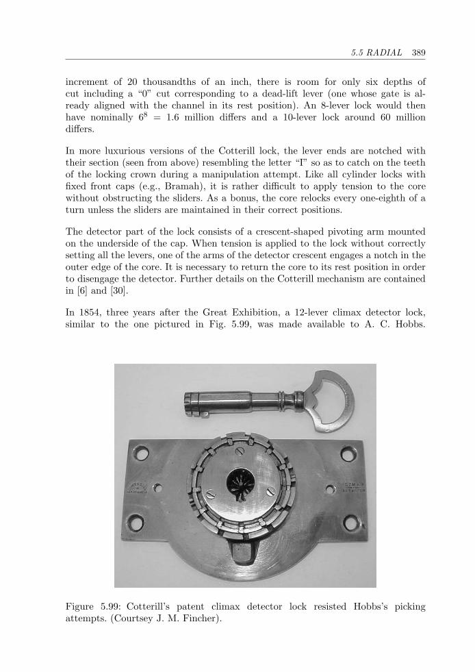
5.5 RADIAL 389
increment of 20 thousandths of an inch, there is room for only six depths ofcut including a “0” cut corresponding to a dead-lift lever (one whose gate is al-ready aligned with the channel in its rest position). An 8-lever lock would thenhave nominally 68 = 1.6 million differs and a 10-lever lock around 60 milliondiffers.
In more luxurious versions of the Cotterill lock, the lever ends are notched withtheir section (seen from above) resembling the letter “I” so as to catch on the teethof the locking crown during a manipulation attempt. Like all cylinder locks withfixed front caps (e.g., Bramah), it is rather difficult to apply tension to the corewithout obstructing the sliders. As a bonus, the core relocks every one-eighth of aturn unless the sliders are maintained in their correct positions.
The detector part of the lock consists of a crescent-shaped pivoting arm mountedon the underside of the cap. When tension is applied to the lock without correctlysetting all the levers, one of the arms of the detector crescent engages a notch in theouter edge of the core. It is necessary to return the core to its rest position in orderto disengage the detector. Further details on the Cotterill mechanism are containedin [6] and [30].
In 1854, three years after the Great Exhibition, a 12-lever climax detector lock,similar to the one pictured in Fig. 5.99, was made available to A. C. Hobbs.
Figure 5.99: Cotterill’s patent climax detector lock resisted Hobbs’s pickingattempts. (Courtsey J. M. Fincher).
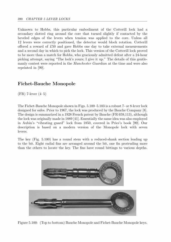
390 CHAPTER 5 LEVER LOCKS
Unknown to Hobbs, this particular embodiment of the Cotterill lock had asecondary slotted ring around the core that turned slightly if contacted by thebeveled edges of the levers when tension was applied to the core. Unless all12 levers were correctly positioned, the detector would block rotation. Cotterilloffered a reward of £50 and gave Hobbs one day to take external measurementsand a second day in which to pick the lock. This version of the Cotterill lock provedto be more than a match for Hobbs, who graciously admitted defeat after a 24-hourpicking attempt, saying “The lock’s yours; I give it up.” The details of this gentle-manly contest were reported in the Manchester Guardian at the time and were alsoreprinted in [99].
Fichet-Bauche Monopole
(FR) 7-lever (4–5)
The Fichet-Bauche Monopole shown in Figs. 5.100–5.103 is a robust 7- or 8-lever lockdesigned for safes. Prior to 1967, the lock was produced by the Bauche Company [8].The design is summarized in a 1928 French patent by Bauche (FR 659,113), althoughthe lock was originally made in 1889 [41]. Essentially the same idea was also employedin Aubin’s “vibrating guard” lock from 1850, covered in Price’s book [99]. Ourdescription is based on a modern version of the Monopole lock with sevenlevers.
The key (Fig. 5.100) has a round stem with a reduced-shank section leading upto the bit. Eight radial fins are arranged around the bit, one fin protruding morethan the others to locate the key. The fins have round bittings to various depths.
Figure 5.100: (Top to bottom) Bauche Monopole and Fichet-Bauche Monopole keys.
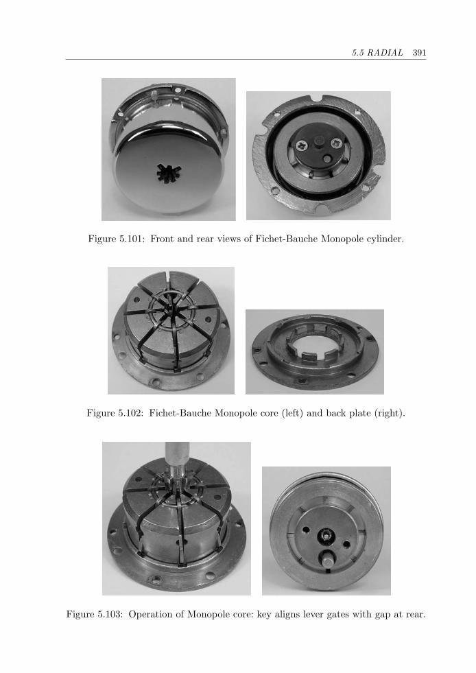
5.5 RADIAL 391
Figure 5.101: Front and rear views of Fichet-Bauche Monopole cylinder.
Figure 5.102: Fichet-Bauche Monopole core (left) and back plate (right).
Figure 5.103: Operation of Monopole core: key aligns lever gates with gap at rear.
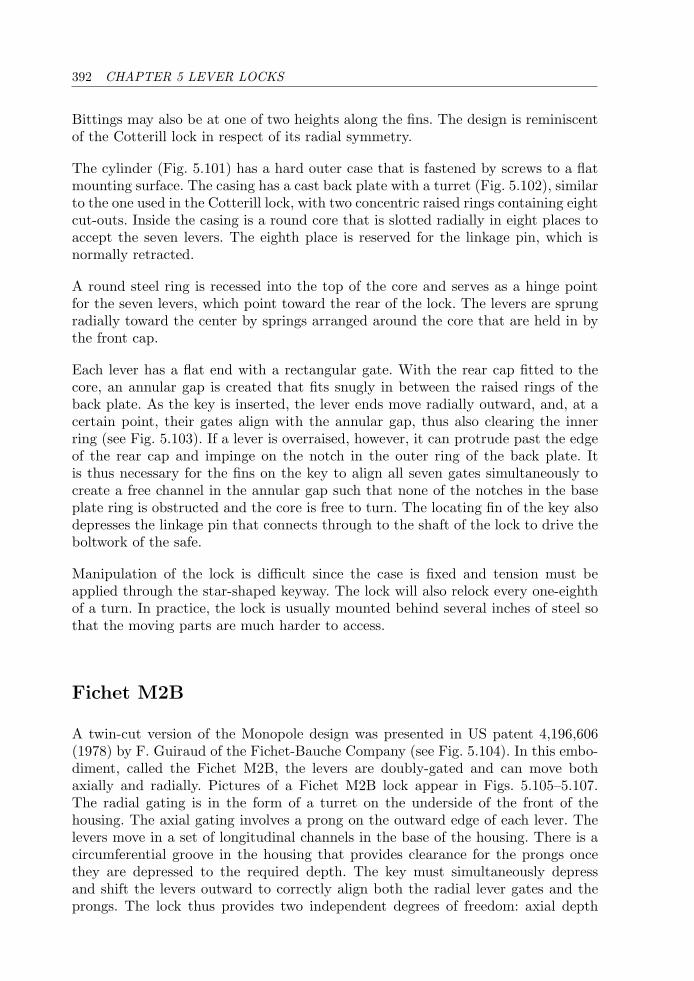
392 CHAPTER 5 LEVER LOCKS
Bittings may also be at one of two heights along the fins. The design is reminiscentof the Cotterill lock in respect of its radial symmetry.
The cylinder (Fig. 5.101) has a hard outer case that is fastened by screws to a flatmounting surface. The casing has a cast back plate with a turret (Fig. 5.102), similarto the one used in the Cotterill lock, with two concentric raised rings containing eightcut-outs. Inside the casing is a round core that is slotted radially in eight places toaccept the seven levers. The eighth place is reserved for the linkage pin, which isnormally retracted.
A round steel ring is recessed into the top of the core and serves as a hinge pointfor the seven levers, which point toward the rear of the lock. The levers are sprungradially toward the center by springs arranged around the core that are held in bythe front cap.
Each lever has a flat end with a rectangular gate. With the rear cap fitted to thecore, an annular gap is created that fits snugly in between the raised rings of theback plate. As the key is inserted, the lever ends move radially outward, and, at acertain point, their gates align with the annular gap, thus also clearing the innerring (see Fig. 5.103). If a lever is overraised, however, it can protrude past the edgeof the rear cap and impinge on the notch in the outer ring of the back plate. Itis thus necessary for the fins on the key to align all seven gates simultaneously tocreate a free channel in the annular gap such that none of the notches in the baseplate ring is obstructed and the core is free to turn. The locating fin of the key alsodepresses the linkage pin that connects through to the shaft of the lock to drive theboltwork of the safe.
Manipulation of the lock is difficult since the case is fixed and tension must beapplied through the star-shaped keyway. The lock will also relock every one-eighthof a turn. In practice, the lock is usually mounted behind several inches of steel sothat the moving parts are much harder to access.
Fichet M2B
A twin-cut version of the Monopole design was presented in US patent 4,196,606(1978) by F. Guiraud of the Fichet-Bauche Company (see Fig. 5.104). In this embo-diment, called the Fichet M2B, the levers are doubly-gated and can move bothaxially and radially. Pictures of a Fichet M2B lock appear in Figs. 5.105–5.107.The radial gating is in the form of a turret on the underside of the front of thehousing. The axial gating involves a prong on the outward edge of each lever. Thelevers move in a set of longitudinal channels in the base of the housing. There is acircumferential groove in the housing that provides clearance for the prongs oncethey are depressed to the required depth. The key must simultaneously depressand shift the levers outward to correctly align both the radial lever gates and theprongs. The lock thus provides two independent degrees of freedom: axial depth
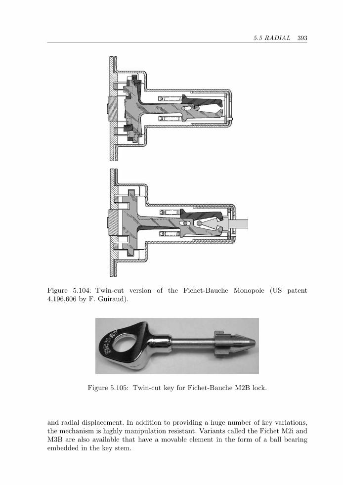
5.5 RADIAL 393
Figure 5.104: Twin-cut version of the Fichet-Bauche Monopole (US patent4,196,606 by F. Guiraud).
Figure 5.105: Twin-cut key for Fichet-Bauche M2B lock.
and radial displacement. In addition to providing a huge number of key variations,the mechanism is highly manipulation resistant. Variants called the Fichet M2i andM3B are also available that have a movable element in the form of a ball bearingembedded in the key stem.
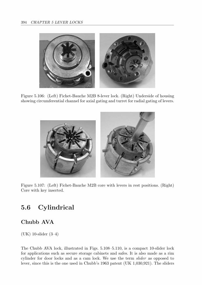
394 CHAPTER 5 LEVER LOCKS
Figure 5.106: (Left) Fichet-Bauche M2B 8-lever lock. (Right) Underside of housingshowing circumferential channel for axial gating and turret for radial gating of levers.
Figure 5.107: (Left) Fichet-Bauche M2B core with levers in rest positions. (Right)Core with key inserted.
5.6 Cylindrical
Chubb AVA
(UK) 10-slider (3–4)
The Chubb AVA lock, illustrated in Figs. 5.108–5.110, is a compact 10-slider lockfor applications such as secure storage cabinets and safes. It is also made as a rimcylinder for door locks and as a cam lock. We use the term slider as opposed tolever, since this is the one used in Chubb’s 1963 patent (UK 1,030,921). The sliders
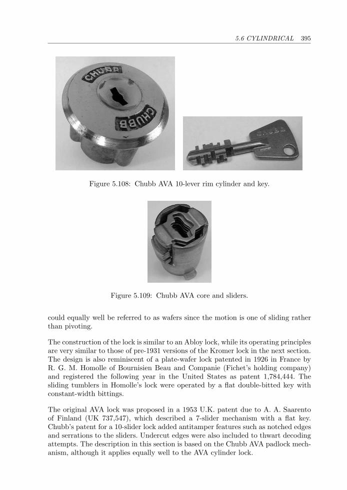
5.6 CYLINDRICAL 395
Figure 5.108: Chubb AVA 10-lever rim cylinder and key.
Figure 5.109: Chubb AVA core and sliders.
could equally well be referred to as wafers since the motion is one of sliding ratherthan pivoting.
The construction of the lock is similar to an Abloy lock, while its operating principlesare very similar to those of pre-1931 versions of the Kromer lock in the next section.The design is also reminiscent of a plate-wafer lock patented in 1926 in France byR. G. M. Homolle of Bournisien Beau and Companie (Fichet’s holding company)and registered the following year in the United States as patent 1,784,444. Thesliding tumblers in Homolle’s lock were operated by a flat double-bitted key withconstant-width bittings.
The original AVA lock was proposed in a 1953 U.K. patent due to A. A. Saarentoof Finland (UK 737,547), which described a 7-slider mechanism with a flat key.Chubb’s patent for a 10-slider lock added antitamper features such as notched edgesand serrations to the sliders. Undercut edges were also included to thwart decodingattempts. The description in this section is based on the Chubb AVA padlock mech-anism, although it applies equally well to the AVA cylinder lock.
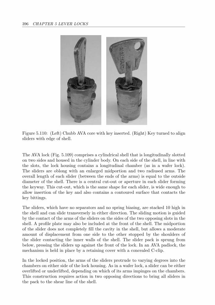
396 CHAPTER 5 LEVER LOCKS
Figure 5.110: (Left) Chubb AVA core with key inserted. (Right) Key turned to alignsliders with edge of shell.
The AVA lock (Fig. 5.109) comprises a cylindrical shell that is longitudinally slottedon two sides and housed in the cylinder body. On each side of the shell, in line withthe slots, the lock housing contains a longitudinal chamber (as in a wafer lock).The sliders are oblong with an enlarged midportion and two radiused arms. Theoverall length of each slider (between the ends of the arms) is equal to the outsidediameter of the shell. There is a central cut-out or aperture in each slider formingthe keyway. This cut-out, which is the same shape for each slider, is wide enough toallow insertion of the key and also contains a contoured surface that contacts thekey bittings.
The sliders, which have no separators and no spring biasing, are stacked 10 high inthe shell and can slide transversely in either direction. The sliding motion is guidedby the contact of the arms of the sliders on the sides of the two opposing slots in theshell. A profile plate may also be included at the front of the shell. The midportionof the slider does not completely fill the cavity in the shell, but allows a moderateamount of displacement from one side to the other stopped by the shoulders ofthe slider contacting the inner walls of the shell. The slider pack is sprung frombelow, pressing the sliders up against the front of the lock. In an AVA padlock, themechanism is held in place by a retaining cover with a concealed C-clip.
In the locked position, the arms of the sliders protrude to varying degrees into thechambers on either side of the lock housing. As in a wafer lock, a slider can be eitheroverlifted or underlifted, depending on which of its arms impinges on the chambers.This construction requires action in two opposing directions to bring all sliders inthe pack to the shear line of the shell.
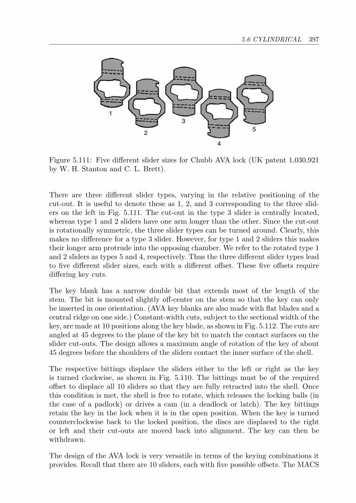
5.6 CYLINDRICAL 397
1
2
3
4
5
Figure 5.111: Five different slider sizes for Chubb AVA lock (UK patent 1,030,921by W. H. Stanton and C. L. Brett).
There are three different slider types, varying in the relative positioning of thecut-out. It is useful to denote these as 1, 2, and 3 corresponding to the three slid-ers on the left in Fig. 5.111. The cut-out in the type 3 slider is centrally located,whereas type 1 and 2 sliders have one arm longer than the other. Since the cut-outis rotationally symmetric, the three slider types can be turned around. Clearly, thismakes no difference for a type 3 slider. However, for type 1 and 2 sliders this makestheir longer arm protrude into the opposing chamber. We refer to the rotated type 1and 2 sliders as types 5 and 4, respectively. Thus the three different slider types leadto five different slider sizes, each with a different offset. These five offsets requirediffering key cuts.
The key blank has a narrow double bit that extends most of the length of thestem. The bit is mounted slightly off-center on the stem so that the key can onlybe inserted in one orientation. (AVA key blanks are also made with flat blades and acentral ridge on one side.) Constant-width cuts, subject to the sectional width of thekey, are made at 10 positions along the key blade, as shown in Fig. 5.112. The cuts areangled at 45 degrees to the plane of the key bit to match the contact surfaces on theslider cut-outs. The design allows a maximum angle of rotation of the key of about45 degrees before the shoulders of the sliders contact the inner surface of the shell.
The respective bittings displace the sliders either to the left or right as the keyis turned clockwise, as shown in Fig. 5.110. The bittings must be of the requiredoffset to displace all 10 sliders so that they are fully retracted into the shell. Oncethis condition is met, the shell is free to rotate, which releases the locking balls (inthe case of a padlock) or drives a cam (in a deadlock or latch). The key bittingsretain the key in the lock when it is in the open position. When the key is turnedcounterclockwise back to the locked position, the discs are displaced to the rightor left and their cut-outs are moved back into alignment. The key can then bewithdrawn.
The design of the AVA lock is very versatile in terms of the keying combinations itprovides. Recall that there are 10 sliders, each with five possible offsets. The MACS
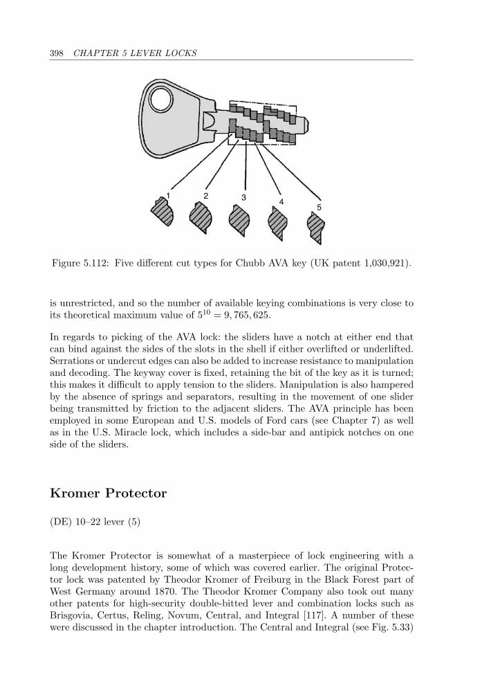
398 CHAPTER 5 LEVER LOCKS
1 2 3 45
Figure 5.112: Five different cut types for Chubb AVA key (UK patent 1,030,921).
is unrestricted, and so the number of available keying combinations is very close toits theoretical maximum value of 510 = 9, 765, 625.
In regards to picking of the AVA lock: the sliders have a notch at either end thatcan bind against the sides of the slots in the shell if either overlifted or underlifted.Serrations or undercut edges can also be added to increase resistance to manipulationand decoding. The keyway cover is fixed, retaining the bit of the key as it is turned;this makes it difficult to apply tension to the sliders. Manipulation is also hamperedby the absence of springs and separators, resulting in the movement of one sliderbeing transmitted by friction to the adjacent sliders. The AVA principle has beenemployed in some European and U.S. models of Ford cars (see Chapter 7) as wellas in the U.S. Miracle lock, which includes a side-bar and antipick notches on oneside of the sliders.
Kromer Protector
(DE) 10–22 lever (5)
The Kromer Protector is somewhat of a masterpiece of lock engineering with along development history, some of which was covered earlier. The original Protec-tor lock was patented by Theodor Kromer of Freiburg in the Black Forest part ofWest Germany around 1870. The Theodor Kromer Company also took out manyother patents for high-security double-bitted lever and combination locks such asBrisgovia, Certus, Reling, Novum, Central, and Integral [117]. A number of thesewere discussed in the chapter introduction. The Central and Integral (see Fig. 5.33)
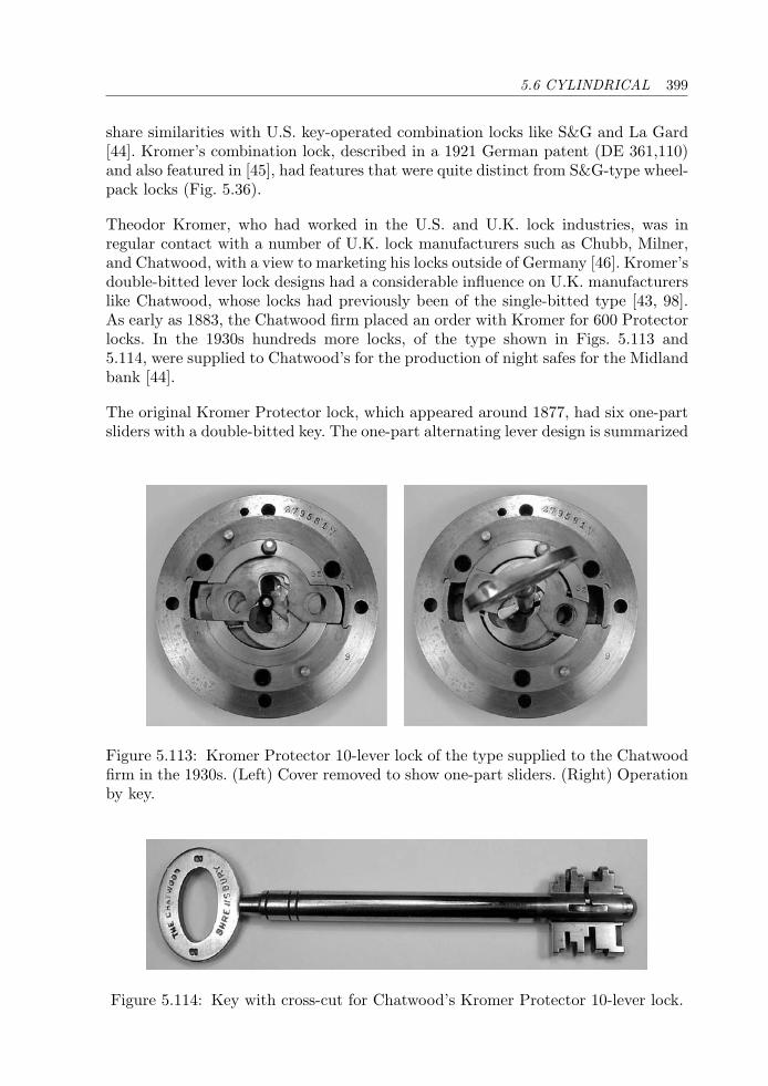
5.6 CYLINDRICAL 399
share similarities with U.S. key-operated combination locks like S&G and La Gard[44]. Kromer’s combination lock, described in a 1921 German patent (DE 361,110)and also featured in [45], had features that were quite distinct from S&G-type wheel-pack locks (Fig. 5.36).
Theodor Kromer, who had worked in the U.S. and U.K. lock industries, was inregular contact with a number of U.K. lock manufacturers such as Chubb, Milner,and Chatwood, with a view to marketing his locks outside of Germany [46]. Kromer’sdouble-bitted lever lock designs had a considerable influence on U.K. manufacturerslike Chatwood, whose locks had previously been of the single-bitted type [43, 98].As early as 1883, the Chatwood firm placed an order with Kromer for 600 Protectorlocks. In the 1930s hundreds more locks, of the type shown in Figs. 5.113 and5.114, were supplied to Chatwood’s for the production of night safes for the Midlandbank [44].
The original Kromer Protector lock, which appeared around 1877, had six one-partsliders with a double-bitted key. The one-part alternating lever design is summarized
Figure 5.113: Kromer Protector 10-lever lock of the type supplied to the Chatwoodfirm in the 1930s. (Left) Cover removed to show one-part sliders. (Right) Operationby key.
Figure 5.114: Key with cross-cut for Chatwood’s Kromer Protector 10-lever lock.
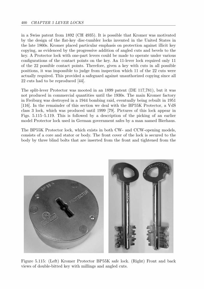
400 CHAPTER 5 LEVER LOCKS
in a Swiss patent from 1892 (CH 4935). It is possible that Kromer was motivatedby the design of the flat-key disc-tumbler locks invented in the United States inthe late 1860s. Kromer placed particular emphasis on protection against illicit keycopying, as evidenced by the progressive addition of angled cuts and bevels to thekey. A Protector lock with one-part levers could be made to operate under variousconfigurations of the contact points on the key. An 11-lever lock required only 11of the 22 possible contact points. Therefore, given a key with cuts in all possiblepositions, it was impossible to judge from inspection which 11 of the 22 cuts wereactually required. This provided a safeguard against unauthorized copying since all22 cuts had to be reproduced [44].
The split-lever Protector was mooted in an 1899 patent (DE 117,781), but it wasnot produced in commercial quantities until the 1930s. The main Kromer factoryin Freiburg was destroyed in a 1944 bombing raid, eventually being rebuilt in 1951[116]. In the remainder of this section we deal with the BP55K Protector, a VdSclass 3 lock, which was produced until 1999 [79]. Pictures of this lock appear inFigs. 5.115–5.119. This is followed by a description of the picking of an earliermodel Protector lock used in German government safes by a man named Bierhaus.
The BP55K Protector lock, which exists in both CW- and CCW-opening models,consists of a core and stator or body. The front cover of the lock is secured to thebody by three blind bolts that are inserted from the front and tightened from the
Figure 5.115: (Left) Kromer Protector BP55K safe lock. (Right) Front and backviews of double-bitted key with millings and angled cuts.
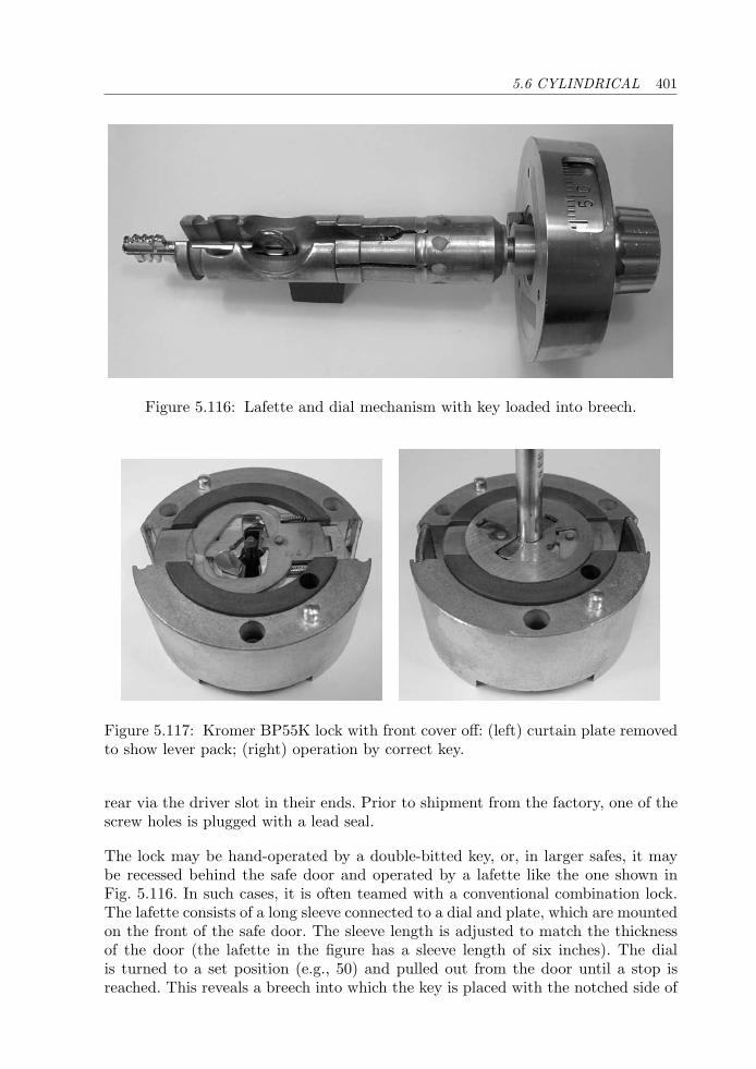
5.6 CYLINDRICAL 401
Figure 5.116: Lafette and dial mechanism with key loaded into breech.
Figure 5.117: Kromer BP55K lock with front cover off: (left) curtain plate removedto show lever pack; (right) operation by correct key.
rear via the driver slot in their ends. Prior to shipment from the factory, one of thescrew holes is plugged with a lead seal.
The lock may be hand-operated by a double-bitted key, or, in larger safes, it maybe recessed behind the safe door and operated by a lafette like the one shown inFig. 5.116. In such cases, it is often teamed with a conventional combination lock.The lafette consists of a long sleeve connected to a dial and plate, which are mountedon the front of the safe door. The sleeve length is adjusted to match the thicknessof the door (the lafette in the figure has a sleeve length of six inches). The dialis turned to a set position (e.g., 50) and pulled out from the door until a stop isreached. This reveals a breech into which the key is placed with the notched side of
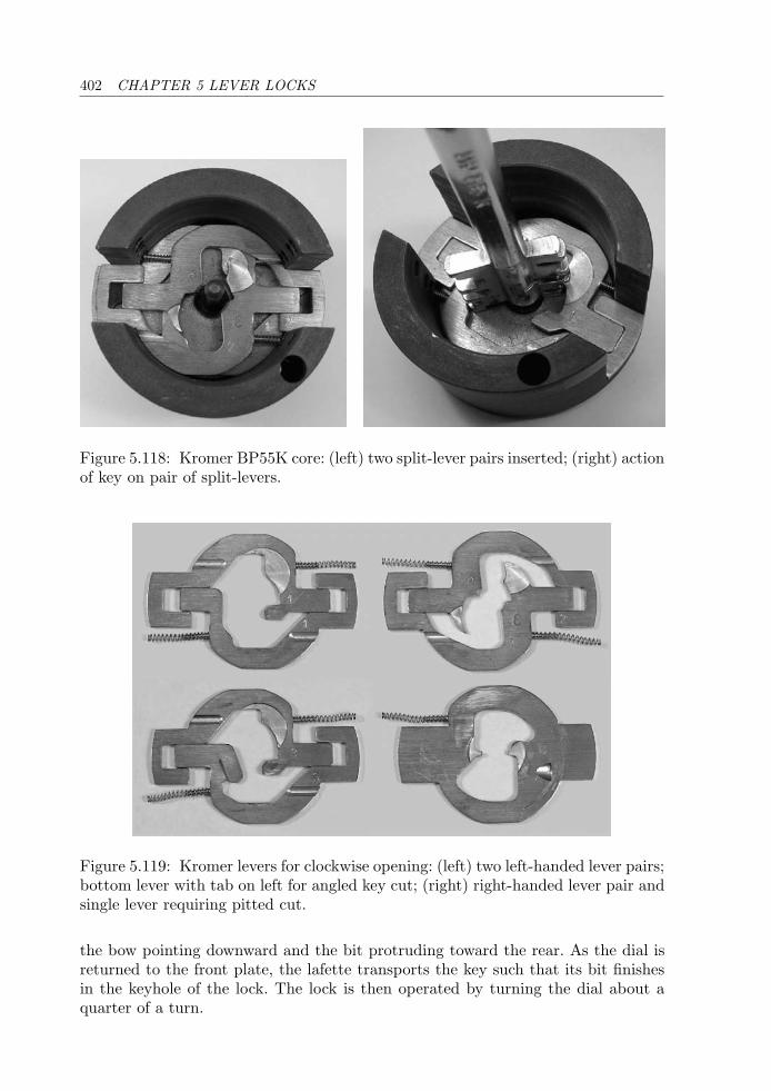
402 CHAPTER 5 LEVER LOCKS
Figure 5.118: Kromer BP55K core: (left) two split-lever pairs inserted; (right) actionof key on pair of split-levers.
Figure 5.119: Kromer levers for clockwise opening: (left) two left-handed lever pairs;bottom lever with tab on left for angled key cut; (right) right-handed lever pair andsingle lever requiring pitted cut.
the bow pointing downward and the bit protruding toward the rear. As the dial isreturned to the front plate, the lafette transports the key such that its bit finishesin the keyhole of the lock. The lock is then operated by turning the dial about aquarter of a turn.
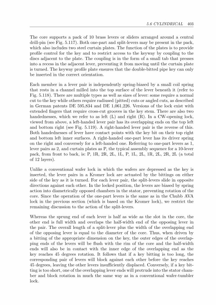
5.6 CYLINDRICAL 403
The core supports a pack of 10 brass levers or sliders arranged around a centraldrill-pin (see Fig. 5.117). Both one-part and split-levers may be present in the pack,which also includes two steel curtain plates. The function of the plates is to provideprofile control for the key and to restrict access to the keyway by coupling to thediscs adjacent to the plate. The coupling is in the form of a small tab that pressesinto a recess in the adjacent lever, preventing it from moving until the curtain plateis turned. The keyway profile plate ensures that the double-bitted pipe key can onlybe inserted in the correct orientation.
Each member in a lever pair is independently spring-biased by a small coil springthat rests in a channel milled into the top surface of the lever beneath it (refer toFig. 5.118). There are multiple types as well as sizes of lever: some require a normalcut to the key while others require radiused (pitted) cuts or angled cuts, as describedin German patents DE 595,834 and DE 1,061,226. Versions of the lock exist withextended fingers that require cross-cut grooves in the key stem. There are also twohandednesses, which we refer to as left (L) and right (R). In a CW-opening lock,viewed from above, a left-handed lever pair has its overlapping ends on the top leftand bottom right (see Fig. 5.119). A right-handed lever pair is the reverse of this.Both handednesses of lever have contact points with the key bit on their top rightand bottom left inner surfaces. A right-handed one-part lever has its driver springon the right and conversely for a left-handed one. Referring to one-part levers as 1,lever pairs as 2, and curtain plates as P, the typical assembly sequence for a 10-leverpack, from front to back, is: P, 1R, 2R, 2L, 1L, P, 1L, 2L, 1R, 2L, 2R, 2L (a totalof 12 layers).
Unlike a conventional wafer lock in which the wafers are depressed as the key isinserted, the lever pairs in a Kromer lock are actuated by the bittings on eitherside of the key as it is turned. For each lever pair, the split-levers slide in oppositedirections against each other. In the locked position, the levers are biased by springaction into diametrically opposed chambers in the stator, preventing rotation of thecore. Since the operation of the one-part levers is the same as in the Chubb AVAlock in the previous section (which is based on the Kromer lock), we restrict theremaining discussion to the action of the split-levers.
Whereas the sprung end of each lever is half as wide as the slot in the core, theother end is full width and overlaps the half-width end of the opposing lever inthe pair. The overall length of a split-lever plus the width of the overlapping endof the opposing lever is equal to the diameter of the core. Thus, when driven bya bitting of the appropriate dimension on the key, the outer edges of the overlap-ping ends of the levers will be flush with the rim of the core and the half-widthends will also be in contact with the inner edge of the overlapping end as thekey reaches 45 degrees rotation. It follows that if a key bitting is too long, thecorresponding pair of levers will block against each other before the key reaches45 degrees, leaving the other levers insufficiently displaced. Conversely, if a key bit-ting is too short, one of the overlapping lever ends will protrude into the stator cham-ber and block rotation in much the same way as in a conventional wafer-tumblerlock.
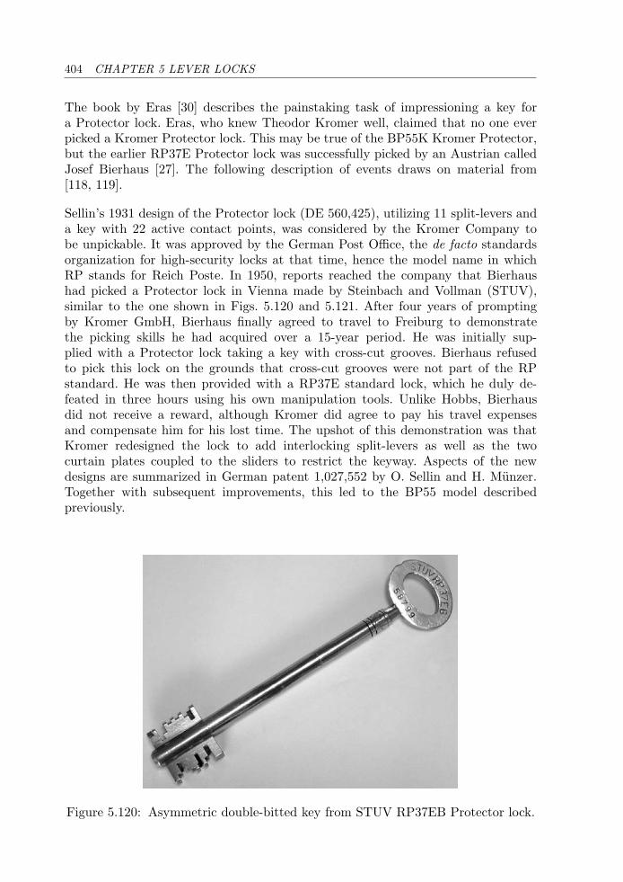
404 CHAPTER 5 LEVER LOCKS
The book by Eras [30] describes the painstaking task of impressioning a key fora Protector lock. Eras, who knew Theodor Kromer well, claimed that no one everpicked a Kromer Protector lock. This may be true of the BP55K Kromer Protector,but the earlier RP37E Protector lock was successfully picked by an Austrian calledJosef Bierhaus [27]. The following description of events draws on material from[118, 119].
Sellin’s 1931 design of the Protector lock (DE 560,425), utilizing 11 split-levers anda key with 22 active contact points, was considered by the Kromer Company tobe unpickable. It was approved by the German Post Office, the de facto standardsorganization for high-security locks at that time, hence the model name in whichRP stands for Reich Poste. In 1950, reports reached the company that Bierhaushad picked a Protector lock in Vienna made by Steinbach and Vollman (STUV),similar to the one shown in Figs. 5.120 and 5.121. After four years of promptingby Kromer GmbH, Bierhaus finally agreed to travel to Freiburg to demonstratethe picking skills he had acquired over a 15-year period. He was initially sup-plied with a Protector lock taking a key with cross-cut grooves. Bierhaus refusedto pick this lock on the grounds that cross-cut grooves were not part of the RPstandard. He was then provided with a RP37E standard lock, which he duly de-feated in three hours using his own manipulation tools. Unlike Hobbs, Bierhausdid not receive a reward, although Kromer did agree to pay his travel expensesand compensate him for his lost time. The upshot of this demonstration was thatKromer redesigned the lock to add interlocking split-levers as well as the twocurtain plates coupled to the sliders to restrict the keyway. Aspects of the newdesigns are summarized in German patent 1,027,552 by O. Sellin and H. Munzer.Together with subsequent improvements, this led to the BP55 model describedpreviously.
Figure 5.120: Asymmetric double-bitted key from STUV RP37EB Protector lock.
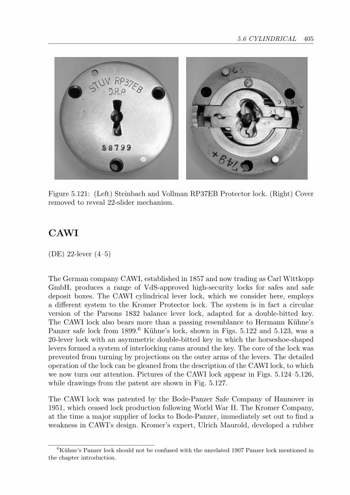
5.6 CYLINDRICAL 405
Figure 5.121: (Left) Steinbach and Vollman RP37EB Protector lock. (Right) Coverremoved to reveal 22-slider mechanism.
CAWI
(DE) 22-lever (4–5)
The German company CAWI, established in 1857 and now trading as Carl WittkoppGmbH, produces a range of VdS-approved high-security locks for safes and safedeposit boxes. The CAWI cylindrical lever lock, which we consider here, employsa different system to the Kromer Protector lock. The system is in fact a circularversion of the Parsons 1832 balance lever lock, adapted for a double-bitted key.The CAWI lock also bears more than a passing resemblance to Hermann Kuhne’sPanzer safe lock from 1899.6 Kuhne’s lock, shown in Figs. 5.122 and 5.123, was a20-lever lock with an asymmetric double-bitted key in which the horseshoe-shapedlevers formed a system of interlocking cams around the key. The core of the lock wasprevented from turning by projections on the outer arms of the levers. The detailedoperation of the lock can be gleaned from the description of the CAWI lock, to whichwe now turn our attention. Pictures of the CAWI lock appear in Figs. 5.124–5.126,while drawings from the patent are shown in Fig. 5.127.
The CAWI lock was patented by the Bode-Panzer Safe Company of Hannover in1951, which ceased lock production following World War II. The Kromer Company,at the time a major supplier of locks to Bode-Panzer, immediately set out to find aweakness in CAWI’s design. Kromer’s expert, Ulrich Maurold, developed a rubber
6Kuhne’s Panzer lock should not be confused with the unrelated 1907 Panzer lock mentioned inthe chapter introduction.
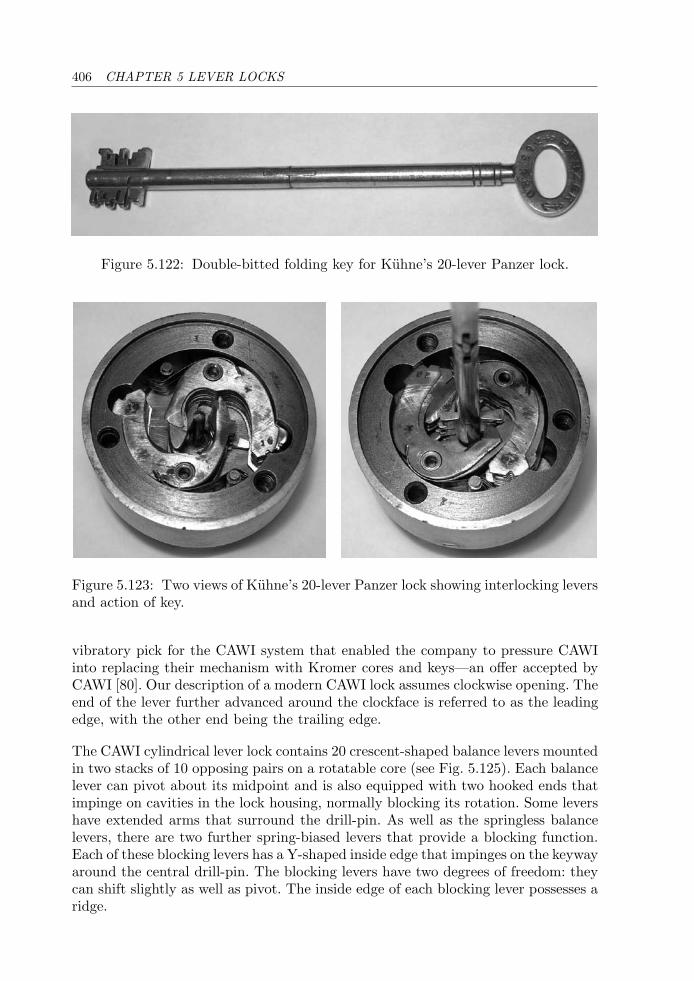
406 CHAPTER 5 LEVER LOCKS
Figure 5.122: Double-bitted folding key for Kuhne’s 20-lever Panzer lock.
Figure 5.123: Two views of Kuhne’s 20-lever Panzer lock showing interlocking leversand action of key.
vibratory pick for the CAWI system that enabled the company to pressure CAWIinto replacing their mechanism with Kromer cores and keys—an offer accepted byCAWI [80]. Our description of a modern CAWI lock assumes clockwise opening. Theend of the lever further advanced around the clockface is referred to as the leadingedge, with the other end being the trailing edge.
The CAWI cylindrical lever lock contains 20 crescent-shaped balance levers mountedin two stacks of 10 opposing pairs on a rotatable core (see Fig. 5.125). Each balancelever can pivot about its midpoint and is also equipped with two hooked ends thatimpinge on cavities in the lock housing, normally blocking its rotation. Some levershave extended arms that surround the drill-pin. As well as the springless balancelevers, there are two further spring-biased levers that provide a blocking function.Each of these blocking levers has a Y-shaped inside edge that impinges on the keywayaround the central drill-pin. The blocking levers have two degrees of freedom: theycan shift slightly as well as pivot. The inside edge of each blocking lever possesses aridge.
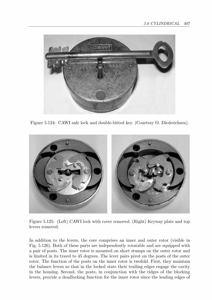
5.6 CYLINDRICAL 407
Figure 5.124: CAWI safe lock and double-bitted key. (Courtesy O. Diederichsen).
Figure 5.125: (Left) CAWI lock with cover removed. (Right) Keyway plate and toplevers removed.
In addition to the levers, the core comprises an inner and outer rotor (visible inFig. 5.126). Both of these parts are independently rotatable and are equipped witha pair of posts. The inner rotor is mounted on short stumps on the outer rotor andis limited in its travel to 45 degrees. The lever pairs pivot on the posts of the outerrotor. The function of the posts on the inner rotor is twofold. First, they maintainthe balance levers so that in the locked state their trailing edges engage the cavityin the housing. Second, the posts, in conjunction with the ridges of the blockinglevers, provide a deadlocking function for the inner rotor since the leading edges of
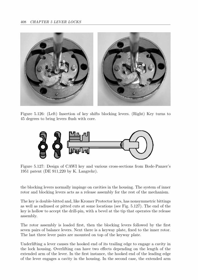
408 CHAPTER 5 LEVER LOCKS
Figure 5.126: (Left) Insertion of key shifts blocking levers. (Right) Key turns to45 degrees to bring levers flush with core.
Figure 5.127: Design of CAWI key and various cross-sections from Bode-Panzer’s1951 patent (DE 911,220 by K. Langrehr).
the blocking levers normally impinge on cavities in the housing. The system of innerrotor and blocking levers acts as a release assembly for the rest of the mechanism.
The key is double-bitted and, like Kromer Protector keys, has nonsymmetric bittingsas well as radiused or pitted cuts at some locations (see Fig. 5.127). The end of thekey is hollow to accept the drill-pin, with a bevel at the tip that operates the releaseassembly.
The rotor assembly is loaded first, then the blocking levers followed by the firstseven pairs of balance levers. Next there is a keyway plate, fixed to the inner rotor.The last three lever pairs are mounted on top of the keyway plate.
Underlifting a lever causes the hooked end of its trailing edge to engage a cavity inthe lock housing. Overlifting can have two effects depending on the length of theextended arm of the lever. In the first instance, the hooked end of the leading edgeof the lever engages a cavity in the housing. In the second case, the extended arm
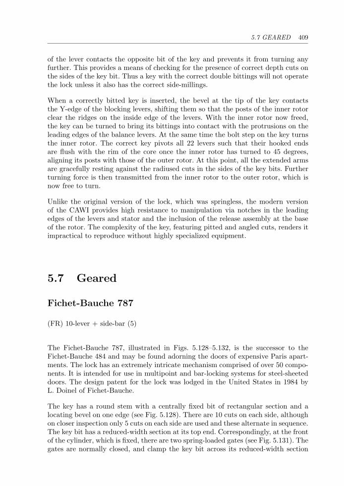
5.7 GEARED 409
of the lever contacts the opposite bit of the key and prevents it from turning anyfurther. This provides a means of checking for the presence of correct depth cuts onthe sides of the key bit. Thus a key with the correct double bittings will not operatethe lock unless it also has the correct side-millings.
When a correctly bitted key is inserted, the bevel at the tip of the key contactsthe Y-edge of the blocking levers, shifting them so that the posts of the inner rotorclear the ridges on the inside edge of the levers. With the inner rotor now freed,the key can be turned to bring its bittings into contact with the protrusions on theleading edges of the balance levers. At the same time the bolt step on the key turnsthe inner rotor. The correct key pivots all 22 levers such that their hooked endsare flush with the rim of the core once the inner rotor has turned to 45 degrees,aligning its posts with those of the outer rotor. At this point, all the extended armsare gracefully resting against the radiused cuts in the sides of the key bits. Furtherturning force is then transmitted from the inner rotor to the outer rotor, which isnow free to turn.
Unlike the original version of the lock, which was springless, the modern versionof the CAWI provides high resistance to manipulation via notches in the leadingedges of the levers and stator and the inclusion of the release assembly at the baseof the rotor. The complexity of the key, featuring pitted and angled cuts, renders itimpractical to reproduce without highly specialized equipment.
5.7 Geared
Fichet-Bauche 787
(FR) 10-lever + side-bar (5)
The Fichet-Bauche 787, illustrated in Figs. 5.128–5.132, is the successor to theFichet-Bauche 484 and may be found adorning the doors of expensive Paris apart-ments. The lock has an extremely intricate mechanism comprised of over 50 compo-nents. It is intended for use in multipoint and bar-locking systems for steel-sheeteddoors. The design patent for the lock was lodged in the United States in 1984 byL. Doinel of Fichet-Bauche.
The key has a round stem with a centrally fixed bit of rectangular section and alocating bevel on one edge (see Fig. 5.128). There are 10 cuts on each side, althoughon closer inspection only 5 cuts on each side are used and these alternate in sequence.The key bit has a reduced-width section at its top end. Correspondingly, at the frontof the cylinder, which is fixed, there are two spring-loaded gates (see Fig. 5.131). Thegates are normally closed, and clamp the key bit across its reduced-width section
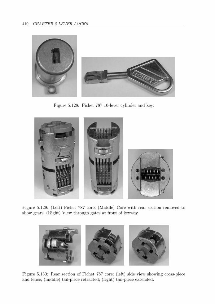
410 CHAPTER 5 LEVER LOCKS
Figure 5.128: Fichet 787 10-lever cylinder and key.
Figure 5.129: (Left) Fichet 787 core. (Middle) Core with rear section removed toshow gears. (Right) View through gates at front of keyway.
Figure 5.130: Rear section of Fichet 787 core: (left) side view showing cross-pieceand fence; (middle) tail-piece retracted; (right) tail-piece extended.
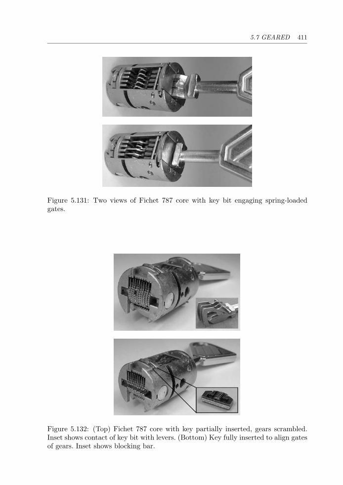
5.7 GEARED 411
Figure 5.131: Two views of Fichet 787 core with key bit engaging spring-loadedgates.
Figure 5.132: (Top) Fichet 787 core with key partially inserted, gears scrambled.Inset shows contact of key bit with levers. (Bottom) Key fully inserted to align gatesof gears. Inset shows blocking bar.
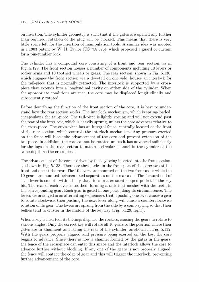
412 CHAPTER 5 LEVER LOCKS
on insertion. The cylinder geometry is such that if the gates are opened any furtherthan required, rotation of the plug will be blocked. This means that there is verylittle space left for the insertion of manipulation tools. A similar idea was mootedin a 1903 patent by W. H. Taylor (US 758,026), which proposed a guard or curtainfor a pin-tumbler lock.
The cylinder has a compound core consisting of a front and rear section, as inFig. 5.129. The front section houses a number of components including 10 levers orrocker arms and 10 toothed wheels or gears. The rear section, shown in Fig. 5.130,which engages the front section via a dovetail on one side, houses an interlock forthe tail-piece that is normally retracted. The interlock is supported by a cross-piece that extends into a longitudinal cavity on either side of the cylinder. Whenthe appropriate conditions are met, the core may be displaced longitudinally andsubsequently rotated.
Before describing the function of the front section of the core, it is best to under-stand how the rear section works. The interlock mechanism, which is spring-loaded,encapsulates the tail-piece. The tail-piece is lightly sprung and will not extend pastthe rear of the interlock, which is heavily sprung, unless the core advances relative tothe cross-piece. The cross-piece has an integral fence, centrally located at the frontof the rear section, which controls the interlock mechanism. Any pressure exertedon the fence will block the advancement of the core and prevent extension of thetail-piece. In addition, the core cannot be rotated unless it has advanced sufficientlyfor the lugs on the rear section to attain a circular channel in the cylinder at thesame depth as the cross-piece.
The advancement of the core is driven by the key being inserted into the front section,as shown in Fig. 5.133. There are three axles in the front part of the core: two at thefront and one at the rear. The 10 levers are mounted on the two front axles while the10 gears are mounted between fixed separators on the rear axle. The forward end ofeach lever is smooth with a belly that rides in a crescent-shaped pocket in the keybit. The rear of each lever is toothed, forming a rack that meshes with the teeth inthe corresponding gear. Each gear is gated in one place along its circumference. Thelevers are arranged in an alternating sequence so that if pushing one lever causes a gearto rotate clockwise, then pushing the next lever along will cause a counterclockwiserotation of its gear. The levers are sprung from the side by a comb spring so that theirbellies tend to cluster in the middle of the keyway (Fig. 5.129, right).
When a key is inserted, its bittings displace the rockers, causing the gears to rotate tovarious angles. Only the correct key will rotate all 10 gears to the position where theirgates are in alignment and facing the rear of the cylinder, as shown in Fig. 5.132.With the gears properly aligned and pressure being exerted on the key, the corebegins to advance. Since there is now a channel formed by the gates in the gears,the fence of the cross-piece can enter this space and the interlock allows the core toadvance further without blocking. If any one of the gears is not properly aligned,the fence will contact the edge of gear and this will trigger the interlock, preventingfurther advancement of the core.
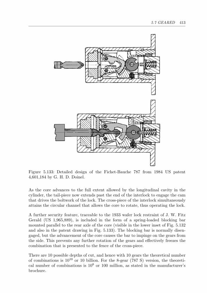
5.7 GEARED 413
Figure 5.133: Detailed design of the Fichet-Bauche 787 from 1984 US patent4,601,184 by G. H. D. Doinel.
As the core advances to the full extent allowed by the longitudinal cavity in thecylinder, the tail-piece now extends past the end of the interlock to engage the camthat drives the boltwork of the lock. The cross-piece of the interlock simultaneouslyattains the circular channel that allows the core to rotate, thus operating the lock.
A further security feature, traceable to the 1933 wafer lock restraint of J. W. FitzGerald (US 1,965,889), is included in the form of a spring-loaded blocking barmounted parallel to the rear axle of the core (visible in the lower inset of Fig. 5.132and also in the patent drawing in Fig. 5.133). The blocking bar is normally disen-gaged, but the advancement of the core causes the bar to impinge on the gears fromthe side. This prevents any further rotation of the gears and effectively freezes thecombination that is presented to the fence of the cross-piece.
There are 10 possible depths of cut, and hence with 10 gears the theoretical numberof combinations is 1010 or 10 billion. For the 8-gear (787 S) version, the theoreti-cal number of combinations is 108 or 100 million, as stated in the manufacturer’sbrochure.
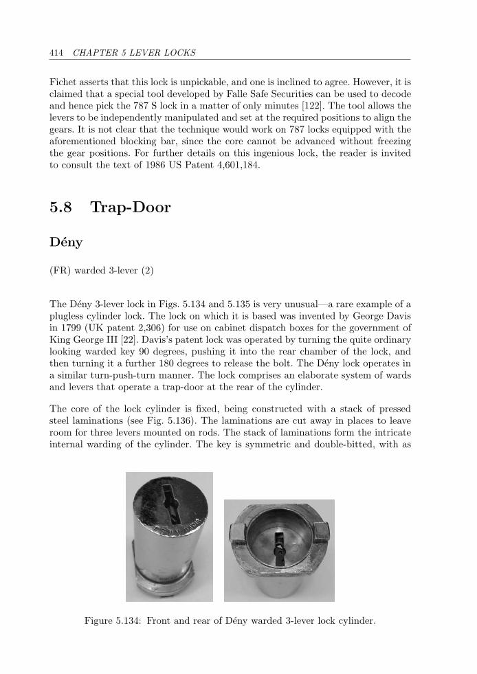
414 CHAPTER 5 LEVER LOCKS
Fichet asserts that this lock is unpickable, and one is inclined to agree. However, it isclaimed that a special tool developed by Falle Safe Securities can be used to decodeand hence pick the 787 S lock in a matter of only minutes [122]. The tool allows thelevers to be independently manipulated and set at the required positions to align thegears. It is not clear that the technique would work on 787 locks equipped with theaforementioned blocking bar, since the core cannot be advanced without freezingthe gear positions. For further details on this ingenious lock, the reader is invitedto consult the text of 1986 US Patent 4,601,184.
5.8 Trap-Door
Deny
(FR) warded 3-lever (2)
The Deny 3-lever lock in Figs. 5.134 and 5.135 is very unusual—a rare example of aplugless cylinder lock. The lock on which it is based was invented by George Davisin 1799 (UK patent 2,306) for use on cabinet dispatch boxes for the government ofKing George III [22]. Davis’s patent lock was operated by turning the quite ordinarylooking warded key 90 degrees, pushing it into the rear chamber of the lock, andthen turning it a further 180 degrees to release the bolt. The Deny lock operates ina similar turn-push-turn manner. The lock comprises an elaborate system of wardsand levers that operate a trap-door at the rear of the cylinder.
The core of the lock cylinder is fixed, being constructed with a stack of pressedsteel laminations (see Fig. 5.136). The laminations are cut away in places to leaveroom for three levers mounted on rods. The stack of laminations form the intricateinternal warding of the cylinder. The key is symmetric and double-bitted, with as
Figure 5.134: Front and rear of Deny warded 3-lever lock cylinder.
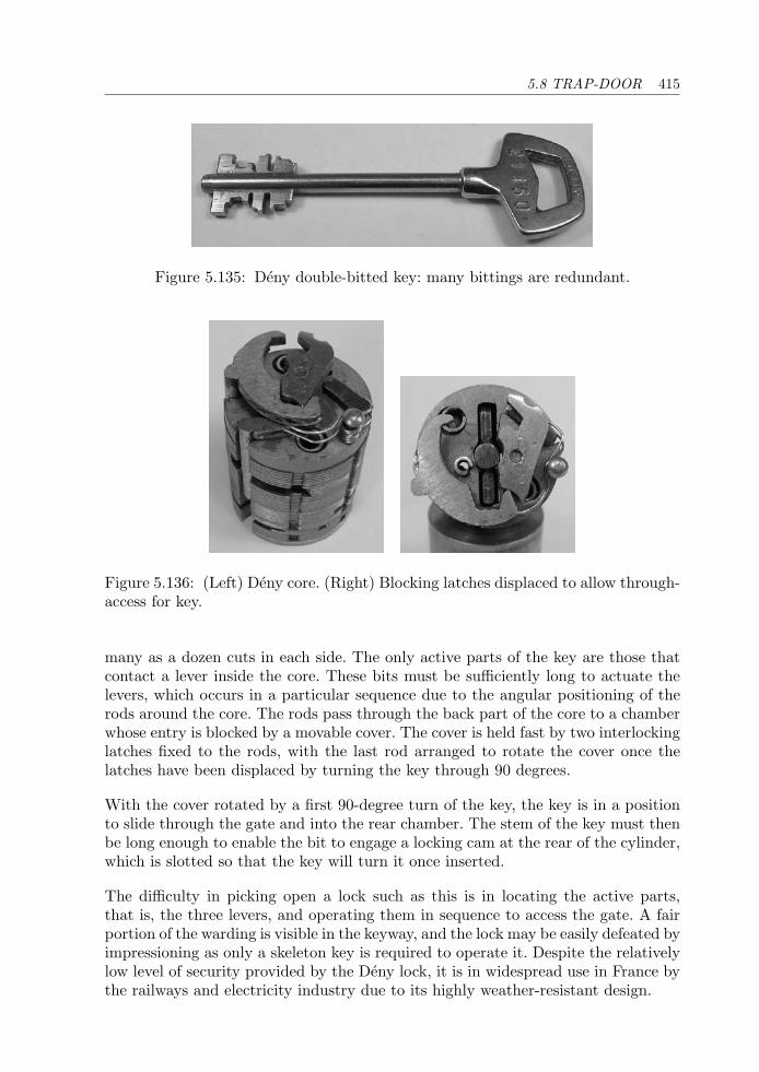
5.8 TRAP-DOOR 415
Figure 5.135: Deny double-bitted key: many bittings are redundant.
Figure 5.136: (Left) Deny core. (Right) Blocking latches displaced to allow through-access for key.
many as a dozen cuts in each side. The only active parts of the key are those thatcontact a lever inside the core. These bits must be sufficiently long to actuate thelevers, which occurs in a particular sequence due to the angular positioning of therods around the core. The rods pass through the back part of the core to a chamberwhose entry is blocked by a movable cover. The cover is held fast by two interlockinglatches fixed to the rods, with the last rod arranged to rotate the cover once thelatches have been displaced by turning the key through 90 degrees.
With the cover rotated by a first 90-degree turn of the key, the key is in a positionto slide through the gate and into the rear chamber. The stem of the key must thenbe long enough to enable the bit to engage a locking cam at the rear of the cylinder,which is slotted so that the key will turn it once inserted.
The difficulty in picking open a lock such as this is in locating the active parts,that is, the three levers, and operating them in sequence to access the gate. A fairportion of the warding is visible in the keyway, and the lock may be easily defeated byimpressioning as only a skeleton key is required to operate it. Despite the relativelylow level of security provided by the Deny lock, it is in widespread use in France bythe railways and electricity industry due to its highly weather-resistant design.
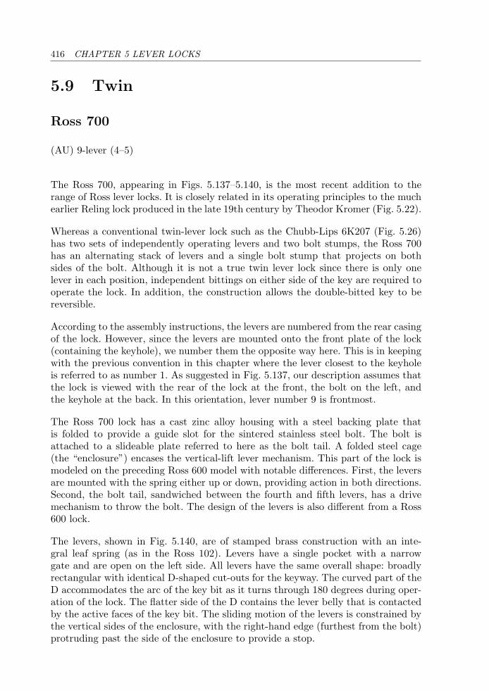
416 CHAPTER 5 LEVER LOCKS
5.9 Twin
Ross 700
(AU) 9-lever (4–5)
The Ross 700, appearing in Figs. 5.137–5.140, is the most recent addition to therange of Ross lever locks. It is closely related in its operating principles to the muchearlier Reling lock produced in the late 19th century by Theodor Kromer (Fig. 5.22).
Whereas a conventional twin-lever lock such as the Chubb-Lips 6K207 (Fig. 5.26)has two sets of independently operating levers and two bolt stumps, the Ross 700has an alternating stack of levers and a single bolt stump that projects on bothsides of the bolt. Although it is not a true twin lever lock since there is only onelever in each position, independent bittings on either side of the key are required tooperate the lock. In addition, the construction allows the double-bitted key to bereversible.
According to the assembly instructions, the levers are numbered from the rear casingof the lock. However, since the levers are mounted onto the front plate of the lock(containing the keyhole), we number them the opposite way here. This is in keepingwith the previous convention in this chapter where the lever closest to the keyholeis referred to as number 1. As suggested in Fig. 5.137, our description assumes thatthe lock is viewed with the rear of the lock at the front, the bolt on the left, andthe keyhole at the back. In this orientation, lever number 9 is frontmost.
The Ross 700 lock has a cast zinc alloy housing with a steel backing plate thatis folded to provide a guide slot for the sintered stainless steel bolt. The bolt isattached to a slideable plate referred to here as the bolt tail. A folded steel cage(the “enclosure”) encases the vertical-lift lever mechanism. This part of the lock ismodeled on the preceding Ross 600 model with notable differences. First, the leversare mounted with the spring either up or down, providing action in both directions.Second, the bolt tail, sandwiched between the fourth and fifth levers, has a drivemechanism to throw the bolt. The design of the levers is also different from a Ross600 lock.
The levers, shown in Fig. 5.140, are of stamped brass construction with an inte-gral leaf spring (as in the Ross 102). Levers have a single pocket with a narrowgate and are open on the left side. All levers have the same overall shape: broadlyrectangular with identical D-shaped cut-outs for the keyway. The curved part of theD accommodates the arc of the key bit as it turns through 180 degrees during oper-ation of the lock. The flatter side of the D contains the lever belly that is contactedby the active faces of the key bit. The sliding motion of the levers is constrained bythe vertical sides of the enclosure, with the right-hand edge (furthest from the bolt)protruding past the side of the enclosure to provide a stop.
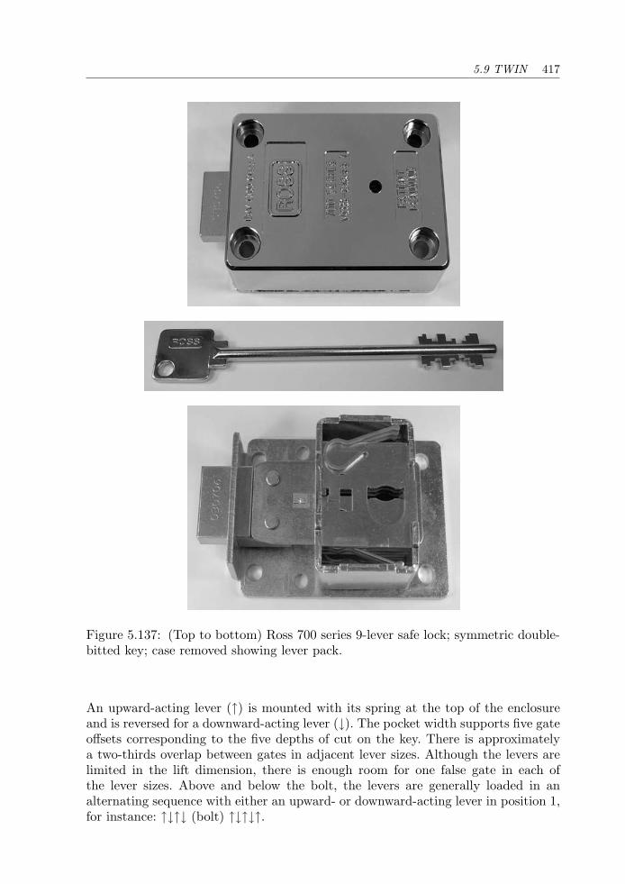
5.9 TWIN 417
Figure 5.137: (Top to bottom) Ross 700 series 9-lever safe lock; symmetric double-bitted key; case removed showing lever pack.
An upward-acting lever (↑) is mounted with its spring at the top of the enclosureand is reversed for a downward-acting lever (↓). The pocket width supports five gateoffsets corresponding to the five depths of cut on the key. There is approximatelya two-thirds overlap between gates in adjacent lever sizes. Although the levers arelimited in the lift dimension, there is enough room for one false gate in each ofthe lever sizes. Above and below the bolt, the levers are generally loaded in analternating sequence with either an upward- or downward-acting lever in position 1,for instance: ↑↓↑↓ (bolt) ↑↓↑↓↑.
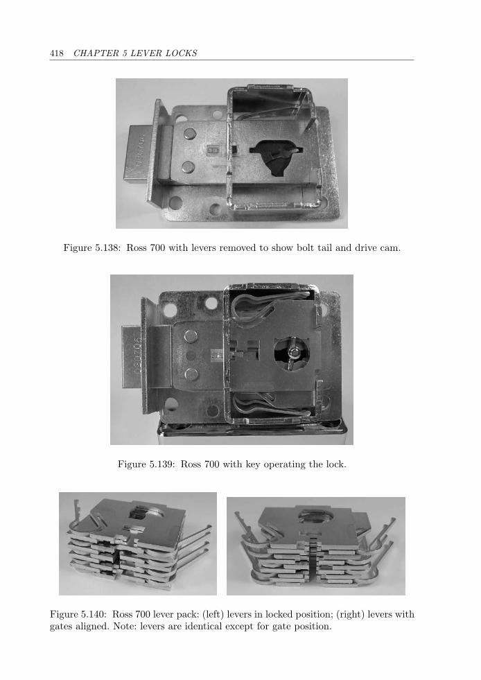
418 CHAPTER 5 LEVER LOCKS
Figure 5.138: Ross 700 with levers removed to show bolt tail and drive cam.
Figure 5.139: Ross 700 with key operating the lock.
Figure 5.140: Ross 700 lever pack: (left) levers in locked position; (right) levers withgates aligned. Note: levers are identical except for gate position.
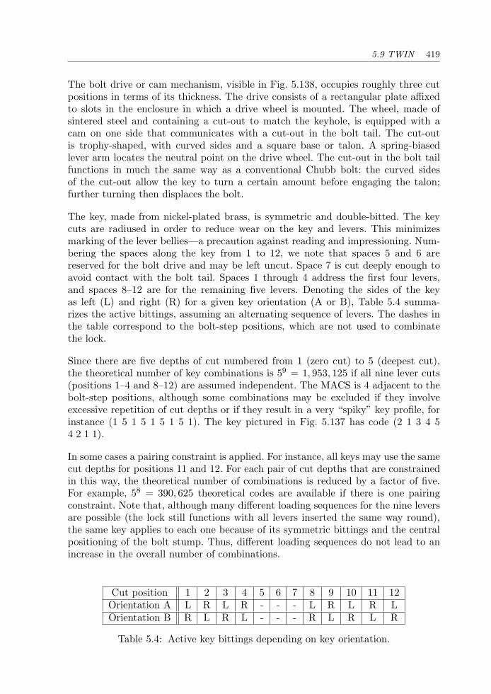
5.9 TWIN 419
The bolt drive or cam mechanism, visible in Fig. 5.138, occupies roughly three cutpositions in terms of its thickness. The drive consists of a rectangular plate affixedto slots in the enclosure in which a drive wheel is mounted. The wheel, made ofsintered steel and containing a cut-out to match the keyhole, is equipped with acam on one side that communicates with a cut-out in the bolt tail. The cut-outis trophy-shaped, with curved sides and a square base or talon. A spring-biasedlever arm locates the neutral point on the drive wheel. The cut-out in the bolt tailfunctions in much the same way as a conventional Chubb bolt: the curved sidesof the cut-out allow the key to turn a certain amount before engaging the talon;further turning then displaces the bolt.
The key, made from nickel-plated brass, is symmetric and double-bitted. The keycuts are radiused in order to reduce wear on the key and levers. This minimizesmarking of the lever bellies—a precaution against reading and impressioning. Num-bering the spaces along the key from 1 to 12, we note that spaces 5 and 6 arereserved for the bolt drive and may be left uncut. Space 7 is cut deeply enough toavoid contact with the bolt tail. Spaces 1 through 4 address the first four levers,and spaces 8–12 are for the remaining five levers. Denoting the sides of the keyas left (L) and right (R) for a given key orientation (A or B), Table 5.4 summa-rizes the active bittings, assuming an alternating sequence of levers. The dashes inthe table correspond to the bolt-step positions, which are not used to combinatethe lock.
Since there are five depths of cut numbered from 1 (zero cut) to 5 (deepest cut),the theoretical number of key combinations is 59 = 1, 953, 125 if all nine lever cuts(positions 1–4 and 8–12) are assumed independent. The MACS is 4 adjacent to thebolt-step positions, although some combinations may be excluded if they involveexcessive repetition of cut depths or if they result in a very “spiky” key profile, forinstance (1 5 1 5 1 5 1 5 1). The key pictured in Fig. 5.137 has code (2 1 3 4 54 2 1 1).
In some cases a pairing constraint is applied. For instance, all keys may use the samecut depths for positions 11 and 12. For each pair of cut depths that are constrainedin this way, the theoretical number of combinations is reduced by a factor of five.For example, 58 = 390, 625 theoretical codes are available if there is one pairingconstraint. Note that, although many different loading sequences for the nine leversare possible (the lock still functions with all levers inserted the same way round),the same key applies to each one because of its symmetric bittings and the centralpositioning of the bolt stump. Thus, different loading sequences do not lead to anincrease in the overall number of combinations.
Cut position 1 2 3 4 5 6 7 8 9 10 11 12Orientation A L R L R - - - L R L R LOrientation B R L R L - - - R L R L R
Table 5.4: Active key bittings depending on key orientation.
420 CHAPTER 5 LEVER LOCKS
The lock operates in response to the insertion of a correctly bitted key (see Fig. 5.139).Seen from the front (opposite to the view presented in Fig. 5.137), the key must beturned clockwise through half a turn to open the lock. As the key is turned, thealternate steps on the bit contact the bellies of the levers, displacing them upward ordownward depending on their orientation. The four levers in front of the bolt tail aswell as the five levers behind it must all be brought to the correct heights to align theirgates. When the key has been rotated to about 70 degrees, the drive cam contacts thetalon of the bolt tail and begins to displace both sections of the bolt stump towardthe pockets in the levers. The bolt is drawn back until a point is reached where thedrive cam falls out of contact with the talon. As the key turns to 180 degrees, thelevers are returned to their rest positions, and the key may be withdrawn thoughthe slot in the bolt tail. A captive key function is also available that stops the drivecam just before half a turn, retaining the key when the lock is unlocked.
Obviously, there is not a great likelihood of picking a lock such as this with con-ventional tools, given the difficulties presented by the small keyway and the needto manipulate levers in both upward and downward directions on both sides of thebolt tail. Recall that the bolt cannot be tensioned in the usual manner due to thebolt drive mechanism and that when this is turned to tension the bolt, the access tothe five rear levers is severely restricted. Furthermore, the lock would normally bemounted behind the door of a safe with the keyway only accessible through a 60 mmtoughened key guide. Nonetheless, a decoder-pick is available from Prescott’s site[97] for around $3,000 Australian dollars that allows a safe engineer to open thelock nondestructively in 30 to 90 minutes. The European Certification Board [32]qualifies this lock as Class A under the ENV 1300 standard [19]; it is also approvedto Class 1 under the VdS standard.
5.10 Variable
Sargent & Greenleaf 6804
(US) 7-lever (4–5)
The company Sargent & Greenleaf, founded in 1865 by James Sargent and now basedin Kentucky, was a major force in the development of the keyless combination lockand the time lock for safes and bank vaults. As explained in the chapter introduction,recombinatable locks, which may be keyless or key-operated, allow the user to effecta rapid change of the lock’s combination whether of necessity or as a routine securityprecaution. The time lock in particular had a major impact in reducing theft fromfinancial institutions by precluding the lock from being opened, even by the bankmanager, outside of office hours [57]. A picture of a S&G 6720 3-wheel keylesscombination lock appears in Fig. 5.36.
5.10 VARIABLE 421
Although S&G, along with many other high-security lock manufacturers, has movedtoward electronic (digital) safe locks, it still produces a number of keyed safe andsafe deposit locks. These must also allow the user to rekey the lock without theneed to dismantle the mechanism. In this section we present the S&G model 6804key-changeable safe lock in which recombination is effected by a variable bolt-stumparray of similar construction to a Hobbs changeable lever lock (Fig. 5.39). Two ver-sions of the 6804 lock are available, one of which is pictured in Figs. 5.141 and 5.142.Unlike the Hobbs lock, whose combination was set automatically to its operatingkey, the recombination of the 6804 requires the insertion of a change key, an Allenkey in this case, via the rear of the lock. The relevant patent is US 4,462,230, whichcovers the application of the variable bolt-stump mechanism in a dual-control safedeposit lock (see Fig. 5.48).
The lock housing and the bolt are die-cast. There is a keyhole in the front coverof the lock that allows the key to be withdrawn at half a turn for the changeoperation. The key does not directly bear on the bolt; instead, the bolt-step of thekey engages a slot in a drive disc seated behind the bolt. The drive disc has a camthat contacts the talon of the bolt at about 90 degrees of rotation.
The only other components in this simple but highly effective lock are the sevenlevers and their stumps. The levers are of stamped brass with an integral leaf spring.All levers are of identical outline with a peripheral gate flanked by a number ofantipicking notches (see Fig. 5.142). The gate offsets and bellies of all levers areidentical. The belly shape differs markedly from that of a Chubb lever in havinga curve at the base of the lever that fully encloses the belly. The curved base ofeach lever rests against a molded stop on the bolt. The enclosed belly constructionprovides rigidity and limits access to the interior of the lock.
Since the levers are in all respects identical, differing is provided through the posi-tioning of the stumps, which are also made from stamped brass stock and havea slotted rectangular body with a narrow perpendicular arm or fence. The sevenstumps are stacked in an array with their rectangular portions slideably mountedon a pair of guide posts. A screw with a captive nut midway between the two postssecures the stump array in a given configuration.
The height of each stump may be set within a fixed interval. Different stump heightsrequire differing degrees of lift of the levers. The gate in each lever is just wide enoughto admit the fence of one stump. The triangular pocket in the lever is required sincethe angle of entry of the fence is different depending on the amount of lift of thelever.
In theory there is a continuum of different stump offset heights. As will be explained,however, the stump heights are adjusted to suit the key that is presented to the lockduring the change operation. In practice, the number of depths of cut on the key issubject to the mechanical tolerances of the lock for effective differing and the overallheight of the key bit. The 6804 lock pictured uses six depths of cut (including thezero cut) with an increment of 20 thousandths of an inch. A second version of
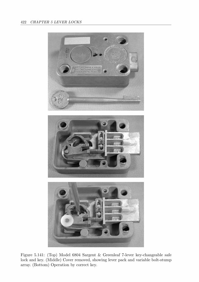
422 CHAPTER 5 LEVER LOCKS
Figure 5.141: (Top) Model 6804 Sargent & Greenleaf 7-lever key-changeable safelock and key. (Middle) Cover removed, showing lever pack and variable bolt-stumparray. (Bottom) Operation by correct key.
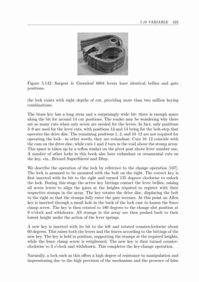
5.10 VARIABLE 423
Figure 5.142: Sargent & Greenleaf 6804 levers have identical bellies and gatepositions.
the lock exists with eight depths of cut, providing more than two million keyingcombinations.
The brass key has a long stem and a surprisingly wide bit: there is enough spacealong the bit for around 14 cut positions. The reader may be wondering why thereare so many cuts when only seven are needed for the levers. In fact, only positions3–9 are used for the lever cuts, with positions 13 and 14 being for the bolt-step thatoperates the drive disc. The remaining positions 1, 2, and 10–12 are not required foroperating the lock—in other words, they are redundant. Cuts 10–12 coincide withthe cam on the drive disc, while cuts 1 and 2 turn in the void above the stump array.This space is taken up by a teflon washer on the pivot post above lever number one.A number of other locks in this book also have redundant or ornamental cuts onthe key, viz., Bricard SuperSurete and Deny.
We describe the operation of the lock by reference to the change operation [107].The lock is assumed to be mounted with the bolt on the right. The correct key isfirst inserted with its bit to the right and turned 135 degrees clockwise to unlockthe lock. During this stage the active key bittings contact the lever bellies, raisingall seven levers to align the gates at the heights required to register with theirrespective stumps in the array. The key rotates the drive disc, displacing the boltto the right so that the stumps fully enter the gate recesses. At this point an Allenkey is inserted through a small hole in the back of the lock case to loosen the fenceclamp screw. The key is then rotated to 180 degrees to the change slot position at9 o’clock and withdrawn. All stumps in the array are then pushed back to theirlowest height under the action of the lever springs.
A new key is inserted with its bit to the left and rotated counterclockwise about60 degrees. This raises both the levers and the fences according to the bittings of thenew key. The key is held in position, supporting the stumps at the required heights,while the fence clamp screw is retightened. The new key is then turned counter-clockwise to 3 o’clock and withdrawn. This completes the key-change operation.
Naturally, a lock such as this offers a high degree of resistance to manipulation andimpressioning due to the high precision of the mechanism and the presence of false
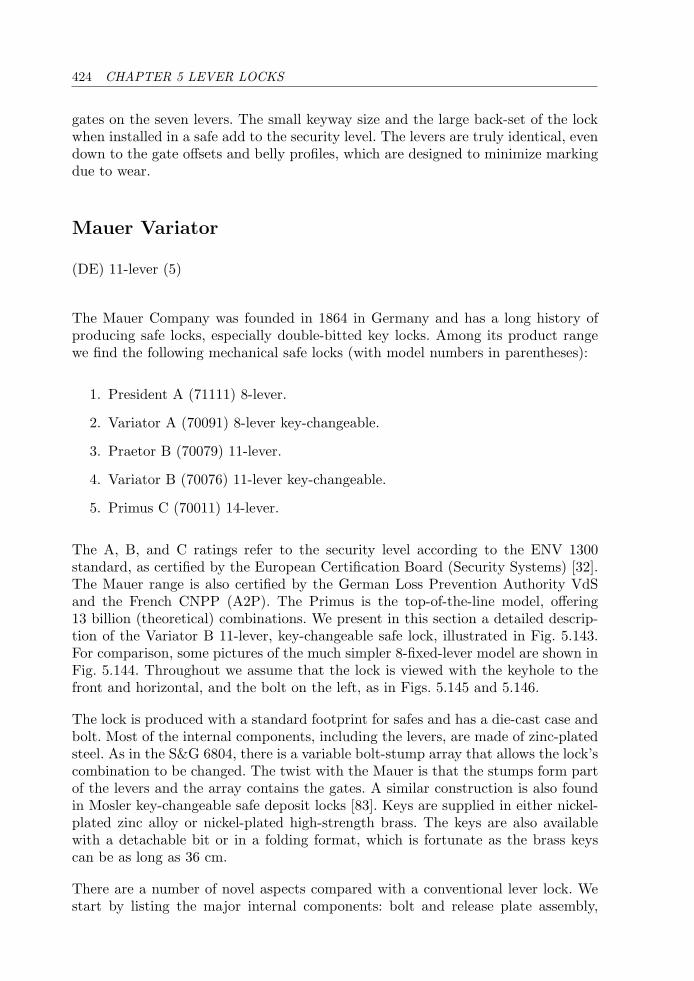
424 CHAPTER 5 LEVER LOCKS
gates on the seven levers. The small keyway size and the large back-set of the lockwhen installed in a safe add to the security level. The levers are truly identical, evendown to the gate offsets and belly profiles, which are designed to minimize markingdue to wear.
Mauer Variator
(DE) 11-lever (5)
The Mauer Company was founded in 1864 in Germany and has a long history ofproducing safe locks, especially double-bitted key locks. Among its product rangewe find the following mechanical safe locks (with model numbers in parentheses):
1. President A (71111) 8-lever.
2. Variator A (70091) 8-lever key-changeable.
3. Praetor B (70079) 11-lever.
4. Variator B (70076) 11-lever key-changeable.
5. Primus C (70011) 14-lever.
The A, B, and C ratings refer to the security level according to the ENV 1300standard, as certified by the European Certification Board (Security Systems) [32].The Mauer range is also certified by the German Loss Prevention Authority VdSand the French CNPP (A2P). The Primus is the top-of-the-line model, offering13 billion (theoretical) combinations. We present in this section a detailed descrip-tion of the Variator B 11-lever, key-changeable safe lock, illustrated in Fig. 5.143.For comparison, some pictures of the much simpler 8-fixed-lever model are shown inFig. 5.144. Throughout we assume that the lock is viewed with the keyhole to thefront and horizontal, and the bolt on the left, as in Figs. 5.145 and 5.146.
The lock is produced with a standard footprint for safes and has a die-cast case andbolt. Most of the internal components, including the levers, are made of zinc-platedsteel. As in the S&G 6804, there is a variable bolt-stump array that allows the lock’scombination to be changed. The twist with the Mauer is that the stumps form partof the levers and the array contains the gates. A similar construction is also foundin Mosler key-changeable safe deposit locks [83]. Keys are supplied in either nickel-plated zinc alloy or nickel-plated high-strength brass. The keys are also availablewith a detachable bit or in a folding format, which is fortunate as the brass keyscan be as long as 36 cm.
There are a number of novel aspects compared with a conventional lever lock. Westart by listing the major internal components: bolt and release plate assembly,
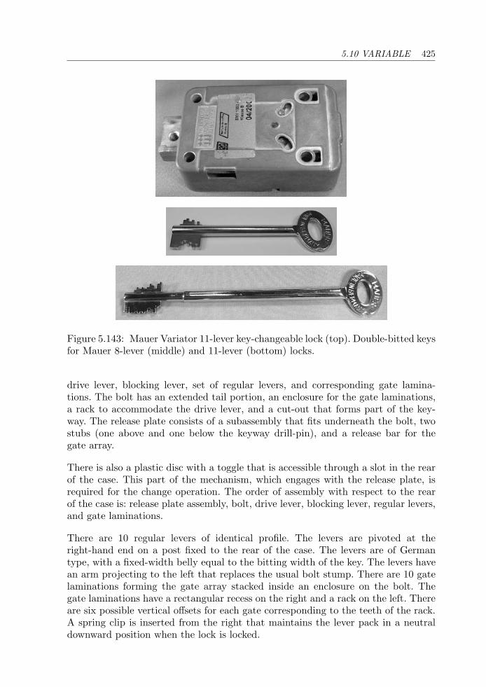
5.10 VARIABLE 425
Figure 5.143: Mauer Variator 11-lever key-changeable lock (top). Double-bitted keysfor Mauer 8-lever (middle) and 11-lever (bottom) locks.
drive lever, blocking lever, set of regular levers, and corresponding gate lamina-tions. The bolt has an extended tail portion, an enclosure for the gate laminations,a rack to accommodate the drive lever, and a cut-out that forms part of the key-way. The release plate consists of a subassembly that fits underneath the bolt, twostubs (one above and one below the keyway drill-pin), and a release bar for thegate array.
There is also a plastic disc with a toggle that is accessible through a slot in the rearof the case. This part of the mechanism, which engages with the release plate, isrequired for the change operation. The order of assembly with respect to the rearof the case is: release plate assembly, bolt, drive lever, blocking lever, regular levers,and gate laminations.
There are 10 regular levers of identical profile. The levers are pivoted at theright-hand end on a post fixed to the rear of the case. The levers are of Germantype, with a fixed-width belly equal to the bitting width of the key. The levers havean arm projecting to the left that replaces the usual bolt stump. There are 10 gatelaminations forming the gate array stacked inside an enclosure on the bolt. Thegate laminations have a rectangular recess on the right and a rack on the left. Thereare six possible vertical offsets for each gate corresponding to the teeth of the rack.A spring clip is inserted from the right that maintains the lever pack in a neutraldownward position when the lock is locked.

426 CHAPTER 5 LEVER LOCKS
Figure 5.144: Mauer 8-lever lock with cover off (top) and operated by key (bottom).
The other two levers are irregularly shaped (refer to Fig. 5.147). We describe theblocking lever first: this is pivoted on a fixed post on the right-hand side of the case.The blocking lever has a cut-out, a post close to its pivot hole, and a protrudingarm. The function of the post is to limit the angular motion of the regular levers,which have the same pivot point as the blocking lever. The blocking lever is spring-biased into a downward position where it normally prevents the rightward motionof the bolt and its subassembly. The eleventh bitting on the key operates this lever,raising the blocking arm to engage a recess in the bolt. The same action releasesthe regular levers so that they may be lifted to address the gate array.
The drive lever is a blend of German and Chubb levers. It pivots on the lower stubof the release plate subassembly; its upper pocket is constrained in its travel by theupper stub. The lower pocket is fashioned like a conventional bolt talon to engagethe bolt-step of the key. Tangential motion is conveyed to the bolt by means of twoteeth on the outside edge of the drive lever. The teeth mesh with a rack in the upperpart of the bolt tail.
The key, which is double bitted, has a pipe end to match the drill-pin in the keyway.The bow of the key has a notched edge on the same side as the bolt-step to help theuser identify the correct orientation. There is also a shoulder stop above the bit formedby the increased-diameter stem. The stop limits the insertion depth of the key.
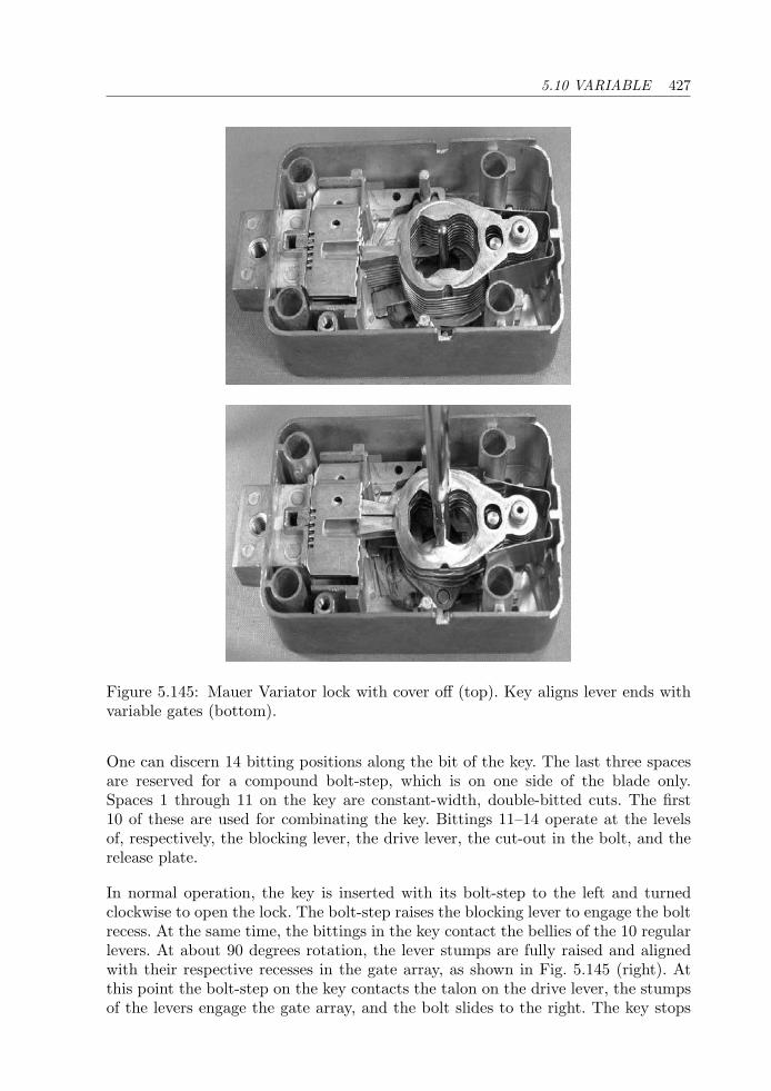
5.10 VARIABLE 427
Figure 5.145: Mauer Variator lock with cover off (top). Key aligns lever ends withvariable gates (bottom).
One can discern 14 bitting positions along the bit of the key. The last three spacesare reserved for a compound bolt-step, which is on one side of the blade only.Spaces 1 through 11 on the key are constant-width, double-bitted cuts. The first10 of these are used for combinating the key. Bittings 11–14 operate at the levelsof, respectively, the blocking lever, the drive lever, the cut-out in the bolt, and therelease plate.
In normal operation, the key is inserted with its bolt-step to the left and turnedclockwise to open the lock. The bolt-step raises the blocking lever to engage the boltrecess. At the same time, the bittings in the key contact the bellies of the 10 regularlevers. At about 90 degrees rotation, the lever stumps are fully raised and alignedwith their respective recesses in the gate array, as shown in Fig. 5.145 (right). Atthis point the bolt-step on the key contacts the talon on the drive lever, the stumpsof the levers engage the gate array, and the bolt slides to the right. The key stops
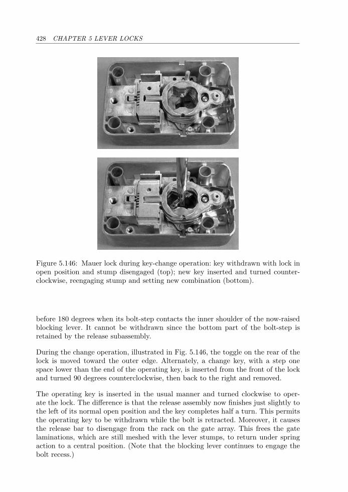
428 CHAPTER 5 LEVER LOCKS
Figure 5.146: Mauer lock during key-change operation: key withdrawn with lock inopen position and stump disengaged (top); new key inserted and turned counter-clockwise, reengaging stump and setting new combination (bottom).
before 180 degrees when its bolt-step contacts the inner shoulder of the now-raisedblocking lever. It cannot be withdrawn since the bottom part of the bolt-step isretained by the release subassembly.
During the change operation, illustrated in Fig. 5.146, the toggle on the rear of thelock is moved toward the outer edge. Alternately, a change key, with a step onespace lower than the end of the operating key, is inserted from the front of the lockand turned 90 degrees counterclockwise, then back to the right and removed.
The operating key is inserted in the usual manner and turned clockwise to oper-ate the lock. The difference is that the release assembly now finishes just slightly tothe left of its normal open position and the key completes half a turn. This permitsthe operating key to be withdrawn while the bolt is retracted. Moreover, it causesthe release bar to disengage from the rack on the gate array. This frees the gatelaminations, which are still meshed with the lever stumps, to return under springaction to a central position. (Note that the blocking lever continues to engage thebolt recess.)
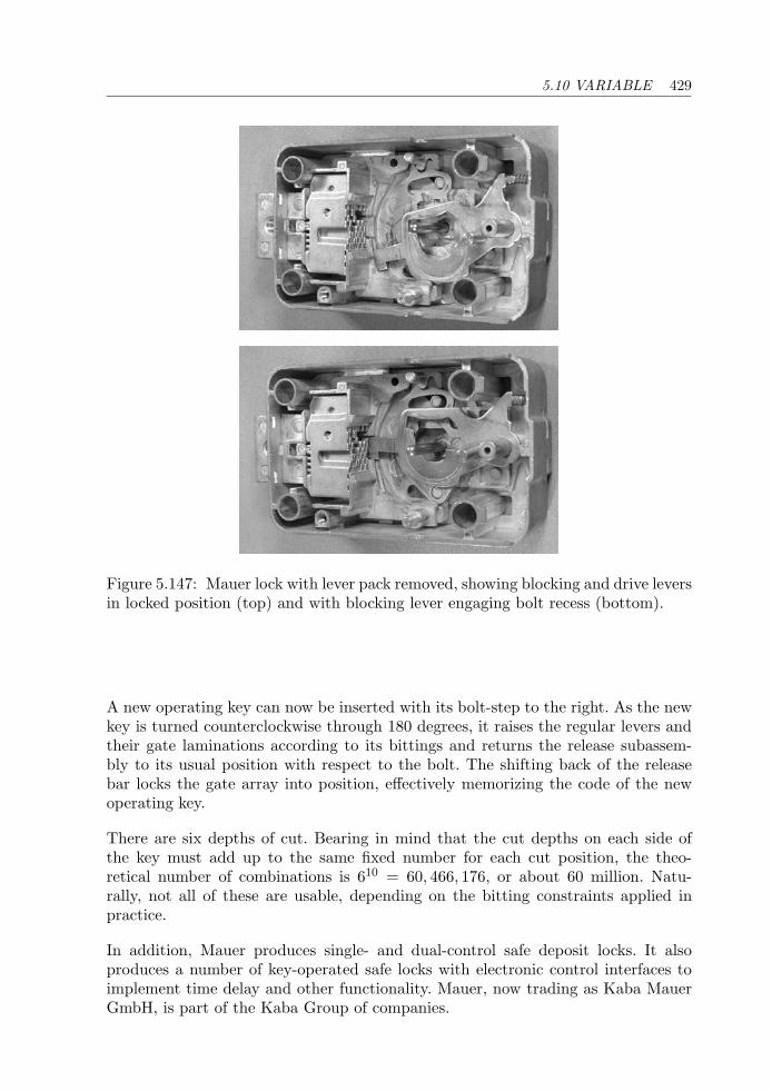
5.10 VARIABLE 429
Figure 5.147: Mauer lock with lever pack removed, showing blocking and drive leversin locked position (top) and with blocking lever engaging bolt recess (bottom).
A new operating key can now be inserted with its bolt-step to the right. As the newkey is turned counterclockwise through 180 degrees, it raises the regular levers andtheir gate laminations according to its bittings and returns the release subassem-bly to its usual position with respect to the bolt. The shifting back of the releasebar locks the gate array into position, effectively memorizing the code of the newoperating key.
There are six depths of cut. Bearing in mind that the cut depths on each side ofthe key must add up to the same fixed number for each cut position, the theo-retical number of combinations is 610 = 60, 466, 176, or about 60 million. Natu-rally, not all of these are usable, depending on the bitting constraints applied inpractice.
In addition, Mauer produces single- and dual-control safe deposit locks. It alsoproduces a number of key-operated safe locks with electronic control interfaces toimplement time delay and other functionality. Mauer, now trading as Kaba MauerGmbH, is part of the Kaba Group of companies.
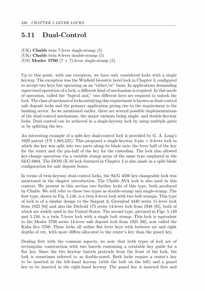
430 CHAPTER 5 LEVER LOCKS
5.11 Dual-Control
(UK) Chubb twin 7-lever single-stump (5)(UK) Chubb twin 8-lever double-stump (5)(US) Mosler 5700 (7 + 7)-lever single-stump (5)
Up to this point, with one exception, we have only considered locks with a singlekeyway. The exception was the Winfield bicentric hotel lock in Chapter 3, configuredto accept two keys but operating on an “either/or” basis. In applications demandingsupervised operation of a lock, a different kind of mechanism is required. In this modeof operation, called the “logical and,” two different keys are required to unlock thelock. The class of mechanical locks satisfying this requirement is known as dual-controlsafe deposit locks and the primary application giving rise to the requirement is thebanking sector. As we mentioned earlier, there are several possible implementationsof the dual-control mechanism, the major variants being single- and double-keywaylocks. Dual control can be achieved in a single-keyway lock by using multiple gatesor by splitting the key.
An interesting example of a split-key dual-control lock is provided by G. A. Long’s1929 patent (US 1,863,525). This proposed a single-keyway 3-pin + 6-lever lock inwhich the key was split into two parts along its blade axis: the lever half of the keyfor the renter and the pin-half of the key for the custodian. The lock also allowedkey-change operation via a variable stump array of the same type employed in theS&G 6804. The DOM iX-10 lock featured in Chapter 2 is also made in a split-bladeconfiguration for safe deposit boxes.
In terms of twin-keyway dual-control locks, the S&G 4500 key-changeable lock wasmentioned in the chapter introduction. The Chubb AVA lock is also used in thiscontext. We present in this section two further locks of this type, both producedby Chubb. We will refer to these two types as double-stump and single-stump. Thefirst type, shown in Fig. 5.148, is a twin 8-lever lock with two bolt stumps. This typeof lock is of a similar design to the Sargent & Greenleaf 4440 series 11-lever lockfrom 1922 [84] and also the Diebold 175 series 14-lever lock from 1948 [85], both ofwhich are widely used in the United States. The second type, pictured in Figs. 5.149and 5.150, is a twin 7-lever lock with a single bolt stump. This lock is equivalentto the Mosler 5700 series 14-lever safe deposit lock from 1925 [86], now called theKaba Ilco 5700. These locks all utilize flat lever keys with between six and eightdepths of cut, with more differs allocated to the renter’s key than the guard key.
Dealing first with the common aspects, we note that both types of lock are ofrectangular construction with two barrels containing a rotatable key guide for aflat key. Since the two keyway barrels protrude from the front of the lock, thelock is sometimes referred to as double-nosed. Both locks require a renter’s keyto be inserted in the left-hand keyway (with the bolt on the left) and a guardkey to be inserted in the right-hand keyway. The guard key is inserted first and
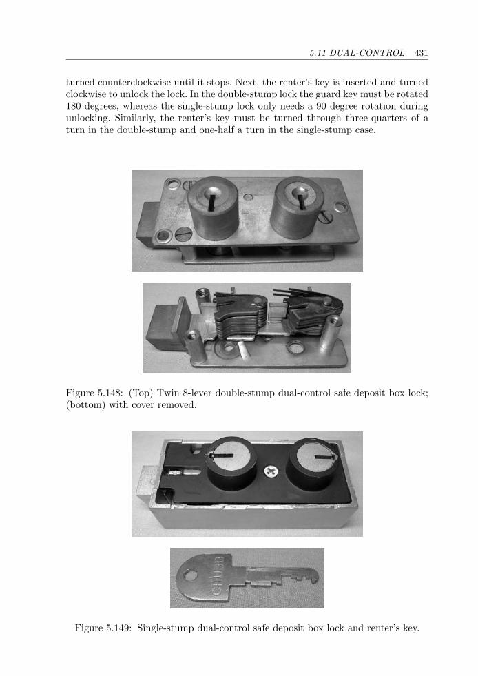
5.11 DUAL-CONTROL 431
turned counterclockwise until it stops. Next, the renter’s key is inserted and turnedclockwise to unlock the lock. In the double-stump lock the guard key must be rotated180 degrees, whereas the single-stump lock only needs a 90 degree rotation duringunlocking. Similarly, the renter’s key must be turned through three-quarters of aturn in the double-stump and one-half a turn in the single-stump case.
Figure 5.148: (Top) Twin 8-lever double-stump dual-control safe deposit box lock;(bottom) with cover removed.
Figure 5.149: Single-stump dual-control safe deposit box lock and renter’s key.
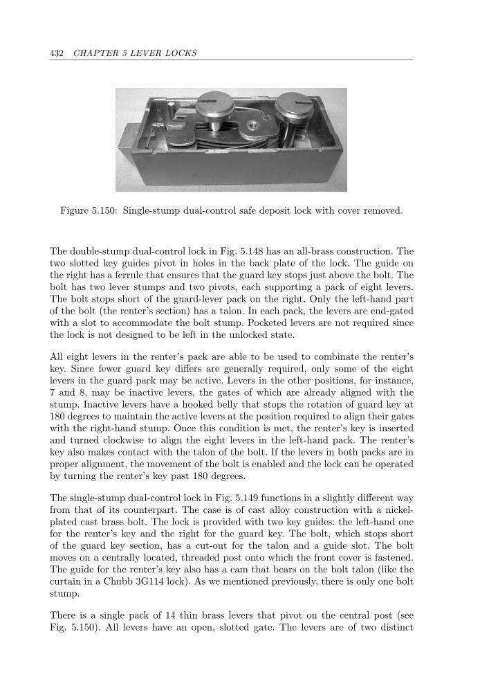
432 CHAPTER 5 LEVER LOCKS
Figure 5.150: Single-stump dual-control safe deposit lock with cover removed.
The double-stump dual-control lock in Fig. 5.148 has an all-brass construction. Thetwo slotted key guides pivot in holes in the back plate of the lock. The guide onthe right has a ferrule that ensures that the guard key stops just above the bolt. Thebolt has two lever stumps and two pivots, each supporting a pack of eight levers.The bolt stops short of the guard-lever pack on the right. Only the left-hand partof the bolt (the renter’s section) has a talon. In each pack, the levers are end-gatedwith a slot to accommodate the bolt stump. Pocketed levers are not required sincethe lock is not designed to be left in the unlocked state.
All eight levers in the renter’s pack are able to be used to combinate the renter’skey. Since fewer guard key differs are generally required, only some of the eightlevers in the guard pack may be active. Levers in the other positions, for instance,7 and 8, may be inactive levers, the gates of which are already aligned with thestump. Inactive levers have a hooked belly that stops the rotation of guard key at180 degrees to maintain the active levers at the position required to align their gateswith the right-hand stump. Once this condition is met, the renter’s key is insertedand turned clockwise to align the eight levers in the left-hand pack. The renter’skey also makes contact with the talon of the bolt. If the levers in both packs are inproper alignment, the movement of the bolt is enabled and the lock can be operatedby turning the renter’s key past 180 degrees.
The single-stump dual-control lock in Fig. 5.149 functions in a slightly different wayfrom that of its counterpart. The case is of cast alloy construction with a nickel-plated cast brass bolt. The lock is provided with two key guides: the left-hand onefor the renter’s key and the right for the guard key. The bolt, which stops shortof the guard key section, has a cut-out for the talon and a guide slot. The boltmoves on a centrally located, threaded post onto which the front cover is fastened.The guide for the renter’s key also has a cam that bears on the bolt talon (like thecurtain in a Chubb 3G114 lock). As we mentioned previously, there is only one boltstump.
There is a single pack of 14 thin brass levers that pivot on the central post (seeFig. 5.150). All levers have an open, slotted gate. The levers are of two distinct
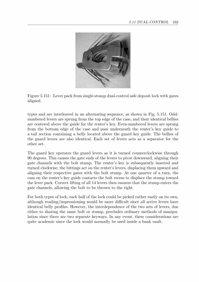
5.11 DUAL-CONTROL 433
Figure 5.151: Lever pack from single-stump dual-control safe deposit lock with gatesaligned.
types and are interleaved in an alternating sequence, as shown in Fig. 5.151. Odd-numbered levers are sprung from the top edge of the case, and their identical belliesare centered above the guide for the renter’s key. Even-numbered levers are sprungfrom the bottom edge of the case and pass underneath the renter’s key guide toa tail section containing a belly located above the guard key guide. The bellies ofthe guard levers are also identical. Each set of levers acts as a separator for theother set.
The guard key operates the guard levers as it is turned counterclockwise through90 degrees. This causes the gate ends of the levers to pivot downward, aligning theirgate channels with the bolt stump. The renter’s key is subsequently inserted andturned clockwise; the bittings act on the renter’s levers, displacing them upward andaligning their respective gates with the bolt stump. At one quarter of a turn, thecam on the renter’s key guide contacts the bolt recess to displace the stump towardthe lever pack. Correct lifting of all 14 levers then ensures that the stump enters thegate channels, allowing the bolt to be thrown to the right.
For both types of lock, each half of the lock could be picked rather easily on its own,although reading/impressioning would be more difficult since all active levers haveidentical belly profiles. However, the interdependence of the two sets of levers, dueeither to sharing the same bolt or stump, precludes ordinary methods of manipu-lation since there are two separate keyways. In any event, these considerations arequite academic since the lock would normally be used inside a bank vault.

This page intentionally left blank
Chapter 6
Magnetic Locks
Security is a relative term, and while no key lock is absolutely “pickproof,”some of them are so difficult to pick as to defy attack except by an expertaided by all favorable circumstances. A. A. Hopkins, The Lure of theLock (1928)1
6.1 Introduction
It had long been recognized that the blocking elements of a lock could be movedeither by mechanical or magnetic force, but the development of magnetic locks wasstymied by a lack of appropriate materials until the second half of the twentiethcentury, when powerful, lightweight permanent magnets became available in com-mercial quantities.
The motivation for magnetic locks is easy to understand: magnetic force can betransmitted through nonmagnetic metallic materials (e.g., brass). It is thereforepossible to devise a lock that does not even possess a keyway! This is quite a twiston conventional lever-tumbler and pin-tumbler locks. The implication is that theblocking elements of a magnetic lock could not be reached or observed withoutdestroying the lock. In practice, it is rather difficult to achieve this goal, and anumber of magnetic locks have been made that had fairly serious security flaws, forinstance, a susceptibility to being rapped open with a hammer.
Replacing mechanical pins with magnetic ones has other potential drawbacks. Mag-netic materials are very brittle and break easily if shear force is applied to them.Magnetic pins are inherently unsuited to master-keying because they cannot bestacked (although there are ways to alleviate this deficiency). The number of
1See [56].
436 CHAPTER 6 MAGNETIC LOCKS
magnets needed to obtain a respectable number of system codes is quite large sincea magnet only has two polarities: north (N) and south (S). In order to achieve ahigh level of security, for instance, against drilling, the lock mechanism should beprovided with a thick wall separating it from the key; but this in turn requiresstrong magnets to work at the increased distance. Traditionally, the strength of amagnet was very much proportional to its size, and no one would want to carry ahuge horseshoe magnet in his or her pocket! A more recent drawback, and one thathas caused mechanical magnetic locks to be unpopular, is that a key containingpermanent magnets is capable of erasing data stored on magnetic media such asmagnetic stripe or swipe cards and floppy disks.
Magnetism and Magnetic Materials
The subject of magnetism and magnetic materials will be unfamiliar to manyreaders of a book such as this, and for this reason we first provide a brief overviewof these matters. This is followed by a historical perspective on the development ofmagnetic locks together with short descriptions of the various operating principles.This leads naturally to the more detailed descriptions of a number of commerciallyproduced magnetic locks. The scope of the presentation is limited to mechanicallocks utilizing permanent magnets; thus magnetic stripe cards and electromagnetic(solenoid) door fasteners are excluded, as are electronic locks based on magneticallyoperated reed switches or other sensors. Our initial discussion of permanent magnetsdraws on material from [2].
Since ancient times, the Greeks and Chinese knew of and used the substancemagnetite, a naturally occurring iron ore. The principal application of magnetitewas in navigation where it was used to determine magnetic north, hence the name“lodestone,” which means “stone that leads.” The phenomenon of magnetism wasstudied scientifically in Europe from the 1600s and was linked to electricity in 1820when Hans Oersted discovered that a magnetic needle could be deflected by anelectric current. Around 1830, the inverse effect of electromagnetic induction wasdiscovered independently by Joseph Henry and Michael Faraday. This discoveryled to ways to generate electricity through rotating magnetic fields. The idea thatmaterials exhibiting permanent magnetism were comprised of tiny magnetic domainswas put forward by Pierre Weiss in 1907. The modern (quantum mechanical)viewpoint is that domains are formed by groups of atoms with parallel magneticmoments.
In iron, the magnetic domains are not necessarily aligned, but this can be achievedunder the influence of a strong external magnetic field. This can be arranged byplacing the sample of iron in the air gap of a C-shaped former with a winding tocarry an electric current (Fig. 6.1). The current produces a magnetizing force ormagnetization (symbol H, Fig. 6.2). As the current in the coil is increased, thestrength of the magnetic field through the sample, as measured by the magnetic
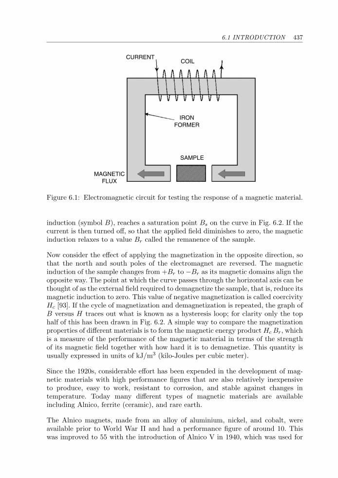
6.1 INTRODUCTION 437
CURRENTCOIL
MAGNETICFLUX
IRONFORMER
SAMPLE
Figure 6.1: Electromagnetic circuit for testing the response of a magnetic material.
induction (symbol B), reaches a saturation point Bs on the curve in Fig. 6.2. If thecurrent is then turned off, so that the applied field diminishes to zero, the magneticinduction relaxes to a value Br called the remanence of the sample.
Now consider the effect of applying the magnetization in the opposite direction, sothat the north and south poles of the electromagnet are reversed. The magneticinduction of the sample changes from +Br to −Br as its magnetic domains align theopposite way. The point at which the curve passes through the horizontal axis can bethought of as the external field required to demagnetize the sample, that is, reduce itsmagnetic induction to zero. This value of negative magnetization is called coercivityHc [93]. If the cycle of magnetization and demagnetization is repeated, the graph ofB versus H traces out what is known as a hysteresis loop; for clarity only the tophalf of this has been drawn in Fig. 6.2. A simple way to compare the magnetizationproperties of different materials is to form the magnetic energy product Hc Br, whichis a measure of the performance of the magnetic material in terms of the strengthof its magnetic field together with how hard it is to demagnetize. This quantity isusually expressed in units of kJ/m3 (kilo-Joules per cubic meter).
Since the 1920s, considerable effort has been expended in the development of mag-netic materials with high performance figures that are also relatively inexpensiveto produce, easy to work, resistant to corrosion, and stable against changes intemperature. Today many different types of magnetic materials are availableincluding Alnico, ferrite (ceramic), and rare earth.
The Alnico magnets, made from an alloy of aluminium, nickel, and cobalt, wereavailable prior to World War II and had a performance figure of around 10. Thiswas improved to 55 with the introduction of Alnico V in 1940, which was used for
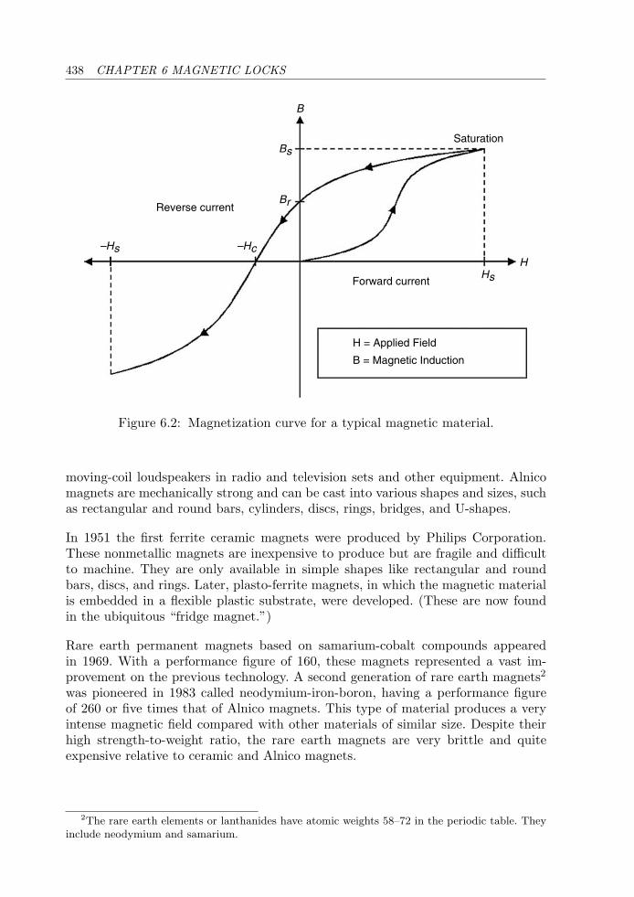
438 CHAPTER 6 MAGNETIC LOCKS
B
Bs
Br
Saturation
Reverse current
–Hs –Hc
HsH
Forward current
H = Applied Field
B = Magnetic Induction
Figure 6.2: Magnetization curve for a typical magnetic material.
moving-coil loudspeakers in radio and television sets and other equipment. Alnicomagnets are mechanically strong and can be cast into various shapes and sizes, suchas rectangular and round bars, cylinders, discs, rings, bridges, and U-shapes.
In 1951 the first ferrite ceramic magnets were produced by Philips Corporation.These nonmetallic magnets are inexpensive to produce but are fragile and difficultto machine. They are only available in simple shapes like rectangular and roundbars, discs, and rings. Later, plasto-ferrite magnets, in which the magnetic materialis embedded in a flexible plastic substrate, were developed. (These are now foundin the ubiquitous “fridge magnet.”)
Rare earth permanent magnets based on samarium-cobalt compounds appearedin 1969. With a performance figure of 160, these magnets represented a vast im-provement on the previous technology. A second generation of rare earth magnets2
was pioneered in 1983 called neodymium-iron-boron, having a performance figureof 260 or five times that of Alnico magnets. This type of material produces a veryintense magnetic field compared with other materials of similar size. Despite theirhigh strength-to-weight ratio, the rare earth magnets are very brittle and quiteexpensive relative to ceramic and Alnico magnets.
2The rare earth elements or lanthanides have atomic weights 58–72 in the periodic table. Theyinclude neodymium and samarium.
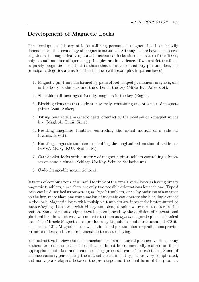
6.1 INTRODUCTION 439
Development of Magnetic Locks
The development history of locks utilizing permanent magnets has been heavilydependent on the technology of magnetic materials. Although there have been scoresof patents for magnetically operated mechanical locks since the start of the 1900s,only a small number of operating principles are in evidence. If we restrict the focusto purely magnetic locks, that is, those that do not use auxiliary pin-tumblers, theprincipal categories are as identified below (with examples in parentheses).
1. Magnetic pin-tumblers formed by pairs of rod-shaped permanent magnets, onein the body of the lock and the other in the key (Miwa EC, Ankerslot).
2. Slideable ball bearings driven by magnets in the key (Eagle).
3. Blocking elements that slide transversely, containing one or a pair of magnets(Miwa 3800, Anker).
4. Tilting pins with a magnetic head, oriented by the position of a magnet in thekey (MagLok, Genii, Sima).
5. Rotating magnetic tumblers controlling the radial motion of a side-bar(Parnis, Elzett).
6. Rotating magnetic tumblers controlling the longitudinal motion of a side-bar(EVVA MCS, IKON System M).
7. Card-in-slot locks with a matrix of magnetic pin-tumblers controlling a knob-set or handle clutch (Schlage CorKey, Schulte-Schlagbaum).
8. Code-changeable magnetic locks.
In terms of combinations, it is useful to think of the type 1 and 7 locks as having binarymagnetic tumblers, since there are only two possible orientations for each one. Type 3locks can be described as possessing multipole tumblers, since, by omission of a magneton the key, more than one combination of magnets can operate the blocking elementin the lock. Magnetic locks with multipole tumblers are inherently better suited tomaster-keying than locks with binary tumblers, a point we return to later in thissection. Some of these designs have been enhanced by the addition of conventionalpin-tumblers, in which case we can refer to them as hybrid magnetic plus mechanicallocks. The Miracle Magnetic lock produced by Liquidonics Industries around 1970 fitsthis profile [121]. Magnetic locks with additional pin-tumblers or profile pins providefar more differs and are more amenable to master-keying.
It is instructive to view these lock mechanisms in a historical perspective since manyof them are based on earlier ideas that could not be commercially realized until theappropriate materials and manufacturing processes came into existence. Some ofthe mechanisms, particularly the magnetic card-in-slot types, are very complicated,and many years elapsed between the prototype and the final form of the product.
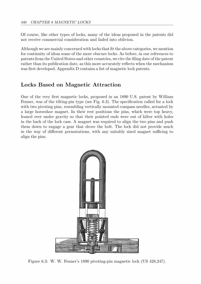
440 CHAPTER 6 MAGNETIC LOCKS
Of course, like other types of locks, many of the ideas proposed in the patents didnot receive commercial consideration and faded into oblivion.
Although we are mainly concerned with locks that fit the above categories, we mentionfor continuity of ideas some of the more obscure locks. As before, in our references topatents from the United States and other countries, we cite the filing date of the patentrather than its publication date, as this more accurately reflects when the mechanismwas first developed. Appendix D contains a list of magnetic lock patents.
Locks Based on Magnetic Attraction
One of the very first magnetic locks, proposed in an 1890 U.S. patent by WilliamFenner, was of the tilting-pin type (see Fig. 6.3). The specification called for a lockwith two pivoting pins, resembling vertically mounted compass needles, actuated bya large horseshoe magnet. In their rest positions the pins, which were top heavy,leaned over under gravity so that their pointed ends were out of kilter with holesin the back of the lock case. A magnet was required to align the two pins and pushthem down to engage a gear that drove the bolt. The lock did not provide muchin the way of different permutations, with any suitably sized magnet sufficing toalign the pins.
Figure 6.3: W. W. Fenner’s 1890 pivoting-pin magnetic lock (US 428,247).
6.1 INTRODUCTION 441
Figure 6.4: P. W. Fuller’s magnetically levitating pin lock (US 1,172,203).
Another early invention, by P. W. Fuller in 1914 (Fig. 6.4), is best described as an“antigravity” lock. In this contraption the lock cylinder was constructed betweenthe poles of a large magnet. A system of doubly sprung pin-tumblers of ferromag-netic material provided the locking function. In the locked position, the upward-acting springs forced the bottom pins up past the shear line. When a ferromagnetic(iron) key was inserted, reducing the air gap between the poles of the magnet, astrong magnetic field was created between the blade of the key and the bottom pins,attracting the pins down onto the key bittings. If the bittings were at the correctheights, the pins would be set at the shear line.
A. E. Anakin’s patent of 1925 (US 1,669,115) put the magnet back into the key,which was formed by folding a piece of magnetized steel into a double-bladed keywith a separating piece to ensure an air gap between the poles of the magnet. Inaddition to pin-tumblers, the lock had a number of passive profile balls that wereattracted up into V-cuts in the bottom of the blade when the key was inserted. Withno springs to tension the profile balls, the blocking mechanism would not have beendifficult to circumvent.
The magnetically driven sliding ball idea was articulated in a 1938 U.S. patent byH. H. Raymond of the Eagle Lock Company (see Fig. 6.5). The lock in question wasa cam lock with two steel balls in longitudinal grooves between the plug and barrel.A magnet in the key brought the balls into line with a circumferential channel,releasing the plug.
Sliding Magnetic Tumblers
We have so far only covered magnetic locks containing magnets in either the bodyor the key, but not both, the working principle being that a magnet attracts aferromagnetic object like a steel pin or ball. This principle fails to capitalize on theobvious advantages of having two magnets that can generate either an attractive ora repulsive force according to their polarity and/or orientation.
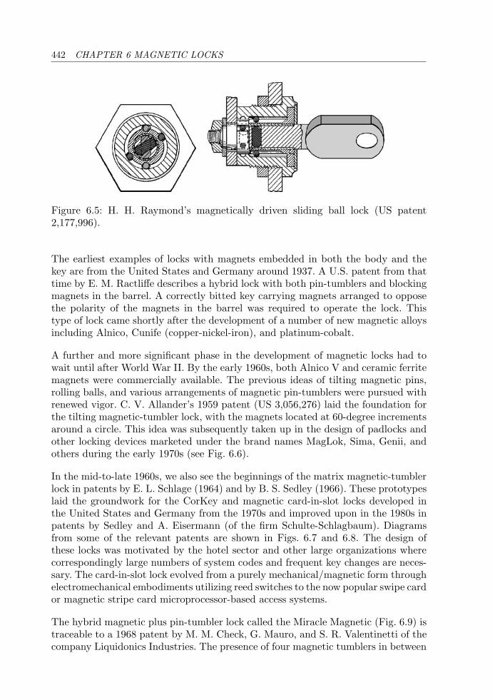
442 CHAPTER 6 MAGNETIC LOCKS
Figure 6.5: H. H. Raymond’s magnetically driven sliding ball lock (US patent2,177,996).
The earliest examples of locks with magnets embedded in both the body and thekey are from the United States and Germany around 1937. A U.S. patent from thattime by E. M. Ractliffe describes a hybrid lock with both pin-tumblers and blockingmagnets in the barrel. A correctly bitted key carrying magnets arranged to opposethe polarity of the magnets in the barrel was required to operate the lock. Thistype of lock came shortly after the development of a number of new magnetic alloysincluding Alnico, Cunife (copper-nickel-iron), and platinum-cobalt.
A further and more significant phase in the development of magnetic locks had towait until after World War II. By the early 1960s, both Alnico V and ceramic ferritemagnets were commercially available. The previous ideas of tilting magnetic pins,rolling balls, and various arrangements of magnetic pin-tumblers were pursued withrenewed vigor. C. V. Allander’s 1959 patent (US 3,056,276) laid the foundation forthe tilting magnetic-tumbler lock, with the magnets located at 60-degree incrementsaround a circle. This idea was subsequently taken up in the design of padlocks andother locking devices marketed under the brand names MagLok, Sima, Genii, andothers during the early 1970s (see Fig. 6.6).
In the mid-to-late 1960s, we also see the beginnings of the matrix magnetic-tumblerlock in patents by E. L. Schlage (1964) and by B. S. Sedley (1966). These prototypeslaid the groundwork for the CorKey and magnetic card-in-slot locks developed inthe United States and Germany from the 1970s and improved upon in the 1980s inpatents by Sedley and A. Eisermann (of the firm Schulte-Schlagbaum). Diagramsfrom some of the relevant patents are shown in Figs. 6.7 and 6.8. The design ofthese locks was motivated by the hotel sector and other large organizations wherecorrespondingly large numbers of system codes and frequent key changes are neces-sary. The card-in-slot lock evolved from a purely mechanical/magnetic form throughelectromechanical embodiments utilizing reed switches to the now popular swipe cardor magnetic stripe card microprocessor-based access systems.
The hybrid magnetic plus pin-tumbler lock called the Miracle Magnetic (Fig. 6.9) istraceable to a 1968 patent by M. M. Check, G. Mauro, and S. R. Valentinetti of thecompany Liquidonics Industries. The presence of four magnetic tumblers in between
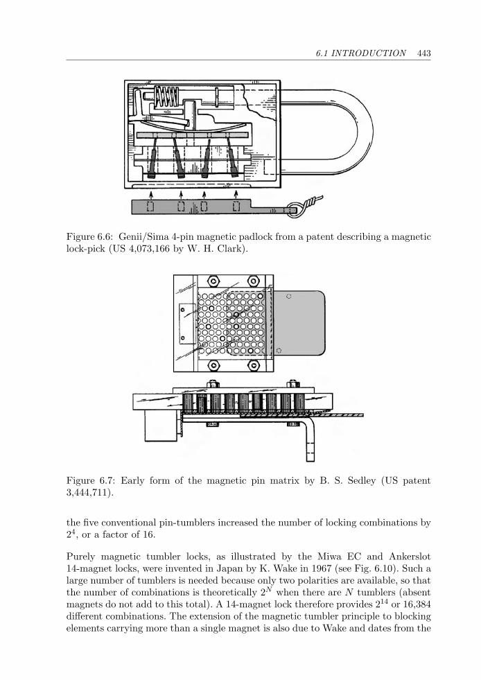
6.1 INTRODUCTION 443
Figure 6.6: Genii/Sima 4-pin magnetic padlock from a patent describing a magneticlock-pick (US 4,073,166 by W. H. Clark).
Figure 6.7: Early form of the magnetic pin matrix by B. S. Sedley (US patent3,444,711).
the five conventional pin-tumblers increased the number of locking combinations by24, or a factor of 16.
Purely magnetic tumbler locks, as illustrated by the Miwa EC and Ankerslot14-magnet locks, were invented in Japan by K. Wake in 1967 (see Fig. 6.10). Such alarge number of tumblers is needed because only two polarities are available, so thatthe number of combinations is theoretically 2N when there are N tumblers (absentmagnets do not add to this total). A 14-magnet lock therefore provides 214 or 16,384different combinations. The extension of the magnetic tumbler principle to blockingelements carrying more than a single magnet is also due to Wake and dates from the
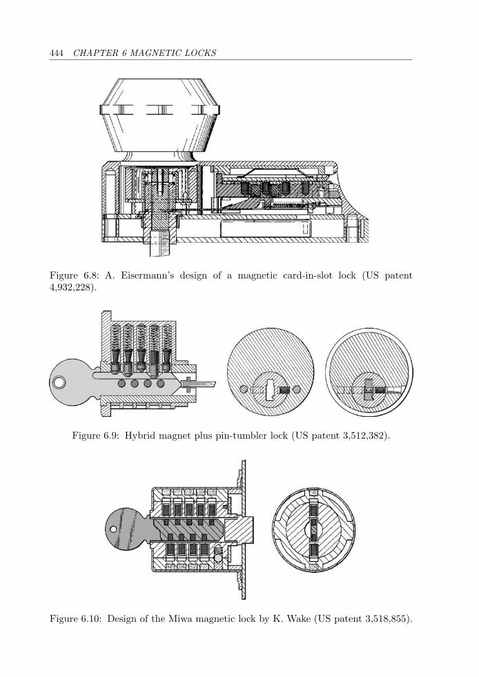
444 CHAPTER 6 MAGNETIC LOCKS
Figure 6.8: A. Eisermann’s design of a magnetic card-in-slot lock (US patent4,932,228).
Figure 6.9: Hybrid magnet plus pin-tumbler lock (US patent 3,512,382).
Figure 6.10: Design of the Miwa magnetic lock by K. Wake (US patent 3,518,855).
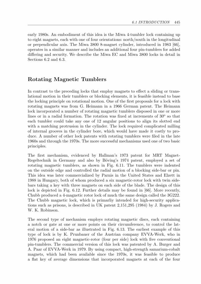
6.1 INTRODUCTION 445
early 1980s. An embodiment of this idea is the Miwa 4-tumbler lock containing upto eight magnets, each with one of four orientations: north/south in the longitudinalor perpendicular axis. The Miwa 3800 8-magnet cylinder, introduced in 1983 [66],operates in a similar manner and includes an additional four pin-tumblers for addeddiffering and security. We describe the Miwa EC and Miwa 3800 locks in detail inSections 6.2 and 6.3.
Rotating Magnetic Tumblers
In contrast to the preceding locks that employ magnets to effect a sliding or trans-lational motion in their tumblers or blocking elements, it is feasible instead to basethe locking principle on rotational motion. One of the first proposals for a lock withrotating magnets was from G. Heimann in a 1966 German patent. The Heimannlock incorporated a number of rotating magnetic tumblers disposed in one or morelines or in a radial formation. The rotation was fixed at increments of 30o so thateach tumbler could take any one of 12 angular positions to align its slotted endwith a matching protrusion in the cylinder. The lock required complicated millingof internal grooves in the cylinder bore, which would have made it costly to pro-duce. A number of other lock patents with rotating tumblers were filed in the late1960s and through the 1970s. The more successful mechanisms used one of two basicprinciples.
The first mechanism, evidenced by Hallman’s 1973 patent for MRT Magnet-Regeltechnik in Germany and also by Boving’s 1974 patent, employed a set ofrotating magnetic tumblers, as shown in Fig. 6.11. The tumblers were indentedon the outside edge and controlled the radial motion of a blocking side-bar or pin.This idea was later commercialized by Parnis in the United States and Elzett in1988 in Hungary, both of whom produced a six magnetic-rotor lock with twin side-bars taking a key with three magnets on each side of the blade. The design of thislock is depicted in Fig. 6.12. Further details may be found in [66]. More recently,Chubb produced a 4-magnetic rotor lock of much the same design called the 3G222.The Chubb magnetic lock, which is primarliy intended for high-security applica-tions such as prisons, is described in UK patent 2,151,295 (1984) by J. Rogers andW. K. Robinson.
The second type of mechanism employs rotating magnetic discs, each containinga notch or gate at one or more points on their circumference, to control the lat-eral motion of a side-bar as illustrated in Fig. 6.13. The earliest example of thistype of lock is by K. Prunbauer of the Austrian company EVVA-Werk, who in1976 proposed an eight magnetic-rotor (four per side) lock with five conventionalpin-tumblers. The commercial version of this lock was patented by A. Burger andA. Paar of EVVA-Werk in 1979. By using compact, high-strength samarium-cobaltmagnets, which had been available since the 1970s, it was feasible to producea flat key of average dimensions that incorporated magnets at each of the four

446 CHAPTER 6 MAGNETIC LOCKS
Figure 6.11: H. Hallman and B. Perkut’s rotating-magnet side-bar lock (US patent3,855,827).
Figure 6.12: Design of the Elzett/Parnis 6-rotor magnetic lock from T. Kassza’s1989 patent (UK 2,214,226).
Figure 6.13: Magnetic control of lateral side-bar motion from E. Boving’s patent(US 3,935,720).
locations along the key stem. This is the high-security 8-rotor, twin side-bar lock,marketed as the EVVA MCS or IKON System M, which we describe in detaillater on. More than any of the preceding locks mentioned in this chapter, this par-ticular one exemplifies what is achievable in the field of magnetic high-security
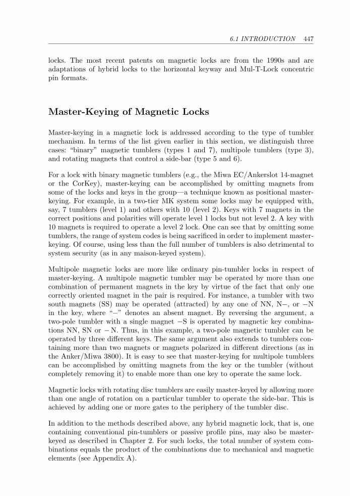
6.1 INTRODUCTION 447
locks. The most recent patents on magnetic locks are from the 1990s and areadaptations of hybrid locks to the horizontal keyway and Mul-T-Lock concentricpin formats.
Master-Keying of Magnetic Locks
Master-keying in a magnetic lock is addressed according to the type of tumblermechanism. In terms of the list given earlier in this section, we distinguish threecases: “binary” magnetic tumblers (types 1 and 7), multipole tumblers (type 3),and rotating magnets that control a side-bar (type 5 and 6).
For a lock with binary magnetic tumblers (e.g., the Miwa EC/Ankerslot 14-magnetor the CorKey), master-keying can be accomplished by omitting magnets fromsome of the locks and keys in the group—a technique known as positional master-keying. For example, in a two-tier MK system some locks may be equipped with,say, 7 tumblers (level 1) and others with 10 (level 2). Keys with 7 magnets in thecorrect positions and polarities will operate level 1 locks but not level 2. A key with10 magnets is required to operate a level 2 lock. One can see that by omitting sometumblers, the range of system codes is being sacrificed in order to implement master-keying. Of course, using less than the full number of tumblers is also detrimental tosystem security (as in any maison-keyed system).
Multipole magnetic locks are more like ordinary pin-tumbler locks in respect ofmaster-keying. A multipole magnetic tumbler may be operated by more than onecombination of permanent magnets in the key by virtue of the fact that only onecorrectly oriented magnet in the pair is required. For instance, a tumbler with twosouth magnets (SS) may be operated (attracted) by any one of NN, N−, or −Nin the key, where “−” denotes an absent magnet. By reversing the argument, atwo-pole tumbler with a single magnet −S is operated by magnetic key combina-tions NN, SN or −N. Thus, in this example, a two-pole magnetic tumbler can beoperated by three different keys. The same argument also extends to tumblers con-taining more than two magnets or magnets polarized in different directions (as inthe Anker/Miwa 3800). It is easy to see that master-keying for multipole tumblerscan be accomplished by omitting magnets from the key or the tumbler (withoutcompletely removing it) to enable more than one key to operate the same lock.
Magnetic locks with rotating disc tumblers are easily master-keyed by allowing morethan one angle of rotation on a particular tumbler to operate the side-bar. This isachieved by adding one or more gates to the periphery of the tumbler disc.
In addition to the methods described above, any hybrid magnetic lock, that is, onecontaining conventional pin-tumblers or passive profile pins, may also be master-keyed as described in Chapter 2. For such locks, the total number of system com-binations equals the product of the combinations due to mechanical and magneticelements (see Appendix A).
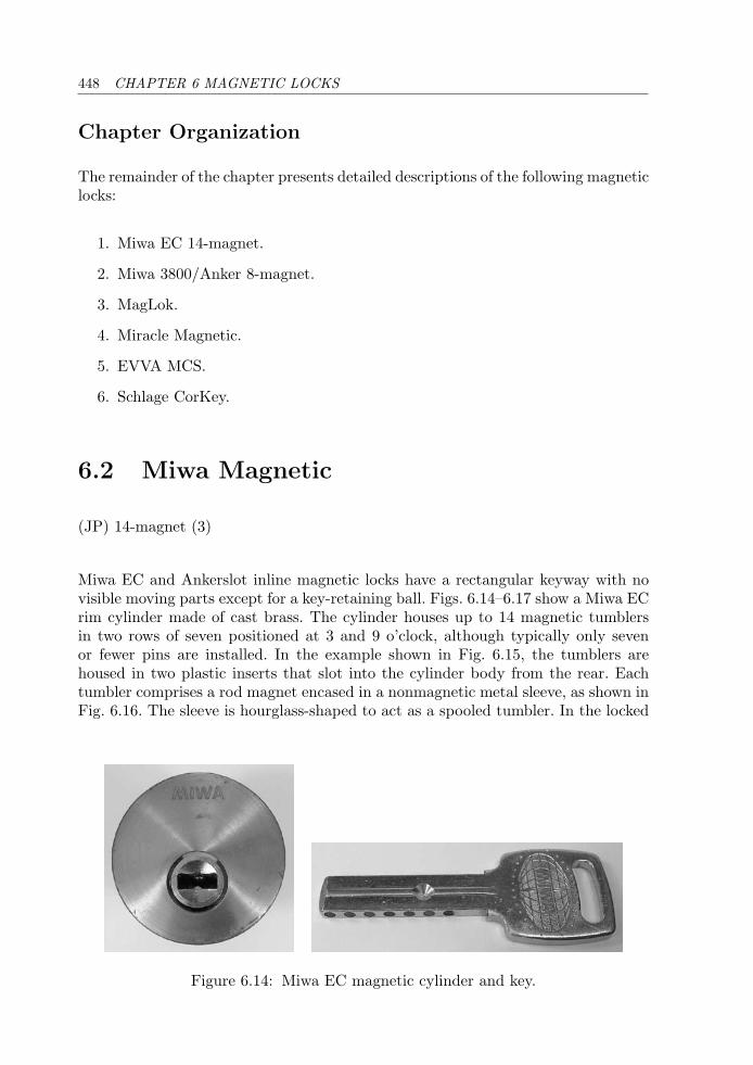
448 CHAPTER 6 MAGNETIC LOCKS
Chapter Organization
The remainder of the chapter presents detailed descriptions of the following magneticlocks:
1. Miwa EC 14-magnet.
2. Miwa 3800/Anker 8-magnet.
3. MagLok.
4. Miracle Magnetic.
5. EVVA MCS.
6. Schlage CorKey.
6.2 Miwa Magnetic
(JP) 14-magnet (3)
Miwa EC and Ankerslot inline magnetic locks have a rectangular keyway with novisible moving parts except for a key-retaining ball. Figs. 6.14–6.17 show a Miwa ECrim cylinder made of cast brass. The cylinder houses up to 14 magnetic tumblersin two rows of seven positioned at 3 and 9 o’clock, although typically only sevenor fewer pins are installed. In the example shown in Fig. 6.15, the tumblers arehoused in two plastic inserts that slot into the cylinder body from the rear. Eachtumbler comprises a rod magnet encased in a nonmagnetic metal sleeve, as shown inFig. 6.16. The sleeve is hourglass-shaped to act as a spooled tumbler. In the locked
Figure 6.14: Miwa EC magnetic cylinder and key.
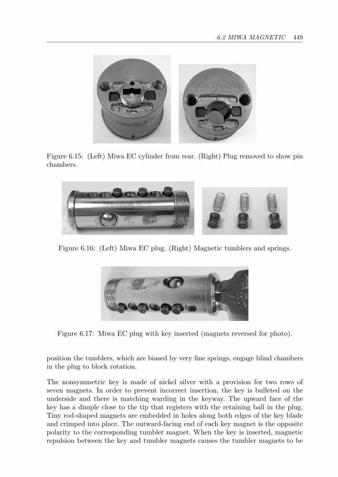
6.2 MIWA MAGNETIC 449
Figure 6.15: (Left) Miwa EC cylinder from rear. (Right) Plug removed to show pinchambers.
Figure 6.16: (Left) Miwa EC plug. (Right) Magnetic tumblers and springs.
Figure 6.17: Miwa EC plug with key inserted (magnets reversed for photo).
position the tumblers, which are biased by very fine springs, engage blind chambersin the plug to block rotation.
The nonsymmetric key is made of nickel silver with a provision for two rows ofseven magnets. In order to prevent incorrect insertion, the key is bulleted on theunderside and there is matching warding in the keyway. The upward face of thekey has a dimple close to the tip that registers with the retaining ball in the plug.Tiny rod-shaped magnets are embedded in holes along both edges of the key bladeand crimped into place. The outward-facing end of each key magnet is the oppositepolarity to the corresponding tumbler magnet. When the key is inserted, magneticrepulsion between the key and tumbler magnets causes the tumbler magnets to be
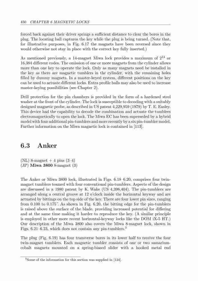
450 CHAPTER 6 MAGNETIC LOCKS
forced back against their driver springs a sufficient distance to clear the bores in theplug. The locating ball captures the key while the plug is being turned. (Note that,for illustrative purposes, in Fig. 6.17 the magnets have been reversed since theywould otherwise not stay in place with the correct key fully inserted.)
As mentioned previously, a 14-magnet Miwa lock provides a maximum of 214 or16,384 different codes. The omission of one or more magnets from the cylinder allowsmore than one key to operate the lock. Only as many magnets need be installed inthe key as there are magnetic tumblers in the cylinder, with the remaining holesfilled by dummy magnets. In a master-keyed system, different positions on the keycan be used to actuate different locks. Extra profile balls may also be used to increasemaster-keying possibilities (see Chapter 2).
Drill protection for the pin chambers is provided in the form of a hardened steelwasher at the front of the cylinder. The lock is susceptible to decoding with a suitablydesigned magnetic probe, as described in US patent 4,229,959 (1979) by T. E. Easley.This device had the capability to decode the combination and actuate the tumblerselectromagnetically to open the lock. The Miwa EC has been superseded by a hybridmodelwith four additional pin-tumblers andmore recently by a six pin-tumblermodel.Further information on the Miwa magnetic lock is contained in [113].
6.3 Anker
(NL) 8-magnet + 4 pins (3–4)(JP) Miwa 3800 8-magnet (3)
The Anker or Miwa 3800 lock, illustrated in Figs. 6.18–6.20, comprises four twin-magnet tumblers teamed with four conventional pin-tumblers. Aspects of the designare discussed in a 1980 patent by K. Wake (US 4,398,404). The pin-tumblers arearranged along a central groove at 12 o’clock inside the horizontal keyway and areactuated by bittings on the top side of the key. There are four lower pin sizes, rangingfrom 0.100 to 0.175 . As shown in Fig. 6.20, the bitting edge for the pin-tumblersis raised above the surface of the blade, providing increased potential for differingand at the same time making it harder to reproduce the key. (A similar principleis employed in other more recent horizontal-keyway locks like the DOM iX-5 HT.)Our description of the Miwa 3800 also covers the Miwa 8-magnet lock, shown inFigs. 6.21–6.23, which does not contain any pin-tumblers.3
The plug (Fig. 6.19) has four transverse bores in its lower half to receive the fourtwin-magnet tumblers. Each magnetic tumbler consists of one or two samarium-cobalt magnets mounted on a spring-biased slider with a hooked metal end
3Some of the information for this section was supplied in [124].
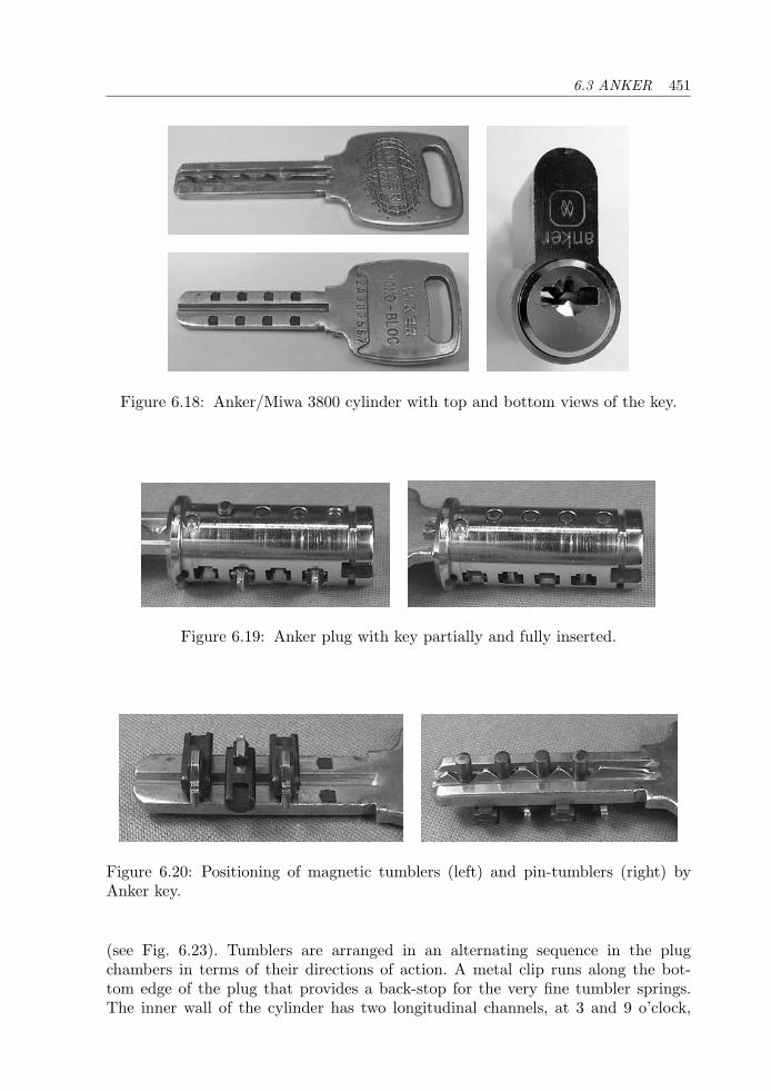
6.3 ANKER 451
Figure 6.18: Anker/Miwa 3800 cylinder with top and bottom views of the key.
Figure 6.19: Anker plug with key partially and fully inserted.
Figure 6.20: Positioning of magnetic tumblers (left) and pin-tumblers (right) byAnker key.
(see Fig. 6.23). Tumblers are arranged in an alternating sequence in the plugchambers in terms of their directions of action. A metal clip runs along the bot-tom edge of the plug that provides a back-stop for the very fine tumbler springs.The inner wall of the cylinder has two longitudinal channels, at 3 and 9 o’clock,
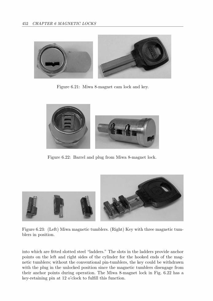
452 CHAPTER 6 MAGNETIC LOCKS
Figure 6.21: Miwa 8-magnet cam lock and key.
Figure 6.22: Barrel and plug from Miwa 8-magnet lock.
Figure 6.23: (Left) Miwa magnetic tumblers. (Right) Key with three magnetic tum-blers in position.
into which are fitted slotted steel “ladders.” The slots in the ladders provide anchorpoints on the left and right sides of the cylinder for the hooked ends of the mag-netic tumblers; without the conventional pin-tumblers, the key could be withdrawnwith the plug in the unlocked position since the magnetic tumblers disengage fromtheir anchor points during operation. The Miwa 8-magnet lock in Fig. 6.22 has akey-retaining pin at 12 o’clock to fulfill this function.
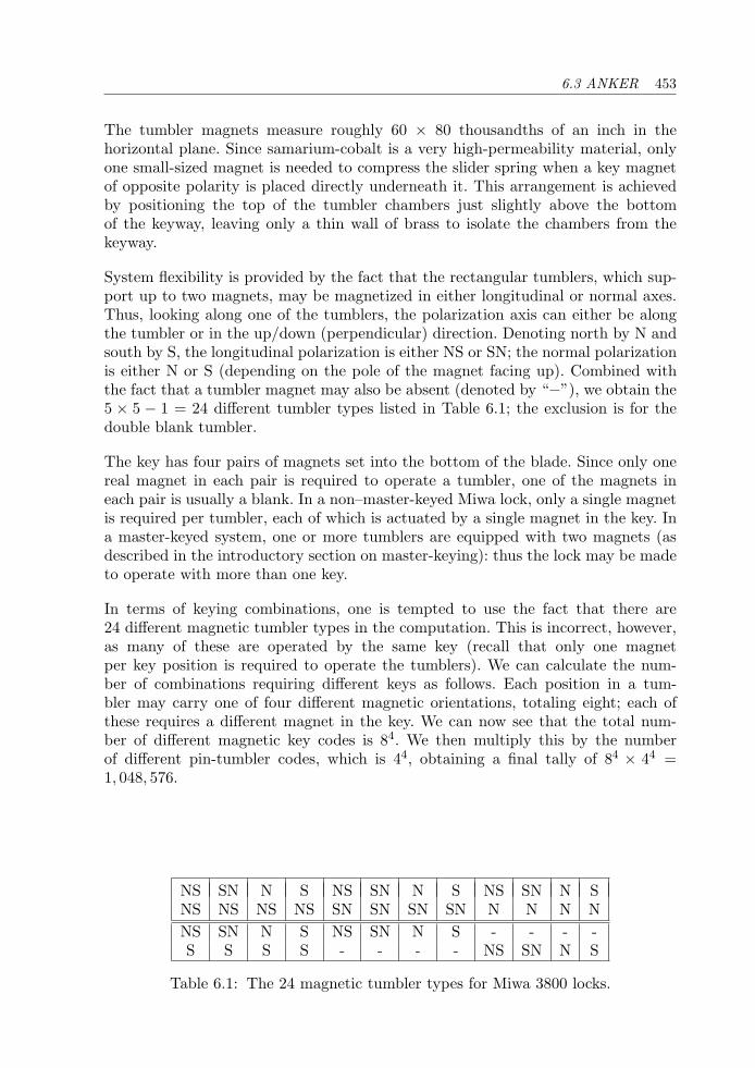
6.3 ANKER 453
The tumbler magnets measure roughly 60 × 80 thousandths of an inch in thehorizontal plane. Since samarium-cobalt is a very high-permeability material, onlyone small-sized magnet is needed to compress the slider spring when a key magnetof opposite polarity is placed directly underneath it. This arrangement is achievedby positioning the top of the tumbler chambers just slightly above the bottomof the keyway, leaving only a thin wall of brass to isolate the chambers from thekeyway.
System flexibility is provided by the fact that the rectangular tumblers, which sup-port up to two magnets, may be magnetized in either longitudinal or normal axes.Thus, looking along one of the tumblers, the polarization axis can either be alongthe tumbler or in the up/down (perpendicular) direction. Denoting north by N andsouth by S, the longitudinal polarization is either NS or SN; the normal polarizationis either N or S (depending on the pole of the magnet facing up). Combined withthe fact that a tumbler magnet may also be absent (denoted by “−”), we obtain the5 × 5 − 1 = 24 different tumbler types listed in Table 6.1; the exclusion is for thedouble blank tumbler.
The key has four pairs of magnets set into the bottom of the blade. Since only onereal magnet in each pair is required to operate a tumbler, one of the magnets ineach pair is usually a blank. In a non–master-keyed Miwa lock, only a single magnetis required per tumbler, each of which is actuated by a single magnet in the key. Ina master-keyed system, one or more tumblers are equipped with two magnets (asdescribed in the introductory section on master-keying): thus the lock may be madeto operate with more than one key.
In terms of keying combinations, one is tempted to use the fact that there are24 different magnetic tumbler types in the computation. This is incorrect, however,as many of these are operated by the same key (recall that only one magnetper key position is required to operate the tumblers). We can calculate the num-ber of combinations requiring different keys as follows. Each position in a tum-bler may carry one of four different magnetic orientations, totaling eight; each ofthese requires a different magnet in the key. We can now see that the total num-ber of different magnetic key codes is 84. We then multiply this by the numberof different pin-tumbler codes, which is 44, obtaining a final tally of 84 × 44 =1, 048, 576.
NS SN N S NS SN N S NS SN N SNS NS NS NS SN SN SN SN N N N NNS SN N S NS SN N S - - - -S S S S - - - - NS SN N S
Table 6.1: The 24 magnetic tumbler types for Miwa 3800 locks.
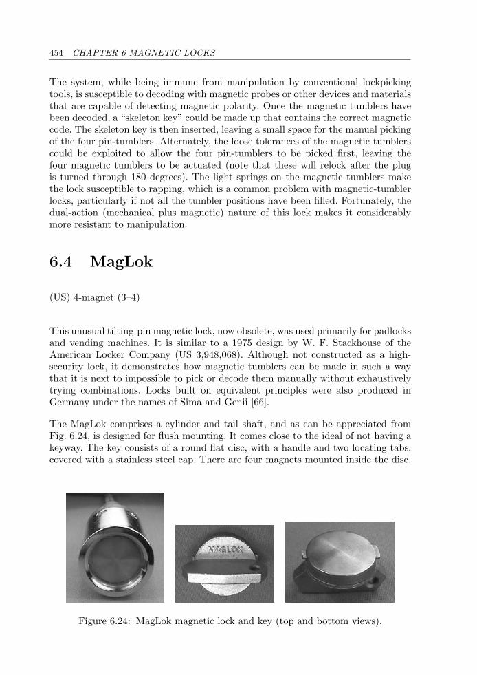
454 CHAPTER 6 MAGNETIC LOCKS
The system, while being immune from manipulation by conventional lockpickingtools, is susceptible to decoding with magnetic probes or other devices and materialsthat are capable of detecting magnetic polarity. Once the magnetic tumblers havebeen decoded, a “skeleton key” could be made up that contains the correct magneticcode. The skeleton key is then inserted, leaving a small space for the manual pickingof the four pin-tumblers. Alternately, the loose tolerances of the magnetic tumblerscould be exploited to allow the four pin-tumblers to be picked first, leaving thefour magnetic tumblers to be actuated (note that these will relock after the plugis turned through 180 degrees). The light springs on the magnetic tumblers makethe lock susceptible to rapping, which is a common problem with magnetic-tumblerlocks, particularly if not all the tumbler positions have been filled. Fortunately, thedual-action (mechanical plus magnetic) nature of this lock makes it considerablymore resistant to manipulation.
6.4 MagLok
(US) 4-magnet (3–4)
This unusual tilting-pin magnetic lock, now obsolete, was used primarily for padlocksand vending machines. It is similar to a 1975 design by W. F. Stackhouse of theAmerican Locker Company (US 3,948,068). Although not constructed as a high-security lock, it demonstrates how magnetic tumblers can be made in such a waythat it is next to impossible to pick or decode them manually without exhaustivelytrying combinations. Locks built on equivalent principles were also produced inGermany under the names of Sima and Genii [66].
The MagLok comprises a cylinder and tail shaft, and as can be appreciated fromFig. 6.24, is designed for flush mounting. It comes close to the ideal of not having akeyway. The key consists of a round flat disc, with a handle and two locating tabs,covered with a stainless steel cap. There are four magnets mounted inside the disc.
Figure 6.24: MagLok magnetic lock and key (top and bottom views).
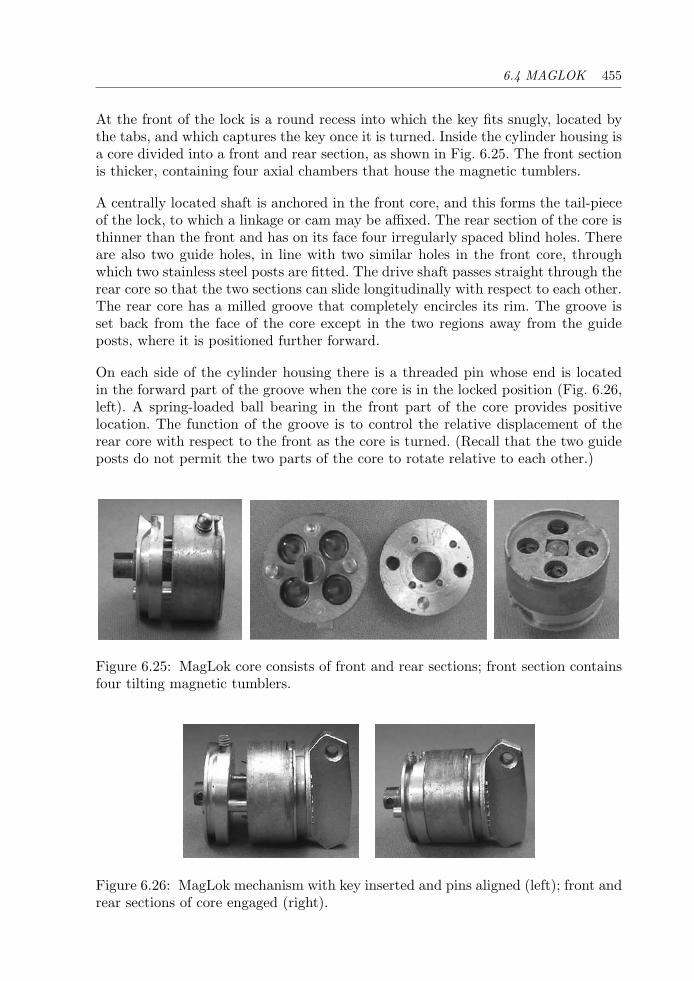
6.4 MAGLOK 455
At the front of the lock is a round recess into which the key fits snugly, located bythe tabs, and which captures the key once it is turned. Inside the cylinder housing isa core divided into a front and rear section, as shown in Fig. 6.25. The front sectionis thicker, containing four axial chambers that house the magnetic tumblers.
A centrally located shaft is anchored in the front core, and this forms the tail-pieceof the lock, to which a linkage or cam may be affixed. The rear section of the core isthinner than the front and has on its face four irregularly spaced blind holes. Thereare also two guide holes, in line with two similar holes in the front core, throughwhich two stainless steel posts are fitted. The drive shaft passes straight through therear core so that the two sections can slide longitudinally with respect to each other.The rear core has a milled groove that completely encircles its rim. The groove isset back from the face of the core except in the two regions away from the guideposts, where it is positioned further forward.
On each side of the cylinder housing there is a threaded pin whose end is locatedin the forward part of the groove when the core is in the locked position (Fig. 6.26,left). A spring-loaded ball bearing in the front part of the core provides positivelocation. The function of the groove is to control the relative displacement of therear core with respect to the front as the core is turned. (Recall that the two guideposts do not permit the two parts of the core to rotate relative to each other.)
Figure 6.25: MagLok core consists of front and rear sections; front section containsfour tilting magnetic tumblers.
Figure 6.26: MagLok mechanism with key inserted and pins aligned (left); front andrear sections of core engaged (right).
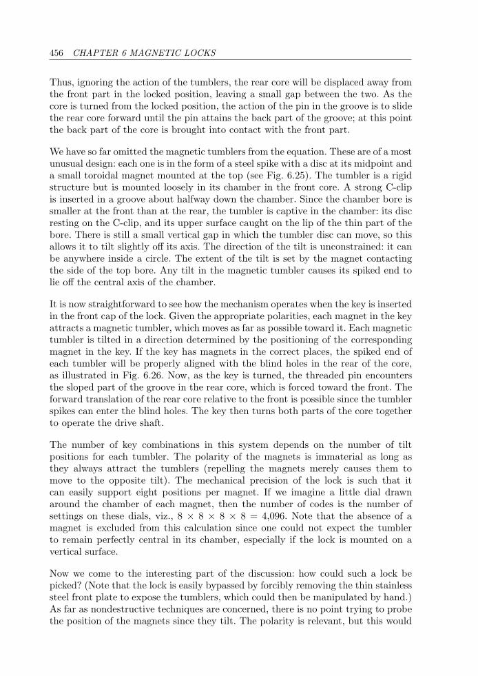
456 CHAPTER 6 MAGNETIC LOCKS
Thus, ignoring the action of the tumblers, the rear core will be displaced away fromthe front part in the locked position, leaving a small gap between the two. As thecore is turned from the locked position, the action of the pin in the groove is to slidethe rear core forward until the pin attains the back part of the groove; at this pointthe back part of the core is brought into contact with the front part.
We have so far omitted the magnetic tumblers from the equation. These are of a mostunusual design: each one is in the form of a steel spike with a disc at its midpoint anda small toroidal magnet mounted at the top (see Fig. 6.25). The tumbler is a rigidstructure but is mounted loosely in its chamber in the front core. A strong C-clipis inserted in a groove about halfway down the chamber. Since the chamber bore issmaller at the front than at the rear, the tumbler is captive in the chamber: its discresting on the C-clip, and its upper surface caught on the lip of the thin part of thebore. There is still a small vertical gap in which the tumbler disc can move, so thisallows it to tilt slightly off its axis. The direction of the tilt is unconstrained: it canbe anywhere inside a circle. The extent of the tilt is set by the magnet contactingthe side of the top bore. Any tilt in the magnetic tumbler causes its spiked end tolie off the central axis of the chamber.
It is now straightforward to see how the mechanism operates when the key is insertedin the front cap of the lock. Given the appropriate polarities, each magnet in the keyattracts a magnetic tumbler, which moves as far as possible toward it. Each magnetictumbler is tilted in a direction determined by the positioning of the correspondingmagnet in the key. If the key has magnets in the correct places, the spiked end ofeach tumbler will be properly aligned with the blind holes in the rear of the core,as illustrated in Fig. 6.26. Now, as the key is turned, the threaded pin encountersthe sloped part of the groove in the rear core, which is forced toward the front. Theforward translation of the rear core relative to the front is possible since the tumblerspikes can enter the blind holes. The key then turns both parts of the core togetherto operate the drive shaft.
The number of key combinations in this system depends on the number of tiltpositions for each tumbler. The polarity of the magnets is immaterial as long asthey always attract the tumblers (repelling the magnets merely causes them tomove to the opposite tilt). The mechanical precision of the lock is such that itcan easily support eight positions per magnet. If we imagine a little dial drawnaround the chamber of each magnet, then the number of codes is the number ofsettings on these dials, viz., 8 × 8 × 8 × 8 = 4,096. Note that the absence of amagnet is excluded from this calculation since one could not expect the tumblerto remain perfectly central in its chamber, especially if the lock is mounted on avertical surface.
Now we come to the interesting part of the discussion: how could such a lock bepicked? (Note that the lock is easily bypassed by forcibly removing the thin stainlesssteel front plate to expose the tumblers, which could then be manipulated by hand.)As far as nondestructive techniques are concerned, there is no point trying to probethe position of the magnets since they tilt. The polarity is relevant, but this would
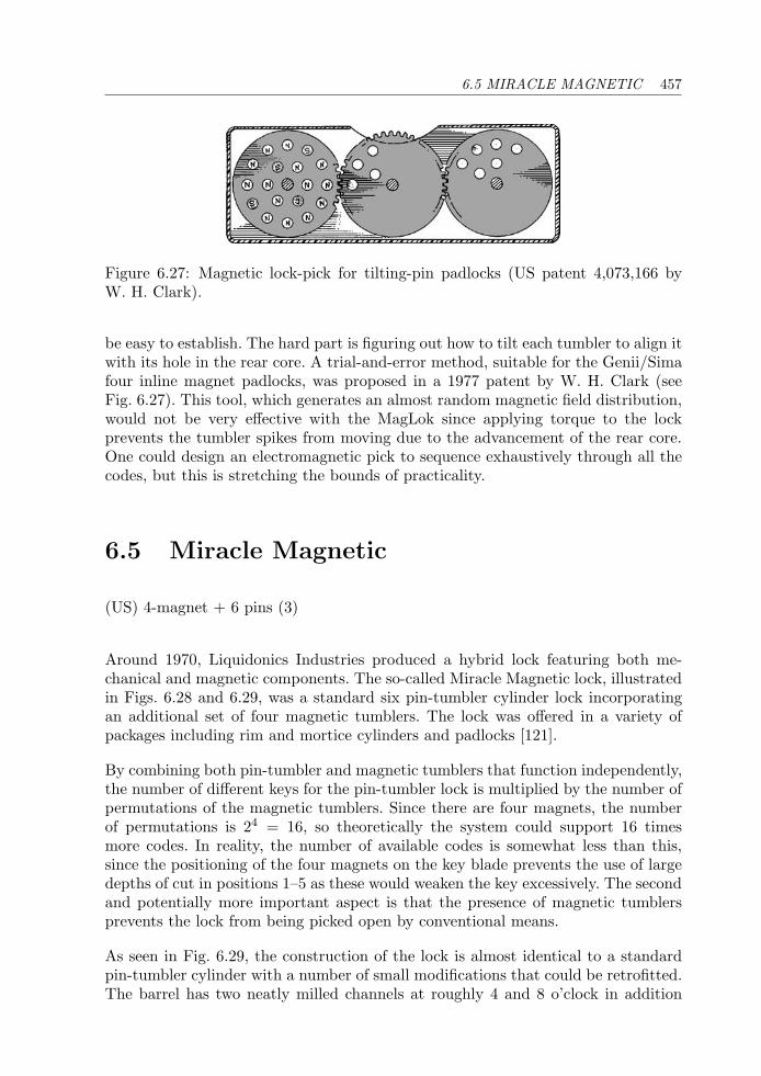
6.5 MIRACLE MAGNETIC 457
Figure 6.27: Magnetic lock-pick for tilting-pin padlocks (US patent 4,073,166 byW. H. Clark).
be easy to establish. The hard part is figuring out how to tilt each tumbler to align itwith its hole in the rear core. A trial-and-error method, suitable for the Genii/Simafour inline magnet padlocks, was proposed in a 1977 patent by W. H. Clark (seeFig. 6.27). This tool, which generates an almost random magnetic field distribution,would not be very effective with the MagLok since applying torque to the lockprevents the tumbler spikes from moving due to the advancement of the rear core.One could design an electromagnetic pick to sequence exhaustively through all thecodes, but this is stretching the bounds of practicality.
6.5 Miracle Magnetic
(US) 4-magnet + 6 pins (3)
Around 1970, Liquidonics Industries produced a hybrid lock featuring both me-chanical and magnetic components. The so-called Miracle Magnetic lock, illustratedin Figs. 6.28 and 6.29, was a standard six pin-tumbler cylinder lock incorporatingan additional set of four magnetic tumblers. The lock was offered in a variety ofpackages including rim and mortice cylinders and padlocks [121].
By combining both pin-tumbler and magnetic tumblers that function independently,the number of different keys for the pin-tumbler lock is multiplied by the number ofpermutations of the magnetic tumblers. Since there are four magnets, the numberof permutations is 24 = 16, so theoretically the system could support 16 timesmore codes. In reality, the number of available codes is somewhat less than this,since the positioning of the four magnets on the key blade prevents the use of largedepths of cut in positions 1–5 as these would weaken the key excessively. The secondand potentially more important aspect is that the presence of magnetic tumblersprevents the lock from being picked open by conventional means.
As seen in Fig. 6.29, the construction of the lock is almost identical to a standardpin-tumbler cylinder with a number of small modifications that could be retrofitted.The barrel has two neatly milled channels at roughly 4 and 8 o’clock in addition
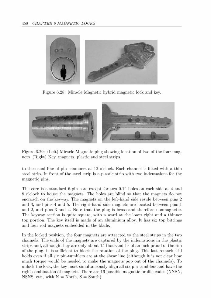
458 CHAPTER 6 MAGNETIC LOCKS
Figure 6.28: Miracle Magnetic hybrid magnetic lock and key.
Figure 6.29: (Left) Miracle Magnetic plug showing location of two of the four mag-nets. (Right) Key, magnets, plastic and steel strips.
to the usual line of pin chambers at 12 o’clock. Each channel is fitted with a thinsteel strip. In front of the steel strip is a plastic strip with two indentations for themagnetic pins.
The core is a standard 6-pin core except for two 0.1˝ holes on each side at 4 and8 o’clock to house the magnets. The holes are blind so that the magnets do notencroach on the keyway. The magnets on the left-hand side reside between pins 2and 3, and pins 4 and 5. The right-hand side magnets are located between pins 1and 2, and pins 3 and 4. Note that the plug is brass and therefore nonmagnetic.The keyway section is quite square, with a ward at the lower right and a thinnertop portion. The key itself is made of an aluminium alloy. It has six top bittingsand four rod magnets embedded in the blade.
In the locked position, the four magnets are attracted to the steel strips in the twochannels. The ends of the magnets are captured by the indentations in the plasticstrips and, although they are only about 15 thousandths of an inch proud of the rimof the plug, it is sufficient to block the rotation of the plug. This last remark stillholds even if all six pin-tumblers are at the shear line (although it is not clear howmuch torque would be needed to make the magnets pop out of the channels). Tounlock the lock, the key must simultaneously align all six pin-tumblers and have theright combination of magnets. There are 16 possible magnetic profile codes (NNSN,NSNS, etc., with N = North, S = South).
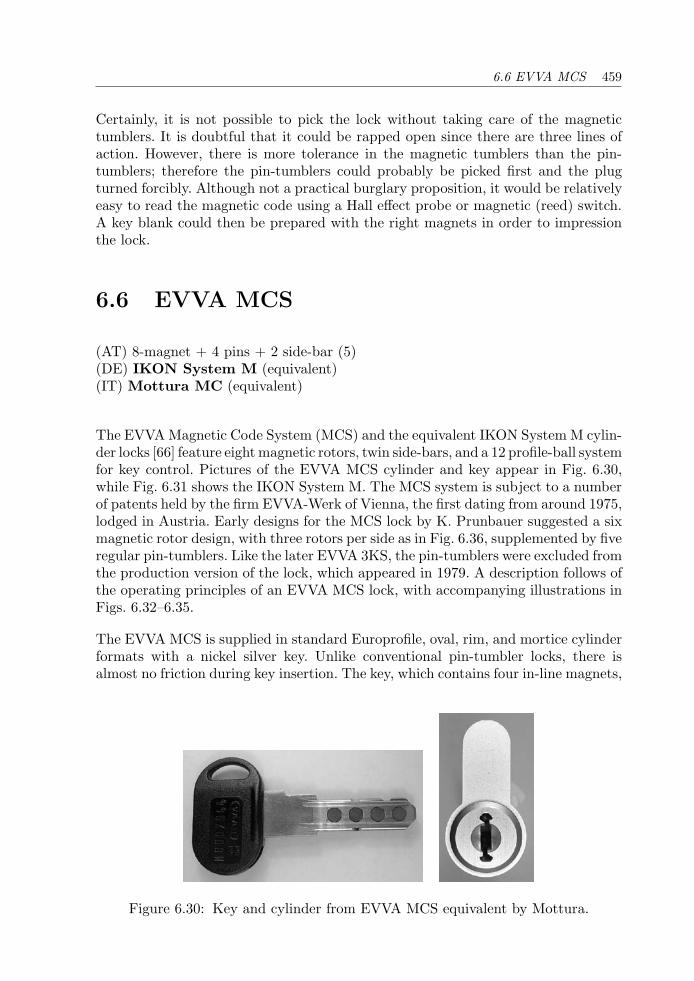
6.6 EVVA MCS 459
Certainly, it is not possible to pick the lock without taking care of the magnetictumblers. It is doubtful that it could be rapped open since there are three lines ofaction. However, there is more tolerance in the magnetic tumblers than the pin-tumblers; therefore the pin-tumblers could probably be picked first and the plugturned forcibly. Although not a practical burglary proposition, it would be relativelyeasy to read the magnetic code using a Hall effect probe or magnetic (reed) switch.A key blank could then be prepared with the right magnets in order to impressionthe lock.
6.6 EVVA MCS
(AT) 8-magnet + 4 pins + 2 side-bar (5)(DE) IKON System M (equivalent)(IT) Mottura MC (equivalent)
The EVVA Magnetic Code System (MCS) and the equivalent IKON System M cylin-der locks [66] feature eight magnetic rotors, twin side-bars, and a 12 profile-ball systemfor key control. Pictures of the EVVA MCS cylinder and key appear in Fig. 6.30,while Fig. 6.31 shows the IKON System M. The MCS system is subject to a numberof patents held by the firm EVVA-Werk of Vienna, the first dating from around 1975,lodged in Austria. Early designs for the MCS lock by K. Prunbauer suggested a sixmagnetic rotor design, with three rotors per side as in Fig. 6.36, supplemented by fiveregular pin-tumblers. Like the later EVVA 3KS, the pin-tumblers were excluded fromthe production version of the lock, which appeared in 1979. A description follows ofthe operating principles of an EVVA MCS lock, with accompanying illustrations inFigs. 6.32–6.35.
The EVVA MCS is supplied in standard Europrofile, oval, rim, and mortice cylinderformats with a nickel silver key. Unlike conventional pin-tumbler locks, there isalmost no friction during key insertion. The key, which contains four in-line magnets,
Figure 6.30: Key and cylinder from EVVA MCS equivalent by Mottura.
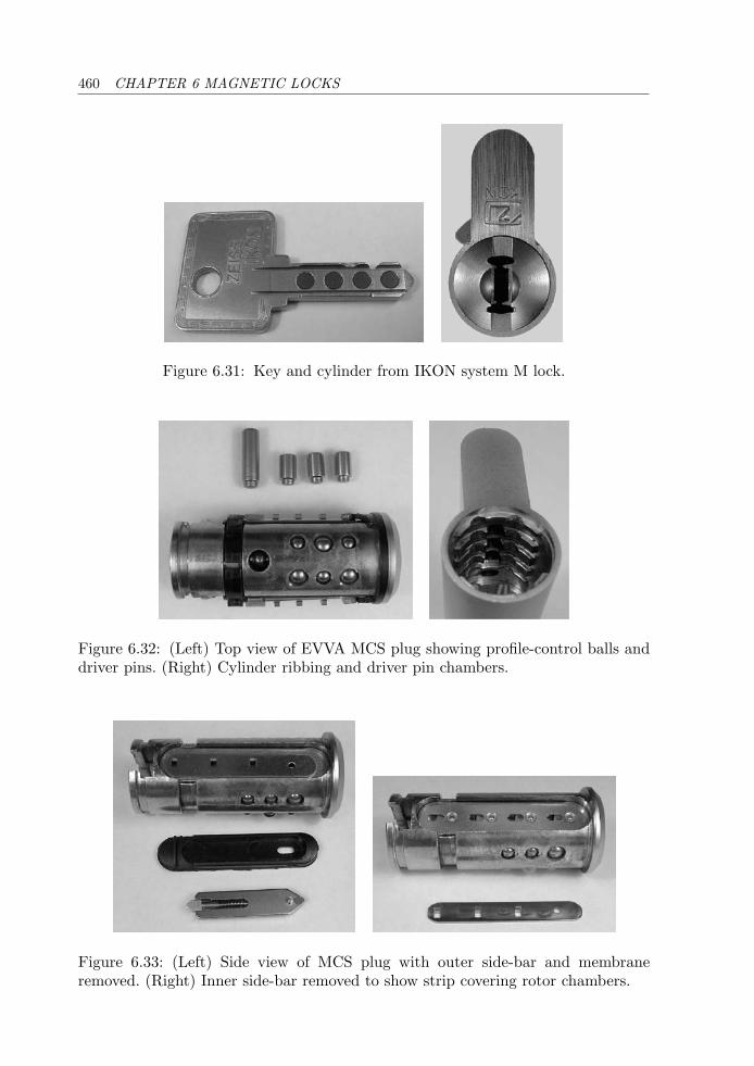
460 CHAPTER 6 MAGNETIC LOCKS
Figure 6.31: Key and cylinder from IKON system M lock.
Figure 6.32: (Left) Top view of EVVA MCS plug showing profile-control balls anddriver pins. (Right) Cylinder ribbing and driver pin chambers.
Figure 6.33: (Left) Side view of MCS plug with outer side-bar and membraneremoved. (Right) Inner side-bar removed to show strip covering rotor chambers.
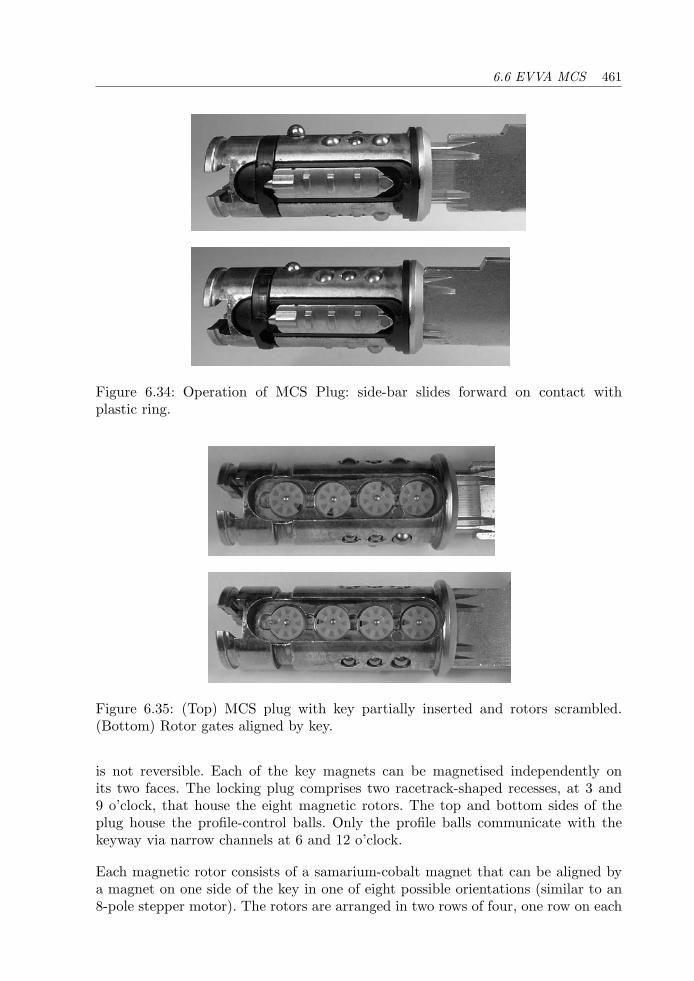
6.6 EVVA MCS 461
Figure 6.34: Operation of MCS Plug: side-bar slides forward on contact withplastic ring.
Figure 6.35: (Top) MCS plug with key partially inserted and rotors scrambled.(Bottom) Rotor gates aligned by key.
is not reversible. Each of the key magnets can be magnetised independently onits two faces. The locking plug comprises two racetrack-shaped recesses, at 3 and9 o’clock, that house the eight magnetic rotors. The top and bottom sides of theplug house the profile-control balls. Only the profile balls communicate with thekeyway via narrow channels at 6 and 12 o’clock.
Each magnetic rotor consists of a samarium-cobalt magnet that can be aligned bya magnet on one side of the key in one of eight possible orientations (similar to an8-pole stepper motor). The rotors are arranged in two rows of four, one row on each
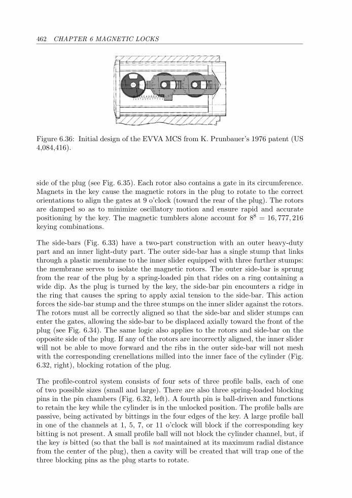
462 CHAPTER 6 MAGNETIC LOCKS
Figure 6.36: Initial design of the EVVA MCS from K. Prunbauer’s 1976 patent (US4,084,416).
side of the plug (see Fig. 6.35). Each rotor also contains a gate in its circumference.Magnets in the key cause the magnetic rotors in the plug to rotate to the correctorientations to align the gates at 9 o’clock (toward the rear of the plug). The rotorsare damped so as to minimize oscillatory motion and ensure rapid and accuratepositioning by the key. The magnetic tumblers alone account for 88 = 16, 777, 216keying combinations.
The side-bars (Fig. 6.33) have a two-part construction with an outer heavy-dutypart and an inner light-duty part. The outer side-bar has a single stump that linksthrough a plastic membrane to the inner slider equipped with three further stumps:the membrane serves to isolate the magnetic rotors. The outer side-bar is sprungfrom the rear of the plug by a spring-loaded pin that rides on a ring containing awide dip. As the plug is turned by the key, the side-bar pin encounters a ridge inthe ring that causes the spring to apply axial tension to the side-bar. This actionforces the side-bar stump and the three stumps on the inner slider against the rotors.The rotors must all be correctly aligned so that the side-bar and slider stumps canenter the gates, allowing the side-bar to be displaced axially toward the front of theplug (see Fig. 6.34). The same logic also applies to the rotors and side-bar on theopposite side of the plug. If any of the rotors are incorrectly aligned, the inner sliderwill not be able to move forward and the ribs in the outer side-bar will not meshwith the corresponding crenellations milled into the inner face of the cylinder (Fig.6.32, right), blocking rotation of the plug.
The profile-control system consists of four sets of three profile balls, each of oneof two possible sizes (small and large). There are also three spring-loaded blockingpins in the pin chambers (Fig. 6.32, left). A fourth pin is ball-driven and functionsto retain the key while the cylinder is in the unlocked position. The profile balls arepassive, being activated by bittings in the four edges of the key. A large profile ballin one of the channels at 1, 5, 7, or 11 o’clock will block if the corresponding keybitting is not present. A small profile ball will not block the cylinder channel, but, ifthe key is bitted (so that the ball is not maintained at its maximum radial distancefrom the center of the plug), then a cavity will be created that will trap one of thethree blocking pins as the plug starts to rotate.
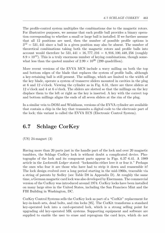
6.7 SCHLAGE CORKEY 463
The profile-control system multiplies the combinations due to the magnetic rotors.For illustrative purposes, we assume that each profile ball provides a binary opera-tion corresponding to whether a small or large ball is installed. If we further assumethat all 12 positions are used, then the number of possible profile options is312 = 531, 441 since a ball in a given position may also be absent. The number oftheoretical combinations taking both the magnetic rotors and profile balls intoaccount would therefore be 531, 441 × 16, 777, 216 = 8, 916, 100, 448, 256 (roughly8.9× 1012). This is a truly enormous number of keying combinations, though some-what less than the quoted number of 2.99 × 1026 (299 quadrillion).
More recent versions of the EVVA MCS include a wavy milling on both the topand bottom edges of the blade that replaces the system of profile balls, althougha key-retaining ball is still present. The millings, which are limited to the width ofthe key blade, operate a system of transerve sliders mounted in cavities in the plugat 6 and 12 o’clock. Viewing the cylinder as in Fig. 6.31, there are three sliders at12 o’clock and 4 at 6 o’clock. The sliders are slotted so that the millings on the keydisplace them to the left or right as the key is inserted. A key with the correct topand bottom millings aligns the ends of all seven sliders at the rim of the plug.
In a similar vein to DOM and Winkhaus, versions of the EVVA cylinder are availablethat contain a chip in the key that transmits a digital code to the electronic part ofthe lock; this variant is called the EVVA ECS (Electronic Control System).
6.7 Schlage CorKey
(US) 24-magnet (3)
Having more than 20 parts just in the handle part of the lock and over 20 magnetictumblers, the Schlage CorKey lock is without doubt a complicated device. Pho-tographs of the lock and its component parts appear in Figs. 6.37–6.41. A 1989article in the Locksmith Ledger stated: “locksmiths either love it or fear it.” Perhapsthe ones who fear it are those who have had to strip it down and reassemble it!The lock design evolved over a long period starting in the mid-1960s, traceable viaa string of patents by Sedley (see Table D8 in Appendix D). At roughly the sametime, a German magnetic card lock was also developed by Eisermann. The commercialversion of the CorKey was introduced around 1974. CorKey locks have been installedon many large sites in the United States, including the San Francisco Mint and theFBI Building in Washington, DC.
CorKey Control Systems sells the CorKey lock as part of a “CorKit” replacement forkey-in-knob sets, dead bolts, and rim locks [95]. The CorKit transforms a standardkey-operated lock into a card-operated lock, which is a strong selling point forupgrading old key-operated MK systems. Supporting equipment and software aresupplied to enable the user to erase and reprogram the card keys, which do not
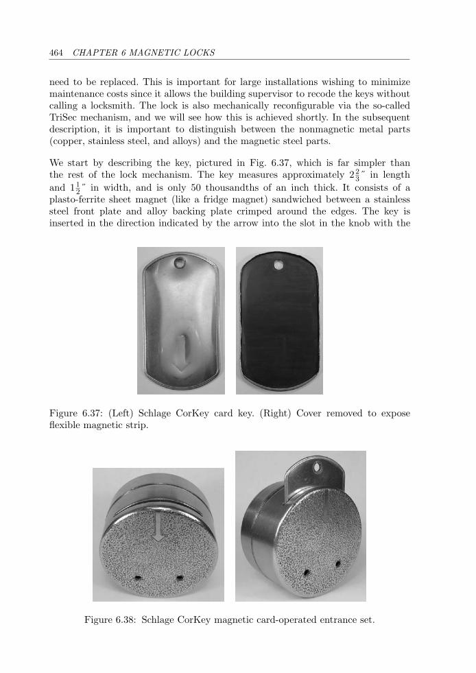
464 CHAPTER 6 MAGNETIC LOCKS
need to be replaced. This is important for large installations wishing to minimizemaintenance costs since it allows the building supervisor to recode the keys withoutcalling a locksmith. The lock is also mechanically reconfigurable via the so-calledTriSec mechanism, and we will see how this is achieved shortly. In the subsequentdescription, it is important to distinguish between the nonmagnetic metal parts(copper, stainless steel, and alloys) and the magnetic steel parts.
We start by describing the key, pictured in Fig. 6.37, which is far simpler thanthe rest of the lock mechanism. The key measures approximately 22
3˝ in lengthand 11
2˝ in width, and is only 50 thousandths of an inch thick. It consists of aplasto-ferrite sheet magnet (like a fridge magnet) sandwiched between a stainlesssteel front plate and alloy backing plate crimped around the edges. The key isinserted in the direction indicated by the arrow into the slot in the knob with the
Figure 6.37: (Left) Schlage CorKey card key. (Right) Cover removed to exposeflexible magnetic strip.
Figure 6.38: Schlage CorKey magnetic card-operated entrance set.
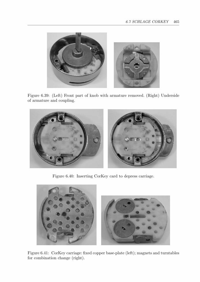
6.7 SCHLAGE CORKEY 465
Figure 6.39: (Left) Front part of knob with armature removed. (Right) Undersideof armature and coupling.
Figure 6.40: Inserting CorKey card to depress carriage.
Figure 6.41: CorKey carriage: fixed copper base-plate (left); magnets and turntablesfor combination change (right).
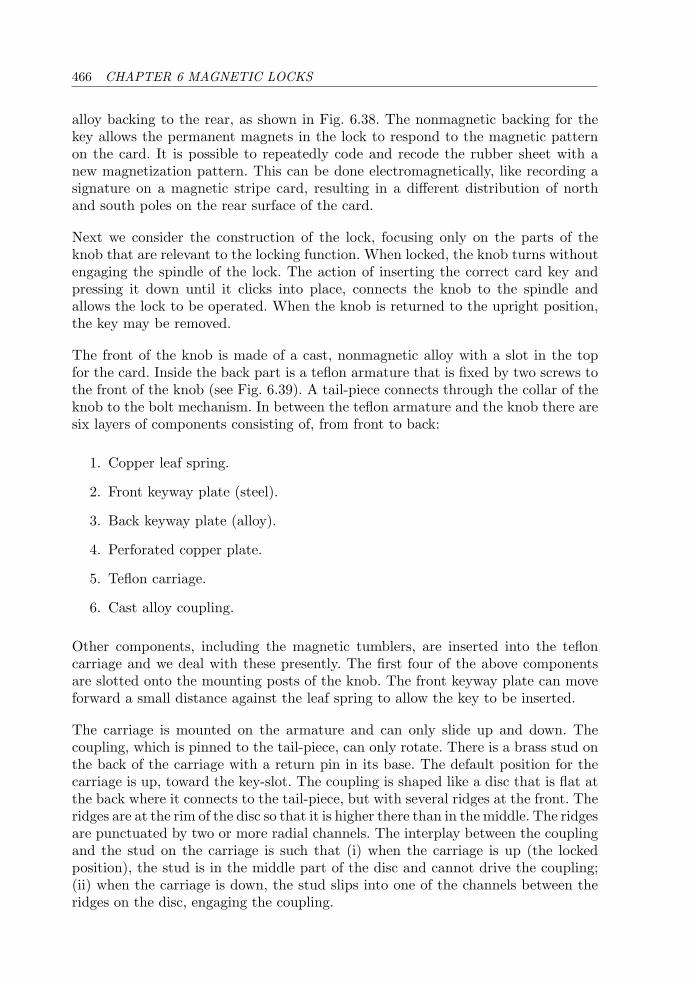
466 CHAPTER 6 MAGNETIC LOCKS
alloy backing to the rear, as shown in Fig. 6.38. The nonmagnetic backing for thekey allows the permanent magnets in the lock to respond to the magnetic patternon the card. It is possible to repeatedly code and recode the rubber sheet with anew magnetization pattern. This can be done electromagnetically, like recording asignature on a magnetic stripe card, resulting in a different distribution of northand south poles on the rear surface of the card.
Next we consider the construction of the lock, focusing only on the parts of theknob that are relevant to the locking function. When locked, the knob turns withoutengaging the spindle of the lock. The action of inserting the correct card key andpressing it down until it clicks into place, connects the knob to the spindle andallows the lock to be operated. When the knob is returned to the upright position,the key may be removed.
The front of the knob is made of a cast, nonmagnetic alloy with a slot in the topfor the card. Inside the back part is a teflon armature that is fixed by two screws tothe front of the knob (see Fig. 6.39). A tail-piece connects through the collar of theknob to the bolt mechanism. In between the teflon armature and the knob there aresix layers of components consisting of, from front to back:
1. Copper leaf spring.
2. Front keyway plate (steel).
3. Back keyway plate (alloy).
4. Perforated copper plate.
5. Teflon carriage.
6. Cast alloy coupling.
Other components, including the magnetic tumblers, are inserted into the tefloncarriage and we deal with these presently. The first four of the above componentsare slotted onto the mounting posts of the knob. The front keyway plate can moveforward a small distance against the leaf spring to allow the key to be inserted.
The carriage is mounted on the armature and can only slide up and down. Thecoupling, which is pinned to the tail-piece, can only rotate. There is a brass stud onthe back of the carriage with a return pin in its base. The default position for thecarriage is up, toward the key-slot. The coupling is shaped like a disc that is flat atthe back where it connects to the tail-piece, but with several ridges at the front. Theridges are at the rim of the disc so that it is higher there than in the middle. The ridgesare punctuated by two or more radial channels. The interplay between the couplingand the stud on the carriage is such that (i) when the carriage is up (the lockedposition), the stud is in the middle part of the disc and cannot drive the coupling;(ii) when the carriage is down, the stud slips into one of the channels between theridges on the disc, engaging the coupling.
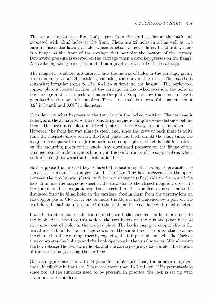
6.7 SCHLAGE CORKEY 467
The teflon carriage (see Fig. 6.40), apart from the stud, is flat at the back andpeppered with blind holes at the front. There are 22 holes in all as well as twocurious discs, also having a hole, whose function we cover later. In addition, thereis a flange on the front of the carriage that occupies the bottom of the keyway.Downward pressure is exerted on the carriage when a card key presses on the flange.A rear-facing swing hook is mounted on a pivot on each side of the carriage.
The magnetic tumblers are inserted into the matrix of holes in the carriage, givinga maximum total of 24 positions, counting the ones in the discs. The matrix issomewhat irregular (refer to Fig. 6.41 to understand the layout). The perforatedcopper plate is located in front of the carriage. In the locked position, the holes inthe carriage match the perforations in the plate. Suppose now that the carriage ispopulated with magnetic tumblers. These are small but powerful magnets about0.2˝ in length and 0.09˝ in diameter.
Consider now what happens to the tumblers in the locked position. The carriage isteflon, as is the armature, so there is nothing magnetic for quite some distance behindthem. The perforated plate and back plate to the keyway are both nonmagnetic.However, the front keyway plate is steel, and, since the keyway back plate is quitethin, the magnets move toward the front plate and latch on. At the same time, themagnets have passed through the perforated copper plate, which is held in positionon the mounting posts of the knob. Any downward pressure on the flange of thecarriage results in the magnets binding in the perforations of the copper plate, whichis thick enough to withstand considerable force.
Now suppose that a card key is inserted whose magnetic coding is precisely thesame as the magnetic tumblers on the carriage. The key intervenes in the spacebetween the two keyway plates, with its nonmagnetic (alloy) side to the rear of thelock. It is now the magnetic sheet in the card that is the closest magnetic object tothe tumblers. The magnetic repulsion exerted on the tumblers causes them to bedisplaced into the blind holes in the carriage, freeing them from the perforations onthe copper plate. Clearly, if one or more tumblers is not matched by a pole on thecard, it will continue to protrude into the plate and the carriage will remain locked.
If all the tumblers match the coding of the card, the carriage can be depressed intothe knob. As a result of this action, the two hooks on the carriage pivot back asthey move out of a slot in the keyway plate. The hooks engage a copper clip in thearmature that holds the carriage down. At the same time, the brass stud reachesthe channel in the coupling, thereby engaging the tail-piece of the lock. The CorKeythus completes the linkage and the knob operates in the usual manner. Withdrawingthe key releases the two swing hooks and the carriage springs back under the tensionof the return pin, ejecting the card key.
One can appreciate that with 24 possible tumbler positions, the number of systemcodes is effectively limitless. There are more than 16.7 million (224) permutationssince not all the tumblers need to be present. In practice, the lock is set up withseven or more tumblers.
468 CHAPTER 6 MAGNETIC LOCKS
But what of the two curious discs we alluded to earlier? These are actually turntablesthat enable the pin that they contain to be rotated to any one of five positions(2, 3, 4, 7, or 11 o’clock). Thus the total number of tumbler positions is in fact24 + 8 = 32, of which 24 may be used at the same time. The discs contain a spring-loaded bolt that locks them into one of the five positions. In the center of eachdisc is a semicircular hole. The lock is cleverly constructed so that these holes lineup exactly with two holes in the front of the knob. When the correct key is usedto depress the carriage and then withdrawn slightly, there is through access for achange key to be inserted to reorient the discs. With two such changeable discsthere are 25 available changes that can be used when it is desired to recombinatethe lock. The marvelous point is that it is not necessary to dismantle the lock tochange the configuration of the magnets. Naturally, new card keys can be issued viathe recoding unit.
Master-keying is accomplished by arranging for different locks to use different tum-bler positions. A master key can be coded for all the tumbler positions, whereas thesubmaster and change keys use only a subset of these positions.
As for manipulation resistance, the key-slot is very narrow, and there is little spacefor a magnetic probe or decoder. In a high-security installation, the lock shouldbe mounted with a protective collar to prevent it from being snapped or sawed off.Following the development of the original invention in the mid-to-late 1970s, furtherpatents were filed for modifications to improve the lock’s resistance to rapping.
Chapter 7
Car Locks
It is a mistake to hold the fatalistic idea that thieves will get in if theyare sufficiently determined, no matter what. F. J. Butter, c. 1958
7.1 Introduction
As the era of horse-drawn transport was winding down and the petroleum age wasramping up, people were seeking practical means of providing individual transporta-tion that did not involve stoking the boiler of a steam engine. Two Germans,Gottlieb Daimler and Wilhelm Maybach, invented an internal combustion engineand were among the first to install it in a four-wheeled vehicle, achieving in 1886the breakneck speed of 14 miles per hour. Although Daimler died in 1890, his businesspartner Maybach went on to develop the Mercedes car. Daimler’s engines were amongthe most reliable of their time, but they were not aimed at providing an affordable carfor a mass market.
The first recognizable motor vehicle companies in the United States started upin the late 1890s, leading in the early 1900s to the two giants we recognize today—the Ford Motor Company and General Motors Corporation. By 1910, the GeneralMotors Company was offering closed car bodies as standard equipment. At that time,automobiles had latches on the doors but locks were not generally fitted. One of theearliest patents for an automotive lock is from 1909 by F. P. Pfleghar (US 914,669),who proposed a push-key operated cylinder lock for limousine doors having a slid-ing dust guard. The following year R. D. Markham patented a pin-tumbler cylinderfor locking the starting crank (US 958,815). In 1911, Charles Kettering of GeneralMotors’ research department devised an electric self-startermotor,whichwas installedin a Cadillac. A number of steering wheel locks were also proposed around this time.The earliest of these was due to E. R. Creamer (US 915,416), whose patent was filed
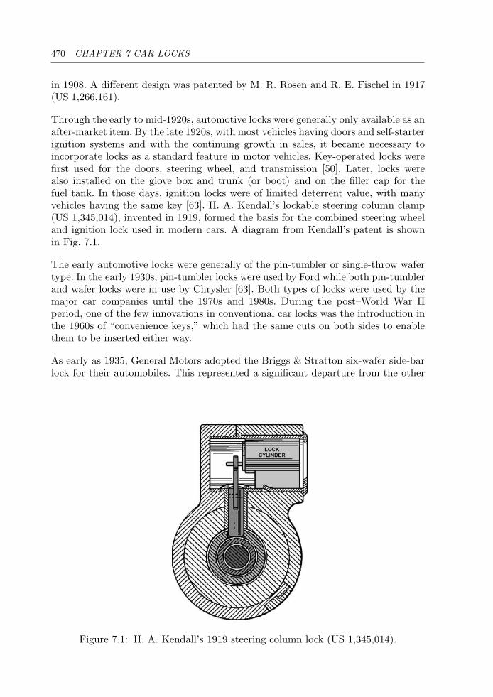
470 CHAPTER 7 CAR LOCKS
in 1908. A different design was patented by M. R. Rosen and R. E. Fischel in 1917(US 1,266,161).
Through the early to mid-1920s, automotive locks were generally only available as anafter-market item. By the late 1920s, with most vehicles having doors and self-starterignition systems and with the continuing growth in sales, it became necessary toincorporate locks as a standard feature in motor vehicles. Key-operated locks werefirst used for the doors, steering wheel, and transmission [50]. Later, locks werealso installed on the glove box and trunk (or boot) and on the filler cap for thefuel tank. In those days, ignition locks were of limited deterrent value, with manyvehicles having the same key [63]. H. A. Kendall’s lockable steering column clamp(US 1,345,014), invented in 1919, formed the basis for the combined steering wheeland ignition lock used in modern cars. A diagram from Kendall’s patent is shownin Fig. 7.1.
The early automotive locks were generally of the pin-tumbler or single-throw wafertype. In the early 1930s, pin-tumbler locks were used by Ford while both pin-tumblerand wafer locks were in use by Chrysler [63]. Both types of locks were used by themajor car companies until the 1970s and 1980s. During the post–World War IIperiod, one of the few innovations in conventional car locks was the introduction inthe 1960s of “convenience keys,” which had the same cuts on both sides to enablethem to be inserted either way.
As early as 1935, General Motors adopted the Briggs & Stratton six-wafer side-barlock for their automobiles. This represented a significant departure from the other
Figure 7.1: H. A. Kendall’s 1919 steering column lock (US 1,345,014).
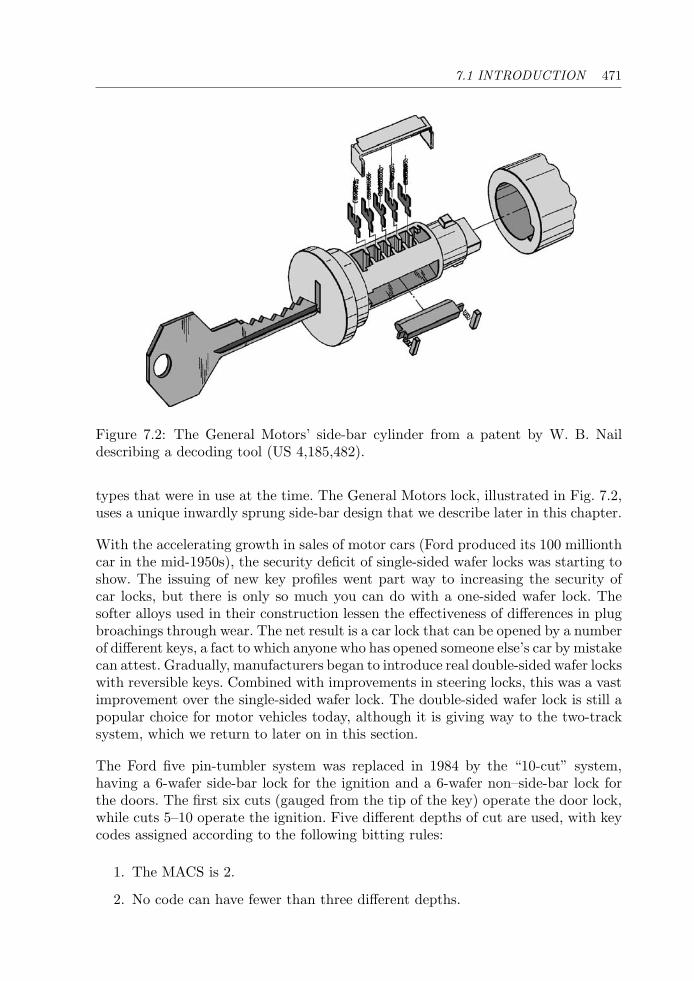
7.1 INTRODUCTION 471
Figure 7.2: The General Motors’ side-bar cylinder from a patent by W. B. Naildescribing a decoding tool (US 4,185,482).
types that were in use at the time. The General Motors lock, illustrated in Fig. 7.2,uses a unique inwardly sprung side-bar design that we describe later in this chapter.
With the accelerating growth in sales of motor cars (Ford produced its 100 millionthcar in the mid-1950s), the security deficit of single-sided wafer locks was starting toshow. The issuing of new key profiles went part way to increasing the security ofcar locks, but there is only so much you can do with a one-sided wafer lock. Thesofter alloys used in their construction lessen the effectiveness of differences in plugbroachings through wear. The net result is a car lock that can be opened by a numberof different keys, a fact to which anyone who has opened someone else’s car by mistakecan attest. Gradually, manufacturers began to introduce real double-sided wafer lockswith reversible keys. Combined with improvements in steering locks, this was a vastimprovement over the single-sided wafer lock. The double-sided wafer lock is still apopular choice for motor vehicles today, although it is giving way to the two-tracksystem, which we return to later on in this section.
The Ford five pin-tumbler system was replaced in 1984 by the “10-cut” system,having a 6-wafer side-bar lock for the ignition and a 6-wafer non–side-bar lock forthe doors. The first six cuts (gauged from the tip of the key) operate the door lock,while cuts 5–10 operate the ignition. Five different depths of cut are used, with keycodes assigned according to the following bitting rules:
1. The MACS is 2.
2. No code can have fewer than three different depths.
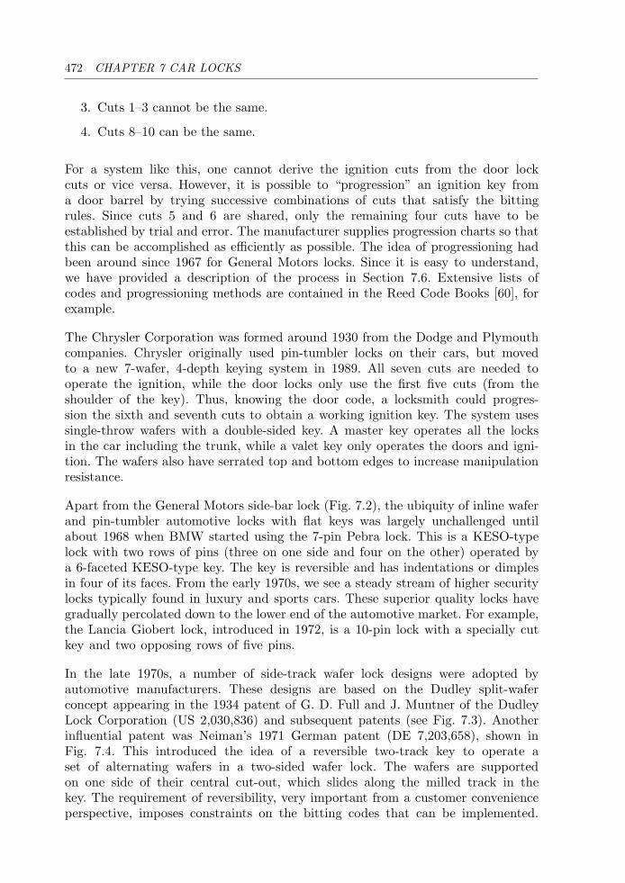
472 CHAPTER 7 CAR LOCKS
3. Cuts 1–3 cannot be the same.
4. Cuts 8–10 can be the same.
For a system like this, one cannot derive the ignition cuts from the door lockcuts or vice versa. However, it is possible to “progression” an ignition key froma door barrel by trying successive combinations of cuts that satisfy the bittingrules. Since cuts 5 and 6 are shared, only the remaining four cuts have to beestablished by trial and error. The manufacturer supplies progression charts so thatthis can be accomplished as efficiently as possible. The idea of progressioning hadbeen around since 1967 for General Motors locks. Since it is easy to understand,we have provided a description of the process in Section 7.6. Extensive lists ofcodes and progressioning methods are contained in the Reed Code Books [60], forexample.
The Chrysler Corporation was formed around 1930 from the Dodge and Plymouthcompanies. Chrysler originally used pin-tumbler locks on their cars, but movedto a new 7-wafer, 4-depth keying system in 1989. All seven cuts are needed tooperate the ignition, while the door locks only use the first five cuts (from theshoulder of the key). Thus, knowing the door code, a locksmith could progres-sion the sixth and seventh cuts to obtain a working ignition key. The system usessingle-throw wafers with a double-sided key. A master key operates all the locksin the car including the trunk, while a valet key only operates the doors and igni-tion. The wafers also have serrated top and bottom edges to increase manipulationresistance.
Apart from the General Motors side-bar lock (Fig. 7.2), the ubiquity of inline waferand pin-tumbler automotive locks with flat keys was largely unchallenged untilabout 1968 when BMW started using the 7-pin Pebra lock. This is a KESO-typelock with two rows of pins (three on one side and four on the other) operated bya 6-faceted KESO-type key. The key is reversible and has indentations or dimplesin four of its faces. From the early 1970s, we see a steady stream of higher securitylocks typically found in luxury and sports cars. These superior quality locks havegradually percolated down to the lower end of the automotive market. For example,the Lancia Giobert lock, introduced in 1972, is a 10-pin lock with a specially cutkey and two opposing rows of five pins.
In the late 1970s, a number of side-track wafer lock designs were adopted byautomotive manufacturers. These designs are based on the Dudley split-waferconcept appearing in the 1934 patent of G. D. Full and J. Muntner of the DudleyLock Corporation (US 2,030,836) and subsequent patents (see Fig. 7.3). Anotherinfluential patent was Neiman’s 1971 German patent (DE 7,203,658), shown inFig. 7.4. This introduced the idea of a reversible two-track key to operate aset of alternating wafers in a two-sided wafer lock. The wafers are supportedon one side of their central cut-out, which slides along the milled track in thekey. The requirement of reversibility, very important from a customer convenienceperspective, imposes constraints on the bitting codes that can be implemented.
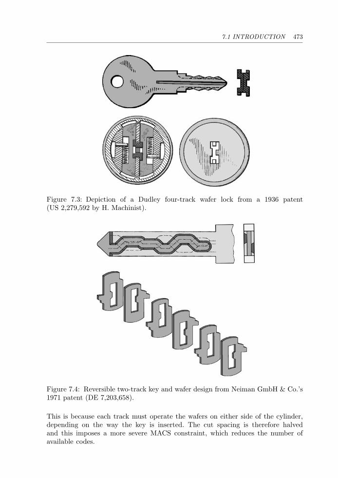
7.1 INTRODUCTION 473
Figure 7.3: Depiction of a Dudley four-track wafer lock from a 1936 patent(US 2,279,592 by H. Machinist).
Figure 7.4: Reversible two-track key and wafer design from Neiman GmbH & Co.’s1971 patent (DE 7,203,658).
This is because each track must operate the wafers on either side of the cylinder,depending on the way the key is inserted. The cut spacing is therefore halvedand this imposes a more severe MACS constraint, which reduces the number ofavailable codes.
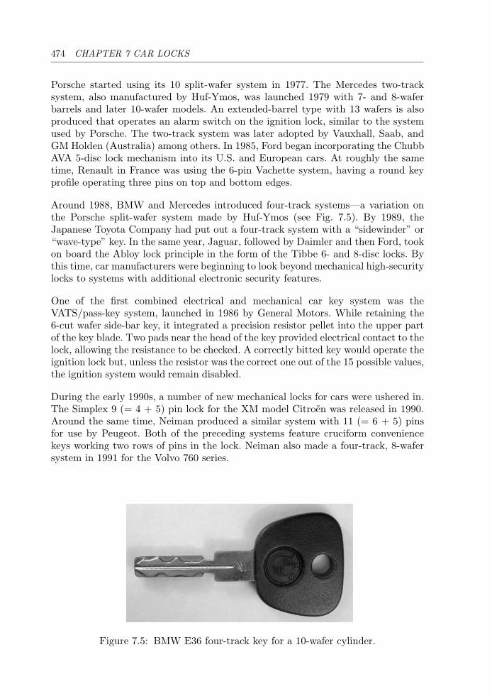
474 CHAPTER 7 CAR LOCKS
Porsche started using its 10 split-wafer system in 1977. The Mercedes two-tracksystem, also manufactured by Huf-Ymos, was launched 1979 with 7- and 8-waferbarrels and later 10-wafer models. An extended-barrel type with 13 wafers is alsoproduced that operates an alarm switch on the ignition lock, similar to the systemused by Porsche. The two-track system was later adopted by Vauxhall, Saab, andGM Holden (Australia) among others. In 1985, Ford began incorporating the ChubbAVA 5-disc lock mechanism into its U.S. and European cars. At roughly the sametime, Renault in France was using the 6-pin Vachette system, having a round keyprofile operating three pins on top and bottom edges.
Around 1988, BMW and Mercedes introduced four-track systems—a variation onthe Porsche split-wafer system made by Huf-Ymos (see Fig. 7.5). By 1989, theJapanese Toyota Company had put out a four-track system with a “sidewinder” or“wave-type” key. In the same year, Jaguar, followed by Daimler and then Ford, tookon board the Abloy lock principle in the form of the Tibbe 6- and 8-disc locks. Bythis time, car manufacturers were beginning to look beyond mechanical high-securitylocks to systems with additional electronic security features.
One of the first combined electrical and mechanical car key system was theVATS/pass-key system, launched in 1986 by General Motors. While retaining the6-cut wafer side-bar key, it integrated a precision resistor pellet into the upper partof the key blade. Two pads near the head of the key provided electrical contact to thelock, allowing the resistance to be checked. A correctly bitted key would operate theignition lock but, unless the resistor was the correct one out of the 15 possible values,the ignition system would remain disabled.
During the early 1990s, a number of new mechanical locks for cars were ushered in.The Simplex 9 (= 4 + 5) pin lock for the XM model Citroen was released in 1990.Around the same time, Neiman produced a similar system with 11 (= 6 + 5) pinsfor use by Peugeot. Both of the preceding systems feature cruciform conveniencekeys working two rows of pins in the lock. Neiman also made a four-track, 8-wafersystem in 1991 for the Volvo 760 series.
Figure 7.5: BMW E36 four-track key for a 10-wafer cylinder.
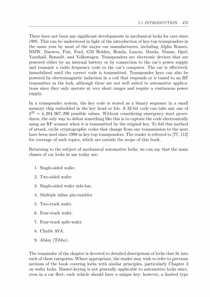
7.1 INTRODUCTION 475
There have not been any significant developments in mechanical locks for cars since1995. This can be understood in light of the introduction of key-top transponders inthe same year by most of the major car manufacturers, including Alpha Romeo,BMW, Daewoo, Fiat, Ford, GM Holden, Honda, Lancia, Mazda, Nissan, Opel,Vauxhall, Renault, and Volkswagen. Transponders are electronic devices that arepowered either by an internal battery or by connection to the car’s power supplyand transmit a radio frequency code to the car’s computer. The car is effectivelyimmobilized until the correct code is transmitted. Transponder keys can also bepowered by electromagnetic induction in a coil that responds or is tuned to an RFtransmitter in the lock, although these are not well suited to automotive applica-tions since they only operate at very short ranges and require a continuous powersupply.
In a transponder system, the key code is stored as a binary sequence in a smallmemory chip embedded in the key head or fob. A 32-bit code can take any one of232 = 4, 294, 967, 296 possible values. Without considering emergency start proce-dures, the only way to defeat something like this is to capture the code electronicallyusing an RF scanner when it is transmitted by the original key. To foil this methodof attack, cyclic cryptographic codes that change from one transmission to the nexthave been used since 1998 in key-top transponders. The reader is referred to [77, 112]for coverage of such topics, which are outside the scope of this book.
Returning to the subject of mechanical automotive locks, we can say that the mainclasses of car locks in use today are:
1. Single-sided wafer.
2. Two-sided wafer.
3. Single-sided wafer side-bar.
4. Multiple inline pin-tumbler.
5. Two-track wafer.
6. Four-track wafer.
7. Four-track split-wafer.
8. Chubb AVA.
9. Abloy (Tibbe).
The remainder of the chapter is devoted to detailed descriptions of locks that fit intoeach of these categories. Where appropriate, the reader may wish to refer to previoussections of the book covering locks with similar principles, particularly Chapter 3on wafer locks. Master-keying is not generally applicable to automotive locks since,even in a car fleet, each vehicle should have a unique key; however, a limited type
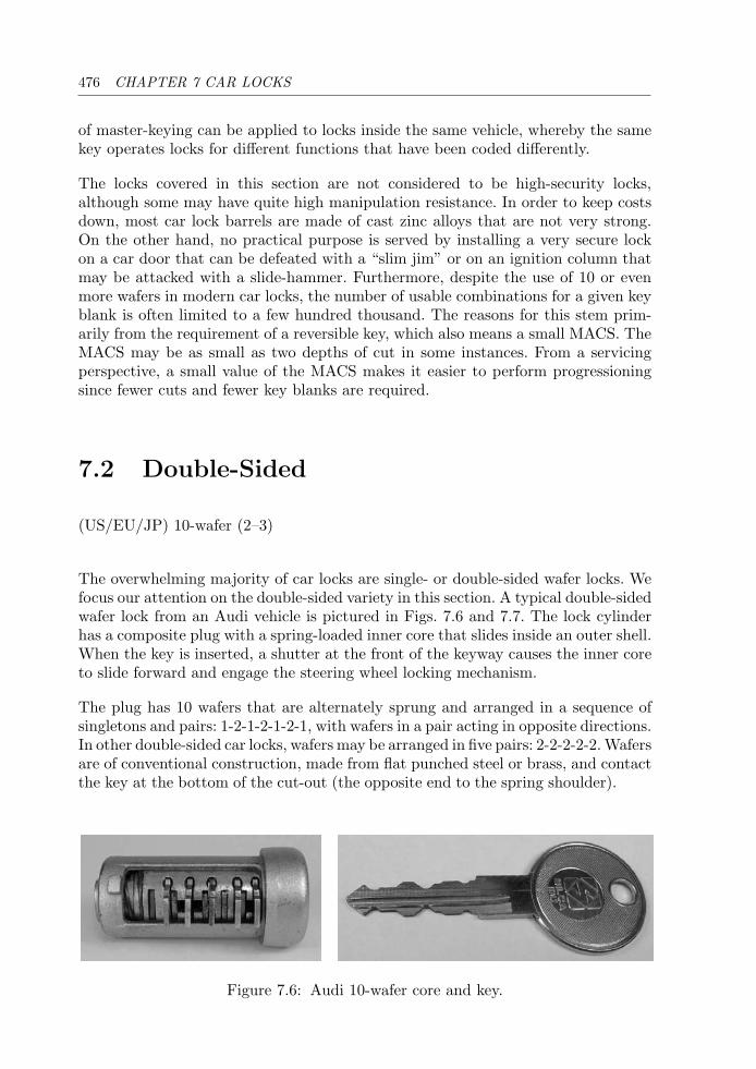
476 CHAPTER 7 CAR LOCKS
of master-keying can be applied to locks inside the same vehicle, whereby the samekey operates locks for different functions that have been coded differently.
The locks covered in this section are not considered to be high-security locks,although some may have quite high manipulation resistance. In order to keep costsdown, most car lock barrels are made of cast zinc alloys that are not very strong.On the other hand, no practical purpose is served by installing a very secure lockon a car door that can be defeated with a “slim jim” or on an ignition column thatmay be attacked with a slide-hammer. Furthermore, despite the use of 10 or evenmore wafers in modern car locks, the number of usable combinations for a given keyblank is often limited to a few hundred thousand. The reasons for this stem prim-arily from the requirement of a reversible key, which also means a small MACS. TheMACS may be as small as two depths of cut in some instances. From a servicingperspective, a small value of the MACS makes it easier to perform progressioningsince fewer cuts and fewer key blanks are required.
7.2 Double-Sided
(US/EU/JP) 10-wafer (2–3)
The overwhelming majority of car locks are single- or double-sided wafer locks. Wefocus our attention on the double-sided variety in this section. A typical double-sidedwafer lock from an Audi vehicle is pictured in Figs. 7.6 and 7.7. The lock cylinderhas a composite plug with a spring-loaded inner core that slides inside an outer shell.When the key is inserted, a shutter at the front of the keyway causes the inner coreto slide forward and engage the steering wheel locking mechanism.
The plug has 10 wafers that are alternately sprung and arranged in a sequence ofsingletons and pairs: 1-2-1-2-1-2-1, with wafers in a pair acting in opposite directions.In other double-sided car locks, wafers may be arranged in five pairs: 2-2-2-2-2. Wafersare of conventional construction, made from flat punched steel or brass, and contactthe key at the bottom of the cut-out (the opposite end to the spring shoulder).
Figure 7.6: Audi 10-wafer core and key.
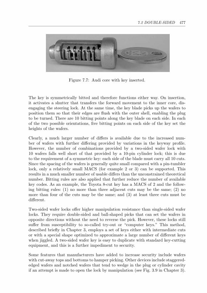
7.2 DOUBLE-SIDED 477
Figure 7.7: Audi core with key inserted.
The key is symmetrically bitted and therefore functions either way. On insertion,it activates a shutter that transfers the forward movement to the inner core, dis-engaging the steering lock. At the same time, the key blade picks up the wafers toposition them so that their edges are flush with the outer shell, enabling the plugto be turned. There are 10 bitting points along the key blade on each side. In eachof the two possible orientations, five bitting points on each side of the key set theheights of the wafers.
Clearly, a much larger number of differs is available due to the increased num-ber of wafers with further differing provided by variations in the keyway profile.However, the number of combinations provided by a two-sided wafer lock with10 wafers falls well short of that provided by a 10-pin cylinder lock; this is dueto the requirement of a symmetric key: each side of the blade must carry all 10 cuts.Since the spacing of the wafers is generally quite small compared with a pin-tumblerlock, only a relatively small MACS (for example 2 or 3) can be supported. Thisresults in a much smaller number of usable differs than the unconstrained theoreticalnumber. Bitting rules are also applied that further reduce the number of availablekey codes. As an example, the Toyota 8-cut key has a MACS of 2 and the follow-ing bitting rules: (1) no more than three adjacent cuts may be the same; (2) nomore than four of the cuts may be the same; and (3) at least three cuts must bedifferent.
Two-sided wafer locks offer higher manipulation resistance than single-sided waferlocks. They require double-sided and ball-shaped picks that can set the wafers inopposite directions without the need to reverse the pick. However, these locks stillsuffer from susceptibility to so-called try-out or “computer keys.” This method,described briefly in Chapter 3, employs a set of keys either with intermediate cutsor with a special shape optimized to approximate a large number of different keyswhen jiggled. A two-sided wafer key is easy to duplicate with standard key-cuttingequipment, and this is a further impediment to security.
Some features that manufacturers have added to increase security include waferswith cut-away tops and bottoms to hamper picking. Other devices include staggered-edged wafers and notched wafers that tend to wedge in the plug or cylinder cavityif an attempt is made to open the lock by manipulation (see Fig. 3.9 in Chapter 3).
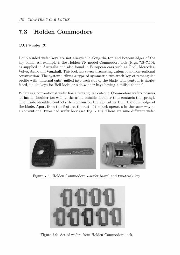
478 CHAPTER 7 CAR LOCKS
7.3 Holden Commodore
(AU) 7-wafer (3)
Double-sided wafer keys are not always cut along the top and bottom edges of thekey blade. An example is the Holden VN-model Commodore lock (Figs. 7.8–7.10),as supplied in Australia and also found in European cars such as Opel, Mercedes,Volvo, Saab, and Vauxhall. This lock has seven alternating wafers of nonconventionalconstruction. The system utilizes a type of symmetric two-track key of rectangularprofile with “internal cuts” milled into each side of the blade. The contour is single-faced, unlike keys for Bell locks or side-winder keys having a milled channel.
Whereas a conventional wafer has a rectangular cut-out, Commodore wafers possessan inside shoulder (as well as the usual outside shoulder that contacts the spring).The inside shoulder contacts the contour on the key rather than the outer edge ofthe blade. Apart from this feature, the rest of the lock operates in the same way asa conventional two-sided wafer lock (see Fig. 7.10). There are nine different wafer
Figure 7.8: Holden Commodore 7-wafer barrel and two-track key.
Figure 7.9: Set of wafers from Holden Commodore lock.
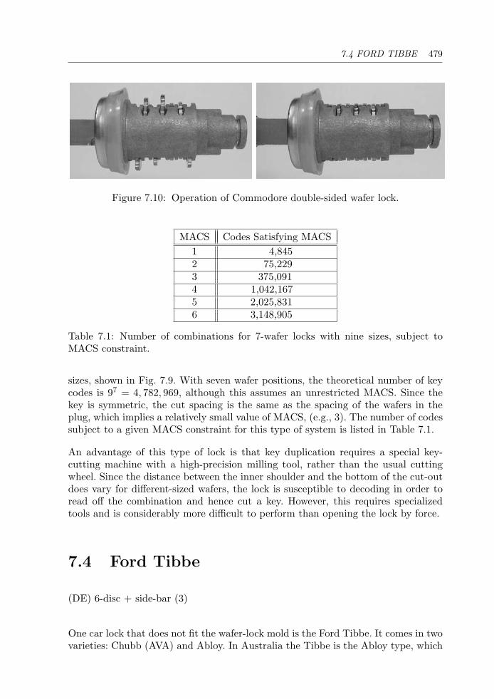
7.4 FORD TIBBE 479
Figure 7.10: Operation of Commodore double-sided wafer lock.
MACS Codes Satisfying MACS1 4,8452 75,2293 375,0914 1,042,1675 2,025,8316 3,148,905
Table 7.1: Number of combinations for 7-wafer locks with nine sizes, subject toMACS constraint.
sizes, shown in Fig. 7.9. With seven wafer positions, the theoretical number of keycodes is 97 = 4, 782, 969, although this assumes an unrestricted MACS. Since thekey is symmetric, the cut spacing is the same as the spacing of the wafers in theplug, which implies a relatively small value of MACS, (e.g., 3). The number of codessubject to a given MACS constraint for this type of system is listed in Table 7.1.
An advantage of this type of lock is that key duplication requires a special key-cutting machine with a high-precision milling tool, rather than the usual cuttingwheel. Since the distance between the inner shoulder and the bottom of the cut-outdoes vary for different-sized wafers, the lock is susceptible to decoding in order toread off the combination and hence cut a key. However, this requires specializedtools and is considerably more difficult to perform than opening the lock by force.
7.4 Ford Tibbe
(DE) 6-disc + side-bar (3)
One car lock that does not fit the wafer-lock mold is the Ford Tibbe. It comes in twovarieties: Chubb (AVA) and Abloy. In Australia the Tibbe is the Abloy type, which
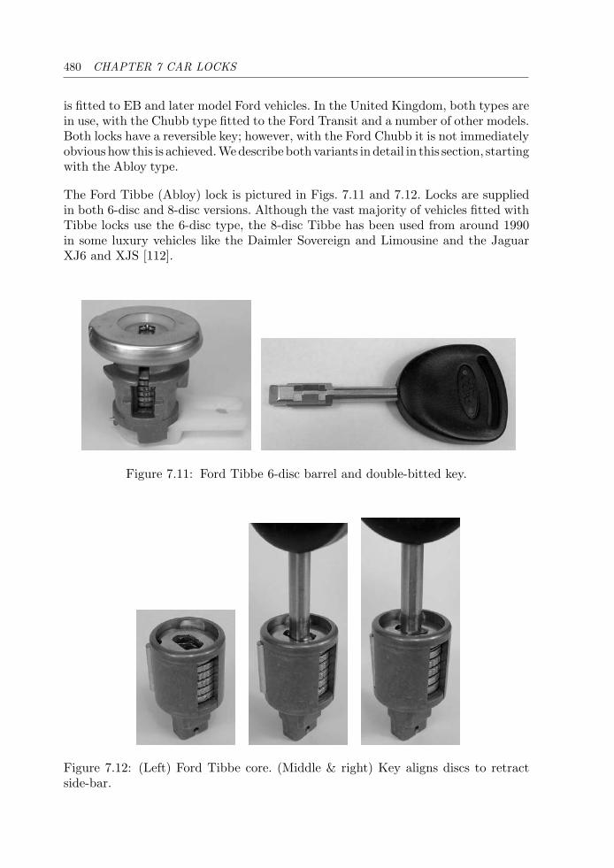
480 CHAPTER 7 CAR LOCKS
is fitted to EB and later model Ford vehicles. In the United Kingdom, both types arein use, with the Chubb type fitted to the Ford Transit and a number of other models.Both locks have a reversible key; however, with the Ford Chubb it is not immediatelyobvious how this is achieved.Wedescribe bothvariants in detail in this section, startingwith the Abloy type.
The Ford Tibbe (Abloy) lock is pictured in Figs. 7.11 and 7.12. Locks are suppliedin both 6-disc and 8-disc versions. Although the vast majority of vehicles fitted withTibbe locks use the 6-disc type, the 8-disc Tibbe has been used from around 1990in some luxury vehicles like the Daimler Sovereign and Limousine and the JaguarXJ6 and XJS [112].
Figure 7.11: Ford Tibbe 6-disc barrel and double-bitted key.
Figure 7.12: (Left) Ford Tibbe core. (Middle & right) Key aligns discs to retractside-bar.
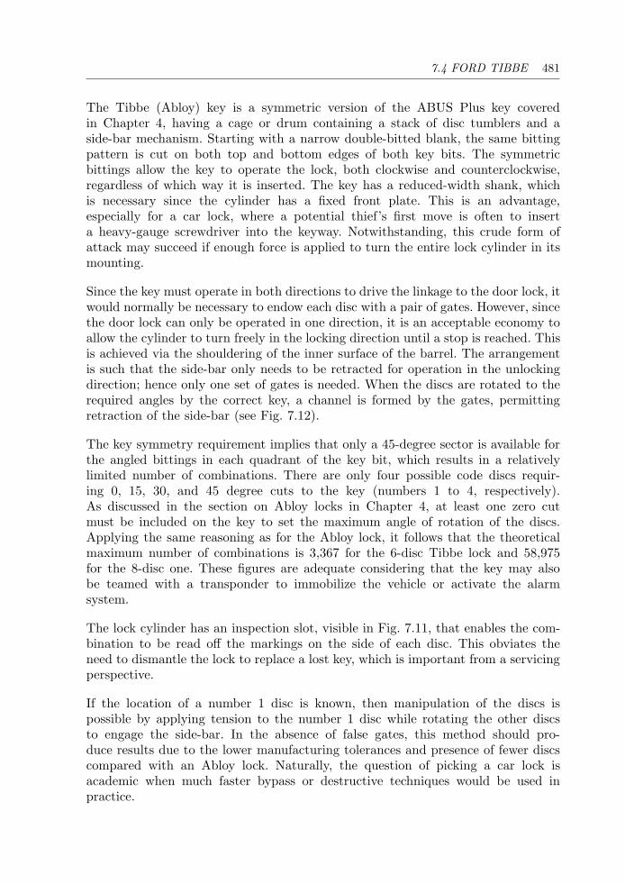
7.4 FORD TIBBE 481
The Tibbe (Abloy) key is a symmetric version of the ABUS Plus key coveredin Chapter 4, having a cage or drum containing a stack of disc tumblers and aside-bar mechanism. Starting with a narrow double-bitted blank, the same bittingpattern is cut on both top and bottom edges of both key bits. The symmetricbittings allow the key to operate the lock, both clockwise and counterclockwise,regardless of which way it is inserted. The key has a reduced-width shank, whichis necessary since the cylinder has a fixed front plate. This is an advantage,especially for a car lock, where a potential thief’s first move is often to inserta heavy-gauge screwdriver into the keyway. Notwithstanding, this crude form ofattack may succeed if enough force is applied to turn the entire lock cylinder in itsmounting.
Since the key must operate in both directions to drive the linkage to the door lock, itwould normally be necessary to endow each disc with a pair of gates. However, sincethe door lock can only be operated in one direction, it is an acceptable economy toallow the cylinder to turn freely in the locking direction until a stop is reached. Thisis achieved via the shouldering of the inner surface of the barrel. The arrangementis such that the side-bar only needs to be retracted for operation in the unlockingdirection; hence only one set of gates is needed. When the discs are rotated to therequired angles by the correct key, a channel is formed by the gates, permittingretraction of the side-bar (see Fig. 7.12).
The key symmetry requirement implies that only a 45-degree sector is available forthe angled bittings in each quadrant of the key bit, which results in a relativelylimited number of combinations. There are only four possible code discs requir-ing 0, 15, 30, and 45 degree cuts to the key (numbers 1 to 4, respectively).As discussed in the section on Abloy locks in Chapter 4, at least one zero cutmust be included on the key to set the maximum angle of rotation of the discs.Applying the same reasoning as for the Abloy lock, it follows that the theoreticalmaximum number of combinations is 3,367 for the 6-disc Tibbe lock and 58,975for the 8-disc one. These figures are adequate considering that the key may alsobe teamed with a transponder to immobilize the vehicle or activate the alarmsystem.
The lock cylinder has an inspection slot, visible in Fig. 7.11, that enables the com-bination to be read off the markings on the side of each disc. This obviates theneed to dismantle the lock to replace a lost key, which is important from a servicingperspective.
If the location of a number 1 disc is known, then manipulation of the discs ispossible by applying tension to the number 1 disc while rotating the other discsto engage the side-bar. In the absence of false gates, this method should pro-duce results due to the lower manufacturing tolerances and presence of fewer discscompared with an Abloy lock. Naturally, the question of picking a car lock isacademic when much faster bypass or destructive techniques would be used inpractice.
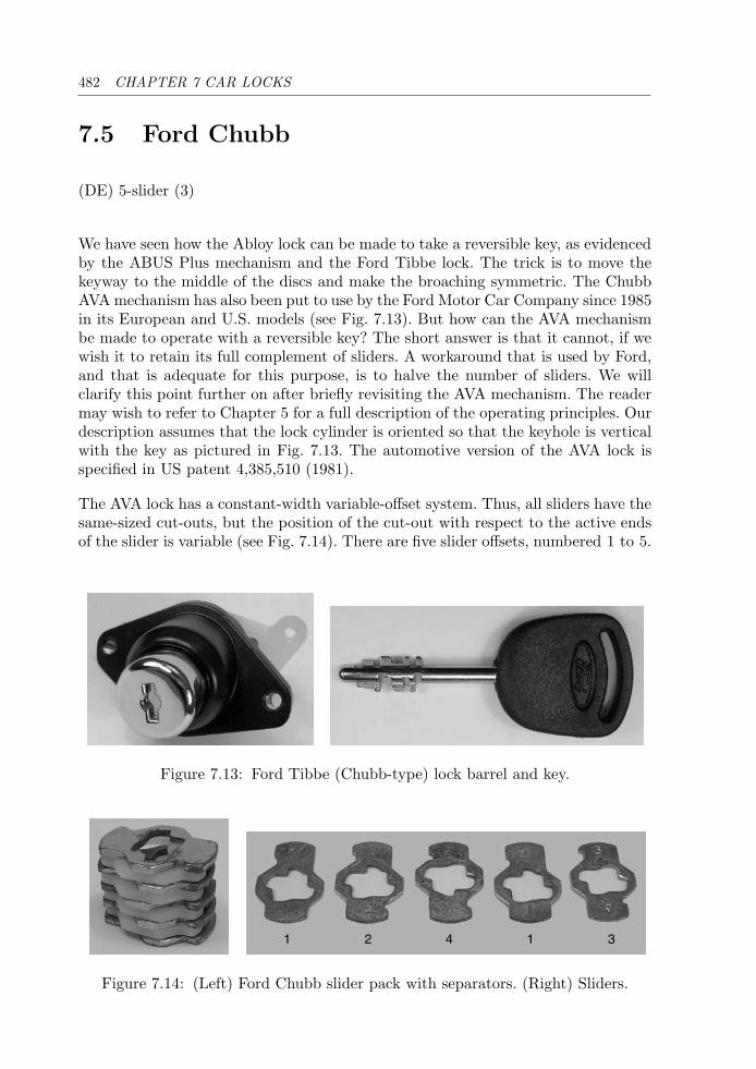
482 CHAPTER 7 CAR LOCKS
7.5 Ford Chubb
(DE) 5-slider (3)
We have seen how the Abloy lock can be made to take a reversible key, as evidencedby the ABUS Plus mechanism and the Ford Tibbe lock. The trick is to move thekeyway to the middle of the discs and make the broaching symmetric. The ChubbAVA mechanism has also been put to use by the Ford Motor Car Company since 1985in its European and U.S. models (see Fig. 7.13). But how can the AVA mechanismbe made to operate with a reversible key? The short answer is that it cannot, if wewish it to retain its full complement of sliders. A workaround that is used by Ford,and that is adequate for this purpose, is to halve the number of sliders. We willclarify this point further on after briefly revisiting the AVA mechanism. The readermay wish to refer to Chapter 5 for a full description of the operating principles. Ourdescription assumes that the lock cylinder is oriented so that the keyhole is verticalwith the key as pictured in Fig. 7.13. The automotive version of the AVA lock isspecified in US patent 4,385,510 (1981).
The AVA lock has a constant-width variable-offset system. Thus, all sliders have thesame-sized cut-outs, but the position of the cut-out with respect to the active endsof the slider is variable (see Fig. 7.14). There are five slider offsets, numbered 1 to 5.
Figure 7.13: Ford Tibbe (Chubb-type) lock barrel and key.
1 2 4 1 3
Figure 7.14: (Left) Ford Chubb slider pack with separators. (Right) Sliders.
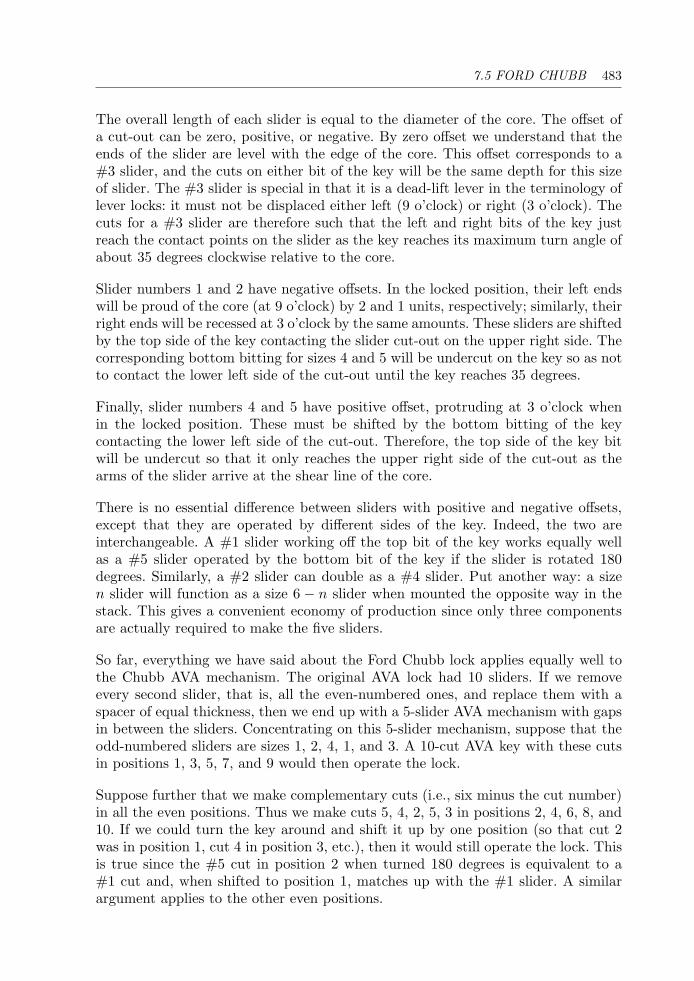
7.5 FORD CHUBB 483
The overall length of each slider is equal to the diameter of the core. The offset ofa cut-out can be zero, positive, or negative. By zero offset we understand that theends of the slider are level with the edge of the core. This offset corresponds to a#3 slider, and the cuts on either bit of the key will be the same depth for this sizeof slider. The #3 slider is special in that it is a dead-lift lever in the terminology oflever locks: it must not be displaced either left (9 o’clock) or right (3 o’clock). Thecuts for a #3 slider are therefore such that the left and right bits of the key justreach the contact points on the slider as the key reaches its maximum turn angle ofabout 35 degrees clockwise relative to the core.
Slider numbers 1 and 2 have negative offsets. In the locked position, their left endswill be proud of the core (at 9 o’clock) by 2 and 1 units, respectively; similarly, theirright ends will be recessed at 3 o’clock by the same amounts. These sliders are shiftedby the top side of the key contacting the slider cut-out on the upper right side. Thecorresponding bottom bitting for sizes 4 and 5 will be undercut on the key so as notto contact the lower left side of the cut-out until the key reaches 35 degrees.
Finally, slider numbers 4 and 5 have positive offset, protruding at 3 o’clock whenin the locked position. These must be shifted by the bottom bitting of the keycontacting the lower left side of the cut-out. Therefore, the top side of the key bitwill be undercut so that it only reaches the upper right side of the cut-out as thearms of the slider arrive at the shear line of the core.
There is no essential difference between sliders with positive and negative offsets,except that they are operated by different sides of the key. Indeed, the two areinterchangeable. A #1 slider working off the top bit of the key works equally wellas a #5 slider operated by the bottom bit of the key if the slider is rotated 180degrees. Similarly, a #2 slider can double as a #4 slider. Put another way: a sizen slider will function as a size 6 − n slider when mounted the opposite way in thestack. This gives a convenient economy of production since only three componentsare actually required to make the five sliders.
So far, everything we have said about the Ford Chubb lock applies equally well tothe Chubb AVA mechanism. The original AVA lock had 10 sliders. If we removeevery second slider, that is, all the even-numbered ones, and replace them with aspacer of equal thickness, then we end up with a 5-slider AVA mechanism with gapsin between the sliders. Concentrating on this 5-slider mechanism, suppose that theodd-numbered sliders are sizes 1, 2, 4, 1, and 3. A 10-cut AVA key with these cutsin positions 1, 3, 5, 7, and 9 would then operate the lock.
Suppose further that we make complementary cuts (i.e., six minus the cut number)in all the even positions. Thus we make cuts 5, 4, 2, 5, 3 in positions 2, 4, 6, 8, and10. If we could turn the key around and shift it up by one position (so that cut 2was in position 1, cut 4 in position 3, etc.), then it would still operate the lock. Thisis true since the #5 cut in position 2 when turned 180 degrees is equivalent to a#1 cut and, when shifted to position 1, matches up with the #1 slider. A similarargument applies to the other even positions.
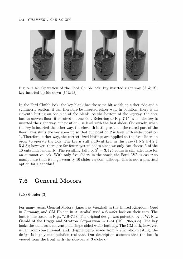
484 CHAPTER 7 CAR LOCKS
A B C D
Figure 7.15: Operation of the Ford Chubb lock: key inserted right way (A & B);key inserted upside down (C & D).
In the Ford Chubb lock, the key blank has the same bit width on either side and asymmetric section; it can therefore be inserted either way. In addition, there is aneleventh bitting on one side of the blank. At the bottom of the keyway, the corehas an uneven floor: it is raised on one side. Referring to Fig. 7.15, when the key isinserted the right way, cut position 1 is level with the first slider. Conversely, whenthe key is inserted the other way, the eleventh bitting rests on the raised part of thefloor. This shifts the key stem up so that cut position 2 is level with slider position1. Therefore, either way, the correct sized bittings are applied to the five sliders inorder to operate the lock. The key is still a 10-cut key, in this case (1 5 2 4 4 2 15 3 3); however, there are far fewer system codes since we only can choose 5 of the10 cuts independently. The resulting tally of 55 = 3, 125 codes is still adequate foran automotive lock. With only five sliders in the stack, the Ford AVA is easier tomanipulate than its high-security 10-slider version, although this is not a practicaloption for a car thief.
7.6 General Motors
(US) 6-wafer (3)
For many years, General Motors (known as Vauxhall in the United Kingdom, Opelin Germany, and GM Holden in Australia) used a 6-wafer lock on their cars. Thelock is illustrated in Figs. 7.16–7.18. The original design was patented by J. W. FitzGerald of the Briggs and Stratton Corporation in 1934 (US 1,965,336). The keylooks the same as a conventional single-sided wafer lock key. The GM lock, however,is far from conventional, and, despite being made from a zinc alloy casting, thedesign is highly manipulation resistant. Our description assumes that the lock isviewed from the front with the side-bar at 3 o’clock.
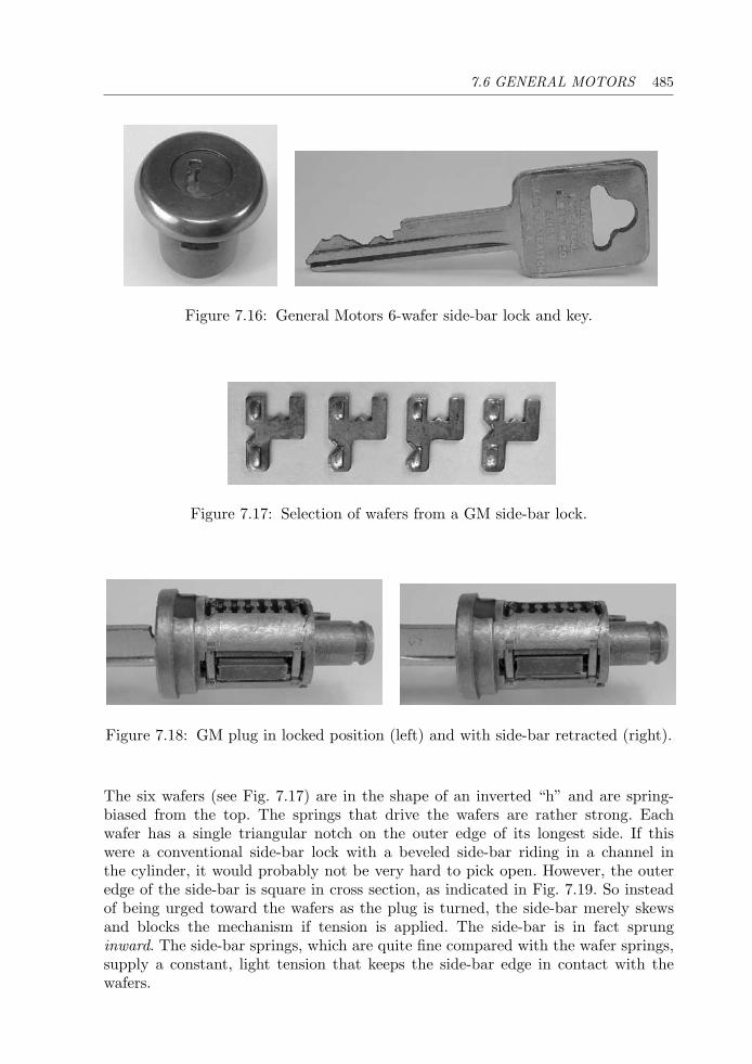
7.6 GENERAL MOTORS 485
Figure 7.16: General Motors 6-wafer side-bar lock and key.
Figure 7.17: Selection of wafers from a GM side-bar lock.
Figure 7.18: GM plug in locked position (left) and with side-bar retracted (right).
The six wafers (see Fig. 7.17) are in the shape of an inverted “h” and are spring-biased from the top. The springs that drive the wafers are rather strong. Eachwafer has a single triangular notch on the outer edge of its longest side. If thiswere a conventional side-bar lock with a beveled side-bar riding in a channel inthe cylinder, it would probably not be very hard to pick open. However, the outeredge of the side-bar is square in cross section, as indicated in Fig. 7.19. So insteadof being urged toward the wafers as the plug is turned, the side-bar merely skewsand blocks the mechanism if tension is applied. The side-bar is in fact sprunginward. The side-bar springs, which are quite fine compared with the wafer springs,supply a constant, light tension that keeps the side-bar edge in contact with thewafers.
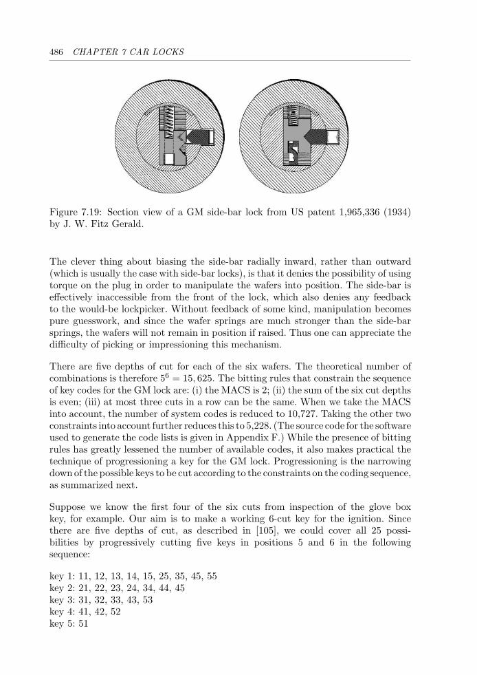
486 CHAPTER 7 CAR LOCKS
Figure 7.19: Section view of a GM side-bar lock from US patent 1,965,336 (1934)by J. W. Fitz Gerald.
The clever thing about biasing the side-bar radially inward, rather than outward(which is usually the case with side-bar locks), is that it denies the possibility of usingtorque on the plug in order to manipulate the wafers into position. The side-bar iseffectively inaccessible from the front of the lock, which also denies any feedbackto the would-be lockpicker. Without feedback of some kind, manipulation becomespure guesswork, and since the wafer springs are much stronger than the side-barsprings, the wafers will not remain in position if raised. Thus one can appreciate thedifficulty of picking or impressioning this mechanism.
There are five depths of cut for each of the six wafers. The theoretical number ofcombinations is therefore 56 = 15, 625. The bitting rules that constrain the sequenceof key codes for the GM lock are: (i) the MACS is 2; (ii) the sum of the six cut depthsis even; (iii) at most three cuts in a row can be the same. When we take the MACSinto account, the number of system codes is reduced to 10,727. Taking the other twoconstraints into account further reduces this to 5,228. (The source code for the softwareused to generate the code lists is given in Appendix F.) While the presence of bittingrules has greatly lessened the number of available codes, it also makes practical thetechnique of progressioning a key for the GM lock. Progressioning is the narrowingdown of the possible keys to be cut according to the constraints on the coding sequence,as summarized next.
Suppose we know the first four of the six cuts from inspection of the glove boxkey, for example. Our aim is to make a working 6-cut key for the ignition. Sincethere are five depths of cut, as described in [105], we could cover all 25 possi-bilities by progressively cutting five keys in positions 5 and 6 in the followingsequence:
key 1: 11, 12, 13, 14, 15, 25, 35, 45, 55key 2: 21, 22, 23, 24, 34, 44, 45key 3: 31, 32, 33, 43, 53key 4: 41, 42, 52key 5: 51
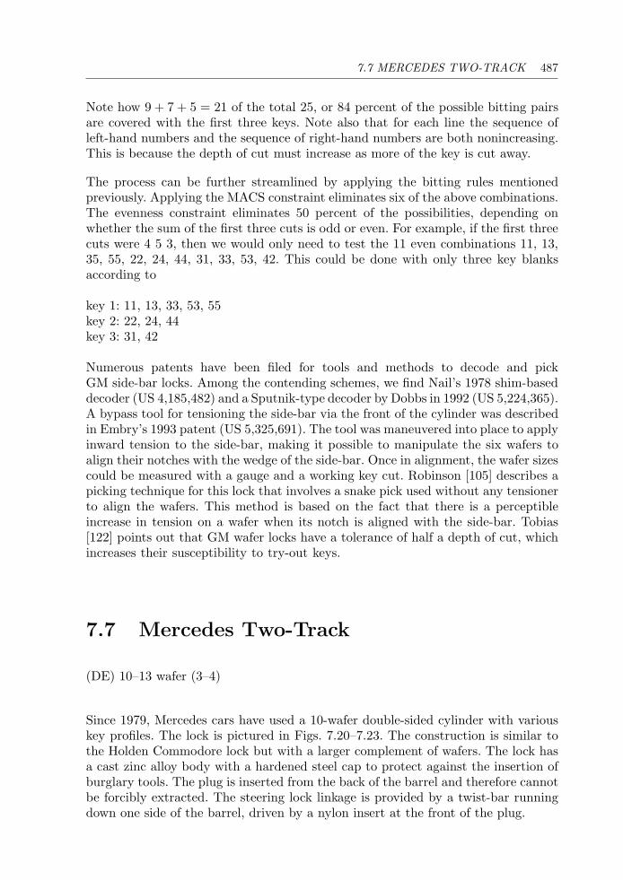
7.7 MERCEDES TWO-TRACK 487
Note how 9 + 7 + 5 = 21 of the total 25, or 84 percent of the possible bitting pairsare covered with the first three keys. Note also that for each line the sequence ofleft-hand numbers and the sequence of right-hand numbers are both nonincreasing.This is because the depth of cut must increase as more of the key is cut away.
The process can be further streamlined by applying the bitting rules mentionedpreviously. Applying the MACS constraint eliminates six of the above combinations.The evenness constraint eliminates 50 percent of the possibilities, depending onwhether the sum of the first three cuts is odd or even. For example, if the first threecuts were 4 5 3, then we would only need to test the 11 even combinations 11, 13,35, 55, 22, 24, 44, 31, 33, 53, 42. This could be done with only three key blanksaccording to
key 1: 11, 13, 33, 53, 55key 2: 22, 24, 44key 3: 31, 42
Numerous patents have been filed for tools and methods to decode and pickGM side-bar locks. Among the contending schemes, we find Nail’s 1978 shim-baseddecoder (US 4,185,482) and a Sputnik-type decoder by Dobbs in 1992 (US 5,224,365).A bypass tool for tensioning the side-bar via the front of the cylinder was describedin Embry’s 1993 patent (US 5,325,691). The tool was maneuvered into place to applyinward tension to the side-bar, making it possible to manipulate the six wafers toalign their notches with the wedge of the side-bar. Once in alignment, the wafer sizescould be measured with a gauge and a working key cut. Robinson [105] describes apicking technique for this lock that involves a snake pick used without any tensionerto align the wafers. This method is based on the fact that there is a perceptibleincrease in tension on a wafer when its notch is aligned with the side-bar. Tobias[122] points out that GM wafer locks have a tolerance of half a depth of cut, whichincreases their susceptibility to try-out keys.
7.7 Mercedes Two-Track
(DE) 10–13 wafer (3–4)
Since 1979, Mercedes cars have used a 10-wafer double-sided cylinder with variouskey profiles. The lock is pictured in Figs. 7.20–7.23. The construction is similar tothe Holden Commodore lock but with a larger complement of wafers. The lock hasa cast zinc alloy body with a hardened steel cap to protect against the insertion ofburglary tools. The plug is inserted from the back of the barrel and therefore cannotbe forcibly extracted. The steering lock linkage is provided by a twist-bar runningdown one side of the barrel, driven by a nylon insert at the front of the plug.
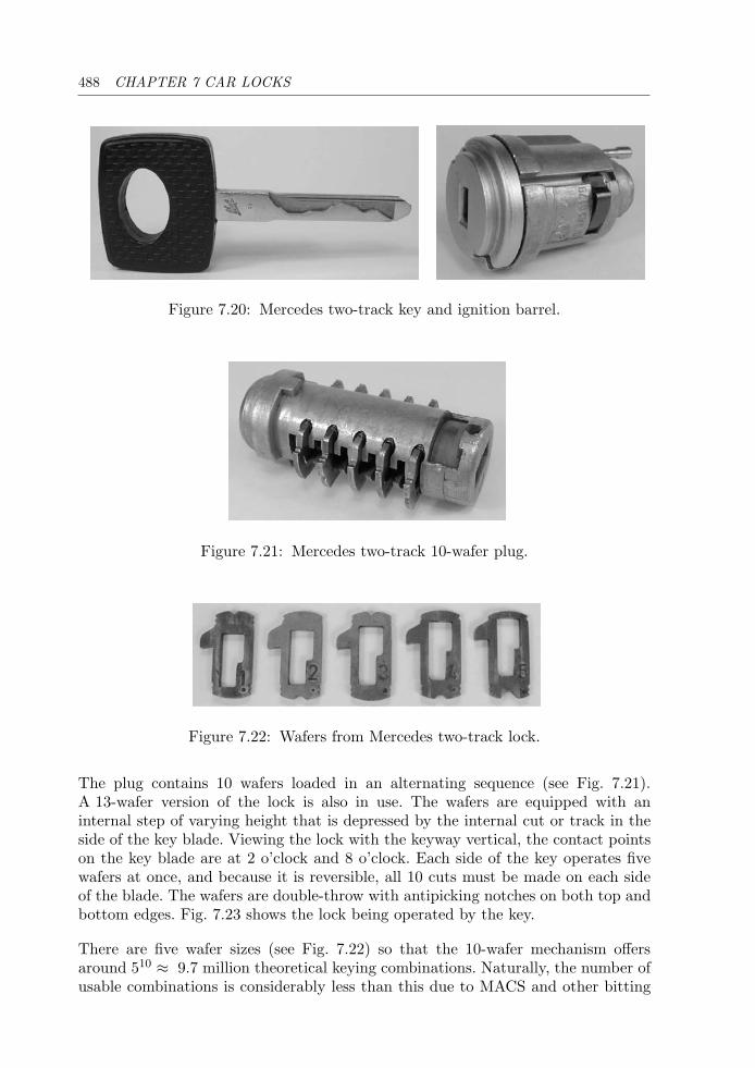
488 CHAPTER 7 CAR LOCKS
Figure 7.20: Mercedes two-track key and ignition barrel.
Figure 7.21: Mercedes two-track 10-wafer plug.
Figure 7.22: Wafers from Mercedes two-track lock.
The plug contains 10 wafers loaded in an alternating sequence (see Fig. 7.21).A 13-wafer version of the lock is also in use. The wafers are equipped with aninternal step of varying height that is depressed by the internal cut or track in theside of the key blade. Viewing the lock with the keyway vertical, the contact pointson the key blade are at 2 o’clock and 8 o’clock. Each side of the key operates fivewafers at once, and because it is reversible, all 10 cuts must be made on each sideof the blade. The wafers are double-throw with antipicking notches on both top andbottom edges. Fig. 7.23 shows the lock being operated by the key.
There are five wafer sizes (see Fig. 7.22) so that the 10-wafer mechanism offersaround 510 ≈ 9.7 million theoretical keying combinations. Naturally, the number ofusable combinations is considerably less than this due to MACS and other bitting
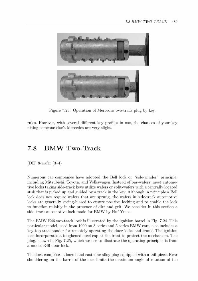
7.8 BMW TWO-TRACK 489
Figure 7.23: Operation of Mercedes two-track plug by key.
rules. However, with several different key profiles in use, the chances of your keyfitting someone else’s Mercedes are very slight.
7.8 BMW Two-Track
(DE) 8-wafer (3–4)
Numerous car companies have adopted the Bell lock or “side-winder” principle,including Mitsubishi, Toyota, and Volkswagen. Instead of bar-wafers, most automo-tive locks taking side-track keys utilize wafers or split-wafers with a centrally locatedstub that is picked up and guided by a track in the key. Although in principle a Belllock does not require wafers that are sprung, the wafers in side-track automotivelocks are generally spring-biased to ensure positive locking and to enable the lockto function reliably in the presence of dirt and grit. We consider in this section aside-track automotive lock made for BMW by Huf-Ymos.
The BMW E46 two-track lock is illustrated by the ignition barrel in Fig. 7.24. Thisparticular model, used from 1999 on 3-series and 5-series BMW cars, also includes akey-top transponder for remotely operating the door locks and trunk. The ignitionlock incorporates a toughened steel cap at the front to protect the mechanism. Theplug, shown in Fig. 7.25, which we use to illustrate the operating principle, is froma model E46 door lock.
The lock comprises a barrel and cast zinc alloy plug equipped with a tail-piece. Rearshouldering on the barrel of the lock limits the maximum angle of rotation of the
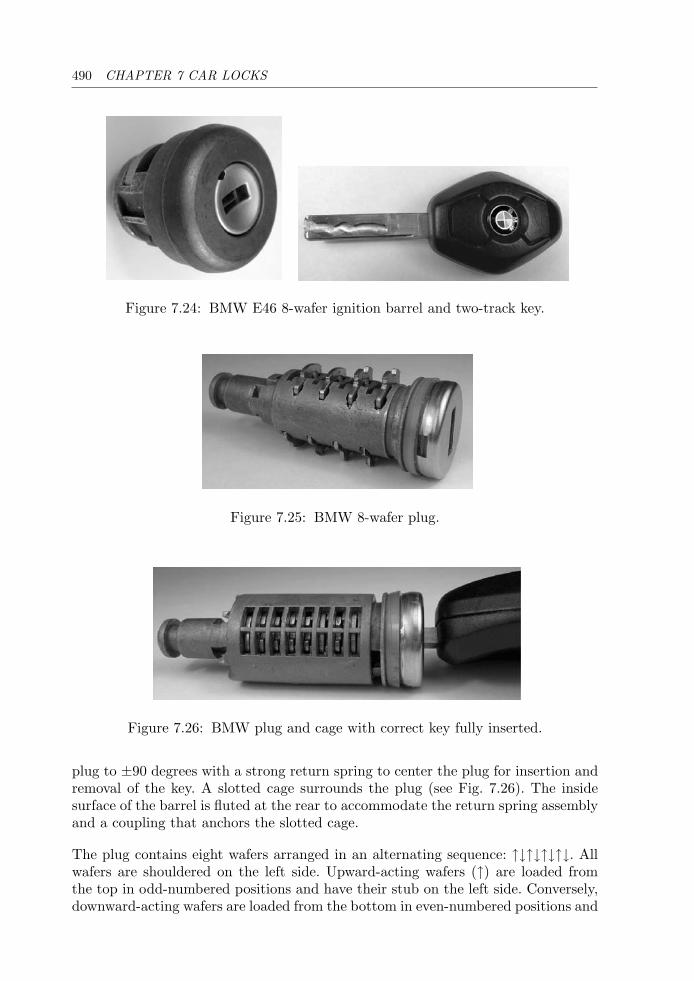
490 CHAPTER 7 CAR LOCKS
Figure 7.24: BMW E46 8-wafer ignition barrel and two-track key.
Figure 7.25: BMW 8-wafer plug.
Figure 7.26: BMW plug and cage with correct key fully inserted.
plug to ±90 degrees with a strong return spring to center the plug for insertion andremoval of the key. A slotted cage surrounds the plug (see Fig. 7.26). The insidesurface of the barrel is fluted at the rear to accommodate the return spring assemblyand a coupling that anchors the slotted cage.
The plug contains eight wafers arranged in an alternating sequence: ↑↓↑↓↑↓↑↓. Allwafers are shouldered on the left side. Upward-acting wafers (↑) are loaded fromthe top in odd-numbered positions and have their stub on the left side. Conversely,downward-acting wafers are loaded from the bottom in even-numbered positions and
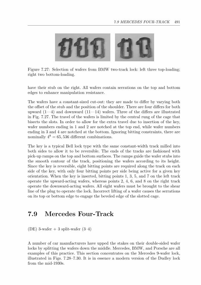
7.9 MERCEDES FOUR-TRACK 491
Figure 7.27: Selection of wafers from BMW two-track lock: left three top-loading;right two bottom-loading.
have their stub on the right. All wafers contain serrations on the top and bottomedges to enhance manipulation resistance.
The wafers have a constant-sized cut-out: they are made to differ by varying boththe offset of the stub and the position of the shoulder. There are four differs for bothupward (1—4) and downward (11—14) wafers. Three of the differs are illustratedin Fig. 7.27. The travel of the wafers is limited by the central rung of the cage thatbisects the slots. In order to allow for the extra travel due to insertion of the key,wafer numbers ending in 1 and 2 are notched at the top end, while wafer numbersending in 3 and 4 are notched at the bottom. Ignoring bitting constraints, there arenominally 48 = 65, 536 different combinations.
The key is a typical Bell lock type with the same constant-width track milled intoboth sides to allow it to be reversible. The ends of the tracks are fashioned withpick-up ramps on the top and bottom surfaces. The ramps guide the wafer stubs intothe smooth contour of the track, positioning the wafers according to its height.Since the key is reversible, eight bitting points are required along the track on eachside of the key, with only four bitting points per side being active for a given keyorientation. When the key is inserted, bitting points 1, 3, 5, and 7 on the left trackoperate the upward-acting wafers, whereas points 2, 4, 6, and 8 on the right trackoperate the downward-acting wafers. All eight wafers must be brought to the shearline of the plug to operate the lock. Incorrect lifting of a wafer causes the serrationson its top or bottom edge to engage the beveled edge of the slotted cage.
7.9 Mercedes Four-Track
(DE) 3-wafer + 3 split-wafer (3–4)
A number of car manufacturers have upped the stakes on their double-sided waferlocks by splitting the wafers down the middle. Mercedes, BMW, and Porsche are allexamples of this practice. This section concentrates on the Mercedes 9-wafer lock,illustrated in Figs. 7.28–7.30. It is in essence a modern version of the Dudley lockfrom the mid-1930s.
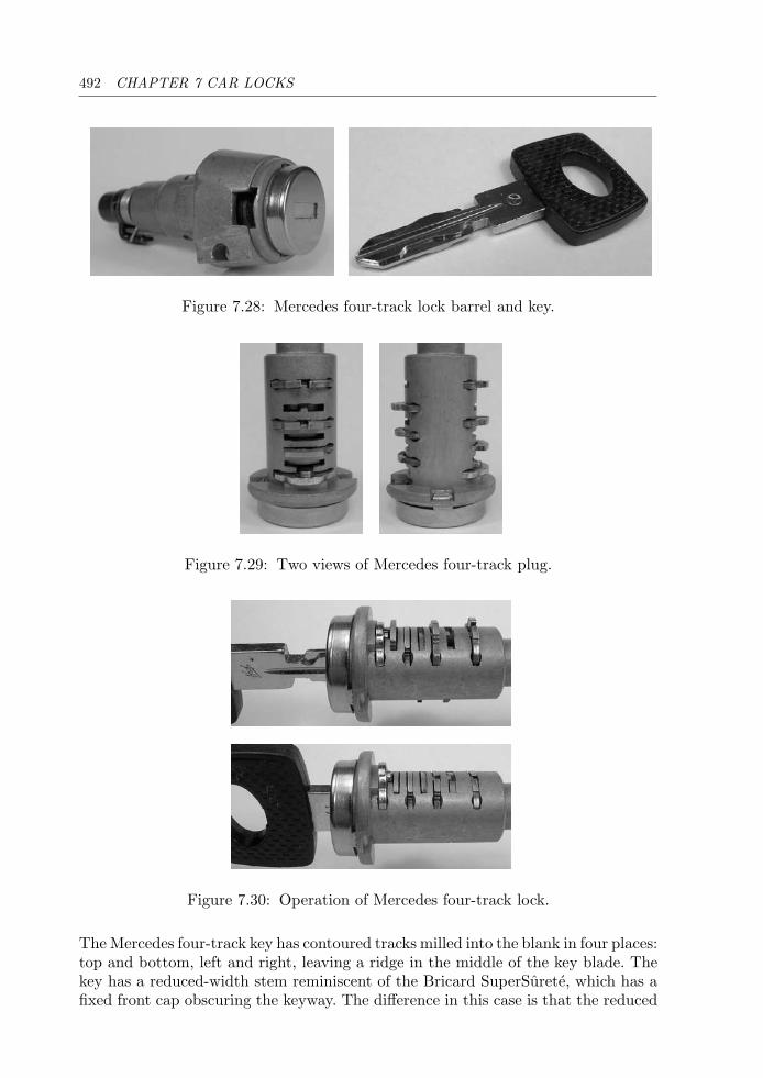
492 CHAPTER 7 CAR LOCKS
Figure 7.28: Mercedes four-track lock barrel and key.
Figure 7.29: Two views of Mercedes four-track plug.
Figure 7.30: Operation of Mercedes four-track lock.
The Mercedes four-track key has contoured tracks milled into the blank in four places:top and bottom, left and right, leaving a ridge in the middle of the key blade. Thekey has a reduced-width stem reminiscent of the Bricard SuperSurete, which has afixed front cap obscuring the keyway. The difference in this case is that the reduced
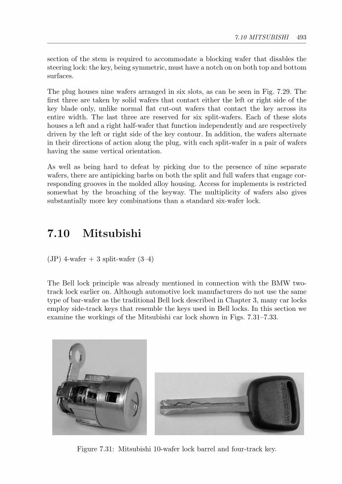
7.10 MITSUBISHI 493
section of the stem is required to accommodate a blocking wafer that disables thesteering lock: the key, being symmetric, must have a notch on on both top and bottomsurfaces.
The plug houses nine wafers arranged in six slots, as can be seen in Fig. 7.29. Thefirst three are taken by solid wafers that contact either the left or right side of thekey blade only, unlike normal flat cut-out wafers that contact the key across itsentire width. The last three are reserved for six split-wafers. Each of these slotshouses a left and a right half-wafer that function independently and are respectivelydriven by the left or right side of the key contour. In addition, the wafers alternatein their directions of action along the plug, with each split-wafer in a pair of wafershaving the same vertical orientation.
As well as being hard to defeat by picking due to the presence of nine separatewafers, there are antipicking barbs on both the split and full wafers that engage cor-responding grooves in the molded alloy housing. Access for implements is restrictedsomewhat by the broaching of the keyway. The multiplicity of wafers also givessubstantially more key combinations than a standard six-wafer lock.
7.10 Mitsubishi
(JP) 4-wafer + 3 split-wafer (3–4)
The Bell lock principle was already mentioned in connection with the BMW two-track lock earlier on. Although automotive lock manufacturers do not use the sametype of bar-wafer as the traditional Bell lock described in Chapter 3, many car locksemploy side-track keys that resemble the keys used in Bell locks. In this section weexamine the workings of the Mitsubishi car lock shown in Figs. 7.31–7.33.
Figure 7.31: Mitsubishi 10-wafer lock barrel and four-track key.
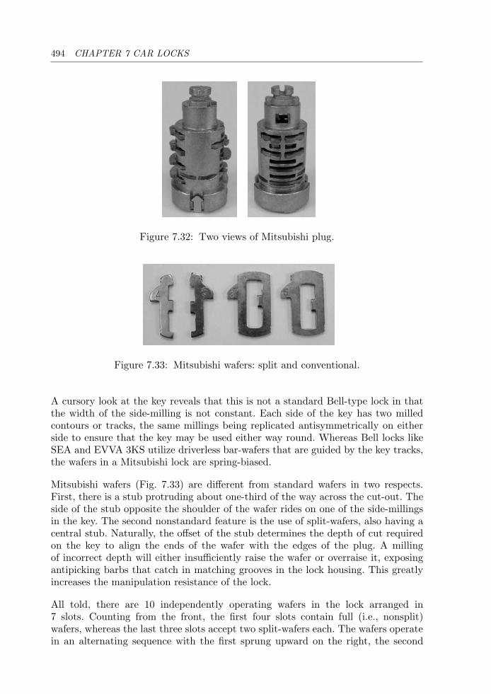
494 CHAPTER 7 CAR LOCKS
Figure 7.32: Two views of Mitsubishi plug.
Figure 7.33: Mitsubishi wafers: split and conventional.
A cursory look at the key reveals that this is not a standard Bell-type lock in thatthe width of the side-milling is not constant. Each side of the key has two milledcontours or tracks, the same millings being replicated antisymmetrically on eitherside to ensure that the key may be used either way round. Whereas Bell locks likeSEA and EVVA 3KS utilize driverless bar-wafers that are guided by the key tracks,the wafers in a Mitsubishi lock are spring-biased.
Mitsubishi wafers (Fig. 7.33) are different from standard wafers in two respects.First, there is a stub protruding about one-third of the way across the cut-out. Theside of the stub opposite the shoulder of the wafer rides on one of the side-millingsin the key. The second nonstandard feature is the use of split-wafers, also having acentral stub. Naturally, the offset of the stub determines the depth of cut requiredon the key to align the ends of the wafer with the edges of the plug. A millingof incorrect depth will either insufficiently raise the wafer or overraise it, exposingantipicking barbs that catch in matching grooves in the lock housing. This greatlyincreases the manipulation resistance of the lock.
All told, there are 10 independently operating wafers in the lock arranged in7 slots. Counting from the front, the first four slots contain full (i.e., nonsplit)wafers, whereas the last three slots accept two split-wafers each. The wafers operatein an alternating sequence with the first sprung upward on the right, the second

7.11 PORSCHE 495
downwards on the right, and so on. Full wafers that are sprung upward on the righthave their stubs on the left and are therefore driven by the upper milling on theleft-hand side of the key. Conversely, wafers that are sprung downward on the rightare actuated by the lower milling on the right-hand side of the key. Each split-waferpair is sprung on the left and right, and the pairs are arranged in an up, down,up configuration. For each pair, therefore, millings on both sides of the key bladecontact the wafer stubs.
A sequence of 10 bitting points must be internally milled on both the upper andlower tracks in order for the key to function in both orientations. The theoreticalnumber of key codes is enormous (of the order of 510 or 9,765,625). However, this issubject to a maximum adjacent cut specification, which, together with the symmetryconstraint, greatly reduces the number of possible track profiles. On the other hand,the mechanical key is only one of the parts required to start the car, the other partbeing a transponder code.
7.11 Porsche
(DE) 10 split-wafer (3–4)
Many car manufacturers base their locks on various high-security locks. We havealready described car locks that use Bell- and Dudley-type wafers, side-bars, andthe like. However, the requirement of low production cost tends to result in the useof lower grade materials, especially zinc alloy castings, which are typically foundin low-end domestic locks. The Porsche 928 lock is one example where a higheremphasis has been placed on physical strength and security.
The Porsche 10-wafer lock in Figs. 7.34–7.36 is manufactured by Huf-Ymos. It differssignificantly in a number of respects from conventional double-sided wafer locks. Thelock housing and plug are of cast alloy, but a number of features are present that
Figure 7.34: Porsche 928 four-track lock barrel and key.
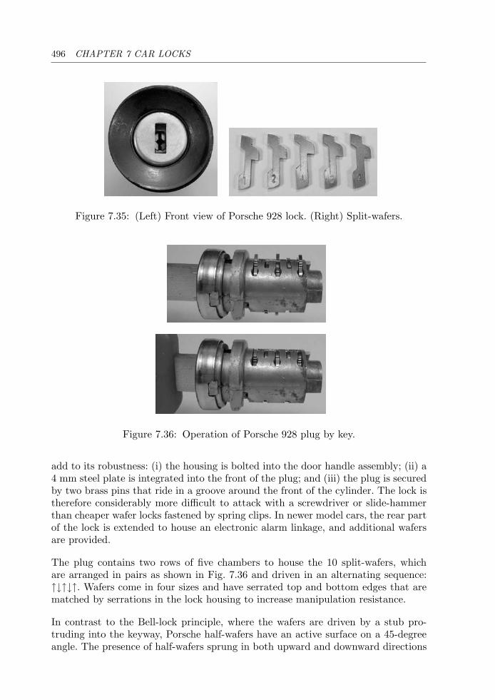
496 CHAPTER 7 CAR LOCKS
Figure 7.35: (Left) Front view of Porsche 928 lock. (Right) Split-wafers.
Figure 7.36: Operation of Porsche 928 plug by key.
add to its robustness: (i) the housing is bolted into the door handle assembly; (ii) a4 mm steel plate is integrated into the front of the plug; and (iii) the plug is securedby two brass pins that ride in a groove around the front of the cylinder. The lock istherefore considerably more difficult to attack with a screwdriver or slide-hammerthan cheaper wafer locks fastened by spring clips. In newer model cars, the rear partof the lock is extended to house an electronic alarm linkage, and additional wafersare provided.
The plug contains two rows of five chambers to house the 10 split-wafers, whichare arranged in pairs as shown in Fig. 7.36 and driven in an alternating sequence:↑↓↑↓↑. Wafers come in four sizes and have serrated top and bottom edges that arematched by serrations in the lock housing to increase manipulation resistance.
In contrast to the Bell-lock principle, where the wafers are driven by a stub pro-truding into the keyway, Porsche half-wafers have an active surface on a 45-degreeangle. The presence of half-wafers sprung in both upward and downward directions
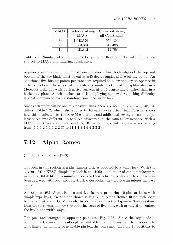
7.12 ALPHA ROMEO 497
MACS Codes satisfying Codes satisfyingMACS all Constraints
3 1,048,576 956,1842 363,314 318,4881 21,892 14,708
Table 7.2: Number of combinations for generic 10-wafer locks with four sizes,subject to MACS and differing constraints.
requires a key that is cut in four different planes. Thus, both edges of the top andbottom of the key blade must be cut at ±45-degree angles at five bitting points. Anadditional five bitting points per track are required to allow the key to operate ineither direction. The action of the wafers is similar to that of the split-wafers in aMercedes lock, but with both active surfaces at a 45-degree angle rather than in ahorizontal plane. As with other car locks employing split-wafers, picking difficultyis greatly enhanced over a standard two-sided wafer lock.
Since each wafer can be one of 4 possible sizes, there are nominally 410 = 1, 048, 576differs. Table 7.2, which also applies to 10-wafer locks other than Porsche, showshow this is affected by the MACS constraint and additional keying constraints (atleast three cuts different, up to three adjacent cuts the same). For instance, with aMACS of 1 there are only around 15,000 usable differs, with a code series rangingfrom (1 1 1 2 1 1 1 2 2 3) to (4 4 4 3 4 4 4 3 3 2).
7.12 Alpha Romeo
(IT) 10 pins in 2 rows (2–3)
The lock in this section is a pin-tumbler lock as opposed to a wafer lock. With theadvent of the KESO dimple-key lock in the 1960s, a number of car manufacturersincluding BMW fitted Gemini-type locks to their vehicles. Although these have nowbeen replaced with two- and four-track wafer locks, they provide an interesting casestudy.
As early as 1981, Alpha Romeo and Lancia were producing 10-pin car locks withdimple-type keys, like the one shown in Fig. 7.37. Alpha Romeo fitted such locksto the Giulietta and GTV models. In a similar vein to the Japanese X-key system,locks for these cars employ two opposing rows of five pins, each arranged to contactthe key blade width-ways.
The pins are arranged in opposing pairs (see Fig. 7.38). Since the key blade is3 mm thick, the maximum cut depth is limited to 1.5 mm, being half the blade-width.This limits the number of available pin lengths, but since there are 10 positions to
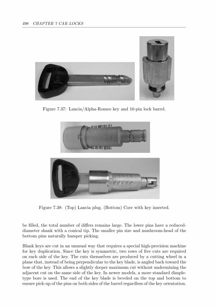
498 CHAPTER 7 CAR LOCKS
Figure 7.37: Lancia/Alpha-Romeo key and 10-pin lock barrel.
Figure 7.38: (Top) Lancia plug. (Bottom) Core with key inserted.
be filled, the total number of differs remains large. The lower pins have a reduced-diameter shank with a conical tip. The smaller pin size and mushroom-head of thebottom pins naturally hamper picking.
Blank keys are cut in an unusual way that requires a special high-precision machinefor key duplication. Since the key is symmetric, two rows of five cuts are requiredon each side of the key. The cuts themselves are produced by a cutting wheel in aplane that, instead of being perpendicular to the key blade, is angled back toward thebow of the key. This allows a slightly deeper maximum cut without undermining theadjacent cut on the same side of the key. In newer models, a more standard dimple-type bore is used. The end of the key blade is beveled on the top and bottom toensure pick-up of the pins on both sides of the barrel regardless of the key orientation.
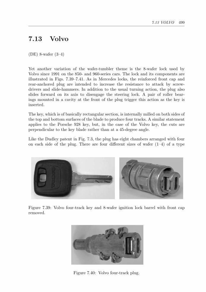
7.13 VOLVO 499
7.13 Volvo
(DE) 8-wafer (3–4)
Yet another variation of the wafer-tumbler theme is the 8-wafer lock used byVolvo since 1991 on the 850- and 960-series cars. The lock and its components areillustrated in Figs. 7.39–7.41. As in Mercedes locks, the reinforced front cap andrear-anchored plug are intended to increase the resistance to attack by screw-drivers and slide-hammers. In addition to the usual turning action, the plug alsoslides forward on its axis to disengage the steering lock. A pair of roller bear-ings mounted in a cavity at the front of the plug trigger this action as the key isinserted.
The key, which is of basically rectangular section, is internally milled on both sides ofthe top and bottom surfaces of the blade to produce four tracks. A similar statementapplies to the Porsche 928 key, but, in the case of the Volvo key, the cuts areperpendicular to the key blade rather than at a 45-degree angle.
Like the Dudley patent in Fig. 7.3, the plug has eight chambers arranged with fouron each side of the plug. There are four different sizes of wafer (1–4) of a type
Figure 7.39: Volvo four-track key and 8-wafer ignition lock barrel with front capremoved.
Figure 7.40: Volvo four-track plug.
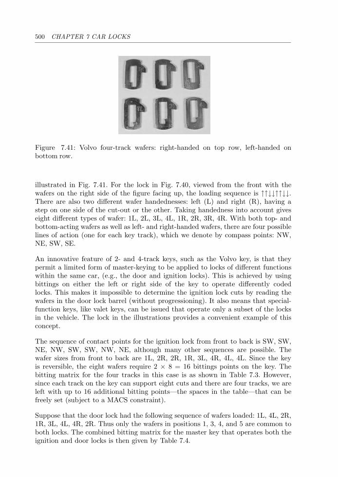
500 CHAPTER 7 CAR LOCKS
Figure 7.41: Volvo four-track wafers: right-handed on top row, left-handed onbottom row.
illustrated in Fig. 7.41. For the lock in Fig. 7.40, viewed from the front with thewafers on the right side of the figure facing up, the loading sequence is ↑↑↓↓↑↑↓↓.There are also two different wafer handednesses: left (L) and right (R), having astep on one side of the cut-out or the other. Taking handedness into account giveseight different types of wafer: 1L, 2L, 3L, 4L, 1R, 2R, 3R, 4R. With both top- andbottom-acting wafers as well as left- and right-handed wafers, there are four possiblelines of action (one for each key track), which we denote by compass points: NW,NE, SW, SE.
An innovative feature of 2- and 4-track keys, such as the Volvo key, is that theypermit a limited form of master-keying to be applied to locks of different functionswithin the same car, (e.g., the door and ignition locks). This is achieved by usingbittings on either the left or right side of the key to operate differently codedlocks. This makes it impossible to determine the ignition lock cuts by reading thewafers in the door lock barrel (without progressioning). It also means that special-function keys, like valet keys, can be issued that operate only a subset of the locksin the vehicle. The lock in the illustrations provides a convenient example of thisconcept.
The sequence of contact points for the ignition lock from front to back is SW, SW,NE, NW, SW, SW, NW, NE, although many other sequences are possible. Thewafer sizes from front to back are 1L, 2R, 2R, 1R, 3L, 4R, 4L, 4L. Since the keyis reversible, the eight wafers require 2 × 8 = 16 bittings points on the key. Thebitting matrix for the four tracks in this case is as shown in Table 7.3. However,since each track on the key can support eight cuts and there are four tracks, we areleft with up to 16 additional bitting points—the spaces in the table—that can befreely set (subject to a MACS constraint).
Suppose that the door lock had the following sequence of wafers loaded: 1L, 4L, 2R,1R, 3L, 4L, 4R, 2R. Thus only the wafers in positions 1, 3, 4, and 5 are common toboth locks. The combined bitting matrix for the master key that operates both theignition and door locks is then given by Table 7.4.
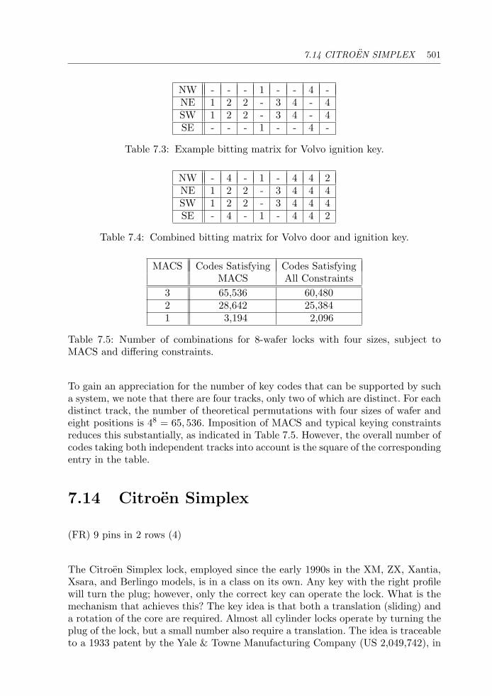
7.14 CITROEN SIMPLEX 501
NW - - - 1 - - 4 -NE 1 2 2 - 3 4 - 4SW 1 2 2 - 3 4 - 4SE - - - 1 - - 4 -
Table 7.3: Example bitting matrix for Volvo ignition key.
NW - 4 - 1 - 4 4 2NE 1 2 2 - 3 4 4 4SW 1 2 2 - 3 4 4 4SE - 4 - 1 - 4 4 2
Table 7.4: Combined bitting matrix for Volvo door and ignition key.
MACS Codes Satisfying Codes SatisfyingMACS All Constraints
3 65,536 60,4802 28,642 25,3841 3,194 2,096
Table 7.5: Number of combinations for 8-wafer locks with four sizes, subject toMACS and differing constraints.
To gain an appreciation for the number of key codes that can be supported by sucha system, we note that there are four tracks, only two of which are distinct. For eachdistinct track, the number of theoretical permutations with four sizes of wafer andeight positions is 48 = 65, 536. Imposition of MACS and typical keying constraintsreduces this substantially, as indicated in Table 7.5. However, the overall number ofcodes taking both independent tracks into account is the square of the correspondingentry in the table.
7.14 Citroen Simplex
(FR) 9 pins in 2 rows (4)
The Citroen Simplex lock, employed since the early 1990s in the XM, ZX, Xantia,Xsara, and Berlingo models, is in a class on its own. Any key with the right profilewill turn the plug; however, only the correct key can operate the lock. What is themechanism that achieves this? The key idea is that both a translation (sliding) anda rotation of the core are required. Almost all cylinder locks operate by turning theplug of the lock, but a small number also require a translation. The idea is traceableto a 1933 patent by the Yale & Towne Manufacturing Company (US 2,049,742), in
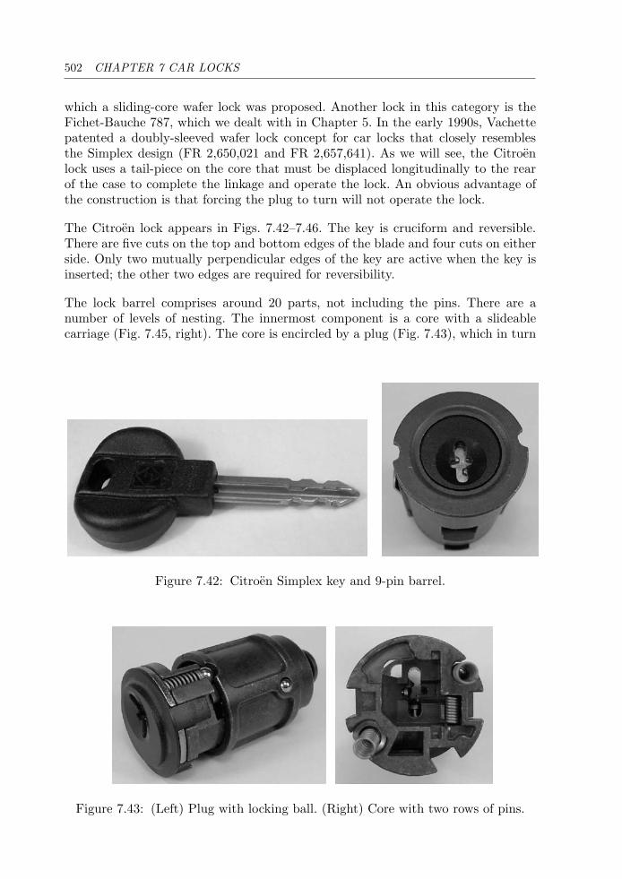
502 CHAPTER 7 CAR LOCKS
which a sliding-core wafer lock was proposed. Another lock in this category is theFichet-Bauche 787, which we dealt with in Chapter 5. In the early 1990s, Vachettepatented a doubly-sleeved wafer lock concept for car locks that closely resemblesthe Simplex design (FR 2,650,021 and FR 2,657,641). As we will see, the Citroenlock uses a tail-piece on the core that must be displaced longitudinally to the rearof the case to complete the linkage and operate the lock. An obvious advantage ofthe construction is that forcing the plug to turn will not operate the lock.
The Citroen lock appears in Figs. 7.42–7.46. The key is cruciform and reversible.There are five cuts on the top and bottom edges of the blade and four cuts on eitherside. Only two mutually perpendicular edges of the key are active when the key isinserted; the other two edges are required for reversibility.
The lock barrel comprises around 20 parts, not including the pins. There are anumber of levels of nesting. The innermost component is a core with a slideablecarriage (Fig. 7.45, right). The core is encircled by a plug (Fig. 7.43), which in turn
Figure 7.42: Citroen Simplex key and 9-pin barrel.
Figure 7.43: (Left) Plug with locking ball. (Right) Core with two rows of pins.
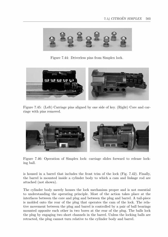
7.14 CITROEN SIMPLEX 503
Figure 7.44: Driverless pins from Simplex lock.
Figure 7.45: (Left) Carriage pins aligned by one side of key. (Right) Core and car-riage with pins removed.
Figure 7.46: Operation of Simplex lock: carriage slides forward to release lock-ing ball.
is housed in a barrel that includes the front trim of the lock (Fig. 7.42). Finally,the barrel is mounted inside a cylinder body to which a cam and linkage rod areattached (not shown).
The cylinder body merely houses the lock mechanism proper and is not essentialto understanding the operating principle. Most of the action takes place at theinterfaces between the core and plug and between the plug and barrel. A tail-pieceis molded onto the rear of the plug that operates the cam of the lock. The rela-tive movement between the plug and barrel is controlled by a pair of ball bearingsmounted opposite each other in two bores at the rear of the plug. The balls lockthe plug by engaging two short channels in the barrel. Unless the locking balls areretracted, the plug cannot turn relative to the cylinder body and barrel.
504 CHAPTER 7 CAR LOCKS
Zooming-in one level to the interface between the core and the plug, we find that itis the rear rim of the core that supports the two ball bearings. A third spring-loadedball locates the core relative to the plug. When a key, any key, is inserted in thecore and torque is applied, the locating ball pops out of its socket and allows theplug to turn. This does not operate the lock, however, because the rim of the corestill acts to retain the locking balls in their channels in the barrel. What is requiredto release the locking balls is the forward movement of the carriage inside the core.The outcome of this action is twofold: first, it causes the locking balls to drop afew millimeters into a recess in the carriage; second, the rear edges of the carriageengage two slots in the end of the plug. So at the same time that the plug is freed toturn, it is coupled to the core, which can then be rotated along with the tail-piecethat drives the locking cam.
It remains to be understood how the key operates the carriage, as illustrated inFig. 7.46. The carriage is a molded component designed to slide on a set of rails at therear of the core; it would slide right off the back were it not for two intervening setsof driverless pin-tumblers, shown in Fig. 7.44. The carriage has five vertically alignedpin chambers at 12 o’clock containing five miniature “top” pins. The chambers arecapped by a steel cover that retains the driver springs.
Instead of top pins or drivers, the pins are ribbed, having a deep circumferentialgroove at various heights. The pins straddle a longitudinal channel in the carriagethat intersects with a horizontal slot in the core at 12 o’clock. The pins are free tomove vertically across this interface under the action of the key bittings, but cannotmove longitudinally due to the chambering of the slot, unless their grooves line upwith the channel. Some of the pins also have false-depth grooves.
The second set of four “side” pins is mounted in the core at 3 o’clock. Again, theseare driverless and have one deep groove around their girth. The shanks of the pinscross a corrugated surface in the carriage on its lower right edge. When a key withthe correct top- and side-bittings is inserted, the top pins are set such that theirgrooves are aligned along the channel in the carriage. This creates a path for thefree movement of the top pins, which no longer block along the channel in the core.At the same time the grooves in the side pins have also formed a line that coincideswith the corrugated edge of the carriage. It follows that the carriage is no longerbound by the pins and it slides backwards until its end stop contacts the bottom ofthe plug, engaging the latter and disengaging the locking balls from the barrel.
The system is ingenious and highly resistant to manipulation. With five sizes of toppin and three sizes of side pin the total number of system codes is 55×34 or 253,125.Like the Rivers lock in Chapter 2, it turns freely until a proper key is presented, andthis gives it a degree of immunity from wrenching. On newer models from Citroenthe lock is teamed with an electronic key-top transponder.

Chapter 8
Conclusion
It is submitted, that the true principles of perfect security, strength,simplicity, and durability should be combined in every good lock. JohnChubb, c. 1850
Let us briefly review the material that has been covered in the preceding chapters.We started with a historical perspective on the development of locks since theindustrial revolution. This led into a discussion of the trade-off between thelocksmith’s responsibility to protect the public from dishonest people (by notdivulging sensitive information) and the public’s right to be fully informed aboutthe product it is paying for. There followed a section on innovation in the lockindustry, which dealt with the important issues of patenting, design registration,customer requirements, industry standards and lockpicking. Some administrativematters such as terminology, classification of locks, conventions, combinations, andgrading of manipulation resistance were then discussed.
In Chapter 2, we surveyed the area of pin-tumbler locks, from their invention byYale Senior and Junior in the latter half of the 19th century to the present day.We explained concepts such as the number of codes in a system, multiplex keyprofiles, MACS, and master-keying at a very basic level. We gave a cursory overviewof lockpicking, impressioning and decoding. We then described measures taken toprotect locks from manipulation and drilling. We explained the differences betweenpassive and active profile pins. We also noted the current trend toward keys withactive elements, which makes it next to impossible to produce unauthorized copiesof keys. The following categories of pin-tumbler locks were identified: (1) inline;(2) inline with passive profile pins; (3) inline horizontal keyway; (4) twin inline;(5) inline with active profile pins; (6) cruciform; (7) multiple inline; (8) tubular oraxial; (9) concentric pin; (10) rotating pin; (11) pin matrix; and (12) key-changeable.This was backed up by detailed descriptions of the operating principles of locks thatexemplify each of these classes. We noted that the multiple inline dimple-key lockby Kaba AG has met with substantial commercial success.
506 CHAPTER 8 CONCLUSION
Chapter 3 treated the subject of disc-tumbler or wafer locks. From their origins inthe last quarter of the 19th century, these locks have generally been used as camlocks and switch locks in the industrial and automotive sectors. We considered bothsingle- and double-throw wafer locks, as well as the number of codes and the conceptof try-out keys. We noted some of the security features that provide resistance topicking and impressioning. The historically important Bramah lock as well as themore recent Bell lock with its side-track key were also discussed in this chapter.We adopted the following classification scheme for wafer locks: (1) conventional;(2) contoured; (3) three-sided; (4) inline push; (5) Bell; (6) axial; (7) reverse cut;(8) split-wafer; and (9) key-changeable. Detailed descriptions of locks of each ofthese types were subsequently presented.
Side-bar locks were the subject of Chapter 4. Although the inclusion of side-bars incylinder locks is relatively recent, dating from the first quarter of the 20th century,the concept is closely connected with ancient designs such as the letter combinationpadlock and Scandinavian disc padlocks of the early 1700s. The side-bar lock categoryincludes locks from the conventional types (pin-tumbler, wafer, and lever) that utilizea side-bar mechanism. We identified the following categories: (1) disc; (2) lever;(3) driverless pin; (4) wafer; and (5) dual-action. Next, we examined the operatingprinciples of a number of high-security locks in these classes. Side-bar locks are themain product line of ASSA Abloy, one of the largest lock companies in the world today.
Chapter 5 was concerned with the most celebrated high-security lock—the leverlock. We traced its history from the late 18th-century Barron lock, through themore familiar form of the Chubb lock, to the double-bitted forms seen in Italyand Germany. We noted Kromer’s important contribution in the development ofdouble-bitted key locks. We recounted some of the events that have contributed tothe colourful history of this class of locks. We also described master-keying in thecontext of lever locks, including the Butter’s system and various other embodiments.Many of the early lever locks were exclusively used in safes, surviving today inmuseums and private collections. The lever locks we presented in the remainder ofthe chapter were arranged in the classes of: (1) conventional; (2) Italian double-throw; (3) lever locks with end-bitted keys; (4) radial lever locks; (5) cylindrical;(6) geared; (7) trap-door; (8) key-changeable; and (9) dual-control.
Chapter 6 was on the topic of magnetic locks, that is, locks using permanent magnets.These are quite distinct from electromagnetic locks, which use solenoids and/orcard readers, and are not within the scope of the book. We explained that thedevelopment of magnetic locks depended on the availability, from the mid-1960s,of lightweight, high-flux-density permanent magnets. The early designs replacedconventional pin-tumblers with various arrangements of magnetic tumblers thatwere driven by the magnets in the key. Some of these designs teamed magnetic andconventional pin-tumblers. We also saw more recent examples based on magneticallyoriented discs, and others that incorporate a matrix of small magnets.
Finally, in Chapter 7 we encountered a number of the more interesting automotivelocks. We had a cursory look at the history of the motor car during the 20th century
CONCLUSION 507
and its impact on the development and spread of wafer locks in particular. We sawthat, apart from the Briggs & Stratton wafer side-bar lock introduced by GeneralMotors in 1935, almost all vehicles used conventional locks with standard pin- orwafer-tumblers until the 1970s. Since then, quite a number of new designs haveemerged, and we considered some of these. Specifically, we dealt with car locksutilizing twin inline pin-tumblers, the Abloy and Chubb locks used by Ford, variousimplementations of double-sided and split-wafer locks with two-track and four-trackkeys, and the Simplex lock used by Citroen.
Despite the numerous topics that we have dealt with, a number of important areaswere omitted. As mentioned in the book’s introduction, we did not cover keylesscombination locks, time locks, or the general topic of safes. This is a vast andhighly specialized area that is the preserve of only a relatively small fraction ofthe locksmithing and security profession. Information about this field, particularlydetailed technical information, is generally unavailable to the public because of therisk of compromising the security of the institutions that rely on this technology.Notwithstanding this point, many of the keyed locks covered in this book have beenand continue to be used on smaller safes and safe deposit boxes. For a discussion ofcombination locks and safes in general, the reader may wish to consult [13, 59, 122]and the references they contain.
Although we did mention in passing a number of nondestructive techniques for open-ing locks (picking, decoding, impressioning, etc.), the general area of opening locksnondestructively without access to the key was not discussed in any great detail. Itseems prudent in a publicly available book to omit very detailed information of thissort. We chose instead to rate the manipulation resistance of individual locks andto note whether they included such features as drill and pry protection. The readeris referred to the references in Chapter 1, where several resources dealing with lock-picking, decoding, impressioning, opening tools, and bypass techniques were cited.Suffice to say that no lock is fully burglar proof; it is more a question of the amountof skill or force required and the time available for its application. Many specializedtechniques developed in laboratories are of no practical value to burglars becausethey are either too difficult to learn, require expensive tools, or take too long to putinto action.
As mentioned in the introductory chapter, the enthusiastic reader may wish to referto the various manufacturers’ Web sites, some of which contain historical or technicalinformation on locks and locksmithing products. There are also a number of onlineforums, some moderated and others not, dedicated to locksmithing and relatedactivities (e.g., Lock Picking 101). The FAQ from the alt.locksmithing newsgroup [60]is a good place to start searching for public-domain information on locks. In particular,the “Montmartre” Web site [7] contains a wealth of information on high-securitylocks and because it is an online resource, is well positioned to follow emergingtechnologies. Bearing in mind that much of the non–peer-reviewed information thatone finds on the Web is unreliable, a search of the patent databases that havebeen made publicly available online is also recommended. This will acquaint theuninitiated reader with the higher level of detail required to specify a new lock
508 CHAPTER 8 CONCLUSION
design precisely. The material that is published through the patenting process hasbeen reviewed by technical experts and suffers less from subjectivity and marketing“hype.” The patent references in Appendix D provide a starting point for furtherstudy.
What of the future of mechanical locks? The 20th century saw the analog electroniccomputer appear and vanish because it was less flexible and more difficult to main-tain than the digital computer: this led to a higher ratio of cost to performance,which signaled the death knell for this technology. The situation with locks, how-ever, is somewhat less clear. For thousands of years, people have dwelt in houses andmore recently apartments with wooden doors. At least for the foreseeable future thiswill continue to be the case. Therefore, there will always be a need for a mechanical“front-end” to a lock, that is, the part that actually secures the door to the frame.The idea that we will eventually either do away with doors or use electric force fieldsor some other barrier, as depicted in popular science fiction movies, seems fancifulto say the least. Mechanical locks will always be needed where there is no electricitysupply (e.g., for perimeters and remote sites), or in applications where the powersupply cannot be relied upon to ensure the locking function. In many situationsthere is still no substitute for the low cost, simplicity, and reliability of a mechanicalcylinder lock or padlock.
On the other hand, in numerous applications we see an increasing prevalenceof electronic locks teamed with electric strike plates and also electromagneticdoor fasteners. The end-users of this technology are typically large industrial andinstitutional complexes, like universities, government offices, and hotels, althoughthey also include smaller private concerns. Examples of these types of systemsinclude digital locks, smart cards, magnetic stripe/swipe cards, noncontact RFproximity cards, and biometric access systems controlled by fingerprint, retinal, orvoice recognition.
Digital combination locks have both mechanical and electronic embodiments. Bothtypes have the advantage of being easily code-changed and not requiring a key.Digital or push button mechanical locks such as Simplex and Lockwood Digital arestill in use, although we have not covered them in this book. Key-operated and fullyelectronic digital locks, where a code is entered by the user via a key pad, must alsouse an electric strike or motor drive. Electronic digital locks, such as those made byMas Hamilton, La Gard, and Rosengrens, are steadily replacing mechanical keylesscombination locks in bank safes and vaults.
While digital locks may provide a higher level of security in terms of the probabilityof someone accidentally stumbling on the correct code, there may be a risk thatthe system can respond to an override code keyed in by an unauthorized individual.It is impossible to tell whether such a code exists from an inspection of the locksince the access code exists only in the memory of a silicon chip inside the lock. Thewidespread use of electronic digital combination locks is also reducing the demandfor persons skilled in the art of safe lock manipulation, possibly the most difficultaspect of locksmithing to master.
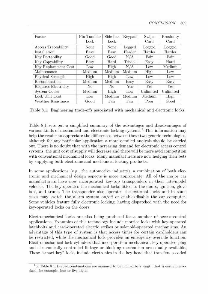
CONCLUSION 509
Factor Pin-Tumbler Side-bar Keypad Swipe ProximityLock Lock Card Card
Access Traceability None None Logged Logged LoggedInstallation Easy Easy Harder Harder HarderKey Portability Good Good N/A Fair FairKey Copyability Easy Hard Trivial Easy HardKey Replacement Cost Low High N/A Low MediumMaintenance Medium Medium Medium High LowPhysical Strength High High Low Low LowRecombination Medium Medium Easy Easy EasyRequires Electricity No No Yes Yes YesSystem Codes Medium High Low Unlimited UnlimitedLock Unit Cost Low Medium Medium Medium HighWeather Resistance Good Fair Fair Poor Good
Table 8.1: Engineering trade-offs associated with mechanical and electronic locks.
Table 8.1 sets out a simplified summary of the advantages and disadvantages ofvarious kinds of mechanical and electronic locking systems.1 This information mayhelp the reader to appreciate the differences between these two generic technologies,although for any particular application a more detailed analysis should be carriedout. There is no doubt that with the increasing demand for electronic access controlsystems, the unit cost of supply will decrease and there will be more avid competitionwith conventional mechanical locks. Many manufacturers are now hedging their betsby supplying both electronic and mechanical locking products.
In some applications (e.g., the automotive industry), a combination of both elec-tronic and mechanical design aspects is more appropriate. All of the major carmanufacturers have now incorporated key-top transponders in their late-modelvehicles. The key operates the mechanical locks fitted to the doors, ignition, glovebox, and trunk. The transponder also operates the external locks and in somecases may switch the alarm system on/off or enable/disable the car computer.Some vehicles feature fully electronic locking, having dispatched with the need forkey-operated locks on the doors.
Electromechanical locks are also being produced for a number of access controlapplications. Examples of this technology include mortice locks with key-operatedlatchbolts and card-operated electric strikes or solenoid-operated mechanisms. Anadvantage of this type of system is that access times for certain cardholders canbe restricted, while the mechanical lock provides an emergency override function.Electromechanical lock cylinders that incorporate a mechanical, key-operated plugand electronically controlled linkage or blocking mechanism are equally available.These “smart key” locks include electronics in the key head that transfers a coded
1In Table 8.1, keypad combinations are assumed to be limited to a length that is easily memo-rized, for example, four or five digits.
510 CHAPTER 8 CONCLUSION
signal to the monitoring system in the lock via either a set of contact pads or wirelessRF induction. Such systems are designed to eliminate unauthorized key duplicationwhile offering greater flexibility in terms of access control.
Epilogue
We hope to have stirred your interest in the fascinating subject of high-securitylocks. There is certainly a lot more that can be said about mechanical locks andwhere the industry is headed. Naturally, many locks have not been included in thisbook due to lack of time or availability of samples.
The progress that has been made in this industry in the space of one generationis staggering. The leading lock-making companies invest considerably in ongoingR&D and are continuing to produce innovative products at a rate that is difficultto keep up with. On the other hand, the number of lock and security companies iscontinuing to diminish due to acquisitions of small- to medium-sized firms by globalplayers such as ASSA Abloy and Kaba. It will be interesting to see the shape ofthe industry over the coming years and what products emerge from this corporatefusion.
Faced by this continual stream of new technology, it serves us well to rememberthe fundamental design principles of what constitutes a good lock, espoused over150 years ago by John Chubb in his dissertation to the Institution of Civil Engineersin London: “security, strength, simplicity, and durability.”

Bibliography
[1] Arnall, F. M. The Padlock Collector, 6th edition, 1998, Claremont, CA.
[2] Arnold Magnetic Technologies. Magnetics Technology Center Web site,http://www.arnoldmagnetics.com/mtc/index.htm.
[3] Assa Abloy. Assa High Security Locks: Technical Specifications and ProductCatalogue, Assa Abloy Group, 2004.
[4] Association of Builders Hardware Manufacturers. “Best Practice Guide: Cylin-ders for Locks,” BS EN 1303 (1998).
[5] Beck, R. A. The Lock Collector, Issue 8, July/August 2005, U.K.
[6] Beck, R. A. “Edwin Cotterill: His Middle Age and Lock Inventions (Part 2),”in The Lock Collector, Issue 10, January/March 2006, U.K.
[7] Becker, J. R. Lock pictures and references, available from http://www.chez.com/montmartre/, http://www.protections-vol.com/.
[8] Bengue, G. Pour le Serrurier: La Serrure: Mise au Point, Dereglements,Reparations, Artisan-Pau, St Joseph, Tarbes, 1963.
[9] Berger, E. Prunk-Kassetten: Europaısche Meisterwerke aus acht Jahrhun-derten, Hans Schell Collection, Graz, Austria, Arnoldsche Art Publishers,1998.
[10] Blaze, M. “Notes on Picking Pin Tumbler Locks,” http://www.crypto.com/papers/notes/picking/, November 2003.
[11] Blaze, M. “Rights Amplification in Master-Keyed Mechanical Locks,” IEEESecurity and Privacy Magazine, pp. 24–32, March 2003.
[12] Blaze, M. “Notes on Schlage Everest Locks,” http://www.crypto.com/photos/misc/everest/, April 2003.
[13] Blaze, M. “Safe Cracking for the Computer Scientist,” Dept. Computer andInformation Science, University of Pennsylvania, draft report, December 2004.Available from http://www.crypto.com/papers/safelocks.pdf.
512 BIBLIOGRAPHY
[14] Bowman, D. L. “Servicing Medeco 3 Mortise Cylinders,” Locksmith Ledger,Fort Atkinson, Wisconsin, pp. 26–38, October 2004.
[15] Bramah, J. “A Dissertation on the Construction of Locks,” London, 1785.
[16] British Standards Institution. “Building Hardware—Cylinders for Locks—Requirements and Test Methods,” BS EN 1303 (1998).
[17] British Standards Institution. Permission to reproduce extracts from BS EN1300: 2004 and BS EN 1303: 1998 is granted by BSI. British Standards canbe obtained from BSI Customer Services, 389 Chiswick High Road, LondonW4 4AL. Tel: +44 (0)20 8996 9001. E-mail: [email protected].
[18] British Standards Institution. “Secure Storage Units—Requirements, Classi-fication and Methods of Test for Resistance to Burglary—Part 2: DepositSystems,” BS EN 1143-2 (2001).
[19] British Standards Institution. “Secure Storage Units—Classification for HighSecurity Locks According to Their Resistance to Unauthorized Opening,” BSEN 1300 (2004).
[20] Bugg, D. E., and Potter, D. P. K. Burglary Protection and Insurance Surveys,4th edition, Stone & Cox, London, 1982.
[21] Butter, F. J. An Encyclopaedia of Locks and Builders Hardware, Josiah Parkes& Sons, Union Works, Willenhall, England, 1958, reprinted in 1968 and 1979.
[22] Chubb, J. “On the Contruction of Locks and Keys,” Proc. Inst. Civ. Eng.,Vol. 9, 1850.
[23] Debito, A. “Generating the Foreigner Crime Wave,” Japan Times,The Zeit Gist, October 4, 2002. Available from http://www.jref.com/forum/archive/index.php/t-834.html See also http://www.debito.org/TheCommunity/communityissues.html.
[24] Dickens, C. The Pickwick Papers, Chapter 53, “Comprising the final exit ofMr. Jingle and Job Trotter, with a great morning of business in Gray’s InnSquare—Concluding with a double knock at Mr. Perker’s door,” Chapmanand Hall, London, 1837.
[25] Diderot & d’Alembert. “Recueil de Planches sur les Sciences, Les ArtsLiberaux, Les Arts Mechaniques, avec leur Explication: Serrurerie,” 57 pages,1762, in Encyclopedie, 1751–1772, Paris.
[26] Diederichsen, O. Photographs of German safe locks, http://www.tresoroeffnung.de, accessed July 25, 2007.
[27] Diederichsen, O. “Kromer Protector Locks,” private correspondence,October 7, 2005.
BIBLIOGRAPHY 513
[28] Duhamel du Monceau, H. L. Descriptions des Arts et Metiers, AcademieRoyale des Sciences, J. Desaint & C. Saillant, Paris, 1761–1782.
[29] Duhamel Du Monceau, H. L. l’Art du Serrurier, Paris, 1767.
[30] Eras, V. J. M. Locks and Keys throughout the Ages, published in Dutch1941, reprinted in English by Lips, Dordrecht, 1957, and by Bailey Bros. andSwinfen, 1974, U.K.
[31] Erroll, D., Erroll, J., and Day, A. American Genius: Nineteenth-Century BankLocks and Time Locks, Quantuck Lane, New York, 2006.
[32] European Certification Board—Security Systems. Lock List ECB S R01,Forschungs und Prufgemeinschaft Geldschranke und Tresoranlagen e.V. Frankfurt, March 2005, Germany.
[33] Evans, J. “A Gazetteer of Lock and Key Makers,” http://www.localhistory.scit.wlv.ac.uk/Museum/locks/gazetteer/gazhoh-izz.htm, 2002.
[34] Evans, J. “A Gazetteer of Lock and Key Makers,” http://www.localhistory.scit.wlv.ac.uk/Museum/locks/gazetteer/chubbs.htm, 2002.
[35] Faundez-Zanuy, M. “Biometric Security Technology,” IEEE Aerospace andElectronic Systems Magazine, pp. 15–26, June 2006.
[36] Fey, H. “The Drumm Geminy Shield,” July 2006. Available from http://www.toool.nl/drumm-geminy.pdf.
[37] Fey, H. “Cutaways Part III,” Journal of Lock Collecting, A Publication of theAmerican Lock Collectors Association (R. Dix, Ed.), Vol. 36, No. 5, pp. 4–14,September 2005.
[38] Fey, H. “The Discs Make the Difference,” Journal of Lock Collecting, A Pub-lication of the American Lock Collectors Association (R. Dix, Ed.), Vol. 35,No. 6, pp. 4–14, November 2004.
[39] Fey, H. “Evolution of Abloy (Part 2),” Journal of Lock Collecting, A Pub-lication of the American Lock Collectors Association (R. Dix, Ed.), Vol. 37,No. 2, pp. 4–14, March 2006.
[40] Fey, H. “High Security European Locks Part III,” Journal of Lock Collecting,A Publication of the American Lock Collectors Association (R. Dix, Ed.),Vol. 36, No. 2, pp. 4–11, March 2005.
[41] Fichet-Bauche. Histoire et Petites Histoires de la Serrurerie, Paris-Versailles,1976.
[42] Fincher, J. M. “Influence of the Bramah Lock on the Development of GermanSafe Locks (1800–1900),” in Lock Collector, R. A. Beck (Ed.), Issue 9,September/December 2005, U.K.
514 BIBLIOGRAPHY
[43] Fincher, J. M. “The Chatwood Locks,” in The Chatwood Story, compiled byA. C. Clare, Exeter, U.K., pp. 27–37, 1999.
[44] Fincher, J. M. “History of the Theodor Kromer Company,” address to theMaster Locksmiths Association Convention, De Vere Hotel, Coventry, U.K.,August 25–30, 1983.
[45] Fincher, J. M. “Evolution of German Safe Locks (Part 2): Theodor Kromer,”in Lock Collector, R. A. Beck (Ed.), Issue 11, April/June 2006, U.K.
[46] Fincher, J. M. Excerpts of correspondence between George H. Chubband William H. Chubb, July 1877. Available from P. A. Prescott’s sitehttp://www.antique-locks.com/kromerchubb.htm, 2002.
[47] Friend, M. The Encyclopaedia for Locksmiths, Bertrams Print On Demand,available from Authors OnLine, March 2004, U.K.
[48] Gillespie, T. “High Security Locks: Schlage Primus,” Locksmith Ledger, FortAtkinson, Wisconsin, pp. 26–30, February 2002.
[49] Gunn, P. J. “Chubb—A Brief History,” 2002, available from: http://www.chubbarchive.co.uk/.
[50] Hennessy, T. F. Early Locks and Lockmakers of America, Nickerson & Collins,Des Plaines, IL, 2nd edition, 1976.
[51] Hobbs, A. C. “On the Principles and Construction of Locks.,” Proc. Inst. Civ.Eng. 1854.
[52] Hobbs, A. C. On the Construction of Locks, in Construction of Locks and Safescicra 1850, C. Tomlinson (Ed.), Virtue and Co., London, 1868. Reprinted 1970,Redwood Press, Trowbridge, U.K.
[53] Hobbs, A. C. Rudimentary Treatise on the Construction of Locks, Weale,London, 1853.
[54] Hobbs, A. C. “Report from the Arbitrators to Whom the Bramah Lock Con-troversy Was Referred,” September 1851.
[55] Hogg, G. Safe Bind, Safe Find, the Story of Locks, Bolts and Bars, PhoenixHouse, London, 1961.
[56] Holmes, F. S. “Bank Vault Construction and Equipment,” ArchitecturalForum, reprinted in The Lure of the Lock, A. A. Hopkins, General Soc. ofMechanics and Tradesmen, Mechanics Institute, NY, 1954, pp. 220–230.
[57] Hopkins, A. A. The Lure of the Lock, General Soc. of Mechanics and Trades-men, Mechanics Institute, NY, 1928, reprinted 1954, 1980, 1991.
[58] Hopkins, R. Notes from private correspondence with R. Chenovick concerningMiller padlocks, December 2005, U.K.
BIBLIOGRAPHY 515
[59] Hunkin, T. “Illegal Engineering,” lecture given at London Science Museum,1997, http://www.timhunkin.com/94 illegal engineering.htm.
[60] Ilacqua, J., Schaffer, H., et al. “Answers to Frequently Asked Questions,”alt.locksmithing newsgroup, http://www.indra.com/archives/alt-locksmith-ing/, also available from http://www.faqs.org/faqs/locksmith-faq/index.html.
[61] Jain, A. K., Ross, A., and Pankanti, S. “Biometrics: A Tool for InformationSecurity,” IEEE Transactions on Information Forensics and Security, Vol. 1,No. 2, pp. 125–143, June 2006.
[62] Jain, A. K., Ross, A., and Prabhakar, S. “An Introduction to Biometric Recog-nition,” IEEE Transactions on Circuits and Systems for Video Technology,Vol. 14, No. 1, pp. 4–20, January 2004.
[63] Johnson, G. “Classic Car Key Facts,” Locksmith Ledger, Fort Atkinson,Wisconsin, pp. 52–55, March 2002.
[64] Jousse, M. La Fidelle Ouverture de l’Art de serrurier: ou l’on Void les Princi-paulx Preceptes, Desseings et Figures, Touchant les Experiences et OperationsManuelles dudict Art, Georges Griveau, La Fleche, France, 1627. Englishtranslation by Smith, C. S., and Sisco, A. G., Technology and Culture, vol. 2,pp. 131–145, 1961. Reprinted in 2004, Librairie des Arts et Metiers—EditionsJacques Laget, Nogent-le-Roi, France.
[65] Kagawa, C. “Attacks Against the Mechanical Pin Tumbler Lock,” GIACSecurity Essentials Certification, SANS Institute, January 2004.
[66] Kruhn, J. Schliesszylinder: Entwicklungsgeschichte Technik Anwendung, GertWohlfarth GmbH, Verlag Fachtechnik + Mercator-Verlag, Duisburg, 1996.
[67] Kyodo News International, Inc. “Lock Business Thrives in Japan,along with Rising Burglaries,” Japan Policy & Politics, December 11,2000. Available from http://www.findarticles.com/p/articles/mi m0XPQ/is 2000 Dec 11/ai 68163430.
[68] Levine, J. “The ASSA Twin V-10,” Locksmith Ledger, Fort Atkinson,Wisconsin, pp. 8–10, February 2002.
[69] Levine, J. “Yale High Security Cylinders,” Locksmith Ledger, Des Plaines,Illinois, April 1991.
[70] Linder, N. (Ed.). Article on Christopher Polhem, Nordisk Familjebok Kon-versationslexikon och Realencyklopedi, Vol. 12, pp. 1490–1494, GernandtsBoktryckeri-Aktiebolag, Stockholm, 1888. Facsimile by Projekt Runeberg,Sweden, 2002, http://runeberg.org/nf/.
[71] Locksmith Ledger. Advertisement for BHI Huck pin. Des Plaines, Illinois,February 1976.
516 BIBLIOGRAPHY
[72] Loss Prevention Certification Board. “Requirements and Testing Proceduresfor the LPCB Approval and Listing of Cylinders for Locks,” Loss Pre-vention Standard LPS 1242, Issue 1, U.K., December 2003. Please checkwww.RedBookLive.com for the most up-to-date issue of this standard.
[73] Loss Prevention Certification Board. “Requirements and Testing Proceduresfor the LPCB Approval and Listing of Burglary Resistant Building Compo-nents, Strongpoints and Security Enclosures,” Loss Prevention Standard LPS1175, Issue 5.1, U.K., February 2004.
[74] Loss Prevention Certification Board. “Requirements and Testing Procedures forthe LPCBApproval andListing of Safe StorageUnits—Part 1: Safes and Strong-rooms,” Loss Prevention Standard LPS 1183, Issue 4.1, U.K., January 2004.
[75] Mandel, G. Clefs, Littostampa Instituto Grafico, Bergamo, 1990; Frenchedition translated by C. Lavigne, EDDL, 2001, Paris.
[76] Mandelbrot, B. B. “The Fractal Geometry of Nature,” W. H. Freeman, NewYork, 1985.
[77] Mangine, R. F. “Examination of Steering Columns and Ignition Locks,” inForensic Investigation of Stolen-Recovered and Other Crime Related Vehicles,Chapter 9, E. Stauffer and M. Bonfanti (Eds.), Academic Press, New York, 2006.
[78] Master Locksmiths Association. “Guidelines for Minimum Security Require-ments for Domestic Property,” 3rd edition, April 2005, U.K.
[79] Mauer GmbH Werk Kromer. Response to letter from J. M. Fincher concerningserial numbers of Kromer Protector locks, Umkirch, October 11, 2001.
[80] Mauer GmbH Werk Kromer. Response to letter from J. M. Fincher concerningCawi and Kromer Protector locks, Umkirch, July 2, 2001.
[81] McBennett, M. (webmaster). “True Crimes,” Newsletter of the Japan ZoneWeb site http://www.japan-zone.com/, Issue 5, July 25, 2001.
[82] McNeil, I. Josepth Bramah, a Century of Invention 1749–1851, David &Charles, Newton Abbot, U.K., 1968.
[83] Miller, H. C. “Mosler PK-5900 Series Safe Deposit Box Lock,” brochureMO-002, The Harry C. Miller Lock Collection, 1977.
[84] Miller, H. C. “Sargent & Greenleaf 4400 Series Safe Deposit Box Lock,”brochure SG-004, The Harry C. Miller Lock Collection, 1977.
[85] Miller, H. C. “Diebold 175 Series Safe Deposit Box Lock,” brochure DI-001,The Harry C. Miller Lock Collection, 1977.
[86] Miller, H. C. “Mosler 5700 Series Safe Deposit Box Lock,” brochure MO-001,The Harry C. Miller Lock Collection, 1977.

BIBLIOGRAPHY 517
[87] Millington, J. “Lock Collecting—Patents,” Keyways, Vol. 24, No. 4, pp. 40–42,February 2002.
[88] Millington, J. Private correspondence relating to the Code Lock, November 8,2005.
[89] Millington, J. “Bibliography of Francis J. Butter,” Keyways, Vol. 22, No. 3,pp. 28–30, December 1999.
[90] Miwa Lock Co. Ltd. Product advertisements in Shuukan Asahi (newspaper),Japan, pp. 76, 142–143, February 25, 2000.
[91] Monk, E. Keys—Their History & Collection, Shire Publications, Aylesbury,U.K., 1974.
[92] Murphy, K. & Kay, J. “Automatic Identification & Information Systems,”in Automatic Identification, an IFS Executive Briefing (R. L. Chase, Ed.),Springer-Verlag, U.K., pp. 111–115, 1988.
[93] Myers, H. P. Introductory Solid State Physics, 2nd edition, Taylor & Francis,New York, pp. 373–375, 1997.
[94] Patent Office Designs Registry. United Kingdom. http://www.patent.gov.uk/design/.
[95] Phillips, B. Professional Locksmithing Techniques, 2nd edition, McGraw-Hill,New York, 1996.
[96] Prescott,P.A. “HobbsandCo.,”http://www.antique-locks.com/hobbsint.htm,2002. See also http://www.antique-locks.com/viewtopic.php?t=161.
[97] Prescott, P. A. “Decoders for Ross Locks,” http://www.antique-locks.com/decoders.htm.
[98] Prescott, P. A. “Chatwood Safe Company,” http://www.antique-locks.com/chtemp1.htm, 2002.
[99] Price, G. Treatise on Fire & Thief-Proof Depositories and Locks & Keys,Simpkin Marshall & Co., London, 1856.
[100] Price, G. A Treatise on Gunpowder-Proof Locks, Gunpowder-Proof Lock-Chambers, Drill-Proof Safes, &c., E. & F. Spon, London, 1860.
[101] Pulford, G. W. “Catalogue of High Security Locks v1.00,” April 1994, availablefrom ftp://ftp.indra.com/archives/alt-locksmithing/hiseclox.ps.Z.
[102] Rathjen, J. E. Locksmithing: From Apprentice to Master, TAB Books, NewYork, 1995.
[103] Roberts, J. The National Locksmith Guide to Antique Padlocks, NationalPublishing Company, Streamwood, IL, 1990.
518 BIBLIOGRAPHY
[104] Robinson, A. “Improvements in or Appertaining to Locks for Safes and theLike,” U.K. patent 179,970, May 1922.
[105] Robinson, R. L. Complete Course in Professional Locksmithing, Nelson-Hall,Chicago, 1983.
[106] Roper, C. A. The Complete Book of Locks and Locksmithing, TAB Books,Blue Ridge Summit, PA, 1983.
[107] Sargent & Greenleaf. “Key Operated Models 6804 and 6824—OperatingInstructions.”
[108] Schlage. “Cylinders, Keys and Key Control,” Ingersoll Rand, 2002, U.S.
[109] Schlage. “Everest Answer Book,” Ingersoll Rand, 2002, U.S.
[110] SilcaTM. 101 Key Catalogue 1993.
[111] SilcaTM. 201 Key Catalogue 1993.
[112] SilcaTM. 503 The Car Book, 1994.
[113] Sloane, E. A. Complete Book of Locks, Keys, Burglar and Smoke Alarms andOther Security Devices, 1977, William Morrow, New York.
[114] Stenner, B. The Lockmakers. A Century of Trade Unionism in the Lock andSafe Trade 1889-1989, Malthouse Press, Oxford, U.K., 1989.
[115] The Mathworks. http://www.mathworks.com/.
[116] Theodor Kromer KG. Translation of text from Kromer’s 100-year bookletfrom 1968, Freiburg.
[117] Theodor Kromer KG. “Katalog uber Sicherheitsschlosser und Sicherheitskom-binationen fur Geldschranke, Panzergewolbeturen, Tresoranlangen und Wert-behalter aller Art, sowie dazugehorende Beschlage,” Ausgabe Nr. 13, Freiburg,Germany, c. 1950.
[118] Theodor Kromer KG. Translation of “A Short Report on the Opening of aLock by Meister Bierhaus,” Freiburg, December 22, 1954.
[119] Theodor Kromer KG. Translation of response to letter from J. M. Fincherconcerning the picking of the RP37E Kromer Protector lock, Freiburg,September 21, 1976.
BIBLIOGRAPHY 519
[120] Tobias, M. W. “Method and Apparatus for Decoding a Pin Tumbler Lock,”U.S. patent 5,355,701, October 18, 1994.
[121] Tobias, M. W. Locks, Safes and Security: A Handbook for Law EnforcementPersonnel, Charles C. Thomas, Springfield, IL, 1971.
[122] Tobias, M. W. Locks, Safes and Security: An International Police Reference,Charles C. Thomas, Springfield, IL, 2000.
[123] Tyler, B., et al. Fractint, fractal generating software (freeware), first written1989, available from http://spanky.triumf.ca/www/fractint/fractint.html.
[124] Van Latum, E. “NTS Miwa locks,” private correspondence, June 8, 1994.
[125] Vaudour, C. Catalogue du Musee Le Secq des Tournelles. Fascicule II: Clefs etSerrures des Origines au Commencement de la Renaissance, Rouen, France,September 1980.
[126] Volpe, F. P. and Volpe S. Chipkarten—Grundlagen, Technik, Anwendungen,Verlag Heinz Heise, Hannover, 1996.
[127] Walker, A. Articles on Vingcard and Marlok, published online in Informatik:The Journal of Privileged Information, Issue 5, October 31, 1992.
[128] Wanlass, M. private correspondence, June 9, 1995.
[129] Wanlass, M., and Hall, S. “Impressioning Manual For Amateur Locksmiths,”http://www.gregmiller.net/locks/impress.html, (revised) 1997.
[130] Wels, B., and Gonggrijp, R. “Bumping Locks,” The Organization of OpenLockpickers (TOOOL), January 2005, http://www.toool.nl/bumping.pdf.
[131] Wels, B., et al. References on bumping locks. The Organization of Open Lock-pickers (TOOOL) Web site, http://www.toool.nl/index-eng.php.
[132] Wels, B., et al. “Certified Locks Get Knocked Out,” originally published inConsumentenbond Magazine, April 2006, Netherlands. English version avail-able from http://www.toool.nl/consumer-reports-nl.pdf.
[133] Wikipedia. The Free Encyclopedia, 2001–2006. Article on Christopher Polhem,http://www.reference.com/browse/wiki/Christopher Polhem.
[134] Yale and Towne Manufacturing Company. “A Bit of History: The Trade-Mark‘YALE’ and Its Origin,” Catalog 22, Wynkoop Hallenbeck Crawford Co., NewYork, pp. 30–38, 1917.
[135] Yale, L., Jr. A Dissertation on Locks and Lockpicking, and the Principles ofBurglar Proofing Invented by Linus Yale, Jr., T. K. Collins and P. G. Collins,Philadelphia, 1856.

This page intentionally left blank
Figure and Table Credits
Photographs
Fig. 3.64 courtesy of O. Diederichsen.
Fig. 3.66 courtesy of O. Diederichsen.
Fig. 4.4 courtesy of R. Loschiavo.
Fig. 5.17 courtesy of R. Hopkins.
Fig. 5.38 (top) courtesy of P. Prescott.
Fig. 5.99 courtesy of J. M. Fincher.
Fig. 5.124 courtesy of O. Diederichsen.
Tables
Table 1.1 reproduced with permission of BSI [17].
Table 1.2 reproduced with permission of BSI [17].
Table 8.28 reproduced with permission of LPCB [72].
Patent Diagrams
All patent diagrams were obtained from the European Patent Office esp@cenet Website at http://ep.espacenet.com. In this section, the publication date of the patent isindicated rather than the filing date. The initials EP stand for “European patent.”Country codes are as defined in Table 1.4 in Chapter 1.
Fig. 1.4 from 1922 US patent 1,403,753.
Fig. 1.5 from 1943 US patent 2,309,677.
522 FIGURE CREDITS
Fig. 1.6 from 1925 US patent 1,639,919.
Fig. 1.7 from 1928 US patent 1,667,223.
Fig. 1.8 from 1936 US patent 2,064,818.
Fig. 1.9 from 1956 US patent 2,763,027.
Fig. 1.10 from 1966 US patent 3,251,206.
Fig. 1.12 from 1992 US patent 5,172,578.
Fig. 2.8 from 1889 US patent 414,720.
Fig. 2.9 from 1965 US patent 3,206,958.
Fig. 2.19 from 1987 US patent 4,683,740.
Fig. 2.22 from 1942 US patent 2,283,489.
Fig. 2.23 from 1939 US patent 2,158,501.
Fig. 2.24 from 1973 US patent 3,762,193.
Fig. 2.25 from 1983 US patent 4,377,940.
Fig. 2.26 from 1968 US patent 3,418,833.
Fig. 2.27 from 1984 US patent 4,434,636.
Fig. 2.28 from 1983 US patent 4,377,082.
Fig. 2.29 from 1975 US patent 3,928,993.
Fig. 2.50 from 1930 US patent 1,770,864.
Fig. 2.68 from 1998 US patent 5,724,841.
Fig. 2.77 from 1968 US patent 3,393,542.
Fig. 2.88 from 1982 US patent 4,320,638.
Fig. 2.101 from 1973 Swiss patent 578,105.
Fig. 2.115 from 1963 UK patent 940,778.
Fig. 2.131 from 1995 US patent 5,457,974.
Fig. 2.144 from 1992 US patent 5,131,249.
Fig. 2.158 from 1973 US patent 3,738,136.
Fig. 2.159 from 1989 US patent 4,802,354.
Fig. 2.173 from 1993 FR patent 2,678,670.
Fig. 2.184 from 1921 US patent 1,390,222.
Fig. 2.188 from 1989 US patent 4,856,309.
Fig. 2.196 from 1980 US patent 4,208,894.
Fig. 2.197 from 1978 US patent 4,098,103.
Fig. 2.203 from 1979 US patent 4,149,394.
Fig. 3.10 from 1934 US patent 1,965,889.
FIGURE CREDITS 523
Fig. 3.11 from 1936 US patent 2,039,126.
Fig. 3.12 from 1918 US patent patent 1,287,882.
Fig. 3.13 from 1990 US patent 4,966,021.
Fig. 3.20 from 1984 US patent patent 4,429,554.
Fig. 3.38 from 1966 US patent 3,263,461.
Fig. 3.45 from 1966 US patent 3,264,852.
Fig. 3.51 from 1964 US patent 3,237,436.
Fig. 3.72 from 1990 US patent 4,966,021.
Fig. 3.75 from 1978 US patent 4,069,694.
Fig. 4.2 from 1879 US patent 213,300.
Fig. 4.3 from 1874 US patent 156,113.
Fig. 4.5 from 1981 US patent 4,267,717.
Fig. 4.6 from 1901 US patent 688,070.
Fig. 4.8 from 1982 US patent 4,356,713.
Fig. 4.9 and Fig. 4.10 from 1970 US patent 3,499,302.
Fig. 4.13 from 1983 US patent 4,404,824.
Fig. 4.14 from 1968 US patent 3,367,156.
Fig. 4.20 from 1971 US patent 3,621,689 and from 1976 US patent 3,948,065.
Fig. 4.21 from 1978 US patent 4,083,212.
Fig. 4.22 from 1987 US patent 4,651,546.
Fig. 4.23 and Fig. 4.24 from 1978 US patent 4,109,495.
Fig. 4.38 from 1985 US patent 4,512,166.
Fig. 4.42 from 1977 US patent 4,044,578.
Fig. 4.47 from 1971 US patent 3,604,231.
Fig. 4.48 from 2002 US patent 6,490,898.
Fig. 4.56 from 2000 JP patent 2000 291300.
Fig. 4.60 from 1973 US patent 3,722,240.
Fig. 4.61 from 1994 US patent 5,375,444.
Fig. 4.66 from 1984 US patent 4,478,061.
Fig. 4.67 from 1986 US patent 4,603,565.
Fig. 4.74 from 2004 US patent 6,681,609.
Fig. 4.79 from 1996 US patent 5,517,840.
Fig. 4.80 from 1937 US patent 2,070,233.
Fig. 4.93 from 1990 US patent 4,977,767.
524 FIGURE CREDITS
Fig. 4.94 from 2003 US patent 6,622,538 and from 2004 US patent 6,758,074.
Fig. 4.99 and Fig. 4.100 from 1987 US patent 4,635,455.
Fig. 4.101 from 1984 US patent 4,450,699.
Fig. 4.106 from 1983 US patent 4,393,673.
Fig. 4.110 from 1991 US patent 5,067,335.
Fig. 5.18 from 1937 DE patent 646,623.
Fig. 5.25 from 1924 UK patent 224,175.
Fig. 5.28 from 1951 UK patent 661,501.
Fig. 5.31 from 1901 US patent 666,697.
Fig. 5.32 from 1983 US patent 4,375,159.
Fig. 5.46 from 1968 US patent 3,402,581.
Fig. 5.48 from 1984 US patent 4,462,230.
Fig. 5.104 from 1980 US patent 4,196,606.
Fig. 5.111 and Fig. 5.112 from 1966 UK patent 1,030,921.
Fig. 5.127 from 1954 DE patent 911,220.
Fig. 5.133 from 1986 US patent 4,601,184.
Fig. 6.3 from 1890 US patent 428,247.
Fig. 6.4 from 1914 US patent 1,172,203.
Fig. 6.5 from 1939 US patent 2,177,996.
Fig. 6.6 from 1978 US patent 4,073,166.
Fig. 6.7 from 1969 US patent 3,444,711.
Fig. 6.8 from 1990 US patent 4,932,228.
Fig. 6.9 from 1970 US patent 3,512,382.
Fig. 6.10 from 1970 US patent 3,518,855.
Fig. 6.11 from 1974 US patent 3,855,827.
Fig. 6.12 from 1989 UK patent 2,214,226.
Fig. 6.13 from 1976 US patent 3,935,720.
Fig. 6.27 from 1978 US patent 4,073,166.
Fig. 6.36 from 1978 US patent 4,084,416.
Fig. 7.1 from 1920 US patent 1,345,014.
Fig. 7.2 from 1980 US patent 4,185,482.
Fig. 7.3 from 1942 US patent 2,279,592.
Fig. 7.4 from 1979 DE patent 7,203,658.
Fig. 7.19 from 1934 US patent 1,965,336.
Appendices
Appendix A1: Permutations and Combinations
This appendix is intended to introduce some basic concepts in permutations andcombinations. These ideas are quite mathematical but of considerable importancefor understanding key codes and master-keyed systems. Readers already acquaintedwith this material may wish to skip to the following section, which deals withpermutations and locks and how the two relate to a new kind of fractal image.
The starting point for any discussion on permutations and combinations is a setSn of n distinct objects, which we will assume are just counting numbers between1 and n, thus Sn = {1, 2, 3, . . . , n}. By “disctinct,” we mean to imply that thereare no repeated entries in the set. (We later relax the assumption that the objectsare distinct.) The first idea is that of a rearrangement of the set. For instance, ifthe set is S3 = {1, 2, 3}, then (1 2 3) is one rearrangement and (2 1 3) is anotherrearrangement of the elements.
The question arises of how many rearrangements are possible for a given set(including the original ordering). For small sets like S3 with n = 3 objects, the rear-rangements can be written out explicitly or enumerated. Thus for the case in questionwe have (1 2 3), (1 3 2), (2 1 3), (2 3 1), (3 1 2), (3 2 1), from which we see that thereare 6 rearrangements in total. For n greater than 5 or so, it becomes very tediousto enumerate all the rearrangements. Luckily, there is a simple analytical answer. Itturns out that for Sn, with n elements, there are n× (n−1)× (n−2)×· · ·×3×2×1possible rearrangements. This formula arises so frequently in the mathematics ofsets that it is given a special name: n!, which is read “n factorial.” Notice that itonly makes sense when n is a positive whole number.
For example, when n = 4 there are 4! = 4.3.2.1 = 24 rearrangements and forn = 5 there are 5! = 5.4.3.2.1 = 120 (in mathematical notation, the × symbol isoften replaced with a simple dot ‘.’). The factorial number grows very rapidly. For10 objects there are 10! = 3, 628, 800 rearrangements. What is the use of this formula?Suppose you had to recombinate a lock with five pins, all of different sizes, using onlythe pins in the lock (ignoring MACS and other constraints). How many ways couldyou do it before you started repeating codes? The answer is 5! or 120 ways.
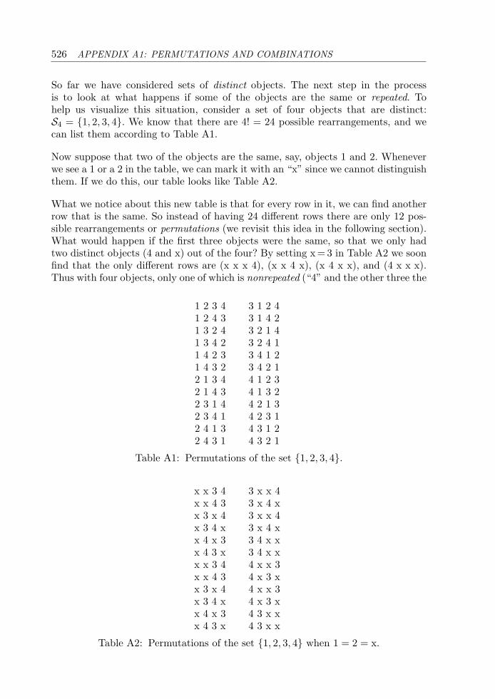
526 APPENDIX A1: PERMUTATIONS AND COMBINATIONS
So far we have considered sets of distinct objects. The next step in the processis to look at what happens if some of the objects are the same or repeated. Tohelp us visualize this situation, consider a set of four objects that are distinct:S4 = {1, 2, 3, 4}. We know that there are 4! = 24 possible rearrangements, and wecan list them according to Table A1.
Now suppose that two of the objects are the same, say, objects 1 and 2. Wheneverwe see a 1 or a 2 in the table, we can mark it with an “x” since we cannot distinguishthem. If we do this, our table looks like Table A2.
What we notice about this new table is that for every row in it, we can find anotherrow that is the same. So instead of having 24 different rows there are only 12 pos-sible rearrangements or permutations (we revisit this idea in the following section).What would happen if the first three objects were the same, so that we only hadtwo distinct objects (4 and x) out of the four? By setting x = 3 in Table A2 we soonfind that the only different rows are (x x x 4), (x x 4 x), (x 4 x x), and (4 x x x).Thus with four objects, only one of which is nonrepeated (“4” and the other three the
1 2 3 4 3 1 2 41 2 4 3 3 1 4 21 3 2 4 3 2 1 41 3 4 2 3 2 4 11 4 2 3 3 4 1 21 4 3 2 3 4 2 12 1 3 4 4 1 2 32 1 4 3 4 1 3 22 3 1 4 4 2 1 32 3 4 1 4 2 3 12 4 1 3 4 3 1 22 4 3 1 4 3 2 1
Table A1: Permutations of the set {1, 2, 3, 4}.
x x 3 4 3 x x 4x x 4 3 3 x 4 xx 3 x 4 3 x x 4x 3 4 x 3 x 4 xx 4 x 3 3 4 x xx 4 3 x 3 4 x xx x 3 4 4 x x 3x x 4 3 4 x 3 xx 3 x 4 4 x x 3x 3 4 x 4 x 3 xx 4 x 3 4 3 x xx 4 3 x 4 3 x x
Table A2: Permutations of the set {1, 2, 3, 4} when 1 = 2 = x.
APPENDIX A1: PERMUTATIONS AND COMBINATIONS 527
same), we have only 4 permutations. On reflection we can explain why this is so. Theoriginal number of permutations is 24, but three of the objects are identical. Thusfor every permutation, there are a number of other permutations that are indistin-guishable from it. Suppose we look at the permutation (4 3 2 1). Since 3 = 2 = 1 = x,this permutation cannot be distinguished from (4 3 1 2), (4 2 1 3), (4 2 3 1),(4 1 3 2), and (4 1 2 3), which are all equivalent to (4 x x x). We can see thatthe number of identical permutations starting with a “4” is 6 because there are3! = 6 ways of arranging the three remaining numbers 1, 2, and 3. The exact sameargument applies regardless of where the “4” turns up in the permutations. Thusthere are 6 permutations that are equivalent to (x 4 x x) and so on.
What we have shown is that the number of permutations of four objects when onlym = 1 of them is nonrepeated is:
4!3!
=246
= 4.
The same line of argument allows us to explain why we got 12 for the case of m = 2nonrepeated objects out of 4:
4!2!
=242
= 12.
Of course, if all the objects were the same, and hence none of them nonrepeatedor m = 0, we would have only one permutation of the form (x x x x), which isexplained as:
4!4!
=2424
= 1.
Also recall our formula for rearrangements of four distinct objects, which we can writeas the m = 3 or m = 4 case since if three of the four are distinct then they all are:
4!1
=241
= 24.
We can summarize all of the four above cases in a single formula, valid form = 0, 1, 2, 3:
The number of permutations of four objects when m of them arenonrepeated is 4!/(4 − m)!
Mathematicians give this formula a special symbol, P4m, where the P stands for
permutation. It is not difficult to show that, in general, if we have n objects, m ofwhich are nonrepeated, then the number of permutations is:
Pnm =
n!(n − m)!
understanding that n must be greater than or equal to m.
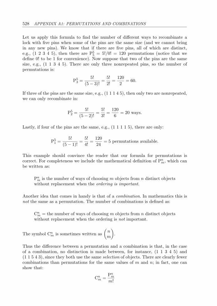
528 APPENDIX A1: PERMUTATIONS AND COMBINATIONS
Let us apply this formula to find the number of different ways to recombinate alock with five pins when some of the pins are the same size (and we cannot bringin any new pins). We know that if there are five pins, all of which are distinct,e.g., (1 2 3 4 5), then there are P5
5 = 5!/0! = 120 permutations (notice that wedefine 0! to be 1 for convenience). Now suppose that two of the pins are the samesize, e.g., (1 1 3 4 5). There are only three nonrepeated pins, so the number ofpermutations is:
P53 =
5!(5 − 3)!
=5!2!
=1202
= 60.
If three of the pins are the same size, e.g., (1 1 1 4 5), then only two are nonrepeated,we can only recombinate in:
P52 =
5!(5 − 2)!
=5!3!
=1206
= 20 ways.
Lastly, if four of the pins are the same, e.g., (1 1 1 1 5), there are only:
P51 =
5!(5 − 1)!
=5!4!
=12024
= 5 permutations available.
This example should convince the reader that our formula for permutations iscorrect. For completeness we include the mathematical definition of Pn
m, which canbe written as:
Pnm is the number of ways of choosing m objects from n distinct objects
without replacement when the ordering is important.
Another idea that comes in handy is that of a combination. In mathematics this isnot the same as a permutation. The number of combinations is defined as:
Cnm = the number of ways of choosing m objects from n distinct objects
without replacement when the ordering is not important.
The symbol Cnm is sometimes written as
(nm
).
Thus the difference between a permutation and a combination is that, in the caseof a combination, no distinction is made between, for instance, (1 1 3 4 5) and(1 1 5 4 3), since they both use the same selection of objects. There are clearly fewercombinations than permutations for the same values of m and n; in fact, one canshow that:
Cnm =
Pnm
m!
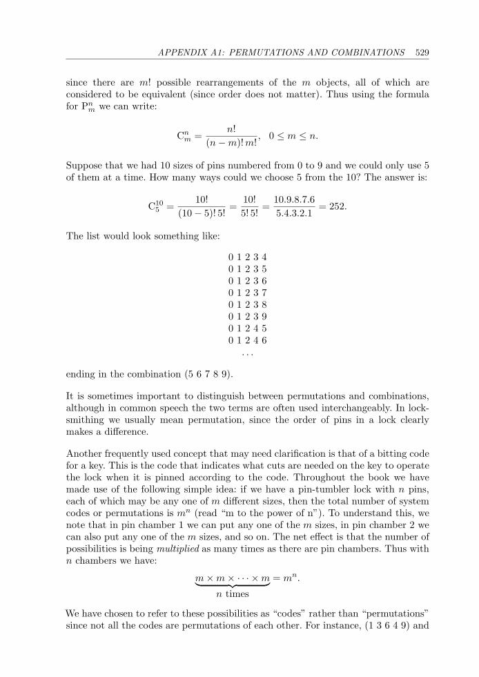
APPENDIX A1: PERMUTATIONS AND COMBINATIONS 529
since there are m! possible rearrangements of the m objects, all of which areconsidered to be equivalent (since order does not matter). Thus using the formulafor Pn
m we can write:
Cnm =
n!(n − m)!m!
, 0 ≤ m ≤ n.
Suppose that we had 10 sizes of pins numbered from 0 to 9 and we could only use 5of them at a time. How many ways could we choose 5 from the 10? The answer is:
C105 =
10!(10 − 5)! 5!
=10!5! 5!
=10.9.8.7.65.4.3.2.1
= 252.
The list would look something like:
0 1 2 3 40 1 2 3 50 1 2 3 60 1 2 3 70 1 2 3 80 1 2 3 90 1 2 4 50 1 2 4 6
. . .
ending in the combination (5 6 7 8 9).
It is sometimes important to distinguish between permutations and combinations,although in common speech the two terms are often used interchangeably. In lock-smithing we usually mean permutation, since the order of pins in a lock clearlymakes a difference.
Another frequently used concept that may need clarification is that of a bitting codefor a key. This is the code that indicates what cuts are needed on the key to operatethe lock when it is pinned according to the code. Throughout the book we havemade use of the following simple idea: if we have a pin-tumbler lock with n pins,each of which may be any one of m different sizes, then the total number of systemcodes or permutations is mn (read “m to the power of n”). To understand this, wenote that in pin chamber 1 we can put any one of the m sizes, in pin chamber 2 wecan also put any one of the m sizes, and so on. The net effect is that the number ofpossibilities is being multiplied as many times as there are pin chambers. Thus withn chambers we have:
m × m × · · · × m︸ ︷︷ ︸n times
= mn.
We have chosen to refer to these possibilities as “codes” rather than “permutations”since not all the codes are permutations of each other. For instance, (1 3 6 4 9) and
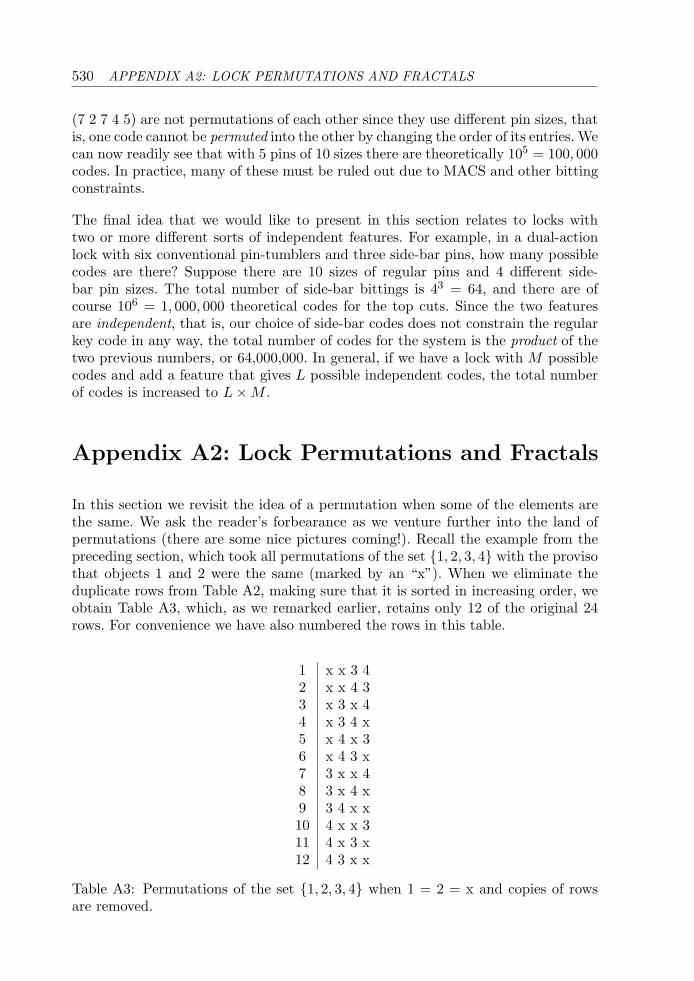
530 APPENDIX A2: LOCK PERMUTATIONS AND FRACTALS
(7 2 7 4 5) are not permutations of each other since they use different pin sizes, thatis, one code cannot be permuted into the other by changing the order of its entries. Wecan now readily see that with 5 pins of 10 sizes there are theoretically 105 = 100, 000codes. In practice, many of these must be ruled out due to MACS and other bittingconstraints.
The final idea that we would like to present in this section relates to locks withtwo or more different sorts of independent features. For example, in a dual-actionlock with six conventional pin-tumblers and three side-bar pins, how many possiblecodes are there? Suppose there are 10 sizes of regular pins and 4 different side-bar pin sizes. The total number of side-bar bittings is 43 = 64, and there are ofcourse 106 = 1, 000, 000 theoretical codes for the top cuts. Since the two featuresare independent, that is, our choice of side-bar codes does not constrain the regularkey code in any way, the total number of codes for the system is the product of thetwo previous numbers, or 64,000,000. In general, if we have a lock with M possiblecodes and add a feature that gives L possible independent codes, the total numberof codes is increased to L × M .
Appendix A2: Lock Permutations and Fractals
In this section we revisit the idea of a permutation when some of the elements arethe same. We ask the reader’s forbearance as we venture further into the land ofpermutations (there are some nice pictures coming!). Recall the example from thepreceding section, which took all permutations of the set {1, 2, 3, 4} with the provisothat objects 1 and 2 were the same (marked by an “x”). When we eliminate theduplicate rows from Table A2, making sure that it is sorted in increasing order, weobtain Table A3, which, as we remarked earlier, retains only 12 of the original 24rows. For convenience we have also numbered the rows in this table.
1 x x 3 42 x x 4 33 x 3 x 44 x 3 4 x5 x 4 x 36 x 4 3 x7 3 x x 48 3 x 4 x9 3 4 x x10 4 x x 311 4 x 3 x12 4 3 x x
Table A3: Permutations of the set {1, 2, 3, 4} when 1 = 2 = x and copies of rowsare removed.
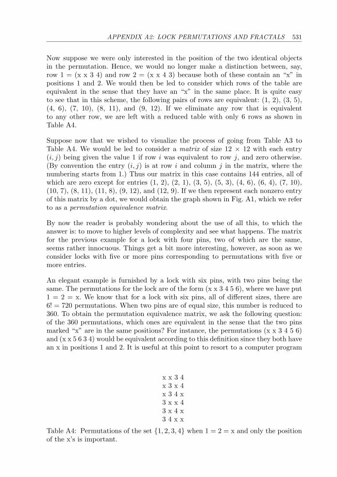
APPENDIX A2: LOCK PERMUTATIONS AND FRACTALS 531
Now suppose we were only interested in the position of the two identical objectsin the permutation. Hence, we would no longer make a distinction between, say,row 1 = (x x 3 4) and row 2 = (x x 4 3) because both of these contain an “x” inpositions 1 and 2. We would then be led to consider which rows of the table areequivalent in the sense that they have an “x” in the same place. It is quite easyto see that in this scheme, the following pairs of rows are equivalent: (1, 2), (3, 5),(4, 6), (7, 10), (8, 11), and (9, 12). If we eliminate any row that is equivalentto any other row, we are left with a reduced table with only 6 rows as shown inTable A4.
Suppose now that we wished to visualize the process of going from Table A3 toTable A4. We would be led to consider a matrix of size 12 × 12 with each entry(i, j) being given the value 1 if row i was equivalent to row j, and zero otherwise.(By convention the entry (i, j) is at row i and column j in the matrix, where thenumbering starts from 1.) Thus our matrix in this case contains 144 entries, all ofwhich are zero except for entries (1, 2), (2, 1), (3, 5), (5, 3), (4, 6), (6, 4), (7, 10),(10, 7), (8, 11), (11, 8), (9, 12), and (12, 9). If we then represent each nonzero entryof this matrix by a dot, we would obtain the graph shown in Fig. A1, which we referto as a permutation equivalence matrix.
By now the reader is probably wondering about the use of all this, to which theanswer is: to move to higher levels of complexity and see what happens. The matrixfor the previous example for a lock with four pins, two of which are the same,seems rather innocuous. Things get a bit more interesting, however, as soon as weconsider locks with five or more pins corresponding to permutations with five ormore entries.
An elegant example is furnished by a lock with six pins, with two pins being thesame. The permutations for the lock are of the form (x x 3 4 5 6), where we have put1 = 2 = x. We know that for a lock with six pins, all of different sizes, there are6! = 720 permutations. When two pins are of equal size, this number is reduced to360. To obtain the permutation equivalence matrix, we ask the following question:of the 360 permutations, which ones are equivalent in the sense that the two pinsmarked “x” are in the same positions? For instance, the permutations (x x 3 4 5 6)and (x x 5 6 3 4) would be equivalent according to this definition since they both havean x in positions 1 and 2. It is useful at this point to resort to a computer program
x x 3 4x 3 x 4x 3 4 x3 x x 43 x 4 x3 4 x x
Table A4: Permutations of the set {1, 2, 3, 4} when 1 = 2 = x and only the positionof the x’s is important.
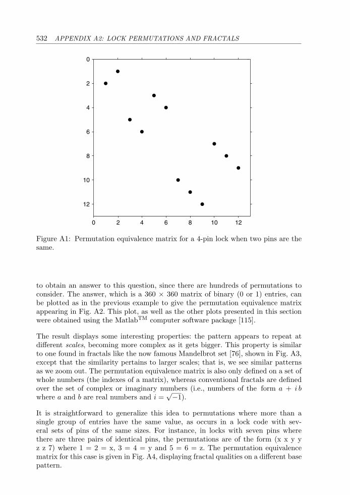
532 APPENDIX A2: LOCK PERMUTATIONS AND FRACTALS
0 2 4 6 8 10 12
0
2
4
6
8
10
12
Figure A1: Permutation equivalence matrix for a 4-pin lock when two pins are thesame.
to obtain an answer to this question, since there are hundreds of permutations toconsider. The answer, which is a 360 × 360 matrix of binary (0 or 1) entries, canbe plotted as in the previous example to give the permutation equivalence matrixappearing in Fig. A2. This plot, as well as the other plots presented in this sectionwere obtained using the MatlabTM computer software package [115].
The result displays some interesting properties: the pattern appears to repeat atdifferent scales, becoming more complex as it gets bigger. This property is similarto one found in fractals like the now famous Mandelbrot set [76], shown in Fig. A3,except that the similarity pertains to larger scales; that is, we see similar patternsas we zoom out. The permutation equivalence matrix is also only defined on a set ofwhole numbers (the indexes of a matrix), whereas conventional fractals are definedover the set of complex or imaginary numbers (i.e., numbers of the form a + i bwhere a and b are real numbers and i =
√−1).
It is straightforward to generalize this idea to permutations where more than asingle group of entries have the same value, as occurs in a lock code with sev-eral sets of pins of the same sizes. For instance, in locks with seven pins wherethere are three pairs of identical pins, the permutations are of the form (x x y yz z 7) where 1 = 2 = x, 3 = 4 = y and 5 = 6 = z. The permutation equivalencematrix for this case is given in Fig. A4, displaying fractal qualities on a different basepattern.
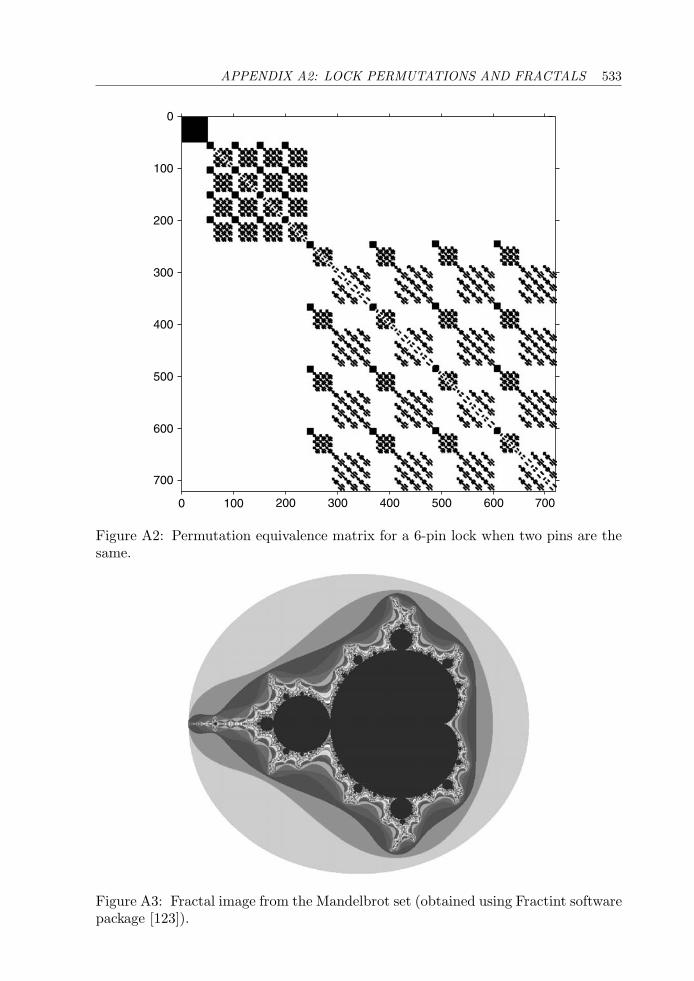
APPENDIX A2: LOCK PERMUTATIONS AND FRACTALS 533
0 100
700
600
500
400
300
200
100
0
200 300 400 500 600 700
Figure A2: Permutation equivalence matrix for a 6-pin lock when two pins are thesame.
Figure A3: Fractal image from the Mandelbrot set (obtained using Fractint softwarepackage [123]).
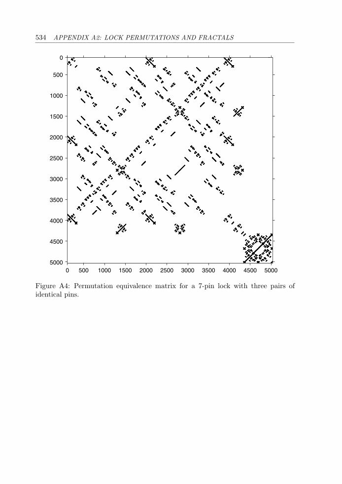
534 APPENDIX A2: LOCK PERMUTATIONS AND FRACTALS
0
500
1000
1500
2000
2500
3000
3500
4000
4500
50000 500 1000 1500 2000 2500 3000 3500 4000 4500 5000
Figure A4: Permutation equivalence matrix for a 7-pin lock with three pairs ofidentical pins.
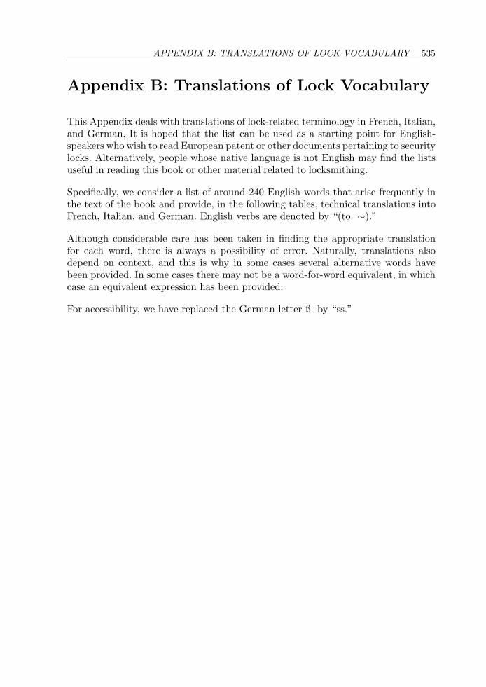
APPENDIX B: TRANSLATIONS OF LOCK VOCABULARY 535
Appendix B: Translations of Lock Vocabulary
This Appendix deals with translations of lock-related terminology in French, Italian,and German. It is hoped that the list can be used as a starting point for English-speakers who wish to read European patent or other documents pertaining to securitylocks. Alternatively, people whose native language is not English may find the listsuseful in reading this book or other material related to locksmithing.
Specifically, we consider a list of around 240 English words that arise frequently inthe text of the book and provide, in the following tables, technical translations intoFrench, Italian, and German. English verbs are denoted by “(to ∼).”
Although considerable care has been taken in finding the appropriate translationfor each word, there is always a possibility of error. Naturally, translations alsodepend on context, and this is why in some cases several alternative words havebeen provided. In some cases there may not be a word-for-word equivalent, in whichcase an equivalent expression has been provided.
For accessibility, we have replaced the German letter ß by “ss.”

536A
PPEN
DIX
B:T
RA
NSL
AT
ION
SO
FLO
CK
VO
CA
BU
LA
RY
ENGLISH FRENCH ITALIAN GERMANaccess control controle d’acces controllo dell’accesso Zugriffskontrollealign (to ∼) aligner allineare ausfluchten, abstimmen, ausrichtenall tout tutto alle(s)alloy alliage lega Legierungangle angle angolo Winkelantipicking/antitamper anti-tatage antieffrazione, antimanomissione pickgeschutztarm bras braccio Armarmored blinde blindato gepanzertassemble (to ∼) assembler, monter assemblare assemblierenattract attirer attrarre, attirare anziehenauthorized autorise autorizzato autorisiertbackward en arriere all’indietro ruckwarts, nach hintenball (bearing) bille sfera (cuscinetto a), sferetta Kugellagerbarrel stator, canon, barrillet canna, involucro Trommel, Zylinder(fuss)belly ventre ventre Bauch, Konturbevel biseau smussatura Schragebit (of lever key) panneton mappa (di chiave a leva) Bart, Schlusselbartbitting coupe, taille dentatura Stufungblacksmithing ferronnerie lavoro di maniscalco, del fabbro schmiedearbeitblade lame lama Klingeblock (to ∼) bloquer, coincer bloccare, immobilizzare blockierenbody, housing corps, logement corpo, alloggio Korper, Gehausebolt pene, verrou catenaccio, chiavistello Riegelbolt-step barbe gradino del chiavistello Riegelstufebore (to ∼) vriller, forer trapanare, forare (aus)bohren
Table B1: Translations of English lock vocabulary into French, Italian, and German.
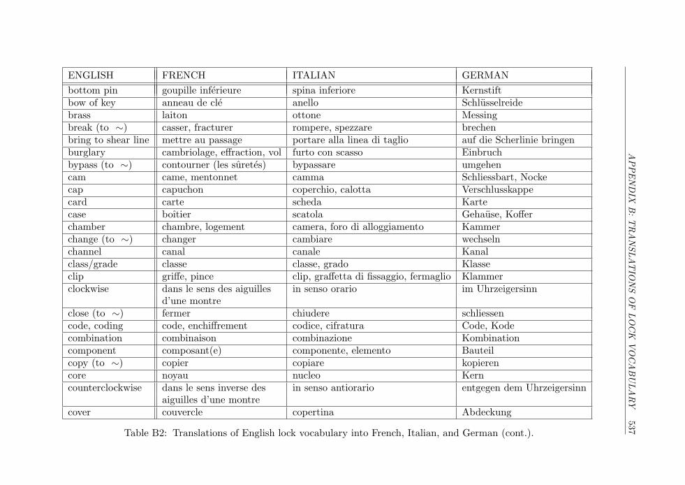
APPEN
DIX
B:T
RA
NSL
AT
ION
SO
FLO
CK
VO
CA
BU
LA
RY
537
ENGLISH FRENCH ITALIAN GERMANbottom pin goupille inferieure spina inferiore Kernstiftbow of key anneau de cle anello Schlusselreidebrass laiton ottone Messingbreak (to ∼) casser, fracturer rompere, spezzare brechenbring to shear line mettre au passage portare alla linea di taglio auf die Scherlinie bringenburglary cambriolage, effraction, vol furto con scasso Einbruchbypass (to ∼) contourner (les suretes) bypassare umgehencam came, mentonnet camma Schliessbart, Nockecap capuchon coperchio, calotta Verschlusskappecard carte scheda Kartecase boıtier scatola Gehause, Kofferchamber chambre, logement camera, foro di alloggiamento Kammerchange (to ∼) changer cambiare wechselnchannel canal canale Kanalclass/grade classe classe, grado Klasseclip griffe, pince clip, graffetta di fissaggio, fermaglio Klammerclockwise dans le sens des aiguilles in senso orario im Uhrzeigersinn
d’une montreclose (to ∼) fermer chiudere schliessencode, coding code, enchiffrement codice, cifratura Code, Kodecombination combinaison combinazione Kombinationcomponent composant(e) componente, elemento Bauteilcopy (to ∼) copier copiare kopierencore noyau nucleo Kerncounterclockwise dans le sens inverse des in senso antiorario entgegen dem Uhrzeigersinn
aiguilles d’une montrecover couvercle copertina Abdeckung
Table B2: Translations of English lock vocabulary into French, Italian, and German (cont.).
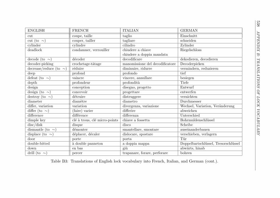
538A
PPEN
DIX
B:T
RA
NSL
AT
ION
SO
FLO
CK
VO
CA
BU
LA
RY
ENGLISH FRENCH ITALIAN GERMANcut coupe, taille taglio Einschnittcut (to ∼) couper, tailler tagliare schneidencylinder cylindre cilindro Zylinderdeadlock condamner, verrouiller chiudere a chiave Riegelschloss
chiudere a doppia mandatadecode (to ∼) decoder decodificare dekodieren, decodierendecoder-picking crochetage-tatage manomissione del decodificatore Decoderpickendecrease/reduce (to ∼) reduire diminuire, ridurre vermindern, reduzierendeep profond profondo tiefdefeat (to ∼) vaincre vincere, annullare besiegendepth profondeur profondita Tiefedesign conception disegno, progetto Entwurfdesign (to ∼) concevoir progettare entwerfendestroy (to ∼) detruire distruggere vernichtendiameter diametre diametro Durchmesserdiffer, variation variation divergenza, variazione Wechsel, Variation, Veranderungdiffer (to ∼) (faire) varier differire abweichendifference difference differenza Unterschieddimple key cle a trous, cle micro-points chiave a fossetta Bohrmuldenschlusseldisc/disk disque disco Scheibedismantle (to ∼) demonter smantellare, smontare auseinanderbauendisplace (to ∼) deplacer, decaler dislocare, spostare verschieben, verlagerndoor porte porta Turdouble-bitted a double panneton a doppia mappa Doppelbartschlussel, Tresorschlusseldown en bas giu abwarts, hinabdrill (to ∼) percer trapanare, forare, perforare bohren
Table B3: Translations of English lock vocabulary into French, Italian, and German (cont.).
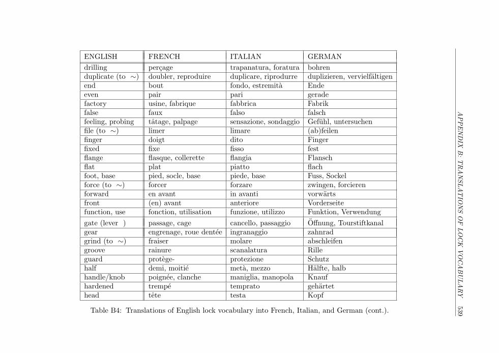
APPEN
DIX
B:T
RA
NSL
AT
ION
SO
FLO
CK
VO
CA
BU
LA
RY
539
ENGLISH FRENCH ITALIAN GERMANdrilling percage trapanatura, foratura bohrenduplicate (to ∼) doubler, reproduire duplicare, riprodurre duplizieren, vervielfaltigenend bout fondo, estremita Endeeven pair pari geradefactory usine, fabrique fabbrica Fabrikfalse faux falso falschfeeling, probing tatage, palpage sensazione, sondaggio Gefuhl, untersuchenfile (to ∼) limer limare (ab)feilenfinger doigt dito Fingerfixed fixe fisso festflange flasque, collerette flangia Flanschflat plat piatto flachfoot, base pied, socle, base piede, base Fuss, Sockelforce (to ∼) forcer forzare zwingen, forcierenforward en avant in avanti vorwartsfront (en) avant anteriore Vorderseitefunction, use fonction, utilisation funzione, utilizzo Funktion, Verwendunggate (lever ) passage, cage cancello, passaggio Offnung, Tourstiftkanalgear engrenage, roue dentee ingranaggio zahnradgrind (to ∼) fraiser molare abschleifengroove rainure scanalatura Rilleguard protege- protezione Schutzhalf demi, moitie meta, mezzo Halfte, halbhandle/knob poignee, clanche maniglia, manopola Knaufhardened trempe temprato gehartethead tete testa Kopf
Table B4: Translations of English lock vocabulary into French, Italian, and German (cont.).
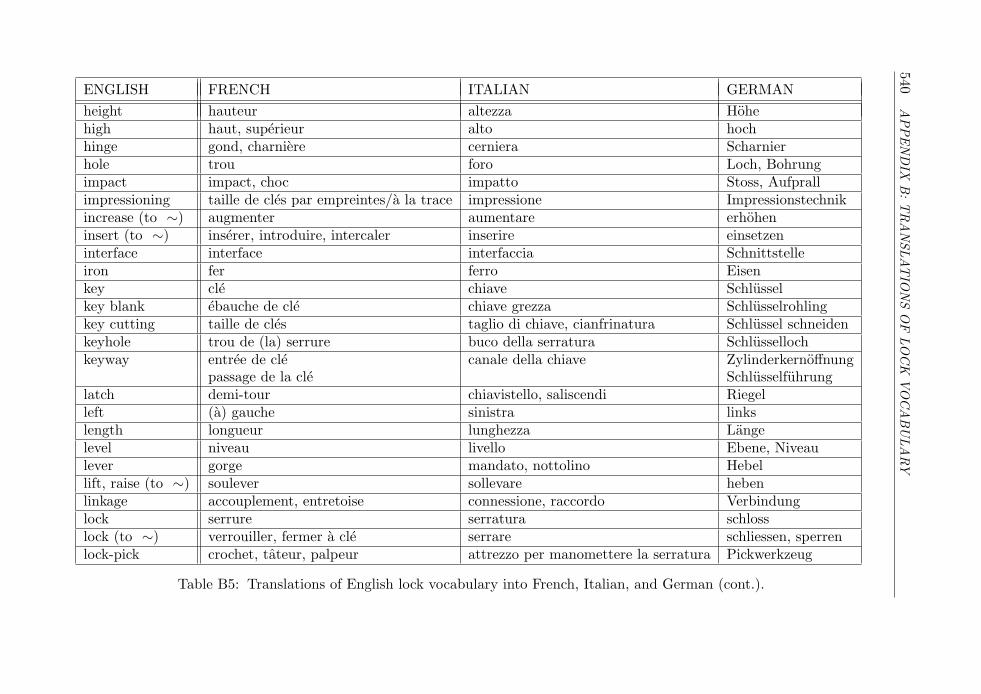
540A
PPEN
DIX
B:T
RA
NSL
AT
ION
SO
FLO
CK
VO
CA
BU
LA
RY
ENGLISH FRENCH ITALIAN GERMANheight hauteur altezza Hohehigh haut, superieur alto hochhinge gond, charniere cerniera Scharnierhole trou foro Loch, Bohrungimpact impact, choc impatto Stoss, Aufprallimpressioning taille de cles par empreintes/a la trace impressione Impressionstechnikincrease (to ∼) augmenter aumentare erhoheninsert (to ∼) inserer, introduire, intercaler inserire einsetzeninterface interface interfaccia Schnittstelleiron fer ferro Eisenkey cle chiave Schlusselkey blank ebauche de cle chiave grezza Schlusselrohlingkey cutting taille de cles taglio di chiave, cianfrinatura Schlussel schneidenkeyhole trou de (la) serrure buco della serratura Schlussellochkeyway entree de cle canale della chiave Zylinderkernoffnung
passage de la cle Schlusselfuhrunglatch demi-tour chiavistello, saliscendi Riegelleft (a) gauche sinistra linkslength longueur lunghezza Langelevel niveau livello Ebene, Niveaulever gorge mandato, nottolino Hebellift, raise (to ∼) soulever sollevare hebenlinkage accouplement, entretoise connessione, raccordo Verbindunglock serrure serratura schlosslock (to ∼) verrouiller, fermer a cle serrare schliessen, sperrenlock-pick crochet, tateur, palpeur attrezzo per manomettere la serratura Pickwerkzeug
Table B5: Translations of English lock vocabulary into French, Italian, and German (cont.).
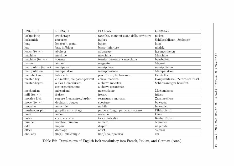
APPEN
DIX
B:T
RA
NSL
AT
ION
SO
FLO
CK
VO
CA
BU
LA
RY
541
ENGLISH FRENCH ITALIAN GERMANlockpicking crochetage raccolto, manomissione della serratura pickenlocksmith serrurier fabbro Schlusseldienst, Schlosserlong long(ue), grand lungo langlow bas, inferieur basso, inferiore niedriglower (to ∼) abaisser abbassare herunterlassenmachine machine macchina Maschinemachine (to ∼) tourner tornire, lavorare a macchina bearbeitenmagnet aimant magnete Magnetmanipulate (to ∼) manipuler manipolare manipulierenmanipulation manipulation manipolazione Manipulationmanufacturer fabricant produttore, fabbricante Herstellermaster key cle maıtre, cle passe-partout chiave maestra Hauptschlussel, Zentralschlusselmaster-keyed a cles hierarchisees a chiave maestra Schliessanlagen bestiftet
sur organigramme a chiave gerarchicamechanism mecanisme meccanismo Mechanismusmill (to ∼) fraiser fresare frasenmortice lock serrure a encastrer/larder serratura a mortasa Zusatzschlossmove (to ∼) deplacer, bouger spostare bewegenmovable amovible mobile beweglichmushroom pin goupille anti-tatage perno a fungo, perno antiscasso Pilzkopfstiftnone aucun nessuno keinenotch cran, encoche tacca, intaglio Kerbe, Nutenumber nombre, numero numero Nummerodd impair dispari ungeradeoffset decalage offset Versatzone, any un(e), quelconque uno/una, qualsiasi ein
Table B6: Translations of English lock vocabulary into French, Italian, and German (cont.).
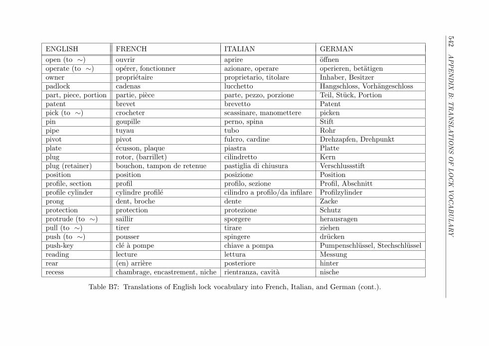
542A
PPEN
DIX
B:T
RA
NSL
AT
ION
SO
FLO
CK
VO
CA
BU
LA
RY
ENGLISH FRENCH ITALIAN GERMANopen (to ∼) ouvrir aprire offnenoperate (to ∼) operer, fonctionner azionare, operare operieren, betatigenowner proprietaire proprietario, titolare Inhaber, Besitzerpadlock cadenas lucchetto Hangschloss, Vorhangeschlosspart, piece, portion partie, piece parte, pezzo, porzione Teil, Stuck, Portionpatent brevet brevetto Patentpick (to ∼) crocheter scassinare, manomettere pickenpin goupille perno, spina Stiftpipe tuyau tubo Rohrpivot pivot fulcro, cardine Drehzapfen, Drehpunktplate ecusson, plaque piastra Platteplug rotor, (barrillet) cilindretto Kernplug (retainer) bouchon, tampon de retenue pastiglia di chiusura Verschlussstiftposition position posizione Positionprofile, section profil profilo, sezione Profil, Abschnittprofile cylinder cylindre profile cilindro a profilo/da infilare Profilzylinderprong dent, broche dente Zackeprotection protection protezione Schutzprotrude (to ∼) saillir sporgere herausragenpull (to ∼) tirer tirare ziehenpush (to ∼) pousser spingere druckenpush-key cle a pompe chiave a pompa Pumpenschlussel, Stechschlusselreading lecture lettura Messungrear (en) arriere posteriore hinterrecess chambrage, encastrement, niche rientranza, cavita nische
Table B7: Translations of English lock vocabulary into French, Italian, and German (cont.).
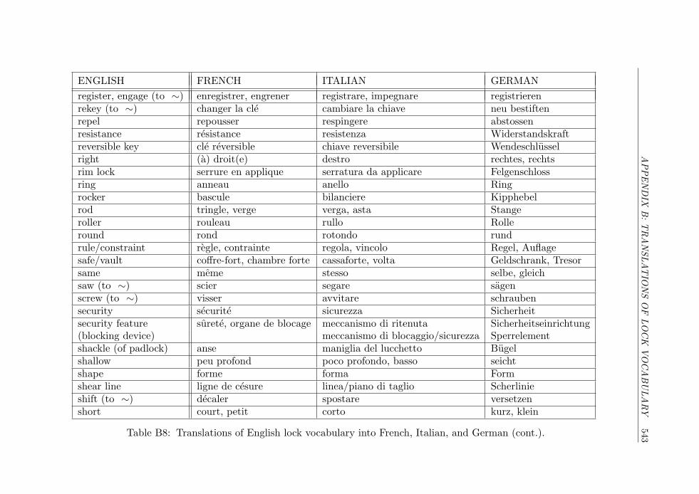
APPEN
DIX
B:T
RA
NSL
AT
ION
SO
FLO
CK
VO
CA
BU
LA
RY
543
ENGLISH FRENCH ITALIAN GERMANregister, engage (to ∼) enregistrer, engrener registrare, impegnare registrierenrekey (to ∼) changer la cle cambiare la chiave neu bestiftenrepel repousser respingere abstossenresistance resistance resistenza Widerstandskraftreversible key cle reversible chiave reversibile Wendeschlusselright (a) droit(e) destro rechtes, rechtsrim lock serrure en applique serratura da applicare Felgenschlossring anneau anello Ringrocker bascule bilanciere Kipphebelrod tringle, verge verga, asta Stangeroller rouleau rullo Rolleround rond rotondo rundrule/constraint regle, contrainte regola, vincolo Regel, Auflagesafe/vault coffre-fort, chambre forte cassaforte, volta Geldschrank, Tresorsame meme stesso selbe, gleichsaw (to ∼) scier segare sagenscrew (to ∼) visser avvitare schraubensecurity securite sicurezza Sicherheitsecurity feature surete, organe de blocage meccanismo di ritenuta Sicherheitseinrichtung(blocking device) meccanismo di blocaggio/sicurezza Sperrelementshackle (of padlock) anse maniglia del lucchetto Bugelshallow peu profond poco profondo, basso seichtshape forme forma Formshear line ligne de cesure linea/piano di taglio Scherlinieshift (to ∼) decaler spostare versetzenshort court, petit corto kurz, klein
Table B8: Translations of English lock vocabulary into French, Italian, and German (cont.).
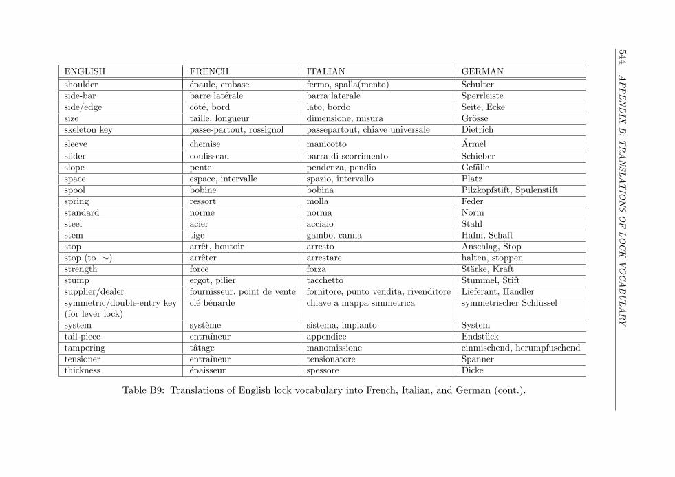
544A
PPEN
DIX
B:T
RA
NSL
AT
ION
SO
FLO
CK
VO
CA
BU
LA
RY
ENGLISH FRENCH ITALIAN GERMANshoulder epaule, embase fermo, spalla(mento) Schulterside-bar barre laterale barra laterale Sperrleisteside/edge cote, bord lato, bordo Seite, Eckesize taille, longueur dimensione, misura Grosseskeleton key passe-partout, rossignol passepartout, chiave universale Dietrich
sleeve chemise manicotto Armelslider coulisseau barra di scorrimento Schieberslope pente pendenza, pendio Gefallespace espace, intervalle spazio, intervallo Platzspool bobine bobina Pilzkopfstift, Spulenstiftspring ressort molla Federstandard norme norma Normsteel acier acciaio Stahlstem tige gambo, canna Halm, Schaftstop arret, boutoir arresto Anschlag, Stopstop (to ∼) arreter arrestare halten, stoppenstrength force forza Starke, Kraftstump ergot, pilier tacchetto Stummel, Stiftsupplier/dealer fournisseur, point de vente fornitore, punto vendita, rivenditore Lieferant, Handlersymmetric/double-entry key cle benarde chiave a mappa simmetrica symmetrischer Schlussel(for lever lock)system systeme sistema, impianto Systemtail-piece entraıneur appendice Endstucktampering tatage manomissione einmischend, herumpfuschendtensioner entraıneur tensionatore Spannerthickness epaisseur spessore Dicke
Table B9: Translations of English lock vocabulary into French, Italian, and German (cont.).
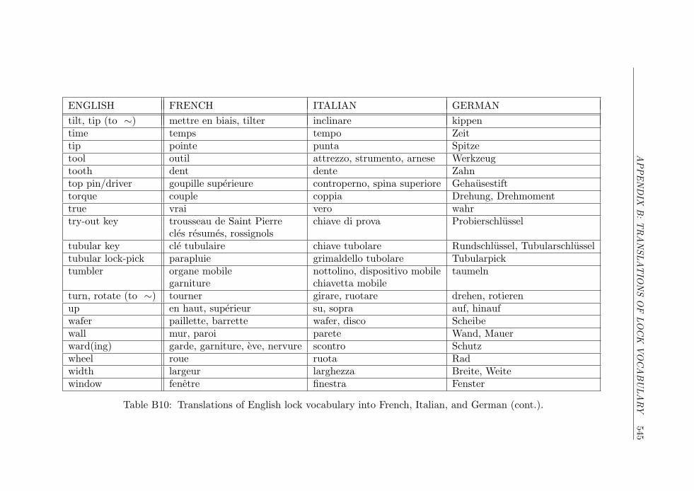
APPEN
DIX
B:T
RA
NSL
AT
ION
SO
FLO
CK
VO
CA
BU
LA
RY
545
ENGLISH FRENCH ITALIAN GERMANtilt, tip (to ∼) mettre en biais, tilter inclinare kippentime temps tempo Zeittip pointe punta Spitzetool outil attrezzo, strumento, arnese Werkzeugtooth dent dente Zahntop pin/driver goupille superieure controperno, spina superiore Gehausestifttorque couple coppia Drehung, Drehmomenttrue vrai vero wahrtry-out key trousseau de Saint Pierre chiave di prova Probierschlussel
cles resumes, rossignolstubular key cle tubulaire chiave tubolare Rundschlussel, Tubularschlusseltubular lock-pick parapluie grimaldello tubolare Tubularpicktumbler organe mobile nottolino, dispositivo mobile taumeln
garniture chiavetta mobileturn, rotate (to ∼) tourner girare, ruotare drehen, rotierenup en haut, superieur su, sopra auf, hinaufwafer paillette, barrette wafer, disco Scheibewall mur, paroi parete Wand, Mauerward(ing) garde, garniture, eve, nervure scontro Schutzwheel roue ruota Radwidth largeur larghezza Breite, Weitewindow fenetre finestra Fenster
Table B10: Translations of English lock vocabulary into French, Italian, and German (cont.).
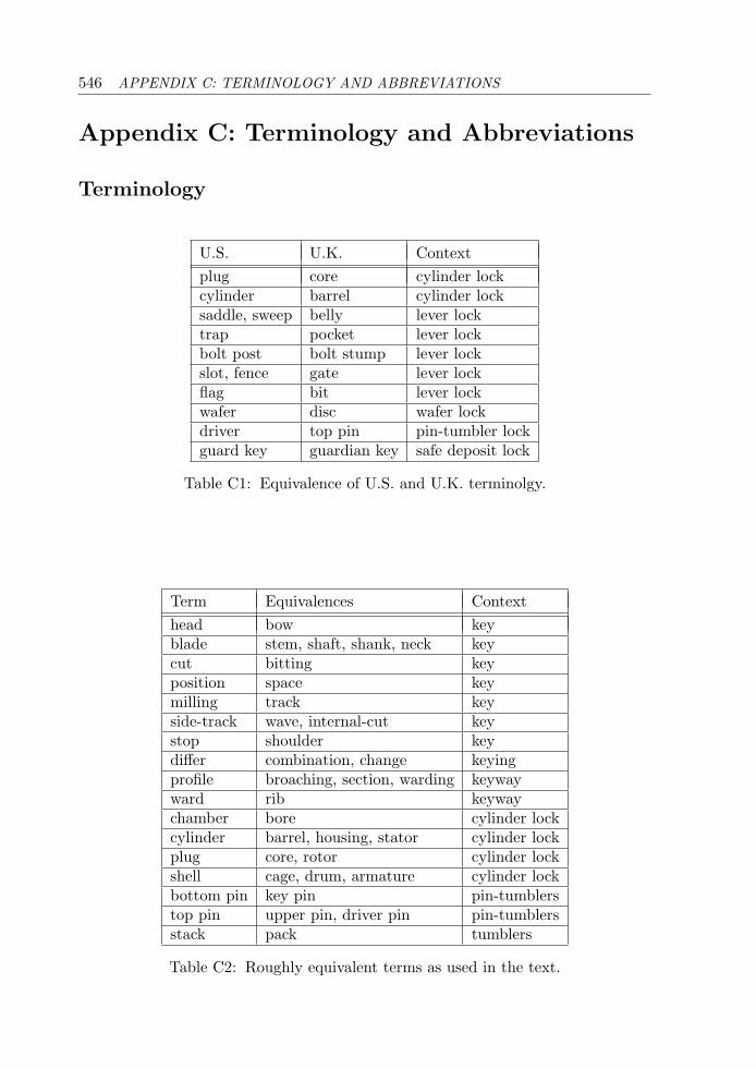
546 APPENDIX C: TERMINOLOGY AND ABBREVIATIONS
Appendix C: Terminology and Abbreviations
Terminology
U.S. U.K. Contextplug core cylinder lockcylinder barrel cylinder locksaddle, sweep belly lever locktrap pocket lever lockbolt post bolt stump lever lockslot, fence gate lever lockflag bit lever lockwafer disc wafer lockdriver top pin pin-tumbler lockguard key guardian key safe deposit lock
Table C1: Equivalence of U.S. and U.K. terminolgy.
Term Equivalences Contexthead bow keyblade stem, shaft, shank, neck keycut bitting keyposition space keymilling track keyside-track wave, internal-cut keystop shoulder keydiffer combination, change keyingprofile broaching, section, warding keywayward rib keywaychamber bore cylinder lockcylinder barrel, housing, stator cylinder lockplug core, rotor cylinder lockshell cage, drum, armature cylinder lockbottom pin key pin pin-tumblerstop pin upper pin, driver pin pin-tumblersstack pack tumblers
Table C2: Roughly equivalent terms as used in the text.
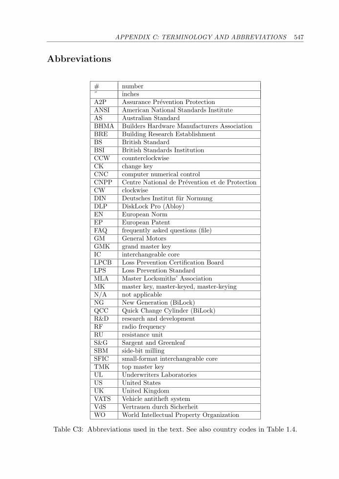
APPENDIX C: TERMINOLOGY AND ABBREVIATIONS 547
Abbreviations
# number˝ inchesA2P Assurance Prevention ProtectionANSI American National Standards InstituteAS Australian StandardBHMA Builders Hardware Manufacturers AssociationBRE Building Research EstablishmentBS British StandardBSI British Standards InstitutionCCW counterclockwiseCK change keyCNC computer numerical controlCNPP Centre National de Prevention et de ProtectionCW clockwiseDIN Deutsches Institut fur NormungDLP DiskLock Pro (Abloy)EN European NormEP European PatentFAQ frequently asked questions (file)GM General MotorsGMK grand master keyIC interchangeable coreLPCB Loss Prevention Certification BoardLPS Loss Prevention StandardMLA Master Locksmiths’ AssociationMK master key, master-keyed, master-keyingN/A not applicableNG New Generation (BiLock)QCC Quick Change Cylinder (BiLock)R&D research and developmentRF radio frequencyRU resistance unitS&G Sargent and GreenleafSBM side-bit millingSFIC small-format interchangeable coreTMK top master keyUL Underwriters LaboratoriesUS United StatesUK United KingdomVATS Vehicle antitheft systemVdS Vertrauen durch SicherheitWO World Intellectual Property Organization
Table C3: Abbreviations used in the text. See also country codes in Table 1.4.
548 APPENDIX D: LOCK PATENTS
Appendix D: Lock Patents
This Appendix summarizes the patent documents that have been used or cited inthe text. It is in no way intended to be exhaustive in terms of the available public-domain information. Patents have been classed as relating to either magnetic ornonmagnetic (mechanical, key-operated) locks. For each patent, we give the filingdate, country of filing, serial number, author and/or assignee’s company, relevance,and a one-line description of the content of the patent. Country codes are defined inTable 1.4 in Chapter 1. Relevance (for nonmagnetic lock patents only) is as definedin the table caption.
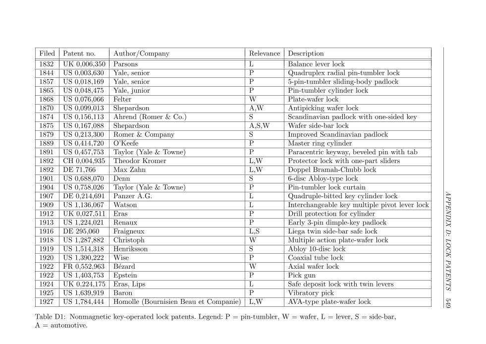
APPEN
DIX
D:LO
CK
PAT
EN
TS
549
Filed Patent no. Author/Company Relevance Description1832 UK 0,006,350 Parsons L Balance lever lock1844 US 0,003,630 Yale, senior P Quadruplex radial pin-tumbler lock1857 US 0,018,169 Yale, senior P 5-pin-tumbler sliding-body padlock1865 US 0,048,475 Yale, junior P Pin-tumbler cylinder lock1868 US 0,076,066 Felter W Plate-wafer lock1870 US 0,099,013 Shepardson A,W Antipicking wafer lock1874 US 0,156,113 Ahrend (Romer & Co.) S Scandinavian padlock with one-sided key1875 US 0,167,088 Shepardson A,S,W Wafer side-bar lock1879 US 0,213,300 Romer & Company S Improved Scandinavian padlock1889 US 0,414,720 O’Keefe P Master ring cylinder1891 US 0,457,753 Taylor (Yale & Towne) P Paracentric keyway, beveled pin with tab1892 CH 0,004,935 Theodor Kromer L,W Protector lock with one-part sliders1892 DE 71,766 Max Zahn L,W Doppel Bramah-Chubb lock1901 US 0,688,070 Denn S 6-disc Abloy-type lock1904 US 0,758,026 Taylor (Yale & Towne) P Pin-tumbler lock curtain1907 DE 0,214,691 Panzer A.G. L Quadruple-bitted key cylinder lock1909 US 1,136,067 Watson L Interchangeable key multiple pivot lever lock1912 UK 0,027,511 Eras P Drill protection for cylinder1913 US 1,224,021 Renaux P Early 3-pin dimple-key padlock1916 DE 295,060 Fraigneux L,S Liega twin side-bar safe lock1918 US 1,287,882 Christoph W Multiple action plate-wafer lock1919 US 1,514,318 Henriksson S Abloy 10-disc lock1920 US 1,390,222 Wise P Coaxial tube lock1922 FR 0,552,963 Bezard W Axial wafer lock1922 US 1,403,753 Epstein P Pick gun1924 UK 0,224,175 Eras, Lips L Safe deposit lock with twin levers1925 US 1,639,919 Baron P Vibratory pick1927 US 1,784,444 Homolle (Bournisien Beau et Companie) L,W AVA-type plate-wafer lock
Table D1: Nonmagnetic key-operated lock patents. Legend: P = pin-tumbler, W = wafer, L = lever, S = side-bar,A = automotive.
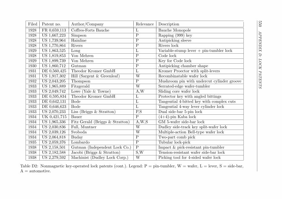
550A
PPEN
DIX
D:LO
CK
PAT
EN
TS
Filed Patent no. Author/Company Relevance Description1928 FR 0,659,113 Coffres-Forts Bauche L Bauche Monopole1928 US 1,667,223 Simpson P Rapping (999) key1928 US 1,739,964 Hainline P Antipicking sleeve1928 US 1,770,864 Rivers P Rivers lock1929 US 1,863,525 Long L Variable-stump lever + pin-tumbler lock1928 US 1,819,853 Von Mehren P Code lock1929 US 1,899,739 Von Mehren P Key for Code lock1930 US 1,860,712 Gutman P Antipicking chamber shape1931 DE 0,560,425 Theodor Kromer GmbH L Kromer Proector with split-levers1931 US 1,917,302 Hill (Sargent & Greenleaf) W Recombinatable wafer lock1932 US 2,043,205 Thompson P Mushroom pin with undercut cylinder groove1933 US 1,965,889 Fitzgerald W Serrated-edge wafer-tumbler1933 US 2,049,742 Lowe (Yale & Towne) A,W Sliding core wafer lock1933 DE 0,595,834 Theodor Kromer GmbH L Protector key with angled bittings1933 DE 0,642,131 Bode L Tangential 4-bitted key with complex cuts1933 DE 0,646,623 Bode L Tangential 4-way lever cylinder lock1933 US 2,070,233 Liss (Briggs & Stratton) P,S Dual side-bar 5-pin lock1934 UK 0,421,715 Bauer P (4+4)-pin Kaba lock1934 US 1,965,336 Fitz Gerald (Briggs & Stratton) A,W,S GM 5-wafer side-bar lock1934 US 2,030,836 Full, Muntner W Dudley side-track key split-wafer lock1934 US 2,039,126 Svoboda W Multiple-action Bell-type wafer lock1934 US 2,064,818 Buday P Two-part comb pick1935 US 2,059,376 Lombardo P Tubular lock-pick1938 US 2,158,501 Gutman (Independent Lock Co.) P Impact & pick-resistant pin-tumbler1938 US 2,182,588 Jacobi (Briggs & Stratton) S,W Tension-resistant wafer side-bar lock1938 US 2,279,592 Machinist (Dudley Lock Corp.) W Picking tool for 4-sided wafer lock
Table D2: Nonmagnetic key-operated lock patents (cont.). Legend: P = pin-tumbler, W = wafer, L = lever, S = side-bar,A = automotive.

APPEN
DIX
D:LO
CK
PAT
EN
TS
551
Filed Patent no. Author/Company Relevance Description1938 US 2,424,514 Sterner P Improved version of Code lock1939 US 2,309,677 Segal P Pick gun1940 US 2,283,489 Crousore P Grooved upper and lower pins1948 US 2,578,211 Spain (Yale & Towne) S Spring-biased Abloy disc lock1949 UK 0,661,501 Butter L Edge-gated lever lock1950 UK 0,678,123 (Fichet-Beau & Cie) W,S Fichet 484 10-lever twin side-bar lock1951 DE 0,911,220 Bode-Panzer L CAWI lock1953 UK 0,737,547 Saarento L,W AVA 7-slider lock1954 DE 1,027,552 Sellin & Munzer L Protector with curtain disc tabs1955 DE 1,061,226 Sellin (Kromer) L Recessed cuts in Protector key bit1955 US 2,763,027 Tampke P,W Comb-foil impressioning tool1959 UK 0,940,778 Pearson P Cruciform locks1959 US 3,035,433 Testa S,W Dudley wafer lock with side-bar1963 UK 1,030,921 Stanton, Brett L,W Chubb AVA 10-slider lock1963 US 3,181,320 Bauer P Deadlocking antipicking cylinder1963 US 3,206,958 Best P Interchangeable-core cylinder1963 US 3,234,768 Russell, Jennie, Armstrong P Construction-keyed cylinder1963 US 3,251,206 Gruber P Tubular lock-pick1963 US 3,263,461 Tartaglia W Recombinatable Bell lock1964 US 3,237,436 Williams W Supra Title 6-slider lock1964 FR 1,425,311 (Fichet) S,W Fichet-Bauche 666 7-wafer side-bar lock1964 US 3,264,852 Gysin W SEA four-track wafer lock1964 US 3,509,749 Regan, Arzig (Duncan Ind.) W Recombinatable Bell lock1965 DE 1,553,294 Bauer P Kaba 201965 US 3,267,706 Kerr P Tamper-proof axial cylinder1965 US 3,393,542 Crepinsek P 4 inline DOM-type cylinder
Table D3: Nonmagnetic key-operated lock patents (cont.). Legend: P = pin-tumbler, W = wafer, L = lever, S = side-bar,A = automotive.
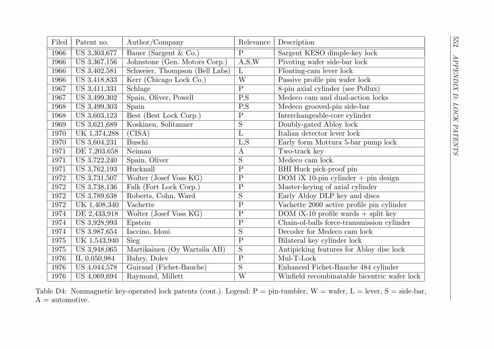
552A
PPEN
DIX
D:LO
CK
PAT
EN
TS
Filed Patent no. Author/Company Relevance Description1966 US 3,303,677 Bauer (Sargent & Co.) P Sargent KESO dimple-key lock1966 US 3,367,156 Johnstone (Gen. Motors Corp.) A,S,W Pivoting wafer side-bar lock1966 US 3,402,581 Schweier, Thompson (Bell Labs) L Floating-cam lever lock1966 US 3,418,833 Kerr (Chicago Lock Co.) W Passive profile pin wafer lock1967 US 3,411,331 Schlage P 8-pin axial cylinder (see Pollux)1967 US 3,499,302 Spain, Oliver, Powell P,S Medeco cam and dual-action locks1968 US 3,499,303 Spain P,S Medeco grooved-pin side-bar1968 US 3,603,123 Best (Best Lock Corp.) P Interchangeable-core cylinder1969 US 3,621,689 Koskinen, Solitanner S Doubly-gated Abloy lock1970 UK 1,374,288 (CISA) L Italian detector lever lock1970 US 3,604,231 Buschi L,S Early form Mottura 5-bar pump lock1971 DE 7,203,658 Neiman A Two-track key1971 US 3,722,240 Spain, Oliver S Medeco cam lock1971 US 3,762,193 Hucknall P BHI Huck pick-proof pin1972 US 3,731,507 Wolter (Josef Voss KG) P DOM iX 10-pin cylinder + pin design1972 US 3,738,136 Falk (Fort Lock Corp.) P Master-keying of axial cylinder1972 US 3,789,638 Roberts, Cohn, Ward S Early Abloy DLP key and discs1972 UK 1,408,340 Vachette P Vachette 2000 active profile pin cylinder1974 DE 2,433,918 Wolter (Josef Voss KG) P DOM iX-10 profile wards + split key1974 US 3,928,993 Epstein P Chain-of-balls force-transmission cylinder1974 US 3,987,654 Iaccino, Idoni S Decoder for Medeco cam lock1975 UK 1,543,940 Sieg P Bilateral key cylinder lock1975 US 3,948,065 Martikainen (Oy Wartsila AB) S Antipicking features for Abloy disc lock1976 IL 0,050,984 Bahry, Dolev P Mul-T-Lock1976 US 4,044,578 Guiraud (Fichet-Bauche) S Enhanced Fichet-Bauche 484 cylinder1976 US 4,069,694 Raymond, Millett W Winfield recombinatable bicentric wafer lock
Table D4: Nonmagnetic key-operated lock patents (cont.). Legend: P = pin-tumbler, W = wafer, L = lever, S = side-bar,A = automotive.
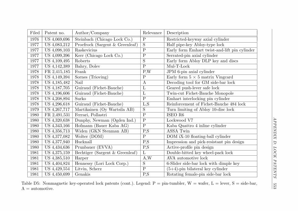
APPEN
DIX
D:LO
CK
PAT
EN
TS
553
Filed Patent no. Author/Company Relevance Description1976 US 4,069,696 Steinbach (Chicago Lock Co.) P Restricted-keyway axial cylinder1977 US 4,083,212 Proefrock (Sargent & Greenleaf) S Half pipe-key Abloy-type lock1977 US 4,098,103 Raskevicius P Early form Emhart twist-and-lift pin cylinder1977 US 4,099,396 Kerr (Chicago Lock Co.) P Serrated-pin axial cylinder1977 US 4,109,495 Roberts S Early form Abloy DLP key and discs1977 US 4,142,389 Bahry, Dolev P Mul-T-Lock1978 FR 2,415,185 Frank P,W JPM 6-pin axial cylinder1978 US 4,149,394 Sornes (Trioving) P Early form 5 × 5 matrix Vingcard1978 US 4,185,482 Nail A Decoding tool for GM side-bar lock1978 US 4,187,705 Guiraud (Fichet-Bauche) L Geared push-lever safe lock1978 US 4,196,606 Guiraud (Fichet-Bauche) L Twin-cut Fichet-Bauche Monopole1978 US 4,208,894 Surko P Emhart interlocking pin cylinder1978 US 4,296,618 Guiraud (Fichet-Bauche) L,S Reinforcement of Fichet-Bauche 484 lock1979 US 4,267,717 Martikainen (Oy Wartsila AB) S Turn limiting of Abloy 10-disc lock1980 FR 2,491,531 Ferrari, Pollastri P ISEO R61980 US 4,320,638 Dunphy, Newman (Ogden Ind.) P Lockwood V71980 US 4,343,166 Hofmann (Bauer Kaba AG) P Kaba Quattro 4 inline cylinder1980 US 4,356,713 Widen (GKN Stenman AB) P,S ASSA Twin1980 US 4,377,082 Wolter (DOM) P DOM iX-10 floating-ball cylinder1980 US 4,377,940 Hucknall P,S Impression and pick-resistant pin design1980 US 4,434,636 Prunbauer (EVVA) P,S Active-profile pin design1981 US 4,375,159 Bechtiger (Sargent & Greenleaf) L Double-bitted key wheel-pack lock1981 US 4,385,510 Harper A,W AVA automotive lock1981 US 4,404,824 Hennessy (Lori Lock Corp.) S 6-Slider side-bar lock with dimple key1981 US 4,429,554 Litvin, Scherz P (5+4)-pin bilateral key cylinder1981 US 4,450,699 Genakis P,S Rotating female-pin side-bar lock
Table D5: Nonmagnetic key-operated lock patents (cont.). Legend: P = pin-tumbler, W = wafer, L = lever, S = side-bar,A = automotive.
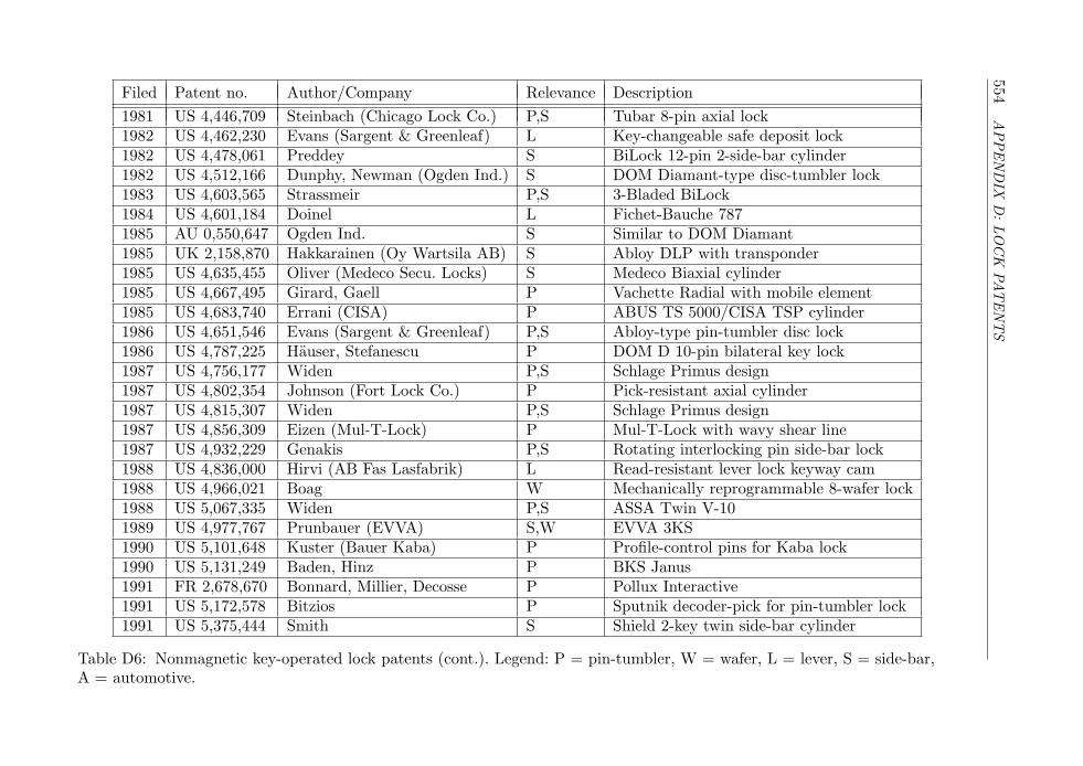
554A
PPEN
DIX
D:LO
CK
PAT
EN
TS
Filed Patent no. Author/Company Relevance Description1981 US 4,446,709 Steinbach (Chicago Lock Co.) P,S Tubar 8-pin axial lock1982 US 4,462,230 Evans (Sargent & Greenleaf) L Key-changeable safe deposit lock1982 US 4,478,061 Preddey S BiLock 12-pin 2-side-bar cylinder1982 US 4,512,166 Dunphy, Newman (Ogden Ind.) S DOM Diamant-type disc-tumbler lock1983 US 4,603,565 Strassmeir P,S 3-Bladed BiLock1984 US 4,601,184 Doinel L Fichet-Bauche 7871985 AU 0,550,647 Ogden Ind. S Similar to DOM Diamant1985 UK 2,158,870 Hakkarainen (Oy Wartsila AB) S Abloy DLP with transponder1985 US 4,635,455 Oliver (Medeco Secu. Locks) S Medeco Biaxial cylinder1985 US 4,667,495 Girard, Gaell P Vachette Radial with mobile element1985 US 4,683,740 Errani (CISA) P ABUS TS 5000/CISA TSP cylinder1986 US 4,651,546 Evans (Sargent & Greenleaf) P,S Abloy-type pin-tumbler disc lock1986 US 4,787,225 Hauser, Stefanescu P DOM D 10-pin bilateral key lock1987 US 4,756,177 Widen P,S Schlage Primus design1987 US 4,802,354 Johnson (Fort Lock Co.) P Pick-resistant axial cylinder1987 US 4,815,307 Widen P,S Schlage Primus design1987 US 4,856,309 Eizen (Mul-T-Lock) P Mul-T-Lock with wavy shear line1987 US 4,932,229 Genakis P,S Rotating interlocking pin side-bar lock1988 US 4,836,000 Hirvi (AB Fas Lasfabrik) L Read-resistant lever lock keyway cam1988 US 4,966,021 Boag W Mechanically reprogrammable 8-wafer lock1988 US 5,067,335 Widen P,S ASSA Twin V-101989 US 4,977,767 Prunbauer (EVVA) S,W EVVA 3KS1990 US 5,101,648 Kuster (Bauer Kaba) P Profile-control pins for Kaba lock1990 US 5,131,249 Baden, Hinz P BKS Janus1991 FR 2,678,670 Bonnard, Millier, Decosse P Pollux Interactive1991 US 5,172,578 Bitzios P Sputnik decoder-pick for pin-tumbler lock1991 US 5,375,444 Smith S Shield 2-key twin side-bar cylinder
Table D6: Nonmagnetic key-operated lock patents (cont.). Legend: P = pin-tumbler, W = wafer, L = lever, S = side-bar,A = automotive.
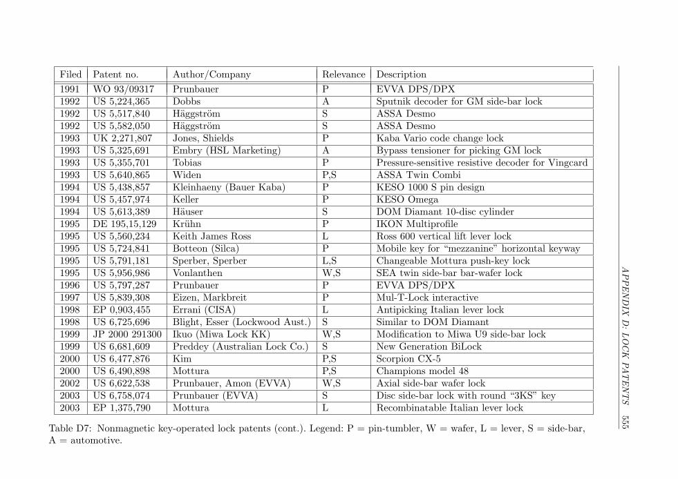
APPEN
DIX
D:LO
CK
PAT
EN
TS
555
Filed Patent no. Author/Company Relevance Description1991 WO 93/09317 Prunbauer P EVVA DPS/DPX1992 US 5,224,365 Dobbs A Sputnik decoder for GM side-bar lock1992 US 5,517,840 Haggstrom S ASSA Desmo1992 US 5,582,050 Haggstrom S ASSA Desmo1993 UK 2,271,807 Jones, Shields P Kaba Vario code change lock1993 US 5,325,691 Embry (HSL Marketing) A Bypass tensioner for picking GM lock1993 US 5,355,701 Tobias P Pressure-sensitive resistive decoder for Vingcard1993 US 5,640,865 Widen P,S ASSA Twin Combi1994 US 5,438,857 Kleinhaeny (Bauer Kaba) P KESO 1000 S pin design1994 US 5,457,974 Keller P KESO Omega1994 US 5,613,389 Hauser S DOM Diamant 10-disc cylinder1995 DE 195,15,129 Kruhn P IKON Multiprofile1995 US 5,560,234 Keith James Ross L Ross 600 vertical lift lever lock1995 US 5,724,841 Botteon (Silca) P Mobile key for “mezzanine” horizontal keyway1995 US 5,791,181 Sperber, Sperber L,S Changeable Mottura push-key lock1995 US 5,956,986 Vonlanthen W,S SEA twin side-bar bar-wafer lock1996 US 5,797,287 Prunbauer P EVVA DPS/DPX1997 US 5,839,308 Eizen, Markbreit P Mul-T-Lock interactive1998 EP 0,903,455 Errani (CISA) L Antipicking Italian lever lock1998 US 6,725,696 Blight, Esser (Lockwood Aust.) S Similar to DOM Diamant1999 JP 2000 291300 Ikuo (Miwa Lock KK) W,S Modification to Miwa U9 side-bar lock1999 US 6,681,609 Preddey (Australian Lock Co.) S New Generation BiLock2000 US 6,477,876 Kim P,S Scorpion CX-52000 US 6,490,898 Mottura P,S Champions model 482002 US 6,622,538 Prunbauer, Amon (EVVA) W,S Axial side-bar wafer lock2003 US 6,758,074 Prunbauer (EVVA) S Disc side-bar lock with round “3KS” key2003 EP 1,375,790 Mottura L Recombinatable Italian lever lock
Table D7: Nonmagnetic key-operated lock patents (cont.). Legend: P = pin-tumbler, W = wafer, L = lever, S = side-bar,A = automotive.
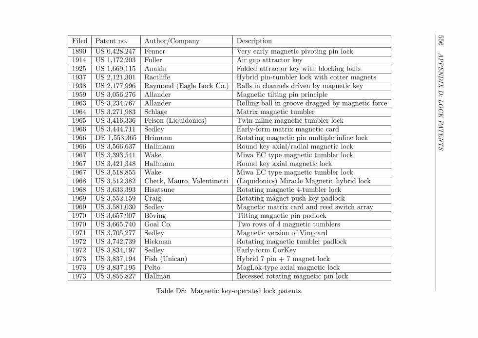
556A
PPEN
DIX
D:LO
CK
PAT
EN
TS
Filed Patent no. Author/Company Description1890 US 0,428,247 Fenner Very early magnetic pivoting pin lock1914 US 1,172,203 Fuller Air gap attractor key1925 US 1,669,115 Anakin Folded attractor key with blocking balls1937 US 2,121,301 Ractliffe Hybrid pin-tumbler lock with cotter magnets1938 US 2,177,996 Raymond (Eagle Lock Co.) Balls in channels driven by magnetic key1959 US 3,056,276 Allander Magnetic tilting pin principle1963 US 3,234,767 Allander Rolling ball in groove dragged by magnetic force1964 US 3,271,983 Schlage Matrix magnetic tumbler1965 US 3,416,336 Felson (Liquidonics) Twin inline magnetic tumbler lock1966 US 3,444,711 Sedley Early-form matrix magnetic card1966 DE 1,553,365 Heimann Rotating magnetic pin multiple inline lock1966 US 3,566,637 Hallmann Round key axial/radial magnetic lock1967 US 3,393,541 Wake Miwa EC type magnetic tumbler lock1967 US 3,421,348 Hallmann Round key axial magnetic lock1967 US 3,518,855 Wake Miwa EC type magnetic tumbler lock1968 US 3,512,382 Check, Mauro, Valentinetti (Liquidonics) Miracle Magnetic hybrid lock1968 US 3,633,393 Hisatsune Rotating magnetic 4-tumbler lock1969 US 3,552,159 Craig Rotating magnet push-key padlock1969 US 3,581,030 Sedley Magnetic matrix card and reed switch array1970 US 3,657,907 Boving Tilting magnetic pin padlock1970 US 3,665,740 Goal Co. Two rows of 4 magnetic tumblers1971 US 3,705,277 Sedley Magnetic version of Vingcard1972 US 3,742,739 Hickman Rotating magnetic tumbler padlock1972 US 3,834,197 Sedley Early-form CorKey1973 US 3,837,194 Fish (Unican) Hybrid 7 pin + 7 magnet lock1973 US 3,837,195 Pelto MagLok-type axial magnetic lock1973 US 3,855,827 Hallman Recessed rotating magnetic pin lock
Table D8: Magnetic key-operated lock patents.
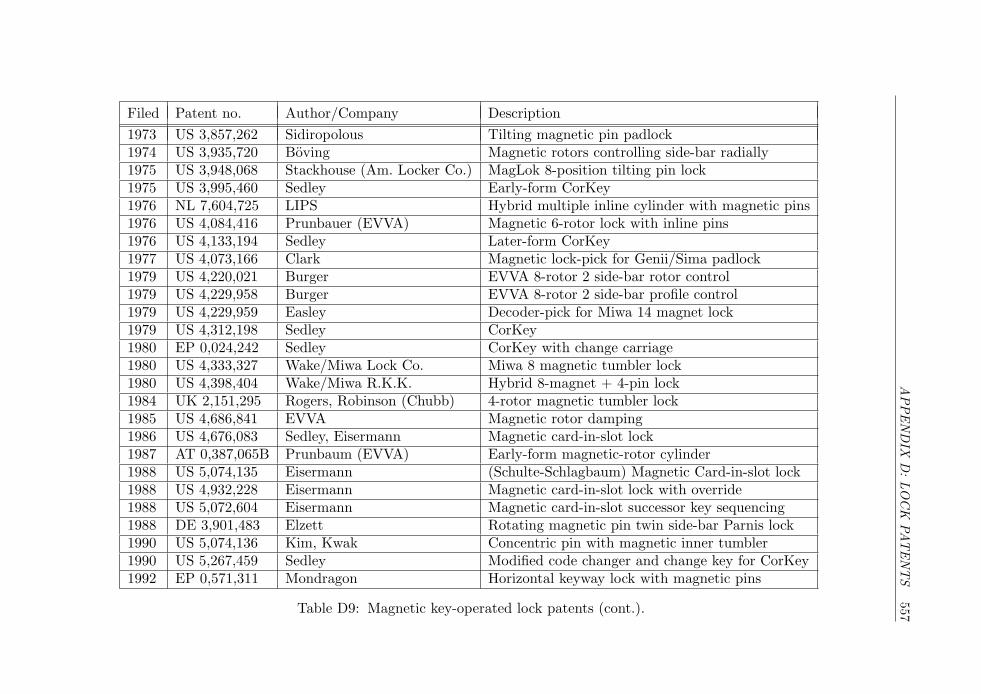
APPEN
DIX
D:LO
CK
PAT
EN
TS
557
Filed Patent no. Author/Company Description1973 US 3,857,262 Sidiropolous Tilting magnetic pin padlock1974 US 3,935,720 Boving Magnetic rotors controlling side-bar radially1975 US 3,948,068 Stackhouse (Am. Locker Co.) MagLok 8-position tilting pin lock1975 US 3,995,460 Sedley Early-form CorKey1976 NL 7,604,725 LIPS Hybrid multiple inline cylinder with magnetic pins1976 US 4,084,416 Prunbauer (EVVA) Magnetic 6-rotor lock with inline pins1976 US 4,133,194 Sedley Later-form CorKey1977 US 4,073,166 Clark Magnetic lock-pick for Genii/Sima padlock1979 US 4,220,021 Burger EVVA 8-rotor 2 side-bar rotor control1979 US 4,229,958 Burger EVVA 8-rotor 2 side-bar profile control1979 US 4,229,959 Easley Decoder-pick for Miwa 14 magnet lock1979 US 4,312,198 Sedley CorKey1980 EP 0,024,242 Sedley CorKey with change carriage1980 US 4,333,327 Wake/Miwa Lock Co. Miwa 8 magnetic tumbler lock1980 US 4,398,404 Wake/Miwa R.K.K. Hybrid 8-magnet + 4-pin lock1984 UK 2,151,295 Rogers, Robinson (Chubb) 4-rotor magnetic tumbler lock1985 US 4,686,841 EVVA Magnetic rotor damping1986 US 4,676,083 Sedley, Eisermann Magnetic card-in-slot lock1987 AT 0,387,065B Prunbaum (EVVA) Early-form magnetic-rotor cylinder1988 US 5,074,135 Eisermann (Schulte-Schlagbaum) Magnetic Card-in-slot lock1988 US 4,932,228 Eisermann Magnetic card-in-slot lock with override1988 US 5,072,604 Eisermann Magnetic card-in-slot successor key sequencing1988 DE 3,901,483 Elzett Rotating magnetic pin twin side-bar Parnis lock1990 US 5,074,136 Kim, Kwak Concentric pin with magnetic inner tumbler1990 US 5,267,459 Sedley Modified code changer and change key for CorKey1992 EP 0,571,311 Mondragon Horizontal keyway lock with magnetic pins
Table D9: Magnetic key-operated lock patents (cont.).
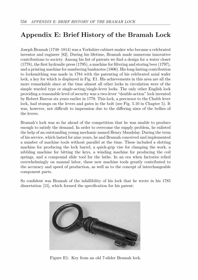
558 APPENDIX E: BRIEF HISTORY OF THE BRAMAH LOCK
Appendix E: Brief History of the Bramah Lock
Joseph Bramah (1748–1814) was a Yorkshire cabinet-maker who became a celebratedinventor and engineer [82]. During his lifetime, Bramah made numerous innovativecontributions to society. Among his list of patents we find a design for a water closet(1778), the first hydraulic press (1795), a machine for filtering and storing beer (1797),and a printing machine for numbering banknotes (1806). His long-lasting contributionto locksmithing was made in 1784 with the patenting of his celebrated axial waferlock, a key for which is displayed in Fig. E1. His achievements in this area are all themore remarkable since at the time almost all other locks in circulation were of thesimple warded type or single-acting/single-lever locks. The only other English lockproviding a reasonable level of security was a two-lever “double-action” lock inventedby Robert Barron six years earlier in 1778. This lock, a precursor to the Chubb leverlock, had stumps on the levers and gates in the bolt (see Fig. 5.10 in Chapter 5). Itwas, however, not difficult to impression due to the differing sizes of the bellies ofthe levers.
Bramah’s lock was so far ahead of the competition that he was unable to produceenough to satisfy the demand. In order to overcome the supply problem, he enlistedthe help of an outstanding young mechanic named Henry Maudslay. During the termof his service, which lasted for nine years, he and Bramah conceived and implementeda number of machine tools without parallel at the time. These included a slottingmachine for producing the lock barrel, a quick-grip vise for clamping the work, anibbling machine for bitting the keys, a winding machine for producing the coilsprings, and a compound slide tool for the lathe. In an era when factories reliedoverwhelmingly on manual labor, these new machine tools greatly contributed tothe accuracy and speed of production, as well as to the concept of interchangeablecomponent parts.
So confident was Bramah of the infallibility of his lock that he wrote in his 1785dissertation [15], which formed the specification for his patent:
Figure E1: Key from an old 7-slider Bramah lock.
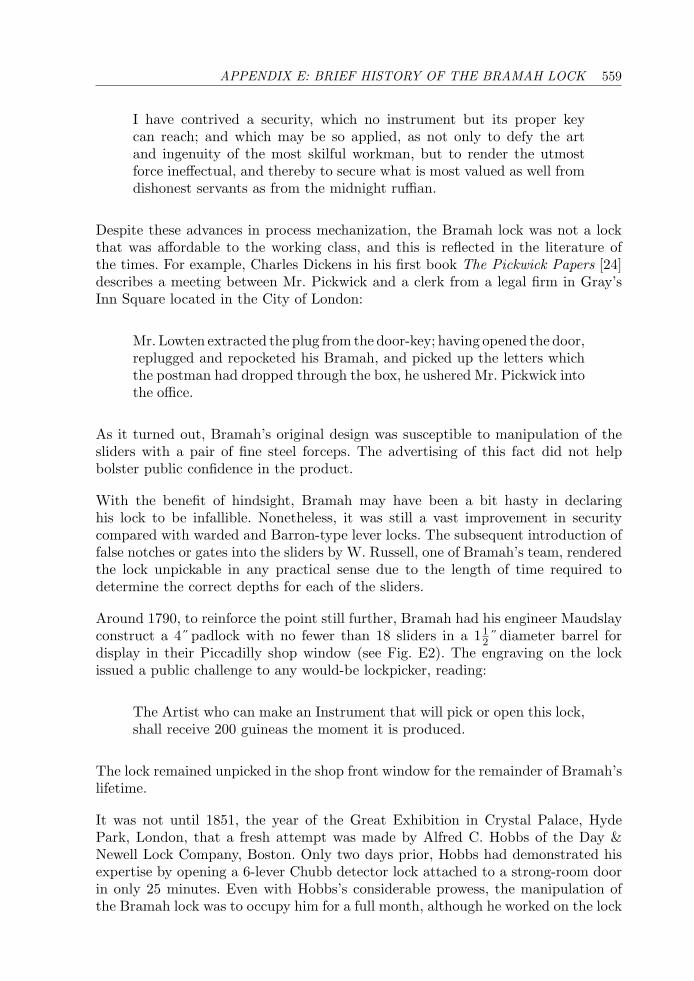
APPENDIX E: BRIEF HISTORY OF THE BRAMAH LOCK 559
I have contrived a security, which no instrument but its proper keycan reach; and which may be so applied, as not only to defy the artand ingenuity of the most skilful workman, but to render the utmostforce ineffectual, and thereby to secure what is most valued as well fromdishonest servants as from the midnight ruffian.
Despite these advances in process mechanization, the Bramah lock was not a lockthat was affordable to the working class, and this is reflected in the literature ofthe times. For example, Charles Dickens in his first book The Pickwick Papers [24]describes a meeting between Mr. Pickwick and a clerk from a legal firm in Gray’sInn Square located in the City of London:
Mr. Lowten extracted the plug from the door-key; having opened the door,replugged and repocketed his Bramah, and picked up the letters whichthe postman had dropped through the box, he ushered Mr. Pickwick intothe office.
As it turned out, Bramah’s original design was susceptible to manipulation of thesliders with a pair of fine steel forceps. The advertising of this fact did not helpbolster public confidence in the product.
With the benefit of hindsight, Bramah may have been a bit hasty in declaringhis lock to be infallible. Nonetheless, it was still a vast improvement in securitycompared with warded and Barron-type lever locks. The subsequent introduction offalse notches or gates into the sliders by W. Russell, one of Bramah’s team, renderedthe lock unpickable in any practical sense due to the length of time required todetermine the correct depths for each of the sliders.
Around 1790, to reinforce the point still further, Bramah had his engineer Maudslayconstruct a 4˝ padlock with no fewer than 18 sliders in a 11
2˝ diameter barrel fordisplay in their Piccadilly shop window (see Fig. E2). The engraving on the lockissued a public challenge to any would-be lockpicker, reading:
The Artist who can make an Instrument that will pick or open this lock,shall receive 200 guineas the moment it is produced.
The lock remained unpicked in the shop front window for the remainder of Bramah’slifetime.
It was not until 1851, the year of the Great Exhibition in Crystal Palace, HydePark, London, that a fresh attempt was made by Alfred C. Hobbs of the Day &Newell Lock Company, Boston. Only two days prior, Hobbs had demonstrated hisexpertise by opening a 6-lever Chubb detector lock attached to a strong-room doorin only 25 minutes. Even with Hobbs’s considerable prowess, the manipulation ofthe Bramah lock was to occupy him for a full month, although he worked on the lock
560 APPENDIX E: BRIEF HISTORY OF THE BRAMAH LOCK
Figure E2: Bramah’s challenge padlock remained unpicked for around 60 years.
for only 44 hours in total over this period, and further delays were experienced asa result of the Bramah Company’s protestations at Hobbs’s methods. The ensuingdebate over whether or not Hobbs had adhered to the rules of the challenge becameknown as the Great Lock Controversy and is documented in Hobbs’s book of 1853[51—53] and in the report of the committee overseeing the challenge [54]. Suffice tosay that the method would not be well suited to use “in the field.”
Notwithstanding the contentions of the Bramah Company, the 200 guineas rewardwas paid to Hobbs on the 9th of September 1851, which he promptly exhibited at theDay & Newell stand at the Great Exhibition. Bramah’s design, despite succumbingon this occasion to Hobbs’s methods, has withstood the test of time and is stillused for security locks and safes in the United Kingdom and elsewhere. Bramah’soriginal challenge padlock, pictured in Fig. E2, can be seen today in the LondonScience Museum, where Maudslay’s screw-cutting lathe also resides. The Bramahprinciple found its way into many other lock designs, particularly in France andGermany, some of which were covered in the preceding chapters.
APPENDIX F: KEY CODE COMPUTATIONS 561
For a more detailed account of this interesting episode in the history of lockdevelopment, the reader is urged to consult Price’s 1856 book [99], which devotes achapter of 50 pages to the Lock Controversy at the time of the Great Exhibition anda further chapter of 77 pages to challenges engendered by the Lock Controversy upto 1856 (one of which was decided in court). Accounts of the tools and techniquesthat Hobbs made use of are contained in Price’s book and also in McNeil’s biographyof Joseph Bramah [82]. Hogg’s book [55] relates the Bramah/Hobbs encounter inan entertaining style. John Chubb’s paper [22] is also a good source of information,containing, for example, a description of Owen’s clockwork decoder for a Bramah6-slider padlock: the device was powered by a weight and line and regularly attainedthe correct combination in half an hour to three hours.
Appendix F: Key Code Computations
This Appendix contains listings of a number of programs useful for determiningkey series with realistic constraints, such as MACS. All programs are written in theMatlabTM language and are compatible with Matlab versions 5 and 6. The outputfrom the programs is a list or matrix of cut depths, which can be interpreted asdirect key codes. The cut positions are numbered from bow to tip.
The first three programs are for pin-tumbler locks. This is followed by a programfor GM-type wafer locks. The last two programs are for lever locks with symmetrickeys. On an algorithmic note, all of the programs are nonrecursive; that is, they donot involve recursive function calls. It is possible to implement the code generationalgorithms in a direct, recursive form so that they run more efficiently.
For 5-pin locks with 10 cut depths the two functions “check macs.m” and“perms macs.m” can be used to generate the code list. The step of computing codessubject to MACS is done first in check macs.m. The first time the program is run,a file called perms5.mat with all possible codes is generated; this file is reloaded onsubsequent runs. The output is stored in another file called perms5 macs[n].mat,where n is the value of MACS used. The user can view the results, which containnonsense codes like (1 1 1 1 1). The second step takes the MACS-compliant resultsand prunes off codes that do not satisfy other constraints, such as “up to three pinsof the same size.” The result of this step is a variable called all perms containingthe key series as a matrix. The number of codes is also displayed. The programcode is easily modified for 6-pin locks, although the run time can be quite long forlarge values of MACS. For MK systems with a progression step of 2, the program“differ by 2.m” can be applied to the output of perms macs.m to generate a uniquesequence of codes that differ by two or more increments in at least one position.
For 6-wafer locks of the General Motors variety, the program “perms macs gm.m”should be used. This program combines all the code-checking steps, including gen-eration of the full list for five wafer sizes; checking codes against the MACS = 3
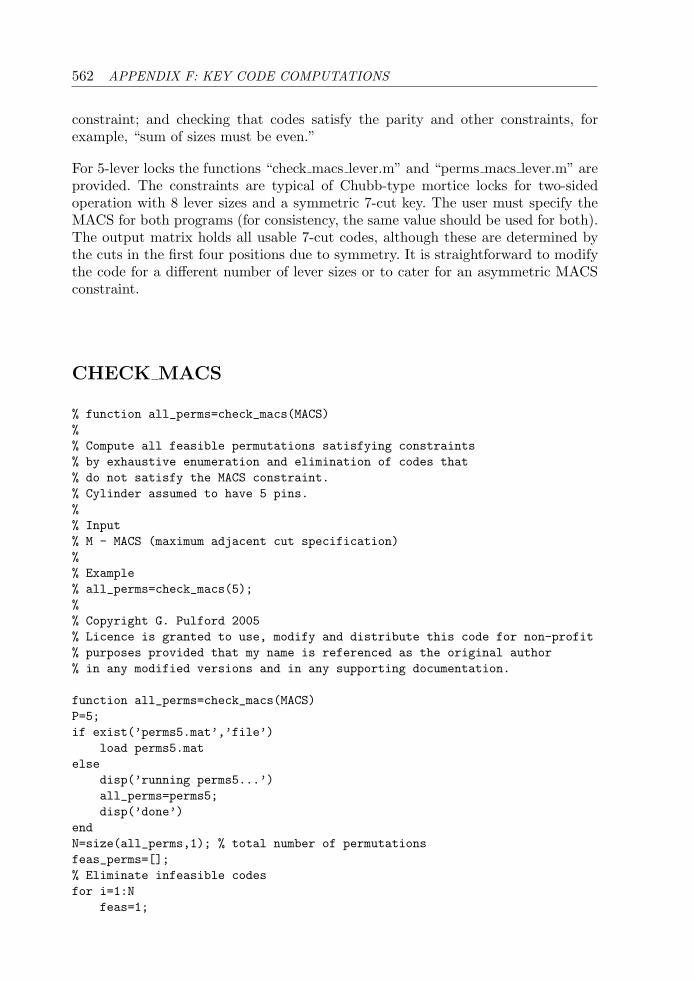
562 APPENDIX F: KEY CODE COMPUTATIONS
constraint; and checking that codes satisfy the parity and other constraints, forexample, “sum of sizes must be even.”
For 5-lever locks the functions “check macs lever.m” and “perms macs lever.m” areprovided. The constraints are typical of Chubb-type mortice locks for two-sidedoperation with 8 lever sizes and a symmetric 7-cut key. The user must specify theMACS for both programs (for consistency, the same value should be used for both).The output matrix holds all usable 7-cut codes, although these are determined bythe cuts in the first four positions due to symmetry. It is straightforward to modifythe code for a different number of lever sizes or to cater for an asymmetric MACSconstraint.
CHECK MACS
% function all_perms=check_macs(MACS)%% Compute all feasible permutations satisfying constraints% by exhaustive enumeration and elimination of codes that% do not satisfy the MACS constraint.% Cylinder assumed to have 5 pins.%% Input% M - MACS (maximum adjacent cut specification)%% Example% all_perms=check_macs(5);%% Copyright G. Pulford 2005% Licence is granted to use, modify and distribute this code for non-profit% purposes provided that my name is referenced as the original author% in any modified versions and in any supporting documentation.
function all_perms=check_macs(MACS)P=5;if exist(’perms5.mat’,’file’)
load perms5.matelse
disp(’running perms5...’)all_perms=perms5;disp(’done’)
endN=size(all_perms,1); % total number of permutationsfeas_perms=[];% Eliminate infeasible codesfor i=1:N
feas=1;
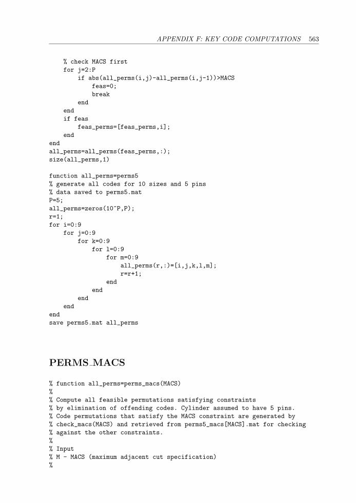
APPENDIX F: KEY CODE COMPUTATIONS 563
% check MACS firstfor j=2:P
if abs(all_perms(i,j)-all_perms(i,j-1))>MACSfeas=0;break
endendif feas
feas_perms=[feas_perms,i];end
endall_perms=all_perms(feas_perms,:);size(all_perms,1)
function all_perms=perms5% generate all codes for 10 sizes and 5 pins% data saved to perms5.matP=5;all_perms=zeros(10^P,P);r=1;for i=0:9
for j=0:9for k=0:9
for l=0:9for m=0:9
all_perms(r,:)=[i,j,k,l,m];r=r+1;
endend
endend
endsave perms5.mat all_perms
PERMS MACS
% function all_perms=perms_macs(MACS)%% Compute all feasible permutations satisfying constraints% by elimination of offending codes. Cylinder assumed to have 5 pins.% Code permutations that satisfy the MACS constraint are generated by% check_macs(MACS) and retrieved from perms5_macs[MACS].mat for checking% against the other constraints.%% Input% M - MACS (maximum adjacent cut specification)%
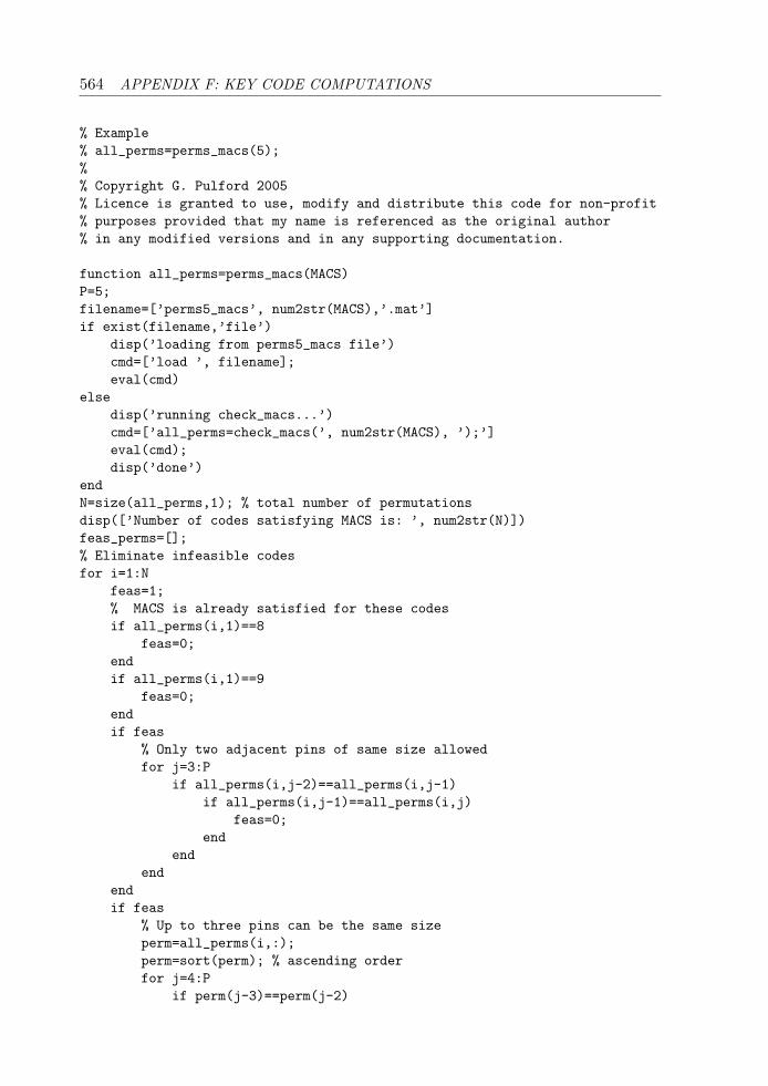
564 APPENDIX F: KEY CODE COMPUTATIONS
% Example% all_perms=perms_macs(5);%% Copyright G. Pulford 2005% Licence is granted to use, modify and distribute this code for non-profit% purposes provided that my name is referenced as the original author% in any modified versions and in any supporting documentation.
function all_perms=perms_macs(MACS)P=5;filename=[’perms5_macs’, num2str(MACS),’.mat’]if exist(filename,’file’)
disp(’loading from perms5_macs file’)cmd=[’load ’, filename];eval(cmd)
elsedisp(’running check_macs...’)cmd=[’all_perms=check_macs(’, num2str(MACS), ’);’]eval(cmd);disp(’done’)
endN=size(all_perms,1); % total number of permutationsdisp([’Number of codes satisfying MACS is: ’, num2str(N)])feas_perms=[];% Eliminate infeasible codesfor i=1:N
feas=1;% MACS is already satisfied for these codesif all_perms(i,1)==8
feas=0;endif all_perms(i,1)==9
feas=0;endif feas
% Only two adjacent pins of same size allowedfor j=3:P
if all_perms(i,j-2)==all_perms(i,j-1)if all_perms(i,j-1)==all_perms(i,j)
feas=0;end
endend
endif feas
% Up to three pins can be the same sizeperm=all_perms(i,:);perm=sort(perm); % ascending orderfor j=4:P
if perm(j-3)==perm(j-2)
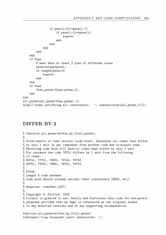
APPENDIX F: KEY CODE COMPUTATIONS 565
if perm(j-2)==perm(j-1)if perm(j-1)==perm(j)
feas=0;end
endend
endendif feas
% must have at least 3 pins of different sizesperm=unique(perm);if length(perm)<3
feas=0;end
endif feas
feas_perms=[feas_perms,i];end
endall_perms=all_perms(feas_perms,:);disp([’Codes satisfying all constraints: ’, num2str(size(all_perms,1))])
DIFFER BY 2
% function all_perms=differ_by_2(all_perms);%% Given matrix of code vectors (code book), determine all codes that differ% by only 1 unit in any component from another code and eliminate them.% Resulting code book will have no codes that differ by only 1 unit.% For instance the code 78751 differs by 1 unit from the following% 10 codes:% 68751, 77751, 78651, 78741, 78750% 88751, 79751, 78851, 78761, 78752%% Notes:% Length 5 code assumed.% Code book should already satisfy other constraints (MACS, etc).%% Requires: code2dec_LUT()%% Copyright G. Pulford, 2005% Licence is granted to use, modify and distribute this code for non-profit% purposes provided that my name is referenced as the original author% in any modified versions and in any supporting documentation.
function all_perms=differ_by_2(all_perms)fwd=input(’loop forwards? yes=1 (default=0): ’);
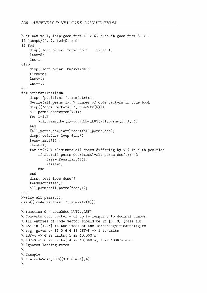
566 APPENDIX F: KEY CODE COMPUTATIONS
% if set to 1, loop goes from 1 -> 5, else it goes from 5 -> 1if isempty(fwd), fwd=0; endif fwd
disp(’loop order: forwards’) first=1;last=5;inc=1;
elsedisp(’loop order: backwards’)first=5;last=1;inc=-1;
endfor n=first:inc:last
disp([’position: ’, num2str(n)])N=size(all_perms,1); % number of code vectors in code bookdisp([’code vectors: ’, num2str(N)])all_perms_dec=zeros(N,1);for i=1:N
all_perms_dec(i)=code2dec_LUT(all_perms(i,:),n);end[all_perms_dec,isrt]=sort(all_perms_dec);disp(’code2dec loop done’)feas=[isrt(1)];itest=1;for i=2:N % eliminate all codes differing by < 2 in n-th position
if abs(all_perms_dec(itest)-all_perms_dec(i))>=2feas=[feas,isrt(i)];itest=i;
endenddisp(’test loop done’)feas=sort(feas);all_perms=all_perms(feas,:);
endN=size(all_perms,1);disp([’code vectors: ’, num2str(N)])
% function d = code2dec_LUT(v,LSF)% Converts code vector v of up to length 5 to decimal number.% All entries of code vector should be in [0..9] (base 10).% LSF in [1..5] is the index of the least-significant-figure% e.g. given v= [3 0 6 4 1] LSF=5 => 1 is units% LSF=4 => 4 is units, 1 is 10,000’s% LSF=3 => 6 is units, 4 is 10,000’s, 1 is 1000’s etc.% Ignores leading zeros.%% Example% d = code2dec_LUT([3 0 6 4 1],4)%
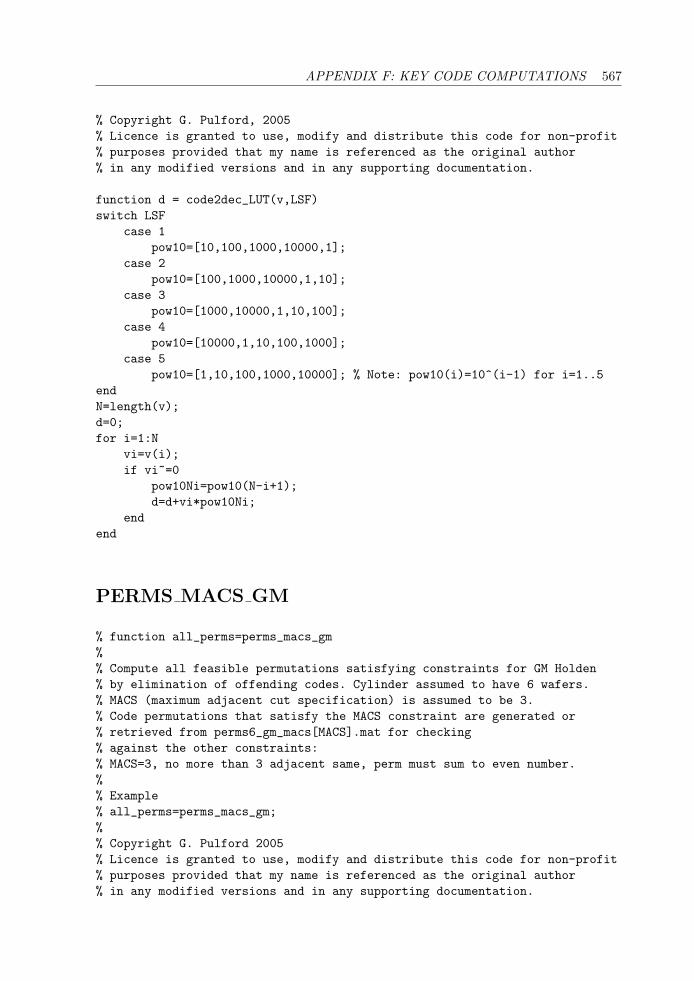
APPENDIX F: KEY CODE COMPUTATIONS 567
% Copyright G. Pulford, 2005% Licence is granted to use, modify and distribute this code for non-profit% purposes provided that my name is referenced as the original author% in any modified versions and in any supporting documentation.
function d = code2dec_LUT(v,LSF)switch LSF
case 1pow10=[10,100,1000,10000,1];
case 2pow10=[100,1000,10000,1,10];
case 3pow10=[1000,10000,1,10,100];
case 4pow10=[10000,1,10,100,1000];
case 5pow10=[1,10,100,1000,10000]; % Note: pow10(i)=10^(i-1) for i=1..5
endN=length(v);d=0;for i=1:N
vi=v(i);if vi~=0
pow10Ni=pow10(N-i+1);d=d+vi*pow10Ni;
endend
PERMS MACS GM
% function all_perms=perms_macs_gm%% Compute all feasible permutations satisfying constraints for GM Holden% by elimination of offending codes. Cylinder assumed to have 6 wafers.% MACS (maximum adjacent cut specification) is assumed to be 3.% Code permutations that satisfy the MACS constraint are generated or% retrieved from perms6_gm_macs[MACS].mat for checking% against the other constraints:% MACS=3, no more than 3 adjacent same, perm must sum to even number.%% Example% all_perms=perms_macs_gm;%% Copyright G. Pulford 2005% Licence is granted to use, modify and distribute this code for non-profit% purposes provided that my name is referenced as the original author% in any modified versions and in any supporting documentation.
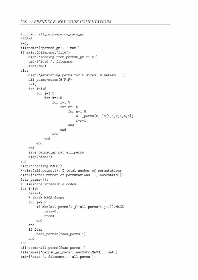
568 APPENDIX F: KEY CODE COMPUTATIONS
function all_perms=perms_macs_gmMACS=3P=6;filename=[’perms6_gm’, ’.mat’]if exist(filename,’file’)
disp(’loading from perms6_gm file’)cmd=[’load ’, filename];eval(cmd)
elsedisp(’generating perms for 5 sizes, 6 wafers...’)all_perms=zeros(5^P,P);r=1;for i=1:5
for j=1:5for k=1:5
for l=1:5for m=1:5
for n=1:5all_perms(r,:)=[i,j,k,l,m,n];r=r+1;
endend
endend
endendsave perms6_gm.mat all_permsdisp(’done’)
enddisp(’checking MACS’)N=size(all_perms,1); % total number of permutationsdisp([’Total number of permutations: ’, num2str(N)])feas_perms=[];% Eliminate infeasible codesfor i=1:N
feas=1;% check MACS firstfor j=2:P
if abs(all_perms(i,j)-all_perms(i,j-1))>MACSfeas=0;break
endendif feas
feas_perms=[feas_perms,i];end
endall_perms=all_perms(feas_perms,:);filename=[’perms6_gm_macs’, num2str(MACS),’.mat’]cmd=[’save ’, filename, ’ all_perms’];
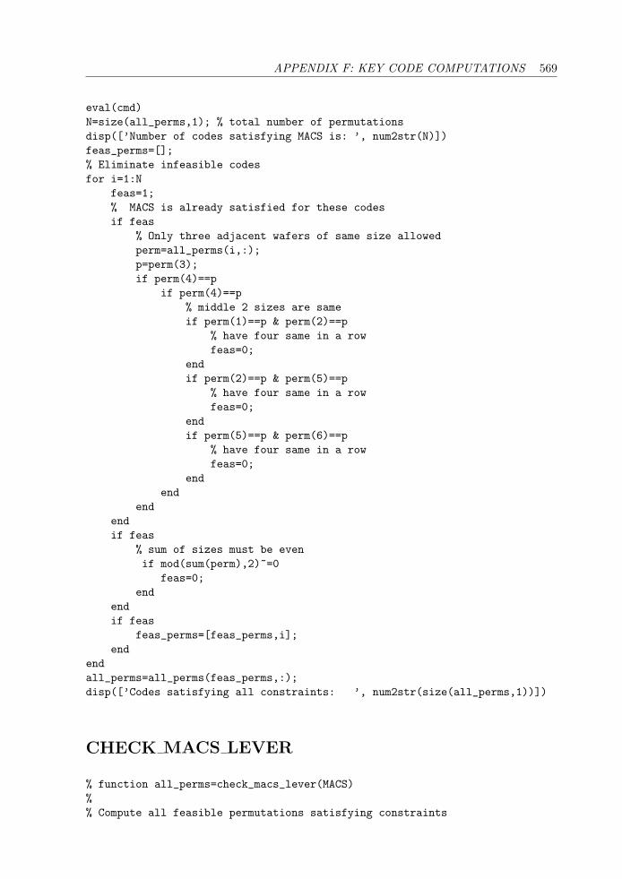
APPENDIX F: KEY CODE COMPUTATIONS 569
eval(cmd)N=size(all_perms,1); % total number of permutationsdisp([’Number of codes satisfying MACS is: ’, num2str(N)])feas_perms=[];% Eliminate infeasible codesfor i=1:N
feas=1;% MACS is already satisfied for these codesif feas
% Only three adjacent wafers of same size allowedperm=all_perms(i,:);p=perm(3);if perm(4)==p
if perm(4)==p% middle 2 sizes are sameif perm(1)==p & perm(2)==p
% have four same in a rowfeas=0;
endif perm(2)==p & perm(5)==p
% have four same in a rowfeas=0;
endif perm(5)==p & perm(6)==p
% have four same in a rowfeas=0;
endend
endendif feas
% sum of sizes must be evenif mod(sum(perm),2)~=0
feas=0;end
endif feas
feas_perms=[feas_perms,i];end
endall_perms=all_perms(feas_perms,:);disp([’Codes satisfying all constraints: ’, num2str(size(all_perms,1))])
CHECK MACS LEVER
% function all_perms=check_macs_lever(MACS)%% Compute all feasible permutations satisfying constraints
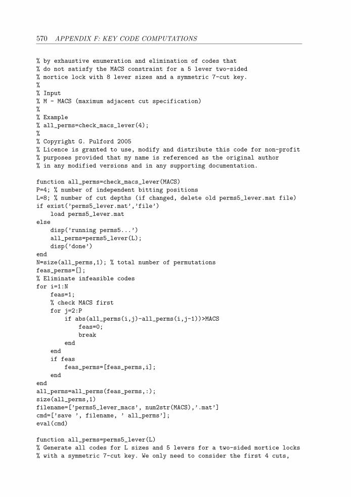
570 APPENDIX F: KEY CODE COMPUTATIONS
% by exhaustive enumeration and elimination of codes that% do not satisfy the MACS constraint for a 5 lever two-sided% mortice lock with 8 lever sizes and a symmetric 7-cut key.%% Input% M - MACS (maximum adjacent cut specification)%% Example% all_perms=check_macs_lever(4);%% Copyright G. Pulford 2005% Licence is granted to use, modify and distribute this code for non-profit% purposes provided that my name is referenced as the original author% in any modified versions and in any supporting documentation.
function all_perms=check_macs_lever(MACS)P=4; % number of independent bitting positionsL=8; % number of cut depths (if changed, delete old perms5_lever.mat file)if exist(’perms5_lever.mat’,’file’)
load perms5_lever.matelse
disp(’running perms5...’)all_perms=perms5_lever(L);disp(’done’)
endN=size(all_perms,1); % total number of permutationsfeas_perms=[];% Eliminate infeasible codesfor i=1:N
feas=1;% check MACS firstfor j=2:P
if abs(all_perms(i,j)-all_perms(i,j-1))>MACSfeas=0;break
endendif feas
feas_perms=[feas_perms,i];end
endall_perms=all_perms(feas_perms,:);size(all_perms,1)filename=[’perms5_lever_macs’, num2str(MACS),’.mat’]cmd=[’save ’, filename, ’ all_perms’];eval(cmd)
function all_perms=perms5_lever(L)% Generate all codes for L sizes and 5 levers for a two-sided mortice locks% with a symmetric 7-cut key. We only need to consider the first 4 cuts,
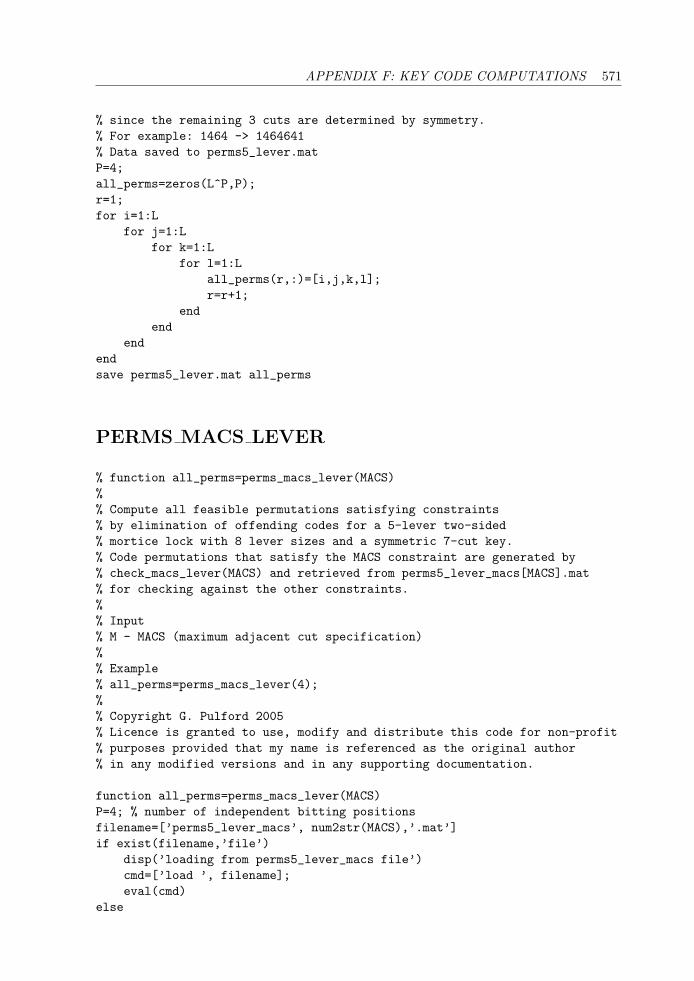
APPENDIX F: KEY CODE COMPUTATIONS 571
% since the remaining 3 cuts are determined by symmetry.% For example: 1464 -> 1464641% Data saved to perms5_lever.matP=4;all_perms=zeros(L^P,P);r=1;for i=1:L
for j=1:Lfor k=1:L
for l=1:Lall_perms(r,:)=[i,j,k,l];r=r+1;
endend
endendsave perms5_lever.mat all_perms
PERMS MACS LEVER
% function all_perms=perms_macs_lever(MACS)%% Compute all feasible permutations satisfying constraints% by elimination of offending codes for a 5-lever two-sided% mortice lock with 8 lever sizes and a symmetric 7-cut key.% Code permutations that satisfy the MACS constraint are generated by% check_macs_lever(MACS) and retrieved from perms5_lever_macs[MACS].mat% for checking against the other constraints.%% Input% M - MACS (maximum adjacent cut specification)%% Example% all_perms=perms_macs_lever(4);%% Copyright G. Pulford 2005% Licence is granted to use, modify and distribute this code for non-profit% purposes provided that my name is referenced as the original author% in any modified versions and in any supporting documentation.
function all_perms=perms_macs_lever(MACS)P=4; % number of independent bitting positionsfilename=[’perms5_lever_macs’, num2str(MACS),’.mat’]if exist(filename,’file’)
disp(’loading from perms5_lever_macs file’)cmd=[’load ’, filename];eval(cmd)
else
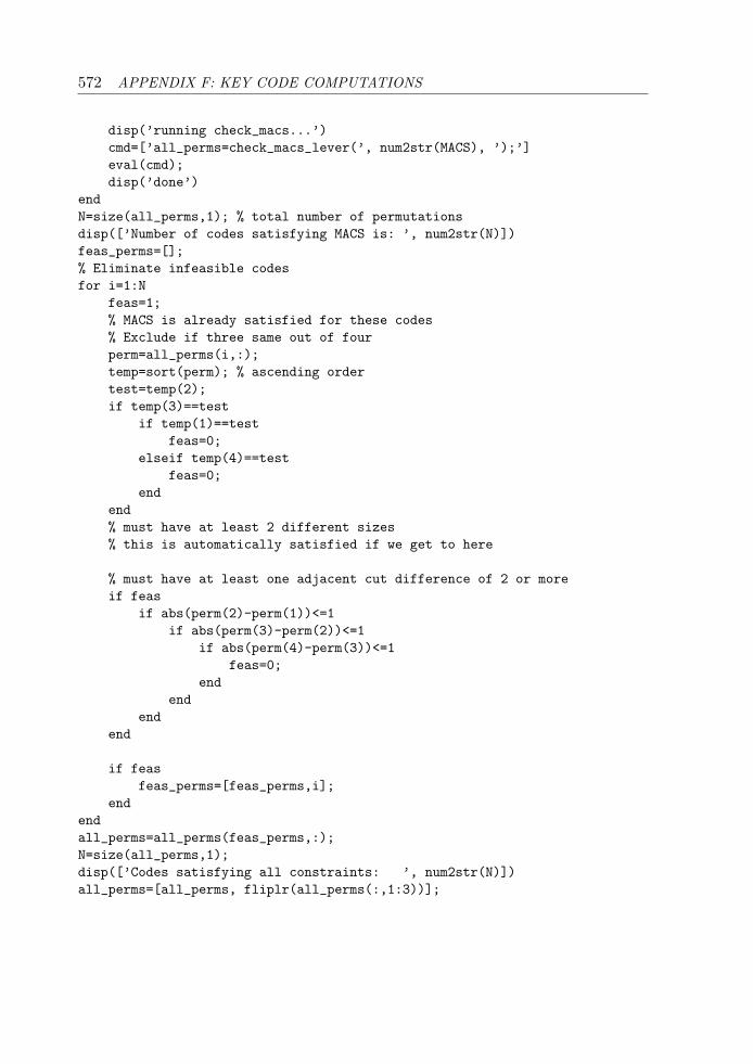
572 APPENDIX F: KEY CODE COMPUTATIONS
disp(’running check_macs...’)cmd=[’all_perms=check_macs_lever(’, num2str(MACS), ’);’]eval(cmd);disp(’done’)
endN=size(all_perms,1); % total number of permutationsdisp([’Number of codes satisfying MACS is: ’, num2str(N)])feas_perms=[];% Eliminate infeasible codesfor i=1:N
feas=1;% MACS is already satisfied for these codes% Exclude if three same out of fourperm=all_perms(i,:);temp=sort(perm); % ascending ordertest=temp(2);if temp(3)==test
if temp(1)==testfeas=0;
elseif temp(4)==testfeas=0;
endend% must have at least 2 different sizes% this is automatically satisfied if we get to here
% must have at least one adjacent cut difference of 2 or moreif feas
if abs(perm(2)-perm(1))<=1if abs(perm(3)-perm(2))<=1
if abs(perm(4)-perm(3))<=1feas=0;
endend
endend
if feasfeas_perms=[feas_perms,i];
endendall_perms=all_perms(feas_perms,:);N=size(all_perms,1);disp([’Codes satisfying all constraints: ’, num2str(N)])all_perms=[all_perms, fliplr(all_perms(:,1:3))];
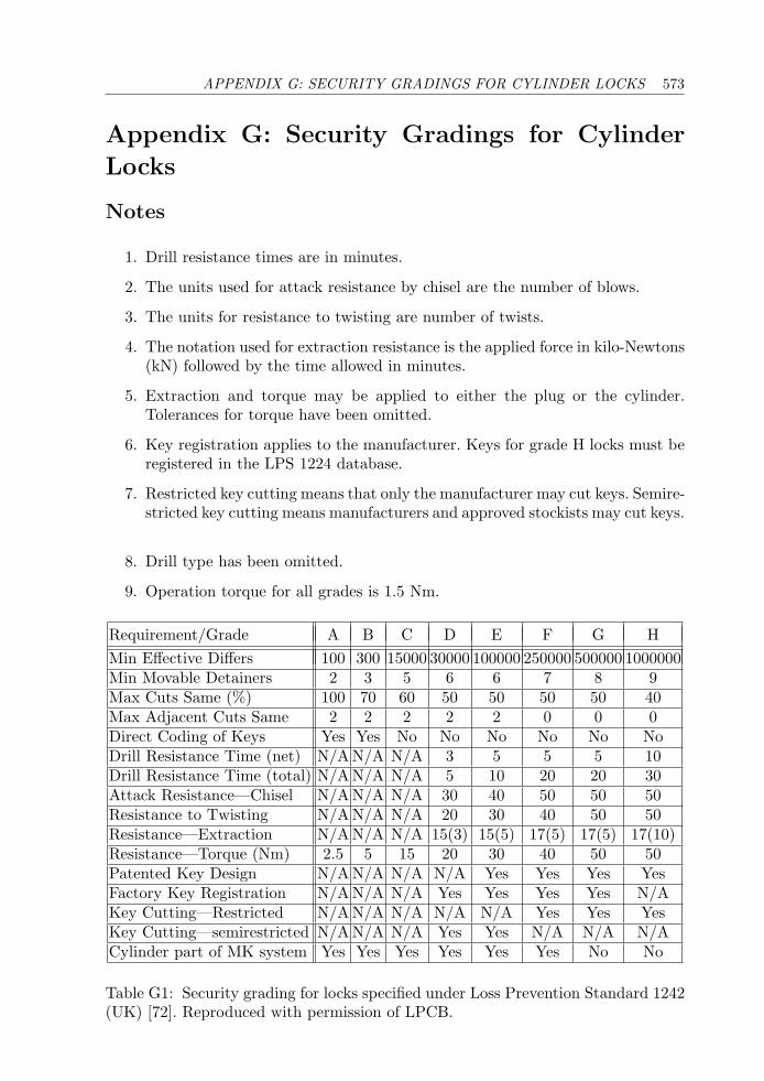
APPENDIX G: SECURITY GRADINGS FOR CYLINDER LOCKS 573
Appendix G: Security Gradings for Cylinder
Locks
Notes
1. Drill resistance times are in minutes.
2. The units used for attack resistance by chisel are the number of blows.
3. The units for resistance to twisting are number of twists.
4. The notation used for extraction resistance is the applied force in kilo-Newtons(kN) followed by the time allowed in minutes.
5. Extraction and torque may be applied to either the plug or the cylinder.Tolerances for torque have been omitted.
6. Key registration applies to the manufacturer. Keys for grade H locks must beregistered in the LPS 1224 database.
7. Restricted key cutting means that only the manufacturer may cut keys. Semire-stricted key cutting means manufacturers and approved stockists may cut keys.
8. Drill type has been omitted.
9. Operation torque for all grades is 1.5 Nm.
Requirement/Grade A B C D E F G HMin Effective Differs 100 300 15000 30000 100000 250000 500000 1000000Min Movable Detainers 2 3 5 6 6 7 8 9Max Cuts Same (%) 100 70 60 50 50 50 50 40Max Adjacent Cuts Same 2 2 2 2 2 0 0 0Direct Coding of Keys Yes Yes No No No No No NoDrill Resistance Time (net) N/A N/A N/A 3 5 5 5 10Drill Resistance Time (total) N/A N/A N/A 5 10 20 20 30Attack Resistance—Chisel N/A N/A N/A 30 40 50 50 50Resistance to Twisting N/A N/A N/A 20 30 40 50 50Resistance—Extraction N/A N/A N/A 15(3) 15(5) 17(5) 17(5) 17(10)Resistance—Torque (Nm) 2.5 5 15 20 30 40 50 50Patented Key Design N/A N/A N/A N/A Yes Yes Yes YesFactory Key Registration N/A N/A N/A Yes Yes Yes Yes N/AKey Cutting—Restricted N/A N/A N/A N/A N/A Yes Yes YesKey Cutting—semirestricted N/A N/A N/A Yes Yes N/A N/A N/ACylinder part of MK system Yes Yes Yes Yes Yes Yes No No
Table G1: Security grading for locks specified under Loss Prevention Standard 1242(UK) [72]. Reproduced with permission of LPCB.

This page intentionally left blank
Index
2-in-1 picksee Hobbs pick, 15, 54
3-in-1 pick, 3795-pin cylinder, 386-pin cylinder, 427-pin cylinder, 52999 key, 76
A2Psee standards, 12
A2P-rated, 84, 134, 255, 424ABA, 156
axial, 199Pagoda, 196
abbreviations, definition of, 547Abloy
Classic, 234Disklock Pro, 240Ford Tibbe, 479Profile, 234Protec, 240
ABUSEC, 86Plus, 245TS 5000, 101
ABUS KG, 245ACE, 138, 144, 170, 207, 277active key element, 61
see mobile element, 60after-market, 10, 53, 470Age, 154alarm, 371, 473, 481, 496, 509Allen key, 142, 421, 423Alnico, 437Alpha, 86–88
Alpha Romeo, 497American Lock Company, 173, 190,
225American Locker Company, 63, 140,
454anchor point, 238, 452Andrews, Dr. S., 337Anker, 450Ankerslot, 448antidrill
see drill resistance, 50antigravity lock, 441antipicking feature
lever lock, 351, 355, 362, 379, 386,421
pin-tumbler lock, 57, 65, 80, 100,107
side-bar lock, 295, 307wafer lock, 181, 196, 207, 477, 487,
493antithrust bolt, 166Apex, 140armature, 170, 466Arnheim axial, 208array
see bolt stump array, 332Arrow 39, 69ASSA
Desmo, 275Twin, 292Twin Combi, 297, 308Twin V-10, 297
ASSA Abloy AB, 64, 84, 115–116, 160,232, 292, 299, 349, 510
576 INDEX
asymmetric key, 112, 231, 247, 260,364, 376, 408, 449, 461
Aubin’s lock, 390Audi, 476Australian Lock Company, 267auto-dialer, 26automotive lock
see car lock, 469AVA
see Chubb AVA, 394axial lock, 138, 205Azbe, 89
balance lever, 321, 405Banham, 302bank, 6, 8, 31–33, 224, 252, 322, 331,
338, 345, 399, 420, 430, 508bar-tumbler, 151bar-wafer, 183, 199, 281, 283, 304, 489,
493barrel
see pin-tumbler lock, 34barrel and curtain
see curtain, 341Barron lock, 317, 375Barron, R., 317, 349Bauche Monopole, 390Bauche, Auguste, 252Bauer
see Bauer Kaba, 117Bauer Central, 332Bauer Kaba AG, 117, 120, 121, 332Bauer Sphinx, 332Bell lock, 183, 199, 286, 489, 493belly
see lever belly, 340belly grouping, 342, 355, 356Best IC, 39, 71bicentric lock, 221bidirectional dynamics, 251Bierhaus, Josef, 404bilateral key, 92, 184, 189, 232, 267,
441BiLock
conventional, 267New Generation, 272
QCC, 271TriLock, 270
binary, 22, 60, 167, 226, 439, 463, 475Binary Plus, 106biometric, 22, 508bitting angle, 235, 244, 289, 291bitting depth, 79, 103, 291, 303bitting matrix, 251, 500bitting pair, 486bitting pattern, 112, 267, 298bitting point, 193, 201, 285, 311, 477,
491, 495, 497, 500bitting rules, 25, 42–43, 51, 87–88, 160,
177, 353, 354, 372, 419, 471,477, 486
pull-out, 43bitting surface, 231, 251BKS Company, 129–131BKS Janus, 129BKS Multipin, 92blank tumbler, 453blind code
see indirect code, 13blind pin, 119, 125blocking
bar, 82, 244, 413lever, 406, 426, 427magnet, 435, 439, 443pin, 462
see pin, 61plate, 146ring, 215rod, 274stump, 323wafer, 492
BMW, 472, 474, 497BMW two-track, 489Bode-Panzer, 322, 405bolt-step, 321, 325, 343, 351, 361, 365,
368, 375, 378, 409, 419, 423,427
bolt stump, 321, 325, 327, 338, 343,352, 361, 368, 372, 381, 384,386, 416, 426, 430, 432
bolt-stump array, 332, 338, 421, 424,430
INDEX 577
bolt tail, 362, 416, 420bolt talon
see talon, 320bolt throw, 325, 349, 356bore pattern, 119, 125borescope, 344boring, 34, 53, 86, 88, 100, 116, 119,
125, 129, 167, 278, 295bottom pin
see pin-tumbler lock, 34Bournisien Beau et Companie, 395bow to tip, 349, 378Bramah C17, 205Bramah history, 558Bramah lock, 145, 183, 205, 384Bramah, Joseph, 5, 183Bramah-Chubb, 215, 328
Doppel, 215breakage
cylinder coupling, 50, 129, 133key
see key breakage, 11breech, 208, 401Brennan’s lock, 224Bricard
14-wafer, 188Bloctout, 188Chifral, 131SuperSurete, 194
Briggs and Stratton, 229, 276, 470,484
broaching, 10, 11, 34, 45, 49, 59, 64, 80,86, 88, 93, 98, 105, 157, 187,193, 199, 270, 273, 278, 296,306, 471, 482, 493
BSsee standards, 12
bullet, 176, 273bump-key, 15, 26, 58, 76burglar, 8, 125, 188, 459, 487,
507burglary resistance, 14, 349burning bar, 16bushing, 261Butter’s system, 224, 324, 330,
344, 355, 370, 379
Butter, F. J., 330bypass, 15, 27, 49, 82, 188, 196,
315, 329, 456, 481, 487,507
C-clip, 263, 396, 456cam
see pin-tumbler lock, 34cam lock, 34, 87, 138, 141, 173, 191,
196, 199, 232, 264, 275, 278,279, 287, 305, 394, 441
captive key, 420car lock
Alpha Romeo, 497Briggs and Stratton, 484Citroen Simplex, 501classification, 475double-sided, 476Ford Chubb, 482Ford Tibbe, 479four-track, 491General Motors, 484history, 469Holden Commodore, 478key box, 208Mercedes, 487, 491Mitsubishi, 493Porsche, 495side-bar, 484side-track, 493two-track, 478, 487Volvo, 499
card-in-slot lock, 39, 439, 442Carl Kastner, 215, 227, 238Carl Wittkopp, 405cast brass, 75, 351, 361, 388, 432cast bronze, 380, 383cast iron, 224cast steel, 247cast zinc, 151, 210, 217, 279, 416, 476,
484, 487, 489, 495Cavers, 143, 150Cavith
see Zenith Cavith, 149CAWI, 321, 405Central, 146, 148
578 INDEX
ceramic, 259, 340, 437, 442Cerberus, 322chain of balls lock, 63challenge
see reward, 183chamber
see pin-tumbler lock, 34Champion
see Miller lock, 379Champions
see Mottura Champions, 257change key, 37, 72, 88, 210, 221, 298,
330, 332, 421, 468chapter organization, 28Chatwood, 324, 330, 399Chatwood Impregnable, 358Chatwood, Samuel, 343Chatwood-Milner, 349check pin, 108–109, 136, 307Chicago Lock Company, 138, 140, 278child labor, 321Chrysler, 472Chrysler 7-wafer, 472Chubb,
3K77, 3563G110, 3703G114, 342, 3493G117, 349, 3563G135, 3723G222, 4453G227, 3563K277, 3565-lever lock, 3496K75, 342, 3587-lever lock, 349, 356Ava, 327, 394Company, 324, 349, 399detector lock, 317dissertation, 7, 317, 341Eloctro, 360lever lock, 349magnetic lock, 445quadruple lever lock, 6, 322SMI, 245twin 7-lever lock
see safe deposit lock, 429
Chubb, Charles, 319Chubb, Jeremiah, 317Chubb, John, 6, 319Chubb-Lips 6K207, 327, 360circular shift, 143, 210CISA S.p.A., 131Citroen, 372Citroen Simplex, 501cle de force (forcing key), 255classification
car locks, 475lever locks, 348locks, 22magnetic locks, 439pin-tumbler locks, 62side-bar locks, 233wafer locks, 184
click lock, 345clicker
see click lock, 345Climax Co., J. H. W., 225climax detector lock
see Cotterill lock, 387clip
see spring clip, 175Club lock, 137clutch, 253, 332, 382, 439CNPP, 12, 424coaxial pick, 54, 238, 246, 379coaxial pin, 140, 153–154, 157coaxial plug, 37, 75Cobra Axira
see Central, 148code book, 13, 261, 472code-change key, 128, 221code disc, 243–246Code lock, 168Codem, 89codes
5-pin, 42–44, 516-pin, 43, 44, 51, 877-pin, 51, 66adjacent, 37angular, 291bitting, 13, 24, 261, 472, 497blind, 13, 40
INDEX 579
block, 126changing, 128, 171, 465country, 23cryptographic, 475dealer, 125definition of, 23digital, 463direct, 13, 40disc, 235, 243, 244duplication, 52encrypted, 136equivalent, 44exhausting of, 11increased, 21, 52, 60indirect, 13, 40, 235, 261inductive, 360key
see key codes, 25keypad, 22lever lock, 353, 357, 372magnetic, 436, 453, 456, 459memorized, 12, 429multiplier, 45number of, 14permutation, 125pin-tumbler, 40plate wafer, 191progression step, 43progressive, 245registration, 52ridge, 295side-bar, 295, 296side-pin, 295signaling, 5single-sided, 261system, 45, 52, 81, 84, 86, 201, 436,
442, 447, 467, 484, 486, 509unique, 44, 245usable, 354, 355user, 131wafer lock, 177with bitting rules, 43with MACS, 42
coding rulessee bitting rules, 42
cog wheel, 83
collar, 12, 148, 351, 466, 468comb pick, 15combination
freezing of, 245, 413, 414combination lock, 26, 32, 332, 345, 398,
420, 508combinations
theoretical, 25, 40, 51, 86–87usable, 13, 25, 51
Commodore VNsee Holden Commodore, 478
compensated pin stack, 37, 55, 71,97–98, 296, 301
computer key, 178, 477computer numerical control, 61, 248,
285, 306computer program
see program, 25conning, 352, 356constant offset, 283constant-width bitting, 189, 190, 324,
325, 327, 343, 378, 395, 397,428, 482
construction keying, 11, 128consumer goods and services, 8contact angle, 243contact point, 54, 179, 207, 223, 243,
249, 256, 329, 362, 400, 403,483, 488, 500
contact surface, 145, 158, 247, 251, 343,351, 397
continuum, 421contouring, 344, 352, 364control card, 166control key, 39, 70, 272control shear line, 69convenience key
cruciform, 472double-sided, 86–87, 179, 470
conventionslever lock, 318lock descriptions, 23pin-tumbler lock, 24, 34wafer lock, 176
Corbinsee Emhart, 160
580 INDEX
Corbin 5-pin cylinder, 34Corbin IC, 39core
see pin-tumbler lock, 34CorKey, 463
TriSec mechanism, 464CorKey Control Systems, 463corrosion, 14, 173, 301, 437Cotterill lock, 387Cotterill, E., 387countermeasure, 344counter-milling, 295counter-pin, 124, 133country codes, 23crank, 372, 381, 383Crepinsek, A., 92, 116crime wave, 188cruciform lock, 111curtain, 351, 359, 362, 403, 404curtain lever, 359curtain pick, 340, 355, 358curved shear line, 93, 116, 159customer
see requirements, 8, 11cut
angled, 288, 383, 388, 400, 403double, 289, 290inverted, 157numbering, 25, 37, 70, 119, 125,
139, 160, 176, 235, 278, 296,301, 311, 352, 397, 450
offset, 290pitted, 385, 403, 408radiused, 244, 351, 403, 408, 419twin, 392
cut angle, 40, 41, 62, 235, 266, 288cut depth
see depth of cut, 25cut root, 40cylinder
see pin-tumbler lock, 34
Daimler & Maybach, 469damping, 191, 249, 261, 383, 462date
see filing date or issue date, 10Davis, G., 414
Day & Newell, 336dead-lift lever, 389, 483dead-lift pin, 102deadlatch, 114, 373deadlock, 73, 255, 259, 274, 349, 370dealer code
see dealer permutation, 125dealer perm
see dealer permutation, 125dealer permutation, 125, 230, 286, 296,
301, 307decoder, 17, 26, 56, 140, 231, 291, 355,
420, 468, 487decoding, 15, 55, 210, 217, 238, 291,
338, 341–343, 362, 369, 379,414, 450, 453, 454
degree of freedom, 162, 288, 304, 339,392, 406
Deny, 414depth and space, 41depth increment, 37, 40, 71, 86, 124,
177, 191, 353, 365, 389, 421depth of cut, 25, 37, 40, 44, 55, 113,
115, 120, 139, 194, 207, 221,251, 261, 266, 268, 277, 289,296, 310, 325, 353–355, 372,373, 383, 389, 413, 417, 419,421, 429, 457, 471, 476, 486,497
design patent, 10destructive opening, 13, 14–16, 481detainer, 371, 374detector lock
see lever lock, 365dial, 322, 345, 401Dickens, Charles, 559die-cast, 115, 170, 173, 191, 217, 260,
421, 424Diebold 175, 430digital lock, 22, 421, 508dimple
see boring, 86dimple key, 52, 59, 60, 79, 85, 86, 90,
93–94, 99, 103, 116–117, 128,131, 133, 137, 264, 272, 472,497
INDEX 581
DINsee standards, 12
direct drive, 201, 275disc tumbler lock
see wafer lock, 173dissertation
Bramah, 558Chubb, 6, 317, 341, 510Yale, 7, 339
DOMD, 92Diamant, 247iX-10, 91–93iX-5, 86, 93S, 64
DOM Sicherheitstechnik, 64, 92, 247,302
Donovan, W. F., 45Doppel Bramah-Chubb, 215double-bitted key, 96, 231, 324–325,
327, 332, 343, 345, 365, 376,380, 395, 398, 405, 415, 419,424, 480
double-entry lock, 137, 313, 325, 352,354, 373
double-nosed lock, 431double-sided key, 179, 186, 190, 224,
231, 281, 472, 476doubly broached
see multiplex master-keying, 46doubly-cut key, 290dovetail, 339, 412drill resistance, 49–50, 75, 82–84, 93,
97, 124, 129, 133, 191, 214,241, 247, 252, 259, 270, 296,307, 308, 364, 420, 450
drill-pin, 115, 148, 205, 388, 403, 406,426, 428
driver disc, 243driver pin
see pin-tumbler lock, 34–35driver spring
see pin-tumbler lock, 34driverless pin-tumbler lock, 229, 232,
257, 264, 275, 287, 504
Drumm Geminy, 50dual-control lock
see safe deposit lock, 345, 429Dudley lock, 183, 199, 280, 491Dudley Lock Corporation, 472DUO, 191dust guard, 469
Eagle Lock Company, 199, 441Egyptian lock, 32electric motor, 34, 207, 461electrical contact, 128, 360, 474electromagnet, 437electromagnetic, 436, 450, 457, 466electromechanical, 4, 10, 22, 245, 442,
474, 509electronic lock, 12, 22, 39, 61, 111, 128,
131, 136, 168, 313, 360, 386,421, 429, 436, 463, 475, 504,508, 509
elevation, 295, 304Elzett magnetic lock, 445Emhart, 160energy, 76, 437entrance set
see key-in-knob lock, 34ENV rated, 420, 424Eras, V. J. M., 49, 340, 345, 404European Certification Board
see ENV rated, 420Europrofile cylinder, 13, 33, 39, 77Everest
see Schlage Everest, 108Everest Primus,
see Schlage Primus, 307EVVA
3KS, 2835 pin, 64DPS
see EVVA DPX, 81DPX, 81ECS, 463ELMO, 286GPI, 65
582 INDEX
MCS, 459EVVA-Werk, 64, 283, 302, 445, 459
FAC, 52Falcon IC, 39, 69Falle Safe Securities, 56, 414false depth
gate, 237, 243, 246, 255, 283groove, 296, 502hole, 267, 270notch, 207, 249, 252, 277, 281slot, 291
Faraday, M., 436Federlos
see springless lock, 324Felter, P. S., 173, 190, 225fence, 230, 268, 277, 289, 295, 308, 412fence-bar, 225ferrite, 437, 442ferromagnetic, 441Fichet, 252, 395
click, 345NS pompe, 153, 224, 382
Fichet, Alexandre, 252Fichet-Bauche, 231
484, 252666, 281787, 27, 409M2B, 392M2i, 392Monopole, 390Sans Souci, 373
figure credits, 521filing date, 10, 440, 521finger pin, 297, 304, 307, 309fire resistance, 13, 252Fitz Gerald, J. W., 413, 484flange, 141, 144, 166, 351, 372, 467flaw
see security flaw, 8flipping, 171, 236, 339floating
ball, 61, 95, 105, 136, 196, 258, 302cam, 344pin, 158
flush mounting, 454
fob, 475Fontaine, 210footprint, 424forced entry, 12, 15, 255Ford 10-cut, 471Ford Chubb, 482Ford Motor Company, 469Ford Tibbe, 474, 479foreigner-proof lock, 188forend, 347, 351, 361, 363formula
combination, 528MACS, 41permutation, 528
Fort Lock Corporation, 139, 140fractal, 44Fraigneux Liega, 231Fraigneux, Emile, 231friction, 207, 255, 383, 398, 459FTH Thirard, 86, 145fulcrum, 330, 343function
dependence, 51, 177mathematical, 41of lock, 8, 33, 34, 175, 221, 349,
419, 509program, 561–562
functionality, 10
gatearray, 332, 424complementary, 378disc, 236, 243, 481false, 237, 310, 372, 384, 417lever, 231, 260, 316, 324, 330, 340,
351, 352, 355, 364, 366, 372,377, 380, 384, 415, 417, 421,432
multiple, 345offset, 251, 278rocker, 255rotor, 445, 462slider, 207, 303wheel, 345
gauge, 55, 481, 487gear, 222, 332, 412
INDEX 583
Gege AP 3000, 82GEM
see ACE, 138Genakis, J. M., 162, 292General Motors, 229, 469, 472, 474, 484Genii
see MagLok, 442German levers, 324, 358, 426GM Holden, 484gradings for locks, 26Great Exhibition, 6, 183, 320, 321,
337, 389Great Lock Controversy, 560–561Gretsch-Unitas Group, 129grouping of lever bellies
see belly grouping, 342guard key, 27, 345, 431, 432guardian key
see guard key, 27Gunnebo AB, 231, 252, 349, 365gunpowder, 16, 343
Hall effect sensor, 22, 459handedness, 116, 125, 240, 249, 251,
297, 403hardplate, 51, 351Head, 98Helason, 114Henriksson, Emil, 226Henry, J., 436hierarchy
see profile hierarchy, 45high-security lock
definition, 12Hobbs Hart and Co., 337, 349Hobbs lock, 336, 421Hobbs pick, 15, 54, 238, 246, 340,
355, 365, 378Hobbs, A. C., 6, 183, 320, 336, 389Holden Commodore, 476horizontal keyway, 86hotel lock, 11, 38, 163, 168, 221,
442Huf-Ymos, 472, 474, 489, 495Hunter, Ebenezer, 319
hybrid lock, 439, 442, 447, 450,457
hysteresis, 437
ICsee interchangeable core, 39
ignition lock, 470, 474, 488, 499IKON
5-pin, 64System M, 459
IKON AG, 64, 307Illinois Lock Company, 191impressioning, 7, 15, 54, 189, 316, 341,
459difficulty grading, 26
inactive lever, 432indirect code, 13, 24, 40, 235, 245, 295industrial revolution, 2, 5, 315industry standards
see standards, 12Ingersoll, 259Ingersoll-Rand, 131innovation, 8, 11, 60, 558insurance standards
see standards, 12interchange
see key interchange, 37interchangeable core, 11, 38, 69, 108,
307, 308Internet, 3, 5invention, 16, 31, 329, 349inventor, 223, 304, 332, 548, 558ISEO
R11, 103R6, 150
ISEO Serrature, 103issue date, 10, 440Italian levers, 325Izis Arnov, 143
Jack in the box, 6jail lock, 224, 445Janus
see BKS, 129Japan, 188jiggler key, 178, 477
584 INDEX
John Tannsee Tann, 365
Johnson’s rotary lock, 142Josiah Parkes and Sons, 330, 349JPM 505, 145JPM 2002, 118Junkunc Bros.
see American Lock Company, 66
Kastner lock, 227, 332Kastner, Carl
see Carl Kastner, 215Kuhne
Panzer, 405Kuhne, Hermann, 405Kaba, 92, 115, 188
20, 116Elolegic, 128ExperT, 125Gemini
see KESO, 118Nova, 128Quattro, 122Star, 117Vario, 128
Kaba AG, 82, 115, 116, 120, 128, 429,505, 510
Kaba Ilco, 431KESO
1000 S, 1192000 Omega, 1202002, 118
KESO AG, 116Kettering, C., 469key
999, 76asymmetric
see asymmetric key, 231bilateral
see bilateral key, 92blank, 10, 25, 34, 45, 46, 49, 51–55,
61, 86, 106, 125, 191, 492, 498bolt-step
see bolt-step, 321breakage, 11, 43, 240, 246, 253bump, 15, 58, 76
change, 37, 71, 88, 142, 210, 221,298, 330, 332, 421, 468
code change, 128, 221code computations, 42–44, 178,
354, 355, 497, 500, 561–562codes, 28, 40, 42, 46, 177, 178, 191,
201, 285, 419, 442, 447, 457,463, 467, 471, 484, 486, 504
comb, 226computer
see computer key, 178construction, 11, 128control, 49, 52, 59, 108, 244, 272,
307, 459cruciform, 112, 474, 502detachable-bit, 227, 339, 424dimple
see dimple key, 90double-bitted
see double-bitted key, 231double-sided
see double-sided key, 179doubly cut, 290end-bitted, 149, 207, 215, 224, 255,
278, 380, 382flat lever, 431folding, 424forcing, 255guard
see guard key, 27guardian
see guard key, 27handedness
see handedness, 125internal cut, 209, 478, 488,
495, 499jiggler
see jiggler key, 178kit, 217make-up
see make-up key, 55movable element, 60, 90, 95, 122,
134, 274pipe
see pipe key, 115programming, 217
INDEX 585
prong, 31, 140, 143, 255quadruple-bitted
see quadruple-bitted key, 6rearrangeable-bit, 338, 339registration, 13regulating, 319, 365removable-bit, 337renter
see renter key, 27reversible
see reversible key, 87series, 42, 177, 353side-track
see side-track key, 183skeleton
see skeleton key, 45split
see split key, 95try-out
see try-out key, 178twin-bitted, 373wave
see side-track key, 201key and combination lock, 345key cutting, 13, 41, 55, 229, 301,
477, 479key guide, 420, 431key interchange, 37, 43, 49, 51–52,
125, 177, 301key safe, 208key switch, 87, 174, 196key-changeable lock, 142, 170,
217, 221, 421, 424key-drive lock, 75key-in-knob lock, 34, 40, 123, 308, 463key-retaining
ball, 448, 463pin, 452
keypad, 22, 509keyway
corrugated, 33, 49insert, 273mezzanine, 87obverse, 307overhang, 101, 108paracentric, 33, 49, 53
see pin-tumbler lock, 34knob set
see key-in-knob lock, 34Kromer
Central, 332Differential, 329Integral, 332Novum, 324Protector, 231, 327, 398Reling, 325, 416
Kromer, Theodor, 216, 327, 398
La Gard 2200, 239, 332, 399ladder, 452lafette, 322, 401
see plunger lock, 208lamination, 187, 259, 383, 414, 426Lancia, 472, 497Laperche, 210
Diam, 90latchbolt, 340, 349, 356, 509lathe, 173, 558, 560laundromat, 191leading edge, 36, 274, 301, 356, 362,
388, 406LeFebure lock, 332letter combination padlock, 224, 506lever
actuator, 380balance, 321, 405belly, 340, 343, 352, 355, 366, 371,
378, 412, 421, 426, 432closed, 264, 343contouring, 352dead-lift, 389, 481gate
see gate, 315German, 324high-lift, 353inactive, 432Italian, 325low-lift, 353, 364meshing, 332monitor, 352, 360pair, 403quadruple, 322
586 INDEX
scoop-type, 385split, 329, 400
lever lock, 313axial, 379Bell Labs, 344Butter’s system, 370CAWI, 405changeable, 330, 332Chubb 3G110, 370Chubb 3G114, 349Chubb Ava, 394classification, 348clicker, 345conventional, 349Cotterill, 387cylindrical, 394Deny, 414Day & Newell, 336decoding, 340detector lock, 365double-acting, 316double-bitted, 324, 375double-throw, 325, 375dual-control, 429Fichet-Bauche 787, 409Fichet-Bauche Monopole, 390Fichet-Bauche Sans Souci, 373geared, 409history, 314Hobbs, 336Italian, 375Kromer Protector, 398master-keying, 329, 330Mauer Variator, 424Miller, 379Mottura, 375Muel, 384NS Fichet, 382operating principle, 313radial, 387Ross 102, 360Ross 600, 363Ross 700, 416S&G 6804, 420safe deposit, 345security, 340
terminology, 319trap-door, 414twin, 327, 416two-stump, 327, 360variable, 420Yale Magic Infallible, 339
leverage, 330limousine, 469, 480Lips, 50, 116, 207, 327, 345, 349Lips Vago, 207Liquidonics Industries, 439, 442, 457loading sequence, 180, 187, 193, 264,
417, 419, 500lock
car, 467lever, 313magnetic, 435, 439pin-tumbler, 31side-bar, 223wafer, 173
lock gradings, 26lock-out, 16lock-pick, 178
feeler, 95rake, 54snake, 54, 487umbrella, 207
lockpicking, 15, 17, 27, 53, 148, 337,358, 372
lock sports, 17locker, 87, 199, 279locksmithing, 4Lockwood
7-pin, 667, 99Twin, 299V7, 97
logical operationand, 430either/or, 222
loiding, 166look-up table, 245Lori, 279Louis XVI, 1, 131Lowe & Fletcher, 174, 179
INDEX 587
LPSsee standards, 12
Lynx, 217
M&C, 76–78MacKinnon’s lock, 337MACS, 25, 40, 51, 139, 177, 201, 301,
472, 476, 486, 497, 501asymmetric, 354, 365unrestricted, 207, 237, 255, 268,
354variable, 162, 290
magazine, 8MagLok, 442, 454Magnet-Regeltechnik, 445magnetic field, 436magnetic lock
Anker, 450attraction based, 440classification, 439EVVA MCS, 459history, 439IKON System M, 459MagLok, 454magnetic materials, 436master-keying, 447Miracle Magnetic, 457Miwa 14-magnet, 448Miwa 3800, 450Miwa 8-magnet, 450Miwa EC, 448rotating tumbler, 445Schlage CorKey, 463sliding tumbler, 441
magnetic materials, 436Alnico, 437ceramic, 438Cunife, 442rare earth, 438samarium-cobalt, 438
magnetic stripe cardsee swipe card, 436
magnetic tumblerbinary, 439multipole, 439
magnetism, 436
magnetization pattern, 466maison-keying, 38, 51, 447make-up key, 55, 338, 358manipulation resistance, 14, 26, 45, 56,
68, 90, 97, 108, 113, 133, 144,153, 174, 180, 199, 204, 270,301, 318, 344, 453, 468, 476,484, 494
manual labor, 3, 321manufacturing, 3, 9, 53, 61, 186, 236,
364, 439manufacturing tolerances
see tolerances, 27mapping the lock, 7marking, 315, 344, 356, 360, 419, 424,
481Marlock, 168master pin, 37–38, 71, 270, 289, 296,
301, 307master ring cylinder, 37, 69, 75master-keying
ABA, 198Abloy, 237, 244, 245ASSA Desmo, 277ASSA Twin, 296, 298axial lock, 140BiLock, 270Bramah, 207Bricard, 196car lock, 472, 475, 500codes, 43, 44complex, 8cruciform lock, 113design, 4differing, 37Emhart, 162IC lock, 72Ingersoll, 261Kaba, 119, 124, 128KESO, 116lever lock, 329, 330, 355, 371Lockwood Twin, 301magnetic lock, 435, 439, 447, 450,
453, 468Medeco, 266, 289, 291Mul-T-Lock, 157
588 INDEX
multiplex, 45, 64permutation, 525pickability, 27, 72positional, 447, 468profile pin, 88, 108recombination, 39safe lock, 348scale, 11, 97, 229Schlage Primus, 307SEA, 204side-bar lock, 229terminology, 46Tover, 153wafer lock, 174, 178
matrix, 22, 163, 442, 467, 531Maudslay, Henry, 558Mauer Variator, 424Maurold, Ulrich, 405Max Zahn, 215, 324Maxis, 68mechanically reprogrammable,
168, 184, 217, 255mechatronic lock, 128, 286Medeco
3, 291Biaxial, 290cam lock, 264, 287
Mercedes, 469, 474, 491four-track, 491two-track, 487
mezzanine keyway, 87microprocessor, 442microswitch, 345, 371, 379Miller lock, 379, 382Miller Lock Company, 224, 379Milner, 324, 330, 345, 399minimum depth difference, 43Miracle lock
see Chubb Ava, 398Miracle Magnetic, 457Mitsubishi, 493Miwa
14-magnet, 4483800, 4508-magnet, 450EC, 448
PR, 264U9, 188, 262wafer lock, 186
MLABinary Plus, 106V7, 97
mobile elementsee movable element, 60
monitor lever, 352, 360monoblock cylinder, 252Moreaux, 112mortice cylinder, 23, 32, 33, 39mortice lock, 96, 205, 259, 302, 349,
352, 370, 378Mosler, 424Mosler 5700, 431Mossman, J. M., 50, 330motor
see electric motor, 34motor car, 469motor vehicle, 469Mottura
Champions, 257double-bitted, 375end-bitted, 255
Mottura S.p.A., 255movable element, 60, 90, 95, 120, 134,
264, 274, 393Muel, 384Mul-T-Lock, 90, 156, 188
conventional, 156Gamma, 158interactive, 158
multiple broaching, 45multiplex master-keying, 11, 38, 45museum, 131mushroom driver
see spooled driver, 56
negativeangle, 240magnetization, 437offset, 251, 483
Neiman, 472, 474Newell lock, 336Newell, R., 337
INDEX 589
nickel silver, 66, 93, 126, 125, 157, 193,260, 293, 296, 301, 449, 459
nickel-plated, 68, 77, 419, 424nitroglycerin, 16nondestructive opening, 12, 16, 26,
365, 420, 456, 507nonsymmetric key
see asymmetric key, 112nonuniform bitting, 297Norman Lock Company, 63Nova Acytra, 375numbering
Abloy lock, 235Anker lock, 450ASSA lock, 296Ava lock, 397axial lock, 139Kaba lock, 119, 124lever lock, 352Lockwood lock, 37Lockwood Twin, 301Mul-T-Lock, 157pin-tumbler lock, 25, 37position, 25Scorpion lock, 311Tubar lock, 278wafer lock, 176
obverse keyway, 307Oersted, H., 436off-axis pin, 93, 106, 295offset
angle, 251bore, 310gate, 355, 417, 421, 424height, 421value, 14variable, 482variable depth, 257vertical, 325, 427
Ogden Industries, 97, 99, 247operating groove, 295operating shear line, 70organization of chapters, 28organization of subject matter, 22ornamental cut, 153, 196, 423
overlift, 108, 132, 177, 182, 281, 320,345, 368, 379, 396, 408
overraise, 54, 100, 106, 111, 317, 319,369, 384, 392, 494
override, 22, 508overrotate, 226, 237oxy-acetylene torch, 16
Pacific Interactivesee Central, 148
padlock, 27, 32, 39, 66, 68, 79, 84, 111,116, 140, 154, 157, 169, 191,223, 238, 245, 259, 321, 379,395, 442, 457
Champion, 380hook lever, 380
pairing constraint, 419pancake padlock, 379Panzer
see Bode-Panzer, 322paracentric keyway, 33, 34, 49, 53,
79, 83parautoptic lock, 336parking meter, 199, 279Parnis magnetic lock, 445Parsons, T., 321, 405pass card, 166patent, 5, 6, 9–11, 17, 28, 440
tables, 549–557permutation, 330, 525permutation equivalence matrix, 532permutation lock, 330Peugeot, 474Philips Corporation, 438Picard
see Vigie Picard, 210Picardie Interactive
see Mul-T-Lock, 158pick gun, 57picking
difficulty grading, 26see lockpicking, 53
pillar, 246pin
ball deflection, 95blocking, 61, 91, 95, 100, 102, 108,
120, 126, 131, 134
590 INDEX
bottomsee pin-tumbler lock, 34
check, 108, 136, 307dead-lift, 102driver
see pin-tumbler lock, 34flanged, 69, 76, 124fore and aft, 290off-axis
see off-axis, 93top
see pin-tumbler lock, 34trap
see trap pin, 77pin-and-cam tool, 55, 338, 358pin chamber
see pin-tumbler lock, 34pin spacing, 40pin stack, 37, 45, 55, 71, 296pin-tumbler
coaxial, 140, 157concentric, 51, 153, 156geometry, 59
pin-tumbler lock, 315-pin, 34, 40, 646-pin, 517-pin, 51ABUS TS 5000, 101ACE, 138active key element, 61active profile pin, 60, 99AGE, 154Alpha, 87American Lock Company
(Junkunc Bros.), 66axial, 138Azbe, 89Binary Plus, 106BKS Janus, 129Bricard Chifral, 131Central, 146classification, 63Code lock, 168Codem, 89codes, 40concentric pin, 153
cruciform, 111depth and space, 41DOM iX-10, 91DOM S, 64Emhart, 160EVVA, 64EVVA DPX, 81Gege, 82GEM, 138Head, 98Helason, 114history, 31horizontal keyway, 86IKON, 64inline, 64interchangeable core, 38, 69ISEO R11, 103ISEO R6, 150Izis Arnov, 143JPM 505, 145Kaba, 115Kaba ExperT, 125Kaba Gemini, 118Kaba Nova, 128Kaba Quattro, 122KESO, 116KESO 1000 S, 119KESO 2000 Omega, 120KESO 2002, 118key-changeable, 168Laperche Diam, 90lock-picking, 53Lockwood 7, 99Lockwood V7, 97M&C, 76master-keying, 45Maxis, 68Mul-T-Lock, 156Mul-T-Lock interactive, 158multiple inline, 115operating principle, 34passive profile pin, 59, 79pin design, 59pin geometry, 59pin matrix, 163Pollux, 146
INDEX 591
Rivers, 73rotating pin, 160Schlage Everest, 108security, 49spooled driver, 56Tover 27A, 151Tover 2F30, 96tubular, 138twin inline, 91Vachette 2000, 105Vachette Radial, 133Vachette VIP, 84Van Lock, 140Vingcard, 163Winkhaus Titan, 110Winkhaus VS, 79Wiselock, 154YBU, 137Zenith Cavith, 149
pinion, 332pipe key, 115, 146, 215, 227, 380, 388,
403pivoting key element, 61, 95, 131, 274pivoting key step, 329pivoting lever, 224, 231, 260, 325, 372,
380, 389pivoting pin, 440plasto-ferrite magnet, 438, 464plate wafer, 190, 225, 395plug
coaxial, 75see pin-tumbler lock, 34
plug-spinner, 78plugless lock, 414plunger lock, 208, 322Polhem, C., 223Pollux
conventionalsee Central, 146
Interactivesee Central, 148
Porsche, 474, 491, 495positive
angle, 240location, 112, 242, 366, 455locking, 190, 489
offset, 251, 482post office, 66, 404powder-proof lock, 16, 339, 343Preddey, B., 267, 273Price, G., 7, 320, 345Primus
see Schlage Primus, 304prison lock
see jail lock, 224production
see manufacturing, 3profile control pin
see profile pin, 49profile cylinder, 23, 34, 39, 50, 77, 129,
286profile hierarchy, 45–47, 99profile pin, 49, 79
active, 60, 99, 204passive, 59, 87
profile plate, 241, 396, 403program, 25, 42–44, 166, 221, 354, 532,
561–562programming key, 217, 221Progres Fontaine
see Fontaine, 210progression step, 43, 44, 51, 139progressioning, 356, 472, 476, 486,
500protection
against attack, 12, 50, 150, 257,340, 363, 487
against copying design, 9, 10, 52against drilling
see drill resistance, 75against key duplication, 120, 134,
150, 196, 229, 232, 244, 248,297, 307, 329, 383, 386, 400
against pickingsee manipulation resistance, 13
against punching, 384against rapping, 468fire, 349of assets, 8of ideas, 9of information, 5
prototype, 10, 442
592 INDEX
proximity card, 4, 508Prunbauer, K., 82, 283, 286, 302, 445,
459public domain, 9, 26, 548push-button, 22, 208push-key lock, 205, 213, 255, 379, 382,
469push-wafer, 210
quadrant, 249, 481quadruple-bitted key, 6, 322quadruple-throw lock, 375quadruplex lock, 31quotation, 6, 7, 12, 15, 231, 317, 328,
329, 339, 559
Reaumur, R. A. F., 7rack, 170, 182, 184, 220, 222, 332, 412,
426rack and pinion, 332radio frequency (RF), 128, 475, 508raking, 54rapping, 15, 76, 204, 454, 468rare earth, 438ratchet, 345ratings for locks, 26ratio
cost to performance, 508strength to weight, 438
Ratner, 330real estate, 208rear-anchored plug, 487, 499rearrangeable-bit key, 338, 339rearrangement, 338, 525recombinatable lock, 170, 183, 184,
217, 221recombinate, 11, 38, 39, 66, 128, 168,
171, 332, 421, 468, 509redundant bitting, 153, 196, 423reed switch, 436, 442, 459references, 10registered design, 9registration, 9–10, 53, 55, 83, 98, 106,
126, 261, 267, 288, 301regulating key, 319, 365
reliability, 3, 12, 58, 61, 171, 173, 217,301, 324, 352, 467, 508
relocker, 16removable-bit key, 337removable core, 39, 66, 271
see interchangeable core, 38–39Renault TS, 115, 474renter key, 27, 345, 430–432reprogram, 39, 168, 255, 463reprogrammable
see mechanically reprogrammable,168
requirements, 8, 11–13, 44, 66, 77, 168,177, 301, 352, 361, 430, 472,476, 477, 495
resettablesee mechanically reprogrammable,
217see recombinatable lock, 168
resistance unit, 14restricted blank, 55, 86, 98, 209, 217,
235, 278, 281, 306restricted keyway shape
see paracentric keyway, 140retrofit, 122, 188, 299, 307, 308, 457return bar, 240, 244reversible key, 87, 89, 97, 116, 129, 158,
179, 201, 240, 257, 283, 416,468, 471, 472, 476, 482, 491,500, 502
rewardfor lockpicking, 17, 183, 291, 318,
321, 338, 340, 399, 404RF induction, 22, 245, 360, 436, 473,
510ridge code, 295Rielda, 217Rielda Serrature S.R.L., 217rim cylinder, 23, 33, 39, 394, 448Rivers, 73, 502rivet, 189, 330roller bolt, 356Romer & Co., 225Romer lock, 225, 332Rosengrens-Tann, 365
INDEX 593
Ross102, 360600, 363700, 416
Ross Security Locks, 313, 360rotary lock, 142rotating disc lock, 239, 332rotor, 34, 407, 445, 459rubber, 249, 261, 406, 466Russell, W., 559
S&G4440, 4304500, 3476700, 3326804, 4206860, 332combination lock, 332disc lock, 238keyed combination lock, 332recombinatable lock, 184safe deposit lock, 345, 430
safe, 6, 12, 16, 224, 252, 313, 340, 349,365, 382, 401
safe deposit box, 95, 252, 327, 332, 345,360, 405, 430
safe deposit lockChubb, 429Diebold 175, 430DOM, 95dual control, 345LeFebure, 332Mosler 5700, 431S&G 4440, 430
safe lockArnheim, 207Bauche, 390Bode-Panzer, 322Bramah-Chubb, 215CAWI, 405Chubb, 342, 358, 394cruciform, 113Fichet, 382Fichet click, 345Fraigneux, 231Italian, 379
Kastner, 227Kromer, 398manipulation, 508Mauer, 424Ross, 360, 416S&G, 420standards, 13twin-lever, 327UK manufacturers, 330
samarium-cobalt, 438Sargent, 47, 116Sargent & Greenleaf
see S&G, 420Sargent, James, 420sashlock, 349, 356Scandinavian padlock, 223, 332Schlage
CorKey, 463Everest, 108Primus, 304
Schulte-Schlagbaum, 442scope, 4, 22, 60, 436, 475Scorpion CX-5, 308SEA
2, 2043, 204Normal, 202
SEA Schliess-Systeme AG, 203seal, 34, 401Sears, Roebuck & Company, 380security breach, 5security flaw, 8, 49, 435security versus obscurity, 5Sedley, B. S., 442, 463segmented pin stack, 37Sellin, Otto, 329, 404serrated
gate, 327, 337, 364, 365, 372pin, 140slider, 395tumbler, 21wafer, 182, 220, 472, 490, 496wedge, 170
servo-motor, 128, 287
594 INDEX
SFICSmall-format interchangeable
core, 39, 69shackle, 68, 156, 191, 224, 259, 380shear line, 37, 69
control, 70inner, 37operating, 69outer, 37, 76
shear line vulnerability, 53shear plane, 139, 144, 151, 153Shepardson, H. S., 173Sherlock, 226shield, 50shim, 15, 55, 158, 166, 175, 487shoulder
disc, 246key, 25, 36, 43, 112, 144, 170, 198,
242, 247, 255, 374, 428pin, 151slider, 206, 215, 396wafer, 176, 193, 476, 478, 494, 499wafer lock, 175
shouldering, 112, 175, 177, 209, 481,489
shuffling, 339side-bar code, 295, 310side-bar lock, 220, 223
Abloy, 234Abloy Disklock Pro, 240Abloy Protec, 240ABUS Plus, 245ASSA Desmo, 275ASSA Twin, 292ASSA Twin V-10, 297ASSA Twin Combi, 297, 308Banham, 302BiLock, 267Chubb SMI, 245classification, 233disc, 234DOM Diamant, 247driverless, 264dual-action, 287EVVA 3KS, 283Fichet-Bauche 484, 252
Fichet-Bauche 666, 281Genakis, 292Ingersoll, 259lever, 252Lockwood Twin, 299Lori, 279Medeco Biaxial, 290Medeco cam lock, 264, 287Miwa U9, 262Mottura, 255New Generation BiLock, 272Schlage Primus, 304Scorpion CX-5, 308Tubar, 277wafer, 279Yale 5000, 302
side-bit milling, 306side-milling, 108, 193, 293, 297, 302,
304, 306–307, 310, 409, 492side-track key, 183, 199, 201, 203, 277,
280, 283, 309, 474, 487, 489,493, 506
side-windersee side-track key, 201
Silca, 49Sima
see MagLok, 442Simplex, 474, 501single-entry lock, 313skeleton key, 45, 49, 82, 311, 315, 415,
454skirt, 142, 144, 341, 351slide-hammer, 476, 496, 499slideable fence, 339, 421slider, 56, 145, 183, 199, 205–208, 210,
215, 255, 303, 322, 329, 387,394, 397, 399, 450, 462, 463,482
sliding ball lock, 441slim jim, 476smart card, 22smoking a key blank, 7, 315software, 463, 486spacing, 37, 40, 115, 125, 190, 473, 477Spain, Roy, 230, 264spline, 92, 139, 288, 291
INDEX 595
split key, 95, 345, 430split lever
see lever, 329split-wafer
see wafer, 184spooled driver, 56, 65, 80, 95, 102, 103,
125, 133, 151, 277, 295, 301spot weld
see weld, 153spring
internally shouldered, 193spring bar, 225spring chamber, 176, 180spring clip, 175, 272, 396, 427, 456, 467,
496spring constant, 153spring tension, 37, 58, 98, 132, 157, 198springless lock, 203, 275, 324Sputnik, 15, 21, 56, 291, 358, 485staggered cuts, 79, 97, 129, 189, 207,
255, 260staggered edges, 477staggered rows, 91, 310stainless steel, 50, 133, 157, 205, 296,
416, 454, 456, 464standards, 12
A2P, 12AS 4145, 12BHMA, 14BS 3621, 12, 349DIN 18252, 12, 129EN 1143, 13EN 1300, 13EN 1303, 13LPS 1175, 13LPS 1183, 13LPS 1242, 13Reich Poste, 404SKG, 77UL 437, 14UL 768, 14VdS, 12
Star Lock Works, 224stator, 34, 170, 207, 329, 400, 409steering lock, 137, 470, 477, 487, 493,
499
Stenman, August, 292stepped disc, 226, 332stump
see bolt stump, 321Supra, 208swipe card, 186, 436, 442, 466, 508symmetry constraint, 261, 285, 352,
356, 361, 373, 479, 493
tail-piece, 34, 63, 71, 123, 151, 241, 253,256, 383, 412, 455, 466, 489,502, 503
talon, 320, 321, 343, 351, 352, 366, 372,378, 419, 421, 427, 432
Tangential, 322Tann, 330
detector lock, 365Taylor, W. H., 49telephone, 138, 264, 344, 386tensioner, 54, 56, 69, 138, 487terminology
ASSA locks, 296equivalent terms, 23, 546foreign, 536Kaba locks, 124lever lock, 313, 319master-keying, 46pin-tumbler lock, 24, 34see conventions, 23
thermic lance, 16thief, 8, 27, 51, 481, 484throw
see bolt throw, 325thumb-turn, 188Tibbe
see Ford Tibbe, 474tilting pin, 440, 442, 454time lock, 420tip to bow, 296tolerances, 27, 51, 61, 86, 153, 173, 178,
190, 267, 301, 308, 311, 340,421, 454, 481, 487
top pinsee pin-tumbler lock, 36
toroidal magnet, 456
596 INDEX
Tover27A, 1512F30, 96
Tower of London, 365Towne, Henry, 33Toyota 8-cut, 477trade-off, 505, 509trailing edge, 352, 355, 362, 406translation, 7, 12, 13, 212translational motion, 194, 226, 441,
456, 499transponder, 4, 22, 61, 111, 128, 131,
136, 245, 475, 481, 489, 495,504, 509
trap-door lock, 414trap pin, 76trap spring, 108trial and error, 457, 472Trioving, 163trip disc, 225triple-control lock, 345try-out key, 178, 477, 487Tubar, 277tube lock, 153, 154tubular lock, 140, 205tumbler
chamber, 453lever, 314magnetic, 439pin, 31wafer, 173
turn-push-turn locksee Deny, 414
turret, 388, 392twin-lever lock, 327, 360
UL rated, 14, 140, 191, 267, 279, 287,296, 307–308
undercut, 40, 82, 108, 181, 308, 395,398, 483
underlift, 182, 281, 295, 321, 396, 408underrotate, 226Underwriters Labs, 14, 16unintended operability, 49, 51Union Locks, 330, 349, 371, 380
unpickable lock, 27, 318, 329, 338, 384,390, 404
utility patent, 9
Vachette, 47, 84, 472, 5022000, 105Radial, 133Radial NT, 134Radial Si, 133VIP, 84
Vago, 207Vak Genius
see Muel, 386valet key, 472, 500Van Lock, 140, 210Vanmatic, 142VATS, 474vault
see safe, 8VdS
see standards, 12VdS rated, 247, 360, 400, 405, 420, 424vending machine, 87, 138, 141, 191,
264, 278, 454vertical-lift
lever, 364, 372, 416side pin, 308
vibrating guard locksee Aubin’s lock, 390
Vigie Picard, 210Vingcard, 39, 163Volvo, 474, 499Voss, Joseph, 64vulnerability, 6, 53, 167, 355
waferbar, 183, 199, 202, 281, 283, 304,
489, 493, 494contoured, 190double-throw, 174, 179dual-profile, 178flanged, 198paired, 193plate, 190, 225push, 210serrated, 182single-throw, 174, 470
INDEX 597
slider, 199split, 491, 495variable-height, 219
wafer lock, 173ABA Pagoda, 196American Lock Company, 190antipicking features, 181axial, 205, 208Bell, 183, 199Bramah, 183, 205Bramah-Chubb, 215Bricard 14-wafer, 188Bricard SuperSurete, 194classification, 184codes, 177Commodore VN, 478contoured, 183, 190conventional, 186double-sided, 179, 476Dudley, 199DUO, 191Fontaine, 210General Motors, 484history, 173key-changeable, 217Laperche, 210master-keying, 178Mercedes, 487, 491Mitsubishi, 493Miwa, 186operating principle, 174plate, 183, 190Porsche, 495push-type, 196Rielda, 217SEA, 201Supra, 208three-sided, 194Vigie Picard, 210Winfield, 221
Wake, K., 443ward
bridge, 316sash, 1, 317, 329wheel, 316
warded lock, 2, 6, 9, 45, 49, 224, 314,414
wardingsee pin-tumbler lock, 34
wave keysee side-track key, 201
wear pattern, 145, 343, 351, 364, 379Web site, 28, 149, 507Weiss, P., 436weld, 153, 189, 351Widen, B. G., 292, 304, 306–307Willenhall, 259, 349Winfield, 221Winkhaus
Blue Chip, 111Titan, 110VS, 79
Wiselock, 154Wolter, H., 95, 302Wolverhampton, 318, 349World War II, 168, 171, 186, 228, 322,
325, 400, 405, 437, 442, 470
YaleMagic Infallible bank lock, 32, 339paracentric keyway, 33, 49
Yale 5000, 302Yale and Towne Manufacturing Co.,
33, 45, 49, 230, 265, 501Yale Lock Manufacturing Company,
33, 173Yale, Linus
Junior, 7, 31, 173Senior, 31, 68
YBU, 137
Zahn, Maxsee Max Zahn, 215
zamacsee die-cast, 260
Zeiss IKONsee IKON, 64
Zeiss, Carl, 64Zenith Cavith, 149

This page intentionally left blank

Related Documents